US11286883B2 - Gas turbine engine with low stage count low pressure turbine and engine mounting arrangement - Google Patents
Gas turbine engine with low stage count low pressure turbine and engine mounting arrangementDownload PDFInfo
- Publication number
- US11286883B2 US11286883B2US16/405,149US201916405149AUS11286883B2US 11286883 B2US11286883 B2US 11286883B2US 201916405149 AUS201916405149 AUS 201916405149AUS 11286883 B2US11286883 B2US 11286883B2
- Authority
- US
- United States
- Prior art keywords
- engine
- case
- fan
- gas turbine
- recited
- Prior art date
- Legal status (The legal status is an assumption and is not a legal conclusion. Google has not performed a legal analysis and makes no representation as to the accuracy of the status listed.)
- Active, expires
Links
Images


Classifications
- F—MECHANICAL ENGINEERING; LIGHTING; HEATING; WEAPONS; BLASTING
- F02—COMBUSTION ENGINES; HOT-GAS OR COMBUSTION-PRODUCT ENGINE PLANTS
- F02K—JET-PROPULSION PLANTS
- F02K3/00—Plants including a gas turbine driving a compressor or a ducted fan
- F02K3/02—Plants including a gas turbine driving a compressor or a ducted fan in which part of the working fluid by-passes the turbine and combustion chamber
- F02K3/04—Plants including a gas turbine driving a compressor or a ducted fan in which part of the working fluid by-passes the turbine and combustion chamber the plant including ducted fans, i.e. fans with high volume, low pressure outputs, for augmenting the jet thrust, e.g. of double-flow type
- F02K3/06—Plants including a gas turbine driving a compressor or a ducted fan in which part of the working fluid by-passes the turbine and combustion chamber the plant including ducted fans, i.e. fans with high volume, low pressure outputs, for augmenting the jet thrust, e.g. of double-flow type with front fan
- B64D27/26—
- B—PERFORMING OPERATIONS; TRANSPORTING
- B64—AIRCRAFT; AVIATION; COSMONAUTICS
- B64D—EQUIPMENT FOR FITTING IN OR TO AIRCRAFT; FLIGHT SUITS; PARACHUTES; ARRANGEMENT OR MOUNTING OF POWER PLANTS OR PROPULSION TRANSMISSIONS IN AIRCRAFT
- B64D27/00—Arrangement or mounting of power plants in aircraft; Aircraft characterised by the type or position of power plants
- B64D27/40—Arrangements for mounting power plants in aircraft
- B64D27/402—Arrangements for mounting power plants in aircraft comprising box like supporting frames, e.g. pylons or arrangements for embracing the power plant
- B—PERFORMING OPERATIONS; TRANSPORTING
- B64—AIRCRAFT; AVIATION; COSMONAUTICS
- B64D—EQUIPMENT FOR FITTING IN OR TO AIRCRAFT; FLIGHT SUITS; PARACHUTES; ARRANGEMENT OR MOUNTING OF POWER PLANTS OR PROPULSION TRANSMISSIONS IN AIRCRAFT
- B64D27/00—Arrangement or mounting of power plants in aircraft; Aircraft characterised by the type or position of power plants
- B64D27/40—Arrangements for mounting power plants in aircraft
- B64D27/404—Suspension arrangements specially adapted for supporting vertical loads
- B—PERFORMING OPERATIONS; TRANSPORTING
- B64—AIRCRAFT; AVIATION; COSMONAUTICS
- B64D—EQUIPMENT FOR FITTING IN OR TO AIRCRAFT; FLIGHT SUITS; PARACHUTES; ARRANGEMENT OR MOUNTING OF POWER PLANTS OR PROPULSION TRANSMISSIONS IN AIRCRAFT
- B64D27/00—Arrangement or mounting of power plants in aircraft; Aircraft characterised by the type or position of power plants
- B64D27/40—Arrangements for mounting power plants in aircraft
- B64D27/406—Suspension arrangements specially adapted for supporting thrust loads, e.g. thrust links
- F—MECHANICAL ENGINEERING; LIGHTING; HEATING; WEAPONS; BLASTING
- F01—MACHINES OR ENGINES IN GENERAL; ENGINE PLANTS IN GENERAL; STEAM ENGINES
- F01D—NON-POSITIVE DISPLACEMENT MACHINES OR ENGINES, e.g. STEAM TURBINES
- F01D15/00—Adaptations of machines or engines for special use; Combinations of engines with devices driven thereby
- F01D15/12—Combinations with mechanical gearing
- F—MECHANICAL ENGINEERING; LIGHTING; HEATING; WEAPONS; BLASTING
- F01—MACHINES OR ENGINES IN GENERAL; ENGINE PLANTS IN GENERAL; STEAM ENGINES
- F01D—NON-POSITIVE DISPLACEMENT MACHINES OR ENGINES, e.g. STEAM TURBINES
- F01D25/00—Component parts, details, or accessories, not provided for in, or of interest apart from, other groups
- F01D25/24—Casings; Casing parts, e.g. diaphragms, casing fastenings
- F—MECHANICAL ENGINEERING; LIGHTING; HEATING; WEAPONS; BLASTING
- F01—MACHINES OR ENGINES IN GENERAL; ENGINE PLANTS IN GENERAL; STEAM ENGINES
- F01D—NON-POSITIVE DISPLACEMENT MACHINES OR ENGINES, e.g. STEAM TURBINES
- F01D25/00—Component parts, details, or accessories, not provided for in, or of interest apart from, other groups
- F01D25/28—Supporting or mounting arrangements, e.g. for turbine casing
- F—MECHANICAL ENGINEERING; LIGHTING; HEATING; WEAPONS; BLASTING
- F01—MACHINES OR ENGINES IN GENERAL; ENGINE PLANTS IN GENERAL; STEAM ENGINES
- F01D—NON-POSITIVE DISPLACEMENT MACHINES OR ENGINES, e.g. STEAM TURBINES
- F01D5/00—Blades; Blade-carrying members; Heating, heat-insulating, cooling or antivibration means on the blades or the members
- F01D5/02—Blade-carrying members, e.g. rotors
- F01D5/06—Rotors for more than one axial stage, e.g. of drum or multiple disc type; Details thereof, e.g. shafts, shaft connections
- F—MECHANICAL ENGINEERING; LIGHTING; HEATING; WEAPONS; BLASTING
- F01—MACHINES OR ENGINES IN GENERAL; ENGINE PLANTS IN GENERAL; STEAM ENGINES
- F01D—NON-POSITIVE DISPLACEMENT MACHINES OR ENGINES, e.g. STEAM TURBINES
- F01D9/00—Stators
- F01D9/02—Nozzles; Nozzle boxes; Stator blades; Guide conduits, e.g. individual nozzles
- F—MECHANICAL ENGINEERING; LIGHTING; HEATING; WEAPONS; BLASTING
- F02—COMBUSTION ENGINES; HOT-GAS OR COMBUSTION-PRODUCT ENGINE PLANTS
- F02C—GAS-TURBINE PLANTS; AIR INTAKES FOR JET-PROPULSION PLANTS; CONTROLLING FUEL SUPPLY IN AIR-BREATHING JET-PROPULSION PLANTS
- F02C3/00—Gas-turbine plants characterised by the use of combustion products as the working fluid
- F02C3/04—Gas-turbine plants characterised by the use of combustion products as the working fluid having a turbine driving a compressor
- F02C3/107—Gas-turbine plants characterised by the use of combustion products as the working fluid having a turbine driving a compressor with two or more rotors connected by power transmission
- F—MECHANICAL ENGINEERING; LIGHTING; HEATING; WEAPONS; BLASTING
- F02—COMBUSTION ENGINES; HOT-GAS OR COMBUSTION-PRODUCT ENGINE PLANTS
- F02C—GAS-TURBINE PLANTS; AIR INTAKES FOR JET-PROPULSION PLANTS; CONTROLLING FUEL SUPPLY IN AIR-BREATHING JET-PROPULSION PLANTS
- F02C7/00—Features, components parts, details or accessories, not provided for in, or of interest apart form groups F02C1/00 - F02C6/00; Air intakes for jet-propulsion plants
- F02C7/20—Mounting or supporting of plant; Accommodating heat expansion or creep
- F—MECHANICAL ENGINEERING; LIGHTING; HEATING; WEAPONS; BLASTING
- F02—COMBUSTION ENGINES; HOT-GAS OR COMBUSTION-PRODUCT ENGINE PLANTS
- F02C—GAS-TURBINE PLANTS; AIR INTAKES FOR JET-PROPULSION PLANTS; CONTROLLING FUEL SUPPLY IN AIR-BREATHING JET-PROPULSION PLANTS
- F02C7/00—Features, components parts, details or accessories, not provided for in, or of interest apart form groups F02C1/00 - F02C6/00; Air intakes for jet-propulsion plants
- F02C7/36—Power transmission arrangements between the different shafts of the gas turbine plant, or between the gas-turbine plant and the power user
- F—MECHANICAL ENGINEERING; LIGHTING; HEATING; WEAPONS; BLASTING
- F02—COMBUSTION ENGINES; HOT-GAS OR COMBUSTION-PRODUCT ENGINE PLANTS
- F02C—GAS-TURBINE PLANTS; AIR INTAKES FOR JET-PROPULSION PLANTS; CONTROLLING FUEL SUPPLY IN AIR-BREATHING JET-PROPULSION PLANTS
- F02C9/00—Controlling gas-turbine plants; Controlling fuel supply in air- breathing jet-propulsion plants
- F02C9/16—Control of working fluid flow
- F02C9/18—Control of working fluid flow by bleeding, bypassing or acting on variable working fluid interconnections between turbines or compressors or their stages
- F—MECHANICAL ENGINEERING; LIGHTING; HEATING; WEAPONS; BLASTING
- F02—COMBUSTION ENGINES; HOT-GAS OR COMBUSTION-PRODUCT ENGINE PLANTS
- F02C—GAS-TURBINE PLANTS; AIR INTAKES FOR JET-PROPULSION PLANTS; CONTROLLING FUEL SUPPLY IN AIR-BREATHING JET-PROPULSION PLANTS
- F02C9/00—Controlling gas-turbine plants; Controlling fuel supply in air- breathing jet-propulsion plants
- F02C9/16—Control of working fluid flow
- F02C9/20—Control of working fluid flow by throttling; by adjusting vanes
- F—MECHANICAL ENGINEERING; LIGHTING; HEATING; WEAPONS; BLASTING
- F02—COMBUSTION ENGINES; HOT-GAS OR COMBUSTION-PRODUCT ENGINE PLANTS
- F02K—JET-PROPULSION PLANTS
- F02K1/00—Plants characterised by the form or arrangement of the jet pipe or nozzle; Jet pipes or nozzles peculiar thereto
- F02K1/06—Varying effective area of jet pipe or nozzle
- F02K1/15—Control or regulation
- B64D2027/266—
- B64D2027/268—
- F—MECHANICAL ENGINEERING; LIGHTING; HEATING; WEAPONS; BLASTING
- F05—INDEXING SCHEMES RELATING TO ENGINES OR PUMPS IN VARIOUS SUBCLASSES OF CLASSES F01-F04
- F05D—INDEXING SCHEME FOR ASPECTS RELATING TO NON-POSITIVE-DISPLACEMENT MACHINES OR ENGINES, GAS-TURBINES OR JET-PROPULSION PLANTS
- F05D2220/00—Application
- F05D2220/30—Application in turbines
- F05D2220/32—Application in turbines in gas turbines
- F—MECHANICAL ENGINEERING; LIGHTING; HEATING; WEAPONS; BLASTING
- F05—INDEXING SCHEMES RELATING TO ENGINES OR PUMPS IN VARIOUS SUBCLASSES OF CLASSES F01-F04
- F05D—INDEXING SCHEME FOR ASPECTS RELATING TO NON-POSITIVE-DISPLACEMENT MACHINES OR ENGINES, GAS-TURBINES OR JET-PROPULSION PLANTS
- F05D2220/00—Application
- F05D2220/30—Application in turbines
- F05D2220/36—Application in turbines specially adapted for the fan of turbofan engines
- F—MECHANICAL ENGINEERING; LIGHTING; HEATING; WEAPONS; BLASTING
- F05—INDEXING SCHEMES RELATING TO ENGINES OR PUMPS IN VARIOUS SUBCLASSES OF CLASSES F01-F04
- F05D—INDEXING SCHEME FOR ASPECTS RELATING TO NON-POSITIVE-DISPLACEMENT MACHINES OR ENGINES, GAS-TURBINES OR JET-PROPULSION PLANTS
- F05D2260/00—Function
- F05D2260/40—Transmission of power
- F05D2260/403—Transmission of power through the shape of the drive components
- F05D2260/4031—Transmission of power through the shape of the drive components as in toothed gearing
- F05D2260/40311—Transmission of power through the shape of the drive components as in toothed gearing of the epicyclical, planetary or differential type
- F—MECHANICAL ENGINEERING; LIGHTING; HEATING; WEAPONS; BLASTING
- F05—INDEXING SCHEMES RELATING TO ENGINES OR PUMPS IN VARIOUS SUBCLASSES OF CLASSES F01-F04
- F05D—INDEXING SCHEME FOR ASPECTS RELATING TO NON-POSITIVE-DISPLACEMENT MACHINES OR ENGINES, GAS-TURBINES OR JET-PROPULSION PLANTS
- F05D2270/00—Control
- F05D2270/40—Type of control system
- F05D2270/42—Type of control system passive or reactive, e.g. using large wind vanes
Definitions
- the present inventionrelates to a gas turbine engine and more particularly to an engine mounting configuration for the mounting of a turbofan gas turbine engine to an aircraft pylon.
- a gas turbine enginemay be mounted at various points on an aircraft such as a pylon integrated with an aircraft structure.
- An engine mounting configurationensures the transmission of loads between the engine and the aircraft structure.
- the loadstypically include the weight of the engine, thrust, aerodynamic side loads, and rotary torque about the engine axis.
- the engine mount configurationmust also absorb the deformations to which the engine is subjected during different flight phases and the dimensional variations due to thermal expansion and retraction.
- One conventional engine mounting configurationincludes a pylon having a forward mount and an aft mount with relatively long thrust links which extend forward from the aft mount to the engine intermediate case structure.
- one disadvantage of this conventional type mounting arrangementis the relatively large “punch loads” into the engine cases from the thrust links which react the thrust from the engine and couple the thrust to the pylon. These loads tend to distort the intermediate case and the low pressure compressor (LPC) cases. The distortion may cause the clearances between the static cases and rotating blade tips to increase which may negatively affect engine performance and increase fuel burn.
- LPClow pressure compressor
- a gas turbine engineincludes a core nacelle defined about an engine centerline axis, a fan nacelle mounted at least partially around the core nacelle to define a fan bypass airflow path for a fan bypass airflow, a gear train defined along an engine centerline axis, the gear train defines a gear reduction ratio of greater than or equal to about 2.3, a spool along the engine centerline axis which drives the gear train, the spool includes a three to six (3-6) low pressure turbine, and a fan variable area nozzle axially movable relative to the fan nacelle to vary a fan nozzle exit area and adjust a pressure ratio of the fan bypass airflow during engine operation.
- the gear trainmay define a gear reduction ratio of greater than or equal to about 2.5.
- the enginemay further include a controller operable to control the fan variable area nozzle to vary the fan nozzle exit area and adjust the pressure ratio of the fan bypass airflow.
- the controllermay be operable to reduce the fan nozzle exit area at a cruise flight condition. Additionally or alternatively, the controller may be operable to control the fan nozzle exit area to reduce a fan instability.
- the fan variable area nozzlemay define a trailing edge of the fan nacelle.
- the gear trainmay drive a fan within the fan nacelle.
- the low pressure turbinemay be a five (5) stage low pressure turbine.
- a gas turbine enginecomprises a gear train defined along an axis.
- a spool along the axisdrives the gear train and includes a low stage count low pressure turbine.
- a fanis rotatable at a fan speed about the axis and driven by the low pressure turbine through the gear train. The fan speed is less than a speed of the low pressure turbine.
- a coreis surrounded by a core nacelle defined about the axis.
- a fan nacelleis mounted at least partially around the core nacelle to define a fan bypass airflow path for a fan bypass airflow.
- a bypass ratio defined by the fan bypass passage airflow divided by airflow through the coreis greater than about ten (10).
- the low stage countincludes six or fewer stages.
- the low pressure turbineis one of three turbine rotors.
- the low pressure turbinedrives the fan, while the other two of the turbine rotors each drive a compressor section.
- a high pressure turbineis also included, with each of the low pressure turbine and the high pressure turbine driving a compressor rotor.
- the gear trainis positioned intermediate a compressor rotor driven by the low pressure turbine and the fan.
- the gear trainis positioned intermediate the low pressure turbine and the compressor rotor is driven by the low pressure turbine.
- FIG. 1Ais a general schematic sectional view through a gas turbine engine along the engine longitudinal axis;
- FIG. 1Bis a general sectional view through a gas turbine engine along the engine longitudinal axis illustrating an engine static structure case arrangement on the lower half thereof;
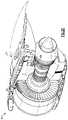
- FIG. 1Cis a side view of an mount system illustrating a rear mount attached through an engine thrust case to a mid-turbine frame between a first and second bearing supported thereby;
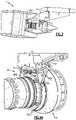
- FIG. 1Dis a forward perspective view of an mount system illustrating a rear mount attached through an engine thrust case to a mid-turbine frame between a first and second bearing supported thereby;
- FIG. 2Ais a top view of an engine mount system
- FIG. 2Bis a side view of an engine mount system within a nacelle system
- FIG. 2Cis a forward perspective view of an engine mount system within a nacelle system
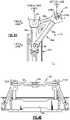
- FIG. 3is a side view of an engine mount system within another front mount
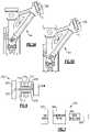
- FIG. 4Ais an aft perspective view of an aft mount
- FIG. 4Bis an aft view of an aft mount of FIG. 4A ;
- FIG. 4Cis a front view of the aft mount of FIG. 4A ;
- FIG. 4Dis a side view of the aft mount of FIG. 4A ;
- FIG. 4Eis a top view of the aft mount of FIG. 4A ;
- FIG. 5Ais a side view of the aft mount of FIG. 4A in a first slide position
- FIG. 5Bis a side view of the aft mount of FIG. 4A in a second slide position.
- FIG. 6shows another embodiment.
- FIG. 7shows yet another embodiment.
- FIG. 1Aillustrates a general partial fragmentary schematic view of a gas turbofan engine 10 suspended from an engine pylon 12 within an engine nacelle assembly N as is typical of an aircraft designed for subsonic operation.
- the turbofan engine 10includes a core engine within a core nacelle C that houses a low spool 14 and high spool 24 .
- the low spool 14includes a low pressure compressor 16 and low pressure turbine 18 .
- the low spool 14drives a fan section 20 connected to the low spool 14 either directly or through a gear train 25 .
- the high spool 24includes a high pressure compressor 26 and high pressure turbine 28 .
- a combustor 30is arranged between the high pressure compressor 26 and high pressure turbine 28 .
- the low and high spools 14 , 24rotate about an engine axis of rotation A.
- the engine 10 in one non-limiting embodimentis a high-bypass geared architecture aircraft engine.
- the engine 10 bypass ratiois greater than about six (6), with an example embodiment being greater than about ten (10)
- the gear train 25is an epicyclic gear train such as a planetary gear system or other gear system with a gear reduction ratio of greater than about 2.3
- the low pressure turbine 18has a pressure ratio that is greater than about 5.
- the engine 10 bypass ratiois greater than ten (10:1)
- the turbofan diameteris significantly larger than that of the low pressure compressor 16
- the low pressure turbine 18has a pressure ratio that is greater than 5:1.
- the gear train 25may be an epicycle gear train such as a planetary gear system or other gear system with a gear reduction ratio of greater than about 2.5:1. It should be understood, however, that the above parameters are only exemplary of one embodiment of a geared architecture engine and that the present invention is applicable to other gas turbine engines including direct drive turbofans.
- the fan section 20communicates airflow into the core nacelle C to the low pressure compressor 16 .
- Core airflow compressed by the low pressure compressor 16 and the high pressure compressor 26is mixed with the fuel in the combustor 30 where is ignited, and burned.
- the resultant high pressure combustor productsare expanded through the high pressure turbine 28 and low pressure turbine 18 .
- the turbines 28 , 18are rotationally coupled to the compressors 26 , 16 respectively to drive the compressors 26 , 16 in response to the expansion of the combustor product.
- the low pressure turbine 18also drives the fan section 20 through gear train 25 .
- a core engine exhaust Eexits the core nacelle C through a core nozzle 43 defined between the core nacelle C and a tail cone 33 .
- the low pressure turbine 18includes a low number of stages, which, in the illustrated non-limiting embodiment, includes three turbine stages, 18 A, 18 B, 18 C.
- the gear train 25operationally effectuates the significantly reduced number of stages within the low pressure turbine 18 .
- the three turbine stages, 18 A, 18 B, 18 Cfacilitate a lightweight and operationally efficient engine architecture. It should be appreciated that a low number of stages contemplates, for example, three to six (3-6) stages.
- Low pressure turbine 18 pressure ratiois pressure measured prior to inlet of low pressure turbine 18 as related to the pressure at the outlet of the low pressure turbine 18 prior to exhaust nozzle.
- Thrustis a function of density, velocity, and area. One or more of these parameters can be manipulated to vary the amount and direction of thrust provided by the bypass flow B.
- the Variable Area Fan Nozzle (“VAFN”) 42operates to effectively vary the area of the fan nozzle exit area 45 to selectively adjust the pressure ratio of the bypass flow B in response to a controller (not shown).
- Low pressure ratio turbofansare desirable for their high propulsive efficiency. However, low pressure ratio fans may be inherently susceptible to fan stability/flutter problems at low power and low flight speeds.
- the VAFN 42allows the engine to change to a more favorable fan operating line at low power, avoiding the instability region, and still provide the relatively smaller nozzle area necessary to obtain a high-efficiency fan operating line at cruise.
- the fan section 20 of the engine 10is designed for a particular flight condition—typically cruise at about 0.8 Mach and about 35,000 feet.
- TSFCThrust Specific Fuel Consumption
- Low fan pressure ratiois the pressure ratio across the fan blade alone, without the Fan Exit Guide Vane (“FEGV”) system 36 .
- the low fan pressure ratio as disclosed herein according to one non-limiting embodimentis less than about 1.45.
- Low corrected fan tip speedis the actual fan tip speed in ft/sec divided by an industry standard temperature correction of [(Tambient deg R)/518.7) ⁇ circumflex over ( ) ⁇ 0.5].
- the “Low corrected fan tip speed” as disclosed herein according to one non-limiting embodimentis less than about 1150 ft/second.
- the VAFN 42is operated to effectively vary the fan nozzle exit area 45 to adjust fan bypass air flow such that the angle of attack or incidence on the fan blades is maintained close to the design incidence for efficient engine operation at other flight conditions, such as landing and takeoff to thus provide optimized engine operation over a range of flight conditions with respect to performance and other operational parameters such as noise levels.
- the engine static structure 44generally has sub-structures including a case structure often referred to as the engine backbone.
- the engine static structure 44generally includes a fan case 46 , an intermediate case (IMC) 48 , a high pressure compressor case 50 , a combustor case 52 A, a high pressure turbine case 52 B, a thrust case 52 C, a low pressure turbine case 54 , and a turbine exhaust case 56 ( FIG. 1B ).
- the combustor case 52 A, the high pressure turbine case 52 B and the thrust case 52 Cmay be combined into a single case. It should be understood that this is an exemplary configuration and any number of cases may be utilized.
- the fan section 20includes a fan rotor 32 with a plurality of circumferentially spaced radially outwardly extending fan blades 34 .
- the fan blades 34are surrounded by the fan case 46 .
- the core engine case structureis secured to the fan case 46 at the IMC 48 which includes a multiple of circumferentially spaced radially extending struts 40 which radially span the core engine case structure and the fan case 46 .
- the engine static structure 44further supports a bearing system upon which the turbines 28 , 18 , compressors 26 , 16 and fan rotor 32 rotate.
- a #1 fan dual bearing 60which rotationally supports the fan rotor 32 is axially located generally within the fan case 46 .
- the #1 fan dual bearing 60is preloaded to react fan thrust forward and aft (in case of surge).
- a #2 LPC bearing 62which rotationally supports the low spool 14 is axially located generally within the intermediate case (IMC) 48 .
- the #2 LPC bearing 62reacts thrust.
- a #3 fan dual bearing 64which rotationally supports the high spool 24 and also reacts thrust.
- the #3 fan bearing 64is also axially located generally within the IMC 48 just forward of the high pressure compressor case 50 .
- a #4 bearing 66which rotationally supports a rear segment of the low spool 14 reacts only radial loads.
- the #4 bearing 66is axially located generally within the thrust case 52 C in an aft section thereof.
- a #5 bearing 68rotationally supports the rear segment of the low spool 14 and reacts only radial loads.
- the #5 bearing 68is axially located generally within the thrust case 52 C just aft of the #4 bearing 66 . It should be understood that this is an exemplary configuration and any number of bearings may be utilized.
- the #4 bearing 66 and the #5 bearing 68are supported within a mid-turbine frame (MTF) 70 to straddle radially extending structural struts 72 which are preloaded in tension ( FIGS. 1C-1D ).
- the MTF 70provides aft structural support within the thrust case 52 C for the #4 bearing 66 and the #5 bearing 68 which rotatably support the spools 14 , 24 .
- a dual rotor engine such as that disclosed in the illustrated embodimenttypically includes a forward frame and a rear frame that support the main rotor bearings.
- the intermediate case (IMC) 48also includes the radially extending struts 40 which are generally radially aligned with the #2 LPC bearing 62 ( FIG. 1B ). It should be understood that various engines with various case and frame structures will benefit from the present invention.
- the turbofan gas turbine engine 10is mounted to aircraft structure such as an aircraft wing through a mount system 80 attachable by the pylon 12 .
- the mount system 80includes a forward mount 82 and an aft mount 84 ( FIG. 2A ).
- the forward mount 82is secured to the IMC 48 and the aft mount 84 is secured to the MTF 70 at the thrust case 52 C.
- the forward mount 82 and the aft mount 84are arranged in a plane containing the axis A of the turbofan gas turbine 10 . This eliminates the thrust links from the intermediate case, which frees up valuable space beneath the core nacelle and minimizes IMC 48 distortion.
- the mount system 80reacts the engine thrust at the aft end of the engine 10 .
- the term “reacts” as utilized in this disclosureis defined as absorbing a load and dissipating the load to another location of the gas turbine engine 10 .
- the forward mount 82supports vertical loads and side loads.
- the forward mount 82in one non-limiting embodiment includes a shackle arrangement which mounts to the IMC 48 at two points 86 A, 86 B.
- the forward mount 82is generally a plate-like member which is oriented transverse to the plane which contains engine axis A. Fasteners are oriented through the forward mount 82 to engage the intermediate case (IMC) 48 generally parallel to the engine axis A.
- the forward mount 82is secured to the IMC 48 .
- the forward mount 82is secured to a portion of the core engine, such as the high-pressure compressor case 50 of the gas turbine engine 10 (see FIG. 3 ).
- the core enginesuch as the high-pressure compressor case 50 of the gas turbine engine 10 (see FIG. 3 ).
- the aft mount 84generally includes a first A-arm 88 A, a second A-arm 88 B, a rear mount platform 90 , a whiffle tree assembly 92 and a drag link 94 .
- the rear mount platform 90is attached directly to aircraft structure such as the pylon 12 .
- the first A-arm 88 A and the second A-arm 88 Bmount between the thrust case 52 C at case bosses 96 which interact with the MTF 70 ( FIGS. 4B-4C ), the rear mount platform 90 and the whiffle tree assembly 92 .
- first A-arm 88 A and the second A-arm 88 Bmay alternatively mount to other areas of the engine 10 such as the high pressure turbine case or other cases. It should also be understood that other frame arrangements may alternatively be used with any engine case arrangement.
- the first A-arm 88 A and the second A-arm 88 Bare rigid generally triangular arrangements, each having a first link arm 89 a , a second link arm 89 b and a third link arm 89 c .
- the first link arm 89 ais between the case boss 96 and the rear mount platform 90 .
- the second link arm 89 bis between the case bosses 96 and the whiffle tree assembly 92 .
- the third link arm 89 cis between the whiffle tree assembly 92 rear mount platform 90 .
- the first A-arm 88 A and the second A-arm 88 Bprimarily support the vertical weight load of the engine 10 and transmit thrust loads from the engine to the rear mount platform 90 .
- the first A-arm 88 A and the second A-arm 88 B of the aft mount 84force the resultant thrust vector at the engine casing to be reacted along the engine axis A which minimizes tip clearance losses due to engine loading at the aft mount 84 . This minimizes blade tip clearance requirements and thereby improves engine performance.
- the whiffle tree assembly 92includes a whiffle link 98 which supports a central ball joint 100 , a first sliding ball joint 102 A and a second sliding ball joint 102 B ( FIG. 4E ). It should be understood that various bushings, vibration isolators and such like may additionally be utilized herewith.
- the central ball joint 100is attached directly to aircraft structure such as the pylon 12 .
- the first sliding ball joint 102 Ais attached to the first A-arm 88 A and the second sliding ball joint 102 B is mounted to the first A-arm 88 A.
- the first and second sliding ball joint 102 A, 102 Bpermit sliding movement of the first and second A-arm 88 A, 88 B (illustrated by arrow S in FIGS.
- the whiffle tree assembly 92allows all engine thrust loads to be equalized transmitted to the engine pylon 12 through the rear mount platform 90 by the sliding movement and equalize the thrust load that results from the dual thrust link configuration.
- the whiffle link 98operates as an equalizing link for vertical loads due to the first sliding ball joint 102 A and the second sliding ball joint 102 B. As the whiffle link 98 rotates about the central ball joint 100 thrust forces are equalized in the axial direction.
- the whiffle tree assembly 92experiences loading only due to vertical loads, and is thus less susceptible to failure than conventional thrust-loaded designs.
- the drag link 94includes a ball joint 104 A mounted to the thrust case 52 C and ball joint 104 B mounted to the rear mount platform 90 ( FIGS. 4B-4C ).
- the drag link 94operates to react torque.
- the aft mount 84transmits engine loads directly to the thrust case 52 C and the MTF 70 . Thrust, vertical, side, and torque loads are transmitted directly from the MTF 70 which reduces the number of structural members as compared to current in-practice designs.
- the mount system 80is compact, and occupies space within the core nacelle volume as compared to turbine exhaust case-mounted configurations, which occupy space outside of the core nacelle which may require additional or relatively larger aerodynamic fairings and increase aerodynamic drag and fuel consumption.
- the mount system 80eliminates the heretofore required thrust links from the IMC, which frees up valuable space adjacent the IMC 48 and the high pressure compressor case 50 within the core nacelle C.
- FIG. 6shows an embodiment 200 , wherein there is a fan drive turbine 208 driving a shaft 206 to in turn drive a fan rotor 202 .
- a gear reduction 204may be positioned between the fan drive turbine 208 and the fan rotor 202 .
- This gear reduction 204may be structured and operate like the gear reduction disclosed above.
- a compressor rotor 210is driven by an intermediate pressure turbine 212
- a second stage compressor rotor 214is driven by a turbine rotor 216 .
- a combustion section 218is positioned intermediate the compressor rotor 214 and the turbine section 216 .
- FIG. 7shows yet another embodiment 300 wherein a fan rotor 302 and a first stage compressor 304 rotate at a common speed.
- the gear reduction 306(which may be structured as disclosed above) is intermediate the compressor rotor 304 and a shaft 308 which is driven by a low pressure turbine section.
Landscapes
- Engineering & Computer Science (AREA)
- Mechanical Engineering (AREA)
- General Engineering & Computer Science (AREA)
- Chemical & Material Sciences (AREA)
- Combustion & Propulsion (AREA)
- Aviation & Aerospace Engineering (AREA)
- Physics & Mathematics (AREA)
- Fluid Mechanics (AREA)
- Structures Of Non-Positive Displacement Pumps (AREA)
- Retarders (AREA)
Abstract
Description
Claims (30)
Priority Applications (4)
| Application Number | Priority Date | Filing Date | Title |
|---|---|---|---|
| US16/405,149US11286883B2 (en) | 2008-06-02 | 2019-05-07 | Gas turbine engine with low stage count low pressure turbine and engine mounting arrangement |
| US17/395,553US11731773B2 (en) | 2008-06-02 | 2021-08-06 | Engine mount system for a gas turbine engine |
| US18/215,394US12179929B2 (en) | 2008-06-02 | 2023-06-28 | Engine mount system for a gas turbine engine |
| US18/937,193US12421916B2 (en) | 2008-06-02 | 2024-11-05 | Engine mount system for a gas turbine engine |
Applications Claiming Priority (6)
| Application Number | Priority Date | Filing Date | Title |
|---|---|---|---|
| US12/131,876US8128021B2 (en) | 2008-06-02 | 2008-06-02 | Engine mount system for a turbofan gas turbine engine |
| US13/340,988US8800914B2 (en) | 2008-06-02 | 2011-12-30 | Gas turbine engine with low stage count low pressure turbine |
| US14/190,429US20140174056A1 (en) | 2008-06-02 | 2014-02-26 | Gas turbine engine with low stage count low pressure turbine |
| US14/755,221US20150300207A1 (en) | 2008-06-02 | 2015-06-30 | Gas turbine engine with low stage count low pressure turbine |
| US15/173,288US10451004B2 (en) | 2008-06-02 | 2016-06-03 | Gas turbine engine with low stage count low pressure turbine |
| US16/405,149US11286883B2 (en) | 2008-06-02 | 2019-05-07 | Gas turbine engine with low stage count low pressure turbine and engine mounting arrangement |
Related Parent Applications (1)
| Application Number | Title | Priority Date | Filing Date |
|---|---|---|---|
| US15/173,288ContinuationUS10451004B2 (en) | 2008-06-02 | 2016-06-03 | Gas turbine engine with low stage count low pressure turbine |
Related Child Applications (1)
| Application Number | Title | Priority Date | Filing Date |
|---|---|---|---|
| US17/395,553ContinuationUS11731773B2 (en) | 2008-06-02 | 2021-08-06 | Engine mount system for a gas turbine engine |
Publications (2)
| Publication Number | Publication Date |
|---|---|
| US20200284222A1 US20200284222A1 (en) | 2020-09-10 |
| US11286883B2true US11286883B2 (en) | 2022-03-29 |
Family
ID=50973086
Family Applications (9)
| Application Number | Title | Priority Date | Filing Date |
|---|---|---|---|
| US14/190,429AbandonedUS20140174056A1 (en) | 2008-06-02 | 2014-02-26 | Gas turbine engine with low stage count low pressure turbine |
| US14/755,221AbandonedUS20150300207A1 (en) | 2008-06-02 | 2015-06-30 | Gas turbine engine with low stage count low pressure turbine |
| US14/755,366AbandonedUS20150315977A1 (en) | 2008-06-02 | 2015-06-30 | Gas turbine engine with low stage count low pressure turbine |
| US14/796,209AbandonedUS20160032828A1 (en) | 2008-06-02 | 2015-07-10 | Gas turbine engine with low stage count low pressure turbine |
| US15/173,288ActiveUS10451004B2 (en) | 2008-06-02 | 2016-06-03 | Gas turbine engine with low stage count low pressure turbine |
| US16/405,149Active2029-12-28US11286883B2 (en) | 2008-06-02 | 2019-05-07 | Gas turbine engine with low stage count low pressure turbine and engine mounting arrangement |
| US17/395,553Active2028-11-30US11731773B2 (en) | 2008-06-02 | 2021-08-06 | Engine mount system for a gas turbine engine |
| US18/215,394ActiveUS12179929B2 (en) | 2008-06-02 | 2023-06-28 | Engine mount system for a gas turbine engine |
| US18/937,193ActiveUS12421916B2 (en) | 2008-06-02 | 2024-11-05 | Engine mount system for a gas turbine engine |
Family Applications Before (5)
| Application Number | Title | Priority Date | Filing Date |
|---|---|---|---|
| US14/190,429AbandonedUS20140174056A1 (en) | 2008-06-02 | 2014-02-26 | Gas turbine engine with low stage count low pressure turbine |
| US14/755,221AbandonedUS20150300207A1 (en) | 2008-06-02 | 2015-06-30 | Gas turbine engine with low stage count low pressure turbine |
| US14/755,366AbandonedUS20150315977A1 (en) | 2008-06-02 | 2015-06-30 | Gas turbine engine with low stage count low pressure turbine |
| US14/796,209AbandonedUS20160032828A1 (en) | 2008-06-02 | 2015-07-10 | Gas turbine engine with low stage count low pressure turbine |
| US15/173,288ActiveUS10451004B2 (en) | 2008-06-02 | 2016-06-03 | Gas turbine engine with low stage count low pressure turbine |
Family Applications After (3)
| Application Number | Title | Priority Date | Filing Date |
|---|---|---|---|
| US17/395,553Active2028-11-30US11731773B2 (en) | 2008-06-02 | 2021-08-06 | Engine mount system for a gas turbine engine |
| US18/215,394ActiveUS12179929B2 (en) | 2008-06-02 | 2023-06-28 | Engine mount system for a gas turbine engine |
| US18/937,193ActiveUS12421916B2 (en) | 2008-06-02 | 2024-11-05 | Engine mount system for a gas turbine engine |
Country Status (1)
| Country | Link |
|---|---|
| US (9) | US20140174056A1 (en) |
Cited By (2)
| Publication number | Priority date | Publication date | Assignee | Title |
|---|---|---|---|---|
| US11420755B2 (en)* | 2019-08-08 | 2022-08-23 | General Electric Company | Shape memory alloy isolator for a gas turbine engine |
| US20240076050A1 (en)* | 2008-06-02 | 2024-03-07 | Raytheon Technologies Corporation | Engine mount system for a gas turbine engine |
Families Citing this family (30)
| Publication number | Priority date | Publication date | Assignee | Title |
|---|---|---|---|---|
| US11346289B2 (en) | 2007-08-01 | 2022-05-31 | Raytheon Technologies Corporation | Turbine section of high bypass turbofan |
| US11149650B2 (en) | 2007-08-01 | 2021-10-19 | Raytheon Technologies Corporation | Turbine section of high bypass turbofan |
| US20150377123A1 (en) | 2007-08-01 | 2015-12-31 | United Technologies Corporation | Turbine section of high bypass turbofan |
| US11486311B2 (en) | 2007-08-01 | 2022-11-01 | Raytheon Technologies Corporation | Turbine section of high bypass turbofan |
| US8844265B2 (en) | 2007-08-01 | 2014-09-30 | United Technologies Corporation | Turbine section of high bypass turbofan |
| US11242805B2 (en) | 2007-08-01 | 2022-02-08 | Raytheon Technologies Corporation | Turbine section of high bypass turbofan |
| US9631558B2 (en) | 2012-01-03 | 2017-04-25 | United Technologies Corporation | Geared architecture for high speed and small volume fan drive turbine |
| US9523422B2 (en) | 2011-06-08 | 2016-12-20 | United Technologies Corporation | Flexible support structure for a geared architecture gas turbine engine |
| US9239012B2 (en) | 2011-06-08 | 2016-01-19 | United Technologies Corporation | Flexible support structure for a geared architecture gas turbine engine |
| US10287914B2 (en) | 2012-01-31 | 2019-05-14 | United Technologies Corporation | Gas turbine engine with high speed low pressure turbine section and bearing support features |
| US10125693B2 (en) | 2012-04-02 | 2018-11-13 | United Technologies Corporation | Geared turbofan engine with power density range |
| FR3010700B1 (en)* | 2013-09-18 | 2017-11-03 | Snecma | DEVICE FOR SUSPENDING A CARTER, TURBOMACHINE AND PROPULSIVE ASSEMBLY |
| FR3012793B1 (en)* | 2013-11-05 | 2017-05-05 | Airbus Operations Sas | AIRCRAFT ASSEMBLY COMPRISING A FASTENER ATTACHED TO THE EXTRADOS PART OF A SAILBOX, FOR MOUNTING A COUPLING MAT ON THIS SAIL BOX |
| US9869190B2 (en) | 2014-05-30 | 2018-01-16 | General Electric Company | Variable-pitch rotor with remote counterweights |
| US10072510B2 (en) | 2014-11-21 | 2018-09-11 | General Electric Company | Variable pitch fan for gas turbine engine and method of assembling the same |
| EP3048266A1 (en)* | 2015-01-22 | 2016-07-27 | United Technologies Corporation | Gas turbine engine with low fan pressure ratio |
| EP3048284A1 (en)* | 2015-01-26 | 2016-07-27 | United Technologies Corporation | Flexible support structure for a geared architecture gas turbine engine |
| US9333603B1 (en) | 2015-01-28 | 2016-05-10 | United Technologies Corporation | Method of assembling gas turbine engine section |
| US9915225B2 (en)* | 2015-02-06 | 2018-03-13 | United Technologies Corporation | Propulsion system arrangement for turbofan gas turbine engine |
| US10100653B2 (en) | 2015-10-08 | 2018-10-16 | General Electric Company | Variable pitch fan blade retention system |
| US20180216575A1 (en)* | 2017-01-27 | 2018-08-02 | General Electric Company | Cool core gas turbine engine |
| GB201804962D0 (en)* | 2018-03-28 | 2018-05-09 | Rolls Royce Plc | A geared turbofan engine mount arrangement |
| EP3591191A1 (en)* | 2018-07-02 | 2020-01-08 | United Technologies Corporation | Turbine section of high bypass turbofan |
| FR3086925B1 (en)* | 2018-10-08 | 2020-09-11 | Safran Aircraft Engines | TURBOMACHINE SUSPENSION KIT |
| CN110645052B (en)* | 2019-10-24 | 2022-07-05 | 周宇凡 | Turbine of aircraft engine |
| US11428160B2 (en) | 2020-12-31 | 2022-08-30 | General Electric Company | Gas turbine engine with interdigitated turbine and gear assembly |
| US11674435B2 (en) | 2021-06-29 | 2023-06-13 | General Electric Company | Levered counterweight feathering system |
| US11795964B2 (en) | 2021-07-16 | 2023-10-24 | General Electric Company | Levered counterweight feathering system |
| US11746664B2 (en)* | 2021-09-23 | 2023-09-05 | Raytheon Technologies Corporation | Geared gas turbine engine with front section moment stiffness relationships |
| US11859506B2 (en) | 2022-05-17 | 2024-01-02 | Pratt & Whitney Canada Corp. | Mounting structure for a gas turbine engine case |
Citations (306)
| Publication number | Priority date | Publication date | Assignee | Title |
|---|---|---|---|---|
| US2258792A (en) | 1941-04-12 | 1941-10-14 | Westinghouse Electric & Mfg Co | Turbine blading |
| US2608821A (en) | 1949-10-08 | 1952-09-02 | Gen Electric | Contrarotating turbojet engine having independent bearing supports for each turbocompressor |
| US2748623A (en) | 1952-02-05 | 1956-06-05 | Boeing Co | Orbit gear controlled reversible planetary transmissions |
| US2936655A (en) | 1955-11-04 | 1960-05-17 | Gen Motors Corp | Self-aligning planetary gearing |
| US3021731A (en) | 1951-11-10 | 1962-02-20 | Wilhelm G Stoeckicht | Planetary gear transmission |
| US3033002A (en) | 1957-11-08 | 1962-05-08 | Fairfield Shipbuilding And Eng | Marine propulsion steam turbine installations |
| US3111005A (en) | 1963-11-19 | Jet propulsion plant | ||
| US3185857A (en) | 1960-02-01 | 1965-05-25 | Lear Siegler Inc | Control apparatus for the parallel operation of alternators |
| US3194487A (en) | 1963-06-04 | 1965-07-13 | United Aircraft Corp | Noise abatement method and apparatus |
| US3222017A (en)* | 1964-03-30 | 1965-12-07 | Gen Electric | Engine mounting |
| US3287906A (en) | 1965-07-20 | 1966-11-29 | Gen Motors Corp | Cooled gas turbine vanes |
| US3352178A (en) | 1965-11-15 | 1967-11-14 | Gen Motors Corp | Planetary gearing |
| US3363419A (en) | 1965-04-27 | 1968-01-16 | Rolls Royce | Gas turbine ducted fan engine |
| US3412560A (en) | 1966-08-03 | 1968-11-26 | Gen Motors Corp | Jet propulsion engine with cooled combustion chamber, fuel heater, and induced air-flow |
| US3468473A (en) | 1966-05-25 | 1969-09-23 | Dowty Rotol Ltd | Gas turbine engines |
| US3526092A (en) | 1967-09-15 | 1970-09-01 | Rolls Royce | Gas turbine engine having improved bearing support means for concentric shafts |
| US3664612A (en) | 1969-12-22 | 1972-05-23 | Boeing Co | Aircraft engine variable highlight inlet |
| GB1309721A (en) | 1971-01-08 | 1973-03-14 | Secr Defence | Fan |
| US3747343A (en) | 1972-02-10 | 1973-07-24 | United Aircraft Corp | Low noise prop-fan |
| US3754484A (en) | 1971-01-08 | 1973-08-28 | Secr Defence | Gearing |
| US3779010A (en) | 1972-08-17 | 1973-12-18 | Gen Electric | Combined thrust reversing and throat varying mechanism for a gas turbine engine |
| US3820719A (en) | 1972-05-09 | 1974-06-28 | Rolls Royce 1971 Ltd | Gas turbine engines |
| US3861139A (en) | 1973-02-12 | 1975-01-21 | Gen Electric | Turbofan engine having counterrotating compressor and turbine elements and unique fan disposition |
| US3886737A (en) | 1972-08-22 | 1975-06-03 | Mtu Muenchen Gmbh | Turbojet engines of multi-shaft and multi-flow construction |
| US3892358A (en) | 1971-03-17 | 1975-07-01 | Gen Electric | Nozzle seal |
| US3932058A (en) | 1974-06-07 | 1976-01-13 | United Technologies Corporation | Control system for variable pitch fan propulsor |
| US3935558A (en) | 1974-12-11 | 1976-01-27 | United Technologies Corporation | Surge detector for turbine engines |
| US3988889A (en) | 1974-02-25 | 1976-11-02 | General Electric Company | Cowling arrangement for a turbofan engine |
| US4013246A (en)* | 1974-12-24 | 1977-03-22 | Rolls-Royce (1971) Limited | Mounting bypass gas turbines engines on aircraft |
| GB1516041A (en) | 1977-02-14 | 1978-06-28 | Secr Defence | Multistage axial flow compressor stators |
| US4118927A (en) | 1975-12-05 | 1978-10-10 | United Turbine Ab & Co. Kommanditbolag | Gas turbine power plant |
| US4130872A (en) | 1975-10-10 | 1978-12-19 | The United States Of America As Represented By The Secretary Of The Air Force | Method and system of controlling a jet engine for avoiding engine surge |
| US4136286A (en) | 1977-07-05 | 1979-01-23 | Woodward Governor Company | Isolated electrical power generation system with multiple isochronous, load-sharing engine-generator units |
| US4137708A (en) | 1973-07-02 | 1979-02-06 | General Motors Corporation | Jet propulsion |
| GB2041090A (en) | 1979-01-31 | 1980-09-03 | Rolls Royce | By-pass gas turbine engines |
| US4233555A (en) | 1979-04-05 | 1980-11-11 | Dyna Technology, Inc. | Alternating current generator for providing three phase and single phase power at different respective voltages |
| US4284174A (en) | 1979-04-18 | 1981-08-18 | Avco Corporation | Emergency oil/mist system |
| US4289360A (en) | 1979-08-23 | 1981-09-15 | General Electric Company | Bearing damper system |
| US4405892A (en) | 1979-07-19 | 1983-09-20 | Brunswick Corporation | Regulator for a generator energized battery |
| GB2130340A (en) | 1981-03-28 | 1984-05-31 | Rolls Royce | Gas turbine rotor assembly |
| US4452567A (en) | 1980-07-15 | 1984-06-05 | Rolls-Royce Limited | Rotor drive systems |
| US4463553A (en) | 1981-05-29 | 1984-08-07 | Office National D'etudes Et De Recherches Aerospatiales | Turbojet with contrarotating wheels |
| US4471609A (en)* | 1982-08-23 | 1984-09-18 | The Boeing Company | Apparatus and method for minimizing engine backbone bending |
| US4478551A (en) | 1981-12-08 | 1984-10-23 | United Technologies Corporation | Turbine exhaust case design |
| US4649114A (en) | 1979-10-05 | 1987-03-10 | Intermedicat Gmbh | Oxygen permeable membrane in fermenter for oxygen enrichment of broth |
| US4660376A (en) | 1984-04-27 | 1987-04-28 | General Electric Company | Method for operating a fluid injection gas turbine engine |
| US4696156A (en) | 1986-06-03 | 1987-09-29 | United Technologies Corporation | Fuel and oil heat management system for a gas turbine engine |
| US4704862A (en) | 1985-05-29 | 1987-11-10 | United Technologies Corporation | Ducted prop engine |
| GB2199375A (en) | 1986-12-23 | 1988-07-06 | Rolls Royce Plc | A turbofan gas turbine engine |
| US4808076A (en) | 1987-12-15 | 1989-02-28 | United Technologies Corporation | Rotor for a gas turbine engine |
| US4809498A (en) | 1987-07-06 | 1989-03-07 | General Electric Company | Gas turbine engine |
| US4879624A (en) | 1987-12-24 | 1989-11-07 | Sundstrand Corporation | Power controller |
| US4885912A (en) | 1987-05-13 | 1989-12-12 | Gibbs & Hill, Inc. | Compressed air turbomachinery cycle with reheat and high pressure air preheating in recuperator |
| US4966338A (en) | 1987-08-05 | 1990-10-30 | General Electric Company | Aircraft pylon |
| US4979362A (en) | 1989-05-17 | 1990-12-25 | Sundstrand Corporation | Aircraft engine starting and emergency power generating system |
| US5074109A (en) | 1989-03-22 | 1991-12-24 | Societe Nationale D'etude Et De Construction De Moteurs D'aviation "S.N.E.C.M.A." | Low pressure turbine rotor suspension in a twin hub turbo-engine |
| US5079916A (en) | 1982-11-01 | 1992-01-14 | General Electric Company | Counter rotation power turbine |
| US5081832A (en) | 1990-03-05 | 1992-01-21 | Rolf Jan Mowill | High efficiency, twin spool, radial-high pressure, gas turbine engine |
| US5102379A (en) | 1991-03-25 | 1992-04-07 | United Technologies Corporation | Journal bearing arrangement |
| US5136839A (en) | 1988-09-28 | 1992-08-11 | Short Brothers Plc | Ducted fan turbine engine |
| US5141400A (en) | 1991-01-25 | 1992-08-25 | General Electric Company | Wide chord fan blade |
| US5157915A (en)* | 1990-04-19 | 1992-10-27 | Societe Nationale D'etude Et De Construction De Motors D'aviation | Pod for a turbofan aero engine of the forward contrafan type having a very high bypass ratio |
| US5168208A (en) | 1988-05-09 | 1992-12-01 | Onan Corporation | Microprocessor based integrated generator set controller apparatus and method |
| US5174525A (en) | 1991-09-26 | 1992-12-29 | General Electric Company | Structure for eliminating lift load bending in engine core of turbofan |
| US5182464A (en) | 1991-01-09 | 1993-01-26 | Techmatics, Inc. | High speed transfer switch |
| US5252905A (en) | 1985-12-23 | 1993-10-12 | York International Corporation | Driving system for single phase A-C induction motor |
| US5273393A (en) | 1992-03-26 | 1993-12-28 | Rolls-Royce Plc | Gas turbine engine casing |
| US5275357A (en) | 1992-01-16 | 1994-01-04 | General Electric Company | Aircraft engine mount |
| US5277382A (en) | 1992-10-13 | 1994-01-11 | General Electric Company | Aircraft engine forward mount |
| US5307622A (en) | 1993-08-02 | 1994-05-03 | General Electric Company | Counterrotating turbine support assembly |
| US5317877A (en) | 1992-08-03 | 1994-06-07 | General Electric Company | Intercooled turbine blade cooling air feed system |
| US5320307A (en) | 1992-03-25 | 1994-06-14 | General Electric Company | Aircraft engine thrust mount |
| US5361580A (en) | 1993-06-18 | 1994-11-08 | General Electric Company | Gas turbine engine rotor support system |
| US5372338A (en) | 1992-04-15 | 1994-12-13 | Rolls-Royce Plc | Mounting arrangement for a gas turbine engine |
| US5388964A (en) | 1993-09-14 | 1995-02-14 | General Electric Company | Hybrid rotor blade |
| US5409184A (en) | 1993-02-20 | 1995-04-25 | Rolls-Royce Plc | Mounting for coupling a turbofan gas turbine engine to an aircraft structure |
| US5433674A (en) | 1994-04-12 | 1995-07-18 | United Technologies Corporation | Coupling system for a planetary gear train |
| US5443229A (en) | 1993-12-13 | 1995-08-22 | General Electric Company | Aircraft gas turbine engine sideways mount |
| US5447411A (en) | 1993-06-10 | 1995-09-05 | Martin Marietta Corporation | Light weight fan blade containment system |
| US5452575A (en) | 1993-09-07 | 1995-09-26 | General Electric Company | Aircraft gas turbine engine thrust mount |
| US5466198A (en) | 1993-06-11 | 1995-11-14 | United Technologies Corporation | Geared drive system for a bladed propulsor |
| US5474258A (en) | 1991-11-25 | 1995-12-12 | Rolls-Royce Plc | Mounting arrangement for a gas turbine engine |
| US5497961A (en) | 1991-08-07 | 1996-03-12 | Rolls-Royce Plc | Gas turbine engine nacelle assembly |
| US5524847A (en) | 1993-09-07 | 1996-06-11 | United Technologies Corporation | Nacelle and mounting arrangement for an aircraft engine |
| US5634767A (en) | 1996-03-29 | 1997-06-03 | General Electric Company | Turbine frame having spindle mounted liner |
| EP0791383A1 (en) | 1996-02-26 | 1997-08-27 | Japan Gore-Tex, Inc. | An assembly for deaeration of liquids |
| US5677060A (en) | 1994-03-10 | 1997-10-14 | Societe Europeenne De Propulsion | Method for protecting products made of a refractory material against oxidation, and resulting protected products |
| US5694027A (en) | 1994-12-08 | 1997-12-02 | Satake Corporation | Three-phase brushless self-excited synchronous generator with no rotor excitation windings |
| US5694765A (en) | 1993-07-06 | 1997-12-09 | Rolls-Royce Plc | Shaft power transfer in gas turbine engines with machines operable as generators or motors |
| US5729059A (en) | 1995-06-07 | 1998-03-17 | Kilroy; Donald G. | Digital no-break power transfer system |
| US5734555A (en) | 1994-03-30 | 1998-03-31 | Intel Corporation | Shared socket multi-chip module and/or piggyback pin grid array package |
| US5740668A (en) | 1994-04-20 | 1998-04-21 | Hitachi, Ltd. | High efficiency gas turbine |
| US5746391A (en) | 1995-04-13 | 1998-05-05 | Rolls-Royce Plc | Mounting for coupling a turbofan gas turbine engine to an aircraft structure |
| US5754033A (en) | 1996-03-13 | 1998-05-19 | Alaska Power Systems Inc. | Control system and circuits for distributed electrical-power generating stations |
| US5778659A (en) | 1994-10-20 | 1998-07-14 | United Technologies Corporation | Variable area fan exhaust nozzle having mechanically separate sleeve and thrust reverser actuation systems |
| US5791789A (en) | 1997-04-24 | 1998-08-11 | United Technologies Corporation | Rotor support for a turbine engine |
| EP0860593A1 (en) | 1997-02-20 | 1998-08-26 | SOCIETE NATIONALE D'ETUDE ET DE CONSTRUCTION DE MOTEURS D'AVIATION -Snecma | Compression system for a turbomachine |
| US5806303A (en) | 1996-03-29 | 1998-09-15 | General Electric Company | Turbofan engine with a core driven supercharged bypass duct and fixed geometry nozzle |
| US5810287A (en) | 1996-05-24 | 1998-09-22 | The Boeing Company | Aircraft support pylon |
| US5857836A (en) | 1996-09-10 | 1999-01-12 | Aerodyne Research, Inc. | Evaporatively cooled rotor for a gas turbine engine |
| US5860276A (en) | 1996-04-18 | 1999-01-19 | Rolls-Royce Plc | Ducted fan gas turbine engine mounting |
| US5871176A (en) | 1996-11-21 | 1999-02-16 | Societe Nationale D'etude Et De Construction De Moteurs D'aviation "Snecma" | Redundant front suspension system for a turboshaft engine |
| US5871177A (en) | 1996-11-21 | 1999-02-16 | Societe Nationale D'etude Et De Construction De Moteurs D'aviation "Snecma" | Redundant front suspension system for a turboshaft engine |
| US5871175A (en) | 1996-11-21 | 1999-02-16 | Societe Nationale D'etude Et De Construction De Moteurs D'aviation | Redundant front suspension system for a turboshaft engine |
| US5886890A (en) | 1996-06-24 | 1999-03-23 | Sanyo Electric Co., Ltd. | Power-supply system involving system interconnection |
| US5915917A (en) | 1994-12-14 | 1999-06-29 | United Technologies Corporation | Compressor stall and surge control using airflow asymmetry measurement |
| US5921500A (en) | 1997-10-08 | 1999-07-13 | General Electric Company | Integrated failsafe engine mount |
| US5927644A (en) | 1997-10-08 | 1999-07-27 | General Electric Company | Double failsafe engine mount |
| US5949153A (en) | 1997-03-06 | 1999-09-07 | Consolidated Natural Gas Service Company, Inc. | Multi-engine controller |
| US5975841A (en) | 1997-10-03 | 1999-11-02 | Thermal Corp. | Heat pipe cooling for turbine stators |
| US5985470A (en) | 1998-03-16 | 1999-11-16 | General Electric Company | Thermal/environmental barrier coating system for silicon-based materials |
| US6073439A (en) | 1997-03-05 | 2000-06-13 | Rolls-Royce Plc | Ducted fan gas turbine engine |
| US6095456A (en)* | 1996-12-23 | 2000-08-01 | The Boeing Company | Strut-wing interface having dual upper links |
| US6104171A (en) | 1998-11-23 | 2000-08-15 | Caterpillar Inc. | Generator set with redundant bus sensing and automatic generator on-line control |
| US6126110A (en) | 1997-12-22 | 2000-10-03 | Mcdonnell Douglas Corporation | Horizontally opposed trunnion forward engine mount system supported beneath a wing pylon |
| US6138949A (en) | 1998-10-30 | 2000-10-31 | Sikorsky Aircraft Corporation | Main rotor pylon support structure |
| US6189830B1 (en) | 1999-02-26 | 2001-02-20 | The Boeing Company | Tuned engine mounting system for jet aircraft |
| US6209311B1 (en) | 1998-04-13 | 2001-04-03 | Nikkiso Company, Ltd. | Turbofan engine including fans with reduced speed |
| US6223616B1 (en) | 1999-12-22 | 2001-05-01 | United Technologies Corporation | Star gear system with lubrication circuit and lubrication method therefor |
| US6260351B1 (en) | 1998-12-10 | 2001-07-17 | United Technologies Corporation | Controlled spring rate gearbox mount |
| EP1142850A1 (en) | 2000-04-06 | 2001-10-10 | General Electric Company | Thermal/environmental barrier coating for silicon-containing materials |
| US6315815B1 (en) | 1999-12-16 | 2001-11-13 | United Technologies Corporation | Membrane based fuel deoxygenator |
| US6318070B1 (en) | 2000-03-03 | 2001-11-20 | United Technologies Corporation | Variable area nozzle for gas turbine engines driven by shape memory alloy actuators |
| US6339927B1 (en) | 1999-10-01 | 2002-01-22 | The United States Of America As Represented By The Secretary Of The Air Force | Integrated fan-core twin spool counter-rotating turbofan gas turbine engine |
| US6378308B1 (en) | 1998-04-16 | 2002-04-30 | 3K Warner Turbosystems Gmbh | Turbocharged internal combustion engine |
| US6387456B1 (en) | 1999-04-15 | 2002-05-14 | General Electric Company | Silicon based substrate with environmental/thermal barrier layer |
| US6397161B1 (en)* | 1997-12-17 | 2002-05-28 | Nippon Sheet Glass Co., Ltd. | Method for stabilizing output of rain sensor and protection method therefor |
| US6398161B1 (en) | 1999-05-17 | 2002-06-04 | Aerospatiale Airbus | Device for fixing an aircraft propulsion system to a strut and a strut adapted to said device |
| US6474597B1 (en) | 1999-11-20 | 2002-11-05 | Rolls-Royce Plc | Gas turbine engine mounting arrangement |
| US20020172593A1 (en) | 2001-05-19 | 2002-11-21 | Udall Kenneth F. | Mounting arrangement for a gas turbine engine |
| US6517341B1 (en) | 1999-02-26 | 2003-02-11 | General Electric Company | Method to prevent recession loss of silica and silicon-containing materials in combustion gas environments |
| US6517027B1 (en) | 2001-12-03 | 2003-02-11 | Pratt & Whitney Canada Corp. | Flexible/fixed support for engine cowl |
| US6555929B1 (en) | 2000-10-24 | 2003-04-29 | Kohler Co. | Method and apparatus for preventing excessive reaction to a load disturbance by a generator set |
| US20030097844A1 (en) | 2001-11-29 | 2003-05-29 | Seda Jorge F. | Aircraft engine with inter-turbine engine frame |
| US6607165B1 (en) | 2002-06-28 | 2003-08-19 | General Electric Company | Aircraft engine mount with single thrust link |
| US20030163984A1 (en) | 2002-03-01 | 2003-09-04 | Seda Jorge F. | Aircraft engine with inter-turbine engine frame supported counter rotating low pressure turbine rotors |
| US6631310B1 (en) | 2000-09-15 | 2003-10-07 | General Electric Company | Wireless engine-generator systems digital assistant |
| US6639331B2 (en) | 2001-11-30 | 2003-10-28 | Onan Corporation | Parallel generator power system |
| US6647707B2 (en) | 2000-09-05 | 2003-11-18 | Sudarshan Paul Dev | Nested core gas turbine engine |
| US6652222B1 (en) | 2002-09-03 | 2003-11-25 | Pratt & Whitney Canada Corp. | Fan case design with metal foam between Kevlar |
| US6653821B2 (en) | 2001-06-15 | 2003-11-25 | Generac Power Systems, Inc. | System controller and method for monitoring and controlling a plurality of generator sets |
| US6657416B2 (en) | 2001-06-15 | 2003-12-02 | Generac Power Systems, Inc. | Control system for stand-by electrical generator |
| US6663530B2 (en) | 2001-12-14 | 2003-12-16 | Pratt & Whitney Canada Corp. | Zero twist carrier |
| US20030235523A1 (en) | 2002-06-24 | 2003-12-25 | Maxim Lyubovsky | Method for methane oxidation and, apparatus for use therewith |
| US6668629B1 (en) | 1999-11-26 | 2003-12-30 | General Electric Company | Methods and apparatus for web-enabled engine-generator systems |
| US6669393B2 (en) | 2001-10-10 | 2003-12-30 | General Electric Co. | Connector assembly for gas turbine engines |
| US6709492B1 (en) | 2003-04-04 | 2004-03-23 | United Technologies Corporation | Planar membrane deoxygenator |
| US6732502B2 (en) | 2002-03-01 | 2004-05-11 | General Electric Company | Counter rotating aircraft gas turbine engine with high overall pressure ratio compressor |
| US6735954B2 (en) | 2001-12-21 | 2004-05-18 | Pratt & Whitney Canada Corp. | Offset drive for gas turbine engine |
| US6763653B2 (en) | 2002-09-24 | 2004-07-20 | General Electric Company | Counter rotating fan aircraft gas turbine engine with aft booster |
| US6792759B2 (en) | 1998-08-31 | 2004-09-21 | William S. Rollins | High density combined cycle power plant process |
| US6814541B2 (en) | 2002-10-07 | 2004-11-09 | General Electric Company | Jet aircraft fan case containment design |
| US6843449B1 (en) | 2004-02-09 | 2005-01-18 | General Electric Company | Fail-safe aircraft engine mounting system |
| US6847297B2 (en) | 2003-01-06 | 2005-01-25 | General Electric Company | Locator devices and methods for centrally controlled power distribution systems |
| US6892115B2 (en) | 2002-02-25 | 2005-05-10 | General Electric Company | Method and apparatus for optimized centralized critical control architecture for switchgear and power equipment |
| US6895741B2 (en) | 2003-06-23 | 2005-05-24 | Pratt & Whitney Canada Corp. | Differential geared turbine engine with torque modulation capability |
| US6899518B2 (en) | 2002-12-23 | 2005-05-31 | Pratt & Whitney Canada Corp. | Turbine shroud segment apparatus for reusing cooling air |
| US20050138914A1 (en) | 2003-04-28 | 2005-06-30 | Marius Paul | Turbo rocket with real carnot cycle |
| US6914763B2 (en) | 2002-01-15 | 2005-07-05 | Wellspring Heritage, Llc | Utility control and autonomous disconnection of distributed generation from a power distribution system |
| US6966174B2 (en) | 2002-04-15 | 2005-11-22 | Paul Marius A | Integrated bypass turbojet engines for air craft and other vehicles |
| US20050257528A1 (en) | 2004-05-19 | 2005-11-24 | Dunbar Donal S Jr | Retractable afterburner for jet engine |
| US6976655B2 (en) | 2002-11-06 | 2005-12-20 | Rolls-Royce Plc | Mounting arrangement |
| US20060029894A1 (en) | 2004-06-10 | 2006-02-09 | Zinn Ben T | Stagnation point reverse flow combustor for a combustion system |
| US7019495B2 (en) | 2003-08-28 | 2006-03-28 | C.E. Neihoff & Co. | Inter-regulator control of multiple electric power sources |
| US7021585B2 (en) | 2003-06-30 | 2006-04-04 | Snecma Moteurs | Aircraft engine rear mount with thrust links and boomerang-shaped lever |
| US7021042B2 (en) | 2002-12-13 | 2006-04-04 | United Technologies Corporation | Geartrain coupling for a turbofan engine |
| GB2419639A (en) | 2004-10-29 | 2006-05-03 | Gen Electric | Lubrication of counter-rotating fans of a gas turbine engine |
| US20060090448A1 (en) | 2004-10-29 | 2006-05-04 | Henry John L | Gas turbine engine and method of assembling same |
| US20060090451A1 (en) | 2004-10-29 | 2006-05-04 | Moniz Thomas O | Counter-rotating gas turbine engine and method of assembling same |
| US7055330B2 (en) | 2004-02-25 | 2006-06-06 | United Technologies Corp | Apparatus for driving an accessory gearbox in a gas turbine engine |
| US7055306B2 (en) | 2003-04-30 | 2006-06-06 | Hamilton Sundstrand Corporation | Combined stage single shaft turbofan engine |
| US20060130456A1 (en) | 2004-12-17 | 2006-06-22 | United Technologies Corporation | Turbine engine rotor stack |
| US20060177302A1 (en) | 2005-02-04 | 2006-08-10 | Berry Henry M | Axial flow compressor |
| US20060179818A1 (en) | 2005-02-15 | 2006-08-17 | Ali Merchant | Jet engine inlet-fan system and design method |
| US7104918B2 (en) | 2003-07-29 | 2006-09-12 | Pratt & Whitney Canada Corp. | Compact epicyclic gear carrier |
| US20060228206A1 (en) | 2005-04-07 | 2006-10-12 | General Electric Company | Low solidity turbofan |
| US20060244327A1 (en) | 2005-04-27 | 2006-11-02 | Stephen Kundel | Permanent magnet generator |
| US20060248900A1 (en) | 2005-05-05 | 2006-11-09 | Gabriel Suciu | Accessory gearbox |
| US7134286B2 (en) | 2004-08-24 | 2006-11-14 | Pratt & Whitney Canada Corp. | Gas turbine floating collar arrangement |
| US7144349B2 (en) | 2004-04-06 | 2006-12-05 | Pratt & Whitney Canada Corp. | Gas turbine gearbox |
| GB2426792A (en) | 2005-04-01 | 2006-12-06 | David Richard Hopkins | Fan with conical hub |
| US7147436B2 (en) | 2004-04-15 | 2006-12-12 | United Technologies Corporation | Turbine engine rotor retainer |
| US7195446B2 (en) | 2004-10-29 | 2007-03-27 | General Electric Company | Counter-rotating turbine engine and method of assembling same |
| WO2007038674A1 (en) | 2005-09-28 | 2007-04-05 | Entrotech Composites, Llc | Braid-reinforced composites and processes for their preparation |
| US20070084218A1 (en)* | 2005-10-14 | 2007-04-19 | Rolls-Royce Plc | Fan static structure |
| US7216475B2 (en) | 2003-11-21 | 2007-05-15 | General Electric Company | Aft FLADE engine |
| US20070125066A1 (en) | 2005-10-19 | 2007-06-07 | Orlando Robert J | Turbofan engine assembly and method of assembling same |
| US7246484B2 (en) | 2003-08-25 | 2007-07-24 | General Electric Company | FLADE gas turbine engine with counter-rotatable fans |
| US20070205323A1 (en) | 2004-08-04 | 2007-09-06 | Airbus France | Engine assembly for aircraft |
| US7269938B2 (en) | 2004-10-29 | 2007-09-18 | General Electric Company | Counter-rotating gas turbine engine and method of assembling same |
| US20070262661A1 (en) | 2005-02-04 | 2007-11-15 | Chun Ai | Miniature Bipolar Single-Phase Generator |
| US7299621B2 (en) | 2004-02-12 | 2007-11-27 | Snecma Moteurs | Three-spool by-pass turbojet with a high by-pass ratio |
| US20080003096A1 (en) | 2006-06-29 | 2008-01-03 | United Technologies Corporation | High coverage cooling hole shape |
| US20080019830A1 (en)* | 2004-12-04 | 2008-01-24 | Suciu Gabriel L | Tip Turbine Single Plane Mount |
| RU2315887C2 (en) | 2005-12-23 | 2008-01-27 | Открытое акционерное общество "Авиадвигатель" | High by-pass ratio turbojet engine |
| US20080022653A1 (en) | 2006-07-31 | 2008-01-31 | Jan Christopher Schilling | Gas turbine engine assembly and method of assembling same |
| US7328580B2 (en) | 2004-06-23 | 2008-02-12 | General Electric Company | Chevron film cooled wall |
| US7338259B2 (en) | 2004-03-02 | 2008-03-04 | United Technologies Corporation | High modulus metallic component for high vibratory operation |
| US20080056888A1 (en) | 2006-09-01 | 2008-03-06 | United Technologies | Guide vane for a gas turbine engine |
| US20080073460A1 (en)* | 2006-05-06 | 2008-03-27 | Beardsley Peter K | Aeroengine mount |
| WO2008045058A1 (en) | 2006-10-12 | 2008-04-17 | United Technologies Corporation | Operational line management of low pressure compressor in a turbofan engine |
| US20080098713A1 (en) | 2006-10-27 | 2008-05-01 | Robert Joseph Orlando | Gas turbine engine assembly and methods of assembling same |
| US20080116009A1 (en) | 2006-11-22 | 2008-05-22 | United Technologies Corporation | Lubrication system with extended emergency operability |
| US20080116010A1 (en) | 2006-11-22 | 2008-05-22 | United Technologies Corporation | Lubrication system with tolerance for reduced gravity |
| US20080148881A1 (en) | 2006-12-21 | 2008-06-26 | Thomas Ory Moniz | Power take-off system and gas turbine engine assembly including same |
| US20080149445A1 (en) | 2006-12-22 | 2008-06-26 | General Electric Company | Variable Magnetic Coupling of Rotating Machinery |
| US20080169378A1 (en) | 2005-03-18 | 2008-07-17 | Airbus France | Engine Fastener Of A Mounting System Interposed Between An Attachment Strut And An Aircraft Engine |
| US7406830B2 (en) | 2004-12-17 | 2008-08-05 | Snecma | Compression-evaporation system for liquefied gas |
| US20080184694A1 (en) | 2007-02-07 | 2008-08-07 | Snecma | Gas turbine with contrarotating hp and lp turbines |
| EP1956224A2 (en) | 2007-02-08 | 2008-08-13 | United Technologies Corporation | Fan variable area nozzle for a gas turbine engine fan nacelle with cam drive ring actuation system |
| EP1959114A2 (en) | 2007-02-16 | 2008-08-20 | Hamilton Sundstrand Corporation | Multi-speed gearbox for low spool driven auxiliary component |
| US20080276621A1 (en) | 2006-07-27 | 2008-11-13 | United Technologies Corporation | Catenary mid-turbine frame design |
| US20080304974A1 (en) | 2007-06-11 | 2008-12-11 | Honeywell International, Inc. | First stage dual-alloy turbine wheel |
| US20080315033A1 (en)* | 2005-10-03 | 2008-12-25 | Airbus France | Turbojet Engine Mounting Structure For Aircraft |
| US20080317588A1 (en) | 2007-06-25 | 2008-12-25 | Grabowski Zbigniew M | Managing spool bearing load using variable area flow nozzle |
| US20090007569A1 (en) | 2007-07-05 | 2009-01-08 | Lemmers Jr Glenn C | High to low pressure spool summing gearbox for accessory power extraction and electric start |
| EP2028359A2 (en) | 2007-08-23 | 2009-02-25 | United Technologies Corporation | Gas turbine engine with axial movable fan variable area nozzle |
| US20090056306A1 (en) | 2007-08-28 | 2009-03-05 | Suciu Gabriel L | Gas turbine engine front architecture |
| US20090056343A1 (en) | 2007-08-01 | 2009-03-05 | Suciu Gabriel L | Engine mounting configuration for a turbofan gas turbine engine |
| US20090067993A1 (en) | 2007-03-22 | 2009-03-12 | Roberge Gary D | Coated variable area fan nozzle |
| US7513103B2 (en) | 2005-10-19 | 2009-04-07 | General Electric Company | Gas turbine engine assembly and methods of assembling same |
| US20090097967A1 (en) | 2007-07-27 | 2009-04-16 | Smith Peter G | Gas turbine engine with variable geometry fan exit guide vane system |
| US7527220B2 (en) | 2004-03-25 | 2009-05-05 | Snecma | Aircraft engine mount |
| US20090155070A1 (en)* | 2007-12-18 | 2009-06-18 | Snecma | Intermediate casing extension for an aircraft jet engine, comprising a sectorised annular groove for receiving the nacelle covers |
| US7557544B2 (en) | 2007-04-23 | 2009-07-07 | Cummins Power Generation Ip, Inc. | Zero crossing detection for an electric power generation system |
| US20090183512A1 (en)* | 2008-01-18 | 2009-07-23 | Suciu Gabriel L | Mounting system for a gas turbine engine |
| EP2098704A2 (en) | 2008-03-05 | 2009-09-09 | United Technologies Corporation | Variable area fan nozzle fan flutter management system |
| US20090229242A1 (en) | 2008-03-12 | 2009-09-17 | Schwark Fred W | Nozzle extension assembly for ground and flight testing |
| US7591754B2 (en) | 2006-03-22 | 2009-09-22 | United Technologies Corporation | Epicyclic gear train integral sun gear coupling design |
| US20090236469A1 (en)* | 2008-03-21 | 2009-09-24 | Suciu Gabriel L | Mounting system for a gas turbine engine |
| US7594404B2 (en) | 2006-07-27 | 2009-09-29 | United Technologies Corporation | Embedded mount for mid-turbine frame |
| US20090245997A1 (en) | 2006-10-12 | 2009-10-01 | Wayne Hurwitz | Method and device to avoid turbo instability in a gas turbine engine |
| US7600370B2 (en) | 2006-05-25 | 2009-10-13 | Siemens Energy, Inc. | Fluid flow distributor apparatus for gas turbine engine mid-frame section |
| US7610763B2 (en) | 2006-05-09 | 2009-11-03 | United Technologies Corporation | Tailorable design configuration topologies for aircraft engine mid-turbine frames |
| US20090293445A1 (en) | 2006-08-22 | 2009-12-03 | Ress Jr Robert A | Gas turbine engine with intermediate speed booster |
| US7632064B2 (en) | 2006-09-01 | 2009-12-15 | United Technologies Corporation | Variable geometry guide vane for a gas turbine engine |
| US20090314881A1 (en) | 2008-06-02 | 2009-12-24 | Suciu Gabriel L | Engine mount system for a turbofan gas turbine engine |
| US20090317229A1 (en) | 2008-06-12 | 2009-12-24 | Suciu Gabriel L | Integrated actuator module for gas turbine engine |
| US20090320488A1 (en) | 2008-06-26 | 2009-12-31 | Jonathan Gilson | Gas turbine engine with noise attenuating variable area fan nozzle |
| US20100007207A1 (en) | 2006-01-16 | 2010-01-14 | Thomas Peuser | Method and Device for Providing a Supply Voltage by Means of Generator Units Connected in Parallel |
| US20100005810A1 (en) | 2008-07-11 | 2010-01-14 | Rob Jarrell | Power transmission among shafts in a turbine engine |
| US7656060B2 (en) | 2007-10-31 | 2010-02-02 | Caterpillar Inc. | Power system with method for adding multiple generator sets |
| US7662059B2 (en) | 2006-10-18 | 2010-02-16 | United Technologies Corporation | Lubrication of windmilling journal bearings |
| US7665293B2 (en) | 2007-08-02 | 2010-02-23 | Florida Turbine Technologies, Inc. | Low speed rotor shaft for a small twin spool gas turbine engine |
| EP2157305A2 (en) | 2008-08-19 | 2010-02-24 | United Technologies Corporation | Gas turbine engine with variable area fan nozzle |
| US20100080700A1 (en) | 2008-05-16 | 2010-04-01 | Gideon Venter | Two-shaft engine for an aircraft gas turbine |
| US7704178B2 (en) | 2006-07-05 | 2010-04-27 | United Technologies Corporation | Oil baffle for gas turbine fan drive gear system |
| US20100105516A1 (en) | 2006-07-05 | 2010-04-29 | United Technologies Corporation | Coupling system for a star gear train in a gas turbine engine |
| US7716914B2 (en) | 2006-12-21 | 2010-05-18 | General Electric Company | Turbofan engine assembly and method of assembling same |
| US20100126141A1 (en) | 2008-11-21 | 2010-05-27 | Jan Christopher Schilling | Gas turbine engine booster having rotatable radially inwardly extending blades and non-rotatable vanes |
| US20100127117A1 (en) | 2007-04-20 | 2010-05-27 | Airbus Operations, | Attachment pylon for aircraft having a rear engine attachment beam offset from the caisson |
| US20100132377A1 (en) | 2008-11-28 | 2010-06-03 | Pratt & Whitney Canada Corp. | Fabricated itd-strut and vane ring for gas turbine engine |
| US20100132376A1 (en) | 2008-11-28 | 2010-06-03 | Pratt & Whitney Canada Corp. | Mid turbine frame for gas turbine engine |
| US20100148396A1 (en) | 2007-04-17 | 2010-06-17 | General Electric Company | Methods of making articles having toughened and untoughened regions |
| US20100147997A1 (en) | 2007-04-20 | 2010-06-17 | Airbus Operations | Aircraft engine attachment pylon having a rear engine attachment provided with a self-locking nut |
| US20100154384A1 (en) | 2008-12-19 | 2010-06-24 | Jan Christopher Schilling | Geared differential speed counter-rotatable low pressure turbine |
| US20100170980A1 (en) | 2007-06-20 | 2010-07-08 | Airbus Operations | Engine mounting structure for aircraft with a rear engine attachment beam forming a spreader beam |
| US20100181419A1 (en) | 2007-07-09 | 2010-07-22 | Airbus Operations | Engine mounting structure for aircraft having a beam spreader connected at four points |
| US7765786B2 (en) | 2004-09-03 | 2010-08-03 | Mtu Aero Engines Gmbh | Aircraft engine with separate auxiliary rotor and fan rotor |
| US20100212281A1 (en) | 2009-02-26 | 2010-08-26 | United Technologies Corporation | Auxiliary pump system for fan drive gear system |
| US20100219779A1 (en) | 2009-03-02 | 2010-09-02 | Rolls-Royce Plc | Variable drive gas turbine engine |
| US20100218483A1 (en) | 2009-02-27 | 2010-09-02 | United Technologies Corporation | Controlled fan stream flow bypass |
| US7797946B2 (en) | 2006-12-06 | 2010-09-21 | United Technologies Corporation | Double U design for mid-turbine frame struts |
| US7806651B2 (en) | 2004-04-02 | 2010-10-05 | Mtu Aero Engines Gmbh | Method for designing a low-pressure turbine of an aircraft engine, and low-pressure turbine |
| US7816813B2 (en) | 2006-09-28 | 2010-10-19 | Asco Power Technologies, L.P. | Method and apparatus for parallel engine generators |
| US7828682B2 (en) | 2006-05-11 | 2010-11-09 | Hansen Transmissions International N.V. | Gearbox for a wind turbine |
| US7841163B2 (en) | 2006-11-13 | 2010-11-30 | Hamilton Sundstrand Corporation | Turbofan emergency generator |
| US7841165B2 (en) | 2006-10-31 | 2010-11-30 | General Electric Company | Gas turbine engine assembly and methods of assembling same |
| US20100301617A1 (en) | 2007-12-20 | 2010-12-02 | Volvo Aero Corporation | Gas turbine engine |
| US20100317477A1 (en) | 2009-06-10 | 2010-12-16 | United Technologies Corporation | Epicyclic gear system with improved lubrication system |
| US20100331139A1 (en) | 2009-06-25 | 2010-12-30 | United Technologies Corporation | Epicyclic gear system with superfinished journal bearing |
| US20100326050A1 (en) | 2009-06-30 | 2010-12-30 | Jan Christopher Schilling | Aircraft gas turbine engine counter-rotatable generator |
| US7882693B2 (en) | 2006-11-29 | 2011-02-08 | General Electric Company | Turbofan engine assembly and method of assembling same |
| US20110056208A1 (en) | 2009-09-09 | 2011-03-10 | United Technologies Corporation | Reversed-flow core for a turbofan with a fan drive gear system |
| US7926260B2 (en) | 2006-07-05 | 2011-04-19 | United Technologies Corporation | Flexible shaft for gas turbine engine |
| US20110106510A1 (en) | 2008-04-29 | 2011-05-05 | Siu Yun Poon | Methods, apparatus and computer readable storage mediums for model-based diagnosis |
| US7942580B2 (en) | 2005-12-15 | 2011-05-17 | Airbus France | Rear suspension for an aircraft engine with shackle in waiting and spring for such a hinge pin in waiting |
| US20110114786A1 (en) | 2007-08-24 | 2011-05-19 | AIRBUS OPERATIONS (inc. as a SOC. Par Act. Simpl. ) | Device for attaching an aircraft engine comprising a thrust force take-up device with a compact design |
| US20110116510A1 (en) | 2009-10-14 | 2011-05-19 | Vss Monitoring, Inc. | System, method and apparatus for distributing captured data packets including tunneling identifiers |
| US20110120081A1 (en) | 2009-11-24 | 2011-05-26 | Schwark Jr Fred W | Variable area fan nozzle bearing track |
| US20110120078A1 (en) | 2009-11-24 | 2011-05-26 | Schwark Jr Fred W | Variable area fan nozzle track |
| US20110130246A1 (en) | 2009-11-30 | 2011-06-02 | United Technologies Corporation | Mounting system for a planatary gear train in a gas turbine engine |
| US7959532B2 (en) | 2004-12-01 | 2011-06-14 | United Technologies Corporation | Hydraulic seal for a gearbox of a tip turbine engine |
| US20110149624A1 (en) | 2009-12-22 | 2011-06-23 | Kabushiki Kaisha Yaskawa Denki | Power conversion apparatus |
| US20110159797A1 (en) | 2009-12-31 | 2011-06-30 | Willem Beltman | Quiet System Cooling Using Coupled Optimization Between Integrated Micro Porous Absorbers And Rotors |
| US20110167790A1 (en) | 2010-01-13 | 2011-07-14 | Cloft Thomas G | Translatable cascade thrust reverser |
| US7997868B1 (en) | 2008-11-18 | 2011-08-16 | Florida Turbine Technologies, Inc. | Film cooling hole for turbine airfoil |
| US8015798B2 (en) | 2007-12-13 | 2011-09-13 | United Technologies Corporation | Geared counter-rotating gas turbofan engine |
| US8015828B2 (en) | 2007-04-03 | 2011-09-13 | General Electric Company | Power take-off system and gas turbine engine assembly including same |
| US8061969B2 (en) | 2008-11-28 | 2011-11-22 | Pratt & Whitney Canada Corp. | Mid turbine frame system for gas turbine engine |
| US20110293423A1 (en) | 2010-05-28 | 2011-12-01 | General Electric Company | Articles which include chevron film cooling holes, and related processes |
| US8075261B2 (en) | 2007-09-21 | 2011-12-13 | United Technologies Corporation | Gas turbine engine compressor case mounting arrangement |
| US20120007431A1 (en) | 2010-07-08 | 2012-01-12 | Delta Electronics Inc. | Power supply having converters with serially connected inputs and parallel connected outputs |
| US20120017603A1 (en) | 2009-04-17 | 2012-01-26 | Snecma | Double-body gas turbine engine provided with an inter-shaft bearing |
| US8104289B2 (en) | 2007-10-09 | 2012-01-31 | United Technologies Corp. | Systems and methods involving multiple torque paths for gas turbine engines |
| US8106633B2 (en) | 2008-12-18 | 2012-01-31 | Caterpillar Inc. | Generator set control system |
| US8104265B2 (en) | 2007-06-28 | 2012-01-31 | United Technologies Corporation | Gas turbines with multiple gas flow paths |
| US8104262B2 (en) | 2006-10-12 | 2012-01-31 | United Technologies Corporation | Dual function cascade integrated variable area fan nozzle and thrust reverser |
| US8172717B2 (en) | 2011-06-08 | 2012-05-08 | General Electric Company | Compliant carrier wall for improved gearbox load sharing |
| US20120124964A1 (en) | 2007-07-27 | 2012-05-24 | Hasel Karl L | Gas turbine engine with improved fuel efficiency |
| US8205432B2 (en) | 2007-10-03 | 2012-06-26 | United Technologies Corporation | Epicyclic gear train for turbo fan engine |
| US8220245B1 (en) | 2005-08-03 | 2012-07-17 | Candent Technologies, Inc. | Multi spool gas turbine system |
| US8297916B1 (en) | 2011-06-08 | 2012-10-30 | United Technologies Corporation | Flexible support structure for a geared architecture gas turbine engine |
| US20130011547A1 (en) | 2007-05-11 | 2013-01-10 | Asml Holding N.V. | Optical Component Fabrication Using Coated Substrates |
| US20130115476A1 (en) | 2011-11-07 | 2013-05-09 | Lea Kennard Castle | Metal casting apparatus, cast work piece and method therefor |
| US8695920B2 (en) | 2008-06-02 | 2014-04-15 | United Technologies Corporation | Gas turbine engine with low stage count low pressure turbine |
Family Cites Families (23)
| Publication number | Priority date | Publication date | Assignee | Title |
|---|---|---|---|---|
| US3390527A (en)* | 1967-07-19 | 1968-07-02 | Avco Corp | High bypass ratio turbofan |
| US3765623A (en) | 1971-10-04 | 1973-10-16 | Mc Donnell Douglas Corp | Air inlet |
| US3843277A (en) | 1973-02-14 | 1974-10-22 | Gen Electric | Sound attenuating inlet duct |
| US4240250A (en) | 1977-12-27 | 1980-12-23 | The Boeing Company | Noise reducing air inlet for gas turbine engines |
| US4220171A (en) | 1979-05-14 | 1980-09-02 | The United States Of America As Represented By The Administrator Of The National Aeronautics And Space Administration | Curved centerline air intake for a gas turbine engine |
| US4722357A (en) | 1986-04-11 | 1988-02-02 | United Technologies Corporation | Gas turbine engine nacelle |
| US4916894A (en)* | 1989-01-03 | 1990-04-17 | General Electric Company | High bypass turbofan engine having a partially geared fan drive turbine |
| US5058617A (en) | 1990-07-23 | 1991-10-22 | General Electric Company | Nacelle inlet for an aircraft gas turbine engine |
| US5160251A (en) | 1991-05-13 | 1992-11-03 | General Electric Company | Lightweight engine turbine bearing support assembly for withstanding radial and axial loads |
| ATE181402T1 (en)* | 1992-08-10 | 1999-07-15 | Dow Deutschland Inc | METHOD FOR MONITORING AND CONTROLLING A COMPRESSOR AND DEVICE THEREFOR. |
| US5625276A (en) | 1994-09-14 | 1997-04-29 | Coleman Powermate, Inc. | Controller for permanent magnet generator |
| US5860623A (en)* | 1995-05-03 | 1999-01-19 | The Boeing Company | Three link failsafe engine mount |
| US5734255A (en) | 1996-03-13 | 1998-03-31 | Alaska Power Systems Inc. | Control system and circuits for distributed electrical power generating stations |
| FR2793769B1 (en)* | 1999-05-19 | 2001-09-07 | Aerospatiale Airbus | DEVICE FOR HANGING AN AIRCRAFT ENGINE TO A MAT |
| US6330995B1 (en)* | 2000-02-29 | 2001-12-18 | General Electric Company | Aircraft engine mount |
| US6296203B1 (en)* | 2000-05-24 | 2001-10-02 | General Electric Company | Snubber thrust mount |
| US6964155B2 (en) | 2002-12-30 | 2005-11-15 | United Technologies Corporation | Turbofan engine comprising an spicyclic transmission having bearing journals |
| GB0418454D0 (en)* | 2004-08-19 | 2004-09-22 | Rolls Royce Plc | An engine mounting assembly |
| FR2891253B1 (en)* | 2005-09-28 | 2007-10-26 | Airbus France Sas | REAR ATTACHMENT OF A TWO-SHOWN AIRCRAFT ENGINE |
| JP4911344B2 (en) | 2006-07-04 | 2012-04-04 | 株式会社Ihi | Turbofan engine |
| US7966806B2 (en) | 2006-10-31 | 2011-06-28 | General Electric Company | Turbofan engine assembly and method of assembling same |
| US20140174056A1 (en)* | 2008-06-02 | 2014-06-26 | United Technologies Corporation | Gas turbine engine with low stage count low pressure turbine |
| US8505432B2 (en) | 2010-09-10 | 2013-08-13 | Alliant Techsystems, Inc. | Multilayer backing materials for composite armor |
- 2014
- 2014-02-26USUS14/190,429patent/US20140174056A1/ennot_activeAbandoned
- 2015
- 2015-06-30USUS14/755,221patent/US20150300207A1/ennot_activeAbandoned
- 2015-06-30USUS14/755,366patent/US20150315977A1/ennot_activeAbandoned
- 2015-07-10USUS14/796,209patent/US20160032828A1/ennot_activeAbandoned
- 2016
- 2016-06-03USUS15/173,288patent/US10451004B2/enactiveActive
- 2019
- 2019-05-07USUS16/405,149patent/US11286883B2/enactiveActive
- 2021
- 2021-08-06USUS17/395,553patent/US11731773B2/enactiveActive
- 2023
- 2023-06-28USUS18/215,394patent/US12179929B2/enactiveActive
- 2024
- 2024-11-05USUS18/937,193patent/US12421916B2/enactiveActive
Patent Citations (348)
| Publication number | Priority date | Publication date | Assignee | Title |
|---|---|---|---|---|
| US3111005A (en) | 1963-11-19 | Jet propulsion plant | ||
| US2258792A (en) | 1941-04-12 | 1941-10-14 | Westinghouse Electric & Mfg Co | Turbine blading |
| US2608821A (en) | 1949-10-08 | 1952-09-02 | Gen Electric | Contrarotating turbojet engine having independent bearing supports for each turbocompressor |
| US3021731A (en) | 1951-11-10 | 1962-02-20 | Wilhelm G Stoeckicht | Planetary gear transmission |
| US2748623A (en) | 1952-02-05 | 1956-06-05 | Boeing Co | Orbit gear controlled reversible planetary transmissions |
| US2936655A (en) | 1955-11-04 | 1960-05-17 | Gen Motors Corp | Self-aligning planetary gearing |
| US3033002A (en) | 1957-11-08 | 1962-05-08 | Fairfield Shipbuilding And Eng | Marine propulsion steam turbine installations |
| US3185857A (en) | 1960-02-01 | 1965-05-25 | Lear Siegler Inc | Control apparatus for the parallel operation of alternators |
| US3194487A (en) | 1963-06-04 | 1965-07-13 | United Aircraft Corp | Noise abatement method and apparatus |
| US3222017A (en)* | 1964-03-30 | 1965-12-07 | Gen Electric | Engine mounting |
| US3363419A (en) | 1965-04-27 | 1968-01-16 | Rolls Royce | Gas turbine ducted fan engine |
| US3287906A (en) | 1965-07-20 | 1966-11-29 | Gen Motors Corp | Cooled gas turbine vanes |
| US3352178A (en) | 1965-11-15 | 1967-11-14 | Gen Motors Corp | Planetary gearing |
| US3468473A (en) | 1966-05-25 | 1969-09-23 | Dowty Rotol Ltd | Gas turbine engines |
| US3412560A (en) | 1966-08-03 | 1968-11-26 | Gen Motors Corp | Jet propulsion engine with cooled combustion chamber, fuel heater, and induced air-flow |
| US3526092A (en) | 1967-09-15 | 1970-09-01 | Rolls Royce | Gas turbine engine having improved bearing support means for concentric shafts |
| US3664612A (en) | 1969-12-22 | 1972-05-23 | Boeing Co | Aircraft engine variable highlight inlet |
| US3754484A (en) | 1971-01-08 | 1973-08-28 | Secr Defence | Gearing |
| GB1309721A (en) | 1971-01-08 | 1973-03-14 | Secr Defence | Fan |
| US3729957A (en) | 1971-01-08 | 1973-05-01 | Secr Defence | Fan |
| US3892358A (en) | 1971-03-17 | 1975-07-01 | Gen Electric | Nozzle seal |
| US3747343A (en) | 1972-02-10 | 1973-07-24 | United Aircraft Corp | Low noise prop-fan |
| US3820719A (en) | 1972-05-09 | 1974-06-28 | Rolls Royce 1971 Ltd | Gas turbine engines |
| US3779010A (en) | 1972-08-17 | 1973-12-18 | Gen Electric | Combined thrust reversing and throat varying mechanism for a gas turbine engine |
| US3886737A (en) | 1972-08-22 | 1975-06-03 | Mtu Muenchen Gmbh | Turbojet engines of multi-shaft and multi-flow construction |
| US3861139A (en) | 1973-02-12 | 1975-01-21 | Gen Electric | Turbofan engine having counterrotating compressor and turbine elements and unique fan disposition |
| US4137708A (en) | 1973-07-02 | 1979-02-06 | General Motors Corporation | Jet propulsion |
| US3988889A (en) | 1974-02-25 | 1976-11-02 | General Electric Company | Cowling arrangement for a turbofan engine |
| US3932058A (en) | 1974-06-07 | 1976-01-13 | United Technologies Corporation | Control system for variable pitch fan propulsor |
| US3935558A (en) | 1974-12-11 | 1976-01-27 | United Technologies Corporation | Surge detector for turbine engines |
| US4013246A (en)* | 1974-12-24 | 1977-03-22 | Rolls-Royce (1971) Limited | Mounting bypass gas turbines engines on aircraft |
| US4130872A (en) | 1975-10-10 | 1978-12-19 | The United States Of America As Represented By The Secretary Of The Air Force | Method and system of controlling a jet engine for avoiding engine surge |
| US4118927A (en) | 1975-12-05 | 1978-10-10 | United Turbine Ab & Co. Kommanditbolag | Gas turbine power plant |
| GB1516041A (en) | 1977-02-14 | 1978-06-28 | Secr Defence | Multistage axial flow compressor stators |
| US4136286A (en) | 1977-07-05 | 1979-01-23 | Woodward Governor Company | Isolated electrical power generation system with multiple isochronous, load-sharing engine-generator units |
| GB2041090A (en) | 1979-01-31 | 1980-09-03 | Rolls Royce | By-pass gas turbine engines |
| US4233555A (en) | 1979-04-05 | 1980-11-11 | Dyna Technology, Inc. | Alternating current generator for providing three phase and single phase power at different respective voltages |
| US4284174A (en) | 1979-04-18 | 1981-08-18 | Avco Corporation | Emergency oil/mist system |
| US4405892A (en) | 1979-07-19 | 1983-09-20 | Brunswick Corporation | Regulator for a generator energized battery |
| US4289360A (en) | 1979-08-23 | 1981-09-15 | General Electric Company | Bearing damper system |
| US4649114A (en) | 1979-10-05 | 1987-03-10 | Intermedicat Gmbh | Oxygen permeable membrane in fermenter for oxygen enrichment of broth |
| US4452567A (en) | 1980-07-15 | 1984-06-05 | Rolls-Royce Limited | Rotor drive systems |
| GB2130340A (en) | 1981-03-28 | 1984-05-31 | Rolls Royce | Gas turbine rotor assembly |
| US4463553A (en) | 1981-05-29 | 1984-08-07 | Office National D'etudes Et De Recherches Aerospatiales | Turbojet with contrarotating wheels |
| US4478551A (en) | 1981-12-08 | 1984-10-23 | United Technologies Corporation | Turbine exhaust case design |
| US4471609A (en)* | 1982-08-23 | 1984-09-18 | The Boeing Company | Apparatus and method for minimizing engine backbone bending |
| US5079916A (en) | 1982-11-01 | 1992-01-14 | General Electric Company | Counter rotation power turbine |
| US4660376A (en) | 1984-04-27 | 1987-04-28 | General Electric Company | Method for operating a fluid injection gas turbine engine |
| US4704862A (en) | 1985-05-29 | 1987-11-10 | United Technologies Corporation | Ducted prop engine |
| US5252905A (en) | 1985-12-23 | 1993-10-12 | York International Corporation | Driving system for single phase A-C induction motor |
| US4696156A (en) | 1986-06-03 | 1987-09-29 | United Technologies Corporation | Fuel and oil heat management system for a gas turbine engine |
| GB2199375A (en) | 1986-12-23 | 1988-07-06 | Rolls Royce Plc | A turbofan gas turbine engine |
| US4827712A (en) | 1986-12-23 | 1989-05-09 | Rolls-Royce Plc | Turbofan gas turbine engine |
| US4885912A (en) | 1987-05-13 | 1989-12-12 | Gibbs & Hill, Inc. | Compressed air turbomachinery cycle with reheat and high pressure air preheating in recuperator |
| US4809498A (en) | 1987-07-06 | 1989-03-07 | General Electric Company | Gas turbine engine |
| US4966338A (en) | 1987-08-05 | 1990-10-30 | General Electric Company | Aircraft pylon |
| US4808076A (en) | 1987-12-15 | 1989-02-28 | United Technologies Corporation | Rotor for a gas turbine engine |
| US4879624A (en) | 1987-12-24 | 1989-11-07 | Sundstrand Corporation | Power controller |
| US5168208A (en) | 1988-05-09 | 1992-12-01 | Onan Corporation | Microprocessor based integrated generator set controller apparatus and method |
| US5390068A (en) | 1988-05-09 | 1995-02-14 | Onan Corporation | Microprocessor based integrated generator set controller apparatus and method |
| US5136839A (en) | 1988-09-28 | 1992-08-11 | Short Brothers Plc | Ducted fan turbine engine |
| US5074109A (en) | 1989-03-22 | 1991-12-24 | Societe Nationale D'etude Et De Construction De Moteurs D'aviation "S.N.E.C.M.A." | Low pressure turbine rotor suspension in a twin hub turbo-engine |
| US4979362A (en) | 1989-05-17 | 1990-12-25 | Sundstrand Corporation | Aircraft engine starting and emergency power generating system |
| US5081832A (en) | 1990-03-05 | 1992-01-21 | Rolf Jan Mowill | High efficiency, twin spool, radial-high pressure, gas turbine engine |
| US5157915A (en)* | 1990-04-19 | 1992-10-27 | Societe Nationale D'etude Et De Construction De Motors D'aviation | Pod for a turbofan aero engine of the forward contrafan type having a very high bypass ratio |
| US5182464A (en) | 1991-01-09 | 1993-01-26 | Techmatics, Inc. | High speed transfer switch |
| US5141400A (en) | 1991-01-25 | 1992-08-25 | General Electric Company | Wide chord fan blade |
| US5102379A (en) | 1991-03-25 | 1992-04-07 | United Technologies Corporation | Journal bearing arrangement |
| US5497961A (en) | 1991-08-07 | 1996-03-12 | Rolls-Royce Plc | Gas turbine engine nacelle assembly |
| US5174525A (en) | 1991-09-26 | 1992-12-29 | General Electric Company | Structure for eliminating lift load bending in engine core of turbofan |
| US5474258A (en) | 1991-11-25 | 1995-12-12 | Rolls-Royce Plc | Mounting arrangement for a gas turbine engine |
| US5275357A (en) | 1992-01-16 | 1994-01-04 | General Electric Company | Aircraft engine mount |
| US5320307A (en) | 1992-03-25 | 1994-06-14 | General Electric Company | Aircraft engine thrust mount |
| US5273393A (en) | 1992-03-26 | 1993-12-28 | Rolls-Royce Plc | Gas turbine engine casing |
| US5372338A (en) | 1992-04-15 | 1994-12-13 | Rolls-Royce Plc | Mounting arrangement for a gas turbine engine |
| US5317877A (en) | 1992-08-03 | 1994-06-07 | General Electric Company | Intercooled turbine blade cooling air feed system |
| US5277382A (en) | 1992-10-13 | 1994-01-11 | General Electric Company | Aircraft engine forward mount |
| US5409184A (en) | 1993-02-20 | 1995-04-25 | Rolls-Royce Plc | Mounting for coupling a turbofan gas turbine engine to an aircraft structure |
| US5447411A (en) | 1993-06-10 | 1995-09-05 | Martin Marietta Corporation | Light weight fan blade containment system |
| US5466198A (en) | 1993-06-11 | 1995-11-14 | United Technologies Corporation | Geared drive system for a bladed propulsor |
| US5361580A (en) | 1993-06-18 | 1994-11-08 | General Electric Company | Gas turbine engine rotor support system |
| US5694765A (en) | 1993-07-06 | 1997-12-09 | Rolls-Royce Plc | Shaft power transfer in gas turbine engines with machines operable as generators or motors |
| US5307622A (en) | 1993-08-02 | 1994-05-03 | General Electric Company | Counterrotating turbine support assembly |
| US5452575A (en) | 1993-09-07 | 1995-09-26 | General Electric Company | Aircraft gas turbine engine thrust mount |
| US5524847A (en) | 1993-09-07 | 1996-06-11 | United Technologies Corporation | Nacelle and mounting arrangement for an aircraft engine |
| US5388964A (en) | 1993-09-14 | 1995-02-14 | General Electric Company | Hybrid rotor blade |
| US5443229A (en) | 1993-12-13 | 1995-08-22 | General Electric Company | Aircraft gas turbine engine sideways mount |
| US5677060A (en) | 1994-03-10 | 1997-10-14 | Societe Europeenne De Propulsion | Method for protecting products made of a refractory material against oxidation, and resulting protected products |
| US5734555A (en) | 1994-03-30 | 1998-03-31 | Intel Corporation | Shared socket multi-chip module and/or piggyback pin grid array package |
| US5433674A (en) | 1994-04-12 | 1995-07-18 | United Technologies Corporation | Coupling system for a planetary gear train |
| US5740668A (en) | 1994-04-20 | 1998-04-21 | Hitachi, Ltd. | High efficiency gas turbine |
| US5778659A (en) | 1994-10-20 | 1998-07-14 | United Technologies Corporation | Variable area fan exhaust nozzle having mechanically separate sleeve and thrust reverser actuation systems |
| US5694027A (en) | 1994-12-08 | 1997-12-02 | Satake Corporation | Three-phase brushless self-excited synchronous generator with no rotor excitation windings |
| US5915917A (en) | 1994-12-14 | 1999-06-29 | United Technologies Corporation | Compressor stall and surge control using airflow asymmetry measurement |
| US5746391A (en) | 1995-04-13 | 1998-05-05 | Rolls-Royce Plc | Mounting for coupling a turbofan gas turbine engine to an aircraft structure |
| US5729059A (en) | 1995-06-07 | 1998-03-17 | Kilroy; Donald G. | Digital no-break power transfer system |
| EP0791383A1 (en) | 1996-02-26 | 1997-08-27 | Japan Gore-Tex, Inc. | An assembly for deaeration of liquids |
| US5754033A (en) | 1996-03-13 | 1998-05-19 | Alaska Power Systems Inc. | Control system and circuits for distributed electrical-power generating stations |
| US5806303A (en) | 1996-03-29 | 1998-09-15 | General Electric Company | Turbofan engine with a core driven supercharged bypass duct and fixed geometry nozzle |
| US5634767A (en) | 1996-03-29 | 1997-06-03 | General Electric Company | Turbine frame having spindle mounted liner |
| US5860276A (en) | 1996-04-18 | 1999-01-19 | Rolls-Royce Plc | Ducted fan gas turbine engine mounting |
| US5810287A (en) | 1996-05-24 | 1998-09-22 | The Boeing Company | Aircraft support pylon |
| US5886890A (en) | 1996-06-24 | 1999-03-23 | Sanyo Electric Co., Ltd. | Power-supply system involving system interconnection |
| US5857836A (en) | 1996-09-10 | 1999-01-12 | Aerodyne Research, Inc. | Evaporatively cooled rotor for a gas turbine engine |
| US5871177A (en) | 1996-11-21 | 1999-02-16 | Societe Nationale D'etude Et De Construction De Moteurs D'aviation "Snecma" | Redundant front suspension system for a turboshaft engine |
| US5871175A (en) | 1996-11-21 | 1999-02-16 | Societe Nationale D'etude Et De Construction De Moteurs D'aviation | Redundant front suspension system for a turboshaft engine |
| US5871176A (en) | 1996-11-21 | 1999-02-16 | Societe Nationale D'etude Et De Construction De Moteurs D'aviation "Snecma" | Redundant front suspension system for a turboshaft engine |
| US6095456A (en)* | 1996-12-23 | 2000-08-01 | The Boeing Company | Strut-wing interface having dual upper links |
| EP0860593A1 (en) | 1997-02-20 | 1998-08-26 | SOCIETE NATIONALE D'ETUDE ET DE CONSTRUCTION DE MOTEURS D'AVIATION -Snecma | Compression system for a turbomachine |
| US6073439A (en) | 1997-03-05 | 2000-06-13 | Rolls-Royce Plc | Ducted fan gas turbine engine |
| US5949153A (en) | 1997-03-06 | 1999-09-07 | Consolidated Natural Gas Service Company, Inc. | Multi-engine controller |
| US5791789A (en) | 1997-04-24 | 1998-08-11 | United Technologies Corporation | Rotor support for a turbine engine |
| US5975841A (en) | 1997-10-03 | 1999-11-02 | Thermal Corp. | Heat pipe cooling for turbine stators |
| US5927644A (en) | 1997-10-08 | 1999-07-27 | General Electric Company | Double failsafe engine mount |
| US5921500A (en) | 1997-10-08 | 1999-07-13 | General Electric Company | Integrated failsafe engine mount |
| US6397161B1 (en)* | 1997-12-17 | 2002-05-28 | Nippon Sheet Glass Co., Ltd. | Method for stabilizing output of rain sensor and protection method therefor |
| US6126110A (en) | 1997-12-22 | 2000-10-03 | Mcdonnell Douglas Corporation | Horizontally opposed trunnion forward engine mount system supported beneath a wing pylon |
| US5985470A (en) | 1998-03-16 | 1999-11-16 | General Electric Company | Thermal/environmental barrier coating system for silicon-based materials |
| US6209311B1 (en) | 1998-04-13 | 2001-04-03 | Nikkiso Company, Ltd. | Turbofan engine including fans with reduced speed |
| US6378308B1 (en) | 1998-04-16 | 2002-04-30 | 3K Warner Turbosystems Gmbh | Turbocharged internal combustion engine |
| US6792759B2 (en) | 1998-08-31 | 2004-09-21 | William S. Rollins | High density combined cycle power plant process |
| US6138949A (en) | 1998-10-30 | 2000-10-31 | Sikorsky Aircraft Corporation | Main rotor pylon support structure |
| US6104171A (en) | 1998-11-23 | 2000-08-15 | Caterpillar Inc. | Generator set with redundant bus sensing and automatic generator on-line control |
| US6260351B1 (en) | 1998-12-10 | 2001-07-17 | United Technologies Corporation | Controlled spring rate gearbox mount |
| US6517341B1 (en) | 1999-02-26 | 2003-02-11 | General Electric Company | Method to prevent recession loss of silica and silicon-containing materials in combustion gas environments |
| US6189830B1 (en) | 1999-02-26 | 2001-02-20 | The Boeing Company | Tuned engine mounting system for jet aircraft |
| US6387456B1 (en) | 1999-04-15 | 2002-05-14 | General Electric Company | Silicon based substrate with environmental/thermal barrier layer |
| US6398161B1 (en) | 1999-05-17 | 2002-06-04 | Aerospatiale Airbus | Device for fixing an aircraft propulsion system to a strut and a strut adapted to said device |
| US6339927B1 (en) | 1999-10-01 | 2002-01-22 | The United States Of America As Represented By The Secretary Of The Air Force | Integrated fan-core twin spool counter-rotating turbofan gas turbine engine |
| US6474597B1 (en) | 1999-11-20 | 2002-11-05 | Rolls-Royce Plc | Gas turbine engine mounting arrangement |
| US6668629B1 (en) | 1999-11-26 | 2003-12-30 | General Electric Company | Methods and apparatus for web-enabled engine-generator systems |
| US6315815B1 (en) | 1999-12-16 | 2001-11-13 | United Technologies Corporation | Membrane based fuel deoxygenator |
| US6223616B1 (en) | 1999-12-22 | 2001-05-01 | United Technologies Corporation | Star gear system with lubrication circuit and lubrication method therefor |
| US6318070B1 (en) | 2000-03-03 | 2001-11-20 | United Technologies Corporation | Variable area nozzle for gas turbine engines driven by shape memory alloy actuators |
| EP1142850A1 (en) | 2000-04-06 | 2001-10-10 | General Electric Company | Thermal/environmental barrier coating for silicon-containing materials |
| US7219490B2 (en) | 2000-09-05 | 2007-05-22 | D-Star Engineering | Nested core gas turbine engine |
| US6647707B2 (en) | 2000-09-05 | 2003-11-18 | Sudarshan Paul Dev | Nested core gas turbine engine |
| US6631310B1 (en) | 2000-09-15 | 2003-10-07 | General Electric Company | Wireless engine-generator systems digital assistant |
| US6555929B1 (en) | 2000-10-24 | 2003-04-29 | Kohler Co. | Method and apparatus for preventing excessive reaction to a load disturbance by a generator set |
| US20020172593A1 (en) | 2001-05-19 | 2002-11-21 | Udall Kenneth F. | Mounting arrangement for a gas turbine engine |
| US6935591B2 (en) | 2001-05-19 | 2005-08-30 | Rolls-Royce Plc | Mounting arrangement for a gas turbine engine |
| US6708925B2 (en) | 2001-05-19 | 2004-03-23 | Rolls-Royce Plc | Mounting arrangement for a gas turbine engine |
| US6657416B2 (en) | 2001-06-15 | 2003-12-02 | Generac Power Systems, Inc. | Control system for stand-by electrical generator |
| US6653821B2 (en) | 2001-06-15 | 2003-11-25 | Generac Power Systems, Inc. | System controller and method for monitoring and controlling a plurality of generator sets |
| US6669393B2 (en) | 2001-10-10 | 2003-12-30 | General Electric Co. | Connector assembly for gas turbine engines |
| US6883303B1 (en) | 2001-11-29 | 2005-04-26 | General Electric Company | Aircraft engine with inter-turbine engine frame |
| US20030097844A1 (en) | 2001-11-29 | 2003-05-29 | Seda Jorge F. | Aircraft engine with inter-turbine engine frame |
| US6708482B2 (en) | 2001-11-29 | 2004-03-23 | General Electric Company | Aircraft engine with inter-turbine engine frame |
| US6639331B2 (en) | 2001-11-30 | 2003-10-28 | Onan Corporation | Parallel generator power system |
| US6517027B1 (en) | 2001-12-03 | 2003-02-11 | Pratt & Whitney Canada Corp. | Flexible/fixed support for engine cowl |
| US6663530B2 (en) | 2001-12-14 | 2003-12-16 | Pratt & Whitney Canada Corp. | Zero twist carrier |
| US7223197B2 (en) | 2001-12-14 | 2007-05-29 | Pratt & Whitney Canada Corp. | Reduced twist carrier |
| US6855089B2 (en) | 2001-12-14 | 2005-02-15 | Pratt & Whitney Canada Corp. | Reduced twist carrier |
| US6735954B2 (en) | 2001-12-21 | 2004-05-18 | Pratt & Whitney Canada Corp. | Offset drive for gas turbine engine |
| US6914763B2 (en) | 2002-01-15 | 2005-07-05 | Wellspring Heritage, Llc | Utility control and autonomous disconnection of distributed generation from a power distribution system |
| US7301738B2 (en) | 2002-02-25 | 2007-11-27 | General Electric Company | Method and apparatus for minimally invasive network monitoring |
| US6985784B2 (en) | 2002-02-25 | 2006-01-10 | General Electric Company | Configuring a centrally controlled circuit breaker protection system |
| US7043340B2 (en) | 2002-02-25 | 2006-05-09 | General Electric Company | Protection system for power distribution systems |
| US6999291B2 (en) | 2002-02-25 | 2006-02-14 | General Electric Company | Method and apparatus for node electronics unit architecture |
| US6892115B2 (en) | 2002-02-25 | 2005-05-10 | General Electric Company | Method and apparatus for optimized centralized critical control architecture for switchgear and power equipment |
| US6909942B2 (en) | 2002-02-25 | 2005-06-21 | General Electric Company | Method for power distribution system components identification, characterization and rating |
| US6619030B1 (en) | 2002-03-01 | 2003-09-16 | General Electric Company | Aircraft engine with inter-turbine engine frame supported counter rotating low pressure turbine rotors |
| US20030163984A1 (en) | 2002-03-01 | 2003-09-04 | Seda Jorge F. | Aircraft engine with inter-turbine engine frame supported counter rotating low pressure turbine rotors |
| US6732502B2 (en) | 2002-03-01 | 2004-05-11 | General Electric Company | Counter rotating aircraft gas turbine engine with high overall pressure ratio compressor |
| US6966174B2 (en) | 2002-04-15 | 2005-11-22 | Paul Marius A | Integrated bypass turbojet engines for air craft and other vehicles |
| US20030235523A1 (en) | 2002-06-24 | 2003-12-25 | Maxim Lyubovsky | Method for methane oxidation and, apparatus for use therewith |
| US6607165B1 (en) | 2002-06-28 | 2003-08-19 | General Electric Company | Aircraft engine mount with single thrust link |
| US6652222B1 (en) | 2002-09-03 | 2003-11-25 | Pratt & Whitney Canada Corp. | Fan case design with metal foam between Kevlar |
| US6763653B2 (en) | 2002-09-24 | 2004-07-20 | General Electric Company | Counter rotating fan aircraft gas turbine engine with aft booster |
| US6814541B2 (en) | 2002-10-07 | 2004-11-09 | General Electric Company | Jet aircraft fan case containment design |
| US6976655B2 (en) | 2002-11-06 | 2005-12-20 | Rolls-Royce Plc | Mounting arrangement |
| US7021042B2 (en) | 2002-12-13 | 2006-04-04 | United Technologies Corporation | Geartrain coupling for a turbofan engine |
| US6899518B2 (en) | 2002-12-23 | 2005-05-31 | Pratt & Whitney Canada Corp. | Turbine shroud segment apparatus for reusing cooling air |
| US6847297B2 (en) | 2003-01-06 | 2005-01-25 | General Electric Company | Locator devices and methods for centrally controlled power distribution systems |
| US6709492B1 (en) | 2003-04-04 | 2004-03-23 | United Technologies Corporation | Planar membrane deoxygenator |
| US20050138914A1 (en) | 2003-04-28 | 2005-06-30 | Marius Paul | Turbo rocket with real carnot cycle |
| US7055306B2 (en) | 2003-04-30 | 2006-06-06 | Hamilton Sundstrand Corporation | Combined stage single shaft turbofan engine |
| US6895741B2 (en) | 2003-06-23 | 2005-05-24 | Pratt & Whitney Canada Corp. | Differential geared turbine engine with torque modulation capability |
| US7021585B2 (en) | 2003-06-30 | 2006-04-04 | Snecma Moteurs | Aircraft engine rear mount with thrust links and boomerang-shaped lever |
| US7104918B2 (en) | 2003-07-29 | 2006-09-12 | Pratt & Whitney Canada Corp. | Compact epicyclic gear carrier |
| US7246484B2 (en) | 2003-08-25 | 2007-07-24 | General Electric Company | FLADE gas turbine engine with counter-rotatable fans |
| US7019495B2 (en) | 2003-08-28 | 2006-03-28 | C.E. Neihoff & Co. | Inter-regulator control of multiple electric power sources |
| US7216475B2 (en) | 2003-11-21 | 2007-05-15 | General Electric Company | Aft FLADE engine |
| US6843449B1 (en) | 2004-02-09 | 2005-01-18 | General Electric Company | Fail-safe aircraft engine mounting system |
| US7299621B2 (en) | 2004-02-12 | 2007-11-27 | Snecma Moteurs | Three-spool by-pass turbojet with a high by-pass ratio |
| US7055330B2 (en) | 2004-02-25 | 2006-06-06 | United Technologies Corp | Apparatus for driving an accessory gearbox in a gas turbine engine |
| US7871247B2 (en) | 2004-03-02 | 2011-01-18 | United Technologies Corporation | High modulus metallic component for high vibratory operation |
| US7338259B2 (en) | 2004-03-02 | 2008-03-04 | United Technologies Corporation | High modulus metallic component for high vibratory operation |
| US7527220B2 (en) | 2004-03-25 | 2009-05-05 | Snecma | Aircraft engine mount |
| US7806651B2 (en) | 2004-04-02 | 2010-10-05 | Mtu Aero Engines Gmbh | Method for designing a low-pressure turbine of an aircraft engine, and low-pressure turbine |
| US7144349B2 (en) | 2004-04-06 | 2006-12-05 | Pratt & Whitney Canada Corp. | Gas turbine gearbox |
| US7147436B2 (en) | 2004-04-15 | 2006-12-12 | United Technologies Corporation | Turbine engine rotor retainer |
| US20050257528A1 (en) | 2004-05-19 | 2005-11-24 | Dunbar Donal S Jr | Retractable afterburner for jet engine |
| US20060029894A1 (en) | 2004-06-10 | 2006-02-09 | Zinn Ben T | Stagnation point reverse flow combustor for a combustion system |
| US7328580B2 (en) | 2004-06-23 | 2008-02-12 | General Electric Company | Chevron film cooled wall |
| US20070205323A1 (en) | 2004-08-04 | 2007-09-06 | Airbus France | Engine assembly for aircraft |
| US7134286B2 (en) | 2004-08-24 | 2006-11-14 | Pratt & Whitney Canada Corp. | Gas turbine floating collar arrangement |
| US7765786B2 (en) | 2004-09-03 | 2010-08-03 | Mtu Aero Engines Gmbh | Aircraft engine with separate auxiliary rotor and fan rotor |
| US7334392B2 (en) | 2004-10-29 | 2008-02-26 | General Electric Company | Counter-rotating gas turbine engine and method of assembling same |
| US7195446B2 (en) | 2004-10-29 | 2007-03-27 | General Electric Company | Counter-rotating turbine engine and method of assembling same |
| US20060090451A1 (en) | 2004-10-29 | 2006-05-04 | Moniz Thomas O | Counter-rotating gas turbine engine and method of assembling same |
| GB2419639A (en) | 2004-10-29 | 2006-05-03 | Gen Electric | Lubrication of counter-rotating fans of a gas turbine engine |
| US7409819B2 (en) | 2004-10-29 | 2008-08-12 | General Electric Company | Gas turbine engine and method of assembling same |
| US7269938B2 (en) | 2004-10-29 | 2007-09-18 | General Electric Company | Counter-rotating gas turbine engine and method of assembling same |
| US20060090448A1 (en) | 2004-10-29 | 2006-05-04 | Henry John L | Gas turbine engine and method of assembling same |
| US7959532B2 (en) | 2004-12-01 | 2011-06-14 | United Technologies Corporation | Hydraulic seal for a gearbox of a tip turbine engine |
| US20080019830A1 (en)* | 2004-12-04 | 2008-01-24 | Suciu Gabriel L | Tip Turbine Single Plane Mount |
| US7309210B2 (en) | 2004-12-17 | 2007-12-18 | United Technologies Corporation | Turbine engine rotor stack |
| US20060130456A1 (en) | 2004-12-17 | 2006-06-22 | United Technologies Corporation | Turbine engine rotor stack |
| US7406830B2 (en) | 2004-12-17 | 2008-08-05 | Snecma | Compression-evaporation system for liquefied gas |
| US20060177302A1 (en) | 2005-02-04 | 2006-08-10 | Berry Henry M | Axial flow compressor |
| US20070262661A1 (en) | 2005-02-04 | 2007-11-15 | Chun Ai | Miniature Bipolar Single-Phase Generator |
| US20060179818A1 (en) | 2005-02-15 | 2006-08-17 | Ali Merchant | Jet engine inlet-fan system and design method |
| US20080169378A1 (en) | 2005-03-18 | 2008-07-17 | Airbus France | Engine Fastener Of A Mounting System Interposed Between An Attachment Strut And An Aircraft Engine |
| GB2426792A (en) | 2005-04-01 | 2006-12-06 | David Richard Hopkins | Fan with conical hub |
| US20060228206A1 (en) | 2005-04-07 | 2006-10-12 | General Electric Company | Low solidity turbofan |
| US7374403B2 (en) | 2005-04-07 | 2008-05-20 | General Electric Company | Low solidity turbofan |
| US20060244327A1 (en) | 2005-04-27 | 2006-11-02 | Stephen Kundel | Permanent magnet generator |
| US7500365B2 (en) | 2005-05-05 | 2009-03-10 | United Technologies Corporation | Accessory gearbox |
| US20060248900A1 (en) | 2005-05-05 | 2006-11-09 | Gabriel Suciu | Accessory gearbox |
| US8220245B1 (en) | 2005-08-03 | 2012-07-17 | Candent Technologies, Inc. | Multi spool gas turbine system |
| WO2007038674A1 (en) | 2005-09-28 | 2007-04-05 | Entrotech Composites, Llc | Braid-reinforced composites and processes for their preparation |
| US20080315033A1 (en)* | 2005-10-03 | 2008-12-25 | Airbus France | Turbojet Engine Mounting Structure For Aircraft |
| US20070084218A1 (en)* | 2005-10-14 | 2007-04-19 | Rolls-Royce Plc | Fan static structure |
| US7513103B2 (en) | 2005-10-19 | 2009-04-07 | General Electric Company | Gas turbine engine assembly and methods of assembling same |
| US7685808B2 (en) | 2005-10-19 | 2010-03-30 | General Electric Company | Gas turbine engine assembly and methods of assembling same |
| US20070125066A1 (en) | 2005-10-19 | 2007-06-07 | Orlando Robert J | Turbofan engine assembly and method of assembling same |
| US7942580B2 (en) | 2005-12-15 | 2011-05-17 | Airbus France | Rear suspension for an aircraft engine with shackle in waiting and spring for such a hinge pin in waiting |
| RU2315887C2 (en) | 2005-12-23 | 2008-01-27 | Открытое акционерное общество "Авиадвигатель" | High by-pass ratio turbojet engine |
| US20100007207A1 (en) | 2006-01-16 | 2010-01-14 | Thomas Peuser | Method and Device for Providing a Supply Voltage by Means of Generator Units Connected in Parallel |
| US7591754B2 (en) | 2006-03-22 | 2009-09-22 | United Technologies Corporation | Epicyclic gear train integral sun gear coupling design |
| US7824305B2 (en) | 2006-03-22 | 2010-11-02 | United Technologies Corporation | Integral sun gear coupling |
| US20080073460A1 (en)* | 2006-05-06 | 2008-03-27 | Beardsley Peter K | Aeroengine mount |
| US7610763B2 (en) | 2006-05-09 | 2009-11-03 | United Technologies Corporation | Tailorable design configuration topologies for aircraft engine mid-turbine frames |
| US7828682B2 (en) | 2006-05-11 | 2010-11-09 | Hansen Transmissions International N.V. | Gearbox for a wind turbine |
| US7600370B2 (en) | 2006-05-25 | 2009-10-13 | Siemens Energy, Inc. | Fluid flow distributor apparatus for gas turbine engine mid-frame section |
| US20080003096A1 (en) | 2006-06-29 | 2008-01-03 | United Technologies Corporation | High coverage cooling hole shape |
| US7926260B2 (en) | 2006-07-05 | 2011-04-19 | United Technologies Corporation | Flexible shaft for gas turbine engine |
| US20100105516A1 (en) | 2006-07-05 | 2010-04-29 | United Technologies Corporation | Coupling system for a star gear train in a gas turbine engine |
| US7704178B2 (en) | 2006-07-05 | 2010-04-27 | United Technologies Corporation | Oil baffle for gas turbine fan drive gear system |
| US7594404B2 (en) | 2006-07-27 | 2009-09-29 | United Technologies Corporation | Embedded mount for mid-turbine frame |
| US20080276621A1 (en) | 2006-07-27 | 2008-11-13 | United Technologies Corporation | Catenary mid-turbine frame design |
| US7694505B2 (en) | 2006-07-31 | 2010-04-13 | General Electric Company | Gas turbine engine assembly and method of assembling same |
| US20080022653A1 (en) | 2006-07-31 | 2008-01-31 | Jan Christopher Schilling | Gas turbine engine assembly and method of assembling same |
| US20090293445A1 (en) | 2006-08-22 | 2009-12-03 | Ress Jr Robert A | Gas turbine engine with intermediate speed booster |
| US7632064B2 (en) | 2006-09-01 | 2009-12-15 | United Technologies Corporation | Variable geometry guide vane for a gas turbine engine |
| US20080056888A1 (en) | 2006-09-01 | 2008-03-06 | United Technologies | Guide vane for a gas turbine engine |
| US7815417B2 (en) | 2006-09-01 | 2010-10-19 | United Technologies Corporation | Guide vane for a gas turbine engine |
| US7816813B2 (en) | 2006-09-28 | 2010-10-19 | Asco Power Technologies, L.P. | Method and apparatus for parallel engine generators |
| US20090245997A1 (en) | 2006-10-12 | 2009-10-01 | Wayne Hurwitz | Method and device to avoid turbo instability in a gas turbine engine |
| US8104262B2 (en) | 2006-10-12 | 2012-01-31 | United Technologies Corporation | Dual function cascade integrated variable area fan nozzle and thrust reverser |
| US8313280B2 (en) | 2006-10-12 | 2012-11-20 | United Technologies Corporation | Method and device to avoid turbo instability in a gas turbine engine |
| WO2008045058A1 (en) | 2006-10-12 | 2008-04-17 | United Technologies Corporation | Operational line management of low pressure compressor in a turbofan engine |
| US7662059B2 (en) | 2006-10-18 | 2010-02-16 | United Technologies Corporation | Lubrication of windmilling journal bearings |
| US20080098713A1 (en) | 2006-10-27 | 2008-05-01 | Robert Joseph Orlando | Gas turbine engine assembly and methods of assembling same |
| US7832193B2 (en) | 2006-10-27 | 2010-11-16 | General Electric Company | Gas turbine engine assembly and methods of assembling same |
| US7841165B2 (en) | 2006-10-31 | 2010-11-30 | General Electric Company | Gas turbine engine assembly and methods of assembling same |
| US7841163B2 (en) | 2006-11-13 | 2010-11-30 | Hamilton Sundstrand Corporation | Turbofan emergency generator |
| US20080116009A1 (en) | 2006-11-22 | 2008-05-22 | United Technologies Corporation | Lubrication system with extended emergency operability |
| US20080116010A1 (en) | 2006-11-22 | 2008-05-22 | United Technologies Corporation | Lubrication system with tolerance for reduced gravity |
| US7882693B2 (en) | 2006-11-29 | 2011-02-08 | General Electric Company | Turbofan engine assembly and method of assembling same |
| US7797946B2 (en) | 2006-12-06 | 2010-09-21 | United Technologies Corporation | Double U design for mid-turbine frame struts |
| US20080148881A1 (en) | 2006-12-21 | 2008-06-26 | Thomas Ory Moniz | Power take-off system and gas turbine engine assembly including same |
| US7716914B2 (en) | 2006-12-21 | 2010-05-18 | General Electric Company | Turbofan engine assembly and method of assembling same |
| US20080149445A1 (en) | 2006-12-22 | 2008-06-26 | General Electric Company | Variable Magnetic Coupling of Rotating Machinery |
| US20080184694A1 (en) | 2007-02-07 | 2008-08-07 | Snecma | Gas turbine with contrarotating hp and lp turbines |
| US7721549B2 (en) | 2007-02-08 | 2010-05-25 | United Technologies Corporation | Fan variable area nozzle for a gas turbine engine fan nacelle with cam drive ring actuation system |
| EP1956224A2 (en) | 2007-02-08 | 2008-08-13 | United Technologies Corporation | Fan variable area nozzle for a gas turbine engine fan nacelle with cam drive ring actuation system |
| US7942079B2 (en) | 2007-02-16 | 2011-05-17 | Hamilton Sundstrand Corporation | Multi-speed gearbox for low spool driven auxiliary component |
| EP1959114A2 (en) | 2007-02-16 | 2008-08-20 | Hamilton Sundstrand Corporation | Multi-speed gearbox for low spool driven auxiliary component |
| US20090067993A1 (en) | 2007-03-22 | 2009-03-12 | Roberge Gary D | Coated variable area fan nozzle |
| US8015828B2 (en) | 2007-04-03 | 2011-09-13 | General Electric Company | Power take-off system and gas turbine engine assembly including same |
| US20100148396A1 (en) | 2007-04-17 | 2010-06-17 | General Electric Company | Methods of making articles having toughened and untoughened regions |
| US20100127117A1 (en) | 2007-04-20 | 2010-05-27 | Airbus Operations, | Attachment pylon for aircraft having a rear engine attachment beam offset from the caisson |
| US20100147997A1 (en) | 2007-04-20 | 2010-06-17 | Airbus Operations | Aircraft engine attachment pylon having a rear engine attachment provided with a self-locking nut |
| US7557544B2 (en) | 2007-04-23 | 2009-07-07 | Cummins Power Generation Ip, Inc. | Zero crossing detection for an electric power generation system |
| US20130011547A1 (en) | 2007-05-11 | 2013-01-10 | Asml Holding N.V. | Optical Component Fabrication Using Coated Substrates |
| US20080304974A1 (en) | 2007-06-11 | 2008-12-11 | Honeywell International, Inc. | First stage dual-alloy turbine wheel |
| US20100170980A1 (en) | 2007-06-20 | 2010-07-08 | Airbus Operations | Engine mounting structure for aircraft with a rear engine attachment beam forming a spreader beam |
| EP2009249A2 (en) | 2007-06-25 | 2008-12-31 | United Technologies Corporation | Control system of the axial bearing load of a gas turbine engine and corresponding method of regulating this load |
| US7950237B2 (en) | 2007-06-25 | 2011-05-31 | United Technologies Corporation | Managing spool bearing load using variable area flow nozzle |
| US20080317588A1 (en) | 2007-06-25 | 2008-12-25 | Grabowski Zbigniew M | Managing spool bearing load using variable area flow nozzle |
| US8104265B2 (en) | 2007-06-28 | 2012-01-31 | United Technologies Corporation | Gas turbines with multiple gas flow paths |
| US7882691B2 (en) | 2007-07-05 | 2011-02-08 | Hamilton Sundstrand Corporation | High to low pressure spool summing gearbox for accessory power extraction and electric start |
| US20090007569A1 (en) | 2007-07-05 | 2009-01-08 | Lemmers Jr Glenn C | High to low pressure spool summing gearbox for accessory power extraction and electric start |
| US20100181419A1 (en) | 2007-07-09 | 2010-07-22 | Airbus Operations | Engine mounting structure for aircraft having a beam spreader connected at four points |
| US20120124964A1 (en) | 2007-07-27 | 2012-05-24 | Hasel Karl L | Gas turbine engine with improved fuel efficiency |
| US20090097967A1 (en) | 2007-07-27 | 2009-04-16 | Smith Peter G | Gas turbine engine with variable geometry fan exit guide vane system |
| US8256707B2 (en) | 2007-08-01 | 2012-09-04 | United Technologies Corporation | Engine mounting configuration for a turbofan gas turbine engine |
| US20090056343A1 (en) | 2007-08-01 | 2009-03-05 | Suciu Gabriel L | Engine mounting configuration for a turbofan gas turbine engine |
| US7665293B2 (en) | 2007-08-02 | 2010-02-23 | Florida Turbine Technologies, Inc. | Low speed rotor shaft for a small twin spool gas turbine engine |
| US8074440B2 (en) | 2007-08-23 | 2011-12-13 | United Technologies Corporation | Gas turbine engine with axial movable fan variable area nozzle |
| US20090053058A1 (en) | 2007-08-23 | 2009-02-26 | Kohlenberg Gregory A | Gas turbine engine with axial movable fan variable area nozzle |
| EP2028359A2 (en) | 2007-08-23 | 2009-02-25 | United Technologies Corporation | Gas turbine engine with axial movable fan variable area nozzle |
| US20110114786A1 (en) | 2007-08-24 | 2011-05-19 | AIRBUS OPERATIONS (inc. as a SOC. Par Act. Simpl. ) | Device for attaching an aircraft engine comprising a thrust force take-up device with a compact design |
| US20090056306A1 (en) | 2007-08-28 | 2009-03-05 | Suciu Gabriel L | Gas turbine engine front architecture |
| US8075261B2 (en) | 2007-09-21 | 2011-12-13 | United Technologies Corporation | Gas turbine engine compressor case mounting arrangement |
| US8205432B2 (en) | 2007-10-03 | 2012-06-26 | United Technologies Corporation | Epicyclic gear train for turbo fan engine |
| US8104289B2 (en) | 2007-10-09 | 2012-01-31 | United Technologies Corp. | Systems and methods involving multiple torque paths for gas turbine engines |
| US7656060B2 (en) | 2007-10-31 | 2010-02-02 | Caterpillar Inc. | Power system with method for adding multiple generator sets |
| US8015798B2 (en) | 2007-12-13 | 2011-09-13 | United Technologies Corporation | Geared counter-rotating gas turbofan engine |
| US20090155070A1 (en)* | 2007-12-18 | 2009-06-18 | Snecma | Intermediate casing extension for an aircraft jet engine, comprising a sectorised annular groove for receiving the nacelle covers |
| US20100301617A1 (en) | 2007-12-20 | 2010-12-02 | Volvo Aero Corporation | Gas turbine engine |
| US20090183512A1 (en)* | 2008-01-18 | 2009-07-23 | Suciu Gabriel L | Mounting system for a gas turbine engine |
| EP2098704A2 (en) | 2008-03-05 | 2009-09-09 | United Technologies Corporation | Variable area fan nozzle fan flutter management system |
| US20090229242A1 (en) | 2008-03-12 | 2009-09-17 | Schwark Fred W | Nozzle extension assembly for ground and flight testing |
| US7762086B2 (en) | 2008-03-12 | 2010-07-27 | United Technologies Corporation | Nozzle extension assembly for ground and flight testing |
| US20090236469A1 (en)* | 2008-03-21 | 2009-09-24 | Suciu Gabriel L | Mounting system for a gas turbine engine |
| US20110106510A1 (en) | 2008-04-29 | 2011-05-05 | Siu Yun Poon | Methods, apparatus and computer readable storage mediums for model-based diagnosis |
| US20100080700A1 (en) | 2008-05-16 | 2010-04-01 | Gideon Venter | Two-shaft engine for an aircraft gas turbine |
| US20090314881A1 (en) | 2008-06-02 | 2009-12-24 | Suciu Gabriel L | Engine mount system for a turbofan gas turbine engine |
| US8695920B2 (en) | 2008-06-02 | 2014-04-15 | United Technologies Corporation | Gas turbine engine with low stage count low pressure turbine |
| US8128021B2 (en) | 2008-06-02 | 2012-03-06 | United Technologies Corporation | Engine mount system for a turbofan gas turbine engine |
| US20090317229A1 (en) | 2008-06-12 | 2009-12-24 | Suciu Gabriel L | Integrated actuator module for gas turbine engine |
| US20090320488A1 (en) | 2008-06-26 | 2009-12-31 | Jonathan Gilson | Gas turbine engine with noise attenuating variable area fan nozzle |
| US20100005810A1 (en) | 2008-07-11 | 2010-01-14 | Rob Jarrell | Power transmission among shafts in a turbine engine |
| EP2157305A2 (en) | 2008-08-19 | 2010-02-24 | United Technologies Corporation | Gas turbine engine with variable area fan nozzle |
| US7997868B1 (en) | 2008-11-18 | 2011-08-16 | Florida Turbine Technologies, Inc. | Film cooling hole for turbine airfoil |
| US8166748B2 (en) | 2008-11-21 | 2012-05-01 | General Electric Company | Gas turbine engine booster having rotatable radially inwardly extending blades and non-rotatable vanes |
| US20100126141A1 (en) | 2008-11-21 | 2010-05-27 | Jan Christopher Schilling | Gas turbine engine booster having rotatable radially inwardly extending blades and non-rotatable vanes |
| US20100132377A1 (en) | 2008-11-28 | 2010-06-03 | Pratt & Whitney Canada Corp. | Fabricated itd-strut and vane ring for gas turbine engine |
| US20100132376A1 (en) | 2008-11-28 | 2010-06-03 | Pratt & Whitney Canada Corp. | Mid turbine frame for gas turbine engine |
| US8061969B2 (en) | 2008-11-28 | 2011-11-22 | Pratt & Whitney Canada Corp. | Mid turbine frame system for gas turbine engine |
| US8091371B2 (en) | 2008-11-28 | 2012-01-10 | Pratt & Whitney Canada Corp. | Mid turbine frame for gas turbine engine |
| US8106633B2 (en) | 2008-12-18 | 2012-01-31 | Caterpillar Inc. | Generator set control system |
| US8191352B2 (en) | 2008-12-19 | 2012-06-05 | General Electric Company | Geared differential speed counter-rotatable low pressure turbine |
| US20100154384A1 (en) | 2008-12-19 | 2010-06-24 | Jan Christopher Schilling | Geared differential speed counter-rotatable low pressure turbine |
| US20100212281A1 (en) | 2009-02-26 | 2010-08-26 | United Technologies Corporation | Auxiliary pump system for fan drive gear system |
| US20100218483A1 (en) | 2009-02-27 | 2010-09-02 | United Technologies Corporation | Controlled fan stream flow bypass |
| US20100219779A1 (en) | 2009-03-02 | 2010-09-02 | Rolls-Royce Plc | Variable drive gas turbine engine |
| US20120017603A1 (en) | 2009-04-17 | 2012-01-26 | Snecma | Double-body gas turbine engine provided with an inter-shaft bearing |
| US20100317477A1 (en) | 2009-06-10 | 2010-12-16 | United Technologies Corporation | Epicyclic gear system with improved lubrication system |
| US20100331139A1 (en) | 2009-06-25 | 2010-12-30 | United Technologies Corporation | Epicyclic gear system with superfinished journal bearing |
| US20100326050A1 (en) | 2009-06-30 | 2010-12-30 | Jan Christopher Schilling | Aircraft gas turbine engine counter-rotatable generator |
| US20110056208A1 (en) | 2009-09-09 | 2011-03-10 | United Technologies Corporation | Reversed-flow core for a turbofan with a fan drive gear system |
| US20110116510A1 (en) | 2009-10-14 | 2011-05-19 | Vss Monitoring, Inc. | System, method and apparatus for distributing captured data packets including tunneling identifiers |
| US20110120081A1 (en) | 2009-11-24 | 2011-05-26 | Schwark Jr Fred W | Variable area fan nozzle bearing track |
| US20110120078A1 (en) | 2009-11-24 | 2011-05-26 | Schwark Jr Fred W | Variable area fan nozzle track |
| US20110130246A1 (en) | 2009-11-30 | 2011-06-02 | United Technologies Corporation | Mounting system for a planatary gear train in a gas turbine engine |
| US20110149624A1 (en) | 2009-12-22 | 2011-06-23 | Kabushiki Kaisha Yaskawa Denki | Power conversion apparatus |
| US20110159797A1 (en) | 2009-12-31 | 2011-06-30 | Willem Beltman | Quiet System Cooling Using Coupled Optimization Between Integrated Micro Porous Absorbers And Rotors |
| US20110167790A1 (en) | 2010-01-13 | 2011-07-14 | Cloft Thomas G | Translatable cascade thrust reverser |
| US20110293423A1 (en) | 2010-05-28 | 2011-12-01 | General Electric Company | Articles which include chevron film cooling holes, and related processes |
| US20120007431A1 (en) | 2010-07-08 | 2012-01-12 | Delta Electronics Inc. | Power supply having converters with serially connected inputs and parallel connected outputs |
| US8172717B2 (en) | 2011-06-08 | 2012-05-08 | General Electric Company | Compliant carrier wall for improved gearbox load sharing |
| US8297916B1 (en) | 2011-06-08 | 2012-10-30 | United Technologies Corporation | Flexible support structure for a geared architecture gas turbine engine |
| US8297917B1 (en) | 2011-06-08 | 2012-10-30 | United Technologies Corporation | Flexible support structure for a geared architecture gas turbine engine |
| US20130115476A1 (en) | 2011-11-07 | 2013-05-09 | Lea Kennard Castle | Metal casting apparatus, cast work piece and method therefor |
Non-Patent Citations (253)
| Title |
|---|
| "Civil Turbojet/Turbofan Specifications", Jet Engine Specification Database (Apr. 3, 2005). |
| "Press release. The GE90 engine. Retreived from: https://www.geaviation.com/commercial/engines/ge90-engine; https://www.geaviation.com/press-release/ge90-engine-family/ge90-115b-fan-completing-blade-testing-schedule-first-engine-test; and https://www.geaviation.com/press-release/ge90-engine-family/ge'scomposite-fan-blade-revolution-turns-20-years-old". |
| About GasTurb. Retrieved Jun. 26, 2018 from: http://gasturb.de/about-gasturb.html. |
| Agarwal, B.D and Broutman, L.J. (1990). Analysis and performance of fiber composites, 2nd Edition. John Wiley & Sons, Inc. New York: New York. pp. 1-30, 50-51, 56-58, 60-61, 64-71, 87-89, 324-349, 436-437. |
| AGMA Standard (1997). Design and selection of components for enclosed gear drives. lexandria, VA: American Gear Manufacturers Association. pp. 1-48. |
| AGMA Standard (1999). Flexible couplings—Mass elastic properties and other characteristics. Alexandria, VA: American Gear Manufacturers Association. pp. 1-46. |
| AGMA Standard (2006). Design manual for enclosed epicyclic gear drives. Alexandria, VA: American Gear Manufacturers Association. pp. 1-104. |
| Ahmad, F. And Mizramoghadam, A.V. (1999). Single v. two stage high pressure turbine design of modern aero engines. ASME. Prestend at the International Gast Turbine & Aeroengine Congress & Exhibition. Indianapolis, Indiana. Jun. 7-10, 1999. pp. 1-9. |
| Amezketa, M., Iriarte, X., Ros, J., and Pintor, J. (2009). Dynamic model of a helical gear pair with backlash and angle0varying mesh stiffness. Multibody Dynamics 2009, ECCOMAS Thematic Conference. 2009. pp. 1-36. |
| Anderson, N.E., Loewenthal, S.F., and Black, J.D. (1984). An analytical method to predict efficiency of aircraft gearboxes. NASA Technical Memorandum prepared for the Twentieth Joint Propulsion Conference. Cinannati, OH. Jun. 11-13, 1984. pp. 1-25. |
| Avco Lycoming Divison. ALF 502L Maintenance Manual. Apr. 1981. pp. 1-118. |
| Aviadvigatel D-110. Jane's Aero-engines, Aero-engines—Turbofan. Jun. 1, 2010. |
| Baker, R.W. (2000). Membrane technology and applications. New York, NY: McGraw-Hill. pp. 87-153. |
| Baskharone, E (2006). Principles of turbomachinery in air-breathing engines. Cambridge University Press. pp. 261-263. |
| Berton, J.J. and Envia, E. (2010). An analytical assessment of NASA's N+1 subsonic fixed wing project noise goal. NASA/TM-2010-216085, the United States, (AIAA, Feb. 1, 2010). |
| Bessarabov, D.G., Jacobs, E.P., Sanderson, R.D., and Beckman, I.N. (1996). Use of nonporous polymeric flat-sheet gas-separation membranes in a membrane-liquid contactor: experimental studies. Journal of Membrane Sciences, vol. 113. 1996. pp. 275-284. |
| Boggia, S. and Rud, K. (2005). Intercooled recuperated gas turbine engine concept. AIAA 2005-4192, 41st AIAA/ASME/SAE/ASEE Joint Propulsion Conference & Exhibit, Jul. 10-13, 2005, Tucson, Arizona, p. 1-11. |
| Bornstein, N. (1993). Oxidation of advanced intermetallic compounds. Journal de Physique IV, 1993, 03 (C9), pp. C9-C367-C9-C373. |
| Brennan, P.J. and Kroliczek, E.J. (1979). Heat pipe design handbook. Prepared for National Aeronautics and Space Administration by B & K Engineering, Inc. Jun. 1979. pp. 1-348. |
| Brines, G.L. (1990). The turbofan of tomorrow. Mechanical Engineering: The Journal of the American Society of Mechanical Engineers,108(8), 65-67. |
| Brochure. LEAP: The power of the future. 2013. Retrieved from: http://www.cfmaeroengines.com. |
| Bucknell, R.L. (1973). Influence of fuels and lubricants on turbine engine design and performance, fuel and lubricant analyses. Final Technical Report, Mar. 1971-Mar. 1973. pp. 1-252. |
| Bunker, R.S. (2005). A review of shaped hole turbine film-cooling technology. Journal of Heat Transfer vol. 127. Apr. 2005. pp. 441-453. |
| Carney, K., Pereira, M. Revilock, and Matheny, P. (2003). Jet engine fan blade containment using two alternate geometries. 4th European LS-DYNA Users Conference. pp. 1-10. |
| CFM56 engine. Delta TechOps. Retrieved Apr. 9, 2017 from: http://www.deltatechops.com/mro-capabilites/view/category/cfm56. |
| Cheryan, M. (1998). Ultrafiltration and microfiltration handbook. Lancaster, PA: Tecnomic Publishing Company, Inc. pp. 171-236. |
| Ciepluch, C. (1977). Quiet clean short-haul experimental engine (QCSEE) under-the-wing (UTW) final design report. Prepared for NASA. NASA-CP-134847. Retreived from: https://ntrs.nasa.gov/archive/nasa/casi.ntrs.nasa.gov/19800075257.pdf. |
| Clarke, D.R. and Levi, C.G. (2003). Materials design for the next generation thermal barrier coatings. Annual. Rev. Mater. Res. vol. 33. 2003. pp. 383-417. |
| Coy, Peter. The little gear that could reshape the jet engine: A simple idea's almost 30-year, $10 billion journey oto the aircraft mainstream. Bloomberg Business. Oct. 15, 2015. p. 1-4. |
| Cramoisi, G. Ed. (2012). Death in the Potomac: The crash of Air Florida Flight 90. Air Crash Investigations. Accident Report NTSB/AAR-82-8. p. 45-47. |
| Cusick, M. (1981). Avco Lycoming's ALF 502 high bypass fan engine. Society of Automotive Engineers, inc. Business Aircraft Meeting & Exposition. Wichita, Kansas. Apr. 7-10, 1981. pp. 1-9. |
| Daly, M. Ed. (2007). Jane's Aero-Engine. Issue Twenty-three. Mar. 2008. p. 707-712. |
| Daly, M. Ed. (2010). Jane's Aero-Engine. Issue Twenty-seven. Mar. 2010. p. 633-636. |
| Damerau, J. (2014) What is the mesh stiffness of gears? Screen shot of query submitted by Vahid Dabbagh, answered by Dr. Jochan Damerau, Research General Manager at Bosch Corp., Japan. Retrieved from: https://www.researchgate.net/post/What_is_the_mesh_stiffness_of_gears. |
| Darrah, S. (1987). Jet fuel deoxygenation. Interim Report for Period Mar. 1987-Jul. 1988. pp. 1-22. |
| Dassault Falcon 900EX Easy Systems Summary. Retrieved from: http://www.smartcockpit.com/docs/F900EX-Engines.pdf pp. 1-31. |
| Datasheet. CF6-80C2 high-bypass turbofan engines. Retreived from https://geaviation.com/sites/default/files/datasheet-CF6-80C2.pdf. |
| Datasheet. CFM56-5B for the Airbus A320ceo family and CFM56-7B for the Boeing 737 family. https://www.cfmaeroengines.com/. |
| Datasheet. Genx™ high bypass turbofan engines. Retreived from: https://www.geaviation.com/sites/default/files/datasheet-genx.pdf. |
| Davies, D. and Miller, D.C. (1971). A variable pitch fan for an ultra quiet demonstrator engine. 1976 Spring Convention: Seeds for Success in Civil Aircraft Design in the Next Two Decades. pp. 1-18. |
| Decision Institution of Inter Partes Review. General Electric Co., Petitioner, v. United Technologies Corp., Patent Owner. IPR2016-00531. U.S. Pat. No. 8,511,605. Entered Jun. 30, 2016. pp. 1-16. |
| Decision. General Electric Company., Petitioner, v. United Technologies Corp., Patent Owner. IPR2017-00425. U.S. Pat. No. 8,448,895 B2. Entered Jul. 3, 2017. pp. 1-29. |
| Decker, S. and Clough, R. (2016). GE wins shot at voiding pratt patent in jet-engine clash. Bloomberg Technology. Retrieved from: https://www.bloomberg.com/news/articles/2016-06-30/ge-wins-shot-to-invalidate-pratt-airplane-engine-patent-in-u-s. |
| Declaration of Dr. Magdy Attia. In re U.S. Pat. No. 8,313,280. Executed Oct. 21, 2016. pp. 1-88. |
| Declaration of Dr. Magdy Attia. In re U.S. Pat. No. 8,517,668. Executed Dec. 8, 2016. pp. 1-81. |
| Declaration of John Eaton, Ph.D. In re U.S. Pat. No. 8,869,568. Executed Mar. 28, 2016. pp. 1-87. |
| Declaration of Reza Abhari, Ph.D in connection with the petition for inter partes review for U.S. Pat. No. 8,511,605 (challenged claims 1,2, and 7-11) executed Jan. 12, 2016. |
| Declaration of Reza Abhari, Ph.D in connection with the petition for inter partes review for U.S. Pat. No. 8,511,605 (challenged claims 1-6 and 12-16) executed Jan. 12, 2016. |
| Declaration of Reza Abhari, Ph.D. In re U.S. Pat. No. 8,844,265. Executed Jun. 28, 2016. pp. 1-91. |
| Declaration of Reza Abhari. In re U.S. Pat. No. 8,448,895. Executed Nov. 28. pp. 1-81. |
| Declaration of Reza Abhari. In re U.S. Pat. No. 8,695,920, claims 1-4, 7-14, 17 and 19. Executed Nov. 29. pp. 1-102. |
| Declaration of Reza Abhari. In re U.S. Pat. No. 8,695,920. Executed Nov. 30. pp. 1-67. |
| Defeo, A. and Kulina, M. (1977). Quiet clean short-haul experimental engine (QCSEE) main reduction gears detailed design final report. Prepared for NASA. NASA-CR-134872. Jul. 1977. pp. 1-221. |
| Diagram of prior art V2500 and PW4090 engines. |
| Dickey, T.A. and Dobak, E.R. (1972). The evolution and development status of ALF 502 turbofan engine. National Aerospace Engineering and Manufacturing Meeting. San Diego, California. Oct. 2-5, 1972. pp. 1-12. |
| Disclaimer in Patent Under 37 CFR 1.321(a) for U.S. Pat. No. 8,695,920. |
| Drago, R.J. (1974). Heavy-lift helicopter brings up drive ideas. Power Transmission Design. Mar. 1987. pp. 1-15. |
| Drago, R.J. and Margasahayam, R.N. (1987). Stress analysis of planet gears with integral bearings; 3D finite-element model development and test validation. 1987 MSC NASTRAN World Users Conference. Los Angeles, CA. Mar. 1987. pp. 1-14. |
| Dudley, D.W., Ed. (1954). Handbook of practical gear design. Lancaster, PA: Technomic Publishing Company, Inc. pp. 3.96-3.102 and 8.12-8.18. |
| Dudley, D.W., Ed. (1962). Gear handbook. New York, NY: McGraw-Hill. pp. 14-17 (TOC, Preface, and Index). |
| Dudley, D.W., Ed. (1962). Gear handbook. New York, NY: McGraw-Hill. pp. 3.14-3.18 and 12.7-12.21. |
| Dudley, D.W., Ed. (1994). Practical gear design. New York, Ny: McGraw-Hill. pp. 119-124. |
| Edkins, D.P., Hirschkron, R., and Lee, R. (1972). TF34 turbofan quiet engine study. Final Report prepared for NASA. NASA-CR-120914. Jan. 1, 1972. pp. 1-99. |
| Edwards, T. and Zabarnick, S. (1993). Supercritical fuel deposition mechanisms. Ind. Eng. Chem. Res. vol. 32. 1993. pp. 3117-3122. |
| El-Sayad, A.F. (2008). Aircraft propulsion and gas turbine engines. Boca Raton, FL: CRC Press. pp. 215-219 and 855-860. |
| Engber, M. et al. (2007). Advanced technologies for next generation regional jets—survey of research activities at MTU Aero Engines. Proceedings of the 18th ISABE Conference, China, International Society of Airbreathing Engines (ISA, Sep. 7, 2007). p. 1-11. |
| European Search Report for European Application No. 12196028.0 completed Jun. 23, 2014. |
| European Search Report for European Application No. 12197866.2 completed Aug. 20, 2014. |
| European Search Report for European Application No. 12863186.8, dated Oct. 29, 2014. |
| European Search Report for European Application No. 20152745.4 dated Jun. 4, 2020. |
| European Search Report for European Patent Application No. 15171345.0 completed Oct. 9, 2015. |
| Faghri, A. (1995). Heat pipe and science technology. Washington, D.C.: Taylor & Francis. pp. 1-60. |
| Falchetti, F., Quiniou, H., and Verdier, L. (1994). Aerodynamic design and 3D Navier-Stokes analysis of a high specific flow fan. ASME. Presented at the International Gas Turbine and Aeroengine Congress and Exposition. The Hague, Netherlands. Jun. 13-16, 1994. pp. 1-10. |
| File History for U.S. Appl. No. 12/131,876. |
| Final Written Decision. General Electric Company, Petitioner, v. United Technologies Corporation, Patent Owner. IPR2017-00428. U.S. Pat. No. 8,695,920. Entered Jun. 22, 2018. pp. 1-40. |
| Final Written Decision. General Electric Company., Petitioner, v. United Technologies Corp., Patent Owner. IPR2016-00531. U.S. Pat. No. 8,511,605 B2. Entered Jun. 26, 2017. pp. 1-35. |
| Final Written Decision. General Electric Company., Petitioner, v. United Technologies Corp., Patent Owner. IPR2016-00533. U.S. Pat. No. 8,511,605 B2. Entered Jun. 26, 2017. pp. 1-19. |
| Fledderjohn, K.R. (1983). The TFE731-5: Evolution of a decade of business jet service. SAE Technical Paper Series. Business Aircraft Meeting & Exposition. Wichita, Kansas. Apr. 12-15, 1983. pp. 1-12. |
| Flying's new gear. (Jan. 2, 2016,). The Economist. Retrieved from: https://www.economist.com/science-and-technology/2015/12/30/flyings-new-gear. |
| Frankenfeld, J.W. and Taylor, W.F. (1980). Deposit fromation from deoxygenated hydrocarbons. 4. Studies in pure compound systems. Ind. Eng. Chem., Prod. Res. Dev., vol. 19(1). 1978. pp. 65-70. |
| Garret TFE731 Turbofan Engine (CAT C). Chapter 79: Lubrciation System. TTFE731 Issue 2. 2010. pp. 1-24. |
| Gates, D. Bombardier flies at higher market. Seattle Times. Jul. 13, 2008. pp. C6. |
| Gibala, R., Ghosh, A.K., Van Aken, D.C., Srolovitz, D.J., Basu, A., Chang, H., . . . Yang, W. (1992). Mechanical behavior and interface design of MoSi2-based alloys and composites. Materials Science and Engineering, A155, 1992. pp. 147-158. |
| Gliebe, P.R. and Janardan, B.A. (2003). Ultra-high bypass engine aeroacoustic study. NASA/CR-2003-21252. GE Aircraft Engines, Cincinnati, Ohio. Oct. 2003. pp. 1-103. |
| Grady, J.E., Weir, D.S., Lamoureux, M.C., and Martinez, M.M. (2007). Engine noise research in NASA's quiet aircraft technology project. Papers from the International Symposium on Air Breathing Engines (ISABE). 2007. |
| Gray, D.E. (1978). Energy efficient engine preliminary design and integration studies. Prepared for NASA. NASA CR-135396. Nov. 1978. pp. 1-366. |
| Gray, D.E. and Gardner, W.B. (1983). Energy efficient engine program technology benefit/cost study—vol. 2. NASA CR-174766. Oct. 1983. pp. 1-118. |
| Griffiths, B. (2005). Composite fan blade containment case. Modern Machine Shop. Retrieved from: http://www.mmsonline.com/articles/composite-fan-blade-containment-case pp. 1-4. |
| Guha, A. (2001). Optimum fan pressure ration for bypass engines with separate or mixed exhaust streams. Journal of Propulsion and Power, 17(5). Sep.-Oct. |
| Gunston, B. (Ed.) (2000). Jane's aero-engines, Issue seven. Coulsdon, Surrey, UK: Jane's Information Group Limited. pp. 510-512. |
| Gunston, B. Ed. (2000). Jane's aero-engines. Issue Seven. Jane's Information Group, Inc. Alexandria, VA. pp. 1-47, 61, and 464-512. |
| Guynn, M. D., Berton, J.J., Fisher, K. L., Haller, W.J., Tong, M. T., and Thurman, D.R. (2011). Refined exploration of turbofan design options for an advanced single-aisle transport. NASA/TM-2011-216883. pp. 1-27. |
| Hall, C.A. and Crichton, D. (2007). Engine design studies for a silent aircraft. Journal of Turbomachinery, 129, 479-487. |
| Han, J., Dutta, S., and Ekkad, S.V. (2000). Gas turbine heat transfer and cooling technology. New York, NY: Taylor & Francis. pp. 1-25, 129-157, and 160-249. |
| Haque, A. and Shamsuzzoha, M., Hussain, F., and Dean, D. (2003). S20-glass/epoxy polymer nanocomposites: Manufacturing, structures, thermal and mechanical properties. Journal of Composite Materials, 37 (20), 1821-1837. |
| Hazlett, R.N. (1991). Thermal oxidation stability of aviation turbine fuels. Philadelphia, PA: ASTM. pp. 1-163. |
| Heingartner, P., MBA, D., Brown, D. (2003). Determining power losses in the helical gear mesh; Case Study. ASME 2003 Design Engineering Technical Conferences. Chicago, IL. Sep. 2-6, 2003. pp. 1-7. |
| Hemighaus, G., Boval, T., Bacha, J., Barnes, F., Franklin, M., Gibbs, L., . . . Morris, J. (2007). Aviation fuels: Technical review. Chevron Products Company. pp. 1-94. Retrieved from: https://www.cgabusinessdesk.com/document/aviation_tech_review.pdf. |
| Hendricks, E.S. and Tong, M.T. (2012). Performance and weight estimates for an advanced open rotor engine. NASA/TM-2012-217710. pp. 1-13. |
| Hess, C. (1998). Pratt & Whitney develops geared turbofan. Flug Revue 43(7). Oct. 1998. |
| Hill, P.G., Peterson, C.R. (1965). Mechanics and thermodynamics of propulsion. Addison-Wesley Publishing Company, Inc. pp. 307-308. |
| Hill, P.G., Peterson, C.R. (1992). Mechanics and thermodynamics of propulsion, 2nd Edition. Addison-Wesley Publishing Company, Inc. pp. 400-406. |
| Honeywell Learjet 31 and 35/36 TFE731-2 to 2C Engine Upgrade Program. Sep. 2005. pp. 1-4. |
| Honeywell LF502. Jane's Aero-engines, Aero-engines—Turbofan. Aug. 17, 2016. |
| Honeywell LF502. Jane's Aero-engines, Aero-engines—Turbofan. Feb. 9, 2012. |
| Honeywell LF507. Jane's Aero-engines, Aero-engines—Turbofan. Feb. 9, 2012. |
| Honeywell Sabreliner 65 TFE731-3 to-3D Engine Upgrade Program. Oct. 2005. pp. 1-4. |
| Honeywell TFE731 Pilot Tips. pp. 1-143. |
| Honeywell TFE731. Jane's Aero-engines, Aero-engines—Turbofan. Jul. 18, 2012. |
| Honeywell TFE731-5AR to-5BR Engine Conversion Program. Sep. 2005. pp. 1-4. |
| Horikoshi, S. and Serpone, N. (2013). Introduction to nanoparticles. Microwaves in nanoparticle synthesis. Wiley-VCH Verlag GmbH & Co. KGaA. pp. 1-24. |
| Huang, H., Sobel, D.R., and Spadaccini, L.J. (2002). Endothermic heat-sink of hydrocarbon fuels for scramjet cooling. AIAA/ASME/SAE/ASEE, Jul. 2002. pp. 1-7. |
| Huff, D.L. Technologies for aircraft noise reduction. NASA Glenn Research Center. West Park Airport Committee Meeting. Feb. 16, 2006. pp. 1-23. |
| Hughes, C. (2002). Aerodynamic performance of scale-model turbofan outlet guide vanes designed for low noise. Prepared for the 40th Aerospace Sciences Meeting and Exhibit. Reno, NV. NASA/TM-2001-211352. Jan. 14-17, 2002. pp. 1-38. |
| Hughes, C. (2010). Geared turbofan technology. NASA Environmentally Responsible Aviation Project. Green Aviation Summit. NASA Ames Research Center. Sep. 8-9, 2010. pp. 1-8. |
| International Preliminary Report on Patentability for PCT Application No. PCT/US2012/072271 dated Jul. 10, 2014. |
| International Search Report & Written Opinion for PCT Application No. PCT/US2012/072271 dated Mar. 8, 2013. |
| Ivchenko-Progress AI-727M. Jane's Aero-engines, Aero-engines—Turbofan. Nov. 27, 2011. |
| Ivchenko-Progress D-436. Jane's Aero-engines, Aero-engines—Turbofan. Feb. 8, 2012. |
| Ivchenko-Progress D-727. Jane's Aero-engines, Aero-engines—Turbofan. Feb. 7, 2007. |
| Jacobson, N.S. (1993). Corrosion of silicon-based ceramics in combustion environments. J. Am. Ceram. Soc. 76 (1). pp. 3-28. |
| Jeng, Y.-L., Lavernia, E.J. (1994). Processing of molybdenum disilicide. J. of Mat. Sci. vol. 29. 1994. pp. 2557-2571. |
| Jorgensen, P.J., Wadsworth, M.E., and Cutler, I.B. (1961). Effects of water vapor on oxidation of silicon carbide. J. Am. Ceram. Soc. 44(6). pp. 248-261. |
| JT15D. Pratt & Whitney Canada. Retrieved Apr. 9, 2017 from: http://www.pwc.ca/en/engines/jt15d. |
| Judgement and Final Written Decision. U.S. Pat. No. 8,448,895. General Electric Company, Petitioner, v. United Technologies Corporation, Patent Owner. IPR2017-00425. Entered Jul. 2, 2018. |
| Judgement and Final Written Decision. U.S. Pat. No. 8,695,920. General Electric Company, Petitioner, v. United Technologies Corporation, Patent Owner. IPR2017-00428. Entered Dec. 19. |
| Kahn, H., Tayebi, N., Ballarini, R., Mullen, R.L., Heuer, A.H. (2000). Fracture toughness of polysilicon MEMS devices. Sensors and Actuators vol. 82. 2000. pp. 274-280. |
| Kandebo, S.W. (1993). Geared-turbofan engine design targets cost, complexity. Aviation Week & Space Technology, 148(8). Start p. 32. |
| Kaplan, B., Nicke, E., Voss, C. (2006), Design of a highly efficient low-noise fan for ultra-high bypass engines. Proceedings of GT2006 for ASME Turbo Expo 2006: Power for Land, Sea and Air. Barcelona, SP. May 8-11, 2006. pp. 1-10. |
| Kasuba, R. and August, R. (1984). Gear mesh stiffness and load sharing in planetary gearing. American Society of Mechanical Engineers, Design Engineering Technical Conference, Cambridge, MA. Oct. 7-10, 1984. pp. 1-6. |
| Kerrebrock, J.L. (1977). Aircraft engines and gas turbines. Cambridge, MA: The MIT Press. p. 11. |
| Kjelgaard, C. (2010). Gear up for the GTF. Aircraft Technology, 105. Apr.-May 2010. pp. 86, 88, 90, 92-95. |
| Knip, Jr., G. (1987). Analysis of an advanced technology subsonic turbofan incorporating revolutionary materials. NASA Technical Memorandum. May 1987. pp. 1-23. |
| Kojima, Y., Usuki, A. Kawasumi, M., Okada, A., Fukushim, Y., Kurauchi, T., and Kamigaito, O. (1992). Mechanical properties of nylon 6-clay hybrid. Journal of Materials Research, 8(5), 1185-1189. |
| Kollar, L.P. and Springer, G.S. (2003). Mechanics of composite structures. Cambridge, UK: Cambridge University Press. p. 465. |
| Krantz, T.L. (1990). Experimental and analytical evaluation of efficiency of helicopter planetary stage. NASA Technical Paper. Nov. 1990. pp. 1-19. |
| Krauskopf, L. and Shumaker, L. (2014). GE exec says avoided geared design in jet engine battle with Pratt. Rueters. Sep. 14, 2014. http://www.reuters.com/article/us-general-electric-united-tech-engine-dUSKBN0HA2H620140915. |
| Krenkel, W., Naslain, R., and Schneider, H. Eds. (2001). High temperature ceramic matrix composites pp. 224-229. Weinheim, DE: Wiley-VCH Verlag GmbH. |
| Kurzke, J. (2001). GasTurb 9: A porgram to calculate design and off-design performance of gas turbines. Retrieved from: https://www.scribd.com/document/92384867/GasTurb9Manual. |
| Kurzke, J. (2008). Preliminary Design, Aero-engine design: From state of the art turbofans towards innovative architectures. pp. 1-72. |
| Kurzke, J. (2009). Fundamental differences between conventional and geared turbofans. Proceedings of ASME Turbo Expo: Power for Land, Sea, and Air. 2009, Orlando, Florida. pp. 145-153. |
| Kurzke, J. (2012). GasTurb 12: Design and off-design performance of gas turbines. Retrieved from: https://www.scribd.com/document/153900429/GasTurb-12. |
| Langston L. and Faghri, A. Heat pipe turbine vane cooling. Prepared for Advanced Turbine Systems Annual Program Review. Morgantown, West Virginia. Oct. 17-19, 1995. pp. 3-9. |
| Lau, K., Gu, C., and Hui, D. (2005). A critical review on nanotube and nanotube/nanoclay related polymer composite materials. Composites: Part B 37(2006) 425-436. |
| Leckie, F.A. and Dal Bello, D.J. (2009). Strength and stiffness of engineering systems. Mechanical Engineering Series. Springer. pp. 1-3. |
| Lee, K.N. (2000). Current status of environmental barrier coatings for Si-Based ceramics. Surface and Coatings Technology 133-134, 2000. pp. 1-7. |
| lewicki, D.G., Black, J.D., Savage, M., and Coy, J.J. (1985). Fatigue life analysis of a turboprop reduction gearbox. NASA Technical Memorandum. Prepared for the Design Technical Conference (ASME). Sep. 11-13, 1985. pp. 1-26. |
| Lord, W.K. (2000). P&W expectations. Quiet Aircraft Technology Workshop, Dallas, TX. Apr. 11-12, 2000. pp. 1-7. |
| Lord, W.K., MacMartin, D.G., and Tillman, T.G. (2000). Flow control opportunities in gas turbine engines. American Institute of Aeronautics and Astronautics. pp. 1-15. |
| Lynwander, P. (1983). Gear drive systems: Design and application. New York, New York: Marcel Dekker, Inc. pp. 145, 355-358. |
| Macisaac, B. and Langston, R. (2011). Gas turbine propulsion systems. Chichester, West Sussex: John Wiley & Sons, Ltd. pp. 260-265. |
| Mancuso, J.R. and Corcoran, J.P. (2003). What are the differences in high performance flexible couplings for turbomachinery? Proceedings of the Thirty-Second Turbomachinery Symposium. 2003. pp. 189-207. |
| Manual. Student's Guide to Learning SolidWorks Software. Dassault Systemes—SolidWorks Corporation. pp. 1-156. |
| Matsumoto, T., Toshiro, U., Kishida, A., Tsutomu, F., Maruyama, L, and Akashi, M. (1996). Novel functional polymers: Poly (dimethylsiloxane)-polyamide multiblock copolymer. VII. Oxygen permeability of aramid-silicone membranes in a gas-membrane-liquid system. Journal of Applied Polymer Science, vol. 64(6). May 9, 1997. pp. 1153-1159. |
| Mattingly, J.D. (1996). Elements of gas turbine propulsion. New York, New York: McGraw-Hill, Inc. pp. 1-18, 60-62, 85-87, 95-104, 121-123, 223-234, 242-245, 278-280, 303-309, 323-326, 462-479, 517-520, 563-565, 673-675, 682-685, 697-699, 703-705, 802-805, 862-864, and 923-925. |
| Mattingly, J.D. (1996). Elements of gas turbine propulsion. New York, New York: McGraw-Hill, Inc. pp. 1-18, 60-62, 85-87, 95-104, 121-123, 223-234, 242-245, 278-285, 303-309, 323-326, 462-479, 517-520, 563-565, 630-632, 668-670, 673-675, 682-685, 697-705, 726-727, 731-732, 802-805, 828-830 and appendices. |
| Mattingly, J.D. (1996). Elements of gas turbine propulsion. New York, New York: McGraw-Hill, Inc. pp. 8-15. |
| Mattingly, J.D. (2002). Aircraft engine design. American Institute of Aeronautics and Astronautics, 2nd Edition, p. 292. |
| McArdle, J.G. (1979). Static test-stand performance of the YF-102 turbofan engine with several exhaust configurations for the quiet short-haul research aircraft (QSRA). Nasa Technical Paper. Nov. 1979. pp. 1-68. |
| McArdle, J.G. and Moore, A.S. (1979). Static test-stand performance of the YF-102 turobfan engine with several exhaust configurations for the Quiet Short-Haul Research Aircraft (QSRA). Prepared for NASA. NASA-TP-1556. Nov. 1979. pp. 1-68. |
| McCune, M.E. (1993). Initial test results of 40,000 horsepower fan drive gear system for advanced ducted propulsion systems. AIAA 29th Joint Conference and Exhibit. Jun. 28-30, 1993. pp. 1-10. |
| McMillian, A. (2008) Material development for fan blade containment casing. Abstract. p. 1. Conference on Engineering and Physics: Synergy for Success 2006. Journal of Physics: Conference Series vol. 105. London, UK. Oct. 5, 2006. |
| Merriam-Webster's collegiate dictionary, 10th Ed. (2001). p. 1125-1126. |
| Merriam-Webster's collegiate dictionary, 11th Ed. (2009). p. 824. |
| Meyer, A.G. (1988). Transmission development of TEXTRON Lycoming's geared fan engine. Technical Paper. Oct. 1988. pp. 1-12. |
| Middleton, P. (1971). 614: VFW's jet feederliner. Flight International, Nov. 4, 1971 p. 725, 729-732. |
| Moxon, J. How to save fuel in tomorrow's engines. Flight International. Jul. 30, 1983. 3873(124). pp. 272-273. |
| Muhlstein, C.L., Stach, E.A., and Ritchie, R.O. (2002). A reaction-layer mechanism for the delayed failure of micron-scale polycrystalline silicon structural films subjected to high-cycle fatigue loading. Acta Materialia vol. 50. 2002. pp. 3579-3595. |
| Munt, R. (1981). Aircraft technology assessment: Progress in low emissions engine. Technical Report. May 1981. pp. 1-171. |
| Nagendra, S. (2005). Optimal rapid multidisciplinary response networks: RAPIDDISK. Stuct Multidisk Optim 29, pp. 213-231. |
| Nanocor Technical Data for Epoxy Nanocomposites using Nanomer 1.30E Nanoclay. Nnacor, Inc. Oct. 2004. |
| NASA Conference Publication. Quiet, powered-lift propulsion. Cleveland, Ohio. Nov. 14-15, 1978. pp. 1-420. |
| Norton, M. and Karczub, D. (2003). Fundamentals of noise and vibration analysis for engineers. Press Syndicate of the University of Cambridge. New York: New York. p. 524. |
| Notice of Opposition to Patent No. EP 2610460. United Technologies Corporation opposed by SNECMA. Mailed Apr. 27, 2016. |
| Oates, G.C. (Ed). (1989). Aircraft propulsion systems and technology and design. Washington, D.C.: American Institute of Aeronautics, Inc. pp. 341-344. |
| Parker, R.G. and Lin, J. (2001). Modeling, modal properties, and mesh stiffness variation instabilities of planetary gears. Prepared for NASA. NASA/CR-2001-210939. May 2001. pp. 1-111. |
| Patent Owner's Preliminary Response. General Electric Company., Petitioner, v. United Technologies Corp., Patent Owner. IPR2017-00428. U.S. Pat. No. 8,695,920. Entered Apr. 10, 2017. pp. 1-36. |
| Patent Owner's Response to Petition for Inter Partes Review of U.S. Pat. No. 8,695,920. General Electric Company, Petitioner, v. United Technologies Corporation, Patent Owner. IPR2017-00428. Filed Sep. 8, 2017. |
| Patentee's Request to Notice of Opposition to Patent No. 2610460. United Technologies Corporation opposed by Safran Aircraft Engines. Mailed Oct. 17, 2016. |
| Petition for Inter Partes Review of U.S. Pat. No. 8,511,605 Claims 1,2, and 7-11. General Electric Company, Petitioner v. United Technologies Corporation, Patent Owner. Filed Jan. 29, 2016. |
| Petition for Inter Partes Review of U.S. Pat. No. 8,511,605 Claims 1-6 and 12-16. General Electric Company, Petitioner v. United Technologies Corporation, Patent Owner. Filed Jan. 29, 2016. |
| Petrovic, J.J., Castro, R.G., Vaidya, R.U., Peters, M.I., Mendoza, D., Hoover, R.C., and Gallegos, D.E. (2001). Molybdenum disilicide materials for glass melting sensor sheaths. Ceramic Engineering and Science Proceedings. vol. 22(3). 2001. pp. 59-64. |
| Pratt & Whitney JT3D/TF33. www.All-Aero.com. Retrieved Apr. 9, 2017 from http://all-aero.com/index.php/contactus/64-engines-power/13428-pratt-whitney-jt3d-tf33. |
| Preliminary Observations by the Board for European Patent Application No. 12196028.0 mailed Jul. 23, 2020. |
| Product Brochure. Garrett TFE731. Allied Signal. Copyright 1987. pp. 1-24. |
| Pyrograf-III Carbon Nanofiber. Product guide. Retrieved Dec. 1, 2015 from: http://pyrografproducts.com/Merchant5/merchant.mvc?Screen=cp_nanofiber. |
| Ramsden, J.M. (Ed). (1978). The new European airliner. Flight International, 113(3590). Jan. 7, 1978. pp. 39-43. |
| Ratna, D. (2009). Handbook of thermoset resins. Shawbury, UK: iSmithers. pp. 187-216. |
| Rauch, D. (1972). Design study of an air pump and integral lift engine ALF-504 using the Lycoming 502 core. Prepare for NASA. Jul. 1972. pp. 1-182. |
| Read, B. (2014). Powerplant revolution. AeroSpace. May 2014. pp. 28-31. |
| Reshotko, M., Karchmer, A., Penko, P.F. (1977). Core noise measurements on a YF-102 turbofan engine. NASA TM X-73587. Prepared for Aerospace Sciences Meeting sponsored by the American Institute of Aeronautics and Astronatics. Jan. 24-26, 2977. |
| Response to Groups for Appeal in European Patent No. 2610460 by Safran Aircraft Engines. dated Sep. 5, 2018. |
| Reynolds, C.N. (1985). Advanced prop-fan engine technology (APET) single- and counter-rotation gearbox/pitch change mechanism. Prepared for NASA. NASA CR-168114 (vol. I). Jul. 1985. pp. 1-295. |
| Riegler, C., and Bichlmaier, C. (2007). The geared turbofan technology—Opportunities, challenges and readiness status. Porceedings CEAS. Sep. 10-13, 2007. Berlin, Germany. pp. 1-12. |
| Rolls-Royce M45H. Jane's Aero-engines, Aero-engines—Turbofan. Feb. 24, 2010. |
| Rolls-Royce RB211022 turbofan engine, cutaway. National Air and Space Museum. Retrieved Apr. 9, 2017 from: https://airandspace.si.edu/collection-objects/rolls-royce-rb211-22-turbofan-engine-cutaway. |
| Roux, E. (2007). Turbofan and turbojet engines database handbook. Editions Elodie Roux. Blagnac: France. pp. 1-595. |
| Salemme, C.T. and Murphy, G.C. (1979). Metal spar/superhybrid shell composite fan blades. Prepared for NASA. NASA-CR-159594. Aug. 1979. pp. 1-127. |
| Savelle, S.A. and Garrard, G.D. (1996). Application of transient and dynamic simulations to the U.S. Army T55L-L-712 helicopter engine. The American Society of Mechanical Engineers. Presented Jun. 10-13, 1996. pp. 1-8. |
| Schaefer, J.W., Sagerser, D.R., and Stakolich, E.G. (1977). Dynamics of high-bypass-engine thrust reversal using a variable-pitch fan. Technical Report prepare for NASA. NASA-TM-X-3524. May 1, 1977. pp. 1-33. |
| Seader, J.D. and Henley, E.J. (1998). Separation process principles. New York, NY: John Wiley & Sons, Inc. pp. 722-726 and 764-71. |
| Sessions, R. (1985). Turbo Hydra-Matic 350 handbook. The Berkley Publishing Group. pp. 24-25. |
| Shah, D.M. (1992). MoSi2 and other silicides as high temperature structural materials. Superalloys 1992. The Minerals, Metals, & Materials Society. pp. 409-422. |
| Shorter Oxford English dictionary, 6th Edition. (2007). vol. 2, N-Z. p. 1888. |
| Silverstein, C.C., Gottschlich, J.M., and Meininger, M. The feasibility of heat pipe turbine vane cooling. Presented at the International Gas Turbine and Aeroengine Congress and Exposition, The Hague, Netherlands. Jun. 13-16, 1994.pp. 1-7. |
| Singh, A. (2005). Application of a system level model to study the planetary load sharing behavior. Jounal of Mechanical Design. vol. 127. May 2005. pp. 469-476. |
| Smith-Boyd, L. and Pike, J. (1986). Expansion of epicyclic gear dynamic analysis program. Prepared for NASA. NASA CR-179563. Aug. 1986. pp. 1-98. |
| Spadaccini, L.J., and Huang, H. (2002). On-line fuel deoxygenation for coke suppression. ASME, Jun. 2002. pp. 1-7. |
| Spadaccini, L.J., Sobel, D.R., and Huang, H. (2001). Deposit formation and mitigation in aircraft fuels. Journal of Eng. For Gas Turbine and Power, vol. 123. Oct. 2001. pp. 741-746. |
| Summons to Attend Oral Proceedings for European Patent Application No. 12863186.8 mailed Jul. 29, 2019. |
| Sundaram, S.K., Hsu, J-Y., Speyer, R.F. (1994). Molten glass corrosion resistance of immersed combustion-heating tube materials in soda-lime-silicate glass. J. Am. Ceram. Soc. 77(6). pp. 1613-1623. |
| Sundaram, S.K., Hsu, J-Y., Speyer, R.F. (1995). Molten glass corrosion resistance of immersed combustion-heating tube materials in e-glass. J. Am. Ceram. Soc. 78(7). pp. 1940-1946. |
| Suzuki, Y., Morgan, P.E.D., and Niihara, K. (1998). Improvement in mechanical properties of powder-processed MoSi2 by the addition of Sc2O3 and Y2O3. J. Am. Ceram. Soci. 81(12). pp. 3141-3149. |
| Sweetman, B. and Sutton, O. (1998). Pratt & Whitney's surprise leap. Interavia Business & Technology, 53.621, p. 25. |
| Taylor, W.F. (1974). Deposit formation from deoxygenated hydrocarbons. I. General features. Ind. Eng. Chem., Prod. Res. Develop., vol. 13(2). 1974. pp. 133-138. |
| Taylor, W.F. (1974). Deposit formation from deoxygenated hydrocarbons. II. Effect of trace sulfur compounds. Ind. Eng. Chem., Prod. Res. Dev., vol. 15(1). 1974. pp. 64-68. |
| Taylor, W.F. and Frankenfeld, J.W. (1978). Deposit fromation from deoxygenated hydrocarbons. 3. Effects of trace nitrogen and oxygen compounds. Ind. Eng. Chem., Prod. Res. Dev., vol. 17(1). 1978. pp. 86-90. |
| Technical Data. Teflon. WS Hampshire Inc. Retrieved from: http://catalog.wshampshire.com/Asset/psg_teflon_ptfe.pdf. |
| Thulin, R.D., Howe, D.C., and Singer, I.D. (1982). Energy efficient engine: High pressure turbine detailed design report. Prepared for NASA. NASA CR-165608. pp. 1-178. |
| Trembley, JR., H.F. (1977). Determination of effects of ambient conditions on aircraft engine emissions. ALF 502 combustor rig testing and engine verification test. Prepared for Environmental Protection Agency. Sep. 1977. pp. 1-256. |
| Trembley, Jr., H.F. (1977). Determination of effects of ambient conditions on aircraft engine emissions. Prepared for Environmental Protection Agency. Ann Arbor, Michigan. Sep. 1977 pp. 1-256. |
| Tsang, D. (2011). Special report: The engine battle heats up (update 1). Aspire Aviation. May 10, 2011. Retrieved from: http://www.aspireaviation.com/2011/05/10/pw-purepower-engine-vs-cfm-leap-x. |
| Tsirlin, M., Pronin, Y.E., Florina, E.K., Mukhametov, S. Kh., Khatsernov, M.A., Yun, H.M., . . . Kroke, E. (2001). Experimental investigation of multifunctional interphase coatings on SiC fibers for non-oxide high temperature resistant CMCs. High Temperature Ceramic Matrix Composites. 4th Int'l Conf. on High Temp. Ceramic Matrix Composites. Oct. 1-3, 2001. pp. 149-156. |
| Tummers, B. (2006). DataThief III. Retreived from: https://datathief.org/DatathiefManual.pdf pp. 1-52. |
| Turbofan engine JT8D cutaway model AE-06. AeroTrain Corp. Retrieved Apr. 9, 2017 from: http://aerotraincorp.com/ae-06.php. |
| Turbomeca Aubisque. Jane's Aero-engines, Aero-engines—Turbofan. Nov. 2, 2009. |
| Turner, M. G., Norris, A., and Veres, J.P. (2004). High-fidelity three-dimensional simulation of the GE90. NASA/TM-2004-212981. pp. 1-18. |
| Type Certificate Data Sheet No. E6NE. Department of Transportation Federal Aviation Administration. Jun. 7, 2002. pp. 1-10. |
| U.S. Appl. No. 11/832,107, dated Aug. 1, 2007, Engine Mounting Configuration for a Turbofan Gas Turbine Engine. |
| U.S. Department of Transportation: Federal Aviation Administration Advisory Circular. Runway overrun prevention. Dated: Nov. 6, 2007. p. 1-8 and Appendix 1 p. 1-15, Appendix 2 p. 1-6, Appendix 3 p. 1-3, and Appendix 4 p. 1-5. |
| U.S. Department of Transportation: Federal Aviation Administration Advisory Circular. Standard operating procedures for flight deck crewmembers. Dated: Feb. 27, 2003 . . . p. 1-6 and Appendices. |
| U.S. Department of Transportation: Federal Aviation Administration Type Certificate Data Sheet No. E46NE Dated: Jan. 23, 2012. p. 1-7. |
| U.S. Department of Transportation: Federal Aviation Administration Type Certificate Data Sheet No. E6WE. Dated: May 9, 2000. p. 1. |
| United Technologies: Rethinking jet engines to make commercial aviation less of a threat to the climate (and the human respiratory system). Fortune. Retrieved Sep. 29, 2016 from: http://beta.fortune.com/change-the-world/united-technologies-8. |
| Vasudevan, A.K. and Petrovic, J.J. (1992). A comparative overview of molybedenum disilicide composites. Materials Science and Engineering, A155, 1992. pp. 1-17. |
| Warwick, G. (2007). Civil engines: Pratt & Whitney gears up for the future with GTF. Flight International, Nov. 2007. Retrieved Jun. 14, 2016 from: https://www.flightglobal.com/news/articles/civil-engines-pratt-amp-whitney-gears-up-for-the-future-with-219989/. |
| Waters, M.H. and Schairer, E.T. (1977). Analysis of turbofan propulsion system weight and dimensions. NASA Technical Memorandum. Jan. 1977. pp. 1-65. |
| Web Article. GE Aviation. GEnx-28 first engine to test. Retrieved Jan. 28, 2012 from: http://www.geaviation.com/engines/commercial/genx/2b_fett.html. |
| Webster, J.D., Westwood, M.E., Hayes, F.H., Day, R.J., Taylor, R., Duran, A., . . . Vogel, W.D. (1998). Oxidation protection coatings for C/SiC based on yttrium silicate. Journal of European Ceramic Society vol. 18. 1998. pp. 2345-2350. |
| Wendus, B.E., Stark, D.F., Holler, R.P., and Funkhouser, M.E. (2003). Follow-on technology requirement study for advanced subsonic transport. NASA/CR-2003-212467. pp. 1-37. |
| Whitaker, R. (1982). ALF 502: plugging the turbofan gap. Flight International, p. 237-241, Jan. 30, 1982. |
| Wikipedia. Stiffness. Retrieved Jun. 28, 2018 from: https://en.wikipedia.org/wiki/Stiffness. |
| Wikipedia. Torsion spring. Retreived Jun. 29, 2018 from: https://en.wikipedia.org/wiki/Torsion_spring. |
| Wilfert, G. (2008). Geared fan. Aero-Engine Design: From State of the Art Turbofans Towards Innovative Architectures, von Karman Institute for Fluid Dynamics, Belgium, Mar. 3-7, 2008. pp. 1-26. |
| Willis, W.S. (1979). Quiet clean short-haul experimental engine (QCSEE) final report. NASA/CR-159473 pp. 1-289. |
| Winn, A. (Ed). (1990). Wide Chord Fan Club. Flight International, 4217(137). May 23-29, 1990. pp. 34-38. |
| Wright, G.H. and Russell, J.G. (1990). The M.45SD-02 variable pitch geared fan engine demonstrator test and evaluation experience. Aeronautical Journal., vol. 84(836). Sep. 1980. pp. 268-277. |
| Xie, M. (2008). Intelligent engine systems: Smart case system. NASA/CR-2008-215233. pp. 1-31. |
| Xu, Y., Cheng, L., Zhang, L., Ying, H., and Zhou, W. (1999). Oxidation behavior and mechanical properties of C/SiC composites with Si—MoSi2 oxidation protection coating. J. of Mat. Sci. vol. 34. 1999. pp. 6009-6014. |
| Yazzie, C. (2013). CFM-56 turbofan jet engines. Retrieved Apr. 9, 2017 from: https://prezi.com/lqwqiuchmgd0/cfm-56-turbofan-jet-engines. |
| Zalud, T. (1998). Gears put a new spin on turbofan performance. Machine Design, 70(20), p. 104. |
| Zamboni, G. and Xu, L. (2009). Fan root aerodynamics for large bypass gas turbine engines: Influence on the engine performance and 3D design. Proceedings of ASME Turbo Expo 2009: Power for Land, Sea and Air. Jun. 8-12, 2009, Orlando, Florida, USA. pp. 1-12. |
| Zhao, J.C. and Westbrook, J.H. (2003). Ultrahigh-temperature materials for jet engines. MRS Bulletin. vol. 28 (9). Sep. 2003. pp. 622-630. |
Cited By (5)
| Publication number | Priority date | Publication date | Assignee | Title |
|---|---|---|---|---|
| US20240076050A1 (en)* | 2008-06-02 | 2024-03-07 | Raytheon Technologies Corporation | Engine mount system for a gas turbine engine |
| US12179929B2 (en)* | 2008-06-02 | 2024-12-31 | Rtx Corporation | Engine mount system for a gas turbine engine |
| US20250058887A1 (en)* | 2008-06-02 | 2025-02-20 | Rtx Corporation | Engine mount system for a gas turbine engine |
| US12421916B2 (en)* | 2008-06-02 | 2025-09-23 | Rtx Corporation | Engine mount system for a gas turbine engine |
| US11420755B2 (en)* | 2019-08-08 | 2022-08-23 | General Electric Company | Shape memory alloy isolator for a gas turbine engine |
Also Published As
| Publication number | Publication date |
|---|---|
| US20160032828A1 (en) | 2016-02-04 |
| US20250058887A1 (en) | 2025-02-20 |
| US20210372349A1 (en) | 2021-12-02 |
| US20140174056A1 (en) | 2014-06-26 |
| US12421916B2 (en) | 2025-09-23 |
| US20240076050A1 (en) | 2024-03-07 |
| US20200284222A1 (en) | 2020-09-10 |
| US12179929B2 (en) | 2024-12-31 |
| US11731773B2 (en) | 2023-08-22 |
| US10451004B2 (en) | 2019-10-22 |
| US20170058830A1 (en) | 2017-03-02 |
| US20150315977A1 (en) | 2015-11-05 |
| US20150300207A1 (en) | 2015-10-22 |
Similar Documents
| Publication | Publication Date | Title |
|---|---|---|
| US12179929B2 (en) | Engine mount system for a gas turbine engine | |
| US8800914B2 (en) | Gas turbine engine with low stage count low pressure turbine | |
| US8695920B2 (en) | Gas turbine engine with low stage count low pressure turbine | |
| US8807477B2 (en) | Gas turbine engine compressor arrangement | |
| US8511605B2 (en) | Gas turbine engine with low stage count low pressure turbine | |
| US8684303B2 (en) | Gas turbine engine compressor arrangement | |
| EP2610460B1 (en) | Gas turbine engine | |
| CA2800464C (en) | Gas turbine engine with low stage count low pressure turbine |
Legal Events
| Date | Code | Title | Description |
|---|---|---|---|
| FEPP | Fee payment procedure | Free format text:ENTITY STATUS SET TO UNDISCOUNTED (ORIGINAL EVENT CODE: BIG.); ENTITY STATUS OF PATENT OWNER: LARGE ENTITY | |
| STPP | Information on status: patent application and granting procedure in general | Free format text:NON FINAL ACTION MAILED | |
| STPP | Information on status: patent application and granting procedure in general | Free format text:RESPONSE TO NON-FINAL OFFICE ACTION ENTERED AND FORWARDED TO EXAMINER | |
| STPP | Information on status: patent application and granting procedure in general | Free format text:NOTICE OF ALLOWANCE MAILED -- APPLICATION RECEIVED IN OFFICE OF PUBLICATIONS | |
| STPP | Information on status: patent application and granting procedure in general | Free format text:PUBLICATIONS -- ISSUE FEE PAYMENT VERIFIED | |
| STCF | Information on status: patent grant | Free format text:PATENTED CASE | |
| AS | Assignment | Owner name:RTX CORPORATION, CONNECTICUT Free format text:CHANGE OF NAME;ASSIGNOR:RAYTHEON TECHNOLOGIES CORPORATION;REEL/FRAME:064714/0001 Effective date:20230714 | |
| MAFP | Maintenance fee payment | Free format text:PAYMENT OF MAINTENANCE FEE, 4TH YEAR, LARGE ENTITY (ORIGINAL EVENT CODE: M1551); ENTITY STATUS OF PATENT OWNER: LARGE ENTITY Year of fee payment:4 |