US11285804B2 - Venting device for venting a motor vehicle tank - Google Patents
Venting device for venting a motor vehicle tankDownload PDFInfo
- Publication number
- US11285804B2 US11285804B2US16/869,714US202016869714AUS11285804B2US 11285804 B2US11285804 B2US 11285804B2US 202016869714 AUS202016869714 AUS 202016869714AUS 11285804 B2US11285804 B2US 11285804B2
- Authority
- US
- United States
- Prior art keywords
- filler pipe
- ventilation
- degassing
- line end
- line
- Prior art date
- Legal status (The legal status is an assumption and is not a legal conclusion. Google has not performed a legal analysis and makes no representation as to the accuracy of the status listed.)
- Active
Links
Images

Classifications
- B—PERFORMING OPERATIONS; TRANSPORTING
- B60—VEHICLES IN GENERAL
- B60K—ARRANGEMENT OR MOUNTING OF PROPULSION UNITS OR OF TRANSMISSIONS IN VEHICLES; ARRANGEMENT OR MOUNTING OF PLURAL DIVERSE PRIME-MOVERS IN VEHICLES; AUXILIARY DRIVES FOR VEHICLES; INSTRUMENTATION OR DASHBOARDS FOR VEHICLES; ARRANGEMENTS IN CONNECTION WITH COOLING, AIR INTAKE, GAS EXHAUST OR FUEL SUPPLY OF PROPULSION UNITS IN VEHICLES
- B60K15/00—Arrangement in connection with fuel supply of combustion engines or other fuel consuming energy converters, e.g. fuel cells; Mounting or construction of fuel tanks
- B60K15/03—Fuel tanks
- B60K15/035—Fuel tanks characterised by venting means
- B60K15/03519—Valve arrangements in the vent line
- B—PERFORMING OPERATIONS; TRANSPORTING
- B60—VEHICLES IN GENERAL
- B60K—ARRANGEMENT OR MOUNTING OF PROPULSION UNITS OR OF TRANSMISSIONS IN VEHICLES; ARRANGEMENT OR MOUNTING OF PLURAL DIVERSE PRIME-MOVERS IN VEHICLES; AUXILIARY DRIVES FOR VEHICLES; INSTRUMENTATION OR DASHBOARDS FOR VEHICLES; ARRANGEMENTS IN CONNECTION WITH COOLING, AIR INTAKE, GAS EXHAUST OR FUEL SUPPLY OF PROPULSION UNITS IN VEHICLES
- B60K15/00—Arrangement in connection with fuel supply of combustion engines or other fuel consuming energy converters, e.g. fuel cells; Mounting or construction of fuel tanks
- B60K15/03—Fuel tanks
- B60K15/035—Fuel tanks characterised by venting means
- B60K15/03504—Fuel tanks characterised by venting means adapted to avoid loss of fuel or fuel vapour, e.g. with vapour recovery systems
- B—PERFORMING OPERATIONS; TRANSPORTING
- B60—VEHICLES IN GENERAL
- B60K—ARRANGEMENT OR MOUNTING OF PROPULSION UNITS OR OF TRANSMISSIONS IN VEHICLES; ARRANGEMENT OR MOUNTING OF PLURAL DIVERSE PRIME-MOVERS IN VEHICLES; AUXILIARY DRIVES FOR VEHICLES; INSTRUMENTATION OR DASHBOARDS FOR VEHICLES; ARRANGEMENTS IN CONNECTION WITH COOLING, AIR INTAKE, GAS EXHAUST OR FUEL SUPPLY OF PROPULSION UNITS IN VEHICLES
- B60K15/00—Arrangement in connection with fuel supply of combustion engines or other fuel consuming energy converters, e.g. fuel cells; Mounting or construction of fuel tanks
- B60K15/03—Fuel tanks
- B60K15/04—Tank inlets
- B—PERFORMING OPERATIONS; TRANSPORTING
- B60—VEHICLES IN GENERAL
- B60K—ARRANGEMENT OR MOUNTING OF PROPULSION UNITS OR OF TRANSMISSIONS IN VEHICLES; ARRANGEMENT OR MOUNTING OF PLURAL DIVERSE PRIME-MOVERS IN VEHICLES; AUXILIARY DRIVES FOR VEHICLES; INSTRUMENTATION OR DASHBOARDS FOR VEHICLES; ARRANGEMENTS IN CONNECTION WITH COOLING, AIR INTAKE, GAS EXHAUST OR FUEL SUPPLY OF PROPULSION UNITS IN VEHICLES
- B60K15/00—Arrangement in connection with fuel supply of combustion engines or other fuel consuming energy converters, e.g. fuel cells; Mounting or construction of fuel tanks
- B60K15/03—Fuel tanks
- B60K2015/03236—Fuel tanks characterised by special filters, the mounting thereof
- B—PERFORMING OPERATIONS; TRANSPORTING
- B60—VEHICLES IN GENERAL
- B60K—ARRANGEMENT OR MOUNTING OF PROPULSION UNITS OR OF TRANSMISSIONS IN VEHICLES; ARRANGEMENT OR MOUNTING OF PLURAL DIVERSE PRIME-MOVERS IN VEHICLES; AUXILIARY DRIVES FOR VEHICLES; INSTRUMENTATION OR DASHBOARDS FOR VEHICLES; ARRANGEMENTS IN CONNECTION WITH COOLING, AIR INTAKE, GAS EXHAUST OR FUEL SUPPLY OF PROPULSION UNITS IN VEHICLES
- B60K15/00—Arrangement in connection with fuel supply of combustion engines or other fuel consuming energy converters, e.g. fuel cells; Mounting or construction of fuel tanks
- B60K15/03—Fuel tanks
- B60K15/035—Fuel tanks characterised by venting means
- B60K15/03504—Fuel tanks characterised by venting means adapted to avoid loss of fuel or fuel vapour, e.g. with vapour recovery systems
- B60K2015/03509—Fuel tanks characterised by venting means adapted to avoid loss of fuel or fuel vapour, e.g. with vapour recovery systems with a droplet separator in the vent line
- B—PERFORMING OPERATIONS; TRANSPORTING
- B60—VEHICLES IN GENERAL
- B60K—ARRANGEMENT OR MOUNTING OF PROPULSION UNITS OR OF TRANSMISSIONS IN VEHICLES; ARRANGEMENT OR MOUNTING OF PLURAL DIVERSE PRIME-MOVERS IN VEHICLES; AUXILIARY DRIVES FOR VEHICLES; INSTRUMENTATION OR DASHBOARDS FOR VEHICLES; ARRANGEMENTS IN CONNECTION WITH COOLING, AIR INTAKE, GAS EXHAUST OR FUEL SUPPLY OF PROPULSION UNITS IN VEHICLES
- B60K15/00—Arrangement in connection with fuel supply of combustion engines or other fuel consuming energy converters, e.g. fuel cells; Mounting or construction of fuel tanks
- B60K15/03—Fuel tanks
- B60K15/035—Fuel tanks characterised by venting means
- B60K15/03504—Fuel tanks characterised by venting means adapted to avoid loss of fuel or fuel vapour, e.g. with vapour recovery systems
- B60K2015/03514—Fuel tanks characterised by venting means adapted to avoid loss of fuel or fuel vapour, e.g. with vapour recovery systems with vapor recovery means
- B—PERFORMING OPERATIONS; TRANSPORTING
- B60—VEHICLES IN GENERAL
- B60K—ARRANGEMENT OR MOUNTING OF PROPULSION UNITS OR OF TRANSMISSIONS IN VEHICLES; ARRANGEMENT OR MOUNTING OF PLURAL DIVERSE PRIME-MOVERS IN VEHICLES; AUXILIARY DRIVES FOR VEHICLES; INSTRUMENTATION OR DASHBOARDS FOR VEHICLES; ARRANGEMENTS IN CONNECTION WITH COOLING, AIR INTAKE, GAS EXHAUST OR FUEL SUPPLY OF PROPULSION UNITS IN VEHICLES
- B60K15/00—Arrangement in connection with fuel supply of combustion engines or other fuel consuming energy converters, e.g. fuel cells; Mounting or construction of fuel tanks
- B60K15/03—Fuel tanks
- B60K15/035—Fuel tanks characterised by venting means
- B60K2015/03523—Arrangements of the venting tube
- B60K2015/03538—Arrangements of the venting tube the venting tube being connected with the filler tube
- B—PERFORMING OPERATIONS; TRANSPORTING
- B60—VEHICLES IN GENERAL
- B60K—ARRANGEMENT OR MOUNTING OF PROPULSION UNITS OR OF TRANSMISSIONS IN VEHICLES; ARRANGEMENT OR MOUNTING OF PLURAL DIVERSE PRIME-MOVERS IN VEHICLES; AUXILIARY DRIVES FOR VEHICLES; INSTRUMENTATION OR DASHBOARDS FOR VEHICLES; ARRANGEMENTS IN CONNECTION WITH COOLING, AIR INTAKE, GAS EXHAUST OR FUEL SUPPLY OF PROPULSION UNITS IN VEHICLES
- B60K15/00—Arrangement in connection with fuel supply of combustion engines or other fuel consuming energy converters, e.g. fuel cells; Mounting or construction of fuel tanks
- B60K15/03—Fuel tanks
- B60K15/035—Fuel tanks characterised by venting means
- B60K2015/03542—Mounting of the venting means
- B60K2015/03552—Mounting of the venting means the venting means are integrated into the fuel filler pipe
- B—PERFORMING OPERATIONS; TRANSPORTING
- B60—VEHICLES IN GENERAL
- B60K—ARRANGEMENT OR MOUNTING OF PROPULSION UNITS OR OF TRANSMISSIONS IN VEHICLES; ARRANGEMENT OR MOUNTING OF PLURAL DIVERSE PRIME-MOVERS IN VEHICLES; AUXILIARY DRIVES FOR VEHICLES; INSTRUMENTATION OR DASHBOARDS FOR VEHICLES; ARRANGEMENTS IN CONNECTION WITH COOLING, AIR INTAKE, GAS EXHAUST OR FUEL SUPPLY OF PROPULSION UNITS IN VEHICLES
- B60K15/00—Arrangement in connection with fuel supply of combustion engines or other fuel consuming energy converters, e.g. fuel cells; Mounting or construction of fuel tanks
- B60K15/03—Fuel tanks
- B60K15/035—Fuel tanks characterised by venting means
- B60K2015/03561—Venting means working at specific times
- B60K2015/03566—Venting means working at specific times comprising means for stopping the venting of fuel vapor, e.g. during refuelling or engine stop
Definitions
- Embodimentsrelate to a ventilation device for ventilating a motor vehicle tank.
- motor vehicle tanksthat is to say tanks in motor vehicles, in particular tanks for the fuel for propelling the motor vehicle, such as petrol or diesel fuel
- the operating ventilationis generally realized at one or more highest points on the motor vehicle tank.
- the evacuated gascan be conducted into a fuel vapor filter, in particular an activated charcoal filter, in order to release the least possible hydrocarbons into the environment.
- a dedicated refueling ventilation systemcan be provided, wherein the gas released during the refueling ventilation is also conducted into the activated charcoal filter.
- liquid separatorIn order to avoid damage to the activated charcoal filter, it is known to separate the fuel vapor flowing in the ventilation lines via a liquid separator, so that liquid is separated off and can flow back into the tank and only gas makes its way to the activated charcoal filter.
- Such liquid separatorscan be arranged in the ventilation lines in the form of dedicated intermediate reservoirs.
- a liquid vapor separator for the fuel system of a vehiclecomprising a body having an inlet, which is connectable to a ventilation system of a fuel tank, and having a vapor outlet, which is connectable to a fuel vapor treatment device, and further comprises a condensation chamber for the condensation of fuel droplets, wherein the condensation chamber is fluidically connected to the inlet and the outlet, and wherein in the condensation chamber is arranged a droplet separator, which comprises a partition wall, and the condensation chamber extends on a filler neck of the fuel system.
- Embodimentsrelate to a ventilation device for ventilating a motor vehicle tank, which ventilation device functions reliably even under high gas volume flows, yet, at the same time, has a small installation space and low manufacturing costs.
- a ventilation device for ventilating a motor vehicle tankmay comprise at least one of: a filler pipe; a ventilation line for fluidic connection at a first ventilation line end to the motor vehicle tank, and at a second ventilation line end opposite the first end, to the filler pipe via a ventilation inlet; and a degassing line for fluidic connection at a first degassing line end to the filler pipe via a degassing outlet; a guide arc arranged in the filler pipe and shaped to guide incoming vapor passing through the ventilation inlet into the filler pipe between an inner wall of the filler pipe and the guide arc along a periphery of the filler pipe, so that a gaseous component of the incoming vapor escapes through the degassing outlet and a liquid component of the incoming vapor flows off through the filler pipe.
- the ventilation inletis arranged to lay, in an installation position, at a top region of the filler pipe.
- the degassing outletis arranged to lay, in an installation position, at a top region of the filler pipe.
- gas flow from a ventilation linein particular, an operating ventilation line, for separating off the contained liquid is conducted to a filler pipe.
- separationis not realized in a connecting nipple on the filler pipe, but in the filler pipe itself.
- the greater volume of the filler pipeis therefore utilized as the operating volume for the separation.
- the gas volume flowis guided via the ventilation line up to a ventilation inlet on the filler pipe, which, in the installation position, is configured at the top, so that the fuel vapor mixture can fall into the filler pipe.
- the movement of the vaporis guided by a guide arc.
- the guide arcis a component having an arcuate or curvilinear cross-section to facilitate flow of vapor peripherally, substantially in a circular arc shape, through the cross-section of the filler pipe, in particular, of the filler head.
- the degassing outleti.e., an additional opening
- the vaporflows in the direction of a fuel vapor filter which may comprise an activated charcoal filter.
- the liquid fuelrises along the flow path defined by the guide arc to short of the degassing outlet and therefore runs off, via the filler pipe, in the direction towards the motor vehicle tank.
- this ventilation deviceeven under high gas volume flows and with high liquid quantity, can achieve a reliable separation of liquid fuel and herein uses volumes and components of the filler pipe, so that the additional installation space and the manufacturing costs are low.
- top and bottomrelate to the gravitational direction, so that, for instance, liquid falls from “top” to “bottom.”
- a plurality of ribsare arranged on an outer wall of the guide arc that faces the inner wall of the filler pipe and configured for separating off the liquid.
- the ribsmay be configured only on a portion of the guide arc, in particular, only on a first half of the guide arc that guides the entering vapor downwards.
- the cross-section of the guide arcis preferably of substantially U-shaped or O-shaped configuration.
- the guide arccan be of multipart construction.
- a moveable flap memberis arranged in the filler pipe at the degassing outlet, so that, when a fuel-pump nozzle is introduced into the filler pipe, the flap member is moved by the fuel-pump nozzle in a closing direction. In that way, the overall area of the degassing outlet, during a refueling of the motor vehicle tank, is reduced or closed. During the refueling, vapor making its way through the ventilation inlet therefore flows off in full, or, for instance, except for a predefined quantity, only through the filler pipe.
- the ventilation inlet and the degassing outletare configured on a common connecting nipple on the filler pipe.
- the guide arcis preferably configured on the common connecting nipple.
- the guide arccan be fastened to the connecting nipple, or the guide arc and the connecting nipple are configured as a one piece or unitary component.
- the ventilation devicecan comprise a flow-guide for the positioning of a fuel-pump valve and for the guidance of a refueling flow
- the guide arccan be configured as a structural portion of the flow-guide
- the degassing lineat a second degassing line end opposite the first degassing line end, is fluidically connected to a liquid separator and/or to a fuel vapor filter comprising an activated charcoal filter.
- the degassing lineat the second degassing line end, is firstly fluidically connected to the liquid separator and, via the liquid separator, to the fuel vapor filter comprising an activated charcoal filter.
- the gas passing out through the degassing lineis therefore once again further treated via a further liquid separator, preferably separate from the filler pipe, before making its way to the activated charcoal filter.
- the liquid separatorcan be utilized also for a further function, in particular, for the separation in a separate refueling ventilation system.
- a second ventilation linein particular, a refueling ventilation line, fluidically connects the motor vehicle tank directly to the liquid separator.
- a second degassing linefluidically connects the liquid separator to the fuel vapor filter.
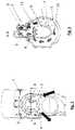
- FIG. 1illustrates a three-dimensional view of a ventilation device in accordance with embodiments.
- FIG. 2illustrates a partial top view, which shows the filler pipe of the ventilation device of FIG. 1 in the region of the connecting nipple.
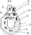
- FIG. 3illustrates a sectional view according to section A-A of FIG. 2 .
- FIG. 1a ventilation device for ventilating a motor vehicle tank, in particular, a fuel tank, is represented, in accordance with embodiments.
- the ventilation devicecomprises a filler pipe 1 and a ventilation line 2 to serve as an operating ventilation line.
- the ventilation line 2at a first ventilation line end, is to be fluidically connected to the motor vehicle tank (See, FIG. 1 the lower end of the ventilation line 2 ).
- the ventilation line 2is to be fluidically connected at a second ventilation line end opposite the first end, downstream of a valve unit 15 , to the filler pipe 1 via a connecting nipple 9 , at a ventilation inlet 3 represented in FIG. 3 .
- the ventilation devicefurther comprises a degassing line 4 to serve as a recirculating line.
- the degassing line 4at a first degassing line end, is to be fluidically connected to the filler pipe 1 via the same connecting nipple 9 , at a degassing outlet 5 represented in FIG. 3 .
- the degassing line 4at a second degassing line end opposite the first end, is to be fluidically connected to a liquid separator 10 which is to serve as a so-called “liquid trap.”
- the ventilation inlet 3 and the degassing outlet 5are configured on the common connecting nipple 9 on the filler pipe 1 .
- the ventilation inlet 3is positioned, in an installation position, at a top region of the filler pipe, so that vapor can fall though the ventilation inlet 3 into the filler pipe 1 .
- the degassing outlet 5is also positioned, in the installation position, at the top region of the filler pipe 1 , or at least not close to the bottom of the filler pipe 1 , in order that only a gaseous component, but not liquid fuel, makes its way up to the degassing outlet 5 .
- a second degassing line 12fluidically connects the liquid separator 10 to a fuel vapor filter comprising an activated charcoal filter.
- a fuel vapor filtercomprising an activated charcoal filter.
- a second ventilation line 11namely a refueling ventilation line, which has a greater diameter than the ventilation line 2 , fluidically connects the motor vehicle tank directly to the liquid separator 10 .
- the connecting nipple 9is more closely represented in the detail in FIG. 2 .
- the section A-A which is marked in FIG. 2is represented in FIG. 3 .
- a guide arc 6is arranged and shaped such that a vapor passing through the ventilation inlet 3 into the filler pipe 1 , which vapor, the arrowed entering fuel-gas-mixture 13 , is guided between the inner wall of the filler pipe 1 and the guide arc 6 along the periphery of the filler pipe 1 , so that a gaseous component of the entering vapor, again marked by arrows as the gas 14 , escapes through the degassing outlet 5 and a liquid component of the entering vapor flows off through the filler pipe 1 (in FIG. 3 in the direction towards the observer).
- the guide arc 6is configured, for instance, in the shape of a cylindrical segment or conical segment or funnel. On an outer wall of the guide arc 6 that faces the inner wall of the filler pipe 1 are configured, in some sections, a plurality of ribs 7 for separating off the liquid.
- the guide arc 6is configured substantially as a profile of U-shaped or O-shaped cross-section.
- a flap member 8is arranged at the degassing outlet 5 .
- the flap member 8is mounted such that it is axially displaceable or moveable.
- the flap member 8is moved by the fuel-pump nozzle in a closing direction, and thus the degassing outlet 5 , during a refueling of the motor vehicle tank, is made smaller or closed.
- the guide arc 6is fastened at its upper ends, the ends of the branches of the U-shape, to the common connecting nipple 9 , or the guide arc 6 forms a portion of a flow guide of the ventilation device, for the positioning of a fuel-pump valve or fuel-pump nozzle and for the guidance of the fluid flow during the refueling of the motor vehicle tank.
- the guide arc 6can also form the valve seat for the flap member 8 .
- Coupledmay be used herein to refer to any type of relationship, direct or indirect, between the components in question, and may apply to electrical, mechanical, fluid, optical, electromagnetic, electromechanical or other connections.
- first,” second, etc.are used herein only to facilitate discussion, and carry no particular temporal or chronological significance unless otherwise indicated.
Landscapes
- Engineering & Computer Science (AREA)
- Life Sciences & Earth Sciences (AREA)
- Sustainable Development (AREA)
- Sustainable Energy (AREA)
- Chemical & Material Sciences (AREA)
- Combustion & Propulsion (AREA)
- Transportation (AREA)
- Mechanical Engineering (AREA)
- Cooling, Air Intake And Gas Exhaust, And Fuel Tank Arrangements In Propulsion Units (AREA)
Abstract
Description
- 1 filler pipe
- 2 ventilation line
- 3 ventilation inlet
- 4 degassing line
- 5 degassing outlet
- 6 guide arc member
- 7 ribs
- 8 flap member
- 9 connecting nipple
- 10 liquid separator
- 11 second ventilation line
- 12 second degassing line
- 13 fuel-gas mixture
- 14 gas
- 15 valve unit
Claims (15)
Applications Claiming Priority (3)
| Application Number | Priority Date | Filing Date | Title |
|---|---|---|---|
| EP19174646.0 | 2019-05-15 | ||
| EP19174646.0AEP3738810B1 (en) | 2019-05-15 | 2019-05-15 | Venting device for venting of motorvehicle tanks |
| EP19174646 | 2019-05-15 |
Publications (2)
| Publication Number | Publication Date |
|---|---|
| US20200361308A1 US20200361308A1 (en) | 2020-11-19 |
| US11285804B2true US11285804B2 (en) | 2022-03-29 |
Family
ID=66554270
Family Applications (1)
| Application Number | Title | Priority Date | Filing Date |
|---|---|---|---|
| US16/869,714ActiveUS11285804B2 (en) | 2019-05-15 | 2020-05-08 | Venting device for venting a motor vehicle tank |
Country Status (3)
| Country | Link |
|---|---|
| US (1) | US11285804B2 (en) |
| EP (1) | EP3738810B1 (en) |
| CN (1) | CN111942146B (en) |
Families Citing this family (2)
| Publication number | Priority date | Publication date | Assignee | Title |
|---|---|---|---|---|
| DE102021201826B4 (en)* | 2021-02-26 | 2022-11-24 | Volkswagen Aktiengesellschaft | Tank filler neck with liquid separator |
| FR3130206A1 (en)* | 2021-12-13 | 2023-06-16 | Psa Automobiles Sa - | CONNECTION DEVICE FOR FILLING TUBE, VEHICLE AND CONNECTION METHOD BASED ON SUCH A DEVICE |
Citations (34)
| Publication number | Priority date | Publication date | Assignee | Title |
|---|---|---|---|---|
| US403704A (en)* | 1889-05-21 | Separator | ||
| US3698160A (en)* | 1970-07-16 | 1972-10-17 | Chrysler Corp | Motor vehicle fuel tank venting |
| US3753443A (en)* | 1971-05-25 | 1973-08-21 | Toyota Motor Co Ltd | Apparatus for removing fuel vapors from a fuel tank on a motor vehicle |
| US4651889A (en)* | 1984-03-23 | 1987-03-24 | Toyota Jidosha Kabushiki Kaisha | Fuel tank nozzle having a dual purpose valve |
| US4699638A (en)* | 1986-03-31 | 1987-10-13 | Stant Inc. | Two-stage roll-over valve |
| US4701198A (en)* | 1984-03-24 | 1987-10-20 | Toyota Jidosha Kabushiki Kaisha | Fuel tank for use in a motor vehicle |
| US4706708A (en)* | 1986-06-23 | 1987-11-17 | General Motors Corporation | Fuel tank venting |
| US4926914A (en)* | 1987-08-10 | 1990-05-22 | Nissan Motor Company, Limited | Vent control valve attached to fuel filler tube |
| US4934417A (en) | 1987-03-26 | 1990-06-19 | Whitehead Engineered Products, Inc. | System for controlling the release of fuel vapors from a vehicle fuel tank |
| US5027868A (en)* | 1986-12-23 | 1991-07-02 | Gt Development Corporation | Vapor recovery systems |
| US5033517A (en)* | 1987-03-26 | 1991-07-23 | Whitehead Engineered Products, Inc. | System for controlling the release of fuel vapors from a vehicle fuel tank |
| US5103877A (en)* | 1991-04-15 | 1992-04-14 | General Motors Corporation | Vapor-liquid separator for evaporative emissions control system |
| US5116257A (en)* | 1991-01-08 | 1992-05-26 | Stant Inc. | Tank venting control assembly |
| DE19605922A1 (en) | 1995-02-17 | 1996-08-22 | Daimler Benz Ag | Device for ventilating motor vehicle fuel tanks |
| US5868119A (en)* | 1997-05-14 | 1999-02-09 | Honda Giken Kogyo Kabushiki Kaisha | Fuel tank venting system for vehicles |
| US6405747B1 (en)* | 1999-10-29 | 2002-06-18 | Stant Manufacturing, Inc. | Fuel tank vent valve with liquid carryover filter |
| US6425379B2 (en)* | 1999-12-27 | 2002-07-30 | Kyosan Denki Co., Ltd. | Evaporative emission control system |
| US20020189691A1 (en) | 2001-06-19 | 2002-12-19 | Bestex Kyoei Co., Ltd | Fuel feed pipe |
| US6880586B2 (en)* | 2002-06-13 | 2005-04-19 | Dayco Products, Llc | Collar with integral vent for fuel filler pipe |
| US7152638B2 (en)* | 2001-03-07 | 2006-12-26 | Inergy Automotive Systems Research (Societe Anonyme) | Safety system for a liquid fuel tank |
| DE202008001586U1 (en) | 2007-02-05 | 2008-06-12 | Raval - Agriculture Cooperative Societies Ltd. | Liquid vapor separator |
| US20090025822A1 (en)* | 2007-07-27 | 2009-01-29 | Rittershofer Frank U | Liquid separator |
| US20100147863A1 (en)* | 2008-12-10 | 2010-06-17 | Kautex Textron Gmbh & Co. Kg | Fuel tank |
| US7770594B2 (en)* | 2006-06-16 | 2010-08-10 | Piolax Inc. | Liquid shutoff valve gear |
| DE102009057860A1 (en) | 2009-12-11 | 2011-06-16 | Kautex Textron Gmbh & Co. Kg | Fuel tank |
| US9248735B2 (en)* | 2011-08-25 | 2016-02-02 | Eaton Corporation | Liquid fuel trap device |
| US20160272061A1 (en)* | 2012-11-15 | 2016-09-22 | Kautex Textron Gmbh & Co. Kg | Liquid/vapor separator |
| US9457649B2 (en)* | 2013-12-04 | 2016-10-04 | Nissan North America, Inc. | Vehicle fuel vapor recovery system |
| US20160325619A1 (en)* | 2013-12-30 | 2016-11-10 | Plastic Omnium Advanced Innovation And Research | Nozzle for filling a fuel tank, comprising a liquid-vapour separator having two positions |
| US10035091B2 (en)* | 2014-03-17 | 2018-07-31 | Kyosan Denki Co., Ltd. | Liquid fuel catcher |
| US10245942B2 (en)* | 2015-08-06 | 2019-04-02 | Audi Ag | Operating medium tank arrangement for a motor vehicle |
| US10267275B2 (en)* | 2014-03-05 | 2019-04-23 | Piolax, Inc. | Valve device for fuel tank |
| US10465634B2 (en)* | 2012-08-20 | 2019-11-05 | Raval A.C.S. Ltd. | Vehicle fuel accessory |
| US10857876B2 (en)* | 2018-02-23 | 2020-12-08 | Ford Global Technologies, Llc | Filler inlet with fluid separation |
Family Cites Families (3)
| Publication number | Priority date | Publication date | Assignee | Title |
|---|---|---|---|---|
| CN101332769B (en)* | 2008-07-24 | 2011-09-14 | 江苏大学 | Vehicle-mounted fuel vapor recovery device and method |
| DE102009052028B4 (en)* | 2009-11-05 | 2017-12-21 | Bayerische Motoren Werke Aktiengesellschaft | Liquid separator in the tank ventilation system of a motor vehicle |
| EP3216640B1 (en)* | 2016-03-10 | 2020-09-16 | Magna Energy Storage Systems GesmbH | Valve device |
- 2019
- 2019-05-15EPEP19174646.0Apatent/EP3738810B1/enactiveActive
- 2020
- 2020-05-08USUS16/869,714patent/US11285804B2/enactiveActive
- 2020-05-12CNCN202010395996.6Apatent/CN111942146B/enactiveActive
Patent Citations (36)
| Publication number | Priority date | Publication date | Assignee | Title |
|---|---|---|---|---|
| US403704A (en)* | 1889-05-21 | Separator | ||
| US3698160A (en)* | 1970-07-16 | 1972-10-17 | Chrysler Corp | Motor vehicle fuel tank venting |
| US3753443A (en)* | 1971-05-25 | 1973-08-21 | Toyota Motor Co Ltd | Apparatus for removing fuel vapors from a fuel tank on a motor vehicle |
| US4651889A (en)* | 1984-03-23 | 1987-03-24 | Toyota Jidosha Kabushiki Kaisha | Fuel tank nozzle having a dual purpose valve |
| US4701198A (en)* | 1984-03-24 | 1987-10-20 | Toyota Jidosha Kabushiki Kaisha | Fuel tank for use in a motor vehicle |
| US4699638A (en)* | 1986-03-31 | 1987-10-13 | Stant Inc. | Two-stage roll-over valve |
| US4706708A (en)* | 1986-06-23 | 1987-11-17 | General Motors Corporation | Fuel tank venting |
| US5027868A (en)* | 1986-12-23 | 1991-07-02 | Gt Development Corporation | Vapor recovery systems |
| US4934417A (en) | 1987-03-26 | 1990-06-19 | Whitehead Engineered Products, Inc. | System for controlling the release of fuel vapors from a vehicle fuel tank |
| US5033517A (en)* | 1987-03-26 | 1991-07-23 | Whitehead Engineered Products, Inc. | System for controlling the release of fuel vapors from a vehicle fuel tank |
| US4926914A (en)* | 1987-08-10 | 1990-05-22 | Nissan Motor Company, Limited | Vent control valve attached to fuel filler tube |
| US5116257A (en)* | 1991-01-08 | 1992-05-26 | Stant Inc. | Tank venting control assembly |
| US5103877A (en)* | 1991-04-15 | 1992-04-14 | General Motors Corporation | Vapor-liquid separator for evaporative emissions control system |
| DE19605922A1 (en) | 1995-02-17 | 1996-08-22 | Daimler Benz Ag | Device for ventilating motor vehicle fuel tanks |
| US5740842A (en)* | 1995-02-17 | 1998-04-21 | Walter Alfmeier GmbH + Co. Prazisions-Baugruppenelemente | Venting device for vehicle fuel tanks |
| US5868119A (en)* | 1997-05-14 | 1999-02-09 | Honda Giken Kogyo Kabushiki Kaisha | Fuel tank venting system for vehicles |
| US6405747B1 (en)* | 1999-10-29 | 2002-06-18 | Stant Manufacturing, Inc. | Fuel tank vent valve with liquid carryover filter |
| US6425379B2 (en)* | 1999-12-27 | 2002-07-30 | Kyosan Denki Co., Ltd. | Evaporative emission control system |
| US7152638B2 (en)* | 2001-03-07 | 2006-12-26 | Inergy Automotive Systems Research (Societe Anonyme) | Safety system for a liquid fuel tank |
| US20020189691A1 (en) | 2001-06-19 | 2002-12-19 | Bestex Kyoei Co., Ltd | Fuel feed pipe |
| US6880586B2 (en)* | 2002-06-13 | 2005-04-19 | Dayco Products, Llc | Collar with integral vent for fuel filler pipe |
| US7770594B2 (en)* | 2006-06-16 | 2010-08-10 | Piolax Inc. | Liquid shutoff valve gear |
| DE202008001586U1 (en) | 2007-02-05 | 2008-06-12 | Raval - Agriculture Cooperative Societies Ltd. | Liquid vapor separator |
| EP1955888A2 (en) | 2007-02-05 | 2008-08-13 | Raval A.C.S. LTD | Liquid vapor separator |
| US20090025822A1 (en)* | 2007-07-27 | 2009-01-29 | Rittershofer Frank U | Liquid separator |
| US20100147863A1 (en)* | 2008-12-10 | 2010-06-17 | Kautex Textron Gmbh & Co. Kg | Fuel tank |
| DE102009057860A1 (en) | 2009-12-11 | 2011-06-16 | Kautex Textron Gmbh & Co. Kg | Fuel tank |
| US9248735B2 (en)* | 2011-08-25 | 2016-02-02 | Eaton Corporation | Liquid fuel trap device |
| US10465634B2 (en)* | 2012-08-20 | 2019-11-05 | Raval A.C.S. Ltd. | Vehicle fuel accessory |
| US20160272061A1 (en)* | 2012-11-15 | 2016-09-22 | Kautex Textron Gmbh & Co. Kg | Liquid/vapor separator |
| US9457649B2 (en)* | 2013-12-04 | 2016-10-04 | Nissan North America, Inc. | Vehicle fuel vapor recovery system |
| US20160325619A1 (en)* | 2013-12-30 | 2016-11-10 | Plastic Omnium Advanced Innovation And Research | Nozzle for filling a fuel tank, comprising a liquid-vapour separator having two positions |
| US10267275B2 (en)* | 2014-03-05 | 2019-04-23 | Piolax, Inc. | Valve device for fuel tank |
| US10035091B2 (en)* | 2014-03-17 | 2018-07-31 | Kyosan Denki Co., Ltd. | Liquid fuel catcher |
| US10245942B2 (en)* | 2015-08-06 | 2019-04-02 | Audi Ag | Operating medium tank arrangement for a motor vehicle |
| US10857876B2 (en)* | 2018-02-23 | 2020-12-08 | Ford Global Technologies, Llc | Filler inlet with fluid separation |
Non-Patent Citations (1)
| Title |
|---|
| European Search Report for European Patent Application No. 19174646.0, dated Dec. 16, 2019, 4 pages. |
Also Published As
| Publication number | Publication date |
|---|---|
| US20200361308A1 (en) | 2020-11-19 |
| CN111942146A (en) | 2020-11-17 |
| CN111942146B (en) | 2024-10-18 |
| EP3738810B1 (en) | 2021-11-03 |
| EP3738810A1 (en) | 2020-11-18 |
Similar Documents
| Publication | Publication Date | Title |
|---|---|---|
| US9765735B2 (en) | Liquid trap with integral jet pump | |
| US7779820B2 (en) | Liquid separator | |
| US8960473B2 (en) | Fuel tank | |
| EP2041409B1 (en) | Venting tubing system for a fuel tank | |
| CN104736369B (en) | Vehicles lower-grade fuel | |
| US11285804B2 (en) | Venting device for venting a motor vehicle tank | |
| CN110072723B (en) | Filling limit exhaust valve with high closing height | |
| JP2013072434A5 (en) | ||
| US10150061B2 (en) | Separator nipple | |
| US20200360839A1 (en) | Venting device for venting a motor vehicle tank | |
| US10059197B2 (en) | Valve device | |
| US10473065B2 (en) | Fuel return device | |
| US8813781B2 (en) | Drop separator | |
| US6367520B1 (en) | Fuel filler inlet for motor vehicles | |
| CN104781096B (en) | Liquid/vapour separator | |
| US20040206392A1 (en) | Ventilation and areation device for a fuel tank | |
| CN209414021U (en) | Ventilation valve module and aerating system and fuel tank system for fuel tank | |
| CN106438138A (en) | Electronic fuel injection system of outboard engine | |
| JP3788264B2 (en) | Lubrication system | |
| JP4268865B2 (en) | Fuel capture device | |
| JP2010500210A (en) | Fuel tank for automobile |
Legal Events
| Date | Code | Title | Description |
|---|---|---|---|
| AS | Assignment | Owner name:MAGNA STEYR FUEL SYSTEMS GESMBH, AUSTRIA Free format text:ASSIGNMENT OF ASSIGNORS INTEREST;ASSIGNORS:WIEDNER, PATRICK MICHAEL;STEINMANN, DOMINIK;KULMER, KARL-HEINZ;SIGNING DATES FROM 20190822 TO 20190826;REEL/FRAME:052607/0578 | |
| FEPP | Fee payment procedure | Free format text:ENTITY STATUS SET TO UNDISCOUNTED (ORIGINAL EVENT CODE: BIG.); ENTITY STATUS OF PATENT OWNER: LARGE ENTITY | |
| STPP | Information on status: patent application and granting procedure in general | Free format text:APPLICATION DISPATCHED FROM PREEXAM, NOT YET DOCKETED | |
| AS | Assignment | Owner name:MAGNA ENERGY STORAGE SYSTEMS GESMBH, AUSTRIA Free format text:CHANGE OF NAME;ASSIGNOR:MAGNA STEYR FUEL SYSTEMS GESMBH;REEL/FRAME:053195/0301 Effective date:20200624 | |
| STPP | Information on status: patent application and granting procedure in general | Free format text:DOCKETED NEW CASE - READY FOR EXAMINATION | |
| STPP | Information on status: patent application and granting procedure in general | Free format text:NON FINAL ACTION MAILED | |
| STPP | Information on status: patent application and granting procedure in general | Free format text:RESPONSE TO NON-FINAL OFFICE ACTION ENTERED AND FORWARDED TO EXAMINER | |
| STPP | Information on status: patent application and granting procedure in general | Free format text:NOTICE OF ALLOWANCE MAILED -- APPLICATION RECEIVED IN OFFICE OF PUBLICATIONS | |
| STPP | Information on status: patent application and granting procedure in general | Free format text:PUBLICATIONS -- ISSUE FEE PAYMENT VERIFIED | |
| STCF | Information on status: patent grant | Free format text:PATENTED CASE | |
| MAFP | Maintenance fee payment | Free format text:PAYMENT OF MAINTENANCE FEE, 4TH YEAR, LARGE ENTITY (ORIGINAL EVENT CODE: M1551); ENTITY STATUS OF PATENT OWNER: LARGE ENTITY Year of fee payment:4 |