US11285255B2 - Collection liner for a medical or a surgical operation - Google Patents
Collection liner for a medical or a surgical operationDownload PDFInfo
- Publication number
- US11285255B2 US11285255B2US16/315,262US201716315262AUS11285255B2US 11285255 B2US11285255 B2US 11285255B2US 201716315262 AUS201716315262 AUS 201716315262AUS 11285255 B2US11285255 B2US 11285255B2
- Authority
- US
- United States
- Prior art keywords
- collection
- valve
- canister
- collection container
- liner
- Prior art date
- Legal status (The legal status is an assumption and is not a legal conclusion. Google has not performed a legal analysis and makes no representation as to the accuracy of the status listed.)
- Active, expires
Links
Images


Classifications
- A—HUMAN NECESSITIES
- A61—MEDICAL OR VETERINARY SCIENCE; HYGIENE
- A61J—CONTAINERS SPECIALLY ADAPTED FOR MEDICAL OR PHARMACEUTICAL PURPOSES; DEVICES OR METHODS SPECIALLY ADAPTED FOR BRINGING PHARMACEUTICAL PRODUCTS INTO PARTICULAR PHYSICAL OR ADMINISTERING FORMS; DEVICES FOR ADMINISTERING FOOD OR MEDICINES ORALLY; BABY COMFORTERS; DEVICES FOR RECEIVING SPITTLE
- A61J1/00—Containers specially adapted for medical or pharmaceutical purposes
- A61J1/05—Containers specially adapted for medical or pharmaceutical purposes for collecting, storing or administering blood, plasma or medical fluids ; Infusion or perfusion containers
- A—HUMAN NECESSITIES
- A61—MEDICAL OR VETERINARY SCIENCE; HYGIENE
- A61M—DEVICES FOR INTRODUCING MEDIA INTO, OR ONTO, THE BODY; DEVICES FOR TRANSDUCING BODY MEDIA OR FOR TAKING MEDIA FROM THE BODY; DEVICES FOR PRODUCING OR ENDING SLEEP OR STUPOR
- A61M1/00—Suction or pumping devices for medical purposes; Devices for carrying-off, for treatment of, or for carrying-over, body-liquids; Drainage systems
- A61M1/60—Containers for suction drainage, adapted to be used with an external suction source
- A—HUMAN NECESSITIES
- A61—MEDICAL OR VETERINARY SCIENCE; HYGIENE
- A61J—CONTAINERS SPECIALLY ADAPTED FOR MEDICAL OR PHARMACEUTICAL PURPOSES; DEVICES OR METHODS SPECIALLY ADAPTED FOR BRINGING PHARMACEUTICAL PRODUCTS INTO PARTICULAR PHYSICAL OR ADMINISTERING FORMS; DEVICES FOR ADMINISTERING FOOD OR MEDICINES ORALLY; BABY COMFORTERS; DEVICES FOR RECEIVING SPITTLE
- A61J1/00—Containers specially adapted for medical or pharmaceutical purposes
- A61J1/14—Details; Accessories therefor
- A61J1/1475—Inlet or outlet ports
- A—HUMAN NECESSITIES
- A61—MEDICAL OR VETERINARY SCIENCE; HYGIENE
- A61M—DEVICES FOR INTRODUCING MEDIA INTO, OR ONTO, THE BODY; DEVICES FOR TRANSDUCING BODY MEDIA OR FOR TAKING MEDIA FROM THE BODY; DEVICES FOR PRODUCING OR ENDING SLEEP OR STUPOR
- A61M1/00—Suction or pumping devices for medical purposes; Devices for carrying-off, for treatment of, or for carrying-over, body-liquids; Drainage systems
- A61M1/0001—
- A61M1/0023—
- A—HUMAN NECESSITIES
- A61—MEDICAL OR VETERINARY SCIENCE; HYGIENE
- A61M—DEVICES FOR INTRODUCING MEDIA INTO, OR ONTO, THE BODY; DEVICES FOR TRANSDUCING BODY MEDIA OR FOR TAKING MEDIA FROM THE BODY; DEVICES FOR PRODUCING OR ENDING SLEEP OR STUPOR
- A61M1/00—Suction or pumping devices for medical purposes; Devices for carrying-off, for treatment of, or for carrying-over, body-liquids; Drainage systems
- A61M1/60—Containers for suction drainage, adapted to be used with an external suction source
- A61M1/604—Bag or liner in a rigid container, with suction applied to both
- A—HUMAN NECESSITIES
- A61—MEDICAL OR VETERINARY SCIENCE; HYGIENE
- A61M—DEVICES FOR INTRODUCING MEDIA INTO, OR ONTO, THE BODY; DEVICES FOR TRANSDUCING BODY MEDIA OR FOR TAKING MEDIA FROM THE BODY; DEVICES FOR PRODUCING OR ENDING SLEEP OR STUPOR
- A61M1/00—Suction or pumping devices for medical purposes; Devices for carrying-off, for treatment of, or for carrying-over, body-liquids; Drainage systems
- A61M1/71—Suction drainage systems
- A61M1/73—Suction drainage systems comprising sensors or indicators for physical values
- A—HUMAN NECESSITIES
- A61—MEDICAL OR VETERINARY SCIENCE; HYGIENE
- A61M—DEVICES FOR INTRODUCING MEDIA INTO, OR ONTO, THE BODY; DEVICES FOR TRANSDUCING BODY MEDIA OR FOR TAKING MEDIA FROM THE BODY; DEVICES FOR PRODUCING OR ENDING SLEEP OR STUPOR
- A61M1/00—Suction or pumping devices for medical purposes; Devices for carrying-off, for treatment of, or for carrying-over, body-liquids; Drainage systems
- A61M1/71—Suction drainage systems
- A61M1/78—Means for preventing overflow or contamination of the pumping systems
- A61M1/782—Means for preventing overflow or contamination of the pumping systems using valves with freely moving parts, e.g. float valves
- A—HUMAN NECESSITIES
- A61—MEDICAL OR VETERINARY SCIENCE; HYGIENE
- A61M—DEVICES FOR INTRODUCING MEDIA INTO, OR ONTO, THE BODY; DEVICES FOR TRANSDUCING BODY MEDIA OR FOR TAKING MEDIA FROM THE BODY; DEVICES FOR PRODUCING OR ENDING SLEEP OR STUPOR
- A61M1/00—Suction or pumping devices for medical purposes; Devices for carrying-off, for treatment of, or for carrying-over, body-liquids; Drainage systems
- A61M1/71—Suction drainage systems
- A61M1/78—Means for preventing overflow or contamination of the pumping systems
- A61M1/784—Means for preventing overflow or contamination of the pumping systems by filtering, sterilising or disinfecting the exhaust air, e.g. swellable filter valves
- A—HUMAN NECESSITIES
- A61—MEDICAL OR VETERINARY SCIENCE; HYGIENE
- A61M—DEVICES FOR INTRODUCING MEDIA INTO, OR ONTO, THE BODY; DEVICES FOR TRANSDUCING BODY MEDIA OR FOR TAKING MEDIA FROM THE BODY; DEVICES FOR PRODUCING OR ENDING SLEEP OR STUPOR
- A61M1/00—Suction or pumping devices for medical purposes; Devices for carrying-off, for treatment of, or for carrying-over, body-liquids; Drainage systems
- A61M1/84—Drainage tubes; Aspiration tips
- A—HUMAN NECESSITIES
- A61—MEDICAL OR VETERINARY SCIENCE; HYGIENE
- A61M—DEVICES FOR INTRODUCING MEDIA INTO, OR ONTO, THE BODY; DEVICES FOR TRANSDUCING BODY MEDIA OR FOR TAKING MEDIA FROM THE BODY; DEVICES FOR PRODUCING OR ENDING SLEEP OR STUPOR
- A61M1/00—Suction or pumping devices for medical purposes; Devices for carrying-off, for treatment of, or for carrying-over, body-liquids; Drainage systems
- A61M1/88—Draining devices having means for processing the drained fluid, e.g. an absorber
- A61M1/882—Draining devices provided with means for releasing antimicrobial or gelation agents in the drained fluid
- A—HUMAN NECESSITIES
- A61—MEDICAL OR VETERINARY SCIENCE; HYGIENE
- A61M—DEVICES FOR INTRODUCING MEDIA INTO, OR ONTO, THE BODY; DEVICES FOR TRANSDUCING BODY MEDIA OR FOR TAKING MEDIA FROM THE BODY; DEVICES FOR PRODUCING OR ENDING SLEEP OR STUPOR
- A61M39/00—Tubes, tube connectors, tube couplings, valves, access sites or the like, specially adapted for medical use
- A61M39/22—Valves or arrangement of valves
- A61M39/223—Multiway valves
- A—HUMAN NECESSITIES
- A61—MEDICAL OR VETERINARY SCIENCE; HYGIENE
- A61M—DEVICES FOR INTRODUCING MEDIA INTO, OR ONTO, THE BODY; DEVICES FOR TRANSDUCING BODY MEDIA OR FOR TAKING MEDIA FROM THE BODY; DEVICES FOR PRODUCING OR ENDING SLEEP OR STUPOR
- A61M39/00—Tubes, tube connectors, tube couplings, valves, access sites or the like, specially adapted for medical use
- A61M39/22—Valves or arrangement of valves
- A61M39/24—Check- or non-return valves
- G—PHYSICS
- G16—INFORMATION AND COMMUNICATION TECHNOLOGY [ICT] SPECIALLY ADAPTED FOR SPECIFIC APPLICATION FIELDS
- G16H—HEALTHCARE INFORMATICS, i.e. INFORMATION AND COMMUNICATION TECHNOLOGY [ICT] SPECIALLY ADAPTED FOR THE HANDLING OR PROCESSING OF MEDICAL OR HEALTHCARE DATA
- G16H40/00—ICT specially adapted for the management or administration of healthcare resources or facilities; ICT specially adapted for the management or operation of medical equipment or devices
- G16H40/60—ICT specially adapted for the management or administration of healthcare resources or facilities; ICT specially adapted for the management or operation of medical equipment or devices for the operation of medical equipment or devices
- G16H40/63—ICT specially adapted for the management or administration of healthcare resources or facilities; ICT specially adapted for the management or operation of medical equipment or devices for the operation of medical equipment or devices for local operation
- A—HUMAN NECESSITIES
- A61—MEDICAL OR VETERINARY SCIENCE; HYGIENE
- A61M—DEVICES FOR INTRODUCING MEDIA INTO, OR ONTO, THE BODY; DEVICES FOR TRANSDUCING BODY MEDIA OR FOR TAKING MEDIA FROM THE BODY; DEVICES FOR PRODUCING OR ENDING SLEEP OR STUPOR
- A61M2205/00—General characteristics of the apparatus
- A61M2205/15—Detection of leaks
- A—HUMAN NECESSITIES
- A61—MEDICAL OR VETERINARY SCIENCE; HYGIENE
- A61M—DEVICES FOR INTRODUCING MEDIA INTO, OR ONTO, THE BODY; DEVICES FOR TRANSDUCING BODY MEDIA OR FOR TAKING MEDIA FROM THE BODY; DEVICES FOR PRODUCING OR ENDING SLEEP OR STUPOR
- A61M2205/00—General characteristics of the apparatus
- A61M2205/33—Controlling, regulating or measuring
- A61M2205/3379—Masses, volumes, levels of fluids in reservoirs, flow rates
- A61M2205/3393—Masses, volumes, levels of fluids in reservoirs, flow rates by weighing the reservoir
- A—HUMAN NECESSITIES
- A61—MEDICAL OR VETERINARY SCIENCE; HYGIENE
- A61M—DEVICES FOR INTRODUCING MEDIA INTO, OR ONTO, THE BODY; DEVICES FOR TRANSDUCING BODY MEDIA OR FOR TAKING MEDIA FROM THE BODY; DEVICES FOR PRODUCING OR ENDING SLEEP OR STUPOR
- A61M2205/00—General characteristics of the apparatus
- A61M2205/50—General characteristics of the apparatus with microprocessors or computers
- A61M2205/502—User interfaces, e.g. screens or keyboards
- A—HUMAN NECESSITIES
- A61—MEDICAL OR VETERINARY SCIENCE; HYGIENE
- A61M—DEVICES FOR INTRODUCING MEDIA INTO, OR ONTO, THE BODY; DEVICES FOR TRANSDUCING BODY MEDIA OR FOR TAKING MEDIA FROM THE BODY; DEVICES FOR PRODUCING OR ENDING SLEEP OR STUPOR
- A61M2205/00—General characteristics of the apparatus
- A61M2205/58—Means for facilitating use, e.g. by people with impaired vision
- A61M2205/587—Lighting arrangements
- A—HUMAN NECESSITIES
- A61—MEDICAL OR VETERINARY SCIENCE; HYGIENE
- A61M—DEVICES FOR INTRODUCING MEDIA INTO, OR ONTO, THE BODY; DEVICES FOR TRANSDUCING BODY MEDIA OR FOR TAKING MEDIA FROM THE BODY; DEVICES FOR PRODUCING OR ENDING SLEEP OR STUPOR
- A61M2205/00—General characteristics of the apparatus
- A61M2205/60—General characteristics of the apparatus with identification means
- A61M2205/6054—Magnetic identification systems
- A—HUMAN NECESSITIES
- A61—MEDICAL OR VETERINARY SCIENCE; HYGIENE
- A61M—DEVICES FOR INTRODUCING MEDIA INTO, OR ONTO, THE BODY; DEVICES FOR TRANSDUCING BODY MEDIA OR FOR TAKING MEDIA FROM THE BODY; DEVICES FOR PRODUCING OR ENDING SLEEP OR STUPOR
- A61M2205/00—General characteristics of the apparatus
- A61M2205/75—General characteristics of the apparatus with filters
- A61M2205/7536—General characteristics of the apparatus with filters allowing gas passage, but preventing liquid passage, e.g. liquophobic, hydrophobic, water-repellent membranes
- A—HUMAN NECESSITIES
- A61—MEDICAL OR VETERINARY SCIENCE; HYGIENE
- A61M—DEVICES FOR INTRODUCING MEDIA INTO, OR ONTO, THE BODY; DEVICES FOR TRANSDUCING BODY MEDIA OR FOR TAKING MEDIA FROM THE BODY; DEVICES FOR PRODUCING OR ENDING SLEEP OR STUPOR
- A61M2209/00—Ancillary equipment
- A61M2209/08—Supports for equipment
- A61M2209/082—Mounting brackets, arm supports for equipment
- A—HUMAN NECESSITIES
- A61—MEDICAL OR VETERINARY SCIENCE; HYGIENE
- A61M—DEVICES FOR INTRODUCING MEDIA INTO, OR ONTO, THE BODY; DEVICES FOR TRANSDUCING BODY MEDIA OR FOR TAKING MEDIA FROM THE BODY; DEVICES FOR PRODUCING OR ENDING SLEEP OR STUPOR
- A61M2209/00—Ancillary equipment
- A61M2209/08—Supports for equipment
- A61M2209/084—Supporting bases, stands for equipment
- A61M2209/086—Docking stations
- A—HUMAN NECESSITIES
- A61—MEDICAL OR VETERINARY SCIENCE; HYGIENE
- A61M—DEVICES FOR INTRODUCING MEDIA INTO, OR ONTO, THE BODY; DEVICES FOR TRANSDUCING BODY MEDIA OR FOR TAKING MEDIA FROM THE BODY; DEVICES FOR PRODUCING OR ENDING SLEEP OR STUPOR
- A61M37/00—Other apparatus for introducing media into the body; Percutany, i.e. introducing medicines into the body by diffusion through the skin
Definitions
- the present inventionrelates to a collection liner for a medical or a surgical operation comprising a closed bag portion and inlets.
- the capacities of the known collection linersare limited because one cannot lift large collection liners when they are full. Further, the known collection liners usually comprise complicated systems with several tubes which must be assembled and disassembled.
- the object of the inventionis to provide a new type of a solution.
- the inventionis characterized by the features of the independent claims. Some embodiments are disclosed in the dependent claims.
- the present inventionmakes it easier and more pleasant to remove and manage heavy collection liners with large volume of fluid. Further, less raw material and less space for storing are required. Furthermore, the present invention makes inadvertent error prevention possible, i.e. a user has no options concerning the correct assembly.
- the collection linercomprises a bag portion and a rigid handle.
- the bag portionis made of a flexible plastic material.
- the bag portionmay be formed of a tubular plastic film. One end of the plastic film, i.e. the bottom of the bag portion, is closed by sealing the edges of the plastic film together, while at its other end the tubular plastic film is fixedly fastened e.g. by welding to the handle in such a manner that the bag portion forms a closed space with the handle.
- the handlecomprises the inlets that are necessary for the operation of the suction process.
- the handlemay be a bar from which the collection liner is comfortable to lift.
- the inletsadvance inside the bar and branch from the bar, thus advancing into the bag portion.
- the inlet for the vacuumhas a lateral branch which is a channel for transmitting negative pressure outside the collection liner.
- solidifying agentis used throughout this text according to the main use but the inlet can be used to introduce any other chemical additive, such as a disinfectant or an anticoagulant.
- each inletis provided with a back flow preventing means, i.e. a back flow preventing device.
- a back flow preventing deviceThere may be a hydrophobic filter in the vacuum interface of the liner. The filter prevents fluid to advance into the vacuum tubing of the apparatus.
- the hydrophobic filteris made of a material which swells if the liquid meets the filter, thus blocking the flow.
- the inlet for the liquid collected from a patienti.e. the inlet for the collection container tube
- the no-return valvemay be a tube made of a thin plastic film. The tube surrounds the mouth of the inlet and it is fastened at the one end to the inlet and the other end is open. The thin plastic tube is open only when the pressure inside the tube is higher than around it.
- the inlet of the solidifying agentif it exists in the collection liner, may be provided with the same kind of no-return valve as the inlet for the collection container tube.
- the bottom of the bag portionmay have a dual seam in such a manner that there are two seams having a distance between each other.
- An openingcan be formed between the two seams, thereby forming an ancillary handle for helping to lift the collection liner.
- the openingcan be, for example, a hole or a slit.
- the ancillary handleenhances the possibility to lift the collection liner with both hands, i.e. one can take a grip with one hand from the handle and with the other hand from the ancillary handle. This property is important because the volume of the collection liner may be large.
- An important embodimentis to use the collection liner with an apparatus for collecting fluid from a patient and thus, the apparatus is described below.
- the main use of the apparatusis to collect fluid from the patient but the apparatus can be used to collect fluid from the operating site in general, e.g. from the floor of the operating theatre.
- the apparatus for collecting fluid from a patientmay comprise a one-piece structure or a two-piece structure.
- the two-piece structurecomprises a control unit and a movable cart.
- the control unit and the movable cartare attachable to each other, i.e. when the surgical operation is going on and liquid is collected from the patient, the control unit and the cart are attached together by a locking means.
- the control unit and the movable cartcan be used as separate units.
- At least the cartis movable and may have, for example, wheels but also the control unit may be movable and it may have wheels as well.
- the cartincludes parts which are in contact with the collected liquid and thus, the movable cart improves the work flow between patients.
- the apparatus for collecting liquid from a patientmay have an external vacuum source, i.e. the apparatus exploits, for example, the vacuum system of the hospital, or the apparatus may have an internal vacuum source, i.e. the apparatus has its own vacuum source, such as a vacuum pump.
- the internal vacuum sourceis preferably located in the control unit.
- the vacuum of the collection containersis regulated by internal vacuum regulators which are preferably located in the control unit.
- the control unit and the movable cartare attached to each other by using connection plates.
- the vacuum lines between the control unit and the movable cartare automatically connected at the same time as well as the electrical connections between the control unit and the cart.
- the platesare drawn to each other by using negative pressure, i.e. vacuum.
- the movable cartcomprises positions for collection containers inside which the liquid flows.
- the collection containersmay be disposable collection liners and they may be used with canisters inside which they are assembled. However, it is also possible that there are no collection liners and the liquid flows directly in the canisters, i.e. the canister is the collection container.
- the collection containersmay be connected to one or more independent suction channels. Usually the apparatus comprises at least two independent suction channels.
- a manifoldcomprises a housing, ports for patient tubes and ports for collection container tubes.
- the patient tubeleads from the suction site or the operating site to the manifold and the collection container tube leads from the manifold to the collection container.
- Each port for connecting a patientis provided with a no-return valve which may be a thin plastic tube surrounding the port inside the housing. The plastic tube is open only when the pressure inside it is higher than around it.
- Each port for the collection container tubemay be provided with a valve.
- the valvemay comprise, for example, a cylinder and a rotatable bar within each other.
- the cylindermay be provided with a hole and the rotatable bar may have a notch.
- the valvecloses or opens depending on the fact whether the hole and the notch are on the same line, i.e. the port opens when the notch is parallel to the hole and the port shuts off when the notch is divergent to the hole.
- the valvemay comprise two cylinders provided with holes within each other. When the holes are on the same line the valve is open and when the holes are not on the same line the valve is closed.
- the rotatable bar or the innermost cylindermay comprise at its end a form to which an actuator, such as a motor, grips.
- Each valvehas an actuator which rotates the valves according to the parameters entered by the user.
- each valveis individually operable, i.e. the valve can be opened or closed individually.
- a tubeWhen liquid is collected from the patient a tube is connected to the patient tube port and the collection container tube is connected to the port for the collection container tube. The liquid enters first to the housing of the manifold and after that it flows through an open port to a collection container.
- the manifoldmay comprise by-pass channels in the ports for the collection container tubes.
- the aim of the channelis to remove fluid which remains in the collection container tube when the suction is interrupted and return the atmospheric pressure in the tube and in the collection container, i.e. the tube and the collection container reach the same pressure which prevails outside the apparatus.
- the channelwhich opens to the outside of the port of the collection container tube, is open only when the port is closed.
- the manifoldmay also comprise a by-pass channel in the housing of the manifold. There is a gasket between the housing and the channel.
- the negative pressure prevailing in the manifoldcan be measured from that channel by connecting the channel to a pressure sensor.
- the advantage of this measuring systemis that liquid or aerosol in the housing of the manifold cannot penetrate into the channel although the manifold contains fluid and humid air and pressure in the manifold changes.
- the shape of the manifoldis designed in such a manner that the by-pass channel is not hit by the fluid flow. The above-mentioned detail may be accomplished by protecting the mouth of the by-pass channel by at least one wall, preferably two walls on both sides of the mouth.
- a no-return valvemay secure that liquid or aerosol are kept away from the channel in the case when pressure inside the manifold is higher than pressure in the by-pass channel.
- the measured negative pressureshows the pressure exerted to the patient. Further, it indicates together with flow measurement if there is a blockage in the system.
- the by-pass channelmay be choked and in contact with the atmospheric pressure.
- the choked contact to the atmospheric pressureguarantees that pressure in the measurement channel follows changes of the negative pressure in the manifold.
- the manifoldmay be provided with an electronic identification system.
- the electronic identification systemmay be an RFID tag comprising identification information about the manifold.
- the RFID tagcomprises an integrated circuit containing the identification information and an antenna.
- the RFID tagis read with a reader and the information obtained from the reader controls the apparatus. If the identification information shows that the manifold is new the operation of the apparatus is allowable. If the identification information shows that the manifold has been used in the same operation the operation of the apparatus is also allowable.
- the above-mentioned caseis possible, for example, if the manifold is unintentionally disconnected, or the manifold is transferred from one collection container to the other in order to increase capacity.
- the manifoldmay be transferred from one suction channel of the apparatus to another suction channel of the apparatus during the same operation, or the manifold may be transferred from one cart to another cart used with the same control unit during the same operation.
- the operation of the apparatusis allowable. If the identification information shows that the manifold has been used before but not in the same operation the operation of the apparatus is prevented. However, if there are more than one suction channel in the apparatus other suction channels continue to function except the suction channel having the unacceptable manifold.
- the collection linermay be used with a canister provided with an openable lid.
- the lidis hinged to the canister.
- the collection lineris placed inside the canister in such a manner that the vacuum is connected to the canister interior and the inlet for the collection container tube extends over the upper edge of the canister. After the collection liner is in its place in the canister, the lid of the canister is closed.
- the lidcomprises a gasket which seals the lid against the edge of the canister and the handle of the collection liner.
- the gasketmay be a separate gasket or it may be an integral part of the lid, i.e. the lid is made of a material which is suitable for sealing, or the lid and the gasket are formed at the same time of different materials.
- a locking meanswhich keeps the lid closed.
- the connection tubeis not required to be disconnected from the liner while the collection liner is removed from the canister.
- the connection tubecan be disconnected from its other end.
- the handle of the collection linermay have a site for connecting the disconnected end of the tube. Thus, if there are fluid drops in the tube they cannot leak out because both ends of the tube are closed.
- the canistersmay be connected to the cart via docking.
- the dockingprovides the mechanical mounting, the locking and the pneumatic connections between the cart and the canister. When the canister is unlocked the use of the canister is prevented.
- the liquid volumeis detected by measuring the weight of the collection container.
- the containeris not filled up to the level of vacuum inlet inside the liner preventing the hydrophobic filter getting in contact with liquid and therefore, the collection liner and the canister have essentially the same pressure level.
- the collection linerengages to the negative pressure through a port in the canister, i.e. there is a connection provided with a gasket through the canister wall.
- the portmay be provided with a flow meter. Together with the pressure measured from the manifold, the flow meter reveals reliably if there is a blockage in the system. If there is no flow or the flow value is under the predetermined range and the pressure measured from the manifold is higher than the regulated pressure there is a blockage in the apparatus, i.e. the absolute value of negative pressure is significantly lower in the manifold than the pressure led to the collection container.
- the pressure led to the collection containermeans the pressure that is intended to be used during the operation.
- a first pressure sensormeasures a first pressure value which corresponds to the pressure value inside the manifold.
- a second pressure sensormeasures a second pressure value in a channel leading negative pressure to the collection containers. The pressure difference of the first pressure value and the second pressure value is calculated.
- the flow valuehas a predetermined range for each pressure difference. If the flow value is under the predetermined range compared to the predetermined range corresponding the pressure difference in question there is a blockage. If the flow value is over the predetermined range compared to the predetermined range corresponding the pressure difference in question there is a leak.
- the control system of the apparatusmay give an alarm and the display of the apparatus may show instructions for removing the blockage or the leakage. Further, it is possible to check the condition of the hydrophobic filter of the collection liner by measuring regulated negative pressure, negative pressure value in the manifold and the flow value. Thus, it is possible to predict clogging of the filter.
- the canister or the cartmay be provided with an optical indication means.
- the optical indication meansmay be illumination of the canister.
- Each canistermay be provided with an illumination device.
- a LED stripemay be fastened, preferably vertically, on a separation wall of the cart behind the canister.
- the illuminationmay be turned on when the canister is in use, or all canisters which are used during an operation may be illuminated.
- the intensity of the illuminationmay adjustable at each canister, or the illumination may be switched on/off at each canister.
- the optical indication meansmay be a film whose transparency can be changed, thereby showing the liquid only when desired.
- the filmmay be, for example, a film whose transparency changes when electricity is led to the film.
- the collection containershave their predetermined positions in the movable cart. Each container is weighed during the suction to follow the amount of the collected liquid and the liquid inside the collection container. The amount of liquid that the collection container is allowed to receive is given beforehand, i.e. the user of the apparatus can choose how much liquid may enter into the collection container.
- the suctionstops concerning the collection container in question when the predetermined amount has been reached.
- the suction and the consequent flow of fluidare directed automatically from the collection container which has reached the predetermined weight to another collection container.
- the change from the previous collection container to the following collection containertakes place by closing the valve of the manifold through which the fluid has flown to the previous collection container and opening the valve of the manifold through which the fluid is going to flow to the following collection container.
- the weighingcan be made, for example, by using strain gauge transducers installed under the positions of the collection containers.
- the electrical resistance of the strain gauge transducervaries due to the load that is exerted to the transducer.
- the weight of the collection containercan be determined.
- the weighinggives reliable results since the collection containers have a floating connection to the cart, i.e. the collection containers can move freely in respect of the cart.
- the collection containersare laterally supported but the weight of each container rests on the strain gauge transducer which is situated under the collection container.
- the cartcomprises a position for a cartridge and a reservoir containing solidifying agent.
- the vacuum in the collection containeris used to move the solidifying agent from the reservoir to the collection container.
- the solidifying agentis inside the cartridge in such a manner that a user does not have to be in touch with the solidifying agent.
- the userjust checks visually from outside whether there is enough solidifying agent in the reservoir and if not, she or he changes the cartridge for a full one.
- the cartridgesare only for a single use. As the cartridge is put in its place in the movable cart the cartridge is opened automatically.
- the control unitmonitors the amount of the solidifying agent dosages given from the cartridge and requests a new cartridge when required, i.e. the control unit detects the misuse of the apparatus.
- the cartridgesmay have radio frequency identification tags (RFID tags) on their surface and the control unit may identify the cartridges according to the identification information of the tags.
- RFID tagsradio frequency identification tags
- the solidifying agentis fed in small doses into the collection container, i.e. the collection liner or the collection canister, during the suction process.
- the feeding processis automatic and it can be programmed so that a portion of the solidifying agent is fed, for example, after every half liter, on the surface of the liquid in the collection container.
- the systemis useful, among others, in that that the liquid in the collection container solidifies as it flows inside the container. Further, the use of the solidifying agent is more precise and more effective compared to the known systems because the amount of the solidifying agent is in proportion with the amount of the collected liquid.
- the cycle to form a portion of the solidifying agentmay be as follows: There are at least three valves regulating the formation of the solidifying agent portion, namely the first valve, the second valve and the third valve.
- the first valveis the nearest valve to the collection container.
- the second valveexists between the first and the third valve.
- the first valve and the third valveare shut.
- the second valveis partially open.
- the first valve and the third valveare open and the second valve is still partially open. Air flows from the third valve which stops the flow of the solidifying agent and compacts the portion of the solidifying agent against the second valve.
- valvesare open.
- the portion of the solidifying agentis shot then into the collection container, thus solidifying the liquid in the collection container.
- the second valve and the third valveare closed in such a manner that the second valve remains half open as in the beginning of the process.
- the first valveis also eventually closed and the cycle to form the portion of the solidifying agent starts all over again.
- valvesthere may be a batching screw and valves, preferably two of them, for forming and releasing the dosage of the solidifying agent.
- the solidifying agentcan be fed as loose powder without forming the above-mentioned compact dosage.
- the aim of this alternativeis to distribute powder from the reservoir into the collection liner at known speed, i.e. certain amount of powder shall be released into the collection liner in certain time.
- the solidifying agentmay be released, among others, after a certain volume of liquid is received in the collection container, after the collection container is full, after all the collection containers of the suction channel in question are full, the cart must be changed, or once the operation is completed.
- the suction processis interrupted during the discharge of the solidifying agent.
- the liner valveis near to the collection container.
- the reservoir receiving solidifying agent from the cartridgeis between the air valve and the liner valve.
- the pipe of the solidifying agent pipeline, which passes through the reservoirmay work as an ejector.
- the pipemay have an opening through which air flow grabs the solidifying agent.
- the openingis preferably on the underside of the pipe because under the pipe the powder is loose and easily movable.
- the lower part of the reservoirmay be an inverted cone through which the pipe passes.
- the liner valve and the air valveare open when the solidifying agent is distributed.
- the solidifying agent pipelineis in contact with ambient air through the air valve and it is in contact with vacuum through the liner valve.
- the pipe beyond the air valvemay be choked in order to adjust the balance between ambient air and powder flowing in the pipe.
- the flush valvemay be a flush valve between the reservoir and the liner valve.
- the flush valveis opened at the end of the powder distribution when the air valve has been closed.
- the aim of the flush valveis that the flush valve opens access to ambient air and the air flow cleans the pipe from the powder residuals.
- the port of the collection container tube in the manifoldmust be closed when the powder is distributed. In other words, the valve of the port of the collection container tube is closed.
- the condition of the hydrophobic filteris important in this process because it may cause higher flow resistance than assumed.
- the by-pass pipeis in contact with ambient air and it can be used to evaluate the condition of the hydrophobic filter of the collection liner.
- the condition of the hydrophobic filtercan be checked before the operation by using known parameters, i.e. pressure, air volume inside the collection container and response time to pressure changes.
- the collection linermay be used in an apparatus which is different from the apparatus described above.
- the collection linermay be used with the canister described above in an apparatus which is different from the apparatus described above.
- the collection container tubemay be connected to a manifold, or directly to a device intended for a patient's treatment or waste collection.
- a detached collection containermay, for example, comprise a canister with a lid and a new type of collection liner with an inlet for a collection container tube.
- the patient tube and the collection container tubeare one and the same tube leading from the suction site to the collection container, i.e. there is no manifold between the patient tube and the collection container tube.
- an external suction sourcei.e. a stand-alone suction pump or a central vacuum system.
- the above mentioned suction systemcan be with or without the distribution of solidifying agent.
- FIGS. 1 a and 1 bshow a collection liner in a cross sectional view
- FIG. 1 cshows a handle of a collection liner in a perspective view
- FIGS. 2 a and 2 bshow a collection liner and a canister in a perspective view
- FIGS. 3 a and 3 bshow a partial magnification of a collection liner and a canister in a perspective view
- FIG. 3 cshows a partial magnification of a canister from inside
- FIGS. 4 a and 4 bshow an apparatus for collecting liquid from a patient in a perspective view
- FIGS. 5 a and 5 bshow a vacuum connection between a control unit and a movable cart in a perspective view
- FIGS. 6 a and 6 bshow a manifold in a perspective view
- FIGS. 6 c and 6 dshow partial magnifications of the manifold of FIG. 6 b;
- FIGS. 7 a to 7 cshow an apparatus for collecting fluid from a patient in a perspective view
- FIGS. 7 d to 7 gshow partial magnifications of details in the apparatus of FIGS. 7 a to 7 c;
- FIG. 8 ashows a schematic view of a system for feeding solidifying agent
- FIG. 8 bshows a schematic view of another system for feeding solidifying agent
- FIG. 8 cshows a detail of FIG. 8 b as a cross-sectional view
- FIG. 9shows schematically a graphical user interface for an apparatus for collecting liquid from a patient
- FIG. 10shows an example of a graphical user interface.
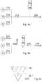
- FIG. 1 ashows a collection liner 21 as a cross sectional view.
- the collection linercomprises a closed bag portion 22 made of a flexible plastic film and a handle 23 .
- the handle 23serves as a handy grip but there are also functional channels inside the handle 23 .
- the bag portion 22 and the handle 23are attached to each other in such a manner that inlets 24 , 25 , 26 , which advance inside the handle 23 , open into the bag portion but otherwise the bag portion 22 is closed by a seam 48 .
- the inlet 24is for vacuum.
- the vacuumis connected to the collection liner 21 through a vacuum port 51 (shown in FIG. 3 a ).
- In the inlet 24 for the vacuumthere is a hydrophobic filter 27 and an opening 29 .
- the inlet 25is for a collection container tube.
- the inlet 25has a first end to which the collection container tube is joined and a second end which opens to the bag portion 22 .
- the inlet 26is for a solidifying agent or any other chemical additive entering into the collection liner 21 .
- Each inlet 24 , 25 , 26is provided with a back flow preventing means, i.e. a back flow preventing device.
- the inlet 24 for vacuumcomprises a hydrophobic filter 27 which swells if liquid reaches it, thus closing the flow.
- the inlet 25 for the collection container tube and the inlet 26 for the solidifying agentare surrounded with a thin plastic tube inside the bag portion 22 .
- the thin plastic tubeis fastened to the upper part of the bag portion 22 , or it is fastened directly to the inlets. It forms a no-return valve 28 .
- the no-return valve 28is open only when the pressure inside the thin plastic tube is higher than around it.
- the thin plastic tubecomprises of two parallel films joined together e.g. by welding. This structure confirms that the plastic tube seals properly without openings in the edges.
- the ancillary handle 30may be a slit which is formed under a seam 49 which closes the bag portion 22 . There may be another seam 50 which is parallel with the above-mentioned seam 49 .
- FIG. 1 bshows a collection liner 21 as a cross sectional view.
- the solution of FIG. 1 bdiffers from the solution of FIG. 1 a in that that the thin plastic tubes, which form the no-return valves 28 , are fastened directly to the inlets 25 , 26 .
- FIG. 1 cshows a handle 23 of a collection liner 21 in a perspective view.
- the handle 23comprises inlets 24 , 25 , 26 .
- the inlet 26is illustrated without a back flow preventing device, such as a no return valve, but the back flow preventing device consisting of a no return valve 28 is shown on the inlet 25 .
- the same kind of no return valve 28may exist in connection with the inlet 26 .
- the no return valve 28comprises two thin plastic films 28 a , 28 b one upon the other. Both films 28 a , 28 b have the upper edge 44 a , the lower edge 44 c and the side edges 44 b , 44 d .
- the upper edges 44 a of the films 28 a , 28 bare joined together and to the inlet 25 e.g. by welding so that a seam 59 a forms.
- the respective side edges 44 b , 44 dare also joined together e.g. by welding in such a manner that seams 59 b , 59 c form.
- the lower edges 44 care not joined together, i.e. the lower end of the no return valve 28 is open. Thus, liquid is able to flow through the valve 28 .
- the seams 59 b , 59 cenhance the performance of the no return valve 28 because the films 28 a , 28 b are tightly together unless the pressure inside the thin plastic tube formed of the films 28 a , 28 b is higher than around it. Therefore, the collection container 21 is secured in such a manner that it cannot leak in any case.
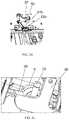
- FIG. 2 ashows one example of the use of the collection liner 21 .
- the collection lineris used with a canister 9 having an openable lid 32 .
- the lid 32is attached to the canister 9 by a hinge 35 .
- the collection liner 21is placed inside the canister 9 in such a manner that the inlet 24 is connected via opening 29 to the internal space of the canister and the inlet 25 for the collection container tube extends over the upper edge of the canister 9 .
- the lid 32 of the canister 9is closed.
- the canister 9comprises a latch (not shown) for the lid 32 . The latch secures that the lid 32 stays closed and sealed until opened.
- the lid 32comprises a gasket 34 which tightens and seals the lid 32 and the handle 21 against the edge of the canister 9 .
- the gasket 34may be a separate gasket or it is an integral part of the lid 32 or the canister 9 , i.e. the lid 32 or the canister 9 is made of a material which is suitable for sealing, or the lid 32 or the canister 9 and the gasket 34 are formed at the same time of different materials.
- FIG. 2 bshows another example of a collection liner and a canister in a perspective view.
- the collection liner 21is used with a canister 9 having an openable lid 32 .
- the lid 32is attached to the canister 9 by hinges 35 . It is possible to detach the lid 32 from the canister 9 , which makes it easier to clean the canister 9 and the lid 32 .
- the collection liner 21is placed inside the canister 9 in such a manner that the inlet 24 is connected via opening 29 to the internal space of the canister and the inlet 25 for the collection container tube extends outside the canister 9 .
- the lid 32 of the canister 9is closed.
- the lid 32comprises at least one latch 201 for the canister 9 . The latch secures that the lid 32 stays closed and sealed until opened.
- the lid 32comprises curved guides 202 inside the lid 32 .
- the curved guidesare preferably concentric as shown in FIG. 2 b .
- the aim of the guides 202is to prevent the collection liner 21 to stretch too much.
- FIG. 3 ashows a partial magnification of a collection liner 21 and a canister 9 .
- the inlet 25 of the collection container tuberemains outside the periphery of the canister 9 .
- the vacuum to the canister 9is connected via a vacuum port 51 .
- the solidifying agent or another additiveis fed through a channel 52 to the inlet 26 (shown in FIG. 2 a ).
- FIG. 3 bshows a partial magnification of another solution comprising a collection liner 21 and a canister 9 .
- the first end of the inlet 25 of the collection container tubeis brought outside the canister 9 .
- the handle 23comprises a gasket 36 which seals the underside of the handle 23 towards the canister 9 .
- the vacuum portis in the recess under the inlet 25 .
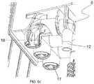
- FIG. 3 cshows a partial magnification of a collection liner from inside.
- the solidifying agent or another additiveis fed through the channel 52 to the inlet 26 .
- the channel 52extends through the wall of the canister 9 .
- the inlet 26tightens against the channel 52 , thus enabling the flow of the solidifying agent or another additive into the collection liner 21 .
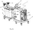
- FIG. 4 ashows an apparatus 1 for collecting liquid from a patient.
- the collection liner 21may be used, for example, in this apparatus.
- the apparatus 1comprises a control unit 2 and a movable cart 3 .
- the control unit 2comprises a display unit 4 , proportional valves 53 to control vacuum in the collection containers and valves 54 for collection container vacuum interfaces.
- the display unit 4may comprise a touch screen acting both for displaying and for entering control parameters.
- the display unit 4may be located on an arm 5 which turns around, i.e. the arm 5 allows the display to tilt and turn.
- On the movable cart 3there are manifolds 6 . Valves of the manifolds 6 are operated by suitable actuators, such as motors 7 .
- the movable cart 3comprises canisters 9 for collecting liquid, and a cartridge 8 a and a reservoir 8 b for a solidifying agent.
- FIG. 4 bshows one variation of the apparatus 1 described in connection with FIG. 4 a.
- FIG. 5 ashows how vacuum and electrical couplings are made between the control unit 2 and the movable cart 3 in the apparatus 1 .
- the control unit 2 and the movable cart 3are attached to each other by using connection plates 40 , 41 .
- the vacuum lines 42 between the control unit 2 and the movable cart 3are automatically connected at the same time.
- the plates 40 , 41are drawn to each other by negative pressure controlled by software via a dedicated valve connected between the plates through line 43 .
- the valve connected to the line 43is turned on when the control unit 2 and the movable cart 3 are sensed to be together. Thus, the valve is only turn on if the movable cart 3 docks with the control unit 2 and a locking means, which locks the control unit 2 and the movable cart 3 together, is on.
- the plates 40 , 41may be used as a mounting and an actuator for the electrical coupling 55 between the control unit 2 and the movable cart 3 .
- FIG. 5 bshows another view how vacuum and electrical couplings are made between the control unit 2 and the movable cart 3 in the apparatus 1 .
- the functioning of the systemis basically the same as described in connection with FIG. 5 a.
- FIG. 6 ashows a manifold 6 in the apparatus 1 .
- the manifold 6comprises a housing 10 , patient ports 11 for connecting a patient tube and ports 12 for collection containers.
- one of the ports 12is provided with a coupling 13 for a collection container tube in order to illustrate the use of the coupling 13 .
- Each patient port 11is provided with a no-return valve.
- Each port 12is provided with a valve 15 .
- the valve 15comprises a cylinder 16 provided with a hole in which is a rotatable bar having a U shaped notch in its head. When the bar is rotated the valve 15 closes or opens depending on the fact whether the hole and the notch are on the same line, i.e. the port 12 opens when the notch is parallel to the hole and the port shuts off when the notch is divergent to the hole.
- the valve 15may comprise two cylinders provided with holes within each other. When the holes of the cylinders are on the same line the valve 15 is open.
- the rotatable barcomprises a form 17 to which an axle of an actuator, such as a motor 7 , grips.
- Each valve 15has an actuator which rotates the valves 15 according to the parameters entered by the user.
- a tubeWhen liquid is collected from the patient a tube is connected to the patient port 11 and the collection container tube is connected to the port 12 by the coupling 13 .
- the fluidenters first to the housing 10 and after that it flows through one port 12 which is open to a collection container.
- the manifold 6may comprise by-pass channels 18 in the ports 12 for the collection container tubes.
- the channel 18is open only when the port 12 is closed by the valve 15 .
- the manifold 6may also comprise a by-pass channel 19 in the housing 10 of the manifold 6 . There is a gasket between the housing 10 and the channel 19 .
- the negative pressure prevailing in the manifold 6can be measured from the channel 19 by connecting the channel 19 to a pressure sensor. The measured negative pressure shows the pressure exerted to the patient and indicates if there is a blockage in the system.
- FIG. 6 bshows another example of a manifold 6 in the apparatus 1 .
- the manifold 6has the same structure as in FIG. 6 a .
- each port 12 for the collection container tubemay comprise a valve 15 comprising two cylinders provided with holes within each other. When the holes are on the same line the valve is open and when the holes are not on the same line the valve is closed.
- the manifold 6may be provided with a no-return valve 31 in the beginning of the channel 19 which prevents liquid for entering into the channel 19 .
- the downstream end of the coupling 13can be closed by a cap 20 after the collection container tube is released from the coupling 13 .
- FIG. 6 cshows a partial magnification of a manifold of FIG. 6 b .
- the valve 15is closed and air flows in the by-pass channel 18 .
- the air flow in the by-pass channel 18is denoted by arrow F.
- FIG. 6 dshows a partial magnification of a manifold of FIG. 6 b .
- the inner cylinder 33 of the valve 15is shown as an exploded view, i.e. the inner cylinder 33 has been taken out from its normal place which is inside the outer cylinder.
- the inner cylinder 33comprises the holes 37 and a first groove 38 which forms the first part of the by-pass channel 18 .
- the second part of the by-pass channel 18is a second groove 39 .
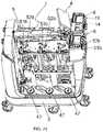
- FIG. 7 ashows an apparatus 1 for collecting liquid from a patient. Some of the canisters 9 are removed so that one can see under the canisters 9 . There is a strain gauge transducer 47 under each canister 9 . The electrical resistance of the strain gauge transducer 47 varies due to the load that is exerted to the transducer 47 . On the basis of the resistance the weight of the collection container, i.e. the canister 9 or the collection liner 21 can be determined.
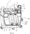
- FIG. 7 bshows one variation of the apparatus 1 in FIG. 7 .
- the apparatus 1comprises a separation wall 204 . Connections for docking the canister 9 onto the movable cart 3 of the apparatus 1 are behind the separation wall 204 .
- the separation wall 204is provided with an illumination device 205 at each canister 9 .
- the illumination device 205may be a LED stripe. Each illumination device may be controlled separately as to the light intensity or switching on off.
- FIG. 7 cshows the apparatus 1 of FIG. 7 b without the separation wall 204 , thus revealing the parts behind the separation wall 204 .
- FIG. 7 dshows a partial magnification of a detail in the apparatus of FIGS. 7 a to 7 c .
- the vacuum port 51is due to connect to the channel 51 b and the channel 52 for the solidifying agent is due to connect to the channel 52 b .
- the channels 51 b and 52 bfloat in respect of the body of the apparatus 1 .
- the floating connectionmakes it possible that the canister 9 moves freely and therefore, it is possible to weigh the canister 9 reliably.
- the floating connectioncan be locked in its place when the canister 9 is changed by moving a docking lever 58 to a prescribed locking position.
- the docking lever 58may be replaced by another suitable device, such as a latch or like.
- the canister 9can be attached and detached but the collection liner 21 cannot be used.
- the floating connectioncan be resumed by moving the docking lever 58 to a prescribed floating position. In this position the collection liner 21 can be attached to the canister 9 but the canister 9 cannot be detached (for further details see FIGS. 7 e to 7 g ).
- the channel 51 bmay comprise a flow meter measuring a flow value and a second pressure sensor measuring a second pressure value.
- a first pressure sensormeasures a first pressure value which corresponds to the pressure value inside the manifold 6 .
- the pressure difference of the first pressure value and the second pressure valueis calculated.
- the flow valuehas a predetermined range for each pressure difference. If the flow value is under the predetermined range compared to the predetermined range corresponding the pressure difference in question there is a blockage. If the flow value is over the predetermined range compared to the predetermined range corresponding the pressure difference in question there is a leak.
- FIG. 7 eshows a further detail of the floating connection of the canister 9 .
- the docking lever 58comprises a stopper 56 which prevents removing the canister 9 .
- FIGS. 7 f and 7 gshow another further detail of the floating connection of the canister 9 .
- the docking lever 58comprises a retainer 57 which prevents putting the collection liner 21 into its place.
- FIG. 8 ashows a schematic view of a system for feeding solidifying agent or another additive.
- the third valve 220is in contact with ambient air A.
- the solidifying agent cartridge 8 a and a reservoir 8 bwhich opens into a tube leading to the collection container 9 .
- the second valve 215is partially open.
- the vacuumstarts to draw the solidifying agent out of the reservoir 8 b so that a portion of the solidifying agent is formed between the second valve 215 and the third valve 220 .
- the first valve 210 and the third valve 220are open and the second valve 215 is still partially open. Air flows from the third valve 220 which stops the flow of the solidifying agent and compacts the portion of the solidifying agent against the second valve 220 .
- valvesare open.
- the portion of the solidifying agentis shot then into the collection container 9 , thus solidifying the liquid in the collection container.
- the second valve 215 and the third valve 220are closed in such a manner that the second valve 215 remains partially open as in the beginning of the process.
- the first valve 210is also eventually closed and the cycle to form the portion of the solidifying agent starts all over again.
- FIG. 8 bshows a schematic view of another system for feeding solidifying agent or another additive.
- the liner valve 225is near to the collection container 9 .
- the reservoir 8 b receiving solidifying agent from the cartridge 8 ais between the air valve 230 and the liner valve 225 .
- the pipe of the solidifying agent pipeline, which passes through the reservoir 8 bmay work as an ejector. Such an alternative is described in connection with FIG. 8 c.
- the liner valve 225 and the air valve 230are open when the solidifying agent is distributed.
- the solidifying agent pipelineis in contact with ambient air A through the air valve 230 and it is in contact with vacuum through the liner valve 225 .
- the pipe beyond the air valve 230may be choked at 235 in order to adjust the balance between ambient air and powder flowing in the pipe.
- flush valve 240between the reservoir 8 b and the liner valve 225 .
- the flush valve 240is opened at the end of the powder distribution when the air valve 230 has been closed.
- the aim of the flush valve 240is that the flush valve 240 opens access to ambient air A and the air flow cleans the pipe from the powder residuals.
- FIG. 8 cshows a detail of FIG. 8 b .
- the pipe 241which passes through the reservoir 8 b , works as an ejector.
- the lower part of the reservoir 8 bmay have a shape of an inverted cone as shown in FIGS. 8 b and 8 c .
- the pipe 241has an opening 242 through which air flow grabs the solidifying agent.
- the opening 242is on the underside of the pipe 241 because under the pipe 241 the powder is loose and easily movable.
- FIG. 9illustrates schematically a graphical user interface 100 for an apparatus for collecting liquid from a patient.
- the graphical user interfacemay comprise a display unit 4 and/or different selection means, such as buttons, mouse, joystick and/or touch screen, with which the user may enter input through the graphical user interface 100 for the control unit 2 .
- the touch screenmay be integrated to the display unit 4 .
- the display unit 4may comprise one or several display screens.
- the graphical user interface 100 for an apparatus for collecting liquid from a patientmay comprise at least one first user interface element 101 configured to display on a display unit 4 information related to at least one, preferably at least two, first collection containers 9 connected to a first suction channel XX, at least one second user interface element 102 configured to display on the display unit 4 information related to at least one, preferably at least two, second collection containers 9 connected to a second suction channel, and a third user interface element 103 configured to display on the display unit 4 information regarding liquid collected from the patient to at least one of the collection container 9 such as the amount of liquid collected from the patient to at least one of the collection containers.
- the third user interface element 103is configured to display on the display unit 4 the total amount of liquid collected from the patient to the collection containers 9 . According to an embodiment, the third user interface element 103 is further configured to display on the display unit 4 information regarding the liquid provided to the patient, such as the amount of liquid provided to the patient; and/or the difference between the amount of liquid provided to the patient and the amount of liquid collected from the patient.
- the first interface element 101 and the second interface element 102may be configured to display a graphical representation 104 a - 104 f of each one of the collection containers 9 .
- one graphical representation of a collection container 104 a - 104 fmay in each case represent one of the collection containers 9 , respectively.
- the graphical interface 100may be configured to receive input from a user in the form of the user affecting any one of the graphical representations 104 a - 104 f of the collection containers 9 .
- the affectingmay comprise pointing a graphical representation 104 a - 104 f , touching a graphical representations 104 a - 104 f , hovering over a graphical representation 104 a - 104 f and/or any other manner of affecting a graphical user interface known as such.
- the graphical interface 100may be configured to select the collection container 9 , the graphical representation 104 a - 104 f of which the user has affected, for collecting fluid from the patient, in response to the input from the user.
- the graphical user interface 100may send a request for the control unit 2 to connect the selected collection container 9 to a corresponding suction channel in response to the user affecting the graphical representation 104 a - 104 f of the collection container 9 .
- the graphical user interface 100may be configured to select the appearance of each one of the graphic representations 104 a - 104 f of the collection containers 9 in such a manner that a difference appearance is selected for a collection container currently selected, a collection container selectable for collecting fluid from the patient, and a collection container not ready for collecting liquid from the patient.
- a different colour, different thickness and/or transparency of lines and filling used for showing a collection container 9 on the display unit 4may be selected by the graphical user interface 100 and/or the control unit 2 based on whether the collection container 9 is a collection container currently selected, a collection container selectable for collecting fluid from the patient, and a collection container not ready for collecting fluid from the patient.
- the graphical user interface 100may be configured to select the appearance of each one of the graphic representations 104 a - 104 f of the collection containers 9 to visually show the degree of filling of the collection container 9 in question.
- the graphical representation 104 a - 104 fmay display an illustration of a collection container filled to a degree of filling corresponding to the degree of filling of the actual, corresponding collection container 9 .
- the graphical user interface 100may further comprise a selection element 105 for starting collection of fluid from the patient to one of said collection containers 9 .
- the graphical user interface 100may then be configured to receive input from a user in the form of the user affecting the selection element 105 for starting collection of liquid.
- the graphical user interface 100may be configured to send a request for starting the collection of liquid from the patient to the selected collection container 9 to a control unit 2 in response to the user affecting the selection element 105 for starting collection of liquid on the graphical user interface 100 .
- the graphical user interface 100may be configured to only process the input from the user affecting the selection element 105 and to send the request to the control unit 2 if at least one of the collection containers 9 is ready for collecting liquid from the patient.
- the graphical user interface 100may comprise at least one selection element 105 related to the first user interface element 101 and at least one selection element 105 related to the second user interface element 102 , whereby each selection element 105 may be configured to send the request to the control unit 2 to start collecting fluid from the patient through the corresponding suction channel to one of the collection containers 9 that are related to the corresponding user interface element 101 , 102 .
- a method in connection with a graphical user interface for an apparatus for collecting liquid from a patientcomprises steps needed for executing at least one of the functions described in connection with the graphical user interface 100 .
- the methodcomprises a combination of steps needed for executing at least two of the functions described in connection with the graphical user interface 100 .
- the control unit 2may comprise a computer, a programmable logic or a programmable microprocessor, for example.
- the control unit 2may be configured to cause display of at least one graphical user interface 100 as described above.
- the apparatus for collecting liquid from a patientmay further comprise at least one memory comprising program code comprising one or more modules, programs or sets of instructions stored in the memory for running operations.
- the program codemay comprise e.g. a system program, an installable application, an application plugin, an Internet browser or any other piece of computer program code.
- computer code for carrying out at least some of the above-illustrated featuresmay be provided.
- the memory and computer program codemay be configured to cause the apparatus for collecting liquid from a patient to carry out at least some of the graphical user interface elements 101 , 102 , 103 , 104 and 105 , and related features illustrated in connection with FIGS. 1 to 9 .
- FIG. 10shows an example of one possible graphical interface 100 .
- the first user interface element 101shows information about suction channel A and the second user interface element 102 shows information about suction channel B.
- the collection containers 104 a - 104 c which are joined to the suction channel Aare illustrated on the first interface element 101 and the collection containers 104 d - 104 f which are joined to the suction channel B are illustrated on the first interface element 102 .
- the vacuum level of suction channel Acan be read from a scale 106 and the vacuum level of suction channel B can be read from a scale 107 .
- the third user interface element 103shows in the section 108 the amount of liquid used for irrigation.
- the section 109shows the amount of liquid that has been collected from the operation site.
- the section 110shows the balance between the readings on the sections 108 and 109 .
- the main processing included in the display unit 4 acontrols the display, audio and touch screen. It communicates with the control unit 2 controller over the USB bus.
- the cart 3has its own controller communicating with the control unit 2 .
- the main processor, the control unit controller and the cart controllerhave their own software, memories and peripherals.
Landscapes
- Health & Medical Sciences (AREA)
- Heart & Thoracic Surgery (AREA)
- Engineering & Computer Science (AREA)
- Biomedical Technology (AREA)
- Public Health (AREA)
- General Health & Medical Sciences (AREA)
- Veterinary Medicine (AREA)
- Life Sciences & Earth Sciences (AREA)
- Animal Behavior & Ethology (AREA)
- Hematology (AREA)
- Anesthesiology (AREA)
- Vascular Medicine (AREA)
- Pulmonology (AREA)
- Surgery (AREA)
- Business, Economics & Management (AREA)
- General Business, Economics & Management (AREA)
- Epidemiology (AREA)
- Medical Informatics (AREA)
- Primary Health Care (AREA)
- Pharmacology & Pharmacy (AREA)
- External Artificial Organs (AREA)
- Accommodation For Nursing Or Treatment Tables (AREA)
- Infusion, Injection, And Reservoir Apparatuses (AREA)
Abstract
Description
Claims (5)
Applications Claiming Priority (3)
| Application Number | Priority Date | Filing Date | Title |
|---|---|---|---|
| FI20165567 | 2016-07-06 | ||
| FI20165567AFI130032B (en) | 2016-07-06 | 2016-07-06 | An apparatus for collecting liquid from a patient and a manifold |
| PCT/FI2017/050521WO2018007687A1 (en) | 2016-07-06 | 2017-07-06 | A collection liner for a medical or a surgical operation |
Publications (2)
| Publication Number | Publication Date |
|---|---|
| US20200179577A1 US20200179577A1 (en) | 2020-06-11 |
| US11285255B2true US11285255B2 (en) | 2022-03-29 |
Family
ID=59399440
Family Applications (6)
| Application Number | Title | Priority Date | Filing Date |
|---|---|---|---|
| US16/315,428Active2038-01-08US11129928B2 (en) | 2016-07-06 | 2017-07-06 | Assembly for collecting fluid during a medical or a surgical operation |
| US16/315,297AbandonedUS20190307931A1 (en) | 2016-07-06 | 2017-07-06 | A method, arrangement and a user interface for controlling collecting fluid from a patient |
| US16/315,202AbandonedUS20190247554A1 (en) | 2016-07-06 | 2017-07-06 | Apparatus for collecting fluid during a medical or a surgical operation and a manifold |
| US16/315,224AbandonedUS20190167870A1 (en) | 2016-07-06 | 2017-07-06 | An apparatus for collecting fluid during a medical or surgical operation and a method for solidifying fluid in a collection container |
| US16/315,341AbandonedUS20190231941A1 (en) | 2016-07-06 | 2017-07-06 | Apparatus for collecting fluid during a medical or surgical operation and a manifold |
| US16/315,262Active2038-05-29US11285255B2 (en) | 2016-07-06 | 2017-07-06 | Collection liner for a medical or a surgical operation |
Family Applications Before (5)
| Application Number | Title | Priority Date | Filing Date |
|---|---|---|---|
| US16/315,428Active2038-01-08US11129928B2 (en) | 2016-07-06 | 2017-07-06 | Assembly for collecting fluid during a medical or a surgical operation |
| US16/315,297AbandonedUS20190307931A1 (en) | 2016-07-06 | 2017-07-06 | A method, arrangement and a user interface for controlling collecting fluid from a patient |
| US16/315,202AbandonedUS20190247554A1 (en) | 2016-07-06 | 2017-07-06 | Apparatus for collecting fluid during a medical or a surgical operation and a manifold |
| US16/315,224AbandonedUS20190167870A1 (en) | 2016-07-06 | 2017-07-06 | An apparatus for collecting fluid during a medical or surgical operation and a method for solidifying fluid in a collection container |
| US16/315,341AbandonedUS20190231941A1 (en) | 2016-07-06 | 2017-07-06 | Apparatus for collecting fluid during a medical or surgical operation and a manifold |
Country Status (10)
| Country | Link |
|---|---|
| US (6) | US11129928B2 (en) |
| EP (6) | EP3481451B1 (en) |
| JP (3) | JP7126486B2 (en) |
| CN (3) | CN109641086A (en) |
| BR (1) | BR112018077505A2 (en) |
| ES (1) | ES2832649T3 (en) |
| FI (1) | FI130032B (en) |
| PL (1) | PL3481450T3 (en) |
| RU (1) | RU2720669C1 (en) |
| WO (13) | WO2018007687A1 (en) |
Families Citing this family (18)
| Publication number | Priority date | Publication date | Assignee | Title |
|---|---|---|---|---|
| EP4257159A3 (en) | 2012-10-24 | 2023-10-25 | Stryker Corporation | Mobile cart of a waste collection system |
| FI130032B (en) | 2016-07-06 | 2022-12-30 | Serres Oy | An apparatus for collecting liquid from a patient and a manifold |
| USD932614S1 (en) | 2018-01-05 | 2021-10-05 | Serres Oy | Suction device for medical use |
| FI128233B (en) | 2018-02-22 | 2020-01-15 | Serres Oy | A collection liner |
| CN109316639B (en)* | 2018-11-12 | 2021-01-22 | 上海市东方医院 | A drainage device for neurosurgery |
| WO2021033079A1 (en)* | 2019-08-21 | 2021-02-25 | Kci Licensing, Inc. | Wound fluid collection canister with user selectable content visualization and system and methods of use |
| JP7269851B2 (en)* | 2019-09-20 | 2023-05-09 | 大研医器株式会社 | Waste liquid storage container, waste liquid reservoir provided with the same, and waste liquid suction system |
| CN114127644A (en)* | 2020-02-27 | 2022-03-01 | 松下知识产权经营株式会社 | Information processing method, information processing apparatus, and program |
| USD959658S1 (en) | 2020-10-12 | 2022-08-02 | Stryker Corportation | Medical waste collection unit |
| CN112782248B (en)* | 2020-12-31 | 2022-12-13 | 东莞市雍华昊信息技术有限公司 | Sensing system |
| CN112648537A (en)* | 2020-12-31 | 2021-04-13 | 苏州联点数据技术有限公司 | Induction system |
| CN112833930B (en)* | 2020-12-31 | 2022-10-11 | 陕西拓普索尔电子科技有限责任公司 | Multifunctional sensing device |
| CN112915269B (en)* | 2021-01-12 | 2022-08-23 | 蔡芳芳 | Peritoneal effusion collection system for gastroenterology |
| CN112915268A (en)* | 2021-01-12 | 2021-06-08 | 郭超凡 | Gastroenterology peritoneal cavity hydrops collection device |
| CN112999442A (en)* | 2021-02-22 | 2021-06-22 | 南京市儿童医院 | Surgical infection negative pressure closed suction system for children |
| WO2023274534A1 (en)* | 2021-07-01 | 2023-01-05 | Serres Oy | A collection container |
| AU2024251948A1 (en)* | 2023-04-11 | 2025-10-09 | Stryker Corporation | Devices and methods for providing an anticlotting element for use with a medical waste collection system |
| CN116212136B (en)* | 2023-05-08 | 2023-07-04 | 四川省医学科学院·四川省人民医院 | Negative pressure suction device for thoracoscopic operation |
Citations (71)
| Publication number | Priority date | Publication date | Assignee | Title |
|---|---|---|---|---|
| US1891579A (en) | 1930-03-22 | 1932-12-20 | Treadwell Engineering Company | Rolling mill |
| US3211144A (en)* | 1962-06-21 | 1965-10-12 | Becton Dickinson Co | Transfusion and storage set |
| US3478743A (en) | 1967-09-20 | 1969-11-18 | Elliot Lab Inc | Closed urinary drainage system |
| US3556101A (en)* | 1969-02-07 | 1971-01-19 | Hollister Inc | Surgical suction assembly |
| US3648698A (en) | 1969-05-23 | 1972-03-14 | George O Doherty | Surgical collection unit |
| US3782384A (en)* | 1970-02-20 | 1974-01-01 | C Timmermans | Surgical suction jar |
| US3848628A (en) | 1972-08-09 | 1974-11-19 | Deaton Medical Co | Disposable safety float valve |
| WO1980002706A1 (en) | 1979-06-04 | 1980-12-11 | Uresil Co | Apparatus and method for introducing fluid into and removing fluid from a living subject |
| EP0040427A1 (en) | 1980-05-20 | 1981-11-25 | Haemonetics Corporation | Suction liquid collection assembly and flexible liquid collection bag suitable for use therein |
| EP0068744A1 (en) | 1981-06-30 | 1983-01-05 | Craig Medical Products Limited | Tap for drainage bag |
| US4404924A (en) | 1980-09-05 | 1983-09-20 | Uresil Company | Body fluid suction device indicators |
| US4449969A (en) | 1982-02-03 | 1984-05-22 | The Kendall Company | Drainage receptacle with support frame |
| US4650478A (en) | 1983-06-28 | 1987-03-17 | The Kendall Company | Liquid drainage system having a hook support member |
| EP0216611A1 (en) | 1985-09-20 | 1987-04-01 | International Business Machines Corporation | Print hammer actuator for impact printer |
| JPH02157083A (en) | 1988-12-06 | 1990-06-15 | Daiken Iki Kk | Container for processing waste fluids containing body fluids |
| EP0390094A1 (en) | 1989-03-30 | 1990-10-03 | Abbott Laboratories | Suction drainage infection control system |
| US5066283A (en) | 1987-07-09 | 1991-11-19 | Avl Ag | Device for the withdrawal and storage of individual fluid fractions lathered at given intervals |
| GB2249613A (en) | 1990-11-07 | 1992-05-13 | Smiths Industries Plc | Urine bag valve |
| US5203769A (en) | 1989-11-06 | 1993-04-20 | Mectra Labs, Inc. | Medical device valving mechanism |
| US5238582A (en) | 1988-12-06 | 1993-08-24 | Daiken Iki Co., Ltd. | Method of treating waste liquid |
| US5248275A (en) | 1991-05-20 | 1993-09-28 | M & D Balloons, Inc. | Balloon with flat film valve and method of manufacture |
| US5391351A (en) | 1987-10-07 | 1995-02-21 | Kaufman; Jack W. | Body waste fluids solidification system |
| EP0668084A1 (en) | 1994-02-16 | 1995-08-23 | Muoviserres Oy | Method and arrangement in connection with a secretion receiver |
| US5589145A (en) | 1987-10-07 | 1996-12-31 | Kaufman; Jack W. | Waste treatment material dispensing canister |
| WO1997027883A1 (en) | 1996-02-01 | 1997-08-07 | Daiken Iki Co., Ltd. | Method for disposal of waste liquid including humor, and apparatus therefor |
| WO1997045055A1 (en) | 1996-05-30 | 1997-12-04 | Alexander Gary E | A multiple vacuum vial blood collection device |
| US5776118A (en) | 1995-12-13 | 1998-07-07 | Steris Corporation | Medical and biological fluid collection and disposal system |
| WO1999000154A1 (en) | 1997-06-30 | 1999-01-07 | Griffiths Gerald R | On-site biohazardous liquid medical waste collection and treatment system |
| US6152902A (en) | 1997-06-03 | 2000-11-28 | Ethicon, Inc. | Method and apparatus for collecting surgical fluids |
| US6183453B1 (en) | 1997-11-20 | 2001-02-06 | Sherwood Services, Ag | Blood evacuation container with blood spike nesting feature |
| WO2001014048A1 (en) | 1999-08-23 | 2001-03-01 | Two Inventors Hb | Method and apparatus for handling and dosing of an additive while collecting a liquid |
| WO2001049344A1 (en) | 1999-12-31 | 2001-07-12 | Oy Nikomed Finland Ab | Suction bag device |
| US20010040123A1 (en) | 2000-05-08 | 2001-11-15 | Scott Beckham | Check valve |
| JP2003526381A (en) | 1997-11-20 | 2003-09-09 | タイコ・グループ・ソシエタ・ア・レスポンサビリタ・リミテ | Blood drainage container with blood spike containment function |
| US20030220607A1 (en) | 2002-05-24 | 2003-11-27 | Don Busby | Peritoneal dialysis apparatus |
| US20030225366A1 (en) | 1999-08-31 | 2003-12-04 | Morgan Michael D. | Liquid venting surgical cassette |
| US6679529B2 (en) | 2001-08-06 | 2004-01-20 | Theodore D. Johnson | Connection system |
| CN2604585Y (en) | 2003-01-29 | 2004-02-25 | 庞鹏远 | Bent duckbilled flexible non-return valve |
| EP1398018A1 (en) | 2002-09-06 | 2004-03-17 | Gambro Lundia AB | Container for dialysis fluid and a method for manufacturing of such container |
| WO2005079947A2 (en) | 2004-02-19 | 2005-09-01 | Stryker Instruments | Manifold and filter assembly with filter basket |
| US20050244083A1 (en) | 2003-02-19 | 2005-11-03 | Mcmahon Michael J | Reclosable vacuum storage bag having flat resealable means |
| EP1642603A1 (en) | 2003-06-10 | 2006-04-05 | Daiken Iki Kabushiki Kaisha | Storage container and medical sucking tool having the same |
| US20060079853A1 (en) | 2004-10-12 | 2006-04-13 | C. R. Bard, Inc. | Corporeal drainage system |
| US20070135779A1 (en) | 2005-12-14 | 2007-06-14 | Stryker Corporation | Medical/surgical waste collection and disposal system including waste containers of different storage volumes with inter-container transfer valve and independently controlled vacuum levels |
| US20070135778A1 (en) | 2005-12-14 | 2007-06-14 | Murray Sean A | Removable inlet manifold for a medical/surgical waste collection system, the manifold including a driver for actuating a valve integral with the waste collection system |
| WO2008118397A1 (en) | 2007-03-23 | 2008-10-02 | Allegiance Corporation | Fluid collection and disposal system having internchangeable collection and other features and methods relating thereof |
| WO2008144951A1 (en) | 2007-05-31 | 2008-12-04 | Medela Holding Ag | Drainage device |
| US20090036847A1 (en) | 2006-02-13 | 2009-02-05 | Veikko Rajamaki | Suction Bag Arrangement |
| WO2009046403A1 (en) | 2007-10-04 | 2009-04-09 | Dornoch Medical Systems, Inc. | Medical waste fluid collection and disposal system |
| US20100016825A1 (en) | 2006-06-02 | 2010-01-21 | Thomas Graf | Container Filled with a Liquid Concentrate for Making Dialysate |
| EP2168611A1 (en) | 2008-09-30 | 2010-03-31 | Tyco Healthcare Group LP | Ball Valve Actuation Mechanism |
| US7708724B2 (en) | 2004-04-05 | 2010-05-04 | Blue Sky Medical Group Incorporated | Reduced pressure wound cupping treatment system |
| US20110118680A1 (en) | 2009-07-15 | 2011-05-19 | Cardinal Health, Inc. | Fluid collection and disposal system and related methods |
| US20120029448A1 (en) | 2010-07-30 | 2012-02-02 | Medela Holding Ag | Suction pump system |
| US20120215187A1 (en) | 2011-02-21 | 2012-08-23 | Fina Technology, Inc. | One-Piece Suction Canister Liner |
| WO2014093984A1 (en) | 2012-12-15 | 2014-06-19 | The Seaberg Company, Inc. | Multi-function hand pump for medical use |
| US20140171887A1 (en)* | 2012-12-19 | 2014-06-19 | Dornoch Medical Systems Inc. | Suction canister liner and system |
| US20140343515A1 (en) | 2013-05-17 | 2014-11-20 | Dornoch Medical Systems, Inc. | User interlock for a medical waste fluid collection and disposal system |
| US20150224237A1 (en) | 2012-10-24 | 2015-08-13 | Stryker Corporation | Mobile instrument assembly for use as part of a medical/surgical waste collection system, the assembly including a vacuum source to which a mobile waste collection cart can be releasably attached |
| WO2015134749A2 (en) | 2014-03-06 | 2015-09-11 | Stryker Corporation | Medical/surgical waste collection unit with a light assembly separate from the primary display, the light assembly presenting informatin about the operation of the system by selectively outputting light |
| JP5800440B1 (en) | 2014-05-15 | 2015-10-28 | 株式会社セントラルユニ | Suction bottle |
| US20150328379A1 (en) | 2014-05-15 | 2015-11-19 | Thermedx, Llc | Fluid management system with pass-through fluid volume measurement |
| US20160038665A1 (en) | 2013-03-15 | 2016-02-11 | Gambro Lundia Ab | Extracorporeal blood treatment fluids interface |
| US20160166742A1 (en) | 2014-12-16 | 2016-06-16 | Novartis Ag | Quick-opening vent valve for phaco fluidics aspiration system |
| US20160235962A1 (en) | 2013-11-07 | 2016-08-18 | Ge Healthcare Bio-Sciences Ab | Connector for aseptic connection |
| WO2017007660A1 (en) | 2015-07-03 | 2017-01-12 | Merit Medical Systems, Inc. | Devices and methods for fluid infusion, drainage and collection |
| WO2017066798A1 (en) | 2015-10-16 | 2017-04-20 | Allegiance Corporation | Fluid collection systems |
| US20170304511A1 (en) | 2016-04-25 | 2017-10-26 | Allegiance Corporation | Fluid collection systems and methods of use |
| US20180043081A1 (en) | 2016-04-04 | 2018-02-15 | Medtronic, Inc. | Peritoneal dialysate purity control system |
| US20180264181A1 (en) | 2015-09-11 | 2018-09-20 | Smith & Nephew, Inc. | Systems and methods for applying reduced negative pressure therapy |
| US20190167870A1 (en) | 2016-07-06 | 2019-06-06 | Serres Oy | An apparatus for collecting fluid during a medical or surgical operation and a method for solidifying fluid in a collection container |
Family Cites Families (22)
| Publication number | Priority date | Publication date | Assignee | Title |
|---|---|---|---|---|
| US4033345A (en)* | 1975-11-13 | 1977-07-05 | Sorenson Research Co., Inc. | Autologous transfusion filter system and method |
| US4559035A (en)* | 1983-09-26 | 1985-12-17 | Snyder Laboratories, Inc. | Collapsible wound suction evacuator |
| US4626248A (en)* | 1985-12-16 | 1986-12-02 | Storz Instrument Company | Ophthalmic cassette |
| ATE93734T1 (en)* | 1989-03-30 | 1993-09-15 | Abbott Lab | SUCTION DEVICE WITH AN INFECTION PREVENTION DEVICE. |
| FR2727847A1 (en)* | 1994-12-07 | 1996-06-14 | C & D Biomedical | Appts. for supply and extraction of clarifying liquid during surgery, e.g. bladder operations |
| US7207966B2 (en)* | 1995-11-01 | 2007-04-24 | Ethicon, Inc. | System for fluid retention management |
| US6010454A (en)* | 1997-05-29 | 2000-01-04 | Aquintel, Inc. | Fluid and electrolyte balance monitoring system for surgical and critically ill patients |
| US7479123B2 (en)* | 2002-03-04 | 2009-01-20 | Therakos, Inc. | Method for collecting a desired blood component and performing a photopheresis treatment |
| AU2005273037A1 (en)* | 2004-02-17 | 2006-02-23 | Stryker Instruments | Waste collection unit |
| EP1765255B1 (en)* | 2004-05-11 | 2014-07-16 | EV (Baby) Limited | Collapsible fluid containers |
| RU98881U1 (en)* | 2008-12-16 | 2010-11-10 | Александр Петрович Шабалин | MOBILE DEVICE FOR THE COLLECTION AND DISPOSAL OF LIQUID WASTE |
| JP3151290U (en)* | 2009-04-02 | 2009-06-18 | 永康醫材科技股▲ふん▼有限公司 | Sealed negative pressure suction device |
| RU86468U1 (en)* | 2009-04-20 | 2009-09-10 | Закрытое акционерное общество "ПКФ "Медфарм" | WASTE PREFERRED PREFERRED PREFERRED CONTAINER |
| US8394081B2 (en)* | 2010-01-29 | 2013-03-12 | Kci Licensing, Inc. | Wound treatment apparatuses and methods for controlled delivery of fluids to a wound |
| CH705011A1 (en)* | 2011-05-27 | 2012-11-30 | Medela Holding Ag | Device for the thorax drainage. |
| CA2905825C (en)* | 2013-03-13 | 2018-04-10 | Thermedx, Llc | Fluid management system |
| WO2015029039A1 (en)* | 2013-08-29 | 2015-03-05 | Motus Gi Medical Technologies Ltd. | Colon cleaning system with automatic self-purging features |
| RS60227B1 (en)* | 2014-02-20 | 2020-06-30 | Jt Int Sa | Led module for aerosol generating devices, aerosol generating device having a led module and method for illuminating vapour |
| US20170210532A1 (en)* | 2014-07-07 | 2017-07-27 | Eliezer Edelstein | Pouch with flat valve |
| CA3179001A1 (en)* | 2014-07-31 | 2016-02-04 | Smith & Nephew, Inc. | Systems and methods for applying reduced pressure therapy |
| PL3040101T3 (en)* | 2014-12-29 | 2017-08-31 | Erbe Elektromedizin Gmbh | Supply device for generating a pulsed fluid jet, application system with a supply device and computer readable memory |
| WO2016183290A1 (en)* | 2015-05-13 | 2016-11-17 | Dornoch Medical Systems, Inc. | Fluid collection and disposal system |
- 2016
- 2016-07-06FIFI20165567Apatent/FI130032B/enactive
- 2017
- 2017-07-06ESES17745776Tpatent/ES2832649T3/enactiveActive
- 2017-07-06USUS16/315,428patent/US11129928B2/enactiveActive
- 2017-07-06WOPCT/FI2017/050521patent/WO2018007687A1/ennot_activeCeased
- 2017-07-06PLPL17745776.9Tpatent/PL3481450T3/enunknown
- 2017-07-06EPEP17746529.1Apatent/EP3481451B1/enactiveActive
- 2017-07-06JPJP2019500493Apatent/JP7126486B2/enactiveActive
- 2017-07-06JPJP2019500492Apatent/JP6707171B2/ennot_activeExpired - Fee Related
- 2017-07-06WOPCT/FI2017/050522patent/WO2018007688A1/ennot_activeCeased
- 2017-07-06EPEP17746530.9Apatent/EP3482322A1/ennot_activeWithdrawn
- 2017-07-06USUS16/315,297patent/US20190307931A1/ennot_activeAbandoned
- 2017-07-06WOPCT/FI2017/050509patent/WO2018007675A1/ennot_activeCeased
- 2017-07-06WOPCT/FI2017/050514patent/WO2018007680A1/ennot_activeCeased
- 2017-07-06JPJP2019500389Apatent/JP6768137B2/ennot_activeExpired - Fee Related
- 2017-07-06EPEP17748520.8Apatent/EP3481452B1/enactiveActive
- 2017-07-06WOPCT/FI2017/050520patent/WO2018007686A1/ennot_activeCeased
- 2017-07-06USUS16/315,202patent/US20190247554A1/ennot_activeAbandoned
- 2017-07-06BRBR112018077505-3Apatent/BR112018077505A2/ennot_activeApplication Discontinuation
- 2017-07-06WOPCT/FI2017/050519patent/WO2018007685A1/ennot_activeCeased
- 2017-07-06CNCN201780041922.9Apatent/CN109641086A/enactivePending
- 2017-07-06CNCN201780041893.6Apatent/CN109641085A/enactivePending
- 2017-07-06WOPCT/FI2017/050516patent/WO2018007682A1/ennot_activeCeased
- 2017-07-06EPEP17745776.9Apatent/EP3481450B1/enactiveActive
- 2017-07-06CNCN201780041920.XApatent/CN109562207B/ennot_activeExpired - Fee Related
- 2017-07-06WOPCT/FI2017/050511patent/WO2018007677A1/ennot_activeCeased
- 2017-07-06USUS16/315,224patent/US20190167870A1/ennot_activeAbandoned
- 2017-07-06USUS16/315,341patent/US20190231941A1/ennot_activeAbandoned
- 2017-07-06WOPCT/FI2017/050518patent/WO2018007684A1/ennot_activeCeased
- 2017-07-06EPEP17745774.4Apatent/EP3481449B1/enactiveActive
- 2017-07-06WOPCT/FI2017/050512patent/WO2018007678A1/ennot_activeCeased
- 2017-07-06WOPCT/FI2017/050517patent/WO2018007683A1/ennot_activeCeased
- 2017-07-06WOPCT/FI2017/050510patent/WO2018007676A1/ennot_activeCeased
- 2017-07-06EPEP17743373.7Apatent/EP3481448A1/ennot_activeWithdrawn
- 2017-07-06WOPCT/FI2017/050515patent/WO2018007681A1/ennot_activeCeased
- 2017-07-06RURU2019101079Apatent/RU2720669C1/enactive
- 2017-07-06USUS16/315,262patent/US11285255B2/enactiveActive
Patent Citations (150)
| Publication number | Priority date | Publication date | Assignee | Title |
|---|---|---|---|---|
| US1891579A (en) | 1930-03-22 | 1932-12-20 | Treadwell Engineering Company | Rolling mill |
| US3211144A (en)* | 1962-06-21 | 1965-10-12 | Becton Dickinson Co | Transfusion and storage set |
| US3478743A (en) | 1967-09-20 | 1969-11-18 | Elliot Lab Inc | Closed urinary drainage system |
| US3556101A (en)* | 1969-02-07 | 1971-01-19 | Hollister Inc | Surgical suction assembly |
| US3648698A (en) | 1969-05-23 | 1972-03-14 | George O Doherty | Surgical collection unit |
| US3782384A (en)* | 1970-02-20 | 1974-01-01 | C Timmermans | Surgical suction jar |
| US3848628A (en) | 1972-08-09 | 1974-11-19 | Deaton Medical Co | Disposable safety float valve |
| CA1168539A (en) | 1979-06-04 | 1984-06-05 | Edward M. Goldberg | Apparatus and method for introducing fluid into and removing fluid from a living subject |
| WO1980002706A1 (en) | 1979-06-04 | 1980-12-11 | Uresil Co | Apparatus and method for introducing fluid into and removing fluid from a living subject |
| EP0040427A1 (en) | 1980-05-20 | 1981-11-25 | Haemonetics Corporation | Suction liquid collection assembly and flexible liquid collection bag suitable for use therein |
| US4404924A (en) | 1980-09-05 | 1983-09-20 | Uresil Company | Body fluid suction device indicators |
| US4525167A (en) | 1980-09-05 | 1985-06-25 | Goldberg Edward M | Body fluid suction device |
| US4648870A (en) | 1980-09-05 | 1987-03-10 | Goldberg Edward M | Device for evacuating body fluids |
| EP0068744A1 (en) | 1981-06-30 | 1983-01-05 | Craig Medical Products Limited | Tap for drainage bag |
| US4449969A (en) | 1982-02-03 | 1984-05-22 | The Kendall Company | Drainage receptacle with support frame |
| US4650478A (en) | 1983-06-28 | 1987-03-17 | The Kendall Company | Liquid drainage system having a hook support member |
| EP0216611A1 (en) | 1985-09-20 | 1987-04-01 | International Business Machines Corporation | Print hammer actuator for impact printer |
| US5066283A (en) | 1987-07-09 | 1991-11-19 | Avl Ag | Device for the withdrawal and storage of individual fluid fractions lathered at given intervals |
| US5589145A (en) | 1987-10-07 | 1996-12-31 | Kaufman; Jack W. | Waste treatment material dispensing canister |
| US5391351A (en) | 1987-10-07 | 1995-02-21 | Kaufman; Jack W. | Body waste fluids solidification system |
| US5238582A (en) | 1988-12-06 | 1993-08-24 | Daiken Iki Co., Ltd. | Method of treating waste liquid |
| JPH02157083A (en) | 1988-12-06 | 1990-06-15 | Daiken Iki Kk | Container for processing waste fluids containing body fluids |
| EP0390094A1 (en) | 1989-03-30 | 1990-10-03 | Abbott Laboratories | Suction drainage infection control system |
| JPH0347257A (en) | 1989-03-30 | 1991-02-28 | Abbott Lab | Apparatus for sucking and recovering excre- tion |
| US5185007A (en) | 1989-03-30 | 1993-02-09 | Abbott Laboratories | Suction drainage infection control system |
| US5203769A (en) | 1989-11-06 | 1993-04-20 | Mectra Labs, Inc. | Medical device valving mechanism |
| GB2249613A (en) | 1990-11-07 | 1992-05-13 | Smiths Industries Plc | Urine bag valve |
| US5248275A (en) | 1991-05-20 | 1993-09-28 | M & D Balloons, Inc. | Balloon with flat film valve and method of manufacture |
| EP0668084A1 (en) | 1994-02-16 | 1995-08-23 | Muoviserres Oy | Method and arrangement in connection with a secretion receiver |
| US5776118A (en) | 1995-12-13 | 1998-07-07 | Steris Corporation | Medical and biological fluid collection and disposal system |
| WO1997027883A1 (en) | 1996-02-01 | 1997-08-07 | Daiken Iki Co., Ltd. | Method for disposal of waste liquid including humor, and apparatus therefor |
| US5945004A (en) | 1996-02-01 | 1999-08-31 | Daiken Iki Co., Ltd. | Method and apparatus for treating waste liquids containing body fluids |
| WO1997045055A1 (en) | 1996-05-30 | 1997-12-04 | Alexander Gary E | A multiple vacuum vial blood collection device |
| US6152902A (en) | 1997-06-03 | 2000-11-28 | Ethicon, Inc. | Method and apparatus for collecting surgical fluids |
| JP2003519460A (en) | 1997-06-03 | 2003-06-17 | フェムレックス・インコーポレイテッド | Surgical fluid collection method and apparatus |
| WO1999000154A1 (en) | 1997-06-30 | 1999-01-07 | Griffiths Gerald R | On-site biohazardous liquid medical waste collection and treatment system |
| US5914047A (en) | 1997-06-30 | 1999-06-22 | Grifco, Llc | On-site biohazardous liquid medical waste collection and treatment system and method of using such system |
| US6183453B1 (en) | 1997-11-20 | 2001-02-06 | Sherwood Services, Ag | Blood evacuation container with blood spike nesting feature |
| JP2003526381A (en) | 1997-11-20 | 2003-09-09 | タイコ・グループ・ソシエタ・ア・レスポンサビリタ・リミテ | Blood drainage container with blood spike containment function |
| WO2001014048A1 (en) | 1999-08-23 | 2001-03-01 | Two Inventors Hb | Method and apparatus for handling and dosing of an additive while collecting a liquid |
| US20030225366A1 (en) | 1999-08-31 | 2003-12-04 | Morgan Michael D. | Liquid venting surgical cassette |
| WO2001049344A1 (en) | 1999-12-31 | 2001-07-12 | Oy Nikomed Finland Ab | Suction bag device |
| US6331246B1 (en) | 2000-05-08 | 2001-12-18 | Stryker Corporation | Waste filter and manifold system |
| US20010040123A1 (en) | 2000-05-08 | 2001-11-15 | Scott Beckham | Check valve |
| US20030213733A1 (en) | 2000-05-08 | 2003-11-20 | Scott Beckham | Waste filter and manifold system |
| US6679529B2 (en) | 2001-08-06 | 2004-01-20 | Theodore D. Johnson | Connection system |
| US20030220607A1 (en) | 2002-05-24 | 2003-11-27 | Don Busby | Peritoneal dialysis apparatus |
| EP1398018A1 (en) | 2002-09-06 | 2004-03-17 | Gambro Lundia AB | Container for dialysis fluid and a method for manufacturing of such container |
| CN2604585Y (en) | 2003-01-29 | 2004-02-25 | 庞鹏远 | Bent duckbilled flexible non-return valve |
| US20050244083A1 (en) | 2003-02-19 | 2005-11-03 | Mcmahon Michael J | Reclosable vacuum storage bag having flat resealable means |
| US8202002B2 (en) | 2003-02-19 | 2012-06-19 | Illinois Tool Works Inc. | Reclosable vacuum storage bag having flat resealable means |
| US7674039B2 (en) | 2003-02-19 | 2010-03-09 | Illinois Tool Works Inc. | Reclosable vacuum storage bag having flat resealable means |
| US20100166341A1 (en) | 2003-02-19 | 2010-07-01 | Illinois Tool Works Inc. | Reclosable Vacuum Storage Bag Having Flat Resealable Means |
| EP1642603A1 (en) | 2003-06-10 | 2006-04-05 | Daiken Iki Kabushiki Kaisha | Storage container and medical sucking tool having the same |
| CN1802180A (en) | 2003-06-10 | 2006-07-12 | 大研医器株式会社 | Storage container and medical sucking tool having the same |
| US20060276762A1 (en) | 2003-06-10 | 2006-12-07 | Daiken Iki Kabushiki Kaisha | Storage container and medical sucking tool having the same |
| US7635359B2 (en) | 2003-06-10 | 2009-12-22 | Daiken Iki Kabushiki Kaisha | Receptacle for use with a medical suction device |
| WO2005079947A2 (en) | 2004-02-19 | 2005-09-01 | Stryker Instruments | Manifold and filter assembly with filter basket |
| US7708724B2 (en) | 2004-04-05 | 2010-05-04 | Blue Sky Medical Group Incorporated | Reduced pressure wound cupping treatment system |
| US20160206791A1 (en) | 2004-10-12 | 2016-07-21 | C. R. Bard, Inc. | Corporeal Drainage System |
| US20130090614A1 (en) | 2004-10-12 | 2013-04-11 | C. R. Bard, Inc. | Corporeal Drainage System |
| US20140358095A1 (en) | 2004-10-12 | 2014-12-04 | C. R. Bard, Inc. | Corporeal Drainage System |
| US20060079853A1 (en) | 2004-10-12 | 2006-04-13 | C. R. Bard, Inc. | Corporeal drainage system |
| CN1891579A (en) | 2005-07-01 | 2007-01-10 | 伊利诺斯器械工程公司 | Reclosable vacuum storage bag having flat resealable means |
| US20150105740A1 (en) | 2005-12-14 | 2015-04-16 | Stryker Corporation | Surgical waste collection unit with a manifold receiver that is offset relative to the horizontal |
| US8216199B2 (en) | 2005-12-14 | 2012-07-10 | Stryker Corporation | Manifold receiver for a medical/surgical waste collection system that includes a valve actuated by the manifold seated in the receiver |
| US10722617B2 (en) | 2005-12-14 | 2020-07-28 | Stryker Corporation | Manifold including a data carrier for a medical/surgical waste collection assembly |
| JP2009519776A (en) | 2005-12-14 | 2009-05-21 | ストライカー・コーポレイション | Removable suction manifold with operating valve driver integral with the system for a medical / surgical waste collection system |
| US8518002B2 (en) | 2005-12-14 | 2013-08-27 | Stryker Corporation | Removable inlet manifold for a medical/surgical waste collection system, the manifold include a backflow prevention valve that seats on a portion of the manifold |
| US7615037B2 (en) | 2005-12-14 | 2009-11-10 | Stryker Corporation | Removable inlet manifold for a medical/surgical waste collection system, the manifold including a driver for actuating a valve integral with the waste collection system |
| CN101370535A (en) | 2005-12-14 | 2009-02-18 | 史赛克公司 | Removable intake manifold for medical/surgical waste collection systems, manifold including actuators for actuating waste collection system integrated valves |
| US20130345652A1 (en) | 2005-12-14 | 2013-12-26 | Stryker Corporation | Removable inlet manifold for a medical/surgical waste collection system, the manifold including a housing with a drip stop, the drip stop projecting out of the housing |
| US20100036335A1 (en) | 2005-12-14 | 2010-02-11 | Sean A Murray | Removable inlet manifold for a medical/surgical waste collection system, the manifold including a driver for actuating a valve integral with the waste collection system |
| US8740866B2 (en) | 2005-12-14 | 2014-06-03 | Stryker Corporation | Medical/surgical waste collection and disposal system including a rover and a docker, the docker having features facilitating the alignment of the docker with the rover |
| US20190269833A1 (en) | 2005-12-14 | 2019-09-05 | Stryker Corporation | Removable Manifold For A Medical/Surgical Waste Collection Unit |
| US20180256790A1 (en) | 2005-12-14 | 2018-09-13 | Stryker Corporation | Removable Inlet Manifold For A Medical/Surgical Waste Collection Unit |
| US20120238975A1 (en) | 2005-12-14 | 2012-09-20 | Murray Sean A | Removable inlet manifold for a medical/surgical waste collection system, the manifold include a backflow prevention valve that seats on a portion of the manifold |
| WO2007079319A2 (en) | 2005-12-14 | 2007-07-12 | Stryker Corporation | Removable inlet manifold for a medical/surgical waste collection system, the manifold including a driver for actuating a valve integral with the waste collection system |
| US20180243487A1 (en) | 2005-12-14 | 2018-08-30 | Stryker Corporation | Flapper valve assembly with plural flapper valves |
| US9782524B2 (en) | 2005-12-14 | 2017-10-10 | Stryker Corporation | Surgical waste collection unit with a manifold receiver that is offset relative to the horizontal |
| US9579428B1 (en) | 2005-12-14 | 2017-02-28 | Stryker Corporation | Surgical waste collection assembly with a manifold receiver and a manifold with complementary features that faciliate the alignment of the manifold with the manifold receiver |
| US20170043064A1 (en) | 2005-12-14 | 2017-02-16 | Stryker Corporation | Manifold for a surgical waste collection unit, the manifold including plural alignment tabs |
| US20170043068A1 (en) | 2005-12-14 | 2017-02-16 | Stryker Corporation | Surgical waste collection assembly with a manifold receiver and a manifold with complementary features that faciliate the alignment of the manifold with the manifold receiver |
| US20070135779A1 (en) | 2005-12-14 | 2007-06-14 | Stryker Corporation | Medical/surgical waste collection and disposal system including waste containers of different storage volumes with inter-container transfer valve and independently controlled vacuum levels |
| US20070135778A1 (en) | 2005-12-14 | 2007-06-14 | Murray Sean A | Removable inlet manifold for a medical/surgical waste collection system, the manifold including a driver for actuating a valve integral with the waste collection system |
| US8915897B2 (en) | 2005-12-14 | 2014-12-23 | Stryker Corporation | Removable inlet manifold for a medical/surgical waste collection system, the manifold including a housing with a drip stop, the drip stop projecting out of the housing |
| JP2009526556A (en)* | 2006-02-13 | 2009-07-23 | セーレス オーワイ | Suction bag device |
| US8118796B2 (en) | 2006-02-13 | 2012-02-21 | Serres Oy | Suction bag arrangement |
| US20090036847A1 (en) | 2006-02-13 | 2009-02-05 | Veikko Rajamaki | Suction Bag Arrangement |
| US20130071048A1 (en) | 2006-06-02 | 2013-03-21 | Fresenius Medical Care Dceutschland GmbH | Container filled with a liquid concentrate for making dialysate |
| CN102514803A (en) | 2006-06-02 | 2012-06-27 | 弗雷森纽斯医疗护理德国有限责任公司 | Container filled with a liquid concentrate for making dialysate |
| US20100016825A1 (en) | 2006-06-02 | 2010-01-21 | Thomas Graf | Container Filled with a Liquid Concentrate for Making Dialysate |
| US8882737B2 (en) | 2006-06-02 | 2014-11-11 | Fresenius Medical Care Deutschland Gmbh | Container filled with a liquid concentrate for making dialysate |
| US8251971B2 (en) | 2006-06-02 | 2012-08-28 | Fresenius Medical Care Deutschland Gmbh | Container filled with a liquid concentrate for making dialysate |
| US20090012485A1 (en) | 2007-03-23 | 2009-01-08 | Michaels Thomas L | Fluid collection and disposal system having interchangeable collection and other features and methods relating thereto |
| WO2008118397A1 (en) | 2007-03-23 | 2008-10-02 | Allegiance Corporation | Fluid collection and disposal system having internchangeable collection and other features and methods relating thereof |
| US20130341330A1 (en) | 2007-03-23 | 2013-12-26 | Allegiance Corporation | Fluid collection and disposal system having interchangeable collection and other features and methods relating thereof |
| US20130345651A1 (en) | 2007-03-23 | 2013-12-26 | Allegiance Corporation | Fluid collection and disposal system having interchangeable collection and other features and methods relating thereto |
| US20090005747A1 (en) | 2007-03-23 | 2009-01-01 | Michaels Thomas L | Fluid collection and disposal system having interchangeable collection and other features and methods relating thereto |
| WO2008144951A1 (en) | 2007-05-31 | 2008-12-04 | Medela Holding Ag | Drainage device |
| US20110277851A1 (en) | 2007-10-04 | 2011-11-17 | Anthony Martini | Medical waster fluid collection and disposal system |
| JP2010540193A (en) | 2007-10-04 | 2010-12-24 | ドアノック・メディカル・システムズ・インコーポレーテッド | Medical waste fluid collection and disposal system |
| US8449510B2 (en) | 2007-10-04 | 2013-05-28 | Dornoch Medical Systems, Inc. | Lid assembly for a medical waste fluid collection and disposal system |
| US8292857B2 (en) | 2007-10-04 | 2012-10-23 | Dornoch Medical Systems, Inc. | Medical waste fluid collection and disposal system |
| US20090101219A1 (en) | 2007-10-04 | 2009-04-23 | Anthony Martini | Medical waste fluid collection and disposal system |
| US20170246358A1 (en) | 2007-10-04 | 2017-08-31 | Dornoch Medical Systems, Inc. | Lid for a medical waste fluid collection and disposal system |
| US8827969B2 (en) | 2007-10-04 | 2014-09-09 | Dornoch Medical Systems, Inc. | Medical waste fluid collection and disposal system |
| US9662426B2 (en) | 2007-10-04 | 2017-05-30 | Dornoch Medical Systems, Inc. | Lid for a medical waste fluid collection and disposal system |
| US20110272039A1 (en) | 2007-10-04 | 2011-11-10 | Anthony Martini | Medical waste fluid collection and disposal system |
| WO2009046403A1 (en) | 2007-10-04 | 2009-04-09 | Dornoch Medical Systems, Inc. | Medical waste fluid collection and disposal system |
| US20110278296A1 (en) | 2007-10-04 | 2011-11-17 | Anthony Martini | Lid for a medical waste fluid collection and disposal system |
| US20110278294A1 (en) | 2007-10-04 | 2011-11-17 | Anthony Martini | Lid assembly for a medical waste fluid collection and disposal system |
| US9089629B2 (en) | 2007-10-04 | 2015-07-28 | Dornoch Medical Systems, Inc. | Lid assembly for a medical waste fluid collection and disposal system |
| US20110278295A1 (en) | 2007-10-04 | 2011-11-17 | Anthony Martini | Lid assembly for a medical waste fluid collection and disposal system |
| US10188775B2 (en) | 2007-10-04 | 2019-01-29 | Dornoch Medical Systems, Inc. | Lid for a medical waste fluid collection and disposal system |
| US9375520B2 (en) | 2007-10-04 | 2016-06-28 | Dornoch Medical Systems, Inc. | Medical waste fluid collection and disposal system |
| EP2168611A1 (en) | 2008-09-30 | 2010-03-31 | Tyco Healthcare Group LP | Ball Valve Actuation Mechanism |
| US20100082016A1 (en) | 2008-09-30 | 2010-04-01 | Tyco Healthcare Group Lp | Ball-Valve Actuation Mechanism |
| US20130144232A1 (en) | 2009-07-15 | 2013-06-06 | Allegiance Corporation | Fluid collection and disposal system and related methods |
| US20130247326A1 (en) | 2009-07-15 | 2013-09-26 | Allegiance Corporation | Fluid collection and disposal system and related methods |
| US20110118680A1 (en) | 2009-07-15 | 2011-05-19 | Cardinal Health, Inc. | Fluid collection and disposal system and related methods |
| US20120029448A1 (en) | 2010-07-30 | 2012-02-02 | Medela Holding Ag | Suction pump system |
| US20120215187A1 (en) | 2011-02-21 | 2012-08-23 | Fina Technology, Inc. | One-Piece Suction Canister Liner |
| US20180361033A1 (en) | 2012-10-24 | 2018-12-20 | Stryker Corporation | Waste collection system with controllers for regulating levels of vacuum drawn on a waste container |
| US10105470B2 (en) | 2012-10-24 | 2018-10-23 | Stryker Corporation | Mobile instrument assembly for use as part of a medical/surgical waste collection system, the assembly including a vacuum source to which a mobile waste collection cart can be releasably attached |
| US20150224237A1 (en) | 2012-10-24 | 2015-08-13 | Stryker Corporation | Mobile instrument assembly for use as part of a medical/surgical waste collection system, the assembly including a vacuum source to which a mobile waste collection cart can be releasably attached |
| CN104936631A (en) | 2012-10-24 | 2015-09-23 | 史赛克公司 | A waste collection system for medical/surgical waste having a mobile cart with a vacuum source and a mobile cart with a waste container to which the belt is coupled to a suction pump |
| JP2015532194A (en) | 2012-10-24 | 2015-11-09 | ストライカー・コーポレイション | Waste collection system for medical / surgical waste having a movable cart having a vacuum source and a movable cart having a waste container coupled to the movable body having a suction pump |
| WO2014093984A1 (en) | 2012-12-15 | 2014-06-19 | The Seaberg Company, Inc. | Multi-function hand pump for medical use |
| US20140171887A1 (en)* | 2012-12-19 | 2014-06-19 | Dornoch Medical Systems Inc. | Suction canister liner and system |
| US20160038665A1 (en) | 2013-03-15 | 2016-02-11 | Gambro Lundia Ab | Extracorporeal blood treatment fluids interface |
| US20140343515A1 (en) | 2013-05-17 | 2014-11-20 | Dornoch Medical Systems, Inc. | User interlock for a medical waste fluid collection and disposal system |
| US20150306285A1 (en) | 2013-05-17 | 2015-10-29 | Dornoch Medical Systems, Inc. | User interlock for a medical waste fluid collection and disposal system |
| US20160235962A1 (en) | 2013-11-07 | 2016-08-18 | Ge Healthcare Bio-Sciences Ab | Connector for aseptic connection |
| WO2015134749A2 (en) | 2014-03-06 | 2015-09-11 | Stryker Corporation | Medical/surgical waste collection unit with a light assembly separate from the primary display, the light assembly presenting informatin about the operation of the system by selectively outputting light |
| JP5800440B1 (en) | 2014-05-15 | 2015-10-28 | 株式会社セントラルユニ | Suction bottle |
| WO2015173980A1 (en) | 2014-05-15 | 2015-11-19 | 株式会社セントラルユニ | Suction bottle |
| US20150328379A1 (en) | 2014-05-15 | 2015-11-19 | Thermedx, Llc | Fluid management system with pass-through fluid volume measurement |
| US20160166742A1 (en) | 2014-12-16 | 2016-06-16 | Novartis Ag | Quick-opening vent valve for phaco fluidics aspiration system |
| WO2017007660A1 (en) | 2015-07-03 | 2017-01-12 | Merit Medical Systems, Inc. | Devices and methods for fluid infusion, drainage and collection |
| US20180264181A1 (en) | 2015-09-11 | 2018-09-20 | Smith & Nephew, Inc. | Systems and methods for applying reduced negative pressure therapy |
| US20170106127A1 (en) | 2015-10-16 | 2017-04-20 | Allegiance Corporation | Fluid collection systems |
| WO2017066798A1 (en) | 2015-10-16 | 2017-04-20 | Allegiance Corporation | Fluid collection systems |
| US20180043081A1 (en) | 2016-04-04 | 2018-02-15 | Medtronic, Inc. | Peritoneal dialysate purity control system |
| US20170304511A1 (en) | 2016-04-25 | 2017-10-26 | Allegiance Corporation | Fluid collection systems and methods of use |
| US20190231941A1 (en) | 2016-07-06 | 2019-08-01 | Serres Oy | Apparatus for collecting fluid during a medical or surgical operation and a manifold |
| US20190247554A1 (en) | 2016-07-06 | 2019-08-15 | Serres Oy | Apparatus for collecting fluid during a medical or a surgical operation and a manifold |
| US20190167870A1 (en) | 2016-07-06 | 2019-06-06 | Serres Oy | An apparatus for collecting fluid during a medical or surgical operation and a method for solidifying fluid in a collection container |
| US20190307932A1 (en) | 2016-07-06 | 2019-10-10 | Serres Oy | An assembly for collecting fluid during a medical or a surgical operation |
| US20190307931A1 (en) | 2016-07-06 | 2019-10-10 | Serres Oy | A method, arrangement and a user interface for controlling collecting fluid from a patient |
Non-Patent Citations (45)
| Title |
|---|
| Ca-Mi Srl: "Ca-Mi Catalogue 2014 Surgical Suction Units Suction Devices", Nov. 30, 2013, XP055413037, Retrieved from the Internet: URL:http://www.medicalsuction.co.uk/media/pdf/CAMI surgical suction line.pdf. |
| Ca-Mi Srl: 11 Catalogue 2013: Suction Line, Oct. 26, 2012, XP055413982, Retrieved from the Internet: URL:http://pdf.medicalexpo.com/pdf/ca-mi/ca-mi-suction-units-general-catalogue-2013/80188-104133.html. |
| Definition of "Unit", https://dictionary.cambridge.org/us/dictionary/english/unit., 2021, 13 pages. |
| Final Office Action dated Aug. 31, 2021, by the U.S Patent and Trademark Office in U.S. Appl. No. 16/315,297, 28 pages. |
| Final Office Action dated Dec. 8, 2021, by the U.S. Patent and Trademark Office in U.S. Appl. No. 16/315,341, 10 pages. |
| Final Office Action dated Sep. 28, 2021, by the U.S Patent and Trademark Office in U.S. Appl. No. 16/315,341, 12 pages. |
| First Notification of Office Action dated Sep. 2, 2020, issued in the corresponding Chinese Patent Application No. 201780041920.X, 14 pages including 7 pages of English translation. |
| First Notification of Office Action dated Sep. 27, 2020, by the Chinese Patent Office in corresponding Chinese Patent Application No. 201780041922.9, and an English Translation of the Office Action. (15 pages). |
| International Preliminary Report on Patentability (PCT/IPEA/409) dated Oct. 15, 2018, by the European Patent Office as the International Preliminary Examining Authority for International Application No. PCT/FI2017/050509. |
| International Preliminary Report on Patentability (PCT/IPEA/409) dated Oct. 15, 2018, by the European Patent Office as the International Preliminary Examining Authority for International Application No. PCT/FI2017/050519. |
| International Preliminary Report on Patentability (PCT/IPEA/409) dated Oct. 17, 2018, by the European Patent Office as the International Preliminary Examining Authority for International Application No. PCT/FI2017/050522. |
| International Preliminary Report on Patentability (PCT/IPEA/409) dated Oct. 2, 2018, by the European Patent Office as the International Preliminary Examining Authority for International Application No. PCT/FI2017/050521. |
| International Preliminary Report on Patentability (PCT/IPEA/409) dated Oct. 8, 2018, by the European Patent Office as the International Preliminary Examining Authority for International Application No. PCT/FI2017/050514. |
| International Preliminary Report on Patentability (PCT/IPEA/409) dated Oct. 8, 2018, by the European Patent Office as the International Preliminary Examining Authority for International Application No. PCT/FI2017/050517. |
| International Search Report (PCT/ISA/210) dated Oct. 10, 2017, by the European Patent Office as the International Searching Authority for International Application No. PCT/FI2017/050519. |
| International Search Report (PCT/ISA/210) dated Oct. 16, 2017, by the European Patent Office as the International Searching Authority for International Application No. PCT/FI2017/050517. |
| International Search Report (PCT/ISA/210) dated Oct. 2, 2017, by the European Patent Office as the International Searching Authority for International Application No. PCT/FI2017/050509. |
| International Search Report (PCT/ISA/210) dated Oct. 20, 2017, by the European Patent Office as the International Searching Authority for International Application No. PCT/FI2017/050522. |
| International Search Report (PCT/ISA/210) dated Oct. 23, 2017, by the European Patent Office as the International Searching Authority for International Application No. PCT/FI2017/050521. |
| International Search Report (PCT/ISA/210) dated Oct. 24, 2017, by the European Patent Office as the International Searching Authority for International Application No. PCT/FI2017/050514. |
| Non Final Office Action dated Jan. 22, 2021, by the U.S. Patent and Trademark Office in U.S Appl. No. 16/315,341, 12 pages. |
| Non Final Office Action dated Mar. 26, 2021, by the U.S Patent and Trademark Office in U.S. Appl. No. 16/315,297, 28 pages. |
| Non-Final Office Action dated Dec. 6, 2021, by the U.S. Patent and Trademark Office in U.S. Appl. No. 16/315,297, 28 pages. |
| Non-Final Office Action dated Dec. 8, 2021, by the U.S. Patent and Trademark Office in U.S. Appl. No. 16/315,202, 15 pages. |
| Notice of Allowance dated Mar. 25, 2021, by the U.S Patent and Trademark Office in U.S. Appl. No. 16/315,428, 8 pages. |
| Notice of Allowance dated May 25, 2021, by the U.S Patent Office in co-pending U.S. Appl. No. 16/315,428. |
| Office Action (Communication) dated Apr. 8, 2021, by the European Patent Office in corresponding European Patent Application No. 17743373.7. (7 pages). |
| Office Action (First Notification of Office Action) dated Nov. 24, 2020, by the Chinese Patent Office in corresponding Chinese Patent Application No. 201780041893.6, and an English Translation of the Office Action. (16 pages). |
| Office Action dated Dec. 17, 2019, by the Japanese Patent Office in corresponding Japanese Patent Application No. 2019-500389, and an English Translation of the Office Action. (9 pages). |
| Office Action dated Jul. 20, 2021, by the U.S Patent and Trademark Office in U.S. Appl. No. 16/315,224. |
| Office Action dated Jul. 22, 2020, issued in the corresponding Japanese Patent Application No. 2019500493, 9 pages including 4 pages of English translation. |
| Office Action dated Jul. 8, 2021, by the U.S Patent and Trademark Office in U.S. Appl. No. 16/315,202. |
| Office Action dated Mar. 15, 2021, by the U.S. Patent and Trademark Office in U.S. Appl. No. 16/315,224, 8 pages. |
| Office Action dated Nov. 23, 2020, by the U.S. Patent and Trademark Office in U.S. Appl. No. 16/315,428. (12 pages). |
| Office Action dated Nov. 24, 2020, by the U.S. Patent and Trademark Office in U.S. Appl. No. 16/315,202. (16 pages). |
| Office Action dated Nov. 27, 2019, issued in the corresponding Japanese Patent Application No. 2019500492, 6 pages including 3 pages of English translation. |
| Office Action dated Nov. 28, 2019, issued in the corresponding Japanese Patent Application No. 2019500493, 8 pages including 4 pages of English translation. |
| Search Report dated Feb. 24, 2017, by the Finnish Patent Office for Application No. 20165567. |
| Second Notification of Office Action dated Apr. 8, 2021, by the Chinese Patent Office in corresponding Chinese Patent Application No. 201780041920, and an English Translation of the Office Action. (14 pages). |
| Written Opinion (PCT/ISA/237) dated Oct. 10, 2017, by the European Patent Office as the International Searching Authority for International Application No. PCT/FI2017/050519. |
| Written Opinion (PCT/ISA/237) dated Oct. 16, 2017, by the European Patent Office as the International Searching Authority for International Application No. PCT/FI2017/050517. |
| Written Opinion (PCT/ISA/237) dated Oct. 2, 2017, by the European Patent Office as the International Searching Authority for International Application No. PCT/FI2017/050509. |
| Written Opinion (PCT/ISA/237) dated Oct. 20, 2017, by the European Patent Office as the International Searching Authority for International Application No. PCT/FI2017/050522. |
| Written Opinion (PCT/ISA/237) dated Oct. 23, 2017, by the European Patent Office as the International Searching Authority for International Application No. PCT/FI2017/050521. |
| Written Opinion (PCT/ISA/237) dated Oct. 24, 2017, by the European Patent Office as the International Searching Authority for International Application No. PCT/FI2017/050514. |
Also Published As
Similar Documents
| Publication | Publication Date | Title |
|---|---|---|
| US11285255B2 (en) | Collection liner for a medical or a surgical operation | |
| US8123731B2 (en) | Method and apparatus for disposing of liquid surgical waste for protection of healthcare workers | |
| SE502020C2 (en) | Apparatus for peritoneal dialysis | |
| US20190381220A1 (en) | Negative pressure systems for the management of pleural effusion | |
| CN109530313A (en) | A kind of fluid infusion system and its control method | |
| MXPA00009835A (en) | Liquid dispenser and control system |
Legal Events
| Date | Code | Title | Description |
|---|---|---|---|
| FEPP | Fee payment procedure | Free format text:ENTITY STATUS SET TO UNDISCOUNTED (ORIGINAL EVENT CODE: BIG.); ENTITY STATUS OF PATENT OWNER: SMALL ENTITY | |
| FEPP | Fee payment procedure | Free format text:ENTITY STATUS SET TO SMALL (ORIGINAL EVENT CODE: SMAL); ENTITY STATUS OF PATENT OWNER: SMALL ENTITY | |
| AS | Assignment | Owner name:SERRES OY, FINLAND Free format text:ASSIGNMENT OF ASSIGNORS INTEREST;ASSIGNORS:KORKEAMAEKI, RAMI-MATTI;MAEKIRANTA, JARMO;LACOSTE, LAURE;SIGNING DATES FROM 20190311 TO 20190318;REEL/FRAME:049271/0351 | |
| STPP | Information on status: patent application and granting procedure in general | Free format text:DOCKETED NEW CASE - READY FOR EXAMINATION | |
| STPP | Information on status: patent application and granting procedure in general | Free format text:NON FINAL ACTION MAILED | |
| STPP | Information on status: patent application and granting procedure in general | Free format text:RESPONSE TO NON-FINAL OFFICE ACTION ENTERED AND FORWARDED TO EXAMINER | |
| STPP | Information on status: patent application and granting procedure in general | Free format text:NOTICE OF ALLOWANCE MAILED -- APPLICATION RECEIVED IN OFFICE OF PUBLICATIONS | |
| STPP | Information on status: patent application and granting procedure in general | Free format text:AWAITING TC RESP., ISSUE FEE NOT PAID | |
| STPP | Information on status: patent application and granting procedure in general | Free format text:NOTICE OF ALLOWANCE MAILED -- APPLICATION RECEIVED IN OFFICE OF PUBLICATIONS | |
| STPP | Information on status: patent application and granting procedure in general | Free format text:PUBLICATIONS -- ISSUE FEE PAYMENT VERIFIED | |
| STCF | Information on status: patent grant | Free format text:PATENTED CASE |