US11285048B2 - Multi-layer compartment dressing and negative-pressure treatment method - Google Patents
Multi-layer compartment dressing and negative-pressure treatment methodDownload PDFInfo
- Publication number
- US11285048B2 US11285048B2US16/632,651US201816632651AUS11285048B2US 11285048 B2US11285048 B2US 11285048B2US 201816632651 AUS201816632651 AUS 201816632651AUS 11285048 B2US11285048 B2US 11285048B2
- Authority
- US
- United States
- Prior art keywords
- layer
- fluid
- dressing
- manifold
- perforations
- Prior art date
- Legal status (The legal status is an assumption and is not a legal conclusion. Google has not performed a legal analysis and makes no representation as to the accuracy of the status listed.)
- Active, expires
Links
Images


Classifications
- A61F13/00068—
- A—HUMAN NECESSITIES
- A61—MEDICAL OR VETERINARY SCIENCE; HYGIENE
- A61M—DEVICES FOR INTRODUCING MEDIA INTO, OR ONTO, THE BODY; DEVICES FOR TRANSDUCING BODY MEDIA OR FOR TAKING MEDIA FROM THE BODY; DEVICES FOR PRODUCING OR ENDING SLEEP OR STUPOR
- A61M1/00—Suction or pumping devices for medical purposes; Devices for carrying-off, for treatment of, or for carrying-over, body-liquids; Drainage systems
- A61M1/90—Negative pressure wound therapy devices, i.e. devices for applying suction to a wound to promote healing, e.g. including a vacuum dressing
- A61M1/91—Suction aspects of the dressing
- A61M1/915—Constructional details of the pressure distribution manifold
- A—HUMAN NECESSITIES
- A61—MEDICAL OR VETERINARY SCIENCE; HYGIENE
- A61F—FILTERS IMPLANTABLE INTO BLOOD VESSELS; PROSTHESES; DEVICES PROVIDING PATENCY TO, OR PREVENTING COLLAPSING OF, TUBULAR STRUCTURES OF THE BODY, e.g. STENTS; ORTHOPAEDIC, NURSING OR CONTRACEPTIVE DEVICES; FOMENTATION; TREATMENT OR PROTECTION OF EYES OR EARS; BANDAGES, DRESSINGS OR ABSORBENT PADS; FIRST-AID KITS
- A61F13/00—Bandages or dressings; Absorbent pads
- A61F13/02—Adhesive bandages or dressings
- A61F13/0276—Apparatus or processes for manufacturing adhesive dressings or bandages
- A61F13/0289—Apparatus or processes for manufacturing adhesive dressings or bandages manufacturing of adhesive dressings
- A—HUMAN NECESSITIES
- A61—MEDICAL OR VETERINARY SCIENCE; HYGIENE
- A61F—FILTERS IMPLANTABLE INTO BLOOD VESSELS; PROSTHESES; DEVICES PROVIDING PATENCY TO, OR PREVENTING COLLAPSING OF, TUBULAR STRUCTURES OF THE BODY, e.g. STENTS; ORTHOPAEDIC, NURSING OR CONTRACEPTIVE DEVICES; FOMENTATION; TREATMENT OR PROTECTION OF EYES OR EARS; BANDAGES, DRESSINGS OR ABSORBENT PADS; FIRST-AID KITS
- A61F13/00—Bandages or dressings; Absorbent pads
- A61F13/05—Bandages or dressings; Absorbent pads specially adapted for use with sub-pressure or over-pressure therapy, wound drainage or wound irrigation, e.g. for use with negative-pressure wound therapy [NPWT]
- A—HUMAN NECESSITIES
- A61—MEDICAL OR VETERINARY SCIENCE; HYGIENE
- A61M—DEVICES FOR INTRODUCING MEDIA INTO, OR ONTO, THE BODY; DEVICES FOR TRANSDUCING BODY MEDIA OR FOR TAKING MEDIA FROM THE BODY; DEVICES FOR PRODUCING OR ENDING SLEEP OR STUPOR
- A61M1/00—Suction or pumping devices for medical purposes; Devices for carrying-off, for treatment of, or for carrying-over, body-liquids; Drainage systems
- A61M1/90—Negative pressure wound therapy devices, i.e. devices for applying suction to a wound to promote healing, e.g. including a vacuum dressing
- A61M1/91—Suction aspects of the dressing
- A61M1/916—Suction aspects of the dressing specially adapted for deep wounds
- A—HUMAN NECESSITIES
- A61—MEDICAL OR VETERINARY SCIENCE; HYGIENE
- A61F—FILTERS IMPLANTABLE INTO BLOOD VESSELS; PROSTHESES; DEVICES PROVIDING PATENCY TO, OR PREVENTING COLLAPSING OF, TUBULAR STRUCTURES OF THE BODY, e.g. STENTS; ORTHOPAEDIC, NURSING OR CONTRACEPTIVE DEVICES; FOMENTATION; TREATMENT OR PROTECTION OF EYES OR EARS; BANDAGES, DRESSINGS OR ABSORBENT PADS; FIRST-AID KITS
- A61F13/00—Bandages or dressings; Absorbent pads
- A61F2013/00361—Plasters
- A61F2013/00544—Plasters form or structure
- A61F2013/00604—Multilayer
- A—HUMAN NECESSITIES
- A61—MEDICAL OR VETERINARY SCIENCE; HYGIENE
- A61F—FILTERS IMPLANTABLE INTO BLOOD VESSELS; PROSTHESES; DEVICES PROVIDING PATENCY TO, OR PREVENTING COLLAPSING OF, TUBULAR STRUCTURES OF THE BODY, e.g. STENTS; ORTHOPAEDIC, NURSING OR CONTRACEPTIVE DEVICES; FOMENTATION; TREATMENT OR PROTECTION OF EYES OR EARS; BANDAGES, DRESSINGS OR ABSORBENT PADS; FIRST-AID KITS
- A61F13/00—Bandages or dressings; Absorbent pads
- A61F2013/00361—Plasters
- A61F2013/00655—Plasters adhesive
- A61F2013/00676—Plasters adhesive hydrogel
- A—HUMAN NECESSITIES
- A61—MEDICAL OR VETERINARY SCIENCE; HYGIENE
- A61M—DEVICES FOR INTRODUCING MEDIA INTO, OR ONTO, THE BODY; DEVICES FOR TRANSDUCING BODY MEDIA OR FOR TAKING MEDIA FROM THE BODY; DEVICES FOR PRODUCING OR ENDING SLEEP OR STUPOR
- A61M1/00—Suction or pumping devices for medical purposes; Devices for carrying-off, for treatment of, or for carrying-over, body-liquids; Drainage systems
- A61M1/90—Negative pressure wound therapy devices, i.e. devices for applying suction to a wound to promote healing, e.g. including a vacuum dressing
- A61M1/91—Suction aspects of the dressing
- A61M1/918—Suction aspects of the dressing for multiple suction locations
- A—HUMAN NECESSITIES
- A61—MEDICAL OR VETERINARY SCIENCE; HYGIENE
- A61M—DEVICES FOR INTRODUCING MEDIA INTO, OR ONTO, THE BODY; DEVICES FOR TRANSDUCING BODY MEDIA OR FOR TAKING MEDIA FROM THE BODY; DEVICES FOR PRODUCING OR ENDING SLEEP OR STUPOR
- A61M1/00—Suction or pumping devices for medical purposes; Devices for carrying-off, for treatment of, or for carrying-over, body-liquids; Drainage systems
- A61M1/90—Negative pressure wound therapy devices, i.e. devices for applying suction to a wound to promote healing, e.g. including a vacuum dressing
- A61M1/92—Negative pressure wound therapy devices, i.e. devices for applying suction to a wound to promote healing, e.g. including a vacuum dressing with liquid supply means
- A—HUMAN NECESSITIES
- A61—MEDICAL OR VETERINARY SCIENCE; HYGIENE
- A61M—DEVICES FOR INTRODUCING MEDIA INTO, OR ONTO, THE BODY; DEVICES FOR TRANSDUCING BODY MEDIA OR FOR TAKING MEDIA FROM THE BODY; DEVICES FOR PRODUCING OR ENDING SLEEP OR STUPOR
- A61M1/00—Suction or pumping devices for medical purposes; Devices for carrying-off, for treatment of, or for carrying-over, body-liquids; Drainage systems
- A61M1/90—Negative pressure wound therapy devices, i.e. devices for applying suction to a wound to promote healing, e.g. including a vacuum dressing
- A61M1/96—Suction control thereof
- A—HUMAN NECESSITIES
- A61—MEDICAL OR VETERINARY SCIENCE; HYGIENE
- A61M—DEVICES FOR INTRODUCING MEDIA INTO, OR ONTO, THE BODY; DEVICES FOR TRANSDUCING BODY MEDIA OR FOR TAKING MEDIA FROM THE BODY; DEVICES FOR PRODUCING OR ENDING SLEEP OR STUPOR
- A61M2205/00—General characteristics of the apparatus
- A61M2205/33—Controlling, regulating or measuring
- A61M2205/3324—PH measuring means
- A—HUMAN NECESSITIES
- A61—MEDICAL OR VETERINARY SCIENCE; HYGIENE
- A61M—DEVICES FOR INTRODUCING MEDIA INTO, OR ONTO, THE BODY; DEVICES FOR TRANSDUCING BODY MEDIA OR FOR TAKING MEDIA FROM THE BODY; DEVICES FOR PRODUCING OR ENDING SLEEP OR STUPOR
- A61M2205/00—General characteristics of the apparatus
- A61M2205/33—Controlling, regulating or measuring
- A61M2205/3331—Pressure; Flow
- A61M2205/3344—Measuring or controlling pressure at the body treatment site
- A—HUMAN NECESSITIES
- A61—MEDICAL OR VETERINARY SCIENCE; HYGIENE
- A61M—DEVICES FOR INTRODUCING MEDIA INTO, OR ONTO, THE BODY; DEVICES FOR TRANSDUCING BODY MEDIA OR FOR TAKING MEDIA FROM THE BODY; DEVICES FOR PRODUCING OR ENDING SLEEP OR STUPOR
- A61M2205/00—General characteristics of the apparatus
- A61M2205/33—Controlling, regulating or measuring
- A61M2205/3368—Temperature
- A—HUMAN NECESSITIES
- A61—MEDICAL OR VETERINARY SCIENCE; HYGIENE
- A61M—DEVICES FOR INTRODUCING MEDIA INTO, OR ONTO, THE BODY; DEVICES FOR TRANSDUCING BODY MEDIA OR FOR TAKING MEDIA FROM THE BODY; DEVICES FOR PRODUCING OR ENDING SLEEP OR STUPOR
- A61M2205/00—General characteristics of the apparatus
- A61M2205/35—Communication
- A61M2205/3576—Communication with non implanted data transmission devices, e.g. using external transmitter or receiver
- A61M2205/3592—Communication with non implanted data transmission devices, e.g. using external transmitter or receiver using telemetric means, e.g. radio or optical transmission
- A—HUMAN NECESSITIES
- A61—MEDICAL OR VETERINARY SCIENCE; HYGIENE
- A61M—DEVICES FOR INTRODUCING MEDIA INTO, OR ONTO, THE BODY; DEVICES FOR TRANSDUCING BODY MEDIA OR FOR TAKING MEDIA FROM THE BODY; DEVICES FOR PRODUCING OR ENDING SLEEP OR STUPOR
- A61M2210/00—Anatomical parts of the body
- A61M2210/10—Trunk
- A61M2210/1017—Peritoneal cavity
- A—HUMAN NECESSITIES
- A61—MEDICAL OR VETERINARY SCIENCE; HYGIENE
- A61M—DEVICES FOR INTRODUCING MEDIA INTO, OR ONTO, THE BODY; DEVICES FOR TRANSDUCING BODY MEDIA OR FOR TAKING MEDIA FROM THE BODY; DEVICES FOR PRODUCING OR ENDING SLEEP OR STUPOR
- A61M2210/00—Anatomical parts of the body
- A61M2210/10—Trunk
- A61M2210/1021—Abdominal cavity
Definitions
- the invention set forth in the appended claimsrelates generally to tissue treatment systems and more particularly, but without limitation, to abdominal treatment systems with negative pressure and optionally instillation.
- Negative-pressure therapymay provide a number of benefits, including migration of epithelial and subcutaneous tissues, improved blood flow, and micro-deformation of tissue at a wound site. Together, these benefits can increase development of granulation tissue and reduce healing times.
- cleansing a tissue sitecan be highly beneficial for new tissue growth.
- a woundcan be washed out with a stream of liquid solution, or a cavity can be washed out using a liquid solution for therapeutic purposes.
- These practicesare commonly referred to as “irrigation” and “lavage” respectively.
- “Instillation”is another practice that generally refers to a process of slowly introducing fluid to a tissue site and leaving the fluid for a prescribed period of time before removing the fluid.
- instillation of topical treatment solutions over a tissue sitecan be combined with negative-pressure therapy to further promote tissue healing by loosening soluble contaminants at a tissue site and removing infectious material. As a result, soluble bacterial burden can be decreased, contaminants removed, and the tissue site cleansed.
- a dressing for treating a tissue sitemay comprise a sheet of reticulated foam between two fenestrated film layers.
- the film layersmay be polyurethane drape layers.
- the dressingcan have a variety of shapes, such as substantially oval or hexagonal.
- the film layersmay be welded or bonded together, and may encapsulate the foam in some examples.
- the film layersmay be bonded with RF welding, ultrasonic welding, adhesives, or some combination.
- the bondingcan be registered or aligned with voids or perforations in the foam, or the film layers may be bonded through the foam in some embodiments.
- the bondsmay be spaced so that they do not inhibit fluid flow through the foam or the ability to size the dressing, and close enough to maintain the structural integrity of the dressing a single unit.
- a dressing for treating a tissue sitemay include a first layer and a second layer coupled to each other to define a chamber therebetween, and a third layer disposed within the chamber.
- Each of the first and second layersmay individually be made from a liquid-impermeable material and may be at least partially fenestrated.
- the third layermay comprise a manifold having a central region and a perimeter region, with the perimeter region containing perforations arranged in a pattern that defines a plurality of sub-regions.
- the first and second layersmay be coupled together by a plurality of welds or bonds through at least some of the perforations in the perimeter region of the third layer comprising the manifold.
- the chambermay comprise a plurality of fluid removal pathways, substantially all of which may be through the manifold.
- a system for treating a tissue sitemay include a dressing comprising a manifold layer and a plurality of fluid pathways therethrough, as well as a negative-pressure source fluidly coupled to the plurality of fluid removal pathways via the manifold layer.
- the dressingmay be configured for deploying in a compartmented tissue site, such as in an abdominal cavity.
- the systemmay further include a fluid source coupled to and in fluid communication with the dressing and a plurality of fluid delivery pathways formed within the chamber and configured to be in fluid communication with the fluid source.
- the fluid delivery pathwaysmay also be in fluid communication with the fluid removal pathways via the manifold layer.
- a method for treating a compartmented wound sitemay include: opening the compartmented wound site to form an open cavity; deploying within the compartmented wound site a dressing or at least a portion of a system for treating a tissue site; and deploying a cover to form a fluid seal over the open cavity.
- the methodmay additionally include deploying a negative-pressure connector subsystem; fluidly coupling the negative-pressure connector subsystem to a negative-pressure source; and activating the negative-pressure source.
- FIG. 1is a functional block diagram of an example embodiment of a therapy system that can deliver negative pressure as well as a treatment fluid to a tissue site and can manage fluids in accordance with this specification;
- FIG. 2is a schematic diagram, from a top view, of an example of a dressing that may be associated with some embodiments of the therapy system of FIG. 1 ;
- FIG. 3is a schematic diagram, in cross-section, of the example embodiment of the dressing portion of FIG. 2 ;
- FIG. 4is a schematic diagram, with a portion in cross-section, of an illustrative device for treating an abdominal cavity that may be associated with some embodiments of the therapy system of FIG. 1 , with the dressing portion of FIGS. 2-3 , or both; and
- FIG. 5is a schematic diagram, with a portion in cross-section, of an illustrative device for treating an abdominal cavity that may be associated with some embodiments of the therapy system of FIG. 1 , with the dressing portion of FIGS. 2-3 , or both.
- FIG. 1is a simplified functional block diagram of an example embodiment of a therapy system 100 that can provide negative-pressure therapy, optionally along with instillation of topical treatment solutions, to a tissue site in accordance with this specification.
- tissue sitein this context broadly refers to a wound, defect, or other treatment target located on or within tissue, particularly compartmented tissue, including but not limited to, bone tissue, adipose tissue, muscle tissue, neural tissue, dermal tissue, vascular tissue, connective tissue, cartilage, tendons, or ligaments.
- Compartmented tissuemay include a wound, defect, or other treatment target in a body cavity, such as an abdominal cavity, for example.
- the therapy system 100may include a therapy unit 104 and a treatment device 101 including a dressing 102 .
- the therapy unit 104may include a negative-pressure source, such as negative-pressure source 106 , optionally a fluid source, such as fluid source 108 , and a regulator or controller 109 .
- the therapy unit 104may include the negative-pressure source 106 , while the optional fluid source 108 and/or the controller 109 may be freestanding, separate units.
- the therapy system 100may optionally also include additional components, such as a container 110 , which may be coupled to or in fluid communication with at least the treatment device 101 , the dressing 102 , the therapy unit 104 , and the negative pressure source 106 , whether directly or indirectly.
- Components of the therapy system 100may be fluidly coupled to each other to provide a path for transferring fluids (i.e., liquid and/or gas) between the components.
- componentsmay be fluidly coupled through a fluid conductor, such as a tube.
- a tubeis an elongated, cylindrical structure with some flexibility, but the geometry and rigidity may vary.
- componentsmay also be coupled by virtue of physical proximity, being integral to a single structure, or being formed from the same piece of material.
- some fluid conductorsmay be molded into or otherwise integrally combined with other components.
- Couplingmay also include mechanical, thermal, electrical, or chemical coupling (such as a chemical bond) in some contexts.
- a tubemay mechanically and fluidly couple the treatment device 101 to the therapy unit 104 in some embodiments.
- components of the therapy system 100may be coupled directly or indirectly.
- the negative-pressure source 106may be configured to be coupled to a distribution component, such as the dressing 102 , for example.
- a distribution componentmay refer to any complementary or ancillary component configured to be fluidly coupled to a negative-pressure supply in a fluid path between a negative-pressure supply and a tissue site.
- a distribution componentis preferably detachable, and may be disposable, reusable, or recyclable.
- the dressing 102 of the treatment device 101may be fluidly coupled to the negative-pressure source 106 of the therapy unit 104 , as illustrated in FIG. 1 .
- the treatment device 101may include the dressing 102 , as well as additional tissue interfaces, fluid conduits, and/or a cover.
- a dressing interfacemay facilitate coupling the negative-pressure source 106 to the dressing 102 of the treatment device 101 .
- a dressing interfacemay be a T.R.A.C.® Pad, SensaT.R.A.C.® Pad, or VeraT.R.A.CTM Pad, or VeraT.R.A.CTM Duo Tubing Set available from KCI of San Antonio, Tex.
- the fluid mechanics of using a negative-pressure source to reduce pressure in another component or location, such as within a sealed therapeutic environment,can be mathematically complex.
- the basic principles of fluid mechanics applicable to negative-pressure therapy and instillationare generally well-known to those skilled in the art, and the process of reducing pressure may be described illustratively herein as “delivering,” “distributing,” or “generating” negative pressure, for example.
- exudates and other fluidsflow toward lower pressure along a fluid path.
- downstreamtypically implies something in a fluid path relatively closer to a source of negative pressure or further away from a source of positive pressure.
- upstreamimplies something relatively further away from a source of negative pressure or closer to a source of positive pressure.
- outletor outlet in such a frame of reference. This orientation is generally presumed for purposes of describing various features and components herein.
- the fluid pathmay also be reversed in some applications (such as by substituting a positive-pressure source for a negative-pressure source) and this descriptive convention should not be construed as a limiting convention.
- Negative pressuregenerally refers to a pressure less than a local ambient pressure, such as the ambient pressure in a local environment external to a sealed therapeutic environment provided by the treatment device 101 or the dressing 102 .
- the local ambient pressuremay also be the atmospheric pressure at which a tissue site is located.
- the pressuremay be less than a hydrostatic pressure associated with tissue at the tissue site. Unless otherwise indicated, values of pressure stated herein are gauge pressures.
- references to increases in negative pressuretypically refer to a decrease in absolute pressure, while decreases in negative pressure typically refer to an increase in absolute pressure.
- the pressureis generally a low vacuum, also commonly referred to as a rough vacuum, between ⁇ 5 mm Hg ( ⁇ 667 Pa) and ⁇ 500 mm Hg ( ⁇ 66.7 kPa).
- a rough vacuumbetween ⁇ 5 mm Hg ( ⁇ 667 Pa) and ⁇ 500 mm Hg ( ⁇ 66.7 kPa).
- Common therapeutic rangesare between ⁇ 50 mm Hg ( ⁇ 6.7 kPa) and ⁇ 300 mm Hg ( ⁇ 39.9 kPa).
- a negative-pressure supplysuch as the negative-pressure source 106 of the therapy unit 104 , may be a reservoir of air at a negative pressure, or may be a manual or electrically-powered device that can reduce the pressure in a sealed volume, such as a vacuum pump, a suction pump, a wall suction port available at many healthcare facilities, or a micro-pump, for example.
- a negative-pressure supplymay be housed within or used in conjunction with other components, such as sensors, processing units, alarm indicators, memory, databases, software, display devices, or user interfaces that further facilitate therapy, such as through the use of therapy unit 104 .
- a negative-pressure supplymay also have one or more supply ports configured to facilitate coupling and de-coupling the negative-pressure supply to one or more distribution components.
- the therapy system 100may include one or more sensors, such as a pressure sensor, an electric sensor, a temperature sensor, a pH sensor, a relative humidity sensor, or a combination thereof, to measure one or more operating parameters and provide feedback signals to the controller 109 indicative of the operating parameters.
- the pressure sensormay also be coupled, or configured to be coupled, to a distribution component and to the negative-pressure source 106 , which may, for example, include wireless connection.
- a sensormay be configured to provide information to a person, who can then manually control one or more operating parameters externally.
- Sensorssuch as pressure sensors or electric sensors, are generally known in the art as any apparatus operable to detect or measure a physical phenomenon or property, and generally provide a signal indicative of the phenomenon or property that is detected or measured.
- a pressure sensormay be a transducer configured to measure pressure in a pneumatic pathway and convert the measurement to a signal indicative of the pressure measured, in some embodiments.
- a pressure sensormay be a piezoresistive strain gauge in some embodiments.
- an electric sensormay optionally measure operating parameters of the negative-pressure source 106 , such as voltage or current, in some embodiments.
- the signals from a pressure sensor and an electric sensormay be suitable as an input signal to the controller 109 , but some signal conditioning may be appropriate in some embodiments.
- the signalmay need to be filtered or amplified before it can be processed by the controller 109 .
- the signalis an electrical signal, but may be represented in other forms, such as an optical signal.
- a sensoris meant to monitor conditions at or near a tissue site or sealed volume, then it may be advantageous for the sensor to be placed as close as practical or possible to the site(s) desired to be monitored.
- a pressure sensormay be placed in a conduit in fluid communication with the negative-pressure source 106 but proximate to the sealed volume, for example near, on, or in one or more layers of the dressing 102 .
- the dressing 102may comprise a manifold.
- a “manifold” in this contextgenerally includes any substance or structure providing a plurality of pathways adapted to collect or distribute fluid across a tissue site under pressure.
- a manifoldmay be adapted to receive negative pressure from a source and distribute negative pressure through multiple apertures across a tissue site, which may have the effect of collecting fluid from across a tissue site and drawing the fluid toward the source.
- the fluid pathmay be reversed or a secondary fluid path may be provided to facilitate delivering fluid across a tissue site.
- a manifoldmay be a porous foam material having interconnected cells or pores.
- cellular foam, open-cell foam, reticulated foam, porous tissue collections, and other porous materialsuch as gauze or felted mat generally include pores, edges, and/or walls adapted to form interconnected fluid channels.
- Liquids, gels, and other foamsmay also include or be cured to include apertures and fluid pathways.
- a manifoldmay additionally or alternatively comprise projections that form interconnected fluid pathways.
- a manifoldmay be molded to provide surface projections that define interconnected fluid pathways.
- the average pore size of a foammay vary according to needs of a prescribed therapy.
- the manifoldmay be a foam having pore sizes in a range of 400-600 microns.
- the tensile strength of the manifoldmay also vary according to needs of a prescribed therapy. For example, the tensile strength of a foam may be increased for instillation of topical treatment solutions.
- a manifolding membermay include a polyurethane foam which may be between 6 mm and 10 mm in thickness.
- a manifolding membermay include a felted foam which may be between 1 mm and 3 mm in thickness.
- the manifoldmay comprise or be an open-cell, reticulated polyurethane foam such as GRANUFOAMTM Dressing or VERAFLOTM Therapy foam, both available from KCI Licensing, Inc. of San Antonio, Tex.
- Other non-limiting examples of manifoldscan include Libeltex TDL2, Libeltex TL4, Baltex 3DXD spacer fabrics, Baltex 4DXD spacer fabrics, embossed films, or some other formed structure.
- Some embodimentsmay include a manifolding member having additional layers or materials, such as absorptive materials, wicking materials, hydrophobic materials, and hydrophilic materials.
- a manifoldmay be either hydrophobic or hydrophilic.
- the manifoldmay also wick fluid away from a tissue site, while continuing to distribute negative pressure to the tissue site.
- the wicking properties of the manifoldmay draw fluid away from a tissue site by capillary flow or other wicking mechanisms.
- An example of a hydrophilic foamis a polyvinyl alcohol, open-cell foam such as V.A.C. WHITEFOAMTM dressing available from KCI Licensing, Inc. of San Antonio, Tex.
- Other hydrophilic foamsmay include those made from polyether.
- Other foams that may exhibit hydrophilic characteristicsinclude hydrophobic foams that have been treated or coated to provide hydrophilicity.
- Manifold materialsmay further promote granulation at a tissue site when pressure within the sealed therapeutic environment is reduced.
- any or all of the surfaces of the portions of the dressing 102 , including the manifoldmay have an uneven, coarse, or jagged profile that can induce microstrains and stresses at a tissue site if negative pressure is applied across the manifold, or across the dressing 102 generally.
- the dressing 102can often include a tissue interface that may be placed within, over, on, or otherwise proximate to a tissue site.
- a covermay be placed over a tissue interface and sealed to an attachment surface near the tissue site.
- a covermay be sealed to undamaged epidermis peripheral to a tissue site.
- the dressing 102can provide a sealed therapeutic environment proximate to a tissue site, substantially isolated from the external environment, and the negative-pressure source 106 can reduce the pressure in the sealed therapeutic environment. Negative pressure applied across the tissue site through a tissue interface in the sealed therapeutic environment can induce macrostrain and microstrain in the tissue site, as well as remove exudates and other fluids from the tissue site, which can be collected in a container such as container 110 .
- a tissue interfacemay be constructed from biodegradable materials.
- Suitable biodegradable materialsmay include, without limitation, a polymeric blend of polylactic acid (PLA) and polyglycolic acid (PGA).
- the polymeric blendmay also include without limitation polycarbonates, polyfumarates, and capralactones.
- a tissue interfacemay further serve as a scaffold for new cell-growth, or a scaffold material may be used in conjunction with the tissue interface to promote cell-growth.
- a scaffoldis generally a substance or structure used to enhance or promote the growth of cells or formation of tissue, such as a three-dimensional porous structure that provides a template for cell growth.
- Illustrative examples of scaffold materialsinclude calcium phosphate, collagen, PLA/PGA, coral hydroxyapatites, carbonates, or processed allograft materials.
- the therapy system 100may optionally also include a source of instillation fluid or solution.
- a fluid source 108may be fluidly coupled to the treatment device 101 , and thus the dressing 102 , as illustrated in the example embodiment of FIG. 1 .
- the fluid source 108may be fluidly coupled to a positive-pressure source in some embodiments, or may be fluidly coupled to the negative-pressure source 106 .
- a regulatorsuch as an instillation regulator, may also be fluidly coupled to the fluid source 106 and the treatment device 101 .
- an instillation regulatormay be fluidly coupled to the negative-pressure source 106 through the treatment device 101 , and thus through the dressing 102 .
- a fluid sourcesuch as the fluid source 108
- the fluid source 108may be housed within or used in conjunction with other components to facilitate movement of a fluid.
- the fluid source 108may be a fluid pump, for example a peristaltic pump.
- the fluid source 108may be a fluid reservoir, which may store and deliver fluid.
- the fluid source 108such as a fluid pump or a fluid reservoir, may include the container 110 repurposed from collecting exudates and other fluids during application of negative pressure, which container can be a canister, pouch, or other storage component.
- the fluid source 108may also be representative of a container, canister, pouch, bag, or other storage component, which can be used to manage exudates and other fluids withdrawn from a tissue site, can provide a solution for instillation therapy, or both.
- Compositions of solutionsmay vary according to a prescribed therapy, but examples of solutions that may be suitable for some prescriptions include hypochlorite-based solutions, silver nitrate (0.5%), sulfur-based solutions, biguanides, cationic solutions, saline solutions, and isotonic solutions.
- a rigid containermay be preferred or required for collecting, storing, and disposing of fluids.
- fluidsmay be properly disposed of without rigid container storage, and a re-usable container could reduce waste and costs associated with negative-pressure therapy.
- a controllersuch as the controller 109 , may be a microprocessor or computer programmed to operate one or more components of the therapy system 100 , such as the negative-pressure source 106 and the fluid source 108 .
- the controller 109may be a microcontroller, which generally comprises an integrated circuit containing a processor core and a memory programmed to directly or indirectly control one or more operating parameters of the therapy system 100 . Operating parameters may include the power applied to the negative-pressure source 106 , the pressure generated by the negative-pressure source 106 , or the pressure distributed to the treatment device 101 , for example.
- Additional operating parametersmay include the power applied to the fluid source 108 , flow rate of instillation fluid provided by the fluid source 108 , or volume of fluid distributed to the treatment device 101 .
- the controller 109is also preferably configured to receive one or more input signals, such as a feedback signal, and programmed to modify one or more operating parameters based on the input signals.
- the negative-pressure source 106 , fluid source 108 , controller 109 , and container 110may be integrated within a single therapy unit, such as therapy unit 104 .
- the therapy system 100may therefore include the treatment device 101 along with a therapy unit 104 such as a V.A.C.ULTATM therapy unit, V.A.C.INSTILLTM wound therapy system, INFOV.A.C.TM therapy unit, each available from KCI Licensing, Inc. of San Antonio, Tex., or other suitable therapy units or systems.
- the therapy unit 104may comprise or consist essentially of a V.A.C.ULTATM unit, which may include software modules specific to negative-pressure therapy in combination with fluid instillation therapy, and specific for use with abdominal dressing systems, such as embodiments of the treatment device 101 .
- any other device capable of providing negative-pressure therapymay be suitable along with any mechanical fluid instillation device, or any negative-pressure therapy device in combination with a manually-managed fluid instillation source, such as a gravity-fed fluid vessel, manual fluid pump, or monitored IV bag or bottle.
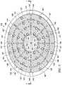
- FIG. 2is a schematic top-view of an example of the dressing 102 , illustrating additional details that may be associated with some embodiments.
- a layer comprising or consisting essentially of a manifold 128may be divided into a central region 140 and a perimeter region 141 .
- the perimeter region 141may contain a plurality of perforations 144 arranged in a pattern so as to define a plurality of sub-regions of the perimeter region. Some of the plurality of perforations 144 , such as the innermost of perforations 144 , may also serve as a dividing edge between the central region 140 and the perimeter region 141 .
- the central region 140is pictured as containing no perforations or fenestrations therethrough.
- the central region 140 of the manifold 128may include perforations or fenestrations relating to provision of a negative-pressure source or provision of a fluid instillation source, typically a manifold need not have a plurality of perforations or fenestrations therethrough, particularly the central region 140 of the manifold 128 in FIG. 2 .
- the perforations 144 in the perimeter region 141 of the manifold 128may facilitate sizing or shaping of the manifold 128 and the dressing 102 in some embodiments, and may also serve a secondary function of assisting in provision or removal of fluid.
- FIG. 2illustrates an example pattern of perforations 144 that may be associated with some embodiments of the dressing 102 .
- a plurality of the perforations 144demarcate a division between the central region 140 of the manifold 128 and the perimeter region 141 .
- the plurality of perforations 144can also be seen to define a plurality of border sub-regions 146 within the perimeter region 141 .
- the perimeter region 141may include a second plurality of perforations 147 , as illustrated in the example of FIG. 2 .
- each of these additional perforations 147contains a weld or bond therethrough, thereby coupling together a layer above the manifold 128 and a layer below the manifold 128 .
- a portion of the second plurality of perforations 147may include perforations 148 containing captivating welds therethrough, which perforations 148 represent the innermost of the second plurality of perforations 147 within the perimeter region 141 , closest to the central region 140 .
- a further coupling of the layer above the manifold 128 and the layer below the manifold 128 in FIG. 2is shown as a sealing portion 121 located near the outer edge of the manifold 128 .
- the perimeter region 141may be concentric with the central region 140 .
- the perimeter region 141may have a central point, such as a center of mass, that is located within the central region 140 .
- a perimeter regionsurrounds an inner region in all directions outward, for example from a center point or from any point located within the inner region. In other words, there can be a 360-degree continuity between the central region 140 and the perimeter region 141 .
- FIG. 2shows the manifold 128 to be an elliptical cylinder and the central region 140 to be a smaller central elliptical cylinder.
- the perimeter region 141which is illustrated as an elliptical hollow cylinder, completely surrounds the central region 140 in the top-view of FIG. 2 . While this example may seem to indicate a concentric symmetry with respect to the breadth of the perimeter region 141 of the manifold 128 , that need not necessarily be the case, so long as the perimeter region 141 exhibits some portion completely surrounding the central region 140 .
- Welds or bonds through the perforations 147 , through the perforations 148 , or to the manifold 128 , such as in the perimeter region 141can function to hold the dressing 102 together, while still allowing the dressing 102 to be manually sized.
- the central region 140may be retained in place by captivating welds through perforations 148 , and in some examples, captivating welds may define a boundary between the central region 140 and the perimeter region 141 .
- the arrangement of the plurality of perforations 147 and perforations 148 throughout the perimeter region 141may advantageously be dispersed to allow one or more border sub-regions 146 to be removed without significantly compromising the coupling of the tri-layer assembly.
- perforations 147 and perforations 148 through which welds or bonds exist to couple the layers above and below the manifold 128are arranged in each quadrant corresponding to the division of the perimeter region 141 into border sub-regions 146 by the perforations 144 .
- these weld pointsare exemplified in FIG. 2 to be as few as one weld-through perforation 147 or captivating weld perforation 148 per border sub-region 146 , it should be understood that the pattern of welded-through perforations 147 and captivating weld perforations 148 in the perimeter region 141 could be any that provide adequate physical coupling of the tri-layer assembly.
- the plurality of perforations 144may provide visual indicia for guiding an external user to more easily customize the manifold 128 or the dressing 102 to fit a given tissue site, the external user need not make use of that guide nor necessarily seek to make manual sizing easier.
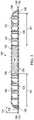
- FIG. 3shows a cross-section of the dressing 102 of FIG. 2 , as viewed along the line between the arrows labelled “ 3 ” at either end of FIG. 2 .
- FIG. 3illustrates the layer below the manifold 128 as a first liquid-impermeable layer 118 and the layer above the manifold 128 as a second liquid-impermeable layer 120 , although the dressing 102 may be formed having a plurality of liquid-impermeable layers.
- the first liquid-impermeable layer 118may be formed to have fenestrations 122
- the second liquid-impermeable layer 120may be formed to have fenestrations 124 .
- Liquid-impermeablewith respect to “liquid-impermeable layers” means that the layers are formed with a liquid-impermeable material. Thus, although formed with a liquid-impermeable material, the layer may be liquid-permeable when fenestrated, but nonetheless is referred to as a liquid-impermeable layer.
- the fenestrations 122 and 124may take many shapes or combinations of shapes, including circular apertures, elliptical apertures, rectangular openings, or polygons, for example.
- the fenestrations 122 and 124are presented in this illustrative embodiment as slits, or linear cuts.
- first liquid-impermeable layer 118 and the second liquid-impermeable layer 120may be sealingly coupled to one another along a sealing portion 121 , as shown in FIG. 3 .
- the couplingmay be accomplished in any suitable manner, for example, without limitation, through chemical means or physical means or both, such as by welding, bonding, adhesives, cements, or other bonding mechanisms.
- the first liquid-impermeable layer 118may be adapted to be positioned between the second liquid-impermeable layer 120 and at least a portion of a tissue site.
- a chamber 125is formed between the first liquid-impermeable layer 118 and the second liquid-impermeable layer 120 .
- the first liquid-impermeable layer 118 and the second liquid-impermeable layer 120may each comprise or consist essentially of a non-adherent material, such as a medical drape, capable of inhibiting tissue from adhering to the non-adherent material.
- the first liquid-impermeable layer 118 and the second liquid-impermeable layer 120may comprise a breathable polyurethane film.
- the chamber 125 between the first liquid-impermeable layer 118 and the second liquid-impermeable layer 120can contain a third layer comprising or consisting essentially of the manifold 128 .
- the manifold 128may be monolithic. In some embodiments, the manifold 128 does not comprise, and the chamber 125 does not contain, any manifolding elements extending outward from an outer edge of the perimeter region 141 , for example radially. In some embodiments, the sealing portion 121 of the first liquid-impermeable layer 118 and second liquid-impermeable layer 120 may be releasably coupled together, for example using an adherent substance such as a low-tack or pressure-sensitive adhesive disposed therebetween.
- a low-tack adhesivecan also be applied between the manifold 128 and one or more of the first liquid-impermeable layer 118 and the second liquid-impermeable layer to further support the structural integrity of the dressing 102 .
- the adhesivemay also contain an antimicrobial compound in some examples.
- the manifold 128 or the third layer comprising the manifold 128may comprise an absorbent material adapted to absorb fluid and adapted to reduce, inhibit, or eliminate in vivo granulation.
- the absorbent materialmay comprise a cross-linked hydrogel, such as a hydrophilic poly(vinyl alcohol), which can inhibit granulation in-growth and function as a fluid storage medium in some embodiments.
- the absorbent materialmay be present within or on one or more surfaces of the layer comprising manifolding member.
- the dressing 102may be sized to fit a given tissue site and disposed at or within the tissue site.
- the dressing 102may be sized to fit a compartment space such as an abdominal cavity. Excess portions of the dressing 102 or of the treatment device 101 may be removed to appropriately size the dressing 102 or the treatment device 101 . In some embodiments, removal can occur by decoupling the sealing portion 121 of the first liquid-impermeable layer 118 and the second liquid-impermeable layer 120 and cutting or tearing the manifold 128 along some of the perforations 144 to remove one or more of the border sub-regions 146 of the perimeter region 141 .
- removalcan occur by cutting or tearing the first liquid-impermeable layer 118 , the second liquid-impermeable layer 120 , and the manifold 128 altogether, optionally using some of the perforations 144 of the manifold 128 as a guide or optionally not using any visual indicia on the dressing 102 .
- the surfaces of the dressing 102may have any suitable shape, examples of which include, but are not limited to, triangles, squares, rhombuses, rhomboids, diamonds, rectangles, trapezoids, ellipses, ellipsoids, circles, semi-circles, pie-wedges, ovals, and various polygons having four, five, six, seven, eight, or more sides. These shapes may additionally or alternatively be adaptations of such common shapes. In some embodiments, shapes with typically rounded edges may be altered to be flatter, such as a rounded hexagonal/octagonal shape made by flattening the rounded edges of a circle.
- shapes with typically rounded edgesmay be altered to be sharper, such as a tear-drop shape made by sharpening a rounded end of an ellipse or ellipsoid, or such as an eye shape made by sharpening two rounded, opposing ends of an ellipse or ellipsoid.
- shapes with typically pointed edgesmay be altered to be more rounded, such as for a blunt-ended triangle.
- shapes with typically flat edgesmay be altered to be more rounded, such as by converting the flat sides of any regular polygon to a sinusoidal edge exhibiting an undulating, curvy edge.
- the shapes of the surfaces of the dressing 102may be limited, for example so as to ensure that no manifolding elements in the third layer comprising the manifold 128 extend outward from the outer edge of the perimeter region 141 .
- the shapes of the surfaces of the dressing 102may be limited, for example such that the collective volume occupied by the plurality of fenestrations 144 , the plurality of perforations 147 , and the captivating weld perforations 148 are less than 50% of the volume of the perimeter region 141 of the manifold 128 ; in particular embodiments, the collective volume occupied by the plurality of fenestrations 144 , the plurality of perforations 147 , and the captivating weld perforations 148 are less than 35%, such as less than 25% or less than 20%, of the volume of the perimeter region 141 of the manifold 128 .
- none of the individual volumes of each fenestration 144 , each perforation 147 , and each perforation 148exceed 5% of the volume of the perimeter region 141 of the manifold 128 ; in particular embodiments, none of the individual volumes of each fenestration 144 , each perforation 147 , and each perforation 148 exceed 3%, or 2%, of the volume of the perimeter region 141 of the manifold 128 .
- the perimeter region 141 of the manifold 128is distinct from manifolding structures described in U.S. patent application Ser. No. 13/043,987, filed on Mar. 9, 2011, for example FIG. 2 , as well as from any U.S.
- the size, shape, area, and volume of the surfaces of the dressing 102may be customized to the location and type of tissue site which the therapy system 100 is to be used to treat.
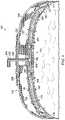
- FIG. 4is a schematic diagram illustrating additional details that may be associated with some embodiments of the treatment device 101 , for example incorporating the dressing 102 from FIGS. 2-3 .
- the treatment device 101 of FIG. 4is applied to a tissue site 112 .
- the tissue site 112may include tissue in a body cavity, such as an abdominal cavity.
- the tissue site 112may include abdominal contents or tissue that is proximate the abdominal cavity.
- Treatment of the tissue site 112may include removal of fluids, e.g., ascites, protection of the abdominal cavity, or negative-pressure therapy.
- the dressing 102may be disposed near or within a tissue site 112 , which may be a compartmented site such as a peritoneal or an abdominal cavity, in order to treat the tissue site 112 .
- tissue site 112may be a compartmented site such as a peritoneal or an abdominal cavity, in order to treat the tissue site 112 .
- the dressing 102may be supported by the abdominal contents, which can be generalized to most compartmented tissue sites.
- a first portion of the dressing 102may be positioned in or proximate to a first paracolic gutter 115
- a second portion of the dressing 102may be placed in or proximate to a second paracolic gutter 117 .
- the first paracolic gutter 115 and the second paracolic gutter 117may each be, for example, an open space on opposing sides of the abdominal cavity among the abdominal contents.
- the first paracolic gutter 115may be laterally disposed from the second paracolic gutter 117 or otherwise located on an opposite side of the tissue site 112 from the second paracolic gutter 117 .
- FIG. 4depicts the treatment device 101 deployed at an abdominal cavity, the treatment device 101 and therapy system 100 may be used at other types of tissue sites, particularly in which tissue contacts the treatment device 101 , or more particularly the dressing 102 , on both a first surface 126 and a second surface 127 , shown in FIG. 3 .
- Non-limiting examples of such tissue sitescan include compartmented wounds, overhang wounds, tunnel wounds, flaps, or the like.
- the treatment device 101may further include a cover 228 for providing a fluid seal over a tissue site 112 , such as an abdominal cavity.
- the cover 228may generally be configured to provide a barrier to microbes, a barrier to external contamination, and protection from physical trauma.
- the cover 228may be constructed from a material that can reduce evaporative losses and provide a fluid seal between two components or two environments, such as between a therapeutic environment and a local external environment.
- the cover 228may be formed from a suitable material, such as a polymer, for example, which may comprise or be an elastomeric film or membrane that can provide a seal at a tissue site.
- the covercan provide a seal adequate to maintain negative pressure at a tissue site for a given negative-pressure source 106 .
- the cover 228may comprise or be a polyurethane.
- the cover 228may have a high moisture-vapor transmission rate (MVTR).
- MVTRmoisture-vapor transmission rate
- the cover 228may comprise a polymer drape, such as a polyurethane film, that may be permeable to water vapor but generally impermeable to liquid water.
- the film or drapemay have a thickness in the range of about from about 15 to about 50 microns.
- the permeabilitygenerally should be low enough that a desired negative pressure may be maintained.
- An attachment devicesuch as attachment device 232 may be used to attach the cover 228 to an attachment surface of a tissue site 112 , such as the epidermis 230 of a patient.
- the attachment device 232may be used to attach the cover 228 to a gasket, or another sealing member or cover.
- the attachment device 232may take any of a variety of suitable forms.
- an attachment devicemay be a medically-acceptable, pressure-sensitive adhesive that extends about a periphery, a portion, or an entire sealing member or cover.
- some or all of the cover 228may be coated with an adherent layer, such as comprising an acrylic adhesive, having a coating weight between 25 and 65 grams per square meter (g.s.m.). Thicker adhesives, or combinations of adhesives, may be applied in some embodiments to improve the seal and reduce leaks.
- Other example embodiments of an attachment devicemay include a double-sided tape, paste, hydrocolloid, hydrogel, silicone gel, or organogel.
- the illustrative systems and devices hereinmay optionally allow for the irrigation and washing out of a tissue site 112 , for example a compartmented site such as a peritoneal or an abdominal cavity, with the controlled and regulated introduction of fluid.
- a tissue site 112for example a compartmented site such as a peritoneal or an abdominal cavity
- the therapy system 100can provide means to instill fluid into an open abdomen to cleanse the abdominal contents, including reaching areas such as the small bowel loops, pancreas, etc.
- the treatment device 101 and the therapy system 100may provide temporary closure to an open abdomen, while optionally allowing for removal of fluid and reduction of edema.
- the therapy system 100may provide the capability of performing washouts of a tissue site, such as a peritoneal or abdominal cavity, without having to repeatedly remove one or more dressings applied to the tissue site of a patient or bringing the patient into the operating room for manual fluid introduction procedures.
- the therapy system 100may thus be able to provide a controlled and regulated full abdominal wash, for example via instillation of a therapeutic fluid, as well as have the capability to provide a targeted wash to certain areas within the abdomen when required.
- Some embodiments of the therapy system 100 , and more particularly the dressing 102may also provide support and maintenance of the fascial domain of an abdominal cavity, for example, and provide overall protection to the abdominal contents.
- the therapy system 100may also include an interface for fluidly connecting the dressing 102 and other portions of the treatment device 101 to a conduit 234 , as shown in FIG. 4 .
- the interfacemay include a connector, which may comprise or be a part of a negative-pressure connector subsystem.
- the interfacemay be partially or fully embedded within a portion of the dressing 102 , or configured in any other way possible for fluidly connecting the treatment device 101 to a therapy unit, such as the therapy unit 104 of FIG. 1 .
- the conduit 234may be fluidly coupled to negative-pressure source 106 and/or fluid source 108 of the therapy unit 104 for providing negative pressure and/or treatment fluid, respectively, to the treatment device 101 .
- the conduit 234may include two substantially parallel, fluidly-isolated conduits, one of which for fluidly coupling the treatment device 101 to the negative-pressure source 106 and the other for fluidly coupling the treatment device 101 to the fluid source 108 .
- the conduit 234may be a multi-lumen conduit with both a negative-pressure lumen 235 and a fluid withdrawal lumen 237 .
- the conduit 234may be replaced with two separate conduits, one containing a negative-pressure lumen and the other containing a fluid withdrawal lumen.
- fluid withdrawal lumen 237can be temporarily or intermittently repurposed to provide instillation fluid, instead of withdrawing fluid, in which situations fluid withdrawal lumen 237 can alternatively be referred to as a fluid supply lumen.
- the conduit 234may be a multi-lumen conduit with a negative-pressure lumen 235 , a fluid withdrawal lumen 237 in fluid communication with container 110 , and a separate fluid supply lumen (not pictured in FIG. 4 ) in fluid communication with fluid source 108 , which may be separate from container 110 .
- the negative-pressure, fluid withdrawal, and fluid supply lumensmay be together within the same conduit 234 or may be in three separate conduits or in two separate conduits, for example with the fluid supply lumen in one conduit and the negative-pressure lumen 235 and the fluid withdrawal lumen 237 together in the other conduit.
- the therapy system 100may further include a filler material 240 , such as a portion of foam, disposed between the second liquid-impermeable layer 120 and the cover 228 .
- the filler material 240may be part of the interface and may be sized to fill the portion of abdominal volume beneath or surrounding an incision or opening into abdomen from the skin layers, such as a portion of abdominal cavity.
- the filler material 240may contain within it, or may itself serve as, a distribution manifold for negative pressure.
- the filler material 240may be positioned between the second liquid-impermeable layer 120 and the cover 228 , and a negative pressure lumen or conduit, such as negative-pressure lumen 235 , may be pneumatically connected to the cover 228 .
- a negative pressure lumen or conduitsuch as negative-pressure lumen 235
- fluid removalmay occur from the layers of the treatment device 101 through the filler material 240 positioned atop second liquid-impermeable layer 120 , and into the negative-pressure lumen 235 .
- the filler materialmay include a three-dimensional woven or non-woven fabric, such as TDL2 or TL4, commercially available from Libeltex of Meulebeke, Belgium, or 3DXD or 4DXD spacer fabrics, commercially available from Baltex of Derbyshire, England, or an open-cell, reticulated polyurethane foam such as GRANUFOAMTM Dressing or VERAFLOWTM Therapy foam, both available from KCI Licensing, Inc. of San Antonio, Tex.
- a three-dimensional woven or non-woven fabricsuch as TDL2 or TL4, commercially available from Libeltex of Meulebeke, Belgium, or 3DXD or 4DXD spacer fabrics, commercially available from Baltex of Derbyshire, England, or an open-cell, reticulated polyurethane foam such as GRANUFOAMTM Dressing or VERAFLOWTM Therapy foam, both available from KCI Licensing, Inc. of San Antonio, Tex.
- a therapy method including fluid instillationcan occur by periodically stopping application of negative pressure through the fluid withdrawal lumen 237 and initiating liquid supply through the same lumen, which can then alternatively be termed a fluid supply lumen.
- the negative-pressure lumen 235may or may not experience an immediate halt in negative pressure application in such fluid instillation embodiments.
- the manifold 128can function both as fluid removal assembly and the optional fluid installation matrix, thereby enabling instillation fluid to be provided to the chamber 125 , through the fenestrations 122 in the first liquid-impermeable layer 118 and through the fenestrations 124 in the second liquid-impermeable layer 120 , and ultimately to the tissue site 112 .
- the manifold 128 within the chamber 125 formed between the first liquid-impermeable layer 118 and the second liquid-impermeable layer 120may function a fluid removal assembly for communicating negative pressure and removing fluids such as exudates from the tissue site 112 , and optionally also an instillation matrix for delivering instillation fluid to the tissue site 112 .
- a plurality of fluid removal pathways 250may extend inward through the fenestrations 122 , through the fenestrations 124 , through the manifold 128 , and into fluid removal tubes positioned in the central region 140 of the manifold 128 and which are fluidly connected to the fluid withdrawal lumen 237 .
- the plurality of fluid removal pathways 250may be fluidly coupled to a fluid removal hub 252 , which is optional but depicted in FIG. 4 .
- the optional fluid removal hub 252may serve as a distribution mechanism for communicating negative pressure to each of the fluid removal pathways 250 from the interface and the negative-pressure source 106 .
- the fluid removal pathways 250may take the form of numerous different shapes or be formed from a variety of materials.
- the fluid removal pathways 250may be formed from portions of the first liquid-impermeable layer 118 and the second liquid-impermeable layer 120 that have been coupled together by a plurality of welds or bonds to form channels.
- Multi-lumen tubesmay additionally or alternatively be a portion of the fluid removal pathways 250 .
- Each of the different forms and configurations of fluid removal pathways 250may also apply to fluid delivery tubes or to an instillation matrix, as applicable, especially in embodiments in which instillation fluid and negative pressure are not alternated using similar pathways but in reverse directions.
- the optional fluid instillation systemcan be integral with but separate from the application of negative pressure for fluid collection.
- negative pressurecan be applied at the same time as fluid is instilled, meaning that fluid withdrawal pathways and fluid supply pathways may need to be separated.
- negative pressurecan be applied to tissue site 112 by negative pressure source 106 through fluid removal pathways in the fluid removal assembly 148 in chamber 125 and through fluid withdrawal lumen 237 into container 110 .
- Fluid or medicamentcan simultaneously be provided by fluid source 108 through fluid supply lumen 238 and through fluid supply pathways via a plurality of fluid delivery tubes 258 also in chamber 125 .
- treatment device 101may be adapted to simultaneously provide fluid or medicament with negative pressure, it is still contemplated that the therapy system 100 shown in FIG. 5 may be operated to alternate application of negative pressure and instillation of fluid, as desired.
- the fluid delivery tubes 258 and optional distribution hub 261may be considered components of an instillation matrix and may be constructed of a variety of different materials, such as soft medical-grade silicone or PVC tubing material.
- the plurality of fluid delivery tubes 258may vary in size, based on the particular size and application of the treatment device 101 , as well as the conditions of the tissue site 112 to which the treatment device 101 is to be applied.
- the fluid delivery tubes 258may have an inner diameter of between 0.5 mm and 4 mm.
- the fluid delivery tubes 258may have an inner diameter of between 1 mm and 2 mm.
- the rather small size of the fluid delivery tubes 258may be conducive for avoiding patient discomfort during therapy as well as ease of removal of the treatment device 101 following completion of therapy.
- the fluid removal tubesmay additionally function to communicate negative pressure and draw fluids through both the ends as well as along the lengths of the fluid removal tubes.
- some embodiments of the fluid removal tubes connected to fluid removal hub 252may include open ends as well as openings or apertures, such as removal pathway apertures, along the length of the fluid removal tubes.
- the fluid delivery tubes 258may only have open ends, such as delivery ends, and may otherwise be fluidly isolated from the surroundings along the length of the fluid delivery tubes 258 .
- the treatment device 101may be offered in a single size with the option to cut and remove portions of the treatment device 101 to reduce its size, thus potentially shortening the length of the fluid delivery tubes 258 , as required on an individual patient basis.
- each of the fluid delivery tubes 258may instead have closed ends, such as delivery tube closed ends, and thus may include openings or perforations, such as delivery tube perforations.
- the fluid delivery tubes 258may include both open ends as well as perforations along their lengths, should the particular need or application arise.
- the fluid delivery tubes 258may be adapted to deliver fluids across the tissue site 112 in a substantially uniform manner.
- each of the fluid delivery tubes 258 , the delivery ends, and the delivery tube perforationsmay be adapted to provide substantially the same back-pressure.
- back-pressuremay refer to an increase in localized pressure caused by a resistance to fluid flow, such as through the confined space of a lumen or aperture.
- Back-pressuremay result from the geometric configuration and material properties of the confined space, such as, without limitation, the size of the space, the presence and shape of bends or joints in the space, surface finishes within the space, and other characteristics.
- a fluid hubsuch as distribution hub 261 , may not be necessary if the perforations along the lengths of the fluid delivery tubes 258 are sized to provide a substantially even distribution of fluid throughout the tissue site 112 . Consistency among the size and configuration of the fluid delivery tubes 258 , and the number and size of the delivery ends and delivery tube perforations in each of the fluid delivery tubes 258 , for example, may enhance the uniformity of fluid delivery to the tissue site 112 .
- the fluid delivery tubes 258may have a cylindrical tube shape and may have an internal diameter between about 2 millimeters and about 6 millimeters. In some other embodiments, the fluid delivery tubes 258 may have an alternate tubing profile, where a lower-profile, or “flatter” tubing profile may be used to increase user comfort when the treatment device 101 is in place in a tissue site 112 .
- the delivery aperturesin some embodiments, may have a diameter between about 0.1 millimeters and about 0.8 millimeters. Sizing the internal diameter or cross-section of the fluid delivery tubes 258 substantially larger than the size, cross-section, or diameter of the delivery ends and the delivery tube perforations may provide a substantially uniform pressure within each of the fluid delivery tubes 258 . In such an embodiment, fluid flow velocity within the fluid delivery tubes 258 may be relatively low or substantially static in comparison to the relatively high fluid flow velocity through the delivery apertures.
- the fluid delivery tubes 258may be arranged in the form of a grid, for example extending outward from a central hub 261 , such as radially, with tubing segments that fluidly connect each of the outwardly-extending fluid delivery tubes 258 . Perforations may exist along any or all portions of the outwardly-extending fluid delivery tubes 258 , as well as the connecting tubing segments, in such embodiments.
- the treatment device 101may comprise a distribution material for assisting with distributing the instillation fluid, such as filler material 240 , as a complement to or an element of the distribution hub 261 .
- a distribution materialfor assisting with distributing the instillation fluid, such as filler material 240 , as a complement to or an element of the distribution hub 261 .
- the distribution hubis elongate, cylindrical in shape, or bell-shaped, or comprises a fitting, such as a tube, tubular fitting, pipe, barbed connection, or similar structure
- the distribution hub 261 or filler material 240may generally be configured to be fluidly coupled between the fluid supply lumen 238 of the conduit 234 and the fluid delivery tubes 258 .
- the treatment device 101may be adapted to provide negative pressure from the negative-pressure source 106 of the therapy unit 104 to a tissue site 112 , such as an abdominal cavity, and to collect and transport fluid extracted from the tissue site 112 . Additionally, the treatment device 101 may also be adapted to deliver a fluid, such as a treatment fluid or medicament, from the fluid source 108 of the therapy unit 104 to the tissue site 112 .
- the dressing 102may include multiple liquid-impermeable layers, or visceral protective layers, which protect the underlying abdominal contents of the tissue site 112 .
- the dressing 102may include a first liquid-impermeable layer 118 having fenestrations 122 and a second liquid-impermeable layer 120 having fenestrations 124 .
- the dressing 102may include a fourth liquid-impermeable layer 275 .
- the first liquid-impermeable layer 118 and the second liquid-impermeable layer 120may contain fenestrations only at the outer edges of the layer(s) or one of the layers may contain no fenestrations.
- the fourth liquid-impermeable layer 275may alternatively exhibit fenestrations only at the outer edges of the fourth liquid-impermeable layer 275 or no fenestrations at all, thereby partially or totally allowing for the instillation liquid to take a circuitous path out of the chamber 125 through fenestrations 122 , among the abdominal contents, around the dressing 102 , through fenestrations 124 back into the chamber 125 , and through the fluid removal pathways 250 in the third layer comprising the manifold 128 .
- the fourth liquid-impermeable layer 275may be disposed within chamber 125 between the first liquid-impermeable layer 118 and the second liquid-impermeable layer 120 , defining a first sub-chamber between the first liquid-impermeable layer 118 and the fourth liquid-impermeable layer 275 and a second sub-chamber between the second liquid-impermeable layer 120 and the fourth liquid-impermeable layer 275 . In that circumstance, both sub-chambers are considered part of chamber 125 .
- the fourth liquid-impermeable layermay be disposed outside chamber 125 , for example below first liquid-impermeable layer 118 .
- each of the liquid-impermeable layersmay be formed from a polyurethane material, each having a thickness of between 25 ⁇ m and 500 ⁇ m.
- the interfacemay provide both a negative-pressure connection as well as a fluid supply connection to the treatment device 101 .
- the interfacemay be sized, shaped, or otherwise adapted to fluidly connect a negative-pressure lumen 235 and a fluid withdrawal lumen 237 of the conduit 234 , as well as a separate fluid supply lumen 238 if desired, to the treatment device 101 in any suitable manner.
- the interfacemay fluidly couple the negative-pressure lumen 235 and the fluid supply lumen 238 through the cover 228 .
- one or more sealing member aperturesmay be disposed through the cover 228 to provide fluid communication and access to the components of the treatment device 101 positioned within a sealed space involving the tissue site 112 .
- the interfacemay be a multi-port interface providing both the negative-pressure connection and the fluid supply connection as individual, fluidly isolated ports within the multi-port interface, such as conduit 234 .
- a wall of one of the individual lumenssuch as the fluid withdrawal lumen 237 or the fluid supply lumen 238 , may be coupled to the filler material 240 or to the distribution hub 261 for fluidly isolating the fluid supply connection from the negative-pressure connection.
- Other configurations for maintaining the fluid isolation of the negative-pressure lumen 235 from the fluid supply lumenare possible.
- FIG. 5shows an exemplary embodiment in which fluid instillation pathways 265 emanating from distribution hub 261 through fluid instillation tubes 258 and are separate from fluid removal pathways 250 flowing into manifold 128 through fluid removal tubes and fluid removal hub 252 .
- the configuration of providing the instillation fluid and the associated back-pressure along the fluid instillation pathways 265 through fluid instillation tubes 258 and using the distribution hub 261may facilitate delivery of the instillation fluid to the tissue site 112 in a substantially uniform manner.
- the treatment device 101may be covered at the tissue site 112 with the cover 228 to provide a sealed space containing the treatment device 101 .
- the cover 228may be positioned and fluidly sealed about the tissue site 112 with the attachment device 232 , as described above. Apertures in the cover 228 may be cut or otherwise disposed through the cover 228 as necessary, if not already provided as part of the cover 228 .
- instillation fluidmay be independently fed from a fluid source, such as fluid source 108 , through the fluid supply lumen 238 and into the chamber 125 .
- a fluid sourcesuch as fluid source 108
- the instillation fluidmay be fed directly to a fluid hub, such as distribution hub 261 , and therefore, the fluid instillation pathways 265 and the fluid removal pathways 250 may be controlled as separate entities. In these embodiments, potential contamination of clean fluid instillation pathways may be reduced or largely eliminated, and a more efficient cleansing cycle may be obtained.
- the instillation fluidmay also be fed directly into a fluid hub and through fluid distribution pathways, but a single hub and a single set of pathways would function for both fluid instillation and fluid removal.
- fluid removal pathways 250 in FIG. 4 woundfunction in the arrow directions to assist fluid removal under negative-pressure conditions and opposite from the arrow directions to assist fluid instillation under conditions for flowing fluid to tissue site 112 .
- fluidmay be fed through the fluid instillation tubes 258 directly into low points of an abdomen, such as the paracolic gutters 115 , 117 .
- Activating the negative-pressure source 106may provide negative pressure to the negative-pressure lumen 235 of the conduit 234 and to the manifold 128 through the fluid withdrawal lumen 237 .
- the fluid source 108may provide instillation fluid to the chamber 125 through the fluid supply lumen 238 (or through repurposed fluid removal lumen 237 , such as in FIG. 4 ), for example, by activing a pump or positive-pressure source in the fluid source 108 , or by operation of gravitational or manual user forces acting on the instillation fluid.
- Negative pressure and instillation fluidmay be provided to the treatment device 101 simultaneously, or cyclically, at alternate times. Further, negative pressure and instillation fluid may be applied to the treatment device 101 intermittently or continuously.
- the fluid removal lumen 237 of the conduit 234may distribute the negative pressure to the manifold 128 or optionally to the fluid removal hub 252 in fluid communication therewith. Fluid from the tissue site 112 may be drawn or extracted through the open ends and removal pathway apertures into the fluid removal pathways 250 . Fluid may be moved through the fluid removal pathways 250 and optionally into fluid removal hub 252 , where the fluid may be drawn into the fluid withdrawal lumen 237 of the conduit 234 and ultimately the container 110 .
- some portion of fluid extracted from the tissue site 112may be stored within the manifold 128 of the treatment device 101 before being drawn into the fluid withdrawal lumen 237 .
- the capability to provide fluid storage and permeability while under negative pressuremay require the manifold 128 or other porous portion of the third layer disposed between the first liquid-impermeable layer 118 and the second liquid-impermeable layer 120 to have a higher volume of fluid capacity compared to that of the fluid delivery tubes 258 that may be under positive pressure. Fluid being instilled or delivered to the tissue site 112 , for example through fluid delivery tubes 258 , may not be required to first pass through portions of the treatment device 101 , such as the manifold 128 , that may encompass a larger volume.
- Such a configurationis shown in FIG. 5 and may enhance the distribution and efficient use of the instillation fluid.
- a usermay remove the treatment device 101 as a largely intact structure, thus maintaining an ease of use of the treatment device 101 .
- the fluid delivery tubes 258may comprise polyurethane film or foam bags with perforations.
- the fluid delivery tubes 258may be constructed using two layers of polyurethane film of approximately 100 micrometers in thickness that are edge-welded together.
- the fluid delivery tubes 258may have open ends for targeted fluid delivery.
- within each of the fluid delivery tubes 258 and the optional fluid removal hub 252may be a central core adapted to ensure that an open pathway is maintained and to aid a user with handling during placement.
- this central coremay be an open-cell foam, such as a reticulated polyurethane.
- the central core material positioned within the fluid delivery tubes 258may vary; for example, the central core material may range from around 2 mm to 10 mm in thickness by about 5 mm to 15 mm in width. In some embodiments, the central core material may be around 6 mm in thickness by 10 mm in width.
- the length of the central core materialmay be varied based on overall sizing considerations of the treatment device 101 . Some embodiments may include a central core material having a width that varies along its length, which may allow for break points to provide user customization and sizing.
- the fluid delivery tubes 258may be adapted so that any instillation fluid remaining within the fluid delivery tubes 258 following delivery of instillation fluid by the fluid source 108 may be squeezed from the fluid delivery tubes 258 when negative pressure is applied to the treatment device 101 , thus ensuring that substantially all instillation fluid is emptied from the fluid delivery tubes 258 to better regulate the volume of instillation fluid provided during therapy cycles.
- fluid instillationmay optionally incorporate a layer of manifolding material or matrix, which may be referred to as an optional instillation matrix.
- the manifold 128may serve that purpose, when not being used for fluid removal.
- the optional instillation matrixcould surround the fluid delivery tubes 258 and be oriented between the fourth liquid-impermeable layer 275 and the first liquid-impermeable layer 118 . If present, the optional instillation matrix could help ensure that the fluid instillation pathway remains open and not occluded or sealed when subjected to negative pressure.
- Example materials for the optional instillation matrixmay be similar to those for the manifold 128 and may include foams, such as polyurethane foam, Libeltex TDL2, Libeltex TL4, Baltex 3DXD spacer fabrics, Baltex 4DXD spacer fabrics, embossed films, or some other formed structure.
- foamssuch as polyurethane foam, Libeltex TDL2, Libeltex TL4, Baltex 3DXD spacer fabrics, Baltex 4DXD spacer fabrics, embossed films, or some other formed structure.
- a manually-controlled instillation vesselsuch as a fluid bag, bottle, or other vessel
- a negative-pressure sourcemay apply negative-pressure therapy to a treatment device and tissue site
- a devicesuch as a clamp, valve, or other form of closure device may prevent fluid from being communicated from the manually-controlled instillation vessel to the treatment device and tissue site.
- a usermay open the clamp or other form of closure device and may manually regulate the volume of fluid being instilled.
- the negative-pressure sourcemay remain active, thus providing immediate removal of the instilled fluid from the treatment device and tissue site. Thus, there may be virtually no dwell time of the fluid in the tissue site, according to some embodiments of the method.
- the usermay then re-clamp or otherwise close the closure device, thus stopping the flow of instillation fluid from the manually-controlled instillation vessel.
- the negative-pressure sourcemay then continue to remove excess or remaining instillation fluid, as well as exudates, from the treatment device and tissue site.
- the negative-pressure sourcemay be paused, thus allowing the instillation fluid to dwell in the tissue site for a prescribed period of time.
- the usermay close off the manually-controlled instillation vessel from delivering instillation fluid.
- negative-pressure therapymay be recommenced, during which time any excess or remaining fluids may be removed from the treatment device and tissue site.
- the negative-pressure sourcemay remain active, while instillation fluid may be periodically provided in various stages.
- some embodiments of the treatment device 101may provide a combined temporary abdominal closure dressing system with fluid instillation capability through an independent matrix of fluid delivery tubing, as well as negative-pressure fluid removal pathways for removal of contaminated fluid.
- Some embodimentsmay provide means for irrigating and cleansing an abdominal cavity while supporting and protecting the abdominal contents, as well as removing contaminated fluid and controlling and/or reducing edema. Additionally, as a result of the various layers and components of the dressing 102 applying tension and closing force to the abdominal contents, quicker primary fascia closure of the abdominal cavity may be facilitated.
- the therapy system 100may provide means for irrigating all areas of an abdominal cavity, including small bowel loops, gutters, retroperitoneal space, portions of the lymphatic system, etc., all while the dressing system is in place, advantageously reducing time required for patients and clinical staff in the operating room.
- Various embodimentscan offer configurations of fluid pathways designed to maximize the exposure of internal organs of abdominal tissue sites to fluid instillation therapy.
- instillationis additionally or alternatively possible, particularly in combination with the embodiments herein in which neither the fluid removal assembly layer containing a manifolding material nor the chamber in which it is disposed contain any manifolding elements extending outward from an outer edge of the perimeter region—some non-limiting examples of instillation arrangements that may be useful include those disclosed in U.S. Provisional Application No. 62/451,284, filed on Jan. 27, 2017, the contents of which are hereby incorporated by reference. Some embodiments may also allow for longer dressing application times without adhering to the fascia of abdominal tissue sites. In some embodiments, repeatable as well as reliable fluid instillation that may be provided relatively evenly to various portions of a tissue site.
- fluid irrigation and cleansingmay be relatively consistent, advantageously leading to a reduction in mortality of patients suffering from septic abdominal cavities.
- Fluid instillationmay be managed at a patient's bedside and may be custom-tailored and adjusted on a case-by-case basis.
- the therapy system 100may enable exudate and infectious material to be drained from tissue sites, such as the abdominal cavity, which can reduce the presence of contaminated abdominal fluids to promote healing. Furthermore, the therapy system 100 may provide separate instillation and negative-pressure pathways to ensure that contaminated fluid is fully removed from the tissue site 112 . In some embodiments of the therapy system 100 , instillation fluid may not be recirculated back into the tissue site, which can increase the clinical benefits of irrigating tissue sites.
- the design of the therapy system 100 or specific portions thereofmay also allow for user sizing and/or customization at the time of application to a patient in the operating room.
- improved ease of use for dressing placement, sizing, and removalmay be provided by built-in sizing or placement visual markings or indicators for guiding users.
- Some embodiments of the disclosed dressing systemsmay also include various components, such as the fluid instillation pathways and/or fluid removal pathways already pre-attached to the structural dressing layers to further streamline and simplify use. In some embodiments, not only may improved fluid delivery and removal be enabled, as compared to existing dressing systems, but increased ease of use may be promoted.
- the therapy system 100may optionally comprise one or more additional materials.
- additional materialsmay include, for example, active materials such as preservatives, stabilizing agents, plasticizers, matrix strengthening materials, dyestuffs, and combinations thereof.
- the therapy system 100may comprise one or more additional active materials, for example, antimicrobial agents that may be effective to aid in wound healing.
- active materialsmay include non-steroidal anti-inflammatory drugs such as acetaminophen, steroids, antimicrobial agents such as penicillins or streptomycins, antiseptics such as chlorhexidine, growth factors such as fibroblast growth factor or platelet derived growth factor, and other well-known therapeutic agents, alone or in combination. If present, such active materials may typically be included at any effective level that show therapeutic efficacy, while preferably not being at such a high level as to significantly counteract any critical or desired physical, chemical, or biological property of the wound dressing.
- the active material(s)may be loaded at a level of from about 10 wppm to about 10 wt % of the layer(s) in which it(they) are present, for example, from about 50 wppm to about 5 wt % or from about 100 wppm to about 1 wt %.
- the antimicrobial agentsmay comprise a safe and effective amount of poly(hexamethylene biguanide) (“PHMB”), which is also known as polyaminopropyl biguanid (“PAPB”) and polyhexanide, having the following general formula.
- PHMBpoly(hexamethylene biguanide)
- PAPBpolyaminopropyl biguanid
- PHMBcan be a cationic broad spectrum antimicrobial agent.
- PHMBmay be synthesized by a variety of methods, including polycondensation of sodium dicyanamide and hexamethylenediamine.
- PHMBis commercially available from a variety of sources.
- the PHMBmay be present in one or more of the dressing layers at a level of from about 0.005 wt % to about 0.025 wt % of each layer in which it is present, particularly from about 0.007 wt % to about 0.2 wt % or from about 0.008 wt % to about 0.012 wt %, or in some cases at about 0.01 wt %.
- the PHMBmay be present in one or more of the dressing layers at a level of from about 0.05 wt % to about 3 wt % of each layer in which it is present, particularly from about 0.1 wt % to about 2.5 wt %, from about 0.3 wt % to about 2 wt %, from about 0.5 wt % to about 1.5 wt %, or in some cases at about 1 wt %.
- silver compounds having antimicrobial efficacymay completely or partially replace the PHMB, as desired.
- silver compounds having antimicrobial efficacymay completely or partially replace the PHMB, as desired.
- the claimed subject mattermay include one or more of the following embodiments.
- Embodiment 1A dressing for treating a tissue site, the dressing comprising: a first layer being made from a liquid-impermeable material and being at least partially fenestrated; a second layer being made from a liquid-impermeable material and being at least partially fenestrated, the second layer coupled to the first layer to define a chamber between the first layer and the second layer; and a third layer disposed within the chamber, the third layer comprising a manifold having a central region and a perimeter region, the perimeter region containing perforations arranged in a pattern that defines a plurality of sub-regions of the perimeter region, wherein the first layer and the second layer are coupled together by a plurality of welds or bonds through the perimeter region of the third layer comprising the manifold.
- Embodiment 2The dressing of embodiment 1, wherein the chamber further comprises a plurality of fluid removal pathways, substantially all of which flow through the manifold.
- Embodiment 3The dressing of embodiment 1 or embodiment 2, wherein the manifold is monolithic and wherein the plurality of welds or bends extends through at least some of the perforations in the perimeter region.
- Embodiment 4The dressing of any of embodiments 1-3, wherein each of the plurality of sub-regions from the perimeter region is configured to be manually removable by a user.
- Embodiment 5The dressing of any of embodiments 1-4, wherein the first layer and the second layer are releasably coupled together near their outer edges.
- Embodiment 6The dressing of any of embodiments 1-5, wherein the first layer and the second layer are coupled together by a plurality of bonds to the perimeter region of the third layer comprising the manifold.
- Embodiment 7The dressing of embodiment 6, the coupling further comprising a low-tack adhesive bonding the first layer to the second layer.
- Embodiment 8The dressing of any of embodiments 1-7, wherein the third layer does not comprise, and the chamber does not contain, any manifolding leg elements extending outward from an outer edge of the perimeter region.
- Embodiment 9The dressing of any of embodiments 1-8, wherein the chamber comprises an effective amount of one or more of an antiseptic and an antimicrobial agent.
- Embodiment 10The dressing of any of embodiments 1-9, wherein the third layer further comprises an absorbent material, such as a cross-linked hydrogel, adapted to reduce, inhibit, or eliminate granulation in vivo and adapted to absorb fluid.
- an absorbent materialsuch as a cross-linked hydrogel
- Embodiment 11The dressing of any of embodiments 1-10, wherein the first layer and the second layer each comprise a polyurethane film, wherein the first layer and the second layer each have a thickness of between 25 ⁇ m and 500 ⁇ m, or both.
- Embodiment 12The dressing of any one of embodiments 1-11, further comprising: a filler member disposed above the central region of the manifold; and a cover disposed above the filler member and configured to form a seal with a tissue site.
- Embodiment 13The dressing of embodiment 12, wherein the cover comprises a polyurethane drape and an adherent layer adapted to sealably couple the polyurethane drape to the tissue site.
- Embodiment 14A dressing for treating a tissue site, the dressing comprising: a first layer being made from a liquid-impermeable material and being at least partially fenestrated; a second layer being made from a liquid-impermeable material and being at least partially fenestrated, the second layer coupled to the first layer to define a chamber between the first layer and the second layer; and a third layer disposed within the chamber, the third layer comprising a manifold having a central region and a perimeter region, the perimeter region containing perforations arranged in a pattern that defines a plurality of sub-regions of the perimeter region, wherein the manifold does not comprise, and the chamber does not contain, any manifolding elements extending outward from an outer edge of the perimeter region, and wherein the first layer and the second layer are coupled together by a plurality of welds or bonds through the perimeter region of the third layer comprising the manifold.
- Embodiment 15A system for treating a tissue site with negative pressure, the system comprising: a dressing according to any of embodiments 1-14; and a negative-pressure source fluidly coupled to a plurality of fluid removal pathways via the manifold layer.
- Embodiment 16The system of embodiment 15, further comprising: a negative-pressure conduit; a negative-pressure connector subsystem for fluidly coupling the negative-pressure source to the plurality of fluid removal pathways via the manifold layer; and optionally a container fluidly coupled to the negative-pressure source and the dressing and adapted to collect fluid.
- Embodiment 17The system of any of embodiments 15-16, further comprising: a fluid source coupled to and in fluid communication with the dressing; and a plurality of fluid delivery pathways formed within the chamber and configured to be in fluid communication with the fluid source, wherein the fluid delivery pathways are also in fluid communication with the fluid removal pathways via the manifold.
- Embodiment 18The system of embodiment 17, wherein the plurality of fluid delivery pathways comprise openings at peripheral ends or perforations along a length of each fluid delivery pathway, are disposed between the third layer and the first layer, or both.
- Embodiment 19The system of embodiment 18, wherein the plurality of fluid delivery pathways are disposed on the first layer outside, but in fluid communication with, the chamber.
- Embodiment 20The system of embodiment 18 or embodiment 19, further comprising a fourth layer being made of a liquid-impermeable material and coupled to the first layer to provide a fluid delivery space, wherein the perforations along the length of the fluid delivery pathways are formed by apertures in the fourth layer or by apertures or fenestrations in the first layer.
- a fourth layerbeing made of a liquid-impermeable material and coupled to the first layer to provide a fluid delivery space, wherein the perforations along the length of the fluid delivery pathways are formed by apertures in the fourth layer or by apertures or fenestrations in the first layer.
- Embodiment 21The system of any of embodiments 17-20, further comprising a centrally-positioned hub in fluid communication with the plurality of fluid delivery pathways.
- Embodiment 22The system of any of embodiments 17-21, further comprising a central manifold configured for fluid delivery and configured to be a part of the plurality of fluid removal pathways, which central manifold is within the filler member when the filler member is present.
- Embodiment 23The system of embodiment 22, wherein the filler member comprises a polyurethane foam or a three-dimensional textile form.
- Embodiment 24The system of any of embodiments 15-23, further comprising a sensor configured to sense relative changes in one or more variables, including pressure, temperature, pH, relative humidity, and location, near the tissue site.
- Embodiment 25The system of embodiment 24, wherein the sensor is configured to wirelessly provide information regarding the one or more variables to a person or to a pressure control system configured to control the negative-pressure source.
- Embodiment 26A method for treating a compartmented wound site, such as a peritoneal or abdominal cavity, the method comprising: opening the compartmented wound site to form an open cavity; deploying within the compartmented wound site the dressing of any of embodiments 1-14 or at least a portion of the system for treating a tissue site according to any of embodiments 15-25; deploying a negative-pressure connector subsystem; deploying a cover to form a fluid seal over the open cavity; fluidly coupling the negative-pressure connector subsystem to a negative-pressure source; and activating the negative-pressure source.
- any feature described in connection with any one embodimentmay also be applicable to any other embodiment.
- Componentsmay be also be combined or eliminated in various configurations for purposes of sale, manufacture, assembly, or use.
- the treatment device 101 including the dressing 102 , the container 110 , or bothmay be eliminated or separated from other components for manufacture or sale.
- the controller 109may additionally or alternatively be manufactured, configured, assembled, or sold independently of other components.
Landscapes
- Health & Medical Sciences (AREA)
- Heart & Thoracic Surgery (AREA)
- Engineering & Computer Science (AREA)
- General Health & Medical Sciences (AREA)
- Biomedical Technology (AREA)
- Life Sciences & Earth Sciences (AREA)
- Animal Behavior & Ethology (AREA)
- Vascular Medicine (AREA)
- Public Health (AREA)
- Veterinary Medicine (AREA)
- Anesthesiology (AREA)
- Hematology (AREA)
- Manufacturing & Machinery (AREA)
- Media Introduction/Drainage Providing Device (AREA)
Abstract
Description

PHMB can be a cationic broad spectrum antimicrobial agent. PHMB may be synthesized by a variety of methods, including polycondensation of sodium dicyanamide and hexamethylenediamine. PHMB is commercially available from a variety of sources. In some embodiments, the PHMB may be present in one or more of the dressing layers at a level of from about 0.005 wt % to about 0.025 wt % of each layer in which it is present, particularly from about 0.007 wt % to about 0.2 wt % or from about 0.008 wt % to about 0.012 wt %, or in some cases at about 0.01 wt %. In some embodiments, the PHMB may be present in one or more of the dressing layers at a level of from about 0.05 wt % to about 3 wt % of each layer in which it is present, particularly from about 0.1 wt % to about 2.5 wt %, from about 0.3 wt % to about 2 wt %, from about 0.5 wt % to about 1.5 wt %, or in some cases at about 1 wt %. In alternative embodiments, silver compounds having antimicrobial efficacy may completely or partially replace the PHMB, as desired. In alternative embodiments, silver compounds having antimicrobial efficacy may completely or partially replace the PHMB, as desired.
Claims (14)
Priority Applications (1)
| Application Number | Priority Date | Filing Date | Title |
|---|---|---|---|
| US16/632,651US11285048B2 (en) | 2017-08-02 | 2018-07-24 | Multi-layer compartment dressing and negative-pressure treatment method |
Applications Claiming Priority (3)
| Application Number | Priority Date | Filing Date | Title |
|---|---|---|---|
| US201762540404P | 2017-08-02 | 2017-08-02 | |
| US16/632,651US11285048B2 (en) | 2017-08-02 | 2018-07-24 | Multi-layer compartment dressing and negative-pressure treatment method |
| PCT/US2018/043444WO2019027731A1 (en) | 2017-08-02 | 2018-07-24 | Multi-layer compartment dressing and negative-pressure treatment method |
Publications (2)
| Publication Number | Publication Date |
|---|---|
| US20200170842A1 US20200170842A1 (en) | 2020-06-04 |
| US11285048B2true US11285048B2 (en) | 2022-03-29 |
Family
ID=63165488
Family Applications (1)
| Application Number | Title | Priority Date | Filing Date |
|---|---|---|---|
| US16/632,651Active2038-08-17US11285048B2 (en) | 2017-08-02 | 2018-07-24 | Multi-layer compartment dressing and negative-pressure treatment method |
Country Status (3)
| Country | Link |
|---|---|
| US (1) | US11285048B2 (en) |
| EP (1) | EP3661570B1 (en) |
| WO (1) | WO2019027731A1 (en) |
Families Citing this family (29)
| Publication number | Priority date | Publication date | Assignee | Title |
|---|---|---|---|---|
| GB0808376D0 (en) | 2008-05-08 | 2008-06-18 | Bristol Myers Squibb Co | Wound dressing |
| GB0817796D0 (en) | 2008-09-29 | 2008-11-05 | Convatec Inc | wound dressing |
| GB201020236D0 (en) | 2010-11-30 | 2011-01-12 | Convatec Technologies Inc | A composition for detecting biofilms on viable tissues |
| WO2012078724A1 (en) | 2010-12-08 | 2012-06-14 | Convatec Technologies Inc. | Apparatus and method for applying pressure to a wound site |
| US10207031B2 (en) | 2010-12-08 | 2019-02-19 | Convatec Technologies Inc. | Integrated system for assessing wound exudates |
| ES2748519T3 (en) | 2010-12-08 | 2020-03-17 | Convatec Technologies Inc | Wound exudate system accessory |
| GB201115182D0 (en) | 2011-09-02 | 2011-10-19 | Trio Healthcare Ltd | Skin contact material |
| GB2497406A (en) | 2011-11-29 | 2013-06-12 | Webtec Converting Llc | Dressing with a perforated binder layer |
| JP2016507663A (en) | 2012-12-20 | 2016-03-10 | コンバテック・テクノロジーズ・インコーポレイテッドConvatec Technologies Inc | Processing of chemically modified cellulosic fibers |
| GB2543544A (en) | 2015-10-21 | 2017-04-26 | Brightwake Ltd | Wound dressing |
| PL3435941T3 (en) | 2016-03-30 | 2022-05-09 | Convatec Technologies Inc. | Detecting microbial infections in wounds |
| AU2017243601A1 (en) | 2016-03-30 | 2018-11-22 | Acib Gmbh | Detecting microbial infection in wounds |
| DK3481349T3 (en) | 2016-07-08 | 2021-07-12 | Convatec Technologies Inc | Flexible vacuum system |
| EP3481348A4 (en) | 2016-07-08 | 2020-02-26 | ConvaTec Technologies Inc. | Fluid collection apparatus |
| MX2019000232A (en) | 2016-07-08 | 2019-11-12 | Convatec Technologies Inc | Fluid flow sensing. |
| CN111836655A (en) | 2017-11-16 | 2020-10-27 | 康沃特克有限公司 | fluid collection equipment |
| EP3917471B1 (en)* | 2019-01-28 | 2024-06-19 | Solventum Intellectual Properties Company | Tearable dressing structure |
| EP4295869A3 (en) | 2019-06-03 | 2024-03-20 | Convatec Limited | Methods and devices to disrupt and contain pathogens |
| CN114144209A (en)* | 2019-06-20 | 2022-03-04 | 凯希特许有限公司 | Systems, devices, and methods for negative pressure therapy with reduced tissue ingrowth and extended wear time |
| EP4007552B1 (en) | 2019-08-01 | 2025-03-19 | Solventum Intellectual Properties Company | Hand dressing for use with negative pressure wound therapy |
| US20220355021A1 (en)* | 2019-09-05 | 2022-11-10 | Kci Licensing, Inc. | Long-Term Wear Tissue Interfaces For High-Closure Force Negative- Pressure Therapy Dressings |
| US11771819B2 (en) | 2019-12-27 | 2023-10-03 | Convatec Limited | Low profile filter devices suitable for use in negative pressure wound therapy systems |
| US11331221B2 (en) | 2019-12-27 | 2022-05-17 | Convatec Limited | Negative pressure wound dressing |
| WO2021152360A1 (en)* | 2020-01-28 | 2021-08-05 | Kci Licensing, Inc. | Extremity dressing and negative pressure wound therapy system using the same |
| GB202006305D0 (en) | 2020-04-29 | 2020-06-10 | Smith & Nephew | Apparatures and methods for negative pressure wound therapy |
| EP4188295B1 (en)* | 2020-07-30 | 2024-10-30 | Solventum Intellectual Properties Company | Unencapsulated open-cavity dressing for negative-pressure therapy |
| WO2022123360A1 (en)* | 2020-12-07 | 2022-06-16 | Kci Manufacturing Unlimited Company | Deformable dressing for negative-pressure therapy |
| WO2022218777A1 (en) | 2021-04-14 | 2022-10-20 | Medela Holding Ag | Wound treatment system and wound treatment kit |
| CN114748774B (en)* | 2022-03-04 | 2024-07-19 | 南京雅乐之舞网络科技有限公司 | Abdominal conditioning device for gastroenterology |
Citations (140)
| Publication number | Priority date | Publication date | Assignee | Title |
|---|---|---|---|---|
| US1355846A (en) | 1920-02-06 | 1920-10-19 | David A Rannells | Medical appliance |
| US2547758A (en) | 1949-01-05 | 1951-04-03 | Wilmer B Keeling | Instrument for treating the male urethra |
| US2632443A (en) | 1949-04-18 | 1953-03-24 | Eleanor P Lesher | Surgical dressing |
| GB692578A (en) | 1949-09-13 | 1953-06-10 | Minnesota Mining & Mfg | Improvements in or relating to drape sheets for surgical use |
| US2682873A (en) | 1952-07-30 | 1954-07-06 | Johnson & Johnson | General purpose protective dressing |
| US2910763A (en) | 1955-08-17 | 1959-11-03 | Du Pont | Felt-like products |
| US2969057A (en) | 1957-11-04 | 1961-01-24 | Brady Co W H | Nematodic swab |
| US3066672A (en) | 1960-09-27 | 1962-12-04 | Jr William H Crosby | Method and apparatus for serial sampling of intestinal juice |
| US3367332A (en) | 1965-08-27 | 1968-02-06 | Gen Electric | Product and process for establishing a sterile area of skin |
| US3520300A (en) | 1967-03-15 | 1970-07-14 | Amp Inc | Surgical sponge and suction device |
| US3568675A (en) | 1968-08-30 | 1971-03-09 | Clyde B Harvey | Fistula and penetrating wound dressing |
| US3648692A (en) | 1970-12-07 | 1972-03-14 | Parke Davis & Co | Medical-surgical dressing for burns and the like |
| US3682180A (en) | 1970-06-08 | 1972-08-08 | Coilform Co Inc | Drain clip for surgical drain |
| US3826254A (en) | 1973-02-26 | 1974-07-30 | Verco Ind | Needle or catheter retaining appliance |
| DE2640413A1 (en) | 1976-09-08 | 1978-03-09 | Wolf Gmbh Richard | CATHETER MONITORING DEVICE |
| US4080970A (en) | 1976-11-17 | 1978-03-28 | Miller Thomas J | Post-operative combination dressing and internal drain tube with external shield and tube connector |
| US4096853A (en) | 1975-06-21 | 1978-06-27 | Hoechst Aktiengesellschaft | Device for the introduction of contrast medium into an anus praeter |
| US4139004A (en) | 1977-02-17 | 1979-02-13 | Gonzalez Jr Harry | Bandage apparatus for treating burns |
| US4165748A (en) | 1977-11-07 | 1979-08-28 | Johnson Melissa C | Catheter tube holder |
| US4184510A (en) | 1977-03-15 | 1980-01-22 | Fibra-Sonics, Inc. | Valued device for controlling vacuum in surgery |
| WO1980002182A1 (en) | 1979-04-06 | 1980-10-16 | J Moss | Portable suction device for collecting fluids from a closed wound |
| US4233969A (en) | 1976-11-11 | 1980-11-18 | Lock Peter M | Wound dressing materials |
| US4245630A (en) | 1976-10-08 | 1981-01-20 | T. J. Smith & Nephew, Ltd. | Tearable composite strip of materials |
| US4256109A (en) | 1978-07-10 | 1981-03-17 | Nichols Robert L | Shut off valve for medical suction apparatus |
| US4261363A (en) | 1979-11-09 | 1981-04-14 | C. R. Bard, Inc. | Retention clips for body fluid drains |
| US4275721A (en) | 1978-11-28 | 1981-06-30 | Landstingens Inkopscentral Lic, Ekonomisk Forening | Vein catheter bandage |
| US4284079A (en) | 1979-06-28 | 1981-08-18 | Adair Edwin Lloyd | Method for applying a male incontinence device |
| US4297995A (en) | 1980-06-03 | 1981-11-03 | Key Pharmaceuticals, Inc. | Bandage containing attachment post |
| US4333468A (en) | 1980-08-18 | 1982-06-08 | Geist Robert W | Mesentery tube holder apparatus |
| US4373519A (en) | 1981-06-26 | 1983-02-15 | Minnesota Mining And Manufacturing Company | Composite wound dressing |
| US4382441A (en) | 1978-12-06 | 1983-05-10 | Svedman Paul | Device for treating tissues, for example skin |
| US4392858A (en) | 1981-07-16 | 1983-07-12 | Sherwood Medical Company | Wound drainage device |
| US4392853A (en) | 1981-03-16 | 1983-07-12 | Rudolph Muto | Sterile assembly for protecting and fastening an indwelling device |
| US4419097A (en) | 1981-07-31 | 1983-12-06 | Rexar Industries, Inc. | Attachment for catheter tube |
| EP0100148A1 (en) | 1982-07-06 | 1984-02-08 | Dow Corning Limited | Medical-surgical dressing and a process for the production thereof |
| US4465485A (en) | 1981-03-06 | 1984-08-14 | Becton, Dickinson And Company | Suction canister with unitary shut-off valve and filter features |
| EP0117632A2 (en) | 1983-01-27 | 1984-09-05 | Johnson & Johnson Products Inc. | Adhesive film dressing |
| US4475909A (en) | 1982-05-06 | 1984-10-09 | Eisenberg Melvin I | Male urinary device and method for applying the device |
| US4480638A (en) | 1980-03-11 | 1984-11-06 | Eduard Schmid | Cushion for holding an element of grafted skin |
| US4525374A (en) | 1984-02-27 | 1985-06-25 | Manresa, Inc. | Treating hydrophobic filters to render them hydrophilic |
| US4525166A (en) | 1981-11-21 | 1985-06-25 | Intermedicat Gmbh | Rolled flexible medical suction drainage device |
| US4540412A (en) | 1983-07-14 | 1985-09-10 | The Kendall Company | Device for moist heat therapy |
| US4543100A (en) | 1983-11-01 | 1985-09-24 | Brodsky Stuart A | Catheter and drain tube retainer |
| US4548202A (en) | 1983-06-20 | 1985-10-22 | Ethicon, Inc. | Mesh tissue fasteners |
| US4551139A (en) | 1982-02-08 | 1985-11-05 | Marion Laboratories, Inc. | Method and apparatus for burn wound treatment |
| EP0161865A2 (en) | 1984-05-03 | 1985-11-21 | Smith and Nephew Associated Companies p.l.c. | Adhesive wound dressing |
| US4569348A (en) | 1980-02-22 | 1986-02-11 | Velcro Usa Inc. | Catheter tube holder strap |
| AU550575B2 (en) | 1981-08-07 | 1986-03-27 | Richard Christian Wright | Wound drainage device |
| US4605399A (en) | 1984-12-04 | 1986-08-12 | Complex, Inc. | Transdermal infusion device |
| US4608041A (en) | 1981-10-14 | 1986-08-26 | Frese Nielsen | Device for treatment of wounds in body tissue of patients by exposure to jets of gas |
| US4640688A (en) | 1985-08-23 | 1987-02-03 | Mentor Corporation | Urine collection catheter |
| US4655754A (en) | 1984-11-09 | 1987-04-07 | Stryker Corporation | Vacuum wound drainage system and lipids baffle therefor |
| US4664662A (en) | 1984-08-02 | 1987-05-12 | Smith And Nephew Associated Companies Plc | Wound dressing |
| WO1987004626A1 (en) | 1986-01-31 | 1987-08-13 | Osmond, Roger, L., W. | Suction system for wound and gastro-intestinal drainage |
| US4710165A (en) | 1985-09-16 | 1987-12-01 | Mcneil Charles B | Wearable, variable rate suction/collection device |
| US4733659A (en) | 1986-01-17 | 1988-03-29 | Seton Company | Foam bandage |
| GB2195255A (en) | 1986-09-30 | 1988-04-07 | Vacutec Uk Limited | Method and apparatus for vacuum treatment of an epidermal surface |
| US4743232A (en) | 1986-10-06 | 1988-05-10 | The Clinipad Corporation | Package assembly for plastic film bandage |
| GB2197789A (en) | 1986-11-28 | 1988-06-02 | Smiths Industries Plc | Anti-foaming disinfectants used in surgical suction apparatus |
| US4758220A (en) | 1985-09-26 | 1988-07-19 | Alcon Laboratories, Inc. | Surgical cassette proximity sensing and latching apparatus |
| US4787888A (en) | 1987-06-01 | 1988-11-29 | University Of Connecticut | Disposable piezoelectric polymer bandage for percutaneous delivery of drugs and method for such percutaneous delivery (a) |
| US4826494A (en) | 1984-11-09 | 1989-05-02 | Stryker Corporation | Vacuum wound drainage system |
| US4838883A (en) | 1986-03-07 | 1989-06-13 | Nissho Corporation | Urine-collecting device |
| US4840187A (en) | 1986-09-11 | 1989-06-20 | Bard Limited | Sheath applicator |
| US4863449A (en) | 1987-07-06 | 1989-09-05 | Hollister Incorporated | Adhesive-lined elastic condom cathether |
| US4872450A (en) | 1984-08-17 | 1989-10-10 | Austad Eric D | Wound dressing and method of forming same |
| US4878901A (en) | 1986-10-10 | 1989-11-07 | Sachse Hans Ernst | Condom catheter, a urethral catheter for the prevention of ascending infections |
| GB2220357A (en) | 1988-05-28 | 1990-01-10 | Smiths Industries Plc | Medico-surgical containers |
| US4897081A (en) | 1984-05-25 | 1990-01-30 | Thermedics Inc. | Percutaneous access device |
| US4906233A (en) | 1986-05-29 | 1990-03-06 | Terumo Kabushiki Kaisha | Method of securing a catheter body to a human skin surface |
| US4906240A (en) | 1988-02-01 | 1990-03-06 | Matrix Medica, Inc. | Adhesive-faced porous absorbent sheet and method of making same |
| US4919654A (en) | 1988-08-03 | 1990-04-24 | Kalt Medical Corporation | IV clamp with membrane |
| CA2005436A1 (en) | 1988-12-13 | 1990-06-13 | Glenda G. Kalt | Transparent tracheostomy tube dressing |
| US4941882A (en) | 1987-03-14 | 1990-07-17 | Smith And Nephew Associated Companies, P.L.C. | Adhesive dressing for retaining a cannula on the skin |
| US4953565A (en) | 1986-11-26 | 1990-09-04 | Shunro Tachibana | Endermic application kits for external medicines |
| WO1990010424A1 (en) | 1989-03-16 | 1990-09-20 | Smith & Nephew Plc | Absorbent devices and precursors therefor |
| US4969880A (en) | 1989-04-03 | 1990-11-13 | Zamierowski David S | Wound dressing and treatment method |
| US4985019A (en) | 1988-03-11 | 1991-01-15 | Michelson Gary K | X-ray marker |
| GB2235877A (en) | 1989-09-18 | 1991-03-20 | Antonio Talluri | Closed wound suction apparatus |
| US5037397A (en) | 1985-05-03 | 1991-08-06 | Medical Distributors, Inc. | Universal clamp |
| US5086170A (en) | 1989-01-16 | 1992-02-04 | Roussel Uclaf | Process for the preparation of azabicyclo compounds |
| US5092858A (en) | 1990-03-20 | 1992-03-03 | Becton, Dickinson And Company | Liquid gelling agent distributor device |
| US5100396A (en) | 1989-04-03 | 1992-03-31 | Zamierowski David S | Fluidic connection system and method |
| US5134994A (en) | 1990-02-12 | 1992-08-04 | Say Sam L | Field aspirator in a soft pack with externally mounted container |
| US5149331A (en) | 1991-05-03 | 1992-09-22 | Ariel Ferdman | Method and device for wound closure |
| US5167613A (en) | 1992-03-23 | 1992-12-01 | The Kendall Company | Composite vented wound dressing |
| US5176663A (en) | 1987-12-02 | 1993-01-05 | Pal Svedman | Dressing having pad with compressibility limiting elements |
| WO1993009727A1 (en) | 1991-11-14 | 1993-05-27 | Wake Forest University | Method and apparatus for treating tissue damage |
| US5215522A (en) | 1984-07-23 | 1993-06-01 | Ballard Medical Products | Single use medical aspirating device and method |
| US5232453A (en) | 1989-07-14 | 1993-08-03 | E. R. Squibb & Sons, Inc. | Catheter holder |
| US5261893A (en) | 1989-04-03 | 1993-11-16 | Zamierowski David S | Fastening system and method |
| US5278100A (en) | 1991-11-08 | 1994-01-11 | Micron Technology, Inc. | Chemical vapor deposition technique for depositing titanium silicide on semiconductor wafers |
| US5279550A (en) | 1991-12-19 | 1994-01-18 | Gish Biomedical, Inc. | Orthopedic autotransfusion system |
| US5298015A (en) | 1989-07-11 | 1994-03-29 | Nippon Zeon Co., Ltd. | Wound dressing having a porous structure |
| US5342376A (en) | 1993-05-03 | 1994-08-30 | Dermagraphics, Inc. | Inserting device for a barbed tissue connector |
| US5344415A (en) | 1993-06-15 | 1994-09-06 | Deroyal Industries, Inc. | Sterile system for dressing vascular access site |
| DE4306478A1 (en) | 1993-03-02 | 1994-09-08 | Wolfgang Dr Wagner | Drainage device, in particular pleural drainage device, and drainage method |
| WO1994020041A1 (en) | 1993-03-09 | 1994-09-15 | Wake Forest University | Wound treatment employing reduced pressure |
| US5358494A (en) | 1989-07-11 | 1994-10-25 | Svedman Paul | Irrigation dressing |
| US5437622A (en) | 1992-04-29 | 1995-08-01 | Laboratoire Hydrex (Sa) | Transparent adhesive dressing with reinforced starter cuts |
| US5437651A (en) | 1993-09-01 | 1995-08-01 | Research Medical, Inc. | Medical suction apparatus |
| DE29504378U1 (en) | 1995-03-15 | 1995-09-14 | MTG Medizinisch, technische Gerätebau GmbH, 66299 Friedrichsthal | Electronically controlled low-vacuum pump for chest and wound drainage |
| WO1996005873A1 (en) | 1994-08-22 | 1996-02-29 | Kinetic Concepts Inc. | Wound drainage equipment |
| US5527293A (en) | 1989-04-03 | 1996-06-18 | Kinetic Concepts, Inc. | Fastening system and method |
| US5549584A (en) | 1994-02-14 | 1996-08-27 | The Kendall Company | Apparatus for removing fluid from a wound |
| US5556375A (en) | 1994-06-16 | 1996-09-17 | Hercules Incorporated | Wound dressing having a fenestrated base layer |
| US5607388A (en) | 1994-06-16 | 1997-03-04 | Hercules Incorporated | Multi-purpose wound dressing |
| WO1997018007A1 (en) | 1995-11-14 | 1997-05-22 | Kci Medical Limited | Portable wound treatment apparatus |
| GB2329127A (en) | 1997-09-12 | 1999-03-17 | Kci Medical Ltd | Suction head and drape wound treatment assembly |
| US6071267A (en) | 1998-02-06 | 2000-06-06 | Kinetic Concepts, Inc. | Medical patient fluid management interface system and method |
| US6135116A (en) | 1997-07-28 | 2000-10-24 | Kci Licensing, Inc. | Therapeutic method for treating ulcers |
| US6241747B1 (en) | 1993-05-03 | 2001-06-05 | Quill Medical, Inc. | Barbed Bodily tissue connector |
| US6287316B1 (en) | 1999-03-26 | 2001-09-11 | Ethicon, Inc. | Knitted surgical mesh |
| US20020077661A1 (en) | 2000-12-20 | 2002-06-20 | Vahid Saadat | Multi-barbed device for retaining tissue in apposition and methods of use |
| US20020115951A1 (en) | 2001-02-22 | 2002-08-22 | Core Products International, Inc. | Ankle brace providing upper and lower ankle adjustment |
| US20020120185A1 (en) | 2000-05-26 | 2002-08-29 | Kci Licensing, Inc. | System for combined transcutaneous blood gas monitoring and vacuum assisted wound closure |
| US20020143286A1 (en) | 2001-03-05 | 2002-10-03 | Kci Licensing, Inc. | Vacuum assisted wound treatment apparatus and infection identification system and method |
| US6488643B1 (en) | 1998-10-08 | 2002-12-03 | Kci Licensing, Inc. | Wound healing foot wrap |
| US6493568B1 (en) | 1994-07-19 | 2002-12-10 | Kci Licensing, Inc. | Patient interface system |
| AU755496B2 (en) | 1997-09-12 | 2002-12-12 | Kci Licensing, Inc. | Surgical drape and suction head for wound treatment |
| US20040030304A1 (en)* | 2000-05-09 | 2004-02-12 | Kenneth Hunt | Abdominal wound dressing |
| US6730737B1 (en)* | 1993-12-27 | 2004-05-04 | Kraton Polymers U.S. Llc | Releasable pressure sensitive adhesive composition |
| JP4129536B2 (en) | 2000-02-24 | 2008-08-06 | ヴェネテック インターナショナル,インコーポレイテッド | Highly compatible catheter anchoring system |
| US20090287133A1 (en)* | 2006-06-06 | 2009-11-19 | Lagreca Sr Alfred J | Disposable or Reclosable Wound or Skin Condition Dressing and Treatment System |
| US7846141B2 (en) | 2002-09-03 | 2010-12-07 | Bluesky Medical Group Incorporated | Reduced pressure treatment system |
| US20110224631A1 (en)* | 2010-03-11 | 2011-09-15 | Tyler Simmons | Dressings, systems, and methods for treating a tissue site |
| US20110224630A1 (en) | 2010-03-11 | 2011-09-15 | Tyler Simmons | Abdominal treatment systems, delivery devices, and methods |
| US20120010578A1 (en)* | 2008-10-29 | 2012-01-12 | Hirsch Elliot M | Wound treatment containment apparatus |
| US8216198B2 (en) | 2009-01-09 | 2012-07-10 | Tyco Healthcare Group Lp | Canister for receiving wound exudate in a negative pressure therapy system |
| US8251979B2 (en) | 2009-05-11 | 2012-08-28 | Tyco Healthcare Group Lp | Orientation independent canister for a negative pressure wound therapy device |
| US8257327B2 (en) | 2003-10-28 | 2012-09-04 | Smith & Nephew Plc | Wound cleansing apparatus with actives |
| US8398614B2 (en) | 2002-10-28 | 2013-03-19 | Smith & Nephew Plc | Apparatus for aspirating, irrigating and cleansing wounds |
| US8449509B2 (en) | 2004-04-05 | 2013-05-28 | Bluesky Medical Group Incorporated | Flexible reduced pressure treatment appliance |
| US8529548B2 (en) | 2004-04-27 | 2013-09-10 | Smith & Nephew Plc | Wound treatment apparatus and method |
| US8551060B2 (en) | 2008-07-17 | 2013-10-08 | Smith & Nephew, Inc. | Subatmospheric pressure mechanism for wound therapy system and related methods therefor |
| US20140316353A1 (en) | 2005-11-02 | 2014-10-23 | Birgit Riesinger | Absorbent article for application to human or animal skin surfaces |
| US8926592B2 (en) | 2003-10-28 | 2015-01-06 | Smith & Nephew Plc | Wound cleansing apparatus with heat |
| US9017302B2 (en) | 2008-07-21 | 2015-04-28 | Smith & Nephew, Inc. | Thin film wound dressing |
| WO2016015001A2 (en) | 2014-07-24 | 2016-01-28 | Kci Licensing, Inc. | Combination fluid instillation and negative pressure dressing |
| US20170182230A1 (en)* | 2015-12-29 | 2017-06-29 | Kci Licensing, Inc. | System and Methods for Treatment of Wounds With Negative Pressure and Peroxy Pyruvic Acid |
- 2018
- 2018-07-24USUS16/632,651patent/US11285048B2/enactiveActive
- 2018-07-24EPEP18752934.2Apatent/EP3661570B1/enactiveActive
- 2018-07-24WOPCT/US2018/043444patent/WO2019027731A1/ennot_activeCeased
Patent Citations (161)
| Publication number | Priority date | Publication date | Assignee | Title |
|---|---|---|---|---|
| US1355846A (en) | 1920-02-06 | 1920-10-19 | David A Rannells | Medical appliance |
| US2547758A (en) | 1949-01-05 | 1951-04-03 | Wilmer B Keeling | Instrument for treating the male urethra |
| US2632443A (en) | 1949-04-18 | 1953-03-24 | Eleanor P Lesher | Surgical dressing |
| GB692578A (en) | 1949-09-13 | 1953-06-10 | Minnesota Mining & Mfg | Improvements in or relating to drape sheets for surgical use |
| US2682873A (en) | 1952-07-30 | 1954-07-06 | Johnson & Johnson | General purpose protective dressing |
| US2910763A (en) | 1955-08-17 | 1959-11-03 | Du Pont | Felt-like products |
| US2969057A (en) | 1957-11-04 | 1961-01-24 | Brady Co W H | Nematodic swab |
| US3066672A (en) | 1960-09-27 | 1962-12-04 | Jr William H Crosby | Method and apparatus for serial sampling of intestinal juice |
| US3367332A (en) | 1965-08-27 | 1968-02-06 | Gen Electric | Product and process for establishing a sterile area of skin |
| US3520300A (en) | 1967-03-15 | 1970-07-14 | Amp Inc | Surgical sponge and suction device |
| US3568675A (en) | 1968-08-30 | 1971-03-09 | Clyde B Harvey | Fistula and penetrating wound dressing |
| US3682180A (en) | 1970-06-08 | 1972-08-08 | Coilform Co Inc | Drain clip for surgical drain |
| US3648692A (en) | 1970-12-07 | 1972-03-14 | Parke Davis & Co | Medical-surgical dressing for burns and the like |
| US3826254A (en) | 1973-02-26 | 1974-07-30 | Verco Ind | Needle or catheter retaining appliance |
| US4096853A (en) | 1975-06-21 | 1978-06-27 | Hoechst Aktiengesellschaft | Device for the introduction of contrast medium into an anus praeter |
| DE2640413A1 (en) | 1976-09-08 | 1978-03-09 | Wolf Gmbh Richard | CATHETER MONITORING DEVICE |
| US4245630A (en) | 1976-10-08 | 1981-01-20 | T. J. Smith & Nephew, Ltd. | Tearable composite strip of materials |
| US4233969A (en) | 1976-11-11 | 1980-11-18 | Lock Peter M | Wound dressing materials |
| US4080970A (en) | 1976-11-17 | 1978-03-28 | Miller Thomas J | Post-operative combination dressing and internal drain tube with external shield and tube connector |
| US4139004A (en) | 1977-02-17 | 1979-02-13 | Gonzalez Jr Harry | Bandage apparatus for treating burns |
| US4184510A (en) | 1977-03-15 | 1980-01-22 | Fibra-Sonics, Inc. | Valued device for controlling vacuum in surgery |
| US4165748A (en) | 1977-11-07 | 1979-08-28 | Johnson Melissa C | Catheter tube holder |
| US4256109A (en) | 1978-07-10 | 1981-03-17 | Nichols Robert L | Shut off valve for medical suction apparatus |
| US4275721A (en) | 1978-11-28 | 1981-06-30 | Landstingens Inkopscentral Lic, Ekonomisk Forening | Vein catheter bandage |
| US4382441A (en) | 1978-12-06 | 1983-05-10 | Svedman Paul | Device for treating tissues, for example skin |
| WO1980002182A1 (en) | 1979-04-06 | 1980-10-16 | J Moss | Portable suction device for collecting fluids from a closed wound |
| US4284079A (en) | 1979-06-28 | 1981-08-18 | Adair Edwin Lloyd | Method for applying a male incontinence device |
| US4261363A (en) | 1979-11-09 | 1981-04-14 | C. R. Bard, Inc. | Retention clips for body fluid drains |
| US4569348A (en) | 1980-02-22 | 1986-02-11 | Velcro Usa Inc. | Catheter tube holder strap |
| US4480638A (en) | 1980-03-11 | 1984-11-06 | Eduard Schmid | Cushion for holding an element of grafted skin |
| US4297995A (en) | 1980-06-03 | 1981-11-03 | Key Pharmaceuticals, Inc. | Bandage containing attachment post |
| US4333468A (en) | 1980-08-18 | 1982-06-08 | Geist Robert W | Mesentery tube holder apparatus |
| US4465485A (en) | 1981-03-06 | 1984-08-14 | Becton, Dickinson And Company | Suction canister with unitary shut-off valve and filter features |
| US4392853A (en) | 1981-03-16 | 1983-07-12 | Rudolph Muto | Sterile assembly for protecting and fastening an indwelling device |
| US4373519A (en) | 1981-06-26 | 1983-02-15 | Minnesota Mining And Manufacturing Company | Composite wound dressing |
| US4392858A (en) | 1981-07-16 | 1983-07-12 | Sherwood Medical Company | Wound drainage device |
| US4419097A (en) | 1981-07-31 | 1983-12-06 | Rexar Industries, Inc. | Attachment for catheter tube |
| AU550575B2 (en) | 1981-08-07 | 1986-03-27 | Richard Christian Wright | Wound drainage device |
| US4608041A (en) | 1981-10-14 | 1986-08-26 | Frese Nielsen | Device for treatment of wounds in body tissue of patients by exposure to jets of gas |
| US4525166A (en) | 1981-11-21 | 1985-06-25 | Intermedicat Gmbh | Rolled flexible medical suction drainage device |
| US4551139A (en) | 1982-02-08 | 1985-11-05 | Marion Laboratories, Inc. | Method and apparatus for burn wound treatment |
| US4475909A (en) | 1982-05-06 | 1984-10-09 | Eisenberg Melvin I | Male urinary device and method for applying the device |
| EP0100148A1 (en) | 1982-07-06 | 1984-02-08 | Dow Corning Limited | Medical-surgical dressing and a process for the production thereof |
| EP0117632A2 (en) | 1983-01-27 | 1984-09-05 | Johnson & Johnson Products Inc. | Adhesive film dressing |
| US4548202A (en) | 1983-06-20 | 1985-10-22 | Ethicon, Inc. | Mesh tissue fasteners |
| US4540412A (en) | 1983-07-14 | 1985-09-10 | The Kendall Company | Device for moist heat therapy |
| US4543100A (en) | 1983-11-01 | 1985-09-24 | Brodsky Stuart A | Catheter and drain tube retainer |
| US4525374A (en) | 1984-02-27 | 1985-06-25 | Manresa, Inc. | Treating hydrophobic filters to render them hydrophilic |
| EP0161865A2 (en) | 1984-05-03 | 1985-11-21 | Smith and Nephew Associated Companies p.l.c. | Adhesive wound dressing |
| US4897081A (en) | 1984-05-25 | 1990-01-30 | Thermedics Inc. | Percutaneous access device |
| US5215522A (en) | 1984-07-23 | 1993-06-01 | Ballard Medical Products | Single use medical aspirating device and method |
| US4664662A (en) | 1984-08-02 | 1987-05-12 | Smith And Nephew Associated Companies Plc | Wound dressing |
| US4872450A (en) | 1984-08-17 | 1989-10-10 | Austad Eric D | Wound dressing and method of forming same |
| US4655754A (en) | 1984-11-09 | 1987-04-07 | Stryker Corporation | Vacuum wound drainage system and lipids baffle therefor |
| US4826494A (en) | 1984-11-09 | 1989-05-02 | Stryker Corporation | Vacuum wound drainage system |
| US4605399A (en) | 1984-12-04 | 1986-08-12 | Complex, Inc. | Transdermal infusion device |
| US5037397A (en) | 1985-05-03 | 1991-08-06 | Medical Distributors, Inc. | Universal clamp |
| US4640688A (en) | 1985-08-23 | 1987-02-03 | Mentor Corporation | Urine collection catheter |
| US4710165A (en) | 1985-09-16 | 1987-12-01 | Mcneil Charles B | Wearable, variable rate suction/collection device |
| US4758220A (en) | 1985-09-26 | 1988-07-19 | Alcon Laboratories, Inc. | Surgical cassette proximity sensing and latching apparatus |
| US4733659A (en) | 1986-01-17 | 1988-03-29 | Seton Company | Foam bandage |
| WO1987004626A1 (en) | 1986-01-31 | 1987-08-13 | Osmond, Roger, L., W. | Suction system for wound and gastro-intestinal drainage |
| US4838883A (en) | 1986-03-07 | 1989-06-13 | Nissho Corporation | Urine-collecting device |
| US4906233A (en) | 1986-05-29 | 1990-03-06 | Terumo Kabushiki Kaisha | Method of securing a catheter body to a human skin surface |
| US4840187A (en) | 1986-09-11 | 1989-06-20 | Bard Limited | Sheath applicator |
| GB2195255A (en) | 1986-09-30 | 1988-04-07 | Vacutec Uk Limited | Method and apparatus for vacuum treatment of an epidermal surface |
| US4743232A (en) | 1986-10-06 | 1988-05-10 | The Clinipad Corporation | Package assembly for plastic film bandage |
| US4878901A (en) | 1986-10-10 | 1989-11-07 | Sachse Hans Ernst | Condom catheter, a urethral catheter for the prevention of ascending infections |
| US4953565A (en) | 1986-11-26 | 1990-09-04 | Shunro Tachibana | Endermic application kits for external medicines |
| GB2197789A (en) | 1986-11-28 | 1988-06-02 | Smiths Industries Plc | Anti-foaming disinfectants used in surgical suction apparatus |
| US4941882A (en) | 1987-03-14 | 1990-07-17 | Smith And Nephew Associated Companies, P.L.C. | Adhesive dressing for retaining a cannula on the skin |
| US4787888A (en) | 1987-06-01 | 1988-11-29 | University Of Connecticut | Disposable piezoelectric polymer bandage for percutaneous delivery of drugs and method for such percutaneous delivery (a) |
| US4863449A (en) | 1987-07-06 | 1989-09-05 | Hollister Incorporated | Adhesive-lined elastic condom cathether |
| US5176663A (en) | 1987-12-02 | 1993-01-05 | Pal Svedman | Dressing having pad with compressibility limiting elements |
| US4906240A (en) | 1988-02-01 | 1990-03-06 | Matrix Medica, Inc. | Adhesive-faced porous absorbent sheet and method of making same |
| US4985019A (en) | 1988-03-11 | 1991-01-15 | Michelson Gary K | X-ray marker |
| GB2220357A (en) | 1988-05-28 | 1990-01-10 | Smiths Industries Plc | Medico-surgical containers |
| EP0358302A2 (en) | 1988-05-28 | 1990-03-14 | Smiths Industries Public Limited Company | Medico-surgical suction container |
| US4919654A (en) | 1988-08-03 | 1990-04-24 | Kalt Medical Corporation | IV clamp with membrane |
| CA2005436A1 (en) | 1988-12-13 | 1990-06-13 | Glenda G. Kalt | Transparent tracheostomy tube dressing |
| US5086170A (en) | 1989-01-16 | 1992-02-04 | Roussel Uclaf | Process for the preparation of azabicyclo compounds |
| WO1990010424A1 (en) | 1989-03-16 | 1990-09-20 | Smith & Nephew Plc | Absorbent devices and precursors therefor |
| US5527293A (en) | 1989-04-03 | 1996-06-18 | Kinetic Concepts, Inc. | Fastening system and method |
| US5261893A (en) | 1989-04-03 | 1993-11-16 | Zamierowski David S | Fastening system and method |
| US5100396A (en) | 1989-04-03 | 1992-03-31 | Zamierowski David S | Fluidic connection system and method |
| US4969880A (en) | 1989-04-03 | 1990-11-13 | Zamierowski David S | Wound dressing and treatment method |
| US5298015A (en) | 1989-07-11 | 1994-03-29 | Nippon Zeon Co., Ltd. | Wound dressing having a porous structure |
| US5358494A (en) | 1989-07-11 | 1994-10-25 | Svedman Paul | Irrigation dressing |
| US5232453A (en) | 1989-07-14 | 1993-08-03 | E. R. Squibb & Sons, Inc. | Catheter holder |
| GB2235877A (en) | 1989-09-18 | 1991-03-20 | Antonio Talluri | Closed wound suction apparatus |
| US5134994A (en) | 1990-02-12 | 1992-08-04 | Say Sam L | Field aspirator in a soft pack with externally mounted container |
| US5092858A (en) | 1990-03-20 | 1992-03-03 | Becton, Dickinson And Company | Liquid gelling agent distributor device |
| US5149331A (en) | 1991-05-03 | 1992-09-22 | Ariel Ferdman | Method and device for wound closure |
| US5278100A (en) | 1991-11-08 | 1994-01-11 | Micron Technology, Inc. | Chemical vapor deposition technique for depositing titanium silicide on semiconductor wafers |
| US5645081A (en) | 1991-11-14 | 1997-07-08 | Wake Forest University | Method of treating tissue damage and apparatus for same |
| WO1993009727A1 (en) | 1991-11-14 | 1993-05-27 | Wake Forest University | Method and apparatus for treating tissue damage |
| US5636643A (en) | 1991-11-14 | 1997-06-10 | Wake Forest University | Wound treatment employing reduced pressure |
| US5279550A (en) | 1991-12-19 | 1994-01-18 | Gish Biomedical, Inc. | Orthopedic autotransfusion system |
| US5167613A (en) | 1992-03-23 | 1992-12-01 | The Kendall Company | Composite vented wound dressing |
| US5437622A (en) | 1992-04-29 | 1995-08-01 | Laboratoire Hydrex (Sa) | Transparent adhesive dressing with reinforced starter cuts |
| DE4306478A1 (en) | 1993-03-02 | 1994-09-08 | Wolfgang Dr Wagner | Drainage device, in particular pleural drainage device, and drainage method |
| WO1994020041A1 (en) | 1993-03-09 | 1994-09-15 | Wake Forest University | Wound treatment employing reduced pressure |
| US6241747B1 (en) | 1993-05-03 | 2001-06-05 | Quill Medical, Inc. | Barbed Bodily tissue connector |
| US5342376A (en) | 1993-05-03 | 1994-08-30 | Dermagraphics, Inc. | Inserting device for a barbed tissue connector |
| US5344415A (en) | 1993-06-15 | 1994-09-06 | Deroyal Industries, Inc. | Sterile system for dressing vascular access site |
| US5437651A (en) | 1993-09-01 | 1995-08-01 | Research Medical, Inc. | Medical suction apparatus |
| US6730737B1 (en)* | 1993-12-27 | 2004-05-04 | Kraton Polymers U.S. Llc | Releasable pressure sensitive adhesive composition |
| US5549584A (en) | 1994-02-14 | 1996-08-27 | The Kendall Company | Apparatus for removing fluid from a wound |
| US5607388A (en) | 1994-06-16 | 1997-03-04 | Hercules Incorporated | Multi-purpose wound dressing |
| US5556375A (en) | 1994-06-16 | 1996-09-17 | Hercules Incorporated | Wound dressing having a fenestrated base layer |
| US6493568B1 (en) | 1994-07-19 | 2002-12-10 | Kci Licensing, Inc. | Patient interface system |
| WO1996005873A1 (en) | 1994-08-22 | 1996-02-29 | Kinetic Concepts Inc. | Wound drainage equipment |
| DE29504378U1 (en) | 1995-03-15 | 1995-09-14 | MTG Medizinisch, technische Gerätebau GmbH, 66299 Friedrichsthal | Electronically controlled low-vacuum pump for chest and wound drainage |
| WO1997018007A1 (en) | 1995-11-14 | 1997-05-22 | Kci Medical Limited | Portable wound treatment apparatus |
| US6135116A (en) | 1997-07-28 | 2000-10-24 | Kci Licensing, Inc. | Therapeutic method for treating ulcers |
| WO1999013793A1 (en) | 1997-09-12 | 1999-03-25 | Kci Medical Limited | Surgical drape and suction head for wound treatment |
| EP1018967A1 (en) | 1997-09-12 | 2000-07-19 | KCI Medical Ltd. | Surgical drape and suction head for wound treatment |
| GB2333965A (en) | 1997-09-12 | 1999-08-11 | Kci Medical Ltd | Surgical drape |
| US6345623B1 (en) | 1997-09-12 | 2002-02-12 | Keith Patrick Heaton | Surgical drape and suction head for wound treatment |
| AU745271B2 (en) | 1997-09-12 | 2002-03-14 | Kci Licensing, Inc. | Surgical drape and suction head for wound treatment |
| GB2329127A (en) | 1997-09-12 | 1999-03-17 | Kci Medical Ltd | Suction head and drape wound treatment assembly |
| US6553998B2 (en) | 1997-09-12 | 2003-04-29 | Kci Licensing, Inc. | Surgical drape and suction head for wound treatment |
| AU755496B2 (en) | 1997-09-12 | 2002-12-12 | Kci Licensing, Inc. | Surgical drape and suction head for wound treatment |
| US6814079B2 (en) | 1997-09-12 | 2004-11-09 | Kci Licensing, Inc. | Surgical drape and suction head for wound treatment |
| US6071267A (en) | 1998-02-06 | 2000-06-06 | Kinetic Concepts, Inc. | Medical patient fluid management interface system and method |
| US6488643B1 (en) | 1998-10-08 | 2002-12-03 | Kci Licensing, Inc. | Wound healing foot wrap |
| US6287316B1 (en) | 1999-03-26 | 2001-09-11 | Ethicon, Inc. | Knitted surgical mesh |
| JP4129536B2 (en) | 2000-02-24 | 2008-08-06 | ヴェネテック インターナショナル,インコーポレイテッド | Highly compatible catheter anchoring system |
| US20040030304A1 (en)* | 2000-05-09 | 2004-02-12 | Kenneth Hunt | Abdominal wound dressing |
| US20020120185A1 (en) | 2000-05-26 | 2002-08-29 | Kci Licensing, Inc. | System for combined transcutaneous blood gas monitoring and vacuum assisted wound closure |
| US20020077661A1 (en) | 2000-12-20 | 2002-06-20 | Vahid Saadat | Multi-barbed device for retaining tissue in apposition and methods of use |
| US20020115951A1 (en) | 2001-02-22 | 2002-08-22 | Core Products International, Inc. | Ankle brace providing upper and lower ankle adjustment |
| US20020143286A1 (en) | 2001-03-05 | 2002-10-03 | Kci Licensing, Inc. | Vacuum assisted wound treatment apparatus and infection identification system and method |
| US9211365B2 (en) | 2002-09-03 | 2015-12-15 | Bluesky Medical Group, Inc. | Reduced pressure treatment system |
| US7846141B2 (en) | 2002-09-03 | 2010-12-07 | Bluesky Medical Group Incorporated | Reduced pressure treatment system |
| US8062273B2 (en) | 2002-09-03 | 2011-11-22 | Bluesky Medical Group Incorporated | Reduced pressure treatment system |
| US8398614B2 (en) | 2002-10-28 | 2013-03-19 | Smith & Nephew Plc | Apparatus for aspirating, irrigating and cleansing wounds |
| US8834451B2 (en) | 2002-10-28 | 2014-09-16 | Smith & Nephew Plc | In-situ wound cleansing apparatus |
| US8535296B2 (en) | 2002-10-28 | 2013-09-17 | Smith & Nephew Plc | Apparatus for aspirating, irrigating and cleansing wounds |
| US8926592B2 (en) | 2003-10-28 | 2015-01-06 | Smith & Nephew Plc | Wound cleansing apparatus with heat |
| US8257327B2 (en) | 2003-10-28 | 2012-09-04 | Smith & Nephew Plc | Wound cleansing apparatus with actives |
| US9289542B2 (en) | 2003-10-28 | 2016-03-22 | Smith & Nephew Plc | Wound cleansing apparatus |
| US8449509B2 (en) | 2004-04-05 | 2013-05-28 | Bluesky Medical Group Incorporated | Flexible reduced pressure treatment appliance |
| US9198801B2 (en) | 2004-04-05 | 2015-12-01 | Bluesky Medical Group, Inc. | Flexible reduced pressure treatment appliance |
| US8529548B2 (en) | 2004-04-27 | 2013-09-10 | Smith & Nephew Plc | Wound treatment apparatus and method |
| US20150080788A1 (en) | 2004-04-27 | 2015-03-19 | Smith & Nephew Plc | Wound treatment apparatus and method |
| US20140316353A1 (en) | 2005-11-02 | 2014-10-23 | Birgit Riesinger | Absorbent article for application to human or animal skin surfaces |
| US20090287133A1 (en)* | 2006-06-06 | 2009-11-19 | Lagreca Sr Alfred J | Disposable or Reclosable Wound or Skin Condition Dressing and Treatment System |
| US8551060B2 (en) | 2008-07-17 | 2013-10-08 | Smith & Nephew, Inc. | Subatmospheric pressure mechanism for wound therapy system and related methods therefor |
| US20140163491A1 (en) | 2008-07-17 | 2014-06-12 | Smith & Nephew, Inc. | Subatmospheric pressure mechanism for wound therapy system and related methods therefor |
| US9017302B2 (en) | 2008-07-21 | 2015-04-28 | Smith & Nephew, Inc. | Thin film wound dressing |
| US20120010578A1 (en)* | 2008-10-29 | 2012-01-12 | Hirsch Elliot M | Wound treatment containment apparatus |
| US8679081B2 (en) | 2009-01-09 | 2014-03-25 | Smith & Nephew, Inc. | Canister for receiving wound exudate in a negative pressure therapy system |
| US8216198B2 (en) | 2009-01-09 | 2012-07-10 | Tyco Healthcare Group Lp | Canister for receiving wound exudate in a negative pressure therapy system |
| US8568386B2 (en) | 2009-05-11 | 2013-10-29 | Smith & Nephew, Inc. | Orientation independent canister for a negative pressure wound therapy device |
| US8251979B2 (en) | 2009-05-11 | 2012-08-28 | Tyco Healthcare Group Lp | Orientation independent canister for a negative pressure wound therapy device |
| US20110224631A1 (en)* | 2010-03-11 | 2011-09-15 | Tyler Simmons | Dressings, systems, and methods for treating a tissue site |
| US20110224630A1 (en) | 2010-03-11 | 2011-09-15 | Tyler Simmons | Abdominal treatment systems, delivery devices, and methods |
| WO2016015001A2 (en) | 2014-07-24 | 2016-01-28 | Kci Licensing, Inc. | Combination fluid instillation and negative pressure dressing |
| US20170209641A1 (en)* | 2014-07-24 | 2017-07-27 | Kci Licensing, Inc. | Combination fluid instillation and negative pressure dressing |
| US20170182230A1 (en)* | 2015-12-29 | 2017-06-29 | Kci Licensing, Inc. | System and Methods for Treatment of Wounds With Negative Pressure and Peroxy Pyruvic Acid |
Non-Patent Citations (40)
| Title |
|---|
| A.A. Safronov, Dissertation Abstract, Vacuum Therapy of Trophic Ulcers of the Lower Leg with Simultaneous Autoplasty of the Skin (Central Scientific Research Institute of Traumatology and Orthopedics, Moscow, U.S.S.R. 1967). |
| Arnljots, Björn et al.: "Irrigation Treatment in Split-Thickness Skin Grafting of Intractable Leg Ulcers", Scand J. Plast Reconstr. Surg., No. 19, 1985, pp. 211-213. |
| C.E. Tennants, "The Use of Hypermia in the Postoperative Treatment of Lesions of the Extremities and Thorax," Journal of the American Medical Association 64 (1915), pp. 1548-1549. |
| Chariker, Mark E., M.D., et al; "Effective Management of incisional and cutaneous fistulae with closed suction wound drainage"; Contemporary Surgery, vol. 34, Jun. 1989, pp. 59-63. |
| Chinn, Steven D. et al.: "Closed Wound Suction Drainage", The Journal of Foot Surgery, vol. 24, No. 1, 1985, pp. 76-81. |
| D.E. Tribble, An Improved Sump Drain-Irrigation Device of Simple Construction, Archives of Surgery 105 (1972) pp. 511-513. |
| Dattilo, Philip P., Jr., et al; "Medical Textiles: Application of an Absorbable Barbed Bi-directional Surgical Suture"; Journal of Textile and Apparel, Technology and Management, vol. 2, Issue 2, Spring 2002, pp. 1-5. |
| Davydov, Yu. A., et al; "Vacuum Therapy in the Treatment of Purulent Lactation Mastitis"; Vestnik Khirurgi, May 14, 1986, pp. 66-70, and 9 page English translation thereof. |
| Davydov, Yu.A., et al; "Bacteriological and Cytological Assessment of Vacuum Therapy for Purulent Wounds"; Vestnik Khirugi, Oct. 1988, pp. 48-52, and 8 page English translation thereof. |
| Davydov, Yu.A., et al; "Concepts for the Clinical-Biological Management of the Wound Process in the Treatment of Purulent Wounds by Means of Vacuum Therapy"; Vestnik Khirurgi, Jul. 7, 1980, pp. 132-136, and 8 page English translation thereof. |
| Egnell Minor, Instruction Book, First Edition, 300 7502, Feb. 1975, pp. 24. |
| Egnell Minor: Addition to the Users Manual Concerning Overflow Protection—Concerns all Egnell Pumps, Feb. 3, 1983, pp. 2. |
| F.E. Johnson, "An Improved Technique for Skin Graft Placement Using a Suction Drain," Surgery, Gynecology, and Obstetrics 159 (1984), pp. 584-585. |
| G. {hacek over (Z)}ivadinovi?, V. ?uki?, {hacek over (Z)}. Maksimovi?, ?. Radak, and P. Pe{hacek over (s)}ka, "Vacuum Therapy in the Treatment of Peripheral Blood Vessels," Timok Medical Journal 11 (1986), pp. 161-164. |
| George V. Letsou, MD., et al; "Stimulation of Adenylate Cyclase Activity in Cultured Endothelial Cells Subjected to Cyclic Stretch"; Journal of Cardiovascular Surgery, 31, 1990, pp. 634-639. |
| International Search Report for PCT International Application PCT/GB95/01983; dated Nov. 23, 1995. |
| James H. Blackburn II, MD et al.: Negative-Pressure Dressings as a Bolster for Skin Grafts; Annals of Plastic Surgery, vol. 40, No. 5, May 1998, pp. 453-457; Lippincott Williams & Wilkins, Inc., Philidelphia, PA, USA. |
| John Masters; "Reliable, Inexpensive and Simple Suction Dressings"; Letter to the Editor, British Journal of Plastic Surgery, 1998, vol. 51 (3), p. 267; Elsevier Science/The British Association of Plastic Surgeons, UK. |
| K.F. Jeter, T.E. Tintle, and M. Chariker, "Managing Draining Wounds and Fistulae: New and Established Methods," Chronic Wound Care, edited by D. Krasner (Health Management Publications, Inc., King of Prussia, PA 1990), pp. 240-246. |
| Kostyuchenok, B.M., et al; "Vacuum Treatment in the Surgical Management of Purulent Wounds"; Vestnik Khirurgi, Sep. 1986, pp. 18-21 and 6 page English translation thereof. |
| Louis C. Argenta, MD and Michael J. Morykwas, PhD; Vacuum-Assisted Closure: A New Method for Wound Control and Treatment Clinical Experience; Annals of Plastic Surgery; vol. 38, No. 6, Jun. 1997; pp. 563-576. |
| M. Schein, R. Saadia, J.R. Jamieson, and G.A.G. Decker, "The ‘Sandwich Technique’ in the Management of the Open Abdomen," British Journal of Surgery 73 (1986), pp. 369-370. |
| M.J. Morykwas, L.C. Argenta, E.I. Shelton-Brown, and W. McGuirt, "Vacuum-Assisted Closure: A New Method for Wound Control and Treatment: Animal Studies and Basic Foundation," Annals of Plastic Surgery 38 (1997), pp. 553-562 (Morykwas I). |
| N.A. Bagautdinov, "Variant of External Vacuum Aspiration in the Treatment of Purulent Diseases of Soft Tissues," Current Problems in Modern Clinical Surgery: Interdepartmental Collection, edited by V. Ye Volkov et al. (Chuvashia State University, Cheboksary, U.S.S.R. 1986); pp. 94-96. |
| Orringer, Jay, et al; "Management of Wounds in Patients with Complex Enterocutaneous Fistulas"; Surgery, Gynecology & Obstetrics, Jul. 1987, vol. 165, pp. 79-80. |
| PCT International Examination and Search Report, PCT International Application PCT/GB96/02802; dated Jan. 15, 1998 & Apr. 29, 1997. |
| PCT International Search Report for PCT International Application PCT/GB98/02713; dated Jan. 8, 1999. |
| PCT Written Opinion, PCT International Application PCT/GB96/02802; dated Sep. 3, 1997. |
| PCT Written Opinion; PCT International Application PCT/GB98/02713; dated Jun. 8, 1999. |
| S.E. Greer, et al. "The Use of Subatmospheric Pressure Dressing Therapy to Close Lymphocutaneous Fistulas of the Groin" British Journal of Plastic Surgery (2000), 53, pp. 484-487. |
| Selections from W. Meyer and V. Schmieden, Bier's Hyperemic Treatment in Surgery, Medicine, and the Specialties: A Manual of Its Practical Application, (W.B. Saunders Co., Philadelphia, PA 1909), pp. 17-25, 44-64, 90-96, 167-170, and 210-211. |
| Susan Mendez-Eatmen, RN; "When wounds Won't Heal" RN Jan. 1998, vol. 61 (1); Medical Economics Company, Inc., Montvale, NJ, USA; pp. 20-24. |
| Svedman, P. et al: "A Dressing System Providing Fluid Supply and Suction Drainage Used for Continuous of Intermittent Irrigation", Annals of Plastic Surgery, vol. 17, No. 2, Aug. 1986, pp. 125-133. |
| Svedman, P.: "A Dressing Allowing Continuous Treatment of a Biosurface", IRCS Medical Science: Biomedical Technology, Clinical Medicine, Surgery and Transplantation, vol. 7, 1979, p. 221. |
| Svedman, P.: "Irrigation Treatment of Leg Ulcers", The Lancet, Sep. 3, 1983, pp. 532-534. |
| V.A. Kuznetsov & N.a. Bagautdinov, "Vacuum and Vacuum-Sorption Treatment of Open Septic Wounds," in II All-Union Conference on Wounds and Wound Infections: Presentation Abstracts, edited by B.M. Kostyuchenok et al. (Moscow, U.S.S.R. Oct. 28-29, 1986) pp. 91-92 ("Bagautdinov II"). |
| V.A. Solovev et al., Guidelines, The Method of Treatment of Immature External Fistulas in the Upper Gastrointestinal Tract, editor-in-chief Prov. V.I. Parahonyak (S.M. Kirov Gorky State Medical Institute, Gorky, U.S.S.R. 1987) ("Solovev Guidelines"). |
| V.A. Solovev, Dissertation Abstract, Treatment and Prevention of Suture Failures after Gastric Resection (S.M. Kirov Gorky State Medical Institute, Gorky, U.S.S.R. 1988) ("Solovev Abstract"). |
| V.A.C.® Therapy Clinical Guidelines: A Reference Source for Clinicians; Jul. 2007. |
| Yusupov. Yu.N., et al; "Active Wound Drainage", Vestnki Khirurgi, vol. 138, Issue 4, 1987, and 7 page English translation thereof. |
Also Published As
| Publication number | Publication date |
|---|---|
| EP3661570B1 (en) | 2022-12-28 |
| EP3661570A1 (en) | 2020-06-10 |
| WO2019027731A1 (en) | 2019-02-07 |
| US20200170842A1 (en) | 2020-06-04 |
Similar Documents
| Publication | Publication Date | Title |
|---|---|---|
| US11285048B2 (en) | Multi-layer compartment dressing and negative-pressure treatment method | |
| US20230390116A1 (en) | Multi-layer abdominal closure dressing with instillation capabilities | |
| US12324728B2 (en) | Manifolding apparatus or dressing exhibiting low tissue ingrowth and negative-pressure treatment method | |
| EP3687467B1 (en) | Dressing exhibiting low tissue ingrowth and negative-pressure treatment method | |
| EP3700598B1 (en) | Low profile distribution components for wound therapy | |
| EP3840795B1 (en) | Methods of managing moisture when using a low profile wound connection conduit | |
| US10780203B2 (en) | Fluid pouch, system, and method for storing fluid from a tissue site | |
| US20210060217A1 (en) | Wound sensor and diagnostics system for wound therapy applications | |
| US20200000643A1 (en) | Long-Duration, Deep Wound Filler With Means To Prevent Granulation In-Growth | |
| CN116370192A (en) | Thin Dispensing Parts for Wound Treatment | |
| EP3241573B1 (en) | System for multiple direction flexible inline canister | |
| US20210187174A1 (en) | Dressing Interface With Integrated Fluid Conduit | |
| US20210205143A1 (en) | Dressing Interface, Systems, And Methods | |
| US20250186263A1 (en) | Apparatus and system for managing tubing at a tissue site | |
| AU2017202683B2 (en) | Fluid pouch, system, and method for storing fluid from a tissue site |
Legal Events
| Date | Code | Title | Description |
|---|---|---|---|
| FEPP | Fee payment procedure | Free format text:ENTITY STATUS SET TO UNDISCOUNTED (ORIGINAL EVENT CODE: BIG.); ENTITY STATUS OF PATENT OWNER: LARGE ENTITY | |
| STPP | Information on status: patent application and granting procedure in general | Free format text:APPLICATION DISPATCHED FROM PREEXAM, NOT YET DOCKETED | |
| STPP | Information on status: patent application and granting procedure in general | Free format text:DOCKETED NEW CASE - READY FOR EXAMINATION | |
| STPP | Information on status: patent application and granting procedure in general | Free format text:NON FINAL ACTION MAILED | |
| STPP | Information on status: patent application and granting procedure in general | Free format text:RESPONSE TO NON-FINAL OFFICE ACTION ENTERED AND FORWARDED TO EXAMINER | |
| STPP | Information on status: patent application and granting procedure in general | Free format text:FINAL REJECTION MAILED | |
| STPP | Information on status: patent application and granting procedure in general | Free format text:RESPONSE AFTER FINAL ACTION FORWARDED TO EXAMINER | |
| STPP | Information on status: patent application and granting procedure in general | Free format text:ADVISORY ACTION MAILED | |
| STPP | Information on status: patent application and granting procedure in general | Free format text:DOCKETED NEW CASE - READY FOR EXAMINATION | |
| STPP | Information on status: patent application and granting procedure in general | Free format text:NOTICE OF ALLOWANCE MAILED -- APPLICATION RECEIVED IN OFFICE OF PUBLICATIONS | |
| STPP | Information on status: patent application and granting procedure in general | Free format text:PUBLICATIONS -- ISSUE FEE PAYMENT VERIFIED | |
| STCF | Information on status: patent grant | Free format text:PATENTED CASE | |
| AS | Assignment | Owner name:3M INNOVATIVE PROPERTIES COMPANY, MINNESOTA Free format text:ASSIGNMENT OF ASSIGNORS INTEREST;ASSIGNOR:KCI LICENSING, INC.;REEL/FRAME:064730/0636 Effective date:20230824 | |
| AS | Assignment | Owner name:SOLVENTUM INTELLECTUAL PROPERTIES COMPANY, MINNESOTA Free format text:ASSIGNMENT OF ASSIGNORS INTEREST;ASSIGNOR:3M INNOVATIVE PROPERTIES COMPANY;REEL/FRAME:066432/0345 Effective date:20240201 | |
| MAFP | Maintenance fee payment | Free format text:PAYMENT OF MAINTENANCE FEE, 4TH YEAR, LARGE ENTITY (ORIGINAL EVENT CODE: M1551); ENTITY STATUS OF PATENT OWNER: LARGE ENTITY Year of fee payment:4 |