US11284996B2 - Attachment of leaflets to prosthetic heart valve - Google Patents
Attachment of leaflets to prosthetic heart valveDownload PDFInfo
- Publication number
- US11284996B2 US11284996B2US16/568,345US201916568345AUS11284996B2US 11284996 B2US11284996 B2US 11284996B2US 201916568345 AUS201916568345 AUS 201916568345AUS 11284996 B2US11284996 B2US 11284996B2
- Authority
- US
- United States
- Prior art keywords
- stent
- prosthetic
- suture
- leaflet
- strut
- Prior art date
- Legal status (The legal status is an assumption and is not a legal conclusion. Google has not performed a legal analysis and makes no representation as to the accuracy of the status listed.)
- Active, expires
Links
Images


Classifications
- A—HUMAN NECESSITIES
- A61—MEDICAL OR VETERINARY SCIENCE; HYGIENE
- A61F—FILTERS IMPLANTABLE INTO BLOOD VESSELS; PROSTHESES; DEVICES PROVIDING PATENCY TO, OR PREVENTING COLLAPSING OF, TUBULAR STRUCTURES OF THE BODY, e.g. STENTS; ORTHOPAEDIC, NURSING OR CONTRACEPTIVE DEVICES; FOMENTATION; TREATMENT OR PROTECTION OF EYES OR EARS; BANDAGES, DRESSINGS OR ABSORBENT PADS; FIRST-AID KITS
- A61F2/00—Filters implantable into blood vessels; Prostheses, i.e. artificial substitutes or replacements for parts of the body; Appliances for connecting them with the body; Devices providing patency to, or preventing collapsing of, tubular structures of the body, e.g. stents
- A61F2/02—Prostheses implantable into the body
- A61F2/24—Heart valves ; Vascular valves, e.g. venous valves; Heart implants, e.g. passive devices for improving the function of the native valve or the heart muscle; Transmyocardial revascularisation [TMR] devices; Valves implantable in the body
- A61F2/2412—Heart valves ; Vascular valves, e.g. venous valves; Heart implants, e.g. passive devices for improving the function of the native valve or the heart muscle; Transmyocardial revascularisation [TMR] devices; Valves implantable in the body with soft flexible valve members, e.g. tissue valves shaped like natural valves
- A61F2/2418—Scaffolds therefor, e.g. support stents
- A—HUMAN NECESSITIES
- A61—MEDICAL OR VETERINARY SCIENCE; HYGIENE
- A61F—FILTERS IMPLANTABLE INTO BLOOD VESSELS; PROSTHESES; DEVICES PROVIDING PATENCY TO, OR PREVENTING COLLAPSING OF, TUBULAR STRUCTURES OF THE BODY, e.g. STENTS; ORTHOPAEDIC, NURSING OR CONTRACEPTIVE DEVICES; FOMENTATION; TREATMENT OR PROTECTION OF EYES OR EARS; BANDAGES, DRESSINGS OR ABSORBENT PADS; FIRST-AID KITS
- A61F2/00—Filters implantable into blood vessels; Prostheses, i.e. artificial substitutes or replacements for parts of the body; Appliances for connecting them with the body; Devices providing patency to, or preventing collapsing of, tubular structures of the body, e.g. stents
- A61F2/02—Prostheses implantable into the body
- A61F2/24—Heart valves ; Vascular valves, e.g. venous valves; Heart implants, e.g. passive devices for improving the function of the native valve or the heart muscle; Transmyocardial revascularisation [TMR] devices; Valves implantable in the body
- A61F2/2427—Devices for manipulating or deploying heart valves during implantation
- A61F2/243—Deployment by mechanical expansion
- A—HUMAN NECESSITIES
- A61—MEDICAL OR VETERINARY SCIENCE; HYGIENE
- A61F—FILTERS IMPLANTABLE INTO BLOOD VESSELS; PROSTHESES; DEVICES PROVIDING PATENCY TO, OR PREVENTING COLLAPSING OF, TUBULAR STRUCTURES OF THE BODY, e.g. STENTS; ORTHOPAEDIC, NURSING OR CONTRACEPTIVE DEVICES; FOMENTATION; TREATMENT OR PROTECTION OF EYES OR EARS; BANDAGES, DRESSINGS OR ABSORBENT PADS; FIRST-AID KITS
- A61F2220/00—Fixations or connections for prostheses classified in groups A61F2/00 - A61F2/26 or A61F2/82 or A61F9/00 or A61F11/00 or subgroups thereof
- A61F2220/0025—Connections or couplings between prosthetic parts, e.g. between modular parts; Connecting elements
- A61F2220/0075—Connections or couplings between prosthetic parts, e.g. between modular parts; Connecting elements sutured, ligatured or stitched, retained or tied with a rope, string, thread, wire or cable
Definitions
- the present disclosurerelates to heart valve replacement and, in particular, to collapsible prosthetic heart valves. More particularly, the present disclosure relates to collapsible prosthetic heart valves having designs that facilitate attachment of a valve assembly to a stent.
- Prosthetic heart valves that are collapsible to a relatively small circumferential sizecan be delivered into a patient less invasively than valves that are not collapsible.
- a collapsible valvemay be delivered into a patient via a tube-like delivery apparatus such as a catheter, a trocar, a laparoscopic instrument, or the like. This collapsibility can avoid the need for a more invasive procedure such as full open-chest, open-heart surgery.
- Collapsible prosthetic heart valvestypically take the form of a valve structure mounted on a stent.
- a stentThere are two types of stents on which the valve structures are ordinarily mounted: a self-expanding stent and a balloon-expandable stent.
- a self-expanding stentTo place such valves into a delivery apparatus and ultimately into a patient, the valve must first be collapsed or crimped to reduce its circumferential size.
- the prosthetic valveWhen a collapsed prosthetic valve has reached the desired implant site in the patient (e.g., at or near the annulus of the patient's heart valve that is to be replaced by the prosthetic valve), the prosthetic valve can be deployed or released from the delivery apparatus and re-expanded to full operating size.
- thisgenerally involves releasing the valve, assuring its proper location, and then expanding a balloon positioned within the valve stent.
- the stentautomatically expands as the sheath covering the valve is withdrawn.
- CAFsare often larger or bulkier than other portions of the stent. It is typically desirable for the prosthetic heart valve to be collapsible to a small profile for transcatheter delivery, and a bulky CAF may result in a larger collapsed profile of the prosthetic heart valve compared to a less bulky CAF. Also, the position of the CAF within the prosthetic heart valve may result in undesirable interference between the CAF and the native anatomy upon implantation of the prosthetic heart valve. Thus, it may be desirable to provide a prosthetic heart valve that allows for secure attachment of leaflet commissures to the stent while minimizing the profile of the stent and reducing or eliminating the likelihood of interference between the CAFs and the native anatomy.
- a prosthetic mitral valveincludes a collapsible stent, a cuff, and a prosthetic valve assembly.
- the stentincludes a plurality of struts, a plurality of cells arranged in circumferential rows, the circumferential rows including a first row at an outflow end of the stent and a second row at an inflow end of the stent, and a plurality of strut intersections where at least two of the struts connect to one another.
- the cuffis attached to the stent.
- the prosthetic valve assemblyis adapted to allow blood to flow from the inflow end of the stent toward the outflow end of the stent and to restrict blood from flowing from the outflow end of the stent toward the inflow of the stent.
- the prosthetic valve assemblyincludes a first prosthetic leaflet having a first end attached directly to a first one of the strut intersections, and a second prosthetic leaflet having a first end attached directly to the first strut intersection.
- the first strut intersectionis partially formed of one of the struts of one of the cells in the first row.
- FIG. 1Ais a side elevational view of a conventional prosthetic heart valve.
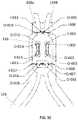
- FIG. 1Bis a schematic developed view of a portion of the prosthetic heart valve of FIG. 1A .
- FIG. 1Cis a schematic view of a suture pattern attaching two leaflets to a CAF in the prosthetic heart valve of FIG. 1A , shown from the exterior of the prosthetic heart valve.
- FIG. 1Dis a schematic view of the suture pattern of FIG. 1C , shown from the interior of the prosthetic heart valve.
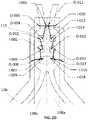
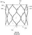
- FIG. 2Ais a side elevational view of another prosthetic heart valve according to the prior art.
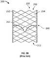
- FIG. 2Bis a highly schematic longitudinal cross-section of the prosthetic heart valve of FIG. 2A .
- FIG. 3is a schematic developed view of a portion of the stent of a prosthetic heart valve according to an embodiment of the disclosure.
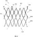
- FIG. 4is a schematic developed view of a portion of the stent of a prosthetic heart valve according to another embodiment of the disclosure.
- FIG. 5Ais a schematic view of a suture pattern on the stent of FIG. 4 , shown from the exterior of the stent.
- FIG. 5Bis a schematic view of the suture pattern of FIG. 5A , shown from the interior of the stent of FIG. 4 .
- FIG. 6Ais a schematic view of another suture pattern on the stent of FIG. 4 , shown from the exterior of the stent.
- FIG. 6Bis a schematic view of the suture pattern of FIG. 6A , shown from the interior of the stent of FIG. 4 .
- the term “inflow end,” when used in connection with a prosthetic heart valve,refers to the end of the heart valve through which blood first passes during antegrade blood flow
- the term “outflow end,” when used in connection with a prosthetic heart valverefers to the end of the heart valve through which blood last passes during antegrade blood flow.
- the term “circumferential,” when used in connection with a prosthetic heart valve,refers to the direction around the perimeter of the valve.
- leading endwhen used in connection with a suture, refers to the end initially advanced through a material, while the term “trailing end” refers to the opposite end.
- FIG. 1Ashows a collapsible stent-supported prosthetic heart valve 100 known in the art.
- Prosthetic heart valve 100is designed to replace the function of a native tricuspid, bicuspid or unicuspid valve of a patient, such as a native aortic valve.
- Prosthetic heart valve 100includes expandable stent 102 , which may be formed from biocompatible materials that are capable of self-expansion, such as, for example, shape memory alloys such as nitinol.
- Stent 102extends from a proximal or annulus end 130 to a distal or aortic end 132 , and includes tubular annulus section 140 adjacent the proximal end and aortic section 142 adjacent the distal end.
- Annulus section 140has a relatively small cross-section in the expanded condition, while aortic section 142 has a relatively large cross-section in the expanded condition.
- annulus section 140is in the form of a cylinder having a substantially constant diameter along its length.
- Transition section 141may taper outwardly from annulus section 140 to aortic section 142 .
- Each of the sections of stent 102includes a plurality of cells 112 connected to one another in one or more annular rows around the stent.
- annulus section 140may include a first proximalmost circumferential row of cells 112 a and a second circumferential row of cells 112 b positioned distal to the first row of cells.
- Aortic section 142may include a circumferential row of cells 112 d , which may be the distalmost row of cells.
- An intermediate circumferential row of cells 112 cmay be positioned between the proximalmost row of cells 112 a and the distalmost row of cells 112 d .
- Cells 112 d in aortic section 142may be larger than cells 112 a , 112 b in annulus section 140 .
- the larger cells in aortic section 142better enable prosthetic valve 100 to be positioned in the native valve annulus without the stent structure interfering with blood flow to the coronary arteries.
- Stent 102may include one or more retaining elements 118 at distal end 132 thereof, the retaining elements being sized and shaped to cooperate with retaining structures provided on the deployment device (not shown).
- the engagement of retaining elements 118 with retaining structures on the deployment devicehelps maintain prosthetic heart valve 100 in assembled relationship with the deployment device, minimizes longitudinal movement of the prosthetic heart valve relative to the deployment device during unsheathing or resheathing procedures, and helps prevent rotation of the prosthetic heart valve relative to the deployment device as the deployment device is advanced to the target location and the heart valve is deployed.
- retaining elements 118may be disposed near proximal end 130 of heart valve 100 .
- Prosthetic heart valve 100includes a valve assembly 104 , preferably positioned in the annulus section 140 of stent 102 and secured to the stent.
- Valve assembly 104may include a cuff 106 and a plurality of prosthetic valve elements, such as leaflets 108 , which collectively function as a one-way valve by coapting with one another, generally allowing blood to flow in an antegrade direction from proximal end 130 to distal end 132 , while substantially blocking blood from flowing in a retrograde direction from the distal end to the proximal end.
- leaflets 108As a prosthetic aortic valve, valve 100 has three leaflets 108 . However, it will be appreciated that other prosthetic heart valves with which the present disclosure may be used may have more or fewer leaflets.
- cuff 106is shown in FIG. 1A as being disposed on the luminal or inner surface of annulus section 140 , it is contemplated that the cuff may be disposed on the abluminal or outer surface of the annulus section or may cover all or part of either or both of the luminal and abluminal surfaces.
- Both cuff 106 and leaflets 108may be wholly or partly formed of any suitable biological material or polymer such as, for example, bovine or porcine pericardial tissue or polytetrafluoroethylene (PTFE).
- Leaflets 108may be attached along their belly portions 110 to cells 112 of stent 102 , with the commissure between adjacent leaflets attached to CAFs 116 . This is shown in FIG. 1B .
- each CAF 116may lie at the intersection of four cells 112 of stent 102 , two of the cells being adjacent one another in the same annular row, and the other two cells being in different annular rows and lying in an end-to-end relationship.
- CAFs 116are positioned entirely within the annulus section 140 of stent 102 or at the juncture of annulus section 140 and transition section 141 , although they may be positioned above the annulus section.
- CAFs 116may include one or more eyelets which facilitate the suturing of the leaflet commissure to the stent.
- CAFs 116are formed by stent 102 , or, in other words, are unitary or integral with the body of the stent. This may be achieved by, for example, laser cutting stent 102 , including CAFs 116 , from a single piece of material. CAFs 116 may add to the profile of valve 100 compared to an identical valve without the CAFs. CAFs 116 may also reduce the ability of stent body 102 to bend to match the anatomy during delivery, such as when the valve 100 is delivered through the aortic arch. This ability to bend or otherwise conform to the anatomy may be referred to as tracking ability.
- CAFs 116may also raise the likelihood of vessel trauma or particulate dislodgement, which may result in problems such as stroke. However, if CAFs 116 are not included in stent body 102 , another method of attaching leaflets 108 to the stent may be required.
- Prosthetic heart valve 100may be used to replace, for example, a native aortic valve, a surgical heart valve, or a heart valve that has undergone a surgical procedure.
- the prosthetic heart valvemay be delivered to the desired site (e.g., near the native aortic annulus) using any suitable delivery device.
- the prosthetic heart valveis disposed inside the delivery device in the collapsed condition.
- the delivery devicemay be introduced into a patient using a transfemoral, transapical, transseptal, transaortic, subclavian, or any other percutaneous approach. Once the delivery device has reached the target site, the user may deploy prosthetic heart valve 100 .
- prosthetic heart valve 100Upon deployment, prosthetic heart valve 100 expands so that annulus section 140 is in secure engagement within the native aortic annulus. When the prosthetic heart valve is properly positioned inside the heart, it works as a one-way valve, allowing blood to flow from the left ventricle of the heart to the aorta, and preventing blood from flowing in the opposite direction.
- FIGS. 1C-Dillustrate an example of a suture pattern for attaching two adjacent leaflets 108 of valve assembly 104 to one of CAFs 116 .
- CAF 116includes four relatively small eyelets positioned in a two-by-two grid (i.e., two rows and two columns), with an elongated eyelet positioned below the four smaller eyelets. It is preferred that a single suture be used to couple first leaflet 108 a and second leaflet 108 b to cuff 106 and CAF 116 , but it should be understood that multiple sutures may also be suitable.
- FIG. 1Cillustrates CAF 116 as viewed from the exterior of prosthetic heart valve 100
- FIG. 1Dillustrates the CAF as viewed from the interior of the prosthetic heart valve.
- an extension of cuff 106is positioned between CAF 116 and leaflets 108 a , 108 b.
- the suture pattern of FIGS. 1C-Dis described and illustrated with reference to part numbers having the format of I- 001 or O- 001 .
- the “I”refers to an end of a suture being passed inwardly through cuff 106 and/or leaflets 108 a , 108 b in the particular view being shown
- the “0”refers to an end of the suture being passed outwardly through the cuff and/or leaflets in the particular view being shown
- the number(e.g., 001) refers to the sequence of the particular stitch being described starting with “001.”
- the suture patternmay begin by passing the suture through leaflet 108 b and cuff 106 at point I- 001 ( FIG.
- the suturemay be inserted at point I- 002 ( FIG. 1C ) through a vertically adjacent eyelet, with the leading end of the suture exiting at point O- 002 ( FIG. 1D ).
- the suturemay be inserted at point I- 003 ( FIG. 1D ) through a vertically adjacent eyelet, with the leading end of the suture exiting at point O- 003 ( FIG. 1C ).
- the suturemay then be inserted at point I- 004 ( FIG. 1C ) through a vertically adjacent eyelet, with the leading end of the suture exiting at point O- 004 ( FIG. 1D ).
- the suturemay then be inserted through leaflet 108 b at point I- 005 ( FIG. 1D ) between two struts extending from the top of CAF 116 , the leading end of the suture exiting at point O- 005 ( FIG. 1C ).
- the suturemay then be passed over one of the struts and inserted again through leaflet 108 b at point I- 006 ( FIG. 1C ), the leading end of the suture exiting at point O- 006 ( FIG. 1D ).
- the trailing end of the sutureis on the luminal (or inner) side of prosthetic heart valve 100 , exiting through the lower left eyelet in the view of FIG. 1D .
- the trailing end of the suturemay then be passed through the elongated eyelet at point I- 007 ( FIG. 1D ), the trailing end exiting the elongated eyelet at point O- 007 ( FIG. 1C ).
- the trailing end of the suturemay be passed over a side of CAF 116 adjacent the elongated eyelet, and inserted through cuff 106 at point I- 008 ( FIG. 1C ), exiting at point O- 008 ( FIG. 1D ).
- the trailing end of the suturemay again be passed over the side of CAF 116 adjacent the elongated eyelet and inserted again through the elongated eyelet at point I- 009 ( FIG. 1D ), exiting the elongated eyelet at point O- 009 ( FIG. 1C ). At this point, the trailing end of the suture may be left exiting at point O- 009 .
- the leading end of the sutureWith the leading end of the suture still exiting at point O- 006 ( FIG. 1D ), the leading end may be passed across the two struts at the top of CAF 116 and inserted through leaflet 108 a at point I- 010 ( FIG. 1D ), exiting at point O- 010 ( FIG. 1C ). The leading end may then be passed over one of the struts connected to the top of CAF 116 and inserted through leaflet 108 a at point I- 011 ( FIG. 1C ), the leading end exiting at point O- 011 ( FIG. 1D ). The leading end of the suture may then be inserted through an eyelet (top right eyelet in FIG.
- the leading end of the suturemay then be inserted through a vertically adjacent eyelet (bottom left eyelet in FIG. 1C ) at point I- 013 , exiting the eyelet at point O- 013 ( FIG. 1D ).
- the leading end of the suturemay again be passed through a vertically adjacent eyelet (top right eyelet in FIG. 1D ) at point I- 014 , exiting the eyelet at point O- 014 ( FIG. 1C ).
- the leading end of the suturemay again be passed through a vertically adjacent eyelet (bottom left eyelet in FIG.
- the leading end of the suturemay then be passed through the elongated eyelet at point I- 016 ( FIG. 1D ), and may exit the elongated eyelet at point O- 016 ( FIG. 1C ).
- the leading end of the suturemay then be passed over a side of CAF 116 adjacent the elongated eyelet and inserted through cuff 106 at point I- 017 ( FIG. 1C ), exiting at point O- 017 ( FIG. 1D ).
- leading end of the suturemay again be passed over the side of CAF 116 adjacent the elongated eyelet and inserted through the elongated eyelet at point I- 018 ( FIG. 1D ), the leading end exiting the elongated eyelet at point O- 018 ( FIG. 1C ).
- the leading end of the sutureexits the elongated eyelet at point O- 018 , while the trailing end still exits the elongated eyelet at point O- 009 .
- the two endsmay be secured together, for example in a knot that is positioned within the elongated eyelet, to complete the suturing process. It will be appreciated that the suture pattern described in connection with FIGS. 1C-D may be obtained without following the exact suturing order described above. Further, although described with the use of a single suture, multiple sutures may be used to obtain the suture pattern described above.
- FIGS. 2A and 2Bare a side view and a longitudinal cross-sectional view, respectively, of a prosthetic heart valve 200 according to the prior art that may be particularly well-suited for replacing a native mitral valve.
- prosthetic valve 200has a substantially cylindrical shape with inflow end 210 and outflow end 212 .
- prosthetic valve 200may have a low profile so as to not obstruct the left ventricle outflow tract (“LVOT”).
- LVOTleft ventricle outflow tract
- Prosthetic heart valve 200may include stent 250 , which may be formed from biocompatible materials that are capable of self-expansion, such as, for example, shape-memory alloys including nitinol.
- Stent 250may include a plurality of struts 252 that form cells 254 connected to one another in one or more annular rows around the stent. Cells 254 may all be of substantially the same size around the perimeter and along the length of stent 250 . Alternatively, cells 254 near inflow end 210 may be larger than the cells near outflow end 212 .
- a plurality of CAFs 216may be provided on the outflow end 212 of stent 250 .
- Stent 250may be expandable to provide a radial force to assist with positioning and stabilizing prosthetic heart valve 200 in the native valve annulus.
- Prosthetic heart valve 200may also include a substantially cylindrical valve assembly 260 including a plurality of leaflets 262 ( FIG. 2B ) attached to a cuff 264 and to CAFs 216 ( FIG. 2A ).
- Leaflets 262replace the function of the native mitral valve leaflets. That is, leaflets 262 coapt with one another to function as a one way valve.
- the valve assembly 260 of prosthetic heart valve 200may include two or three leaflets, but it is contemplated that prosthetic heart valve 200 may have more than three leaflets.
- Both cuff 264 and leaflets 262may be wholly or partly formed of any suitable biological material, such as bovine or porcine pericardium, or polymers, such as PTFE, urethanes and the like.
- Valve assembly 260may be secured to stent 250 by suturing to struts 252 or by using tissue glue, ultrasonic welding, or other suitable methods.
- prosthetic heart valve 200When prosthetic heart valve 200 is implanted in a patient, for example at the annulus of the native mitral valve, it is biased towards an expanded condition, providing radial force to anchor the valve in place.
- prosthetic mitral valvesit is desirable for prosthetic mitral valves to avoid structure that extends too far into the left ventricle, as such structures may obstruct the LVOT.
- a prosthetic mitral valveit is generally preferable for a prosthetic mitral valve to avoid any structure that contacts the walls of the left ventricle, as such contact may cause conduction issues or disturbances in the heart.
- FIG. 3is a developed view of a stent 350 of a prosthetic mitral valve, illustrated as if cut longitudinally and laid out flat.
- stent 350is similar to stent 250 , and includes an inflow end 310 and an outflow end 312 , although it should be understood that stent 350 is shown in an opposite orientation to how stent 250 is shown in FIG. 2A .
- stent 250includes two rows of cells 254
- stent 350includes three rows of cells 354 , including a proximalmost row 354 a nearest outflow end 312 , a distalmost row 354 c nearest inflow end 310 , and an intermediate row 354 b between the proximalmost and distalmost rows.
- a CAF 316may extend in the outflow direction from selected cells in proximalmost row 354 a , the CAFs providing a similar or identical function as other CAFs described above. Otherwise, stent 350 may be coupled to a cuff and leaflets similar to those described above in connection with prosthetic heart valves 100 and/or 200 . If the prosthetic mitral valve incorporating stent 350 includes two leaflets, the stent will include two CAFs 316 , although the number of leaflets need not exactly equal the number of the CAFs, so that, for example, two leaflets could be used with three CAFs. If the prosthetic mitral valve incorporating stent 350 includes three leaflets, the stent will include three CAFs 316 . Each CAF 316 may also include a retaining element 318 that may serve a similar or identical function as retaining elements 118 of prosthetic heart valve 100 .
- FIG. 4illustrates a stent 450 that is identical to stent 350 , with the exception that the CAFs 316 have been removed.
- the length of the struts to which retainers 418 are attachedmay also be shorter than the combined length of the strut and CAF 316 of stent 350 .
- a prosthetic mitral valve that incorporates stent 450may (i) provide additional flexibility regarding where leaflets can be attached to the stent, (ii) reduce the profile of the heart valve due to the elimination of the relatively bulky CAFs, and/or (iii) decrease the number of structures positioned outside the rows of cells and reduce interaction with anatomical structures in the left ventricle.
- FIG. 4is a developed view of stent 450 , illustrated as if cut longitudinally and laid out flat.
- Stent 450may be particularly useful in a prosthetic mitral valve.
- stent 450includes an inflow end 410 , an outflow end 412 , and three rows 454 a - 454 c of cells 454 .
- stent 450does not include CAFs that have similar structure to CAFs 316 , although stent 450 may still include retaining elements 418 similar to retaining elements 318 .
- a prosthetic heart valve incorporating stent 450may include a cuff similar to cuff 264 , and a valve assembly with leaflets similar to valve assembly 260 and leaflets 262 .
- stent 450eliminates structures similar to the CAFs 316 of stent 350 , the attachment of the leaflets to the stent may be different than in stents 102 , 250 , and 350 .
- FIG. 4illustrates various potential locations for coupling portions of two adjacent leaflets directly to struts of stent 450 via suturing. However, as will become clear, other locations in which struts intersect similarly to the identified locations in FIG.
- a first connection location P 5is shown at a “Y”-shaped intersection of three struts, the “Y”-shaped intersection being formed by two struts of a cell 454 in row 454 a from which retaining element 418 extends, with the third strut of the “Y”-shape being a part of the retaining element.
- a second connection location P 6is shown at an “X”-shaped intersection of four struts, the “X”-shaped intersection being formed by two struts of a first cell 454 in first row 454 a , and two struts of an adjacent second cell in the first row.
- connection location P 7is substantially similar to connection location P 6 , with the main difference being that connection location P 6 is positioned in a first circumferential direction from a retaining element 418 , while connection location P 7 is positioned in a second circumferential direction opposite the first circumferential direction from the retaining element.
- connection location P 7is also at an “X”-shaped intersection of four struts, the “X”-shaped intersection being formed by two struts of a first cell 454 in first row 454 a , and two struts of an adjacent second cell in the first row.
- a fourth attachment location P 8is shown at a generally “X”-shaped intersection of four struts, the “X”-shaped intersection being formed by two struts of a first cell 454 in intermediate row 454 b , and two struts of an adjacent second cell in the intermediate row.
- attachment location P 8may be referred to as “X”-shaped, in the illustrated example, attachment location P 8 includes a strut connector or runner r that extends in the longitudinal direction between the cells 454 in rows 454 a and 454 c .
- attachment location P 8may be circumferentially aligned with attachment location P 5 , but positioned circumferentially between attachment locations P 6 and P 7 , and closer to the inflow end 410 of stent 450 than each of attachment locations P 5 , P 6 , and P 7 . Only one of these connection locations is used to couple the ends of any pair of adjacent leaflets to stent 450 . Further, since stent 450 has a repeating circumferential structure, the ends of other pairs of adjacent leaflets can be coupled together and to the stent in a similar fashion.
- attachment locations P 5 , P 6 , P 7 , and P 8each include at least one strut that is part of a cell 454 in the first circumferential row 454 a .
- the same valvecould be attached to stent 450 using different attachment sites for each attachment and/or different suture patterns for each attachment.
- a leaflet pairmay be preferable to attach to two of the P 8 locations on opposite sides of stent 450 , but using different suture patterns, while in still other situations it may be preferable to attach one end of a leaflet pair to a P 8 location and the other end of the leaflet pair to a P 7 location on a different portion of the stent, using either the same or different suture patterns.
- FIGS. 5A-Billustrate a suture pattern for suturing portions of two adjacent leaflets 462 a , 462 b to connection location P 5 shown in FIG. 4 .
- the connection location P 5is at a “Y”-shaped intersection of two struts 452 a , 452 b of a cell 454 in row 454 a from which retaining element 418 extends, with the third strut 452 c of the “Y”-shape connecting an apex of the cell to the retaining element.
- FIG. 5Aillustrates the suture pattern as viewed from the exterior of stent 450
- FIG. 5Billustrates the suture pattern as viewed from the interior of the stent. It should be understood that, although a cuff is not illustrated, typically a cuff would be positioned between the leaflets 462 a , 462 b and stent 450 .
- the suture pattern of FIGS. 5A-Bis described and illustrated with reference to part numbers having the format of I- 101 or O- 101 .
- the “I”refers to an end of a suture being passed inwardly through the cuff and/or leaflets 462 a , 462 b in the particular view being shown
- the “O”refers to an end of the suture being passed outwardly through the cuff and/or leaflets in the particular view being shown
- the numbere.g., 101 refers to the sequence of the particular stitch being described starting with “101.”
- the suture patternmay begin by passing the leading end of the suture through leaflet 462 b at point I- 101 ( FIG.
- the leading end of the suturemay be passed over strut 452 b and inserted through leaflet 462 b at point I- 102 ( FIG. 5A ), the leading end exiting leaflet 462 b at point O- 102 ( FIG. 5B ).
- the leading end of the suturemay then be inserted through leaflet 462 b at point I- 103 ( FIG. 5B ) on the opposite side of strut 452 b , the leading end exiting leaflet 462 b at point O- 103 ( FIG. 5A ).
- the leading end of the suturemay again be passed over strut 452 b and inserted through leaflet 462 b at point I- 104 ( FIG. 5A ), exiting leaflet 462 b at point O- 104 ( FIG. 5B ).
- the leading end of the suturemay then be inserted through leaflet 462 b at point I- 105 ( FIG. 5B ) on the opposite side of strut 452 b , exiting leaflet 462 b at point O- 105 ( FIG. 5A ).
- the leading end of the suturemay then be passed over strut 452 c and inserted through leaflet 462 a at point I- 106 ( FIG. 5A ), the leading end exiting leaflet 462 a at point O- 106 ( FIG.
- the leading end of the suturemay then be inserted through leaflet 462 b at point I- 107 ( FIG. 5B ) on the opposite side of strut 452 c , exiting leaflet 462 b at point O- 107 ( FIG. 5B ).
- the leading end of the suturemay again be passed over strut 452 c and inserted through leaflet 462 a at point I- 108 ( FIG. 5A ), the leading end exiting leaflet 462 a at point O- 108 ( FIG. 5B ).
- the leading end of the suturemay then be inserted through leaflet 462 a at point I- 109 ( FIG.
- FIG. 5BOn the opposite side of strut 452 a , exiting leaflet 462 a at point O- 109 ( FIG. 5A ).
- the leading end of the suturemay then be passed over strut 452 a and inserted through leaflet 462 a at point I- 110 ( FIG. 5A ), exiting leaflet 462 a at point O- 110 ( FIG. 5B ).
- the leading end of the suturemay again be inserted through leaflet 462 a at point I- 111 ( FIG. 5B ) on the opposite side of strut 452 a , exiting leaflet 462 a at point O- 111 ( FIG. 5A ).
- the leading end of the suturemay then be passed over strut 452 a and inserted through leaflet 462 a at point I- 112 ( FIG. 5A ), the leading end exiting leaflet 462 a at point O- 112 ( FIG. 5B ).
- the leading end of the suturemay then be inserted through leaflet 462 a at point I- 113 ( FIG. 5B ) again on the opposite side of strut 452 a , the leading end exiting leaflet 462 a at point O- 113 ( FIG. 5A ).
- the trailing end of the sutureis still on the luminal side of the leaflets, exiting leaflet 462 b at point I- 101 ( FIG. 5B ).
- the trailing end of the suturemay be inserted through leaflet 462 b at point I- 114 ( FIG. 5B ) on the opposite side of strut 452 b , the trailing end of the suture exiting leaflet 462 b at point O- 114 ( FIG. 5A ).
- the leading and trailing endsmay be secured together, for example, in a knot that is positioned between struts 452 a and 452 b , to complete the suturing process.
- the suture pattern described in connection with FIGS. 5A-Bmay be obtained without following the exact suturing order described above. Further, although described with the use of a single suture, multiple sutures may be used to obtain the suture pattern described above.
- FIGS. 6A-Billustrate a suture pattern for suturing portions of two adjacent leaflets 462 a , 462 b to connection location P 6 shown in FIG. 4 .
- the connection location P 6is at a “X”-shaped intersection of two struts 452 d , 452 e of a first cell 454 in row 454 a with two struts 452 f , 452 g of a second cell in row 454 a adjacent the first cell.
- FIG. 6Aillustrates the suture pattern as viewed from the exterior of stent 450
- FIG. 6Billustrates the suture pattern as viewed from the interior of the stent.
- the suture pattern of FIGS. 6A-Bis described and illustrated with reference to part numbers having the format of I- 201 or O- 201 .
- the “I”refers to an end of a suture being passed inward through the cuff and/or leaflets 462 a , 462 b in the particular view being shown
- the “O”refers to an end of the suture being passed outwardly through the cuff and/or leaflets in the particular view being shown
- the number(e.g., 201) refers to the sequence of the particular stitch being described starting with “201.”
- the suture patternmay begin by passing the leading end of the suture through leaflet 462 b at point I- 201 ( FIG.
- FIG. 6BWith the leading end of the suture exiting at point O- 201 ( FIG. 6A ).
- the leading end of the suturemay be passed over strut 452 g and inserted through leaflet 462 b at point I- 202 ( FIG. 6A ), the leading end exiting leaflet 462 b at point O- 202 ( FIG. 6B ).
- the leading end of the suturemay then be inserted through leaflet 462 b at point I- 203 ( FIG. 6B ) on the opposite side of strut 452 g , exiting leaflet 462 b at point O- 203 ( FIG. 6A ).
- the leading end of the suturemay again be passed over strut 452 g and inserted through leaflet 462 b at point I- 204 ( FIG. 6A ), the leading end exiting leaflet 462 b at point O- 204 ( FIG. 6B ).
- the leading end of the suturemay then be inserted through leaflet 462 b at point I- 205 ( FIG. 6B ) on the other side of strut connector 453 where struts 452 d - g intersect, the leading end of the suture exiting leaflet 462 b at point O- 205 ( FIG. 6A ).
- the leading end of the suturemay then be passed over strut 452 f and inserted through leaflet 462 b at point I- 206 ( FIG.
- the leading end exiting leaflet 462 b at point O- 206( FIG. 6B ).
- the leading end of the suturemay then be inserted through leaflet 462 a at point I- 207 ( FIG. 6B ) across struts 452 d and 452 f , exiting leaflet 462 a at point O- 207 ( FIG. 6A ).
- the leading end of the suturemay be passed over strut 452 d and through leaflet 462 a at point I- 208 ( FIG. 6A ), exiting leaflet 462 a at point O- 208 ( FIG. 6B ).
- the leading end of the suturemay then be inserted through leaflet 462 a at point I- 209 ( FIG.
- FIG. 6BOn the other side of strut connector 453 , exiting leaflet 462 a at point O- 209 ( FIG. 6A ).
- the leading end of the suturemay then be passed over strut 452 e and through leaflet 462 a at point I- 210 ( FIG. 6A ), the leading end exiting leaflet 462 a at point O- 210 ( FIG. 6B ).
- the leading end of the suturemay then be inserted through leaflet 462 a at point I- 211 ( FIG. 6B ) on the other side of strut 452 e , exiting leaflet 462 a at point O- 211 ( FIG. 6A ).
- the leading end of the suturemay then be passed over strut 452 e and through leaflet 462 a at point I- 212 ( FIG. 6A ), the leading end exiting leaflet 462 a at point O- 212 ( FIG. 6B ).
- the leading end of the suturemay then be inserted through leaflet 462 a at point I- 213 ( FIG. 6B ) on the other side of strut 452 e , exiting leaflet 462 a at point O- 213 ( FIG. 6A ).
- the trailing end of the sutureis still on the luminal side of the leaflets, exiting leaflet 462 b at point I- 201 ( FIG. 6B ).
- the trailing end of the suturemay be inserted through leaflet 462 b at point I- 214 ( FIG. 6B ) on the opposite side of strut 452 g , exiting leaflet 462 b at point O- 214 ( FIG. 6A ).
- the leading and trailing endsmay be secured together, for example, in a knot that is positioned between struts 452 e and 452 g , to complete the suturing process.
- the suture pattern described in connection with FIGS. 6A-Bmay be obtained without following the exact suturing order described above. Further, although described with the use of a single suture, multiple sutures may be used to obtain the suture pattern described above.
- the suture pattern for attaching two adjacent leaflets 462 a , 462 b to stent 450 at location P 6may be substantially the same as or identical to the suture pattern for attaching two adjacent leaflets to locations P 7 or P 8 .
- locations P 6 and P 7are structurally identical (or nearly identical), location P 8 may have slight structural differences compared to locations P 6 and P 7 .
- location P 8while still being formed at the intersection of two struts of a cell 454 in row 454 b with two struts of an adjacent cell 454 in row 454 b , may include a runner r that is longer in the longitudinal direction of stent 454 compared to strut connector 453 in locations P 6 and P 7 .
- the longitudinal directionrefers to the direction extending from inflow end 410 to outflow end 412 of stent 450 , or vice versa.
- connection locationsmay be driven, at least in part, by the shape of the stent at those locations and the corresponding geometry of the leaflets.
- attachment locations P 5allows leaflets 462 a , 462 b to be positioned nearer outflow end 412 compared to attachment locations P 6 , P 7 , and P 8 , while attachment locations P 6 and P 7 provide intermediate attachment locations in the longitudinal direction compared to locations P 5 and P 8 .
- attachment locations P 6 and P 7enable attachment of leaflets 462 a , 462 b in either circumferential direction of stent 450 compared to attachment locations P 5 and P 8 .
- the foregoing attachment optionsallow the prosthetic leaflets to be shifted in different directions relative to the native prosthetic valve annulus, which may assist in reducing LVOT obstruction, increasing sealing between the prosthetic heart valve and the native valve annulus, and/or optimizing prosthetic leaflet function.
- the various possible attachment locationsenable other features to be incorporated into stent 450 , while providing a leaflet attachment location that minimizes interference with such additional structures.
- additional stent featuressuch as clips, anchor arms, or the like that assist in capturing the native valve leaflets may be added to stent 450 at positions near where CAFs 316 of stent 350 are positioned.
- stent 450may be desirable to provide stent 450 with a flange, such as a braided flange, that is to be positioned in the left atrium to help prevent migration of the prosthetic mitral valve into the left ventricle during operation.
- a braided flangeit may be desirable to provide braid connectors on stent 450 to attach the braided flange to the stent.
- Such braid connectorsdesirably may be positioned near the axial center of stent 450 in some embodiments.
- prosthetic leaflets 462 a , 462 bmay be desirable to attach prosthetic leaflets 462 a , 462 b to attachment locations P 5 , P 6 , or P 7 , which are relatively far from the axial center of the stent compared to location P 8 .
- the broader implicationis that the particular attachment sites of the leaflets can be picked based on various considerations which may be different based on the features of the prosthetic heart valve, allowing for significant flexibility in design choice.
- a prosthetic mitral valvecomprises:
- a collapsible stentincluding a plurality of struts, a plurality of cells arranged in circumferential rows, the circumferential rows including a first row at an outflow end of the stent and a second row at an inflow end of the stent, and a plurality of strut intersections where at least two of the struts connect to one another;
- a prosthetic valve assemblyadapted to allow blood to flow from the inflow end of the stent toward the outflow end of the stent and to restrict blood from flowing from the outflow end of the stent toward the inflow of the stent, the prosthetic valve assembly including a first prosthetic leaflet having a first end attached directly to a first one of the strut intersections, and a second prosthetic leaflet having a first end attached directly to the first strut intersection,
- first strut intersectionis partially formed of one of the struts of one of the cells in the first row;
- the stentincludes at least one retaining element sized and shaped to cooperate with a corresponding retaining structure of a delivery device, the retaining element including a strut extending from an apex of one of the cells in the first row of cells; and/or
- the first strut intersectionis a “Y”-shaped intersection formed by the strut of the retaining element, and two struts that form the apex of the one cell in the first row of cells;
- the leading end of the sutureis secured to the trailing end of the suture in a knot;
- the knotis positioned between the two struts that form the apex of the one cell in the first row of cells;
- the first strut intersectionis an “X”-shaped intersection formed by four struts;
- the four struts forming the “X”-shaped intersectioninclude first and second struts of a first cell in the first row, and third and fourth struts of a second cell in the first row circumferentially adjacent the first cell, the first and second struts being joined to the third and fourth struts via a strut connector; and/or
- the leading end of the sutureis secured to the trailing end of the suture in a knot;
- the knotis positioned between the first cell and the second cell;
- the stentincludes an intermediate circumferential row of cells positioned between the first row and the second row;
- the first strut intersectionis an “X”-shaped intersection formed by four struts, the four struts including first and second struts of a first cell in the intermediate row, and third and fourth struts of a second cell in the intermediate row circumferentially adjacent the first cell, the first and second struts being joined to the third and fourth struts via a strut connector; and/or
- the first strutalso forms a portion of a third cell in the first row, and the third strut also forms a portion of a fourth cell in the first row;
- the leading end of the sutureis secured to the trailing end of the suture in a knot;
- the knotis positioned between the second strut and the fourth strut;
- the first prosthetic leaflethas a second end attached directly to a second one of the strut intersections, and the second prosthetic leaflet has a second end attached directly to the second strut intersection;
- the first strut intersectionhas a first position on the stent and the second strut intersection has a second position on the stent, the first position being diametrically opposed to the second position.
Landscapes
- Health & Medical Sciences (AREA)
- Cardiology (AREA)
- Engineering & Computer Science (AREA)
- Biomedical Technology (AREA)
- Oral & Maxillofacial Surgery (AREA)
- Transplantation (AREA)
- Heart & Thoracic Surgery (AREA)
- Vascular Medicine (AREA)
- Life Sciences & Earth Sciences (AREA)
- Animal Behavior & Ethology (AREA)
- General Health & Medical Sciences (AREA)
- Public Health (AREA)
- Veterinary Medicine (AREA)
- Mechanical Engineering (AREA)
- Prostheses (AREA)
Abstract
Description
Claims (5)
Priority Applications (1)
| Application Number | Priority Date | Filing Date | Title |
|---|---|---|---|
| US16/568,345US11284996B2 (en) | 2018-09-20 | 2019-09-12 | Attachment of leaflets to prosthetic heart valve |
Applications Claiming Priority (2)
| Application Number | Priority Date | Filing Date | Title |
|---|---|---|---|
| US201862733902P | 2018-09-20 | 2018-09-20 | |
| US16/568,345US11284996B2 (en) | 2018-09-20 | 2019-09-12 | Attachment of leaflets to prosthetic heart valve |
Publications (2)
| Publication Number | Publication Date |
|---|---|
| US20200093590A1 US20200093590A1 (en) | 2020-03-26 |
| US11284996B2true US11284996B2 (en) | 2022-03-29 |
Family
ID=68000161
Family Applications (1)
| Application Number | Title | Priority Date | Filing Date |
|---|---|---|---|
| US16/568,345Active2039-12-31US11284996B2 (en) | 2018-09-20 | 2019-09-12 | Attachment of leaflets to prosthetic heart valve |
Country Status (3)
| Country | Link |
|---|---|
| US (1) | US11284996B2 (en) |
| EP (1) | EP3852679B1 (en) |
| WO (1) | WO2020060828A1 (en) |
Families Citing this family (5)
| Publication number | Priority date | Publication date | Assignee | Title |
|---|---|---|---|---|
| WO2020123945A1 (en) | 2018-12-13 | 2020-06-18 | Abbott Laboratories | Fabric material for medical devices |
| US11547557B2 (en) | 2018-12-13 | 2023-01-10 | Abbott Laboratories | Stabilized fabric material for medical devices |
| US11045301B2 (en)* | 2019-03-12 | 2021-06-29 | Cook Medical Technologies Llc | Implantable medical device with compound stitching connection of framework to fabric |
| EP4048204A1 (en) | 2019-10-24 | 2022-08-31 | Abbott Laboratories | Sheet material for medical devices |
| CN116999207A (en)* | 2022-04-29 | 2023-11-07 | 上海微创心通医疗科技有限公司 | Valve stent, valve prosthesis and valve prosthesis system |
Citations (229)
| Publication number | Priority date | Publication date | Assignee | Title |
|---|---|---|---|---|
| US3657744A (en) | 1970-05-08 | 1972-04-25 | Univ Minnesota | Method for fixing prosthetic implants in a living body |
| US4275469A (en) | 1979-12-13 | 1981-06-30 | Shelhigh Inc. | Prosthetic heart valve |
| US4491986A (en) | 1976-05-12 | 1985-01-08 | Shlomo Gabbay | Heart valve |
| US4759758A (en) | 1984-12-07 | 1988-07-26 | Shlomo Gabbay | Prosthetic heart valve |
| US4878906A (en) | 1986-03-25 | 1989-11-07 | Servetus Partnership | Endoprosthesis for repairing a damaged vessel |
| US4922905A (en) | 1985-11-30 | 1990-05-08 | Strecker Ernst P | Dilatation catheter |
| US4994077A (en) | 1989-04-21 | 1991-02-19 | Dobben Richard L | Artificial heart valve for implantation in a blood vessel |
| WO1991017720A1 (en) | 1990-05-18 | 1991-11-28 | Henning Rud Andersen | A valve prosthesis for implantation in the body and a catheter for implantating such valve prosthesis |
| US5411552A (en) | 1990-05-18 | 1995-05-02 | Andersen; Henning R. | Valve prothesis for implantation in the body and a catheter for implanting such valve prothesis |
| US5415664A (en) | 1994-03-30 | 1995-05-16 | Corvita Corporation | Method and apparatus for introducing a stent or a stent-graft |
| US5480423A (en) | 1993-05-20 | 1996-01-02 | Boston Scientific Corporation | Prosthesis delivery |
| WO1997016133A1 (en) | 1995-11-01 | 1997-05-09 | Biocompatibles Limited | Braided stent |
| EP0850607A1 (en) | 1996-12-31 | 1998-07-01 | Cordis Corporation | Valve prosthesis for implantation in body channels |
| WO1998032412A2 (en) | 1997-01-24 | 1998-07-30 | Scimed Life Systems Inc | Bistable spring construction for a stent and other medical apparatus |
| US5843167A (en) | 1993-04-22 | 1998-12-01 | C. R. Bard, Inc. | Method and apparatus for recapture of hooked endoprosthesis |
| US5855601A (en) | 1996-06-21 | 1999-01-05 | The Trustees Of Columbia University In The City Of New York | Artificial heart valve and method and device for implanting the same |
| WO1999013801A1 (en) | 1997-09-16 | 1999-03-25 | Zadno Azizi Gholam Reza | Body fluid flow control device |
| US5935163A (en) | 1998-03-31 | 1999-08-10 | Shelhigh, Inc. | Natural tissue heart valve prosthesis |
| US5961549A (en) | 1997-04-03 | 1999-10-05 | Baxter International Inc. | Multi-leaflet bioprosthetic heart valve |
| US6045576A (en) | 1997-09-16 | 2000-04-04 | Baxter International Inc. | Sewing ring having increased annular coaptation |
| EP1000590A1 (en) | 1998-11-09 | 2000-05-17 | Cordis Corporation | An improved stent which is easly recaptured and repositioned within the body |
| US6077297A (en) | 1993-11-04 | 2000-06-20 | C. R. Bard, Inc. | Non-migrating vascular prosthesis and minimally invasive placement system therefor |
| DE19857887A1 (en) | 1998-12-15 | 2000-07-06 | Fraunhofer Ges Forschung | Anchoring support for a heart valve prosthesis comprises a single-piece component which is formed of rod shaped elements made of a memory metal, and has at least in part a lattice structure |
| US6090140A (en) | 1999-02-17 | 2000-07-18 | Shelhigh, Inc. | Extra-anatomic heart valve apparatus |
| WO2001028459A1 (en) | 1999-10-21 | 2001-04-26 | Scimed Life Systems, Inc. | Implantable prosthetic valve |
| WO2001049213A2 (en) | 1999-12-31 | 2001-07-12 | Advanced Bio Prosthetic Surfaces, Ltd. | Endoluminal cardiac and venous valve prostheses and methods of manufacture and delivery thereof |
| US6264691B1 (en) | 1999-04-23 | 2001-07-24 | Shlomo Gabbay | Apparatus and method for supporting a heart valve |
| WO2001054625A1 (en) | 2000-01-31 | 2001-08-02 | Cook Biotech Incorporated | Stent valves and uses of same |
| WO2001056500A2 (en) | 2000-02-03 | 2001-08-09 | Cook Incorporated | Implantable vascular device |
| WO2001076510A2 (en) | 2000-04-06 | 2001-10-18 | Edwards Lifesciences Corporation | Minimally-invasive heart valves and methods of use |
| US20020036220A1 (en) | 2000-09-26 | 2002-03-28 | Shlomo Gabbay | Curved implantable sheath and method of making same |
| US6368348B1 (en) | 2000-05-15 | 2002-04-09 | Shlomo Gabbay | Annuloplasty prosthesis for supporting an annulus of a heart valve |
| WO2002036048A1 (en) | 2000-10-31 | 2002-05-10 | Jacques Seguin | Tubular support for setting, by percutaneous route, a substitution cusp |
| WO2002047575A2 (en) | 2000-12-15 | 2002-06-20 | Angiomed Gmbh & Co. Medizintechnik Kg | Stent with valve |
| US6419695B1 (en) | 2000-05-22 | 2002-07-16 | Shlomo Gabbay | Cardiac prosthesis for helping improve operation of a heart valve |
| WO2002067782A2 (en) | 2001-02-26 | 2002-09-06 | Ev3 Peripheral, Inc. | Implant delivery system with interlock |
| US6468660B2 (en) | 2000-12-29 | 2002-10-22 | St. Jude Medical, Inc. | Biocompatible adhesives |
| US20030023303A1 (en) | 1999-11-19 | 2003-01-30 | Palmaz Julio C. | Valvular prostheses having metal or pseudometallic construction and methods of manufacture |
| US6517576B2 (en) | 2000-12-11 | 2003-02-11 | Shlomo Gabbay | Implantable patch prosthesis having one or more cusps for improved competency |
| US20030050694A1 (en) | 2001-09-13 | 2003-03-13 | Jibin Yang | Methods and apparatuses for deploying minimally-invasive heart valves |
| US6533810B2 (en) | 1995-11-27 | 2003-03-18 | Schneider (Europe) Ag | Conical stent |
| WO2003047468A1 (en) | 2001-10-11 | 2003-06-12 | Percutaneous Valve Technologies | Implantable prosthetic valve |
| US6582464B2 (en) | 2000-05-03 | 2003-06-24 | Shlomo Gabbay | Biomechanical heart valve prosthesis and method for making same |
| US20030130726A1 (en) | 1999-09-10 | 2003-07-10 | Thorpe Patricia E. | Combination valve and stent for treating vascular reflux |
| US6623518B2 (en) | 2001-02-26 | 2003-09-23 | Ev3 Peripheral, Inc. | Implant delivery system with interlock |
| US6685625B2 (en) | 2000-09-26 | 2004-02-03 | Shlomo Gabbay | Curved implantable sheath and method of making same |
| US6716244B2 (en) | 2000-12-20 | 2004-04-06 | Carbomedics, Inc. | Sewing cuff assembly for heart valves |
| US6719789B2 (en) | 1993-11-01 | 2004-04-13 | 3F Therapeutics, Inc. | Replacement heart valve |
| US20040111111A1 (en) | 2002-12-10 | 2004-06-10 | Scimed Life Systems, Inc. | Intravascular filter membrane with shape memory |
| FR2850008A1 (en) | 2003-01-17 | 2004-07-23 | Daniel Roux | Vascular prosthesis has tube and collar for adapting to blood vessel ends of different diameters |
| US6783556B1 (en) | 2000-09-26 | 2004-08-31 | Shlomo Gabbay | System and method for making a calotte-shaped implantable sheath |
| US6790230B2 (en) | 2001-04-30 | 2004-09-14 | Universitatsklinikum Freiburg | Vascular implant |
| US20040210304A1 (en) | 1999-11-17 | 2004-10-21 | Corevalve, S.A. | Prosthetic valve for transluminal delivery |
| US6814746B2 (en) | 2002-11-01 | 2004-11-09 | Ev3 Peripheral, Inc. | Implant delivery system with marker interlock |
| US6830584B1 (en) | 1999-11-17 | 2004-12-14 | Jacques Seguin | Device for replacing a cardiac valve by percutaneous route |
| US20040260389A1 (en) | 2003-04-24 | 2004-12-23 | Cook Incorporated | Artificial valve prosthesis with improved flow dynamics |
| US6869444B2 (en) | 2000-05-22 | 2005-03-22 | Shlomo Gabbay | Low invasive implantable cardiac prosthesis and method for helping improve operation of a heart valve |
| US20050096726A1 (en) | 2000-05-30 | 2005-05-05 | Jacques Sequin | Noncylindrical stent deployment system for treating vascular bifurcations |
| US20050137697A1 (en) | 2003-12-23 | 2005-06-23 | Amr Salahieh | Leaflet engagement elements and methods for use thereof |
| US20050137695A1 (en) | 2003-12-23 | 2005-06-23 | Sadra Medical | Replacement valve and anchor |
| US20050137682A1 (en) | 2003-12-22 | 2005-06-23 | Henri Justino | Stent mounted valve |
| WO2005070343A1 (en) | 2003-12-23 | 2005-08-04 | Laboratoires Perouse | Kit which is intended to be implanted in a conduit |
| US20050203605A1 (en) | 2004-03-15 | 2005-09-15 | Medtronic Vascular, Inc. | Radially crush-resistant stent |
| US6951573B1 (en) | 2001-12-22 | 2005-10-04 | Dilling Emery W | Prosthetic aortic valve |
| EP1584306A1 (en) | 1999-02-02 | 2005-10-12 | Bard Peripheral Vascular, Inc. | Partial encapsulation of stents using bands |
| FR2847800B1 (en) | 2002-11-28 | 2005-10-14 | Perouse Laboratoires | INTERCHANGEABLE PROTHETIC VALVE |
| US20050240200A1 (en) | 2004-04-23 | 2005-10-27 | Bjarne Bergheim | Method and system for cardiac valve delivery |
| US20050256566A1 (en) | 2004-05-03 | 2005-11-17 | Shlomo Gabbay | Apparatus and method for improving ventricular function |
| EP1598031A2 (en) | 1998-03-04 | 2005-11-23 | Boston Scientific Limited | Stent having variable properties |
| EP1360942B1 (en) | 2002-05-11 | 2005-12-14 | Willy Rüsch GmbH | Stent |
| US20060008497A1 (en) | 2004-07-09 | 2006-01-12 | Shlomo Gabbay | Implantable apparatus having improved biocompatibility and process of making the same |
| US7018406B2 (en) | 1999-11-17 | 2006-03-28 | Corevalve Sa | Prosthetic valve for transluminal delivery |
| US20060074484A1 (en) | 2004-10-02 | 2006-04-06 | Huber Christoph H | Methods and devices for repair or replacement of heart valves or adjacent tissue without the need for full cardiopulmonary support |
| US7025780B2 (en) | 2000-09-12 | 2006-04-11 | Shlomo Gabbay | Valvular prosthesis |
| US20060122692A1 (en) | 2004-05-10 | 2006-06-08 | Ran Gilad | Stent valve and method of using same |
| US20060149360A1 (en) | 2003-07-08 | 2006-07-06 | Ventor Technologies Ltd. | Fluid flow prosthetic device |
| WO2006073626A2 (en) | 2005-01-05 | 2006-07-13 | The Cleveland Clinic Foundation | Method for fixing tissue |
| US20060161249A1 (en) | 2004-11-22 | 2006-07-20 | Fidel Realyvasquez | Ring-shaped valve prosthesis attachment device |
| US20060173532A1 (en) | 2004-12-20 | 2006-08-03 | Jacob Flagle | Intraluminal support frame and medical devices including the support frame |
| US20060178740A1 (en) | 2005-02-10 | 2006-08-10 | Sorin Biomedica Cardio S.R.L. | Cardiac-valve prosthesis |
| DE102005003632A1 (en) | 2005-01-20 | 2006-08-17 | Fraunhofer-Gesellschaft zur Förderung der angewandten Forschung e.V. | Catheter for the transvascular implantation of heart valve prostheses |
| US20060195180A1 (en) | 2005-02-25 | 2006-08-31 | Arash Kheradvar | Implantable small percutaneous valve and methods of delivery |
| US20060206202A1 (en) | 2004-11-19 | 2006-09-14 | Philippe Bonhoeffer | Apparatus for treatment of cardiac valves and method of its manufacture |
| US20060241744A1 (en) | 2003-03-20 | 2006-10-26 | Aortech International Plc | Valve |
| US20060259120A1 (en) | 2005-05-12 | 2006-11-16 | Ev3, Inc. | Implant delivery system with interlocked RX port orientation |
| US20060259137A1 (en) | 2003-10-06 | 2006-11-16 | Jason Artof | Minimally invasive valve replacement system |
| US7137184B2 (en) | 2002-09-20 | 2006-11-21 | Edwards Lifesciences Corporation | Continuous heart valve support frame and method of manufacture |
| US20060265056A1 (en) | 2005-05-13 | 2006-11-23 | Corevalve, Inc. | Heart valve prosthesis and methods of manufacture and use |
| US20060276813A1 (en) | 2005-05-20 | 2006-12-07 | The Cleveland Clinic Foundation | Apparatus and methods for repairing the function of a diseased valve and method for making same |
| US20060276874A1 (en) | 2005-05-27 | 2006-12-07 | Heart Leaflet Technologies, Inc. | Intravascular cuff |
| US7160322B2 (en) | 2003-08-13 | 2007-01-09 | Shlomo Gabbay | Implantable cardiac prosthesis for mitigating prolapse of a heart valve |
| US20070010876A1 (en) | 2003-12-23 | 2007-01-11 | Amr Salahieh | Externally Expandable Heart Valve Anchor and Method |
| US20070027534A1 (en) | 2005-07-27 | 2007-02-01 | Bjarne Bergheim | Methods and systems for cardiac valve delivery |
| US20070043435A1 (en) | 1999-11-17 | 2007-02-22 | Jacques Seguin | Non-cylindrical prosthetic valve system for transluminal delivery |
| US20070055358A1 (en) | 2005-08-22 | 2007-03-08 | Krolik Jeffrey A | Axially compressible flared stents and apparatus and methods for delivering them |
| US20070067029A1 (en) | 2005-09-16 | 2007-03-22 | Shlomo Gabbay | Support apparatus to facilitate implantation of cardiac prosthesis |
| US20070093890A1 (en) | 2005-10-26 | 2007-04-26 | Eliasen Kenneth A | Heart valve implant |
| US20070100435A1 (en) | 2003-04-24 | 2007-05-03 | Cook Incorporated | Artificial prostheses with preferred geometries |
| US20070118210A1 (en) | 2005-11-18 | 2007-05-24 | Leonard Pinchuk | Trileaflet Heart Valve |
| WO2007071436A2 (en) | 2005-12-22 | 2007-06-28 | Symetis Sa | Stent-valves for valve replacement and associated methods and systems for surgery |
| US7247167B2 (en) | 2004-02-19 | 2007-07-24 | Shlomo Gabbay | Low profile heart valve prosthesis |
| US20070213813A1 (en) | 2005-12-22 | 2007-09-13 | Symetis Sa | Stent-valves for valve replacement and associated methods and systems for surgery |
| US7276078B2 (en) | 2004-06-30 | 2007-10-02 | Edwards Lifesciences Pvt | Paravalvular leak detection, sealing, and prevention |
| US20070233228A1 (en) | 2006-03-28 | 2007-10-04 | Medtronic, Inc. | Prosthetic cardiac valve formed from pericardium material and methods of making same |
| US20070244552A1 (en) | 2003-12-23 | 2007-10-18 | Amr Salahieh | Assessing the location and performance of replacement heart valves |
| US20070244545A1 (en) | 2006-04-14 | 2007-10-18 | Medtronic Vascular, Inc. | Prosthetic Conduit With Radiopaque Symmetry Indicators |
| US20070288087A1 (en) | 2006-05-30 | 2007-12-13 | Cook Incorporated | Artificial valve prosthesis |
| US7311730B2 (en) | 2004-02-13 | 2007-12-25 | Shlomo Gabbay | Support apparatus and heart valve prosthesis for sutureless implantation |
| US7320704B2 (en) | 2004-05-05 | 2008-01-22 | Direct Flow Medical, Inc. | Nonstented temporary valve for cardiovascular therapy |
| US20080021552A1 (en) | 2001-10-09 | 2008-01-24 | Shlomo Gabbay | Apparatus To Facilitate Implantation |
| US20080039934A1 (en) | 2004-09-07 | 2008-02-14 | Laboratoires Perouse | Interchangeable Prosthetic Valve |
| US20080071369A1 (en) | 2006-09-19 | 2008-03-20 | Yosi Tuval | Valve fixation member having engagement arms |
| US20080082164A1 (en) | 2006-10-02 | 2008-04-03 | Friedman Robert S | Sutureless heart valve attachment |
| US20080097595A1 (en) | 2006-08-22 | 2008-04-24 | Shlomo Gabbay | Intraventricular cardiac prosthesis |
| US20080114452A1 (en) | 2007-11-14 | 2008-05-15 | Shlomo Gabbay | Prosthesis exhibiting post-implantation size change |
| US7374573B2 (en) | 2004-05-03 | 2008-05-20 | Shlomo Gabbay | System and method for improving ventricular function |
| US7381219B2 (en) | 2003-12-23 | 2008-06-03 | Sadra Medical, Inc. | Low profile heart valve and delivery system |
| EP1926455A2 (en) | 2005-09-20 | 2008-06-04 | Sadra Medical, Inc. | Methods and apparatus for endovascular heart valve replacement comprising tissue grasping elements |
| US20080140189A1 (en) | 2006-12-06 | 2008-06-12 | Corevalve, Inc. | System and method for transapical delivery of an annulus anchored self-expanding valve |
| US20080147183A1 (en) | 2006-12-14 | 2008-06-19 | Mikolaj Styrc | Endovalve |
| US20080154355A1 (en) | 2006-12-22 | 2008-06-26 | Netanel Benichou | Implantable prosthetic valve assembly and method of making the same |
| US20080243245A1 (en) | 2004-03-11 | 2008-10-02 | Percutaneous Cardiovascular Solutions Pty Limited | Percutaneous Heart Valve Prosthesis |
| US20080255662A1 (en) | 2004-03-03 | 2008-10-16 | Sorin Biomedica Cardio S.R.L. | Minimally-invasive cardiac-valve prosthesis |
| US20080262602A1 (en) | 1998-09-10 | 2008-10-23 | Jenavalve Technology, Inc. | Methods and conduits for flowing blood from a heart chamber to a blood vessel |
| US20080269879A1 (en) | 2005-07-27 | 2008-10-30 | Rahul Dilip Sathe | Implantable Prosthetic Vascular Valve |
| US7452371B2 (en) | 1999-06-02 | 2008-11-18 | Cook Incorporated | Implantable vascular device |
| DE202008009610U1 (en) | 2008-07-17 | 2008-12-11 | Nvt Ag | Prosthetic heart valve system |
| US7510572B2 (en) | 2000-09-12 | 2009-03-31 | Shlomo Gabbay | Implantation system for delivery of a heart valve prosthesis |
| US20090099653A1 (en) | 2007-10-12 | 2009-04-16 | Sorin Biomedica Cardio S.R.L. | Expandable valve prosthesis with sealing mechanism |
| US7524331B2 (en) | 2006-04-06 | 2009-04-28 | Medtronic Vascular, Inc. | Catheter delivered valve having a barrier to provide an enhanced seal |
| US20090112309A1 (en) | 2005-07-21 | 2009-04-30 | The Florida International University Board Of Trustees | Collapsible Heart Valve with Polymer Leaflets |
| US20090138079A1 (en) | 2007-10-10 | 2009-05-28 | Vector Technologies Ltd. | Prosthetic heart valve for transfemoral delivery |
| US20090254175A1 (en) | 2008-04-03 | 2009-10-08 | Quijano Rodolfo C | Valved stent for chronic venous insufficiency |
| US20090276027A1 (en) | 2008-05-01 | 2009-11-05 | Medtronic Vasscular, Inc. | Stent Graft Delivery System and Method of Use |
| US20100004740A1 (en) | 1999-11-17 | 2010-01-07 | Jacques Seguin | Prosthetic Valve for Transluminal Delivery |
| WO2010008548A2 (en) | 2008-07-15 | 2010-01-21 | St. Jude Medical, Inc. | Collapsible and re-expandable prosthetic heart valve cuff designs and complementary technological applications |
| WO2010008549A1 (en) | 2008-07-15 | 2010-01-21 | St. Jude Medical, Inc. | Axially anchoring collapsible and re-expandable prosthetic heart valves for various disease states |
| US20100036484A1 (en) | 2008-06-06 | 2010-02-11 | Edwards Lifesciences Corporation | Low profile transcatheter heart valve |
| US20100049306A1 (en) | 2008-02-25 | 2010-02-25 | Medtronic Vascular, Inc. | Infundibular Reducer Devices |
| US7682390B2 (en) | 2001-07-31 | 2010-03-23 | Medtronic, Inc. | Assembly for setting a valve prosthesis in a corporeal duct |
| US20100087907A1 (en) | 2007-02-16 | 2010-04-08 | Emory University | Apparatus And Methods For Treating The Aorta |
| US7708775B2 (en) | 2005-05-24 | 2010-05-04 | Edwards Lifesciences Corporation | Methods for rapid deployment of prosthetic heart valves |
| US20100168844A1 (en) | 2007-01-26 | 2010-07-01 | 3F Therapeutics, Inc. | Methods and systems for reducing paravalvular leakage in heart valves |
| US20100168839A1 (en) | 2007-06-04 | 2010-07-01 | Braido Peter N | Prosthetic heart valves |
| US20100168778A1 (en) | 2007-06-08 | 2010-07-01 | Braido Peter N | Devices for transcatheter prosthetic heart valve implantation and access closure |
| US7748389B2 (en) | 2003-12-23 | 2010-07-06 | Sadra Medical, Inc. | Leaflet engagement elements and methods for use thereof |
| US20100185277A1 (en) | 2007-09-26 | 2010-07-22 | St. Jude Medical, Inc. | Collapsible prosthetic heart valves |
| US20100191326A1 (en) | 2007-06-26 | 2010-07-29 | Alkhatib Yousef F | Apparatus and method for implanting collapsible/expandable prosthetic heart valves |
| US20100204785A1 (en) | 2007-09-28 | 2010-08-12 | Alkhatib Yousef F | Two-stage collapsible/expandable prosthetic heart valves and anchoring systems |
| US20100204781A1 (en) | 2007-08-24 | 2010-08-12 | Alkhatib Yousef F | Prosthetic aortic heart valves |
| US7780725B2 (en) | 2004-06-16 | 2010-08-24 | Sadra Medical, Inc. | Everting heart valve |
| US20100217382A1 (en) | 2009-02-25 | 2010-08-26 | Edwards Lifesciences | Mitral valve replacement with atrial anchoring |
| WO2010096176A1 (en) | 2009-02-20 | 2010-08-26 | St. Jude Medical, Inc. | Devices and methods for collapsing prosthetic heart valves |
| WO2010098857A1 (en) | 2009-02-27 | 2010-09-02 | St. Jude Medical, Inc. | Stent features for collapsible prosthetic heart valves |
| US20100234940A1 (en) | 2009-03-12 | 2010-09-16 | Medtronic Vascular , Inc. | Prosthetic Valve Delivery System |
| US20100249923A1 (en) | 2007-09-28 | 2010-09-30 | St Jude Medical Inc. | Collapsible/expandable prosthetic heart valves with native calcified leaflet retention features |
| US20100249911A1 (en) | 2007-11-05 | 2010-09-30 | St Jude Medical Inc. | Collapsible/expandable prosthetic heart valves with non-expanding stent posts and retrieval features |
| US7824442B2 (en) | 2003-12-23 | 2010-11-02 | Sadra Medical, Inc. | Methods and apparatus for endovascularly replacing a heart valve |
| US20100286768A1 (en) | 2008-01-16 | 2010-11-11 | Alkhatib Yousef F | Delivery and retrieval systems for collapsible/expandable prosthetic heart valves |
| US7837727B2 (en) | 2006-02-16 | 2010-11-23 | Transcatheter Technologies Gmbh | Minimally invasive heart valve replacement |
| US20100298931A1 (en) | 2009-04-15 | 2010-11-25 | Arshad Quadri | Vascular implant and delivery system |
| US20110029072A1 (en) | 2009-08-03 | 2011-02-03 | Shlomo Gabbay | Heart valve prosthesis and method of implantation thereof |
| US20110054466A1 (en) | 2009-08-27 | 2011-03-03 | Medtronic, Inc. | Paravalvular Leak Closure Devices and Methods |
| US20110137397A1 (en) | 2009-12-04 | 2011-06-09 | Edwards Lifesciences Corporation | Prosthetic valve for replacing mitral valve |
| US7959666B2 (en) | 2003-12-23 | 2011-06-14 | Sadra Medical, Inc. | Methods and apparatus for endovascularly replacing a heart valve |
| US7972378B2 (en) | 2008-01-24 | 2011-07-05 | Medtronic, Inc. | Stents for prosthetic heart valves |
| US7988724B2 (en) | 2003-12-23 | 2011-08-02 | Sadra Medical, Inc. | Systems and methods for delivering a medical implant |
| US20110208283A1 (en) | 2010-02-24 | 2011-08-25 | Rust Matthew J | Transcatheter valve structure and methods for valve delivery |
| US20110264206A1 (en) | 2010-04-21 | 2011-10-27 | Medtronic, Inc. | Prosthetic Valve with Sealing Members and Methods of Use Thereof |
| US8052741B2 (en) | 2009-03-23 | 2011-11-08 | Medtronic Vascular, Inc. | Branch vessel prosthesis with a roll-up sealing assembly |
| USD648854S1 (en) | 2010-09-20 | 2011-11-15 | St. Jude Medical, Inc. | Commissure points |
| US8062355B2 (en) | 2005-11-04 | 2011-11-22 | Jenavalve Technology, Inc. | Self-expandable medical instrument for treating defects in a patient's heart |
| US8075611B2 (en) | 2009-06-02 | 2011-12-13 | Medtronic, Inc. | Stented prosthetic heart valves |
| USD652927S1 (en) | 2010-09-20 | 2012-01-24 | St. Jude Medical, Inc. | Surgical stent |
| USD652926S1 (en) | 2010-09-20 | 2012-01-24 | St. Jude Medical, Inc. | Forked end |
| USD653342S1 (en) | 2010-09-20 | 2012-01-31 | St. Jude Medical, Inc. | Stent connections |
| USD653343S1 (en) | 2010-09-20 | 2012-01-31 | St. Jude Medical, Inc. | Surgical cuff |
| USD653341S1 (en) | 2010-09-20 | 2012-01-31 | St. Jude Medical, Inc. | Surgical stent |
| US20120035722A1 (en) | 2010-02-24 | 2012-02-09 | Medtronic Ventor Technologies, Ltd | Mitral Prosthesis and Methods for Implantation |
| USD654170S1 (en) | 2010-09-20 | 2012-02-14 | St. Jude Medical, Inc. | Stent connections |
| USD654169S1 (en) | 2010-09-20 | 2012-02-14 | St. Jude Medical Inc. | Forked ends |
| US8137398B2 (en) | 2008-10-13 | 2012-03-20 | Medtronic Ventor Technologies Ltd | Prosthetic valve having tapered tip when compressed for delivery |
| US20120101572A1 (en) | 2010-10-21 | 2012-04-26 | Medtronic, Inc. | Mitral Bioprosthesis with Low Ventricular Profile |
| US20120123529A1 (en) | 2010-10-05 | 2012-05-17 | Edwards Lifesciences Corporation | Prosthetic heart valve |
| USD660433S1 (en) | 2010-09-20 | 2012-05-22 | St. Jude Medical, Inc. | Surgical stent assembly |
| USD660432S1 (en) | 2010-09-20 | 2012-05-22 | St. Jude Medical, Inc. | Commissure point |
| USD660967S1 (en) | 2010-09-20 | 2012-05-29 | St. Jude Medical, Inc. | Surgical stent |
| US8231670B2 (en) | 2003-12-23 | 2012-07-31 | Sadra Medical, Inc. | Repositionable heart valve and method |
| US8230717B2 (en) | 2008-12-18 | 2012-07-31 | Ethicon, Inc. | Paravalvular leak test apparatus and method |
| US8308798B2 (en) | 2008-12-19 | 2012-11-13 | Edwards Lifesciences Corporation | Quick-connect prosthetic heart valve and methods |
| US8313525B2 (en) | 2008-03-18 | 2012-11-20 | Medtronic Ventor Technologies, Ltd. | Valve suturing and implantation procedures |
| US20120303116A1 (en) | 2009-11-05 | 2012-11-29 | The Trustees Of The University Of Pennsylvania | Valve prosthesis |
| US8323336B2 (en) | 2008-04-23 | 2012-12-04 | Medtronic, Inc. | Prosthetic heart valve devices and methods of valve replacement |
| US8323335B2 (en) | 2008-06-20 | 2012-12-04 | Edwards Lifesciences Corporation | Retaining mechanisms for prosthetic valves and methods for using |
| EP2537487A1 (en) | 2003-12-23 | 2012-12-26 | Sadra Medical, Inc. | Repositionable heart valve |
| US8348998B2 (en) | 2009-06-26 | 2013-01-08 | Edwards Lifesciences Corporation | Unitary quick connect prosthetic heart valve and deployment system and methods |
| US8366769B2 (en) | 2000-06-01 | 2013-02-05 | Edwards Lifesciences Corporation | Low-profile, pivotable heart valve sewing ring |
| US8403983B2 (en) | 2008-09-29 | 2013-03-26 | Cardiaq Valve Technologies, Inc. | Heart valve |
| US8408214B2 (en) | 2010-07-08 | 2013-04-02 | Benjamin Spenser | Method for implanting prosthetic valve |
| US8449604B2 (en) | 2005-12-16 | 2013-05-28 | Micardia Corporation | Adjustable prosthetic valve implant |
| USD684692S1 (en) | 2010-09-20 | 2013-06-18 | St. Jude Medical, Inc. | Forked ends |
| US20130261740A1 (en) | 2012-03-30 | 2013-10-03 | Carol EBERHARDT | Valve Prosthesis |
| US20130274873A1 (en) | 2012-03-22 | 2013-10-17 | Symetis Sa | Transcatheter Stent-Valves and Methods, Systems and Devices for Addressing Para-Valve Leakage |
| US8568474B2 (en) | 2010-04-26 | 2013-10-29 | Medtronic, Inc. | Transcatheter prosthetic heart valve post-dilatation remodeling devices and methods |
| US8579962B2 (en) | 2003-12-23 | 2013-11-12 | Sadra Medical, Inc. | Methods and apparatus for performing valvuloplasty |
| US8603160B2 (en) | 2003-12-23 | 2013-12-10 | Sadra Medical, Inc. | Method of using a retrievable heart valve anchor with a sheath |
| US8613765B2 (en) | 2008-02-28 | 2013-12-24 | Medtronic, Inc. | Prosthetic heart valve systems |
| US8623074B2 (en) | 2007-02-16 | 2014-01-07 | Medtronic, Inc. | Delivery systems and methods of implantation for replacement prosthetic heart valves |
| US8652204B2 (en) | 2010-04-01 | 2014-02-18 | Medtronic, Inc. | Transcatheter valve with torsion spring fixation and related systems and methods |
| US8663322B2 (en) | 2006-11-13 | 2014-03-04 | Medtentia International Ltd. Oy | Device and method for improving function of heart valve |
| US8685080B2 (en) | 2008-07-21 | 2014-04-01 | Jenesis Surgical, Llc | Repositionable endoluminal support structure and its applications |
| US20140121763A1 (en) | 2012-10-31 | 2014-05-01 | Medtronic Vascular Galway Limited | Prosthetic Mitral Valve and Delivery Method |
| US20140155997A1 (en) | 2007-09-28 | 2014-06-05 | Peter Nicholas Braido | Collapsible-expandable prosthetic heart valves with structures for clamping native tissue |
| US8764820B2 (en) | 2005-11-16 | 2014-07-01 | Edwards Lifesciences Corporation | Transapical heart valve delivery system and method |
| US20140214159A1 (en) | 2011-08-11 | 2014-07-31 | Tendyne Holdings, Inc. | Prosthetic valves and related inventions |
| US8795357B2 (en) | 2011-07-15 | 2014-08-05 | Edwards Lifesciences Corporation | Perivalvular sealing for transcatheter heart valve |
| US8834563B2 (en) | 2008-12-23 | 2014-09-16 | Sorin Group Italia S.R.L. | Expandable prosthetic valve having anchoring appendages |
| US8840661B2 (en) | 2008-05-16 | 2014-09-23 | Sorin Group Italia S.R.L. | Atraumatic prosthetic heart valve prosthesis |
| US8840663B2 (en) | 2003-12-23 | 2014-09-23 | Sadra Medical, Inc. | Repositionable heart valve method |
| US20140303719A1 (en) | 2011-06-24 | 2014-10-09 | Inceptus Medical, Llc | Percutaneously implantable artificial heart valve system and associated methods and devices |
| US20140324164A1 (en) | 2011-08-05 | 2014-10-30 | Mitraltech Ltd. | Techniques for percutaneous mitral valve replacement and sealing |
| US20140350669A1 (en) | 2011-12-01 | 2014-11-27 | The Trustees if The University of Pennsylvania | Percutaneous valve replacement devices |
| US20140350668A1 (en) | 2013-03-13 | 2014-11-27 | Symetis Sa | Prosthesis Seals and Methods for Sealing an Expandable Prosthesis |
| US8940040B2 (en) | 2011-12-06 | 2015-01-27 | Aortic Innovations, Llc | Device for endovascular aortic repair and method of using the same |
| US8945209B2 (en) | 2011-05-20 | 2015-02-03 | Edwards Lifesciences Corporation | Encapsulated heart valve |
| US8974523B2 (en) | 2005-05-27 | 2015-03-10 | Hlt, Inc. | Stentless support structure |
| US8974524B2 (en) | 2009-09-21 | 2015-03-10 | Medtronic, Inc. | Stented transcatheter prosthetic heart valve delivery system and method |
| US20150073545A1 (en)* | 2013-09-12 | 2015-03-12 | St. Jude Medical, Cardiology Division, Inc. | Stent designs for prosthetic heart valves |
| US20150127100A1 (en)* | 2013-11-06 | 2015-05-07 | St. Jude Medical, Cardiology Division, Inc. | Reduced profile prosthetic heart valve |
- 2019
- 2019-09-12WOPCT/US2019/050724patent/WO2020060828A1/ennot_activeCeased
- 2019-09-12USUS16/568,345patent/US11284996B2/enactiveActive
- 2019-09-12EPEP19773323.1Apatent/EP3852679B1/enactiveActive
Patent Citations (301)
| Publication number | Priority date | Publication date | Assignee | Title |
|---|---|---|---|---|
| US3657744A (en) | 1970-05-08 | 1972-04-25 | Univ Minnesota | Method for fixing prosthetic implants in a living body |
| US4491986A (en) | 1976-05-12 | 1985-01-08 | Shlomo Gabbay | Heart valve |
| US4275469A (en) | 1979-12-13 | 1981-06-30 | Shelhigh Inc. | Prosthetic heart valve |
| US4759758A (en) | 1984-12-07 | 1988-07-26 | Shlomo Gabbay | Prosthetic heart valve |
| US4922905A (en) | 1985-11-30 | 1990-05-08 | Strecker Ernst P | Dilatation catheter |
| US4878906A (en) | 1986-03-25 | 1989-11-07 | Servetus Partnership | Endoprosthesis for repairing a damaged vessel |
| US4994077A (en) | 1989-04-21 | 1991-02-19 | Dobben Richard L | Artificial heart valve for implantation in a blood vessel |
| WO1991017720A1 (en) | 1990-05-18 | 1991-11-28 | Henning Rud Andersen | A valve prosthesis for implantation in the body and a catheter for implantating such valve prosthesis |
| US5411552A (en) | 1990-05-18 | 1995-05-02 | Andersen; Henning R. | Valve prothesis for implantation in the body and a catheter for implanting such valve prothesis |
| US5843167A (en) | 1993-04-22 | 1998-12-01 | C. R. Bard, Inc. | Method and apparatus for recapture of hooked endoprosthesis |
| US5480423A (en) | 1993-05-20 | 1996-01-02 | Boston Scientific Corporation | Prosthesis delivery |
| US6719789B2 (en) | 1993-11-01 | 2004-04-13 | 3F Therapeutics, Inc. | Replacement heart valve |
| US6077297A (en) | 1993-11-04 | 2000-06-20 | C. R. Bard, Inc. | Non-migrating vascular prosthesis and minimally invasive placement system therefor |
| US5415664A (en) | 1994-03-30 | 1995-05-16 | Corvita Corporation | Method and apparatus for introducing a stent or a stent-graft |
| WO1997016133A1 (en) | 1995-11-01 | 1997-05-09 | Biocompatibles Limited | Braided stent |
| USRE40816E1 (en) | 1995-11-01 | 2009-06-30 | Biocompatibles Uk Limited | Biocompatible crosslinked coating and crosslinkable coating polymer composition for forming such a coating |
| US6083257A (en) | 1995-11-01 | 2000-07-04 | Biocompatibles Limited | Braided stent |
| US6533810B2 (en) | 1995-11-27 | 2003-03-18 | Schneider (Europe) Ag | Conical stent |
| US5855601A (en) | 1996-06-21 | 1999-01-05 | The Trustees Of Columbia University In The City Of New York | Artificial heart valve and method and device for implanting the same |
| US7846203B2 (en) | 1996-12-31 | 2010-12-07 | Edwards Lifesciences Pvt, Inc. | Implanting a stent valve prosthesis at the native aortic valve |
| US8591575B2 (en) | 1996-12-31 | 2013-11-26 | Edwards Lifesciences Pvt, Inc. | Method of dilating a stenotic aortic valve and implanting a prosthetic valve |
| US6908481B2 (en) | 1996-12-31 | 2005-06-21 | Edwards Lifesciences Pvt, Inc. | Value prosthesis for implantation in body channels |
| EP0850607A1 (en) | 1996-12-31 | 1998-07-01 | Cordis Corporation | Valve prosthesis for implantation in body channels |
| US7585321B2 (en) | 1996-12-31 | 2009-09-08 | Edwards Lifesciences Pvt, Inc. | Methods of implanting a prosthetic heart valve within a native heart valve |
| US7846204B2 (en) | 1996-12-31 | 2010-12-07 | Edwards Lifesciences Pvt, Inc. | Aortic valve prosthesis having natural tissue and an internal cover |
| WO1998032412A2 (en) | 1997-01-24 | 1998-07-30 | Scimed Life Systems Inc | Bistable spring construction for a stent and other medical apparatus |
| US6488702B1 (en) | 1997-01-24 | 2002-12-03 | Jomed Gmbh | Bistable spring construction for a stent and other medical apparatus |
| US5961549A (en) | 1997-04-03 | 1999-10-05 | Baxter International Inc. | Multi-leaflet bioprosthetic heart valve |
| WO1999013801A1 (en) | 1997-09-16 | 1999-03-25 | Zadno Azizi Gholam Reza | Body fluid flow control device |
| US6045576A (en) | 1997-09-16 | 2000-04-04 | Baxter International Inc. | Sewing ring having increased annular coaptation |
| EP1598031A2 (en) | 1998-03-04 | 2005-11-23 | Boston Scientific Limited | Stent having variable properties |
| US5935163A (en) | 1998-03-31 | 1999-08-10 | Shelhigh, Inc. | Natural tissue heart valve prosthesis |
| US20080262602A1 (en) | 1998-09-10 | 2008-10-23 | Jenavalve Technology, Inc. | Methods and conduits for flowing blood from a heart chamber to a blood vessel |
| US6214036B1 (en) | 1998-11-09 | 2001-04-10 | Cordis Corporation | Stent which is easily recaptured and repositioned within the body |
| US6267783B1 (en) | 1998-11-09 | 2001-07-31 | Cordis Corporation | Stent which is easily recaptured and repositioned within the body |
| EP1000590A1 (en) | 1998-11-09 | 2000-05-17 | Cordis Corporation | An improved stent which is easly recaptured and repositioned within the body |
| DE19857887A1 (en) | 1998-12-15 | 2000-07-06 | Fraunhofer Ges Forschung | Anchoring support for a heart valve prosthesis comprises a single-piece component which is formed of rod shaped elements made of a memory metal, and has at least in part a lattice structure |
| EP1584306A1 (en) | 1999-02-02 | 2005-10-12 | Bard Peripheral Vascular, Inc. | Partial encapsulation of stents using bands |
| US6090140A (en) | 1999-02-17 | 2000-07-18 | Shelhigh, Inc. | Extra-anatomic heart valve apparatus |
| US6264691B1 (en) | 1999-04-23 | 2001-07-24 | Shlomo Gabbay | Apparatus and method for supporting a heart valve |
| US7452371B2 (en) | 1999-06-02 | 2008-11-18 | Cook Incorporated | Implantable vascular device |
| US20030130726A1 (en) | 1999-09-10 | 2003-07-10 | Thorpe Patricia E. | Combination valve and stent for treating vascular reflux |
| WO2001028459A1 (en) | 1999-10-21 | 2001-04-26 | Scimed Life Systems, Inc. | Implantable prosthetic valve |
| US7267686B2 (en) | 1999-10-21 | 2007-09-11 | Boston Scientific Scimed, Inc | Implantable prosthetic valve |
| US8603159B2 (en) | 1999-11-17 | 2013-12-10 | Medtronic Corevalve, Llc | Prosthetic valve for transluminal delivery |
| US7018406B2 (en) | 1999-11-17 | 2006-03-28 | Corevalve Sa | Prosthetic valve for transluminal delivery |
| US20100004740A1 (en) | 1999-11-17 | 2010-01-07 | Jacques Seguin | Prosthetic Valve for Transluminal Delivery |
| US20070043435A1 (en) | 1999-11-17 | 2007-02-22 | Jacques Seguin | Non-cylindrical prosthetic valve system for transluminal delivery |
| US7329278B2 (en) | 1999-11-17 | 2008-02-12 | Corevalve, Inc. | Prosthetic valve for transluminal delivery |
| US8016877B2 (en) | 1999-11-17 | 2011-09-13 | Medtronic Corevalve Llc | Prosthetic valve for transluminal delivery |
| US6830584B1 (en) | 1999-11-17 | 2004-12-14 | Jacques Seguin | Device for replacing a cardiac valve by percutaneous route |
| US7892281B2 (en) | 1999-11-17 | 2011-02-22 | Medtronic Corevalve Llc | Prosthetic valve for transluminal delivery |
| US8579966B2 (en) | 1999-11-17 | 2013-11-12 | Medtronic Corevalve Llc | Prosthetic valve for transluminal delivery |
| US20040210304A1 (en) | 1999-11-17 | 2004-10-21 | Corevalve, S.A. | Prosthetic valve for transluminal delivery |
| US20030023303A1 (en) | 1999-11-19 | 2003-01-30 | Palmaz Julio C. | Valvular prostheses having metal or pseudometallic construction and methods of manufacture |
| US7195641B2 (en) | 1999-11-19 | 2007-03-27 | Advanced Bio Prosthetic Surfaces, Ltd. | Valvular prostheses having metal or pseudometallic construction and methods of manufacture |
| US6652578B2 (en) | 1999-12-31 | 2003-11-25 | Abps Venture One, Ltd. | Endoluminal cardiac and venous valve prostheses and methods of manufacture and delivery thereof |
| WO2001049213A2 (en) | 1999-12-31 | 2001-07-12 | Advanced Bio Prosthetic Surfaces, Ltd. | Endoluminal cardiac and venous valve prostheses and methods of manufacture and delivery thereof |
| US7799069B2 (en) | 1999-12-31 | 2010-09-21 | Abps Venture One, Ltd. | Endoluminal cardiac and venous valve prostheses and methods of manufacture and delivery thereof |
| US20080125853A1 (en) | 1999-12-31 | 2008-05-29 | Abps Venture One, Ltd. | Endoluminal cardiac and venous valve prostheses and methods of manufacture and delivery thereof |
| US8221493B2 (en) | 1999-12-31 | 2012-07-17 | Abps Venture One, Ltd. | Endoluminal cardiac and venous valve prostheses and methods of manufacture and delivery thereof |
| US6458153B1 (en) | 1999-12-31 | 2002-10-01 | Abps Venture One, Ltd. | Endoluminal cardiac and venous valve prostheses and methods of manufacture and delivery thereof |
| US20080154356A1 (en) | 2000-01-31 | 2008-06-26 | Obermiller Joseph F | Percutaneous heart valve devices |
| US20040049262A1 (en) | 2000-01-31 | 2004-03-11 | Obermiller Joseph F. | Stent valves and uses of same |
| WO2001054625A1 (en) | 2000-01-31 | 2001-08-02 | Cook Biotech Incorporated | Stent valves and uses of same |
| WO2001056500A2 (en) | 2000-02-03 | 2001-08-09 | Cook Incorporated | Implantable vascular device |
| WO2001076510A2 (en) | 2000-04-06 | 2001-10-18 | Edwards Lifesciences Corporation | Minimally-invasive heart valves and methods of use |
| US7381218B2 (en) | 2000-04-06 | 2008-06-03 | Edwards Lifesciences Corporation | System and method for implanting a two-part prosthetic heart valve |
| US6582464B2 (en) | 2000-05-03 | 2003-06-24 | Shlomo Gabbay | Biomechanical heart valve prosthesis and method for making same |
| US6610088B1 (en) | 2000-05-03 | 2003-08-26 | Shlomo Gabbay | Biologically covered heart valve prosthesis |
| US6368348B1 (en) | 2000-05-15 | 2002-04-09 | Shlomo Gabbay | Annuloplasty prosthesis for supporting an annulus of a heart valve |
| US6419695B1 (en) | 2000-05-22 | 2002-07-16 | Shlomo Gabbay | Cardiac prosthesis for helping improve operation of a heart valve |
| US6869444B2 (en) | 2000-05-22 | 2005-03-22 | Shlomo Gabbay | Low invasive implantable cardiac prosthesis and method for helping improve operation of a heart valve |
| US20050096726A1 (en) | 2000-05-30 | 2005-05-05 | Jacques Sequin | Noncylindrical stent deployment system for treating vascular bifurcations |
| US8366769B2 (en) | 2000-06-01 | 2013-02-05 | Edwards Lifesciences Corporation | Low-profile, pivotable heart valve sewing ring |
| US7803185B2 (en) | 2000-09-12 | 2010-09-28 | Shlomo Gabbay | Method of implantation of a heart valve prosthesis through a tubular catheter |
| US7025780B2 (en) | 2000-09-12 | 2006-04-11 | Shlomo Gabbay | Valvular prosthesis |
| US7510572B2 (en) | 2000-09-12 | 2009-03-31 | Shlomo Gabbay | Implantation system for delivery of a heart valve prosthesis |
| US20020036220A1 (en) | 2000-09-26 | 2002-03-28 | Shlomo Gabbay | Curved implantable sheath and method of making same |
| US6783556B1 (en) | 2000-09-26 | 2004-08-31 | Shlomo Gabbay | System and method for making a calotte-shaped implantable sheath |
| US6685625B2 (en) | 2000-09-26 | 2004-02-03 | Shlomo Gabbay | Curved implantable sheath and method of making same |
| WO2002036048A1 (en) | 2000-10-31 | 2002-05-10 | Jacques Seguin | Tubular support for setting, by percutaneous route, a substitution cusp |
| US6517576B2 (en) | 2000-12-11 | 2003-02-11 | Shlomo Gabbay | Implantable patch prosthesis having one or more cusps for improved competency |
| WO2002047575A2 (en) | 2000-12-15 | 2002-06-20 | Angiomed Gmbh & Co. Medizintechnik Kg | Stent with valve |
| US20040093075A1 (en) | 2000-12-15 | 2004-05-13 | Titus Kuehne | Stent with valve and method of use thereof |
| US6716244B2 (en) | 2000-12-20 | 2004-04-06 | Carbomedics, Inc. | Sewing cuff assembly for heart valves |
| US6468660B2 (en) | 2000-12-29 | 2002-10-22 | St. Jude Medical, Inc. | Biocompatible adhesives |
| US6623518B2 (en) | 2001-02-26 | 2003-09-23 | Ev3 Peripheral, Inc. | Implant delivery system with interlock |
| WO2002067782A2 (en) | 2001-02-26 | 2002-09-06 | Ev3 Peripheral, Inc. | Implant delivery system with interlock |
| US6790230B2 (en) | 2001-04-30 | 2004-09-14 | Universitatsklinikum Freiburg | Vascular implant |
| DE10121210B4 (en) | 2001-04-30 | 2005-11-17 | Universitätsklinikum Freiburg | Anchoring element for the intraluminal anchoring of a heart valve replacement and method for its production |
| US7682390B2 (en) | 2001-07-31 | 2010-03-23 | Medtronic, Inc. | Assembly for setting a valve prosthesis in a corporeal duct |
| US20030050694A1 (en) | 2001-09-13 | 2003-03-13 | Jibin Yang | Methods and apparatuses for deploying minimally-invasive heart valves |
| US20080021552A1 (en) | 2001-10-09 | 2008-01-24 | Shlomo Gabbay | Apparatus To Facilitate Implantation |
| US7510575B2 (en) | 2001-10-11 | 2009-03-31 | Edwards Lifesciences Corporation | Implantable prosthetic valve |
| WO2003047468A1 (en) | 2001-10-11 | 2003-06-12 | Percutaneous Valve Technologies | Implantable prosthetic valve |
| US6730118B2 (en) | 2001-10-11 | 2004-05-04 | Percutaneous Valve Technologies, Inc. | Implantable prosthetic valve |
| US6893460B2 (en) | 2001-10-11 | 2005-05-17 | Percutaneous Valve Technologies Inc. | Implantable prosthetic valve |
| US6951573B1 (en) | 2001-12-22 | 2005-10-04 | Dilling Emery W | Prosthetic aortic valve |
| US7731742B2 (en) | 2002-05-11 | 2010-06-08 | Boston Scientific Scimed, Inc. | Stent |
| EP1360942B1 (en) | 2002-05-11 | 2005-12-14 | Willy Rüsch GmbH | Stent |
| US7137184B2 (en) | 2002-09-20 | 2006-11-21 | Edwards Lifesciences Corporation | Continuous heart valve support frame and method of manufacture |
| US6814746B2 (en) | 2002-11-01 | 2004-11-09 | Ev3 Peripheral, Inc. | Implant delivery system with marker interlock |
| FR2847800B1 (en) | 2002-11-28 | 2005-10-14 | Perouse Laboratoires | INTERCHANGEABLE PROTHETIC VALVE |
| US20040111111A1 (en) | 2002-12-10 | 2004-06-10 | Scimed Life Systems, Inc. | Intravascular filter membrane with shape memory |
| FR2850008A1 (en) | 2003-01-17 | 2004-07-23 | Daniel Roux | Vascular prosthesis has tube and collar for adapting to blood vessel ends of different diameters |
| US20060241744A1 (en) | 2003-03-20 | 2006-10-26 | Aortech International Plc | Valve |
| US20100131055A1 (en) | 2003-04-24 | 2010-05-27 | Cook Incorporated | Artificial valve prosthesis with improved flow dynamics |
| US20040260389A1 (en) | 2003-04-24 | 2004-12-23 | Cook Incorporated | Artificial valve prosthesis with improved flow dynamics |
| US20070100435A1 (en) | 2003-04-24 | 2007-05-03 | Cook Incorporated | Artificial prostheses with preferred geometries |
| US20060149360A1 (en) | 2003-07-08 | 2006-07-06 | Ventor Technologies Ltd. | Fluid flow prosthetic device |
| US7160322B2 (en) | 2003-08-13 | 2007-01-09 | Shlomo Gabbay | Implantable cardiac prosthesis for mitigating prolapse of a heart valve |
| US20060259137A1 (en) | 2003-10-06 | 2006-11-16 | Jason Artof | Minimally invasive valve replacement system |
| US20050137682A1 (en) | 2003-12-22 | 2005-06-23 | Henri Justino | Stent mounted valve |
| US7959666B2 (en) | 2003-12-23 | 2011-06-14 | Sadra Medical, Inc. | Methods and apparatus for endovascularly replacing a heart valve |
| US7988724B2 (en) | 2003-12-23 | 2011-08-02 | Sadra Medical, Inc. | Systems and methods for delivering a medical implant |
| US8343213B2 (en) | 2003-12-23 | 2013-01-01 | Sadra Medical, Inc. | Leaflet engagement elements and methods for use thereof |
| US8231670B2 (en) | 2003-12-23 | 2012-07-31 | Sadra Medical, Inc. | Repositionable heart valve and method |
| US7959672B2 (en) | 2003-12-23 | 2011-06-14 | Sadra Medical | Replacement valve and anchor |
| US20070244552A1 (en) | 2003-12-23 | 2007-10-18 | Amr Salahieh | Assessing the location and performance of replacement heart valves |
| WO2005070343A1 (en) | 2003-12-23 | 2005-08-04 | Laboratoires Perouse | Kit which is intended to be implanted in a conduit |
| US8840663B2 (en) | 2003-12-23 | 2014-09-23 | Sadra Medical, Inc. | Repositionable heart valve method |
| US8048153B2 (en) | 2003-12-23 | 2011-11-01 | Sadra Medical, Inc. | Low profile heart valve and delivery system |
| US20070010876A1 (en) | 2003-12-23 | 2007-01-11 | Amr Salahieh | Externally Expandable Heart Valve Anchor and Method |
| US7748389B2 (en) | 2003-12-23 | 2010-07-06 | Sadra Medical, Inc. | Leaflet engagement elements and methods for use thereof |
| US20050137697A1 (en) | 2003-12-23 | 2005-06-23 | Amr Salahieh | Leaflet engagement elements and methods for use thereof |
| US7824442B2 (en) | 2003-12-23 | 2010-11-02 | Sadra Medical, Inc. | Methods and apparatus for endovascularly replacing a heart valve |
| US8828078B2 (en) | 2003-12-23 | 2014-09-09 | Sadra Medical, Inc. | Methods and apparatus for endovascular heart valve replacement comprising tissue grasping elements |
| US8182528B2 (en) | 2003-12-23 | 2012-05-22 | Sadra Medical, Inc. | Locking heart valve anchor |
| US8052749B2 (en) | 2003-12-23 | 2011-11-08 | Sadra Medical, Inc. | Methods and apparatus for endovascular heart valve replacement comprising tissue grasping elements |
| US8603160B2 (en) | 2003-12-23 | 2013-12-10 | Sadra Medical, Inc. | Method of using a retrievable heart valve anchor with a sheath |
| EP2537487A1 (en) | 2003-12-23 | 2012-12-26 | Sadra Medical, Inc. | Repositionable heart valve |
| US8579962B2 (en) | 2003-12-23 | 2013-11-12 | Sadra Medical, Inc. | Methods and apparatus for performing valvuloplasty |
| US7381219B2 (en) | 2003-12-23 | 2008-06-03 | Sadra Medical, Inc. | Low profile heart valve and delivery system |
| US20050137695A1 (en) | 2003-12-23 | 2005-06-23 | Sadra Medical | Replacement valve and anchor |
| US7311730B2 (en) | 2004-02-13 | 2007-12-25 | Shlomo Gabbay | Support apparatus and heart valve prosthesis for sutureless implantation |
| US7247167B2 (en) | 2004-02-19 | 2007-07-24 | Shlomo Gabbay | Low profile heart valve prosthesis |
| US20080255662A1 (en) | 2004-03-03 | 2008-10-16 | Sorin Biomedica Cardio S.R.L. | Minimally-invasive cardiac-valve prosthesis |
| US20080243245A1 (en) | 2004-03-11 | 2008-10-02 | Percutaneous Cardiovascular Solutions Pty Limited | Percutaneous Heart Valve Prosthesis |
| US20050203605A1 (en) | 2004-03-15 | 2005-09-15 | Medtronic Vascular, Inc. | Radially crush-resistant stent |
| US20050240200A1 (en) | 2004-04-23 | 2005-10-27 | Bjarne Bergheim | Method and system for cardiac valve delivery |
| US20050256566A1 (en) | 2004-05-03 | 2005-11-17 | Shlomo Gabbay | Apparatus and method for improving ventricular function |
| US7374573B2 (en) | 2004-05-03 | 2008-05-20 | Shlomo Gabbay | System and method for improving ventricular function |
| US7320704B2 (en) | 2004-05-05 | 2008-01-22 | Direct Flow Medical, Inc. | Nonstented temporary valve for cardiovascular therapy |
| US20060122692A1 (en) | 2004-05-10 | 2006-06-08 | Ran Gilad | Stent valve and method of using same |
| US8668733B2 (en) | 2004-06-16 | 2014-03-11 | Sadra Medical, Inc. | Everting heart valve |
| US7780725B2 (en) | 2004-06-16 | 2010-08-24 | Sadra Medical, Inc. | Everting heart valve |
| US7628805B2 (en) | 2004-06-30 | 2009-12-08 | Edwards Lifesciences Pvt, Inc. | Paravalvular leak detection, sealing and prevention |
| US7276078B2 (en) | 2004-06-30 | 2007-10-02 | Edwards Lifesciences Pvt | Paravalvular leak detection, sealing, and prevention |
| US20060008497A1 (en) | 2004-07-09 | 2006-01-12 | Shlomo Gabbay | Implantable apparatus having improved biocompatibility and process of making the same |
| US20080039934A1 (en) | 2004-09-07 | 2008-02-14 | Laboratoires Perouse | Interchangeable Prosthetic Valve |
| US20060074484A1 (en) | 2004-10-02 | 2006-04-06 | Huber Christoph H | Methods and devices for repair or replacement of heart valves or adjacent tissue without the need for full cardiopulmonary support |
| US20060206202A1 (en) | 2004-11-19 | 2006-09-14 | Philippe Bonhoeffer | Apparatus for treatment of cardiac valves and method of its manufacture |
| US20060161249A1 (en) | 2004-11-22 | 2006-07-20 | Fidel Realyvasquez | Ring-shaped valve prosthesis attachment device |
| US20060173532A1 (en) | 2004-12-20 | 2006-08-03 | Jacob Flagle | Intraluminal support frame and medical devices including the support frame |
| WO2006073626A2 (en) | 2005-01-05 | 2006-07-13 | The Cleveland Clinic Foundation | Method for fixing tissue |
| DE102005003632A1 (en) | 2005-01-20 | 2006-08-17 | Fraunhofer-Gesellschaft zur Förderung der angewandten Forschung e.V. | Catheter for the transvascular implantation of heart valve prostheses |
| US7857845B2 (en) | 2005-02-10 | 2010-12-28 | Sorin Biomedica Cardio S.R.L. | Cardiac-valve prosthesis |
| US20060178740A1 (en) | 2005-02-10 | 2006-08-10 | Sorin Biomedica Cardio S.R.L. | Cardiac-valve prosthesis |
| US20060195180A1 (en) | 2005-02-25 | 2006-08-31 | Arash Kheradvar | Implantable small percutaneous valve and methods of delivery |
| US20060259120A1 (en) | 2005-05-12 | 2006-11-16 | Ev3, Inc. | Implant delivery system with interlocked RX port orientation |
| US20110172765A1 (en) | 2005-05-13 | 2011-07-14 | Medtronic Corevalve Llc | Heart Valve Prosthesis and Methods of Manufacture and Use |
| US7914569B2 (en) | 2005-05-13 | 2011-03-29 | Medtronics Corevalve Llc | Heart valve prosthesis and methods of manufacture and use |
| US20060265056A1 (en) | 2005-05-13 | 2006-11-23 | Corevalve, Inc. | Heart valve prosthesis and methods of manufacture and use |
| US20060276813A1 (en) | 2005-05-20 | 2006-12-07 | The Cleveland Clinic Foundation | Apparatus and methods for repairing the function of a diseased valve and method for making same |
| US7708775B2 (en) | 2005-05-24 | 2010-05-04 | Edwards Lifesciences Corporation | Methods for rapid deployment of prosthetic heart valves |
| US8500798B2 (en) | 2005-05-24 | 2013-08-06 | Edwards Lifesciences Corporation | Rapid deployment prosthetic heart valve |
| US20060276874A1 (en) | 2005-05-27 | 2006-12-07 | Heart Leaflet Technologies, Inc. | Intravascular cuff |
| US8974523B2 (en) | 2005-05-27 | 2015-03-10 | Hlt, Inc. | Stentless support structure |
| US20090112309A1 (en) | 2005-07-21 | 2009-04-30 | The Florida International University Board Of Trustees | Collapsible Heart Valve with Polymer Leaflets |
| US20070027534A1 (en) | 2005-07-27 | 2007-02-01 | Bjarne Bergheim | Methods and systems for cardiac valve delivery |
| US20080269879A1 (en) | 2005-07-27 | 2008-10-30 | Rahul Dilip Sathe | Implantable Prosthetic Vascular Valve |
| US20070055358A1 (en) | 2005-08-22 | 2007-03-08 | Krolik Jeffrey A | Axially compressible flared stents and apparatus and methods for delivering them |
| US20070067029A1 (en) | 2005-09-16 | 2007-03-22 | Shlomo Gabbay | Support apparatus to facilitate implantation of cardiac prosthesis |
| EP1926455A2 (en) | 2005-09-20 | 2008-06-04 | Sadra Medical, Inc. | Methods and apparatus for endovascular heart valve replacement comprising tissue grasping elements |
| US20070093890A1 (en) | 2005-10-26 | 2007-04-26 | Eliasen Kenneth A | Heart valve implant |
| US8062355B2 (en) | 2005-11-04 | 2011-11-22 | Jenavalve Technology, Inc. | Self-expandable medical instrument for treating defects in a patient's heart |
| US8764820B2 (en) | 2005-11-16 | 2014-07-01 | Edwards Lifesciences Corporation | Transapical heart valve delivery system and method |
| US20070118210A1 (en) | 2005-11-18 | 2007-05-24 | Leonard Pinchuk | Trileaflet Heart Valve |
| US8449604B2 (en) | 2005-12-16 | 2013-05-28 | Micardia Corporation | Adjustable prosthetic valve implant |
| WO2007071436A2 (en) | 2005-12-22 | 2007-06-28 | Symetis Sa | Stent-valves for valve replacement and associated methods and systems for surgery |
| US20070213813A1 (en) | 2005-12-22 | 2007-09-13 | Symetis Sa | Stent-valves for valve replacement and associated methods and systems for surgery |
| US7837727B2 (en) | 2006-02-16 | 2010-11-23 | Transcatheter Technologies Gmbh | Minimally invasive heart valve replacement |
| US20070233228A1 (en) | 2006-03-28 | 2007-10-04 | Medtronic, Inc. | Prosthetic cardiac valve formed from pericardium material and methods of making same |
| US7524331B2 (en) | 2006-04-06 | 2009-04-28 | Medtronic Vascular, Inc. | Catheter delivered valve having a barrier to provide an enhanced seal |
| US20070244545A1 (en) | 2006-04-14 | 2007-10-18 | Medtronic Vascular, Inc. | Prosthetic Conduit With Radiopaque Symmetry Indicators |
| US20070288087A1 (en) | 2006-05-30 | 2007-12-13 | Cook Incorporated | Artificial valve prosthesis |
| US20080097595A1 (en) | 2006-08-22 | 2008-04-24 | Shlomo Gabbay | Intraventricular cardiac prosthesis |
| US8348996B2 (en) | 2006-09-19 | 2013-01-08 | Medtronic Ventor Technologies Ltd. | Valve prosthesis implantation techniques |
| US20080071369A1 (en) | 2006-09-19 | 2008-03-20 | Yosi Tuval | Valve fixation member having engagement arms |
| US8876894B2 (en) | 2006-09-19 | 2014-11-04 | Medtronic Ventor Technologies Ltd. | Leaflet-sensitive valve fixation member |
| US8876895B2 (en) | 2006-09-19 | 2014-11-04 | Medtronic Ventor Technologies Ltd. | Valve fixation member having engagement arms |
| US8052750B2 (en) | 2006-09-19 | 2011-11-08 | Medtronic Ventor Technologies Ltd | Valve prosthesis fixation techniques using sandwiching |
| US8348995B2 (en) | 2006-09-19 | 2013-01-08 | Medtronic Ventor Technologies, Ltd. | Axial-force fixation member for valve |
| US8414643B2 (en) | 2006-09-19 | 2013-04-09 | Medtronic Ventor Technologies Ltd. | Sinus-engaging valve fixation member |
| US7534261B2 (en) | 2006-10-02 | 2009-05-19 | Edwards Lifesciences Corporation | Sutureless heart valve attachment |
| US20080082164A1 (en) | 2006-10-02 | 2008-04-03 | Friedman Robert S | Sutureless heart valve attachment |
| US8142497B2 (en) | 2006-10-02 | 2012-03-27 | Edwards Lifesciences Corporation | Sutureless heart valve attachment |
| US8663322B2 (en) | 2006-11-13 | 2014-03-04 | Medtentia International Ltd. Oy | Device and method for improving function of heart valve |
| US8747459B2 (en) | 2006-12-06 | 2014-06-10 | Medtronic Corevalve Llc | System and method for transapical delivery of an annulus anchored self-expanding valve |
| US20080140189A1 (en) | 2006-12-06 | 2008-06-12 | Corevalve, Inc. | System and method for transapical delivery of an annulus anchored self-expanding valve |
| WO2008070797A2 (en) | 2006-12-06 | 2008-06-12 | Medtronic Corevalve, Inc. | System and method for transapical delivery of an annulus anchored self-expanding valve |
| US20080147183A1 (en) | 2006-12-14 | 2008-06-19 | Mikolaj Styrc | Endovalve |
| US20080154355A1 (en) | 2006-12-22 | 2008-06-26 | Netanel Benichou | Implantable prosthetic valve assembly and method of making the same |
| US20100168844A1 (en) | 2007-01-26 | 2010-07-01 | 3F Therapeutics, Inc. | Methods and systems for reducing paravalvular leakage in heart valves |
| US8623074B2 (en) | 2007-02-16 | 2014-01-07 | Medtronic, Inc. | Delivery systems and methods of implantation for replacement prosthetic heart valves |
| US20100087907A1 (en) | 2007-02-16 | 2010-04-08 | Emory University | Apparatus And Methods For Treating The Aorta |
| US20100168839A1 (en) | 2007-06-04 | 2010-07-01 | Braido Peter N | Prosthetic heart valves |
| US20100168778A1 (en) | 2007-06-08 | 2010-07-01 | Braido Peter N | Devices for transcatheter prosthetic heart valve implantation and access closure |
| US20100191326A1 (en) | 2007-06-26 | 2010-07-29 | Alkhatib Yousef F | Apparatus and method for implanting collapsible/expandable prosthetic heart valves |
| US8728154B2 (en) | 2007-08-24 | 2014-05-20 | St. Jude Medical, Inc. | Prosthetic aortic heart valves |
| US20100204781A1 (en) | 2007-08-24 | 2010-08-12 | Alkhatib Yousef F | Prosthetic aortic heart valves |
| US8425593B2 (en) | 2007-09-26 | 2013-04-23 | St. Jude Medical, Inc. | Collapsible prosthetic heart valves |
| US20100185277A1 (en) | 2007-09-26 | 2010-07-22 | St. Jude Medical, Inc. | Collapsible prosthetic heart valves |
| US8454686B2 (en) | 2007-09-28 | 2013-06-04 | St. Jude Medical, Inc. | Two-stage collapsible/expandable prosthetic heart valves and anchoring systems |
| US20140155997A1 (en) | 2007-09-28 | 2014-06-05 | Peter Nicholas Braido | Collapsible-expandable prosthetic heart valves with structures for clamping native tissue |
| US20100204785A1 (en) | 2007-09-28 | 2010-08-12 | Alkhatib Yousef F | Two-stage collapsible/expandable prosthetic heart valves and anchoring systems |
| US8961595B2 (en) | 2007-09-28 | 2015-02-24 | St. Jude Medical, Inc. | Two-stage collapsible/expandable prosthetic heart valves and anchoring systems |
| US20100249923A1 (en) | 2007-09-28 | 2010-09-30 | St Jude Medical Inc. | Collapsible/expandable prosthetic heart valves with native calcified leaflet retention features |
| US20090138079A1 (en) | 2007-10-10 | 2009-05-28 | Vector Technologies Ltd. | Prosthetic heart valve for transfemoral delivery |
| US20090099653A1 (en) | 2007-10-12 | 2009-04-16 | Sorin Biomedica Cardio S.R.L. | Expandable valve prosthesis with sealing mechanism |
| US20100249911A1 (en) | 2007-11-05 | 2010-09-30 | St Jude Medical Inc. | Collapsible/expandable prosthetic heart valves with non-expanding stent posts and retrieval features |
| US8597349B2 (en) | 2007-11-05 | 2013-12-03 | St. Jude Medical, Inc. | Collapsible/expandable prosthetic heart valves with non-expanding stent posts and retrieval features |
| US20080114452A1 (en) | 2007-11-14 | 2008-05-15 | Shlomo Gabbay | Prosthesis exhibiting post-implantation size change |
| US20100286768A1 (en) | 2008-01-16 | 2010-11-11 | Alkhatib Yousef F | Delivery and retrieval systems for collapsible/expandable prosthetic heart valves |
| US7972378B2 (en) | 2008-01-24 | 2011-07-05 | Medtronic, Inc. | Stents for prosthetic heart valves |
| US20100049306A1 (en) | 2008-02-25 | 2010-02-25 | Medtronic Vascular, Inc. | Infundibular Reducer Devices |
| US8801776B2 (en) | 2008-02-25 | 2014-08-12 | Medtronic Vascular, Inc. | Infundibular reducer devices |
| US8613765B2 (en) | 2008-02-28 | 2013-12-24 | Medtronic, Inc. | Prosthetic heart valve systems |
| US8313525B2 (en) | 2008-03-18 | 2012-11-20 | Medtronic Ventor Technologies, Ltd. | Valve suturing and implantation procedures |
| US20090254175A1 (en) | 2008-04-03 | 2009-10-08 | Quijano Rodolfo C | Valved stent for chronic venous insufficiency |
| US8323336B2 (en) | 2008-04-23 | 2012-12-04 | Medtronic, Inc. | Prosthetic heart valve devices and methods of valve replacement |
| US20090276027A1 (en) | 2008-05-01 | 2009-11-05 | Medtronic Vasscular, Inc. | Stent Graft Delivery System and Method of Use |
| US8840661B2 (en) | 2008-05-16 | 2014-09-23 | Sorin Group Italia S.R.L. | Atraumatic prosthetic heart valve prosthesis |
| US20100036484A1 (en) | 2008-06-06 | 2010-02-11 | Edwards Lifesciences Corporation | Low profile transcatheter heart valve |
| US7993394B2 (en) | 2008-06-06 | 2011-08-09 | Ilia Hariton | Low profile transcatheter heart valve |
| US8323335B2 (en) | 2008-06-20 | 2012-12-04 | Edwards Lifesciences Corporation | Retaining mechanisms for prosthetic valves and methods for using |
| WO2010008549A1 (en) | 2008-07-15 | 2010-01-21 | St. Jude Medical, Inc. | Axially anchoring collapsible and re-expandable prosthetic heart valves for various disease states |
| US20110098802A1 (en) | 2008-07-15 | 2011-04-28 | St. Jude Medical, Inc. | Collapsible and re-expandable prosthetic heart valve cuff designs and complementary technological applications |
| US20110098800A1 (en) | 2008-07-15 | 2011-04-28 | St. Jude Medical, Inc | Axially anchoring collapsible and re-expandable prosthetic heart valves for various disease states |
| US8808356B2 (en) | 2008-07-15 | 2014-08-19 | St. Jude Medical, Inc. | Collapsible and re-expandable prosthetic heart valve cuff designs and complementary technological applications |
| WO2010008548A2 (en) | 2008-07-15 | 2010-01-21 | St. Jude Medical, Inc. | Collapsible and re-expandable prosthetic heart valve cuff designs and complementary technological applications |
| DE202008009610U1 (en) | 2008-07-17 | 2008-12-11 | Nvt Ag | Prosthetic heart valve system |
| US8685080B2 (en) | 2008-07-21 | 2014-04-01 | Jenesis Surgical, Llc | Repositionable endoluminal support structure and its applications |
| US8403983B2 (en) | 2008-09-29 | 2013-03-26 | Cardiaq Valve Technologies, Inc. | Heart valve |
| US8137398B2 (en) | 2008-10-13 | 2012-03-20 | Medtronic Ventor Technologies Ltd | Prosthetic valve having tapered tip when compressed for delivery |
| US8230717B2 (en) | 2008-12-18 | 2012-07-31 | Ethicon, Inc. | Paravalvular leak test apparatus and method |
| US8308798B2 (en) | 2008-12-19 | 2012-11-13 | Edwards Lifesciences Corporation | Quick-connect prosthetic heart valve and methods |
| US8834563B2 (en) | 2008-12-23 | 2014-09-16 | Sorin Group Italia S.R.L. | Expandable prosthetic valve having anchoring appendages |
| WO2010096176A1 (en) | 2009-02-20 | 2010-08-26 | St. Jude Medical, Inc. | Devices and methods for collapsing prosthetic heart valves |
| US20100217382A1 (en) | 2009-02-25 | 2010-08-26 | Edwards Lifesciences | Mitral valve replacement with atrial anchoring |
| US8252051B2 (en) | 2009-02-25 | 2012-08-28 | Edwards Lifesciences Corporation | Method of implanting a prosthetic valve in a mitral valve with pulmonary vein anchoring |
| WO2010098857A1 (en) | 2009-02-27 | 2010-09-02 | St. Jude Medical, Inc. | Stent features for collapsible prosthetic heart valves |
| US20120078347A1 (en) | 2009-02-27 | 2012-03-29 | St. Jude Medical, Inc. | Stent features for collapsible prosthetic heart valves |
| US20100234940A1 (en) | 2009-03-12 | 2010-09-16 | Medtronic Vascular , Inc. | Prosthetic Valve Delivery System |
| US8052741B2 (en) | 2009-03-23 | 2011-11-08 | Medtronic Vascular, Inc. | Branch vessel prosthesis with a roll-up sealing assembly |
| US20100298931A1 (en) | 2009-04-15 | 2010-11-25 | Arshad Quadri | Vascular implant and delivery system |
| US8075611B2 (en) | 2009-06-02 | 2011-12-13 | Medtronic, Inc. | Stented prosthetic heart valves |
| US8348998B2 (en) | 2009-06-26 | 2013-01-08 | Edwards Lifesciences Corporation | Unitary quick connect prosthetic heart valve and deployment system and methods |
| US20110029072A1 (en) | 2009-08-03 | 2011-02-03 | Shlomo Gabbay | Heart valve prosthesis and method of implantation thereof |
| US20110054466A1 (en) | 2009-08-27 | 2011-03-03 | Medtronic, Inc. | Paravalvular Leak Closure Devices and Methods |
| US8974524B2 (en) | 2009-09-21 | 2015-03-10 | Medtronic, Inc. | Stented transcatheter prosthetic heart valve delivery system and method |
| US20120303116A1 (en) | 2009-11-05 | 2012-11-29 | The Trustees Of The University Of Pennsylvania | Valve prosthesis |
| US8585755B2 (en) | 2009-12-04 | 2013-11-19 | Edwards Lifesciences Corporation | Prosthetic apparatus for implantation at mitral valve |
| US8449599B2 (en) | 2009-12-04 | 2013-05-28 | Edwards Lifesciences Corporation | Prosthetic valve for replacing mitral valve |
| US20110137397A1 (en) | 2009-12-04 | 2011-06-09 | Edwards Lifesciences Corporation | Prosthetic valve for replacing mitral valve |
| US20140228946A1 (en) | 2009-12-04 | 2014-08-14 | Edwards Lifesciences Corporation | Apparatus for treating a mitral valve |
| US20120035722A1 (en) | 2010-02-24 | 2012-02-09 | Medtronic Ventor Technologies, Ltd | Mitral Prosthesis and Methods for Implantation |
| US20110208283A1 (en) | 2010-02-24 | 2011-08-25 | Rust Matthew J | Transcatheter valve structure and methods for valve delivery |
| US8652204B2 (en) | 2010-04-01 | 2014-02-18 | Medtronic, Inc. | Transcatheter valve with torsion spring fixation and related systems and methods |
| US20110264206A1 (en) | 2010-04-21 | 2011-10-27 | Medtronic, Inc. | Prosthetic Valve with Sealing Members and Methods of Use Thereof |
| US8568474B2 (en) | 2010-04-26 | 2013-10-29 | Medtronic, Inc. | Transcatheter prosthetic heart valve post-dilatation remodeling devices and methods |
| US8408214B2 (en) | 2010-07-08 | 2013-04-02 | Benjamin Spenser | Method for implanting prosthetic valve |
| USD652927S1 (en) | 2010-09-20 | 2012-01-24 | St. Jude Medical, Inc. | Surgical stent |
| USD660432S1 (en) | 2010-09-20 | 2012-05-22 | St. Jude Medical, Inc. | Commissure point |
| USD648854S1 (en) | 2010-09-20 | 2011-11-15 | St. Jude Medical, Inc. | Commissure points |
| USD652926S1 (en) | 2010-09-20 | 2012-01-24 | St. Jude Medical, Inc. | Forked end |
| USD653342S1 (en) | 2010-09-20 | 2012-01-31 | St. Jude Medical, Inc. | Stent connections |
| USD660433S1 (en) | 2010-09-20 | 2012-05-22 | St. Jude Medical, Inc. | Surgical stent assembly |
| USD684692S1 (en) | 2010-09-20 | 2013-06-18 | St. Jude Medical, Inc. | Forked ends |
| USD653343S1 (en) | 2010-09-20 | 2012-01-31 | St. Jude Medical, Inc. | Surgical cuff |
| USD653341S1 (en) | 2010-09-20 | 2012-01-31 | St. Jude Medical, Inc. | Surgical stent |
| USD654170S1 (en) | 2010-09-20 | 2012-02-14 | St. Jude Medical, Inc. | Stent connections |
| USD654169S1 (en) | 2010-09-20 | 2012-02-14 | St. Jude Medical Inc. | Forked ends |
| USD660967S1 (en) | 2010-09-20 | 2012-05-29 | St. Jude Medical, Inc. | Surgical stent |
| US20120123529A1 (en) | 2010-10-05 | 2012-05-17 | Edwards Lifesciences Corporation | Prosthetic heart valve |
| US20120101572A1 (en) | 2010-10-21 | 2012-04-26 | Medtronic, Inc. | Mitral Bioprosthesis with Low Ventricular Profile |
| US8945209B2 (en) | 2011-05-20 | 2015-02-03 | Edwards Lifesciences Corporation | Encapsulated heart valve |
| US20140303719A1 (en) | 2011-06-24 | 2014-10-09 | Inceptus Medical, Llc | Percutaneously implantable artificial heart valve system and associated methods and devices |
| US8795357B2 (en) | 2011-07-15 | 2014-08-05 | Edwards Lifesciences Corporation | Perivalvular sealing for transcatheter heart valve |
| US20140343671A1 (en) | 2011-07-15 | 2014-11-20 | Edwards Lifesciences Corporation | Perivalvular sealing for transcatheter heart valve |
| US20140324164A1 (en) | 2011-08-05 | 2014-10-30 | Mitraltech Ltd. | Techniques for percutaneous mitral valve replacement and sealing |
| US20140214159A1 (en) | 2011-08-11 | 2014-07-31 | Tendyne Holdings, Inc. | Prosthetic valves and related inventions |
| US20140350669A1 (en) | 2011-12-01 | 2014-11-27 | The Trustees if The University of Pennsylvania | Percutaneous valve replacement devices |
| US8940040B2 (en) | 2011-12-06 | 2015-01-27 | Aortic Innovations, Llc | Device for endovascular aortic repair and method of using the same |
| US20130274873A1 (en) | 2012-03-22 | 2013-10-17 | Symetis Sa | Transcatheter Stent-Valves and Methods, Systems and Devices for Addressing Para-Valve Leakage |
| US20130261740A1 (en) | 2012-03-30 | 2013-10-03 | Carol EBERHARDT | Valve Prosthesis |
| US20140121763A1 (en) | 2012-10-31 | 2014-05-01 | Medtronic Vascular Galway Limited | Prosthetic Mitral Valve and Delivery Method |
| US20140350668A1 (en) | 2013-03-13 | 2014-11-27 | Symetis Sa | Prosthesis Seals and Methods for Sealing an Expandable Prosthesis |
| US20150073545A1 (en)* | 2013-09-12 | 2015-03-12 | St. Jude Medical, Cardiology Division, Inc. | Stent designs for prosthetic heart valves |
| US20150127100A1 (en)* | 2013-11-06 | 2015-05-07 | St. Jude Medical, Cardiology Division, Inc. | Reduced profile prosthetic heart valve |
Non-Patent Citations (25)
| Title |
|---|
| "Catheter-Implanted Prosthetic Heart Valves: Transluminal Catheter Implantation of a New Expandable Artificial Heart Valve in the Descending Thoracic Aorta In Isolated Vessels and Closed Chest Pigs", Knudsen et al., The International Journal of Artificial Organs, vol. 16, No. 5, May 1993, pp. 253-262 (profiled at 1,798,509). |
| "Closed Heart Surgery: Back to the Future", Samuel V. Lichtenstein, The Journal of Thoracic and Cardiovascular Surgery, vol. 131, No. 5, May 2006, pp. 941-943. (profiled at 5635963). |
| "Direct-Access Valve Replacement", Christoph H. Huber, et al., Journal of the American College of Cardiology, vol. 46, No. 2, (Jul. 19, 2005). (profiled at 3,729,371). |
| "Minimally invasive cardiac surgery", M. J. Mack, Surgical Endoscopy, 2006, 20:S488-S492, DOI: 10.1007/s00464-006-0110-8 (presented Mar. 23, 2006) (profiled at 3,717,330). |
| "Percutaneous Aortic Valve Implantation Retrograde From the Femoral Artery", John G. Webb et al., Circulation, 2006; 113:842-850 (Feb. 6, 2006). (profiled at 3,827,967). |
| "Percutaneous Aortic Valve Replacement: Resection Before Implantation", Quaden, Rene et al., European J. of Cardio-Thoracic Surgery, vol. 27, No. 5, May 2005, pp. 836-840 (profiled at 1,039,678). |
| "Transapical aortic valve implantation: an animal feasibility study"; Todd M. Dewey et al., The annals of thoracic surgery 2006; 82: 110-6 (Feb. 13, 2006). (profiled at 3,717,325). |
| "Transapical Approach for Sutureless Stent-Fixed Aortic Valve Implantation: Experimental Results", Th. Walther et al., European Journal of Cardio-Thoracic Surgery, vol. 29, No. 5, May 2006, pp. 703-708. (profiled at 3,717,332). |
| "Transapical Transcatheter Aortic Valve Implantation in Humans", Samuel V. Lichtenstein et al., Circulation. 2006; 114: 591-596 (Jul. 31, 2006) (profiled at 3,831,615). |
| "Transcatheter Umbrella Closure of Valvular and Paravalvular Leaks", Hourihan et al., Journal of the American College of Cardiology, vol. 20, No. 6, Nov. 1992, pp. 1371-1377. |
| "Transluminal Aortic Valve Placement. A Feasability Study with a Newly Designed Collapsible Aortic Valve", Moazami et al., ASAIO Journal, vol. 42, No. 5, 1996, pp. M381-M385 (profiled at 1,798,531). |
| "Transluminal Catheter Implanted Prosthetic Heart Valves", Andersen, H. R., International Journal of Angiology, vol. 7, No. 2, Mar. 1998, pp. 102-106 (profiled at 1,798,541). |
| "Transluminal Implantation of Artificial Heart Valves", Andersen, H. R., et al., European Heart Journal, vol. 13, No. 5, May 1992, pp. 704-708 (profiled at 1,805,328). |
| Buellesfeld et al., "Treatment of Paravalvular Leaks Through Inverventional Techniques", Multimedia Manual of Cardithoracic Surgery, Department of Cardiology, Ben University Hospital, Jan. 2011. |
| De Cicco, et al., "Aortic Valve Periprosthetic Leakage: Anatomic Observations and Surgical Results", The Annals of Thoracic Surgery, vol. 79, No. 5, May 2005, pp. 1480-1485. |
| Gössl and Rihal, "Percutaneous Treatment of Aortic and Mitral Valve Paravalvular Regurgitation", Current Cardiology Reports, vol. 15, No. 8, Aug. 2013, pp. 1-8. |
| Heat Advisor, "Heart repairs without surgery. Minimally invasive procedures aim to correct valve leakage", Sep. 2004, PubMed ID 15586429. |
| International Search Report including the Written Opinion from Application No. PCT/US2019/050724 dated Nov. 13, 2019, 11 pages. |
| Is It Reasonable to Treat All Calcified Stenotic Aortic Valves With a Valved Stent?, 579-584, Zegdi, Rachid, MD, PhD et al., J. of the American College of Cardiology, vol. 51, No. 5, Feb. 5, 2008 (profiled at 1,039,679). |
| Muñoz, Daniel Rodríguez, Carla Lázaro Rivera, and José Luis Zamorano Gómez, "Guidance of Treatment of Perivalvular Prosthetic Leaks", Current Cardiology Reports, vol. 16, No. 1, Nov. 2013, pp. 1-6. |
| Rohde, I., Masch, J.-M., Theisen-Kunde, D., Marczynski-Bühlow, M., Bombien Quaden, R., Lutter, G. and Brinkmann, R., "Resection of Calcified Aortic Heart Leaflets In Vitro by Q-Switched 2?μm Microsecond Laser Radiation", Journal of Cardiac Surgery, vol. 30, No. 2, Feb. 2015, pp. 157-162. doi: 10.1111/jocs.12481. |
| Ruiz, Carlos, Overview of PRE-CE Mark Transcatheter Aortic Valve Technologies, Euro PCR (powerpoint profiled at 1,389,233)—dated May 25, 2010? |
| Swiatkiewicz et al., "Percutaneous Closure of Mitral Perivalvular Leak", Kardiologia Polska, vol. 67, No. 7, 2009, pp. 762-764. |
| Transcatheter Valve Repair, Hijazi et al., CRC Press, Jan. 2006, pp. 165-186. (profiled at 4,174,242). |
| U.S. Appl. No. 29/375,243—Braido, et al., U.S. Appl. No. 29/375,243, filed Sep. 20, 2010, titled "Surgical Stent Assembly". |
Also Published As
| Publication number | Publication date |
|---|---|
| EP3852679A1 (en) | 2021-07-28 |
| WO2020060828A1 (en) | 2020-03-26 |
| EP3852679B1 (en) | 2024-08-21 |
| US20200093590A1 (en) | 2020-03-26 |
Similar Documents
| Publication | Publication Date | Title |
|---|---|---|
| US10433957B2 (en) | Stent cell bridge for cuff attachment | |
| US20200405478A1 (en) | Stented prosthetic heart valves | |
| EP3459499B1 (en) | Prosthetic heart valve with atraumatic aortic portion | |
| US20210038380A1 (en) | Stents for Prosthetic Heart Valves | |
| US10321993B2 (en) | Self-expanding heart valves for coronary perfusion and sealing | |
| JP2022140591A (en) | flexible commissure frame | |
| US10070954B2 (en) | Mitral heart valve replacement | |
| EP3893804B1 (en) | Prosthetic tricuspid valve replacement design | |
| US7331991B2 (en) | Implantable small percutaneous valve and methods of delivery | |
| US11284996B2 (en) | Attachment of leaflets to prosthetic heart valve | |
| US11672654B2 (en) | Alternate stent CAF design for TAVR | |
| US20080275550A1 (en) | Implantable small percutaneous valve and methods of delivery | |
| US12023246B2 (en) | Stented prosthesis delivery devices having steering capabilities and methods | |
| US11730590B2 (en) | Low profile expandable heart valve | |
| US12138163B2 (en) | Fully deployable and recapturable prosthetic heart valve |
Legal Events
| Date | Code | Title | Description |
|---|---|---|---|
| FEPP | Fee payment procedure | Free format text:ENTITY STATUS SET TO UNDISCOUNTED (ORIGINAL EVENT CODE: BIG.); ENTITY STATUS OF PATENT OWNER: LARGE ENTITY | |
| STPP | Information on status: patent application and granting procedure in general | Free format text:NON FINAL ACTION MAILED | |
| STPP | Information on status: patent application and granting procedure in general | Free format text:RESPONSE TO NON-FINAL OFFICE ACTION ENTERED AND FORWARDED TO EXAMINER | |
| STPP | Information on status: patent application and granting procedure in general | Free format text:FINAL REJECTION MAILED | |
| STPP | Information on status: patent application and granting procedure in general | Free format text:RESPONSE AFTER FINAL ACTION FORWARDED TO EXAMINER | |
| STPP | Information on status: patent application and granting procedure in general | Free format text:ADVISORY ACTION MAILED | |
| STPP | Information on status: patent application and granting procedure in general | Free format text:DOCKETED NEW CASE - READY FOR EXAMINATION | |
| STPP | Information on status: patent application and granting procedure in general | Free format text:NON FINAL ACTION MAILED | |
| STPP | Information on status: patent application and granting procedure in general | Free format text:RESPONSE TO NON-FINAL OFFICE ACTION ENTERED AND FORWARDED TO EXAMINER | |
| AS | Assignment | Owner name:ST. JUDE MEDICAL, CARDIOLOGY DIVISION, INC., MINNESOTA Free format text:ASSIGNMENT OF ASSIGNORS INTEREST;ASSIGNORS:REIMER, JAY;AHMANN, KATHERINE A.;MOUA, MAI;SIGNING DATES FROM 20210716 TO 20211122;REEL/FRAME:058240/0456 | |
| STPP | Information on status: patent application and granting procedure in general | Free format text:NOTICE OF ALLOWANCE MAILED -- APPLICATION RECEIVED IN OFFICE OF PUBLICATIONS | |
| STPP | Information on status: patent application and granting procedure in general | Free format text:PUBLICATIONS -- ISSUE FEE PAYMENT VERIFIED | |
| STCF | Information on status: patent grant | Free format text:PATENTED CASE | |
| MAFP | Maintenance fee payment | Free format text:PAYMENT OF MAINTENANCE FEE, 4TH YEAR, LARGE ENTITY (ORIGINAL EVENT CODE: M1551); ENTITY STATUS OF PATENT OWNER: LARGE ENTITY Year of fee payment:4 |