US11284896B2 - Surgical buttress loading and attaching/detaching assemblies - Google Patents
Surgical buttress loading and attaching/detaching assembliesDownload PDFInfo
- Publication number
- US11284896B2 US11284896B2US16/387,951US201916387951AUS11284896B2US 11284896 B2US11284896 B2US 11284896B2US 201916387951 AUS201916387951 AUS 201916387951AUS 11284896 B2US11284896 B2US 11284896B2
- Authority
- US
- United States
- Prior art keywords
- legs
- surgical
- surgical buttress
- assembly
- housing
- Prior art date
- Legal status (The legal status is an assumption and is not a legal conclusion. Google has not performed a legal analysis and makes no representation as to the accuracy of the status listed.)
- Active, expires
Links
- 230000000712assemblyEffects0.000titledescription21
- 238000000429assemblyMethods0.000titledescription21
- 239000012636effectorSubstances0.000claimsabstractdescription23
- 239000000463materialSubstances0.000description35
- 238000000034methodMethods0.000description20
- -1alkylene carbonatesChemical class0.000description10
- 238000010304firingMethods0.000description8
- 125000006850spacer groupChemical group0.000description8
- 238000005520cutting processMethods0.000description7
- 230000003872anastomosisEffects0.000description6
- 238000002725brachytherapyMethods0.000description4
- 238000003466weldingMethods0.000description4
- AEMRFAOFKBGASW-UHFFFAOYSA-NGlycolic acidChemical compoundOCC(O)=OAEMRFAOFKBGASW-UHFFFAOYSA-N0.000description3
- 239000004698PolyethyleneSubstances0.000description3
- 239000004743PolypropyleneSubstances0.000description3
- 239000000853adhesiveSubstances0.000description3
- 230000001070adhesive effectEffects0.000description3
- 230000008901benefitEffects0.000description3
- 239000000560biocompatible materialSubstances0.000description3
- 229920000573polyethylenePolymers0.000description3
- 229920001155polypropylenePolymers0.000description3
- 229920002994synthetic fiberPolymers0.000description3
- OZJPLYNZGCXSJM-UHFFFAOYSA-N5-valerolactoneChemical compoundO=C1CCCCO1OZJPLYNZGCXSJM-UHFFFAOYSA-N0.000description2
- WERYXYBDKMZEQL-UHFFFAOYSA-Nbutane-1,4-diolChemical compoundOCCCCOWERYXYBDKMZEQL-UHFFFAOYSA-N0.000description2
- 238000002512chemotherapyMethods0.000description2
- 229920001577copolymerPolymers0.000description2
- 239000003814drugSubstances0.000description2
- 230000000694effectsEffects0.000description2
- 239000006260foamSubstances0.000description2
- 238000005304joiningMethods0.000description2
- JVTAAEKCZFNVCJ-UHFFFAOYSA-Nlactic acidChemical compoundCC(O)C(O)=OJVTAAEKCZFNVCJ-UHFFFAOYSA-N0.000description2
- 230000000670limiting effectEffects0.000description2
- 230000004048modificationEffects0.000description2
- 238000012986modificationMethods0.000description2
- 210000000056organAnatomy0.000description2
- 229920000728polyesterPolymers0.000description2
- 229920002635polyurethanePolymers0.000description2
- 239000004814polyurethaneSubstances0.000description2
- 230000002028prematureEffects0.000description2
- 230000000717retained effectEffects0.000description2
- 239000000126substanceSubstances0.000description2
- VKSWWACDZPRJAP-UHFFFAOYSA-N1,3-dioxepan-2-oneChemical compoundO=C1OCCCCO1VKSWWACDZPRJAP-UHFFFAOYSA-N0.000description1
- VPVXHAANQNHFSF-UHFFFAOYSA-N1,4-dioxan-2-oneChemical compoundO=C1COCCO1VPVXHAANQNHFSF-UHFFFAOYSA-N0.000description1
- RKDVKSZUMVYZHH-UHFFFAOYSA-N1,4-dioxane-2,5-dioneChemical compoundO=C1COC(=O)CO1RKDVKSZUMVYZHH-UHFFFAOYSA-N0.000description1
- 239000004952PolyamideSubstances0.000description1
- 229920002732PolyanhydridePolymers0.000description1
- 229920000954PolyglycolidePolymers0.000description1
- 229920000331PolyhydroxybutyratePolymers0.000description1
- 229920001710PolyorthoesterPolymers0.000description1
- 239000004699Ultra-high molecular weight polyethyleneSubstances0.000description1
- 210000003815abdominal wallAnatomy0.000description1
- 230000015572biosynthetic processEffects0.000description1
- 239000002729catgutSubstances0.000description1
- 239000003795chemical substances by applicationSubstances0.000description1
- 239000011248coating agentSubstances0.000description1
- 238000000576coating methodMethods0.000description1
- 238000004891communicationMethods0.000description1
- 238000010276constructionMethods0.000description1
- 230000007547defectEffects0.000description1
- 239000007857degradation productSubstances0.000description1
- 210000000188diaphragmAnatomy0.000description1
- 239000004205dimethyl polysiloxaneSubstances0.000description1
- 238000007598dipping methodMethods0.000description1
- 238000005530etchingMethods0.000description1
- 239000012530fluidSubstances0.000description1
- 230000035876healingEffects0.000description1
- 229920001519homopolymerPolymers0.000description1
- 238000009434installationMethods0.000description1
- 230000000968intestinal effectEffects0.000description1
- 210000000936intestineAnatomy0.000description1
- 235000014655lactic acidNutrition0.000description1
- 239000004310lactic acidSubstances0.000description1
- JJTUDXZGHPGLLC-UHFFFAOYSA-NlactideChemical compoundCC1OC(=O)C(C)OC1=OJJTUDXZGHPGLLC-UHFFFAOYSA-N0.000description1
- 238000003698laser cuttingMethods0.000description1
- 230000014759maintenance of locationEffects0.000description1
- 230000036244malformationEffects0.000description1
- 238000004519manufacturing processMethods0.000description1
- 239000012567medical materialSubstances0.000description1
- 239000000203mixtureSubstances0.000description1
- 230000004962physiological conditionEffects0.000description1
- 229920000435poly(dimethylsiloxane)Polymers0.000description1
- 239000005014poly(hydroxyalkanoate)Substances0.000description1
- 239000005015poly(hydroxybutyrate)Substances0.000description1
- 229920003229poly(methyl methacrylate)Polymers0.000description1
- 239000002745poly(ortho ester)Substances0.000description1
- 229920000058polyacrylatePolymers0.000description1
- 229920002647polyamidePolymers0.000description1
- 229920000139polyethylene terephthalatePolymers0.000description1
- 239000005020polyethylene terephthalateSubstances0.000description1
- 229920000903polyhydroxyalkanoatePolymers0.000description1
- 229920000098polyolefinPolymers0.000description1
- 229920001343polytetrafluoroethylenePolymers0.000description1
- 239000004810polytetrafluoroethyleneSubstances0.000description1
- 229920000909polytetrahydrofuranPolymers0.000description1
- 230000008439repair processEffects0.000description1
- 238000000926separation methodMethods0.000description1
- 238000005507sprayingMethods0.000description1
- 238000001356surgical procedureMethods0.000description1
- 239000000057synthetic resinSubstances0.000description1
- 229920003002synthetic resinPolymers0.000description1
- 210000000779thoracic wallAnatomy0.000description1
- YFHICDDUDORKJB-UHFFFAOYSA-Ntrimethylene carbonateChemical compoundO=C1OCCCO1YFHICDDUDORKJB-UHFFFAOYSA-N0.000description1
- 229920000785ultra high molecular weight polyethylenePolymers0.000description1
- PAPBSGBWRJIAAV-UHFFFAOYSA-Nε-CaprolactoneChemical compoundO=C1CCCCCO1PAPBSGBWRJIAAV-UHFFFAOYSA-N0.000description1
Images


Classifications
- A—HUMAN NECESSITIES
- A61—MEDICAL OR VETERINARY SCIENCE; HYGIENE
- A61B—DIAGNOSIS; SURGERY; IDENTIFICATION
- A61B17/00—Surgical instruments, devices or methods
- A61B17/068—Surgical staplers, e.g. containing multiple staples or clamps
- A61B17/072—Surgical staplers, e.g. containing multiple staples or clamps for applying a row of staples in a single action, e.g. the staples being applied simultaneously
- A61B17/07207—Surgical staplers, e.g. containing multiple staples or clamps for applying a row of staples in a single action, e.g. the staples being applied simultaneously the staples being applied sequentially
- A—HUMAN NECESSITIES
- A61—MEDICAL OR VETERINARY SCIENCE; HYGIENE
- A61B—DIAGNOSIS; SURGERY; IDENTIFICATION
- A61B17/00—Surgical instruments, devices or methods
- A61B17/068—Surgical staplers, e.g. containing multiple staples or clamps
- A61B17/072—Surgical staplers, e.g. containing multiple staples or clamps for applying a row of staples in a single action, e.g. the staples being applied simultaneously
- A61B17/07292—Reinforcements for staple line, e.g. pledgets
- A—HUMAN NECESSITIES
- A61—MEDICAL OR VETERINARY SCIENCE; HYGIENE
- A61B—DIAGNOSIS; SURGERY; IDENTIFICATION
- A61B17/00—Surgical instruments, devices or methods
- A61B17/11—Surgical instruments, devices or methods for performing anastomosis; Buttons for anastomosis
- A61B17/115—Staplers for performing anastomosis, e.g. in a single operation
- A61B17/1155—Circular staplers comprising a plurality of staples
- A—HUMAN NECESSITIES
- A61—MEDICAL OR VETERINARY SCIENCE; HYGIENE
- A61B—DIAGNOSIS; SURGERY; IDENTIFICATION
- A61B17/00—Surgical instruments, devices or methods
- A61B2017/0042—Surgical instruments, devices or methods with special provisions for gripping
- A—HUMAN NECESSITIES
- A61—MEDICAL OR VETERINARY SCIENCE; HYGIENE
- A61B—DIAGNOSIS; SURGERY; IDENTIFICATION
- A61B17/00—Surgical instruments, devices or methods
- A61B2017/0042—Surgical instruments, devices or methods with special provisions for gripping
- A61B2017/00424—Surgical instruments, devices or methods with special provisions for gripping ergonomic, e.g. fitting in fist
- A—HUMAN NECESSITIES
- A61—MEDICAL OR VETERINARY SCIENCE; HYGIENE
- A61B—DIAGNOSIS; SURGERY; IDENTIFICATION
- A61B17/00—Surgical instruments, devices or methods
- A61B2017/0042—Surgical instruments, devices or methods with special provisions for gripping
- A61B2017/00438—Surgical instruments, devices or methods with special provisions for gripping connectable to a finger
- A—HUMAN NECESSITIES
- A61—MEDICAL OR VETERINARY SCIENCE; HYGIENE
- A61B—DIAGNOSIS; SURGERY; IDENTIFICATION
- A61B17/00—Surgical instruments, devices or methods
- A61B2017/00477—Coupling
- A—HUMAN NECESSITIES
- A61—MEDICAL OR VETERINARY SCIENCE; HYGIENE
- A61B—DIAGNOSIS; SURGERY; IDENTIFICATION
- A61B17/00—Surgical instruments, devices or methods
- A61B2017/00831—Material properties
- A61B2017/00893—Material properties pharmaceutically effective
- A—HUMAN NECESSITIES
- A61—MEDICAL OR VETERINARY SCIENCE; HYGIENE
- A61B—DIAGNOSIS; SURGERY; IDENTIFICATION
- A61B17/00—Surgical instruments, devices or methods
- A61B17/068—Surgical staplers, e.g. containing multiple staples or clamps
- A61B17/072—Surgical staplers, e.g. containing multiple staples or clamps for applying a row of staples in a single action, e.g. the staples being applied simultaneously
- A61B2017/07214—Stapler heads
- A61B2017/07257—Stapler heads characterised by its anvil
- A—HUMAN NECESSITIES
- A61—MEDICAL OR VETERINARY SCIENCE; HYGIENE
- A61B—DIAGNOSIS; SURGERY; IDENTIFICATION
- A61B17/00—Surgical instruments, devices or methods
- A61B17/068—Surgical staplers, e.g. containing multiple staples or clamps
- A61B17/072—Surgical staplers, e.g. containing multiple staples or clamps for applying a row of staples in a single action, e.g. the staples being applied simultaneously
- A61B2017/07214—Stapler heads
- A61B2017/07271—Stapler heads characterised by its cartridge
- A—HUMAN NECESSITIES
- A61—MEDICAL OR VETERINARY SCIENCE; HYGIENE
- A61B—DIAGNOSIS; SURGERY; IDENTIFICATION
- A61B17/00—Surgical instruments, devices or methods
- A61B17/068—Surgical staplers, e.g. containing multiple staples or clamps
- A61B17/072—Surgical staplers, e.g. containing multiple staples or clamps for applying a row of staples in a single action, e.g. the staples being applied simultaneously
- A61B2017/07214—Stapler heads
- A61B2017/07278—Stapler heads characterised by its sled or its staple holder
- A—HUMAN NECESSITIES
- A61—MEDICAL OR VETERINARY SCIENCE; HYGIENE
- A61B—DIAGNOSIS; SURGERY; IDENTIFICATION
- A61B17/00—Surgical instruments, devices or methods
- A61B17/068—Surgical staplers, e.g. containing multiple staples or clamps
- A61B17/072—Surgical staplers, e.g. containing multiple staples or clamps for applying a row of staples in a single action, e.g. the staples being applied simultaneously
- A61B2017/07214—Stapler heads
- A61B2017/07285—Stapler heads characterised by its cutter
- A—HUMAN NECESSITIES
- A61—MEDICAL OR VETERINARY SCIENCE; HYGIENE
- A61B—DIAGNOSIS; SURGERY; IDENTIFICATION
- A61B90/00—Instruments, implements or accessories specially adapted for surgery or diagnosis and not covered by any of the groups A61B1/00 - A61B50/00, e.g. for luxation treatment or for protecting wound edges
- A61B90/03—Automatic limiting or abutting means, e.g. for safety
- A61B2090/037—Automatic limiting or abutting means, e.g. for safety with a frangible part, e.g. by reduced diameter
Definitions
- the present applicationrelates to surgical buttresses for use with surgical stapling apparatus and more particularly, to surgical buttress loading and attaching/detaching assemblies for releasably securing the surgical buttress to a surgical stapling apparatus.
- Surgical stapling apparatusare employed by surgeons to sequentially or simultaneously apply one or more rows of fasteners, e.g., staples or two-part fasteners, to body tissue for the purpose of joining segments of body tissue together and/or creating anastomoses.
- fastenerse.g., staples or two-part fasteners
- Linear surgical stapling apparatusgenerally include a pair of jaws or finger-like structures between which the body tissue to be joined is placed.
- longitudinally moving firing barscontact staple drive members in one of the jaws.
- the staple drive memberspush the surgical staples through the body tissue and into an anvil in the opposite jaw which forms the staples.
- a knife bladecan be provided in one of the jaws of the apparatus to cut the body tissue between the lines of staples.
- Annular surgical stapling apparatusgenerally include a staple cartridge assembly including annular rows of staples, an anvil assembly operatively associated with the staple cartridge assembly, and an annular blade disposed internal to the annular rows of staples.
- a staple cartridge assemblyincluding annular rows of staples
- an anvil assemblyoperatively associated with the staple cartridge assembly
- an annular bladedisposed internal to the annular rows of staples.
- two ends of hollow tissue sectionse.g., bowels, intestines, or other tubular organs
- the annular bladeis advanced to cut portions of the tissue sections extending inside the staple lines, thereby establishing a passage through the two stapled tissue sections.
- Surgical supportse.g., meshes or buttress materials
- surgical stapling apparatusmay be used in combination with surgical stapling apparatus to bridge, repair, and/or reinforce tissue defects within a patient such as those occurring, for example, in the abdominal wall, chest wall, diaphragm, or musculo-aponeurotic areas of the body.
- the buttress materialreinforces the staple line as well as covers the juncture of the tissues to reduce leakage prior to healing.
- the buttress materialcan help promote proper staple formation while reducing twisting/malformation caused by any misalignment of tissue and/or unusual or non-uniform tissue.
- the buttress materialcan also provide support to weakened tissue, or help address differences in the thickness of tissues.
- buttress materialsprovide clinical benefits. Nonetheless, improvements are desired, for example, to reduce the complexity of manufacture and/or application of the buttress materials onto surgical stapling apparatus or into tissue, or to expand the range of application for use of the buttress materials.
- the surgical buttressincludes a tubular body and an elongate member extending from the tubular body.
- the surgical buttress applicatorincludes a base and a handle releasably engaged with the base. The elongate member is disposed within and extends through the handle, and the tubular body of the surgical buttress is positioned within a cavity of the base.
- the base of the surgical buttress applicatormay include an elongate body having a proximal end defining an opening into the cavity, and a closed distal end.
- a tabextends proximally from the proximal end of the elongate body of the base and between the handle and the cavity of the base, and is positioned through an aperture defined in the elongate member of the surgical buttress.
- a tabextends proximally from the proximal end of the elongate body of the base, and is positioned through an aperture defined in the tubular body of the surgical buttress.
- the base of the surgical buttress applicatormay include a fin having a concave wall defining an arcuate cut-out configured to receive the handle therein.
- the handle of the surgical buttress applicatormay include an outer wall defining a groove therein that is configured to receive the concave wall of the base therein to releasably retain the handle within the arcuate cut-out of the base.
- the handle of the surgical buttress applicationmay include an outer handle housing including an outer wall and an inner wall defining an annular cavity therebetween.
- the elongate member of the surgical buttressmay be disposed within the annular cavity of the outer handle housing.
- the outer wall of the outer handle housingincludes a slot defined therethrough that is in fluid communication with the annular cavity, and the elongate member of the surgical buttress extends through the slot.
- the handle of the surgical buttress applicationincludes an inner handle housing rotatably disposed within the annular cavity of the outer handle housing, and the elongate member of the surgical buttress is wrapped around the inner handle housing.
- the inner wall of the outer handle housingincludes flexible wall segments extending radially around a central opening defined in the outer handle housing. At least one of the flexible wall segments may include a lip extending therefrom to aid in retaining the inner handle housing within the annular cavity of the outer handle housing.
- the inner handle housingincludes an annular base including an inner surface configured to engage and be rotatably mounted on the inner wall of the outer handle housing.
- the inner handle housingmay include annular flanges extending from opposed sides of the annular base to aid in retaining the elongate member of the surgical buttress on an outer surface of the annular base.
- a surgical stapling systemin another aspect of the present disclosure, includes a surgical stapling apparatus and a surgical buttress loading assembly.
- the surgical stapling apparatusincludes a handle assembly, an elongate tubular body portion extending distally from the handle assembly, and an end effector extending distally from the elongate tubular body portion.
- the end effectorincludes an anvil assembly and a staple cartridge assembly.
- the surgical buttress loading assemblyincludes a surgical buttress and a surgical buttress applicator.
- the surgical buttressincludes a tubular body and an elongate member extending from the tubular body.
- the surgical buttress applicatorincludes a base and a handle releasably engaged with the base.
- the elongate memberis disposed within and extends through the handle, and the tubular body of the surgical buttress is positioned within a cavity of the base.
- the cavity of the baseis sized and shaped to slidably receive at least one of the anvil assembly or the staple cartridge assembly of the surgical stapling apparatus therein.
- the tubular body of the surgical buttressincludes a buttress portion and a folded portion
- the base of the surgical buttress applicatorincludes a first wall portion configured to extend over a tissue facing surface of the anvil or the staple cartridge assembly and a second wall portion configured to extend around the anvil or the staple cartridge assembly and over an outwardly facing surface of the anvil or staple cartridge assembly.
- the buttress portion of the surgical buttressis positioned adjacent to the first wall portion and the folded portion is positioned adjacent to the second wall portion such that the tubular body of the surgical buttress is open to receive the anvil or staple cartridge assembly therein.
- the handle of the surgical buttress applicatormay include a pair of fingers extending from an outer wall thereof that are configured to releasably engage the elongate tubular body portion of the surgical stapling apparatus.
- a method of using a surgical buttress loading assembly with a surgical stapling apparatusincludes: sliding a surgical buttress loading assembly onto an anvil assembly or a staple cartridge assembly of a surgical stapling apparatus to dispose the anvil or staple cartridge assembly within a tubular body of the surgical buttress, the surgical buttress loading assembly including: a surgical buttress including a tubular body and an elongate member extending from the tubular body; and a surgical buttress applicator including a base and a handle releasably engaged with the base, the elongate member disposed within and extending through the handle, and the tubular body of the surgical buttress positioned within a cavity of the base.
- the methodmay further include detaching the handle of the surgical buttress applicator from the base; and sliding the base of the surgical buttress applicator off of the anvil or staple cartridge assembly, leaving the tubular body of the surgical buttress disposed over the anvil or staple cartridge assembly.
- the methodfurther includes attaching the handle of the surgical buttress applicator to the elongate tubular body portion of the surgical stapling apparatus. In some embodiments, the method further includes: firing the surgical stapling apparatus to drive fasteners through a buttress portion of the tubular body of the surgical buttress; and pulling the handle of the surgical buttress applicator away from the buttress portion to separate the elongate member and a folded portion of the tubular body of the surgical buttress from the buttress portion.
- a surgical stapling systemincludes a surgical stapling apparatus and a staple cartridge surgical buttress assembly.
- the surgical stapling apparatusincludes a handle assembly, an elongate tubular body extending distally from the handle assembly, and an end effector extending distally from the elongate tubular body.
- the end effectorincludes an anvil assembly and a staple cartridge assembly.
- the staple cartridge surgical buttress assemblyincludes a surgical buttress and a leash.
- the surgical buttressincludes a body having an annular configuration and legs extending from the body. The body is positioned against a tissue facing surface of the staple cartridge assembly and the legs are positioned against a housing of the staple cartridge assembly.
- the leashis threaded through at least one of the legs and extends proximally from the surgical buttress towards the handle assembly.
- Each of the legs of the surgical buttressmay include at least one opening or cutout defined therein.
- the legs of the surgical buttressmay alternate between including at least one opening and at least one cutout defined therein.
- a central portion of the leashis looped through a pair of openings defined in a first leg of the legs of the surgical buttress, and first and second elongated portions of the leash are passed around the housing of the staple cartridge assembly and through an opening defined in a second leg of the legs of the surgical buttress that is opposed to the first leg.
- third and fourth legs of the legs of the surgical buttresseach include a pair of opposed cutouts defined therein, and the first and second elongated portions of the leash respectively extend under the pair of opposed cutouts.
- Free ends of the legs of the surgical buttressmay be secured to the housing of the staple cartridge assembly.
- a sleeve tubemay be positioned around the housing of the staple cartridge assembly and over free ends of the legs of the surgical buttress to retain the legs against the staple cartridge assembly.
- the surgical stapling systemfurther includes an anvil surgical buttress assembly.
- the anvil surgical buttress assemblyincludes a surgical buttress and an anvil cap.
- the surgical buttressincludes a body having an annular configuration and legs extending from the body. The body is positioned against a tissue facing surface of the anvil assembly and the legs are positioned against a distal surface of a housing of the anvil assembly.
- the anvil capis coupled to the housing of the anvil assembly. The anvil cap is movable between an approximated position in which the legs of the surgical buttress are captured between the anvil cap and the housing of the anvil assembly and an unapproximated position in which the anvil cap is spaced from the housing and the legs of the surgical buttress are released.
- the anvil capincludes a cap body supported on the distal surface of the housing and pegs extending proximally from the cap body. The pegs are positioned through openings defined in the housing. In some embodiments, the pegs of the anvil cap have flanged ends. In certain embodiments, each of the pegs of the anvil cap has a split body including first and second legs terminating at the flanged ends, the first and second legs deflectable inwardly and outwardly relative to each other.
- a staple cartridge assemblyin another aspect of the present disclosure, includes a housing, a staple guide, a surgical buttress, and a leash.
- the staple guideis supported within the housing and includes a tissue facing surface having staple receiving slots defined therein. Each of the staple receiving slots houses a staple therein.
- the surgical buttressincludes a body having an annular configuration and legs extending from the body. The body is positioned against the tissue facing surface of the staple guide and the legs are positioned against the housing. The leash is threaded through at least one of the legs and extends proximally from the surgical buttress.
- Each of the legs of the surgical buttressmay include at least one opening or cutout defined therein.
- the legs of the surgical buttressmay alternate between including at least one opening and at least one cutout defined therein.
- a central portion of the leashis looped through a pair of openings defined in a first leg of the legs of the surgical buttress, and first and second elongated portions of the leash are passed around the housing and through an opening defined in a second leg of the legs of the surgical buttress that is opposed to the first leg.
- third and fourth legs of the legs of the surgical buttresseach include a pair of opposed cutouts defined therein, and the first and second elongated portions of the leash respectively extend under the pair of opposed cutouts.
- Free ends of the legs of the surgical buttressmay be secured to the housing.
- a sleeve tubemay be positioned around the housing and over free ends of the legs of the surgical buttress to retain the legs against the housing.
- FIG. 1is a perspective view of a surgical stapling apparatus having a surgical buttress disposed thereon in accordance with an embodiment of the present disclosure
- FIG. 2is an exploded, perspective view of anvil and staple cartridge assemblies of an end effector of the surgical stapling apparatus of FIG. 1 ;
- FIG. 3is a perspective view of an end effector of the surgical stapling apparatus of FIG. 1 , showing the surgical buttress disposed thereon;
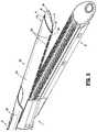
- FIG. 4is a side view of the surgical buttress of FIG. 1 , separated from the surgical stapling apparatus;
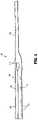
- FIG. 5is a plan view of the surgical buttress of FIG. 4 , in an unfolded condition in accordance with an embodiment of the present disclosure
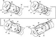
- FIG. 6is a side, perspective view of a surgical buttress loading assembly including a surgical buttress applicator and a surgical buttress in a loaded configuration in accordance with an embodiment of the present disclosure
- FIG. 7is an end, perspective view of a base of the surgical buttress applicator of FIG. 6 ;
- FIG. 8is a perspective view, with parts separated, of the surgical buttress loading assembly of FIG. 6 ;
- FIG. 9is a side view of the surgical stapling apparatus of FIG. 1 including the surgical buttress loading assembly of FIG. 6 disposed thereon;
- FIG. 10is a side view of a surgical stapling apparatus including the surgical buttress loading assembly of FIG. 9 , illustrating a handle of the surgical buttress applicator separated from a base of the surgical buttress applicator;
- FIG. 11is a perspective view of anvil and cartridge buttresses in accordance with another embodiment of the present disclosure.
- FIG. 12is a cross-sectional view of the anvil buttress of FIG. 11 ;
- FIG. 13is a perspective view of an end effector having the anvil and cartridge buttresses of FIG. 11 disposed thereon in accordance with an embodiment of the present disclosure
- FIG. 14is a perspective view of a surgical stapling apparatus having surgical buttresses disposed thereon in accordance with an embodiment of the present disclosure
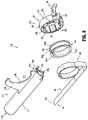
- FIG. 15is an exploded, perspective view of an anvil assembly of an end effector of the surgical stapling apparatus of FIG. 14 ;
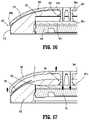
- FIG. 16is a cross-sectional, close-up view of an anvil head of the anvil assembly of FIG. 15 , illustrating an anvil cap in an approximated position securing a surgical buttress to the anvil head;
- FIG. 17is a cross-sectional, close-up view of the anvil head of FIG. 16 , illustrating the anvil cap in an unapproximated position releasing the surgical buttress from the anvil head;
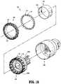
- FIG. 18is an exploded, perspective view of a staple cartridge assembly of an end effector of the surgical stapling apparatus of FIG. 14 ;
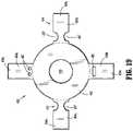
- FIG. 19is a plan view of a surgical buttress of the surgical stapling apparatus of FIG. 14 in accordance with an embodiment of the present disclosure
- FIG. 20is a perspective view of a staple cartridge assembly of the surgical stapling apparatus of FIG. 14 including the surgical buttress of FIG. 19 and a leash, illustrating a step-by-step release of the surgical buttress from the staple cartridge assembly in accordance with an embodiment of the present disclosure
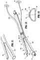
- FIG. 21is a perspective view of a surgical stapling apparatus in accordance with another embodiment of the present disclosure.
- FIG. 22is a perspective view of a surgical stapling apparatus in accordance with yet another embodiment of the present disclosure.
- proximalrefers to a portion of a structure, or component thereof, that is closer to a user
- distalrefers to a portion of the structure, or component thereof, that is farther from the user.
- Directional reference terms, such as “top,” “bottom,” “side,” and the like,are used to ease description of the embodiments and are not intended to have any limiting effect on the ultimate orientation of a structure or any part thereof.
- well-known functions or constructionsare not described in detail to avoid obscuring the present disclosure in unnecessary detail.
- the surgical stapling apparatus 1generally includes a handle assembly 10 , an elongate tubular body portion 20 extending distally from the handle assembly 10 , and an end effector or jaw assembly 30 extending distally from the elongate tubular body portion 20 .
- the jaw assembly 30includes an anvil assembly 40 and a staple cartridge assembly 50 .
- the jaw assembly 30may be permanently affixed to the elongate tubular body portion 20 or may be detachable with respect to the elongate tubular body portion 20 and thus, replaceable with a new jaw assembly 30 .
- the anvil assembly 40 and/or the staple cartridge assembly 50is pivotable with respect to the elongate tubular body portion 20 such that the anvil and/or staple cartridge assemblies 40 , 50 is movable between an open position in which the anvil and staple cartridge assemblies 40 , 50 are spaced apart with respect to each other and a closed position in which the anvil and staple cartridge assemblies 40 , 50 are substantially adjacent each other.
- the handle assembly 10includes a stationary handle member 12 a , a movable handle member 12 b , and a barrel portion 14 .
- An articulation lever 16is mounted on the forward end of the barrel portion 14 to facilitate articulation of the jaw assembly 30 .
- a rotatable member 18is also mounted on the forward end of the barrel portion 14 , adjacent the articulation lever 16 . Rotation of the rotatable member 18 relative to the barrel portion 14 rotates the elongate tubular body portion 20 and the jaw assembly 30 relative to the handle assembly 10 so as to properly orient the anvil and staple cartridge assemblies 40 , 50 relative to tissue to be stapled.
- a knob 19is movably positionable along the barrel portion 14 .
- the knob 19is advanced distally to approximate or close the anvil and staple cartridge assemblies 40 , 50 , relative to each other, and retracted proximally to unapproximate or open the anvil and staple cartridge assemblies 40 , 50 , with respect to each other. Actuation of the movable handle member 12 b applies lines of staples 58 ( FIG. 2 ) to tissue captured between the anvil and staple cartridge assemblies 40 , 50 .
- the anvil assembly 40includes an anvil plate 42 having a central longitudinal slot 41 formed therein, and a cover plate 44 secured over the anvil plate 42 such that the cover plate 44 defines a top or outwardly facing surface 46 of the anvil assembly 40 .
- the anvil plate 42may include a plurality of staple forming pockets/cavities (not shown) defined in an inwardly or tissue facing surface 48 thereof.
- the staple cartridge assembly 50includes a cartridge carrier 52 defining an elongated support channel 51 configured and dimensioned to selectively receive a staple cartridge 54 therein.
- the cartridge carrier 52also defines a bottom or outwardly facing surface 53 of the staple cartridge assembly 50 .
- the staple cartridge 54is removable and replaceable in the cartridge carrier 52 of the staple cartridge assembly 50 .
- the staple cartridge 54includes an inwardly or tissue facing surface 56 defining staple pockets or retention slots 55 formed therein for receiving a plurality of fasteners or staples 58 and staple pushers 60 .
- a central longitudinal slot 57is formed in and extends along a substantial length of the staple cartridge 54 to facilitate passage of a knife blade 62 of a drive bar 64 therethrough.
- an actuation sled 66translates through the staple cartridge 54 to advance cam wedges 68 of the actuation sled 66 into sequential contact with the staple pushers 60 , to cause the staple pushers 60 to translate vertically within the staple pockets 55 and urge the staples 58 from the staple pockets 55 towards the tissue facing surface 48 of the anvil plate 42 of the anvil assembly 40 .
- surgical stapling apparatusmay be utilized with the surgical buttresses and/or surgical buttress applicators of the present disclosure such as, for example, laparoscopic staplers, open staplers, transverse anastomosis staplers, and end-to-end anastomosis staplers having a circular staple cartridge and anvil, as well as staple cartridge assemblies housing surgical fasteners other than staples.
- a surgical buttress 100is shown releasably coupled to the anvil assembly 40 of the surgical stapler 1 .
- the surgical buttress 100is fabricated from biocompatible materials which are bioabsorbable or non-absorbable, natural or synthetic materials. It should be understood that any combination of natural, synthetic, bioabsorbable, and/or non-bioabsorbable materials may be used to form the surgical buttress 100 .
- the surgical buttress 100may be biodegradable (e.g., formed from bioabsorbable and bioresorable materials) such that the surgical buttress 100 decomposes or is broken down (physically or chemically) under physiological conditions in the body, and the degradation products are excretable or absorbable by the body. Components or portions of the surgical buttress 100 may be formed from the same material or different materials.
- At least a portion of the surgical buttress 100is made from biodegradable materials selected from the following group: natural collagenous materials, cat gut, and synthetic resins including those derived from alkylene carbonates, trimethylene carbonate, tetramethylene carbonate, caprolactone, valerolactone, dioxanone, polyanhydrides, polyesters, polyacrylates, polymethylmethacrylates, polyurethanes, glycolic acid, lactic acid, glycolide, lactide, polyhydroxy butyrates, polyorthoester, polyhydroxy alkanoates, homopolymers thereof, and copolymers thereof.
- biodegradable materialsselected from the following group: natural collagenous materials, cat gut, and synthetic resins including those derived from alkylene carbonates, trimethylene carbonate, tetramethylene carbonate, caprolactone, valerolactone, dioxanone, polyanhydrides, polyesters, polyacrylates, polymethylmethacrylates, polyurethanes, glycolic acid, lactic acid,
- the surgical buttress 100is made from non-biodegradable materials selected from the following group: polyolefins, polyethylene, polydimethylsiloxane, polypropylene, copolymers of polyethylene and polypropylene, blends of polyethylene and polypropylene, ultra high molecular weight polyethylene, polyamides, polyesters, polyethylene terephthalate, polytetrafluoroethylene, polyether-esters, polybutester, polytetramethylene ether glycol, 1,4-butanediol, and polyurethanes.
- non-biodegradable materialsselected from the following group: polyolefins, polyethylene, polydimethylsiloxane, polypropylene, copolymers of polyethylene and polypropylene, blends of polyethylene and polypropylene, ultra high molecular weight polyethylene, polyamides, polyesters, polyethylene terephthalate, polytetrafluoroethylene, polyether-esters, polybutester, polyte
- the surgical buttress 100may be porous, non-porous, or combinations thereof.
- Suitable porous structuresinclude, for example, fibrous structures (e.g., knitted structures, woven structures, and non-woven structures) and/or foams (e.g., open or closed cell foams).
- Suitable non-porous structuresinclude, for example, films.
- the surgical buttress 100 , or portions thereofmay be a non-woven structure formed by melt-blown or melt-spun methods, a mesh material, a braid material, and/or a molded or extruded sheet.
- the surgical buttress 100 , or portions thereofmay be a single porous or non-porous layer, or include a plurality of layers including any combination of porous and/or non-porous layers.
- the surgical buttress 100includes an elongate member 102 , a folded portion 104 , and a buttress portion 106 .
- the elongate member 102is coupled to the folded portion 104
- the folded portion 104is coupled to the buttress portion 106 and is separable therefrom by perforations 108 .
- the folded portion 104 and the buttress portion 106form a tubular body 110 that is sized and shaped to facilitate the reception of the anvil assembly 40 and/or the staple cartridge assembly 50 therethrough.
- the elongate member 102is secured to the folded portion 104 of the surgical buttress 100 and extends proximally therefrom.
- the elongate member 102is of a sufficient length to be accessible outside of a patient's body and may extend the length of the elongate tubular body portion 20 of the surgical stapler 1 .
- the elongate member 102may be a band, a cord, a rope, a strap, a suture, among other elongate structures tethered to or integrally formed with the folded portion 104 of the surgical buttress 100 .
- the elongate member 102may include two or more elongate sections such as, for example, a suture attached to a strip of material that extends proximally from the folded portion 104 of the surgical buttress 100 .
- the folded portion 104 and the elongate member 102separate from the buttress portion 106 along the perforations 108 .
- the perforations 108may be omitted from the surgical buttress 100 .
- the juncture between the folded portion 104 and the buttress portion 106may be formed or otherwise secured to one another to facilitate separation of the folded portion 104 from the buttress portion 106 upon application of a force to the elongate member 102 .
- the folded portion 104can include one or more sections of material, and can be made from the same material as the buttress portion 106 , or from a different material, as discussed above.
- the folded portion 104can be secured to itself to form the tubular body 110 and/or the buttress portion 106 can be attached to the folded portion 104 or itself.
- the folded portion 104 and/or the buttress portion 106 , or sections thereof,may be integrally formed or secured together via any suitable attachment features within the purview of those skilled in the art, such as, mechanical attachment features (e.g., sutures, pins), chemical attachment features (e.g., adhesives), and/or attachment methods (e.g., welding).
- the folded portion 104can include first and second sections 112 , 114 secured to one another. In embodiments, the first and second sections 112 , 114 are welded to each other.
- the elongate member 102can be unitary with the folded portion 104 and/or may be permanently secured to the folded portion 104 . As seen in FIG. 4 , the elongate member 102 can be integrally formed with the first section 112 of the folded portion 104 and attached to the second section 114 by welding at an attachment region 113 .
- the elongate member 102can include one or more elongate sections, as discussed above, and can be made from the same material, or different material, as the folded and/or buttress portions 104 , 106 .
- the surgical buttress 100is disposed on the anvil assembly 40 of the stapler 1 with the buttress portion 106 positioned over the tissue facing surface 48 of the anvil assembly 40 , the folded portion 104 positioned over the outwardly facing surface 46 of the anvil assembly 40 , and the elongate member 102 extending proximally along the elongate tubular body portion 20 of the surgical stapler 1 .
- the perforations 108are positioned adjacent side surfaces 49 of the anvil assembly 40 that interconnect the outwardly and tissue facing surfaces 46 , 48 of the anvil assembly 40 .
- the perforations 108can be any size and shape, such as small pin-holes or larger openings such as, for example, the elongated openings shown in FIG. 3 , or the perforations 108 can be a single feature, such as a line of weakness in the buttress material or materials forming the folded and buttress portions 104 , 106 .
- the perforations 108may be formed using laser cutting, knife cutting, press cutting, scoring, etching, among other methods within the purview of those skilled in the art.
- the surgical buttress 100is formed from a non-woven polyglycolide material that is laser cut to form the perforations 108 .
- the entire surgical buttress 100may be formed from a single sheet of material 120 .
- the surgical buttress 100is cut from the single sheet of material 120 and the perforations 108 are formed therein.
- the single sheet of material 120is cut such that the surgical buttress 100 includes the elongate member 102 , the folded portion 104 including first and second sections 112 , 114 , and the buttress portion 106 .
- the first and second sections 112 , 114 of the folded portion 104can be folded and attached to one another before the surgical buttress 100 is disposed on or around the anvil assembly 40 of the surgical stapler 1 (e.g., prior to loading the surgical buttress 100 into a surgical buttress applicator 200 ( FIG.
- first and second sections 112 , 114 of the folded portion 104can be attached to one other by, for example, welding, using adhesives, tying sutures, etc.
- the surgical buttress loading assembly 201includes a surgical buttress applicator 200 configured for positioning the surgical buttress 100 onto a surgical stapler 1 ( FIG. 1 ) and/or removing the elongate member 102 and the folded portion 104 ( FIG. 1 ) of the surgical buttress 100 from a surgical site.
- the surgical buttress applicator 200includes a base 210 sized and shaped to releasably retain the tubular body 110 ( FIG. 3 ) of the surgical buttress 100 therein, and a handle 220 configured to retain the elongate member 102 of the surgical buttress 100 therein.
- the base 210includes an elongate body 212 having a proximal end 212 a and a distal end 212 b , and defines a cavity 213 therein.
- the cavity 213is sized and shaped to slidably receive at least one of the anvil or staple cartridge assembly 40 , 50 ( FIG. 1 ) of the surgical stapler 1 therein.
- the elongate body 212includes a first or substantially flat wall section 214 a corresponding to the tissue facing surface 48 , 56 ( FIG.
- anvil or staple cartridge assembly 40 , 50 of the surgical stapler 1and a second or rounded wall section 214 b configured to extend around the anvil or staple cartridge assembly 40 , 50 and over the outwardly facing surface 46 , 53 ( FIG. 2 ) of the anvil or staple cartridge assembly 40 , 50 .
- the proximal end 212 a of the elongate body 212defines an opening into the cavity 213 of the base 210 , and the distal end 212 b is closed by a distal wall section 214 c . It is envisioned, however, that the distal end 212 b of the elongate body 212 may be open.
- the proximal end 212 afurther includes first and second tabs 216 a , 216 b extending proximally and axially from the respective first and second wall sections 214 a , 214 b of the elongate body 212 in opposed relation relative to each other.
- the first and second tabs 216 a , 216 bare configured to engage the surgical buttress 100 .
- the base 210 of the surgical buttress applicator 200further includes a fin 218 .
- the fin 218extends from the second wall section 214 b of the elongate body 212 .
- the fin 218includes a concave wall 218 a defining an arcuate cut-out 219 configured to receive the handle 220 therein.
- the handle 220includes an outer handle housing 230 and an inner handle housing 240 rotatably disposed within the outer handle housing 230 .
- the elongate member 102 of the surgical buttress 100is spooled, wound or rolled around the inner handle housing 240 and extends through a slot 237 defined through the outer handle housing 230 such that the tubular body 110 of the surgical buttress 100 is positionable within the cavity 213 of the base 210 .
- the outer handle housing 230includes an outer wall 232 and an inner wall 234 defining an annular cavity 233 therebetween.
- the outer wall 232includes a groove 235 defined therein that corresponds with, and is configured to frictionally engage, the concave wall 218 a of the fin 218 of the base 210 to releasably retain the handle 220 within the arcuate cut-out 219 of the base 210 .
- the outer handle housing 230further includes a pair of fingers 236 extending from the outer wall 232 that are configured to releasably engage the elongate tubular body portion 20 ( FIG. 1 ) of the surgical stapler 1 , and a slot 237 defined through the outer wall 232 that is sized and shaped for passage of the elongate member 102 of the surgical buttress 100 therethrough.
- the inner wall 234 of the outer handle housing 230includes flexible wall segments 238 extending radially around a central opening 239 defined in the outer handle housing 230 .
- the flexible wall segments 238are movable to allow a user to insert or remove the inner handle housing 240 into or out of the annular cavity 233 of the outer housing 230 .
- At least one of the flexible wall segments 238includes a lip 238 a extending towards the outer wall 232 to help retain the inner handle housing 240 within the annular cavity 233 .
- At least two flexible wall segments 238may each include a lip 238 a extending therefrom and, in some embodiments, alternating flexible wall segments 238 may each include a lip 238 a extending therefrom.
- the inner handle housing 240is concentric with and configured to be received within the annular cavity 233 of the outer handle housing 230 .
- the inner handle housing 240includes an annular base 242 having an inner surface 242 a configured to engage the inner wall 234 of the outer handle housing 230 and to be rotatably mounted thereon.
- the arcuate base 242also includes an outer surface 242 b that is configured to receive the elongate member 102 of the surgical buttress 100 therearound.
- Annular flanges 244 a , 244 bextend from opposed sides of the annular base 242 adjacent respective sides of the elongate member 102 when the elongate member 102 is wrapped around the annular base 242 .
- the elongate member 102 of the surgical buttress 100is wrapped around the outer surface 242 b of the annular base 242 of the inner handle housing 240 such that the elongate member 102 conforms to the contour of the annular base 242 .
- the elongate member 102is wound around the annular base 242 such that a majority of the elongate member 102 is wound around the inner handle housing 240 , and the tubular body 110 of the surgical buttress 100 freely extends therefrom.
- a terminal end of the elongate member 102may be secured to the inner handle housing 240 and/or to itself (e.g., the terminal end may form a closed loop 107 a ( FIG.
- the tubular body 110is passed through the slot 237 of the outer handle housing 230 and pulled therethrough, and the inner handle housing 240 is inserted into the annular cavity 233 of the outer handle housing 230 .
- the assembled handle 220is positioned within the arcuate cut-out 219 of the base 210 of the surgical buttress applicator 200 , and the tubular body 110 of the surgical buttress 100 , which includes the folded and buttress portions 104 , 106 of the surgical buttress 100 , is positioned within the cavity 213 of the base 210 of the surgical buttress applicator 200 .
- the folded portion 104 of the surgical buttress 100is positioned adjacent to the second wall section 214 b of the base 210 and the buttress portion 106 is disposed adjacent to the first wall section 214 a of the base 210 such that the tubular body 110 is open to receive the anvil or staple cartridge assembly 40 , 50 therein.
- the inner handle member 240may then be rotated relative to the outer handle member 230 to wind or unwind the elongate member 102 around the inner handle member 240 so that the elongate member 102 is made taut as shown in FIG. 6 .
- the portion of the elongate member 102 extending between the base 210 and the handle 220 of the surgical buttress applicator 200is secured to the second tab 216 b of the base 210 to help retain the tubular body 110 of the surgical buttress 100 within the base 210 .
- the second tab 216 bis positioned through an aperture 103 defined through the elongate member 102 .
- the aperture 103may be formed during assembly of the surgical buttress 100 into the surgical buttress applicator 200 , or the aperture 103 may be pre-formed in the surgical buttress 100 prior to assembly.
- the first tab 216 a of the base 210 of the surgical buttress applicator 200may be engaged with an aperture 105 ( FIG. 13 ) defined in the buttress portion 106 of the surgical buttress 100 to further help retain the tubular body 110 within the base 210 in an open configuration for receiving the anvil or staple cartridge assembly 40 , 50 therein.
- the surgical buttress loading assembly 201is applied to the anvil assembly 40 of the surgical stapler 1 .
- a usergrasps the handle 220 of the surgical buttress applicator 200 and manipulates the surgical buttress loading assembly 201 onto the anvil assembly 40 by aligning the cavity 213 ( FIG. 7 ) of the base 210 with the distal end of the anvil assembly 40 and sliding the surgical buttress applicator 200 proximally over the anvil assembly 40 until the anvil assembly 40 abuts the distal wall section 214 c ( FIG. 7 ) of the base 210 .
- the shape (e.g., a transverse cross-sectional shape/profile) of the cavity 213 of the base 210corresponds to the shape (e.g., a transverse cross-sectional shape/profile) of the anvil assembly 40 (or the staple cartridge assembly 50 ) for ease of application of the surgical buttress 100 thereon.
- the handle 220 of the surgical buttress applicator 200is detached from the base 210 and pulled proximally towards the user, thereby unrolling the elongate member 102 from within the handle 220 of the surgical buttress applicator 200 , as shown in FIG. 10 .
- the handle 220is secured to the elongate tubular body portion 20 of the surgical stapler 1 via the pair of fingers 236 of the outer handle housing 230 at a position proximal of the end effector 30 , such as adjacent to the handle assembly 10 ( FIG.
- the surgical stapler 1can then grasp the base 210 of the surgical buttress applicator 200 and slide it distally off of the anvil assembly 40 .
- the base 210may be removed from the anvil assembly 40 either prior to, or after, attaching the handle 220 to the surgical stapler 1 .
- the surgical buttress 100disengages from the second tab 216 b of the base 210 such that the surgical buttress 100 is left loaded on the anvil assembly 40 .
- the surgical stapler 1is now ready for use.
- the loaded surgical stapler 1is introduced to a surgical site through a trocar or other access device.
- the surgical stapler 1is operated within methods known by those skilled in the art.
- the surgical stapler 1is fired.
- the drive bar 64( FIG. 2 ) is advanced distally through the jaw assembly 30 urging the staple pushers 60 upwardly which, in turn, drive the staples 58 out of the staple pockets 55 and through the buttress portion 106 of the surgical buttress 100 as well as the captured tissue, thereby stapling the buttress portion 106 to the tissue.
- the knife blade 62 of the drive bar 64travels distally while substantially simultaneously cutting and dividing the tissue as well as the buttress portion 106 of the surgical buttress 100 disposed between the rows of now formed staples 58 .
- the folded portion 104 and the elongate member 102 of the surgical buttress 100can then be detached from the now-stapled buttress portion 106 by pulling the handle 220 proximally to tear the folded portion 104 from the buttress portion 106 via the perforations 108 .
- the handle 220may be pulled separately from the surgical stapler 1 by detaching the handle 220 from the elongate tubular body portion 20 of the surgical stapler 1 , or the handle 220 may be pulled when the surgical stapler 1 is pulled proximally away from the surgical site. Alternatively, the user may grasp an exposed portion of the elongate member 102 and pull the elongate member 102 directly.
- a surgical buttress loading assemblymay be applied to the staple cartridge assembly of the surgical stapler and/or either the anvil assembly or the staple cartridge assembly can include a buttress material pre-loaded thereon.
- the staple cartridge assemblymay have a buttress pre-loaded onto it by the manufacturer.
- the usercan utilize a surgical buttress loading assembly that is ready for installation on the anvil assembly, as discussed above.
- the surgical stapling apparatuscan be re-used on the same patient by reloading it with a staple cartridge assembly having a fresh set of staples ready to be fired and a fresh buttress material.
- a new surgical buttress loading assemblymay be applied to the anvil assembly, as discussed above, or a fresh surgical buttress may be installed into the surgical buttress applicator, as also discussed above.
- the surgical buttress loading assemblycan be sized and shaped to correspond to a particular jaw onto which it is to be assembled.
- a first surgical buttress loading assemblymay have a shape corresponding to the shape of the anvil assembly and a second surgical buttress loading assembly may have a shape corresponding to the staple cartridge assembly.
- the anvil assembly 40has a lower profile and is more curved in shape than the staple cartridge assembly 50 , which is deeper and may be rounded or more rectangular in shape.
- the surgical buttress and the surgical buttress applicator of the present disclosuremay be any size and/or shape to accommodate a variety of surgical stapler sizes and/or configurations.
- surgical buttressesshown as anvil and cartridge buttresses 100 a , 100 b
- surgical buttress applicatorsare configured for use with the anvil and cartridge buttresses 100 a , 100 b .
- the anvil and cartridge buttresses 100 a , 100 beach include an elongate member 102 a , 102 b , a folded portion 104 a , 104 b , and a buttress portion 106 a , 106 b .
- Perforations 108 a , 108 bare disposed between the folded portion 104 a , 104 b and the buttress portion 106 a , 106 b of the respective anvil and cartridge buttress 100 a , 100 b , and are optimized to allow for sequential detachment of the folded portion 104 a , 104 b from the buttress portion 106 a , 106 b when the elongate member 102 a , 102 b is pulled.
- the folded portion 106 a , 106 b and the buttress portion 106 a , 106 bare formed from a single sheet of material having the perforations 108 a , 108 b formed therein, and the elongate member 102 a , 102 b is attached to the respective folded portion 106 a , 106 b .
- Loops 107 a , 107 bare disposed at terminal ends of the respective elongate member 102 a , 102 b and are configured for positioning around the inner handle housing of the respective surgical buttress applicator with which the anvil and cartridge buttresses 100 a , 100 b are utilized.
- the surgical buttressmay be provided and/or sold as part of the surgical buttress loading assembly that includes the surgical buttress and the surgical buttress applicator.
- the surgical buttress and the surgical buttress applicatormay be provided and/or sold separately and assembled by the user.
- one or more surgical buttresses and one or more surgical buttress applicatorsare provided in a kit.
- the kitfurther includes one or more end effectors and, in certain embodiments, the kit further includes a surgical stapler.
- a surgical stapling apparatus or surgical stapler 2 in the form of an annular surgical stapling deviceis shown for use in stapling tissue and applying one or more buttress materials or surgical buttresses to tissue.
- the surgical stapler 2generally includes a handle assembly 310 , an elongate tubular body 320 extending distally from the handle assembly 310 , and an end effector 330 extending distally from the elongate tubular body 320 .
- the end effector 330includes an anvil assembly 332 and a staple cartridge assembly 334 .
- the anvil assembly 332is releasably coupled to a distal end portion 322 of the elongate tubular body 320 , and the staple cartridge assembly 334 is disposed at the distal end portion 322 of the elongate tubular body 320 .
- the handle assembly 310includes at least one movable handle member 312 for actuating the firing of staples 410 ( FIG. 18 ) from the staple cartridge assembly 334 and the cutting of tissue secured between the anvil and staple cartridge assemblies 332 , 334 .
- the handle assembly 310further includes an advancing member 314 for moving the anvil assembly 332 between an open or spaced apart position and a closed or approximated position relative to the staple cartridge assembly 334 .
- the elongate tubular body 320may be flexible or rigid, and/or straight or curved along a portion or the entirety thereof. It should be understood that the elongate tubular body 320 may be otherwise configured (e.g., shaped and/or dimensioned) depending on, for example, the surgical application or procedure of use as is within the purview of those skilled in the art.
- the staple cartridge assembly 334may be fixedly connected to the distal end portion 322 of the elongate tubular body 320 or may be configured to concentrically fit within, or be otherwise connected to, the distal end portion 322 of the elongate tubular body 320 such that the staple cartridge assembly 334 is removable and replaceable.
- the anvil assembly 332includes a head assembly 350 and a center rod assembly 360 pivotally secured to the head assembly 350 .
- the head assembly 350includes a central post or connector 351 , a housing or anvil head 352 , a backup plate 353 , a cut ring assembly 354 , an anvil plate 356 , and a spacer 358 .
- the connector 351extends proximally from the housing 352 and is dimensioned to operatively couple to a first end portion 362 a of a center rod 362 of the center rod assembly 360 .
- the connector 351may be substantially centrally positioned through a bore (not shown) defined in the housing 352 , or the connector 351 may be integrally or monolithically formed with the housing 352 .
- One or more openings 352 aare defined through the housing 352 , and the housing 352 includes an inner annular recess 352 b and an outer annular recess 352 c supporting the backup plate 353 , the cut ring assembly 354 , the anvil plate 356 , and the spacer 358 therein.
- the anvil plate 356is supported in the outer annular recess 352 c of the housing 352 and includes a tissue facing surface 357 having a plurality of staple forming pockets 357 a for receiving and deforming staples.
- the anvil plate 356may include at least one tab 356 a extending radially outwardly form the anvil plate 356 that is received within a cutout 352 d formed in an outer rim of the housing 352 .
- the tab 356 a and the cutout 352 dfunction to align and/or properly locate and retain the anvil plate 356 within the outer annular recess 352 c of the housing 352 .
- the inner annular recess 352 bis located between the connector 351 and the outer annular recess 352 c .
- the backup plate 353includes a substantially centrally located opening 353 a positioned and slidably mounted about the connector 351 within the inner annular recess 352 b .
- the backup plate 353includes a raised center platform 353 b and a pair of inwardly extending fingers 353 c , although other configurations are envisioned.
- the cut ring assembly 354includes a body 354 a and a cover 354 b .
- the body 354 aincludes an opening 355 a having an inner configuration substantially the same as the platform 353 b of the backup plate 353 to facilitate positioning of the cut ring assembly 354 about the platform 353 b .
- the cover 354 bincludes a substantially centrally located opening 355 b for receiving the connector 351 and is secured to an outwardly facing or proximal surface of the body 354 a .
- the cut ring assembly 354may be fixedly secured or otherwise fastened to the backup plate 353 .
- the spacer 358is positioned in the inner annular recess 352 b of the housing 352 between the backup plate 353 and an inner or proximally facing surface 352 e of the housing 352 .
- the spacer 358is annular and may include deformable tabs 358 a which engage a distally facing surface of the backup plate 353 .
- the spacer 358prevents the backup plate 353 and the cut ring assembly 354 from moving or being pushed into the inner annular recess 352 b of the housing 352 until a predetermined force sufficient to deform the tabs 358 a has been applied to the backup plate 353 and the cut ring assembly 354 .
- the predetermined forcemay be, for example, close to but less than the force applied by an annular knife 420 ( FIG. 18 ) of the staple cartridge assembly 334 to the cut ring assembly 354 as the surgical stapler 2 is fired.
- the predetermined forceWhen the predetermined force is reached, e.g., during cutting of tissue, the backup plate 353 and the cut ring assembly 354 will move into the inner annular recess 352 b of the housing 252 and compress the spacer 358 .
- other crushable, deformable, collapsible, and/or movable spacing membersmay be used to retain the backup plate 353 and the cut ring assembly 354 in a fixed position until the predetermined force has been applied to the backup plate 353 and the cut ring assembly 354 .
- the backup plate 353may be omitted and the cut ring assembly 354 may be configured for positioning about the connector 351 within the housing 352 with the spacer 358 positioned in the inner annular recess 352 b of the housing 352 between the cutting ring assembly 354 and the inner surface 352 e of the housing 352 .
- the center rod assembly 360includes a center rod or anvil shaft 362 , a plunger 364 , and a plunger spring 365 .
- a pivot pin 366pivotably secures the connector 351 of the head assembly 350 to the center rod 362 via throughbores 367 such that the head assembly 350 is pivotably mounted to the center rod assembly 360 .
- the plunger 364is slidably positioned in a bore 363 a formed in a first end portion 362 a of the center rod 362 .
- the plunger 364includes an engagement finger 364 a biased into engagement with the connector 351 by the plunger spring 365 to urge the head assembly 350 from a non-tilted or operative position to a pivoted or tilted position on the center rod 362 .
- the fingers 353 c formed on the backup plate 353engage a top surface 362 b of the center rod 362 to prevent the head assembly 350 from pivoting about the pivot pin 366 .
- the backup plate 353 and the cut ring assembly 354are pushed into the inner annular recess 352 b of the housing 352 about the connector 351 by the annular knife 420 ( FIG. 18 ) to move the fingers 353 c of the backup plate 353 out of engagement with the top surface 362 b of the center rod 362 and to permit the plunger 364 to pivot the head assembly 350 about the pivot pin 366 .
- the spacer 358prevents inadvertent or premature movement of the backup plate 353 and the cut ring assembly 354 to prevent premature or inadvertent tilting of the head assembly 350 .
- a retaining clip 368is positioned in a transverse slot 351 a formed in the connector 351 and is operatively engaged with the pivot pin 366 .
- the retaining clip 368is configured to prevent the backup plate 353 and the cut ring assembly 354 from sticking to the annular knife 420 when the anvil assembly 332 is moved away from the staple cartridge assembly 334 .
- a second end portion 362 c of the center rod 362includes a bore 363 b defined by flexible arms 362 d .
- the flexible arms 362 dare configured and dimensioned to releasably secure a trocar (not shown) of the surgical stapler 2 to the center rod 362 of the anvil assembly 332 .
- a plurality of splines 362 eare formed about the center rod 362 to align the anvil assembly 332 with the staple cartridge assembly 334 of the surgical stapler 2 , and a recessed portion 362 f of the center rod 362 facilitates grasping of the anvil assembly 332 by a user (e.g., with a grasper).
- a surgical buttress 370is releasably coupled to the anvil assembly 332 of the surgical stapler 2 via an anvil cap 380 .
- the surgical buttress 370may be fabricated from biocompatible materials which are bioabsorbable or non-absorbable, natural or synthetic materials, or combinations thereof, and may be porous, non-porous, or combinations thereof, as described above with respect to the surgical buttress 100 , 200 .
- the surgical buttress 370includes a body or buttress portion 372 and a plurality of legs 374 extending radially outwardly from the body portion 372 .
- the body portion 372has a generally circular or annular configuration defining a central aperture 373 therethrough.
- the body portion 372is sized and dimensioned to extend over (e.g., completely cover) the tissue facing surface 357 of the anvil assembly 332 .
- the central aperture 373is sized and dimensioned to allow passage of the center rod 362 of the anvil assembly 332 therethrough.
- the central aperture 373has a diameter that is larger than the diameter of the center rod 362 of the anvil assembly 332 and, in some embodiments, the central aperture 373 has a diameter that is about the same as or smaller than the diameter of the center rod 362 such that the center rod 362 frictionally engages the surgical buttress 370 .
- the legs 374 of the surgical buttress 370extend from the body portion 372 radially beyond the tissue facing surface 357 of the anvil assembly 332 such that the legs 374 can be wrapped around the housing 352 of the anvil assembly 332 . While the legs 374 are shown extending linearly and uniformly from the body portion 372 , other configurations of the legs 374 are envisioned.
- the surgical buttress 370is disposed on the anvil assembly 332 of the surgical stapler 2 with the body portion 372 selectively supported on and positioned over the tissue facing surface 357 of the anvil plate 356 and the legs 374 selectively positioned around the housing 352 such that free ends 374 a of the legs 374 are adjacent an outer or distal surface 352 f of the housing 352 .
- the legs 374are releasably secured against the distal surface 352 f of the housing 352 by the anvil cap 380 .
- the anvil cap 380includes a cap body 382 supported on the distal surface 352 f of the housing 352 .
- the cap body 382includes one or more pegs 384 extending proximally from an inner or proximal wall 382 a of the cap body 382 .
- Each peg 384has a split body including first and second legs 384 a , 384 b terminating at flanged ends 384 c .
- the first and second legs 384 a , 384 bare deflectable inwardly and outwardly relative to each other.
- the pegs 384are positionable through the openings 352 a defined in the housing 352 to facilitate securement of the anvil cap 380 to the housing 352 and to permit the anvil cap 380 to move relative to the housing 352 between an approximated or closed position and an unapproximated or open position, as described in further detail below.
- the anvil cap 380is utilized to releasably attach the surgical buttress 370 to the anvil assembly 332 .
- the pegs 384 of the anvil cap 380are positioned through the openings 352 a of the housing 352 of the anvil assembly 332 such that the proximal wall 382 a of the anvil cap 380 abuts the distal surface 352 f of the housing 352 , and engages and holds the legs 374 of the surgical buttress 370 therebetween.
- the legs 374 of the surgical buttress 370are retained between a curved rim 382 b of the body 382 of the anvil cap 380 and the distal surface 352 f of the housing 352 .
- the flanged ends 384 c of the pegs 384 of the anvil cap 380are positioned adjacent to (e.g., against) the backup plate 353 of the anvil assembly 332 .
- the cutting ring assembly 354 and the backup plate 353are moved towards and into engagement with the pegs 384 to move the anvil cap 380 to the unapproximated position, as shown in FIG. 17 .
- the pegs 384 and thus, the anvil cap 380are moved distally or axially away from the housing 352 to create a gap “G” between the housing 352 and the anvil cap 380 such that the legs 374 of the surgical buttress 370 can be released from the anvil assembly 332 and the surgical buttress 370 can separate from the anvil assembly 332 .
- the flanged ends 384 c of the pegs 384act as self-locking features to ensure that the anvil cap 380 remains attached to, and does not pop off the housing 352 when moved between the approximated and unapproximated positions.
- the body portion 372 of the surgical buttress 370is position adjacent to the tissue facing surface 357 of the anvil plate 356 and the legs 374 are wrapped around the housing 352 of the anvil assembly 332 such that the free ends 374 a of the legs 370 of the surgical buttress 374 are positioned adjacent the distal surface 352 f of the housing 352 .
- the anvil cap 380is then attached to the housing 352 by aligning the pegs 384 with the openings 352 a defined in the housing 352 and axially pushing the anvil cap 380 towards the housing 352 and into the approximated position such that the legs 374 of the surgical buttress 370 are trapped between the anvil cap 380 and the housing 352 .
- the first and second legs 384 a , 384 b of each of the pegs 384are deflected towards each other as the flanged ends 384 c are compressed into the opening 352 a of the housing 352 and then return to their biased position such that the flanged ends 384 c of the pegs 384 are slidably retained within the housing 352 .
- the anvil assembly 332with loaded surgical buttress 370 , is ready for use with the surgical stapler 2 according to methods within the purview of those skilled in the art.
- the staple cartridge assembly 334is disposed at the distal end portion 322 of the elongate tubular body 320 of the surgical stapler 2 and is configured to fire and form an annular array of surgical fasteners or staples, and to sever a ring of tissue.
- the staple cartridge assembly 334includes a housing 390 having a staple guide 400 , a plurality of staples 410 , an annular knife 420 , and a staple pusher 430 disposed therein.
- the staple guide 400includes a tissue facing surface 402 defining at least one annular array of staple receiving slots 404 therein.
- the plurality of staples 410are disposed, one each, in each of the staple receiving slots 404 .
- the staple pusher 430includes a proximal portion 430 a having a generally frusto-conical shape and a distal portion 430 b defining at least one concentric ring of peripherally spaced fingers 432 , each of which is received within one of the respective staple receiving slots 404 of the staple guide 400 .
- the annular knife 420is mounted to the staple pusher 430 and is substantially in the form of an open cup with a rim thereof defining a knife edge 422 .
- the annular knife 420is disposed radially inward of the staples 410 and the staple receiving slots 404 of the staple guide 400 such that, in use, as the staple pusher 430 is advanced, the annular knife 420 is also advanced axially in a linear direction.
- a surgical buttress assembly 440is releasably coupled to the staple cartridge assembly 334 of the surgical stapler 2 .
- the surgical buttress assembly 440includes a surgical buttress 450 and an elongate member, tether or leash 460 .
- the surgical buttress 450may be fabricated from biocompatible materials which are bioabsorbable or non-absorbable, natural or synthetic materials, or combinations thereof, and may be porous, non-porous, or combinations thereof, as described above with respect to the surgical buttress 100 , 200 , 370 .
- the surgical buttress 450is substantially the same as surgical buttress 370 and includes a body or buttress portion 452 and a plurality of legs 454 extending radially outwardly from the body 452 .
- the body 452has a generally circular or annular configuration defining a central aperture 453 therethrough.
- the body 452is sized and dimensioned to extend over (e.g., completely cover) the tissue facing surface 402 of the staple cartridge assembly 334 .
- the central aperture 453is sized and dimensioned to allow passage of the center rod 362 of the anvil assembly 332 therethrough.
- the legs 454 of the surgical buttress 450extend from the body 452 radially beyond the tissue facing surface 402 of the staple cartridge assembly 334 . Together, the body 452 and the legs 454 are sized and shaped to be positioned over the staple cartridge assembly 334 .
- the elongate member 460is secured to the legs 454 of the surgical buttress 450 and extends proximally therefrom.
- the elongate member 460is of a sufficient length to be accessible outside of a patient's body and may extend the length of the elongate tubular body 320 of the surgical stapler 2 (e.g., at least to or beyond the handle assembly 310 ).
- the elongate member 460may be wrapped or loosely tied along the length of the elongate tubular body 320 , or the elongate member 460 may extend freely along the length thereof.
- the elongate member 460may be a band, a cord, a rope, a strap, a suture, among other elongate structures tethered to the legs 454 of the surgical buttress 450 .
- the legs 454 of the surgical buttress 450are disposed equidistantly around the body 452 .
- Each of the legs 374is configured to include at least one opening or cutout disposed in a portion of the leg 454 adjacent the body 452 that will be aligned with the elongate member 460 ( FIG. 14 ).
- a first leg 454 aincludes a pair of openings 455 defined therein, a second leg 454 b disposed in opposed relation relative to the first leg 454 a defines an elongated opening or slot 456 therein, and third and fourth legs 454 c , 454 d each include a pair of opposed cutouts 457 (e.g., recesses or notches) defined therein.
- a central portion 460 a of the elongate member 460is looped through the pair of openings 455 defined in the second leg 454 a , and first and second elongated portions 460 b , 460 c of the elongate member 460 are passed under the second and third legs 454 c , 454 d , respectively, such that the elongate member 460 is aligned with and positioned beneath the opposed cutouts 457 defined in the third and fourth legs 454 c , 454 d .
- first and second elongated portions 460 b , 460 care then passed through the elongated opening 456 of the second leg 454 b and guided proximally along the elongate tubular body 320 of the surgical stapler 2 .
- a sleeve tube 480is utilized to hold free ends 454 e of the legs 454 against the housing 390 of the staple cartridge assembly 334 .
- the free ends 454 e of the legs 454may be secured to the staple cartridge assembly 334 via any suitable attachment features within the purview of those skilled in the art, such as, mechanical attachment features (e.g., sutures, pins), chemical attachment features (e.g., adhesives), and/or attachment methods (e.g., welding).
- the elongate member 460breaks (e.g., cuts or tears) through the legs 454 of the surgical buttress 450 as shown in FIG. 20 .
- the elongate member 460first tears through the second leg 454 b of the surgical buttress 450 , then through the third and fourth legs 454 c , 454 d , and finally through the first leg 454 a thus separating the legs 454 from the body 452 so that the body 452 is free and the legs 454 remain secured to the staple cartridge assembly 334 .
- legs 454 of the surgical buttress 450are also envisioned that are suitable for separating the legs 454 from the body 452 of the surgical buttress 450 (e.g., weakened, perforated, and/or thinner regions of the legs) via the elongate member 460 .
- the loaded surgical stapler 2is introduced to a surgical site.
- the surgical stapler 2 and detachable anvil assembly 332are used in an anastomosis procedure to effect joining of tissue sections (e.g., intestinal or other tubular organ sections).
- tissue sectionse.g., intestinal or other tubular organ sections.
- the surgical stapler 2is operated within methods known by those skilled in the art.
- the anvil assembly 332is approximated towards the elongated tubular body 320 (e.g., via the advancing member 314 of the handle assembly 310 ) to approximate the tissue sections and the surgical stapler 2 is fired (e.g., via movable handle members 312 ) to fire the staples 410 from the staple cartridge assembly 334 towards the housing 352 of the anvil assembly 332 to effect stapling of the tissue sections to one another, as well as the surgical buttresses 370 , 450 to the tissue sections.
- the annular knife 420cuts the stapled tissue sections, as well as any portion of the surgical buttresses 370 , 450 extending radially inwardly of the annular knife 420 to complete the anastomosis.
- the cut ring assembly 334is pushed axially such that the anvil cap 380 is moved distally away from the anvil assembly 332 from the approximated position to the unapproximated position, as described above, so that the legs 374 of the surgical buttress 370 associated with the anvil assembly 332 are free to release the now-stapled surgical buttress 370 therefrom.
- the surgical buttress 450 associated with the staple cartridge assembly 334can then be detached from the now-stapled body 452 of the surgical buttress 450 by pulling the elongate member 460 proximally to separate the legs 454 from the body 452 , as described above.
- the surgical buttresscan include, or be used with, brachytherapy, chemotherapy, other medical materials or pharmaceuticals.
- the buttress portion or body of the surgical buttresscan have pockets, apertures, or other features for retaining brachytherapy seeds with the buttress portion, or brachytherapy seeds or materials can be incorporated into a suture or sutures that are threaded into or through the buttress portion or otherwise attached thereto.
- a coating having brachytherapy materialscan be applied to a buttress portion or body of a surgical buttress by spraying or dipping.
- Chemotherapy pharmaceuticals or agentscan be incorporated into the buttress portion of the surgical buttress, coated thereon, or applied as part of a suture or suture or other feature.
- surgical buttresses, surgical buttress loading assemblies, and/or surgical buttress assemblies described hereinmay be used with other surgical apparatus, such as electromechanical surgical devices as described, for example, in U.S. Patent Appl. Pub. Nos. 2015/0157320 and 2015/0157321, and U.S. patent application Ser. No. 15/972,606, filed on May 7, 2018, the entire contents of each of which are incorporated herein by reference.
- a surgical device 500is in the form of a powered handheld electromechanical instrument.
- the surgical device 500includes a handle assembly 510 configured for selective connection with an adapter assembly 520 and, in turn, the adapter assembly 200 is configured for selective connection with an end effector 530 .
- Surgical buttresses 100 , 100 a , 100 b and/or surgical buttress loading assembly 201may be configured for use with the end effector 530 of the surgical device 500 .
- FIG. 21a surgical device 500 is in the form of a powered handheld electromechanical instrument.
- the surgical device 500includes a handle assembly 510 configured for selective connection with an adapter assembly 520 and, in turn, the adapter assembly 200 is configured for selective connection with an end effector 530 .
- Surgical buttresses 100 , 100 a , 100 b and/or surgical buttress loading assembly 201may be configured for use with the end effector 530 of the surgical device 500 .
- a surgical device 600also in the form of a powered handheld electromechanical instrument, includes the handle assembly 510 configured for selective connection with an adapter assembly 620 and, in turn, the adapter assembly 620 is configured for selective connection with an end effector 630 .
- Surgical buttress assembliesincluding the surgical buttress 370 and the anvil cap 380 , and/or the surgical buttress 450 and the elongate member 460 may be configured for use with the end effector 630 of the surgical device 600 .
Landscapes
- Health & Medical Sciences (AREA)
- Life Sciences & Earth Sciences (AREA)
- Surgery (AREA)
- Heart & Thoracic Surgery (AREA)
- Engineering & Computer Science (AREA)
- Biomedical Technology (AREA)
- Nuclear Medicine, Radiotherapy & Molecular Imaging (AREA)
- Medical Informatics (AREA)
- Molecular Biology (AREA)
- Animal Behavior & Ethology (AREA)
- General Health & Medical Sciences (AREA)
- Public Health (AREA)
- Veterinary Medicine (AREA)
- Surgical Instruments (AREA)
Abstract
Description
Claims (19)
Priority Applications (7)
| Application Number | Priority Date | Filing Date | Title |
|---|---|---|---|
| US16/387,951US11284896B2 (en) | 2018-05-09 | 2019-04-18 | Surgical buttress loading and attaching/detaching assemblies |
| CA3041257ACA3041257A1 (en) | 2018-05-09 | 2019-04-25 | Surgical buttress loading and attaching/detaching assemblies |
| AU2019203001AAU2019203001A1 (en) | 2018-05-09 | 2019-04-30 | Surgical buttress loading and attaching/detaching assemblies |
| CN201910368757.9ACN110464397B (en) | 2018-05-09 | 2019-05-05 | Surgical buttress loading and attachment/detachment assembly |
| JP2019087596AJP2019195630A (en) | 2018-05-09 | 2019-05-07 | Surgical buttress loading and attaching/detaching assemblies |
| EP19173353.4AEP3566660A1 (en) | 2018-05-09 | 2019-05-08 | Surgical buttress loading and attaching/detaching assemblies |
| US17/705,437US11931039B2 (en) | 2018-05-09 | 2022-03-28 | Surgical buttress loading and attaching/detaching assemblies |
Applications Claiming Priority (5)
| Application Number | Priority Date | Filing Date | Title |
|---|---|---|---|
| US201862668858P | 2018-05-09 | 2018-05-09 | |
| US201862668851P | 2018-05-09 | 2018-05-09 | |
| US201862725327P | 2018-08-31 | 2018-08-31 | |
| US201962789580P | 2019-01-08 | 2019-01-08 | |
| US16/387,951US11284896B2 (en) | 2018-05-09 | 2019-04-18 | Surgical buttress loading and attaching/detaching assemblies |
Related Child Applications (1)
| Application Number | Title | Priority Date | Filing Date |
|---|---|---|---|
| US17/705,437ContinuationUS11931039B2 (en) | 2018-05-09 | 2022-03-28 | Surgical buttress loading and attaching/detaching assemblies |
Publications (2)
| Publication Number | Publication Date |
|---|---|
| US20190343521A1 US20190343521A1 (en) | 2019-11-14 |
| US11284896B2true US11284896B2 (en) | 2022-03-29 |
Family
ID=66483845
Family Applications (2)
| Application Number | Title | Priority Date | Filing Date |
|---|---|---|---|
| US16/387,951Active2040-01-17US11284896B2 (en) | 2018-05-09 | 2019-04-18 | Surgical buttress loading and attaching/detaching assemblies |
| US17/705,437ActiveUS11931039B2 (en) | 2018-05-09 | 2022-03-28 | Surgical buttress loading and attaching/detaching assemblies |
Family Applications After (1)
| Application Number | Title | Priority Date | Filing Date |
|---|---|---|---|
| US17/705,437ActiveUS11931039B2 (en) | 2018-05-09 | 2022-03-28 | Surgical buttress loading and attaching/detaching assemblies |
Country Status (6)
| Country | Link |
|---|---|
| US (2) | US11284896B2 (en) |
| EP (1) | EP3566660A1 (en) |
| JP (1) | JP2019195630A (en) |
| CN (1) | CN110464397B (en) |
| AU (1) | AU2019203001A1 (en) |
| CA (1) | CA3041257A1 (en) |
Cited By (3)
| Publication number | Priority date | Publication date | Assignee | Title |
|---|---|---|---|---|
| US20200237351A1 (en)* | 2016-08-05 | 2020-07-30 | Covidien Lp | Adapter assemblies for surgical devices |
| US11484316B2 (en)* | 2013-02-04 | 2022-11-01 | Covidien Lp | Circular stapling device including buttress material |
| US11931039B2 (en) | 2018-05-09 | 2024-03-19 | Covidien Lp | Surgical buttress loading and attaching/detaching assemblies |
Families Citing this family (11)
| Publication number | Priority date | Publication date | Assignee | Title |
|---|---|---|---|---|
| US20220175370A1 (en)* | 2010-09-30 | 2022-06-09 | Cilag Gmbh International | Tissue thickness compensator comprising at least one medicament |
| US10925607B2 (en)* | 2017-02-28 | 2021-02-23 | Covidien Lp | Surgical stapling apparatus with staple sheath |
| US10849625B2 (en)* | 2017-08-07 | 2020-12-01 | Covidien Lp | Surgical buttress retention systems for surgical stapling apparatus |
| US10595873B2 (en)* | 2018-04-19 | 2020-03-24 | Franklin Institute of Innovation, LLC | Surgical staplers and related methods |
| US11547411B2 (en)* | 2019-02-22 | 2023-01-10 | Covidien Lp | Anastomosis wound protector |
| US11969169B2 (en)* | 2019-09-10 | 2024-04-30 | Covidien Lp | Anvil buttress loading unit for a surgical stapling apparatus |
| US11571208B2 (en)* | 2019-10-11 | 2023-02-07 | Covidien Lp | Surgical buttress loading units |
| US11523824B2 (en)* | 2019-12-12 | 2022-12-13 | Covidien Lp | Anvil buttress loading for a surgical stapling apparatus |
| US11399833B2 (en)* | 2020-10-19 | 2022-08-02 | Covidien Lp | Anvil buttress attachment for surgical stapling apparatus |
| JP2024524389A (en)* | 2021-06-30 | 2024-07-05 | ボストン サイエンティフィック メディカル デバイス リミテッド | MULTI-DEGREE-OF-FREEDOM MEDICAL DEVICE HANDLE - Patent application |
| US11801052B2 (en)* | 2021-08-30 | 2023-10-31 | Covidien Lp | Assemblies for surgical stapling instruments |
Citations (383)
| Publication number | Priority date | Publication date | Assignee | Title |
|---|---|---|---|---|
| DE1602563U (en) | 1949-08-01 | 1950-03-02 | Lebrecht Langenohl | S-FOERMIGER, SPRING BREAKER FOR CLEANING TOBACCO PIPE HEADS. |
| US3054406A (en) | 1958-10-17 | 1962-09-18 | Phillips Petroleum Co | Surgical mesh |
| US3124136A (en) | 1964-03-10 | Method of repairing body tissue | ||
| US3364200A (en) | 1960-03-28 | 1968-01-16 | Johnson & Johnson | Oxidized cellulose product and method for preparing the same |
| US3499591A (en) | 1967-06-23 | 1970-03-10 | United States Surgical Corp | Instrument for placing lateral gastro-intestinal anastomoses |
| US3797494A (en) | 1969-04-01 | 1974-03-19 | Alza Corp | Bandage for the administration of drug by controlled metering through microporous materials |
| US3939068A (en) | 1973-12-06 | 1976-02-17 | The United States Of America As Represented By The Secretary Of The Army | Process for treating waste water containing cellulose nitrate particles |
| US3948666A (en) | 1973-04-13 | 1976-04-06 | Teijin Limited | Support for liquid photosensitive resin |
| US4064062A (en) | 1975-12-15 | 1977-12-20 | Colgate-Palmolive | Stabilized activated percompound bleaching compositions and methods for manufacture thereof |
| US4166800A (en) | 1977-08-25 | 1979-09-04 | Sandoz, Inc. | Processes for preparation of microspheres |
| US4282236A (en) | 1979-11-07 | 1981-08-04 | Beecham Group Limited | β-Lactam antibacterial agents, their use in pharmaceutical compositions, and intermediates |
| US4347847A (en) | 1980-06-06 | 1982-09-07 | Usher Francis C | Method of hernia repair |
| US4354628A (en) | 1980-09-29 | 1982-10-19 | United States Surgical Corporation | Surgical stapler apparatus having pivotally related staple holder and anvil |
| US4416698A (en) | 1977-07-26 | 1983-11-22 | Akzona Incorporated | Shaped cellulose article prepared from a solution containing cellulose dissolved in a tertiary amine N-oxide solvent and a process for making the article |
| US4429695A (en) | 1980-02-05 | 1984-02-07 | United States Surgical Corporation | Surgical instruments |
| US4452245A (en) | 1980-06-06 | 1984-06-05 | Usher Francis C | Surgical mesh and method |
| US4473077A (en) | 1982-05-28 | 1984-09-25 | United States Surgical Corporation | Surgical stapler apparatus with flexible shaft |
| US4576167A (en) | 1981-09-03 | 1986-03-18 | United States Surgical Corporation | Surgical stapler apparatus with curved shaft |
| US4605730A (en) | 1982-10-01 | 1986-08-12 | Ethicon, Inc. | Surgical articles of copolymers of glycolide and ε-caprolactone and methods of producing the same |
| US4626253A (en) | 1984-10-05 | 1986-12-02 | Johnson & Johnson Products, Inc. | Surgical hemostat comprising oxidized cellulose |
| US4655221A (en) | 1985-05-06 | 1987-04-07 | American Cyanamid Company | Method of using a surgical repair mesh |
| US4834090A (en) | 1987-03-02 | 1989-05-30 | Moore J Paul | Suture boot |
| US4838884A (en) | 1984-04-26 | 1989-06-13 | American Cyanamid Company | Method of using a surgical repair mesh |
| EP0327022A2 (en) | 1988-02-01 | 1989-08-09 | Neuroregen, L.L.C. | Bioabsorbable surgical device for treating nerve defects and method for manufacturing it |
| US4927640A (en) | 1985-10-11 | 1990-05-22 | Aktiebolaget Hassle | Controlled release beads having glass or silicon dioxide core |
| WO1990005489A1 (en) | 1988-11-18 | 1990-05-31 | Immuno Sweden Ab | Instrument for anastomosis |
| US4930674A (en) | 1989-02-24 | 1990-06-05 | Abiomed, Inc. | Surgical stapler |
| US5002551A (en) | 1985-08-22 | 1991-03-26 | Johnson & Johnson Medical, Inc. | Method and material for prevention of surgical adhesions |
| US5005749A (en) | 1988-07-01 | 1991-04-09 | United States Surgical Corp. | Anastomosis surgical stapling instrument |
| US5014899A (en) | 1990-03-30 | 1991-05-14 | United States Surgical Corporation | Surgical stapling apparatus |
| US5040715A (en) | 1989-05-26 | 1991-08-20 | United States Surgical Corporation | Apparatus and method for placing staples in laparoscopic or endoscopic procedures |
| US5057334A (en) | 1990-07-13 | 1991-10-15 | Ort's Inc. | Process for recovery of cellulose |
| US5065929A (en) | 1991-04-01 | 1991-11-19 | Ethicon, Inc. | Surgical stapler with locking means |
| US5112496A (en) | 1988-11-02 | 1992-05-12 | Petrolite Corporation | Methods for inhibition of scale in high brine environments |
| US5119983A (en) | 1987-05-26 | 1992-06-09 | United States Surgical Corporation | Surgical stapler apparatus |
| US5162430A (en) | 1988-11-21 | 1992-11-10 | Collagen Corporation | Collagen-polymer conjugates |
| US5205459A (en) | 1991-08-23 | 1993-04-27 | Ethicon, Inc. | Surgical anastomosis stapling instrument |
| US5263629A (en) | 1992-06-29 | 1993-11-23 | Ethicon, Inc. | Method and apparatus for achieving hemostasis along a staple line |
| US5281197A (en) | 1992-07-27 | 1994-01-25 | Symbiosis Corporation | Endoscopic hemostatic agent delivery system |
| EP0594148A1 (en) | 1992-10-21 | 1994-04-27 | United States Surgical Corporation | Bioabsorbable foam pledgets |
| US5307976A (en) | 1991-10-18 | 1994-05-03 | Ethicon, Inc. | Linear stapling mechanism with cutting means |
| US5312023A (en) | 1991-10-18 | 1994-05-17 | United States Surgical Corporation | Self contained gas powered surgical apparatus |
| US5314471A (en) | 1991-07-24 | 1994-05-24 | Baxter International Inc. | Tissue inplant systems and methods for sustaining viable high cell densities within a host |
| US5318221A (en) | 1989-05-26 | 1994-06-07 | United States Surgical Corporation | Apparatus and method for placing staples in laparoscopic or endoscopic procedures |
| US5326013A (en) | 1991-10-18 | 1994-07-05 | United States Surgical Corporation | Self contained gas powered surgical apparatus |
| US5332142A (en) | 1991-10-18 | 1994-07-26 | Ethicon, Inc. | Linear stapling mechanism with cutting means |
| US5344454A (en) | 1991-07-24 | 1994-09-06 | Baxter International Inc. | Closed porous chambers for implanting tissue in a host |
| US5392979A (en) | 1987-05-26 | 1995-02-28 | United States Surgical Corporation | Surgical stapler apparatus |
| US5397324A (en) | 1993-03-10 | 1995-03-14 | Carroll; Brendan J. | Surgical stapler instrument and method for vascular hemostasis |
| US5405072A (en) | 1991-10-17 | 1995-04-11 | United States Surgical Corporation | Anvil for surgical staplers |
| US5410016A (en) | 1990-10-15 | 1995-04-25 | Board Of Regents, The University Of Texas System | Photopolymerizable biodegradable hydrogels as tissue contacting materials and controlled-release carriers |
| WO1995016221A1 (en) | 1992-06-12 | 1995-06-15 | Boit, Inc. | Liquid crystal color modulation displays |
| US5441193A (en) | 1993-09-23 | 1995-08-15 | United States Surgical Corporation | Surgical fastener applying apparatus with resilient film |
| US5441507A (en) | 1992-07-29 | 1995-08-15 | Wilk; Peter J. | Laparoscopic or endoscopic anastomosis technique and associated instruments |
| US5443198A (en) | 1991-10-18 | 1995-08-22 | United States Surgical Corporation | Surgical fastener applying apparatus |
| US5468253A (en) | 1993-01-21 | 1995-11-21 | Ethicon, Inc. | Elastomeric medical device |
| US5484913A (en) | 1993-12-23 | 1996-01-16 | Johnson & Johnson Medical, Inc. | Calcium-modified oxidized cellulose hemostat |
| US5489308A (en)* | 1989-07-06 | 1996-02-06 | Spine-Tech, Inc. | Spinal implant |
| US5503638A (en) | 1994-02-10 | 1996-04-02 | Bio-Vascular, Inc. | Soft tissue stapling buttress |
| US5514379A (en) | 1992-08-07 | 1996-05-07 | The General Hospital Corporation | Hydrogel compositions and methods of use |
| US5543441A (en) | 1988-11-21 | 1996-08-06 | Collagen Corporation | Implants coated with collagen-polymer conjugates |
| US5542594A (en) | 1993-10-06 | 1996-08-06 | United States Surgical Corporation | Surgical stapling apparatus with biocompatible surgical fabric |
| US5550187A (en) | 1988-11-21 | 1996-08-27 | Collagen Corporation | Method of preparing crosslinked biomaterial compositions for use in tissue augmentation |
| US5588579A (en) | 1994-08-25 | 1996-12-31 | United States Surgical Corporation | Anvil for circular stapler |
| US5645915A (en) | 1994-07-27 | 1997-07-08 | W. L. Gore & Associates, Inc. | High strength porous PTFE sheet material |
| US5683809A (en) | 1993-08-23 | 1997-11-04 | Hercules Incorporated | Barrier element fabrics, barrier elements, and protective articles incorporating such elements |
| US5690675A (en) | 1991-02-13 | 1997-11-25 | Fusion Medical Technologies, Inc. | Methods for sealing of staples and other fasteners in tissue |
| US5702409A (en) | 1995-07-21 | 1997-12-30 | W. L. Gore & Associates, Inc. | Device and method for reinforcing surgical staples |
| US5752974A (en) | 1995-12-18 | 1998-05-19 | Collagen Corporation | Injectable or implantable biomaterials for filling or blocking lumens and voids of the body |
| US5752965A (en) | 1996-10-21 | 1998-05-19 | Bio-Vascular, Inc. | Apparatus and method for producing a reinforced surgical fastener suture line |
| US5762256A (en) | 1995-08-28 | 1998-06-09 | United States Surgical Corporation | Surgical stapler |
| US5766188A (en) | 1995-05-08 | 1998-06-16 | Kabushikikaisha Igaki Iryo Sekkei | Medical suturing material |
| US5769892A (en) | 1996-10-22 | 1998-06-23 | Mitroflow International Inc. | Surgical stapler sleeve for reinforcing staple lines |
| US5782396A (en) | 1995-08-28 | 1998-07-21 | United States Surgical Corporation | Surgical stapler |
| US5799857A (en) | 1993-10-07 | 1998-09-01 | United States Surgical Corporation | Circular anastomosis device |
| WO1998038923A1 (en) | 1997-03-04 | 1998-09-11 | Medtronic, Inc. | Bioprothesis film strip for surgical stapler and method of attaching the same |
| US5810855A (en) | 1995-07-21 | 1998-09-22 | Gore Enterprise Holdings, Inc. | Endoscopic device and method for reinforcing surgical staples |
| US5814057A (en) | 1994-06-03 | 1998-09-29 | Gunze Limited | Supporting element for staple region |
| US5819350A (en) | 1996-08-19 | 1998-10-13 | Wang; Chi-Hsiang | Process for continuously producing carbon fabric adsorbents and device therefor |
| US5833695A (en) | 1994-07-13 | 1998-11-10 | Yoon; Inbae | Surgical stapling system and method of applying staples from multiple staple cartridges |
| US5843096A (en) | 1995-05-08 | 1998-12-01 | Igaki; Keiji | Medical suturing material |
| US5871135A (en) | 1993-05-05 | 1999-02-16 | Ethicon Endo-Surgery | Surgical stapler and staple cartridge |
| US5874500A (en) | 1995-12-18 | 1999-02-23 | Cohesion Technologies, Inc. | Crosslinked polymer compositions and methods for their use |
| US5895412A (en) | 1995-10-11 | 1999-04-20 | Fusion Medical Technologies, Inc. | Device and method for sealing tissue |
| US5895415A (en) | 1995-06-06 | 1999-04-20 | Optobionics Corporation | Multi-phasic microphotodiode retinal implant and adaptive imaging retinal stimulation system |
| US5902312A (en)* | 1995-07-03 | 1999-05-11 | Frater; Dirk A. | System for mounting bolster material on tissue staplers |
| WO1999026826A2 (en) | 1997-11-14 | 1999-06-03 | Continental Teves Ag & Co. Ohg | Brake-power transmission device, especially for motor vehicles |
| US5931847A (en) | 1997-01-09 | 1999-08-03 | Ethicon Endo-Surgery, Inc. | Surgical cutting instrument with improved cutting edge |
| US5957363A (en) | 1994-06-17 | 1999-09-28 | Elf Atochem S.A. | Method of performing vascular anastomosis |
| US5964394A (en) | 1996-03-15 | 1999-10-12 | United States Surgical Corporation | Surgical fastener applying device |
| US5997895A (en) | 1997-09-16 | 1999-12-07 | Integra Lifesciences Corporation | Dural/meningeal repair product using collagen matrix |
| US6019791A (en) | 1995-07-17 | 2000-02-01 | Wood; Alfred E. | Buttress for cardiac valve reconstruction |
| US6030392A (en) | 1995-01-18 | 2000-02-29 | Motorola, Inc. | Connector for hollow anatomical structures and methods of use |
| WO2000010456A1 (en) | 1998-08-02 | 2000-03-02 | Super Dimension Ltd. | Intrabody navigation system for medical applications |
| US6032849A (en) | 1995-08-28 | 2000-03-07 | United States Surgical | Surgical stapler |
| WO2000016684A1 (en) | 1998-09-24 | 2000-03-30 | Super Dimension Ltd. | System and method for determining the location of a catheter during an intra-body medical procedure |
| US6053390A (en) | 1992-05-19 | 2000-04-25 | United States Surgical | Anvil for surgical stapler |
| JP2000166933A (en) | 1998-12-07 | 2000-06-20 | Gunze Ltd | Anastomotic butting material |
| US6080169A (en) | 1999-08-10 | 2000-06-27 | Turtel; Lawrence | Strabismus recession clamp |
| US6093557A (en) | 1997-06-12 | 2000-07-25 | Regents Of The University Of Minnesota | Electrospraying apparatus and method for introducing material into cells |
| US6099551A (en) | 1998-03-12 | 2000-08-08 | Shelhigh, Inc. | Pericardial strip and stapler assembly for dividing and sealing visceral tissues and method of use thereof |
| US6125574A (en)* | 1996-05-20 | 2000-10-03 | The Noknots Group, Incorporated | Fishing line fastener |
| US6142933A (en) | 1998-11-23 | 2000-11-07 | Ethicon Endo-Surgery, Inc. | Anoscope for hemorrhoidal surgery |
| US6149667A (en) | 1998-05-11 | 2000-11-21 | Surgical Connections, Inc. | Devices and methods for treating E.G. urinary stress incontinence |
| US6152943A (en) | 1998-08-14 | 2000-11-28 | Incept Llc | Methods and apparatus for intraluminal deposition of hydrogels |
| DE19924311A1 (en) | 1999-05-27 | 2000-11-30 | Walter A Rau | Clip cutting device to cut body tissue and place staple on at least one side of cut line; has clamp head with staples and pressure plate part, with collagen and fibrin fleece underlay covering staples |
| US6156677A (en) | 1998-03-25 | 2000-12-05 | Kimberly-Clark Worldwide, Inc. | Cellulose-Based medical packaging material sterilizable by oxidizing gas plasma |
| US6155265A (en) | 1997-12-17 | 2000-12-05 | Hemodynamics, Inc. | Controlled viscosity dermal adhesive |
| US6165201A (en) | 1998-08-14 | 2000-12-26 | Incept Llc | Method and apparatus for in situ formation of hydrogels |
| US6179862B1 (en) | 1998-08-14 | 2001-01-30 | Incept Llc | Methods and apparatus for in situ formation of hydrogels |
| US6210439B1 (en) | 1997-04-17 | 2001-04-03 | Ethicon S.A.S | To subcutaneous prostheses for mammaplasty |
| US6214020B1 (en) | 1992-05-20 | 2001-04-10 | C. R. Bard, Inc. | Implantable prosthesis and method and apparatus for loading and delivering an implantable prosthesis |
| US6241139B1 (en) | 1997-09-23 | 2001-06-05 | Keith L. Milliman | Surgical stapling apparatus |
| US6258107B1 (en) | 1998-08-17 | 2001-07-10 | DEUTSCHES ZENTRUM FüR LUFT-UND RAUMFAHRT E.V. | Apparatus for connecting a variety of surgical instruments to an operating control device |
| US6270530B1 (en) | 1997-05-01 | 2001-08-07 | C.R. Bard, Inc. | Prosthetic repair fabric |
| US6273897B1 (en) | 2000-02-29 | 2001-08-14 | Ethicon, Inc. | Surgical bettress and surgical stapling apparatus |
| US6280453B1 (en) | 1994-09-29 | 2001-08-28 | Bard Asdi Inc. | Hernia mesh patch with stiffener line segment |
| US6299631B1 (en) | 1998-11-12 | 2001-10-09 | Poly-Med, Inc. | Polyester/cyanoacrylate tissue adhesive formulations |
| US6309569B1 (en) | 1998-05-13 | 2001-10-30 | Microbiological Research Authority | Encapsulation of bioactive agents |
| US6312474B1 (en) | 1999-09-15 | 2001-11-06 | Bio-Vascular, Inc. | Resorbable implant materials |
| US6312457B1 (en) | 1999-04-01 | 2001-11-06 | Boston Scientific Corporation | Intraluminal lining |
| US6325810B1 (en) | 1999-06-30 | 2001-12-04 | Ethicon, Inc. | Foam buttress for stapling apparatus |
| US20020091397A1 (en) | 2001-01-05 | 2002-07-11 | Te-Chuan Chen | Structure of intestinal anastomosis gun |
| JP2002202213A (en) | 2000-12-28 | 2002-07-19 | Yaskawa Electric Corp | Tightening pressure detection method |
| US6436030B2 (en) | 2000-01-31 | 2002-08-20 | Om P. Rehil | Hiatal hernia repair patch and method for using the same |
| US6454780B1 (en) | 2001-06-21 | 2002-09-24 | Scimed Life Systems, Inc. | Aneurysm neck obstruction device |
| US6461368B2 (en) | 1997-12-18 | 2002-10-08 | Novare Surgical Systems, Inc. | Vascular clamps and surgical retractors with directional filaments for tissue engagement |
| US20020151911A1 (en) | 2001-04-16 | 2002-10-17 | Shlomo Gabbay | Biological tissue strip and system and method to seal tissue |
| US6500777B1 (en) | 1996-06-28 | 2002-12-31 | Ethicon, Inc. | Bioresorbable oxidized cellulose composite material for prevention of postsurgical adhesions |
| US6503257B2 (en) | 2001-05-07 | 2003-01-07 | Ethicon Endo-Surgery, Inc. | Method for releasing buttress material attached to a surgical fastening device |
| US6514534B1 (en) | 1998-08-14 | 2003-02-04 | Incept Llc | Methods for forming regional tissue adherent barriers and drug delivery systems |
| US6517566B1 (en) | 1998-05-11 | 2003-02-11 | Surgical Connections, Inc. | Devices and methods for treating e.g. urinary stress incontinence |
| US20030065345A1 (en) | 2001-09-28 | 2003-04-03 | Kevin Weadock | Anastomosis devices and methods for treating anastomotic sites |
| US6551356B2 (en) | 2001-03-19 | 2003-04-22 | Ethicon, Inc. | Pocketed hernia repair |
| US20030078209A1 (en) | 2000-05-12 | 2003-04-24 | Schmidt Richard J. | Solid compositions exhibiting iron binding activity |
| US6566406B1 (en) | 1998-12-04 | 2003-05-20 | Incept, Llc | Biocompatible crosslinked polymers |
| US6568398B2 (en) | 2001-03-07 | 2003-05-27 | Edgar C. Cohen | Method for hemostasis |
| US20030125676A1 (en) | 2001-12-28 | 2003-07-03 | Becton, Dickinson And Company | Medical needle assemblies |
| US6590095B1 (en) | 1997-12-24 | 2003-07-08 | Zimmer A.G. | Method of preparing a cellulose carbamate solution |
| US6592597B2 (en) | 2001-05-07 | 2003-07-15 | Ethicon Endo-Surgery, Inc. | Adhesive for attaching buttress material to a surgical fastening device |
| US6605294B2 (en) | 1998-08-14 | 2003-08-12 | Incept Llc | Methods of using in situ hydration of hydrogel articles for sealing or augmentation of tissue or vessels |
| US6610006B1 (en) | 2000-07-25 | 2003-08-26 | C. R. Bard, Inc. | Implantable prosthesis |
| US20030181927A1 (en) | 2001-06-21 | 2003-09-25 | Wallace Michael P. | Aneurysm neck obstruction device |
| US6627749B1 (en) | 1999-11-12 | 2003-09-30 | University Of Iowa Research Foundation | Powdered oxidized cellulose |
| US20030208231A1 (en) | 1999-05-11 | 2003-11-06 | Williamson Warren P. | Surgical clamp devices and methods especially useful in cardiac surgery |
| US6656200B2 (en) | 2000-04-07 | 2003-12-02 | Collagen Matrix, Inc. | Embolization device |
| US6669735B1 (en) | 1998-07-31 | 2003-12-30 | Davol, Inc. | Prosthesis for surgical treatment of hernia |
| US6677258B2 (en) | 1996-05-29 | 2004-01-13 | E. I. Du Pont De Nemours And Company | Breathable composite sheet structure and absorbent articles utilizing same |
| US6685714B2 (en) | 1999-11-19 | 2004-02-03 | Ethicon, Inc. | Method for deploying medical textiles |
| US6703047B2 (en) | 2001-02-02 | 2004-03-09 | Incept Llc | Dehydrated hydrogel precursor-based, tissue adherent compositions and methods of use |
| US6704210B1 (en) | 1994-05-20 | 2004-03-09 | Medtronic, Inc. | Bioprothesis film strip for surgical stapler and method of attaching the same |
| US6702828B2 (en) | 1999-09-01 | 2004-03-09 | Converge Medical, Inc. | Anastomosis system |
| US6726706B2 (en) | 2001-06-26 | 2004-04-27 | Steven Dominguez | Suture tape and method for use |
| US20040092912A1 (en) | 2002-09-18 | 2004-05-13 | Kabushiki Kaisha Toshiba | Medical manipulator |
| US6736854B2 (en) | 2002-05-10 | 2004-05-18 | C. R. Bard, Inc. | Prosthetic repair fabric with erosion resistant edge |
| US6736823B2 (en) | 2002-05-10 | 2004-05-18 | C.R. Bard, Inc. | Prosthetic repair fabric |
| US6746458B1 (en) | 2000-09-07 | 2004-06-08 | William G. Cloud | Mesh material to repair hernias |
| US20040131418A1 (en) | 2001-11-13 | 2004-07-08 | Frank Budde | Force strut brace |
| US6764720B2 (en) | 2000-05-16 | 2004-07-20 | Regents Of The University Of Minnesota | High mass throughput particle generation using multiple nozzle spraying |
| US6773458B1 (en) | 1991-07-24 | 2004-08-10 | Baxter International Inc. | Angiogenic tissue implant systems and methods |
| US6818018B1 (en) | 1998-08-14 | 2004-11-16 | Incept Llc | In situ polymerizable hydrogels |
| US20040254590A1 (en) | 2003-06-16 | 2004-12-16 | Hoffman Gary H. | Method and instrument for the performance of stapled anastamoses |
| US20040260315A1 (en) | 2003-06-17 | 2004-12-23 | Dell Jeffrey R. | Expandable tissue support member and method of forming the support member |
| US20050002981A1 (en) | 2001-04-30 | 2005-01-06 | Fit Biotech Oy Plc | Medical device |
| US20050006429A1 (en) | 2003-07-09 | 2005-01-13 | Wales Kenneth S. | Surgical stapling instrument having articulation joint support plates for supporting a firing bar |
| US6843252B2 (en) | 2002-04-23 | 2005-01-18 | Samuel W. Harrison | Surgical drape |
| US20050021085A1 (en) | 1998-05-11 | 2005-01-27 | Surgical Connections, Inc. | Surgical stabilizer devices and methods |
| US20050059997A1 (en) | 2003-09-17 | 2005-03-17 | Bauman Ann M. | Circular stapler buttress |
| US20050059996A1 (en) | 2003-09-17 | 2005-03-17 | Bauman Ann M. | Circular stapler buttress |
| US20050070929A1 (en) | 2003-09-30 | 2005-03-31 | Dalessandro David A. | Apparatus and method for attaching a surgical buttress to a stapling apparatus |
| US6896684B2 (en) | 2000-06-12 | 2005-05-24 | Niti Medical Technologies Ltd. | Surgical clip applicator device |
| US20050118435A1 (en) | 2003-12-01 | 2005-06-02 | Kimberly-Clark Worldwide, Inc. | Films and methods of forming films having polyorganosiloxane enriched surface layers |
| US20050149073A1 (en) | 2003-12-17 | 2005-07-07 | Arani Djavad T. | Mechanisms and methods used in the anastomosis of biological conduits |
| US6927315B1 (en) | 1999-07-30 | 2005-08-09 | 3M Innovative Properties Company | Adhesive composite having distinct phases |
| US6939358B2 (en) | 2001-12-20 | 2005-09-06 | Gore Enterprise Holdings, Inc. | Apparatus and method for applying reinforcement material to a surgical stapler |
| US6946196B2 (en) | 1999-05-27 | 2005-09-20 | Foss Manufacturing Co., Inc. | Anti-microbial fiber and fibrous products |
| US6959851B2 (en) | 2003-07-16 | 2005-11-01 | Tyco Healthcare Group Lp | Surgical stapling device with tissue tensioner |
| US20050283256A1 (en) | 2004-02-09 | 2005-12-22 | Codman & Shurtleff, Inc. | Collagen device and method of preparing the same |
| US20060008505A1 (en) | 2004-07-08 | 2006-01-12 | Brandon Gerard J | Product |
| US7009034B2 (en) | 1996-09-23 | 2006-03-07 | Incept, Llc | Biocompatible crosslinked polymers |
| US7025772B2 (en) | 2001-03-09 | 2006-04-11 | Scimed Life Systems, Inc. | System for implanting an implant and method thereof |
| US20060121266A1 (en) | 2004-12-02 | 2006-06-08 | Marco Fandel | Porous SiC-bodies with micro-channels and process for their fabrication |
| US20060173470A1 (en) | 2005-01-31 | 2006-08-03 | Oray B N | Surgical fastener buttress material |
| US7087065B2 (en) | 2001-10-04 | 2006-08-08 | Ethicon, Inc. | Mesh for pelvic floor repair |
| US20060190027A1 (en) | 2003-03-28 | 2006-08-24 | Downey Earl C | Surgical instrument with trigger control |
| US7108701B2 (en) | 2001-09-28 | 2006-09-19 | Ethicon, Inc. | Drug releasing anastomosis devices and methods for treating anastomotic sites |
| US7128748B2 (en) | 2002-03-26 | 2006-10-31 | Synovis Life Technologies, Inc. | Circular stapler buttress combination |
| US7134438B2 (en) | 1995-10-13 | 2006-11-14 | Medtronic Vascular, Inc. | Methods and apparatus for bypassing arterial obstructions and/or performing other transvascular procedures |
| US7141055B2 (en) | 2002-04-24 | 2006-11-28 | Surgical Connections, Inc. | Resection and anastomosis devices and methods |
| US7147138B2 (en) | 2004-07-28 | 2006-12-12 | Ethicon Endo-Surgery, Inc. | Surgical stapling instrument having an electroactive polymer actuated buttress deployment mechanism |
| US7160299B2 (en) | 2003-05-01 | 2007-01-09 | Sherwood Services Ag | Method of fusing biomaterials with radiofrequency energy |
| US20070034669A1 (en) | 2005-08-09 | 2007-02-15 | Towertech Research Group | Surgical fastener apparatus and reinforcing material |
| US7179268B2 (en) | 2000-07-31 | 2007-02-20 | Sumit Roy | Device, apparatus, and prosthesis for suturless anastomosis |
| US7210810B1 (en) | 2004-09-03 | 2007-05-01 | Pmt Corporation | Surgical headlight assembly |
| US7214727B2 (en) | 2003-06-30 | 2007-05-08 | Hyosung Corporation | Solution containing cellulose dissolved in N-methylmorpholine-N-oxide and high tenacity lyocell multifilament using the same |
| JP2007124166A (en) | 2005-10-27 | 2007-05-17 | Fujitsu Media Device Kk | Piezoelectric thin film resonator and filter |
| US7232449B2 (en) | 2000-04-29 | 2007-06-19 | Medtronic, Inc. | Components, systems and methods for forming anastomoses using magnetism or other coupling means |
| US7241300B2 (en) | 2000-04-29 | 2007-07-10 | Medtronic, Inc, | Components, systems and methods for forming anastomoses using magnetism or other coupling means |
| US7247338B2 (en) | 2001-05-16 | 2007-07-24 | Regents Of The University Of Minnesota | Coating medical devices |
| US20070203510A1 (en) | 2006-02-28 | 2007-08-30 | Bettuchi Michael J | Annular disk for reduction of anastomotic tension and methods of using the same |
| US20070243227A1 (en) | 2006-04-14 | 2007-10-18 | Michael Gertner | Coatings for surgical staplers |
| US20070246505A1 (en) | 2006-04-24 | 2007-10-25 | Medical Ventures Inc. | Surgical buttress assemblies and methods of uses thereof |
| US7307031B2 (en) | 1997-05-29 | 2007-12-11 | The Procter & Gamble Company | Breathable composite sheet structure and absorbent articles utilizing same |
| US7311720B2 (en) | 2003-03-06 | 2007-12-25 | Aesculap Ag & Co. Kg | Closure device for a puncture channel and applicator device |
| US20080009811A1 (en) | 2004-11-18 | 2008-01-10 | 3M Innovative Properties Company | Non-Skin-Contacting Microneedle Array Applicator |
| US20080029570A1 (en) | 2006-08-02 | 2008-02-07 | Shelton Frederick E | Pneumatically powered surgical cutting and fastening instrument with improved volume storage |
| US7328829B2 (en) | 2004-12-13 | 2008-02-12 | Niti Medical Technologies Ltd. | Palm size surgical stapler for single hand operation |
| US7334717B2 (en) | 2001-10-05 | 2008-02-26 | Tyco Healthcare Group Lp | Surgical fastener applying apparatus |
| US7347850B2 (en) | 1998-08-14 | 2008-03-25 | Incept Llc | Adhesion barriers applicable by minimally invasive surgery and methods of use thereof |
| US20080082126A1 (en) | 2006-09-29 | 2008-04-03 | Murray Michael A | Surgical staple having a deformable member with a non-circular cross-sectional geometry |
| US7377928B2 (en) | 2002-04-15 | 2008-05-27 | Cook Biotech Incorporated | Apparatus and method for producing a reinforced surgical staple line |
| US20080140115A1 (en) | 2004-08-17 | 2008-06-12 | Stopek Joshua B | Stapling Support Structures |
| US20080169333A1 (en) | 2007-01-11 | 2008-07-17 | Shelton Frederick E | Surgical stapler end effector with tapered distal end |
| US20080169328A1 (en) | 2007-01-11 | 2008-07-17 | Shelton Frederick E | Buttress material for use with a surgical stapler |
| US20080220047A1 (en) | 2007-03-05 | 2008-09-11 | Sawhney Amarpreet S | Low-swelling biocompatible hydrogels |
| US20080216855A1 (en) | 2007-03-07 | 2008-09-11 | Nasca Brian R | Exfoliating apparatus |
| US7438209B1 (en) | 2007-03-15 | 2008-10-21 | Ethicon Endo-Surgery, Inc. | Surgical stapling instruments having a releasable staple-forming pocket |
| US20080290134A1 (en) | 2007-05-25 | 2008-11-27 | Michael Bettuchi | Staple buttress retention system |
| US7464849B2 (en) | 2006-01-31 | 2008-12-16 | Ethicon Endo-Surgery, Inc. | Electro-mechanical surgical instrument with closure system and anvil alignment components |
| US20090031842A1 (en) | 2007-07-30 | 2009-02-05 | Terumo Kabushiki Kaisha | Working mechanism for medical manipulator and cleaning method therefor |
| US7571845B2 (en) | 2002-05-10 | 2009-08-11 | Tyco Healthcare Group Lp | Surgical stapling apparatus having a wound closure material applicator assembly |
| US20090206139A1 (en) | 2008-02-15 | 2009-08-20 | Ethicon Endo-Surgery, Inc. | Buttress material for a surgical instrument |
| US20090218384A1 (en) | 2007-06-18 | 2009-09-03 | Ernie Aranyi | Structure for attachment of buttress material to anvils and cartridges of surgical staplers |
| US7595392B2 (en) | 2000-12-29 | 2009-09-29 | University Of Iowa Research Foundation | Biodegradable oxidized cellulose esters |
| US7594921B2 (en) | 2001-03-30 | 2009-09-29 | Mpathy Medical Devices Limited | Surgical implant |
| US7611494B2 (en) | 2005-02-08 | 2009-11-03 | Confluent Surgical, Inc. | Spray for fluent materials |
| US7635073B2 (en) | 2002-04-16 | 2009-12-22 | Tyco Healthcare Group Lp | Surgical stapler and method |
| US7645874B2 (en) | 2004-08-05 | 2010-01-12 | Xylos Corporation | Cellulose oxidation by nitrogen dioxide in a perfluorinated tertiary amine solvent |
| US7649089B2 (en) | 2001-12-06 | 2010-01-19 | University Of Iowa Research Foundation | Biodegradable oxidized cellulose esters and their uses as microspheres |
| US20100016855A1 (en) | 2008-07-15 | 2010-01-21 | Immersion Corporation | Modular Tool With Signal Feedback |
| US20100016888A1 (en) | 2005-05-05 | 2010-01-21 | Allison Calabrese | Surgical Gasket |
| US7655288B2 (en) | 2005-07-29 | 2010-02-02 | Gore Enterprise Holdings, Inc. | Composite self-cohered web materials |
| US7662409B2 (en) | 1998-09-25 | 2010-02-16 | Gel-Del Technologies, Inc. | Protein matrix materials, devices and methods of making and using thereof |
| US7665646B2 (en) | 2007-06-18 | 2010-02-23 | Tyco Healthcare Group Lp | Interlocking buttress material retention system |
| US7666198B2 (en) | 1997-10-24 | 2010-02-23 | Innovative Interventional Technologies B.V. | Mechanical anastomosis system for hollow structures |
| US20100087840A1 (en) | 2007-03-06 | 2010-04-08 | Garrett Ebersole | Wound closure material |
| US7709631B2 (en) | 2006-03-13 | 2010-05-04 | Xylos Corporation | Oxidized microbial cellulose and use thereof |
| US7708180B2 (en) | 2006-11-09 | 2010-05-04 | Ethicon Endo-Surgery, Inc. | Surgical fastening device with initiator impregnation of a matrix or buttress to improve adhesive application |
| US7717313B2 (en) | 2004-10-18 | 2010-05-18 | Tyco Healthcare Group Lp | Surgical apparatus and structure for applying sprayable wound treatment material |
| US7722642B2 (en) | 1996-02-23 | 2010-05-25 | Medtronic, Inc. | Extremely long wire fasteners for use in minimally invasive surgery and means and methods for handling those fasteners |
| US20100147922A1 (en) | 2008-12-16 | 2010-06-17 | Tyco Healthcare Group Lp | Surgical Apparatus Including Surgical Buttress |
| US7744627B2 (en) | 2002-06-17 | 2010-06-29 | Tyco Healthcare Group Lp | Annular support structures |
| WO2010075298A2 (en) | 2008-12-23 | 2010-07-01 | Surmodics Pharmaceuticals, Inc. | Implantable composites and compositions comprising releasable bioactive agents |
| US20100174253A1 (en) | 2007-06-12 | 2010-07-08 | Convatec Technologies Inc. | Ostomy Appliance |
| US7754002B2 (en) | 2005-04-15 | 2010-07-13 | Basf Aktiengesellschaft | Solubility of cellulose in ionic liquids with addition of amino bases |
| US20100203151A1 (en) | 2007-06-25 | 2010-08-12 | Otsuka Pharmaceutical Co., Ltd. | Microspheres having core/shell structure |
| US7793813B2 (en) | 2006-02-28 | 2010-09-14 | Tyco Healthcare Group Lp | Hub for positioning annular structure on a surgical device |
| US7799026B2 (en) | 2002-11-14 | 2010-09-21 | Covidien Ag | Compressible jaw configuration with bipolar RF output electrodes for soft tissue fusion |
| JP2010214132A (en) | 2010-06-04 | 2010-09-30 | Awajitec:Kk | Arm holder |
| US20100243707A1 (en) | 2009-03-31 | 2010-09-30 | Lee Olson | Surgical stapling apparatus |
| US7819896B2 (en) | 2002-10-04 | 2010-10-26 | Tyco Healthcare Group Lp | Tool assembly for a surgical stapling device |
| US7823592B2 (en) | 2004-10-18 | 2010-11-02 | Tyco Healthcare Group Lp | Annular adhesive structure |
| US7824420B2 (en) | 2002-01-07 | 2010-11-02 | C.R. Bard, Inc. | Implantable prosthesis |
| US7845536B2 (en) | 2004-10-18 | 2010-12-07 | Tyco Healthcare Group Lp | Annular adhesive structure |
| US7845533B2 (en) | 2007-06-22 | 2010-12-07 | Tyco Healthcare Group Lp | Detachable buttress material retention systems for use with a surgical stapling device |
| US7846149B2 (en) | 2002-04-15 | 2010-12-07 | Tyco Healthcare Group Lp | Instrument introducer |
| US20100331859A1 (en) | 2009-06-24 | 2010-12-30 | Terumo Kabushiki Kaisha | Medical robot system for supporting an organ in a position suitable for a medical treatment |
| US20110034910A1 (en) | 2009-08-10 | 2011-02-10 | Tyco Healthcare Group Lp | System and method for preventing reprocessing of a powered surgical instrument |
| US7892247B2 (en) | 2001-10-03 | 2011-02-22 | Bioconnect Systems, Inc. | Devices and methods for interconnecting vessels |
| US7909837B2 (en) | 2000-12-13 | 2011-03-22 | Medtronic, Inc. | Methods, devices and systems for forming magnetic anastomoses |
| US20110089220A1 (en) | 2009-10-15 | 2011-04-21 | Ingmanson Michael D | Staple Line Reinforcement For Anvil And Cartridge |
| US7938307B2 (en) | 2004-10-18 | 2011-05-10 | Tyco Healthcare Group Lp | Support structures and methods of using the same |
| US7942890B2 (en) | 2005-03-15 | 2011-05-17 | Tyco Healthcare Group Lp | Anastomosis composite gasket |
| US20110125138A1 (en) | 2009-11-20 | 2011-05-26 | Donald Malinouskas | Surgical console and hand-held surgical device |
| US7951248B1 (en) | 2003-03-17 | 2011-05-31 | The United States Of America As Represented By The Secretary Of The Navy | Electrostatic charge dissipation compositions including energetic particles |
| US7967179B2 (en) | 2009-03-31 | 2011-06-28 | Tyco Healthcare Group Lp | Center cinch and release of buttress material |
| US20110166673A1 (en) | 2008-06-10 | 2011-07-07 | Patel Umesh H | Quilted implantable graft |
| US7988027B2 (en) | 2009-03-31 | 2011-08-02 | Tyco Healthcare Group Lp | Crimp and release of suture holding buttress material |
| US8011555B2 (en) | 2007-03-06 | 2011-09-06 | Tyco Healthcare Group Lp | Surgical stapling apparatus |
| US8011550B2 (en) | 2009-03-31 | 2011-09-06 | Tyco Healthcare Group Lp | Surgical stapling apparatus |
| US8025199B2 (en) | 2004-02-23 | 2011-09-27 | Tyco Healthcare Group Lp | Surgical cutting and stapling device |
| US8028883B2 (en) | 2006-10-26 | 2011-10-04 | Tyco Healthcare Group Lp | Methods of using shape memory alloys for buttress attachment |
| US8033983B2 (en) | 2001-03-09 | 2011-10-11 | Boston Scientific Scimed, Inc. | Medical implant |
| US8033483B2 (en) | 2008-04-25 | 2011-10-11 | Confluent Surgical Inc. | Silicone spray tip |
| US8052699B1 (en) | 2007-05-15 | 2011-11-08 | Cook Medical Technologies Llc | Viscerotomy closure device and method of use |
| US8062330B2 (en) | 2007-06-27 | 2011-11-22 | Tyco Healthcare Group Lp | Buttress and surgical stapling apparatus |
| US8062673B2 (en) | 2006-04-11 | 2011-11-22 | E I Du Pont De Nemours And Company | Process for embolization using swellable and deformable microspheres |
| US20110293690A1 (en) | 2010-05-27 | 2011-12-01 | Tyco Healthcare Group Lp | Biodegradable Polymer Encapsulated Microsphere Particulate Film and Method of Making Thereof |
| US8091756B2 (en) | 2008-05-09 | 2012-01-10 | Tyco Healthcare Group Lp | Varying tissue compression using take-up component |
| US20120012641A1 (en)* | 2010-07-19 | 2012-01-19 | Milliman Keith L | Anvil assembly for surgical stapling device |
| US8127975B2 (en) | 2005-10-04 | 2012-03-06 | Tyco Healthcare Group Lp | Staple drive assembly |
| US8133559B2 (en) | 2006-05-24 | 2012-03-13 | Endologix, Inc. | Material for creating multi-layered films and methods for making the same |
| US8133336B2 (en) | 2006-02-03 | 2012-03-13 | Tissuemed Limited | Tissue-adhesive materials |
| US20120080336A1 (en) | 2010-09-30 | 2012-04-05 | Ethicon Endo-Surgery, Inc. | Staple cartridge comprising staples positioned within a compressible portion thereof |
| US8178746B2 (en) | 2006-11-02 | 2012-05-15 | Sca Hygiene Products Ab | Delivery device |
| US8177797B2 (en) | 2003-07-17 | 2012-05-15 | Gunze Limited | Suture reinforement material for automatic suturing device |
| US8201720B2 (en) | 2008-11-24 | 2012-06-19 | Tyco Healthcare Group Lp | Pouch used to deliver medication when ruptured |
| US8210453B2 (en) | 2008-09-12 | 2012-07-03 | Confluent Surgical, Inc. | Spray applicator |
| US8252339B2 (en) | 2006-04-11 | 2012-08-28 | Massachusetts Institute Of Technology | Medical treatment applications of swellable and deformable microspheres |
| US8252921B2 (en) | 2004-07-29 | 2012-08-28 | Centre National De La Recherche Scientifique (Cnrs) | Method for the controlled oxidation of polysaccharides |
| EP2491867A1 (en) | 2011-02-25 | 2012-08-29 | THD S.p.A. | A device for implanting a prosthesis in a tissue. |
| US20120241491A1 (en) | 2010-09-30 | 2012-09-27 | Ethicon Endo-Surgery, Inc. | Expandable tissue thickness compensator |
| US20120241493A1 (en) | 2010-09-30 | 2012-09-27 | Ethicon Endo-Surgery, Inc. | Tissue thickness compensator comprising controlled release and expansion |
| US20120253298A1 (en) | 2010-09-30 | 2012-10-04 | Ethicon Endo-Surgery, Inc. | Layered tissue thickness compensator |
| US8317790B2 (en) | 2007-09-14 | 2012-11-27 | W. L. Gore & Associates, Inc. | Surgical staple line reinforcements |
| US8322590B2 (en) | 2009-10-28 | 2012-12-04 | Covidien Lp | Surgical stapling instrument |
| US8348130B2 (en) | 2010-12-10 | 2013-01-08 | Covidien Lp | Surgical apparatus including surgical buttress |
| US8348126B2 (en) | 2009-03-31 | 2013-01-08 | Covidien Lp | Crimp and release of suture holding buttress material |
| US8353438B2 (en)* | 2009-11-19 | 2013-01-15 | Ethicon Endo-Surgery, Inc. | Circular stapler introducer with rigid cap assembly configured for easy removal |
| US8365972B2 (en) | 2009-03-31 | 2013-02-05 | Covidien Lp | Surgical stapling apparatus |
| US8367089B2 (en) | 2006-04-24 | 2013-02-05 | Axcelon Biopolymers Corporation | Nanosilver coated bacterial cellulose |
| US8371493B2 (en) | 2007-03-06 | 2013-02-12 | Covidien Lp | Surgical stapling apparatus |
| US8372094B2 (en) | 2004-10-15 | 2013-02-12 | Covidien Lp | Seal element for anastomosis |
| US8393517B2 (en) | 2009-06-26 | 2013-03-12 | QuickRing Medical Technologies, Ltd. | Surgical stapler and method of surgical stapling |
| US8393514B2 (en) | 2010-09-30 | 2013-03-12 | Ethicon Endo-Surgery, Inc. | Selectively orientable implantable fastener cartridge |
| US8408480B2 (en) | 2008-04-25 | 2013-04-02 | Confluent Surgical, Inc. | Self-cleaning spray tip |
| US8418909B2 (en) | 2009-06-02 | 2013-04-16 | Covidien Lp | Surgical instrument and method for performing a resection |
| US8453904B2 (en) | 2007-10-08 | 2013-06-04 | W. L. Gore & Associates, Inc. | Apparatus for supplying surgical staple line reinforcement |
| US8464925B2 (en) | 2010-05-11 | 2013-06-18 | Ethicon Endo-Surgery, Inc. | Methods and apparatus for delivering tissue treatment compositions to stapled tissue |
| US20130153641A1 (en) | 2008-02-15 | 2013-06-20 | Ethicon Endo-Surgery, Inc. | Releasable layer of material and surgical end effector having the same |
| US20130153634A1 (en) | 2011-12-14 | 2013-06-20 | Sally Carter | Surgical Stapling Apparatus Including Buttress Attachment Via Tabs |
| US8470360B2 (en) | 2008-04-18 | 2013-06-25 | Warsaw Orthopedic, Inc. | Drug depots having different release profiles for reducing, preventing or treating pain and inflammation |
| US8479968B2 (en) | 2011-03-10 | 2013-07-09 | Covidien Lp | Surgical instrument buttress attachment |
| US20130193190A1 (en) | 2012-01-26 | 2013-08-01 | Tyco Healthcare Group Lp | Circular Stapler Including Buttress |
| US8518440B2 (en) | 2010-12-21 | 2013-08-27 | Confluent Surgical, Inc. | Biodegradable osmotic pump implant for drug delivery |
| US8540131B2 (en) | 2011-03-15 | 2013-09-24 | Ethicon Endo-Surgery, Inc. | Surgical staple cartridges with tissue tethers for manipulating divided tissue and methods of using same |
| US20130256380A1 (en) | 2011-04-29 | 2013-10-03 | Ethicon Endo-Surgery, Inc. | Layer of material for a surgical end effector |
| US8579990B2 (en) | 2011-03-30 | 2013-11-12 | Ethicon, Inc. | Tissue repair devices of rapid therapeutic absorbency |
| US8584920B2 (en) | 2011-11-04 | 2013-11-19 | Covidien Lp | Surgical stapling apparatus including releasable buttress |
| US8617132B2 (en) | 2009-10-06 | 2013-12-31 | Regents Of The University Of Minnesota | Bioresorbable embolization microspheres |
| US8646674B2 (en) | 2010-05-11 | 2014-02-11 | Ethicon Endo-Surgery, Inc. | Methods and apparatus for delivering tissue treatment compositions to stapled tissue |
| US20140048580A1 (en) | 2012-08-20 | 2014-02-20 | Covidien Lp | Buttress attachment features for surgical stapling apparatus |
| US8678263B2 (en) | 2007-09-24 | 2014-03-25 | Covidien Lp | Materials delivery system for stapling device |
| US8721703B2 (en) | 2006-12-05 | 2014-05-13 | Covidien Lp | Adhesive coated stent and insertion instrument |
| US20140131418A1 (en) | 2012-11-09 | 2014-05-15 | Covidien Lp | Surgical Stapling Apparatus Including Buttress Attachment |
| US8789737B2 (en) | 2011-04-27 | 2014-07-29 | Covidien Lp | Circular stapler and staple line reinforcement material |
| US20140217148A1 (en) | 2013-02-04 | 2014-08-07 | Covidien Lp | Buttress Attachment for Circular Stapling Device |
| US20140224686A1 (en) | 2013-02-08 | 2014-08-14 | Ethicon Endo-Surgery, Inc. | Staple cartridge comprising a releasable cover |
| US8814888B2 (en) | 2005-04-07 | 2014-08-26 | Sofradim Production | System for putting reinforcement-forming means for a suture into place |
| US20140239047A1 (en) | 2013-02-28 | 2014-08-28 | Covidien Lp | Adherence concepts for non-woven absorbable felt buttresses |
| US8820606B2 (en) | 2012-02-24 | 2014-09-02 | Covidien Lp | Buttress retention system for linear endostaplers |
| US8920444B2 (en) | 2004-02-17 | 2014-12-30 | Cook Biotech Incorporated | Medical devices and methods useful for applying bolster material |
| US8956390B2 (en) | 2008-05-21 | 2015-02-17 | Cook Biotech Incorporated | Devices and methods for applying bolster materials to surgical fastening apparatuses |
| US9010612B2 (en) | 2012-01-26 | 2015-04-21 | Covidien Lp | Buttress support design for EEA anvil |
| US9010608B2 (en) | 2011-12-14 | 2015-04-21 | Covidien Lp | Releasable buttress retention on a surgical stapler |
| US20150133995A1 (en) | 2013-11-08 | 2015-05-14 | Ethicon Endo-Surgery, Inc. | Hybrid adjunct materials for use in surgical stapling |
| US20150157320A1 (en) | 2013-12-09 | 2015-06-11 | Covidien Lp | Adapter assembly for interconnecting electromechanical surgical devices and surgical loading units, and surgical systems thereof |
| US9084602B2 (en) | 2011-01-26 | 2015-07-21 | Covidien Lp | Buttress film with hemostatic action for surgical stapling apparatus |
| US20150231409A1 (en) | 2009-10-15 | 2015-08-20 | Covidien Lp | Buttress brachytherapy and integrated staple line markers for margin identification |
| US9113885B2 (en) | 2011-12-14 | 2015-08-25 | Covidien Lp | Buttress assembly for use with surgical stapling device |
| US9113871B2 (en) | 2008-09-10 | 2015-08-25 | Covidien Lp | Surgical stapling device |
| US9113893B2 (en) | 2008-08-29 | 2015-08-25 | Covidien Lp | Endoscopic surgical clip applier with clip retention |
| US9161753B2 (en) | 2012-10-10 | 2015-10-20 | Covidien Lp | Buttress fixation for a circular stapler |
| US9192384B2 (en) | 2012-11-09 | 2015-11-24 | Covidien Lp | Recessed groove for better suture retention |
| US9192383B2 (en)* | 2013-02-04 | 2015-11-24 | Covidien Lp | Circular stapling device including buttress material |
| US9204881B2 (en) | 2013-01-11 | 2015-12-08 | Covidien Lp | Buttress retainer for EEA anvil |
| US9237892B2 (en) | 2011-12-14 | 2016-01-19 | Covidien Lp | Buttress attachment to the cartridge surface |
| US9295466B2 (en) | 2012-11-30 | 2016-03-29 | Covidien Lp | Surgical apparatus including surgical buttress |
| US9326773B2 (en) | 2012-01-26 | 2016-05-03 | Covidien Lp | Surgical device including buttress material |
| US9328111B2 (en) | 2011-12-31 | 2016-05-03 | Beigene Ltd. | Substituted cycloocta[5,6]pyrido[4,3,2-de]phthalazines as PARP inhibitors |
| US9326768B2 (en) | 2005-08-31 | 2016-05-03 | Ethicon Endo-Surgery, Llc | Staple cartridges for forming staples having differing formed staple heights |
| US20160128694A1 (en) | 2014-11-06 | 2016-05-12 | Ethicon Endo-Surgery, Inc. | Staple cartridge comprising a releasable adjunct material |
| US9351732B2 (en) | 2011-12-14 | 2016-05-31 | Covidien Lp | Buttress attachment to degradable polymer zones |
| US9351731B2 (en) | 2011-12-14 | 2016-05-31 | Covidien Lp | Surgical stapling apparatus including releasable surgical buttress |
| US9358005B2 (en) | 2010-09-30 | 2016-06-07 | Ethicon Endo-Surgery, Llc | End effector layer including holding features |
| US9364229B2 (en) | 2005-03-15 | 2016-06-14 | Covidien Lp | Circular anastomosis structures |
| US9386988B2 (en) | 2010-09-30 | 2016-07-12 | Ethicon End-Surgery, LLC | Retainer assembly including a tissue thickness compensator |
| US9402627B2 (en) | 2012-12-13 | 2016-08-02 | Covidien Lp | Folded buttress for use with a surgical apparatus |
| US20160249923A1 (en) | 2011-10-26 | 2016-09-01 | Covidien Lp | Buttress release from surgical stapler by knife pushing |
| US9433420B2 (en) | 2013-01-23 | 2016-09-06 | Covidien Lp | Surgical apparatus including surgical buttress |
| US9463260B2 (en) | 2009-06-29 | 2016-10-11 | Covidien Lp | Self-sealing compositions |
| US9486215B2 (en) | 2009-03-31 | 2016-11-08 | Covidien Lp | Surgical stapling apparatus |
| US9492170B2 (en) | 2011-08-10 | 2016-11-15 | Ethicon Endo-Surgery, Inc. | Device for applying adjunct in endoscopic procedure |
| US9504470B2 (en) | 2013-02-25 | 2016-11-29 | Covidien Lp | Circular stapling device with buttress |
| US9517164B2 (en) | 2010-09-30 | 2016-12-13 | Covidien Lp | Wound dressing with advanced fluid handling |
| US9572576B2 (en) | 2012-07-18 | 2017-02-21 | Covidien Lp | Surgical apparatus including surgical buttress |
| US9610080B2 (en) | 2009-10-15 | 2017-04-04 | Covidien Lp | Staple line reinforcement for anvil and cartridge |
| US9629626B2 (en) | 2006-02-02 | 2017-04-25 | Covidien Lp | Mechanically tuned buttress material to assist with proper formation of surgical element in diseased tissue |
| US20170119390A1 (en) | 2015-10-29 | 2017-05-04 | Ethicon Endo-Surgery, Llc | Surgical stapler buttress assembly with features to interact with movable end effector components |
| DE102015221722A1 (en)* | 2015-11-05 | 2017-05-11 | Alexander Senger | Adhesive tape, method of making and method of actuating the adhesive tape |
| US9655620B2 (en) | 2013-10-28 | 2017-05-23 | Covidien Lp | Circular surgical stapling device including buttress material |
| US9681936B2 (en) | 2012-11-30 | 2017-06-20 | Covidien Lp | Multi-layer porous film material |
| US9687262B2 (en) | 2005-11-30 | 2017-06-27 | CARDINAL HEALTH SWITZERLAND 515 GmbH | Methods and devices for treating vulnerable plaque |
| US9693772B2 (en) | 2009-10-15 | 2017-07-04 | Covidien Lp | Staple line reinforcement for anvil and cartridge |
| US9708184B2 (en) | 2004-07-26 | 2017-07-18 | Massachusetts Institute Of Technology | Microspheres including nanoparticles |
| US9782173B2 (en)* | 2013-03-07 | 2017-10-10 | Covidien Lp | Circular stapling device including buttress release mechanism |
| US20170354415A1 (en) | 2016-06-14 | 2017-12-14 | Covidien Lp | Buttress attachment for surgical stapling instrument |
| US9844378B2 (en) | 2014-04-29 | 2017-12-19 | Covidien Lp | Surgical stapling apparatus and methods of adhering a surgical buttress thereto |
| US9931116B2 (en) | 2012-02-10 | 2018-04-03 | Covidien Lp | Buttress composition |
| US20180125491A1 (en) | 2016-11-08 | 2018-05-10 | Covidien Lp | Structure for attaching buttress to anvil and/or cartridge of surgical stapling instrument |
| US20180250000A1 (en) | 2009-10-15 | 2018-09-06 | Covidien Lp | Brachytherapy buttress |
| US20180256164A1 (en) | 2017-03-09 | 2018-09-13 | Covidien Lp | Structure for attaching buttress material to anvil and cartridge of surgical stapling instrument |
| US20180360460A1 (en) | 2017-06-09 | 2018-12-20 | Covidien Lp | Handheld electromechanical surgical system |
Family Cites Families (7)
| Publication number | Priority date | Publication date | Assignee | Title |
|---|---|---|---|---|
| SU1114405A1 (en)* | 1982-02-23 | 1984-09-23 | Всесоюзный научно-исследовательский и испытательный институт медицинской техники | Surgical suturing apparatus for placing compression anastomoses on the organs of digestive tract |
| US6027068A (en)* | 1998-03-19 | 2000-02-22 | New Millennium Products, Inc. | Dispenser for solder and other ductile strand materials |
| JP4157997B2 (en)* | 1999-09-02 | 2008-10-01 | グンゼ株式会社 | Suture prosthesis |
| US11272927B2 (en)* | 2008-02-15 | 2022-03-15 | Cilag Gmbh International | Layer arrangements for surgical staple cartridges |
| EP3434202B1 (en)* | 2011-08-24 | 2023-10-11 | Touchstone International Medical Science Co., Ltd. | Introducer accessory |
| US10435268B2 (en)* | 2014-01-23 | 2019-10-08 | Timothy Briggs | Tape holder |
| US11284896B2 (en) | 2018-05-09 | 2022-03-29 | Covidien Lp | Surgical buttress loading and attaching/detaching assemblies |
- 2019
- 2019-04-18USUS16/387,951patent/US11284896B2/enactiveActive
- 2019-04-25CACA3041257Apatent/CA3041257A1/enactivePending
- 2019-04-30AUAU2019203001Apatent/AU2019203001A1/ennot_activeAbandoned
- 2019-05-05CNCN201910368757.9Apatent/CN110464397B/enactiveActive
- 2019-05-07JPJP2019087596Apatent/JP2019195630A/enactivePending
- 2019-05-08EPEP19173353.4Apatent/EP3566660A1/ennot_activeWithdrawn
- 2022
- 2022-03-28USUS17/705,437patent/US11931039B2/enactiveActive
Patent Citations (584)
| Publication number | Priority date | Publication date | Assignee | Title |
|---|---|---|---|---|
| US3124136A (en) | 1964-03-10 | Method of repairing body tissue | ||
| DE1602563U (en) | 1949-08-01 | 1950-03-02 | Lebrecht Langenohl | S-FOERMIGER, SPRING BREAKER FOR CLEANING TOBACCO PIPE HEADS. |
| US3054406A (en) | 1958-10-17 | 1962-09-18 | Phillips Petroleum Co | Surgical mesh |
| US3364200A (en) | 1960-03-28 | 1968-01-16 | Johnson & Johnson | Oxidized cellulose product and method for preparing the same |
| US3499591A (en) | 1967-06-23 | 1970-03-10 | United States Surgical Corp | Instrument for placing lateral gastro-intestinal anastomoses |
| US3499591B1 (en) | 1967-06-23 | 1988-09-20 | ||
| US3797494A (en) | 1969-04-01 | 1974-03-19 | Alza Corp | Bandage for the administration of drug by controlled metering through microporous materials |
| US3948666A (en) | 1973-04-13 | 1976-04-06 | Teijin Limited | Support for liquid photosensitive resin |
| US3939068A (en) | 1973-12-06 | 1976-02-17 | The United States Of America As Represented By The Secretary Of The Army | Process for treating waste water containing cellulose nitrate particles |
| US4064062A (en) | 1975-12-15 | 1977-12-20 | Colgate-Palmolive | Stabilized activated percompound bleaching compositions and methods for manufacture thereof |
| US4416698A (en) | 1977-07-26 | 1983-11-22 | Akzona Incorporated | Shaped cellulose article prepared from a solution containing cellulose dissolved in a tertiary amine N-oxide solvent and a process for making the article |
| US4166800A (en) | 1977-08-25 | 1979-09-04 | Sandoz, Inc. | Processes for preparation of microspheres |
| US4282236A (en) | 1979-11-07 | 1981-08-04 | Beecham Group Limited | β-Lactam antibacterial agents, their use in pharmaceutical compositions, and intermediates |
| US4429695A (en) | 1980-02-05 | 1984-02-07 | United States Surgical Corporation | Surgical instruments |
| US4347847A (en) | 1980-06-06 | 1982-09-07 | Usher Francis C | Method of hernia repair |
| US4452245A (en) | 1980-06-06 | 1984-06-05 | Usher Francis C | Surgical mesh and method |
| US4354628A (en) | 1980-09-29 | 1982-10-19 | United States Surgical Corporation | Surgical stapler apparatus having pivotally related staple holder and anvil |
| US4576167A (en) | 1981-09-03 | 1986-03-18 | United States Surgical Corporation | Surgical stapler apparatus with curved shaft |
| US4473077A (en) | 1982-05-28 | 1984-09-25 | United States Surgical Corporation | Surgical stapler apparatus with flexible shaft |
| US4605730A (en) | 1982-10-01 | 1986-08-12 | Ethicon, Inc. | Surgical articles of copolymers of glycolide and ε-caprolactone and methods of producing the same |
| US4838884A (en) | 1984-04-26 | 1989-06-13 | American Cyanamid Company | Method of using a surgical repair mesh |
| US4626253A (en) | 1984-10-05 | 1986-12-02 | Johnson & Johnson Products, Inc. | Surgical hemostat comprising oxidized cellulose |
| US4655221A (en) | 1985-05-06 | 1987-04-07 | American Cyanamid Company | Method of using a surgical repair mesh |
| US5002551A (en) | 1985-08-22 | 1991-03-26 | Johnson & Johnson Medical, Inc. | Method and material for prevention of surgical adhesions |
| US4927640A (en) | 1985-10-11 | 1990-05-22 | Aktiebolaget Hassle | Controlled release beads having glass or silicon dioxide core |
| US4834090A (en) | 1987-03-02 | 1989-05-30 | Moore J Paul | Suture boot |
| US5119983A (en) | 1987-05-26 | 1992-06-09 | United States Surgical Corporation | Surgical stapler apparatus |
| US5392979A (en) | 1987-05-26 | 1995-02-28 | United States Surgical Corporation | Surgical stapler apparatus |
| EP0327022A2 (en) | 1988-02-01 | 1989-08-09 | Neuroregen, L.L.C. | Bioabsorbable surgical device for treating nerve defects and method for manufacturing it |
| US5005749A (en) | 1988-07-01 | 1991-04-09 | United States Surgical Corp. | Anastomosis surgical stapling instrument |
| US5112496A (en) | 1988-11-02 | 1992-05-12 | Petrolite Corporation | Methods for inhibition of scale in high brine environments |
| WO1990005489A1 (en) | 1988-11-18 | 1990-05-31 | Immuno Sweden Ab | Instrument for anastomosis |
| US5550187A (en) | 1988-11-21 | 1996-08-27 | Collagen Corporation | Method of preparing crosslinked biomaterial compositions for use in tissue augmentation |
| US5543441A (en) | 1988-11-21 | 1996-08-06 | Collagen Corporation | Implants coated with collagen-polymer conjugates |
| US5324775A (en) | 1988-11-21 | 1994-06-28 | Collagen Corporation | Biologically inert, biocompatible-polymer conjugates |
| US5162430A (en) | 1988-11-21 | 1992-11-10 | Collagen Corporation | Collagen-polymer conjugates |
| US4930674A (en) | 1989-02-24 | 1990-06-05 | Abiomed, Inc. | Surgical stapler |
| US5040715A (en) | 1989-05-26 | 1991-08-20 | United States Surgical Corporation | Apparatus and method for placing staples in laparoscopic or endoscopic procedures |
| US5040715B1 (en) | 1989-05-26 | 1994-04-05 | United States Surgical Corp | Apparatus and method for placing staples in laparoscopic or endoscopic procedures |
| US5318221A (en) | 1989-05-26 | 1994-06-07 | United States Surgical Corporation | Apparatus and method for placing staples in laparoscopic or endoscopic procedures |
| US5425745A (en) | 1989-05-26 | 1995-06-20 | United States Surgical Corporation | Apparatus and method for placing staples in laparoscopic or endoscopic procedures |
| US5489308A (en)* | 1989-07-06 | 1996-02-06 | Spine-Tech, Inc. | Spinal implant |
| US5014899A (en) | 1990-03-30 | 1991-05-14 | United States Surgical Corporation | Surgical stapling apparatus |
| US5057334A (en) | 1990-07-13 | 1991-10-15 | Ort's Inc. | Process for recovery of cellulose |
| US5410016A (en) | 1990-10-15 | 1995-04-25 | Board Of Regents, The University Of Texas System | Photopolymerizable biodegradable hydrogels as tissue contacting materials and controlled-release carriers |
| US5653756A (en) | 1990-10-31 | 1997-08-05 | Baxter International Inc. | Closed porous chambers for implanting tissue in a host |
| US5690675A (en) | 1991-02-13 | 1997-11-25 | Fusion Medical Technologies, Inc. | Methods for sealing of staples and other fasteners in tissue |
| US5065929A (en) | 1991-04-01 | 1991-11-19 | Ethicon, Inc. | Surgical stapler with locking means |
| US6773458B1 (en) | 1991-07-24 | 2004-08-10 | Baxter International Inc. | Angiogenic tissue implant systems and methods |
| US5344454A (en) | 1991-07-24 | 1994-09-06 | Baxter International Inc. | Closed porous chambers for implanting tissue in a host |
| US5314471A (en) | 1991-07-24 | 1994-05-24 | Baxter International Inc. | Tissue inplant systems and methods for sustaining viable high cell densities within a host |
| US5205459A (en) | 1991-08-23 | 1993-04-27 | Ethicon, Inc. | Surgical anastomosis stapling instrument |
| US5405072A (en) | 1991-10-17 | 1995-04-11 | United States Surgical Corporation | Anvil for surgical staplers |
| US5915616A (en) | 1991-10-18 | 1999-06-29 | United States Surgical Corporation | Surgical fastener applying apparatus |
| US5326013A (en) | 1991-10-18 | 1994-07-05 | United States Surgical Corporation | Self contained gas powered surgical apparatus |
| US5307976A (en) | 1991-10-18 | 1994-05-03 | Ethicon, Inc. | Linear stapling mechanism with cutting means |
| US5332142A (en) | 1991-10-18 | 1994-07-26 | Ethicon, Inc. | Linear stapling mechanism with cutting means |
| US5443198A (en) | 1991-10-18 | 1995-08-22 | United States Surgical Corporation | Surgical fastener applying apparatus |
| US5312023A (en) | 1991-10-18 | 1994-05-17 | United States Surgical Corporation | Self contained gas powered surgical apparatus |
| US6053390A (en) | 1992-05-19 | 2000-04-25 | United States Surgical | Anvil for surgical stapler |
| US6214020B1 (en) | 1992-05-20 | 2001-04-10 | C. R. Bard, Inc. | Implantable prosthesis and method and apparatus for loading and delivering an implantable prosthesis |
| US6267772B1 (en) | 1992-05-20 | 2001-07-31 | C. R. Bard, Inc. | Implantable prosthesis |
| WO1995016221A1 (en) | 1992-06-12 | 1995-06-15 | Boit, Inc. | Liquid crystal color modulation displays |
| US5263629A (en) | 1992-06-29 | 1993-11-23 | Ethicon, Inc. | Method and apparatus for achieving hemostasis along a staple line |
| US5281197A (en) | 1992-07-27 | 1994-01-25 | Symbiosis Corporation | Endoscopic hemostatic agent delivery system |
| US5441507A (en) | 1992-07-29 | 1995-08-15 | Wilk; Peter J. | Laparoscopic or endoscopic anastomosis technique and associated instruments |
| US5514379A (en) | 1992-08-07 | 1996-05-07 | The General Hospital Corporation | Hydrogel compositions and methods of use |
| EP0594148A1 (en) | 1992-10-21 | 1994-04-27 | United States Surgical Corporation | Bioabsorbable foam pledgets |
| US5468253A (en) | 1993-01-21 | 1995-11-21 | Ethicon, Inc. | Elastomeric medical device |
| US5397324A (en) | 1993-03-10 | 1995-03-14 | Carroll; Brendan J. | Surgical stapler instrument and method for vascular hemostasis |
| US5871135A (en) | 1993-05-05 | 1999-02-16 | Ethicon Endo-Surgery | Surgical stapler and staple cartridge |
| US5683809A (en) | 1993-08-23 | 1997-11-04 | Hercules Incorporated | Barrier element fabrics, barrier elements, and protective articles incorporating such elements |
| US5441193A (en) | 1993-09-23 | 1995-08-15 | United States Surgical Corporation | Surgical fastener applying apparatus with resilient film |
| US5542594A (en) | 1993-10-06 | 1996-08-06 | United States Surgical Corporation | Surgical stapling apparatus with biocompatible surgical fabric |
| US6045560A (en) | 1993-10-06 | 2000-04-04 | United States Surgical Corporation | Surgical stapling apparatus with biocompatible surgical fabric |
| US5964774A (en) | 1993-10-06 | 1999-10-12 | United States Surgical Corporation | Surgical stapling apparatus and method with surgical fabric |
| US5908427A (en) | 1993-10-06 | 1999-06-01 | United States Surgical Corporation | Surgical stapling apparatus and method |
| US5799857A (en) | 1993-10-07 | 1998-09-01 | United States Surgical Corporation | Circular anastomosis device |
| US5484913A (en) | 1993-12-23 | 1996-01-16 | Johnson & Johnson Medical, Inc. | Calcium-modified oxidized cellulose hemostat |
| US5575803A (en) | 1994-02-10 | 1996-11-19 | Bio-Vascular, Inc. | Soft tissue stapling buttress |
| US5549628A (en) | 1994-02-10 | 1996-08-27 | Bio-Vascular, Inc. | Soft tissue stapling buttress |
| US5503638A (en) | 1994-02-10 | 1996-04-02 | Bio-Vascular, Inc. | Soft tissue stapling buttress |
| US6704210B1 (en) | 1994-05-20 | 2004-03-09 | Medtronic, Inc. | Bioprothesis film strip for surgical stapler and method of attaching the same |
| US5814057A (en) | 1994-06-03 | 1998-09-29 | Gunze Limited | Supporting element for staple region |
| US6063097A (en) | 1994-06-03 | 2000-05-16 | Gunze Limited | Supporting element for staple region |
| US5957363A (en) | 1994-06-17 | 1999-09-28 | Elf Atochem S.A. | Method of performing vascular anastomosis |
| US5833695A (en) | 1994-07-13 | 1998-11-10 | Yoon; Inbae | Surgical stapling system and method of applying staples from multiple staple cartridges |
| US5645915A (en) | 1994-07-27 | 1997-07-08 | W. L. Gore & Associates, Inc. | High strength porous PTFE sheet material |
| US5588579A (en) | 1994-08-25 | 1996-12-31 | United States Surgical Corporation | Anvil for circular stapler |
| US6280453B1 (en) | 1994-09-29 | 2001-08-28 | Bard Asdi Inc. | Hernia mesh patch with stiffener line segment |
| US6030392A (en) | 1995-01-18 | 2000-02-29 | Motorola, Inc. | Connector for hollow anatomical structures and methods of use |
| US5843096A (en) | 1995-05-08 | 1998-12-01 | Igaki; Keiji | Medical suturing material |
| US5766188A (en) | 1995-05-08 | 1998-06-16 | Kabushikikaisha Igaki Iryo Sekkei | Medical suturing material |
| US5895415A (en) | 1995-06-06 | 1999-04-20 | Optobionics Corporation | Multi-phasic microphotodiode retinal implant and adaptive imaging retinal stimulation system |
| US5902312A (en)* | 1995-07-03 | 1999-05-11 | Frater; Dirk A. | System for mounting bolster material on tissue staplers |
| US6019791A (en) | 1995-07-17 | 2000-02-01 | Wood; Alfred E. | Buttress for cardiac valve reconstruction |
| US5702409A (en) | 1995-07-21 | 1997-12-30 | W. L. Gore & Associates, Inc. | Device and method for reinforcing surgical staples |
| US5810855A (en) | 1995-07-21 | 1998-09-22 | Gore Enterprise Holdings, Inc. | Endoscopic device and method for reinforcing surgical staples |
| US5762256A (en) | 1995-08-28 | 1998-06-09 | United States Surgical Corporation | Surgical stapler |
| US5782396A (en) | 1995-08-28 | 1998-07-21 | United States Surgical Corporation | Surgical stapler |
| US7128253B2 (en) | 1995-08-28 | 2006-10-31 | United States Surgical Corporation | Surgical stapler |
| US7308998B2 (en) | 1995-08-28 | 2007-12-18 | United States Surgical Corporation | Surgical stapler |
| US6032849A (en) | 1995-08-28 | 2000-03-07 | United States Surgical | Surgical stapler |
| US5895412A (en) | 1995-10-11 | 1999-04-20 | Fusion Medical Technologies, Inc. | Device and method for sealing tissue |
| US7134438B2 (en) | 1995-10-13 | 2006-11-14 | Medtronic Vascular, Inc. | Methods and apparatus for bypassing arterial obstructions and/or performing other transvascular procedures |
| US5874500A (en) | 1995-12-18 | 1999-02-23 | Cohesion Technologies, Inc. | Crosslinked polymer compositions and methods for their use |
| US5752974A (en) | 1995-12-18 | 1998-05-19 | Collagen Corporation | Injectable or implantable biomaterials for filling or blocking lumens and voids of the body |
| US7722642B2 (en) | 1996-02-23 | 2010-05-25 | Medtronic, Inc. | Extremely long wire fasteners for use in minimally invasive surgery and means and methods for handling those fasteners |
| US5964394A (en) | 1996-03-15 | 1999-10-12 | United States Surgical Corporation | Surgical fastener applying device |
| US6125574A (en)* | 1996-05-20 | 2000-10-03 | The Noknots Group, Incorporated | Fishing line fastener |
| US6677258B2 (en) | 1996-05-29 | 2004-01-13 | E. I. Du Pont De Nemours And Company | Breathable composite sheet structure and absorbent articles utilizing same |
| US6500777B1 (en) | 1996-06-28 | 2002-12-31 | Ethicon, Inc. | Bioresorbable oxidized cellulose composite material for prevention of postsurgical adhesions |
| US5819350A (en) | 1996-08-19 | 1998-10-13 | Wang; Chi-Hsiang | Process for continuously producing carbon fabric adsorbents and device therefor |
| US7592418B2 (en) | 1996-09-23 | 2009-09-22 | Incept Llc | Biocompatible crosslinked polymers with visualization agents |
| US7009034B2 (en) | 1996-09-23 | 2006-03-07 | Incept, Llc | Biocompatible crosslinked polymers |
| US5752965A (en) | 1996-10-21 | 1998-05-19 | Bio-Vascular, Inc. | Apparatus and method for producing a reinforced surgical fastener suture line |
| US5769892A (en) | 1996-10-22 | 1998-06-23 | Mitroflow International Inc. | Surgical stapler sleeve for reinforcing staple lines |
| US5931847A (en) | 1997-01-09 | 1999-08-03 | Ethicon Endo-Surgery, Inc. | Surgical cutting instrument with improved cutting edge |
| WO1998038923A1 (en) | 1997-03-04 | 1998-09-11 | Medtronic, Inc. | Bioprothesis film strip for surgical stapler and method of attaching the same |
| CA2282761A1 (en) | 1997-03-04 | 1998-09-11 | Medtronic, Inc. | Bioprothesis film strip for surgical stapler and method of attaching the same |
| US6210439B1 (en) | 1997-04-17 | 2001-04-03 | Ethicon S.A.S | To subcutaneous prostheses for mammaplasty |
| US6270530B1 (en) | 1997-05-01 | 2001-08-07 | C.R. Bard, Inc. | Prosthetic repair fabric |
| US7307031B2 (en) | 1997-05-29 | 2007-12-11 | The Procter & Gamble Company | Breathable composite sheet structure and absorbent articles utilizing same |
| US6399362B1 (en) | 1997-06-12 | 2002-06-04 | Regents Of The University Of Minnesota | Electrospraying apparatus and method for introducing material into cells |
| US7279322B2 (en) | 1997-06-12 | 2007-10-09 | Regents Of The University Of Minnesota | Electrospraying apparatus and method for coating particles |
| US6746869B2 (en) | 1997-06-12 | 2004-06-08 | Regents Of The University Of Minnesota | Electrospraying apparatus and method for coating particles |
| US6093557A (en) | 1997-06-12 | 2000-07-25 | Regents Of The University Of Minnesota | Electrospraying apparatus and method for introducing material into cells |
| US5997895A (en) | 1997-09-16 | 1999-12-07 | Integra Lifesciences Corporation | Dural/meningeal repair product using collagen matrix |
| US8256656B2 (en) | 1997-09-23 | 2012-09-04 | Tyco Healthcare Group Lp | Surgical stapling apparatus |
| US6241139B1 (en) | 1997-09-23 | 2001-06-05 | Keith L. Milliman | Surgical stapling apparatus |
| US9027817B2 (en) | 1997-09-23 | 2015-05-12 | Covidien Lp | Surgical stapling apparatus including sensing mechanism |
| US6953139B2 (en) | 1997-09-23 | 2005-10-11 | United States Surgical Corporation | Surgical stapling apparatus |
| US6330965B1 (en) | 1997-09-23 | 2001-12-18 | United States Surgical Corporation | Surgical stapling apparatus |
| US7666198B2 (en) | 1997-10-24 | 2010-02-23 | Innovative Interventional Technologies B.V. | Mechanical anastomosis system for hollow structures |
| WO1999026826A2 (en) | 1997-11-14 | 1999-06-03 | Continental Teves Ag & Co. Ohg | Brake-power transmission device, especially for motor vehicles |
| US6155265A (en) | 1997-12-17 | 2000-12-05 | Hemodynamics, Inc. | Controlled viscosity dermal adhesive |
| US6461368B2 (en) | 1997-12-18 | 2002-10-08 | Novare Surgical Systems, Inc. | Vascular clamps and surgical retractors with directional filaments for tissue engagement |
| US6590095B1 (en) | 1997-12-24 | 2003-07-08 | Zimmer A.G. | Method of preparing a cellulose carbamate solution |
| US6099551A (en) | 1998-03-12 | 2000-08-08 | Shelhigh, Inc. | Pericardial strip and stapler assembly for dividing and sealing visceral tissues and method of use thereof |
| US6156677A (en) | 1998-03-25 | 2000-12-05 | Kimberly-Clark Worldwide, Inc. | Cellulose-Based medical packaging material sterilizable by oxidizing gas plasma |
| US6517566B1 (en) | 1998-05-11 | 2003-02-11 | Surgical Connections, Inc. | Devices and methods for treating e.g. urinary stress incontinence |
| US20050021085A1 (en) | 1998-05-11 | 2005-01-27 | Surgical Connections, Inc. | Surgical stabilizer devices and methods |
| US6149667A (en) | 1998-05-11 | 2000-11-21 | Surgical Connections, Inc. | Devices and methods for treating E.G. urinary stress incontinence |
| US6309569B1 (en) | 1998-05-13 | 2001-10-30 | Microbiological Research Authority | Encapsulation of bioactive agents |
| US6669735B1 (en) | 1998-07-31 | 2003-12-30 | Davol, Inc. | Prosthesis for surgical treatment of hernia |
| WO2000010456A1 (en) | 1998-08-02 | 2000-03-02 | Super Dimension Ltd. | Intrabody navigation system for medical applications |
| US7347850B2 (en) | 1998-08-14 | 2008-03-25 | Incept Llc | Adhesion barriers applicable by minimally invasive surgery and methods of use thereof |
| US6165201A (en) | 1998-08-14 | 2000-12-26 | Incept Llc | Method and apparatus for in situ formation of hydrogels |
| US6152943A (en) | 1998-08-14 | 2000-11-28 | Incept Llc | Methods and apparatus for intraluminal deposition of hydrogels |
| US6673093B1 (en) | 1998-08-14 | 2004-01-06 | Incept Llc | Methods and apparatus for in situ formation of hydrogels |
| US6179862B1 (en) | 1998-08-14 | 2001-01-30 | Incept Llc | Methods and apparatus for in situ formation of hydrogels |
| US6818018B1 (en) | 1998-08-14 | 2004-11-16 | Incept Llc | In situ polymerizable hydrogels |
| US6605294B2 (en) | 1998-08-14 | 2003-08-12 | Incept Llc | Methods of using in situ hydration of hydrogel articles for sealing or augmentation of tissue or vessels |
| US6514534B1 (en) | 1998-08-14 | 2003-02-04 | Incept Llc | Methods for forming regional tissue adherent barriers and drug delivery systems |
| US6258107B1 (en) | 1998-08-17 | 2001-07-10 | DEUTSCHES ZENTRUM FüR LUFT-UND RAUMFAHRT E.V. | Apparatus for connecting a variety of surgical instruments to an operating control device |
| WO2000016684A1 (en) | 1998-09-24 | 2000-03-30 | Super Dimension Ltd. | System and method for determining the location of a catheter during an intra-body medical procedure |
| US7662409B2 (en) | 1998-09-25 | 2010-02-16 | Gel-Del Technologies, Inc. | Protein matrix materials, devices and methods of making and using thereof |
| US6299631B1 (en) | 1998-11-12 | 2001-10-09 | Poly-Med, Inc. | Polyester/cyanoacrylate tissue adhesive formulations |
| US6723114B2 (en) | 1998-11-12 | 2004-04-20 | Poly-Med, Inc. | Polyester/cyanoacrylate tissue adhesive formulations |
| US6142933A (en) | 1998-11-23 | 2000-11-07 | Ethicon Endo-Surgery, Inc. | Anoscope for hemorrhoidal surgery |
| US6566406B1 (en) | 1998-12-04 | 2003-05-20 | Incept, Llc | Biocompatible crosslinked polymers |
| JP2000166933A (en) | 1998-12-07 | 2000-06-20 | Gunze Ltd | Anastomotic butting material |
| US6514283B2 (en) | 1999-04-01 | 2003-02-04 | Boston Scientific Corporation | Intraluminal lining |
| US7060087B2 (en) | 1999-04-01 | 2006-06-13 | Boston Scientific Corporation | Intraluminal lining |
| US6312457B1 (en) | 1999-04-01 | 2001-11-06 | Boston Scientific Corporation | Intraluminal lining |
| US20030208231A1 (en) | 1999-05-11 | 2003-11-06 | Williamson Warren P. | Surgical clamp devices and methods especially useful in cardiac surgery |
| DE19924311A1 (en) | 1999-05-27 | 2000-11-30 | Walter A Rau | Clip cutting device to cut body tissue and place staple on at least one side of cut line; has clamp head with staples and pressure plate part, with collagen and fibrin fleece underlay covering staples |
| US6946196B2 (en) | 1999-05-27 | 2005-09-20 | Foss Manufacturing Co., Inc. | Anti-microbial fiber and fibrous products |
| US6325810B1 (en) | 1999-06-30 | 2001-12-04 | Ethicon, Inc. | Foam buttress for stapling apparatus |
| US6927315B1 (en) | 1999-07-30 | 2005-08-09 | 3M Innovative Properties Company | Adhesive composite having distinct phases |
| US6080169A (en) | 1999-08-10 | 2000-06-27 | Turtel; Lawrence | Strabismus recession clamp |
| US6702828B2 (en) | 1999-09-01 | 2004-03-09 | Converge Medical, Inc. | Anastomosis system |
| US6312474B1 (en) | 1999-09-15 | 2001-11-06 | Bio-Vascular, Inc. | Resorbable implant materials |
| US6652594B2 (en) | 1999-09-15 | 2003-11-25 | Synovis Life Technologies, Inc. | Resorbable implant materials |
| US20040107006A1 (en) | 1999-09-15 | 2004-06-03 | Francis Ralph T. | Resorbable implant materials |
| US6627749B1 (en) | 1999-11-12 | 2003-09-30 | University Of Iowa Research Foundation | Powdered oxidized cellulose |
| US6685714B2 (en) | 1999-11-19 | 2004-02-03 | Ethicon, Inc. | Method for deploying medical textiles |
| US6436030B2 (en) | 2000-01-31 | 2002-08-20 | Om P. Rehil | Hiatal hernia repair patch and method for using the same |
| US6273897B1 (en) | 2000-02-29 | 2001-08-14 | Ethicon, Inc. | Surgical bettress and surgical stapling apparatus |
| US6656200B2 (en) | 2000-04-07 | 2003-12-02 | Collagen Matrix, Inc. | Embolization device |
| US7232449B2 (en) | 2000-04-29 | 2007-06-19 | Medtronic, Inc. | Components, systems and methods for forming anastomoses using magnetism or other coupling means |
| US7241300B2 (en) | 2000-04-29 | 2007-07-10 | Medtronic, Inc, | Components, systems and methods for forming anastomoses using magnetism or other coupling means |
| US20030078209A1 (en) | 2000-05-12 | 2003-04-24 | Schmidt Richard J. | Solid compositions exhibiting iron binding activity |
| US6764720B2 (en) | 2000-05-16 | 2004-07-20 | Regents Of The University Of Minnesota | High mass throughput particle generation using multiple nozzle spraying |
| US7498063B2 (en) | 2000-05-16 | 2009-03-03 | Regents Of The University Of Minnesota | High mass throughput particle generation using multiple nozzle spraying |
| US6896684B2 (en) | 2000-06-12 | 2005-05-24 | Niti Medical Technologies Ltd. | Surgical clip applicator device |
| US6610006B1 (en) | 2000-07-25 | 2003-08-26 | C. R. Bard, Inc. | Implantable prosthesis |
| US7179268B2 (en) | 2000-07-31 | 2007-02-20 | Sumit Roy | Device, apparatus, and prosthesis for suturless anastomosis |
| US6746458B1 (en) | 2000-09-07 | 2004-06-08 | William G. Cloud | Mesh material to repair hernias |
| US7909837B2 (en) | 2000-12-13 | 2011-03-22 | Medtronic, Inc. | Methods, devices and systems for forming magnetic anastomoses |
| JP2002202213A (en) | 2000-12-28 | 2002-07-19 | Yaskawa Electric Corp | Tightening pressure detection method |
| US7662801B2 (en) | 2000-12-29 | 2010-02-16 | University Of Iowa Research Foundation | Biodegradable oxidized cellulose esters |
| US7595392B2 (en) | 2000-12-29 | 2009-09-29 | University Of Iowa Research Foundation | Biodegradable oxidized cellulose esters |
| US20020091397A1 (en) | 2001-01-05 | 2002-07-11 | Te-Chuan Chen | Structure of intestinal anastomosis gun |
| US6703047B2 (en) | 2001-02-02 | 2004-03-09 | Incept Llc | Dehydrated hydrogel precursor-based, tissue adherent compositions and methods of use |
| US6568398B2 (en) | 2001-03-07 | 2003-05-27 | Edgar C. Cohen | Method for hemostasis |
| US7025772B2 (en) | 2001-03-09 | 2006-04-11 | Scimed Life Systems, Inc. | System for implanting an implant and method thereof |
| US8033983B2 (en) | 2001-03-09 | 2011-10-11 | Boston Scientific Scimed, Inc. | Medical implant |
| US6551356B2 (en) | 2001-03-19 | 2003-04-22 | Ethicon, Inc. | Pocketed hernia repair |
| US7594921B2 (en) | 2001-03-30 | 2009-09-29 | Mpathy Medical Devices Limited | Surgical implant |
| US20020151911A1 (en) | 2001-04-16 | 2002-10-17 | Shlomo Gabbay | Biological tissue strip and system and method to seal tissue |
| US6638285B2 (en) | 2001-04-16 | 2003-10-28 | Shlomo Gabbay | Biological tissue strip and system and method to seal tissue |
| US20050002981A1 (en) | 2001-04-30 | 2005-01-06 | Fit Biotech Oy Plc | Medical device |
| US6592597B2 (en) | 2001-05-07 | 2003-07-15 | Ethicon Endo-Surgery, Inc. | Adhesive for attaching buttress material to a surgical fastening device |
| US6656193B2 (en) | 2001-05-07 | 2003-12-02 | Ethicon Endo-Surgery, Inc. | Device for attachment of buttress material to a surgical fastening device |
| US6503257B2 (en) | 2001-05-07 | 2003-01-07 | Ethicon Endo-Surgery, Inc. | Method for releasing buttress material attached to a surgical fastening device |
| US7247338B2 (en) | 2001-05-16 | 2007-07-24 | Regents Of The University Of Minnesota | Coating medical devices |
| US20030181927A1 (en) | 2001-06-21 | 2003-09-25 | Wallace Michael P. | Aneurysm neck obstruction device |
| US6454780B1 (en) | 2001-06-21 | 2002-09-24 | Scimed Life Systems, Inc. | Aneurysm neck obstruction device |
| US20030083676A1 (en) | 2001-06-21 | 2003-05-01 | Wallace Michael P. | Aneurysm neck obstruction device |
| US6726706B2 (en) | 2001-06-26 | 2004-04-27 | Steven Dominguez | Suture tape and method for use |
| US7108701B2 (en) | 2001-09-28 | 2006-09-19 | Ethicon, Inc. | Drug releasing anastomosis devices and methods for treating anastomotic sites |
| US20030065345A1 (en) | 2001-09-28 | 2003-04-03 | Kevin Weadock | Anastomosis devices and methods for treating anastomotic sites |
| US7892247B2 (en) | 2001-10-03 | 2011-02-22 | Bioconnect Systems, Inc. | Devices and methods for interconnecting vessels |
| US7087065B2 (en) | 2001-10-04 | 2006-08-08 | Ethicon, Inc. | Mesh for pelvic floor repair |
| US7334717B2 (en) | 2001-10-05 | 2008-02-26 | Tyco Healthcare Group Lp | Surgical fastener applying apparatus |
| US20040131418A1 (en) | 2001-11-13 | 2004-07-08 | Frank Budde | Force strut brace |
| US7649089B2 (en) | 2001-12-06 | 2010-01-19 | University Of Iowa Research Foundation | Biodegradable oxidized cellulose esters and their uses as microspheres |
| US6939358B2 (en) | 2001-12-20 | 2005-09-06 | Gore Enterprise Holdings, Inc. | Apparatus and method for applying reinforcement material to a surgical stapler |
| US20030125676A1 (en) | 2001-12-28 | 2003-07-03 | Becton, Dickinson And Company | Medical needle assemblies |
| US7824420B2 (en) | 2002-01-07 | 2010-11-02 | C.R. Bard, Inc. | Implantable prosthesis |
| US7128748B2 (en) | 2002-03-26 | 2006-10-31 | Synovis Life Technologies, Inc. | Circular stapler buttress combination |
| US7776060B2 (en) | 2002-03-26 | 2010-08-17 | Synovis Life Technologies, Inc. | Circular stapler buttress combination |
| US7377928B2 (en) | 2002-04-15 | 2008-05-27 | Cook Biotech Incorporated | Apparatus and method for producing a reinforced surgical staple line |
| US7846149B2 (en) | 2002-04-15 | 2010-12-07 | Tyco Healthcare Group Lp | Instrument introducer |
| US7789889B2 (en) | 2002-04-15 | 2010-09-07 | Cook Biotech Incorporated | Apparatus and method for producing a reinforced surgical staple line |
| US7635073B2 (en) | 2002-04-16 | 2009-12-22 | Tyco Healthcare Group Lp | Surgical stapler and method |
| US8413869B2 (en) | 2002-04-16 | 2013-04-09 | Covidien Lp | Surgical stapler and method |
| US6843252B2 (en) | 2002-04-23 | 2005-01-18 | Samuel W. Harrison | Surgical drape |
| US7141055B2 (en) | 2002-04-24 | 2006-11-28 | Surgical Connections, Inc. | Resection and anastomosis devices and methods |
| US6736854B2 (en) | 2002-05-10 | 2004-05-18 | C. R. Bard, Inc. | Prosthetic repair fabric with erosion resistant edge |
| US7571845B2 (en) | 2002-05-10 | 2009-08-11 | Tyco Healthcare Group Lp | Surgical stapling apparatus having a wound closure material applicator assembly |
| US6736823B2 (en) | 2002-05-10 | 2004-05-18 | C.R. Bard, Inc. | Prosthetic repair fabric |
| US8257391B2 (en) | 2002-06-17 | 2012-09-04 | Tyco Healthcare Group Lp | Annular support structures |
| US9351729B2 (en) | 2002-06-17 | 2016-05-31 | Covidien Lp | Annular support structures |
| US8551138B2 (en) | 2002-06-17 | 2013-10-08 | Covidien Lp | Annular support structures |
| US8192460B2 (en) | 2002-06-17 | 2012-06-05 | Tyco Healthcare Group Lp | Annular support structures |
| US7744627B2 (en) | 2002-06-17 | 2010-06-29 | Tyco Healthcare Group Lp | Annular support structures |
| US7951166B2 (en) | 2002-06-17 | 2011-05-31 | Tyco Healthcare Group Lp | Annular support structures |
| US20040092912A1 (en) | 2002-09-18 | 2004-05-13 | Kabushiki Kaisha Toshiba | Medical manipulator |
| US7819896B2 (en) | 2002-10-04 | 2010-10-26 | Tyco Healthcare Group Lp | Tool assembly for a surgical stapling device |
| US7799026B2 (en) | 2002-11-14 | 2010-09-21 | Covidien Ag | Compressible jaw configuration with bipolar RF output electrodes for soft tissue fusion |
| US7311720B2 (en) | 2003-03-06 | 2007-12-25 | Aesculap Ag & Co. Kg | Closure device for a puncture channel and applicator device |
| US7951248B1 (en) | 2003-03-17 | 2011-05-31 | The United States Of America As Represented By The Secretary Of The Navy | Electrostatic charge dissipation compositions including energetic particles |
| US20060190027A1 (en) | 2003-03-28 | 2006-08-24 | Downey Earl C | Surgical instrument with trigger control |
| US7160299B2 (en) | 2003-05-01 | 2007-01-09 | Sherwood Services Ag | Method of fusing biomaterials with radiofrequency energy |
| US20040254590A1 (en) | 2003-06-16 | 2004-12-16 | Hoffman Gary H. | Method and instrument for the performance of stapled anastamoses |
| US20040260315A1 (en) | 2003-06-17 | 2004-12-23 | Dell Jeffrey R. | Expandable tissue support member and method of forming the support member |
| US7214727B2 (en) | 2003-06-30 | 2007-05-08 | Hyosung Corporation | Solution containing cellulose dissolved in N-methylmorpholine-N-oxide and high tenacity lyocell multifilament using the same |
| US20050006429A1 (en) | 2003-07-09 | 2005-01-13 | Wales Kenneth S. | Surgical stapling instrument having articulation joint support plates for supporting a firing bar |
| US6959851B2 (en) | 2003-07-16 | 2005-11-01 | Tyco Healthcare Group Lp | Surgical stapling device with tissue tensioner |
| US8177797B2 (en) | 2003-07-17 | 2012-05-15 | Gunze Limited | Suture reinforement material for automatic suturing device |
| US20050059997A1 (en) | 2003-09-17 | 2005-03-17 | Bauman Ann M. | Circular stapler buttress |
| US8123767B2 (en) | 2003-09-17 | 2012-02-28 | Gore Enterprise Holdings, Inc. | Circular stapler buttress |
| US20050059996A1 (en) | 2003-09-17 | 2005-03-17 | Bauman Ann M. | Circular stapler buttress |
| US7547312B2 (en)* | 2003-09-17 | 2009-06-16 | Gore Enterprise Holdings, Inc. | Circular stapler buttress |
| US8556918B2 (en) | 2003-09-17 | 2013-10-15 | W. L. Gore & Associates, Inc. | Circular stapler buttress |
| US8123766B2 (en)* | 2003-09-17 | 2012-02-28 | Gore Enterprise Holdings, Inc. | Circular stapler buttress |
| US8679137B2 (en) | 2003-09-17 | 2014-03-25 | W. L. Gore & Associates, Inc. | Circular stapler buttress |
| US20050070929A1 (en) | 2003-09-30 | 2005-03-31 | Dalessandro David A. | Apparatus and method for attaching a surgical buttress to a stapling apparatus |
| US20090277944A9 (en) | 2003-09-30 | 2009-11-12 | Dalessandro David A | Apparatus and method for attaching a surgical buttress to a stapling apparatus |
| US20050118435A1 (en) | 2003-12-01 | 2005-06-02 | Kimberly-Clark Worldwide, Inc. | Films and methods of forming films having polyorganosiloxane enriched surface layers |
| US20050149073A1 (en) | 2003-12-17 | 2005-07-07 | Arani Djavad T. | Mechanisms and methods used in the anastomosis of biological conduits |
| US20050283256A1 (en) | 2004-02-09 | 2005-12-22 | Codman & Shurtleff, Inc. | Collagen device and method of preparing the same |
| US9186140B2 (en) | 2004-02-17 | 2015-11-17 | Cook Biotech Incorporated | Medical devices and methods useful for applying bolster material |
| US8920443B2 (en) | 2004-02-17 | 2014-12-30 | Cook Biotech Incorporated | Medical devices and methods useful for applying bolster material |
| US8920444B2 (en) | 2004-02-17 | 2014-12-30 | Cook Biotech Incorporated | Medical devices and methods useful for applying bolster material |
| US8025199B2 (en) | 2004-02-23 | 2011-09-27 | Tyco Healthcare Group Lp | Surgical cutting and stapling device |
| US20060008505A1 (en) | 2004-07-08 | 2006-01-12 | Brandon Gerard J | Product |
| US9708184B2 (en) | 2004-07-26 | 2017-07-18 | Massachusetts Institute Of Technology | Microspheres including nanoparticles |
| US7147138B2 (en) | 2004-07-28 | 2006-12-12 | Ethicon Endo-Surgery, Inc. | Surgical stapling instrument having an electroactive polymer actuated buttress deployment mechanism |
| US8252921B2 (en) | 2004-07-29 | 2012-08-28 | Centre National De La Recherche Scientifique (Cnrs) | Method for the controlled oxidation of polysaccharides |
| US7645874B2 (en) | 2004-08-05 | 2010-01-12 | Xylos Corporation | Cellulose oxidation by nitrogen dioxide in a perfluorinated tertiary amine solvent |
| US20080140115A1 (en) | 2004-08-17 | 2008-06-12 | Stopek Joshua B | Stapling Support Structures |
| US7210810B1 (en) | 2004-09-03 | 2007-05-01 | Pmt Corporation | Surgical headlight assembly |
| US8372094B2 (en) | 2004-10-15 | 2013-02-12 | Covidien Lp | Seal element for anastomosis |
| US7938307B2 (en) | 2004-10-18 | 2011-05-10 | Tyco Healthcare Group Lp | Support structures and methods of using the same |
| US8313014B2 (en) | 2004-10-18 | 2012-11-20 | Covidien Lp | Support structures and methods of using the same |
| US20160310143A1 (en) | 2004-10-18 | 2016-10-27 | Covidien Lp | Support Structures and Methods of Using the Same |
| US7823592B2 (en) | 2004-10-18 | 2010-11-02 | Tyco Healthcare Group Lp | Annular adhesive structure |
| US8424742B2 (en) | 2004-10-18 | 2013-04-23 | Covidien Lp | Support structures and methods of using the same |
| US8146791B2 (en) | 2004-10-18 | 2012-04-03 | Tyco Healthcare Group Lp | Annular adhesive structure |
| US8684250B2 (en) | 2004-10-18 | 2014-04-01 | Covidien Lp | Annular adhesive structure |
| US10154840B2 (en) | 2004-10-18 | 2018-12-18 | Covidien Lp | Annular adhesive structure |
| US8312885B2 (en) | 2004-10-18 | 2012-11-20 | Tyco Healthcare Group Lp | Annular adhesive structure |
| US7717313B2 (en) | 2004-10-18 | 2010-05-18 | Tyco Healthcare Group Lp | Surgical apparatus and structure for applying sprayable wound treatment material |
| US8308045B2 (en) | 2004-10-18 | 2012-11-13 | Tyco Healthcare Group Lp | Annular adhesive structure |
| US8485414B2 (en) | 2004-10-18 | 2013-07-16 | Covidien Lp | Surgical apparatus and structure for applying sprayable wound treatment material |
| US8511533B2 (en) | 2004-10-18 | 2013-08-20 | Covidien Lp | Annular adhesive structure |
| US9445817B2 (en) | 2004-10-18 | 2016-09-20 | Covidien Lp | Support structures and methods of using the same |
| US20160100834A1 (en) | 2004-10-18 | 2016-04-14 | Covidien Lp | Annular adhesive structure |
| US20190083087A1 (en) | 2004-10-18 | 2019-03-21 | Covidien Lp | Annular adhesive structure |
| US8276800B2 (en) | 2004-10-18 | 2012-10-02 | Tyco Healthcare Group Lp | Support structures and methods of using the same |
| US8225981B2 (en) | 2004-10-18 | 2012-07-24 | Tyco Healthcare Group Lp | Surgical apparatus and structure for applying sprayable wound treatment material |
| US9220504B2 (en) | 2004-10-18 | 2015-12-29 | Covidien Lp | Annular adhesive structure |
| US8225799B2 (en) | 2004-10-18 | 2012-07-24 | Tyco Healthcare Group Lp | Support structures and methods of using the same |
| US7845536B2 (en) | 2004-10-18 | 2010-12-07 | Tyco Healthcare Group Lp | Annular adhesive structure |
| US20080009811A1 (en) | 2004-11-18 | 2008-01-10 | 3M Innovative Properties Company | Non-Skin-Contacting Microneedle Array Applicator |
| US20060121266A1 (en) | 2004-12-02 | 2006-06-08 | Marco Fandel | Porous SiC-bodies with micro-channels and process for their fabrication |
| US7328829B2 (en) | 2004-12-13 | 2008-02-12 | Niti Medical Technologies Ltd. | Palm size surgical stapler for single hand operation |
| US20120197272A1 (en) | 2005-01-31 | 2012-08-02 | Synovis Life Technologies, Inc. | Surgical fastener buttress material |
| US20060173470A1 (en) | 2005-01-31 | 2006-08-03 | Oray B N | Surgical fastener buttress material |
| US7611494B2 (en) | 2005-02-08 | 2009-11-03 | Confluent Surgical, Inc. | Spray for fluent materials |
| US8152777B2 (en) | 2005-02-08 | 2012-04-10 | Confluent Surgical, Inc. | Spray for fluent materials |
| US8167895B2 (en) | 2005-03-15 | 2012-05-01 | Tyco Healthcare Group Lp | Anastomosis composite gasket |
| US20160174988A1 (en) | 2005-03-15 | 2016-06-23 | Covidien Lp | Circular anastomosis structures |
| US9226754B2 (en) | 2005-03-15 | 2016-01-05 | Covidien Lp | Anastomosis composite gasket |
| US9364229B2 (en) | 2005-03-15 | 2016-06-14 | Covidien Lp | Circular anastomosis structures |
| US7942890B2 (en) | 2005-03-15 | 2011-05-17 | Tyco Healthcare Group Lp | Anastomosis composite gasket |
| US8814888B2 (en) | 2005-04-07 | 2014-08-26 | Sofradim Production | System for putting reinforcement-forming means for a suture into place |
| US7754002B2 (en) | 2005-04-15 | 2010-07-13 | Basf Aktiengesellschaft | Solubility of cellulose in ionic liquids with addition of amino bases |
| US20100016888A1 (en) | 2005-05-05 | 2010-01-21 | Allison Calabrese | Surgical Gasket |
| US7655288B2 (en) | 2005-07-29 | 2010-02-02 | Gore Enterprise Holdings, Inc. | Composite self-cohered web materials |
| US7559937B2 (en) | 2005-08-09 | 2009-07-14 | Towertech Research Group | Surgical fastener apparatus and reinforcing material |
| US20070034669A1 (en) | 2005-08-09 | 2007-02-15 | Towertech Research Group | Surgical fastener apparatus and reinforcing material |
| US9326768B2 (en) | 2005-08-31 | 2016-05-03 | Ethicon Endo-Surgery, Llc | Staple cartridges for forming staples having differing formed staple heights |
| US8127975B2 (en) | 2005-10-04 | 2012-03-06 | Tyco Healthcare Group Lp | Staple drive assembly |
| JP2007124166A (en) | 2005-10-27 | 2007-05-17 | Fujitsu Media Device Kk | Piezoelectric thin film resonator and filter |
| US9687262B2 (en) | 2005-11-30 | 2017-06-27 | CARDINAL HEALTH SWITZERLAND 515 GmbH | Methods and devices for treating vulnerable plaque |
| US7464849B2 (en) | 2006-01-31 | 2008-12-16 | Ethicon Endo-Surgery, Inc. | Electro-mechanical surgical instrument with closure system and anvil alignment components |
| US9629626B2 (en) | 2006-02-02 | 2017-04-25 | Covidien Lp | Mechanically tuned buttress material to assist with proper formation of surgical element in diseased tissue |
| US8133336B2 (en) | 2006-02-03 | 2012-03-13 | Tissuemed Limited | Tissue-adhesive materials |
| US20070203510A1 (en) | 2006-02-28 | 2007-08-30 | Bettuchi Michael J | Annular disk for reduction of anastomotic tension and methods of using the same |
| US9161757B2 (en) | 2006-02-28 | 2015-10-20 | Covidien Lp | Hub for positioning annular structure on a surgical device |
| US8286849B2 (en) | 2006-02-28 | 2012-10-16 | Tyco Healthcare Group Lp | Hub for positioning annular structure on a surgical device |
| US7793813B2 (en) | 2006-02-28 | 2010-09-14 | Tyco Healthcare Group Lp | Hub for positioning annular structure on a surgical device |
| US7709631B2 (en) | 2006-03-13 | 2010-05-04 | Xylos Corporation | Oxidized microbial cellulose and use thereof |
| US8252339B2 (en) | 2006-04-11 | 2012-08-28 | Massachusetts Institute Of Technology | Medical treatment applications of swellable and deformable microspheres |
| US8062673B2 (en) | 2006-04-11 | 2011-11-22 | E I Du Pont De Nemours And Company | Process for embolization using swellable and deformable microspheres |
| US20070243227A1 (en) | 2006-04-14 | 2007-10-18 | Michael Gertner | Coatings for surgical staplers |
| US8367089B2 (en) | 2006-04-24 | 2013-02-05 | Axcelon Biopolymers Corporation | Nanosilver coated bacterial cellulose |
| US20070246505A1 (en) | 2006-04-24 | 2007-10-25 | Medical Ventures Inc. | Surgical buttress assemblies and methods of uses thereof |
| US8133559B2 (en) | 2006-05-24 | 2012-03-13 | Endologix, Inc. | Material for creating multi-layered films and methods for making the same |
| US20080029570A1 (en) | 2006-08-02 | 2008-02-07 | Shelton Frederick E | Pneumatically powered surgical cutting and fastening instrument with improved volume storage |
| US20080082126A1 (en) | 2006-09-29 | 2008-04-03 | Murray Michael A | Surgical staple having a deformable member with a non-circular cross-sectional geometry |
| US8245901B2 (en) | 2006-10-26 | 2012-08-21 | Tyco Healthcare Group Lp | Methods of using shape memory alloys for buttress attachment |
| US8028883B2 (en) | 2006-10-26 | 2011-10-04 | Tyco Healthcare Group Lp | Methods of using shape memory alloys for buttress attachment |
| US8453652B2 (en) | 2006-10-26 | 2013-06-04 | Covidien Lp | Methods of using shape memory alloys for buttress attachment |
| US9433413B2 (en) | 2006-10-26 | 2016-09-06 | Covidien Lp | Methods of using shape memory alloys for buttress attachment |
| US8178746B2 (en) | 2006-11-02 | 2012-05-15 | Sca Hygiene Products Ab | Delivery device |
| US7708180B2 (en) | 2006-11-09 | 2010-05-04 | Ethicon Endo-Surgery, Inc. | Surgical fastening device with initiator impregnation of a matrix or buttress to improve adhesive application |
| US8721703B2 (en) | 2006-12-05 | 2014-05-13 | Covidien Lp | Adhesive coated stent and insertion instrument |
| US20080169332A1 (en) | 2007-01-11 | 2008-07-17 | Shelton Frederick E | Surgical stapling device with a curved cutting member |
| US20080169333A1 (en) | 2007-01-11 | 2008-07-17 | Shelton Frederick E | Surgical stapler end effector with tapered distal end |
| US7434717B2 (en) | 2007-01-11 | 2008-10-14 | Ethicon Endo-Surgery, Inc. | Apparatus for closing a curved anvil of a surgical stapling device |
| US8540128B2 (en) | 2007-01-11 | 2013-09-24 | Ethicon Endo-Surgery, Inc. | Surgical stapling device with a curved end effector |
| US20080169328A1 (en) | 2007-01-11 | 2008-07-17 | Shelton Frederick E | Buttress material for use with a surgical stapler |
| US8827133B2 (en) | 2007-01-11 | 2014-09-09 | Ethicon Endo-Surgery, Inc. | Surgical stapling device having supports for a flexible drive mechanism |
| US8701958B2 (en) | 2007-01-11 | 2014-04-22 | Ethicon Endo-Surgery, Inc. | Curved end effector for a surgical stapling device |
| US20080220047A1 (en) | 2007-03-05 | 2008-09-11 | Sawhney Amarpreet S | Low-swelling biocompatible hydrogels |
| US10111659B2 (en) | 2007-03-06 | 2018-10-30 | Covidien Lp | Surgical stapling apparatus |
| US9192378B2 (en) | 2007-03-06 | 2015-11-24 | Covidien Lp | Surgical stapling apparatus |
| US8371493B2 (en) | 2007-03-06 | 2013-02-12 | Covidien Lp | Surgical stapling apparatus |
| US8371492B2 (en) | 2007-03-06 | 2013-02-12 | Covidien Lp | Surgical stapling apparatus |
| US8011555B2 (en) | 2007-03-06 | 2011-09-06 | Tyco Healthcare Group Lp | Surgical stapling apparatus |
| US20190059878A1 (en) | 2007-03-06 | 2019-02-28 | Covidien Lp | Surgical stapling apparatus |
| US8231043B2 (en) | 2007-03-06 | 2012-07-31 | Tyco Healthcare Group Lp | Surgical stapling apparatus |
| US8413871B2 (en) | 2007-03-06 | 2013-04-09 | Covidien Lp | Surgical stapling apparatus |
| US9192379B2 (en) | 2007-03-06 | 2015-11-24 | Covidien Lp | Surgical stapling apparatus |
| US20100087840A1 (en) | 2007-03-06 | 2010-04-08 | Garrett Ebersole | Wound closure material |
| US9192380B2 (en) | 2007-03-06 | 2015-11-24 | Covidien Lp | Surgical stapling apparatus |
| US9345479B2 (en) | 2007-03-06 | 2016-05-24 | Covidien Lp | Surgical stapling apparatus |
| US20080216855A1 (en) | 2007-03-07 | 2008-09-11 | Nasca Brian R | Exfoliating apparatus |
| US8590762B2 (en) | 2007-03-15 | 2013-11-26 | Ethicon Endo-Surgery, Inc. | Staple cartridge cavity configurations |
| US7669747B2 (en) | 2007-03-15 | 2010-03-02 | Ethicon Endo-Surgery, Inc. | Washer for use with a surgical stapling instrument |
| US7438209B1 (en) | 2007-03-15 | 2008-10-21 | Ethicon Endo-Surgery, Inc. | Surgical stapling instruments having a releasable staple-forming pocket |
| US8727197B2 (en) | 2007-03-15 | 2014-05-20 | Ethicon Endo-Surgery, Inc. | Staple cartridge cavity configuration with cooperative surgical staple |
| US7604151B2 (en) | 2007-03-15 | 2009-10-20 | Ethicon Endo-Surgery, Inc. | Surgical stapling systems and staple cartridges for deploying surgical staples with tissue compression features |
| US20090001121A1 (en) | 2007-03-15 | 2009-01-01 | Hess Christopher J | Surgical staple having an expandable portion |
| US20090001130A1 (en) | 2007-03-15 | 2009-01-01 | Hess Christopher J | Surgical procedure using a cutting and stapling instrument having releasable staple-forming pockets |
| US7735703B2 (en) | 2007-03-15 | 2010-06-15 | Ethicon Endo-Surgery, Inc. | Re-loadable surgical stapling instrument |
| US7673782B2 (en) | 2007-03-15 | 2010-03-09 | Ethicon Endo-Surgery, Inc. | Surgical stapling instrument having a releasable buttress material |
| US8052699B1 (en) | 2007-05-15 | 2011-11-08 | Cook Medical Technologies Llc | Viscerotomy closure device and method of use |
| US8256654B2 (en) | 2007-05-25 | 2012-09-04 | Tyco Healthcare Group Lp | Staple buttress retention system |
| US8016177B2 (en) | 2007-05-25 | 2011-09-13 | Tyco Healthcare Group Lp | Staple buttress retention system |
| US8453910B2 (en) | 2007-05-25 | 2013-06-04 | Covidien Lp | Staple buttress retention system |
| US9433412B2 (en) | 2007-05-25 | 2016-09-06 | Covidien Lp | Staple buttress retention system |
| US9775618B2 (en) | 2007-05-25 | 2017-10-03 | Covidien Lp | Staple buttress retention system |
| US8038045B2 (en) | 2007-05-25 | 2011-10-18 | Tyco Healthcare Group Lp | Staple buttress retention system |
| US8210414B2 (en) | 2007-05-25 | 2012-07-03 | Tyco Healthcare Group Lp | Staple buttress retention system |
| US20080290134A1 (en) | 2007-05-25 | 2008-11-27 | Michael Bettuchi | Staple buttress retention system |
| US20100174253A1 (en) | 2007-06-12 | 2010-07-08 | Convatec Technologies Inc. | Ostomy Appliance |
| US7950561B2 (en) | 2007-06-18 | 2011-05-31 | Tyco Healthcare Group Lp | Structure for attachment of buttress material to anvils and cartridges of surgical staplers |
| US8308046B2 (en) | 2007-06-18 | 2012-11-13 | Tyco Healthcare Group Lp | Interlocking buttress material retention system |
| US8083119B2 (en) | 2007-06-18 | 2011-12-27 | Tyco Healthcare Group Lp | Interlocking buttress material retention system |
| US10022125B2 (en) | 2007-06-18 | 2018-07-17 | Covidien Lp | Interlocking buttress material retention system |
| US7909224B2 (en) | 2007-06-18 | 2011-03-22 | Tyco Healthcare Group Lp | Interlocking buttress material retention system |
| US8616430B2 (en) | 2007-06-18 | 2013-12-31 | Covidien Lp | Interlocking buttress material retention system |
| US7665646B2 (en) | 2007-06-18 | 2010-02-23 | Tyco Healthcare Group Lp | Interlocking buttress material retention system |
| US9364234B2 (en) | 2007-06-18 | 2016-06-14 | Covidien Lp | Interlocking buttress material retention system |
| US20090218384A1 (en) | 2007-06-18 | 2009-09-03 | Ernie Aranyi | Structure for attachment of buttress material to anvils and cartridges of surgical staplers |
| US20180310937A1 (en) | 2007-06-18 | 2018-11-01 | Covidien Lp | Interlocking buttress material retention system |
| US9016543B2 (en) | 2007-06-18 | 2015-04-28 | Covidien Lp | Interlocking buttress material retention system |
| US8308042B2 (en) | 2007-06-18 | 2012-11-13 | Tyco Healthcare Group Lp | Structure for attachment of buttress material to anvils and cartridges of surgical stapler |
| US9198663B1 (en) | 2007-06-22 | 2015-12-01 | Covidien Lp | Detachable buttress material retention systems for use with a surgical stapling device |
| US8512402B2 (en) | 2007-06-22 | 2013-08-20 | Covidien Lp | Detachable buttress material retention systems for use with a surgical stapling device |
| US9113873B2 (en) | 2007-06-22 | 2015-08-25 | Covidien Lp | Detachable buttress material retention systems for use with a surgical stapling device |
| US7845533B2 (en) | 2007-06-22 | 2010-12-07 | Tyco Healthcare Group Lp | Detachable buttress material retention systems for use with a surgical stapling device |
| US20100203151A1 (en) | 2007-06-25 | 2010-08-12 | Otsuka Pharmaceutical Co., Ltd. | Microspheres having core/shell structure |
| US8496683B2 (en) | 2007-06-27 | 2013-07-30 | Covidien Lp | Buttress and surgical stapling apparatus |
| US8062330B2 (en) | 2007-06-27 | 2011-11-22 | Tyco Healthcare Group Lp | Buttress and surgical stapling apparatus |
| US9005243B2 (en) | 2007-06-27 | 2015-04-14 | Covidien Lp | Buttress and surgical stapling apparatus |
| US9636850B2 (en) | 2007-06-27 | 2017-05-02 | Covidien Lp | Buttress and surgical stapling apparatus |
| US20170231629A1 (en) | 2007-06-27 | 2017-08-17 | Covidien Lp | Buttress and surgical stapling apparatus |
| US20090031842A1 (en) | 2007-07-30 | 2009-02-05 | Terumo Kabushiki Kaisha | Working mechanism for medical manipulator and cleaning method therefor |
| US8317790B2 (en) | 2007-09-14 | 2012-11-27 | W. L. Gore & Associates, Inc. | Surgical staple line reinforcements |
| US8678263B2 (en) | 2007-09-24 | 2014-03-25 | Covidien Lp | Materials delivery system for stapling device |
| US8453904B2 (en) | 2007-10-08 | 2013-06-04 | W. L. Gore & Associates, Inc. | Apparatus for supplying surgical staple line reinforcement |
| US20090206126A1 (en) | 2008-02-15 | 2009-08-20 | Ethicon Endo-Surgery, Inc. | Buttress material with alignment and retention features for use with surgical end effectors |
| US20090206139A1 (en) | 2008-02-15 | 2009-08-20 | Ethicon Endo-Surgery, Inc. | Buttress material for a surgical instrument |
| US20090206142A1 (en) | 2008-02-15 | 2009-08-20 | Ethicon Endo-Surgery, Inc. | Buttress material for a surgical stapling instrument |
| US9585657B2 (en) | 2008-02-15 | 2017-03-07 | Ethicon Endo-Surgery, Llc | Actuator for releasing a layer of material from a surgical end effector |
| US9770245B2 (en) | 2008-02-15 | 2017-09-26 | Ethicon Llc | Layer arrangements for surgical staple cartridges |
| US20150201939A1 (en)* | 2008-02-15 | 2015-07-23 | Ethicon Endo-Surgery, Inc. | Layer arrangements for surgical staple cartridges |
| US20090206141A1 (en) | 2008-02-15 | 2009-08-20 | Ethicon Endo-Surgery, Inc. | Buttress material having an activatable adhesive |
| US20090206125A1 (en) | 2008-02-15 | 2009-08-20 | Ethicon Endo-Surgery, Inc. | Packaging for attaching buttress material to a surgical stapling instrument |
| US20130153636A1 (en) | 2008-02-15 | 2013-06-20 | Ethicon Endo-Surgery, Inc. | Implantable arrangements for surgical staple cartridges |
| US8371491B2 (en)* | 2008-02-15 | 2013-02-12 | Ethicon Endo-Surgery, Inc. | Surgical end effector having buttress retention features |
| US20130153641A1 (en) | 2008-02-15 | 2013-06-20 | Ethicon Endo-Surgery, Inc. | Releasable layer of material and surgical end effector having the same |
| US8470360B2 (en) | 2008-04-18 | 2013-06-25 | Warsaw Orthopedic, Inc. | Drug depots having different release profiles for reducing, preventing or treating pain and inflammation |
| US8033483B2 (en) | 2008-04-25 | 2011-10-11 | Confluent Surgical Inc. | Silicone spray tip |
| US8408480B2 (en) | 2008-04-25 | 2013-04-02 | Confluent Surgical, Inc. | Self-cleaning spray tip |
| US8091756B2 (en) | 2008-05-09 | 2012-01-10 | Tyco Healthcare Group Lp | Varying tissue compression using take-up component |
| US8956390B2 (en) | 2008-05-21 | 2015-02-17 | Cook Biotech Incorporated | Devices and methods for applying bolster materials to surgical fastening apparatuses |
| US20110166673A1 (en) | 2008-06-10 | 2011-07-07 | Patel Umesh H | Quilted implantable graft |
| US20100016855A1 (en) | 2008-07-15 | 2010-01-21 | Immersion Corporation | Modular Tool With Signal Feedback |
| US9113893B2 (en) | 2008-08-29 | 2015-08-25 | Covidien Lp | Endoscopic surgical clip applier with clip retention |
| US9113871B2 (en) | 2008-09-10 | 2015-08-25 | Covidien Lp | Surgical stapling device |
| US8210453B2 (en) | 2008-09-12 | 2012-07-03 | Confluent Surgical, Inc. | Spray applicator |
| US8201720B2 (en) | 2008-11-24 | 2012-06-19 | Tyco Healthcare Group Lp | Pouch used to deliver medication when ruptured |
| US20100147922A1 (en) | 2008-12-16 | 2010-06-17 | Tyco Healthcare Group Lp | Surgical Apparatus Including Surgical Buttress |
| US20160206315A1 (en) | 2008-12-16 | 2016-07-21 | Covidien Lp | Surgical apparatus including surgical buttress |
| US20100147921A1 (en) | 2008-12-16 | 2010-06-17 | Lee Olson | Surgical Apparatus Including Surgical Buttress |
| US8668129B2 (en) | 2008-12-16 | 2014-03-11 | Covidien Lp | Surgical apparatus including surgical buttress |
| WO2010075298A2 (en) | 2008-12-23 | 2010-07-01 | Surmodics Pharmaceuticals, Inc. | Implantable composites and compositions comprising releasable bioactive agents |
| US20100243707A1 (en) | 2009-03-31 | 2010-09-30 | Lee Olson | Surgical stapling apparatus |
| US9445812B2 (en) | 2009-03-31 | 2016-09-20 | Covidien Lp | Center cinch and release of buttress material |
| US20160367252A1 (en) | 2009-03-31 | 2016-12-22 | Covidien Lp | Center cinch and release of buttress material |
| US9486215B2 (en) | 2009-03-31 | 2016-11-08 | Covidien Lp | Surgical stapling apparatus |
| US7988027B2 (en) | 2009-03-31 | 2011-08-02 | Tyco Healthcare Group Lp | Crimp and release of suture holding buttress material |
| US8348126B2 (en) | 2009-03-31 | 2013-01-08 | Covidien Lp | Crimp and release of suture holding buttress material |
| US8365972B2 (en) | 2009-03-31 | 2013-02-05 | Covidien Lp | Surgical stapling apparatus |
| US8408440B2 (en) | 2009-03-31 | 2013-04-02 | Covidien Lp | Surgical stapling apparatus |
| US7967179B2 (en) | 2009-03-31 | 2011-06-28 | Tyco Healthcare Group Lp | Center cinch and release of buttress material |
| US8631989B2 (en) | 2009-03-31 | 2014-01-21 | Covidien Lp | Surgical stapling apparatus |
| US8453909B2 (en) | 2009-03-31 | 2013-06-04 | Covidien Lp | Center cinch and release of buttress material |
| US20170042540A1 (en) | 2009-03-31 | 2017-02-16 | Covidien Lp | Surgical stapling apparatus |
| US8011550B2 (en) | 2009-03-31 | 2011-09-06 | Tyco Healthcare Group Lp | Surgical stapling apparatus |
| US8016178B2 (en) | 2009-03-31 | 2011-09-13 | Tyco Healthcare Group Lp | Surgical stapling apparatus |
| US8939344B2 (en) | 2009-03-31 | 2015-01-27 | Covidien Lp | Surgical stapling apparatus |
| US8157149B2 (en) | 2009-03-31 | 2012-04-17 | Tyco Healthcare Group Lp | Crimp and release of suture holding buttress material |
| US8235273B2 (en) | 2009-03-31 | 2012-08-07 | Tyco Healthcare Group Lp | Center cinch and release of buttress material |
| US9010606B2 (en) | 2009-03-31 | 2015-04-21 | Covidien Lp | Surgical stapling apparatus |
| US8757466B2 (en) | 2009-03-31 | 2014-06-24 | Covidien Lp | Surgical stapling apparatus |
| US8418909B2 (en) | 2009-06-02 | 2013-04-16 | Covidien Lp | Surgical instrument and method for performing a resection |
| US20100331859A1 (en) | 2009-06-24 | 2010-12-30 | Terumo Kabushiki Kaisha | Medical robot system for supporting an organ in a position suitable for a medical treatment |
| US8393517B2 (en) | 2009-06-26 | 2013-03-12 | QuickRing Medical Technologies, Ltd. | Surgical stapler and method of surgical stapling |
| US9463260B2 (en) | 2009-06-29 | 2016-10-11 | Covidien Lp | Self-sealing compositions |
| US20110034910A1 (en) | 2009-08-10 | 2011-02-10 | Tyco Healthcare Group Lp | System and method for preventing reprocessing of a powered surgical instrument |
| US8617132B2 (en) | 2009-10-06 | 2013-12-31 | Regents Of The University Of Minnesota | Bioresorbable embolization microspheres |
| US20110089220A1 (en) | 2009-10-15 | 2011-04-21 | Ingmanson Michael D | Staple Line Reinforcement For Anvil And Cartridge |
| US20180250000A1 (en) | 2009-10-15 | 2018-09-06 | Covidien Lp | Brachytherapy buttress |
| US9693772B2 (en) | 2009-10-15 | 2017-07-04 | Covidien Lp | Staple line reinforcement for anvil and cartridge |
| US20170296188A1 (en) | 2009-10-15 | 2017-10-19 | Covidien Lp | Staple line reinforcement for anvil and cartridge |
| US9610080B2 (en) | 2009-10-15 | 2017-04-04 | Covidien Lp | Staple line reinforcement for anvil and cartridge |
| US8157151B2 (en) | 2009-10-15 | 2012-04-17 | Tyco Healthcare Group Lp | Staple line reinforcement for anvil and cartridge |
| US9622745B2 (en) | 2009-10-15 | 2017-04-18 | Covidien Lp | Staple line reinforcement for anvil and cartridge |
| US20180229054A1 (en) | 2009-10-15 | 2018-08-16 | Covidien Lp | Buttress brachytherapy and integrated staple line markers for margin identification |
| US8561873B2 (en) | 2009-10-15 | 2013-10-22 | Covidien Lp | Staple line reinforcement for anvil and cartridge |
| US20150231409A1 (en) | 2009-10-15 | 2015-08-20 | Covidien Lp | Buttress brachytherapy and integrated staple line markers for margin identification |
| US8322590B2 (en) | 2009-10-28 | 2012-12-04 | Covidien Lp | Surgical stapling instrument |
| US8353438B2 (en)* | 2009-11-19 | 2013-01-15 | Ethicon Endo-Surgery, Inc. | Circular stapler introducer with rigid cap assembly configured for easy removal |
| US20110125138A1 (en) | 2009-11-20 | 2011-05-26 | Donald Malinouskas | Surgical console and hand-held surgical device |
| US8464925B2 (en) | 2010-05-11 | 2013-06-18 | Ethicon Endo-Surgery, Inc. | Methods and apparatus for delivering tissue treatment compositions to stapled tissue |
| US8646674B2 (en) | 2010-05-11 | 2014-02-11 | Ethicon Endo-Surgery, Inc. | Methods and apparatus for delivering tissue treatment compositions to stapled tissue |
| US20110293690A1 (en) | 2010-05-27 | 2011-12-01 | Tyco Healthcare Group Lp | Biodegradable Polymer Encapsulated Microsphere Particulate Film and Method of Making Thereof |
| JP2010214132A (en) | 2010-06-04 | 2010-09-30 | Awajitec:Kk | Arm holder |
| US20120012641A1 (en)* | 2010-07-19 | 2012-01-19 | Milliman Keith L | Anvil assembly for surgical stapling device |
| US8529600B2 (en) | 2010-09-30 | 2013-09-10 | Ethicon Endo-Surgery, Inc. | Fastener system comprising a retention matrix |
| US8857694B2 (en) | 2010-09-30 | 2014-10-14 | Ethicon Endo-Surgery, Inc. | Staple cartridge loading assembly |
| US9517164B2 (en) | 2010-09-30 | 2016-12-13 | Covidien Lp | Wound dressing with advanced fluid handling |
| US8393514B2 (en) | 2010-09-30 | 2013-03-12 | Ethicon Endo-Surgery, Inc. | Selectively orientable implantable fastener cartridge |
| US9386988B2 (en) | 2010-09-30 | 2016-07-12 | Ethicon End-Surgery, LLC | Retainer assembly including a tissue thickness compensator |
| US20120080336A1 (en) | 2010-09-30 | 2012-04-05 | Ethicon Endo-Surgery, Inc. | Staple cartridge comprising staples positioned within a compressible portion thereof |
| US9358005B2 (en) | 2010-09-30 | 2016-06-07 | Ethicon Endo-Surgery, Llc | End effector layer including holding features |
| US9044227B2 (en) | 2010-09-30 | 2015-06-02 | Ethicon Endo-Surgery, Inc. | Collapsible fastener cartridge |
| US20120253298A1 (en) | 2010-09-30 | 2012-10-04 | Ethicon Endo-Surgery, Inc. | Layered tissue thickness compensator |
| US20120241493A1 (en) | 2010-09-30 | 2012-09-27 | Ethicon Endo-Surgery, Inc. | Tissue thickness compensator comprising controlled release and expansion |
| US8474677B2 (en) | 2010-09-30 | 2013-07-02 | Ethicon Endo-Surgery, Inc. | Fastener system comprising a retention matrix and a cover |
| US20120241491A1 (en) | 2010-09-30 | 2012-09-27 | Ethicon Endo-Surgery, Inc. | Expandable tissue thickness compensator |
| US8864009B2 (en) | 2010-09-30 | 2014-10-21 | Ethicon Endo-Surgery, Inc. | Tissue thickness compensator for a surgical stapler comprising an adjustable anvil |
| US8348130B2 (en) | 2010-12-10 | 2013-01-08 | Covidien Lp | Surgical apparatus including surgical buttress |
| US8518440B2 (en) | 2010-12-21 | 2013-08-27 | Confluent Surgical, Inc. | Biodegradable osmotic pump implant for drug delivery |
| US9084602B2 (en) | 2011-01-26 | 2015-07-21 | Covidien Lp | Buttress film with hemostatic action for surgical stapling apparatus |
| EP2491867A1 (en) | 2011-02-25 | 2012-08-29 | THD S.p.A. | A device for implanting a prosthesis in a tissue. |
| US8479968B2 (en) | 2011-03-10 | 2013-07-09 | Covidien Lp | Surgical instrument buttress attachment |
| US9107665B2 (en) | 2011-03-10 | 2015-08-18 | Covidien Lp | Surgical instrument buttress attachment |
| US9055944B2 (en) | 2011-03-10 | 2015-06-16 | Covidien Lp | Surgical instrument buttress attachment |
| US8540131B2 (en) | 2011-03-15 | 2013-09-24 | Ethicon Endo-Surgery, Inc. | Surgical staple cartridges with tissue tethers for manipulating divided tissue and methods of using same |
| US8579990B2 (en) | 2011-03-30 | 2013-11-12 | Ethicon, Inc. | Tissue repair devices of rapid therapeutic absorbency |
| US20180168654A1 (en) | 2011-04-27 | 2018-06-21 | Covidien Lp | Circular stapler and staple line reinforcment material |
| US8789737B2 (en) | 2011-04-27 | 2014-07-29 | Covidien Lp | Circular stapler and staple line reinforcement material |
| US20150209045A1 (en) | 2011-04-27 | 2015-07-30 | Covidien Lp | Circular stapler and staple line reinforcment material |
| US9016544B2 (en) | 2011-04-27 | 2015-04-28 | Covidien Lp | Circular stapler and staple line reinforcement material |
| US20130256380A1 (en) | 2011-04-29 | 2013-10-03 | Ethicon Endo-Surgery, Inc. | Layer of material for a surgical end effector |
| US9492170B2 (en) | 2011-08-10 | 2016-11-15 | Ethicon Endo-Surgery, Inc. | Device for applying adjunct in endoscopic procedure |
| US20160249923A1 (en) | 2011-10-26 | 2016-09-01 | Covidien Lp | Buttress release from surgical stapler by knife pushing |
| US9675351B2 (en) | 2011-10-26 | 2017-06-13 | Covidien Lp | Buttress release from surgical stapler by knife pushing |
| US20150041347A1 (en) | 2011-11-04 | 2015-02-12 | Covidien Lp | Surgical stapling apparatus including releasable buttress |
| US8870050B2 (en) | 2011-11-04 | 2014-10-28 | Covidien Lp | Surgical stapling apparatus including releasable buttress |
| US8584920B2 (en) | 2011-11-04 | 2013-11-19 | Covidien Lp | Surgical stapling apparatus including releasable buttress |
| US9107667B2 (en) | 2011-11-04 | 2015-08-18 | Covidien Lp | Surgical stapling apparatus including releasable buttress |
| US20150327864A1 (en) | 2011-12-14 | 2015-11-19 | Covidien Lp | Buttress assembly for use with surgical stapling device |
| US8967448B2 (en)* | 2011-12-14 | 2015-03-03 | Covidien Lp | Surgical stapling apparatus including buttress attachment via tabs |
| US9351731B2 (en) | 2011-12-14 | 2016-05-31 | Covidien Lp | Surgical stapling apparatus including releasable surgical buttress |
| US9010608B2 (en) | 2011-12-14 | 2015-04-21 | Covidien Lp | Releasable buttress retention on a surgical stapler |
| US20170172575A1 (en) | 2011-12-14 | 2017-06-22 | Covidien Lp | Buttress attachment to the cartridge surface |
| US20130153634A1 (en) | 2011-12-14 | 2013-06-20 | Sally Carter | Surgical Stapling Apparatus Including Buttress Attachment Via Tabs |
| US9351732B2 (en) | 2011-12-14 | 2016-05-31 | Covidien Lp | Buttress attachment to degradable polymer zones |
| US9113885B2 (en) | 2011-12-14 | 2015-08-25 | Covidien Lp | Buttress assembly for use with surgical stapling device |
| US10098639B2 (en) | 2011-12-14 | 2018-10-16 | Covidien Lp | Buttress attachment to the cartridge surface |
| US9597077B2 (en) | 2011-12-14 | 2017-03-21 | Covidien Lp | Buttress attachment to the cartridge surface |
| US9237892B2 (en) | 2011-12-14 | 2016-01-19 | Covidien Lp | Buttress attachment to the cartridge surface |
| US20160106430A1 (en) | 2011-12-14 | 2016-04-21 | Covidien Lp | Surgical stapling apparatus including buttress attachment via tabs |
| US20160270793A1 (en) | 2011-12-14 | 2016-09-22 | Covidien Lp | Surgical stapling apparatus including releasable surgical buttress |
| US9237893B2 (en) | 2011-12-14 | 2016-01-19 | Covidien Lp | Surgical stapling apparatus including buttress attachment via tabs |
| US9277922B2 (en) | 2011-12-14 | 2016-03-08 | Covidien Lp | Surgical stapling apparatus including buttress attachment via tabs |
| US20190021734A1 (en) | 2011-12-14 | 2019-01-24 | Covidien Lp | Buttress attachment to the cartridge surface |
| US9328111B2 (en) | 2011-12-31 | 2016-05-03 | Beigene Ltd. | Substituted cycloocta[5,6]pyrido[4,3,2-de]phthalazines as PARP inhibitors |
| US20130193190A1 (en) | 2012-01-26 | 2013-08-01 | Tyco Healthcare Group Lp | Circular Stapler Including Buttress |
| US9010609B2 (en) | 2012-01-26 | 2015-04-21 | Covidien Lp | Circular stapler including buttress |
| US9186144B2 (en) | 2012-01-26 | 2015-11-17 | Covidien Lp | Buttress support design for EEA anvil |
| US9775617B2 (en) | 2012-01-26 | 2017-10-03 | Covidien Lp | Circular stapler including buttress |
| US9010612B2 (en) | 2012-01-26 | 2015-04-21 | Covidien Lp | Buttress support design for EEA anvil |
| US9326773B2 (en) | 2012-01-26 | 2016-05-03 | Covidien Lp | Surgical device including buttress material |
| US20160220257A1 (en) | 2012-01-26 | 2016-08-04 | Covidien Lp | Surgical device including buttress material |
| US9931116B2 (en) | 2012-02-10 | 2018-04-03 | Covidien Lp | Buttress composition |
| US9198660B2 (en) | 2012-02-24 | 2015-12-01 | Covidien Lp | Buttress retention system for linear endostaplers |
| US8820606B2 (en) | 2012-02-24 | 2014-09-02 | Covidien Lp | Buttress retention system for linear endostaplers |
| US9010610B2 (en) | 2012-02-24 | 2015-04-21 | Covidien Lp | Buttress retention system for linear endostaplers |
| US9572576B2 (en) | 2012-07-18 | 2017-02-21 | Covidien Lp | Surgical apparatus including surgical buttress |
| US20170150967A1 (en) | 2012-07-18 | 2017-06-01 | Covidien Lp | Surgical apparatus including surgical buttress |
| US20140048580A1 (en) | 2012-08-20 | 2014-02-20 | Covidien Lp | Buttress attachment features for surgical stapling apparatus |
| US20180214147A1 (en) | 2012-08-20 | 2018-08-02 | Covidien Lp | Buttress attachment features for surgical stapling apparatus |
| US20160022268A1 (en) | 2012-10-10 | 2016-01-28 | Covidien Lp | Buttress fixation for a circular stapler |
| US9161753B2 (en) | 2012-10-10 | 2015-10-20 | Covidien Lp | Buttress fixation for a circular stapler |
| US20140131418A1 (en) | 2012-11-09 | 2014-05-15 | Covidien Lp | Surgical Stapling Apparatus Including Buttress Attachment |
| US9192384B2 (en) | 2012-11-09 | 2015-11-24 | Covidien Lp | Recessed groove for better suture retention |
| US9681936B2 (en) | 2012-11-30 | 2017-06-20 | Covidien Lp | Multi-layer porous film material |
| US20170281328A1 (en) | 2012-11-30 | 2017-10-05 | Covidien Lp | Multi-layer porous film material |
| US9295466B2 (en) | 2012-11-30 | 2016-03-29 | Covidien Lp | Surgical apparatus including surgical buttress |
| US20160157857A1 (en) | 2012-11-30 | 2016-06-09 | Covidien Lp | Surgical apparatus including surgical buttress |
| US20160367257A1 (en) | 2012-12-13 | 2016-12-22 | Covidien Lp | Folded buttress for use with a surgical apparatus |
| US9402627B2 (en) | 2012-12-13 | 2016-08-02 | Covidien Lp | Folded buttress for use with a surgical apparatus |
| US9204881B2 (en) | 2013-01-11 | 2015-12-08 | Covidien Lp | Buttress retainer for EEA anvil |
| US9433420B2 (en) | 2013-01-23 | 2016-09-06 | Covidien Lp | Surgical apparatus including surgical buttress |
| US20160367253A1 (en) | 2013-01-23 | 2016-12-22 | Covidien Lp | Surgical apparatus including surgical buttress |
| US20160338704A1 (en) | 2013-02-04 | 2016-11-24 | Covidien Lp | Buttress attachment for circular stapling device |
| US20180140301A1 (en) | 2013-02-04 | 2018-05-24 | Covidien Lp | Circular stapling device including buttress material |
| US9414839B2 (en)* | 2013-02-04 | 2016-08-16 | Covidien Lp | Buttress attachment for circular stapling device |
| US20160045200A1 (en) | 2013-02-04 | 2016-02-18 | Covidien Lp | Circular stapling device including buttress material |
| US20140217148A1 (en) | 2013-02-04 | 2014-08-07 | Covidien Lp | Buttress Attachment for Circular Stapling Device |
| US9895151B2 (en)* | 2013-02-04 | 2018-02-20 | Covidien Lp | Circular stapling device including buttress material |
| US9192383B2 (en)* | 2013-02-04 | 2015-11-24 | Covidien Lp | Circular stapling device including buttress material |
| US20140224686A1 (en) | 2013-02-08 | 2014-08-14 | Ethicon Endo-Surgery, Inc. | Staple cartridge comprising a releasable cover |
| US9504470B2 (en) | 2013-02-25 | 2016-11-29 | Covidien Lp | Circular stapling device with buttress |
| US20170049452A1 (en) | 2013-02-25 | 2017-02-23 | Covidien Lp | Circular stapling device with buttress |
| US20180296214A1 (en) | 2013-02-28 | 2018-10-18 | Covidien Lp | Adherence concepts for non-woven absorbable felt buttresses |
| US20140239047A1 (en) | 2013-02-28 | 2014-08-28 | Covidien Lp | Adherence concepts for non-woven absorbable felt buttresses |
| US9782173B2 (en)* | 2013-03-07 | 2017-10-10 | Covidien Lp | Circular stapling device including buttress release mechanism |
| US20170238931A1 (en) | 2013-10-28 | 2017-08-24 | Covidien Lp | Circular surgical stapling device including buttress material |
| US9655620B2 (en) | 2013-10-28 | 2017-05-23 | Covidien Lp | Circular surgical stapling device including buttress material |
| US20150133995A1 (en) | 2013-11-08 | 2015-05-14 | Ethicon Endo-Surgery, Inc. | Hybrid adjunct materials for use in surgical stapling |
| US20150157321A1 (en) | 2013-12-09 | 2015-06-11 | Covidien Lp | Adapter assembly for interconnecting electromechanical surgical devices and surgical loading units, and surgical systems thereof |
| US9918713B2 (en) | 2013-12-09 | 2018-03-20 | Covidien Lp | Adapter assembly for interconnecting electromechanical surgical devices and surgical loading units, and surgical systems thereof |
| US20150157320A1 (en) | 2013-12-09 | 2015-06-11 | Covidien Lp | Adapter assembly for interconnecting electromechanical surgical devices and surgical loading units, and surgical systems thereof |
| US9844378B2 (en) | 2014-04-29 | 2017-12-19 | Covidien Lp | Surgical stapling apparatus and methods of adhering a surgical buttress thereto |
| US20160128694A1 (en) | 2014-11-06 | 2016-05-12 | Ethicon Endo-Surgery, Inc. | Staple cartridge comprising a releasable adjunct material |
| US20170119390A1 (en) | 2015-10-29 | 2017-05-04 | Ethicon Endo-Surgery, Llc | Surgical stapler buttress assembly with features to interact with movable end effector components |
| DE102015221722A1 (en)* | 2015-11-05 | 2017-05-11 | Alexander Senger | Adhesive tape, method of making and method of actuating the adhesive tape |
| US20170354415A1 (en) | 2016-06-14 | 2017-12-14 | Covidien Lp | Buttress attachment for surgical stapling instrument |
| US20180125491A1 (en) | 2016-11-08 | 2018-05-10 | Covidien Lp | Structure for attaching buttress to anvil and/or cartridge of surgical stapling instrument |
| US20180256164A1 (en) | 2017-03-09 | 2018-09-13 | Covidien Lp | Structure for attaching buttress material to anvil and cartridge of surgical stapling instrument |
| US20180360460A1 (en) | 2017-06-09 | 2018-12-20 | Covidien Lp | Handheld electromechanical surgical system |
Non-Patent Citations (174)
| Title |
|---|
| Australian Examination Report No. 1 corresponding to AU 2011250822 dated May 18, 2015. |
| Australian Examination Report No. 1 corresponding to AU 2012227358 dated May 16, 2016. |
| Australian Examination Report No. 1 corresponding to AU 2012244169 dated May 10, 2016. |
| Australian Examination Report No. 1 corresponding to AU 2012244380 dated May 20, 2016. |
| Australian Examination Report No. 1 corresponding to AU 2012254977 dated May 30, 2016. |
| Australian Examination Report No. 1 corresponding to AU 2013206777 dated Feb. 1, 2017. |
| Australian Examination Report No. 1 corresponding to AU 2013206804 dated Mar. 21, 2017. |
| Australian Examination Report No. 1 corresponding to AU 2013211499 dated May 4, 2017. |
| Australian Examination Report No. 1 corresponding to AU 2013213767 dated Jun. 29, 2017. |
| Australian Examination Report No. 1 corresponding to AU 2013234418 dated Jul. 14, 2017. |
| Australian Examination Report No. 1 corresponding to AU 2013234420 dated Oct. 24, 2017. |
| Australian Examination Report No. 1 corresponding to AU 2013266989 dated Jul. 10, 2017. |
| Australian Examination Report No. 1 corresponding to AU 2014200074 dated Jul. 20, 2017. |
| Australian Examination Report No. 1 corresponding to AU 2014200109 dated Jul. 20, 2017. |
| Australian Examination Report No. 1 corresponding to AU 2014200584 dated Jun. 15, 2015. |
| Australian Examination Report No. 1 corresponding to AU 2014200793 dated Sep. 2, 2017. |
| Australian Examination Report No. 1 corresponding to AU 2014201008 dated May 23, 2017. |
| Australian Examination Report No. 1 corresponding to AU 2014227480 dated May 21, 2016. |
| Australian Examination Report No. 1 corresponding to Patent Application AU 2017225037 dated Jan. 23, 2018. |
| Australian Examination Report No. 2 corresponding to AU 2012261752 dated Jul. 7, 2017. |
| Australian Patent Examination Report No. 1 corresponding to AU 2012244382 dated Jul. 10, 2016. |
| Australian Patent Examination Report No. 1 corresponding to AU 2012250278 dated Jul. 10, 2016. |
| Australian Patent Examination Report No. 1 corresponding to AU 2012261752 dated Sep. 6, 2016. |
| Australian Patent Examination Report No. 1 corresponding to AU 2012268923 dated Sep. 28, 2016. |
| Canadian First Office Action corresponding to CA 2,686,105 dated Sep. 17, 2015. |
| Canadian Office Action corresponding to CA 2,665,206 dated Nov. 19, 2013. |
| Canadian Office Action corresponding to CA 2,696,419 dated Jan. 14, 2016. |
| Canadian Office Action corresponding to CA 2,697,819 dated Jan. 6, 2016. |
| Canadian Office Action corresponding to CA 2,712,617 dated Jun. 30, 2016. |
| Canadian Office Action corresponding to Patent Application CA 2,790,743 dated May 14, 2018. |
| Chinese First Office Action corresponding to CN 201210544552 dated Nov. 23, 2015. |
| Chinese First Office Action corresponding to CN 201210545228 dated Nov. 30, 2015. |
| Chinese First Office Action corresponding to CN 2013103036903 dated Jun. 30, 2016. |
| Chinese First Office Action corresponding to CN 201310353628.5 dated Jan. 25, 2016. |
| Chinese First Office Action corresponding to CN 201310646606.8 dated Dec. 23, 2016. |
| Chinese First Office Action corresponding to CN 2013107068710 dated Dec. 16, 2016. |
| Chinese First Office Action corresponding to CN 201410028462.4 dated Mar. 2, 2017. |
| Chinese First Office Action corresponding to CN 201410084070 dated Mar. 13, 2017. |
| Chinese First Office Action corresponding to CN 201410449019.4 dated Mar. 30, 2016. |
| Chinese First Office Action corresponding to CN 201410778512.0 dated May 13, 2016. |
| Chinese First Office Action corresponding to Patent Application CN 201410588811.8 dated Dec. 5, 2017. |
| Chinese First Office Action corresponding to Patent Application CN 201610279682.3 dated Jan. 10, 2018. |
| Chinese Notification of Reexamination corresponding to CN 201010517292.8 dated Jun. 2, 2015. |
| Chinese Office Action corresponding to CN 201010517292.8 dated Jun. 2, 2015. |
| Chinese Office Action corresponding to CN 201210129787.2 dated Aug. 24, 2015. |
| Chinese Office Action corresponding to CN 201210545228 dated Jun. 29, 2016. |
| Chinese Second Office Action corresponding to CN 2013103036903 dated Feb. 23, 2017. |
| Chinese Second Office Action corresponding to CN 201310353628.5 dated Sep. 26, 2016. |
| Chinese Second Office Action corresponding to Patent Application CN 201410588811.8 dated Aug. 27, 2018. |
| Chinese Second Office Action corresponding to Patent Application CN 201610279682.3 dated Aug. 8, 2018. |
| European Communication corresponding to EP 13 17 6895.4 dated Nov. 5, 2015. |
| European Office Action corresponding to EP 10 25 0715.9 dated May 12, 2016. |
| European Office Action corresponding to EP 11 18 3256.4 dated Apr. 20, 2016. |
| European Office Action corresponding to EP 12 15 2541.4 dated Sep. 27, 2016. |
| European Office Action corresponding to EP 12 16 5609.4 dated Aug. 5, 2016. |
| European Office Action corresponding to EP 12 186 175.1 dated Jun. 1, 2015. |
| European Office Action corresponding to EP 12 19 4784.0 dated May 29, 2017. |
| European Office Action corresponding to EP 12 19 8776.2 dated Jan. 19, 2016. |
| European Office Action corresponding to EP 12 19 8776.2 dated Sep. 12, 2016. |
| European Office Action corresponding to EP 12 198 776.2 dated Apr. 7, 2015. |
| European Office Action corresponding to EP 13 156 297.7 dated Apr. 10, 2015. |
| European Office Action corresponding to EP 13 17 3986.4 dated Nov. 29, 2017. |
| European Office Action corresponding to EP 13 180 881.8 dated Jun. 19, 2015. |
| European Office Action corresponding to EP 13 19 7958.5 dated Dec. 11, 2017. |
| European Office Action corresponding to EP 14 15 2060.1 dated Aug. 4, 2016. |
| European Office Action corresponding to EP 14 15 7997.9 dated Jun. 29, 2016. |
| European Office Action corresponding to EP 14 157 195.0 dated Jul. 2, 2015. |
| European Office Action corresponding to EP 14 17 2681.0 dated May 13, 2016. |
| European Office Action corresponding to EP 15 15 2392.5 dated Aug. 8, 2016. |
| European Office Action corresponding to EP 15 17 4146.9 dated May 15, 2017. |
| European Office Action corresponding to Patent Application EP 14 15 7195.0 dated Jun. 12, 2018. |
| European Office Action corresponding to Patent Application EP 16 16 6367.9 dated Dec. 11, 2017. |
| European Search Report corresponding to EP 05 80 4382.9, completed Oct. 5, 2010 and dated Oct. 12, 2010; (3 pp). |
| European Search Report corresponding to EP 06 00 4598, completed Jun. 22, 2006; (2 pp). |
| European Search Report corresponding to EP 06 01 6962.0, completed Jan. 3, 2007 and dated Jan. 11, 2007; (10 pp). |
| European Search Report corresponding to EP 08 25 1779, completed Jul. 14, 2008 and dated Jul. 23, 2008; (5 pp). |
| European Search Report corresponding to EP 08 25 1989.3, completed Mar. 11, 2010 and dated Mar. 24, 2010; (6 pp). |
| European Search Report corresponding to EP 09 25 2897.5, completed Feb. 7, 2011 and dated Feb. 15, 2011; (3 pp). |
| European Search Report corresponding to EP 10 25 0639.1, completed Jun. 17, 2010 and dated Jun. 28, 2010; (7 pp). |
| European Search Report corresponding to EP 10 25 0642.5, completed Mar. 25, 2011 and dated Apr. 4, 2011; (4 pp). |
| European Search Report corresponding to EP 10 25 0715.9, completed Jun. 30, 2010 and dated Jul. 20, 2010; (3 pp). |
| European Search Report corresponding to EP 12 15 0511.9, completed Apr. 16, 2012 and dated Apr. 24, 2012; (7 pp). |
| European Search Report corresponding to EP 12 15 2229.6, completed Feb. 23, 2012 and dated Mar. 1, 2012; (4 pp). |
| European Search Report corresponding to EP 12 15 2541.4, completed Apr. 23, 2012 and dated May 3, 2012; (10 pp). |
| European Search Report corresponding to EP 12 15 8861.0, completed Jul. 17, 2012 and dated Jul. 24, 2012; (9 pp). |
| European Search Report corresponding to EP 12 16 5609.4, completed Jul. 5, 2012 and dated Jul. 13, 2012; (8 pp). |
| European Search Report corresponding to EP 12 16 5878.5, completed Jul. 24, 2012 and dated Aug. 6, 2012; (8 pp). |
| Extended European Search Report corresponding to EP 07 00 5842.5, completed May 13, 2013 and dated May 29, 2013; (7 pp). |
| Extended European Search Report corresponding to EP 07 86 1534.1, completed Sep. 20, 2013 and dated Sep. 30, 2013; (5 pp). |
| Extended European Search Report corresponding to EP 08 72 6500.5, completed Feb. 20, 2014 and dated Mar. 3, 2014; (7 pp). |
| Extended European Search Report corresponding to EP 10 25 1795.0, completed Dec. 11, 2013 and dated Dec. 20, 2013; (6 pp). |
| Extended European Search Report corresponding to EP 12 18 6175.1, completed Jan. 15, 2013 and dated Jan. 23, 2013; (7 pp). |
| Extended European Search Report corresponding to EP 12 19 1035.0, completed Jan. 11, 2013 and dated Jan. 18, 2013; (7 pp). |
| Extended European Search Report corresponding to EP 12 19 1114.3, completed Jan. 23, 2013 and dated Jan. 31, 2013; (10 pp). |
| Extended European Search Report corresponding to EP 12 19 2224.9, completed Mar. 14, 2013 and dated Mar. 26, 2013; (8 pp). |
| Extended European Search Report corresponding to EP 12 19 6902.6 dated Aug. 6, 2015. |
| Extended European Search Report corresponding to EP 12 19 6904.2, completed Mar. 28, 2013 and dated Jul. 26, 2013; (8 pp). |
| Extended European Search Report corresponding to EP 12 19 6911.7, completed Apr. 18, 2013 and dated Apr. 24, 2013; (8 pp). |
| Extended European Search Report corresponding to EP 12 19 6912.5 dated Feb. 1, 2016. |
| Extended European Search Report corresponding to EP 12 19 8749.9, completed May 21, 2013 and dated May 31, 2013; (8 pp). |
| Extended European Search Report corresponding to EP 12 19 8753.1 dated Feb. 24, 2016. |
| Extended European Search Report corresponding to EP 12 19 8776.2, completed May 16, 2013 and dated May 27, 2013; (8 pp). |
| Extended European Search Report corresponding to EP 13 15 4571.7, completed Oct. 10, 2014 and dated Oct. 20, 2014; (8 pp). |
| Extended European Search Report corresponding to EP 13 15 6297.7, completed Jun. 4, 2013 and dated Jun. 13, 2013; (7 pp). |
| Extended European Search Report corresponding to EP 13 17 1856.1, completed Oct. 29, 2013 and dated Nov. 7, 2013; (8 pp). |
| Extended European Search Report corresponding to EP 13 17 3985.6, completed Aug. 19, 2013 and dated Aug. 28, 2013; (6 pp). |
| Extended European Search Report corresponding to EP 13 17 3986.4, completed Aug. 20, 2013 and dated Aug. 29, 2013; (6 pp). |
| Extended European Search Report corresponding to EP 13 17 6895.4, completed Nov. 29, 2013 and dated Dec. 12, 2013; (5 pp). |
| Extended European Search Report corresponding to EP 13 17 7437.4, completed Sep. 11, 2013 and dated Sep. 19, 2013; 6 pages. |
| Extended European Search Report corresponding to EP 13 17 7441.6, completed Sep. 11, 2013 and dated Sep. 19, 2013; (6 pp). |
| Extended European Search Report corresponding to EP 13 18 0373.6, completed Oct. 31, 2013 and dated Nov. 13, 2013; (7 pp). |
| Extended European Search Report corresponding to EP 13 18 0881.8, completed Nov. 5, 2013 and dated Nov. 14, 2013; (6 pp). |
| Extended European Search Report corresponding to EP 13 18 2911.1, completed Dec. 2, 2013 and dated Dec. 16, 2013; (8 pp). |
| Extended European Search Report corresponding to EP 13 18 3876.5, completed Oct. 14, 2013 and dated Oct. 24, 2013; (5 pp). |
| Extended European Search Report corresponding to EP 13 18 7911.6, completed Jan. 22, 2014 and dated Jan. 31, 2014; (8 pp). |
| Extended European Search Report corresponding to EP 13 19 2111.6, completed Feb. 13, 2014 and dated Feb. 27, 2014; (10 pp). |
| Extended European Search Report corresponding to EP 13 19 4995.0, completed Jun. 5, 2014 and dated Jun. 16, 2014; (5 pp). |
| Extended European Search Report corresponding to EP 13 19 4995.0, completed Jun. 5, 2014 and dated Oct. 13, 2014; (10 pp). |
| Extended European Search Report corresponding to EP 13 19 5019.8, completed Mar. 14, 2014 and dated Mar. 24, 2014; (7 pp). |
| Extended European Search Report corresponding to EP 13 19 5919.9, completed Feb. 10, 2014 and dated Mar. 3, 2014; (7 pp). |
| Extended European Search Report corresponding to EP 13 19 6816.6, completed Mar. 28, 2014 and dated Apr. 9, 2014; (9 pp). |
| Extended European Search Report corresponding to EP 13 19 7958.5, completed Apr. 4, 2014 and dated Apr. 15, 2014; (8 pp). |
| Extended European Search Report corresponding to EP 14 15 2060.1 dated Aug. 14, 2015. |
| Extended European Search Report corresponding to EP 14 15 3609.4 dated Jul. 14, 2017. |
| Extended European Search Report corresponding to EP 14 15 3610.2 dated Jul. 17, 2017. |
| Extended European Search Report corresponding to EP 14 15 6342.9, completed Jul. 22, 2014 and dated Jul. 29, 2014; (8 pp). |
| Extended European Search Report corresponding to EP 14 15 7195.0, completed Jun. 5, 2014 and dated Jun. 18, 2014; (9 pp). |
| Extended European Search Report corresponding to EP 14 15 7997.9, completed Sep. 9, 2014 and dated Sep. 17, 2014; (8 pp). |
| Extended European Search Report corresponding to EP 14 16 8904.2, completed Sep. 10, 2014 and dated Sep. 18, 2014; (8 pp). |
| Extended European Search Report corresponding to EP 14 16 9739.1, completed Aug. 19, 2014 and Aug. 29, 2014; (7 pp). |
| Extended European Search Report corresponding to EP 14 17 4814.5 dated Jun. 9, 2015. |
| Extended European Search Report corresponding to EP 14 18 1125.7, completed Oct. 16, 2014 and dated Oct. 24, 2014; (7 pp). |
| Extended European Search Report corresponding to EP 14 18 1127.3, completed Oct. 16, 2014 and dated Nov. 10, 2014; (8 pp). |
| Extended European Search Report corresponding to EP 14 19 0419.3, completed Mar. 24, 2015 and dated Mar. 30, 2015; (6 pp). |
| Extended European Search Report corresponding to EP 15 17 4146.9 dated Jan. 20, 2016. |
| Extended European Search Report corresponding to EP 15 18 0491.1 dated Dec. 9, 2015. |
| Extended European Search Report corresponding to EP 15 18 3819.0 dated Dec. 11, 2015. |
| Extended European Search Report corresponding to EP 16 15 0232.3 dated Apr. 12, 2016. |
| Extended European Search Report corresponding to EP 16 15 3647.9 dated Jun. 3, 2016. |
| Extended European Search Report corresponding to EP 16 16 6367.9 dated Jan. 16, 2017. |
| Extended European Search Report corresponding to EP 16 19 6549.6 dated Mar. 17, 2017. |
| Extended European Search Report corresponding to EP 17 17 5656.2 dated Nov. 7, 2017. |
| Extended European Search Report corresponding to EP 17 17 8528.0 dated Oct. 13, 2017. |
| Extended European Search Report corresponding to Patent Application EP 12196912.5 dated Feb. 1, 2016. |
| Extended European Search Report corresponding to Patent Application EP 18160809.2 dated Sep. 18, 2018. |
| Extended European Search Report corresponding to Patent Application EP 18190154.7 dated Feb. 4, 2019. |
| Extended European Search Report corresponding to Patent Application EP 18192317.8 dated Dec. 20, 2018. |
| Extended European Search Report dated Oct. 9, 2019 corresponding to counterpart Patent Application EP 19173353.4. |
| International Search Report corresponding to International Application No. PCT/US2005/036740, completed Feb. 20, 2007 and dated Mar. 23, 2007; (8 pp). |
| International Search Report corresponding to International Application No. PCT/US2007/022713, completed Apr. 21, 2008 and dated May 15, 2008; (1 p). |
| International Search Report corresponding to International Application No. PCT/US2008/002981, completed Jun. 9, 2008 and dated Jun. 26, 2008; (2 pp). |
| Japanese Office Action corresponding to 2012-255242 dated Jul. 26, 2016. |
| Japanese Office Action corresponding to JP 2012-040188 dated May 17, 2016. |
| Japanese Office Action corresponding to JP 2012-040188 dated Oct. 21, 2015. |
| Japanese Office Action corresponding to JP 2012-098903 dated Feb. 22, 2016. |
| Japanese Office Action corresponding to JP 2012-250058 dated Jun. 29, 2016. |
| Japanese Office Action corresponding to JP 2012-268668 dated Jul. 27, 2016. |
| Japanese Office Action corresponding to JP 2013-000321 dated Jan. 4, 2017. |
| Japanese Office Action corresponding to JP 2013-000321 dated Sep. 13, 2016. |
| Japanese Office Action corresponding to JP 2013-003624 dated Aug. 25, 2016. |
| Japanese Office Action corresponding to JP 2013-147701 dated Mar. 21, 2017. |
| Japanese Office Action corresponding to JP 2013-147701 dated Oct. 27, 2017. |
| Japanese Office Action corresponding to JP 2013-154561 dated May 23, 2017. |
| Japanese Office Action corresponding to JP 2013-169083 dated May 31, 2017. |
| Japanese Office Action corresponding to JP 2013-175379 dated Mar. 1, 2017. |
| Japanese Office Action corresponding to JP 2013-175379 dated Oct. 20, 2017. |
| Japanese Office Action corresponding to JP 2013-229471 dated Aug. 17, 2017. |
| Japanese Office Action corresponding to JP 2013-250857 dated Aug. 17, 2017. |
| Japanese Office Action corresponding to JP 2014-009738 dated Nov. 14, 2017. |
| Japanese Office Action corresponding to JP 2014-216989 dated Sep. 11, 2015. |
| Japanese Office Action corresponding to JP 2014-252703 dated Sep. 26, 2016. |
| Japanese Office Action corresponding to JP 2017-075975 dated Dec. 4, 2017. |
| Japanese Office Action corresponding to Patent Application JP 2013-154561 dated Jan. 15, 2018. |
| Japanese Office Action corresponding to Patent Application JP 2013-229471 dated May 1, 2018. |
Cited By (4)
| Publication number | Priority date | Publication date | Assignee | Title |
|---|---|---|---|---|
| US11484316B2 (en)* | 2013-02-04 | 2022-11-01 | Covidien Lp | Circular stapling device including buttress material |
| US20200237351A1 (en)* | 2016-08-05 | 2020-07-30 | Covidien Lp | Adapter assemblies for surgical devices |
| US11883013B2 (en)* | 2016-08-05 | 2024-01-30 | Covidien Lp | Adapter assemblies for surgical devices |
| US11931039B2 (en) | 2018-05-09 | 2024-03-19 | Covidien Lp | Surgical buttress loading and attaching/detaching assemblies |
Also Published As
| Publication number | Publication date |
|---|---|
| US11931039B2 (en) | 2024-03-19 |
| US20190343521A1 (en) | 2019-11-14 |
| CA3041257A1 (en) | 2019-11-09 |
| JP2019195630A (en) | 2019-11-14 |
| CN110464397B (en) | 2024-07-02 |
| US20220211376A1 (en) | 2022-07-07 |
| CN110464397A (en) | 2019-11-19 |
| EP3566660A1 (en) | 2019-11-13 |
| AU2019203001A1 (en) | 2019-11-28 |
Similar Documents
| Publication | Publication Date | Title |
|---|---|---|
| US11931039B2 (en) | Surgical buttress loading and attaching/detaching assemblies | |
| US20220409207A1 (en) | Surgical buttress assemblies | |
| US11571208B2 (en) | Surgical buttress loading units | |
| US10786255B2 (en) | Buttress assembly for use with surgical stapling device | |
| US9277922B2 (en) | Surgical stapling apparatus including buttress attachment via tabs | |
| US11957348B2 (en) | Anvil buttress attachment for surgical stapling apparatus | |
| US12349910B2 (en) | Surgical staple cartridge for supporting surgical buttress material | |
| CA2648764A1 (en) | Surgical buttress assemblies and methods of use thereof | |
| US12102322B2 (en) | Buttress attachment for surgical stapling apparatus | |
| US11969169B2 (en) | Anvil buttress loading unit for a surgical stapling apparatus |
Legal Events
| Date | Code | Title | Description |
|---|---|---|---|
| AS | Assignment | Owner name:MEDTRONIC ENGINEERING AND INNOVATION CENTER PRIVATE LIMITED, INDIA Free format text:ASSIGNMENT OF ASSIGNORS INTEREST;ASSIGNORS:MOHANASUNDARAM, SURESH KUMAR PREMA;PALAKUNNATH, RAJESH;REEL/FRAME:048927/0403 Effective date:20190327 Owner name:COVIDIEN LP, MASSACHUSETTS Free format text:ASSIGNMENT OF ASSIGNORS INTEREST;ASSIGNORS:WILLIAMS, JUSTIN;MARCZYK, STANISLAW;PRIBANIC, RUSSELL;REEL/FRAME:048927/0276 Effective date:20190326 Owner name:MEDTRONIC ENGINEERING AND INNOVATION CENTER PRIVAT Free format text:ASSIGNMENT OF ASSIGNORS INTEREST;ASSIGNORS:MOHANASUNDARAM, SURESH KUMAR PREMA;PALAKUNNATH, RAJESH;REEL/FRAME:048927/0403 Effective date:20190327 | |
| FEPP | Fee payment procedure | Free format text:ENTITY STATUS SET TO UNDISCOUNTED (ORIGINAL EVENT CODE: BIG.); ENTITY STATUS OF PATENT OWNER: LARGE ENTITY | |
| AS | Assignment | Owner name:COVIDIEN PRIVATE LIMITED, CHINA Free format text:ASSIGNMENT OF ASSIGNORS INTEREST;ASSIGNOR:MEDTRONIC ENGINEERING AND INNOVATION CENTER PRIVATE LIMITED;REEL/FRAME:049173/0057 Effective date:20190329 Owner name:MEDTRONIC INTERNATIONAL IP GMBH, SWITZERLAND Free format text:ASSIGNMENT OF ASSIGNORS INTEREST;ASSIGNOR:COVIDIEN PRIVATE LIMITED;REEL/FRAME:049173/0150 Effective date:20190416 Owner name:COVIDIEN LP, MASSACHUSETTS Free format text:ASSIGNMENT OF ASSIGNORS INTEREST;ASSIGNOR:MEDTRONIC INTERNATIONAL IP GMBH;REEL/FRAME:049173/0237 Effective date:20190418 | |
| STPP | Information on status: patent application and granting procedure in general | Free format text:NON FINAL ACTION MAILED | |
| STPP | Information on status: patent application and granting procedure in general | Free format text:RESPONSE TO NON-FINAL OFFICE ACTION ENTERED AND FORWARDED TO EXAMINER | |
| STPP | Information on status: patent application and granting procedure in general | Free format text:FINAL REJECTION MAILED | |
| STPP | Information on status: patent application and granting procedure in general | Free format text:RESPONSE AFTER FINAL ACTION FORWARDED TO EXAMINER | |
| STPP | Information on status: patent application and granting procedure in general | Free format text:NOTICE OF ALLOWANCE MAILED -- APPLICATION RECEIVED IN OFFICE OF PUBLICATIONS | |
| STPP | Information on status: patent application and granting procedure in general | Free format text:PUBLICATIONS -- ISSUE FEE PAYMENT VERIFIED | |
| STCF | Information on status: patent grant | Free format text:PATENTED CASE |