US11284738B2 - Easy connection of a liquid tank to a beverage machine - Google Patents
Easy connection of a liquid tank to a beverage machineDownload PDFInfo
- Publication number
- US11284738B2 US11284738B2US15/774,421US201615774421AUS11284738B2US 11284738 B2US11284738 B2US 11284738B2US 201615774421 AUS201615774421 AUS 201615774421AUS 11284738 B2US11284738 B2US 11284738B2
- Authority
- US
- United States
- Prior art keywords
- beverage
- tank
- liquid
- supply tank
- liquid supply
- Prior art date
- Legal status (The legal status is an assumption and is not a legal conclusion. Google has not performed a legal analysis and makes no representation as to the accuracy of the status listed.)
- Active, expires
Links
Images


Classifications
- A—HUMAN NECESSITIES
- A47—FURNITURE; DOMESTIC ARTICLES OR APPLIANCES; COFFEE MILLS; SPICE MILLS; SUCTION CLEANERS IN GENERAL
- A47J—KITCHEN EQUIPMENT; COFFEE MILLS; SPICE MILLS; APPARATUS FOR MAKING BEVERAGES
- A47J31/00—Apparatus for making beverages
- A47J31/44—Parts or details or accessories of beverage-making apparatus
- A47J31/4403—Constructional details
- A—HUMAN NECESSITIES
- A47—FURNITURE; DOMESTIC ARTICLES OR APPLIANCES; COFFEE MILLS; SPICE MILLS; SUCTION CLEANERS IN GENERAL
- A47J—KITCHEN EQUIPMENT; COFFEE MILLS; SPICE MILLS; APPARATUS FOR MAKING BEVERAGES
- A47J31/00—Apparatus for making beverages
- A47J31/24—Coffee-making apparatus in which hot water is passed through the filter under pressure, i.e. in which the coffee grounds are extracted under pressure
- A47J31/34—Coffee-making apparatus in which hot water is passed through the filter under pressure, i.e. in which the coffee grounds are extracted under pressure with hot water under liquid pressure
- A47J31/36—Coffee-making apparatus in which hot water is passed through the filter under pressure, i.e. in which the coffee grounds are extracted under pressure with hot water under liquid pressure with mechanical pressure-producing means
Definitions
- the present inventionconcerns a beverage machine having a beverage preparation module and a liquid storage tank that is disconnectably connectable thereto.
- a “beverage”is meant to include any human-consumable liquid substance, such as tea, coffee, hot or cold chocolate, milk, soup, baby food, etc. . . . .
- a “capsule”is meant to include any pre-portioned beverage ingredient, such as a flavouring ingredient, within an enclosing packaging of any material, in particular an airtight packaging, e.g. plastic, aluminium, recyclable and/or biodegradable packagings, and of any shape and structure, including soft pods or rigid cartridges containing the ingredient.
- the capsulemay contain an amount of ingredient for preparing a single beverage portion or a plurality of beverage portions.
- beverage machinesuse capsules containing ingredients to be extracted or to be dissolved and/or ingredients that are stored and dosed automatically in the machine or else are added at the time of preparation of the drink.
- Other beverage machinesuse loose ingredients to prepare beverages.
- Some beverage machines possess filling meansthat include a pump for liquid, usually water, which pumps the liquid from a source of water that is cold or indeed heated through heating means, e.g. a thermoblock or the like.
- a capsule containing beverage ingredientsis inserted in a brewing device.
- the brewing deviceis tightly closed about the capsule, water is injected at the first face of the capsule, the beverage is produced in the closed volume of the capsule and a brewed beverage can be drained from a second face of the capsule and collected into a receptacle such as a cup or glass.
- Brewing deviceshave been developed to facilitate insertion of a “fresh” capsule and removal of the capsule upon use.
- the brewing devicescomprise two parts relatively movable from a configuration for inserting/removing a capsule to a configuration for brewing the ingredient in the capsule.
- a beverage machinetypically includes a housing containing a beverage processing module and a water tank in fluid communication with the beverage processing module.
- beverage machinesare disclosed in EP 1 208 782, EP 1 267 687, EP 1 686 879, EP 1 731 065, EP 1 829 469, EP 1 864 598, EP 1 865 815, EP 1 867 260, EP 1 878 368, EP 2 222 210, EP 2 222 211, EP 2 222 212, EP 2 227 121, EP 2 227 122, US 2008/0006159, U.S. Pat. No. 7,165,488, WO 2007/111884, WO 2009/074553, WO 2010/015427 and WO 2012/055767.
- Some systemsinclude a continuous water supply by connecting the beverage machine to the city water distribution network, as for instance disclosed in CN201076369, PCT/EP15/065409, PCT/EP15/065410, PCT/EP15/065411 and PCT/EP15/065414.
- WO 2011/089210discloses an embodiment of a beverage machine with a beverage preparation module and a removable water tank that is connectable to the module and that has a lid.
- the lidis movable between an open and a closed position.
- the lidhas fastening means for fastening the water tank to the module.
- the inventionrelates to a machine for preparing a beverage.
- the machinecan be an in-home or out of home machine.
- the machinemay be for the preparation of coffee, tea, chocolate, cacao, milk, soup, baby food, etc . . . .
- the preparation of a beveragetypically includes the mixing of a plurality of beverage ingredients, e.g. water and milk powder, and/or the infusion of a beverage ingredient, such as an infusion of ground coffee or tea with water.
- a beverage ingredientsuch as an infusion of ground coffee or tea with water.
- One or more of such ingredientsmay be supplied in loose and/or agglomerate powder form and/or in liquid form, in particular in a concentrate form.
- a carrier or diluents liquid, e.g. watermay be mixed with such ingredient to form the beverage.
- a predetermined amount of beverageis formed and dispensed on user-request, which corresponds to a serving.
- the volume of such a servingmay be in the range of 25 to 200 ml and even up to 300 or 400 ml, e.g.
- a coffee machinemay be configured for dispensing espressos, e.g. an adjustable volume of 20 to 60 ml per serving, and/or for dispensing lungos, e.g. a volume in the range of 70 to 150 ml per serving.
- the machinemay be arranged for preparing within a mixing chamber a beverage by passing hot or cold water or another liquid through a cartridge containing an ingredient, such as a flavouring ingredient, of the beverage to be prepared, such as ground coffee or tea or chocolate or cacao or milk powder.
- the beverage machine of the inventioncomprises: a beverage processing module having a liquid inlet and a module fastening arrangement; and a liquid supply tank having a liquid outlet and a tank fastening arrangement, e.g. a tank for supplying water.
- the outletis fluidically connectable to the inlet and disconnectable therefrom. Hence, liquid can be passed from the tank to the module via the outlet and the inlet.
- the tank's outletis disconnected from the module's inlet.
- the liquid supply tankhas an opening delimited by a rim of the tank for (re-)filling the tank.
- the tankcan be delimited by a bottom part and a peripheral wall extending from and above the bottom part towards the opening.
- the outletcan be located at the bottom of the tank.
- beverage machines with liquid supply tanksthat can be adapted for the purpose of the present invention are disclosed in EP 2 228 633, WO 2009/074550, WO 2010/046442, WO 2010/128109, WO 2011/083103, WO 2011/089210, WO 2011/144723, WO 2012/055767 and WO 2013/104643.
- the fastening arrangementsmay have a female connector and a male connector cooperating with the female connector for reversibly assembling the module and the tank.
- a male tank connectorcooperates with a female module connector or a male module connector cooperates with a female tank connector.
- the tankcan have a pivot area about which the tank is pivoted into and out of a fastening position in which the tank and the module are fastened together via the fastening arrangement.
- the fastening arrangementsfurther comprise at least one pair of a support surface and a resilient member cooperating together, such as module support surface and a tank resilient member or a tank support surface and a module resilient member, for urging the male connector into the female connector so as to fasten the tank to the module.
- the female and male connectorshave one or more degrees of freedom when the tank is assembled to the module, the degree(s) of freedom being generally in opposition to a direction into which the tank is urged by the resilient member cooperating with the support surface.
- Such urging directionis deemed to be generally in opposition when its orthogonal projection onto the direction(s) of the degree(s) of freedom is opposite thereto.
- the said at least one pairmay include a support surface and a resilient member configured to be urged together when the tank is assembled to the module.
- the tank and the modulecan be urged: together at the level of the cooperating support surface and resilient member; and urged together at the level of the female and male connectors.
- the support surfacecan form an outer face of the tank and the resilient member may form a support arm or panel, such as a foot, projecting from a main body of the module and extending across the tank at the outer face, e.g. across a predominant part of the tank at the outer face.
- the support surfacecan form an outer face of the module and the resilient member may form a support arm or panel, such as a foot, projecting from a main body of the tank and extending across the module at the outer face, e.g. across a predominant part of the module at the outer face.
- the said at least one paircan include a support surface and a resilient member configured to urge apart (at the support surface and the resilient member): an outer face of the tank and an outer face of the module that faces the outer tank face.
- the tank and the modulecan be urged: apart at the level of the cooperating support surface and resilient member; and urged together at the level of the female and male connectors.
- both above configurations at the level of the cooperating support surface and resilient membercan be combined in a single embodiment, namely: the tank and module urging apart arrangement and the tank and module urging together arrangement. Both arrangements result in combined forces urging together the tank and module at the level of the female and male connectors.
- the resilient membermay include an urging element, such as a ram mounted on a spring, movably mounted at one of the outer faces, the support surface being fixedly or integrally or movably mounted at the other of the outer faces (so as to resist against the resilient member).
- an urging elementsuch as a ram mounted on a spring, movably mounted at one of the outer faces, the support surface being fixedly or integrally or movably mounted at the other of the outer faces (so as to resist against the resilient member).
- the resilient membercan be movably mounted to or in the outlet and the support surface can be fixedly or integrally or movably mounted in or to said inlet.
- the resilient membercan be movably mounted to or in the inlet and the support surface may fixedly or integrally or movably mounted in or to the outlet.
- the resilient member and the support surfacecan be formed as or within a male-female mechanical connection arrangement between the module and the tank, e.g. a mechanical connection formed by the inlet and outlet.
- the outer faces of the tank and modulecan thus be urged together or apart or both (if different systems are combined) to cause the tank and the module to be urged together at the level of the female and male connectors.
- the female connectorcan be formed as a recessed part and the male connector may be formed as a protruding part having a shape generally complementary to the recessed part.
- the female connector and the male connectormay be formed as a hook part and a catch part (that catches the hook).
- the machinetypically has a lid at an opening of the tank and movable between a position covering the opening and a position uncovering the opening.
- the lidis permanently assembled to the tank or to the module or is removable from both the tank and the module.
- a permanent assemblyis an assembly which requires for separation a destruction or special tools or special knowledge that is not readily available to the mere user of the machine.
- the lid and the tankcan have a fastening arrangement for fastening the lid in the covering position, such as a lid flange projecting and fastened in or around a tank rim delimiting the opening and/or a lid and a tank in a hook and hook-retainer configuration when the lid is in the covering position.
- the lidcan be permanently or temporarily assembled to the tank, the lid comprising one of the female connector and the male connector for cooperating with the other of the female connector and the male connector comprised by the module so as to fasten tank with the lid to the module.
- the male connectormay be formed by a hinge of the lid and/or by a hinge holder of the tank, e.g. end portions of the hinge or hinge holder.
- the female and male connectorscan be assembled by moving the lid, e.g. pivoting the lid, from the open to the closed position and being disassembled by moving the lid, e.g. pivoting the lid, from the closed to the open position.
- the tankmay include an upright wall delimiting a liquid storage cavity, an outside face of the upright wall forming or being fixed to one of the female connector and the male connector for cooperating with the other of the female connector and the male connector.
- the other of the female connector and the male connectoris formed or fixed to an outside face of an upright wall of the module.
- the female connector and the male connectorcan be located at one end of the tank, said at least one pair (the cooperating support surface and resilient member) being locate at a generally opposite end of the tank when the tank is assembled to the module.
- the female connector and the male connectorcan be located at one face of the tank, said at least one pair being locate at another face of the tank when the tank is assembled to the module.
- said another faceis adjacent to or opposite to said one face, e.g. said another face can be a bottom face of the tank and said one face can be a side face or a top face of the tank.
- the modulemay include a beverage outlet to which the liquid inlet is fluidically connected.
- Any beverage outletis contemplated. Examples of advantageous outlets are disclosed in WO 2006/050769, WO 2011/095502, WO 2012/055765, WO 2012/072758 and WO 2013/127907.
- the modulemay include a platform for supporting the tank and or extending under a bottom of the tank when the tank is assembled to the module, the platform optionally comprising the inlet.
- the modulecan have an ingredient inlet for supplying an ingredient, such as an ingredient contained in a capsule, to be processed with liquid from the tank via the liquid inlet.
- the ingredient inletusually has an ingredient passage with or without a loading device for transporting the ingredient at the inlet.
- a loading devicefor transporting the ingredient at the inlet. Examples of such arrangements are disclosed in EP 1447034, WO 01/84993, WO 02/078499, WO 03/056987, WO 2012/072766, WO 2012/093107, WO 2012/126971, WO 2014/056821, WO 2014/056641 and WO 2014/056642.
- the modulecan comprise a support for placing a user-recipient, e.g. a cup or a mug, for collecting the beverage delivered by the beverage outlet.
- a user-recipiente.g. a cup or a mug
- Suitable examples of such supportsare disclosed in EP 1943931, EP 1867260, EP 2189087, EP 2189088, EP 2189089, WO 2009/074557, WO 2011/154492, WO 2012/007313 and WO 2013/104636.
- the modulemay include an actuator, such as a handle or a motor, for actuating the module for receiving in and/or evacuating from the module an ingredient, such as an ingredient contained in a capsule.
- an actuatorsuch as a handle or a motor
- the modulemay have a pump for pumping liquid from the outlet (connected to the inlet) to the beverage outlet.
- Suitable pumps and/or their integration in the fluid line of beverage machinesare disclosed in WO 2009/024500, WO 2009/150030, WO 2010/006953, WO 2011/107574, WO 2010/108700 and WO 2013/098173.
- the modulemay comprise a mixing chamber in fluid connection with the inlet and the beverage outlet for mixing the liquid with an ingredient such as an ingredient contained in a capsule.
- the mixing chamberis actuated, e.g. by a handle, between an open position for inserting into and/or removing from the chamber the ingredient and a closed position for mixing the ingredient and liquid for subsequent dispensing via the beverage outlet.
- actuators and mixing chambersare disclosed in U.S. Pat. No. 8,272,319, WO 2004/071259, WO 2005/004683, WO2007/135136, WO 2009/043630, WO 2010/015427, WO 2012/025258, WO 2012/025259, WO 2013/127476, WO 2014/056810, WO 2014/056862, WO 2014/060370, WO 2014/096122, WO 2014/096123 and EP2015175091.6.
- the modulemay include a thermal conditioner, such as a heater and/or a cooler, for thermally conditioning liquid supplied from the inlet to the beverage outlet.
- a thermal conditionersuch as a heater and/or a cooler
- thermal conditioners and and/or their integration in the fluid line of beverage machinesare disclosed in U.S. Pat. No. 8,646,377, WO 01/54551, WO 2004/006742, WO 2006/029763, WO 2009/092746, WO 2009/043851, WO 2009/043865 and WO 2011/157675.
- the modulecan have a machine control unit such as a control unit with a user-interface.
- control units and user-interfaces in beverage machinesare for example disclosed in WO 2008/138710, WO 2009/043865, WO 2009/135821, WO 2010/003932, WO 2010/037806, WO 2010/046442, WO 2011/020779, WO 2011/026853, WO 2011/029813, WO 2011/144719, WO 2011/144720, WO 2012/007260, WO 2012/032019 and WO 2012/072764.
- the machinecan comprise an electric connector for supplying power via a power connector to the connecting device, e.g. as disclosed in WO 2009/074555.
- the modulecan comprise a waste collector, such as a collector of residual liquid and/or residual ingredient e.g. contained in a capsule.
- a waste collectorsuch as a collector of residual liquid and/or residual ingredient e.g. contained in a capsule.
- the waste collectoris removable from the module for servicing. Examples of a suitable collectors are disclosed in EP 1 731 065, EP 1 867 260 WO 2009/074559.
- the tankcan include a valve for allowing a passage of liquid via the tank's outlet when the tank's outlet is connected to the module's inlet and for preventing the passage of liquid via the tank's outlet when the tank's outlet is disconnected from the module's inlet, for instance the valve forming part of said at least one pair (the cooperating support surface and resilient member) such as forming said urging element and optional spring as mentioned above.
- the valveis controlled by the assembly and disassembly of the tank to the module.
- the tankmay have a bottom and one or more peripheral upright sidewalls delimiting a liquid storage cavity.
- the tankcan include an opening delimited by a rim for filling a storage cavity of the tank with liquid, such as water.
- the tankmay comprise a foot on which the tank can rest when filled with liquid before and/or upon assembly of the tank to the module.
- the tankcan have a passage, such as a notch or through-opening, for passing an electric cord to the module, such as an opening in a foot of the tank.
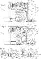
- FIG. 1is a perspective view a beverage machine having a beverage processing module and a liquid supply tank exhibiting part of the fastening arrangements according to the invention
- FIG. 1 ais an enlarged view of a detail of FIG. 1 showing male and female connectors of the fastening arrangements of FIG. 1 .
- FIGS. 2 to 4illustrate a sequence of fastening the tank to the module in the machine of FIG. 1 ;
- FIGS. 2 a to 4 aillustrate an enlarged view of a detail of FIGS. 2 to 4 showing the pair formed of the support surface and the resilient member of part of the fastening arrangements.
- FIGS. 1 to 4 aillustrates an exemplary embodiment of a beverage machine 1 according to the invention.
- Machine 1includes: a beverage processing module 10 having a liquid inlet 11 and a module fastening arrangement 12 , 13 , 15 ; and a liquid supply tank 30 having a liquid outlet 31 and a tank fastening arrangement 32 , 33 , 35 , e.g. a tank 30 for supplying water.
- Tank outlet 31can be fluidically connected to module inlet 11 and disconnected therefrom, as illustrated in FIGS. 2 a to 4 a.
- Fastening arrangements 12 , 13 , 15 ; 32 , 33 , 35comprise a female connector 12 and a male connector 32 cooperating with female connector 12 for reversibly assembling module and tank 30 .
- a male tank connector 32cooperates with a female module connector 12 or a male module connector cooperates with a female tank connector.
- Tank 30can have a pivot area 30 ′ about which tank 30 is pivoted into and out of a fastening position in which tank 30 and module 10 are fastened together via the fastening arrangement 12 , 13 , 15 ; 32 , 33 , 35 . See FIGS. 2 a , 3 a and 4 a.
- Fastening arrangements 12 , 13 , 15 ; 32 , 33 , 35further comprise at least one pair made of a support surface 13 , 35 and a resilient member 33 , 15 that cooperate together for urging male connector 32 into female connector 12 so as to fasten the tank 30 to the module.
- the paircomprises as module support surface 13 and a tank resilient member 33 or a tank support surface 35 and a module resilient member 15 .
- Female and male connectors 12 , 32 of the paircan have one or more degrees of freedom F 1 ,F 2 when tank 30 is assembled to module 10 , such degree(s) of freedom F 1 ,F 2 being in general opposition to a direction U into which tank 30 is urged by resilient member 33 , 15 cooperating with support surface 13 , 35 . See FIG. 4 .
- At least one of such paircan be made of a support surface 13 , 35 and a resilient member 33 , 15 configured to be urged together when tank 30 is assembled to module 10 .
- Support surface 35may form an outer face of tank 30 and resilient member 15 may form a support arm or panel, such as a foot, projecting from a main body 10 ′ of module 10 and extending across tank 30 at outer face 35 .
- support arm or panelcan extend across a predominant part of the tank 30 at outer face 35 . See FIGS. 2 a , 3 a and 4 a.
- the support surfacecan form an outer face of the module and the resilient member can form a support arm or panel, such as a foot, projecting from a main body of the tank and extending across the module at the outer face.
- a support arm or panelsuch as a foot
- such support arm or panelmay extend across a predominant part of the module at the outer face.
- At least one of such paircan be made of a support surface 13 and a resilient member 33 configured to urge apart at support surface 13 and resilient member 33 : an outer face 34 of tank 30 and an outer face 14 of module 10 that faces outer tank face 34 .
- Resilient member 33may include an urging element 331 , such as a ram 331 mounted on a spring 332 , movably mounted at one 34 of outer faces 14 , 34 .
- Support surface 13can be fixedly or integrally or movably mounted at the other 14 of outer faces 14 , 34 . See FIGS. 2 a , 3 a and 4 a.
- Resilient member 33can be movably mounted to or in outlet 31 and support surface 13 can be fixedly or integrally or movably mounted in or to inlet 11 . See FIGS. 2 a , 3 a and 4 a.
- Resilient membermay be movably mounted to or in the inlet and support surface may be fixedly or integrally or movably mounted in or to the outlet.
- Resilient member 33 and support surface 13can be formed as or within a male-female mechanical connection arrangement between module 10 and tank 30 , e.g. a mechanical connection formed by inlet 11 and outlet 31 . See FIGS. 2 a , 3 a and 4 a.
- Female connector 12can be formed as a recessed part and male connector 32 can be formed as a protruding part having a shape generally complementary to the recessed part.
- Female connector 12 and male connector 32can be formed as a hook part and a catch part. See FIGS. 1 a , 2 and 4 .
- Machine 1can include a lid 36 at an opening 36 ′ of tank 30 . See FIGS. 1, 1 a and 2 .
- Lid 36may be moved between a position covering opening 36 ′ and a position uncovering opening 36 ′.
- lid 36 and tank 30have a fastening arrangement for fastening lid 36 in the covering position.
- lid-tank fastening arrangementincludes lid flange 361 ′ projecting and fastened in or around a tank rim 361 ′ delimiting opening 36 ′ and/or a lid and a tank in a hook and hook-retainer configuration, when lid 36 is in the covering position.
- Lid 36can be permanently or temporarily assembled to tank 30 .
- Lid 36may include one 32 of female connector 12 and male connector 32 for cooperating with the other 32 of female connector 12 and male connector 32 comprised by module 10 so as to fasten tank 30 with lid 36 to module 10 .
- Male connector 32can be formed by a hinge of lid 36 and/or by a hinge holder of tank 30 , e.g. end portions of the hinge or hinge holder. See FIGS. 1, 1 a and 4 .
- Female and male connectorscan be assembled by moving the lid, e.g. pivoting the lid, from the open to the closed position and being disassembled by moving the lid, e.g. pivoting the lid, from the closed to the open position.
- Tank 30can include an upright wall 37 delimiting a liquid storage cavity, an outside face of upright wall 37 forming or being fixed to one 32 of female connector 12 and male connector 32 for cooperating with the other 12 of female connector 12 and male connector 32 .
- the other 12 of female connector 12 and male connector 32is formed or fixed to an outside face of an upright wall 17 of module 10 .
- Female and male connectors 12 , 32can be located at one end of tank 30 and said at least one pair 13 , 35 ; 33 , 15 can be locate at a generally opposite end of tank 30 when tank 30 is assembled to module 10 . See FIG. 4 .
- Female connector 12 and male connector 32may be located at one face 36 , 37 of tank 30 and said at least one pair 13 , 35 ; 33 , 15 can be locate at an another face 34 of tank 30 when tank 30 is assembled to module 10 .
- Such another face 34being for instance adjacent to or opposite to said one face 36 , 3 ).
- such another face 34being a bottom face of tank 30 and such one face 36 , 37 being a side face 37 or a top face 36 of tank 30 .
- Module 10may include a beverage outlet 20 to which liquid inlet 11 is fluidically connected.
- Module 10can have a platform 19 for supporting tank 30 and or extending under a bottom 35 of tank 30 when tank 30 is assembled to module 10 .
- platform 19comprises the inlet.
- Module 10may have an ingredient inlet 21 for supplying an ingredient, such as an ingredient contained in a capsule, to be processed with liquid from tank 30 via liquid inlet 11 .
- Module 10can include a support 22 for placing a user-recipient, e.g. a cup or a mug, for collecting the beverage delivered by outlet 20 .
- a user-recipiente.g. a cup or a mug
- Module 10may have an actuator, such as a handle 23 or a motor, for actuating module 10 for receiving in and/or evacuating from module 10 an ingredient, such as an ingredient contained in a capsule.
- an actuatorsuch as a handle 23 or a motor
- Module 10can comprise a pump 24 for pumping liquid from outlet 31 to beverage outlet 20 .
- Module 10can include a mixing chamber 25 in fluid connection with inlet 11 and beverage outlet 20 for mixing liquid with an ingredient such as an ingredient contained in a capsule.
- mixing chamber 25is actuated e.g. by a handle 23 between an open position for inserting into and/or removing from chamber 25 the ingredient and a closed position for mixing the ingredient and liquid and for subsequent dispensing via beverage outlet 20 .
- Module 10can have a thermal conditioner 26 , such as a heater and/or a cooler, for thermally conditioning liquid supplied from inlet 11 to beverage outlet 20 .
- a thermal conditioner 26such as a heater and/or a cooler
- Module 10can comprise a machine control unit such as a control unit with a user-interface 27 .
- Module 10can include a waste collector 28 , such as a collector of residual liquid and/or residual ingredient e.g. contained in a capsule.
- waste collector 28is removable from module 10 for servicing.
- Tank 30may have a valve 331 , 332 for allowing a passage of liquid via the tank's outlet 31 when the tank's outlet 31 is connected to the module's inlet 11 and for preventing the passage of liquid via the tank's outlet 31 when the tank's outlet 31 is disconnected from the module's inlet 11 .
- valve 331 , 332forms part of the above at least one pair 33 , such as forming the urging element 331 and optional spring 332 as mentioned above.
- Tank 30can have a bottom 34 and one or more peripheral upright sidewalls 37 delimiting a liquid storage cavity 38 .
- Tank 30may have an opening 36 ′ delimited by a rim 361 ′ for filling a storage cavity 38 of the tank with liquid, such as water.
- Tank 30can have a foot 39 on which tank 30 can rest when filled with liquid before and/or upon assembly of tank 30 to module 10 .
- Tank 30may include a passage 39 , e.g. a notch or through-opening, for passing an electric cord 18 to module 10 , such as an opening in a foot 39 ′ of tank 30 .
- a passage 39e.g. a notch or through-opening
Landscapes
- Engineering & Computer Science (AREA)
- Food Science & Technology (AREA)
- Mechanical Engineering (AREA)
- Apparatus For Making Beverages (AREA)
- Devices For Dispensing Beverages (AREA)
Abstract
Description
Claims (19)
Applications Claiming Priority (4)
| Application Number | Priority Date | Filing Date | Title |
|---|---|---|---|
| EP15194020.2 | 2015-11-11 | ||
| EP15194020 | 2015-11-11 | ||
| EP15194020 | 2015-11-11 | ||
| PCT/EP2016/077076WO2017081055A1 (en) | 2015-11-11 | 2016-11-09 | Easy connection of a liquid tank to a beverage machine |
Publications (2)
| Publication Number | Publication Date |
|---|---|
| US20180317697A1 US20180317697A1 (en) | 2018-11-08 |
| US11284738B2true US11284738B2 (en) | 2022-03-29 |
Family
ID=54539948
Family Applications (1)
| Application Number | Title | Priority Date | Filing Date |
|---|---|---|---|
| US15/774,421Active2037-06-11US11284738B2 (en) | 2015-11-11 | 2016-11-09 | Easy connection of a liquid tank to a beverage machine |
Country Status (10)
| Country | Link |
|---|---|
| US (1) | US11284738B2 (en) |
| EP (1) | EP3373779B1 (en) |
| JP (1) | JP6910352B2 (en) |
| CN (1) | CN108348093B (en) |
| AU (1) | AU2016353456B2 (en) |
| CA (1) | CA3001089A1 (en) |
| ES (1) | ES2847752T3 (en) |
| PT (1) | PT3373779T (en) |
| RU (1) | RU2713330C2 (en) |
| WO (1) | WO2017081055A1 (en) |
Cited By (5)
| Publication number | Priority date | Publication date | Assignee | Title |
|---|---|---|---|---|
| US12005408B1 (en) | 2023-04-14 | 2024-06-11 | Sharkninja Operating Llc | Mixing funnel |
| US12017192B1 (en) | 2023-06-16 | 2024-06-25 | Sharkninja Operating Llc | Carbonation mixing nozzles |
| USD1048793S1 (en) | 2023-05-02 | 2024-10-29 | Sharkninja Operating Llc | Coffee machine |
| USD1048792S1 (en)* | 2023-04-12 | 2024-10-29 | Sharkninja Operating Llc | Coffee machine |
| US12171361B2 (en) | 2020-12-30 | 2024-12-24 | Sharkninja Operating Llc | Hybrid receptacle beverage brewing system |
Families Citing this family (8)
| Publication number | Priority date | Publication date | Assignee | Title |
|---|---|---|---|---|
| ECSDI18067794S (en)* | 2018-03-09 | 2018-10-31 | "Drink dispenser" (NESCAFE DOLCE GUSTO) | |
| ECSDI18067810S (en)* | 2018-03-09 | 2018-10-31 | "Drink dispenser" (NESCAFE DOLCE GUSTO) | |
| ECSDI18067780S (en)* | 2018-03-26 | 2018-10-31 | "Drink dispenser" (NESCAFE DOLCE GUSTO) | |
| EP3628195A1 (en) | 2018-09-27 | 2020-04-01 | Société des Produits Nestlé S.A. | Beverage preparation machine with recipient detection |
| US12390044B2 (en) | 2018-09-27 | 2025-08-19 | Societe Des Produits Nestle S.A. | Adaptive service unit of a beverage machine |
| RU2758622C2 (en)* | 2019-10-14 | 2021-11-01 | Общество с ограниченной ответственностью "ЭР ЛАБ" | Device for automatic water intake with simultaneous weight measurement |
| CN118102953A (en) | 2021-10-08 | 2024-05-28 | 雀巢产品有限公司 | Beverage preparation machine with easy ergonomic opening and closing |
| JP2024537023A (en) | 2021-10-13 | 2024-10-10 | ソシエテ・デ・プロデュイ・ネスレ・エス・アー | Ergonomic Drinking Machine |
Citations (8)
| Publication number | Priority date | Publication date | Assignee | Title |
|---|---|---|---|---|
| JPS5679223A (en) | 1979-11-30 | 1981-06-29 | Yaskawa Electric Mfg Co Ltd | Detecting system for instantaneous torque of ac motor |
| JPS5799640A (en) | 1980-10-02 | 1982-06-21 | Ciba Geigy Ag | Hydroquinone derivative and use thereof in photographic material |
| FR2841116A1 (en) | 2002-06-19 | 2003-12-26 | Seb Sa | EXPRESSO TYPE COFFEE MAKER WITH REMOVABLE WATER TANK |
| JP2004236761A (en) | 2003-02-04 | 2004-08-26 | Zojirushi Corp | Water tank mounting structure for coffee maker |
| WO2011089210A1 (en) | 2010-01-21 | 2011-07-28 | Nestec S.A. | Beverage machine with removable liquid supply reservoir |
| US20130014647A1 (en) | 2010-01-06 | 2013-01-17 | Nestec S.A. | Vibration proof water tank of a beverage machine |
| JP5679223B2 (en) | 2012-01-24 | 2015-03-04 | 株式会社ダイフク | Protrusion prevention mechanism for rack items |
| JP5799640B2 (en) | 2011-07-29 | 2015-10-28 | 株式会社村田製作所 | Electrostrictive sensor |
Family Cites Families (87)
| Publication number | Priority date | Publication date | Assignee | Title |
|---|---|---|---|---|
| CH587647A5 (en)* | 1975-07-11 | 1977-05-13 | Icomag Trust Reg | |
| JPS605871Y2 (en)* | 1979-11-22 | 1985-02-23 | 三洋電機株式会社 | Lid mounting device |
| JPS5799640U (en)* | 1980-12-09 | 1982-06-18 | ||
| DE19504839C1 (en)* | 1995-02-14 | 1996-04-04 | Braun Ag | Cold water supply container for electric coffee filter machine |
| US6459854B1 (en) | 2000-01-24 | 2002-10-01 | Nestec S.A. | Process and module for heating liquid |
| FR2806606B1 (en) | 2000-03-24 | 2002-10-25 | Moulinex Sa | ELECTRIC COFFEE MACHINE WITH PIVOTING WATER TANK |
| ES2246201T3 (en) | 2000-05-09 | 2006-02-16 | Societe Des Produits Nestle S.A. | DEVICE FOR THE REMOVAL OF A SUBSTANCE. |
| ATE274321T1 (en) | 2000-11-28 | 2004-09-15 | Nestle Sa | PERCOLATION DEVICE |
| DE20105672U1 (en) | 2001-03-31 | 2001-09-13 | Eugster/Frismag Ag, Romanshorn | Espresso brewing device |
| CA2470363C (en) | 2002-01-10 | 2010-08-03 | Alfred Yoakim | Automatic device for the extraction of a substance |
| DE60227248D1 (en) | 2002-07-12 | 2008-08-07 | Nestec Sa | Device for heating a liquid |
| DE60303320T2 (en) | 2003-02-07 | 2006-09-21 | Nestec S.A. | Linear extraction module for preparing a beverage from a cartridge |
| DE20302410U1 (en) | 2003-02-13 | 2004-06-24 | Nestec S.A. | Capsule magazine unit with capsule magazine unit receiving device, in particular an espresso machine |
| EP1495702A1 (en) | 2003-07-10 | 2005-01-12 | Nestec S.A. | Device for the extraction of a cartridge |
| US7644649B2 (en) | 2003-11-22 | 2010-01-12 | Nestec S.A. | Mobile or portable apparatus with pressurized gas supply for preparing beverages or similar products |
| US7165488B2 (en) | 2003-12-12 | 2007-01-23 | Keurig, Incorporated | Brew chamber for a single serve beverage brewer |
| EP1634520A1 (en) | 2004-09-13 | 2006-03-15 | Nestec S.A. | Device and method for heating a liquid |
| DE202004020907U1 (en)* | 2004-09-24 | 2006-05-24 | BSH Bosch und Siemens Hausgeräte GmbH | Espresso or coffee pad machine has heater for water pumped from tank and, after heating, into brewing chamber whose outlet has temperature sensor connected to control which switches off pump or heater when temperature rises too far |
| DE602004031632D1 (en) | 2004-11-11 | 2011-04-14 | Nestec Sa | Self-cleaning mixing head for milk drinks and machines with such a mixing head |
| MX2007011943A (en) | 2005-03-29 | 2007-12-12 | Nestec Sa | Standalone drink dispensing machine. |
| DE602005007475D1 (en) | 2005-06-07 | 2008-07-24 | Nestec Sa | Beverage machine with drip tray for containers of different heights |
| ES2321108T4 (en) | 2005-09-20 | 2010-11-24 | Nestec S.A. | DRINK PRODUCTION DEVICE BASED ON THERMOBLOCK WITH INFUSION CHAMBERS. |
| PT1767129E (en) | 2005-09-27 | 2008-11-11 | Nestec Sa | Extraction module for a capsule-based beverage production device |
| DE202006002678U1 (en) | 2006-02-17 | 2006-04-20 | Eugster/Frismag Ag | Coffee machine for preparing a coffee beverage by means of packaged, pre-portioned Kaffeepouches |
| FR2898028B1 (en) | 2006-03-01 | 2008-05-16 | Seb Sa | INFUSING MACHINE COMPRISING A DEVICE FOR EJECTING THE INFUSED PRODUCT |
| US7513192B2 (en) | 2006-03-23 | 2009-04-07 | Keurig, Incorporated | Beverage forming device with opening/closing mechanism for a beverage cartridge receiver |
| DE602006009232D1 (en) | 2006-05-24 | 2009-10-29 | Nestec Sa | Brewing device for capsule with locking mechanism with variable transmission ratio |
| ATE498340T1 (en) | 2006-06-09 | 2011-03-15 | Nestec Sa | MODULAR DRINK MAKING SYSTEM WITH A DOCKING STATION |
| ES2415132T3 (en) | 2006-06-16 | 2013-07-24 | Nestec S.A. | Beverage distribution device with a support and drop recovery system for containers of different sizes |
| DE602006007698D1 (en) | 2006-07-11 | 2009-08-20 | Nestec Sa | Machine for preparing drinks with functional device and foot construction |
| EP1992263B2 (en) | 2007-05-16 | 2016-10-12 | Nestec S.A. | Beverage production module and method for operating a beverage production module |
| CN201076369Y (en) | 2007-07-24 | 2008-06-25 | 宁波圣开纳电器有限公司 | Tap water coffee maker |
| EP2027798A1 (en) | 2007-08-20 | 2009-02-25 | Nestec S.A. | Beverage production module and method for operating a beverage production module |
| EP2218369B1 (en) | 2007-10-04 | 2017-05-03 | Nestec S.A. | Beverage brewing unit |
| CL2008002963A1 (en) | 2007-10-04 | 2010-01-22 | Nestec Sa | Heating device for a machine for the preparation of liquid food or drink, comprising a thermal unit with a metallic mass, through which the liquid circulates, and accumulates heat and supplies it to the liquid, and has one or more insured electrical components rigidly to the thermal unit; and machine. |
| CN102133047B (en) | 2007-10-04 | 2014-04-30 | 雀巢产品技术援助有限公司 | Heating device with an integrated thermoblock for a beverage preparation machine |
| EP2070454B1 (en) | 2007-12-12 | 2015-07-15 | Nestec S.A. | Beverage production machines comprising a plurality of core units |
| AU2008334691B2 (en) | 2007-12-12 | 2015-01-22 | Société des Produits Nestlé S.A. | Used capsule or pod receptacle for liquid food or beverage machines |
| EP2082669A2 (en) | 2008-01-25 | 2009-07-29 | Nestec S.A. | Hybrid apparatus for preparing beverages |
| BRPI0912189A2 (en) | 2008-05-08 | 2015-10-06 | Nestec Sa | setting the fill level in a cup used with a drink dispenser. |
| AU2009245745A1 (en)* | 2008-05-08 | 2009-11-12 | Nestec S.A. | Beverage production device |
| EP2296515B1 (en) | 2008-05-28 | 2012-07-18 | Nestec S.A. | Pump for liquid beverage preparation devices |
| AU2009268073B2 (en) | 2008-07-09 | 2014-12-04 | Nestec S.A. | Ergonomic interface screen for a beverage machine |
| CA2728224A1 (en) | 2008-07-14 | 2010-01-21 | Nestec S.A. | Water circulation system for a beverage preparation device |
| EP2309900B1 (en) | 2008-08-08 | 2015-05-27 | Nestec S.A. | Beverage machine with carrying handle and configurable appearance&side functions |
| US20110168026A1 (en) | 2008-10-03 | 2011-07-14 | Nestec S.A. | User friendly interface for a beverage machine |
| EP2228633B1 (en) | 2009-03-10 | 2017-07-05 | Nestec S.A. | Optical level detector for a beverage machine |
| WO2010108700A1 (en) | 2009-03-23 | 2010-09-30 | Nestec S.A. | Pump mount in a beverage preparation machine |
| EP2427085B1 (en) | 2009-05-06 | 2016-09-21 | Nestec S.A. | Method for manufacturing beverage machines with simplified servicing |
| JP5715627B2 (en) | 2009-08-19 | 2015-05-07 | ネステク ソシエテ アノニム | User-friendly start-up mode for beverage preparation equipment |
| US9693652B2 (en) | 2009-09-02 | 2017-07-04 | Nestec S.A. | Beverage machine for a network |
| JP2013504140A (en) | 2009-09-09 | 2013-02-04 | ネステク ソシエテ アノニム | Beverage machine on the network |
| EP2353469A1 (en) | 2010-02-03 | 2011-08-10 | Nestec S.A. | Beverage preparation machine for large size beverages |
| RU2560323C2 (en) | 2010-03-05 | 2015-08-20 | Нестек С.А. | Pump with reduced vibration |
| WO2011144719A1 (en) | 2010-05-21 | 2011-11-24 | Nestec S.A. | Ergonomic handle & user-interface |
| BR112012029661B1 (en) | 2010-05-21 | 2020-01-28 | Nestec Sa | machine to prepare a drink |
| PL2571408T3 (en) | 2010-05-21 | 2014-11-28 | Nestec Sa | Beverage machine with ergonomic water management |
| CA2801278A1 (en) | 2010-06-09 | 2011-12-15 | Nestec S.A. | Ergonomic service arrangement for beverage machine |
| AU2011267130B2 (en) | 2010-06-17 | 2015-11-19 | Société des Produits Nestlé S.A. | Fast heat-up of a thermal conditioning device e.g. for coffee machine |
| JP2013535242A (en) | 2010-07-12 | 2013-09-12 | ネステク ソシエテ アノニム | Secure cup support for beverage machines |
| WO2012007260A1 (en) | 2010-07-16 | 2012-01-19 | Nestec S.A. | Advanced heating device |
| EP2608704B1 (en) | 2010-08-27 | 2016-06-22 | Nestec S.A. | Simple motorized brewing unit |
| CN103188972B (en) | 2010-09-07 | 2015-08-05 | 雀巢产品技术援助有限公司 | Ergonomic handle with user interface |
| RU2571197C2 (en) | 2010-10-27 | 2015-12-20 | Нестек С.А. | Device for preparing beverages for different 3d environments |
| AU2011322725A1 (en) | 2010-10-27 | 2013-04-04 | Nestec S.A. | Beverage machine with a handy outlet |
| EP2645914B1 (en) | 2010-12-01 | 2016-07-13 | Nestec S.A. | Beverage preparation machine with drop collector |
| JP2013544174A (en) | 2010-12-01 | 2013-12-12 | ネステク ソシエテ アノニム | Ergonomic user interface for motorized material chamber |
| CN103338683B (en) | 2010-12-01 | 2016-08-10 | 雀巢产品技术援助有限公司 | There is the beverage machine of the capsule path of band door |
| CN201977568U (en)* | 2010-12-24 | 2011-09-21 | 博西华电器(江苏)有限公司 | Coffee machine |
| MX2013007768A (en) | 2011-01-03 | 2013-11-20 | Nestec Sa | Beverage machine with a cover for an ingredient inlet. |
| WO2012126971A1 (en) | 2011-03-23 | 2012-09-27 | Nestec S.A. | Beverage machine with a cover for an ingredient inlet |
| ES2546531T3 (en) | 2011-12-30 | 2015-09-24 | Nestec S.A. | A machine for drinks with multiple systems |
| IN2014DN05873A (en) | 2012-01-13 | 2015-05-22 | Nestec Sa | |
| RU2617365C9 (en) | 2012-01-13 | 2017-07-04 | Нестек С.А. | Beverage preparation machine for low and high cups |
| EP2633789A1 (en) | 2012-02-28 | 2013-09-04 | Nestec S.A. | Beverage preparation machine with drop management |
| DE112012001531T5 (en) | 2012-02-28 | 2013-12-24 | Nestec S.A. | Capsule-controlled motorized brewing unit |
| JP6416081B2 (en)* | 2012-05-23 | 2018-10-31 | コーニンクレッカ フィリップス エヌ ヴェKoninklijke Philips N.V. | Beverage production equipment with two-position water container |
| CN104869874B (en) | 2012-10-09 | 2018-01-05 | 雀巢产品技术援助有限公司 | Extraction unit with more size magazine chambers |
| RU2015116419A (en) | 2012-10-09 | 2016-11-27 | Нестек С.А. | EXTRACTION DEVICE WITH ADJUSTABLE RECEIVER FOR VARIOUS SIZES CAPSULES |
| CA2889970A1 (en) | 2012-10-09 | 2014-04-17 | Nestec S.A. | Multi-size cartridge extraction unit having slides |
| JP2015534486A (en) | 2012-10-09 | 2015-12-03 | ネステク ソシエテ アノニム | Beverage machine equipped with ingredient capsule attachment device |
| CN103767547B (en)* | 2012-10-18 | 2017-11-07 | 苏州工业园区咖乐美电器有限公司 | A kind of water supply installation for beverage machine |
| WO2014060370A1 (en) | 2012-10-19 | 2014-04-24 | Nestec S.A. | Extensible cartridge cage with a lock |
| WO2014096122A1 (en) | 2012-12-20 | 2014-06-26 | Nestec S.A. | Variable transmission for closing a receptacle holder |
| PT2934246T (en) | 2012-12-20 | 2018-07-16 | Nestle Sa | Double ramp for closing a receptacle holder |
| CN203693321U (en)* | 2014-01-02 | 2014-07-09 | 广东顺德雷蒙电器科技有限公司 | Instant heating type kettle |
| CN203873569U (en)* | 2014-04-29 | 2014-10-15 | 张海龙 | Capsule coffee machine |
- 2016
- 2016-11-09USUS15/774,421patent/US11284738B2/enactiveActive
- 2016-11-09ESES16791629Tpatent/ES2847752T3/enactiveActive
- 2016-11-09CACA3001089Apatent/CA3001089A1/enactivePending
- 2016-11-09EPEP16791629.5Apatent/EP3373779B1/enactiveActive
- 2016-11-09AUAU2016353456Apatent/AU2016353456B2/enactiveActive
- 2016-11-09JPJP2018522752Apatent/JP6910352B2/enactiveActive
- 2016-11-09CNCN201680064939.1Apatent/CN108348093B/enactiveActive
- 2016-11-09PTPT167916295Tpatent/PT3373779T/enunknown
- 2016-11-09WOPCT/EP2016/077076patent/WO2017081055A1/ennot_activeCeased
- 2016-11-09RURU2018120477Apatent/RU2713330C2/enactive
Patent Citations (10)
| Publication number | Priority date | Publication date | Assignee | Title |
|---|---|---|---|---|
| JPS5679223A (en) | 1979-11-30 | 1981-06-29 | Yaskawa Electric Mfg Co Ltd | Detecting system for instantaneous torque of ac motor |
| JPS5799640A (en) | 1980-10-02 | 1982-06-21 | Ciba Geigy Ag | Hydroquinone derivative and use thereof in photographic material |
| FR2841116A1 (en) | 2002-06-19 | 2003-12-26 | Seb Sa | EXPRESSO TYPE COFFEE MAKER WITH REMOVABLE WATER TANK |
| US20050247204A1 (en)* | 2002-06-19 | 2005-11-10 | Lafond Jean M | Espresso coffeemaker with removable water reservoir |
| JP2004236761A (en) | 2003-02-04 | 2004-08-26 | Zojirushi Corp | Water tank mounting structure for coffee maker |
| US20130014647A1 (en) | 2010-01-06 | 2013-01-17 | Nestec S.A. | Vibration proof water tank of a beverage machine |
| WO2011089210A1 (en) | 2010-01-21 | 2011-07-28 | Nestec S.A. | Beverage machine with removable liquid supply reservoir |
| US20120285966A1 (en)* | 2010-01-21 | 2012-11-15 | Nestec S.A. | Beverage machine with removable liquid supply reservoir |
| JP5799640B2 (en) | 2011-07-29 | 2015-10-28 | 株式会社村田製作所 | Electrostrictive sensor |
| JP5679223B2 (en) | 2012-01-24 | 2015-03-04 | 株式会社ダイフク | Protrusion prevention mechanism for rack items |
Cited By (8)
| Publication number | Priority date | Publication date | Assignee | Title |
|---|---|---|---|---|
| US12171361B2 (en) | 2020-12-30 | 2024-12-24 | Sharkninja Operating Llc | Hybrid receptacle beverage brewing system |
| US12357118B2 (en) | 2020-12-30 | 2025-07-15 | Sharkninja Operating Llc | Hybrid receptacle beverage brewing system |
| USD1048792S1 (en)* | 2023-04-12 | 2024-10-29 | Sharkninja Operating Llc | Coffee machine |
| USD1086778S1 (en) | 2023-04-12 | 2025-08-05 | Sharkninja Operating Llc | Coffee machine |
| US12005408B1 (en) | 2023-04-14 | 2024-06-11 | Sharkninja Operating Llc | Mixing funnel |
| USD1048793S1 (en) | 2023-05-02 | 2024-10-29 | Sharkninja Operating Llc | Coffee machine |
| USD1083475S1 (en) | 2023-05-02 | 2025-07-15 | Sharkninja Operating Llc | Coffee machine |
| US12017192B1 (en) | 2023-06-16 | 2024-06-25 | Sharkninja Operating Llc | Carbonation mixing nozzles |
Also Published As
| Publication number | Publication date |
|---|---|
| AU2016353456A1 (en) | 2018-04-05 |
| AU2016353456B2 (en) | 2022-02-24 |
| EP3373779A1 (en) | 2018-09-19 |
| CN108348093B (en) | 2020-12-15 |
| EP3373779B1 (en) | 2020-12-23 |
| WO2017081055A1 (en) | 2017-05-18 |
| JP2018537160A (en) | 2018-12-20 |
| CA3001089A1 (en) | 2017-05-18 |
| PT3373779T (en) | 2021-02-12 |
| JP6910352B2 (en) | 2021-07-28 |
| CN108348093A (en) | 2018-07-31 |
| ES2847752T3 (en) | 2021-08-03 |
| US20180317697A1 (en) | 2018-11-08 |
| RU2018120477A (en) | 2019-12-16 |
| RU2713330C2 (en) | 2020-02-04 |
| RU2018120477A3 (en) | 2019-12-16 |
Similar Documents
| Publication | Publication Date | Title |
|---|---|---|
| US11284738B2 (en) | Easy connection of a liquid tank to a beverage machine | |
| US9277839B2 (en) | Secure cup support for beverage machine | |
| US9149148B2 (en) | Multi-system beverage machine | |
| US9980597B2 (en) | Beverage preparation machine with drop collector | |
| AU2015366401B2 (en) | Beverage machine with slidingly connectable cup-support | |
| EP2755537B1 (en) | Clean multi-system beverage machine | |
| EP2755535B1 (en) | Multi-system beverage machine multiple connections | |
| EP2755536B1 (en) | Multi-system beverage machine safe connector | |
| US20240407586A1 (en) | Ergonomic beverage machine | |
| US20220031112A1 (en) | Adaptive service unit of a beverage machine |
Legal Events
| Date | Code | Title | Description |
|---|---|---|---|
| FEPP | Fee payment procedure | Free format text:ENTITY STATUS SET TO UNDISCOUNTED (ORIGINAL EVENT CODE: BIG.); ENTITY STATUS OF PATENT OWNER: LARGE ENTITY | |
| STPP | Information on status: patent application and granting procedure in general | Free format text:DOCKETED NEW CASE - READY FOR EXAMINATION | |
| AS | Assignment | Owner name:NESTEC S.A., SWITZERLAND Free format text:ASSIGNMENT OF ASSIGNORS INTEREST;ASSIGNORS:CAHEN, ANTOINE;GRANGER, ERIC;SIGNING DATES FROM 20151111 TO 20151207;REEL/FRAME:049166/0551 | |
| AS | Assignment | Owner name:SOCIETE DES PRODUITS NESTLE S.A., SWITZERLAND Free format text:MERGER;ASSIGNOR:NESTEC S.A.;REEL/FRAME:049391/0756 Effective date:20190528 | |
| AS | Assignment | Owner name:SOCIETE DES PRODUITS NESTLE S.A., SWITZERLAND Free format text:CORRECTIVE ASSIGNMENT TO CORRECT THE ENGLISH TRANSLATION TO SHOW THE FULL AND CORRECT NEW NAME IN SECTION 51. PREVIOUSLY RECORDED AT REEL: 049391 FRAME: 0756. ASSIGNOR(S) HEREBY CONFIRMS THE MERGER;ASSIGNOR:NESTEC S.A.;REEL/FRAME:049853/0398 Effective date:20190528 | |
| STPP | Information on status: patent application and granting procedure in general | Free format text:NON FINAL ACTION MAILED | |
| AS | Assignment | Owner name:SOCIETE DES PRODUITS NESTLE S.A., SWITZERLAND Free format text:CORRECTIVE ASSIGNMENT TO CORRECT THE PATENT NUMBER 16062921 PREVIOUSLY RECORDED ON REEL 049391 FRAME 0756. ASSIGNOR(S) HEREBY CONFIRMS THE PATENT NUMBER SHOULD HAVE BEEN 16062912;ASSIGNOR:NESTEC S.A.;REEL/FRAME:054082/0001 Effective date:20190528 Owner name:SOCIETE DES PRODUITS NESTLE S.A., SWITZERLAND Free format text:CORRECTIVE ASSIGNMENT TO CORRECT THE PATENT NUMBER 16062921 PREVIOUSLY RECORDED ON REEL 049391 FRAME 0756. ASSIGNOR(S) HEREBY CONFIRMS THE PATENT NUMBER SHOULD HAVE BEEN 16062912;ASSIGNOR:NESTEC S.A.;REEL/FRAME:054082/0165 Effective date:20190528 | |
| STPP | Information on status: patent application and granting procedure in general | Free format text:RESPONSE TO NON-FINAL OFFICE ACTION ENTERED AND FORWARDED TO EXAMINER | |
| STPP | Information on status: patent application and granting procedure in general | Free format text:ADVISORY ACTION MAILED | |
| STPP | Information on status: patent application and granting procedure in general | Free format text:DOCKETED NEW CASE - READY FOR EXAMINATION | |
| STPP | Information on status: patent application and granting procedure in general | Free format text:NON FINAL ACTION MAILED | |
| STPP | Information on status: patent application and granting procedure in general | Free format text:RESPONSE TO NON-FINAL OFFICE ACTION ENTERED AND FORWARDED TO EXAMINER | |
| STPP | Information on status: patent application and granting procedure in general | Free format text:FINAL REJECTION MAILED | |
| STPP | Information on status: patent application and granting procedure in general | Free format text:RESPONSE AFTER FINAL ACTION FORWARDED TO EXAMINER | |
| STPP | Information on status: patent application and granting procedure in general | Free format text:NOTICE OF ALLOWANCE MAILED -- APPLICATION RECEIVED IN OFFICE OF PUBLICATIONS | |
| STPP | Information on status: patent application and granting procedure in general | Free format text:PUBLICATIONS -- ISSUE FEE PAYMENT VERIFIED | |
| STCF | Information on status: patent grant | Free format text:PATENTED CASE | |
| MAFP | Maintenance fee payment | Free format text:PAYMENT OF MAINTENANCE FEE, 4TH YEAR, LARGE ENTITY (ORIGINAL EVENT CODE: M1551); ENTITY STATUS OF PATENT OWNER: LARGE ENTITY Year of fee payment:4 |