US11282303B2 - System and method for identifying vehicle operation mode - Google Patents
System and method for identifying vehicle operation modeDownload PDFInfo
- Publication number
- US11282303B2 US11282303B2US16/205,617US201816205617AUS11282303B2US 11282303 B2US11282303 B2US 11282303B2US 201816205617 AUS201816205617 AUS 201816205617AUS 11282303 B2US11282303 B2US 11282303B2
- Authority
- US
- United States
- Prior art keywords
- vehicle
- operating
- indication
- requirement
- accessory
- Prior art date
- Legal status (The legal status is an assumption and is not a legal conclusion. Google has not performed a legal analysis and makes no representation as to the accuracy of the status listed.)
- Active, expires
Links
Images


Classifications
- G—PHYSICS
- G07—CHECKING-DEVICES
- G07C—TIME OR ATTENDANCE REGISTERS; REGISTERING OR INDICATING THE WORKING OF MACHINES; GENERATING RANDOM NUMBERS; VOTING OR LOTTERY APPARATUS; ARRANGEMENTS, SYSTEMS OR APPARATUS FOR CHECKING NOT PROVIDED FOR ELSEWHERE
- G07C5/00—Registering or indicating the working of vehicles
- G07C5/08—Registering or indicating performance data other than driving, working, idle, or waiting time, with or without registering driving, working, idle or waiting time
- G07C5/0816—Indicating performance data, e.g. occurrence of a malfunction
- G07C5/0825—Indicating performance data, e.g. occurrence of a malfunction using optical means
- B—PERFORMING OPERATIONS; TRANSPORTING
- B60—VEHICLES IN GENERAL
- B60Q—ARRANGEMENT OF SIGNALLING OR LIGHTING DEVICES, THE MOUNTING OR SUPPORTING THEREOF OR CIRCUITS THEREFOR, FOR VEHICLES IN GENERAL
- B60Q1/00—Arrangement of optical signalling or lighting devices, the mounting or supporting thereof or circuits therefor
- B60Q1/26—Arrangement of optical signalling or lighting devices, the mounting or supporting thereof or circuits therefor the devices being primarily intended to indicate the vehicle, or parts thereof, or to give signals, to other traffic
- B60Q1/50—Arrangement of optical signalling or lighting devices, the mounting or supporting thereof or circuits therefor the devices being primarily intended to indicate the vehicle, or parts thereof, or to give signals, to other traffic for indicating other intentions or conditions, e.g. request for waiting or overtaking
- B60Q1/507—Arrangement of optical signalling or lighting devices, the mounting or supporting thereof or circuits therefor the devices being primarily intended to indicate the vehicle, or parts thereof, or to give signals, to other traffic for indicating other intentions or conditions, e.g. request for waiting or overtaking specific to autonomous vehicles
- B—PERFORMING OPERATIONS; TRANSPORTING
- B60—VEHICLES IN GENERAL
- B60Q—ARRANGEMENT OF SIGNALLING OR LIGHTING DEVICES, THE MOUNTING OR SUPPORTING THEREOF OR CIRCUITS THEREFOR, FOR VEHICLES IN GENERAL
- B60Q1/00—Arrangement of optical signalling or lighting devices, the mounting or supporting thereof or circuits therefor
- B60Q1/26—Arrangement of optical signalling or lighting devices, the mounting or supporting thereof or circuits therefor the devices being primarily intended to indicate the vehicle, or parts thereof, or to give signals, to other traffic
- B60Q1/50—Arrangement of optical signalling or lighting devices, the mounting or supporting thereof or circuits therefor the devices being primarily intended to indicate the vehicle, or parts thereof, or to give signals, to other traffic for indicating other intentions or conditions, e.g. request for waiting or overtaking
- B60Q1/509—Arrangement of optical signalling or lighting devices, the mounting or supporting thereof or circuits therefor the devices being primarily intended to indicate the vehicle, or parts thereof, or to give signals, to other traffic for indicating other intentions or conditions, e.g. request for waiting or overtaking specific to unauthorised use, e.g. for indicating stolen vehicles or infringements of traffic rules
- B—PERFORMING OPERATIONS; TRANSPORTING
- B60—VEHICLES IN GENERAL
- B60Q—ARRANGEMENT OF SIGNALLING OR LIGHTING DEVICES, THE MOUNTING OR SUPPORTING THEREOF OR CIRCUITS THEREFOR, FOR VEHICLES IN GENERAL
- B60Q1/00—Arrangement of optical signalling or lighting devices, the mounting or supporting thereof or circuits therefor
- B60Q1/26—Arrangement of optical signalling or lighting devices, the mounting or supporting thereof or circuits therefor the devices being primarily intended to indicate the vehicle, or parts thereof, or to give signals, to other traffic
- B60Q1/50—Arrangement of optical signalling or lighting devices, the mounting or supporting thereof or circuits therefor the devices being primarily intended to indicate the vehicle, or parts thereof, or to give signals, to other traffic for indicating other intentions or conditions, e.g. request for waiting or overtaking
- B60Q1/543—Arrangement of optical signalling or lighting devices, the mounting or supporting thereof or circuits therefor the devices being primarily intended to indicate the vehicle, or parts thereof, or to give signals, to other traffic for indicating other intentions or conditions, e.g. request for waiting or overtaking for indicating other states or conditions of the vehicle
- B—PERFORMING OPERATIONS; TRANSPORTING
- B60—VEHICLES IN GENERAL
- B60Q—ARRANGEMENT OF SIGNALLING OR LIGHTING DEVICES, THE MOUNTING OR SUPPORTING THEREOF OR CIRCUITS THEREFOR, FOR VEHICLES IN GENERAL
- B60Q1/00—Arrangement of optical signalling or lighting devices, the mounting or supporting thereof or circuits therefor
- B60Q1/26—Arrangement of optical signalling or lighting devices, the mounting or supporting thereof or circuits therefor the devices being primarily intended to indicate the vehicle, or parts thereof, or to give signals, to other traffic
- B60Q1/50—Arrangement of optical signalling or lighting devices, the mounting or supporting thereof or circuits therefor the devices being primarily intended to indicate the vehicle, or parts thereof, or to give signals, to other traffic for indicating other intentions or conditions, e.g. request for waiting or overtaking
- B60Q1/544—Arrangement of optical signalling or lighting devices, the mounting or supporting thereof or circuits therefor the devices being primarily intended to indicate the vehicle, or parts thereof, or to give signals, to other traffic for indicating other intentions or conditions, e.g. request for waiting or overtaking for indicating other states or conditions of the vehicle occupants, e.g. for indicating disabled occupants
- B—PERFORMING OPERATIONS; TRANSPORTING
- B60—VEHICLES IN GENERAL
- B60R—VEHICLES, VEHICLE FITTINGS, OR VEHICLE PARTS, NOT OTHERWISE PROVIDED FOR
- B60R1/00—Optical viewing arrangements; Real-time viewing arrangements for drivers or passengers using optical image capturing systems, e.g. cameras or video systems specially adapted for use in or on vehicles
- B60R1/02—Rear-view mirror arrangements
- B60R1/04—Rear-view mirror arrangements mounted inside vehicle
- G06K9/00818—
- G—PHYSICS
- G06—COMPUTING OR CALCULATING; COUNTING
- G06V—IMAGE OR VIDEO RECOGNITION OR UNDERSTANDING
- G06V20/00—Scenes; Scene-specific elements
- G06V20/50—Context or environment of the image
- G06V20/56—Context or environment of the image exterior to a vehicle by using sensors mounted on the vehicle
- G06V20/58—Recognition of moving objects or obstacles, e.g. vehicles or pedestrians; Recognition of traffic objects, e.g. traffic signs, traffic lights or roads
- G06V20/582—Recognition of moving objects or obstacles, e.g. vehicles or pedestrians; Recognition of traffic objects, e.g. traffic signs, traffic lights or roads of traffic signs
- G—PHYSICS
- G07—CHECKING-DEVICES
- G07C—TIME OR ATTENDANCE REGISTERS; REGISTERING OR INDICATING THE WORKING OF MACHINES; GENERATING RANDOM NUMBERS; VOTING OR LOTTERY APPARATUS; ARRANGEMENTS, SYSTEMS OR APPARATUS FOR CHECKING NOT PROVIDED FOR ELSEWHERE
- G07C5/00—Registering or indicating the working of vehicles
- G07C5/02—Registering or indicating driving, working, idle, or waiting time only
- G—PHYSICS
- G07—CHECKING-DEVICES
- G07C—TIME OR ATTENDANCE REGISTERS; REGISTERING OR INDICATING THE WORKING OF MACHINES; GENERATING RANDOM NUMBERS; VOTING OR LOTTERY APPARATUS; ARRANGEMENTS, SYSTEMS OR APPARATUS FOR CHECKING NOT PROVIDED FOR ELSEWHERE
- G07C5/00—Registering or indicating the working of vehicles
- G07C5/08—Registering or indicating performance data other than driving, working, idle, or waiting time, with or without registering driving, working, idle or waiting time
- B—PERFORMING OPERATIONS; TRANSPORTING
- B60—VEHICLES IN GENERAL
- B60K—ARRANGEMENT OR MOUNTING OF PROPULSION UNITS OR OF TRANSMISSIONS IN VEHICLES; ARRANGEMENT OR MOUNTING OF PLURAL DIVERSE PRIME-MOVERS IN VEHICLES; AUXILIARY DRIVES FOR VEHICLES; INSTRUMENTATION OR DASHBOARDS FOR VEHICLES; ARRANGEMENTS IN CONNECTION WITH COOLING, AIR INTAKE, GAS EXHAUST OR FUEL SUPPLY OF PROPULSION UNITS IN VEHICLES
- B60K6/00—Arrangement or mounting of plural diverse prime-movers for mutual or common propulsion, e.g. hybrid propulsion systems comprising electric motors and internal combustion engines
- B60K6/20—Arrangement or mounting of plural diverse prime-movers for mutual or common propulsion, e.g. hybrid propulsion systems comprising electric motors and internal combustion engines the prime-movers consisting of electric motors and internal combustion engines, e.g. HEVs
- B60K6/22—Arrangement or mounting of plural diverse prime-movers for mutual or common propulsion, e.g. hybrid propulsion systems comprising electric motors and internal combustion engines the prime-movers consisting of electric motors and internal combustion engines, e.g. HEVs characterised by apparatus, components or means specially adapted for HEVs
- B—PERFORMING OPERATIONS; TRANSPORTING
- B60—VEHICLES IN GENERAL
- B60R—VEHICLES, VEHICLE FITTINGS, OR VEHICLE PARTS, NOT OTHERWISE PROVIDED FOR
- B60R1/00—Optical viewing arrangements; Real-time viewing arrangements for drivers or passengers using optical image capturing systems, e.g. cameras or video systems specially adapted for use in or on vehicles
- B60R1/12—Mirror assemblies combined with other articles, e.g. clocks
- B60R1/1207—Mirror assemblies combined with other articles, e.g. clocks with lamps; with turn indicators
- B—PERFORMING OPERATIONS; TRANSPORTING
- B60—VEHICLES IN GENERAL
- B60R—VEHICLES, VEHICLE FITTINGS, OR VEHICLE PARTS, NOT OTHERWISE PROVIDED FOR
- B60R11/00—Arrangements for holding or mounting articles, not otherwise provided for
- B60R11/04—Mounting of cameras operative during drive; Arrangement of controls thereof relative to the vehicle
- B—PERFORMING OPERATIONS; TRANSPORTING
- B60—VEHICLES IN GENERAL
- B60R—VEHICLES, VEHICLE FITTINGS, OR VEHICLE PARTS, NOT OTHERWISE PROVIDED FOR
- B60R1/00—Optical viewing arrangements; Real-time viewing arrangements for drivers or passengers using optical image capturing systems, e.g. cameras or video systems specially adapted for use in or on vehicles
- B60R1/12—Mirror assemblies combined with other articles, e.g. clocks
- B60R2001/1253—Mirror assemblies combined with other articles, e.g. clocks with cameras, video cameras or video screens
- B—PERFORMING OPERATIONS; TRANSPORTING
- B60—VEHICLES IN GENERAL
- B60Y—INDEXING SCHEME RELATING TO ASPECTS CROSS-CUTTING VEHICLE TECHNOLOGY
- B60Y2200/00—Type of vehicle
- B60Y2200/90—Vehicles comprising electric prime movers
- B60Y2200/92—Hybrid vehicles
- G—PHYSICS
- G05—CONTROLLING; REGULATING
- G05D—SYSTEMS FOR CONTROLLING OR REGULATING NON-ELECTRIC VARIABLES
- G05D1/00—Control of position, course, altitude or attitude of land, water, air or space vehicles, e.g. using automatic pilots
- G05D1/02—Control of position or course in two dimensions
- G05D1/021—Control of position or course in two dimensions specially adapted to land vehicles
- G05D2201/0213—
- G—PHYSICS
- G06—COMPUTING OR CALCULATING; COUNTING
- G06V—IMAGE OR VIDEO RECOGNITION OR UNDERSTANDING
- G06V20/00—Scenes; Scene-specific elements
- G06V20/50—Context or environment of the image
- G06V20/59—Context or environment of the image inside of a vehicle, e.g. relating to seat occupancy, driver state or inner lighting conditions
- G06V20/593—Recognising seat occupancy
- G—PHYSICS
- G08—SIGNALLING
- G08G—TRAFFIC CONTROL SYSTEMS
- G08G1/00—Traffic control systems for road vehicles
- G08G1/16—Anti-collision systems
- G08G1/166—Anti-collision systems for active traffic, e.g. moving vehicles, pedestrians, bikes
Definitions
- the disclosurerelates to an indicator system for a vehicle and, more specifically, to an indicator device configured to indicate an operating mode of a vehicle.
- the disclosureprovides for an accessory for a vehicle.
- the accessorycomprises a housing forming a front surface configured to display a rearward directed field of view from the vehicle and a rear surface directed in a forward operating direction of the vehicle.
- An at least partially light transmissive panelis directed toward a front windscreen of the vehicle and is in connection with the rear surface.
- a light sourceis disposed in the housing proximate the light transmissive panel and is configured to emit light through the at least partially light transmissive panel.
- a controlleris in communication with the light source. The controller is configured to receive an indication of an operating condition of the vehicle and selectively activate the light source in response to an operating condition of the vehicle.
- a method for controlling an indicator accessory for a vehiclecomprises detecting a vehicle operating requirement for operation on a roadway and monitoring an operating condition of the vehicle.
- the operating conditionindicates at least one of a vehicle occupancy requirement, a vehicle propulsion characteristic, and an autonomous vehicle operation condition.
- the methodfurther comprises selectively activating a light source disposed on a forward directed portion of a rearview assembly comprising the indicator accessory in response to the operating condition.
- the light sourceis controlled to emit a compliance indication outward through a portion of the vehicle.
- an indication accessory for a vehiclecomprises a housing comprising a front surface configured to display a rearward directed field of view from the vehicle and a rear surface directed in a forward operating direction of the vehicle.
- a light sourceis in connection with the accessory and configured to emit light from the rear surface of the housing.
- An imageris configured to capture image data in a field of view proximate to the vehicle.
- a controlleris configured to process the image data and identify at least one roadway symbol. Based on the roadway symbol, the controller may determine an operation compliance requirement for the operation of the vehicle. The controller may further monitor an operating characteristic of the vehicle. Based on the operating characteristic, the controller may selectively activate the light source emitting a compliance indication from the vehicle in response to the operating characteristic conforming to the operation compliance requirement.
- FIG. 1is a diagram of a vehicle interior demonstrating a vehicle accessory comprising an operation indicator
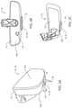
- FIG. 2Ais a partial front projected view of a vehicle accessory incorporated in an interior mirror or display comprising an operation indicator;
- FIG. 2Bis a rear-projected view of a vehicle accessory comprising an operation indicator
- FIG. 2Cis a partial rear projected view of a vehicle accessory comprising an operation indicator
- FIG. 3is a schematic diagram of a vehicle demonstrating an operation of an operation indicator
- FIG. 4is a schematic diagram of a vehicle demonstrating an operation of an operation indicator
- FIG. 5is a block diagram of a controller configured to control an operation indicator in accordance with the disclosure.
- the terms “upper,” “lower,” “right,” “left,” “rear,” “front,” “vertical,” “horizontal,” and derivatives thereofshall relate to the device as oriented in FIG. 1 .
- the devicemay assume various alternative orientations and step sequences, except where expressly specified to the contrary.
- the specific devices and processes illustrated in the attached drawings, and described in the following specificationare simply exemplary embodiments of the inventive concepts defined in the appended claims. Hence, specific dimensions and other physical characteristics relating to the embodiments disclosed herein are not to be considered as limiting, unless the claims expressly state otherwise.
- the vehicle accessory 10comprises an operation indicator 14 , which may be in communication with a controller.
- the controller indicated by reference numeral 60is demonstrated in FIG. 5 .
- the vehicle accessory 10may correspond to an interior mirror assembly 18 or vehicle display.
- the vehicle accessory 10may be configured to display a rearward directed field of view into a passenger compartment 20 of the vehicle 12 .
- the operation indicator 14may be disposed on a rear surface 10 b of the vehicle accessory 10 and configured to illuminate a portion of the rear surface 10 b to direct light in a forward operating direction of the vehicle 12 .
- the vehicle accessory 10comprises a front surface 10 a directed into the passenger compartment 20 and the rear surface 10 b directed in a forward operating direction of the vehicle 12 .
- the operation indicator 14may be incorporated in an exterior mirror assembly 26 , a vehicle panel, a headliner portion 27 , and/or as a stand-alone device disposed proximate a forward directed portion of the vehicle 12 .
- the operation indicator 14may comprise a light source 28 configured to illuminate a lens or panel 30 incorporated in a housing 32 of the vehicle accessory 10 .
- the panel 30may correspond to an at least partially light transmissive element configured to transmit light from the light source 28 outward from the rear surface 10 b. Accordingly, the panel 30 may be disposed on or form a portion of the rear surface 10 b of the vehicle accessory 10 such that the operation indicator 14 is positioned proximate a front windscreen 34 of the vehicle 12 .
- an emission of light from the operation indicator 14may illuminate the panel 30 such that an indicator emission 36 of light is directed in the forward operating direction of the vehicle 12 outward through a central portion of the windscreen 34 .
- the indicator emission 36may identify one or more operating properties or operating modes of the vehicle 12 , which may be visible from outside the vehicle 12 .
- the vehicle accessory 10may comprise a forward-facing image sensor 39 incorporated in the rear surface 10 b.
- the image sensormay be configured to capture image data in a scene typically comprising oncoming objects.
- the vehicle accessory 10may comprise one or more input devices 40 configured to control operation of one or more features of the accessory 10 .
- the controller of the accessory 10may be in communication with the input devices 40 and configured to control one or more programmable operations.
- the accessory 10may comprise a trainable transceiver or transmitter 41 (e.g. a wireless transmitter configured to control a remote electronic device), such as a HOMELINK® device.
- the controllermay be configured to receive user inputs to the input devices 40 to control the transceiver to emit wireless transmissions to control one or more remote electronic devices (e.g. garage doors, lights, barriers, smart home devices, etc.).
- the operation indicator 14may be utilized for a variety of beneficial applications.
- the controller of the operation indicator 14may be in communication with an engine or vehicle control module 42 of the vehicle 12 .
- the controllermay selectively activate the light source 28 of the operation indicator 14 to indicate an operating mode of the vehicle 12 .
- the indicator emission 36may be emitted outward in the forward operating direction 44 of the vehicle 12 .
- the indicator emission 36may be emitted outward from the windscreen 34 communicating one or more operating properties or modes of operation of the vehicle 12 on a roadway 46 .
- the operating mode of the vehicle 12 indicated by the indicator emission 36may correspond to an identification of an electric or internal combustion operation of one or more engines of the vehicle 12 .
- the indicator emission 36may also communicate whether the vehicle 12 is operating in a conventional human driver mode of operation or an autonomous mode of operation.
- the controllermay be configured to control the operation indicator 14 to emit the indicator emission 36 based on an occupancy of the vehicle (e.g. a number of passengers in the vehicle 12 ). Accordingly, the operation indicator 14 may emit the indicator emission 36 such that an onlooker of the vehicle 12 may identify one or more operating properties or operating modes of the vehicle 12 .
- the electric operating modemay particularly be distinguished from an internal combustion operating mode in hybrid electric vehicles or plug-in electric hybrid vehicles.
- an internal combustion mode of operationmay be activated when an electrical battery has insufficient energy to sustain the operation of the vehicle 12 .
- the controller 60may identify the operating mode of the vehicle and control the light source 28 to selectively activate indicator emission 36 such that a visual indication of the operating mode of the vehicle 12 is visible through the windscreen 34 .
- One particularly beneficial application of the operation indicator 14may be for enforcement of one or more traffic or operating requirements for the roadway 46 .
- the controllermay be configured to selectively activate the indicator emission 36 and may serve as a visual indication to an enforcement official identifying whether the mode or operating properties of the vehicle 12 conform to the restriction for the restricted use lane 48 .
- Such restrictionsmay include a minimum occupancy of the vehicle, a mode of operation (e.g. internal combustion or electric, autonomous or human operated), or a variety of other operating properties or modes for the vehicle 12 .
- an enforcement officermay utilize the indicator emission 36 as a visual indication of the conformance of the vehicle 12 to the operating restriction. That is, the enforcement official may utilize the indicator emission 36 as a factor in deciding whether the vehicle is conforming to the operating restriction and apply appropriate enforcement procedures accordingly.
- the vehicle accessory 10may comprise or otherwise be in communication with an image sensor (shown in FIG. 4 ).
- the image sensormay be configured to capture image data in a field of view and detect one or more conditions of the operating environment of the vehicle 12 .
- the image sensormay be configured to communicate the image data to a processor to identify one or more identifiers (e.g. the symbol 50 identifying the restricted use lane 48 ) on the roadway 46 .
- the controllermay compare an operating requirement indicated by the symbol 50 to an operating condition or state of the vehicle 12 to determine a compliance with the operating requirement.
- the controllermay selectively activate the light source 28 to output the indicator emission 36 . In this way, the controller may automatically activate the indicator emission 36 during conditions where the indication may be necessary to communicate the operating condition or properties of the vehicle.
- the operation indicator 14may similarly be applied in a variety of additional operating environments to indicate the mode of operation of the vehicle 12 .
- the vehicle 12is demonstrated by operating in a roadway 46 with a pedestrian 54 .
- the controllermay identify such a mode of operation based on the operation indication signal from the vehicle control module 42 .
- the controllermay control the light source 28 to activate indicator emission 36 .
- the controllermay be configured to selectively activate the indicator emission 36 to notify the pedestrian 54 that the vehicle 12 is operating in an autonomous or human operated mode of operation.
- an enforcement official or motoristmay similarly utilize the visual identification emitted from the operation indicator 14 as the indicator emission 36 to identify the mode of operation of the vehicle 12 .
- the controller 60may be in communication with a vehicle control module 42 via a vehicle bus 64 to identify the mode of operation of the vehicle 12 .
- the controller 60may identify the mode of operation based on the operation indication signal from the vehicle control module 42 . Accordingly, the controller 60 may selectively activate the light source 28 of the operation indicator 14 to indicate an operating mode of the vehicle 12 .
- the modes of operationmay include, but, are not limited to, an electric operating mode, an internal combustion operating mode, an autonomous (robotic or computer-assisted) operating mode, a conventional human driver operated mode, etc.
- the electric operating modemay particularly be distinguished from an internal combustion operating mode in hybrid electric vehicles or plug-in electric hybrid vehicles. In such vehicles, an internal combustion mode of operation may be activated when an electrical battery has insufficient energy to sustain the operation of the vehicle 12 .
- the controller 60may identify the operating mode of the vehicle and control the light source 28 to selectively activate indicator emission 36 such that a visual indication of the operating mode of the vehicle 12 is visible through the windscreen 34 .
- the controller 60may be configured to identify an occupancy of the vehicle 12 via one or more occupancy sensors 66 .
- the occupancy sensors 66may be incorporated in the vehicle accessory 10 or in communication with the controller 60 via a communication interface (e.g. the vehicle bus 64 ).
- the occupancy sensors 66may correspond to one or more weight sensors, image sensors, proximity or presence sensors or various detection devices that may be utilized in the vehicle 12 .
- the controller 60may selectively activate the light source 28 to identify an occupancy condition of the vehicle 12 .
- controller 60may be configured to monitor detection signals or image data from the occupancy sensors 66 to identify if more than one occupant is in the passenger compartment 20 of the vehicle 12 . In response to the identification of the occupancy being greater than one passenger, the controller 60 may activate the light source 28 to illuminate the operation indicator 14 .
- the controller 60may comprise a processor 72 configured to receive the image data and various other data discussed herein.
- the processor 72may be in communication with a memory 74 configured to store various data and/or instructions to support processing.
- the processor 72may be implemented using a microcontroller, a microprocessor, a digital signal processor, a programmable logic unit, a discrete circuitry, or any combination thereof. Additionally, the microcontroller may be implemented using more than one microprocessor.
- the vehicle accessory 10may comprise or otherwise be in communication with an image sensor 76 (e.g. the image sensor 39 ).
- the image sensor 76may be configured to capture image data and detect one or more conditions of the operating environment of the vehicle 12 .
- the image sensor 76may be configured to communicate the image data to the processor 72 to identify one or more identifiers (e.g. the symbol 50 identifying the restricted use lane 48 ) on the roadway 46 .
- the controller 60may selectively activate the light source 28 to output the indicator emission 36 . In this way, the controller 60 may automatically activate the indicator emission 36 during conditions where the indication may communicate the operating condition or properties of the vehicle 12 .
- the image sensor 76may correspond to any form of image or light sensor, for example a charge-coupled device (CCD) or complementary metal-oxide-semiconductor (CMOS).
- CCDcharge-coupled device
- CMOScomplementary metal-oxide-semiconductor
- the vehicle accessory 10may also comprise a display screen 78 configured to display image data.
- the display screen 78may be configured to display the image data from one or more of the image sensors 76 as discussed herein.
- the display screen 78may correspond to a liquid crystal display (LCD), a light emitting diode (LED) display, or a variety of display technologies.
Landscapes
- Engineering & Computer Science (AREA)
- Mechanical Engineering (AREA)
- Physics & Mathematics (AREA)
- General Physics & Mathematics (AREA)
- Multimedia (AREA)
- Automation & Control Theory (AREA)
- Transportation (AREA)
- Theoretical Computer Science (AREA)
- Lighting Device Outwards From Vehicle And Optical Signal (AREA)
Abstract
Description
Claims (20)
Priority Applications (1)
| Application Number | Priority Date | Filing Date | Title |
|---|---|---|---|
| US16/205,617US11282303B2 (en) | 2017-12-01 | 2018-11-30 | System and method for identifying vehicle operation mode |
Applications Claiming Priority (2)
| Application Number | Priority Date | Filing Date | Title |
|---|---|---|---|
| US201762593737P | 2017-12-01 | 2017-12-01 | |
| US16/205,617US11282303B2 (en) | 2017-12-01 | 2018-11-30 | System and method for identifying vehicle operation mode |
Publications (2)
| Publication Number | Publication Date |
|---|---|
| US20190172273A1 US20190172273A1 (en) | 2019-06-06 |
| US11282303B2true US11282303B2 (en) | 2022-03-22 |
Family
ID=66658148
Family Applications (1)
| Application Number | Title | Priority Date | Filing Date |
|---|---|---|---|
| US16/205,617Active2039-09-18US11282303B2 (en) | 2017-12-01 | 2018-11-30 | System and method for identifying vehicle operation mode |
Country Status (3)
| Country | Link |
|---|---|
| US (1) | US11282303B2 (en) |
| DE (1) | DE212018000369U1 (en) |
| WO (1) | WO2019106630A1 (en) |
Cited By (1)
| Publication number | Priority date | Publication date | Assignee | Title |
|---|---|---|---|---|
| US11487261B2 (en)* | 2016-02-02 | 2022-11-01 | Phoenix Contact Gmbh & Co. Kg | Automation device |
Citations (26)
| Publication number | Priority date | Publication date | Assignee | Title |
|---|---|---|---|---|
| US4849733A (en)* | 1988-10-31 | 1989-07-18 | Conigliaro Thomas S | Seat belt indicator system |
| US5837994A (en) | 1997-04-02 | 1998-11-17 | Gentex Corporation | Control system to automatically dim vehicle head lamps |
| US5990469A (en) | 1997-04-02 | 1999-11-23 | Gentex Corporation | Control circuit for image array sensors |
| US6008486A (en) | 1997-12-31 | 1999-12-28 | Gentex Corporation | Wide dynamic range optical sensor |
| US6049171A (en) | 1998-09-18 | 2000-04-11 | Gentex Corporation | Continuously variable headlamp control |
| US6130448A (en) | 1998-08-21 | 2000-10-10 | Gentex Corporation | Optical sensor package and method of making same |
| US6130421A (en) | 1998-06-09 | 2000-10-10 | Gentex Corporation | Imaging system for vehicle headlamp control |
| US6403942B1 (en) | 2000-03-20 | 2002-06-11 | Gentex Corporation | Automatic headlamp control system utilizing radar and an optical sensor |
| US6465963B1 (en) | 1999-02-16 | 2002-10-15 | Gentex Corporation | Headlight control system utilizing information from a microwave receiver |
| US6587573B1 (en) | 2000-03-20 | 2003-07-01 | Gentex Corporation | System for controlling exterior vehicle lights |
| US6611610B1 (en) | 1997-04-02 | 2003-08-26 | Gentex Corporation | Vehicle lamp control |
| US6614579B2 (en)* | 1999-10-22 | 2003-09-02 | Gentex Corporation | Proximity switch and vehicle rearview mirror assembly incorporating the same and having a transparent housing |
| US6631316B2 (en) | 2001-03-05 | 2003-10-07 | Gentex Corporation | Image processing system to control vehicle headlamps or other vehicle equipment |
| US6774988B2 (en) | 2002-07-30 | 2004-08-10 | Gentex Corporation | Light source detection and categorization system for automatic vehicle exterior light control and method of manufacturing |
| US6861809B2 (en) | 1998-09-18 | 2005-03-01 | Gentex Corporation | Headlamp control to prevent glare |
| US20090096937A1 (en) | 2007-08-16 | 2009-04-16 | Bauer Frederick T | Vehicle Rearview Assembly Including a Display for Displaying Video Captured by a Camera and User Instructions |
| US20100169007A1 (en)* | 2008-12-30 | 2010-07-01 | Shashikumar Kaushik | Method and apparatus for navigation system for detecting and warning traffic rule violation |
| US8045760B2 (en) | 2003-02-21 | 2011-10-25 | Gentex Corporation | Automatic vehicle exterior light control systems |
| US8339526B2 (en) | 2006-03-09 | 2012-12-25 | Gentex Corporation | Vehicle rearview mirror assembly including a high intensity display |
| US20150175057A1 (en) | 2013-11-21 | 2015-06-25 | Ford Global Technologies, Llc | Photoluminescent vehicle illumination |
| US20160229335A1 (en)* | 2015-02-06 | 2016-08-11 | Toyota Motor Engineering & Manufacturing North America, Inc. | External zero emissions indicator |
| US20170060234A1 (en) | 2015-08-26 | 2017-03-02 | Lg Electronics Inc. | Driver assistance apparatus and method for controlling the same |
| US20170315349A1 (en) | 2016-04-27 | 2017-11-02 | Gentex Corporation | Vehicle display comprising focal distance correction feature |
| US20180208185A1 (en)* | 2017-01-20 | 2018-07-26 | Ford Global Technologies, Llc | Vehicle occupancy indication and utilization thereof |
| US10053001B1 (en)* | 2015-09-24 | 2018-08-21 | Apple Inc. | System and method for visual communication of an operational status |
| US20180372504A1 (en)* | 2017-06-27 | 2018-12-27 | NextEv USA, Inc. | Adaptive route and motion planning based on learned external and internal vehicle environment |
- 2018
- 2018-11-30DEDE212018000369.6Upatent/DE212018000369U1/enactiveActive
- 2018-11-30WOPCT/IB2018/059531patent/WO2019106630A1/ennot_activeCeased
- 2018-11-30USUS16/205,617patent/US11282303B2/enactiveActive
Patent Citations (28)
| Publication number | Priority date | Publication date | Assignee | Title |
|---|---|---|---|---|
| US4849733A (en)* | 1988-10-31 | 1989-07-18 | Conigliaro Thomas S | Seat belt indicator system |
| US5837994C1 (en) | 1997-04-02 | 2001-10-16 | Gentex Corp | Control system to automatically dim vehicle head lamps |
| US5837994A (en) | 1997-04-02 | 1998-11-17 | Gentex Corporation | Control system to automatically dim vehicle head lamps |
| US5990469A (en) | 1997-04-02 | 1999-11-23 | Gentex Corporation | Control circuit for image array sensors |
| US6611610B1 (en) | 1997-04-02 | 2003-08-26 | Gentex Corporation | Vehicle lamp control |
| US6008486A (en) | 1997-12-31 | 1999-12-28 | Gentex Corporation | Wide dynamic range optical sensor |
| US6130421A (en) | 1998-06-09 | 2000-10-10 | Gentex Corporation | Imaging system for vehicle headlamp control |
| US6130448A (en) | 1998-08-21 | 2000-10-10 | Gentex Corporation | Optical sensor package and method of making same |
| US6621616B1 (en) | 1998-08-21 | 2003-09-16 | Gentex Corporation | Devices incorporating electrochromic elements and optical sensors |
| US6861809B2 (en) | 1998-09-18 | 2005-03-01 | Gentex Corporation | Headlamp control to prevent glare |
| US6049171A (en) | 1998-09-18 | 2000-04-11 | Gentex Corporation | Continuously variable headlamp control |
| US6465963B1 (en) | 1999-02-16 | 2002-10-15 | Gentex Corporation | Headlight control system utilizing information from a microwave receiver |
| US6614579B2 (en)* | 1999-10-22 | 2003-09-02 | Gentex Corporation | Proximity switch and vehicle rearview mirror assembly incorporating the same and having a transparent housing |
| US6403942B1 (en) | 2000-03-20 | 2002-06-11 | Gentex Corporation | Automatic headlamp control system utilizing radar and an optical sensor |
| US6587573B1 (en) | 2000-03-20 | 2003-07-01 | Gentex Corporation | System for controlling exterior vehicle lights |
| US6631316B2 (en) | 2001-03-05 | 2003-10-07 | Gentex Corporation | Image processing system to control vehicle headlamps or other vehicle equipment |
| US6774988B2 (en) | 2002-07-30 | 2004-08-10 | Gentex Corporation | Light source detection and categorization system for automatic vehicle exterior light control and method of manufacturing |
| US8045760B2 (en) | 2003-02-21 | 2011-10-25 | Gentex Corporation | Automatic vehicle exterior light control systems |
| US8339526B2 (en) | 2006-03-09 | 2012-12-25 | Gentex Corporation | Vehicle rearview mirror assembly including a high intensity display |
| US20090096937A1 (en) | 2007-08-16 | 2009-04-16 | Bauer Frederick T | Vehicle Rearview Assembly Including a Display for Displaying Video Captured by a Camera and User Instructions |
| US20100169007A1 (en)* | 2008-12-30 | 2010-07-01 | Shashikumar Kaushik | Method and apparatus for navigation system for detecting and warning traffic rule violation |
| US20150175057A1 (en) | 2013-11-21 | 2015-06-25 | Ford Global Technologies, Llc | Photoluminescent vehicle illumination |
| US20160229335A1 (en)* | 2015-02-06 | 2016-08-11 | Toyota Motor Engineering & Manufacturing North America, Inc. | External zero emissions indicator |
| US20170060234A1 (en) | 2015-08-26 | 2017-03-02 | Lg Electronics Inc. | Driver assistance apparatus and method for controlling the same |
| US10053001B1 (en)* | 2015-09-24 | 2018-08-21 | Apple Inc. | System and method for visual communication of an operational status |
| US20170315349A1 (en) | 2016-04-27 | 2017-11-02 | Gentex Corporation | Vehicle display comprising focal distance correction feature |
| US20180208185A1 (en)* | 2017-01-20 | 2018-07-26 | Ford Global Technologies, Llc | Vehicle occupancy indication and utilization thereof |
| US20180372504A1 (en)* | 2017-06-27 | 2018-12-27 | NextEv USA, Inc. | Adaptive route and motion planning based on learned external and internal vehicle environment |
Non-Patent Citations (6)
| Title |
|---|
| High-occupancy vehicle lane, Wikipedia, Nov. 21, 2017 (Year: 2017).* |
| How E-ZPass Works, How Stuff Works, Oct. 6, 2017 (Year: 2017).* |
| U.S. Appl. No. 60/394,583, filed Jul. 9, 2002, entitled Vehicle Vision System With High Dynamic Range. |
| U.S. Appl. No. 60/404,879, filed Aug. 21, 2002, entitled Image Acquisition and Processing Method for Vehicular Lighting Control. |
| U.S. Appl. No. 60/780,655, filed Mar. 9, 2006, entitled Vehicle Rearview Assembly Including a Transflective Mirror Element and a High Intensity Display. |
| U.S. Appl. No. 60/804,351, filed Jun. 9, 2006, entitled Vehicle Rearview Assembly Including a Transflective Mirror Element and a High Intensity Display. |
Cited By (1)
| Publication number | Priority date | Publication date | Assignee | Title |
|---|---|---|---|---|
| US11487261B2 (en)* | 2016-02-02 | 2022-11-01 | Phoenix Contact Gmbh & Co. Kg | Automation device |
Also Published As
| Publication number | Publication date |
|---|---|
| WO2019106630A1 (en) | 2019-06-06 |
| DE212018000369U1 (en) | 2020-08-14 |
| US20190172273A1 (en) | 2019-06-06 |
Similar Documents
| Publication | Publication Date | Title |
|---|---|---|
| EP3093192B1 (en) | Rear combination lamp for vehicle comprising a display | |
| CN106915302B (en) | Display device for vehicle and control method thereof | |
| US10296083B2 (en) | Driver assistance apparatus and method for controlling the same | |
| US9854085B2 (en) | Apparatus and method for controlling portable device in vehicle | |
| US8922388B2 (en) | Vehicle puddle lamp responsive to ground surface conditions | |
| KR102562786B1 (en) | Driver assistance apparatus and parking control system comprising same | |
| KR101860615B1 (en) | Vehicle Assistance Apparatus and Vehicle Having The Same | |
| CN105722716B (en) | Internal display system and method | |
| EP3109095A1 (en) | Headlamp for vehicle | |
| US7853405B2 (en) | Intervehicle communication system | |
| US20210385432A1 (en) | Vehicle control device | |
| US20180288848A1 (en) | Vehicle imaging systems and methods for lighting diagnosis | |
| CN108621943A (en) | System and method for the dynamic display image on vehicle electric display | |
| US20170297493A1 (en) | System and method to improve situational awareness while operating a motor vehicle | |
| CN108810421A (en) | Improve the vehicle camera performance in low illumination scene using near-infrared luminaire | |
| US9823349B2 (en) | Driver entry detector for a motor vehicle | |
| US10106075B2 (en) | Vehicle hazard notification system | |
| US20180350235A1 (en) | System and method for providing forward traffic light information during stop | |
| CN116635268A (en) | Method for operating ambient lighting of a vehicle | |
| WO2018145489A1 (en) | Blind spot monitoring method, license plate frame device and rear view mirror for use in blind spot monitoring | |
| CN111559386A (en) | Short-range communication-based vehicle presentation generation for vehicle displays | |
| KR102470298B1 (en) | A method of correcting cameras and device thereof | |
| US10460605B2 (en) | Driver assistance system for a motor vehicle | |
| CN106114500A (en) | Vehicle travel control method and controlling device for vehicle running | |
| CN103587465A (en) | Vehicle obstacle prompting system and method |
Legal Events
| Date | Code | Title | Description |
|---|---|---|---|
| AS | Assignment | Owner name:GENTEX CORPORATION, MICHIGAN Free format text:ASSIGNMENT OF ASSIGNORS INTEREST;ASSIGNOR:ROTH, MARK R.;REEL/FRAME:047634/0777 Effective date:20181129 | |
| FEPP | Fee payment procedure | Free format text:ENTITY STATUS SET TO UNDISCOUNTED (ORIGINAL EVENT CODE: BIG.); ENTITY STATUS OF PATENT OWNER: LARGE ENTITY | |
| STPP | Information on status: patent application and granting procedure in general | Free format text:DOCKETED NEW CASE - READY FOR EXAMINATION | |
| STPP | Information on status: patent application and granting procedure in general | Free format text:NON FINAL ACTION MAILED | |
| STPP | Information on status: patent application and granting procedure in general | Free format text:RESPONSE TO NON-FINAL OFFICE ACTION ENTERED AND FORWARDED TO EXAMINER | |
| STPP | Information on status: patent application and granting procedure in general | Free format text:FINAL REJECTION MAILED | |
| STPP | Information on status: patent application and granting procedure in general | Free format text:RESPONSE AFTER FINAL ACTION FORWARDED TO EXAMINER | |
| STPP | Information on status: patent application and granting procedure in general | Free format text:ADVISORY ACTION MAILED | |
| STPP | Information on status: patent application and granting procedure in general | Free format text:DOCKETED NEW CASE - READY FOR EXAMINATION | |
| STPP | Information on status: patent application and granting procedure in general | Free format text:NON FINAL ACTION MAILED | |
| STPP | Information on status: patent application and granting procedure in general | Free format text:RESPONSE TO NON-FINAL OFFICE ACTION ENTERED AND FORWARDED TO EXAMINER | |
| STPP | Information on status: patent application and granting procedure in general | Free format text:NOTICE OF ALLOWANCE MAILED -- APPLICATION RECEIVED IN OFFICE OF PUBLICATIONS | |
| STCF | Information on status: patent grant | Free format text:PATENTED CASE | |
| MAFP | Maintenance fee payment | Free format text:PAYMENT OF MAINTENANCE FEE, 4TH YEAR, LARGE ENTITY (ORIGINAL EVENT CODE: M1551); ENTITY STATUS OF PATENT OWNER: LARGE ENTITY Year of fee payment:4 |