US11281394B2 - Replication across partitioning schemes in a distributed storage system - Google Patents
Replication across partitioning schemes in a distributed storage systemDownload PDFInfo
- Publication number
- US11281394B2 US11281394B2US16/450,632US201916450632AUS11281394B2US 11281394 B2US11281394 B2US 11281394B2US 201916450632 AUS201916450632 AUS 201916450632AUS 11281394 B2US11281394 B2US 11281394B2
- Authority
- US
- United States
- Prior art keywords
- storage
- data
- storage system
- metadata
- authorities
- Prior art date
- Legal status (The legal status is an assumption and is not a legal conclusion. Google has not performed a legal analysis and makes no representation as to the accuracy of the status listed.)
- Active, expires
Links
Images


Classifications
- G—PHYSICS
- G06—COMPUTING OR CALCULATING; COUNTING
- G06F—ELECTRIC DIGITAL DATA PROCESSING
- G06F12/00—Accessing, addressing or allocating within memory systems or architectures
- G06F12/02—Addressing or allocation; Relocation
- G06F12/0223—User address space allocation, e.g. contiguous or non contiguous base addressing
- G06F12/023—Free address space management
- G06F12/0238—Memory management in non-volatile memory, e.g. resistive RAM or ferroelectric memory
- G06F12/0246—Memory management in non-volatile memory, e.g. resistive RAM or ferroelectric memory in block erasable memory, e.g. flash memory
- G—PHYSICS
- G06—COMPUTING OR CALCULATING; COUNTING
- G06F—ELECTRIC DIGITAL DATA PROCESSING
- G06F12/00—Accessing, addressing or allocating within memory systems or architectures
- G06F12/02—Addressing or allocation; Relocation
- G06F12/08—Addressing or allocation; Relocation in hierarchically structured memory systems, e.g. virtual memory systems
- G06F12/0802—Addressing of a memory level in which the access to the desired data or data block requires associative addressing means, e.g. caches
- G06F12/0866—Addressing of a memory level in which the access to the desired data or data block requires associative addressing means, e.g. caches for peripheral storage systems, e.g. disk cache
- G06F12/0868—Data transfer between cache memory and other subsystems, e.g. storage devices or host systems
- G—PHYSICS
- G06—COMPUTING OR CALCULATING; COUNTING
- G06F—ELECTRIC DIGITAL DATA PROCESSING
- G06F12/00—Accessing, addressing or allocating within memory systems or architectures
- G06F12/02—Addressing or allocation; Relocation
- G06F12/08—Addressing or allocation; Relocation in hierarchically structured memory systems, e.g. virtual memory systems
- G06F12/10—Address translation
- G—PHYSICS
- G06—COMPUTING OR CALCULATING; COUNTING
- G06F—ELECTRIC DIGITAL DATA PROCESSING
- G06F3/00—Input arrangements for transferring data to be processed into a form capable of being handled by the computer; Output arrangements for transferring data from processing unit to output unit, e.g. interface arrangements
- G06F3/06—Digital input from, or digital output to, record carriers, e.g. RAID, emulated record carriers or networked record carriers
- G06F3/0601—Interfaces specially adapted for storage systems
- G06F3/0602—Interfaces specially adapted for storage systems specifically adapted to achieve a particular effect
- G06F3/0604—Improving or facilitating administration, e.g. storage management
- G—PHYSICS
- G06—COMPUTING OR CALCULATING; COUNTING
- G06F—ELECTRIC DIGITAL DATA PROCESSING
- G06F3/00—Input arrangements for transferring data to be processed into a form capable of being handled by the computer; Output arrangements for transferring data from processing unit to output unit, e.g. interface arrangements
- G06F3/06—Digital input from, or digital output to, record carriers, e.g. RAID, emulated record carriers or networked record carriers
- G06F3/0601—Interfaces specially adapted for storage systems
- G06F3/0602—Interfaces specially adapted for storage systems specifically adapted to achieve a particular effect
- G06F3/0614—Improving the reliability of storage systems
- G06F3/0619—Improving the reliability of storage systems in relation to data integrity, e.g. data losses, bit errors
- G—PHYSICS
- G06—COMPUTING OR CALCULATING; COUNTING
- G06F—ELECTRIC DIGITAL DATA PROCESSING
- G06F3/00—Input arrangements for transferring data to be processed into a form capable of being handled by the computer; Output arrangements for transferring data from processing unit to output unit, e.g. interface arrangements
- G06F3/06—Digital input from, or digital output to, record carriers, e.g. RAID, emulated record carriers or networked record carriers
- G06F3/0601—Interfaces specially adapted for storage systems
- G06F3/0628—Interfaces specially adapted for storage systems making use of a particular technique
- G06F3/0638—Organizing or formatting or addressing of data
- G06F3/0644—Management of space entities, e.g. partitions, extents, pools
- G—PHYSICS
- G06—COMPUTING OR CALCULATING; COUNTING
- G06F—ELECTRIC DIGITAL DATA PROCESSING
- G06F3/00—Input arrangements for transferring data to be processed into a form capable of being handled by the computer; Output arrangements for transferring data from processing unit to output unit, e.g. interface arrangements
- G06F3/06—Digital input from, or digital output to, record carriers, e.g. RAID, emulated record carriers or networked record carriers
- G06F3/0601—Interfaces specially adapted for storage systems
- G06F3/0628—Interfaces specially adapted for storage systems making use of a particular technique
- G06F3/0646—Horizontal data movement in storage systems, i.e. moving data in between storage devices or systems
- G06F3/065—Replication mechanisms
- G—PHYSICS
- G06—COMPUTING OR CALCULATING; COUNTING
- G06F—ELECTRIC DIGITAL DATA PROCESSING
- G06F3/00—Input arrangements for transferring data to be processed into a form capable of being handled by the computer; Output arrangements for transferring data from processing unit to output unit, e.g. interface arrangements
- G06F3/06—Digital input from, or digital output to, record carriers, e.g. RAID, emulated record carriers or networked record carriers
- G06F3/0601—Interfaces specially adapted for storage systems
- G06F3/0668—Interfaces specially adapted for storage systems adopting a particular infrastructure
- G06F3/067—Distributed or networked storage systems, e.g. storage area networks [SAN], network attached storage [NAS]
- G—PHYSICS
- G06—COMPUTING OR CALCULATING; COUNTING
- G06F—ELECTRIC DIGITAL DATA PROCESSING
- G06F2212/00—Indexing scheme relating to accessing, addressing or allocation within memory systems or architectures
- G06F2212/10—Providing a specific technical effect
- G06F2212/1016—Performance improvement
- G—PHYSICS
- G06—COMPUTING OR CALCULATING; COUNTING
- G06F—ELECTRIC DIGITAL DATA PROCESSING
- G06F2212/00—Indexing scheme relating to accessing, addressing or allocation within memory systems or architectures
- G06F2212/10—Providing a specific technical effect
- G06F2212/1032—Reliability improvement, data loss prevention, degraded operation etc
- G—PHYSICS
- G06—COMPUTING OR CALCULATING; COUNTING
- G06F—ELECTRIC DIGITAL DATA PROCESSING
- G06F2212/00—Indexing scheme relating to accessing, addressing or allocation within memory systems or architectures
- G06F2212/10—Providing a specific technical effect
- G06F2212/1048—Scalability
- G—PHYSICS
- G06—COMPUTING OR CALCULATING; COUNTING
- G06F—ELECTRIC DIGITAL DATA PROCESSING
- G06F2212/00—Indexing scheme relating to accessing, addressing or allocation within memory systems or architectures
- G06F2212/15—Use in a specific computing environment
- G06F2212/154—Networked environment
- G—PHYSICS
- G06—COMPUTING OR CALCULATING; COUNTING
- G06F—ELECTRIC DIGITAL DATA PROCESSING
- G06F2212/00—Indexing scheme relating to accessing, addressing or allocation within memory systems or architectures
- G06F2212/21—Employing a record carrier using a specific recording technology
- G06F2212/214—Solid state disk
- G—PHYSICS
- G06—COMPUTING OR CALCULATING; COUNTING
- G06F—ELECTRIC DIGITAL DATA PROCESSING
- G06F2212/00—Indexing scheme relating to accessing, addressing or allocation within memory systems or architectures
- G06F2212/22—Employing cache memory using specific memory technology
- G06F2212/222—Non-volatile memory
- G06F2212/2228—Battery-backed RAM
- G—PHYSICS
- G06—COMPUTING OR CALCULATING; COUNTING
- G06F—ELECTRIC DIGITAL DATA PROCESSING
- G06F2212/00—Indexing scheme relating to accessing, addressing or allocation within memory systems or architectures
- G06F2212/28—Using a specific disk cache architecture
- G06F2212/285—Redundant cache memory
- G06F2212/286—Mirrored cache memory
- G—PHYSICS
- G06—COMPUTING OR CALCULATING; COUNTING
- G06F—ELECTRIC DIGITAL DATA PROCESSING
- G06F2212/00—Indexing scheme relating to accessing, addressing or allocation within memory systems or architectures
- G06F2212/31—Providing disk cache in a specific location of a storage system
- G06F2212/312—In storage controller
- G—PHYSICS
- G06—COMPUTING OR CALCULATING; COUNTING
- G06F—ELECTRIC DIGITAL DATA PROCESSING
- G06F2212/00—Indexing scheme relating to accessing, addressing or allocation within memory systems or architectures
- G06F2212/72—Details relating to flash memory management
- G06F2212/7204—Capacity control, e.g. partitioning, end-of-life degradation
- G—PHYSICS
- G06—COMPUTING OR CALCULATING; COUNTING
- G06F—ELECTRIC DIGITAL DATA PROCESSING
- G06F2212/00—Indexing scheme relating to accessing, addressing or allocation within memory systems or architectures
- G06F2212/72—Details relating to flash memory management
- G06F2212/7205—Cleaning, compaction, garbage collection, erase control
- G—PHYSICS
- G06—COMPUTING OR CALCULATING; COUNTING
- G06F—ELECTRIC DIGITAL DATA PROCESSING
- G06F2212/00—Indexing scheme relating to accessing, addressing or allocation within memory systems or architectures
- G06F2212/72—Details relating to flash memory management
- G06F2212/7208—Multiple device management, e.g. distributing data over multiple flash devices
- Y—GENERAL TAGGING OF NEW TECHNOLOGICAL DEVELOPMENTS; GENERAL TAGGING OF CROSS-SECTIONAL TECHNOLOGIES SPANNING OVER SEVERAL SECTIONS OF THE IPC; TECHNICAL SUBJECTS COVERED BY FORMER USPC CROSS-REFERENCE ART COLLECTIONS [XRACs] AND DIGESTS
- Y02—TECHNOLOGIES OR APPLICATIONS FOR MITIGATION OR ADAPTATION AGAINST CLIMATE CHANGE
- Y02D—CLIMATE CHANGE MITIGATION TECHNOLOGIES IN INFORMATION AND COMMUNICATION TECHNOLOGIES [ICT], I.E. INFORMATION AND COMMUNICATION TECHNOLOGIES AIMING AT THE REDUCTION OF THEIR OWN ENERGY USE
- Y02D10/00—Energy efficient computing, e.g. low power processors, power management or thermal management
Definitions
- Replication of objects, in object-based storageis straightforward when source storage array and target storage array replication are configured identically.
- storage arrayscan be partitioned in various ways. Replication of objects from a storage array configured with a larger number of partitions to a storage array configured with a smaller number of partitions, from a storage array configured with a smaller number of partitions to a storage array configured with a larger number of partitions, or from one partitioning scheme to another partitioning scheme poses problems.
- Object identifiersmay have to be changed, objects may have to be broken up or sharded differently, identifiers for portions of objects or shards of objects may have to be created. There may be an imbalance in distributions of objects, portions of objects or shards of objects in the target storage array relative to the number of partitions, creating processing or data bandwidth bottlenecks or storage imbalance. It is in this context that present embodiments arise.
- FIG. 1Aillustrates a first example system for data storage in accordance with some implementations.
- FIG. 1Billustrates a second example system for data storage in accordance with some implementations.
- FIG. 1Cillustrates a third example system for data storage in accordance with some implementations.
- FIG. 1Dillustrates a fourth example system for data storage in accordance with some implementations.
- FIG. 2Ais a perspective view of a storage cluster with multiple storage nodes and internal storage coupled to each storage node to provide network attached storage, in accordance with some embodiments.
- FIG. 2Bis a block diagram showing an interconnect switch coupling multiple storage nodes in accordance with some embodiments.
- FIG. 2Cis a multiple level block diagram, showing contents of a storage node and contents of one of the non-volatile solid state storage units in accordance with some embodiments.
- FIG. 2Dshows a storage server environment, which uses embodiments of the storage nodes and storage units of some previous figures in accordance with some embodiments.
- FIG. 2Eis a blade hardware block diagram, showing a control plane, compute and storage planes, and authorities interacting with underlying physical resources, in accordance with some embodiments.
- FIG. 2Fdepicts elasticity software layers in blades of a storage cluster, in accordance with some embodiments.
- FIG. 2Gdepicts authorities and storage resources in blades of a storage cluster, in accordance with some embodiments.
- FIG. 3Asets forth a diagram of a storage system that is coupled for data communications with a cloud services provider in accordance with some embodiments of the present disclosure.
- FIG. 3Bsets forth a diagram of a storage system in accordance with some embodiments of the present disclosure.
- FIG. 3Csets forth an example of a cloud-based storage system in accordance with some embodiments of the present disclosure.
- FIG. 3Dillustrates an exemplary computing device 350 that may be specifically configured to perform one or more of the processes described herein.
- FIG. 4depicts object replication in a distributed storage system, from a source storage array that has one partitioning scheme to a target storage array that has another partitioning scheme.
- FIG. 5Adepicts a pseudorandom deterministic transformation performed on an object identifier to produce a pointer to a destination authority, for use in an embodiment of object replication as depicted in FIG. 4 .
- FIG. 5Bdepicts a pseudorandom deterministic transformation performed on an object identifier to produce a pointer to a destination partition and location, for use in a locality preserving embodiment of object replication, as a variation of the depiction of object replication in FIG. 4 .
- FIG. 5Cdepicts a pseudorandom deterministic transformation performed on an object identifier to produce a pointer to a destination partition and location, for use in a locality creating embodiment of object replication, as a variation of the depiction of object replication in FIG. 4 .
- FIG. 6illustrates a transformation on object identifiers that maps from an object that is chunked to a first chunk size according to a first partitioning scheme, to object chunks of a second chunk size according to a second partitioning scheme, as a variation of the depiction of object replication in FIG. 4 .
- FIG. 7shows various aspects of partitioning schemes that may influence the transformation performed on the ID of data or metadata, in embodiments of object replication.
- FIG. 8depicts the deployment of stream engines that operate in parallel across partitions of a storage system in one partitioning scheme, to produce data streams that are mapped into and distributed across partitions of another partitioning scheme in a destination storage system, in one embodiment.
- FIG. 9is a flow diagram of a method of replicating between two storage systems with different partitioning schemes, which can be practiced by embodiments of storage systems described herein.
- Storage systems, and distributed storage systemsare described herein in embodiments that perform data and metadata replication from storage according to one partitioning scheme to storage according to another, differing partitioning scheme.
- One storage systemperforms object mapping from a source storage array with a specified number of authorities to replicate to a target storage array with a differing number of authorities.
- One storage systemperforms object mapping for objects chunked to one chunk size in one partitioning scheme to replicate to a target storage array that chunks objects to a different chunk size according to another partitioning scheme.
- Embodiments taught hereinare generalized to various partitioning schemes, and generalize from objects to data and metadata.
- Factors for various partitioning schemes and transformations or translations performed on identifiers of data and metadata to form pointers for the data and metadata into partitions of a destination storage deviceare discussed at length.
- An embodimentis shown with stream engines operating in parallel across partitions in a source storage device, producing data streams to distribute replicated data and metadata across partitions in a destination storage system.
- Storage systems in various embodiments that are suitable for these data and metadata replication mechanismsare described with reference to FIGS. 1A-3C . Further storage systems can use these data and metadata replication mechanisms.
- Data and metadata replication mechanismsare described with reference to FIGS. 4-8 .
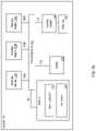
- FIG. 1Aillustrates an example system for data storage, in accordance with some implementations.
- System 100also referred to as “storage system” herein
- storage systemincludes numerous elements for purposes of illustration rather than limitation. It may be noted that system 100 may include the same, more, or fewer elements configured in the same or different manner in other implementations.
- System 100includes a number of computing devices 164 A-B.
- Computing devicesmay be embodied, for example, a server in a data center, a workstation, a personal computer, a notebook, or the like.
- Computing devices 164 A-Bmay be coupled for data communications to one or more storage arrays 102 A-B through a storage area network (‘SAN’) 158 or a local area network (‘LAN’) 160 .
- SANstorage area network
- LANlocal area network
- the SAN 158may be implemented with a variety of data communications fabrics, devices, and protocols.
- the fabrics for SAN 158may include Fibre Channel, Ethernet, Infiniband, Serial Attached Small Computer System Interface (‘SAS’), or the like.
- Data communications protocols for use with SAN 158may include Advanced Technology Attachment (‘ATA’), Fibre Channel Protocol, Small Computer System Interface (‘SCSI’), Internet Small Computer System Interface (‘iSCSI’), HyperSCSI, Non-Volatile Memory Express (‘NVMe’) over Fabrics, or the like.
- SAN 158is provided for illustration, rather than limitation.
- Other data communication couplingsmay be implemented between computing devices 164 A-B and storage arrays 102 A-B.
- the LAN 160may also be implemented with a variety of fabrics, devices, and protocols.
- the fabrics for LAN 160may include Ethernet (802.3), wireless (802.11), or the like.
- Data communication protocols for use in LAN 160may include Transmission Control Protocol (‘TCP’), User Datagram Protocol (‘UDP’), Internet Protocol (‘IP’), HyperText Transfer Protocol (‘HTTP’), Wireless Access Protocol (‘WAP’), Handheld Device Transport Protocol (‘HDTP’), Session Initiation Protocol (‘SIP’), Real Time Protocol (‘RTP’), or the like.
- TCPTransmission Control Protocol
- UDPUser Datagram Protocol
- IPInternet Protocol
- HTTPHyperText Transfer Protocol
- WAPWireless Access Protocol
- HDTPHandheld Device Transport Protocol
- SIPSession Initiation Protocol
- RTPReal Time Protocol
- Storage arrays 102 A-Bmay provide persistent data storage for the computing devices 164 A-B.
- Storage array 102 Amay be contained in a chassis (not shown), and storage array 102 B may be contained in another chassis (not shown), in implementations.
- Storage array 102 A and 102 Bmay include one or more storage array controllers 110 A-D (also referred to as “controller” herein).
- a storage array controller 110 A-Dmay be embodied as a module of automated computing machinery comprising computer hardware, computer software, or a combination of computer hardware and software. In some implementations, the storage array controllers 110 A-D may be configured to carry out various storage tasks.
- Storage tasksmay include writing data received from the computing devices 164 A-B to storage array 102 A-B, erasing data from storage array 102 A-B, retrieving data from storage array 102 A-B and providing data to computing devices 164 A-B, monitoring and reporting of disk utilization and performance, performing redundancy operations, such as Redundant Array of Independent Drives (‘RAID’) or RAID-like data redundancy operations, compressing data, encrypting data, and so forth.
- redundancy operationssuch as Redundant Array of Independent Drives (‘RAID’) or RAID-like data redundancy operations
- Storage array controller 110 A-Dmay be implemented in a variety of ways, including as a Field Programmable Gate Array (‘FPGA’), a Programmable Logic Chip (‘PLC’), an Application Specific Integrated Circuit (‘ASIC’), System-on-Chip (‘SOC’), or any computing device that includes discrete components such as a processing device, central processing unit, computer memory, or various adapters.
- Storage array controller 110 A-Dmay include, for example, a data communications adapter configured to support communications via the SAN 158 or LAN 160 . In some implementations, storage array controller 110 A-D may be independently coupled to the LAN 160 .
- storage array controller 110 A-Dmay include an I/O controller or the like that couples the storage array controller 110 A-D for data communications, through a midplane (not shown), to a persistent storage resource 170 A-B (also referred to as a “storage resource” herein).
- the persistent storage resource 170 A-B maininclude any number of storage drives 171 A-F (also referred to as “storage devices” herein) and any number of non-volatile Random Access Memory (‘NVRAM’) devices (not shown).
- NVRAMnon-volatile Random Access Memory
- the NVRAM devices of a persistent storage resource 170 A-Bmay be configured to receive, from the storage array controller 110 A-D, data to be stored in the storage drives 171 A-F.
- the datamay originate from computing devices 164 A-B.
- writing data to the NVRAM devicemay be carried out more quickly than directly writing data to the storage drive 171 A-F.
- the storage array controller 110 A-Dmay be configured to utilize the NVRAM devices as a quickly accessible buffer for data destined to be written to the storage drives 171 A-F. Latency for write requests using NVRAM devices as a buffer may be improved relative to a system in which a storage array controller 110 A-D writes data directly to the storage drives 171 A-F.
- the NVRAM devicesmay be implemented with computer memory in the form of high bandwidth, low latency RAM.
- the NVRAM deviceis referred to as “non-volatile” because the NVRAM device may receive or include a unique power source that maintains the state of the RAM after main power loss to the NVRAM device.
- a power sourcemay be a battery, one or more capacitors, or the like.
- the NVRAM devicemay be configured to write the contents of the RAM to a persistent storage, such as the storage drives 171 A-F.
- storage drive 171 A-Fmay refer to any device configured to record data persistently, where “persistently” or “persistent” refers as to a device's ability to maintain recorded data after loss of power.
- storage drive 171 A-Fmay correspond to non-disk storage media.
- the storage drive 171 A-Fmay be one or more solid-state drives (‘SSDs’), flash memory based storage, any type of solid-state non-volatile memory, or any other type of non-mechanical storage device.
- SSDssolid-state drives
- storage drive 171 A-Fmay include mechanical or spinning hard disk, such as hard-disk drives (‘HDD’).
- the storage array controllers 110 A-Dmay be configured for offloading device management responsibilities from storage drive 171 A-F in storage array 102 A-B.
- storage array controllers 110 A-Dmay manage control information that may describe the state of one or more memory blocks in the storage drives 171 A-F.
- the control informationmay indicate, for example, that a particular memory block has failed and should no longer be written to, that a particular memory block contains boot code for a storage array controller 110 A-D, the number of program-erase (‘P/E’) cycles that have been performed on a particular memory block, the age of data stored in a particular memory block, the type of data that is stored in a particular memory block, and so forth.
- P/Eprogram-erase
- control informationmay be stored with an associated memory block as metadata.
- control information for the storage drives 171 A-Fmay be stored in one or more particular memory blocks of the storage drives 171 A-F that are selected by the storage array controller 110 A-D.
- the selected memory blocksmay be tagged with an identifier indicating that the selected memory block contains control information.
- the identifiermay be utilized by the storage array controllers 110 A-D in conjunction with storage drives 171 A-F to quickly identify the memory blocks that contain control information. For example, the storage controllers 110 A-D may issue a command to locate memory blocks that contain control information.
- control informationmay be so large that parts of the control information may be stored in multiple locations, that the control information may be stored in multiple locations for purposes of redundancy, for example, or that the control information may otherwise be distributed across multiple memory blocks in the storage drive 171 A-F.
- storage array controllers 110 A-Dmay offload device management responsibilities from storage drives 171 A-F of storage array 102 A-B by retrieving, from the storage drives 171 A-F, control information describing the state of one or more memory blocks in the storage drives 171 A-F. Retrieving the control information from the storage drives 171 A-F may be carried out, for example, by the storage array controller 110 A-D querying the storage drives 171 A-F for the location of control information for a particular storage drive 171 A-F.
- the storage drives 171 A-Fmay be configured to execute instructions that enable the storage drive 171 A-F to identify the location of the control information.
- the instructionsmay be executed by a controller (not shown) associated with or otherwise located on the storage drive 171 A-F and may cause the storage drive 171 A-F to scan a portion of each memory block to identify the memory blocks that store control information for the storage drives 171 A-F.
- the storage drives 171 A-Fmay respond by sending a response message to the storage array controller 110 A-D that includes the location of control information for the storage drive 171 A-F. Responsive to receiving the response message, storage array controllers 110 A-D may issue a request to read data stored at the address associated with the location of control information for the storage drives 171 A-F.
- the storage array controllers 110 A-Dmay further offload device management responsibilities from storage drives 171 A-F by performing, in response to receiving the control information, a storage drive management operation.
- a storage drive management operationmay include, for example, an operation that is typically performed by the storage drive 171 A-F (e.g., the controller (not shown) associated with a particular storage drive 171 A-F).
- a storage drive management operationmay include, for example, ensuring that data is not written to failed memory blocks within the storage drive 171 A-F, ensuring that data is written to memory blocks within the storage drive 171 A-F in such a way that adequate wear leveling is achieved, and so forth.
- storage array 102 A-Bmay implement two or more storage array controllers 110 A-D.
- storage array 102 Amay include storage array controllers 110 A and storage array controllers 110 B.
- a single storage array controller 110 A-De.g., storage array controller 110 A
- primary controlleralso referred to as “primary controller” herein
- secondary controlleralso referred to as “secondary controller” herein
- the primary controllermay have particular rights, such as permission to alter data in persistent storage resource 170 A-B (e.g., writing data to persistent storage resource 170 A-B).
- At least some of the rights of the primary controllermay supersede the rights of the secondary controller.
- the secondary controllermay not have permission to alter data in persistent storage resource 170 A-B when the primary controller has the right.
- the status of storage array controllers 110 A-Dmay change.
- storage array controller 110 Amay be designated with secondary status
- storage array controller 110 Bmay be designated with primary status.
- a primary controllersuch as storage array controller 110 A
- a second controllersuch as storage array controller 110 B
- storage array controller 110 Amay be the primary controller for storage array 102 A and storage array 102 B
- storage array controller 110 Bmay be the secondary controller for storage array 102 A and 102 B
- storage array controllers 110 C and 110 Dmay neither have primary or secondary status.
- Storage array controllers 110 C and 110 Dmay act as a communication interface between the primary and secondary controllers (e.g., storage array controllers 110 A and 110 B, respectively) and storage array 102 B.
- storage array controller 110 A of storage array 102 Amay send a write request, via SAN 158 , to storage array 102 B.
- the write requestmay be received by both storage array controllers 110 C and 110 D of storage array 102 B.
- Storage array controllers 110 C and 110 Dfacilitate the communication, e.g., send the write request to the appropriate storage drive 171 A-F. It may be noted that in some implementations storage processing modules may be used to increase the number of storage drives controlled by the primary and secondary controllers.
- storage array controllers 110 A-Dare communicatively coupled, via a midplane (not shown), to one or more storage drives 171 A-F and to one or more NVRAM devices (not shown) that are included as part of a storage array 102 A-B.
- the storage array controllers 110 A-Dmay be coupled to the midplane via one or more data communication links and the midplane may be coupled to the storage drives 171 A-F and the NVRAM devices via one or more data communications links.
- the data communications links described hereinare collectively illustrated by data communications links 108 A-D and may include a Peripheral Component Interconnect Express (‘PCIe’) bus, for example.
- PCIePeripheral Component Interconnect Express
- FIG. 1Billustrates an example system for data storage, in accordance with some implementations.
- Storage array controller 101 illustrated in FIG. 1Bmay similar to the storage array controllers 110 A-D described with respect to FIG. 1A .
- storage array controller 101may be similar to storage array controller 110 A or storage array controller 110 B.
- Storage array controller 101includes numerous elements for purposes of illustration rather than limitation. It may be noted that storage array controller 101 may include the same, more, or fewer elements configured in the same or different manner in other implementations. It may be noted that elements of FIG. 1A may be included below to help illustrate features of storage array controller 101 .
- Storage array controller 101may include one or more processing devices 104 and random access memory (‘RAM’) 111 .
- Processing device 104represents one or more general-purpose processing devices such as a microprocessor, central processing unit, or the like. More particularly, the processing device 104 (or controller 101 ) may be a complex instruction set computing (‘CISC’) microprocessor, reduced instruction set computing (‘RISC’) microprocessor, very long instruction word (‘VLIW’) microprocessor, or a processor implementing other instruction sets or processors implementing a combination of instruction sets.
- CISCcomplex instruction set computing
- RISCreduced instruction set computing
- VLIWvery long instruction word
- the processing device 104may also be one or more special-purpose processing devices such as an application specific integrated circuit (‘ASIC’), a field programmable gate array (‘FPGA’), a digital signal processor (‘DSP’), network processor, or the like.
- ASICapplication specific integrated circuit
- FPGAfield programmable gate array
- DSPdigital signal processor
- the processing device 104may be connected to the RAM 111 via a data communications link 106 , which may be embodied as a high speed memory bus such as a Double-Data Rate 4 (‘DDR4’) bus.
- a data communications link 106Stored in RAM 111 is an operating system 112 .
- instructions 113are stored in RAM 111 .
- Instructions 113may include computer program instructions for performing operations in a direct-mapped flash storage system.
- a direct-mapped flash storage systemis one that that addresses data blocks within flash drives directly and without an address translation performed by the storage controllers of the flash drives.
- storage array controller 101includes one or more host bus adapters 103 A-C that are coupled to the processing device 104 via a data communications link 105 A-C.
- host bus adapters 103 A-Cmay be computer hardware that connects a host system (e.g., the storage array controller) to other network and storage arrays.
- host bus adapters 103 A-Cmay be a Fibre Channel adapter that enables the storage array controller 101 to connect to a SAN, an Ethernet adapter that enables the storage array controller 101 to connect to a LAN, or the like.
- Host bus adapters 103 A-Cmay be coupled to the processing device 104 via a data communications link 105 A-C such as, for example, a PCIe bus.
- storage array controller 101may include a host bus adapter 114 that is coupled to an expander 115 .
- the expander 115may be used to attach a host system to a larger number of storage drives.
- the expander 115may, for example, be a SAS expander utilized to enable the host bus adapter 114 to attach to storage drives in an implementation where the host bus adapter 114 is embodied as a SAS controller.
- storage array controller 101may include a switch 116 coupled to the processing device 104 via a data communications link 109 .
- the switch 116may be a computer hardware device that can create multiple endpoints out of a single endpoint, thereby enabling multiple devices to share a single endpoint.
- the switch 116may, for example, be a PCIe switch that is coupled to a PCIe bus (e.g., data communications link 109 ) and presents multiple PCIe connection points to the midplane.
- storage array controller 101includes a data communications link 107 for coupling the storage array controller 101 to other storage array controllers.
- data communications link 107may be a QuickPath Interconnect (QPI) interconnect.
- QPIQuickPath Interconnect
- a traditional storage system that uses traditional flash drivesmay implement a process across the flash drives that are part of the traditional storage system. For example, a higher level process of the storage system may initiate and control a process across the flash drives. However, a flash drive of the traditional storage system may include its own storage controller that also performs the process. Thus, for the traditional storage system, a higher level process (e.g., initiated by the storage system) and a lower level process (e.g., initiated by a storage controller of the storage system) may both be performed.
- a higher level processe.g., initiated by the storage system
- a lower level processe.g., initiated by a storage controller of the storage system
- the flash storage systemmay include flash drives that do not include storage controllers that provide the process.
- the operating system of the flash storage systemitself may initiate and control the process. This may be accomplished by a direct-mapped flash storage system that addresses data blocks within the flash drives directly and without an address translation performed by the storage controllers of the flash drives.
- the operating system of the flash storage systemmay identify and maintain a list of allocation units across multiple flash drives of the flash storage system.
- the allocation unitsmay be entire erase blocks or multiple erase blocks.
- the operating systemmay maintain a map or address range that directly maps addresses to erase blocks of the flash drives of the flash storage system.
- Direct mapping to the erase blocks of the flash drivesmay be used to rewrite data and erase data.
- the operationsmay be performed on one or more allocation units that include a first data and a second data where the first data is to be retained and the second data is no longer being used by the flash storage system.
- the operating systemmay initiate the process to write the first data to new locations within other allocation units and erasing the second data and marking the allocation units as being available for use for subsequent data.
- the processmay only be performed by the higher level operating system of the flash storage system without an additional lower level process being performed by controllers of the flash drives.
- Advantages of the process being performed only by the operating system of the flash storage systeminclude increased reliability of the flash drives of the flash storage system as unnecessary or redundant write operations are not being performed during the process.
- One possible point of novelty hereis the concept of initiating and controlling the process at the operating system of the flash storage system.
- the processcan be controlled by the operating system across multiple flash drives. This is contrast to the process being performed by a storage controller of a flash drive.
- a storage systemcan consist of two storage array controllers that share a set of drives for failover purposes, or it could consist of a single storage array controller that provides a storage service that utilizes multiple drives, or it could consist of a distributed network of storage array controllers each with some number of drives or some amount of Flash storage where the storage array controllers in the network collaborate to provide a complete storage service and collaborate on various aspects of a storage service including storage allocation and garbage collection.
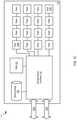
- FIG. 1Cillustrates a third example system 117 for data storage in accordance with some implementations.
- System 117also referred to as “storage system” herein
- storage systemincludes numerous elements for purposes of illustration rather than limitation. It may be noted that system 117 may include the same, more, or fewer elements configured in the same or different manner in other implementations.
- system 117includes a dual Peripheral Component Interconnect (‘PCI’) flash storage device 118 with separately addressable fast write storage.
- System 117may include a storage controller 119 .
- storage controller 119 A-Dmay be a CPU, ASIC, FPGA, or any other circuitry that may implement control structures necessary according to the present disclosure.
- system 117includes flash memory devices (e.g., including flash memory devices 120 a - n ), operatively coupled to various channels of the storage device controller 119 .
- Flash memory devices 120 a - nmay be presented to the controller 119 A-D as an addressable collection of Flash pages, erase blocks, and/or control elements sufficient to allow the storage device controller 119 A-D to program and retrieve various aspects of the Flash.
- storage device controller 119 A-Dmay perform operations on flash memory devices 120 a - n including storing and retrieving data content of pages, arranging and erasing any blocks, tracking statistics related to the use and reuse of Flash memory pages, erase blocks, and cells, tracking and predicting error codes and faults within the Flash memory, controlling voltage levels associated with programming and retrieving contents of Flash cells, etc.
- system 117may include RAM 121 to store separately addressable fast-write data.
- RAM 121may be one or more separate discrete devices.
- RAM 121may be integrated into storage device controller 119 A-D or multiple storage device controllers.
- the RAM 121may be utilized for other purposes as well, such as temporary program memory for a processing device (e.g., a CPU) in the storage device controller 119 .
- system 117may include a stored energy device 122 , such as a rechargeable battery or a capacitor.
- Stored energy device 122may store energy sufficient to power the storage device controller 119 , some amount of the RAM (e.g., RAM 121 ), and some amount of Flash memory (e.g., Flash memory 120 a - 120 n ) for sufficient time to write the contents of RAM to Flash memory.
- storage device controller 119 A-Dmay write the contents of RAM to Flash Memory if the storage device controller detects loss of external power.
- system 117includes two data communications links 123 a , 123 b .
- data communications links 123 a , 123 bmay be PCI interfaces.
- data communications links 123 a , 123 bmay be based on other communications standards (e.g., HyperTransport, InfiniBand, etc.).
- Data communications links 123 a , 123 bmay be based on non-volatile memory express (‘NVMe’) or NVMe over fabrics (‘NVMf’) specifications that allow external connection to the storage device controller 119 A-D from other components in the storage system 117 .
- NVMenon-volatile memory express
- NVMfNVMe over fabrics
- System 117may also include an external power source (not shown), which may be provided over one or both data communications links 123 a , 123 b , or which may be provided separately.
- An alternative embodimentincludes a separate Flash memory (not shown) dedicated for use in storing the content of RAM 121 .
- the storage device controller 119 A-Dmay present a logical device over a PCI bus which may include an addressable fast-write logical device, or a distinct part of the logical address space of the storage device 118 , which may be presented as PCI memory or as persistent storage. In one embodiment, operations to store into the device are directed into the RAM 121 . On power failure, the storage device controller 119 A-D may write stored content associated with the addressable fast-write logical storage to Flash memory (e.g., Flash memory 120 a - n ) for long-term persistent storage.
- Flash memorye.g., Flash memory 120 a - n
- the logical devicemay include some presentation of some or all of the content of the Flash memory devices 120 a - n , where that presentation allows a storage system including a storage device 118 (e.g., storage system 117 ) to directly address Flash memory pages and directly reprogram erase blocks from storage system components that are external to the storage device through the PCI bus.
- the presentationmay also allow one or more of the external components to control and retrieve other aspects of the Flash memory including some or all of: tracking statistics related to use and reuse of Flash memory pages, erase blocks, and cells across all the Flash memory devices; tracking and predicting error codes and faults within and across the Flash memory devices; controlling voltage levels associated with programming and retrieving contents of Flash cells; etc.
- the stored energy device 122may be sufficient to ensure completion of in-progress operations to the Flash memory devices 120 a - 120 n stored energy device 122 may power storage device controller 119 A-D and associated Flash memory devices (e.g., 120 a - n ) for those operations, as well as for the storing of fast-write RAM to Flash memory.
- Stored energy device 122may be used to store accumulated statistics and other parameters kept and tracked by the Flash memory devices 120 a - n and/or the storage device controller 119 .
- Separate capacitors or stored energy devices(such as smaller capacitors near or embedded within the Flash memory devices themselves) may be used for some or all of the operations described herein.
- Various schemesmay be used to track and optimize the life span of the stored energy component, such as adjusting voltage levels over time, partially discharging the storage energy device 122 to measure corresponding discharge characteristics, etc. If the available energy decreases over time, the effective available capacity of the addressable fast-write storage may be decreased to ensure that it can be written safely based on the currently available stored energy.
- FIG. 1Dillustrates a third example system 124 for data storage in accordance with some implementations.
- system 124includes storage controllers 125 a , 125 b .
- storage controllers 125 a , 125 bare operatively coupled to Dual PCI storage devices 119 a , 119 b and 119 c , 119 d , respectively.
- Storage controllers 125 a , 125 bmay be operatively coupled (e.g., via a storage network 130 ) to some number of host computers 127 a - n.
- two storage controllersprovide storage services, such as a SCS) block storage array, a file server, an object server, a database or data analytics service, etc.
- the storage controllers 125 a , 125 bmay provide services through some number of network interfaces (e.g., 126 a - d ) to host computers 127 a - n outside of the storage system 124 .
- Storage controllers 125 a , 125 bmay provide integrated services or an application entirely within the storage system 124 , forming a converged storage and compute system.
- the storage controllers 125 a , 125 bmay utilize the fast write memory within or across storage devices 119 a - d to journal in progress operations to ensure the operations are not lost on a power failure, storage controller removal, storage controller or storage system shutdown, or some fault of one or more software or hardware components within the storage system 124 .
- controllers 125 a , 125 boperate as PCI masters to one or the other PCI buses 128 a , 128 b .
- 128 a and 128 bmay be based on other communications standards (e.g., HyperTransport, InfiniBand, etc.).
- Other storage system embodimentsmay operate storage controllers 125 a , 125 b as multi-masters for both PCI buses 128 a , 128 b .
- a PCI/NVMe/NVMf switching infrastructure or fabricmay connect multiple storage controllers.
- Some storage system embodimentsmay allow storage devices to communicate with each other directly rather than communicating only with storage controllers.
- a storage device controller 119 amay be operable under direction from a storage controller 125 a to synthesize and transfer data to be stored into Flash memory devices from data that has been stored in RAM (e.g., RAM 121 of FIG. 1C ).
- RAMe.g., RAM 121 of FIG. 1C
- a recalculated version of RAM contentmay be transferred after a storage controller has determined that an operation has fully committed across the storage system, or when fast-write memory on the device has reached a certain used capacity, or after a certain amount of time, to ensure improve safety of the data or to release addressable fast-write capacity for reuse.
- This mechanismmay be used, for example, to avoid a second transfer over a bus (e.g., 128 a , 128 b ) from the storage controllers 125 a , 125 b .
- a recalculationmay include compressing data, attaching indexing or other metadata, combining multiple data segments together, performing erasure code calculations, etc.
- a storage device controller 119 a , 119 bmay be operable to calculate and transfer data to other storage devices from data stored in RAM (e.g., RAM 121 of FIG. 1C ) without involvement of the storage controllers 125 a , 125 b .
- This operationmay be used to mirror data stored in one controller 125 a to another controller 125 b , or it could be used to offload compression, data aggregation, and/or erasure coding calculations and transfers to storage devices to reduce load on storage controllers or the storage controller interface 129 a , 129 b to the PCI bus 128 a , 128 b.
- a storage device controller 119 A-Dmay include mechanisms for implementing high availability primitives for use by other parts of a storage system external to the Dual PCI storage device 118 .
- reservation or exclusion primitivesmay be provided so that, in a storage system with two storage controllers providing a highly available storage service, one storage controller may prevent the other storage controller from accessing or continuing to access the storage device. This could be used, for example, in cases where one controller detects that the other controller is not functioning properly or where the interconnect between the two storage controllers may itself not be functioning properly.
- a storage system for use with Dual PCI direct mapped storage devices with separately addressable fast write storageincludes systems that manage erase blocks or groups of erase blocks as allocation units for storing data on behalf of the storage service, or for storing metadata (e.g., indexes, logs, etc.) associated with the storage service, or for proper management of the storage system itself.
- Flash pageswhich may be a few kilobytes in size, may be written as data arrives or as the storage system is to persist data for long intervals of time (e.g., above a defined threshold of time).
- the storage controllersmay first write data into the separately addressable fast write storage on one more storage devices.
- the storage controllers 125 a , 125 bmay initiate the use of erase blocks within and across storage devices (e.g., 118 ) in accordance with an age and expected remaining lifespan of the storage devices, or based on other statistics.
- the storage controllers 125 a , 125 bmay initiate garbage collection and data migration data between storage devices in accordance with pages that are no longer needed as well as to manage Flash page and erase block lifespans and to manage overall system performance.
- the storage system 124may utilize mirroring and/or erasure coding schemes as part of storing data into addressable fast write storage and/or as part of writing data into allocation units associated with erase blocks. Erasure codes may be used across storage devices, as well as within erase blocks or allocation units, or within and across Flash memory devices on a single storage device, to provide redundancy against single or multiple storage device failures or to protect against internal corruptions of Flash memory pages resulting from Flash memory operations or from degradation of Flash memory cells. Mirroring and erasure coding at various levels may be used to recover from multiple types of failures that occur separately or in combination.
- FIGS. 2A-Gillustrate a storage cluster that stores user data, such as user data originating from one or more user or client systems or other sources external to the storage cluster.
- the storage clusterdistributes user data across storage nodes housed within a chassis, or across multiple chassis, using erasure coding and redundant copies of metadata.
- Erasure codingrefers to a method of data protection or reconstruction in which data is stored across a set of different locations, such as disks, storage nodes or geographic locations.
- Flash memoryis one type of solid-state memory that may be integrated with the embodiments, although the embodiments may be extended to other types of solid-state memory or other storage medium, including non-solid state memory.
- Control of storage locations and workloadsare distributed across the storage locations in a clustered peer-to-peer system. Tasks such as mediating communications between the various storage nodes, detecting when a storage node has become unavailable, and balancing/Os (inputs and outputs) across the various storage nodes, are all handled on a distributed basis. Data is laid out or distributed across multiple storage nodes in data fragments or stripes that support data recovery in some embodiments. Ownership of data can be reassigned within a cluster, independent of input and output patterns. This architecture described in more detail below allows a storage node in the cluster to fail, with the system remaining operational, since the data can be reconstructed from other storage nodes and thus remain available for input and output operations.
- a storage nodemay be referred to as a cluster node, a blade, or a server.
- the storage clustermay be contained within a chassis, i.e., an enclosure housing one or more storage nodes.
- a mechanism to provide power to each storage node, such as a power distribution bus, and a communication mechanism, such as a communication bus that enables communication between the storage nodesare included within the chassis.
- the storage clustercan run as an independent system in one location according to some embodiments.
- a chassiscontains at least two instances of both the power distribution and the communication bus which may be enabled or disabled independently.
- the internal communication busmay be an Ethernet bus, however, other technologies such as PCIe, InfiniBand, and others, are equally suitable.
- the chassisprovides a port for an external communication bus for enabling communication between multiple chassis, directly or through a switch, and with client systems.
- the external communicationmay use a technology such as Ethernet, InfiniBand, Fibre Channel, etc.
- the external communication bususes different communication bus technologies for inter-chassis and client communication.
- the switchmay act as a translation between multiple protocols or technologies.
- the storage clustermay be accessed by a client using either proprietary interfaces or standard interfaces such as network file system (‘NFS’), common internet file system (‘CIFS’), small computer system interface (‘SCSI’) or hypertext transfer protocol (‘HTTP’). Translation from the client protocol may occur at the switch, chassis external communication bus or within each storage node.
- multiple chassismay be coupled or connected to each other through an aggregator switch.
- a portion and/or all of the coupled or connected chassismay be designated as a storage cluster.
- each chassiscan have multiple blades, each blade has a media access control (‘MAC’) address, but the storage cluster is presented to an external network as having a single cluster IP address and a single MAC address in some embodiments.
- MACmedia access control
- Each storage nodemay be one or more storage servers and each storage server is connected to one or more non-volatile solid state memory units, which may be referred to as storage units or storage devices.
- One embodimentincludes a single storage server in each storage node and between one to eight non-volatile solid state memory units, however this one example is not meant to be limiting.
- the storage servermay include a processor, DRAM and interfaces for the internal communication bus and power distribution for each of the power buses. Inside the storage node, the interfaces and storage unit share a communication bus, e.g., PCI Express, in some embodiments.
- the non-volatile solid state memory unitsmay directly access the internal communication bus interface through a storage node communication bus, or request the storage node to access the bus interface.
- the non-volatile solid state memory unitcontains an embedded CPU, solid state storage controller, and a quantity of solid state mass storage, e.g., between 2-32 terabytes (‘TB’) in some embodiments.
- An embedded volatile storage medium, such as DRAM, and an energy reserve apparatusare included in the non-volatile solid state memory unit.
- the energy reserve apparatusis a capacitor, super-capacitor, or battery that enables transferring a subset of DRAM contents to a stable storage medium in the case of power loss.
- the non-volatile solid state memory unitis constructed with a storage class memory, such as phase change or magnetoresistive random access memory (‘MRAM’) that substitutes for DRAM and enables a reduced power hold-up apparatus.
- MRAMmagnetoresistive random access memory
- the storage nodes and non-volatile solid state storagecan determine when a storage node or non-volatile solid state storage in the storage cluster is unreachable, independent of whether there is an attempt to read data involving that storage node or non-volatile solid state storage.
- the storage nodes and non-volatile solid state storagethen cooperate to recover and rebuild the data in at least partially new locations. This constitutes a proactive rebuild, in that the system rebuilds data without waiting until the data is needed for a read access initiated from a client system employing the storage cluster.
- FIG. 2Ais a perspective view of a storage cluster 161 , with multiple storage nodes 150 and internal solid-state memory coupled to each storage node to provide network attached storage or storage area network, in accordance with some embodiments.
- a network attached storage, storage area network, or a storage cluster, or other storage memorycould include one or more storage clusters 161 , each having one or more storage nodes 150 , in a flexible and reconfigurable arrangement of both the physical components and the amount of storage memory provided thereby.
- the storage cluster 161is designed to fit in a rack, and one or more racks can be set up and populated as desired for the storage memory.
- the storage cluster 161has a chassis 138 having multiple slots 142 .
- chassis 138may be referred to as a housing, enclosure, or rack unit.
- the chassis 138has fourteen slots 142 , although other numbers of slots are readily devised. For example, some embodiments have four slots, eight slots, sixteen slots, thirty-two slots, or other suitable number of slots.
- Each slot 142can accommodate one storage node 150 in some embodiments.
- Chassis 138includes flaps 148 that can be utilized to mount the chassis 138 on a rack.
- Fans 144provide air circulation for cooling of the storage nodes 150 and components thereof, although other cooling components could be used, or an embodiment could be devised without cooling components.
- a switch fabric 146couples storage nodes 150 within chassis 138 together and to a network for communication to the memory.
- the slots 142 to the left of the switch fabric 146 and fans 144are shown occupied by storage nodes 150 , while the slots 142 to the right of the switch fabric 146 and fans 144 are empty and available for insertion of storage node 150 for illustrative purposes.
- This configurationis one example, and one or more storage nodes 150 could occupy the slots 142 in various further arrangements.
- the storage node arrangementsneed not be sequential or adjacent in some embodiments.
- Storage nodes 150are hot pluggable, meaning that a storage node 150 can be inserted into a slot 142 in the chassis 138 , or removed from a slot 142 , without stopping or powering down the system.
- the systemUpon insertion or removal of storage node 150 from slot 142 , the system automatically reconfigures in order to recognize and adapt to the change.
- Reconfigurationincludes restoring redundancy and/or rebalancing data or load.
- Each storage node 150can have multiple components.
- the storage node 150includes a printed circuit board 159 populated by a CPU 156 , i.e., processor, a memory 154 coupled to the CPU 156 , and a non-volatile solid state storage 152 coupled to the CPU 156 , although other mountings and/or components could be used in further embodiments.
- the memory 154has instructions which are executed by the CPU 156 and/or data operated on by the CPU 156 .
- the non-volatile solid state storage 152includes flash or, in further embodiments, other types of solid-state memory.
- storage cluster 161is scalable, meaning that storage capacity with non-uniform storage sizes is readily added, as described above.
- One or more storage nodes 150can be plugged into or removed from each chassis and the storage cluster self-configures in some embodiments.
- Plug-in storage nodes 150whether installed in a chassis as delivered or later added, can have different sizes.
- a storage node 150can have any multiple of 4 TB, e.g., 8 TB, 12 TB, 16 TB, 32 TB, etc.
- a storage node 150could have any multiple of other storage amounts or capacities.
- Storage capacity of each storage node 150is broadcast, and influences decisions of how to stripe the data. For maximum storage efficiency, an embodiment can self-configure as wide as possible in the stripe, subject to a predetermined requirement of continued operation with loss of up to one, or up to two, non-volatile solid state storage units 152 or storage nodes 150 within the chassis.
- FIG. 2Bis a block diagram showing a communications interconnect 173 and power distribution bus 172 coupling multiple storage nodes 150 .
- the communications interconnect 173can be included in or implemented with the switch fabric 146 in some embodiments. Where multiple storage clusters 161 occupy a rack, the communications interconnect 173 can be included in or implemented with a top of rack switch, in some embodiments. As illustrated in FIG. 2B , storage cluster 161 is enclosed within a single chassis 138 .
- External port 176is coupled to storage nodes 150 through communications interconnect 173 , while external port 174 is coupled directly to a storage node.
- External power port 178is coupled to power distribution bus 172 .
- Storage nodes 150may include varying amounts and differing capacities of non-volatile solid state storage 152 as described with reference to FIG. 2A .
- one or more storage nodes 150may be a compute only storage node as illustrated in FIG. 2B .
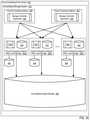
- Authorities 168are implemented on the non-volatile solid state storages 152 , for example as lists or other data structures stored in memory. In some embodiments the authorities are stored within the non-volatile solid state storage 152 and supported by software executing on a controller or other processor of the non-volatile solid state storage 152 .
- authorities 168are implemented on the storage nodes 150 , for example as lists or other data structures stored in the memory 154 and supported by software executing on the CPU 156 of the storage node 150 .
- authorities 168control how and where data is stored in the non-volatile solid state storages 152 in some embodiments. This control assists in determining which type of erasure coding scheme is applied to the data, and which storage nodes 150 have which portions of the data.
- Each authority 168may be assigned to a non-volatile solid state storage 152 .
- Each authoritymay control a range of inode numbers, segment numbers, or other data identifiers which are assigned to data by a file system, by the storage nodes 150 , or by the non-volatile solid state storage 152 , in various embodiments.
- every piece of data and every piece of metadatahas an owner, which may be referred to as an authority. If that authority is unreachable, for example through failure of a storage node, there is a plan of succession for how to find that data or that metadata.
- authorities 168there are redundant copies of authorities 168 .
- Authorities 168have a relationship to storage nodes 150 and non-volatile solid state storage 152 in some embodiments. Each authority 168 , covering a range of data segment numbers or other identifiers of the data, may be assigned to a specific non-volatile solid state storage 152 .
- the authorities 168 for all of such rangesare distributed over the non-volatile solid state storages 152 of a storage cluster.
- Each storage node 150has a network port that provides access to the non-volatile solid state storage(s) 152 of that storage node 150 .
- Datacan be stored in a segment, which is associated with a segment number and that segment number is an indirection for a configuration of a RAID (redundant array of independent disks) stripe in some embodiments.
- the assignment and use of the authorities 168thus establishes an indirection to data. Indirection may be referred to as the ability to reference data indirectly, in this case via an authority 168 , in accordance with some embodiments.
- a segmentidentifies a set of non-volatile solid state storage 152 and a local identifier into the set of non-volatile solid state storage 152 that may contain data.
- the local identifieris an offset into the device and may be reused sequentially by multiple segments. In other embodiments the local identifier is unique for a specific segment and never reused.
- the offsets in the non-volatile solid state storage 152are applied to locating data for writing to or reading from the non-volatile solid state storage 152 (in the form of a RAID stripe). Data is striped across multiple units of non-volatile solid state storage 152 , which may include or be different from the non-volatile solid state storage 152 having the authority 168 for a particular data segment.
- the authority 168 for that data segmentshould be consulted, at that non-volatile solid state storage 152 or storage node 150 having that authority 168 .
- embodimentscalculate a hash value for a data segment or apply an inode number or a data segment number.
- the output of this operationpoints to a non-volatile solid state storage 152 having the authority 168 for that particular piece of data.
- the first stagemaps an entity identifier (ID), e.g., a segment number, inode number, or directory number to an authority identifier.
- IDentity identifier
- This mappingmay include a calculation such as a hash or a bit mask.
- the second stageis mapping the authority identifier to a particular non-volatile solid state storage 152 , which may be done through an explicit mapping.
- the operationis repeatable, so that when the calculation is performed, the result of the calculation repeatably and reliably points to a particular non-volatile solid state storage 152 having that authority 168 .
- the operationmay include the set of reachable storage nodes as input. If the set of reachable non-volatile solid state storage units changes the optimal set changes.
- the persisted valueis the current assignment (which is always true) and the calculated value is the target assignment the cluster will attempt to reconfigure towards.
- This calculationmay be used to determine the optimal non-volatile solid state storage 152 for an authority in the presence of a set of non-volatile solid state storage 152 that are reachable and constitute the same cluster.
- the calculationalso determines an ordered set of peer non-volatile solid state storage 152 that will also record the authority to non-volatile solid state storage mapping so that the authority may be determined even if the assigned non-volatile solid state storage is unreachable.
- a duplicate or substitute authority 168may be consulted if a specific authority 168 is unavailable in some embodiments.
- two of the many tasks of the CPU 156 on a storage node 150are to break up write data, and reassemble read data.
- the authority 168 for that datais located as above.
- the request to writeis forwarded to the non-volatile solid state storage 152 currently determined to be the host of the authority 168 determined from the segment.
- the host CPU 156 of the storage node 150on which the non-volatile solid state storage 152 and corresponding authority 168 reside, then breaks up or shards the data and transmits the data out to various non-volatile solid state storage 152 .
- the transmitted datais written as a data stripe in accordance with an erasure coding scheme.
- datais requested to be pulled, and in other embodiments, data is pushed.
- the authority 168 for the segment ID containing the datais located as described above.
- the host CPU 156 of the storage node 150 on which the non-volatile solid state storage 152 and corresponding authority 168 residerequests the data from the non-volatile solid state storage and corresponding storage nodes pointed to by the authority.
- the datais read from flash storage as a data stripe.
- the host CPU 156 of storage node 150then reassembles the read data, correcting any errors (if present) according to the appropriate erasure coding scheme, and forwards the reassembled data to the network. In further embodiments, some or all of these tasks can be handled in the non-volatile solid state storage 152 . In some embodiments, the segment host requests the data be sent to storage node 150 by requesting pages from storage and then sending the data to the storage node making the original request.
- datais handled with an index node or inode, which specifies a data structure that represents an object in a file system.
- the objectcould be a file or a directory, for example.
- Metadatamay accompany the object, as attributes such as permission data and a creation timestamp, among other attributes.
- a segment numbercould be assigned to all or a portion of such an object in a file system.
- data segmentsare handled with a segment number assigned elsewhere.
- the unit of distributionis an entity, and an entity can be a file, a directory or a segment. That is, entities are units of data or metadata stored by a storage system. Entities are grouped into sets called authorities. Each authority has an authority owner, which is a storage node that has the exclusive right to update the entities in the authority. In other words, a storage node contains the authority, and that the authority, in turn, contains entities.
- a segmentis a logical container of data in accordance with some embodiments.
- a segmentis an address space between medium address space and physical flash locations, i.e., the data segment number, are in this address space. Segments may also contain meta-data, which enable data redundancy to be restored (rewritten to different flash locations or devices) without the involvement of higher level software.
- an internal format of a segmentcontains client data and medium mappings to determine the position of that data. Each data segment is protected, e.g., from memory and other failures, by breaking the segment into a number of data and parity shards, where applicable.
- the data and parity shardsare distributed, i.e., striped, across non-volatile solid state storage 152 coupled to the host CPUs 156 (See FIGS. 2E and 2G ) in accordance with an erasure coding scheme.
- Usage of the term segmentsrefers to the container and its place in the address space of segments in some embodiments.
- Usage of the term striperefers to the same set of shards as a segment and includes how the shards are distributed along with redundancy or parity information in accordance with some embodiments.
- a series of address-space transformationstakes place across an entire storage system.
- the directory entriesfile names which link to an inode.
- Inodespoint into medium address space, where data is logically stored.
- Medium addressesmay be mapped through a series of indirect mediums to spread the load of large files, or implement data services like deduplication or snapshots.
- Medium addressesmay be mapped through a series of indirect mediums to spread the load of large files, or implement data services like deduplication or snapshots. Segment addresses are then translated into physical flash locations. Physical flash locations have an address range bounded by the amount of flash in the system in accordance with some embodiments.
- Medium addresses and segment addressesare logical containers, and in some embodiments use a 128 bit or larger identifier so as to be practically infinite, with a likelihood of reuse calculated as longer than the expected life of the system. Addresses from logical containers are allocated in a hierarchical fashion in some embodiments. Initially, each non-volatile solid state storage unit 152 may be assigned a range of address space. Within this assigned range, the non-volatile solid state storage 152 is able to allocate addresses without synchronization with other non-volatile solid state storage 152 .
- Data and metadatais stored by a set of underlying storage layouts that are optimized for varying workload patterns and storage devices. These layouts incorporate multiple redundancy schemes, compression formats and index algorithms. Some of these layouts store information about authorities and authority masters, while others store file metadata and file data.
- the redundancy schemesinclude error correction codes that tolerate corrupted bits within a single storage device (such as a NAND flash chip), erasure codes that tolerate the failure of multiple storage nodes, and replication schemes that tolerate data center or regional failures.
- low density parity check (‘LDPC’) codeis used within a single storage unit.
- Reed-Solomon encodingis used within a storage cluster, and mirroring is used within a storage grid in some embodiments.
- Metadatamay be stored using an ordered log structured index (such as a Log Structured Merge Tree), and large data may not be stored in a log structured layout.
- the storage nodesagree implicitly on two things through calculations: (1) the authority that contains the entity, and (2) the storage node that contains the authority.
- the assignment of entities to authoritiescan be done by pseudo randomly assigning entities to authorities, by splitting entities into ranges based upon an externally produced key, or by placing a single entity into each authority. Examples of pseudorandom schemes are linear hashing and the Replication Under Scalable Hashing (‘RUSH’) family of hashes, including Controlled Replication Under Scalable Hashing (‘CRUSH’).
- pseudo-random assignmentis utilized only for assigning authorities to nodes because the set of nodes can change. The set of authorities cannot change so any subjective function may be applied in these embodiments.
- a pseudorandom schemeis utilized to map from each authority to a set of candidate authority owners.
- a pseudorandom data distribution function related to CRUSHmay assign authorities to storage nodes and create a list of where the authorities are assigned.
- Each storage nodehas a copy of the pseudorandom data distribution function, and can arrive at the same calculation for distributing, and later finding or locating an authority.
- Each of the pseudorandom schemesrequires the reachable set of storage nodes as input in some embodiments in order to conclude the same target nodes. Once an entity has been placed in an authority, the entity may be stored on physical devices so that no expected failure will lead to unexpected data loss.
- rebalancing algorithmsattempt to store the copies of all entities within an authority in the same layout and on the same set of machines.
- expected failuresinclude device failures, stolen machines, datacenter fires, and regional disasters, such as nuclear or geological events. Different failures lead to different levels of acceptable data loss.
- a stolen storage nodeimpacts neither the security nor the reliability of the system, while depending on system configuration, a regional event could lead to no loss of data, a few seconds or minutes of lost updates, or even complete data loss.
- the placement of data for storage redundancyis independent of the placement of authorities for data consistency.
- storage nodes that contain authoritiesdo not contain any persistent storage. Instead, the storage nodes are connected to non-volatile solid state storage units that do not contain authorities.
- the communications interconnect between storage nodes and non-volatile solid state storage unitsconsists of multiple communication technologies and has non-uniform performance and fault tolerance characteristics.
- non-volatile solid state storage unitsare connected to storage nodes via PCI express, storage nodes are connected together within a single chassis using Ethernet backplane, and chassis are connected together to form a storage cluster.
- Storage clustersare connected to clients using Ethernet or fiber channel in some embodiments. If multiple storage clusters are configured into a storage grid, the multiple storage clusters are connected using the Internet or other long-distance networking links, such as a “metro scale” link or private link that does not traverse the internet.
- Authority ownershave the exclusive right to modify entities, to migrate entities from one non-volatile solid state storage unit to another non-volatile solid state storage unit, and to add and remove copies of entities. This allows for maintaining the redundancy of the underlying data.
- an authority ownerfails, is going to be decommissioned, or is overloaded, the authority is transferred to a new storage node.
- Transient failuresmake it non-trivial to ensure that all non-faulty machines agree upon the new authority location.
- the ambiguity that arises due to transient failurescan be achieved automatically by a consensus protocol such as Paxos, hot-warm failover schemes, via manual intervention by a remote system administrator, or by a local hardware administrator (such as by physically removing the failed machine from the cluster, or pressing a button on the failed machine).
- a consensus protocolis used, and failover is automatic. If too many failures or replication events occur in too short a time period, the system goes into a self-preservation mode and halts replication and data movement activities until an administrator intervenes in accordance with some embodiments.
- the systemtransfers messages between the storage nodes and non-volatile solid state storage units.
- persistent messagesmessages that have different purposes are of different types. Depending on the type of the message, the system maintains different ordering and durability guarantees.
- the persistent messagesare being processed, the messages are temporarily stored in multiple durable and non-durable storage hardware technologies.
- messagesare stored in RAM, NVRAM and on NAND flash devices, and a variety of protocols are used in order to make efficient use of each storage medium. Latency-sensitive client requests may be persisted in replicated NVRAM, and then later NAND, while background rebalancing operations are persisted directly to NAND.
- Persistent messagesare persistently stored prior to being transmitted. This allows the system to continue to serve client requests despite failures and component replacement.
- many hardware componentscontain unique identifiers that are visible to system administrators, manufacturer, hardware supply chain and ongoing monitoring quality control infrastructure, applications running on top of the infrastructure address virtualize addresses. These virtualized addresses do not change over the lifetime of the storage system, regardless of component failures and replacements. This allows each component of the storage system to be replaced over time without reconfiguration or disruptions of client request processing, i.e., the system supports non-disruptive upgrades.
- the virtualized addressesare stored with sufficient redundancy.
- a continuous monitoring systemcorrelates hardware and software status and the hardware identifiers. This allows detection and prediction of failures due to faulty components and manufacturing details. The monitoring system also enables the proactive transfer of authorities and entities away from impacted devices before failure occurs by removing the component from the critical path in some embodiments.
- FIG. 2Cis a multiple level block diagram, showing contents of a storage node 150 and contents of a non-volatile solid state storage 152 of the storage node 150 .
- Datais communicated to and from the storage node 150 by a network interface controller (‘NIC’) 202 in some embodiments.
- NICnetwork interface controller
- Each storage node 150has a CPU 156 , and one or more non-volatile solid state storage 152 , as discussed above.
- each non-volatile solid state storage 152has a relatively fast non-volatile solid state memory, such as nonvolatile random access memory (‘NVRAM’) 204 , and flash memory 206 .
- NVRAMnonvolatile random access memory
- NVRAM 204may be a component that does not require program/erase cycles (DRAM, MRAM, PCM), and can be a memory that can support being written vastly more often than the memory is read from.
- the NVRAM 204is implemented in one embodiment as high speed volatile memory, such as dynamic random access memory (DRAM) 216 , backed up by energy reserve 218 .
- Energy reserve 218provides sufficient electrical power to keep the DRAM 216 powered long enough for contents to be transferred to the flash memory 206 in the event of power failure.
- energy reserve 218is a capacitor, super-capacitor, battery, or other device, that supplies a suitable supply of energy sufficient to enable the transfer of the contents of DRAM 216 to a stable storage medium in the case of power loss.
- the flash memory 206is implemented as multiple flash dies 222 , which may be referred to as packages of flash dies 222 or an array of flash dies 222 . It should be appreciated that the flash dies 222 could be packaged in any number of ways, with a single die per package, multiple dies per package (i.e. multichip packages), in hybrid packages, as bare dies on a printed circuit board or other substrate, as encapsulated dies, etc.
- the non-volatile solid state storage 152has a controller 212 or other processor, and an input output (I/O) port 210 coupled to the controller 212 .
- I/O port 210is coupled to the CPU 156 and/or the network interface controller 202 of the flash storage node 150 .
- Flash input output (I/O) port 220is coupled to the flash dies 222 , and a direct memory access unit (DMA) 214 is coupled to the controller 212 , the DRAM 216 and the flash dies 222 .
- DMAdirect memory access unit
- the I/O port 210 , controller 212 , DMA unit 214 and flash I/O port 220are implemented on a programmable logic device (‘PLD’) 208 , e.g., a field programmable gate array (FPGA).
- PLDprogrammable logic device
- FPGAfield programmable gate array
- each flash die 222has pages, organized as sixteen kB (kilobyte) pages 224 , and a register 226 through which data can be written to or read from the flash die 222 .
- other types of solid-state memoryare used in place of, or in addition to flash memory illustrated within flash die 222 .
- Storage clusters 161in various embodiments as disclosed herein, can be contrasted with storage arrays in general.
- the storage nodes 150are part of a collection that creates the storage cluster 161 .
- Each storage node 150owns a slice of data and computing required to provide the data.
- Multiple storage nodes 150cooperate to store and retrieve the data.
- Storage memory or storage devices, as used in storage arrays in general,are less involved with processing and manipulating the data.
- Storage memory or storage devices in a storage arrayreceive commands to read, write, or erase data.
- the storage memory or storage devices in a storage arrayare not aware of a larger system in which they are embedded, or what the data means.
- Storage memory or storage devices in storage arrayscan include various types of storage memory, such as RAM, solid state drives, hard disk drives, etc.
- the storage units 152 described hereinhave multiple interfaces active simultaneously and serving multiple purposes. In some embodiments, some of the functionality of a storage node 150 is shifted into a storage unit 152 , transforming the storage unit 152 into a combination of storage unit 152 and storage node 150 . Placing computing (relative to storage data) into the storage unit 152 places this computing closer to the data itself.
- the various system embodimentshave a hierarchy of storage node layers with different capabilities. By contrast, in a storage array, a controller owns and knows everything about all of the data that the controller manages in a shelf or storage devices.
- multiple controllers in multiple storage units 152 and/or storage nodes 150cooperate in various ways (e.g., for erasure coding, data sharding, metadata communication and redundancy, storage capacity expansion or contraction, data recovery, and so on).
- FIG. 2Dshows a storage server environment, which uses embodiments of the storage nodes 150 and storage units 152 of FIGS. 2A-C .
- each storage unit 152has a processor such as controller 212 (see FIG. 2C ), an FPGA (field programmable gate array), flash memory 206 , and NVRAM 204 (which is super-capacitor backed DRAM 216 , see FIGS. 2B and 2C ) on a PCIe (peripheral component interconnect express) board in a chassis 138 (see FIG. 2A ).
- the storage unit 152may be implemented as a single board containing storage, and may be the largest tolerable failure domain inside the chassis. In some embodiments, up to two storage units 152 may fail and the device will continue with no data loss.
- the physical storageis divided into named regions based on application usage in some embodiments.
- the NVRAM 204is a contiguous block of reserved memory in the storage unit 152 DRAM 216 , and is backed by NAND flash.
- NVRAM 204is logically divided into multiple memory regions written for two as spool (e.g., spool_region). Space within the NVRAM 204 spools is managed by each authority 168 independently. Each device provides an amount of storage space to each authority 168 . That authority 168 further manages lifetimes and allocations within that space. Examples of a spool include distributed transactions or notions.
- onboard super-capacitorsprovide a short duration of power hold up. During this holdup interval, the contents of the NVRAM 204 are flushed to flash memory 206 . On the next power-on, the contents of the NVRAM 204 are recovered from the flash memory 206 .
- the responsibility of the logical “controller”is distributed across each of the blades containing authorities 168 .
- This distribution of logical controlis shown in FIG. 2D as a host controller 242 , mid-tier controller 244 and storage unit controller(s) 246 . Management of the control plane and the storage plane are treated independently, although parts may be physically co-located on the same blade.
- Each authority 168effectively serves as an independent controller.
- Each authority 168provides its own data and metadata structures, its own background workers, and maintains its own lifecycle.
- FIG. 2Eis a blade 252 hardware block diagram, showing a control plane 254 , compute and storage planes 256 , 258 , and authorities 168 interacting with underlying physical resources, using embodiments of the storage nodes 150 and storage units 152 of FIGS. 2A-C in the storage server environment of FIG. 2D .
- the control plane 254is partitioned into a number of authorities 168 which can use the compute resources in the compute plane 256 to run on any of the blades 252 .
- the storage plane 258is partitioned into a set of devices, each of which provides access to flash 206 and NVRAM 204 resources.
- the compute plane 256may perform the operations of a storage array controller, as described herein, on one or more devices of the storage plane 258 (e.g., a storage array).
- the authorities 168interact with the underlying physical resources (i.e., devices). From the point of view of an authority 168 , its resources are striped over all of the physical devices. From the point of view of a device, it provides resources to all authorities 168 , irrespective of where the authorities happen to run.
- Each authority 168has allocated or has been allocated one or more partitions 260 of storage memory in the storage units 152 , e.g. partitions 260 in flash memory 206 and NVRAM 204 . Each authority 168 uses those allocated partitions 260 that belong to it, for writing or reading user data.
- authoritiescan be associated with differing amounts of physical storage of the system. For example, one authority 168 could have a larger number of partitions 260 or larger sized partitions 260 in one or more storage units 152 than one or more other authorities 168 .
- FIG. 2Fdepicts elasticity software layers in blades 252 of a storage cluster, in accordance with some embodiments.
- elasticity softwareis symmetric, i.e., each blade's compute module 270 runs the three identical layers of processes depicted in FIG. 2F .
- Storage managers 274execute read and write requests from other blades 252 for data and metadata stored in local storage unit 152 NVRAM 204 and flash 206 .
- Authorities 168fulfill client requests by issuing the necessary reads and writes to the blades 252 on whose storage units 152 the corresponding data or metadata resides.
- Endpoints 272parse client connection requests received from switch fabric 146 supervisory software, relay the client connection requests to the authorities 168 responsible for fulfillment, and relay the authorities' 168 responses to clients.
- the symmetric three-layer structureenables the storage system's high degree of concurrency. Elasticity scales out efficiently and reliably in these embodiments. In addition, elasticity implements a unique scale-out technique that balances work evenly across all resources regardless of client access pattern, and maximizes concurrency by eliminating much of the need for inter-blade coordination that typically occurs with conventional distributed locking.
- authorities 168 running in the compute modules 270 of a blade 252perform the internal operations required to fulfill client requests.
- authorities 168are stateless, i.e., they cache active data and metadata in their own blades' 252 DRAMs for fast access, but the authorities store every update in their NVRAM 204 partitions on three separate blades 252 until the update has been written to flash 206 . All the storage system writes to NVRAM 204 are in triplicate to partitions on three separate blades 252 in some embodiments. With triple-mirrored NVRAM 204 and persistent storage protected by parity and Reed-Solomon RAID checksums, the storage system can survive concurrent failure of two blades 252 with no loss of data, metadata, or access to either.
- authorities 168are stateless, they can migrate between blades 252 .
- Each authority 168has a unique identifier.
- NVRAM 204 and flash 206 partitionsare associated with authorities' 168 identifiers, not with the blades 252 on which they are running in some.
- the authority 168continues to manage the same storage partitions from its new location.
- the systemautomatically rebalances load by: partitioning the new blade's 252 storage for use by the system's authorities 168 , migrating selected authorities 168 to the new blade 252 , starting endpoints 272 on the new blade 252 and including them in the switch fabric's 146 client connection distribution algorithm.
- migrated authorities 168persist the contents of their NVRAM 204 partitions on flash 206 , process read and write requests from other authorities 168 , and fulfill the client requests that endpoints 272 direct to them. Similarly, if a blade 252 fails or is removed, the system redistributes its authorities 168 among the system's remaining blades 252 . The redistributed authorities 168 continue to perform their original functions from their new locations.
- FIG. 2Gdepicts authorities 168 and storage resources in blades 252 of a storage cluster, in accordance with some embodiments.
- Each authority 168is exclusively responsible for a partition of the flash 206 and NVRAM 204 on each blade 252 .
- the authority 168manages the content and integrity of its partitions independently of other authorities 168 .
- Authorities 168compress incoming data and preserve it temporarily in their NVRAM 204 partitions, and then consolidate, RAID-protect, and persist the data in segments of the storage in their flash 206 partitions. As the authorities 168 write data to flash 206 , storage managers 274 perform the necessary flash translation to optimize write performance and maximize media longevity.
- authorities 168“garbage collect,” or reclaim space occupied by data that clients have made obsolete by overwriting the data. It should be appreciated that since authorities' 168 partitions are disjoint, there is no need for distributed locking to execute client and writes or to perform background functions.
- the embodiments described hereinmay utilize various software, communication and/or networking protocols.
- the configuration of the hardware and/or softwaremay be adjusted to accommodate various protocols.
- the embodimentsmay utilize Active Directory, which is a database based system that provides authentication, directory, policy, and other services in a WINDOWSTM environment.
- LDAPLightweight Directory Access Protocol
- a network lock manager(‘NLM’) is utilized as a facility that works in cooperation with the Network File System (‘NFS’) to provide a System V style of advisory file and record locking over a network.
- NLMnetwork lock manager
- SMBServer Message Block
- CIFSCommon Internet File System
- SMPoperates as an application-layer network protocol typically used for providing shared access to files, printers, and serial ports and miscellaneous communications between nodes on a network.
- SMBalso provides an authenticated inter-process communication mechanism.
- AMAZONTM S3Simple Storage Service
- RESTrepresentational state transfer
- SOAPsimple object access protocol
- BitTorrentBitTorrent
- Each moduleaddresses a particular underlying part of the transaction.
- the control or permissions provided with these embodiments, especially for object data,may include utilization of an access control list (‘ACL’).
- ACLis a list of permissions attached to an object and the ACL specifies which users or system processes are granted access to objects, as well as what operations are allowed on given objects.
- the systemsmay utilize Internet Protocol version 6 (‘IPv6’), as well as IPv4, for the communications protocol that provides an identification and location system for computers on networks and routes traffic across the Internet.
- IPv6Internet Protocol version 6
- IPv4Internet Protocol version 6
- the routing of packets between networked systemsmay include Equal-cost multi-path routing (‘ECMP’), which is a routing strategy where next-hop packet forwarding to a single destination can occur over multiple “best paths” which tie for top place in routing metric calculations.
- ECMPEqual-cost multi-path routing
- Multi-path routingcan be used in conjunction with most routing protocols, because it is a per-hop decision limited to a single router.
- the softwaremay support Multi-tenancy, which is an architecture in which a single instance of a software application serves multiple customers. Each customer may be referred to as a tenant. Tenants may be given the ability to customize some parts of the application, but may not customize the application's code, in some embodiments.
- the embodimentsmay maintain audit logs.
- An audit logis a document that records an event in a computing system. In addition to documenting what resources were accessed, audit log entries typically include destination and source addresses, a timestamp, and user login information for compliance with various regulations.
- the embodimentsmay support various key management policies, such as encryption key rotation.
- the systemmay support dynamic root passwords or some variation dynamically changing passwords.
- FIG. 3Asets forth a diagram of a storage system 306 that is coupled for data communications with a cloud services provider 302 in accordance with some embodiments of the present disclosure.
- the storage system 306 depicted in FIG. 3Amay be similar to the storage systems described above with reference to FIGS. 1A-1D and FIGS. 2A-2G .
- the storage system 306 depicted in FIG. 3Amay be similar to the storage systems described above with reference to FIGS. 1A-1D and FIGS. 2A-2G .
- 3Amay be embodied as a storage system that includes imbalanced active/active controllers, as a storage system that includes balanced active/active controllers, as a storage system that includes active/active controllers where less than all of each controller's resources are utilized such that each controller has reserve resources that may be used to support failover, as a storage system that includes fully active/active controllers, as a storage system that includes dataset-segregated controllers, as a storage system that includes dual-layer architectures with front-end controllers and back-end integrated storage controllers, as a storage system that includes scale-out clusters of dual-controller arrays, as well as combinations of such embodiments.
- the storage system 306is coupled to the cloud services provider 302 via a data communications link 304 .
- the data communications link 304may be embodied as a dedicated data communications link, as a data communications pathway that is provided through the use of one or data communications networks such as a wide area network (‘WAN’) or local area network (‘LAN’), or as some other mechanism capable of transporting digital information between the storage system 306 and the cloud services provider 302 .
- WANwide area network
- LANlocal area network
- Such a data communications link 304may be fully wired, fully wireless, or some aggregation of wired and wireless data communications pathways.
- digital informationmay be exchanged between the storage system 306 and the cloud services provider 302 via the data communications link 304 using one or more data communications protocols.
- digital informationmay be exchanged between the storage system 306 and the cloud services provider 302 via the data communications link 304 using the handheld device transfer protocol (‘HDTP’), hypertext transfer protocol (‘HTTP’), internet protocol (‘IP’), real-time transfer protocol (‘RTP’), transmission control protocol (‘TCP’), user datagram protocol (‘UDP’), wireless application protocol (‘WAP’), or other protocol.
- HDTPhandheld device transfer protocol
- HTTPhypertext transfer protocol
- IPinternet protocol
- RTPreal-time transfer protocol
- TCPtransmission control protocol
- UDPuser datagram protocol
- WAPwireless application protocol
- the cloud services provider 302 depicted in FIG. 3Amay be embodied, for example, as a system and computing environment that provides a vast array of services to users of the cloud services provider 302 through the sharing of computing resources via the data communications link 304 .
- the cloud services provider 302may provide on-demand access to a shared pool of configurable computing resources such as computer networks, servers, storage, applications and services, and so on.
- the shared pool of configurable resourcesmay be rapidly provisioned and released to a user of the cloud services provider 302 with minimal management effort.
- the user of the cloud services provider 302is unaware of the exact computing resources utilized by the cloud services provider 302 to provide the services.
- a cloud services provider 302may be accessible via the Internet, readers of skill in the art will recognize that any system that abstracts the use of shared resources to provide services to a user through any data communications link may be considered a cloud services provider 302 .
- the cloud services provider 302may be configured to provide a variety of services to the storage system 306 and users of the storage system 306 through the implementation of various service models.
- the cloud services provider 302may be configured to provide services through the implementation of an infrastructure as a service (‘IaaS’) service model where the cloud services provider 302 offers computing infrastructure such as virtual machines and other resources as a service to subscribers, through the implementation of a platform as a service (‘PaaS’) service model where the cloud services provider 302 offers a development environment to application developers, or in other ways.
- IaaSinfrastructure as a service
- PaaSplatform as a service
- Such a development environmentmay include, for example, an operating system, programming-language execution environment, database, web server, or other components that may be utilized by application developers to develop and run software solutions on a cloud platform.
- the cloud services provider 302may be configured to provide services through the implementation of a software as a service (‘SaaS’) service model where the cloud services provider 302 offers application software, databases, as well as the platforms that are used to run the applications to the storage system 306 and users of the storage system 306 , providing the storage system 306 and users of the storage system 306 with on-demand software and eliminating the need to install and run the application on local computers, which may simplify maintenance and support of the application.
- SaaSsoftware as a service
- the cloud services provider 302may be further configured to provide services through the implementation of an authentication as a service (‘AaaS’) service model where the cloud services provider 302 offers authentication services that can be used to secure access to applications, data sources, or other resources.
- the cloud services provider 302may also be configured to provide services to the storage system 306 and users of the storage system 306 through the implementation of a storage as a service model where the cloud services provider 302 offers access to its storage infrastructure for use by the storage system 306 and users of the storage system 306 .
- the cloud services provider 302may be configured to provide additional services to the storage system 306 and users of the storage system 306 through the implementation of additional service models, as the service models described above are included only for explanatory purposes and in no way represent a limitation of the services that may be offered by the cloud services provider 302 or a limitation as to the service models that may be implemented by the cloud services provider 302 .
- the cloud services provider 302may be embodied, for example, as a private cloud, as a public cloud, or as a combination of a private cloud and public cloud.
- the cloud services provider 302may be dedicated to providing services to a single organization rather than providing services to multiple organizations.
- the cloud services provider 302may provide services to multiple organizations.
- Public cloud and private cloud deployment modelsmay differ and may come with various advantages and disadvantages.
- the cloud services provider 302may be embodied as a mix of a private and public cloud services with a hybrid cloud deployment.
- the storage system 306may be coupled to (or even include) a cloud storage gateway.
- a cloud storage gatewaymay be embodied, for example, as hardware-based or software-based appliance that is located on premise with the storage system 306 .
- Such a cloud storage gatewaymay operate as a bridge between local applications that are executing on the storage array 306 and remote, cloud-based storage that is utilized by the storage array 306 .
- a cloud storage gatewaymay be configured to emulate a disk array, a block-based device, a file server, or other storage system that can translate the SCSI commands, file server commands, or other appropriate command into REST-space protocols that facilitate communications with the cloud services provider 302 .
- a cloud migration processmay take place during which data, applications, or other elements from an organization's local systems (or even from another cloud environment) are moved to the cloud services provider 302 .
- middlewaresuch as a cloud migration tool may be utilized to bridge gaps between the cloud services provider's 302 environment and an organization's environment.
- cloud migration toolsmay also be configured to address potentially high network costs and long transfer times associated with migrating large volumes of data to the cloud services provider 302 , as well as addressing security concerns associated with sensitive data to the cloud services provider 302 over data communications networks.
- a cloud orchestratormay also be used to arrange and coordinate automated tasks in pursuit of creating a consolidated process or workflow.
- Such a cloud orchestratormay perform tasks such as configuring various components, whether those components are cloud components or on-premises components, as well as managing the interconnections between such components.
- the cloud orchestratorcan simplify the inter-component communication and connections to ensure that links are correctly configured and maintained.
- the cloud services provider 302may be configured to provide services to the storage system 306 and users of the storage system 306 through the usage of a SaaS service model where the cloud services provider 302 offers application software, databases, as well as the platforms that are used to run the applications to the storage system 306 and users of the storage system 306 , providing the storage system 306 and users of the storage system 306 with on-demand software and eliminating the need to install and run the application on local computers, which may simplify maintenance and support of the application.
- Such applicationsmay take many forms in accordance with various embodiments of the present disclosure.
- the cloud services provider 302may be configured to provide access to data analytics applications to the storage system 306 and users of the storage system 306 .
- data analytics applicationsmay be configured, for example, to receive vast amounts of telemetry data phoned home by the storage system 306 .
- Such telemetry datamay describe various operating characteristics of the storage system 306 and may be analyzed for a vast array of purposes including, for example, to determine the health of the storage system 306 , to identify workloads that are executing on the storage system 306 , to predict when the storage system 306 will run out of various resources, to recommend configuration changes, hardware or software upgrades, workflow migrations, or other actions that may improve the operation of the storage system 306 .
- the cloud services provider 302may also be configured to provide access to virtualized computing environments to the storage system 306 and users of the storage system 306 .
- virtualized computing environmentsmay be embodied, for example, as a virtual machine or other virtualized computer hardware platforms, virtual storage devices, virtualized computer network resources, and so on. Examples of such virtualized environments can include virtual machines that are created to emulate an actual computer, virtualized desktop environments that separate a logical desktop from a physical machine, virtualized file systems that allow uniform access to different types of concrete file systems, and many others.
- FIG. 3Bsets forth a diagram of a storage system 306 in accordance with some embodiments of the present disclosure.
- the storage system 306 depicted in FIG. 3Bmay be similar to the storage systems described above with reference to FIGS. 1A-1D and FIGS. 2A-2G as the storage system may include many of the components described above.
- the storage system 306 depicted in FIG. 3Bmay include a vast amount of storage resources 308 , which may be embodied in many forms.
- the storage resources 308can include nano-RAM or another form of nonvolatile random access memory that utilizes carbon nanotubes deposited on a substrate, 3D crosspoint non-volatile memory, flash memory including single-level cell (‘SLC’) NAND flash, multi-level cell (‘MLC’) NAND flash, triple-level cell (‘TLC’) NAND flash, quad-level cell (‘QLC’) NAND flash, or others.
- the storage resources 308may include non-volatile magnetoresistive random-access memory (‘MRAM’), including spin transfer torque (‘STT’) MRAM.
- MRAMnon-volatile magnetoresistive random-access memory
- STTspin transfer torque
- the example storage resources 308may alternatively include non-volatile phase-change memory (‘PCM’), quantum memory that allows for the storage and retrieval of photonic quantum information, resistive random-access memory (‘ReRAM’), storage class memory (‘SCM’), or other form of storage resources, including any combination of resources described herein. Readers will appreciate that other forms of computer memories and storage devices may be utilized by the storage systems described above, including DRAM, SRAM, EEPROM, universal memory, and many others.
- PCMnon-volatile phase-change memory
- ReRAMresistive random-access memory
- SCMstorage class memory
- 3Amay be embodied in a variety of form factors, including but not limited to, dual in-line memory modules (‘DIMMs’), non-volatile dual in-line memory modules (‘NVDIMMs’), M.2, U.2, and others.
- DIMMsdual in-line memory modules
- NVDIMMsnon-volatile dual in-line memory modules
- the storage resources 308 depicted in FIG. 3Amay include various forms of storage-class memory (‘SCM’).
- SCMmay effectively treat fast, non-volatile memory (e.g., NAND flash) as an extension of DRAM such that an entire dataset may be treated as an in-memory dataset that resides entirely in DRAM.
- SCMmay include non-volatile media such as, for example, NAND flash.
- NAND flashmay be accessed utilizing NVMe that can use the PCIe bus as its transport, providing for relatively low access latencies compared to older protocols.
- the network protocols used for SSDs in all-flash arrayscan include NVMe using Ethernet (ROCE, NVME TCP), Fibre Channel (NVMe FC), InfiniBand (iWARP), and others that make it possible to treat fast, non-volatile memory as an extension of DRAM.
- a controller software/hardware stackmay be needed to convert the block data to the bytes that are stored in the media. Examples of media and software that may be used as SCM can include, for example, 3D XPoint, Intel Memory Drive Technology, Samsung's Z-SSD, and others.
- the example storage system 306 depicted in FIG. 3Bmay implement a variety of storage architectures.
- storage systems in accordance with some embodiments of the present disclosuremay utilize block storage where data is stored in blocks, and each block essentially acts as an individual hard drive.
- Storage systems in accordance with some embodiments of the present disclosuremay utilize object storage, where data is managed as objects. Each object may include the data itself, a variable amount of metadata, and a globally unique identifier, where object storage can be implemented at multiple levels (e.g., device level, system level, interface level).
- Storage systems in accordance with some embodiments of the present disclosureutilize file storage in which data is stored in a hierarchical structure. Such data may be saved in files and folders, and presented to both the system storing it and the system retrieving it in the same format.
- the example storage system 306 depicted in FIG. 3Bmay be embodied as a storage system in which additional storage resources can be added through the use of a scale-up model, additional storage resources can be added through the use of a scale-out model, or through some combination thereof.
- additional storagemay be added by adding additional storage devices.
- additional storage nodesmay be added to a cluster of storage nodes, where such storage nodes can include additional processing resources, additional networking resources, and so on.
- the storage system 306 depicted in FIG. 3Balso includes communications resources 310 that may be useful in facilitating data communications between components within the storage system 306 , as well as data communications between the storage system 306 and computing devices that are outside of the storage system 306 , including embodiments where those resources are separated by a relatively vast expanse.
- the communications resources 310may be configured to utilize a variety of different protocols and data communication fabrics to facilitate data communications between components within the storage systems as well as computing devices that are outside of the storage system.
- the communications resources 310can include fibre channel (‘FC’) technologies such as FC fabrics and FC protocols that can transport SCSI commands over FC networks.
- FCfibre channel
- the communications resources 310can also include FC over ethernet (‘FCoE’) technologies through which FC frames are encapsulated and transmitted over Ethernet networks.
- FCoEFC over ethernet
- the communications resources 310can also include InfiniBand (‘IB’) technologies in which a switched fabric topology is utilized to facilitate transmissions between channel adapters.
- IBInfiniBand
- the communications resources 310can also include NVM Express (‘NVMe’) technologies and NVMe over fabrics (‘NVMeoF’) technologies through which non-volatile storage media attached via a PCI express (‘PCIe’) bus may be accessed.
- NVMeNVM Express
- NVMeoFNVMe over fabrics
- the communications resources 310can also include mechanisms for accessing storage resources 308 within the storage system 306 utilizing serial attached SCSI (‘SAS’), serial ATA (‘SATA’) bus interfaces for connecting storage resources 308 within the storage system 306 to host bus adapters within the storage system 306 , internet small computer systems interface (‘iSCSI’) technologies to provide block-level access to storage resources 308 within the storage system 306 , and other communications resources that that may be useful in facilitating data communications between components within the storage system 306 , as well as data communications between the storage system 306 and computing devices that are outside of the storage system 306 .
- SASserial attached SCSI
- SATAserial ATA
- iSCSIinternet small computer systems interface
- the storage system 306 depicted in FIG. 3Balso includes processing resources 312 that may be useful in useful in executing computer program instructions and performing other computational tasks within the storage system 306 .
- the processing resources 312may include one or more application-specific integrated circuits (‘ASICs’) that are customized for some particular purpose as well as one or more central processing units (‘CPUs’).
- the processing resources 312may also include one or more digital signal processors (‘DSPs’), one or more field-programmable gate arrays (‘FPGAs’), one or more systems on a chip (‘SoCs’), or other form of processing resources 312 .
- DSPsdigital signal processors
- FPGAsfield-programmable gate arrays
- SoCssystems on a chip
- the storage system 306may utilize the storage resources 312 to perform a variety of tasks including, but not limited to, supporting the execution of software resources 314 that will be described in greater detail below.
- the storage system 306 depicted in FIG. 3Balso includes software resources 314 that, when executed by processing resources 312 within the storage system 306 , may perform a vast array of tasks.
- the software resources 314may include, for example, one or more modules of computer program instructions that when executed by processing resources 312 within the storage system 306 are useful in carrying out various data protection techniques to preserve the integrity of data that is stored within the storage systems. Readers will appreciate that such data protection techniques may be carried out, for example, by system software executing on computer hardware within the storage system, by a cloud services provider, or in other ways.
- Such data protection techniquescan include, for example, data archiving techniques that cause data that is no longer actively used to be moved to a separate storage device or separate storage system for long-term retention, data backup techniques through which data stored in the storage system may be copied and stored in a distinct location to avoid data loss in the event of equipment failure or some other form of catastrophe with the storage system, data replication techniques through which data stored in the storage system is replicated to another storage system such that the data may be accessible via multiple storage systems, data snapshotting techniques through which the state of data within the storage system is captured at various points in time, data and database cloning techniques through which duplicate copies of data and databases may be created, and other data protection techniques.
- data protection techniquesbusiness continuity and disaster recovery objectives may be met as a failure of the storage system may not result in the loss of data stored in the storage system.
- the software resources 314may also include software that is useful in implementing software-defined storage (‘SDS’).
- the software resources 314may include one or more modules of computer program instructions that, when executed, are useful in policy-based provisioning and management of data storage that is independent of the underlying hardware.
- Such software resources 314may be useful in implementing storage virtualization to separate the storage hardware from the software that manages the storage hardware.
- the software resources 314may also include software that is useful in facilitating and optimizing I/O operations that are directed to the storage resources 308 in the storage system 306 .
- the software resources 314may include software modules that perform carry out various data reduction techniques such as, for example, data compression, data deduplication, and others.
- the software resources 314may include software modules that intelligently group together I/O operations to facilitate better usage of the underlying storage resource 308 , software modules that perform data migration operations to migrate from within a storage system, as well as software modules that perform other functions.
- Such software resources 314may be embodied as one or more software containers or in many other ways.
- FIG. 3Csets forth an example of a cloud-based storage system 318 in accordance with some embodiments of the present disclosure.
- the cloud-based storage system 318is created entirely in a cloud computing environment 316 such as, for example, Amazon Web Services (‘AWS’), Microsoft Azure, Google Cloud Platform, IBM Cloud, Oracle Cloud, and others.
- AWSAmazon Web Services
- AzureMicrosoft Azure
- Google Cloud PlatformIBM Cloud
- IBM CloudIBM Cloud
- Oracle CloudOracle Cloud
- the cloud-based storage system 318may be used to provide block storage services to users of the cloud-based storage system 318
- the cloud-based storage system 318may be used to provide storage services to users of the cloud-based storage system 318 through the use of solid-state storage, and so on.
- the cloud-based storage system 318 depicted in FIG. 3Cincludes two cloud computing instances 320 , 322 that each are used to support the execution of a storage controller application 324 , 326 .
- the cloud computing instances 320 , 322may be embodied, for example, as instances of cloud computing resources (e.g., virtual machines) that may be provided by the cloud computing environment 316 to support the execution of software applications such as the storage controller application 324 , 326 .
- the cloud computing instances 320 , 322may be embodied as Amazon Elastic Compute Cloud (‘EC2’) instances.
- an Amazon Machine Image (‘AMI’)that includes the storage controller application 324 , 326 may be booted to create and configure a virtual machine that may execute the storage controller application 324 , 326 .
- the storage controller application 324 , 326may be embodied as a module of computer program instructions that, when executed, carries out various storage tasks.
- the storage controller application 324 , 326may be embodied as a module of computer program instructions that, when executed, carries out the same tasks as the controllers 110 A, 110 B in FIG.
- cloud computing instances 320 , 322that each include the storage controller application 324 , 326
- one cloud computing instance 320may operate as the primary controller as described above while the other cloud computing instance 322 may operate as the secondary controller as described above.
- the cloud computing instance 320 that operates as the primary controllermay be deployed on a relatively high-performance and relatively expensive cloud computing instance while the cloud computing instance 322 that operates as the secondary controller may be deployed on a relatively low-performance and relatively inexpensive cloud computing instance.
- the storage controller application 324 , 326 depicted in FIG. 3Cmay include identical source code that is executed within different cloud computing instances 320 , 322 .
- the cloud computing environment 316is embodied as AWS and the cloud computing instances are embodied as EC2 instances.
- AWSoffers many types of EC2 instances.
- AWSoffers a suite of general purpose EC2 instances that include varying levels of memory and processing power.
- the cloud computing instance 320 that operates as the primary controllermay be deployed on one of the instance types that has a relatively large amount of memory and processing power while the cloud computing instance 322 that operates as the secondary controller may be deployed on one of the instance types that has a relatively small amount of memory and processing power.
- a double failovermay actually be carried out such that: 1) a first failover event where the cloud computing instance 322 that formerly operated as the secondary controller begins to operate as the primary controller, and 2) a third cloud computing instance (not shown) that is of an instance type that has a relatively large amount of memory and processing power is spun up with a copy of the storage controller application, where the third cloud computing instance begins operating as the primary controller while the cloud computing instance 322 that originally operated as the secondary controller begins operating as the secondary controller again.
- the cloud computing instance 320 that formerly operated as the primary controllermay be terminated.
- the cloud computing instance 320 that is operating as the secondary controller after the failover eventmay continue to operate as the secondary controller and the cloud computing instance 322 that operated as the primary controller after the occurrence of the failover event may be terminated once the primary role has been assumed by the third cloud computing instance (not shown).
- each cloud computing instance 320 , 322may operate as a primary controller for some portion of the address space supported by the cloud-based storage system 318
- each cloud computing instance 320 , 322may operate as a primary controller where the servicing of I/O operations directed to the cloud-based storage system 318 are divided in some other way, and so on.
- costs savingsmay be prioritized over performance demands, only a single cloud computing instance may exist that contains the storage controller application.
- a controller failuremay take more time to recover from as a new cloud computing instance that includes the storage controller application would need to be spun up rather than having an already created cloud computing instance take on the role of servicing I/O operations that would have otherwise been handled by the failed cloud computing instance.
- the cloud-based storage system 318 depicted in FIG. 3Cincludes cloud computing instances 340 a , 340 b , 340 n with local storage 330 , 334 , 338 .
- the cloud computing instances 340 a , 340 b , 340 n depicted in FIG. 3Cmay be embodied, for example, as instances of cloud computing resources that may be provided by the cloud computing environment 316 to support the execution of software applications.
- the cloud computing instances 340 a , 340 b , 340 n of FIG. 3Cmay differ from the cloud computing instances 320 , 322 described above as the cloud computing instances 340 a , 340 b , 340 n of FIG.
- the cloud computing instances 340 a , 340 b , 340 n with local storage 330 , 334 , 338may be embodied, for example, as EC2 M5 instances that include one or more SSDs, as EC2 R5 instances that include one or more SSDs, as EC2 I3 instances that include one or more SSDs, and so on.
- the local storage 330 , 334 , 338must be embodied as solid-state storage (e.g., SSDs) rather than storage that makes use of hard disk drives.
- each of the cloud computing instances 340 a , 340 b , 340 n with local storage 330 , 334 , 338can include a software daemon 328 , 332 , 336 that, when executed by a cloud computing instance 340 a , 340 b , 340 n can present itself to the storage controller applications 324 , 326 as if the cloud computing instance 340 a , 340 b , 340 n were a physical storage device (e.g., one or more SSDs).
- a physical storage devicee.g., one or more SSDs
- the software daemon 328 , 332 , 336may include computer program instructions similar to those that would normally be contained on a storage device such that the storage controller applications 324 , 326 can send and receive the same commands that a storage controller would send to storage devices.
- the storage controller applications 324 , 326may include code that is identical to (or substantially identical to) the code that would be executed by the controllers in the storage systems described above.
- communications between the storage controller applications 324 , 326 and the cloud computing instances 340 a , 340 b , 340 n with local storage 330 , 334 , 338may utilize iSCSI, NVMe over TCP, messaging, a custom protocol, or in some other mechanism.
- each of the cloud computing instances 340 a , 340 b , 340 n with local storage 330 , 334 , 338may also be coupled to block-storage 342 , 344 , 346 that is offered by the cloud computing environment 316 .
- the block-storage 342 , 344 , 346 that is offered by the cloud computing environment 316may be embodied, for example, as Amazon Elastic Block Store (‘EBS’) volumes.
- EBSAmazon Elastic Block Store
- a first EBS volumemay be coupled to a first cloud computing instance 340 a
- a second EBS volumemay be coupled to a second cloud computing instance 340 b
- a third EBS volumemay be coupled to a third cloud computing instance 340 n .
- the block-storage 342 , 344 , 346 that is offered by the cloud computing environment 316may be utilized in a manner that is similar to how the NVRAM devices described above are utilized, as the software daemon 328 , 332 , 336 (or some other module) that is executing within a particular cloud comping instance 340 a , 340 b , 340 n may, upon receiving a request to write data, initiate a write of the data to its attached EBS volume as well as a write of the data to its local storage 330 , 334 , 338 resources.
- datamay only be written to the local storage 330 , 334 , 338 resources within a particular cloud comping instance 340 a , 340 b , 340 n .
- actual RAM on each of the cloud computing instances 340 a , 340 b , 340 n with local storage 330 , 334 , 338may be used as NVRAM, thereby decreasing network utilization costs that would be associated with using an EBS volume as the NVRAM.
- the cloud computing instances 340 a , 340 b , 340 n with local storage 330 , 334 , 338may be utilized, by cloud computing instances 320 , 322 that support the execution of the storage controller application 324 , 326 to service I/O operations that are directed to the cloud-based storage system 318 .
- a first cloud computing instance 320 that is executing the storage controller application 324is operating as the primary controller.
- the first cloud computing instance 320 that is executing the storage controller application 324may receive (directly or indirectly via the secondary controller) requests to write data to the cloud-based storage system 318 from users of the cloud-based storage system 318 .
- the first cloud computing instance 320 that is executing the storage controller application 324may perform various tasks such as, for example, deduplicating the data contained in the request, compressing the data contained in the request, determining where to the write the data contained in the request, and so on, before ultimately sending a request to write a deduplicated, encrypted, or otherwise possibly updated version of the data to one or more of the cloud computing instances 340 a , 340 b , 340 n with local storage 330 , 334 , 338 .
- Either cloud computing instance 320 , 322may receive a request to read data from the cloud-based storage system 318 and may ultimately send a request to read data to one or more of the cloud computing instances 340 a , 340 b , 340 n with local storage 330 , 334 , 338 .
- the software daemon 328 , 332 , 336 or some other module of computer program instructions that is executing on the particular cloud computing instance 340 a , 340 b , 340 nmay be configured to not only write the data to its own local storage 330 , 334 , 338 resources and any appropriate block-storage 342 , 344 , 346 that are offered by the cloud computing environment 316 , but the software daemon 328 , 332 , 336 or some other module of computer program instructions that is executing on the particular cloud computing instance 340 a , 340 b , 340 n may also be configured to write the data to cloud-based object storage 348 that is attached to the particular cloud computing instance 340 a , 340 b , 340 n .
- the cloud-based object storage 348 that is attached to the particular cloud computing instance 340 a , 340 b , 340 nmay be embodied, for example, as Amazon Simple Storage Service (‘S3’) storage that is accessible by the particular cloud computing instance 340 a , 340 b , 340 n .
- the cloud computing instances 320 , 322 that each include the storage controller application 324 , 326may initiate the storage of the data in the local storage 330 , 334 , 338 of the cloud computing instances 340 a , 340 b , 340 n and the cloud-based object storage 348 .
- the cloud-based storage system 318may be used to provide block storage services to users of the cloud-based storage system 318 . While the local storage 330 , 334 , 338 resources and the block-storage 342 , 344 , 346 resources that are utilized by the cloud computing instances 340 a , 340 b , 340 n may support block-level access, the cloud-based object storage 348 that is attached to the particular cloud computing instance 340 a , 340 b , 340 n supports only object-based access.
- the software daemon 328 , 332 , 336 or some other module of computer program instructions that is executing on the particular cloud computing instance 340 a , 340 b , 340 nmay be configured to take blocks of data, package those blocks into objects, and write the objects to the cloud-based object storage 348 that is attached to the particular cloud computing instance 340 a , 340 b , 340 n.
- writing the data to the local storage 330 , 334 , 338 resources and the block-storage 342 , 344 , 346 resources that are utilized by the cloud computing instances 340 a , 340 b , 340 nis relatively straightforward as 5 blocks that are 1 MB in size are written to the local storage 330 , 334 , 338 resources and the block-storage 342 , 344 , 346 resources that are utilized by the cloud computing instances 340 a , 340 b , 340 n .
- the software daemon 328 , 332 , 336 or some other module of computer program instructions that is executing on the particular cloud computing instance 340 a , 340 b , 340 nmay be configured to: 1) create a first object that includes the first 1 MB of data and write the first object to the cloud-based object storage 348 , 2) create a second object that includes the second 1 MB of data and write the second object to the cloud-based object storage 348 , 3) create a third object that includes the third 1 MB of data and write the third object to the cloud-based object storage 348 , and so on.
- each object that is written to the cloud-based object storage 348may be identical (or nearly identical) in size. Readers will appreciate that in such an example, metadata that is associated with the data itself may be included in each object (e.g., the first 1 MB of the object is data and the remaining portion is metadata associated with the data).
- the cloud-based object storage 348may be incorporated into the cloud-based storage system 318 to increase the durability of the cloud-based storage system 318 .
- the cloud computing instances 340 a , 340 b , 340 nare EC2 instances
- relying on the cloud computing instances 340 a , 340 b , 340 n with local storage 330 , 334 , 338 as the only source of persistent data storage in the cloud-based storage system 318may result in a relatively unreliable storage system.
- EBS volumesare designed for 99.999% availability. As such, even relying on EBS as the persistent data store in the cloud-based storage system 318 may result in a storage system that is not sufficiently durable.
- Amazon S3is designed to provide 99.999999999% durability, meaning that a cloud-based storage system 318 that can incorporate S3 into its pool of storage is substantially more durable than various other options.
- 3Cnot only stores data in S3 but the cloud-based storage system 318 also stores data in local storage 330 , 334 , 338 resources and block-storage 342 , 344 , 346 resources that are utilized by the cloud computing instances 340 a , 340 b , 340 n , such that read operations can be serviced from local storage 330 , 334 , 338 resources and the block-storage 342 , 344 , 346 resources that are utilized by the cloud computing instances 340 a , 340 b , 340 n , thereby reducing read latency when users of the cloud-based storage system 318 attempt to read data from the cloud-based storage system 318 .
- all data that is stored by the cloud-based storage system 318may be stored in both: 1) the cloud-based object storage 348 , and 2) at least one of the local storage 330 , 334 , 338 resources or block-storage 342 , 344 , 346 resources that are utilized by the cloud computing instances 340 a , 340 b , 340 n .
- the local storage 330 , 334 , 338 resources and block-storage 342 , 344 , 346 resources that are utilized by the cloud computing instances 340 a , 340 b , 340 nmay effectively operate as cache that generally includes all data that is also stored in S3, such that all reads of data may be serviced by the cloud computing instances 340 a , 340 b , 340 n without requiring the cloud computing instances 340 a , 340 b , 340 n to access the cloud-based object storage 348 .
- all data that is stored by the cloud-based storage system 318may be stored in the cloud-based object storage 348 , but less than all data that is stored by the cloud-based storage system 318 may be stored in at least one of the local storage 330 , 334 , 338 resources or block-storage 342 , 344 , 346 resources that are utilized by the cloud computing instances 340 a , 340 b , 340 n .
- various policiesmay be utilized to determine which subset of the data that is stored by the cloud-based storage system 318 should reside in both: 1) the cloud-based object storage 348 , and 2) at least one of the local storage 330 , 334 , 338 resources or block-storage 342 , 344 , 346 resources that are utilized by the cloud computing instances 340 a , 340 b , 340 n.
- the cloud computing instances 340 a , 340 b , 340 n with local storage 330 , 334 , 338are embodied as EC2 instances
- the cloud computing instances 340 a , 340 b , 340 n with local storage 330 , 334 , 338are only guaranteed to have a monthly uptime of 99.9% and data stored in the local instance store only persists during the lifetime of each cloud computing instance 340 a , 340 b , 340 n with local storage 330 , 334 , 338 .
- one or more modules of computer program instructions that are executing within the cloud-based storage system 318may be designed to handle the failure of one or more of the cloud computing instances 340 a , 340 b , 340 n with local storage 330 , 334 , 338 .
- the monitoring modulemay handle the failure of one or more of the cloud computing instances 340 a , 340 b , 340 n with local storage 330 , 334 , 338 by creating one or more new cloud computing instances with local storage, retrieving data that was stored on the failed cloud computing instances 340 a , 340 b , 340 n from the cloud-based object storage 348 , and storing the data retrieved from the cloud-based object storage 348 in local storage on the newly created cloud computing instances. Readers will appreciate that many variants of this process may be implemented.
- the monitoring modulemay create new cloud computing instances with local storage, where high-bandwidth instances types are selected that allow for the maximum data transfer rates between the newly created high-bandwidth cloud computing instances with local storage and the cloud-based object storage 348 .
- instances typesare selected that allow for the maximum data transfer rates between the new cloud computing instances and the cloud-based object storage 348 such that the new high-bandwidth cloud computing instances can be rehydrated with data from the cloud-based object storage 348 as quickly as possible.
- the new high-bandwidth cloud computing instancesare rehydrated with data from the cloud-based object storage 348 , less expensive lower-bandwidth cloud computing instances may be created, data may be migrated to the less expensive lower-bandwidth cloud computing instances, and the high-bandwidth cloud computing instances may be terminated.
- the number of new cloud computing instances that are createdmay substantially exceed the number of cloud computing instances that are needed to locally store all of the data stored by the cloud-based storage system 318 .
- the number of new cloud computing instances that are createdmay substantially exceed the number of cloud computing instances that are needed to locally store all of the data stored by the cloud-based storage system 318 in order to more rapidly pull data from the cloud-based object storage 348 and into the new cloud computing instances, as each new cloud computing instance can (in parallel) retrieve some portion of the data stored by the cloud-based storage system 318 .
- the data stored by the cloud-based storage system 318has been pulled into the newly created cloud computing instances, the data may be consolidated within a subset of the newly created cloud computing instances and those newly created cloud computing instances that are excessive may be terminated.
- the monitoring modulemay cause 100,000 cloud computing instances to be created, where each cloud computing instance is responsible for retrieving, from the cloud-based object storage 348 , distinct 1/100,000th chunks of the valid data that users of the cloud-based storage system 318 have written to the cloud-based storage system 318 and locally storing the distinct chunk of the dataset that it retrieved.
- the caching layermay be restored 100 times faster as compared to an embodiment where the monitoring module only create 1000 replacement cloud computing instances.
- the data that is stored locally in the 100,000could be consolidated into 1,000 cloud computing instances and the remaining 99,000 cloud computing instances could be terminated.
- cloud-based storage system 318may be monitored (e.g., by a monitoring module that is executing in an EC2 instance) such that the cloud-based storage system 318 can be scaled-up or scaled-out as needed.
- the monitoring modulemonitors the performance of the could-based storage system 318 via communications with one or more of the cloud computing instances 320 , 322 that each are used to support the execution of a storage controller application 324 , 326 , via monitoring communications between cloud computing instances 320 , 322 , 340 a , 340 b , 340 n , via monitoring communications between cloud computing instances 320 , 322 , 340 a , 340 b , 340 n and the cloud-based object storage 348 , or in some other way.
- the monitoring moduledetermines that the cloud computing instances 320 , 322 that are used to support the execution of a storage controller application 324 , 326 are undersized and not sufficiently servicing the I/O requests that are issued by users of the cloud-based storage system 318 .
- the monitoring modulemay create a new, more powerful cloud computing instance (e.g., a cloud computing instance of a type that includes more processing power, more memory, etc. . . . ) that includes the storage controller application such that the new, more powerful cloud computing instance can begin operating as the primary controller.
- the monitoring modulemay create a new, less powerful (and less expensive) cloud computing instance that includes the storage controller application such that the new, less powerful cloud computing instance can begin operating as the primary controller.
- the monitoring moduledetermines that the utilization of the local storage that is collectively provided by the cloud computing instances 340 a , 340 b , 340 n has reached a predetermined utilization threshold (e.g., 95%).
- the monitoring modulemay create additional cloud computing instances with local storage to expand the pool of local storage that is offered by the cloud computing instances.
- the monitoring modulemay create one or more new cloud computing instances that have larger amounts of local storage than the already existing cloud computing instances 340 a , 340 b , 340 n , such that data stored in an already existing cloud computing instance 340 a , 340 b , 340 n can be migrated to the one or more new cloud computing instances and the already existing cloud computing instance 340 a , 340 b , 340 n can be terminated, thereby expanding the pool of local storage that is offered by the cloud computing instances.
- the pool of local storage that is offered by the cloud computing instancesis unnecessarily large, data can be consolidated and some cloud computing instances can be terminated.
- the cloud-based storage system 318may be sized up and down automatically by a monitoring module applying a predetermined set of rules that may be relatively simple of relatively complicated.
- the monitoring modulemay not only take into account the current state of the cloud-based storage system 318 , but the monitoring module may also apply predictive policies that are based on, for example, observed behavior (e.g., every night from 10 PM until 6 AM usage of the storage system is relatively light), predetermined fingerprints (e.g., every time a virtual desktop infrastructure adds 100 virtual desktops, the number of IOPS directed to the storage system increase by X), and so on.
- the dynamic scaling of the cloud-based storage system 318may be based on current performance metrics, predicted workloads, and many other factors, including combinations thereof.
- the cloud-based storage system 318may be dynamically scaled, the cloud-based storage system 318 may even operate in a way that is more dynamic.
- garbage collectionIn a traditional storage system, the amount of storage is fixed. As such, at some point the storage system may be forced to perform garbage collection as the amount of available storage has become so constrained that the storage system is on the verge of running out of storage.
- the cloud-based storage system 318 described herecan always ‘add’ additional storage (e.g., by adding more cloud computing instances with local storage). Because the cloud-based storage system 318 described here can always ‘add’ additional storage, the cloud-based storage system 318 can make more intelligent decisions regarding when to perform garbage collection.
- the cloud-based storage system 318may implement a policy that garbage collection only be performed when the number of IOPS being serviced by the cloud-based storage system 318 falls below a certain level.
- other system-level functionse.g., deduplication, compression
- embodiments of the present disclosureresolve an issue with block-storage services offered by some cloud computing environments as some cloud computing environments only allow for one cloud computing instance to connect to a block-storage volume at a single time.
- some cloud computing environmentsonly allow for one cloud computing instance to connect to a block-storage volume at a single time.
- Amazon AWSonly a single EC2 instance may be connected to an EBS volume.
- the drive instancesmay include software executing within the drive instance that allows the drive instance to support I/O directed to a particular volume from each connected EC2 instance.
- some embodiments of the present disclosuremay be embodied as multi-connect block storage services that may not include all of the components depicted in FIG. 3C .
- the cloud-based storage system 318may include one or more modules (e.g., a module of computer program instructions executing on an EC2 instance) that are configured to ensure that when the local storage of a particular cloud computing instance is rehydrated with data from S3, the appropriate data is actually in S3.
- modulese.g., a module of computer program instructions executing on an EC2 instance
- S3implements an eventual consistency model where, when overwriting an existing object, reads of the object will eventually (but not necessarily immediately) become consistent and will eventually (but not necessarily immediately) return the overwritten version of the object.
- objects in S3are never overwritten. Instead, a traditional ‘overwrite’ would result in the creation of the new object (that includes the updated version of the data) and the eventual deletion of the old object (that includes the previous version of the data).
- the resultant objectmay be tagged with a sequence number.
- these sequence numbersmay be persisted elsewhere (e.g., in a database) such that at any point in time, the sequence number associated with the most up-to-date version of some piece of data can be known. In such a way, a determination can be made as to whether S3 has the most recent version of some piece of data by merely reading the sequence number associated with an object—and without actually reading the data from S3.
- the ability to make this determinationmay be particularly important when a cloud computing instance with local storage crashes, as it would be undesirable to rehydrate the local storage of a replacement cloud computing instance with out-of-date data.
- the cloud-based storage system 318does not need to access the data to verify its validity, the data can stay encrypted and access charges can be avoided.
- the storage systems described abovemay carry out intelligent data backup techniques through which data stored in the storage system may be copied and stored in a distinct location to avoid data loss in the event of equipment failure or some other form of catastrophe.
- the storage systems described abovemay be configured to examine each backup to avoid restoring the storage system to an undesirable state.
- the storage systemmay include software resources 314 that can scan each backup to identify backups that were captured before the malware infected the storage system and those backups that were captured after the malware infected the storage system.
- the storage systemmay restore itself from a backup that does not include the malware—or at least not restore the portions of a backup that contained the malware.
- the storage systemmay include software resources 314 that can scan each backup to identify the presences of malware (or a virus, or some other undesirable), for example, by identifying write operations that were serviced by the storage system and originated from a network subnet that is suspected to have delivered the malware, by identifying write operations that were serviced by the storage system and originated from a user that is suspected to have delivered the malware, by identifying write operations that were serviced by the storage system and examining the content of the write operation against fingerprints of the malware, and in many other ways.
- malwareor a virus, or some other undesirable
- the backupsmay also be utilized to perform rapid recovery of the storage system.
- software resources 314 within the storage systemmay be configured to detect the presence of ransomware and may be further configured to restore the storage system to a point-in-time, using the retained backups, prior to the point-in-time at which the ransomware infected the storage system.
- the presence of ransomwaremay be explicitly detected through the use of software tools utilized by the system, through the use of a key (e.g., a USB drive) that is inserted into the storage system, or in a similar way.
- the presence of ransomwaremay be inferred in response to system activity meeting a predetermined fingerprint such as, for example, no reads or writes coming into the system for a predetermined period of time.
- Such converged infrastructuresmay include pools of computers, storage and networking resources that can be shared by multiple applications and managed in a collective manner using policy-driven processes. Such converged infrastructures may minimize compatibility issues between various components within the storage system 306 while also reducing various costs associated with the establishment and operation of the storage system 306 .
- Such converged infrastructuresmay be implemented with a converged infrastructure reference architecture, with standalone appliances, with a software driven hyper-converged approach (e.g., hyper-converged infrastructures), or in other ways.
- the storage system 306 depicted in FIG. 3Bmay be useful for supporting various types of software applications.
- the storage system 306may be useful in supporting artificial intelligence (‘A’) applications, database applications, DevOps projects, electronic design automation tools, event-driven software applications, high performance computing applications, simulation applications, high-speed data capture and analysis applications, machine learning applications, media production applications, media serving applications, picture archiving and communication systems (‘PACS’) applications, software development applications, virtual reality applications, augmented reality applications, and many other types of applications by providing storage resources to such applications.
- Aartificial intelligence
- database applicationsdatabase applications
- DevOps projectselectronic design automation tools
- event-driven software applicationshigh performance computing applications
- simulation applicationshigh-speed data capture and analysis applications
- machine learning applicationsmachine learning applications
- media production applicationsmedia serving applications
- picture archiving and communication systems (‘PACS’) applicationssoftware development applications
- virtual reality applicationsvirtual reality applications
- augmented reality applicationsand many other types of applications by providing storage resources to such applications.
- the storage systems described abovemay operate to support a wide variety of applications.
- the storage systemsmay be well suited to support applications that are resource intensive such as, for example, AI applications.
- AI applicationsmay enable devices to perceive their environment and take actions that maximize their chance of success at some goal. Examples of such AI applications can include IBM Watson, Microsoft Oxford, Google DeepMind, Baidu Minwa, and others.
- the storage systems described abovemay also be well suited to support other types of applications that are resource intensive such as, for example, machine learning applications.
- Machine learning applicationsmay perform various types of data analysis to automate analytical model building. Using algorithms that iteratively learn from data, machine learning applications can enable computers to learn without being explicitly programmed.
- Reinforcement learninginvolves taking suitable actions to maximize reward in a particular situation.
- Reinforcement learningmay be employed to find the best possible behavior or path that a particular software application or machine should take in a specific situation.
- Reinforcement learningdiffers from other areas of machine learning (e.g., supervised learning, unsupervised learning) in that correct input/output pairs need not be presented for reinforcement learning and sub-optimal actions need not be explicitly corrected.
- the storage systems described abovemay also include graphics processing units (‘GPUs’), occasionally referred to as visual processing unit (‘VPUs’).
- GPUsgraphics processing units
- VPUsvisual processing unit
- Such GPUsmay be embodied as specialized electronic circuits that rapidly manipulate and alter memory to accelerate the creation of images in a frame buffer intended for output to a display device.
- Such GPUsmay be included within any of the computing devices that are part of the storage systems described above, including as one of many individually scalable components of a storage system, where other examples of individually scalable components of such storage system can include storage components, memory components, compute components (e.g., CPUs, FPGAs, ASICs), networking components, software components, and others.
- the storage systems described abovemay also include neural network processors (‘NNPs’) for use in various aspects of neural network processing. Such NNPs may be used in place of (or in addition to) GPUs and may be also be independently scalable.
- NNPsneural network processors
- the storage systems described hereinmay be configured to support artificial intelligence applications, machine learning applications, big data analytics applications, and many other types of applications.
- the rapid growth in these sort of applicationsis being driven by three technologies: deep learning (DL), GPU processors, and Big Data.
- Deep learningis a computing model that makes use of massively parallel neural networks inspired by the human brain. Instead of experts handcrafting software, a deep learning model writes its own software by learning from lots of examples.
- a GPUis a modern processor with thousands of cores, well-suited to run algorithms that loosely represent the parallel nature of the human brain.
- AIartificial intelligence
- data scientistsWith improved algorithms, larger data sets, and various frameworks (including open-source software libraries for machine learning across a range of tasks), data scientists are tackling new use cases like autonomous driving vehicles, natural language processing and understanding, computer vision, machine reasoning, strong AI, and many others.
- Applications of such techniquesmay include: machine and vehicular object detection, identification and avoidance; visual recognition, classification and tagging; algorithmic financial trading strategy performance management; simultaneous localization and mapping; predictive maintenance of high-value machinery; prevention against cyber security threats, expertise automation; image recognition and classification; question answering; robotics; text analytics (extraction, classification) and text generation and translation; and many others.
- AI techniqueshas materialized in a wide array of products include, for example, Amazon Echo's speech recognition technology that allows users to talk to their machines, Google TranslateTM which allows for machine-based language translation, Spotify's Discover Weekly that provides recommendations on new songs and artists that a user may like based on the user's usage and traffic analysis, Quill's text generation offering that takes structured data and turns it into narrative stories, Chatbots that provide real-time, contextually specific answers to questions in a dialog format, and many others.
- AImay impact a wide variety of industries and sectors. For example, A solutions may be used in healthcare to take clinical notes, patient files, research data, and other inputs to generate potential treatment options for doctors to explore. Likewise, AI solutions may be used by retailers to personalize consumer recommendations based on a person's digital footprint of behaviors, profile data, or other data.
- GPUsare massively parallel processors capable of operating on large amounts of data simultaneously.
- a high throughput pipelinemay be required to feed input data from storage to the compute engines. Deep learning is more than just constructing and training models. There also exists an entire data pipeline that must be designed for the scale, iteration, and experimentation necessary for a data science team to succeed.
- Data samplesmay undergo a series of processing steps including, but not limited to: 1) ingesting the data from an external source into the training system and storing the data in raw form, 2) cleaning and transforming the data in a format convenient for training, including linking data samples to the appropriate label, 3) exploring parameters and models, quickly testing with a smaller dataset, and iterating to converge on the most promising models to push into the production cluster, 4) executing training phases to select random batches of input data, including both new and older samples, and feeding those into production GPU servers for computation to update model parameters, and 5) evaluating including using a holdback portion of the data not used in training in order to evaluate model accuracy on the holdout data.
- This lifecyclemay apply for any type of parallelized machine learning, not just neural networks or deep learning.
- each stage in the AI data pipelinemay have varying requirements from the data hub (e.g., the storage system or collection of storage systems).
- Scale-out storage systemsmust deliver uncompromising performance for all manner of access types and patterns—from small, metadata-heavy to large files, from random to sequential access patterns, and from low to high concurrency.
- the storage systems described abovemay serve as an ideal AI data hub as the systems may service unstructured workloads.
- datais ideally ingested and stored on to the same data hub that following stages will use, in order to avoid excess data copying.
- the next two stepscan be done on a standard compute server that optionally includes a GPU, and then in the fourth and last stage, full training production jobs are run on powerful GPU-accelerated servers.
- the GPU-accelerated serverscan be used independently for different models or joined together to train on one larger model, even spanning multiple systems for distributed training. If the shared storage tier is slow, then data must be copied to local storage for each phase, resulting in wasted time staging data onto different servers.
- the ideal data hub for the AI training pipelinedelivers performance similar to data stored locally on the server node while also having the simplicity and performance to enable all pipeline stages to operate concurrently.
- a data scientistworks to improve the usefulness of the trained model through a wide variety of approaches: more data, better data, smarter training, and deeper models.
- Multiple, concurrent workloads of data processing, experimentation, and full-scale training layerthe demands of multiple access patterns on the storage tier. In other words, storage cannot just satisfy large file reads, but must contend with a mix of large and small file reads and writes.
- the storage systems described abovemay provide a natural shared storage home for the dataset, with data protection redundancy (e.g., by using RAID6) and the performance necessary to be a common access point for multiple developers and multiple experiments.
- Using the storage systems described abovemay avoid the need to carefully copy subsets of the data for local work, saving both engineering and GPU-accelerated servers use time. These copies become a constant and growing tax as the raw data set and desired transformations constantly update and change.
- Small file performance of the storage tiermay be critical as many types of inputs, including text, audio, or images will be natively stored as small files. If the storage tier does not handle small files well, an extra step will be required to pre-process and group samples into larger files. Storage, built on top of spinning disks, that relies on SSD as a caching tier, may fall short of the performance needed. Because training with random input batches results in more accurate models, the entire data set must be accessible with full performance. SSD caches only provide high performance for a small subset of the data and will be ineffective at hiding the latency of spinning drives.
- DDLdistributed deep learning
- the storage systems described hereinmay also be part of a distributed deep learning (‘DDL’) platform to support the execution of DDL algorithms.
- DDLdistributed deep learning
- the storage systems described abovemay also be paired with other technologies such as TensorFlow, an open-source software library for dataflow programming across a range of tasks that may be used for machine learning applications such as neural networks, to facilitate the development of such machine learning models, applications, and so on.
- Neuromorphic computingis a form of computing that mimics brain cells.
- an architecture of interconnected “neurons”replace traditional computing models with low-powered signals that go directly between neurons for more efficient computation.
- Neuromorphic computingmay make use of very-large-scale integration (VLSI) systems containing electronic analog circuits to mimic neuro-biological architectures present in the nervous system, as well as analog, digital, mixed-mode analog/digital VLSI, and software systems that implement models of neural systems for perception, motor control, or multisensory integration.
- VLSIvery-large-scale integration
- the storage systems described abovemay be configured to support the storage or use of (among other types of data) blockchains.
- the storage systems described abovemay also support the storage and use of derivative items such as, for example, open source blockchains and related tools that are part of the IBMTM Hyperledger project, permissioned blockchains in which a certain number of trusted parties are allowed to access the block chain, blockchain products that enable developers to build their own distributed ledger projects, and others.
- Blockchains and the storage systems described hereinmay be leveraged to support on-chain storage of data as well as off-chain storage of data.
- Off-chain storage of datacan be implemented in a variety of ways and can occur when the data itself is not stored within the blockchain.
- a hash functionmay be utilized and the data itself may be fed into the hash function to generate a hash value.
- the hashes of large pieces of datamay be embedded within transactions, instead of the data itself.
- alternatives to blockchainsmay be used to facilitate the decentralized storage of information.
- a blockchain that may be usedis a blockweave. While conventional blockchains store every transaction to achieve validation, a blockweave permits secure decentralization without the usage of the entire chain, thereby enabling low cost on-chain storage of data.
- Such blockweavesmay utilize a consensus mechanism that is based on proof of access (PoA) and proof of work (PoW). While typical PoW systems only depend on the previous block in order to generate each successive block, the PoA algorithm may incorporate data from a randomly chosen previous block. Combined with the blockweave data structure, miners do not need to store all blocks (forming a blockchain), but rather can store any previous blocks forming a weave of blocks (a blockweave).
- PoAproof of access
- PoWproof of work
- blockweavesmay be deployed on a decentralized storage network in which incentives are created to encourage rapid data sharing.
- decentralized storage networksmay also make use of blockshadowing techniques, where nodes only send a minimal block “shadow” to other nodes that allows peers to reconstruct a full block, instead of transmitting the full block itself.
- the storage systems described abovemay, either alone or in combination with other computing devices, be used to support in-memory computing applications.
- In-memory computinginvolves the storage of information in RAM that is distributed across a cluster of computers. Readers will appreciate that the storage systems described above, especially those that are configurable with customizable amounts of processing resources, storage resources, and memory resources (e.g., those systems in which blades that contain configurable amounts of each type of resource), may be configured in a way so as to provide an infrastructure that can support in-memory computing.
- the storage systems described abovemay include component parts (e.g., NVDIMMs, 3D crosspoint storage that provide fast random access memory that is persistent) that can actually provide for an improved in-memory computing environment as compared to in-memory computing environments that rely on RAM distributed across dedicated servers.
- component partse.g., NVDIMMs, 3D crosspoint storage that provide fast random access memory that is persistent
- the storage systems described abovemay be configured to operate as a hybrid in-memory computing environment that includes a universal interface to all storage media (e.g., RAM, flash storage, 3D crosspoint storage).
- the storage systemmay (in the background) move data to the fastest layer available—including intelligently placing the data in dependence upon various characteristics of the data or in dependence upon some other heuristic.
- the storage systemsmay even make use of existing products such as Apache Ignite and GridGain to move data between the various storage layers, or the storage systems may make use of custom software to move data between the various storage layers.
- the storage systems described hereinmay implement various optimizations to improve the performance of in-memory computing such as, for example, having computations occur as close to the data as possible.
- the storage systems described abovemay be paired with other resources to support the applications described above.
- one infrastructurecould include primary compute in the form of servers and workstations which specialize in using General-purpose computing on graphics processing units (‘GPGPU’) to accelerate deep learning applications that are interconnected into a computation engine to train parameters for deep neural networks.
- GPUGeneral-purpose computing on graphics processing units
- Each systemmay have Ethernet external connectivity, InfiniBand external connectivity, some other form of external connectivity, or some combination thereof.
- the GPUscan be grouped for a single large training or used independently to train multiple models.
- the infrastructurecould also include a storage system such as those described above to provide, for example, a scale-out all-flash file or object store through which data can be accessed via high-performance protocols such as NFS, S3, and so on.
- the infrastructurecan also include, for example, redundant top-of-rack Ethernet switches connected to storage and compute via ports in MLAG port channels for redundancy.
- the infrastructurecould also include additional compute in the form of whitebox servers, optionally with GPUs, for data ingestion, pre-processing, and model debugging. Readers will appreciate that additional infrastructures are also be possible.
- DDASdistributed direct-attached storage
- server nodesSuch DDAS solutions may be built for handling large, less sequential accesses but may be less able to handle small, random accesses.
- DDAS solutionsmay be built for handling large, less sequential accesses but may be less able to handle small, random accesses.
- the storage systems described abovemay be utilized to provide a platform for the applications described above that is preferable to the utilization of cloud-based resources as the storage systems may be included in an on-site or in-house infrastructure that is more secure, more locally and internally managed, more robust in feature sets and performance, or otherwise preferable to the utilization of cloud-based resources as part of a platform to support the applications described above.
- AI as a servicemay be less desirable than internally managed and offered AI as a service that is supported by storage systems such as the storage systems described above, for a wide array of technical reasons as well as for various business reasons.
- the storage systems described abovemay be configured to support other AI related tools.
- the storage systemsmay make use of tools like ONXX or other open neural network exchange formats that make it easier to transfer models written in different AI frameworks.
- the storage systemsmay be configured to support tools like Amazon's Gluon that allow developers to prototype, build, and train deep learning models.
- the storage systems described abovemay be part of a larger platform, such as IBMTM Cloud Private for Data, that includes integrated data science, data engineering and application building services.
- Such platformsmay seamlessly collect, organize, secure, and analyze data across an enterprise, as well as simplify hybrid data management, unified data governance and integration, data science and business analytics with a single solution.
- the storage systems described abovemay also be deployed as an edge solution.
- Such an edge solutionmay be in place to optimize cloud computing systems by performing data processing at the edge of the network, near the source of the data.
- Edge computingcan push applications, data and computing power (i.e., services) away from centralized points to the logical extremes of a network.
- computational tasksmay be performed using the compute resources provided by such storage systems, data may be storage using the storage resources of the storage system, and cloud-based services may be accessed through the use of various resources of the storage system (including networking resources).
- While many tasksmay benefit from the utilization of an edge solution, some particular uses may be especially suited for deployment in such an environment.
- devices like drones, autonomous cars, robots, and othersmay require extremely rapid processing—so fast, in fact, that sending data up to a cloud environment and back to receive data processing support may simply be too slow.
- machines like locomotives and gas turbines that generate large amounts of information through the use of a wide array of data-generating sensorsmay benefit from the rapid data processing capabilities of an edge solution.
- IoT devicessuch as connected video cameras may not be well-suited for the utilization of cloud-based resources as it may be impractical (not only from a privacy perspective, security perspective, or a financial perspective) to send the data to the cloud simply because of the pure volume of data that is involved.
- many tasks that really on data processing, storage, or communicationsmay be better suited by platforms that include edge solutions such as the storage systems described above.
- the storage systems described abovemay alone, or in combination with other computing resources, serves as a network edge platform that combines compute resources, storage resources, networking resources, cloud technologies and network virtualization technologies, and so on.
- the edgemay take on characteristics similar to other network facilities, from the customer premise and backhaul aggregation facilities to Points of Presence (PoPs) and regional data centers. Readers will appreciate that network workloads, such as Virtual Network Functions (VNFs) and others, will reside on the network edge platform. Enabled by a combination of containers and virtual machines, the network edge platform may rely on controllers and schedulers that are no longer geographically co-located with the data processing resources.
- VNFsVirtual Network Functions
- control planesmay split into control planes, user and data planes, or even state machines, allowing for independent optimization and scaling techniques to be applied.
- user and data planesmay be enabled through increased accelerators, both those residing in server platforms, such as FPGAs and Smart NICs, and through SDN-enabled merchant silicon and programmable ASICs.
- Big data analyticsmay be generally described as the process of examining large and varied data sets to uncover hidden patterns, unknown correlations, market trends, customer preferences and other useful information that can help organizations make more-informed business decisions.
- Big data analytics applicationsenable data scientists, predictive modelers, statisticians and other analytics professionals to analyze growing volumes of structured transaction data, plus other forms of data that are often left untapped by conventional business intelligence (BI) and analytics programs.
- BIbusiness intelligence
- semi-structured and unstructured datasuch as, for example, internet clickstream data, web server logs, social media content, text from customer emails and survey responses, mobile-phone call-detail records, IoT sensor data, and other data may be converted to a structured form.
- Big data analyticsis a form of advanced analytics, which involves complex applications with elements such as predictive models, statistical algorithms and what-if analyses powered by high-performance analytics systems.
- the storage systems described abovemay also support (including implementing as a system interface) applications that perform tasks in response to human speech.
- the storage systemsmay support the execution intelligent personal assistant applications such as, for example, Amazon's Alexa, Apple Siri, Google Voice, Samsung Bixby, Microsoft Cortana, and others.
- the examples described in the previous sentencemake use of voice as input
- the storage systems described abovemay also support chatbots, talkbots, chatterbots, or artificial conversational entities or other applications that are configured to conduct a conversation via auditory or textual methods.
- the storage systemmay actually execute such an application to enable a user such as a system administrator to interact with the storage system via speech.
- Such applicationsare generally capable of voice interaction, music playback, making to-do lists, setting alarms, streaming podcasts, playing audiobooks, and providing weather, traffic, and other real time information, such as news, although in embodiments in accordance with the present disclosure, such applications may be utilized as interfaces to various system management operations.
- the storage systems described abovemay also implement AI platforms for delivering on the vision of self-driving storage.
- AI platformsmay be configured to deliver global predictive intelligence by collecting and analyzing large amounts of storage system telemetry data points to enable effortless management, analytics and support.
- storage systemsmay be capable of predicting both capacity and performance, as well as generating intelligent advice on workload deployment, interaction and optimization.
- AI platformsmay be configured to scan all incoming storage system telemetry data against a library of issue fingerprints to predict and resolve incidents in real-time, before they impact customer environments, and captures hundreds of variables related to performance that are used to forecast performance load.
- the storage systems described abovemay support the serialized or simultaneous execution of artificial intelligence applications, machine learning applications, data analytics applications, data transformations, and other tasks that collectively may form an AI ladder.
- Such an AI laddermay effectively be formed by combining such elements to form a complete data science pipeline, where exist dependencies between elements of the AI ladder.
- AImay require that some form of machine learning has taken place
- machine learningmay require that some form of analytics has taken place
- analyticsmay require that some form of data and information architecting has taken place
- each elementmay be viewed as a rung in an AI ladder that collectively can form a complete and sophisticated AI solution.
- the storage systems described abovemay also, either alone or in combination with other computing environments, be used to deliver an AI everywhere experience where AI permeates wide and expansive aspects of business and life.
- AImay play an important role in the delivery of deep learning solutions, deep reinforcement learning solutions, artificial general intelligence solutions, autonomous vehicles, cognitive computing solutions, commercial UAVs or drones, conversational user interfaces, enterprise taxonomies, ontology management solutions, machine learning solutions, smart dust, smart robots, smart workplaces, and many others.
- the storage systems described abovemay also, either alone or in combination with other computing environments, be used to deliver a wide range of transparently immersive experiences where technology can introduce transparency between people, businesses, and things.
- Such transparently immersive experiencesmay be delivered as augmented reality technologies, connected homes, virtual reality technologies, brain-computer interfaces, human augmentation technologies, nanotube electronics, volumetric displays, 4D printing technologies, or others.
- the storage systems described abovemay also, either alone or in combination with other computing environments, be used to support a wide variety of digital platforms.
- digital platformscan include, for example, 5G wireless systems and platforms, digital twin platforms, edge computing platforms, IoT platforms, quantum computing platforms, serverless PaaS, software-defined security, neuromorphic computing platforms, and so on.
- digital twinsof various “things” such as people, places, processes, systems, and so on.
- Such digital twins and other immersive technologiescan alter the way that humans interact with technology, as conversational platforms, augmented reality, virtual reality and mixed reality provide a more natural and immersive interaction with the digital world.
- digital twinsmay be linked with the real-world, perhaps even in real-time, to understand the state of a thing or system, respond to changes, and so on. Because digital twins consolidate massive amounts of information on individual assets and groups of assets (even possibly providing control of those assets), digital twins may communicate with each other to digital factory models of multiple linked digital twins.
- the storage systems described abovemay also be part of a multi-cloud environment in which multiple cloud computing and storage services are deployed in a single heterogeneous architecture.
- DevOps toolsmay be deployed to enable orchestration across clouds.
- continuous development and continuous integration toolsmay be deployed to standardize processes around continuous integration and delivery, new feature rollout and provisioning cloud workloads. By standardizing these processes, a multi-cloud strategy may be implemented that enables the utilization of the best provider for each workload.
- application monitoring and visibility toolsmay be deployed to move application workloads around different clouds, identify performance issues, and perform other tasks.
- security and compliance toolsmay be deployed for to ensure compliance with security requirements, government regulations, and so on.
- Such a multi-cloud environmentmay also include tools for application delivery and smart workload management to ensure efficient application delivery and help direct workloads across the distributed and heterogeneous infrastructure, as well as tools that ease the deployment and maintenance of packaged and custom applications in the cloud and enable portability amongst clouds.
- the multi-cloud environmentmay similarly include tools for data portability.
- the storage systems described abovemay be used as a part of a platform to enable the use of crypto-anchors that may be used to authenticate a product's origins and contents to ensure that it matches a blockchain record associated with the product.
- Such crypto-anchorsmay take many forms including, for example, as edible ink, as a mobile sensor, as a microchip, and others.
- the storage systems described abovemay implement various encryption technologies and schemes, including lattice cryptography.
- Lattice cryptographycan involve constructions of cryptographic primitives that involve lattices, either in the construction itself or in the security proof.
- public-key schemessuch as the RSA, Diffie-Hellman or Elliptic-Curve cryptosystems, which are easily attacked by a quantum computer, some lattice-based constructions appear to be resistant to attack by both classical and quantum computers.
- a quantum computeris a device that performs quantum computing.
- Quantum computingis computing using quantum-mechanical phenomena, such as superposition and entanglement.
- Quantum computersdiffer from traditional computers that are based on transistors, as such traditional computers require that data be encoded into binary digits (bits), each of which is always in one of two definite states ( 0 or 1 ).
- quantum computersuse quantum bits, which can be in superpositions of states.
- a quantum computermaintains a sequence of qubits, where a single qubit can represent a one, a zero, or any quantum superposition of those two qubit states.
- a pair of qubitscan be in any quantum superposition of 4 states, and three qubits in any superposition of 8 states.
- a quantum computer with n qubitscan generally be in an arbitrary superposition of up to 2 A n different states simultaneously, whereas a traditional computer can only be in one of these states at any one time.
- a quantum Turing machineis a theoretical model of such a computer.
- the storage systems described abovemay also be paired with FPGA-accelerated servers as part of a larger AI or ML infrastructure.
- FPGA-accelerated serversmay reside near (e.g., in the same data center) the storage systems described above or even incorporated into an appliance that includes one or more storage systems, one or more FPGA-accelerated servers, networking infrastructure that supports communications between the one or more storage systems and the one or more FPGA-accelerated servers, as well as other hardware and software components.
- FPGA-accelerated serversmay reside within a cloud computing environment that may be used to perform compute-related tasks for AI and ML jobs. Any of the embodiments described above may be used to collectively serve as a FPGA-based AI or ML platform.
- the FPGAs that are contained within the FPGA-accelerated serversmay be reconfigured for different types of ML models (e.g., LSTMs, CNNs, GRUs).
- ML modelse.g., LSTMs, CNNs, GRUs.
- the ability to reconfigure the FPGAs that are contained within the FPGA-accelerated serversmay enable the acceleration of a ML or AI application based on the most optimal numerical precision and memory model being used.
- Readerswill appreciate that by treating the collection of FPGA-accelerated servers as a pool of FPGAs, any CPU in the data center may utilize the pool of FPGAs as a shared hardware microservice, rather than limiting a server to dedicated accelerators plugged into it.
- the FPGA-accelerated servers and the GPU-accelerated servers described abovemay implement a model of computing where, rather than keeping a small amount of data in a CPU and running a long stream of instructions over it as occurred in more traditional computing models, the machine learning model and parameters are pinned into the high-bandwidth on-chip memory with lots of data streaming though the high-bandwidth on-chip memory.
- FPGAsmay even be more efficient than GPUs for this computing model, as the FPGAs can be programmed with only the instructions needed to run this kind of computing model.
- the storage systems described abovemay be configured to provide parallel storage, for example, through the use of a parallel file system such as BeeGFS.
- a parallel file systemsuch as BeeGFS.
- Such parallel files systemsmay include a distributed metadata architecture.
- the parallel file systemmay include a plurality of metadata servers across which metadata is distributed, as well as components that include services for clients and storage servers.
- file contentsmay be distributed over a plurality of storage servers using striping and metadata may be distributed over a plurality of metadata servers on a directory level, with each server storing a part of the complete file system tree.
- the storage servers and metadata serversmay run in userspace on top of an existing local file system.
- dedicated hardwareis not required for client services, the metadata servers, or the hardware servers as metadata servers, storage servers, and even the client services may be run on the same machines.
- Containerized applicationscan be managed using a variety of tools.
- containerized applicationsmay be managed using Docker Swarm, a clustering and scheduling tool for Docker containers that enables IT administrators and developers to establish and manage a cluster of Docker nodes as a single virtual system.
- containerized applicationsmay be managed through the use of Kubernetes, a container-orchestration system for automating deployment, scaling and management of containerized applications.
- Kubernetesmay execute on top of operating systems such as, for example, Red Hat Enterprise Linux, Ubuntu Server, SUSE Linux Enterprise Servers, and others.
- a master nodemay assign tasks to worker/minion nodes.
- Kubernetescan include a set of components (e.g., kubelet, kube-proxy, cAdvisor) that manage individual nodes as a well as a set of components (e.g., etd, API server, Scheduler, Control Manager) that form a control plane.
- Various controllerse.g., Replication Controller, DaemonSet Controller
- Containerized applicationsmay be used to facilitate a serverless, cloud native computing deployment and management model for software applications.
- containersmay be used as part of an event handling mechanisms (e.g., AWS Lambdas) such that various events cause a containerized application to be spun up to operate as an event handler.
- an event handling mechanismse.g., AWS Lambdas
- the systems described abovemay be deployed in a variety of ways, including being deployed in ways that support fifth generation (‘5G’) networks.
- 5G networksmay support substantially faster data communications than previous generations of mobile communications networks and, as a consequence may lead to the disaggregation of data and computing resources as modern massive data centers may become less prominent and may be replaced, for example, by more-local, micro data centers that are close to the mobile-network towers.
- the systems described abovemay be included in such local, micro data centers and may be part of or paired to multi-access edge computing (‘MEC’) systems.
- MECmulti-access edge computing
- Such MEC systemsmay enable cloud computing capabilities and an IT service environment at the edge of the cellular network. By running applications and performing related processing tasks closer to the cellular customer, network congestion may be reduced and applications may perform better.
- MEC technologyis designed to be implemented at the cellular base stations or other edge nodes, and enables flexible and rapid deployment of new applications and services for customers. MEC may also allow cellular operators to open their radio access network (‘RAN’) to authorized third-parties, such as application developers and content provider. Furthermore, edge computing and micro data centers may substantially reduce the cost of smartphones that work with the 5G network because customer may not need devices with such intensive processing power and the expensive requisite components.
- RANradio access network
- 5G networksmay generate more data than previous network generations, especially in view of the fact that the high network bandwidth offered by 5G networks may cause the 5G networks to handle amounts and types of data (e.g., sensor data from self-driving cars, data generated by ARVR technologies) that did't as feasible for previous generation networks.
- datae.g., sensor data from self-driving cars, data generated by ARVR technologies
- the scalability offered by the systems described abovemay be very valuable as the amount of data increases, adoption of emerging technologies increase, and so on.
- FIG. 3Dillustrates an exemplary computing device 350 that may be specifically configured to perform one or more of the processes described herein.
- computing device 350may include a communication interface 352 , a processor 354 , a storage device 356 , and an input/output (“I/O”) module 358 communicatively connected one to another via a communication infrastructure 360 .
- I/Oinput/output
- FIG. 3Dthe components illustrated in FIG. 3D are not intended to be limiting. Additional or alternative components may be used in other embodiments. Components of computing device 350 shown in FIG. 3D will now be described in additional detail.
- Communication interface 352may be configured to communicate with one or more computing devices. Examples of communication interface 352 include, without limitation, a wired network interface (such as a network interface card), a wireless network interface (such as a wireless network interface card), a modem, an audio/video connection, and any other suitable interface.
- a wired network interfacesuch as a network interface card
- a wireless network interfacesuch as a wireless network interface card
- modeman audio/video connection
- Processor 354generally represents any type or form of processing unit capable of processing data and/or interpreting, executing, and/or directing execution of one or more of the instructions, processes, and/or operations described herein. Processor 354 may perform operations by executing computer-executable instructions 362 (e.g., an application, software, code, and/or other executable data instance) stored in storage device 356 .
- computer-executable instructions 362e.g., an application, software, code, and/or other executable data instance
- Storage device 356may include one or more data storage media, devices, or configurations and may employ any type, form, and combination of data storage media and/or device.
- storage device 356may include, but is not limited to, any combination of the non-volatile media and/or volatile media described herein.
- Electronic data, including data described herein,may be temporarily and/or permanently stored in storage device 356 .
- data representative of computer-executable instructions 362 configured to direct processor 354 to perform any of the operations described hereinmay be stored within storage device 356 .
- datamay be arranged in one or more databases residing within storage device 356 .
- I/O module 358may include one or more I/O modules configured to receive user input and provide user output.
- I/O module 358may include any hardware, firmware, software, or combination thereof supportive of input and output capabilities.
- I/O module 358may include hardware and/or software for capturing user input, including, but not limited to, a keyboard or keypad, a touchscreen component (e.g., touchscreen display), a receiver (e.g., an RF or infrared receiver), motion sensors, and/or one or more input buttons.
- I/O module 358may include one or more devices for presenting output to a user, including, but not limited to, a graphics engine, a display (e.g., a display screen), one or more output drivers (e.g., display drivers), one or more audio speakers, and one or more audio drivers.
- I/O module 358is configured to provide graphical data to a display for presentation to a user.
- the graphical datamay be representative of one or more graphical user interfaces and/or any other graphical content as may serve a particular implementation.
- any of the systems, computing devices, and/or other components described hereinmay be implemented by computing device 350 .
- a method of replication in a distributed storage systemcomprising managing a first index for data or metadata in a first storage system, the first storage system having a first partitioning scheme; managing a second index for data or metadata in a second storage system, the second storage system having a second partitioning scheme differing from the first partitioning scheme in number of partitions; replicating the data or metadata from the first storage system to the second storage system; performing a pseudorandom deterministic transformation, which may be referred to as a hash operation, on an identifier of the data or metadata from the first storage system; and mapping the replicated data or metadata into the second partitioning scheme, via the pseudorandom deterministic transformation on the identifier of the data or metadata from the first storage system.
- a pseudorandom deterministic transformationwhich may be referred to as a hash operation
- the method of statement 2 or statement 1 wherein/further comprising the managing the first index in the first storage systemcomprises assigning ownership of portions of the data or metadata in the first storage system to a first plurality of authorities in the first storage system, to partition the data or metadata of the first storage system according to the first partitioning scheme and record the ownership by the first plurality of authorities in the first index;
- the managing the second index in the first storage systemcomprises assigning ownership of portions of the data or metadata in the second storage system to a second plurality of authorities in the second storage system, differing in number from the first plurality of authorities, to partition the data or metadata of the first storage system according to the second partitioning scheme and record the ownership by the second plurality of authorities in the second index;
- the mapping via the pseudorandom deterministic transformationdistributes portions of the replicated data or metadata from the first storage system across the second plurality of authorities in the second storage system.
- FIG. 4depicts object replication in a distributed storage system, from a source storage array 402 that has one partitioning scheme to a target storage array 404 that has another partitioning scheme, i.e., non-homogenous systems.
- the partitioning schemesare according to the number of authorities 168 present in each of the storage arrays 402 , 404 .
- Objects in the source storage array 402are partitioned according to one number of authorities, for example 32 authorities or 128 authorities (see example list for source, below the source storage array 402 ).
- Objects in the target storage array 404are partitioned according to another number of authorities 168 , for example 32 authorities or 128 authorities (see example list for target, below the target storage array 404 ).
- object mapping 416is from a source partitioning with 32 authorities to the same number, 32 authorities in the target, from source partitioning with 32 authorities to target partitioning with 128 authorities, and from source partitioning with 128 authorities to target partitioning with 32 authorities.
- object mapping 416is performed by the source storage array 402 , based on the number of authorities in the target storage array 404 , so that the replicated objects, or chunks of the replicated objects, are distributed across the target number of authorities 168 in the target storage array 404 .
- object mapping 416can be performed in the target storage array 404 in some embodiments.
- these examplesgeneralize from object replication 414 to data and metadata replication, and from object mapping 416 to data and metadata mapping, in further embodiments.
- object mapping 416One of the goals of object mapping 416 is to be able to use the same object identifier to find an object 410 in the source storage array 402 , or find the replicated object 410 in the target storage array 404 .
- the object mapping 416uses a deterministic statistically evenly distributed mapping function, e.g., a hash functionon the object identifier, which may also be referred to as a translation of the identifier, as described below.
- the transformation or translationoperates in a statistically evenly distributed manner, so that the transformation or translation is repeatable or reproducible for any object identifier, which the object retains in both systems.
- each authority 168 in the source storage array 402creates and manages an index 408 with database information about objects 410 the authority 168 owns, and is responsible for replication of these objects 410 .
- the source array object-owning authority 168maps the object ID to one of the authorities 168 in the target storage array 404 .
- One mechanism for this object mapping 416is to take the object ID (see FIG. 5A ), and perform a hash function as described aboveon the object ID, to point to the target authority 168 in the target storage array 404 . This makes a statistically evenly distributed selection of target authorities 168 , balancing distribution of replicated objects across the number of authorities 168 in the target storage array 404 .
- FIG. 5Adepicts a hash function being performed on an object identifier 502 to produce a pointer 508 to a destination authority 168 , for use in an embodiment of object replication 414 as depicted in FIG. 4 .
- a select number of least significant bits 506e.g. seven bits
- a select number of least significant bits 506e.g. seven bits
- the authority field 504 bitsrepresenting the authority 168 in authority space (e.g., five bits for 32 authorities) in the object ID 502 .
- a modulo operationcan be applied to the result to distribute between a number of targets that is not a power of two.
- the object ID 502 and authority 168can be XOR'd together in their entirety and a modulo can be applied. It should be appreciated that there are a large variety of hash functions that produce evenly distributed results based on various presumptions about their input which in the embodiments described herein would be based on how the object ID space is distributed and how the source and target number spaces or array IDs are distributed.
- the source storage array object-owning authority 168sends the object 410 (including data and metadata) to the target authority 168 in the target storage array 404 , according to the pointer 508 .
- the target authority 168stores the replicated object 410 in the target storage array 404 , and writes appropriate metadata to the index 408 managed by the target authority 168 , in the target storage array 404 .
- these indexes 408have the form of or behave like snapshots.
- the target storage array 404 of FIG. 5Atreats the received replicated object as if new data arrived to NVRAM 204 , and performs an NVRAM flush to flash memory 222 , with attendant metadata writing.
- the target storage array 404continues to use the same object identifier for the object 410 , but creates new metadata 412 for the index 408 in the target storage array 404 according to the authority ownership and specifics of where in storage memory the object 410 is located, e.g., physical address and address indirection.
- FIG. 5Bdepicts a statistically evenly distributed transformation or translation performed on an object identifier 510 to produce a pointer 516 to a destination partition and location, for use in a locality preserving embodiment of object replication 414 , as a variation of the depiction of object replication 414 in FIG. 4 .
- a functionis applied to some number of bits of the identifier 510 , generalized in this example to a data identifier or metadata identifier.
- the functionis a hash function 514 .
- a locality field 512 in the identifierspecifies locality relative to some other associated data or metadata, and it is desired to preserve this locality information so that the associated data or metadata can be retrieved readily along with or in addition to the data or metadata represented by the identifier 510 .
- the pointer 516 to the destination partition and locationis assembled from the results of the hash function 514 and the preserved locality field 512 , for example by concatenation, field insertion or other data operation. With this formation, the pointer 516 has the property of pointing to one of the partitions in the destination storage according to the partitioning scheme of the destination storage, and also has the property of preserving the locality field 512 so that locality is preserved in the transformation on the data or metadata identifier 510 .
- FIG. 5Cdepicts a statistically evenly distributed transformation or translation performed on an object identifier to produce a pointer to a destination partition and location, for use in a locality creating embodiment of object replication, as a variation of the depiction of object replication 414 in FIG. 4 .
- a functionhere a hash function 514
- results of the hash function 514are used to build the pointer 518 to the destination partition and location.
- a locality field generator 520uses metadata that relates to locality of associated data or metadata to produce a locality field 512 (e.g., some number of bits that are used to associate data or metadata) and inserts the locality field 512 into the pointer 518 , for example by concatenation, field insertion or other data operation.
- the pointer 518has the property of pointing to one of the partitions in the destination storage according to the partitioning scheme of the destination storage, and also as the property of having a locality field 512 , so that locality is created in the statistically evenly distributed transformation on the data or metadata identifier 510 .
- each authority 168owns a group of object chunks.
- a source storage array 402could have a first partitioning scheme 620 with first chunk size 612 of 16 MB shards or chunks of files. Chunks of files are treated as objects 410 , and these objects 110 are replicated to a target storage array that has 1 MB shards or chunks of files, shown as second chunk size 614 .
- the 16 MB chunks 606 on the source arrayare broken up into 1 MB shards, each given an object ID 608 , then replicated to the target storage array using object ID mapping to target authorities 168 in the target storage array 402 .
- the transformation 610 on the identifier 608 of the chunk 606 of the object 602 , or alternatively on the object identifier 624is used to produce the new identifier 618 of the chunk 616 in the second chunk size 614 according to the second partitioning scheme 622 .
- the object 602maintains the same object identifier 624 in both storage systems, and each chunk 606 , 616 in each storage system has its own ID 608 , 618 . Metadata in each of the storage systems and each of the partitioning schemes 620 , 622 associates the chunks 606 , 616 with the object 602 .
- FIG. 7shows various aspects of partitioning schemes 712 that may influence the transformation 708 performed on the ID 702 of data 704 or metadata 706 , in embodiments of object replication.
- Datacould be a file, a file chunk, an object, or an object chunk, each of which could have an ID 702 .
- Metadata 706could include pointers, an access control list (e.g., with file or object access permissions), addressing indirection information, locality association information, or other information relating to data 704 .
- partitioning schemes 712could be based on the number of authorities, or chunk size.
- a partitioning scheme 712could be based on storage tiering, for example reliability tiers, hot (e.g., frequently accessed), cold (e.g., infrequently accessed or archival) or other temperature of data, memory type such as solid-state, single level cell, multilevel cell, or hard drive, access speed, or throughput, etc.
- Partitions 710could be based on whether files or objects are random write or random overwrite versus sequential write. Partitions 710 could be based on the number of shards, data size, RAID layouts, or storage layouts.
- a data storecould have one number of partitions, and a metadata store another number of partitions.
- Partitioning schemes 712could be based on the number of nodes in a storage system, the number of tenants with access to the storage system, or security partitioning. Partitioning schemes 712 could be based on the number of local storage sites versus the number of cloud storage sites. Different software versions could require different partitioning, or one partition per software version. It could be desirable to have locality preserving partitioning schemes 712 , or locality creating partitioning schemes 712 .
- Directory partitioningcould differ from data or object partitioning.
- a partitioning scheme 712could be based on generations of technology, which in turn could relate to storage tiering.
- a hash functioncould be used for the transformation 708 on an identifier.
- a locality preserving functionsee FIG. 5B
- a locality creating functionsee FIG. 5C
- the transformation 708should be based on the target number or range of partitions, and could be for even distribution, or have weighting for deliberately uneven or unbalanced distribution across the partitions in the target partitioning scheme 712 .
- Storage systemscould communicate regarding numbers or characteristics of partitions and partitioning schemes, and generate, parameterize or optimize a transformation 708 accordingly.
- FIG. 8depicts the deployment of stream engines 810 that operate in parallel across partitions 826 of a storage system in one partitioning scheme 806 , to produce data streams 816 that are mapped into and distributed across partitions of another partitioning scheme 808 in a destination storage system 828 , in one embodiment.
- One or more processors 802 of the storage systemdeploy processing resources (identified in dashed line box in FIG. 8 ), such as processing threads, assignment of processors, or assignment of authorities 168 in some embodiments, and activate stream engines 810 .
- there is one stream engine 810 per partition 826forming and sending out a data stream from data 820 and 824 in that partition 826 .
- each stream engine 810performs a transformation 812 on the identifier 822 of the data 820 or the identifier 830 of the metadata 824 , and uses results of the transformation 812 to map 814 to a partition in the destination storage system 828 .
- the stream engine 810reads the data 820 or metadata 824 from storage memory 804 , and sends out the data 820 or metadata 824 , appropriately addressed according to the map 814 , in the corresponding data stream 816 to the destination storage system 828 .
- the stream engines 810operate in parallel across the partitions 826 of the storage system, performing the transformations 812 and the maps 814 in parallel across the partitions 826 , and producing the data streams 816 in parallel.
- Variations of the storage system shown in FIGS. 4-8are envisioned for cloud computing, cloud storage, data and metadata backup and restore, data migration and data transfer.
- the source storage systemperforms the transformation on the identifier of data or metadata, and the mapping into the partitioning scheme of the destination storage system.
- the source storage systemthen sends out data and metadata addressed according to the mapping, based on this transformation on the identifier of the data or metadata.
- the above mechanism(s)offload some of the task(s) of partitioning from the destination storage system and thereby make it less processing intensive for the destination storage system to receive data into the various partitions of the processing scheme used in the destination storage system.
- FIG. 9is a flow diagram of a method of replicating between two storage systems with different partitioning schemes, which can be practiced by embodiments of storage systems described herein. More specifically, the method can be practiced by one or more processors of storage systems.
- the first storage systemhas a first partitioning scheme and manages a first index for data and metadata according to the first partitioning scheme.
- the first indexrecords ownership of data and metadata by authorities, as partitioning of data and metadata.
- the first indexrecords membership of objects or objects chunks to partitions.
- the second storage systemhas a second partitioning scheme and manages a second index for data and metadata according to the second partitioning scheme.
- the first and second partitioning schemesmay differ, e.g., in the number of partitions.
- the first and second storage systemsmay communicate regarding the partitioning schemes, in some embodiments.
- the first storage systemconfigures a transformation (to be used in the action 908 ) according to such communication, and communicates regarding the configuration of the transformation, to the second storage system for use therein.
- data or metadatais replicated from the first storage system to the second storage system.
- the first storage systemuses the first index to access the data or metadata according to the first partitioning scheme, for the replication.
- the first storage systemperforms a transformation, e.g., hash function, on an identifier of data or metadata from the first storage system.
- Hash functions, locality preserving functions, locality creating functions and other aspects of statistically evenly distributed transformationsare described herein with reference to FIGS. 4-8 .
- the identifiercould be a data ID, a data chunk ID, a metadata ID, a metadata chunk ID, an object ID, an object chunk ID, a file ID, a file chunk ID, an inode number, etc.
- the first storage systemmaps the replicated data or metadata into the second partitioning scheme, via the hash function. This mapping could include forming a pointer, an address, or other metadata specifying the destination partition in the second storage system, according to the second partitioning scheme, for the replicated data or metadata.
- data or metadatais sent from the first storage system to the second storage system. The data or metadata is addressed according to the mapping to the second partitioning scheme, from the action 910 . For example, there could be metadata sent with the data or metadata, specifying the partition in the second storage system to which the data or metadata is to be written.
- the replicated data or metadatais received into partitions at the second storage system, according to the addressing and the map. Since the mapping has already been performed by the first storage system, this receiving into partitions at the second storage system is less processing intensive than would otherwise be the case.
- the second storage systemrecords the replicated data or metadata in the second index, according to the second partitioning scheme. In embodiments of storage systems with authorities, this could include assigning portions of data to authorities and recording this assignment in the second index. In embodiments of object-oriented storage, this could include assigning object chunks to partitions, and recording this assignment in the second index.
- the embodimentsmay be extended to a storage system using some number of authorities replicating in parallel into an object store with one organization and related sharded index structure, and then another storage system with a different number of authorities rehydrating from that object store and sharded index structure into its native authority structure.
- the following scenario and embodimentis implemented with mapping from one partitioning scheme to another partitioning scheme.
- Multiple nodes of a storage systemeach with multiple authorities, perform parallel writes into cloud storage, for example into S3 objects (as in Amazon's cloud service) chosen by each parallel writer.
- S3 objectsas in Amazon's cloud service
- each bucket or object namecould be based on the writer (e.g., an authority in a node), or an ID map could be written into the beginning of an object.
- the embodimentsare not limited to a certain cloud storage provider as and cloud storage provider may be integrated with the embodiments described herein.
- the S3 objects, or any other cloud storage provider objectsare rehydrated, which also may be referred to as being replicated or copied, from the cloud storage into another storage system that has a different number of authorities.
- This other or second storage systemhas its own authority structure, differing from that of the originating storage system (and, of necessity, differing from the cloud storage which might not even use authorities).
- parallel readerse.g., authorities in nodes in the other storage system in some embodiments
- the other storage systemcould perform parallel reading based on the original authority mapping, in a variation.
- This other storage system doing the storingcould also map to a larger number of authority buckets when writing into S3 objects and buckets, so that on rehydrating the parallel readers (e.g., authorities in nodes, or other entities in the storage system) have greater flexibility and mapping to the parallel structure of the new system, without the need for forwarding or otherwise complicating the division of objects, in some embodiments.
- the parallel readerse.g., authorities in nodes, or other entities in the storage system
- locality-preserving or locality-generating hashingis used to further benefit the storing of S3 objects. This could also lead to relatively efficient filtering of rehashed data (where only a subset of files is retrieved without having to do a large number of random seeks within the objects).
Landscapes
- Engineering & Computer Science (AREA)
- Theoretical Computer Science (AREA)
- Physics & Mathematics (AREA)
- General Engineering & Computer Science (AREA)
- General Physics & Mathematics (AREA)
- Human Computer Interaction (AREA)
- Computer Security & Cryptography (AREA)
- Information Retrieval, Db Structures And Fs Structures Therefor (AREA)
Abstract
Description
Claims (20)
Priority Applications (2)
| Application Number | Priority Date | Filing Date | Title |
|---|---|---|---|
| US16/450,632US11281394B2 (en) | 2019-06-24 | 2019-06-24 | Replication across partitioning schemes in a distributed storage system |
| US17/668,946US11822807B2 (en) | 2019-06-24 | 2022-02-10 | Data replication in a storage system |
Applications Claiming Priority (1)
| Application Number | Priority Date | Filing Date | Title |
|---|---|---|---|
| US16/450,632US11281394B2 (en) | 2019-06-24 | 2019-06-24 | Replication across partitioning schemes in a distributed storage system |
Related Child Applications (1)
| Application Number | Title | Priority Date | Filing Date |
|---|---|---|---|
| US17/668,946ContinuationUS11822807B2 (en) | 2019-06-24 | 2022-02-10 | Data replication in a storage system |
Publications (2)
| Publication Number | Publication Date |
|---|---|
| US20200401316A1 US20200401316A1 (en) | 2020-12-24 |
| US11281394B2true US11281394B2 (en) | 2022-03-22 |
Family
ID=74039246
Family Applications (2)
| Application Number | Title | Priority Date | Filing Date |
|---|---|---|---|
| US16/450,632Active2039-12-03US11281394B2 (en) | 2019-06-24 | 2019-06-24 | Replication across partitioning schemes in a distributed storage system |
| US17/668,946ActiveUS11822807B2 (en) | 2019-06-24 | 2022-02-10 | Data replication in a storage system |
Family Applications After (1)
| Application Number | Title | Priority Date | Filing Date |
|---|---|---|---|
| US17/668,946ActiveUS11822807B2 (en) | 2019-06-24 | 2022-02-10 | Data replication in a storage system |
Country Status (1)
| Country | Link |
|---|---|
| US (2) | US11281394B2 (en) |
Cited By (4)
| Publication number | Priority date | Publication date | Assignee | Title |
|---|---|---|---|---|
| US20220164109A1 (en)* | 2019-06-24 | 2022-05-26 | Pure Storage, Inc. | Data replication in a storage system |
| US11675324B2 (en)* | 2019-09-19 | 2023-06-13 | Bao Tran | Air transportation systems and methods |
| US12346383B1 (en)* | 2024-09-11 | 2025-07-01 | Concentric Software, Inc | Methods and systems for clustering documents based on semantic similarity |
| US12407760B1 (en)* | 2024-02-29 | 2025-09-02 | Infineon Technologies Ag | Device manager |
Families Citing this family (24)
| Publication number | Priority date | Publication date | Assignee | Title |
|---|---|---|---|---|
| US11416342B2 (en)* | 2019-07-03 | 2022-08-16 | EMC IP Holding Company LLC | Automatically configuring boot sequence of container systems for disaster recovery |
| US11184334B2 (en)* | 2019-09-05 | 2021-11-23 | Microsoft Technology Licensing, Llc | Control of the delegated use of DID-related data |
| US11237726B2 (en)* | 2019-12-13 | 2022-02-01 | Micron Technology, Inc. | Memory system performance enhancements using measured signal and noise characteristics of memory cells |
| US20210218807A1 (en)* | 2020-01-14 | 2021-07-15 | EMC IP Holding Company LLC | Real-time replication of object storage in cloud storage |
| US11221800B2 (en) | 2020-03-02 | 2022-01-11 | Micron Technology, Inc. | Adaptive and/or iterative operations in executing a read command to retrieve data from memory cells |
| US11740970B2 (en) | 2020-03-02 | 2023-08-29 | Micron Technology, Inc. | Dynamic adjustment of data integrity operations of a memory system based on error rate classification |
| US11086572B1 (en) | 2020-03-02 | 2021-08-10 | Micron Technology, Inc. | Self adapting iterative read calibration to retrieve data from memory cells |
| US11029890B1 (en) | 2020-03-02 | 2021-06-08 | Micron Technology, Inc. | Compound feature generation in classification of error rate of data retrieved from memory cells |
| US12009034B2 (en) | 2020-03-02 | 2024-06-11 | Micron Technology, Inc. | Classification of error rate of data retrieved from memory cells |
| US11081200B1 (en) | 2020-05-07 | 2021-08-03 | Micron Technology, Inc. | Intelligent proactive responses to operations to read data from memory cells |
| US11257546B2 (en) | 2020-05-07 | 2022-02-22 | Micron Technology, Inc. | Reading of soft bits and hard bits from memory cells |
| US11947803B2 (en)* | 2020-10-26 | 2024-04-02 | EMC IP Holding Company LLC | Effective utilization of different drive capacities |
| US11635918B2 (en) | 2021-08-31 | 2023-04-25 | International Business Machines Corporation | Data migration and replication |
| US20230072677A1 (en)* | 2021-09-08 | 2023-03-09 | International Business Machines Corporation | Aggregation model replication at a disaster recovery site |
| US12437094B2 (en)* | 2021-09-17 | 2025-10-07 | Salesforce, Inc. | Access controls for external data records |
| CN114598706B (en)* | 2022-03-08 | 2023-05-16 | 中南大学 | Storage system elastic expansion method based on Serverless function |
| US11842063B2 (en) | 2022-03-25 | 2023-12-12 | Ebay Inc. | Data placement and recovery in the event of partition failures |
| WO2023212848A1 (en)* | 2022-05-05 | 2023-11-09 | Micron Technology, Inc. | Multi-partition file system for storing video streams in managed non-volatile memory device |
| US20240202464A1 (en) | 2022-12-16 | 2024-06-20 | C3.Ai, Inc. | Iterative context-based generative artificial intelligence |
| CN119473120A (en) | 2023-08-10 | 2025-02-18 | 戴尔产品有限公司 | Method, electronic device, and program product for disk mapping |
| US12309441B1 (en)* | 2023-09-19 | 2025-05-20 | Amazon Technologies, Inc. | Rebalancing architecture for video streaming event communication |
| US12248475B1 (en) | 2023-10-25 | 2025-03-11 | Bank Of America Corporation | System for intelligent and integrated preservation of multiple electronic data records within a distributed electronic data register |
| US20250202874A1 (en)* | 2023-12-18 | 2025-06-19 | Western Digital Technologies, Inc. | Secure peer-to-peer file sharing using distributed ownership data |
| US12437097B2 (en)* | 2023-12-29 | 2025-10-07 | Dell Products L.P. | Access control command processing in a distributed data storage system |
Citations (434)
| Publication number | Priority date | Publication date | Assignee | Title |
|---|---|---|---|---|
| US5208813A (en) | 1990-10-23 | 1993-05-04 | Array Technology Corporation | On-line reconstruction of a failed redundant array system |
| WO1995002349A1 (en) | 1993-07-15 | 1995-01-26 | Paul Hettich Gmbh & Co. | Locking device for drawers and the like |
| US5390327A (en) | 1993-06-29 | 1995-02-14 | Digital Equipment Corporation | Method for on-line reorganization of the data on a RAID-4 or RAID-5 array in the absence of one disk and the on-line restoration of a replacement disk |
| US5403639A (en) | 1992-09-02 | 1995-04-04 | Storage Technology Corporation | File server having snapshot application data groups |
| US5450581A (en) | 1992-04-30 | 1995-09-12 | International Business Machines Corporation | System for copying from one database management system to another by translating authorization statements |
| US5479653A (en) | 1994-07-14 | 1995-12-26 | Dellusa, L.P. | Disk array apparatus and method which supports compound raid configurations and spareless hot sparing |
| US5649093A (en) | 1995-05-22 | 1997-07-15 | Sun Microsystems, Inc. | Server disk error recovery system |
| US5764767A (en) | 1996-08-21 | 1998-06-09 | Technion Research And Development Foundation Ltd. | System for reconstruction of a secret shared by a plurality of participants |
| WO1999013403A1 (en) | 1997-09-09 | 1999-03-18 | Storage Technology Corporation | Data file storage management system for snapshot copy operations |
| US5940838A (en) | 1997-07-11 | 1999-08-17 | International Business Machines Corporation | Parallel file system and method anticipating cache usage patterns |
| US6182214B1 (en) | 1999-01-08 | 2001-01-30 | Bay Networks, Inc. | Exchanging a secret over an unreliable network |
| US6263350B1 (en) | 1996-10-11 | 2001-07-17 | Sun Microsystems, Inc. | Method and system for leasing storage |
| US6275898B1 (en) | 1999-05-13 | 2001-08-14 | Lsi Logic Corporation | Methods and structure for RAID level migration within a logical unit |
| WO2002013033A1 (en) | 2000-08-04 | 2002-02-14 | 3Pardata, Inc. | Data storage system |
| US20020038436A1 (en) | 2000-09-28 | 2002-03-28 | Nec Corporation | Disk array apparatus, error control method for the same apparatus, and control program for the same method |
| US6412045B1 (en) | 1995-05-23 | 2002-06-25 | Lsi Logic Corporation | Method for transferring data from a host computer to a storage media using selectable caching strategies |
| US20020087544A1 (en) | 2000-06-20 | 2002-07-04 | Selkirk Stephen S. | Dynamically changeable virtual mapping scheme |
| US20020112113A1 (en) | 2001-01-11 | 2002-08-15 | Yotta Yotta, Inc. | Storage virtualization system and methods |
| US20020144059A1 (en) | 2001-03-28 | 2002-10-03 | Kendall Terry L. | Flash memory low-latency cache |
| US20020147862A1 (en) | 2001-04-07 | 2002-10-10 | Traut Eric P. | Method for establishing a drive image in a computing environment |
| US20020178335A1 (en) | 2000-06-19 | 2002-11-28 | Storage Technology Corporation | Apparatus and method for dynamically changeable virtual mapping scheme |
| US6535417B2 (en) | 2000-07-31 | 2003-03-18 | Mitsubishi Denki Kabushiki Kaisha | Semiconductor storage device |
| US20030105984A1 (en) | 2001-12-03 | 2003-06-05 | Dell Products L.P. | System and method for autonomous power sequencing |
| US20030110205A1 (en) | 2001-12-07 | 2003-06-12 | Leith Johnson | Virtualized resources in a partitionable server |
| US20030140209A1 (en) | 2001-12-10 | 2003-07-24 | Richard Testardi | Fast path caching |
| US6643748B1 (en) | 2000-04-20 | 2003-11-04 | Microsoft Corporation | Programmatic masking of storage units |
| US20040049572A1 (en) | 2002-09-06 | 2004-03-11 | Hitachi, Ltd. | Event notification in storage networks |
| US6718448B1 (en) | 2000-11-28 | 2004-04-06 | Emc Corporation | Queued locking of a shared resource using multimodal lock types |
| US6725392B1 (en) | 1999-03-03 | 2004-04-20 | Adaptec, Inc. | Controller fault recovery system for a distributed file system |
| US6757769B1 (en) | 2000-11-28 | 2004-06-29 | Emc Corporation | Cooperative lock override procedure |
| US20040161086A1 (en) | 1998-12-11 | 2004-08-19 | Securelogix Corporation | Telephony security system |
| US6799283B1 (en) | 1998-12-04 | 2004-09-28 | Matsushita Electric Industrial Co., Ltd. | Disk array device |
| US6834298B1 (en) | 1999-09-21 | 2004-12-21 | Siemens Information And Communication Networks, Inc. | System and method for network auto-discovery and configuration |
| US20050001652A1 (en) | 2003-07-02 | 2005-01-06 | Daniel Industries, Inc. | Programmable logic device configuration via device communication lines |
| US6850938B1 (en) | 2001-02-08 | 2005-02-01 | Cisco Technology, Inc. | Method and apparatus providing optimistic locking of shared computer resources |
| US20050066095A1 (en) | 2003-09-23 | 2005-03-24 | Sachin Mullick | Multi-threaded write interface and methods for increasing the single file read and write throughput of a file server |
| US20050076228A1 (en) | 2003-10-02 | 2005-04-07 | Davis John M. | System and method for a secure I/O interface |
| US6915434B1 (en) | 1998-12-18 | 2005-07-05 | Fujitsu Limited | Electronic data storage apparatus with key management function and electronic data storage method |
| US20050216535A1 (en) | 2004-03-29 | 2005-09-29 | Nobuyuki Saika | Backup method, storage system, and program for backup |
| US20050223154A1 (en) | 2004-04-02 | 2005-10-06 | Hitachi Global Storage Technologies Netherlands B.V. | Method for controlling disk drive |
| US20050235132A1 (en) | 2003-11-26 | 2005-10-20 | Veritas Operating Corporation | System and method for dynamic LUN mapping |
| US6973549B1 (en) | 2001-12-10 | 2005-12-06 | Incipient, Inc. | Locking technique for control and synchronization |
| US20050278460A1 (en) | 2004-05-27 | 2005-12-15 | George Shin | Communication in multiprocessor using proxy sockets |
| US20050283649A1 (en) | 2004-06-03 | 2005-12-22 | Turner Bryan C | Arrangement in a network for passing control of distributed data between network nodes for optimized client access based on locality |
| US6985995B2 (en) | 2002-03-29 | 2006-01-10 | Panasas, Inc. | Data file migration from a mirrored RAID to a non-mirrored XOR-based RAID without rewriting the data |
| US20060015683A1 (en) | 2004-06-21 | 2006-01-19 | Dot Hill Systems Corporation | Raid controller using capacitor energy source to flush volatile cache data to non-volatile memory during main power outage |
| US20060074940A1 (en) | 2004-10-05 | 2006-04-06 | International Business Machines Corporation | Dynamic management of node clusters to enable data sharing |
| US7028216B2 (en) | 2003-11-26 | 2006-04-11 | Hitachi, Ltd. | Disk array system and a method of avoiding failure of the disk array system |
| US7028218B2 (en) | 2002-12-02 | 2006-04-11 | Emc Corporation | Redundant multi-processor and logical processor configuration for a file server |
| US7032125B2 (en) | 2002-04-25 | 2006-04-18 | Lsi Logic Corporation | Method for loosely coupling metadata and data in a storage array |
| US7039827B2 (en) | 2001-02-13 | 2006-05-02 | Network Appliance, Inc. | Failover processing in a storage system |
| US7051155B2 (en) | 2002-08-05 | 2006-05-23 | Sun Microsystems, Inc. | Method and system for striping data to accommodate integrity metadata |
| US20060114930A1 (en) | 2004-11-17 | 2006-06-01 | International Business Machines (Ibm) Corporation | In-band control of indicators to identify devices distributed on the same domain |
| US7065617B2 (en) | 2000-07-31 | 2006-06-20 | Microsoft Corporation | Efficient write-watch mechanism useful for garbage collection in a computer system |
| US20060136365A1 (en) | 2004-04-26 | 2006-06-22 | Storewiz Inc. | Method and system for compression of data for block mode access storage |
| US7069383B2 (en) | 1996-04-08 | 2006-06-27 | Hitachi, Ltd. | Apparatus and method for reallocating logical to physical disk devices using a storage controller, with access frequency and sequential access ratio calculations and display |
| WO2006069235A1 (en) | 2004-12-22 | 2006-06-29 | Sandisk Corporation | Erased sector detection mechanisms |
| US7076606B2 (en) | 2002-09-20 | 2006-07-11 | Quantum Corporation | Accelerated RAID with rewind capability |
| US20060155946A1 (en) | 2005-01-10 | 2006-07-13 | Minwen Ji | Method for taking snapshots of data |
| US20060174074A1 (en) | 2005-02-03 | 2006-08-03 | International Business Machines Corporation | Point-in-time copy operation |
| US20060174157A1 (en) | 2004-11-05 | 2006-08-03 | Barrall Geoffrey S | Dynamically expandable and contractible fault-tolerant storage system with virtual hot spare |
| US7107480B1 (en) | 2000-12-22 | 2006-09-12 | Simpletech, Inc. | System and method for preventing data corruption in solid-state memory devices after a power failure |
| US20060248294A1 (en) | 2005-04-29 | 2006-11-02 | Nedved E R | System and method for proxying network management protocol commands to enable cluster wide management of data backups |
| US7159150B2 (en) | 2002-12-31 | 2007-01-02 | International Business Machines Corporation | Distributed storage system capable of restoring data in case of a storage failure |
| US7162575B2 (en) | 2002-12-20 | 2007-01-09 | Veritas Operating Corporation | Adaptive implementation of requested capabilities for a logical volume |
| US7164608B2 (en) | 2004-07-28 | 2007-01-16 | Aplus Flash Technology, Inc. | NVRAM memory cell architecture that integrates conventional SRAM and flash cells |
| US20070067585A1 (en) | 2005-09-21 | 2007-03-22 | Naoto Ueda | Snapshot maintenance apparatus and method |
| US20070079068A1 (en) | 2005-09-30 | 2007-04-05 | Intel Corporation | Storing data with different specified levels of data redundancy |
| JP2007094472A (en) | 2005-09-27 | 2007-04-12 | Hitachi Ltd | Snapshot management apparatus and method, and storage system |
| US7216164B1 (en) | 2002-10-09 | 2007-05-08 | Cisco Technology, Inc. | Methods and apparatus for determining the performance of a server |
| US20070109856A1 (en) | 2005-11-08 | 2007-05-17 | Stmicroelectronics S.R.I | Method of managing fails in a non-volatile memory device and relative memory device |
| US20070162954A1 (en) | 2003-04-07 | 2007-07-12 | Pela Peter L | Network security system based on physical location |
| US20070174673A1 (en) | 2006-01-25 | 2007-07-26 | Tomohiro Kawaguchi | Storage system and data restoration method thereof |
| US20070171562A1 (en) | 2006-01-25 | 2007-07-26 | Fujitsu Limited | Disk array apparatus and disk-array control method |
| US20070214194A1 (en) | 2006-03-07 | 2007-09-13 | James Reuter | Consistency methods and systems |
| US20070214314A1 (en) | 2006-03-07 | 2007-09-13 | Reuter James M | Methods and systems for hierarchical management of distributed data |
| US20070220313A1 (en) | 2006-03-03 | 2007-09-20 | Hitachi, Ltd. | Storage control device and data recovery method for storage control device |
| US20070234016A1 (en) | 2006-03-28 | 2007-10-04 | Sun Microsystems, Inc. | Method and system for trace generation using memory index hashing |
| US20070245090A1 (en) | 2006-03-24 | 2007-10-18 | Chris King | Methods and Systems for Caching Content at Multiple Levels |
| US20070266179A1 (en) | 2006-05-11 | 2007-11-15 | Emulex Communications Corporation | Intelligent network processor and method of using intelligent network processor |
| US20070268905A1 (en) | 2006-05-18 | 2007-11-22 | Sigmatel, Inc. | Non-volatile memory error correction system and method |
| US7334156B2 (en) | 2004-02-13 | 2008-02-19 | Tandberg Data Corp. | Method and apparatus for RAID conversion |
| US20080059699A1 (en) | 2006-09-06 | 2008-03-06 | International Business Machines Corporation | System and method of mirrored raid array write management |
| US20080065852A1 (en) | 2006-09-08 | 2008-03-13 | Derick Guy Moore | Identification of Uncommitted Memory Blocks During an Initialization Procedure |
| US20080080709A1 (en) | 1999-04-27 | 2008-04-03 | Antibody Software Inc. | Method for encrypting information and device for realization of the method |
| US20080095375A1 (en) | 2006-10-18 | 2008-04-24 | Kabushiki Kaisha Toshiba | Secret information management apparatus and secret information management system |
| US7370220B1 (en) | 2003-12-26 | 2008-05-06 | Storage Technology Corporation | Method and apparatus for controlling power sequencing of a plurality of electrical/electronic devices |
| US20080107274A1 (en) | 2006-06-21 | 2008-05-08 | Rf Code, Inc. | Location-based security, privacy, assess control and monitoring system |
| US20080134174A1 (en) | 2006-12-05 | 2008-06-05 | Microsoft Corporation | Reduction of operational costs of virtual TLBs |
| US20080155191A1 (en) | 2006-12-21 | 2008-06-26 | Anderson Robert J | Systems and methods for providing heterogeneous storage systems |
| US7398285B2 (en) | 2003-07-30 | 2008-07-08 | International Business Machines Corporation | Apparatus and system for asynchronous replication of a hierarchically-indexed data store |
| US20080178040A1 (en) | 2005-05-19 | 2008-07-24 | Fujitsu Limited | Disk failure restoration method and disk array apparatus |
| WO2008102347A1 (en) | 2007-02-25 | 2008-08-28 | Sandisk Il Ltd. | Interruptible cache flushing in flash memory systems |
| US20080209096A1 (en) | 2006-08-10 | 2008-08-28 | Lin Robert H C | Structure for initializing expansion adpaters installed in a computer system having similar expansion adapters |
| WO2008103569A1 (en) | 2007-02-20 | 2008-08-28 | Nec Laboratories America, Inc. | Methods for operating a fixed prefix peer to peer network |
| US7424592B1 (en) | 2004-07-30 | 2008-09-09 | Symantec Operating Corporation | System and method for implementing volume sets in a storage system |
| US7424498B1 (en) | 2003-06-30 | 2008-09-09 | Data Domain, Inc. | Probabilistic summary data structure based encoding for garbage collection |
| US20080244205A1 (en) | 2007-03-30 | 2008-10-02 | Hitachi, Ltd. And Hitachi Computer Peripherals Co., Ltd. | Storage system and storage control method |
| US20080256141A1 (en) | 2007-04-11 | 2008-10-16 | Dot Hill Systems Corp. | Method and apparatus for separating snapshot preserved and write data |
| US20080275928A1 (en) | 2007-04-27 | 2008-11-06 | Gary Stephen Shuster | Flexible data storage system |
| US20080282045A1 (en) | 2007-05-09 | 2008-11-13 | Sudeep Biswas | Garbage collection in storage devices based on flash memories |
| US20080285083A1 (en) | 2007-03-30 | 2008-11-20 | Brother Kogyo Kabushiki Kaisha | Image-processing device |
| US20080295118A1 (en) | 2007-05-23 | 2008-11-27 | Cheng Liao | Universal user input/output application layers |
| US20080307270A1 (en) | 2007-06-07 | 2008-12-11 | Micron Technology, Inc. | Emerging bad block detection |
| WO2008157081A2 (en) | 2007-06-15 | 2008-12-24 | Microsoft Corporation | Distributed data storage using erasure resilient coding |
| US20090006587A1 (en) | 2005-05-19 | 2009-01-01 | Wyse Technology Inc. | Method and system for thin client configuration |
| US7480658B2 (en) | 2003-07-16 | 2009-01-20 | Joltid Ltd. | Distributed database system and method having nodes co-ordinated in a decentralized manner |
| US7484057B1 (en) | 2006-06-29 | 2009-01-27 | Emc Corporation | Consolidating N-storage arrays into one storage array using full array non-disruptive data migration |
| US7484059B1 (en) | 2006-06-29 | 2009-01-27 | Emc Corporation | Full array non-disruptive migration of extended storage functionality |
| US7484056B2 (en) | 2006-06-29 | 2009-01-27 | Emc Corporation | Partitioning of a storage array into N-storage arrays using full array non-disruptive data migration |
| US20090037662A1 (en) | 2007-07-30 | 2009-02-05 | Lee Charles La Frese | Method for Selectively Enabling and Disabling Read Caching in a Storage Subsystem |
| US20090077208A1 (en) | 2006-10-30 | 2009-03-19 | Cuong Nguyen | System And Method For Assigning Addresses To Information Handling Systems |
| US20090138654A1 (en) | 2006-12-11 | 2009-05-28 | Pantas Sutardja | Fatigue management system and method for hybrid nonvolatile solid state memory system |
| US7558859B2 (en) | 2005-10-17 | 2009-07-07 | Microsoft Corporation | Peer-to-peer auction based data distribution |
| US7565446B2 (en) | 2007-08-27 | 2009-07-21 | Gear Six, Inc. | Method for efficient delivery of clustered data via adaptive TCP connection migration |
| US20090204858A1 (en) | 2006-11-27 | 2009-08-13 | Fujitsu Limited | Server management program, system, and method, and mail server management program |
| US20090216920A1 (en) | 2007-06-21 | 2009-08-27 | Seamicro Corp. | Dis-Aggregated and Distributed Data-Center Architecture Using a Direct Interconnect Fabric |
| US20090216910A1 (en) | 2007-04-23 | 2009-08-27 | Duchesneau David D | Computing infrastructure |
| US20090228648A1 (en) | 2008-03-04 | 2009-09-10 | International Business Machines Corporation | High performance disk array rebuild |
| US7613947B1 (en) | 2006-11-30 | 2009-11-03 | Netapp, Inc. | System and method for storage takeover |
| US20090300084A1 (en) | 2008-05-29 | 2009-12-03 | Red Hat, Inc. | Set partitioning for encoding file system allocation metadata |
| US20100017444A1 (en) | 2008-07-15 | 2010-01-21 | Paresh Chatterjee | Continuous Data Protection of Files Stored on a Remote Storage Device |
| US20100042636A1 (en) | 2008-08-13 | 2010-02-18 | Inventec Corporation | Internet server system, method of creating virtual machine of the internet server and method of starting the same |
| US20100057673A1 (en) | 2008-09-04 | 2010-03-04 | Boris Savov | Reusable mapping rules for data to data transformation |
| US20100058026A1 (en) | 2008-08-27 | 2010-03-04 | International Business Machines Corporation | Loading entries into a tlb in hardware via indirect tlb entries |
| US7681105B1 (en) | 2004-08-09 | 2010-03-16 | Bakbone Software, Inc. | Method for lock-free clustered erasure coding and recovery of data across a plurality of data stores in a network |
| US7681104B1 (en) | 2004-08-09 | 2010-03-16 | Bakbone Software, Inc. | Method for erasure coding data across a plurality of data stores in a network |
| EP2164006A2 (en) | 2008-09-11 | 2010-03-17 | NEC Laboratories America, Inc. | Scalable secondary storage systems and methods |
| US20100067706A1 (en) | 2007-05-30 | 2010-03-18 | Fujitsu Limited | Image encrypting device, image decrypting device and method |
| US20100077205A1 (en) | 2008-09-19 | 2010-03-25 | Ekstrom Joseph J | System and Method for Cipher E-Mail Protection |
| US20100082879A1 (en) | 2008-09-26 | 2010-04-01 | Mckean Brian D | Priority command queues for low latency solid state drives |
| US20100094806A1 (en) | 2008-09-18 | 2010-04-15 | Arriad, Inc. | File storage system, cache appliance, and method |
| US20100106905A1 (en) | 2008-10-29 | 2010-04-29 | Kabushiki Kaisha Toshiba | Disk array control device and storage device |
| US20100115070A1 (en) | 2008-05-27 | 2010-05-06 | Thierry Missimilly | Method for generating manipulation requests of an initialization and administration database of server cluster, data medium and corresponding a server cluster, data medium and corresponding service cluster |
| US20100125695A1 (en) | 2008-11-15 | 2010-05-20 | Nanostar Corporation | Non-volatile memory storage system |
| US7730258B1 (en) | 2005-11-01 | 2010-06-01 | Netapp, Inc. | System and method for managing hard and soft lock state information in a distributed storage system environment |
| US20100153620A1 (en) | 2008-12-17 | 2010-06-17 | Mckean Brian | Storage system snapshot assisted by SSD technology |
| US20100153641A1 (en) | 2008-12-12 | 2010-06-17 | Divya Jagadish | Hierarchical storage management (hsm) for redundant array of independent disks (raid) |
| US7743276B2 (en) | 2006-09-27 | 2010-06-22 | Hewlett-Packard Development Company, L.P. | Sufficient free space for redundancy recovery within a distributed data-storage system |
| WO2010071655A1 (en) | 2008-12-19 | 2010-06-24 | Hewlett-Packard Development Company, L.P. | Redundant data storage for uniform read latency |
| US20100169707A1 (en) | 2008-12-30 | 2010-07-01 | George Mathew | Failure handling using overlay objects on a file system using object based storage devices |
| US20100174576A1 (en) | 2009-01-08 | 2010-07-08 | New Flyer Industries Canada Ulc | System and method for monitoring operation of vehicles |
| US7757038B2 (en) | 2006-10-20 | 2010-07-13 | Hitachi, Ltd. | Storage device and storing method |
| US7757059B1 (en) | 2006-06-29 | 2010-07-13 | Emc Corporation | Virtual array non-disruptive management data migration |
| US20100191897A1 (en) | 2009-01-23 | 2010-07-29 | Seagate Technology Llc | System and method for wear leveling in a data storage device |
| US7778960B1 (en) | 2005-10-20 | 2010-08-17 | American Megatrends, Inc. | Background movement of data between nodes in a storage cluster |
| US20100233428A1 (en) | 2009-03-13 | 2010-09-16 | Keith Joseph Stone | Article having a seal and process for forming the same |
| JP2010211681A (en) | 2009-03-12 | 2010-09-24 | Toshiba Corp | Storage device and virtual device |
| US20100250882A1 (en) | 2009-03-30 | 2010-09-30 | International Business Machines Corporation | Incremental backup of source to target storage volume |
| US20100250802A1 (en) | 2009-03-26 | 2010-09-30 | Arm Limited | Data processing apparatus and method for performing hazard detection |
| US20100268908A1 (en) | 2007-11-22 | 2010-10-21 | China Mobile Communications Corporation | Data storage method, device and system and management server |
| US7827439B2 (en) | 2007-09-28 | 2010-11-02 | Symantec Corporation | System and method of redundantly storing and retrieving data with cooperating storage devices |
| US7827351B2 (en) | 2007-07-31 | 2010-11-02 | Hitachi, Ltd. | Storage system having RAID level changing function |
| US20100281225A1 (en) | 2009-04-30 | 2010-11-04 | Inventec Corporation | Data processing apparatus of basic input/output system |
| US20100287327A1 (en) | 2009-05-06 | 2010-11-11 | Via Telecom, Inc. | Computing systems and methods for managing flash memory device |
| EP2256621A1 (en) | 2003-12-30 | 2010-12-01 | Sandisk Corporation | Writing of data in nonvolatile memory |
| US20100312915A1 (en) | 2009-06-03 | 2010-12-09 | Novell, Inc. | System and method for implementing a cluster token registry for business continuity |
| US7870105B2 (en) | 2007-11-20 | 2011-01-11 | Hitachi, Ltd. | Methods and apparatus for deduplication in storage system |
| US7873619B1 (en) | 2008-03-31 | 2011-01-18 | Emc Corporation | Managing metadata |
| US7885938B1 (en) | 2008-02-27 | 2011-02-08 | Symantec Corporation | Techniques for granular recovery of data from local and remote storage |
| US7886111B2 (en) | 2006-05-24 | 2011-02-08 | Compellent Technologies | System and method for raid management, reallocation, and restriping |
| US20110035540A1 (en) | 2009-08-10 | 2011-02-10 | Adtron, Inc. | Flash blade system architecture and method |
| US20110040925A1 (en) | 2009-08-11 | 2011-02-17 | Texas Memory Systems, Inc. | Method and Apparatus for Addressing Actual or Predicted Failures in a FLASH-Based Storage System |
| US20110060927A1 (en) | 2009-09-09 | 2011-03-10 | Fusion-Io, Inc. | Apparatus, system, and method for power reduction in a storage device |
| US7908448B1 (en) | 2007-01-30 | 2011-03-15 | American Megatrends, Inc. | Maintaining data consistency in mirrored cluster storage systems with write-back cache |
| US7913300B1 (en) | 2005-04-08 | 2011-03-22 | Netapp, Inc. | Centralized role-based access control for storage servers |
| US20110072300A1 (en) | 2009-09-21 | 2011-03-24 | Stmicroelectronics (Rousset) Sas | Tearing-proof method for writing data in a nonvolatile memory |
| US7916538B2 (en) | 2008-01-28 | 2011-03-29 | Samsung Electronics Co., Ltd. | Memory device employing NVRAM and flash memory cells |
| US7921268B2 (en) | 2007-07-12 | 2011-04-05 | Jakob Holger | Method and system for function-specific time-configurable replication of data |
| US7933936B2 (en) | 2005-06-10 | 2011-04-26 | Network Appliance, Inc. | Method and system for automatic management of storage space |
| US20110119462A1 (en) | 2009-11-19 | 2011-05-19 | Ocz Technology Group, Inc. | Method for restoring and maintaining solid-state drive performance |
| US20110121231A1 (en) | 2008-10-22 | 2011-05-26 | Evonik Stockhausen Inc. | Recycling superabsorbent polymer fines |
| US20110145598A1 (en) | 2009-12-16 | 2011-06-16 | Smith Ned M | Providing Integrity Verification And Attestation In A Hidden Execution Environment |
| US7971129B2 (en) | 2006-05-10 | 2011-06-28 | Digital Fountain, Inc. | Code generator and decoder for communications systems operating using hybrid codes to allow for multiple efficient users of the communications systems |
| US20110161559A1 (en) | 2009-12-31 | 2011-06-30 | Yurzola Damian P | Physical compression of data with flat or systematic pattern |
| US20110167221A1 (en) | 2010-01-06 | 2011-07-07 | Gururaj Pangal | System and method for efficiently creating off-site data volume back-ups |
| US7979613B2 (en) | 2005-07-15 | 2011-07-12 | International Business Machines Corporation | Performance of a storage system |
| US7991822B2 (en) | 2007-08-29 | 2011-08-02 | International Business Machines Corporation | Propagation of updates for attributes of a storage object from an owner node of the storage object to other nodes |
| US8010485B1 (en) | 2005-10-20 | 2011-08-30 | American Megatrends, Inc. | Background movement of data between nodes in a storage cluster |
| US8010829B1 (en) | 2005-10-20 | 2011-08-30 | American Megatrends, Inc. | Distributed hot-spare storage in a storage cluster |
| US20110219170A1 (en) | 2010-03-05 | 2011-09-08 | Texas Memory Systems, Inc. | Method and Apparatus for Optimizing the Performance of a Storage System |
| US8020047B2 (en) | 2006-01-17 | 2011-09-13 | Xyratex Technology Limited | Method and apparatus for managing storage of data |
| US20110238634A1 (en) | 2010-03-24 | 2011-09-29 | Makoto Kobara | Storage apparatus which eliminates duplicated data in cooperation with host apparatus, storage system with the storage apparatus, and deduplication method for the system |
| US20110238625A1 (en) | 2008-12-03 | 2011-09-29 | Hitachi, Ltd. | Information processing system and method of acquiring backup in an information processing system |
| US8046548B1 (en) | 2007-01-30 | 2011-10-25 | American Megatrends, Inc. | Maintaining data consistency in mirrored cluster storage systems using bitmap write-intent logging |
| US20110264843A1 (en) | 2010-04-22 | 2011-10-27 | Seagate Technology Llc | Data segregation in a storage device |
| US20110302369A1 (en) | 2010-06-03 | 2011-12-08 | Buffalo Inc. | Storage apparatus and control method therefor |
| US8082393B2 (en) | 2008-06-06 | 2011-12-20 | Pivot3 | Method and system for rebuilding data in a distributed RAID system |
| US8086652B1 (en) | 2007-04-27 | 2011-12-27 | Netapp, Inc. | Storage system-based hole punching for reclaiming unused space from a data container |
| US8086634B2 (en) | 2008-10-07 | 2011-12-27 | Hitachi, Ltd. | Method and apparatus for improving file access performance of distributed storage system |
| US8086911B1 (en) | 2008-10-29 | 2011-12-27 | Netapp, Inc. | Method and apparatus for distributed reconstruct in a raid system |
| US20120011398A1 (en) | 2010-04-12 | 2012-01-12 | Eckhardt Andrew D | Failure recovery using consensus replication in a distributed flash memory system |
| US20120023375A1 (en) | 2010-07-23 | 2012-01-26 | Salesforce.Com, Inc. | Generating performance alerts |
| US8108502B2 (en) | 2008-07-24 | 2012-01-31 | Symform, Inc. | Storage device for use in a shared community storage network |
| US20120036309A1 (en) | 2010-08-05 | 2012-02-09 | Ut-Battelle, Llc | Coordinated garbage collection for raid array of solid state disks |
| US8117464B1 (en) | 2008-04-30 | 2012-02-14 | Netapp, Inc. | Sub-volume level security for deduplicated data |
| US8117388B2 (en) | 2009-04-30 | 2012-02-14 | Netapp, Inc. | Data distribution through capacity leveling in a striped file system |
| US8140821B1 (en) | 2009-12-18 | 2012-03-20 | Emc Corporation | Efficient read/write algorithms and associated mapping for block-level data reduction processes |
| US8145736B1 (en) | 2003-06-30 | 2012-03-27 | Symantec Operating Corporation | Fast distributed object lookup for a computer network |
| US8145840B2 (en) | 2009-06-05 | 2012-03-27 | Lsi Corporation | Method and system for storing excess data in a redundant array of independent disk level 6 |
| US8145838B1 (en) | 2009-03-10 | 2012-03-27 | Netapp, Inc. | Processing and distributing write logs of nodes of a cluster storage system |
| US20120079318A1 (en) | 2010-09-28 | 2012-03-29 | John Colgrove | Adaptive raid for an ssd environment |
| US20120089567A1 (en) | 2010-10-06 | 2012-04-12 | Fujitsu Limited | Storage device, data replication method, and storage system |
| US20120110249A1 (en) | 2010-10-29 | 2012-05-03 | Hyojin Jeong | Memory system, data storage device, user device and data management method thereof |
| US20120117029A1 (en) | 2010-11-08 | 2012-05-10 | Stephen Gold | Backup policies for using different storage tiers |
| US8180855B2 (en) | 2005-01-27 | 2012-05-15 | Netapp, Inc. | Coordinated shared storage architecture |
| US20120131253A1 (en) | 2010-11-18 | 2012-05-24 | Mcknight Thomas P | Pcie nvram card based on nvdimm |
| US8200887B2 (en) | 2007-03-29 | 2012-06-12 | Violin Memory, Inc. | Memory management system and method |
| US20120150826A1 (en) | 2010-12-14 | 2012-06-14 | Commvault Systems, Inc. | Distributed deduplicated storage system |
| US8205065B2 (en) | 2009-03-30 | 2012-06-19 | Exar Corporation | System and method for data deduplication |
| US20120158923A1 (en) | 2009-05-29 | 2012-06-21 | Ansari Mohamed | System and method for allocating resources of a server to a virtual machine |
| US8225006B1 (en) | 2007-08-30 | 2012-07-17 | Virident Systems, Inc. | Methods for data redundancy across three or more storage devices |
| US20120191900A1 (en) | 2009-07-17 | 2012-07-26 | Atsushi Kunimatsu | Memory management device |
| US20120198175A1 (en) | 2011-01-31 | 2012-08-02 | Fusion-Io, Inc. | Apparatus, system, and method for managing eviction of data |
| US20120198261A1 (en) | 2008-02-19 | 2012-08-02 | International Business Machines Corporation | Controlling power sequence in a blade center environment |
| US20120198152A1 (en) | 2011-02-01 | 2012-08-02 | Drobo, Inc. | System, apparatus, and method supporting asymmetrical block-level redundant storage |
| US8239618B2 (en) | 2010-05-27 | 2012-08-07 | Dell Products L.P. | System and method for emulating preconditioning of solid-state device |
| US20120209943A1 (en) | 2011-02-14 | 2012-08-16 | Ki-Young Jung | Apparatus and method for controlling distributed memory cluster |
| US20120226934A1 (en) | 2011-03-01 | 2012-09-06 | Rao G R Mohan | Mission critical nand flash |
| US20120233416A1 (en) | 2011-03-08 | 2012-09-13 | International Business Machines Corporation | Multi-target, point-in-time-copy architecture with data deduplication |
| US8271455B2 (en) | 2010-02-09 | 2012-09-18 | Google, Inc. | Storing replication requests for objects in a distributed storage system |
| US20120246435A1 (en) | 2011-03-21 | 2012-09-27 | Anobit Technologies Ltd. | Storage system exporting internal storage rules |
| US20120260055A1 (en) | 2008-09-29 | 2012-10-11 | Hitachi, Ltd. | System and method for chunk based tiered storage volume migration |
| US8305811B2 (en) | 2009-06-19 | 2012-11-06 | Samsung Electronics Co., Ltd. | Flash memory device and method of reading data |
| US8315999B2 (en) | 2007-08-29 | 2012-11-20 | Nirvanix, Inc. | Policy-based file management for a storage delivery network |
| US8327080B1 (en) | 2010-09-28 | 2012-12-04 | Emc Corporation | Write-back cache protection |
| US20120311557A1 (en) | 2011-06-06 | 2012-12-06 | Cleversafe, Inc. | Updating distributed storage network software |
| WO2012174427A2 (en) | 2011-06-16 | 2012-12-20 | OneID Inc. | Method and system for determining authentication levels in transactions |
| US8341118B2 (en) | 2010-02-09 | 2012-12-25 | Google Inc. | Method and system for dynamically replicating data within a distributed storage system |
| US20120330954A1 (en) | 2011-06-27 | 2012-12-27 | Swaminathan Sivasubramanian | System And Method For Implementing A Scalable Data Storage Service |
| US8352540B2 (en) | 2008-03-06 | 2013-01-08 | International Business Machines Corporation | Distinguishing data streams to enhance data storage efficiency |
| US8351290B1 (en) | 2008-09-12 | 2013-01-08 | Marvell International Ltd. | Erased page detection |
| US20130022201A1 (en) | 2011-07-19 | 2013-01-24 | Gerrity Daniel A | Encrypted memory |
| US20130036314A1 (en) | 2011-08-04 | 2013-02-07 | Glew Andrew F | Security perimeter |
| US8375146B2 (en) | 2004-08-09 | 2013-02-12 | SanDisk Technologies, Inc. | Ring bus structure and its use in flash memory systems |
| US20130042052A1 (en) | 2011-08-11 | 2013-02-14 | John Colgrove | Logical sector mapping in a flash storage array |
| US20130042056A1 (en) | 2011-08-12 | 2013-02-14 | Serge Shats | Cache Management Including Solid State Device Virtualization |
| US20130047029A1 (en) | 2011-08-17 | 2013-02-21 | Fujitsu Limited | Storage system, storage control apparatus, and storage control method |
| US20130046995A1 (en) | 2010-02-23 | 2013-02-21 | David Movshovitz | Method and computer program product for order preserving symbol based encryption |
| WO2013032825A2 (en) | 2011-09-01 | 2013-03-07 | Microsoft Corporation | Optimization of a partially deduplicated file |
| US20130060884A1 (en) | 2011-09-02 | 2013-03-07 | Ilt Innovations Ab | Method And Device For Writing Data To A Data Storage System Comprising A Plurality Of Data Storage Nodes |
| WO2013032544A1 (en) | 2011-08-30 | 2013-03-07 | Netapp, Inc. | System and method for retaining deduplication in a storage object after a clone split operation |
| US8397016B2 (en) | 2008-12-31 | 2013-03-12 | Violin Memory, Inc. | Efficient use of hybrid media in cache architectures |
| US20130067188A1 (en) | 2011-09-12 | 2013-03-14 | Microsoft Corporation | Storage device drivers and cluster participation |
| US8402152B2 (en) | 2007-08-13 | 2013-03-19 | Paul A Duran | Apparatus and system for object-based storage solid-state drive |
| US20130073894A1 (en) | 2011-09-20 | 2013-03-21 | Cloudbyte, Inc. | Techniques for achieving high availability with multi-tenant storage when a partial fault occurs or when more than two complete faults occur |
| US8412880B2 (en) | 2009-01-08 | 2013-04-02 | Micron Technology, Inc. | Memory system controller to manage wear leveling across a plurality of storage nodes |
| US20130091102A1 (en) | 2011-10-11 | 2013-04-11 | Netapp, Inc. | Deduplication aware scheduling of requests to access data blocks |
| US8423739B2 (en) | 2008-02-06 | 2013-04-16 | International Business Machines Corporation | Apparatus, system, and method for relocating logical array hot spots |
| US20130124776A1 (en) | 2011-11-15 | 2013-05-16 | XtremlO Ltd. | Secure data storage in raid memory devices |
| US20130132800A1 (en) | 2011-11-22 | 2013-05-23 | Simplivity Corporation | Method and apparatus for allocating erasure coded data to disk storage |
| US8452928B1 (en) | 2006-06-29 | 2013-05-28 | Emc Corporation | Virtual array non-disruptive migration of extended storage functionality |
| US20130151771A1 (en) | 2011-12-13 | 2013-06-13 | Fujitsu Limited | Disk array device, control device and data write method |
| US20130151653A1 (en) | 2007-06-22 | 2013-06-13 | Antoni SAWICKI | Data management systems and methods |
| US8473778B2 (en) | 2010-09-08 | 2013-06-25 | Microsoft Corporation | Erasure coding immutable data |
| US20130173853A1 (en) | 2011-09-26 | 2013-07-04 | Nec Laboratories America, Inc. | Memory-efficient caching methods and systems |
| US8498967B1 (en) | 2007-01-30 | 2013-07-30 | American Megatrends, Inc. | Two-node high availability cluster storage solution using an intelligent initiator to avoid split brain syndrome |
| US20130205110A1 (en) | 2012-02-06 | 2013-08-08 | Doron Kettner | Storage Device and Method for Selective Data Compression |
| US8522073B2 (en) | 2009-02-03 | 2013-08-27 | Bittorrent, Inc. | Distributed storage of recoverable data |
| US20130227236A1 (en) | 2011-03-18 | 2013-08-29 | Fusion-Io, Inc. | Systems and methods for storage allocation |
| US8527544B1 (en) | 2011-08-11 | 2013-09-03 | Pure Storage Inc. | Garbage collection in a storage system |
| US8533527B2 (en) | 2007-06-13 | 2013-09-10 | Fujitsu Limited | Raid-group converting apparatus and method |
| US8533408B1 (en) | 2006-06-29 | 2013-09-10 | Emc Corporation | Consolidating N-storage arrays into one storage array using virtual array non-disruptive data migration |
| US20130238554A1 (en) | 2010-12-16 | 2013-09-12 | Netapp Inc. | Cluster configuration backup and recovery |
| US8539177B1 (en) | 2006-06-29 | 2013-09-17 | Emc Corporation | Partitioning of a storage array into N-storage arrays using virtual array non-disruptive data migration |
| EP2639997A1 (en) | 2012-03-15 | 2013-09-18 | ATS Group (IP Holdings) Limited | Method and system for secure access of a first computer to a second computer |
| US8544029B2 (en) | 2011-05-24 | 2013-09-24 | International Business Machines Corporation | Implementing storage adapter performance optimization with chained hardware operations minimizing hardware/firmware interactions |
| US20130262758A1 (en) | 2012-03-30 | 2013-10-03 | Netapp, Inc. | Systems and Methods for Tracking Block Ownership |
| US20130259234A1 (en) | 2012-03-29 | 2013-10-03 | Microsoft Corporation | Role-based distributed key management |
| US8560747B1 (en) | 2007-02-16 | 2013-10-15 | Vmware, Inc. | Associating heartbeat data with access to shared resources of a computer system |
| US20130275391A1 (en) | 2012-04-17 | 2013-10-17 | Fusion-Io, Inc. | Data Expiry in a Non-Volatile Device |
| US20130275656A1 (en) | 2012-04-17 | 2013-10-17 | Fusion-Io, Inc. | Apparatus, system, and method for key-value pool identifier encoding |
| CN103370685A (en) | 2010-09-15 | 2013-10-23 | 净睿存储股份有限公司 | Scheduling of I/O writes in a storage environment |
| CN103370686A (en) | 2010-09-15 | 2013-10-23 | 净睿存储股份有限公司 | Scheduling of reconstructive I/O read operations in a storage environment |
| US20130283058A1 (en) | 2012-04-23 | 2013-10-24 | International Business Machines Corporation | Preserving redundancy in data deduplication systems by encryption |
| US20130290648A1 (en) | 2012-04-27 | 2013-10-31 | Netapp, Inc. | Efficient data object storage and retrieval |
| US8583861B1 (en) | 2006-06-29 | 2013-11-12 | Emc Corporation | Presentation of management functionality of virtual arrays |
| US8589504B1 (en) | 2006-06-29 | 2013-11-19 | Emc Corporation | Full array non-disruptive management data migration |
| US20130318314A1 (en) | 2012-05-25 | 2013-11-28 | Red Hat, Inc. | Managing copies of data on multiple nodes using a data controller node to avoid transaction deadlock |
| US20130339635A1 (en) | 2012-06-14 | 2013-12-19 | International Business Machines Corporation | Reducing read latency using a pool of processing cores |
| US20130339314A1 (en) | 2012-06-13 | 2013-12-19 | Caringo, Inc. | Elimination of duplicate objects in storage clusters |
| US20130339303A1 (en) | 2012-06-18 | 2013-12-19 | Actifio, Inc. | System and method for incrementally backing up out-of-band data |
| US20130339818A1 (en) | 2012-06-13 | 2013-12-19 | Caringo, Inc. | Erasure coding and replication in storage clusters |
| US8615599B1 (en) | 2006-03-31 | 2013-12-24 | Cisco Technology, Inc. | Method and apparatus for preventing loops in a network by controlling broadcasts |
| US8621241B1 (en) | 2008-04-25 | 2013-12-31 | Netapp, Inc. | Storage and recovery of cryptographic key identifiers |
| US8627136B2 (en) | 2010-12-27 | 2014-01-07 | Netapp Inc. | Non-disruptive failover of RDMA connection |
| US8627138B1 (en) | 2010-03-26 | 2014-01-07 | Emc Corporation | Data protection system and method |
| US8639669B1 (en) | 2011-12-22 | 2014-01-28 | Emc Corporation | Method and apparatus for determining optimal chunk sizes of a deduplicated storage system |
| US20140040535A1 (en) | 2012-07-31 | 2014-02-06 | Wonseok Lee | Nonvolatile memory device having wear-leveling control and method of operating the same |
| US20140040702A1 (en) | 2012-07-31 | 2014-02-06 | International Business Machines Corporation | Managing a storage array |
| US20140047269A1 (en) | 2012-08-07 | 2014-02-13 | Samsung Electronics Co., Ltd. | Operating method for memory system including nonvolatile ram and nand flash memory |
| US20140047263A1 (en) | 2012-08-08 | 2014-02-13 | Susan Coatney | Synchronous local and cross-site failover in clustered storage systems |
| US20140052946A1 (en) | 2012-08-17 | 2014-02-20 | Jeffrey S. Kimmel | Techniques for opportunistic data storage |
| US8660131B2 (en) | 2005-06-09 | 2014-02-25 | Nxp B.V. | Storage unit for communication system node, method for data storage and communication system node |
| US8661218B1 (en) | 2007-10-18 | 2014-02-25 | Datadirect Networks, Inc. | Method for reducing latency in a solid-state memory system while maintaining data integrity |
| US20140068224A1 (en) | 2012-08-30 | 2014-03-06 | Microsoft Corporation | Block-level Access to Parallel Storage |
| US20140068791A1 (en) | 2012-08-31 | 2014-03-06 | Cleversafe, Inc. | Securely storing data in a dispersed storage network |
| US20140064048A1 (en) | 2012-09-04 | 2014-03-06 | Lsi Corporation | Scalable Storage Protection |
| US20140063721A1 (en) | 2012-08-28 | 2014-03-06 | Skyera, Inc. | Chassis with separate thermal chamber for solid state memory |
| US8671072B1 (en) | 2009-09-14 | 2014-03-11 | Netapp, Inc. | System and method for hijacking inodes based on replication operations received in an arbitrary order |
| US20140075252A1 (en) | 2012-09-13 | 2014-03-13 | Sandisk Technologies Inc. | Erased Page Confirmation in Multilevel Memory |
| US20140089730A1 (en) | 2012-09-26 | 2014-03-27 | Fujitsu Limited | Storage control device and method for controlling storages |
| US20140101361A1 (en) | 2012-10-08 | 2014-04-10 | International Business Machines Corporation | System supporting multiple partitions with differing translation formats |
| US8700875B1 (en) | 2011-09-20 | 2014-04-15 | Netapp, Inc. | Cluster view for storage devices |
| US8712963B1 (en) | 2011-12-22 | 2014-04-29 | Emc Corporation | Method and apparatus for content-aware resizing of data chunks for replication |
| US20140122510A1 (en) | 2012-10-31 | 2014-05-01 | Samsung Sds Co., Ltd. | Distributed database managing method and composition node thereof supporting dynamic sharding based on the metadata and data transaction quantity |
| US8725730B2 (en) | 2011-05-23 | 2014-05-13 | Hewlett-Packard Development Company, L.P. | Responding to a query in a data processing system |
| US20140143517A1 (en) | 2012-11-19 | 2014-05-22 | Hitachi, Ltd. | Storage system |
| US8751463B1 (en) | 2011-06-30 | 2014-06-10 | Emc Corporation | Capacity forecasting for a deduplicating storage system |
| US20140172929A1 (en) | 2012-12-14 | 2014-06-19 | Jeffrey C. Sedayao | Adaptive data striping and replication across multiple storage clouds for high availability and performance |
| US8762793B2 (en) | 2010-08-26 | 2014-06-24 | Cleversafe, Inc. | Migrating encoded data slices from a re-provisioned memory device of a dispersed storage network memory |
| US20140181402A1 (en) | 2012-12-21 | 2014-06-26 | Advanced Micro Devices, Inc. | Selective cache memory write-back and replacement policies |
| US20140201150A1 (en) | 2013-01-11 | 2014-07-17 | Commvault Systems, Inc. | Single snapshot for multiple agents |
| US8788913B1 (en) | 2011-12-30 | 2014-07-22 | Emc Corporation | Selection of erasure code parameters for no data repair |
| US20140215129A1 (en) | 2013-01-28 | 2014-07-31 | Radian Memory Systems, LLC | Cooperative flash memory control |
| US8806160B2 (en) | 2011-08-16 | 2014-08-12 | Pure Storage, Inc. | Mapping in a storage system |
| US20140229452A1 (en) | 2011-10-06 | 2014-08-14 | Hitachi, Ltd. | Stored data deduplication method, stored data deduplication apparatus, and deduplication program |
| US20140229131A1 (en) | 2012-05-04 | 2014-08-14 | Lsi Corporation | Retention-drift-history-based non-volatile memory read threshold optimization |
| US20140237164A1 (en) | 2013-02-19 | 2014-08-21 | Kabushiki Kaisha Toshiba | Hybrid drive that implements a deferred trim list |
| US8819383B1 (en) | 2012-02-17 | 2014-08-26 | Netapp, Inc. | Non-disruptive realignment of virtual data |
| US8824261B1 (en) | 2013-03-07 | 2014-09-02 | Seagate Technology Llc | Peer to peer vibration mitigation |
| CN104025010A (en) | 2011-09-30 | 2014-09-03 | 净睿存储股份有限公司 | Variable length encoding in a storage system |
| US20140281308A1 (en) | 2013-03-15 | 2014-09-18 | Bracket Computing, Inc. | Storage unit selection for virtualized storage units |
| US20140279936A1 (en) | 2011-09-02 | 2014-09-18 | Compuverde Ab | Method for data retrieval from a distributed data storage system |
| US20140280025A1 (en) | 2009-10-05 | 2014-09-18 | Salesforce.Com, Inc. | Methods and systems for joining indexes for query optimization in a multi-tenant database |
| US8843700B1 (en) | 2013-11-29 | 2014-09-23 | NXGN Data, Inc. | Power efficient method for cold storage data retention management |
| US20140289588A1 (en) | 2008-03-07 | 2014-09-25 | Kabushiki Kaisha Toshiba | Memory system |
| US8850108B1 (en) | 2014-06-04 | 2014-09-30 | Pure Storage, Inc. | Storage cluster |
| US8850288B1 (en) | 2012-06-27 | 2014-09-30 | Amazon Technologies, Inc. | Throughput-sensitive redundancy encoding schemes for data storage |
| US8856619B1 (en) | 2012-03-09 | 2014-10-07 | Google Inc. | Storing data across groups of storage nodes |
| US8862847B2 (en) | 2013-02-08 | 2014-10-14 | Huawei Technologies Co., Ltd. | Distributed storage method, apparatus, and system for reducing a data loss that may result from a single-point failure |
| US8868825B1 (en) | 2014-07-02 | 2014-10-21 | Pure Storage, Inc. | Nonrepeating identifiers in an address space of a non-volatile solid-state storage |
| US8874850B1 (en) | 2012-05-10 | 2014-10-28 | Netapp, Inc. | Hierarchically tagged cache |
| US8874836B1 (en) | 2014-07-03 | 2014-10-28 | Pure Storage, Inc. | Scheduling policy for queues in a non-volatile solid-state storage |
| US20140325115A1 (en) | 2013-04-25 | 2014-10-30 | Fusion-Io, Inc. | Conditional Iteration for a Non-Volatile Device |
| US20140330785A1 (en) | 2012-03-29 | 2014-11-06 | Hitachi Data Systems Corporation | Highly available search index with storage node addition and removal |
| US8898388B1 (en) | 2014-01-08 | 2014-11-25 | Netapp, Inc. | NVRAM caching and logging in a storage system |
| US8918478B2 (en) | 2009-07-31 | 2014-12-23 | Microsoft Corporation | Erasure coded storage aggregation in data centers |
| US20140380125A1 (en) | 2013-06-25 | 2014-12-25 | Microsoft Corporation | Erasure coding across multiple zones |
| US20140380126A1 (en) | 2013-06-25 | 2014-12-25 | Microsoft Corporation | Erasure coding across multiple zones and sub-zones |
| US8930307B2 (en) | 2011-09-30 | 2015-01-06 | Pure Storage, Inc. | Method for removing duplicate data from a storage array |
| US20150032720A1 (en) | 2013-07-23 | 2015-01-29 | Yahoo! Inc. | Optimizing database queries |
| US20150039645A1 (en) | 2013-08-02 | 2015-02-05 | Formation Data Systems, Inc. | High-Performance Distributed Data Storage System with Implicit Content Routing and Data Deduplication |
| US20150039849A1 (en) | 2013-08-02 | 2015-02-05 | Formation Data Systems, Inc. | Multi-Layer Data Storage Virtualization Using a Consistent Data Reference Model |
| US8959110B2 (en) | 2011-09-18 | 2015-02-17 | Microsoft Technology Licensing, Llc | Dynamic query for external data connections |
| US8959305B1 (en) | 2012-06-29 | 2015-02-17 | Emc Corporation | Space reclamation with virtually provisioned devices |
| US8977597B2 (en) | 2008-05-21 | 2015-03-10 | Oracle International Corporation | Generating and applying redo records |
| US20150089283A1 (en) | 2012-05-03 | 2015-03-26 | Thomson Licensing | Method of data storing and maintenance in a distributed data storage system and corresponding device |
| US20150089623A1 (en) | 2011-09-29 | 2015-03-26 | Oracle International Corporation | Service profile-specific token attributes and resource server token attribute overriding |
| US9003144B1 (en) | 2014-06-04 | 2015-04-07 | Pure Storage, Inc. | Mechanism for persisting messages in a storage system |
| US20150100746A1 (en) | 2013-10-03 | 2015-04-09 | Qualcomm Incorporated | System and method for uniform interleaving of data across a multiple-channel memory architecture with asymmetric storage capacity |
| US9009724B2 (en) | 2010-09-24 | 2015-04-14 | Hewlett-Packard Development Company, L.P. | Load balancing data access in virtualized storage nodes |
| US9025393B2 (en) | 2013-03-25 | 2015-05-05 | Seagate Technology Llc | Method of optimizing solid state drive soft retry voltages |
| US20150134824A1 (en) | 2013-11-12 | 2015-05-14 | Microsoft Corporation | Constructing virtual motherboards and virtual storage devices |
| US9043372B2 (en) | 2009-12-08 | 2015-05-26 | Netapp, Inc. | Metadata subsystem for a distributed object store in a network storage system |
| US20150153800A1 (en) | 2013-11-29 | 2015-06-04 | Sandisk Enterprise Ip Llc | Power Inrush Management of Storage Devices |
| US9053808B2 (en) | 2012-06-21 | 2015-06-09 | Sandisk Technologies Inc. | Flash memory with targeted read scrub algorithm |
| US9058155B2 (en) | 2009-06-19 | 2015-06-16 | Hewlett-Packard Development Company, L.P. | Enclosure power controller providing plurality of power control signals to plurality of removable compute nodes based on a duty cycle of each power control signal |
| US9063895B1 (en) | 2007-06-29 | 2015-06-23 | Emc Corporation | System and method of non-disruptive data migration between heterogeneous storage arrays |
| US9063896B1 (en) | 2007-06-29 | 2015-06-23 | Emc Corporation | System and method of non-disruptive data migration between virtual arrays of heterogeneous storage arrays |
| US20150180714A1 (en) | 2013-12-24 | 2015-06-25 | International Business Machines Corporation | Configuration updates across peer storage systems |
| US9098211B1 (en) | 2007-06-29 | 2015-08-04 | Emc Corporation | System and method of non-disruptive data migration between a full storage array and one or more virtual arrays |
| US9110964B1 (en) | 2013-03-05 | 2015-08-18 | Emc Corporation | Metadata optimization for network replication using differential encoding |
| US9110898B1 (en) | 2012-12-20 | 2015-08-18 | Emc Corporation | Method and apparatus for automatically detecting replication performance degradation |
| US20150234709A1 (en) | 2014-02-20 | 2015-08-20 | Fujitsu Limited | Storage controller, storage system, and control method |
| US9116819B2 (en) | 2012-10-17 | 2015-08-25 | Datadirect Networks, Inc. | Reducing metadata in a write-anywhere storage system |
| US9117536B2 (en) | 2012-12-05 | 2015-08-25 | Samsung Electronics Co., Ltd. | Method for operating non-volatile memory device and memory controller |
| US20150244775A1 (en) | 2014-02-27 | 2015-08-27 | Commvault Systems, Inc. | Work flow management for an information management system |
| US9122401B2 (en) | 2012-08-23 | 2015-09-01 | Apple Inc. | Efficient enforcement of command execution order in solid state drives |
| US9134908B2 (en) | 2013-01-09 | 2015-09-15 | Apple Inc. | Logical volume space sharing |
| US20150278534A1 (en) | 2014-03-26 | 2015-10-01 | Amazon Technologies, Inc. | Electronic communication with secure screen sharing of sensitive information |
| US20150280959A1 (en) | 2014-03-31 | 2015-10-01 | Amazon Technologies, Inc. | Session management in distributed storage systems |
| US9158472B2 (en) | 2013-06-25 | 2015-10-13 | Google Inc. | Hierarchical chunking of objects in a distributed storage system |
| US9189650B2 (en) | 2012-07-31 | 2015-11-17 | J.D. Power And Associates | Privacy preserving method for summarizing user data |
| US9201733B2 (en) | 2013-03-13 | 2015-12-01 | Futurewei Technologies, Inc. | Systems and methods for data repair |
| US9207876B2 (en) | 2007-04-19 | 2015-12-08 | Microsoft Technology Licensing, Llc | Remove-on-delete technologies for solid state drive optimization |
| US9235475B1 (en) | 2013-03-05 | 2016-01-12 | Emc Corporation | Metadata optimization for network replication using representative of metadata batch |
| US20160019114A1 (en) | 2014-07-15 | 2016-01-21 | Nimble Storage, Inc. | Methods and systems for storing data in a redundant manner on a plurality of storage units of a storage system |
| US9268648B1 (en) | 2015-07-28 | 2016-02-23 | Zerto Ltd. | System and method for consistency verification of replicated data in a recovery system |
| US9268806B1 (en) | 2013-07-26 | 2016-02-23 | Google Inc. | Efficient reference counting in content addressable storage |
| US9298760B1 (en) | 2012-08-03 | 2016-03-29 | Google Inc. | Method for shard assignment in a large-scale data processing job |
| US20160098191A1 (en) | 2014-10-07 | 2016-04-07 | Pure Storage, Inc. | Optimizing replication by distinguishing user and system write activity |
| US20160098199A1 (en) | 2014-10-07 | 2016-04-07 | Pure Storage, Inc. | Utilizing unmapped and unknown states in a replicated storage system |
| US9323667B2 (en) | 2012-04-12 | 2016-04-26 | Violin Memory Inc. | System and method for managing trim operations in a flash memory system using mapping tables and block status tables |
| US9348538B2 (en) | 2012-10-18 | 2016-05-24 | Netapp, Inc. | Selective deduplication |
| US20160191508A1 (en) | 2014-12-31 | 2016-06-30 | Nexenta Systems, Inc. | Methods and Systems for Block Sharding of Objects Stored in Distributed Storage System |
| US9384082B1 (en) | 2015-10-23 | 2016-07-05 | Pure Storage, Inc. | Proactively providing corrective measures for storage arrays |
| US9384252B2 (en) | 2012-06-05 | 2016-07-05 | International Business Machines Corporation | User initiated replication in a synchronized object replication system |
| US9390019B2 (en) | 2006-02-28 | 2016-07-12 | Violin Memory Inc. | Method and apparatus for providing high-performance and highly-scalable storage acceleration |
| US9396202B1 (en) | 2013-12-27 | 2016-07-19 | Google Inc. | Weakly synchronized garbage collection and compaction for aggregated, replicated object stores |
| US9405478B2 (en) | 2012-02-08 | 2016-08-02 | Hitachi, Ltd. | Storage apparatus provided with a plurality of nonvolatile semiconductor storage media and storage control method |
| US9432541B2 (en) | 2014-07-04 | 2016-08-30 | Canon Kabushiki Kaisha | Transfer controlling method, transfer controlling apparatus, and storage medium storing program |
| US9436720B2 (en) | 2013-01-10 | 2016-09-06 | Pure Storage, Inc. | Safety for volume operations |
| US9471579B1 (en) | 2011-06-24 | 2016-10-18 | Emc Corporation | Replicating selected snapshots from one storage array to another, with minimal data transmission |
| US9477661B1 (en) | 2012-12-20 | 2016-10-25 | Emc Corporation | Method and apparatus for predicting potential replication performance degradation |
| US9477632B2 (en) | 2013-05-02 | 2016-10-25 | Huawei Technologies Co., Ltd. | Access proxy for accessing peripheral component interconnect express endpoint device, PCIe exchanger and computer system |
| US9516016B2 (en) | 2013-11-11 | 2016-12-06 | Pure Storage, Inc. | Storage array password management |
| US9513820B1 (en) | 2014-04-07 | 2016-12-06 | Pure Storage, Inc. | Dynamically controlling temporary compromise on data redundancy |
| US20160378612A1 (en) | 2015-06-29 | 2016-12-29 | Vmware, Inc. | Data protection for a document database system |
| US9552299B2 (en) | 2010-06-11 | 2017-01-24 | California Institute Of Technology | Systems and methods for rapid processing and storage of data |
| US9552248B2 (en) | 2014-12-11 | 2017-01-24 | Pure Storage, Inc. | Cloud alert to replica |
| EP3120235A1 (en) | 2014-03-20 | 2017-01-25 | Pure Storage, Inc. | Remote replication using mediums |
| US9563517B1 (en) | 2013-12-30 | 2017-02-07 | EMC IP Holding Company LLC | Cloud snapshots |
| US9600193B2 (en) | 2015-02-04 | 2017-03-21 | Delphix Corporation | Replicating snapshots from a source storage system to a target storage system |
| US20170091236A1 (en) | 2015-09-30 | 2017-03-30 | Pure Storage, Inc. | Mechanism for a system where data and metadata are located closely together |
| US20170103094A1 (en) | 2015-10-07 | 2017-04-13 | Oracle International Corporation | Request routing and query processing in a sharded database |
| US9632870B2 (en) | 2007-03-29 | 2017-04-25 | Violin Memory, Inc. | Memory system with multiple striping of raid groups and method for performing the same |
| US9667720B1 (en) | 2014-03-31 | 2017-05-30 | EMC IP Holding Company LLC | Shard reorganization based on dimensional description in sharded storage systems |
| US9710535B2 (en) | 2011-08-12 | 2017-07-18 | Nexenta Systems, Inc. | Object storage system with local transaction logs, a distributed namespace, and optimized support for user directories |
| US9740700B1 (en) | 2013-11-18 | 2017-08-22 | EMC IP Holding Company LLC | Snapshot map |
| US9740762B2 (en) | 2011-04-01 | 2017-08-22 | Mongodb, Inc. | System and method for optimizing data migration in a partitioned database |
| US9798486B1 (en) | 2013-12-18 | 2017-10-24 | EMC IP Holding Company LLC | Method and system for file system based replication of a deduplicated storage system |
| US9811546B1 (en) | 2014-06-30 | 2017-11-07 | EMC IP Holding Company LLC | Storing data and metadata in respective virtual shards on sharded storage systems |
| US9818478B2 (en) | 2012-12-07 | 2017-11-14 | Attopsemi Technology Co., Ltd | Programmable resistive device and memory using diode as selector |
| US9829066B2 (en) | 2014-04-07 | 2017-11-28 | Gates Corporation | Electrically conductive power transmission belt |
| US9892005B2 (en) | 2015-05-21 | 2018-02-13 | Zerto Ltd. | System and method for object-based continuous data protection |
| US9891860B1 (en) | 2013-06-28 | 2018-02-13 | EMC IP Holding Company, LLC. | Managing copying of data in storage systems |
| US9904717B2 (en) | 2011-08-30 | 2018-02-27 | International Business Machines Corporation | Replication of data objects from a source server to a target server |
| US9904589B1 (en) | 2015-07-01 | 2018-02-27 | Amazon Technologies, Inc. | Incremental media size extension for grid encoded data storage systems |
| US9946604B1 (en) | 2015-02-04 | 2018-04-17 | Tintri Inc. | Optimized remote cloning |
| US9959167B1 (en) | 2015-07-01 | 2018-05-01 | Amazon Technologies, Inc. | Rebundling grid encoded data storage systems |
| US9965539B2 (en) | 2014-09-18 | 2018-05-08 | HGST Netherlands B.V. | Computer implemented method for dynamic sharding |
| US9998539B1 (en) | 2015-07-01 | 2018-06-12 | Amazon Technologies, Inc. | Non-parity in grid encoded data storage systems |
| EP3066610B1 (en) | 2013-11-06 | 2018-06-20 | Pure Storage, Inc. | Data protection in a storage system using external secrets |
| US10007457B2 (en) | 2015-12-22 | 2018-06-26 | Pure Storage, Inc. | Distributed transactions with token-associated execution |
| US20180217756A1 (en) | 2017-01-31 | 2018-08-02 | Hewlett Packard Enterprise Development Lp | Volume and snapshot replication |
| US10082985B2 (en) | 2015-03-27 | 2018-09-25 | Pure Storage, Inc. | Data striping across storage nodes that are assigned to multiple logical arrays |
| US10089176B1 (en) | 2015-07-01 | 2018-10-02 | Amazon Technologies, Inc. | Incremental updates of grid encoded data storage systems |
| US10108819B1 (en) | 2015-07-01 | 2018-10-23 | Amazon Technologies, Inc. | Cross-datacenter extension of grid encoded data storage systems |
| US10146787B2 (en) | 2013-07-26 | 2018-12-04 | Quest Software Inc. | Transferring differences between chunks during replication |
| US10152268B1 (en) | 2016-03-30 | 2018-12-11 | EMC IP Holding Company LLC | System and methods for replication resource management in asymmetric secure multi-tenancy deployments in protection storage |
| US10162704B1 (en) | 2015-07-01 | 2018-12-25 | Amazon Technologies, Inc. | Grid encoded data storage systems for efficient data repair |
| US20190036703A1 (en) | 2017-07-28 | 2019-01-31 | Nexenta Systems, Inc. | Shard groups for efficient updates of, and access to, distributed metadata in an object storage system |
| US10248523B1 (en)* | 2016-08-05 | 2019-04-02 | Veritas Technologies Llc | Systems and methods for provisioning distributed datasets |
Family Cites Families (102)
| Publication number | Priority date | Publication date | Assignee | Title |
|---|---|---|---|---|
| JP2888401B2 (en) | 1992-08-03 | 1999-05-10 | インターナショナル・ビジネス・マシーンズ・コーポレイション | Synchronization method for redundant disk drive arrays |
| US6269453B1 (en) | 1993-06-29 | 2001-07-31 | Compaq Computer Corporation | Method for reorganizing the data on a RAID-4 or RAID-5 array in the absence of one disk |
| US5504858A (en) | 1993-06-29 | 1996-04-02 | Digital Equipment Corporation | Method and apparatus for preserving data integrity in a multiple disk raid organized storage system |
| US5574882A (en) | 1995-03-03 | 1996-11-12 | International Business Machines Corporation | System and method for identifying inconsistent parity in an array of storage |
| US5883909A (en) | 1996-11-06 | 1999-03-16 | Lsi Logic Corporation | Method and apparatus for reducing data transfers across a memory bus of a disk array controller |
| US6000010A (en) | 1997-05-09 | 1999-12-07 | Unisys Corporation | Method of increasing the storage capacity of a level five RAID disk array by adding, in a single step, a new parity block and N--1 new data blocks which respectively reside in a new columns, where N is at least two |
| US6453428B1 (en) | 1998-07-17 | 2002-09-17 | Adaptec, Inc. | Dual-drive fault tolerant method and system for assigning data chunks to column parity sets |
| US6260156B1 (en) | 1998-12-04 | 2001-07-10 | Datalight, Inc. | Method and system for managing bad areas in flash memory |
| GB2359153A (en) | 2000-02-10 | 2001-08-15 | Int Computers Ltd | Device discovery in a shared data storage system |
| US6523087B2 (en) | 2001-03-06 | 2003-02-18 | Chaparral Network Storage, Inc. | Utilizing parity caching and parity logging while closing the RAID5 write hole |
| US7055058B2 (en) | 2001-12-26 | 2006-05-30 | Boon Storage Technologies, Inc. | Self-healing log-structured RAID |
| US7047358B2 (en) | 2001-12-26 | 2006-05-16 | Boon Storage Technologies, Inc. | High-performance log-structured RAID |
| US7188270B1 (en) | 2002-11-21 | 2007-03-06 | Adaptec, Inc. | Method and system for a disk fault tolerance in a disk array using rotating parity |
| US7730257B2 (en) | 2004-12-16 | 2010-06-01 | Broadcom Corporation | Method and computer program product to increase I/O write performance in a redundant array |
| US7318138B1 (en) | 2005-08-30 | 2008-01-08 | Symantec Operating Corporation | Preventing undesired trespass in storage arrays |
| US7856583B1 (en) | 2005-09-16 | 2010-12-21 | Network Equipment Technologies, Inc. | Techniques for enhanced reliability of data transfer with dynamic scaling |
| US7386666B1 (en) | 2005-09-30 | 2008-06-10 | Emc Corporation | Global sparing of storage capacity across multiple storage arrays |
| US7681109B2 (en) | 2005-10-13 | 2010-03-16 | Ramot At Tel Aviv University Ltd. | Method of error correction in MBC flash memory |
| US7634617B2 (en) | 2006-01-03 | 2009-12-15 | Emc Corporation | Methods, systems, and computer program products for optimized copying of logical units (LUNs) in a redundant array of inexpensive disks (RAID) environment using buffers that are larger than LUN delta map chunks |
| US7634618B2 (en) | 2006-01-03 | 2009-12-15 | Emc Corporation | Methods, systems, and computer program products for optimized copying of logical units (LUNs) in a redundant array of inexpensive disks (RAID) environment using buffers that are smaller than LUN delta map chunks |
| US7783955B2 (en) | 2006-01-18 | 2010-08-24 | Sandisk Il Ltd. | Method for implementing error-correction codes in flash memory |
| US7831768B2 (en) | 2006-11-03 | 2010-11-09 | Hewlett-Packard Development Company, L.P. | Method and apparatus for writing data to a disk array |
| US7752489B2 (en) | 2007-05-10 | 2010-07-06 | International Business Machines Corporation | Data integrity validation in storage systems |
| US8751859B2 (en) | 2007-05-10 | 2014-06-10 | International Business Machines Corporation | Monitoring lost data in a storage system |
| US7930499B2 (en) | 2007-08-15 | 2011-04-19 | Digi-Data Corporation | Method to accelerate block level snapshots in archiving storage systems |
| US8689042B1 (en) | 2007-08-30 | 2014-04-01 | Virident Systems, Inc. | Methods for data redundancy across replaceable non-volatile memory storage devices |
| US8706932B1 (en) | 2007-08-30 | 2014-04-22 | Virident Systems, Inc. | Replaceable non-volatile memory apparatus with a plurality of pluggable electrical connectors |
| US8639863B1 (en) | 2007-08-30 | 2014-01-28 | Virident Systems, Inc. | Memory apparatus for replaceable non-volatile memory |
| US8650343B1 (en) | 2007-08-30 | 2014-02-11 | Virident Systems, Inc. | Methods for upgrading, diagnosing, and maintaining replaceable non-volatile memory |
| US7873878B2 (en) | 2007-09-24 | 2011-01-18 | International Business Machines Corporation | Data integrity validation in storage systems |
| US8176405B2 (en) | 2007-09-24 | 2012-05-08 | International Business Machines Corporation | Data integrity validation in a computing environment |
| WO2009054827A1 (en) | 2007-10-25 | 2009-04-30 | Hewlett-Packard Development Company, L.P. | Data processing apparatus and method of processing data |
| US7890504B2 (en) | 2007-12-19 | 2011-02-15 | Netapp, Inc. | Using the LUN type for storage allocation |
| US9123422B2 (en) | 2012-07-02 | 2015-09-01 | Super Talent Technology, Corp. | Endurance and retention flash controller with programmable binary-levels-per-cell bits identifying pages or blocks as having triple, multi, or single-level flash-memory cells |
| US8117521B2 (en) | 2008-08-26 | 2012-02-14 | Spansion Llc | Implementation of recycling unused ECC parity bits during flash memory programming |
| WO2010049928A1 (en) | 2008-10-27 | 2010-05-06 | Kaminario Tehnologies Ltd. | System and methods for raid writing and asynchronous parity computation |
| US8473815B2 (en) | 2008-12-22 | 2013-06-25 | Industrial Technology Research Institute | Methods and systems of a flash memory controller and an error correction code (ECC) controller using variable-length segmented ECC data |
| US8209469B2 (en) | 2009-03-10 | 2012-06-26 | Microsoft Corporation | Offline device-side logical unit number controller |
| US8175012B2 (en) | 2009-03-26 | 2012-05-08 | Mediatek Inc. | Decoding/encoding method for booting from a NAND flash and system thereof |
| US8364920B1 (en) | 2009-04-06 | 2013-01-29 | Network Appliance, Inc. | System and method for transferring and backing up luns and lun clones on primary and secondary servers |
| US8261016B1 (en) | 2009-04-24 | 2012-09-04 | Netapp, Inc. | Method and system for balancing reconstruction load in a storage array using a scalable parity declustered layout |
| US8074038B2 (en) | 2009-05-12 | 2011-12-06 | Microsoft Corporation | Converting luns into files or files into luns in real time |
| US8281227B2 (en) | 2009-05-18 | 2012-10-02 | Fusion-10, Inc. | Apparatus, system, and method to increase data integrity in a redundant storage system |
| WO2011024239A1 (en) | 2009-08-31 | 2011-03-03 | Hitachi, Ltd. | Storage system having plurality of flash packages |
| US8549224B1 (en) | 2009-12-16 | 2013-10-01 | Emc Corporation | Migration analyzer for hardware-based storage tiering |
| US8365041B2 (en) | 2010-03-17 | 2013-01-29 | Sandisk Enterprise Ip Llc | MLC self-raid flash data protection scheme |
| US8793447B2 (en) | 2010-03-30 | 2014-07-29 | Netapp, Inc. | Restoration of a parent LUN through modification of a read-write clone LUN as the parent LUN |
| US8719621B1 (en) | 2010-05-05 | 2014-05-06 | Marvell International Ltd. | Solid-state disk cache assisted redundant array of independent disks |
| US8719675B1 (en) | 2010-06-16 | 2014-05-06 | Google Inc. | Orthogonal coding for data storage, access, and maintenance |
| US8631271B2 (en) | 2010-06-24 | 2014-01-14 | International Business Machines Corporation | Heterogeneous recovery in a redundant memory system |
| KR101694984B1 (en) | 2010-12-08 | 2017-01-11 | 한국전자통신연구원 | Method of parity updates in asymmetric clustering filesystem |
| US8769232B2 (en) | 2011-04-06 | 2014-07-01 | Western Digital Technologies, Inc. | Non-volatile semiconductor memory module enabling out of order host command chunk media access |
| US8880793B2 (en) | 2011-04-08 | 2014-11-04 | Symantec Corporation | Storage management systems and methods |
| US9159422B1 (en) | 2011-04-12 | 2015-10-13 | Sk Hynix Memory Solutions Inc. | Cross page management to avoid NAND physical page size limitation |
| US9785498B2 (en) | 2011-04-29 | 2017-10-10 | Tata Consultancy Services Limited | Archival storage and retrieval system |
| US9318166B2 (en) | 2011-07-22 | 2016-04-19 | SanDisk Technologies, Inc. | Systems and methods of storing data |
| US9619430B2 (en) | 2012-02-24 | 2017-04-11 | Hewlett Packard Enterprise Development Lp | Active non-volatile memory post-processing |
| US9335942B2 (en) | 2012-04-18 | 2016-05-10 | Avago Technologies General IP (Technologies) Pte. Ltd. | Methods and structure for LUN masking in a switching device |
| US8996828B2 (en) | 2012-04-20 | 2015-03-31 | International Business Machines Corporation | Systems and methods for migrating data |
| CN103389920B (en) | 2012-05-09 | 2016-06-15 | 深圳市腾讯计算机系统有限公司 | The self-sensing method of a kind of disk bad block and device |
| WO2013171792A1 (en) | 2012-05-16 | 2013-11-21 | Hitachi, Ltd. | Storage control apparatus and storage control method |
| US9047214B1 (en) | 2012-05-22 | 2015-06-02 | Pmc-Sierra, Inc. | System and method for tolerating a failed page in a flash device |
| US8972478B1 (en) | 2012-05-23 | 2015-03-03 | Netapp, Inc. | Using append only log format in data storage cluster with distributed zones for determining parity of reliability groups |
| US9229656B1 (en) | 2012-06-28 | 2016-01-05 | Emc Corporation | Managing settings and queries in host-based data migration |
| US9430250B2 (en) | 2012-12-03 | 2016-08-30 | Kingston Digital, Inc. | Bootability with multiple logical unit numbers |
| US9355022B2 (en) | 2012-12-07 | 2016-05-31 | Sandisk Technologies Inc. | Systems and methods for intelligent flash management |
| US9501398B2 (en) | 2012-12-26 | 2016-11-22 | Sandisk Technologies Llc | Persistent storage device with NVRAM for staging writes |
| US8959388B1 (en) | 2012-12-28 | 2015-02-17 | Emc Corporation | Managing TLU recovery using pre-allocated LUN slices |
| WO2014101117A1 (en) | 2012-12-28 | 2014-07-03 | 华为技术有限公司 | Data storage method and storage device |
| US9286002B1 (en) | 2012-12-28 | 2016-03-15 | Virident Systems Inc. | Dynamic restriping in nonvolatile memory systems |
| US9124300B2 (en) | 2013-02-28 | 2015-09-01 | Sandisk Technologies Inc. | Error correction coding in non-volatile memory |
| US10073626B2 (en) | 2013-03-15 | 2018-09-11 | Virident Systems, Llc | Managing the write performance of an asymmetric memory system |
| US8996796B1 (en) | 2013-03-15 | 2015-03-31 | Virident Systems Inc. | Small block write operations in non-volatile memory systems |
| CN104423889B (en) | 2013-08-26 | 2017-06-16 | 国际商业机器公司 | A kind of multi-path management method and system |
| KR101748717B1 (en) | 2013-09-27 | 2017-06-19 | 인하대학교 산학협력단 | Deduplication of parity data in ssd based raid systems |
| US9952809B2 (en) | 2013-11-01 | 2018-04-24 | Dell Products, L.P. | Self destroying LUN |
| US9250999B1 (en) | 2013-11-19 | 2016-02-02 | Google Inc. | Non-volatile random access memory in computer primary memory |
| KR20150061258A (en) | 2013-11-27 | 2015-06-04 | 한국전자통신연구원 | Operating System and Method for Parity chunk update processing in distributed Redundant Array of Inexpensive Disks system |
| US9594652B1 (en) | 2013-12-19 | 2017-03-14 | Veritas Technologies | Systems and methods for decreasing RAID rebuilding time |
| US9417960B2 (en) | 2013-12-20 | 2016-08-16 | Seagate Technology Llc | Preventing programming errors from occurring when programming flash memory cells |
| US10031703B1 (en) | 2013-12-31 | 2018-07-24 | Emc Corporation | Extent-based tiering for virtual storage using full LUNs |
| CN104765693B (en) | 2014-01-06 | 2018-03-27 | 国际商业机器公司 | A kind of methods, devices and systems for data storage |
| US9454434B2 (en) | 2014-01-17 | 2016-09-27 | Netapp, Inc. | File system driven raid rebuild technique |
| US9804925B1 (en) | 2014-02-25 | 2017-10-31 | Google Inc. | Data reconstruction in distributed storage systems |
| JP5901698B2 (en) | 2014-06-17 | 2016-04-13 | インターナショナル・ビジネス・マシーンズ・コーポレーションInternational Business Machines Corporation | Memory management method |
| US9836245B2 (en) | 2014-07-02 | 2017-12-05 | Pure Storage, Inc. | Non-volatile RAM and flash memory in a non-volatile solid-state storage |
| US9529542B2 (en) | 2015-04-14 | 2016-12-27 | E8 Storage Systems Ltd. | Lockless distributed redundant storage and NVRAM caching of compressed data in a highly-distributed shared topology with direct memory access capable interconnect |
| US9525737B2 (en) | 2015-04-14 | 2016-12-20 | E8 Storage Systems Ltd. | Lockless distributed redundant storage and NVRAM cache in a highly-distributed shared topology with direct memory access capable interconnect |
| US10013177B2 (en) | 2015-04-20 | 2018-07-03 | Hewlett Packard Enterprise Development Lp | Low write amplification in solid state drive |
| US10089012B1 (en) | 2015-06-25 | 2018-10-02 | EMC IP Holding Company LLC | Zero on demand operations based on zeroed chunk tables of storage drive objects stored in main memory |
| TWI575531B (en) | 2015-08-10 | 2017-03-21 | 慧榮科技股份有限公司 | Method for accessing flash memory module and associated flash memory controller and memory device |
| US9619321B1 (en) | 2015-10-08 | 2017-04-11 | Seagate Technology Llc | Internal copy-back with read-verify |
| US10437502B2 (en) | 2015-12-29 | 2019-10-08 | EMC IP Holding Company LLC | Efficient deduplication of logical units |
| US9910748B2 (en) | 2015-12-31 | 2018-03-06 | Futurewei Technologies, Inc. | Rebuilding process for storage array |
| US10019317B2 (en) | 2016-04-25 | 2018-07-10 | Nexenta Systems, Inc. | Parity protection for data chunks in an object storage system |
| US10019314B2 (en) | 2016-04-27 | 2018-07-10 | Silicon Motion Inc. | Flash memory apparatus and storage management method for flash memory |
| US10180875B2 (en) | 2016-07-08 | 2019-01-15 | Toshiba Memory Corporation | Pool-level solid state drive error correction |
| TWI607312B (en) | 2016-10-07 | 2017-12-01 | 慧榮科技股份有限公司 | Data storage device and data writing method thereof |
| KR102721225B1 (en) | 2016-10-12 | 2024-10-24 | 삼성전자주식회사 | Storage device storing data in raid manner |
| US10705911B2 (en) | 2017-04-24 | 2020-07-07 | Hewlett Packard Enterprise Development Lp | Storing data in a distributed storage system |
| US20180321874A1 (en) | 2017-05-03 | 2018-11-08 | Alibaba Group Holding Limited | Flash management optimization for data update with small block sizes for write amplification mitigation and fault tolerance enhancement |
| US11281394B2 (en)* | 2019-06-24 | 2022-03-22 | Pure Storage, Inc. | Replication across partitioning schemes in a distributed storage system |
- 2019
- 2019-06-24USUS16/450,632patent/US11281394B2/enactiveActive
- 2022
- 2022-02-10USUS17/668,946patent/US11822807B2/enactiveActive
Patent Citations (510)
| Publication number | Priority date | Publication date | Assignee | Title |
|---|---|---|---|---|
| US5208813A (en) | 1990-10-23 | 1993-05-04 | Array Technology Corporation | On-line reconstruction of a failed redundant array system |
| US5450581A (en) | 1992-04-30 | 1995-09-12 | International Business Machines Corporation | System for copying from one database management system to another by translating authorization statements |
| US5564113A (en) | 1992-04-30 | 1996-10-08 | International Business Machines Corporation | Computer program product for rendering relational database management system differences transparent |
| US5403639A (en) | 1992-09-02 | 1995-04-04 | Storage Technology Corporation | File server having snapshot application data groups |
| US5390327A (en) | 1993-06-29 | 1995-02-14 | Digital Equipment Corporation | Method for on-line reorganization of the data on a RAID-4 or RAID-5 array in the absence of one disk and the on-line restoration of a replacement disk |
| WO1995002349A1 (en) | 1993-07-15 | 1995-01-26 | Paul Hettich Gmbh & Co. | Locking device for drawers and the like |
| US5479653A (en) | 1994-07-14 | 1995-12-26 | Dellusa, L.P. | Disk array apparatus and method which supports compound raid configurations and spareless hot sparing |
| US5649093A (en) | 1995-05-22 | 1997-07-15 | Sun Microsystems, Inc. | Server disk error recovery system |
| US6412045B1 (en) | 1995-05-23 | 2002-06-25 | Lsi Logic Corporation | Method for transferring data from a host computer to a storage media using selectable caching strategies |
| US7069383B2 (en) | 1996-04-08 | 2006-06-27 | Hitachi, Ltd. | Apparatus and method for reallocating logical to physical disk devices using a storage controller, with access frequency and sequential access ratio calculations and display |
| US8898383B2 (en) | 1996-04-08 | 2014-11-25 | Hitachi, Ltd. | Apparatus for reallocating logical to physical disk devices using a storage controller and method of the same |
| US5764767A (en) | 1996-08-21 | 1998-06-09 | Technion Research And Development Foundation Ltd. | System for reconstruction of a secret shared by a plurality of participants |
| US6263350B1 (en) | 1996-10-11 | 2001-07-17 | Sun Microsystems, Inc. | Method and system for leasing storage |
| US5940838A (en) | 1997-07-11 | 1999-08-17 | International Business Machines Corporation | Parallel file system and method anticipating cache usage patterns |
| WO1999013403A1 (en) | 1997-09-09 | 1999-03-18 | Storage Technology Corporation | Data file storage management system for snapshot copy operations |
| US6799283B1 (en) | 1998-12-04 | 2004-09-28 | Matsushita Electric Industrial Co., Ltd. | Disk array device |
| US20040161086A1 (en) | 1998-12-11 | 2004-08-19 | Securelogix Corporation | Telephony security system |
| US6915434B1 (en) | 1998-12-18 | 2005-07-05 | Fujitsu Limited | Electronic data storage apparatus with key management function and electronic data storage method |
| US6182214B1 (en) | 1999-01-08 | 2001-01-30 | Bay Networks, Inc. | Exchanging a secret over an unreliable network |
| US6725392B1 (en) | 1999-03-03 | 2004-04-20 | Adaptec, Inc. | Controller fault recovery system for a distributed file system |
| US20080080709A1 (en) | 1999-04-27 | 2008-04-03 | Antibody Software Inc. | Method for encrypting information and device for realization of the method |
| US6275898B1 (en) | 1999-05-13 | 2001-08-14 | Lsi Logic Corporation | Methods and structure for RAID level migration within a logical unit |
| US6834298B1 (en) | 1999-09-21 | 2004-12-21 | Siemens Information And Communication Networks, Inc. | System and method for network auto-discovery and configuration |
| US6643748B1 (en) | 2000-04-20 | 2003-11-04 | Microsoft Corporation | Programmatic masking of storage units |
| US20020178335A1 (en) | 2000-06-19 | 2002-11-28 | Storage Technology Corporation | Apparatus and method for dynamically changeable virtual mapping scheme |
| US20020087544A1 (en) | 2000-06-20 | 2002-07-04 | Selkirk Stephen S. | Dynamically changeable virtual mapping scheme |
| US7065617B2 (en) | 2000-07-31 | 2006-06-20 | Microsoft Corporation | Efficient write-watch mechanism useful for garbage collection in a computer system |
| US6535417B2 (en) | 2000-07-31 | 2003-03-18 | Mitsubishi Denki Kabushiki Kaisha | Semiconductor storage device |
| WO2002013033A1 (en) | 2000-08-04 | 2002-02-14 | 3Pardata, Inc. | Data storage system |
| US20020038436A1 (en) | 2000-09-28 | 2002-03-28 | Nec Corporation | Disk array apparatus, error control method for the same apparatus, and control program for the same method |
| US6718448B1 (en) | 2000-11-28 | 2004-04-06 | Emc Corporation | Queued locking of a shared resource using multimodal lock types |
| US6757769B1 (en) | 2000-11-28 | 2004-06-29 | Emc Corporation | Cooperative lock override procedure |
| US7107480B1 (en) | 2000-12-22 | 2006-09-12 | Simpletech, Inc. | System and method for preventing data corruption in solid-state memory devices after a power failure |
| US20020112113A1 (en) | 2001-01-11 | 2002-08-15 | Yotta Yotta, Inc. | Storage virtualization system and methods |
| US6850938B1 (en) | 2001-02-08 | 2005-02-01 | Cisco Technology, Inc. | Method and apparatus providing optimistic locking of shared computer resources |
| US7039827B2 (en) | 2001-02-13 | 2006-05-02 | Network Appliance, Inc. | Failover processing in a storage system |
| US6836816B2 (en) | 2001-03-28 | 2004-12-28 | Intel Corporation | Flash memory low-latency cache |
| US20020144059A1 (en) | 2001-03-28 | 2002-10-03 | Kendall Terry L. | Flash memory low-latency cache |
| US20020147862A1 (en) | 2001-04-07 | 2002-10-10 | Traut Eric P. | Method for establishing a drive image in a computing environment |
| US20030105984A1 (en) | 2001-12-03 | 2003-06-05 | Dell Products L.P. | System and method for autonomous power sequencing |
| US7444532B2 (en) | 2001-12-03 | 2008-10-28 | Dell Products L.P. | System and method for autonomous power sequencing |
| US20030110205A1 (en) | 2001-12-07 | 2003-06-12 | Leith Johnson | Virtualized resources in a partitionable server |
| US20030140209A1 (en) | 2001-12-10 | 2003-07-24 | Richard Testardi | Fast path caching |
| US6973549B1 (en) | 2001-12-10 | 2005-12-06 | Incipient, Inc. | Locking technique for control and synchronization |
| US6985995B2 (en) | 2002-03-29 | 2006-01-10 | Panasas, Inc. | Data file migration from a mirrored RAID to a non-mirrored XOR-based RAID without rewriting the data |
| US7032125B2 (en) | 2002-04-25 | 2006-04-18 | Lsi Logic Corporation | Method for loosely coupling metadata and data in a storage array |
| US7051155B2 (en) | 2002-08-05 | 2006-05-23 | Sun Microsystems, Inc. | Method and system for striping data to accommodate integrity metadata |
| US20040049572A1 (en) | 2002-09-06 | 2004-03-11 | Hitachi, Ltd. | Event notification in storage networks |
| US7076606B2 (en) | 2002-09-20 | 2006-07-11 | Quantum Corporation | Accelerated RAID with rewind capability |
| US7216164B1 (en) | 2002-10-09 | 2007-05-08 | Cisco Technology, Inc. | Methods and apparatus for determining the performance of a server |
| US7028218B2 (en) | 2002-12-02 | 2006-04-11 | Emc Corporation | Redundant multi-processor and logical processor configuration for a file server |
| US7162575B2 (en) | 2002-12-20 | 2007-01-09 | Veritas Operating Corporation | Adaptive implementation of requested capabilities for a logical volume |
| US7159150B2 (en) | 2002-12-31 | 2007-01-02 | International Business Machines Corporation | Distributed storage system capable of restoring data in case of a storage failure |
| US20070162954A1 (en) | 2003-04-07 | 2007-07-12 | Pela Peter L | Network security system based on physical location |
| US7783682B1 (en) | 2003-06-30 | 2010-08-24 | Emc Corporation | Probabilistic summary data structure based encoding for garbage collection in backup systems |
| US7424498B1 (en) | 2003-06-30 | 2008-09-09 | Data Domain, Inc. | Probabilistic summary data structure based encoding for garbage collection |
| US8145736B1 (en) | 2003-06-30 | 2012-03-27 | Symantec Operating Corporation | Fast distributed object lookup for a computer network |
| US20050001652A1 (en) | 2003-07-02 | 2005-01-06 | Daniel Industries, Inc. | Programmable logic device configuration via device communication lines |
| US7480658B2 (en) | 2003-07-16 | 2009-01-20 | Joltid Ltd. | Distributed database system and method having nodes co-ordinated in a decentralized manner |
| US7398285B2 (en) | 2003-07-30 | 2008-07-08 | International Business Machines Corporation | Apparatus and system for asynchronous replication of a hierarchically-indexed data store |
| US7984016B2 (en) | 2003-07-30 | 2011-07-19 | International Business Machines Corporation | Method for asynchronous replication of a hierarchically-indexed data store |
| US20050066095A1 (en) | 2003-09-23 | 2005-03-24 | Sachin Mullick | Multi-threaded write interface and methods for increasing the single file read and write throughput of a file server |
| US20050076228A1 (en) | 2003-10-02 | 2005-04-07 | Davis John M. | System and method for a secure I/O interface |
| US7028216B2 (en) | 2003-11-26 | 2006-04-11 | Hitachi, Ltd. | Disk array system and a method of avoiding failure of the disk array system |
| US20050235132A1 (en) | 2003-11-26 | 2005-10-20 | Veritas Operating Corporation | System and method for dynamic LUN mapping |
| US7370220B1 (en) | 2003-12-26 | 2008-05-06 | Storage Technology Corporation | Method and apparatus for controlling power sequencing of a plurality of electrical/electronic devices |
| EP2256621A1 (en) | 2003-12-30 | 2010-12-01 | Sandisk Corporation | Writing of data in nonvolatile memory |
| US7334156B2 (en) | 2004-02-13 | 2008-02-19 | Tandberg Data Corp. | Method and apparatus for RAID conversion |
| US20050216535A1 (en) | 2004-03-29 | 2005-09-29 | Nobuyuki Saika | Backup method, storage system, and program for backup |
| US20050223154A1 (en) | 2004-04-02 | 2005-10-06 | Hitachi Global Storage Technologies Netherlands B.V. | Method for controlling disk drive |
| US20060136365A1 (en) | 2004-04-26 | 2006-06-22 | Storewiz Inc. | Method and system for compression of data for block mode access storage |
| US20050278460A1 (en) | 2004-05-27 | 2005-12-15 | George Shin | Communication in multiprocessor using proxy sockets |
| US8090837B2 (en) | 2004-05-27 | 2012-01-03 | Hewlett-Packard Development Company, L.P. | Communication in multiprocessor using proxy sockets |
| US20050283649A1 (en) | 2004-06-03 | 2005-12-22 | Turner Bryan C | Arrangement in a network for passing control of distributed data between network nodes for optimized client access based on locality |
| US7536506B2 (en) | 2004-06-21 | 2009-05-19 | Dot Hill Systems Corporation | RAID controller using capacitor energy source to flush volatile cache data to non-volatile memory during main power outage |
| US20060015683A1 (en) | 2004-06-21 | 2006-01-19 | Dot Hill Systems Corporation | Raid controller using capacitor energy source to flush volatile cache data to non-volatile memory during main power outage |
| US7164608B2 (en) | 2004-07-28 | 2007-01-16 | Aplus Flash Technology, Inc. | NVRAM memory cell architecture that integrates conventional SRAM and flash cells |
| US7424592B1 (en) | 2004-07-30 | 2008-09-09 | Symantec Operating Corporation | System and method for implementing volume sets in a storage system |
| US8375146B2 (en) | 2004-08-09 | 2013-02-12 | SanDisk Technologies, Inc. | Ring bus structure and its use in flash memory systems |
| US8051361B2 (en) | 2004-08-09 | 2011-11-01 | Quest Software, Inc. | Method for lock-free clustered erasure coding and recovery of data across a plurality of data stores in a network |
| US7681105B1 (en) | 2004-08-09 | 2010-03-16 | Bakbone Software, Inc. | Method for lock-free clustered erasure coding and recovery of data across a plurality of data stores in a network |
| US7681104B1 (en) | 2004-08-09 | 2010-03-16 | Bakbone Software, Inc. | Method for erasure coding data across a plurality of data stores in a network |
| US20100162076A1 (en) | 2004-08-09 | 2010-06-24 | Siew Yong Sim-Tang | Method for lock-free clustered erasure coding and recovery of data across a plurality of data stores in a network |
| US20060074940A1 (en) | 2004-10-05 | 2006-04-06 | International Business Machines Corporation | Dynamic management of node clusters to enable data sharing |
| US7814273B2 (en) | 2004-11-05 | 2010-10-12 | Data Robotics, Inc. | Dynamically expandable and contractible fault-tolerant storage system permitting variously sized storage devices and method |
| US7814272B2 (en) | 2004-11-05 | 2010-10-12 | Data Robotics, Inc. | Dynamically upgradeable fault-tolerant storage system permitting variously sized storage devices and method |
| US7818531B2 (en) | 2004-11-05 | 2010-10-19 | Data Robotics, Inc. | Storage system condition indicator and method |
| US20060174157A1 (en) | 2004-11-05 | 2006-08-03 | Barrall Geoffrey S | Dynamically expandable and contractible fault-tolerant storage system with virtual hot spare |
| US20060114930A1 (en) | 2004-11-17 | 2006-06-01 | International Business Machines (Ibm) Corporation | In-band control of indicators to identify devices distributed on the same domain |
| WO2006069235A1 (en) | 2004-12-22 | 2006-06-29 | Sandisk Corporation | Erased sector detection mechanisms |
| US20060155946A1 (en) | 2005-01-10 | 2006-07-13 | Minwen Ji | Method for taking snapshots of data |
| US8180855B2 (en) | 2005-01-27 | 2012-05-15 | Netapp, Inc. | Coordinated shared storage architecture |
| WO2006083327A2 (en) | 2005-02-03 | 2006-08-10 | International Business Machines Corporation | A new point-in-time copy operation |
| US20060174074A1 (en) | 2005-02-03 | 2006-08-03 | International Business Machines Corporation | Point-in-time copy operation |
| US7913300B1 (en) | 2005-04-08 | 2011-03-22 | Netapp, Inc. | Centralized role-based access control for storage servers |
| US20060248294A1 (en) | 2005-04-29 | 2006-11-02 | Nedved E R | System and method for proxying network management protocol commands to enable cluster wide management of data backups |
| US8886778B2 (en) | 2005-04-29 | 2014-11-11 | Netapp, Inc. | System and method for proxying network management protocol commands to enable cluster wide management of data backups |
| US20080178040A1 (en) | 2005-05-19 | 2008-07-24 | Fujitsu Limited | Disk failure restoration method and disk array apparatus |
| US20090006587A1 (en) | 2005-05-19 | 2009-01-01 | Wyse Technology Inc. | Method and system for thin client configuration |
| US8660131B2 (en) | 2005-06-09 | 2014-02-25 | Nxp B.V. | Storage unit for communication system node, method for data storage and communication system node |
| US7933936B2 (en) | 2005-06-10 | 2011-04-26 | Network Appliance, Inc. | Method and system for automatic management of storage space |
| US7979613B2 (en) | 2005-07-15 | 2011-07-12 | International Business Machines Corporation | Performance of a storage system |
| US20070067585A1 (en) | 2005-09-21 | 2007-03-22 | Naoto Ueda | Snapshot maintenance apparatus and method |
| JP2007087036A (en) | 2005-09-21 | 2007-04-05 | Hitachi Ltd | Snapshot maintenance apparatus and method |
| JP2007094472A (en) | 2005-09-27 | 2007-04-12 | Hitachi Ltd | Snapshot management apparatus and method, and storage system |
| US20070079068A1 (en) | 2005-09-30 | 2007-04-05 | Intel Corporation | Storing data with different specified levels of data redundancy |
| US7558859B2 (en) | 2005-10-17 | 2009-07-07 | Microsoft Corporation | Peer-to-peer auction based data distribution |
| US8479037B1 (en) | 2005-10-20 | 2013-07-02 | American Megatrends, Inc. | Distributed hot-spare storage in a storage cluster |
| US7778960B1 (en) | 2005-10-20 | 2010-08-17 | American Megatrends, Inc. | Background movement of data between nodes in a storage cluster |
| US8010829B1 (en) | 2005-10-20 | 2011-08-30 | American Megatrends, Inc. | Distributed hot-spare storage in a storage cluster |
| US8010485B1 (en) | 2005-10-20 | 2011-08-30 | American Megatrends, Inc. | Background movement of data between nodes in a storage cluster |
| US7730258B1 (en) | 2005-11-01 | 2010-06-01 | Netapp, Inc. | System and method for managing hard and soft lock state information in a distributed storage system environment |
| US20070109856A1 (en) | 2005-11-08 | 2007-05-17 | Stmicroelectronics S.R.I | Method of managing fails in a non-volatile memory device and relative memory device |
| US8020047B2 (en) | 2006-01-17 | 2011-09-13 | Xyratex Technology Limited | Method and apparatus for managing storage of data |
| US20070174673A1 (en) | 2006-01-25 | 2007-07-26 | Tomohiro Kawaguchi | Storage system and data restoration method thereof |
| US20070171562A1 (en) | 2006-01-25 | 2007-07-26 | Fujitsu Limited | Disk array apparatus and disk-array control method |
| US9390019B2 (en) | 2006-02-28 | 2016-07-12 | Violin Memory Inc. | Method and apparatus for providing high-performance and highly-scalable storage acceleration |
| US20070220313A1 (en) | 2006-03-03 | 2007-09-20 | Hitachi, Ltd. | Storage control device and data recovery method for storage control device |
| US20070214194A1 (en) | 2006-03-07 | 2007-09-13 | James Reuter | Consistency methods and systems |
| US20070214314A1 (en) | 2006-03-07 | 2007-09-13 | Reuter James M | Methods and systems for hierarchical management of distributed data |
| US20070245090A1 (en) | 2006-03-24 | 2007-10-18 | Chris King | Methods and Systems for Caching Content at Multiple Levels |
| US20070234016A1 (en) | 2006-03-28 | 2007-10-04 | Sun Microsystems, Inc. | Method and system for trace generation using memory index hashing |
| US8615599B1 (en) | 2006-03-31 | 2013-12-24 | Cisco Technology, Inc. | Method and apparatus for preventing loops in a network by controlling broadcasts |
| US7971129B2 (en) | 2006-05-10 | 2011-06-28 | Digital Fountain, Inc. | Code generator and decoder for communications systems operating using hybrid codes to allow for multiple efficient users of the communications systems |
| US20070266179A1 (en) | 2006-05-11 | 2007-11-15 | Emulex Communications Corporation | Intelligent network processor and method of using intelligent network processor |
| US20070268905A1 (en) | 2006-05-18 | 2007-11-22 | Sigmatel, Inc. | Non-volatile memory error correction system and method |
| US7886111B2 (en) | 2006-05-24 | 2011-02-08 | Compellent Technologies | System and method for raid management, reallocation, and restriping |
| US20080107274A1 (en) | 2006-06-21 | 2008-05-08 | Rf Code, Inc. | Location-based security, privacy, assess control and monitoring system |
| US8452928B1 (en) | 2006-06-29 | 2013-05-28 | Emc Corporation | Virtual array non-disruptive migration of extended storage functionality |
| US7484059B1 (en) | 2006-06-29 | 2009-01-27 | Emc Corporation | Full array non-disruptive migration of extended storage functionality |
| US7757059B1 (en) | 2006-06-29 | 2010-07-13 | Emc Corporation | Virtual array non-disruptive management data migration |
| US8533408B1 (en) | 2006-06-29 | 2013-09-10 | Emc Corporation | Consolidating N-storage arrays into one storage array using virtual array non-disruptive data migration |
| US7484057B1 (en) | 2006-06-29 | 2009-01-27 | Emc Corporation | Consolidating N-storage arrays into one storage array using full array non-disruptive data migration |
| US8539177B1 (en) | 2006-06-29 | 2013-09-17 | Emc Corporation | Partitioning of a storage array into N-storage arrays using virtual array non-disruptive data migration |
| US7484056B2 (en) | 2006-06-29 | 2009-01-27 | Emc Corporation | Partitioning of a storage array into N-storage arrays using full array non-disruptive data migration |
| US8583861B1 (en) | 2006-06-29 | 2013-11-12 | Emc Corporation | Presentation of management functionality of virtual arrays |
| US8589504B1 (en) | 2006-06-29 | 2013-11-19 | Emc Corporation | Full array non-disruptive management data migration |
| US20080209096A1 (en) | 2006-08-10 | 2008-08-28 | Lin Robert H C | Structure for initializing expansion adpaters installed in a computer system having similar expansion adapters |
| US20080059699A1 (en) | 2006-09-06 | 2008-03-06 | International Business Machines Corporation | System and method of mirrored raid array write management |
| US20080065852A1 (en) | 2006-09-08 | 2008-03-13 | Derick Guy Moore | Identification of Uncommitted Memory Blocks During an Initialization Procedure |
| US7743276B2 (en) | 2006-09-27 | 2010-06-22 | Hewlett-Packard Development Company, L.P. | Sufficient free space for redundancy recovery within a distributed data-storage system |
| US20080095375A1 (en) | 2006-10-18 | 2008-04-24 | Kabushiki Kaisha Toshiba | Secret information management apparatus and secret information management system |
| US7757038B2 (en) | 2006-10-20 | 2010-07-13 | Hitachi, Ltd. | Storage device and storing method |
| US20090077208A1 (en) | 2006-10-30 | 2009-03-19 | Cuong Nguyen | System And Method For Assigning Addresses To Information Handling Systems |
| US20090204858A1 (en) | 2006-11-27 | 2009-08-13 | Fujitsu Limited | Server management program, system, and method, and mail server management program |
| US7613947B1 (en) | 2006-11-30 | 2009-11-03 | Netapp, Inc. | System and method for storage takeover |
| US20080134174A1 (en) | 2006-12-05 | 2008-06-05 | Microsoft Corporation | Reduction of operational costs of virtual TLBs |
| US9153337B2 (en) | 2006-12-11 | 2015-10-06 | Marvell World Trade Ltd. | Fatigue management system and method for hybrid nonvolatile solid state memory system |
| US20090138654A1 (en) | 2006-12-11 | 2009-05-28 | Pantas Sutardja | Fatigue management system and method for hybrid nonvolatile solid state memory system |
| US20080155191A1 (en) | 2006-12-21 | 2008-06-26 | Anderson Robert J | Systems and methods for providing heterogeneous storage systems |
| US8244999B1 (en) | 2007-01-30 | 2012-08-14 | American Megatrends, Inc. | Maintaining data consistency in mirrored cluster storage systems with write-back cache |
| US8595455B2 (en) | 2007-01-30 | 2013-11-26 | American Megatrends, Inc. | Maintaining data consistency in mirrored cluster storage systems using bitmap write-intent logging |
| US8046548B1 (en) | 2007-01-30 | 2011-10-25 | American Megatrends, Inc. | Maintaining data consistency in mirrored cluster storage systems using bitmap write-intent logging |
| US7908448B1 (en) | 2007-01-30 | 2011-03-15 | American Megatrends, Inc. | Maintaining data consistency in mirrored cluster storage systems with write-back cache |
| US8498967B1 (en) | 2007-01-30 | 2013-07-30 | American Megatrends, Inc. | Two-node high availability cluster storage solution using an intelligent initiator to avoid split brain syndrome |
| US8560747B1 (en) | 2007-02-16 | 2013-10-15 | Vmware, Inc. | Associating heartbeat data with access to shared resources of a computer system |
| WO2008103569A1 (en) | 2007-02-20 | 2008-08-28 | Nec Laboratories America, Inc. | Methods for operating a fixed prefix peer to peer network |
| WO2008102347A1 (en) | 2007-02-25 | 2008-08-28 | Sandisk Il Ltd. | Interruptible cache flushing in flash memory systems |
| US9189334B2 (en) | 2007-03-29 | 2015-11-17 | Violin Memory, Inc. | Memory management system and method |
| US9081713B1 (en) | 2007-03-29 | 2015-07-14 | Violin Memory, Inc. | Memory management system and method |
| US9311182B2 (en) | 2007-03-29 | 2016-04-12 | Violin Memory Inc. | Memory management system and method |
| US8200887B2 (en) | 2007-03-29 | 2012-06-12 | Violin Memory, Inc. | Memory management system and method |
| US9632870B2 (en) | 2007-03-29 | 2017-04-25 | Violin Memory, Inc. | Memory system with multiple striping of raid groups and method for performing the same |
| US20080244205A1 (en) | 2007-03-30 | 2008-10-02 | Hitachi, Ltd. And Hitachi Computer Peripherals Co., Ltd. | Storage system and storage control method |
| US20080285083A1 (en) | 2007-03-30 | 2008-11-20 | Brother Kogyo Kabushiki Kaisha | Image-processing device |
| JP2008250667A (en) | 2007-03-30 | 2008-10-16 | Hitachi Ltd | Storage system and storage control method |
| US20080256141A1 (en) | 2007-04-11 | 2008-10-16 | Dot Hill Systems Corp. | Method and apparatus for separating snapshot preserved and write data |
| US9207876B2 (en) | 2007-04-19 | 2015-12-08 | Microsoft Technology Licensing, Llc | Remove-on-delete technologies for solid state drive optimization |
| US8706914B2 (en) | 2007-04-23 | 2014-04-22 | David D. Duchesneau | Computing infrastructure |
| US20090216910A1 (en) | 2007-04-23 | 2009-08-27 | Duchesneau David D | Computing infrastructure |
| US8086652B1 (en) | 2007-04-27 | 2011-12-27 | Netapp, Inc. | Storage system-based hole punching for reclaiming unused space from a data container |
| US7958303B2 (en) | 2007-04-27 | 2011-06-07 | Gary Stephen Shuster | Flexible data storage system |
| US20080275928A1 (en) | 2007-04-27 | 2008-11-06 | Gary Stephen Shuster | Flexible data storage system |
| US20080282045A1 (en) | 2007-05-09 | 2008-11-13 | Sudeep Biswas | Garbage collection in storage devices based on flash memories |
| US20080295118A1 (en) | 2007-05-23 | 2008-11-27 | Cheng Liao | Universal user input/output application layers |
| US8819311B2 (en) | 2007-05-23 | 2014-08-26 | Rpx Corporation | Universal user input/output application layers |
| US20100067706A1 (en) | 2007-05-30 | 2010-03-18 | Fujitsu Limited | Image encrypting device, image decrypting device and method |
| US20080307270A1 (en) | 2007-06-07 | 2008-12-11 | Micron Technology, Inc. | Emerging bad block detection |
| US8533527B2 (en) | 2007-06-13 | 2013-09-10 | Fujitsu Limited | Raid-group converting apparatus and method |
| WO2008157081A2 (en) | 2007-06-15 | 2008-12-24 | Microsoft Corporation | Distributed data storage using erasure resilient coding |
| US8051362B2 (en) | 2007-06-15 | 2011-11-01 | Microsoft Corporation | Distributed data storage using erasure resilient coding |
| US20090216920A1 (en) | 2007-06-21 | 2009-08-27 | Seamicro Corp. | Dis-Aggregated and Distributed Data-Center Architecture Using a Direct Interconnect Fabric |
| US20130151653A1 (en) | 2007-06-22 | 2013-06-13 | Antoni SAWICKI | Data management systems and methods |
| US9063895B1 (en) | 2007-06-29 | 2015-06-23 | Emc Corporation | System and method of non-disruptive data migration between heterogeneous storage arrays |
| US9098211B1 (en) | 2007-06-29 | 2015-08-04 | Emc Corporation | System and method of non-disruptive data migration between a full storage array and one or more virtual arrays |
| US9063896B1 (en) | 2007-06-29 | 2015-06-23 | Emc Corporation | System and method of non-disruptive data migration between virtual arrays of heterogeneous storage arrays |
| US7921268B2 (en) | 2007-07-12 | 2011-04-05 | Jakob Holger | Method and system for function-specific time-configurable replication of data |
| US20090037662A1 (en) | 2007-07-30 | 2009-02-05 | Lee Charles La Frese | Method for Selectively Enabling and Disabling Read Caching in a Storage Subsystem |
| US7827351B2 (en) | 2007-07-31 | 2010-11-02 | Hitachi, Ltd. | Storage system having RAID level changing function |
| US8402152B2 (en) | 2007-08-13 | 2013-03-19 | Paul A Duran | Apparatus and system for object-based storage solid-state drive |
| US7565446B2 (en) | 2007-08-27 | 2009-07-21 | Gear Six, Inc. | Method for efficient delivery of clustered data via adaptive TCP connection migration |
| US8315999B2 (en) | 2007-08-29 | 2012-11-20 | Nirvanix, Inc. | Policy-based file management for a storage delivery network |
| US7991822B2 (en) | 2007-08-29 | 2011-08-02 | International Business Machines Corporation | Propagation of updates for attributes of a storage object from an owner node of the storage object to other nodes |
| US8225006B1 (en) | 2007-08-30 | 2012-07-17 | Virident Systems, Inc. | Methods for data redundancy across three or more storage devices |
| US7827439B2 (en) | 2007-09-28 | 2010-11-02 | Symantec Corporation | System and method of redundantly storing and retrieving data with cooperating storage devices |
| US8661218B1 (en) | 2007-10-18 | 2014-02-25 | Datadirect Networks, Inc. | Method for reducing latency in a solid-state memory system while maintaining data integrity |
| US7870105B2 (en) | 2007-11-20 | 2011-01-11 | Hitachi, Ltd. | Methods and apparatus for deduplication in storage system |
| US20100268908A1 (en) | 2007-11-22 | 2010-10-21 | China Mobile Communications Corporation | Data storage method, device and system and management server |
| US7916538B2 (en) | 2008-01-28 | 2011-03-29 | Samsung Electronics Co., Ltd. | Memory device employing NVRAM and flash memory cells |
| US8423739B2 (en) | 2008-02-06 | 2013-04-16 | International Business Machines Corporation | Apparatus, system, and method for relocating logical array hot spots |
| US20120198261A1 (en) | 2008-02-19 | 2012-08-02 | International Business Machines Corporation | Controlling power sequence in a blade center environment |
| US7885938B1 (en) | 2008-02-27 | 2011-02-08 | Symantec Corporation | Techniques for granular recovery of data from local and remote storage |
| US20090228648A1 (en) | 2008-03-04 | 2009-09-10 | International Business Machines Corporation | High performance disk array rebuild |
| US8352540B2 (en) | 2008-03-06 | 2013-01-08 | International Business Machines Corporation | Distinguishing data streams to enhance data storage efficiency |
| US20140289588A1 (en) | 2008-03-07 | 2014-09-25 | Kabushiki Kaisha Toshiba | Memory system |
| US7873619B1 (en) | 2008-03-31 | 2011-01-18 | Emc Corporation | Managing metadata |
| US8621241B1 (en) | 2008-04-25 | 2013-12-31 | Netapp, Inc. | Storage and recovery of cryptographic key identifiers |
| US8117464B1 (en) | 2008-04-30 | 2012-02-14 | Netapp, Inc. | Sub-volume level security for deduplicated data |
| US8977597B2 (en) | 2008-05-21 | 2015-03-10 | Oracle International Corporation | Generating and applying redo records |
| US20100115070A1 (en) | 2008-05-27 | 2010-05-06 | Thierry Missimilly | Method for generating manipulation requests of an initialization and administration database of server cluster, data medium and corresponding a server cluster, data medium and corresponding service cluster |
| US20090300084A1 (en) | 2008-05-29 | 2009-12-03 | Red Hat, Inc. | Set partitioning for encoding file system allocation metadata |
| US8082393B2 (en) | 2008-06-06 | 2011-12-20 | Pivot3 | Method and system for rebuilding data in a distributed RAID system |
| US20100017444A1 (en) | 2008-07-15 | 2010-01-21 | Paresh Chatterjee | Continuous Data Protection of Files Stored on a Remote Storage Device |
| US8706694B2 (en) | 2008-07-15 | 2014-04-22 | American Megatrends, Inc. | Continuous data protection of files stored on a remote storage device |
| US8108502B2 (en) | 2008-07-24 | 2012-01-31 | Symform, Inc. | Storage device for use in a shared community storage network |
| US20100042636A1 (en) | 2008-08-13 | 2010-02-18 | Inventec Corporation | Internet server system, method of creating virtual machine of the internet server and method of starting the same |
| US20100058026A1 (en) | 2008-08-27 | 2010-03-04 | International Business Machines Corporation | Loading entries into a tlb in hardware via indirect tlb entries |
| US20100057673A1 (en) | 2008-09-04 | 2010-03-04 | Boris Savov | Reusable mapping rules for data to data transformation |
| EP2164006A2 (en) | 2008-09-11 | 2010-03-17 | NEC Laboratories America, Inc. | Scalable secondary storage systems and methods |
| US8351290B1 (en) | 2008-09-12 | 2013-01-08 | Marvell International Ltd. | Erased page detection |
| US9323681B2 (en) | 2008-09-18 | 2016-04-26 | Avere Systems, Inc. | File storage system, cache appliance, and method |
| US20100094806A1 (en) | 2008-09-18 | 2010-04-15 | Arriad, Inc. | File storage system, cache appliance, and method |
| US20100077205A1 (en) | 2008-09-19 | 2010-03-25 | Ekstrom Joseph J | System and Method for Cipher E-Mail Protection |
| US20100082879A1 (en) | 2008-09-26 | 2010-04-01 | Mckean Brian D | Priority command queues for low latency solid state drives |
| US20120260055A1 (en) | 2008-09-29 | 2012-10-11 | Hitachi, Ltd. | System and method for chunk based tiered storage volume migration |
| US8086634B2 (en) | 2008-10-07 | 2011-12-27 | Hitachi, Ltd. | Method and apparatus for improving file access performance of distributed storage system |
| US20110121231A1 (en) | 2008-10-22 | 2011-05-26 | Evonik Stockhausen Inc. | Recycling superabsorbent polymer fines |
| US20100106905A1 (en) | 2008-10-29 | 2010-04-29 | Kabushiki Kaisha Toshiba | Disk array control device and storage device |
| US8086911B1 (en) | 2008-10-29 | 2011-12-27 | Netapp, Inc. | Method and apparatus for distributed reconstruct in a raid system |
| US20100125695A1 (en) | 2008-11-15 | 2010-05-20 | Nanostar Corporation | Non-volatile memory storage system |
| US20110238625A1 (en) | 2008-12-03 | 2011-09-29 | Hitachi, Ltd. | Information processing system and method of acquiring backup in an information processing system |
| US20100153641A1 (en) | 2008-12-12 | 2010-06-17 | Divya Jagadish | Hierarchical storage management (hsm) for redundant array of independent disks (raid) |
| US8200922B2 (en) | 2008-12-17 | 2012-06-12 | Netapp, Inc. | Storage system snapshot assisted by SSD technology |
| US20100153620A1 (en) | 2008-12-17 | 2010-06-17 | Mckean Brian | Storage system snapshot assisted by SSD technology |
| WO2010071655A1 (en) | 2008-12-19 | 2010-06-24 | Hewlett-Packard Development Company, L.P. | Redundant data storage for uniform read latency |
| US7941697B2 (en) | 2008-12-30 | 2011-05-10 | Symantec Operating Corporation | Failure handling using overlay objects on a file system using object based storage devices |
| US20100169707A1 (en) | 2008-12-30 | 2010-07-01 | George Mathew | Failure handling using overlay objects on a file system using object based storage devices |
| US8397016B2 (en) | 2008-12-31 | 2013-03-12 | Violin Memory, Inc. | Efficient use of hybrid media in cache architectures |
| US20100174576A1 (en) | 2009-01-08 | 2010-07-08 | New Flyer Industries Canada Ulc | System and method for monitoring operation of vehicles |
| US8412880B2 (en) | 2009-01-08 | 2013-04-02 | Micron Technology, Inc. | Memory system controller to manage wear leveling across a plurality of storage nodes |
| US20100191897A1 (en) | 2009-01-23 | 2010-07-29 | Seagate Technology Llc | System and method for wear leveling in a data storage device |
| US8522073B2 (en) | 2009-02-03 | 2013-08-27 | Bittorrent, Inc. | Distributed storage of recoverable data |
| US8145838B1 (en) | 2009-03-10 | 2012-03-27 | Netapp, Inc. | Processing and distributing write logs of nodes of a cluster storage system |
| JP2010211681A (en) | 2009-03-12 | 2010-09-24 | Toshiba Corp | Storage device and virtual device |
| US20100233428A1 (en) | 2009-03-13 | 2010-09-16 | Keith Joseph Stone | Article having a seal and process for forming the same |
| US20100250802A1 (en) | 2009-03-26 | 2010-09-30 | Arm Limited | Data processing apparatus and method for performing hazard detection |
| US20100250882A1 (en) | 2009-03-30 | 2010-09-30 | International Business Machines Corporation | Incremental backup of source to target storage volume |
| US8205065B2 (en) | 2009-03-30 | 2012-06-19 | Exar Corporation | System and method for data deduplication |
| US8117388B2 (en) | 2009-04-30 | 2012-02-14 | Netapp, Inc. | Data distribution through capacity leveling in a striped file system |
| US20100281225A1 (en) | 2009-04-30 | 2010-11-04 | Inventec Corporation | Data processing apparatus of basic input/output system |
| US20100287327A1 (en) | 2009-05-06 | 2010-11-11 | Via Telecom, Inc. | Computing systems and methods for managing flash memory device |
| US20120158923A1 (en) | 2009-05-29 | 2012-06-21 | Ansari Mohamed | System and method for allocating resources of a server to a virtual machine |
| US20100312915A1 (en) | 2009-06-03 | 2010-12-09 | Novell, Inc. | System and method for implementing a cluster token registry for business continuity |
| US8145840B2 (en) | 2009-06-05 | 2012-03-27 | Lsi Corporation | Method and system for storing excess data in a redundant array of independent disk level 6 |
| US8305811B2 (en) | 2009-06-19 | 2012-11-06 | Samsung Electronics Co., Ltd. | Flash memory device and method of reading data |
| US9058155B2 (en) | 2009-06-19 | 2015-06-16 | Hewlett-Packard Development Company, L.P. | Enclosure power controller providing plurality of power control signals to plurality of removable compute nodes based on a duty cycle of each power control signal |
| US20120191900A1 (en) | 2009-07-17 | 2012-07-26 | Atsushi Kunimatsu | Memory management device |
| US8918478B2 (en) | 2009-07-31 | 2014-12-23 | Microsoft Corporation | Erasure coded storage aggregation in data centers |
| US20110035540A1 (en) | 2009-08-10 | 2011-02-10 | Adtron, Inc. | Flash blade system architecture and method |
| US20110040925A1 (en) | 2009-08-11 | 2011-02-17 | Texas Memory Systems, Inc. | Method and Apparatus for Addressing Actual or Predicted Failures in a FLASH-Based Storage System |
| US8176360B2 (en) | 2009-08-11 | 2012-05-08 | Texas Memory Systems, Inc. | Method and apparatus for addressing actual or predicted failures in a FLASH-based storage system |
| US20110060927A1 (en) | 2009-09-09 | 2011-03-10 | Fusion-Io, Inc. | Apparatus, system, and method for power reduction in a storage device |
| US8429436B2 (en) | 2009-09-09 | 2013-04-23 | Fusion-Io, Inc. | Apparatus, system, and method for power reduction in a storage device |
| US9244626B2 (en) | 2009-09-14 | 2016-01-26 | Netapp, Inc. | System and method for hijacking inodes based on replication operations received in an arbitrary order |
| US8671072B1 (en) | 2009-09-14 | 2014-03-11 | Netapp, Inc. | System and method for hijacking inodes based on replication operations received in an arbitrary order |
| US20110072300A1 (en) | 2009-09-21 | 2011-03-24 | Stmicroelectronics (Rousset) Sas | Tearing-proof method for writing data in a nonvolatile memory |
| US20140280025A1 (en) | 2009-10-05 | 2014-09-18 | Salesforce.Com, Inc. | Methods and systems for joining indexes for query optimization in a multi-tenant database |
| US20110119462A1 (en) | 2009-11-19 | 2011-05-19 | Ocz Technology Group, Inc. | Method for restoring and maintaining solid-state drive performance |
| US9043372B2 (en) | 2009-12-08 | 2015-05-26 | Netapp, Inc. | Metadata subsystem for a distributed object store in a network storage system |
| US20110145598A1 (en) | 2009-12-16 | 2011-06-16 | Smith Ned M | Providing Integrity Verification And Attestation In A Hidden Execution Environment |
| US8140821B1 (en) | 2009-12-18 | 2012-03-20 | Emc Corporation | Efficient read/write algorithms and associated mapping for block-level data reduction processes |
| US20110161559A1 (en) | 2009-12-31 | 2011-06-30 | Yurzola Damian P | Physical compression of data with flat or systematic pattern |
| US20110167221A1 (en) | 2010-01-06 | 2011-07-07 | Gururaj Pangal | System and method for efficiently creating off-site data volume back-ups |
| US8341118B2 (en) | 2010-02-09 | 2012-12-25 | Google Inc. | Method and system for dynamically replicating data within a distributed storage system |
| US8271455B2 (en) | 2010-02-09 | 2012-09-18 | Google, Inc. | Storing replication requests for objects in a distributed storage system |
| US8285686B2 (en) | 2010-02-09 | 2012-10-09 | Google Inc. | Executing prioritized replication requests for objects in a distributed storage system |
| US8335769B2 (en) | 2010-02-09 | 2012-12-18 | Google Inc. | Executing replication requests for objects in a distributed storage system |
| US8862617B2 (en) | 2010-02-09 | 2014-10-14 | Google Inc. | System and method for replicating objects in a distributed storage system |
| US20130046995A1 (en) | 2010-02-23 | 2013-02-21 | David Movshovitz | Method and computer program product for order preserving symbol based encryption |
| US20110219170A1 (en) | 2010-03-05 | 2011-09-08 | Texas Memory Systems, Inc. | Method and Apparatus for Optimizing the Performance of a Storage System |
| US8756387B2 (en) | 2010-03-05 | 2014-06-17 | International Business Machines Corporation | Method and apparatus for optimizing the performance of a storage system |
| US20110238634A1 (en) | 2010-03-24 | 2011-09-29 | Makoto Kobara | Storage apparatus which eliminates duplicated data in cooperation with host apparatus, storage system with the storage apparatus, and deduplication method for the system |
| US8627138B1 (en) | 2010-03-26 | 2014-01-07 | Emc Corporation | Data protection system and method |
| US20120011398A1 (en) | 2010-04-12 | 2012-01-12 | Eckhardt Andrew D | Failure recovery using consensus replication in a distributed flash memory system |
| US8856593B2 (en) | 2010-04-12 | 2014-10-07 | Sandisk Enterprise Ip Llc | Failure recovery using consensus replication in a distributed flash memory system |
| US20110264843A1 (en) | 2010-04-22 | 2011-10-27 | Seagate Technology Llc | Data segregation in a storage device |
| US8239618B2 (en) | 2010-05-27 | 2012-08-07 | Dell Products L.P. | System and method for emulating preconditioning of solid-state device |
| US20110302369A1 (en) | 2010-06-03 | 2011-12-08 | Buffalo Inc. | Storage apparatus and control method therefor |
| US9552299B2 (en) | 2010-06-11 | 2017-01-24 | California Institute Of Technology | Systems and methods for rapid processing and storage of data |
| US20120023375A1 (en) | 2010-07-23 | 2012-01-26 | Salesforce.Com, Inc. | Generating performance alerts |
| US20120036309A1 (en) | 2010-08-05 | 2012-02-09 | Ut-Battelle, Llc | Coordinated garbage collection for raid array of solid state disks |
| US8762793B2 (en) | 2010-08-26 | 2014-06-24 | Cleversafe, Inc. | Migrating encoded data slices from a re-provisioned memory device of a dispersed storage network memory |
| US8473778B2 (en) | 2010-09-08 | 2013-06-25 | Microsoft Corporation | Erasure coding immutable data |
| US9436396B2 (en) | 2010-09-15 | 2016-09-06 | Pure Storage, Inc. | Scheduling of reconstructive I/O read operations in a storage environment |
| US9423967B2 (en) | 2010-09-15 | 2016-08-23 | Pure Storage, Inc. | Scheduling of I/O writes in a storage environment |
| US8589625B2 (en) | 2010-09-15 | 2013-11-19 | Pure Storage, Inc. | Scheduling of reconstructive I/O read operations in a storage environment |
| CN103370685A (en) | 2010-09-15 | 2013-10-23 | 净睿存储股份有限公司 | Scheduling of I/O writes in a storage environment |
| CN103370686A (en) | 2010-09-15 | 2013-10-23 | 净睿存储股份有限公司 | Scheduling of reconstructive I/O read operations in a storage environment |
| US9009724B2 (en) | 2010-09-24 | 2015-04-14 | Hewlett-Packard Development Company, L.P. | Load balancing data access in virtualized storage nodes |
| EP3082047A1 (en) | 2010-09-28 | 2016-10-19 | Pure Storage, Inc. | Adaptive raid for an ssd environment |
| US20120079318A1 (en) | 2010-09-28 | 2012-03-29 | John Colgrove | Adaptive raid for an ssd environment |
| US8775868B2 (en) | 2010-09-28 | 2014-07-08 | Pure Storage, Inc. | Adaptive RAID for an SSD environment |
| US8327080B1 (en) | 2010-09-28 | 2012-12-04 | Emc Corporation | Write-back cache protection |
| US20120089567A1 (en) | 2010-10-06 | 2012-04-12 | Fujitsu Limited | Storage device, data replication method, and storage system |
| US20120110249A1 (en) | 2010-10-29 | 2012-05-03 | Hyojin Jeong | Memory system, data storage device, user device and data management method thereof |
| US20120117029A1 (en) | 2010-11-08 | 2012-05-10 | Stephen Gold | Backup policies for using different storage tiers |
| US20120131253A1 (en) | 2010-11-18 | 2012-05-24 | Mcknight Thomas P | Pcie nvram card based on nvdimm |
| US8949502B2 (en) | 2010-11-18 | 2015-02-03 | Nimble Storage, Inc. | PCIe NVRAM card based on NVDIMM |
| US20120150826A1 (en) | 2010-12-14 | 2012-06-14 | Commvault Systems, Inc. | Distributed deduplicated storage system |
| US20130238554A1 (en) | 2010-12-16 | 2013-09-12 | Netapp Inc. | Cluster configuration backup and recovery |
| US8627136B2 (en) | 2010-12-27 | 2014-01-07 | Netapp Inc. | Non-disruptive failover of RDMA connection |
| US20140136880A1 (en) | 2010-12-27 | 2014-05-15 | Netapp Inc. | Non-disruptive failover of rdma connection |
| US20120198175A1 (en) | 2011-01-31 | 2012-08-02 | Fusion-Io, Inc. | Apparatus, system, and method for managing eviction of data |
| US20120198152A1 (en) | 2011-02-01 | 2012-08-02 | Drobo, Inc. | System, apparatus, and method supporting asymmetrical block-level redundant storage |
| US20120209943A1 (en) | 2011-02-14 | 2012-08-16 | Ki-Young Jung | Apparatus and method for controlling distributed memory cluster |
| US20120226934A1 (en) | 2011-03-01 | 2012-09-06 | Rao G R Mohan | Mission critical nand flash |
| US20120233416A1 (en) | 2011-03-08 | 2012-09-13 | International Business Machines Corporation | Multi-target, point-in-time-copy architecture with data deduplication |
| US20130227236A1 (en) | 2011-03-18 | 2013-08-29 | Fusion-Io, Inc. | Systems and methods for storage allocation |
| US20120246435A1 (en) | 2011-03-21 | 2012-09-27 | Anobit Technologies Ltd. | Storage system exporting internal storage rules |
| US9021215B2 (en) | 2011-03-21 | 2015-04-28 | Apple Inc. | Storage system exporting internal storage rules |
| US9740762B2 (en) | 2011-04-01 | 2017-08-22 | Mongodb, Inc. | System and method for optimizing data migration in a partitioned database |
| US8725730B2 (en) | 2011-05-23 | 2014-05-13 | Hewlett-Packard Development Company, L.P. | Responding to a query in a data processing system |
| US8544029B2 (en) | 2011-05-24 | 2013-09-24 | International Business Machines Corporation | Implementing storage adapter performance optimization with chained hardware operations minimizing hardware/firmware interactions |
| US20120311557A1 (en) | 2011-06-06 | 2012-12-06 | Cleversafe, Inc. | Updating distributed storage network software |
| WO2012174427A2 (en) | 2011-06-16 | 2012-12-20 | OneID Inc. | Method and system for determining authentication levels in transactions |
| US9471579B1 (en) | 2011-06-24 | 2016-10-18 | Emc Corporation | Replicating selected snapshots from one storage array to another, with minimal data transmission |
| US20120330954A1 (en) | 2011-06-27 | 2012-12-27 | Swaminathan Sivasubramanian | System And Method For Implementing A Scalable Data Storage Service |
| US8751463B1 (en) | 2011-06-30 | 2014-06-10 | Emc Corporation | Capacity forecasting for a deduplicating storage system |
| US20130022201A1 (en) | 2011-07-19 | 2013-01-24 | Gerrity Daniel A | Encrypted memory |
| US20130036314A1 (en) | 2011-08-04 | 2013-02-07 | Glew Andrew F | Security perimeter |
| US9251066B2 (en) | 2011-08-11 | 2016-02-02 | Pure Storage, Inc. | Garbage collection in a storage system |
| US20130042052A1 (en) | 2011-08-11 | 2013-02-14 | John Colgrove | Logical sector mapping in a flash storage array |
| US8527544B1 (en) | 2011-08-11 | 2013-09-03 | Pure Storage Inc. | Garbage collection in a storage system |
| US9454476B2 (en) | 2011-08-11 | 2016-09-27 | Pure Storage, Inc. | Logical sector mapping in a flash storage array |
| US9454477B2 (en) | 2011-08-11 | 2016-09-27 | Pure Storage, Inc. | Logical sector mapping in a flash storage array |
| US20130042056A1 (en) | 2011-08-12 | 2013-02-14 | Serge Shats | Cache Management Including Solid State Device Virtualization |
| US9710535B2 (en) | 2011-08-12 | 2017-07-18 | Nexenta Systems, Inc. | Object storage system with local transaction logs, a distributed namespace, and optimized support for user directories |
| US8806160B2 (en) | 2011-08-16 | 2014-08-12 | Pure Storage, Inc. | Mapping in a storage system |
| US20130047029A1 (en) | 2011-08-17 | 2013-02-21 | Fujitsu Limited | Storage system, storage control apparatus, and storage control method |
| US20180101588A1 (en) | 2011-08-30 | 2018-04-12 | International Business Machines Corporation | Replication of data objects from a source server to a target server |
| US9904717B2 (en) | 2011-08-30 | 2018-02-27 | International Business Machines Corporation | Replication of data objects from a source server to a target server |
| US20180101587A1 (en) | 2011-08-30 | 2018-04-12 | International Business Machines Corporation | Replication of data objects from a source server to a target server |
| US9910904B2 (en) | 2011-08-30 | 2018-03-06 | International Business Machines Corporation | Replication of data objects from a source server to a target server |
| WO2013032544A1 (en) | 2011-08-30 | 2013-03-07 | Netapp, Inc. | System and method for retaining deduplication in a storage object after a clone split operation |
| WO2013032825A2 (en) | 2011-09-01 | 2013-03-07 | Microsoft Corporation | Optimization of a partially deduplicated file |
| US20130060884A1 (en) | 2011-09-02 | 2013-03-07 | Ilt Innovations Ab | Method And Device For Writing Data To A Data Storage System Comprising A Plurality Of Data Storage Nodes |
| US9021053B2 (en) | 2011-09-02 | 2015-04-28 | Compuverde Ab | Method and device for writing data to a data storage system comprising a plurality of data storage nodes |
| US20140279936A1 (en) | 2011-09-02 | 2014-09-18 | Compuverde Ab | Method for data retrieval from a distributed data storage system |
| US20130067188A1 (en) | 2011-09-12 | 2013-03-14 | Microsoft Corporation | Storage device drivers and cluster participation |
| US8959110B2 (en) | 2011-09-18 | 2015-02-17 | Microsoft Technology Licensing, Llc | Dynamic query for external data connections |
| US8862928B2 (en) | 2011-09-20 | 2014-10-14 | Cloudbyte, Inc. | Techniques for achieving high availability with multi-tenant storage when a partial fault occurs or when more than two complete faults occur |
| US8700875B1 (en) | 2011-09-20 | 2014-04-15 | Netapp, Inc. | Cluster view for storage devices |
| US20130073894A1 (en) | 2011-09-20 | 2013-03-21 | Cloudbyte, Inc. | Techniques for achieving high availability with multi-tenant storage when a partial fault occurs or when more than two complete faults occur |
| US20130173853A1 (en) | 2011-09-26 | 2013-07-04 | Nec Laboratories America, Inc. | Memory-efficient caching methods and systems |
| US20150089623A1 (en) | 2011-09-29 | 2015-03-26 | Oracle International Corporation | Service profile-specific token attributes and resource server token attribute overriding |
| CN104025010A (en) | 2011-09-30 | 2014-09-03 | 净睿存储股份有限公司 | Variable length encoding in a storage system |
| CN104025010B (en) | 2011-09-30 | 2016-11-16 | 净睿存储股份有限公司 | Variable length code in storage system |
| US8930307B2 (en) | 2011-09-30 | 2015-01-06 | Pure Storage, Inc. | Method for removing duplicate data from a storage array |
| US20140229452A1 (en) | 2011-10-06 | 2014-08-14 | Hitachi, Ltd. | Stored data deduplication method, stored data deduplication apparatus, and deduplication program |
| US20130091102A1 (en) | 2011-10-11 | 2013-04-11 | Netapp, Inc. | Deduplication aware scheduling of requests to access data blocks |
| US20130124776A1 (en) | 2011-11-15 | 2013-05-16 | XtremlO Ltd. | Secure data storage in raid memory devices |
| US20130132800A1 (en) | 2011-11-22 | 2013-05-23 | Simplivity Corporation | Method and apparatus for allocating erasure coded data to disk storage |
| US8713405B2 (en) | 2011-11-22 | 2014-04-29 | Simplivity Corporation | Method and apparatus for allocating erasure coded data to disk storage |
| US20130151771A1 (en) | 2011-12-13 | 2013-06-13 | Fujitsu Limited | Disk array device, control device and data write method |
| US8712963B1 (en) | 2011-12-22 | 2014-04-29 | Emc Corporation | Method and apparatus for content-aware resizing of data chunks for replication |
| US8639669B1 (en) | 2011-12-22 | 2014-01-28 | Emc Corporation | Method and apparatus for determining optimal chunk sizes of a deduplicated storage system |
| US8788913B1 (en) | 2011-12-30 | 2014-07-22 | Emc Corporation | Selection of erasure code parameters for no data repair |
| US20130205110A1 (en) | 2012-02-06 | 2013-08-08 | Doron Kettner | Storage Device and Method for Selective Data Compression |
| US9405478B2 (en) | 2012-02-08 | 2016-08-02 | Hitachi, Ltd. | Storage apparatus provided with a plurality of nonvolatile semiconductor storage media and storage control method |
| US8819383B1 (en) | 2012-02-17 | 2014-08-26 | Netapp, Inc. | Non-disruptive realignment of virtual data |
| US8856619B1 (en) | 2012-03-09 | 2014-10-07 | Google Inc. | Storing data across groups of storage nodes |
| EP2639997A1 (en) | 2012-03-15 | 2013-09-18 | ATS Group (IP Holdings) Limited | Method and system for secure access of a first computer to a second computer |
| US20130259234A1 (en) | 2012-03-29 | 2013-10-03 | Microsoft Corporation | Role-based distributed key management |
| US20140330785A1 (en) | 2012-03-29 | 2014-11-06 | Hitachi Data Systems Corporation | Highly available search index with storage node addition and removal |
| US20130262758A1 (en) | 2012-03-30 | 2013-10-03 | Netapp, Inc. | Systems and Methods for Tracking Block Ownership |
| US9323667B2 (en) | 2012-04-12 | 2016-04-26 | Violin Memory Inc. | System and method for managing trim operations in a flash memory system using mapping tables and block status tables |
| US20130275391A1 (en) | 2012-04-17 | 2013-10-17 | Fusion-Io, Inc. | Data Expiry in a Non-Volatile Device |
| US20130275656A1 (en) | 2012-04-17 | 2013-10-17 | Fusion-Io, Inc. | Apparatus, system, and method for key-value pool identifier encoding |
| US20130283058A1 (en) | 2012-04-23 | 2013-10-24 | International Business Machines Corporation | Preserving redundancy in data deduplication systems by encryption |
| US20130290648A1 (en) | 2012-04-27 | 2013-10-31 | Netapp, Inc. | Efficient data object storage and retrieval |
| US20150089283A1 (en) | 2012-05-03 | 2015-03-26 | Thomson Licensing | Method of data storing and maintenance in a distributed data storage system and corresponding device |
| US20140229131A1 (en) | 2012-05-04 | 2014-08-14 | Lsi Corporation | Retention-drift-history-based non-volatile memory read threshold optimization |
| US8874850B1 (en) | 2012-05-10 | 2014-10-28 | Netapp, Inc. | Hierarchically tagged cache |
| US20130318314A1 (en) | 2012-05-25 | 2013-11-28 | Red Hat, Inc. | Managing copies of data on multiple nodes using a data controller node to avoid transaction deadlock |
| US9384252B2 (en) | 2012-06-05 | 2016-07-05 | International Business Machines Corporation | User initiated replication in a synchronized object replication system |
| US9892186B2 (en) | 2012-06-05 | 2018-02-13 | International Business Machines Corporation | User initiated replication in a synchronized object replication system |
| US9430542B2 (en) | 2012-06-05 | 2016-08-30 | International Business Machines Corporation | User initiated replication in a synchronized object replication system |
| US20180081958A1 (en) | 2012-06-05 | 2018-03-22 | International Business Machines Corporation | User initiated replication in a synchronized object replication system |
| US9734225B2 (en) | 2012-06-05 | 2017-08-15 | International Business Machines Corporation | User initiated replication in a synchronized object replication system |
| US8799746B2 (en) | 2012-06-13 | 2014-08-05 | Caringo, Inc. | Erasure coding and replication in storage clusters |
| US20130339314A1 (en) | 2012-06-13 | 2013-12-19 | Caringo, Inc. | Elimination of duplicate objects in storage clusters |
| US20130339818A1 (en) | 2012-06-13 | 2013-12-19 | Caringo, Inc. | Erasure coding and replication in storage clusters |
| US20130339635A1 (en) | 2012-06-14 | 2013-12-19 | International Business Machines Corporation | Reducing read latency using a pool of processing cores |
| US8930633B2 (en) | 2012-06-14 | 2015-01-06 | International Business Machines Corporation | Reducing read latency using a pool of processing cores |
| US20130339303A1 (en) | 2012-06-18 | 2013-12-19 | Actifio, Inc. | System and method for incrementally backing up out-of-band data |
| US9053808B2 (en) | 2012-06-21 | 2015-06-09 | Sandisk Technologies Inc. | Flash memory with targeted read scrub algorithm |
| US8850288B1 (en) | 2012-06-27 | 2014-09-30 | Amazon Technologies, Inc. | Throughput-sensitive redundancy encoding schemes for data storage |
| US8959305B1 (en) | 2012-06-29 | 2015-02-17 | Emc Corporation | Space reclamation with virtually provisioned devices |
| US20140040702A1 (en) | 2012-07-31 | 2014-02-06 | International Business Machines Corporation | Managing a storage array |
| US9189650B2 (en) | 2012-07-31 | 2015-11-17 | J.D. Power And Associates | Privacy preserving method for summarizing user data |
| US20140040535A1 (en) | 2012-07-31 | 2014-02-06 | Wonseok Lee | Nonvolatile memory device having wear-leveling control and method of operating the same |
| US9298760B1 (en) | 2012-08-03 | 2016-03-29 | Google Inc. | Method for shard assignment in a large-scale data processing job |
| US20140047269A1 (en) | 2012-08-07 | 2014-02-13 | Samsung Electronics Co., Ltd. | Operating method for memory system including nonvolatile ram and nand flash memory |
| US20140047263A1 (en) | 2012-08-08 | 2014-02-13 | Susan Coatney | Synchronous local and cross-site failover in clustered storage systems |
| US8904231B2 (en) | 2012-08-08 | 2014-12-02 | Netapp, Inc. | Synchronous local and cross-site failover in clustered storage systems |
| US20140052946A1 (en) | 2012-08-17 | 2014-02-20 | Jeffrey S. Kimmel | Techniques for opportunistic data storage |
| US9122401B2 (en) | 2012-08-23 | 2015-09-01 | Apple Inc. | Efficient enforcement of command execution order in solid state drives |
| US20140063721A1 (en) | 2012-08-28 | 2014-03-06 | Skyera, Inc. | Chassis with separate thermal chamber for solid state memory |
| US20140068224A1 (en) | 2012-08-30 | 2014-03-06 | Microsoft Corporation | Block-level Access to Parallel Storage |
| US20140068791A1 (en) | 2012-08-31 | 2014-03-06 | Cleversafe, Inc. | Securely storing data in a dispersed storage network |
| US20140064048A1 (en) | 2012-09-04 | 2014-03-06 | Lsi Corporation | Scalable Storage Protection |
| US20140075252A1 (en) | 2012-09-13 | 2014-03-13 | Sandisk Technologies Inc. | Erased Page Confirmation in Multilevel Memory |
| US20140089730A1 (en) | 2012-09-26 | 2014-03-27 | Fujitsu Limited | Storage control device and method for controlling storages |
| US20140101361A1 (en) | 2012-10-08 | 2014-04-10 | International Business Machines Corporation | System supporting multiple partitions with differing translation formats |
| US9116819B2 (en) | 2012-10-17 | 2015-08-25 | Datadirect Networks, Inc. | Reducing metadata in a write-anywhere storage system |
| US9348538B2 (en) | 2012-10-18 | 2016-05-24 | Netapp, Inc. | Selective deduplication |
| US20140122510A1 (en) | 2012-10-31 | 2014-05-01 | Samsung Sds Co., Ltd. | Distributed database managing method and composition node thereof supporting dynamic sharding based on the metadata and data transaction quantity |
| US20140143517A1 (en) | 2012-11-19 | 2014-05-22 | Hitachi, Ltd. | Storage system |
| US9117536B2 (en) | 2012-12-05 | 2015-08-25 | Samsung Electronics Co., Ltd. | Method for operating non-volatile memory device and memory controller |
| US9818478B2 (en) | 2012-12-07 | 2017-11-14 | Attopsemi Technology Co., Ltd | Programmable resistive device and memory using diode as selector |
| US20140172929A1 (en) | 2012-12-14 | 2014-06-19 | Jeffrey C. Sedayao | Adaptive data striping and replication across multiple storage clouds for high availability and performance |
| US9110898B1 (en) | 2012-12-20 | 2015-08-18 | Emc Corporation | Method and apparatus for automatically detecting replication performance degradation |
| US9477661B1 (en) | 2012-12-20 | 2016-10-25 | Emc Corporation | Method and apparatus for predicting potential replication performance degradation |
| US20140181402A1 (en) | 2012-12-21 | 2014-06-26 | Advanced Micro Devices, Inc. | Selective cache memory write-back and replacement policies |
| US9134908B2 (en) | 2013-01-09 | 2015-09-15 | Apple Inc. | Logical volume space sharing |
| US9436720B2 (en) | 2013-01-10 | 2016-09-06 | Pure Storage, Inc. | Safety for volume operations |
| US20140201150A1 (en) | 2013-01-11 | 2014-07-17 | Commvault Systems, Inc. | Single snapshot for multiple agents |
| US20140215129A1 (en) | 2013-01-28 | 2014-07-31 | Radian Memory Systems, LLC | Cooperative flash memory control |
| US8862847B2 (en) | 2013-02-08 | 2014-10-14 | Huawei Technologies Co., Ltd. | Distributed storage method, apparatus, and system for reducing a data loss that may result from a single-point failure |
| US20140237164A1 (en) | 2013-02-19 | 2014-08-21 | Kabushiki Kaisha Toshiba | Hybrid drive that implements a deferred trim list |
| US9110964B1 (en) | 2013-03-05 | 2015-08-18 | Emc Corporation | Metadata optimization for network replication using differential encoding |
| US9235475B1 (en) | 2013-03-05 | 2016-01-12 | Emc Corporation | Metadata optimization for network replication using representative of metadata batch |
| US9934237B1 (en) | 2013-03-05 | 2018-04-03 | EMC IP Holding Company LLC | Metadata optimization for network replication using representative of metadata batch |
| US8824261B1 (en) | 2013-03-07 | 2014-09-02 | Seagate Technology Llc | Peer to peer vibration mitigation |
| US9201733B2 (en) | 2013-03-13 | 2015-12-01 | Futurewei Technologies, Inc. | Systems and methods for data repair |
| US20140281308A1 (en) | 2013-03-15 | 2014-09-18 | Bracket Computing, Inc. | Storage unit selection for virtualized storage units |
| US9025393B2 (en) | 2013-03-25 | 2015-05-05 | Seagate Technology Llc | Method of optimizing solid state drive soft retry voltages |
| US20140325115A1 (en) | 2013-04-25 | 2014-10-30 | Fusion-Io, Inc. | Conditional Iteration for a Non-Volatile Device |
| US9477632B2 (en) | 2013-05-02 | 2016-10-25 | Huawei Technologies Co., Ltd. | Access proxy for accessing peripheral component interconnect express endpoint device, PCIe exchanger and computer system |
| US9400828B2 (en) | 2013-06-25 | 2016-07-26 | Google Inc. | Hierarchical chunking of objects in a distributed storage system |
| US9158472B2 (en) | 2013-06-25 | 2015-10-13 | Google Inc. | Hierarchical chunking of objects in a distributed storage system |
| US20140380126A1 (en) | 2013-06-25 | 2014-12-25 | Microsoft Corporation | Erasure coding across multiple zones and sub-zones |
| US20140380125A1 (en) | 2013-06-25 | 2014-12-25 | Microsoft Corporation | Erasure coding across multiple zones |
| US9891860B1 (en) | 2013-06-28 | 2018-02-13 | EMC IP Holding Company, LLC. | Managing copying of data in storage systems |
| US20150032720A1 (en) | 2013-07-23 | 2015-01-29 | Yahoo! Inc. | Optimizing database queries |
| US10146787B2 (en) | 2013-07-26 | 2018-12-04 | Quest Software Inc. | Transferring differences between chunks during replication |
| US9268806B1 (en) | 2013-07-26 | 2016-02-23 | Google Inc. | Efficient reference counting in content addressable storage |
| US9747320B2 (en) | 2013-07-26 | 2017-08-29 | Google Inc. | Efficient reference counting in content addressable storage |
| US20150039645A1 (en) | 2013-08-02 | 2015-02-05 | Formation Data Systems, Inc. | High-Performance Distributed Data Storage System with Implicit Content Routing and Data Deduplication |
| US20150039849A1 (en) | 2013-08-02 | 2015-02-05 | Formation Data Systems, Inc. | Multi-Layer Data Storage Virtualization Using a Consistent Data Reference Model |
| US20150100746A1 (en) | 2013-10-03 | 2015-04-09 | Qualcomm Incorporated | System and method for uniform interleaving of data across a multiple-channel memory architecture with asymmetric storage capacity |
| EP3066610B1 (en) | 2013-11-06 | 2018-06-20 | Pure Storage, Inc. | Data protection in a storage system using external secrets |
| US9516016B2 (en) | 2013-11-11 | 2016-12-06 | Pure Storage, Inc. | Storage array password management |
| US20150134824A1 (en) | 2013-11-12 | 2015-05-14 | Microsoft Corporation | Constructing virtual motherboards and virtual storage devices |
| US9740700B1 (en) | 2013-11-18 | 2017-08-22 | EMC IP Holding Company LLC | Snapshot map |
| US8843700B1 (en) | 2013-11-29 | 2014-09-23 | NXGN Data, Inc. | Power efficient method for cold storage data retention management |
| US20150153800A1 (en) | 2013-11-29 | 2015-06-04 | Sandisk Enterprise Ip Llc | Power Inrush Management of Storage Devices |
| US9798486B1 (en) | 2013-12-18 | 2017-10-24 | EMC IP Holding Company LLC | Method and system for file system based replication of a deduplicated storage system |
| US20150180714A1 (en) | 2013-12-24 | 2015-06-25 | International Business Machines Corporation | Configuration updates across peer storage systems |
| US9396202B1 (en) | 2013-12-27 | 2016-07-19 | Google Inc. | Weakly synchronized garbage collection and compaction for aggregated, replicated object stores |
| US9563517B1 (en) | 2013-12-30 | 2017-02-07 | EMC IP Holding Company LLC | Cloud snapshots |
| US8898388B1 (en) | 2014-01-08 | 2014-11-25 | Netapp, Inc. | NVRAM caching and logging in a storage system |
| US20150234709A1 (en) | 2014-02-20 | 2015-08-20 | Fujitsu Limited | Storage controller, storage system, and control method |
| US20150244775A1 (en) | 2014-02-27 | 2015-08-27 | Commvault Systems, Inc. | Work flow management for an information management system |
| EP3120235A1 (en) | 2014-03-20 | 2017-01-25 | Pure Storage, Inc. | Remote replication using mediums |
| US20150278534A1 (en) | 2014-03-26 | 2015-10-01 | Amazon Technologies, Inc. | Electronic communication with secure screen sharing of sensitive information |
| US20150280959A1 (en) | 2014-03-31 | 2015-10-01 | Amazon Technologies, Inc. | Session management in distributed storage systems |
| US9667720B1 (en) | 2014-03-31 | 2017-05-30 | EMC IP Holding Company LLC | Shard reorganization based on dimensional description in sharded storage systems |
| US9513820B1 (en) | 2014-04-07 | 2016-12-06 | Pure Storage, Inc. | Dynamically controlling temporary compromise on data redundancy |
| US9829066B2 (en) | 2014-04-07 | 2017-11-28 | Gates Corporation | Electrically conductive power transmission belt |
| US8850108B1 (en) | 2014-06-04 | 2014-09-30 | Pure Storage, Inc. | Storage cluster |
| US9477554B2 (en) | 2014-06-04 | 2016-10-25 | Pure Storage, Inc. | Mechanism for persisting messages in a storage system |
| US9003144B1 (en) | 2014-06-04 | 2015-04-07 | Pure Storage, Inc. | Mechanism for persisting messages in a storage system |
| US9811546B1 (en) | 2014-06-30 | 2017-11-07 | EMC IP Holding Company LLC | Storing data and metadata in respective virtual shards on sharded storage systems |
| US8868825B1 (en) | 2014-07-02 | 2014-10-21 | Pure Storage, Inc. | Nonrepeating identifiers in an address space of a non-volatile solid-state storage |
| US8874836B1 (en) | 2014-07-03 | 2014-10-28 | Pure Storage, Inc. | Scheduling policy for queues in a non-volatile solid-state storage |
| US9432541B2 (en) | 2014-07-04 | 2016-08-30 | Canon Kabushiki Kaisha | Transfer controlling method, transfer controlling apparatus, and storage medium storing program |
| US20160019114A1 (en) | 2014-07-15 | 2016-01-21 | Nimble Storage, Inc. | Methods and systems for storing data in a redundant manner on a plurality of storage units of a storage system |
| US9965539B2 (en) | 2014-09-18 | 2018-05-08 | HGST Netherlands B.V. | Computer implemented method for dynamic sharding |
| US20160098191A1 (en) | 2014-10-07 | 2016-04-07 | Pure Storage, Inc. | Optimizing replication by distinguishing user and system write activity |
| US20160098199A1 (en) | 2014-10-07 | 2016-04-07 | Pure Storage, Inc. | Utilizing unmapped and unknown states in a replicated storage system |
| US10235065B1 (en) | 2014-12-11 | 2019-03-19 | Pure Storage, Inc. | Datasheet replication in a cloud computing environment |
| US9552248B2 (en) | 2014-12-11 | 2017-01-24 | Pure Storage, Inc. | Cloud alert to replica |
| US9767130B2 (en) | 2014-12-31 | 2017-09-19 | Nexenta Systems, Inc. | Methods and systems for key sharding of objects stored in distributed storage system |
| US9747319B2 (en) | 2014-12-31 | 2017-08-29 | Nexenta Systems, Inc. | Read-modify-write processing of chunks at the storage server level in a distributed object storage system |
| US20160191508A1 (en) | 2014-12-31 | 2016-06-30 | Nexenta Systems, Inc. | Methods and Systems for Block Sharding of Objects Stored in Distributed Storage System |
| US10185730B2 (en) | 2014-12-31 | 2019-01-22 | Nexenta Systems, Inc. | Methods and systems for key-value-tuple-encoded storage |
| US9946604B1 (en) | 2015-02-04 | 2018-04-17 | Tintri Inc. | Optimized remote cloning |
| US9600193B2 (en) | 2015-02-04 | 2017-03-21 | Delphix Corporation | Replicating snapshots from a source storage system to a target storage system |
| US10082985B2 (en) | 2015-03-27 | 2018-09-25 | Pure Storage, Inc. | Data striping across storage nodes that are assigned to multiple logical arrays |
| US9892005B2 (en) | 2015-05-21 | 2018-02-13 | Zerto Ltd. | System and method for object-based continuous data protection |
| US20160378612A1 (en) | 2015-06-29 | 2016-12-29 | Vmware, Inc. | Data protection for a document database system |
| US9959167B1 (en) | 2015-07-01 | 2018-05-01 | Amazon Technologies, Inc. | Rebundling grid encoded data storage systems |
| US10162704B1 (en) | 2015-07-01 | 2018-12-25 | Amazon Technologies, Inc. | Grid encoded data storage systems for efficient data repair |
| US9904589B1 (en) | 2015-07-01 | 2018-02-27 | Amazon Technologies, Inc. | Incremental media size extension for grid encoded data storage systems |
| US10108819B1 (en) | 2015-07-01 | 2018-10-23 | Amazon Technologies, Inc. | Cross-datacenter extension of grid encoded data storage systems |
| US9998539B1 (en) | 2015-07-01 | 2018-06-12 | Amazon Technologies, Inc. | Non-parity in grid encoded data storage systems |
| US10089176B1 (en) | 2015-07-01 | 2018-10-02 | Amazon Technologies, Inc. | Incremental updates of grid encoded data storage systems |
| US9268648B1 (en) | 2015-07-28 | 2016-02-23 | Zerto Ltd. | System and method for consistency verification of replicated data in a recovery system |
| US20170091236A1 (en) | 2015-09-30 | 2017-03-30 | Pure Storage, Inc. | Mechanism for a system where data and metadata are located closely together |
| US20170103116A1 (en) | 2015-10-07 | 2017-04-13 | Oracle International Corporation | Relational database organization for sharding |
| US20170103098A1 (en) | 2015-10-07 | 2017-04-13 | Oracle International Corporation | Composite sharding |
| US20170103092A1 (en) | 2015-10-07 | 2017-04-13 | Oracle International Corporation | Ddl processing in sharded databases |
| US20170103094A1 (en) | 2015-10-07 | 2017-04-13 | Oracle International Corporation | Request routing and query processing in a sharded database |
| US9384082B1 (en) | 2015-10-23 | 2016-07-05 | Pure Storage, Inc. | Proactively providing corrective measures for storage arrays |
| US10007457B2 (en) | 2015-12-22 | 2018-06-26 | Pure Storage, Inc. | Distributed transactions with token-associated execution |
| US10152268B1 (en) | 2016-03-30 | 2018-12-11 | EMC IP Holding Company LLC | System and methods for replication resource management in asymmetric secure multi-tenancy deployments in protection storage |
| US10248523B1 (en)* | 2016-08-05 | 2019-04-02 | Veritas Technologies Llc | Systems and methods for provisioning distributed datasets |
| US20180217756A1 (en) | 2017-01-31 | 2018-08-02 | Hewlett Packard Enterprise Development Lp | Volume and snapshot replication |
| US20190036703A1 (en) | 2017-07-28 | 2019-01-31 | Nexenta Systems, Inc. | Shard groups for efficient updates of, and access to, distributed metadata in an object storage system |
Non-Patent Citations (32)
| Title |
|---|
| Hwang et al., "RAID-x: A New Distributed Disk Array for I/O-Centric Cluster Computing," HPDC '00 Proceedings of the 9th IEEE International Symposium on High Performance Distributed Computing, IEEE, 2000, pp. 279-286. |
| International Search Report and Written Opinion, PCT/US2014/010719, dated Mar. 7, 2014. |
| International Search Report and Written Opinion, PCT/US2015/018169, dated May 15, 2015. |
| International Search Report and Written Opinion, PCT/US2015/034302, dated Sep. 11, 2015. |
| International Search Report and Written Opinion, PCT/US2015/039135, dated Sep. 18, 2015. |
| International Search Report and Written Opinion, PCT/US2015/039136, dated Sep. 23, 2015. |
| International Search Report and Written Opinion, PCT/US2015/039137, dated Oct. 1, 2015. |
| International Search Report and Written Opinion, PCT/US2016/016504, dated Jul. 6, 2016. |
| International Search Report and Written Opinion, PCT/US2016/023485, dated Jul. 21, 2016. |
| International Search Report and Written Opinion, PCT/US2016/024391, dated Jul. 12, 2016. |
| International Search Report and Written Opinion, PCT/US2016/026529, dated Jul. 19, 2016. |
| International Search Report and Written Opinion, PCT/US2016/031039, dated May 5, 2016. |
| International Search Report and Written Opinion, PCT/US2016/033306, dated Aug. 19, 2016. |
| International Search Report and Written Opinion, PCT/US2016/042147, dated Nov. 30, 2016. |
| International Search Report and Written Opinion, PCT/US2016/047808, dated Nov. 25, 2016. |
| International Search Report and Written Opinion, PCT/US2016/054080, dated Dec. 21, 2016. |
| International Search Report and Written Opinion, PCT/US2016/056917, dated Jan. 27, 2017. |
| International Search Report, PCT/US2015/034291, dated Sep. 30, 2015. |
| International Search Report, PCT/US2015/039142, dated Sep. 24, 2015. |
| International Search Report, PCT/US2015/044370, dated Dec. 15, 2015. |
| International Search Report, PCT/US2016/014356, dated Jun. 28, 2016. |
| International Search Report, PCT/US2016/014357, dated Jun. 29, 2016. |
| International Search Report, PCT/US2016/014361, dated May 30, 2016. |
| International Search Report, PCT/US2016/014604, dated May 19, 2016. |
| Kim et al., "Data Access Frequency based Data Replication Method using Erasure Codes in Cloud Storage System," Journal of the Institute of Electronics and Information Engineers, Feb. 2014, vol. 51, No. 2, pp. 85-91. |
| Microsoft Corporation, "Fundamentals of Garbage Collection", Retrieved Aug. 30, 2013 via the WayBack Machine, 11 pgs. |
| Microsoft Corporation, "GCSettings.IsServerGC Property," Retrieved Oct. 27, 2013 via the WayBack Machine, 3 pgs. |
| Rouse, "What is flash-based solid state drive (SSD)?" TechTarget, 2012, available: https://searchstorage.techtarget.com/definition/flash-based-solid-state-drive-SSD. |
| Schmid, "RAID Scaling Charts, Part 3:4-128 κB Stripes Compared," Tom's Hardware, http://www.tomshardware.com/reviews/RAID-SCALING-CHARTS.1735-4.html, Nov. 27, 2007, pp. 1-2. |
| Stalzer, "FlashBlades: System Architecture and Applications," Proceedings of the 2nd Workshop on Architectures and Systems for Big Data, Association for Computing Machinery, New York, NY, 2012, pp. 10-11. |
| Storer et al., "Pergamum: Replacing Tape with Energy Efficient, Reliable, Disk-Based Archival Storage," Fast '08: 6th USENIX Conference on File and Storage Technologies, San Jose, CA, Feb. 26 to Feb. 29, 2008, pp. 1-16. |
| Wong et al., "Verifiable secret redistribution for archive systems," In: Proceedings on First International IEEE Security in Storage Workshop 2002, (SISW'02), Dec. 11, 2002, pp. 1-12. |
Cited By (6)
| Publication number | Priority date | Publication date | Assignee | Title |
|---|---|---|---|---|
| US20220164109A1 (en)* | 2019-06-24 | 2022-05-26 | Pure Storage, Inc. | Data replication in a storage system |
| US11822807B2 (en)* | 2019-06-24 | 2023-11-21 | Pure Storage, Inc. | Data replication in a storage system |
| US11675324B2 (en)* | 2019-09-19 | 2023-06-13 | Bao Tran | Air transportation systems and methods |
| US12407760B1 (en)* | 2024-02-29 | 2025-09-02 | Infineon Technologies Ag | Device manager |
| US20250280055A1 (en)* | 2024-02-29 | 2025-09-04 | Infineon Technologies Ag | Device manager |
| US12346383B1 (en)* | 2024-09-11 | 2025-07-01 | Concentric Software, Inc | Methods and systems for clustering documents based on semantic similarity |
Also Published As
| Publication number | Publication date |
|---|---|
| US20220164109A1 (en) | 2022-05-26 |
| US20200401316A1 (en) | 2020-12-24 |
| US11822807B2 (en) | 2023-11-21 |
Similar Documents
| Publication | Publication Date | Title |
|---|---|---|
| US11822807B2 (en) | Data replication in a storage system | |
| US11762781B2 (en) | Providing end-to-end encryption for data stored in a storage system | |
| US11354058B2 (en) | Local relocation of data stored at a storage device of a storage system | |
| US20210383878A1 (en) | Conserving bandwidth using efficient relocation of data between storage devices | |
| US11869586B2 (en) | Increased data protection by recovering data from partially-failed solid-state devices | |
| US12079125B2 (en) | Tiered caching of data in a storage system | |
| US12135878B2 (en) | Programming frequently read data to low latency portions of a solid-state storage array | |
| US10929046B2 (en) | Identifying and relocating hot data to a cache determined with read velocity based on a threshold stored at a storage device | |
| US12135888B2 (en) | Intelligent grouping of data based on expected lifespan | |
| US11086713B1 (en) | Optimized end-to-end integrity storage system | |
| US11494109B1 (en) | Erase block trimming for heterogenous flash memory storage devices | |
| US20210208783A1 (en) | Dynamically selecting segment heights in a heterogeneous raid group | |
| US11899582B2 (en) | Efficient memory dump | |
| US20220138035A1 (en) | Readable data determination | |
| US20240004568A1 (en) | Striping data across erase blocks having differing sizes | |
| US11507297B2 (en) | Efficient management of optimal read levels for flash storage systems | |
| US20210076518A1 (en) | Low profile latching mechanism | |
| US11403043B2 (en) | Efficient data compression by grouping similar data within a data segment | |
| US11334254B2 (en) | Reliability based flash page sizing | |
| US20240194259A1 (en) | Utilizing flash memory of storage devices experiencing power loss protection failures | |
| US12373340B2 (en) | Intelligent subsegment formation in a heterogeneous storage system | |
| US20250046370A1 (en) | Utilizing flash memory of storage devices experiencing power loss protection failures |
Legal Events
| Date | Code | Title | Description |
|---|---|---|---|
| AS | Assignment | Owner name:PURE STORAGE, INC., CALIFORNIA Free format text:ASSIGNMENT OF ASSIGNORS INTEREST;ASSIGNORS:HANKINS, RICHARD A.;OSTROVSKY, IGOR;COLGROVE, JOHN;AND OTHERS;SIGNING DATES FROM 20190620 TO 20190623;REEL/FRAME:049570/0623 | |
| FEPP | Fee payment procedure | Free format text:ENTITY STATUS SET TO UNDISCOUNTED (ORIGINAL EVENT CODE: BIG.); ENTITY STATUS OF PATENT OWNER: LARGE ENTITY | |
| AS | Assignment | Owner name:BARCLAYS BANK PLC AS ADMINISTRATIVE AGENT, NEW YORK Free format text:SECURITY INTEREST;ASSIGNOR:PURE STORAGE, INC.;REEL/FRAME:053867/0581 Effective date:20200824 | |
| STPP | Information on status: patent application and granting procedure in general | Free format text:NON FINAL ACTION MAILED | |
| STPP | Information on status: patent application and granting procedure in general | Free format text:RESPONSE TO NON-FINAL OFFICE ACTION ENTERED AND FORWARDED TO EXAMINER Free format text:NON FINAL ACTION MAILED | |
| STPP | Information on status: patent application and granting procedure in general | Free format text:RESPONSE TO NON-FINAL OFFICE ACTION ENTERED AND FORWARDED TO EXAMINER | |
| STPP | Information on status: patent application and granting procedure in general | Free format text:NOTICE OF ALLOWANCE MAILED -- APPLICATION RECEIVED IN OFFICE OF PUBLICATIONS | |
| STCF | Information on status: patent grant | Free format text:PATENTED CASE | |
| AS | Assignment | Owner name:PURE STORAGE, INC., CALIFORNIA Free format text:TERMINATION AND RELEASE OF SECURITY INTEREST IN PATENT RIGHTS;ASSIGNOR:BARCLAYS BANK PLC, AS ADMINISTRATIVE AGENT;REEL/FRAME:071558/0523 Effective date:20250610 | |
| MAFP | Maintenance fee payment | Free format text:PAYMENT OF MAINTENANCE FEE, 4TH YEAR, LARGE ENTITY (ORIGINAL EVENT CODE: M1551); ENTITY STATUS OF PATENT OWNER: LARGE ENTITY Year of fee payment:4 |