US11280515B2 - Ventilation fan trim ring mounting assembly - Google Patents
Ventilation fan trim ring mounting assemblyDownload PDFInfo
- Publication number
- US11280515B2 US11280515B2US16/403,164US201916403164AUS11280515B2US 11280515 B2US11280515 B2US 11280515B2US 201916403164 AUS201916403164 AUS 201916403164AUS 11280515 B2US11280515 B2US 11280515B2
- Authority
- US
- United States
- Prior art keywords
- housing
- tab
- trim ring
- sized
- opening
- Prior art date
- Legal status (The legal status is an assumption and is not a legal conclusion. Google has not performed a legal analysis and makes no representation as to the accuracy of the status listed.)
- Active, expires
Links
Images


Classifications
- F—MECHANICAL ENGINEERING; LIGHTING; HEATING; WEAPONS; BLASTING
- F24—HEATING; RANGES; VENTILATING
- F24F—AIR-CONDITIONING; AIR-HUMIDIFICATION; VENTILATION; USE OF AIR CURRENTS FOR SCREENING
- F24F7/00—Ventilation
- F24F7/007—Ventilation with forced flow
- F—MECHANICAL ENGINEERING; LIGHTING; HEATING; WEAPONS; BLASTING
- F24—HEATING; RANGES; VENTILATING
- F24F—AIR-CONDITIONING; AIR-HUMIDIFICATION; VENTILATION; USE OF AIR CURRENTS FOR SCREENING
- F24F13/00—Details common to, or for air-conditioning, air-humidification, ventilation or use of air currents for screening
- F24F13/02—Ducting arrangements
- F24F13/06—Outlets for directing or distributing air into rooms or spaces, e.g. ceiling air diffuser
- F24F13/078—Outlets for directing or distributing air into rooms or spaces, e.g. ceiling air diffuser combined with lighting fixtures
- F—MECHANICAL ENGINEERING; LIGHTING; HEATING; WEAPONS; BLASTING
- F24—HEATING; RANGES; VENTILATING
- F24F—AIR-CONDITIONING; AIR-HUMIDIFICATION; VENTILATION; USE OF AIR CURRENTS FOR SCREENING
- F24F13/00—Details common to, or for air-conditioning, air-humidification, ventilation or use of air currents for screening
- F24F13/20—Casings or covers
- F—MECHANICAL ENGINEERING; LIGHTING; HEATING; WEAPONS; BLASTING
- F21—LIGHTING
- F21S—NON-PORTABLE LIGHTING DEVICES; SYSTEMS THEREOF; VEHICLE LIGHTING DEVICES SPECIALLY ADAPTED FOR VEHICLE EXTERIORS
- F21S8/00—Lighting devices intended for fixed installation
- F21S8/02—Lighting devices intended for fixed installation of recess-mounted type, e.g. downlighters
- F21S8/026—Lighting devices intended for fixed installation of recess-mounted type, e.g. downlighters intended to be recessed in a ceiling or like overhead structure, e.g. suspended ceiling
- F—MECHANICAL ENGINEERING; LIGHTING; HEATING; WEAPONS; BLASTING
- F24—HEATING; RANGES; VENTILATING
- F24F—AIR-CONDITIONING; AIR-HUMIDIFICATION; VENTILATION; USE OF AIR CURRENTS FOR SCREENING
- F24F13/00—Details common to, or for air-conditioning, air-humidification, ventilation or use of air currents for screening
- F24F13/20—Casings or covers
- F24F2013/205—Mounting a ventilator fan therein
- F—MECHANICAL ENGINEERING; LIGHTING; HEATING; WEAPONS; BLASTING
- F24—HEATING; RANGES; VENTILATING
- F24F—AIR-CONDITIONING; AIR-HUMIDIFICATION; VENTILATION; USE OF AIR CURRENTS FOR SCREENING
- F24F2221/00—Details or features not otherwise provided for
- F24F2221/14—Details or features not otherwise provided for mounted on the ceiling
Definitions
- the present disclosurepertains to the mounting of objects within a structural member, such as a wall, ceiling, and the like and, more particularly, to a ceiling or wall exhaust fan mounting system employing trim rings for simplified and secure installation, effective movement of air and vapor, and the presentation of an appealing appearance that facilitates a reduced height and room-side installation.
- the present disclosureis directed to a system for use in mounting an object in an opening in a structural member, the structural member having opposing first and second surfaces, the system including a housing that is sized and shaped to define an interior to house the object and that can be received within the opening in the structural member, the housing having at least one flange extending outward therefrom to bear against the first surface of the structural member and support the housing on the structural member, the housing further including at least one tab opening, and a trim ring having an interior side and an opposing exterior side, the interior side having at least one resilient tab sized and shaped to releasably engage the tab opening in the housing, the trim ring further including at least one second member sized and shaped to bear against the second surface of the structural member when the tab is engaged with the tab opening in the housing and thereby hold the trim ring in place on the housing while bearing against the second surface of the structural member.
- the systemincludes a cover having a panel sized and shaped to cover the trim ring, the cover having a connector that releasably connects the cover to the housing, the cover further including at least one standoff extending therefrom that is sized and shaped to bear against the trim ring to hold the trim ring in place.
- the housinghas at least one wall that circumscribes the interior of the housing, the at least one wall having an interior face and a distal end, wherein the trim ring includes a body with a central opening and a flange extending from the body that is sized and shaped to bear against the interior face of the at least one wall adjacent the distal end in slidable engagement with the housing and to have an interference fit with the housing.
- the body of the trim ringcomprises a ledge that extends from and is substantially orthogonal to the flange and is sized and shaped to bear against the second surface of the structural member when the trim ring is mounted on the housing.
- the at least one wall of the housinghas at least two tab openings in vertical arrangement and that are sized and shaped to releasably engage with the tab on the trim ring to accommodate different thicknesses of the structural member.
- an assembly for use in mounting an object in an opening in a structural memberhas opposing first and second surfaces, and the assembly includes a housing that is sized and shaped to define an interior to house the object and that can be received within the opening in the structural member, the housing having at least one wall with a distal end and at least two pairs of openings formed in the at least one wall, the first opening positioned at least partially between the second opening and the distal end of the at least one wall; and a trim ring sized and shaped to fit within the interior of the housing, the trim ring having at least two tabs, each tab having a terminal end with a lip extending from the terminal end that is sized and shaped to be received in either one of the first and second openings in a respective one of the at least two pairs of first and second openings.
- the liphas a convex distal surface and an opposing planar surface.
- a first tabextending from the at least one wall of the housing, the first tab sized and shaped to be bent to bear against the first surface of the structural member.
- the assemblyincludes a shield having a panel sized and shaped to cover the trim ring, the shield having a connector that releasably connects the shield to the housing, the shield further including at least one standoff extending therefrom that is sized and shaped to bear against the trim ring to hold the trim ring in place.
- FIG. 1is a bottom, right, front axonometric view of a fan housing formed in accordance with the present disclosure
- FIG. 2is a right side elevational view of the fan housing of FIG. 1 ;
- FIG. 3is a left side elevational view of the fan housing of FIG. 1 ;
- FIG. 4is a rear elevational view of the fan housing of FIG. 1 ;
- FIG. 5is a front elevational view of the fan housing of FIG. 1 ;
- FIG. 6is a bottom plan view of the fan housing of FIG. 1 ;
- FIG. 7is a top plan view of the fan housing of FIG. 1 ;
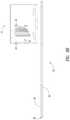
- FIG. 8Ais a partial cross-sectional front view of the housing below a rough opening prior to installation
- FIG. 8Bis a partial cross-sectional front view of the housing inserted through the rough opening and positioned above the ceiling to the side of the rough opening;
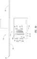
- FIG. 9Aillustrates the housing positioned above the rough opening with the vent duct connector in exploded view
- FIG. 9Billustrates the vent duct connector in an initial orientation against the housing
- FIG. 9Cshows the vent duct connector slid down the tracks into an installed position
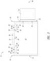
- FIG. 10Ais an illustration of the assembled housing and vent duct connector positioned above the rough opening with the outer tabs orthogonal to their respective walls;
- FIG. 10Bis an illustration of the assembled housing and vent duct connector positioned in the rough opening and supported by the outer tabs on top of the structural member and held in place by the center tabs on an opposing side of the structural member;
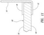
- FIG. 11is a partial cross-sectional side elevation showing the outer and center tabs holding the housing in place on the ceiling;
- FIG. 12is an axonometric exploded view of a ventilation system formed in accordance with the present disclosure that utilizes the fan housing of FIG. 1 ;
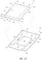
- FIG. 13is an axonometric exploded view of the relationship of a trim ring and cover used in the ventilation system of FIG. 12 ;
- FIG. 14is side view in partial cross section of the assembled ventilation system of FIG. 12 ;
- FIG. 15is an exploded axonometric illustration of a housing and a trim ring formed in accordance with another aspect of the present disclosure
- FIG. 16is a partial cross sectional side view of a trim ring with tab engaged with a first opening in the housing
- FIG. 17is a partial cross sectional side view of a trim ring with tab engaged with a second opening in the housing;
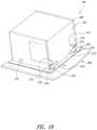
- FIG. 18is an axonometric view of a ventilation fan assembly including housing, trim ring, and shield;
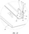
- FIG. 19is an enlarged, axonometric, cross sectional view of one side the assembled components.
- a housing 10formed of at least one wall 12 that defines a housing interior space 14 .
- the fan housing 10has the fan 100 , motor 102 , and electrical connection (not shown) in the housing interior space 14 when it is sold or installed, although this is not required.
- the at least one wall 12is formed to have a square planform shape defined by four sidewalls 16 , 18 , 20 , 22 that are preferably—but not required to be—orthogonal to adjacent sidewalls, each sidewall 16 , 18 , 20 , 22 having a substantially square or rectangular shape.
- An end wall 24is formed at a closed end 26 of the housing 10 , while the opposing side is an open end.
- the cross-sectional configuration of the housingis that of a rectangle, and the shorter walls 16 , 20 cooperate with the longer walls 18 , 22 to form a rectangular planform shape. It is to be understood that the cross-sectional shape may vary from a circle to any number of sides (polygon), and other geometric shapes, such as triangle (with three sides) or square, and the three-dimensional housing shape may take other forms, such as a cone.
- Each of the sidewalls 16 , 18 , 20 , 22has a distal end 30 on which is formed a plurality of tabs that include a center tab 32 , a pair of intermediate tabs 34 , one on each side of and adjacent to the center tab 32 , and a pair of outside tabs 36 , each outside tab 36 adjacent to a respective intermediate tab 34 .
- a tabcan be a flange, flap, strip, or similar component.
- Each tab 32 , 34 , 36has optional openings 38 for a fastener if desired.
- the housing 10is preferably formed of material, such as aluminum or other material having similar properties, with a thickness that permits manual bending of the tabs about the supporting legs as described below, in order to enable mounting of the housing 10 to a structural member, also as described below.
- the intermediate tabs 34 and outside tabs 36extend upward to terminate evenly with the distal edge 44 of their respective wall 16 , 18 , 20 , 22 .
- each of the tabs 32 , 24 , 36is co-planar with its respective wall 16 , 18 , 20 , 22 , when initially formed.
- the tabs 32 , 24 , 36have a different bendable length and different bend lines to limit the length of the tab when it is repositioned to a bent configuration.
- the tabs 32 , 34 , 36are formed to be bent at substantially a 90 degree angle to be orthogonal to the respective wall 16 , 18 , 20 , 22 to which it is formed.
- center tab 32has one or more elongate opxenings 40 formed at the intersection of the center tab 32 and the respective wall 16 , 18 , 20 , 22 .
- these openings 40are a matter of design choice and aesthetic appearance. Between these openings 40 are legs 42 that support the tab 32 on the wall 16 , 18 , 20 , 22 and that enable bending in response to a manual force exerted on the tab 32 .
- the manual forceis preferably that of a human hand or the fingers of the human hand.
- the center tab 32can be repositioned by manually bending about the legs 42 in a range of about 180 degrees either direction and, more preferably, to be orthogonal to the respective wall 16 , 18 , 20 , 22 , either towards the interior space 14 or towards the exterior of the housing 10 , which is described more fully below.
- the center tab 32extends further than the terminal end or distal edge 44 of the respective wall 16 , 18 , 20 , 22 a sufficient distance that, when the housing 10 is placed in the rough opening, the center tab 32 extends down below the exterior surface of the structural member (in this case a ceiling or wall).
- the intermediate tab 34is formed by two longitudinal elongate openings 46 , 48 on each side of the tab 34 of equal length.
- An elongate opening 40is formed below the intermediate tab 24 and between the two longitudinal elongate openings 46 to form two support legs 42 that are sized and shaped to yield to a manual force asserted on the intermediate tab 34 , and to bend up to and beyond a 90 degree angle, such as about 180 degrees either direction (limited by bend allowance).
- the tab 34can be repositioned to any angle from 0 to about 180 degrees or ⁇ 180 degrees relative to the wall 22 , including a preferred 90 degree or right angle.
- the length of the intermediate tab 34when it is repositioned, is determined by the distance of the respective opening 40 from the distal edge 44 of the respective wall 16 , 18 , 20 , 22 .
- the outside tab 36is formed by two longitudinal openings 50 , 52 on either side and of equal length.
- the longitudinal opening 50is longer than the adjacent longitudinal opening 48 , and it joins the longitudinal opening 48 with a stepped bottom edge 54 .
- the outside tab 36is, thus, supported by two legs 42 , as are the other tabs, and these two legs are separated by an elongate opening 40 .
- the legs 42bend adjacent the elongate opening 40 , as do the legs of the other tabs 32 , 24 .
- the outside tab 36is longer than the intermediate tab 34 due to the length of the longitudinal openings 50 , 52 , and this will form a larger tab 36 when force is applied to the tab 36 and the legs 42 bend in either direction.
- the outside tab 36can bend up to about 180 degrees (considering bend allowance) in either direction relative to the respective wall 16 , 18 , 20 , 22 .
- the outside tab 36has a width of about 1 ⁇ 2 inch when it is bent about the legs 42
- the intermediate tab 34has a width of about 5 ⁇ 8 inch when it is bent about its supporting legs 42 .
- a duct opening 60is formed in one of the walls, in this case the longer wall 20 , and adjacent one edge of the wall 20 .
- the openingcan have a round or square shape, although almost any geometric or irregular shape may be used as needed.
- There are two L-shaped guides 62 on opposing exterior sides of the vent duct opening 60each L-shaped guide 62 has a leg 64 spaced away from the wall 20 to create a slot or track 66 .
- a vent duct connector 68is provided having a flange 70 that is sized and shaped to be slid into place in the slots or tracks 66 of the guides 62 after the ducting 72 is attached thereto.
- vent duct connector 68It is also possible to attach vent duct connector 68 to the housing 10 prior to attaching the ducting 72 .
- the vent duct connector 68has a cylindrical extension or tubular nozzle 74 (with a back draft swing damper—not shown).
- the tubular nozzle 74is connected to the ducting 72 by sliding the ducting 72 in place over the nozzle 74 , and a clamp may be used to secure the ducting in place, which is a conventional method of attaching ducting and will not be described in more detail herein.
- a unique feature of the present designis that the flange 70 material (preferably plastic) has two notches 76 on opposing sides that are sized and shaped to be slid over the L-shaped guides 62 so the vent duct connector 68 does not need to be raised up as high to get it started in the four tracks 66 . This feature allows for a shallow opening installation.
- a rough opening 78is created in the structural member, here a ceiling 80 , in which the fan and fan housing 10 in which the fan resides are to be mounted.
- the structural membercan be a ceiling, a wall, a soffit, or other structural member of a residential or commercial building. Generally these structural members are formed from sheet rock or other interior wall or ceiling material that has a typical thickness of 1 ⁇ 2 inch or 5 ⁇ 8 inch.
- the rough opening 78can be created for a new installation or it can be an existing rough opening in which an old fan is removed. In either situation, the rough opening 78 is prepped for the installation of the fan 100 and housing 10 of the present disclosure by sizing it to the correct dimensions of the housing 10 .
- the fan 100 and the housing 10 in which the fan residesare slid into the rough opening 78 .
- the vent duct connector 68is either already installed on the housing 10 as described above or it can be installed at this point by aligning the notches 76 with the upper L-shaped legs 62 , then sliding the vent connector downward until it hits a stop 77 extending from the wall 20 .
- the vent duct connector 68can be installed before or after the housing 10 is placed through the rough opening 78 .
- the vent duct connector 68is then coupled to the ducting 72 by sliding the open end of the ducting over the nozzle portion 74 as described above.
- the installerthen repositions all the intermediate tabs 34 to about a 90 degree orientation with the respective wall 16 , 18 , 20 , 22 when the structural member has a thickness of 5 ⁇ 8 inch.
- the installerwill reposition the outside tabs 36 to an orientation of about 90 degrees with respect to the respective wall 16 , 18 , 20 , 22 .
- the tabs 34 or 36are repositioned to face outwards away from the interior space 14 of the housing.
- the housing 10can now be placed over the rough opening 78 and will be supported on the top side or attic side 82 of the ceiling 80 by the respective intermediate tabs 34 or outside tabs 36 .
- the outside tabs 36are used due to the thickness of the ceiling material 80 .
- the installerwill reposition the center tabs 32 outward away from the interior space 14 of the housing 10 to bear against the bottom side or room side 84 of the ceiling 80 to sandwich the ceiling 80 sheet rock between the center tabs 32 and the respective interior tabs 34 or outside tabs 36 as the case may be.
- a key feature related to the housing designis that this installation can always be done from the room side and without the need for screws or attic access. In addition, this is particularly useful in situations where tools may not always be available.
- the tabscan be repositioned or bent more than once, ideally two, three, or more times without failure due to fatigue and in order to facilitate removal and reinstallation as needed.
- this designallows the installer to put the fan housing 10 up inside the rough opening and move it out of the way to work on the vent duct connection and the electrical connection.
- Preferably eight intermediate or outside tabs 34 , 36hold the housing 10 in the opening from the attic or interior wall side, and the center tabs 32 are used to secure it to the sheet rock on the room side.
- more than eight or fewer than eight intermediate or outside tabscan be used as desired.
- the electrical connectionsare located towards the room side so the connection can be done from the room side.
- Another unique featureis the sheet rock grab with the tabs.
- the notches on the vent duct connectorenable the slide-in installation of the vent duct connector 68 and room side electrical to be a combined true “room side” installation or retrofit. New construction has access to studs and attic, so this design and method works well for new construction. This high level of ease on the room side has never been done before.
- plastichas two notches so the installer does not need to raise the plastic up as high to get it started in the four metal tracks. This feature allows for a shallow opening installation.
- the weight of the fan body and the pinching of the metal tabsis enough to overcome the low fan vibration.
- housing 10 and vent duct connector 68taken alone and in combination, provide an aesthetic appearance that extends beyond any functionality associated therewith.
- Non-limiting examplesinclude radius of curvature, symmetry, and balance, use of geometric shapes not dictated by function, and the like.
- FIGS. 12-14illustrated therein is a complete ventilation system 110 installation formed in accordance with another aspect of the present disclosure. As shown therein, the fan housing 10 is combined with a trim ring 112 and cover 114 to form a completed system 110 installation as shown in FIG. 14 .
- FIG. 12is an isometric exploded view of the ventilation system 110 positioned below the rough opening 78 in the ceiling 80 .
- the housing 10is installed in the rough opening 78 as described above in connection with FIGS. 10A-11 . Once the fan housing 10 is secured in place with the ducting, and the wiring is connected, the trim ring 112 is placed on the housing.
- FIG. 13is an axonometric exploded view of the trim ring 112 and the cover 114 showing the details of the interior of both. It is to be understood that many aspects of the trim ring 112 and cover 114 are ornamental in nature, including without limitation the size, shape, and symmetry of the exterior, such as the geometric shape, radius of curvature or lack thereof of the exterior corners, the thickness, the relative positioning of the trim ring 112 and grille cover 114 .
- the trim ring 112has a substantially square planform shape with a flat circumferential ledge 116 that has an interior surface 118 and exterior surface 120 (seen in FIG. 12 ) that circumscribes a central opening 122 .
- the exterior edge of the ledge 116has a lip 124 that is turned up towards the ceiling 80 when installed.
- the size and shape of the lip 24accommodates the tabs on the housing 10 , as will be explained in more detail in connection with FIG. 14 below.
- the four corners 126 on the trim ring 112are rounded for appearance only, and the radius of curvature is chosen based on cosmetic appearance only.
- Optional punch-through depressions 127are formed on the interior surface 118 of the ledge 116 , centrally located on each side, for use in installation with fasteners if desired. These are not visible on the exterior surface 120 of the ledge 116 .
- An upstanding wall 128is formed on an interior edge of the ledge 116 to circumscribe the opening 122 . It is sized and shaped to fit inside the housing 10 , as described more fully below in connection with FIG. 14 . Ideally the trim ring has an interference fit or friction fit in the housing, including friction fit notches to hold it in place.
- a cutout 130is formed in one of the walls 128 that is sized and shaped to accommodate the vent duct connector 68 described above.
- the cover 114has a substantially square planform shape with a single wall 132 with an interior surface 134 and exterior surface 136 . As can be seen more clearly in FIGS. 12 and 14 , the cover 114 is concave on the interior surface 134 with an open top and correspondingly concave on the exterior surface 136 to form a closed bottom, similar to a shallow bowl. A lip 138 extends outward and away from the interior surface 134 and circumscribes the exterior of the cover. The four corners 140 of the cover 114 and the lip 138 are preferably rounded purely for cosmetic purposes. The radius of curvature is selected to cooperate with the corners 126 of the trim plate 112 to provide an attractive appearance.
- An upstanding wall 142is formed to circumscribe a middle portion of the interior surface 134 of the cover 114 .
- the wall 142has a height that is sized to avoid interfering with the housing 10 and the components inside the housing 10 when the cover is mounted thereon.
- the upstanding wall 142forms an enclosure 144 that houses an optional lighting system that will not be described in detail herein.
- the cover 114is preferably formed of translucent material that permits light to pass through without enabling viewing of the inside of the housing 10 .
- the central area 148 bounded by the upstanding wall 142may be clear if there is a cover attached to the wall 142 over the area 148 . However, it is preferred that the material be translucent for the central area 148 as well as the entire cover 114 .
- a standoff 144is formed adjacent each corner 140 to extend upward and away from the interior surface 134 .
- Each standoffhas a circular cross-sectional shape purely for ornamental reasons, and it is to be understood that they may have different cross-sectional shapes, such as square, hexagonal, octagonal, and other geometric shapes without affecting their function.
- the standoffs 144are positioned to bear against the trim ring when the cover 114 is attached to the housing 10 , thus assisting in holding the trim ring to the housing.
- the standoffs 144further have a height from the interior surface 134 that is sized to space the wall 132 away from the ceiling 80 so as to provide a gap between the lip 138 and the ceiling 80 as described more fully below.
- a pair of spring clips 146affixed to the interior surface 134 on opposing sides of the upstanding wall 142 .
- Theseare conventional spring clips 146 that are readily commercially available and will not be described in detail herein.
- the clips 146engage the housing 10 as described below to hold the cover 114 to the housing 10 with the standoffs 144 pressed against the trim plate 112 , thus holding the trim plate 112 in place.
- FIG. 14is a side view in partial cross section of the assembled ventilation system 110 .
- the housing 10is held in place with the tabs 32 and 36 as described above.
- the trim ring 112is slideably engaged with the housing so that the upstanding wall 128 bears against the inside of the respective one of the walls 16 , 18 , 20 , 22 of the housing 10 .
- the upstanding wall 128extends upward only to the location of the bend line of the center tab 36 , which is near the top surface 82 of the ceiling 80 .
- the ledge 116will bear against the lower tab 32 with the lip 124 on the ledge 116 bearing against the bottom side or room side 84 of the ceiling 80 .
- the height of the lipis sized to accommodate the thickness of the lower tab 32 so the trim ring prevents exposure of the tabs 32 , 34 to view from the room side 84 of the ceiling 80 .
- the trim ring 112is held in place to the housing 10 by a friction fit between the walls 128 (and corners 150 of the walls 128 ) with the housing 80 .
- the cover 114is then placed in position with the pair of springs 146 engaging the housing 10 in a conventional manner known to those of skill in the art.
- the springs 146engage slots (not shown) in the housing 10 .
- the springs 146allow the cover 114 to be pulled away from the ceiling 80 a short distance while still engaging the housing 10 through the springs 146 .
- the standoffs 144will bear against the lower surface 120 of the trim ring ledge 116 , thus holding the trim ring 112 in place.
- the standoffs 144are sized to create a gap 152 between the lip 138 and the room side surface 84 of the ceiling 80 that allows air to be drawn into the housing 10 by the fan 100 .
- FIG. 15is an exploded axonometric illustration of an assembly 190 for use with a structural member 192 having opposing first and second surfaces 194 , 196 and an opening 198 formed therein that communicates with the first and second surfaces 194 , 196 .
- the assembly 190includes a housing 200 a trim ring 202 , and in one implementation a cover or shield 204 to cover the trim ring and housing, all formed in accordance with another aspect of the present disclosure.
- the housing 200has at least one wall 201 that is sized and shaped to define an interior 206 to house the object, in this case a ventilation fan 208 .
- the housingis sized and shaped to be received within the opening 198 in the structural member 192 , such as a ceiling or wall.
- the housing 200 and the opening 192can be other than rectilinear as shown throughout this disclosure. Other shapes include cylindrical, rectangular, triangular, and other well-known geometric shapes.
- the housing 200has at least one support tab 210 that is a bendable flange formed in the at least one wall 201 that can be bent to extend outward from therefrom to bear against the first surface 194 of the structural member 192 and support the housing 200 on the structural member 192 .
- the housing 200further includes at least one opening and preferably two pairs 212 , 214 of first and second openings 216 , 218 each.
- the trim ring 202having an interior side 220 and an opposing exterior side 222 , the interior side 220 having at least one resilient tab and preferably at least two tabs 224 with a distal end 226 sized and shaped to releasably engage the first opening 216 or the second opening 218 in the housing 200 .
- the trim ring 202further includes at least one second member, such as a ledge 228 sized and shaped to bear against the second surface 196 of the structural member 192 when the tab 224 is engaged with the first or second opening 216 , 218 in the housing 200 and thereby hold the trim ring 202 in place on the housing 200 while bearing against the second surface 196 of the structural member 192 .
- the trim ring 202includes an upstanding wall 238 in which the tabs 224 are preferably integrally formed.
- the housing 200has a distal end 230 of the at least one wall 201 , and the at least two pairs 212 , 214 of first and second openings 216 , 218 are formed in the at least one wall 201 with the first opening 216 opening positioned at least partially between the second opening 218 and the distal end 230 of the at least one wall 201 .
- the first opening 216is aligned with the second opening 218 to form a ladder arrangement of the openings in relation to the distal end 230 of the at least one wall 201 .
- the upstanding wall 238 of the trim ring 202is sized and shaped to fit within the interior 206 of the housing 200 and the trim ring 202 has a lip 232 extending from the distal end of the tab 234 that is sized and shaped to be received in either one of the first and second openings 216 , 218 in a respective one of the at least two pairs 212 , 214 of first and second openings 216 , 218 .
- the lip 232has a convex distal surface 234 and an opposing planar bottom surface 236 .
- FIG. 16which is a partial cross section side view of the trim ring 202
- the lip 232 on the tab 224is engaged with the first opening 216 in the housing
- FIG. 17which is also a partial cross section side view of the trim ring 202
- the lip 232 on the tab 224is engaged with the second opening 218 in the housing 200 .
- the installation of the housing 200 and trim ring 202 on the structural member 192includes forming the opening 198 to allow the housing 200 to be slid through the opening 198 and to rest temporarily on the first surface 194 , such as the interior surface of a ceiling.
- the support tab 210is then bent outward at each location on the at least one wall 201 of the housing.
- there are two support tabs on opposing side walls of a rectilinear housing 200 as shown in FIG. 15plus one support tab 210 on a front wall where the duct opening is located, and two support tabs 210 on an opposing back wall.
- the number, size, shape, and placement of the support tabs 210can be varied and mixed on each housing 200 .
- the housing 200is positioned in the opening 198 and lowered down until the support tabs 210 bear against the first surface 194 of the structural member 192 .
- the trim ring 202is then positioned with the upstanding wall 238 in alignment with the housing 200 below the structural member 192 .
- the upstanding wallis slid inside the at least one wall 201 , and the tabs 224 will have their respective lip 232 vertically aligned with the respective pair 212 , 214 of first and second openings 216 , 218 .
- the lipwill ratchet through the first opening 216 and into the second opening 218 if the structural member 192 is of a first smaller thickness, such as 1 ⁇ 2 inch. If the structural member 192 is of a larger thickness, such as 5 ⁇ 8 inch, then the lip 232 on the tab 224 will lock into place in the first opening 216 .
- the housing 200 and trim ring 202are installed on a thicker 5 ⁇ 8 structural support 192 .
- the support tab 210 on the housing 200is bent to be orthogonal to the at least one wall 201 and to bear against and support the housing 200 on the first surface 194 of the structural member 192 .
- the trim ring 202is positioned so that the tab 224 engages the first opening 216 via the lip 232 .
- the planar bottom surface 236 of the lip 232rests on the lower edge of the first opening 216 .
- the housing 200 and trim ring 202are installed on a thinner 1 ⁇ 2 inch structural support 192 .
- the support tab 210 on the housing 200is again bent to be orthogonal to the at least one wall 201 and to bear against and support the housing 200 on the first surface 194 of the structural member 192 .
- the trim ring 202is positioned so that the tab 224 engages the second opening 218 via the lip 232 .
- the planar bottom surface 236 of the lip 232rests on the lower edge of the second opening 218 .
- FIG. 18is an axonometric view of the assembled ventilation fan assembly 190 including housing 200 , trim ring 202 , and shield 240 but without the structural member 192 in order to better show the relationship of the components.
- the shield 240is substantially the same as the cover 114 described above and its installation is also substantially the same. Hence, it will not be described in detail herein.
- FIG. 19is an enlarged axonometric cross section view of the tab 224 and its relationship to the upstanding wall 238 on the trim ring 202 .
- the tab 224is integrally formed with the upstanding wall using known injection molding or other construction techniques. It is in this implementation hinged along the side at a hinge point 242 .
- the bottom of the tab 224has a foot 244 that pivots inward and over a clearance ramp 246 formed in the ledge 228 .
- the lip 232preloads the tab 224 when the upstanding wall 238 of the trim ring 202 is slid into the opening 206 of the housing 202 .
- the upstanding wall 238is sized and shaped to slid into the housing 202 without an interference fit, but with minimal clearance so the lip 232 will contact the inside surface of the at least one wall 201 and preload the tab 224 .
- the lip 232is released from the first and second openings 216 , 218 by pressing at the bottom of the tab 224 on the opposite face of the foot- 242 244 , which causes the tab 224 to pivot about the hinge point 242 and move the lip 232 away from the at least one wall 201 .
- the tabs 224 on the trim ring 202are about 1 inch in width, but this can be varied depending on the application.
- the openings 216 , 218can be about 0.118 inches (3 mm) in vertical height and about 1 inch wide. Again, these dimensions can be varied for particular applications. While the drawings are not intended to be to scale, they are provided with the components in relative sizes to each other as accurately as possible.
Landscapes
- Engineering & Computer Science (AREA)
- Chemical & Material Sciences (AREA)
- Combustion & Propulsion (AREA)
- Mechanical Engineering (AREA)
- General Engineering & Computer Science (AREA)
- Structures Of Non-Positive Displacement Pumps (AREA)
- Duct Arrangements (AREA)
Abstract
Description
Claims (5)
Priority Applications (4)
| Application Number | Priority Date | Filing Date | Title |
|---|---|---|---|
| US16/403,164US11280515B2 (en) | 2019-01-09 | 2019-05-03 | Ventilation fan trim ring mounting assembly |
| CA3066440ACA3066440A1 (en) | 2019-01-09 | 2020-01-02 | Ventilation fan trim ring mounting assembly |
| AU2020200089AAU2020200089A1 (en) | 2019-01-09 | 2020-01-07 | Ventilation fan trim ring mounting assembly |
| CN202010018205.8ACN111425979B (en) | 2019-01-09 | 2020-01-08 | Ventilation fan trim ring mounting assembly |
Applications Claiming Priority (2)
| Application Number | Priority Date | Filing Date | Title |
|---|---|---|---|
| US16/243,666US11015822B2 (en) | 2019-01-09 | 2019-01-09 | Ventilation fan mounting assembly |
| US16/403,164US11280515B2 (en) | 2019-01-09 | 2019-05-03 | Ventilation fan trim ring mounting assembly |
Related Parent Applications (1)
| Application Number | Title | Priority Date | Filing Date |
|---|---|---|---|
| US16/243,666Continuation-In-PartUS11015822B2 (en) | 2019-01-09 | 2019-01-09 | Ventilation fan mounting assembly |
Publications (2)
| Publication Number | Publication Date |
|---|---|
| US20200217552A1 US20200217552A1 (en) | 2020-07-09 |
| US11280515B2true US11280515B2 (en) | 2022-03-22 |
Family
ID=71404319
Family Applications (1)
| Application Number | Title | Priority Date | Filing Date |
|---|---|---|---|
| US16/403,164Active2039-04-10US11280515B2 (en) | 2019-01-09 | 2019-05-03 | Ventilation fan trim ring mounting assembly |
Country Status (4)
| Country | Link |
|---|---|
| US (1) | US11280515B2 (en) |
| CN (1) | CN111425979B (en) |
| AU (1) | AU2020200089A1 (en) |
| CA (1) | CA3066440A1 (en) |
Families Citing this family (1)
| Publication number | Priority date | Publication date | Assignee | Title |
|---|---|---|---|---|
| USD996600S1 (en)* | 2021-04-14 | 2023-08-22 | Ascent Holdings, Llc | Ventilation shield |
Citations (119)
| Publication number | Priority date | Publication date | Assignee | Title |
|---|---|---|---|---|
| US2899542A (en)* | 1959-08-11 | De mauro | ||
| US2961115A (en) | 1959-04-07 | 1960-11-22 | Eugene W Aylor | Chain guards for poultry coops and the like |
| US2963783A (en) | 1957-07-31 | 1960-12-13 | Williamson Company | Sheet metal fittings |
| US3286090A (en)* | 1964-08-10 | 1966-11-15 | Sechrist Mfg Co | Adjustable ceiling fixtures |
| US3420995A (en)* | 1965-10-22 | 1969-01-07 | Lithonia Lighting Inc | Self-locking latch |
| US3590241A (en)* | 1968-07-01 | 1971-06-29 | Marvin Electric Mfg Co | Lighting fixture |
| US3697742A (en)* | 1970-09-04 | 1972-10-10 | Air King Corp | Trim ring for architectural light including means for stepped rotational and axial adjustment |
| US3720432A (en)* | 1971-06-14 | 1973-03-13 | Prudential Lighting Corp | Latch mechanism |
| US4009894A (en) | 1976-01-16 | 1977-03-01 | Mutz Corporation | Fitting for insulated duct |
| US4294476A (en) | 1979-11-08 | 1981-10-13 | Nash Patrick L | Connecting device |
| US4491124A (en) | 1982-06-01 | 1985-01-01 | Goettel Richard J | Self-tapping duct fitting |
| US4550648A (en) | 1983-07-11 | 1985-11-05 | Eagle Jon R | Attic ventilation system |
| US5044987A (en) | 1990-01-05 | 1991-09-03 | Northern Telecom Limited | Mounting plate for telecommunications wall outlet |
| US5152117A (en) | 1991-02-25 | 1992-10-06 | Wynar Roger N | Corner construction and wallboard backer bracket therefor |
| US5161573A (en)* | 1991-05-06 | 1992-11-10 | David Krupp | Pressure equalizing damper |
| US5211580A (en) | 1991-09-12 | 1993-05-18 | G.B. Electrical, Inc. | Universal backplate for electrical outlets |
| US5314212A (en) | 1991-09-03 | 1994-05-24 | Gcs Innovations, Inc. | Duct connector for leakfree attachment to the curved sidewall of highly flexible trunkline duct |
| US5393106A (en) | 1993-09-15 | 1995-02-28 | Casco Manufacturing | Sealed knock-down duct collar |
| US5475577A (en)* | 1992-07-07 | 1995-12-12 | Donnelly Corporation | Accessory attachment plate for vehicle panels |
| US5518277A (en) | 1991-09-03 | 1996-05-21 | Gcs Innovations, Inc. | Single piece duct connector for leakfree attachment to sidewall of highly flexible trunkline duct |
| US5537714A (en)* | 1994-09-01 | 1996-07-23 | Erico International Corp. | Metal stud grommet |
| US5538293A (en) | 1994-11-18 | 1996-07-23 | Thinking Vents, Inc. | Secondary duct installation apparatus and method for a forced air ventilation system |
| US5746507A (en)* | 1997-01-06 | 1998-05-05 | Thomas Industries, Inc. | Recessed lighting fixture for two light sizes |
| US5799446A (en) | 1997-05-07 | 1998-09-01 | Tamlyn; John Thomas | Soffit construction for improved eave construction |
| US5820247A (en)* | 1996-03-05 | 1998-10-13 | Nutone Inc. | Modular cover |
| US5934783A (en)* | 1996-05-10 | 1999-08-10 | Matsushita Seiko Co., Ltd. | Ventilating fan/light combination |
| US5951151A (en)* | 1997-02-06 | 1999-09-14 | Cooper Technologies Company | Lamp assembly for a recessed ceiling fixture |
| US5957506A (en) | 1998-02-27 | 1999-09-28 | M & M Manufacturing Co., Inc. | Sheet-metal insulated register box with adjustable elbow fitting |
| US5957572A (en)* | 1997-06-27 | 1999-09-28 | Lightolier | Remodeler light fixture support structure and method |
| US6000818A (en)* | 1998-10-19 | 1999-12-14 | Canlyte Inc. | Mounting clip for a recessed light fixture |
| US6095671A (en)* | 1999-01-07 | 2000-08-01 | Hutain; Barry | Actively cooled lighting trim apparatus |
| US6149280A (en)* | 1999-02-05 | 2000-11-21 | Spaulding Lighting, Inc. | Method and apparatus for retrofitting canopy luminaire assemblies |
| US6261175B1 (en)* | 1999-12-18 | 2001-07-17 | Broan-Nutone Llc | Ventilating exhaust fan |
| US6350046B1 (en)* | 1999-07-22 | 2002-02-26 | Kenneth Lau | Light fixture |
| US6371630B1 (en)* | 1999-03-10 | 2002-04-16 | Wila Leuchten Ag | Luminaire configuration having luminaire and mounting modules attachable and detachable without disturbing illumination producing components |
| US6452336B1 (en)* | 2001-04-26 | 2002-09-17 | Raju S. Dandu | Flourescent lamp for recessed ceiling mounting |
| US20020172047A1 (en)* | 2001-05-15 | 2002-11-21 | Josh Ashley | Recessed light fixture converted to lower voltage halaogen fixture |
| US6585389B2 (en)* | 2001-02-15 | 2003-07-01 | 3F Filippi S.P.A. | Luminaire, particularly of the ceiling-mounted type or of the type for recessed fitting in ceilings and walls |
| US6595664B2 (en)* | 2001-02-23 | 2003-07-22 | King Of Fans, Inc. | Quick-install, flush-mount bracket for light and other fixtures |
| US6632006B1 (en)* | 2000-11-17 | 2003-10-14 | Genlyte Thomas Group Llc | Recessed wall wash light fixture |
| US20030193811A1 (en)* | 2002-04-11 | 2003-10-16 | Nate Mullen | Attachment for retaining lenses on a reflector lamp |
| US20050111972A1 (en)* | 2003-11-21 | 2005-05-26 | Broan-Nutone Llc | Modular ventilating exhaust fan assembly and method |
| US6957896B2 (en)* | 1998-08-28 | 2005-10-25 | John David Tilbury Burgess | Aperture edging member and method |
| US6969181B1 (en)* | 2001-05-08 | 2005-11-29 | Genlyte Thomas Group Llc | Fully recessed unit equipment luminaire |
| US7011578B1 (en) | 2003-12-31 | 2006-03-14 | R.C. Air Devices, Llc | Plenum and diffuser for heating, ventilating and air conditioning applications |
| US20060221620A1 (en)* | 2005-03-31 | 2006-10-05 | Philip Thomas | Replacement module for recessed light |
| US7186008B2 (en)* | 2002-02-28 | 2007-03-06 | Rsa Lighting, Llc | Ceiling lighting fixture assembly |
| US7203416B2 (en)* | 2003-11-21 | 2007-04-10 | Broan-Nutone Llc | Ventilating and heating apparatus with heater shielded by tapered discharge duct |
| US20080112171A1 (en)* | 2006-11-14 | 2008-05-15 | Focal Point, L.L.C. | Recessed Luminaire |
| US20080137347A1 (en)* | 2006-11-30 | 2008-06-12 | Led Lighting Fixtures, Inc. | Light fixtures, lighting devices, and components for the same |
| US20080180961A1 (en)* | 2006-11-13 | 2008-07-31 | Cooper Technologies Company | Housing for a Recessed Light Fixture |
| US20080232116A1 (en)* | 2007-03-22 | 2008-09-25 | Led Folio Corporation | Lighting device for a recessed light fixture |
| US20080304269A1 (en)* | 2007-05-03 | 2008-12-11 | Cree Led Lighting Solutions, Inc. | Lighting fixture |
| US20080318515A1 (en) | 2007-06-20 | 2008-12-25 | Peter Yeung | Ventilation exhaust fan |
| US20090004966A1 (en)* | 2007-07-01 | 2009-01-01 | Max Su | Ventilating Exhaust fan and Outlet Fitting Assembly |
| US20090186572A1 (en) | 2008-01-22 | 2009-07-23 | Gerald Farrell | Air distributing apparatus for reducing energy consumption |
| US7607807B2 (en)* | 2004-09-20 | 2009-10-27 | Federal-Mogul World Wide, Inc. | Vehicular lamp and retainer assembly for interior applications |
| US7614769B2 (en)* | 2007-11-23 | 2009-11-10 | Sell Timothy L | LED conversion system for recessed lighting |
| US7625105B1 (en)* | 2007-09-18 | 2009-12-01 | Genlyte Thomas Group, Llc | Relamping cartridge assembly |
| US20100009621A1 (en)* | 2008-07-11 | 2010-01-14 | Hsieh Te-Hsuan | External rotor brushless dc motor driven exhaust fan |
| US20100020551A1 (en)* | 2008-07-23 | 2010-01-28 | Lightology, Inc. | Recessed lighting fixture |
| US7722208B1 (en)* | 2007-09-30 | 2010-05-25 | Genlyte Thomas Group, Llc | Recessed luminaire trim assembly |
| US20100175399A1 (en)* | 2009-01-09 | 2010-07-15 | Lg Electronics Inc. | Air conditioner |
| US20100190432A1 (en)* | 2009-01-26 | 2010-07-29 | Viggers Cheryl F | Magnetic register cover |
| US7784979B2 (en)* | 2008-05-05 | 2010-08-31 | Cooper Technologies Company | Reflector assembly for a recessed luminaire |
| US7828465B2 (en)* | 2007-05-04 | 2010-11-09 | Koninlijke Philips Electronis N.V. | LED-based fixtures and related methods for thermal management |
| US7909487B1 (en)* | 2010-03-04 | 2011-03-22 | Keyser-Group | Lighting system and method of making same |
| US20110080746A1 (en)* | 2009-10-07 | 2011-04-07 | Patti Anthony G | Lighting enclosure system |
| US7987649B1 (en) | 2008-02-01 | 2011-08-02 | Ross Manufacturing, Llc | Vent strip for installation with soffit boards of different thicknesses |
| US20120087128A1 (en)* | 2010-10-11 | 2012-04-12 | Broan-Nutone Llc | Lighting and Ventilating System and Method |
| US20120140489A1 (en)* | 2010-12-02 | 2012-06-07 | Devin Chung | Illumination Device with a Lamp Cap Capable of Dissipating Heat and Spreading Light |
| US8297798B1 (en)* | 2010-04-16 | 2012-10-30 | Cooper Technologies Company | LED lighting fixture |
| US8382340B2 (en)* | 2008-10-03 | 2013-02-26 | Lsi Industries, Inc. | Interchangeable lightiing |
| US8382332B2 (en)* | 2010-10-11 | 2013-02-26 | Broan NuTone, LLC | Lighting and ventilating system and method |
| US8388166B2 (en)* | 2007-10-24 | 2013-03-05 | Lsi Industries, Inc. | Lighting apparatus with a boost |
| US20130083549A1 (en)* | 2011-09-30 | 2013-04-04 | Toshiba Lighting & Technology Corporation | Led lighting device and led luminaire |
| US8486525B2 (en) | 2008-12-23 | 2013-07-16 | David G. Segur | Method and apparatus having two surfaces for sealing distribution ducts |
| US8511867B1 (en)* | 2011-07-22 | 2013-08-20 | Cooper Technologies Company | Apparatus and method for providing adjustable lip heights for plaster applications on a ceiling surface |
| US8523383B1 (en)* | 2010-02-19 | 2013-09-03 | Cooper Technologies Company | Retrofitting recessed lighting fixtures |
| US20130315731A1 (en)* | 2011-04-27 | 2013-11-28 | Panasonic Corporation | Celing mounted ventilation fan with illumination |
| US20140254177A1 (en)* | 2013-03-08 | 2014-09-11 | Michael D. Danesh | Wide angle adjustable retrofit lamp for recessed lighting |
| US8899374B2 (en)* | 2012-06-11 | 2014-12-02 | Yamaha Corporation | Speaker unit and speaker unit mounting structure |
| US8950898B2 (en)* | 2010-11-10 | 2015-02-10 | Terralux, Inc. | Recessed can downlight retrofit illumination device |
| US8985364B2 (en) | 2011-05-05 | 2015-03-24 | Brainwave Research Corporation | Wall mounting apparatus and frame assembly |
| US9046257B2 (en)* | 2009-09-22 | 2015-06-02 | Koninklijkle Philips N.V. | Lighting device |
| US20150159910A1 (en)* | 2013-12-10 | 2015-06-11 | Delta Electronics, Inc. | Ventilation fan |
| US9134014B2 (en)* | 2012-04-13 | 2015-09-15 | Everlight Electonics Co., Ltd. | Recessed lamp housing with adjustable spring clipping device |
| US20150345761A1 (en)* | 2014-05-30 | 2015-12-03 | Generation Brands Llc | Adjustable luminaire |
| US9222266B1 (en) | 2003-03-28 | 2015-12-29 | John S. Conboy | Hinged metal connectors and joint constructions |
| US20160108925A1 (en)* | 2014-10-15 | 2016-04-21 | Delta Electronics, Inc. | Ventilation fan with lamp |
| US9344787B2 (en)* | 2012-12-22 | 2016-05-17 | Homewerks Worldwide, LLC | Audio equipped fan |
| US20160201884A1 (en)* | 2015-01-12 | 2016-07-14 | Rafael M. Ramirez | Shuttle Downlight fixture |
| US20160230947A1 (en)* | 2015-02-09 | 2016-08-11 | Eclairage Contraste M.L. Inc. | Light fixture for mounting to a ceiling |
| US9416989B1 (en)* | 2010-09-17 | 2016-08-16 | Chien Luen Industries Co., Ltd., Inc. | 80/90 CFM bath fan with telescoping side extension brackets and side by side motor and blower wheel |
| US20160313021A1 (en)* | 2015-04-27 | 2016-10-27 | Fujitsu General Limited | Ceiling-embedded air conditioner |
| US20160320007A1 (en)* | 2015-04-30 | 2016-11-03 | Ever Venture Solutions, Inc. | Non-round retrofit recessed led lighting fixture |
| US20160356524A1 (en)* | 2014-02-18 | 2016-12-08 | Toshiba Carrier Corporation | Air conditioner |
| US20170059102A1 (en)* | 2015-09-02 | 2017-03-02 | Rick Grant | Lighting housing assembly |
| US9609407B2 (en)* | 2012-12-22 | 2017-03-28 | Homewerks Worldwide, LLC | Method of manufacturing an audio equipped fan assembly |
| US9631789B2 (en)* | 2014-03-31 | 2017-04-25 | Terralux, Inc. | Apparatus and method for retrofitting a fluorescent downlight illumination device |
| US20170115028A1 (en)* | 2015-10-23 | 2017-04-27 | Samsung Electronics Co., Ltd. | Air conditioner |
| US20170184285A1 (en)* | 2015-12-29 | 2017-06-29 | Number Eight Lighting Company | Airtight and ic-rated recessed light housing |
| US9709253B2 (en)* | 2007-09-21 | 2017-07-18 | Cooper Lighting, Llc | Light emitting diode recessed light fixture |
| US9726354B1 (en)* | 2016-09-16 | 2017-08-08 | Usai, Llc | Light fixture with movable enclosure |
| US9739455B2 (en)* | 2012-04-17 | 2017-08-22 | Abl Ip Holding Llc | LED light engines |
| US20170307198A1 (en)* | 2016-04-25 | 2017-10-26 | Ecoled Ventures Limited | Ssl can light fixture with built-in junction box |
| US20170314770A1 (en)* | 2016-04-29 | 2017-11-02 | Focal Point, Llc | Luminaire having an adjustable torsion spring |
| US20170314750A1 (en)* | 2016-04-28 | 2017-11-02 | Juna Construction, Inc. | Device, method, and a kit for retrofitting a trimmed recessed light fixture for installation of a trimless recessed light fixture |
| US20180017239A1 (en)* | 2016-04-26 | 2018-01-18 | Shenzhen Jiawei Photovoltaic Lighting Co., Ltd. | Compatible downlight |
| US20180127977A1 (en)* | 2016-11-07 | 2018-05-10 | Carl H Voellmecke, III | Housing apparatus for installation of ceiling or wall-mounted electrical appliances |
| US10041654B1 (en)* | 2015-11-16 | 2018-08-07 | Cooper Technologies Company | Adjustable lighting finishing structure |
| US20180231239A1 (en)* | 2015-08-10 | 2018-08-16 | GE Lighting Solutions, LLC | Ventilation kit and recessed light fixture assembly with ventilation |
| US10060617B2 (en)* | 2013-12-19 | 2018-08-28 | Sunonwealth Electric Machine Industry Co., Ltd. | Lamp and air-guiding ring thereof |
| US10082259B1 (en)* | 2017-05-24 | 2018-09-25 | Focal Point, Llc | Aperture trim assembly for recessed lighting fixture |
| US10125958B1 (en)* | 2017-02-15 | 2018-11-13 | Cooper Technologies Company | Recessed luminaire components for varying finishing section installations |
| US10378738B1 (en)* | 2011-03-15 | 2019-08-13 | Eaton Intelligent Power Limited | LED module with mounting brackets |
| US10415804B2 (en)* | 2016-10-21 | 2019-09-17 | Eaton Intelligent Power Limited | Luminaire mounting system |
| US10429039B1 (en)* | 2018-08-24 | 2019-10-01 | Eaton Intelligent Power Limited | Mounting system for magnetic installation of varying finishing sections |
| US20200158122A1 (en)* | 2014-10-15 | 2020-05-21 | Delta Electronics, Inc. | Ventilation system |
Family Cites Families (4)
| Publication number | Priority date | Publication date | Assignee | Title |
|---|---|---|---|---|
| JP2001004187A (en)* | 1999-06-18 | 2001-01-12 | Mitsubishi Electric Corp | Ventilation device replacement method and ventilation device |
| US20110017742A1 (en)* | 2009-07-23 | 2011-01-27 | Delphi Technologies, Inc. | In-Groove Snap Fastener |
| CN103234252A (en)* | 2013-05-06 | 2013-08-07 | 沈阳远大铝业工程有限公司 | Energy-saving type dust-and-haze proof ventilator |
| US10502447B2 (en)* | 2017-07-26 | 2019-12-10 | Ascent Products, Llc | Ventilation fan housing and mounting system |
- 2019
- 2019-05-03USUS16/403,164patent/US11280515B2/enactiveActive
- 2020
- 2020-01-02CACA3066440Apatent/CA3066440A1/enactivePending
- 2020-01-07AUAU2020200089Apatent/AU2020200089A1/enactivePending
- 2020-01-08CNCN202010018205.8Apatent/CN111425979B/enactiveActive
Patent Citations (128)
| Publication number | Priority date | Publication date | Assignee | Title |
|---|---|---|---|---|
| US2899542A (en)* | 1959-08-11 | De mauro | ||
| US2963783A (en) | 1957-07-31 | 1960-12-13 | Williamson Company | Sheet metal fittings |
| US2961115A (en) | 1959-04-07 | 1960-11-22 | Eugene W Aylor | Chain guards for poultry coops and the like |
| US3286090A (en)* | 1964-08-10 | 1966-11-15 | Sechrist Mfg Co | Adjustable ceiling fixtures |
| US3420995A (en)* | 1965-10-22 | 1969-01-07 | Lithonia Lighting Inc | Self-locking latch |
| US3590241A (en)* | 1968-07-01 | 1971-06-29 | Marvin Electric Mfg Co | Lighting fixture |
| US3697742A (en)* | 1970-09-04 | 1972-10-10 | Air King Corp | Trim ring for architectural light including means for stepped rotational and axial adjustment |
| US3720432A (en)* | 1971-06-14 | 1973-03-13 | Prudential Lighting Corp | Latch mechanism |
| US4009894A (en) | 1976-01-16 | 1977-03-01 | Mutz Corporation | Fitting for insulated duct |
| US4294476A (en) | 1979-11-08 | 1981-10-13 | Nash Patrick L | Connecting device |
| US4491124A (en) | 1982-06-01 | 1985-01-01 | Goettel Richard J | Self-tapping duct fitting |
| US4550648A (en) | 1983-07-11 | 1985-11-05 | Eagle Jon R | Attic ventilation system |
| US5044987A (en) | 1990-01-05 | 1991-09-03 | Northern Telecom Limited | Mounting plate for telecommunications wall outlet |
| US5152117A (en) | 1991-02-25 | 1992-10-06 | Wynar Roger N | Corner construction and wallboard backer bracket therefor |
| US5161573A (en)* | 1991-05-06 | 1992-11-10 | David Krupp | Pressure equalizing damper |
| US5314212A (en) | 1991-09-03 | 1994-05-24 | Gcs Innovations, Inc. | Duct connector for leakfree attachment to the curved sidewall of highly flexible trunkline duct |
| US5518277A (en) | 1991-09-03 | 1996-05-21 | Gcs Innovations, Inc. | Single piece duct connector for leakfree attachment to sidewall of highly flexible trunkline duct |
| US5211580A (en) | 1991-09-12 | 1993-05-18 | G.B. Electrical, Inc. | Universal backplate for electrical outlets |
| US5475577A (en)* | 1992-07-07 | 1995-12-12 | Donnelly Corporation | Accessory attachment plate for vehicle panels |
| US5393106A (en) | 1993-09-15 | 1995-02-28 | Casco Manufacturing | Sealed knock-down duct collar |
| US5537714A (en)* | 1994-09-01 | 1996-07-23 | Erico International Corp. | Metal stud grommet |
| US5538293A (en) | 1994-11-18 | 1996-07-23 | Thinking Vents, Inc. | Secondary duct installation apparatus and method for a forced air ventilation system |
| US5820247A (en)* | 1996-03-05 | 1998-10-13 | Nutone Inc. | Modular cover |
| US5934783A (en)* | 1996-05-10 | 1999-08-10 | Matsushita Seiko Co., Ltd. | Ventilating fan/light combination |
| US5746507A (en)* | 1997-01-06 | 1998-05-05 | Thomas Industries, Inc. | Recessed lighting fixture for two light sizes |
| US5951151A (en)* | 1997-02-06 | 1999-09-14 | Cooper Technologies Company | Lamp assembly for a recessed ceiling fixture |
| US5799446A (en) | 1997-05-07 | 1998-09-01 | Tamlyn; John Thomas | Soffit construction for improved eave construction |
| US5957572A (en)* | 1997-06-27 | 1999-09-28 | Lightolier | Remodeler light fixture support structure and method |
| US5957506A (en) | 1998-02-27 | 1999-09-28 | M & M Manufacturing Co., Inc. | Sheet-metal insulated register box with adjustable elbow fitting |
| US6957896B2 (en)* | 1998-08-28 | 2005-10-25 | John David Tilbury Burgess | Aperture edging member and method |
| US6000818A (en)* | 1998-10-19 | 1999-12-14 | Canlyte Inc. | Mounting clip for a recessed light fixture |
| US6095671A (en)* | 1999-01-07 | 2000-08-01 | Hutain; Barry | Actively cooled lighting trim apparatus |
| US6149280A (en)* | 1999-02-05 | 2000-11-21 | Spaulding Lighting, Inc. | Method and apparatus for retrofitting canopy luminaire assemblies |
| US6371630B1 (en)* | 1999-03-10 | 2002-04-16 | Wila Leuchten Ag | Luminaire configuration having luminaire and mounting modules attachable and detachable without disturbing illumination producing components |
| US6350046B1 (en)* | 1999-07-22 | 2002-02-26 | Kenneth Lau | Light fixture |
| US6488579B2 (en) | 1999-12-18 | 2002-12-03 | Broan-Nutone Llc | Ventilating exhaust fan |
| US6261175B1 (en)* | 1999-12-18 | 2001-07-17 | Broan-Nutone Llc | Ventilating exhaust fan |
| US6632006B1 (en)* | 2000-11-17 | 2003-10-14 | Genlyte Thomas Group Llc | Recessed wall wash light fixture |
| US6585389B2 (en)* | 2001-02-15 | 2003-07-01 | 3F Filippi S.P.A. | Luminaire, particularly of the ceiling-mounted type or of the type for recessed fitting in ceilings and walls |
| US6595664B2 (en)* | 2001-02-23 | 2003-07-22 | King Of Fans, Inc. | Quick-install, flush-mount bracket for light and other fixtures |
| US6452336B1 (en)* | 2001-04-26 | 2002-09-17 | Raju S. Dandu | Flourescent lamp for recessed ceiling mounting |
| US6969181B1 (en)* | 2001-05-08 | 2005-11-29 | Genlyte Thomas Group Llc | Fully recessed unit equipment luminaire |
| US20020172047A1 (en)* | 2001-05-15 | 2002-11-21 | Josh Ashley | Recessed light fixture converted to lower voltage halaogen fixture |
| US7186008B2 (en)* | 2002-02-28 | 2007-03-06 | Rsa Lighting, Llc | Ceiling lighting fixture assembly |
| US20030193811A1 (en)* | 2002-04-11 | 2003-10-16 | Nate Mullen | Attachment for retaining lenses on a reflector lamp |
| US9222266B1 (en) | 2003-03-28 | 2015-12-29 | John S. Conboy | Hinged metal connectors and joint constructions |
| US7203416B2 (en)* | 2003-11-21 | 2007-04-10 | Broan-Nutone Llc | Ventilating and heating apparatus with heater shielded by tapered discharge duct |
| US20050111972A1 (en)* | 2003-11-21 | 2005-05-26 | Broan-Nutone Llc | Modular ventilating exhaust fan assembly and method |
| US6979169B2 (en)* | 2003-11-21 | 2005-12-27 | Broan-Nutone Llc | Modular ventilating exhaust fan assembly and method |
| US7011578B1 (en) | 2003-12-31 | 2006-03-14 | R.C. Air Devices, Llc | Plenum and diffuser for heating, ventilating and air conditioning applications |
| US7607807B2 (en)* | 2004-09-20 | 2009-10-27 | Federal-Mogul World Wide, Inc. | Vehicular lamp and retainer assembly for interior applications |
| US20060221620A1 (en)* | 2005-03-31 | 2006-10-05 | Philip Thomas | Replacement module for recessed light |
| US20080180961A1 (en)* | 2006-11-13 | 2008-07-31 | Cooper Technologies Company | Housing for a Recessed Light Fixture |
| US20080112171A1 (en)* | 2006-11-14 | 2008-05-15 | Focal Point, L.L.C. | Recessed Luminaire |
| US7748868B2 (en)* | 2006-11-14 | 2010-07-06 | Focal Point, L.L.C. | Recessed luminaire |
| US20080137347A1 (en)* | 2006-11-30 | 2008-06-12 | Led Lighting Fixtures, Inc. | Light fixtures, lighting devices, and components for the same |
| US8096670B2 (en)* | 2006-11-30 | 2012-01-17 | Cree, Inc. | Light fixtures, lighting devices, and components for the same |
| US20080232116A1 (en)* | 2007-03-22 | 2008-09-25 | Led Folio Corporation | Lighting device for a recessed light fixture |
| US20080304269A1 (en)* | 2007-05-03 | 2008-12-11 | Cree Led Lighting Solutions, Inc. | Lighting fixture |
| US7967480B2 (en)* | 2007-05-03 | 2011-06-28 | Cree, Inc. | Lighting fixture |
| US7828465B2 (en)* | 2007-05-04 | 2010-11-09 | Koninlijke Philips Electronis N.V. | LED-based fixtures and related methods for thermal management |
| US20080318515A1 (en) | 2007-06-20 | 2008-12-25 | Peter Yeung | Ventilation exhaust fan |
| US20090004966A1 (en)* | 2007-07-01 | 2009-01-01 | Max Su | Ventilating Exhaust fan and Outlet Fitting Assembly |
| US7625105B1 (en)* | 2007-09-18 | 2009-12-01 | Genlyte Thomas Group, Llc | Relamping cartridge assembly |
| US9709253B2 (en)* | 2007-09-21 | 2017-07-18 | Cooper Lighting, Llc | Light emitting diode recessed light fixture |
| US7722208B1 (en)* | 2007-09-30 | 2010-05-25 | Genlyte Thomas Group, Llc | Recessed luminaire trim assembly |
| US8388166B2 (en)* | 2007-10-24 | 2013-03-05 | Lsi Industries, Inc. | Lighting apparatus with a boost |
| US7614769B2 (en)* | 2007-11-23 | 2009-11-10 | Sell Timothy L | LED conversion system for recessed lighting |
| US20090186572A1 (en) | 2008-01-22 | 2009-07-23 | Gerald Farrell | Air distributing apparatus for reducing energy consumption |
| US7987649B1 (en) | 2008-02-01 | 2011-08-02 | Ross Manufacturing, Llc | Vent strip for installation with soffit boards of different thicknesses |
| US7980735B1 (en)* | 2008-05-05 | 2011-07-19 | Cooper Technologies Company | Reflector assembly for a recessed luminaire |
| US7784979B2 (en)* | 2008-05-05 | 2010-08-31 | Cooper Technologies Company | Reflector assembly for a recessed luminaire |
| US20100009621A1 (en)* | 2008-07-11 | 2010-01-14 | Hsieh Te-Hsuan | External rotor brushless dc motor driven exhaust fan |
| US20100020551A1 (en)* | 2008-07-23 | 2010-01-28 | Lightology, Inc. | Recessed lighting fixture |
| US8382340B2 (en)* | 2008-10-03 | 2013-02-26 | Lsi Industries, Inc. | Interchangeable lightiing |
| US8486525B2 (en) | 2008-12-23 | 2013-07-16 | David G. Segur | Method and apparatus having two surfaces for sealing distribution ducts |
| US20100175399A1 (en)* | 2009-01-09 | 2010-07-15 | Lg Electronics Inc. | Air conditioner |
| US20100190432A1 (en)* | 2009-01-26 | 2010-07-29 | Viggers Cheryl F | Magnetic register cover |
| US9046257B2 (en)* | 2009-09-22 | 2015-06-02 | Koninklijkle Philips N.V. | Lighting device |
| US20110080746A1 (en)* | 2009-10-07 | 2011-04-07 | Patti Anthony G | Lighting enclosure system |
| US8523383B1 (en)* | 2010-02-19 | 2013-09-03 | Cooper Technologies Company | Retrofitting recessed lighting fixtures |
| US7909487B1 (en)* | 2010-03-04 | 2011-03-22 | Keyser-Group | Lighting system and method of making same |
| US8297798B1 (en)* | 2010-04-16 | 2012-10-30 | Cooper Technologies Company | LED lighting fixture |
| US9416989B1 (en)* | 2010-09-17 | 2016-08-16 | Chien Luen Industries Co., Ltd., Inc. | 80/90 CFM bath fan with telescoping side extension brackets and side by side motor and blower wheel |
| US20120087128A1 (en)* | 2010-10-11 | 2012-04-12 | Broan-Nutone Llc | Lighting and Ventilating System and Method |
| US8382332B2 (en)* | 2010-10-11 | 2013-02-26 | Broan NuTone, LLC | Lighting and ventilating system and method |
| US8967832B2 (en)* | 2010-10-11 | 2015-03-03 | Broan-Nutone Llc | Lighting and ventilating system and method |
| US8950898B2 (en)* | 2010-11-10 | 2015-02-10 | Terralux, Inc. | Recessed can downlight retrofit illumination device |
| US20120140489A1 (en)* | 2010-12-02 | 2012-06-07 | Devin Chung | Illumination Device with a Lamp Cap Capable of Dissipating Heat and Spreading Light |
| US10378738B1 (en)* | 2011-03-15 | 2019-08-13 | Eaton Intelligent Power Limited | LED module with mounting brackets |
| US20130315731A1 (en)* | 2011-04-27 | 2013-11-28 | Panasonic Corporation | Celing mounted ventilation fan with illumination |
| US8985364B2 (en) | 2011-05-05 | 2015-03-24 | Brainwave Research Corporation | Wall mounting apparatus and frame assembly |
| US8511867B1 (en)* | 2011-07-22 | 2013-08-20 | Cooper Technologies Company | Apparatus and method for providing adjustable lip heights for plaster applications on a ceiling surface |
| US20130083549A1 (en)* | 2011-09-30 | 2013-04-04 | Toshiba Lighting & Technology Corporation | Led lighting device and led luminaire |
| US9134014B2 (en)* | 2012-04-13 | 2015-09-15 | Everlight Electonics Co., Ltd. | Recessed lamp housing with adjustable spring clipping device |
| US9739455B2 (en)* | 2012-04-17 | 2017-08-22 | Abl Ip Holding Llc | LED light engines |
| US8899374B2 (en)* | 2012-06-11 | 2014-12-02 | Yamaha Corporation | Speaker unit and speaker unit mounting structure |
| US9344787B2 (en)* | 2012-12-22 | 2016-05-17 | Homewerks Worldwide, LLC | Audio equipped fan |
| US9609407B2 (en)* | 2012-12-22 | 2017-03-28 | Homewerks Worldwide, LLC | Method of manufacturing an audio equipped fan assembly |
| US20140254177A1 (en)* | 2013-03-08 | 2014-09-11 | Michael D. Danesh | Wide angle adjustable retrofit lamp for recessed lighting |
| US10352584B2 (en)* | 2013-12-10 | 2019-07-16 | Delta Electronics, Inc. | Ventilation fan |
| US20150159910A1 (en)* | 2013-12-10 | 2015-06-11 | Delta Electronics, Inc. | Ventilation fan |
| US10060617B2 (en)* | 2013-12-19 | 2018-08-28 | Sunonwealth Electric Machine Industry Co., Ltd. | Lamp and air-guiding ring thereof |
| US20160356524A1 (en)* | 2014-02-18 | 2016-12-08 | Toshiba Carrier Corporation | Air conditioner |
| US9631789B2 (en)* | 2014-03-31 | 2017-04-25 | Terralux, Inc. | Apparatus and method for retrofitting a fluorescent downlight illumination device |
| US20150345761A1 (en)* | 2014-05-30 | 2015-12-03 | Generation Brands Llc | Adjustable luminaire |
| US20200158122A1 (en)* | 2014-10-15 | 2020-05-21 | Delta Electronics, Inc. | Ventilation system |
| US20160108925A1 (en)* | 2014-10-15 | 2016-04-21 | Delta Electronics, Inc. | Ventilation fan with lamp |
| US20160201884A1 (en)* | 2015-01-12 | 2016-07-14 | Rafael M. Ramirez | Shuttle Downlight fixture |
| US20160230947A1 (en)* | 2015-02-09 | 2016-08-11 | Eclairage Contraste M.L. Inc. | Light fixture for mounting to a ceiling |
| US20160313021A1 (en)* | 2015-04-27 | 2016-10-27 | Fujitsu General Limited | Ceiling-embedded air conditioner |
| US20160320007A1 (en)* | 2015-04-30 | 2016-11-03 | Ever Venture Solutions, Inc. | Non-round retrofit recessed led lighting fixture |
| US10371371B2 (en)* | 2015-08-10 | 2019-08-06 | Current Lighting Solutions, Llc | Ventilation kit and recessed light fixture assembly with ventilation |
| US20180231239A1 (en)* | 2015-08-10 | 2018-08-16 | GE Lighting Solutions, LLC | Ventilation kit and recessed light fixture assembly with ventilation |
| US20170059102A1 (en)* | 2015-09-02 | 2017-03-02 | Rick Grant | Lighting housing assembly |
| US20170115028A1 (en)* | 2015-10-23 | 2017-04-27 | Samsung Electronics Co., Ltd. | Air conditioner |
| US10041654B1 (en)* | 2015-11-16 | 2018-08-07 | Cooper Technologies Company | Adjustable lighting finishing structure |
| US20170184285A1 (en)* | 2015-12-29 | 2017-06-29 | Number Eight Lighting Company | Airtight and ic-rated recessed light housing |
| US20170307198A1 (en)* | 2016-04-25 | 2017-10-26 | Ecoled Ventures Limited | Ssl can light fixture with built-in junction box |
| US20180017239A1 (en)* | 2016-04-26 | 2018-01-18 | Shenzhen Jiawei Photovoltaic Lighting Co., Ltd. | Compatible downlight |
| US20170314750A1 (en)* | 2016-04-28 | 2017-11-02 | Juna Construction, Inc. | Device, method, and a kit for retrofitting a trimmed recessed light fixture for installation of a trimless recessed light fixture |
| US20170314770A1 (en)* | 2016-04-29 | 2017-11-02 | Focal Point, Llc | Luminaire having an adjustable torsion spring |
| US9726354B1 (en)* | 2016-09-16 | 2017-08-08 | Usai, Llc | Light fixture with movable enclosure |
| US10415804B2 (en)* | 2016-10-21 | 2019-09-17 | Eaton Intelligent Power Limited | Luminaire mounting system |
| US20180127977A1 (en)* | 2016-11-07 | 2018-05-10 | Carl H Voellmecke, III | Housing apparatus for installation of ceiling or wall-mounted electrical appliances |
| US10125958B1 (en)* | 2017-02-15 | 2018-11-13 | Cooper Technologies Company | Recessed luminaire components for varying finishing section installations |
| US10082259B1 (en)* | 2017-05-24 | 2018-09-25 | Focal Point, Llc | Aperture trim assembly for recessed lighting fixture |
| US10429039B1 (en)* | 2018-08-24 | 2019-10-01 | Eaton Intelligent Power Limited | Mounting system for magnetic installation of varying finishing sections |
Non-Patent Citations (1)
| Title |
|---|
| U.S. Appl. No. 15/799,078, filed Oct. 31, 2017, Ventilation Fan Housing and Mounting System. |
Also Published As
| Publication number | Publication date |
|---|---|
| CA3066440A1 (en) | 2020-07-09 |
| CN111425979B (en) | 2023-02-28 |
| AU2020200089A1 (en) | 2020-07-23 |
| CN111425979A (en) | 2020-07-17 |
| US20200217552A1 (en) | 2020-07-09 |
Similar Documents
| Publication | Publication Date | Title |
|---|---|---|
| US11686483B2 (en) | Ventilation fan mounting assembly | |
| US10502447B2 (en) | Ventilation fan housing and mounting system | |
| US10584837B2 (en) | Bar hanger system for recessed fixtures | |
| US6196915B1 (en) | Vent apparatus | |
| US3420995A (en) | Self-locking latch | |
| US8632040B2 (en) | Low profile mounting of electronic devices | |
| US7673842B2 (en) | Captive retaining spring | |
| US20170356625A1 (en) | Removable louver or lens holder for a ceiling support grid and method of use | |
| US11280515B2 (en) | Ventilation fan trim ring mounting assembly | |
| US6572239B1 (en) | Storage and display apparatus | |
| US7258607B1 (en) | Return air grille assembly | |
| US20240352785A1 (en) | Access panel with mounting tabs | |
| CN206350647U (en) | Locking structure | |
| US20250067279A1 (en) | Ventilation fan mounting system | |
| US6625933B1 (en) | Attic cover | |
| US20050034407A1 (en) | Support frame for duct | |
| US20160017567A1 (en) | Access door | |
| US20150008067A1 (en) | Narrow ceiling panel speaker systems | |
| US11603662B1 (en) | Ceiling grid system | |
| JP4402986B2 (en) | Ceiling vents | |
| JPS6320899Y2 (en) | ||
| CA2481002A1 (en) | Cpu storage cabinet | |
| US20200088388A1 (en) | Ceiling interface for luminaires | |
| HK1145357B (en) | Fan and grille assembly | |
| US20120018188A1 (en) | Temporary Mounting Device For An Electrical Junction Box |
Legal Events
| Date | Code | Title | Description |
|---|---|---|---|
| FEPP | Fee payment procedure | Free format text:ENTITY STATUS SET TO UNDISCOUNTED (ORIGINAL EVENT CODE: BIG.); ENTITY STATUS OF PATENT OWNER: SMALL ENTITY | |
| FEPP | Fee payment procedure | Free format text:ENTITY STATUS SET TO SMALL (ORIGINAL EVENT CODE: SMAL); ENTITY STATUS OF PATENT OWNER: SMALL ENTITY | |
| AS | Assignment | Owner name:ASCENT PRODUCTS, LLC, WASHINGTON Free format text:ASSIGNMENT OF ASSIGNORS INTEREST;ASSIGNOR:BRANHAM, TONY J.;REEL/FRAME:051275/0343 Effective date:20191212 | |
| STPP | Information on status: patent application and granting procedure in general | Free format text:NON FINAL ACTION MAILED | |
| STPP | Information on status: patent application and granting procedure in general | Free format text:RESPONSE TO NON-FINAL OFFICE ACTION ENTERED AND FORWARDED TO EXAMINER | |
| STPP | Information on status: patent application and granting procedure in general | Free format text:FINAL REJECTION MAILED | |
| AS | Assignment | Owner name:ASCENT HOLDINGS, LLC, WASHINGTON Free format text:CHANGE OF NAME;ASSIGNOR:ASCENT PRODUCTS, LLC;REEL/FRAME:056348/0640 Effective date:20200619 | |
| STPP | Information on status: patent application and granting procedure in general | Free format text:ADVISORY ACTION MAILED | |
| STPP | Information on status: patent application and granting procedure in general | Free format text:DOCKETED NEW CASE - READY FOR EXAMINATION | |
| STPP | Information on status: patent application and granting procedure in general | Free format text:NON FINAL ACTION MAILED | |
| STPP | Information on status: patent application and granting procedure in general | Free format text:NOTICE OF ALLOWANCE MAILED -- APPLICATION RECEIVED IN OFFICE OF PUBLICATIONS | |
| STPP | Information on status: patent application and granting procedure in general | Free format text:AWAITING TC RESP., ISSUE FEE NOT PAID | |
| STPP | Information on status: patent application and granting procedure in general | Free format text:NOTICE OF ALLOWANCE MAILED -- APPLICATION RECEIVED IN OFFICE OF PUBLICATIONS | |
| STCF | Information on status: patent grant | Free format text:PATENTED CASE | |
| MAFP | Maintenance fee payment | Free format text:PAYMENT OF MAINTENANCE FEE, 4TH YR, SMALL ENTITY (ORIGINAL EVENT CODE: M2551); ENTITY STATUS OF PATENT OWNER: SMALL ENTITY Year of fee payment:4 |