US11278744B2 - Systems and methods to account for tilt of a radiation measurement system - Google Patents
Systems and methods to account for tilt of a radiation measurement systemDownload PDFInfo
- Publication number
- US11278744B2 US11278744B2US16/582,445US201916582445AUS11278744B2US 11278744 B2US11278744 B2US 11278744B2US 201916582445 AUS201916582445 AUS 201916582445AUS 11278744 B2US11278744 B2US 11278744B2
- Authority
- US
- United States
- Prior art keywords
- radiation detector
- scanning system
- radiation
- water surface
- recording
- Prior art date
- Legal status (The legal status is an assumption and is not a legal conclusion. Google has not performed a legal analysis and makes no representation as to the accuracy of the status listed.)
- Active, expires
Links
Images


Classifications
- A—HUMAN NECESSITIES
- A61—MEDICAL OR VETERINARY SCIENCE; HYGIENE
- A61N—ELECTROTHERAPY; MAGNETOTHERAPY; RADIATION THERAPY; ULTRASOUND THERAPY
- A61N5/00—Radiation therapy
- A61N5/10—X-ray therapy; Gamma-ray therapy; Particle-irradiation therapy
- A61N5/1048—Monitoring, verifying, controlling systems and methods
- A61N5/1075—Monitoring, verifying, controlling systems and methods for testing, calibrating, or quality assurance of the radiation treatment apparatus
- G—PHYSICS
- G01—MEASURING; TESTING
- G01T—MEASUREMENT OF NUCLEAR OR X-RADIATION
- G01T7/00—Details of radiation-measuring instruments
- G01T7/005—Details of radiation-measuring instruments calibration techniques
- A—HUMAN NECESSITIES
- A61—MEDICAL OR VETERINARY SCIENCE; HYGIENE
- A61N—ELECTROTHERAPY; MAGNETOTHERAPY; RADIATION THERAPY; ULTRASOUND THERAPY
- A61N5/00—Radiation therapy
- A61N5/10—X-ray therapy; Gamma-ray therapy; Particle-irradiation therapy
- A61N5/1048—Monitoring, verifying, controlling systems and methods
- A61N5/1075—Monitoring, verifying, controlling systems and methods for testing, calibrating, or quality assurance of the radiation treatment apparatus
- A61N2005/1076—Monitoring, verifying, controlling systems and methods for testing, calibrating, or quality assurance of the radiation treatment apparatus using a dummy object placed in the radiation field, e.g. phantom
Definitions
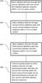
- Radiation delivery profilesmay be measured using a phantom to approximate the absorption of radiation by a patient. With measurement of what radiation a delivery system actually delivers (e.g., to the phantom), the radiation delivery system can be adjusted or calibrated for optimal delivery of a prescribed dose to a patient.
- a systemincludes a scanning system including a radiation detector, the scanning system configured to enable movement of the radiation detector.
- the systemalso includes at least one programmable processor and a non-transitory machine-readable medium storing instructions which, when executed by the at least one programmable processor, cause the at least one programmable processor to perform various operations.
- the operationsinclude moving the radiation detector through a first vertical calibration path and recording a first radiation detector response within 3 cm of a water surface, moving the radiation detector through a second vertical calibration path and recording a second radiation detector response within 3 cm of the water surface, moving the radiation detector through a third vertical calibration path and recording a third radiation detector response within 3 cm of the water surface, and controlling the scanning system to move the radiation detector through at least one measurement path that takes into account a scanning system tilt, the at least one measurement path determined based on at least the first, second, and third radiation detector responses.
- a systemin an interrelated aspect, includes a scanning system including multiple radiation detectors, the scanning system configured to enable movement of the radiation detectors.
- the systemalso includes at least one programmable processor and a non-transitory machine-readable medium storing instructions which, when executed by the at least one programmable processor, cause the at least one programmable processor to perform various operations.
- the operationsinclude moving the multiple radiation detectors through multiple calibration paths and recording multiple radiation detector responses within 3 cm of a water surface, and controlling the scanning system to move a radiation detector through at least one measurement path that takes into account a scanning system tilt, the at least one measurement path determined based on at least the multiple radiation detector responses.
- a systemin yet another interrelated aspect, includes a scanning system including multiple radiation detectors, the scanning system configured to enable movement of the radiation detectors.
- the systemalso includes at least one programmable processor and a non-transitory machine-readable medium storing instructions which, when executed by the at least one programmable processor, cause the at least one programmable processor to perform various operations.
- the operationsinclude moving the radiation detector through a first vertical calibration path and recording a first radiation detector response within 3 cm of a water surface, moving the radiation detector through a second vertical calibration path and recording a second radiation detector response within 3 cm of the water surface, moving the radiation detector through a third vertical calibration path and recording a third radiation detector response within 3 cm of the water surface, and controlling an actuator to cause a leveling of the scanning system such that at least one movement axis of the scanning system is parallel to the water surface, the controlling based on at least the first, second, and third radiation detector responses.
- a computer program productincludes a non-transitory, machine-readable medium storing instructions which, when executed by at least one programmable processor, cause the at least one programmable processor to perform various operations.
- the operationsinclude moving a radiation detector through a first vertical calibration path and recording a first radiation detector response within 3 cm of a water surface, moving the radiation detector through a second vertical calibration path and recording a second radiation detector response within 3 cm of the water surface, moving the radiation detector through a third vertical calibration path and recording a third radiation detector response within 3 cm of the water surface, and controlling a scanning system to move the radiation detector through at least one measurement path that takes into account a scanning system tilt, the at least one measurement path determined based on at least the first, second, and third radiation detector responses.
- the measurement path determinationcan be based on high-gradient regions of the first, second, and third radiation detector responses.
- the operationscan further include calculating an offset based on any two of the first radiation detector response, the second radiation detector response, and the third radiation detector response.
- the measurement path determinationcan be based on at least the offset.
- the offsetcan be calculated in a high-gradient region of the first, second, or third radiation detector responses.
- the operationscan further include performing functional fits to the any two radiation detector responses, calculating feature locations based on at least the functional fits, and determining the offset based on differences in the any two radiation detector responses at the feature locations.
- the feature locationscan correspond to at least one of a maximum gradient location, an inflection point, a maximum curvature, and a specific dose value.
- the operationscan further include calculating, based on at least the offset, a normal vector representing a plane of the scanning system or calculating, based on at least the offset, a pair of angles representing the plane of the scanning system.
- the measurement path determinationcan be based on at least the normal vector or the pair of angles.
- a computer program productincludes a non-transitory, machine-readable medium storing instructions which, when executed by at least one programmable processor, cause the at least one programmable processor to perform operations including moving a radiation detector through a first vertical calibration path and recording a first radiation detector response within 3 cm of a water surface, moving the radiation detector through a second vertical calibration path and recording a second radiation detector response within 3 cm of the water surface, moving the radiation detector through a third vertical calibration path and recording a third radiation detector response within 3 cm of the water surface, calculating a correction function based on at least the first, second, and third radiation detector responses, controlling the scanning system to move the radiation detector through a raw data path and recording, during the movement of the radiation detector along the raw data path, a raw data radiation detector response, and providing a corrected radiation detector response based on at least an application of the correction function to the raw data radiation detector response.
- a computer program productincludes a non-transitory, machine-readable medium storing instructions which, when executed by at least one programmable processor, cause the at least one programmable processor to perform operations including moving multiple radiation detectors through multiple calibration paths and recording multiple radiation detector responses within 3 cm of a water surface, and controlling a scanning system to move a radiation detector through at least one measurement path that takes into account a scanning system tilt, the at least one measurement path determined based on at least the multiple radiation detector responses.
- a computer program productincludes a non-transitory, machine-readable medium storing instructions which, when executed by at least one programmable processor, cause the at least one programmable processor to perform operations including moving a radiation detector through a first vertical calibration path and recording a first radiation detector response within 3 cm of a water surface, moving the radiation detector through a second vertical calibration path and recording a second radiation detector response within 3 cm of the water surface, moving the radiation detector through a third vertical calibration path and recording a third radiation detector response within 3 cm of the water surface, and controlling an actuator to cause a leveling of a scanning system such that at least one movement axis of the scanning system is parallel to the water surface, the controlling based on at least the first, second, and third radiation detector responses.
- the operationscan further include calculating an offset based on any two of the first radiation detector response, the second radiation detector response, and the third radiation detector response, where the controlling of the actuator to cause the leveling of the scanning system can be further based on the offset.
- Embodiments of the current subject mattercan include, but are not limited to, methods consistent with the descriptions provided herein as well as articles that comprise a tangibly embodied machine-readable medium operable to cause one or more machines (e.g., computers, etc.) to result in operations implementing one or more of the described features.
- machinese.g., computers, etc.
- computer systemsare also contemplated that may include one or more processors and one or more memories coupled to the one or more processors.
- a memorywhich can include a computer-readable storage medium, may include, encode, store, or the like, one or more programs that cause one or more processors to perform one or more of the operations described herein.
- Computer implemented methods consistent with one or more embodiments of the current subject mattercan be implemented by one or more data processors residing in a single computing system or across multiple computing systems. Such multiple computing systems can be connected and can exchange data and/or commands or other instructions or the like via one or more connections, including but not limited to a connection over a network (e.g., the internet, a wireless wide area network, a local area network, a wide area network, a wired network, or the like), via a direct connection between one or more of the multiple computing systems, etc.
- a networke.g., the internet, a wireless wide area network, a local area network, a wide area network, a wired network, or the like
- FIG. 1is a simplified diagram of an exemplary radiation source and exemplary phantom and radiation detection scanning system.
- FIG. 2is a detailed diagram of an exemplary scanning system, in accordance with certain aspects of the present disclosure.
- FIG. 3is a simplified diagram of a profile of dose delivery in a phantom vs. vertical position of a radiation detector, in accordance with certain aspects of the present disclosure.
- FIG. 5is a simplified diagram illustrating an example of a tilted scanning system and phantom, in accordance with certain aspects of the present disclosure.
- FIG. 6is a process flow diagram describing an exemplary process for using a radiation detector to determine a scanning system tilt, in accordance with certain aspects of the present disclosure.
- FIG. 7is a process flow diagram describing an exemplary process for use of multiple radiation detectors to determine a scanning system tilt, in accordance with certain aspects of the present disclosure.
- FIG. 8is a simplified diagram illustrating an exemplary indication of offset in radiation detector responses caused by scanning system tilt, in accordance with certain aspects of the present disclosure.
- FIG. 9is a process flow diagram describing an exemplary process for physical leveling of a scanning system, in accordance with certain aspects of the present disclosure.
- Radiation delivery systemscan be used, for example, for delivering radiation therapy to patients.
- Radiation delivery systemscan include, for example, linear accelerators, radioisotope systems (e.g., cobalt sources).
- the amount and location of radiation deliveredcan be specified by a radiation treatment plan, which can include specific instructions for how and under what configuration a radiation delivery system is to be operated.
- the radiation delivery systemcan be calibrated to ensure that the radiation is delivered as intended. These calibrations can include characterizing the radiation beam (e.g., fluence, homogeneity, energy, etc.).
- a phantomcan be used to provide a volume that can receive radiation.
- Phantomscan be, for example, water phantoms, solid water phantoms or water-equivalent phantoms.
- the phantomscan be circular (cylindrical), rectangular, or anthropomorphic-shaped.
- Radiation detectorscan be used in or around the phantom to measure a delivered radiation dose for comparison with expected radiation output. Accordingly, the systems, computer program products, and methods described herein provide embodiments that can, among other things, enable accurate measurements of radiation even in the case where the phantom is misaligned or tilted relative to the radiation beam. Such embodiments can include using the radiation detector itself to determine the misalignment, without having to locate a water surface.
- FIG. 1is a simplified diagram of an exemplary radiation source 14 and exemplary scanning system 10 with a radiation detector 38 , in accordance with certain aspects of the present disclosure.
- FIG. 2is a detailed diagram of the exemplary scanning system 10 , in accordance with certain aspects of the present disclosure.
- Radiation detector 38can be provided for measuring radiation 12 emitted from radiation source 14 , for example along central axis 78 .
- Types of radiation detectorscan include, for example, gaseous ionization detectors, ionization chambers, proportional counters, scintillation counters, semiconductor detectors, dosimeters (e.g. films), or electroscopes or electrometers.
- scanning system 10can include radiation detector 38 and can be configured to enable movement of radiation detector 38 inside phantom 58 .
- scanning system 10can include any combination of drives, including, for example, linear drives, ring drives, diameter drives, vertical drives, horizontal drives, etc.
- Scanning system 10can also include tracks, belts, gears, motors, or the like to allow positioning of radiation detector 38 .
- Scanning system 10can also be connected to a processor 16 having analysis and data storage capabilities and controller 18 operable with the processor.
- ring drive 20can be operable with controller 18 for providing a rotational movement 22 about first axis 24 responsive to commands from the controller.
- Horizontal drive 26can be operable with controller 18 for providing horizontal movement 28 along second axis 30 .
- horizontal drive 26can be operable with ring drive 20 for providing rotational movement 22 .
- Vertical drive 32can be operable with controller 18 for providing vertical movement 34 of horizontal drive 26 along third axis 36 responsive to commands from controller 18 .
- Radiation detector 38can be carried by mount 40 affixed to horizontal drive 26 for locating it along horizontal drive 26 by horizontal movement 28 .
- Radiation detector 38can provide sensing signals to processor 16 for selected locations of the radiation detector when orientated through the circular (rotational), horizontal, and vertical movements 22 , 28 , 34 along the first, second and third axes 24 , 30 , 36 , respectively, as a result of commands from controller 18 .
- the term “drive”refers to motors, tracks, belts, bearings, etc., that enable the desired motion associated with the drive (e.g., horizontal, vertical, rotational).
- scanning system 10can include electrometer 54 operable between processor 16 and radiation detector 38 .
- a reference detector 56can be located at a fixed location for comparing the sensing signals from the radiation detector 38 to the reference detector 56 .
- a cylindrical water tank 58 carrying water(one example of a “phantom”) can be dimensioned for movement of the radiation detector 38 and drives 20 , 26 , 32 described above. While a circular cross-section water phantom 58 is shown, the technologies of the present disclosure are contemplated to be applicable to other shapes and types of phantoms, for example, square, rectangular, hexagonal, etc.
- Controller 18can be capable of communicating movement commands and receiving encoder information from the motors and bi-directional communication of movement command and encoder position data to programmable processor 16 .
- the embodiment described hereinis by way of example only for application to a cylindrical phantom/scanning system.
- other geometrically shaped vesselse.g., square, rectangular
- the scanning systemcan be a Cartesian scanning system where instead of ring drive 20 , there can be two horizontal drives (e.g. corresponding to an X axis and a Y axis), which, when combined with vertical drive 32 , can also provide three-dimensional movement of radiation detector 38 .
- the phantom/vesselmay contain water, or air scans can be performed with an empty vessel.
- Scanning system 10may also be implemented without a vessel and assembled in a self-supporting frame that rests on a treatment couch, or may be mounted to the head of radiation source 14 for testing radiation beam characteristics as gantry 62 is moved.
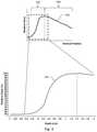
- FIG. 3is a simplified diagram of a profile of dose delivery in a phantom vs. vertical position of a radiation detector, in accordance with certain aspects of the present disclosure.
- scanning system 10can be used with a phantom that provides a generally known absorption of radiation.
- the dose delivered to the phantomvaries with depth because the radiation beam is attenuated, absorbed and scattered as it passes through the material of the phantom. Also, the measured dose can vary near the edge of the phantom, as further described below.
- dosemeans the deposition of energy in a material as a result of exposure to ionizing radiation.
- the “dose”refers to the material of the phantom (e.g., water, solid water, etc.).
- the illustrated dose curves hereinare generally described as the “radiation detector response.”
- the term “radiation detector response”means any response to radiation of radiation detector 38 (or other types of radiation detectors described herein), but can also refer to a response of radiation detector 38 converted to dose, relative dose, etc.
- the top panel of FIG. 3illustrates an example of dose 310 as measured at different positions in phantom 58 .
- the doseis shown as normalized to 100% at the peak of the measured dose and described as “relative dose.” Accordingly, as used herein, when referring to “dose” this can also refer, for simplicity, to “relative dose.”
- dosebuilds up to a maximum and then falls off further into the phantom 58 . This introduces two regions of the radiation detector response.
- the first regionis the “high-gradient region” 320 , where scattered radiation (electrons and photons) from the primary radiation is not in equilibrium as a function of primary fluence per unit path length.
- Equilibriumoccurs at a depth that is dependent on the primary radiation energy and field size. Equilibrium depths typically range from 0.1 to 5 cm, where equilibrium depth increases with beam energy, due primarily to the extended range of the secondary radiation. As depth increases, so too does the detector response to the increasing scattered radiation. The rate of increase in the detector response with depth continues until equilibrium is reached. At this depth, the detector response has peaked, and the scattered radiation is in equilibrium with the primary radiation fluence which then decreases by primary attenuation with increasing depth. After the peak, the detector response decreases along with primary radiation attenuation in the phantom. The rate of increase in the detector response before the peak is greater than the rate of decrease after the peak, hence the “high-gradient region.”
- the second region 330is where the delivered dose is directly relatable to the fluence of the radiation beam where, in any volume, as many electrons are stopped as set in motion.
- the termination of the high-gradient regionis the location where the relative dose is a maximum.
- such a divisionis merely assumed for ease of discussion and that these processes occur on a continuum, and thus such a distinction should not be considered as overly limiting.
- the inset indicated by the dashed square in the top panel of FIG. 3is illustrated in the example of the bottom panel in FIG. 3 .
- Thisprovides an exemplary illustration of the relative dose in the high-gradient region as a function of vertical position of radiation detector 38 in phantom 58 .
- the values shown with respect to relative dose and vertical positionare examples only and that other curves corresponding to relative dose versus vertical position may be obtained.
- the high-gradient regionmay not have the exact shape shown in the examples provided herein, as the specific radiation detector responses can be a function of beam energy, geometry, etc.
- the bottom panel in FIG. 3is intended to merely illustrate one example where a high gradient region can occur close to top of phantom 58 (e.g., a water surface when phantom 58 is a water phantom 58 ).
- FIG. 4is a simplified diagram illustrating an example of a level scanning system 10 and phantom 58 , in accordance with certain aspects of the present disclosure.
- the measurement of dosecan be a function of vertical position of radiation detector 38 in phantom 58 .
- the simplified diagram of FIG. 4shows a radiation detector that can be moved, for example, by a combination of a vertical drive and a horizontal drive.
- the plot to the right of scanning system 10illustrates conceptually how an example measurement of relative dose versus vertical position (also referred to herein as “radiation detector response”) relates to scanning system 10 and phantom 58 .
- radiation detector responsealso referred to herein as “radiation detector response”
- FIG. 4because scanning system 10 is level, a vertical scan of radiation detector at any location in phantom 58 will result in the same radiation detector response (under the simplifying assumption that the beam fluence is uniform or homogenous).
- FIG. 5is a simplified diagram illustrating an example of a tilted scanning system 10 and phantom 58 , in accordance with certain aspects of the present disclosure.
- scanning system 10 and/or phantom 58are “level” relative to the radiation beam (e.g., movement of the vertical drive is parallel to the central axis of the radiation beam and movement by the horizontal drives or ring drives is orthogonal to the central axis of the radiation beam).
- scanning system 10is tilted, the radiation detector response will be different when measured at different locations. A simplified illustration of this effect is shown by the example plot to the right of the tilted scanning system 10 .
- three radiation detector responses( 510 , 520 , 530 ) are shown for three vertical scans ( 540 , 550 , 560 ) (also referred to herein as vertical calibration paths) performed by the vertical drive. Examples of three locations, as projected onto a water surface, are shown in the top portion of FIG. 5 . Due to the scanning system tilt, the radiation detector responses plotted, as a function of vertical position, are offset from each other. Certain embodiments of the present disclosure can utilize measurements/calculations of these offsets to determine and compensate for scanning system tilt. Accordingly, disclosed herein are a number of different embodiments of systems, methods, and computer programs that allow for the physical and/or electronic correction of the effects of a tilted scanning system 10 .
- a phantom vessele.g., a water tank
- the scanning system 10is aligned with the scanning system 10 such that when the vessel is tilted, the scanning system 10 is also tilted.
- the scanning system 10 and the water tankcan be separately tilted at different angles.
- tiltrefers to the tilt of a scanning system 10 with respect to a water surface (or other such assumed horizontal surface of a phantom 58 that is taken to be perpendicular to a central axis of the radiation beam).
- FIG. 6is a process flow diagram describing exemplary process for using a single radiation detector to determine a scanning system tilt, in accordance with certain aspects of the present disclosure.
- Radiation detector responses recorded along the three different pathscan allow determination of the tilt of scanning system 10 .
- thiscan be done by a single radiation detector that is controlled to move vertically along three non-coplanar calibration paths.
- a radiation detectorcan be moved through a first vertical calibration path and a first radiation detector response can be recorded, for example, within 3 cm of a water surface.
- a measurement or calibration pathmay extend through or above a water surface.
- a radiation detectorcan be moved through a second vertical calibration path and a second radiation detector response can be recorded, for example, within 3 cm of the water surface.
- a radiation detectorcan be moved through a third vertical calibration path and a third radiation detector response can be recorded, for example, within 3 cm of the water surface.
- 3 cmis an example of where the high-gradient region can allow easier distinction between differences or offsets in radiation detector responses, measurements at other locations or in other regions can also be performed. It should be understood that 3 cm is an exemplary choice and that the actual number can vary from embodiment to embodiment and can be based in part on the energy of the radiation beam and the type of radiation (e.g., electron, photon, etc.).
- the high gradient regionmay be shallower than 3 cm and, as such, some embodiments may have radiation detector responses recorded within 2 cm or 1 cm of the water surface.
- the beam energyis higher (e.g., 25 MV)
- radiation detector responsesmay be recorded within 6 cm of the water surface while still sampling in the high-gradient region.
- the sampling regionmay also be determined through consideration of a potential or likely phantom tilt. For example, a higher potential tilt counsels in favor of recording data through a greater region from the expected water surface.
- different embodimentsmay include moving the radiation detector (e.g., along a calibration path and/or measurement path) and recording a radiation detector response within 1 cm, 2 cm, 3 cm, 4 cm, 5 cm, 6 cm, etc., of the water surface.
- Such pathsmay include the entire high-gradient region, or a fraction of the high-gradient region, for example, approximately 50%, 75%, or 90% of the high gradient region.
- scanning system tiltdetermined, at 640 , scanning system 10 can be controlled to move the radiation detector through one or more measurement paths that take into account the scanning system tilt.
- the measurement pathscan be determined based on at least the first, second, and third radiation detector responses. As described below, particularly with reference to the FIG. 8 , determination of a scanning system tilt provides the needed information to determine the appropriate measurement path to take into account the scanning system tilt.
- the embodiment described aboveparticularly notes that radiation detector response can be measured where it changes rapidly. Accordingly, in some embodiments, rather than using detector response data acquired where the detector response data changes slowly as a function of depth, the measurement path determination can be based on high-gradient regions of the first, second, and third radiation detector responses.
- horizontal or verticalWhen referring to directions such as “horizontal” or “vertical,” this is with reference to scanning system 10 , and not to the central axis 78 of the radiation beam, the phantom, or the water surface in the phantom. Furthermore, “horizontal” or “vertical,” as used herein, do not mean exactly vertical or horizontal, but rather describe generally horizontal or vertical (which, respectively, may be at a right angle to or in the direction relative to gravity or towards a water surface).
- the tilt of scanning system 10may be small, movement by a vertical drive is still considered “vertical” and lateral movement, such as by the horizontal drive, may still be considered “horizontal.” Furthermore, it is understood that any given directions need not be exact, and that deviations due to machine error or deviations in paths that do not affect the principles or methods described herein are considered sufficiently “horizontal” or “vertical.”
- the term “calibration path”means any path that the radiation detector is moved along during a calibration process.
- the data taken along the calibration pathcan be used for actual measurement data, for example, as when performing quality assurance or any sort of non-calibration operations.
- radiation detector 38can be moved along the three calibration paths, and once the scanning system tilt is accounted for, the data acquired along those calibration paths can be used as measurement data.
- a “calibration path”is a path used in determining a scanning system tilt and a “measurement path” is a path that can be executed while measuring the output of the radiation beam as part of QA. Both can be considered to be part of a “calibration,” initialization, adjustment, or characterization of a radiation therapy delivery system.
- executing a “calibration path”does not require that a “calibration” be performed—as discussed further below, embodiments disclosed herein (with particular reference to FIG. 9 ) can allow for adjustment of scanning system 10 such that such that the scanning system is not tilted and no “calibration” to account for the tilt is necessary.
- the phrase “take into account the scanning system tilt”means applying one or more of a correction or adjustment to the motion or position of a radiation detector, or applying a modification or correction of received radiation detector data, such that the use of the scanning system behaves as if the scanning system was parallel to the water surface.
- modifications or corrections to the operation of scanning system 10may not be performed, or such corrections will be null corrections (i.e., adding zero or changing a measurement path slope by zero degrees).
- FIG. 7is a process flow diagram describing use of multiple radiation detectors to determine a scanning system tilt, in accordance with certain aspects of the present disclosure.
- more than one detectormay be used, for example, to acquire some calibration paths in parallel.
- three radiation detectorscan be coupled to scanning system 10 such that with a single scan of the vertical drive the three calibration paths can be acquired.
- scanning system 10can include any number of radiation detectors and scanning system 10 can be configured to enable movement of the radiation detectors.
- the radiation detectorscan be moved through a number of calibration paths and a number of radiation detector responses can be recorded, for example, within 3 cm of a water surface.
- the scanning system 10can be controlled to move a radiation detector through at least one measurement path that takes into account a scanning system tilt.
- the measurement pathcan be determined based on at least the radiation detector responses.
- the measurement pathcan be determined similarly to the measurement path determination described above with reference to using a single radiation detector.
- the radiation detector that is moved through the measurement pathcan be one of the radiation detectors moved through the calibration path.
- the radiation detector that is moved through the measurement pathcan be a different radiation detector (e.g., separate from any that may have been used with the calibration paths). Though specifically discussed for this embodiment, it is contemplated that the radiation detector(s) used for measurement can be either the same used for calibration or can be different—for any of the embodiments described herein.
- the scanning system 10includes a ring drive
- there can be two radiation detectors mounted on a diameter drivee.g., on a horizontal drive along a diameter of the ring drive.
- a first vertical scan(acquiring two calibration paths) can then be acquired with two radiation detectors on the diameter drive.
- a second vertical scancan be acquired with the diameter drive after rotating the two radiation detectors to a different angle (acquiring another two calibration paths).
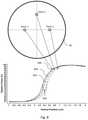
- FIG. 8is a simplified diagram illustrating an offset in radiation detector responses caused by scanning system tilt, in accordance with certain aspects of the present disclosure.
- Vertically scanning with a radiation detector when the scanning system 10 is tiltedcan result in an offset 810 of a radiation detector response profile from location to location (e.g., at different X-Y locations in the scanning system).
- this offsetis easiest to measure in the high-gradient region of the radiation detector response. Accordingly, as described in further detail below, a rapidly changing radiation detector response can facilitate accurate determination of scanning system tilt with fewer acquisition points.
- the radiation detector responsescan be normalized to their maximum values to allow for a variable fluence radiation field.
- determination of the scanning system tiltcan include determining slopes of the points in the radiation detector responses according to the following expression:
- the summationsare taken over data points (i) in the radiation detector responses around the location where the slope is being determined, e.g., resulting in three to five points in the sum, including the central point at the location where the slope is being calculated.
- x iis the position along the vertical axis (e.g. the vertical scan direction)
- y iis the value of the response at x i
- nis the total number of data points in the summation.
- a subset of the calculated slope datacan be isolated or extracted, e.g., the three or five adjacent points including a central point at the location of maximum slope.
- the data subsetscan be used to determine the offset between the radiation detector responses at a location of maximum slope, as described below.
- the present disclosuredescribes several computational methods for determining offsets and the corresponding tilt.
- functional fitscan be performed to any two of the radiation detector responses in order to calculate slopes and offsets between them. For example, it can be seen from FIG. 8 that a significant portion of the radiation detector response can be well-fitted by a hyperbolic tangent. Similarly, some portions, for instance those in the steepest part of the high-gradient region, could be well-fitted by a line. Also, some portions of the radiation detector response may be fitted with a polynomial function. Such analytical expressions have corresponding features associated with them. For example, “features” of a linear fit are the slope and intercept.
- features of a hyperbolic tangentcan be various coefficients or constants defined in the fitting function.
- other quantitiescan be derived that can be used as “features.” For example, regardless of what fitting function may be used, some “features” can describe a particular location or attribute of the radiation detector response. Determining the offset can be based on differences in any two radiation detector responses at the feature locations. Calculating feature locations can be based at least on the functional fits, with the feature locations corresponding to, for example, a maximum gradient location, an inflection point, a maximum curvature, a specific dose value, etc. In this way, a similar subset of data points around any defined feature of the functional fit can be used in a manner similar to that described with regard to using a location of maximum gradient.
- the offset described abovecan be calculated based on any two (or optionally three) of the first radiation detector response, the second radiation detector response, and the third radiation detector response.
- the offset between the radiation detector responsescan be determined and, as described herein, the measurement path determination can then be based on at least the offset.
- the offset between two radiation detector responsescan be determined by performing a least-squares minimization.
- one of the radiation detector responsescan include a variable offset parameter added to the vertical position coordinate (referred to below as “z”, and taken along the Z-axis of the scanning system).
- zthe vertical position coordinate
- such a minimizationcan include minimizing the following expression based on any two radiation detector responses, referred to below as curve 1 and curve 2: ⁇ all points in curve2 (Dose curve1 ( z -offset) ⁇ Dose curve2 ( z )) 2 (1)
- the points usedcan be the (e.g., 3-5) points determined to correspond to, for example, the location of maximum slope.
- the minimizationneed not be performed on the entire radiation detector responses and, by using this smaller and more relevant data subset, a result can be calculated using less computer memory and fewer processing cycles.
- One method of minimizing Eq. 1can include performing a binary search over different values of the offset. Such a binary search can have a specified resolution, for example 0.01 mm.
- the resolutioncan be smaller (or much smaller) than a gradient scale length of either of the radiation detector response curves (e.g., resolution ⁇ (response)/( ⁇ (response)/unit length in the vertical direction)). Accordingly, the offset can be calculated between the three pairs of radiation detector responses 820 and 830 , 830 and 840 , and 820 and 840 .
- the offsetis between two radiation detector response curves, taken at different X-Y locations in the phantom.
- the offsetthus represents the change in detector response, not as a function of Z, but as a function of location (i.e., X and Y).
- the scanning system tiltcan be expressed in terms of the slope (or tilt) in the X direction and a slope (or tilt) in the Y direction.
- offset 12shown as element 810 and corresponding to the offset between responses measured at Point 1 and Point 2
- offset 23between Point 2 and Point 3
- offset 13between Point 1 and Point 3
- the tilt in the X directionis
- offset_x ⁇ ⁇ ⁇ xwhich is the offset between the two X-axis points (or offset 12 ) divided by the total separation between the X-axis points (or X-coordinates of Point 1 and Point 2).
- the tilt in the Y directionis
- offset_y ⁇ ⁇ ⁇ ywhich is the average of offset 23 and offset 13 , divided by the Y axis position of Point 3.
- X_axis ⁇ _tilt[ atan ⁇ ( offset_x ⁇ ⁇ ⁇ x ) ] •
- ⁇ Y_axis ⁇ _tilt[ atan ⁇ ( offset_y ⁇ ⁇ ⁇ y ) ] • .
- X axis tilt and Y axis tiltcan be displayed as angles to the user so they understand the physical alignment of scanning system 10 .
- These slopescan also be used by the software to adjust the vertical positions of any step-by-step (or continuous motion with motor/drive synchronization) scan measurements made during actual testing/commissioning.
- the system's motorscan be instructed to move both horizontally and vertically in order to stay parallel to the water surface.
- controlling the scanning system 10 movement through the measurement pathcan be based on at least one of the first, second, or third radiation detector responses as recorded in a high-gradient region of the corresponding first 820 , second 830 , or third 840 radiation detector responses.
- the measurement pathcan result, for example, in part from the adjusted vertical positions as described above.
- a normal vectorcan be calculated that represents a plane of the scanning system 10 (e.g., a plane that is parallel to the horizontal drive of the scanning system 10 ).
- the measurement pathcan, for example, be determined based on at least the normal vector, or the pair of angles.
- the above-determined tiltcan be used to determine the measurement path such that the radiation detector goes to the intended location relative not to scanning system 10 but instead relative to the water surface.
- any controlling or adjustment to the scanning system or the radiation detectorcan be done without determining the actual surface location of the water.
- system tiltcan be accounted for by correcting detector responses/measurements performed during QA to account for a tilt when the measurement path has not been altered to proceed parallel to a water surface. For example, if, at a given location, a radiation detector response (e.g., in terms of current, voltage, counts, etc.) should be changing by 10%/cm in the X direction, but due to the scanning system tilt the change is only 9%/cm, then the radiation detector response can be corrected to add 1% to the radiation detector response after 1 cm of X travel based on a determination of system tilt in accordance with the teachings of the present disclosure.
- a radiation detector responsee.g., in terms of current, voltage, counts, etc.
- Such embodimentscan thus include controlling the scanning system to move the radiation detector through a raw data path (which can be any path of radiation detector 38 ) and during movement of the detector along the raw data path, a raw data radiation detector response can be recorded.
- the raw data radiation detector responseis the data from radiation detector 38 , which may be inaccurate due to the tilt of scanning system 10 .
- a corrected radiation detector responsecan then be provided based on at least an application of a correction function to the raw data radiation detector response. As described in the example above, after applying a correction function, the corrected radiation detector response is what the radiation detector would have recorded if scanning system 10 had not been tilted.
- a correction functioncan be, for example, values from a lookup table, an analytical formula, or any sort of data store that can be accessed to correct the raw data radiation detector response.
- Such an embodimentcan be used with known or derived dose (or response) vs. depth data, provided from another calibration or determined based on the methods described herein.
- FIG. 9is a process flow diagram describing physical leveling of a scanning system 10 , in accordance with certain aspects of the present disclosure.
- scanning system 10can be physically leveled by correcting the scanning system tilt itself. This can include, for example, at 910 , moving a radiation detector through a first vertical calibration path and recording a first radiation detector response, for example, within 3 cm of a water surface, at 920 , moving a radiation detector through a second vertical calibration path and recording a second radiation detector response, for example, within 3 cm of the water surface, and, at 930 , moving a radiation detector through a third vertical calibration path and recording a third radiation detector response, for example, within 3 cm of the water surface.
- an actuatorcan be controlled to cause a leveling of the scanning system 10 such that at least one movement axis of the scanning system 10 is parallel to the water surface.
- the controllingcan be based on at least the first, second, and third radiation detector responses.
- the term “actuator”means any mechanical device for moving or controlling something.
- an actuatorcan be a spring-actuated adjustment mechanism, pneumatic lift, gear train, belt system, screw adjustment mechanism, etc.
- Such actuatorscan be incorporated into, for example, a leveling table, tripod, etc., that can be manually adjusted or computer controlled to cause a reduction in scanning system tilt.
- some embodimentscan include calculating an offset based on any two of the first radiation detector response, the second radiation detector response, and the third radiation detector response. Then, the controlling of the actuator to cause the leveling of the scanning system 10 can be further based on the offset.
- One or more aspects or features of the subject matter described hereincan be realized in digital electronic circuitry, integrated circuitry, specially designed application specific integrated circuits (ASICs), field programmable gate arrays (FPGAs) computer hardware, firmware, software, and/or combinations thereof.
- ASICsapplication specific integrated circuits
- FPGAsfield programmable gate arrays
- These various aspects or featurescan include embodiment in one or more computer programs that are executable and/or interpretable on a programmable system including at least one programmable processor, which can be special or general purpose, coupled to receive data and instructions from, and to transmit data and instructions to, a storage system, at least one input device, and at least one output device.
- the programmable system or computing systemmay include clients and servers.
- a client and serverare generally remote from each other and typically interact through a communication network. The relationship of client and server arises by virtue of computer programs running on the respective computers and having a client-server relationship to each other.
- machine-readable signalrefers to any signal used to provide machine instructions and/or data to a programmable processor.
- the machine-readable mediumcan store such machine instructions non-transitorily, such as for example as would a non-transient solid-state memory or a magnetic hard drive or any equivalent storage medium.
- the machine-readable mediumcan alternatively or additionally store such machine instructions in a transient manner, such as for example as would a processor cache or other random access memory associated with one or more physical processor cores.
- one or more aspects or features of the subject matter described hereincan be implemented on a computer having a display device, such as for example a cathode ray tube (CRT) or a liquid crystal display (LCD) or a light emitting diode (LED) monitor for displaying information to the user and a keyboard and a pointing device, such as for example a mouse or a trackball, by which the user may provide input to the computer.
- a display devicesuch as for example a cathode ray tube (CRT) or a liquid crystal display (LCD) or a light emitting diode (LED) monitor for displaying information to the user
- LCDliquid crystal display
- LEDlight emitting diode
- a keyboard and a pointing devicesuch as for example a mouse or a trackball
- feedback provided to the usercan be any form of sensory feedback, such as for example visual feedback, auditory feedback, or tactile feedback; and input from the user may be received in any form, including, but not limited to, acoustic, speech, or tactile input.
- Other possible input devicesinclude, but are not limited to, touch screens or other touch-sensitive devices such as single or multi-point resistive or capacitive trackpads, voice recognition hardware and software, optical scanners, optical pointers, digital image capture devices and associated interpretation software, and the like.
- phrases such as “at least one of” or “one or more of”may occur followed by a conjunctive list of elements or features.
- the term “and/or”may also occur in a list of two or more elements or features. Unless otherwise implicitly or explicitly contradicted by the context in which it used, such a phrase is intended to mean any of the listed elements or features individually or any of the recited elements or features in combination with any of the other recited elements or features.
- the phrases “at least one of A and B;” “one or more of A and B;” and “A and/or B”are each intended to mean “A alone, B alone, or A and B together.”
- a similar interpretationis also intended for lists including three or more items.
- the phrases “at least one of A, B, and C;” “one or more of A, B, and C;” and “A, B, and/or C”are each intended to mean “A alone, B alone, C alone, A and B together, A and C together, B and C together, or A and B and C together.”
- Use of the term “based on,” above and in the claimsis intended to mean, “based at least in part on,” such that an unrecited feature or element is also permissible.
Landscapes
- Health & Medical Sciences (AREA)
- Engineering & Computer Science (AREA)
- Biomedical Technology (AREA)
- Life Sciences & Earth Sciences (AREA)
- General Health & Medical Sciences (AREA)
- Radiology & Medical Imaging (AREA)
- Nuclear Medicine, Radiotherapy & Molecular Imaging (AREA)
- Animal Behavior & Ethology (AREA)
- Pathology (AREA)
- Public Health (AREA)
- Veterinary Medicine (AREA)
- Physics & Mathematics (AREA)
- General Physics & Mathematics (AREA)
- High Energy & Nuclear Physics (AREA)
- Molecular Biology (AREA)
- Spectroscopy & Molecular Physics (AREA)
- Measurement Of Radiation (AREA)
Abstract
Description
Σall points in curve2(Dosecurve1(z-offset)−Dosecurve2(z))2 (1)
which is the offset between the two X-axis points (or offset12) divided by the total separation between the X-axis points (or X-coordinates of
which is the average of offset23and offset13, divided by the Y axis position of
These angles (or any equivalent expression of the scanning system tilt) can be used for determination of measurement paths, physical correction of the scanning system, etc.
Claims (11)
Priority Applications (1)
| Application Number | Priority Date | Filing Date | Title |
|---|---|---|---|
| US16/582,445US11278744B2 (en) | 2018-09-28 | 2019-09-25 | Systems and methods to account for tilt of a radiation measurement system |
Applications Claiming Priority (2)
| Application Number | Priority Date | Filing Date | Title |
|---|---|---|---|
| US201862738613P | 2018-09-28 | 2018-09-28 | |
| US16/582,445US11278744B2 (en) | 2018-09-28 | 2019-09-25 | Systems and methods to account for tilt of a radiation measurement system |
Publications (2)
| Publication Number | Publication Date |
|---|---|
| US20200101327A1 US20200101327A1 (en) | 2020-04-02 |
| US11278744B2true US11278744B2 (en) | 2022-03-22 |
Family
ID=69945603
Family Applications (1)
| Application Number | Title | Priority Date | Filing Date |
|---|---|---|---|
| US16/582,445Active2040-09-17US11278744B2 (en) | 2018-09-28 | 2019-09-25 | Systems and methods to account for tilt of a radiation measurement system |
Country Status (1)
| Country | Link |
|---|---|
| US (1) | US11278744B2 (en) |
Families Citing this family (6)
| Publication number | Priority date | Publication date | Assignee | Title |
|---|---|---|---|---|
| WO2018160763A1 (en) | 2017-02-28 | 2018-09-07 | Sun Nuclear Corporation | Radiation therapy treatment verification with electronic portal imaging device transit images |
| US12011616B2 (en) | 2019-07-10 | 2024-06-18 | Sun Nuclear Corporation | Image-based radiation therapy quality assurance |
| US11378700B2 (en) | 2019-07-10 | 2022-07-05 | Sun Nuclear Corporation | Scintillator-based radiation therapy quality assurance |
| US11600004B2 (en) | 2019-07-10 | 2023-03-07 | Sun Nuclear Corporation | Image-based radiation therapy quality assurance |
| DE102021111815A1 (en)* | 2021-05-06 | 2022-11-10 | L A P Gmbh Laser Applikationen | Method and device for validating the axial linearity and/or the positioning accuracy of an adjustment mechanism for a radiation detector |
| US12201850B2 (en) | 2022-06-16 | 2025-01-21 | Sun Nuclear Corporation | High dose rate radiation therapy systems and dosimetry |
Citations (244)
| Publication number | Priority date | Publication date | Assignee | Title |
|---|---|---|---|---|
| US759608A (en) | 1903-09-28 | 1904-05-10 | Samuel W Harper | Clamp for holding plate-glass. |
| US1239145A (en) | 1914-01-29 | 1917-09-04 | Victor Electric Corp | X-ray apparatus. |
| US2818510A (en) | 1953-07-23 | 1957-12-31 | Philips Corp | Diagnostic x-ray device |
| US3033985A (en) | 1959-07-24 | 1962-05-08 | Petree Ben | Radiation calorimeter-dosimeter |
| US3267728A (en) | 1964-08-25 | 1966-08-23 | Honeywell Inc | Dynamic automatically controlled calorimeter and melting point device |
| US3327213A (en) | 1963-08-08 | 1967-06-20 | Jr Walter A Von Wald | Electrical calorimeter for measuring the mean square of a varying voltage |
| US3394258A (en) | 1965-02-19 | 1968-07-23 | Navy Usa | Apparatus for thermally measuring absorbed radiation doses |
| US3433953A (en) | 1967-01-04 | 1969-03-18 | Nasa | Compensating radiometer |
| US3665762A (en) | 1969-11-04 | 1972-05-30 | Us Health Education & Welfare | Calorimeter |
| US3783251A (en) | 1970-11-27 | 1974-01-01 | Varian Associates | Computer assisted radiation therapy machine |
| US3790794A (en) | 1972-12-21 | 1974-02-05 | Us Navy | Absolute calorimetric dosimeter |
| US3980885A (en) | 1974-09-06 | 1976-09-14 | Vincent William Steward | Diagnosis by proton bombardment |
| US4058832A (en) | 1976-03-05 | 1977-11-15 | Picker Corporation | Display for television imaging system |
| US4063097A (en) | 1976-09-16 | 1977-12-13 | General Electric Company | X-ray body scanner for computerized tomography comprising inner fluid container surrounded by outer fluid container |
| US4107531A (en) | 1976-09-16 | 1978-08-15 | General Electric Company | X-ray body scanner using encoder for generating system controlling timing pulse train |
| US4157472A (en) | 1976-09-16 | 1979-06-05 | General Electric Company | X-ray body scanner for computerized tomography |
| US4312224A (en) | 1980-02-29 | 1982-01-26 | United States Of America | Absorbed dose water calorimeter |
| US4450440A (en) | 1981-12-24 | 1984-05-22 | U.S. Philips Corporation | Construction of an epid bar graph |
| US4455609A (en) | 1980-09-17 | 1984-06-19 | Nippon Electric Co., Ltd. | Apparatus for realtime fast reconstruction and display of dose distribution |
| US4613754A (en) | 1983-12-29 | 1986-09-23 | Shell Oil Company | Tomographic calibration apparatus |
| US4729099A (en) | 1985-07-19 | 1988-03-01 | Picker International, Inc. | Therapy treatment planning by radiation dose determination |
| US4765749A (en) | 1985-12-19 | 1988-08-23 | Commissariat A L'energie Atomique | Quasi-adiabatic calorimeter for measuring the energy transported by radiation |
| US4777442A (en) | 1987-08-12 | 1988-10-11 | University Of Pittsburgh | NMR quality assurance phantom |
| US4887287A (en) | 1988-05-06 | 1989-12-12 | U.S. Philips Corporation | Mobile x-ray apparatus comprising exchangeable wheels |
| US5099505A (en) | 1990-07-02 | 1992-03-24 | Varian Associates | Method for increasing the accuracy of a radiation therapy apparatus |
| US5160337A (en) | 1990-09-24 | 1992-11-03 | Cosman Eric R | Curved-shaped floor stand for use with a linear accelerator in radiosurgery |
| JPH05154209A (en) | 1991-12-05 | 1993-06-22 | Mitsubishi Electric Corp | Radiotherapeutic device |
| US5262649A (en) | 1989-09-06 | 1993-11-16 | The Regents Of The University Of Michigan | Thin-film, flat panel, pixelated detector array for real-time digital imaging and dosimetry of ionizing radiation |
| US5388142A (en) | 1991-11-27 | 1995-02-07 | X-Cel X-Ray Corporation | Portable radiographic device |
| US5394452A (en) | 1992-03-19 | 1995-02-28 | Wisconsin Alumni Research Foundation | Verification system for radiation therapy |
| US5596653A (en) | 1991-04-09 | 1997-01-21 | Mitsubishi Denki Kabushiki Kaisha | Radiation therapy treatment planning system |
| US5602892A (en) | 1996-03-21 | 1997-02-11 | Llacer; Jorge | Method for optimization of radiation therapy planning |
| US5621214A (en)* | 1995-10-10 | 1997-04-15 | Sofield Science Services, Inc. | Radiation beam scanner |
| US5622187A (en) | 1994-09-30 | 1997-04-22 | Nomos Corporation | Method and apparatus for patient positioning for radiation therapy |
| US5635709A (en) | 1995-10-12 | 1997-06-03 | Photoelectron Corporation | Method and apparatus for measuring radiation dose distribution |
| US5640436A (en) | 1995-01-26 | 1997-06-17 | Hitachi Medical Corporation | Method and apparatus for X-ray computed tomography |
| US5661310A (en) | 1994-03-28 | 1997-08-26 | Keithley Instruments, Inc. | Radiation dose mapping systems and methods |
| US5704890A (en) | 1995-05-31 | 1998-01-06 | Battelle Memorial Institute | Real time sensor for therapeutic radiation delivery |
| US5712482A (en) | 1996-08-05 | 1998-01-27 | Physics Technology, Inc. | Portable electronic radiographic imaging apparatus |
| US5873826A (en) | 1996-07-19 | 1999-02-23 | Ge Yokogawa Medical Systems, Limited | Fluoroscopy method and X-ray CT apparatus |
| US5988875A (en) | 1997-12-19 | 1999-11-23 | The United States Of America As Respresented By The Department Of Health And Human Services | Calorimeter and method for simultaneous measurement of thermal conductivity and specific heat of fluids |
| US6038283A (en) | 1996-10-24 | 2000-03-14 | Nomos Corporation | Planning method and apparatus for radiation dosimetry |
| US6125335A (en) | 1998-04-10 | 2000-09-26 | Sun Nuclear Corporation | Wide field calibration of a multi-sensor array |
| US6131690A (en) | 1998-05-29 | 2000-10-17 | Galando; John | Motorized support for imaging means |
| US6148272A (en) | 1998-11-12 | 2000-11-14 | The Regents Of The University Of California | System and method for radiation dose calculation within sub-volumes of a monte carlo based particle transport grid |
| EP1060726A1 (en) | 1999-05-21 | 2000-12-20 | Datex-Ohmeda, Inc. | Heater door safety interlock for infant warming apparatus |
| US6175761B1 (en) | 1998-04-21 | 2001-01-16 | Bechtel Bwxt Idaho, Llc | Methods and computer executable instructions for rapidly calculating simulated particle transport through geometrically modeled treatment volumes having uniform volume elements for use in radiotherapy |
| US6207952B1 (en)* | 1997-08-11 | 2001-03-27 | Sumitomo Heavy Industries, Ltd. | Water phantom type dose distribution determining apparatus |
| US6257552B1 (en) | 1998-09-15 | 2001-07-10 | Gray Automotive Products, Inc. | Arrangement for handling a load |
| US6261219B1 (en) | 1998-05-04 | 2001-07-17 | Novoste Corporation | Intraluminal radiation treatment system |
| US6301329B1 (en) | 1998-02-09 | 2001-10-09 | The University Of Southampton | Treatment planning method and apparatus for radiation therapy |
| US20010042841A1 (en) | 2000-02-24 | 2001-11-22 | Lyons Stan V. | Bulk material irradiation system and method |
| US6322249B1 (en) | 1999-07-26 | 2001-11-27 | Siemens Medical Solutions Usa, Inc. | System and method for automatic calibration of a multileaf collimator |
| US6345114B1 (en) | 1995-06-14 | 2002-02-05 | Wisconsin Alumni Research Foundation | Method and apparatus for calibration of radiation therapy equipment and verification of radiation treatment |
| US6364529B1 (en) | 2000-10-20 | 2002-04-02 | Med-Tec Iowa, Inc. | Radiation phantom |
| US6398710B1 (en) | 1999-01-06 | 2002-06-04 | Ball Semiconductor, Inc. | Radiation dosimetry system |
| US20020077545A1 (en) | 2000-12-14 | 2002-06-20 | Shuichi Takahashi | Irradiation system ans its irradiation target movement monitoring method, and irradiation target position recognizing method |
| US20020080912A1 (en) | 1997-10-15 | 2002-06-27 | Mackie Thomas R. | Method and apparatus for calibration of radiation therapy equipment and verification of radiation treatment |
| US6516046B1 (en) | 1999-11-04 | 2003-02-04 | Brainlab Ag | Exact patient positioning by compairing reconstructed x-ray images and linac x-ray images |
| US20030043879A1 (en) | 2001-05-31 | 2003-03-06 | Keiichi Tanaka | Calorimeter |
| US20030043960A1 (en) | 2001-08-10 | 2003-03-06 | Op De Beek Johannes Catharina Antonius | X-ray examination apparatus for reconstructing a three-dimensional data set from projection images |
| US6535574B1 (en) | 2001-11-01 | 2003-03-18 | Siemens Medical Solutions Usa, Inc. | Patient positioning system employing surface photogrammetry and portal imaging |
| US6535756B1 (en) | 2000-04-07 | 2003-03-18 | Surgical Navigation Technologies, Inc. | Trajectory storage apparatus and method for surgical navigation system |
| US6552347B1 (en) | 1997-08-11 | 2003-04-22 | Bio-Scan S.A. | Method and device for radiographic imaging using gamma rays and X-ray beams |
| US6560311B1 (en) | 1998-08-06 | 2003-05-06 | Wisconsin Alumni Research Foundation | Method for preparing a radiation therapy plan |
| US6594336B2 (en) | 2001-03-14 | 2003-07-15 | Mitsubishi Denki Kabushiki Kaisha | Absorption dose measuring apparatus for intensity modulated radio therapy |
| US20030138077A1 (en) | 1999-11-05 | 2003-07-24 | Lee Eva K. | Systems and methods for global optimization of treatment planning for external beam radiation therapy |
| US6609826B1 (en) | 1999-08-06 | 2003-08-26 | Hitachi Medical Corporation | Mobile radiography device |
| US6609626B2 (en) | 2001-08-31 | 2003-08-26 | Gary Young | Article holding device for a cooler |
| US6626569B2 (en) | 2001-05-30 | 2003-09-30 | The Research Foundation Of Suny | Quality assurance system for a medical linear accelerator |
| JP2003310590A (en) | 2002-04-23 | 2003-11-05 | Mitsubishi Electric Corp | Dose distribution measuring device |
| US6648503B2 (en) | 2000-01-14 | 2003-11-18 | Seiko Instruments Inc. | Calorimeter and manufacturing method thereof |
| US20030231740A1 (en) | 2002-06-12 | 2003-12-18 | Paliwal Bhudatt R. | Radiation therapy volume phantom using film |
| US6712508B2 (en) | 2001-06-11 | 2004-03-30 | Elekta Ab (Publ) | Radiation recording device |
| US20040068182A1 (en) | 2002-09-18 | 2004-04-08 | Misra Satrajit Chandra | Digitally reconstruced portal image and radiation therapy workflow incorporating the same |
| US20040066880A1 (en) | 2002-10-02 | 2004-04-08 | Shiro Oikawa | Radiographic apparatus |
| US20040096033A1 (en) | 2002-10-04 | 2004-05-20 | Varian Medical Systems Technologies, Inc. | Radiation process and apparatus |
| US20040120560A1 (en) | 1998-11-12 | 2004-06-24 | The University Of British Columbia | Film phantom for three-dimensional dosimetry |
| US20040158145A1 (en) | 2003-02-12 | 2004-08-12 | Siemens Medical Solutions Usa, Inc. | Verification of radiation beam characteristics |
| US6799068B1 (en) | 1999-02-19 | 2004-09-28 | Gesellschaft Fuer Schwerionenforschung Mbh | Method for verifying the calculated radiation dose of an ion beam therapy system |
| US6810107B2 (en) | 2001-11-02 | 2004-10-26 | Siemens Medical Solutions Usa, Inc. | System and method for measuring beam quality and dosimetry using electronic portal imaging |
| US6810108B2 (en) | 2001-11-02 | 2004-10-26 | Siemens Medical Solutions Usa, Inc. | System and method for positioning an electronic portal imaging device |
| US20040211917A1 (en) | 2003-03-03 | 2004-10-28 | Adamovics John A. | Three-dimensional dosimeter for penetrating radiation and method of use |
| US20040228435A1 (en) | 2003-05-14 | 2004-11-18 | Russell Kevin J. | Phantom for intensity modulated radiation therapy |
| US20040251419A1 (en) | 2003-06-16 | 2004-12-16 | Nelson Robert Sigurd | Device and system for enhanced SPECT, PET, and Compton scatter imaging in nuclear medicine |
| US6833707B1 (en) | 1999-12-29 | 2004-12-21 | 3M Innovative Properties Company | Method and apparatus for characterizing high-energy electrochemical cells using power functions obtained from calorimetry |
| US6839404B2 (en) | 2001-11-02 | 2005-01-04 | Siemens Medical Solutions Usa, Inc. | System and method for positioning an electric portal imaging device |
| US20050013406A1 (en) | 2003-07-14 | 2005-01-20 | Dyk Jake Van | Phantom for evaluating nondosimetric functions in a multi-leaf collimated radiation treatment planning system |
| US6853702B2 (en) | 2000-12-15 | 2005-02-08 | Wendel Dean Renner | Radiation therapy dosimetry quality control process |
| US20050077459A1 (en) | 2003-02-19 | 2005-04-14 | Engler Mark J. | Radiation phantom |
| US6888919B2 (en) | 2001-11-02 | 2005-05-03 | Varian Medical Systems, Inc. | Radiotherapy apparatus equipped with an articulable gantry for positioning an imaging unit |
| US20050111621A1 (en) | 2003-10-07 | 2005-05-26 | Robert Riker | Planning system, method and apparatus for conformal radiation therapy |
| US20060002519A1 (en) | 2004-07-01 | 2006-01-05 | East Carolina University | Radiation isocenter measurement devices and methods and 3-D radiation isocenter visualization systems and related methods |
| US6990368B2 (en) | 2002-04-04 | 2006-01-24 | Surgical Navigation Technologies, Inc. | Method and apparatus for virtual digital subtraction angiography |
| US6992309B1 (en) | 2004-08-13 | 2006-01-31 | Axcelis Technologies, Inc. | Ion beam measurement systems and methods for ion implant dose and uniformity control |
| US20060033044A1 (en) | 2004-08-04 | 2006-02-16 | Gentry John R | Treatment planning tool for multi-energy electron beam radiotherapy |
| US7016454B2 (en) | 2002-03-19 | 2006-03-21 | Swemac Medical Appliances Ab | Device for displaying x-ray images of an object |
| US7065812B2 (en) | 2003-03-18 | 2006-06-27 | Hill-Rom Services, Inc. | Patient care equipment management system |
| US7076023B2 (en) | 2001-10-26 | 2006-07-11 | Siemens Medical Solutions Usa, Inc. | X-ray therapy electronic portal imaging system and method for artifact reduction |
| US20060184124A1 (en) | 2005-01-21 | 2006-08-17 | Cowan Kevin P | Injectors, injector systems and methods for injecting fluids |
| US20060203964A1 (en) | 2004-12-23 | 2006-09-14 | Nucletron B.V. | Method and device for calculating the radiation dose distribution for a radiation treatment system for the purpose of radiation therapy of an animal body |
| US20060203967A1 (en) | 2003-05-23 | 2006-09-14 | Gorgen Nilsson | Method for pre treatment verification in radiation therapy |
| US7116749B2 (en) | 2003-06-25 | 2006-10-03 | Besson Guy M | Methods for acquiring multi spectral data of an object |
| US7125163B2 (en) | 2003-11-24 | 2006-10-24 | The Boeing Company | Simple high accuracy high energy calorimeter |
| US7127028B2 (en) | 2004-03-23 | 2006-10-24 | Fuji Photo Film Co., Lts. | Radiation image taking system |
| US7127030B2 (en) | 2002-08-05 | 2006-10-24 | Canon Kabushiki Kaisha | Area exposure dosimetry and area absorbed dosimetry |
| US7142634B2 (en) | 2003-01-29 | 2006-11-28 | New England Medical Center Hospitals, Inc. | Radiation field detection |
| US20060266951A1 (en) | 2005-05-27 | 2006-11-30 | Ernst Fritsch | Device and method for quality assurance and online verification of radiation therapy |
| WO2006138513A1 (en) | 2005-06-16 | 2006-12-28 | Nomos Corporation | Variance reduction simulation system, program product, and related methods |
| US20070041497A1 (en) | 2005-07-22 | 2007-02-22 | Eric Schnarr | Method and system for processing data relating to a radiation therapy treatment plan |
| US20070041499A1 (en) | 2005-07-22 | 2007-02-22 | Weiguo Lu | Method and system for evaluating quality assurance criteria in delivery of a treatment plan |
| US20070053492A1 (en) | 2005-08-31 | 2007-03-08 | Takao Kidani | Positioning system and method for radiation therapy |
| US7193220B1 (en) | 2006-06-28 | 2007-03-20 | Daniel Navarro | Modular radiation bean analyzer |
| US20070071169A1 (en) | 2005-09-29 | 2007-03-29 | Inhwan Yeo | Method for verification of intensity modulated radiation therapy |
| US20070081629A1 (en) | 2003-08-28 | 2007-04-12 | Fang-Fang Yin | Fuzzy logic guided inverse treatment planning |
| US20070086577A1 (en) | 2005-10-17 | 2007-04-19 | Canon Kabushiki Kaisha | Radiation imaging apparatus and table therefor |
| US7221733B1 (en) | 2002-01-02 | 2007-05-22 | Varian Medical Systems Technologies, Inc. | Method and apparatus for irradiating a target |
| US7233688B2 (en) | 2005-01-20 | 2007-06-19 | Radiological Imaging Technology Inc. | Relative and absolute calibration for dosimetric devices |
| US7234355B2 (en) | 2004-12-27 | 2007-06-26 | General Electric Company | Method and system for inspecting flaws using ultrasound scan data |
| US20070172020A1 (en)* | 2006-01-12 | 2007-07-26 | Shuya Nambu | X-ray ct apparatus and method of creating correction data for x-ray ct |
| US20070195930A1 (en) | 2005-07-22 | 2007-08-23 | Kapatoes Jeffrey M | System and method of generating contour structures using a dose volume histogram |
| US7298820B2 (en) | 2006-03-31 | 2007-11-20 | Wisconsin Alumni Research Foundation | Portal imaging using modulated treatment beam |
| WO2008013956A1 (en) | 2006-07-26 | 2008-01-31 | Nomos Corporation | System for enhancing intensity modulated radiation therapy, program product, and related methods |
| US20080031406A1 (en) | 2006-05-25 | 2008-02-07 | Di Yan | Real-time, on-line and offline treatment dose tracking and feedback process for volumetric image guided adaptive radiotherapy |
| US20080049896A1 (en) | 2006-08-25 | 2008-02-28 | Kuduvalli Gopinath R | Determining a target-to-surface distance and using it for real time absorbed dose calculation and compensation |
| US7339159B2 (en) | 2003-05-09 | 2008-03-04 | Ra Hyeong Juh, Ho Sang Jin, Joo Young Song, Tae Suk Suh, And Catholic University Of Medical College | Phantom for evaluating accuracy of image registration software |
| US7352840B1 (en) | 2004-06-21 | 2008-04-01 | Radiation Monitoring Devices, Inc. | Micro CT scanners incorporating internal gain charge-coupled devices |
| US20080091388A1 (en) | 2003-03-14 | 2008-04-17 | Failla Gregory A | Method for calculation radiation doses from acquired image data |
| US20080103834A1 (en) | 2006-10-25 | 2008-05-01 | Bruce Reiner | Method and apparatus of providing a radiation scorecard |
| JP2008105882A (en) | 2006-10-24 | 2008-05-08 | Nippon Electric Glass Co Ltd | Apparatus and method for manufacturing glass ribbon |
| US20080118137A1 (en) | 2006-07-31 | 2008-05-22 | Shoupu Chen | Method and system of image fusion for radiation therapy |
| US7386089B2 (en) | 2005-06-14 | 2008-06-10 | Canon Kabushiki Kaisha | Radiographic imaging apparatus, control method thereof, and radiographic imaging system |
| US7420160B2 (en) | 2005-06-30 | 2008-09-02 | Siemens Aktiengesellschaft | Phantom for measuring ionizing radiation |
| US20080260368A1 (en) | 2007-04-18 | 2008-10-23 | Chang Kun-Rong | Image stabilization apparatus for stabilizing an image sensor |
| US7453976B1 (en) | 2005-05-17 | 2008-11-18 | Fang-Fang Yin | Computerized tomography image reconstruction |
| US7455449B2 (en) | 2006-01-27 | 2008-11-25 | Sii Nanotechnology Inc. | Differential scanning calorimeter |
| US20080292055A1 (en) | 2005-11-21 | 2008-11-27 | The Regents Of The University Of California | Method for computing patient radiation dose in computed tomography |
| US7471765B2 (en) | 2000-02-18 | 2008-12-30 | William Beaumont Hospital | Cone beam computed tomography with a flat panel imager |
| US20090003512A1 (en) | 2007-06-28 | 2009-01-01 | Jean Pouliot | Dose-guided radiation therapy using cone beam CT |
| EP2016445A2 (en) | 2006-05-05 | 2009-01-21 | Ion Beam Applications S.A. | Water phantom |
| US20090067576A1 (en) | 2007-09-11 | 2009-03-12 | Siemens Medical Solutions Usa, Inc | Online verification of radiation field, collimator position and/or leakage |
| US7515681B2 (en) | 2004-06-30 | 2009-04-07 | Lexitek, Inc. | High resolution proton beam monitor |
| US20090090870A1 (en) | 2006-05-04 | 2009-04-09 | Scanditronix Wellhofer Ab | Detector response modeling |
| US20090175418A1 (en) | 2008-01-09 | 2009-07-09 | Yasuo Sakurai | Radiotherapy support apparatus |
| US7579608B2 (en) | 2007-06-01 | 2009-08-25 | Mitsubishi Electric Corporation | Particle-beam treatment system |
| US20090217999A1 (en) | 2008-02-29 | 2009-09-03 | Tyco Thermal Controls Llc | Multilayer heat tracing insulation device and method |
| US20090227841A1 (en) | 2008-03-04 | 2009-09-10 | Fujifilm Corporation | Endoscope |
| WO2009114669A1 (en) | 2008-03-12 | 2009-09-17 | Sun Nuclear Corp. | Radiation therapy plan dose perturbation system and method |
| WO2009120494A2 (en) | 2008-03-12 | 2009-10-01 | Sun Nuclear Corp. | Three dimensional dosimetry using solid array geometry |
| US7605365B2 (en) | 2007-10-02 | 2009-10-20 | Institute Of Nuclear Energy Research Atomic Energy Council, Executive Yuan | Water phantom with fixed water level for measuring dose of ionizing radiation absorbed to water and the method thereof |
| WO2009137794A2 (en) | 2008-05-08 | 2009-11-12 | The Johns Hopkins University | Real-time dose computation for radiation therapy using graphics processing unit acceleration of the convolution/superposition dose computation method |
| EP2117649A2 (en) | 2007-02-27 | 2009-11-18 | Philips Intellectual Property & Standards GmbH | Simulation and visualization of scattered radiation |
| US7636419B1 (en) | 2006-02-21 | 2009-12-22 | Brett Kilgore Nelson | Method and apparatus for automated three dimensional dosimetry |
| US20090326365A1 (en)* | 2008-06-18 | 2009-12-31 | Goldenberg Andrew A | Medical robot for use in a MRI |
| US20100008467A1 (en) | 2008-06-02 | 2010-01-14 | Chantal Dussault | Methods and Systems for Guiding Clinical Radiotherapy Setups |
| US7668292B1 (en) | 2008-08-26 | 2010-02-23 | Siemens Medical Solutions Usa, Inc. | Patient setup error evaluation and error minimizing setup correction in association with radiotherapy treatment |
| EP2186542A1 (en) | 2008-11-14 | 2010-05-19 | Ion Beam Applications S.A. | Method and device for determining a radiation isocenter in a particle therapy room |
| US7734010B2 (en) | 2005-05-13 | 2010-06-08 | Bc Cancer Agency | Method and apparatus for planning and delivering radiation treatment |
| US7750311B2 (en) | 2005-02-25 | 2010-07-06 | Intramedical Imaging, Llc | Positron emission detectors and configurations |
| US7766903B2 (en) | 2003-12-24 | 2010-08-03 | The Board Of Trustees Of The Leland Stanford Junior University | Patterned laser treatment of the retina |
| US7773723B2 (en) | 2008-08-28 | 2010-08-10 | Varian Medical Systems International Ag | Radiation treatment trajectory and planning methods |
| US7778392B1 (en) | 2004-11-02 | 2010-08-17 | Pme Ip Australia Pty Ltd | Method of reconstructing computed tomography (CT) volumes suitable for execution on commodity central processing units (CPUs) and graphics processors, and apparatus operating in accord with those methods (rotational X-ray on GPUs) |
| US7778680B2 (en) | 2003-08-01 | 2010-08-17 | Dexcom, Inc. | System and methods for processing analyte sensor data |
| US7778383B2 (en) | 2006-03-29 | 2010-08-17 | Koninklijke Philips Electronics N.V. | Effective dual-energy x-ray attenuation measurement |
| US7782998B2 (en) | 2004-12-21 | 2010-08-24 | General Electric Company | Method and apparatus for correcting motion in image reconstruction |
| JP2010215428A (en) | 2009-03-13 | 2010-09-30 | Avanstrate Inc | Method and apparatus for manufacturing glass plate |
| JP2010234521A (en) | 2009-01-22 | 2010-10-21 | Panasonic Corp | Robot arm control device and control method, robot, robot arm control program, and integrated electronic circuit |
| WO2011011471A1 (en) | 2009-07-23 | 2011-01-27 | Sun Nuclear Corporation | Multiple axes scanning system and method for measuring radiation from a radiation source |
| DE102009039345A1 (en) | 2009-08-29 | 2011-03-03 | Pfeiler, Manfred, Dr. Ing. | Therapeutic irradiation device for irradiating body of patient during tumor therapy, has image forming electronic for reproducing image of organ structures inside volume of body and shapes and intensity distributions of radiation beams |
| US20110085716A1 (en) | 2009-10-08 | 2011-04-14 | Chefd Hotel Christophe | System and method for verifying registration accuracy in digital medical images |
| US20110096906A1 (en) | 2009-08-04 | 2011-04-28 | Willem Gerhardus Johanne Langeveld | Method and System for Extracting Spectroscopic Information from Images and Waveforms |
| US20110158386A1 (en) | 2009-09-10 | 2011-06-30 | General Electric Company | Method and system for measuring visceral fat mass using dual energy x-ray absorptiometry |
| US20110204262A1 (en) | 2008-12-24 | 2011-08-25 | Yuehu Pu | Particle beam therapy system |
| US20110210258A1 (en) | 2001-11-30 | 2011-09-01 | Black Robert D | Disposable single-use external dosimeters for detecting radiation in fluoroscopy and other medical procedures/therapies |
| US20110248188A1 (en) | 2008-05-06 | 2011-10-13 | Caterina Brusasco | Device And Method For Particle Therapy Monitoring And Verification |
| US20110278444A1 (en) | 2008-12-03 | 2011-11-17 | Daniel Navarro | Radiation Beam Analyzer And Method |
| US20110306864A1 (en) | 2010-06-14 | 2011-12-15 | General Electric Company | Positioner for ultra-portable imaging system |
| US8093549B2 (en) | 2008-12-03 | 2012-01-10 | Daniel Navarro | Radiation beam analyzer and method |
| US20120014618A1 (en) | 2010-07-16 | 2012-01-19 | Mingshan Sun | System and method for measuring x-ray beam profile using an area detector |
| US20120025105A1 (en) | 2010-07-27 | 2012-02-02 | Mevex Corporation | Power concentrator for transmuting isotopes |
| US20120025826A1 (en)* | 2009-04-14 | 2012-02-02 | The Board Of Trustees Of The University Of Illinois | Method For Reducing Artifacts In Magnetic Resonance Imaging |
| US8130905B1 (en) | 2007-11-21 | 2012-03-06 | Sun Nuclear Corporation | Dosimetry system and method for radiation therapy |
| US8136773B2 (en) | 2007-01-03 | 2012-03-20 | Firefly Medical, Inc. | Integrated infusion management system |
| US8147139B2 (en) | 2008-10-13 | 2012-04-03 | George Papaioannou | Dynamic biplane roentgen stereophotogrammetric analysis |
| WO2012053440A1 (en) | 2010-10-19 | 2012-04-26 | 日本電気硝子株式会社 | Method for manufacturing belt-shaped glass film, and device for manufacturing belt-shaped glass film |
| US8218718B1 (en) | 2011-06-01 | 2012-07-10 | Elekta Ab (Publ) | Radiotherapy and imaging methods and apparatus |
| US8235530B2 (en) | 2009-12-07 | 2012-08-07 | C-Rad Positioning Ab | Object positioning with visual feedback |
| US8242458B2 (en) | 2008-10-17 | 2012-08-14 | Ad Verwaltungs-Gmbh & Co. Kg | Irradiation system and irradiation method |
| US20120230462A1 (en) | 2011-03-07 | 2012-09-13 | James Leonard Robar | Methods and apparatus for imaging in conjunction with radiotherapy |
| US20120292517A1 (en) | 2011-05-19 | 2012-11-22 | Washington University | Real-time imaging dosimeter systems and method |
| US20120305793A1 (en) | 2010-02-09 | 2012-12-06 | Hans Schiefer | Rotationally symmetrical coherent verification phantom (virtual patient) with a flat detector disposed on a rotary axis integrated in a multi purpose qc-accessory |
| US20120326057A1 (en) | 2011-06-23 | 2012-12-27 | Peter Remeijer | Methods and Systems for Protecting Critical Structures During Radiation Treatment |
| US20130048883A1 (en) | 2011-08-31 | 2013-02-28 | Sun Nuclear Corporation | Systems and methods for preventing unsafe medical treatment |
| WO2013049839A2 (en) | 2011-09-29 | 2013-04-04 | The Johns Hopkins University | Dose computation for radiation therapy using heterogeneity compensated superposition |
| US8430564B2 (en) | 2011-02-28 | 2013-04-30 | General Electric Company | Sliding counterbalanced C-arm positioning devices and methods for using such devices |
| US8457713B2 (en) | 2006-09-29 | 2013-06-04 | Siemens Aktiengesellschaft | Medical treatment system |
| US8474794B2 (en) | 2009-03-06 | 2013-07-02 | Liko Research & Development Ab | Lift control systems for lifting devices and lifting devices comprising the same |
| US8536547B2 (en) | 2011-01-20 | 2013-09-17 | Accuray Incorporated | Ring gantry radiation treatment delivery system with dynamically controllable inward extension of treatment head |
| US8541756B1 (en) | 2012-05-08 | 2013-09-24 | Accuray Incorporated | Systems and methods for generating X-rays and neutrons using a single linear accelerator |
| US20130258105A1 (en) | 2012-03-30 | 2013-10-03 | New York University | Dynamic field monitoring system in intensity modulated radiotherapy beams |
| US20130303902A1 (en) | 2010-09-13 | 2013-11-14 | Rmit University | Brachytherapy dose verification apparatus, system and method |
| WO2013177677A1 (en) | 2012-05-29 | 2013-12-05 | THE ROYAL INSTITUTION FOR THE ADVANCEMENT OF LEARINING/McGILL UNIVERSITY | Method and system for calorimetry probe |
| US8605857B1 (en) | 2010-12-23 | 2013-12-10 | Math Resolutions, LLC | Method and system to reconstruct treatment dose to a patient from integrated exit-transit images of radiation fields taken during treatment |
| US20140016754A1 (en) | 2011-01-25 | 2014-01-16 | Hamamatsu Photonics K.K. | Radiation image acquisition device |
| US8632448B1 (en) | 2009-02-05 | 2014-01-21 | Loma Linda University Medical Center | Proton scattering analysis system |
| US20140064445A1 (en) | 2012-09-05 | 2014-03-06 | David Lewis Adler | High speed x-ray inspection microscope |
| US20140073834A1 (en) | 2012-05-02 | 2014-03-13 | Sun Nuclear Corporation | System and method for radiation beam measurement normalization |
| EP2708919A2 (en) | 2012-09-18 | 2014-03-19 | ELEKTA AB (publ.) | Radiation Detector and Radiotherapy Apparatus |
| US20140077098A1 (en) | 2011-04-27 | 2014-03-20 | Sumitomo Heavy Industries, Ltd. | Charged particle beam irradiation apparatus |
| US20140094642A1 (en) | 2011-08-17 | 2014-04-03 | Mitsubishi Electric Corporation | Skin dose evaluation support apparatus and treatment planning apparatus |
| US20140105355A1 (en) | 2012-10-12 | 2014-04-17 | Varian Medical Systems International Ag | Systems, devices, and methods for quality assurance of radiation therapy |
| US8726814B1 (en) | 2009-04-24 | 2014-05-20 | Salvatore Matteo | Convertible workstation |
| US8794899B2 (en) | 2008-01-23 | 2014-08-05 | Frank Charles Cozza | Lifting system for display cases |
| US8833709B2 (en) | 2011-11-28 | 2014-09-16 | Mtm International, Ltd. | Mobile base device |
| US20140263990A1 (en) | 2013-03-13 | 2014-09-18 | Viewray Incorporated | Systems and methods for improved radioisotopic dose calculation and delivery |
| US8840340B2 (en) | 2009-06-05 | 2014-09-23 | Tgs Geophysical Company (Uk) Limited | Deploying sensor arrays |
| US8874385B2 (en) | 2010-01-26 | 2014-10-28 | Hitachi, Ltd. | Radiation detector and verification technique of positioning accuracy for radiation detector |
| US8927921B1 (en) | 2012-10-02 | 2015-01-06 | Sun Nuclear Corporation | Systems and methods for composite dose quality assurance with three dimensional arrays |
| WO2015024360A1 (en) | 2013-08-17 | 2015-02-26 | 珠海中富工业集团有限公司 | Bottle cap assembly and container bottle having same |
| US20150080634A1 (en) | 2013-09-19 | 2015-03-19 | ProNova Solutions, LLC | Tracking external markers to internal bodily structures |
| US20150087879A1 (en) | 2013-09-20 | 2015-03-26 | Benjamin E. Nelms | Benchmark system for radiation therapy planning |
| EP2865417A1 (en) | 2013-10-28 | 2015-04-29 | Elekta AB (PUBL) | Radiotherapy apparatus |
| US20150124930A1 (en) | 2013-11-07 | 2015-05-07 | Varian Medical Systems International Ag | Time-resolved pre-treatment portal dosimetry systems, devices, and methods |
| WO2015073899A1 (en) | 2013-11-15 | 2015-05-21 | Sun Nuclear Corporation | Radiation beam measurement normalization |
| US9097384B1 (en) | 2011-11-30 | 2015-08-04 | Sun Nuclear Corporation | Support apparatus for radiotherapy measurement system |
| EP2904974A1 (en) | 2014-02-07 | 2015-08-12 | Varian Medical Systems, Inc. | Systems, methods, and devices for real-time treatment verification using an electronic portal imaging device |
| US20150283403A1 (en) | 2014-04-03 | 2015-10-08 | Sun Nuclear Corporation | Dosimetry for Radiotherapy Treatment Verification |
| US20150309193A1 (en) | 2012-10-02 | 2015-10-29 | Sun Nuclear | Radiation Beam Direction Determination Using Three-Dimensional Measurement Device |
| US20150327825A1 (en) | 2014-05-19 | 2015-11-19 | Kabushiki Kaisha Toshiba | X-ray computed tomography apparatus and medical image display apparatus |
| US20150352376A1 (en) | 2014-06-04 | 2015-12-10 | Varian Medical Systems, Inc. | Imaging-based self-adjusting radiation therapy systems, devices, and methods |
| US20160067479A1 (en) | 2014-09-04 | 2016-03-10 | AtaCor Medical, Inc. | Cardiac pacing lead delivery system |
| US9310263B2 (en) | 2010-07-08 | 2016-04-12 | Katholieke Universiteit Leuven | Adiabatic scanning calorimeter |
| EP3075417A1 (en) | 2015-04-02 | 2016-10-05 | Varian Medical Systems International AG | Portal dosimetry systems, devices and methods |
| WO2016172352A1 (en) | 2015-04-23 | 2016-10-27 | Sun Nuclear Corporation | Radiation detector calibration |
| US20170177812A1 (en) | 2015-12-21 | 2017-06-22 | Elekta Ab (Publ) | Systems and methods for optimizing treatment planning |
| US20170225015A1 (en)* | 2016-02-05 | 2017-08-10 | Varian Medical Systems International Ag | Systems, methods, and devices for radiation beam alignment and radiation beam measurements using electronic portal imaging devices |
| US20170274225A1 (en) | 2014-08-27 | 2017-09-28 | Scandidos Ab | A position detector |
| US20180185672A1 (en) | 2016-12-30 | 2018-07-05 | Sun Nuclear Corporation | Determination of radiation collimator component position |
| US20180243586A1 (en) | 2017-02-28 | 2018-08-30 | Sun Nuclear Corporation | Radiation therapy treatment verification with electronic portal imaging device transit images |
| US20180250531A1 (en)* | 2017-03-03 | 2018-09-06 | Varian Medical Systems International Ag | Systems, methods, and devices for radiation beam asymmetry measurements using electronic portal imaging devices |
| WO2019157249A1 (en) | 2018-02-08 | 2019-08-15 | Ih Ip Holdings Limited | Calibration methods for calorimeter |
| US20190298285A1 (en)* | 2018-03-30 | 2019-10-03 | Xoran Technologies, Inc. | Modular and configurable computed tomography scanning assembly |
| US20200253001A1 (en) | 2017-09-26 | 2020-08-06 | Schunk Kohlenstofftechnik Gmbh | High-temperature component and method for the production thereof |
| US10755823B2 (en) | 2015-04-10 | 2020-08-25 | Commissariat A L'energie Atomique Et Aux Energies Alternatives | Sample holder for measuring nuclear heating in a nuclear reactor, and calorimetric cell including at least one such sample holder |
- 2019
- 2019-09-25USUS16/582,445patent/US11278744B2/enactiveActive
Patent Citations (287)
| Publication number | Priority date | Publication date | Assignee | Title |
|---|---|---|---|---|
| US759608A (en) | 1903-09-28 | 1904-05-10 | Samuel W Harper | Clamp for holding plate-glass. |
| US1239145A (en) | 1914-01-29 | 1917-09-04 | Victor Electric Corp | X-ray apparatus. |
| US2818510A (en) | 1953-07-23 | 1957-12-31 | Philips Corp | Diagnostic x-ray device |
| US3033985A (en) | 1959-07-24 | 1962-05-08 | Petree Ben | Radiation calorimeter-dosimeter |
| US3327213A (en) | 1963-08-08 | 1967-06-20 | Jr Walter A Von Wald | Electrical calorimeter for measuring the mean square of a varying voltage |
| US3267728A (en) | 1964-08-25 | 1966-08-23 | Honeywell Inc | Dynamic automatically controlled calorimeter and melting point device |
| US3394258A (en) | 1965-02-19 | 1968-07-23 | Navy Usa | Apparatus for thermally measuring absorbed radiation doses |
| US3433953A (en) | 1967-01-04 | 1969-03-18 | Nasa | Compensating radiometer |
| US3665762A (en) | 1969-11-04 | 1972-05-30 | Us Health Education & Welfare | Calorimeter |
| US3783251A (en) | 1970-11-27 | 1974-01-01 | Varian Associates | Computer assisted radiation therapy machine |
| US3790794A (en) | 1972-12-21 | 1974-02-05 | Us Navy | Absolute calorimetric dosimeter |
| US3980885A (en) | 1974-09-06 | 1976-09-14 | Vincent William Steward | Diagnosis by proton bombardment |
| US4058832A (en) | 1976-03-05 | 1977-11-15 | Picker Corporation | Display for television imaging system |
| US4063097A (en) | 1976-09-16 | 1977-12-13 | General Electric Company | X-ray body scanner for computerized tomography comprising inner fluid container surrounded by outer fluid container |
| US4107531A (en) | 1976-09-16 | 1978-08-15 | General Electric Company | X-ray body scanner using encoder for generating system controlling timing pulse train |
| US4157472A (en) | 1976-09-16 | 1979-06-05 | General Electric Company | X-ray body scanner for computerized tomography |
| US4312224A (en) | 1980-02-29 | 1982-01-26 | United States Of America | Absorbed dose water calorimeter |
| US4455609A (en) | 1980-09-17 | 1984-06-19 | Nippon Electric Co., Ltd. | Apparatus for realtime fast reconstruction and display of dose distribution |
| US4450440A (en) | 1981-12-24 | 1984-05-22 | U.S. Philips Corporation | Construction of an epid bar graph |
| US4613754A (en) | 1983-12-29 | 1986-09-23 | Shell Oil Company | Tomographic calibration apparatus |
| US4729099A (en) | 1985-07-19 | 1988-03-01 | Picker International, Inc. | Therapy treatment planning by radiation dose determination |
| US4765749A (en) | 1985-12-19 | 1988-08-23 | Commissariat A L'energie Atomique | Quasi-adiabatic calorimeter for measuring the energy transported by radiation |
| US4777442A (en) | 1987-08-12 | 1988-10-11 | University Of Pittsburgh | NMR quality assurance phantom |
| US4887287A (en) | 1988-05-06 | 1989-12-12 | U.S. Philips Corporation | Mobile x-ray apparatus comprising exchangeable wheels |
| US5262649A (en) | 1989-09-06 | 1993-11-16 | The Regents Of The University Of Michigan | Thin-film, flat panel, pixelated detector array for real-time digital imaging and dosimetry of ionizing radiation |
| US5099505A (en) | 1990-07-02 | 1992-03-24 | Varian Associates | Method for increasing the accuracy of a radiation therapy apparatus |
| US5160337A (en) | 1990-09-24 | 1992-11-03 | Cosman Eric R | Curved-shaped floor stand for use with a linear accelerator in radiosurgery |
| US5596653A (en) | 1991-04-09 | 1997-01-21 | Mitsubishi Denki Kabushiki Kaisha | Radiation therapy treatment planning system |
| US5388142A (en) | 1991-11-27 | 1995-02-07 | X-Cel X-Ray Corporation | Portable radiographic device |
| JPH05154209A (en) | 1991-12-05 | 1993-06-22 | Mitsubishi Electric Corp | Radiotherapeutic device |
| US5394452A (en) | 1992-03-19 | 1995-02-28 | Wisconsin Alumni Research Foundation | Verification system for radiation therapy |
| US5661310A (en) | 1994-03-28 | 1997-08-26 | Keithley Instruments, Inc. | Radiation dose mapping systems and methods |
| US5622187A (en) | 1994-09-30 | 1997-04-22 | Nomos Corporation | Method and apparatus for patient positioning for radiation therapy |
| US5640436A (en) | 1995-01-26 | 1997-06-17 | Hitachi Medical Corporation | Method and apparatus for X-ray computed tomography |
| US5704890A (en) | 1995-05-31 | 1998-01-06 | Battelle Memorial Institute | Real time sensor for therapeutic radiation delivery |
| US6345114B1 (en) | 1995-06-14 | 2002-02-05 | Wisconsin Alumni Research Foundation | Method and apparatus for calibration of radiation therapy equipment and verification of radiation treatment |
| US5621214A (en)* | 1995-10-10 | 1997-04-15 | Sofield Science Services, Inc. | Radiation beam scanner |
| US5627367A (en) | 1995-10-10 | 1997-05-06 | Sofield Science Services, Inc. | Radiation beam calibrater |
| US5635709A (en) | 1995-10-12 | 1997-06-03 | Photoelectron Corporation | Method and apparatus for measuring radiation dose distribution |
| US5602892A (en) | 1996-03-21 | 1997-02-11 | Llacer; Jorge | Method for optimization of radiation therapy planning |
| US5873826A (en) | 1996-07-19 | 1999-02-23 | Ge Yokogawa Medical Systems, Limited | Fluoroscopy method and X-ray CT apparatus |
| US5712482A (en) | 1996-08-05 | 1998-01-27 | Physics Technology, Inc. | Portable electronic radiographic imaging apparatus |
| US6038283A (en) | 1996-10-24 | 2000-03-14 | Nomos Corporation | Planning method and apparatus for radiation dosimetry |
| US6552347B1 (en) | 1997-08-11 | 2003-04-22 | Bio-Scan S.A. | Method and device for radiographic imaging using gamma rays and X-ray beams |
| US6207952B1 (en)* | 1997-08-11 | 2001-03-27 | Sumitomo Heavy Industries, Ltd. | Water phantom type dose distribution determining apparatus |
| US6636622B2 (en) | 1997-10-15 | 2003-10-21 | Wisconsin Alumni Research Foundation | Method and apparatus for calibration of radiation therapy equipment and verification of radiation treatment |
| US20020080912A1 (en) | 1997-10-15 | 2002-06-27 | Mackie Thomas R. | Method and apparatus for calibration of radiation therapy equipment and verification of radiation treatment |
| US5988875A (en) | 1997-12-19 | 1999-11-23 | The United States Of America As Respresented By The Department Of Health And Human Services | Calorimeter and method for simultaneous measurement of thermal conductivity and specific heat of fluids |
| US6301329B1 (en) | 1998-02-09 | 2001-10-09 | The University Of Southampton | Treatment planning method and apparatus for radiation therapy |
| US6125335A (en) | 1998-04-10 | 2000-09-26 | Sun Nuclear Corporation | Wide field calibration of a multi-sensor array |
| US6175761B1 (en) | 1998-04-21 | 2001-01-16 | Bechtel Bwxt Idaho, Llc | Methods and computer executable instructions for rapidly calculating simulated particle transport through geometrically modeled treatment volumes having uniform volume elements for use in radiotherapy |
| US6261219B1 (en) | 1998-05-04 | 2001-07-17 | Novoste Corporation | Intraluminal radiation treatment system |
| US6131690A (en) | 1998-05-29 | 2000-10-17 | Galando; John | Motorized support for imaging means |
| US6560311B1 (en) | 1998-08-06 | 2003-05-06 | Wisconsin Alumni Research Foundation | Method for preparing a radiation therapy plan |
| US6257552B1 (en) | 1998-09-15 | 2001-07-10 | Gray Automotive Products, Inc. | Arrangement for handling a load |
| US20040120560A1 (en) | 1998-11-12 | 2004-06-24 | The University Of British Columbia | Film phantom for three-dimensional dosimetry |
| US6148272A (en) | 1998-11-12 | 2000-11-14 | The Regents Of The University Of California | System and method for radiation dose calculation within sub-volumes of a monte carlo based particle transport grid |
| US6904162B2 (en) | 1998-11-12 | 2005-06-07 | The University Of British Columbia | Film phantom for three-dimensional dosimetry |
| US6398710B1 (en) | 1999-01-06 | 2002-06-04 | Ball Semiconductor, Inc. | Radiation dosimetry system |
| US6799068B1 (en) | 1999-02-19 | 2004-09-28 | Gesellschaft Fuer Schwerionenforschung Mbh | Method for verifying the calculated radiation dose of an ion beam therapy system |
| EP1060726B1 (en) | 1999-05-21 | 2004-06-30 | Datex-Ohmeda, Inc. | Heater door safety interlock for infant warming apparatus |
| EP1060726A1 (en) | 1999-05-21 | 2000-12-20 | Datex-Ohmeda, Inc. | Heater door safety interlock for infant warming apparatus |
| US6322249B1 (en) | 1999-07-26 | 2001-11-27 | Siemens Medical Solutions Usa, Inc. | System and method for automatic calibration of a multileaf collimator |
| US6609826B1 (en) | 1999-08-06 | 2003-08-26 | Hitachi Medical Corporation | Mobile radiography device |
| US6516046B1 (en) | 1999-11-04 | 2003-02-04 | Brainlab Ag | Exact patient positioning by compairing reconstructed x-ray images and linac x-ray images |
| US20030138077A1 (en) | 1999-11-05 | 2003-07-24 | Lee Eva K. | Systems and methods for global optimization of treatment planning for external beam radiation therapy |
| US6833707B1 (en) | 1999-12-29 | 2004-12-21 | 3M Innovative Properties Company | Method and apparatus for characterizing high-energy electrochemical cells using power functions obtained from calorimetry |
| US6648503B2 (en) | 2000-01-14 | 2003-11-18 | Seiko Instruments Inc. | Calorimeter and manufacturing method thereof |
| US7471765B2 (en) | 2000-02-18 | 2008-12-30 | William Beaumont Hospital | Cone beam computed tomography with a flat panel imager |
| US20010042841A1 (en) | 2000-02-24 | 2001-11-22 | Lyons Stan V. | Bulk material irradiation system and method |
| US20040113094A1 (en) | 2000-02-24 | 2004-06-17 | Mitec Incorporated | Bulk material irradiation system and method |
| US6535756B1 (en) | 2000-04-07 | 2003-03-18 | Surgical Navigation Technologies, Inc. | Trajectory storage apparatus and method for surgical navigation system |
| US6364529B1 (en) | 2000-10-20 | 2002-04-02 | Med-Tec Iowa, Inc. | Radiation phantom |
| US20020077545A1 (en) | 2000-12-14 | 2002-06-20 | Shuichi Takahashi | Irradiation system ans its irradiation target movement monitoring method, and irradiation target position recognizing method |
| US6853702B2 (en) | 2000-12-15 | 2005-02-08 | Wendel Dean Renner | Radiation therapy dosimetry quality control process |
| US6594336B2 (en) | 2001-03-14 | 2003-07-15 | Mitsubishi Denki Kabushiki Kaisha | Absorption dose measuring apparatus for intensity modulated radio therapy |
| US6626569B2 (en) | 2001-05-30 | 2003-09-30 | The Research Foundation Of Suny | Quality assurance system for a medical linear accelerator |
| US20030043879A1 (en) | 2001-05-31 | 2003-03-06 | Keiichi Tanaka | Calorimeter |
| US6712508B2 (en) | 2001-06-11 | 2004-03-30 | Elekta Ab (Publ) | Radiation recording device |
| US6788759B2 (en) | 2001-08-10 | 2004-09-07 | Koninklijke Philips Electronics N.V. | X-ray examination apparatus for reconstructing a three-dimensional data set from projection images |
| US20030043960A1 (en) | 2001-08-10 | 2003-03-06 | Op De Beek Johannes Catharina Antonius | X-ray examination apparatus for reconstructing a three-dimensional data set from projection images |
| US6609626B2 (en) | 2001-08-31 | 2003-08-26 | Gary Young | Article holding device for a cooler |
| US7076023B2 (en) | 2001-10-26 | 2006-07-11 | Siemens Medical Solutions Usa, Inc. | X-ray therapy electronic portal imaging system and method for artifact reduction |
| US6535574B1 (en) | 2001-11-01 | 2003-03-18 | Siemens Medical Solutions Usa, Inc. | Patient positioning system employing surface photogrammetry and portal imaging |
| US6888919B2 (en) | 2001-11-02 | 2005-05-03 | Varian Medical Systems, Inc. | Radiotherapy apparatus equipped with an articulable gantry for positioning an imaging unit |
| US6810107B2 (en) | 2001-11-02 | 2004-10-26 | Siemens Medical Solutions Usa, Inc. | System and method for measuring beam quality and dosimetry using electronic portal imaging |
| US6810108B2 (en) | 2001-11-02 | 2004-10-26 | Siemens Medical Solutions Usa, Inc. | System and method for positioning an electronic portal imaging device |
| US6839404B2 (en) | 2001-11-02 | 2005-01-04 | Siemens Medical Solutions Usa, Inc. | System and method for positioning an electric portal imaging device |
| US20110210258A1 (en) | 2001-11-30 | 2011-09-01 | Black Robert D | Disposable single-use external dosimeters for detecting radiation in fluoroscopy and other medical procedures/therapies |
| US7221733B1 (en) | 2002-01-02 | 2007-05-22 | Varian Medical Systems Technologies, Inc. | Method and apparatus for irradiating a target |
| US7016454B2 (en) | 2002-03-19 | 2006-03-21 | Swemac Medical Appliances Ab | Device for displaying x-ray images of an object |
| US6990368B2 (en) | 2002-04-04 | 2006-01-24 | Surgical Navigation Technologies, Inc. | Method and apparatus for virtual digital subtraction angiography |
| JP2003310590A (en) | 2002-04-23 | 2003-11-05 | Mitsubishi Electric Corp | Dose distribution measuring device |
| US20030231740A1 (en) | 2002-06-12 | 2003-12-18 | Paliwal Bhudatt R. | Radiation therapy volume phantom using film |
| US6974254B2 (en) | 2002-06-12 | 2005-12-13 | Wisconsin Alumni Research Foundation | Radiation therapy volume phantom using film |
| US7127030B2 (en) | 2002-08-05 | 2006-10-24 | Canon Kabushiki Kaisha | Area exposure dosimetry and area absorbed dosimetry |
| US20040068182A1 (en) | 2002-09-18 | 2004-04-08 | Misra Satrajit Chandra | Digitally reconstruced portal image and radiation therapy workflow incorporating the same |
| US20040066880A1 (en) | 2002-10-02 | 2004-04-08 | Shiro Oikawa | Radiographic apparatus |
| US6904119B2 (en) | 2002-10-02 | 2005-06-07 | Shimadzu Corporation | Radiographic apparatus |
| US20040096033A1 (en) | 2002-10-04 | 2004-05-20 | Varian Medical Systems Technologies, Inc. | Radiation process and apparatus |
| US7142634B2 (en) | 2003-01-29 | 2006-11-28 | New England Medical Center Hospitals, Inc. | Radiation field detection |
| US20040158145A1 (en) | 2003-02-12 | 2004-08-12 | Siemens Medical Solutions Usa, Inc. | Verification of radiation beam characteristics |
| US20050077459A1 (en) | 2003-02-19 | 2005-04-14 | Engler Mark J. | Radiation phantom |
| US7098463B2 (en) | 2003-03-03 | 2006-08-29 | Heuris Pharma, Llc | Three-dimensional dosimeter for penetrating radiation and method of use |
| US20040211917A1 (en) | 2003-03-03 | 2004-10-28 | Adamovics John A. | Three-dimensional dosimeter for penetrating radiation and method of use |
| US20080091388A1 (en) | 2003-03-14 | 2008-04-17 | Failla Gregory A | Method for calculation radiation doses from acquired image data |
| US7065812B2 (en) | 2003-03-18 | 2006-06-27 | Hill-Rom Services, Inc. | Patient care equipment management system |
| US7339159B2 (en) | 2003-05-09 | 2008-03-04 | Ra Hyeong Juh, Ho Sang Jin, Joo Young Song, Tae Suk Suh, And Catholic University Of Medical College | Phantom for evaluating accuracy of image registration software |
| US20040228435A1 (en) | 2003-05-14 | 2004-11-18 | Russell Kevin J. | Phantom for intensity modulated radiation therapy |
| US20060203967A1 (en) | 2003-05-23 | 2006-09-14 | Gorgen Nilsson | Method for pre treatment verification in radiation therapy |
| US7371007B2 (en) | 2003-05-23 | 2008-05-13 | Gorgen Nilsson | Method for pre treatment verification in radiation therapy |
| US20040251419A1 (en) | 2003-06-16 | 2004-12-16 | Nelson Robert Sigurd | Device and system for enhanced SPECT, PET, and Compton scatter imaging in nuclear medicine |
| US7116749B2 (en) | 2003-06-25 | 2006-10-03 | Besson Guy M | Methods for acquiring multi spectral data of an object |
| US20050013406A1 (en) | 2003-07-14 | 2005-01-20 | Dyk Jake Van | Phantom for evaluating nondosimetric functions in a multi-leaf collimated radiation treatment planning system |
| US6904125B2 (en) | 2003-07-14 | 2005-06-07 | Cancer Care Ontario | Phantom for evaluating nondosimetric functions in a multi-leaf collimated radiation treatment planning system |
| US7778680B2 (en) | 2003-08-01 | 2010-08-17 | Dexcom, Inc. | System and methods for processing analyte sensor data |
| US20070081629A1 (en) | 2003-08-28 | 2007-04-12 | Fang-Fang Yin | Fuzzy logic guided inverse treatment planning |
| US20050111621A1 (en) | 2003-10-07 | 2005-05-26 | Robert Riker | Planning system, method and apparatus for conformal radiation therapy |
| US7125163B2 (en) | 2003-11-24 | 2006-10-24 | The Boeing Company | Simple high accuracy high energy calorimeter |
| US7766903B2 (en) | 2003-12-24 | 2010-08-03 | The Board Of Trustees Of The Leland Stanford Junior University | Patterned laser treatment of the retina |
| US7127028B2 (en) | 2004-03-23 | 2006-10-24 | Fuji Photo Film Co., Lts. | Radiation image taking system |
| US7352840B1 (en) | 2004-06-21 | 2008-04-01 | Radiation Monitoring Devices, Inc. | Micro CT scanners incorporating internal gain charge-coupled devices |
| US7515681B2 (en) | 2004-06-30 | 2009-04-07 | Lexitek, Inc. | High resolution proton beam monitor |
| US20060002519A1 (en) | 2004-07-01 | 2006-01-05 | East Carolina University | Radiation isocenter measurement devices and methods and 3-D radiation isocenter visualization systems and related methods |
| US7349523B2 (en) | 2004-07-01 | 2008-03-25 | East Carolina University | Radiation isocenter measurement devices and methods and 3-D radiation isocenter visualization systems and related methods |
| US20060033044A1 (en) | 2004-08-04 | 2006-02-16 | Gentry John R | Treatment planning tool for multi-energy electron beam radiotherapy |
| US6992309B1 (en) | 2004-08-13 | 2006-01-31 | Axcelis Technologies, Inc. | Ion beam measurement systems and methods for ion implant dose and uniformity control |
| US7778392B1 (en) | 2004-11-02 | 2010-08-17 | Pme Ip Australia Pty Ltd | Method of reconstructing computed tomography (CT) volumes suitable for execution on commodity central processing units (CPUs) and graphics processors, and apparatus operating in accord with those methods (rotational X-ray on GPUs) |
| US7782998B2 (en) | 2004-12-21 | 2010-08-24 | General Electric Company | Method and apparatus for correcting motion in image reconstruction |
| US20060203964A1 (en) | 2004-12-23 | 2006-09-14 | Nucletron B.V. | Method and device for calculating the radiation dose distribution for a radiation treatment system for the purpose of radiation therapy of an animal body |
| US7234355B2 (en) | 2004-12-27 | 2007-06-26 | General Electric Company | Method and system for inspecting flaws using ultrasound scan data |
| US7233688B2 (en) | 2005-01-20 | 2007-06-19 | Radiological Imaging Technology Inc. | Relative and absolute calibration for dosimetric devices |
| US20060184124A1 (en) | 2005-01-21 | 2006-08-17 | Cowan Kevin P | Injectors, injector systems and methods for injecting fluids |
| US7750311B2 (en) | 2005-02-25 | 2010-07-06 | Intramedical Imaging, Llc | Positron emission detectors and configurations |
| US7734010B2 (en) | 2005-05-13 | 2010-06-08 | Bc Cancer Agency | Method and apparatus for planning and delivering radiation treatment |
| US7453976B1 (en) | 2005-05-17 | 2008-11-18 | Fang-Fang Yin | Computerized tomography image reconstruction |
| US20060266951A1 (en) | 2005-05-27 | 2006-11-30 | Ernst Fritsch | Device and method for quality assurance and online verification of radiation therapy |
| US7386089B2 (en) | 2005-06-14 | 2008-06-10 | Canon Kabushiki Kaisha | Radiographic imaging apparatus, control method thereof, and radiographic imaging system |
| WO2006138513A1 (en) | 2005-06-16 | 2006-12-28 | Nomos Corporation | Variance reduction simulation system, program product, and related methods |
| US7420160B2 (en) | 2005-06-30 | 2008-09-02 | Siemens Aktiengesellschaft | Phantom for measuring ionizing radiation |
| US20070195930A1 (en) | 2005-07-22 | 2007-08-23 | Kapatoes Jeffrey M | System and method of generating contour structures using a dose volume histogram |
| US20070041497A1 (en) | 2005-07-22 | 2007-02-22 | Eric Schnarr | Method and system for processing data relating to a radiation therapy treatment plan |
| US20070041499A1 (en) | 2005-07-22 | 2007-02-22 | Weiguo Lu | Method and system for evaluating quality assurance criteria in delivery of a treatment plan |
| US20070053492A1 (en) | 2005-08-31 | 2007-03-08 | Takao Kidani | Positioning system and method for radiation therapy |
| US20070071169A1 (en) | 2005-09-29 | 2007-03-29 | Inhwan Yeo | Method for verification of intensity modulated radiation therapy |
| US20070086577A1 (en) | 2005-10-17 | 2007-04-19 | Canon Kabushiki Kaisha | Radiation imaging apparatus and table therefor |
| US20080292055A1 (en) | 2005-11-21 | 2008-11-27 | The Regents Of The University Of California | Method for computing patient radiation dose in computed tomography |
| US20070172020A1 (en)* | 2006-01-12 | 2007-07-26 | Shuya Nambu | X-ray ct apparatus and method of creating correction data for x-ray ct |
| US7455449B2 (en) | 2006-01-27 | 2008-11-25 | Sii Nanotechnology Inc. | Differential scanning calorimeter |
| US7636419B1 (en) | 2006-02-21 | 2009-12-22 | Brett Kilgore Nelson | Method and apparatus for automated three dimensional dosimetry |
| US7778383B2 (en) | 2006-03-29 | 2010-08-17 | Koninklijke Philips Electronics N.V. | Effective dual-energy x-ray attenuation measurement |
| US7298820B2 (en) | 2006-03-31 | 2007-11-20 | Wisconsin Alumni Research Foundation | Portal imaging using modulated treatment beam |
| US20090090870A1 (en) | 2006-05-04 | 2009-04-09 | Scanditronix Wellhofer Ab | Detector response modeling |
| EP2016445A2 (en) | 2006-05-05 | 2009-01-21 | Ion Beam Applications S.A. | Water phantom |
| US20080031406A1 (en) | 2006-05-25 | 2008-02-07 | Di Yan | Real-time, on-line and offline treatment dose tracking and feedback process for volumetric image guided adaptive radiotherapy |
| US7193220B1 (en) | 2006-06-28 | 2007-03-20 | Daniel Navarro | Modular radiation bean analyzer |
| US20080049898A1 (en) | 2006-07-26 | 2008-02-28 | Nomos Corporation | System for enhancing intensity modulated radiation therapy, program product, and related methods |
| WO2008013956A1 (en) | 2006-07-26 | 2008-01-31 | Nomos Corporation | System for enhancing intensity modulated radiation therapy, program product, and related methods |
| US20080118137A1 (en) | 2006-07-31 | 2008-05-22 | Shoupu Chen | Method and system of image fusion for radiation therapy |
| US20080049896A1 (en) | 2006-08-25 | 2008-02-28 | Kuduvalli Gopinath R | Determining a target-to-surface distance and using it for real time absorbed dose calculation and compensation |
| US8457713B2 (en) | 2006-09-29 | 2013-06-04 | Siemens Aktiengesellschaft | Medical treatment system |
| JP2008105882A (en) | 2006-10-24 | 2008-05-08 | Nippon Electric Glass Co Ltd | Apparatus and method for manufacturing glass ribbon |
| US20080103834A1 (en) | 2006-10-25 | 2008-05-01 | Bruce Reiner | Method and apparatus of providing a radiation scorecard |
| US8136773B2 (en) | 2007-01-03 | 2012-03-20 | Firefly Medical, Inc. | Integrated infusion management system |
| EP2117649A2 (en) | 2007-02-27 | 2009-11-18 | Philips Intellectual Property & Standards GmbH | Simulation and visualization of scattered radiation |
| US20080260368A1 (en) | 2007-04-18 | 2008-10-23 | Chang Kun-Rong | Image stabilization apparatus for stabilizing an image sensor |
| US7579608B2 (en) | 2007-06-01 | 2009-08-25 | Mitsubishi Electric Corporation | Particle-beam treatment system |
| US20090003512A1 (en) | 2007-06-28 | 2009-01-01 | Jean Pouliot | Dose-guided radiation therapy using cone beam CT |
| US20090067576A1 (en) | 2007-09-11 | 2009-03-12 | Siemens Medical Solutions Usa, Inc | Online verification of radiation field, collimator position and/or leakage |
| US7605365B2 (en) | 2007-10-02 | 2009-10-20 | Institute Of Nuclear Energy Research Atomic Energy Council, Executive Yuan | Water phantom with fixed water level for measuring dose of ionizing radiation absorbed to water and the method thereof |
| US8130905B1 (en) | 2007-11-21 | 2012-03-06 | Sun Nuclear Corporation | Dosimetry system and method for radiation therapy |
| EP2078537A1 (en) | 2008-01-09 | 2009-07-15 | Kabushiki Kaisha Toshiba | Radiotherapy support apparatus |
| US20090175418A1 (en) | 2008-01-09 | 2009-07-09 | Yasuo Sakurai | Radiotherapy support apparatus |
| US8794899B2 (en) | 2008-01-23 | 2014-08-05 | Frank Charles Cozza | Lifting system for display cases |
| US20090217999A1 (en) | 2008-02-29 | 2009-09-03 | Tyco Thermal Controls Llc | Multilayer heat tracing insulation device and method |
| US20090227841A1 (en) | 2008-03-04 | 2009-09-10 | Fujifilm Corporation | Endoscope |
| WO2009120494A2 (en) | 2008-03-12 | 2009-10-01 | Sun Nuclear Corp. | Three dimensional dosimetry using solid array geometry |
| US8044359B2 (en) | 2008-03-12 | 2011-10-25 | SunNuclear Corp. | Three dimensional dosimetry using solid array geometry |
| WO2009114669A1 (en) | 2008-03-12 | 2009-09-17 | Sun Nuclear Corp. | Radiation therapy plan dose perturbation system and method |
| US7945022B2 (en) | 2008-03-12 | 2011-05-17 | Sun Nuclear Corp. | Radiation therapy plan dose perturbation system and method |
| CA2718408A1 (en) | 2008-03-12 | 2009-09-17 | Sun Nuclear Corp. | Radiation therapy plan dose perturbation system and method |
| US20090252292A1 (en) | 2008-03-12 | 2009-10-08 | Sun Nucear, Corp. | Radiation therapy plan dose perturbation system and method |
| US20090250618A1 (en) | 2008-03-12 | 2009-10-08 | Sun Nuclear Corp. | Three dimensional dosimetry using solid array geometry |
| US20110248188A1 (en) | 2008-05-06 | 2011-10-13 | Caterina Brusasco | Device And Method For Particle Therapy Monitoring And Verification |
| US20110051893A1 (en) | 2008-05-08 | 2011-03-03 | The Johns Hopkins University | Real-time dose computation for radiation therapy using graphics processing unit acceleration of the convolution/superposition dose computation method |
| US8325878B2 (en) | 2008-05-08 | 2012-12-04 | The Johns Hopkins University | Real-time dose computation for radiation therapy using graphics processing unit acceleration of the convolution/superposition dose computation method |
| WO2009137794A2 (en) | 2008-05-08 | 2009-11-12 | The Johns Hopkins University | Real-time dose computation for radiation therapy using graphics processing unit acceleration of the convolution/superposition dose computation method |
| US20100008467A1 (en) | 2008-06-02 | 2010-01-14 | Chantal Dussault | Methods and Systems for Guiding Clinical Radiotherapy Setups |
| US20090326365A1 (en)* | 2008-06-18 | 2009-12-31 | Goldenberg Andrew A | Medical robot for use in a MRI |
| US7668292B1 (en) | 2008-08-26 | 2010-02-23 | Siemens Medical Solutions Usa, Inc. | Patient setup error evaluation and error minimizing setup correction in association with radiotherapy treatment |
| US7773723B2 (en) | 2008-08-28 | 2010-08-10 | Varian Medical Systems International Ag | Radiation treatment trajectory and planning methods |
| US8147139B2 (en) | 2008-10-13 | 2012-04-03 | George Papaioannou | Dynamic biplane roentgen stereophotogrammetric analysis |
| US8242458B2 (en) | 2008-10-17 | 2012-08-14 | Ad Verwaltungs-Gmbh & Co. Kg | Irradiation system and irradiation method |
| EP2186542A1 (en) | 2008-11-14 | 2010-05-19 | Ion Beam Applications S.A. | Method and device for determining a radiation isocenter in a particle therapy room |
| US8093549B2 (en) | 2008-12-03 | 2012-01-10 | Daniel Navarro | Radiation beam analyzer and method |
| US20110278444A1 (en) | 2008-12-03 | 2011-11-17 | Daniel Navarro | Radiation Beam Analyzer And Method |
| US20110204262A1 (en) | 2008-12-24 | 2011-08-25 | Yuehu Pu | Particle beam therapy system |
| JP2010234521A (en) | 2009-01-22 | 2010-10-21 | Panasonic Corp | Robot arm control device and control method, robot, robot arm control program, and integrated electronic circuit |
| US8632448B1 (en) | 2009-02-05 | 2014-01-21 | Loma Linda University Medical Center | Proton scattering analysis system |
| US8474794B2 (en) | 2009-03-06 | 2013-07-02 | Liko Research & Development Ab | Lift control systems for lifting devices and lifting devices comprising the same |
| JP2010215428A (en) | 2009-03-13 | 2010-09-30 | Avanstrate Inc | Method and apparatus for manufacturing glass plate |
| US20120025826A1 (en)* | 2009-04-14 | 2012-02-02 | The Board Of Trustees Of The University Of Illinois | Method For Reducing Artifacts In Magnetic Resonance Imaging |
| US8726814B1 (en) | 2009-04-24 | 2014-05-20 | Salvatore Matteo | Convertible workstation |
| US8840340B2 (en) | 2009-06-05 | 2014-09-23 | Tgs Geophysical Company (Uk) Limited | Deploying sensor arrays |
| EP2457237A1 (en) | 2009-07-23 | 2012-05-30 | Sun Nuclear Corp. | Multiple axes scanning system and method for measuring radiation from a radiation source |
| WO2011011471A1 (en) | 2009-07-23 | 2011-01-27 | Sun Nuclear Corporation | Multiple axes scanning system and method for measuring radiation from a radiation source |
| US8321179B2 (en) | 2009-07-23 | 2012-11-27 | Sun Nuclear Corporation | Multiple axes scanning system and method for measuring radiation from a radiation source |
| US20110022360A1 (en) | 2009-07-23 | 2011-01-27 | Sun Nuclear Corporation | Multiple axes scanning system and method for measuring radiation from a radiation source |
| US20110096906A1 (en) | 2009-08-04 | 2011-04-28 | Willem Gerhardus Johanne Langeveld | Method and System for Extracting Spectroscopic Information from Images and Waveforms |
| DE102009039345A1 (en) | 2009-08-29 | 2011-03-03 | Pfeiler, Manfred, Dr. Ing. | Therapeutic irradiation device for irradiating body of patient during tumor therapy, has image forming electronic for reproducing image of organ structures inside volume of body and shapes and intensity distributions of radiation beams |
| US20110158386A1 (en) | 2009-09-10 | 2011-06-30 | General Electric Company | Method and system for measuring visceral fat mass using dual energy x-ray absorptiometry |
| US20110085716A1 (en) | 2009-10-08 | 2011-04-14 | Chefd Hotel Christophe | System and method for verifying registration accuracy in digital medical images |
| US8235530B2 (en) | 2009-12-07 | 2012-08-07 | C-Rad Positioning Ab | Object positioning with visual feedback |
| US8874385B2 (en) | 2010-01-26 | 2014-10-28 | Hitachi, Ltd. | Radiation detector and verification technique of positioning accuracy for radiation detector |
| US20120305793A1 (en) | 2010-02-09 | 2012-12-06 | Hans Schiefer | Rotationally symmetrical coherent verification phantom (virtual patient) with a flat detector disposed on a rotary axis integrated in a multi purpose qc-accessory |
| US8840304B2 (en) | 2010-06-14 | 2014-09-23 | General Electric Company | Positioner for ultra-portable imaging system |
| US20110306864A1 (en) | 2010-06-14 | 2011-12-15 | General Electric Company | Positioner for ultra-portable imaging system |
| US9310263B2 (en) | 2010-07-08 | 2016-04-12 | Katholieke Universiteit Leuven | Adiabatic scanning calorimeter |
| US20120014618A1 (en) | 2010-07-16 | 2012-01-19 | Mingshan Sun | System and method for measuring x-ray beam profile using an area detector |
| US20120025105A1 (en) | 2010-07-27 | 2012-02-02 | Mevex Corporation | Power concentrator for transmuting isotopes |
| US20130303902A1 (en) | 2010-09-13 | 2013-11-14 | Rmit University | Brachytherapy dose verification apparatus, system and method |
| WO2012053440A1 (en) | 2010-10-19 | 2012-04-26 | 日本電気硝子株式会社 | Method for manufacturing belt-shaped glass film, and device for manufacturing belt-shaped glass film |
| US8605857B1 (en) | 2010-12-23 | 2013-12-10 | Math Resolutions, LLC | Method and system to reconstruct treatment dose to a patient from integrated exit-transit images of radiation fields taken during treatment |
| US8536547B2 (en) | 2011-01-20 | 2013-09-17 | Accuray Incorporated | Ring gantry radiation treatment delivery system with dynamically controllable inward extension of treatment head |
| US20140016754A1 (en) | 2011-01-25 | 2014-01-16 | Hamamatsu Photonics K.K. | Radiation image acquisition device |
| US8430564B2 (en) | 2011-02-28 | 2013-04-30 | General Electric Company | Sliding counterbalanced C-arm positioning devices and methods for using such devices |
| US20120230462A1 (en) | 2011-03-07 | 2012-09-13 | James Leonard Robar | Methods and apparatus for imaging in conjunction with radiotherapy |
| US20140077098A1 (en) | 2011-04-27 | 2014-03-20 | Sumitomo Heavy Industries, Ltd. | Charged particle beam irradiation apparatus |
| US20120292517A1 (en) | 2011-05-19 | 2012-11-22 | Washington University | Real-time imaging dosimeter systems and method |
| US8218718B1 (en) | 2011-06-01 | 2012-07-10 | Elekta Ab (Publ) | Radiotherapy and imaging methods and apparatus |
| US20120326057A1 (en) | 2011-06-23 | 2012-12-27 | Peter Remeijer | Methods and Systems for Protecting Critical Structures During Radiation Treatment |
| US20140094642A1 (en) | 2011-08-17 | 2014-04-03 | Mitsubishi Electric Corporation | Skin dose evaluation support apparatus and treatment planning apparatus |
| US20130048883A1 (en) | 2011-08-31 | 2013-02-28 | Sun Nuclear Corporation | Systems and methods for preventing unsafe medical treatment |
| US9750955B2 (en) | 2011-09-29 | 2017-09-05 | The Johns Hopkins University | Dose computation for radiation therapy using heterogeneity compensated superposition |
| WO2013049839A2 (en) | 2011-09-29 | 2013-04-04 | The Johns Hopkins University | Dose computation for radiation therapy using heterogeneity compensated superposition |
| US8833709B2 (en) | 2011-11-28 | 2014-09-16 | Mtm International, Ltd. | Mobile base device |
| US9097384B1 (en) | 2011-11-30 | 2015-08-04 | Sun Nuclear Corporation | Support apparatus for radiotherapy measurement system |
| US20130258105A1 (en) | 2012-03-30 | 2013-10-03 | New York University | Dynamic field monitoring system in intensity modulated radiotherapy beams |
| US9050460B2 (en) | 2012-05-02 | 2015-06-09 | Sun Nuclear Corporation | System and method for radiation beam measurement normalization |
| US9561388B2 (en) | 2012-05-02 | 2017-02-07 | Sun Nuclear Corporation | System and method for radiation beam measurement normalization |
| US20140073834A1 (en) | 2012-05-02 | 2014-03-13 | Sun Nuclear Corporation | System and method for radiation beam measurement normalization |
| US20150238778A1 (en) | 2012-05-02 | 2015-08-27 | Sun Nuclear Corporation | System and Method for Radiation Beam Measurement Normalization |
| US8541756B1 (en) | 2012-05-08 | 2013-09-24 | Accuray Incorporated | Systems and methods for generating X-rays and neutrons using a single linear accelerator |
| US20170173367A1 (en) | 2012-05-29 | 2017-06-22 | Sun Nuclear Corporation | Method and system for calorimetry probe |
| US9586060B2 (en) | 2012-05-29 | 2017-03-07 | The Royal Institution For The Advancement Of Learning/Mcgill University | Method and system for calorimetry probe |
| US20150108356A1 (en) | 2012-05-29 | 2015-04-23 | The Royal Institution For The Advancement Of Learning / Mcgill University | Method and System for Calorimetry Probe |
| WO2013177677A1 (en) | 2012-05-29 | 2013-12-05 | THE ROYAL INSTITUTION FOR THE ADVANCEMENT OF LEARINING/McGILL UNIVERSITY | Method and system for calorimetry probe |
| US20180250529A1 (en) | 2012-05-29 | 2018-09-06 | Sun Nuclear Corporation | Method and system for calorimetry probe |
| US9895557B2 (en) | 2012-05-29 | 2018-02-20 | Sun Nuclear Corporation | Method and system for calorimetry probe |
| US20140064445A1 (en) | 2012-09-05 | 2014-03-06 | David Lewis Adler | High speed x-ray inspection microscope |
| EP2708919A2 (en) | 2012-09-18 | 2014-03-19 | ELEKTA AB (publ.) | Radiation Detector and Radiotherapy Apparatus |
| US8927921B1 (en) | 2012-10-02 | 2015-01-06 | Sun Nuclear Corporation | Systems and methods for composite dose quality assurance with three dimensional arrays |
| US20160166857A1 (en) | 2012-10-02 | 2016-06-16 | Sun Nuclear Corporation | Systems and Methods for Composite Dose Quality Assurance with Three-Dimensional Arrays |
| US20150309193A1 (en) | 2012-10-02 | 2015-10-29 | Sun Nuclear | Radiation Beam Direction Determination Using Three-Dimensional Measurement Device |
| US20140105355A1 (en) | 2012-10-12 | 2014-04-17 | Varian Medical Systems International Ag | Systems, devices, and methods for quality assurance of radiation therapy |
| US20140263990A1 (en) | 2013-03-13 | 2014-09-18 | Viewray Incorporated | Systems and methods for improved radioisotopic dose calculation and delivery |
| WO2015024360A1 (en) | 2013-08-17 | 2015-02-26 | 珠海中富工业集团有限公司 | Bottle cap assembly and container bottle having same |
| US20150080634A1 (en) | 2013-09-19 | 2015-03-19 | ProNova Solutions, LLC | Tracking external markers to internal bodily structures |
| US9463336B2 (en) | 2013-09-20 | 2016-10-11 | Sun Nuclear Corporation | Benchmark system for radiation therapy planning |
| US20170021194A1 (en) | 2013-09-20 | 2017-01-26 | Sun Nuclear Corporation | Benchmark system for radiation therapy planning |
| US20150087879A1 (en) | 2013-09-20 | 2015-03-26 | Benjamin E. Nelms | Benchmark system for radiation therapy planning |
| EP2865417A1 (en) | 2013-10-28 | 2015-04-29 | Elekta AB (PUBL) | Radiotherapy apparatus |
| US20150124930A1 (en) | 2013-11-07 | 2015-05-07 | Varian Medical Systems International Ag | Time-resolved pre-treatment portal dosimetry systems, devices, and methods |
| EP3074088A1 (en) | 2013-11-15 | 2016-10-05 | Sun Nuclear Corporation | Radiation beam measurement normalization |
| WO2015073899A1 (en) | 2013-11-15 | 2015-05-21 | Sun Nuclear Corporation | Radiation beam measurement normalization |
| US20160136460A1 (en) | 2014-02-07 | 2016-05-19 | Varian Medical Systems, Inc. | Systems, methods, and devices for real-time treatment verification using an electronic portal imaging device |
| EP2904974A1 (en) | 2014-02-07 | 2015-08-12 | Varian Medical Systems, Inc. | Systems, methods, and devices for real-time treatment verification using an electronic portal imaging device |
| US20150283403A1 (en) | 2014-04-03 | 2015-10-08 | Sun Nuclear Corporation | Dosimetry for Radiotherapy Treatment Verification |
| US9480861B2 (en) | 2014-04-03 | 2016-11-01 | Sun Nuclear Corporation | Dosimetry for radiotherapy treatment verification |
| US20150327825A1 (en) | 2014-05-19 | 2015-11-19 | Kabushiki Kaisha Toshiba | X-ray computed tomography apparatus and medical image display apparatus |
| US20150352376A1 (en) | 2014-06-04 | 2015-12-10 | Varian Medical Systems, Inc. | Imaging-based self-adjusting radiation therapy systems, devices, and methods |
| US20180028143A1 (en) | 2014-06-04 | 2018-02-01 | Varian Medical Systems, Inc. | Imaging-based self-adjusting radiation therapy systems, devices, and methods |
| US20170274225A1 (en) | 2014-08-27 | 2017-09-28 | Scandidos Ab | A position detector |
| US20160067479A1 (en) | 2014-09-04 | 2016-03-10 | AtaCor Medical, Inc. | Cardiac pacing lead delivery system |
| US20160287906A1 (en) | 2015-04-02 | 2016-10-06 | Varian Medical Systems International Ag | Portal dosimetry systems, devices, and methods |
| EP3075417A1 (en) | 2015-04-02 | 2016-10-05 | Varian Medical Systems International AG | Portal dosimetry systems, devices and methods |
| US10755823B2 (en) | 2015-04-10 | 2020-08-25 | Commissariat A L'energie Atomique Et Aux Energies Alternatives | Sample holder for measuring nuclear heating in a nuclear reactor, and calorimetric cell including at least one such sample holder |
| US20160310762A1 (en) | 2015-04-23 | 2016-10-27 | Sun Nuclear Corporation | Radiation Detector Calibration |
| WO2016172352A1 (en) | 2015-04-23 | 2016-10-27 | Sun Nuclear Corporation | Radiation detector calibration |
| US20170177812A1 (en) | 2015-12-21 | 2017-06-22 | Elekta Ab (Publ) | Systems and methods for optimizing treatment planning |
| US20170225015A1 (en)* | 2016-02-05 | 2017-08-10 | Varian Medical Systems International Ag | Systems, methods, and devices for radiation beam alignment and radiation beam measurements using electronic portal imaging devices |
| US20180185672A1 (en) | 2016-12-30 | 2018-07-05 | Sun Nuclear Corporation | Determination of radiation collimator component position |
| US20180243586A1 (en) | 2017-02-28 | 2018-08-30 | Sun Nuclear Corporation | Radiation therapy treatment verification with electronic portal imaging device transit images |
| US20180250531A1 (en)* | 2017-03-03 | 2018-09-06 | Varian Medical Systems International Ag | Systems, methods, and devices for radiation beam asymmetry measurements using electronic portal imaging devices |
| US20200253001A1 (en) | 2017-09-26 | 2020-08-06 | Schunk Kohlenstofftechnik Gmbh | High-temperature component and method for the production thereof |
| WO2019157249A1 (en) | 2018-02-08 | 2019-08-15 | Ih Ip Holdings Limited | Calibration methods for calorimeter |
| US20190298285A1 (en)* | 2018-03-30 | 2019-10-03 | Xoran Technologies, Inc. | Modular and configurable computed tomography scanning assembly |
Non-Patent Citations (105)
| Title |
|---|
| "Hi-Art,"; www.tomotherapy.com; TomoTherapy, Madison, WI; 2007; pp. 1-8. |
| "Rapid Arc"; Varian Medical Systems, Inc., Palo Alto, CA; www.varian.com; 2007; pp. 1-8. |
| "VMAT"; Elekta,Ltd., Crawley UK; Document No. 4513 3710770; Oct. 8, 2008, 8 pages. |
| "Waterphantom Dosimetry"; Medical Physics, vol. 3, May/Jun. 1976; pp. 189. |
| Ahnesjo et al. Phys. Med. Biol. 44, R99-R155 1999. |
| Ahnesjo et al., Acta. Oncol., 26, 49-56, 1987. |
| Ahnesjo, Med. Phys. 16, 577-92, 1989. |
| Albers et al., CRC Handbook of Chemistry and Physics, 87th Ed., Edited by R.C. Weast (CRC, Cleveland, 1976. pp. F-11, D-171, E-6. (4 pages). |
| Almond et al. In "AAPM TG-51 Protocol for Clinical Reference Dosimetry of Hign Energy Photon and Electron Beams" (Med. Phys. VI, 26, pp. 1847-1870, 1999. |
| Amanatides et al., Eurographics '87, Conference Proceedings, 1987, 10 pages. |
| Aspen Aerogels, Pyrogel.RTM. 2250 Datasheet (Aspen Aerogels, Inc., Northborough, 2010). 2 pages. |
| Benedick Fraass; "Quality Assurance for Clinical Radiotherapy Treatment Planning," Med Phys., 25(10), Oct. 1998; pp. 1773-1829. |
| BENJAMIN E NELMS, KARL H RASMUSSEN, WOLFGANG A TOMé: "Evaluation of a fast method of EPID‐based dosimetry for intensity‐modulated radiation therapy", JOURNAL OF APPLIED CLINICAL MEDICAL PHYSICS, 1 January 2010 (2010-01-01), pages 140 - 157, XP055476020, Retrieved from the Internet <URL:https://www.ncbi.nlm.nih.gov/pmc/articles/PMC2897728/pdf/nihms-208879.pdf> DOI: 10.1120/jacmp.v11i2.3185 |
| Berlyand et al., "Portable Calorimeter for Measuring Absorbed Doses of X-Rays and Electrons from Accelerators", translated from Izeritel'naya Teknika, No. 11, Nov. 1991, pp. 56-58. |
| Boutillon in "Gap Correction for the Calorimetric Measurement of Absorbed Dose in Graphite with a 60Co Beam" (Phys. Med. Biol., vol. 34, pp. 1809-1821, 1989. |
| Brusasco, C, et al. ‘A Dosimetry System for Fast Measurement of 3D Depth-dose Profiles in Charged-particle Tumor Therapy with Scanning Techniques.’ Nuclear Instruments & Methods in Physics Research, Section—B: Beam Interactions With Materials and Atom 168.4 (2000): 578-92. |
| Cyberknife; Cyberknife Systems; "The Standard of Radiosurgery" by Accuracy, Sunnyvale, CA; 2009; pp. 1-6. |
| D.W.O. Rogers; "Montey Carlo Techniques in Radiotherapy,"; Physics in Canada, Medical Physics Special Issue, v. 58 #2; 2002; pp. 63-70. |
| Daures et al., "New Constant-Temperature Operating Mode for Graphite Calorimeter at LNE-LNHB", Physics in Medicine and Biology, vol. 50, 2005, No. pp. 4035-4052. |
| Daures et al., "Small section graphite calorimeter (CR10) at LNE-LNHB for measurement in small beams for IMRT", Metrologica, (Dec. 1, 2011), XP020229547, 5 pages. |
| Daures et al., "Small Section Graphite Calorimeter (GR-10) at LNE-LNHB for Measurements in Small Beams for IMRT Metrologia", vol. 49, No. 5, 2012, pp. S174-S178. |
| Domen et al., "A Heat-loss-Compensated Calori meter: Theory, Design, and Performance", Journal of Research of the National Bureau of Standards—A. Physics and Chemistry, vol. 78A, No. 5, Sep.-Oct. 1974, pp. 595-610. |
| Domen, "Absorbed Dose Water Calorimeter" (Med. Phys., vol. 7, pp. 157-159). |
| Duane et al., "An Absorbed Dose Calorimeter for IMRT Dosimetry", Metrologia, vol. 49, No. 5, 2012, pp. S168-S173. |
| EP2277353 Search Report dated Jul. 21, 2017; 10 pages. |
| EP2457237 Supplemental European Search Report and Written Opinion dated Mar. 8, 2017; 10 pages. |
| G.J. Kutcher; "Comprehensive AQ for Radiation Oncology Report;" AAPM Radiation Therapy Committee Task Group 40; Med. Phys., 21; Apr. 1994; pp. 581-618. |
| Iaea, Trs., "398. Absorbed Dose Determination in External Beam Radiotherapy: An International Code of Practice for Dosimetry based on Standards of Absorbed Dose to Water," Vienna International Atomic Energy Agency (2000). 242 pages. |
| Indra J. Das, Chee-Wai Cheng, Ronald J. Watt, Anders Ahnesjo, John Gibbons, X. Allen Li, Jessica Lowenstien, Raj K. Mitra, William E. Simon, Timothy C. Zhu; Accelerator Beam Data Commissioning Equiptment and Procedures; Report of the TG-106 of the Therapy Physics Committee of the AAPM; Med. Phys. 35(9), Sep. 2008; pp. 4186-4215. |
| International Search Report and Written Opinion dated Oct. 2, 2020, PCT Application No. PCT/US2020/041458. |
| J DAURES; A OSTROWSKY; B RAPP: "Paper;Small section graphite calorimeter (GR-10) at LNE-LNHB for measurements in small beams for IMRT;Small section graphite calorimeter (GR-10) at LNE-LNHB for measurements in small beams for IMRT", METROLOGIA, INSTITUTE OF PHYSICS PUBLISHING, BRISTOL, GB, vol. 49, no. 5, 10 August 2012 (2012-08-10), GB , pages S174 - S178, XP020229547, ISSN: 0026-1394, DOI: 10.1088/0026-1394/49/5/S174 |
| J. Seuntjens and S. Duane, "Photon absorbed dose standards," Metrologia 46, S39-S58 (2009). |
| Joseph O. Deasy; "A Computational Environment for Radiotherapy Research," Med. Phys. 30, (5), May 2003; pp. 979-985. |
| Kawrakow et al. In "The EGSnrc Code System: Monte-Carlo Simulation of Electron and Photon Transport" (Canadian National Research Center, NRC Report PIRS-701, 2006. |
| Linacre, J.K. , "Harwell Graphite Calorimeter", IAEA, vol. 47, 1970 (pp. 46-54.). |
| Liu et al., Med. Phys. 24, 1729-1741, 1997. |
| Lu et al., Phys. Med. Biol. 50, 655-680, 2005. |
| Mackie et al., "Generation of Photon Energy Deposition Kernels Using the EGS Monte Carlo Code," 1988, Phys. Med. Biol. 33, pp. 1-20. |
| Mackie et al., Med. Phys. 12, 188-196, 1985. |
| Mackie et al., Proceedings of the 1996 AAPM Summer School, 1996. 36 pages. |
| Mackie et al., Use of Comp. In Rad. Ther., 107-110 1987. |
| MapCALC; www.sunnuclear.com; manufactured by Sun Nuclear Corp.; Melbourne, FL; 2009, 2 pages. |
| MapCheck and EPIDose; www.sunnuclear.com; manufactured by Sun Nuclear Corp.; Melbourne,FL; 2010, 8 pages. |
| Mathilda Van Zijtveld, Maaretn L.P. Dirkxa, Hans C.J. De Boera, and Ben J.M. Heijmen; "3D Dose Reconstruction for Clinical Evaluation of IMRT Pretreatment Verification with an EPID." Radiotherapy and Oncology, 82(2); Feb. 2007; pp. 201-201. |
| McDermott et al.; "Replacing Pretreatment Verification with In Vivo EPID Dosimetry for Prostate IMRT"; International Journal of Radiation: Oncology Biology Physics, Pergamon Press, USA, vol. 67, No. 5, Mar. 28, 2007, pp. 1568-1577, XP022101268, ISSN: 0360-3016, DOI: 10.1016/J.IJROBP.2006.11.047. |
| MCDERMOTT, L.N. WENDLING, M. SONKE, J.J. VAN HERK, M. MIJNHEER, B.J.: "Replacing Pretreatment Verification With In Vivo EPID Dosimetry for Prostate IMRT", INTERNATIONAL JOURNAL OF RADIATION: ONCOLOGY BIOLOGY PHYSICS., PERGAMON PRESS., USA, vol. 67, no. 5, 28 March 2007 (2007-03-28), USA , pages 1568 - 1577, XP022101268, ISSN: 0360-3016, DOI: 10.1016/j.ijrobp.2006.11.047 |
| McDonald et al., "Portable Tissue Equivalent Calorimeter", Medical Physics, vol. 3, 2, Mar.-Apr. 1976, pp. 80-86. |
| McEwen at al., ‘A Portable Calorimeter for Measuring Absorbed Dose in the Radiotherapy Clinic’, Physics in Medicine and Biology, vol. 45, No. 12, Dec. 2000, pp. 3675-3691. |
| McEwen et al., Portable Graphite Calorimeter for Measuring Absorbed Dose in the Radiotherapy Clinic.Standards and Codes of Practice in Medical Radiation Dosimetry,IAEA-CN-96-9P,2002, pp. 115-121. |
| McEwen et al.; "A portable calorimeter for measuring absorbed dose in radiotherapy clinic"; Dec. 2000; Phys. Med. Biol., vol. 45; pp. 3675-3691. |
| Miller, "Polystyrene Calorimeter for Electron Beam Dose Measurements", Radiation Physics Chemistry vol. 46, No. 4-6, Aug. 1995, pp. 1243-1246. |
| Mohan et al., Med. Phys. 12, 592-597, 1985. |
| Myers et al., "Precision Adiabatic Gamma-Ray Calorimeter using Thermistor Thermometry", Review of Scientific Instruments, vol. 32, No. 9, Sep. 1961, pp. 1013-1015. |
| Nelms, Benjamin et al.; "Evalution of a Fast Method of EPID-based Dosimetry for Intensity-modulated Radiation Therapy"; Journal of Applied Clinical Medical Physics, Jan. 1, 2010, pp. 140-157, XP055476020. |
| Nelms, Benjamin. "Variation in External Beam Treatment, Plan Quality: An Inter-institutional Study of Planners and Planning Systems." Practical Radiation Oncology 2.4 (2012): 296-305. |
| Nutbrown et. "Evaluation of Factors to Convert Absorbed Dose Calibrations in Graphite to Water for Mega-Voltage Photon Beams" (UK National Pysical Laboratory, NPL Report CIRM 37, 2000. 45 pages. |
| Ostrowsky et al., "The Construction of the Graphite Calorimeter GR9 at LNE-LNHB (Geometrical and technical considerations)", Report CEA-R-6184, 2008, 52 pages. |
| Otto, Med. Phys. 35, 310-317, 2008. |
| Owen et al "Correction for the Effect of the Gaps around the Core of an Absorbed Dose Graphite Calorimeter in High Energy Photon Radiation" (Phys. Med. Biol., vol. 36, pp. 1699-1704, 1991. |
| Palmans et al., "A Small-Body Portable Graphite Calorimeter for Dosimetry in Low-Energy Clinical Proton Beams", Physics in Medicine and Biology, vol. 49, No. 16, Aug. 2004, pp. 3737-3749. |
| Papanikolaou et al., Med. Phys. 20, 1327-1336, 1993. |
| PCT App. No. PCT/US2009/036775; International Preliminary Report on Patentability Chapter II and Written Opinion dated Sep. 12, 2010; 12 pages. |
| PCT App. No. PCT/US2009/036775; International Search Report dated Nov. 12, 2009; 2 pages. |
| PCT App. No. PCT/US2009/036917; International Preliminary Report on Chapter II Patentability dated Mar. 15, 2011. 3 pages. |
| PCT App. No. PCT/US2009/036917; International Search Report dated Sep. 17, 2009. 2 pages. |
| PCT App. No. PCT/US2009/036917; Written Opinion dated Sep. 12, 2010; 4 pages. |
| PCT App. No. PCT/US2009/043341; International Preliminary Report on Patentability Chapter I dated Nov. 9, 2010. 4 pages. |
| PCT App. No. PCT/US2009/043341; International Search Report dated Jan. 5, 2010. 3 pages. |
| PCT App. No. PCT/US2009/043341; Written Opinion of the International Search Authority dated Nov. 8, 2010. 3 pages. |
| PCT App. No. PCT/US2010/042680; International Preliminary Report on Patentability Chapter I dated Jan. 24, 2012; 9 pages. |
| PCT App. No. PCT/US2010/042680; International Search Report dated Jan. 27, 2011; 2 pages. |
| PCT App. No. PCT/US2010/042680; International Written Opinion dated Jan. 23, 2012; 8 pages. |
| PCT App. No. PCT/US2012/053440; International Preliminary Report on Patentability Chapter I dated Mar. 3, 2015; 8 pages. |
| PCT App. No. PCT/US2012/053440; International Search Report and Written Opinion dated Mar. 26, 2014; 3 pages. |
| PCT App. No. PCT/US2012/058345; International Preliminary Report on Patentability Chapter I dated Apr. 1, 2014; 5 pages. |
| PCT App. No. PCT/US2012/058345; International Search Report dated Apr. 17, 2013; 3 pages. |
| PCT App. No. PCT/US2012/058345; International Written Opinion of the International Search Authority dated Mar. 29, 2014; 4 pages. |
| PCT App. No. PCT/US2014/065808; International Preliminary Report on Patentability Chapter I dated May 17, 2016; 7 pages. |
| PCT App. No. PCT/US2014/065808; International Search Report and Written Opinion dated May 21, 2015; 9 pages. |
| PCT App. No. PCT/US2015/024360; International Preliminary Report on Patentability Chapter I dated Oct. 4, 2016; 9 pages. |
| PCT App. No. PCT/US2015/024360; International Search Report and Written Opinion dated Oct. 8, 2015; 13 page. |
| PCT App. No. PCT/US2016/028664; International Preliminary Report on Patentability dated Nov. 2, 2017; 5 pages. |
| PCT App. No. PCT/US2017/062608; International Search Report and Written Opinion dated Feb. 22, 2018; 11 pages. |
| PCT App. No. PCT/US2018/020320; International Preliminary Report on Patentability Chapter I dated Sep. 12, 2019. pp. 1-11. |
| PCT App. No. PCT/US2018/020320; International Search Report and Written Opinion dated Jul. 24, 2018; 18 pages. |
| PCT/US2017/044472; International Search Report and Written Opinion of the International Searching Authority, or the Declaration dated Oct. 13, 17; 12 pages. |
| Petree et al., "A Comparison of Absorbed Dose Determinations in Graphite by Cavity Ionization Measurements and by Calorimetry", Journal of Research of the National Bureau of Standards—C. Engineering and Instrumentation, vol. 71 C, No. 1, Jan.-Mar. 1967, pp. 19-27. |
| Picard et al., "Construction of an Absorbed-Dose Graphite Calorimeter", Report BIPM-09/01' May 2009, 12 pages. |
| R. Alfonso et al., ‘A new formalism for reference dosimetry of small and nonstandard fields,’ Med. Phys. 35, 5179-5186 (2008). |
| Renaud et al., "Development of a graphite probe calorimeter for absolute clinical dosimetry", Med. Phvs., (Jan. 9, 2013), vol. 40, No. 2, p. 020701, XP012170941. |
| RENAUD JAMES; MARCHINGTON DAVID; SEUNTJENS JAN; SARFEHNIA ARMAN: "Development of a graphite probe calorimeter for absolute clinical dosimetry", MEDICAL PHYSICS., AIP, MELVILLE, NY., US, vol. 40, no. 2, 1 February 2013 (2013-02-01), US , pages 20701 - 020701-6, XP012170941, ISSN: 0094-2405, DOI: 10.1118/1.4773870 |
| Robert M. Eisberg; "Fundamentals of Modern Physics," Chapter 9—Perturbation Theory; John Wiley & Sons; 1967; pp. 268-272. |
| Rogers, "The physics of AAPM's TG-51 protocol," in Clinical Dosimetry Measurements in Radiotherapy, Medical Physics Monograph No. 34, edited by D. W. O. Rogers and J. E. Cygler (Medical Physics Publishing, Madison, WI, 2009), pp. 239-298. |
| Ross et al. In "Water Calorimetry for Radiation Dosimetry" (Phys. Med. Biol., vol. 41, pp. I-29). |
| S. Picard, D. T. Burns, and P. Roger, "Determination of the specific heat capacity of a graphite sample using absolute and differential methods," Metrologia 44, 294-302 (2007). |
| Sander et al., "NPL's new absorbed dose standard for the calibration of HDR 192lr brachytherapy sources," Metrologia 49, S184-S188 (2012). |
| Seuntjens et al., Review of Calorimeter Based Absorbed Dose to Water Standards, Standards and Codes of Practice in Medical Radiation Dosimetry, IAEA-CN-96-3,2002 p. 37-66. |
| Stewart in "The Development of New Devices for Accurate Radiation Dose Measurement: A garded Liquid Ionization Chamber and an Electron Sealed Water Calorimeter" (Ph. D. Dissertation McGill University, 2007. |
| Sundara et al., "Graphite Calorimeter in Water and Calibration of Ionization Chambers in Dose to Water for 60Co Gamma Radiation", Medical Physics, vol. 7, No. 3, May-Jun. 1980, pp. 196-201. |
| T.R. McNutt, T.R. Mackie, P.J. Reckwerdt, B.R. Paliwal; "Analysis and Convergence of the Iterative Convolution/Superposition Dose Reconstruction Technique,"; Med. Phys. 24(9) Sep. 1997; pp. 1465-1476. |
| Williams, SIGGRAPH Comput. Graph. 17, 3, 1-11, 1983. |
| Witzani et al., "A Graphite Absorbed-Dose Calorimeter in the Quasi-Isothermal Mode of Operation", Metrologia, vol. 20, No. 3, 1984, pp. 73-79. |
| Y. Morishita et al., "A standard for absorbed dose rate to water in a 60Co field using a graphite calorimeter at the national metrology institute of Japan," Radiat. Prot. Dosim. 1-9 (2012) (published E-first Sep. 5, 2012). |
| Yan et al., Phys. Med. Biol. 42, 123-132, 1997. |
| Yu, Phys. Med. Biol. 40, 1435-1449, 1995. |
Also Published As
| Publication number | Publication date |
|---|---|
| US20200101327A1 (en) | 2020-04-02 |
Similar Documents
| Publication | Publication Date | Title |
|---|---|---|
| US11278744B2 (en) | Systems and methods to account for tilt of a radiation measurement system | |
| US12194315B2 (en) | Systems, methods, and devices for radiation beam alignment and radiation beam measurements using electronic portal imaging devices | |
| US11420077B2 (en) | Radiation detector calibration | |
| US11691031B2 (en) | Systems, methods, and devices for radiation beam asymmetry measurements using electronic portal imaging devices | |
| Chen et al. | Calibration of an amorphous‐silicon flat panel portal imager for exit‐beam dosimetry | |
| US11861845B2 (en) | Image-based radiation therapy quality assurance | |
| Boggula et al. | Evaluation of a 2D detector array for patient-specific VMAT QA with different setups | |
| US20090238338A1 (en) | Radiotherapeutic apparatus | |
| US11600004B2 (en) | Image-based radiation therapy quality assurance | |
| Du et al. | On the selection of gantry and collimator angles for isocenter localization using Winston‐Lutz tests | |
| US10596394B2 (en) | Beam angle direction determination | |
| Slama et al. | Beam focal spot intrafraction motion and gantry angle dependence: a study of Varian linac focal spot alignment | |
| Mohammadi et al. | Evaluation of MLC leaf positioning using a scanning liquid ionization chamber EPID | |
| Dirkx et al. | Testing of the stability of intensity modulated beams generated with dynamic multileaf collimation, applied to the MM50 Racetrack Microtron | |
| Mohammadi et al. | Evaluation of relative transmitted dose for a step and shoot head and neck intensity modulated radiation therapy using a scanning liquid ionization chamber electronic portal imaging device | |
| CN110913952B (en) | Method, device and system for installing and detecting collimator of radiotherapy equipment | |
| Shawata et al. | Improving patient care and accuracy of given doses in radiation therapy using in vivo dosimetry verification⁎ |
Legal Events
| Date | Code | Title | Description |
|---|---|---|---|
| FEPP | Fee payment procedure | Free format text:ENTITY STATUS SET TO UNDISCOUNTED (ORIGINAL EVENT CODE: BIG.); ENTITY STATUS OF PATENT OWNER: LARGE ENTITY | |
| FEPP | Fee payment procedure | Free format text:ENTITY STATUS SET TO SMALL (ORIGINAL EVENT CODE: SMAL); ENTITY STATUS OF PATENT OWNER: LARGE ENTITY | |
| AS | Assignment | Owner name:SUN NUCLEAR CORPORATION, FLORIDA Free format text:ASSIGNMENT OF ASSIGNORS INTEREST;ASSIGNORS:ALQUIST, ERIK;SIMON, WILLIAM E.;REEL/FRAME:051196/0535 Effective date:20191016 | |
| AS | Assignment | Owner name:MORGAN STANLEY SENIOR FUNDING, INC., MARYLAND Free format text:SECURITY AGREEMENT;ASSIGNORS:SUN NUCLEAR CORP.;GAMMEX, INC.;REEL/FRAME:054912/0663 Effective date:20210106 | |
| FEPP | Fee payment procedure | Free format text:ENTITY STATUS SET TO UNDISCOUNTED (ORIGINAL EVENT CODE: BIG.); ENTITY STATUS OF PATENT OWNER: LARGE ENTITY | |
| STPP | Information on status: patent application and granting procedure in general | Free format text:DOCKETED NEW CASE - READY FOR EXAMINATION | |
| AS | Assignment | Owner name:SUN NUCLEAR CORP., FLORIDA Free format text:RELEASE BY SECURED PARTY;ASSIGNOR:MORGAN STANLEY SENIOR FUNDING, INC.;REEL/FRAME:057890/0970 Effective date:20211020 Owner name:GAMMEX, INC., WISCONSIN Free format text:RELEASE BY SECURED PARTY;ASSIGNOR:MORGAN STANLEY SENIOR FUNDING, INC.;REEL/FRAME:057890/0970 Effective date:20211020 Owner name:BIODEX MEDICAL SYSTEMS, INC., NEW YORK Free format text:RELEASE BY SECURED PARTY;ASSIGNOR:MORGAN STANLEY SENIOR FUNDING, INC.;REEL/FRAME:057890/0970 Effective date:20211020 Owner name:MIRION TECHNOLOGIES, INC., CALIFORNIA Free format text:RELEASE BY SECURED PARTY;ASSIGNOR:MORGAN STANLEY SENIOR FUNDING, INC.;REEL/FRAME:057890/0970 Effective date:20211020 Owner name:MIRION TECHNOLOGIES (IST) CORPORATION, NEW YORK Free format text:RELEASE BY SECURED PARTY;ASSIGNOR:MORGAN STANLEY SENIOR FUNDING, INC.;REEL/FRAME:057890/0970 Effective date:20211020 Owner name:MIRION TECHNOLOGIES (CANBERRA) INC. (F/K/A MIRION TECHNOLOGIES (IMAGING), LLC), CONNECTICUT Free format text:RELEASE BY SECURED PARTY;ASSIGNOR:MORGAN STANLEY SENIOR FUNDING, INC.;REEL/FRAME:057890/0970 Effective date:20211020 Owner name:MIRION TECHNOLOGIES (CANBERRA), INC. (F/K/A CANBERRA INDUSTRIES, INC.), CONNECTICUT Free format text:RELEASE BY SECURED PARTY;ASSIGNOR:MORGAN STANLEY SENIOR FUNDING, INC.;REEL/FRAME:057890/0970 Effective date:20211020 Owner name:MIRION TECHNOLOGIES (CANBERRA), INC., CONNECTICUT Free format text:RELEASE BY SECURED PARTY;ASSIGNOR:MORGAN STANLEY SENIOR FUNDING, INC.;REEL/FRAME:057890/0970 Effective date:20211020 Owner name:MIRION TECHNOLOGIES (CANBERRA) SAS, FRANCE Free format text:RELEASE BY SECURED PARTY;ASSIGNOR:MORGAN STANLEY SENIOR FUNDING, INC.;REEL/FRAME:057890/0970 Effective date:20211020 Owner name:MIRION TECHNOLOGIES (CANBERRA UK) LTD., UNITED KINGDOM Free format text:RELEASE BY SECURED PARTY;ASSIGNOR:MORGAN STANLEY SENIOR FUNDING, INC.;REEL/FRAME:057890/0970 Effective date:20211020 Owner name:MIRION TECHNOLOGIES (RADOS) GMBH, GERMANY Free format text:RELEASE BY SECURED PARTY;ASSIGNOR:MORGAN STANLEY SENIOR FUNDING, INC.;REEL/FRAME:057890/0970 Effective date:20211020 Owner name:CITIBANK, N.A., AS COLLATERAL AGENT, DELAWARE Free format text:SECURITY INTEREST;ASSIGNORS:MIRION TECHNOLOGIES (HOLDINGSUB2), LTD.;MIRION TECHNOLOGIES (USHOLDINGS), INC.;MIRION TECHNOLOGIES (US), INC.;AND OTHERS;REEL/FRAME:057890/0509 Effective date:20211020 | |
| STPP | Information on status: patent application and granting procedure in general | Free format text:NOTICE OF ALLOWANCE MAILED -- APPLICATION RECEIVED IN OFFICE OF PUBLICATIONS | |
| STPP | Information on status: patent application and granting procedure in general | Free format text:AWAITING TC RESP., ISSUE FEE NOT PAID | |
| STPP | Information on status: patent application and granting procedure in general | Free format text:NOTICE OF ALLOWANCE MAILED -- APPLICATION RECEIVED IN OFFICE OF PUBLICATIONS | |
| STCF | Information on status: patent grant | Free format text:PATENTED CASE | |
| MAFP | Maintenance fee payment | Free format text:PAYMENT OF MAINTENANCE FEE, 4TH YEAR, LARGE ENTITY (ORIGINAL EVENT CODE: M1551); ENTITY STATUS OF PATENT OWNER: LARGE ENTITY Year of fee payment:4 |