US11278689B2 - Humidification of respiratory gases - Google Patents
Humidification of respiratory gasesDownload PDFInfo
- Publication number
- US11278689B2 US11278689B2US15/525,257US201515525257AUS11278689B2US 11278689 B2US11278689 B2US 11278689B2US 201515525257 AUS201515525257 AUS 201515525257AUS 11278689 B2US11278689 B2US 11278689B2
- Authority
- US
- United States
- Prior art keywords
- humidification chamber
- humidification
- gases
- sensor
- sensors
- Prior art date
- Legal status (The legal status is an assumption and is not a legal conclusion. Google has not performed a legal analysis and makes no representation as to the accuracy of the status listed.)
- Active, expires
Links
Images


Classifications
- A—HUMAN NECESSITIES
- A61—MEDICAL OR VETERINARY SCIENCE; HYGIENE
- A61M—DEVICES FOR INTRODUCING MEDIA INTO, OR ONTO, THE BODY; DEVICES FOR TRANSDUCING BODY MEDIA OR FOR TAKING MEDIA FROM THE BODY; DEVICES FOR PRODUCING OR ENDING SLEEP OR STUPOR
- A61M16/00—Devices for influencing the respiratory system of patients by gas treatment, e.g. ventilators; Tracheal tubes
- A61M16/10—Preparation of respiratory gases or vapours
- A61M16/14—Preparation of respiratory gases or vapours by mixing different fluids, one of them being in a liquid phase
- A61M16/16—Devices to humidify the respiration air
- A—HUMAN NECESSITIES
- A61—MEDICAL OR VETERINARY SCIENCE; HYGIENE
- A61M—DEVICES FOR INTRODUCING MEDIA INTO, OR ONTO, THE BODY; DEVICES FOR TRANSDUCING BODY MEDIA OR FOR TAKING MEDIA FROM THE BODY; DEVICES FOR PRODUCING OR ENDING SLEEP OR STUPOR
- A61M16/00—Devices for influencing the respiratory system of patients by gas treatment, e.g. ventilators; Tracheal tubes
- A61M16/021—Devices for influencing the respiratory system of patients by gas treatment, e.g. ventilators; Tracheal tubes operated by electrical means
- A61M16/022—Control means therefor
- A61M16/024—Control means therefor including calculation means, e.g. using a processor
- A—HUMAN NECESSITIES
- A61—MEDICAL OR VETERINARY SCIENCE; HYGIENE
- A61M—DEVICES FOR INTRODUCING MEDIA INTO, OR ONTO, THE BODY; DEVICES FOR TRANSDUCING BODY MEDIA OR FOR TAKING MEDIA FROM THE BODY; DEVICES FOR PRODUCING OR ENDING SLEEP OR STUPOR
- A61M16/00—Devices for influencing the respiratory system of patients by gas treatment, e.g. ventilators; Tracheal tubes
- A61M16/0003—Accessories therefor, e.g. sensors, vibrators, negative pressure
- A—HUMAN NECESSITIES
- A61—MEDICAL OR VETERINARY SCIENCE; HYGIENE
- A61M—DEVICES FOR INTRODUCING MEDIA INTO, OR ONTO, THE BODY; DEVICES FOR TRANSDUCING BODY MEDIA OR FOR TAKING MEDIA FROM THE BODY; DEVICES FOR PRODUCING OR ENDING SLEEP OR STUPOR
- A61M16/00—Devices for influencing the respiratory system of patients by gas treatment, e.g. ventilators; Tracheal tubes
- A61M16/10—Preparation of respiratory gases or vapours
- A61M16/1075—Preparation of respiratory gases or vapours by influencing the temperature
- A61M16/109—Preparation of respiratory gases or vapours by influencing the temperature the humidifying liquid or the beneficial agent
- A—HUMAN NECESSITIES
- A61—MEDICAL OR VETERINARY SCIENCE; HYGIENE
- A61M—DEVICES FOR INTRODUCING MEDIA INTO, OR ONTO, THE BODY; DEVICES FOR TRANSDUCING BODY MEDIA OR FOR TAKING MEDIA FROM THE BODY; DEVICES FOR PRODUCING OR ENDING SLEEP OR STUPOR
- A61M16/00—Devices for influencing the respiratory system of patients by gas treatment, e.g. ventilators; Tracheal tubes
- A61M16/10—Preparation of respiratory gases or vapours
- A61M16/14—Preparation of respiratory gases or vapours by mixing different fluids, one of them being in a liquid phase
- A61M16/16—Devices to humidify the respiration air
- A61M16/161—Devices to humidify the respiration air with means for measuring the humidity
- A—HUMAN NECESSITIES
- A61—MEDICAL OR VETERINARY SCIENCE; HYGIENE
- A61M—DEVICES FOR INTRODUCING MEDIA INTO, OR ONTO, THE BODY; DEVICES FOR TRANSDUCING BODY MEDIA OR FOR TAKING MEDIA FROM THE BODY; DEVICES FOR PRODUCING OR ENDING SLEEP OR STUPOR
- A61M16/00—Devices for influencing the respiratory system of patients by gas treatment, e.g. ventilators; Tracheal tubes
- A61M16/0003—Accessories therefor, e.g. sensors, vibrators, negative pressure
- A61M2016/003—Accessories therefor, e.g. sensors, vibrators, negative pressure with a flowmeter
- A61M2016/0033—Accessories therefor, e.g. sensors, vibrators, negative pressure with a flowmeter electrical
- A—HUMAN NECESSITIES
- A61—MEDICAL OR VETERINARY SCIENCE; HYGIENE
- A61M—DEVICES FOR INTRODUCING MEDIA INTO, OR ONTO, THE BODY; DEVICES FOR TRANSDUCING BODY MEDIA OR FOR TAKING MEDIA FROM THE BODY; DEVICES FOR PRODUCING OR ENDING SLEEP OR STUPOR
- A61M2205/00—General characteristics of the apparatus
- A61M2205/02—General characteristics of the apparatus characterised by a particular materials
- A61M2205/0244—Micromachined materials, e.g. made from silicon wafers, microelectromechanical systems [MEMS] or comprising nanotechnology
- A—HUMAN NECESSITIES
- A61—MEDICAL OR VETERINARY SCIENCE; HYGIENE
- A61M—DEVICES FOR INTRODUCING MEDIA INTO, OR ONTO, THE BODY; DEVICES FOR TRANSDUCING BODY MEDIA OR FOR TAKING MEDIA FROM THE BODY; DEVICES FOR PRODUCING OR ENDING SLEEP OR STUPOR
- A61M2205/00—General characteristics of the apparatus
- A61M2205/33—Controlling, regulating or measuring
- A61M2205/3331—Pressure; Flow
- A61M2205/3334—Measuring or controlling the flow rate
- A—HUMAN NECESSITIES
- A61—MEDICAL OR VETERINARY SCIENCE; HYGIENE
- A61M—DEVICES FOR INTRODUCING MEDIA INTO, OR ONTO, THE BODY; DEVICES FOR TRANSDUCING BODY MEDIA OR FOR TAKING MEDIA FROM THE BODY; DEVICES FOR PRODUCING OR ENDING SLEEP OR STUPOR
- A61M2205/00—General characteristics of the apparatus
- A61M2205/33—Controlling, regulating or measuring
- A61M2205/3368—Temperature
- A—HUMAN NECESSITIES
- A61—MEDICAL OR VETERINARY SCIENCE; HYGIENE
- A61M—DEVICES FOR INTRODUCING MEDIA INTO, OR ONTO, THE BODY; DEVICES FOR TRANSDUCING BODY MEDIA OR FOR TAKING MEDIA FROM THE BODY; DEVICES FOR PRODUCING OR ENDING SLEEP OR STUPOR
- A61M2205/00—General characteristics of the apparatus
- A61M2205/36—General characteristics of the apparatus related to heating or cooling
- A61M2205/3606—General characteristics of the apparatus related to heating or cooling cooled
- A—HUMAN NECESSITIES
- A61—MEDICAL OR VETERINARY SCIENCE; HYGIENE
- A61M—DEVICES FOR INTRODUCING MEDIA INTO, OR ONTO, THE BODY; DEVICES FOR TRANSDUCING BODY MEDIA OR FOR TAKING MEDIA FROM THE BODY; DEVICES FOR PRODUCING OR ENDING SLEEP OR STUPOR
- A61M2205/00—General characteristics of the apparatus
- A61M2205/36—General characteristics of the apparatus related to heating or cooling
- A61M2205/362—General characteristics of the apparatus related to heating or cooling by gas flow
- A—HUMAN NECESSITIES
- A61—MEDICAL OR VETERINARY SCIENCE; HYGIENE
- A61M—DEVICES FOR INTRODUCING MEDIA INTO, OR ONTO, THE BODY; DEVICES FOR TRANSDUCING BODY MEDIA OR FOR TAKING MEDIA FROM THE BODY; DEVICES FOR PRODUCING OR ENDING SLEEP OR STUPOR
- A61M2205/00—General characteristics of the apparatus
- A61M2205/50—General characteristics of the apparatus with microprocessors or computers
- A61M2205/502—User interfaces, e.g. screens or keyboards
Definitions
- the present disclosuregenerally relates to humidifying respiratory gases. More particularly, the present disclosure relates to a humidification apparatus that promotes heat loss from the humidification chamber.
- a humidification apparatusis used to provide heated and humidified respiratory gases to a patient via a patient interface.
- Respiratory gases delivered to a patient at 100% relative humidity and 37° C.mimic the transformation of air that occurs as the respiratory gases pass through the upper airway to the lungs. This may promote efficient gas exchange and ventilation in the lungs, aid defense mechanisms in the airway and increase patient comfort during treatment.
- Respiratory gases entering a humidification apparatusare heated and humidified by passing over the surface of the liquid within the humidification chamber. Thus, they are substantially saturated with vapour when they flow out of the humidification chamber through the outlet port.
- a controllerdetermines the amount of power to supply to the heater so that the respiratory gases comprise a predetermined characteristic such as temperature, humidity or flow at the outlet port. The characteristic can be measured by one or more sensors at the outlet port. Therefore, the humidification apparatus heats and humidifies the respiratory gases so that they are substantially saturated and comprise a predetermined characteristic as they exit the humidification apparatus.
- a respiratory assistance systemcomprises mechanisms to increase heat loss from a humidification chamber to a surrounding ambient environment.
- An embodimentdiscloses a structure that couples to a humidification apparatus and at least partially encloses the humidification chamber.
- the structurecomprises integrated sensors that protrude from the structure and extend at least partially into the humidification chamber.
- the structurecomprises alignment and orientation features to better facilitate coupling with the humidification chamber.
- the structureincludes alignment features, such as a shroud and a hood.
- the shroudfacilitates coupling with an inspiratory tube connector.
- the hoodaligns with a corresponding nose of the humidification chamber.
- the hoodfurther comprises rails that aid in alignment of the humidification chamber.
- the hoodcomprises an opening that allows heat loss from the humidification chamber to the surrounding ambient environment.
- the sensorsare positioned both within the shroud, and on a post, which provides a platform to allow sensing within the humidification chamber.
- the structureincludes an active cooling mechanism that acts to blow air on or around the humidification chamber.
- An example of an active cooling mechanismis a fan.
- the humidification chamberincludes apertures that can receive the sensors.
- the humidification chamberincludes a passive cooling mechanism.
- the passive cooling mechanismis in the form of a heat sink, for example, fins. The fins protrude from the humidification chamber and extend in an upward direction. The fins encourage additional heat loss from the humidification chamber.
- the humidification chamberincludes a wall that bulges outwardly from between the base and an upper surface of the humidification chamber. This increases the surface area of the liquid within the humidification chamber, which increases the amount of humidity that is transferred to the respiratory gases.
- a humidification chambermay be used that includes altered geometries such that the surface area of the liquid is optimised.
- regions of the humidification chamberinclude a thermally conductive material. This facilitates heat loss from the humidification chamber without altering the overall geometry or size of the humidification chamber.
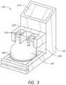
- FIG. 1is a schematic of a respiratory assistance system
- FIGS. 2-3are perspective views of a humidification apparatus according to an embodiment of the present disclosure.
- FIG. 4is a perspective view of a humidification chamber according to an embodiment of the present disclosure.
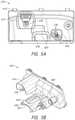
- FIG. 5Ais a front perspective view of a structure according to an embodiment of the present disclosure.
- FIG. 5Bis an isometric view of a structure according to the embodiment of FIG. 5A .
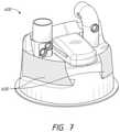
- FIG. 6is a perspective view of a structure according an embodiment of the present disclosure.
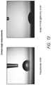
- FIGS. 7-9are perspective views of different embodiments of a humidification chamber.
- FIG. 10illustrates an embodiment of a humidification chamber with a cooling structure.
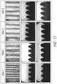
- FIG. 11illustrates embodiments of cooling structures having different design parameters.
- FIG. 12illustrates the design parameters of the cooling structures shown in FIG. 10 .
- FIG. 13shows contact angle measurements for two different materials that can be used to make the cooling structures.
- FIG. 14illustrates capillary height measurements for the cooling structures of FIG. 10 .
- FIG. 15shows example results corresponding to the change in relative humidity from adding cooling structures to the humidification chamber.
- FIG. 16illustrates an embodiment of a base structure that can be used with the humidification chamber.
- FIG. 17illustrates a top view of the base structure of FIG. 16 .
- FIG. 1discloses a respiratory assistance system 100 that includes a gases source 110 .
- the gases source 110utilises a gases supply tube 120 to supply respiratory gases to a humidification apparatus 130 .
- the gases source 110 and the humidification apparatus 130are within the same housing.
- the gases source 110 and the humidification apparatus 130are in different housings.
- the humidification apparatus 130includes a base unit 135 and a humidification chamber 140 .
- the humidification chamber 140can be mounted on the base unit 135 .
- the humidification chamber 140can hold a volume of liquid, for example, water.
- the humidification chamber 140further includes an inlet port 142 and an outlet port 144 .
- Respiratory gasesare humidified as they pass through the humidification chamber 140 via the outlet port 144 and into an inspiratory tube 150 where they are transported to a patient interface 160 .
- an expiratory tube 170transports exhaled gases away from a patient.
- the base unit 135includes a heater plate 240 .
- a controller 132 of the humidification apparatus 130determines the amount of power to supply to the heater plate 240 to heat the humidification chamber 140 when the humidification chamber 140 is mounted on the base unit 135 so that the respiratory gases include a predetermined characteristic at the outlet port 144 as measured by a sensor (not shown in FIG. 1 ) at or near the outlet port 144 . Therefore, the humidification apparatus 130 acts to heat and humidify the respiratory gases so that they are substantially saturated and include a predetermined characteristic.
- a controller 128 of the gases source 110may communicate with the controller 132 as part of the operations of the controller 132 herein described. In some embodiments, the controller 128 may execute part or all of the operations of the controller 132 herein described.
- the predetermined characteristicis a gases temperature. In some embodiments, the predetermined characteristic may be a relative humidity, an absolute humidity, or a flow rate of gases.
- the temperature of the respiratory gases at the inlet port 142is typically less than a temperature of the respiratory gases at the outlet port 144 .
- a temperature differentialexists between the inlet port 142 and the outlet port 144 .
- This, in effect,is a temperature differential that exists between the incoming gases and the outgoing gases, respectively.
- the controller 132determines how much power to supply to the heater plate 240 to bring the temperature of the respiratory gases to a value similar to the predetermined temperature at the outlet port 144 . As the heater plate 240 heats the respiratory gases to the predetermined temperature, the respiratory gases can be humidified during the process of heating.
- the temperature of the respiratory gases at or near the outlet port 144may already be at or close to the predetermined temperature. This may be due to a high ambient temperature, gases supplied from the gases source 110 to the humidification apparatus 130 at a higher temperature, heating effects from within the humidification apparatus 130 , or heating effects from within the gases source 110 . As a result, the controller 132 determines that less heating is necessary to heat the respiratory gases to the predetermined temperature and supplies less power to the heater plate 240 . Thus, although the respiratory gases leaving the humidification chamber 140 are substantially similar to the predetermined temperature, less humidity is added to the respiratory gases.
- the humidification apparatus 130includes mechanisms to facilitate heat loss from the humidification chamber 140 to allow a greater temperature differential between the inlet port 142 and the outlet port 144 .
- a greater temperature differentialcauses more power to be supplied to the heater plate 240 to heat the respiratory gases. This allows more humidity to be added to the respiratory gases.
- a structure 220includes mechanisms to promote heat loss.
- the humidification chamber 140includes mechanisms to improve heat loss. The mechanism may correspond to a shape, design, or an insert.
- FIGS. 2-3illustrate an embodiment of the humidification apparatus 130 that includes the base unit 135 , a display 210 , the structure 220 , the humidification chamber 140 , and the heater plate 240 .
- the structure 220includes sensors 230 .
- the sensors 230are permanently mounted onto the structure 220 .
- the sensors 230may be removably coupled to the structure 220 .
- the sensors 230may be positioned to protrude into the inlet port 142 and/or the outlet port 144 when the humidification chamber 140 is mounted on the base unit 135 .
- two of the sensors 230are positioned to measure at least one characteristic of the gases flow at the inlet port 142 , and one of the sensors 230 is positioned to measure at least one characteristic of the gases flow at the outlet port 144 .
- one of the sensors 230is positioned to measure at least one characteristic of the gases flow at the inlet port 142
- two of the sensors 230are positioned to measure at least one characteristic of the gases flow at the outlet port 144 , when the humidification chamber 140 is mounted on the base unit 135 .
- two of the sensors 230are positioned to measure at least one characteristic of the gases flow at the inlet port 142 , while one sensor is positioned at the outlet port 144 .
- the sensors 230can also be arranged in other configurations with different combinations at the inlet port 142 and the outlet port 144 .
- the structure 220can also include more than 3 sensors or less than 3 sensors.
- the sensors 230are mounted in planes parallel or substantially parallel with respect to each other. Further, the sensors 230 can be oriented in the same direction with respect to each other. In the illustrated embodiment in FIG. 2 , the sensors 230 are situated parallel to the x-y plane and extend along the x-axis. In some embodiments, the placement of the sensors 230 advantageously enables for the humidification chamber 240 to slide into the humidification apparatus 130 with respect to the structure 220 (as shown in FIG. 3 ). Moreover, as seen in FIG. 2 , the sensors 230 are all placed perpendicular to a vertical plane. Two of the sensors 230 are positioned in a different but substantially parallel horizontal planes.
- one of these sensorsmay measure characteristic of a gas at a different point in time as the gas flows through the humidification chamber 140 because of the difference in location. That is, a first sensor is positioned such that the gas passes over it shortly before the gas passes over the second sensor.
- two of the sensors 230may be mounted in the same horizontal plane or substantially the same horizontal plane so that the sensors 230 can measure characteristic of the gas flow at the same time. In some embodiments, if the sensors are measuring different characteristics, it may be advantageous to have them measure the characteristics at the same point in time of gas flow for the purposes of comparison.
- FIG. 3illustrates the humidification chamber 140 attached to the base 135 .
- some of the portions of the humidification chamber 140are occluded or covered by the base 135 , particular the top portions of the humidification chamber 140 .
- the covered portionsmay act as an insulator for the humidification chamber 140 and trap heat inside the humidification chamber 140 .
- the base 135 as illustrated hereinis designed to increase exposure of the surface area of the humidification chamber 140 to external environment. For example, in the embodiments illustrated, about 45% to about 50% of the chamber is exposed as viewed from the top.
- the chamberis exposed as viewed from the top.
- the base 135 and the humidification chamber 140can also be designed to expose more than 50%, such as 60% or 70% of the chamber.
- the percentagecan be calculated by measuring the entire surface area of the humidification chamber 140 and dividing the exposed surface area by the entire surface area.
- the sensors 230each may measure one of temperature, flow rate, or humidity. In some embodiments, the sensors 230 may measure a combination of any one of temperature, flow rate, and humidity. In some embodiments, two of the sensors 230 may be used in combination to derive a characteristic of the gases flow; for example, two of the sensors 230 may be positioned to measure gases temperature at the inlet port 142 , and the controller 132 may use the two measurements to derive a flow rate of the gases. In some embodiments, one of the sensors 230 may be positioned downstream of the humidification apparatus 130 , for example, near the patient interface 160 . In some embodiments, one of the sensors 230 may be positioned at the heater plate 240 .
- Heating of the heater plate 240is controlled by the controller 132 .
- the controller 132determines the amount of power required to provide sufficient heat to the liquid within the humidification chamber 140 .
- the surface of the heater plate 240is in contact with a thermally conductive surface of the humidification chamber 140 . This provides a thermally conductive pathway to enable the transfer of heat from the heater plate 240 to the liquid within the humidification chamber 140 .
- the structure 220is removably coupled to the base unit 135 .
- the structure 220may be permanently coupled to the base unit 135 .
- the structure 220may be integrally formed with the base unit 135 .
- the structure 220can form a support structure for the sensors 230 .
- the structure 220includes features that aid with alignment and orientation of the humidification chamber 140 relative to the base unit 135 and/or the sensors 230 , which will be discussed in further detail below, and as described in the embodiments disclosed in U.S. Provisional Patent Application No. 62/059,339 and International Application No. PCT/NZ2014/000201, the contents of which are hereby incorporated by reference in their entirety.
- the structure 220is coupled to or integral with a portion of the base unit 135 that is positioned above the heater plate 240 . This positions electronic components within the base unit 135 and electronic components within the structure 220 above likely leak points of the humidification chamber 140 when the humidification chamber 140 is mounted on the base unit 135 in contact with the heater plate 240 .
- the display 210is positioned on an upper surface of the base unit 135 above the structure 220 . This increases visibility of the display 210 in use.
- the humidification chamber 140is mounted within a recess 250 formed by the base unit 135 .
- the structure 220at least partially encloses the humidification chamber 140 within the recess 250 .
- the orientation and placement of the sensors 230can enable the humidification chamber 140 to be mounted within the recess 250 .
- FIG. 4illustrates the humidification chamber 140 in more detail.
- the humidification chamber 140includes a nose 310 and apertures 330 .
- the nose 310mates with a corresponding hood 420 (as shown in FIGS. 5A-5B ).
- the nose 310aids alignment between the humidification chamber 140 and the structure 220 .
- the nose 310includes rails 320 , which mate with corresponding grooves 430 in the structure 220 (as shown in FIGS. 5A-5B ).
- the rails 320also aid alignment between the humidification chamber 140 and the structure 220 .
- the nose 310does not include the rails 320 and the structure 220 does not include the grooves 430 .
- the tongue 312 of the nose 310is tapered.
- the tapered tongue 312can advantageously prevent the humidification chamber 140 from rocking with respect to the hood 420 . Rocking may result in disconnection of sensors 230 .
- the apertures 330can receive the sensors 230 that are positioned on the structure 220 (refer to FIGS. 5A-5B ). Thus, when the humidification chamber 140 is mounted on the base unit 135 , the sensors 230 protrude into the apertures 330 of the humidification chamber 140 . The sensors 230 measure a characteristic of the gases flow in the humidification chamber 140 through the apertures 330 .
- the apertures 330are positioned at or near the inlet port 142 and/or the outlet port 144 of the humidification chamber 140 .
- the apertures 330each further include a seal or barrier (not shown) to maintain a sealed pathway for the gases flow. The seal can be an o-ring.
- the apertures 330can include a grommet or an elastic glove that can protect the sensors 230 as they are inserted into the apertures 330 .
- two of the apertures 330are positioned near the inlet port 142 and one of the apertures 330 is positioned near the outlet port 144 .
- one of the apertures 330is positioned near the inlet port 142 and two of the apertures 330 are positioned near the outlet port 144 .
- variations or different combinations of the apertures 330may be positioned at or near each port. For example, multiple of the apertures 330 may be positioned at both the inlet port 142 and the outlet port 144 .
- the sensors 230are oriented in the same direction and positioned in same or parallel planes. Accordingly, the apertures 330 may also be positioned on the humidification chamber 140 such that they align with their respective sensors 230 . In some embodiments, the apertures 330 face the same or substantially the same direction as illustrated in FIG. 4 .
- the sensors 230align with the apertures 330 and positioned to measure the characteristics of gas flow at particular locations near the inlet port 142 and the outlet port 144 .
- the sensorsare all positioned within the chamber in a single connection step by a user such that the user does not need to separately position the sensors in the chamber as is required by prior art devices.
- the outlet port 144( FIG. 4 ) includes a vertical portion 144 b and a horizontal portion 144 a connected by a curved portion 144 c . While the illustrated embodiment shows an L-shape or a right angle, the angle between horizontal portion 144 a and the vertical portion 144 b can be greater than 90 degrees. Higher angles may make the transition from the vertical portion 144 b to the horizontal portion 144 a smoother and as a result may decrease turbulence in the air moving from the vertical portion 144 b to the horizontal portion 144 a .
- the horizontal portion 144 amay advantageously enable a user to connect a conduit with the humidification chamber 140 either before the humidification chamber 140 is attached to the base 135 or after the attachment with the base 135 .
- the inlet port 142can also include a vertical portion, a horizontal portion, and a curved portion as discussed above with respect to the outlet port.
- FIGS. 5A-5Billustrate different views of an embodiment of the structure 220 .
- the structure 220includes a shroud 410 , the hood 420 , the sensors 230 , and a post 440 .
- the shroud 410can receive a connector, for example, a connector configured to connect the inspiratory tube 150 to the humidification apparatus 130 .
- the connectoris configured to form an electrical connection between the inspiratory tube 150 and the humidification apparatus 130 .
- the connectoris configured to form an electrical connection with the structure 220
- the structure 220is configured to form an electrical connection with the base unit 135 .
- the structure 220includes electrical contacts 415 within the shroud 410 , as shown in more detail in FIG.
- the shroud 410helps to align the connector of the inspiratory tube 150 with the structure 220 .
- the shroud 410facilitates pneumatic coupling between the inspiratory tube 150 and the outlet port 144 of the humidification chamber 140 .
- the structure 220includes one of the sensors 230 within the shroud 410 .
- the shroud 410protects the electrical contacts 415 from spills or other environmental conditions.
- the hood 420can accommodate the nose 310 of the humidification chamber 140 .
- the hood 420includes grooves 430 to mate with the optional rails 320 that protrude from the nose 310 of the humidification chamber 140 .
- the hood 420can include an optional opening 425 .
- the opening 425allows heat energy from the humidification chamber 140 to dissipate to the surrounding ambient environment.
- the opening 425reduces the mechanical contact between the humidification chamber 140 and the structure 220 . This improves cooling of the humidification chamber 140 as it is further isolated from the structure 220 .
- the post 440includes two of the sensors 230 .
- the post 440provides a platform that facilitates coupling of the two of the sensors 230 with two of the apertures 330 that are associated with the inlet port 142 of the humidification chamber 140 .
- the post 440enables the two of the sensors 230 to protrude into the two of the apertures 330 of the inlet port 142 . This enables the two of the sensors 230 to more accurately determine a characteristic of the gases flow.
- the controller 132adjusts the power supplied to the heater plate 240 for adding energy into the respiratory assistance system 100 .
- the added energy from the heater plate 240can evaporate liquid in the humidification chamber 140 .
- the evaporated liquidcan add humidity to the respiratory gases.
- the controller 132can continue to supply power to the heater plate 240 until a characteristic of the respiratory gases at the outlet port 144 reaches a predetermined output condition, or a set point.
- the characteristic of the respiratory gases at the outlet port 144can be measured by the sensors 230 (discussed above) at the outlet port 144 .
- the characteristic of the respiratory gasescan be measured at other locations in the respiratory assistance system 100 .
- the characteristic of the respiratory gasescan be measured at the patient interface 160 .
- characteristics of respiratory gasescan include humidity, temperature, and flow rate.
- the respiratory assistance system 100does not include a humidity sensor to directly measure humidity conditions of the respiratory gases.
- the controller 132can control the heater plate 240 to deliver a target humidity condition using temperature and/or flow rate measurements provided by the sensors 230 to estimate humidity conditions of the respiratory gases delivered by the humidification apparatus 130 and to use such estimated humidity conditions to control the heater plate 240 to generate humidity.
- Some conditions of the gases supplied to the humidification apparatus 130 by the gases source 110may compromise the ability of the humidification apparatus 130 to add sufficient humidity.
- the controller 132relying on estimated humidity conditions based on temperature measurements to control the heater plate 240 may result in compromised humidity generation.
- the gases source 110is drawing in ambient gases to supply to the humidification apparatus 130
- the characteristics of the gases drawn in by the gases source 110can fluctuate depending on ambient conditions. In a desert environment, the ambient air may have high temperature and low humidity.
- the controller 132may initially provide power to the heater plate 240 to add heat to the liquid in the humidification chamber 140 to evaporate liquid and add humidity to the gases; however, when the incoming gases are already at a high temperature, the controller 132 may stop providing power to the heater plate 240 before sufficient humidity or vapor has been added to the respiratory gases.
- the controller 132may provide power to the heater plate 240 until the respiratory gases reaches 37 degrees at the outlet port 144 .
- the heater plate 240may not need to add much heat for the respiratory gases to reach the set point temperature. The amount of heat needed may not be enough. In particular, if the incoming ambient gas is dry, the gases delivered at the patient interface 160 may not have sufficient humidity for patient comfort.
- humidity additionmay further be compromised because of the flow rate of the gases and the design constraints of the respiratory assistance system 100 .
- a high flow therapymay be required. Accordingly, there may be even less time to add humidity to the gases because of the higher flow.
- the humidification chamber 140can be modified as described below to improve heat transfer and/or increase surface area between the liquid and the flowing respiratory gases.
- the structure 220at least partially encloses the humidification chamber 140 when it is mounted on the base unit 135 .
- features on the structure 220facilitate coupling of the humidification chamber 140 with the sensors 230 to provide more accurate determinations of characteristics of the gases flow.
- the features on the structure 220also aid with alignment and orientation of the humidification chamber 140 with respect to the base unit 135 or the sensors 230 .
- the humidification chamber 140 being partially enclosedfacilitates greater heat loss between the humidification chamber 140 and the surrounding ambient environment.
- FIG. 6illustrates an embodiment wherein a structure 500 includes an active cooling mechanism 540 to facilitate heat loss from the humidification apparatus 130 to the surrounding ambient environment.
- the active cooling mechanism 540moves air onto and around the humidification chamber 140 . This encourages heat loss from the humidification chamber 140 to the surrounding ambient environment.
- the active cooling mechanism 540includes a fan.
- the active cooling mechanism 540may include a blower.
- the structure 500includes an air inlet to allow the active cooling mechanism 540 to draw air into the structure 500 from the surrounding ambient environment.
- the structure 500includes an air outlet to allow the active cooling mechanism 540 to expel air from the structure 500 out to the surrounding ambient environment.
- the active cooling mechanism 540may aid heat loss in the structure 500 .
- the structure 500 including the active cooling mechanism 540provides an increased enclosure effect on the humidification chamber 140 relative to the structure 220 illustrated in FIGS. 5A-5B .
- a hood 520does not include an opening such as the opening 425 of the hood 420 to encourage further heat loss.
- the body of the structure 500extends such that it interacts more fully with the humidification chamber 140 .
- the active cooling mechanism 540may be combined with the structure 220 in FIGS. 5A-5B to further enhance heat loss.
- the structure 220 or the structure 500may include a thermally insulating material to slow the spread of heat therein. In some embodiments, the thermally insulating material may be combined with the active cooling mechanism 540 .
- FIG. 7is an example of a humidification chamber 600 including a passive cooling mechanism 650 .
- the passive cooling mechanism 650may be any mechanism that passively encourages heat transfer to occur between the humidification chamber 600 and the surrounding ambient environment, for example, a heat sink including fins or pins.
- the passive cooling mechanism 650acts to increase the surface area of the humidification chamber 600 that can be utilised for heat loss.
- the passive cooling mechanism 650may be permanently coupled to the humidification chamber 600 . Permanent coupling of the passive cooling mechanism 650 could be using a snap-fit mechanism, clipping, adhesives or welding mechanisms. In some embodiments, the passive cooling mechanism 650 may be an integral part of the humidification chamber 600 . In some embodiments, the passive cooling mechanism 650 may be removably coupled to the humidification chamber 600 . Removable coupling of the passive cooling mechanism 650 allows the humidification chamber 600 to couple with different structures, for example, the structure 220 or the structure 500 .
- the passive cooling mechanism 650includes a fin. In some embodiments, the passive cooling mechanism 650 may include multiple fins. The fin 650 protrudes from the humidification chamber 600 such that the alignment and orientation features of the humidification chamber 600 are still able to facilitate coupling between the humidification chamber 600 and the structure 220 .
- the fin 650may comprise the same material as the humidification chamber 600 .
- the fin 650may include a more thermally conductive material to further promote heat loss from the humidification chamber 600 .
- the geometry of the fin 650may depend on the geometry of the structure 220 to which the humidification chamber 600 is to be coupled. For example, In some embodiments, the fin 650 may extend substantially vertically towards the ports of the humidification chamber 600 . In some embodiments, the fin 650 may extend substantially horizontally from the humidification chamber 600 . A combination of the above geometries may also be used.
- FIG. 8illustrates an embodiment that includes a wall 750 of a humidification chamber 700 that has been enlarged.
- the wall 750includes at least a portion that bulges out between a base 760 and an upper surface 770 of the humidification chamber 700 .
- Thisincreases the surface area of the humidification chamber 700 , without substantially increasing its footprint. Thus, a greater amount of humidity is transferred to the respiratory gases.
- the humidification chamber 700is mountable on the base unit 135 with minimal or no changes required to the base unit 135 .
- the humidification chamber 700may include different geometries that increase the surface area. Increasing the surface area increases the area of contact between the liquid and the respiratory gases, which promotes more efficient humidification of respiratory gases.
- the size of the humidification chamber 700may be increased, or the shape of the humidification chamber 700 may be optimised to produce an optimal surface area between the liquid and the respiratory gases.
- the interior of the wall 750may include microstructures as disclosed in International Application No. PCT/NZ2013/000113, the contents of which are hereby incorporated by reference in their entirety.
- FIG. 9illustrates an embodiment wherein a humidification chamber 800 includes regions 850 that facilitate improved heat loss.
- the regions 850include a material that has a higher thermal conductivity than the material of the humidification chamber 800 .
- two regions 850are utilised.
- a single region 850 or multiple regions 850can be used to encourage heat loss from the humidification chamber 800 to the surrounding ambient environment.
- the materialmay be metal, for example, copper.
- the regions 850facilitate greater heat loss through a wall 860 of the humidification chamber 800 . This enables heat loss to occur without altering the geometry of the humidification chamber 800 .
- the regions 850are permanently coupled to the humidification chamber 800 .
- the regions 850may be integral to the humidification chamber 800 .
- the entirety of the humidification chamber 800 or the wall 860 of the humidification chamber 800may be made from thermally conductive material.
- the humidification chamber 140may include a cooling structure 1050 as shown in FIG. 10 .
- the cooling structure 1050can be located inside the humidification chamber 140 .
- the cooling structure 1050may be a separate component that can be removably inserted in the humidification chamber 140 .
- the cooling structure 1050may be secured using a fastener or designed to fit around the shape of the humidification chamber 140 .
- the cooling structure 1050is secured against the side walls 1060 of the humidification chamber 1000 .
- the cooling structure 1050may completely or partially cover the sidewalls 1060 .
- the cooling structure 1050is placed near the inlet port 142 . In some embodiments, placing the cooling structure 1050 near the inlet port 142 may result in increased humidity generation because of a higher temperature gradient.
- the cooling structure 1050may include channels as shown in FIG. 11 .
- the cooling structure 1050may also include microstructures as described in International Application No. PCT/NZ2013/000113.
- the channelsmay run parallel to the x axis or the y-axis or any angle between the x and y axes.
- the channelsmay be straight or curved.
- the channelscan be in the shape of spirals.
- the channelscan reduce gas temperature because of the increase in evaporative cooling.
- the channelscan also increase surface area of the interaction between liquid and respiratory gases.
- the channels located along the side wall of the humidification chamber 140can collect liquid through capillary forces which evaporates directly from the side walls.
- adding the channelscan increase the humidity output by at least 7 mg/L.
- FIG. 10illustrates a portion of the channels discussed above.
- Each zonehas different design parameters as illustrated in FIGS. 11 and 12 .
- Modifying the design parameterscan change the wetting angle of the surface of the cooling structure 1050 .
- the wetting anglecan determine capillary height and also surface forces.
- the channelsare designed to maximize the wetting angle. Increased wetting can increase capillary height.
- the channelscan also be designed to stop or start capillary filling under certain conditions, such as, at a particular location, or temperature, temperature gradient, or humidity levels.
- the design of channelscan provide controlled evaporative cooling according to predetermined parameters. Accordingly, the channel parameters may affect evaporation in the humidification chamber 140 .
- the channel parametersare selected to maximize evaporation.
- the L f parameteris the same as L ⁇ in FIG. 14 .
- the sidewalls 1060may also include heating elements on either the interior or exterior of the humidification chamber 140 .
- the cooling structure 1050may also include heating elements.
- the heating elements of the sidewallcan increase evaporative rate of the liquid adhering to the cooling structure 1050 .
- the heater plate 240can be designed to directly heat the chamber walls.
- the back of the heater plate 240can be arranged to directly contact the chamber walls and heat the chamber walls directly.
- the heater plate 240can also have a diameter larger than the cooling structure 1050 .
- the cooling structure 1050is manufactured using injection moulding.
- the materialscan be polycarbonate, Arnitel VT3108, PP+Techsurf or any other thermoplastics.
- the materialscan also affect contact angle or the wetting of the liquid on the cooling structure 1050 as shown in FIG. 13 .
- the contact angle for watercan be higher than a material like Arnitel.
- the contact anglecan determine wettability of the material. In some embodiments, higher wettability may be desired to increase capillary height.
- FIG. 14illustrates example calculations of capillary heights as a function of design parameters and materials of the cooling structure 1050 shown in FIG. 11 .
- Larger capillary heightcan indicate that a column of liquid will rise higher along the channels of the cooling structure 1050 .
- the surface area of the liquid available for evaporative coolingcan also increase.
- evaporative coolingcan decrease temperature of the respiratory gases in the humidification chamber.
- cis the wetted x-sectional length of the channel
- Ais the cross-sectional area
- ⁇liquid/vapour surface tension
- ⁇liquid density
- ⁇inclination of channel (which is 90 deg if vertical)
- ggravity constant.
- FIG. 15illustrates results from one of the embodiments described above with the cooling structure 1050 having channels attached to sidewalls near the inlet port 142 and the outlet port 144 .
- the figureshows that the cooling structure 1050 including channels placed inside the humidification chamber 140 can increase the relative humidity added to the respiratory gases.
- FIG. 16illustrates an embodiment of the humidification chamber 140 with a base structure 1602 placed on the base of the humidification chamber 140 .
- the base structure 1602can be integral of the base of the chamber.
- the base structure 1602can also be removably inserted in the humidification chamber 140 .
- the base structure 1602can cover some or the entire portion of the base of the humidification chamber 140 .
- the base structure 1602lies above the heater plate 240 .
- the base structure 1602can be designed to hold a thin layer of liquid.
- An embodiment of the base structure 1602is shown in FIG. 17 .
- a thin layer of liquidmay evaporate faster than a larger volume of liquid.
- the thin layer of liquidcan be continuously maintained using a source (not shown).
- the base structure 1602can include channels as discussed above as shown in FIG. 17 .
- Liquidcan be fed from a source and directed towards the channels.
- the design of the channelscan increase evaporation.
- the height of the channel or any other dimensionmay vary along the length of the channel to account for variations in the base temperature or gas conditions to prevent thin-film break-up (dry out) and maintain high evaporation rates.
- the wall tiltis adjusted to maximize fluid recirculation (thus temperature homogenization) via surface tension (Marangoni) driven convection.
- the controller 132can automatically adjust the set point based on detecting the temperature of the respiratory gases at the inlet port 142 .
- the controller 132can also track humidity and/or flow rate of the respiratory gases at the inlet port 142 .
- the controller 132can receive a humidity indication based on a user input.
- the controller 132can receive humidity measurements from a humidity sensor.
- the controller 132can measure a difference between the inlet gas temperature and the set point. If the temperature difference is small, the controller 132 can automatically increase the set point temperature. This can enable the heater plate 240 to run longer and add sufficient humidity to the respiratory gases. In some instances, if the controller 132 determines that the humidity in the gases at the inlet port 142 is not that different from the set point humidity, the controller 132 may not change the temperature set point. The controller 132 can also determine the set point based on the flow rate. For a high flow rate, the controller 132 may increase the temperature set point to increase humidity generation.
- the disclosed apparatus and systemsmay also be said broadly to consist in the parts, elements and features referred to or indicated in the specification of the application, individually or collectively, in any or all combinations of two or more of said parts, elements or features.
Landscapes
- Health & Medical Sciences (AREA)
- Emergency Medicine (AREA)
- Pulmonology (AREA)
- Engineering & Computer Science (AREA)
- Anesthesiology (AREA)
- Biomedical Technology (AREA)
- Heart & Thoracic Surgery (AREA)
- Hematology (AREA)
- Life Sciences & Earth Sciences (AREA)
- Animal Behavior & Ethology (AREA)
- General Health & Medical Sciences (AREA)
- Public Health (AREA)
- Veterinary Medicine (AREA)
- Air Humidification (AREA)
Abstract
Description
Claims (13)
Priority Applications (1)
| Application Number | Priority Date | Filing Date | Title |
|---|---|---|---|
| US15/525,257US11278689B2 (en) | 2014-11-17 | 2015-11-17 | Humidification of respiratory gases |
Applications Claiming Priority (3)
| Application Number | Priority Date | Filing Date | Title |
|---|---|---|---|
| US201462080814P | 2014-11-17 | 2014-11-17 | |
| US15/525,257US11278689B2 (en) | 2014-11-17 | 2015-11-17 | Humidification of respiratory gases |
| PCT/NZ2015/050193WO2016080847A1 (en) | 2014-11-17 | 2015-11-17 | Humidification of respiratory gases |
Related Parent Applications (1)
| Application Number | Title | Priority Date | Filing Date |
|---|---|---|---|
| PCT/NZ2015/050193A-371-Of-InternationalWO2016080847A1 (en) | 2014-11-17 | 2015-11-17 | Humidification of respiratory gases |
Related Child Applications (1)
| Application Number | Title | Priority Date | Filing Date |
|---|---|---|---|
| US17/652,734ContinuationUS20220249788A1 (en) | 2014-11-17 | 2022-02-28 | Humidification of respiratory gases |
Publications (2)
| Publication Number | Publication Date |
|---|---|
| US20180280644A1 US20180280644A1 (en) | 2018-10-04 |
| US11278689B2true US11278689B2 (en) | 2022-03-22 |
Family
ID=56014263
Family Applications (2)
| Application Number | Title | Priority Date | Filing Date |
|---|---|---|---|
| US15/525,257Active2037-03-18US11278689B2 (en) | 2014-11-17 | 2015-11-17 | Humidification of respiratory gases |
| US17/652,734PendingUS20220249788A1 (en) | 2014-11-17 | 2022-02-28 | Humidification of respiratory gases |
Family Applications After (1)
| Application Number | Title | Priority Date | Filing Date |
|---|---|---|---|
| US17/652,734PendingUS20220249788A1 (en) | 2014-11-17 | 2022-02-28 | Humidification of respiratory gases |
Country Status (3)
| Country | Link |
|---|---|
| US (2) | US11278689B2 (en) |
| EP (2) | EP3925654B1 (en) |
| WO (1) | WO2016080847A1 (en) |
Cited By (1)
| Publication number | Priority date | Publication date | Assignee | Title |
|---|---|---|---|---|
| US20210093825A1 (en)* | 2019-09-27 | 2021-04-01 | Apex Medical Corp. | Respiratory system |
Families Citing this family (5)
| Publication number | Priority date | Publication date | Assignee | Title |
|---|---|---|---|---|
| EP3405245A4 (en)* | 2016-01-18 | 2019-09-11 | Fisher&Paykel Healthcare Limited | HUMIDIFICATION OF RESPIRATORY GASES |
| EP4378509A3 (en) | 2016-07-21 | 2024-07-31 | Fisher & Paykel Healthcare Limited | Medical tubes for breathing circuit |
| WO2019121749A1 (en)* | 2017-12-19 | 2019-06-27 | Koninklijke Philips N.V. | Ventilation system with cold passover humidification control |
| CN109172974A (en)* | 2018-08-20 | 2019-01-11 | 赵鑫飚 | Gynecological multifunctional therapeutic device |
| US12390615B2 (en)* | 2019-03-11 | 2025-08-19 | Fisher & Paykel Healthcare Limited | Systems and methods for controlling humidity output in a humidifier |
Citations (360)
| Publication number | Priority date | Publication date | Assignee | Title |
|---|---|---|---|---|
| US1154259A (en) | 1913-03-17 | 1915-09-21 | Claus H Light | Hose-coupling. |
| US2634311A (en) | 1950-01-31 | 1953-04-07 | Ralph E Darling | Composite fluid and electrical connector |
| US2745074A (en) | 1951-01-11 | 1956-05-08 | Ralph E Darling | Electrically equipped oxygen hose |
| US3163707A (en) | 1962-12-27 | 1964-12-29 | Ralph E Darling | Non-stretch flexible tube with conductors therein |
| US3283580A (en) | 1963-09-24 | 1966-11-08 | Nanmac Corp | Fast response right angle thermocouple |
| US3394954A (en) | 1966-05-06 | 1968-07-30 | Sarns Inc | Tube coupling for medical appliances |
| US3485237A (en) | 1967-03-20 | 1969-12-23 | Rca Corp | Self-propelling hose |
| US3582094A (en) | 1970-02-16 | 1971-06-01 | Greene Tweed & Co Inc | Sealing assembly |
| US3588859A (en) | 1969-04-21 | 1971-06-28 | Frank Petree | Level detector |
| US3638926A (en) | 1967-09-27 | 1972-02-01 | Alfred W Melville | Humidification |
| US3659604A (en) | 1970-03-30 | 1972-05-02 | Fisher & Paykel | Humidifying means |
| US3703892A (en) | 1970-12-09 | 1972-11-28 | Edward F Meyers | Disposable, retractable thermometer jacket |
| GB1310949A (en) | 1969-07-01 | 1973-03-21 | Hirtz H | Device for treating the respiratory passages with warm air |
| US3777298A (en) | 1971-12-02 | 1973-12-04 | Empire Prod Inc | Electrical connector |
| GB1364127A (en) | 1972-12-11 | 1974-08-21 | Cape Eng Co Ltd | Humidifier |
| US3903742A (en) | 1974-02-06 | 1975-09-09 | J Tec Ass Inc | Disposable respiratory parameter sensor |
| US3954920A (en) | 1973-09-04 | 1976-05-04 | Parkland International Inc. | Gas humidification system |
| US3987133A (en) | 1975-09-05 | 1976-10-19 | Fisher Scientific Company | Humidifier |
| US3990727A (en) | 1976-01-26 | 1976-11-09 | Stephen Franics Gallagher | Quick detachable coupler |
| US4028444A (en) | 1974-03-25 | 1977-06-07 | Chemetron Corporation | Humidifier and automatic control system therefor |
| US4038519A (en) | 1973-11-15 | 1977-07-26 | Rhone-Poulenc S.A. | Electrically heated flexible tube having temperature measuring probe |
| US4060576A (en) | 1972-09-13 | 1977-11-29 | Graham Cameron Grant | Method and apparatus for vapor saturated gas delivery |
| US4111197A (en) | 1976-03-05 | 1978-09-05 | Dragerwerk Aktiengesellschaft | Respiratory device coupling construction |
| US4139762A (en) | 1977-02-22 | 1979-02-13 | Pohrer Harry H | Humidifier |
| US4172709A (en) | 1976-03-23 | 1979-10-30 | Becton, Dickinson And Company | Bacteria filters with transparent housings |
| US4183248A (en) | 1978-08-08 | 1980-01-15 | Rwb Labs | Fast response electronic thermometer probe |
| US4269573A (en)* | 1979-07-30 | 1981-05-26 | Milton Roy Company | Pump drive mechanism for an evaporative cooler |
| US4333451A (en) | 1980-12-12 | 1982-06-08 | Paluch Bernard R | Positive pressure breathing apparatus with condensate removal |
| DE3110903A1 (en) | 1981-03-20 | 1982-09-30 | Hospital Engineering GmbH, 7204 Wurmlingen | Device for connecting supply lines for hospitals, especially operating theatres and intensive care units |
| US4473923A (en) | 1982-05-10 | 1984-10-02 | Dayco Corporation | Vacuum cleaning tool adapter with electrical control means |
| US4529867A (en) | 1984-02-09 | 1985-07-16 | Inspiron Corporation | Humidifier and heater |
| US4545290A (en) | 1983-12-23 | 1985-10-08 | Tol-O-Matic, Inc. | Pressure cylinder |
| US4564748A (en) | 1982-10-29 | 1986-01-14 | Respiratory Care, Inc. | Variable temperature heating control system for inhalation therapy apparatus |
| US4588425A (en) | 1983-11-08 | 1986-05-13 | Bunnell Life Systems, Inc. | Humidifier |
| US4621632A (en) | 1984-11-01 | 1986-11-11 | Bear Medical Systems, Inc. | Humidifier system |
| EP0201985A1 (en) | 1985-04-04 | 1986-11-20 | The BOC Group plc | Inhalation apparatus |
| GB2176313A (en) | 1985-06-07 | 1986-12-17 | Fraser Sweatman Ind Inc | Apparatus and method for controlling and monitoring mixing of two or more gases |
| US4676237A (en) | 1985-01-29 | 1987-06-30 | Boutade Worldwide Investments Nv | Inhaler device |
| US4708831A (en) | 1985-05-22 | 1987-11-24 | Fisher & Paykel Limited | Methods of and/or apparatus for humidifying gases |
| DE3618614A1 (en) | 1986-06-03 | 1987-12-10 | Draegerwerk Ag | Heat exchanger for moistened breathing air |
| US4774032A (en) | 1985-04-29 | 1988-09-27 | Penlon Limted | Vaporizers and wick assemblies therefor |
| EP0291921A2 (en) | 1987-05-19 | 1988-11-23 | Drägerwerk Aktiengesellschaft | Material exchange system, especially for wetting of gas |
| US4813280A (en) | 1987-04-01 | 1989-03-21 | The Dow Chemical Company | Thermal pulse flow meter with disposable cell |
| US4844512A (en) | 1987-07-06 | 1989-07-04 | Ems-Inventa Ag | Freely rotatable snap-fit connector for pipes |
| US4942877A (en) | 1986-09-05 | 1990-07-24 | Minolta Camera Kabushiki Kaisha | Device for measuring oxygen saturation degree in arterial blood |
| US4944310A (en) | 1981-04-24 | 1990-07-31 | Somed Pty. Ltd. | Device for treating snoring sickness |
| US4967744A (en) | 1988-11-03 | 1990-11-06 | Airoflex Medical, Inc. | Flexible breathing circuit |
| US5031612A (en) | 1990-04-24 | 1991-07-16 | Devilbiss Health Care, Inc. | System and method for delivering warm humidified air |
| JPH03194747A (en) | 1989-12-22 | 1991-08-26 | Kyocera Corp | Magnetic head for magnetic field modulating magneto-optical recording |
| US5058588A (en) | 1989-09-19 | 1991-10-22 | Hewlett-Packard Company | Oximeter and medical sensor therefor |
| US5060506A (en) | 1989-10-23 | 1991-10-29 | Douglas David W | Method and apparatus for monitoring the content of binary gas mixtures |
| DE4020522A1 (en) | 1990-06-28 | 1992-01-09 | Fresenius Ag | Medical equipment system with identification of one-time use articles - uses electrical resistors with values specifying types and sizes |
| US5117819A (en) | 1990-09-10 | 1992-06-02 | Healthdyne, Inc. | Nasal positive pressure device |
| DE4102223A1 (en) | 1991-01-23 | 1992-07-30 | Peter Dr Sc Techn Schaller | Patient hose heating for respirator - has heat exchanger heated by controlled heating element between breathing gas humidifier and inspiration hose |
| US5134996A (en) | 1991-01-09 | 1992-08-04 | Smiths Industries Medical Systems, Inc. | Inspiration and expiration indicator for a suction catheter |
| US5148801A (en) | 1990-03-23 | 1992-09-22 | University Of Victoria | Electronic heater-humidifier for hypothermia treatment |
| EP0535952A1 (en) | 1991-10-04 | 1993-04-07 | FISHER & PAYKEL LIMITED | Humidifier |
| US5213376A (en) | 1991-09-03 | 1993-05-25 | Itt Corporation | Squeeze-to-release quick connector |
| EP0567158A2 (en) | 1992-04-24 | 1993-10-27 | FISHER & PAYKEL LIMITED | Humidifier apparatus and/or gas distribution chambers and/or temperature probe |
| JPH0623051A (en) | 1992-07-06 | 1994-02-01 | Toransumedo Kk | Heating/humidifying apparatus |
| USRE34599E (en) | 1988-11-01 | 1994-05-03 | Diatek Incorporated | Disposable probe cover assembly for medical thermometer |
| US5357948A (en) | 1992-01-18 | 1994-10-25 | Heinz Eilentropp | Heatable respiratory hose |
| US5392770A (en) | 1993-06-29 | 1995-02-28 | Clawson; Burrell E. | Tubing circuit systems for humidified respiratory gas |
| US5454061A (en) | 1994-05-27 | 1995-09-26 | Steward Plastics, Inc. | Apparatus and method for making flexible tubing with helically wound heating conductor |
| US5483616A (en) | 1994-12-21 | 1996-01-09 | Duracraft Corporation | Humidifier tank with improved handle |
| US5537996A (en) | 1993-11-22 | 1996-07-23 | Fisher & Paykel Limited | Heated respiratory humidifier conduit |
| US5551883A (en) | 1993-11-17 | 1996-09-03 | The Whitaker Corporation | Electrical connector |
| WO1997018001A1 (en) | 1995-11-13 | 1997-05-22 | Fisher & Paykel Limited | Heated respiratory conduit |
| US5640951A (en) | 1994-03-15 | 1997-06-24 | Fisher & Paykel Limited | Humidifier conduit |
| US5660567A (en) | 1995-11-14 | 1997-08-26 | Nellcor Puritan Bennett Incorporated | Medical sensor connector with removable encoding device |
| US5720293A (en) | 1991-01-29 | 1998-02-24 | Baxter International Inc. | Diagnostic catheter with memory |
| DE19647548A1 (en) | 1996-11-16 | 1998-05-28 | Bgm Buerk Ges Fuer Vertrieb Un | Heating arrangement for medical breathing apparatus |
| US5778872A (en) | 1996-11-18 | 1998-07-14 | Medlis, Inc. | Artificial ventilation system and methods of controlling carbon dioxide rebreathing |
| EP0885623A2 (en) | 1997-06-17 | 1998-12-23 | FISHER & PAYKEL LIMITED | Respiratory humidification system |
| US5906201A (en) | 1994-12-01 | 1999-05-25 | Louis Gibeck AB | Heat and moisture exchanger |
| US5943473A (en) | 1997-05-29 | 1999-08-24 | Levine; Walter | Heated cartridge humidifier |
| JPH11248076A (en) | 1998-03-05 | 1999-09-14 | Fujii Gokin Seisakusho Co Ltd | Outlet for fluid |
| USD419522S (en) | 1997-06-19 | 2000-01-25 | Thomas & Betts International, Inc. | Four position two-piece battery block connector assembly |
| US6039696A (en) | 1997-10-31 | 2000-03-21 | Medcare Medical Group, Inc. | Method and apparatus for sensing humidity in a patient with an artificial airway |
| US6053482A (en) | 1997-01-31 | 2000-04-25 | Holmes Products Corp. | Humidifier including a water filtration device |
| WO2000029057A1 (en) | 1998-11-18 | 2000-05-25 | Stefanov, Alexander R. | Catheter |
| US6078729A (en) | 1997-10-21 | 2000-06-20 | National Environmental Products Ltd., Inc. | Foam, drain and fill control system for humidifier |
| US6090036A (en)* | 1997-09-09 | 2000-07-18 | Atom Medical Corporation | Humidifying Mechanism for Incubator |
| US6102037A (en) | 1998-02-28 | 2000-08-15 | Drager Medizintechnik Gmbh | Respiration humidifier |
| US6105970A (en) | 1997-09-09 | 2000-08-22 | Firma Carl Freudenberg | Seal arrangement |
| US6126610A (en) | 1997-11-03 | 2000-10-03 | Novametrix Medical Systems, Inc. | Pneumatic connector with encoding |
| US6138674A (en) | 1997-10-16 | 2000-10-31 | Datex-Ohmeda, Inc. | Active temperature and humidity compensator for anesthesia monitoring systems |
| US6196980B1 (en) | 1997-09-10 | 2001-03-06 | Radi Medical System Ab | Male connector with a continuous surface for a guide wire, and method therefor |
| US6201983B1 (en) | 1998-01-22 | 2001-03-13 | Siemens Aktiengesellschaft | Combined power and data transmission arrangement accommodating all electrical needs of a number of independently operable medical apparatuses in a medical workstation |
| JP2001095920A (en) | 1999-09-29 | 2001-04-10 | Fukuda Denshi Co Ltd | Home medical device and alarm display method for home medical device |
| US6226451B1 (en) | 2000-03-13 | 2001-05-01 | Raymond Electric Ltd. | Humidifier |
| WO2001032069A2 (en) | 1999-11-01 | 2001-05-10 | Respironics, Inc. | Apparatus for controlling a medical device |
| US20010017134A1 (en) | 2000-02-24 | 2001-08-30 | Siemens Elema Ab | Conduit for connecting a fluid transfer device to a patient |
| DE19958296C1 (en) | 1999-12-03 | 2001-09-20 | Map Gmbh | Heated breathing tube for patient has heating element formed by tube wall and consisting of layer of electrically conductive synthetic material, voltage supply line integrated into tube wall |
| US20010050080A1 (en) | 2000-03-21 | 2001-12-13 | Seakins Paul John | Breathing assistance apparatus |
| WO2001097894A1 (en) | 2000-06-19 | 2001-12-27 | Hoffrichter Gmbh | Method for humidifying respiratory air and air humidifier for a breathing device |
| US6360741B2 (en) | 1998-11-25 | 2002-03-26 | Respironics, Inc. | Pressure support system with a low leak alarm and method of using same |
| US6402207B1 (en) | 1997-06-09 | 2002-06-11 | Qd Enterprises, Llc | Safety indexed medical connectors |
| US20020100320A1 (en) | 2001-01-31 | 2002-08-01 | Smith Malcolm David | Respiratory humidification system |
| US6435180B1 (en)* | 1999-07-01 | 2002-08-20 | J&M Distributors Limited | Method and apparatus for delivering humidified air to a face mask |
| WO2002066106A1 (en) | 2001-02-16 | 2002-08-29 | Resmed Limited | Humidifier with structure to prevent backflow of liquid through the humidifier inlet |
| WO2002066107A1 (en) | 2001-02-16 | 2002-08-29 | Resmed Limited | Air pressure signal monitoring in apparatus for treating sleep disordered breathing |
| AU2002244571A1 (en) | 2001-03-15 | 2002-10-03 | Franc Gergek | Combined connector for fluid and electrical connection |
| US6467477B1 (en) | 1999-03-26 | 2002-10-22 | Respironics, Inc. | Breath-based control of a therapeutic treatment |
| US6508249B2 (en) | 2000-10-05 | 2003-01-21 | Vital Signs, Inc. | Connecting apparatus for placing fluid flow paths in fluid communication |
| US6511075B1 (en) | 1999-04-01 | 2003-01-28 | Dichtungstechnik G. Bruss Gmbh & Co. | Elastomer seal between a piston and a cylinder or a shaft on an automatic transmission |
| US6551143B2 (en) | 2000-10-20 | 2003-04-22 | Tyco Electronics, Amp, K.K. | Battery connector |
| US6554260B1 (en) | 1999-10-13 | 2003-04-29 | Resmed Limited | Humidifier for breathable gas apparatus |
| US6591061B2 (en) | 2000-10-03 | 2003-07-08 | Burton, Inc. | Humidifier |
| US6598604B1 (en) | 1998-12-23 | 2003-07-29 | Fisher & Paykel Limited | Fault protection system for a respiratory conduit heater element |
| US20030148664A1 (en) | 2002-02-06 | 2003-08-07 | Chih-Jen Cheng | Connection port structure of CF card |
| JP2003275312A (en) | 2002-03-25 | 2003-09-30 | Ngk Spark Plug Co Ltd | Oxygen concentration device |
| EP1352670A1 (en) | 2002-04-11 | 2003-10-15 | Armstrong Medical Limited | Coaxial breathing system |
| US20030200727A1 (en) | 2002-04-26 | 2003-10-30 | Becton, Dickinson And Company | Collection assembly |
| US6648669B1 (en) | 2002-07-17 | 2003-11-18 | Yazaki North America | Electrical connection with sequential disconnect |
| US20030236015A1 (en) | 2002-06-05 | 2003-12-25 | Edirisuriya Deshitha Airawana | Connector for breathing conduits |
| US6668828B1 (en) | 2000-10-16 | 2003-12-30 | Pulmonox Technologies Corporations | System and elements for managing therapeutic gas administration to a spontaneously breathing non-ventilated patient |
| US6685491B2 (en) | 2001-03-15 | 2004-02-03 | Frank Gergek | Combined connector for fluid and electrical connection |
| WO2004011072A1 (en) | 2002-07-31 | 2004-02-05 | Fisher & Paykel Healthcare Limited | Isolated temperature sensor for humidification system |
| CA2495451A1 (en) | 2002-08-30 | 2004-03-11 | Fisher & Paykel Healthcare Limited | Humidification system |
| US20040087213A1 (en) | 2002-08-16 | 2004-05-06 | Chi-Lei Kao | Plug used for connection with a usb receptacle |
| US20040149284A1 (en) | 2000-03-21 | 2004-08-05 | Fisher & Paykel Healthcare Limited | Humidified gases delivery apparatus |
| US20040221843A1 (en) | 2001-10-18 | 2004-11-11 | Martin Baecke | Evaporator, especially a respiratory humidifier, storage tank and casing therefor |
| US20040234254A1 (en)* | 2001-11-15 | 2004-11-25 | Czupich Ted W | Humidifier module |
| US20040239001A1 (en) | 2001-12-14 | 2004-12-02 | Edirisuriya Deshitha Airawana | Method of forming a respiratory conduit |
| US6827084B2 (en) | 2002-06-21 | 2004-12-07 | Lloyd Thomas Grubb, Jr. | Automatic gas blender |
| US20040244858A1 (en) | 2001-07-24 | 2004-12-09 | In-Seon Jeong | Spiral hose using polyethylene |
| WO2005011785A1 (en) | 2003-08-01 | 2005-02-10 | Fisher & Paykel Healthcare Limited | Device for supplying a respiratory gas with integrated humidifier |
| WO2005021076A2 (en) | 2003-08-28 | 2005-03-10 | E.M.E. (Electro Medical Equipment) Limited | Heater for ventilator conduit |
| CN1598510A (en) | 2004-08-31 | 2005-03-23 | 胡首信 | Centigrade thermometer and making method and temp. extracting method |
| US6874771B2 (en) | 2002-08-09 | 2005-04-05 | Kaz, Inc. | Humidifier with a heating disc |
| US6895803B2 (en) | 2000-10-20 | 2005-05-24 | Fisher & Paykel Healthcare Limited | Humidity sensor |
| WO2005050523A2 (en) | 2003-11-13 | 2005-06-02 | Draeger Medical Systems, Inc | A processing device and display system |
| DE202004006484U1 (en) | 2004-04-21 | 2005-09-08 | GRÜNDLER GmbH | Heatable hose for artificial respiration, respiratory therapies and the like incorporates a temperature sensor which permanently extends into the hose interior |
| US6943566B2 (en) | 2000-12-20 | 2005-09-13 | Abertax Research And Development Ltd. | Method and device for measuring levels |
| DE102004030747A1 (en) | 2004-06-25 | 2006-01-19 | Weinmann Geräte für Medizin GmbH + Co. KG | Air-oxygen breathing mixtures, for emergency respirators, are produced using supply of pressurized oxygen to suck atmospheric air through venturi nozzle eductor |
| US20060030191A1 (en) | 2004-06-30 | 2006-02-09 | Tuin Jacobus N | Connector for electronic components |
| EP1646910A2 (en) | 2003-07-17 | 2006-04-19 | Viasys Healthcare, Inc. | Nasal interface apparatus |
| US20060118113A1 (en) | 2002-11-01 | 2006-06-08 | Bremner Michael B E | System for sensing the delivery of gases to a patient |
| EP1669098A2 (en) | 1999-08-05 | 2006-06-14 | Map-Medizintechnologie GmbH | Device for supplying respiratory gas, humidifying device, respiratory gas tube, and connecting device therefor |
| US7063668B2 (en) | 2003-04-28 | 2006-06-20 | Maquet Critical Care Ab | Method and arrangement for acoustic determination of moisture content of a gas mixture |
| US7086422B2 (en) | 2000-02-18 | 2006-08-08 | Map Medizin-Technologie Gmbh | Respiratory gas hose system for supplying a respiratory gas |
| US7090541B1 (en) | 2005-05-27 | 2006-08-15 | Inventec Multimedia & Telecom Corporation | Slim USB electronic device |
| DE202005008156U1 (en) | 2005-05-21 | 2006-10-05 | GRÜNDLER GmbH | Disposable heated hose with integral temperature sensor for breathing/breathing therapy has hose heating, temperature sensor wires in common multi-wire connecting cable and/or common connecting element, is specified for one-time use |
| DE202005008152U1 (en) | 2005-05-21 | 2006-10-05 | GRÜNDLER GmbH | Condensation prevention device for active breathing gas humidification has breathing gas humidifier controller with adjustable element for regulating heating unit for heating exhaling valve/sensing arrangement |
| US7120354B2 (en) | 2000-03-21 | 2006-10-10 | Fisher & Paykel Healthcare Limited | Gases delivery conduit |
| US20060237012A1 (en) | 2000-03-21 | 2006-10-26 | Mohammad Thudor | Apparatus for Delivering Humidified Gases |
| US7140367B2 (en) | 2002-02-20 | 2006-11-28 | Fisher & Paykel Healtcare Limited | Conduit overheating detection system |
| US7157035B2 (en) | 2001-12-14 | 2007-01-02 | Fisher & Paykel Healthcare Limited | Method of forming a respiratory conduit |
| EP1741462A1 (en) | 2005-07-06 | 2007-01-10 | Deas S.R.L. | Flexible duct with heating devices and elements for transmitting parameters sensed by sensing probes |
| US20070039374A1 (en) | 2004-02-23 | 2007-02-22 | Stefano Borali | Receptacle for sensors |
| US7191780B2 (en) | 2003-09-22 | 2007-03-20 | Comedica Incorporated | Continuous high-frequency oscillation breathing treatment apparatus |
| US20070079982A1 (en) | 2003-09-19 | 2007-04-12 | Laurent Kristopher P M | Connector |
| WO2007051230A1 (en) | 2005-10-31 | 2007-05-10 | Resmed Ltd | Sensing cuff for breathing apparatus |
| US20070107737A1 (en) | 2005-09-12 | 2007-05-17 | Mergenet Medical, Inc. | Nasal cannula |
| US20070144519A1 (en) | 2005-12-21 | 2007-06-28 | Resmed Limited | Identification system and method for mask and ventilator components |
| US20070163295A1 (en)* | 2006-01-18 | 2007-07-19 | Martin Lendell Sr | Air treatment systems |
| US20070175473A1 (en) | 2005-09-12 | 2007-08-02 | Lewis Charles A | High flow therapy device utilizing a non-sealing respiratory interface and related methods |
| DE20321472U1 (en) | 2002-04-23 | 2007-08-23 | Resmed Ltd., North Ryde | Ergonomic and adaptable respiratory mask assembly with bracket assembly |
| DE202006007397U1 (en) | 2006-05-08 | 2007-09-20 | GRÜNDLER GmbH | Ventilation hose with different heating zones |
| US7284554B2 (en) | 2001-04-12 | 2007-10-23 | Lifevent Limited | Continuous positive airway pressure device |
| US20070248934A1 (en) | 2004-05-28 | 2007-10-25 | Bien-Air Holding Sa | Pipe and Universal Coupling for Supplying instruments for Dental or Surgical Use |
| DE202006011754U1 (en) | 2006-07-28 | 2007-12-06 | GRÜNDLER GmbH | Device for condensate avoidance |
| US20070284361A1 (en) | 2004-09-15 | 2007-12-13 | Hossein Nadjafizadeh | System and method for regulating a heating humidifier |
| US20080000474A1 (en) | 2004-10-26 | 2008-01-03 | Map Medizin-Technologie Gmbh | Apparatus for Administering a Breathable Gas, and Components Thereof |
| US20080015257A1 (en) | 2006-03-23 | 2008-01-17 | Grosskreutz Cynthia L | Compositions and methods for reducing body fat |
| US7327547B1 (en) | 2006-01-20 | 2008-02-05 | Epstein Barry M | Circuit element and use thereof |
| US7327949B1 (en) | 2006-12-27 | 2008-02-05 | Apex Medical Corp. | Heater assembly for a respiratory treatment machine |
| US7334587B2 (en) | 2005-05-31 | 2008-02-26 | Western Oilfields Supply Co. | Fluid containment assembly for use in hydroblast cleaning |
| US20080051674A1 (en) | 2003-07-28 | 2008-02-28 | Davenport James M | Respiratory Therapy System Including a Nasal Cannula Assembly |
| US20080066751A1 (en) | 2006-09-18 | 2008-03-20 | Invacare Corporation | System and method for humidifying a breathing gas |
| US7364436B2 (en) | 2001-11-23 | 2008-04-29 | Excel Rite Enterprise Co., Ltd. | Low height USB interface connecting device and a memory storage apparatus thereof |
| DE20122844U1 (en) | 2001-11-22 | 2008-05-08 | Resmed Ltd., North Ryde | Respiratory mask and outflow valve |
| US20080105257A1 (en) | 2006-11-08 | 2008-05-08 | Resmed Limited | Humidifier for respiratory apparatus |
| WO2008058328A1 (en) | 2006-11-13 | 2008-05-22 | Resmed Ltd | Systems, methods, and/or apparatuses for non-invasive monitoring of respiratory parameters in sleep disordered breathing |
| EP1924311A1 (en) | 2005-08-15 | 2008-05-28 | ResMed Ltd. | Humidifier and/or flow generator for cpap device |
| US20080142019A1 (en) | 2005-09-12 | 2008-06-19 | Lewis Charles A | High flow therapy device utilizing a non-sealing respiratory interface and related methods |
| DE102007003454A1 (en) | 2007-01-18 | 2008-07-31 | Schaller, Peter, Dr.-Ing.habil. | Heater for heating e.g. breathing gas tube, has electrical connections respectively formed at ends of heating sections between heating wires, where resistance of one of connections is controllable, and other is controllable or not |
| DE102007003455A1 (en) | 2007-01-18 | 2008-08-07 | Schaller, Peter, Dr.-Ing.habil. | Heater for breathing tube, has adapter with control circuit, where inputs of control circuit is electrically connected with control module by cable and outputs of control circuit is connected with connectors for heating sections |
| US20080251073A1 (en) | 2005-10-20 | 2008-10-16 | Intersurgical Ag | Ventilation Tubes |
| US7448383B2 (en) | 2002-03-08 | 2008-11-11 | Kaerys, S.A. | Air assistance apparatus providing fast rise and fall of pressure within one patient's breath |
| WO2009002004A1 (en) | 2007-06-28 | 2008-12-31 | Ewha University-Industry Collaboration Foundation | An optical module including a plurality of detectors for an optical signal |
| US7478635B2 (en) | 2002-11-12 | 2009-01-20 | Fisher & Paykel Healthcare Limited | Breathing assistance apparatus |
| WO2009022004A2 (en) | 2007-08-14 | 2009-02-19 | Plastiflex Belgium | A respiratory system |
| DE102007039391A1 (en) | 2007-08-21 | 2009-02-26 | Dräger Medical AG & Co. KG | respiratory humidifier |
| JP4242816B2 (en) | 2004-08-30 | 2009-03-25 | 日本特殊陶業株式会社 | Oxygen concentrator |
| US7525663B2 (en) | 2004-08-20 | 2009-04-28 | Resmed Limited | Method and apparatus for humidification of breathable gas by condensation and/or dehumidification |
| US20090107981A1 (en) | 2007-10-29 | 2009-04-30 | Smiths Medical Asd, Inc. | Respiratory system heater unit |
| US20090110022A1 (en) | 2007-10-29 | 2009-04-30 | Smiths Medical Asd, Inc. | Thermistor circuit calibration |
| US20090107496A1 (en) | 2007-10-29 | 2009-04-30 | Smiths Medical Asd, Inc. | Rainout reduction in a breathing circuit |
| US20090107493A1 (en) | 2007-10-29 | 2009-04-30 | Smiths Medical Asd, Inc. | Redundant power control for respiratory system heaters |
| US20090107501A1 (en) | 2007-10-24 | 2009-04-30 | Ana Krieger | System and method of monitoring respiratory airflow and oxygen concentration |
| US20090110378A1 (en) | 2007-10-29 | 2009-04-30 | Smiths Medical Asd, Inc. | Environmentally protected thermistor for respiratory system |
| EP2089086A2 (en) | 2006-11-14 | 2009-08-19 | Dräger Medical AG & Co. KG | Respiratory tube connecting device |
| US20090223514A1 (en) | 2008-03-06 | 2009-09-10 | Resmed Limited | Humidification of respiratory gases |
| DE102008001022A1 (en) | 2008-04-07 | 2009-10-08 | Dräger Medical AG & Co. KG | Device for ventilating patients |
| WO2009146484A1 (en) | 2008-06-05 | 2009-12-10 | Resmed Ltd | Treatment of respiratory conditions |
| US20090301482A1 (en) | 2005-10-21 | 2009-12-10 | Compumedics Limited | Apparatus for delivery of pressurised gas |
| US20090320840A1 (en) | 2006-11-08 | 2009-12-31 | Resmed Ltd. | Humidifer for respiratory apparatus |
| US20100043791A1 (en) | 2006-08-25 | 2010-02-25 | Mcauley Alastair Edwin | Humidifier with internal heating element and heater plate |
| US7677246B2 (en) | 2005-09-23 | 2010-03-16 | Ric Investments, Llc | Modular pressure support system |
| WO2010031126A1 (en) | 2008-09-17 | 2010-03-25 | Resmed Ltd | Humidification of respiratory gases |
| US20100102799A1 (en) | 2008-10-27 | 2010-04-29 | Schnidrig Juerg | Cartridge with fill level detection |
| US20100116272A1 (en) | 2008-09-17 | 2010-05-13 | Resmed Limited | Cuff for air delivery conduit |
| WO2010031125A9 (en) | 2008-09-17 | 2010-05-20 | Resmed Ltd | Display and controls for a cpap device |
| US20100147301A1 (en) | 2005-03-01 | 2010-06-17 | Resmed Limited | Recognition System for an Apparatus That Delivers Breathable Gas to a Patient |
| US20100154796A1 (en) | 2005-08-15 | 2010-06-24 | Resmed Ltd | Humidifier tub for cpap device |
| US7766050B2 (en) | 2003-11-28 | 2010-08-03 | Fisher & Paykel Healthcare Limited | Conduit and method of forming |
| US7794426B2 (en) | 2007-05-21 | 2010-09-14 | Asante Solutions, Inc. | Infusion pump system with contamination-resistant features |
| DE202004021758U1 (en) | 2003-02-21 | 2010-09-30 | ResMed Ltd., Bella Vista | Nasal arrangement |
| DE20122937U1 (en) | 2000-12-29 | 2010-09-30 | Resmed Ltd., North Ryde | Characterization of mask systems |
| US20100242963A1 (en) | 2009-03-30 | 2010-09-30 | Drager Medical Ag & Co. Kg | Humidifying device for breathing gases |
| DE202004021757U1 (en) | 2003-02-21 | 2010-09-30 | ResMed Ltd., Bella Vista | Nasal arrangement |
| US7827981B2 (en) | 2003-01-29 | 2010-11-09 | Vapotherm, Inc. | Method for reducing the work of breathing |
| DE202004021774U1 (en) | 2003-06-20 | 2010-11-18 | ResMed Ltd., Bella Vista | Breathing apparatus with humidifier |
| USD628288S1 (en) | 2009-01-22 | 2010-11-30 | Resmed Limited | Cuff for air delivery tube |
| US20100307495A1 (en) | 2008-02-26 | 2010-12-09 | Koninklijke Philips Electronics, N.V. | Pressure support system with upstream humidifier |
| US7870857B2 (en) | 2005-05-23 | 2011-01-18 | Aeon Research And Technology, Inc. | Patient interface assemblies for use in ventilator systems to deliver medication to a patient |
| US20110023874A1 (en) | 2009-07-31 | 2011-02-03 | Resmed Limited | Wire heated tube with temperature control system, tube type detection, and active over temperature protection for humidifier for respiratory apparatus |
| US20110046433A1 (en) | 2008-04-22 | 2011-02-24 | Draeger Medical Systems, Inc. | Method and apparatus for controlling temperature in a warming therapy device |
| US20110046494A1 (en) | 2009-08-19 | 2011-02-24 | Mindray Ds Usa, Inc. | Blood Pressure Cuff and Connector Incorporating an Electronic Component |
| EP2307082A1 (en) | 2008-08-06 | 2011-04-13 | RIC Investments, LLC. | System and method for determining humidity in a respiratory treatment system |
| US20110088693A1 (en) | 2007-01-23 | 2011-04-21 | Andrew Robert Donald Somervell | Humidification apparatus having rfid tag sensor at patient end of gas pathway |
| DE20122945U1 (en) | 2000-12-12 | 2011-05-12 | ResMed Ltd., Bella Vista | headband |
| US20110108031A1 (en) | 2009-11-11 | 2011-05-12 | Carefusion 2200 Inc. | Heated conduit for respiratory humidification |
| US7942389B2 (en) | 2006-08-17 | 2011-05-17 | Dräger Medical GmbH | Air humidifier for respirators and incubators |
| US7942380B2 (en) | 2006-06-09 | 2011-05-17 | Resmed Limited | Portable positive airway pressure device accessories and methods for use thereof |
| US20110114093A1 (en) | 2009-11-16 | 2011-05-19 | Honeywell International Inc. | Automatic fitment detection and flow calibration using non-contact sensing in powered air purifying respirators |
| DE202004021829U1 (en) | 2003-05-02 | 2011-05-26 | ResMed Ltd., New South Wales | A mask system |
| DE202005021927U1 (en) | 2004-06-25 | 2011-06-09 | ResMed Ltd., New South Wales | Forehead support for a patient interface |
| US7965930B2 (en) | 2007-09-25 | 2011-06-21 | Eric Carlson | Flexible tubing with imbedded helical conductors and method of making |
| EP2340867A1 (en) | 2009-12-30 | 2011-07-06 | Deas S.R.L. | Safety sensor for detecting excessive levels of liquid in a humidification chamber and a humidification chamber with safety sensor |
| US20110162649A1 (en)* | 2006-11-06 | 2011-07-07 | Venkata Subbarao Potharaju | Method and apparatus for increasing therapy compliance |
| US7983542B2 (en) | 2007-10-29 | 2011-07-19 | Smiths Medical Asd, Inc. | PID coefficient adjustment for respiratory heater closed loop control |
| US7992554B2 (en) | 2005-11-15 | 2011-08-09 | Dräger Medical GmbH | Liquid evaporator |
| EP2355881A1 (en) | 2008-09-23 | 2011-08-17 | Nellcor Puritan Bennett LLC | Safe standby mode for ventilator |
| US8025849B2 (en) | 2002-08-14 | 2011-09-27 | Cozart Bioscience | Oral fluid collection, transfer and transportation device and method |
| US20110247623A1 (en) | 2010-04-09 | 2011-10-13 | Mccarthy Daniel A | Air/oxygen ventilator system and method |
| US8063343B2 (en) | 2007-10-29 | 2011-11-22 | Smiths Medical Asd, Inc. | Heated breathing circuit detection |
| US20110288474A1 (en) | 1998-05-19 | 2011-11-24 | Ott Douglas E | Method and apparatus for conditioning gas for medical procedures |
| WO2011151739A1 (en) | 2010-06-04 | 2011-12-08 | Koninklijke Philips Electronics N.V. | Automatic control of temperature in a patient circuit |
| DE20321882U1 (en) | 2002-09-06 | 2011-12-09 | Resmed Ltd. | Forehead pad for breathing mask |
| US8078040B2 (en) | 2009-02-20 | 2011-12-13 | Schauenburg Hose Technology Gmbh | Heatable hose |
| US20110308518A1 (en) | 2009-02-13 | 2011-12-22 | Koninklijke Philips Electronics N.V. | Pressure support device user interface |
| US20110313689A1 (en) | 2009-02-11 | 2011-12-22 | Resmed Limited | Acoustic detection for respiratory treatment apparatus |
| US20110316562A1 (en) | 2008-10-02 | 2011-12-29 | Cellnovo Limited | Displacement sensor |
| DE202011107902U1 (en) | 2010-11-15 | 2012-01-11 | GRÜNDLER GmbH | Y-piece |
| US8100124B2 (en) | 2006-09-27 | 2012-01-24 | Dräger Medical GmbH | Device with a respirator and a humidifier |
| DE202007019350U1 (en) | 2006-09-07 | 2012-01-26 | Resmed Limited | Systems for lowering the exhalation pressure in a mask system |
| EP2415445A2 (en) | 2008-09-29 | 2012-02-08 | Draeger Medical Systems, Inc. | Warming therapy device including modular humidification system |
| US20120037156A9 (en) | 2008-05-27 | 2012-02-16 | Fisher & Paykel Heathcare Limited | Control of humidifier chamber temperature for accurate humidity control |
| DE202010016037U1 (en) | 2010-11-30 | 2012-03-01 | Resmed Ltd. | bag |
| US20120060838A1 (en) | 2009-05-19 | 2012-03-15 | Koninklijke Philips Electronics N.V. | System and method for prompting a subject to alter one or more breathing parameters |
| US8136521B2 (en) | 2001-10-12 | 2012-03-20 | Ric Investments, Llc | Auto-titration bi-level pressure support system and method of using same |
| US8137082B2 (en) | 2007-12-20 | 2012-03-20 | G-G Distribution And Development Co., Inc. | Air blower assembly |
| US8181940B2 (en) | 2006-08-10 | 2012-05-22 | Intersurgical Ag | Humidification chambers |
| US8182144B2 (en) | 2007-08-11 | 2012-05-22 | Dräger Medical GmbH | Temperature-measuring device for a respiration humidifier |
| WO2012065999A2 (en) | 2010-11-15 | 2012-05-24 | GRÜNDLER GmbH | Methods and devices in the field of treatment with medical gases |
| US8186345B2 (en) | 2004-08-20 | 2012-05-29 | Fisher & Paykel Healthcare Limited | Apparatus for supplying gases to a patient |
| WO2012080941A1 (en) | 2010-12-17 | 2012-06-21 | Koninklijke Philips Electronics N.V. | System and method for administering humidified gas to a ventilated patient |
| WO2012087644A2 (en) | 2010-12-21 | 2012-06-28 | Carefusion 207, Inc. | Radiant barrier for heated air circuits |
| US20120174924A1 (en) | 2000-06-21 | 2012-07-12 | Fisher & Paykel Healthcare Limited | Conduit with heated wick |
| US8221530B2 (en) | 2009-06-05 | 2012-07-17 | Draeger Medical Gmbh | Water trap |
| WO2012100291A1 (en) | 2011-01-24 | 2012-08-02 | Resmed Limited | Humidifier |
| US20120215125A1 (en) | 2009-11-03 | 2012-08-23 | Koninklijke Philips Electronics N.V. | System and method of monitoring breathing |
| US8257286B2 (en) | 2006-09-21 | 2012-09-04 | Tyco Healthcare Group Lp | Safety connector apparatus |
| US20120227738A1 (en) | 2009-11-03 | 2012-09-13 | Resmed Limited | Cpap systems |
| DE202012007229U1 (en) | 2011-07-29 | 2012-10-05 | GRÜNDLER GmbH | Apparatus for on-site generation of humidifier water for use in breathing gas humidifiers |
| US20120255758A1 (en) | 2011-04-07 | 2012-10-11 | Hyun Mi Lee | Extension Hose for Vacuum Cleaners |
| EP2514478A1 (en) | 2011-04-21 | 2012-10-24 | Plastiflex Group | Flexible plastic hose and method for manufacturing same |
| US20120285448A1 (en) | 2011-05-11 | 2012-11-15 | Dugan Greg J | Tube placement in non-invasive ventilation |
| US8316848B2 (en) | 2005-08-15 | 2012-11-27 | Resmed Limited | CPAP systems |
| WO2012164407A1 (en) | 2011-06-03 | 2012-12-06 | Fisher & Paykel Healthcare Corporation Limited | Medical tubes and methods of manufacture |
| US8333199B2 (en) | 2005-09-12 | 2012-12-18 | Mergenet Medical, Inc. | High flow therapy artificial airway interfaces and related methods |
| US20130008158A1 (en) | 2009-11-06 | 2013-01-10 | Raphael Hon | Wave Energy Conversion Device |
| US8355753B2 (en) | 2009-11-06 | 2013-01-15 | Crisi Medical Systems, Inc. | Medication injection site and data collection system |
| US8360059B2 (en) | 2008-08-21 | 2013-01-29 | Dräger Medical GmbH | Respirator with a breathing tube system |
| US8365726B2 (en) | 2007-06-07 | 2013-02-05 | Resmed Limited | Tub for humidifier |
| US20130043677A1 (en) | 2010-04-30 | 2013-02-21 | James David Gibson | Tube and pipe end cartridge seal |
| WO2013026901A2 (en) | 2011-08-23 | 2013-02-28 | Armstrong Medical Limited | Humidified gas delivery system |
| WO2013045586A1 (en) | 2011-10-01 | 2013-04-04 | Hamilton Bonaduz Ag | Respiratory humidifier |
| WO2013045575A1 (en) | 2011-10-01 | 2013-04-04 | Hamilton Bonaduz Ag | Connection system for a respiratory humidifier |
| WO2013049660A2 (en) | 2011-09-30 | 2013-04-04 | Carefusion 207, Inc. | Humidification device, elements, and methodology |
| WO2013050907A1 (en) | 2011-10-05 | 2013-04-11 | Koninklijke Philips Electronics N.V. | Respiratory therapy systems and methods using a gas mixing circuit |
| US20130087143A1 (en) | 2010-06-04 | 2013-04-11 | Koninklijke Philips Electronics N.V. | Automatic humidity control in a pressure support system |
| US8424514B2 (en) | 2005-10-14 | 2013-04-23 | Resmed Limited | Flow generator message system |
| US20130112202A1 (en) | 2010-05-07 | 2013-05-09 | Petter Fogelbrink | User interface for breathing apparatus |
| US8453643B2 (en) | 2010-04-27 | 2013-06-04 | Covidien Lp | Ventilation system with system status display for configuration and program information |
| US8496001B2 (en) | 2005-06-08 | 2013-07-30 | Dräger Medical GmbH | Process and device for the automatic identification of breathing tubes |
| US8511651B2 (en) | 2011-03-29 | 2013-08-20 | Smiths Medical Asd, Inc. | Heater unit humidification chamber monitor |
| WO2013127474A1 (en) | 2012-03-02 | 2013-09-06 | Hamilton Bonaduz Ag | Respiratory tube |
| US8528552B2 (en) | 2008-12-01 | 2013-09-10 | Dräger Medical GmbH | SPO2 control with adaptive linear compensation |
| CA2867266A1 (en)* | 2012-03-15 | 2013-09-19 | Fisher & Paykel Healthcare Limited | Respiratory gas humidification system |
| US20130239966A1 (en) | 2007-07-31 | 2013-09-19 | Resmed Limited | Heating element, humidifier for respiratory apparatus including heating element, and respiratory apparatus |
| US20130247905A1 (en) | 2010-12-03 | 2013-09-26 | Intersurgical Ag | Breathing systems |
| US8544465B2 (en) | 2005-08-15 | 2013-10-01 | Redmed Limited | Compliant coupling or adaptor |
| US20130255677A1 (en) | 2012-03-30 | 2013-10-03 | Christopher M. Varga | Disposable respiratory circuit coupled with a disposable temperature sensor |
| WO2013148734A1 (en) | 2012-03-30 | 2013-10-03 | Carefusion 207, Inc. | Transporting liquid in a respiratory component |
| WO2013147623A1 (en) | 2012-03-30 | 2013-10-03 | Dexter Chi Lun Cheung | Humidification system |
| WO2013162386A1 (en) | 2012-04-27 | 2013-10-31 | Fisher & Paykel Healthcare Limited | Usability features for respiratory humidification system |
| WO2013170290A1 (en) | 2012-05-18 | 2013-11-21 | Resmed Limited | Nasal mask system |
| US20130333701A1 (en) | 2012-06-18 | 2013-12-19 | Roy Herron | Heated cpap hose and fitting |
| US20140020684A1 (en) | 2011-04-05 | 2014-01-23 | Resmed Limited | Respiratory breathing apparatus |
| US8640696B2 (en) | 2005-07-07 | 2014-02-04 | Ric Investments Llc | System and method for determining humidity in a respiratory treatment system |
| EP2703034A2 (en) | 2012-08-28 | 2014-03-05 | Weinmann | Device for the humidification of respiratory gas |
| WO2014055407A1 (en) | 2012-10-01 | 2014-04-10 | Circulite, Inc. | Implantable connector assembly and method of communicating an element to an implantable device |
| US20140116433A1 (en) | 2012-09-11 | 2014-05-01 | Fisher & Paykel Healthcare Limited | Surgical humidifier control |
| WO2014077706A1 (en) | 2012-11-14 | 2014-05-22 | Fisher & Paykel Healthcare Limited | Zone heating for respiratory circuits |
| US8733348B2 (en) | 2011-09-30 | 2014-05-27 | Carefusion 207, Inc. | Humidifying respiratory gases |
| US8770190B2 (en) | 2007-04-25 | 2014-07-08 | Resmed Limited | Connectors for connecting components of a breathing apparatus |
| US20140216446A1 (en) | 2013-02-02 | 2014-08-07 | Dräger Medical GmbH | Device and method for providing a breathing gas stream |
| US20140216459A1 (en)* | 2013-02-01 | 2014-08-07 | Resmed Limited | Wire heated tube with temperature control system for humidifier for respiratory apparatus |
| US20140251322A1 (en) | 2011-11-01 | 2014-09-11 | Intersurgical Ag | Breathing systems |
| WO2014142677A1 (en) | 2013-03-14 | 2014-09-18 | Fisher & Paykel Healthcare Limited | Medical components with microstructures for humidification and condensate management |
| US8851071B2 (en) | 2007-08-08 | 2014-10-07 | Dräger Medical GmbH | Respiration humidifier |
| US20140338666A1 (en) | 2013-05-17 | 2014-11-20 | Children's Hospital Central California | Humidification of ventilator gases |
| US20140345614A1 (en) | 2004-08-10 | 2014-11-27 | Resmed Limited | Method and apparatus for humidification of breathable gas with profiled delivery |
| US8905023B2 (en) | 2007-10-05 | 2014-12-09 | Vapotherm, Inc. | Hyperthermic humidification system |
| US20140366876A1 (en) | 2008-09-10 | 2014-12-18 | Resmed Limited | Power management in respiratory treatment apparatus |
| WO2014205513A1 (en) | 2013-06-25 | 2014-12-31 | Resmed Limited | Outlet connection assembly and method of making the same |
| US8931481B2 (en) | 2009-06-04 | 2015-01-13 | Redmed Limited | Flow generator chassis assembly with suspension seal |
| WO2015038013A1 (en) | 2013-09-13 | 2015-03-19 | Fisher And Paykel Healthcare Limited | Connections for humidifcation system |
| US20150083126A1 (en) | 2012-04-27 | 2015-03-26 | Draeger Medical Systems, Inc. | Breathing Circuit Humidification System |
| US20150107588A1 (en) | 2012-05-02 | 2015-04-23 | Fisher & Paykel Healthcare Limited | Respiratory humidifier communication systems and methods |
| WO2015060729A1 (en) | 2013-10-21 | 2015-04-30 | Fisher & Paykel Healthcare Limited | Breathing assistance apparatus user interface |
| US9022946B2 (en) | 2010-05-20 | 2015-05-05 | Carefusion 207, Inc. | Contamination removal from sensors placed in an airway |
| US20150144130A1 (en) | 2012-05-23 | 2015-05-28 | Fisher & Paykel Healthcare Limited | Flow path fault detection method for a respiratory assistance apparatus |
| WO2015093989A1 (en) | 2013-12-20 | 2015-06-25 | Fisher & Paykel Healthcare Limited | Humidification system connections |
| US9067036B2 (en) | 2011-09-30 | 2015-06-30 | Carefusion 207, Inc. | Removing condensation from a breathing circuit |
| US9132252B2 (en) | 2009-05-29 | 2015-09-15 | Resmed Limited | PAP system |
| WO2015160268A1 (en) | 2014-04-16 | 2015-10-22 | Fisher & Paykel Healthcare Limited | Methods and systems for delivering gas to a patient |
| US9186477B2 (en) | 1997-06-17 | 2015-11-17 | Fisher & Paykel Healthcare Limited | Humidity controller |
| US9212673B2 (en) | 2011-09-30 | 2015-12-15 | Carefusion 207, Inc. | Maintaining a water level in a humidification component |
| US20150359990A1 (en) | 2013-01-30 | 2015-12-17 | Fisher & Paykel Healthcare Limited | Respiratory assistance apparatus |
| US20160015927A1 (en) | 2012-02-24 | 2016-01-21 | Koninklijke Philips N.V. | Rainout protection for respiratory therapy including humidification |
| US20160022954A1 (en) | 2013-03-15 | 2016-01-28 | Resmed Limited | Humidifier reservoir |
| US9254368B2 (en) | 2011-12-02 | 2016-02-09 | Drägerwerk AG & Co. KGaA | Oxygen regulation with at least two SPO2 monitors and automatic recognition of a signal having a higher rating |
| WO2016042522A1 (en) | 2014-09-18 | 2016-03-24 | Koninklijke Philips N.V. | System and method for adjusting humidification during pressure support therapy |
| WO2016089224A1 (en) | 2014-12-03 | 2016-06-09 | Fisher & Paykel Healthcare Limited | Respiratory gas therapy |
| US9387299B2 (en) | 2009-11-02 | 2016-07-12 | Scott Health & Safety Ltd. | Improvements to powered air breathing apparatus |
| US20160199612A1 (en) | 2013-06-25 | 2016-07-14 | Resmed Limited | Outlet connection assembly and method of making the same |
| WO2016139645A1 (en) | 2015-03-05 | 2016-09-09 | Resmed Limited | A humidifier for a respiratory therapy device |
| US20160310691A1 (en) | 2013-12-17 | 2016-10-27 | Resmed Limited | A respiratory pressure treatment system |
| US9517321B2 (en) | 2011-11-17 | 2016-12-13 | Hamilton Bonaduz Ag | Tube for a respirator system |
| US20160367776A1 (en) | 2005-09-12 | 2016-12-22 | Mergenet Medical, Inc. | High flow therapy device utilizing a non-sealing respiratory interface and related methods |
| US20160367779A1 (en) | 2005-09-12 | 2016-12-22 | Mergenet Medical, Inc. | High flow therapy device utilizing a non-sealing respiratory interface and related methods |
| US9566409B2 (en) | 2002-10-31 | 2017-02-14 | ResMed Humidification Technologies GmbH | Device and method for tempering and humidifying gas, especially respiratory air |
| US9572951B2 (en) | 2010-04-27 | 2017-02-21 | Fisher & Paykel Healthcare Limited | Apparatus for supplying gases to a patient |
| WO2017027906A1 (en) | 2015-08-14 | 2017-02-23 | Resmed Limited | Monitoring respiratory pressure therapy |
| US20170095635A1 (en) | 2015-10-05 | 2017-04-06 | Resmed Limited | Respiratory system with humidifier and conformable reservoir |
| US20170136198A1 (en) | 2014-05-27 | 2017-05-18 | Resmed Limited | Remote respiratory therapy device management |
| US20170161461A1 (en) | 2014-05-27 | 2017-06-08 | Resmed Limited | Remote data management for medical devices |
| US20170173293A1 (en) | 2014-02-07 | 2017-06-22 | Fisher & Paykel Healthcare Limited | Respiratory humidification system |
| WO2017126980A2 (en) | 2016-01-18 | 2017-07-27 | Fisher & Paykel Healthcare Limited | Humidification of respiratory gases |
| US20170239432A1 (en) | 2014-05-27 | 2017-08-24 | Resmed Limited | Remote diagnostics of respiratory therapy devices |
| US20170326320A1 (en) | 2014-11-26 | 2017-11-16 | Resmed Limited | Textile patient interface |
| US9838759B2 (en) | 2014-06-20 | 2017-12-05 | Google Inc. | Displaying information related to content playing on a device |
| US9861778B2 (en) | 2013-03-15 | 2018-01-09 | Resmed Limited | Humidifier reservoir |
| US20180169361A1 (en) | 2015-03-13 | 2018-06-21 | Redmed Limited | Respiratory therapy apparatus and method |
| US20180250491A1 (en) | 2007-06-05 | 2018-09-06 | Resmed Limited | Electrical heater with particular application to humidification and fluid warming |
Family Cites Families (4)
| Publication number | Priority date | Publication date | Assignee | Title |
|---|---|---|---|---|
| US3757082A (en)* | 1972-01-21 | 1973-09-04 | Critical Care Systems Inc | Humidifier and heater for delicered gases |
| US3864440A (en)* | 1972-01-21 | 1975-02-04 | Respiratory Care | Humidifier and heater for delivered gas |
| US4744614A (en)* | 1986-04-10 | 1988-05-17 | Gombosi Kenneth D | Bait box and rack assembly |
| SG11201805302UA (en)* | 2015-12-23 | 2018-07-30 | Fisher & Paykel Healthcare Ltd | Heating arrangements for humidification systems |
- 2015
- 2015-11-17WOPCT/NZ2015/050193patent/WO2016080847A1/enactiveApplication Filing
- 2015-11-17EPEP21177907.9Apatent/EP3925654B1/enactiveActive
- 2015-11-17USUS15/525,257patent/US11278689B2/enactiveActive
- 2015-11-17EPEP15861435.4Apatent/EP3220992B1/enactiveActive
- 2022
- 2022-02-28USUS17/652,734patent/US20220249788A1/enactivePending
Patent Citations (492)
| Publication number | Priority date | Publication date | Assignee | Title |
|---|---|---|---|---|
| US1154259A (en) | 1913-03-17 | 1915-09-21 | Claus H Light | Hose-coupling. |
| US2634311A (en) | 1950-01-31 | 1953-04-07 | Ralph E Darling | Composite fluid and electrical connector |
| US2745074A (en) | 1951-01-11 | 1956-05-08 | Ralph E Darling | Electrically equipped oxygen hose |
| US3163707A (en) | 1962-12-27 | 1964-12-29 | Ralph E Darling | Non-stretch flexible tube with conductors therein |
| US3283580A (en) | 1963-09-24 | 1966-11-08 | Nanmac Corp | Fast response right angle thermocouple |
| US3394954A (en) | 1966-05-06 | 1968-07-30 | Sarns Inc | Tube coupling for medical appliances |
| US3485237A (en) | 1967-03-20 | 1969-12-23 | Rca Corp | Self-propelling hose |
| US3638926A (en) | 1967-09-27 | 1972-02-01 | Alfred W Melville | Humidification |
| US3588859A (en) | 1969-04-21 | 1971-06-28 | Frank Petree | Level detector |
| GB1310949A (en) | 1969-07-01 | 1973-03-21 | Hirtz H | Device for treating the respiratory passages with warm air |
| US3582094A (en) | 1970-02-16 | 1971-06-01 | Greene Tweed & Co Inc | Sealing assembly |
| US3659604A (en) | 1970-03-30 | 1972-05-02 | Fisher & Paykel | Humidifying means |
| US3703892A (en) | 1970-12-09 | 1972-11-28 | Edward F Meyers | Disposable, retractable thermometer jacket |
| US3777298A (en) | 1971-12-02 | 1973-12-04 | Empire Prod Inc | Electrical connector |
| US4060576A (en) | 1972-09-13 | 1977-11-29 | Graham Cameron Grant | Method and apparatus for vapor saturated gas delivery |
| GB1364127A (en) | 1972-12-11 | 1974-08-21 | Cape Eng Co Ltd | Humidifier |
| US3954920A (en) | 1973-09-04 | 1976-05-04 | Parkland International Inc. | Gas humidification system |
| US4038519A (en) | 1973-11-15 | 1977-07-26 | Rhone-Poulenc S.A. | Electrically heated flexible tube having temperature measuring probe |
| US3903742A (en) | 1974-02-06 | 1975-09-09 | J Tec Ass Inc | Disposable respiratory parameter sensor |
| US4028444A (en) | 1974-03-25 | 1977-06-07 | Chemetron Corporation | Humidifier and automatic control system therefor |
| US3987133A (en) | 1975-09-05 | 1976-10-19 | Fisher Scientific Company | Humidifier |
| US3990727A (en) | 1976-01-26 | 1976-11-09 | Stephen Franics Gallagher | Quick detachable coupler |
| US4111197A (en) | 1976-03-05 | 1978-09-05 | Dragerwerk Aktiengesellschaft | Respiratory device coupling construction |
| US4172709A (en) | 1976-03-23 | 1979-10-30 | Becton, Dickinson And Company | Bacteria filters with transparent housings |
| US4139762A (en) | 1977-02-22 | 1979-02-13 | Pohrer Harry H | Humidifier |
| US4183248A (en) | 1978-08-08 | 1980-01-15 | Rwb Labs | Fast response electronic thermometer probe |
| US4269573A (en)* | 1979-07-30 | 1981-05-26 | Milton Roy Company | Pump drive mechanism for an evaporative cooler |
| US4333451A (en) | 1980-12-12 | 1982-06-08 | Paluch Bernard R | Positive pressure breathing apparatus with condensate removal |
| DE3110903A1 (en) | 1981-03-20 | 1982-09-30 | Hospital Engineering GmbH, 7204 Wurmlingen | Device for connecting supply lines for hospitals, especially operating theatres and intensive care units |
| US4944310A (en) | 1981-04-24 | 1990-07-31 | Somed Pty. Ltd. | Device for treating snoring sickness |
| US4473923A (en) | 1982-05-10 | 1984-10-02 | Dayco Corporation | Vacuum cleaning tool adapter with electrical control means |
| US4564748A (en) | 1982-10-29 | 1986-01-14 | Respiratory Care, Inc. | Variable temperature heating control system for inhalation therapy apparatus |
| US4588425A (en) | 1983-11-08 | 1986-05-13 | Bunnell Life Systems, Inc. | Humidifier |
| US4545290A (en) | 1983-12-23 | 1985-10-08 | Tol-O-Matic, Inc. | Pressure cylinder |
| US4545290B1 (en) | 1983-12-23 | 1993-03-30 | Tol O Matic Inc | |
| US4529867A (en) | 1984-02-09 | 1985-07-16 | Inspiron Corporation | Humidifier and heater |
| US4621632A (en) | 1984-11-01 | 1986-11-11 | Bear Medical Systems, Inc. | Humidifier system |
| US4676237A (en) | 1985-01-29 | 1987-06-30 | Boutade Worldwide Investments Nv | Inhaler device |
| EP0201985A1 (en) | 1985-04-04 | 1986-11-20 | The BOC Group plc | Inhalation apparatus |
| US4686354A (en) | 1985-04-04 | 1987-08-11 | The Boc Group Plc | Inhalation apparatus |
| US4774032A (en) | 1985-04-29 | 1988-09-27 | Penlon Limted | Vaporizers and wick assemblies therefor |
| US4708831A (en) | 1985-05-22 | 1987-11-24 | Fisher & Paykel Limited | Methods of and/or apparatus for humidifying gases |
| GB2176313A (en) | 1985-06-07 | 1986-12-17 | Fraser Sweatman Ind Inc | Apparatus and method for controlling and monitoring mixing of two or more gases |
| DE3618614A1 (en) | 1986-06-03 | 1987-12-10 | Draegerwerk Ag | Heat exchanger for moistened breathing air |
| US4942877A (en) | 1986-09-05 | 1990-07-24 | Minolta Camera Kabushiki Kaisha | Device for measuring oxygen saturation degree in arterial blood |
| US4813280A (en) | 1987-04-01 | 1989-03-21 | The Dow Chemical Company | Thermal pulse flow meter with disposable cell |
| EP0291921A2 (en) | 1987-05-19 | 1988-11-23 | Drägerwerk Aktiengesellschaft | Material exchange system, especially for wetting of gas |
| US4844512A (en) | 1987-07-06 | 1989-07-04 | Ems-Inventa Ag | Freely rotatable snap-fit connector for pipes |
| USRE34599E (en) | 1988-11-01 | 1994-05-03 | Diatek Incorporated | Disposable probe cover assembly for medical thermometer |
| US4967744A (en) | 1988-11-03 | 1990-11-06 | Airoflex Medical, Inc. | Flexible breathing circuit |
| US5058588A (en) | 1989-09-19 | 1991-10-22 | Hewlett-Packard Company | Oximeter and medical sensor therefor |
| US5060506A (en) | 1989-10-23 | 1991-10-29 | Douglas David W | Method and apparatus for monitoring the content of binary gas mixtures |
| JPH03194747A (en) | 1989-12-22 | 1991-08-26 | Kyocera Corp | Magnetic head for magnetic field modulating magneto-optical recording |
| US5148801A (en) | 1990-03-23 | 1992-09-22 | University Of Victoria | Electronic heater-humidifier for hypothermia treatment |
| US5031612A (en) | 1990-04-24 | 1991-07-16 | Devilbiss Health Care, Inc. | System and method for delivering warm humidified air |
| DE4020522A1 (en) | 1990-06-28 | 1992-01-09 | Fresenius Ag | Medical equipment system with identification of one-time use articles - uses electrical resistors with values specifying types and sizes |
| US5117819A (en) | 1990-09-10 | 1992-06-02 | Healthdyne, Inc. | Nasal positive pressure device |
| US5134996A (en) | 1991-01-09 | 1992-08-04 | Smiths Industries Medical Systems, Inc. | Inspiration and expiration indicator for a suction catheter |
| DE4102223A1 (en) | 1991-01-23 | 1992-07-30 | Peter Dr Sc Techn Schaller | Patient hose heating for respirator - has heat exchanger heated by controlled heating element between breathing gas humidifier and inspiration hose |
| US5720293A (en) | 1991-01-29 | 1998-02-24 | Baxter International Inc. | Diagnostic catheter with memory |
| US5213376A (en) | 1991-09-03 | 1993-05-25 | Itt Corporation | Squeeze-to-release quick connector |
| EP0535952A1 (en) | 1991-10-04 | 1993-04-07 | FISHER & PAYKEL LIMITED | Humidifier |
| US5357948A (en) | 1992-01-18 | 1994-10-25 | Heinz Eilentropp | Heatable respiratory hose |
| EP0567158A2 (en) | 1992-04-24 | 1993-10-27 | FISHER & PAYKEL LIMITED | Humidifier apparatus and/or gas distribution chambers and/or temperature probe |
| US5367604A (en) | 1992-04-24 | 1994-11-22 | Fisher & Paykel Limited | Humidifier apparatus and/or gases distribution chambers and/or temperature probe |
| JPH0623051A (en) | 1992-07-06 | 1994-02-01 | Toransumedo Kk | Heating/humidifying apparatus |
| US5392770A (en) | 1993-06-29 | 1995-02-28 | Clawson; Burrell E. | Tubing circuit systems for humidified respiratory gas |
| US5551883A (en) | 1993-11-17 | 1996-09-03 | The Whitaker Corporation | Electrical connector |
| US5537996A (en) | 1993-11-22 | 1996-07-23 | Fisher & Paykel Limited | Heated respiratory humidifier conduit |
| US5640951A (en) | 1994-03-15 | 1997-06-24 | Fisher & Paykel Limited | Humidifier conduit |
| US5454061A (en) | 1994-05-27 | 1995-09-26 | Steward Plastics, Inc. | Apparatus and method for making flexible tubing with helically wound heating conductor |
| US5906201A (en) | 1994-12-01 | 1999-05-25 | Louis Gibeck AB | Heat and moisture exchanger |
| US5483616A (en) | 1994-12-21 | 1996-01-09 | Duracraft Corporation | Humidifier tank with improved handle |
| EP1262208A2 (en) | 1995-11-13 | 2002-12-04 | Fisher & Paykel Healthcare Limited | Heated respiratory conduit |
| WO1997018001A1 (en) | 1995-11-13 | 1997-05-22 | Fisher & Paykel Limited | Heated respiratory conduit |
| US5660567A (en) | 1995-11-14 | 1997-08-26 | Nellcor Puritan Bennett Incorporated | Medical sensor connector with removable encoding device |
| DE19647548A1 (en) | 1996-11-16 | 1998-05-28 | Bgm Buerk Ges Fuer Vertrieb Un | Heating arrangement for medical breathing apparatus |
| US5778872A (en) | 1996-11-18 | 1998-07-14 | Medlis, Inc. | Artificial ventilation system and methods of controlling carbon dioxide rebreathing |
| US6053482A (en) | 1997-01-31 | 2000-04-25 | Holmes Products Corp. | Humidifier including a water filtration device |
| US5943473A (en) | 1997-05-29 | 1999-08-24 | Levine; Walter | Heated cartridge humidifier |
| US6402207B1 (en) | 1997-06-09 | 2002-06-11 | Qd Enterprises, Llc | Safety indexed medical connectors |
| US6349722B1 (en) | 1997-06-17 | 2002-02-26 | Fisher & Paykel Limited | Respiratory humidification system |
| US9186477B2 (en) | 1997-06-17 | 2015-11-17 | Fisher & Paykel Healthcare Limited | Humidity controller |
| EP0885623A2 (en) | 1997-06-17 | 1998-12-23 | FISHER & PAYKEL LIMITED | Respiratory humidification system |
| USD419522S (en) | 1997-06-19 | 2000-01-25 | Thomas & Betts International, Inc. | Four position two-piece battery block connector assembly |
| US6090036A (en)* | 1997-09-09 | 2000-07-18 | Atom Medical Corporation | Humidifying Mechanism for Incubator |
| US6105970A (en) | 1997-09-09 | 2000-08-22 | Firma Carl Freudenberg | Seal arrangement |
| US6196980B1 (en) | 1997-09-10 | 2001-03-06 | Radi Medical System Ab | Male connector with a continuous surface for a guide wire, and method therefor |
| US6138674A (en) | 1997-10-16 | 2000-10-31 | Datex-Ohmeda, Inc. | Active temperature and humidity compensator for anesthesia monitoring systems |
| US6078729A (en) | 1997-10-21 | 2000-06-20 | National Environmental Products Ltd., Inc. | Foam, drain and fill control system for humidifier |
| US6039696A (en) | 1997-10-31 | 2000-03-21 | Medcare Medical Group, Inc. | Method and apparatus for sensing humidity in a patient with an artificial airway |
| US6126610A (en) | 1997-11-03 | 2000-10-03 | Novametrix Medical Systems, Inc. | Pneumatic connector with encoding |
| US6201983B1 (en) | 1998-01-22 | 2001-03-13 | Siemens Aktiengesellschaft | Combined power and data transmission arrangement accommodating all electrical needs of a number of independently operable medical apparatuses in a medical workstation |
| US6102037A (en) | 1998-02-28 | 2000-08-15 | Drager Medizintechnik Gmbh | Respiration humidifier |
| JPH11248076A (en) | 1998-03-05 | 1999-09-14 | Fujii Gokin Seisakusho Co Ltd | Outlet for fluid |
| US20110288474A1 (en) | 1998-05-19 | 2011-11-24 | Ott Douglas E | Method and apparatus for conditioning gas for medical procedures |
| US6612624B1 (en) | 1998-06-08 | 2003-09-02 | Qd Enterprises, Llc | Fastening mechanism for medical connectors |
| US7137654B2 (en) | 1998-06-08 | 2006-11-21 | Qd Enterprises Llc | Fastening mechanism for medical connectors |
| WO2000029057A1 (en) | 1998-11-18 | 2000-05-25 | Stefanov, Alexander R. | Catheter |
| US6360741B2 (en) | 1998-11-25 | 2002-03-26 | Respironics, Inc. | Pressure support system with a low leak alarm and method of using same |
| US6598604B1 (en) | 1998-12-23 | 2003-07-29 | Fisher & Paykel Limited | Fault protection system for a respiratory conduit heater element |
| US6467477B1 (en) | 1999-03-26 | 2002-10-22 | Respironics, Inc. | Breath-based control of a therapeutic treatment |
| US6511075B1 (en) | 1999-04-01 | 2003-01-28 | Dichtungstechnik G. Bruss Gmbh & Co. | Elastomer seal between a piston and a cylinder or a shaft on an automatic transmission |
| US6435180B1 (en)* | 1999-07-01 | 2002-08-20 | J&M Distributors Limited | Method and apparatus for delivering humidified air to a face mask |
| US8469025B2 (en) | 1999-08-05 | 2013-06-25 | Resmed R&D Germany Gmbh | Apparatus for humidifying a respiratory gas |
| US7096864B1 (en) | 1999-08-05 | 2006-08-29 | Map Medizin-Technologie Gmbh | Device for supplying respiratory gas |
| US9545493B2 (en) | 1999-08-05 | 2017-01-17 | Resmed R&D Germany Gmbh | Apparatus for humidifying a respiratory gas |
| EP1669098A2 (en) | 1999-08-05 | 2006-06-14 | Map-Medizintechnologie GmbH | Device for supplying respiratory gas, humidifying device, respiratory gas tube, and connecting device therefor |
| JP2001095920A (en) | 1999-09-29 | 2001-04-10 | Fukuda Denshi Co Ltd | Home medical device and alarm display method for home medical device |
| US6554260B1 (en) | 1999-10-13 | 2003-04-29 | Resmed Limited | Humidifier for breathable gas apparatus |
| WO2001032069A2 (en) | 1999-11-01 | 2001-05-10 | Respironics, Inc. | Apparatus for controlling a medical device |
| US7225809B1 (en) | 1999-11-01 | 2007-06-05 | Ric Investments, Llc | Method and apparatus for monitoring and controlling a medical device |
| US8381724B2 (en) | 1999-11-01 | 2013-02-26 | Ric Investments, Llc | Method and apparatus for monitoring and controlling a medical device |
| DE19958296C1 (en) | 1999-12-03 | 2001-09-20 | Map Gmbh | Heated breathing tube for patient has heating element formed by tube wall and consisting of layer of electrically conductive synthetic material, voltage supply line integrated into tube wall |
| US7086422B2 (en) | 2000-02-18 | 2006-08-08 | Map Medizin-Technologie Gmbh | Respiratory gas hose system for supplying a respiratory gas |
| US7637288B2 (en) | 2000-02-18 | 2009-12-29 | Map Medizin-Technologie Gmbh | Respiratory gas hose system for supplying a respiratory gas |
| US20080202512A1 (en) | 2000-02-18 | 2008-08-28 | Map Medizin-Technologie Gmbh | Respiratory gas hose system for supplying a respiratory gas |
| US20010017134A1 (en) | 2000-02-24 | 2001-08-30 | Siemens Elema Ab | Conduit for connecting a fluid transfer device to a patient |
| US6226451B1 (en) | 2000-03-13 | 2001-05-01 | Raymond Electric Ltd. | Humidifier |
| US20040149284A1 (en) | 2000-03-21 | 2004-08-05 | Fisher & Paykel Healthcare Limited | Humidified gases delivery apparatus |
| US20010050080A1 (en) | 2000-03-21 | 2001-12-13 | Seakins Paul John | Breathing assistance apparatus |
| US6918389B2 (en) | 2000-03-21 | 2005-07-19 | Fisher & Paykel Healthcare Limited | Breathing assistance apparatus |
| US20150090260A1 (en) | 2000-03-21 | 2015-04-02 | Fisher & Paykel Healthcare Limited | Breathing assistance apparatus |
| US8550072B2 (en) | 2000-03-21 | 2013-10-08 | Fisher & Paykel Healthcare Limited | Apparatus for delivering humidified gases |
| US20060237012A1 (en) | 2000-03-21 | 2006-10-26 | Mohammad Thudor | Apparatus for Delivering Humidified Gases |
| US20040074493A1 (en) | 2000-03-21 | 2004-04-22 | Fisher & Paykel Healthcare Limited | Breathing assistance apparatus |
| US7120354B2 (en) | 2000-03-21 | 2006-10-10 | Fisher & Paykel Healthcare Limited | Gases delivery conduit |
| WO2001097894A1 (en) | 2000-06-19 | 2001-12-27 | Hoffrichter Gmbh | Method for humidifying respiratory air and air humidifier for a breathing device |
| US20120174924A1 (en) | 2000-06-21 | 2012-07-12 | Fisher & Paykel Healthcare Limited | Conduit with heated wick |
| US6591061B2 (en) | 2000-10-03 | 2003-07-08 | Burton, Inc. | Humidifier |
| US6508249B2 (en) | 2000-10-05 | 2003-01-21 | Vital Signs, Inc. | Connecting apparatus for placing fluid flow paths in fluid communication |
| US6668828B1 (en) | 2000-10-16 | 2003-12-30 | Pulmonox Technologies Corporations | System and elements for managing therapeutic gas administration to a spontaneously breathing non-ventilated patient |
| US6551143B2 (en) | 2000-10-20 | 2003-04-22 | Tyco Electronics, Amp, K.K. | Battery connector |
| US6895803B2 (en) | 2000-10-20 | 2005-05-24 | Fisher & Paykel Healthcare Limited | Humidity sensor |
| DE20122943U1 (en) | 2000-12-12 | 2011-05-12 | ResMed Ltd., Bella Vista | headband |
| DE20122944U1 (en) | 2000-12-12 | 2011-05-12 | ResMed Ltd., Bella Vista | headband |
| DE20122945U1 (en) | 2000-12-12 | 2011-05-12 | ResMed Ltd., Bella Vista | headband |
| US6943566B2 (en) | 2000-12-20 | 2005-09-13 | Abertax Research And Development Ltd. | Method and device for measuring levels |
| US7987847B2 (en) | 2000-12-29 | 2011-08-02 | Resmed Limited | Characterisation of mask systems |
| DE20122937U1 (en) | 2000-12-29 | 2010-09-30 | Resmed Ltd., North Ryde | Characterization of mask systems |
| US20020100320A1 (en) | 2001-01-31 | 2002-08-01 | Smith Malcolm David | Respiratory humidification system |
| US7043979B2 (en) | 2001-01-31 | 2006-05-16 | Fisher & Paykel Healthcare Limited | Respiratory humidification system |
| US6935337B2 (en) | 2001-02-16 | 2005-08-30 | Resmed Limited | Humidifier with structure to prevent backflow of liquid through the humidifier inlet |
| EP2335761A1 (en) | 2001-02-16 | 2011-06-22 | ResMed Limited | Humidifier with structure to prevent backflow of liquid through the humidifier inlet |
| USRE44453E1 (en) | 2001-02-16 | 2013-08-27 | Resmed Limited | Humidifier with structure to prevent backflow of liquid through the humidifier inlet |
| WO2002066107A1 (en) | 2001-02-16 | 2002-08-29 | Resmed Limited | Air pressure signal monitoring in apparatus for treating sleep disordered breathing |
| USRE46079E1 (en) | 2001-02-16 | 2016-07-26 | Resmed Limited | Humidifier with structure to prevent backflow of liquid through the humidifier inlet |
| WO2002066106A1 (en) | 2001-02-16 | 2002-08-29 | Resmed Limited | Humidifier with structure to prevent backflow of liquid through the humidifier inlet |
| US6685491B2 (en) | 2001-03-15 | 2004-02-03 | Frank Gergek | Combined connector for fluid and electrical connection |
| AU2002244571A1 (en) | 2001-03-15 | 2002-10-03 | Franc Gergek | Combined connector for fluid and electrical connection |
| US7284554B2 (en) | 2001-04-12 | 2007-10-23 | Lifevent Limited | Continuous positive airway pressure device |
| US20040244858A1 (en) | 2001-07-24 | 2004-12-09 | In-Seon Jeong | Spiral hose using polyethylene |
| US8136521B2 (en) | 2001-10-12 | 2012-03-20 | Ric Investments, Llc | Auto-titration bi-level pressure support system and method of using same |
| US20040221843A1 (en) | 2001-10-18 | 2004-11-11 | Martin Baecke | Evaporator, especially a respiratory humidifier, storage tank and casing therefor |
| US20040234254A1 (en)* | 2001-11-15 | 2004-11-25 | Czupich Ted W | Humidifier module |
| DE20122844U1 (en) | 2001-11-22 | 2008-05-08 | Resmed Ltd., North Ryde | Respiratory mask and outflow valve |
| US7364436B2 (en) | 2001-11-23 | 2008-04-29 | Excel Rite Enterprise Co., Ltd. | Low height USB interface connecting device and a memory storage apparatus thereof |
| US20040239001A1 (en) | 2001-12-14 | 2004-12-02 | Edirisuriya Deshitha Airawana | Method of forming a respiratory conduit |
| US7157035B2 (en) | 2001-12-14 | 2007-01-02 | Fisher & Paykel Healthcare Limited | Method of forming a respiratory conduit |
| US20030148664A1 (en) | 2002-02-06 | 2003-08-07 | Chih-Jen Cheng | Connection port structure of CF card |
| US7140367B2 (en) | 2002-02-20 | 2006-11-28 | Fisher & Paykel Healtcare Limited | Conduit overheating detection system |
| US7448383B2 (en) | 2002-03-08 | 2008-11-11 | Kaerys, S.A. | Air assistance apparatus providing fast rise and fall of pressure within one patient's breath |
| JP2003275312A (en) | 2002-03-25 | 2003-09-30 | Ngk Spark Plug Co Ltd | Oxygen concentration device |
| EP1352670A1 (en) | 2002-04-11 | 2003-10-15 | Armstrong Medical Limited | Coaxial breathing system |
| DE20321468U1 (en) | 2002-04-23 | 2007-08-23 | Resmed Ltd., North Ryde | Ergonomic and adaptable respiratory mask assembly with bracket assembly |
| DE20321472U1 (en) | 2002-04-23 | 2007-08-23 | Resmed Ltd., North Ryde | Ergonomic and adaptable respiratory mask assembly with bracket assembly |
| US7997267B2 (en) | 2002-04-23 | 2011-08-16 | Resmed Limited | Ergonomic and adjustable respiratory mask assembly with elbow assembly |
| DE20321471U1 (en) | 2002-04-23 | 2007-08-30 | Resmed Ltd., North Ryde | Ergonomic and adaptable respiratory mask assembly with bracket assembly |
| US20130174839A1 (en) | 2002-04-23 | 2013-07-11 | Resmed Limited | Ergonomic and adjustable respiratory mask assembly with elbow assembly |
| DE20321470U1 (en) | 2002-04-23 | 2007-08-30 | Resmed Ltd., North Ryde | Ergonomic and adaptable respiratory mask assembly with bracket assembly |
| DE20321469U1 (en) | 2002-04-23 | 2007-08-23 | Resmed Ltd., North Ryde | Ergonomic and adaptable respiratory mask assembly with bracket assembly |
| US20030200727A1 (en) | 2002-04-26 | 2003-10-30 | Becton, Dickinson And Company | Collection assembly |
| US6953354B2 (en) | 2002-06-05 | 2005-10-11 | Fisher & Paykel Healthcare Limited | Connector for breathing conduits |
| US20030236015A1 (en) | 2002-06-05 | 2003-12-25 | Edirisuriya Deshitha Airawana | Connector for breathing conduits |
| US6827084B2 (en) | 2002-06-21 | 2004-12-07 | Lloyd Thomas Grubb, Jr. | Automatic gas blender |
| US6648669B1 (en) | 2002-07-17 | 2003-11-18 | Yazaki North America | Electrical connection with sequential disconnect |
| US20060137445A1 (en) | 2002-07-31 | 2006-06-29 | Smith Malcolm D | Isolated temperature sensor for humidification system |
| WO2004011072A1 (en) | 2002-07-31 | 2004-02-05 | Fisher & Paykel Healthcare Limited | Isolated temperature sensor for humidification system |
| US6874771B2 (en) | 2002-08-09 | 2005-04-05 | Kaz, Inc. | Humidifier with a heating disc |
| US8025849B2 (en) | 2002-08-14 | 2011-09-27 | Cozart Bioscience | Oral fluid collection, transfer and transportation device and method |
| US20040087213A1 (en) | 2002-08-16 | 2004-05-06 | Chi-Lei Kao | Plug used for connection with a usb receptacle |
| CA2495451A1 (en) | 2002-08-30 | 2004-03-11 | Fisher & Paykel Healthcare Limited | Humidification system |
| WO2004020031A1 (en) | 2002-08-30 | 2004-03-11 | Fisher & Paykel Healthcare Limited | Humidification system |
| DE20321882U1 (en) | 2002-09-06 | 2011-12-09 | Resmed Ltd. | Forehead pad for breathing mask |
| US9566409B2 (en) | 2002-10-31 | 2017-02-14 | ResMed Humidification Technologies GmbH | Device and method for tempering and humidifying gas, especially respiratory air |
| US7814907B2 (en) | 2002-11-01 | 2010-10-19 | Fisher & Paykel Healthcare Limited | System for sensing the delivery of gases to a patient |
| US20060118113A1 (en) | 2002-11-01 | 2006-06-08 | Bremner Michael B E | System for sensing the delivery of gases to a patient |
| US7478635B2 (en) | 2002-11-12 | 2009-01-20 | Fisher & Paykel Healthcare Limited | Breathing assistance apparatus |
| US7827981B2 (en) | 2003-01-29 | 2010-11-09 | Vapotherm, Inc. | Method for reducing the work of breathing |
| DE202004021757U1 (en) | 2003-02-21 | 2010-09-30 | ResMed Ltd., Bella Vista | Nasal arrangement |
| US8186352B2 (en) | 2003-02-21 | 2012-05-29 | Resmed Limited | Nasal assembly |
| DE202004021758U1 (en) | 2003-02-21 | 2010-09-30 | ResMed Ltd., Bella Vista | Nasal arrangement |
| DE202004021876U1 (en) | 2003-02-21 | 2012-01-30 | Resmed Limited | Nasal arrangement |
| DE202004021756U1 (en) | 2003-02-21 | 2010-10-07 | ResMed Ltd., Bella Vista | Nasal arrangement |
| DE202004021759U1 (en) | 2003-02-21 | 2010-10-07 | ResMed Ltd., Bella Vista | Nasal arrangement |
| US7063668B2 (en) | 2003-04-28 | 2006-06-20 | Maquet Critical Care Ab | Method and arrangement for acoustic determination of moisture content of a gas mixture |
| DE202004021829U1 (en) | 2003-05-02 | 2011-05-26 | ResMed Ltd., New South Wales | A mask system |
| DE202004021795U1 (en) | 2003-06-20 | 2011-02-10 | ResMed Ltd., Bella Vista | Breathing apparatus with humidifier |
| DE202004021798U1 (en) | 2003-06-20 | 2011-02-10 | ResMed Ltd., Bella Vista | Breathing apparatus with humidifier |
| DE202004021774U1 (en) | 2003-06-20 | 2010-11-18 | ResMed Ltd., Bella Vista | Breathing apparatus with humidifier |
| DE202004021777U1 (en) | 2003-06-20 | 2010-12-02 | ResMed Ltd., Bella Vista | Breathing apparatus with humidifier |
| DE202004021796U1 (en) | 2003-06-20 | 2011-02-10 | ResMed Ltd., Bella Vista | Breathing apparatus with humidifier |
| DE202004021794U1 (en) | 2003-06-20 | 2011-02-10 | ResMed Ltd., Bella Vista | Breathing apparatus with humidifier |
| EP1646910A2 (en) | 2003-07-17 | 2006-04-19 | Viasys Healthcare, Inc. | Nasal interface apparatus |
| US20080051674A1 (en) | 2003-07-28 | 2008-02-28 | Davenport James M | Respiratory Therapy System Including a Nasal Cannula Assembly |
| US8245710B2 (en) | 2003-08-01 | 2012-08-21 | Fisher & Paykel Healthcare Limited | Apparatus for delivering humidified gases |
| WO2005011785A1 (en) | 2003-08-01 | 2005-02-10 | Fisher & Paykel Healthcare Limited | Device for supplying a respiratory gas with integrated humidifier |
| WO2005021076A2 (en) | 2003-08-28 | 2005-03-10 | E.M.E. (Electro Medical Equipment) Limited | Heater for ventilator conduit |
| US7396995B2 (en) | 2003-09-19 | 2008-07-08 | Fisher & Paykel Healthcare Limited | Connector |
| US20070079982A1 (en) | 2003-09-19 | 2007-04-12 | Laurent Kristopher P M | Connector |
| US7191780B2 (en) | 2003-09-22 | 2007-03-20 | Comedica Incorporated | Continuous high-frequency oscillation breathing treatment apparatus |
| WO2005050523A2 (en) | 2003-11-13 | 2005-06-02 | Draeger Medical Systems, Inc | A processing device and display system |
| US7766050B2 (en) | 2003-11-28 | 2010-08-03 | Fisher & Paykel Healthcare Limited | Conduit and method of forming |
| US20070039374A1 (en) | 2004-02-23 | 2007-02-22 | Stefano Borali | Receptacle for sensors |
| DE202004006484U1 (en) | 2004-04-21 | 2005-09-08 | GRÜNDLER GmbH | Heatable hose for artificial respiration, respiratory therapies and the like incorporates a temperature sensor which permanently extends into the hose interior |
| US20070248934A1 (en) | 2004-05-28 | 2007-10-25 | Bien-Air Holding Sa | Pipe and Universal Coupling for Supplying instruments for Dental or Surgical Use |
| DE202005021927U1 (en) | 2004-06-25 | 2011-06-09 | ResMed Ltd., New South Wales | Forehead support for a patient interface |
| DE102004030747A1 (en) | 2004-06-25 | 2006-01-19 | Weinmann Geräte für Medizin GmbH + Co. KG | Air-oxygen breathing mixtures, for emergency respirators, are produced using supply of pressurized oxygen to suck atmospheric air through venturi nozzle eductor |
| US20060030191A1 (en) | 2004-06-30 | 2006-02-09 | Tuin Jacobus N | Connector for electronic components |
| US20140345614A1 (en) | 2004-08-10 | 2014-11-27 | Resmed Limited | Method and apparatus for humidification of breathable gas with profiled delivery |
| US8186345B2 (en) | 2004-08-20 | 2012-05-29 | Fisher & Paykel Healthcare Limited | Apparatus for supplying gases to a patient |
| US7525663B2 (en) | 2004-08-20 | 2009-04-28 | Resmed Limited | Method and apparatus for humidification of breathable gas by condensation and/or dehumidification |
| US20090174092A1 (en) | 2004-08-20 | 2009-07-09 | Resmed Limited | Method and apparatus for humidification of breathable gas by condensation and/or dehumidification |
| US8453641B2 (en) | 2004-08-20 | 2013-06-04 | Fisher & Paykel Healthcare Limited | Apparatus for measuring properties of gases supplied to a patient |
| JP4242816B2 (en) | 2004-08-30 | 2009-03-25 | 日本特殊陶業株式会社 | Oxygen concentrator |
| CN1598510A (en) | 2004-08-31 | 2005-03-23 | 胡首信 | Centigrade thermometer and making method and temp. extracting method |
| US20070284361A1 (en) | 2004-09-15 | 2007-12-13 | Hossein Nadjafizadeh | System and method for regulating a heating humidifier |
| US20080000474A1 (en) | 2004-10-26 | 2008-01-03 | Map Medizin-Technologie Gmbh | Apparatus for Administering a Breathable Gas, and Components Thereof |
| US8267084B2 (en) | 2005-03-01 | 2012-09-18 | Resmed Limited | Recognition system for an apparatus that delivers breathable gas to a patient |
| US20100147301A1 (en) | 2005-03-01 | 2010-06-17 | Resmed Limited | Recognition System for an Apparatus That Delivers Breathable Gas to a Patient |
| DE202006021019U1 (en) | 2005-03-01 | 2011-11-08 | Resmed Ltd. | Detection system for a device that supplies a breathable gas to a patient |
| US20160008560A1 (en) | 2005-03-01 | 2016-01-14 | Resmed Limited | Recognition system for an apparatus that delivers breathable gas to a patient |
| US9162035B2 (en) | 2005-03-01 | 2015-10-20 | Resmed Limited | Recognition system for an apparatus that delivers breathable gas to a patient |
| DE202005008152U1 (en) | 2005-05-21 | 2006-10-05 | GRÜNDLER GmbH | Condensation prevention device for active breathing gas humidification has breathing gas humidifier controller with adjustable element for regulating heating unit for heating exhaling valve/sensing arrangement |
| DE202005008156U1 (en) | 2005-05-21 | 2006-10-05 | GRÜNDLER GmbH | Disposable heated hose with integral temperature sensor for breathing/breathing therapy has hose heating, temperature sensor wires in common multi-wire connecting cable and/or common connecting element, is specified for one-time use |
| US7870857B2 (en) | 2005-05-23 | 2011-01-18 | Aeon Research And Technology, Inc. | Patient interface assemblies for use in ventilator systems to deliver medication to a patient |
| US7090541B1 (en) | 2005-05-27 | 2006-08-15 | Inventec Multimedia & Telecom Corporation | Slim USB electronic device |
| US7334587B2 (en) | 2005-05-31 | 2008-02-26 | Western Oilfields Supply Co. | Fluid containment assembly for use in hydroblast cleaning |
| US8496001B2 (en) | 2005-06-08 | 2013-07-30 | Dräger Medical GmbH | Process and device for the automatic identification of breathing tubes |
| EP1741462A1 (en) | 2005-07-06 | 2007-01-10 | Deas S.R.L. | Flexible duct with heating devices and elements for transmitting parameters sensed by sensing probes |
| US8640696B2 (en) | 2005-07-07 | 2014-02-04 | Ric Investments Llc | System and method for determining humidity in a respiratory treatment system |
| DE202006020952U1 (en) | 2005-08-15 | 2011-02-24 | ResMed Ltd., Bella Vista | Humidifier and / or flow generator for CPAP device |
| NZ564886A (en) | 2005-08-15 | 2011-02-25 | Resmed Ltd | Humidifier for CPAP device with tub base plate forced into engagement with heater plate by cradle retaining structure |
| DE202006020951U1 (en) | 2005-08-15 | 2011-02-24 | ResMed Ltd., Bella Vista | Humidifier and / or flow generator for CPAP device |
| US20100154796A1 (en) | 2005-08-15 | 2010-06-24 | Resmed Ltd | Humidifier tub for cpap device |
| EP1924311A1 (en) | 2005-08-15 | 2008-05-28 | ResMed Ltd. | Humidifier and/or flow generator for cpap device |
| US8544465B2 (en) | 2005-08-15 | 2013-10-01 | Redmed Limited | Compliant coupling or adaptor |
| US20130042867A1 (en) | 2005-08-15 | 2013-02-21 | Resmed Limited | Cpap systems |
| US20110283999A2 (en) | 2005-08-15 | 2011-11-24 | Resmed Limited | Humidifier and/or flow generator for cpap |
| US8316848B2 (en) | 2005-08-15 | 2012-11-27 | Resmed Limited | CPAP systems |
| NZ597020A (en) | 2005-08-15 | 2013-06-28 | Resmed Ltd | CPAP device with muffler downstream of flow generator capable of storing spill-back from a humidifier |
| NZ586325A (en) | 2005-08-15 | 2012-01-12 | Resmed Ltd | Adapter in form of tube to connect between fan and humidifier to allow for misalignment |
| US8333199B2 (en) | 2005-09-12 | 2012-12-18 | Mergenet Medical, Inc. | High flow therapy artificial airway interfaces and related methods |
| US9427547B2 (en) | 2005-09-12 | 2016-08-30 | Mergenet Medical, Inc. | High flow therapy device utilizing a non-sealing respiratory interface and related methods |
| US20130104901A1 (en) | 2005-09-12 | 2013-05-02 | Mergenet Medical, Inc. | High Flow Therapy Artificial Airway Interfaces and Related Methods |
| US20160367776A1 (en) | 2005-09-12 | 2016-12-22 | Mergenet Medical, Inc. | High flow therapy device utilizing a non-sealing respiratory interface and related methods |
| US20130340752A1 (en) | 2005-09-12 | 2013-12-26 | Mergenet Medical, Inc. | High flow therapy device utilizing a non-sealing respiratory interface and related methods |
| US20130104888A1 (en) | 2005-09-12 | 2013-05-02 | Mergenet Medical, Inc. | High Flow Therapy Device Utilizing A Non-Sealing Respiratory Interface and Related Methods |
| US8333194B2 (en) | 2005-09-12 | 2012-12-18 | Mergenet Medical, Inc. | High flow therapy device utilizing a non-sealing respiratory interface and related methods |
| US20070175473A1 (en) | 2005-09-12 | 2007-08-02 | Lewis Charles A | High flow therapy device utilizing a non-sealing respiratory interface and related methods |
| US20080142019A1 (en) | 2005-09-12 | 2008-06-19 | Lewis Charles A | High flow therapy device utilizing a non-sealing respiratory interface and related methods |
| US9381317B2 (en) | 2005-09-12 | 2016-07-05 | Mergenet Medical, Inc. | High flow therapy artificial airway interfaces and related methods |
| US20160296721A1 (en) | 2005-09-12 | 2016-10-13 | Mergenet Medical, Inc. | High flow therapy artificial airway interfaces and related methods |
| US8522782B2 (en) | 2005-09-12 | 2013-09-03 | Mergenet Medical, Inc. | High flow therapy device utilizing a non-sealing respiratory interface and related methods |
| US20070107737A1 (en) | 2005-09-12 | 2007-05-17 | Mergenet Medical, Inc. | Nasal cannula |
| US20160367779A1 (en) | 2005-09-12 | 2016-12-22 | Mergenet Medical, Inc. | High flow therapy device utilizing a non-sealing respiratory interface and related methods |
| US20140318536A1 (en) | 2005-09-12 | 2014-10-30 | Mergenet Medicial, Inc. | Nasal cannula |
| US20130206140A1 (en) | 2005-09-23 | 2013-08-15 | Ric Investments, Llc | Modular pressure support system and method |
| US7677246B2 (en) | 2005-09-23 | 2010-03-16 | Ric Investments, Llc | Modular pressure support system |
| US20150196725A1 (en) | 2005-10-14 | 2015-07-16 | Resmed Limited | Flow generator message system |
| US8424514B2 (en) | 2005-10-14 | 2013-04-23 | Resmed Limited | Flow generator message system |
| US20080251073A1 (en) | 2005-10-20 | 2008-10-16 | Intersurgical Ag | Ventilation Tubes |
| US20090301482A1 (en) | 2005-10-21 | 2009-12-10 | Compumedics Limited | Apparatus for delivery of pressurised gas |
| US8985105B2 (en) | 2005-10-21 | 2015-03-24 | Compumedics Medical Innovation Pty Ltd | Apparatus for delivery of pressurised gas |
| WO2007051230A1 (en) | 2005-10-31 | 2007-05-10 | Resmed Ltd | Sensing cuff for breathing apparatus |
| US7992554B2 (en) | 2005-11-15 | 2011-08-09 | Dräger Medical GmbH | Liquid evaporator |
| WO2008060295A2 (en) | 2005-12-14 | 2008-05-22 | Mergenet Medical Inc. | High flow therapy device |
| US20070144519A1 (en) | 2005-12-21 | 2007-06-28 | Resmed Limited | Identification system and method for mask and ventilator components |
| US8939147B2 (en) | 2005-12-21 | 2015-01-27 | Resmed Limited | Identification system and method for mask and ventilator components |
| US7913689B2 (en) | 2005-12-21 | 2011-03-29 | Resmed Limited | Identification system and method for mask and ventilator components |
| US20070163295A1 (en)* | 2006-01-18 | 2007-07-19 | Martin Lendell Sr | Air treatment systems |
| US7327547B1 (en) | 2006-01-20 | 2008-02-05 | Epstein Barry M | Circuit element and use thereof |
| US20080015257A1 (en) | 2006-03-23 | 2008-01-17 | Grosskreutz Cynthia L | Compositions and methods for reducing body fat |
| DE202006007397U1 (en) | 2006-05-08 | 2007-09-20 | GRÜNDLER GmbH | Ventilation hose with different heating zones |
| US7942380B2 (en) | 2006-06-09 | 2011-05-17 | Resmed Limited | Portable positive airway pressure device accessories and methods for use thereof |
| DE202006011754U1 (en) | 2006-07-28 | 2007-12-06 | GRÜNDLER GmbH | Device for condensate avoidance |
| US8181940B2 (en) | 2006-08-10 | 2012-05-22 | Intersurgical Ag | Humidification chambers |
| US7942389B2 (en) | 2006-08-17 | 2011-05-17 | Dräger Medical GmbH | Air humidifier for respirators and incubators |
| US20100043791A1 (en) | 2006-08-25 | 2010-02-25 | Mcauley Alastair Edwin | Humidifier with internal heating element and heater plate |
| DE202007019350U1 (en) | 2006-09-07 | 2012-01-26 | Resmed Limited | Systems for lowering the exhalation pressure in a mask system |
| US20080066751A1 (en) | 2006-09-18 | 2008-03-20 | Invacare Corporation | System and method for humidifying a breathing gas |
| US8287517B2 (en) | 2006-09-21 | 2012-10-16 | Tyco Healtcare Group Lp | Safety connector assembly |
| US8257286B2 (en) | 2006-09-21 | 2012-09-04 | Tyco Healthcare Group Lp | Safety connector apparatus |
| US8100124B2 (en) | 2006-09-27 | 2012-01-24 | Dräger Medical GmbH | Device with a respirator and a humidifier |
| US20110162649A1 (en)* | 2006-11-06 | 2011-07-07 | Venkata Subbarao Potharaju | Method and apparatus for increasing therapy compliance |
| WO2008055308A1 (en) | 2006-11-08 | 2008-05-15 | Resmed Ltd | Conduit for use in a respiratory apparatus |
| NZ625605A (en) | 2006-11-08 | 2016-04-29 | Resmed Ltd | Conduit for use in a respiratory apparatus |
| US20090320840A1 (en) | 2006-11-08 | 2009-12-31 | Resmed Ltd. | Humidifer for respiratory apparatus |
| US20080105257A1 (en) | 2006-11-08 | 2008-05-08 | Resmed Limited | Humidifier for respiratory apparatus |
| US20160256657A1 (en) | 2006-11-08 | 2016-09-08 | Resmed Limited | Humidifier for respiratory apparatus |
| AU2007317198A1 (en) | 2006-11-08 | 2008-05-15 | ResMed Pty Ltd | Conduit for use in a respiratory apparatus |
| WO2008058328A1 (en) | 2006-11-13 | 2008-05-22 | Resmed Ltd | Systems, methods, and/or apparatuses for non-invasive monitoring of respiratory parameters in sleep disordered breathing |
| EP2089086A2 (en) | 2006-11-14 | 2009-08-19 | Dräger Medical AG & Co. KG | Respiratory tube connecting device |
| WO2008076230A2 (en) | 2006-12-14 | 2008-06-26 | Mergenet Medical Inc. | High flow therapy device utilizing a non-sealing respiratory interface and related methods |
| US7327949B1 (en) | 2006-12-27 | 2008-02-05 | Apex Medical Corp. | Heater assembly for a respiratory treatment machine |
| DE102007003454A1 (en) | 2007-01-18 | 2008-07-31 | Schaller, Peter, Dr.-Ing.habil. | Heater for heating e.g. breathing gas tube, has electrical connections respectively formed at ends of heating sections between heating wires, where resistance of one of connections is controllable, and other is controllable or not |
| DE102007003455A1 (en) | 2007-01-18 | 2008-08-07 | Schaller, Peter, Dr.-Ing.habil. | Heater for breathing tube, has adapter with control circuit, where inputs of control circuit is electrically connected with control module by cable and outputs of control circuit is connected with connectors for heating sections |
| US20110088693A1 (en) | 2007-01-23 | 2011-04-21 | Andrew Robert Donald Somervell | Humidification apparatus having rfid tag sensor at patient end of gas pathway |
| US8770190B2 (en) | 2007-04-25 | 2014-07-08 | Resmed Limited | Connectors for connecting components of a breathing apparatus |
| US7794426B2 (en) | 2007-05-21 | 2010-09-14 | Asante Solutions, Inc. | Infusion pump system with contamination-resistant features |
| US20180250491A1 (en) | 2007-06-05 | 2018-09-06 | Resmed Limited | Electrical heater with particular application to humidification and fluid warming |
| US8365726B2 (en) | 2007-06-07 | 2013-02-05 | Resmed Limited | Tub for humidifier |
| WO2009002004A1 (en) | 2007-06-28 | 2008-12-31 | Ewha University-Industry Collaboration Foundation | An optical module including a plurality of detectors for an optical signal |
| US20130239966A1 (en) | 2007-07-31 | 2013-09-19 | Resmed Limited | Heating element, humidifier for respiratory apparatus including heating element, and respiratory apparatus |
| US8851071B2 (en) | 2007-08-08 | 2014-10-07 | Dräger Medical GmbH | Respiration humidifier |
| US8182144B2 (en) | 2007-08-11 | 2012-05-22 | Dräger Medical GmbH | Temperature-measuring device for a respiration humidifier |
| US20120125333A1 (en) | 2007-08-14 | 2012-05-24 | Plastiflex Belgium | Respiratory system |
| WO2009022004A2 (en) | 2007-08-14 | 2009-02-19 | Plastiflex Belgium | A respiratory system |
| EP2195061A2 (en) | 2007-08-14 | 2010-06-16 | Plastiflex Belgium | A respiratory system |
| US9119933B2 (en) | 2007-08-14 | 2015-09-01 | Plastiflex Group | Respiratory system |
| DE102007039391A1 (en) | 2007-08-21 | 2009-02-26 | Dräger Medical AG & Co. KG | respiratory humidifier |
| US20090050150A1 (en) | 2007-08-21 | 2009-02-26 | Drager Medical Ag & Co. Kg | Respiration humidifier |
| US8245709B2 (en) | 2007-08-21 | 2012-08-21 | Dräger Medical GmbH | Respiration humidifier |
| US7965930B2 (en) | 2007-09-25 | 2011-06-21 | Eric Carlson | Flexible tubing with imbedded helical conductors and method of making |
| US8905023B2 (en) | 2007-10-05 | 2014-12-09 | Vapotherm, Inc. | Hyperthermic humidification system |
| US20090107501A1 (en) | 2007-10-24 | 2009-04-30 | Ana Krieger | System and method of monitoring respiratory airflow and oxygen concentration |
| US20090107981A1 (en) | 2007-10-29 | 2009-04-30 | Smiths Medical Asd, Inc. | Respiratory system heater unit |
| US8197123B2 (en) | 2007-10-29 | 2012-06-12 | Smiths Medical Asd, Inc. | Thermistor circuit calibration |
| US20090110378A1 (en) | 2007-10-29 | 2009-04-30 | Smiths Medical Asd, Inc. | Environmentally protected thermistor for respiratory system |
| US20090107496A1 (en) | 2007-10-29 | 2009-04-30 | Smiths Medical Asd, Inc. | Rainout reduction in a breathing circuit |
| US8253076B2 (en) | 2007-10-29 | 2012-08-28 | Smiths Medical Asd, Inc. | Respiratory system heater unit |
| US7983542B2 (en) | 2007-10-29 | 2011-07-19 | Smiths Medical Asd, Inc. | PID coefficient adjustment for respiratory heater closed loop control |
| US20090110022A1 (en) | 2007-10-29 | 2009-04-30 | Smiths Medical Asd, Inc. | Thermistor circuit calibration |
| US8059947B2 (en) | 2007-10-29 | 2011-11-15 | Smiths Medical Asd, Inc. | Environmentally protected thermistor for respiratory system |
| US8511305B2 (en) | 2007-10-29 | 2013-08-20 | Smiths Medical Asd, Inc. | Redundant power control for respiratory system heaters |
| US8063343B2 (en) | 2007-10-29 | 2011-11-22 | Smiths Medical Asd, Inc. | Heated breathing circuit detection |
| US8122882B2 (en) | 2007-10-29 | 2012-02-28 | Smiths Medical Asd, Inc. | Rainout reduction in a breathing circuit |
| US20090107493A1 (en) | 2007-10-29 | 2009-04-30 | Smiths Medical Asd, Inc. | Redundant power control for respiratory system heaters |
| US8137082B2 (en) | 2007-12-20 | 2012-03-20 | G-G Distribution And Development Co., Inc. | Air blower assembly |
| US20100307495A1 (en) | 2008-02-26 | 2010-12-09 | Koninklijke Philips Electronics, N.V. | Pressure support system with upstream humidifier |
| NZ604137A (en) | 2008-03-06 | 2014-06-27 | Resmed Ltd | Humidification of respiratory gases |
| US20090223514A1 (en) | 2008-03-06 | 2009-09-10 | Resmed Limited | Humidification of respiratory gases |
| EP2471568A2 (en) | 2008-03-06 | 2012-07-04 | ResMed Ltd. | Humidification of respiratory gases |
| US8490621B2 (en) | 2008-04-07 | 2013-07-23 | Dräger Medical GmbH | Device for respirating patients |
| DE102008001022A1 (en) | 2008-04-07 | 2009-10-08 | Dräger Medical AG & Co. KG | Device for ventilating patients |
| US20110046433A1 (en) | 2008-04-22 | 2011-02-24 | Draeger Medical Systems, Inc. | Method and apparatus for controlling temperature in a warming therapy device |
| US20120037156A9 (en) | 2008-05-27 | 2012-02-16 | Fisher & Paykel Heathcare Limited | Control of humidifier chamber temperature for accurate humidity control |
| WO2009146484A1 (en) | 2008-06-05 | 2009-12-10 | Resmed Ltd | Treatment of respiratory conditions |
| EP3053623A1 (en) | 2008-06-05 | 2016-08-10 | ResMed Ltd. | Treatment of respiratory conditions |
| US20110253136A1 (en) | 2008-06-05 | 2011-10-20 | Resmed Limited | Treatment of respiratory conditions |
| EP2307082A1 (en) | 2008-08-06 | 2011-04-13 | RIC Investments, LLC. | System and method for determining humidity in a respiratory treatment system |
| US8360059B2 (en) | 2008-08-21 | 2013-01-29 | Dräger Medical GmbH | Respirator with a breathing tube system |
| US20140366876A1 (en) | 2008-09-10 | 2014-12-18 | Resmed Limited | Power management in respiratory treatment apparatus |
| US8631789B2 (en) | 2008-09-17 | 2014-01-21 | Resmed Limited | Humidification of respiratory gases |
| WO2010031126A1 (en) | 2008-09-17 | 2010-03-25 | Resmed Ltd | Humidification of respiratory gases |
| WO2010031125A9 (en) | 2008-09-17 | 2010-05-20 | Resmed Ltd | Display and controls for a cpap device |
| US20100116272A1 (en) | 2008-09-17 | 2010-05-13 | Resmed Limited | Cuff for air delivery conduit |
| US20110155132A1 (en) | 2008-09-17 | 2011-06-30 | Resmed Limited | Humidification of respiratory gases |
| US20140130802A1 (en) | 2008-09-17 | 2014-05-15 | Resmed Limited | Humidification of respiratory gases |
| EP2355881A1 (en) | 2008-09-23 | 2011-08-17 | Nellcor Puritan Bennett LLC | Safe standby mode for ventilator |
| EP2415445A2 (en) | 2008-09-29 | 2012-02-08 | Draeger Medical Systems, Inc. | Warming therapy device including modular humidification system |
| US20110316562A1 (en) | 2008-10-02 | 2011-12-29 | Cellnovo Limited | Displacement sensor |
| US20100102799A1 (en) | 2008-10-27 | 2010-04-29 | Schnidrig Juerg | Cartridge with fill level detection |
| US8528552B2 (en) | 2008-12-01 | 2013-09-10 | Dräger Medical GmbH | SPO2 control with adaptive linear compensation |
| USD628288S1 (en) | 2009-01-22 | 2010-11-30 | Resmed Limited | Cuff for air delivery tube |
| US20110313689A1 (en) | 2009-02-11 | 2011-12-22 | Resmed Limited | Acoustic detection for respiratory treatment apparatus |
| US20110308518A1 (en) | 2009-02-13 | 2011-12-22 | Koninklijke Philips Electronics N.V. | Pressure support device user interface |
| US8078040B2 (en) | 2009-02-20 | 2011-12-13 | Schauenburg Hose Technology Gmbh | Heatable hose |
| US20100242963A1 (en) | 2009-03-30 | 2010-09-30 | Drager Medical Ag & Co. Kg | Humidifying device for breathing gases |
| EP2236167A1 (en) | 2009-03-30 | 2010-10-06 | Dräger Medical AG & Co. KG | Humidifier for breathing gases |
| US20120060838A1 (en) | 2009-05-19 | 2012-03-15 | Koninklijke Philips Electronics N.V. | System and method for prompting a subject to alter one or more breathing parameters |
| US9132252B2 (en) | 2009-05-29 | 2015-09-15 | Resmed Limited | PAP system |
| US8931481B2 (en) | 2009-06-04 | 2015-01-13 | Redmed Limited | Flow generator chassis assembly with suspension seal |
| US20150083132A1 (en) | 2009-06-04 | 2015-03-26 | Resmed Limited | Flow generator chassis assembly with suspension seal |
| US8221530B2 (en) | 2009-06-05 | 2012-07-17 | Draeger Medical Gmbh | Water trap |
| AU2010206053A1 (en) | 2009-07-31 | 2011-02-17 | ResMed Pty Ltd | Wire Heated Tube with Temperature Control System, Tube Type Detection, and Active Over Temperature Protection for Humidifier for Respiratory Apparatus |
| US20140202460A1 (en) | 2009-07-31 | 2014-07-24 | Resmed Limited | Wire heated tube with temperature control system, tube type detection, and active over temperature protection for humidifier for respiratory apparatus |
| US8733349B2 (en) | 2009-07-31 | 2014-05-27 | Resmed Limited | Wire heated tube with temperature control system, tube type detection, and active over temperature protection for humidifier for respiratory apparatus |
| US20110023874A1 (en) | 2009-07-31 | 2011-02-03 | Resmed Limited | Wire heated tube with temperature control system, tube type detection, and active over temperature protection for humidifier for respiratory apparatus |
| US20110046494A1 (en) | 2009-08-19 | 2011-02-24 | Mindray Ds Usa, Inc. | Blood Pressure Cuff and Connector Incorporating an Electronic Component |
| US9387299B2 (en) | 2009-11-02 | 2016-07-12 | Scott Health & Safety Ltd. | Improvements to powered air breathing apparatus |
| US20120227738A1 (en) | 2009-11-03 | 2012-09-13 | Resmed Limited | Cpap systems |
| US9446210B2 (en) | 2009-11-03 | 2016-09-20 | Koninklijke Philips N.V. | System and method of monitoring breathing |
| US20120215125A1 (en) | 2009-11-03 | 2012-08-23 | Koninklijke Philips Electronics N.V. | System and method of monitoring breathing |
| US20130008158A1 (en) | 2009-11-06 | 2013-01-10 | Raphael Hon | Wave Energy Conversion Device |
| US8355753B2 (en) | 2009-11-06 | 2013-01-15 | Crisi Medical Systems, Inc. | Medication injection site and data collection system |
| WO2011059622A1 (en) | 2009-11-11 | 2011-05-19 | Carefusion 2200, Inc. | Heated conduit for respiratory humidification |
| US20110108031A1 (en) | 2009-11-11 | 2011-05-12 | Carefusion 2200 Inc. | Heated conduit for respiratory humidification |
| US20110114093A1 (en) | 2009-11-16 | 2011-05-19 | Honeywell International Inc. | Automatic fitment detection and flow calibration using non-contact sensing in powered air purifying respirators |
| EP2340867A1 (en) | 2009-12-30 | 2011-07-06 | Deas S.R.L. | Safety sensor for detecting excessive levels of liquid in a humidification chamber and a humidification chamber with safety sensor |
| US8844521B2 (en) | 2010-04-09 | 2014-09-30 | Daniel A. McCarthy | Air/oxygen ventilator system and method |
| US20110247623A1 (en) | 2010-04-09 | 2011-10-13 | Mccarthy Daniel A | Air/oxygen ventilator system and method |
| US9572951B2 (en) | 2010-04-27 | 2017-02-21 | Fisher & Paykel Healthcare Limited | Apparatus for supplying gases to a patient |
| US8453643B2 (en) | 2010-04-27 | 2013-06-04 | Covidien Lp | Ventilation system with system status display for configuration and program information |
| US20130043677A1 (en) | 2010-04-30 | 2013-02-21 | James David Gibson | Tube and pipe end cartridge seal |
| US20130112202A1 (en) | 2010-05-07 | 2013-05-09 | Petter Fogelbrink | User interface for breathing apparatus |
| US9022946B2 (en) | 2010-05-20 | 2015-05-05 | Carefusion 207, Inc. | Contamination removal from sensors placed in an airway |
| WO2011151739A1 (en) | 2010-06-04 | 2011-12-08 | Koninklijke Philips Electronics N.V. | Automatic control of temperature in a patient circuit |
| US10046136B2 (en) | 2010-06-04 | 2018-08-14 | Koninklijke Philips N.V. | Automatic humidity control in a pressure support system |
| US20130087143A1 (en) | 2010-06-04 | 2013-04-11 | Koninklijke Philips Electronics N.V. | Automatic humidity control in a pressure support system |
| US9586019B2 (en) | 2010-11-15 | 2017-03-07 | ResMed Humidification Technologies GmbH | Methods and devices in the field of treatment with medical gases |
| US20140311489A1 (en) | 2010-11-15 | 2014-10-23 | GRÜNDLER GmbH | Methods and devices in the field of treatment with medical gases |
| US8800970B2 (en) | 2010-11-15 | 2014-08-12 | GRÜNDLER GmbH | Methods and devices in the field of treatment with medical gases |
| WO2012065999A2 (en) | 2010-11-15 | 2012-05-24 | GRÜNDLER GmbH | Methods and devices in the field of treatment with medical gases |
| DE202011107902U1 (en) | 2010-11-15 | 2012-01-11 | GRÜNDLER GmbH | Y-piece |
| WO2012065999A3 (en) | 2010-11-15 | 2012-10-11 | GRÜNDLER GmbH | Methods and devices in the field of treatment with medical gases |
| US20120146251A1 (en) | 2010-11-15 | 2012-06-14 | GRÜNDLER GmbH | Methods and devices in the field of treatment with medical gases |
| DE202010016037U1 (en) | 2010-11-30 | 2012-03-01 | Resmed Ltd. | bag |
| US20130247905A1 (en) | 2010-12-03 | 2013-09-26 | Intersurgical Ag | Breathing systems |
| WO2012080941A1 (en) | 2010-12-17 | 2012-06-21 | Koninklijke Philips Electronics N.V. | System and method for administering humidified gas to a ventilated patient |
| WO2012087644A2 (en) | 2010-12-21 | 2012-06-28 | Carefusion 207, Inc. | Radiant barrier for heated air circuits |
| WO2012100291A1 (en) | 2011-01-24 | 2012-08-02 | Resmed Limited | Humidifier |
| US8511651B2 (en) | 2011-03-29 | 2013-08-20 | Smiths Medical Asd, Inc. | Heater unit humidification chamber monitor |
| US20140020684A1 (en) | 2011-04-05 | 2014-01-23 | Resmed Limited | Respiratory breathing apparatus |
| US20120255758A1 (en) | 2011-04-07 | 2012-10-11 | Hyun Mi Lee | Extension Hose for Vacuum Cleaners |
| EP2514478A1 (en) | 2011-04-21 | 2012-10-24 | Plastiflex Group | Flexible plastic hose and method for manufacturing same |
| US8915250B2 (en) | 2011-05-11 | 2014-12-23 | Carefusion 207, Inc. | Tube placement in non-invasive ventilation |
| US20120285448A1 (en) | 2011-05-11 | 2012-11-15 | Dugan Greg J | Tube placement in non-invasive ventilation |
| WO2012164407A1 (en) | 2011-06-03 | 2012-12-06 | Fisher & Paykel Healthcare Corporation Limited | Medical tubes and methods of manufacture |
| DE202012007229U1 (en) | 2011-07-29 | 2012-10-05 | GRÜNDLER GmbH | Apparatus for on-site generation of humidifier water for use in breathing gas humidifiers |
| WO2013026901A2 (en) | 2011-08-23 | 2013-02-28 | Armstrong Medical Limited | Humidified gas delivery system |
| US9642979B2 (en) | 2011-09-30 | 2017-05-09 | Carefusion 207, Inc. | Fluted heater wire |
| US20160051789A1 (en) | 2011-09-30 | 2016-02-25 | Carefusion 207, Inc. | Fluted heater wire |
| US20160101258A1 (en) | 2011-09-30 | 2016-04-14 | Carefusion 207, Inc. | Capillary heater wire |
| US20160089510A1 (en) | 2011-09-30 | 2016-03-31 | Carefusion 207, Inc. | Device for controlling water level |
| WO2013049660A2 (en) | 2011-09-30 | 2013-04-04 | Carefusion 207, Inc. | Humidification device, elements, and methodology |
| US9289572B2 (en) | 2011-09-30 | 2016-03-22 | Carefusion 207, Inc. | Humidifying gas for respiratory therapy |
| US9242064B2 (en) | 2011-09-30 | 2016-01-26 | Carefusion 207, Inc. | Capillary heater wire |
| US8733348B2 (en) | 2011-09-30 | 2014-05-27 | Carefusion 207, Inc. | Humidifying respiratory gases |
| US20140251331A1 (en) | 2011-09-30 | 2014-09-11 | Carefusion 207, Inc. | Humidifying respiratory gases |
| US9212673B2 (en) | 2011-09-30 | 2015-12-15 | Carefusion 207, Inc. | Maintaining a water level in a humidification component |
| US9067036B2 (en) | 2011-09-30 | 2015-06-30 | Carefusion 207, Inc. | Removing condensation from a breathing circuit |
| US9205220B2 (en) | 2011-09-30 | 2015-12-08 | Carefusion 207, Inc. | Fluted heater wire |
| US20150040897A1 (en) | 2011-10-01 | 2015-02-12 | Hamilton Bonaduz Ag | Respiratory Humidifier |
| WO2013045586A1 (en) | 2011-10-01 | 2013-04-04 | Hamilton Bonaduz Ag | Respiratory humidifier |
| WO2013045575A1 (en) | 2011-10-01 | 2013-04-04 | Hamilton Bonaduz Ag | Connection system for a respiratory humidifier |
| US9937316B2 (en) | 2011-10-01 | 2018-04-10 | Hamilton Medical Ag | Connecting-system kit for a respiratory humidifier |
| US9937314B2 (en) | 2011-10-01 | 2018-04-10 | Hamilton Medical Ag | Connection system for a respiratory humidifier |
| WO2013050907A1 (en) | 2011-10-05 | 2013-04-11 | Koninklijke Philips Electronics N.V. | Respiratory therapy systems and methods using a gas mixing circuit |
| US20140251322A1 (en) | 2011-11-01 | 2014-09-11 | Intersurgical Ag | Breathing systems |
| US9517321B2 (en) | 2011-11-17 | 2016-12-13 | Hamilton Bonaduz Ag | Tube for a respirator system |
| US9254368B2 (en) | 2011-12-02 | 2016-02-09 | Drägerwerk AG & Co. KGaA | Oxygen regulation with at least two SPO2 monitors and automatic recognition of a signal having a higher rating |
| US20160015927A1 (en) | 2012-02-24 | 2016-01-21 | Koninklijke Philips N.V. | Rainout protection for respiratory therapy including humidification |
| WO2013127474A1 (en) | 2012-03-02 | 2013-09-06 | Hamilton Bonaduz Ag | Respiratory tube |
| CA2867266A1 (en)* | 2012-03-15 | 2013-09-19 | Fisher & Paykel Healthcare Limited | Respiratory gas humidification system |
| WO2013137753A1 (en)* | 2012-03-15 | 2013-09-19 | Fisher & Paykel Healthcare Limited | Respiratory gas humidification system |
| US20150048530A1 (en) | 2012-03-30 | 2015-02-19 | Fisher & Paykel Healthcare Limited | Humidification system |
| US20130255677A1 (en) | 2012-03-30 | 2013-10-03 | Christopher M. Varga | Disposable respiratory circuit coupled with a disposable temperature sensor |
| WO2013147623A1 (en) | 2012-03-30 | 2013-10-03 | Dexter Chi Lun Cheung | Humidification system |
| WO2013148734A1 (en) | 2012-03-30 | 2013-10-03 | Carefusion 207, Inc. | Transporting liquid in a respiratory component |
| WO2013162386A1 (en) | 2012-04-27 | 2013-10-31 | Fisher & Paykel Healthcare Limited | Usability features for respiratory humidification system |
| US20150083126A1 (en) | 2012-04-27 | 2015-03-26 | Draeger Medical Systems, Inc. | Breathing Circuit Humidification System |
| US20150107588A1 (en) | 2012-05-02 | 2015-04-23 | Fisher & Paykel Healthcare Limited | Respiratory humidifier communication systems and methods |
| WO2013170290A1 (en) | 2012-05-18 | 2013-11-21 | Resmed Limited | Nasal mask system |
| US20150144130A1 (en) | 2012-05-23 | 2015-05-28 | Fisher & Paykel Healthcare Limited | Flow path fault detection method for a respiratory assistance apparatus |
| US20130333701A1 (en) | 2012-06-18 | 2013-12-19 | Roy Herron | Heated cpap hose and fitting |
| EP2703034A2 (en) | 2012-08-28 | 2014-03-05 | Weinmann | Device for the humidification of respiratory gas |
| US20140116433A1 (en) | 2012-09-11 | 2014-05-01 | Fisher & Paykel Healthcare Limited | Surgical humidifier control |
| WO2014055407A1 (en) | 2012-10-01 | 2014-04-10 | Circulite, Inc. | Implantable connector assembly and method of communicating an element to an implantable device |
| WO2014077706A1 (en) | 2012-11-14 | 2014-05-22 | Fisher & Paykel Healthcare Limited | Zone heating for respiratory circuits |
| US20150359990A1 (en) | 2013-01-30 | 2015-12-17 | Fisher & Paykel Healthcare Limited | Respiratory assistance apparatus |
| US20140216459A1 (en)* | 2013-02-01 | 2014-08-07 | Resmed Limited | Wire heated tube with temperature control system for humidifier for respiratory apparatus |
| US9572949B2 (en) | 2013-02-01 | 2017-02-21 | Resmed Limited | Wire heated tube with temperature control system for humidifier for respiratory apparatus |
| NZ710078A (en) | 2013-02-01 | 2017-01-27 | Resmed Ltd | Wire heated tube with temperature control system for humidifier for respiratory apparatus |
| US20140216446A1 (en) | 2013-02-02 | 2014-08-07 | Dräger Medical GmbH | Device and method for providing a breathing gas stream |
| WO2014142677A1 (en) | 2013-03-14 | 2014-09-18 | Fisher & Paykel Healthcare Limited | Medical components with microstructures for humidification and condensate management |
| US9861778B2 (en) | 2013-03-15 | 2018-01-09 | Resmed Limited | Humidifier reservoir |
| US20180078730A1 (en) | 2013-03-15 | 2018-03-22 | Resmed Limited | Humidifier reservoir |
| US20160022954A1 (en) | 2013-03-15 | 2016-01-28 | Resmed Limited | Humidifier reservoir |
| US20140338666A1 (en) | 2013-05-17 | 2014-11-20 | Children's Hospital Central California | Humidification of ventilator gases |
| US20160199612A1 (en) | 2013-06-25 | 2016-07-14 | Resmed Limited | Outlet connection assembly and method of making the same |
| WO2014205513A1 (en) | 2013-06-25 | 2014-12-31 | Resmed Limited | Outlet connection assembly and method of making the same |
| NZ631008A (en) | 2013-06-25 | 2017-07-28 | Resmed Ltd | Outlet connection assembly and method of making the same |
| WO2015038013A1 (en) | 2013-09-13 | 2015-03-19 | Fisher And Paykel Healthcare Limited | Connections for humidifcation system |
| WO2015060729A1 (en) | 2013-10-21 | 2015-04-30 | Fisher & Paykel Healthcare Limited | Breathing assistance apparatus user interface |
| US20160256642A1 (en) | 2013-10-21 | 2016-09-08 | Fisher & Paykel Healthcare Limited | Breathing assistance apparatus user interface |
| US20160310691A1 (en) | 2013-12-17 | 2016-10-27 | Resmed Limited | A respiratory pressure treatment system |
| WO2015093989A1 (en) | 2013-12-20 | 2015-06-25 | Fisher & Paykel Healthcare Limited | Humidification system connections |
| US20170173293A1 (en) | 2014-02-07 | 2017-06-22 | Fisher & Paykel Healthcare Limited | Respiratory humidification system |
| WO2015160268A1 (en) | 2014-04-16 | 2015-10-22 | Fisher & Paykel Healthcare Limited | Methods and systems for delivering gas to a patient |
| US20170239432A1 (en) | 2014-05-27 | 2017-08-24 | Resmed Limited | Remote diagnostics of respiratory therapy devices |
| US20170161461A1 (en) | 2014-05-27 | 2017-06-08 | Resmed Limited | Remote data management for medical devices |
| US20170136198A1 (en) | 2014-05-27 | 2017-05-18 | Resmed Limited | Remote respiratory therapy device management |
| US9838759B2 (en) | 2014-06-20 | 2017-12-05 | Google Inc. | Displaying information related to content playing on a device |
| WO2016042522A1 (en) | 2014-09-18 | 2016-03-24 | Koninklijke Philips N.V. | System and method for adjusting humidification during pressure support therapy |
| US20170326320A1 (en) | 2014-11-26 | 2017-11-16 | Resmed Limited | Textile patient interface |
| WO2016089224A1 (en) | 2014-12-03 | 2016-06-09 | Fisher & Paykel Healthcare Limited | Respiratory gas therapy |
| WO2016139645A1 (en) | 2015-03-05 | 2016-09-09 | Resmed Limited | A humidifier for a respiratory therapy device |
| US20180169361A1 (en) | 2015-03-13 | 2018-06-21 | Redmed Limited | Respiratory therapy apparatus and method |
| WO2017027906A1 (en) | 2015-08-14 | 2017-02-23 | Resmed Limited | Monitoring respiratory pressure therapy |
| US20170095635A1 (en) | 2015-10-05 | 2017-04-06 | Resmed Limited | Respiratory system with humidifier and conformable reservoir |
| WO2017126980A2 (en) | 2016-01-18 | 2017-07-27 | Fisher & Paykel Healthcare Limited | Humidification of respiratory gases |
Non-Patent Citations (2)
| Title |
|---|
| International Preliminary Report on Patentability in PCT/NZ2015/050193 dated Jun. 1, 2017 in 2 pages. |
| International Search Report and Written Opinion in PCT/NZ2015/050193 dated Mar. 1, 2016 in 12 pages. |
Cited By (2)
| Publication number | Priority date | Publication date | Assignee | Title |
|---|---|---|---|---|
| US20210093825A1 (en)* | 2019-09-27 | 2021-04-01 | Apex Medical Corp. | Respiratory system |
| US12083284B2 (en)* | 2019-09-27 | 2024-09-10 | Apex Medical Corp. | Respiratory system |
Also Published As
| Publication number | Publication date |
|---|---|
| EP3925654B1 (en) | 2024-04-17 |
| US20220249788A1 (en) | 2022-08-11 |
| EP3220992B1 (en) | 2021-06-23 |
| WO2016080847A1 (en) | 2016-05-26 |
| US20180280644A1 (en) | 2018-10-04 |
| EP3925654A1 (en) | 2021-12-22 |
| EP3220992A1 (en) | 2017-09-27 |
| EP3220992A4 (en) | 2018-06-27 |
Similar Documents
| Publication | Publication Date | Title |
|---|---|---|
| US20220249788A1 (en) | Humidification of respiratory gases | |
| US8059947B2 (en) | Environmentally protected thermistor for respiratory system | |
| TWI674119B (en) | Respiratory humidification system | |
| US12397127B2 (en) | Respiratory humidification system | |
| CN104755850B (en) | Modular data center and control method therefor | |
| ES2369850T3 (en) | RESPIRATORY HUMIDIFICATION SYSTEM. | |
| US12364837B2 (en) | Tubing for delivery of respiratory gases | |
| CN106390263B (en) | Device for supplying gas to a patient | |
| CN103907411B (en) | Be used for the equipment of the temperature of controlling object | |
| JP5887023B2 (en) | Incubator | |
| US20090107981A1 (en) | Respiratory system heater unit | |
| RU2014127684A (en) | AEROSOL-GENERATING DEVICE WITH AIR VENT VENT Nozzles | |
| US10188825B2 (en) | Humidifier for a respiratory assistance device, a respiratory assistance device and related methods and apparatus | |
| KR20140006852A (en) | Thermal diffusion chamber control device and method | |
| ES2783978T3 (en) | Improved water reservoir for a medical ventilator powered heating gas humidifier | |
| US10299411B2 (en) | Data center | |
| JP5736979B2 (en) | Cooling system | |
| WO2016110218A1 (en) | Humidification device, humidifier and ventilator | |
| US20140338668A1 (en) | Respiratory Mask for Controlling Body Temperature and Method of Controlling Body Temperature by Using Respiratory Gas | |
| US20240131291A1 (en) | Chamber adaptor and manufacturing method thereof | |
| ES2732667T3 (en) | Humidifier for respiratory assistance device | |
| IT201800005586A1 (en) | ACTIVE HUMIDIFIER AND THERMOREGULATED CIRCUIT INTEGRATING THIS ACTIVE HUMIDIFIER. | |
| US20250303099A1 (en) | Respiratory support apparatus | |
| CN221979120U (en) | Heating components and ventilator humidifiers | |
| CN218328475U (en) | Humidifier and nuclear magnetic compatible equipment |
Legal Events
| Date | Code | Title | Description |
|---|---|---|---|
| STPP | Information on status: patent application and granting procedure in general | Free format text:DOCKETED NEW CASE - READY FOR EXAMINATION | |
| STPP | Information on status: patent application and granting procedure in general | Free format text:NON FINAL ACTION MAILED | |
| STPP | Information on status: patent application and granting procedure in general | Free format text:RESPONSE TO NON-FINAL OFFICE ACTION ENTERED AND FORWARDED TO EXAMINER | |
| STPP | Information on status: patent application and granting procedure in general | Free format text:FINAL REJECTION MAILED | |
| STPP | Information on status: patent application and granting procedure in general | Free format text:ADVISORY ACTION MAILED | |
| STPP | Information on status: patent application and granting procedure in general | Free format text:DOCKETED NEW CASE - READY FOR EXAMINATION | |
| STPP | Information on status: patent application and granting procedure in general | Free format text:NON FINAL ACTION MAILED | |
| STPP | Information on status: patent application and granting procedure in general | Free format text:RESPONSE TO NON-FINAL OFFICE ACTION ENTERED AND FORWARDED TO EXAMINER | |
| STPP | Information on status: patent application and granting procedure in general | Free format text:NOTICE OF ALLOWANCE MAILED -- APPLICATION RECEIVED IN OFFICE OF PUBLICATIONS | |
| AS | Assignment | Owner name:FISHER & PAYKEL HEALTHCARE LIMITED, NEW ZEALAND Free format text:ASSIGNMENT OF ASSIGNORS INTEREST;ASSIGNORS:HERMEZ, LAITH ADEEB;EVANS, STEPHEN DAVID;OSBORNE, HAMISH ADRIAN;AND OTHERS;SIGNING DATES FROM 20180302 TO 20180312;REEL/FRAME:058574/0068 | |
| STCF | Information on status: patent grant | Free format text:PATENTED CASE | |
| CC | Certificate of correction | ||
| MAFP | Maintenance fee payment | Free format text:PAYMENT OF MAINTENANCE FEE, 4TH YEAR, LARGE ENTITY (ORIGINAL EVENT CODE: M1551); ENTITY STATUS OF PATENT OWNER: LARGE ENTITY Year of fee payment:4 |