US11278406B2 - Catheter system for introducing an expandable heart valve stent into the body of a patient, insertion system with a catheter system and medical device for treatment of a heart valve defect - Google Patents
Catheter system for introducing an expandable heart valve stent into the body of a patient, insertion system with a catheter system and medical device for treatment of a heart valve defectDownload PDFInfo
- Publication number
- US11278406B2 US11278406B2US15/222,641US201615222641AUS11278406B2US 11278406 B2US11278406 B2US 11278406B2US 201615222641 AUS201615222641 AUS 201615222641AUS 11278406 B2US11278406 B2US 11278406B2
- Authority
- US
- United States
- Prior art keywords
- catheter
- stent
- tube
- sleeve member
- heart valve
- Prior art date
- Legal status (The legal status is an assumption and is not a legal conclusion. Google has not performed a legal analysis and makes no representation as to the accuracy of the status listed.)
- Active, expires
Links
Images


Classifications
- A—HUMAN NECESSITIES
- A61—MEDICAL OR VETERINARY SCIENCE; HYGIENE
- A61F—FILTERS IMPLANTABLE INTO BLOOD VESSELS; PROSTHESES; DEVICES PROVIDING PATENCY TO, OR PREVENTING COLLAPSING OF, TUBULAR STRUCTURES OF THE BODY, e.g. STENTS; ORTHOPAEDIC, NURSING OR CONTRACEPTIVE DEVICES; FOMENTATION; TREATMENT OR PROTECTION OF EYES OR EARS; BANDAGES, DRESSINGS OR ABSORBENT PADS; FIRST-AID KITS
- A61F2/00—Filters implantable into blood vessels; Prostheses, i.e. artificial substitutes or replacements for parts of the body; Appliances for connecting them with the body; Devices providing patency to, or preventing collapsing of, tubular structures of the body, e.g. stents
- A61F2/02—Prostheses implantable into the body
- A61F2/24—Heart valves ; Vascular valves, e.g. venous valves; Heart implants, e.g. passive devices for improving the function of the native valve or the heart muscle; Transmyocardial revascularisation [TMR] devices; Valves implantable in the body
- A61F2/2427—Devices for manipulating or deploying heart valves during implantation
- A61F2/2436—Deployment by retracting a sheath
- A—HUMAN NECESSITIES
- A61—MEDICAL OR VETERINARY SCIENCE; HYGIENE
- A61F—FILTERS IMPLANTABLE INTO BLOOD VESSELS; PROSTHESES; DEVICES PROVIDING PATENCY TO, OR PREVENTING COLLAPSING OF, TUBULAR STRUCTURES OF THE BODY, e.g. STENTS; ORTHOPAEDIC, NURSING OR CONTRACEPTIVE DEVICES; FOMENTATION; TREATMENT OR PROTECTION OF EYES OR EARS; BANDAGES, DRESSINGS OR ABSORBENT PADS; FIRST-AID KITS
- A61F2/00—Filters implantable into blood vessels; Prostheses, i.e. artificial substitutes or replacements for parts of the body; Appliances for connecting them with the body; Devices providing patency to, or preventing collapsing of, tubular structures of the body, e.g. stents
- A61F2/02—Prostheses implantable into the body
- A61F2/24—Heart valves ; Vascular valves, e.g. venous valves; Heart implants, e.g. passive devices for improving the function of the native valve or the heart muscle; Transmyocardial revascularisation [TMR] devices; Valves implantable in the body
- A61F2/2412—Heart valves ; Vascular valves, e.g. venous valves; Heart implants, e.g. passive devices for improving the function of the native valve or the heart muscle; Transmyocardial revascularisation [TMR] devices; Valves implantable in the body with soft flexible valve members, e.g. tissue valves shaped like natural valves
- A61F2/2418—Scaffolds therefor, e.g. support stents
- A—HUMAN NECESSITIES
- A61—MEDICAL OR VETERINARY SCIENCE; HYGIENE
- A61F—FILTERS IMPLANTABLE INTO BLOOD VESSELS; PROSTHESES; DEVICES PROVIDING PATENCY TO, OR PREVENTING COLLAPSING OF, TUBULAR STRUCTURES OF THE BODY, e.g. STENTS; ORTHOPAEDIC, NURSING OR CONTRACEPTIVE DEVICES; FOMENTATION; TREATMENT OR PROTECTION OF EYES OR EARS; BANDAGES, DRESSINGS OR ABSORBENT PADS; FIRST-AID KITS
- A61F2/00—Filters implantable into blood vessels; Prostheses, i.e. artificial substitutes or replacements for parts of the body; Appliances for connecting them with the body; Devices providing patency to, or preventing collapsing of, tubular structures of the body, e.g. stents
- A61F2/02—Prostheses implantable into the body
- A61F2/24—Heart valves ; Vascular valves, e.g. venous valves; Heart implants, e.g. passive devices for improving the function of the native valve or the heart muscle; Transmyocardial revascularisation [TMR] devices; Valves implantable in the body
- A61F2/2427—Devices for manipulating or deploying heart valves during implantation
- A61F2/243—Deployment by mechanical expansion
- A61F2/2433—Deployment by mechanical expansion using balloon catheter
- A—HUMAN NECESSITIES
- A61—MEDICAL OR VETERINARY SCIENCE; HYGIENE
- A61F—FILTERS IMPLANTABLE INTO BLOOD VESSELS; PROSTHESES; DEVICES PROVIDING PATENCY TO, OR PREVENTING COLLAPSING OF, TUBULAR STRUCTURES OF THE BODY, e.g. STENTS; ORTHOPAEDIC, NURSING OR CONTRACEPTIVE DEVICES; FOMENTATION; TREATMENT OR PROTECTION OF EYES OR EARS; BANDAGES, DRESSINGS OR ABSORBENT PADS; FIRST-AID KITS
- A61F2/00—Filters implantable into blood vessels; Prostheses, i.e. artificial substitutes or replacements for parts of the body; Appliances for connecting them with the body; Devices providing patency to, or preventing collapsing of, tubular structures of the body, e.g. stents
- A61F2/95—Instruments specially adapted for placement or removal of stents or stent-grafts
- A61F2/9517—Instruments specially adapted for placement or removal of stents or stent-grafts handle assemblies therefor
- A—HUMAN NECESSITIES
- A61—MEDICAL OR VETERINARY SCIENCE; HYGIENE
- A61F—FILTERS IMPLANTABLE INTO BLOOD VESSELS; PROSTHESES; DEVICES PROVIDING PATENCY TO, OR PREVENTING COLLAPSING OF, TUBULAR STRUCTURES OF THE BODY, e.g. STENTS; ORTHOPAEDIC, NURSING OR CONTRACEPTIVE DEVICES; FOMENTATION; TREATMENT OR PROTECTION OF EYES OR EARS; BANDAGES, DRESSINGS OR ABSORBENT PADS; FIRST-AID KITS
- A61F2/00—Filters implantable into blood vessels; Prostheses, i.e. artificial substitutes or replacements for parts of the body; Appliances for connecting them with the body; Devices providing patency to, or preventing collapsing of, tubular structures of the body, e.g. stents
- A61F2/95—Instruments specially adapted for placement or removal of stents or stent-grafts
- A61F2/962—Instruments specially adapted for placement or removal of stents or stent-grafts having an outer sleeve
- A61F2/966—Instruments specially adapted for placement or removal of stents or stent-grafts having an outer sleeve with relative longitudinal movement between outer sleeve and prosthesis, e.g. using a push rod
- A—HUMAN NECESSITIES
- A61—MEDICAL OR VETERINARY SCIENCE; HYGIENE
- A61F—FILTERS IMPLANTABLE INTO BLOOD VESSELS; PROSTHESES; DEVICES PROVIDING PATENCY TO, OR PREVENTING COLLAPSING OF, TUBULAR STRUCTURES OF THE BODY, e.g. STENTS; ORTHOPAEDIC, NURSING OR CONTRACEPTIVE DEVICES; FOMENTATION; TREATMENT OR PROTECTION OF EYES OR EARS; BANDAGES, DRESSINGS OR ABSORBENT PADS; FIRST-AID KITS
- A61F2/00—Filters implantable into blood vessels; Prostheses, i.e. artificial substitutes or replacements for parts of the body; Appliances for connecting them with the body; Devices providing patency to, or preventing collapsing of, tubular structures of the body, e.g. stents
- A61F2/95—Instruments specially adapted for placement or removal of stents or stent-grafts
- A61F2002/9505—Instruments specially adapted for placement or removal of stents or stent-grafts having retaining means other than an outer sleeve, e.g. male-female connector between stent and instrument
- A—HUMAN NECESSITIES
- A61—MEDICAL OR VETERINARY SCIENCE; HYGIENE
- A61F—FILTERS IMPLANTABLE INTO BLOOD VESSELS; PROSTHESES; DEVICES PROVIDING PATENCY TO, OR PREVENTING COLLAPSING OF, TUBULAR STRUCTURES OF THE BODY, e.g. STENTS; ORTHOPAEDIC, NURSING OR CONTRACEPTIVE DEVICES; FOMENTATION; TREATMENT OR PROTECTION OF EYES OR EARS; BANDAGES, DRESSINGS OR ABSORBENT PADS; FIRST-AID KITS
- A61F2/00—Filters implantable into blood vessels; Prostheses, i.e. artificial substitutes or replacements for parts of the body; Appliances for connecting them with the body; Devices providing patency to, or preventing collapsing of, tubular structures of the body, e.g. stents
- A61F2/95—Instruments specially adapted for placement or removal of stents or stent-grafts
- A61F2/962—Instruments specially adapted for placement or removal of stents or stent-grafts having an outer sleeve
- A61F2/966—Instruments specially adapted for placement or removal of stents or stent-grafts having an outer sleeve with relative longitudinal movement between outer sleeve and prosthesis, e.g. using a push rod
- A61F2002/9665—Instruments specially adapted for placement or removal of stents or stent-grafts having an outer sleeve with relative longitudinal movement between outer sleeve and prosthesis, e.g. using a push rod with additional retaining means
- A—HUMAN NECESSITIES
- A61—MEDICAL OR VETERINARY SCIENCE; HYGIENE
- A61F—FILTERS IMPLANTABLE INTO BLOOD VESSELS; PROSTHESES; DEVICES PROVIDING PATENCY TO, OR PREVENTING COLLAPSING OF, TUBULAR STRUCTURES OF THE BODY, e.g. STENTS; ORTHOPAEDIC, NURSING OR CONTRACEPTIVE DEVICES; FOMENTATION; TREATMENT OR PROTECTION OF EYES OR EARS; BANDAGES, DRESSINGS OR ABSORBENT PADS; FIRST-AID KITS
- A61F2210/00—Particular material properties of prostheses classified in groups A61F2/00 - A61F2/26 or A61F2/82 or A61F9/00 or A61F11/00 or subgroups thereof
- A61F2210/0014—Particular material properties of prostheses classified in groups A61F2/00 - A61F2/26 or A61F2/82 or A61F9/00 or A61F11/00 or subgroups thereof using shape memory or superelastic materials, e.g. nitinol
- A—HUMAN NECESSITIES
- A61—MEDICAL OR VETERINARY SCIENCE; HYGIENE
- A61M—DEVICES FOR INTRODUCING MEDIA INTO, OR ONTO, THE BODY; DEVICES FOR TRANSDUCING BODY MEDIA OR FOR TAKING MEDIA FROM THE BODY; DEVICES FOR PRODUCING OR ENDING SLEEP OR STUPOR
- A61M25/00—Catheters; Hollow probes
- A61M25/01—Introducing, guiding, advancing, emplacing or holding catheters
- A61M25/09—Guide wires
- A61M2025/09133—Guide wires having specific material compositions or coatings; Materials with specific mechanical behaviours, e.g. stiffness, strength to transmit torque
- A61M2025/09141—Guide wires having specific material compositions or coatings; Materials with specific mechanical behaviours, e.g. stiffness, strength to transmit torque made of shape memory alloys which take a particular shape at a certain temperature
Definitions
- the present disclosureconcerns a catheter system for introducing an expandable heart valve stent into the body of a patient.
- the disclosurefurther concerns an insertion system comprising a catheter system and a handle for inserting an expandable heart valve stent into the body of a patient, as well as a medical device for treatment of a heart valve defect, in particular a heart valve failure or a heart valve stenosis in a patient, wherein the medical device has an insertion system and an expandable heart valve stent accommodated in the catheter tip of the insertion system.
- heart valve stenosis and/or heart valve insufficiencyshall generally be understood here as a congenital or acquired functional disorder of one or several heart valves.
- a valve defect of this typecan affect each of the four heart valves, whereby the valves in the left ventricle (aortic and mitral valve) are certainly more frequently affected than those of the right heart (pulmonary and tricuspid valve).
- the functional disordercan result in narrowing (stenosis) or inability to close (insufficiency) or a combination of the two (combined cardiac defect).
- a stent system of this typeconsists, for example, of a self-expanding or balloon-expanding anchoring support (also termed “heart valve stent” or “stent” in the following), to which the actual heart valve prosthesis is fastened, preferably at the distal retaining region of the anchoring support.
- the problem addressed by the present disclosureis the fact that medical technology does not currently offer any insertion system in particular for transarterial or transfemoral implantation of a self- or balloon-expandable heart valve stent with a heart valve prosthesis attached to it in which, on the one hand, the insertion system enables a minimally invasive implantation of the heart valve prosthesis in a predictable manner and, on the other, dispensing with the need to use a heart-lung machine during the operation on the anaesthetized patient. Consequently the operative intervention can be designed to be especially cost-effective and, in particular, to reduce the physical and mental stress on the patient.
- there is a lack of a medical device for implantation of heart valve prosthesesthat can also be used for patients on whom, due to their age, an operation cannot be carried out without the aid of a heart-lung machine.
- a heart valve stent for heart valve prosthesisis described in document WO 2004/019825 A1.
- distal-end support arches or hoops and positioning arches or hoopsare provided, which can be inserted into the pockets of the native heart valve of a patient so that the heart valve stent can be positioned by means of the support hoops.
- Additional so-called commissural hoopscan also be formed on the known heart valve stent which, together with the support arches, clamp parts of the old heart valve once the stent has unfolded to that the stent can be positioned and anchored as a result of this clamping action.
- the support arches provided on the anchoring stentenable improved positioning of the heart valve prosthesis to be implanted, there is nevertheless still a risk of incorrect implantation and of the heart valve prosthesis being incapable of functioning correctly or functioning but unsatisfactorily.
- the heart valve prosthesis or the heart valve stentis not optimally dimensioned for the patient.
- removal (explantation) or repositioning of the heart valve stent with the heart valve prosthesisis no longer possible and there exists an increased mortality risk for the particular patient.
- the aortic arch in the human bodyrepresents a further problem for such interventions, since it has to be accessed during insertion through the aorta.
- the catheter tip and the respective cathetermust undergo a change of direction of approximately 180° over a relatively small radius, usually about 50 mm, without causing injury or damage to the vessel wall.
- the objective of the disclosureis to propose a catheter system for introducing an expandable heart valve stent into the body of a patient and for positioning the stent at a desired implantation site, wherein the catheter system is designed to enable the implantation of a heart valve prosthesis attached to a heart valve stent in the optimum implantation location in a sequence of events defined before the intervention.
- the objectiveis to propose a medical device for treatment of a heart valve stenosis and/or heart valve insufficiency, comprising a catheter system and an expandable heart valve stent mounted in the catheter tip of the insertion system and which is designed to reduce the risk to the patient on implantation of the heart valve prosthesis.
- the present disclosureprovides a catheter system for introducing an expandable heart valve stent into the body of a patient, the catheter system comprising a catheter tip and a catheter shaft.
- the catheter tip of the catheter systemhas a seat portion for accommodating the stent to be introduced into the patient's body in its collapsed state.
- the catheter systemhas further a stent holder for realisably fixing the stent to the catheter tip.
- the seat portion of the catheter tipis constituted by a first sleeve-shaped member and a second sleeve-shaped member, said sleeve-shaped members being moveable relative to each other as well as relative to the stent holder of the catheter tip.
- the catheter shaftcomprises first force transmitting means, second force transmitting means and guiding means.
- the distal end section of the first force transmitting meansis connected to the first sleeve-shaped member of the catheter tip and the proximal end section of the first force transmitting means is connectable to a first operating means of a handle.
- the distal end section of the second force transmitting meansis connected to the second sleeve-shaped member of the catheter tip and the proximal end section of the second force transmitting means is connectable to a second operating means of the handle.
- the guiding means of the catheter shafthas a distal end, a proximal end and a passageway extending there between.
- the first and second force transmitting meansare at least partly received within this passageway such as to be moveable relative to the guiding means.
- the guiding meanshas a length such that the distal end of the guiding means terminates proximal to the catheter tip of the catheter system.
- an insertion system for inserting an expandable heart valve stentis disclosed.
- vascularrefers to the blood vessels of the patient's body including both veins and arteries
- the insertion systemis for transarterial delivery using the arteries, although it is conceivable that in other embodiments transveous delivery via a vein could be used.
- the vascular insertion systemcomprises a catheter system with a catheter tip, a catheter shaft and a handle.
- the catheter tiphas a seat portion for accommodating a stent to be inserted in its collapsed state and a stent holder for releasably fixing the stent.
- the proximal end of the catheter systemis attached to the handle and the distal end is attached to the catheter tip.
- the catheter systemcomprises the catheter shaft for connecting the catheter tip to the handle of the insertion system, the distal end section of the catheter shaft being flexible enough such that the catheter tip and the distal end section of the catheter shaft may be easily navigated through the anatomy and especially through the aortic arch during insertion through the aorta of the patient.
- the handlehas at least one first and one second operating means with which the catheter tip of the insertion system may be appropriately manipulated so that an expandable stent housed in the catheter tip may be released from the catheter tip in steps or in a defined or definable sequence of events.
- the catheter tiphas first and second housing portions termed “sleeve-shaped members” in the following, that may be manipulated with the handle. These sleeve-shaped members are used for accommodating specific portions of the stent.
- the first sleeve-shaped memberis used for accommodating first functional components of the stent, for example retaining hoops of the stent (or alternatively positioning hoops of the stent), while the second sleeve-shaped member is used for accommodating the second functional components of the stent, for example, positioning hoops of the stent (or alternatively for accommodating retaining hoops of the stent).
- the first operating meanscooperate with the first sleeve-shaped member of the catheter tip so that, on actuation of the first operating means; a previously definable longitudinal displacement of the first sleeve-shaped member may be effected relative to the stent holder and the guiding tube of the catheter shaft.
- the second operating meanscooperates with the second sleeve-shaped member of the catheter tip so that a previously definable longitudinal displacement of the second sleeve-shaped member may be affected relative to the stent holder and the guiding tube of the catheter shaft.
- the cross-section of the second sleeve-shaped memberis identical to the cross-section of the first sleeve-shaped member such that the sleeve-shaped members can completely enclose a stent accommodated in the catheter tip without a gap between the first and second sleeve-shaped members thereby providing a catheter tip having an atraumatic shape.
- the first and second sleeve-shaped membersare movable relative to each other and relative to the stent holder.
- first force transmitting meanswith a distal end section connected to the first sleeve-shaped member and a proximal end section connected to first operating means of the handle are provided.
- second force transmitting meanswith a distal end section connected to the second sleeve-shaped member and a proximal end section connected to second operating means of the handle are provided.
- the first force transmitting meansis constituted by a first catheter tube defining a first lumen and the second force transmitting means is constituted by a second catheter tube defining a second lumen.
- the second catheter tubehas a cross-section less than the cross-section of the first catheter tube.
- the first catheter tubeis disposed concentrically and coaxially with the second catheter tube and the second catheter tube is received within the first lumen defined by the first catheter tube.
- the stent holder of the catheter tipis not moveable relative to the handle of the insertion system. Rather, the stent holder is connected to the handle by using a stent holder tube having a distal end connected to the stent holder and a proximal end connected to a body of the handle.
- the stent holder tubehas a cross-section less than the cross-section of the first catheter tube.
- the first catheter tubeis disposed concentrically and coaxially with both, the second catheter tube on the one hand and the stent holder tube on the other hand.
- the stent holder tubehas a cross-section less than the cross-section of the first catheter tube and greater than the cross-section of the second catheter tube such that the stent holder tube is received within the first lumen defined by the first catheter tube and the second catheter tube is received within a passageway defined by the stent holder tube.
- the passageway defined by the stent holder tubehas a diameter sufficient to accommodate the second catheter tube such that the second catheter tube is moveable relative to the stent holder tube.
- the second lumen defined by the second catheter tubehas a diameter sufficient to accommodate a guide wire.
- the second catheter tubeis made from a rigid material including, for example, nitinol, stainless steel or a rigid plastic material.
- the material of the distal end section of the second catheter tubemay have an increased flexibility compared to the material of the proximal end section in order to allow the distal end section of the catheter shaft to pass the aortic arch during insertion of the catheter tip.
- the distal end section of the second catheter tubeterminates in a soft catheter end tip having an atraumatic shape.
- the soft catheter end tipis provided with a channel aligned with the second lumen defined by the second catheter tube such that a guide wire accommodated within the second lumen of the second catheter tube may pass through the channel of the soft catheter end tip.
- the second sleeve-shaped member of the catheter tipis connected to the soft catheter end tip such that the opened end of the second sleeve-shaped member faces in the proximal direction opposite to the direction of the soft catheter end tip and to the second catheter tube.
- the stent holder tubeis made of a rigid material, for example, a rigid plastic material, stainless steel or nitinol.
- the distal end of the stent holder tubeterminates in the stent holder which is also made of a rigid material, for example, a rigid plastic material or stainless steel.
- the passageway defined by the stent holder tubeis aligned with a channel which passes through the stent holder. In this way, the second catheter tube is accommodated in the passageway of the stent holder tube and the channel of the stent holder such as to be moveable relative to the stent holder tube and the stent holder.
- the stent holder tubeis provided for connecting the stent holder to the handle.
- the stent holder tubehas a distal end connected to the stent holder and a proximal end connected to a body of the handle.
- the first catheter tubeis made of a bendable but inelastic material.
- the first catheter tubemay be at least partly made of a braided or non-braided catheter tube.
- the first catheter tubehas a stiff braid reinforced body similar to the catheter body described in U.S. Pat. No. 4,665,604 which is incorporated herein by reference.
- the first catheter tubeshall be adapted to transfer compression and tension forces from the first operating means of the handle to the first sleeve-shaped member of the catheter tip without overly changing of its total length.
- the distal end of the first catheter tubeterminates at a flared section as the transition to the section defining the first sleeve-shaped member of the catheter tip.
- the flared section and the first sleeve-shaped membermay be formed integrally and may be connected to the distal end section of the first catheter tube.
- the first sleeve-shaped member and the flared section of the first catheter tubemay be all of the same material and originating from the same raw tube prior to a widening process so that the flared section and the first sleeve-shaped member are the same elements.
- the insertion systemfurther comprises a guiding tube having a cross-section greater than the cross-section of the first catheter tube.
- the guiding tubedefines a passageway and is disposed concentrically and coaxially with the first catheter tube, the stent holder tube and the second catheter tube such that the first catheter tube with the stent holder tube and the second catheter tube accommodated therein is at least partly accommodated within the passageway defined by the guiding tube, wherein the first catheter tube is moveable relative to the guiding tube.
- the guiding tubeterminates proximal to the catheter tip wherein the cross-section of proximal end section of the guiding tube shall be substantially the same as or less than the cross-section of the flared section provided at the proximal end of the first catheter tube.
- the proximal end section of the guiding tubeterminates distal to the handle.
- the proximal end section of the guiding tubemay be detached/disconnected from the handle so that the handle as well as the first and second catheter tubes and the stent holder tube together with catheter tip may be moved relative to the guiding tube.
- the distal end of the guiding tubeis formed such that the flared section provided at the distal end section of the first catheter tube may abut on the distal end of the guiding tube without abrupt transition.
- the guiding tubemay be of a thin material such as to allow length deformation of the guiding tube upon transfer of compression and tension forces.
- the guiding tube materialshall have sufficient stiffness in order to mechanically avoid kinking of the flexible sections of the distal portion of the catheter shaft during insertion of the catheter tip.
- the proximal end of the guiding tubeis releasably connectable to the body of the handle.
- the guiding tubemay have a double-function:
- the guiding tubeserves as a distal extension of the body of the handle relative to which the first and second operating means are moveable for manipulating the first and second sleeve-shaped members of the catheter tip.
- position of the stent holder relative to the native heart valve of the patientmay be changed by moving the guiding tube connected to the handle.
- the guiding tubemay serve as a portal for passing the catheter shaft of the catheter system into the patient's body from proximal of the catheter tip.
- An inletmay be provided at a proximal end section of the guiding tube for injection of fluids into the guiding tube.
- a check valvemay be provided at the proximal end section of the guiding tube to prevent fluid from leaking out of the guiding tube.
- the guiding tubemay have a length sufficient to protect the inner wall of the blood vessel through which the catheter tip passes.
- a separate introducer system(not belonging to the catheter system) may be provided. The introducer system then may serve as a portal for passing the complete catheter system from the catheter tip to the catheter shaft into the patient's body and up to the heart.
- the guiding tubereduces the compression force exerted on the first catheter tube that is inserted through the guiding tube.
- Thisincreases maneuverability of the first catheter tube throughout the procedure in which the first catheter tube serves as force transmitting means for manipulating the first sleeve-shaped member of the catheter tip. A consequence thereof is that the frictional force acting on the first catheter tube is reduced compared with a catheter design which is not provided with a guiding tube.
- moving the catheter tip after it has been advanced through the vascular system of a patientis greatly improved while at the same time lowering the risk of injury of the patient.
- the guiding tubehas a cross-section equal to or less than the cross-section of the catheter tip.
- the guiding tubewill have a length shorter than the length of the first and second catheter tubes such that the distal end of the guiding tube terminates proximal to the catheter tip.
- the guiding tubemay not be removed from the catheter system in case the proximal end sections of the first and second catheter tube are connected to the respective operating means of a handle.
- the length of the guiding tubedepends on the length of the first and second catheter tubes and will typically be between about 20 cm and 100 cm. Those skilled in the art will appreciate, however, that all dimensions provided herein are intended as examples only, and that the guiding tubes and catheter tubes of different dimensions may be substituted for a particular use.
- the guiding tubewill be of a size, i.e. has an outer diameter, which will permit insertion in a patient's blood vessel (artery or vein) which is used for moving the stent transarterially or via a vein to an insufficient heart valve.
- a patient's blood vesselartery or vein
- the guiding tubemay be capable of traversing tortuous pathways in the body of the patient without kinking.
- the guiding tubemay include an inner lubricious liner, an outer polymeric jacket, and a coil reinforcement between the inner and the outer layers. This guiding tube may provide favourable flexibility without kinking or compression.
- One or more radiopaque bands or markersmay be incorporated within the guiding tubes material to allow precise location of the guiding tubes distal end for positioning accuracy. Those skilled in the art will appreciate that other known materials may also be suitable for a particular purpose.
- a medical deviceIn order to treat a heart valve stenosis and/or heart valve insufficiency in a patient, a medical device is disclosed.
- the medical devicecomprises an insertion system and an expandable heart valve stent accommodated in the catheter tip of the insertion system. While it is accommodated in the catheter tip of the insertion system, the stent adopts a first previously definable configuration. Outside the catheter tip or in the implanted state, however, the stent exists in a second previously definable configuration. The first configuration of the stent corresponds to the folded-up state, while the stent exists in its expanded state in the second configuration.
- a heart valve stentis used with the medical device, as described for example in the European Patent Application No. 07 110 318 or in the European Patent Application No. 08 151 963.
- a heart valve stentis accordingly used which exhibits the following:
- an insertion systemis proposed, with which an expandable heart valve stent with a heart valve prosthesis attached to this stent can be advanced to the implantation site in a particularly simple way, for example via the aorta of a patient being treated (transarterially or transfemorally).
- the whole free cross-section available within the aortais not completely filled up, since the catheter tip provided at the distal end region of the catheter system, in which the stent can be accommodated with the heart valve prosthesis, can be made sufficiently small with respect to its external diameter.
- the expandable heart valve stent with the heart valve prosthesis attached to itcan be accommodated temporarily during implantation in the folded-up state in the catheter tip of the insertion system, which is provided at the distal end region of the catheter system.
- the catheter systemmay be of a length sufficient to allow the catheter tip provided at the distal end region of the catheter system to be guided through the aorta to the patient's heart by insertion at the patient's groin.
- the insertion system designed for transarterial or transfemoral accessis therefore suitable for inserting a heart valve stent with a heart valve prosthesis attached to it, transarterially or transfemorally into the body of the patient; for example, the catheter system of the insertion system is inserted with the catheter tip located at the distal end of the catheter system via puncture of the A. femoris communis (inguinal artery).
- the catheter systemmay be designed so that it is both kink-resistant and flexible such that a bending radius of up to 4 cm, and preferably up to 3 cm, can be realised, at least at the distal end region of the catheter system.
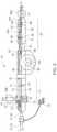
- FIG. 1an embodiment of an insertion system for transfemoral/transarterial insertion of an expandable heart valve stent in a part-sectioned side elevation;
- FIG. 2an embodiment of a handle for an insertion system for transfemoral/transarterial insertion of an expandable heart valve stent in a part-sectioned side elevation;
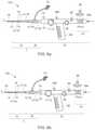
- FIG. 3 aan embodiment of an insertion system for transfemoral/transarterial insertion of a heart valve stent in a side elevation;
- FIG. 3 ba side elevation of the transfemoral/transarterial insertion system in accordance with FIG. 3 a with a deflected catheter system;
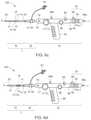
- FIG. 4a further embodiment of an insertion system for transfemoral/transarterial insertion of a heart valve stent in a side elevation;
- FIG. 5a further embodiment of an insertion system for transfemoral/transarterial insertion of a heart valve stent in a side elevation;
- FIG. 6 a - dside elevations of the transfemoral/transarterial insertion system in accordance with FIG. 3 a in its four previously defined functional states to illustrate the loading procedure of the insertion system
- FIG. 7 a - dside elevations of the transfemoral/transarterial insertion system in accordance with FIG. 3 a in its four previously defined functional states to illustrate the release procedure of a stent housed in the catheter tip of the insertion system;
- FIG. 8an embodiment of a catheter tip for an insertion system for transfemoral/transarterial insertion of an expandable heart valve stent in a part-sectioned side elevation;
- FIG. 9a further embodiment of a catheter tip for an insertion system for transfemoral/transarterial insertion of an expandable heart valve stent in a part-sectioned side elevation;
- FIG. 10 aan exemplary embodiment of a catheter shaft for an insertion system for transfemoral/transarterial insertion of an expandable heart valve stent in a cross-sectional elevation;
- FIG. 10 ba further exemplary embodiment of a catheter shaft for an insertion system for transfemoral/transarterial insertion of an expandable heart valve stent in a cross-sectional elevation;
- FIG. 11a schematic view to illustrate a transfemoral/transarterial implantation procedure of a heart valve stent.
- FIG. 12 a - cthree-dimensional schematic part-sectioned view of the catheter tip of a transfemoral/trans-apical insertion system in different functional states to illustrate the implantation procedure of a heart valve stent mounted in the catheter tip.
- FIG. 11shows schematically an example of how a transarterial or transfemoral access can be gained to the heart of a patient.
- a heart valve stent 150is advanced with the aid of a insertion system 100 via the femoral artery to the aortic valve.
- Embodiments of an insertion system 100which is suitable for transarterial or transfemoral access, are described in the following.
- an insertion system 100has a catheter system 1 and a handle 70 connected to the proximal end section of the catheter system 1 .
- the catheter system 1 of the preferred embodimentcomprises a catheter tip 10 having a seat portion for accommodating a stent to be inserted in its collapsed state and a stent holder 15 for releasably fixing the stent.
- the catheter system 1further comprises a catheter shaft 30 for connecting the catheter tip 10 to the handle 70 of the insertion system 100 , the distal end section of the catheter shaft 30 being flexible enough such that the catheter tip 10 and the distal end section of the catheter shaft 30 may pass the aortic arch during insertion through the aorta of the patient.
- the seat portion of the catheter tip 10comprises a first sleeve-shaped member 11 and a second sleeve-shaped member 21 , the cross-section of the second sleeve-shaped member 21 are preferably identical to each other such that the first and second sleeve-shaped member 11 , 21 can completely enclosed a stent accommodated in the catheter tip 10 .
- the first and second sleeve-shaped members 11 , 21are movable relative to each other and relative to the stent holder 15 .
- first force transmitting means 31with a distal end section connected to the first sleeve-shaped member 11 and a proximal end section connected to first operating means 71 of the handle 70 are provided.
- second force transmitting means 41with a distal end section connected to the second sleeve-shaped member 21 and a proximal end section connected to second operating means 81 of the handle 70 are provided.
- the first force transmitting means 31may be constituted by a first catheter tube 32 defining a first lumen and the second force transmitting means 41 is constituted by a second catheter tube 42 defining a second lumen.
- the second catheter tube 42may have a cross-section less than the cross-section of the first catheter tube 32 .
- the first catheter tube 32may be disposed concentrically and coaxially with the second catheter tube 42 and the second catheter tube 42 is received within the first lumen defined by the first catheter tube 32 .
- the stent holder 15 of the catheter tip 10is not moveable relative to the handle 70 of the insertion system 100 . Rather, the stent holder 15 is connected to the housing 70 ′ of the handle 70 by using a stent holder tube 62 having a distal end connected to the stent holder 15 and a proximal end connected to a body 70 ′ of the handle 70 .
- the stent holder tube 62may have a cross-section less than the cross-section of the first catheter tube 32 .
- the first catheter tube 32may be disposed concentrically and coaxially with both, the second catheter tube 42 on the one hand and the stent holder tube 62 on the other hand.
- the stent holder tube 62has a cross-section less than the cross-section of the first catheter tube 32 and greater than the cross-section of the second catheter tube 42 such that the stent holder tube 62 is received within the first lumen defined by the first catheter tube 32 and the second catheter tube 42 is received within a passageway defined by the stent holder tube 62 .
- the passageway defined by the stent holder tube 62has a diameter sufficient to accommodate the second catheter tube 42 such that the second catheter tube 42 is moveable relative to the stent holder tube 62 .
- the second lumen defined by the second catheter tube 42has a diameter sufficient to accommodate a guide wire 180 .
- the second catheter tube 42may 136 made from a rigid material including, for example, nitinol, stainless steel or a rigid plastic material (see FIG. 10 b ).
- the material of the distal end section of the second catheter tube 42may have an increased flexibility compared to the material of the proximal end section in order to allow the distal end section of the catheter shaft 30 to pass the aortic arch during insertion of the catheter tip 10 .
- the guiding tube 52may be a 17 F-catheter tube and the first catheter tube 32 may be a 12 F-catheter tube.
- the distal end section of the second catheter tube 42terminates in a soft catheter end tip 25 having an atraumatic shape.
- the soft catheter end tip 25is provided with a channel aligned with the second lumen defined by the second catheter tube 42 such that a guide wire 180 accommodated within the second lumen of the second catheter tube 42 may pass through the channel of the soft catheter end tip 25 .
- the second sleeve-shaped member 21 of the catheter tip 10is connected to the soft catheter end tip 25 such that the opened end of the second sleeve-shaped member 21 faces in the proximal direction opposite to the direction of the soft catheter end tip 25 and to the second catheter tube 42 .
- the stent holder tube 62is made of a rigid material, for example, a rigid plastic material, stainless steel or nitinol.
- the distal end of the stent holder tube 62terminates in the stent holder 15 which is also made of a rigid material, for example, a rigid plastic material or stainless steel.
- the passageway defined by the stent holder tube 62is aligned with a channel which passes through the stent holder 15 .
- the second catheter tube 42is accommodated in the passageway of the stent holder tube 62 and the channel of the stent holder 15 such as to be moveable relative to the stent holder tube 62 and the stent holder 15 .
- the first catheter tube 32is made of a bendable but inelastic material.
- the first catheter tube 32may be at least partly made of a braided or non-braided catheter tube.
- the first catheter tube 32shall be adapted to transfer compression and tension forces from the first operating means 71 of the handle 70 to the first sleeve-shaped member 11 of the catheter tip 10 without overly changing its total length.
- the distal end of the first catheter tube 32terminates at a flared section as a transition to the section defining the first sleeve-shaped member 11 of the catheter tip 10 .
- the flared section and the first sleeve-shaped member 11may be formed integrally and may be connected to the distal end section of the first catheter tube 31 .
- the flared sectionmay constitute the first sleeve-shaped member 11 of the catheter tip 10 .
- the first sleeve-shaped member 11 and the flared section of the first catheter tube 31may be all of the same material and originating from the same raw tube prior to a widening process so that the flared section and the first sleeve-shaped member 11 are the same elements.
- the insertion system 100further comprises a guiding tube 52 having a cross-section greater than the cross-section of the first catheter tube 32 .
- the guiding tube 52defines a passageway and is disposed concentrically and coaxially with the first catheter tube 32 , the stent holder tube 62 and the second catheter tube 42 such that the first catheter tube 32 with the stent holder tube 62 and the second catheter tube 42 accommodated therein is at least partly accommodated within the passageway defined by the guiding tube 52 , wherein the first catheter tube 32 is moveable relative to the guiding tube 52 .
- the guiding tube 52terminates proximal to the catheter tip 10 wherein the cross-section of proximal end section of the guiding tube 52 shall be the same as or less than the cross-section of the flared section provided at the proximal end of the first catheter tube 32 so that a smooth transition from the first sleeve-shaped member 11 of the catheter tip 10 to the guiding tube 52 may be achieved (see FIG. 9 ).
- the proximal end section of the guiding tube 52terminates distal to the handle 70 .
- the proximal end section of the guiding tube 52may be detached/disconnected from the handle 70 so that the handle 70 as well as the first and second catheter tubes 32 , 42 and the stent holder tube 62 together with catheter tip 10 may be moved relative to the guiding tube 52 .
- the distal end of the guiding tube 52is formed such that the flared section provided at the distal end section of the first catheter tube 32 may abut on the distal end of the guiding tube 52 without abrupt transition.
- the guiding tube 52may be of a thin material such as to allow length deformation of the guiding tube 52 upon transfer of compression and tension forces.
- the material of the guiding tube 52shall have sufficient stiffness in order to mechanically avoid kinking of the flexible sections of the distal portion of the catheter shaft 30 during insertion of the catheter tip 10 .
- the proximal end of the guiding tube 52is releasably connectable to the body 70 ′ of the handle 70 .
- the guiding tube 52may have a double-function:
- the guiding tube 52serves as a distal extension of the body 70 ′ of the handle 70 relative to which the first and second operating means 71 , 81 are moveable for manipulating the first and second sleeve-shaped members 11 , 21 of the catheter tip 10 .
- the position of the stent holder 15 relative to the native heart valve of the patientmay be changed by moving the guiding tube 52 connected to the handle 70 .
- the guiding tube 52may serve as an introducer tube, i.e. as a portal for passing the catheter tip 10 of the catheter system 1 into the patient's body and up to the heart.
- an inlet port 53may be provided at a proximal end section of the guiding tube 52 for injection of fluids into the guiding tube 52 .
- a check valvemay be provided at the proximal end section of the guiding tube 52 to prevent fluid from leaking out of the guiding tube 52 .
- FIGS. 1 to 10 bA description is given in the following, with reference to FIGS. 1 to 10 b , of the components of exemplary embodiments of insertion systems 100 , which are suitable for a transarterial or transfemoral access to the implantation location.
- the catheter tip 10 of the insertion system 100is advanced, for example, via the aorta to the implantation site.
- FIG. 1shows a part-sectioned representation of an exemplary embodiment of an insertion system 100 designed for transfemoral or transarterial access.
- an insertion system 100may comprise a catheter system 1 and a handle 70 connected to the proximal end section of the catheter system 1 .
- the catheter system 1comprises a catheter tip 10 and a catheter shaft 30 for connecting the catheter tip 10 to the handle 70 .
- the catheter tip 10has a seat portion for accommodating a stent (see FIGS. 12 a - c ) in its collapsed state as well as a stent holder 15 for releasably fixing the stent.
- the seat portion of the catheter tip 10is constituted by a first sleeve-shaped member 11 and a second sleeve-shaped member 21 .
- the sleeve-shaped members 11 , 21 of the catheter tip 10are movable relative to each other and relative to the stent holder 15 .
- the catheter shaft 30comprises first force transmitting means 31 , second force transmitting means 41 and guiding means 51 .
- the first and second force transmitting means 41 31 , 41 of the catheter system 1are realized as flexible, elongated catheter tubes 32 , 42 .
- Each of the first and second catheter tubes 32 , 42defines a separate lumen.
- the guiding means 51is realized as guiding tube 52 defining a passageway within which the first and second catheter tubes 32 , 42 are received such as to be movable relative to the guiding tube 52 .
- the guiding tube 52has a distal end which terminates proximal to the catheter tip 10 .
- the first catheter tube 32has a length which is the same as, or substantially similar to the length of the second catheter tube 42 .
- the first catheter tube 32terminates at its distal end in a flared section as a transition to the section with wider cross-section defining the first sleeve-shaped member 11 of the catheter tip 10 .
- the wider section of the first catheter tube 32is formed integrally with the distal end section of the first catheter tube 32 .
- the wider sectionhas a length greater than the length of a collapsed stent to be accommodated in the catheter tip 10 .
- the first force transmitting means 31 of the catheter system 1is constituted by a first catheter tube 32 defining a first lumen
- the second force transmitting means 41is constituted by a second catheter tube 42 defining a second lumen
- the second catheter tube 42has a cross-section less than the cross-section of the first catheter tube 32 , wherein the first catheter tube 32 is disposed concentrically and coaxially with the second catheter tube 42 .
- the cross-section of the catheter tip 10is greater than or equal to the cross-section of the guiding tube 52 .
- the guiding tube 52has a cross-section which is greater than the cross-section of the part of the first catheter tube 32 which is received within the guiding tube 52 .
- the cross-section of the catheter tip 10is greater than the cross-section of the guiding tube 52 .
- a check valvemay be provided for preventing fluid from leaking out of the guiding tube 52 .
- an inlet port 53may be provided at the proximal end section of the guiding tube 52 for injection of fluids into the guiding tube 52 .
- fluidssuch as saline solution may be injected through the inlet port 52 to flush the interior passageway of the guiding tube 52 and to reduce the incidence of blood clotting.
- a stopcockmay be attached to the inlet port 53 to maintain the port 53 in a closed position when the port 53 is not being accessed to flush the passageway of the guiding tube 52 .
- the guiding tube 52is movable relative to the handle 70 and the first and second catheter tubes 32 , 42 . This provides a grip for the user who can hold the catheter shaft 30 at its proximal end section during positioning of the catheter tip 10 and during manipulation of the sleeve-shaped element 11 of the catheter tip 10 .
- the usercan hold the guiding tube 52 , and in particular the proximal end section of the guiding tube 52 for supporting the movement of the first sleeve-shaped element 11 of the catheter tip 10 relative to the handle 70 such that the outer sheath of the catheter system 1 need not be held by the user or kinked.
- a handle 70is utilized, said handle 70 comprising first and a second operating means 71 , 81 , which are connected by means of corresponding first and second force transmission means 31 , 41 of the catheter shaft 30 to the first and second sleeve-shaped member 21 s 11 , 21 of the catheter tip 10 .
- the first operating means 71has a first pusher 73 which is functionally connected to the first slide 74 .
- the first slide 74is guided in a first guide 72 in the longitudinal direction L of the handle 70 .
- the distal-side end of the first guide 72defines the first stop 75 and the proximal-side end of the first guide 72 the second stop 76 , which define the overall longitudinal displacement that can be effected with the first operating means 71 .
- a locking element 77 ′may be positioned between the distal-side and the proximal-side end of the first guide 72 , which defines the additional stop 77 .
- the second operating means 81 of the handle 70 shown in FIG. 1has a second pusher 83 , which is functionally connected to a second slide 84 .
- the second slide 84is guided in a longitudinal guide (second guide 82 ) between a first stop 85 and a second stop 86 .
- the second slide 84is connected by means of the second force transmission means 41 with the second sleeve-shaped member 21 of the catheter tip 10 .
- the second slide 84On actuation of the second operating means 81 , the second slide 84 is moved in the longitudinal direction L of the handle 70 from the first stop 85 to the second stop 86 . This movement effects a longitudinal displacement of the second sleeve-shaped member 21 of the catheter tip 10 connected via the second force transmission means 41 with the second operating means 81 .
- the second operating means 81is equipped with a securing element 89 , which may connect the second slide 84 with the body 70 ′ of the handle 70 when in use.
- a longitudinal displacement of the second slide 84 to the second stop 86is possible following removal or deactivation of the securing element 89 .
- FIG. 2shows a further embodiment of a handle 70 of an insertion system 100 designed for transfemoral or transarterial access in a part-sectioned side view.
- the construction and mode of operation of the first and second operating means 81 71 , 81 of the embodiment of the handle 70 shown in FIG. 2is comparable in structural and functional respects to the handle 70 as previously described with reference to FIG. 1 .
- elements in FIG. 2 that are generally similar to previously described elementshave the same reference numbers compared with the reference numbers in FIG. 1 previously used for the similar elements.
- the handle 70 in accordance with FIG. 2is provided with a third operating means 96 in the form of a wheel, by means of which a flexural link region 34 of the catheter shaft 30 can be controlled.
- a flexural link region 34 of the catheter shaft 30can be controlled.
- the catheter shaft 30is only optionally provided with such flexural link region 34 .
- the material of the distal end section of the catheter shaft 30may have an increased flexibility compared to the material of the proximal end section in order to allow the distal end section of the catheter shaft to pass 30 the aortic arch during insertion of the catheter tip.
- the third operating element 96preferably has a detent device 100 ′, to allow a set deflection of the flexural link region 34 of the catheter shaft 30 to be fixed.
- a suitable catch mechanismon the hand wheel of the third operating means 96 , which cooperates with the body 70 ′ of the handle 70 .
- the flexural link region 34 of the catheter shaft 30is connected to the third operating means 96 by way of a control wire 35 whereby, on an actuation of the third operating means 96 via the control wire 35 a tensile force is exerted on the flexural link region 34 , which produces the deflection of the flexural link region 34 (see FIG. 3 b ).
- the third operating means 96 for deflecting a flexural link region 34 of the catheter shaft 30in case the catheter shaft 30 is provided with such a flexural link region 34 .
- the handle 70 of the insertion system 100 designed for transarterial or transfemoral accessmay be provided with a pretensioning device, shown in FIG. 2 .
- a pretensioning deviceWith such a pretensioning device, a constant tensile force may be exerted via the second operating means 81 on the second sleeve-shaped member 21 of the catheter tip 10 .
- the pretensioning devicemay have a compression spring 97 , permanently stressed along its spring axis, which is prestressed between a first stop 97 a connected to the body 70 ′ of the handle 70 and a second stop 97 b connected to the proximal end region of the second operating means 81 .
- a permanent, previously defined or definable tensile forceis exerted on the second sleeve-shaped member 21 of the catheter tip 10 .
- the pretensioning device implemented with the spring 97 in the embodiment in accordance with FIG. 2may be advantageous when the catheter shaft 30 is bent during the implantation procedure, for example, when the catheter tip 10 of the insertion system 100 is inserted through the aorta.
- the outer fibres of the catheter shaft 30are shortened. This can be compensated appropriately with the aid of the pretensioning device.
- the outer fibres of the catheter shaft 30 radially spaced from the neutral fibresare shortened.
- the second force transmission means 41which connects the second operating means 81 with the second sleeve-shaped member 21 in the insertion system 100 , normally runs along the neutral fibre of the catheter shaft 30 , a bending contraction inevitably occurs when the catheter shaft 30 is bent, having the result that, despite fixing of the first operating means 71 , the first sleeve-shaped member 11 of the catheter tip 10 is displaced relative to the stent holder 15 in a proximal direction.
- FIGS. 3 a, bA further exemplary embodiment of an insertion system 100 designed for transarterial/transfemoral access is shown in FIGS. 3 a, b .
- Elements in FIGS. 3 a, b that are generally similar to previously described elementshave the same reference numbers compared with the reference numbers in FIGS. 1 and 2 previously used for the similar elements.
- the insertion system 100 shown in FIGS. 3 a, bcomprises a catheter system 1 of the kind as previously described with reference to FIG. 1 , i.e. a catheter system 1 having a catheter tip 10 and a catheter shaft 30 which is provided with a first catheter tube 32 acting as first force transmitting means 31 , a second catheter tube 42 acting as second force transmitting means 41 , and a guiding tube 52 acting as guiding means 51 .
- the catheter shaft 30 of the insertion system 100 shown in FIGS. 3 a, bis provided with a flexural link region 34 of the kind as previously described with reference to FIG. 2 .
- the insertion system 100 shown in FIGS. 3 a, bis provided with a different embodiment of a handle 70 which is used in order to manipulate the first and second sleeve-shaped members 11 , 21 of the catheter tip 10 .
- the end region of the handle 70is in the form of a turning mechanism 98 (rotatable means), with which the second force transmission means 41 of the catheter shaft 30 can be twisted with the distal-side end tip 25 and the second sleeve-shaped member 21 of the catheter tip 10 fastened to it about the longitudinal axis L of the catheter tip 10 .
- the second sleeve-shaped member 21 of the catheter tip 10is connected by means of a loose bearing to the stent holder 15 , allowing transmission of a turning moment between the second sleeve-shaped member 21 and the stent holder 15 , without allowing transmission of any tensile or compression forces acting in the direction of the longitudinal axis L of the catheter tip 10 .
- the stent holder 15also turns correspondingly about the longitudinal axis L.
- the turning mechanism 98preferably allows the stent holder 15 to twist through approximately 120°.
- the rotation of a stent housed in the catheter tip 10and particularly the positioning hoops already released in the second functional state of the insertion system 100 , can be controlled, facilitating precise positioning of the already expanded positioning hoops of the stent in the pockets of the insufficient, native heart valve.
- the rotation movement of the stent holder 15 about the longitudinal axis L of the catheter tip 10 that can be effected with the turning mechanism 98exhibits a previously definable, preferably small delay in reaction to a turning moment initiated by means of the turning mechanism 98 .
- the embodiment of the handle 70 shown in FIG. 3 ais equipped with a third operating means 96 in the form of a wheel, with which a flexural link 34 , preferably provided at the distal end region of the catheter shaft 30 , can be deflected.
- FIG. 3 bThe deflection of the distal end region of the catheter shaft 30 that can be effected with this flexural link region 34 is shown schematically in FIG. 3 b .
- a deviceis provided for force transmission (control wire 35 —see FIG. 8 ) which is connected on one side to the flexural link regions 34 preferably provided at the distal end region of the catheter shaft 30 and, on the other side, to the third operating means 96 of the handle 70 implemented in the embodiment shown in FIG. 3 as a hand wheel.
- the device for force transmissionas a control wire 35 , which is passed through the inside of the first transmission means 31 and preferably at the distal end of the flexural link region 34 or at the proximal end of the catheter tip 10 (see FIG. 8 ) to have a directed effect on the curvature of the flexural link region 34 .
- the tensile forces that can be exerted on the flexural link region 34 with the aid of the control wire 35it is possible to obtain a defined curvature of the distal end region of the catheter shaft 30 . This is a particular advantage during transarterial/transfemoral access when navigating the aortic arch.
- FIGS. 4 and 5Further exemplary embodiments of an insertion system 100 which is suitable for transarterial/transfemoral access to the implantation location are shown in FIGS. 4 and 5 . Elements in FIGS. 4 and 5 that are generally similar to previously described elements have the same reference numbers compared with the reference numbers in FIGS. 1, 2 and 3 a, b previously used for the similar elements.
- FIGS. 4 and 5differ first and foremost in relation to the implementation of the corresponding operating means 71 , 81 of the handle 70 .
- the insertion system 100 in accordance with FIG. 4has a handle 70 with which the first operating means 71 , which is used for manipulation of the first sleeve-shaped member 11 of the catheter tip 10 , is similar to a trigger of a revolver.
- the usersuch as a physician who carries out the treatment may hold the handle 70 at the grip 88 , while the first operating means 71 in the form of a trigger of a revolver is operated with the index finger of the hand holding it.
- a handle 70is used which corresponds in structural and functional respects to the handle 70 used with the insertion system 100 in FIG. 3 with the exception of the grip 88 provided in the embodiment in accordance with FIG. 3 .
- FIGS. 6 a - d and FIGS. 7 a - dA description is given in the following, with reference to FIGS. 6 a - d and FIGS. 7 a - d , of the functional coaction of the components of an insertion system 100 , which is suitable for a transarterial or transfemoral access to the implantation location.
- Elements in FIGS. 6 a to 6 d and FIGS. 7 a to 7 d that are generally similar to previously described elementshave the same reference numbers compared with the reference numbers in FIGS. 1 to 5 previously used for the similar elements.
- FIGS. 6 a to 6 dfor illustrating the procedure for loading a stent into the catheter tip 10 of the insertion system 100 .
- FIGS. 7 a to 7 dthe stepwise release of a stent mounted in the catheter tip 10 of the insertion system 100 is illustrated.
- the handle 70 for the transarterial/transfemoral insertion system 100has a wheel rotatably mounted in the handle 70 which is functionally connected to the first sleeve-shaped member 11 of the catheter tip 10 associated with the first operating means 71 via a corresponding first force transmission means 31 , so that force can be directly transmitted from the first operating means 71 in the form of the wheel to the first sleeve-shaped member 11 of the catheter tip 10 .
- the first operating means 71 of the handle 70 in accordance with FIG. 6 and FIG. 7can turn between a first stop and a second stop, in order to execute a definable longitudinal displacement stroke on the first sleeve-shaped member 11 of the catheter tip 10 .
- the first operating means 71 of the handle 70is provided with a additional stop between the first and second stop which cooperates, on one side with the first stop and on the other up with the second stop so that, on actuation of the first operating means 71 , a longitudinal displacement of the first sleeve-shaped member 11 of the catheter tip 10 can be effected relative to the stent holder 15 of the catheter tip 10 , consisting of two defined separate steps.
- the additional stop associated with the first operating means 71is in the form of a locking element 77 ′ positioned removably in the flow of force between the wheel and the first sleeve-shaped member 11 of the catheter tip 10 , interrupting direct force transmission from the wheel to the first sleeve-shaped member 11 of the catheter tip 10 .
- the additional stop associated with the first operating means 71it is possible for the additional stop associated with the first operating means 71 to be in the form of a locking element restricting the free rotation of the wheel between the first and the second stop.
- the first operating means 71 of the handle 70 used with the insertion system 100 designed for transarterial/transfemoral accessnot to be a wheel, but to be implemented as a pusher mechanism.
- the second operating means 81has a second slide 84 guided in a second guide 82 and functionally connected to a second pusher 83 .
- This second slide 84which is guided in the interior of the handle 70 and therefore cannot be seen in the view of FIGS.
- the second operating means 81can be displaced between a first position (Pos. 1 ) and a second position (Pos. 2 ) in the longitudinal direction of the handle 70 , whereby the longitudinal displacement stroke that can be thus effected via the second force transmission means 41 is transferred directly to the second sleeve-shaped member 21 of the catheter tip 10 .
- the first and second positionsare each defined with the aid of a first and a second stop 85 , 86 .
- a securing element 89is provided, associated with the second operating means 81 , which is removably located on the second guide 82 and which blocks longitudinal displacement of the (second) slide 84 associated with the second operating means 81 when used.
- the handle 70which is used with the transarterial/transfemoral insertion system 100 of the embodiment shown in FIGS. 6 and 7 further exhibits an optional grip 88 , which facilitates the operability of the handle 70 and in particular the operating conformity of the handle 70 .
- the grip 88is preferably releasably connected to the body 70 ′ of the handle 70 and can optionally be fixed at different positions on the body 70 ′ of the handle 70 .
- the catheter tip 10In relation to the construction of the catheter tip 10 which is used, for example, with the insertion system 100 shown in FIGS. 6 and 7 and which allows transarterial/transfemoral access of a stent housed in the catheter tip 10 to the implantation location, it can be seen from FIGS. 6 and 7 that the catheter tip 10 has a stent holder 15 for releasably fixing of, for example, the second retaining region of a stent that can be housed in the catheter tip 10 .
- the retaining elements 16 of the stent holder 15 in the form of a crownare provided at the proximal end of the stent holder 15 .
- the catheter tip 10 of the insertion system 100 designed for transarterial/transfemoral accesscomprises a mounting device for mounting a heart valve stent, where required, with a heart valve prosthesis fastened to it.
- the mounting device of the catheter tip 10consists of a first sleeve-shaped member 11 , particularly for accommodating the positioning hoops of a stent, and a second sleeve-shaped member 21 , in particular for accommodating the heart valve prosthesis fastened to it, when required.
- the first operating means 71 of the handle 70co-operates in the embodiment according to FIGS. 6 and 7 with the first sleeve-shaped member 11 of the catheter tip 10 so that, on actuation of the first operating means 71 , by transfer of a defined longitudinal displacement stroke, a previously definable longitudinal displacement of the first sleeve-shaped member 11 can be effected relative to the stent holder 15 .
- the second operating means 81 of the handle 70co-operates with the second sleeve-shaped member 21 of the catheter tip 10 so that, on actuation of the second operating means 81 , by transfer of a defined longitudinal displacement stroke, a previously definable longitudinal displacement of the second sleeve-shaped member 21 of the catheter tip 10 relative to the stent holder 15 can be effected.
- the second sleeve-shaped member 21which is used to house the retaining hoops of the stent with, where required, the heart valve prosthesis fastened to them, is located at the distal end region of the catheter tip 10 , while the first sleeve-shaped member 11 is located between the second sleeve-shaped member 21 and the handle 70 .
- the second force transmission means 41which connects the second operating means 81 of the handle 70 to the second sleeve-shaped member 21 of the catheter tip 10 , is preferably in the form of an inner catheter running inside the interior of the catheter or tube system.
- the first force transmission means 31which connects the first operating means 71 of the handle 70 to the first sleeve-shaped member 11 of the catheter tip 10 , is in the form of an outer catheter, in the interior of which the first force transmission means 31 runs in the form of the inner catheter.
- the second sleeve-shaped member 21can be moved relative to the stent holder 15 in the longitudinal direction L of the catheter tip 10 in a distal direction, thus away from the handle 70 , while, on actuation of the first operating means 71 of the handle 70 , the first sleeve-shaped member 11 of the catheter tip 10 can be moved relative to the stent holder 15 in the longitudinal direction L of the catheter tip 10 in a proximal direction, and thus towards the handle 70 .
- FIGS. 7 a to 7 dAn embodiment of a transarterial/transfemoral insertion system 100 is shown in its four different functional states in FIGS. 7 a to 7 d .
- the insertion system 100is shown in its first functional state in FIG. 7 a , in which the catheter shaft 30 with the catheter tip 10 and, where required, with the stent accommodated in it can be inserted into the patient transarterially or transfemorally and advanced via the aorta to the implantation site.
- the catheter tip 10is completely closed, whereby the two sleeve-shaped members 11 , 21 of the catheter tip 10 overlap telescopically.
- the respective diameters of the sleeve-shaped members 11 , 21are chosen so that the folded-up retaining hoops of a stent, with the heart valve prosthesis fastened to them where required, can be housed in the second sleeve-shaped member 21 .
- the folded-up positioning hoops of the stent housed between the second sleeve-shaped member 21 and the first sleeve-shaped member 11are held together in their folded form.
- the second retaining region of the stentis shown in the first functional state of the insertion system 100 , as shown in FIG. 7 a , with the stent holder 15 fixed at the proximal end of the catheter tip 10 .
- the retaining elements(retaining rings etc.) provided at the second retaining region of the stent are engaged with retaining elements 16 of the stent holder 15 .
- the retaining elements 16 of the stent holder 15are covered by the first sleeve-shaped member 11 of the catheter tip 10 in the first functional state shown in FIG. 7 a , so that an engagement between retaining elements provided on the second retaining region of a stent and retaining elements 16 of the stent holder 15 would be possible.
- the first functional state of the insertion system 100 shown in FIG. 7 ais maintained during the transarterial insertion procedure.
- the insertion system 100is transferred from the first functional state shown in FIG. 7 a to the second functional state shown in FIG. 7 b , by transferring the first operating means 71 (shown in the embodiment of the wheel in FIG. 7 ) from the first position into the second position.
- the longitudinal displacement stroke transferred by actuation of the first operating means 71 to the first sleeve-shaped member 11 of the catheter tip 10effects a displacement of the first sleeve-shaped member 11 relative to the stent holder 15 in the proximal direction, thus towards the handle 70 .
- the longitudinal displacement stroke executed on the first sleeve-shaped member 11 of the catheter tip 10 during the transition from the first functional state (see FIG. 7 a ) to the second functional state (see FIG. 7 b ) by the first operating means 71 of the handle 70 via a corresponding first force transmission means 31is previously defined so that the first sleeve-shaped member 11 is displaced relative to the stent holder 15 in the proximal direction just so far that the positioning hoops of a stent housed in the catheter tip 10 would be released, though the distal end of the first sleeve-shaped member 11 of the catheter tip 10 would still cover the retaining elements 16 of the stent holder 15 , so that the engagement between the retaining elements provided at the second retaining region of the stent and the retaining elements 16 of the stent holder 15 would be secure.
- the first retaining region of a stent housed in the catheter tip 10 with the heart valve prosthesis fastened to itwould continue to be housed in its folded together state in the sleeve-shaped element of the second sleeve-shaped member 21 .
- the positioning hoops of a stent housed in the catheter tip 10 released in the second functional state of the insertion system 100are opened as a result of the radial forces acting on them and can thus be positioned in the pockets of the insufficient native heart valve.
- the insertion system 100is transferred from the second functional state shown in FIG. 7 b into the third functional state shown in FIG. 7 c . This is done my manipulation of the second operating means 81 , after the securing element 89 associated with the second operating means 81 has been removed.
- the second sleeve-shaped member 21 of the catheter tip 10 associated with the second operating means 81is moved relative to the stent holder 15 by a previously established longitudinal displacement stroke defined with the second operating means 81 in a distal direction, thus away from the handle 70 .
- the longitudinal displacement stroke acting on the second sleeve-shaped member 21is chosen so that the sleeve-shaped member 21 no longer covers the first retaining region of a stent housed in the catheter tip 10 with the heart valve prosthesis fastened to it, where required, and thus releases the first retaining region of the stent. Due to the action of the radial forces, the distal retaining region of the stent with the heart valve prosthesis attached to it, where required, unfolds completely.
- the distal end region of the first sleeve-shaped member 11continues to cover the retaining elements 16 of the stent holder 15 , so that the engagement between the retaining elements of a stent housed in the catheter tip 10 and the retaining elements 16 of the stent holder 15 is secure and the proximal retaining region of the stent is in its folded-up state.
- This anchorage of the stent to the catheter tip 10 of the insertion system 100allows an explanation of a stent that is already partially unfolded by returning the insertion system 100 from the third functional state, by appropriate manipulation of the second operating means 81 of the handle 70 , to the second functional state and then by suitable actuation of the first operating means 71 transfer to the first functional state.
- the insertion system 100is transferred from the third functional state shown in FIG. 7 c into the fourth functional state shown in FIG. 7 d , by turning the first operating means 71 of the handle 70 further from the second position to the third position after removal of the securing element 79 (locking element).
- This manipulation of the first operating means 71 that can be effected after removal of the securing element 79results in a further defined movement of the first sleeve-shaped member 11 relative to the stent holder 15 of the catheter tip 10 in a proximal direction, thus towards the handle 70 .
- the longitudinal displacement stroke executed on the first sleeve-shaped member 11is chosen so that the distal end of the first sleeve-shaped member 11 no longer covers the retaining elements 16 of the stent holder 15 , as a result of which an engagement between the retaining elements of a stent housed in the catheter tip 10 and the retaining elements 16 of the stent holder 15 can be released, which would also lead to a complete release of the second retaining region of the stent and a complete separation of the stent from the catheter tip 10 and correspondingly to a complete unfolding of the stent.
- FIGS. 6 a to 6 dThe four functional states of the insertion system 100 designed for transarterial/transfemoral access, previously described with reference to FIGS. 7 a to 7 d , are shown in reverse order in FIGS. 6 a to 6 d to clarify the procedure for loading a stent into the catheter tip 10 of the insertion system 100 .
- FIGS. 6 a to 6 d and FIGS. 7 a to 7 dshow that the insertion system 100 can be loaded with a heart valve stent by transferring the insertion system 100 , starting from its fourth functional state in accordance with FIG. 6 a (see FIG. 7 d ), into its third functional state in accordance with FIG. 6 b (see FIG.
- FIG. 9for describing an exemplary embodiment of the catheter tip 10 .
- Elements in FIG. 9 that are generally similar to previously described elementshave the same reference numbers compared with the reference numbers in FIGS. 1 to 7 previously used for the similar elements.
- catheter shaft 30An exemplary embodiment of a catheter shaft 30 is described in the following, with reference to the illustration in FIG. 9 .
- This catheter shaft 30can be used with an insertion system 100 designed for transarterial or transfemoral access.
- FIG. 9shows an exemplary embodiment of a shaft for an insertion system 100 in a cross-sectional elevation.
- the catheter shaft 30exhibits a first force transmission means 31 in the form of a first catheter tube 32 , whereby this first catheter tube 32 is used to connect the first operating means 71 of the handle 70 to the first sleeve-shaped member 11 of the catheter tip 10 .
- the first force transmission means 31implemented as a first catheter tube 32 may be clamped between a screw cap 74 ′ and the first slide 74 of the first operating means 71 and consequently is permanently connected to the first slide 74 .
- the distal-side end region of the first catheter tube 32merges into the first sleeve-shaped member 11 of the catheter tip 10 in the form of the stent sheath.
- the second force transmission means 41 of the catheter shaft 30 used with an insertion system 100 designed for transarterial or transfemoral accessis preferably implemented as a second catheter tube 42 .
- the proximal-side end region of the second catheter tube 42is connected to the second operating means 81 of the handle 70 .
- the distal-side end region of the second catheter tube 42is connected to the catheter end tip 25 of the catheter tip 10 .
- the second sleeve-shaped member 21 of the catheter tip 10is permanently connected by means of its distal-side end to the end tip 25 of the catheter tip 10 so that, on actuation of the second operating means 81 via the force transmission means 41 in the form of the second catheter tube 42 , a tensile or compressive force can be transmitted to the second sleeve-shaped member 21 of the catheter tip 10 .
- the exemplary embodiment of the catheter tip 10further comprises a stent holder 15 at the proximal end section of the catheter tip 10 .
- the stent holder 15has a passageway extending there through.
- the distal end section of the second force transmitting means 41(second catheter tube 42 ) passes through the passageway of the stent holder 15 and terminates at the second sleeve-shaped member 21 .
- the respective sleeve-shaped members 11 , 21 of the catheter tip 10can be manipulated by corresponding operating means 71 , 81 of a handle 70 (not shown in FIG. 9 ).
- the first sleeve-shaped member 11 of the catheter tip 10is connected with a first operating means 71 of a handle 70 by using a first force transmitting means 31 .
- the second sleeve-shaped member 21 of the catheter tip 10is connected to a second operating means 81 of the handle 70 by using a second force transmitting means 41 .
- the first force transmitting means 31is constituted by a first catheter tube 32 defining a first lumen
- the second force transmitting means 41is constituted by a second catheter tube 42 defining a second lumen.
- the second catheter tube 42has a cross-section less than the cross-section of the first catheter tube 32 , wherein the first catheter tube 32 is disposed concentrically and coaxially with the second catheter tube 42 .
- the distal end section of the second catheter tube 42passes through the opened front face of the second sleeve-shaped member 21 and terminates in a cone-shaped end tip 25 of the catheter system 1 , wherein the base of this cone-shaped end tip 25 defines the distal front face of the second sleeve-shaped member 21 .
- the end tip 25 of the catheter system 1is preferably a soft catheter end tip, for example a soft polymeric catheter end tip.
- the first catheter tube 32terminates after an intermediate flared section in a section with wider cross-section defining the first sleeve-shaped member 11 of the catheter tip 10 .
- the flared sectionis formed integrally with the distal end section of the first catheter tube 32 .
- the flared sectionhas a length greater than the length of a collapsed stent to be accommodated in the catheter tip 10 , wherein the difference in the length between the flared section and the stent in its collapsed state represents the length of the stent holder 15 .
- the catheter shaft 30which is connected to the catheter tip 10 depicted in FIG. 9 , also comprises a guiding tube 52 of the kind as previously described with reference to the exemplary embodiment depicted in FIG. 1 .
- the distal end of the guiding tube 52terminates proximal to the catheter tip 10 .
- the guiding tube 52defines a passageway within which the first and second catheter tube 42 32 , 42 are received such as to be movable relative to the guiding tube 52 .
- the distal end of the guiding tube 52may be tapered such that it abuts the first catheter tube 32 .
- FIG. 10 ais a cross-sectional view of a catheter shaft 30 according to an exemplary embodiment.
- the second force transmission means 41 in the form of the second catheter tube 42runs along the neutral fibre of the catheter shaft 30 inside the first catheter tube 32 .
- the space between the first catheter tube 32 and the second catheter tube 42may be filled with a filler material, so that a filler body 40 is formed.
- the filler materialis preferably a relatively elastic plastic material to allow the catheter shaft 30 to bend overall.
- the filler body 40is used for connecting the stent holder 15 of the catheter tip 10 to the body 70 ′ of the handle 70 .
- a stent holder tube 62may be used for connecting the stent holder 15 of the catheter tip 10 to the body 70 ′ of the handle 70 .
- the stent holder tube 62may have a distal end connected to the stent holder 15 , a proximal end connected to the body 70 ′ of the handle 70 and a passageway extending through the stent holder tube 62 .
- the stent holder tube 62has a cross-section less than the cross-section of the first catheter tube 32 and greater than the cross-section of the second catheter tube 42 , wherein the first catheter tube 32 is disposed concentrically and coaxially with the stent holder tube 62 thereby accommodating the stent holder tube 62 such that the first catheter tube 32 is moveable relative to the stent holder tube 62 .
- the passageway of the stent holder tube 62shall have a diameter sufficient to accommodate the second catheter tube 42 such that the second catheter tube 42 is moveable relative to the stent holder tube 62 .
- the filler body 40(or the stent holder tube 62 ) may be connected by means of a fixing 87 to the body 70 ′ of the handle 70 .
- the proximal-side end region of the stent holder 15attaches at the distal-side end region of the filler body 40 (see FIG. 8 ).
- the connection between the stent holder 15 and the filler body 40is preferably chosen so that it allows rotation of the stent holder 15 relative to the filler body 40 . This is especially necessary for control of the rotation of the positioning hoops of the already partially released stent during the implantation procedure (see FIG. 12 a ).
- the complete catheter system 1can be rotated for appropriate positioning of a stent connected with the catheter tip 10 and, in particular the positioning hoops of an already partially released stent during the implantation procedure. This is possible due to an appropriate transmission of torque and the flexibility of the catheter system 1 .
- a stent holder tube 62is used for connecting the stent holder 15 of the catheter tip 10 to the body 70 ′ of the handle 70 , the stent holder tube 62 may be rotatable relatively to the first and second catheter tubes 32 , 42 about the longitudinal axis L of the catheter system 1 . This will be described later in more detail with reference to the exemplary embodiment depicted in FIG. 10 b.
- the second force transmission means 41 in the form of the second catheter tube 42can be turned about the longitudinal direction L, for example, by means of a rotatable cap 98 which may be provided at the proximal end region of the handle 70 .
- This rotary movementis transferred from the second catheter tube 42 direct to the end tip 25 of the catheter tip 10 and thus to the second sleeve-shaped member 21 of the catheter tip 10 .
- the second catheter tube 42runs through the body of the stent holder 15 and cooperates with the stent holder 15 with the aid of a suitable toothing, to transmit a turning moment exerted by means of the rotary cap of the handle 70 on the second catheter tube 42 to the stent holder 15 , while tensile or compression forces acting in the longitudinal direction L of the catheter tip 10 are not transmitted from the second catheter tube 42 to the stent holder 15 .
- a least one fluid channel 43may be provided in the filler body 40 of the catheter shaft 30 , connected at its proximal-side end to an injection adapter 99 b (see FIG. 2 ) and at its distal-side end correspondingly to the catheter tip 10 , consequently ensuring supply of fluid to the catheter tip 10 and draining of fluid from the catheter tip 10 .
- a channelmay be provided in the filler body 40 for accommodating a control wire (control wire 35 —see FIG. 8 ), with an operating means may cooperate with a flexural link region, in case the catheter shaft 30 is provided with such a flexural link region (see FIG. 3 and FIG. 2 ).
- control wire 35control wire 35 —see FIG. 8
- an operating meansmay cooperate with a flexural link region, in case the catheter shaft 30 is provided with such a flexural link region (see FIG. 3 and FIG. 2 ).
- the distal-side end of a control wire 35is fixed to the proximal-side end region of the stent holder 15 .
- FIG. 10 bis a cross-sectional view of a catheter shaft 30 according to an alternative exemplary embodiment.
- the first force transmitting means 31may be constituted by a first catheter tube 32 defining a first lumen and the second force transmitting means 41 is constituted by a second catheter tube 42 defining a second lumen.
- the second catheter tube 42may have a cross-section less than the cross-section of the first catheter tube 32 .
- the first catheter tube 32may be disposed concentrically and coaxially with the second catheter tube 42 and the second catheter tube 42 is received within the first lumen defined by the first catheter tube 32 .
- a stent holder tube 62is provided for connecting the stent holder 15 to the handle 70 , said stent holder tube 62 having a distal end connected to the stent holder 15 and a proximal end connected to a body 70 ′ of the handle 70 .
- the stent holder tube 62may have a cross-section less than the cross-section of the first catheter tube 32 .
- the first catheter tube 32may be disposed concentrically and coaxially with both, the second catheter tube 42 on the one hand and the stent holder tube 62 on the other hand.
- the stent holder tube 62has a cross-section less than the cross-section of the first catheter tube 32 and greater than the cross-section of the second catheter tube 42 such that the stent holder tube 62 is received within the first lumen defined by the first catheter tube 32 and the second catheter tube 42 is received within a passageway defined by the stent holder tube 62 .
- the passageway defined by the stent holder tube 62has a diameter sufficient to accommodate the second catheter tube 42 such that the second catheter tube 42 is moveable relative to the stent holder tube 62 .
- the second lumen defined by the second catheter tube 42has a diameter sufficient to accommodate a guide wire 180 .
- the second catheter tube 42may be made from a rigid material including, for example, nitinol, stainless steel or a rigid plastic material.
- the material of the distal end section of the second catheter tube 42may have an increased flexibility compared to the material of the proximal end section in order to allow the distal end section of the catheter shaft 30 to pass the aortic arch during insertion of the catheter tip 10 .
- the guiding tube 52may be a 17 F-catheter tube and the first catheter tube 32 may be a 12 F-catheter tube.
- the stent holder tube 62is made of a rigid material, for example, a rigid plastic material, stainless steel or nitinol.
- the distal end of the stent holder tube 62terminates in the stent holder 15 which is also made of a rigid material, for example, a rigid plastic material or stainless steel.
- the passageway defined by the stent holder tube 62is aligned with a channel which passes through the stent holder 15 .
- the second catheter tube 42is accommodated in the passageway of the stent holder tube 62 and the channel of the stent holder 15 such as to be moveable relative to the stent holder tube 62 and the stent holder 15 .
- the embodiments of the insertion system 100 designed for transarterial/transfemoral accessmay have a first injection adapter 99 a at the proximal end of the handle 70 .
- This first injection adapter 99 ais used for flushing the insertion system 100 and as outlet of a guide wire 180 , with the aid of which the actual introduction of the catheter shaft 30 with the catheter tip 10 provided at the distal end of the catheter shaft 30 into the body of the patient is simplified.
- the catheter shaft 30 , the catheter tip 10 and the handle 70are thereby threaded into the guide wire 180 and pushed along it, for example into the aorta and to the heart of the patient.
- a second injection adapter 99 bmay further be provided, by means of which a liquid coolant etc. can be passed, for example, via the fluid channels 43 (see FIG. 10 a ) formed in the interior of the catheter shaft 30 to the catheter tip 10 .
- a liquid coolantetc.
- a stent accommodated in the catheter tip 10can be appropriately cooled while the catheter tip 10 is being advanced to the implantation location, as long as the insertion system 100 is in its first functional state, in which the catheter tip 10 is completely enclosed by the telescopically arranged sleeve-shaped members 11 and 21 .
- the provision of cooling that can be produced with the second injection adapter 99 b for the stent accommodated in the catheter tip 10is a particular advantage when a shape memory material is used as stent material and when the stent can deform under the effect of an external stimulus from a temporary form to a permanent form, whereby the temporary form exists in the first configuration of the stent (in the folded-up state, when the stent is accommodated in the catheter tip 10 ) and the permanent form exists in the second configuration of the stent (in the expanded state of the stent after release of the stent from the catheter tip 10 ).
- the guiding tube 52is preferably made from a material allowing the guiding tube 52 to be capable of traversing a tortuous pathway in the body of the patient without kinking.
- the guiding tube 52may include an inner lubricious liner, an outer polymeric jacket, and a coil reinforcement between the inner and outer layers.
- first and second catheter tubes 32 , 42 of the catheter shaft 30are preferably made from flexible, sterilizable materials. These materials may include, for example, polyurethane, silicone, polyvinyl chloride (PVC) and/or nylon. Furthermore, the first and second catheter tubes 32 , 42 are respectively made from a less rigid material than the guiding tube 52 . In an exemplary embodiment, the first catheter tube 32 and/or the second catheter tube 42 are/is at least partly made of a braided wire construction. In addition, the stent holder tube 62 may also be at least partly made of a braided wire construction.
- FIGS. 12 a to 12 cA preferred embodiment of a medical device for treatment of a heart valve stenosis and/or heart valve insufficiency in a patient is described in the following with reference to FIGS. 12 a to 12 c .
- the medical deviceexhibits an insertion system 100 designed for transarterial/transfemoral access, as has been described in detail previously, for example, with reference to FIGS. 1 to 10 .
- the medical devicehas an expandable heart valve stent 150 mounted in the catheter tip 10 of the insertion system 100 , to which a heart valve prosthesis 160 to be implanted is fastened.
- the stent 150In the first functional state, not shown, the stent 150 exhibits a first, previously definable configuration, in which it is in its folded-together state.
- the stent 150is designed to adopt a second previously definable configuration in the implanted state, in which it exists in its expanded state.
- the stent 150is transferred sequentially, following a previously definable sequence of events in steps from its first previously defined configuration into its second previously defined configuration.
- the stent 150that is used with the medical device in accordance with the depiction in FIGS. 12 a to 12 c exhibits a first retaining region, to which the heart valve prosthesis 160 is attached. Further, the stent 150 comprises a second retaining region with three retaining elements 151 , each in the configuration of retaining rings, which can be brought in to a releasable engagement with the retaining elements 16 of the stent holder 15 provided in the catheter tip 10 .
- the stent 150has three retaining hoops 153 to accommodate the heart valve prosthesis 160 and three positioning hoops 154 for automatic positioning of the stent 150 at the implantation site, whereby the respective positioning hoops 154 of the stent 150 are designed in functional and structural respects to engage the pockets 170 of the native heart valve during the implantation procedure and in the implanted state of the stent 150 , in particular from the second functional state of the insertion system 100 .
- each positioning hoop 154 and its associated retaining hoop 153has an essentially U or V-shaped structure, which is closed towards the distal end of the stent 150 .
- the stent 150which together with the insertion system 100 forms the basis of the medical device, is especially suitable for insertion into the body of a patient with the aid of the insertion system 100 with minimal invasiveness.
- the distinctive feature of the stent 150is that the three positioning hoops 154 of the stent 150 undertake the function of automatic positioning of the stent 150 with the heart valve prosthesis 160 attached to it in the aorta of the patient.
- the positioning hoops 154have radiused head sections, which engage in the pockets 170 of the insufficient heart valve to be replaced by the heart valve prosthesis during positioning of the stent 150 at the implantation site.
- the provision of a total of three positioning hoops 154takes care of the necessary positioning accuracy in the rotary direction.
- the catheter tip 10 and the catheter shaft 30 of the transarterial or transfemoral insertion system 100has been inserted by a puncture of the groin artery of the patient and the catheter tip 10 has been advanced to the implantation site with the aid of a guide wire 180 .
- the insertion system 100 to be usedis shown already in its second functional state in FIG. 12 a .
- the second functional state of the insertion system 100 designed for transarterial or transfemoral accesshas been described previously, for example with reference to FIG. 7 b.
- the first sleeve-shaped member 11 of the catheter tip 10has already moved by a first predetermined amount of movement in a proximal direction, and thus towards the handle 70 , leading to a release of the positioning hoops 154 of the stent 150 .
- These already expanded positioning hoops 154 of the stent 150 shown in FIG. 12 aare positioned—where necessary by a suitable rotation of the stent holder 15 of the catheter tip 10 —in the pockets 170 of the native heart valve position.
- the insertion system 100is transferred from its second functional state (see FIG. 7 b ) into its third functional state (see FIG. 7 c ).
- FIG. 12 bshows the insertion system 100 in accordance with FIG. 12 a , in which the second sleeve-shaped member 21 has been displaced in a distal direction so that the first retaining region of the stent 150 with the retaining hoops 153 and the heart valve prosthesis 160 attached to them are released.
- These componentsare opened as a result of the radial forces attacking them, whereby the old heart valves are clamped between the positioning hoops 154 and the retaining hoops 153 .
- FIG. 12shows the effect of the transfer of the insertion system 100 into its fourth functional state on the heart valve prosthesis 160 and the stent 150 .
- the first sleeve-shaped member 11 of the catheter tip 10has been displaced further in a proximal direction, as a result of which the anchorage of the retaining elements 151 on the second retaining region of the stent 150 is released. This has the result that that the second retaining region of the stent 150 can also expand and press against the vessel wall.
- the old (insufficient) heart valveis pressed against the vessel wall at the same time due to the self-expanding characteristic of the stent 150 , as can be seen in particular in FIG. 12 c .
- the semilunar heart valves of the insufficient, native heart valveare clamped between the positioning hoops 154 and the retaining hoops 153 because of the expansion of the stent 150 , in addition to which the heart valve prosthesis 160 located on the first retaining region of the stent 150 is optimally positioned and is stably anchored.
- the disclosed solutionsprovide an improved insertion system 100 with the stent mountable in the catheter tip 10 of the insertion system 100 .
- the stentmay be inserted transarterially by the special insertion system 100 and can be optimally positioned, so that a heart valve prosthesis sewn on the first retaining region of the stent can undertake the function of the insufficient or stenosed native heart valve.
- the radial forces developed due to the self-expanding characteristic of the stentensure a secure anchoring in the area of the aorta.
- the catheter system 1 of the insertion system 100is preferably an 18 to 21 F introducer, which is compatible with 21 F-insertion tubes and a 0.035′′ guide wire 180 .
- the length of the catheter system 1 for transarterial accessshould be at least 100 cm.
- the optionally provided flexural link region at the distal region of the catheter system 1is preferably approximately 30 cm.
Landscapes
- Health & Medical Sciences (AREA)
- Cardiology (AREA)
- Engineering & Computer Science (AREA)
- Biomedical Technology (AREA)
- Oral & Maxillofacial Surgery (AREA)
- Transplantation (AREA)
- Heart & Thoracic Surgery (AREA)
- Vascular Medicine (AREA)
- Life Sciences & Earth Sciences (AREA)
- Animal Behavior & Ethology (AREA)
- General Health & Medical Sciences (AREA)
- Public Health (AREA)
- Veterinary Medicine (AREA)
- Mechanical Engineering (AREA)
- Prostheses (AREA)
Abstract
Description
- a first retaining region, to which a heart valve prosthesis can be attached;
- an opposing, second retaining region with at least one retaining element, for example in the form of retaining eyes or in the form of retaining heads, whereby at least one retaining element of the stent can be put in releasable engagement with the stent holder of the catheter tip forming part of the insertion system;
- at least one retaining hoop, to which a heart valve prosthesis can be fastened; and
- at least one and preferably three positioning hoops, which are designed to engage in pockets of the native heart valve in the implanted state of the stent, thus to enable automatic positioning of the stent in the aorta of the patient.
| List of |
| 1 | ||
| 10 | ||
| 11 | first sleeve-shaped | |
| 15 | ||
| 16 | retaining | |
| 21 | second sleeve-shaped | |
| 25 | ||
| 30 | ||
| 31 | first force transmission means | |
| 32 | ||
| 34 | flexural link region | |
| 36 | ||
| 35 | ||
| 40 | ||
| 41 | second force transmission means | |
| 42 | ||
| 43 | fluid channels | |
| 51 | guiding means | |
| 52 | guiding | |
| 53 | ||
| 62 | ||
| 70 | handle | |
| 70′ | body of the | |
| 71 | first operating means | |
| 72 | ||
| 73 | ||
| 74 | ||
| 74′ | ||
| 75 | ||
| 76 | ||
| 77 | ||
| 77 | locking element | |
| 79 | securing | |
| 81 | second operating means | |
| 82 | ||
| 83 | ||
| 84 | ||
| 85 | ||
| 86 | ||
| 87 | fixing | |
| 88 | ||
| 89 | securing | |
| 96 | third operating means | |
| 97 | ||
| 97a | ||
| 97b | second stop | |
| 98 | turning mechanism/ | |
| 99a | ||
| 99b | ||
| 100 | ||
| 150 | stent | |
| 151 | retaining | |
| 153 | retaining | |
| 154 | ||
| 160 | ||
| 170 | pockets of | |
| 180 | guiding wire | |
| L | longitudinal direction of | |
| system | ||
| 100 | ||
Claims (27)
Priority Applications (1)
| Application Number | Priority Date | Filing Date | Title |
|---|---|---|---|
| US15/222,641US11278406B2 (en) | 2010-05-20 | 2016-07-28 | Catheter system for introducing an expandable heart valve stent into the body of a patient, insertion system with a catheter system and medical device for treatment of a heart valve defect |
Applications Claiming Priority (2)
| Application Number | Priority Date | Filing Date | Title |
|---|---|---|---|
| US12/801,090US10856978B2 (en) | 2010-05-20 | 2010-05-20 | Catheter system |
| US15/222,641US11278406B2 (en) | 2010-05-20 | 2016-07-28 | Catheter system for introducing an expandable heart valve stent into the body of a patient, insertion system with a catheter system and medical device for treatment of a heart valve defect |
Related Parent Applications (1)
| Application Number | Title | Priority Date | Filing Date |
|---|---|---|---|
| US12/801,090ContinuationUS10856978B2 (en) | 2010-05-20 | 2010-05-20 | Catheter system |
Publications (2)
| Publication Number | Publication Date |
|---|---|
| US20170049568A1 US20170049568A1 (en) | 2017-02-23 |
| US11278406B2true US11278406B2 (en) | 2022-03-22 |
Family
ID=80684710
Family Applications (1)
| Application Number | Title | Priority Date | Filing Date |
|---|---|---|---|
| US15/222,641Active2032-08-10US11278406B2 (en) | 2010-05-20 | 2016-07-28 | Catheter system for introducing an expandable heart valve stent into the body of a patient, insertion system with a catheter system and medical device for treatment of a heart valve defect |
Country Status (1)
| Country | Link |
|---|---|
| US (1) | US11278406B2 (en) |
Cited By (10)
| Publication number | Priority date | Publication date | Assignee | Title |
|---|---|---|---|---|
| US11857441B2 (en) | 2018-09-04 | 2024-01-02 | 4C Medical Technologies, Inc. | Stent loading device |
| US11931253B2 (en) | 2020-01-31 | 2024-03-19 | 4C Medical Technologies, Inc. | Prosthetic heart valve delivery system: ball-slide attachment |
| US11944537B2 (en) | 2017-01-24 | 2024-04-02 | 4C Medical Technologies, Inc. | Systems, methods and devices for two-step delivery and implantation of prosthetic heart valve |
| US11957577B2 (en) | 2017-01-19 | 2024-04-16 | 4C Medical Technologies, Inc. | Systems, methods and devices for delivery systems, methods and devices for implanting prosthetic heart valves |
| US11992403B2 (en) | 2020-03-06 | 2024-05-28 | 4C Medical Technologies, Inc. | Devices, systems and methods for improving recapture of prosthetic heart valve device with stent frame having valve support with inwardly stent cells |
| US12029647B2 (en) | 2017-03-07 | 2024-07-09 | 4C Medical Technologies, Inc. | Systems, methods and devices for prosthetic heart valve with single valve leaflet |
| US12036113B2 (en) | 2017-06-14 | 2024-07-16 | 4C Medical Technologies, Inc. | Delivery of heart chamber prosthetic valve implant |
| US12053375B2 (en) | 2020-03-05 | 2024-08-06 | 4C Medical Technologies, Inc. | Prosthetic mitral valve with improved atrial and/or annular apposition and paravalvular leakage mitigation |
| US12133797B2 (en) | 2020-01-31 | 2024-11-05 | 4C Medical Technologies, Inc. | Prosthetic heart valve delivery system: paddle attachment feature |
| US12232991B2 (en) | 2019-04-15 | 2025-02-25 | 4C Medical Technologies, Inc. | Loading systems for collapsible prosthetic heart valve devices and methods thereof |
Families Citing this family (13)
| Publication number | Priority date | Publication date | Assignee | Title |
|---|---|---|---|---|
| DE102005003632A1 (en) | 2005-01-20 | 2006-08-17 | Fraunhofer-Gesellschaft zur Förderung der angewandten Forschung e.V. | Catheter for the transvascular implantation of heart valve prostheses |
| US7896915B2 (en) | 2007-04-13 | 2011-03-01 | Jenavalve Technology, Inc. | Medical device for treating a heart valve insufficiency |
| BR112012021347A2 (en) | 2008-02-26 | 2019-09-24 | Jenavalve Tecnology Inc | stent for positioning and anchoring a valve prosthesis at an implantation site in a patient's heart |
| US9044318B2 (en) | 2008-02-26 | 2015-06-02 | Jenavalve Technology Gmbh | Stent for the positioning and anchoring of a valvular prosthesis |
| US10856978B2 (en) | 2010-05-20 | 2020-12-08 | Jenavalve Technology, Inc. | Catheter system |
| WO2011147849A1 (en) | 2010-05-25 | 2011-12-01 | Jenavalve Technology Inc. | Prosthetic heart valve and transcatheter delivered endoprosthesis comprising a prosthetic heart valve and a stent |
| CN105491978A (en) | 2013-08-30 | 2016-04-13 | 耶拿阀门科技股份有限公司 | Radially collapsible frame for a prosthetic valve and method for manufacturing such a frame |
| EP3270825B1 (en) | 2015-03-20 | 2020-04-22 | JenaValve Technology, Inc. | Heart valve prosthesis delivery system |
| US10709555B2 (en) | 2015-05-01 | 2020-07-14 | Jenavalve Technology, Inc. | Device and method with reduced pacemaker rate in heart valve replacement |
| WO2017195125A1 (en) | 2016-05-13 | 2017-11-16 | Jenavalve Technology, Inc. | Heart valve prosthesis delivery system and method for delivery of heart valve prosthesis with introducer sheath and loading system |
| WO2018138658A1 (en) | 2017-01-27 | 2018-08-02 | Jenavalve Technology, Inc. | Heart valve mimicry |
| CN116059005A (en)* | 2021-11-02 | 2023-05-05 | 上海臻亿医疗科技有限公司 | Catheter assembly, implant system, implant delivery system, and methods of use thereof |
| WO2024102411A1 (en) | 2022-11-09 | 2024-05-16 | Jenavalve Technology, Inc. | Catheter system for sequential deployment of an expandable implant |
Citations (297)
| Publication number | Priority date | Publication date | Assignee | Title |
|---|---|---|---|---|
| EP0084395A1 (en) | 1982-01-20 | 1983-07-27 | Martin Morris Black | Artificial heart valves |
| US4502488A (en)* | 1983-01-13 | 1985-03-05 | Allied Corporation | Injection system |
| US4665918A (en)* | 1986-01-06 | 1987-05-19 | Garza Gilbert A | Prosthesis system and method |
| JPS6449571A (en) | 1987-08-19 | 1989-02-27 | Nippon Zeon Co | Medical guide wire |
| US4922905A (en) | 1985-11-30 | 1990-05-08 | Strecker Ernst P | Dilatation catheter |
| US4950227A (en) | 1988-11-07 | 1990-08-21 | Boston Scientific Corporation | Stent delivery system |
| WO1990009102A1 (en) | 1989-02-17 | 1990-08-23 | Baxter International Inc. | Calcification mitigation of bioprosthetic implants |
| US5002566A (en) | 1989-02-17 | 1991-03-26 | Baxter International Inc. | Calcification mitigation of bioprosthetic implants |
| US5061277A (en) | 1986-08-06 | 1991-10-29 | Baxter International Inc. | Flexible cardiac valvular support prosthesis |
| US5094661A (en) | 1988-04-01 | 1992-03-10 | The University Of Michigan | Calcification-resistant materials and methods of making same through use of trivalent aluminum |
| US5104407A (en) | 1989-02-13 | 1992-04-14 | Baxter International Inc. | Selectively flexible annuloplasty ring |
| EP0515324A1 (en) | 1991-05-24 | 1992-11-25 | SORIN BIOMEDICA CARDIO S.p.A. | A cardiac valve prosthesis, particularly for replacement of the aortic valve |
| US5197979A (en) | 1990-09-07 | 1993-03-30 | Baxter International Inc. | Stentless heart valve and holder |
| US5201757A (en)* | 1992-04-03 | 1993-04-13 | Schneider (Usa) Inc. | Medial region deployment of radially self-expanding stents |
| US5279612A (en) | 1989-06-09 | 1994-01-18 | Medtronic, Inc. | Dynamic fixation of porcine aortic valves |
| US5332402A (en) | 1992-05-12 | 1994-07-26 | Teitelbaum George P | Percutaneously-inserted cardiac valve |
| US5352240A (en) | 1989-05-31 | 1994-10-04 | Promedica International, Inc. | Human heart valve replacement with porcine pulmonary valve |
| US5368608A (en) | 1988-04-01 | 1994-11-29 | University Of Michigan, The Board Of Regents | Calcification-resistant materials and methods of making same through use of multivalent cations |
| WO1995011055A1 (en) | 1993-10-22 | 1995-04-27 | Scimed Lifesystems, Inc. | Improved stent delivery apparatus and method |
| US5411552A (en) | 1990-05-18 | 1995-05-02 | Andersen; Henning R. | Valve prothesis for implantation in the body and a catheter for implanting such valve prothesis |
| US5433723A (en) | 1991-10-11 | 1995-07-18 | Angiomed Ag | Apparatus for widening a stenosis |
| WO1995024873A1 (en) | 1994-03-14 | 1995-09-21 | Cryolife, Inc. | Treated tissue for implantation and preparation methods |
| US5456713A (en) | 1991-10-25 | 1995-10-10 | Cook Incorporated | Expandable transluminal graft prosthesis for repairs of aneurysm and method for implanting |
| EP0592410B1 (en) | 1990-05-18 | 1995-10-11 | ANDERSEN, Henning Rud | A valve prosthesis for implantation in the body and a catheter for implantating such valve prosthesis |
| WO1995028183A1 (en) | 1994-04-18 | 1995-10-26 | Hancock Jaffe Laboratories | Biological material pre-fixation treatment |
| US5509930A (en) | 1993-12-17 | 1996-04-23 | Autogenics | Stentless heart valve |
| WO1996013227A1 (en) | 1994-10-21 | 1996-05-09 | University Of Michigan | Calcification-resistant bioprosthetic tissue and methods of making same |
| US5534007A (en) | 1995-05-18 | 1996-07-09 | Scimed Life Systems, Inc. | Stent deployment catheter with collapsible sheath |
| US5549666A (en) | 1994-09-02 | 1996-08-27 | Baxter International Inc. | Natural tissue valve prostheses having variably complaint leaflets |
| DE19546692A1 (en) | 1995-12-14 | 1997-06-19 | Figulla Hans Reiner Prof Dr Me | Self-expandable heart valve bio-prosthesis or synthetic polyurethane valve |
| WO1997032615A1 (en) | 1996-03-04 | 1997-09-12 | Baxter International Inc. | Nonpolymeric epoxy compounds for cross-linking biological tissue and bioprosthetic grafts prepared thereby |
| US5683451A (en) | 1994-06-08 | 1997-11-04 | Cardiovascular Concepts, Inc. | Apparatus and methods for deployment release of intraluminal prostheses |
| US5690644A (en) | 1992-12-30 | 1997-11-25 | Schneider (Usa) Inc. | Apparatus for deploying body implantable stent |
| US5697972A (en) | 1994-07-13 | 1997-12-16 | Korea Institute Of Science And Technology | Bioprosthetic heart valves having high calcification resistance |
| US5700269A (en)* | 1995-06-06 | 1997-12-23 | Corvita Corporation | Endoluminal prosthesis deployment device for use with prostheses of variable length and having retraction ability |
| US5746775A (en) | 1988-04-01 | 1998-05-05 | The Board Of Regent6S Of The University Of Michigan | Method of making calcification-resistant bioprosthetic tissue |
| US5755777A (en) | 1991-10-25 | 1998-05-26 | Cook Incorporated | Expandable transluminal graft prosthesis for repair of aneurysm |
| WO1998043556A1 (en) | 1997-03-27 | 1998-10-08 | Baxter International Inc. | Natural tissue heart valves and methods of making same |
| US5824041A (en) | 1994-06-08 | 1998-10-20 | Medtronic, Inc. | Apparatus and methods for placement and repositioning of intraluminal prostheses |
| US5824080A (en) | 1995-09-28 | 1998-10-20 | The General Hospital Corporation | Photochemistry for the preparation of biologic grafts--allografts and xenografts |
| WO1998046165A1 (en) | 1997-04-11 | 1998-10-22 | Cryolife, Inc. | Tissue decellularization |
| US5841382A (en) | 1997-03-19 | 1998-11-24 | Lucent Technologies Inc. | Fast testing of D/A converters |
| EP0778775B1 (en) | 1994-09-01 | 1999-01-20 | PHARMACIA & UPJOHN COMPANY | Cosolvent parenteral formulation of tirilazad |
| US5876434A (en) | 1997-07-13 | 1999-03-02 | Litana Ltd. | Implantable medical devices of shape memory alloy |
| US5906619A (en) | 1997-07-24 | 1999-05-25 | Medtronic, Inc. | Disposable delivery device for endoluminal prostheses |
| EP0928615A1 (en) | 1996-06-12 | 1999-07-14 | A.S.A. Sangyo CO., Ltd. | Method for recovering and regenerating peritoneal dialyzate, apparatus therefor, and attachments thereof |
| WO1999037337A2 (en) | 1998-01-27 | 1999-07-29 | St. Jude Medical, Inc. | Prostheses with associated growth factors |
| US5935163A (en) | 1998-03-31 | 1999-08-10 | Shelhigh, Inc. | Natural tissue heart valve prosthesis |
| WO1999053987A1 (en) | 1998-04-18 | 1999-10-28 | Jakoubek Medizintechnik Gmbh | Flexible catheter sleeve guide |
| US5976153A (en)* | 1997-03-31 | 1999-11-02 | Fischell; Robert E. | Stent delivery catheter system |
| US6001126A (en) | 1997-12-24 | 1999-12-14 | Baxter International Inc. | Stentless bioprosthetic heart valve with coronary protuberances and related methods for surgical repair of defective heart valves |
| WO1999066863A2 (en) | 1998-06-24 | 1999-12-29 | Sulzer Carbomedics Inc. | Altering heart valve leaflet attachment geometry to influence the location and magnitude of maximum loaded stress on the leaflet |
| WO2000002503A1 (en) | 1998-07-10 | 2000-01-20 | American Medical Systems, Inc. | Stent placement instrument and method of assembly |
| US6019778A (en)* | 1998-03-13 | 2000-02-01 | Cordis Corporation | Delivery apparatus for a self-expanding stent |
| US6019777A (en) | 1997-04-21 | 2000-02-01 | Advanced Cardiovascular Systems, Inc. | Catheter and method for a stent delivery system |
| WO2000015148A1 (en) | 1998-09-10 | 2000-03-23 | Percardia, Inc. | Transmyocardial shunt made with a blood vessel graft for left ventricular revascularization |
| WO2000018445A1 (en) | 1998-09-30 | 2000-04-06 | Medtronic, Inc. | Process for reducing mineralization of tissue used in transplantation |
| WO2000025702A1 (en) | 1998-11-03 | 2000-05-11 | Jacques Seguin | Prosthesis for corporeal duct, in particular vascular stent |
| DE20003874U1 (en) | 2000-02-28 | 2000-05-25 | Fraunhofer-Gesellschaft zur Förderung der angewandten Forschung e.V., 80636 München | Device for fastening and anchoring heart valve prostheses |
| US6077297A (en) | 1993-11-04 | 2000-06-20 | C. R. Bard, Inc. | Non-migrating vascular prosthesis and minimally invasive placement system therefor |
| DE19857887A1 (en) | 1998-12-15 | 2000-07-06 | Fraunhofer Ges Forschung | Anchoring support for a heart valve prosthesis comprises a single-piece component which is formed of rod shaped elements made of a memory metal, and has at least in part a lattice structure |
| US6093530A (en) | 1998-02-06 | 2000-07-25 | Sulzer Carbomedics Inc. | Non-calcific biomaterial by glutaraldehyde followed by oxidative fixation |
| WO2000047139A1 (en) | 1999-02-10 | 2000-08-17 | Heartport, Inc. | Methods and devices for implanting cardiac valves |
| US6117169A (en) | 1998-06-24 | 2000-09-12 | Sulzer Carbomedics Inc. | Living hinge attachment of leaflet to a valve body |
| WO2000053125A1 (en) | 1999-03-10 | 2000-09-14 | Sulzer Carbomedics Inc. | Pre-stressed devices incorporating materials subject to stress softening |
| WO2000062714A1 (en) | 1999-04-15 | 2000-10-26 | Sulzer Carbomedics Inc. | Heart valve leaflet with scalloped free margin |
| US6146415A (en) | 1999-05-07 | 2000-11-14 | Advanced Cardiovascular Systems, Inc. | Stent delivery system |
| US6177514B1 (en) | 1999-04-09 | 2001-01-23 | Sulzer Carbomedics Inc. | Blocked functional reagants for cross-linking biological tissues |
| US6183481B1 (en) | 1999-09-22 | 2001-02-06 | Endomed Inc. | Delivery system for self-expanding stents and grafts |
| WO2001010209A1 (en) | 1999-08-11 | 2001-02-15 | Biomedical Design, Inc. | Sterilization of biological tissue |
| US6190393B1 (en) | 1999-03-29 | 2001-02-20 | Cordis Corporation | Direct stent delivery catheter system |
| US6200336B1 (en) | 1998-06-02 | 2001-03-13 | Cook Incorporated | Multiple-sided intraluminal medical device |
| US6214055B1 (en) | 1998-10-30 | 2001-04-10 | Mures Cardiovascular Research, Inc. | Method and kit for rapid preparation of autologous tissue medical devices |
| US6231602B1 (en) | 1999-04-16 | 2001-05-15 | Edwards Lifesciences Corporation | Aortic annuloplasty ring |
| WO2001035870A1 (en) | 1999-11-17 | 2001-05-25 | Jacques Seguin | Device for replacing a cardiac valve by percutaneous route |
| WO2001041679A1 (en) | 1999-12-08 | 2001-06-14 | Aortech Europe Limited | Hearth valve prosthesis and method of manufacture |
| US6254636B1 (en) | 1998-06-26 | 2001-07-03 | St. Jude Medical, Inc. | Single suture biological tissue aortic stentless valve |
| US6258087B1 (en)* | 1998-02-19 | 2001-07-10 | Curon Medical, Inc. | Expandable electrode assemblies for forming lesions to treat dysfunction in sphincters and adjoining tissue regions |
| WO2001051104A1 (en) | 2000-01-10 | 2001-07-19 | St. Jude Medical, Inc. | Biocompatible prosthetic tissue |
| WO2001054625A1 (en) | 2000-01-31 | 2001-08-02 | Cook Biotech Incorporated | Stent valves and uses of same |
| US6270521B1 (en)* | 1999-05-21 | 2001-08-07 | Cordis Corporation | Stent delivery catheter system for primary stenting |
| US6273895B1 (en)* | 1995-06-06 | 2001-08-14 | Corvita Corporation | Method of measuring a body cavity |
| WO2001058503A1 (en) | 2000-02-09 | 2001-08-16 | The Children's Hospital Of Philadelphia | Stabilization of implantable bioprosthetic tissue |
| US6276661B1 (en) | 1996-11-06 | 2001-08-21 | Medtronic, Inc. | Pressure actuated introducer valve |
| WO2001062189A1 (en) | 2000-02-28 | 2001-08-30 | Fraunhofer-Gesellschaft zur Förderung der angewandten Forschung e.V. | Device for fastening and anchoring cardiac valve prostheses |
| WO2001064137A1 (en) | 2000-02-28 | 2001-09-07 | Fraunhofer-Gesellschaft zur Förderung der angewandten Forschung e.V. | Anchoring system for implantable heart valve prostheses |
| US20010037141A1 (en) | 1997-11-14 | 2001-11-01 | Yee Carl E. | Multi-sheath delivery catheter |
| US20010039450A1 (en) | 1999-06-02 | 2001-11-08 | Dusan Pavcnik | Implantable vascular device |
| US6338740B1 (en) | 1999-01-26 | 2002-01-15 | Edwards Lifesciences Corporation | Flexible heart valve leaflets |
| US6344044B1 (en) | 2000-02-11 | 2002-02-05 | Edwards Lifesciences Corp. | Apparatus and methods for delivery of intraluminal prosthesis |
| US20020032481A1 (en) | 2000-09-12 | 2002-03-14 | Shlomo Gabbay | Heart valve prosthesis and sutureless implantation of a heart valve prosthesis |
| US20020045929A1 (en) | 2000-10-13 | 2002-04-18 | Juan-Carlos Diaz | Stent delivery system with hydraulic deployment |
| US6379740B1 (en) | 1997-12-10 | 2002-04-30 | Sorin Biomedica Cardio S.P.A. | Method for treating a prosthesis having an apertured structure and associated devices |
| US6379365B1 (en) | 1999-03-29 | 2002-04-30 | Alexis Diaz | Stent delivery catheter system having grooved shaft |
| US20020055775A1 (en) | 1999-01-26 | 2002-05-09 | Alain F. Carpentier | Flexible heart valve |
| WO2002036048A1 (en) | 2000-10-31 | 2002-05-10 | Jacques Seguin | Tubular support for setting, by percutaneous route, a substitution cusp |
| US6391051B2 (en)* | 1996-11-27 | 2002-05-21 | Scimed Life Systems, Inc. | Pull back stent delivery system with pistol grip retraction handle |
| WO2002058745A1 (en) | 2000-12-06 | 2002-08-01 | Frey, Rainer | Method for conserving biological protheses, conserved biological protheses and conserving solutions |
| US20020120323A1 (en)* | 2001-02-26 | 2002-08-29 | Intratherapeutics, Inc. | Implant delivery system with interlock |
| US20020123790A1 (en) | 1999-09-28 | 2002-09-05 | White Geoffrey Hamilton | Enhanced engagement member for anchoring prosthetic devices in body lumen |
| US20020133226A1 (en) | 1999-01-26 | 2002-09-19 | Salvador Marquez | Holder for flexible heart valve |
| US6454799B1 (en) | 2000-04-06 | 2002-09-24 | Edwards Lifesciences Corporation | Minimally-invasive heart valves and methods of use |
| US6475169B2 (en) | 1997-12-05 | 2002-11-05 | Micrus Corporation | Micro-strand cable with enhanced radiopacity |
| US6478819B2 (en) | 1999-05-27 | 2002-11-12 | Sulzer Carbomedics Inc. | Prosthetic heart valves with flexible post geometry |
| DE10121210A1 (en) | 2001-04-30 | 2002-11-14 | Universitaetsklinikum Freiburg | Replacement heart valve, comprises an anchoring element, and has a starting volume which is opened up to the normal volume using a catheter |
| WO2002100301A1 (en) | 2001-06-13 | 2002-12-19 | Aortech Europe Limited | Heat valve prosthesis and method of manufacture |
| WO2002102286A1 (en) | 2001-06-14 | 2002-12-27 | Cemvac System Ab | Method and device for preparation of bone cement |
| WO2003003949A2 (en) | 2001-07-04 | 2003-01-16 | Jacques Seguin | Kit enabling a prosthetic valve to be placed in a body enabling a prosthetic valve to be put into place in a duct in the body |
| WO2003007795A2 (en) | 2001-07-16 | 2003-01-30 | Edwards Lifesciences Corporation | Tissue engineered heart valve |
| EP1281375A2 (en) | 2001-08-03 | 2003-02-05 | Philipp Bonhoeffer | Implantation device and method for an endoprosthesis |
| EP1281357A2 (en) | 1997-09-26 | 2003-02-05 | Duke University | Perfusion-occlusion catheter and methods |
| WO2003009785A1 (en) | 2001-07-26 | 2003-02-06 | 3F Therapeutics, Inc. | Method of cutting material for use in implantable medical device |
| WO2003011195A2 (en) | 2001-07-31 | 2003-02-13 | Corevalve | Assembly for setting a valve prosthesis in a corporeal duct |
| WO2003013239A2 (en) | 2001-08-06 | 2003-02-20 | Peter Lamm | Method for the devitalisation of natural organs and/or for the preparation of extracellular matrices for tissue engineering |
| US20030050694A1 (en) | 2001-09-13 | 2003-03-13 | Jibin Yang | Methods and apparatuses for deploying minimally-invasive heart valves |
| US20030055495A1 (en) | 2001-03-23 | 2003-03-20 | Pease Matthew L. | Rolled minimally-invasive heart valves and methods of manufacture |
| US6540782B1 (en) | 2000-02-02 | 2003-04-01 | Robert V. Snyders | Artificial heart valve |
| US20030065386A1 (en) | 2001-09-28 | 2003-04-03 | Weadock Kevin Shaun | Radially expandable endoprosthesis device with two-stage deployment |
| US6562063B1 (en) | 1993-10-22 | 2003-05-13 | Scimed Life Systems, Inc. | Stent delivery apparatus and method |
| WO2003047468A1 (en) | 2001-10-11 | 2003-06-12 | Percutaneous Valve Technologies | Implantable prosthetic valve |
| US6582460B1 (en) | 2000-11-20 | 2003-06-24 | Advanced Cardiovascular Systems, Inc. | System and method for accurately deploying a stent |
| US20030139796A1 (en) | 1996-06-06 | 2003-07-24 | Jacques Sequin | Endoprosthesis deployment system for treating vascular bifurcations |
| US20030139803A1 (en) | 2000-05-30 | 2003-07-24 | Jacques Sequin | Method of stenting a vessel with stent lumenal diameter increasing distally |
| US6623491B2 (en) | 2001-01-18 | 2003-09-23 | Ev3 Peripheral, Inc. | Stent delivery system with spacer member |
| US20030181942A1 (en)* | 2002-01-25 | 2003-09-25 | Sutton Gregg S. | Atrial appendage blood filtration systems |
| WO2003079928A2 (en) | 2002-03-21 | 2003-10-02 | Providence Health System-Oregon | Bioprosthesis and method for suturelessly making same |
| EP1354569A1 (en) | 1996-05-08 | 2003-10-22 | SORIN BIOMEDICA S.p.A. | An angioplasty stent |
| US20030212410A1 (en)* | 2002-05-08 | 2003-11-13 | Stenzel Eric B. | Method and device for providing full protection to a stent |
| WO2003096935A1 (en) | 2002-05-16 | 2003-11-27 | Cook Incorporated | Flexible barb for anchoring a prosthesis |
| US20040006380A1 (en) | 2002-07-05 | 2004-01-08 | Buck Jerrick C. | Stent delivery system |
| US6682559B2 (en) | 2000-01-27 | 2004-01-27 | 3F Therapeutics, Inc. | Prosthetic heart valve |
| DE10301026A1 (en) | 2002-08-13 | 2004-02-26 | Markus Dr.med. Dr.disc.pol. Ferrari | Stent to be used for percutaneous insertion of artificial heart valve, comprising hook-shaped elements for exact positioning |
| WO2004016201A2 (en) | 2002-08-15 | 2004-02-26 | Cook Incorporated | Stent and method of forming a stent with integral barbs |
| WO2004016200A1 (en) | 2002-08-15 | 2004-02-26 | Cook Incorporated | Implantable vascular device |
| WO2004019825A1 (en) | 2002-08-13 | 2004-03-11 | Fraunhofer-Gesellschaft zur Förderung der angewandten Forschung e.V. | Device for the implantation and fixing of heart valve prostheses |
| EP1041943B1 (en) | 1997-12-24 | 2004-03-31 | Edwards Lifesciences Corporation | Kit and method for chemical fixation of stentless cardiac valvular bioprostheses |
| WO2004026173A2 (en) | 2002-09-20 | 2004-04-01 | Edwards Lifesciences Corporation | Continuous heart valve support frame and method of manufacture |
| WO2004026117A2 (en) | 2002-09-23 | 2004-04-01 | 3F Therapeutics, Inc. | Prosthetic mitral valve |
| WO2004028399A2 (en) | 2002-06-28 | 2004-04-08 | Cook Incorporated | Thoracic deployment device |
| US20040073289A1 (en) | 2002-08-23 | 2004-04-15 | William A. Cook Australia Pty. Ltd. | Asymmetric stent graft attachment |
| US6736839B2 (en) | 2001-02-01 | 2004-05-18 | Charles Cummings | Medical device delivery system |
| US20040117004A1 (en) | 2002-05-16 | 2004-06-17 | Osborne Thomas A. | Stent and method of forming a stent with integral barbs |
| EP1435878A1 (en) | 2001-10-17 | 2004-07-14 | Boston Scientific Limited | System for fixation of endoluminal devices |
| DE10302447A1 (en) | 2003-01-21 | 2004-07-29 | pfm Produkte für die Medizin AG | Implantable device for closing holes or making connections in human or animal bodies has a contractable supporting structure formed from a single wire-like element |
| US20040153145A1 (en) | 2002-11-26 | 2004-08-05 | Clemson University | Fixation method for bioprostheses |
| US20040176791A1 (en) | 2003-03-06 | 2004-09-09 | Florencia Lim | Catheter balloon liner with variable thickness and method for making same |
| US20040186558A1 (en) | 2001-02-05 | 2004-09-23 | Cook Incorporated | Implantable vascular device |
| US20040186563A1 (en) | 2003-03-18 | 2004-09-23 | Lobbi Mario M. | Minimally-invasive heart valve with cusp positioners |
| US20040193252A1 (en)* | 2003-03-27 | 2004-09-30 | Perez Juan I. | Delivery system for endoluminal implant |
| US20040193244A1 (en) | 2002-12-04 | 2004-09-30 | Cook Incorporated | Device and method for treating thoracic aorta |
| WO2004082528A2 (en) | 2003-03-17 | 2004-09-30 | Cook Incorporated | Vascular valve with removable support component |
| US20040210304A1 (en) | 1999-11-17 | 2004-10-21 | Corevalve, S.A. | Prosthetic valve for transluminal delivery |
| WO2004096100A1 (en) | 2003-04-24 | 2004-11-11 | Cook Incorporated | Artificial valve prosthesis with improved flow dynamics |
| US6821211B2 (en) | 2001-09-14 | 2004-11-23 | Golftech | Sport swing analysis system |
| US6821297B2 (en) | 2000-02-02 | 2004-11-23 | Robert V. Snyders | Artificial heart valve, implantation instrument and method therefor |
| US6849084B2 (en) | 2002-12-31 | 2005-02-01 | Intek Technology L.L.C. | Stent delivery system |
| DE10335948B3 (en) | 2003-08-04 | 2005-02-03 | Qualimed Innovative Medizinprodukte Gmbh | Stent for medical applications comprises a tubular support structure made from joined ring segments and twisted by a thread with ends guided into the support structure via a deviating unit and coupled by a connector |
| US20050038495A1 (en)* | 2003-08-16 | 2005-02-17 | Trevor Greenan | Double sheath deployment system |
| US6861211B2 (en) | 1999-04-27 | 2005-03-01 | The Children's Hospital Of Philadelphia | Stabilization of implantable bioprosthetic devices |
| US20050049692A1 (en) | 2003-09-02 | 2005-03-03 | Numamoto Michael J. | Medical device for reduction of pressure effects of cardiac tricuspid valve regurgitation |
| US20050049674A1 (en)* | 2003-09-03 | 2005-03-03 | Berra Humberto A. | Stent graft |
| US6872226B2 (en) | 2001-01-29 | 2005-03-29 | 3F Therapeutics, Inc. | Method of cutting material for use in implantable medical device |
| US20050075725A1 (en) | 2003-10-02 | 2005-04-07 | Rowe Stanton J. | Implantable prosthetic valve with non-laminar flow |
| US20050075776A1 (en) | 2002-11-28 | 2005-04-07 | Cho Young Shin | Shift control method and apparatus of an automatic transmission |
| US20050096735A1 (en) | 2003-10-31 | 2005-05-05 | Hikmat Hojeibane | Implantable valvular prosthesis |
| US20050096726A1 (en) | 2000-05-30 | 2005-05-05 | Jacques Sequin | Noncylindrical stent deployment system for treating vascular bifurcations |
| US20050113910A1 (en) | 2002-01-04 | 2005-05-26 | David Paniagua | Percutaneously implantable replacement heart valve device and method of making same |
| US20050119736A1 (en) | 2003-10-30 | 2005-06-02 | Peter Zilla | Bioprosthetic tissue preparation with synthetic hydrogels |
| US20050119728A1 (en) | 2001-07-19 | 2005-06-02 | The Cleveland Clinic Foundation | Method for fixing tissue |
| US6908481B2 (en) | 1996-12-31 | 2005-06-21 | Edwards Lifesciences Pvt, Inc. | Value prosthesis for implantation in body channels |
| US20050137698A1 (en) | 2003-12-23 | 2005-06-23 | Amr Salahieh | Leaflet engagement elements and methods for use thereof |
| US20050137687A1 (en) | 2003-12-23 | 2005-06-23 | Sadra Medical | Heart valve anchor and method |
| US20050137697A1 (en) | 2003-12-23 | 2005-06-23 | Amr Salahieh | Leaflet engagement elements and methods for use thereof |
| US20050137690A1 (en) | 2003-12-23 | 2005-06-23 | Sadra Medical | Low profile heart valve and delivery system |
| US20050137702A1 (en) | 2003-12-23 | 2005-06-23 | Haug Ulrich R. | Methods and apparatus for endovascularly replacing a patient's heart valve |
| US20050137688A1 (en) | 2003-12-23 | 2005-06-23 | Sadra Medical, A Delaware Corporation | Repositionable heart valve and method |
| US20050149166A1 (en) | 2003-11-08 | 2005-07-07 | Schaeffer Darin G. | Branch vessel prosthesis with anchoring device and method |
| WO2005063980A1 (en) | 2003-12-31 | 2005-07-14 | Toudai Tlo, Ltd. | METHOD OF ENZYMATICALLY CONSTRUCTING RNAi LIBRARY |
| WO2005062980A2 (en) | 2003-12-23 | 2005-07-14 | Sadra Medical, Inc. | Repositionable heart valve |
| WO2005070343A1 (en) | 2003-12-23 | 2005-08-04 | Laboratoires Perouse | Kit which is intended to be implanted in a conduit |
| WO2005072654A1 (en) | 2004-01-23 | 2005-08-11 | Edwards Lifesciences Corporation | Anatomically approximate prosthetic mitral heart valve |
| US20050197695A1 (en) | 2004-03-03 | 2005-09-08 | Sorin Biomedica Cardio S.R.L. | Minimally-invasive cardiac-valve prosthesis |
| US20050234546A1 (en) | 2004-02-05 | 2005-10-20 | Alan Nugent | Transcatheter delivery of a replacement heart valve |
| US20050267560A1 (en) | 2000-02-03 | 2005-12-01 | Cook Incorporated | Implantable bioabsorbable valve support frame |
| US20060025857A1 (en) | 2004-04-23 | 2006-02-02 | Bjarne Bergheim | Implantable prosthetic valve |
| US20060047343A1 (en) | 2004-08-24 | 2006-03-02 | Oviatt Henry W | Anti-calcification treatments for heart valves and vascular grafts |
| US7018406B2 (en) | 1999-11-17 | 2006-03-28 | Corevalve Sa | Prosthetic valve for transluminal delivery |
| US20060074484A1 (en) | 2004-10-02 | 2006-04-06 | Huber Christoph H | Methods and devices for repair or replacement of heart valves or adjacent tissue without the need for full cardiopulmonary support |
| US20060077447A1 (en) | 2004-10-08 | 2006-04-13 | Sharp Laboratories Of America, Inc. | Methods and systems for imaging device notification access control |
| US7050276B2 (en) | 2002-06-13 | 2006-05-23 | Alps Electric Co., Ltd. | GMR magnetic sensing element having an antiferromagnetic layer extending beyond the track width and method for making the same |
| US20060111770A1 (en) | 1999-06-02 | 2006-05-25 | Dusan Pavcnik | Implantable vascular device comprising a bioabsorbable frame |
| WO2006066327A1 (en) | 2004-12-24 | 2006-06-29 | Celxcel Pty Ltd | An implantable biomaterial and a method of producing same |
| US20060149360A1 (en) | 2003-07-08 | 2006-07-06 | Ventor Technologies Ltd. | Fluid flow prosthetic device |
| US20060155366A1 (en) | 2005-01-10 | 2006-07-13 | Laduca Robert | Apparatus and method for deploying an implantable device within the body |
| US7078163B2 (en) | 2001-03-30 | 2006-07-18 | Medtronic, Inc. | Process for reducing mineralization of tissue used in transplantation |
| US20060167543A1 (en) | 1999-12-31 | 2006-07-27 | Bailey Steven R | Endoluminal cardiac and venous valve prostheses and methods of manufacture and delivery thereof |
| WO2006076890A1 (en) | 2005-01-20 | 2006-07-27 | Fraunhofer-Gesellschaft zur Förderung der angewandten Forschung e.V. | Catheter for the transvascular implantation of prosthetic heart valves |
| US20060178740A1 (en) | 2005-02-10 | 2006-08-10 | Sorin Biomedica Cardio S.R.L. | Cardiac-valve prosthesis |
| WO2006089517A1 (en) | 2005-02-25 | 2006-08-31 | Ernst-Peter Strecker | Implanting a self-expanding stent by means of hydraulic power |
| US20060210597A1 (en) | 2005-03-19 | 2006-09-21 | Cook Biotech Incorporated | Prosthetic implants including ECM composite material |
| WO2006108090A2 (en) | 2005-04-06 | 2006-10-12 | Edwards Lifesciences Corporation | Connecting band and stress absorbing frame for highly flexible heart valve |
| US20060229561A1 (en) | 2005-04-08 | 2006-10-12 | Medtronic Vascular, Inc. | Integrated detachable introducer |
| US20060246584A1 (en) | 2002-08-01 | 2006-11-02 | Bruno Covelli | In-vitro method for the production of a homologous stented tissue-engineered heart valve |
| US20060259134A1 (en) | 2003-07-08 | 2006-11-16 | Ehud Schwammenthal | Implantable prosthetic devices particularly for transarterial delivery in the treatment of aortic stenosis, and methods of implanting such devices |
| US20060259137A1 (en) | 2003-10-06 | 2006-11-16 | Jason Artof | Minimally invasive valve replacement system |
| US20060259136A1 (en) | 2005-05-13 | 2006-11-16 | Corevalve Sa | Heart valve prosthesis and methods of manufacture and use |
| US7141064B2 (en) | 2002-05-08 | 2006-11-28 | Edwards Lifesciences Corporation | Compressed tissue for heart valve leaflets |
| WO2006127756A2 (en) | 2005-05-24 | 2006-11-30 | Edwards Lifesciences Corporation | Rapid deployment prosthetic heart valve |
| WO2006127765A1 (en) | 2005-05-24 | 2006-11-30 | Corevalve, Inc. | A non-cylindrical prosthetic valve system for transluminal delivery |
| WO2006132948A1 (en) | 2005-06-03 | 2006-12-14 | Arbor Surgical Technologies, Inc. | Apparatus and methods for making leaflets and valve prostheses including such leaflets |
| WO2006133959A1 (en) | 2005-06-16 | 2006-12-21 | Angiomed Gmbh & Co. Medizintechnik Kg | Catheter device |
| US20060290027A1 (en) | 1999-12-08 | 2006-12-28 | O'connor Bernard | Heart valve prosthesis and method of manufacture |
| US20070005131A1 (en) | 2005-06-13 | 2007-01-04 | Taylor David M | Heart valve delivery system |
| US20070005132A1 (en) | 2002-11-26 | 2007-01-04 | Simionescu Dan T | Tissue material and process for bioprosthesis |
| US20070021826A1 (en) | 2003-04-24 | 2007-01-25 | Cook Incorporated | Intralumenally implantable frames |
| US20070020248A1 (en) | 2005-03-01 | 2007-01-25 | Everaerts Frank J L | Process for biological tissue |
| US20070027535A1 (en) | 2005-07-28 | 2007-02-01 | Cook Incorporated | Implantable thromboresistant valve |
| US20070038291A1 (en) | 2003-04-24 | 2007-02-15 | Cook Incorporated | Intralumenally-implantable frames |
| US20070038295A1 (en) | 2005-08-12 | 2007-02-15 | Cook Incorporated | Artificial valve prosthesis having a ring frame |
| US20070043420A1 (en)* | 2005-08-17 | 2007-02-22 | Medtronic Vascular, Inc. | Apparatus and method for stent-graft release using a cap |
| US20070050014A1 (en) | 2005-08-31 | 2007-03-01 | Johnson Chad E | Implantable valve |
| US20070088431A1 (en) | 2005-10-18 | 2007-04-19 | Henry Bourang | Heart valve delivery system with valve catheter |
| US20070093887A1 (en) | 2005-10-21 | 2007-04-26 | Cook Incorporated | Artificial valve with center leaflet attachment |
| WO2007048529A1 (en) | 2005-10-28 | 2007-05-03 | Jenavalve Technology Inc. | Device for implanting and fastening heart valve prostheses |
| US20070100435A1 (en) | 2003-04-24 | 2007-05-03 | Cook Incorporated | Artificial prostheses with preferred geometries |
| WO2007051620A1 (en) | 2005-11-04 | 2007-05-10 | Jenavalve Technology Inc. | Self-expandable medical instrument for treatment of defects on a patient’s heart |
| US20070112422A1 (en) | 2005-11-16 | 2007-05-17 | Mark Dehdashtian | Transapical heart valve delivery system and method |
| US20070123979A1 (en) | 2005-06-27 | 2007-05-31 | Patrick Perier | Apparatus, system, and method for treatment of posterior leaflet prolapse |
| US20070123700A1 (en) | 2004-06-01 | 2007-05-31 | Yuichiro Ueda | Processes for removing cells and cell debris from tissue and tissue constructs used in transplantation and tissue reconstruction |
| DE202007005491U1 (en) | 2007-04-13 | 2007-06-14 | Jenavalve Technology Gmbh | Medical device for treating aortic valve insufficiency of patient, has self-expandable endoprosthesis for positioning and fixing heart valve implant in arota of patient, and retaining segment with brackets for receiving implant |
| US20070135889A1 (en) | 2003-09-03 | 2007-06-14 | Bolton Medical, Inc. | Lumen repair device with capture structure |
| WO2007071436A2 (en) | 2005-12-22 | 2007-06-28 | Symetis Sa | Stent-valves for valve replacement and associated methods and systems for surgery |
| US20070162103A1 (en) | 2001-02-05 | 2007-07-12 | Cook Incorporated | Implantable device with remodelable material and covering material |
| US20070198078A1 (en) | 2003-09-03 | 2007-08-23 | Bolton Medical, Inc. | Delivery system and method for self-centering a Proximal end of a stent graft |
| WO2007098232A2 (en) | 2006-02-21 | 2007-08-30 | Med Institute, Inc. | Split sheath deployment system |
| US7264632B2 (en) | 2002-06-07 | 2007-09-04 | Medtronic Vascular, Inc. | Controlled deployment delivery system |
| US20070213813A1 (en) | 2005-12-22 | 2007-09-13 | Symetis Sa | Stent-valves for valve replacement and associated methods and systems for surgery |
| US20070239271A1 (en) | 2006-04-10 | 2007-10-11 | Than Nguyen | Systems and methods for loading a prosthesis onto a minimally invasive delivery system |
| US20070244551A1 (en) | 2006-04-14 | 2007-10-18 | Robert Stobie | Holders for prosthetic aortic heart valves |
| US20070255390A1 (en) | 2006-04-27 | 2007-11-01 | William A. Cook Australia Pty. Ltd. | Rotary handle for controlled sequential deployment device |
| US20070288087A1 (en) | 2006-05-30 | 2007-12-13 | Cook Incorporated | Artificial valve prosthesis |
| EP1878407A1 (en) | 2006-07-12 | 2008-01-16 | Efstathios-Andreas Agathos | Human cardiac valve replacement with seal heart valve (aortic or pulmonary) |
| US20080021546A1 (en) | 2006-07-18 | 2008-01-24 | Tim Patz | System for deploying balloon-expandable heart valves |
| US7323066B1 (en) | 2003-06-25 | 2008-01-29 | Collin Budron | Paint accessory cleaning device and method |
| US20080033534A1 (en) | 2002-05-16 | 2008-02-07 | Cook Incorporated | Flexible Barb for Anchoring a Prosthesis |
| GB2440809A (en) | 2006-07-28 | 2008-02-13 | Geoffrey Douglas Tansley | Prosthetic heart valve with leaflets curved by residual stresses |
| US20080045921A1 (en)* | 2003-11-25 | 2008-02-21 | Anderson Neil L | Modular Catheter |
| US20080065011A1 (en) | 2006-09-08 | 2008-03-13 | Philippe Marchand | Integrated heart valve delivery system |
| EP1900343A2 (en) | 2000-01-31 | 2008-03-19 | Cook Biotech, Inc. | Stent valves and uses of same |
| US20080071369A1 (en) | 2006-09-19 | 2008-03-20 | Yosi Tuval | Valve fixation member having engagement arms |
| US20080086205A1 (en) | 2006-10-10 | 2008-04-10 | Celonova Biosciences, Inc. | Bioprosthetic Heart Valve With Polyphosphazene |
| US20080102439A1 (en) | 2006-10-27 | 2008-05-01 | Bin Tian | Biological tissue for surgical implantation |
| US7381216B2 (en) | 2001-10-12 | 2008-06-03 | Cordi Corporation | Method for locking handle deployment mechanism with medical device |
| WO2008070797A2 (en) | 2006-12-06 | 2008-06-12 | Medtronic Corevalve, Inc. | System and method for transapical delivery of an annulus anchored self-expanding valve |
| US20080147182A1 (en)* | 2006-12-19 | 2008-06-19 | Sorin Biomedica Cardio S.R.L. | Instrument and method for in situ deployment of cardiac valve prostheses |
| US20080154355A1 (en) | 2006-12-22 | 2008-06-26 | Netanel Benichou | Implantable prosthetic valve assembly and method of making the same |
| WO2008098191A2 (en) | 2007-02-08 | 2008-08-14 | C. R. Bard, Inc. | Shape memory medical device and methods of manufacturing |
| WO2008101083A2 (en) | 2007-02-15 | 2008-08-21 | Cook Incorporated | Artificial valve prostheses with a free leaflet portion |
| EP1980220A1 (en) | 2007-04-13 | 2008-10-15 | JenaValve Technology GmbH | Medical device for treating a heart valve insufficiency or stenosis |
| US20080255660A1 (en) | 2007-04-13 | 2008-10-16 | Volker Guyenot | Medical device for treating a heart valve insufficiency |
| US20080255661A1 (en) | 2007-04-13 | 2008-10-16 | Helmut Straubinger | Medical device for treating a heart valve insufficiency or stenosis |
| WO2008125153A1 (en) | 2007-04-13 | 2008-10-23 | Jenavalve Technology Inc. | Medical device for treating a heart valve insufficiency or stenosis |
| US20080264102A1 (en) | 2004-02-23 | 2008-10-30 | Bolton Medical, Inc. | Sheath Capture Device for Stent Graft Delivery System and Method for Operating Same |
| JP2008539305A (en) | 2005-04-29 | 2008-11-13 | モーメンティブ・パフォーマンス・マテリアルズ・インク | Silylated polymer derived from butadiene and solvent-resistant pressure-sensitive adhesive composition containing the same |
| WO2008138584A1 (en) | 2007-05-15 | 2008-11-20 | Jenavalve Technology Inc. | Handle for manipulating a catheter tip, catheter system and medical insertion system for inserting a self-expandable heart valve stent |
| WO2008150529A1 (en) | 2007-06-04 | 2008-12-11 | St. Jude Medical, Inc. | Prosthetic heart valves |
| US20090093876A1 (en) | 2007-08-31 | 2009-04-09 | Edwards Lifesciences Corporation | Recoil inhibitor for prosthetic valve |
| US20090216313A1 (en) | 2008-02-26 | 2009-08-27 | Helmut Straubinger | Stent for the positioning and anchoring of a valvular prosthesis |
| US7651519B2 (en) | 2003-09-16 | 2010-01-26 | Cook Incorporated | Prosthesis deployment system |
| US20100057051A1 (en) | 2008-08-26 | 2010-03-04 | Cook Incorporated | Introducer sheath with encapsulated reinforcing member |
| US20100100167A1 (en) | 2008-10-17 | 2010-04-22 | Georg Bortlein | Delivery system for deployment of medical devices |
| US7735493B2 (en)* | 2003-08-15 | 2010-06-15 | Atritech, Inc. | System and method for delivering a left atrial appendage containment device |
| US7771463B2 (en) | 2003-03-26 | 2010-08-10 | Ton Dai T | Twist-down implant delivery technologies |
| US20100234932A1 (en)* | 2009-03-13 | 2010-09-16 | Bolton Medical, Inc. | System and method for deploying an endoluminal prosthesis at a surgical site |
| US20100249915A1 (en) | 2009-03-30 | 2010-09-30 | Ji Zhang | Valve prosthesis with movably attached claspers with apex |
| US7862602B2 (en) | 2005-11-02 | 2011-01-04 | Biosensors International Group, Ltd | Indirect-release electrolytic implant delivery systems |
| US7972359B2 (en)* | 2005-09-16 | 2011-07-05 | Atritech, Inc. | Intracardiac cage and method of delivering same |
| WO2011102968A1 (en) | 2010-02-17 | 2011-08-25 | Medtronic Vascular Inc. | Catheter assembly with valve crimping accessories |
| US20110257733A1 (en) | 2010-04-19 | 2011-10-20 | Medtronic, Inc. | Transcatheter Prosthetic Heart Valve Delivery System and Method with Expandable Stability Tube |
| US8052715B2 (en)* | 2005-12-01 | 2011-11-08 | Atritech, Inc. | Method and apparatus for recapturing an implant from the left atrial appendage |
| US20110288626A1 (en) | 2010-05-20 | 2011-11-24 | Helmut Straubinger | Catheter system for introducing an expandable heart valve stent into the body of a patient, insertion system with a catheter system and medical device for treatment of a heart valve defect |
| US8083788B2 (en) | 2001-12-03 | 2011-12-27 | Xtent, Inc. | Apparatus and methods for positioning prostheses for deployment from a catheter |
| US20120185030A1 (en) | 2009-09-25 | 2012-07-19 | Kyoto Medical Planning Co., Ltd | Medical catheter apparatus |
| US20120316637A1 (en) | 2011-04-08 | 2012-12-13 | Holm Brian C | Endoprosthesis delivery system |
| US8491650B2 (en) | 2010-04-08 | 2013-07-23 | Medtronic, Inc. | Transcatheter prosthetic heart valve delivery system and method with stretchable stability tube |
| US8512401B2 (en) | 2010-04-12 | 2013-08-20 | Medtronic, Inc. | Transcatheter prosthetic heart valve delivery system with funnel recapturing feature and method |
| US8512400B2 (en)* | 2010-04-09 | 2013-08-20 | Medtronic, Inc. | Transcatheter heart valve delivery system with reduced area moment of inertia |
| US8535368B2 (en)* | 2006-05-19 | 2013-09-17 | Boston Scientific Scimed, Inc. | Apparatus for loading and delivering a stent |
| US20130274870A1 (en) | 2010-09-24 | 2013-10-17 | Symetis Sa | Stent Valve, Delivery Apparatus and Method Therefor |
| US8721713B2 (en)* | 2002-04-23 | 2014-05-13 | Medtronic, Inc. | System for implanting a replacement valve |
| US8795305B2 (en) | 2011-05-23 | 2014-08-05 | Lazarus Effect, Inc. | Retrieval systems and methods for use thereof |
| US8852272B2 (en) | 2011-08-05 | 2014-10-07 | Mitraltech Ltd. | Techniques for percutaneous mitral valve replacement and sealing |
| US8956383B2 (en) | 2010-12-03 | 2015-02-17 | ArgioDynamics, Inc. | Devices and methods for removing clots |
| US20150127092A1 (en) | 2011-10-21 | 2015-05-07 | Jenavalve Technology Gmbh | Catheter system for introducing an expandable heart valve stent into the body of a patient, |
| US9186482B2 (en) | 2007-11-12 | 2015-11-17 | C. R. Bard, Inc. | Elongate medical device |
| US9301840B2 (en) | 2008-10-10 | 2016-04-05 | Edwards Lifesciences Corporation | Expandable introducer sheath |
| US9987133B2 (en) | 2008-02-26 | 2018-06-05 | Jenavalve Technology, Inc. | Stent for the positioning and anchoring of a valvular prosthesis in an implantation site in the heart of a patient |
- 2016
- 2016-07-28USUS15/222,641patent/US11278406B2/enactiveActive
Patent Citations (561)
| Publication number | Priority date | Publication date | Assignee | Title |
|---|---|---|---|---|
| EP0084395A1 (en) | 1982-01-20 | 1983-07-27 | Martin Morris Black | Artificial heart valves |
| US4502488A (en)* | 1983-01-13 | 1985-03-05 | Allied Corporation | Injection system |
| US4922905A (en) | 1985-11-30 | 1990-05-08 | Strecker Ernst P | Dilatation catheter |
| US4665918A (en)* | 1986-01-06 | 1987-05-19 | Garza Gilbert A | Prosthesis system and method |
| US5061277A (en) | 1986-08-06 | 1991-10-29 | Baxter International Inc. | Flexible cardiac valvular support prosthesis |
| US5061277B1 (en) | 1986-08-06 | 2000-02-29 | Baxter Travenol Lab | Flexible cardiac valvular support prosthesis |
| JPS6449571A (en) | 1987-08-19 | 1989-02-27 | Nippon Zeon Co | Medical guide wire |
| US5094661A (en) | 1988-04-01 | 1992-03-10 | The University Of Michigan | Calcification-resistant materials and methods of making same through use of trivalent aluminum |
| US5746775A (en) | 1988-04-01 | 1998-05-05 | The Board Of Regent6S Of The University Of Michigan | Method of making calcification-resistant bioprosthetic tissue |
| US5679112A (en) | 1988-04-01 | 1997-10-21 | The Board Of Regents Of The University Of Michigan | Calcification-resistant materials and methods of making same through use of multivalent cations |
| US5368608A (en) | 1988-04-01 | 1994-11-29 | University Of Michigan, The Board Of Regents | Calcification-resistant materials and methods of making same through use of multivalent cations |
| US4950227A (en) | 1988-11-07 | 1990-08-21 | Boston Scientific Corporation | Stent delivery system |
| US5104407A (en) | 1989-02-13 | 1992-04-14 | Baxter International Inc. | Selectively flexible annuloplasty ring |
| US5104407B1 (en) | 1989-02-13 | 1999-09-21 | Baxter Int | Selectively flexible annuloplasty ring |
| US5002566A (en) | 1989-02-17 | 1991-03-26 | Baxter International Inc. | Calcification mitigation of bioprosthetic implants |
| WO1990009102A1 (en) | 1989-02-17 | 1990-08-23 | Baxter International Inc. | Calcification mitigation of bioprosthetic implants |
| EP0458877B1 (en) | 1989-02-17 | 1995-05-17 | Baxter International Inc. | Calcification mitigation of bioprosthetic implants |
| US5352240A (en) | 1989-05-31 | 1994-10-04 | Promedica International, Inc. | Human heart valve replacement with porcine pulmonary valve |
| EP0402036B1 (en) | 1989-05-31 | 1996-04-03 | ROSS, Donald N. | Human heart valve replacement with porcine pulmonary valve |
| EP0402176B1 (en) | 1989-06-09 | 1994-04-27 | Medtronic, Inc. | Dynamic fixation of porcine aortic valves |
| US5279612A (en) | 1989-06-09 | 1994-01-18 | Medtronic, Inc. | Dynamic fixation of porcine aortic valves |
| US20030036795A1 (en) | 1990-05-18 | 2003-02-20 | Andersen Henning Rud | Valve prosthesis for implantation in the body and a catheter for implanting such valve prosthesis |
| US6582462B1 (en) | 1990-05-18 | 2003-06-24 | Heartport, Inc. | Valve prosthesis for implantation in the body and a catheter for implanting such valve prosthesis |
| US5411552A (en) | 1990-05-18 | 1995-05-02 | Andersen; Henning R. | Valve prothesis for implantation in the body and a catheter for implanting such valve prothesis |
| US5840081A (en) | 1990-05-18 | 1998-11-24 | Andersen; Henning Rud | System and method for implanting cardiac valves |
| US6168614B1 (en) | 1990-05-18 | 2001-01-02 | Heartport, Inc. | Valve prosthesis for implantation in the body |
| EP0592410B1 (en) | 1990-05-18 | 1995-10-11 | ANDERSEN, Henning Rud | A valve prosthesis for implantation in the body and a catheter for implantating such valve prosthesis |
| US5197979A (en) | 1990-09-07 | 1993-03-30 | Baxter International Inc. | Stentless heart valve and holder |
| US5336258A (en) | 1990-09-07 | 1994-08-09 | Baxter International Inc. | Stentless heart valve and holder |
| EP0547135B1 (en) | 1990-09-07 | 2002-01-09 | Edwards Lifesciences Corporation | Stentless heart valve |
| EP0515324A1 (en) | 1991-05-24 | 1992-11-25 | SORIN BIOMEDICA CARDIO S.p.A. | A cardiac valve prosthesis, particularly for replacement of the aortic valve |
| US5713953A (en) | 1991-05-24 | 1998-02-03 | Sorin Biomedica Cardio S.P.A. | Cardiac valve prosthesis particularly for replacement of the aortic valve |
| US5433723A (en) | 1991-10-11 | 1995-07-18 | Angiomed Ag | Apparatus for widening a stenosis |
| US5456713A (en) | 1991-10-25 | 1995-10-10 | Cook Incorporated | Expandable transluminal graft prosthesis for repairs of aneurysm and method for implanting |
| US5755777A (en) | 1991-10-25 | 1998-05-26 | Cook Incorporated | Expandable transluminal graft prosthesis for repair of aneurysm |
| US5201757A (en)* | 1992-04-03 | 1993-04-13 | Schneider (Usa) Inc. | Medial region deployment of radially self-expanding stents |
| US5332402A (en) | 1992-05-12 | 1994-07-26 | Teitelbaum George P | Percutaneously-inserted cardiac valve |
| US5690644A (en) | 1992-12-30 | 1997-11-25 | Schneider (Usa) Inc. | Apparatus for deploying body implantable stent |
| EP0729364B1 (en) | 1993-10-21 | 2002-01-16 | The Regents Of The University Of Michigan | Method of making calcification-resistant bioprosthetic tissue |
| US6562063B1 (en) | 1993-10-22 | 2003-05-13 | Scimed Life Systems, Inc. | Stent delivery apparatus and method |
| WO1995011055A1 (en) | 1993-10-22 | 1995-04-27 | Scimed Lifesystems, Inc. | Improved stent delivery apparatus and method |
| US6077297A (en) | 1993-11-04 | 2000-06-20 | C. R. Bard, Inc. | Non-migrating vascular prosthesis and minimally invasive placement system therefor |
| US5509930A (en) | 1993-12-17 | 1996-04-23 | Autogenics | Stentless heart valve |
| WO1995024873A1 (en) | 1994-03-14 | 1995-09-21 | Cryolife, Inc. | Treated tissue for implantation and preparation methods |
| EP1452153A1 (en) | 1994-03-14 | 2004-09-01 | Cryolife, Inc | Treated tissue for implantation and preparation methods |
| US5632778A (en) | 1994-03-14 | 1997-05-27 | Cryolife, Inc. | Treated tissue for implantation and methods of preparation |
| US5613982A (en) | 1994-03-14 | 1997-03-25 | Cryolife, Inc. | Method of preparing transplant tissue to reduce immunogenicity upon implantation |
| US5899936A (en) | 1994-03-14 | 1999-05-04 | Cryolife, Inc. | Treated tissue for implantation and methods of preparation |
| EP0871414A1 (en) | 1994-03-14 | 1998-10-21 | Cryolife, Inc | Treated tissue for implantation and preparation methods |
| WO1995028183A1 (en) | 1994-04-18 | 1995-10-26 | Hancock Jaffe Laboratories | Biological material pre-fixation treatment |
| EP0756498B1 (en) | 1994-04-18 | 2002-07-24 | Hancock Jaffe Laboratories | Biological material pre-fixation treatment |
| US5595571A (en) | 1994-04-18 | 1997-01-21 | Hancock Jaffe Laboratories | Biological material pre-fixation treatment |
| US5843181A (en) | 1994-04-18 | 1998-12-01 | Hancock Jaffe Laboratories | Biological material pre-fixation treatment |
| US5683451A (en) | 1994-06-08 | 1997-11-04 | Cardiovascular Concepts, Inc. | Apparatus and methods for deployment release of intraluminal prostheses |
| US5824041A (en) | 1994-06-08 | 1998-10-20 | Medtronic, Inc. | Apparatus and methods for placement and repositioning of intraluminal prostheses |
| US6350278B1 (en) | 1994-06-08 | 2002-02-26 | Medtronic Ave, Inc. | Apparatus and methods for placement and repositioning of intraluminal prostheses |
| US6126685A (en) | 1994-06-08 | 2000-10-03 | Medtronic, Inc. | Apparatus and methods for placement and repositioning of intraluminal prostheses |
| US5697972A (en) | 1994-07-13 | 1997-12-16 | Korea Institute Of Science And Technology | Bioprosthetic heart valves having high calcification resistance |
| EP0778775B1 (en) | 1994-09-01 | 1999-01-20 | PHARMACIA & UPJOHN COMPANY | Cosolvent parenteral formulation of tirilazad |
| US5549666A (en) | 1994-09-02 | 1996-08-27 | Baxter International Inc. | Natural tissue valve prostheses having variably complaint leaflets |
| US5674298A (en) | 1994-10-21 | 1997-10-07 | The Board Of Regents Of The University Of Michigan | Calcification-resistant bioprosthetic tissue and methods of making same |
| WO1996013227A1 (en) | 1994-10-21 | 1996-05-09 | University Of Michigan | Calcification-resistant bioprosthetic tissue and methods of making same |
| EP0786970A1 (en) | 1994-10-21 | 1997-08-06 | The University Of Michigan | Calcification-resistant bioprosthetic tissue and methods of making same |
| US5534007A (en) | 1995-05-18 | 1996-07-09 | Scimed Life Systems, Inc. | Stent deployment catheter with collapsible sheath |
| US6273895B1 (en)* | 1995-06-06 | 2001-08-14 | Corvita Corporation | Method of measuring a body cavity |
| US5700269A (en)* | 1995-06-06 | 1997-12-23 | Corvita Corporation | Endoluminal prosthesis deployment device for use with prostheses of variable length and having retraction ability |
| US5824080A (en) | 1995-09-28 | 1998-10-20 | The General Hospital Corporation | Photochemistry for the preparation of biologic grafts--allografts and xenografts |
| DE19546692A1 (en) | 1995-12-14 | 1997-06-19 | Figulla Hans Reiner Prof Dr Me | Self-expandable heart valve bio-prosthesis or synthetic polyurethane valve |
| US5880242A (en) | 1996-03-04 | 1999-03-09 | Baxter International Inc. | Nonpolymeric epoxy compounds for cross linking biological tissue and bioprosthetic grafts prepared thereby |
| EP0888142A1 (en) | 1996-03-04 | 1999-01-07 | Baxter International Inc. | Nonpolymeric epoxy compounds for cross-linking biological tissue and bioprosthetic grafts prepared thereby |
| WO1997032615A1 (en) | 1996-03-04 | 1997-09-12 | Baxter International Inc. | Nonpolymeric epoxy compounds for cross-linking biological tissue and bioprosthetic grafts prepared thereby |
| EP1354569A1 (en) | 1996-05-08 | 2003-10-22 | SORIN BIOMEDICA S.p.A. | An angioplasty stent |
| US20030139796A1 (en) | 1996-06-06 | 2003-07-24 | Jacques Sequin | Endoprosthesis deployment system for treating vascular bifurcations |
| EP0928615A1 (en) | 1996-06-12 | 1999-07-14 | A.S.A. Sangyo CO., Ltd. | Method for recovering and regenerating peritoneal dialyzate, apparatus therefor, and attachments thereof |
| US6276661B1 (en) | 1996-11-06 | 2001-08-21 | Medtronic, Inc. | Pressure actuated introducer valve |
| US6391051B2 (en)* | 1996-11-27 | 2002-05-21 | Scimed Life Systems, Inc. | Pull back stent delivery system with pistol grip retraction handle |
| EP2000115A2 (en) | 1996-12-31 | 2008-12-10 | Edwards Lifesciences PVT, Inc. | Valve prosthesis for implantation in body channels |
| US20080077236A1 (en) | 1996-12-31 | 2008-03-27 | Brice Letac | Valve prosthesis for implantation in body channels |
| US6908481B2 (en) | 1996-12-31 | 2005-06-21 | Edwards Lifesciences Pvt, Inc. | Value prosthesis for implantation in body channels |
| US5841382A (en) | 1997-03-19 | 1998-11-24 | Lucent Technologies Inc. | Fast testing of D/A converters |
| US6585766B1 (en) | 1997-03-27 | 2003-07-01 | Edwards Lifesciences Corporation | Cloth-covered stents for tissue heart valves |
| US6102944A (en) | 1997-03-27 | 2000-08-15 | Edwards Lifesciences Corporation | Methods of tissue heart valve assembly |
| US20030195620A1 (en) | 1997-03-27 | 2003-10-16 | Huynh Van Le | Heart valves and suture rings therefor |
| WO1998043556A1 (en) | 1997-03-27 | 1998-10-08 | Baxter International Inc. | Natural tissue heart valves and methods of making same |
| US20060009842A1 (en) | 1997-03-27 | 2006-01-12 | Huynh Van L | Contoured heart valve suture rings |
| US5928281A (en) | 1997-03-27 | 1999-07-27 | Baxter International Inc. | Tissue heart valves |
| EP0971649B1 (en) | 1997-03-27 | 2002-12-18 | Edwards Lifesciences Corporation | Natural tissue heart valves and methods of making same |
| US6945997B2 (en) | 1997-03-27 | 2005-09-20 | Edwards Lifesciences Corporation | Heart valves and suture rings therefor |
| US5976153A (en)* | 1997-03-31 | 1999-11-02 | Fischell; Robert E. | Stent delivery catheter system |
| EP0987998B1 (en) | 1997-04-11 | 2004-10-13 | CryoLife, Inc. | Tissue decellularization |
| US7318998B2 (en) | 1997-04-11 | 2008-01-15 | Cryolife, Inc. | Tissue decellularization |
| WO1998046165A1 (en) | 1997-04-11 | 1998-10-22 | Cryolife, Inc. | Tissue decellularization |
| US6019777A (en) | 1997-04-21 | 2000-02-01 | Advanced Cardiovascular Systems, Inc. | Catheter and method for a stent delivery system |
| US5876434A (en) | 1997-07-13 | 1999-03-02 | Litana Ltd. | Implantable medical devices of shape memory alloy |
| EP1017868B1 (en) | 1997-07-15 | 2003-09-03 | Litana Ltd. | Implantable medical devices of shape memory alloy |
| US5906619A (en) | 1997-07-24 | 1999-05-25 | Medtronic, Inc. | Disposable delivery device for endoluminal prostheses |
| EP1281357A2 (en) | 1997-09-26 | 2003-02-05 | Duke University | Perfusion-occlusion catheter and methods |
| US20010037141A1 (en) | 1997-11-14 | 2001-11-01 | Yee Carl E. | Multi-sheath delivery catheter |
| US6475169B2 (en) | 1997-12-05 | 2002-11-05 | Micrus Corporation | Micro-strand cable with enhanced radiopacity |
| US6379740B1 (en) | 1997-12-10 | 2002-04-30 | Sorin Biomedica Cardio S.P.A. | Method for treating a prosthesis having an apertured structure and associated devices |
| US6572642B2 (en) | 1997-12-10 | 2003-06-03 | Sorin Biomedica Cardio S.P.A. | Method for treating a prosthesis having an apertured structure and associated devices |
| US6001126A (en) | 1997-12-24 | 1999-12-14 | Baxter International Inc. | Stentless bioprosthetic heart valve with coronary protuberances and related methods for surgical repair of defective heart valves |
| EP1041942B1 (en) | 1997-12-24 | 2006-06-14 | Edwards Lifesciences Corporation | Stentless bioprosthetic heart valve with coronary protuberances |
| EP1041943B1 (en) | 1997-12-24 | 2004-03-31 | Edwards Lifesciences Corporation | Kit and method for chemical fixation of stentless cardiac valvular bioprostheses |
| US6342070B1 (en) | 1997-12-24 | 2002-01-29 | Edwards Lifesciences Corp. | Stentless bioprosthetic heart valve with patent coronary protuberances and method of surgical use thereof |
| EP1051204A2 (en) | 1998-01-27 | 2000-11-15 | St. Jude Medical, Inc. | Prostheses with associated growth factors |
| WO1999037337A2 (en) | 1998-01-27 | 1999-07-29 | St. Jude Medical, Inc. | Prostheses with associated growth factors |
| US6093530A (en) | 1998-02-06 | 2000-07-25 | Sulzer Carbomedics Inc. | Non-calcific biomaterial by glutaraldehyde followed by oxidative fixation |
| US6258087B1 (en)* | 1998-02-19 | 2001-07-10 | Curon Medical, Inc. | Expandable electrode assemblies for forming lesions to treat dysfunction in sphincters and adjoining tissue regions |
| US6019778A (en)* | 1998-03-13 | 2000-02-01 | Cordis Corporation | Delivery apparatus for a self-expanding stent |
| EP0986348B1 (en) | 1998-03-31 | 2002-09-04 | Shlomo Gabbay | Natural tissue heart valve prosthesis |
| US5935163A (en) | 1998-03-31 | 1999-08-10 | Shelhigh, Inc. | Natural tissue heart valve prosthesis |
| WO1999053987A1 (en) | 1998-04-18 | 1999-10-28 | Jakoubek Medizintechnik Gmbh | Flexible catheter sleeve guide |
| US6200336B1 (en) | 1998-06-02 | 2001-03-13 | Cook Incorporated | Multiple-sided intraluminal medical device |
| US6974474B2 (en) | 1998-06-02 | 2005-12-13 | Cook Incorporated | Multiple-sided intraluminal medical device |
| EP1087727B1 (en) | 1998-06-02 | 2004-11-10 | Cook Incorporated | Multiple-sided intraluminal medical device |
| US20010011187A1 (en) | 1998-06-02 | 2001-08-02 | Dusan Pavcnik | Multiple-sided intraluminal medical device |
| US6508833B2 (en) | 1998-06-02 | 2003-01-21 | Cook Incorporated | Multiple-sided intraluminal medical device |
| US20030125795A1 (en) | 1998-06-02 | 2003-07-03 | Cook Incorporated | Multiple-sided intraluminal medical device |
| EP1089676A2 (en) | 1998-06-24 | 2001-04-11 | Sulzer Carbomedics Inc. | Altering heart valve leaflet attachment geometry to influence the location and magnitude of maximum loaded stress on the leaflet |
| US6117169A (en) | 1998-06-24 | 2000-09-12 | Sulzer Carbomedics Inc. | Living hinge attachment of leaflet to a valve body |
| WO1999066863A2 (en) | 1998-06-24 | 1999-12-29 | Sulzer Carbomedics Inc. | Altering heart valve leaflet attachment geometry to influence the location and magnitude of maximum loaded stress on the leaflet |
| US6613086B1 (en) | 1998-06-24 | 2003-09-02 | Carbomedics Inc. | Altering heart valve leaflet attachment geometry to influence the location and magnitude of maximum loaded stress on the leaflet |
| US6558417B2 (en) | 1998-06-26 | 2003-05-06 | St. Jude Medical, Inc. | Single suture biological tissue aortic stentless valve |
| US6254636B1 (en) | 1998-06-26 | 2001-07-03 | St. Jude Medical, Inc. | Single suture biological tissue aortic stentless valve |
| WO2000002503A1 (en) | 1998-07-10 | 2000-01-20 | American Medical Systems, Inc. | Stent placement instrument and method of assembly |
| US20080262602A1 (en) | 1998-09-10 | 2008-10-23 | Jenavalve Technology, Inc. | Methods and conduits for flowing blood from a heart chamber to a blood vessel |
| US6881199B2 (en) | 1998-09-10 | 2005-04-19 | Percardia, Inc. | Left ventricular conduit with blood vessel graft |
| WO2000015148A1 (en) | 1998-09-10 | 2000-03-23 | Percardia, Inc. | Transmyocardial shunt made with a blood vessel graft for left ventricular revascularization |
| JP2007296375A (en) | 1998-09-10 | 2007-11-15 | Jenavalve Technology Inc | Transmyocardial shunt |
| US20050033220A1 (en) | 1998-09-10 | 2005-02-10 | Percardia, Inc. | Left ventricular conduit with blood vessel graft |
| US6254564B1 (en) | 1998-09-10 | 2001-07-03 | Percardia, Inc. | Left ventricular conduit with blood vessel graft |
| EP1112042B1 (en) | 1998-09-10 | 2007-11-14 | JenaValve Technology, Inc. | Transmyocardial shunt |
| EP1886649A2 (en) | 1998-09-10 | 2008-02-13 | JenaValve Technology, Inc. | Transmyocardial shunt |
| JP2005118585A (en) | 1998-09-10 | 2005-05-12 | Percardia Inc | Transmyocardial shunt |
| US6509145B1 (en) | 1998-09-30 | 2003-01-21 | Medtronic, Inc. | Process for reducing mineralization of tissue used in transplantation |
| EP1117446A1 (en) | 1998-09-30 | 2001-07-25 | Medtronic Inc. | Process for reducing mineralization of tissue used in transplantation |
| WO2000018445A1 (en) | 1998-09-30 | 2000-04-06 | Medtronic, Inc. | Process for reducing mineralization of tissue used in transplantation |
| EP1117446B1 (en) | 1998-09-30 | 2004-11-24 | Medtronic, Inc. | Process for reducing mineralization of tissue used in transplantation |
| US6214055B1 (en) | 1998-10-30 | 2001-04-10 | Mures Cardiovascular Research, Inc. | Method and kit for rapid preparation of autologous tissue medical devices |
| WO2000025702A1 (en) | 1998-11-03 | 2000-05-11 | Jacques Seguin | Prosthesis for corporeal duct, in particular vascular stent |
| DE19857887B4 (en) | 1998-12-15 | 2005-05-04 | Fraunhofer-Gesellschaft zur Förderung der angewandten Forschung e.V. | Anchoring support for a heart valve prosthesis |
| DE19857887A1 (en) | 1998-12-15 | 2000-07-06 | Fraunhofer Ges Forschung | Anchoring support for a heart valve prosthesis comprises a single-piece component which is formed of rod shaped elements made of a memory metal, and has at least in part a lattice structure |
| US20040148018A1 (en) | 1999-01-26 | 2004-07-29 | Carpentier Alain F. | Flexible heart valve and associated connecting band |
| US6558418B2 (en) | 1999-01-26 | 2003-05-06 | Edwards Lifesciences Corporation | Flexible heart valve |
| US20020055775A1 (en) | 1999-01-26 | 2002-05-09 | Alain F. Carpentier | Flexible heart valve |
| US20020133226A1 (en) | 1999-01-26 | 2002-09-19 | Salvador Marquez | Holder for flexible heart valve |
| US6736845B2 (en) | 1999-01-26 | 2004-05-18 | Edwards Lifesciences Corporation | Holder for flexible heart valve |
| US6338740B1 (en) | 1999-01-26 | 2002-01-15 | Edwards Lifesciences Corporation | Flexible heart valve leaflets |
| US6425916B1 (en) | 1999-02-10 | 2002-07-30 | Michi E. Garrison | Methods and devices for implanting cardiac valves |
| WO2000047139A1 (en) | 1999-02-10 | 2000-08-17 | Heartport, Inc. | Methods and devices for implanting cardiac valves |
| EP1164976A1 (en) | 1999-02-10 | 2002-01-02 | Heartport, Inc. | Methods and devices for implanting cardiac valves |
| EP1158937A1 (en) | 1999-03-10 | 2001-12-05 | Sulzer Carbomedics Inc. | Pre-stressed devices incorporating materials subject to stress softening |
| US6287338B1 (en) | 1999-03-10 | 2001-09-11 | Sulzer Carbomedics Inc. | Pre-stressing devices incorporating materials subject to stress softening |
| WO2000053125A1 (en) | 1999-03-10 | 2000-09-14 | Sulzer Carbomedics Inc. | Pre-stressed devices incorporating materials subject to stress softening |
| US6379365B1 (en) | 1999-03-29 | 2002-04-30 | Alexis Diaz | Stent delivery catheter system having grooved shaft |
| US6190393B1 (en) | 1999-03-29 | 2001-02-20 | Cordis Corporation | Direct stent delivery catheter system |
| US6177514B1 (en) | 1999-04-09 | 2001-01-23 | Sulzer Carbomedics Inc. | Blocked functional reagants for cross-linking biological tissues |
| US6283995B1 (en) | 1999-04-15 | 2001-09-04 | Sulzer Carbomedics Inc. | Heart valve leaflet with scalloped free margin |
| EP1171061A1 (en) | 1999-04-15 | 2002-01-16 | Sulzer Carbomedics Inc. | Heart valve leaflet with scalloped free margin |
| WO2000062714A1 (en) | 1999-04-15 | 2000-10-26 | Sulzer Carbomedics Inc. | Heart valve leaflet with scalloped free margin |
| US6231602B1 (en) | 1999-04-16 | 2001-05-15 | Edwards Lifesciences Corporation | Aortic annuloplasty ring |
| US6861211B2 (en) | 1999-04-27 | 2005-03-01 | The Children's Hospital Of Philadelphia | Stabilization of implantable bioprosthetic devices |
| US6146415A (en) | 1999-05-07 | 2000-11-14 | Advanced Cardiovascular Systems, Inc. | Stent delivery system |
| US6270521B1 (en)* | 1999-05-21 | 2001-08-07 | Cordis Corporation | Stent delivery catheter system for primary stenting |
| US6478819B2 (en) | 1999-05-27 | 2002-11-12 | Sulzer Carbomedics Inc. | Prosthetic heart valves with flexible post geometry |
| US20060111770A1 (en) | 1999-06-02 | 2006-05-25 | Dusan Pavcnik | Implantable vascular device comprising a bioabsorbable frame |
| US7452371B2 (en) | 1999-06-02 | 2008-11-18 | Cook Incorporated | Implantable vascular device |
| US20010039450A1 (en) | 1999-06-02 | 2001-11-08 | Dusan Pavcnik | Implantable vascular device |
| WO2001010209A1 (en) | 1999-08-11 | 2001-02-15 | Biomedical Design, Inc. | Sterilization of biological tissue |
| US6521179B1 (en) | 1999-08-11 | 2003-02-18 | Biomedical Design, Inc. | Sterilization |
| EP1206179B1 (en) | 1999-08-11 | 2004-10-27 | Biomedical Design, Inc. | Sterilization of biological tissue |
| EP1206179A1 (en) | 1999-08-11 | 2002-05-22 | Biomedical Design, Inc. | Sterilization of biological tissue |
| US6183481B1 (en) | 1999-09-22 | 2001-02-06 | Endomed Inc. | Delivery system for self-expanding stents and grafts |
| US20020123790A1 (en) | 1999-09-28 | 2002-09-05 | White Geoffrey Hamilton | Enhanced engagement member for anchoring prosthetic devices in body lumen |
| EP1233731B1 (en) | 1999-11-17 | 2004-12-29 | Jacques Seguin | Device for replacing a cardiac valve by percutaneous route |
| WO2001035870A1 (en) | 1999-11-17 | 2001-05-25 | Jacques Seguin | Device for replacing a cardiac valve by percutaneous route |
| US7329278B2 (en) | 1999-11-17 | 2008-02-12 | Corevalve, Inc. | Prosthetic valve for transluminal delivery |
| US20040210304A1 (en) | 1999-11-17 | 2004-10-21 | Corevalve, S.A. | Prosthetic valve for transluminal delivery |
| US20070043435A1 (en) | 1999-11-17 | 2007-02-22 | Jacques Seguin | Non-cylindrical prosthetic valve system for transluminal delivery |
| EP1233731A1 (en) | 1999-11-17 | 2002-08-28 | Jacques Seguin | Device for replacing a cardiac valve by percutaneous route |
| US6830584B1 (en) | 1999-11-17 | 2004-12-14 | Jacques Seguin | Device for replacing a cardiac valve by percutaneous route |
| US20080133003A1 (en) | 1999-11-17 | 2008-06-05 | Jacques Seguin | Prosthetic valve for transluminal delivery |
| US7018406B2 (en) | 1999-11-17 | 2006-03-28 | Corevalve Sa | Prosthetic valve for transluminal delivery |
| US20060290027A1 (en) | 1999-12-08 | 2006-12-28 | O'connor Bernard | Heart valve prosthesis and method of manufacture |
| WO2001041679A1 (en) | 1999-12-08 | 2001-06-14 | Aortech Europe Limited | Hearth valve prosthesis and method of manufacture |
| EP1235537A1 (en) | 1999-12-08 | 2002-09-04 | Aortech Europe Ltd. | Hearth valve prosthesis and method of manufacture |
| US20060167543A1 (en) | 1999-12-31 | 2006-07-27 | Bailey Steven R | Endoluminal cardiac and venous valve prostheses and methods of manufacture and delivery thereof |
| WO2001051104A1 (en) | 2000-01-10 | 2001-07-19 | St. Jude Medical, Inc. | Biocompatible prosthetic tissue |
| EP1248655A1 (en) | 2000-01-10 | 2002-10-16 | St. Jude Medical, Inc. | Biocompatible prosthetic tissue |
| US6471723B1 (en) | 2000-01-10 | 2002-10-29 | St. Jude Medical, Inc. | Biocompatible prosthetic tissue |
| US7037333B2 (en) | 2000-01-27 | 2006-05-02 | 3F Therapeutics, Inc. | Prosthetic heart valve |
| EP1251804B1 (en) | 2000-01-27 | 2008-07-02 | 3F Therapeutics, Inc | Prosthetic heart valve |
| US6682559B2 (en) | 2000-01-27 | 2004-01-27 | 3F Therapeutics, Inc. | Prosthetic heart valve |
| US6911043B2 (en) | 2000-01-27 | 2005-06-28 | 3F Therapeutics, Inc. | Prosthetic heart value |
| US20040049262A1 (en) | 2000-01-31 | 2004-03-11 | Obermiller Joseph F. | Stent valves and uses of same |
| US20050096736A1 (en) | 2000-01-31 | 2005-05-05 | Osse Francisco J. | Percutaneous heart valve devices |
| EP1900343A2 (en) | 2000-01-31 | 2008-03-19 | Cook Biotech, Inc. | Stent valves and uses of same |
| WO2001054625A1 (en) | 2000-01-31 | 2001-08-02 | Cook Biotech Incorporated | Stent valves and uses of same |
| EP1255510A1 (en) | 2000-01-31 | 2002-11-13 | Cook Biotech, Inc. | Stent valves and uses of same |
| EP1255510B1 (en) | 2000-01-31 | 2007-04-25 | Cook Biotech, Inc. | Stent valves |
| EP1251803B1 (en) | 2000-02-02 | 2005-06-01 | Robert V. Snyders | Artificial heart valve |
| US6540782B1 (en) | 2000-02-02 | 2003-04-01 | Robert V. Snyders | Artificial heart valve |
| US6821297B2 (en) | 2000-02-02 | 2004-11-23 | Robert V. Snyders | Artificial heart valve, implantation instrument and method therefor |
| EP1251805B1 (en) | 2000-02-03 | 2007-03-28 | Cook Incorporated | Implantable vascular device |
| US20040210301A1 (en) | 2000-02-03 | 2004-10-21 | Obermiller Joseph F. | Implantable vascular device |
| US20060142846A1 (en) | 2000-02-03 | 2006-06-29 | Dusan Pavcnik | Implantable vascular device |
| US20050267560A1 (en) | 2000-02-03 | 2005-12-01 | Cook Incorporated | Implantable bioabsorbable valve support frame |
| US20050143807A1 (en) | 2000-02-03 | 2005-06-30 | Dusan Pavcnik | Implantable vascular device comprising a bioabsorbable frame |
| EP1257305A1 (en) | 2000-02-09 | 2002-11-20 | The Children's Hospital Of Philadelphia | Stabilization of implantable bioprosthetic tissue |
| US6824970B2 (en) | 2000-02-09 | 2004-11-30 | The Children's Hospital Of Philadelphia | Stabilization of implantable bioprosthetic tissue |
| US6391538B1 (en) | 2000-02-09 | 2002-05-21 | The Children's Hospital Of Philadelphia | Stabilization of implantable bioprosthetic tissue |
| WO2001058503A1 (en) | 2000-02-09 | 2001-08-16 | The Children's Hospital Of Philadelphia | Stabilization of implantable bioprosthetic tissue |
| US6344044B1 (en) | 2000-02-11 | 2002-02-05 | Edwards Lifesciences Corp. | Apparatus and methods for delivery of intraluminal prosthesis |
| US6808529B2 (en) | 2000-02-11 | 2004-10-26 | Edwards Lifesciences Corporation | Apparatus and methods for delivery of intraluminal prostheses |
| EP1253875B1 (en) | 2000-02-11 | 2005-04-27 | Edwards Lifesciences Corporation | Apparatus for delivery of intraluminal prostheses |
| US20030149478A1 (en) | 2000-02-28 | 2003-08-07 | Hans-Reiner Figulla | Device for fastening and anchoring cardiac valve prostheses |
| DE10010074A1 (en) | 2000-02-28 | 2001-10-18 | Fraunhofer Ges Forschung | Device for fastening and anchoring heart valve prostheses |
| US20070005129A1 (en) | 2000-02-28 | 2007-01-04 | Christoph Damm | Anchoring system for implantable heart valve prostheses |
| DE20003874U1 (en) | 2000-02-28 | 2000-05-25 | Fraunhofer-Gesellschaft zur Förderung der angewandten Forschung e.V., 80636 München | Device for fastening and anchoring heart valve prostheses |
| WO2001062189A1 (en) | 2000-02-28 | 2001-08-30 | Fraunhofer-Gesellschaft zur Förderung der angewandten Forschung e.V. | Device for fastening and anchoring cardiac valve prostheses |
| DE10010074B4 (en) | 2000-02-28 | 2005-04-14 | Fraunhofer-Gesellschaft zur Förderung der angewandten Forschung e.V. | Device for fastening and anchoring heart valve prostheses |
| WO2001064137A1 (en) | 2000-02-28 | 2001-09-07 | Fraunhofer-Gesellschaft zur Förderung der angewandten Forschung e.V. | Anchoring system for implantable heart valve prostheses |
| US7198646B2 (en) | 2000-02-28 | 2007-04-03 | Fraunhofer-Gesellschaft Zur Forderung Der Angewandten Forschung E.V. | Device for fastening and anchoring cardiac valve prostheses |
| DE10010073A1 (en) | 2000-02-28 | 2001-09-27 | Fraunhofer Ges Forschung | Tie piece for heart valve prosthesis consists of hooked elements, and extra hooked elements, fixed by arms or base pieces |
| JP2003523262A (en) | 2000-02-28 | 2003-08-05 | フラウンホーファー−ゲゼルシャフト ツール フエルデルング デア アンゲヴァンテン フォルシュング エー.ファオ. | Device for fastening and locking a prosthetic valve of the heart |
| EP1259193A1 (en) | 2000-02-28 | 2002-11-27 | Fraunhofer-Gesellschaft zur Förderung der angewandten Forschung e.V. | Anchoring system for implantable heart valve prostheses |
| DE10010073B4 (en) | 2000-02-28 | 2005-12-22 | Fraunhofer-Gesellschaft zur Förderung der angewandten Forschung e.V. | Anchoring for implantable heart valve prostheses |
| US20030149476A1 (en) | 2000-02-28 | 2003-08-07 | Christoph Damm | Anchoring system for implantable heart valve prostheses |
| EP1259195B1 (en) | 2000-02-28 | 2008-10-15 | JenaValve Technology Inc. | Device for fastening and anchoring cardiac valve prostheses |
| EP1994913A2 (en) | 2000-02-28 | 2008-11-26 | JenaValve Technology Inc. | Device for fixing and anchoring heart valve prosthetics |
| JP2003524504A (en) | 2000-02-28 | 2003-08-19 | フラウンホーファー−ゲゼルシャフト ツール フエルデルング デア アンゲヴァンテン フォルシュング エー.ファオ. | Implantable artificial heart valve fixation system |
| US7381218B2 (en) | 2000-04-06 | 2008-06-03 | Edwards Lifesciences Corporation | System and method for implanting a two-part prosthetic heart valve |
| US6454799B1 (en) | 2000-04-06 | 2002-09-24 | Edwards Lifesciences Corporation | Minimally-invasive heart valves and methods of use |
| US6767362B2 (en) | 2000-04-06 | 2004-07-27 | Edwards Lifesciences Corporation | Minimally-invasive heart valves and methods of use |
| US20020198594A1 (en) | 2000-04-06 | 2002-12-26 | Stefan Schreck | Minimally-invasive heart valves and methods of use |
| US20040186565A1 (en) | 2000-04-06 | 2004-09-23 | Stefan Schreck | Minimally-invasive heart valves with wireforms |
| US20050096726A1 (en) | 2000-05-30 | 2005-05-05 | Jacques Sequin | Noncylindrical stent deployment system for treating vascular bifurcations |
| US20030139803A1 (en) | 2000-05-30 | 2003-07-24 | Jacques Sequin | Method of stenting a vessel with stent lumenal diameter increasing distally |
| US20030040792A1 (en) | 2000-09-12 | 2003-02-27 | Shlomo Gabbay | Heart valve prosthesis and sutureless implantation of a heart valve prosthesis |
| US20020032481A1 (en) | 2000-09-12 | 2002-03-14 | Shlomo Gabbay | Heart valve prosthesis and sutureless implantation of a heart valve prosthesis |
| US20020045929A1 (en) | 2000-10-13 | 2002-04-18 | Juan-Carlos Diaz | Stent delivery system with hydraulic deployment |
| WO2002036048A1 (en) | 2000-10-31 | 2002-05-10 | Jacques Seguin | Tubular support for setting, by percutaneous route, a substitution cusp |
| EP1330213A1 (en) | 2000-10-31 | 2003-07-30 | Jacques Seguin | Tubular support for setting, by percutaneous route, a substitution cusp |
| US6582460B1 (en) | 2000-11-20 | 2003-06-24 | Advanced Cardiovascular Systems, Inc. | System and method for accurately deploying a stent |
| EP1347785A1 (en) | 2000-12-06 | 2003-10-01 | Frey, Rainer | Method for conserving biological protheses, conserved biological protheses and conserving solutions |
| US7014655B2 (en) | 2000-12-06 | 2006-03-21 | Rainer Frey | Method for conserving biological prostheses, conserved biological prostheses and conserving solutions |
| WO2002058745A1 (en) | 2000-12-06 | 2002-08-01 | Frey, Rainer | Method for conserving biological protheses, conserved biological protheses and conserving solutions |
| US6623491B2 (en) | 2001-01-18 | 2003-09-23 | Ev3 Peripheral, Inc. | Stent delivery system with spacer member |
| US6872226B2 (en) | 2001-01-29 | 2005-03-29 | 3F Therapeutics, Inc. | Method of cutting material for use in implantable medical device |
| US8128676B2 (en) | 2001-02-01 | 2012-03-06 | Charles Cummings | Medical device delivery system |
| US6736839B2 (en) | 2001-02-01 | 2004-05-18 | Charles Cummings | Medical device delivery system |
| US7387640B2 (en) | 2001-02-01 | 2008-06-17 | Boston Scientific Scimed, Inc. | Medical device delivery system |
| US8628562B2 (en) | 2001-02-01 | 2014-01-14 | Boston Scientific Scimed, Inc. | Medical device delivery system |
| US20040215317A1 (en)* | 2001-02-01 | 2004-10-28 | Charles Cummings | Medical device delivery system |
| US20080097586A1 (en) | 2001-02-05 | 2008-04-24 | Dusan Pavcnik | Implantable vascular device |
| US20070162103A1 (en) | 2001-02-05 | 2007-07-12 | Cook Incorporated | Implantable device with remodelable material and covering material |
| US20040186558A1 (en) | 2001-02-05 | 2004-09-23 | Cook Incorporated | Implantable vascular device |
| US20020120323A1 (en)* | 2001-02-26 | 2002-08-29 | Intratherapeutics, Inc. | Implant delivery system with interlock |
| US20030055495A1 (en) | 2001-03-23 | 2003-03-20 | Pease Matthew L. | Rolled minimally-invasive heart valves and methods of manufacture |
| US7078163B2 (en) | 2001-03-30 | 2006-07-18 | Medtronic, Inc. | Process for reducing mineralization of tissue used in transplantation |
| DE10121210A1 (en) | 2001-04-30 | 2002-11-14 | Universitaetsklinikum Freiburg | Replacement heart valve, comprises an anchoring element, and has a starting volume which is opened up to the normal volume using a catheter |
| US20020193871A1 (en) | 2001-04-30 | 2002-12-19 | Universitatsklinikum Freiburg | Vascular implant |
| US6790230B2 (en) | 2001-04-30 | 2004-09-14 | Universitatsklinikum Freiburg | Vascular implant |
| WO2002100301A1 (en) | 2001-06-13 | 2002-12-19 | Aortech Europe Limited | Heat valve prosthesis and method of manufacture |
| EP1395208A1 (en) | 2001-06-14 | 2004-03-10 | Cemvac System Aktiebolag | Method and device for preparation of bone cement |
| WO2002102286A1 (en) | 2001-06-14 | 2002-12-27 | Cemvac System Ab | Method and device for preparation of bone cement |
| EP1401359A2 (en) | 2001-07-04 | 2004-03-31 | Jacques Seguin | Kit enabling a prosthetic valve to be placed in a body enabling a prosthetic valve to be put into place in a duct in the body |
| US20080215143A1 (en) | 2001-07-04 | 2008-09-04 | Jacques Seguin | Assembly for placing a prosthetic valve in a duct in the body |
| US7252682B2 (en) | 2001-07-04 | 2007-08-07 | Corevalve, S.A. | Kit enabling a prosthetic valve to be placed in a body enabling a prosthetic valve to be put into place in a duct in the body |
| US20050043790A1 (en) | 2001-07-04 | 2005-02-24 | Jacques Seguin | Kit enabling a prosthetic valve to be placed in a body enabling a prosthetic valve to be put into place in a duct in the body |
| WO2003003949A2 (en) | 2001-07-04 | 2003-01-16 | Jacques Seguin | Kit enabling a prosthetic valve to be placed in a body enabling a prosthetic valve to be put into place in a duct in the body |
| US20030027332A1 (en) | 2001-07-16 | 2003-02-06 | Edwards Lifesciences Corporation | Tissue engineered heart valve |
| WO2003007795A2 (en) | 2001-07-16 | 2003-01-30 | Edwards Lifesciences Corporation | Tissue engineered heart valve |
| EP1406561A2 (en) | 2001-07-16 | 2004-04-14 | Edwards Lifesciences Corporation | Tissue engineered heart valve |
| US20050119728A1 (en) | 2001-07-19 | 2005-06-02 | The Cleveland Clinic Foundation | Method for fixing tissue |
| EP1408882A1 (en) | 2001-07-26 | 2004-04-21 | 3F Therapeutics, Inc | Method of cutting material for use in implantable medical device |
| US20050098547A1 (en) | 2001-07-26 | 2005-05-12 | Cali Douglas S. | Method of cutting material for use in implantable medical device |
| WO2003009785A1 (en) | 2001-07-26 | 2003-02-06 | 3F Therapeutics, Inc. | Method of cutting material for use in implantable medical device |
| US20050033398A1 (en) | 2001-07-31 | 2005-02-10 | Jacques Seguin | Assembly for setting a valve prosthesis in a corporeal duct |
| WO2003011195A2 (en) | 2001-07-31 | 2003-02-13 | Corevalve | Assembly for setting a valve prosthesis in a corporeal duct |
| US8579965B2 (en) | 2001-08-03 | 2013-11-12 | Jenavalve Technology, Inc. | Methods of implanting an implantation device |
| US20030036791A1 (en) | 2001-08-03 | 2003-02-20 | Bonhoeffer Philipp | Implant implantation unit and procedure for implanting the unit |
| EP1281375A2 (en) | 2001-08-03 | 2003-02-05 | Philipp Bonhoeffer | Implantation device and method for an endoprosthesis |
| US9889002B2 (en) | 2001-08-03 | 2018-02-13 | Jenavalve Technology, Inc. | Devices useful for implantation at a heart valve |
| FR2828263A1 (en) | 2001-08-03 | 2003-02-07 | Philipp Bonhoeffer | IMPLANT IMPLANTATION DEVICE AND DEVICE IMPLANTATION METHOD |
| US20180368976A1 (en) | 2001-08-03 | 2018-12-27 | Jenavalve Technology, Inc. | Devices useful for implantation at a heart valve |
| US8585756B2 (en) | 2001-08-03 | 2013-11-19 | Jenavalve Technology, Inc. | Methods of treating valves |
| US8216301B2 (en) | 2001-08-03 | 2012-07-10 | Philipp Bonhoeffer | Implant implantation unit |
| US8206437B2 (en) | 2001-08-03 | 2012-06-26 | Philipp Bonhoeffer | Implant implantation unit and procedure for implanting the unit |
| US8303653B2 (en) | 2001-08-03 | 2012-11-06 | Philipp Bonhoeffer | Implant implantation unit and procedure for implanting the unit |
| CA2436258A1 (en) | 2001-08-03 | 2005-01-30 | Philipp Bonhoeffer | Implant implantation unit and procedure for implanting the unit |
| US9949824B2 (en) | 2001-08-03 | 2018-04-24 | Jenavalve Technology, Inc. | Devices useful for implantation at a heart valve |
| EP1414295A2 (en) | 2001-08-06 | 2004-05-06 | Peter Lamm | Method for the devitalisation of natural organs and/or for the preparation of extracellular matrices for tissue engineering |
| WO2003013239A2 (en) | 2001-08-06 | 2003-02-20 | Peter Lamm | Method for the devitalisation of natural organs and/or for the preparation of extracellular matrices for tissue engineering |
| US20050009000A1 (en) | 2001-08-06 | 2005-01-13 | Wilhelm Peter Lamm | Method for the devitalisation of natural organs and/or for the preparation of extracellular matrices for tissue engineering |
| US20030050694A1 (en) | 2001-09-13 | 2003-03-13 | Jibin Yang | Methods and apparatuses for deploying minimally-invasive heart valves |
| US6821211B2 (en) | 2001-09-14 | 2004-11-23 | Golftech | Sport swing analysis system |
| WO2003028592A1 (en) | 2001-09-28 | 2003-04-10 | Ethicon, Inc. | Radially expandable endoprosthesis device with two-stage deployment |
| EP1435879A1 (en) | 2001-09-28 | 2004-07-14 | Ethicon, Inc. | Radially expandable endoprosthesis device with two-stage deployment |
| US20030065386A1 (en) | 2001-09-28 | 2003-04-03 | Weadock Kevin Shaun | Radially expandable endoprosthesis device with two-stage deployment |
| US20030153974A1 (en) | 2001-10-11 | 2003-08-14 | Benjamin Spenser | Implantable prosthetic valve |
| EP1441672A1 (en) | 2001-10-11 | 2004-08-04 | Percutaneous Valve Technologies | Implantable prosthetic valve |
| US7393360B2 (en) | 2001-10-11 | 2008-07-01 | Edwards Lifesciences Pvt, Inc. | Implantable prosthetic valve |
| US20080004688A1 (en) | 2001-10-11 | 2008-01-03 | Benjamin Spenser | Implantable prosthetic valve |
| US20030114913A1 (en) | 2001-10-11 | 2003-06-19 | Benjamin Spenser | Implantable prosthetic valve |
| US6893460B2 (en) | 2001-10-11 | 2005-05-17 | Percutaneous Valve Technologies Inc. | Implantable prosthetic valve |
| WO2003047468A1 (en) | 2001-10-11 | 2003-06-12 | Percutaneous Valve Technologies | Implantable prosthetic valve |
| US20040039436A1 (en) | 2001-10-11 | 2004-02-26 | Benjamin Spenser | Implantable prosthetic valve |
| US6730118B2 (en) | 2001-10-11 | 2004-05-04 | Percutaneous Valve Technologies, Inc. | Implantable prosthetic valve |
| US20050192665A1 (en) | 2001-10-11 | 2005-09-01 | Benjamin Spenser | Implantable prosthetic valve |
| US7381216B2 (en) | 2001-10-12 | 2008-06-03 | Cordi Corporation | Method for locking handle deployment mechanism with medical device |
| US7476244B2 (en) | 2001-10-12 | 2009-01-13 | Cordis Corporation | Locking handle deployment mechanism for medical device and method |
| US20050143804A1 (en) | 2001-10-17 | 2005-06-30 | Haverkost Patrick A. | Method and system for fixation of endoluminal devices |
| EP1435878A1 (en) | 2001-10-17 | 2004-07-14 | Boston Scientific Limited | System for fixation of endoluminal devices |
| US8083788B2 (en) | 2001-12-03 | 2011-12-27 | Xtent, Inc. | Apparatus and methods for positioning prostheses for deployment from a catheter |
| US20050113910A1 (en) | 2002-01-04 | 2005-05-26 | David Paniagua | Percutaneously implantable replacement heart valve device and method of making same |
| US20030181942A1 (en)* | 2002-01-25 | 2003-09-25 | Sutton Gregg S. | Atrial appendage blood filtration systems |
| WO2003079928A2 (en) | 2002-03-21 | 2003-10-02 | Providence Health System-Oregon | Bioprosthesis and method for suturelessly making same |
| EP1494616A2 (en) | 2002-03-21 | 2005-01-12 | Providence Health System-Oregon | Bioprosthesis and method for suturelessly making same |
| US7163556B2 (en) | 2002-03-21 | 2007-01-16 | Providence Health System - Oregon | Bioprosthesis and method for suturelessly making same |
| US7322932B2 (en) | 2002-03-21 | 2008-01-29 | Providence Health System - Oregon | Method for suturelessly attaching a biomaterial to an implantable bioprosthesis frame |
| US8721713B2 (en)* | 2002-04-23 | 2014-05-13 | Medtronic, Inc. | System for implanting a replacement valve |
| US7141064B2 (en) | 2002-05-08 | 2006-11-28 | Edwards Lifesciences Corporation | Compressed tissue for heart valve leaflets |
| US20030212410A1 (en)* | 2002-05-08 | 2003-11-13 | Stenzel Eric B. | Method and device for providing full protection to a stent |
| US6830575B2 (en) | 2002-05-08 | 2004-12-14 | Scimed Life Systems, Inc. | Method and device for providing full protection to a stent |
| US20040117004A1 (en) | 2002-05-16 | 2004-06-17 | Osborne Thomas A. | Stent and method of forming a stent with integral barbs |
| US20080033534A1 (en) | 2002-05-16 | 2008-02-07 | Cook Incorporated | Flexible Barb for Anchoring a Prosthesis |
| WO2003096935A1 (en) | 2002-05-16 | 2003-11-27 | Cook Incorporated | Flexible barb for anchoring a prosthesis |
| US20030236570A1 (en) | 2002-05-16 | 2003-12-25 | Cook Incorporated | Flexible barb for anchoring a prosthesis |
| US7081132B2 (en) | 2002-05-16 | 2006-07-25 | Cook Incorporated | Flexible barb for anchoring a prosthesis |
| US7264632B2 (en) | 2002-06-07 | 2007-09-04 | Medtronic Vascular, Inc. | Controlled deployment delivery system |
| US7050276B2 (en) | 2002-06-13 | 2006-05-23 | Alps Electric Co., Ltd. | GMR magnetic sensing element having an antiferromagnetic layer extending beyond the track width and method for making the same |
| WO2004028399A2 (en) | 2002-06-28 | 2004-04-08 | Cook Incorporated | Thoracic deployment device |
| US20040006380A1 (en) | 2002-07-05 | 2004-01-08 | Buck Jerrick C. | Stent delivery system |
| EP1519697A1 (en) | 2002-07-05 | 2005-04-06 | Edwards Lifesciences AG | Stent delivery system |
| WO2004004597A2 (en) | 2002-07-05 | 2004-01-15 | Edwards Lifesciences Ag | Stent delivery system |
| EP1499366B1 (en) | 2002-08-01 | 2007-07-25 | Universität Zürich | In-vitro method for the production of a homologous stented tissue-engineered heart valve |
| US20060246584A1 (en) | 2002-08-01 | 2006-11-02 | Bruno Covelli | In-vitro method for the production of a homologous stented tissue-engineered heart valve |
| DE10301026A1 (en) | 2002-08-13 | 2004-02-26 | Markus Dr.med. Dr.disc.pol. Ferrari | Stent to be used for percutaneous insertion of artificial heart valve, comprising hook-shaped elements for exact positioning |
| WO2004019825A1 (en) | 2002-08-13 | 2004-03-11 | Fraunhofer-Gesellschaft zur Förderung der angewandten Forschung e.V. | Device for the implantation and fixing of heart valve prostheses |
| EP1469797B1 (en) | 2002-08-13 | 2005-11-02 | Hans-Reiner Figulla | Device for the implantation and fixing of heart valve prostheses |
| WO2004016201A2 (en) | 2002-08-15 | 2004-02-26 | Cook Incorporated | Stent and method of forming a stent with integral barbs |
| WO2004016200A1 (en) | 2002-08-15 | 2004-02-26 | Cook Incorporated | Implantable vascular device |
| US20040073289A1 (en) | 2002-08-23 | 2004-04-15 | William A. Cook Australia Pty. Ltd. | Asymmetric stent graft attachment |
| US7137184B2 (en) | 2002-09-20 | 2006-11-21 | Edwards Lifesciences Corporation | Continuous heart valve support frame and method of manufacture |
| WO2004026173A2 (en) | 2002-09-20 | 2004-04-01 | Edwards Lifesciences Corporation | Continuous heart valve support frame and method of manufacture |
| US20040078950A1 (en) | 2002-09-20 | 2004-04-29 | Stefan Schreck | Continuous heart valve support frame and method of manufacture |
| US20050150775A1 (en) | 2002-09-20 | 2005-07-14 | Xiangyang Zhang | Method of manufacture of a heart valve support frame |
| EP1539047A2 (en) | 2002-09-20 | 2005-06-15 | Edwards Lifesciences Corporation | Continuous heart valve support frame and method of manufacture |
| US7318278B2 (en) | 2002-09-20 | 2008-01-15 | Edwards Lifesciences Corporation | Method of manufacture of a heart valve support frame |
| US20070173932A1 (en) | 2002-09-23 | 2007-07-26 | 3F Therapeutics, Inc. | Prosthetic mitral valve |
| US20040117009A1 (en) | 2002-09-23 | 2004-06-17 | Cali Douglas S. | Prosthetic mitral valve |
| EP1551274A2 (en) | 2002-09-23 | 2005-07-13 | 3F Therapeutics, Inc | Prosthetic mitral valve |
| WO2004026117A2 (en) | 2002-09-23 | 2004-04-01 | 3F Therapeutics, Inc. | Prosthetic mitral valve |
| EP1560542A1 (en) | 2002-11-11 | 2005-08-10 | Devax, Inc. | Endoprosthesis deployment system for treating vascular bifurcations |
| WO2004043301A1 (en) | 2002-11-11 | 2004-05-27 | Devax, Inc. | Endoprosthesis deployment system for treating vascular bifurcations |
| US20040153145A1 (en) | 2002-11-26 | 2004-08-05 | Clemson University | Fixation method for bioprostheses |
| US7189259B2 (en) | 2002-11-26 | 2007-03-13 | Clemson University | Tissue material and process for bioprosthesis |
| US20070005132A1 (en) | 2002-11-26 | 2007-01-04 | Simionescu Dan T | Tissue material and process for bioprosthesis |
| US20050075776A1 (en) | 2002-11-28 | 2005-04-07 | Cho Young Shin | Shift control method and apparatus of an automatic transmission |
| US20040193244A1 (en) | 2002-12-04 | 2004-09-30 | Cook Incorporated | Device and method for treating thoracic aorta |
| US6849084B2 (en) | 2002-12-31 | 2005-02-01 | Intek Technology L.L.C. | Stent delivery system |
| DE10302447A1 (en) | 2003-01-21 | 2004-07-29 | pfm Produkte für die Medizin AG | Implantable device for closing holes or making connections in human or animal bodies has a contractable supporting structure formed from a single wire-like element |
| US20060224183A1 (en) | 2003-01-21 | 2006-10-05 | Franz Freudenthal | Implantable device |
| US20040176791A1 (en) | 2003-03-06 | 2004-09-09 | Florencia Lim | Catheter balloon liner with variable thickness and method for making same |
| WO2004082528A2 (en) | 2003-03-17 | 2004-09-30 | Cook Incorporated | Vascular valve with removable support component |
| WO2004082527A2 (en) | 2003-03-18 | 2004-09-30 | Edwards Lifesciences Corporation | Minimally-invasive heart valve with cusp positioners |
| US20080269878A1 (en) | 2003-03-18 | 2008-10-30 | Edwards Lifesciences Corporation | Minimally-invasive heart valve with cusp positioners |
| US20040186563A1 (en) | 2003-03-18 | 2004-09-23 | Lobbi Mario M. | Minimally-invasive heart valve with cusp positioners |
| US7399315B2 (en) | 2003-03-18 | 2008-07-15 | Edwards Lifescience Corporation | Minimally-invasive heart valve with cusp positioners |
| EP1603493A2 (en) | 2003-03-18 | 2005-12-14 | Edwards Lifesciences Corporation | Minimally-invasive heart valve with cusp positioners |
| US7771463B2 (en) | 2003-03-26 | 2010-08-10 | Ton Dai T | Twist-down implant delivery technologies |
| US6984244B2 (en)* | 2003-03-27 | 2006-01-10 | Endovascular Technologies, Inc. | Delivery system for endoluminal implant |
| US20040193252A1 (en)* | 2003-03-27 | 2004-09-30 | Perez Juan I. | Delivery system for endoluminal implant |
| US20040260389A1 (en) | 2003-04-24 | 2004-12-23 | Cook Incorporated | Artificial valve prosthesis with improved flow dynamics |
| US20070038291A1 (en) | 2003-04-24 | 2007-02-15 | Cook Incorporated | Intralumenally-implantable frames |
| US20070100435A1 (en) | 2003-04-24 | 2007-05-03 | Cook Incorporated | Artificial prostheses with preferred geometries |
| WO2004096100A1 (en) | 2003-04-24 | 2004-11-11 | Cook Incorporated | Artificial valve prosthesis with improved flow dynamics |
| US20070021826A1 (en) | 2003-04-24 | 2007-01-25 | Cook Incorporated | Intralumenally implantable frames |
| US20070260327A1 (en) | 2003-04-24 | 2007-11-08 | Case Brian C | Artificial Valve Prosthesis with Improved Flow Dynamics |
| US7323066B1 (en) | 2003-06-25 | 2008-01-29 | Collin Budron | Paint accessory cleaning device and method |
| US20070185565A1 (en) | 2003-07-08 | 2007-08-09 | Ventor Technologies Ltd. | Fluid flow prosthetic device |
| US7201772B2 (en) | 2003-07-08 | 2007-04-10 | Ventor Technologies, Ltd. | Fluid flow prosthetic device |
| US20060259134A1 (en) | 2003-07-08 | 2006-11-16 | Ehud Schwammenthal | Implantable prosthetic devices particularly for transarterial delivery in the treatment of aortic stenosis, and methods of implanting such devices |
| US20060149360A1 (en) | 2003-07-08 | 2006-07-06 | Ventor Technologies Ltd. | Fluid flow prosthetic device |
| DE10335948B3 (en) | 2003-08-04 | 2005-02-03 | Qualimed Innovative Medizinprodukte Gmbh | Stent for medical applications comprises a tubular support structure made from joined ring segments and twisted by a thread with ends guided into the support structure via a deviating unit and coupled by a connector |
| US7735493B2 (en)* | 2003-08-15 | 2010-06-15 | Atritech, Inc. | System and method for delivering a left atrial appendage containment device |
| US20050038495A1 (en)* | 2003-08-16 | 2005-02-17 | Trevor Greenan | Double sheath deployment system |
| WO2005021063A2 (en) | 2003-09-02 | 2005-03-10 | 3F Therapeutics, Inc. | Medical device for reduction of pressure effects of cardiac tricuspid valve regurgitation |
| US20050049692A1 (en) | 2003-09-02 | 2005-03-03 | Numamoto Michael J. | Medical device for reduction of pressure effects of cardiac tricuspid valve regurgitation |
| EP1663070A2 (en) | 2003-09-02 | 2006-06-07 | 3F Therapeutics, Inc | Medical device for reduction of pressure effects of cardiac tricuspid valve regurgitation |
| US20050049674A1 (en)* | 2003-09-03 | 2005-03-03 | Berra Humberto A. | Stent graft |
| US20080077227A1 (en) | 2003-09-03 | 2008-03-27 | Bolton Medical, Inc. | Method for Operating a Stent Graft Delivery System Handle |
| US20070198078A1 (en) | 2003-09-03 | 2007-08-23 | Bolton Medical, Inc. | Delivery system and method for self-centering a Proximal end of a stent graft |
| US20070135889A1 (en) | 2003-09-03 | 2007-06-14 | Bolton Medical, Inc. | Lumen repair device with capture structure |
| US7651519B2 (en) | 2003-09-16 | 2010-01-26 | Cook Incorporated | Prosthesis deployment system |
| WO2005034812A1 (en) | 2003-10-02 | 2005-04-21 | Edwards Lifesciences Corporation | Implantable prosthetic valve with non-laminar flow |
| US20080275549A1 (en) | 2003-10-02 | 2008-11-06 | Edwards Lifesciences Pvt, Inc. | Implantable prosthetic valve with non-laminar flow |
| EP1667614A1 (en) | 2003-10-02 | 2006-06-14 | Edwards Lifesciences Corporation | Implantable prosthetic valve with non-laminar flow |
| US20050075725A1 (en) | 2003-10-02 | 2005-04-07 | Rowe Stanton J. | Implantable prosthetic valve with non-laminar flow |
| US20060259137A1 (en) | 2003-10-06 | 2006-11-16 | Jason Artof | Minimally invasive valve replacement system |
| US20050119736A1 (en) | 2003-10-30 | 2005-06-02 | Peter Zilla | Bioprosthetic tissue preparation with synthetic hydrogels |
| US20050096735A1 (en) | 2003-10-31 | 2005-05-05 | Hikmat Hojeibane | Implantable valvular prosthesis |
| US20050171597A1 (en) | 2003-11-08 | 2005-08-04 | Boatman Scott E. | Helical stent for branched vessel prosthesis |
| US20050222668A1 (en) | 2003-11-08 | 2005-10-06 | Schaeffer Darin G | Flareable branch vessel prosthesis and method |
| US20060058864A1 (en) | 2003-11-08 | 2006-03-16 | Schaeffer Darin G | Balloon flareable branch vessel prosthesis and method |
| US20070179592A1 (en) | 2003-11-08 | 2007-08-02 | Schaeffer Darin G | Branch vessel prosthesis with positional indicator system and method |
| US20050171598A1 (en) | 2003-11-08 | 2005-08-04 | Schaeffer Darin G. | Aorta and branch vessel stent grafts and method |
| US20050149166A1 (en) | 2003-11-08 | 2005-07-07 | Schaeffer Darin G. | Branch vessel prosthesis with anchoring device and method |
| US20080045921A1 (en)* | 2003-11-25 | 2008-02-21 | Anderson Neil L | Modular Catheter |
| US20050137687A1 (en) | 2003-12-23 | 2005-06-23 | Sadra Medical | Heart valve anchor and method |
| WO2005062980A2 (en) | 2003-12-23 | 2005-07-14 | Sadra Medical, Inc. | Repositionable heart valve |
| US20050137702A1 (en) | 2003-12-23 | 2005-06-23 | Haug Ulrich R. | Methods and apparatus for endovascularly replacing a patient's heart valve |
| US20050137698A1 (en) | 2003-12-23 | 2005-06-23 | Amr Salahieh | Leaflet engagement elements and methods for use thereof |
| WO2005070343A1 (en) | 2003-12-23 | 2005-08-04 | Laboratoires Perouse | Kit which is intended to be implanted in a conduit |
| US20050137690A1 (en) | 2003-12-23 | 2005-06-23 | Sadra Medical | Low profile heart valve and delivery system |
| US20050137697A1 (en) | 2003-12-23 | 2005-06-23 | Amr Salahieh | Leaflet engagement elements and methods for use thereof |
| EP1702247A2 (en) | 2003-12-23 | 2006-09-20 | Sadra Medical, Inc. | Repositionable heart valve |
| US20050137688A1 (en) | 2003-12-23 | 2005-06-23 | Sadra Medical, A Delaware Corporation | Repositionable heart valve and method |
| WO2005063980A1 (en) | 2003-12-31 | 2005-07-14 | Toudai Tlo, Ltd. | METHOD OF ENZYMATICALLY CONSTRUCTING RNAi LIBRARY |
| WO2005072654A1 (en) | 2004-01-23 | 2005-08-11 | Edwards Lifesciences Corporation | Anatomically approximate prosthetic mitral heart valve |
| EP1734902A1 (en) | 2004-01-23 | 2006-12-27 | Edwards Lifesciences Corporation | Anatomically approximate prosthetic mitral heart valve |
| US20060293745A1 (en) | 2004-01-23 | 2006-12-28 | Carpentier Alain F | Anatomically approximate prosthetic mitral heart valve |
| US20050234546A1 (en) | 2004-02-05 | 2005-10-20 | Alan Nugent | Transcatheter delivery of a replacement heart valve |
| US20080264102A1 (en) | 2004-02-23 | 2008-10-30 | Bolton Medical, Inc. | Sheath Capture Device for Stent Graft Delivery System and Method for Operating Same |
| US20050197695A1 (en) | 2004-03-03 | 2005-09-08 | Sorin Biomedica Cardio S.R.L. | Minimally-invasive cardiac-valve prosthesis |
| US20060025857A1 (en) | 2004-04-23 | 2006-02-02 | Bjarne Bergheim | Implantable prosthetic valve |
| US20070123700A1 (en) | 2004-06-01 | 2007-05-31 | Yuichiro Ueda | Processes for removing cells and cell debris from tissue and tissue constructs used in transplantation and tissue reconstruction |
| US20060047343A1 (en) | 2004-08-24 | 2006-03-02 | Oviatt Henry W | Anti-calcification treatments for heart valves and vascular grafts |
| US20060074484A1 (en) | 2004-10-02 | 2006-04-06 | Huber Christoph H | Methods and devices for repair or replacement of heart valves or adjacent tissue without the need for full cardiopulmonary support |
| US20060077447A1 (en) | 2004-10-08 | 2006-04-13 | Sharp Laboratories Of America, Inc. | Methods and systems for imaging device notification access control |
| EP1835948A1 (en) | 2004-12-24 | 2007-09-26 | Celxcel Pty Ltd. | An implantable biomaterial and a method of producing same |
| WO2006066327A1 (en) | 2004-12-24 | 2006-06-29 | Celxcel Pty Ltd | An implantable biomaterial and a method of producing same |
| US20060193885A1 (en) | 2004-12-24 | 2006-08-31 | Celxcel Pty Ltd | Implantable biomaterial and a method of producing same |
| US20060155366A1 (en) | 2005-01-10 | 2006-07-13 | Laduca Robert | Apparatus and method for deploying an implantable device within the body |
| GB2433700A (en) | 2005-01-20 | 2007-07-04 | Fraunhofer Ges Forschung | Catheter for the transvascular implantation of prosthetic heart valves |
| CA2595233A1 (en) | 2005-01-20 | 2006-07-27 | Fraunhofer Gesellschaft Zur Forderung Der Angewandten Forschung E.V. | Catheter for the transvascular implantation of prosthetic heart valves |
| WO2006076890A1 (en) | 2005-01-20 | 2006-07-27 | Fraunhofer-Gesellschaft zur Förderung der angewandten Forschung e.V. | Catheter for the transvascular implantation of prosthetic heart valves |
| EP1690515A1 (en) | 2005-02-10 | 2006-08-16 | Sorin Biomedica Cardio S.R.L. | Cardiac-valve prosthesis |
| US20060178740A1 (en) | 2005-02-10 | 2006-08-10 | Sorin Biomedica Cardio S.R.L. | Cardiac-valve prosthesis |
| WO2006089517A1 (en) | 2005-02-25 | 2006-08-31 | Ernst-Peter Strecker | Implanting a self-expanding stent by means of hydraulic power |
| US20070020248A1 (en) | 2005-03-01 | 2007-01-25 | Everaerts Frank J L | Process for biological tissue |
| EP1863545A2 (en) | 2005-03-19 | 2007-12-12 | Cook Biotech, Inc. | Prosthetic implants including ecm composite material |
| WO2006102063A2 (en) | 2005-03-19 | 2006-09-28 | Cook Biotech Incorporated | Prosthetic implants including ecm composite material |
| US20060210597A1 (en) | 2005-03-19 | 2006-09-21 | Cook Biotech Incorporated | Prosthetic implants including ECM composite material |
| US20060229719A1 (en) | 2005-04-06 | 2006-10-12 | Salvador Marquez | Highly flexible heart valve connecting band |
| WO2006108090A2 (en) | 2005-04-06 | 2006-10-12 | Edwards Lifesciences Corporation | Connecting band and stress absorbing frame for highly flexible heart valve |
| US20060229718A1 (en) | 2005-04-06 | 2006-10-12 | Salvador Marquez | Stress absorbing flexible heart valve frame |
| US7473275B2 (en) | 2005-04-06 | 2009-01-06 | Edwards Lifesciences Corporation | Stress absorbing flexible heart valve frame |
| US20060229561A1 (en) | 2005-04-08 | 2006-10-12 | Medtronic Vascular, Inc. | Integrated detachable introducer |
| JP2008539305A (en) | 2005-04-29 | 2008-11-13 | モーメンティブ・パフォーマンス・マテリアルズ・インク | Silylated polymer derived from butadiene and solvent-resistant pressure-sensitive adhesive composition containing the same |
| US20060265056A1 (en) | 2005-05-13 | 2006-11-23 | Corevalve, Inc. | Heart valve prosthesis and methods of manufacture and use |
| EP1893132A2 (en) | 2005-05-13 | 2008-03-05 | Corevalve, Inc | Heart valve prothesis and methods of manufacture and use |
| WO2006124649A2 (en) | 2005-05-13 | 2006-11-23 | Corevalve, Inc. | Heart valve prothesis and methods of manufacture and use |
| US20060259136A1 (en) | 2005-05-13 | 2006-11-16 | Corevalve Sa | Heart valve prosthesis and methods of manufacture and use |
| WO2006127765A1 (en) | 2005-05-24 | 2006-11-30 | Corevalve, Inc. | A non-cylindrical prosthetic valve system for transluminal delivery |
| US20060287717A1 (en) | 2005-05-24 | 2006-12-21 | Rowe Stanton J | Methods for rapid deployment of prosthetic heart valves |
| US20060287719A1 (en) | 2005-05-24 | 2006-12-21 | Rowe Stanton J | Rapid deployment prosthetic heart valve |
| WO2006127756A2 (en) | 2005-05-24 | 2006-11-30 | Edwards Lifesciences Corporation | Rapid deployment prosthetic heart valve |
| US7238200B2 (en) | 2005-06-03 | 2007-07-03 | Arbor Surgical Technologies, Inc. | Apparatus and methods for making leaflets and valve prostheses including such leaflets |
| US20070203576A1 (en) | 2005-06-03 | 2007-08-30 | Arbor Surgical Technologies, Inc. | Apparatus and methods for making leaflets and valve prostheses including such leaflets |
| WO2006132948A1 (en) | 2005-06-03 | 2006-12-14 | Arbor Surgical Technologies, Inc. | Apparatus and methods for making leaflets and valve prostheses including such leaflets |
| EP1901681A1 (en) | 2005-06-03 | 2008-03-26 | Arbor Surgical Technologies, Inc. | Apparatus and methods for making leaflets and valve prostheses including such leaflets |
| US20070005131A1 (en) | 2005-06-13 | 2007-01-04 | Taylor David M | Heart valve delivery system |
| WO2006133959A1 (en) | 2005-06-16 | 2006-12-21 | Angiomed Gmbh & Co. Medizintechnik Kg | Catheter device |
| US20070123979A1 (en) | 2005-06-27 | 2007-05-31 | Patrick Perier | Apparatus, system, and method for treatment of posterior leaflet prolapse |
| US20070027535A1 (en) | 2005-07-28 | 2007-02-01 | Cook Incorporated | Implantable thromboresistant valve |
| US20070038295A1 (en) | 2005-08-12 | 2007-02-15 | Cook Incorporated | Artificial valve prosthesis having a ring frame |
| US20070043420A1 (en)* | 2005-08-17 | 2007-02-22 | Medtronic Vascular, Inc. | Apparatus and method for stent-graft release using a cap |
| US20070050014A1 (en) | 2005-08-31 | 2007-03-01 | Johnson Chad E | Implantable valve |
| US7972359B2 (en)* | 2005-09-16 | 2011-07-05 | Atritech, Inc. | Intracardiac cage and method of delivering same |
| US20070088431A1 (en) | 2005-10-18 | 2007-04-19 | Henry Bourang | Heart valve delivery system with valve catheter |
| WO2007047488A2 (en) | 2005-10-18 | 2007-04-26 | Edwards Lifesciences Corporation | Heart valve delivery system with valve catheter |
| WO2007047945A2 (en) | 2005-10-21 | 2007-04-26 | Cook Incorporated | Artificial valve with center leaflet attachment |
| US20070093887A1 (en) | 2005-10-21 | 2007-04-26 | Cook Incorporated | Artificial valve with center leaflet attachment |
| US20070100440A1 (en) | 2005-10-28 | 2007-05-03 | Jen.Cardiotec Gmbh | Device for the implantation and fixation of prosthetic valves |
| DE102005051849A1 (en) | 2005-10-28 | 2007-05-03 | Jen.Cardiotec Gmbh | Device for implantation and attachment of heart valve prostheses |
| AU2006308187A1 (en) | 2005-10-28 | 2007-05-03 | Jenavalve Technology Inc. | Device for implanting and fastening heart valve prostheses |
| WO2007048529A1 (en) | 2005-10-28 | 2007-05-03 | Jenavalve Technology Inc. | Device for implanting and fastening heart valve prostheses |
| US7862602B2 (en) | 2005-11-02 | 2011-01-04 | Biosensors International Group, Ltd | Indirect-release electrolytic implant delivery systems |
| WO2007051620A1 (en) | 2005-11-04 | 2007-05-10 | Jenavalve Technology Inc. | Self-expandable medical instrument for treatment of defects on a patient’s heart |
| DE102005052628A1 (en) | 2005-11-04 | 2007-05-10 | Jen.Cardiotec Gmbh | Self-expanding, flexible wire mesh with integrated valve prosthesis for the transvascular heart valve replacement |
| US20090222076A1 (en) | 2005-11-04 | 2009-09-03 | Jen. Cardiotec Gmbh | Self-Expandable Medical Instrument for Treating of Defects in a Patient's Heart |
| AU2006310681A1 (en) | 2005-11-04 | 2007-05-10 | Jenavalve Technology Inc. | Self-expandable medical instrument for treatment of defects on a patient's heart |
| CA2627555A1 (en) | 2005-11-04 | 2007-05-10 | Jenavalve Technology Inc. | Self-expandable medical instrument for treating defects in a patient's heart |
| US20070142906A1 (en) | 2005-11-04 | 2007-06-21 | Jen. Cardiotec Gmbh | Self-expandable medical instrument for treating defects in a patient's heart |
| WO2007059252A1 (en) | 2005-11-16 | 2007-05-24 | Edwards Lifesciences Corporation | Transapical heart valve delivery system and method |
| US20070112422A1 (en) | 2005-11-16 | 2007-05-17 | Mark Dehdashtian | Transapical heart valve delivery system and method |
| US8052715B2 (en)* | 2005-12-01 | 2011-11-08 | Atritech, Inc. | Method and apparatus for recapturing an implant from the left atrial appendage |
| WO2007071436A2 (en) | 2005-12-22 | 2007-06-28 | Symetis Sa | Stent-valves for valve replacement and associated methods and systems for surgery |
| US20070213813A1 (en) | 2005-12-22 | 2007-09-13 | Symetis Sa | Stent-valves for valve replacement and associated methods and systems for surgery |
| US20070233222A1 (en) | 2006-02-21 | 2007-10-04 | Med Institute, Inc. | Split sheath deployment system |
| WO2007098232A2 (en) | 2006-02-21 | 2007-08-30 | Med Institute, Inc. | Split sheath deployment system |
| US20070239271A1 (en) | 2006-04-10 | 2007-10-11 | Than Nguyen | Systems and methods for loading a prosthesis onto a minimally invasive delivery system |
| WO2007120543A1 (en) | 2006-04-10 | 2007-10-25 | Corevalve, Inc. | Systems and methods for loading a prosthesis onto a minimally invasive delivery system |
| US20070244551A1 (en) | 2006-04-14 | 2007-10-18 | Robert Stobie | Holders for prosthetic aortic heart valves |
| US20070255390A1 (en) | 2006-04-27 | 2007-11-01 | William A. Cook Australia Pty. Ltd. | Rotary handle for controlled sequential deployment device |
| US20070260301A1 (en) | 2006-04-27 | 2007-11-08 | Cook Incorporated | Controlled sequential deployment |
| US8535368B2 (en)* | 2006-05-19 | 2013-09-17 | Boston Scientific Scimed, Inc. | Apparatus for loading and delivering a stent |
| US20070288087A1 (en) | 2006-05-30 | 2007-12-13 | Cook Incorporated | Artificial valve prosthesis |
| EP1878407A1 (en) | 2006-07-12 | 2008-01-16 | Efstathios-Andreas Agathos | Human cardiac valve replacement with seal heart valve (aortic or pulmonary) |
| US20080021546A1 (en) | 2006-07-18 | 2008-01-24 | Tim Patz | System for deploying balloon-expandable heart valves |
| GB2440809A (en) | 2006-07-28 | 2008-02-13 | Geoffrey Douglas Tansley | Prosthetic heart valve with leaflets curved by residual stresses |
| WO2008028569A1 (en) | 2006-09-07 | 2008-03-13 | Symetis Sa | Stent-valves for valve replacement and associated methods and systems for surgery |
| US20080065011A1 (en) | 2006-09-08 | 2008-03-13 | Philippe Marchand | Integrated heart valve delivery system |
| US20080071363A1 (en) | 2006-09-19 | 2008-03-20 | Yosi Tuval | Valve prosthesis fixation techniques using sandwiching |
| US20080071369A1 (en) | 2006-09-19 | 2008-03-20 | Yosi Tuval | Valve fixation member having engagement arms |
| US20080071362A1 (en) | 2006-09-19 | 2008-03-20 | Yosi Tuval | Valve prosthesis implantation techniques |
| US20080071366A1 (en) | 2006-09-19 | 2008-03-20 | Yosi Tuval | Axial-force fixation member for valve |
| US20080071368A1 (en) | 2006-09-19 | 2008-03-20 | Yosi Tuval | Sinus-engaging valve fixation member |
| US20080071361A1 (en) | 2006-09-19 | 2008-03-20 | Yosi Tuval | Leaflet-sensitive valve fixation member |
| WO2008035337A2 (en) | 2006-09-19 | 2008-03-27 | Ventor Technologies, Ltd. | Fixation member for valve |
| US20080086205A1 (en) | 2006-10-10 | 2008-04-10 | Celonova Biosciences, Inc. | Bioprosthetic Heart Valve With Polyphosphazene |
| WO2008045949A2 (en) | 2006-10-10 | 2008-04-17 | Celonova Biosciences, Inc. | Bioprosthetic heart valve with polyphosphazene |
| US20080102439A1 (en) | 2006-10-27 | 2008-05-01 | Bin Tian | Biological tissue for surgical implantation |
| WO2008070797A2 (en) | 2006-12-06 | 2008-06-12 | Medtronic Corevalve, Inc. | System and method for transapical delivery of an annulus anchored self-expanding valve |
| US20080140189A1 (en) | 2006-12-06 | 2008-06-12 | Corevalve, Inc. | System and method for transapical delivery of an annulus anchored self-expanding valve |
| US20080147182A1 (en)* | 2006-12-19 | 2008-06-19 | Sorin Biomedica Cardio S.R.L. | Instrument and method for in situ deployment of cardiac valve prostheses |
| US20080154355A1 (en) | 2006-12-22 | 2008-06-26 | Netanel Benichou | Implantable prosthetic valve assembly and method of making the same |
| WO2008079962A1 (en) | 2006-12-22 | 2008-07-03 | Edwards Lifesciences Corporation | Implantable prosthetic valve assembly and method for making the same |
| WO2008098191A2 (en) | 2007-02-08 | 2008-08-14 | C. R. Bard, Inc. | Shape memory medical device and methods of manufacturing |
| US20080200977A1 (en) | 2007-02-15 | 2008-08-21 | Cook Incorporated | Artificial Valve Prostheses with a Free Leaflet Portion |
| WO2008101083A2 (en) | 2007-02-15 | 2008-08-21 | Cook Incorporated | Artificial valve prostheses with a free leaflet portion |
| US7896915B2 (en) | 2007-04-13 | 2011-03-01 | Jenavalve Technology, Inc. | Medical device for treating a heart valve insufficiency |
| US7914575B2 (en) | 2007-04-13 | 2011-03-29 | Jenavalve Technology, Inc. | Medical device for treating a heart valve insufficiency |
| WO2008125153A1 (en) | 2007-04-13 | 2008-10-23 | Jenavalve Technology Inc. | Medical device for treating a heart valve insufficiency or stenosis |
| DE202007005491U1 (en) | 2007-04-13 | 2007-06-14 | Jenavalve Technology Gmbh | Medical device for treating aortic valve insufficiency of patient, has self-expandable endoprosthesis for positioning and fixing heart valve implant in arota of patient, and retaining segment with brackets for receiving implant |
| US20080255661A1 (en) | 2007-04-13 | 2008-10-16 | Helmut Straubinger | Medical device for treating a heart valve insufficiency or stenosis |
| US20080255660A1 (en) | 2007-04-13 | 2008-10-16 | Volker Guyenot | Medical device for treating a heart valve insufficiency |
| EP1980220A1 (en) | 2007-04-13 | 2008-10-15 | JenaValve Technology GmbH | Medical device for treating a heart valve insufficiency or stenosis |
| WO2008138584A1 (en) | 2007-05-15 | 2008-11-20 | Jenavalve Technology Inc. | Handle for manipulating a catheter tip, catheter system and medical insertion system for inserting a self-expandable heart valve stent |
| WO2008150529A1 (en) | 2007-06-04 | 2008-12-11 | St. Jude Medical, Inc. | Prosthetic heart valves |
| US20090093876A1 (en) | 2007-08-31 | 2009-04-09 | Edwards Lifesciences Corporation | Recoil inhibitor for prosthetic valve |
| US9186482B2 (en) | 2007-11-12 | 2015-11-17 | C. R. Bard, Inc. | Elongate medical device |
| US20090216313A1 (en) | 2008-02-26 | 2009-08-27 | Helmut Straubinger | Stent for the positioning and anchoring of a valvular prosthesis |
| US9987133B2 (en) | 2008-02-26 | 2018-06-05 | Jenavalve Technology, Inc. | Stent for the positioning and anchoring of a valvular prosthesis in an implantation site in the heart of a patient |
| US10154901B2 (en) | 2008-02-26 | 2018-12-18 | Jenavalve Technology, Inc. | Stent for the positioning and anchoring of a valvular prosthesis in an implantation site in the heart of a patient |
| US20100057051A1 (en) | 2008-08-26 | 2010-03-04 | Cook Incorporated | Introducer sheath with encapsulated reinforcing member |
| US8343136B2 (en) | 2008-08-26 | 2013-01-01 | Cook Medical Technologies Llc | Introducer sheath with encapsulated reinforcing member |
| US9301840B2 (en) | 2008-10-10 | 2016-04-05 | Edwards Lifesciences Corporation | Expandable introducer sheath |
| US20100100167A1 (en) | 2008-10-17 | 2010-04-22 | Georg Bortlein | Delivery system for deployment of medical devices |
| US20100234932A1 (en)* | 2009-03-13 | 2010-09-16 | Bolton Medical, Inc. | System and method for deploying an endoluminal prosthesis at a surgical site |
| US8366767B2 (en) | 2009-03-30 | 2013-02-05 | Causper Medical Inc. | Methods and devices for transapical delivery of a sutureless valve prosthesis |
| US20100249916A1 (en) | 2009-03-30 | 2010-09-30 | Ji Zhang | Methods and devices for transapical delivery of a sutureless valve prosthesis |
| US20100249917A1 (en) | 2009-03-30 | 2010-09-30 | Ji Zhang | Methods for Delivery of a Sutureless Pulmonary or Mitral Valve |
| US20100249915A1 (en) | 2009-03-30 | 2010-09-30 | Ji Zhang | Valve prosthesis with movably attached claspers with apex |
| US20100249918A1 (en) | 2009-03-30 | 2010-09-30 | Ji Zhang | Devices and methods for delivery of aortic and mitral valve prostheses |
| US20120185030A1 (en) | 2009-09-25 | 2012-07-19 | Kyoto Medical Planning Co., Ltd | Medical catheter apparatus |
| WO2011102968A1 (en) | 2010-02-17 | 2011-08-25 | Medtronic Vascular Inc. | Catheter assembly with valve crimping accessories |
| US8491650B2 (en) | 2010-04-08 | 2013-07-23 | Medtronic, Inc. | Transcatheter prosthetic heart valve delivery system and method with stretchable stability tube |
| US8512400B2 (en)* | 2010-04-09 | 2013-08-20 | Medtronic, Inc. | Transcatheter heart valve delivery system with reduced area moment of inertia |
| US8512401B2 (en) | 2010-04-12 | 2013-08-20 | Medtronic, Inc. | Transcatheter prosthetic heart valve delivery system with funnel recapturing feature and method |
| US20110257733A1 (en) | 2010-04-19 | 2011-10-20 | Medtronic, Inc. | Transcatheter Prosthetic Heart Valve Delivery System and Method with Expandable Stability Tube |
| US20110288626A1 (en) | 2010-05-20 | 2011-11-24 | Helmut Straubinger | Catheter system for introducing an expandable heart valve stent into the body of a patient, insertion system with a catheter system and medical device for treatment of a heart valve defect |
| US20130274870A1 (en) | 2010-09-24 | 2013-10-17 | Symetis Sa | Stent Valve, Delivery Apparatus and Method Therefor |
| US8956383B2 (en) | 2010-12-03 | 2015-02-17 | ArgioDynamics, Inc. | Devices and methods for removing clots |
| US20120316637A1 (en) | 2011-04-08 | 2012-12-13 | Holm Brian C | Endoprosthesis delivery system |
| US8795305B2 (en) | 2011-05-23 | 2014-08-05 | Lazarus Effect, Inc. | Retrieval systems and methods for use thereof |
| US8852272B2 (en) | 2011-08-05 | 2014-10-07 | Mitraltech Ltd. | Techniques for percutaneous mitral valve replacement and sealing |
| US20150127092A1 (en) | 2011-10-21 | 2015-05-07 | Jenavalve Technology Gmbh | Catheter system for introducing an expandable heart valve stent into the body of a patient, |
Non-Patent Citations (11)
| Title |
|---|
| Aortenklappenbioprothese erfolgreich in der Entwicklung, (1 page), May 16, 2003. |
| File history for German Patent DE 195 46 692 filed Dec. 14, 1995 and patented Jul. 11, 2002. |
| Gummert, J.F. et al., "Cardiac Surgery in German During 2006: A Report on Behalf of the German Society for Thoracic and Cardiovascular Surgery", Thorac. Cardiov. Surg., vol. 55, pp. 343-350 (2007). |
| Gummert, J.F. et al., "Cardiac Surgery in German During 2007: A Report on Behalf of the German Society for Thoracic and Cardiovascular Surgery", Thorac. Cardiov. Surg., vol. 56, pp. 328-336 (2008). |
| Huber, Christoph, et al. "Direct Access Valve Replacement (DAVR)—are we entering a new era in cardiac surgery?" European Journal of Cardia-Thoracic Surgery, 380-385, (6 pages), Jan. 19, 2006. |
| Klein, Allan L. et al., "Age-related Prevalence of Valvular Regurgitation in Normal Subjects: A Comprehensive Color Flow Examination of 118 Volunteers", J. Am. Soc. Echocardiography, vol. 3, No. 1, pp. 54-63 (1990). |
| Liang, Ma, et al., "Double-crowned valved stents for off-pump mitral valve replacement," European Journal of Cardia-Thoracic Surgery, 194-198 (5 pages), Jun. 13, 2005. |
| Screen shots from http://www.fraunhofer.de/presselfilme/2006/index.jsp (2 pages), 2006. |
| Translation of Aortenklappenbioprothese erfolgreich in der Entwicklung (2 pages), original document dated May 16, 2003. |
| Translation of DE 19546692 A1 (4 pages), original document dated Jun. 19, 2007. |
| Translation of EP 1469797 B1 (16 pages), original document dated Nov. 2, 2005. |
Cited By (10)
| Publication number | Priority date | Publication date | Assignee | Title |
|---|---|---|---|---|
| US11957577B2 (en) | 2017-01-19 | 2024-04-16 | 4C Medical Technologies, Inc. | Systems, methods and devices for delivery systems, methods and devices for implanting prosthetic heart valves |
| US11944537B2 (en) | 2017-01-24 | 2024-04-02 | 4C Medical Technologies, Inc. | Systems, methods and devices for two-step delivery and implantation of prosthetic heart valve |
| US12029647B2 (en) | 2017-03-07 | 2024-07-09 | 4C Medical Technologies, Inc. | Systems, methods and devices for prosthetic heart valve with single valve leaflet |
| US12036113B2 (en) | 2017-06-14 | 2024-07-16 | 4C Medical Technologies, Inc. | Delivery of heart chamber prosthetic valve implant |
| US11857441B2 (en) | 2018-09-04 | 2024-01-02 | 4C Medical Technologies, Inc. | Stent loading device |
| US12232991B2 (en) | 2019-04-15 | 2025-02-25 | 4C Medical Technologies, Inc. | Loading systems for collapsible prosthetic heart valve devices and methods thereof |
| US11931253B2 (en) | 2020-01-31 | 2024-03-19 | 4C Medical Technologies, Inc. | Prosthetic heart valve delivery system: ball-slide attachment |
| US12133797B2 (en) | 2020-01-31 | 2024-11-05 | 4C Medical Technologies, Inc. | Prosthetic heart valve delivery system: paddle attachment feature |
| US12053375B2 (en) | 2020-03-05 | 2024-08-06 | 4C Medical Technologies, Inc. | Prosthetic mitral valve with improved atrial and/or annular apposition and paravalvular leakage mitigation |
| US11992403B2 (en) | 2020-03-06 | 2024-05-28 | 4C Medical Technologies, Inc. | Devices, systems and methods for improving recapture of prosthetic heart valve device with stent frame having valve support with inwardly stent cells |
Also Published As
| Publication number | Publication date |
|---|---|
| US20170049568A1 (en) | 2017-02-23 |
Similar Documents
| Publication | Publication Date | Title |
|---|---|---|
| US12414854B2 (en) | Catheter system for introducing an expandable stent into the body of a patient | |
| US11278406B2 (en) | Catheter system for introducing an expandable heart valve stent into the body of a patient, insertion system with a catheter system and medical device for treatment of a heart valve defect | |
| EP2387977B1 (en) | Catheter system for introducing an expandable heart valve stent into the body of a patient | |
| US9510947B2 (en) | Catheter system for introducing an expandable heart valve stent into the body of a patient | |
| US20250041089A1 (en) | Heart valve prosthesis delivery system and method for delivery of heart valve prosthesis with introducer sheath | |
| US9295551B2 (en) | Methods of implanting an endoprosthesis | |
| EP2810619B1 (en) | Handle for manipulating a catheter tip, catheter system and medical insertion system for inserting a self-expandable heart valve stent |
Legal Events
| Date | Code | Title | Description |
|---|---|---|---|
| STPP | Information on status: patent application and granting procedure in general | Free format text:RESPONSE TO NON-FINAL OFFICE ACTION ENTERED AND FORWARDED TO EXAMINER | |
| AS | Assignment | Owner name:KREOS CAPITAL V (UK) LIMITED, UNITED KINGDOM Free format text:SECURITY INTEREST;ASSIGNOR:JENAVALVE TECHNOLOGY, INC.;REEL/FRAME:048325/0368 Effective date:20181130 | |
| STPP | Information on status: patent application and granting procedure in general | Free format text:FINAL REJECTION MAILED | |
| AS | Assignment | Owner name:JENAVALVE TECHNOLOGY, INC., DELAWARE Free format text:ASSIGNMENT OF ASSIGNORS INTEREST;ASSIGNORS:STRAUBINGER, HELMUT;MAYER, ARNULF;JUNG, JOHANNES;SIGNING DATES FROM 20100617 TO 20100622;REEL/FRAME:050787/0249 | |
| STPP | Information on status: patent application and granting procedure in general | Free format text:ADVISORY ACTION MAILED | |
| STPP | Information on status: patent application and granting procedure in general | Free format text:DOCKETED NEW CASE - READY FOR EXAMINATION | |
| AS | Assignment | Owner name:JENAVALVE TECHNOLOGY, INC., CALIFORNIA Free format text:RELEASE BY SECURED PARTY;ASSIGNOR:KREOS CAPITAL V (UK) LIMITED;REEL/FRAME:058802/0452 Effective date:20220114 | |
| AS | Assignment | Owner name:INNOVATUS LIFE SCIENCES LENDING FUND I, LP, NEW YORK Free format text:INTELLECTUAL PROPERTY SECURITY AGREEMENT;ASSIGNOR:JENAVALVE TECHNOLOGY, INC.;REEL/FRAME:058894/0788 Effective date:20211229 | |
| STCF | Information on status: patent grant | Free format text:PATENTED CASE | |
| MAFP | Maintenance fee payment | Free format text:PAYMENT OF MAINTENANCE FEE, 4TH YR, SMALL ENTITY (ORIGINAL EVENT CODE: M2551); ENTITY STATUS OF PATENT OWNER: SMALL ENTITY Year of fee payment:4 |