US11278231B2 - Cardiac analysis user interface system and method - Google Patents
Cardiac analysis user interface system and methodDownload PDFInfo
- Publication number
- US11278231B2 US11278231B2US15/128,563US201515128563AUS11278231B2US 11278231 B2US11278231 B2US 11278231B2US 201515128563 AUS201515128563 AUS 201515128563AUS 11278231 B2US11278231 B2US 11278231B2
- Authority
- US
- United States
- Prior art keywords
- information
- cardiac
- heart
- dipole
- electrodes
- Prior art date
- Legal status (The legal status is an assumption and is not a legal conclusion. Google has not performed a legal analysis and makes no representation as to the accuracy of the status listed.)
- Active, expires
Links
Images


Classifications
- A—HUMAN NECESSITIES
- A61—MEDICAL OR VETERINARY SCIENCE; HYGIENE
- A61B—DIAGNOSIS; SURGERY; IDENTIFICATION
- A61B5/00—Measuring for diagnostic purposes; Identification of persons
- A61B5/68—Arrangements of detecting, measuring or recording means, e.g. sensors, in relation to patient
- A61B5/6846—Arrangements of detecting, measuring or recording means, e.g. sensors, in relation to patient specially adapted to be brought in contact with an internal body part, i.e. invasive
- A61B5/6847—Arrangements of detecting, measuring or recording means, e.g. sensors, in relation to patient specially adapted to be brought in contact with an internal body part, i.e. invasive mounted on an invasive device
- A61B5/6852—Catheters
- A61B5/6858—Catheters with a distal basket, e.g. expandable basket
- A—HUMAN NECESSITIES
- A61—MEDICAL OR VETERINARY SCIENCE; HYGIENE
- A61B—DIAGNOSIS; SURGERY; IDENTIFICATION
- A61B5/00—Measuring for diagnostic purposes; Identification of persons
- A61B5/24—Detecting, measuring or recording bioelectric or biomagnetic signals of the body or parts thereof
- A61B5/316—Modalities, i.e. specific diagnostic methods
- A61B5/318—Heart-related electrical modalities, e.g. electrocardiography [ECG]
- A61B5/339—Displays specially adapted therefor
- A—HUMAN NECESSITIES
- A61—MEDICAL OR VETERINARY SCIENCE; HYGIENE
- A61B—DIAGNOSIS; SURGERY; IDENTIFICATION
- A61B18/00—Surgical instruments, devices or methods for transferring non-mechanical forms of energy to or from the body
- A61B18/04—Surgical instruments, devices or methods for transferring non-mechanical forms of energy to or from the body by heating
- A61B18/12—Surgical instruments, devices or methods for transferring non-mechanical forms of energy to or from the body by heating by passing a current through the tissue to be heated, e.g. high-frequency current
- A61B18/14—Probes or electrodes therefor
- A61B18/1492—Probes or electrodes therefor having a flexible, catheter-like structure, e.g. for heart ablation
- A—HUMAN NECESSITIES
- A61—MEDICAL OR VETERINARY SCIENCE; HYGIENE
- A61B—DIAGNOSIS; SURGERY; IDENTIFICATION
- A61B5/00—Measuring for diagnostic purposes; Identification of persons
- A61B5/24—Detecting, measuring or recording bioelectric or biomagnetic signals of the body or parts thereof
- A61B5/25—Bioelectric electrodes therefor
- A61B5/279—Bioelectric electrodes therefor specially adapted for particular uses
- A61B5/28—Bioelectric electrodes therefor specially adapted for particular uses for electrocardiography [ECG]
- A61B5/283—Invasive
- A61B5/287—Holders for multiple electrodes, e.g. electrode catheters for electrophysiological study [EPS]
- A—HUMAN NECESSITIES
- A61—MEDICAL OR VETERINARY SCIENCE; HYGIENE
- A61B—DIAGNOSIS; SURGERY; IDENTIFICATION
- A61B5/00—Measuring for diagnostic purposes; Identification of persons
- A61B5/74—Details of notification to user or communication with user or patient; User input means
- A61B5/742—Details of notification to user or communication with user or patient; User input means using visual displays
- A61B5/7425—Displaying combinations of multiple images regardless of image source, e.g. displaying a reference anatomical image with a live image
- A—HUMAN NECESSITIES
- A61—MEDICAL OR VETERINARY SCIENCE; HYGIENE
- A61B—DIAGNOSIS; SURGERY; IDENTIFICATION
- A61B5/00—Measuring for diagnostic purposes; Identification of persons
- A61B5/74—Details of notification to user or communication with user or patient; User input means
- A61B5/742—Details of notification to user or communication with user or patient; User input means using visual displays
- A61B5/743—Displaying an image simultaneously with additional graphical information, e.g. symbols, charts, function plots
- A—HUMAN NECESSITIES
- A61—MEDICAL OR VETERINARY SCIENCE; HYGIENE
- A61B—DIAGNOSIS; SURGERY; IDENTIFICATION
- A61B8/00—Diagnosis using ultrasonic, sonic or infrasonic waves
- A61B8/12—Diagnosis using ultrasonic, sonic or infrasonic waves in body cavities or body tracts, e.g. by using catheters
- A—HUMAN NECESSITIES
- A61—MEDICAL OR VETERINARY SCIENCE; HYGIENE
- A61B—DIAGNOSIS; SURGERY; IDENTIFICATION
- A61B8/00—Diagnosis using ultrasonic, sonic or infrasonic waves
- A61B8/44—Constructional features of the ultrasonic, sonic or infrasonic diagnostic device
- A61B8/4444—Constructional features of the ultrasonic, sonic or infrasonic diagnostic device related to the probe
- A61B8/445—Details of catheter construction
- A—HUMAN NECESSITIES
- A61—MEDICAL OR VETERINARY SCIENCE; HYGIENE
- A61B—DIAGNOSIS; SURGERY; IDENTIFICATION
- A61B8/00—Diagnosis using ultrasonic, sonic or infrasonic waves
- A61B8/44—Constructional features of the ultrasonic, sonic or infrasonic diagnostic device
- A61B8/4483—Constructional features of the ultrasonic, sonic or infrasonic diagnostic device characterised by features of the ultrasound transducer
- A—HUMAN NECESSITIES
- A61—MEDICAL OR VETERINARY SCIENCE; HYGIENE
- A61B—DIAGNOSIS; SURGERY; IDENTIFICATION
- A61B90/00—Instruments, implements or accessories specially adapted for surgery or diagnosis and not covered by any of the groups A61B1/00 - A61B50/00, e.g. for luxation treatment or for protecting wound edges
- A61B90/36—Image-producing devices or illumination devices not otherwise provided for
- A61B90/37—Surgical systems with images on a monitor during operation
- A—HUMAN NECESSITIES
- A61—MEDICAL OR VETERINARY SCIENCE; HYGIENE
- A61B—DIAGNOSIS; SURGERY; IDENTIFICATION
- A61B18/00—Surgical instruments, devices or methods for transferring non-mechanical forms of energy to or from the body
- A61B2018/00053—Mechanical features of the instrument of device
- A61B2018/00107—Coatings on the energy applicator
- A61B2018/00148—Coatings on the energy applicator with metal
- A—HUMAN NECESSITIES
- A61—MEDICAL OR VETERINARY SCIENCE; HYGIENE
- A61B—DIAGNOSIS; SURGERY; IDENTIFICATION
- A61B18/00—Surgical instruments, devices or methods for transferring non-mechanical forms of energy to or from the body
- A61B2018/00053—Mechanical features of the instrument of device
- A61B2018/00214—Expandable means emitting energy, e.g. by elements carried thereon
- A61B2018/00267—Expandable means emitting energy, e.g. by elements carried thereon having a basket shaped structure
- A—HUMAN NECESSITIES
- A61—MEDICAL OR VETERINARY SCIENCE; HYGIENE
- A61B—DIAGNOSIS; SURGERY; IDENTIFICATION
- A61B18/00—Surgical instruments, devices or methods for transferring non-mechanical forms of energy to or from the body
- A61B2018/00315—Surgical instruments, devices or methods for transferring non-mechanical forms of energy to or from the body for treatment of particular body parts
- A61B2018/00345—Vascular system
- A61B2018/00351—Heart
- A61B2018/00357—Endocardium
- A—HUMAN NECESSITIES
- A61—MEDICAL OR VETERINARY SCIENCE; HYGIENE
- A61B—DIAGNOSIS; SURGERY; IDENTIFICATION
- A61B18/00—Surgical instruments, devices or methods for transferring non-mechanical forms of energy to or from the body
- A61B2018/00571—Surgical instruments, devices or methods for transferring non-mechanical forms of energy to or from the body for achieving a particular surgical effect
- A61B2018/00577—Ablation
- A—HUMAN NECESSITIES
- A61—MEDICAL OR VETERINARY SCIENCE; HYGIENE
- A61B—DIAGNOSIS; SURGERY; IDENTIFICATION
- A61B2505/00—Evaluating, monitoring or diagnosing in the context of a particular type of medical care
- A61B2505/05—Surgical care
- A—HUMAN NECESSITIES
- A61—MEDICAL OR VETERINARY SCIENCE; HYGIENE
- A61B—DIAGNOSIS; SURGERY; IDENTIFICATION
- A61B2576/00—Medical imaging apparatus involving image processing or analysis
- A61B2576/02—Medical imaging apparatus involving image processing or analysis specially adapted for a particular organ or body part
- A61B2576/023—Medical imaging apparatus involving image processing or analysis specially adapted for a particular organ or body part for the heart
- A—HUMAN NECESSITIES
- A61—MEDICAL OR VETERINARY SCIENCE; HYGIENE
- A61B—DIAGNOSIS; SURGERY; IDENTIFICATION
- A61B5/00—Measuring for diagnostic purposes; Identification of persons
- A61B5/24—Detecting, measuring or recording bioelectric or biomagnetic signals of the body or parts thereof
- A61B5/316—Modalities, i.e. specific diagnostic methods
- A61B5/318—Heart-related electrical modalities, e.g. electrocardiography [ECG]
- G—PHYSICS
- G16—INFORMATION AND COMMUNICATION TECHNOLOGY [ICT] SPECIALLY ADAPTED FOR SPECIFIC APPLICATION FIELDS
- G16H—HEALTHCARE INFORMATICS, i.e. INFORMATION AND COMMUNICATION TECHNOLOGY [ICT] SPECIALLY ADAPTED FOR THE HANDLING OR PROCESSING OF MEDICAL OR HEALTHCARE DATA
- G16H30/00—ICT specially adapted for the handling or processing of medical images
- G16H30/40—ICT specially adapted for the handling or processing of medical images for processing medical images, e.g. editing
Definitions
- the inventionrelates to the field of systems and methods for analyzing cardiac activity and for diagnosing and treating cardiac related abnormalities, and in particular to systems and methods that display cardiac-related information useful in such activities.
- Electrode catheterscan be inserted into the heart and moved around while recording cardiac potentials during normal heart rhythm or cardiac arrhythmia. If the arrhythmia has a regular activation sequence, the timing of local activation measured from the cardiac potentials at each site visited by the electrode can be combined across many sites and over many heart beats during the arrhythmia, to create a three dimensional “Local Activation Time” (LAT) map of the electric activation.
- LATLocal Activation Time
- This mapping procedureis often aided by computer systems generating three dimensional maps of catheter positions by localizing the catheter with the help of magnetic fields (the so called Carto System) or transthoracic impedances (by Localisa and NavX). Because all the points of such maps are obtained by electrode positions in contact with the cardiac surface, this mapping system is called “conventional contact mapping”. It has the inherent limitation that cardiac activation can only be assessed simultaneously at the points in contact with the myocardium. Hence, an instantaneous map of the entire cardiac activation is impossible because the entire heart chamber cannot be contacted simultaneously without compromising blood circulation.
- Instantaneous mapping of the entire electric activation of the heart chambermight be advantageous in unstable arrhythmias of short duration, for which the conventional mapping procedures (moving the electrode around during the arrhythmia) are too time-consuming compared to this short duration and are therefore unable to capture a clinically relevant electric activation map.
- an instantaneous map of cardiac electric activationmight be advantageous during irregular arrhythmias or arrhythmias with non-constant activation sequences that render accumulation of activation times from contact mapping impossible.
- instantaneous maps of cardiac activationare probably also faster and easier obtained, than a contact map generated by time consuming catheter movements to different areas of the heart in all sorts of cardiac arrhythmias.
- non-contact mappingallows for mapping cardiac activation of a heart chamber simultaneously without contact to the cardiac wall.
- a multi electrode array mounted on an inflatable ballooncan be inserted into the heart.
- the geometry of the heart chamberis obtained either (i) by reconstruction of a contact map, which is obtained from an accumulation of 3D surface positions during movements with an electrode catheter within the heart chamber, or (ii) by importing imaging data from computed tomography or MRI (magnetic resonance imaging).
- the information of a simultaneous recording of cardiac far field potentials (unipoles) by the multi electrode arraycan be extrapolated to the desired cardiac map using advanced mathematical methods.
- This non-contact mappinghas the advantage that it provides the entire electric activation measured by far field unipolar potentials either in sinus rhythm or during arrhythmia without the need for moving an electrode catheter around the cardiac chamber. This information allows for a single beat analysis of cardiac activation and, therefore, unstable, irregular or multifocal arrhythmias can be tracked and treated.
- the disadvantage of non-contact mappingis that it relies on far field potentials, which do not allow for the same precision in localization as contact mapping (i.e. measuring local electrograms (potentials) of cardiac activation by touching the endocardium at the site of interest with a mapping electrode).
- non-contact mappingis more prone to artifact generation and interference from potentials generated by cardiac re-polarization and adjacent heart chambers (atria/ventricles).
- non-contact mappingi.e. the instantaneous cardiac activation maps
- disadvantagesi.e. the decreased spatial resolution due to recording of far field signals, filtering of artifacts, etc.
- ECGelectrocardiogram
- mapping methodsi.e. contact and non-contact types
- mapping methodsi.e. contact and non-contact types
- potentialsare the result of a summation of ionic charge-sources within the membrane of all cardiac cells spanning the entire 3D volume of the cardiac tissue.
- This summation of electric forces generated by the ionic charge-sources in cardiac cellsprovides for the potentials that are measured by current mapping systems.
- the surface charge densities and/or dipole densitiescannot be directly measured in the heart, but instead must be mathematically and accurately calculated starting from measured potentials.
- the information of voltage maps obtained by conventional mapping systemscan be greatly refined when calculating surface charge densities or dipole densities from these.
- determining surface and dipole densities from voltage information and mapsis not a trivial mathematical exercise.
- U.S. Pat. Nos. 8,417,313 B2 and 8,512,255 B2, each to Scharf et al.describe approach for determining surface and dipole densities from voltage information and maps.
- Surface charge densitymeans surface charge (Coulombs) per unit area (cm 2 ).
- a dipoleas such, is a neutral element, wherein one part comprises a positive charge and the other part comprises the same, but negative charge.
- a dipole or surface charge mapcould be considered to represent the electric nature of cellular membranes better than voltage maps, because in a biological environment, ion charges are not macroscopically separated.
- mapping systemsdisplay cardiac images and activity based on measured potentials, not dipole or surface charge densities. As discussed above, this inherently includes inaccuracies, since voltages are averaged and/or smoothed field data and dipole or surface charge densities are much more accurate source data. Additionally, such display systems do not provide a real-time or near real-time display of the heart or cardiac activity because the volume of rapidly changing cardiac-generated voltage data tends to be far too large for real-time or near real-time mapping using such systems. In fact, such mapping and display systems represent an image of the heart that is not accurate, such as due to left atrial enlargement that can occur during mapping and treatment procedures.
- a displayed image of the heartcannot be rapidly and accurately updated using current systems, so the practitioner must work with the inaccurate cardiac image. This is particularly troublesome, for example, when the practitioner is attempting to precisely locate heart tissue for ablation—which requires some amount of guesswork by the practitioner using conventional imaging and display systems.
- Methods of generating a graphical representation of cardiac information on a display screencomprise: electronically creating or acquiring an anatomical model of the heart including multiple cardiac locations; electronically determining a data set of source information corresponding to cardiac activity at the multiple cardiac locations; electronically rendering the data set of source information in relation to the multiple cardiac locations on the display screen.
- Systems and devices for providing a graphical representation of cardiac informationare also provided.
- a method of generating a graphical representation of cardiac information on a display screencomprises: electronically creating an anatomical model of the heart including multiple cardiac locations; electronically determining a data set of source information corresponding to cardiac activity at the multiple cardiac locations; and electronically rendering the data set of source information in relation to the multiple cardiac locations on the display screen.
- the source informationcan be data representing, at a location in 3D space, a physical property or properties discrete to the specific location in 3D space.
- the source informationcan comprise recording signals from at least one sensor.
- the at least one sensorcan comprise multiple sensors.
- the multiple sensorscan be mounted to an expandable array constructed and arranged for placement within a cardiac chamber.
- the at least one sensorcan comprise: electrode; pH sensor; temperature sensor; or combinations of two or more thereof.
- the source informationcan comprise: dipole density information; surface charge density information; pH information; temperature information; or combinations of two or more thereof.
- electronically determining a data set of source informationcan comprise electronically determining multiple sequential data sets of source information representing different phases of at least one cardiac cycle.
- the at least one cardiac cyclecan comprise multiple cardiac cycles.
- the multiple sequential data setscan represent dynamic data sets that are updated at least thirty times per second.
- the multiple sequential data setscan represent or include dynamic data sets that are updated at least once per second.
- the multiple sequential data setscan represent or include dynamic data sets that are updated at least once every 30 minutes.
- the source informationcan be presented in the form of or using a differentiating map.
- the differentiating mapcan comprise a color map.
- the differentiating mapcan comprise a map of value differentiating parameters including: color; contrast; brightness; hue; saturation level; or combinations of two or more thereof.
- the methodcan comprise electronically rendering the anatomical model of the heart on the display screen.
- the anatomical modelcan be created using signals from at least one ultrasound transducer.
- the methodcan comprise displaying a static image of the heart on the display screen.
- the static imagecan comprise an image of the heart temporally proximate the end of systole.
- the static imagecan comprise an image of the heart temporally proximate the end of diastole.
- the static image of the heartcan be updated at least once every thirty minutes.
- the methodcan comprise displaying a dynamic image of the heart comprising multiple images of a cardiac cycle on the display screen.
- the methodcan comprise displaying a dynamic image of the heart comprising multiple images of multiple cardiac cycles on the display screen.
- the methodcan comprise updating the multiple images of a cardiac cycle at least once every thirty minutes.
- the methodcan comprise rendering a data set of field information on the display screen.
- the data set of field informationcan comprise a data set of voltage information.
- the data set of field informationcan correspond to the multiple cardiac locations and can be optionally associated with the multiple cardiac locations on the display screen.
- the methodcan comprise displaying the data set of field information in a side-by-side arrangement with the data set of source information.
- the methodcan comprise displaying the data set of field information in an overlay arrangement with the data set of source information.
- the methodcan comprise displaying the data set of field information in an alternating arrangement with the data set of source information.
- the methodcan comprise producing calculated information and electronically rendering the calculated information on the display screen.
- the calculated informationcan be electronically rendered on the display screen in relation to one or more cardiac locations.
- the calculated informationcan comprise information based on recordings from at least one ultrasound transducer.
- the calculated informationcan comprise information based on recordings from an array of ultrasound transducers positioned in a cardiac chamber.
- the calculated informationcan comprise: cardiac chamber volume; cardiac wall thickness; average cardiac wall thickness; a cardiac chamber dimension; ejection fraction; cardiac output; cardiac flow rate; cardiac contractility; cardiac wall motion; or combinations of two or more thereof.
- the calculated informationcan comprise information based on recordings from at least one electrode.
- the calculated informationcan comprise information based on recordings from an array of electrodes positioned in a cardiac chamber.
- the calculated informationcan comprise: voltage at a heart surface location; dipole state at a heart surface location; or combinations of two or more thereof.
- the calculated informationcan comprise quantitative information.
- the calculated informationcan be rendered on the display in a form including: numerals; bar chart; pie chart; or combinations of two or more thereof.
- the calculated informationcan comprise mathematically processed recorded information.
- the recorded informationcan comprise information recorded by a component including: one or more electrodes; one or more ultrasound transducers; one or more sensors; or combinations of two or more thereof.
- the mathematical processingcan comprise processing including: summing; averaging; integrating; differentiating; finding the mean; finding a maximum; finding a minimum; or combinations of two or more thereof.
- the recorded informationcan comprise information recorded by one or more electrodes.
- the calculated informationcan comprise information including: dipole density information; surface charge density information; or combinations of two or more thereof.
- the calculated informationcan comprise mathematically processed dipole density or surface charge density information.
- the mathematical processingcan comprise processing including: summing; averaging; integrating; differentiating; finding the mean; finding a maximum; finding a minimum; or combinations of two or more thereof.
- the recorded informationcan comprise information recorded by one or more ultrasound transducers.
- the calculated informationcan represent a measure of heart contractility, and wherein the calculated information is rendered on the display screen.
- the methodcan comprise identifying an undesired contractility decrease based on the calculated information.
- the calculated informationcan represent a measure of heart enlargement, and wherein the calculated information is rendered on the display screen.
- the calculated informationcan represent a measure of left atrial enlargement.
- the methodcan comprise identifying an undesired heart enlargement based on the calculated information.
- the calculated informationcan comprise a measurement of a change in patient information over a time period.
- the calculated informationcan comprise a comparison of patient information to a threshold.
- the methodcan comprise changing the appearance of the calculated information on the display screen when the threshold is exceeded.
- changing the appearancecan comprise changing a parameter including: color; boldness; font; size; static or dynamic presentation, or combinations of two or more thereof.
- the methodcan comprise activating an alert when the threshold is exceeded.
- the methodcan comprise electronically rendering additional patient information on the display screen.
- the additional patient informationcan comprise information including: age; sex; race; height; weight; patient ID; or combinations of two or more thereof.
- the additional patient informationcan comprise information including: blood pressure; heart rate; cardiac cycle length; pulse oximetry; respiration rate; or combinations of two or more thereof.
- the additional patient informationcan comprise quantitative information.
- the methodcan comprise representing the quantitative information on the display screen by a graphic element including: numerals; bar chart; pie chart; graph; plot; or combinations of two or more thereof.
- the methodcan comprise performing a therapeutic procedure on the patient based on at least the determined source information.
- the therapeutic procedurecan be performed based on the rendered source information.
- the therapeutic procedurecan comprise a cardiac ablation procedure.
- the cardiac ablation procedurecan comprise ablating at least tissue of the left atrium.
- display of the data set of source information in relation to the multiple cardiac locationscan be a user interactive display.
- user interactive displaycan be responsive to a user input to: pause, initiate, and/or record dynamic display of cardiac activity; store, display, or output a data value associated with at least one cardiac location; display or output an associated information in a secondary window or frame providing graphical, numerical, or textual information relating to cardiac activity represented by the data set; zoom in on, zoom out from, and/or rotate a cardiac image; isolate a portion of the cardiac image; reveal a cross-section or slice through the cardiac image; or combinations of two or more thereof.
- associated informationcan include an ECG, EKG, or both.
- a systemconfigured and arranged to provide a graphical representation of cardiac information on a display screen.
- the systemcomprises: a first receiver configured to receive cardiac geometry information and to create an anatomical model of the heart including multiple cardiac locations; a second receiver configured to receive information including: source information; field information; or combinations of two or more thereof, and to determine a set of source information corresponding to cardiac activity at the multiple cardiac locations; and a display screen configured to provide the data set of source information in relation to the multiple cardiac locations.
- the source informationcan be data representing, at a location in 3D space, a physical property or properties discrete to the specific location in 3D space.
- the source informationcan include dipole density data determined for a point on the surface of the heart.
- the source informationcan comprise: dipole density information; surface charge density information; pH information; temperature information; or combinations of two or more thereof.
- the systemcan comprise at least one ultrasound transducer configured to provide the cardiac geometry information to the first receiver.
- the at least one ultrasound transducercan comprise multiple ultrasound transducers.
- the multiple ultrasound transducerscan be constructed and arranged in an expandable array.
- the systemcan comprise at least one sensor configured to provide the information received by the second receiver.
- the at least one sensorcan comprise an electrode.
- the at least one sensorcan comprise: pH sensor; temperature sensor; or combinations of two or more thereof.
- the systemcan comprise an imaging device configured to provide the cardiac geometry information to the first receiver.
- the imaging devicecan comprise: a Computed Tomography apparatus; an MRI apparatus; an Ultrasound apparatus; a multi-electrode mapping catheter; a multi-transducer imaging catheter such as an imaging catheter comprising an array of ultrasound transducers; or combinations of two or more thereof.
- system display of the data set of source information in relation to the multiple cardiac locationscan be a user interactive display.
- the system user interactive displaycan be responsive to a user input to: pause, initiate, and/or record dynamic display of cardiac activity; store, display, or output a data value associated with at least one cardiac location; display or output an associated information in a secondary window or frame providing graphical, numerical, or textual information relating to cardiac activity represented by the data set; zoom in on, zoom out from, and/or rotate a cardiac image; isolate a portion of the cardiac image; reveal a cross-section or slice through the cardiac image; or combinations of two or more thereof.
- the system associated informationcan include an ECG, EKG, or both.
- the systemcan comprise a therapeutic device configured to treat the patient based on the source information provided on the display.
- the therapeutic devicecan be an ablation catheter.
- a cardiac information display methodas shown and described in reference to the figures herein.
- a cardiac information display systemas shown and described in reference to the figures herein.
- FIG. 1illustrates a block diagram of an embodiment of a device for determining a database table of dipole densities d(y) and/or surface charge densities ⁇ (P′,t) of at least one heart chamber, in accordance with aspects of the present invention
- FIG. 2illustrates a flow chart of an embodiment of a preferred method for determining a database table of dipole densities and/or surface charge densities ⁇ (P′,t) of at least one heart chamber, in accordance with aspects of the present invention
- FIG. 3illustrates a schematic view of an embodiment of a system for determining a database table of dipole densities and/or surface charge densities ⁇ (P′,t) of at least one heart chamber with help of the solid angle ⁇ acute over ( ⁇ ) ⁇ (x,y), in accordance with aspects of the present invention
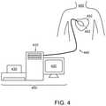
- FIG. 4is an exemplary embodiment of a system for determining a database table of dipole and/or surface charge densities and for displaying such density information, in accordance with aspects of the present invention
- FIG. 5Ais a perspective view of the distal portion of a system for treating a patient including an ablation catheter slidingly received by the shaft of a diagnostic catheter and FIG. 5B is a perspective view of the system of FIG. 5A , with the ablation catheter in a bent configuration for treating a patient, in accordance with aspects of the present invention;
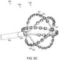
- FIG. 5Cis a perspective view of the distal portion of a system for determining a database of dipole and/or surface charge densities, in accordance with aspects of the present invention.
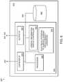
- FIG. 6is an exemplary embodiment of a computer architecture forming part of the system of FIG. 4 , in accordance with aspects of the present invention
- FIG. 7is an example embodiment of a method of determining and storing surface charge densities, in accordance with aspects of the present invention.
- FIG. 8is an example embodiment of a method of determining and storing dipole densities, in accordance with aspects of the present invention.
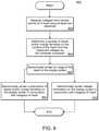
- FIG. 9is an example embodiment of a method of displaying dipole and/or surface charge densities, in accordance with aspects of the present invention.
- FIG. 10is an exemplary embodiment of a user interface display of dipole and/or surface charge density information that can be generated on one or more displays, in accordance with aspects of the present invention
- FIG. 11is another embodiment of a user interface display of dipole and/or surface charge density information that can be generated on one or more devices, in accordance with aspects of the present invention.
- FIG. 12is an example embodiment of a method of producing a model of a heart including the geometry of the cardiac surfaces, in accordance with aspects of the present invention.
- spatially relative termssuch as “beneath,” “below,” “lower,” “above,” “upper” and the like may be used to describe an element and/or feature's relationship to another element(s) and/or feature(s) as, for example, illustrated in the figures. It will be understood that the spatially relative terms are intended to encompass different orientations of the device in use and/or operation in addition to the orientation depicted in the figures. For example, if the device in the figures is turned over, elements described as “below” and/or “beneath” other elements or features would then be oriented “above” the other elements or features. The device may be otherwise oriented (e.g., rotated 90 degrees or at other orientations) and the spatially relative descriptors used herein interpreted accordingly.
- the terms “subject” and “patient”refer to any animal, such as a mammal like livestock, pets, and preferably a human. Specific examples of “subjects” and “patients” include, but are not limited, to individuals requiring medical assistance, diagnosis, and/or treatment, for example, patients with an arrhythmia, such as atrial fibrillation (AF).
- AFatrial fibrillation
- Surface charge densitymeans surface charge (Coulombs) per unit area (cm 2 ).
- a dipoleas such, is a neutral element, wherein one part comprises a positive charge and the other part comprises the same, but negative charge.
- a dipole or surface charge mapcould be considered to represent an electric nature of cellular membranes better than voltage maps, because in a biological environment, ion charges are not macroscopically separated.
- mapand “mapping” can include “electrical map”, “electrical mapping”, “anatomical map”, “anatomical mapping”, “device map” and “device mapping”, each of which is defined herein below.
- electrical mapcan include recording, processing and/or displaying electrical information, such as electrical information recorded by one or more electrodes of the present invention.
- This electrical informationincludes, but is not limited to: cardiac or other tissue voltage measurements; cardiac or other tissue bipolar and/or unipolar electrograms; cardiac or other tissue surface charge data; cardiac or other tissue dipole density data; cardiac or other tissue monophasic action potentials; and combinations of these.
- anatomical mapand “anatomical mapping” can include recording, processing and/or displaying anatomical information, such as anatomical information provided by one or more ultrasound transducers of the present invention and/or one or more electrodes of the present invention.
- This anatomical informationincludes, but is not limited to: two or three dimensional representations of tissue such as one or more chambers of a heart; tissue wall thicknesses such as the thickness of an atrial or ventricular wall; distance between two tissue surfaces; and combinations of these.
- a dipole density mapis provided by using information provided by multiple electrodes and multiple ultrasound transducers, such as is described in U.S. Pat. No. 8,512,255 B2.
- device mapand “device mapping” can include recording, processing and/or displaying of device distance information, such as information comprising the distance between a device or device component and another object, such as tissue or another device or device component.
- patient informationcan include physiologic and other information related to the patient, including but not limited to source information and field information, as defined herein, that relates to the patient's heart or other patient location.
- Patient informationcan include information which is derived from or is otherwise based on recordings made by one or more sensors, such as one or more electrodes, ultrasound transducers and/or other sensors of the present invention.
- Patient informationcan include mathematically processed patient information, such as patient information that is averaged, summed, integrated, differentiated and/or otherwise mathematically processed to create new patient information.
- Patient informationcan include patient demographic information, including but not limited to: age; sex; race; height; weight; and patient ID (e.g. an ID assigned to the patient by a hospital).
- cardiac informationcan include patient physiologic and other information related to the patient's heart, including but not limited to source information and field information, as defined herein, that relates to the patient's heart and/or cardiac activity.
- the systems and device of the present inventioninclude one or more sensors or transducers, such as electrodes and ultrasound transducers.
- any pair of electrodescan be constructed and arranged to provide distance information, such as the distance between that pair of electrodes, or the distance between one of the electrodes and one or more proximate components (e.g., a component at a known distance from one or both of the electrodes in the pair).
- the signalcan by processed and/or calibrated according to one or more known separation distances (e.g., the separation distance between two electrodes fixedly mounted to a rigid structure at a pre-determined distance).
- Calibrated signal valuescan be combined across adjacent sets of electrode pairs to accurately estimate the distance between any pair (e.g. any arbitrary pair of electrodes on any one or more devices of the system) of electrodes for which the separation distance is not known.
- Known and calculated separation distancescan be used as “reference” electrodes and combined to triangulate the unknown position of one or more “marker” electrodes, such as an electrode positioned on the present invention or on a separate or external device and positioned proximate the present invention.
- the process of triangulationcan be used to dynamically localize the multi-dimensional position of any or all of the electrodes either individually and/or as a combined entity in multi-dimensional space. Numerous distance measurement techniques can be used.
- any or all electrodescan be used to deliver electric energy, such as radiofrequency energy.
- FIGS. 1-12illustrate embodiments of devices, systems and methods that can be used for determining dipole (or surface charge) densities from the cardiac activity of a patient or subject.
- the present inventionis not limited to these particular configurations.
- the descriptionwill generally refer to “dipole densities,” which should be interpreted to include, either additionally or alternatively, surface charge densities, unless otherwise stated, understood by those skilled in the art.
- FIG. 1a block diagram of an embodiment of a dipole and/or surface charge density system including device 100 configured to determine a database table of dipole and/or surface charge densities of at least one heart chamber of a patient is illustrated.
- Device 100can include a plurality of receivers, e.g., receivers ( 1 ), ( 2 ) . . . (n), configured to receive one or more types of information from a patient, associated system, and/or other sensors.
- device 100includes a first receiver 110 configured to receive electrical potentials from a separate device, such as a device including a multi-electrode mapping catheter (e.g., placed in the circulating blood within a chamber of the patient's heart).
- a separate devicesuch as a device including a multi-electrode mapping catheter (e.g., placed in the circulating blood within a chamber of the patient's heart).
- Device 100can further include a second receiver 120 configured to receive cardiac geometry information (e.g., the geometric contour of the cardiac chamber wall), such as from an instrument including, but not limited to: Computed Tomography; MRI; Ultrasound; a multi-electrode mapping catheter; a multi-transducer imaging catheter such as an imaging catheter comprising an array of ultrasound transducers; and combinations of these.
- cardiac geometry informatione.g., the geometric contour of the cardiac chamber wall
- first receiver 110receives information from an array of electrodes placed in a chamber of the heart
- second receiver 120receives information from an array of ultrasound transducers also placed in a chamber of the heart.
- the electrodes and ultrasound transducerscan be included on a single deployable basket or other expandable assembly, such as is described herebelow in reference to FIG.
- a standard geometrycan be loaded representing a model of the heart, such as a model including the geometry of the cardiac chamber.
- a receivere.g., receiver (n)
- source informationis data representing, at a location in 3D space, a physical property or properties discrete to the specific location in 3D space.
- field informationwhich, as used herein, is data representing, at a location in 3D space, a physical property or properties of a continuum extending through the 3D space.
- Device 100further includes a dipole density module 130 which comprises mathematical processing elements, such as a computer or other electronic module including software and/or hardware for performing mathematical or other calculations when executed by at least one computer processor.
- Dipole density module 130receives electrical mapping information and/or other information (hereinafter “mapping information”) from first receiver 110 and cardiac geometry information from second receiver 120 .
- Dipole density module 130preferably uses one or more algorithms to correlate and/or otherwise process the received mapping and geometry information, such as to produce a database table of dipole and/or surface charge densities (e.g. comprising multiple sequential data sets that represent one or more phases of one or more cardiac cycles).
- the dipole and/or surface charge density information (or other source information)is updated at least once per second.
- the dipole density information (or other source information)is updated as least once per 10 seconds. Accordingly, dipole density module 130 can be configured to produce a database or database table of dipole densities, surface charge densities, or both.
- the geometrical model of the cardiac chamberis processed by dipole density module 130 into multiple small polygons, such as multiple small triangles or other polygons (e.g., trapezoids, squares, rectangles, pentagons, hexagons, octagons, and so forth), hereinafter, collectively referred to as “triangles.”
- trianglesWhen the triangles or other polygons are sufficiently small, the dipole and/or surface charge density at each triangle can be regarded as constant.
- a standard cardiac chamber of 4-6 cm diameteris divided up into over 1000 triangles.
- the number of triangles determined by dipole density module 130is based on the size of the heart chamber. With the electrodes positioned in a cardiac chamber by a clinician, such as an electrophysiologist, the potentials at each electrode are recorded. Each triangle is seen by the corresponding electrode under a certain solid angle.
- solid angleis the angle subtended by a triangle on the heart wall at a position x of observation.
- the straight linesthen define the spherical triangle on the surface of the sphere.
- the solid angleis proportional to the surface area of the projection of that object onto a sphere centered at the point x.
- the dipole density module 130computes the solid angle ⁇ acute over ( ⁇ ) ⁇ (x,y) subtended by each triangle at position y on each electrode at position x on the multi-electrode catheter. If the dipole density at the triangle is d(y), the triangle contributes ⁇ acute over ( ⁇ ) ⁇ (x,y) times d(y) to the potential V(x) at the position x on the multi-electrode catheter. The total measured potential V(x) is the sum resulting from all the triangles. A detailed description is provided in reference to FIG. 3 herein below.
- dipole density module 130can implement a progressive algorithm that can be modified and/or refined in order to improve spatial and/or time resolution of the database of dipole densities that are produced.
- the dipole densities d(y)are obtained by solving a linear system of equations. This calculation requires some care to avoid numerical instabilities.
- a map of dipole and/or surface charge densitiescan be created at corresponding time intervals. The synthesis of the maps generates a cascade of the activation sequence of each corresponding heart beat (also referred to herein as “cardiac cycle”) that can be used to define the origin of the electrical activity, arrhythmias and/or diagnose cardiac disease.
- the measuring electrodes usedcan be placed in the blood flow in a heart chamber, a relatively homogeneous condition, such that the mathematical analysis is well applicable.
- skin electrodesare also implemented such that dipole density module 130 can use the information received from the skin electrodes to calculate and/or recalculate the dipole densities for the cardiac wall.
- the spatial resolution which can be obtained by invasive (i.e., placed in the chamber) multi-electrode potential measurementscorrelates to the number of electrodes that can be placed in any cardiac chamber, such as the Left Atrium (LA).
- Skin placed electrodes, such as electrodes placed on the thoraxare not space limited and can be used to enhance calculations of the dipole densities.
- Application of electrical information measured from skin electrodes at known locations on the torsocan enhance the accuracy of dipole and/or surface charge density calculations by adding independent complementary information from the opposite side of the dipole layer, as compared to information obtained from an electrode located within the heart chamber.
- a highly complicated boundary value problemmust be solved with boundary conditions that are poorly known, and previous attempts at determining the “action potential” from body surface ECG (alone) have not been very successful.
- the badly defined boundary value problemcan be avoided by an additional measurement (in addition to the skin electrode measurements) of the chamber-inserted multi-electrode array of the present invention.
- This methodyields a higher spatial resolution than the L array electrodes alone.
- regularization techniquesmust be used (e.g. Tikhonov regularization and its modifications) in order to avoid numerical instabilities.
- a temperature from a temperature sensore.g. a thermocouple
- pH from a pH sensore.g. a pH sensor
- the associated sensorcan be placed at multiple locations along a cardiac surface while data is recorded.
- Module 130can be used to correlate the recordings provided by the sensor to the anatomical information.
- Step 10an embodiment of a preferred method for determining a database table of dipole (and/or surface charge) densities of at least one heart chamber of a patient is illustrated.
- Step 10a multi-electrode array catheter device is placed within the corresponding heart chamber.
- Step 20a model of the heart including the geometry of the corresponding heart chamber is created (i.e. electronically created).
- the model of the heartis created in relation to the multi-electrode array position.
- the model of the heartcomprises a static model comprising the geometry of one or more cardiac chambers representing that geometry at one particular reference point in a cardiac cycle (e.g.
- the geometry of the static heart modelcan comprise a single image (e.g. created one time) or it can be updated over time (e.g. updated by capturing chamber geometry information at the same reference point in multiple sequential or non-sequential cardiac cycles). In some embodiments, the static heart model is updated at least once every thirty minutes.
- the model of the heartcomprises a dynamic model (also referred to as a “beating heart model”).
- the dynamic modelcan comprise the cardiac geometry at multiple reference points of a single cardiac cycle (i.e. multiple images for a single heart beat) or it can be updated over time (e.g.
- the dynamic heart modelis updated at least 30 times per second (e.g. to provide a continuous image of the heart at 30 frames of video per second). In other embodiments, the dynamic heart model is updated at least once every 100 milliseconds, at least once every second, at least once every minute, or at least once every thirty minutes. In some embodiments, source information and/or field information is updated at least 30 times per second (e.g. to provide a continuous image of changing source information and/or field information at 30 frames of video per second). In other embodiments, source information and/or field information is updated at least once every 100 milliseconds, at least once every second, at least once every minute, or at least once every thirty minutes.
- the heart chamber geometryis provided by image-producing sensors (e.g. ultrasound sensors) from the same catheter device or a separate catheter device placed in the heart chamber.
- the model of the heart including heart chamber geometryis created (i.e. electronically created) from information provided by an imaging device external to the patient (e.g. a fluoroscope, computer tomography device, ultrasound imager, MRI) before and/or after the multi-electrode array of electrodes has been placed in the heart chamber.
- the surface of the geometry of the corresponding heart chamber modelcan be divided into small triangles, typically at least 1000 small triangles.
- the dipole density d(y)can be calculated (i.e. electronically determined) from the measured potential values and the calculated solid angles.
- the measurementscan be repeated successively during the cardiac cycle, such as to achieve sufficient resolution over time.
- the information of the time dependent dipole densitiescan be depicted as an activation map of the corresponding heart chamber for the given heartbeat.
- the informationcan be used to diagnose and/or treat a patient with a cardiac disease or disorder, such as atrial fibrillation or other cardiac arrhythmia.
- the surface charge densitycan be calculated in Step 30 .
- the dipole and/or surface charge densitiescan be stored in a database or database table, in Step 30 .
- the informationcan be used to determine cardiac wall treatment locations for lesion creation to treat an arrhythmia, such as a lesion created in the Left or Right atrium, by an RF, microwave, laser, ultrasound and/or cryogenic ablation catheter.
- the multiple electrode mapping arrayis placed in a ventricle and the dipole densities are determined for the ventricular wall, such as to detect ischemia or quantify myocardial function.
- FIG. 3an embodiment of a system for determining a database table of dipole densities and/or other information of at least one heart chamber of a patient is illustrated.
- System 300includes device 100 , which can be configured to create a database (or table) of dipole densities d(y) based on electrical potential measurements within the heart chamber and image information relating to the heart chamber, as has been described herein above. Alternatively or additionally, device 100 can be configured to create a database of other information, such as other local information regarding surface charge densities, temperature and/or pH levels at a cardiac surface.
- System 300further includes imaging unit 220 , which is configured to provide a two or three-dimensional image of the heart chamber relative to information provided by device 100 . Imaging unit 220 can perform at least one of fluoroscopy, Computed Tomography, MRI and/or ultrasound imaging, as examples of imaging technologies. Imaging unit 220 can produce any form of real or virtual models of the cardiac chambers, such that a mesh analysis (e.g. using triangles, polygons, etc.) is possible.
- a mesh analysise.g. using triangles, polygons, etc.
- System 300further includes mapping catheter 310 , which includes shaft 311 , shown inserted into a chamber of a patient's heart, such as the Left Atrium (LA). At the proximal end of shaft 311 is handle 312 . At the distal end of shaft 311 is an array 315 including multiple electrodes 316 and/or multiple other sensors configured to record local information and/or field information.
- Array 315is shown in a basket construction, but numerous other constructions can be used including multiple independent arms, spiral arrays, electrode, ultrasound sensor and/or other sensor-covered balloons, and other constructions configured to place multiple sensors and/or transducers into a two or three-dimensional arrangement.
- any catheter with a multi-dimensional array of electrodes or other sensorscan be used to supply the mapping or other information to device 100 .
- the electrodes and/or sensorscan include sensors to sense other types of “source information,” e.g., temperature and pH, as examples.
- Handle 312can include one or more controls, not shown but such as one or more controls to steer shaft 311 and/or control one or more sensors or transducers of array 315 , such as to activate one or more electrodes 316 .
- catheter 310can include one or more types of imaging transducers, such as ultra-sound transducers (USTs) built into catheter 310 or array 315 , such as is described herebelow in reference to catheter 500 of FIG. 5A or catheter 500 ′ of FIG. 5C .
- imaging transducerscould be used to obtain imaging information to generate, maintain, update and/or augment the image of the heart, in conjunction with imaging unit 220 .
- Electrodes 316are connected to wires, not shown, but traveling proximally, passing through handle 312 to cable 317 , which is electrically connected to a mapping unit 210 , such as an electrocardiogram (ECG) unit.
- Mapping unit 210includes a monitor for displaying information, such as the potentials recorded by electrodes 316 , as well as the dipole density or other information produced by device 100 .
- device 100further includes a monitor, not shown, but configured to display one or more of: dipole density information; surface charge information; potentials recorded by electrodes 316 ; information recorded by one or more sensors such as one or more temperature and/or pH sensors; and cardiac chamber contours and other geometry information.
- imaging unit 220can include a device configured to create an image of the cardiac chamber from signals recorded from an sensor array catheter, such as catheter 310 of FIG. 3 , catheter 500 of FIG. 5A or catheter 500 ′ of FIG. 5C .
- System 300can include a device for treating a cardiac arrhythmia, such as ablation source 230 , which is electrically attached to electrodes 316 via cable 318 .
- ablation source 230can be operably attached (e.g. via wires, fluid delivery tubes and/or optical fibers) to a different ablation catheter, such as a single or multiple ablation element catheter configured to deliver ablation energy such as RF energy, microwave energy, laser energy, ultrasound energy, cryogenic energy, or other tissue disrupting energy.
- triangle T 1defined by device 100 , is at location Y.
- Array 315includes multiple electrodes 316 , such as electrode 316 a positioned at location X.
- the geometric relationship between triangle T 1 and location Xis defined by the solid angle, angle ⁇ acute over ( ⁇ ) ⁇ (X,Y).
- Device 100includes dipole density module 130 such that each triangle at location y contributes ⁇ acute over ( ⁇ ) ⁇ (x,y) times the dipole density d(y) to the potential V(x) at the position x for each electrode of array 315 .
- Solid angle ⁇ acute over ( ⁇ ) ⁇ (x,y), as defined above,corresponds to the triangle at a location y and the electrode at positions x on the multi-electrode array 315 .
- the dipole density module 130 of device 100determines from the total measured potential V(x), which is the sum resulting from all the triangles defined by device 100 , the desired dipole density d(y).
- the dipole density d(y) at many equally distributed regions y on the cardiac wallis calculated by solving a linear equation system.
- the solid angle ⁇ acute over ( ⁇ ) ⁇ (x,y) of a regionis the sum of the solid angles of the individual triangles in the region on the cardiac wall.
- the resultsare presented in a visual, anatomical format, such as depicting the dipole densities on a geometric image of the cardiac wall in relation to time (t).
- This formatallows a clinician, such as an electrophysiologist, to determine the activation sequence on the cardiac wall, such as to determine treatment locations for a cardiac arrhythmia.
- the resultscan be shown on a display of mapping unit 210 , or on a separate unit such as a display included with device 100 , display not shown but preferably a color monitor.
- the device of the present inventionis implemented as, or includes, a software program that is executable by at least one processor.
- the software programcan be integrated into one or more of: an ECG system; a cardiac tissue ablation system; an imaging system; a computer; and combinations of these.
- the multi-electrode catheter 310includes at least 10 electrodes 316 and/or other sensor, configured to provide local information and/or field information in relation to a multi-dimensional representation of a heart.
- the electrodes 316are preferably positioned in a spherical geometry, such as a spherical geometry created in a basket catheter.
- Elliptical electrode array geometriescan be used, such as those provided in the Ensite Array Catheter, manufactured by St. Jude Medical of St. Paul Minn.
- multiple cathetersare inserted into the heart chamber to provide the multiple electrodes.
- the electrodes 316 of the multi-electrode mapping array 315are repositioned during the method of determining dipole densities. Repositioning of electrodes 316 and/or other sensors or transducers of array 315 can be beneficial to increase the number of measured potential values, if electrode 316 positions are known. Therefore, repositioning is in concordance with adjustment of the geometry map in relation to the multi-electrode mapping array 315 .
- array 315further comprises one or more transducers, such as one or more ultrasound transducers (USTs), as described variously herein. Also in some embodiments, either alternatively or in addition to the electrodes 316 , array 315 can include non-electrode sensors, such as temperature sensors and/or pH sensors.
- transducerssuch as one or more ultrasound transducers (USTs)
- USTsultrasound transducers
- array 315can include non-electrode sensors, such as temperature sensors and/or pH sensors.
- FIG. 4shows an example embodiment of a system 400 configured to determine a database table of dipole and/or surface charge densities of at least one heart chamber of a patient, e.g., as an embodiment of system 300 above. That is, system 400 can be considered to be a somewhat simplified version of system 300 , used to describe an approach for determining dipole and/or surface charge densities using voltage measurements representing cardiac activity.
- System 400can be used to map activity of a heart 452 of a patient 450 , e.g., a human.
- the geometry of the given heart chamberis determined or obtained in any of a variety of manners such as those described herein.
- the multi-dimensional geometry of the cardiac chambercan be assessed, in various embodiments, by currently available and common mapping systems (so-called locator systems) or, alternatively, by integrating anatomical data from CT/MRI scans.
- System 400can include a computer 410 having known types of input devices and output devices, such as a display 420 and printer 430 , and a probe system 440 .
- a computer 410having known types of input devices and output devices, such as a display 420 and printer 430 , and a probe system 440 .
- contact and/or non-contact mapping methodscan be used.
- the mapping methodscan use probe electrode system 442 , which is connected to the computer 410 via a cable and forms part of probe system 440 as shown in FIG. 4 .
- Probe system 440can take the form of, or include, a catheter.
- the computer 410can be configured to include at least one processor and computer storage device, comprising a set of executable functional modules that perform various tasks to determine dipole and/or surface charge density using cardiac potential information from the probe system 440 .
- the probe electrode 442can take the form of a multi-electrode array with elliptic or spherical shape, in some embodiments.
- the spherical shape of such an arraycan have certain advantages for the subsequent data analysis.
- other types or even several independent electrodescould be used to measure V e (i.e., the voltage on the endocardium).
- V ei.e., the voltage on the endocardium
- V ethe voltage on the endocardium
- Vthe potential and x,y,z denote the three dimensional coordinates.
- the solutionis an integral that allows for calculating the potential V(x′y′z′) at any point x′y′z′ in the whole volume of the heart chamber that is filled with blood.
- a discretization of the cardiac surfaceis necessary and the so called boundary element method (BEM) can be used.
- the boundary element methodis a numerical computational method for solving linear integral equations (i.e. in surface integral form).
- the methodis applied in many areas of engineering and science, including fluid mechanics, acoustics, electromagnetics, and fracture mechanics.
- Boundary element formulationstypically give rise to fully populated matrices after discretization. This result means that the storage requirements and computational time, using BEM, will tend to grow according to the square of the problem size.
- finite element matricesare typically banded (elements are only locally connected) and the storage requirements for the system matrices typically grow quite linearly with the problem size.
- the surface charge and/or dipole densitiesare determined.
- the surface charge density and the dipole densityare related to potential according to the following two Poisson equations:
- V e ⁇ ( P )- 1 4 ⁇ ⁇ ⁇ ⁇ S e ⁇ ⁇ ⁇ ( P ′ ) ⁇ P ′ - P ⁇ ⁇ d ⁇ ⁇ ⁇ ⁇ ( P ′ ) ( 7 )
- V e ⁇ ( P )1 4 ⁇ ⁇ ⁇ ⁇ S e ⁇ ⁇ ⁇ ( P ′ ) ⁇ ⁇ ⁇ n P ′ ⁇ 1 ⁇ P - P ′ ⁇ ⁇ d ⁇ ⁇ ⁇ ⁇ ( P ′ ) ( 8 ) (For a review see Jackson JD. Classical Electrodynamics, edition, Wiley, New York 1975.)
- the boundary element methodagain provides a code for transforming the potential V e in formulas 7 and 8 into the desired surface charge densities and dipole densities, which can be recorded in a database of surface charge densities and/or dipole densities.
- the electric potential(s) V eis (are) determined by contact mapping. In this case the steps for calculating the electric potential V e are not necessary, because the direct contact of the electrode to the wall of the heart chamber already provides the electric potential V e .
- the probe electrodecomprises a shape that allows for calculating precisely the electric potential V e and, thus, simplifies the calculations for transforming V e into the desired charge or dipole densities. That is, the geometry of the electrode can be ellipsoidal or spherical in such an embodiment.
- a systemcomprising at least the following can be used:
- the present inventionis not limited to any particular types of electrodes or other sensors or transducers. Instead, the invention provides a new and advantageous processing of the available data that will allow for an increase in precision, accuracy and spatial resolution of cardiac activation mapping when compared to prior art systems based on electric surface potentials in the heart only.
- the present inventionprovides enhanced diagnostic means for diagnosing cardiac diseases and disorders (e.g. arrhythmias) and other electric status of heart cells including metabolic and functional information.
- Catheters and other devices as used in the context of the present inventioncan include numerous forms of diagnostic catheters such as catheters including one or more electrodes, or therapeutic catheters such as tissue ablation catheters, such as, for example, the catheters described in U.S. patent application Ser. No. 14/422,941, filed Feb. 5, 2015, entitled Catheter System and Methods of Medical Use of Same, Including Diagnostic and Treatment Uses for the Heart.
- Catheterscan be introduced percutaneously into a patient's heart, such as to record electrical activity, measure distances between structures, or deliver energy.
- External devices and systemscan be included, such as body surface electrodes used to record an electrical signal and/or deliver an electric signal, or visualization devices such as external ultrasound or fluoroscopic imaging systems.
- any of these catheters or other devicescan include one or more electrodes, one or more ultrasound transducers, and/or one or more other sensors or transducers. These electrodes, ultrasound transducers, and/or other sensors or transducers can be positioned at any location on the device, for example at a distal or proximal portion of the device, and can be positioned internal or external to a patient's body.
- any or all of the ultrasound transducerscan be used to measure a distance between the transducer and a surface, as is known in the art.
- One exampleincludes measuring the distance between the ultrasound transducer and a wall of the cardiac chamber.
- Another exampleincludes measuring the distance between the ultrasound transducer and a component of the same or a separate device.
- any or all of the electrodes of such catheterscan be used to record electric “signals” (e.g. voltages and/or currents) at or between the electrode locations.
- Recorded electric signalscan be used to map electrical activity of tissue, such as when an electrode is positioned away from tissue (e.g. in the circulating blood) or when an electrode is in contact with tissue.
- Algorithms, such as those described hereabovecan be used to correlate recorded signals at multiple non-contacting locations to signals present at one or more tissue locations.
- the mapped electrical activity and/or other electrical signalscan be further processed (e.g. in terms of sources of charge and charge density and correlated with various physiologic parameters related to the function of the heart) and the mapped electrical activity and other recorded and calculated information can be provided visually to one or more operators of the system of the present invention.
- any or all of the electrodescan be used to deliver and/or record electric signals that are generated by the system. Such delivered signals can be emitted from any one or more electrodes, and can be delivered between any two or more electrodes.
- Recorded signalscan comprise a signal present at a single electrode location or at multiple electrode locations (e.g. a signal representing a comparison of two or more signals present at two or more electrode locations). Recorded signals can be measured, for example, synchronously or asynchronously in terms of voltage and/or current.
- Recorded signalscan be further processed in terms of, for example, resistive and reactive components of impedance and/or the combined magnitude of impedance with any original or processed signal “values” (e.g. those represented by a parameter selected from the group consisting of: instantaneous amplitude; phase; peak; Root-Mean-Square; demodulated magnitude; and combinations of these).
- FIGS. 5A and 5Bperspective views of the distal portion of a system for diagnosing and/or treating a heart disease or disorder, such as atrial fibrillation and/or ventricular tachycardia, is illustrated.
- the systemcan be an embodiment of array 315 of FIG. 3 , array 530 ′ of FIG. 5C , and/or probe electrode system 442 of FIG. 4 , or portions thereof.
- FIG. 5Aillustrates an ablation catheter slidingly received by the shaft of a diagnostic catheter and
- FIG. 5Billustrates the ablation catheter of FIG. 5A in a bent configuration, in accordance with aspects of the present invention.
- the probe system 440includes a diagnostic catheter 500 which is constructed and arranged for insertion into a body location, such as the chamber of a heart.
- Catheter 500includes shaft 502 , typically constructed of sufficiently flexible material to allow insertion through the tortuosity imposed by the patient's vascular system.
- an expandable assembly 530On the distal portion of shaft 502 is an expandable assembly 530 , which includes a plurality of electrodes 541 coupled thereon. Additionally, a plurality of ultrasound transducers 551 are coupled to expandable assembly 530 in this embodiment. Electrodes 541 and USTs 551 are each electrically attached to one or more wires which travel proximally within shaft 502 , connecting to one or more receivers such as receivers 110 and 120 described hereabove in reference to FIG. 1 .
- catheter 500 , expandable assembly 530 , electrodes 541 and/or ultrasound transducers 551are constructed and arranged as the similar components described in Applicant's co-pending U.S. patent application Ser. No. 14/003,671, entitled Device and Method for the Geometric Determination of Electrical Dipole Densities on the Cardiac Wall, filed Sep. 6, 2013, the entirety of which is incorporated herein by reference.
- the number and pattern of electrodes (or other sensors) and USTscan be different in different embodiments; the invention is not limited to the embodiment depicted in FIGS. 5A and 5B which includes a pattern of two electrodes 541 between pairs of USTs 551 .
- catheter 500can include other types of electrodes or other sensors, e.g., temperature and/or pH sensors, either in addition to or as an alternative to the electrodes shown.
- the systemfurther comprises an ablation catheter 520 , which includes shaft 522 .
- Shaft 522includes at least one ablation element 561 , located at a tip or otherwise on a distal portion of shaft 522 .
- Ablation element 561is constructed and arranged to deliver energy to tissue, such as when ablation catheter 520 is attached to a source of energy.
- Shaft 502includes a lumen 526 traveling from at least a proximal portion of shaft 502 (e.g. from a handle, not shown but typically positioned on shaft 502 's proximal end) to a distal portion of shaft 502 (e.g. to shaft 502 's distal end).
- Shaft 502 of ablation catheter 520 and lumen 526 of diagnostic catheter 500are constructed and arranged to allow shaft 522 of ablation catheter 520 to be slidingly received by lumen 526 .
- Lumen 526can be further configured to slidingly receive additional catheters or other elongate devices, such as prior to insertion of diagnostic catheter 500 into a body, or after diagnostic catheter 500 has been inserted into a body.
- Diagnostic catheter 500can be used for mapping tissue such as an organ or portion of an organ (e.g. a portion of a heart wall).
- Multi-dimensional anatomical mapping information collected by diagnostic catheter 500can be used by the system (e.g., computer system 400 ) to create a multi-dimensional display of an anatomical location of which at least a portion is to be treated by ablation catheter 520 .
- Diagnostic catheter 500can be coupled to a computer system, e.g., computer system 400 ) configured to display anatomical mapping information generated by diagnostic catheter 500 , such as volumes, locations, shapes, contours, and movement of organs, nerves, and other tissue within the body.
- Diagnostic catheter 500can be coupled to the computer system 400 to display the electrical mapping information generated by diagnostic catheter 500 , such as to display dipole mapping or other information as has been described above. Additionally, the location of ablation catheter 520 or other inserted devices can be displayed, such as their position relative to tissue or diagnostic catheter 500 . For example, diagnostic catheter 500 can be used to map the heart, while ablation catheter 520 can be directed to a tissue location in the heart targeted for treatment (e.g. targeted for treatment based on information provided by diagnostic catheter 500 and/or another component of system 400 ).
- ablation catheter 520can be configured to ablate cardiac tissue to treat a patient suffering from a cardiac arrhythmia, such as atrial fibrillation, atrial flutter, supraventricular tachycardias (SVT), Wolff-Parkinson-White syndrome, and ventricular tachycardias (VT).
- a cardiac arrhythmiasuch as atrial fibrillation, atrial flutter, supraventricular tachycardias (SVT), Wolff-Parkinson-White syndrome, and ventricular tachycardias (VT).
- An ablation catheterwill be described herein as a form of a treatment device for purposes of conveying aspects of the invention, but a different type of treatment device (e.g., a pacing device; a defibrillation device; a stent delivery device; a drug delivery device, a stem cell delivery device, or the like) can be used in other embodiments in combination with diagnostic catheter 500 .
- one or more of these treatment devicesis inserted through a lume
- the systemis configured to access the left atrium of the patient while utilizing a single transseptal puncture through which all the catheter components of system access the left atrium (and subsequently the left ventricle in some cases). In other embodiments, the system is configured to access the left ventricle of the patient while utilizing a single crossing of the aortic valve through which all the catheter components of the system access the left ventricle (and subsequently the left atrium in some cases).
- the systemcan include sheath 504 , for example a standard access sheath, such as a standard transseptal access sheath.
- sheath 504can be inserted through the atrial septum and into the left atrium, followed by the insertion of diagnostic catheter 500 through a lumen of sheath 504 .
- ablation catheter 520can be inserted through lumen 526 of diagnostic catheter 500 .
- sheath 504is inserted into the left atrium, followed by the simultaneous insertion of diagnostic Catheter 500 and ablation catheter 520 (e.g. diagnostic catheter 500 is inserted with ablation catheter 520 residing at least partially within lumen 526 ).
- sheath 504can comprise a steerable sheath.
- Shaft 502comprises a diameter along the majority of its length such as to be slidingly received by sheath 504 .
- shaft 502comprises a diameter less than or equal to 15 Fr.
- diagnostic catheter 500 and/or ablation catheter 520can be steerable, so that manual, semi-automatic or automatic steering can be performed by an operator and/or a robotic control assembly of the system, as shown in FIG. 5B .
- Diagnostic catheter 500can be positioned in the left atrium and can provide information selected from the group consisting of: electrical information, such as voltage information (e.g. voltage information which is analyzed to produce surface charge information); anatomical geometry information, such as heart wall surface information or heart wall thickness information; other physiologic and anatomical information, such as those described herein; and combinations of these.
- Shaft 502 of diagnostic catheter 500can be configured to be inserted into the heart via the venous system, for example a vein in a leg or a vein in a neck.
- Shaft 502can include a braid within its outer and inner surfaces, not shown but typically a braid of plastic or metal fibers that enhance the structural integrity and performance of shaft 502 .
- the braid of shaft 502can include conductors (e.g. one or more conductors connected to an electrode 541 and/or an ultrasound transducer 551 ).
- diagnostic catheter 500includes lumen 526 extending from a proximal portion to a distal portion of shaft 502 , for example from a proximal end to a distal end of shaft 502 so as to allow a separate catheter or other elongate device to be inserted therethrough, such as ablation catheter 520 , as shown.
- the inserted catheter or other elongate devicecan include a diagnostic catheter, such as a diagnostic catheter configured to record signals from a location selected from the group consisting of: the left atrium; the right atrium; the Bundle of HIS; the right ventricular apex; a pulmonary vein; the coronary sinus.
- the inserted cathetercan comprise another catheter device.
- Diagnostic catheter 500can include expandable assembly 530 , which is positioned at the distal end of shaft 502 —here in the form of a basket array.
- expandable assembly 530includes an array of splines 531 , each spline 531 having proximal segment 532 , middle portion 534 , and distal segment 533 .
- Proximal segment 532 of each spline 531connects to shaft 502 , via connection point 527 .
- the distal ends of each spline 531connect in a circumferential ring configuration to form opening 535 . Opening 535 allows a device to pass through, such as a device inserted into lumen 526 , for example shaft 522 of ablation catheter 520 .
- expandable assembly 530can include one or more guide elements configured to guide a device through opening 535 .
- Expandable assembly 530can be constructed and arranged to be positioned in the expanded Shape shown in FIGS. 5A and 5B .
- the expanded geometry of assembly 530including at least two or more splines 531 in an expanded or partially expanded state (hereinafter “expanded state”), can be described as a “basket” having a substantially hollow center and spaces between adjacent splines 531 .
- the basketis spherical, but can include any suitable shape, for example an ellipsoid or other symmetric or asymmetric shape.
- assembly 530can comprise different shapes or combination of shapes, such as an array of splines 531 where two or more splines 531 comprise similar or dissimilar shapes, dimensions or configurations.
- two or more splines 531include a varied radius of curvature.
- Expandable assembly 530can be biased in an expanded or non-expanded state.
- assembly 530can be self-expanding such that splines 531 are resiliently biased in the curved geometry shown in FIGS. 5A and 5B .
- Assembly 530can automatically expand when assembly 530 exits the distal end of sheath 504 , such as by advancement of shaft 522 and/or retraction of sheath 504 .
- assembly 530can be manually expanded, for example via retraction of a rod (not shown) that slides within shaft 502 and is connected to distal end of assembly 530 .
- Splines 531can be constructed of a material selected from the group consisting of: one or more thermoplastic polymers such as polyether block amide, polyurethane and/or polyether ether ketone; one or more of thermoset polymers such as silicon and/or tetrafluoroethylene; one or more metals such as stainless steel and/or shape memory alloys such as nickel titanium alloy; one or more shape memory polymers such as triple shape acrylic; and combinations of these.
- thermoplastic polymerssuch as polyether block amide, polyurethane and/or polyether ether ketone
- thermoset polymerssuch as silicon and/or tetrafluoroethylene
- metalssuch as stainless steel and/or shape memory alloys such as nickel titanium alloy
- shape memory polymerssuch as triple shape acrylic
- Splines 531can include one or more electrodes 541 and/or one or more ultrasound transducers 551 arranged in any combination.
- each spline 531includes at least four, six or eight electrodes 541 ; each spline 531 includes at least four, six or eight ultrasound transducers 551 ; and combinations of these.
- at least one electrode 541is positioned between two ultrasound transducers 551 on a single spline 531 (such as in the alternating pattern shown in FIG. 5C ).
- at least two electrodes 541are positioned between two ultrasound transducers 551 on a single spline 531 .
- Each spline 531can include a similar or dissimilar arrangement of electrodes 541 and/or ultrasound transducers 551 such as an adjacent spline 531 or any other spline 531 in assembly 530 .
- assembly 530includes eight splines 531 , where each spline 531 can include two to eight electrodes 541 and two to eight ultrasound transducers 551 .
- assembly 530includes six splines 531 , where each spline 531 can include eight electrodes 541 and eight ultrasound transducers 551 .
- one or more splines 531include a number of electrodes 541 that comprises a quantity within one of the quantity of ultrasound transducers 551 that are included on that spline 531 .
- a spline 531can include seven electrodes 541 and either six or eight ultrasound transducers 551 .
- a set of electrodes 541 and ultrasound transducers 551can be arranged in an alternating arrangement, such that one or more single ultrasound transducers 551 lies between two electrodes 541 .
- some sets of electrodes 541 and ultrasound transducers 551can be arranged such that one or more single electrodes 541 is positioned between two ultrasound transducers 551 .
- Electrodes 541can be configured to record electric signals such as voltage and/or current signals.
- the systemcan utilize the recorded signals to produce electrogram information; dipole mapping information; surface charge information; distance information such as the distance between any device and/or component of the system; and other information or combinations of information described in detail herein.
- Any or all electrodes 541can comprise a dipole and/or surface charge mapping electrode, such as an electrode with an impedance or other electrical property configured to provide information related to surface charge or other dipole mapping parameter.
- the electrodes 541are of sufficiently low impedance, such as in the range less than 10,000 ohms, such as to achieve high-fidelity recording of signal frequencies greater than or equal to 0.1 Hz.
- one or more electrodesare of sufficiently low impedance, such as in the range less than 10,000 ohms, such as to achieve high-fidelity recording of signal frequencies greater than or equal to 0.1 Hz.
- Electrodes 541include an iridium oxide coating, such as to reduce the impedance of electrodes 541 .
- numerous forms of coatings or other treatmentscan be included with one or more electrodes 541 , such as a platinum black coating or a carbon nanotube layer.
- electrodes 541can be constructed and arranged to deliver electric energy, such as radiofrequency energy.
- diagnostic catheter 500can deliver therapy, such as an ablation therapy delivered to tissue, in addition to its function as a diagnostic catheter, e.g. providing electrical, anatomical and/or device mapping information.
- one or more electrodes 541each comprise one or more coils, such as when the one or more coils are configured to create one or more magnetic fields.
- Electrodes 541can include various materials such as non-polarizing metals and/or polarizing metals.
- one or more electrodes 541comprise at least one non-noble metal such that electrodes 541 oxidize when in contact with at least one of blood, blood plasma or saline solutions.
- electrodes 541include a coating, for example a coating selected from the group consisting of: a metal oxide coating; a conductive polymer coating; and combinations of these.
- one or more electrodes 541can include an outer layer and an inner layer, such as when the outer layer comprises an impedance lowering coating or other layer and the inner layer comprises a layer configured to bond the outer layer to the metallic and/or other remaining portion of the one or more electrodes 541 .
- Ultrasound transducers 551can be configured to record distance information such as the distance between any device and/or component of the system and tissue such as cardiac wall or other solid tissue.
- Ultrasound transducers 551can include a construction comprising: single or multi-element piezoelectric ceramics; piezoelectric micro-machined ultrasound transducers (pMUT); capacitive micro-machined ultrasound transducers (cMUT); piezoelectric polymers; and combinations of these.
- diagnostic catheter 500can include a multi-layer or laminate construction, for example where shaft 502 includes a tube inside of another tube; where shaft 502 includes a liner such as a liner constructed of a lubricous material such as PTFE; where shaft 502 includes a braided construction such as a braid positioned between two layers of shaft 502 ; and combinations of these.
- diagnostic catheter 500can be steerable, for example via the incorporation of a pull wire and anchor (not shown).
- diagnostic catheter shaft 502 outer diameteris less than 15 Fr.
- Ablation catheter 520 of FIGS. 5A and 5Bincludes ablation element 561 positioned on shaft 522 , for example on a distal portion or the distal tip of shaft 522 .
- Ablation element 561can include a functional element selected from the group consisting of: one or more electrodes; a vessel or port configured to deliver cryogenic energy; a laser diode; an optical fiber configured to deliver ablative light energy; a microwave energy delivery element; an ultrasound energy delivery element; a drug, stein cell, or other agent delivery element; an abrasive or other mechanical ablative energy delivery element; and combinations of these.
- the electrodescan include electrodes constructed and arranged to deliver radiofrequency (RF) energy.
- RFradiofrequency
- ablation element 561can include an array of elements.
- Ablation catheter 520can be operably connected to a device configured to deliver energy to ablation element 561 , such as ablation source 230 of FIG. 3 .
- Typical energy delivered by ablation element 561comprises an energy selected from the group consisting of: electromagnetic energy such as radiofrequency energy; cryogenic energy; laser energy; light energy; microwave energy; ultrasound energy; chemical energy; and combinations of these.
- ablation catheter 520can be steerable, similar to diagnostic catheter 500 and sheath 504 , such as via a pull wire and anchor.
- ablation catheter 520has been steered in a curved geometry 525 , as shown, to cause ablation element 561 to exit expandable assembly 530 of diagnostic catheter 500 , passing between two middle portions 534 of two splines 531 .
- Ablation catheter 520can be steered and advanced by an operator such as a clinician, so as to exit at any opening of the expandable assembly 530 , including the space between two splines 531 or through opening 535 , such as to be further advanced to contact or move proximate to cardiac tissue, e.g., for ablation.
- timing sequencescan be used for sending and/or recording signals to and/or from electrodes 541 and/or USTs 551 on splines 531 of expandable assembly 530 in FIGS. 5A and 5B .
- a timing sequenceis used that provides a pattern of “ringing” the USTs that alternates between splines.
- the timing sequencecan also include timing of driving some of the spline electrodes and skin patch electrodes (optionally included) for localization.
- electrodes 541are continuously recorded.
- an electrode 541 and a UST 551share a common conductor, and an electrode 541 does not record when the UST 551 sharing the common conductor is receiving a ring signal.
- the timing sequence of sending and/or recording signalscan be computer controlled.
- a full cycle of a timing sequencecan be, for example, 100 ms or less (e.g. a cycle in which a series of sequential ring signals are sent to each UST 551 ).
- a timing sequenceis modified over time, such as to change the time of a full cycle and/or to modify the order in which signals are sent (e.g. to ring a UST 551 ) or recorded (e.g. from an electrode 541 ).
- Probe system 440includes mapping catheter 500 ′ and sheath 504 through which the distal portion of mapping catheter 500 ′ has been inserted.
- Mapping catheter 500 ′includes array 530 ′ positioned on the distal end of shaft 502 ′.
- Array 530 ′comprises multiple splines 531 upon which an alternating pattern of a single electrode 541 followed by a single UST 551 is positioned, as shown.
- Electrodes 541 and USTs 551are each electrically attached to one or more wires which travel proximally within shaft 502 ′, connecting to one or more receivers such as receivers 110 and 120 described hereabove in reference to FIG. 1 .
- System 440can include an ablation catheter, such as an ablation catheter similar to ablation catheter 520 of FIGS. 5A and 5B .
- the ablation cathetercan be advanced into the heart alongside shaft 502 ′ and sheath 504 .
- shaft 502 ′comprises a lumen, such as shaft 502 of FIGS. 5A and 5B , through which an ablation catheter or other device can be inserted.
- FIG. 6provides an example embodiment of a computer architecture 600 that can form part of system 400 configured to determine a database table of dipole densities of at least one heart chamber of a patient, which can communicate with the probe system 440 of FIGS. 4, 5A and/or 5C , as examples.
- Architecture 600can include standard interface modules 610 for probe system 440 (and electrodes 442 and/or catheters 500 , 500 ′ and 520 ) and interface modules 620 for interfacing with output devices 420 , 430 .
- Architecture 600can further include cardiac information display controller 650 for receiving, interpreting, generating, processing and/or providing cardiac information.
- the computer 410includes at least one processor 640 and at least one computer memory 680 connected to elements 610 , 620 , 630 , 640 and/or 650 via bus 660 as shown.
- the architecture 600further includes an electrical potential to surface charge density and/or dipole density converter module 630 .
- Module 630includes executable computer instructions necessary for carrying out the methods described herein, when executed by processor 640 , wherein the results of such processing are stored in memory (e.g., a database, data storage system, or data storage device) 680 —as would be understood by one skilled in the art having the benefit of this disclosure. That is, module 630 is preferably configured to determine dipole and/or surface charge densities from data received, at least in part, from probe system 440 , as described herein or otherwise.
- FIG. 7 and FIG. 8summarize embodiments of methods for determining and storing surface charge densities and dipole densities in accordance with aspects of the present invention, respectively, which have been described in detail above.
- Step 702system 400 is used to measure and/or calculate one or more electric potential(s) V e into one or more position(s) P within a heart chamber at a given time t.
- V eis transformed into a surface charge density ⁇ (P′,t).
- Step 706the surface charge density ⁇ (P′,t) is stored in a database table. The method is repeated if there is another P, in Step 708 .
- mapping system 400is used to measure and/or calculate one or more electric potential(s) V e in one or more position(s) P within a heart chamber at a given time t.
- V eis transformed into said dipole density ⁇ (P′,t) by using an algorithm suitable for transforming an electric potential into surface charge density.
- the dipole density ⁇ (P′,t)is stored in a database table. The method is repeated if there is another P, in Step 808 .
- the architecture 600further includes a cardiac information display (CID) controller 650 .
- CID controller 650is configured to generate and/or provide information sufficient for at least one display device to render cardiac information, which can include, but is not limited to, dipole density and/or surface charge density information.
- the cardiac informationcould also include cardiac voltage (or potential) information, a graphical model of a heart or portion of a heart (or other organ), images of a heart or portions thereof (or other organ), other local information such as temperature and/or pH information, other field information (e.g. other than voltage information), or combinations thereof.
- the rendering of the heart and/or portion of the heart (or other organ)could be two-dimensional (2-D), three-dimensional (3-D), or combinations thereof.
- cardiac informationcan also include an electrocardiogram (EKG or ECG), e.g., such as a graph of the heart's electrical activity versus time.
- EKG or ECGelectrocardiogram
- the above types of cardiac informationcould be displayed in various combinations, e.g., to include dipole density and/or surface charge density information, and displayed in 2-D, 3-D, or combinations thereof.
- Such cardiac informationcould be stored in memory 680 for real-time, near real-time, or subsequent display.
- the displaycould be a computer monitor, tablet, smartphone, television, or other type of display device or device comprising such a display.
- the display(s)could be local, remote, or combinations thereof (if more than one display).
- the display(s)could be wired, wireless, or combinations thereof (e.g. if more than one).
- dipole and charge density informationis different from voltage (or potential) information.
- dipole and charge density informatione.g., from methods 700 and 800
- source informationis data representing, at a location in 3D space, a physical property or properties discrete to the specific location in 3D space, e.g., similar to temperature or pH information which is also source information.
- voltage (or potential) informationcan be considered to be “field information,” which is data representing, at a location in 3D space, a physical property or properties of a continuum extending through the 3D space.
- FIG. 9describes an embodiment of a method 900 of displaying dipole and/or charge density information in at least one electronic or computer display, preferably in conjunction with at least one image of a heart.
- the methodcan be implemented by system 400 , as an example.
- Step 902voltages are measured from multiple cardiac locations (e.g. within or on the endocardial surface of a heart chamber) using at least one electrode, as field information.
- Step 904from the voltages (or field information), a plurality of dipole and/or charge densities (or source information) are determined by the computer processor, e.g., on multiple locations on the surface of the heart, from the measured voltages.
- Step 906at least one image of the heart is electronically rendered on at least one (local and/or remote) display screen.
- Step 908a distribution of dipole and/or charge densities is electronically rendered on the at least one display screen, e.g., in conjunction with the image(s) of the heart.
- Step 910which is an optional step, a voltage information is electronically rendered on the at least one display screen, e.g., in conjunction with the image(s) of the heart.
- Step 910can be a user selectable options, wherein, for example, voltage information could be toggled on and off under the user's control.
- Step 902comprises measuring voltages from an array of electrodes, serially or sequentially. In some embodiments, Step 902 further comprises moving one or more electrodes from a first location to one or more different locations and measuring voltages from the one or more electrodes at each location.
- Step 908comprises rending a series of dipole and/or charge densities on the display screen, such as a series of images representing a complete cardiac cycle (i.e., heartbeat).
- the series of images representing a complete cardiac cyclecan be repeated (i.e. looped).
- the series of images representing a complete cardiac cyclecan be updated (e.g. continuously updated and/or updated at discrete time intervals).
- a series of images representing a complete cardiac cyclecan be displayed with a static image of the heart (e.g. a single heart image rendered on the screen in Step 906 , such as an image representing the end of systole or diastole).
- a series of images representing a complete cardiac cyclecan be displayed with a corresponding series (e.g. a temporally corresponding series) of images of the heart that show the contraction and expansion of the heart during a cardiac cycle.
- FIG. 10is an exemplary embodiment of a display 1000 of dipole and/or surface charge density information that can be generated on one or more devices, in accordance with aspects of the present invention.
- dipole density informationis shown, but in other embodiments, additionally or alternatively, surface charge density, pH information, temperature information and/or other source or field information could be included.
- Display 1000could comprise any now known or hereafter developed graphical display, such as a computer monitor, tablet, cellphone, television, display panel, Google glass, and so forth. Alternatively or additionally, information provided on display 1000 could be provided on paper such as via a printer, or sent wirelessly to a separate device.
- Display 1000can include a patient information box, display area 1002 that provides relevant information about the patient (e.g. patient name, age, hospital patient ID, and the like) from whom the cardiac information was collected.
- Voltageis a “force field” that spreads out from “dipolar” sources of charge, (e.g. foci in AF diagnostics), so is field information, as that term is used herein. Region of influence typically spans several centimeters in a chamber of the heart. Voltage presents a broad, blurred view of the physiologic state, similar to de-focusing a camera lens. Voltage measurements include far-field interference from adjacent locations such as adjacent chambers. In contrast, dipolar charge sources (e.g. “focal pockets”) are source information, as that term is used herein, that can be derived from multiple voltage measurements (i.e., field information).
- dipolar charge sourcese.g. “focal pockets” are source information, as that term is used herein, that can be derived from multiple voltage measurements (i.e., field information).
- Dipole and surface charge density imagesrepresent a refined, high-resolution view of physiologic information that span a very small area (e.g., ⁇ 1 mm or smaller). Far-field interference from adjacent locations is reduced or eliminated. Therefore, the dipole density method is similar to re-focusing a camera lens to significantly improve resolution of local physiologic state and activity.
- display 1000includes a dipole (or surface charge) density display area 1010 in which dipole (or surface charge) density information can be displayed, as a form of source information.
- the dipole (or surface charge) density information ( ⁇ (P′,t)) 1012is displayed overlaid on an image of a heart, heart image 1011 .
- heart image 1011is not included.
- Heart image 1011can be an image or model of the particular heart being analyzed or a representative model of a heart, either of which can be stored in computer memory.
- the dipole density information 1012is shown for only a portion of the heart image 1011 , which can be a user selectable portion.
- the dipole density information 1012can be displayed over substantially all of heart image 1011 .
- the systeme.g., the electrical potential to surface charge/dipole density converter module 630 , can be configured to render the dipole density information 1012 for a portion of the heart to which the system attributes abnormal behavior or indications, as diagnosed using the dipole (or surface charge) density information and/or voltage measurement information.
- the dipole density information 1012 and/or the heart image 1011can represent a dynamic series of information sets, presented in a dynamic format (e.g. series of sequential frame of images).
- dipole density information 1012is updated throughout one or more cardiac cycles and presented on a static or dynamic heart image 1011 , as described hereabove in reference to the method of FIG. 9 .
- the dipole density information 1012 or other patient information included in display 1000can be shown via a differentiating map, such as a display that differentiates values of information by varying a parameter selected from the group consisting of: color (e.g. a color map); contrast; brightness; hue; saturation level; and combinations thereof.
- display 1000can include one or more other display areas provided in conjunction with the dipole (or surface charge) density area 1010 .
- Such other display areascan be secondary display areas displaying information related to (e.g. related to and/or mathematically derived from) the dipole (or surface charge) density information in area 1010 .
- a dipole (or surface charge) density time-plot display area 1014can be provided that can be configured to dynamically show a plot of dipole density versus time at one or more heart chamber surface locations (one shown), which could correspond to dynamically changing dipole density information displayed in the dipole (or surface charge) density area 1010 (e.g. shown in synchrony with the information displayed in area 1010 ).
- the surface locationsare operator selectable.
- the dynamically displayed information(e.g. area 1010 , area 1014 and/or other dynamically displayed information displayed on display 1000 ) can preferably be played, paused, stopped, rewound, fast forwarded and/or otherwise controlled, using controls 1030 .
- the dipole (or surface charge) density area 1010 , dipole density time-plot area 1014 and/or other information of displayed on display 1000can be independently controlled (e.g. via controls 1030 ) and/or temporally linked (e.g. temporally linked in static or dynamic views), in some embodiments.
- Another optional secondary display areacould be an analysis display area 1016 .
- analysis area 1016includes diagnostic information determined from the dipole density data.
- the analysis area 1016indicates an assessment of a heart condition and/or a cause of a heart condition (e.g., a rotor or other aberrant electrical activity resulting in an arrhythmia such as atrial fibrillation), at least in part, from the dipole density data.
- the indicationcould include one or more dipole density values and associated time stamps corresponding to dynamically displayed dipole density information in area 1010 that is automatically (e.g. by the system) and/or manually (e.g. by an operator of the system) marked for future viewing and/or assessment.
- the display 1000can optionally include a second display area 1020 (or voltage measurement information area 1020 ), within which can be electronically rendered the voltage measurement information 1022 in conjunction with heart image 1011 .
- the measured voltages 1022are projected or overlaid onto a surface of heart image 1011 . Therefore, in accordance with aspects of the present invention, the system and display can overlay the distribution of dipole densities 1012 on the surface of heart image 1011 and project the measured voltages 1022 on the surface of the second heart image 1011 , e.g., at the same time and in synchrony, as shown.
- the dynamically displayed information in area 1020can preferably be played, paused, stopped, rewound, fast forwarded and/or otherwise controlled, using controls 1030 (e.g. independently or in synchrony with area 1010 ).
- display 1000can include one or more controls (e.g. touch screen controls) responsive to user interaction to selectively toggle between the rendering of the dipole densities, surface charge densities, and/or voltage measurements on the image of the heart on the display screen (e.g. sequentially and/or simultaneously such as by using an overlay as described herebelow in reference to FIG. 11 ).
- controlse.g. touch screen controls
- display 1000can include one or more other display areas (e.g. in conjunction with the voltage measurement information area 1020 ). Such other areas can be secondary areas displaying information related to the voltage measurement information area 1020 .
- a voltage measurement time-plot 1024can be provided that can be configured to dynamically show a plot of measure voltage versus time at one or more heart chamber surface locations (one shown), which could correspond to dynamically changing voltage measurement information displayed in the voltage measurement information area 1020 —at one or more endocardial surface locations (e.g. synchronized to one or more operator selected surface locations) on the same time scale. That is, the time scale is the same as the time scale in the dipole density area 1010 , and related secondary areas.
- the usercan select whether or not areas 1010 and 1020 are synchronized, and whether or not secondary areas are synchronized with the corresponding primary area 1010 and 1020 .
- the dynamically displayed informationcan preferably be paused, stopped, rewound, and/or fast forwarded.
- the voltage measurement information area 1020 and voltage measurement information time-plot area 1024 and/or other information displayed on display 1000can be independently controlled (e.g. via controls 1030 ) and/or temporally linked (e.g. temporally linked in static or dynamic views), in some embodiments.
- analysis area 1026includes diagnostic information determined from the voltage measurement information. More specifically, in this case, the analysis area 1026 indicates a heart condition (e.g., atrial fibrillation) determined, at least in part, from the voltage measurement information. The indication could include a voltage measurement information value and time stamp corresponding to the dynamically displayed voltage measurement information in area 1020 .
- a heart conditione.g., atrial fibrillation
- display 1000can include one or more graphical mechanisms or other controls responsive to user interaction to change an orientation in two-dimensional (2D) or three-dimensional (3D) space of the image of the heart 1011 with overlaid dipole densities 1012 .
- one or more areascan include controls 1032 to zoom in and out or controls 1034 to rotate or turn the heart and overlaid information in an area (e.g., areas 1010 and 1020 ).
- the displays in areas 1010 and 1020can be dynamically updated, where the system dynamically updates the distribution of dipole densities by altering visual characteristics thereof corresponding to changes in the dipole densities and/or measured voltages over time.
- Altering the visual characteristicscan comprise altering at least one of color, intensity, hue, and shape of at least a portion of the rendered distribution of dipole densities 1012 and/or voltage measurement information 1022 .
- the electronic rendering of the distribution of dipole densities 1012 on the display screencan be performed in real-time in response to voltage measurements obtained in real-time using the at least one electrode, as described above.
- the electronic rendering of the distribution of dipole densities on the display screencan be performed as post processing and/or analysis based on voltage measurements stored in at least one computer memory.
- the display 1000can include one or more graphical controls 1040 responsive to user interaction to record the user interactions with the display, e.g., on the same temporal time scale as the information displayed in areas 1010 and 1020 , and related secondary areas (if any).
- the systemcould be configured to receive audio inputs from a user interacting with the display 1000 .
- Inputs that could be recorded and/or savedcan include, but are not limited to: text inputs, audio inputs, and graphical inputs (or interactions).
- a Practitioner Notes box 1042could be included for textual inputs by a user and an audio input control 1044 can be included on enable and disable audio inputs.
- Controls 1030can be used to play, rewind, and fast forward changes in the rendering of the distribution of dipole densities on the display screen over time, along with any recorded user interactions.
- FIG. 11is another embodiment of a user interface display 1100 of dipole and/or surface charge density information that can be generated on one or more devices, in accordance with aspects of the present invention.
- the display of FIG. 11can also include any of the interactive controls or features of the display of FIG. 10 .
- Display 1100includes area 1110 including one or more anatomical views of physiologic activity on one or more surfaces of a heart, such as the Right Posterior Oblique (RPO) view shown on the left and the Left Anterior Oblique (LAO) view shown on the right.
- RPORight Posterior Oblique
- LAOLeft Anterior Oblique
- the anatomic images of area 1110include a representation of sets of varying source and/or field data correlated in 3D space with surfaces of a heart and differentiated in magnitude with a color map, in the preferred embodiment.
- datacan be differentiated with other graphical properties such as contrast, brightness, hue and/or saturation levels.
- These value-differentiating mapscan represent the magnitude of field data (e.g. voltage data) and/or source data (e.g. dipole density or charge density data), e.g., at the same point in time in each view, simultaneously (e.g. via an overlay) or sequentially (e.g. by toggling the views).
- an image of the heartis also shown, simultaneously or sequentially with the field and/or source data, as described hereabove in reference to FIG. 10 .
- a heart imagecan comprise a static heart image (e.g. the image of the heart at the end of systole or diastole upon which field and/or source information is displayed), or a dynamic heart image such as a beating heart image.
- a static or dynamic heart imagecan be routinely updated, such as an image that is updated based on signals received from the ultrasound transducers of the present invention.
- field informatione.g. voltage information
- source informatione.g. dipole density or surface charge density information
- This overlaycould be done using an algorithm that mixes the overlaid colors (a “pigment-based” mixing), or by other methods, such as methods that affect brightness, contrast, or other techniques, known to those skilled in computer color manipulation and image processing.
- Different layerscan be turned on and off, or toggled, color schemes modified, views changed, and so on, in response to an operator instruction or input or the presence of a condition determined by the computer, e.g., the cardiac information display controller 650 in FIG. 6 .
- Each viewcan be controlled or changed independently or together—as a related pair.
- a 3D frame of reference icon 1112 A, 1112 Bis displayed to aid the user in understanding the orientation of the heart image provided (e.g. anterior, posterior, medial, lateral and combinations of these, all standard orientations used in clinical imaging).
- One or both of the viewscan display real (or near-real) time information that can dynamically change in response to changes in source and/or field information represented in or otherwise used in the views.
- the information displayed in both viewscan dynamically change in response to measured, sensed, or calculated changes in represented source and/or field information, such as voltages, dipole density, surface charge density, temperature, pH, and so forth.
- Such changescan be embodied in changes in colors, hues, intensities, dynamic patterns, and so forth used in the views.
- EKGelectrocardiogram
- ECGelectrocardiogram
- the EKG area 1120 and anatomical images 1111 A, 1111 Bcan dynamically change together, in various embodiments.
- EKG area 1120translates the heart's electrical activity into line tracings on the display.
- the EKG area 1120can be turned on and off by the user.
- the displayincludes two tables 1132 and 1134 that include data gathered from the ultrasound transducers, electrodes, and/or other sensors of the present invention.
- the data(as shown in table 1132 ) could represent the chamber or system as a whole (Quantitative Data) and can also represent data (as shown in table 1134 ) specific to a cursor position or area selected by a user (e.g., a physician), e.g., by drawing a box with a cursor or placing the cursor over the image, as with cursor C (+) in FIG. 11 .
- display 1100further includes area 1121 .
- Area 1121can be configured to provide information provided by one or more of the ultrasound transducers, electrodes and/or other sensors of the present invention, such as ultrasound transducers 551 , electrodes 541 of FIG. 5C described hereabove.
- Area 1121can provide various patient information, such as calculated patient information (hereinafter “calculated information”) as described herein.
- area 1121comprises quantitative and/or qualitative patient information related to a physiologic parameter of a patient that comprises calculated information determined by the sensor information (e.g. determined by mathematically processing the sensor information).
- Calculated informationcan comprise patient information selected from the group consisting of: cardiac chamber volume; cardiac wall thickness; average cardiac wall thickness; a cardiac chamber dimension; ejection fraction; cardiac output; cardiac flow rate; cardiac contractility; cardiac wall motion; other cardiac function information; voltage at a cardiac surface location; dipole state at a cardiac surface location; and combinations thereof.
- voltage and/or dipole informationcan be calculated from signals recorded by one or more electrodes.
- signals from one or more ultrasound transducerscan be used to determine cardiac geometry information. Signals from one or more ultrasound transducers can be analyzed to determine the level or status one or more of chamber volume; average wall thickness; chamber dimensions; ejection fraction; cardiac output; flow rate; contractility; wall motion; voltage; dipole state; and wall thickness.
- the information recorded by the ultrasound transducerscan be used to dynamically define the geometric shapes of the chambers and walls of the heart, and one or more algorithms can be included to create quantitative measures of the these cardiac parameters, avoiding the need for: transesophageol and/or Transthoracic electrocardiography (TTE/TEE) and/or Intracardiac Echo (ICE) to measure wall motion such as abnormal wall motion; Functional MRI to measure contractility, cardiac output and/or stroke work; Positron Emission Tomography (PET Scan) and/or Single-Photon Emission Computed Tomography (SPECT Scan) to measure metabolic performance; Thermodilution and/or Impedance Volumetry catheters to measure cardiac output; and combinations of these.
- TTE/TEETransthoracic electrocardiography
- ICEIntracardiac Echo
- Functional MRIto measure contractility, cardiac output and/or stroke work
- PET ScanPositron Emission Tomography
- SPECT ScanSingle-Photon Emission Computed Tomography
- area 1121provides patient information selected from the group consisting of: blood pressure; heart rate; cardiac cycle length; pulse oximetry; respiration rate; and combinations of these.
- the information provided in area 1121 and/or other areas of display 1100is updated relatively continuously over time, e.g. at least every 10 seconds.
- area 1121includes an image of the heart, and cardiac information such as those listed above can be displayed in relation to the heart image (e.g. wall thickness displayed relative to the associated wall, chamber volume within the associated chamber, etc.).
- quantitative informationis displayed in numeric form (i.e. graphic elements of display 1100 comprising one or more numerals).
- quantitative informationcan be displayed with one or more graphic elements such as a line chart, bar chart and/or pie chart.
- the information provided in area 1121 and/or other areas of display 1100is updated on a periodic basis, such as once per minute, once per 5 minutes or once per 10 minutes.
- the information provided in area 1121can be calculated information based on information collected over time, such as patient information that is summed, averaged, integrated, differentiated and/or otherwise mathematically processed by one or more algorithms.
- the patient informationcan comprise source information (e.g. dipole density of surface charge density information).
- one or more algorithmsfind an average, a mean, a maximum level, a minimum level of one or more patient parameters.
- one or more algorithmscompare calculated information or other patient information to a threshold to produce calculated information. For example, if the level of a particular parameter exceeds a threshold (e.g. is over a maximum threshold or under a minimum threshold), the system can enter a new state such as an alert state. In some embodiments, after exceeding a threshold, the appearance of already displayed patient information can change, such as a color change (e.g. a change to red) and/or a font change (a change to italics or a change in boldness). Alternatively or additionally, an alert can be activated (e.g. an audible or tactile alert) to notify an operator of the system (e.g. a clinician) that a threshold has been exceeded.
- a thresholde.g. is over a maximum threshold or under a minimum threshold
- an alertcan be activated (e.g. an audible or tactile alert) to notify an operator of the system (e.g. a clinician) that a threshold has been exceeded.
- Method 1200comprises displaying source information (e.g. dipole and/or surface charge density information) relative to a heart image on a display screen.
- source informatione.g. dipole and/or surface charge density information
- Other informationsuch as field information (e.g. voltage information or other field information relative to the same or different cardiac locations) can be displayed, such as in a side-by-side arrangement, an overlay arrangement and/or an arrangement where the two sets of information are presented sequentially (e.g. toggled back and forth) in the same location (an “alternating arrangement”).
- one or more cardiac parametersare quantified or otherwise determined utilizing the systems and devices of the present invention described hereabove.
- Cardiac parameters determined callinclude cardiac dimensions (e.g. chamber volume or wall thickness), cardiac function parameters (e.g. ejection fraction or cardiac output) and/or cardiac health,
- Step 1210the distal end of a catheter of the present invention is placed into one or more body locations, such as one or more cardiac chambers of a patient.
- the cathetercomprises at least one electrode and at least one ultrasound element.
- the catheterincludes one or more electrodes positioned on a distal portion of the catheter and configured to record electrical activity in tissue and/or deliver ablation energy.
- anatomical informationsuch as tissue location, tissue movement, tissue thickness and/or tissue contour information can be determined via the at least one ultrasound element, typically an element configured to transmit and receive ultrasound waves as described hereabove.
- position and/or distance informationcan be recorded, such as position and/or distance information relative to one or more device components and/or tissue locations.
- Step 1230source information for one or more tissue locations can be determined via the at least one electrode, e.g. by recording voltage reading from multiple locations on and/or within the chamber of the heart and calculated the source information (e.g. calculating dipole density and/or surface charge density information as described hereabove).
- Steps 1220 and 1230can be performed simultaneously or sequentially, in full or partial steps, and in any order. Either or both Steps 1220 and 1230 can be performed in two or more independent time periods.
- At least source informationis provided to an operator of the system, such as via a display screen or in written form.
- informationis provided relative to a static image of the heart, such as an image at the end of systole or diastole.
- a dynamic set of heart imagescan be created representing a full cardiac cycle, or multiple cardiac cycles created over the course of a patient treatment procedure such as a cardiac ablation procedure performed to treat an arrhythmia such as atrial fibrillation.
- a dynamic set of source informationcan be presented on a display screen in synchrony with the dynamic set of heart images.
- source information, field information, cardiac image information and/or cardiac parameter informationare stored in memory, such as memory 680 of FIG. 6 described hereabove. In these embodiments, playback of stored information can be provided to an operator via the display screen.
- a further analysis of the ultrasound reflections recorded and the electrical charge informationis performed.
- the further analysiscan include determining a cardiac parameter selected from the group consisting of: cardiac chamber volume; cardiac wall thickness; average cardiac wall thickness; a cardiac chamber dimension; ejection fraction; cardiac output; cardiac flow rate; cardiac contractility; cardiac wall motion; other cardiac function information; voltage at a cardiac surface location; dipole state at a cardiac surface location; and combinations thereof, each of which can be provided to the operator on a display screen (e.g. information provided in relation to a certain tissue portion of the heart such as wall thickness information provided relative to the particular cardiac wall).
- the further analysiscan include producing a diagnosis and/or prognosis of a tissue portion, which can similarly be provided to the operator on a display screen (e.g. information provided in relation to a certain tissue portion of the heart such as cardiac wall motion information provided relative to the particular cardiac wall).
- a tissue portionwhich can similarly be provided to the operator on a display screen (e.g. information provided in relation to a certain tissue portion of the heart such as cardiac wall motion information provided relative to the particular cardiac wall).
- electrical information indicative of adequate electrical activity and anatomical information indicative of adequate tissue motioncan correlate to the presence of healthy tissue. Additionally, electrical information indicative of adequate electrical activity and anatomical information indicative of inadequate tissue motion can correlate to presence of at least one of ischemic tissue or hibernating tissue. Conversely, electrical information indicative of inadequate electrical activity and anatomical information indicative of inadequate tissue motion can correlate to presence of scar tissue. Additionally, electrical information indicative of inadequate electrical activity and anatomical information indicative of inadequate tissue motion can correlate to the presence of a complete ablation, such as an ablation performed in a cardiac ablation performed to treat a cardiac arrhythmia (e.g. ablation of at least left atrial tissue to treat atrial fibrillation). In some embodiments, the complete ablation comprises a transmural ablation. In this use, the diagnosis and/or prognosis provided on the display screen can include the confirmation of the creation of a transmural lesion in the patient's heart tissue, such as when both tissue motion and electrical activity have been eliminated or decreased below a threshold.
- the actual threshold for determining adequacy of electrical function of any one area of the heartis dependent upon many factors, including the degree of coordination of the activation pattern and the mass of the cells being activated. Additionally, this threshold will be different for each chamber of the heart as well as from smaller to larger patients. For example, a threshold of 0.5 mV can be appropriate, wherein an electrical potential smaller than 0.5 mV can be indicative of inadequate electrical function and an electrical potential at or larger than 0.5 mV can be indicative of adequate electrical function.
- the thresholdsare adjustable via one or more controls of the system of the present invention.
- tissue diagnostic algorithmscan be configured to allow a clinician to assess the electrical integrity of cardiac cells. For example, the functional status of the cardiac cells can be assessed.
- the electrical informationcomprises dipole density information. Additionally or alternatively, the electrical information can comprise at least one of repolarization or speed of repolarization information.
- tissue diagnostic algorithmsuse recordings from one or more ultrasound transducers (e.g. one or more ultrasound transducers on an array of the present invention) to produce calculated information representing a change in cardiac geometry.
- the calculated informationcan represent a measurement of heart contractility, and an undesired level of heart contractility and/or change in heart contractility can be identified and provided on a display.
- the calculated informationcan represent a measurement of volume of one or more cardiac chambers and an undesired level of cardiac chamber volume and/or change in cardiac chamber volume (e.g. left atrial enlargement that can occur during an atrial fibrillation procedure) can be identified and provided on a display.
- Numerous forms of patient informationcan be assessed, such as via a calculation that creates a measure of a change in patient information over a time period.
- the information collected in Steps 1210 through 1230 and/or information derived from or otherwise calculated based on the collected informationcan be presented to an operator, such as when area 1121 or another area of display 1100 of FIG. 11 comprises the collected and/or calculated information.
- the methodcan further comprise the optional Step 1250 comprising ablating or otherwise treating cardiac tissue, such as an ablation performed based upon source information, tissue diagnostic information and/or other information provided on a display screen.
- the anatomical informationcomprising tissue thickness information and at least one of the magnitude of ablation energy or the time period in which ablation energy is delivered, is adjusted based on the tissue thickness information recorded by one or more ultrasound sensors.
- one or more other therapeutic procedurescan be performed.
- various calculated and/or collected informatione.g. anatomic, physiologic, therapeutic device and/or therapeutic procedure information
- Such informationincludes but is not limited to: tissue thickness information; tissue contractility information; tissue density information; tissue temperature information; therapeutic device component temperature information (e.g. temperature of an electrode); duration of energy delivery information; and combinations of these.
- changes in informationare reflected by changes in the way information is displayed, such as density information for a tissue area changing from a grey or other color to a white or other non-grey color during ablation of that tissue area.
Landscapes
- Health & Medical Sciences (AREA)
- Life Sciences & Earth Sciences (AREA)
- Surgery (AREA)
- Engineering & Computer Science (AREA)
- General Health & Medical Sciences (AREA)
- Public Health (AREA)
- Veterinary Medicine (AREA)
- Animal Behavior & Ethology (AREA)
- Biomedical Technology (AREA)
- Heart & Thoracic Surgery (AREA)
- Medical Informatics (AREA)
- Molecular Biology (AREA)
- Physics & Mathematics (AREA)
- Pathology (AREA)
- Biophysics (AREA)
- Nuclear Medicine, Radiotherapy & Molecular Imaging (AREA)
- Radiology & Medical Imaging (AREA)
- Cardiology (AREA)
- Gynecology & Obstetrics (AREA)
- Otolaryngology (AREA)
- Plasma & Fusion (AREA)
- Physiology (AREA)
- Oral & Maxillofacial Surgery (AREA)
- Measurement And Recording Of Electrical Phenomena And Electrical Characteristics Of The Living Body (AREA)
- Ultra Sonic Daignosis Equipment (AREA)
- Surgical Instruments (AREA)
- Apparatus For Radiation Diagnosis (AREA)
- Magnetic Resonance Imaging Apparatus (AREA)
Abstract
Description
N is chosen to be N=K+L where K is the number of surface electrodes and L is the number of internally placed array electrodes.
needs to be solved, wherein V is the potential and x,y,z denote the three dimensional coordinates. The boundary conditions for this equation are V(x,y,z)=Vp(x,y,z) on Sp, wherein Vpis the potential on surface of the probe Sp.
wherein ρ(P) is the surface charge density in position P=x,y,z, δs
(For a review see Jackson JD. Classical Electrodynamics, edition, Wiley, New York 1975.)
- a) one unit for measuring and recording electric potentials V at a given position P(x,y,z) on the surface of a given heart chamber (contact mapping) or a probe electrode positioned within the heart, but without direct wall contact (noncontact mapping)
- b) one aid-converter for converting the measured electric potentials into digital data,
- c) one memory (e.g., computer memory) to save the measured and/or transformed data, and
- d) one processor unit for transforming the digital data into digital surface charge density or dipole density data.
- Case 1: Electrical and anatomical are adequate—Tissue is healthy,
- Case 2: Electrical is adequate and anatomical is inadequate—Tissue is compromised,
- Case 3: Electrical is inadequate and anatomical is adequate—Tissue is compromised, and
- Case 4: Electrical and anatomical are both inadequate—Tissue necrosis.
Claims (22)
Priority Applications (1)
| Application Number | Priority Date | Filing Date | Title |
|---|---|---|---|
| US15/128,563US11278231B2 (en) | 2014-03-25 | 2015-03-24 | Cardiac analysis user interface system and method |
Applications Claiming Priority (3)
| Application Number | Priority Date | Filing Date | Title |
|---|---|---|---|
| US201461970027P | 2014-03-25 | 2014-03-25 | |
| PCT/US2015/022187WO2015148470A1 (en) | 2014-03-25 | 2015-03-24 | Cardiac analysis user interface system and method |
| US15/128,563US11278231B2 (en) | 2014-03-25 | 2015-03-24 | Cardiac analysis user interface system and method |
Related Parent Applications (1)
| Application Number | Title | Priority Date | Filing Date |
|---|---|---|---|
| PCT/US2015/022187A-371-Of-InternationalWO2015148470A1 (en) | 2014-03-25 | 2015-03-24 | Cardiac analysis user interface system and method |
Related Child Applications (1)
| Application Number | Title | Priority Date | Filing Date |
|---|---|---|---|
| US17/578,522ContinuationUS11931157B2 (en) | 2014-03-25 | 2022-01-19 | Cardiac analysis user interface system and method |
Publications (2)
| Publication Number | Publication Date |
|---|---|
| US20170202469A1 US20170202469A1 (en) | 2017-07-20 |
| US11278231B2true US11278231B2 (en) | 2022-03-22 |
Family
ID=54196289
Family Applications (3)
| Application Number | Title | Priority Date | Filing Date |
|---|---|---|---|
| US15/128,563Active2035-10-11US11278231B2 (en) | 2014-03-25 | 2015-03-24 | Cardiac analysis user interface system and method |
| US17/578,522ActiveUS11931157B2 (en) | 2014-03-25 | 2022-01-19 | Cardiac analysis user interface system and method |
| US18/582,299ActiveUS12402825B2 (en) | 2014-03-25 | 2024-02-20 | Cardiac analysis user interface system and method |
Family Applications After (2)
| Application Number | Title | Priority Date | Filing Date |
|---|---|---|---|
| US17/578,522ActiveUS11931157B2 (en) | 2014-03-25 | 2022-01-19 | Cardiac analysis user interface system and method |
| US18/582,299ActiveUS12402825B2 (en) | 2014-03-25 | 2024-02-20 | Cardiac analysis user interface system and method |
Country Status (4)
| Country | Link |
|---|---|
| US (3) | US11278231B2 (en) |
| EP (1) | EP3122246B1 (en) |
| JP (2) | JP6739346B2 (en) |
| WO (1) | WO2015148470A1 (en) |
Cited By (1)
| Publication number | Priority date | Publication date | Assignee | Title |
|---|---|---|---|---|
| US20220386927A1 (en)* | 2014-03-25 | 2022-12-08 | Acutus Medical, Inc. | Cardiac analysis user interface system and method |
Families Citing this family (46)
| Publication number | Priority date | Publication date | Assignee | Title |
|---|---|---|---|---|
| WO2008014629A2 (en) | 2006-08-03 | 2008-02-07 | Christoph Scharf | Method and device for determining and presenting surface charge and dipole densities on cardiac walls |
| EP2737849A3 (en) | 2008-01-17 | 2014-10-29 | Christoph Scharf | A device and method for the geometric determination of electrical dipole densities on the cardiac wall |
| US9757044B2 (en) | 2011-03-10 | 2017-09-12 | Acutus Medical, Inc. | Device and method for the geometric determination of electrical dipole densities on the cardiac wall |
| EP2890292B1 (en) | 2012-08-31 | 2021-01-13 | Acutus Medical, Inc. | Catheter system for the heart |
| CN105358070B (en) | 2013-02-08 | 2018-03-23 | 阿库图森医疗有限公司 | Expandable catheter assembly with flexible printed circuit board |
| CA2922941C (en) | 2013-09-13 | 2021-11-16 | Acutus Medical, Inc. | Devices and methods for determination of electrical dipole densities on a cardiac surface |
| CN115299988A (en)* | 2015-05-12 | 2022-11-08 | 阿库图森医疗有限公司 | Ultrasonic sequencing systems and methods |
| US10593234B2 (en) | 2015-05-12 | 2020-03-17 | Acutus Medical, Inc. | Cardiac virtualization test tank and testing system and method |
| US10653318B2 (en) | 2015-05-13 | 2020-05-19 | Acutus Medical, Inc. | Localization system and method useful in the acquisition and analysis of cardiac information |
| WO2017176765A1 (en)* | 2016-04-04 | 2017-10-12 | Dearmond Daniel | Sensor, system, and method for monitoring lung integrity |
| US11737817B2 (en) | 2016-04-18 | 2023-08-29 | Boston Scientific Scimed, Inc. | Methods and systems for controlling energy delivery in medical devices |
| EP3451916A4 (en)* | 2016-05-03 | 2019-10-16 | Acutus Medical Inc. | SYSTEM AND METHOD FOR THE DYNAMIC DISPLAY OF HEART DATA |
| CA3022806A1 (en)* | 2016-05-03 | 2017-11-09 | Acutus Medical, Inc. | Cardiac mapping system with efficiency algorithm |
| WO2017197114A1 (en) | 2016-05-11 | 2017-11-16 | Affera, Inc. | Anatomical model generation |
| WO2017197294A1 (en)* | 2016-05-12 | 2017-11-16 | Affera, Inc. | Three-dimensional cardiac representation |
| US10695122B2 (en) | 2016-10-24 | 2020-06-30 | The Cleveland Clinic Foundation | Systems and methods for creating one or more lesions in neurological tissue |
| US10258302B2 (en) | 2017-04-13 | 2019-04-16 | Apn Health, Llc | Rapid 3D cardiac parameter mapping |
| US10561380B2 (en) | 2017-05-02 | 2020-02-18 | Apn Health, Llc | Determining and displaying the 3D location and orientation of a cardiac-ablation balloon |
| US20190015003A1 (en)* | 2017-07-11 | 2019-01-17 | Biosense Webster (Israel) Ltd. | Embedding visual information into ecg signal in real time |
| US11471219B2 (en)* | 2017-08-18 | 2022-10-18 | Biosense Webster (Israel) Ltd. | Catheter probe navigation method and device employing opposing transducers |
| EP3449857A1 (en) | 2017-08-29 | 2019-03-06 | Koninklijke Philips N.V. | Ablation catheter, catheter arrangement and system for providing ablative treatment |
| KR102053449B1 (en)* | 2017-09-25 | 2019-12-06 | (주) 타우피엔유메디칼 | Capture catheter |
| JP7055610B2 (en)* | 2017-09-26 | 2022-04-18 | フクダ電子株式会社 | Intracardiac defibrillation system |
| WO2019070649A1 (en)* | 2017-10-02 | 2019-04-11 | Boston Scientific Scimed Inc. | Display of multiple electrograms anatomical map |
| JP7433233B2 (en)* | 2018-01-21 | 2024-02-19 | アクタス メディカル インク | System for identifying cardiac conduction patterns |
| KR102067989B1 (en)* | 2018-03-26 | 2020-01-20 | (주) 타우피엔유메디칼 | Cardiac muscle electrical signal sensing capture catheter |
| US12178582B2 (en) | 2018-11-09 | 2024-12-31 | Acutus Medical, Inc. | Systems and methods for calculating patient information |
| KR102137740B1 (en) | 2018-11-15 | 2020-07-24 | (주) 타우피엔유메디칼 | Pacemaker lead for cerclage pacing |
| US12268456B2 (en) | 2019-01-23 | 2025-04-08 | Affera, Inc. | Systems and methods for therapy annotation |
| WO2020163940A1 (en) | 2019-02-14 | 2020-08-20 | Kardium Inc. | Catheter navigation systems and methods |
| US20220225941A1 (en)* | 2019-05-07 | 2022-07-21 | Auckland Uniservices Limited | Catheter |
| CA3135773A1 (en) | 2019-06-04 | 2020-12-10 | Acutus Medical, Inc. | Systems and methods for performing localization within a body |
| US20210106244A1 (en)* | 2019-10-15 | 2021-04-15 | Biosense Webster (Israel) Ltd. | Local rendering based multi-modality subset presentation |
| US11253183B2 (en) | 2019-10-16 | 2022-02-22 | Biosense Webster (Israel) Ltd. | Data reuse for filling in missing data points |
| EP4087511A4 (en)* | 2020-01-08 | 2024-02-14 | 460Medical, Inc. | Systems and methods for optical interrogation of ablation lesions |
| CN117119985A (en)* | 2021-03-03 | 2023-11-24 | 圣犹达医疗用品心脏病学部门有限公司 | Electrode with protected impedance-reducing coating |
| US12082881B2 (en) | 2021-03-22 | 2024-09-10 | Biosense Webster (Israel) Ltd. | Visualizing multiple parameters overlaid on an anatomical map |
| USD1029847S1 (en)* | 2021-03-24 | 2024-06-04 | Neutrace Inc. | Display screen or portion thereof with a graphical user interface for a medical device |
| CR20230475A (en) | 2021-04-07 | 2024-01-19 | Btl Medical Dev A S | Pulsed field ablation device and method |
| US11915416B2 (en) | 2021-04-20 | 2024-02-27 | Biosense Webster (Israel) Ltd. | Multi-layered visualization of data points over heart map |
| EP4366637B1 (en) | 2021-07-06 | 2025-06-25 | BTL Medical Development A.S. | Pulsed field ablation device |
| EP4376716A4 (en)* | 2021-07-27 | 2025-06-18 | Acutus Medical, Inc. | TISSUE TREATMENT SYSTEM |
| US12361821B2 (en) | 2021-08-27 | 2025-07-15 | Welch Allyn, Inc. | Continuous patient monitoring |
| KR102721801B1 (en)* | 2022-04-14 | 2024-10-24 | 연세대학교 산학협력단 | Apparatus and method for predicting atrial fibrillation recurrence |
| WO2024014838A1 (en)* | 2022-07-13 | 2024-01-18 | 주식회사 메디컬에이아이 | Method, program, and device for providing visualization content based on ecg reading |
| IL319700A (en) | 2022-10-05 | 2025-05-01 | Btl Medical Dev A S | Pulsed field ablation device and method |
Citations (198)
| Publication number | Priority date | Publication date | Assignee | Title |
|---|---|---|---|---|
| US4173228A (en) | 1977-05-16 | 1979-11-06 | Applied Medical Devices | Catheter locating device |
| US5041973A (en) | 1988-10-25 | 1991-08-20 | London Health Association | Cardiac mapping system simulator |
| US5156151A (en) | 1991-02-15 | 1992-10-20 | Cardiac Pathways Corporation | Endocardial mapping and ablation system and catheter probe |
| US5293868A (en) | 1992-06-30 | 1994-03-15 | American Cardiac Ablation Co., Inc. | Cardiac ablation catheter having resistive mapping electrodes |
| WO1994006349A1 (en) | 1992-09-23 | 1994-03-31 | Endocardial Therapeutics, Inc. | Endocardial mapping system |
| US5482472A (en) | 1993-11-17 | 1996-01-09 | Board Of Regents, The University Of Texas System | Electrical signal generator interface with three-dimensional electrical pathway and transparent heart and method of visually simulating cardiac waveforms in three dimensions |
| US5499981A (en) | 1993-03-16 | 1996-03-19 | Ep Technologies, Inc. | Flexible interlaced multiple electrode assemblies |
| JPH08504333A (en) | 1992-09-25 | 1996-05-14 | イーピー・テクノロジーズ・インコーポレーテッド | Electrode-supported splines for the cardiac system |
| JPH08164140A (en) | 1995-06-06 | 1996-06-25 | Matsushita Electric Ind Co Ltd | Ultrasonic diagnostic equipment |
| US5555883A (en) | 1992-02-24 | 1996-09-17 | Avitall; Boaz | Loop electrode array mapping and ablation catheter for cardiac chambers |
| US5595183A (en) | 1995-02-17 | 1997-01-21 | Ep Technologies, Inc. | Systems and methods for examining heart tissue employing multiple electrode structures and roving electrodes |
| US5601084A (en) | 1993-06-23 | 1997-02-11 | University Of Washington | Determining cardiac wall thickness and motion by imaging and three-dimensional modeling |
| US5647367A (en) | 1996-05-31 | 1997-07-15 | Hewlett-Packard Company | Scanning ultrasonic probe with locally-driven sweeping ultrasonic source |
| US5662108A (en) | 1992-09-23 | 1997-09-02 | Endocardial Solutions, Inc. | Electrophysiology mapping system |
| US5722402A (en) | 1994-10-11 | 1998-03-03 | Ep Technologies, Inc. | Systems and methods for guiding movable electrode elements within multiple-electrode structures |
| US5722416A (en) | 1995-02-17 | 1998-03-03 | Ep Technologies, Inc. | Systems and methods for analyzing biopotential morphologies in heart tissue to locate potential ablation sites |
| US5740808A (en) | 1996-10-28 | 1998-04-21 | Ep Technologies, Inc | Systems and methods for guilding diagnostic or therapeutic devices in interior tissue regions |
| US5749833A (en) | 1995-08-15 | 1998-05-12 | Hakki; A-Hamid | Combined echo-electrocardiographic probe |
| US5759158A (en) | 1995-07-28 | 1998-06-02 | E.P. Technologies, Inc. | Systems and methods for conducting electrophysiological testing using high-voltage energy pulses to stun heart tissue |
| US5782239A (en) | 1992-06-30 | 1998-07-21 | Cordis Webster, Inc. | Unique electrode configurations for cardiovascular electrode catheter with built-in deflection method and central puller wire |
| US5795298A (en) | 1995-03-28 | 1998-08-18 | Sonometrics Corporation | System for sharing electrocardiogram electrodes and transducers |
| US5795299A (en) | 1997-01-31 | 1998-08-18 | Acuson Corporation | Ultrasonic transducer assembly with extended flexible circuits |
| US5820568A (en) | 1996-10-15 | 1998-10-13 | Cardiac Pathways Corporation | Apparatus and method for aiding in the positioning of a catheter |
| US5830144A (en) | 1995-03-28 | 1998-11-03 | Vesely; Ivan | Tracking data sheath |
| US5846198A (en) | 1996-05-31 | 1998-12-08 | Siemens Aktiengesellschaft | Apparatus for localizing action currents in the heart |
| WO1999005971A1 (en) | 1997-08-01 | 1999-02-11 | Cardiac Pathways Corporation | System for electrode localization using ultrasound |
| US5876336A (en) | 1994-10-11 | 1999-03-02 | Ep Technologies, Inc. | Systems and methods for guiding movable electrode elements within multiple-electrode structure |
| US5928228A (en) | 1993-03-16 | 1999-07-27 | Ep Technologies, Inc. | Flexible high density multiple electrode circuit assemblies employing ribbon cable |
| US5944022A (en) | 1997-04-28 | 1999-08-31 | American Cardiac Ablation Co. Inc. | Catheter positioning system |
| US5968040A (en) | 1994-03-04 | 1999-10-19 | Ep Technologies, Inc. | Systems and methods using asymmetric multiple electrode arrays |
| US6014590A (en) | 1974-03-04 | 2000-01-11 | Ep Technologies, Inc. | Systems and methods employing structures having asymmetric mechanical properties to support diagnostic or therapeutic elements in contact with tissue in interior body regions |
| US6024703A (en) | 1997-05-07 | 2000-02-15 | Eclipse Surgical Technologies, Inc. | Ultrasound device for axial ranging |
| WO2000007501A1 (en) | 1998-08-03 | 2000-02-17 | Cardiac Pathways Corporation | A dynamically alterable three-dimensional graphical model of a body region |
| US6066096A (en) | 1998-05-08 | 2000-05-23 | Duke University | Imaging probes and catheters for volumetric intraluminal ultrasound imaging and related systems |
| US6086532A (en) | 1997-09-26 | 2000-07-11 | Ep Technologies, Inc. | Systems for recording use of structures deployed in association with heart tissue |
| WO2000040166A1 (en) | 1999-01-06 | 2000-07-13 | Boston Scientific Limited | Ultrasound-guided ablation catheter and methods of use |
| US6107699A (en) | 1998-05-22 | 2000-08-22 | Scimed Life Systems, Inc. | Power supply for use in electrophysiological apparatus employing high-voltage pulses to render tissue temporarily unresponsive |
| US6115626A (en) | 1998-03-26 | 2000-09-05 | Scimed Life Systems, Inc. | Systems and methods using annotated images for controlling the use of diagnostic or therapeutic instruments in instruments in interior body regions |
| JP2000358299A (en) | 1999-06-16 | 2000-12-26 | Ngk Spark Plug Co Ltd | Wave transmitting and receiving element for ultrasonic probe, its production method and ultrasonic probe using the same element |
| US6187032B1 (en) | 1997-10-30 | 2001-02-13 | Kabushiki Kaisha Toshiba | Measurement of intracardiac electrophysiological phenomena |
| US6188928B1 (en) | 1996-11-18 | 2001-02-13 | Pacesetter Ab | Apparatus for tissue stimulation |
| JP2001070269A (en) | 1999-09-06 | 2001-03-21 | Toshiba Corp | Electrophysiology mapping device |
| US6216043B1 (en) | 1994-03-04 | 2001-04-10 | Ep Technologies, Inc. | Asymmetric multiple electrode support structures |
| US6240307B1 (en) | 1993-09-23 | 2001-05-29 | Endocardial Solutions, Inc. | Endocardial mapping system |
| US20010007070A1 (en) | 1999-04-05 | 2001-07-05 | Medtronic, Inc. | Ablation catheter assembly and method for isolating a pulmonary vein |
| US6301496B1 (en) | 1998-07-24 | 2001-10-09 | Biosense, Inc. | Vector mapping of three-dimensionally reconstructed intrabody organs and method of display |
| EP1166714A1 (en) | 2000-06-21 | 2002-01-02 | Biosense, Inc. | Rapid mapping of electrical activity in the heart |
| JP2002113004A (en) | 2000-08-18 | 2002-04-16 | Biosense Inc | Three-dimensional reconstruction using ultrasonic wave |
| US20020045810A1 (en) | 1993-07-20 | 2002-04-18 | Shlomo Ben-Haim | Method for mapping a heart using catheters having ultrasonic position sensors |
| US20020099292A1 (en) | 1998-11-16 | 2002-07-25 | Cardiac Pathways Corporation | Catheter including ultrasound transducer with emissions attenuation |
| US20020128565A1 (en) | 1997-07-31 | 2002-09-12 | Case Western Reserve University | System and method for non-invasive electrocardiographic imaging |
| US20020165441A1 (en) | 2000-01-27 | 2002-11-07 | Coleman James H. | Bidirectional catheter having mapping assembly |
| US6514249B1 (en) | 1997-07-08 | 2003-02-04 | Atrionix, Inc. | Positioning system and method for orienting an ablation element within a pulmonary vein ostium |
| JP2003509145A (en) | 1999-09-16 | 2003-03-11 | メイヨ フオンデーシヨン フオー メデイカル エジユケーシヨン アンド リサーチ | How to draw medical images in real time |
| JP2003511098A (en) | 1998-04-14 | 2003-03-25 | ジーエムピー・ドラツグ・デリバリー・インコーポレーテツド | Iontophoresis, electroporation and combination catheters for local drug delivery to arteries and other body tissues |
| US20030065271A1 (en) | 2001-09-27 | 2003-04-03 | Baylor College Of Medicine | Cardiac catheter imaging system |
| US20030078494A1 (en) | 2001-10-24 | 2003-04-24 | Scimed Life Systems, Inc. | Systems and methods for guiding and locating functional elements on medical devices positioned in a body |
| US6574492B1 (en) | 1996-01-08 | 2003-06-03 | Biosense, Inc. | Catheter having multiple arms with electrode and position sensor |
| US20030120318A1 (en) | 1998-06-30 | 2003-06-26 | Hauck John A. | Congestive heart failure pacing optimization method and device |
| US20030158477A1 (en) | 2001-11-09 | 2003-08-21 | Dorin Panescu | Systems and methods for guiding catheters using registered images |
| US20030163046A1 (en) | 2002-01-30 | 2003-08-28 | Wilk Ultrasound Of Canada, Inc. | 3D ultrasonic imaging apparatus and method |
| US20030231789A1 (en) | 2002-06-18 | 2003-12-18 | Scimed Life Systems, Inc. | Computer generated representation of the imaging pattern of an imaging device |
| US20030236466A1 (en) | 2002-06-21 | 2003-12-25 | Tarjan Peter P. | Single or multi-mode cardiac activity data collection, processing and display obtained in a non-invasive manner |
| US20040039312A1 (en) | 2002-02-20 | 2004-02-26 | Liposonix, Inc. | Ultrasonic treatment and imaging of adipose tissue |
| WO2004026134A1 (en) | 2002-08-24 | 2004-04-01 | Krishnan Subramaniam C | Method and apparatus for locating the fossa ovalis and performing transseptal puncture |
| US20040082870A1 (en) | 1997-07-31 | 2004-04-29 | Yoram Rudy | Systems and methods for determining a surface geometry |
| EP1415608A2 (en) | 2002-10-21 | 2004-05-06 | Biosense, Inc. | Real-time monitoring and mapping of ablation lesion formation in the heart |
| US20040113498A1 (en) | 2002-12-12 | 2004-06-17 | Thomas Kroenke | Electrical isolation interface for medical instrumentation |
| US6773402B2 (en) | 2001-07-10 | 2004-08-10 | Biosense, Inc. | Location sensing with real-time ultrasound imaging |
| US20040254437A1 (en) | 1998-06-30 | 2004-12-16 | Hauck John A. | Method and apparatus for catheter navigation and location and mapping in the heart |
| JP2004350702A (en) | 2003-05-26 | 2004-12-16 | Olympus Corp | Ultrasonic diagnosis probe apparatus |
| US6839588B1 (en) | 1997-07-31 | 2005-01-04 | Case Western Reserve University | Electrophysiological cardiac mapping system based on a non-contact non-expandable miniature multi-electrode catheter and method therefor |
| US20050059880A1 (en) | 2003-09-11 | 2005-03-17 | Mathias Sanjay George | ECG driven image reconstruction for cardiac imaging |
| US20050113665A1 (en) | 2003-11-26 | 2005-05-26 | Mohr Kelly A. | Cardiac display methods and apparatus |
| US20050148836A1 (en) | 2003-11-26 | 2005-07-07 | Martin Kleen | Catheter device |
| US6939309B1 (en) | 1993-09-23 | 2005-09-06 | Endocardial Solutions, Inc. | Electrophysiology mapping system |
| US20060058676A1 (en) | 2002-04-17 | 2006-03-16 | Tomoyuki Yagi | Ultrasonic probe in body cavity |
| US20060116576A1 (en) | 2004-12-01 | 2006-06-01 | Scimed Life Systems, Inc. | System and use thereof to provide indication of proximity between catheter and location of interest in 3-D space |
| CN1856123A (en) | 2005-04-29 | 2006-11-01 | 华为技术有限公司 | System and method for exchanging modules in switch |
| US20060244177A1 (en) | 2005-04-19 | 2006-11-02 | Masayuki Kaneto | Flexible printed circuit board for catheter, catheter using same, and production method of catheter |
| JP2006525072A (en) | 2003-05-02 | 2006-11-09 | ボストン サイエンティフィック リミテッド | Multi-function medical catheter |
| US20070016007A1 (en) | 2005-07-15 | 2007-01-18 | Assaf Govari | Hybrid magnetic-based and impedance-based position sensing |
| EP1760661A2 (en) | 2005-08-30 | 2007-03-07 | Biosense Webster, Inc. | Segmentation and registration of multimodal images using physiological data |
| US20070055150A1 (en) | 2005-08-16 | 2007-03-08 | General Electric Company | Method and system for mapping physiology information onto ultrasound-based anatomic structure |
| US20070060832A1 (en) | 2005-08-26 | 2007-03-15 | Michael Levin | Detection of skin impedance |
| US20070083194A1 (en) | 2005-06-20 | 2007-04-12 | Kunis Christopher G | Ablation catheter |
| EP1779787A2 (en) | 2005-10-28 | 2007-05-02 | Biosense Webster, Inc. | Synchronization of ultrasound imaging data with electrical mapping |
| US20070167722A1 (en) | 1992-08-14 | 2007-07-19 | British Telecommunications Public Limited Company | Surgical navigation |
| US20070219551A1 (en) | 2003-09-22 | 2007-09-20 | Honour Kirk S | Medical device with flexible printed circuit |
| CN101048100A (en) | 2004-09-08 | 2007-10-03 | 奥林巴斯株式会社 | capsule medical device |
| US20070232949A1 (en) | 2006-03-31 | 2007-10-04 | Ep Medsystems, Inc. | Method For Simultaneous Bi-Atrial Mapping Of Atrial Fibrillation |
| US7291146B2 (en) | 2003-09-12 | 2007-11-06 | Minnow Medical, Inc. | Selectable eccentric remodeling and/or ablation of atherosclerotic material |
| US20080009758A1 (en) | 2006-05-17 | 2008-01-10 | Voth Eric J | System and method for mapping electrophysiology information onto complex geometry |
| WO2008014629A2 (en) | 2006-08-03 | 2008-02-07 | Christoph Scharf | Method and device for determining and presenting surface charge and dipole densities on cardiac walls |
| CA2825736A1 (en) | 2006-11-03 | 2008-05-08 | Research Triangle Institute | Enhanced ultrasound imaging probes using flexure mode piezoelectric transducers |
| US20080146937A1 (en) | 2006-12-14 | 2008-06-19 | General Electric Company | Mechanically expanding transducer assembly |
| US20080287777A1 (en) | 2007-05-16 | 2008-11-20 | General Electric Company | System and method to register a tracking system with an intracardiac echocardiography (ice) imaging system |
| US20080319297A1 (en) | 2007-06-20 | 2008-12-25 | Kenneth Danehorn | Electrode catheter positioning system |
| US20090024086A1 (en) | 2007-07-20 | 2009-01-22 | Qiming Zhang | Micro-steerable catheter |
| US7505810B2 (en) | 2006-06-13 | 2009-03-17 | Rhythmia Medical, Inc. | Non-contact cardiac mapping, including preprocessing |
| US20090076483A1 (en) | 2007-09-14 | 2009-03-19 | Kenneth Danehorn | Catheter localization system |
| US20090082691A1 (en) | 2007-09-26 | 2009-03-26 | Medtronic, Inc. | Frequency selective monitoring of physiological signals |
| CN201223445Y (en) | 2008-06-23 | 2009-04-22 | 北京有色金属研究总院 | Radio frequency ablation catheter |
| US20090131930A1 (en) | 2007-11-16 | 2009-05-21 | Daniel Gelbart | Medical device for use in bodily lumens, for example an atrium |
| US20090143651A1 (en) | 2006-06-01 | 2009-06-04 | Bengt Kallback | Device for Invasive Use |
| US20090148012A1 (en) | 2007-12-05 | 2009-06-11 | Andres Claudio Altmann | Anatomical modeling from a 3-d image and a surface mapping |
| JP2009135109A (en) | 2009-03-09 | 2009-06-18 | Advanced Systems Japan Inc | Sheet-like connecting terminal and method of connecting fpc substrate using this |
| US20090171274A1 (en) | 2007-12-28 | 2009-07-02 | Doron Harlev | Non contact mapping catheter |
| CN201275144Y (en) | 2007-08-10 | 2009-07-22 | 北京美中双和医疗器械有限公司 | Electrophysiologic ablation device |
| WO2009090547A2 (en) | 2008-01-17 | 2009-07-23 | Christoph Scharf | A device and method for the geometric determination of electrical dipole densities on the cardiac wall |
| US7573182B2 (en) | 2005-06-01 | 2009-08-11 | Prorhythm, Inc. | Ultrasonic transducer |
| US20100023004A1 (en) | 2008-07-28 | 2010-01-28 | David Francischelli | Systems and methods for cardiac tissue electroporation ablation |
| US20100076426A1 (en) | 2007-05-09 | 2010-03-25 | De La Rama Alan | Basket catheter having multiple electrodes |
| US20100094279A1 (en) | 2006-10-10 | 2010-04-15 | Kauphusman James V | Circuit for a catheter or sheath and method of forming same |
| US20100168578A1 (en) | 2007-06-12 | 2010-07-01 | University Of Virginia Patent Foundation | System and Method for Combined ECG-Echo for Cardiac Diagnosis |
| US20100279263A1 (en) | 2009-04-29 | 2010-11-04 | Scott Duryea | Polysomnography Training Apparatus |
| US20100286551A1 (en) | 2009-05-08 | 2010-11-11 | Rhythmia Medical, Inc. | Impedance Based Anatomy Generation |
| US7841986B2 (en) | 2006-05-10 | 2010-11-30 | Regents Of The University Of Minnesota | Methods and apparatus of three dimensional cardiac electrophysiological imaging |
| JP2011504363A (en) | 2007-11-23 | 2011-02-10 | ディーエスエム アイピー アセッツ ビー.ブイ. | Production of improved bioactive peptides |
| US20110077526A1 (en) | 2008-05-27 | 2011-03-31 | Gil Zwirn | Ultrasound garment |
| US20110092809A1 (en) | 2009-04-07 | 2011-04-21 | Pacesetter, Inc. | Cardiac coordinate system for motion analysis |
| US20110118726A1 (en) | 2009-11-13 | 2011-05-19 | St. Jude Medical, Inc. | Assembly of staggered ablation elements |
| US20110125172A1 (en) | 2006-05-19 | 2011-05-26 | Kardium Inc. | Automatic atherectomy system |
| US20110144510A1 (en) | 2009-12-16 | 2011-06-16 | Pacesetter, Inc. | Methods to identify damaged or scarred tissue based on position information and physiological information |
| US20110201951A1 (en) | 2010-02-12 | 2011-08-18 | Siemens Medical Solutions Usa, Inc. | System for cardiac arrhythmia detection and characterization |
| US20110213231A1 (en) | 2007-05-09 | 2011-09-01 | Hall Sacha C | Bendable catheter arms having varied flexibility |
| US20110230775A1 (en) | 2008-11-24 | 2011-09-22 | Koninklijke Philips Electronics N.V. | Imaging apparatus for imaging a heart |
| WO2011136867A1 (en) | 2010-04-28 | 2011-11-03 | Medtronic Ablation Frontiers Llc | Systems and methods of performing medical procedures |
| US20120082969A1 (en) | 2010-10-05 | 2012-04-05 | Yitzhack Schwartz | Simulation of an invasive procedure |
| US20120123296A1 (en) | 2009-08-03 | 2012-05-17 | Dune Medical Devices Ltd. | Surgical tool |
| WO2012068471A1 (en) | 2010-11-19 | 2012-05-24 | Boston Scientific Scimed, Inc. | Renal nerve detection and ablation apparatus and method |
| US20120143298A1 (en) | 2010-12-02 | 2012-06-07 | Just Dale E | Catheter electrode assemblies and methods of construction therefor |
| US20120165667A1 (en) | 2010-12-22 | 2012-06-28 | Andres Claudio Altmann | Lasso catheter with ultrasound transducer |
| WO2012092016A1 (en) | 2010-12-30 | 2012-07-05 | St. Jude Medical, Atrial Fibrillation Division, Inc. | System and method for diagnosing arrhythmias and directing catheter therapies |
| US20120172702A1 (en) | 2010-12-29 | 2012-07-05 | Koyrakh Lev A | Dynamic adaptive respiration compensation with automatic gain control |
| US20120172859A1 (en) | 2011-01-05 | 2012-07-05 | Medtronic Ablation Frontiers Llc | Multipolarity epicardial radiofrequency ablation |
| US20120184863A1 (en) | 2011-01-13 | 2012-07-19 | Rhythmia Medical, Inc. | Electroanatomical mapping |
| WO2012100185A2 (en) | 2011-01-21 | 2012-07-26 | Kardium Inc. | Enhanced medical device for use in bodily cavities, for example an atrium |
| WO2012122517A2 (en) | 2011-03-10 | 2012-09-13 | Acutus Medical, Inc. | Device and method for the geometric determination of electrical dipole densities on the cardiac wall |
| US20120265054A1 (en) | 2011-04-14 | 2012-10-18 | Olson Eric S | System and Method for Registration of Multiple Navigation Systems to a Common Coordinate Frame |
| US20120271138A1 (en) | 2011-04-22 | 2012-10-25 | Topera, Inc. | Basket style cardiac mapping catheter having a flexible electrode assembly for detection of cardiac rhythm disorders |
| US20120302912A1 (en) | 2011-05-27 | 2012-11-29 | Boston Scientific Neuromodulation Corporation | Collection of clinical data for graphical representation and analysis |
| US20120310064A1 (en) | 2011-06-01 | 2012-12-06 | Mcgee David L | Ablation probe with ultrasonic imaging capabilities |
| US20130006238A1 (en) | 2011-06-30 | 2013-01-03 | Tom Allen Ditter | Catheter with variable arcuate distal section |
| US20130085361A1 (en) | 2010-04-01 | 2013-04-04 | Ecole Polytechnique Federale De Lausanne | Device for interacting with neurological tissue and methods of making and using the same |
| US20130096432A1 (en) | 1998-06-30 | 2013-04-18 | John A. Hauck | System and method for navigating an ultrasound catheter to image a beating heart |
| US8428690B2 (en) | 2007-05-16 | 2013-04-23 | General Electric Company | Intracardiac echocardiography image reconstruction in combination with position tracking system |
| US20130158537A1 (en) | 2010-06-30 | 2013-06-20 | Koninklijke Philips Electronics N.V. | Energy application apparatus for applying energy to an object |
| US20130165916A1 (en) | 2011-12-23 | 2013-06-27 | Vessix Vascular, Inc. | Methods and apparatuses for remodeling tissue of or adjacent to a body passage |
| US20130172715A1 (en) | 2011-12-30 | 2013-07-04 | Dale E. Just | Electrode support structure assemblies |
| WO2013101257A1 (en) | 2011-12-29 | 2013-07-04 | St. Jude Medical, Atrial Fibrillation Division, Inc. | Method and system for constructing an electrophysiology map |
| US20130190587A1 (en) | 2011-01-21 | 2013-07-25 | Kardium Inc. | High-density electrode-based medical device system |
| US20130197614A1 (en) | 2005-05-03 | 2013-08-01 | Vessix Vascular, Inc. | Selective accumulation of energy with or without knowledge of tissue topography |
| WO2013123549A1 (en) | 2012-02-20 | 2013-08-29 | Adelaide Research & Innovation Pty Ltd | Method for identifying a cardiac region for ablation |
| US20130241929A1 (en) | 2012-03-13 | 2013-09-19 | Fady Massarwa | Selectably transparent electrophysiology map |
| US20130245621A1 (en) | 2012-03-16 | 2013-09-19 | St. Jude Medical Ab | Ablation stent and method of using an ablation stent |
| US20130245433A1 (en) | 2010-11-18 | 2013-09-19 | Koninklijke Philips Electronics N.V. | Location determination apparatus |
| US20130267853A1 (en) | 2010-12-03 | 2013-10-10 | Research Triangle Institute | Ultrasound device, and associated cable assembly |
| US20130282084A1 (en) | 2004-09-10 | 2013-10-24 | Vessix Vascular, Inc. | Apparatus and Method for Treatment of In-Stent Restenosis |
| US20130304062A1 (en) | 2012-05-14 | 2013-11-14 | Biosense Webster (Irael), Ltd. | Catheter with helical end section for vessel ablation |
| US20130310827A1 (en) | 2012-05-21 | 2013-11-21 | Kardium Inc. | Systems and methods for selecting, activating, or selecting and activating transducers |
| US20130330701A1 (en) | 2012-06-12 | 2013-12-12 | Vladimir Rubinstein | Physical heart simulator |
| WO2014036439A2 (en) | 2012-08-31 | 2014-03-06 | Acutus Medical, Inc. | Catheter system and methods of medical uses of same, including diagnostic and treatment uses for the heart |
| US20140095105A1 (en) | 2012-10-03 | 2014-04-03 | Lev Abramovich Koyrakh | Scaling of electrical impedance-based navigation space using inter-electrode spacing |
| WO2014059308A2 (en) | 2012-10-12 | 2014-04-17 | Cardioinsight Technologies, Inc. | Medical amplifier isolation |
| US20140221803A1 (en) | 2008-09-30 | 2014-08-07 | Biosense Webster (Israel), Ltd. | Current localization tracker |
| WO2014124231A1 (en) | 2013-02-08 | 2014-08-14 | Acutus Medical, Inc. | Expandable catheter assembly with flexible printed circuit board |
| WO2014130169A1 (en) | 2013-02-21 | 2014-08-28 | Medtronic, Inc. | Methods for simultaneous cardiac substrate mapping using spatial correlation maps between neighboring unipolar electrograms |
| US20140249505A1 (en) | 2013-03-02 | 2014-09-04 | Vladislav Bukhman | Method and System of Utilizing ECG Signal for Central Venous Catheter Tip Positioning |
| US20140257069A1 (en) | 2013-03-08 | 2014-09-11 | St. Jude Medical, Atrial Fibrillation Division, Inc. | Basket for a multi-electrode array catheter |
| US20140257071A1 (en) | 2013-03-05 | 2014-09-11 | Timothy G. Curran | System and Method for Detecting Sheathing and Unsheathing of Localization Elements |
| US20140276789A1 (en) | 2013-03-15 | 2014-09-18 | Boston Scientific Scimed, Inc. | Methods and apparatuses for remodeling tissue of or adjacent to a body passage |
| US20140276733A1 (en) | 2013-03-14 | 2014-09-18 | St. Jude Medical, Cardiology Division, Inc. | Mediguide-enabled renal denervation system for ensuring wall contact and mapping lesion locations |
| US20140276746A1 (en) | 2013-03-15 | 2014-09-18 | St. Jude Medical, Cardiology Division, Inc. | Feedback systems and methods utilizing two or more sites along denervation catheter |
| US20140358143A1 (en) | 2013-05-31 | 2014-12-04 | Medtronic Ablation Frontiers Llc | Adjustable catheter for ostial, septal, and roof ablation in atrial fibrillation patients |
| WO2015038607A2 (en) | 2013-09-13 | 2015-03-19 | Acutus Medical, Inc. | Devices and methods for determination of electrical dipole densities on a cardiac surface |
| CN104462650A (en) | 2014-11-10 | 2015-03-25 | 张建卿 | Materialized heart 3D model manufacturing method capable of achieving internal and external structures |
| US20150196217A1 (en) | 2006-06-13 | 2015-07-16 | Rhythmia Medical, Inc. | Cardiac mapping |
| US20150208938A1 (en) | 2014-01-29 | 2015-07-30 | Biosense Webster (Israel) Ltd. | Hybrid bipolar/unipolar detection of activation wavefront |
| US20150257732A1 (en) | 2013-03-15 | 2015-09-17 | Stephen Eric Ryan | Distance, diameter and area determining device |
| US20150257825A1 (en) | 2014-03-13 | 2015-09-17 | Medtronic Ardian Luxembourg S.A.R.L. | Low Profile Catheter Assemblies and Associated Systems and Methods |
| WO2015148470A1 (en) | 2014-03-25 | 2015-10-01 | Acutus Medical, Inc. | Cardiac analysis user interface system and method |
| US20150294082A1 (en) | 2014-04-10 | 2015-10-15 | Siemens Aktiengesellschaft | System and method for patient-specific image-based guidance of cardiac arrhythmia therapies |
| US20150342491A1 (en) | 2014-06-03 | 2015-12-03 | Boston Scientific Scimed, Inc. | Electrode assembly having an atraumatic distal tip |
| US20150374252A1 (en) | 2007-05-23 | 2015-12-31 | St. Jude Medical, Cardiology Division, Inc. | Flexible high-density mapping catheter tips and flexible ablation catheter tips with onboard high-density mapping electrodes |
| WO2016018348A1 (en) | 2014-07-31 | 2016-02-04 | Hewlett-Packard Development Company, L.P. | Event clusters |
| US20160051321A1 (en) | 2013-04-08 | 2016-02-25 | Amr Salahieh | Tissue ablation and monitoring |
| USD758596S1 (en) | 2015-04-17 | 2016-06-07 | Micron Devices Llc | Flexible circuit for an implantable neural stimulator |
| US20160256112A1 (en) | 2009-11-03 | 2016-09-08 | Vivaquant Llc | System for processing physiological data |
| WO2016183179A1 (en) | 2015-05-12 | 2016-11-17 | Acutus Medical, Inc. | Cardiac virtualization test tank and testing system and method |
| WO2016183285A1 (en) | 2015-05-12 | 2016-11-17 | Acutus Medical, Inc. | Ultrasound sequencing system and method |
| WO2016183468A1 (en) | 2015-05-13 | 2016-11-17 | Acutus Medical, Inc. | Localization system and method useful in the acquisition and analysis of cardiac information |
| US20170065204A1 (en) | 2015-09-04 | 2017-03-09 | Biosense Webster (Israel) Ltd. | Field-based location coordinate correction |
| WO2017192769A1 (en) | 2016-05-03 | 2017-11-09 | Acutus Medical, Inc. | Cardiac information dynamic display system and method |
| WO2017192775A1 (en) | 2016-05-03 | 2017-11-09 | Acutus Medical, Inc. | Cardiac mapping system with efficiency algorithm |
| US20170319180A1 (en) | 2014-12-11 | 2017-11-09 | Koninklijke Philips N.V. | Catheter transducer with staggered columns of micromachined ultrasonic transducers |
| WO2019144103A1 (en) | 2018-01-21 | 2019-07-25 | Acutus Medical, Inc. | System for identifying cardiac conduction patterns |
| WO2019217430A1 (en) | 2018-05-08 | 2019-11-14 | Acutus Medical, Inc. | Cardiac information processing system |
Family Cites Families (82)
| Publication number | Priority date | Publication date | Assignee | Title |
|---|---|---|---|---|
| CH6808A (en) | 1893-05-12 | 1893-11-15 | Massau Peter Paul | Frame that can be pushed together and apart |
| CH125106A (en) | 1926-03-04 | 1928-04-16 | Westinghouse Freins & Signaux | Supply valve device for pressurized fluid brakes. |
| US4841977A (en) | 1987-05-26 | 1989-06-27 | Inter Therapy, Inc. | Ultra-thin acoustic transducer and balloon catheter using same in imaging array subassembly |
| US5020540A (en) | 1987-10-09 | 1991-06-04 | Biometrak Corporation | Cardiac biopotential analysis system and method |
| US6892091B1 (en) | 2000-02-18 | 2005-05-10 | Biosense, Inc. | Catheter, method and apparatus for generating an electrical map of a chamber of the heart |
| US6957101B2 (en) | 2002-08-21 | 2005-10-18 | Joshua Porath | Transient event mapping in the heart |
| JP3931238B2 (en) | 2003-03-24 | 2007-06-13 | 独立行政法人産業技術総合研究所 | Nerve cell action potential classifier and its classification program |
| US20050267453A1 (en) | 2004-05-27 | 2005-12-01 | Wong Serena H | High intensity focused ultrasound for imaging and treatment of arrhythmias |
| US7908001B2 (en) | 2005-08-23 | 2011-03-15 | Cardiac Pacemakers, Inc. | Automatic multi-level therapy based on morphologic organization of an arrhythmia |
| US8075486B2 (en) | 2006-05-03 | 2011-12-13 | Biosense Webster, Inc. | Enhanced ultrasound image display |
| US9131892B2 (en) | 2006-07-25 | 2015-09-15 | Gal Markel | Wearable items providing physiological, environmental and situational parameter monitoring |
| GB0624085D0 (en) | 2006-12-01 | 2007-01-10 | Oxford Biosignals Ltd | Biomedical signal analysis method |
| US7996055B2 (en) | 2006-12-29 | 2011-08-09 | St. Jude Medical, Atrial Fibrillation Division, Inc. | Cardiac navigation system including electrode array for use therewith |
| US8155756B2 (en) | 2007-02-16 | 2012-04-10 | Pacesetter, Inc. | Motion-based optimization for placement of cardiac stimulation electrodes |
| US7715907B2 (en) | 2007-03-02 | 2010-05-11 | Siemens Medical Solutions Usa, Inc. | Method and system for atrial fibrillation analysis, characterization, and mapping |
| US9549689B2 (en) | 2007-03-09 | 2017-01-24 | St. Jude Medical, Atrial Fibrillation Division, Inc. | System and method for correction of inhomogeneous fields |
| EP2142070B1 (en) | 2007-04-27 | 2021-01-06 | St. Jude Medical, Atrial Fibrillation Division, Inc. | Catheter |
| US8086303B2 (en) | 2007-05-10 | 2011-12-27 | Siemens Medical Solutions Usa, Inc. | Cardiac arrhythmias analysis of electrophysiological signals based on symbolic dynamics |
| US9173638B2 (en) | 2007-06-04 | 2015-11-03 | Biosense Webster, Inc. | Cardiac mechanical assessment using ultrasound |
| US8740840B2 (en) | 2008-01-16 | 2014-06-03 | Catheter Robotics Inc. | Remotely controlled catheter insertion system |
| US8929975B2 (en) | 2008-04-11 | 2015-01-06 | Siemens Medical Solutions Usa, Inc. | System for heart monitoring, characterization and abnormality detection |
| US8456182B2 (en) | 2008-09-30 | 2013-06-04 | Biosense Webster, Inc. | Current localization tracker |
| CA2703347C (en) | 2009-05-08 | 2016-10-04 | Endosense Sa | Method and apparatus for controlling lesion size in catheter-based ablation treatment |
| WO2010138919A2 (en) | 2009-05-28 | 2010-12-02 | Angiodynamics, Inc. | System and method for synchronizing energy delivery to the cardiac rhythm |
| US8986207B2 (en) | 2009-11-12 | 2015-03-24 | Covidien Lp | Systems and methods for providing sensor arrays for detecting physiological characteristics |
| US8903510B2 (en) | 2010-01-28 | 2014-12-02 | Pacesetter, Inc. | Electrode configurations for leads or catheters to enhance localization using a localization system |
| US9005198B2 (en) | 2010-01-29 | 2015-04-14 | Ethicon Endo-Surgery, Inc. | Surgical instrument comprising an electrode |
| US20130204311A1 (en) | 2010-05-12 | 2013-08-08 | Helical Solutions, Inc. | Implants and methods for treating cardiac arrhythmias |
| WO2012037471A2 (en) | 2010-09-17 | 2012-03-22 | Cardioinsight Technologies, Inc. | System and methods for computing activation maps |
| US9061155B2 (en) | 2010-12-23 | 2015-06-23 | Medtronic, Inc. | Implanted device data to guide ablation therapy |
| EP3482708B1 (en) | 2010-12-27 | 2021-03-10 | St. Jude Medical International Holding S.à r.l. | Prediction of atrial wall electrical reconnection based on contact force measured duing rf ablation |
| US9002442B2 (en) | 2011-01-13 | 2015-04-07 | Rhythmia Medical, Inc. | Beat alignment and selection for cardiac mapping |
| RU2622371C2 (en) | 2011-02-17 | 2017-06-14 | Конинклейке Филипс Электроникс Н.В. | Electrical activity map provision system |
| EP2491883B1 (en) | 2011-02-24 | 2014-06-18 | VascoMed GmbH | Catheter and catheter arrangement |
| US9314620B2 (en) | 2011-02-28 | 2016-04-19 | Ethicon Endo-Surgery, Inc. | Electrical ablation devices and methods |
| US10506948B2 (en) | 2011-07-05 | 2019-12-17 | Cardioinsight Technologies, Inc. | Localization for electrocardiographic mapping |
| EP2750765A4 (en) | 2011-09-01 | 2015-07-01 | Perseus Biomed Inc | Method and system for tissue modulation |
| US9220425B2 (en) | 2012-09-17 | 2015-12-29 | Magnetecs Corp. | Method and apparatus for measuring biopotential and mapping ephaptic coupling employing a catheter with MOSFET sensor array |
| CA2884096C (en) | 2012-09-05 | 2021-01-26 | Element, Inc. | System and method for biometric authentication in connection with camera-equipped devices |
| EP2711676B1 (en) | 2012-09-20 | 2020-10-07 | VascoMed GmbH | Fiber-optic force sensor, force measurement device and catheter |
| US11096741B2 (en) | 2012-10-10 | 2021-08-24 | Biosense Webster (Israel) Ltd. | Ablation power control based on contact force |
| US9706935B2 (en) | 2013-01-16 | 2017-07-18 | University Of Vermont | Catheter systems and related methods for mapping, minimizing, and treating cardiac fibrillation |
| US10049771B2 (en) | 2013-03-15 | 2018-08-14 | St. Jude Medical, Atrial Fibrillation Division, Inc. | Laplacian and Tikhonov regularization for voltage mapping with a medical device |
| EP2818104B1 (en) | 2013-06-25 | 2016-01-06 | VascoMed GmbH | Catheter and method for producing same |
| US9775578B2 (en) | 2013-08-12 | 2017-10-03 | Biosense Webster (Israel) Ltd. | Unmapped region visualization |
| US9456759B2 (en) | 2013-09-16 | 2016-10-04 | Biotronik Se & Co. Kg | Device for automatic mapping of complex fractionated atrial electrogram |
| US9955917B2 (en) | 2014-06-11 | 2018-05-01 | Vascomed Gmbh | Planar logic board for ablation catheter with force measurement functionality |
| EP3206576B1 (en) | 2014-10-15 | 2019-09-04 | St. Jude Medical, Cardiology Division, Inc. | Methods and systems for mapping local conduction velocity |
| WO2016069788A1 (en) | 2014-10-29 | 2016-05-06 | Spectral Md, Inc. | Reflective mode multi-spectral time-resolved optical imaging methods and apparatuses for tissue classification |
| US10271893B2 (en) | 2014-12-15 | 2019-04-30 | Medtronic Ablation Frontiers Llc | Timed energy delivery |
| US9662033B2 (en) | 2014-12-31 | 2017-05-30 | Biosense Webster (Israel) Ltd. | System and method for visualizing electrophysiology data |
| US9833161B2 (en) | 2015-02-09 | 2017-12-05 | Biosense Webster (Israel) Ltd. | Basket catheter with far-field electrode |
| US11564607B2 (en) | 2015-04-30 | 2023-01-31 | The Regents Of The University Of Michigan | Method and system for mapping and analyzing cardiac electrical activity |
| US10299692B2 (en) | 2015-05-13 | 2019-05-28 | Ep Solutions, S.A. | Systems, components, devices and methods for cardiac mapping using numerical reconstruction of cardiac action potentials |
| WO2016196047A1 (en) | 2015-06-03 | 2016-12-08 | St. Jude Medical, Cardiology Division, Inc. | Aligning a cardiac model |
| US10517670B2 (en) | 2015-07-16 | 2019-12-31 | Biosense Webster (Israel) Ltd. | Estimation of lesion size |
| US11445975B2 (en) | 2015-07-27 | 2022-09-20 | Cn Medical Research Llc | Methods and systems for improved prediction of fluid responsiveness |
| CN108348155B (en) | 2015-09-02 | 2019-02-01 | 圣犹达医疗用品心脏病学部门有限公司 | For identification with the method and system of mapping heart excitement wavefront |
| WO2017053921A1 (en) | 2015-09-26 | 2017-03-30 | Boston Scientific Scimed Inc. | Intracardiac egm signals for beat matching and acceptance |
| CN108140265B (en) | 2015-09-26 | 2022-06-28 | 波士顿科学医学有限公司 | System and method for anatomical shell editing |
| US10258249B2 (en) | 2015-12-08 | 2019-04-16 | Regents Of The University Of Minnesota | Graphically mapping rotors in a heart using Shannon entropy |
| US10172673B2 (en) | 2016-01-05 | 2019-01-08 | Farapulse, Inc. | Systems devices, and methods for delivery of pulsed electric field ablative energy to endocardial tissue |
| US10362955B2 (en) | 2016-02-10 | 2019-07-30 | Regents Of The University Of Minnesota | Graphically mapping rotors in a heart |
| EP3432819B1 (en) | 2016-05-03 | 2020-10-14 | St. Jude Medical, Cardiology Division, Inc. | Lesion prediction based in part on tissue characterization |
| CN106388932B (en) | 2016-07-12 | 2017-10-10 | 上海睿刀医疗科技有限公司 | Irreversible electroporation device |
| EP3525665A4 (en) | 2016-10-11 | 2020-05-13 | Acutus Medical, Inc. | ABLATION SYSTEM WITH POWER CONTROL |
| WO2018087016A1 (en) | 2016-11-08 | 2018-05-17 | Koninklijke Philips N.V. | System and method for real-time creation of cardiac electro-physiology signals in the heart |
| US20180235692A1 (en) | 2017-02-01 | 2018-08-23 | The George Washington University | High resolution multi-function and conformal electronics device for diagnosis and treatment of cardiac arrhythmias |
| US10424045B2 (en) | 2017-06-21 | 2019-09-24 | International Business Machines Corporation | Machine learning model for automatic image registration quality assessment and correction |
| US10456056B2 (en) | 2017-06-21 | 2019-10-29 | Biosense Webster (Israel) Ltd. | Combination torso vest to map cardiac electrophysiology |
| US11389642B2 (en) | 2017-08-24 | 2022-07-19 | Cardiac Pacemakers, Inc. | Electroporation delivery systems and methods of using electroporation delivery systems |
| CN118873838A (en) | 2017-10-23 | 2024-11-01 | 梅约医学教育与研究基金会 | Systems and methods for electroporation |
| CN118557279A (en) | 2018-02-05 | 2024-08-30 | 梅奥医学教育与研究基金会 | System and method for mapping and modulating repolarization |
| CN112236109A (en) | 2018-04-04 | 2021-01-15 | 先进冷却疗法有限责任公司 | Esophageal heat transfer device and method for cardiac tissue ablation |
| US12178582B2 (en) | 2018-11-09 | 2024-12-31 | Acutus Medical, Inc. | Systems and methods for calculating patient information |
| JP2022529908A (en) | 2019-04-18 | 2022-06-27 | アクタス メディカル インク | System for generating composite maps |
| CA3135773A1 (en) | 2019-06-04 | 2020-12-10 | Acutus Medical, Inc. | Systems and methods for performing localization within a body |
| WO2021102230A1 (en) | 2019-11-22 | 2021-05-27 | Acutus Medical, Inc. | Tissue treatment systems, devices, and methods |
| WO2022178077A1 (en) | 2021-02-17 | 2022-08-25 | Acutus Medical, Inc. | Energy delivery systems with ablation index |
| WO2023009586A1 (en) | 2021-07-27 | 2023-02-02 | Acutus Medical, Inc. | Energy delivery systems with lesion index |
| EP4376716A4 (en) | 2021-07-27 | 2025-06-18 | Acutus Medical, Inc. | TISSUE TREATMENT SYSTEM |
| WO2023018937A1 (en) | 2021-08-13 | 2023-02-16 | Acutus Medical, Inc. | Intravascular atrial fibrillation treatment system and method |
- 2015
- 2015-03-24JPJP2016558799Apatent/JP6739346B2/enactiveActive
- 2015-03-24WOPCT/US2015/022187patent/WO2015148470A1/enactiveApplication Filing
- 2015-03-24USUS15/128,563patent/US11278231B2/enactiveActive
- 2015-03-24EPEP15768711.2Apatent/EP3122246B1/enactiveActive
- 2020
- 2020-05-01JPJP2020081074Apatent/JP7075439B2/enactiveActive
- 2022
- 2022-01-19USUS17/578,522patent/US11931157B2/enactiveActive
- 2024
- 2024-02-20USUS18/582,299patent/US12402825B2/enactiveActive
Patent Citations (377)
| Publication number | Priority date | Publication date | Assignee | Title |
|---|---|---|---|---|
| US6014590A (en) | 1974-03-04 | 2000-01-11 | Ep Technologies, Inc. | Systems and methods employing structures having asymmetric mechanical properties to support diagnostic or therapeutic elements in contact with tissue in interior body regions |
| US4173228A (en) | 1977-05-16 | 1979-11-06 | Applied Medical Devices | Catheter locating device |
| US5041973A (en) | 1988-10-25 | 1991-08-20 | London Health Association | Cardiac mapping system simulator |
| US5156151A (en) | 1991-02-15 | 1992-10-20 | Cardiac Pathways Corporation | Endocardial mapping and ablation system and catheter probe |
| US5555883A (en) | 1992-02-24 | 1996-09-17 | Avitall; Boaz | Loop electrode array mapping and ablation catheter for cardiac chambers |
| US5293868A (en) | 1992-06-30 | 1994-03-15 | American Cardiac Ablation Co., Inc. | Cardiac ablation catheter having resistive mapping electrodes |
| US5782239A (en) | 1992-06-30 | 1998-07-21 | Cordis Webster, Inc. | Unique electrode configurations for cardiovascular electrode catheter with built-in deflection method and central puller wire |
| US20070167722A1 (en) | 1992-08-14 | 2007-07-19 | British Telecommunications Public Limited Company | Surgical navigation |
| US8200314B2 (en) | 1992-08-14 | 2012-06-12 | British Telecommunications Public Limited Company | Surgical navigation |
| US20060058693A1 (en) | 1992-09-23 | 2006-03-16 | Endocardial Solutions, Inc. | Mapping electrophysiological data in a heart chamber |
| US6978168B2 (en) | 1992-09-23 | 2005-12-20 | Endocardial Solutions, Inc. | Software for mapping potential distribution of a heart chamber |
| US6728562B1 (en) | 1992-09-23 | 2004-04-27 | Endocardial Solutions, Inc. | Method for creating a virtual electrogram |
| WO1994006349A1 (en) | 1992-09-23 | 1994-03-31 | Endocardial Therapeutics, Inc. | Endocardial mapping system |
| US20060084970A1 (en) | 1992-09-23 | 2006-04-20 | Endocardial Solutions, Inc. | Mapping physiological data in a heart chamber |
| US5662108A (en) | 1992-09-23 | 1997-09-02 | Endocardial Solutions, Inc. | Electrophysiology mapping system |
| US6826421B1 (en) | 1992-09-23 | 2004-11-30 | Graydon Ernest Beatty | Endocardial mapping catheter |
| US6826420B1 (en) | 1992-09-23 | 2004-11-30 | Endocardial Solutions, Inc. | Method of mapping a plug in a mapping catheter |
| US20060084884A1 (en) | 1992-09-23 | 2006-04-20 | Endocardial Solutions, Inc. | Mapping electrophysiological data in a heart chamber |
| US8208998B2 (en) | 1992-09-23 | 2012-06-26 | St. Jude Medical, Atrial Fibrillation Division, Inc. | Representing the geometry of a heart chamber |
| US20060084971A1 (en) | 1992-09-23 | 2006-04-20 | Endocardial Solutions, Inc. | Mapping physiological data in a heart chamber |
| US7289843B2 (en) | 1992-09-23 | 2007-10-30 | St. Jude Medical, Atrial Fibrillation Division, Inc. | Software for mapping potential distribution of a heart chamber |
| US20060084972A1 (en) | 1992-09-23 | 2006-04-20 | Endocardial Solutions, Inc. | Delivering ablation therapy in a heart chamber |
| US6640119B1 (en) | 1992-09-23 | 2003-10-28 | Endocardial Solutions, Inc. | Method for orienting an electrode array |
| US6990370B1 (en) | 1992-09-23 | 2006-01-24 | Endocardial Solutions, Inc. | Method for mapping heart electrophysiology |
| JPH08501477A (en) | 1992-09-23 | 1996-02-20 | エンドカーディアル・セラピューティクス・インコーポレーテッド | Endocardial mapping system |
| US20060058692A1 (en)* | 1992-09-23 | 2006-03-16 | Endocardial Solutions, Inc. | Mapping physiological data in a heart chamber |
| JPH08504333A (en) | 1992-09-25 | 1996-05-14 | イーピー・テクノロジーズ・インコーポレーテッド | Electrode-supported splines for the cardiac system |
| US5499981A (en) | 1993-03-16 | 1996-03-19 | Ep Technologies, Inc. | Flexible interlaced multiple electrode assemblies |
| US5928228A (en) | 1993-03-16 | 1999-07-27 | Ep Technologies, Inc. | Flexible high density multiple electrode circuit assemblies employing ribbon cable |
| US5601084A (en) | 1993-06-23 | 1997-02-11 | University Of Washington | Determining cardiac wall thickness and motion by imaging and three-dimensional modeling |
| US20020045810A1 (en) | 1993-07-20 | 2002-04-18 | Shlomo Ben-Haim | Method for mapping a heart using catheters having ultrasonic position sensors |
| US6939309B1 (en) | 1993-09-23 | 2005-09-06 | Endocardial Solutions, Inc. | Electrophysiology mapping system |
| US6240307B1 (en) | 1993-09-23 | 2001-05-29 | Endocardial Solutions, Inc. | Endocardial mapping system |
| US5482472A (en) | 1993-11-17 | 1996-01-09 | Board Of Regents, The University Of Texas System | Electrical signal generator interface with three-dimensional electrical pathway and transparent heart and method of visually simulating cardiac waveforms in three dimensions |
| US5968040A (en) | 1994-03-04 | 1999-10-19 | Ep Technologies, Inc. | Systems and methods using asymmetric multiple electrode arrays |
| US6216043B1 (en) | 1994-03-04 | 2001-04-10 | Ep Technologies, Inc. | Asymmetric multiple electrode support structures |
| US5876336A (en) | 1994-10-11 | 1999-03-02 | Ep Technologies, Inc. | Systems and methods for guiding movable electrode elements within multiple-electrode structure |
| US5722402A (en) | 1994-10-11 | 1998-03-03 | Ep Technologies, Inc. | Systems and methods for guiding movable electrode elements within multiple-electrode structures |
| US5595183A (en) | 1995-02-17 | 1997-01-21 | Ep Technologies, Inc. | Systems and methods for examining heart tissue employing multiple electrode structures and roving electrodes |
| US5722416A (en) | 1995-02-17 | 1998-03-03 | Ep Technologies, Inc. | Systems and methods for analyzing biopotential morphologies in heart tissue to locate potential ablation sites |
| US5830144A (en) | 1995-03-28 | 1998-11-03 | Vesely; Ivan | Tracking data sheath |
| US5795298A (en) | 1995-03-28 | 1998-08-18 | Sonometrics Corporation | System for sharing electrocardiogram electrodes and transducers |
| JPH11504541A (en) | 1995-05-01 | 1999-04-27 | コーディス ウェブスター,インコーポレイティド | Intrinsic electrode configuration for cardiovascular electrode catheters with integrated flexure and central puller wire |
| JPH08164140A (en) | 1995-06-06 | 1996-06-25 | Matsushita Electric Ind Co Ltd | Ultrasonic diagnostic equipment |
| US5759158A (en) | 1995-07-28 | 1998-06-02 | E.P. Technologies, Inc. | Systems and methods for conducting electrophysiological testing using high-voltage energy pulses to stun heart tissue |
| US5749833A (en) | 1995-08-15 | 1998-05-12 | Hakki; A-Hamid | Combined echo-electrocardiographic probe |
| US6574492B1 (en) | 1996-01-08 | 2003-06-03 | Biosense, Inc. | Catheter having multiple arms with electrode and position sensor |
| US5647367A (en) | 1996-05-31 | 1997-07-15 | Hewlett-Packard Company | Scanning ultrasonic probe with locally-driven sweeping ultrasonic source |
| US5846198A (en) | 1996-05-31 | 1998-12-08 | Siemens Aktiengesellschaft | Apparatus for localizing action currents in the heart |
| JPH10137207A (en) | 1996-07-12 | 1998-05-26 | Ep Technol Inc | System and method for guiding movable electrode element within multiple-electrode structure |
| US5820568A (en) | 1996-10-15 | 1998-10-13 | Cardiac Pathways Corporation | Apparatus and method for aiding in the positioning of a catheter |
| US5740808A (en) | 1996-10-28 | 1998-04-21 | Ep Technologies, Inc | Systems and methods for guilding diagnostic or therapeutic devices in interior tissue regions |
| US6188928B1 (en) | 1996-11-18 | 2001-02-13 | Pacesetter Ab | Apparatus for tissue stimulation |
| US5795299A (en) | 1997-01-31 | 1998-08-18 | Acuson Corporation | Ultrasonic transducer assembly with extended flexible circuits |
| JP2000510250A (en) | 1997-03-06 | 2000-08-08 | ソノメトリクス コーポレイション | Tracking data generation sheath |
| JP2000510030A (en) | 1997-03-07 | 2000-08-08 | ソノメトリクス コーポレイション | Electrocardiogram electrode and transducer sharing system |
| JP2001522288A (en) | 1997-04-28 | 2001-11-13 | アメリカン カーディアック アブレイション カンパニー インコーポレイテッド | Catheter positioning system |
| US5944022A (en) | 1997-04-28 | 1999-08-31 | American Cardiac Ablation Co. Inc. | Catheter positioning system |
| US6024703A (en) | 1997-05-07 | 2000-02-15 | Eclipse Surgical Technologies, Inc. | Ultrasound device for axial ranging |
| US6514249B1 (en) | 1997-07-08 | 2003-02-04 | Atrionix, Inc. | Positioning system and method for orienting an ablation element within a pulmonary vein ostium |
| US6772004B2 (en) | 1997-07-31 | 2004-08-03 | Case Western Reserve University | System and method for non-invasive electrocardiographic imaging |
| US20040082870A1 (en) | 1997-07-31 | 2004-04-29 | Yoram Rudy | Systems and methods for determining a surface geometry |
| US6839588B1 (en) | 1997-07-31 | 2005-01-04 | Case Western Reserve University | Electrophysiological cardiac mapping system based on a non-contact non-expandable miniature multi-electrode catheter and method therefor |
| US20020128565A1 (en) | 1997-07-31 | 2002-09-12 | Case Western Reserve University | System and method for non-invasive electrocardiographic imaging |
| US6490474B1 (en) | 1997-08-01 | 2002-12-03 | Cardiac Pathways Corporation | System and method for electrode localization using ultrasound |
| US8412307B2 (en) | 1997-08-01 | 2013-04-02 | Boston Scientific Scimed, Inc. | System and method for marking an anatomical structure in three-dimensional coordinate system |
| US20030036696A1 (en) | 1997-08-01 | 2003-02-20 | Cardiac Pathways Corporation | System for electrode localization using ultrasound |
| US20060058663A1 (en) | 1997-08-01 | 2006-03-16 | Scimed Life Systems, Inc. | System and method for marking an anatomical structure in three-dimensional coordinate system |
| US6970733B2 (en) | 1997-08-01 | 2005-11-29 | Scimed Life Systems, Inc. | System and method for electrode localization using ultrasound |
| US6216027B1 (en) | 1997-08-01 | 2001-04-10 | Cardiac Pathways Corporation | System for electrode localization using ultrasound |
| US20130225983A1 (en) | 1997-08-01 | 2013-08-29 | Boston Scientific Scimed, Inc. | System and method for marking an anatomical structure in three-dimensional coordinate system |
| WO1999005971A1 (en) | 1997-08-01 | 1999-02-11 | Cardiac Pathways Corporation | System for electrode localization using ultrasound |
| US6086532A (en) | 1997-09-26 | 2000-07-11 | Ep Technologies, Inc. | Systems for recording use of structures deployed in association with heart tissue |
| US6187032B1 (en) | 1997-10-30 | 2001-02-13 | Kabushiki Kaisha Toshiba | Measurement of intracardiac electrophysiological phenomena |
| US6115626A (en) | 1998-03-26 | 2000-09-05 | Scimed Life Systems, Inc. | Systems and methods using annotated images for controlling the use of diagnostic or therapeutic instruments in instruments in interior body regions |
| JP2003511098A (en) | 1998-04-14 | 2003-03-25 | ジーエムピー・ドラツグ・デリバリー・インコーポレーテツド | Iontophoresis, electroporation and combination catheters for local drug delivery to arteries and other body tissues |
| US6066096A (en) | 1998-05-08 | 2000-05-23 | Duke University | Imaging probes and catheters for volumetric intraluminal ultrasound imaging and related systems |
| US6107699A (en) | 1998-05-22 | 2000-08-22 | Scimed Life Systems, Inc. | Power supply for use in electrophysiological apparatus employing high-voltage pulses to render tissue temporarily unresponsive |
| US20130096432A1 (en) | 1998-06-30 | 2013-04-18 | John A. Hauck | System and method for navigating an ultrasound catheter to image a beating heart |
| US20030120318A1 (en) | 1998-06-30 | 2003-06-26 | Hauck John A. | Congestive heart failure pacing optimization method and device |
| US7187973B2 (en) | 1998-06-30 | 2007-03-06 | Endocardial Solutions, Inc. | Congestive heart failure pacing optimization method and device |
| US20040254437A1 (en) | 1998-06-30 | 2004-12-16 | Hauck John A. | Method and apparatus for catheter navigation and location and mapping in the heart |
| US6301496B1 (en) | 1998-07-24 | 2001-10-09 | Biosense, Inc. | Vector mapping of three-dimensionally reconstructed intrabody organs and method of display |
| WO2000007501A1 (en) | 1998-08-03 | 2000-02-17 | Cardiac Pathways Corporation | A dynamically alterable three-dimensional graphical model of a body region |
| US20050203375A1 (en) | 1998-08-03 | 2005-09-15 | Scimed Life Systems, Inc. | System and method for passively reconstructing anatomical structure |
| US6950689B1 (en) | 1998-08-03 | 2005-09-27 | Boston Scientific Scimed, Inc. | Dynamically alterable three-dimensional graphical model of a body region |
| JP2002522106A (en) | 1998-08-03 | 2002-07-23 | カーディアック・パスウェイズ・コーポレーション | Dynamically changeable 3D graphic model of the human body |
| US6695785B2 (en) | 1998-11-16 | 2004-02-24 | Cardiac Pathways Corporation | Catheter including ultrasound transducer with emissions attenuation |
| US20020099292A1 (en) | 1998-11-16 | 2002-07-25 | Cardiac Pathways Corporation | Catheter including ultrasound transducer with emissions attenuation |
| US6824515B2 (en) | 1999-01-06 | 2004-11-30 | Scimed Life Systems, Inc. | Ultrasound-guided ablation catheter and methods of use |
| US20030153907A1 (en) | 1999-01-06 | 2003-08-14 | Scimed Life Systems, Inc. | Ultrasound-guided ablation catheter and methods of use |
| WO2000040166A1 (en) | 1999-01-06 | 2000-07-13 | Boston Scientific Limited | Ultrasound-guided ablation catheter and methods of use |
| US6556695B1 (en) | 1999-02-05 | 2003-04-29 | Mayo Foundation For Medical Education And Research | Method for producing high resolution real-time images, of structure and function during medical procedures |
| US20010007070A1 (en) | 1999-04-05 | 2001-07-05 | Medtronic, Inc. | Ablation catheter assembly and method for isolating a pulmonary vein |
| US7285119B2 (en) | 1999-04-05 | 2007-10-23 | Medtronic, Inc. | Ablation catheter assembly and method for isolating a pulmonary vein |
| US6396198B1 (en) | 1999-06-16 | 2002-05-28 | Ngk Spark Plug Co. Ltd. | Wave transmission-reception element for use in ultrasound probe, method for manufacturing the wave transmission-reception element and ultrasound probe incorporating the transmission-reception element |
| JP2000358299A (en) | 1999-06-16 | 2000-12-26 | Ngk Spark Plug Co Ltd | Wave transmitting and receiving element for ultrasonic probe, its production method and ultrasonic probe using the same element |
| JP2001070269A (en) | 1999-09-06 | 2001-03-21 | Toshiba Corp | Electrophysiology mapping device |
| JP2003509145A (en) | 1999-09-16 | 2003-03-11 | メイヨ フオンデーシヨン フオー メデイカル エジユケーシヨン アンド リサーチ | How to draw medical images in real time |
| US20020165441A1 (en) | 2000-01-27 | 2002-11-07 | Coleman James H. | Bidirectional catheter having mapping assembly |
| JP2002051998A (en) | 2000-06-21 | 2002-02-19 | Biosense Inc | High-speed mapping of cardiac electrical activity |
| EP1166714A1 (en) | 2000-06-21 | 2002-01-02 | Biosense, Inc. | Rapid mapping of electrical activity in the heart |
| US6400981B1 (en) | 2000-06-21 | 2002-06-04 | Biosense, Inc. | Rapid mapping of electrical activity in the heart |
| US6716166B2 (en) | 2000-08-18 | 2004-04-06 | Biosense, Inc. | Three-dimensional reconstruction using ultrasound |
| JP2002113004A (en) | 2000-08-18 | 2002-04-16 | Biosense Inc | Three-dimensional reconstruction using ultrasonic wave |
| WO2002045608A2 (en) | 2000-12-08 | 2002-06-13 | Medtronic, Inc. | Ablation catheter assembly and method for isolating a pulmonary vein |
| US6773402B2 (en) | 2001-07-10 | 2004-08-10 | Biosense, Inc. | Location sensing with real-time ultrasound imaging |
| US20030065271A1 (en) | 2001-09-27 | 2003-04-03 | Baylor College Of Medicine | Cardiac catheter imaging system |
| WO2003026722A2 (en) | 2001-09-27 | 2003-04-03 | Baylor College Of Medicine | Cardiac catheter imaging system |
| US7187964B2 (en) | 2001-09-27 | 2007-03-06 | Dirar S. Khoury | Cardiac catheter imaging system |
| US6895267B2 (en) | 2001-10-24 | 2005-05-17 | Scimed Life Systems, Inc. | Systems and methods for guiding and locating functional elements on medical devices positioned in a body |
| US20030078494A1 (en) | 2001-10-24 | 2003-04-24 | Scimed Life Systems, Inc. | Systems and methods for guiding and locating functional elements on medical devices positioned in a body |
| US8175680B2 (en) | 2001-11-09 | 2012-05-08 | Boston Scientific Scimed, Inc. | Systems and methods for guiding catheters using registered images |
| US20030158477A1 (en) | 2001-11-09 | 2003-08-21 | Dorin Panescu | Systems and methods for guiding catheters using registered images |
| US20120277574A1 (en) | 2001-11-09 | 2012-11-01 | Boston Scientific Scimed, Inc. | Systems and methods for guiding catheters using registered images |
| US7285094B2 (en) | 2002-01-30 | 2007-10-23 | Nohara Timothy J | 3D ultrasonic imaging apparatus and method |
| US20030163046A1 (en) | 2002-01-30 | 2003-08-28 | Wilk Ultrasound Of Canada, Inc. | 3D ultrasonic imaging apparatus and method |
| US20040039312A1 (en) | 2002-02-20 | 2004-02-26 | Liposonix, Inc. | Ultrasonic treatment and imaging of adipose tissue |
| US7258674B2 (en) | 2002-02-20 | 2007-08-21 | Liposonix, Inc. | Ultrasonic treatment and imaging of adipose tissue |
| US7766838B2 (en) | 2002-04-17 | 2010-08-03 | Hitachi Medical Corporation | Ultrasonic probe in body cavity |
| US20060058676A1 (en) | 2002-04-17 | 2006-03-16 | Tomoyuki Yagi | Ultrasonic probe in body cavity |
| US20030231789A1 (en) | 2002-06-18 | 2003-12-18 | Scimed Life Systems, Inc. | Computer generated representation of the imaging pattern of an imaging device |
| US20030236466A1 (en) | 2002-06-21 | 2003-12-25 | Tarjan Peter P. | Single or multi-mode cardiac activity data collection, processing and display obtained in a non-invasive manner |
| US7043292B2 (en) | 2002-06-21 | 2006-05-09 | Tarjan Peter P | Single or multi-mode cardiac activity data collection, processing and display obtained in a non-invasive manner |
| WO2004026134A1 (en) | 2002-08-24 | 2004-04-01 | Krishnan Subramaniam C | Method and apparatus for locating the fossa ovalis and performing transseptal puncture |
| JP2005536313A (en) | 2002-08-24 | 2005-12-02 | サブラマニアム シー. クリシュナン | Method and apparatus for identifying the position of the foveal fossa |
| EP1415608A2 (en) | 2002-10-21 | 2004-05-06 | Biosense, Inc. | Real-time monitoring and mapping of ablation lesion formation in the heart |
| US20040113498A1 (en) | 2002-12-12 | 2004-06-17 | Thomas Kroenke | Electrical isolation interface for medical instrumentation |
| JP2006511296A (en) | 2002-12-18 | 2006-04-06 | ボストン サイエンティフィック リミテッド | Catheter guidance system using registered images |
| JP2006525072A (en) | 2003-05-02 | 2006-11-09 | ボストン サイエンティフィック リミテッド | Multi-function medical catheter |
| JP2004350702A (en) | 2003-05-26 | 2004-12-16 | Olympus Corp | Ultrasonic diagnosis probe apparatus |
| US20050059880A1 (en) | 2003-09-11 | 2005-03-17 | Mathias Sanjay George | ECG driven image reconstruction for cardiac imaging |
| US7291146B2 (en) | 2003-09-12 | 2007-11-06 | Minnow Medical, Inc. | Selectable eccentric remodeling and/or ablation of atherosclerotic material |
| US8147486B2 (en) | 2003-09-22 | 2012-04-03 | St. Jude Medical, Atrial Fibrillation Division, Inc. | Medical device with flexible printed circuit |
| US20070219551A1 (en) | 2003-09-22 | 2007-09-20 | Honour Kirk S | Medical device with flexible printed circuit |
| US20050148836A1 (en) | 2003-11-26 | 2005-07-07 | Martin Kleen | Catheter device |
| US20050113665A1 (en) | 2003-11-26 | 2005-05-26 | Mohr Kelly A. | Cardiac display methods and apparatus |
| CN101048100A (en) | 2004-09-08 | 2007-10-03 | 奥林巴斯株式会社 | capsule medical device |
| US9713730B2 (en) | 2004-09-10 | 2017-07-25 | Boston Scientific Scimed, Inc. | Apparatus and method for treatment of in-stent restenosis |
| US20130282084A1 (en) | 2004-09-10 | 2013-10-24 | Vessix Vascular, Inc. | Apparatus and Method for Treatment of In-Stent Restenosis |
| WO2006060613A1 (en) | 2004-12-01 | 2006-06-08 | Boston Scientific Scimed, Inc. | System and use thereof to provide indication of proximity between catheter and location of interest |
| US20060116576A1 (en) | 2004-12-01 | 2006-06-01 | Scimed Life Systems, Inc. | System and use thereof to provide indication of proximity between catheter and location of interest in 3-D space |
| US7351914B2 (en) | 2005-04-19 | 2008-04-01 | Nitto Denko Corporation | Flexible printed circuit board for catheter, catheter using same, and production method of catheter |
| US20060244177A1 (en) | 2005-04-19 | 2006-11-02 | Masayuki Kaneto | Flexible printed circuit board for catheter, catheter using same, and production method of catheter |
| CN1856123A (en) | 2005-04-29 | 2006-11-01 | 华为技术有限公司 | System and method for exchanging modules in switch |
| US9486355B2 (en) | 2005-05-03 | 2016-11-08 | Vessix Vascular, Inc. | Selective accumulation of energy with or without knowledge of tissue topography |
| US20130197614A1 (en) | 2005-05-03 | 2013-08-01 | Vessix Vascular, Inc. | Selective accumulation of energy with or without knowledge of tissue topography |
| US7573182B2 (en) | 2005-06-01 | 2009-08-11 | Prorhythm, Inc. | Ultrasonic transducer |
| US20070083194A1 (en) | 2005-06-20 | 2007-04-12 | Kunis Christopher G | Ablation catheter |
| US20070016007A1 (en) | 2005-07-15 | 2007-01-18 | Assaf Govari | Hybrid magnetic-based and impedance-based position sensing |
| US7536218B2 (en) | 2005-07-15 | 2009-05-19 | Biosense Webster, Inc. | Hybrid magnetic-based and impedance-based position sensing |
| US20070055150A1 (en) | 2005-08-16 | 2007-03-08 | General Electric Company | Method and system for mapping physiology information onto ultrasound-based anatomic structure |
| US20070060832A1 (en) | 2005-08-26 | 2007-03-15 | Michael Levin | Detection of skin impedance |
| EP1760661A2 (en) | 2005-08-30 | 2007-03-07 | Biosense Webster, Inc. | Segmentation and registration of multimodal images using physiological data |
| US7918793B2 (en) | 2005-10-28 | 2011-04-05 | Biosense Webster, Inc. | Synchronization of ultrasound imaging data with electrical mapping |
| US20070106146A1 (en) | 2005-10-28 | 2007-05-10 | Altmann Andres C | Synchronization of ultrasound imaging data with electrical mapping |
| EP1779787A2 (en) | 2005-10-28 | 2007-05-02 | Biosense Webster, Inc. | Synchronization of ultrasound imaging data with electrical mapping |
| US20070232949A1 (en) | 2006-03-31 | 2007-10-04 | Ep Medsystems, Inc. | Method For Simultaneous Bi-Atrial Mapping Of Atrial Fibrillation |
| US7841986B2 (en) | 2006-05-10 | 2010-11-30 | Regents Of The University Of Minnesota | Methods and apparatus of three dimensional cardiac electrophysiological imaging |
| US20080009758A1 (en) | 2006-05-17 | 2008-01-10 | Voth Eric J | System and method for mapping electrophysiology information onto complex geometry |
| US20110125172A1 (en) | 2006-05-19 | 2011-05-26 | Kardium Inc. | Automatic atherectomy system |
| US8150499B2 (en) | 2006-05-19 | 2012-04-03 | Kardium Inc. | Automatic atherectomy system |
| US20090143651A1 (en) | 2006-06-01 | 2009-06-04 | Bengt Kallback | Device for Invasive Use |
| US20150196217A1 (en) | 2006-06-13 | 2015-07-16 | Rhythmia Medical, Inc. | Cardiac mapping |
| US9730602B2 (en) | 2006-06-13 | 2017-08-15 | Boston Scientific Scimed Inc. | Cardiac mapping |
| US7953475B2 (en) | 2006-06-13 | 2011-05-31 | Rhythmia Medical, Inc. | Preprocessing for cardiac mapping |
| US7505810B2 (en) | 2006-06-13 | 2009-03-17 | Rhythmia Medical, Inc. | Non-contact cardiac mapping, including preprocessing |
| WO2008014629A2 (en) | 2006-08-03 | 2008-02-07 | Christoph Scharf | Method and device for determining and presenting surface charge and dipole densities on cardiac walls |
| US8417313B2 (en) | 2006-08-03 | 2013-04-09 | Christoph Scharf | Method and device for determining and presenting surface charge and dipole densities on cardiac walls |
| US20090264781A1 (en) | 2006-08-03 | 2009-10-22 | Christoph Scharf | Method and device for determining and presenting surface charge and dipole densities on cardiac walls |
| US9167982B2 (en) | 2006-08-03 | 2015-10-27 | Christoph Scharf | Method and device for determining and presenting surface charge and dipole densities on cardiac walls |
| US20170258347A1 (en) | 2006-08-03 | 2017-09-14 | Christoph Scharf | Method and device for determining and presenting surface charge and dipole densities on cardiac walls |
| EP2051625A2 (en) | 2006-08-03 | 2009-04-29 | Christoph Scharf | Method and device for determining and presenting surface charge and dipole densities on cardiac walls |
| US8918158B2 (en) | 2006-08-03 | 2014-12-23 | Christoph Scharf | Method and device for determining and presenting surface charge and dipole densities on cardiac walls |
| US20130226017A1 (en) | 2006-08-03 | 2013-08-29 | Christoph Scharf | Method and device for determining and presenting surface charge and dipole densities on cardiac walls |
| US20140180150A1 (en) | 2006-08-03 | 2014-06-26 | Christoph Scharf | Method and device for determining and presenting surface charge and dipole densities on cardiac walls |
| US9610024B2 (en) | 2006-08-03 | 2017-04-04 | Christoph Scharf | Method and device for determining and presenting surface charge and dipole densities on cardiac walls |
| US8700119B2 (en) | 2006-08-03 | 2014-04-15 | Christoph Scharf | Method and device for determining and presenting surface charge and dipole densities on cardiac walls |
| US8968299B2 (en) | 2006-10-10 | 2015-03-03 | St. Jude Medical, Atrial Fibrillation Division, Inc. | Circuit for a catheter or sheath and method of forming same |
| US20100094279A1 (en) | 2006-10-10 | 2010-04-15 | Kauphusman James V | Circuit for a catheter or sheath and method of forming same |
| CA2825736A1 (en) | 2006-11-03 | 2008-05-08 | Research Triangle Institute | Enhanced ultrasound imaging probes using flexure mode piezoelectric transducers |
| US20080146937A1 (en) | 2006-12-14 | 2008-06-19 | General Electric Company | Mechanically expanding transducer assembly |
| JP2008149132A (en) | 2006-12-14 | 2008-07-03 | General Electric Co <Ge> | Mechanically expanding transducer assembly |
| US20100076426A1 (en) | 2007-05-09 | 2010-03-25 | De La Rama Alan | Basket catheter having multiple electrodes |
| US20110213231A1 (en) | 2007-05-09 | 2011-09-01 | Hall Sacha C | Bendable catheter arms having varied flexibility |
| US8989842B2 (en) | 2007-05-16 | 2015-03-24 | General Electric Company | System and method to register a tracking system with intracardiac echocardiography (ICE) imaging system |
| US8428690B2 (en) | 2007-05-16 | 2013-04-23 | General Electric Company | Intracardiac echocardiography image reconstruction in combination with position tracking system |
| US20080287777A1 (en) | 2007-05-16 | 2008-11-20 | General Electric Company | System and method to register a tracking system with an intracardiac echocardiography (ice) imaging system |
| US20150374252A1 (en) | 2007-05-23 | 2015-12-31 | St. Jude Medical, Cardiology Division, Inc. | Flexible high-density mapping catheter tips and flexible ablation catheter tips with onboard high-density mapping electrodes |
| US20100168578A1 (en) | 2007-06-12 | 2010-07-01 | University Of Virginia Patent Foundation | System and Method for Combined ECG-Echo for Cardiac Diagnosis |
| US20080319297A1 (en) | 2007-06-20 | 2008-12-25 | Kenneth Danehorn | Electrode catheter positioning system |
| US8311613B2 (en) | 2007-06-20 | 2012-11-13 | Siemens Aktiengesellschaft | Electrode catheter positioning system |
| US20090024086A1 (en) | 2007-07-20 | 2009-01-22 | Qiming Zhang | Micro-steerable catheter |
| US8454596B2 (en) | 2007-08-10 | 2013-06-04 | Beijing Amsino Medical Co., Ltd. | Electrophysiology ablation device |
| CN201275144Y (en) | 2007-08-10 | 2009-07-22 | 北京美中双和医疗器械有限公司 | Electrophysiologic ablation device |
| US8825134B2 (en) | 2007-09-14 | 2014-09-02 | Siemens Aktiengesellschaft | Catheter localization system |
| US20090076483A1 (en) | 2007-09-14 | 2009-03-19 | Kenneth Danehorn | Catheter localization system |
| US20090082691A1 (en) | 2007-09-26 | 2009-03-26 | Medtronic, Inc. | Frequency selective monitoring of physiological signals |
| US20110172658A1 (en) | 2007-11-16 | 2011-07-14 | Kardium Inc. | Medical device for use in bodily lumens, for example an atrium |
| US20090131930A1 (en) | 2007-11-16 | 2009-05-21 | Daniel Gelbart | Medical device for use in bodily lumens, for example an atrium |
| WO2009065042A2 (en) | 2007-11-16 | 2009-05-22 | Kardium Inc. | Medical device for use in bodily lumens, for example an atrium background |
| JP2011504363A (en) | 2007-11-23 | 2011-02-10 | ディーエスエム アイピー アセッツ ビー.ブイ. | Production of improved bioactive peptides |
| US20110045130A1 (en) | 2007-11-23 | 2011-02-24 | Luppo Edens | Bioactive peptide production |
| JP2009136679A (en) | 2007-12-05 | 2009-06-25 | Biosense Webster Inc | Anatomical modeling with 3-D images and surface mapping |
| US20090148012A1 (en) | 2007-12-05 | 2009-06-11 | Andres Claudio Altmann | Anatomical modeling from a 3-d image and a surface mapping |
| US8320711B2 (en) | 2007-12-05 | 2012-11-27 | Biosense Webster, Inc. | Anatomical modeling from a 3-D image and a surface mapping |
| US20090171274A1 (en) | 2007-12-28 | 2009-07-02 | Doron Harlev | Non contact mapping catheter |
| JP2011507656A (en) | 2007-12-28 | 2011-03-10 | リズミア メディカル インコーポレイテッド | Non-contact mapping catheter |
| US20130253298A1 (en) | 2007-12-28 | 2013-09-26 | Rhythmia, Medical, Inc. | Cardiac mapping catheter |
| US20120078077A1 (en) | 2007-12-28 | 2012-03-29 | Rhythmia Medical, Inc. | Cardiac mapping catheter |
| US8447377B2 (en) | 2007-12-28 | 2013-05-21 | Rhythmia Medical, Inc. | Cardiac mapping catheter |
| US8103327B2 (en) | 2007-12-28 | 2012-01-24 | Rhythmia Medical, Inc. | Cardiac mapping catheter |
| US20140275921A1 (en) | 2007-12-28 | 2014-09-18 | Rhythmia Medical, Inc. | Cardiac mapping catheter |
| US8755861B2 (en) | 2007-12-28 | 2014-06-17 | Rhythmia Medical, Inc. | Cardiac mapping catheter |
| US20100298690A1 (en)* | 2008-01-17 | 2010-11-25 | Christoph Scharf | Device and method for the geometric determination of electrical dipole densities on the cardiac wall |
| US20160038051A1 (en) | 2008-01-17 | 2016-02-11 | Christoph Scharf | Device and method for the geometric determination of electrical dipole densities on the cardiac wall |
| US9913589B2 (en) | 2008-01-17 | 2018-03-13 | Christoph Scharf | Device and method for the geometric determination of electrical dipole densities on the cardiac wall |
| US9504395B2 (en) | 2008-01-17 | 2016-11-29 | Christoph Scharf | Device and method for the geometric determination of electrical dipole densities on the cardiac wall |
| US9192318B2 (en) | 2008-01-17 | 2015-11-24 | Christoph Scharf | Device and method for the geometric determination of electrical dipole densities on the cardiac wall |
| US8512255B2 (en) | 2008-01-17 | 2013-08-20 | Christoph Scharf | Device and method for the geometric determination of electrical dipole densities on the cardiac wall |
| US20140024910A1 (en) | 2008-01-17 | 2014-01-23 | Christoph Scharf | Device and method for the geometric determination of electrical dipole densities on the cardiac wall |
| US20170100049A1 (en) | 2008-01-17 | 2017-04-13 | Christoph Scharf | Device and method for the geometric determination of electrical dipole densities on the cardiac wall |
| EP2252203A2 (en) | 2008-01-17 | 2010-11-24 | Christoph Scharf | A device and method for the geometric determination of electrical dipole densities on the cardiac wall |
| WO2009090547A2 (en) | 2008-01-17 | 2009-07-23 | Christoph Scharf | A device and method for the geometric determination of electrical dipole densities on the cardiac wall |
| US20110077526A1 (en) | 2008-05-27 | 2011-03-31 | Gil Zwirn | Ultrasound garment |
| US8465433B2 (en) | 2008-05-27 | 2013-06-18 | Volusonics Medical Imaging Ltd. | Ultrasound garment |
| CN201223445Y (en) | 2008-06-23 | 2009-04-22 | 北京有色金属研究总院 | Radio frequency ablation catheter |
| US20100023004A1 (en) | 2008-07-28 | 2010-01-28 | David Francischelli | Systems and methods for cardiac tissue electroporation ablation |
| US8221411B2 (en) | 2008-07-28 | 2012-07-17 | Medtronic, Inc. | Systems and methods for cardiac tissue electroporation ablation |
| US9023027B2 (en) | 2008-09-30 | 2015-05-05 | Biosense Webster (Israel), Ltd. | Current localization tracker |
| US20140221803A1 (en) | 2008-09-30 | 2014-08-07 | Biosense Webster (Israel), Ltd. | Current localization tracker |
| JP2012509701A (en) | 2008-11-24 | 2012-04-26 | コーニンクレッカ フィリップス エレクトロニクス エヌ ヴィ | Imaging device for imaging the heart |
| US20110230775A1 (en) | 2008-11-24 | 2011-09-22 | Koninklijke Philips Electronics N.V. | Imaging apparatus for imaging a heart |
| JP2009135109A (en) | 2009-03-09 | 2009-06-18 | Advanced Systems Japan Inc | Sheet-like connecting terminal and method of connecting fpc substrate using this |
| US8478388B2 (en) | 2009-04-07 | 2013-07-02 | Pacesetter, Inc. | Cardiac coordinate system for motion analysis |
| US20110092809A1 (en) | 2009-04-07 | 2011-04-21 | Pacesetter, Inc. | Cardiac coordinate system for motion analysis |
| US20100279263A1 (en) | 2009-04-29 | 2010-11-04 | Scott Duryea | Polysomnography Training Apparatus |
| US8360786B2 (en) | 2009-04-29 | 2013-01-29 | Scott Duryea | Polysomnography training apparatus |
| US8571647B2 (en) | 2009-05-08 | 2013-10-29 | Rhythmia Medical, Inc. | Impedance based anatomy generation |
| US20100286551A1 (en) | 2009-05-08 | 2010-11-11 | Rhythmia Medical, Inc. | Impedance Based Anatomy Generation |
| CN102770085A (en) | 2009-08-03 | 2012-11-07 | 沙丘医疗设备有限公司 | Surgical tool |
| US20120123296A1 (en) | 2009-08-03 | 2012-05-17 | Dune Medical Devices Ltd. | Surgical tool |
| US9498192B2 (en) | 2009-08-03 | 2016-11-22 | Dune Medical Devices Ltd. | Surgical tool |
| US20160256112A1 (en) | 2009-11-03 | 2016-09-08 | Vivaquant Llc | System for processing physiological data |
| US10028706B2 (en) | 2009-11-03 | 2018-07-24 | Vivaquant Llc | System for processing physiological data |
| US20110118726A1 (en) | 2009-11-13 | 2011-05-19 | St. Jude Medical, Inc. | Assembly of staggered ablation elements |
| US8979839B2 (en) | 2009-11-13 | 2015-03-17 | St. Jude Medical, Inc. | Assembly of staggered ablation elements |
| US20110144510A1 (en) | 2009-12-16 | 2011-06-16 | Pacesetter, Inc. | Methods to identify damaged or scarred tissue based on position information and physiological information |
| US20110201951A1 (en) | 2010-02-12 | 2011-08-18 | Siemens Medical Solutions Usa, Inc. | System for cardiac arrhythmia detection and characterization |
| US8233972B2 (en) | 2010-02-12 | 2012-07-31 | Siemens Medical Solutions Usa, Inc. | System for cardiac arrhythmia detection and characterization |
| US9549708B2 (en) | 2010-04-01 | 2017-01-24 | Ecole Polytechnique Federale De Lausanne | Device for interacting with neurological tissue and methods of making and using the same |
| US20130085361A1 (en) | 2010-04-01 | 2013-04-04 | Ecole Polytechnique Federale De Lausanne | Device for interacting with neurological tissue and methods of making and using the same |
| US20110270237A1 (en) | 2010-04-28 | 2011-11-03 | Medtronic Ablation Frontiers Llc | Systems and methods of performing medical procedures |
| WO2011136867A1 (en) | 2010-04-28 | 2011-11-03 | Medtronic Ablation Frontiers Llc | Systems and methods of performing medical procedures |
| US20130158537A1 (en) | 2010-06-30 | 2013-06-20 | Koninklijke Philips Electronics N.V. | Energy application apparatus for applying energy to an object |
| US20120082969A1 (en) | 2010-10-05 | 2012-04-05 | Yitzhack Schwartz | Simulation of an invasive procedure |
| US20130245433A1 (en) | 2010-11-18 | 2013-09-19 | Koninklijke Philips Electronics N.V. | Location determination apparatus |
| US10405828B2 (en) | 2010-11-18 | 2019-09-10 | Koninklijke Philips N.V. | Location determination apparatus |
| WO2012068471A1 (en) | 2010-11-19 | 2012-05-24 | Boston Scientific Scimed, Inc. | Renal nerve detection and ablation apparatus and method |
| US20120143298A1 (en) | 2010-12-02 | 2012-06-07 | Just Dale E | Catheter electrode assemblies and methods of construction therefor |
| US20130267853A1 (en) | 2010-12-03 | 2013-10-10 | Research Triangle Institute | Ultrasound device, and associated cable assembly |
| US20120165667A1 (en) | 2010-12-22 | 2012-06-28 | Andres Claudio Altmann | Lasso catheter with ultrasound transducer |
| US9113807B2 (en) | 2010-12-29 | 2015-08-25 | St. Jude Medical, Atrial Fibrillation Division, Inc. | Dynamic adaptive respiration compensation with automatic gain control |
| US20120172702A1 (en) | 2010-12-29 | 2012-07-05 | Koyrakh Lev A | Dynamic adaptive respiration compensation with automatic gain control |
| US20160100770A1 (en) | 2010-12-30 | 2016-04-14 | St. Jude Medical, Atrial Fibrillation Division, Inc. | System and method for diagnosing arrhythmias and directing catheter therapies |
| JP2014506171A (en) | 2010-12-30 | 2014-03-13 | セント・ジュード・メディカル・エイトリアル・フィブリレーション・ディヴィジョン・インコーポレーテッド | System and method for arrhythmia diagnosis and catheter therapy |
| US20130274582A1 (en) | 2010-12-30 | 2013-10-17 | Valtino X. Afonso | System and Method for Diagnosing Arrhythmias and Directing Catheter Therapies |
| WO2012092016A1 (en) | 2010-12-30 | 2012-07-05 | St. Jude Medical, Atrial Fibrillation Division, Inc. | System and method for diagnosing arrhythmias and directing catheter therapies |
| US20170311833A1 (en) | 2010-12-30 | 2017-11-02 | St. Jude Medical, Atrial Fibrillation Division, Inc. | System and method for diagnosing arrhythmias and directing catheter therapies |
| US9186081B2 (en) | 2010-12-30 | 2015-11-17 | St. Jude Medical, Atrial Fibrillation Division, Inc. | System and method for diagnosing arrhythmias and directing catheter therapies |
| US9044245B2 (en) | 2011-01-05 | 2015-06-02 | Medtronic Ablation Frontiers Llc | Multipolarity epicardial radiofrequency ablation |
| US20120172859A1 (en) | 2011-01-05 | 2012-07-05 | Medtronic Ablation Frontiers Llc | Multipolarity epicardial radiofrequency ablation |
| US8948837B2 (en) | 2011-01-13 | 2015-02-03 | Rhythmia Medical, Inc. | Electroanatomical mapping |
| US20120184863A1 (en) | 2011-01-13 | 2012-07-19 | Rhythmia Medical, Inc. | Electroanatomical mapping |
| US9480525B2 (en) | 2011-01-21 | 2016-11-01 | Kardium, Inc. | High-density electrode-based medical device system |
| US9675401B2 (en) | 2011-01-21 | 2017-06-13 | Kardium Inc. | Enhanced medical device for use in bodily cavities, for example an atrium |
| WO2012100185A2 (en) | 2011-01-21 | 2012-07-26 | Kardium Inc. | Enhanced medical device for use in bodily cavities, for example an atrium |
| US20130190587A1 (en) | 2011-01-21 | 2013-07-25 | Kardium Inc. | High-density electrode-based medical device system |
| US20130178851A1 (en) | 2011-01-21 | 2013-07-11 | Kardium Inc. | Enhanced medical device for use in bodily cavities, for example an atrium |
| WO2012100184A2 (en) | 2011-01-21 | 2012-07-26 | Kardium Inc. | Enhanced medical device for use in bodily cavities, for example an atrium |
| US9492228B2 (en) | 2011-01-21 | 2016-11-15 | Kardium Inc. | Enhanced medical device for use in bodily cavities, for example an atrium |
| US20130304065A1 (en) | 2011-01-21 | 2013-11-14 | Kardium Inc. | Enhanced medical device for use in bodily cavities, for example an atrium |
| US9492227B2 (en) | 2011-01-21 | 2016-11-15 | Kardium Inc. | Enhanced medical device for use in bodily cavities, for example an atrium |
| US9526573B2 (en) | 2011-01-21 | 2016-12-27 | Kardium Inc. | Enhanced medical device for use in bodily cavities, for example an atrium |
| US20170035486A1 (en) | 2011-01-21 | 2017-02-09 | Kardium Inc. | Enhanced medical device for use in bodily cavities, for example an atrium |
| JP2014514031A (en) | 2011-03-10 | 2014-06-19 | アクタス メディカル インク | Apparatus and method for geometric measurement of heart wall electric dipole density |
| CA2829626A1 (en) | 2011-03-10 | 2012-09-13 | Acutus Medical, Inc. | Device and method for the geometric determination of electrical dipole densities on the cardiac wall |
| US9757044B2 (en)* | 2011-03-10 | 2017-09-12 | Acutus Medical, Inc. | Device and method for the geometric determination of electrical dipole densities on the cardiac wall |
| US20140121470A1 (en) | 2011-03-10 | 2014-05-01 | Acutus Medical, Inc. | Device and method for the geometric determination of electrical dipole densities on the cardiac wall |
| US9968268B2 (en) | 2011-03-10 | 2018-05-15 | Acutus Medical, Inc. | Device and method for the geometric determination of electrical dipole densities on the cardiac wall |
| WO2012122517A2 (en) | 2011-03-10 | 2012-09-13 | Acutus Medical, Inc. | Device and method for the geometric determination of electrical dipole densities on the cardiac wall |
| US20180055374A1 (en) | 2011-03-10 | 2018-03-01 | Acutus Medical, Inc. | Device and method for the geometric determination of electrical dipole densities on the cardiac wall |
| EP2683293A2 (en) | 2011-03-10 | 2014-01-15 | Acutus Medical, Inc. | Device and method for the geometric determination of electrical dipole densities on the cardiac wall |
| US20120265054A1 (en) | 2011-04-14 | 2012-10-18 | Olson Eric S | System and Method for Registration of Multiple Navigation Systems to a Common Coordinate Frame |
| US9901303B2 (en) | 2011-04-14 | 2018-02-27 | St. Jude Medical, Atrial Fibrillation Division, Inc. | System and method for registration of multiple navigation systems to a common coordinate frame |
| US20120271139A1 (en) | 2011-04-22 | 2012-10-25 | Topera, Inc. | Basket style cardiac mapping catheter having spline bends for detection of cardiac rhythm disorders |
| US20120271138A1 (en) | 2011-04-22 | 2012-10-25 | Topera, Inc. | Basket style cardiac mapping catheter having a flexible electrode assembly for detection of cardiac rhythm disorders |
| US8364234B2 (en) | 2011-04-22 | 2013-01-29 | Topera, Inc. | Basket style cardiac mapping catheter having spline bends for detection of cardiac rhythm disorders |
| US8346339B2 (en) | 2011-04-22 | 2013-01-01 | Topera, Inc. | Basket style cardiac mapping catheter having a flexible electrode assembly for detection of cardiac rhythm disorders |
| US20120302912A1 (en) | 2011-05-27 | 2012-11-29 | Boston Scientific Neuromodulation Corporation | Collection of clinical data for graphical representation and analysis |
| US9358398B2 (en) | 2011-05-27 | 2016-06-07 | Boston Scientific Neuromodulation Corporation | Collection of clinical data for graphical representation and analysis |
| JP2014516723A (en) | 2011-06-01 | 2014-07-17 | ボストン サイエンティフィック サイムド,インコーポレイテッド | Ablation probe with ultrasound imaging capability |
| US20120310064A1 (en) | 2011-06-01 | 2012-12-06 | Mcgee David L | Ablation probe with ultrasonic imaging capabilities |
| US9241687B2 (en) | 2011-06-01 | 2016-01-26 | Boston Scientific Scimed Inc. | Ablation probe with ultrasonic imaging capabilities |
| US20130006238A1 (en) | 2011-06-30 | 2013-01-03 | Tom Allen Ditter | Catheter with variable arcuate distal section |
| US9717559B2 (en) | 2011-06-30 | 2017-08-01 | Biosense Webster (Israel) Ltd. | Catheter with adjustable arcuate distal section |
| US20160128771A1 (en) | 2011-06-30 | 2016-05-12 | Biosense Webster (Israel), Ltd. | Catheter with adjustable arcuate distal section |
| US9037259B2 (en) | 2011-12-23 | 2015-05-19 | Vessix Vascular, Inc. | Methods and apparatuses for remodeling tissue of or adjacent to a body passage |
| US20130165916A1 (en) | 2011-12-23 | 2013-06-27 | Vessix Vascular, Inc. | Methods and apparatuses for remodeling tissue of or adjacent to a body passage |
| WO2013101257A1 (en) | 2011-12-29 | 2013-07-04 | St. Jude Medical, Atrial Fibrillation Division, Inc. | Method and system for constructing an electrophysiology map |
| US20130172715A1 (en) | 2011-12-30 | 2013-07-04 | Dale E. Just | Electrode support structure assemblies |
| US8825130B2 (en) | 2011-12-30 | 2014-09-02 | St. Jude Medical, Atrial Fibrillation Division, Inc. | Electrode support structure assemblies |
| WO2013123549A1 (en) | 2012-02-20 | 2013-08-29 | Adelaide Research & Innovation Pty Ltd | Method for identifying a cardiac region for ablation |
| US20130241929A1 (en) | 2012-03-13 | 2013-09-19 | Fady Massarwa | Selectably transparent electrophysiology map |
| JP2013188476A (en) | 2012-03-13 | 2013-09-26 | Biosense Webster (Israel) Ltd | Selectively transparent electrophysiology map |
| US20130245621A1 (en) | 2012-03-16 | 2013-09-19 | St. Jude Medical Ab | Ablation stent and method of using an ablation stent |
| US8934988B2 (en) | 2012-03-16 | 2015-01-13 | St. Jude Medical Ab | Ablation stent with meander structure |
| US20130304062A1 (en) | 2012-05-14 | 2013-11-14 | Biosense Webster (Irael), Ltd. | Catheter with helical end section for vessel ablation |
| US9717555B2 (en) | 2012-05-14 | 2017-08-01 | Biosense Webster (Israel), Ltd. | Catheter with helical end section for vessel ablation |
| US20130310827A1 (en) | 2012-05-21 | 2013-11-21 | Kardium Inc. | Systems and methods for selecting, activating, or selecting and activating transducers |
| US20160128772A1 (en) | 2012-05-21 | 2016-05-12 | Kardium Inc. | Systems and methods for activating transducers |
| US9011423B2 (en) | 2012-05-21 | 2015-04-21 | Kardium, Inc. | Systems and methods for selecting, activating, or selecting and activating transducers |
| US20130330701A1 (en) | 2012-06-12 | 2013-12-12 | Vladimir Rubinstein | Physical heart simulator |
| US10004459B2 (en) | 2012-08-31 | 2018-06-26 | Acutus Medical, Inc. | Catheter system and methods of medical uses of same, including diagnostic and treatment uses for the heart |
| WO2014036439A2 (en) | 2012-08-31 | 2014-03-06 | Acutus Medical, Inc. | Catheter system and methods of medical uses of same, including diagnostic and treatment uses for the heart |
| USD782686S1 (en) | 2012-08-31 | 2017-03-28 | Acutus Medical, Inc. | Transducer-electrode pair for a catheter |
| US20150223757A1 (en)* | 2012-08-31 | 2015-08-13 | Acutus Medical, Inc. | Catheter system and methods of medical uses of same, including diagnostic and treatment uses for the heart |
| US20140095105A1 (en) | 2012-10-03 | 2014-04-03 | Lev Abramovich Koyrakh | Scaling of electrical impedance-based navigation space using inter-electrode spacing |
| US10082395B2 (en) | 2012-10-03 | 2018-09-25 | St. Jude Medical, Atrial Fibrillation Division, Inc. | Scaling of electrical impedance-based navigation space using inter-electrode spacing |
| WO2014059308A2 (en) | 2012-10-12 | 2014-04-17 | Cardioinsight Technologies, Inc. | Medical amplifier isolation |
| US10201311B2 (en) | 2013-02-08 | 2019-02-12 | Acutus Medical, Inc. | Expandable catheter assembly with flexible printed circuit board (PCB) electrical pathways |
| WO2014124231A1 (en) | 2013-02-08 | 2014-08-14 | Acutus Medical, Inc. | Expandable catheter assembly with flexible printed circuit board |
| US20150366508A1 (en) | 2013-02-08 | 2015-12-24 | Acutus Medical., Inc. | Expandable catheter assembly with flexible printed circuit board (pcb) electrical pathways |
| EP2953550A1 (en) | 2013-02-08 | 2015-12-16 | Acutus Medical Inc. | Expandable catheter assembly with flexible printed circuit board |
| JP2016511026A (en) | 2013-02-08 | 2016-04-14 | アクタス メディカル インク | Expandable catheter assembly with flexible printed circuit board |
| US20190159729A1 (en) | 2013-02-08 | 2019-05-30 | Acutus Medical, Inc. | Expandable catheter assembly with flexible printed circuit board (pcb) electrical pathways |
| WO2014130169A1 (en) | 2013-02-21 | 2014-08-28 | Medtronic, Inc. | Methods for simultaneous cardiac substrate mapping using spatial correlation maps between neighboring unipolar electrograms |
| US9220432B2 (en) | 2013-03-02 | 2015-12-29 | C. R. Bard, Inc. | Method and system of utilizing ECG signal for central venous catheter tip positioning |
| US20140249505A1 (en) | 2013-03-02 | 2014-09-04 | Vladislav Bukhman | Method and System of Utilizing ECG Signal for Central Venous Catheter Tip Positioning |
| WO2014137897A1 (en) | 2013-03-05 | 2014-09-12 | St. Jude Medical, Atrial Fibrillation Division, Inc. | System and method for detecting sheathing and unsheathing of localization elements |
| US20140257071A1 (en) | 2013-03-05 | 2014-09-11 | Timothy G. Curran | System and Method for Detecting Sheathing and Unsheathing of Localization Elements |
| US9026196B2 (en) | 2013-03-05 | 2015-05-05 | St. Jude Medical, Atrial Fibrillation Division, Inc. | System and method for detecting sheathing and unsheathing of localization elements |
| US20140257069A1 (en) | 2013-03-08 | 2014-09-11 | St. Jude Medical, Atrial Fibrillation Division, Inc. | Basket for a multi-electrode array catheter |
| US9474486B2 (en) | 2013-03-08 | 2016-10-25 | St. Jude Medical, Atrial Fibrillation Division, Inc. | Basket for a multi-electrode array catheter |
| US20140276733A1 (en) | 2013-03-14 | 2014-09-18 | St. Jude Medical, Cardiology Division, Inc. | Mediguide-enabled renal denervation system for ensuring wall contact and mapping lesion locations |
| US20150257732A1 (en) | 2013-03-15 | 2015-09-17 | Stephen Eric Ryan | Distance, diameter and area determining device |
| US20140276746A1 (en) | 2013-03-15 | 2014-09-18 | St. Jude Medical, Cardiology Division, Inc. | Feedback systems and methods utilizing two or more sites along denervation catheter |
| US9827039B2 (en) | 2013-03-15 | 2017-11-28 | Boston Scientific Scimed, Inc. | Methods and apparatuses for remodeling tissue of or adjacent to a body passage |
| US20140276789A1 (en) | 2013-03-15 | 2014-09-18 | Boston Scientific Scimed, Inc. | Methods and apparatuses for remodeling tissue of or adjacent to a body passage |
| US9186212B2 (en) | 2013-03-15 | 2015-11-17 | St. Jude Medical, Cardiology Division, Inc. | Feedback systems and methods utilizing two or more sites along denervation catheter |
| US20160051321A1 (en) | 2013-04-08 | 2016-02-25 | Amr Salahieh | Tissue ablation and monitoring |
| US20140358143A1 (en) | 2013-05-31 | 2014-12-04 | Medtronic Ablation Frontiers Llc | Adjustable catheter for ostial, septal, and roof ablation in atrial fibrillation patients |
| US9351789B2 (en) | 2013-05-31 | 2016-05-31 | Medtronic Ablation Frontiers Llc | Adjustable catheter for ostial, septal, and roof ablation in atrial fibrillation patients |
| US20160192902A1 (en) | 2013-09-13 | 2016-07-07 | Acutus Medical, Inc. | Devices and methods for determination of electrical dipole densities on a cardiac surface |
| WO2015038607A2 (en) | 2013-09-13 | 2015-03-19 | Acutus Medical, Inc. | Devices and methods for determination of electrical dipole densities on a cardiac surface |
| US20150208938A1 (en) | 2014-01-29 | 2015-07-30 | Biosense Webster (Israel) Ltd. | Hybrid bipolar/unipolar detection of activation wavefront |
| US9579149B2 (en) | 2014-03-13 | 2017-02-28 | Medtronic Ardian Luxembourg S.A.R.L. | Low profile catheter assemblies and associated systems and methods |
| US20150257825A1 (en) | 2014-03-13 | 2015-09-17 | Medtronic Ardian Luxembourg S.A.R.L. | Low Profile Catheter Assemblies and Associated Systems and Methods |
| JP2017514553A (en) | 2014-03-25 | 2017-06-08 | アクタス メディカル インク | Cardiac analysis user interface system and method |
| WO2015148470A1 (en) | 2014-03-25 | 2015-10-01 | Acutus Medical, Inc. | Cardiac analysis user interface system and method |
| US20150294082A1 (en) | 2014-04-10 | 2015-10-15 | Siemens Aktiengesellschaft | System and method for patient-specific image-based guidance of cardiac arrhythmia therapies |
| US10296707B2 (en) | 2014-04-10 | 2019-05-21 | Siemens Healthcare Gmbh | System and method for patient-specific image-based guidance of cardiac arrhythmia therapies |
| US9585588B2 (en) | 2014-06-03 | 2017-03-07 | Boston Scientific Scimed, Inc. | Electrode assembly having an atraumatic distal tip |
| US20150342491A1 (en) | 2014-06-03 | 2015-12-03 | Boston Scientific Scimed, Inc. | Electrode assembly having an atraumatic distal tip |
| WO2016018348A1 (en) | 2014-07-31 | 2016-02-04 | Hewlett-Packard Development Company, L.P. | Event clusters |
| CN104462650A (en) | 2014-11-10 | 2015-03-25 | 张建卿 | Materialized heart 3D model manufacturing method capable of achieving internal and external structures |
| US20170319180A1 (en) | 2014-12-11 | 2017-11-09 | Koninklijke Philips N.V. | Catheter transducer with staggered columns of micromachined ultrasonic transducers |
| USD758596S1 (en) | 2015-04-17 | 2016-06-07 | Micron Devices Llc | Flexible circuit for an implantable neural stimulator |
| WO2016183285A1 (en) | 2015-05-12 | 2016-11-17 | Acutus Medical, Inc. | Ultrasound sequencing system and method |
| WO2016183179A1 (en) | 2015-05-12 | 2016-11-17 | Acutus Medical, Inc. | Cardiac virtualization test tank and testing system and method |
| US20180146948A1 (en) | 2015-05-12 | 2018-05-31 | Acutus Medical, Inc. | Ultrasound sequencing system and method |
| WO2016183468A1 (en) | 2015-05-13 | 2016-11-17 | Acutus Medical, Inc. | Localization system and method useful in the acquisition and analysis of cardiac information |
| US20170065204A1 (en) | 2015-09-04 | 2017-03-09 | Biosense Webster (Israel) Ltd. | Field-based location coordinate correction |
| WO2017192769A1 (en) | 2016-05-03 | 2017-11-09 | Acutus Medical, Inc. | Cardiac information dynamic display system and method |
| WO2017192775A1 (en) | 2016-05-03 | 2017-11-09 | Acutus Medical, Inc. | Cardiac mapping system with efficiency algorithm |
| WO2019144103A1 (en) | 2018-01-21 | 2019-07-25 | Acutus Medical, Inc. | System for identifying cardiac conduction patterns |
| WO2019217430A1 (en) | 2018-05-08 | 2019-11-14 | Acutus Medical, Inc. | Cardiac information processing system |
Non-Patent Citations (114)
| Title |
|---|
| Anatomy Warehouse, "Axis Heart Model", 2014, pp. 1-3, at http://www.anatomywarehouse.com/axis-scientific-2-part-deluxe-life-size-human-heart-a-104269. (Year: 2014). |
| Anoop Kumar Gupta, et al., "Point of View Cardiac Mapping: Utility or Futility?", Non-contact Endocardial Mapping Indian Pacing and Electrophysiology Journal, vol. 2, No. 1, Jan. 1, 2002, pp. 20-32 XP055128732. |
| ANOOP KUMAR GUPTA, MAHESHWARI ALOK, THAKUR RANJAN, LOKHANDWALA YASH Y: "Point of View Cardiac Mapping: Utility or Futility? Non-contact Endocardial mapping", INDIAN PACING AND ELECTROPHYSIOLOGY JOURNAL, vol. 2, no. 1, 1 January 2002 (2002-01-01), pages 20 - 32, XP055128732, ISSN: 09726292 |
| Australian Examination Report dated Feb. 8, 2019 issued in corresponding Australian Application No. 2018250516. |
| Australian Examination Report dated Jun. 28, 2018, issued in corresponding Australian Patent Application No. 2014318872. |
| Australian Office Action dated Dec. 22, 2019 issued in corresponding Australian Application No. 2018278959. |
| Australian Office Action dated Feb. 26, 2018 issued in Australian Application No. 2017201560. |
| Australian Office Action dated Jan. 15, 2020 issued in corresponding Australian Application No. 2016262547. |
| Australian Office Action dated Jan. 26, 2019 issued in corresponding Australian Application No. 2018211348. |
| Australian Office Action dated Jul. 6, 2017, issued in Australian Application No. 2014/214756. |
| Australian Office Action dated Jun. 27, 2017 issued in Australian Application No. 2013308531. |
| Australian Office Action dated Mar. 16, 2020 issued in corresponding Australian Application No. 2016260522. |
| Canadian Office Action dated Apr. 26, 2017 issued in corresponding Canadian Application No. 2932956. |
| Canadian Office Action dated Jan. 22, 2018 issued in corresponding Canadian Application No. 2932956. |
| Canadian Office Action dated Mar. 30, 2017 issued in corresponding Canadian Application No. 2747859. |
| Canadian Office Action dated May 20, 2020 issued in corresponding Canadian Application No. 2881457. |
| Canadian Office Action dated Nov. 27, 2017 issued in corresponding Canadian Application No. 2829626. |
| Canadian Office Action dated Nov. 7, 2018 issued in corresponding Canadian Application No. 2932956. |
| Canadian Office Action dated Oct. 29, 2018 issued in corresponding Canadian Application No. 2829626. |
| Chinese Office Action dated Apr. 17, 2017 issued in corresponding Chinese Application No. 201480018328.4. |
| Chinese Office Action dated Apr. 8, 2020 issued in corresponding Chinese Application No. 201810153436.2. |
| Chinese Office Action dated Sep. 8, 2021 issued in corresponding Chinese Application No. 201680040709.1. |
| Christoph Scharft et al. Declaration under 37 C.F.R. 1.132, Nov. 15, 2012. |
| Communication Under Rule 71(3) EPC dated Nov. 15, 2021 issued in corresponding European Application No. 15768711.2. |
| Decision dated Jan. 16, 2018 issued for European Patent Application No. 09702094.5. |
| Decision dated Jan. 18, 2018 issued for European Patent Application No. 13176658.6. |
| Della Bella et al. "Non-contact mapping to guide catheter ablation of untolerated ventrical tachycardia" European Heart Journal, May 2002, 23(9)742-752. |
| European Office Action dated Apr. 23, 2018 issued in corresponding European Application No. 07785075.8. |
| European Office Action dated Apr. 28, 2014, issued in corresponding European Application No. 09 702 094.5-1660. |
| European Office Action dated Feb. 29, 2016 issued in corresponding European Application No. 07 785 975.8-1657. |
| European Office Action dated Feb. 6, 2019 issued in corresponding European Application No. 14843283.4. |
| European Office Action dated Jan. 28, 2019 issued in corresponding European Application No. 14748567.6. |
| European Office Action dated Jun. 15, 2020 issued in corresponding European Application No. 15768711.2. |
| European Office Action dated Mar. 21, 2017 issued in corresponding European Application No. 07785075.8. |
| Examiner's Report dated Dec. 22 2015 in related Canadian Application No. 2656898. |
| Extended European Search Report dated Aug. 10, 2021 issued in corresponding European Application No. 19741310.7. |
| Extended European Search Report dated Dec. 3, 2021 issued in corresponding European Application No. 19800090.3. |
| Extended European Search Report dated Dec. 5, 2018 issued in corresponding European Application No. 16793622.8. |
| Extended European Search Report dated Jul. 23, 2021 issued in corresponding European Application No. 21150862.7. |
| Extended European Search Report dated Jul. 8, 2016 in related European Application No. 14748567.6. |
| Extended European Search Report dated Nov. 26, 2019 issued in corresponding European Application No. 19184148.5. |
| Extended European Search Report dated Oct. 18, 2017, issued in European Application No. 15768711. |
| Extended European Search Report dated Oct. 4, 2018 issued in corresponding European Application No. 16793503.0. |
| Extended European Search Report for related U.S. Appl. No. 13/176,658 dated Sep. 29, 2014. |
| Flavia et al. "Wave Similarity Mapping Shows the Spatiotemporal Distribution of Fibrillatory Wave Complexity in the Human Right Atrium During Paroxysmal and Chronic Atrial Fibrillation", Journal of Cardiovascular Electrophysiology, vol. 16, No. 10 (Oct. 2005) pp. 1071-1076. |
| Gupta et al. "Point of view cardiac mapping; utility or futility? Non-contact endocardial mapping" Indian Pacing and Electrophysiology Journal2:2Q-32 (2002). |
| He et al. "An equivalent body surface charge model representing three-dimensional bioelectrical activity" IEEE Transactions on Biomedical Engineering, 42.7 (1995) pp. 637-646. |
| He et al. "An equivalent body surface charge model representing three-dimensional bioelectrical activity" IEEE Transactions on Biomedical Engineering, 42.7 (Jul. 7, 1995) pp. 637-646. |
| International Search Report and Written Opinion dated Apr. 8, 2019, issued in corresponding International Application No. PCT/US19/14498. |
| International Search Report and Written Opinion dated Jan. 14, 2020 issued in International Application No. PCT/US2019/060433. |
| International Search Report and Written Opinion dated Jul. 21, 2020 issued in corresponding International Application No. PCT/US2020/028779. |
| International Search Report and Written Opinion dated Jul. 23, 2019 issued in corresponding International Application No. PCT/US2019/031131. |
| International Search Report and Written Opinion dated Jun. 26, 2015 issued in International Application No. PCT/US2015/022187. |
| International Search Report and Written Opinion dated Sep. 14, 2020 issued in corresponding International Application No. PCT/US2020/036110. |
| International Search Report and Written Opinion in related Application No. PCT/US2012/028593 dated Mar. 5, 2013. |
| International Search Report dated Apr. 14, 2008 in related International Application No. PCT/CH2007/000380. |
| International Search Report dated Jun. 5, 2014 issued in corresponding PCT application WO 2014/036439. |
| International Search Report dated Mar. 10, 2015 issued in corresponding International Application No. PCT/US14/54942. |
| International Search Report dated Sep. 10, 2014 issued in corresponding International Application No. PCT/US14/54942. |
| International Search Report in related Application No. PCT/IB2009/000071 dated Oct. 7, 2009. |
| Invitation to Pay Additional Fees dated Jan. 8, 2014 in corresponding International Application No. PCT/US2013/057579. |
| ISRWO dated Aug. 11, 2016 issued in corresponding International Application No. PCT/US2016/032017. |
| ISRWO dated Aug. 18, 2016 issued in corresponding International Application No. PCT/US16/32420. |
| ISRWO dated Aug. 4, 2017, issued in Application No. PCT/US17/30915. |
| ISRWO dated Aug. 8, 2016 issued in corresponding European Application No. PCT/US2016/031823. |
| ISRWO dated Dec. 12, 2017 issued in corresponding International Application No. PCT/US2017/056064. |
| ISRWO dated Sep. 25, 2017, issued in Application No. PCT/US17/30922. |
| ISRWO issued on May 20, 2014 in International application No. PCT/US14/15261. |
| Jackson JD, "Classical Electrodynamics", 3rd edition, Dec. 1998, pp. 31-34. |
| Jackson, JD, "Surface Distributions of Charges and Dipoles and Discontinuities in the Electric Field and Potential", Classical Electrodynamics, 3rd edition, Dec. 1998, pp. 31-34. |
| Japanese Notice of Allowance dated Feb. 27, 2018 issued in corresponding Japanese Application No. 2015-530101, with English language translation. |
| Japanese Notice of Allowance dated Jul. 11, 2017 issued in Japanese Application No. 2013-557926. |
| Japanese Notice of Allowance dated Jul. 7, 2020 issued in corresponding Japanese Application No. 2016558799, with English translation of allowed claims. |
| Japanese Notice of Allowance dated Jun. 11, 2019 issued in corresponding Japanese Application No. 2018-024907, with English translation. |
| Japanese Notice of Allowance dated Mar. 5, 2019 issued in corresponding Japanese Application No. 2018061040, with English translation. |
| Japanese Notice of Allowance dated Sep. 18, 2018 issued in corresponding Japanese Application No. 2015-557091, with English language translation. |
| Japanese Notice of Allowance Jul. 11, 2017 issued in corresponding Japanese Application No. 2013-557-926, with English language summary. |
| Japanese Office Action dated Aug. 28, 2018 issued in corresponding Japanese Application No. 2016-542062, with machine translation into English. |
| Japanese Office Action dated Dec. 11, 2018 issued in corresponding Japanese Application No. 2018-024907, with machine translation to English. |
| Japanese Office Action dated Feb. 16, 2016 issued in corresponding Japanese Application No. 2013-557-926, with English language summary. |
| Japanese Office Action dated Feb. 19, 2019 issued in corresponding Japanese Application No. 2016-558799, with machine translation to English. |
| Japanese Office Action dated Jan. 31, 2017 issued in corresponding Japanese Application No. 2013-557-926, with English language summary. |
| Japanese Office Action dated Jan. 7, 2020 issued in corresponding Japanese Application No. 2016-558799, with machine translation to English. |
| Japanese Office Action dated Jul. 23, 2019 issued in corresponding Japanese Application No. 2016-542062, with machine translation to English. |
| Japanese Office Action dated Jul. 28, 2020 issued in corresponding Japanese Application No. 2018-195960, with machine translation to English. |
| Japanese Office Action dated Jun. 27, 2017 issued in corresponding Japanese Application No. 2015-530101, with English language translation. |
| Japanese Office Action dated Jun. 29, 2021 issued in corresponding Japanese Application No. 2020-081074, with machine translation to English. |
| Japanese Office Action dated Jun. 30, 2020 issued in corresponding Japanese Application No. 2017559317, with machine translation to English. |
| Japanese Office Action dated Mar. 10, 2020 issued in corresponding Japanese Application No. 2017-559320, with machine translation to English. |
| Japanese Office Action dated Mar. 17, 2020 issued in corresponding Japanese Application No. 2019-071004, with machine translation to English. |
| Japanese Office Action dated Nov. 2, 2021 issued in corresponding Japanese Application No. 2020-192741, with English translation. |
| Japanese Office Action dated Oct. 15, 2019 issued in corresponding Japanese Application No. 2018-195960, with machine translation to English. |
| Japanese Office Action dated Sep. 26, 2017 issued in corresponding Japanese Application No. 2017-155346, with English translation. |
| Japanese Office Notice of Allowance dated Sep. 1, 2020 issued in corresponding Japanese Application No. 2017-559320, with English summary. |
| Leif et al., "Geometric modeling based on polygonal meshes". Eurographics 2000 Tutorial, Aug. 21, 2000. |
| NOLTING, WOLFGANG: "Elektrodynamik - Grundkurs Theoretische Physik 3", 1 January 2013, SPRINGER , ISBN: 978-3-642-37905-5, pages: 89 - 91, XP009188752 |
| Office Action dated Apr. 27, 2016 in corresponding Canadian Application No. 2,747,859. |
| Office Action dated Jan. 31, 2018 issued for European Patent Application No. 13763151.1. |
| Office Action dated Mar. 17, 2018 issued in corresponding Australian Application No. 2013308531. |
| Office Action dated Mar. 9, 2016 in corresponding European Patent Application No. 09702094.5. |
| Office Action dated Mar. 9, 2016 in corresponding European Patent Application No. 13176658.6. |
| Office Action dated May 30, 2016 in related Australian Patent Application No. 2012225250. |
| Office Action dated Nov. 7, 2017, issued in European Application No. 15768711. |
| Office Action dated Oct. 10, 2017, issued in Application No. 2015-557091 with machine translation to English. |
| Office Action dated Oct. 4, 2013 in corresponding Canadian Patent Application No. 2,659,898. |
| Partial European Search Report dated Apr. 29, 2014 in corresponding European Application No. 13176658. |
| Patent Examination Report No. 2 dated Jun. 14, 2018 in related Australian Application No. 2014214756. |
| Patent Examination Report No. 3 dated Sep. 21, 2016 in related Australian Application No. 2012225250. |
| PCT ISRWO dated Jun. 5, 2014, issued in corresponding PCT Application No. PCT/US2013/057579. |
| Pullan et al. "The inverse problem of electrocardiology" Northeastern University Electrical and Computer Engineering, Feb. 23, 2007. |
| Van Oosterom A: "Solidifying the solid angle." 2002 Journal of Electrocardiology 2002 vol. 35 Suppl pp. 181-192 ISSN: 0022-0736. |
| William G. Stevenson et al: "Recording Techniques for Clinical Electrophysiology" Journal of Cardiovascular Electrophysiology, vol. 16 No. 91, Sep. 2005, pp. 1017-1022. |
| Wolfgang Nolting: Elektrodynamik—Grundkurs Theoretische Physik 3 Springer Spektrum pp. D 89-91. |
| Wolfgang Nolting: Elektrodynamik—Grundkurs Theoretische Physik 3, Springer Spectrum, Feb. 28, 2016, p. 89-91, XP009188752. |
Cited By (4)
| Publication number | Priority date | Publication date | Assignee | Title |
|---|---|---|---|---|
| US20220386927A1 (en)* | 2014-03-25 | 2022-12-08 | Acutus Medical, Inc. | Cardiac analysis user interface system and method |
| US11931157B2 (en)* | 2014-03-25 | 2024-03-19 | Acutus Medical, Inc. | Cardiac analysis user interface system and method |
| US20250017508A1 (en)* | 2014-03-25 | 2025-01-16 | Acutus Medical, Inc. | Cardiac analysis user interface system and method |
| US12402825B2 (en)* | 2014-03-25 | 2025-09-02 | Enchannel Medical, Ltd. | Cardiac analysis user interface system and method |
Also Published As
| Publication number | Publication date |
|---|---|
| US20250017508A1 (en) | 2025-01-16 |
| US12402825B2 (en) | 2025-09-02 |
| JP2020124582A (en) | 2020-08-20 |
| EP3122246B1 (en) | 2022-05-04 |
| WO2015148470A1 (en) | 2015-10-01 |
| US11931157B2 (en) | 2024-03-19 |
| JP7075439B2 (en) | 2022-05-25 |
| JP6739346B2 (en) | 2020-08-12 |
| JP2017514553A (en) | 2017-06-08 |
| US20220386927A1 (en) | 2022-12-08 |
| EP3122246A4 (en) | 2017-11-15 |
| EP3122246A1 (en) | 2017-02-01 |
| US20170202469A1 (en) | 2017-07-20 |
Similar Documents
| Publication | Publication Date | Title |
|---|---|---|
| US12402825B2 (en) | Cardiac analysis user interface system and method | |
| US11116438B2 (en) | Device and method for the geometric determination of electrical dipole densities on the cardiac wall | |
| CN104812297B (en) | Catheter systems and methods of their medical use, including cardiac diagnostic and therapeutic use | |
| US20150196217A1 (en) | Cardiac mapping | |
| US20150150472A1 (en) | Cardiac mapping with catheter shape information | |
| US20070299353A1 (en) | Non-contact cardiac mapping, including preprocessing | |
| CN107530018A (en) | System and method for directionally independent sensing | |
| WO2007146864A2 (en) | Non-contact cardiac mapping, including moving catheter and multi-beat integration | |
| JP2015093201A (en) | Reverse ecg mapping | |
| US20250127449A1 (en) | Signal processing of velocity streams of a signal flow for coherent mapping of an anatomical structure | |
| US11464437B2 (en) | Mid-field signal extraction | |
| US11553867B2 (en) | Systems and methods for displaying EP maps using confidence metrics | |
| US20240307121A1 (en) | Predictive modeling and lesion zoneization and index/score from pfa application | |
| CN119214666A (en) | Intracardiac unipolar far-field cancellation using multiple electrode catheters and methods for creating ECG depth and radial lenses | |
| JP2023059862A (en) | Point-list linking to three-dimensional anatomy | |
| CN118382394A (en) | Intracardiac unipolar far-field cancellation using a multi-electrode catheter |
Legal Events
| Date | Code | Title | Description |
|---|---|---|---|
| AS | Assignment | Owner name:ACUTUS MEDICAL, INC., CALIFORNIA Free format text:ASSIGNMENT OF ASSIGNORS INTEREST;ASSIGNORS:SCHARF, CHRISTOPH;BEATTY, GRAYDON E.;SCHARF, GUNTER;AND OTHERS;SIGNING DATES FROM 20140401 TO 20140420;REEL/FRAME:041703/0928 | |
| AS | Assignment | Owner name:ACUTUS MEDICAL, INC., CALIFORNIA Free format text:ASSIGNMENT OF ASSIGNORS INTEREST;ASSIGNORS:SCHARF, CHRISTOPH;BEATTY, GRAYDON E.;SCHARF, GUNTER;AND OTHERS;SIGNING DATES FROM 20140401 TO 20140420;REEL/FRAME:044585/0080 | |
| STPP | Information on status: patent application and granting procedure in general | Free format text:NON FINAL ACTION MAILED | |
| AS | Assignment | Owner name:WILMINGTON TRUST, NATIONAL ASSOCIATION, AS ADMINST Free format text:SECURITY INTEREST;ASSIGNOR:ACUTUS MEDICAL, INC.;REEL/FRAME:049245/0001 Effective date:20190520 Owner name:WILMINGTON TRUST, NATIONAL ASSOCIATION, AS ADMINSTRATIVE AGENT, MINNESOTA Free format text:SECURITY INTEREST;ASSIGNOR:ACUTUS MEDICAL, INC.;REEL/FRAME:049245/0001 Effective date:20190520 | |
| STPP | Information on status: patent application and granting procedure in general | Free format text:RESPONSE TO NON-FINAL OFFICE ACTION ENTERED AND FORWARDED TO EXAMINER | |
| STPP | Information on status: patent application and granting procedure in general | Free format text:FINAL REJECTION MAILED | |
| STPP | Information on status: patent application and granting procedure in general | Free format text:ADVISORY ACTION MAILED | |
| STPP | Information on status: patent application and granting procedure in general | Free format text:DOCKETED NEW CASE - READY FOR EXAMINATION | |
| STPP | Information on status: patent application and granting procedure in general | Free format text:NON FINAL ACTION MAILED | |
| STPP | Information on status: patent application and granting procedure in general | Free format text:RESPONSE TO NON-FINAL OFFICE ACTION ENTERED AND FORWARDED TO EXAMINER | |
| STPP | Information on status: patent application and granting procedure in general | Free format text:RESPONSE AFTER FINAL ACTION FORWARDED TO EXAMINER | |
| STPP | Information on status: patent application and granting procedure in general | Free format text:ADVISORY ACTION MAILED | |
| STPP | Information on status: patent application and granting procedure in general | Free format text:DOCKETED NEW CASE - READY FOR EXAMINATION | |
| STPP | Information on status: patent application and granting procedure in general | Free format text:NON FINAL ACTION MAILED | |
| STPP | Information on status: patent application and granting procedure in general | Free format text:NON FINAL ACTION MAILED | |
| STPP | Information on status: patent application and granting procedure in general | Free format text:RESPONSE TO NON-FINAL OFFICE ACTION ENTERED AND FORWARDED TO EXAMINER | |
| STPP | Information on status: patent application and granting procedure in general | Free format text:AWAITING TC RESP., ISSUE FEE NOT PAID | |
| STPP | Information on status: patent application and granting procedure in general | Free format text:NOTICE OF ALLOWANCE MAILED -- APPLICATION RECEIVED IN OFFICE OF PUBLICATIONS | |
| STCF | Information on status: patent grant | Free format text:PATENTED CASE | |
| AS | Assignment | Owner name:ENCHANNEL MEDICAL, LTD., CALIFORNIA Free format text:ASSIGNMENT OF ASSIGNORS INTEREST;ASSIGNOR:ACUTUS MEDICAL, INC.;REEL/FRAME:071698/0777 Effective date:20250627 | |
| MAFP | Maintenance fee payment | Free format text:PAYMENT OF MAINTENANCE FEE, 4TH YR, SMALL ENTITY (ORIGINAL EVENT CODE: M2551); ENTITY STATUS OF PATENT OWNER: SMALL ENTITY Year of fee payment:4 |