US11273608B2 - Multi-material three-dimensional printer - Google Patents
Multi-material three-dimensional printerDownload PDFInfo
- Publication number
- US11273608B2 US11273608B2US16/167,088US201816167088AUS11273608B2US 11273608 B2US11273608 B2US 11273608B2US 201816167088 AUS201816167088 AUS 201816167088AUS 11273608 B2US11273608 B2US 11273608B2
- Authority
- US
- United States
- Prior art keywords
- substrate
- dimensional printing
- printed layer
- printing apparatus
- transfer
- Prior art date
- Legal status (The legal status is an assumption and is not a legal conclusion. Google has not performed a legal analysis and makes no representation as to the accuracy of the status listed.)
- Active, expires
Links
Images


Classifications
- B—PERFORMING OPERATIONS; TRANSPORTING
- B29—WORKING OF PLASTICS; WORKING OF SUBSTANCES IN A PLASTIC STATE IN GENERAL
- B29C—SHAPING OR JOINING OF PLASTICS; SHAPING OF MATERIAL IN A PLASTIC STATE, NOT OTHERWISE PROVIDED FOR; AFTER-TREATMENT OF THE SHAPED PRODUCTS, e.g. REPAIRING
- B29C64/00—Additive manufacturing, i.e. manufacturing of three-dimensional [3D] objects by additive deposition, additive agglomeration or additive layering, e.g. by 3D printing, stereolithography or selective laser sintering
- B29C64/10—Processes of additive manufacturing
- B29C64/171—Processes of additive manufacturing specially adapted for manufacturing multiple 3D objects
- B—PERFORMING OPERATIONS; TRANSPORTING
- B29—WORKING OF PLASTICS; WORKING OF SUBSTANCES IN A PLASTIC STATE IN GENERAL
- B29C—SHAPING OR JOINING OF PLASTICS; SHAPING OF MATERIAL IN A PLASTIC STATE, NOT OTHERWISE PROVIDED FOR; AFTER-TREATMENT OF THE SHAPED PRODUCTS, e.g. REPAIRING
- B29C64/00—Additive manufacturing, i.e. manufacturing of three-dimensional [3D] objects by additive deposition, additive agglomeration or additive layering, e.g. by 3D printing, stereolithography or selective laser sintering
- B29C64/30—Auxiliary operations or equipment
- B29C64/379—Handling of additively manufactured objects, e.g. using robots
- B—PERFORMING OPERATIONS; TRANSPORTING
- B22—CASTING; POWDER METALLURGY
- B22F—WORKING METALLIC POWDER; MANUFACTURE OF ARTICLES FROM METALLIC POWDER; MAKING METALLIC POWDER; APPARATUS OR DEVICES SPECIALLY ADAPTED FOR METALLIC POWDER
- B22F10/00—Additive manufacturing of workpieces or articles from metallic powder
- B22F10/10—Formation of a green body
- B22F10/14—Formation of a green body by jetting of binder onto a bed of metal powder
- B—PERFORMING OPERATIONS; TRANSPORTING
- B22—CASTING; POWDER METALLURGY
- B22F—WORKING METALLIC POWDER; MANUFACTURE OF ARTICLES FROM METALLIC POWDER; MAKING METALLIC POWDER; APPARATUS OR DEVICES SPECIALLY ADAPTED FOR METALLIC POWDER
- B22F12/00—Apparatus or devices specially adapted for additive manufacturing; Auxiliary means for additive manufacturing; Combinations of additive manufacturing apparatus or devices with other processing apparatus or devices
- B22F12/22—Driving means
- B22F12/224—Driving means for motion along a direction within the plane of a layer
- B—PERFORMING OPERATIONS; TRANSPORTING
- B22—CASTING; POWDER METALLURGY
- B22F—WORKING METALLIC POWDER; MANUFACTURE OF ARTICLES FROM METALLIC POWDER; MAKING METALLIC POWDER; APPARATUS OR DEVICES SPECIALLY ADAPTED FOR METALLIC POWDER
- B22F12/00—Apparatus or devices specially adapted for additive manufacturing; Auxiliary means for additive manufacturing; Combinations of additive manufacturing apparatus or devices with other processing apparatus or devices
- B22F12/30—Platforms or substrates
- B22F12/33—Platforms or substrates translatory in the deposition plane
- B—PERFORMING OPERATIONS; TRANSPORTING
- B22—CASTING; POWDER METALLURGY
- B22F—WORKING METALLIC POWDER; MANUFACTURE OF ARTICLES FROM METALLIC POWDER; MAKING METALLIC POWDER; APPARATUS OR DEVICES SPECIALLY ADAPTED FOR METALLIC POWDER
- B22F12/00—Apparatus or devices specially adapted for additive manufacturing; Auxiliary means for additive manufacturing; Combinations of additive manufacturing apparatus or devices with other processing apparatus or devices
- B22F12/50—Means for feeding of material, e.g. heads
- B22F12/53—Nozzles
- B—PERFORMING OPERATIONS; TRANSPORTING
- B22—CASTING; POWDER METALLURGY
- B22F—WORKING METALLIC POWDER; MANUFACTURE OF ARTICLES FROM METALLIC POWDER; MAKING METALLIC POWDER; APPARATUS OR DEVICES SPECIALLY ADAPTED FOR METALLIC POWDER
- B22F12/00—Apparatus or devices specially adapted for additive manufacturing; Auxiliary means for additive manufacturing; Combinations of additive manufacturing apparatus or devices with other processing apparatus or devices
- B22F12/60—Planarisation devices; Compression devices
- B—PERFORMING OPERATIONS; TRANSPORTING
- B22—CASTING; POWDER METALLURGY
- B22F—WORKING METALLIC POWDER; MANUFACTURE OF ARTICLES FROM METALLIC POWDER; MAKING METALLIC POWDER; APPARATUS OR DEVICES SPECIALLY ADAPTED FOR METALLIC POWDER
- B22F12/00—Apparatus or devices specially adapted for additive manufacturing; Auxiliary means for additive manufacturing; Combinations of additive manufacturing apparatus or devices with other processing apparatus or devices
- B22F12/80—Plants, production lines or modules
- B22F12/82—Combination of additive manufacturing apparatus or devices with other processing apparatus or devices
- B22F12/84—Parallel processing within single device
- B—PERFORMING OPERATIONS; TRANSPORTING
- B22—CASTING; POWDER METALLURGY
- B22F—WORKING METALLIC POWDER; MANUFACTURE OF ARTICLES FROM METALLIC POWDER; MAKING METALLIC POWDER; APPARATUS OR DEVICES SPECIALLY ADAPTED FOR METALLIC POWDER
- B22F12/00—Apparatus or devices specially adapted for additive manufacturing; Auxiliary means for additive manufacturing; Combinations of additive manufacturing apparatus or devices with other processing apparatus or devices
- B22F12/80—Plants, production lines or modules
- B22F12/88—Handling of additively manufactured products, e.g. by robots
- B—PERFORMING OPERATIONS; TRANSPORTING
- B22—CASTING; POWDER METALLURGY
- B22F—WORKING METALLIC POWDER; MANUFACTURE OF ARTICLES FROM METALLIC POWDER; MAKING METALLIC POWDER; APPARATUS OR DEVICES SPECIALLY ADAPTED FOR METALLIC POWDER
- B22F7/00—Manufacture of composite layers, workpieces, or articles, comprising metallic powder, by sintering the powder, with or without compacting wherein at least one part is obtained by sintering or compression
- B22F7/02—Manufacture of composite layers, workpieces, or articles, comprising metallic powder, by sintering the powder, with or without compacting wherein at least one part is obtained by sintering or compression of composite layers
- B—PERFORMING OPERATIONS; TRANSPORTING
- B22—CASTING; POWDER METALLURGY
- B22F—WORKING METALLIC POWDER; MANUFACTURE OF ARTICLES FROM METALLIC POWDER; MAKING METALLIC POWDER; APPARATUS OR DEVICES SPECIALLY ADAPTED FOR METALLIC POWDER
- B22F7/00—Manufacture of composite layers, workpieces, or articles, comprising metallic powder, by sintering the powder, with or without compacting wherein at least one part is obtained by sintering or compression
- B22F7/06—Manufacture of composite layers, workpieces, or articles, comprising metallic powder, by sintering the powder, with or without compacting wherein at least one part is obtained by sintering or compression of composite workpieces or articles from parts, e.g. to form tipped tools
- B22F7/062—Manufacture of composite layers, workpieces, or articles, comprising metallic powder, by sintering the powder, with or without compacting wherein at least one part is obtained by sintering or compression of composite workpieces or articles from parts, e.g. to form tipped tools involving the connection or repairing of preformed parts
- B—PERFORMING OPERATIONS; TRANSPORTING
- B29—WORKING OF PLASTICS; WORKING OF SUBSTANCES IN A PLASTIC STATE IN GENERAL
- B29C—SHAPING OR JOINING OF PLASTICS; SHAPING OF MATERIAL IN A PLASTIC STATE, NOT OTHERWISE PROVIDED FOR; AFTER-TREATMENT OF THE SHAPED PRODUCTS, e.g. REPAIRING
- B29C64/00—Additive manufacturing, i.e. manufacturing of three-dimensional [3D] objects by additive deposition, additive agglomeration or additive layering, e.g. by 3D printing, stereolithography or selective laser sintering
- B29C64/10—Processes of additive manufacturing
- B29C64/165—Processes of additive manufacturing using a combination of solid and fluid materials, e.g. a powder selectively bound by a liquid binder, catalyst, inhibitor or energy absorber
- B—PERFORMING OPERATIONS; TRANSPORTING
- B29—WORKING OF PLASTICS; WORKING OF SUBSTANCES IN A PLASTIC STATE IN GENERAL
- B29C—SHAPING OR JOINING OF PLASTICS; SHAPING OF MATERIAL IN A PLASTIC STATE, NOT OTHERWISE PROVIDED FOR; AFTER-TREATMENT OF THE SHAPED PRODUCTS, e.g. REPAIRING
- B29C64/00—Additive manufacturing, i.e. manufacturing of three-dimensional [3D] objects by additive deposition, additive agglomeration or additive layering, e.g. by 3D printing, stereolithography or selective laser sintering
- B29C64/20—Apparatus for additive manufacturing; Details thereof or accessories therefor
- B29C64/205—Means for applying layers
- B29C64/209—Heads; Nozzles
- B—PERFORMING OPERATIONS; TRANSPORTING
- B29—WORKING OF PLASTICS; WORKING OF SUBSTANCES IN A PLASTIC STATE IN GENERAL
- B29C—SHAPING OR JOINING OF PLASTICS; SHAPING OF MATERIAL IN A PLASTIC STATE, NOT OTHERWISE PROVIDED FOR; AFTER-TREATMENT OF THE SHAPED PRODUCTS, e.g. REPAIRING
- B29C64/00—Additive manufacturing, i.e. manufacturing of three-dimensional [3D] objects by additive deposition, additive agglomeration or additive layering, e.g. by 3D printing, stereolithography or selective laser sintering
- B29C64/20—Apparatus for additive manufacturing; Details thereof or accessories therefor
- B29C64/205—Means for applying layers
- B29C64/218—Rollers
- B—PERFORMING OPERATIONS; TRANSPORTING
- B29—WORKING OF PLASTICS; WORKING OF SUBSTANCES IN A PLASTIC STATE IN GENERAL
- B29C—SHAPING OR JOINING OF PLASTICS; SHAPING OF MATERIAL IN A PLASTIC STATE, NOT OTHERWISE PROVIDED FOR; AFTER-TREATMENT OF THE SHAPED PRODUCTS, e.g. REPAIRING
- B29C64/00—Additive manufacturing, i.e. manufacturing of three-dimensional [3D] objects by additive deposition, additive agglomeration or additive layering, e.g. by 3D printing, stereolithography or selective laser sintering
- B29C64/20—Apparatus for additive manufacturing; Details thereof or accessories therefor
- B29C64/227—Driving means
- B29C64/236—Driving means for motion in a direction within the plane of a layer
- B—PERFORMING OPERATIONS; TRANSPORTING
- B29—WORKING OF PLASTICS; WORKING OF SUBSTANCES IN A PLASTIC STATE IN GENERAL
- B29C—SHAPING OR JOINING OF PLASTICS; SHAPING OF MATERIAL IN A PLASTIC STATE, NOT OTHERWISE PROVIDED FOR; AFTER-TREATMENT OF THE SHAPED PRODUCTS, e.g. REPAIRING
- B29C64/00—Additive manufacturing, i.e. manufacturing of three-dimensional [3D] objects by additive deposition, additive agglomeration or additive layering, e.g. by 3D printing, stereolithography or selective laser sintering
- B29C64/20—Apparatus for additive manufacturing; Details thereof or accessories therefor
- B29C64/245—Platforms or substrates
- B—PERFORMING OPERATIONS; TRANSPORTING
- B29—WORKING OF PLASTICS; WORKING OF SUBSTANCES IN A PLASTIC STATE IN GENERAL
- B29C—SHAPING OR JOINING OF PLASTICS; SHAPING OF MATERIAL IN A PLASTIC STATE, NOT OTHERWISE PROVIDED FOR; AFTER-TREATMENT OF THE SHAPED PRODUCTS, e.g. REPAIRING
- B29C64/00—Additive manufacturing, i.e. manufacturing of three-dimensional [3D] objects by additive deposition, additive agglomeration or additive layering, e.g. by 3D printing, stereolithography or selective laser sintering
- B29C64/30—Auxiliary operations or equipment
- B29C64/307—Handling of material to be used in additive manufacturing
- B29C64/321—Feeding
- B29C64/336—Feeding of two or more materials
- B—PERFORMING OPERATIONS; TRANSPORTING
- B29—WORKING OF PLASTICS; WORKING OF SUBSTANCES IN A PLASTIC STATE IN GENERAL
- B29C—SHAPING OR JOINING OF PLASTICS; SHAPING OF MATERIAL IN A PLASTIC STATE, NOT OTHERWISE PROVIDED FOR; AFTER-TREATMENT OF THE SHAPED PRODUCTS, e.g. REPAIRING
- B29C64/00—Additive manufacturing, i.e. manufacturing of three-dimensional [3D] objects by additive deposition, additive agglomeration or additive layering, e.g. by 3D printing, stereolithography or selective laser sintering
- B29C64/30—Auxiliary operations or equipment
- B29C64/386—Data acquisition or data processing for additive manufacturing
- B29C64/393—Data acquisition or data processing for additive manufacturing for controlling or regulating additive manufacturing processes
- B—PERFORMING OPERATIONS; TRANSPORTING
- B33—ADDITIVE MANUFACTURING TECHNOLOGY
- B33Y—ADDITIVE MANUFACTURING, i.e. MANUFACTURING OF THREE-DIMENSIONAL [3-D] OBJECTS BY ADDITIVE DEPOSITION, ADDITIVE AGGLOMERATION OR ADDITIVE LAYERING, e.g. BY 3-D PRINTING, STEREOLITHOGRAPHY OR SELECTIVE LASER SINTERING
- B33Y10/00—Processes of additive manufacturing
- B—PERFORMING OPERATIONS; TRANSPORTING
- B33—ADDITIVE MANUFACTURING TECHNOLOGY
- B33Y—ADDITIVE MANUFACTURING, i.e. MANUFACTURING OF THREE-DIMENSIONAL [3-D] OBJECTS BY ADDITIVE DEPOSITION, ADDITIVE AGGLOMERATION OR ADDITIVE LAYERING, e.g. BY 3-D PRINTING, STEREOLITHOGRAPHY OR SELECTIVE LASER SINTERING
- B33Y30/00—Apparatus for additive manufacturing; Details thereof or accessories therefor
- B—PERFORMING OPERATIONS; TRANSPORTING
- B33—ADDITIVE MANUFACTURING TECHNOLOGY
- B33Y—ADDITIVE MANUFACTURING, i.e. MANUFACTURING OF THREE-DIMENSIONAL [3-D] OBJECTS BY ADDITIVE DEPOSITION, ADDITIVE AGGLOMERATION OR ADDITIVE LAYERING, e.g. BY 3-D PRINTING, STEREOLITHOGRAPHY OR SELECTIVE LASER SINTERING
- B33Y40/00—Auxiliary operations or equipment, e.g. for material handling
- B—PERFORMING OPERATIONS; TRANSPORTING
- B33—ADDITIVE MANUFACTURING TECHNOLOGY
- B33Y—ADDITIVE MANUFACTURING, i.e. MANUFACTURING OF THREE-DIMENSIONAL [3-D] OBJECTS BY ADDITIVE DEPOSITION, ADDITIVE AGGLOMERATION OR ADDITIVE LAYERING, e.g. BY 3-D PRINTING, STEREOLITHOGRAPHY OR SELECTIVE LASER SINTERING
- B33Y70/00—Materials specially adapted for additive manufacturing
- B33Y70/10—Composites of different types of material, e.g. mixtures of ceramics and polymers or mixtures of metals and biomaterials
- B—PERFORMING OPERATIONS; TRANSPORTING
- B22—CASTING; POWDER METALLURGY
- B22F—WORKING METALLIC POWDER; MANUFACTURE OF ARTICLES FROM METALLIC POWDER; MAKING METALLIC POWDER; APPARATUS OR DEVICES SPECIALLY ADAPTED FOR METALLIC POWDER
- B22F12/00—Apparatus or devices specially adapted for additive manufacturing; Auxiliary means for additive manufacturing; Combinations of additive manufacturing apparatus or devices with other processing apparatus or devices
- B22F12/60—Planarisation devices; Compression devices
- B22F12/63—Rollers
- B—PERFORMING OPERATIONS; TRANSPORTING
- B22—CASTING; POWDER METALLURGY
- B22F—WORKING METALLIC POWDER; MANUFACTURE OF ARTICLES FROM METALLIC POWDER; MAKING METALLIC POWDER; APPARATUS OR DEVICES SPECIALLY ADAPTED FOR METALLIC POWDER
- B22F2998/00—Supplementary information concerning processes or compositions relating to powder metallurgy
- B22F2998/10—Processes characterised by the sequence of their steps
- B—PERFORMING OPERATIONS; TRANSPORTING
- B22—CASTING; POWDER METALLURGY
- B22F—WORKING METALLIC POWDER; MANUFACTURE OF ARTICLES FROM METALLIC POWDER; MAKING METALLIC POWDER; APPARATUS OR DEVICES SPECIALLY ADAPTED FOR METALLIC POWDER
- B22F2999/00—Aspects linked to processes or compositions used in powder metallurgy
- B—PERFORMING OPERATIONS; TRANSPORTING
- B33—ADDITIVE MANUFACTURING TECHNOLOGY
- B33Y—ADDITIVE MANUFACTURING, i.e. MANUFACTURING OF THREE-DIMENSIONAL [3-D] OBJECTS BY ADDITIVE DEPOSITION, ADDITIVE AGGLOMERATION OR ADDITIVE LAYERING, e.g. BY 3-D PRINTING, STEREOLITHOGRAPHY OR SELECTIVE LASER SINTERING
- B33Y50/00—Data acquisition or data processing for additive manufacturing
- B33Y50/02—Data acquisition or data processing for additive manufacturing for controlling or regulating additive manufacturing processes
- Y—GENERAL TAGGING OF NEW TECHNOLOGICAL DEVELOPMENTS; GENERAL TAGGING OF CROSS-SECTIONAL TECHNOLOGIES SPANNING OVER SEVERAL SECTIONS OF THE IPC; TECHNICAL SUBJECTS COVERED BY FORMER USPC CROSS-REFERENCE ART COLLECTIONS [XRACs] AND DIGESTS
- Y02—TECHNOLOGIES OR APPLICATIONS FOR MITIGATION OR ADAPTATION AGAINST CLIMATE CHANGE
- Y02P—CLIMATE CHANGE MITIGATION TECHNOLOGIES IN THE PRODUCTION OR PROCESSING OF GOODS
- Y02P10/00—Technologies related to metal processing
- Y02P10/25—Process efficiency
Definitions
- the present inventionrelates to three-dimensional printing systems and associated methods for creating structures of two or more materials.
- Both of these three-dimensional printersemploy powder-bed technology, but with different approaches to fixing the powder into the desired configuration. Both applications benefit from the ability to use technical materials chosen for the application as opposed to plastics chosen either for their melting and solidification properties for a fused deposition modeling machine or their polymerization properties for use in vat polymerization machine.
- the jetted binder three-dimensional printerfurther benefits from the ability to rapidly deposit a full layer of powder and fix the desired pattern with a high-speed ink jet like print head.
- the most significant limiting factor of a jetted binder type three-dimensional printeris the restriction to a single material within each layer.
- a multi-material three-dimensional printing apparatusincludes two or more print stations. Each of the print stations includes a substrate, a transportation device, a dispersion device, a compaction device, a printing device, a fixing device, and a fluidized materials removal device.
- the apparatusalso includes an assembly apparatus in communication with the two or more print stations via the transportation device.
- the apparatusalso includes one or more transfer devices in communication with the assembly apparatus.
- the apparatusalso includes a computing and controlling device configured to control the operations of the two or more print stations, the assembly apparatus and the one or more transfer devices.
- the transfer deviceis configured to transfer a printed layer from the substrate onto at least one of a build substrate or onto a printed layer of a stack of printed layers previously affixed to the build substrate.
- the transfer devicecan include a pick-up assembly including an attachment device configured to remove the printed layer from the substrate.
- the attachment deviceincludes a vacuum device or an adhesive device configured to overcome a force holding the printed layer to the substrate.
- the transfer devicecan include a translation device configured to move the printed layer from the substrate to the assembly apparatus.
- the fluidized materials removal deviceincludes a vacuum device, a disruptive device, and an air knife. Furthermore, the fluidized materials removal device can be configured to remove all of the fluidized material deposited and compacted onto the substrate.
- the fixing deviceis configured to provide at least one radiant energy source selected from the group of IR radiation, UV radiation, and electron beam.
- the printing devicecan include an ink jet type print head with jetting nozzles spanning the width of the substrate. In alternative embodiments, the printing device includes an ink jet type print head with fewer jetting nozzles required to span the width of the substrate.
- the compaction deviceincludes a settling device configured to provide vibration and at least one of a compliant pressure cuff or a roller.
- the compaction devicecan be configured to compact a fluidized material to a high density of at least 40% of the theoretical density of the fluidized material.
- FIG. 1illustrates a schematic representation of a print station and assembly apparatus with a continuous substrate, in accordance with an embodiment of the disclosure
- FIG. 2illustrates a schematic representation of a multi-material three-dimensional printer, in accordance with an embodiment of the disclosure
- FIG. 3illustrates a schematic representation of the print station and assembly apparatus with an alternative carrier device, in accordance with an embodiment of the disclosure
- FIG. 4depicts a flow chart describing a process for creating structures of two or more materials by each print station, in accordance with an implementation of the disclosure
- FIG. 5depicts a flow chart describing a process for creating structures of two or more materials by the three-dimensional printer as a whole, in accordance with an implementation of the disclosure
- FIG. 6illustrates a schematic representation a system level computing and control device, in accordance with an implementation of the disclosure
- FIG. 7illustrates a schematic representation of an individual print station controller, in accordance with an implementation of the disclosure
- FIG. 8illustrates a schematic representation of a fluidized materials removal device, in accordance with an implementation of the disclosure
- FIG. 9illustrates a schematic representation of an alternative embodiment of the transfer device, in accordance with an implementation of the disclosure.
- FIG. 10of an alternative embodiment of the attachment device, in accordance with an implementation of the disclosure.
- FIG. 11of an alternative embodiment of the attachment device, in accordance with an implementation of the disclosure.
- FIG. 12of an alternative embodiment of the attachment device, in accordance with an implementation of the disclosure.
- embodiments disclosed hereinare directed to three-dimensional printing systems and associated methods for creating structures of two or more materials.
- the disclosed three-dimensional printing systemsleverages the powder bed and jetted binder technology to address the single material limitation.
- the present disclosureteaches building up the structure in layers, each layer including of one or more materials.
- the disclosed methodalso teaches patterning each of the individual materials of each layer and combining those individual materials slices into the desired three-dimensional structure, through the use of computer-aided design and drafting (CAD) software. As each material in each layer is printed, it is stacked on previously printed layers in sequence to generate the desired structure in three dimensions and in two or more materials.
- CADcomputer-aided design and drafting
- a conventional jetted binder three-dimensional printerbuilds up a three-dimensional structure by depositing and compacting a full layer of a single material directly on a previous layer and defining the pattern by applying a binder to the deposited powder layer. Any powder in a given layer that is not fixed in place by the jetted binder is left in place to continue a flat and level surface to receive subsequent layers of powder.
- the present disclosureteaches creating each material for each layer on a substrate, where the substrate can be associated with a part of, or affixed to a transport device.
- the transport devicecan be separate from an assembly apparatus where individually printed layers are assembled in order to create the desired three-dimensional object.
- the present disclosurealso teaches a materials deposition and patterning system (collectively a print station) for each of the materials.
- Each of the print stationscan include a dispensing device capable of dispensing a fluidized material in a uniform and dense layer on a substrate.
- Each print stationcan further include a compaction device capable of compacting the deposited fluidized material to have an apparent density of at least 40% of the theoretical density of the fluidized material.
- Each print stationcan also include a printing device capable of dispensing a liquid binding material in a precise pattern, where the pattern and dispensing driven by pre-set CAD design in a fully automated fashion.
- Each print stationcan also include a fixing device configured to cure the liquid binder material to solidly fix the portions of the fluidized material exposed to the liquid binding material.
- Each print stationcan also include material removal device configured to remove portions of the fluidized material dispersed by the dispersing device, that was not exposed by the liquid binding material dispersed by the printing device.
- the substratecan be configured to transfer the portion of the fluidized material fixed in place by the cured liquid binding material, a printed layer, to the assembly apparatus.
- the assembly apparatuscan also include a transfer device capable of transferring the printed layer precisely onto a build substrate, or onto a printed layer of a stack of printed layers previously affixed to the build substrate. Any single complete layer on the build substrate or stack of layers can include printed layers from one or more print station, aligned such that empty portions of one printed layer are filled precisely with different materials of other printed layers from another print station.
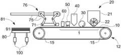
- FIG. 1schematically depicts a print station and an assembly apparatus with a continuous substrate, in accordance with an embodiment of the present disclosure.
- the print stationcan include a carrier device 12 .
- the carrier device 12can include a conveyor configured to transport or move materials from a first position to a second position.
- the conveyorcan include a belt and two rotating elements 15 , configured to rotate in the same direction to advance the belt in a certain direction.
- the carrier device 12can have a distal end and a proximal end.
- the carrier device 12can transport a substrate 10 from the distal end to the proximal end.
- the substrate 10can be positioned by the two rotating elements 15 to a location where a transfer device 76 can transport a printed layer (not shown in FIG. 1 ) to a build substrate 80 .
- a dispensing device 20can be provided.
- the dispensing device 20can simply be a dispenser configured to dispense fluidized material.
- the dispensing device 20can include a materials storage 21 and a dispensing controller 22 .
- the dispensing controller 22can be configured to precisely meter an amount of fluidized material deposited onto a substrate 10 .
- the dispensing controller 22can also be configured to precisely control the uniformity of the deposited fluidized material.
- a compaction device 30can be provided.
- the compaction device 30can include a roller, made up of a hardened metal material designed as a cylindrical tube.
- the compaction device 30can include a compliant pressure cuff, or another device configured to apply a controlled pressure orthogonal to the plane of the deposited fluidized material and the substrate 10 .
- the compaction device 30can also include a settling device configured to provide vibration. The vibration of the compaction device 30 can improve the distribution and compaction of the fluidized material.
- the compaction device 30can be configured to compact a fluidized material to a high density of at least 40% of the theoretical density of the fluidized material.
- a printing device 40can be provided.
- the printing device 40can be configured to deposit a liquid binding material to fix a precise pattern into the fluidized material.
- the precise patterncan be fixed into the fluidized material by binding the fluidized material into a connected and robust mass.
- the printing device 40can be an ink jet type print head under direct control of a computer (not shown).
- the computercan be instructed using a set of patterning instructions, for instance a pre-set CAD design.
- the printing device 40can include an ink jet type print head with jetting nozzles spanning the width of the substrate 10 .
- the ink jet type print headscan also be positioned at a sufficient density to achieve a desired print resolution.
- the ink jet type headcan be fixed in position and the functioning of each jetting nozzle can be coordinated with the movement of the substrate 10 on the rotating elements 15 , to create the desired pattern in the fluidized material.
- the printing device 40can include an ink jet head that includes fewer jetting nozzles than are required to span the width of substrate 10 , and yet achieves a desired resolution.
- the ink jet type headcan be movable, under computer control, across the width of the substrate 10 , and the movement of both the ink jet type print head and the rotating elements 15 may be coordinated to achieve the desired fixed printed pattern in the fluidized material.
- a fixing device 50can be provided.
- the fixing device 50can be configured to solidify the liquid binding material, thus fixing the fluidized material exposed to the liquid binding material in a robust solid pattern.
- the fixing device 50can be a source of radiant energy that may interact with the liquid binding material to cause it to become solid.
- the radiant energycan be IR radiation, UV radiation, electron beam, or other known radiation types. It should be understood the fixing device 50 does not need to be limited to the disclosed radiation types, as this list is presented for exemplary embodiments and not intended to be exhaustive.
- the fixing device 50can include a device for dispersing a reactive agent.
- the reactive agentcan be configured to react with the liquid binding material and the fluidized material to convert the fluidized material to a robust mass.
- a fluidized materials removal device 60can be provided downstream from the fixing device 50 .
- the fluidized materials removal device 60can be configured to remove all of the fluidized material deposited and compacted onto the substrate 10 .
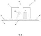
- the fluidized materials removal device 60can remove the fluidized material deposited and compacted onto the substrate, but not fixed in place by the liquid binder material. Referring momentarily to FIG. 8 , the fluidized materials removal device 60 is illustrated in greater detail.
- the fluidized material removal device 60can include an enclosure 63 .
- the enclosurecan have a distal end and a proximal end.
- the printed layer 88can be transported from the distal end of the enclosure 63 to the proximal end along the substrate 10 .
- the enclosure 63can include a disruptive device 61 , such as a brush or a probe to loosen compacted powder 84 . Any residual powder 86 can be further dislocated by an air knife device 62 .
- the disruptive device 61can be designed to have disruptive strength sufficient to disrupt compacted powder that has not been fixed in place.
- the disruptive device 61is configured to not remove any compacted powder which has been treated with binder and fixed by the fixing device 50 of FIG. 1 .
- the non-fixed compacted powder 84When the non-fixed compacted powder 84 is fully dislodged and aerosolized within enclosure 63 , some fixed powder 88 can remain attached to substrate 10 .
- the aerosolized compacted powder 84can be removed from the substrate by the vacuum port 64 . It should be understood, that other exemplary embodiments of the fluidized materials removal device 60 may contain more or less devices than enumerated herein.
- a transfer device 76can be implemented downstream from the fluidized materials removal device 60 in the assembly apparatus.
- the transfer device 76can be configured to move a printed layer (shown in FIG. 2 as reference 90 ) from the substrate 10 .
- the printed layer 90can be moved from the substrate 10 to a build substrate 80 , or to the top of a stack of previously positioned layers 91 .
- the transfer device 76can also include a pick-up assembly.
- the pick-up assemblycan include an attachment device 71 configured to remove a printed layer 90 from the substrate 10 .
- the attachment device 71can include a vacuum device or an adhesive device to overcome the force holding the printed layer 90 to the substrate 10 .
- the transfer device 76may also include a translation device 75 configured to move the printed layer 90 from the substrate 10 to an assembly apparatus 81 .
- the transfer device 120can include an end effector 78 , which may be in communication with an attachment device 71 .
- the transfer device 120can be configured to accurately position the attachment device 71 relative to the printed layer 90 on a substrate 10 .
- the end effector 78can cause the attachment device 71 to remove the printed layer 90 from the substrate 10 .
- the substrate 10can include alignment fiducials 110 to enable coordination with the alignment sensor 105 .
- the end effector 78can also provide an accurate vertical and rotational translation for the attachment device 71 while coordinating between joint one 122 acting on an inner arm 126 and joint two 124 acting on an outer arm 128 .
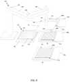
- FIG. 9also illustrates an alternate arrangement of the print stations.
- the print stationscan be oriented in a single row.
- the transfer device 120can be positioned at any location that provides the attachment device 71 access to any one of printed layers on the substrates.
- the build platform 80can be located anywhere within the range of the transfer device 120 . As discussed above with respect to FIG. 1 , the build platform 80 can include an elevator device. In an alternative embodiment, the build platform 80 can be fixed and the attachment device 71 can be raised or lowered using the end effector 78 .
- the printed layers 90 A, 90 B, and 90 Ceach represent the product of three print stations 1 , each producing printed layers with different materials. For the purposes of building a multi-material product, at least two print stations are required. It should be noted, however, there is no maximum number of print stations that can be incorporated into the multi-material print system.
- the assembly apparatus 81can include a build plate 80 , alignment fiducials 110 , and an elevator device 100 (see FIGS. 1 and 3 ).
- the build plate 80can also include an adhesion modifying device (not shown) configured to maintain the position of the build product while enabling an easy release after the build is complete.
- the adhesion modifier devicecan modify the adhesion by stimulating the interface between the first printed layer and the build plate 80 with thermal, electrical, magnetic or mechanical stimulus.
- the elevator device 100is configured to maintain the level of the top of the stack of previously positioned layers 91 .
- the elevator device 100can include lead screws.
- the elevator device 100can include a linear motor device.
- the alignment fiducials 110can be provided to facilitate precise alignment of printed layers on the build plate 80 and on the top of previously positioned layers 91 .
- the alignment fiducials 110can be used in coordination with the alignment sensor 105 and the computer control system to precisely align the printed layer 90 with the top of the stack of previously positioned layers 91 .
- the alignment fiducialscan be incorporated in the surface of the build plate 80 .
- the alignment fiducials 110can project from the surface of the build plate 80 . In yet another embodiment of the build plate 80 , the alignment fiducials 110 can project from the surface of the build plate 80 by a distance proportional to height of the current printed layer.
- the attachment device 71can also include alignment sensors 105 that are aligned with the alignment fiducials 110 when a printed layer 90 is prepositioned.
- the alignment sensor 105 and alignment fiducial 110can be designed in concert to enable the alignment sensor 105 to sense the position relative to the alignment fiducials 110 to within 0.01 mm.
- the alignment sensor 105can be an optical sensor, a laser sensor, a magnetic sensor, an ultrasonic sensor, or a mechanical sensor. Multiple alignment sensors and associated alignment fiducials 110 can make up the alignment system for precise alignment between the attachment device 71 , the build plate 80 , and the substrates 10 .
- the attachment device 71is described in further detail with respect to FIG. 10 .
- the attachment device 71can include an attachment device base 79 , an adhesive device 73 , and an adhesion modifier 74 .
- the attachment device base 79can be connected to the end effector 78 .
- the adhesive device 73can include a vacuum device (not shown) and an adhesive surface device.
- the adhesive surface devicecan include a jell pad, a micro hair device, or a static electric device. It should be understood that other adhesive surface devices can be implemented herein.
- the strength of the adhesioncan be modified by applying a stimulus to the adhesive device 73 with an adhesion modifier 74 .
- the adhesion modifier 74can be configured to apply thermal, electrical, magnetic or mechanical stimulus to the adhesion device 73 .
- the transfer station 70can also include a section of substrate 10 and an adhesion reducing device 68 .
- a printed layer 90can be cycled into the transfer station 70 by movement of the substrate 10 .
- the printed layer 90can be adhered to the surface of substrate 10 by the adhesive properties of a fixed powder in contact with the surfaces of substrate 10 .
- the surface of the substrate 10 or discrete platform 11may be designed to provide a predetermined adhesive force with fixed powder 88 .
- the adhesion reducer 68can provide a stimulus to an interface between the fixed powder 88 and a surface of the substrate 10 to reduce the adhesive force to facilitate an easy transfer of the printed layer (not shown) to the attachment device 71 .
- the stimulus provided by the adhesion reducing layer 68can be thermal, electrical, magnetic or mechanical.
- transfer of the printed layer 90 from the substrate 10 to the attachment device 71can be facilitated by directed contact to the adhesive device 73 . In some embodiments, transfer of the printed layer 90 from the substrate 10 to the attachment device 71 can be facilitated by activation of an adhesion modifier 74 , or activation of the adhesion reducer 68 , or a combination both.
- FIG. 11illustrates another embodiment of the attachment device 71 .
- the attachment device 71 of FIG. 11can further include a shape modifier 72 .
- the shape modifier 72can provide a peeling action in order to better facilitate the transfer of a printed layer 88 from the substrate 10 to the adhesive device 73 .
- the shape modifier 72can include a preformed curved structure.
- the curved structurecan be made up of an elastic material that can be flattened by mechanical pressure applied normal to the curved surface.
- the shape modifier 72can be an adjustable structure that may be modified to form a flat surface or a curved surface by the application of pneumatic, hydraulic or mechanical force.
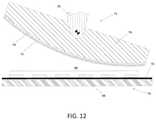
- FIG. 12illustrates another embodiment of the attachment device 71 .
- the attachment device 71 of FIG. 12can further include an attachment device base 79 with a rounded surface.
- the attachment device base 79can include the adhesive device 73 and the adhesion modifier 73 , as described above.
- the attachment device 71can also be configured to pivot about the end effector 78 such that the attachment device 71 can be configured to roll and peel the printed layer 90 .
- the peeling actioncan provide greater control of the transfer of the printed layer 90 from the substrate 10 to the adhesive device 73 , and from the adhesive device 73 to previously positioned layers.
- the print stationcan deploy a continuous web.
- the continuous webcan be a loop of material, returning to the beginning of the print station 1 after a printed layer 90 is released to the transfer device 76 .
- the continuous webcan be an elongated structure such as a roll of robust polymer film or a roll of metal foil.
- the continuous webcan pass through the print station 1 a single time and may then be removed from the print station to be discarded or recovered.
- FIG. 2illustrates a schematic representation of a multi-material three-dimensional printer, in accordance with an embodiment of the present disclosure.
- the three-dimensional printercan include multiple work stations. Each work station can include a transfer station 70 and a print station 1 .
- the print station 1can include the substrate 10 , rotating elements 15 , dispensing device 20 , compaction device 30 , printing device 40 , fixing device 50 and fluidized fluid material removal device 60 of FIG. 1 .
- the transfer station 70can include the transfer device 76 and all of its components.
- the multi-material three-dimensional printercan include a single print station 1 for each different material to be included in the final printed part. Each print station can contribute one material to each complete layer of the final printed part.
- each complete layer in the final printed partcan include as little as one material to as many materials as there are print stations.
- Each materialcan be transferred onto to the build substrate 80 , or to the top of a stack of previously positioned layers 91 and positioned in precise alignment with alignment fiducials associated with the build substrate 80 . The alignment is considered complete and precise where the top surface of the printed material is coplanar and no subsequent material is present within the top surface.
- FIG. 2exemplifies a single transfer device 76 for each print station 1
- the transfer device 76can be configured to access the transfer locations 70 of each print stations 1 .
- the transfer device 76can be configured to transfer a printed layer 90 from each of the print stations to build the substrate 80 or to the top of a stack of previously positioned layers 91 .
- the transfer device 76can be configured to transfer a printed layer 90 to the top of the stack previously positioned layers 91 in precise alignment with alignment fiducials associated with the build substrate 80 .
- the transfer device 76can be provided for each print station 1 .
- Each transfer device 76can be configured to precisely transfer a printed layer 80 from the associated transfer location 70 to build substrate 80 or to top a stack of previously positioned layers 91 .
- the ratio of transfer devices 76 to print stations 1can vary by any number based on printing needs and strategies. Regardless of the number of transfer devices 76 , each transfer device 76 can be capable of precisely transferring a printed layer 90 from the associated transfer location 70 to build a substrate 80 or to top a stack of previously positioned layers 91 .
- the multi-material three-dimensional printercan also include a single assembly apparatus 81 .
- all of the layers of a subject buildare stacked one upon the last with one to several different materials in each layer, the constituents of each layer bonded securely to the next.
- the final structurecan be a solid mass including monolithic structures of at least two different materials.
- Each of the two or more distinct material structurescan be contiguous with at least one other distinct material structure.
- the distinct material structurescan be made up of material from only one printed layer or from material from two or more printed layers.
- the assembly apparatus 81can include a build substrate 80 .
- the build substrate 80can be equipped with a surface designed to hold the stack of previously positioned layers 91 throughout the build process.
- the surface holding the stackcan also be configured to facilitate removal of the subject from the build substrate 80 at the completion of the build process.
- the assembly apparatus 81can also include position reference fiducials to facilitate accurate placement of each printed layer.
- the build substrate 80can be positioned in a fixed location during the build process.
- the build substrate 80can include an elevator device 100 to present the top surface of the stack of previously positioned layers 91 at a desired elevation relative to other components of the multi-material three-dimensional printer.
- the multi-material three-dimensional printercan also include a computing and control device.
- the computing and control devicecan be capable of interpreting print instructions, for instance from a pre-set CAD design, to direct and coordinate the operation of all of the major components.
- the computing and control devicecan autonomously produce the desired three-dimensional parts made up of two or more materials. The computing and control device is described below in greater detail with respect to FIG. 6 .
- FIG. 3schematically depicts an alternative print station and an assembly apparatus with a continuous substrate, in accordance with an embodiment of the present disclosure.
- a carrier device 14can include a discrete platform 11 .
- the discrete platform 11can be advanced towards the build substrate 80 via a transport device 17 .
- the discreet platform 11can shuttle through the print station 1 and to the transfer device 76 .
- the present embodimentcan deploy a continuous web.
- the continuous webcan be a loop of material, returning to the beginning of the print station 1 after a printed layer 90 is released to the transfer device 76 .
- the continuous webcan be an elongated structure such as a roll of robust polymer film or a roll of metal foil.
- the continuous webcan pass through the print station 1 a single time and may then be removed from the print station to be discarded or recovered.
- FIG. 4depicts a flow chart describing the process 400 for creating structures of two or more materials by each print station 1 (of FIG. 2 ), in accordance with an implementation of the present disclosure.
- the following description of the process 400is described in detail with reference to the components of the three-dimensional printer of FIG. 2 .
- the process 400starts at step 401 , where a multi-material object design is divided into print thickness layers.
- the layersare then separated into single material patterns at step 402 .
- Each single material patterncan be sent to a print station 1 of the three-dimensional printer.
- Each print station 1can perform the steps 403 through 417 for each single material pattern.
- a print station 1can receive print instructions to a material for a first layer at step 403 .
- the print station 1can perform the steps 403 through 417 for each layer of the multi-material object design.
- the material of the single material pattern for the first layercan be dispersed on a substrate.
- the substratecan be indexed to move the dispersed material to a compaction apparatus.
- the materialis compacted at step 406 .
- the substratecan be indexed to move the dispersed material to a printing apparatus.
- a bindercan be dispersed in a predetermined pattern on the compacted material.
- the substratecan be indexed to move the patterned material to a fixing apparatus.
- the binder patterncan be fixed with fixing radiation, at step 410 .
- the substratecan be indexed to move the fixed pattern to a fluidized material removal apparatus.
- the compacted material not fixed in position by a bindercan be removed, at step 412 .
- the substratecan be indexed to move the patterned and fixed material to a transfer station.
- the printed layeris transferred to the build substrate 80 , or to the top of a stack of previously positioned layers 91 when directed by computer control system.
- a determinationis made at step 415 . Specifically, the process 400 determines whether the last layer was printed. If it is determined the last layer was printed at step 415 , the process 400 advances to step 416 where the printing was ended. In contrast, the last layer was not printed at step 415 , the process 400 advances to 417 where print instructions are sent for the next layer. After step 417 , the process 400 cycles back through steps 404 to 417 .
- FIG. 5depicts a flow chart describing the process 500 for creating structures of two or more materials by a three-dimensional printer, in accordance with an implementation of the present disclosure.
- the following description of the process 500is described in detail with reference to the components of the three-dimensional printer of FIG. 2 .
- the process 500starts at step 501 , where a multi-material object design is divided into print thickness layers.
- the first layeris then selected step 502 .
- the different materials within the layeris identified at step 503 .
- the steps 504 - 506can be performed on each material identified within the layer.
- Each materialcan be assigned to a print station 1 , at step 504 .
- the process 500advances to step 505 , where the material object is created by each print station 1 .
- the printed materialcan be transferred to the build plate, at step 506 .
- a determinationis made as to whether the three-dimensional printer printed the last part at step 507 . If is determined that the last part has been printed at step 507 , the process 500 advances to step 508 where the printing is ended and the part is removed from the build plate. If it is determined that the last part has not been printed, then the process 500 advances to step 509 where it is determined whether the last print on the layer was completed.
- step 510the build plate is incremented down the thickness of the next plate.
- the processadvances from steps 509 and 510 towards step 511 , where the next layer is selected.
- step 503This process is continued until the last part has been printed (YES at step 507 ).
- FIG. 6illustrates a schematic representation a system level computing and control device 600 , in accordance with an implementation of the present disclosure.
- the computing and control device 600can be a server, a personal computer, a portable computer, a thin client, or any suitable device or devices.
- the disclosure and/or components thereofmay be a single device at a single location, or multiple devices at a single, or multiple, locations that are connected together using any appropriate communication protocols over any communication medium such as electric cable, fiber optic cable, or in a wireless manner.
- An input device 602can receive print instructions, for instance from a pre-set CAD design file 601 , to direct and coordinate the operation of all of the major components of the print station.
- the central processing unit 604connected to the input device 602 , an output device 603 , and a memory 605 is configured to initiate the three-dimensional printing of the desired three-dimensional parts made up of two or more materials. Each material can be assigned to a specific print station 607 ( 1 ), 607 ( 2 ) up to 607 ( n ) based on the amount of materials to be used.
- the central processing unit 604can interface with each print station via the interface bus 606 .
- FIG. 7illustrates a schematic representation of an individual print station controller, in accordance with an implementation of the present disclosure.
- the central processing unit 604can instruct the print station control unit 607 ( 1 ) to print a print product of a specific material.
- the print station control unit 607 ( 1 )can convey the print instructions to the device controller 700 , which corresponds with all of the components of the print station 1 , as discussed above.
Landscapes
- Engineering & Computer Science (AREA)
- Chemical & Material Sciences (AREA)
- Materials Engineering (AREA)
- Manufacturing & Machinery (AREA)
- Mechanical Engineering (AREA)
- Physics & Mathematics (AREA)
- Optics & Photonics (AREA)
- Composite Materials (AREA)
- Robotics (AREA)
- Ceramic Engineering (AREA)
- Civil Engineering (AREA)
- Structural Engineering (AREA)
Abstract
Description
Claims (16)
Priority Applications (10)
| Application Number | Priority Date | Filing Date | Title |
|---|---|---|---|
| US16/167,088US11273608B2 (en) | 2018-06-07 | 2018-10-22 | Multi-material three-dimensional printer |
| JP2020567983AJP7329859B2 (en) | 2018-06-07 | 2019-05-07 | Multi-material three-dimensional printing device and method for making structures of two or more materials |
| PCT/US2019/031171WO2019236236A1 (en) | 2018-06-07 | 2019-05-07 | Multi-material three-dimensional printer |
| KR1020207038127AKR102677762B1 (en) | 2018-06-07 | 2019-05-07 | Multi-material 3D printer |
| KR1020247020369AKR102781100B1 (en) | 2018-06-07 | 2019-05-07 | Multi-material three-dimensional printer |
| CN201980038425.2ACN112262044A (en) | 2018-06-07 | 2019-05-07 | Multi-material 3D printer |
| EP19814917.1AEP3802131A4 (en) | 2018-06-07 | 2019-05-07 | Multi-material three-dimensional printer |
| US17/592,297US11504913B2 (en) | 2018-06-07 | 2022-02-03 | Multi-material three-dimensional printer |
| US17/970,347US11806937B2 (en) | 2018-06-07 | 2022-10-20 | Method for creating structures of two or more materials using a multi-material three-dimensional printer |
| JP2023125260AJP7553150B2 (en) | 2018-06-07 | 2023-08-01 | Method for manufacturing a structure made of two or more materials |
Applications Claiming Priority (2)
| Application Number | Priority Date | Filing Date | Title |
|---|---|---|---|
| US201862682067P | 2018-06-07 | 2018-06-07 | |
| US16/167,088US11273608B2 (en) | 2018-06-07 | 2018-10-22 | Multi-material three-dimensional printer |
Related Child Applications (1)
| Application Number | Title | Priority Date | Filing Date |
|---|---|---|---|
| US17/592,297ContinuationUS11504913B2 (en) | 2018-06-07 | 2022-02-03 | Multi-material three-dimensional printer |
Publications (2)
| Publication Number | Publication Date |
|---|---|
| US20190375159A1 US20190375159A1 (en) | 2019-12-12 |
| US11273608B2true US11273608B2 (en) | 2022-03-15 |
Family
ID=68765465
Family Applications (3)
| Application Number | Title | Priority Date | Filing Date |
|---|---|---|---|
| US16/167,088Active2039-08-09US11273608B2 (en) | 2018-06-07 | 2018-10-22 | Multi-material three-dimensional printer |
| US17/592,297ActiveUS11504913B2 (en) | 2018-06-07 | 2022-02-03 | Multi-material three-dimensional printer |
| US17/970,347ActiveUS11806937B2 (en) | 2018-06-07 | 2022-10-20 | Method for creating structures of two or more materials using a multi-material three-dimensional printer |
Family Applications After (2)
| Application Number | Title | Priority Date | Filing Date |
|---|---|---|---|
| US17/592,297ActiveUS11504913B2 (en) | 2018-06-07 | 2022-02-03 | Multi-material three-dimensional printer |
| US17/970,347ActiveUS11806937B2 (en) | 2018-06-07 | 2022-10-20 | Method for creating structures of two or more materials using a multi-material three-dimensional printer |
Country Status (6)
| Country | Link |
|---|---|
| US (3) | US11273608B2 (en) |
| EP (1) | EP3802131A4 (en) |
| JP (2) | JP7329859B2 (en) |
| KR (2) | KR102781100B1 (en) |
| CN (1) | CN112262044A (en) |
| WO (1) | WO2019236236A1 (en) |
Cited By (1)
| Publication number | Priority date | Publication date | Assignee | Title |
|---|---|---|---|---|
| US12005640B2 (en) | 2022-06-03 | 2024-06-11 | Sakuu Corporation | Method and system of using gradual drying in multi-material 3D printing |
Families Citing this family (22)
| Publication number | Priority date | Publication date | Assignee | Title |
|---|---|---|---|---|
| US11273608B2 (en) | 2018-06-07 | 2022-03-15 | Sakuu Corporation | Multi-material three-dimensional printer |
| US11167480B2 (en) | 2018-10-08 | 2021-11-09 | Sakuu Corporation | Three-dimensional, additive manufacturing system, and a method of manufacturing a three-dimensional object |
| CN112805112B (en)* | 2018-10-08 | 2023-07-21 | 萨库公司 | Three-dimensional additive manufacturing system and method for manufacturing three-dimensional objects |
| WO2020117498A1 (en) | 2018-12-04 | 2020-06-11 | Keracel, Inc. | Electrophotographic multi-material 3d printer |
| CN111300587B (en)* | 2019-12-13 | 2021-04-13 | 安徽薄荷三维科技有限公司 | A finished product transmission and blanking device for a ceramic 3D printer |
| EP4111351A4 (en) | 2020-03-25 | 2024-03-20 | OPT Industries, Inc. | SYSTEMS, METHODS AND FILE FORMAT FOR 3D PRINTING OF MICROSTRUCTURES |
| US12275187B2 (en)* | 2020-06-03 | 2025-04-15 | Sakuu Corporation | 3D printer with pressure-assisted fluid extraction |
| US11260581B2 (en)* | 2020-06-03 | 2022-03-01 | Sakuu Corporation | Jetted material printer with pressure-assisted fluid extraction |
| JP2021193210A (en)* | 2020-06-05 | 2021-12-23 | サクウ コーポレーション | 3D additive manufacturing system and 3D object manufacturing method |
| US11072125B1 (en)* | 2020-07-23 | 2021-07-27 | Inkbit, LLC | Reflective coating for material calibration |
| CN112895458A (en)* | 2021-01-15 | 2021-06-04 | 江苏威拉里新材料科技有限公司 | 3D prints and shifts out device with product |
| JP2024513701A (en)* | 2021-03-31 | 2024-03-27 | サクウ コーポレーション | Multi-material 3D printer and method for manufacturing 3D objects |
| US11241742B1 (en) | 2021-03-31 | 2022-02-08 | Sakuu Corporation | Multi-material three-dimensional printer with underlying adjustable binder |
| US12240172B2 (en)* | 2021-07-14 | 2025-03-04 | Sakuu Corporation | Three-dimensional (“3D”) printing apparatus with counter-rotating roller |
| US20240157638A1 (en)* | 2021-07-22 | 2024-05-16 | NEXA3D Inc. | Additive chemistries, methods, and systems for additive manufacturing |
| WO2023068965A1 (en)* | 2021-10-22 | 2023-04-27 | Общество с ограниченной ответственностью "СКАНИ" | 3d printing table arrangement with an automatic conveyor system for removing articles |
| FR3130660B1 (en)* | 2021-12-16 | 2024-11-08 | Safran Additive Mfg Campus | Powder bed additive manufacturing process |
| WO2023137494A1 (en)* | 2022-01-14 | 2023-07-20 | Sakuu Corporation | Method and apparatus to process and bond layers in an additive manufacturing system |
| US12059838B2 (en) | 2022-01-14 | 2024-08-13 | Sakuu Corporation | Method and apparatus to process and bond layers in an additive manufacturing system |
| CN114918371B (en)* | 2022-05-20 | 2023-04-25 | 南京航空航天大学 | A highly flexible multi-region sand laying method and device for multi-material sand mold printing |
| US20230390999A1 (en)* | 2022-06-03 | 2023-12-07 | Sakuu Corporation | Apparatus and method of binder jetting 3d printing |
| EP4424439A1 (en)* | 2023-02-28 | 2024-09-04 | Siemens Aktiengesellschaft | Method for producing a laminated core for an electric machine |
Citations (43)
| Publication number | Priority date | Publication date | Assignee | Title |
|---|---|---|---|---|
| US5204055A (en)* | 1989-12-08 | 1993-04-20 | Massachusetts Institute Of Technology | Three-dimensional printing techniques |
| JPH07164534A (en)* | 1993-12-14 | 1995-06-27 | Teijin Seiki Co Ltd | Stereolithography method and stereolithography apparatus |
| JPH0872153A (en)* | 1994-09-02 | 1996-03-19 | Teijin Seiki Co Ltd | Stereolithography device |
| US6076652A (en) | 1971-04-16 | 2000-06-20 | Texas Instruments Incorporated | Assembly line system and apparatus controlling transfer of a workpiece |
| US20040081475A1 (en) | 2002-10-28 | 2004-04-29 | Phillips Quintin T. | System and methods for calibrating a printing process |
| US20080192093A1 (en) | 2004-05-10 | 2008-08-14 | Pinard Adam I | Jet printer with enhanced print drop delivery |
| US20090226833A1 (en) | 2008-03-10 | 2009-09-10 | Fuji Xerox Co., Ltd. | Electrophotographic toner, method for manufacturing the same, electrophotographic developing agent, toner cartridge, process cartridge and image forming apparatus |
| US20100038807A1 (en) | 1998-07-10 | 2010-02-18 | Pentron Ceramics, Inc. | Solid Free-Form Fabrication Methods For The Production Of Dental Restorations |
| EP2272653A1 (en)* | 2009-07-07 | 2011-01-12 | TNO Bedrijven B.V. | Method and apparatus for layerwise production of a 3D object |
| EP2447044A1 (en)* | 2010-11-01 | 2012-05-02 | DSM IP Assets B.V. | Foil guiding system for additive fabrication |
| US20130075013A1 (en) | 2011-09-23 | 2013-03-28 | Stratasys, Inc. | Layer Transfusion with Rotatable Belt for Additive Manufacturing |
| US20130077996A1 (en) | 2011-09-23 | 2013-03-28 | Stratasys, Inc. | Electrophotography-based additive manufacturing system with reciprocating operation |
| US20130272746A1 (en) | 2011-09-23 | 2013-10-17 | Stratasys, Inc. | Electrophotography-based additive manufacturing system with transfer-medium service loops |
| US20150227070A1 (en) | 2013-07-17 | 2015-08-13 | Stratasys, Inc. | Part material for electrophotography-based additive manufacturing |
| US20160067922A1 (en)* | 2014-09-09 | 2016-03-10 | Disney Enterprises, Inc. | Three dimensional (3d) printing by volumetric addition through selective curing of a fluid matrix |
| US20160200084A1 (en) | 2015-01-14 | 2016-07-14 | Xactiv, Inc. | Fabrication of 3d objects via multiple build platforms |
| WO2016202957A1 (en)* | 2015-06-16 | 2016-12-22 | Mcor Technologies Limited | Desktop 3-dimensional printing apparatus |
| KR20170003935A (en) | 2014-05-08 | 2017-01-10 | 스트라타시스 엘티디. | Method and apparatus for 3d printing by selective sintering |
| US20170015063A1 (en)* | 2014-03-07 | 2017-01-19 | Canon Kabushiki Kaisha | Method of producing three-dimensional shaped article |
| US20170050379A1 (en) | 2014-04-23 | 2017-02-23 | Nederlacdse Organisatie voor toegepast- natuurwetenschappelijk onderzoek TNO | Apparatus and method for making tangible products by layerwise manufacturing |
| US9604411B2 (en)* | 2014-05-04 | 2017-03-28 | Eoplex Limited | Multi-material three dimensional printer |
| WO2017156623A1 (en) | 2016-03-14 | 2017-09-21 | Nanogrande | Method and apparatus for forming layers of particles for use in additive manufacturing |
| US20170297267A1 (en)* | 2016-04-14 | 2017-10-19 | Xerox Corporation | Electro-photographic 3-d printing using collapsible substrate |
| US20170299973A1 (en) | 2016-04-18 | 2017-10-19 | Stratasys, Inc. | Electrophotography-based additive manufacturing with part molding |
| US20170348909A1 (en)* | 2016-06-07 | 2017-12-07 | Xerox Corporation | Electrostatic 3-d printer using layer and mechanical planer |
| US20180034038A1 (en) | 2015-06-04 | 2018-02-01 | Eoplex Limited | Lead carrier structure and packages formed therefrom without die attach pads |
| US20180043619A1 (en)* | 2015-03-20 | 2018-02-15 | Lg Electronics Inc. | 3d printing apparatus |
| US20180085993A1 (en)* | 2015-05-22 | 2018-03-29 | Luxexcel Holding B.V. | Method for printing a three-dimensional structure and a system for printing a three-dimensional structure |
| US20180117790A1 (en)* | 2015-07-16 | 2018-05-03 | Korea Institute Of Machinery & Materials | 3d ceramic printer and a method using the same |
| US10071527B2 (en)* | 2012-05-22 | 2018-09-11 | Mcor Technologies Limited | Colour 3-dimensional printing with 3D gamut mapping |
| US10076869B2 (en)* | 2016-06-07 | 2018-09-18 | Xerox Corporation | Electrostatic 3-D printer using leveling material and mechanical planer |
| US10201930B2 (en)* | 2016-05-06 | 2019-02-12 | Xerox Corporation | Acoustic transfude 3-D printing |
| US20190152135A1 (en)* | 2017-10-20 | 2019-05-23 | Formlabs, Inc. | Techniques for application of light in additive fabrication and related systems and methods |
| WO2019152797A1 (en) | 2018-02-02 | 2019-08-08 | Evolve Additive Solutions, Inc. | Method of thermally transferring layers in a selective deposition-based additive manufacturing system using conductive heat |
| US20190263054A1 (en)* | 2016-11-17 | 2019-08-29 | Orbotech Ltd. | Hybrid, multi-material 3D printing |
| WO2019236236A1 (en) | 2018-06-07 | 2019-12-12 | Keracel, Inc. | Multi-material three-dimensional printer |
| US20200108553A1 (en) | 2018-10-08 | 2020-04-09 | Keracel, Inc. | Three-dimensional, additive manufacturing system, and a method of manufacturing a three-dimensional object |
| US20200171752A1 (en) | 2018-12-04 | 2020-06-04 | Keracel, Inc. | Electrophotographic multi-material 3d printer |
| US20200207013A1 (en)* | 2018-12-28 | 2020-07-02 | Palo Alto Research Center Incorporated | Constructing 3-dimensional parts using electrophotography |
| US20200298477A1 (en)* | 2018-10-08 | 2020-09-24 | Keracel, Inc. | Three-dimensional, additive manufacturing system, and a method of manufacturing a three-dimensional object |
| US10882247B2 (en)* | 2015-01-28 | 2021-01-05 | Structo Pte Ltd | Additive manufacturing device with release mechanism |
| US20210023784A1 (en)* | 2018-03-29 | 2021-01-28 | Sisma S.P.A. | Apparatus for 3d printing of bottom-up photo-curing type, with independent elastic membrane system and tilting reference and relative methods of use |
| US10919214B2 (en)* | 2013-06-20 | 2021-02-16 | Canon Kabushiki Kaisha | Method and apparatus for manufacturing structure |
Family Cites Families (24)
| Publication number | Priority date | Publication date | Assignee | Title |
|---|---|---|---|---|
| US5593531A (en)* | 1994-11-09 | 1997-01-14 | Texas Instruments Incorporated | System, method and process for fabrication of 3-dimensional objects by a static electrostatic imaging and lamination device |
| US6066285A (en)* | 1997-12-12 | 2000-05-23 | University Of Florida | Solid freeform fabrication using power deposition |
| US6376148B1 (en)* | 2001-01-17 | 2002-04-23 | Nanotek Instruments, Inc. | Layer manufacturing using electrostatic imaging and lamination |
| US6780368B2 (en)* | 2001-04-10 | 2004-08-24 | Nanotek Instruments, Inc. | Layer manufacturing of a multi-material or multi-color 3-D object using electrostatic imaging and lamination |
| DE10310385B4 (en)* | 2003-03-07 | 2006-09-21 | Daimlerchrysler Ag | Method for the production of three-dimensional bodies by means of powder-based layer-building methods |
| US7706910B2 (en) | 2007-01-17 | 2010-04-27 | 3D Systems, Inc. | Imager assembly and method for solid imaging |
| JP4404136B2 (en)* | 2007-12-17 | 2010-01-27 | 富士ゼロックス株式会社 | Toner for developing electrostatic image, method for producing the same, electrostatic image developer, toner cartridge, process cartridge, and image forming apparatus |
| US8568951B2 (en)* | 2011-03-16 | 2013-10-29 | Ricoh Company, Ltd. | Toner, method of manufacturing toner, image forming method, image forming apparatus, and process cartridge |
| GB201109045D0 (en)* | 2011-05-31 | 2011-07-13 | Warwick Ventures | Additive building |
| US20130186549A1 (en)* | 2011-09-23 | 2013-07-25 | Stratasys, Inc. | Layer transfusion for additive manufacturing |
| US20130186558A1 (en)* | 2011-09-23 | 2013-07-25 | Stratasys, Inc. | Layer transfusion with heat capacitor belt for additive manufacturing |
| IN2015DN01776A (en) | 2012-09-05 | 2015-05-29 | Aprecia Pharmaceuticals Co | |
| US9550349B1 (en)* | 2012-10-31 | 2017-01-24 | The Boeing Company | System and method for additive fabrication using laminated sheets |
| EP3057776B1 (en) | 2013-10-17 | 2020-03-18 | Xjet Ltd. | Support ink for three dimensional (3d) printing |
| KR101767300B1 (en)* | 2013-12-18 | 2017-08-10 | 캐논 가부시끼가이샤 | Method for manufacturing a pattern, manufacturing apparatus for manufacturing a pattern, method for manufacturing structural body and manufacturing apparatus therefor |
| US9688027B2 (en)* | 2014-04-01 | 2017-06-27 | Stratasys, Inc. | Electrophotography-based additive manufacturing with overlay control |
| JP6601920B2 (en) | 2014-09-21 | 2019-11-06 | メイド イン スペース インコーポレイティッド | Ground and space installation manufacturing systems |
| KR101669357B1 (en)* | 2015-02-17 | 2016-10-25 | 길재수 | Three dimensional printer |
| US10046512B2 (en)* | 2016-04-14 | 2018-08-14 | Xerox Corporation | Electro-photographic 3-D printing using dissolvable paper |
| US10195787B2 (en)* | 2016-05-12 | 2019-02-05 | Xerox Corporation | Electrostatic 3-D development apparatus using different melting point materials |
| IL262995B2 (en)* | 2016-05-29 | 2023-03-01 | Stratasys Ltd | Method and apparatus for 3d printing |
| JP2018020474A (en)* | 2016-08-02 | 2018-02-08 | キヤノン株式会社 | Modeling apparatus and modeling method |
| WO2019133099A1 (en)* | 2017-12-26 | 2019-07-04 | Desktop Metal, Inc. | System and method for controlling powder bed density for 3d printing |
| US11241742B1 (en)* | 2021-03-31 | 2022-02-08 | Sakuu Corporation | Multi-material three-dimensional printer with underlying adjustable binder |
- 2018
- 2018-10-22USUS16/167,088patent/US11273608B2/enactiveActive
- 2019
- 2019-05-07JPJP2020567983Apatent/JP7329859B2/enactiveActive
- 2019-05-07EPEP19814917.1Apatent/EP3802131A4/enactivePending
- 2019-05-07CNCN201980038425.2Apatent/CN112262044A/enactivePending
- 2019-05-07KRKR1020247020369Apatent/KR102781100B1/enactiveActive
- 2019-05-07KRKR1020207038127Apatent/KR102677762B1/enactiveActive
- 2019-05-07WOPCT/US2019/031171patent/WO2019236236A1/ennot_activeCeased
- 2022
- 2022-02-03USUS17/592,297patent/US11504913B2/enactiveActive
- 2022-10-20USUS17/970,347patent/US11806937B2/enactiveActive
- 2023
- 2023-08-01JPJP2023125260Apatent/JP7553150B2/enactiveActive
Patent Citations (55)
| Publication number | Priority date | Publication date | Assignee | Title |
|---|---|---|---|---|
| US6076652A (en) | 1971-04-16 | 2000-06-20 | Texas Instruments Incorporated | Assembly line system and apparatus controlling transfer of a workpiece |
| US5204055A (en)* | 1989-12-08 | 1993-04-20 | Massachusetts Institute Of Technology | Three-dimensional printing techniques |
| JPH07164534A (en)* | 1993-12-14 | 1995-06-27 | Teijin Seiki Co Ltd | Stereolithography method and stereolithography apparatus |
| JPH0872153A (en)* | 1994-09-02 | 1996-03-19 | Teijin Seiki Co Ltd | Stereolithography device |
| US20100038807A1 (en) | 1998-07-10 | 2010-02-18 | Pentron Ceramics, Inc. | Solid Free-Form Fabrication Methods For The Production Of Dental Restorations |
| US20040081475A1 (en) | 2002-10-28 | 2004-04-29 | Phillips Quintin T. | System and methods for calibrating a printing process |
| US20080192093A1 (en) | 2004-05-10 | 2008-08-14 | Pinard Adam I | Jet printer with enhanced print drop delivery |
| US20090226833A1 (en) | 2008-03-10 | 2009-09-10 | Fuji Xerox Co., Ltd. | Electrophotographic toner, method for manufacturing the same, electrophotographic developing agent, toner cartridge, process cartridge and image forming apparatus |
| EP2272653A1 (en)* | 2009-07-07 | 2011-01-12 | TNO Bedrijven B.V. | Method and apparatus for layerwise production of a 3D object |
| EP2447044A1 (en)* | 2010-11-01 | 2012-05-02 | DSM IP Assets B.V. | Foil guiding system for additive fabrication |
| US20130075022A1 (en) | 2011-09-23 | 2013-03-28 | Stratasys, Inc. | Layer Transfusion with Transfixing for Additive Manufacturing |
| US20130077996A1 (en) | 2011-09-23 | 2013-03-28 | Stratasys, Inc. | Electrophotography-based additive manufacturing system with reciprocating operation |
| US20130075013A1 (en) | 2011-09-23 | 2013-03-28 | Stratasys, Inc. | Layer Transfusion with Rotatable Belt for Additive Manufacturing |
| US20130272746A1 (en) | 2011-09-23 | 2013-10-17 | Stratasys, Inc. | Electrophotography-based additive manufacturing system with transfer-medium service loops |
| US8879957B2 (en)* | 2011-09-23 | 2014-11-04 | Stratasys, Inc. | Electrophotography-based additive manufacturing system with reciprocating operation |
| US9720363B2 (en)* | 2011-09-23 | 2017-08-01 | Stratasys, Inc. | Layer transfusion with rotatable belt for additive manufacturing |
| US9141015B2 (en)* | 2011-09-23 | 2015-09-22 | Stratasys, Inc. | Electrophotography-based additive manufacturing system with transfer-medium service loops |
| US10071527B2 (en)* | 2012-05-22 | 2018-09-11 | Mcor Technologies Limited | Colour 3-dimensional printing with 3D gamut mapping |
| US10919214B2 (en)* | 2013-06-20 | 2021-02-16 | Canon Kabushiki Kaisha | Method and apparatus for manufacturing structure |
| US9482974B2 (en)* | 2013-07-17 | 2016-11-01 | Stratasys, Inc. | Part material for electrophotography-based additive manufacturing |
| US20150227070A1 (en) | 2013-07-17 | 2015-08-13 | Stratasys, Inc. | Part material for electrophotography-based additive manufacturing |
| US20170015063A1 (en)* | 2014-03-07 | 2017-01-19 | Canon Kabushiki Kaisha | Method of producing three-dimensional shaped article |
| US10421265B2 (en)* | 2014-04-23 | 2019-09-24 | Nederlandse Organisatie Voor Toegepast-Natuurwetenschappelijk Onderzoek Tno | Apparatus and method for making tangible products by layerwise manufacturing |
| US20170050379A1 (en) | 2014-04-23 | 2017-02-23 | Nederlacdse Organisatie voor toegepast- natuurwetenschappelijk onderzoek TNO | Apparatus and method for making tangible products by layerwise manufacturing |
| US9604411B2 (en)* | 2014-05-04 | 2017-03-28 | Eoplex Limited | Multi-material three dimensional printer |
| US20170173696A1 (en)* | 2014-05-08 | 2017-06-22 | Stratasys Ltd. | Method and apparatus for 3d printing by selective sintering |
| KR20170003935A (en) | 2014-05-08 | 2017-01-10 | 스트라타시스 엘티디. | Method and apparatus for 3d printing by selective sintering |
| US20160067922A1 (en)* | 2014-09-09 | 2016-03-10 | Disney Enterprises, Inc. | Three dimensional (3d) printing by volumetric addition through selective curing of a fluid matrix |
| US20160200084A1 (en) | 2015-01-14 | 2016-07-14 | Xactiv, Inc. | Fabrication of 3d objects via multiple build platforms |
| US10272664B2 (en)* | 2015-01-14 | 2019-04-30 | Xactiv, Inc. | Fabrication of 3D objects via multiple build platforms |
| US10882247B2 (en)* | 2015-01-28 | 2021-01-05 | Structo Pte Ltd | Additive manufacturing device with release mechanism |
| US20180043619A1 (en)* | 2015-03-20 | 2018-02-15 | Lg Electronics Inc. | 3d printing apparatus |
| US20180085993A1 (en)* | 2015-05-22 | 2018-03-29 | Luxexcel Holding B.V. | Method for printing a three-dimensional structure and a system for printing a three-dimensional structure |
| US20180034038A1 (en) | 2015-06-04 | 2018-02-01 | Eoplex Limited | Lead carrier structure and packages formed therefrom without die attach pads |
| WO2016202957A1 (en)* | 2015-06-16 | 2016-12-22 | Mcor Technologies Limited | Desktop 3-dimensional printing apparatus |
| US20180117790A1 (en)* | 2015-07-16 | 2018-05-03 | Korea Institute Of Machinery & Materials | 3d ceramic printer and a method using the same |
| WO2017156623A1 (en) | 2016-03-14 | 2017-09-21 | Nanogrande | Method and apparatus for forming layers of particles for use in additive manufacturing |
| US20170297267A1 (en)* | 2016-04-14 | 2017-10-19 | Xerox Corporation | Electro-photographic 3-d printing using collapsible substrate |
| US20170299973A1 (en) | 2016-04-18 | 2017-10-19 | Stratasys, Inc. | Electrophotography-based additive manufacturing with part molding |
| US10105902B2 (en)* | 2016-04-18 | 2018-10-23 | Evolve Additive Solutions, Inc. | Electrophotography-based additive manufacturing with part molding |
| US10201930B2 (en)* | 2016-05-06 | 2019-02-12 | Xerox Corporation | Acoustic transfude 3-D printing |
| US10293547B2 (en)* | 2016-06-07 | 2019-05-21 | Xerox Corporation | Electrostatic 3-D printer using layer and mechanical planer |
| US20170348909A1 (en)* | 2016-06-07 | 2017-12-07 | Xerox Corporation | Electrostatic 3-d printer using layer and mechanical planer |
| US10076869B2 (en)* | 2016-06-07 | 2018-09-18 | Xerox Corporation | Electrostatic 3-D printer using leveling material and mechanical planer |
| US20190263054A1 (en)* | 2016-11-17 | 2019-08-29 | Orbotech Ltd. | Hybrid, multi-material 3D printing |
| US20190152135A1 (en)* | 2017-10-20 | 2019-05-23 | Formlabs, Inc. | Techniques for application of light in additive fabrication and related systems and methods |
| WO2019152797A1 (en) | 2018-02-02 | 2019-08-08 | Evolve Additive Solutions, Inc. | Method of thermally transferring layers in a selective deposition-based additive manufacturing system using conductive heat |
| US20210023784A1 (en)* | 2018-03-29 | 2021-01-28 | Sisma S.P.A. | Apparatus for 3d printing of bottom-up photo-curing type, with independent elastic membrane system and tilting reference and relative methods of use |
| WO2019236236A1 (en) | 2018-06-07 | 2019-12-12 | Keracel, Inc. | Multi-material three-dimensional printer |
| US20200298477A1 (en)* | 2018-10-08 | 2020-09-24 | Keracel, Inc. | Three-dimensional, additive manufacturing system, and a method of manufacturing a three-dimensional object |
| WO2020076734A1 (en) | 2018-10-08 | 2020-04-16 | Keracel, Inc. | Three-dimensional, additive manufacturing system, and a method of manufacturing a three-dimensional object |
| US20200108553A1 (en) | 2018-10-08 | 2020-04-09 | Keracel, Inc. | Three-dimensional, additive manufacturing system, and a method of manufacturing a three-dimensional object |
| WO2020117498A1 (en) | 2018-12-04 | 2020-06-11 | Keracel, Inc. | Electrophotographic multi-material 3d printer |
| US20200171752A1 (en) | 2018-12-04 | 2020-06-04 | Keracel, Inc. | Electrophotographic multi-material 3d printer |
| US20200207013A1 (en)* | 2018-12-28 | 2020-07-02 | Palo Alto Research Center Incorporated | Constructing 3-dimensional parts using electrophotography |
Non-Patent Citations (3)
| Title |
|---|
| International Search Report and Written Opinion for PCT/US2019/031171 dated Jul. 17, 2019. |
| International Search Report and Written Opinion for PCT/US2019/055061 dated Jan. 2, 2020, 12 pages. |
| International Search Report and Written Opinion for PCT/US2019/062839 dated Feb. 7, 2020, 14 pages. |
Cited By (2)
| Publication number | Priority date | Publication date | Assignee | Title |
|---|---|---|---|---|
| US12005640B2 (en) | 2022-06-03 | 2024-06-11 | Sakuu Corporation | Method and system of using gradual drying in multi-material 3D printing |
| US12325184B2 (en) | 2022-06-03 | 2025-06-10 | Sakuu Corporation | Method and system of using gradual drying in multi-material 3D printing |
Also Published As
| Publication number | Publication date |
|---|---|
| CN112262044A (en) | 2021-01-22 |
| US11806937B2 (en) | 2023-11-07 |
| US20220152932A1 (en) | 2022-05-19 |
| KR102677762B1 (en) | 2024-06-26 |
| JP2021526985A (en) | 2021-10-11 |
| KR20210041542A (en) | 2021-04-15 |
| US20190375159A1 (en) | 2019-12-12 |
| US20230039713A1 (en) | 2023-02-09 |
| WO2019236236A1 (en) | 2019-12-12 |
| KR20240101707A (en) | 2024-07-02 |
| US11504913B2 (en) | 2022-11-22 |
| JP7329859B2 (en) | 2023-08-21 |
| KR102781100B1 (en) | 2025-03-17 |
| JP7553150B2 (en) | 2024-09-18 |
| EP3802131A1 (en) | 2021-04-14 |
| JP2023145643A (en) | 2023-10-11 |
| EP3802131A4 (en) | 2022-03-09 |
Similar Documents
| Publication | Publication Date | Title |
|---|---|---|
| US11504913B2 (en) | Multi-material three-dimensional printer | |
| JP7500081B2 (en) | Three-dimensional object, three-dimensional additive manufacturing system, and method for manufacturing three-dimensional object | |
| US20220379555A1 (en) | Three-dimensional, additive manufacturing system, and a method of manufacturing a three-dimensional object | |
| US9592635B2 (en) | Method for the construction of a shaped body | |
| TW201930090A (en) | Additive manufacturing with powder dispensing | |
| CN108025499A (en) | Array of printhead modules for an additive manufacturing system | |
| EP3919260A1 (en) | Three-dimensional additive manufacturing system | |
| JPH08294742A (en) | Method and device for making prototype containing part and support | |
| CN114867587A (en) | Machine for additive manufacturing of bonded moulding layers | |
| EP3829890B1 (en) | Digital printing enhancement system | |
| US12005640B2 (en) | Method and system of using gradual drying in multi-material 3D printing | |
| US20050173045A1 (en) | Method of registering and bonding coatings to form a part, apparatus for manufacturing a part |
Legal Events
| Date | Code | Title | Description |
|---|---|---|---|
| FEPP | Fee payment procedure | Free format text:ENTITY STATUS SET TO UNDISCOUNTED (ORIGINAL EVENT CODE: BIG.); ENTITY STATUS OF PATENT OWNER: SMALL ENTITY | |
| FEPP | Fee payment procedure | Free format text:ENTITY STATUS SET TO SMALL (ORIGINAL EVENT CODE: SMAL); ENTITY STATUS OF PATENT OWNER: SMALL ENTITY | |
| AS | Assignment | Owner name:KERACEL, INC., CALIFORNIA Free format text:ASSIGNMENT OF ASSIGNORS INTEREST;ASSIGNOR:ROGREN, PHILIP E.;REEL/FRAME:048128/0675 Effective date:20190123 | |
| AS | Assignment | Owner name:KERACEL, INC., CALIFORNIA Free format text:ASSIGNMENT OF ASSIGNORS INTEREST;ASSIGNORS:ROGREN, PHILIP E.;VATANI, MORTEZA;REEL/FRAME:048968/0609 Effective date:20190422 | |
| STPP | Information on status: patent application and granting procedure in general | Free format text:NON FINAL ACTION MAILED | |
| STPP | Information on status: patent application and granting procedure in general | Free format text:NON FINAL ACTION MAILED | |
| STPP | Information on status: patent application and granting procedure in general | Free format text:RESPONSE TO NON-FINAL OFFICE ACTION ENTERED AND FORWARDED TO EXAMINER | |
| STPP | Information on status: patent application and granting procedure in general | Free format text:FINAL REJECTION MAILED | |
| AS | Assignment | Owner name:SAKUU CORPORATION, CALIFORNIA Free format text:CHANGE OF NAME;ASSIGNOR:KERACEL, INC.;REEL/FRAME:056177/0864 Effective date:20210423 | |
| STPP | Information on status: patent application and granting procedure in general | Free format text:RESPONSE AFTER FINAL ACTION FORWARDED TO EXAMINER | |
| STPP | Information on status: patent application and granting procedure in general | Free format text:ADVISORY ACTION MAILED | |
| STPP | Information on status: patent application and granting procedure in general | Free format text:DOCKETED NEW CASE - READY FOR EXAMINATION | |
| STPP | Information on status: patent application and granting procedure in general | Free format text:NON FINAL ACTION MAILED | |
| STPP | Information on status: patent application and granting procedure in general | Free format text:RESPONSE TO NON-FINAL OFFICE ACTION ENTERED AND FORWARDED TO EXAMINER | |
| STPP | Information on status: patent application and granting procedure in general | Free format text:NOTICE OF ALLOWANCE MAILED -- APPLICATION RECEIVED IN OFFICE OF PUBLICATIONS | |
| STCF | Information on status: patent grant | Free format text:PATENTED CASE | |
| AS | Assignment | Owner name:WILLYO EQUITY, LP, CALIFORNIA Free format text:SECURITY INTEREST;ASSIGNOR:SAKUU CORPORATION;REEL/FRAME:064793/0082 Effective date:20230901 | |
| AS | Assignment | Owner name:SAKUU CORPORATION, CALIFORNIA Free format text:RELEASE BY SECURED PARTY;ASSIGNOR:WILLYO EQUITY, LP;REEL/FRAME:067091/0415 Effective date:20240412 | |
| FEPP | Fee payment procedure | Free format text:SURCHARGE FOR LATE PAYMENT, SMALL ENTITY (ORIGINAL EVENT CODE: M2554); ENTITY STATUS OF PATENT OWNER: SMALL ENTITY | |
| MAFP | Maintenance fee payment | Free format text:PAYMENT OF MAINTENANCE FEE, 4TH YR, SMALL ENTITY (ORIGINAL EVENT CODE: M2551); ENTITY STATUS OF PATENT OWNER: SMALL ENTITY Year of fee payment:4 |