US11273495B2 - Modified frame and recoating system - Google Patents
Modified frame and recoating systemDownload PDFInfo
- Publication number
- US11273495B2 US11273495B2US15/722,525US201715722525AUS11273495B2US 11273495 B2US11273495 B2US 11273495B2US 201715722525 AUS201715722525 AUS 201715722525AUS 11273495 B2US11273495 B2US 11273495B2
- Authority
- US
- United States
- Prior art keywords
- powder
- recoater
- recoater mechanism
- arm
- vertical
- Prior art date
- Legal status (The legal status is an assumption and is not a legal conclusion. Google has not performed a legal analysis and makes no representation as to the accuracy of the status listed.)
- Active, expires
Links
Images


Classifications
- B—PERFORMING OPERATIONS; TRANSPORTING
- B28—WORKING CEMENT, CLAY, OR STONE
- B28B—SHAPING CLAY OR OTHER CERAMIC COMPOSITIONS; SHAPING SLAG; SHAPING MIXTURES CONTAINING CEMENTITIOUS MATERIAL, e.g. PLASTER
- B28B1/00—Producing shaped prefabricated articles from the material
- B28B1/001—Rapid manufacturing of 3D objects by additive depositing, agglomerating or laminating of material
- B—PERFORMING OPERATIONS; TRANSPORTING
- B22—CASTING; POWDER METALLURGY
- B22F—WORKING METALLIC POWDER; MANUFACTURE OF ARTICLES FROM METALLIC POWDER; MAKING METALLIC POWDER; APPARATUS OR DEVICES SPECIALLY ADAPTED FOR METALLIC POWDER
- B22F10/00—Additive manufacturing of workpieces or articles from metallic powder
- B—PERFORMING OPERATIONS; TRANSPORTING
- B22—CASTING; POWDER METALLURGY
- B22F—WORKING METALLIC POWDER; MANUFACTURE OF ARTICLES FROM METALLIC POWDER; MAKING METALLIC POWDER; APPARATUS OR DEVICES SPECIALLY ADAPTED FOR METALLIC POWDER
- B22F12/00—Apparatus or devices specially adapted for additive manufacturing; Auxiliary means for additive manufacturing; Combinations of additive manufacturing apparatus or devices with other processing apparatus or devices
- B—PERFORMING OPERATIONS; TRANSPORTING
- B33—ADDITIVE MANUFACTURING TECHNOLOGY
- B33Y—ADDITIVE MANUFACTURING, i.e. MANUFACTURING OF THREE-DIMENSIONAL [3-D] OBJECTS BY ADDITIVE DEPOSITION, ADDITIVE AGGLOMERATION OR ADDITIVE LAYERING, e.g. BY 3-D PRINTING, STEREOLITHOGRAPHY OR SELECTIVE LASER SINTERING
- B33Y40/00—Auxiliary operations or equipment, e.g. for material handling
- B—PERFORMING OPERATIONS; TRANSPORTING
- B05—SPRAYING OR ATOMISING IN GENERAL; APPLYING FLUENT MATERIALS TO SURFACES, IN GENERAL
- B05D—PROCESSES FOR APPLYING FLUENT MATERIALS TO SURFACES, IN GENERAL
- B05D3/00—Pretreatment of surfaces to which liquids or other fluent materials are to be applied; After-treatment of applied coatings, e.g. intermediate treating of an applied coating preparatory to subsequent applications of liquids or other fluent materials
- B05D3/06—Pretreatment of surfaces to which liquids or other fluent materials are to be applied; After-treatment of applied coatings, e.g. intermediate treating of an applied coating preparatory to subsequent applications of liquids or other fluent materials by exposure to radiation
- B05D3/068—Pretreatment of surfaces to which liquids or other fluent materials are to be applied; After-treatment of applied coatings, e.g. intermediate treating of an applied coating preparatory to subsequent applications of liquids or other fluent materials by exposure to radiation using ionising radiations (gamma, X, electrons)
- B—PERFORMING OPERATIONS; TRANSPORTING
- B22—CASTING; POWDER METALLURGY
- B22F—WORKING METALLIC POWDER; MANUFACTURE OF ARTICLES FROM METALLIC POWDER; MAKING METALLIC POWDER; APPARATUS OR DEVICES SPECIALLY ADAPTED FOR METALLIC POWDER
- B22F10/00—Additive manufacturing of workpieces or articles from metallic powder
- B22F10/10—Formation of a green body
- B22F10/14—Formation of a green body by jetting of binder onto a bed of metal powder
- B—PERFORMING OPERATIONS; TRANSPORTING
- B22—CASTING; POWDER METALLURGY
- B22F—WORKING METALLIC POWDER; MANUFACTURE OF ARTICLES FROM METALLIC POWDER; MAKING METALLIC POWDER; APPARATUS OR DEVICES SPECIALLY ADAPTED FOR METALLIC POWDER
- B22F10/00—Additive manufacturing of workpieces or articles from metallic powder
- B22F10/20—Direct sintering or melting
- B22F10/28—Powder bed fusion, e.g. selective laser melting [SLM] or electron beam melting [EBM]
- B—PERFORMING OPERATIONS; TRANSPORTING
- B22—CASTING; POWDER METALLURGY
- B22F—WORKING METALLIC POWDER; MANUFACTURE OF ARTICLES FROM METALLIC POWDER; MAKING METALLIC POWDER; APPARATUS OR DEVICES SPECIALLY ADAPTED FOR METALLIC POWDER
- B22F12/00—Apparatus or devices specially adapted for additive manufacturing; Auxiliary means for additive manufacturing; Combinations of additive manufacturing apparatus or devices with other processing apparatus or devices
- B22F12/60—Planarisation devices; Compression devices
- B22F12/67—Blades
- B—PERFORMING OPERATIONS; TRANSPORTING
- B22—CASTING; POWDER METALLURGY
- B22F—WORKING METALLIC POWDER; MANUFACTURE OF ARTICLES FROM METALLIC POWDER; MAKING METALLIC POWDER; APPARATUS OR DEVICES SPECIALLY ADAPTED FOR METALLIC POWDER
- B22F3/00—Manufacture of workpieces or articles from metallic powder characterised by the manner of compacting or sintering; Apparatus specially adapted therefor ; Presses and furnaces
- B22F3/003—Apparatus, e.g. furnaces
- B—PERFORMING OPERATIONS; TRANSPORTING
- B29—WORKING OF PLASTICS; WORKING OF SUBSTANCES IN A PLASTIC STATE IN GENERAL
- B29C—SHAPING OR JOINING OF PLASTICS; SHAPING OF MATERIAL IN A PLASTIC STATE, NOT OTHERWISE PROVIDED FOR; AFTER-TREATMENT OF THE SHAPED PRODUCTS, e.g. REPAIRING
- B29C64/00—Additive manufacturing, i.e. manufacturing of three-dimensional [3D] objects by additive deposition, additive agglomeration or additive layering, e.g. by 3D printing, stereolithography or selective laser sintering
- B29C64/20—Apparatus for additive manufacturing; Details thereof or accessories therefor
- B29C64/205—Means for applying layers
- B—PERFORMING OPERATIONS; TRANSPORTING
- B33—ADDITIVE MANUFACTURING TECHNOLOGY
- B33Y—ADDITIVE MANUFACTURING, i.e. MANUFACTURING OF THREE-DIMENSIONAL [3-D] OBJECTS BY ADDITIVE DEPOSITION, ADDITIVE AGGLOMERATION OR ADDITIVE LAYERING, e.g. BY 3-D PRINTING, STEREOLITHOGRAPHY OR SELECTIVE LASER SINTERING
- B33Y10/00—Processes of additive manufacturing
- B—PERFORMING OPERATIONS; TRANSPORTING
- B33—ADDITIVE MANUFACTURING TECHNOLOGY
- B33Y—ADDITIVE MANUFACTURING, i.e. MANUFACTURING OF THREE-DIMENSIONAL [3-D] OBJECTS BY ADDITIVE DEPOSITION, ADDITIVE AGGLOMERATION OR ADDITIVE LAYERING, e.g. BY 3-D PRINTING, STEREOLITHOGRAPHY OR SELECTIVE LASER SINTERING
- B33Y30/00—Apparatus for additive manufacturing; Details thereof or accessories therefor
- B—PERFORMING OPERATIONS; TRANSPORTING
- B33—ADDITIVE MANUFACTURING TECHNOLOGY
- B33Y—ADDITIVE MANUFACTURING, i.e. MANUFACTURING OF THREE-DIMENSIONAL [3-D] OBJECTS BY ADDITIVE DEPOSITION, ADDITIVE AGGLOMERATION OR ADDITIVE LAYERING, e.g. BY 3-D PRINTING, STEREOLITHOGRAPHY OR SELECTIVE LASER SINTERING
- B33Y70/00—Materials specially adapted for additive manufacturing
- C—CHEMISTRY; METALLURGY
- C23—COATING METALLIC MATERIAL; COATING MATERIAL WITH METALLIC MATERIAL; CHEMICAL SURFACE TREATMENT; DIFFUSION TREATMENT OF METALLIC MATERIAL; COATING BY VACUUM EVAPORATION, BY SPUTTERING, BY ION IMPLANTATION OR BY CHEMICAL VAPOUR DEPOSITION, IN GENERAL; INHIBITING CORROSION OF METALLIC MATERIAL OR INCRUSTATION IN GENERAL
- C23C—COATING METALLIC MATERIAL; COATING MATERIAL WITH METALLIC MATERIAL; SURFACE TREATMENT OF METALLIC MATERIAL BY DIFFUSION INTO THE SURFACE, BY CHEMICAL CONVERSION OR SUBSTITUTION; COATING BY VACUUM EVAPORATION, BY SPUTTERING, BY ION IMPLANTATION OR BY CHEMICAL VAPOUR DEPOSITION, IN GENERAL
- C23C16/00—Chemical coating by decomposition of gaseous compounds, without leaving reaction products of surface material in the coating, i.e. chemical vapour deposition [CVD] processes
- C23C16/44—Chemical coating by decomposition of gaseous compounds, without leaving reaction products of surface material in the coating, i.e. chemical vapour deposition [CVD] processes characterised by the method of coating
- C23C16/4417—Methods specially adapted for coating powder
- B—PERFORMING OPERATIONS; TRANSPORTING
- B22—CASTING; POWDER METALLURGY
- B22F—WORKING METALLIC POWDER; MANUFACTURE OF ARTICLES FROM METALLIC POWDER; MAKING METALLIC POWDER; APPARATUS OR DEVICES SPECIALLY ADAPTED FOR METALLIC POWDER
- B22F10/00—Additive manufacturing of workpieces or articles from metallic powder
- B22F10/10—Formation of a green body
- B—PERFORMING OPERATIONS; TRANSPORTING
- B22—CASTING; POWDER METALLURGY
- B22F—WORKING METALLIC POWDER; MANUFACTURE OF ARTICLES FROM METALLIC POWDER; MAKING METALLIC POWDER; APPARATUS OR DEVICES SPECIALLY ADAPTED FOR METALLIC POWDER
- B22F12/00—Apparatus or devices specially adapted for additive manufacturing; Auxiliary means for additive manufacturing; Combinations of additive manufacturing apparatus or devices with other processing apparatus or devices
- B22F12/40—Radiation means
- B22F12/49—Scanners
- B—PERFORMING OPERATIONS; TRANSPORTING
- B22—CASTING; POWDER METALLURGY
- B22F—WORKING METALLIC POWDER; MANUFACTURE OF ARTICLES FROM METALLIC POWDER; MAKING METALLIC POWDER; APPARATUS OR DEVICES SPECIALLY ADAPTED FOR METALLIC POWDER
- B22F12/00—Apparatus or devices specially adapted for additive manufacturing; Auxiliary means for additive manufacturing; Combinations of additive manufacturing apparatus or devices with other processing apparatus or devices
- B22F12/50—Means for feeding of material, e.g. heads
- B22F12/52—Hoppers
- B—PERFORMING OPERATIONS; TRANSPORTING
- B22—CASTING; POWDER METALLURGY
- B22F—WORKING METALLIC POWDER; MANUFACTURE OF ARTICLES FROM METALLIC POWDER; MAKING METALLIC POWDER; APPARATUS OR DEVICES SPECIALLY ADAPTED FOR METALLIC POWDER
- B22F2202/00—Treatment under specific physical conditions
- B22F2202/11—Use of irradiation
- B—PERFORMING OPERATIONS; TRANSPORTING
- B22—CASTING; POWDER METALLURGY
- B22F—WORKING METALLIC POWDER; MANUFACTURE OF ARTICLES FROM METALLIC POWDER; MAKING METALLIC POWDER; APPARATUS OR DEVICES SPECIALLY ADAPTED FOR METALLIC POWDER
- B22F2998/00—Supplementary information concerning processes or compositions relating to powder metallurgy
- B22F2998/10—Processes characterised by the sequence of their steps
- B—PERFORMING OPERATIONS; TRANSPORTING
- B29—WORKING OF PLASTICS; WORKING OF SUBSTANCES IN A PLASTIC STATE IN GENERAL
- B29C—SHAPING OR JOINING OF PLASTICS; SHAPING OF MATERIAL IN A PLASTIC STATE, NOT OTHERWISE PROVIDED FOR; AFTER-TREATMENT OF THE SHAPED PRODUCTS, e.g. REPAIRING
- B29C64/00—Additive manufacturing, i.e. manufacturing of three-dimensional [3D] objects by additive deposition, additive agglomeration or additive layering, e.g. by 3D printing, stereolithography or selective laser sintering
- B29C64/10—Processes of additive manufacturing
- B29C64/141—Processes of additive manufacturing using only solid materials
- B29C64/153—Processes of additive manufacturing using only solid materials using layers of powder being selectively joined, e.g. by selective laser sintering or melting
- Y—GENERAL TAGGING OF NEW TECHNOLOGICAL DEVELOPMENTS; GENERAL TAGGING OF CROSS-SECTIONAL TECHNOLOGIES SPANNING OVER SEVERAL SECTIONS OF THE IPC; TECHNICAL SUBJECTS COVERED BY FORMER USPC CROSS-REFERENCE ART COLLECTIONS [XRACs] AND DIGESTS
- Y02—TECHNOLOGIES OR APPLICATIONS FOR MITIGATION OR ADAPTATION AGAINST CLIMATE CHANGE
- Y02P—CLIMATE CHANGE MITIGATION TECHNOLOGIES IN THE PRODUCTION OR PROCESSING OF GOODS
- Y02P10/00—Technologies related to metal processing
- Y02P10/25—Process efficiency
Definitions
- the present disclosuregenerally relates to improved methods and apparatuses for additive manufacturing. More specifically, the present disclosure is directed to improving powder coating efficiency and coverage and supporting structures for use in methods and apparatuses for the same.
- AMadditive manufacturing
- NPSnet or near net shape
- AMadditive manufacturing
- ASTM F2792industry standard term
- AMencompasses various manufacturing and prototyping techniques known under a variety of names, including freeform fabrication, 3D printing, rapid prototyping/tooling, etc.
- AM techniquesare capable of fabricating complex components from a wide variety of materials.
- a freestanding objectcan be fabricated from a computer aided design (CAD) model.
- CADcomputer aided design
- a particular type of AM processuses electromagnetic radiation such as a laser beam, to melt or sinter a powdered material, creating a solid three-dimensional object.
- FIG. 1AAn example of an apparatus for AM using a powdered build material is shown in FIG. 1A .
- the apparatus 140builds objects or portions of objects, for example, the object 152 , in a layer-by-layer manner by sintering or melting a powder material (not shown) using an energy beam 170 generated by a source 150 , which can be, for example, a laser for producing a laser beam, or a filament that emits electrons when a current flows through it.
- a source 150can be, for example, a laser for producing a laser beam, or a filament that emits electrons when a current flows through it.
- the powder to be melted by the energy beamis supplied by a powder reservoir (not shown) or by a powder hopper (not shown) attached to a recoater mechanism, such as recoater arm 146 , and spread evenly over a powder bed 142 using a recoater arm 146 traveling in the y-direction to maintain the powder at a level 148 and remove excess powder material extending above the powder level 148 to waste container 158 .
- the energy beam 170sinters or melts a cross sectional layer of the object being built under control of an irradiation emission directing device, such as a laser galvo scanner 162 .
- the galvo scanner 162may comprise, for example, a plurality of movable mirrors or scanning lenses.
- the speed at which the energy beam is scannedis a critical controllable process parameter, impacting the quantity of energy delivered to a particular spot. Typical energy beam scan speeds are on the order of 10 to 1000 millimeters per second.
- the build platform 144is lowered and another layer of powder is spread over the powder bed and object being built, followed by successive melting/sintering of the powder by the laser 150 .
- the powder layeris typically, for example, 10 to 100 microns in thickness.
- the processis repeated until the object 152 is completely built up from the melted/sintered powder material.
- the energy beam 170may be controlled by a computer system including a processor and a memory (not shown).
- the computer systemmay determine a scan pattern for each layer and control energy beam 170 to irradiate the powder material according to the scan pattern.
- various post-processing proceduresmay be applied to the object 152 .
- Post-processing proceduresinclude removal of excess powder by, for example, blowing or vacuuming.
- Other post processing proceduresinclude a stress relief heat treat process.
- thermal and chemical post processing procedurescan be used to finish the object 152 .
- Conventional methods and apparatusesmay have a powder hopper (not shown) attached to the top of recoater arm 146 , as shown in FIG. 1B .
- the recoater arm 146may contain a plurality of slits 168 , which in conventional apparatuses are vertical, thus allowing powder flow in substantially only the vertical direction, i.e., direction 167 . Subsequent motion of the recoater arm 146 in the positive y-direction then spreads or coats the powder on the build surface, e.g., build plate 144 or the last completed layer of object 152 .
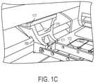
- Conventional recoater arms 146have a first end 165 and a second end 166 , which can be configured to attach to support arms, such as support arm 169 ( FIG. 1C ), at either end of the recoater arm 146 .
- First end 165 and second end 166may be opposite ends of the recoater arm 146 .
- Support arm 169may itself contain support substructures such as those shown in FIG. 1C , such as to accommodate, at attachment point 171 , first end 165 of a recoater arm 146 , which then runs the length 172 to another support arm 169 at the second end 166 of the recoater arm 146 .
- Support arm 169may have a curved surface as it approaches attachment point 171 , with a narrower width in the y-direction surrounding attachment point 171 .
- the narrower y-direction width surrounding attachment point 171may limit the size of recoater arm 146 that can be accommodated (at least the size in the y-direction) and, in turn, the dimensions of the powder hopper that can be accommodated by recoater arm 146 .
- the more limited the size of the powder hopper that can be accommodatedthe greater the number of powder hoppers that will be necessary to build a given part; for manufacturing of large objects or parts, the need to keep cycling in a new powder hopper can drastically prolong production time. Accordingly, there is a need to be able to accommodate larger powder hoppers at a time.
- the present disclosureis directed to a method of fabricating an object, comprising: (a) fusing at least a portion of a given layer of a given powder to form at least one fused region; (b) providing a subsequent layer of the powder, the powder being delivered down through a recoater mechanism, the mechanism having a plurality of vanes oriented at an angle to spread powder in a lateral direction toward the edges of a powder bed; and (c) repeating steps (a) and (b) until the object is formed.
- the recoater mechanismcomprises a recoater arm.
- the recoater mechanismfurther comprises a recoater blade.
- the fusingcomprises irradiating with a laser beam or with an electron beam.
- the fusingcomprises binder jetting.
- the present disclosureis directed to an apparatus for forming an object by additive manufacturing, comprising: a powder bed area defined by a build plate, the build plate adapted to lower as the object is being made; a powder fusion mechanism for fusing portions of powder within the powder bed; and a powder recoater mechanism for providing a layer of powder, the mechanism having two opposite ends and having a plurality of vanes oriented at an angle to spread powder in a lateral direction toward the edges of a powder bed.
- the powder recoater mechanismis held in plate with a first support arm and a second support arm on opposite edges of the powder bed, the first and second support arms each having a generally horizontal surface near the respective edge of the powder bed, the horizontal surface adapted to support each end of the recoater mechanism.
- the horizontal surface of each supportis unobstructed in a vertical direction, allowing attachment of the recoater mechanism by lowering it into place from a vertical direction while keeping the recoater mechanism level.
- the powder recoater mechanismcomprises a recoater arm.
- the powder fusion mechanismcomprises an energy source.
- the energy sourceis a laser source.
- the energy sourceis an electron beam source.
- the recoater armcomprises a recoater blade.
- FIG. 1Ashows a schematic of an example of an apparatus for AM according to conventional methods.
- FIG. 1Bshows a schematic of an example of a recoater arm for AM according to conventional methods.
- FIG. 1Cshows an example of a support arm for AM according to conventional methods.
- FIG. 2Ashows a schematic of an example of an apparatus for AM according to some aspects of the present disclosure.
- FIG. 2Bshows a schematic of an example of a recoater arm for AM according to some aspects of the present disclosure.
- FIG. 2Cshows an example of a support arm for AM according to some aspects of the present disclosure.
- the present applicationis directed to methods and apparatuses for improving powder coating efficiency and coverage.
- an even powder coat across a DMLM platformis key for part quality.
- Powder distribution systemscan be hindered by the effects of chamber pressurization and powder dynamics. Further, machine modifications may require powder to be distributed further than originally designed. These effects can result in a lack of powder at, for example, the edges of the plate.
- vanescan be incorporated into recoater mechanisms in order to direct powder from a hopper atop the recoater to be deposited to the edge of the platform, thus improving powder distribution.
- Such powder distribution vanesmay be built into a recoater arm directly or incorporated into an insert which may be nested into the recoater mechanism above deposition slits.
- the vanesmay be constructed at various directions and angles from the vertical, to ensure that powder is deposited laterally or with at least a nonzero lateral component.
- Methods and apparatuses incorporating powder distribution vanes into recoater mechanismscan reduce powder usage and keep powder distribution from becoming a limiting factor in production. Existing powder distribution systems and powder-based additive manufacturing methods and apparatuses may be leveraged in such machine expansion/modification efforts.
- the use of powder distribution vanesmay increase the powder throughput capability of the recoating mechanism and may maximize the powder distribution capability of a given system. Vane application also allows for larger build volume (increase recoater effective width) with a minimum number of machine modifications.
- the vanesmay utilize and leverage the potential energy of the powder height in the reservoir above the recoater to accomplish a wider layer of powder along the full distance of recoater travel without increasing other attributes of the recoater or machine interface.
- recoaters incorporating directional/angled powder distribution vanesmay be used with modified support arms, such as modified support brackets, to accommodate wider powder hoppers and/or wider recoater arms.
- the “vertical” directionrefers to the z-direction
- “lowering” somethingrefers to moving it downward vertically, i.e., in the z-dimension, such as in the negative z-direction.
- the powder recoater mechanismmay contain a plurality of vanes oriented at an angle to spread powder in a lateral direction toward the edges of a powder bed.
- the angle from the verticalmay be any angle greater than 0°, up to and including 90°, such as 10°, 20°, 30°, 40°, 50°, 60°, 70°, 80°, or any integer or range in between, as may be disclosed in other sections of this specification, which are incorporated into this paragraph by reference.
- all of the plurality of vanes in the recoater mechanismmay be oriented at the same angle from the vertical.
- the plurality of vanesmay be oriented at a plurality of different angles from the vertical.
- the “lateral” directionrefers to the horizontal direction, i.e., the xy-plane.
- the recoater mechanismmay have a plurality of vanes oriented at an angle to spread powder in a lateral direction.
- the spread of the powderhas a component in the lateral direction, i.e., in the xy-plane, and also has a component in the vertical direction, i.e., the z-direction.
- the lateral componentis greater than the vertical component. In other of those aspects, the lateral component is less than the vertical component.
- support armsinclude, but are not limited to, brackets.
- FIG. 2Ashows a schematic of an example of an apparatus for AM according to the present disclosure.
- Apparatus 240may be similar in some aspects to apparatus 140 ( FIG. 1A ).
- the recoater mechanismsuch as recoater arm 246
- recoater arm 246is a modified recoater arm, as shown in FIG. 2B .
- Recoater arm 246may be similar in some aspects to recoater arm 146 .
- Recoater arm 246may contain a plurality of slits 268 , which may be substantially vertical in some aspects.
- one or more of the plurality of slits 268may comprise an opening that is at an angle from the vertical, such as to allow powder flow downward not only vertically (i.e., in direction 267 ) but also at various angles, e.g., in a first direction 273 and a second direction 274 .
- an insert 280may be nested in recoater arm 246 , the insert 280 comprising a plurality of vanes 275 at one or more angles from the vertical.
- the plurality of vanes 275may be generated by any suitable means known to those skilled in the art. Powder flowing from a powder hopper (not pictured) attached to the top of recoater arm 246 and insert 280 , and through the plurality of vanes 275 , may be spread more greatly in the x-dimension than powder flowing through the plurality of slits 168 (without directional vanes at an angle from the vertical) in recoater arm 146 .
- all of the plurality of vanes 275are at the same angle from the vertical. In other aspects, the plurality of vanes 275 may be at a plurality of different angles from the vertical. In some aspects, the plurality of vanes 275 may be positioned at or near the first end 265 and/or the second end 266 of the recoater arm 246 . In some aspects, the plurality of vanes 275 may be positioned along the full length of the recoater arm 246 . In some aspects, the insert 280 may be sized to serve as a standalone recoater mechanism, without nesting into a recoater arm 246 .
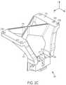
- FIG. 2Cshows an example of a modified support arm 269 for use with recoater arm 246 in apparatus 240 .
- the support armmay include a mounting surface 279 which may comprise a substantially flat surface forming a plane that is substantially parallel with the x-y plane shown in FIG. 2C .
- the mounting surfacemay further include a series of mounting points 276 A-C which may be through holes and/or threaded holes. The mounting points may be configured to line up with mounting points on the apparatus (e.g. at portion 177 shown in FIG. 1C ).
- the support arm 269may further include a cross brace 278 which may be substantially X-shaped. Recoater arm 246 may be held in place in apparatus 240 using the modified support arm 269 , at attachment interface 271 .
- the attachment interface 271comprises a substantially flat surface forming a plane that is substantially parallel with the x-y plane shown in FIG. 2C , and side surfaces 290 which may be formed as substantially flat surfaces forming planes that are substantially perpendicular to the x-y plane.
- the attachment interfacemay further include at least one mounting point 277 , which may be a through hole and/or threaded hole.
- the dimensions of the substantially flat surface 271 , side surfaces 290 , and/or mounting point(s) 277may be dimensioned to accommodate ends 265 , 266 of the recoater arm 246 .
- the attachment interface 271 of the modified support arm 269is moved such that the attachment interface 271 is closer to the mounting points 276 A-C of the mounting surface 279 in the x direction.
- the modified support arm(s)may accommodate a recoater that is longer along an x-direction; allowing for a larger usable build area.
- the abovementioned advantage(s) of moving the attachment interface 271 closer to the mounting points 276 A-C in the x-directionmay be accomplished by removing cross brace 175 shown in FIG. 1C .
- the angle of down braces 270 of the modified support armis modified to be steeper than portions 169 of the support arm shown in FIG. 1C .
- a cross bracee.g. cross brace 278 shown in FIG. 2C
Landscapes
- Engineering & Computer Science (AREA)
- Chemical & Material Sciences (AREA)
- Materials Engineering (AREA)
- Manufacturing & Machinery (AREA)
- Physics & Mathematics (AREA)
- Mechanical Engineering (AREA)
- Plasma & Fusion (AREA)
- Optics & Photonics (AREA)
- Ceramic Engineering (AREA)
- Health & Medical Sciences (AREA)
- General Health & Medical Sciences (AREA)
- Toxicology (AREA)
- General Chemical & Material Sciences (AREA)
- Chemical Kinetics & Catalysis (AREA)
- Metallurgy (AREA)
- Organic Chemistry (AREA)
- Powder Metallurgy (AREA)
- Producing Shaped Articles From Materials (AREA)
Abstract
Description
Claims (19)
Priority Applications (5)
| Application Number | Priority Date | Filing Date | Title |
|---|---|---|---|
| US15/722,525US11273495B2 (en) | 2017-10-02 | 2017-10-02 | Modified frame and recoating system |
| EP18194593.2AEP3461574B1 (en) | 2017-10-02 | 2018-09-14 | Modified frame and recoating system |
| JP2018172079AJP6791922B2 (en) | 2017-10-02 | 2018-09-14 | Modified frame and recoating system |
| CN201811139446.7ACN109590465B (en) | 2017-10-02 | 2018-09-28 | Method and apparatus for manufacturing articles |
| ZA2018/06496AZA201806496B (en) | 2017-10-02 | 2018-10-01 | Modified frame and recoating system |
Applications Claiming Priority (1)
| Application Number | Priority Date | Filing Date | Title |
|---|---|---|---|
| US15/722,525US11273495B2 (en) | 2017-10-02 | 2017-10-02 | Modified frame and recoating system |
Publications (2)
| Publication Number | Publication Date |
|---|---|
| US20190099807A1 US20190099807A1 (en) | 2019-04-04 |
| US11273495B2true US11273495B2 (en) | 2022-03-15 |
Family
ID=63592633
Family Applications (1)
| Application Number | Title | Priority Date | Filing Date |
|---|---|---|---|
| US15/722,525Active2039-01-11US11273495B2 (en) | 2017-10-02 | 2017-10-02 | Modified frame and recoating system |
Country Status (5)
| Country | Link |
|---|---|
| US (1) | US11273495B2 (en) |
| EP (1) | EP3461574B1 (en) |
| JP (1) | JP6791922B2 (en) |
| CN (1) | CN109590465B (en) |
| ZA (1) | ZA201806496B (en) |
Families Citing this family (4)
| Publication number | Priority date | Publication date | Assignee | Title |
|---|---|---|---|---|
| US20180264598A1 (en)* | 2017-03-15 | 2018-09-20 | General Electric Company | Constantly varying hatch for additive manufacturing |
| WO2022087044A1 (en) | 2020-10-21 | 2022-04-28 | General Electric Company | Material supply system and method for using the same |
| FR3116461B1 (en)* | 2020-11-26 | 2022-12-23 | S A S 3Dceram Sinto | Machine for manufacturing raw parts in ceramic or metallic material |
| US12134131B2 (en) | 2021-06-16 | 2024-11-05 | General Electric Company | Methods and apparatus for recoating parameter control |
Citations (23)
| Publication number | Priority date | Publication date | Assignee | Title |
|---|---|---|---|---|
| EP1439050A1 (en)* | 2003-01-14 | 2004-07-21 | Concept Laser GmbH | Coating device for an apparatus for producing articles made of pulverulent material |
| DE102009035258A1 (en)* | 2009-07-29 | 2011-02-03 | Cl Schutzrechtsverwaltungs Gmbh | Method for producing a three-dimensional object |
| US8524142B2 (en) | 2009-08-25 | 2013-09-03 | Bego Medical Gmbh | Apparatus and process for continuous generative production |
| US9067360B2 (en) | 2009-08-25 | 2015-06-30 | Bego Medical Gmbh | Device and method for generative production |
| WO2015141779A1 (en) | 2014-03-19 | 2015-09-24 | シーメット株式会社 | Recoater unit, three-dimensional-layer shaping device, three-dimensional-layer shaping method, and shaped article |
| US9156056B2 (en) | 2008-08-05 | 2015-10-13 | Panasonic Intellectual Property Management Co., Ltd. | Apparatus for producing an integrally laminated three-dimensional object by repeating formation of powder layer and solidified layer |
| US20150323318A1 (en) | 2014-05-09 | 2015-11-12 | MTU Aero Engines AG | Device and method for generative production of at least one component area of a component |
| US20150367415A1 (en) | 2014-06-20 | 2015-12-24 | Velo3D, Inc. | Apparatuses, systems and methods for three-dimensional printing |
| US9327450B2 (en) | 2006-11-10 | 2016-05-03 | Eos Gmbh Electro Optical Systems | Device and method for manufacturing a three-dimensional object by means of an application device for building material in powder form |
| CN105855548A (en) | 2016-06-08 | 2016-08-17 | 天津清研智束科技有限公司 | Powder distribution device and additive manufacturing device |
| CN106346003A (en) | 2015-07-13 | 2017-01-25 | 株式会社沙迪克 | Metal 3d printer |
| US20170028630A1 (en) | 2007-10-21 | 2017-02-02 | Voxeljet Ag | Method and device for layer-wise production of patterns |
| US20170057013A1 (en) | 2015-08-25 | 2017-03-02 | General Electric Company | Coater apparatus and method for additive manufacturing |
| US20170113242A1 (en) | 2015-10-27 | 2017-04-27 | Hamilton Sundstrand Corporation | Rake systems for additive manufacturing systems |
| US20170151727A1 (en) | 2015-12-01 | 2017-06-01 | Voxeljet Ag | Method and device for producing three-dimensional components with the aid of an overfeed sensor |
| EP3205483A1 (en) | 2016-01-12 | 2017-08-16 | Hamilton Sundstrand Corporation | Additive manufacturing quality control systems |
| WO2017143145A1 (en) | 2016-02-17 | 2017-08-24 | UCT Additive Manufacturing Center Pte. Ltd. | Multi-blade recoater |
| CN107107469A (en) | 2014-12-15 | 2017-08-29 | 阿卡姆股份公司 | Improved method for increasing material manufacturing |
| WO2017180084A1 (en) | 2016-04-10 | 2017-10-19 | Hewlett-Packard Development Company, L.P. | Dispensing powdered build material for additive manufacturing |
| US20180043616A1 (en)* | 2016-08-10 | 2018-02-15 | Toyota Jidosha Kabushiki Kaisha | Three-dimensional molding device and three-dimensional molding method |
| US20180133796A1 (en)* | 2016-11-16 | 2018-05-17 | Sodick Co., Ltd. | Laminating and shaping apparatus |
| US20180345378A1 (en)* | 2017-05-31 | 2018-12-06 | General Electric Company | Apparatus and method for real-time simultaneous additive and subtractive manufacturing with mechanism to recover unused raw material |
| US20210206087A1 (en)* | 2017-07-28 | 2021-07-08 | Hewlett-Packard Development Company, L.P. | Three-dimensional printer |
- 2017
- 2017-10-02USUS15/722,525patent/US11273495B2/enactiveActive
- 2018
- 2018-09-14JPJP2018172079Apatent/JP6791922B2/enactiveActive
- 2018-09-14EPEP18194593.2Apatent/EP3461574B1/enactiveActive
- 2018-09-28CNCN201811139446.7Apatent/CN109590465B/enactiveActive
- 2018-10-01ZAZA2018/06496Apatent/ZA201806496B/enunknown
Patent Citations (25)
| Publication number | Priority date | Publication date | Assignee | Title |
|---|---|---|---|---|
| EP1439050A1 (en)* | 2003-01-14 | 2004-07-21 | Concept Laser GmbH | Coating device for an apparatus for producing articles made of pulverulent material |
| US9327450B2 (en) | 2006-11-10 | 2016-05-03 | Eos Gmbh Electro Optical Systems | Device and method for manufacturing a three-dimensional object by means of an application device for building material in powder form |
| US20170028630A1 (en) | 2007-10-21 | 2017-02-02 | Voxeljet Ag | Method and device for layer-wise production of patterns |
| US9156056B2 (en) | 2008-08-05 | 2015-10-13 | Panasonic Intellectual Property Management Co., Ltd. | Apparatus for producing an integrally laminated three-dimensional object by repeating formation of powder layer and solidified layer |
| DE102009035258A1 (en)* | 2009-07-29 | 2011-02-03 | Cl Schutzrechtsverwaltungs Gmbh | Method for producing a three-dimensional object |
| US8524142B2 (en) | 2009-08-25 | 2013-09-03 | Bego Medical Gmbh | Apparatus and process for continuous generative production |
| US9067360B2 (en) | 2009-08-25 | 2015-06-30 | Bego Medical Gmbh | Device and method for generative production |
| WO2015141779A1 (en) | 2014-03-19 | 2015-09-24 | シーメット株式会社 | Recoater unit, three-dimensional-layer shaping device, three-dimensional-layer shaping method, and shaped article |
| US20150323318A1 (en) | 2014-05-09 | 2015-11-12 | MTU Aero Engines AG | Device and method for generative production of at least one component area of a component |
| US20150367415A1 (en) | 2014-06-20 | 2015-12-24 | Velo3D, Inc. | Apparatuses, systems and methods for three-dimensional printing |
| CN106488819A (en) | 2014-06-20 | 2017-03-08 | 维洛3D公司 | Apparatus, system and method for three-dimensional printing |
| CN107107469A (en) | 2014-12-15 | 2017-08-29 | 阿卡姆股份公司 | Improved method for increasing material manufacturing |
| CN106346003A (en) | 2015-07-13 | 2017-01-25 | 株式会社沙迪克 | Metal 3d printer |
| JP2017020081A (en)* | 2015-07-13 | 2017-01-26 | 株式会社ソディック | Lamination molding device |
| US20170057013A1 (en) | 2015-08-25 | 2017-03-02 | General Electric Company | Coater apparatus and method for additive manufacturing |
| US20170113242A1 (en) | 2015-10-27 | 2017-04-27 | Hamilton Sundstrand Corporation | Rake systems for additive manufacturing systems |
| US20170151727A1 (en) | 2015-12-01 | 2017-06-01 | Voxeljet Ag | Method and device for producing three-dimensional components with the aid of an overfeed sensor |
| EP3205483A1 (en) | 2016-01-12 | 2017-08-16 | Hamilton Sundstrand Corporation | Additive manufacturing quality control systems |
| WO2017143145A1 (en) | 2016-02-17 | 2017-08-24 | UCT Additive Manufacturing Center Pte. Ltd. | Multi-blade recoater |
| WO2017180084A1 (en) | 2016-04-10 | 2017-10-19 | Hewlett-Packard Development Company, L.P. | Dispensing powdered build material for additive manufacturing |
| CN105855548A (en) | 2016-06-08 | 2016-08-17 | 天津清研智束科技有限公司 | Powder distribution device and additive manufacturing device |
| US20180043616A1 (en)* | 2016-08-10 | 2018-02-15 | Toyota Jidosha Kabushiki Kaisha | Three-dimensional molding device and three-dimensional molding method |
| US20180133796A1 (en)* | 2016-11-16 | 2018-05-17 | Sodick Co., Ltd. | Laminating and shaping apparatus |
| US20180345378A1 (en)* | 2017-05-31 | 2018-12-06 | General Electric Company | Apparatus and method for real-time simultaneous additive and subtractive manufacturing with mechanism to recover unused raw material |
| US20210206087A1 (en)* | 2017-07-28 | 2021-07-08 | Hewlett-Packard Development Company, L.P. | Three-dimensional printer |
Non-Patent Citations (7)
| Title |
|---|
| English Translation of Chinese office action for application 201811139446.7 dated Sep. 2, 2020 (13 pages). |
| English Translation of Japanese office action for application JP2018-172079 dated Feb. 4, 2020 (11 pages). |
| European Search Report Corresponding to Application No. 181645932 dated Feb. 19, 2019. |
| Herzog Frank: English Translation of DE-102009035258-A1; "Producing a three-dimensional object, comprises successively compacting layers of building material by electron beam, electromagnetic- or particle radiation, and introducing powdered materials into construction area by coating device"; (2011) (Year: 2011).* |
| Herzog Frank; English Translation of EP-1439050-A1; "Coating device for an apparatus for producing articles made of pulverulent material"; (2004) (Year: 2004).* |
| Kawada; English Translation of JP-2017020081-A; "Lamination Molding Device"; (2008) (Year: 2008).* |
| Machine English Translation of Kawada et al. (WO2015141779A1). Retrieved from Espace.net https://worldwide.espacenet.com/patent/search/family/054144741/publication/WO2015141779A1?q=pn%3DWO2015141779A1 (Year: 2015).* |
Also Published As
| Publication number | Publication date |
|---|---|
| CN109590465A (en) | 2019-04-09 |
| CN109590465B (en) | 2021-09-07 |
| US20190099807A1 (en) | 2019-04-04 |
| ZA201806496B (en) | 2019-08-28 |
| EP3461574B1 (en) | 2021-10-27 |
| EP3461574A1 (en) | 2019-04-03 |
| JP6791922B2 (en) | 2020-11-25 |
| JP2019064255A (en) | 2019-04-25 |
Similar Documents
| Publication | Publication Date | Title |
|---|---|---|
| EP3486008B1 (en) | Powder reduction apparatus | |
| US20220023952A1 (en) | Method and apparatus for continuously refreshing a recoater blade for additive manufacturing | |
| EP3461574B1 (en) | Modified frame and recoating system | |
| CN110337359B (en) | Additive manufacturing using a mobile build space | |
| CN110177676B (en) | Large-scale additive manufacturing machine | |
| CN110191792B (en) | Additive manufacturing using a moving scan area | |
| US11135653B2 (en) | DMLM build release layer and method of use thereof | |
| US11981082B2 (en) | Device and method for the generative production of a three-dimensional object | |
| US10919114B2 (en) | Methods and support structures leveraging grown build envelope | |
| US20170232683A1 (en) | Method and connecting supports for additive manufacturing | |
| US20190322050A1 (en) | Additive manufacturing system and method | |
| US11014189B2 (en) | Method to control additive manufacturing builds using laser angle of incidence | |
| US20180369961A1 (en) | Treatment of solidified layer | |
| US20170326815A1 (en) | Methods and rail supports for additive manufacturing | |
| US11084208B2 (en) | Additive manufacturing systems and methods including louvered particulate containment wall | |
| JP2023063778A (en) | Method for creating molding programs, additive manufacturing method, and additive manufacturing equipment | |
| EP3437765B1 (en) | Continuous additive manufacture of high pressure turbine | |
| US11084096B2 (en) | Movable wall for additive powder bed | |
| RU154761U1 (en) | DEVICE FOR PRODUCING PRODUCTS FROM POWDERED MATERIALS |
Legal Events
| Date | Code | Title | Description |
|---|---|---|---|
| FEPP | Fee payment procedure | Free format text:ENTITY STATUS SET TO UNDISCOUNTED (ORIGINAL EVENT CODE: BIG.); ENTITY STATUS OF PATENT OWNER: LARGE ENTITY | |
| AS | Assignment | Owner name:GENERAL ELECTRIC COMPANY, NEW YORK Free format text:ASSIGNMENT OF ASSIGNORS INTEREST;ASSIGNORS:JONES, LUCAS CHRISTIAN;ORTNER, JONATHAN;MOORES, JOHN;AND OTHERS;SIGNING DATES FROM 20170920 TO 20170925;REEL/FRAME:043769/0153 | |
| STPP | Information on status: patent application and granting procedure in general | Free format text:DOCKETED NEW CASE - READY FOR EXAMINATION | |
| STPP | Information on status: patent application and granting procedure in general | Free format text:NON FINAL ACTION MAILED | |
| STPP | Information on status: patent application and granting procedure in general | Free format text:RESPONSE TO NON-FINAL OFFICE ACTION ENTERED AND FORWARDED TO EXAMINER | |
| STPP | Information on status: patent application and granting procedure in general | Free format text:DOCKETED NEW CASE - READY FOR EXAMINATION | |
| STPP | Information on status: patent application and granting procedure in general | Free format text:NON FINAL ACTION MAILED | |
| STPP | Information on status: patent application and granting procedure in general | Free format text:RESPONSE TO NON-FINAL OFFICE ACTION ENTERED AND FORWARDED TO EXAMINER | |
| STPP | Information on status: patent application and granting procedure in general | Free format text:NOTICE OF ALLOWANCE MAILED -- APPLICATION RECEIVED IN OFFICE OF PUBLICATIONS | |
| STCF | Information on status: patent grant | Free format text:PATENTED CASE | |
| MAFP | Maintenance fee payment | Free format text:PAYMENT OF MAINTENANCE FEE, 4TH YEAR, LARGE ENTITY (ORIGINAL EVENT CODE: M1551); ENTITY STATUS OF PATENT OWNER: LARGE ENTITY Year of fee payment:4 |