US11273304B2 - Electrode positioning system and method - Google Patents
Electrode positioning system and methodDownload PDFInfo
- Publication number
- US11273304B2 US11273304B2US16/397,917US201916397917AUS11273304B2US 11273304 B2US11273304 B2US 11273304B2US 201916397917 AUS201916397917 AUS 201916397917AUS 11273304 B2US11273304 B2US 11273304B2
- Authority
- US
- United States
- Prior art keywords
- bridge
- user
- band
- electrodes
- ear pad
- Prior art date
- Legal status (The legal status is an assumption and is not a legal conclusion. Google has not performed a legal analysis and makes no representation as to the accuracy of the status listed.)
- Active, expires
Links
Images


Classifications
- A—HUMAN NECESSITIES
- A61—MEDICAL OR VETERINARY SCIENCE; HYGIENE
- A61N—ELECTROTHERAPY; MAGNETOTHERAPY; RADIATION THERAPY; ULTRASOUND THERAPY
- A61N1/00—Electrotherapy; Circuits therefor
- A61N1/02—Details
- A61N1/04—Electrodes
- A61N1/0404—Electrodes for external use
- A61N1/0472—Structure-related aspects
- A61N1/0476—Array electrodes (including any electrode arrangement with more than one electrode for at least one of the polarities)
- A—HUMAN NECESSITIES
- A61—MEDICAL OR VETERINARY SCIENCE; HYGIENE
- A61B—DIAGNOSIS; SURGERY; IDENTIFICATION
- A61B5/00—Measuring for diagnostic purposes; Identification of persons
- A61B5/68—Arrangements of detecting, measuring or recording means, e.g. sensors, in relation to patient
- A61B5/6801—Arrangements of detecting, measuring or recording means, e.g. sensors, in relation to patient specially adapted to be attached to or worn on the body surface
- A61B5/6802—Sensor mounted on worn items
- A61B5/6803—Head-worn items, e.g. helmets, masks, headphones or goggles
- A—HUMAN NECESSITIES
- A61—MEDICAL OR VETERINARY SCIENCE; HYGIENE
- A61B—DIAGNOSIS; SURGERY; IDENTIFICATION
- A61B5/00—Measuring for diagnostic purposes; Identification of persons
- A61B5/68—Arrangements of detecting, measuring or recording means, e.g. sensors, in relation to patient
- A61B5/6801—Arrangements of detecting, measuring or recording means, e.g. sensors, in relation to patient specially adapted to be attached to or worn on the body surface
- A61B5/6813—Specially adapted to be attached to a specific body part
- A61B5/6814—Head
- A—HUMAN NECESSITIES
- A61—MEDICAL OR VETERINARY SCIENCE; HYGIENE
- A61N—ELECTROTHERAPY; MAGNETOTHERAPY; RADIATION THERAPY; ULTRASOUND THERAPY
- A61N1/00—Electrotherapy; Circuits therefor
- A61N1/02—Details
- A61N1/04—Electrodes
- A61N1/0404—Electrodes for external use
- A61N1/0408—Use-related aspects
- A61N1/0456—Specially adapted for transcutaneous electrical nerve stimulation [TENS]
- A—HUMAN NECESSITIES
- A61—MEDICAL OR VETERINARY SCIENCE; HYGIENE
- A61N—ELECTROTHERAPY; MAGNETOTHERAPY; RADIATION THERAPY; ULTRASOUND THERAPY
- A61N1/00—Electrotherapy; Circuits therefor
- A61N1/18—Applying electric currents by contact electrodes
- A61N1/32—Applying electric currents by contact electrodes alternating or intermittent currents
- A61N1/36—Applying electric currents by contact electrodes alternating or intermittent currents for stimulation
- A61N1/36014—External stimulators, e.g. with patch electrodes
- A61N1/36025—External stimulators, e.g. with patch electrodes for treating a mental or cerebral condition
- A—HUMAN NECESSITIES
- A61—MEDICAL OR VETERINARY SCIENCE; HYGIENE
- A61N—ELECTROTHERAPY; MAGNETOTHERAPY; RADIATION THERAPY; ULTRASOUND THERAPY
- A61N1/00—Electrotherapy; Circuits therefor
- A61N1/02—Details
- A61N1/04—Electrodes
- A61N1/0404—Electrodes for external use
- A61N1/0472—Structure-related aspects
- A61N1/0484—Garment electrodes worn by the patient
- A—HUMAN NECESSITIES
- A61—MEDICAL OR VETERINARY SCIENCE; HYGIENE
- A61N—ELECTROTHERAPY; MAGNETOTHERAPY; RADIATION THERAPY; ULTRASOUND THERAPY
- A61N1/00—Electrotherapy; Circuits therefor
- A61N1/02—Details
- A61N1/04—Electrodes
- A61N1/0404—Electrodes for external use
- A61N1/0472—Structure-related aspects
- A61N1/0492—Patch electrodes
- H—ELECTRICITY
- H04—ELECTRIC COMMUNICATION TECHNIQUE
- H04R—LOUDSPEAKERS, MICROPHONES, GRAMOPHONE PICK-UPS OR LIKE ACOUSTIC ELECTROMECHANICAL TRANSDUCERS; DEAF-AID SETS; PUBLIC ADDRESS SYSTEMS
- H04R1/00—Details of transducers, loudspeakers or microphones
- H04R1/10—Earpieces; Attachments therefor ; Earphones; Monophonic headphones
- H04R1/1058—Manufacture or assembly
- H—ELECTRICITY
- H04—ELECTRIC COMMUNICATION TECHNIQUE
- H04R—LOUDSPEAKERS, MICROPHONES, GRAMOPHONE PICK-UPS OR LIKE ACOUSTIC ELECTROMECHANICAL TRANSDUCERS; DEAF-AID SETS; PUBLIC ADDRESS SYSTEMS
- H04R2460/00—Details of hearing devices, i.e. of ear- or headphones covered by H04R1/10 or H04R5/033 but not provided for in any of their subgroups, or of hearing aids covered by H04R25/00 but not provided for in any of its subgroups
- H04R2460/13—Hearing devices using bone conduction transducers
- H—ELECTRICITY
- H04—ELECTRIC COMMUNICATION TECHNIQUE
- H04R—LOUDSPEAKERS, MICROPHONES, GRAMOPHONE PICK-UPS OR LIKE ACOUSTIC ELECTROMECHANICAL TRANSDUCERS; DEAF-AID SETS; PUBLIC ADDRESS SYSTEMS
- H04R5/00—Stereophonic arrangements
- H04R5/033—Headphones for stereophonic communication
- H—ELECTRICITY
- H04—ELECTRIC COMMUNICATION TECHNIQUE
- H04R—LOUDSPEAKERS, MICROPHONES, GRAMOPHONE PICK-UPS OR LIKE ACOUSTIC ELECTROMECHANICAL TRANSDUCERS; DEAF-AID SETS; PUBLIC ADDRESS SYSTEMS
- H04R5/00—Stereophonic arrangements
- H04R5/033—Headphones for stereophonic communication
- H04R5/0335—Earpiece support, e.g. headbands or neckrests
Definitions
- This inventionrelates generally to the biosignals field, and more specifically to a new and useful electrode positioning system and method.
- Electrode systems in the biosignals fieldare used to transmit electrical signals to a subject, and can be used to detect or measure biosignals from the subject.
- Current electrode systems for electrical stimulation and/or biosignal detectionare, however, insufficient for many reasons including inadequate contact between the subject and the electrode(s) of a system, non-robust contact between the subject and the electrode(s) of a system, inadequate accommodation of individual anatomical variation across subjects, subject discomfort while using an electrode system, and/or limited use within multiple electrical simulation or biosignal detection paradigms.
- current systems and methodsgenerally fail to allow a user to properly position electrodes at a head region by him/herself in a non-clinical or non-research environment.
- FIG. 1depicts a schematic of an embodiment of an electrode positioning system
- FIGS. 2A-2Ddepict a first specific example of an embodiment of an electrode positioning system
- FIG. 3depicts a portion of an embodiment of an electrode positioning system
- FIG. 4depicts a portion of an embodiment of an electrode positioning system
- FIGS. 5A-5Hdepict features of a specific example of an electrode positioning system
- FIG. 8depicts a second specific alternative example of an embodiment of an electrode positioning system
- FIG. 9depicts a third specific alternative example of an embodiment of an electrode positioning system.
- the system 100can comprise: a set of ear pad modules 110 configured to provide a pair of anchoring points at contralateral head regions of the user; a band 120 having a first end coupled to a first ear pad module of the set of ear pad modules 110 and a second end coupled to a second ear pad module of the set of ear pad modules 110 ; a bridge 130 coupled to an inferior midregion of the band 120 and configured to house a set of electrodes 140 for providing electrical stimulation to the user; a set of structural links providing paths for transmitting electrical current to the set of electrodes, the set of structural links 150 coupled to interior portions of the set of ear pad modules and having an elastic modulus above a threshold modulus such that 1) in a first operation mode, lateral displacement of the set of ear pad modules 110 by the user produces lateral displacement of the set of electrodes 140 away from the head region of the user, and 2) in a second operation mode, release of the set of ear pad modules 110 by the user orients protrusions
- the system 100can additionally or alternatively incorporate or cooperate with one or more of: transducers (e.g., optical sensors, optical emitters, ultrasonic transducers, etc.), additional sensors (e.g., temperature sensors, activity detecting sensors, sensors associated with position, velocity, or acceleration detection, biometric sensors, etc.) for sensing signals from the user, additional sensors (e.g., temperature sensors, barometric pressure sensors, light sensors, microphones, etc.) for sensing signals from the environment of the user, and any other suitable module.
- transducerse.g., optical sensors, optical emitters, ultrasonic transducers, etc.
- additional sensorse.g., temperature sensors, activity detecting sensors, sensors associated with position, velocity, or acceleration detection, biometric sensors, etc.
- additional sensorse.g., temperature sensors, barometric pressure sensors, light sensors, microphones, etc.
- the system 100thus prevents or delays deflection or bending of individual electrode protrusions into an orientation approximately tangential to the scalp of the user (e.g., during initial placement of the system 100 at the body of the user), and facilitates maintenance of a protrusion orientation during approach to the head that is more perpendicular to the scalp of the user.
- the system 100can control the orientation(s) at which deflectable electrode elements of the system approach the head of the user, thereby preventing early dragging of deflectable electrode elements over the hair of the user in an undesired manner during placement of the system 100 at the head of the user.
- the system 100can provide enhanced comfort during placement of the system 100 at the head of the user, and/or provide proper positioning of elements of the system 100 at the head of the user.
- the system 100can prevent or delay deflection/bending of individual electrode protrusions into an orientation approximately tangential to any other convex surface of a body (e.g., an anatomical region of a human or other animal), for instance, during initial placement of the system 100 at the convex surface. Furthermore, the system 100 can facilitate maintenance of a protrusion orientation during approach to the convex surface of the body that is more perpendicular to the convex surface.
- a bodye.g., an anatomical region of a human or other animal
- the system 100can be applied to, stimulate, or otherwise sense signals from one or more of: a limb region (e.g., arm region, leg region) of the user, a gluteal region of a user, a pelvic region of a user, a torso region of a user (e.g., an abdominal region of a user, a breast region of a user), a neck region of a user, another head region of a user, or any other suitable body region of a user.
- a limb regione.g., arm region, leg region
- the system 100can thus facilitate maintenance of an electrode configuration that provides desired impedance characteristics and/or a desired type of contact at the user-electrode interface during placement and/or during use of the system 100 .
- the systemcan further include features configured to provide a high level of comfort in terms of wearability, as the user wears the system 100 during a period of stimulation treatment.
- the system 100is configured to interface with and position electrode units at the head of the user, such as the embodiments, variations, and examples of electrode systems described in U.S. application Ser. No. 14/878,647 entitled “Electrode System for Electrical Stimulation” and filed on 8 Oct. 2015 and/or electrode systems described in U.S. application Ser. No.
- the system 100is preferably configured to be worn by a user who is away from a research or clinical setting, such that the user can wear the system 100 while he or she is in a natural setting (e.g., at home, at a gym, outdoors, etc.).
- the system 100can additionally or alternatively be configured to be operated by a user who is in a research setting, a clinical setting, or any other suitable setting.
- some embodiments of the systemare configured to be worn at the head of the user, alternative embodiments of the system 100 can be configured to be worn or coupled to any other suitable body region of the user, as described above.
- the system 100can implement and/or facilitate implementation of one or more embodiments, variations, or examples of the method(s) described in U.S. application Ser. No. 14/470,747 entitled “Method and System for Providing Electrical Stimulation to a User” and filed on 27 Aug. 2014 and/or U.S. application Ser. No. 15/059,095 entitled “Method and System for Providing Electrical Stimulation to a User” and filed on 2 Mar. 2016, which are each incorporated in its entirety by this reference.
- the system 100 and/or method(s)can be configured for application of one or more of: transcranial electrical stimulation (TES) in the form of transcranial direct current stimulation (tDCS), transcranial alternating current stimulation (tACS), transcranial magnetic stimulation (TMS), transcranial random noise stimulation (tRNS, e.g., band-limited random noise stimulation), transcranial variable frequency stimulation (tVFS), band-limited stimulation transformed to increase RMS power while minimizing transients and clipping, and any other suitable form of TES.
- TEStranscranial electrical stimulation
- tDCStranscranial direct current stimulation
- tACStranscranial alternating current stimulation
- TMStranscranial magnetic stimulation
- tRNStranscranial random noise stimulation
- tVFStranscranial variable frequency stimulation
- band-limited stimulationtransformed to increase RMS power while minimizing transients and clipping
- the system 100 and/or methodcan be configured to for delivery of stimulation as anodal stimulation and/or cathodal stimulation.
- the electrical stimulationcan additionally or alternatively comprise any other form of electrical stimulation (e.g., electrical muscle stimulation, etc.) configured to stimulate any other suitable region of the user's body, with any suitable penetration depth, and/or any suitable tissue structure (e.g., neural, musculoskeletal).
- electrical stimulatione.g., electrical muscle stimulation, etc.
- tissue structuree.g., neural, musculoskeletal
- robust connection with the user provided by the elements (e.g., mechanical aspects) of the system 100additionally or alternatively apply to transmission of non-electrical modes of stimulation according to other suitable methods.
- the system 100 and/or method(s)can additionally or alternatively be configured to transmit non-electrical modes of stimulation (e.g., ultrasound stimulation, optical stimulation) by using any appropriate transducer or set of transducers in place of or in addition to electrode contacts.
- non-electrical modes of stimulatione.g., ultrasound stimulation, optical stimulation
- one variation of the system 100can be used to provide ultrasound transducing elements at a desired body region of the user, as facilitated by an array of protrusions configured to displace obstacles to ultrasound stimulation at the body region of the user.
- ultrasound transducing elementscan be configured at any suitable position along a length of a protrusion and/or at a distal end of a protrusion.
- Other variationscan, however, be configured to incorporate any other element(s) for stimulating the user.
- system 100can implement or facilitate implementation of any other suitable method(s).
- the set of pads 110 a /ear pad modules 110functions to provide a pair of anchoring points at contralateral head regions (or other opposing body regions) of the user.
- the set of pads 110 a /ear pad modules 110can also function to enhance comfort of the system 100 as the system 100 is being worn by the user. Additionally or alternatively, the set of pads 110 a /ear pad modules 110 can be configured to provide desired audio output functions (e.g., in terms of sound quality, in terms of noise cancelling, etc.) in variations of the system 100 configured with one or more speaker elements.
- each of the set of ear pad modulespreferably comprises a region of compliant material configured to interface with the head of the user, in proximity to an ear of the user in order to provide comfort, and a rigid portion configured to facilitate maintenance of contact between the user and the system during use.
- the compliant/padded portions of the ear pad modulescan be circumaural, or can alternatively be supra-aural.
- the set of ear pad modulescan produce a headphone-type form factor; however, the set of ear pad modules can alternatively contribute to any other suitable form factor for the system 100 .
- the set of ear pad modulescan provide an earphone-type form factor.
- the set of ear pad modulescan be substituted with or supplemented with any suitable element(s) that provide(s) anchoring points at the head of the user, and may not provide anchoring points at contralateral head regions of the user (e.g., the system can be asymmetric in form factor, or may provide anchoring points at other anatomically-opposing locations, such as inion and frontal pole of the head).
- the set of ear pad modulescan be substituted with pads/housing configured to produce anchoring points at the body of the user by one or more of: friction, adhesives (e.g., mild adhesives), biasing forces, hair grabbers (e.g., hair clips, hair ties, etc.), and any other suitable mechanism.
- the pads/ear pad modulescan be modular and include portions configured to provide structure/protection, and portions configured for user comfort.
- some variations of the pads/ear pad modulescan comprise pad modules including an outer housing 112 (i.e., lateral portion) that provides structural support for coupling to other elements of the system 100 and/or supports a medial compliant portion 113 that interfaces with the body of the user.
- the outer housing 112can be composed of a rigid material (e.g., plastic, metal, wood, ceramic, glass, etc.), while the medial portion 113 can be composed of a compliant material (e.g., foam, sponge, fabric, air/fluid/hydrogel/gel filled sac, etc.).
- variations of the system 100can additionally or alternatively omit outer housings 112 and/or medial compliant portions 113 for the pad modules.
- the pads/ear pad modulecan additionally or alternatively be configured in any other suitable manner.
- each of the set of ear pad modules 100preferably comprises a padded medial portion configured to interface with the head of the user, and a rigid lateral portion, coupled to (e.g., partially housing) the padded medial portion and configured to interface with the band 120 of the system 100 , as described in more detail below.
- the padded medial portionis configured to be filled with a compliant material and circumaural, such that the set of ear pad modules 110 substantially surround the ears of the user and provide comfortable anchoring points approximately centered at the ear regions of the user.
- each of the set of ear pad modulescan be configured to be acoustically transparent, or to have a high degree of acoustic transparency, such that the user can still hear sounds from the environment of the user, while using the system (e.g., in an application wherein the user is an athlete and needs to hear instructions from a coaching entity).
- this specific examplecan be applied to situations where the user is undergoing a session of electrical stimulation (e.g., transcranial stimulation) while receiving instruction and/or performing tasks in coordination with receiving instruction from an entity (e.g., coaching entity, electronic device providing instructions, etc.) in proximity, in the environment of the user.
- this specific example of the system 100can comprise pads (e.g., at a medially-oriented compliant portion of an ear pad module) that are not configured for sound isolation, noise cancelling, or noise reduction during operation of the system 100 .
- each of the set of ear pad modulescan be configured to have a low degree of acoustic transparency, or to cooperate with other electronics of the system 100 to provide sound isolation, noise reduction, or noise cancelling for the user, or to provide isolation from undesired sounds for the user while also providing desired sounds (such as music or instructions) to the user (e.g., using speakers, electronic amplification, wireless or wired transmission of audio signals, etc.).
- this specific examplecan be applied to situations where the user is undergoing a session of electrical stimulation (e.g., transcranial stimulation) while receiving instruction and/or performing tasks in coordination with receiving instruction through audio output elements (e.g., speakers) integrated with the set of ear pad modules 110 a or otherwise integrated with the system 100 .
- electrical stimulatione.g., transcranial stimulation
- audio output elementse.g., speakers
- variations of the specific examplecan alternatively be configured in any other suitable manner.
- the configuration of the system 100 and set of pads 110 a / 110can be configured to facilitate stimulation delivery/training in the context of motor skill training including one or more of: athletic training (e.g., team sports training, individual sports training), motor skill rehabilitation training (e.g., stroke rehabilitation training, etc.), military training (e.g., army training, air force training, marine corps training, navy training, coast guard training), motor skill training (e.g., surgeon training), and/or any other suitable type of motor skill training.
- athletic traininge.g., team sports training, individual sports training
- motor skill rehabilitation traininge.g., stroke rehabilitation training, etc.
- military traininge.g., army training, air force training, marine corps training, navy training, coast guard training
- motor skill traininge.g., surgeon training
- any other suitable type of motor skill traininge.g., surgeon training
- the configuration of the system 100 and set of pads 110 a / 110can be configured to facilitate stimulation delivery/training in any other suitable context (e.g., focus, memory, learning, etc.), depending upon the brain region(s) stimulation and/or the type(s) of stimulation applied.
- any other suitable contexte.g., focus, memory, learning, etc.
- the band 120is configured to have a first end coupled to a first pad module of the set of pad modules 110 and a second end coupled to a second pad module of the set of pad modules 110 , and functions to support the set of pad modules, and facilitate biasing of the system 100 into coupling with the head of the user.
- the band 120is preferably composed of a rigid material that is elastically deformable within the range of deformation needed to allow the user to wear the system, such that the user can induce a deformation of the band 120 in the process of donning the system 100 , and the system 100 can elastically recover and provide a biasing force that facilitates coupling of the system 100 at the head of the user. Variations of operation modes of the system 100 in relation to coupling of the system 100 to the user are described in more detail below. However, the band 120 can alternatively be inelastically deformable in some manner to facilitate coupling of the system 100 to the user.
- the band 120can be composed of a polymeric material (e.g., a plastic, etc.) and/or a metallic material that exhibit(s) properties of elastic deformation. Additionally or alternatively, the band 120 can be composed of a material that has ductile properties or brittle properties.
- the band 120can comprise a single material, or can comprise a composite of different materials (e.g., with regions or layers of different materials).
- the band 120is preferably of unitary construction and continuous across its length and/or its width; however, the band 120 can alternatively be modular and comprise one or more components that couple together in a physically coextensive manner (e.g., in a press fit, in a snap fit, with adhesives, with magnetic coupling, etc.) to form the band 120 . Additionally or alternatively, in some variations, the band 120 can be configured to have parts that bend relative to each other (e.g., with a hinge), in order to transition the system 100 between a compact/storage mode and an in-use mode.
- the band 120preferably has a first end coupled to a first pad module of the set of pad modules 110 and a second end coupled to a second pad module of the set of pad modules 110 , such that the band traverses laterally over the frontal bone and/or the parietal bone of the user's skull, and supports the pad modules 110 at the ears of the user.
- the first end of the band 120can couple to an exterior (e.g., lateral) surface of the first ear pad module (e.g., an outer housing 112 portion of the first ear pad module), and the second end of the band 120 can couple to an exterior (e.g., lateral) surface of the second ear pad module (e.g., an outer housing 112 portion of the second ear pad module), an example of which is shown in FIG. 3 (with only one of the two ends of the band shown).
- an exteriore.g., lateral surface of the first ear pad module
- the second end of the band 120can couple to an exterior (e.g., lateral) surface of the second ear pad module (e.g., an outer housing 112 portion of the second ear pad module)
- the band 120can comprise an interior plastic layer coupled to an exterior metal layer (e.g., steel layer), wherein bonding of the plastic layer to the metal layer provides a composite that has desired elastic deformation properties in relation to coupling of the system 100 to the user.
- an exterior metal layere.g., steel layer
- variations of the specific example of the bandcan additionally or alternatively comprise any other suitable material(s) composition and/or be configured in any other suitable manner.
- the band 120can include a longitudinal expansion mechanism that allows the length and/or radius of curvature of the band 120 to be adjusted to different head sizes.
- the longitudinal expansion mechanismcan include one or more of: sleeves, extendable (e.g., stretchable) materials, linking elements (e.g., links), and any other suitable expansion element(s).
- the longitudinal expansion mechanismcan comprise concentric or otherwise loosely coupled sleeves that allow lengthening of the band 120 to one or more positions (e.g., with a ratcheting mechanism, with a detent mechanism, with a locking mechanism, etc.).
- the longitudinal expansion mechanismcan cooperate with lengthening functions of the set of structural links 150 described below, in order to allow lengthening of the band 120 in parallel with lengthening functions of the set of structural links 150 .
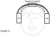
- the bridge 130is configured to couple to the band 120 and functions to support one or more electrodes for providing electrical stimulation to the user.
- the bridge 130preferably includes regions that facilitate electrical and/or mechanical coupling of one or more electrode units to the bridge 130 (e.g., at an interior surface).
- the bridge 130is configured to couple to an inferior midregion of the band in a manner that allows outward displacement of lateral end regions of the band 130 during use of the system 100 ; however, the bridge 130 can additionally or alternatively be configured to couple to the band 120 and/or any other element of the system 100 in any other suitable manner.
- the bridge 130is configured to house at least one of a set of electrodes 140 for providing electrical stimulation to the user, in a configuration wherein an interior surface of the bridge 130 includes recesses corresponding to the set of electrodes 140 and electrical/mechanical coupling elements proximal to the recesses to robustly retain the electrodes 140 and provide current for electrical stimulation of the user through the electrodes 140 .
- the set of electrodes 140can include a pair of contralateral electrodes (i.e., lateral electrodes) configured to be positioned proximal contralateral motor/pre-motor cortices of the user during operation of the system.
- the set of electrodes 140can include a middle electrode configured to be positioned midway or substantially midway between lateral electrodes and thus coupleable to a midregion of the bridge 130 (e.g., within a recess at a midregion of the inferior surface of the bridge 130 ).
- the set of electrodes 140preferably comprise embodiments, variations, and/or examples of the electrode units described in U.S. application Ser. No. 14/878,647 entitled “Electrode System for Electrical Stimulation” and filed on 8 Oct. 2015 and/or electrode systems described in U.S. application Ser. No. 14/470,683 entitled “Electrode System for Electrical Stimulation” and filed on 27 Aug. 2014, and/or electrode systems described in U.S. application Ser. No. 29/553,732 entitled “Biointerface Electrode” and filed on 4 Feb. 2016, which can be configured for transcranial electrical stimulation of a user in various modes.
- one or more of the set of electrodes 140can include: an array of permeable bodies configured to absorb and deliver a solution that facilitates electrical coupling between the system and a body region of the user; a housing supporting the array of permeable bodies; and a coupling subsystem comprising a first electrical coupling region in electrical communication with the array of permeable bodies at an interior portion of the housing and a second electrical coupling region, configured to couple the first electrical coupling region to the electronics subsystem of the system 100 .
- the bridge 130(or other portion of the system 100 ) can additionally or alternatively be configured to support elements for any other suitable type of stimulation, therapy, or sensing for the user.
- the set of electrodes 140can be configured to magnetically couple to the bridge 130 in a manner such as that described in U.S. application Ser. No. 14/878,647, where the bridge includes one or more magnets and the set of lateral electrodes include one or more incorporated ferromagnets that are complementary to the magnet of the bridge 130 .
- the electrodes 140can magnetically couple to the bridge 130 in an alternative manner, or can alternatively be configured to mechanically couple to the bridge 130 in any other suitable manner.
- the bridge 130can be configured to interface with one or more electrode units (e.g., an electrode unit centrally located between a set of lateral electrodes) in addition to the set of lateral electrodes 140 .
- the system 100can be configured to ensure that laterally positioned electrodes 140 maintain proper contact with their corresponding head regions of the user (e.g., the scalp of the user), while ensuring that middle electrode also maintains good contact with its corresponding head region of the user.
- ensuring proper contact between all electrodes of the system 100 and their corresponding head regions of the userfurther constrains design of the system 100 .
- the set of electrodes 140includes electrode units that are configured to be positioned at contralateral head regions of the user, and in a specific example, the bridge 130 can be configured to position the set of lateral electrodes for stimulation of contralateral motor cortex regions of the user's brain.
- the bridge 130can, however, be configured to support and facilitate positioning of the electrode unit(s) for stimulation of any other suitable brain regions of the user.
- the electrode unitscan have one or more protrusions supporting permeable bodies or otherwise deflectable elements that facilitate delivery of electrical stimulation to the user, and mechanical interactions between the bridge 130 and other elements of the system 100 (e.g., the band 120 , the set of structural links 150 , etc.) can prevent deflection or bending of individual protrusions into an orientation approximately tangential to the scalp of the user.
- the bridge 130can, along with other portions of the system 100 , facilitate maintenance of an electrode protrusion orientation that is more perpendicular to the scalp of the user in producing desired impedance characteristics and/or a desired type of contact at the user-electrode interface.
- one or more portions of the system 100can additionally or alternatively be configured to couple to an electrode unit 145 (e.g., electrode pad, electrode sponge, electrode with protrusions, etc.) that interfaces with a frontal or prefrontal cortex region of the user during operation of the system 100 .
- the electrode unitcan include a cable providing a mechanical/electrical pathway that couples the electrode-user interface (e.g., electrode pad, electrode sponge, electrode with protrusions, etc.) to electronics of the system 100 .
- a first end of the cablecan plug into the bridge 130 or the band 120 to access the current source of an electronics system, and a second end of the cable can connect to the electrode portion that interfaces with the user.
- the set of electrodes 140can additionally or alternatively include any other suitable electrodes.
- the bridge 130is preferably composed of a rigid material that is elastically deformable within the range of deformation needed to allow the user to wear the system 100 , such that the user can induce a deformation (e.g., outward deflection) of the bridge 130 in the process of donning the system 100 , and the system 100 can elastically recover and provide a biasing force that facilitates coupling of the set of lateral electrodes 140 at the head of the user.
- a deformatione.g., outward deflection
- the bridge 130is indirectly coupled to the band 120 through one or more other elements of the system (e.g., the set of links 150 , the set of pad modules 110 , etc.), in order to allow lateral displacement of the end regions of the band 120 to affect lateral displacement of regions of the bridge 130 associated with the set of electrodes 140 ; however, the bridge 130 and the band 120 can additionally or alternatively be directly coupled to each other in order to have coupled deformation behavior across the band 120 and the bridge 130 .
- the bridge 130 and the band 120can additionally or alternatively be directly coupled to each other in order to have coupled deformation behavior across the band 120 and the bridge 130 .
- the bridge 130can thus be indirectly induced to deform due to coupling between the bridge 130 and the set of ear pads 110 (by way of the set of structural links 150 described in more detail below), and coupling between the set of ear pads 110 and the band 120 ; however, the bridge 130 can alternatively be induced to deform during electrode positioning at the body region of the user in any other suitable manner, variations and examples of which are described below. Furthermore, variations of operation modes of the system 100 in relation to coupling of the system 100 to the user are described in more detail below.
- the bridge 130can be composed of a polymeric material (e.g., a plastic, etc.) and/or a metallic material that exhibit(s) properties of elastic deformation. Additionally or alternatively, the bridge 130 can be composed of a material that has ductile properties or brittle properties with joints or hinged regions to allow the bridge 130 to outwardly deflect, as described in more detail below, or the bridge 130 can be composed of a material that exhibits properties at least partially of plastic deformation, so that the bridge can be deformed to conform with the head of a user.
- the bridge 130can comprise a single material, or can comprise a composite of different materials (e.g., with regions or layers of different materials).
- the bridge 130can comprise a set of joints 135 that allow portions of the bridge to bend at defined positions (e.g., as hinges), an example of which are shown in FIG. 4 .
- the set of joints 135can be positioned between adjacent electrode positions (e.g., two adjacent electrode positions) defined by the bridge 130 , such that the bridge is configured to flex at inter-electrode positions (e.g., in variations in which substrate portions of the electrodes 140 are substantially rigid).
- the set of joints 135can comprise joints configured at intra-electrode positions of the bridge 130 .
- the set of joints 135are preferably evenly spaced, but can alternatively comprise non-evenly spaced joints.
- the set of joints 135can comprise regions thinner than a characteristic thickness of the bulk of the bridge 130 .
- the set of joints 135can comprise regions of material having lower stiffness than that of non-joint regions of the bridge 130 .
- the set of joints 135can comprise physical hinge elements coupling adjacent pieces of the bridge 130 , such that the hinges allow bending between portions of the bridge 130 at the hinges.
- the set of joints 135can alternatively be defined in any other suitable manner.
- the bridge 130may alternatively omit a set of joints, such that the bridge 130 can deform continuously across the span of the bridge 130 .
- the bridge 130preferably couples to the band 120 at an inferior surface of the band 120 , in order to provide a fixed region relative to which opposing ends of the bridge 130 can deflect.
- variations of the bridge 130can alternatively have no direct coupling to the band 120 , and instead rely upon other elements of the system 100 (e.g., structural links, pad modules, etc.) for deflection of the bridge 130 in response to outward displacement of end regions of the band 120 and/or pad modules 110 .
- the bridge 130can couple to the band 120 at a midregion of the inferior surface of the band 120 ; however, the bridge 130 can additionally or alternatively couple to any other suitable portion of the band 120 that provides desired relative bending behavior between the bridge 130 and the band 120 , or provides a desired spatial relationship between the band 120 and bridge 130 in order to bring electrodes 140 into proximity with a desired anatomical target.
- the bridge 130can couple to the band 120 using any one or more of: mechanical fasteners (e.g., screws, bolts), adhesives, thermal bonding, magnetic coupling, and any other suitable manner.
- the bridge 130can couple to the band 120 by way of a set of fasteners (e.g., screws, bolts, etc.) that substantially lock the position of the bridge 130 in place relative to the band 120 at the fixed region.
- the footprint of the bridge 130is also contained within the footprint of the band 120 ; however, variations of the example of coupling between the bridge 130 and the band 120 can be configured in any other suitable manner.
- the bridge 130preferably has a characteristic radius of curvature that is smaller than the radius of curvature of the band 120 , wherein the radius of curvature of the bridge 130 , while the system 100 is worn by the user, is complementary to the radius of curvature of the user's head.
- morphology of the bridge 130provides a substantially continuous and robust interface between surfaces of the set of electrodes 140 and the head region(s) of the user involved in the stimulation therapy process.
- the bridge 130 and the band 120can alternatively have any other suitable morphology and/or be configured relative to each other in any other suitable manner that allows a proper electrode-user interface (e.g., in terms of impedance) to be provided by the system 100 .
- Each of the set of links 150is preferably coupled to the bridge 130 and to a corresponding ear pad module of the set of ear pad modules, and collectively can function to perform one or more of the following: 1) indirectly facilitate lengthening of the band 120 with the longitudinal expansion mechanism described above (by allowing other portions of the system 100 to extend); 2) provide electrical paths for transmitting electrical current to the set of lateral electrodes coupled to the bridge 130 or from one ear pad module to a second ear pad module (by electrically conductive elements coupled to or otherwise integrate with the links); and 3) provide desired mechanical behavior that prevents undesired deformation of portions of the set of electrode units 140 as the user dons the system 100 .
- the set of links 150can cooperate with other elements of the system 100 to provide a partial coupling mechanism that allows outward deflection of the set of ear pad modules 110 to induce some outward deflection of the set of electrodes 140 (i.e., lateral electrodes), by way of the bridge 130 .
- the partial coupling mechanismcan allow the bridge 130 and coupled electrodes 140 to independently conform to the shape of the head of the user without being fully constrained by the band 120 (or other elements of the system 100 ).
- One or more of these functionscan, however, be enabled using variations of elements of the system 100 described above, additional variations of elements of the system 100 described in Section 1.5 below, and/or any other suitable additional element(s).
- the set of links 150is preferably coupled to interior portions (e.g., medial portions of the outer housing 112 ) of the set of pad modules 110 and preferably, each of the set of structural links 150 has a characteristic stiffness (in terms of elastic modulus) above a threshold modulus such that 1) in a first operation mode, lateral displacement of the set of pad modules 110 by the user produces displacement of the set of electrodes 140 away from the head region of the user in a direction approximately normal to the surface of the head region, and 2) in a second operation mode, release of the set of pad modules 110 by the user brings protrusions (i.e., permeable bodies, protrusions supporting the permeable bodies) of the set of electrodes 140 into contact with the head region of the user along a path approximately normal to the surface of the head region of the user.
- protrusionsi.e., permeable bodies, protrusions supporting the permeable bodies
- transitioning between the first operation mode and the second operation modeis associated with donning of the system 100 by the user, such that lateral electrodes coupled to the bridge 130 are properly positioned at the head of the user with minimal-to-no-bending of flexible protrusions of the electrodes into undesired configurations (e.g., flattened or tangential configurations).
- each of the set of links 150has a first region coupled to a corresponding pad module of the set of pad modules 110 (e.g., at an outer housing 112 ), and a second region coupled to a corresponding lateral portion of the bridge 130 (e.g., an end region of the bridge 130 ), such that outward deflection of arms of the band 120 produces outward deflection of the bridge 130 (due to indirect coupling between the band 120 and the bridge 130 , by way of the set of pad modules 110 ).
- either or both the band 120 and the bridge 130can be coupled to the set of ear pad modules 110 at any other suitable region(s), and/or in any other suitable manner.
- the bridge 130can be directly coupled to the band 120 in order to couple their applied force-induced deflection responses together, with or without coupling of the bridge 130 to the set of ear pad modules 110 by the set of structural links 150 , one specific example of which is described in Section 1.5 below.
- each of the set of links 150is substantially stiff (e.g., in terms of elastic modulus), such that forces that produce outward displacement of the set of ear pad modules 110 from each other, and that correspondingly produce bending moments at along each of the set of structural links 150 (e.g., at junctions between the set of pad modules 110 and the set of links 150 and at junctions between the set of structural links 150 and the bridge 130 ) result in a low level of deflection (e.g., bending without buckling) along the length of a respective structural link (i.e., relative to endpoints of the structural link).
- a low level of deflectione.g., bending without buckling
- lateral portions of the bridge 130are able to deflect outward away from the head of the user in parallel with outward deflection of lateral portions of the band 120 .
- lateral electrodes housed within the bridge 130are displaced away from the scalp of the user, such that the donning of the system 100 cannot induce shear within each protrusion of the set of lateral electrodes 140 that would otherwise bend flexible protrusions into undesired orientations (e.g., orientations that prevent the protrusions from penetrating hair of the user).
- the set of links 150are composed of materials that can elastically deform within the range of deformation induced during normal use of the system 100 ; however, the set of structural links 150 can additionally or alternatively include regions or materials that have inelastic deformation or brittle properties within the range of deformation induced during normal use of the system 100 .
- the set of links 150can comprise one or more of a metallic material (e.g., steel, nitinol, etc.) and a polymeric material; however, in alternative variations, the set of structural links 150 can be composed of any other suitable material.
- the set of links 150can comprise cables, such as flexible printed circuit material or one or more individual electrical conductors substantially surrounded by an insulating material (e.g., sheath) such as overmolded thermoplastic resin or silicone rubber.
- an insulating materiale.g., sheath
- the set of links 150can have structural properties and facilitate electrical coupling between different portions of the system 100 .
- the set of links 150can facilitate lengthening of portions of the system 100 related to proper sizing of the system 100 relative to heads of different users.
- the set of links 150is preferably able to facilitate lengthening of the band 120 according to variations of the longitudinal expansion mechanism described above.
- each of the set of structural links 150has an adjustable exposed length between the bridge 130 and an ear pad module, wherein extra lengths of the set of links 150 are contained within, but able to be extracted from, one or more of the bridge 130 and the set of pad modules 110 .
- relative displacement between the set of ear pad modules and the bandmodulates an exposed length of each of the set of structural links.
- unexposed lengths of a link of the set of links 150can be contained within, at, or otherwise proximal to an exterior housing 112 of a pad module, or contained within, at, or otherwise proximal to an end region of the bridge 130 .
- each of the set of links 150can be configured to elastically extend (e.g., as in a spring or elastomer with an appropriate spring constant) along a longitudinal axis, while still preventing undesired amounts of non-axial deflection or buckling in response to outward displacement of the set of ear pad modules 110 .
- the set of links 150can facilitate lengthening of the band 120 in any other suitable manner.
- the set of links 150may or may not be involved in aspects of the system 100 related to size-adjustability for different users.
- the set of links 150can also function to provide electrical paths for transmission of current to electrodes coupled to the bridge, wherein the electrical paths have endpoints at 1) electronics involved in generation of the desired type of stimulation and/or electrode detection and 2) regions of coupling to the set of electrodes at the bridge 130 .
- the set of structural links 130can enable stimulation of the user through the set of electrodes 140 , and/or detection of electrodes coupled to the bridge 130 , variations and examples of which are described in U.S. application Ser. No. 14/878,647 entitled “Electrode System for Electrical Stimulation” and filed on 8 Oct. 2015 and/or electrode systems described in U.S. application Ser. No. 14/470,683 entitled “Electrode System for Electrical Stimulation” and filed on 27 Aug.
- the set of links 150can function to provide electrical paths for transmission of energy and/or signals from one ear pad module of the set of ear pad modules 110 to another ear pad module, for example, to carry current from a battery to a control circuit, or to carry an audio signal from an audio input to a speaker.
- Alternative variations of the set of structural links 150may, however, not provide electrical paths between electronics of the system 100 and the set of electrodes coupled to the bridge 130 .
- each of the set of linkscomprises a cable that has a first region coupled to a medial portion of an exterior plastic housing 112 of a corresponding ear pad module, and couples, at a second region to a lateral arm of the bridge 130 (e.g., at an end region of the bridge 130 ).
- each cableis characterized by a stiffness value that prevents undesired amounts of non-axial deflection or buckling in response to outward displacement of the set of ear pad modules 110 .
- each of the set of links 150is involved in lengthening of the band, such that the length of a cable between an ear pad module and the bridge 130 can be adjusted according to the size of the user's head.
- each of the set of links 150further provides an electrical path to at least one electrode coupled to the bridge 130 .
- the bridge 130can have three bridge segments separated from each other by hinged regions, wherein the bridge 130 has an arc length of approximately 70 mm and a radius of curvature of 87 mm, as shown in FIG. 5A .
- the additional bend angle at two bridge segments between joints of the bridgeis approximately 10 degrees, and the bridge 130 has an approximate lateral elastic constant of 12N/cm when force is applied and measured at an end region of the bridge.
- FIG. 5Adepict views and aspects of the first specific example
- the radius of curvature of the band 120 (at rest)is 78 mm
- the band 120has an approximate lateral elastic constant of 1N/cm (when force is applied and measured at a central region of one of the ear pad modules).
- an overmolded flex cable that functions as a structural link 150has an approximate lateral elastic constant of 3N/cm when force is applied and measured at the tip of the flex cable, extended out 5 cm.
- the overmolded flex cablehas a length of 53 mm between an end of the bridge 130 and a corresponding one of the set of earpad modules 110 when the earpad module is fully extended.
- the yaw angleis 1.5 degrees and the roll angle is 18 degrees, as shown in FIGS. 5C and 5D , respectively, and the length of a holder of the ear pad module 110 is ⁇ 135 mm from the top of the band 120 to a central region of the earpad (when at the lowest portion of the adjustment range of the earpad), as shown in FIG. 5E , wherein the holder has an adjustment range of 48 mm, as shown in FIG. 5F .
- the angular ball-and-socket range of motion of an ear pad module 110 in the roll directionis +/ ⁇ 10°, as shown in FIG.
- the angular ball-and-socket range of motion in the yaw directionis +/ ⁇ 10°, as shown in FIG. 5H .
- the angular range of motion of a pad module 110 in the roll directionis +5°/ ⁇ 0.5°, (i.e. 5° deviation from the neutral position in the direction that causes the top of the ear pad module 110 to move away from the contralateral ear pad module 110 ) in “positive camber”, and 0.5° deviation from the neutral position in the direction that causes the top of the ear pad module 110 to move toward the contralateral ear pad module 110 (i.e., “negative camber”).
- the bridge 130can have three bridge segments separated from each other by hinged regions, wherein the bridge 130 has an arc length 50-90 mm and a radius of curvature from 60-100 mm.
- the additional bend angle at two bridge segmentscan be from 5-15°, and the bridge 130 can have an approximate lateral elastic constant from 5-20N/cm (when force is applied and measured at a tip region of the bridge).
- the radius of curvature of the band 120 (at rest)is can be from 65-95 mm, and the band 120 can have an approximate lateral elastic constant from 0.2-5 N/cm (when force is applied and measured at a central region of one of the ear pad modules).
- an overmolded flex cable that functions as a structural link 150can have an approximate lateral elastic constant from 0.5-10N/cm when force is applied and measured at the tip of the flex cable, extended out to a usable length during use).
- the overmolded flex cablecan have a length of from 30-70 mm between an end of the bridge 130 and a corresponding one of the set of earpad modules 110 when the earpad module is fully extended.
- the yaw anglecan be from 0.2-3 degrees and the roll angle can be from 12-30 degrees, respectively, and the length of a holder of the ear pad module 110 can be from 110-160 mm from the top of the band 120 to a central region of the earpad (when at the lowest portion of the adjustment range of the earpad), wherein the holder can have an adjustment range from 35-65 mm.
- the angular ball-and-socket range of motion of an ear pad module 110 in the roll directioncan be from +/ ⁇ 5° to +/ ⁇ 15°
- the angular ball-and-socket range of motion in the yaw directioncan be from +/ ⁇ 5° to +/ ⁇ 15°
- each of the set of links 150has a substantially low stiffness value (e.g., in terms of elastic modulus) that produces non-axial deflection or buckling in response to outward displacement of the set of ear pad modules 110 .
- substantially low stiffness valuee.g., in terms of elastic modulus
- variations of the specific examplescan be configured in any other suitable manner.
- the band 120 ′ and the bridgecan be directly coupled to each other (e.g., at midregions of the band 120 and the bridge), and/or can be directly coupled to each other at lateral regions by way of elastically deformable and resilient lateral members 160 ′ situated between the band 120 ′ and the bridge 130 ′.
- the lateral members 160 ′can comprise materials and/or morphologies that result in a desired spring constant, such that outward deflection of lateral portions of the band 120 ′ produces a desired level of outward deflection of lateral portions of the bridge 130 ′ that couple to the set of lateral electrodes 140 ′.
- the bridge 130 ′can include a set of hinges 135 ′, as described above and shown in at least FIG. 4 ; however, variations of the first specific alternative example may omit a set of hinges 135 ′ within the bridge 130 ′. Furthermore, variations of the first specific alternative example can omit direct coupling between the band 120 ′ and the bridge 130 ′.
- lateral regions (e.g. lateral arms) of the bridge 130 ′′can be biased outward toward the band, such that the radius of curvature of the bridge 130 ′′ approaches that, or is slightly smaller than that of the band 120 ′′.
- the lateral regions (e.g., lateral arms) of the bridge 130 ′′ with coupled electrodescan be displaced in a medial direction to position the set of lateral electrodes at the head of the user.
- the lateral arms of the bridge 130can be pushed or pulled in the medial direction by one or more of: set screws, magnetic elements, pins, wedges configured to be positioned between the bridge 130 and the band 120 , and any other suitable elements.
- the lateral regions of the bridge 130 ′′′can be adjusted outward, which displaces lateral electrodes housed within the bridge 130 ′′′ away from the scalp of the user, such that the donning of the system 100 cannot induce shear within each protrusion of the set of lateral electrodes 140 ′′′ that would otherwise bend flexible protrusions into undesired orientations (e.g., orientations that prevent the protrusions from penetrating hair of the user).
- the lateral regions (e.g., lateral arms) of the bridge 130 ′′′ with coupled electrodescan be displaced in a medial direction to position the set of lateral electrodes at the head of the user.
- the lateral arms of the bridge 130 ′′′can be pushed or pulled in the medial direction by one or more of: set screws, magnetic elements, pins, wedges configured to be positioned between the bridge 130 ′′′ and the band 120 ′′′, and any other suitable elements.
- transitioning between the different modes of operationcan be implemented manually (e.g., by user action) and/or in an automated manner (e.g., using actuators coupled to controllers, etc.).
- the bridgecan comprise a shape memory material (e.g., nitinol, shape-memory polymer, etc.) that can be transitioned between different morphological configurations, upon being subject to different temperatures, or different applied electrical currents.
- a shape memory materiale.g., nitinol, shape-memory polymer, etc.
- the lateral regions of the bridge 130 ′′′can be in an adjusted outward state (i.e., expanded state) using a first heat state and/or a first electric current state, which results in lateral electrodes housed within the bridge 130 ′′′ being displaced away from the scalp of the user, and such that the donning of the system 100 cannot induce shear within each protrusion of the set of lateral electrodes 140 ′′′ that would otherwise bend flexible protrusions into undesired orientations (e.g., orientations that prevent the protrusions from penetrating hair of the user).
- the lateral regions (e.g., lateral arms) of the bridge 130 ′′′ with coupled electrodescan be displaced in a medial direction to position the set of lateral electrodes at the head of the user (e.g., with a second heat state, with a second electric current state, etc.).
- the shape memory portion of the bridge 130 ′′′′can thus be coupled to one or more of: a heating element (e.g., resistance heater, Peltier heater, etc.) with a controller, a cooling element (e.g., fan, Peltier cooler, etc.) with a controller, a current source with a controller, and any other suitable component that facilitates transitioning of the shape memory material between different states.
- a heating elemente.g., resistance heater, Peltier heater, etc.
- a cooling elemente.g., fan, Peltier cooler, etc.
- a current sourcewith a controller
- transitioning between different states in the bridge 130can be implemented automatically using sensors integrated with one or more elements of the system 100 .
- variations of the specific examplescan include one or more force sensors, one or more position sensors, and/or any other suitable sensor(s) coupled to one or more of: the links 150 , the electrodes 140 , bridge 130 , the band 120 , and the pad module(s) 110 can be configured to sense outward and/or inward deflection of the system in association with donning of the system 100 , in order to properly transition the electrodes 140 between outwardly deflected states and inwardly positioned states.
- the bridge 130can be coupled to the band not only at a single point at a vertex region of the bridge 130 , but along a segment of the bridge 130 .
- the segment of the bridge 130can be centered at the vertex region of the bridge 130 , but can alternatively be centered about any other suitable point of reference.
- coupling between the bridge 130 and the band 120 along a length of the bridge 130where both the bridge 130 and the band 120 are elastically deformable during use of the system 100 , will allow expansion of the band 120 to induce some expansion of the bridge 130 in providing a partial coupling mechanism.
- the system 100can, however, comprise any other suitable element(s) or combination of elements that enable displacement of a user's hair and/or enhance coupling between the electrode system 100 and the user. Furthermore, variations of the examples described above can be associated with deflection of the bridge 130 or the band 120 in any other suitable manner.
- the system 100 and method of the preferred embodiment and variations thereofcan be embodied and/or implemented at least in part as a machine configured to receive a computer-readable medium storing computer-readable instructions.
- the instructionsare preferably executed by computer-executable components preferably integrated with the system 100 and one or more portions of the processor and/or a controller.
- the computer-readable mediumcan be stored on any suitable computer-readable media such as RAMs, ROMs, flash memory, EEPROMs, optical devices (CD or DVD), hard drives, floppy drives, or any suitable device.
- the computer-executable componentis preferably a general or application specific processor, but any suitable dedicated hardware or hardware/firmware combination device can alternatively or additionally execute the instructions.
Landscapes
- Health & Medical Sciences (AREA)
- Life Sciences & Earth Sciences (AREA)
- General Health & Medical Sciences (AREA)
- Engineering & Computer Science (AREA)
- Biomedical Technology (AREA)
- Veterinary Medicine (AREA)
- Public Health (AREA)
- Animal Behavior & Ethology (AREA)
- Radiology & Medical Imaging (AREA)
- Nuclear Medicine, Radiotherapy & Molecular Imaging (AREA)
- Biophysics (AREA)
- Heart & Thoracic Surgery (AREA)
- Surgery (AREA)
- Physics & Mathematics (AREA)
- Molecular Biology (AREA)
- Medical Informatics (AREA)
- Pathology (AREA)
- Child & Adolescent Psychology (AREA)
- Developmental Disabilities (AREA)
- Hospice & Palliative Care (AREA)
- Neurology (AREA)
- Psychiatry (AREA)
- Psychology (AREA)
- Social Psychology (AREA)
- Electrotherapy Devices (AREA)
Abstract
Description
Claims (6)
Priority Applications (1)
| Application Number | Priority Date | Filing Date | Title |
|---|---|---|---|
| US16/397,917US11273304B2 (en) | 2015-10-26 | 2019-04-29 | Electrode positioning system and method |
Applications Claiming Priority (4)
| Application Number | Priority Date | Filing Date | Title |
|---|---|---|---|
| US201562236200P | 2015-10-26 | 2015-10-26 | |
| US201662289709P | 2016-02-01 | 2016-02-01 | |
| US15/335,240US10315026B2 (en) | 2015-10-26 | 2016-10-26 | Electrode positioning system and method |
| US16/397,917US11273304B2 (en) | 2015-10-26 | 2019-04-29 | Electrode positioning system and method |
Related Parent Applications (1)
| Application Number | Title | Priority Date | Filing Date |
|---|---|---|---|
| US15/335,240ContinuationUS10315026B2 (en) | 2015-10-26 | 2016-10-26 | Electrode positioning system and method |
Publications (2)
| Publication Number | Publication Date |
|---|---|
| US20190255313A1 US20190255313A1 (en) | 2019-08-22 |
| US11273304B2true US11273304B2 (en) | 2022-03-15 |
Family
ID=58564803
Family Applications (2)
| Application Number | Title | Priority Date | Filing Date |
|---|---|---|---|
| US15/335,240Active2037-08-02US10315026B2 (en) | 2015-10-26 | 2016-10-26 | Electrode positioning system and method |
| US16/397,917Active2037-06-05US11273304B2 (en) | 2015-10-26 | 2019-04-29 | Electrode positioning system and method |
Family Applications Before (1)
| Application Number | Title | Priority Date | Filing Date |
|---|---|---|---|
| US15/335,240Active2037-08-02US10315026B2 (en) | 2015-10-26 | 2016-10-26 | Electrode positioning system and method |
Country Status (4)
| Country | Link |
|---|---|
| US (2) | US10315026B2 (en) |
| EP (1) | EP3368146B1 (en) |
| CN (1) | CN108290037B (en) |
| WO (1) | WO2017075086A1 (en) |
Cited By (2)
| Publication number | Priority date | Publication date | Assignee | Title |
|---|---|---|---|---|
| US12246172B2 (en) | 2018-07-31 | 2025-03-11 | Flow Neuroscience Ab | Positioning of electrodes for transcranial brain stimulation |
| US12329968B2 (en) | 2016-02-08 | 2025-06-17 | Flow Neuroscience, Inc. | Method and system for improving provision of electrical stimulation |
Families Citing this family (12)
| Publication number | Priority date | Publication date | Assignee | Title |
|---|---|---|---|---|
| US20230346284A1 (en)* | 2012-06-14 | 2023-11-02 | Medibotics Llc | Dry Electrode with Sliding Electroconductive Protrusions for Use on a Hair-Covered Area of a Person's Head |
| US12201427B2 (en) | 2012-06-14 | 2025-01-21 | Medibotics Llc | Headband with brain activity sensors |
| USD1061473S1 (en)* | 2017-04-05 | 2025-02-11 | Sonusmed Incorporated | Headset |
| KR102152084B1 (en)* | 2018-01-18 | 2020-09-04 | 고려대학교 산학협력단 | Nerve stimulation device |
| EP3908363B1 (en)* | 2019-01-10 | 2024-03-06 | Jeffrey Bennett | Anatomical/physiological event apparatus and method of treating an approaching |
| WO2020227664A1 (en)* | 2019-05-09 | 2020-11-12 | Rpw Technology, Llc | Systems and methods for a transcranial electrical stimulation device |
| USD908664S1 (en)* | 2019-06-02 | 2021-01-26 | Sens.Ai Inc. | Headset with biometric sensors |
| USD1051088S1 (en)* | 2021-02-25 | 2024-11-12 | Vital Neuro, Inc. | Audio headset |
| CN116784840A (en)* | 2021-06-07 | 2023-09-22 | 丹阳慧创医疗设备有限公司 | Head optical application device and transcranial light control equipment |
| USD1000416S1 (en)* | 2021-06-24 | 2023-10-03 | New Audio LLC | Wireless headphones |
| US11700474B2 (en) | 2021-06-24 | 2023-07-11 | New Audio LLC | Multi-microphone headset |
| JP7152818B1 (en) | 2022-01-21 | 2022-10-13 | 東和株式会社 | Biomedical electrode device |
Citations (117)
| Publication number | Priority date | Publication date | Assignee | Title |
|---|---|---|---|---|
| US3472233A (en) | 1966-12-02 | 1969-10-14 | Robert I Sarbacher | Electrical muscle stimulator |
| US4928696A (en) | 1989-07-26 | 1990-05-29 | Mindcenter Corporation | Electrode-supporting headset |
| US4967038A (en) | 1986-12-16 | 1990-10-30 | Sam Techology Inc. | Dry electrode brain wave recording system |
| US4977895A (en) | 1989-05-22 | 1990-12-18 | Ely Shavit Pasternak | Electrical apparatus for medical treatment |
| US5058605A (en) | 1989-02-22 | 1991-10-22 | Ceske Vysoke Uceni Technicke | Method and device for the controlled local, non-invasive application of dc pulses to human and animal tissues |
| US5087242A (en) | 1989-07-21 | 1992-02-11 | Iomed, Inc. | Hydratable bioelectrode |
| US5137817A (en) | 1990-10-05 | 1992-08-11 | Amoco Corporation | Apparatus and method for electroporation |
| US5250023A (en) | 1989-10-27 | 1993-10-05 | Korean Research Institute on Chemical Technology | Transdermal administration method of protein or peptide drug and its administration device thereof |
| US5387231A (en) | 1992-07-21 | 1995-02-07 | Sporer; Patsy | Electrotherapy method |
| US5622168A (en) | 1992-11-18 | 1997-04-22 | John L. Essmyer | Conductive hydrogels and physiological electrodes and electrode assemblies therefrom |
| JPH10234713A (en) | 1997-02-28 | 1998-09-08 | Rion Co Ltd | Bone conduction receiver for hearing examination |
| US6077237A (en) | 1998-11-06 | 2000-06-20 | Adaboy, Inc. | Headset for vestibular stimulation in virtual environments |
| US6263226B1 (en) | 1998-02-09 | 2001-07-17 | Axelgaard Manufacturing Co., Ltd. | Sponge electrode |
| US6379324B1 (en) | 1999-06-09 | 2002-04-30 | The Procter & Gamble Company | Intracutaneous microneedle array apparatus |
| US6406811B1 (en) | 1997-04-17 | 2002-06-18 | 3M Innovative Properties Company | Battery for headset assembly |
| US6480743B1 (en) | 2000-04-05 | 2002-11-12 | Neuropace, Inc. | System and method for adaptive brain stimulation |
| US20020169485A1 (en) | 1995-10-16 | 2002-11-14 | Neuropace, Inc. | Differential neurostimulation therapy driven by physiological context |
| US6505079B1 (en) | 2000-09-13 | 2003-01-07 | Foster Bio Technology Corp. | Electrical stimulation of tissue for therapeutic and diagnostic purposes |
| US6510333B1 (en) | 2000-05-16 | 2003-01-21 | Mark J. Licata | Sensor for biopotential measurements |
| US20040019370A1 (en) | 2001-10-15 | 2004-01-29 | Gliner Bradford Evan | Systems and methods for reducing the likelihood of inducing collateral neural activity during neural stimulation threshold test procedures |
| US20050165460A1 (en) | 2004-01-26 | 2005-07-28 | Onje' Erfan | Neuro-Electric-Therapy Headset |
| US20060111754A1 (en) | 2000-01-20 | 2006-05-25 | Ali Rezai | Methods of treating medical conditions by neuromodulation of the sympathetic nervous system |
| US20060229502A1 (en) | 2003-06-03 | 2006-10-12 | Bayer Healthcare Llc | Portable medical diagnostic apparatus |
| US20060259094A1 (en) | 2001-04-27 | 2006-11-16 | Biophysical Mind Technologies, Ltd. | Diagnosis, treatment, and research of brain disorders |
| US20070015984A1 (en) | 2005-06-30 | 2007-01-18 | Samsung Electronics Co., Ltd. | Electrode for measuring biosignal |
| US20070038265A1 (en) | 2002-02-05 | 2007-02-15 | Neuropace, Inc. | Responsive electrical stimulation for movement disorders |
| US20070093706A1 (en) | 2005-10-26 | 2007-04-26 | Sam Technology, Inc | EEG electrode headset |
| US20070118070A1 (en) | 1996-06-18 | 2007-05-24 | Cormier Michel J | Device with anchoring elements for transdermal delivery or sampling of agents |
| US20070213783A1 (en) | 2006-03-13 | 2007-09-13 | Neuropace, Inc. | Implantable system enabling responsive therapy for pain |
| US20070238945A1 (en) | 2006-03-22 | 2007-10-11 | Emir Delic | Electrode Headset |
| US20070237797A1 (en) | 2006-03-28 | 2007-10-11 | Gholam A. Peyman | Neural Conduit Agent Dissemination |
| US20070237678A1 (en) | 2004-10-07 | 2007-10-11 | Bernd Roesicke | Analytical Test Element With Wireless Data Transmission |
| US20070250145A1 (en) | 2005-01-26 | 2007-10-25 | Cerbomed Gmbh | Device for the transdermal stimulation of a nerve of the human body |
| US20080004676A1 (en) | 2006-06-16 | 2008-01-03 | Osypka Thomas P | Implantable neurostimulation systems |
| US20080021520A1 (en) | 2006-07-18 | 2008-01-24 | Cerbomed Gmbh | System for the transcutaneous stimulation of a nerve in the human body |
| US20080027345A1 (en) | 2004-06-25 | 2008-01-31 | Olympus Corporation | Electrode Apparatus For Detecting Brain Waves And Package |
| WO2008048471A2 (en) | 2006-10-13 | 2008-04-24 | Apnex Medical, Inc. | Obstructive sleep apnea treatment devices, systems and methods |
| US20090069803A1 (en) | 2007-09-10 | 2009-03-12 | Medtronic, Inc. | Selective depth electrode deployment for electrical stimulation |
| US20090099627A1 (en) | 2007-10-16 | 2009-04-16 | Medtronic, Inc. | Therapy control based on a patient movement state |
| US20090105785A1 (en) | 2007-09-26 | 2009-04-23 | Medtronic, Inc. | Therapy program selection |
| US20090187159A1 (en) | 2008-01-17 | 2009-07-23 | California Institute Of Technology | Chronically implantable hybrid cannula-microelectrode system for continuous monitoring electrophysiological signals during infusion of a chemical or pharmaceutical agent |
| WO2009134763A1 (en) | 2008-04-29 | 2009-11-05 | Board of Governors for Higher Education, State of Rhode Island and the Providence Plantations | Biomedical sensors usable on un-prepared contact surfaces |
| US20100030129A1 (en) | 2001-10-24 | 2010-02-04 | Power Paper Ltd. | Dermal patch |
| US20100152810A1 (en) | 2008-12-11 | 2010-06-17 | Conor Minogue | Facial stimulation apparatus |
| JP2010152731A (en) | 2008-12-25 | 2010-07-08 | Rakuten Inc | Device and method for registering presentation information, program for presentation information transmission control processing, and presentation information transmission system |
| US20100213070A1 (en) | 2008-08-26 | 2010-08-26 | Panasonic Corporation | Artificial lipid membrane forming method and artificial lipid membrane forming apparatus |
| US7818515B1 (en) | 2004-08-10 | 2010-10-19 | Symantec Operating Corporation | System and method for enforcing device grouping rules for storage virtualization |
| US20100268287A1 (en) | 2009-03-13 | 2010-10-21 | The Johns Hopkins University | Methods and devices for increasing learning and effects of training in healthy individuals and patients after brain lesions using dc stimulation and apparatuses and systems related thereto |
| US20100330589A1 (en) | 2007-08-14 | 2010-12-30 | Bahrami S Bahram | Needle array assembly and method for delivering therapeutic agents |
| US20110040291A1 (en) | 2006-10-31 | 2011-02-17 | Anna Weissenrieder-Norlin | Tissue stimulating device and method |
| US20110112590A1 (en) | 2009-11-11 | 2011-05-12 | Medtronic, Inc. | Deep brain stimulation for sleep and movement disorders |
| US20110118806A1 (en) | 2007-01-22 | 2011-05-19 | Alvaro Pascual-Leone | Device For Treating Human Vision Using Combined Optical And Electrical Stimulation |
| CN102083495A (en) | 2008-06-20 | 2011-06-01 | 麦哲利夫有限公司 | Systems, apparatuses, and methods for providing non-transcranial electrotherapy |
| US20110276112A1 (en) | 2009-03-20 | 2011-11-10 | ElectroCore, LLC. | Devices and methods for non-invasive capacitive electrical stimulation and their use for vagus nerve stimulation on the neck of a patient |
| US20110288610A1 (en) | 2008-11-21 | 2011-11-24 | Burkhard Brocke | Mobile device for transcranial auto-stimulation and method for controlling and regulating the device |
| US20110319975A1 (en) | 2008-12-30 | 2011-12-29 | Research Foundation Of The City University Of New York | Methods for Reducing Discomfort During Electrostimulation, and Compositions and Apparatus Therefor |
| US20120065699A1 (en) | 2010-09-13 | 2012-03-15 | Cranial Medical Systems, Inc. | Devices and methods for tissue modulation and monitoring |
| US20120071947A1 (en) | 2010-09-22 | 2012-03-22 | Medtronic, Inc. | Method and apparatus for event-triggered reinforcement of a favorable brain state |
| US20120078323A1 (en) | 2009-03-23 | 2012-03-29 | Flint Hills Scientific, Llc | System and apparatus for increasing regularity and/or phase-locking of neuronal activity relating to an epileptic event |
| CN102427762A (en) | 2009-05-18 | 2012-04-25 | 皇家飞利浦电子股份有限公司 | Arrangement and method for influencing and/or detecting magnetic particles |
| EP2449961A1 (en) | 2009-06-29 | 2012-05-09 | Sony Corporation | Bio-signal measurement equipment |
| US8195174B2 (en) | 2007-04-03 | 2012-06-05 | Samsung Electronics Co., Ltd | Apparatus and method for allocating frequency resource in a communication system |
| CN102596021A (en) | 2009-11-04 | 2012-07-18 | 皇家飞利浦电子股份有限公司 | Device for positioning electrodes on a user's scalp |
| US20120184894A1 (en) | 2010-12-31 | 2012-07-19 | Mir Imran | Patches and Methods for the Transdermal Delivery of Agents to Treat Hair Loss |
| US20120191157A1 (en) | 2011-01-25 | 2012-07-26 | Medtronic, Inc. | Target therapy delivery site selection |
| US8239030B1 (en) | 2010-01-06 | 2012-08-07 | DJ Technologies | Transcranial stimulation device and method based on electrophysiological testing |
| US20120289869A1 (en) | 2009-11-04 | 2012-11-15 | Arizona Board Of Regents For And On Behalf Of Arizona State University | Devices and methods for modulating brain activity |
| WO2013004763A1 (en) | 2011-07-05 | 2013-01-10 | Smp Swiss Macro Polymers Ag | Assembly comprising a woven sleeve and hardening material for fastening an anchoring element in a drilled hole |
| US20130085347A1 (en) | 2007-09-14 | 2013-04-04 | Corventis, Inc. | Adherent device with multiple physiological sensors |
| US20130113059A1 (en) | 2011-11-07 | 2013-05-09 | Nam-Kyu Song | Photovoltaic device and method of manufacturing the same |
| US20130184779A1 (en) | 2012-01-13 | 2013-07-18 | Marom Bikson | Voltage limited neurostimulation |
| US20130204315A1 (en) | 2011-08-05 | 2013-08-08 | Ndi Medical, Llc | Systems for and methods of transcranial direct current electrical stimulation |
| WO2013113059A1 (en) | 2012-01-31 | 2013-08-08 | Creativity Cap | A method and device for increasing human ability for idea generation and insight related tasks using dc stimulation |
| US20130261706A1 (en) | 2012-03-30 | 2013-10-03 | Neuropace, Inc. | Systems and methods for applying rapid sequential electrode stimulation |
| US20130281759A1 (en) | 2010-01-06 | 2013-10-24 | Evoke Neuroscience, Inc. | Transcranial stimulation device and method based on electrophysiological testing |
| US20140035043A1 (en) | 2009-12-03 | 2014-02-06 | Taiwan Semiconductor Manufacturing Company, Ltd. | FinFETs with Multiple Fin Heights |
| US20140069212A1 (en) | 2012-09-11 | 2014-03-13 | SynTouch, LLC | Compliant tactile sensor with fluid-filled, sponge-like material |
| US20140148872A1 (en) | 2012-11-26 | 2014-05-29 | Isy Goldwasser | Wearable transdermal electrical stimulation devices and methods of using them |
| US20140172041A1 (en) | 2012-12-13 | 2014-06-19 | NorDocs Technologies Inc. | Neurostimulation system, device, and method |
| US20140277324A1 (en) | 2013-03-12 | 2014-09-18 | Ethicon Endo-Surgery, Inc. | Device For Providing Transdermal Electrical Stimulation at an Adjustable Position on a Head |
| WO2014141213A1 (en) | 2013-03-15 | 2014-09-18 | Neurolief Ltd. | Headset for treatment and assessment of medical conditions |
| US20140316505A1 (en) | 2013-04-23 | 2014-10-23 | Yani Skincare, LLC | Electrode for use with transcranial direct current stimulation |
| US20140350431A1 (en)* | 2010-01-06 | 2014-11-27 | Evoke Neuroscience, Inc. | Headgear with displacable sensors for electrophysiology measurement and training |
| CN204017145U (en) | 2014-04-25 | 2014-12-17 | 上海银狐医疗科技有限公司 | A kind of wear-type stimulating electrode |
| US20150005841A1 (en) | 2013-06-29 | 2015-01-01 | Sumon K. PAL | Transdermal electrical stimulation devices for modifying or inducing cognitive state |
| US20150065838A1 (en) | 2013-08-27 | 2015-03-05 | Halo Neuro, Inc. | Electrode system for electrical stimulation |
| US20150066104A1 (en) | 2013-08-27 | 2015-03-05 | Halo Neuro, Inc. | Method and system for providing electrical stimulation to a user |
| US8979837B2 (en) | 2007-04-04 | 2015-03-17 | St. Jude Medical, Atrial Fibrillation Division, Inc. | Flexible tip catheter with extended fluid lumen |
| US20150088224A1 (en) | 2012-11-26 | 2015-03-26 | Isy Goldwasser | Wearable transdermal electrical stimulation devices and methods of using them |
| US20150112153A1 (en) | 2013-10-22 | 2015-04-23 | Neba Health, Llc | System and method for a compact eeg headset |
| CN204411500U (en) | 2014-12-23 | 2015-06-24 | 先進電子醫療工業有限公司 | Head-mounted wireless control transcranial electrical stimulator |
| KR20150088224A (en) | 2015-07-13 | 2015-07-31 | 안범주 | traffic signal control system |
| US20150238759A1 (en) | 2014-02-21 | 2015-08-27 | Novo HB, LLC | Transcranial electrostimulation device and method |
| US20150238762A1 (en) | 2014-02-27 | 2015-08-27 | Sumon K. PAL | Methods for user control of neurostimulation to modify a cognitive state |
| US20150258327A1 (en) | 2014-03-14 | 2015-09-17 | Contour Optik Inc. | Cranial electrotherapy stimulation device |
| US20150328467A1 (en) | 2014-05-17 | 2015-11-19 | Remi Demers | Methods and apparatuses for control of a wearable transdermal neurostimulator to apply ensemble waveforms |
| US20150335877A1 (en) | 2014-05-25 | 2015-11-26 | Douglas Jeffery | Cantilever electrodes for transdermal and transcranial stimulation |
| US20150352364A1 (en) | 2013-01-29 | 2015-12-10 | National Ict Australia Limited | Neuroprosthetic stimulation |
| US20150352357A1 (en) | 2014-06-06 | 2015-12-10 | Medtronic, Inc. | External stimulation therapy for dorsal genital nerve stimulation |
| US20150360027A1 (en) | 2011-09-22 | 2015-12-17 | Djo, Llc | Devices, systems and methods for treating pain with electrical stimulation |
| US20150375007A1 (en) | 2014-06-27 | 2015-12-31 | Panasonic Intellectual Property Management Co., Ltd. | Optical hair-growing device |
| US20160017558A1 (en) | 2010-04-23 | 2016-01-21 | French Development Enterprises, LLC | Aquatic Animal Passage With Counter |
| US20160022981A1 (en) | 2013-08-27 | 2016-01-28 | Halo Neuro, Inc. | Electrode system for electrical stimulation |
| US20160175589A1 (en) | 2013-08-27 | 2016-06-23 | Halo Neuro, Inc. | Method and system for providing electrical stimulation to a user |
| US20160184585A1 (en) | 2013-04-24 | 2016-06-30 | Neurosigma, Inc. | Modulation of Autonomic Nervous System Activity and Integrated Electrode Assemblies for Trigeminal Neurostimulation |
| US20160256105A1 (en) | 2013-11-05 | 2016-09-08 | The University Of North Carolina At Chapel Hill | Methods, apparatuses and systems for transcranial stimulation |
| US20160303362A1 (en) | 2015-04-14 | 2016-10-20 | Taiwan Textile Research Institute | Wound care dressing |
| US20160346530A1 (en) | 2015-05-29 | 2016-12-01 | Douglas Jeffery | Methods and apparatuses for transdermal electrical stimulation |
| US20160360990A1 (en) | 2015-06-15 | 2016-12-15 | Edward Lafe Altshuler | Electrode holding device |
| US20160366507A1 (en) | 2015-06-15 | 2016-12-15 | Uneo Inc. | Green headphone |
| KR20170021158A (en) | 2015-08-17 | 2017-02-27 | 엘지전자 주식회사 | Mobile terminal identifying a fingerprint and controlling method thereof |
| KR20170028197A (en) | 2015-09-03 | 2017-03-13 | 옥윤선 | Monitoring system using zipper based on IoT, and monitoring method using the same |
| US20170224978A1 (en) | 2014-08-01 | 2017-08-10 | Y-Brain Inc. | Electrical stimulation device |
| US20170224990A1 (en) | 2012-11-26 | 2017-08-10 | Isy Goldwasser | Apparatuses and methods for neuromodulation |
| US20170368344A1 (en) | 2015-01-13 | 2017-12-28 | Theranica Bio-Electronics Ltd. | Treatment of headaches by electrical stimulation |
| US20180021565A1 (en) | 2007-08-23 | 2018-01-25 | Bioness Inc. | System for transmitting electrical current to a bodily tissue |
| KR20180021565A (en) | 2016-08-22 | 2018-03-05 | 엘지전자 주식회사 | Defrosting device and refrigerator having the same |
- 2016
- 2016-10-26CNCN201680068575.4Apatent/CN108290037B/enactiveActive
- 2016-10-26EPEP16860711.7Apatent/EP3368146B1/enactiveActive
- 2016-10-26WOPCT/US2016/058919patent/WO2017075086A1/ennot_activeCeased
- 2016-10-26USUS15/335,240patent/US10315026B2/enactiveActive
- 2019
- 2019-04-29USUS16/397,917patent/US11273304B2/enactiveActive
Patent Citations (177)
| Publication number | Priority date | Publication date | Assignee | Title |
|---|---|---|---|---|
| US3472233A (en) | 1966-12-02 | 1969-10-14 | Robert I Sarbacher | Electrical muscle stimulator |
| US4967038A (en) | 1986-12-16 | 1990-10-30 | Sam Techology Inc. | Dry electrode brain wave recording system |
| US5058605A (en) | 1989-02-22 | 1991-10-22 | Ceske Vysoke Uceni Technicke | Method and device for the controlled local, non-invasive application of dc pulses to human and animal tissues |
| US4977895A (en) | 1989-05-22 | 1990-12-18 | Ely Shavit Pasternak | Electrical apparatus for medical treatment |
| US5087242A (en) | 1989-07-21 | 1992-02-11 | Iomed, Inc. | Hydratable bioelectrode |
| US4928696A (en) | 1989-07-26 | 1990-05-29 | Mindcenter Corporation | Electrode-supporting headset |
| US5250023A (en) | 1989-10-27 | 1993-10-05 | Korean Research Institute on Chemical Technology | Transdermal administration method of protein or peptide drug and its administration device thereof |
| US5137817A (en) | 1990-10-05 | 1992-08-11 | Amoco Corporation | Apparatus and method for electroporation |
| US5387231A (en) | 1992-07-21 | 1995-02-07 | Sporer; Patsy | Electrotherapy method |
| US5622168A (en) | 1992-11-18 | 1997-04-22 | John L. Essmyer | Conductive hydrogels and physiological electrodes and electrode assemblies therefrom |
| US20020169485A1 (en) | 1995-10-16 | 2002-11-14 | Neuropace, Inc. | Differential neurostimulation therapy driven by physiological context |
| US20070118070A1 (en) | 1996-06-18 | 2007-05-24 | Cormier Michel J | Device with anchoring elements for transdermal delivery or sampling of agents |
| JPH10234713A (en) | 1997-02-28 | 1998-09-08 | Rion Co Ltd | Bone conduction receiver for hearing examination |
| US6406811B1 (en) | 1997-04-17 | 2002-06-18 | 3M Innovative Properties Company | Battery for headset assembly |
| US6263226B1 (en) | 1998-02-09 | 2001-07-17 | Axelgaard Manufacturing Co., Ltd. | Sponge electrode |
| US6077237A (en) | 1998-11-06 | 2000-06-20 | Adaboy, Inc. | Headset for vestibular stimulation in virtual environments |
| US6379324B1 (en) | 1999-06-09 | 2002-04-30 | The Procter & Gamble Company | Intracutaneous microneedle array apparatus |
| US7877146B2 (en) | 2000-01-20 | 2011-01-25 | The Cleveland Clinic Foundation | Methods of treating medical conditions by neuromodulation of the sympathetic nervous system |
| US20060111754A1 (en) | 2000-01-20 | 2006-05-25 | Ali Rezai | Methods of treating medical conditions by neuromodulation of the sympathetic nervous system |
| US6480743B1 (en) | 2000-04-05 | 2002-11-12 | Neuropace, Inc. | System and method for adaptive brain stimulation |
| US7966073B2 (en) | 2000-04-05 | 2011-06-21 | Neuropace, Inc. | Differential neurostimulation therapy driven by physiological therapy |
| US20060212093A1 (en) | 2000-04-05 | 2006-09-21 | Pless Benjamin D | Differential neurostimulation therapy driven by physiological therapy |
| US6510333B1 (en) | 2000-05-16 | 2003-01-21 | Mark J. Licata | Sensor for biopotential measurements |
| US6505079B1 (en) | 2000-09-13 | 2003-01-07 | Foster Bio Technology Corp. | Electrical stimulation of tissue for therapeutic and diagnostic purposes |
| US7610095B2 (en) | 2001-04-27 | 2009-10-27 | Biophysical Mind Technologies, Ltd. | Diagnosis, treatment, and research of brain disorders |
| US20060259094A1 (en) | 2001-04-27 | 2006-11-16 | Biophysical Mind Technologies, Ltd. | Diagnosis, treatment, and research of brain disorders |
| US7024247B2 (en) | 2001-10-15 | 2006-04-04 | Northstar Neuroscience, Inc. | Systems and methods for reducing the likelihood of inducing collateral neural activity during neural stimulation threshold test procedures |
| US20040019370A1 (en) | 2001-10-15 | 2004-01-29 | Gliner Bradford Evan | Systems and methods for reducing the likelihood of inducing collateral neural activity during neural stimulation threshold test procedures |
| US20100030129A1 (en) | 2001-10-24 | 2010-02-04 | Power Paper Ltd. | Dermal patch |
| US20070038265A1 (en) | 2002-02-05 | 2007-02-15 | Neuropace, Inc. | Responsive electrical stimulation for movement disorders |
| US7813802B2 (en) | 2002-02-05 | 2010-10-12 | Neuropace, Inc. | Responsive electrical stimulation for movement disorders |
| US20060229502A1 (en) | 2003-06-03 | 2006-10-12 | Bayer Healthcare Llc | Portable medical diagnostic apparatus |
| US20050165460A1 (en) | 2004-01-26 | 2005-07-28 | Onje' Erfan | Neuro-Electric-Therapy Headset |
| US20080027345A1 (en) | 2004-06-25 | 2008-01-31 | Olympus Corporation | Electrode Apparatus For Detecting Brain Waves And Package |
| US7818515B1 (en) | 2004-08-10 | 2010-10-19 | Symantec Operating Corporation | System and method for enforcing device grouping rules for storage virtualization |
| US20070237678A1 (en) | 2004-10-07 | 2007-10-11 | Bernd Roesicke | Analytical Test Element With Wireless Data Transmission |
| US7988917B2 (en) | 2004-10-07 | 2011-08-02 | Roche Diagnostics Operations, Inc. | Analytical test element with wireless data transmission |
| US20070250145A1 (en) | 2005-01-26 | 2007-10-25 | Cerbomed Gmbh | Device for the transdermal stimulation of a nerve of the human body |
| US20070015984A1 (en) | 2005-06-30 | 2007-01-18 | Samsung Electronics Co., Ltd. | Electrode for measuring biosignal |
| US20070093706A1 (en) | 2005-10-26 | 2007-04-26 | Sam Technology, Inc | EEG electrode headset |
| US7551952B2 (en) | 2005-10-26 | 2009-06-23 | Sam Technology, Inc. | EEG electrode headset |
| US7894905B2 (en) | 2006-03-13 | 2011-02-22 | Neuropace, Inc. | Implantable system enabling responsive therapy for pain |
| US20070213783A1 (en) | 2006-03-13 | 2007-09-13 | Neuropace, Inc. | Implantable system enabling responsive therapy for pain |
| US20070238945A1 (en) | 2006-03-22 | 2007-10-11 | Emir Delic | Electrode Headset |
| US20070237797A1 (en) | 2006-03-28 | 2007-10-11 | Gholam A. Peyman | Neural Conduit Agent Dissemination |
| US8116875B2 (en) | 2006-06-16 | 2012-02-14 | Neuropoint Medical, Inc. | Implantable neurostimulation systems |
| US20080004676A1 (en) | 2006-06-16 | 2008-01-03 | Osypka Thomas P | Implantable neurostimulation systems |
| US20080021520A1 (en) | 2006-07-18 | 2008-01-24 | Cerbomed Gmbh | System for the transcutaneous stimulation of a nerve in the human body |
| WO2008048471A2 (en) | 2006-10-13 | 2008-04-24 | Apnex Medical, Inc. | Obstructive sleep apnea treatment devices, systems and methods |
| US8419716B2 (en) | 2006-10-31 | 2013-04-16 | St. Jude Medical Ab | Tissue stimulating device and method |
| US20110040291A1 (en) | 2006-10-31 | 2011-02-17 | Anna Weissenrieder-Norlin | Tissue stimulating device and method |
| US20110118806A1 (en) | 2007-01-22 | 2011-05-19 | Alvaro Pascual-Leone | Device For Treating Human Vision Using Combined Optical And Electrical Stimulation |
| US8195174B2 (en) | 2007-04-03 | 2012-06-05 | Samsung Electronics Co., Ltd | Apparatus and method for allocating frequency resource in a communication system |
| US8979837B2 (en) | 2007-04-04 | 2015-03-17 | St. Jude Medical, Atrial Fibrillation Division, Inc. | Flexible tip catheter with extended fluid lumen |
| US20100330589A1 (en) | 2007-08-14 | 2010-12-30 | Bahrami S Bahram | Needle array assembly and method for delivering therapeutic agents |
| US8349554B2 (en) | 2007-08-14 | 2013-01-08 | Fred Hutchinson Cancer Research Center | Needle array assembly and method for delivering therapeutic agents |
| US20180021565A1 (en) | 2007-08-23 | 2018-01-25 | Bioness Inc. | System for transmitting electrical current to a bodily tissue |
| US8301265B2 (en) | 2007-09-10 | 2012-10-30 | Medtronic, Inc. | Selective depth electrode deployment for electrical stimulation |
| US20090069803A1 (en) | 2007-09-10 | 2009-03-12 | Medtronic, Inc. | Selective depth electrode deployment for electrical stimulation |
| US20130085347A1 (en) | 2007-09-14 | 2013-04-04 | Corventis, Inc. | Adherent device with multiple physiological sensors |
| US8795174B2 (en) | 2007-09-14 | 2014-08-05 | Corventis, Inc. | Adherent device with multiple physiological sensors |
| US20090105785A1 (en) | 2007-09-26 | 2009-04-23 | Medtronic, Inc. | Therapy program selection |
| US8290596B2 (en) | 2007-09-26 | 2012-10-16 | Medtronic, Inc. | Therapy program selection based on patient state |
| US20090099627A1 (en) | 2007-10-16 | 2009-04-16 | Medtronic, Inc. | Therapy control based on a patient movement state |
| US8121694B2 (en) | 2007-10-16 | 2012-02-21 | Medtronic, Inc. | Therapy control based on a patient movement state |
| US20090187159A1 (en) | 2008-01-17 | 2009-07-23 | California Institute Of Technology | Chronically implantable hybrid cannula-microelectrode system for continuous monitoring electrophysiological signals during infusion of a chemical or pharmaceutical agent |
| WO2009134763A1 (en) | 2008-04-29 | 2009-11-05 | Board of Governors for Higher Education, State of Rhode Island and the Providence Plantations | Biomedical sensors usable on un-prepared contact surfaces |
| US20110054288A1 (en) | 2008-04-29 | 2011-03-03 | The Board Of Governors For Higher Education, State Of Rhode Island And Providence Plantations | Biomedical sensors usable on un-prepared contact surfaces |
| US8626259B2 (en) | 2008-04-29 | 2014-01-07 | Board Of Governors For Higher Education, State Of Rhode Island And Providence Plantations | Biomedical sensors usable on un-prepared contact surfaces |
| CN102083495A (en) | 2008-06-20 | 2011-06-01 | 麦哲利夫有限公司 | Systems, apparatuses, and methods for providing non-transcranial electrotherapy |
| US7828947B2 (en) | 2008-08-26 | 2010-11-09 | Panasonic Corporation | Artificial lipid membrane forming method and artificial lipid membrane forming apparatus |
| US20100213070A1 (en) | 2008-08-26 | 2010-08-26 | Panasonic Corporation | Artificial lipid membrane forming method and artificial lipid membrane forming apparatus |
| US20110288610A1 (en) | 2008-11-21 | 2011-11-24 | Burkhard Brocke | Mobile device for transcranial auto-stimulation and method for controlling and regulating the device |
| US8554324B2 (en) | 2008-11-21 | 2013-10-08 | Burkhard Brocke | Mobile device for transcranial auto-stimulation and method for controlling and regulating the device |
| US20100152810A1 (en) | 2008-12-11 | 2010-06-17 | Conor Minogue | Facial stimulation apparatus |
| JP2010152731A (en) | 2008-12-25 | 2010-07-08 | Rakuten Inc | Device and method for registering presentation information, program for presentation information transmission control processing, and presentation information transmission system |
| US9440063B2 (en) | 2008-12-30 | 2016-09-13 | Research Foundation Od The City University Of New York | Methods for reducing discomfort during electrostimulation, and compositions and apparatus therefor |
| KR101685124B1 (en) | 2008-12-30 | 2016-12-09 | 리서치 파운데이션 오브 더 시티 유니버시티 오브 뉴욕 | Methods for reducing discomfort during electrostimulation, and compositions and apparatus therefor |
| US20110319975A1 (en) | 2008-12-30 | 2011-12-29 | Research Foundation Of The City University Of New York | Methods for Reducing Discomfort During Electrostimulation, and Compositions and Apparatus Therefor |
| US20100268287A1 (en) | 2009-03-13 | 2010-10-21 | The Johns Hopkins University | Methods and devices for increasing learning and effects of training in healthy individuals and patients after brain lesions using dc stimulation and apparatuses and systems related thereto |
| US8874227B2 (en) | 2009-03-20 | 2014-10-28 | ElectroCore, LLC | Devices and methods for non-invasive capacitive electrical stimulation and their use for vagus nerve stimulation on the neck of a patient |
| US20110276112A1 (en) | 2009-03-20 | 2011-11-10 | ElectroCore, LLC. | Devices and methods for non-invasive capacitive electrical stimulation and their use for vagus nerve stimulation on the neck of a patient |
| US20120078323A1 (en) | 2009-03-23 | 2012-03-29 | Flint Hills Scientific, Llc | System and apparatus for increasing regularity and/or phase-locking of neuronal activity relating to an epileptic event |
| US8989863B2 (en) | 2009-03-23 | 2015-03-24 | Flint Hills Scientific, Llc | System and apparatus for increasing regularity and/or phase-locking of neuronal activity relating to an epileptic event |
| CN102427762A (en) | 2009-05-18 | 2012-04-25 | 皇家飞利浦电子股份有限公司 | Arrangement and method for influencing and/or detecting magnetic particles |
| EP2449961A1 (en) | 2009-06-29 | 2012-05-09 | Sony Corporation | Bio-signal measurement equipment |
| US20120289869A1 (en) | 2009-11-04 | 2012-11-15 | Arizona Board Of Regents For And On Behalf Of Arizona State University | Devices and methods for modulating brain activity |
| US20120226127A1 (en)* | 2009-11-04 | 2012-09-06 | Koninklijke Philips Electronics N.V. | Device for positioning electrodes on a user's scalp |
| CN102596021A (en) | 2009-11-04 | 2012-07-18 | 皇家飞利浦电子股份有限公司 | Device for positioning electrodes on a user's scalp |
| US9770204B2 (en) | 2009-11-11 | 2017-09-26 | Medtronic, Inc. | Deep brain stimulation for sleep and movement disorders |
| US20110112590A1 (en) | 2009-11-11 | 2011-05-12 | Medtronic, Inc. | Deep brain stimulation for sleep and movement disorders |
| US20140035043A1 (en) | 2009-12-03 | 2014-02-06 | Taiwan Semiconductor Manufacturing Company, Ltd. | FinFETs with Multiple Fin Heights |
| US20140350431A1 (en)* | 2010-01-06 | 2014-11-27 | Evoke Neuroscience, Inc. | Headgear with displacable sensors for electrophysiology measurement and training |
| US8838247B2 (en) | 2010-01-06 | 2014-09-16 | Evoke Neuroscience, Inc. | Transcranial stimulation device and method based on electrophysiological testing |
| US8239030B1 (en) | 2010-01-06 | 2012-08-07 | DJ Technologies | Transcranial stimulation device and method based on electrophysiological testing |
| US8938301B2 (en) | 2010-01-06 | 2015-01-20 | Evoke Neuroscience, Inc. | Headgear with displaceable sensors for electrophysiology measurement and training |
| US20130281759A1 (en) | 2010-01-06 | 2013-10-24 | Evoke Neuroscience, Inc. | Transcranial stimulation device and method based on electrophysiological testing |
| US8380316B2 (en) | 2010-01-06 | 2013-02-19 | Evoke Neuroscience, Inc. | Transcranial stimulation device and method based on electrophysiological testing |
| US20120271377A1 (en) | 2010-01-06 | 2012-10-25 | Dj Technologies, Inc. | Transcranial stimulation device and method based on electrophysiological testing |
| US20160017558A1 (en) | 2010-04-23 | 2016-01-21 | French Development Enterprises, LLC | Aquatic Animal Passage With Counter |
| US8583237B2 (en) | 2010-09-13 | 2013-11-12 | Cranial Medical Systems, Inc. | Devices and methods for tissue modulation and monitoring |
| US20120065699A1 (en) | 2010-09-13 | 2012-03-15 | Cranial Medical Systems, Inc. | Devices and methods for tissue modulation and monitoring |
| US8473063B2 (en) | 2010-09-22 | 2013-06-25 | Medtronic, Inc. | Method and apparatus for event-triggered reinforcement of a favorable brain state |
| US20120071947A1 (en) | 2010-09-22 | 2012-03-22 | Medtronic, Inc. | Method and apparatus for event-triggered reinforcement of a favorable brain state |
| US20120184894A1 (en) | 2010-12-31 | 2012-07-19 | Mir Imran | Patches and Methods for the Transdermal Delivery of Agents to Treat Hair Loss |
| US8706181B2 (en) | 2011-01-25 | 2014-04-22 | Medtronic, Inc. | Target therapy delivery site selection |
| US20120191157A1 (en) | 2011-01-25 | 2012-07-26 | Medtronic, Inc. | Target therapy delivery site selection |
| CN103517732A (en) | 2011-03-10 | 2014-01-15 | 电核有限责任公司 | Devices and methods for non-invasive capacitive electrical stimulation and their use for vagus nerve stimulation on the neck of a patient |
| WO2013004763A1 (en) | 2011-07-05 | 2013-01-10 | Smp Swiss Macro Polymers Ag | Assembly comprising a woven sleeve and hardening material for fastening an anchoring element in a drilled hole |
| US20130204315A1 (en) | 2011-08-05 | 2013-08-08 | Ndi Medical, Llc | Systems for and methods of transcranial direct current electrical stimulation |
| US20150360027A1 (en) | 2011-09-22 | 2015-12-17 | Djo, Llc | Devices, systems and methods for treating pain with electrical stimulation |
| US20130113059A1 (en) | 2011-11-07 | 2013-05-09 | Nam-Kyu Song | Photovoltaic device and method of manufacturing the same |
| US8818515B2 (en) | 2012-01-13 | 2014-08-26 | Research Foundation Of The City University Of New York | Voltage limited neurostimulation |
| US20130184779A1 (en) | 2012-01-13 | 2013-07-18 | Marom Bikson | Voltage limited neurostimulation |
| WO2013113059A1 (en) | 2012-01-31 | 2013-08-08 | Creativity Cap | A method and device for increasing human ability for idea generation and insight related tasks using dc stimulation |
| US20130261706A1 (en) | 2012-03-30 | 2013-10-03 | Neuropace, Inc. | Systems and methods for applying rapid sequential electrode stimulation |
| US20140069212A1 (en) | 2012-09-11 | 2014-03-13 | SynTouch, LLC | Compliant tactile sensor with fluid-filled, sponge-like material |
| US9080918B2 (en) | 2012-09-11 | 2015-07-14 | Syntouch Llc | Compliant tactile sensor with fluid-filled, sponge-like material |
| US8903494B2 (en) | 2012-11-26 | 2014-12-02 | Thync, Inc. | Wearable transdermal electrical stimulation devices and methods of using them |
| US20140148872A1 (en) | 2012-11-26 | 2014-05-29 | Isy Goldwasser | Wearable transdermal electrical stimulation devices and methods of using them |
| US9440070B2 (en) | 2012-11-26 | 2016-09-13 | Thyne Global, Inc. | Wearable transdermal electrical stimulation devices and methods of using them |
| US20170224990A1 (en) | 2012-11-26 | 2017-08-10 | Isy Goldwasser | Apparatuses and methods for neuromodulation |
| US20150088224A1 (en) | 2012-11-26 | 2015-03-26 | Isy Goldwasser | Wearable transdermal electrical stimulation devices and methods of using them |
| US8874220B2 (en) | 2012-12-13 | 2014-10-28 | Nuraleve Inc. | Neurostimulation system, device, and method |
| US20140172041A1 (en) | 2012-12-13 | 2014-06-19 | NorDocs Technologies Inc. | Neurostimulation system, device, and method |
| US9517345B2 (en) | 2013-01-29 | 2016-12-13 | National Ict Australia Limited | Neuroprosthetic stimulation |
| US20150352364A1 (en) | 2013-01-29 | 2015-12-10 | National Ict Australia Limited | Neuroprosthetic stimulation |
| US8880173B2 (en) | 2013-03-12 | 2014-11-04 | Ethicon Endo-Surgery, Inc. | Device for providing transdermal electrical stimulation at an adjustable position on a head |
| US20140277324A1 (en) | 2013-03-12 | 2014-09-18 | Ethicon Endo-Surgery, Inc. | Device For Providing Transdermal Electrical Stimulation at an Adjustable Position on a Head |
| US9433774B2 (en) | 2013-03-15 | 2016-09-06 | Neurolief Ltd. | Headset for treatment and assessment of medical conditions |
| US20150374971A1 (en) | 2013-03-15 | 2015-12-31 | Neurolief Ltd. | Headset for treatment and assessment of medical conditions |
| WO2014141213A1 (en) | 2013-03-15 | 2014-09-18 | Neurolief Ltd. | Headset for treatment and assessment of medical conditions |
| US20140316505A1 (en) | 2013-04-23 | 2014-10-23 | Yani Skincare, LLC | Electrode for use with transcranial direct current stimulation |
| US9913973B2 (en) | 2013-04-23 | 2018-03-13 | Yani Skincare, LLC | Transcranial direct current brain stimulation apparatus |
| US9731127B2 (en) | 2013-04-24 | 2017-08-15 | Neurosigma, Inc. | Modulation of autonomic nervous system activity and integrated electrode assemblies for trigeminal neurostimulation |
| US20160184585A1 (en) | 2013-04-24 | 2016-06-30 | Neurosigma, Inc. | Modulation of Autonomic Nervous System Activity and Integrated Electrode Assemblies for Trigeminal Neurostimulation |
| US20150005841A1 (en) | 2013-06-29 | 2015-01-01 | Sumon K. PAL | Transdermal electrical stimulation devices for modifying or inducing cognitive state |
| US9002458B2 (en) | 2013-06-29 | 2015-04-07 | Thync, Inc. | Transdermal electrical stimulation devices for modifying or inducing cognitive state |
| US20170021158A1 (en) | 2013-08-27 | 2017-01-26 | Halo Neuro, Inc. | Electrode system for electrical stimulation |
| US9802042B2 (en) | 2013-08-27 | 2017-10-31 | Halo Neuro, Inc. | Method and system for providing electrical stimulation to a user |
| US9486618B2 (en) | 2013-08-27 | 2016-11-08 | Halo Neuro, Inc. | Electrode system for electrical stimulation |
| US20160022981A1 (en) | 2013-08-27 | 2016-01-28 | Halo Neuro, Inc. | Electrode system for electrical stimulation |
| US20160175589A1 (en) | 2013-08-27 | 2016-06-23 | Halo Neuro, Inc. | Method and system for providing electrical stimulation to a user |
| US9630005B2 (en) | 2013-08-27 | 2017-04-25 | Halo Neuro, Inc. | Method and system for providing electrical stimulation to a user |
| US9782585B2 (en) | 2013-08-27 | 2017-10-10 | Halo Neuro, Inc. | Method and system for providing electrical stimulation to a user |
| US10238869B2 (en) | 2013-08-27 | 2019-03-26 | Halo Neuro, Inc. | Electrode system for electrical stimulation |
| US9889290B2 (en) | 2013-08-27 | 2018-02-13 | Halo Neuro, Inc. | Electrode system for electrical stimulation |
| US20160361541A1 (en) | 2013-08-27 | 2016-12-15 | Halo Neuro, Inc. | Method and system for providing electrical stimulation to a user |
| US20170361096A1 (en) | 2013-08-27 | 2017-12-21 | Halo Neuro, Inc. | Method and system for providing electrical stimulation to a user |
| US20150065838A1 (en) | 2013-08-27 | 2015-03-05 | Halo Neuro, Inc. | Electrode system for electrical stimulation |
| US20150066104A1 (en) | 2013-08-27 | 2015-03-05 | Halo Neuro, Inc. | Method and system for providing electrical stimulation to a user |
| US9757561B2 (en) | 2013-08-27 | 2017-09-12 | Halo Neuro, Inc. | Method and system for providing electrical stimulation to a user |
| US20150112153A1 (en) | 2013-10-22 | 2015-04-23 | Neba Health, Llc | System and method for a compact eeg headset |
| US20160256105A1 (en) | 2013-11-05 | 2016-09-08 | The University Of North Carolina At Chapel Hill | Methods, apparatuses and systems for transcranial stimulation |
| US20150238759A1 (en) | 2014-02-21 | 2015-08-27 | Novo HB, LLC | Transcranial electrostimulation device and method |
| US9186505B2 (en) | 2014-02-21 | 2015-11-17 | Novo HB, LLC | Transcranial electrostimulation device and method |
| US20150238762A1 (en) | 2014-02-27 | 2015-08-27 | Sumon K. PAL | Methods for user control of neurostimulation to modify a cognitive state |
| US9399126B2 (en) | 2014-02-27 | 2016-07-26 | Thync Global, Inc. | Methods for user control of neurostimulation to modify a cognitive state |
| US20150258327A1 (en) | 2014-03-14 | 2015-09-17 | Contour Optik Inc. | Cranial electrotherapy stimulation device |
| CN204017145U (en) | 2014-04-25 | 2014-12-17 | 上海银狐医疗科技有限公司 | A kind of wear-type stimulating electrode |
| US20150328467A1 (en) | 2014-05-17 | 2015-11-19 | Remi Demers | Methods and apparatuses for control of a wearable transdermal neurostimulator to apply ensemble waveforms |
| US9393430B2 (en) | 2014-05-17 | 2016-07-19 | Thync Global, Inc. | Methods and apparatuses for control of a wearable transdermal neurostimulator to apply ensemble waveforms |
| US20150335877A1 (en) | 2014-05-25 | 2015-11-26 | Douglas Jeffery | Cantilever electrodes for transdermal and transcranial stimulation |
| US20150352357A1 (en) | 2014-06-06 | 2015-12-10 | Medtronic, Inc. | External stimulation therapy for dorsal genital nerve stimulation |
| US20150375007A1 (en) | 2014-06-27 | 2015-12-31 | Panasonic Intellectual Property Management Co., Ltd. | Optical hair-growing device |
| US20170224978A1 (en) | 2014-08-01 | 2017-08-10 | Y-Brain Inc. | Electrical stimulation device |
| CN204411500U (en) | 2014-12-23 | 2015-06-24 | 先進電子醫療工業有限公司 | Head-mounted wireless control transcranial electrical stimulator |
| US20170368344A1 (en) | 2015-01-13 | 2017-12-28 | Theranica Bio-Electronics Ltd. | Treatment of headaches by electrical stimulation |
| US9643001B2 (en) | 2015-04-14 | 2017-05-09 | Taiwan Textile Research Institute | Wound care dressing |
| US20160303362A1 (en) | 2015-04-14 | 2016-10-20 | Taiwan Textile Research Institute | Wound care dressing |
| US20160346530A1 (en) | 2015-05-29 | 2016-12-01 | Douglas Jeffery | Methods and apparatuses for transdermal electrical stimulation |
| US20160366507A1 (en) | 2015-06-15 | 2016-12-15 | Uneo Inc. | Green headphone |
| US20160360990A1 (en) | 2015-06-15 | 2016-12-15 | Edward Lafe Altshuler | Electrode holding device |
| KR20150088224A (en) | 2015-07-13 | 2015-07-31 | 안범주 | traffic signal control system |
| KR20170021158A (en) | 2015-08-17 | 2017-02-27 | 엘지전자 주식회사 | Mobile terminal identifying a fingerprint and controlling method thereof |
| KR20170028197A (en) | 2015-09-03 | 2017-03-13 | 옥윤선 | Monitoring system using zipper based on IoT, and monitoring method using the same |
| KR20180021565A (en) | 2016-08-22 | 2018-03-05 | 엘지전자 주식회사 | Defrosting device and refrigerator having the same |
Non-Patent Citations (2)
| Title |
|---|
| Office Action for Chinese Patent Application No. 201710611160.3 dated Jul. 31, 2019. |
| US 8,919,831, 12/2014, Tateishi et al. (withdrawn). |
Cited By (2)
| Publication number | Priority date | Publication date | Assignee | Title |
|---|---|---|---|---|
| US12329968B2 (en) | 2016-02-08 | 2025-06-17 | Flow Neuroscience, Inc. | Method and system for improving provision of electrical stimulation |
| US12246172B2 (en) | 2018-07-31 | 2025-03-11 | Flow Neuroscience Ab | Positioning of electrodes for transcranial brain stimulation |
Also Published As
| Publication number | Publication date |
|---|---|
| CN108290037A (en) | 2018-07-17 |
| US10315026B2 (en) | 2019-06-11 |
| WO2017075086A1 (en) | 2017-05-04 |
| US20190255313A1 (en) | 2019-08-22 |
| EP3368146A1 (en) | 2018-09-05 |
| CN108290037B (en) | 2021-10-08 |
| EP3368146B1 (en) | 2021-04-07 |
| EP3368146A4 (en) | 2019-06-19 |
| US20170113033A1 (en) | 2017-04-27 |
Similar Documents
| Publication | Publication Date | Title |
|---|---|---|
| US11273304B2 (en) | Electrode positioning system and method | |
| US20240207605A1 (en) | Neural sleeve for neuromuscular stimulation, sensing and recording | |
| US11534605B2 (en) | Neural sleeve for neuromuscular stimulation, sensing and recording | |
| Park et al. | Soft sensors and actuators for wearable human–machine interfaces | |
| KR102363552B1 (en) | Topical neurological stimulation | |
| US8308665B2 (en) | Method and apparatus for improving human balance and gait and preventing foot injury | |
| ES2980847T3 (en) | Neuroprosthetic system that restores upper limb function through coordinated electrical stimulation | |
| Dobrzynski et al. | Quantifying information transfer through a head-attached vibrotactile display: principles for design and control | |
| Zhou et al. | Electrotactile perception properties and its applications: A review | |
| JP2009537266A (en) | Device for applying a stimulus percutaneously or detecting a parameter percutaneously | |
| JP2018015435A (en) | Electrical muscle stimulation apparatus, electrical muscle stimulation system, electrical muscle stimulation method, and program | |
| KR20190031979A (en) | Muscle stimulating wearable apparatus for directional stimulation and controlling method thereof | |
| JP2017516571A (en) | Rehabilitation system and method | |
| KR20200118501A (en) | Non-invasive nerve stimulation | |
| CN214550664U (en) | A neck health care device | |
| Nohama et al. | Electrotactile stimulator for artificial proprioception | |
| US20240310918A1 (en) | Multi-pad electrode and system for providing electrotactile stimulation | |
| WO2021220127A1 (en) | Multi-dimensional sensory feedback system | |
| WO2020037706A1 (en) | Foot drop functional electric stimulation therapeutic apparatus | |
| Vinil et al. | Investigation of controllable multi electrode based FES (functional electrical stimulation) system for restoration of grasp-preliminary study on healthy individuals | |
| JP2000172406A (en) | Control method for force tactile presenting device | |
| Ventura et al. | Design and fast-fabrication of a system for functional electrical stimulation in upper limb of people with tetraplegia | |
| Lam | Vibrotactile pattern recognition on the torso with one and two dimensional displays | |
| RO135506A2 (en) | Device for assistance in performing external chest compressions | |
| Nakamura | A torso haptic display based on shape memory alloy actuators |
Legal Events
| Date | Code | Title | Description |
|---|---|---|---|
| AS | Assignment | Owner name:HALO NEURO, INC., CALIFORNIA Free format text:ASSIGNMENT OF ASSIGNORS INTEREST;ASSIGNORS:WINGEIER, BRETT;BAR-OR, TAL;DAVIS, COLIN;AND OTHERS;SIGNING DATES FROM 20161101 TO 20170130;REEL/FRAME:049026/0157 | |
| FEPP | Fee payment procedure | Free format text:ENTITY STATUS SET TO UNDISCOUNTED (ORIGINAL EVENT CODE: BIG.); ENTITY STATUS OF PATENT OWNER: SMALL ENTITY | |
| FEPP | Fee payment procedure | Free format text:ENTITY STATUS SET TO SMALL (ORIGINAL EVENT CODE: SMAL); ENTITY STATUS OF PATENT OWNER: SMALL ENTITY | |
| STPP | Information on status: patent application and granting procedure in general | Free format text:DOCKETED NEW CASE - READY FOR EXAMINATION | |
| STPP | Information on status: patent application and granting procedure in general | Free format text:NON FINAL ACTION MAILED | |
| STPP | Information on status: patent application and granting procedure in general | Free format text:RESPONSE TO NON-FINAL OFFICE ACTION ENTERED AND FORWARDED TO EXAMINER | |
| STPP | Information on status: patent application and granting procedure in general | Free format text:NOTICE OF ALLOWANCE MAILED -- APPLICATION RECEIVED IN OFFICE OF PUBLICATIONS | |
| STCF | Information on status: patent grant | Free format text:PATENTED CASE | |
| AS | Assignment | Owner name:FLOW NEUROSCIENCE, INC., CALIFORNIA Free format text:ASSIGNMENT OF ASSIGNORS INTEREST;ASSIGNOR:HALO (ABC), LLC;REEL/FRAME:060276/0115 Effective date:20201125 Owner name:HALO (ABC), LLC, CALIFORNIA Free format text:ASSIGNMENT OF ASSIGNORS INTEREST;ASSIGNOR:HALO NEURO, INC.;REEL/FRAME:060275/0694 Effective date:20201125 | |
| MAFP | Maintenance fee payment | Free format text:PAYMENT OF MAINTENANCE FEE, 4TH YR, SMALL ENTITY (ORIGINAL EVENT CODE: M2551); ENTITY STATUS OF PATENT OWNER: SMALL ENTITY Year of fee payment:4 |