US11273290B2 - Flexible instrument with nested conduits - Google Patents
Flexible instrument with nested conduitsDownload PDFInfo
- Publication number
- US11273290B2 US11273290B2US14/844,341US201514844341AUS11273290B2US 11273290 B2US11273290 B2US 11273290B2US 201514844341 AUS201514844341 AUS 201514844341AUS 11273290 B2US11273290 B2US 11273290B2
- Authority
- US
- United States
- Prior art keywords
- control element
- conduit
- distal
- proximal
- medical instrument
- Prior art date
- Legal status (The legal status is an assumption and is not a legal conclusion. Google has not performed a legal analysis and makes no representation as to the accuracy of the status listed.)
- Active, expires
Links
Images


Classifications
- A—HUMAN NECESSITIES
- A61—MEDICAL OR VETERINARY SCIENCE; HYGIENE
- A61M—DEVICES FOR INTRODUCING MEDIA INTO, OR ONTO, THE BODY; DEVICES FOR TRANSDUCING BODY MEDIA OR FOR TAKING MEDIA FROM THE BODY; DEVICES FOR PRODUCING OR ENDING SLEEP OR STUPOR
- A61M25/00—Catheters; Hollow probes
- A61M25/01—Introducing, guiding, advancing, emplacing or holding catheters
- A61M25/0105—Steering means as part of the catheter or advancing means; Markers for positioning
- A61M25/0133—Tip steering devices
- A61M25/0147—Tip steering devices with movable mechanical means, e.g. pull wires
- A—HUMAN NECESSITIES
- A61—MEDICAL OR VETERINARY SCIENCE; HYGIENE
- A61B—DIAGNOSIS; SURGERY; IDENTIFICATION
- A61B34/00—Computer-aided surgery; Manipulators or robots specially adapted for use in surgery
- A61B34/30—Surgical robots
- A—HUMAN NECESSITIES
- A61—MEDICAL OR VETERINARY SCIENCE; HYGIENE
- A61B—DIAGNOSIS; SURGERY; IDENTIFICATION
- A61B34/00—Computer-aided surgery; Manipulators or robots specially adapted for use in surgery
- A61B34/30—Surgical robots
- A61B34/35—Surgical robots for telesurgery
- A—HUMAN NECESSITIES
- A61—MEDICAL OR VETERINARY SCIENCE; HYGIENE
- A61B—DIAGNOSIS; SURGERY; IDENTIFICATION
- A61B34/00—Computer-aided surgery; Manipulators or robots specially adapted for use in surgery
- A61B34/70—Manipulators specially adapted for use in surgery
- A61B34/71—Manipulators operated by drive cable mechanisms
- A—HUMAN NECESSITIES
- A61—MEDICAL OR VETERINARY SCIENCE; HYGIENE
- A61B—DIAGNOSIS; SURGERY; IDENTIFICATION
- A61B34/00—Computer-aided surgery; Manipulators or robots specially adapted for use in surgery
- A61B34/70—Manipulators specially adapted for use in surgery
- A61B34/76—Manipulators having means for providing feel, e.g. force or tactile feedback
- A—HUMAN NECESSITIES
- A61—MEDICAL OR VETERINARY SCIENCE; HYGIENE
- A61M—DEVICES FOR INTRODUCING MEDIA INTO, OR ONTO, THE BODY; DEVICES FOR TRANSDUCING BODY MEDIA OR FOR TAKING MEDIA FROM THE BODY; DEVICES FOR PRODUCING OR ENDING SLEEP OR STUPOR
- A61M25/00—Catheters; Hollow probes
- A61M25/01—Introducing, guiding, advancing, emplacing or holding catheters
- A61M25/0105—Steering means as part of the catheter or advancing means; Markers for positioning
- A61M25/0133—Tip steering devices
- A61M25/0138—Tip steering devices having flexible regions as a result of weakened outer material, e.g. slots, slits, cuts, joints or coils
- A—HUMAN NECESSITIES
- A61—MEDICAL OR VETERINARY SCIENCE; HYGIENE
- A61B—DIAGNOSIS; SURGERY; IDENTIFICATION
- A61B34/00—Computer-aided surgery; Manipulators or robots specially adapted for use in surgery
- A61B34/20—Surgical navigation systems; Devices for tracking or guiding surgical instruments, e.g. for frameless stereotaxis
- A61B2034/2046—Tracking techniques
- A61B2034/2051—Electromagnetic tracking systems
- A—HUMAN NECESSITIES
- A61—MEDICAL OR VETERINARY SCIENCE; HYGIENE
- A61B—DIAGNOSIS; SURGERY; IDENTIFICATION
- A61B34/00—Computer-aided surgery; Manipulators or robots specially adapted for use in surgery
- A61B34/20—Surgical navigation systems; Devices for tracking or guiding surgical instruments, e.g. for frameless stereotaxis
- A61B2034/2046—Tracking techniques
- A61B2034/2061—Tracking techniques using shape-sensors, e.g. fiber shape sensors with Bragg gratings
- A—HUMAN NECESSITIES
- A61—MEDICAL OR VETERINARY SCIENCE; HYGIENE
- A61B—DIAGNOSIS; SURGERY; IDENTIFICATION
- A61B34/00—Computer-aided surgery; Manipulators or robots specially adapted for use in surgery
- A61B34/30—Surgical robots
- A61B2034/301—Surgical robots for introducing or steering flexible instruments inserted into the body, e.g. catheters or endoscopes
- A—HUMAN NECESSITIES
- A61—MEDICAL OR VETERINARY SCIENCE; HYGIENE
- A61B—DIAGNOSIS; SURGERY; IDENTIFICATION
- A61B34/00—Computer-aided surgery; Manipulators or robots specially adapted for use in surgery
- A61B34/30—Surgical robots
- A61B2034/305—Details of wrist mechanisms at distal ends of robotic arms
- A61B2034/306—Wrists with multiple vertebrae
- A—HUMAN NECESSITIES
- A61—MEDICAL OR VETERINARY SCIENCE; HYGIENE
- A61B—DIAGNOSIS; SURGERY; IDENTIFICATION
- A61B90/00—Instruments, implements or accessories specially adapted for surgery or diagnosis and not covered by any of the groups A61B1/00 - A61B50/00, e.g. for luxation treatment or for protecting wound edges
- A61B90/06—Measuring instruments not otherwise provided for
- A61B2090/064—Measuring instruments not otherwise provided for for measuring force, pressure or mechanical tension
- A61B2090/066—Measuring instruments not otherwise provided for for measuring force, pressure or mechanical tension for measuring torque
- A—HUMAN NECESSITIES
- A61—MEDICAL OR VETERINARY SCIENCE; HYGIENE
- A61B—DIAGNOSIS; SURGERY; IDENTIFICATION
- A61B90/00—Instruments, implements or accessories specially adapted for surgery or diagnosis and not covered by any of the groups A61B1/00 - A61B50/00, e.g. for luxation treatment or for protecting wound edges
- A61B90/36—Image-producing devices or illumination devices not otherwise provided for
- A61B90/361—Image-producing devices, e.g. surgical cameras
- A61B2090/3614—Image-producing devices, e.g. surgical cameras using optical fibre
- A—HUMAN NECESSITIES
- A61—MEDICAL OR VETERINARY SCIENCE; HYGIENE
- A61B—DIAGNOSIS; SURGERY; IDENTIFICATION
- A61B90/00—Instruments, implements or accessories specially adapted for surgery or diagnosis and not covered by any of the groups A61B1/00 - A61B50/00, e.g. for luxation treatment or for protecting wound edges
- A61B90/36—Image-producing devices or illumination devices not otherwise provided for
- A61B90/37—Surgical systems with images on a monitor during operation
- A61B2090/371—Surgical systems with images on a monitor during operation with simultaneous use of two cameras
Definitions
- the present disclosureis directed to systems and methods for navigating a patient anatomy to conduct a minimally invasive procedure, and more particularly to apparatus and methods for steering a low-profile, flexible interventional instrument into a patient anatomy.
- Minimally invasive medical techniquesare intended to reduce the amount of tissue that is damaged during interventional procedures, thereby reducing patient recovery time, discomfort, and deleterious side effects.
- Such minimally invasive techniquesmay be performed through natural orifices in a patient anatomy or through one or more surgical incisions. Through these natural orifices or incisions clinicians may insert interventional instruments (including surgical, diagnostic, therapeutic, or biopsy instruments) to reach a target tissue location.
- interventional instrumentsincluding surgical, diagnostic, therapeutic, or biopsy instruments
- a minimally invasive interventional instrumentmay navigate natural or surgically created passageways in anatomical systems such as the lungs, the colon, the intestines, the kidneys, the heart, the circulatory system, or the like.
- Some minimally invasive medical instrumentsmay be teleoperated or otherwise computer-assisted.
- Telerobotic interventional instrumentsmay be used to navigate through the patient anatomy, and such instruments need to be small enough and flexible enough to physically fit within those anatomical lumens. In some applications, it is desirable to have different articulable lengths of the instrument to allow for greater maneuverability and ease of use during the procedure. In some instances, this may be achieved with additional articulation motors and/or a telescoping instrument.
- manufacturing a flexible telerobotic instrument with distinct articulable sectionsthat is sized to contain the mechanical structures suitable for remote or telerobotic operation and that has an outer diameter that is sufficiently small to navigate very small passageways can be challenging. Improved devices and systems are needed for telerobotic surgical instruments configured for insertion into anatomical or surgically-created passageways, especially very small passageways.
- the present disclosureis directed to a medical instrument comprising an elongate flexible body including a proximal section and a steerable distal section.
- the instrumentalso comprises a control tendon extending within the elongate flexible body.
- the instrumentalso comprises an axially variable stiffening mechanism including a first conduit extending through a second conduit.
- the axially variable stiffening mechanismis adjustable between a first state in which an actuation of the control tendon produces a first bend radius in the steerable distal section and a second state in which the actuation of the control tendon produces a second bend radius in the steerable distal section.
- the second bend radiusis different than the first bend radius.
- the present disclosureis directed to a minimally invasive medical instrument comprising an elongate flexible body including a proximal portion, a distal portion, and a distal end.
- the instrumentalso includes a plurality of tendons extending from the proximal portion through the distal portion of the elongate flexible body. Each tendon is actuatable to bend the distal portion.
- the instrumentalso includes a plurality of nested conduits extending through the elongate flexible body and a plurality of control elements, each coupled to one of the plurality of nested conduits. Each of the control elements is adjustable between a first state configured to increase the axial stiffness of the coupled conduit and a second state configured to decrease the axial stiffness of the coupled conduit.
- a minimally invasive medical systemcomprises an actuator and an elongate flexible body including a proximal portion, a distal portion, and a distal end.
- the systemalso includes a plurality of nested conduits extending through the elongate flexible body.
- Each nested conduitcomprises a first conduit including a first lumen and a second conduit including a second lumen configured to receive the first conduit.
- the systemalso includes a plurality of actuation tendons. Each actuation tendon is fixed at a proximal end relative to the actuator and extending through the first lumen of one of the plurality of first conduits into the distal portion.
- the plurality of actuation tendonsare actuatable to bend the distal portion.
- the systemalso includes a first control element in contact with at least one first conduit.
- the first control elementincludes a first state configured to increase the axial stiffness of the at least one first conduit.
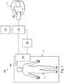
- FIG. 1illustrates a telerobotic interventional system in accordance with an embodiment of the present disclosure.
- FIG. 2illustrates an interventional instrument system in accordance with an embodiment of the present disclosure.
- FIG. 3Aillustrates an exemplary catheter system, showing relative positions of various elements that enable articulation of the system, in accordance with an embodiment of the present disclosure.
- FIG. 3Billustrates an exemplary catheter system, showing relative positions of various elements that enable articulation of the system, in accordance with an embodiment of the present disclosure.
- FIG. 4illustrates an exemplary catheter system according to one embodiment of the present disclosure.
- FIG. 5illustrates a diagrammatic representation of an exemplary interventional instrument system including an exemplary catheter system according to one embodiment of the present disclosure.
- FIG. 6Ais illustrates an exemplary instrument body according to one embodiment of the present disclosure.
- FIG. 6Bis illustrates exemplary control elements on the exemplary instrument body shown in FIG. 6A according to one embodiment of the present disclosure.
- FIG. 7illustrates a perspective, partially cut-away view of an exemplary catheter system according to one embodiment of the present disclosure.
- FIGS. 8 and 9illustrate perspective, partially cut-away views of the exemplary catheter system shown in FIG. 7 , shown having varying articulable lengths.
- FIG. 10illustrates a cross-sectional view of a proximal portion of the exemplary catheter system shown in FIG. 7 .
- FIG. 11illustrates a cross-sectional view of a distal portion of the exemplary catheter system shown in FIG. 7 .
- the term “position”refers to the location of an object or a portion of an object in a three-dimensional space (e.g., three degrees of translational freedom along Cartesian X, Y, Z coordinates).
- orientationrefers to the rotational placement of an object or a portion of an object (three degrees of rotational freedom—e.g., roll, pitch, and yaw).
- the term “pose”refers to the position of an object or a portion of an object in at least one degree of translational freedom and to the orientation of that object or portion of the object in at least one degree of rotational freedom (up to six total degrees of freedom).
- the term “shape”refers to a set of poses, positions, or orientations measured along an elongated object.
- proximal and distalare used herein with reference to a clinician manipulating an end of an instrument extending from the clinician to a surgical or diagnostic site.
- proximalrefers to the portion of the instrument closer to the clinician
- distalrefers to the portion of the instrument further away from the clinician and closer to the surgical or diagnostic site.
- spatial termssuch as “horizontal,” “vertical,” “above,” and “below” may be used herein with respect to the drawings.
- surgical and diagnostic instrumentsare used in many orientations and positions, and there terms are not intended to be limiting and absolute.
- the present disclosurerelates generally to steerable conduits or tubes for actuation cables used in the operation of articulating devices.
- embodiments of the present disclosureare configured to be part of a telerobotic system.
- the steerable conduits disclosed hereinmay be utilized in similar (e.g., non-telerobotic) applications requiring a steerable distal tip.
- the steerable conduits disclosed hereinare formed of a flexible material and are configured to carry actuation/control cables or tendons.
- the walls of the steerable conduits disclosed hereininclude channels that are shaped and configured to carry the cables/tendons.
- the steerable conduits disclosed hereincomprise nested conduits that run coaxially with respect to each other along at least a portion of the articulating device.
- the articulable devicesinclude a cable/tendon running through a first conduit, which runs through a second conduit having a larger cross-sectional diameter than the first conduit.
- the articulable devices disclosed hereinare capable of at least two different articulable lengths without requiring additional articulation motors and/or a telescoping design.
- the nested conduits disclosed hereinmay improve the flexibility and performance of steerable portions of articulating devices, and may increase the range of suitable applications for articulating devices utilizing such steerable conduits.
- a teleoperational medical systemfor use in, for example, medical procedures including diagnostic, therapeutic, or surgical procedures, is generally indicated by the reference numeral 100 .
- the teleoperational medical systems of this disclosureare under the teleoperational control of a surgeon.
- a teleoperational medical systemmay be under the partial control of a computer programmed to perform the procedure or sub-procedure.
- a fully automated medical systemunder the full control of a computer programmed to perform the procedure or sub-procedure, may be used to perform procedures or sub-procedures.
- the teleoperational medical system 100generally includes a teleoperational assembly 102 mounted to or near an operating table O on which a patient P is positioned.
- a medical instrument system 104is operably coupled to the teleoperational assembly 102 .
- An operator input system 106allows a surgeon or other type of clinician S to view images of or representing the surgical site and to control the operation of the medical instrument system 104 .
- the operator input system 106may be located at a surgeon's console, which is usually located in the same room as operating table O. It should be understood, however, that the surgeon S can be located in a different room or a completely different building from the patient P.
- Operator input system 106generally includes one or more control device(s) for controlling the medical instrument system 104 .
- the control device(s)may include one or more of any number of a variety of input devices, such as hand grips, joysticks, trackballs, data gloves, trigger-guns, hand-operated controllers, voice recognition devices, touch screens, body motion or presence sensors, and the like.
- control device(s)will be provided with the same degrees of freedom as the medical instruments of the teleoperational assembly to provide the surgeon with telepresence, the perception that the control device(s) are integral with the instruments so that the surgeon has a strong sense of directly controlling instruments as if present at the surgical site.
- the control device(s)may have more or fewer degrees of freedom than the associated medical instruments and still provide the surgeon with telepresence.
- the control device(s)are manual input devices which move with six degrees of freedom, and which may also include an actuatable handle for actuating instruments (for example, for closing grasping jaws, applying an electrical potential to an electrode, delivering a medicinal treatment, and the like).
- the teleoperational assembly 102supports the medical instrument system 104 and may include a kinematic structure of one or more non-servo controlled links (e.g., one or more links that may be manually positioned and locked in place, generally referred to as a set-up structure) and a teleoperational manipulator.
- the teleoperational assembly 102includes plurality of motors that drive inputs on the medical instrument system 104 . These motors move in response to commands from the control system (e.g., control system 112 ).
- the motorsinclude drive systems which when coupled to the medical instrument system 104 may advance the medical instrument into a naturally or surgically created anatomical orifice.
- motorized drive systemsmay move the distal end of the medical instrument in multiple degrees of freedom, which may include three degrees of linear motion (e.g., linear motion along the X, Y, Z Cartesian axes) and in three degrees of rotational motion (e.g., rotation about the X, Y, Z Cartesian axes). Additionally, the motors can be used to actuate an articulable end effector of the instrument for grasping tissue in the jaws of a biopsy device or the like.
- degrees of linear motione.g., linear motion along the X, Y, Z Cartesian axes
- rotational motione.g., rotation about the X, Y, Z Cartesian axes
- the teleoperational medical system 100also includes a sensor system 108 with one or more sub-systems for receiving information about the instruments of the teleoperational assembly.
- Such sub-systemsmay include a position sensor system (e.g., an electromagnetic (EM) sensor system); a shape sensor system for determining the position, orientation, speed, velocity, pose, and/or shape of the catheter tip and/or of one or more segments along a flexible body of instrument system 104 ; and/or a visualization system for capturing images from the distal end of the catheter system.
- EMelectromagnetic
- the teleoperational medical system 100also includes a display system 110 for displaying an image or representation of the surgical site and medical instrument system(s) 104 generated by sub-systems of the sensor system 108 .
- the display 110 and the operator input system 106may be oriented so the operator can control the medical instrument system 104 and the operator input system 106 with the perception of telepresence.
- display system 110may present images of the surgical site recorded and/or imaged preoperatively or intra-operatively using imaging technology such as computerized tomography (CT), magnetic resonance imaging (MRI), fluoroscopy, thermography, ultrasound, optical coherence tomography (OCT), thermal imaging, impedance imaging, laser imaging, nanotube X-ray imaging, and the like.
- imaging technologysuch as computerized tomography (CT), magnetic resonance imaging (MRI), fluoroscopy, thermography, ultrasound, optical coherence tomography (OCT), thermal imaging, impedance imaging, laser imaging, nanotube X-ray imaging, and the like.
- CTcomputerized tomography
- MRImagnetic resonance imaging
- fluoroscopyfluoroscopy
- thermographythermography
- ultrasoundultrasound
- OCToptical coherence tomography
- OCToptical coherence tomography
- thermal imagingimpedance imaging
- laser imaginglaser imaging
- nanotube X-ray imagingand the like.
- the presented preoperative or intra-operative imagesmay include two-dimensional, three-
- the display system 110may display a virtual visualization image in which the actual location of the medical instrument is registered (e.g., dynamically referenced) with preoperative or concurrent images to present the surgeon with a virtual image of the internal surgical site at the location of the tip of the medical instrument.
- a virtual visualization imagein which the actual location of the medical instrument is registered (e.g., dynamically referenced) with preoperative or concurrent images to present the surgeon with a virtual image of the internal surgical site at the location of the tip of the medical instrument.
- the display system 110may display a virtual visualization image in which the actual location of the medical instrument is registered with prior images (including preoperatively recorded images) or concurrent images to present the surgeon with a virtual image of a medical instrument at the surgical site.
- An image of a portion of the medical instrument system 104may be superimposed on the virtual image to assist the surgeon controlling the medical instrument.
- the teleoperational medical system 100also includes a control system 112 .
- the control system 112includes at least one memory and at least one processor (not shown), and typically a plurality of processors, for effecting control between the medical instrument system 104 , the operator input system 106 , the sensor system 108 , and the display system 110 .
- the control system 112also includes programmed instructions (e.g., a computer-readable medium storing the instructions) to implement some or all of the methods described in accordance with aspects disclosed herein. While control system 112 is shown as a single block in the simplified schematic of FIG.
- the systemmay include two or more data processing circuits with one portion of the processing optionally being performed on or adjacent the teleoperational assembly 102 , another portion of the processing being performed at the operator input system 106 , and the like. Any of a wide variety of centralized or distributed data processing architectures may be employed. Similarly, the programmed instructions may be implemented as a number of separate programs or subroutines, or they may be integrated into a number of other aspects of the teleoperational systems described herein. In one embodiment, control system 112 supports wireless communication protocols such as Bluetooth, IrDA, HomeRF, IEEE 802.11, DECT, and Wireless Telemetry.
- wireless communication protocolssuch as Bluetooth, IrDA, HomeRF, IEEE 802.11, DECT, and Wireless Telemetry.
- control system 112may include one or more servo controllers that receive force and/or torque feedback from the medical instrument system 104 . Responsive to the feedback, the servo controllers transmit signals to the operator input system 106 . The servo controller(s) may also transmit signals instructing teleoperational assembly 102 to move the medical instrument system(s) 104 which extend into an internal surgical site within the patient body via openings in the body. Any suitable conventional or specialized servo controller may be used. A servo controller may be separate from, or integrated with, teleoperational assembly 102 . In some embodiments, the servo controller and teleoperational assembly are provided as part of a teleoperational arm cart positioned adjacent to the patient's body.
- the control system 112may further include a virtual visualization system to provide navigation assistance to the medical instrument system(s) 104 .
- Virtual navigation using the virtual visualization systemis based upon reference to an acquired dataset associated with the three dimensional structure of the anatomical passageways. More specifically, the virtual visualization system processes images of the surgical site imaged using imaging technology such as computerized tomography (CT), magnetic resonance imaging (MRI), fluoroscopy, thermography, ultrasound, optical coherence tomography (OCT), thermal imaging, impedance imaging, laser imaging, nanotube X-ray imaging, or the like.
- CTcomputerized tomography
- MRImagnetic resonance imaging
- fluoroscopythermography
- ultrasoundoptical coherence tomography
- OCToptical coherence tomography
- thermal imagingimpedance imaging
- laser imagingnanotube X-ray imaging, or the like.
- Softwareis used to convert the recorded images into a two dimensional or three dimensional composite representation of a partial or an entire anatomical organ or anatomical region.
- An image data setis
- the composite representation and the image data setdescribe the various locations and shapes of the passageways and their connectivity.
- the images used to generate the composite representationmay be recorded preoperatively or intra-operatively during a clinical procedure.
- a virtual visualization systemmay use standard representations (i.e., not patient specific) or hybrids of a standard representation and patient specific data.
- the composite representation and any virtual images generated by the composite representationmay represent the static posture of a deformable anatomic region during one or more phases of motion (e.g., during an inspiration/expiration cycle of a lung).
- the sensor system 108may be used to compute an approximate location of the instrument with respect to the patient anatomy.
- the locationcan be used to produce both macro-level tracking images of the patient anatomy and virtual internal images of the patient anatomy.
- Various systems for using fiber optic sensors to register and display a medical implement together with preoperatively recorded surgical images, such as those from a virtual visualization systemare known.
- U.S. patent application Ser. No. 13/107,562(filed May 13, 2011) (disclosing “Medical System Providing Dynamic Registration of a Model of an Anatomical Structure for Image-Guided Surgery”) which is incorporated by reference herein in its entirety, discloses one such system.
- the teleoperational medical system 100may further include optional operation and support systems (not shown) such as illumination systems, steering control systems, irrigation systems, and/or suction systems.
- the teleoperational systemmay include more than one teleoperational assembly and/or more than one operator input system.
- the exact number of manipulator assemblieswill depend on the surgical procedure and the space constraints within the operating room, among other factors.
- the operator input systemsmay be collocated, or they may be positioned in separate locations. Multiple operator input systems allow more than one operator to control one or more manipulator assemblies in various combinations.
- FIG. 2illustrates an interventional instrument system 200 which may be used as the interventional instrument system 104 of the telerobotic interventional system 100 .
- the interventional instrument system 200may be used for non-robotic exploratory procedures or in procedures involving traditional manually operated interventional instruments, such as endoscopy.
- the interventional instrument system 200may include a flexible bronchial instrument, such as a bronchoscope or bronchial catheter for use in examination, diagnosis, biopsy, or treatment of a lung.
- the systemis also suited for navigation and treatment of other tissues, via natural or surgically created connected passageways, in any of a variety of anatomical systems including the colon, the intestines, the kidneys, the brain, the heart, the circulatory system, or the like.
- the instrument system 200includes a catheter system 202 coupled to an instrument body 204 .
- the catheter system 202includes an elongated flexible body 216 having a proximal end 217 and a distal end or tip portion 218 .
- a distal portion 221extends between the distal end 218 and a transition section 230 .
- at least one set of conduits for actuation cablesterminates at the transition section 230 .
- a proximal portion 220extends between the transition section 230 and the proximal end 217 .
- the flexible body 216has an approximately 3 mm outer diameter. Other flexible body outer diameters may be larger or smaller.
- the flexible body outer diametertapers from the proximal end 217 to the distal end 218 .
- the flexible body outer diameter at the proximal end 217may be greater than the flexible body outer diameter at the distal end 218 .
- the flexible body outer diameteris substantially unchanged throughout the proximal portion 220 . In some embodiments, the flexible body outer diameter is substantially unchanged throughout the distal portion 221 .
- the flexible body outer diametermay taper throughout the proximal portion 220 and/or the distal portion 221 . In other embodiments, there can be an abrupt change or stop in the flexible body 216 at the transition section 230 from a larger outer diameter of the proximal portion 220 to a smaller diameter of the distal portion 221 .
- the catheter system 202may optionally include a shape sensor 222 for determining the position, orientation, speed, pose, and/or shape of the catheter tip at distal end 218 and/or of one or more segments 224 along the body 216 .
- the entire length of the body 216 between the distal end 218 and the proximal end 217may be effectively divided into the segments 224 .
- the shape sensor 222may be a component of the sensor system 108 . If the instrument system 200 is manually operated or otherwise used for non-robotic procedures, the shape sensor 222 may be coupled to a tracking system that interrogates the shape sensor and processes the received shape data.
- the shape sensor system 222may include an optical fiber aligned with the flexible catheter body 216 (e.g., provided within an interior channel (not shown) or mounted externally).
- the optical fiber of the shape sensor system 222may form a fiber optic bend sensor for determining the shape of at least a portion of the catheter system 202 .
- Various systems and methods for monitoring the shape and relative position of an optical fiber in three dimensionsare described in U.S. patent application Ser. No. 11/180,389, filed Jul. 13, 2005, disclosing “Fiber optic position and shape sensing device and method relating thereto;” U.S. Provisional Pat. App. No. 60/588,336, filed on Jul. 16, 2004, disclosing “Fiber-optic shape and relative position sensing;” and U.S. Pat.
- the sensor systeme.g. sensor system 108 or another type of tracking system as described in FIG. 3A
- the sensor systemmay include an interrogation system for generating and detecting the light used for determining the shape of the catheter system 202 .
- This informationin turn, in can be used to determine other related variables, such as velocity and acceleration of the parts of an interventional instrument.
- the flexible catheter body 216includes a lumen 225 sized and shaped to receive an auxiliary tool 226 .
- Auxiliary toolsmay include, for example, image capture probes, biopsy devices, laser ablation fibers, or other surgical, diagnostic, or therapeutic tools.
- Auxiliary toolsmay include end effectors having a single working member such as a scalpel, a blade, an optical fiber, or an electrode.
- Other end effectorsmay include pair or plurality of working members such as forceps, graspers, scissors, or clip appliers, for example. Examples of electrically activated end effectors include electrosurgical electrodes, transducers, sensors, and the like.
- Other embodimentsmay lack a lumen 225 .
- the auxiliary tool 226may be an image capture probe including a tip portion with a stereoscopic or monoscopic camera disposed near the distal end 218 of the flexible catheter body 216 for capturing images (including video images) that are processed for display.
- the image capture probemay include a cable coupled to the camera for transmitting the captured image data.
- the image capture instrumentmay be a fiber-optic bundle, such as a fiberscope, that couples to the imaging system.
- the image capture instrumentmay be single or multi-spectral, for example capturing image data in the visible spectrum, or capturing image data in the visible and infrared or ultraviolet spectrums.
- the catheter system 202may optionally include a position sensor system 231 (e.g., an electromagnetic (EM) sensor system) which may be disabled by an operator or an automated system (e.g., a function of the control system 112 ) if it becomes unreliable due to, for example, magnetic interference from other equipment in the surgical suite or if other navigation tracking systems are more reliable.
- the position sensor system 231may be an EM sensor system that includes one or more conductive coils that may be subjected to an externally generated electromagnetic field. Each coil of the EM sensor system 231 then produces an induced electrical signal having characteristics that depend on the position and orientation of the coil relative to the externally generated electromagnetic field.
- the EM sensor systemmay be configured and positioned to measure six degrees of freedom (“6-DOF”), e.g., three position coordinates X, Y, Z and three orientation angles indicating pitch, yaw, and roll of a base point or five degrees of freedom, e.g., three position coordinates X, Y, Z and two orientation angles indicating pitch and yaw of a base point.
- 6-DOFdegrees of freedom
- the flexible catheter body 216may also house actuation cables, linkages, or other steering controls (not shown in FIG. 2 ) that extend between the instrument body 204 and the distal end 218 to controllably bend or turn the distal portion 221 as shown for example by the dotted line versions of the distal portion.
- the flexible body 216can define one or more additional lumens through which interventional instruments, cables, linkages, and/or other steering controls (such as, by way of non-limiting example, coil pipes and tendons) may extend.
- the instrument body 204may include drive inputs that couple to motorized drive elements of the telerobotic assembly.
- the instrument body 204may include gripping features, manual actuators, and other components for manually controlling the motion of the instrument system.
- the catheter systemmay be steerable or, alternatively, may be non-steerable with no integrated mechanism for operator control of the instrument bending.
- the proximal portion 220is configured to passively deflect in response to forces acting upon the flexible body, and the distal portion 221 is configured to actively articulate in response to the telerobotic assembly and/or control signals from the instrument body 204 .
- FIG. 3Aillustrates a portion of a catheter system 300 having a proximal portion 302 , a distal portion 304 , a wall 305 , a proximal transition section 306 a disposed between the proximal portion 302 and the distal portion 304 , and a distal transition section 306 b disposed in the distal portion 304 .
- the catheter system 300may be the same as the catheter system 202 described above in relation to FIG. 2 .
- the proximal portion 302may be the same as a distal-most segment 224 of the proximal portion 220 and the distal portion 304 may be the same as a proximal-most segment 224 of the distal portion 221 of the catheter system 202 .
- the transition section 306 ais the same as the transition section 230 shown between the proximal portion 220 and the distal portion 221 shown in FIG. 2 .
- the distal portion 304includes a steerable segment 307 , which includes a proximal steerable portion or first bendable portion 307 a and a distal steerable portion or second bendable portion 307 b .
- the steerable segment 307includes a proximal end 308 and a distal end 309 .
- the proximal steerable portion 307 aextends from the proximal transition section 306 a to the distal transition section 306 b
- the proximal steerable portion 307 bextends from the distal transition section 306 b to the distal end 309 .
- Other embodimentsmay include more transition sections within the distal portion 304 .
- a lumen 310extends centrally through the proximal portion 302 , the transition sections 306 a , 306 b , and the distal portion 304 of the catheter system 300 .
- the transition sections 306 a , 306 bmay include flexible walls with layered wall components and/or plate-like structures that are omitted from the illustration of FIG. 3A for the sake of clarity.
- Cable assemblies 314extend down the length of a catheter flexible body (e.g., flexible body 216 ) of the catheter system 300 to the distal portion 304 .
- the cable assemblies 314have similar characteristics to a Bowden cable, which is a type of flexible cable used to transmit mechanical force or energy by the movement of an inner cable relative to a hollow outer cable housing such as, without limitation, a helical coil pipe.
- four cable assemblies 314are arranged circumferentially in the wall 305 around the lumen 310 .
- Other embodimentsmay include any number of cable assemblies 314 arranged in any of a variety of symmetrical or asymmetrical patterns within the wall 305 .
- the cable assemblies 314extend entirely within or at least partially within the wall 305 of the catheter system 300 .
- the cable assemblies 314comprise multiple sets of nested conduits or coil pipes 316 through which control wires or tendons 318 extend.
- the conduits or coil pipes described hereinmay comprise helically-wound tubular housings defining a passageway, including, without limitation, a cylindrical tube formed of a single, tightly wound wire and a cylindrical tube formed of several wire strands running in a multiple helix.
- the conduits or coil pipes described hereinmay comprise any tubular housing that is flexible and axially compressible, such as, without limitation, a cylindrical tube having a braided or woven wall construction.
- each cable assembly 314comprises an inner coil pipe 316 nested within an outer coil pipe 320 .
- “nested”refers to a concentric arrangement of tubes having different diameters that are coaxially aligned about a common longitudinal axis.
- an inner tubemay be nested within an outer tube having a large outer diameter than the inner tube, and the inner and outer tubes may be axially movable relative to each other.
- the space between the inner and outer tubesmay be fluid-filled (e.g., air-filled), or may be filled with an insulating or imaging material that does not limit the axial translation of the tubes relative to each other.
- the inner and outer coil pipes 316 , 320form an axially variable stiffening mechanism that is configured to isolate the articulation or bending motion of the catheter system 300 to the distal portion 304 .
- the inner coil pipe 316 and the outer coil pipe 320comprise flexible conduits for the tendons 318 .
- the coil pipes 316 , 320are axially compressible until loading on the coil pipes causes the helical coils to touch. When the helical coils contact each other, the coil pipes become non-compressible and rigid.
- the inner coil pipe 316 and the outer coil pipe 320are coaxially aligned along the length of the catheter system 300 .
- the inner coil pipe 316houses the tendon 318 along the length of the flexible body, and the tendon 318 can slide longitudinally within the inner coil pipe 316 .
- the outer coil pipe 320houses the inner coil pipe 316 along the length of the flexible body, and the inner coil pipe 316 can slide longitudinally within the outer coil pipe 320 .
- Each set of coil pipesis fixed or terminated at distal and proximal ends.
- the inner coil pipes 316terminate at the distal transition section 306 b , proximal to the distal steerable portion 307 b within the distal portion 304 .
- the outer coil pipes 320terminate at the proximal transition section 306 a , proximal to the entire steerable section 307 , including both the proximal steerable portion 307 a and the distal steerable portion 307 b .
- the tendons 318extend out of the coil pipes 316 at the distal transition section 306 b at or distal to the distal transition section 306 b , extend through the distal steerable portion 307 b , and attach to the distal end 309 .
- the inner coil pipes 316include an outer diameter D 1 that is smaller than an inner diameter D 2 of the outer coil pipes 320 .
- the outer diameter D 1 of the inner coil pipes 316ranges from 0.010-0.011 inches, with an inner diameter ranging from 0.008-0.009 inches.
- the inner diameter D 2 of the outer coil pipes 320ranges from 0.012-0.014 inches, with an inner diameter ranging from 0.010-0.012 inches.
- the tendons 318are 0.007 inches thick. These measurements are provided for exemplary purposes and are not intended to be limiting. Other dimensions are contemplated.
- each cable assembly 314includes two coil pipes 316 , 320 of varying diameters and varying termination locations.
- the coil pipes 316 , 320may be wound in opposite directions, or counterwound.
- the coil pipes 316 , 320can free float with respect to each other.
- the two separate, nested coil pipes 316 , 320are arranged to have a space between them and can freely shift along a common longitudinal axis LA with respect to each other.
- the coil pipes 316 , 320may be coated in a lubricant or friction-minimizing material such as, by way of non-limiting example, polytetrafluoroethylene (PTFE).
- PTFEpolytetrafluoroethylene
- the two separate coil pipes 316 , 320allow each cable assembly 314 to articulate two different lengths of the distal portion 304 of the catheter system 300 .
- Other embodimentsmay include any number of nested coil pipes having varying diameters and termination locations (e.g., each cable assembly may have more than two sets of nested coil pipes), thereby enabling a greater number of different articulable lengths of the catheter system 300 .
- the inner coil pipes 316terminate at the distal transition section 306 b in approximately a common plane perpendicular to the lumen 310
- the outer coil pipes 320terminate at the proximal transition section 306 a in approximately a common plane perpendicular to the lumen 310 .
- the outer coil pipes 320terminate in the wall 305 where the outer coil pipes 320 are embedded or anchored to a proximal termination element 330 within the proximal transition section 306 a of the wall 305 .
- the inner coil pipes 316terminate in the wall 305 where the inner coil pipes 316 are embedded or anchored to a distal termination element 332 within the distal transition section 306 b of the wall 305 .
- the proximal and distal termination elements 330 , 332may comprise any of a variety of structures configured to anchor or bind the outer and inner coil pipes 320 , 316 , respectively.
- the distal termination elements 330 , 332may comprise rigid rings, flexible rings, and/or discrete anchoring structures within the wall 305 .
- the walls or anchoring ringsmay serve to block distal movement of the coil pipe.
- a ringmay serve as a proximal termination element 330 .
- the ringhas apertures large enough to allow passage of the tendon, but not the coil pipe through which the tendon extends.
- the coil pipeis in abutment with the ring 300 but may not be fixed to the ring. Nevertheless, the ring 300 prevents the distal movement of the coil pipe when the coil pipe is under a load.
- the proximal and distal termination elementsmay be generally parallel or non-parallel to each other.
- each outer coil pipe 320is directly secured to the proximal termination element 330 proximal to the steerable section 307
- a distal end 342 of each inner coil pipe 316is directly secured to the distal termination element 332 proximal to the distal steerable portion 307 b
- the coil pipes 316 , 320may have a surface treatment to aid in fixation to the termination elements 332 , 330
- the distal ends 340 , 342 of each coil pipe 320 , 316may be secured to the termination elements 330 , 332 , respectively, via, by way of non-limiting example, an adhesive or melting.
- the elements 330 , 332may not fixedly terminate the distal ends of the coil pipes, but rather may create an abutment surface that blocks movement of the coil pipes when a load is applied.
- the distal ends 340 , 342 of the coil pipes 320 , 316are not anchored to any discrete termination elements, such as rigid rings, within the flexible wall 305 or the catheter system 300 . Rather, each coil pipe 320 , 316 terminates within and is affixed to the wall 305 at a position proximal to whichever steerable section of the distal portion 304 is configured to be steered by the tendon 318 carried within the particular cable assembly 314 .
- a resulting articulable length L1 of the catheter system 300would include the length of the catheter system 300 distal to the proximal termination element 330 (i.e., the proximal and distal steerable portions 307 a , 307 b ). If, however, the inner coil pipes 316 are axially constrained (e.g., via clamping), a resulting articulable length L2 of the catheter system 300 would include the length of the catheter system 300 distal to the distal termination element 332 (i.e., only the distal steerable portion 307 b ). Thus, as shown more clearly in FIGS.
- the inner and outer coil pipes 316 , 320comprise axially variable stiffening mechanisms that are adjustable between a first state in which an actuation of the control tendon 318 produces a first bend radius in the steerable distal section and a second state in which the actuation of the control tendon 318 produces a second bend radius, different from the first bend radius, in the steerable distal portion 314 .
- the coil pipes 316 , 320 in the pictured embodimentterminate at two separate common planes at the distal transition section 306 b and the proximal transition section 306 a , respectively, it should be understood that an individual coil pipe could extend into any length of the catheter system 300 (e.g., the flexible body 216 ) with the coil pipes terminating at different lengths (i.e., not in a common plane).
- the coil pipes 316 , 320extend only partially along the length of the catheter system 300 .
- at least one set of the coil pipes 316 , 320extends the entire length or substantially the entire length of the catheter system 300 (e.g., to a distal-most steerable segment within the distal portion 304 ).
- the inner coil pipes 316 ′extend substantially the entire length of the catheter system 300 ′ and terminate at a common plane defined by the distal end 309 ′.
- the catheter system 300 ′is substantially similar to the catheter system 300 described above in relation to FIG. 3 except for the differences in coil pipe termination positions described herein.
- the outer coil pipes 320 ′extend past the proximal transition section 306 ′ to terminate at the distal transition section 306 b ′ within the distal portion 304 ′, proximal to the distal steerable portion 307 b ′.
- the inner coil pipes 316 ′extend out of the outer coil pipes 320 ′ at the distal transition section 306 b ′, extend through the distal steerable portion 307 b ′, and attach to the distal end 309 ′.
- the inner coil pipes 316 ′extend the entire length of the tendons 318 ′ within the steerable distal portion 304 ′.
- the entire steerable distal portion 304 ′is stiffened, thereby preventing articulation of both the proximal steerable portion 307 a ′ and the distal steerable portion 307 b ′.
- the outer coil pipes 320 ′are axially constrained, only the more proximal portion of the distal portion 304 ′, i.e., the proximal steerable portion 307 a ′, is stiffened, resulting in an articulable length L1′ including the length of the distal steerable portion 307 b ′ (e.g., extending from the distal transition section 306 b ′ to the distal end 309 ′).
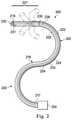
- FIG. 4is illustrates an exemplary catheter system 400 according to one embodiment of the present disclosure.
- the catheter system 400may be the same as the catheter system 300 described above in relation to FIG. 3A .
- FIG. 4shows a part of a proximal portion 402 and the entire distal portion 404 of the catheter system 400 .
- the distal portion 404comprises a steerable portion of the catheter system 400 .
- the catheter system 400includes a distal termination element 410 , which divides the distal portion 404 into a proximal steerable portion 415 a and a distal steerable portion 415 b , and a proximal termination element 420 .
- the proximal steerable portion 415 aextends from the proximal termination element 420 to the distal termination element 410
- the distal steerable portion 415 bextends from the distal termination element 410 to a distal end 425 of the catheter system 400
- the catheter system 400includes a soft distal tip 430 , which may assist in minimizing inadvertent trauma to patient tissue as the catheter system 400 is advanced within the patient's anatomy.
- the catheter system 400includes a plurality of cable assemblies, each of which includes an inner coil pipe (not shown) nested within an outer coil pipe (not shown) that are coaxially aligned along the length of the catheter system 400 .
- the inner coil pipesextend through a wall of the catheter system 400 into the distal portion 404 and terminate at the distal termination element 410 , proximal to the distal steerable portion 415 b .
- the outer coil pipesextend through a wall of the catheter system 400 through the proximal portion 402 and terminate at the proximal termination element 420 , proximal to the distal portion 404 , including both the proximal steerable portion 415 a and the distal steerable portion 415 b.
- a resulting articulable length L3 of the catheter system 300would include the length of the catheter system 400 distal to the proximal termination element 420 (i.e., the proximal and distal steerable portions 415 a , 415 b ).
- a resulting articulable length L4 of the catheter system 400would include the length of the catheter system 400 distal to the distal termination element 410 (i.e., only the distal steerable portion 415 b ).
- FIG. 5illustrates a diagrammatic representation of an interventional instrument system 500 including an exemplary catheter system 510 according to one embodiment of the present disclosure.
- the interventional instrument system 500may be the same as the interventional instrument system 200 described above in relation to FIG. 2
- the catheter system 510may be the same as the catheter system 300 described above in relation to FIG. 3A .
- the interventional instrument system 500includes an actuator 515 and an instrument body 520 in addition to the catheter system 510 .
- the actuator 515may be disposed within or integral with the instrument body 520 .
- the various components of the interventional instrument system 500are not drawn to scale with respect to each other, and the instrument body 520 is shown enlarged for illustrative purposes.
- the instrument body 520is shown as a simplified tube-like structure in the pictured embodiment, the instrument body 520 may have any of a variety of shapes and configurations designed to enable a controller (e.g., a user or a robotic arm) to manipulate the catheter system 510 .
- a controllere.g., a user or a robotic arm
- Cable assemblies 525extend from the actuator 515 , through the instrument body 520 , and into the catheter system 510 .
- Each cable assembly 525includes nested coil pipes that house at least one control cable or tendon 530 , as described above in relation to FIGS. 3 and 4 .
- each cable assembly 525includes the control tendon 530 extending through an inner coil pipe 535 , which is nested within an outer coil pipe 540 .
- the tension applied to the tendon 530 by the actuator 515is isolated to a particular segment of the catheter system 510 through the use of the coil pipes 535 , 540 .
- These cable assemblies 525can be actuated remotely and can be used to selectively apply force to and articulate discrete segments.
- the tendons 530may be made from any of a variety of materials, including without limitation, stainless steel, titanium, Nitinol, ultra-high molecular weight polyethylene, and any other suitable material known to the skilled artisan.
- the cable assemblies 525are substantially similar in construct and in operation to the cables disclosed in U.S. Patent Application No. 2009/0099420 A1, entitled “System for Managing Bowden Cables in Articulating Instruments,” filed Oct. 11, 2007, and published on Apr. 16, 2009, which is incorporated by reference herein in its entirety.
- the outer coil pipes 540extend from the actuator 510 to a proximal termination element 545 of the catheter system 510 , halting proximally of a proximal steerable portion 547 and a distal steerable portion 549 .
- the inner coil pipes 535extend from the actuator 510 to a distal termination element 550 of the catheter system 510 , halting proximally of the distal steerable portion 549 .
- the control tendons 530continue past the distal termination element 550 (and the distal ends of the inner coil pipes 535 ) to end at a distal end 555 of the catheter system 510 . In some embodiments, the control tendons 530 may terminate proximal to the distal end 555 .
- the inner and outer coil pipes 535 , 540may be substantially the same as the inner and outer coil pipes 316 , 320 , respectively, shown in FIG. 3A .
- the proximal and distal termination elements 545 , 550may be substantially the same as the proximal and distal termination elements 330 , 332 , respectively, shown in FIG. 3A .
- the instrument body 520can include axial control elements, such as, by way of non-limiting example, control clamps, that contact and interact with the different coil pipes of the cable assemblies 525 .
- the instrument body 520includes two different axial control elements or control clamps, the proximal control clamp 560 and the distal control clamp 565 .
- the control clamps 560 , 565may be controlled or adjusted by a user (e.g., manually) or by a telerobotic assembly (e.g., via computer-assistance or robotically).
- the control clamps 560 , 565may comprise any of a variety of structures configured to selectively clamp, compress, and/or tighten particular coil pipes 535 , 540 , and/or selectively constrict the particular lumen through which each separate set of coil pipes 535 , 540 extend. Clamping the coil pipes 535 , 540 substantially prevents the coil pipes from translating when under load thereby increasing the axial stiffness of the coil pipe when the tendon is tensioned.
- the proximal control clamp 560interacts with the inner coil pipes 535
- the distal control clamp 565interacts with the outer coil pipes 540 .
- the proximal and distal control clamps 560 , 565each include a first state configured to increase the axial stiffness of the inner and outer coil pipes 535 , 540 , respectively.
- clamping the coil pipe 535 , 540e.g., by selectively transitioning the proximal and distal control clamps 560 , 565 , respectively, into the first state
- axially compresses the coil pipe along its lengthe.g., from the control clamps 560 , 565 to the distal and proximal termination elements 550 , 545 , respectively).
- Each control clamp 560 , 565includes a plurality of individual control features 570 , 575 , respectively.
- the control clamp 560includes four different control features 570 a , 570 b , 570 c , and 570 d
- the control clamp 570includes four different control features 575 a , 575 b , 575 c , and 575 d .
- Each individual control feature 570 a - d and 575 a - dis configured to interact with an individual coil pipe of the interventional instrument system 500 .
- each control clamp 560 , 565includes at least one control feature 570 , 575 , respectively, that is configured to control movement in the pitch directions (or plane of motion) and at least one control feature 570 , 575 , respectively, that is configured to control movement in the yaw directions (or plane of motion).
- the interventional instrument system 500includes four control tendons 530 a - d running through four separate cable assemblies 525 a - d having inner coil pipes 535 a - d and outer coil pipes 535 a - d , 540 a - d , respectively.
- the control features 570 a - dare arranged to interact with the corresponding inner coil pipes 535 a - d , respectively, and the control features 575 a - d are arranged to interact with the corresponding outer coil pipes 540 a - d.
- each individual coil pipemay be adjusted independently of the others.
- the outer coil pipe 540 amay be axially constrained (e.g., clamped) while the inner coil pipe 535 a remains unconstrained (e.g., unclamped).
- the outer coil pipes 540 a , 540 cmay be axially constrained (e.g., clamped), thus affecting tendons 530 a , 530 c , respectively, while the outer coil pipes 540 b , 540 d remain unconstrained (e.g., unclamped).
- the controllere.g., a user or a telerobotic assembly/control system
- the controllermay adjust the control clamps 560 , 565 such that the articulable length of the catheter system 510 is greater in the x-y plane than in the x-z plane, or vice-versa.
- FIGS. 6A and 6Billustrate an exemplary instrument body 600 according to one embodiment of the present disclosure.
- the instrument body 600may substantially similar to the instrument body 520 described above in relation to FIG. 5 .
- the instrument body 600includes a first control element 605 and a second control element 610 , each of which are associated with cable assemblies (not shown) extending through the instrument body 600 .
- Each cable assemblyincludes nested inner coil pipes (not shown) and outer coil pipes 617 a - c (a fourth coil pipe is not shown due to in FIG. 6A ) which surround a control tendon.
- each control element 605 , 610controls the inner and outer coil pipes, respectively, and includes at least four individual control features 615 a - c and 620 a - c , respectively.
- Each individual control feature 615 a - ccontacts and controls an individual inner coil pipe.
- each individual control feature 620 a - ccontacts and controls an individual outer coil pipe 617 a - c , respectively.
- each control feature 615 a - c , 620 a - cincludes screws 625 that can be individually adjusted (e.g., tightened or loosened) by the controller to selectively adjust the axial stiffness of the inner and outer coil pipes, respectively.
- the inner and outer coil pipescomprise axially variable stiffening mechanisms that are adjustable between a first state (i.e., in which either the inner or outer coil pipes are axially constrained (e.g., via tightening of the screws 625 )) in which an actuation of the control tendon produces a first bend radius in the steerable distal section and a second state (i.e., in which the other of the inner or outer coil pipes are axially constrained) in which the actuation of the control tendon produces a second bend radius, different from the first bend radius, in the steerable distal portion.
- a first statei.e., in which either the inner or outer coil pipes are axially constrained (e.g., via tightening of the screws 625 )
- a second statei.e., in which the other of the inner or outer coil pipes are axially constrained
- FIG. 6Billustrates the instrument body 600 with the control feature 620 c removed to expose a grip element 630 , which is disposed about the cable assembly 612 c .
- the grip element 630comprises an axially movable cylinder that is coupled to the cable assembly 612 c and is positioned within a groove 631 .
- the grip element 630can translate axially within the groove 631 .
- the grip element 630can comprise any of a variety of coupling structures capable of compressing or constraining the axial motion of the desired coil pipe (in this case, the outer coil pipe 617 c ) when force is applied to the grip element 630 .
- the controllermay adjust the control feature 620 c to apply force to the grip element 630 (e.g., to apply a transverse load to the grip element 630 ), which then compresses or constrains the axial motion of a proximal end of the outer coil pipe 617 c .
- adjustment of the control feature 620 cmay halt the axial translation of the grip element 630 by applying a transverse force or load on the grip element 630 , thereby preventing the axial translation of the proximal end of the outer coil pipe 617 c , which stiffens the catheter system along the length of the outer coil pipe 617 c .
- the grip element 630is sized relative to the control feature 620 c to allow for adequate restriction of axial motion of the grip element 630 .
- the grip element 630 and the control feature 620 cmay share a common axial length.
- the grip elementmay comprise any size and shape of structure coupled to a proximal portion of a coil pipe and configured to limit or otherwise control the axial translation of the coil pipe.
- axial control elementmay be a barrier placed proximally of the coil pipe to prevent the coil pipe from translating when under load.
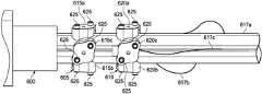
- FIG. 7illustrates a perspective, partially cut-away view of an exemplary catheter system 700 according to one embodiment of the present disclosure.
- the catheter system 700may be the same as the catheter system 300 described above in relation to FIG. 3A .
- FIG. 7shows a part of a proximal portion 702 (in a partially cut-away view for illustrative purposes) and the entire distal portion 704 of the catheter system 700 .
- the distal portion 704comprises a steerable or articulable portion of the catheter system 700 .
- the distal portion 704may comprise any of a variety of elongate structures, including, without limitation, an elongate tube having a plurality of cut-out features lending flexibility or a series of linearly-arranged links connected by link pivots (e.g., hinge joints).
- the catheter system 700includes a distal termination element 710 , which divides the distal portion 704 into a proximal steerable portion 715 a and a distal steerable portion 715 b , and a proximal termination element 720 .
- the proximal steerable portion 715 aextends from the proximal termination element 720 to the distal termination element 710
- the distal steerable portion 715 bextends from the distal termination element 710 to a distal end 425 of the catheter system 700 .
- the catheter system 700includes a plurality of cable assemblies 730 , each of which includes a first or inner coil pipe 735 nested within a second or outer coil pipe 740 that are coaxially aligned along the length of the catheter system 700 .
- Each cable assembly 730also includes a control tendon 742 , which extends through the inner coil pipe 735 .
- the inner coil pipes 735extend through a wall (not shown) of the catheter system 700 into the distal portion 704 and terminate at the distal termination element 710 , proximal to the distal steerable portion 715 b .
- the outer coil pipes 740extend through a wall of the catheter system 700 through the proximal portion 702 and terminate at the proximal termination element 720 , proximal to the distal portion 704 , including both the proximal steerable portion 715 a and the distal steerable portion 715 b.
- the catheter system 700includes a distal tip 728 extending past the tendons, which terminate at the distal end 425 .
- the distal tip 728comprises a soft and/or pliable tip configured to reduce trauma to patient tissue as the catheter system 700 is advanced through the patient's anatomy.
- a resulting articulable length L5 of the catheter system 700would include the parts of the catheter system 700 distal to the proximal termination element 720 (i.e., the proximal and distal steerable portions 715 a , 715 b ).
- the axial stiffnessis increased along a length L6 of the catheter system 700 when the outer coil pipes 740 are axially constrained (e.g., via clamping).
- the length L6includes the entire axially constrained length of the outer coil pipes 740 . Constraining the coil pipes provides axial stiffness to the proximal shaft sufficient to prevent bending when the tendon is tensioned.
- a resulting articulable length L7 of the catheter system 700would include only the parts of the catheter system 700 distal to the distal termination element 710 (i.e., only the distal steerable portion 715 b ). Thus, any articulation can only occur distal to the termination points of the axially constrained set of coil pipes.
- the articulable length of the catheter system 700can be adjusted by selectively axially constraining (e.g., via clamping) either the inner or outer coil pipes 735 , 740 , respectively.
- the axial stiffnessis increased along a length L8 of the catheter system 700 when the inner coil pipes 735 are axially constrained (e.g., via clamping).
- the length L6includes the entire axially constrained length of the inner coil pipes 735 .
- the inner and outer coil pipes 735 , 740comprise axially variable stiffening mechanisms that are adjustable between a first state in which an actuation of the control tendon 742 produces a first bend radius (e.g., bend radius BR 1 shown in FIG. 8 ) in the steerable distal section and a second state in which the actuation of the control tendon 742 produces a second bend radius (e.g., bend radius BR 2 , shown in FIG. 9 ), different from the first bend radius, in the steerable distal portion 704 .
- the bend radius of the catheter system 700is altered by the clamping of the different coil pipes (i.e., 735 and 740 ).
- the bend radius BR 1 of the catheter system 700 when the outer coil pipes 740 are axially constrainedis greater than the bend radius BR 2 of the catheter system 700 when the inner coil pipes 735 , or more distally-extending coil pipes, are axially constrained.
- FIGS. 7-9present partially cut-away views of the catheter system 700 , and although the inner and outer coil pipes 735 , 740 , respectively, are not shown extending proximally toward an instrument body and an actuator, both the inner and outer coil pipes 735 , 740 , in actuality, will extend proximally over the control tendons 742 toward an instrument body and an actuator (e.g., the instrument body 520 and the actuator 510 shown in FIG. 5 ). Thus, the lengths L6 and L8 shown in FIGS. 8 and 9 may extend proximally toward an instrument body and an actuator (e.g., the instrument body 520 and the actuator 510 shown in FIG. 5 ) as well.
- an actuatore.g., the instrument body 520 and the actuator 510 shown in FIG. 5
- each individual coil pipemay be adjusted independently of the others.
- a set of opposite outer coil pipes 740may be axially constrained (e.g., clamped) while the remaining outer coil pipes 740 remain unconstrained (e.g., unclamped), thus affecting one set of tendons 730 responsible for bending the distal portion 704 in one plane, without affecting the other set of tendons 730 , which may be responsible for bending the distal portion in a different plane.
- the controllere.g., a user or a telerobotic assembly/control system
- the controllermay adjust the control clamps (e.g., the control clamps 560 , 565 shown in FIG. 5 ) such that the articulable length of the catheter system 700 is greater in the x-y plane than in the x-z plane, or vice-versa.
- the selective axial constraining of the inner or outer coil pipes 735 , 740can control the articulable length as well as the desired directionality of the distal portion 704 .
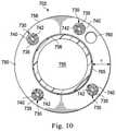
- FIG. 10illustrates a cross-sectional view of the proximal portion 702 of the exemplary catheter system 700 pictured in FIG. 7 .
- the catheter system 700comprises a hollow cylindrical tube or wall 750 defining a lumen 755 .
- the lumen 755is configured as a working channel for the passage of medical tools.
- Other embodimentsmay lack a lumen 755 .
- the wall 750comprises a length of flexible tubing with a thickness T extending from an inner surface 756 to an outer surface 758 .
- the wall 750carries includes five channels, including four cable assemblies 730 configured to carry the tendons 742 , and an additional channel 760 , which may be configured to carry additional tools or sensors, such as, by way of non-limiting example, a sensor element.
- the inner coil pipes 735 and the outer coil pipes 740are disposed concentrically and co-axially about the tendons 742 within the wall 750 .
- the coil pipesinclude a wound element having either an open pitch or a closed pitch.
- the coil pipesinclude a woven or braided element.
- the proximal portion 702includes a support layer 765 , which may be configured to help maintain the patency of the lumen 755 .
- Other embodimentsmay include any number or arrangement of channels, support layers, and/or coil pipes relative to the lumen 755 , depending upon the application and structure of the catheter system 700 .
- the cable assemblies 730are configured to maintain the patency or openness of the lumen 755 and minimize friction such that (1) the inner coil pipes 735 can slide freely or float within the outer coil pipes 740 , and (2) the tendons 742 can slide freely or float within the inner coil pipes 735 . In some embodiments, the cable assemblies 730 are configured to provide reliable positioning of the tendons 742 along the length of the catheter system 700 .
- the coil pipes 735 , 740may be constructed of any a variety of flexible materials, including without limitation, nylon, polyimide, PTFE, Pebax, and any other suitable material known to the skilled artisan.
- the coil pipes 735 , 740may be constructed with a coil or braided structure.
- the wall 750is configured to maintain the cable assemblies 730 in a substantially known radial position (e.g., a constant radial distance from the longitudinal axis LA extending through the center of the lumen 755 , as shown in FIG. 3A ) through the length of or at least a portion of the length of the catheter system 700 .
- a substantially known radial positione.g., a constant radial distance from the longitudinal axis LA extending through the center of the lumen 755 , as shown in FIG. 3A
- the radial position of the cable assemblies 730vary along the length of the proximal portion 702 , relative to the inner surface 756 and the outer surface 758 .
- the cable assemblies 730may shift closer to the outer surface 758 as the cable assemblies 730 extend distally through the catheter system 700 toward the distal portion 704 .
- FIG. 11illustrates a cross-sectional view of the distal portion 704 of the exemplary catheter system 700 pictured in FIG. 7 .
- FIG. 11illustrates a cross-sectional view of the distal portion 704 at or proximal to the distal termination element 710 shown in FIG. 7 (i.e., where the inner coil pipes 735 terminate or anchor).
- the distal portion 704comprises a steerable or articulable portion of the catheter system 700 .
- the distal portion 704may comprise any of a variety of elongate structures, including, without limitation, an elongate, steerable tube 775 having a plurality of cut-out features lending flexibility or a series of linearly-arranged links connected by link pivots (e.g., hinge joints).
- the tendons 742 and the inner coil pipes 735continue into the distal portion 704 (i.e., into the proximal steerable portion 715 a of the distal portion 704 ).
- the tendons 742 and the inner coil pipes 735extend within grooves 780 disposed on an outer surface 785 of the tube 775 .
- the tendons 742 and the inner coil pipes 735may be disposed within a wall 790 of the tube 775 , between an inner surface 795 and the outer surface 785 .
- the steerable tube 775may be made of any suitable biocompatible material that provides the requisite tensile and flexural properties. Suitable materials may include, by way of non-limiting example, shape memory material such as Nitinol, stainless steel, and plastics. In some embodiments, the steerable tube 775 is made from the same material throughout. In other embodiments, the steerable tube 775 may be made from two or more different materials (e.g., stainless steel in a less flexible zone and Nitinol in a more flexible zone).
- One technique for the construction of the steerable tube 775is laser cutting technology, which may produce the steerable tube 775 in an automatic fashion (e.g., by computer numeric controlled cutting).
- Fine changes in the wall thickness, the length, an inner diameter, and an outer diameter of the tube 775may be automatically programmed and generated using laser cutting technology.
- suitable manufacturing methodsmay include, by way of non-limiting example, water jet cutting, electrochemical etching, electrical discharge machining, and diamond cutting.
- the embodiment disclosed hereinprovide for a single instrument or catheter system that is configured to provide at least two different articulable lengths having different bend radii, which may be suitable for applications requiring tools having varying radii of curvature (e.g., to navigate the branching, progressively narrower bronchial passageways of a patient).
- the nested coil pipes disclosed hereinact as an axially adjustable stiffening mechanism configured to increase the axial stiffness of various lengths of a single catheter system.
- One or more elements in embodiments of the inventionmay be implemented in software to execute on a processor of a computer system such as control system 112 .
- the elements of the embodiments of the inventionare essentially the code segments to perform the necessary tasks.
- the program or code segmentscan be stored in a processor readable storage medium or device that may have been downloaded by way of a computer data signal embodied in a carrier wave over a transmission medium or a communication link.
- the processor readable storage devicemay include any medium that can store information including an optical medium, semiconductor medium, and magnetic medium.
- Processor readable storage device examplesinclude an electronic circuit; a semiconductor device, a semiconductor memory device, a read only memory (ROM), a flash memory, an erasable programmable read only memory (EPROM); a floppy diskette, a CD-ROM, an optical disk, a hard disk, or other storage device,
- the code segmentsmay be downloaded via computer networks such as the Internet, intranet, etc.
Landscapes
- Health & Medical Sciences (AREA)
- Life Sciences & Earth Sciences (AREA)
- Engineering & Computer Science (AREA)
- Surgery (AREA)
- Veterinary Medicine (AREA)
- Biomedical Technology (AREA)
- Heart & Thoracic Surgery (AREA)
- Animal Behavior & Ethology (AREA)
- General Health & Medical Sciences (AREA)
- Public Health (AREA)
- Molecular Biology (AREA)
- Medical Informatics (AREA)
- Nuclear Medicine, Radiotherapy & Molecular Imaging (AREA)
- Robotics (AREA)
- Hematology (AREA)
- Anesthesiology (AREA)
- Pulmonology (AREA)
- Biophysics (AREA)
- Mechanical Engineering (AREA)
- Endoscopes (AREA)
- Surgical Instruments (AREA)
Abstract
Description
Claims (20)
Priority Applications (2)
| Application Number | Priority Date | Filing Date | Title |
|---|---|---|---|
| US14/844,341US11273290B2 (en) | 2014-09-10 | 2015-09-03 | Flexible instrument with nested conduits |
| US17/591,490US20220152356A1 (en) | 2014-09-10 | 2022-02-02 | Flexible instrument with nested conduits |
Applications Claiming Priority (2)
| Application Number | Priority Date | Filing Date | Title |
|---|---|---|---|
| US201462048536P | 2014-09-10 | 2014-09-10 | |
| US14/844,341US11273290B2 (en) | 2014-09-10 | 2015-09-03 | Flexible instrument with nested conduits |
Related Child Applications (1)
| Application Number | Title | Priority Date | Filing Date |
|---|---|---|---|
| US17/591,490DivisionUS20220152356A1 (en) | 2014-09-10 | 2022-02-02 | Flexible instrument with nested conduits |
Publications (2)
| Publication Number | Publication Date |
|---|---|
| US20160067450A1 US20160067450A1 (en) | 2016-03-10 |
| US11273290B2true US11273290B2 (en) | 2022-03-15 |
Family
ID=55436510
Family Applications (2)
| Application Number | Title | Priority Date | Filing Date |
|---|---|---|---|
| US14/844,341Active2036-11-11US11273290B2 (en) | 2014-09-10 | 2015-09-03 | Flexible instrument with nested conduits |
| US17/591,490PendingUS20220152356A1 (en) | 2014-09-10 | 2022-02-02 | Flexible instrument with nested conduits |
Family Applications After (1)
| Application Number | Title | Priority Date | Filing Date |
|---|---|---|---|
| US17/591,490PendingUS20220152356A1 (en) | 2014-09-10 | 2022-02-02 | Flexible instrument with nested conduits |
Country Status (1)
| Country | Link |
|---|---|
| US (2) | US11273290B2 (en) |
Cited By (61)
| Publication number | Priority date | Publication date | Assignee | Title |
|---|---|---|---|---|
| US20230058649A1 (en)* | 2021-08-17 | 2023-02-23 | Biosense Webster (Israel) Ltd. | Sheath, catheter, and method of controlling radial orientation thereof |
| US11648022B2 (en) | 2017-10-30 | 2023-05-16 | Cilag Gmbh International | Surgical instrument systems comprising battery arrangements |
| US11666331B2 (en) | 2017-12-28 | 2023-06-06 | Cilag Gmbh International | Systems for detecting proximity of surgical end effector to cancerous tissue |
| US11672605B2 (en) | 2017-12-28 | 2023-06-13 | Cilag Gmbh International | Sterile field interactive control displays |
| US11678881B2 (en) | 2017-12-28 | 2023-06-20 | Cilag Gmbh International | Spatial awareness of surgical hubs in operating rooms |
| US11696760B2 (en) | 2017-12-28 | 2023-07-11 | Cilag Gmbh International | Safety systems for smart powered surgical stapling |
| US11701139B2 (en) | 2018-03-08 | 2023-07-18 | Cilag Gmbh International | Methods for controlling temperature in ultrasonic device |
| US11701185B2 (en) | 2017-12-28 | 2023-07-18 | Cilag Gmbh International | Wireless pairing of a surgical device with another device within a sterile surgical field based on the usage and situational awareness of devices |
| US11737668B2 (en) | 2017-12-28 | 2023-08-29 | Cilag Gmbh International | Communication hub and storage device for storing parameters and status of a surgical device to be shared with cloud based analytics systems |
| US11744604B2 (en) | 2017-12-28 | 2023-09-05 | Cilag Gmbh International | Surgical instrument with a hardware-only control circuit |
| US11751958B2 (en) | 2017-12-28 | 2023-09-12 | Cilag Gmbh International | Surgical hub coordination of control and communication of operating room devices |
| US11771487B2 (en) | 2017-12-28 | 2023-10-03 | Cilag Gmbh International | Mechanisms for controlling different electromechanical systems of an electrosurgical instrument |
| US11775682B2 (en) | 2017-12-28 | 2023-10-03 | Cilag Gmbh International | Data stripping method to interrogate patient records and create anonymized record |
| US11779337B2 (en) | 2017-12-28 | 2023-10-10 | Cilag Gmbh International | Method of using reinforced flexible circuits with multiple sensors to optimize performance of radio frequency devices |
| US11786251B2 (en) | 2017-12-28 | 2023-10-17 | Cilag Gmbh International | Method for adaptive control schemes for surgical network control and interaction |
| US11801098B2 (en) | 2017-10-30 | 2023-10-31 | Cilag Gmbh International | Method of hub communication with surgical instrument systems |
| US11818052B2 (en) | 2017-12-28 | 2023-11-14 | Cilag Gmbh International | Surgical network determination of prioritization of communication, interaction, or processing based on system or device needs |
| US11832899B2 (en) | 2017-12-28 | 2023-12-05 | Cilag Gmbh International | Surgical systems with autonomously adjustable control programs |
| US11839396B2 (en) | 2018-03-08 | 2023-12-12 | Cilag Gmbh International | Fine dissection mode for tissue classification |
| US11844579B2 (en) | 2017-12-28 | 2023-12-19 | Cilag Gmbh International | Adjustments based on airborne particle properties |
| US11857152B2 (en) | 2017-12-28 | 2024-01-02 | Cilag Gmbh International | Surgical hub spatial awareness to determine devices in operating theater |
| US11864728B2 (en) | 2017-12-28 | 2024-01-09 | Cilag Gmbh International | Characterization of tissue irregularities through the use of mono-chromatic light refractivity |
| US11871901B2 (en) | 2012-05-20 | 2024-01-16 | Cilag Gmbh International | Method for situational awareness for surgical network or surgical network connected device capable of adjusting function based on a sensed situation or usage |
| US11890065B2 (en) | 2017-12-28 | 2024-02-06 | Cilag Gmbh International | Surgical system to limit displacement |
| US11896322B2 (en) | 2017-12-28 | 2024-02-13 | Cilag Gmbh International | Sensing the patient position and contact utilizing the mono-polar return pad electrode to provide situational awareness to the hub |
| US11896443B2 (en) | 2017-12-28 | 2024-02-13 | Cilag Gmbh International | Control of a surgical system through a surgical barrier |
| US11903601B2 (en) | 2017-12-28 | 2024-02-20 | Cilag Gmbh International | Surgical instrument comprising a plurality of drive systems |
| US11903587B2 (en) | 2017-12-28 | 2024-02-20 | Cilag Gmbh International | Adjustment to the surgical stapling control based on situational awareness |
| US11911045B2 (en) | 2017-10-30 | 2024-02-27 | Cllag GmbH International | Method for operating a powered articulating multi-clip applier |
| US11925350B2 (en) | 2019-02-19 | 2024-03-12 | Cilag Gmbh International | Method for providing an authentication lockout in a surgical stapler with a replaceable cartridge |
| US11931027B2 (en) | 2018-03-28 | 2024-03-19 | Cilag Gmbh Interntional | Surgical instrument comprising an adaptive control system |
| US11937769B2 (en) | 2017-12-28 | 2024-03-26 | Cilag Gmbh International | Method of hub communication, processing, storage and display |
| US11969142B2 (en) | 2017-12-28 | 2024-04-30 | Cilag Gmbh International | Method of compressing tissue within a stapling device and simultaneously displaying the location of the tissue within the jaws |
| US11969216B2 (en) | 2017-12-28 | 2024-04-30 | Cilag Gmbh International | Surgical network recommendations from real time analysis of procedure variables against a baseline highlighting differences from the optimal solution |
| US11986185B2 (en) | 2018-03-28 | 2024-05-21 | Cilag Gmbh International | Methods for controlling a surgical stapler |
| US11986233B2 (en) | 2018-03-08 | 2024-05-21 | Cilag Gmbh International | Adjustment of complex impedance to compensate for lost power in an articulating ultrasonic device |
| US11998193B2 (en) | 2017-12-28 | 2024-06-04 | Cilag Gmbh International | Method for usage of the shroud as an aspect of sensing or controlling a powered surgical device, and a control algorithm to adjust its default operation |
| US12009095B2 (en) | 2017-12-28 | 2024-06-11 | Cilag Gmbh International | Real-time analysis of comprehensive cost of all instrumentation used in surgery utilizing data fluidity to track instruments through stocking and in-house processes |
| US12029506B2 (en) | 2017-12-28 | 2024-07-09 | Cilag Gmbh International | Method of cloud based data analytics for use with the hub |
| US12035890B2 (en) | 2017-12-28 | 2024-07-16 | Cilag Gmbh International | Method of sensing particulate from smoke evacuated from a patient, adjusting the pump speed based on the sensed information, and communicating the functional parameters of the system to the hub |
| US12035983B2 (en) | 2017-10-30 | 2024-07-16 | Cilag Gmbh International | Method for producing a surgical instrument comprising a smart electrical system |
| US12042207B2 (en) | 2017-12-28 | 2024-07-23 | Cilag Gmbh International | Estimating state of ultrasonic end effector and control system therefor |
| US12048496B2 (en) | 2017-12-28 | 2024-07-30 | Cilag Gmbh International | Adaptive control program updates for surgical hubs |
| US12059218B2 (en) | 2017-10-30 | 2024-08-13 | Cilag Gmbh International | Method of hub communication with surgical instrument systems |
| US12062442B2 (en) | 2017-12-28 | 2024-08-13 | Cilag Gmbh International | Method for operating surgical instrument systems |
| US12059169B2 (en) | 2017-12-28 | 2024-08-13 | Cilag Gmbh International | Controlling an ultrasonic surgical instrument according to tissue location |
| US12076010B2 (en) | 2017-12-28 | 2024-09-03 | Cilag Gmbh International | Surgical instrument cartridge sensor assemblies |
| US12127729B2 (en) | 2017-12-28 | 2024-10-29 | Cilag Gmbh International | Method for smoke evacuation for surgical hub |
| US12133773B2 (en) | 2017-12-28 | 2024-11-05 | Cilag Gmbh International | Surgical hub and modular device response adjustment based on situational awareness |
| US12137991B2 (en) | 2017-12-28 | 2024-11-12 | Cilag Gmbh International | Display arrangements for robot-assisted surgical platforms |
| US12144518B2 (en) | 2017-12-28 | 2024-11-19 | Cilag Gmbh International | Surgical systems for detecting end effector tissue distribution irregularities |
| US12226151B2 (en) | 2017-12-28 | 2025-02-18 | Cilag Gmbh International | Capacitive coupled return path pad with separable array elements |
| US12226166B2 (en) | 2017-12-28 | 2025-02-18 | Cilag Gmbh International | Surgical instrument with a sensing array |
| US12295674B2 (en) | 2017-12-28 | 2025-05-13 | Cilag Gmbh International | Usage and technique analysis of surgeon / staff performance against a baseline to optimize device utilization and performance for both current and future procedures |
| US12310586B2 (en) | 2017-12-28 | 2025-05-27 | Cilag Gmbh International | Method for adaptive control schemes for surgical network control and interaction |
| US12318152B2 (en) | 2017-12-28 | 2025-06-03 | Cilag Gmbh International | Computer implemented interactive surgical systems |
| US12329467B2 (en) | 2017-10-30 | 2025-06-17 | Cilag Gmbh International | Method of hub communication with surgical instrument systems |
| US12376855B2 (en) | 2017-12-28 | 2025-08-05 | Cilag Gmbh International | Safety systems for smart powered surgical stapling |
| US12383115B2 (en) | 2017-12-28 | 2025-08-12 | Cilag Gmbh International | Method for smart energy device infrastructure |
| US12396806B2 (en) | 2017-12-28 | 2025-08-26 | Cilag Gmbh International | Adjustment of a surgical device function based on situational awareness |
| US12433508B2 (en) | 2017-12-28 | 2025-10-07 | Cilag Gmbh International | Surgical system having a surgical instrument controlled based on comparison of sensor and database data |
Families Citing this family (57)
| Publication number | Priority date | Publication date | Assignee | Title |
|---|---|---|---|---|
| US9254123B2 (en) | 2009-04-29 | 2016-02-09 | Hansen Medical, Inc. | Flexible and steerable elongate instruments with shape control and support elements |
| US20120071752A1 (en) | 2010-09-17 | 2012-03-22 | Sewell Christopher M | User interface and method for operating a robotic medical system |
| US20130030363A1 (en) | 2011-07-29 | 2013-01-31 | Hansen Medical, Inc. | Systems and methods utilizing shape sensing fibers |
| WO2014098246A1 (en)* | 2012-12-20 | 2014-06-26 | Olympus Corporation | Position detection sensor and manipulator |
| US10149720B2 (en) | 2013-03-08 | 2018-12-11 | Auris Health, Inc. | Method, apparatus, and a system for facilitating bending of an instrument in a surgical or medical robotic environment |
| US10376672B2 (en) | 2013-03-15 | 2019-08-13 | Auris Health, Inc. | Catheter insertion system and method of fabrication |
| EP3060157B1 (en) | 2013-10-24 | 2019-12-11 | Auris Health, Inc. | System for robotic-assisted endolumenal surgery |
| US10792464B2 (en) | 2014-07-01 | 2020-10-06 | Auris Health, Inc. | Tool and method for using surgical endoscope with spiral lumens |
| US9744335B2 (en)* | 2014-07-01 | 2017-08-29 | Auris Surgical Robotics, Inc. | Apparatuses and methods for monitoring tendons of steerable catheters |
| US9561083B2 (en) | 2014-07-01 | 2017-02-07 | Auris Surgical Robotics, Inc. | Articulating flexible endoscopic tool with roll capabilities |
| US11819636B2 (en)* | 2015-03-30 | 2023-11-21 | Auris Health, Inc. | Endoscope pull wire electrical circuit |
| US10575754B2 (en) | 2015-09-23 | 2020-03-03 | Covidien Lp | Catheter having a sensor and an extended working channel |
| US10441371B2 (en)* | 2015-10-02 | 2019-10-15 | Vanderbilt University | Concentric tube robot |
| US20190105112A1 (en)* | 2016-03-31 | 2019-04-11 | Koninklijke Philips N.V. | Image guided robot for catheter placement |
| US20190314098A1 (en)* | 2016-07-14 | 2019-10-17 | Intuitive Surgical Operations, Inc. | Routing mechanisms for surgical instruments, and related devices, systems, and methods |
| WO2018037931A1 (en)* | 2016-08-22 | 2018-03-01 | Canon Kabushiki Kaisha | Continuum robot, modification method of kinematic model of continuum robot, and control method of continuum robot |
| US10729886B2 (en) | 2016-08-24 | 2020-08-04 | Intuitive Surgical Operations, Inc. | Axial support structure for a flexible elongate device |
| US10463439B2 (en) | 2016-08-26 | 2019-11-05 | Auris Health, Inc. | Steerable catheter with shaft load distributions |
| CN106308932B (en)* | 2016-08-31 | 2020-08-04 | 上海交通大学 | Single-hole surgical robot with rigid-soft coupling design for emergency surgery |
| JP7167035B2 (en)* | 2016-09-21 | 2022-11-08 | インテュイティブ サージカル オペレーションズ, インコーポレイテッド | Systems and methods for instrument buckling detection |
| US11529190B2 (en) | 2017-01-30 | 2022-12-20 | Covidien Lp | Enhanced ablation and visualization techniques for percutaneous surgical procedures |
| KR102576296B1 (en) | 2017-05-17 | 2023-09-08 | 아우리스 헬스, 인코포레이티드 | Interchangeable working channels |
| WO2019018736A2 (en) | 2017-07-21 | 2019-01-24 | Intuitive Surgical Operations, Inc. | Flexible elongate device systems and methods |
| CN107261297A (en)* | 2017-08-01 | 2017-10-20 | 郑州大学第附属医院 | The interposing catheter of multistage controlled deflection |
| CN117017505A (en) | 2018-03-28 | 2023-11-10 | 奥瑞斯健康公司 | Composite instrument and robotic system |
| US10872449B2 (en) | 2018-05-02 | 2020-12-22 | Covidien Lp | System and method for constructing virtual radial ultrasound images from CT data and performing a surgical navigation procedure using virtual ultrasound images |
| GB2575675A (en) | 2018-07-19 | 2020-01-22 | Imperial College Sci Tech & Medicine | A device |
| US11071591B2 (en) | 2018-07-26 | 2021-07-27 | Covidien Lp | Modeling a collapsed lung using CT data |
| WO2020033318A1 (en) | 2018-08-07 | 2020-02-13 | Auris Health, Inc. | Combining strain-based shape sensing with catheter control |
| CN112804933B (en) | 2018-09-26 | 2024-10-18 | 奥瑞斯健康公司 | Articulating medical device |
| JP7128963B2 (en)* | 2018-10-25 | 2022-08-31 | キヤノン ユーエスエイ,インコーポレイテッド | Medical device with reflow trap anchor and method of use thereof |
| WO2020139973A1 (en) | 2018-12-28 | 2020-07-02 | Auris Health, Inc. | Medical instrument with articulable segment |
| EP3934558A4 (en) | 2019-03-07 | 2022-12-14 | PROCEPT BioRobotics Corporation | Robotic arms and methods for tissue resection and imaging |
| US11617627B2 (en) | 2019-03-29 | 2023-04-04 | Auris Health, Inc. | Systems and methods for optical strain sensing in medical instruments |
| US11975157B2 (en) | 2019-04-12 | 2024-05-07 | Covidien Lp | Method of manufacturing an elongated catheter having multiple sensors for three-dimensional location of the catheter |
| US12042209B2 (en) | 2019-05-16 | 2024-07-23 | Intuitive Surgical Operations, Inc. | Insert guide members for surgical instruments, and related devices, systems, and methods |
| CN114025699B (en) | 2019-05-31 | 2025-04-04 | 佳能美国公司 | Actively controlled steerable medical devices with passive bending modes |
| US11628020B2 (en) | 2019-06-19 | 2023-04-18 | Virtuoso Surgical, Inc. | Insertable robot for minimally invasive surgery |
| WO2021028883A1 (en) | 2019-08-15 | 2021-02-18 | Auris Health, Inc. | Medical device having multiple bending sections |
| WO2021081184A1 (en)* | 2019-10-23 | 2021-04-29 | Canon U.S.A., Inc. | Medical apparatus with segmented bendable sections |
| US11071601B2 (en) | 2019-11-11 | 2021-07-27 | Procept Biorobotics Corporation | Surgical probes for tissue resection with robotic arms |
| CN114901188A (en) | 2019-12-31 | 2022-08-12 | 奥瑞斯健康公司 | Dynamic pulley system |
| CN111436893A (en)* | 2020-05-14 | 2020-07-24 | 江苏工大博实医用机器人研究发展有限公司 | A medical flexible tubular tool |
| US12064191B2 (en) | 2020-06-03 | 2024-08-20 | Covidien Lp | Surgical tool navigation using sensor fusion |
| US11701492B2 (en) | 2020-06-04 | 2023-07-18 | Covidien Lp | Active distal tip drive |
| US11877818B2 (en) | 2020-06-26 | 2024-01-23 | Procept Biorobotics Corporation | Integration of robotic arms with surgical probes |
| US11096753B1 (en) | 2020-06-26 | 2021-08-24 | Procept Biorobotics Corporation | Systems and methods for defining and modifying range of motion of probe used in patient treatment |
| US12383352B2 (en) | 2020-08-13 | 2025-08-12 | Covidien Lp | Endoluminal robotic (ELR) systems and methods |
| US12256923B2 (en) | 2020-08-13 | 2025-03-25 | Covidien Lp | Endoluminal robotic systems and methods for suturing |
| US12161309B2 (en) | 2020-09-24 | 2024-12-10 | Covidien Lp | Articulating mechanism for the laparoscopic ablation device for blunt dissection |
| WO2022087477A1 (en) | 2020-10-23 | 2022-04-28 | Canon U.S.A., Inc. | Reinforced center lumen for steerable device |
| WO2022109034A1 (en)* | 2020-11-18 | 2022-05-27 | Inari Medical, Inc. | Catheters having steerable distal portions, and associated systems and methods |
| US20220192917A1 (en)* | 2020-12-17 | 2022-06-23 | Wolf Medical, LLC | Cardiopulmonary Resuscitation (CPR) Device With Blood Flow Cardiopulmonary Resuscitation Value Feedback And Interface |
| JP2024512759A (en)* | 2021-04-02 | 2024-03-19 | ベクトン・ディキンソン・アンド・カンパニー | Instrument advancement device with anti-buckling function |
| JP2024515193A (en) | 2021-04-20 | 2024-04-05 | プロセプト バイオロボティクス コーポレイション | Surgical probe with independent energy source - Patents.com |
| US12303220B2 (en) | 2022-01-26 | 2025-05-20 | Covidien Lp | Autonomous endobronchial access with an EM guided catheter |
| CN118557876B (en)* | 2024-07-31 | 2024-12-27 | 上海术之道医疗器械有限公司 | Microcatheter and method for controlling bending of microcatheter |
Citations (40)
| Publication number | Priority date | Publication date | Assignee | Title |
|---|---|---|---|---|
| US6380732B1 (en) | 1997-02-13 | 2002-04-30 | Super Dimension Ltd. | Six-degree of freedom tracking system having a passive transponder on the object being tracked |
| US6389187B1 (en) | 1997-06-20 | 2002-05-14 | Qinetiq Limited | Optical fiber bend sensor |
| US20020068868A1 (en)* | 1990-02-02 | 2002-06-06 | Thompson Russell B. | Assemblies for creating compound curves in distal catheter regions |
| US20020161281A1 (en)* | 2000-04-03 | 2002-10-31 | Ross Jaffe | Endoscope having a guide tube |
| US20030018318A1 (en)* | 1999-07-29 | 2003-01-23 | Gerald Melsky | Irrigation and aspiration device |
| US20030045778A1 (en)* | 2000-04-03 | 2003-03-06 | Ohline Robert M. | Tendon-driven endoscope and methods of insertion |
| US20030171775A1 (en)* | 2002-01-09 | 2003-09-11 | Amir Belson | Apparatus and method for endoscopic colectomy |
| US20040122360A1 (en)* | 2002-12-23 | 2004-06-24 | Waldhauser Steven L. | Steerable catheter |
| US20040242966A1 (en)* | 2003-06-02 | 2004-12-02 | Barry James P. | Wire spring guide for flexible endoscope |
| US20050070844A1 (en)* | 2003-09-30 | 2005-03-31 | Mina Chow | Deflectable catheter assembly and method of making same |
| US20060013523A1 (en) | 2004-07-16 | 2006-01-19 | Luna Innovations Incorporated | Fiber optic position and shape sensing device and method relating thereto |
| US20070260225A1 (en)* | 2002-11-15 | 2007-11-08 | Applied Medical Resources Corporation | Steerable sheath actuator |
| US20070270679A1 (en)* | 2006-05-17 | 2007-11-22 | Duy Nguyen | Deflectable variable radius catheters |
| US20070282358A1 (en)* | 2006-05-19 | 2007-12-06 | Stan Remiszewski | Steerable medical instrument |
| US20090043372A1 (en)* | 2007-08-06 | 2009-02-12 | Boston Scientific Scimed, Inc. | Alternative micromachined structures |
| US20090062606A1 (en)* | 2007-08-31 | 2009-03-05 | Hoya Corporation | Endoscope guiding tube device |
| US20090099420A1 (en)* | 2007-10-11 | 2009-04-16 | Neoguide Systems, Inc. | System for managing bowden cables in articulating instruments |
| US20090137875A1 (en)* | 2005-09-22 | 2009-05-28 | Hideya Kitagawa | Endoscope insertion portion |
| US20090240110A1 (en)* | 2008-03-19 | 2009-09-24 | Tetsumaru MIYAWAKI | Endoscope |
| US20100280320A1 (en)* | 2009-04-29 | 2010-11-04 | Hansen Medical, Inc. | Flexible and steerable elongate instruments with shape control and support elements |
| US20100280449A1 (en)* | 2009-04-29 | 2010-11-04 | Hansen Medical, Inc. | Flexible and steerable elongate instruments with shape control and support elements |
| US20100331820A1 (en)* | 2009-06-30 | 2010-12-30 | Intuitive Surgical, Inc. | Compliant surgical device |
| US20110106055A1 (en)* | 2009-11-02 | 2011-05-05 | Boston Scientific Scimed, Inc. | Flexible endoscope with modifiable stiffness |
| US20110137309A1 (en)* | 2008-03-20 | 2011-06-09 | David Bruce Ogle | Steerable stylet |
| US20110319714A1 (en)* | 2010-06-24 | 2011-12-29 | Hansen Medical, Inc. | Methods and devices for controlling a shapeable medical device |
| US20120123441A1 (en)* | 2010-11-12 | 2012-05-17 | Intuitive Surgical Operations, Inc. | Tension control in actuation of multi-joint medical instruments |
| US8251977B2 (en)* | 2006-11-28 | 2012-08-28 | Cathrx Ltd | Catheter steering system |
| US20120265016A1 (en)* | 2011-04-14 | 2012-10-18 | Fujifilm Corporation | Endoscope |
| US20120289777A1 (en) | 2011-05-13 | 2012-11-15 | Intuitive Surgical Operations, Inc. | Medical system providing dynamic registration of a model of an anatomical structure for image-guided surgery |
| US20130096384A1 (en)* | 2011-03-08 | 2013-04-18 | Olympus Medical Systems Corp. | Insertion device |
| US20130178705A1 (en)* | 2011-03-25 | 2013-07-11 | Olympus Medical Systems Corp. | Endoscope |
| US20130197563A1 (en)* | 2002-09-30 | 2013-08-01 | Advanced Polymers, Inc. | Apparatus and methods for treating bone structures, tissues and ducts using a narrow gauge cannula system |
| US20130296781A1 (en)* | 2012-05-07 | 2013-11-07 | St. Jude Medical, Atrial Fibrillation Division, Inc. | Deflectable catheter shaft section, catheter incorporating same, and method of manufacturing same |
| US20130317519A1 (en)* | 2012-05-25 | 2013-11-28 | Hansen Medical, Inc. | Low friction instrument driver interface for robotic systems |
| US20140142387A1 (en)* | 2012-11-15 | 2014-05-22 | Viktor Josef Wimmer | Unknown |
| US20140148759A1 (en)* | 2012-11-28 | 2014-05-29 | Hansen Medical, Inc. | Catheter having unirail pullwire architecture |
| US20140371764A1 (en)* | 2011-09-13 | 2014-12-18 | Medrobotics Corporation | Highly articulated probes with anti-twist link arrangement, methods of formation thereof, and methods of performing medical procedures |
| US20150359416A1 (en)* | 2013-01-21 | 2015-12-17 | G.I. View Ltd. | Integrated steering device |
| US20150374211A1 (en)* | 2006-03-02 | 2015-12-31 | Syntheon, Llc | Variably Flexible Insertion Device and Method for Variably Flexing an Insertion Device |
| US20160310701A1 (en)* | 2013-12-10 | 2016-10-27 | St. Jude Medical, Atrial Fibrillation Division, Inc. | Catheter curve shape strut |
- 2015
- 2015-09-03USUS14/844,341patent/US11273290B2/enactiveActive
- 2022
- 2022-02-02USUS17/591,490patent/US20220152356A1/enactivePending
Patent Citations (40)
| Publication number | Priority date | Publication date | Assignee | Title |
|---|---|---|---|---|
| US20020068868A1 (en)* | 1990-02-02 | 2002-06-06 | Thompson Russell B. | Assemblies for creating compound curves in distal catheter regions |
| US6380732B1 (en) | 1997-02-13 | 2002-04-30 | Super Dimension Ltd. | Six-degree of freedom tracking system having a passive transponder on the object being tracked |
| US6389187B1 (en) | 1997-06-20 | 2002-05-14 | Qinetiq Limited | Optical fiber bend sensor |
| US20030018318A1 (en)* | 1999-07-29 | 2003-01-23 | Gerald Melsky | Irrigation and aspiration device |
| US20020161281A1 (en)* | 2000-04-03 | 2002-10-31 | Ross Jaffe | Endoscope having a guide tube |
| US20030045778A1 (en)* | 2000-04-03 | 2003-03-06 | Ohline Robert M. | Tendon-driven endoscope and methods of insertion |
| US20030171775A1 (en)* | 2002-01-09 | 2003-09-11 | Amir Belson | Apparatus and method for endoscopic colectomy |
| US20130197563A1 (en)* | 2002-09-30 | 2013-08-01 | Advanced Polymers, Inc. | Apparatus and methods for treating bone structures, tissues and ducts using a narrow gauge cannula system |
| US20070260225A1 (en)* | 2002-11-15 | 2007-11-08 | Applied Medical Resources Corporation | Steerable sheath actuator |
| US20040122360A1 (en)* | 2002-12-23 | 2004-06-24 | Waldhauser Steven L. | Steerable catheter |
| US20040242966A1 (en)* | 2003-06-02 | 2004-12-02 | Barry James P. | Wire spring guide for flexible endoscope |
| US20050070844A1 (en)* | 2003-09-30 | 2005-03-31 | Mina Chow | Deflectable catheter assembly and method of making same |
| US20060013523A1 (en) | 2004-07-16 | 2006-01-19 | Luna Innovations Incorporated | Fiber optic position and shape sensing device and method relating thereto |
| US20090137875A1 (en)* | 2005-09-22 | 2009-05-28 | Hideya Kitagawa | Endoscope insertion portion |
| US20150374211A1 (en)* | 2006-03-02 | 2015-12-31 | Syntheon, Llc | Variably Flexible Insertion Device and Method for Variably Flexing an Insertion Device |
| US20070270679A1 (en)* | 2006-05-17 | 2007-11-22 | Duy Nguyen | Deflectable variable radius catheters |
| US20070282358A1 (en)* | 2006-05-19 | 2007-12-06 | Stan Remiszewski | Steerable medical instrument |
| US8251977B2 (en)* | 2006-11-28 | 2012-08-28 | Cathrx Ltd | Catheter steering system |
| US20090043372A1 (en)* | 2007-08-06 | 2009-02-12 | Boston Scientific Scimed, Inc. | Alternative micromachined structures |
| US20090062606A1 (en)* | 2007-08-31 | 2009-03-05 | Hoya Corporation | Endoscope guiding tube device |
| US20090099420A1 (en)* | 2007-10-11 | 2009-04-16 | Neoguide Systems, Inc. | System for managing bowden cables in articulating instruments |
| US20090240110A1 (en)* | 2008-03-19 | 2009-09-24 | Tetsumaru MIYAWAKI | Endoscope |
| US20110137309A1 (en)* | 2008-03-20 | 2011-06-09 | David Bruce Ogle | Steerable stylet |
| US20100280449A1 (en)* | 2009-04-29 | 2010-11-04 | Hansen Medical, Inc. | Flexible and steerable elongate instruments with shape control and support elements |
| US20100280320A1 (en)* | 2009-04-29 | 2010-11-04 | Hansen Medical, Inc. | Flexible and steerable elongate instruments with shape control and support elements |
| US20100331820A1 (en)* | 2009-06-30 | 2010-12-30 | Intuitive Surgical, Inc. | Compliant surgical device |
| US20110106055A1 (en)* | 2009-11-02 | 2011-05-05 | Boston Scientific Scimed, Inc. | Flexible endoscope with modifiable stiffness |
| US20110319714A1 (en)* | 2010-06-24 | 2011-12-29 | Hansen Medical, Inc. | Methods and devices for controlling a shapeable medical device |
| US20120123441A1 (en)* | 2010-11-12 | 2012-05-17 | Intuitive Surgical Operations, Inc. | Tension control in actuation of multi-joint medical instruments |
| US20130096384A1 (en)* | 2011-03-08 | 2013-04-18 | Olympus Medical Systems Corp. | Insertion device |
| US20130178705A1 (en)* | 2011-03-25 | 2013-07-11 | Olympus Medical Systems Corp. | Endoscope |
| US20120265016A1 (en)* | 2011-04-14 | 2012-10-18 | Fujifilm Corporation | Endoscope |
| US20120289777A1 (en) | 2011-05-13 | 2012-11-15 | Intuitive Surgical Operations, Inc. | Medical system providing dynamic registration of a model of an anatomical structure for image-guided surgery |
| US20140371764A1 (en)* | 2011-09-13 | 2014-12-18 | Medrobotics Corporation | Highly articulated probes with anti-twist link arrangement, methods of formation thereof, and methods of performing medical procedures |
| US20130296781A1 (en)* | 2012-05-07 | 2013-11-07 | St. Jude Medical, Atrial Fibrillation Division, Inc. | Deflectable catheter shaft section, catheter incorporating same, and method of manufacturing same |
| US20130317519A1 (en)* | 2012-05-25 | 2013-11-28 | Hansen Medical, Inc. | Low friction instrument driver interface for robotic systems |
| US20140142387A1 (en)* | 2012-11-15 | 2014-05-22 | Viktor Josef Wimmer | Unknown |
| US20140148759A1 (en)* | 2012-11-28 | 2014-05-29 | Hansen Medical, Inc. | Catheter having unirail pullwire architecture |
| US20150359416A1 (en)* | 2013-01-21 | 2015-12-17 | G.I. View Ltd. | Integrated steering device |
| US20160310701A1 (en)* | 2013-12-10 | 2016-10-27 | St. Jude Medical, Atrial Fibrillation Division, Inc. | Catheter curve shape strut |
Non-Patent Citations (1)
| Title |
|---|
| Vertut, Jean and Phillipe Coiffet, Robot Technology: Teleoperation and Robotics Evolution and Development, English translation, Prentice-Hall, Inc., Inglewood Cliffs, NJ, USA 1986, vol. 3A, 332 pages. |
Cited By (81)
| Publication number | Priority date | Publication date | Assignee | Title |
|---|---|---|---|---|
| US11871901B2 (en) | 2012-05-20 | 2024-01-16 | Cilag Gmbh International | Method for situational awareness for surgical network or surgical network connected device capable of adjusting function based on a sensed situation or usage |
| US12121255B2 (en) | 2017-10-30 | 2024-10-22 | Cilag Gmbh International | Electrical power output control based on mechanical forces |
| US12329467B2 (en) | 2017-10-30 | 2025-06-17 | Cilag Gmbh International | Method of hub communication with surgical instrument systems |
| US11793537B2 (en) | 2017-10-30 | 2023-10-24 | Cilag Gmbh International | Surgical instrument comprising an adaptive electrical system |
| US12059218B2 (en) | 2017-10-30 | 2024-08-13 | Cilag Gmbh International | Method of hub communication with surgical instrument systems |
| US11696778B2 (en) | 2017-10-30 | 2023-07-11 | Cilag Gmbh International | Surgical dissectors configured to apply mechanical and electrical energy |
| US12035983B2 (en) | 2017-10-30 | 2024-07-16 | Cilag Gmbh International | Method for producing a surgical instrument comprising a smart electrical system |
| US11925373B2 (en) | 2017-10-30 | 2024-03-12 | Cilag Gmbh International | Surgical suturing instrument comprising a non-circular needle |
| US11911045B2 (en) | 2017-10-30 | 2024-02-27 | Cllag GmbH International | Method for operating a powered articulating multi-clip applier |
| US11648022B2 (en) | 2017-10-30 | 2023-05-16 | Cilag Gmbh International | Surgical instrument systems comprising battery arrangements |
| US11819231B2 (en) | 2017-10-30 | 2023-11-21 | Cilag Gmbh International | Adaptive control programs for a surgical system comprising more than one type of cartridge |
| US11801098B2 (en) | 2017-10-30 | 2023-10-31 | Cilag Gmbh International | Method of hub communication with surgical instrument systems |
| US11759224B2 (en) | 2017-10-30 | 2023-09-19 | Cilag Gmbh International | Surgical instrument systems comprising handle arrangements |
| US11969142B2 (en) | 2017-12-28 | 2024-04-30 | Cilag Gmbh International | Method of compressing tissue within a stapling device and simultaneously displaying the location of the tissue within the jaws |
| US12029506B2 (en) | 2017-12-28 | 2024-07-09 | Cilag Gmbh International | Method of cloud based data analytics for use with the hub |
| US11779337B2 (en) | 2017-12-28 | 2023-10-10 | Cilag Gmbh International | Method of using reinforced flexible circuits with multiple sensors to optimize performance of radio frequency devices |
| US11786251B2 (en) | 2017-12-28 | 2023-10-17 | Cilag Gmbh International | Method for adaptive control schemes for surgical network control and interaction |
| US11771487B2 (en) | 2017-12-28 | 2023-10-03 | Cilag Gmbh International | Mechanisms for controlling different electromechanical systems of an electrosurgical instrument |
| US11751958B2 (en) | 2017-12-28 | 2023-09-12 | Cilag Gmbh International | Surgical hub coordination of control and communication of operating room devices |
| US11818052B2 (en) | 2017-12-28 | 2023-11-14 | Cilag Gmbh International | Surgical network determination of prioritization of communication, interaction, or processing based on system or device needs |
| US11744604B2 (en) | 2017-12-28 | 2023-09-05 | Cilag Gmbh International | Surgical instrument with a hardware-only control circuit |
| US11832899B2 (en) | 2017-12-28 | 2023-12-05 | Cilag Gmbh International | Surgical systems with autonomously adjustable control programs |
| US12433508B2 (en) | 2017-12-28 | 2025-10-07 | Cilag Gmbh International | Surgical system having a surgical instrument controlled based on comparison of sensor and database data |
| US11844579B2 (en) | 2017-12-28 | 2023-12-19 | Cilag Gmbh International | Adjustments based on airborne particle properties |
| US12396806B2 (en) | 2017-12-28 | 2025-08-26 | Cilag Gmbh International | Adjustment of a surgical device function based on situational awareness |
| US11857152B2 (en) | 2017-12-28 | 2024-01-02 | Cilag Gmbh International | Surgical hub spatial awareness to determine devices in operating theater |
| US11864845B2 (en) | 2017-12-28 | 2024-01-09 | Cilag Gmbh International | Sterile field interactive control displays |
| US11864728B2 (en) | 2017-12-28 | 2024-01-09 | Cilag Gmbh International | Characterization of tissue irregularities through the use of mono-chromatic light refractivity |
| US11737668B2 (en) | 2017-12-28 | 2023-08-29 | Cilag Gmbh International | Communication hub and storage device for storing parameters and status of a surgical device to be shared with cloud based analytics systems |
| US11890065B2 (en) | 2017-12-28 | 2024-02-06 | Cilag Gmbh International | Surgical system to limit displacement |
| US11896322B2 (en) | 2017-12-28 | 2024-02-13 | Cilag Gmbh International | Sensing the patient position and contact utilizing the mono-polar return pad electrode to provide situational awareness to the hub |
| US11896443B2 (en) | 2017-12-28 | 2024-02-13 | Cilag Gmbh International | Control of a surgical system through a surgical barrier |
| US11903601B2 (en) | 2017-12-28 | 2024-02-20 | Cilag Gmbh International | Surgical instrument comprising a plurality of drive systems |
| US11903587B2 (en) | 2017-12-28 | 2024-02-20 | Cilag Gmbh International | Adjustment to the surgical stapling control based on situational awareness |
| US11701185B2 (en) | 2017-12-28 | 2023-07-18 | Cilag Gmbh International | Wireless pairing of a surgical device with another device within a sterile surgical field based on the usage and situational awareness of devices |
| US11918302B2 (en) | 2017-12-28 | 2024-03-05 | Cilag Gmbh International | Sterile field interactive control displays |
| US12383115B2 (en) | 2017-12-28 | 2025-08-12 | Cilag Gmbh International | Method for smart energy device infrastructure |
| US12376855B2 (en) | 2017-12-28 | 2025-08-05 | Cilag Gmbh International | Safety systems for smart powered surgical stapling |
| US11666331B2 (en) | 2017-12-28 | 2023-06-06 | Cilag Gmbh International | Systems for detecting proximity of surgical end effector to cancerous tissue |
| US11937769B2 (en) | 2017-12-28 | 2024-03-26 | Cilag Gmbh International | Method of hub communication, processing, storage and display |
| US12318152B2 (en) | 2017-12-28 | 2025-06-03 | Cilag Gmbh International | Computer implemented interactive surgical systems |
| US11969216B2 (en) | 2017-12-28 | 2024-04-30 | Cilag Gmbh International | Surgical network recommendations from real time analysis of procedure variables against a baseline highlighting differences from the optimal solution |
| US12310586B2 (en) | 2017-12-28 | 2025-05-27 | Cilag Gmbh International | Method for adaptive control schemes for surgical network control and interaction |
| US12295674B2 (en) | 2017-12-28 | 2025-05-13 | Cilag Gmbh International | Usage and technique analysis of surgeon / staff performance against a baseline to optimize device utilization and performance for both current and future procedures |
| US11998193B2 (en) | 2017-12-28 | 2024-06-04 | Cilag Gmbh International | Method for usage of the shroud as an aspect of sensing or controlling a powered surgical device, and a control algorithm to adjust its default operation |
| US12009095B2 (en) | 2017-12-28 | 2024-06-11 | Cilag Gmbh International | Real-time analysis of comprehensive cost of all instrumentation used in surgery utilizing data fluidity to track instruments through stocking and in-house processes |
| US11775682B2 (en) | 2017-12-28 | 2023-10-03 | Cilag Gmbh International | Data stripping method to interrogate patient records and create anonymized record |
| US12035890B2 (en) | 2017-12-28 | 2024-07-16 | Cilag Gmbh International | Method of sensing particulate from smoke evacuated from a patient, adjusting the pump speed based on the sensed information, and communicating the functional parameters of the system to the hub |
| US11696760B2 (en) | 2017-12-28 | 2023-07-11 | Cilag Gmbh International | Safety systems for smart powered surgical stapling |
| US12042207B2 (en) | 2017-12-28 | 2024-07-23 | Cilag Gmbh International | Estimating state of ultrasonic end effector and control system therefor |
| US12048496B2 (en) | 2017-12-28 | 2024-07-30 | Cilag Gmbh International | Adaptive control program updates for surgical hubs |
| US12053159B2 (en) | 2017-12-28 | 2024-08-06 | Cilag Gmbh International | Method of sensing particulate from smoke evacuated from a patient, adjusting the pump speed based on the sensed information, and communicating the functional parameters of the system to the hub |
| US11678881B2 (en) | 2017-12-28 | 2023-06-20 | Cilag Gmbh International | Spatial awareness of surgical hubs in operating rooms |
| US12059124B2 (en) | 2017-12-28 | 2024-08-13 | Cilag Gmbh International | Surgical hub spatial awareness to determine devices in operating theater |
| US12062442B2 (en) | 2017-12-28 | 2024-08-13 | Cilag Gmbh International | Method for operating surgical instrument systems |
| US12059169B2 (en) | 2017-12-28 | 2024-08-13 | Cilag Gmbh International | Controlling an ultrasonic surgical instrument according to tissue location |
| US12076010B2 (en) | 2017-12-28 | 2024-09-03 | Cilag Gmbh International | Surgical instrument cartridge sensor assemblies |
| US12096985B2 (en) | 2017-12-28 | 2024-09-24 | Cilag Gmbh International | Surgical network recommendations from real time analysis of procedure variables against a baseline highlighting differences from the optimal solution |
| US12096916B2 (en) | 2017-12-28 | 2024-09-24 | Cilag Gmbh International | Method of sensing particulate from smoke evacuated from a patient, adjusting the pump speed based on the sensed information, and communicating the functional parameters of the system to the hub |
| US11672605B2 (en) | 2017-12-28 | 2023-06-13 | Cilag Gmbh International | Sterile field interactive control displays |
| US12256995B2 (en) | 2017-12-28 | 2025-03-25 | Cilag Gmbh International | Surgical network recommendations from real time analysis of procedure variables against a baseline highlighting differences from the optimal solution |
| US12127729B2 (en) | 2017-12-28 | 2024-10-29 | Cilag Gmbh International | Method for smoke evacuation for surgical hub |
| US12133709B2 (en) | 2017-12-28 | 2024-11-05 | Cilag Gmbh International | Communication hub and storage device for storing parameters and status of a surgical device to be shared with cloud based analytics systems |
| US12133773B2 (en) | 2017-12-28 | 2024-11-05 | Cilag Gmbh International | Surgical hub and modular device response adjustment based on situational awareness |
| US12137991B2 (en) | 2017-12-28 | 2024-11-12 | Cilag Gmbh International | Display arrangements for robot-assisted surgical platforms |
| US12144518B2 (en) | 2017-12-28 | 2024-11-19 | Cilag Gmbh International | Surgical systems for detecting end effector tissue distribution irregularities |
| US12193636B2 (en) | 2017-12-28 | 2025-01-14 | Cilag Gmbh International | Characterization of tissue irregularities through the use of mono-chromatic light refractivity |
| US12207817B2 (en) | 2017-12-28 | 2025-01-28 | Cilag Gmbh International | Safety systems for smart powered surgical stapling |
| US12226151B2 (en) | 2017-12-28 | 2025-02-18 | Cilag Gmbh International | Capacitive coupled return path pad with separable array elements |
| US12226166B2 (en) | 2017-12-28 | 2025-02-18 | Cilag Gmbh International | Surgical instrument with a sensing array |
| US12232729B2 (en) | 2017-12-28 | 2025-02-25 | Cilag Gmbh International | Systems for detecting proximity of surgical end effector to cancerous tissue |
| US12239320B2 (en) | 2017-12-28 | 2025-03-04 | Cilag Gmbh International | Method of using reinforced flexible circuits with multiple sensors to optimize performance of radio frequency devices |
| US12121256B2 (en) | 2018-03-08 | 2024-10-22 | Cilag Gmbh International | Methods for controlling temperature in ultrasonic device |
| US11986233B2 (en) | 2018-03-08 | 2024-05-21 | Cilag Gmbh International | Adjustment of complex impedance to compensate for lost power in an articulating ultrasonic device |
| US11701139B2 (en) | 2018-03-08 | 2023-07-18 | Cilag Gmbh International | Methods for controlling temperature in ultrasonic device |
| US11844545B2 (en) | 2018-03-08 | 2023-12-19 | Cilag Gmbh International | Calcified vessel identification |
| US11839396B2 (en) | 2018-03-08 | 2023-12-12 | Cilag Gmbh International | Fine dissection mode for tissue classification |
| US11986185B2 (en) | 2018-03-28 | 2024-05-21 | Cilag Gmbh International | Methods for controlling a surgical stapler |
| US11931027B2 (en) | 2018-03-28 | 2024-03-19 | Cilag Gmbh Interntional | Surgical instrument comprising an adaptive control system |
| US11925350B2 (en) | 2019-02-19 | 2024-03-12 | Cilag Gmbh International | Method for providing an authentication lockout in a surgical stapler with a replaceable cartridge |
| US20230058649A1 (en)* | 2021-08-17 | 2023-02-23 | Biosense Webster (Israel) Ltd. | Sheath, catheter, and method of controlling radial orientation thereof |
Also Published As
| Publication number | Publication date |
|---|---|
| US20220152356A1 (en) | 2022-05-19 |
| US20160067450A1 (en) | 2016-03-10 |
Similar Documents
| Publication | Publication Date | Title |
|---|---|---|
| US20220152356A1 (en) | Flexible instrument with nested conduits | |
| US12011241B2 (en) | Flexible instrument with grooved steerable tube | |
| US20210212783A1 (en) | Flexible instrument with embedded actuation conduits | |
| US20250312114A1 (en) | Flexible elongate device systems and methods | |
| KR102746051B1 (en) | Medical devices with variable bending stiffness profiles | |
| US20210015470A1 (en) | Devices, systems, and methods using a steerable stylet and flexible needle | |
| US20240407635A1 (en) | Flexible Elongate Devices Having Axial Support Structures | |
| CN119867830A (en) | Flexible elongate device with articulatable body portion support structure |
Legal Events
| Date | Code | Title | Description |
|---|---|---|---|
| AS | Assignment | Owner name:INTUITIVE SURGICAL OPERATIONS, INC., CALIFORNIA Free format text:ASSIGNMENT OF ASSIGNORS INTEREST;ASSIGNOR:KOWSHIK, ANOOP B.;REEL/FRAME:036487/0611 Effective date:20150903 | |
| STPP | Information on status: patent application and granting procedure in general | Free format text:FINAL REJECTION MAILED | |
| STPP | Information on status: patent application and granting procedure in general | Free format text:RESPONSE AFTER FINAL ACTION FORWARDED TO EXAMINER | |
| STPP | Information on status: patent application and granting procedure in general | Free format text:ADVISORY ACTION MAILED | |
| STPP | Information on status: patent application and granting procedure in general | Free format text:DOCKETED NEW CASE - READY FOR EXAMINATION | |
| STPP | Information on status: patent application and granting procedure in general | Free format text:NON FINAL ACTION MAILED | |
| STPP | Information on status: patent application and granting procedure in general | Free format text:RESPONSE TO NON-FINAL OFFICE ACTION ENTERED AND FORWARDED TO EXAMINER | |
| STPP | Information on status: patent application and granting procedure in general | Free format text:FINAL REJECTION MAILED | |
| STCV | Information on status: appeal procedure | Free format text:NOTICE OF APPEAL FILED | |
| STCV | Information on status: appeal procedure | Free format text:NOTICE OF APPEAL FILED | |
| STPP | Information on status: patent application and granting procedure in general | Free format text:DOCKETED NEW CASE - READY FOR EXAMINATION | |
| STPP | Information on status: patent application and granting procedure in general | Free format text:NOTICE OF ALLOWANCE MAILED -- APPLICATION RECEIVED IN OFFICE OF PUBLICATIONS | |
| STCF | Information on status: patent grant | Free format text:PATENTED CASE | |
| MAFP | Maintenance fee payment | Free format text:PAYMENT OF MAINTENANCE FEE, 4TH YEAR, LARGE ENTITY (ORIGINAL EVENT CODE: M1551); ENTITY STATUS OF PATENT OWNER: LARGE ENTITY Year of fee payment:4 |