US11273261B2 - Injection device for performing medical injections - Google Patents
Injection device for performing medical injectionsDownload PDFInfo
- Publication number
- US11273261B2 US11273261B2US12/865,048US86504809AUS11273261B2US 11273261 B2US11273261 B2US 11273261B2US 86504809 AUS86504809 AUS 86504809AUS 11273261 B2US11273261 B2US 11273261B2
- Authority
- US
- United States
- Prior art keywords
- piston rod
- foot
- injection device
- plunger
- cartridge
- Prior art date
- Legal status (The legal status is an assumption and is not a legal conclusion. Google has not performed a legal analysis and makes no representation as to the accuracy of the status listed.)
- Active, expires
Links
Images


Classifications
- A—HUMAN NECESSITIES
- A61—MEDICAL OR VETERINARY SCIENCE; HYGIENE
- A61M—DEVICES FOR INTRODUCING MEDIA INTO, OR ONTO, THE BODY; DEVICES FOR TRANSDUCING BODY MEDIA OR FOR TAKING MEDIA FROM THE BODY; DEVICES FOR PRODUCING OR ENDING SLEEP OR STUPOR
- A61M5/00—Devices for bringing media into the body in a subcutaneous, intra-vascular or intramuscular way; Accessories therefor, e.g. filling or cleaning devices, arm-rests
- A61M5/178—Syringes
- A61M5/24—Ampoule syringes, i.e. syringes with needle for use in combination with replaceable ampoules or carpules, e.g. automatic
- A—HUMAN NECESSITIES
- A61—MEDICAL OR VETERINARY SCIENCE; HYGIENE
- A61M—DEVICES FOR INTRODUCING MEDIA INTO, OR ONTO, THE BODY; DEVICES FOR TRANSDUCING BODY MEDIA OR FOR TAKING MEDIA FROM THE BODY; DEVICES FOR PRODUCING OR ENDING SLEEP OR STUPOR
- A61M5/00—Devices for bringing media into the body in a subcutaneous, intra-vascular or intramuscular way; Accessories therefor, e.g. filling or cleaning devices, arm-rests
- A61M5/178—Syringes
- A61M5/31—Details
- A61M5/3146—Priming, e.g. purging, reducing backlash or clearance
- A—HUMAN NECESSITIES
- A61—MEDICAL OR VETERINARY SCIENCE; HYGIENE
- A61M—DEVICES FOR INTRODUCING MEDIA INTO, OR ONTO, THE BODY; DEVICES FOR TRANSDUCING BODY MEDIA OR FOR TAKING MEDIA FROM THE BODY; DEVICES FOR PRODUCING OR ENDING SLEEP OR STUPOR
- A61M5/00—Devices for bringing media into the body in a subcutaneous, intra-vascular or intramuscular way; Accessories therefor, e.g. filling or cleaning devices, arm-rests
- A61M5/178—Syringes
- A61M5/31—Details
- A61M5/315—Pistons; Piston-rods; Guiding, blocking or restricting the movement of the rod or piston; Appliances on the rod for facilitating dosing ; Dosing mechanisms
- A61M5/31511—Piston or piston-rod constructions, e.g. connection of piston with piston-rod
- A61M5/31515—Connection of piston with piston rod
- A—HUMAN NECESSITIES
- A61—MEDICAL OR VETERINARY SCIENCE; HYGIENE
- A61M—DEVICES FOR INTRODUCING MEDIA INTO, OR ONTO, THE BODY; DEVICES FOR TRANSDUCING BODY MEDIA OR FOR TAKING MEDIA FROM THE BODY; DEVICES FOR PRODUCING OR ENDING SLEEP OR STUPOR
- A61M5/00—Devices for bringing media into the body in a subcutaneous, intra-vascular or intramuscular way; Accessories therefor, e.g. filling or cleaning devices, arm-rests
- A61M5/178—Syringes
- A61M5/24—Ampoule syringes, i.e. syringes with needle for use in combination with replaceable ampoules or carpules, e.g. automatic
- A61M2005/2403—Ampoule inserted into the ampoule holder
- A61M2005/2407—Ampoule inserted into the ampoule holder from the rear
- A—HUMAN NECESSITIES
- A61—MEDICAL OR VETERINARY SCIENCE; HYGIENE
- A61M—DEVICES FOR INTRODUCING MEDIA INTO, OR ONTO, THE BODY; DEVICES FOR TRANSDUCING BODY MEDIA OR FOR TAKING MEDIA FROM THE BODY; DEVICES FOR PRODUCING OR ENDING SLEEP OR STUPOR
- A61M5/00—Devices for bringing media into the body in a subcutaneous, intra-vascular or intramuscular way; Accessories therefor, e.g. filling or cleaning devices, arm-rests
- A61M5/178—Syringes
- A61M5/24—Ampoule syringes, i.e. syringes with needle for use in combination with replaceable ampoules or carpules, e.g. automatic
- A61M2005/2485—Ampoule holder connected to rest of syringe
- A61M2005/2488—Ampoule holder connected to rest of syringe via rotation, e.g. threads or bayonet
- A—HUMAN NECESSITIES
- A61—MEDICAL OR VETERINARY SCIENCE; HYGIENE
- A61M—DEVICES FOR INTRODUCING MEDIA INTO, OR ONTO, THE BODY; DEVICES FOR TRANSDUCING BODY MEDIA OR FOR TAKING MEDIA FROM THE BODY; DEVICES FOR PRODUCING OR ENDING SLEEP OR STUPOR
- A61M2207/00—Methods of manufacture, assembly or production
- A—HUMAN NECESSITIES
- A61—MEDICAL OR VETERINARY SCIENCE; HYGIENE
- A61M—DEVICES FOR INTRODUCING MEDIA INTO, OR ONTO, THE BODY; DEVICES FOR TRANSDUCING BODY MEDIA OR FOR TAKING MEDIA FROM THE BODY; DEVICES FOR PRODUCING OR ENDING SLEEP OR STUPOR
- A61M5/00—Devices for bringing media into the body in a subcutaneous, intra-vascular or intramuscular way; Accessories therefor, e.g. filling or cleaning devices, arm-rests
- A61M5/178—Syringes
- A61M5/31—Details
- A61M5/3129—Syringe barrels
Definitions
- the inventionrelates to a variable connection for an injection device and preferably for a variable connection between the parts of an injection device determining the distance between the movable element in the container and the part moving the movable part.
- People suffering from diabetesare often treated with multiple daily injections in a regimen comprising one or two daily injections of a long acting insulin to cover the basal requirement supplemented by bolus injections of a short or rapid acting insulin to cover requirements related to meals.
- the first type of systembeing injection devices with a replaceable cartridge containing the insulin to be injected. Often such cartridges contain 3 ml of insulin, and when this amount has been injected a new cartridge is inserted in the same injection device which therefore often is in use for several years. Such injections devices are usually referred to durable injection devices.
- injection devicescontaining a predetermined and non-replaceable amount of insulin, also often 3 ml.
- the insulinis often contained in a cartridge embedded in the injection device.
- the predetermined amounthas been injected which can take anywhere from a few days to a month, the entire injection device is discarded and a new injection device is used for subsequent injections.
- Such injection devicesare often referred to as disposable or prefilled injection pens.
- the present inventionlies within this type of injection devices.
- the tolerancesWhen clicking the parts of an injection device together the tolerances must be calculated such that the click- or snap function will always be activated i.e. the tolerances must be such that the “point of no return” is always reached during assembly otherwise the injection device will fall apart.
- the distal end of the piston rod meansmust not be pressed against the plunger while this will pressurize the content in the cartridge with the result that the liquid drug will start to flow from the injection device once an injection needle is mounted to the needle mount.
- the assembled injection devicewill always be delivered to its final user with a distance between the plunger and the distal end of the piston rod means, a distance that will vary for each single injection device.
- the usermust therefore make an initial priming of the injection device before first use i.e. the user must perform one or more air shoots before the first use of the device such that the distal end of the piston rod means are moved into abutment with the rubber plunger.
- the deviceBy determining the distance between the distal end of the piston rod means and the plunger of the cartridge individually during assembly, the device can be assembled such that this distance is minimized, preferably minimized to zero such that the piston rod means abuts the plunger.
- the individual adjustment of this distancecan be practised in many different ways, one way could be to have the piston rod means comprise two parts which can be adjusted relative to each other in the axial direction during assembly, another could be to have the housing comprise of two parts which can be adjusted relative to each other during assembly.
- the piston rod meanscould e.g. be made from a piston rod and a piston rod foot which has an interface that can slide axially. Once the piston rod and the piston rod foot are slid into the correct position the two elements are permanently connected to each other, preferably by welding.
- the piston rod footis provided with a number of wings that engages a number of recesses in the piston rod, which recesses preferably has a sloping configuration such that the piston rod foot is urged in the distal direction.
- the apparatus for performing medical injectionscomprises, a housing, a container containing the liquid medicament and a dose setting and injection mechanism for setting and injecting a dose of the liquid medicament,
- the container and the dose setting and injection mechanismare encapsulated inside the housing, which comprises a first part and a second part locked together by a longitudinal variable connection.
- the distance between the dose setting and injection mechanism and the containercan be differentiated in each device and thereby minimized in accordance with the tolerances for the specific injection device.
- the two partsis preferably permanently secured to each other in the variable position thereby permanently embedding the dose setting and injection mechanism and the container.
- the dose setting and injection mechanismcomprises the piston rod and the container comprises a plunger, and the distance between these two parts are, according to the invention sought minimized.
- the two parts making up the housingis permanently locked to each other when the piston rod and the plunger are in abutment thereby setting the distance between the piston rod means and the plunger top zero.
- the methodcomprises the steps of:
- the methodcomprises the steps of:
- the piston rod meanscan be telescopic and locked together during the assembly.
- the system that makes up a prefilled injection deviceusually comprises two parts, a dose setting and injection mechanism which are contained in a first body part of the housing and a cartridge which is embedded in a second body part of the housing, often referred to as the cartridge holder.
- this systemfurther comprises means for varying the distance between the piston rod means of the dose setting and injection part and the plunger of the cartridge holder part.
- piston rod meanssuch as between the piston rod and the piston rod foot or alternatively be provided between the first body part and the second body part of the housing.
- injection penis typically an injection apparatus having an oblong or elongated shape somewhat like a pen for writing. Although such pens usually have a tubular cross-section, they could easily have a different cross-section such as triangular, rectangular or square or any variation around these geometries.
- drugis meant to encompass any drug-containing flowable medicine capable of being passed through a delivery means such as a hollow needle in a controlled manner, such as a liquid, solution, gel or fine suspension.
- a delivery meanssuch as a hollow needle in a controlled manner, such as a liquid, solution, gel or fine suspension.
- Representative drugsincludes pharmaceuticals such as peptides, proteins (e.g. insulin, insulin analogues and Cpeptide), and hormones, biologically derived or active agents, hormonal and gene based agents, nutritional formulas and other substances in both solid (dispensed) or liquid form.
- subcutaneous injectionis meant to encompass any method of transcutaneous delivery to a subject.
- injection needledefines a piercing member adapted to penetrate the skin of a subject for the purpose of delivering or removing a liquid.
- An “injection needle”usually comprises a “needle cannula” and a “hub”.
- the term “Needle Cannula”is used to describe the actual conduit performing the penetration of the skin during injection.
- a needle cannulais usually made from a metallic material such as stainless steel and connected to a hub to form an injection needle assembly.
- a needle cannulacould however also be made from a polymeric material or a glass material.
- the “hub”being the part in which the needle cannula is mounted carries the connecting means for connecting the needle cannula to an injection apparatus.
- a hubis usually moulded from a suitable thermoplastic material.
- An “injection needle”is also sometime referred as a “needle assembly” i.e. comprising a needle cannula mounted in a hub as supplied to the user.
- Cartridgeis the term used to describe the container containing the liquid drug e.g. insulin. Cartridges are usually made from glass but could also be moulded from any suitable polymer. A cartridge or ampoule is preferably sealed at one end by a pierceable membrane which can be pierced e.g. by an injection needle. The opposite end is closed by a plunger made from rubber or a suitable polymer. The plunger can be slidable moved inside the cartridge. The space between the pierceable membrane and the movable plunger holds the liquid drug which is pressed out as the plunger decreased the volume of the space holding the liquid drug.
- a pierceable membranewhich can be pierced e.g. by an injection needle.
- the opposite endis closed by a plunger made from rubber or a suitable polymer.
- the plungercan be slidable moved inside the cartridge. The space between the pierceable membrane and the movable plunger holds the liquid drug which is pressed out as the plunger decreased the volume of the space
- Pimal rod meansis the term used to describe the mechanical element that transfer force from the dosing mechanism to the plunger inside the cartridge thereby moving the plunger forward.
- the “piston rod means”usually comprises a piston rod and a piston rod foot which is typically the element abutting the plunger.
- the piston rod and the piston rod footcan be made as two separate pieces or they can be made as one integral element.
- the “piston rod means”could also only be the piston rod without any foot in which case the piston rod would abut directly on the plunger.
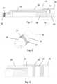
- FIG. 1shows a cross section of the injection device.
- FIG. 2shows a perspective view of an assembly of the housing.
- FIG. 3shows a cross sectional view of an alternatively assembly of the housing.
- FIG. 4shows a perspective view of an alternatively assembly of the housing.
- FIG. 5shows a perspective view of an alternatively assembly of the housing.
- FIG. 6shows a cross sectional view of the piston rod means prior to assembly.
- FIG. 7shows a cross sectional view of the piston rod means in one assembled position.
- FIG. 8shows a cross sectional view of the piston rod means in a different assembled position.
- FIG. 9shows a view of the piston rod means.
- FIG. 10show a cross section of the injection device during assembly.
- distal endin the appended figures is meant to refer to the end of the injection device carrying the injection needle whereas the term “proximal end” is meant to refer to the opposite end pointing away from the injection needle.
- FIG. 1discloses a pen shaped injection device 1 comprising a housing 10 formed from two parts 20 , 30 .
- a first part 20 holding the cartridge 40 and a second part 30comprising a dose setting and injection mechanism which comprises a piston rod means 50 .
- the cartridge 40 which contains the liquid medicament to be expelledis at a first end 41 provided with a membrane 42 which is pierceable by a not shown injection needle and a second end 43 which is locked by a movable plunger 44 .
- the piston rod means 50is moved forward into contact with the plunger 44 which it then continues to move forward thereby expelling the set dose through the injection needle.
- the first part 20is at its proximal end provided with a number of outwardly pointing ratchet teeth 21 which as disclosed in FIG. 2 can surround the entire periphery of the first part 20 .
- the second part 30is at its distal end provided with corresponding inwardly pointing ratchet teeth 31 .
- the teeth 21 , 31could be provided only on a part of the periphery.
- the outwardly pointing ratchet teeth 21engages the inwardly pointing ratchet teeth 31 on the second part 30 thereby preventing the two part 20 , 30 from being separated.
- the two parts 20 , 30can be variable adjusted relatively to each other such that the distance X between the piston rod means 50 and the plunger 44 can be minimized.
- the two parts 20 , 30can be irreversible locked to each other. This irreversible locking can be performed in a number of different ways.
- the two parts 20 , 30are permanently secured to each other by deforming zones 32 of the second part 30 .
- This deformationcan be done by pressure or by heat deformation.
- FIG. 3A solution based on a counter nut 60 is disclosed in FIG. 3 .
- the first part 20 and the second part 30is provided with engaging threads 22 , 33 such that the two parts 20 , 30 are moved closer to each other when rotated.
- the counter nut 60is screwed in the distal direction until it abuts the first part 20 thereby locking the two parts 20 , together.
- the first part 20is provided with a number of outwardly pointing protrusions 23 and the second part 30 is provided with a number of axially located ribs 34 .
- the protrusions 23penetrates through the ribs 34 as disclosed in the close-up figure, thereby locking the two parts 20 , 30 to each other.
- the first part 20is provided with an axially extending rib 24 which during assembly engages a longitudinal slit 35 in the second part.
- FIGS. 6 to 10disclose an alternative way of minimizing the distance between the piston rod means 150 and the plunger 144 .
- the piston rod means 150comprises a piston rod 160 and a piston rod foot 170 .
- the piston rod foot 170is provided with a number of resilient attaching wings 171 pointing in the proximal direction and the piston rod 160 is provided with a number of recesses 161 for receiving the attaching wings 171 .
- These recesses 161have a sloping configuration sloping towards the distal end of the piston rod 160 such that the piston rod foot 170 will slide in the proximal direction when the piston rod foot 170 is mounted on the piston rod 160 .
- piston rod 160is provided with a number of protrusions 162 engaging a number of barbs 172 on the piston rod foot 170 when it is in its most distal position thereby preventing the piston rod foot 170 from being automatically separated from the piston rod 160 .
- the cartridge holder 20 , 120could in all the embodiments be provided with an opening or window as indicated in FIGS. 4, 5 and 10 through which the liquid drug in the cartridge 40 , 140 can be viewed.
- the piston foot 170When an injection device is assembled the piston foot 170 is axially pushed onto the piston rod 160 as disclosed in FIGS. 6 to 9 . Once the correct relative position between the piston rod foot 170 and the piston rod 160 is obtained a laser beam 180 is directed towards the attaching wings 171 such that a melting zone 181 between the attaching wings 171 of the piston rod foot 170 and the recesses 161 of the piston rod 161 is obtained thereby melting the piston rod foot 170 and the piston rod 160 together.
- laser weldingis described in this application a number of alternative methods for attaching the two parts 160 , 170 can be used.
- the piston rod foot 170 and the piston rod 160could e.g. be attached to each other through a variable mechanical connection such as a threaded connection or a telescopic mechanism; alternatively the two parts 160 , 170 could be glued together in their final position.
- the usual procedure as disclosed in FIG. 10would be first to assemble the dose setting and injection mechanism, thereafter attaching the piston rod foot 170 on the piston rod 160 and finally to press the cartridge holder 120 with the cartridge 140 into the position in which the cartridge holder 120 locks to the main body 130 .
- the plunger 144 of the cartridge 140will then move the piston rod foot 170 in the proximal direction relatively to the piston rod 160 .
- the piston rod foot 170will abut the plunger 144 due the sloping interface between the piston rod foot 170 and the piston rod 160 .
Landscapes
- Health & Medical Sciences (AREA)
- Vascular Medicine (AREA)
- Engineering & Computer Science (AREA)
- Anesthesiology (AREA)
- Biomedical Technology (AREA)
- Heart & Thoracic Surgery (AREA)
- Hematology (AREA)
- Life Sciences & Earth Sciences (AREA)
- Animal Behavior & Ethology (AREA)
- General Health & Medical Sciences (AREA)
- Public Health (AREA)
- Veterinary Medicine (AREA)
- Infusion, Injection, And Reservoir Apparatuses (AREA)
Abstract
Description
- (i) Bringing the piston rod means in abutment with the plunger,
- (ii) Securing the first part of the housing and the second part of the housing in this position.
- (i) Bringing the piston rod means in abutment with the plunger,
- (ii) Securing the piston rod means in this position.
Claims (2)
Priority Applications (1)
| Application Number | Priority Date | Filing Date | Title |
|---|---|---|---|
| US12/865,048US11273261B2 (en) | 2008-01-28 | 2009-01-20 | Injection device for performing medical injections |
Applications Claiming Priority (6)
| Application Number | Priority Date | Filing Date | Title |
|---|---|---|---|
| EP08100987.0 | 2008-01-28 | ||
| EP08100987 | 2008-01-28 | ||
| EP08100987 | 2008-01-28 | ||
| US2709308P | 2008-02-08 | 2008-02-08 | |
| US12/865,048US11273261B2 (en) | 2008-01-28 | 2009-01-20 | Injection device for performing medical injections |
| PCT/EP2009/050590WO2009095332A1 (en) | 2008-01-28 | 2009-01-20 | Injection device for performing medical injections |
Publications (2)
| Publication Number | Publication Date |
|---|---|
| US20110046567A1 US20110046567A1 (en) | 2011-02-24 |
| US11273261B2true US11273261B2 (en) | 2022-03-15 |
Family
ID=39511120
Family Applications (1)
| Application Number | Title | Priority Date | Filing Date |
|---|---|---|---|
| US12/865,048Active2031-01-24US11273261B2 (en) | 2008-01-28 | 2009-01-20 | Injection device for performing medical injections |
Country Status (12)
| Country | Link |
|---|---|
| US (1) | US11273261B2 (en) |
| EP (2) | EP2703020B2 (en) |
| JP (2) | JP5905199B2 (en) |
| CN (2) | CN103212143B (en) |
| AU (1) | AU2009210184B2 (en) |
| BR (1) | BRPI0907110A2 (en) |
| CA (1) | CA2710819C (en) |
| DK (2) | DK2247327T3 (en) |
| ES (2) | ES2467103T3 (en) |
| PL (2) | PL2247327T3 (en) |
| RU (1) | RU2497550C2 (en) |
| WO (1) | WO2009095332A1 (en) |
Families Citing this family (31)
| Publication number | Priority date | Publication date | Assignee | Title |
|---|---|---|---|---|
| CN103212143B (en) | 2008-01-28 | 2016-02-17 | 诺沃—诺迪斯克有限公司 | For performing the injection device of medicine injection |
| RU2530661C2 (en) | 2009-04-30 | 2014-10-10 | Санофи-Авентис Дойчланд Гмбх | Axially regulated connection of piston rod with piston for drive mechanism of device for medicinal substance delivery |
| EP2482872B2 (en) | 2009-09-30 | 2019-12-11 | Sanofi-Aventis Deutschland GmbH | Method for assembling a drug delivery device, assembly for a drug delivery device and piston rod for a drug delivery device |
| JP2013506460A (en)* | 2009-09-30 | 2013-02-28 | サノフィ−アベンティス・ドイチュラント・ゲゼルシャフト・ミット・ベシュレンクテル・ハフツング | Methods and assemblies for drug delivery devices |
| US9358340B2 (en)* | 2009-09-30 | 2016-06-07 | Sanofi-Aventis Deutschland Gmbh | Method and assembly for a drug delivery device |
| BR112012007741A2 (en)* | 2009-10-08 | 2016-08-23 | Sanofi Aventis Deutschland | drive mechanism for drug delivery devices |
| EP2485789A1 (en)* | 2009-10-08 | 2012-08-15 | Sanofi-Aventis Deutschland GmbH | Drug delivery device with clearance compensation means |
| WO2011051365A2 (en) | 2009-10-30 | 2011-05-05 | Sanofi-Aventis Deutschland Gmbh | Drug delivery devices and method of assembly |
| ES2749395T3 (en) | 2009-11-20 | 2020-03-20 | Becton Dickinson Co | Injection device without the need for a gear |
| US8986259B2 (en)* | 2010-03-31 | 2015-03-24 | Sanofi-Aventis Deutschland Gmbh | Piston rod assembly for a drug delivery device |
| EP2468330A1 (en) | 2010-12-21 | 2012-06-27 | Sanofi-Aventis Deutschland GmbH | Auto-injector |
| EP3878495B1 (en) | 2011-03-16 | 2024-06-12 | Becton, Dickinson and Company | Multiple use disposable injection pen |
| US11577029B2 (en) | 2012-03-15 | 2023-02-14 | Becton, Dickinson And Company | Multiple use disposable injection pen |
| US12350474B2 (en) | 2011-03-16 | 2025-07-08 | Becton, Dickinson And Company | Multiple use disposable injection pen |
| WO2013045527A1 (en)* | 2011-09-29 | 2013-04-04 | Sanofi-Aventis Deutschland Gmbh | Drug delivery device and method for a drug delivery device |
| CN107787234B (en) | 2015-07-01 | 2021-03-12 | 诺和诺德股份有限公司 | Piston washer for a drug delivery device and drug delivery device incorporating such a piston washer |
| CN107787237B (en)* | 2015-07-01 | 2021-02-02 | 诺和诺德股份有限公司 | Drug delivery device |
| US10485927B2 (en) | 2015-07-01 | 2019-11-26 | Novo Nordisk A/S | Method for assembling a drug delivery device and drug delivery device formed by the method |
| JP6858758B2 (en)* | 2015-10-01 | 2021-04-14 | ノボ・ノルデイスク・エー/エス | Piston washer assembly, assembly method, and drug delivery device incorporating such a piston washer assembly |
| EP3368105B1 (en) | 2015-10-30 | 2020-07-01 | Novo Nordisk A/S | Method of manufacturing prefilled drug delivery devices |
| EP3175875A1 (en) | 2015-12-02 | 2017-06-07 | Novo Nordisk A/S | Method for assembling a drug delivery device and drug delivery device formed by the method |
| EP3202443A1 (en) | 2016-02-02 | 2017-08-09 | Novo Nordisk A/S | Piston washer for a drug delivery device, method of preparing such piston washer and method of assembly of a drug delivery device |
| US10549044B2 (en)* | 2016-06-09 | 2020-02-04 | Becton, Dickinson And Company | Spacer assembly for drug delivery system |
| CH712629A2 (en) | 2016-06-23 | 2017-12-29 | Tecpharma Licensing Ag | Cartridge receiving device for an administering device and method for assembling a carpule in a cartridge receiving device. |
| WO2018007623A1 (en) | 2016-07-08 | 2018-01-11 | Novo Nordisk A/S | Drug delivery device comprising an adjustment member |
| EP3694584A1 (en) | 2017-10-10 | 2020-08-19 | Novo Nordisk A/S | Prefilled drug delivery device with reduced air gap |
| JP7470682B2 (en)* | 2018-10-26 | 2024-04-18 | ノボ・ノルデイスク・エー/エス | Zeroing a prefilled drug delivery device |
| US20230008805A1 (en)* | 2019-12-18 | 2023-01-12 | Novo Nordisk A/S | An injection device for delivering a liquid drug |
| WO2021122221A1 (en) | 2019-12-18 | 2021-06-24 | Novo Nordisk A/S | Injection device for delivering a liquid drug and a method of assembly |
| CN114870160B (en)* | 2022-03-31 | 2024-05-31 | 宁波睿爱产品设计有限公司 | Injection syringe |
| EP4623962A1 (en) | 2024-03-28 | 2025-10-01 | Ypsomed AG | Injection device for administering a fluid product and method for assembling said device |
Citations (29)
| Publication number | Priority date | Publication date | Assignee | Title |
|---|---|---|---|---|
| GB806703A (en) | 1955-01-04 | 1958-12-31 | Cook Waite Lab Inc | Improvements in or relating to aspirating cartridge syringe |
| US3577980A (en) | 1968-05-28 | 1971-05-11 | Milton J Cohen | Fluid extraction device |
| US3941129A (en) | 1974-12-10 | 1976-03-02 | Pleznac Ida M | Quantity indicating injection device |
| US4883466A (en)* | 1988-04-25 | 1989-11-28 | Glazier Stephen C | Non-reusable syringe |
| US4973309A (en) | 1988-03-21 | 1990-11-27 | Microtechnic | Disposable syringe |
| US5114406A (en) | 1986-11-14 | 1992-05-19 | Wilhelm Haselmeier Gmbh & Co. | Injection device for injection, especially self-administered injection, of medicament, including mechanisms for nulling and for selecting dosage, especially for use with multi-dose ampules |
| DE19519147A1 (en) | 1994-05-30 | 1995-12-07 | Medico Dev Investment Co | Unit for injecting fluid into patient |
| WO1997010864A1 (en) | 1995-09-19 | 1997-03-27 | Becton Dickinson And Company | Pen injector with cartridge loading mechanism |
| US5695472A (en) | 1993-05-27 | 1997-12-09 | Washington Biotech Corporation | Modular automatic or manual emergency medicine injection system |
| WO1999016487A1 (en) | 1997-09-29 | 1999-04-08 | Becton Dickinson And Company | Disposable, pre-filled drug cartridge |
| RU2132704C1 (en) | 1993-03-15 | 1999-07-10 | Эли Лилли Энд Компани | Device for distribution of medicinal agents, injector construction, method of reduction of excess dose of measured product |
| US6004297A (en) | 1998-01-30 | 1999-12-21 | Novo Nordisk A/S | Injection syringe |
| EP1074273A1 (en) | 1999-08-06 | 2001-02-07 | Becton Dickinson and Company | Improved medication delivery pen |
| WO2001072357A2 (en) | 2000-03-29 | 2001-10-04 | Minimed, Inc. | Improved methods, apparatuses, and uses for infusion pump fluid pressure and force detection |
| WO2003008023A1 (en) | 2001-07-16 | 2003-01-30 | Eli Lilly And Company | Medication dispensing apparatus configured for rotate to prime and pull/push to inject functionality |
| US20040215153A1 (en) | 2001-07-30 | 2004-10-28 | Roney Graf | Latching block for connecting casing sections of an administering apparatus |
| JP2004535254A (en) | 2001-07-16 | 2004-11-25 | イーライ・リリー・アンド・カンパニー | Cartridge-free multiple dose injection device |
| WO2005018721A1 (en) | 2003-08-12 | 2005-03-03 | Eli Lilly And Company | Medication dispensing apparatus with triple screw threads for mechanical advantage |
| JP2005073985A (en) | 2003-09-01 | 2005-03-24 | Otsuka Pharmaceut Factory Inc | Prefilled syringe chemical solution administration device |
| WO2005044346A2 (en) | 2003-11-05 | 2005-05-19 | Tecpharma Licensing Ag | Device for the administration of an injectable product |
| WO2005097233A2 (en) | 2004-03-30 | 2005-10-20 | Eli Lilly And Company | Medication dispensing apparatus with spring-driven locking feature enabled by administration of final dose |
| WO2006074171A1 (en) | 2005-01-07 | 2006-07-13 | Becton, Dickinson And Company | Positive displacement flush syringe |
| US20060178634A1 (en) | 2004-12-06 | 2006-08-10 | Wyrick Ronald S | Medicine injection devices and methods |
| WO2007017051A1 (en) | 2005-07-25 | 2007-02-15 | Novo Nordisk A/S | A syringe device and a method of assembling the same |
| EP1776975A2 (en) | 2001-05-16 | 2007-04-25 | Eli Lilly & Company | Medication injector apparatus with drive assembly that facilitates reset |
| US20070191784A1 (en) | 2004-03-30 | 2007-08-16 | Jacobs Alexander T | Medication dispensing apparatus with gear set having drive member accommodating opening |
| WO2008003560A1 (en) | 2006-07-03 | 2008-01-10 | Novo Nordisk A/S | Coupling for injection devices |
| EP1911479A1 (en) | 2006-10-09 | 2008-04-16 | F.Hoffmann-La Roche Ag | Drug delivery device with magnetic connection between piston and piston rod |
| EP2247327A1 (en) | 2008-01-28 | 2010-11-10 | Novo Nordisk A/S | Injection device for performing medical injections |
Family Cites Families (1)
| Publication number | Priority date | Publication date | Assignee | Title |
|---|---|---|---|---|
| CN200963388Y (en)* | 2006-10-16 | 2007-10-24 | 陈庆强 | Anti-pollution sealed medicine adding syringe |
- 2009
- 2009-01-20CNCN201310088949.7Apatent/CN103212143B/enactiveActive
- 2009-01-20RURU2010133890/14Apatent/RU2497550C2/ennot_activeIP Right Cessation
- 2009-01-20WOPCT/EP2009/050590patent/WO2009095332A1/enactiveApplication Filing
- 2009-01-20ESES09706155.0Tpatent/ES2467103T3/enactiveActive
- 2009-01-20CACA2710819Apatent/CA2710819C/ennot_activeExpired - Fee Related
- 2009-01-20CNCN2009801033739Apatent/CN101925375B/enactiveActive
- 2009-01-20USUS12/865,048patent/US11273261B2/enactiveActive
- 2009-01-20BRBRPI0907110Apatent/BRPI0907110A2/ennot_activeIP Right Cessation
- 2009-01-20PLPL09706155Tpatent/PL2247327T3/enunknown
- 2009-01-20ESES13183809.6Tpatent/ES2531907T3/enactiveActive
- 2009-01-20JPJP2010544663Apatent/JP5905199B2/enactiveActive
- 2009-01-20EPEP13183809.6Apatent/EP2703020B2/enactiveActive
- 2009-01-20DKDK09706155.0Tpatent/DK2247327T3/enactive
- 2009-01-20PLPL13183809Tpatent/PL2703020T3/enunknown
- 2009-01-20EPEP09706155.0Apatent/EP2247327B1/enactiveActive
- 2009-01-20DKDK13183809Tpatent/DK2703020T3/enactive
- 2009-01-20AUAU2009210184Apatent/AU2009210184B2/ennot_activeCeased
- 2014
- 2014-06-12JPJP2014121110Apatent/JP6055440B2/enactiveActive
Patent Citations (34)
| Publication number | Priority date | Publication date | Assignee | Title |
|---|---|---|---|---|
| GB806703A (en) | 1955-01-04 | 1958-12-31 | Cook Waite Lab Inc | Improvements in or relating to aspirating cartridge syringe |
| US3577980A (en) | 1968-05-28 | 1971-05-11 | Milton J Cohen | Fluid extraction device |
| US3941129A (en) | 1974-12-10 | 1976-03-02 | Pleznac Ida M | Quantity indicating injection device |
| US5114406A (en) | 1986-11-14 | 1992-05-19 | Wilhelm Haselmeier Gmbh & Co. | Injection device for injection, especially self-administered injection, of medicament, including mechanisms for nulling and for selecting dosage, especially for use with multi-dose ampules |
| US4973309A (en) | 1988-03-21 | 1990-11-27 | Microtechnic | Disposable syringe |
| US4883466A (en)* | 1988-04-25 | 1989-11-28 | Glazier Stephen C | Non-reusable syringe |
| RU2132704C1 (en) | 1993-03-15 | 1999-07-10 | Эли Лилли Энд Компани | Device for distribution of medicinal agents, injector construction, method of reduction of excess dose of measured product |
| US5695472A (en) | 1993-05-27 | 1997-12-09 | Washington Biotech Corporation | Modular automatic or manual emergency medicine injection system |
| DE19519147A1 (en) | 1994-05-30 | 1995-12-07 | Medico Dev Investment Co | Unit for injecting fluid into patient |
| US6241709B1 (en) | 1994-05-30 | 2001-06-05 | B D Medico S.A.R.L. | Injection device |
| US5688251A (en)* | 1995-09-19 | 1997-11-18 | Becton Dickinson And Company | Cartridge loading and priming mechanism for a pen injector |
| WO1997010864A1 (en) | 1995-09-19 | 1997-03-27 | Becton Dickinson And Company | Pen injector with cartridge loading mechanism |
| WO1999016487A1 (en) | 1997-09-29 | 1999-04-08 | Becton Dickinson And Company | Disposable, pre-filled drug cartridge |
| US20030004466A1 (en) | 1997-09-29 | 2003-01-02 | Bitdinger Ralf V. | Disposable, pre-filled drug cartridge |
| US6004297A (en) | 1998-01-30 | 1999-12-21 | Novo Nordisk A/S | Injection syringe |
| EP1074273A1 (en) | 1999-08-06 | 2001-02-07 | Becton Dickinson and Company | Improved medication delivery pen |
| US6485465B2 (en) | 2000-03-29 | 2002-11-26 | Medtronic Minimed, Inc. | Methods, apparatuses, and uses for infusion pump fluid pressure and force detection |
| WO2001072357A2 (en) | 2000-03-29 | 2001-10-04 | Minimed, Inc. | Improved methods, apparatuses, and uses for infusion pump fluid pressure and force detection |
| EP1776975A2 (en) | 2001-05-16 | 2007-04-25 | Eli Lilly & Company | Medication injector apparatus with drive assembly that facilitates reset |
| WO2003008023A1 (en) | 2001-07-16 | 2003-01-30 | Eli Lilly And Company | Medication dispensing apparatus configured for rotate to prime and pull/push to inject functionality |
| JP2004535254A (en) | 2001-07-16 | 2004-11-25 | イーライ・リリー・アンド・カンパニー | Cartridge-free multiple dose injection device |
| US20040215153A1 (en) | 2001-07-30 | 2004-10-28 | Roney Graf | Latching block for connecting casing sections of an administering apparatus |
| WO2005018721A1 (en) | 2003-08-12 | 2005-03-03 | Eli Lilly And Company | Medication dispensing apparatus with triple screw threads for mechanical advantage |
| JP2007502146A (en) | 2003-08-12 | 2007-02-08 | イーライ リリー アンド カンパニー | Three-threaded drug delivery device for mechanical advantage |
| JP2005073985A (en) | 2003-09-01 | 2005-03-24 | Otsuka Pharmaceut Factory Inc | Prefilled syringe chemical solution administration device |
| WO2005044346A2 (en) | 2003-11-05 | 2005-05-19 | Tecpharma Licensing Ag | Device for the administration of an injectable product |
| WO2005097233A2 (en) | 2004-03-30 | 2005-10-20 | Eli Lilly And Company | Medication dispensing apparatus with spring-driven locking feature enabled by administration of final dose |
| US20070191784A1 (en) | 2004-03-30 | 2007-08-16 | Jacobs Alexander T | Medication dispensing apparatus with gear set having drive member accommodating opening |
| US20060178634A1 (en) | 2004-12-06 | 2006-08-10 | Wyrick Ronald S | Medicine injection devices and methods |
| WO2006074171A1 (en) | 2005-01-07 | 2006-07-13 | Becton, Dickinson And Company | Positive displacement flush syringe |
| WO2007017051A1 (en) | 2005-07-25 | 2007-02-15 | Novo Nordisk A/S | A syringe device and a method of assembling the same |
| WO2008003560A1 (en) | 2006-07-03 | 2008-01-10 | Novo Nordisk A/S | Coupling for injection devices |
| EP1911479A1 (en) | 2006-10-09 | 2008-04-16 | F.Hoffmann-La Roche Ag | Drug delivery device with magnetic connection between piston and piston rod |
| EP2247327A1 (en) | 2008-01-28 | 2010-11-10 | Novo Nordisk A/S | Injection device for performing medical injections |
Non-Patent Citations (2)
| Title |
|---|
| European Patent Application EP08100987.0, filed Jan. 28, 2008. |
| Webster's New World College Dictionary Fourth Edition 2001, Michael Agnes, Editor in Chief, Embed Definition. pp. 1-3. |
Also Published As
| Publication number | Publication date |
|---|---|
| JP2011510717A (en) | 2011-04-07 |
| CA2710819C (en) | 2016-06-21 |
| DK2247327T3 (en) | 2014-06-10 |
| WO2009095332A1 (en) | 2009-08-06 |
| AU2009210184A1 (en) | 2009-08-06 |
| RU2010133890A (en) | 2012-03-10 |
| EP2703020B1 (en) | 2014-12-17 |
| CA2710819A1 (en) | 2009-08-06 |
| EP2703020B2 (en) | 2018-05-02 |
| DK2703020T3 (en) | 2015-03-23 |
| BRPI0907110A2 (en) | 2019-09-24 |
| JP6055440B2 (en) | 2016-12-27 |
| RU2497550C2 (en) | 2013-11-10 |
| CN103212143A (en) | 2013-07-24 |
| PL2703020T3 (en) | 2015-05-29 |
| CN103212143B (en) | 2016-02-17 |
| CN101925375B (en) | 2013-04-24 |
| EP2703020A1 (en) | 2014-03-05 |
| AU2009210184B2 (en) | 2014-04-03 |
| ES2531907T3 (en) | 2015-03-20 |
| CN101925375A (en) | 2010-12-22 |
| EP2247327B1 (en) | 2014-03-12 |
| JP5905199B2 (en) | 2016-04-20 |
| JP2014221278A (en) | 2014-11-27 |
| US20110046567A1 (en) | 2011-02-24 |
| PL2247327T3 (en) | 2014-08-29 |
| EP2247327A1 (en) | 2010-11-10 |
| ES2467103T3 (en) | 2014-06-11 |
Similar Documents
| Publication | Publication Date | Title |
|---|---|---|
| US11273261B2 (en) | Injection device for performing medical injections | |
| US8574199B2 (en) | Coupling for injection devices | |
| EP3378507B1 (en) | Injection device with a needle cannula | |
| EP2593162B1 (en) | A piston rod foot | |
| US20220409820A1 (en) | An injection device for delivering a predefined plurality of predetermined dose volumes | |
| WO2015117854A1 (en) | A cartridge and needle assembly in combination | |
| US20230008805A1 (en) | An injection device for delivering a liquid drug | |
| US20190262533A1 (en) | Injection device with a needle cannula | |
| CN104185489B (en) | end of dose indicator | |
| CN107787234B (en) | Piston washer for a drug delivery device and drug delivery device incorporating such a piston washer | |
| US20160361505A1 (en) | An Injection Apparatus | |
| US12337157B2 (en) | Injection device for delivering a liquid drug and a method of assembly |
Legal Events
| Date | Code | Title | Description |
|---|---|---|---|
| AS | Assignment | Owner name:NOVO NORDISK A/S, DENMARK Free format text:ASSIGNMENT OF ASSIGNORS INTEREST;ASSIGNORS:RADMER, BO;WIELANDT, JAKOB OEST;JESPERSEN, FRANK ANDREAS;AND OTHERS;SIGNING DATES FROM 20100806 TO 20100811;REEL/FRAME:025398/0516 | |
| STPP | Information on status: patent application and granting procedure in general | Free format text:FINAL REJECTION MAILED | |
| STPP | Information on status: patent application and granting procedure in general | Free format text:NON FINAL ACTION MAILED | |
| STCV | Information on status: appeal procedure | Free format text:NOTICE OF APPEAL FILED | |
| STCV | Information on status: appeal procedure | Free format text:APPEAL BRIEF (OR SUPPLEMENTAL BRIEF) ENTERED AND FORWARDED TO EXAMINER | |
| STCV | Information on status: appeal procedure | Free format text:EXAMINER'S ANSWER TO APPEAL BRIEF MAILED | |
| STCV | Information on status: appeal procedure | Free format text:ON APPEAL -- AWAITING DECISION BY THE BOARD OF APPEALS | |
| STCV | Information on status: appeal procedure | Free format text:BOARD OF APPEALS DECISION RENDERED | |
| STPP | Information on status: patent application and granting procedure in general | Free format text:NOTICE OF ALLOWANCE MAILED -- APPLICATION RECEIVED IN OFFICE OF PUBLICATIONS | |
| STCF | Information on status: patent grant | Free format text:PATENTED CASE | |
| CC | Certificate of correction | ||
| MAFP | Maintenance fee payment | Free format text:PAYMENT OF MAINTENANCE FEE, 4TH YEAR, LARGE ENTITY (ORIGINAL EVENT CODE: M1551); ENTITY STATUS OF PATENT OWNER: LARGE ENTITY Year of fee payment:4 |