US11273255B2 - Helical insertion infusion device - Google Patents
Helical insertion infusion deviceDownload PDFInfo
- Publication number
- US11273255B2 US11273255B2US16/433,884US201916433884AUS11273255B2US 11273255 B2US11273255 B2US 11273255B2US 201916433884 AUS201916433884 AUS 201916433884AUS 11273255 B2US11273255 B2US 11273255B2
- Authority
- US
- United States
- Prior art keywords
- cannula
- assembly
- user
- stylet
- base assembly
- Prior art date
- Legal status (The legal status is an assumption and is not a legal conclusion. Google has not performed a legal analysis and makes no representation as to the accuracy of the status listed.)
- Active, expires
Links
Images


Classifications
- A—HUMAN NECESSITIES
- A61—MEDICAL OR VETERINARY SCIENCE; HYGIENE
- A61M—DEVICES FOR INTRODUCING MEDIA INTO, OR ONTO, THE BODY; DEVICES FOR TRANSDUCING BODY MEDIA OR FOR TAKING MEDIA FROM THE BODY; DEVICES FOR PRODUCING OR ENDING SLEEP OR STUPOR
- A61M5/00—Devices for bringing media into the body in a subcutaneous, intra-vascular or intramuscular way; Accessories therefor, e.g. filling or cleaning devices, arm-rests
- A61M5/14—Infusion devices, e.g. infusing by gravity; Blood infusion; Accessories therefor
- A61M5/142—Pressure infusion, e.g. using pumps
- A61M5/14244—Pressure infusion, e.g. using pumps adapted to be carried by the patient, e.g. portable on the body
- A61M5/14248—Pressure infusion, e.g. using pumps adapted to be carried by the patient, e.g. portable on the body of the skin patch type
- A—HUMAN NECESSITIES
- A61—MEDICAL OR VETERINARY SCIENCE; HYGIENE
- A61M—DEVICES FOR INTRODUCING MEDIA INTO, OR ONTO, THE BODY; DEVICES FOR TRANSDUCING BODY MEDIA OR FOR TAKING MEDIA FROM THE BODY; DEVICES FOR PRODUCING OR ENDING SLEEP OR STUPOR
- A61M25/00—Catheters; Hollow probes
- A61M25/01—Introducing, guiding, advancing, emplacing or holding catheters
- A61M25/06—Body-piercing guide needles or the like
- A—HUMAN NECESSITIES
- A61—MEDICAL OR VETERINARY SCIENCE; HYGIENE
- A61M—DEVICES FOR INTRODUCING MEDIA INTO, OR ONTO, THE BODY; DEVICES FOR TRANSDUCING BODY MEDIA OR FOR TAKING MEDIA FROM THE BODY; DEVICES FOR PRODUCING OR ENDING SLEEP OR STUPOR
- A61M5/00—Devices for bringing media into the body in a subcutaneous, intra-vascular or intramuscular way; Accessories therefor, e.g. filling or cleaning devices, arm-rests
- A61M5/14—Infusion devices, e.g. infusing by gravity; Blood infusion; Accessories therefor
- A61M5/158—Needles for infusions; Accessories therefor, e.g. for inserting infusion needles, or for holding them on the body
- A—HUMAN NECESSITIES
- A61—MEDICAL OR VETERINARY SCIENCE; HYGIENE
- A61M—DEVICES FOR INTRODUCING MEDIA INTO, OR ONTO, THE BODY; DEVICES FOR TRANSDUCING BODY MEDIA OR FOR TAKING MEDIA FROM THE BODY; DEVICES FOR PRODUCING OR ENDING SLEEP OR STUPOR
- A61M5/00—Devices for bringing media into the body in a subcutaneous, intra-vascular or intramuscular way; Accessories therefor, e.g. filling or cleaning devices, arm-rests
- A61M5/178—Syringes
- A61M5/31—Details
- A61M5/32—Needles; Details of needles pertaining to their connection with syringe or hub; Accessories for bringing the needle into, or holding the needle on, the body; Devices for protection of needles
- A61M5/3287—Accessories for bringing the needle into the body; Automatic needle insertion
- A—HUMAN NECESSITIES
- A61—MEDICAL OR VETERINARY SCIENCE; HYGIENE
- A61M—DEVICES FOR INTRODUCING MEDIA INTO, OR ONTO, THE BODY; DEVICES FOR TRANSDUCING BODY MEDIA OR FOR TAKING MEDIA FROM THE BODY; DEVICES FOR PRODUCING OR ENDING SLEEP OR STUPOR
- A61M5/00—Devices for bringing media into the body in a subcutaneous, intra-vascular or intramuscular way; Accessories therefor, e.g. filling or cleaning devices, arm-rests
- A61M5/14—Infusion devices, e.g. infusing by gravity; Blood infusion; Accessories therefor
- A61M5/142—Pressure infusion, e.g. using pumps
- A61M5/14244—Pressure infusion, e.g. using pumps adapted to be carried by the patient, e.g. portable on the body
- A61M5/14248—Pressure infusion, e.g. using pumps adapted to be carried by the patient, e.g. portable on the body of the skin patch type
- A61M2005/14252—Pressure infusion, e.g. using pumps adapted to be carried by the patient, e.g. portable on the body of the skin patch type with needle insertion means
- A—HUMAN NECESSITIES
- A61—MEDICAL OR VETERINARY SCIENCE; HYGIENE
- A61M—DEVICES FOR INTRODUCING MEDIA INTO, OR ONTO, THE BODY; DEVICES FOR TRANSDUCING BODY MEDIA OR FOR TAKING MEDIA FROM THE BODY; DEVICES FOR PRODUCING OR ENDING SLEEP OR STUPOR
- A61M5/00—Devices for bringing media into the body in a subcutaneous, intra-vascular or intramuscular way; Accessories therefor, e.g. filling or cleaning devices, arm-rests
- A61M5/14—Infusion devices, e.g. infusing by gravity; Blood infusion; Accessories therefor
- A61M5/142—Pressure infusion, e.g. using pumps
- A61M5/14244—Pressure infusion, e.g. using pumps adapted to be carried by the patient, e.g. portable on the body
- A61M5/14248—Pressure infusion, e.g. using pumps adapted to be carried by the patient, e.g. portable on the body of the skin patch type
- A61M2005/1426—Pressure infusion, e.g. using pumps adapted to be carried by the patient, e.g. portable on the body of the skin patch type with means for preventing access to the needle after use
- A—HUMAN NECESSITIES
- A61—MEDICAL OR VETERINARY SCIENCE; HYGIENE
- A61M—DEVICES FOR INTRODUCING MEDIA INTO, OR ONTO, THE BODY; DEVICES FOR TRANSDUCING BODY MEDIA OR FOR TAKING MEDIA FROM THE BODY; DEVICES FOR PRODUCING OR ENDING SLEEP OR STUPOR
- A61M5/00—Devices for bringing media into the body in a subcutaneous, intra-vascular or intramuscular way; Accessories therefor, e.g. filling or cleaning devices, arm-rests
- A61M5/14—Infusion devices, e.g. infusing by gravity; Blood infusion; Accessories therefor
- A61M5/158—Needles for infusions; Accessories therefor, e.g. for inserting infusion needles, or for holding them on the body
- A61M2005/1581—Right-angle needle-type devices
- A—HUMAN NECESSITIES
- A61—MEDICAL OR VETERINARY SCIENCE; HYGIENE
- A61M—DEVICES FOR INTRODUCING MEDIA INTO, OR ONTO, THE BODY; DEVICES FOR TRANSDUCING BODY MEDIA OR FOR TAKING MEDIA FROM THE BODY; DEVICES FOR PRODUCING OR ENDING SLEEP OR STUPOR
- A61M5/00—Devices for bringing media into the body in a subcutaneous, intra-vascular or intramuscular way; Accessories therefor, e.g. filling or cleaning devices, arm-rests
- A61M5/14—Infusion devices, e.g. infusing by gravity; Blood infusion; Accessories therefor
- A61M5/158—Needles for infusions; Accessories therefor, e.g. for inserting infusion needles, or for holding them on the body
- A61M2005/1583—Needle extractors
- A—HUMAN NECESSITIES
- A61—MEDICAL OR VETERINARY SCIENCE; HYGIENE
- A61M—DEVICES FOR INTRODUCING MEDIA INTO, OR ONTO, THE BODY; DEVICES FOR TRANSDUCING BODY MEDIA OR FOR TAKING MEDIA FROM THE BODY; DEVICES FOR PRODUCING OR ENDING SLEEP OR STUPOR
- A61M5/00—Devices for bringing media into the body in a subcutaneous, intra-vascular or intramuscular way; Accessories therefor, e.g. filling or cleaning devices, arm-rests
- A61M5/14—Infusion devices, e.g. infusing by gravity; Blood infusion; Accessories therefor
- A61M5/158—Needles for infusions; Accessories therefor, e.g. for inserting infusion needles, or for holding them on the body
- A61M2005/1585—Needle inserters
- A—HUMAN NECESSITIES
- A61—MEDICAL OR VETERINARY SCIENCE; HYGIENE
- A61M—DEVICES FOR INTRODUCING MEDIA INTO, OR ONTO, THE BODY; DEVICES FOR TRANSDUCING BODY MEDIA OR FOR TAKING MEDIA FROM THE BODY; DEVICES FOR PRODUCING OR ENDING SLEEP OR STUPOR
- A61M5/00—Devices for bringing media into the body in a subcutaneous, intra-vascular or intramuscular way; Accessories therefor, e.g. filling or cleaning devices, arm-rests
- A61M5/14—Infusion devices, e.g. infusing by gravity; Blood infusion; Accessories therefor
- A61M5/158—Needles for infusions; Accessories therefor, e.g. for inserting infusion needles, or for holding them on the body
- A61M2005/1586—Holding accessories for holding infusion needles on the body
Definitions
- Described hereinare devices for delivering therapeutic fluids, and more particularly small, disposable, portable infusion devices and methods that can be used to transcutaneously deliver fluids safely and simply to a patient.
- parenteral deliveryof drugs in liquid form is often desired to enhance the effect of the substance being delivered, insuring that the unaltered medicine reaches its intended site at a significant concentration. Moreover, undesired side effects associated with other routes of delivery, such as systemic toxicity, can potentially be avoided by parenteral delivery. Further, many medicines are only available in liquid form, and/or the liquid may have desirable characteristics that cannot be achieved with solid or pill form. Delivery of liquid medicines may best be accomplished by infusing directly into the cardiovascular system via veins or arteries, into the subcutaneous tissue, or directly into organs, tumors, cavities, bones, or other site-specific locations within the body.
- Ambulatory infusion pumpshave been developed for delivering liquid medicaments to a patient. These infusion devices have the ability to offer sophisticated fluid delivery profiles that can provide bolus delivery, continuous infusion, and variable flow rate delivery. Ambulatory infusion pumps, however, can be problematic, as the user is generally forced to choose between a soft delivery cannula, which tends to have high initial failure rates and is prone to kinking, or a steel needle set, which has a lower initial failure rate but is associated with increased pain and shortened time of use.
- infusion setswhich are easiest to insert, are also associated with the highest rates of failure, partially due to needle breakage and/or fluid leaking out of the relatively short insertion path.
- infusion sets with a soft cannulatend to be harder to insert and/or are associated with increased apprehension/intimidation.
- a necessary and important step in preparing an infusion set for useis filling the tubing with liquid medicament, such as insulin to be delivered to a person with diabetes.
- liquid medicamentsuch as insulin to be delivered to a person with diabetes.
- Thisis often done by attaching the infusion set tubing to either the insulin pump reservoir or the insulin pump reservoir adaptor (e.g., a device that holds the reservoir into the pump).
- the pumpis then programmed to fill the tubing with insulin. This is not an automatic process.
- the useris typically either asked to hold down a button until the tubing is filled or to program an amount believed to be sufficient to fill the tubing.
- the useris instructed not to move on to another step until they observe insulin drops exiting the distal end of the tubing to infusion site connection or the distal end of the infusion cannula. The observation confirms that the tubing has been filled.
- Tube fillingcarries two risk cases.
- the first risk caseis when the user attempts to fill the tube and makes the mistake of connecting the tube to an infusion set that has already been inserted into their body. This would prevent the user from knowing when the tube had been completely filled and would result in any excess insulin delivered in an attempt to fill the tube to be delivered to the pump user, resulting in an over delivery. Over delivery carries with it a significant risk of hypoglycemia (low blood glucose levels).
- the second risk caseis incomplete filling of the tubing. Failure to completely fill the tubing can lead to under delivery of insulin. This in turn can lead to hyperglycemia (elevated glucose levels).
- the amount of missed insulin (10 to 15 units)can be approximately 25 to 50% of a typical pump user's daily dose ( ⁇ 42 units) but could exceed the total daily dose of a pump user with higher than typical insulin sensitivity.
- the missed insulin associated with a non-filled or partially filled tubecauses a significant health risk to the pump user. Filling the tubing is not an easy task, especially for those with any macular degeneration, as is often associated with diabetes progression.
- an ambulatory infusion pump setthat is efficient, safe, effective, easy to insert into a patient, and easy/safe to fill is desired.
- a device for delivering fluid to a patientincludes a housing assembly, a subcutaneous infusion cannula assembly extending from the housing, an insertion mechanism, and a fluid connection port.
- the insertion mechanismis configured to extend the infusion cannula in a helical path from the housing assembly.
- the fluid connection portis configured to connect the device to a source of delivery fluid.
- the infusion cannulacan have a pre-set curved shape.
- the devicecan further include a sharp inner stylet configured to extend through the infusion cannula.
- the sharp inner styletcan have a pre-set curved shape.
- the insertion mechanismcan further include mechanical features to define or limit the depth of extension of the infusion cannula from the housing assembly.
- the insertion mechanismcan further include a rotational drive mechanism configured to rotate the infusion cannula as the cannula is extended from the housing assembly.
- the rotational drive mechanismcan be a spring.
- the housingcan include an adhesive on at least one surface thereof configured to attach the device to skin of the patient.
- the subcutaneous infusion cannulacan be flexible.
- the cannulacan include an outer tube and an inner reinforcement coil.
- the cannulacan include two or more fluid exit holes at or near the distal end thereof.
- the insertion mechanismcan include an automatic retraction mechanism for moving the stylet from the advanced position to the retracted position on completion of the insertion cycle.
- the housing assemblycan contain a releasable fluid interconnect assembly to connect the subcutaneous cannula assembly to the source of fluid.
- a system for delivering fluid to a user transcutaneouslyincludes a subcutaneous infusion cannula base assembly, a cannula inserter assembly and a fluid connection assembly.
- the subcutaneous infusion cannula base assemblyis configured to be located on the user's skin.
- the cannula inserter assemblyis coupled to the cannula base assembly and is configured to drive an infusion cannula through the user's skin in a nominally helical trajectory.
- the fluid connection assemblyis configured to fluidically connect the cannula base assembly to a source of delivery fluid.
- the inserter assemblyis removably coupled to the cannula base assembly.
- the systemmay further comprise a sharp inner stylet configured to extend through the infusion cannula.
- the sharp inner styletmay have a pre-set curved shape.
- the cannula base assemblyincludes an adhesive on at least one surface thereof configured to attach the cannula base assembly to the user's skin.
- the subcutaneous infusion cannulais flexible.
- the cannulamay include an outer tube and an inner reinforcement coil.
- the cannulaincludes two or more fluid exit holes at or near the distal end thereof.
- the inserter assemblyincludes an automatic retraction mechanism configured to move the stylet from an advanced position to a retracted position after completion of a cannula insertion cycle.
- the inserter assemblymay also include an automatic release mechanism configured to decouple the inserter assembly from the cannula base assembly after completion of a stylet retraction cycle.
- the inserter assemblymay be configured to automatically perform the cannula insertion cycle, the stylet retraction cycle and a release cycle in succession after a single trigger event without further interaction from the user.
- the inserter assemblyincludes a single drive spring configured to supply all energy required to drive the cannula insertion cycle, the stylet retraction cycle and the release cycle.
- the systemmay further comprise packaging for enclosing at least the inserter assembly before use.
- the inserter assemblymay include at least one drive spring, and the inserter assembly may be configured to automatically charge the drive spring as the packaging is being opened.
- the fluid connection assembly of the infusion systemincludes tubing and an element or assembly that changes color when the tubing has been primed with fluid.
- the fluid connection assemblymay include a releasable fluid interconnect assembly configured to releasably connect the cannula base assembly to the source of delivery fluid, and the source of delivery fluid may be external to the cannula base assembly.
- the releasable fluid interconnect assemblymay include a needle and a septum, and the fluid interconnect assembly may be configured to insert an end of the needle through the septum after a cannula stylet is withdrawn from the septum.
- a system for delivering fluid to a user transcutaneouslyincludes a subcutaneous infusion cannula base assembly, a cannula inserter assembly and a fluid connection assembly.
- the cannula base assemblyis configured to be located on the user's skin and includes an infusion cannula having a central lumen therethrough.
- the cannulaincludes a reinforcing coil extending along a portion of the central lumen. The coil has at least two different pitches along its length.
- the cannula inserter assemblyis coupled to the cannula base assembly and includes a sharp stylet configured to pass through the central lumen of the cannula.
- the inserter assemblyis configured to drive the stylet and infusion cannula together through the user's skin without a needle placed over the cannula.
- the fluid connection assemblyis configured to fluidically connect the cannula base assembly to a source of delivery fluid.
- the reinforcing coilhas a first section with a first coil pitch and a second section with a second coil pitch, the first section being located more distally in the cannula than the second section.
- the first coil pitchis greater than the second coil pitch.
- the first coil pitchis an open pitch and the second coil pitch is a closed pitch.
- the first sectionincludes a plurality of holes though a side wall of the cannula.
- the inserter assemblymay be configured to drive the stylet and infusion cannula together through the user's skin at a 90 degree angle.
- the inserter assemblymay be configured to drive the stylet and infusion cannula together through the user's skin at an angle of less than 45 degrees.
- a system for delivering fluid to a user transcutaneouslyincludes a subcutaneous infusion cannula base assembly, a cannula inserter assembly and a fluid connection assembly.
- the cannula base assemblyis configured to be located on the user's skin and includes an infusion cannula formed from a polyether block amide thermoplastic elastomer having a central lumen therethrough.
- the cannulahas a nominal outside diameter no greater than 0.56 mm.
- the cannulaincludes a reinforcing coil extending along a portion of the central lumen.
- the reinforcing coilhas a nominal inside diameter and a nominal outside diameter. The nominal outside diameter is the same as a nominal inside diameter of the central lumen it resides in.
- the reinforcing coilhas a first section with a first coil pitch and a second section with a second coil pitch.
- the first coil sectionis located more distally in the cannula than the second section.
- the first coil pitchis an open pitch and the second coil pitch is a closed pitch.
- the first sectionincludes a plurality of holes though a side wall of the cannula.
- the cannulaincludes a distalmost section having an outer taper of between 10 and 30 degrees and no reinforcing coil located in the distalmost section. A portion of the cannula is siliconized to reduce insertion force.
- the cannula inserter assemblyis coupled to the cannula base assembly and includes a sharp stylet configured to pass through the central lumen of the cannula.
- the stylethas a nominal outside diameter that is the same as the nominal inside diameter of the reinforcing coil.
- the stylethas a sharpened distal tip that extends from the distalmost section of the cannula.
- the inserter assemblyis configured to drive the stylet and cannula together through the user's skin without a needle placed over the cannula.
- the fluid connection assemblyis configured to fluidically connect the cannula base assembly to a source of delivery fluid.
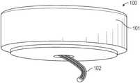
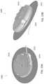
- FIG. 1Ashows an exemplary infusion device.
- FIG. 1Bshows an exemplary cannula for use with the infusion device of FIG. 1A .
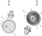
- FIG. 2Ashows the bottom surface of another exemplary infusion device.
- FIG. 2Bshows a cannula release mechanism that can be positioned within the infusion device of FIG. 2A .
- FIG. 3Ashows another exemplary infusion device.
- FIG. 3Bshows a cannula release mechanism of the infusion device of FIG. 3A .
- FIG. 3Cis a cross section of the infusion device of FIG. 3A .
- FIG. 3Dshows the top of an infusion device of FIG. 3A .
- FIG. 3Eis a cross section of the infusion device of FIG. 3A .
- FIG. 3Fshows the top of the infusion device of FIG. 3A with the cover removed.
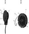
- FIG. 4Ashows an exemplary external insertion device.
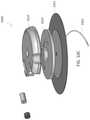
- FIG. 4Bis an exploded view of the external insertion device of FIG. 4A .
- FIG. 4Cis a cross section of the external insertion device of FIG. 4A .
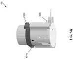
- FIG. 5Ashows an external insertion device mated with an infusion device.
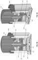
- FIGS. 5B and 5Care cross-sections of FIG. 5A taken along a vertical plane.
- FIGS. 5D and 5Eare cross-sections of FIG. 5A taken along a horizontal plane.
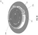
- FIGS. 6A-6Dshow an exemplary cannula for use with the infusion devices described herein.
- FIG. 7Ashows a cannula with a stylet extending therethrough.
- FIG. 7Bshows the stylet retracted.
- FIG. 8shows an exemplary distal tip of a cannula.
- FIGS. 9A-9Cshow an infusion device and an external inserter combined in a single packaging element.
- FIGS. 10A-10Eshow another exemplary infusion device.
- FIG. 11is a perspective view showing the outer packaging for an exemplary transcutaneous infusion system.
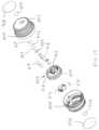
- FIG. 12is an exploded view showing the infusion system of FIG. 11 with the packaging opened and the inserter assembly removed.
- FIG. 13is an exploded top view showing the components of the infusion system of FIG. 11 without the inserter assembly.
- FIG. 14is an exploded bottom view showing the components of the infusion system of FIG. 11 without the inserter assembly.
- FIG. 15is a top view showing the inside of the packaging jar of the infusion system of FIG. 11 .
- FIG. 16is a bottom view showing the inside of the packaging lid of the infusion system of FIG. 11 .
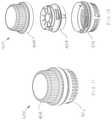
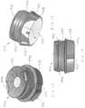
- FIG. 17is a top perspective view showing the inserter assembly of the infusion system of FIG. 11 .
- FIG. 18is a bottom perspective view showing the inserter assembly of the infusion system of FIG. 11 .
- FIG. 19is a side view showing the inserter assembly of the infusion system of FIG. 11 .
- FIG. 20is a top exploded view showing the components of the inserter assembly of the infusion system of FIG. 11 .
- FIG. 21is a bottom exploded view showing the components of the inserter assembly of the infusion system of FIG. 11 .
- FIG. 22is a cross-sectional view taken through the release buttons of the inserter assembly of the infusion system of FIG. 11 .
- FIG. 23is a cross-sectional view taken between the release buttons of the inserter assembly of the infusion system of FIG. 11 .
- FIGS. 24A-24Pare a series of views of the base assembly of the infusion system of FIG. 11 showing a sequence of events starting with the base assembly first being attached to the user's skin and through use of the infusion system.
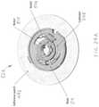
- FIG. 25Ais a fragmentary top view in partial cross-section showing the cannula of the infusion system of FIG. 11 .
- FIG. 25Bis a fragmentary side view of the cannula shown in FIG. 25A .
- FIG. 25Cis an enlarged view of the distal tip of the cannula shown in FIG. 25A .
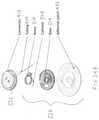
- FIG. 26Ais a top plan view showing the stylet of the infusion system of FIG. 11 .
- FIG. 26Bis a fragmentary side view showing the distal and proximal ends of the stylet shown in FIG. 26A .
- FIG. 26Cis a fragmentary side view showing the distal and proximal ends of the cannula shown in FIGS. 25A-25C assembled with the stylet shown in FIGS. 26A and 26B .
- FIGS. 27A and 27Bare graphs showing results of lateral stiffness tests performed on the cannula of FIGS. 25A-25C and the cannula and stylet assembly of FIG. 26C , respectively.
- FIGS. 28A and 28Bare graphs showing results of insertion force tests performed on the cannula and stylet assembly of FIG. 26C .
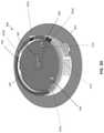
- FIG. 29Ais a bottom view showing the base assembly of the infusion system of FIG. 11 .
- FIG. 29Bis a table and diagram showing the trigonometric relationships between parameters of the cannula of the infusion system of FIG. 11 .
- the in-dwelling infusion devicesmay include a multi-orifice soft cannula and a user-depth controlled curved insertion cannula that provides for a spiral or helical insertion path through the tissue.
- an exemplary infusion device 100includes a housing assembly 101 , a hollow curved cannula 102 , and a driver to which the hollow curved cannula 102 is attached.
- the driverrotates the hollow curved cannula 102 and simultaneously translates the hollow curved cannula 102 into the soft tissue.
- the device 100is configured to insert the curved cannula 102 spirally or helically into soft tissue, thereby better fixing the cannula 102 in the soft tissue.
- the infusion device 100can be configured to interface with an infusion pump.
- the hollow curved cannula 102can be a 24 Ga catheter (0.56 m outer diameter) made of a polymer-coated stainless steel coil. In other embodiments, the cannula 102 can be made entirely of metal, e.g., stainless steel.
- the curved shapecan, for example, be heat set into the cannula 102 .
- the curved shape of the cannula 102can, for example, have a radius of curvature of between 0.5 inches and 1.25 inches. Further, the curved shape of the cannula 102 can have a pitch, for example, of between 10 mm and 30 mm. In some embodiments, the cannula 102 can end in a sharpened tip.
- the hollow curved cannula 102can further include a series of perforations, including one or more fluid exit holes 111 along the length thereof in a variety of patterns. Further, the hollow curved cannula 102 , due to its curvature, can be inserted at a 30°-60° angle relative to the plane of the skin surface in a spiral or helical path that accommodates target insertion depths ranging from 6 to 10 mm. Further, in some embodiments, the curve of the hollow curved cannula can provide for a 1-3 cm diameter insertion path.
- the infusion device 200includes a housing 201 .
- the underside 221 of the housingcan be flexible and include an adhesive thereon for attachment to the skin.
- a release mechanism 210can be positioned inside the housing 201 ( FIG. 2B shows the housing removed for clarity). Further, the release mechanism 210 can include an rotatable disk 222 and an inner disk 224 that are rotatable with respect to one another.
- the cannula 202can extend from the outer disk 222 and can be wound or curled up within the inner radius of the outer disk 222 .
- the inner disk 224can be fixed relative to the housing 201 .
- a coiled or torsion spring 229can be positioned within the release mechanism 210 and attached to both the inner disk 224 and the outer disk 222 . Further, the spring 229 can be held in a loaded position when the cannula 202 is wound and positioned within the housing 201 . Upon release of the spring 229 (e.g., by a user-activated button), the outer disk 222 can rotate relative to the inner disk 224 , thereby causing the cannula 202 to rotate relative to the housing 201 .
- the cannula 202As the cannula 202 rotates, it can extend from an aperture 211 on the bottom surface 221 of the housing 201 , thereby allowing the sharp tip of the cannula 202 to pierce the skin and extend in a spiral or helical path through the subcutaneous tissue.
- a second coiled spring 218 within the release mechanism 210can be loaded so as to rotate the outer disk 222 in the opposite direction relative to the inner disk 224 when released (e.g., by a user-activated button), thereby permitting the cannula 202 to be retracted into the housing 201 by the user as desired.
- FIGS. 3A-3EAnother similar infusion device 300 is shown in FIGS. 3A-3E .
- device 300is intended to be used with a separate external insertion device.
- the infusion device 300includes a housing 301 configured to house a release mechanism 310 and a curved cannula 302 .
- release mechanism 310can include two disks 324 , 322 that are rotatable relative to one another to allow the curved cannula 302 (fixed relative to the outer disk 322 ) to rotate and extend through the aperture 311 on the bottom surface 321 of the housing 301 . This rotation can be activated, for example, through an external device such as that shown and described with respect to FIGS. 4A-4C .
- the release mechanism 310can include a second spring (see FIG. 3F ) configured to retract the cannula 302 when released.
- the underside 321 of the housing 301can be flexible and include an adhesive thereon for attachment to the skin.
- a fluid inlet 397can provide delivery fluid to the needle 302 (e.g., through a detachable fluid connection 323 ).
- the fluid inlet 397can be fixed to the stationary inner disk 324 , thereby maintaining a fixed position relative to the fluid reservoir.
- an insertion device 433can be configured to be used with the infusion devices (such as device 300 ) described herein.
- the insertion device 433can separately house the torsion spring 429 and a rotatable portion 454 .
- Buttons 439 a,bcan allow the user to release the spring 429 to provide rotation of the rotatable portion 454 .
- the insertion device 433can include a user-adjustable knob 435 configured to allow the user to set the depth of insertion (e.g., at 6, 8, or 10 mm).
- the insertion device 433can include features configured to positively engage with the infusion device. For example, legs 441 (see FIG. 4C ) of the insertion device 433 can be configured to sit within indents 336 (see FIGS. 3B and 3D ) on the cover 391 of the release mechanism 310 .
- buttons 439 a,b(two are included for redundancy, but only one may be used) can be pushed downwards. Pushing the buttons 439 a,b downwards pushes on the compression springs 449 a,b associated with the buttons 439 a,b , which causes the internal fixation element(s) 459 (see FIG.
- the usercan preselect the insertion depth using the knob 435 prior to inserting the cannula 302 .
- the knob 435As shown in FIGS. 5D-5E , as the knob 435 is rotated to the desired position, extensions 462 on the internal radius thereof engage with mating teeth 464 on an internal fixed portion of the device 433 . Doing so establishes the position of a stop 455 (that rotates with knob 435 ). As such, when the rotatable portion 454 rotates, it will be allowed to rotate only until the mating stop 457 hits the stop 455 , thereby controlling the length of the cannula 302 that is released, and thus controlling the depth of insertion.
- the cannula 302can be retracted back into the body 301 .
- the infusion device 300can include two tabs 348 a,b .
- the hook 346which is usually engaged with teeth 342 on the outer surface of the outer disk 322
- the loaded spring 318can release.
- the spring 318in turn, which is connected to the inner and outer disks 324 , 322 , can then cause the outer disk 322 to rotate, pulling the cannula 302 back into the body 301 .
- the second spring 318(see FIG. 3F ) can be coiled or loaded in an opposite direction as the spring used for insertion (e.g., spring 429 ), thereby permitting rotation of the disk 322 and cannula 302 in the opposite direction.
- both tabs 348 a,bmust be pushed simultaneously to activate the retraction mechanism, thereby preventing accidental retraction.
- FIGS. 10A-10EAnother infusion device 1000 that is similar to infusion device 300 is shown in FIGS. 10A-10E . Similar to infusion device 300 , however, device 1000 is intended to be used with a separate external insertion device.
- the infusion device 1000includes a rotational body 1010 configured to rotate to extend cannula 1002 spirally or helically into the tissue, as described above.
- the infusion device 1000further includes a fixed base plate 1024 .
- the fixed base plate 1024is attached to an adhesive layer 1021 for adhering the device 1000 to the skin. As shown best in FIGS.
- the fixed base plate 1024includes a cannula guidance and support feature 1072 (e.g., a curved cut-out) therein, a detent lock feature 1073 , and a central post 1075 that acts as a rotational axis for the rotational body 1010 and as a lumen for the passage of fluid to the cannula 1002 .
- the detent lock feature 1073is configured to engage when the rotational body 1010 reaches its full rotational travel distance.
- the fixed base plate 1024advantageously provides rigidity to the adhesive layer 1021 , cannula guidance during the insertion operation, attachment for the rotational body 1010 , and cannula support during normal operation.
- the fixed base plate 1024can include a region of alternating color and/or alpha-numeric characters that are only visible through a rotational body window at specific angular sectors indicating a binary state (e.g., ready/deployed/etc.).
- FIGS. 9A-9CA package 980 holding a combined insertion device 933 and infusion set 900 is shown in FIGS. 9A-9C .
- the insertion device 933is similar to insertion device 433
- the infusion set 900is similar to infusion set 1000 .
- a packaging element 999is used to surround the insertion device 933 and infusion set 900 .
- the packaging 999further includes a removable cap 998 .
- the exterior packaging 999 of the insertion device 933advantageously facilitates or promotes a specific user operational sequence that encourage proper use of the product and help ensure patient safety. That is, the insertion device 933 is packaged so as to encourage the tubing of the infusion device to be filled with fluid before inserting the set. As shown in FIGS. 9A-9B , the insertion device 933 thus includes external packaging 999 such that the tubing is presented to the user first (after removal of the cap 998 ) and the infusion set base and cannula are “behind” the tubing in the packaging 999 (i.e. can only be accessed once the tubing has been removed from the packaging 999 ).
- connection for tube to the pumpis in an easy to reach location that presents itself to the use upon opening the packaging 999 , thereby advantageously encouraging the user to grab it first when unpacking the set.
- the tubing-to-pump connection and the portion of the tubing immediately attached to itcan be positioned/held within the external packaging 999 so that the tubing to pump connection can be removed from the packaging 999 without removing the bulk of the tubing (i.e., the first foot or so of tubing comes lose with the tubing to pump connection but the rest of the tubing stays in place until intentionally removed).
- Thisallows the user to fill the tube without removing the bulk of it from the packaging 999 and without exposing the rest of the infusion device 900 until after the tubing is filled.
- the tube-to-infusion set hub connectioncan be positioned in a less accessible location. This discourages the user from grabbing that end first and helps ensure the flow of fill tubing before inserting the infusion set.
- the packing 999can further include a material thereon that changes color when droplets of insulin or diluent contact it. This advantageously helps the user know that the tubing has been filled.
- the color changing materialcan be located so that when the package is resting on a flat surface, gravity directs any droplets exiting the distal end of the tubing towards the material.
- the distal portion of the tube to infusion set hub connectorcan contain the material that changes color when in contact with insulin or diluent.
- the curved cannula 602can include a hollow tube 614 made of a with a soft bio-compatible material.
- a spiraled or helical coil 644can extend within the tube 614 to provide reinforcement thereto.
- the tube 614can be made of a plastic material such as Teflon or Nylon.
- the coil 644can be made of a plastic having a higher stiffness than the material of the tube 614 or can be made of a metal.
- the tube 614is made of metal.
- the coil pitchcan be equal to or greater than the wire diameter.
- an extruded reinforcementcan be used in place of the coil 644 .
- the curved cannula 602can further include a plurality of exit holes 611 at or near the distal end thereof.
- the holes 611can be of a defined pattern, size, and shape (e.g., circular or elongated slots). In some embodiments, the holes 611 can vary in diameter by linear distance from the distal end of the cannula.
- a solid and pointed stylet 766can be extended coaxially through the hollow cannula 702 (including outer tube 714 and coil 744 ) and retracted during fluid delivery.
- the solid wire stylet 766can advantageously be used to pierce the derma during use.
- the stylet 766can have the curved shape that allows for spiral or helical insertion of the cannula 702 rather than the cannula 702 itself having the curved shape.
- the cannula 702can be flexible so as to take the curved shape of the stylet 766 .
- the stylet 766can have a sharpened distal tip that is a single bevel, has multiple bevel facets, that has a pencil-type tip, and/or a conical tip.
- a styletsuch as stylet 766
- the retraction mechanism described abovee.g., using a second user-activated spring, can be used only to remove the stylet, leaving the outer tube in place.
- the cannulacan be replaced with a spirally or helically inserted body analyte sensor.
- the body analyte sensorcan be a wire assembly including chemistry components.
- the cannulaonce inserted in a spiral or helical fashion, can function as a spring member to provide three-dimensional strain relief.
- the infusion set adhesively attached to the dermiscan freely move without transferring moment energy to the cannula.
- the cannulais soft and semi-rigid and is coated with a lubricating element, such as a liquid, a conformal coating applied by dipping and drying, or a coating applied by gas or vapor deposition.
- a lubricating elementsuch as a liquid, a conformal coating applied by dipping and drying, or a coating applied by gas or vapor deposition.
- the cannulacan include an anti-inflammatory agent, an anti-biotic agent, and/or an anti-clotting agent thereon.
- the distal tip 888 of the cannulacan include a molded or shaped form that promotes tissue insertion.
- the distal tipcan be cone shaped.
- the included angle formed by opposite sides of the conecan be, for example, an angle of greater than 10° and less than 40°.
- the conecan have an axial lumen with dimensions that support a slip-fit internal stylet.
- the reinforcing coilcan have a fixed pitch from the proximal to the distal ends. In other embodiments, the reinforcing coil can have a variable pitch from the proximal to distal end. For example, the pitch can vary from 1:1 to 1:n over a defined region and at a defined distance from either the distal or the proximal end.
- the reinforcing coilcan be made of stainless steel or of an engineering polymer. Further, the reinforcing coil can be a round wire or a flat wire. In some embodiments, the reinforcing coil can be injection molded.
- the cannulacan have a fixed durometer from the proximal to the distal end. In other embodiments, the cannula can have a varied durometer from the proximal to the distal end.
- the depth control mechanismis described above with respect to an external insertion device, the depth control mechanism can also be used as part of an internal insertion mechanism, such as that described with respect to device 200 .
- the insertion devicecan be either reusable or single-use.
- the insertion devicecan include the cannula therein.
- a locking mechanismmay be used that prevents the cannula from being released again.
- the fluid connections described hereincan be attachable and detachable from the fluid source.
- the fluid connectioncan include, for example, a standard Luer lock or Minimed Paradigm connection point for connection to the pump and/or fluid reservoir.
- the connectioncan include a valve, such as a septum valve, that ensures that the connection remains in a closed state until initiation of an external fluid supply physical connection.
- the connectioncan be reusable, can have only one correct insertion direction, can include features to prevent accidental disconnect, and/or can allow for connection to commercially available infusion tube sets.
- various lengths of pump tubingmay be provided (e.g. 23, 32 and 43 inch long tubing) to accommodate patient comfort and convenience.
- the devices described hereincan have a visual indicator to show that the cannula has been fully inserted.
- the indicatorcan be, for example, a visual color change or a visual indicator symbol.
- the devices described hereincan have a visual indicator to show that the cannula has been fully retracted.
- This visual indicatorcan also be, for example, a window in the hollow body and can include a color change or visual indicator symbol
- the cover 391 of the infusion device 300can include an indicator 375 thereon that rotates as the outer disk 322 rotates.
- the stationary housing 301can include a ring 374 thereon with color-coded or other visual markers 355 a,b,c,d .
- the indicator 375can rotate to align with one or more of the markers 355 a,b,c,d on the ring 374 .
- the first marker 355 acan indicate that the cannula is retracted
- the second marker 355 bcan indicate that the cannula is at 6 mm
- the third marker 355 ccan indicate that the cannula is at 8 mm
- the fourth marker 355 dcan indicate that the cannula is at 10 mm.
- the indicator 375is at the fourth marker 355 d , indicating that the cannula is at 10 mm.
- the infusion delivery device and system described hereincan be simple to use yet provide enhanced fluid delivery capabilities.
- the systemcan allow for controlled delivery of fluid to different and precise depths, thereby permitting delivery to areas with both thin and thick layers of fat or tissue.
- the spiral or helical insertion path of the cannulacan advantageously help reduce tissue trauma from insertion relative to devices that insert the cannula at 90 degrees relative to the surface of the skin. Insertion along a long spiral or helical path also helps prevent leakage of delivered fluid, which can otherwise occur along short (e.g., 90 degree) insertion paths.
- the described systemcan therefore reduce thrombus formation, inflammation, infiltration of the wound, and encapsulation.
- the infusion delivery devices described hereincan also have a small footprint, small packaging, and/or a small profile about the skin while providing for an angled insertion path (i.e., non-90 degree insertion).
- the height of the devicei.e., distance it extends about the skin
- the device bodycan have a diameter of less than 1.5 inches, such as less than 1.2 inches, such as less than 1.0 inches.
- the adhesive attachment patchcan have a diameter of less than 1.5 inches, such as less than 1.4 inches.
- FIGS. 11-29Banother exemplary infusion system 400 will be described.
- System 400is similar in construction and method of use to the previously described systems.
- all of the working components of system 400may be packaged within a generally cylindrical container having two cup-shaped halves that thread together.
- the lower portion of the containeris referred to herein as jar 402 and the upper portion as lid 404 .
- FIG. 12shows lid 404 unscrewed and removed from jar 402 , and inserter assembly 406 removed from within jar 402 where it resides until use.
- a tubing assembly 408may be provided within the packaging in a manner that encourages the user to fill the tubing with fluid, such as insulin, before inserting a transcutaneous cannula.
- Tubing assembly 408includes a coiled length of tubing 410 , a connector assembly 412 located at one end of tubing 410 , and a pump connector 414 located at the opposite end of tubing 410 .
- a tubing strip 416may be provided to help maintain tubing 410 coiled in a fashion that fits within lid 404 .
- An adapter 418may also be provided to receive pump connector 414 and secure it in lid 404 , as will be subsequently described in more detail. This arrangement allows the user to easily remove just the pump connector end of tubing 410 for connecting it to an infusion pump reservoir for priming the tubing 410 .
- Color dot 420 , two filter membranes 422 , and a gasket 424may also be installed in the underside of lid 404 as will be subsequently described in more detail to aid the user in priming the tubing 410 .
- the tubing setmay be located on top of the inserter assembly or elsewhere in the packaging rather than in lid 404 .
- a Tyvek label 426is used during the manufacture of system 400 to cover aperture 427 in lid 404 .
- Aperture 427is one of several apertures used to allow sterilization gas (such as Ethylene Oxide) to freely circulate within the closed package during product sterilization.
- sterilization gassuch as Ethylene Oxide
- label 426is applied to lid 404 to ensure infusion system 400 remains sterile.
- a larger label 428is then used to cover the top of lid 404 .
- an anti-rotation pin 470may be permanently attached to the bottom of jar 402 for mating with the bottom of inserter assembly 406 , as will be subsequently explained in more detail.
- a blank connector 472similar to the main portion of connector assembly 412 , may be releasably attached to the bottom of jar 402 underneath inserter assembly 406 . Blank connector 472 may be removed from jar 402 by the user to replace connector assembly 412 on the cannula base when not in use, as will be subsequently described in more detail.
- Another Tyvek label 426is used during the manufacture of system 400 to cover aperture 474 in jar 402 (used for circulation of sterilization gas, as described above), and a larger label 476 is used to cover the bottom of jar 402 .
- the bottom inside surface of jar 402may be provided with upwardly extending ribs 478 configured to receive blank connector 472 (shown in FIGS. 13 and 14 ) when not in use.
- ribs 478extend 1 to 2 mm above the inside bottom of jar 402 .
- Connector 472may snap into place over ribs 478 and may be released by pressing a release lever on connector 472 .
- the bottom of jar 402may also be provided with upwardly extending ribs 480 to support the bottom of inserter assembly 406 (shown in FIG. 12 ) above connector 472 .
- ribs 480extend about 6 mm above the inside bottom of jar 402 .
- a portion of ribs 480also serve as a boss to securely hold pin 470 in place.
- One or more inwardly extending ridges 482may be provided on the inside of the vertical walls of jar 402 . Ridges 482 are configured to mate with recesses 483 spaced around the lower periphery of inserter 406 , as shown in FIGS. 17-19 . These mating ridges 482 and recesses 483 serve to keep inserter 406 from rotating with respect to jar 402 when the inserter 406 is being charged, as will be subsequently explained in more detail.
- lid 404the inside of lid 404 is shown.
- the bottom of lid 404i.e. the underside of the top surface
- the bottom of lid 404may be provided with downwardly extending ribs 478 configured to receive connector assembly 412 (shown in FIGS. 13 and 14 ) before use.
- ribs 478extend 1 to 2 mm below the inside bottom surface of lid 404 .
- Connector assembly 412may snap into place over ribs 478 and may be released by pressing a release lever on connector assembly 412 .
- Ribs 484may be configured to hold color dot 420 , two filter membranes 422 , and gasket 424 (shown in FIGS. 13 and 14 .) Ribs 484 hold these four circular items directly below the needle of connector assembly 412 such that when lid 404 is inverted (e.g. resting on a horizontal surface like a cup) and tubing assembly 408 is being primed, liquid drips from the needle onto the filter membranes 422 and travels down through them into color dot 420 to change its color and indicate to the user that the tubing has been primed.
- color dot 420may start as a brightly colored piece of PVC laminating film that is not readily visible through filter membranes 422 until the membranes become wet.
- the bottom of lid 404may also be provided with downwardly extending ribs 486 configured to receive adapter 418 (shown in FIGS. 13 and 14 ) such that pump connector 414 may be removably held in lid 404 until ready for use.
- ribs 486extend about 8 and 11 mm below the inside bottom of lid 404 .
- inserter assembly 406is provided with a bottom housing 488 , and a top housing 490 that can rotate in a limited manner about a vertical axis with respect to bottom housing 488 to charge/wind the inserter.
- An adhesive patch 492is provided on the bottom surface of bottom housing 488 for first attaching the entire inserter assembly 406 to an insertion site of a user's skin while an infusion cannula is inserted, and then for retaining a portion of inserter assembly 406 on the insertion site.
- Release buttons 494are provided on opposite sides of top housing 490 for triggering the cannula insertion sequence after the inserter assembly 406 has been charged/wound and attached to the user's skin.
- inserter assembly 406other components of inserter assembly 406 include middle fork 496 , torsion spring 498 , bottom rotor 500 , top rotor 502 , bottom fork 504 , stylet 506 , cannula 508 , rotor 510 , septum 512 , base 514 , M2 ⁇ 20 mm hex screw 516 , M2 stainless steel washer 518 , M2 PTFE washer 520 , M2 locknut 522 and label 524 .
- Bottom fork 504is provided with a hexagonal recess in the center of its bottom surface for receiving locknut 522 .
- Screw 516 and locknut 522captivate top housing 490 , middle fork 496 , bottom housing 488 , bottom rotor 500 , top rotor 502 and bottom fork 504 therebetween, and each component is permitted to rotate in a limited manner with respect to the other components.
- Torsion spring 498is engaged between the bottom of middle fork 496 and the top of bottom rotor 500 , initially in a relaxed state. When the inserter assembly 406 is charged, this single spring 498 is wound up and urges middle fork 496 in a clockwise direction (when viewed from above) relative to stationary bottom housing 488 , and urges bottom rotor 500 in a counter-clockwise direction.
- base 514When inserter assembly 406 is assembled, base 514 is adhered to the top side of adhesive patch 492 .
- Rotor 510is rotatably retained on the center hub of base 514 .
- Septum 512is located in a curved circumferential channel through a radially extending wing of rotor 510 .
- Cannula 508is located on stylet 506 such that a short tip portion of stylet 506 extends from the distal end of cannula 508 and a proximal portion of stylet 506 including a 90 degree bend extends from the proximal end of cannula 508 .
- stylet 506 and cannula 508extend from the curved circumferential channel in a clockwise direction (when viewed from above).
- the proximal end of cannula 508terminates inside the curved channel in a sealed manner with the channel, while the proximal end of stylet continues through the channel and septum 512 , and extends out the opposite end of the channel in the counter-clockwise direction.
- Base assembly 526is first releasably attached to the rest of inserter assembly 406 by way of bottom rotor 500 . Once the distal end of cannula 508 is inserted through a user's skin and stylet 506 is retracted, base assembly 526 is released from inserter assembly 406 and becomes a separate unit that remains on the user's skin.
- Inserter assembly 406may be provided to a user in a sterilized and sealed state inside closed jar 402 and lid 404 (as shown by FIGS. 11 and 12 ), such as with a plastic seal (not shown) that can cover the junction between jar 402 and lid 404 .
- a plastic sealis not needed since an airtight seal may be formed when jar 402 and lid 404 are screwed together. but a tamper resistant label may be applied to indicate that the packaging remains unopened.
- torsion spring 498is provided in a relaxed state.
- torsion spring 498is automatically charged/wound as the packaging for inserter assembly 406 is opened. After any plastic seal is removed from around jar 402 and lid 404 , lid 404 is unscrewed from jar 402 . The rotation of unscrewing lid 404 simultaneously charges spring 498 by rotating top housing 490 counter-clockwise (as viewed from above) relative to bottom housing 488 . As previously indicated, bottom housing 488 and jar 402 are provided with mating features that rotationally lock the two components together.
- the inside of vertical sidewalls of lid 404may be provided with a pair of ratchet tabs 528 (shown in FIGS. 14 and 16 ) configured to engage with opposing ratchet tabs located on release buttons 494 when lid 404 is rotated in a counter-clockwise direction, so that top housing 490 is turned counter-clockwise as lid 404 is unscrewed from jar 402 .
- middle fork 496is rotationally locked to top housing 490 so that it also rotates with top housing 490 and lid 404 .
- anti-rotation pin 470shown in FIGS.
- top housing 490 and middle fork 496extends from jar 402 up into the bottom of inserter assembly 406 to prevent base 514 , bottom fork 504 and bottom rotor 500 from rotating during charging. Therefore, when container lid 404 is unscrewed, top housing 490 and middle fork 496 are the only components that rotate with it, along with the top portion of torsion spring 498 . Top housing 490 and middle fork 496 both rotate about 360 degrees counter-clockwise before they each lock into place and inserter assembly 406 is fully charged. Top housing 490 will not rotate again during the cannula/stylet insertion and stylet retraction process, but middle fork 496 will rotate back about 120 degrees in the clockwise direction, as will be further described below. Once lid 404 is unscrewed from jar 402 (as shown in FIG. 12 ), the automatically charged inserter assembly 406 may be removed from jar 402 .
- pump connector 414 located at one end of tubing 410may be removed from lid 404 , connected to an infusion pump, and tubing 410 may be primed with fluid from the pump reservoir.
- the lining of adhesive patch 492shown in FIG. 18 ) may be removed to expose the adhesive. The bottom of inserter assembly 406 may then be applied to an insertion site on the skin of the user and held in place with adhesive patch 492 .
- both release buttons 494are pushed inwardly to activate the firing sequence.
- the release buttons 494rotationally unlock middle fork 496 from top housing 490 , allowing torsion spring 498 to drive middle fork 496 about 120 degrees in the clockwise direction.
- Middle fork 496is provided with radially protruding features on a central hub (best seen in FIG. 21 ) that allow it to simultaneously drive bottom fork 504 about 120 degrees in the clockwise direction.
- Bottom fork 504in turn drives rotor 510 clockwise, causing stylet 506 and cannula 508 to be driven into the user's skin in a helical fashion, as will be subsequently described in more detail. Both middle fork 496 and bottom fork 504 stop rotating and are locked in place.
- Bottom rotor 500drives top rotor 502 which in turn drives stylet 506 about 240 degrees in the counter-clockwise direction, which removes stylet 506 from cannula 508 and withdraws stylet 506 out of sight into the inserter, as will be subsequently described in more detail.
- bottom rotor 500reaches the end of its counter-clockwise travel, locking features on bottom rotor 500 release base 514 so that inserter assembly 406 can be removed from the user, leaving adhesive patch 492 , base 514 , rotor 510 and cannula 508 intact on the user.
- release buttons 494As disclosed above, once release buttons 494 are pressed, the aforementioned components cooperate to automatically insert cannula 508 and stylet 506 through the skin in a clockwise direction, then retract stylet 506 in a counter-clockwise direction, and then release the base assembly from the inserter assembly without further interaction from the user.
- a single spring 498provides all of the energy required for this automatic insertion and retraction process. Before, during and after this process, the user is never able to see or touch stylet 506 or cannula 508 , providing further safety and comfort to the user.
- only one release button 494may be provided, or if multiple release buttons are provided only one needs to be pressed to automatically activate the insertion, retraction and release cycles. This may be referred to as a single “trigger event”, regardless of how many buttons need to be pushed.
- FIGS. 24A-24Pthe steps of applying base 514 to a user, automatically inserting cannula 508 , and connecting the primed infusion pump tubing to base 514 are shown.
- the steps shown in FIGS. 24A-24Dcorrespond to some of the steps described above in reference to FIGS. 20-23 , but focus on what is occurring with the components in base assembly 526 rather than the components in the rest of inserter assembly 406 .
- FIG. 24Ashows base assembly 526 in a ready to deploy state, when inserter assembly 406 is first applied to the user's skin. The rest of inserter assembly 406 (shown in FIGS. 20-23 ) is still attached to base assembly 526 at this point but is removed from FIGS. 24A-24D for clarity.
- base assembly 526includes adhesive patch 492 , base 514 , rotor 510 , septum 512 and cannula or catheter 508 .
- cannula 508is mounted over stylet 506 , with the pointed distal tip (not shown) of stylet 506 protruding slightly from the distal end of cannula 508 .
- the proximal end of cannula 508terminates inside the circumferential channel of rotor 510 , while the proximal bent end of stylet 506 extends through septum 512 (not shown) and out through the opposite end of the channel.
- the distal ends of stylet 506 and cannula 508are retracted within base 514 rather than extending through adhesive patch 492 .
- base assembly 526is shown with the distal ends (not shown) of stylet 506 and cannula 508 deployed downwardly into the skin (not shown but located beneath adhesive patch 492 .) Comparing FIG. 24B with FIG. 24A , it can be seen that rotor 510 , catheter 508 and stylet 506 have been rotated together about 120 degrees in the clockwise direction, as previously described in reference to FIGS. 20-23 .
- Stylet 506 and cannula 508follow a generally helical path through and beneath the skin due to the stylet 506 and/or the cannula 508 having been pre-formed in a helical shape and due to the downwardly sloped cam surface 530 of base 514 that guides stylet 506 and cannula 508 down into the skin.
- stylet 506 and cam surface 530each have a 30 degree angle relative to the surface of the skin, and stylet 506 has a constant nominal radius of 7.15 mm.
- base assembly 526is shown with stylet 506 rotated back alone and retracted from cannula 508 and from the channel in rotor 510 .
- stylet 506is retracted about 240 degrees in the counter-clockwise direction.
- base assembly 526is shown with stylet 506 removed completely, as occurs when base 514 is released from the rest of inserter assembly 406 and the inserter is removed with stylet 506 retracted within it.
- FIGS. 24E and 24Fan exploded top view and exploded bottom view, respectively, show details of connector assembly 412 before it is mated with base assembly 526 .
- tubing 410enters radially into a groove 532 that extends around the periphery of the top surface of connector assembly 412 .
- Groove 532 and tubing 410extend about 270 degrees around connector assembly 412 before tubing 410 passes into the interior of connector assembly 412 .
- FIG. 24Fwhen the tubing passes into the interior of connector assembly 412 , it connects with needle 534 which continues to extend tangentially into the interior of connector assembly 412 .
- a cross-section viewshows connector assembly 412 placed onto base assembly 526 in an unlocked position.
- This viewmore clearly shows tubing 410 extending along periphery groove 532 , and an enlarged portion formed on the distal end of tubing 410 for receiving the proximal end of needle 534 .
- connector assembly 412includes an internal boss configured to hold a middle portion of needle 534 in a controlled orientation such that the distal end of needle 534 can pass through septum 512 when the connector assembly 412 is rotated clockwise with respect to base assembly 526 .
- FIG. 24Ha cross-section view similar to FIG. 24G is shown, but with connector assembly 412 rotated from the unlocked position to the locked position.
- connector assembly 412is rotated 90 degrees clockwise relative to base assembly 526 .
- the distal end of needle 534pierces septum 512 to enter the channel of rotor 510 , such that it is in fluid communication with the proximal end of cannula 508 as shown.
- Locking arm 536prevents connector assembly 412 from rotating back to the unlocked position until it is pressed radially inward.
- FIG. 24Ia bottom view of FIG. 24G shows connector assembly 412 coupled with base assembly 526 in an unlocked position (with adhesive patch 492 removed for clarity.)
- a center postwhich depends from the bottom of connector 412 can be seen protruding through an aperture in the center of base 514 .
- Radially extending tabs 538 and 540may be provided on this center post of base 514 , which pass through mating apertures in base 514 when connector 412 is aligned with it in the unlocked position.
- tabs 538 and 540travel along ramps 542 to retain connector 412 on base 514 .
- FIG. 24Ja top view similar to FIG. 24G but not in cross-section shows connector assembly 412 placed onto base assembly 526 in an unlocked position.
- FIG. 24Ka top view similar to FIG. 24H but not in cross-section shows connector assembly 412 rotated 90 degrees clockwise with respect to base assembly 526 into a locked position.
- FIG. 24La top view similar to FIG. 24K is shown.
- peripheral groove 532 of connector assembly 412may be provided with multiple tubing exit points.
- three tubing exit points 544 , 546 and 548are provided.
- a greater or lesser number of tubing exit pointsmay be provided.
- the usermay choose to leave tubing 410 in exit point 544 , as shown in FIG. 24K . If instead the user prefers that tubing 410 extends in a different direction from connector 412 toward the infusion pump (not shown), the user may lift a portion of tubing 410 out of peripheral groove 532 and lock the tubing into exit point 546 , or lock the tubing into exit point 548 as shown.
- an indicatormay be provided on inserter assembly 406 , such as the arrow shown on top of inserter assembly 406 in FIG. 17 , to indicate to the user before applying the inserter assembly to the skin which direction the tubing will be exiting the base assembly 526 .
- the infusion setis ready to use and the infusion pump may be activated.
- FIG. 24Ma top view similar to FIG. 24L is shown.
- release arm 536has been pressed inwardly and connector assembly 412 has been rotated 90 degrees counter-clockwise relative to base assembly 526 into the unlocked position.
- tubing 410is removed from fluid communication with cannula 508 (not shown but still inserted under the user's skin), and connector assembly 412 may be removed from base 514 .
- this top viewshows base assembly 526 remaining on the user's skin after connector assembly 412 has been unlocked and removed.
- this top viewshows blank connector 472 placed onto base assembly 526 in an unlocked position.
- a usermay wish to temporarily replace connector assembly 412 with blank connector 472 to protect base assembly 526 when not in use, such as when the infusion pump and tubing is removed for showering.
- blank connector 472may be stored in jar 402 until needed.
- FIG. 24Pa top view similar to FIG. 24O .
- This viewshows blank connector 472 after it has been rotated 90 degrees clockwise relative to base assembly 526 into the locked position.
- release arm 536is pressed in and blank connector is rotated 90 degree counter-clockwise.
- adhesive patch 492is peeled back from the user's skin and pulled off, taking the cannula and other components with it.
- inserter assembly 406has a maximum diameter no greater than 2.25 inches and a height no greater than 1.5 inches. In some embodiments, when connector assembly 412 is coupled to base 514 , the combined assembly has a maximum diameter no greater than 1.25 inches and a height above the user's skin no greater than 0.3 inches.
- FIGS. 25A-25Cvarious views are provided showing details of exemplary cannula 508 constructed according to aspects of the disclosure.
- Applicantshave found that the unique combination of specific cannula and stylet features disclosed herein provide a soft, kink-resistant cannula for increased user comfort, and one that is reliably self-inserted (i.e. inserted without a needle over the cannula) without collapsing, buckling or crushing. While this cannula and stylet design is described in relation to helical inserter infusion system 400 disclosed above, it should be noted that it may also find useful application in non-helical self-insertion infusion systems, and may be introduced through the skin at any angle from 90 degrees to close to 0 degrees.
- cannula 508is formed from a polyether block amide (PEBA) thermoplastic elastomer, such as a PEBA sold under the tradename of Pebax® by Arkema Inc. headquartered in King of Prussia, Pa. Applicants have found that using a Pebax® material having a durometer of 72D, in combination with other features disclosed herein, provides greatly improved cannula performance over lower durometers such as 63D.
- cannula 508has a length L of 24.8 mm and an outside diameter of 0.56 mm. Except for a short region at the distal tip of cannula 508 (as shown in FIG.
- the inside diameter of the cannulais 0.41 mm.
- a section extending proximally 0.71 mm from the distal tip of cannula 508has an inside diameter of 0.26 mm, and a conical taper having an included angle of 20 degrees, as shown in FIG. 25C , A radius of 0.03 mm may be applied to the leading distal edge of the taper.
- cannula 508is open at both ends with a single axial lumen extending between the openings.
- the nominal conical taper anglemay be between about 10 and about 30 degrees.
- three holes 550are formed in cannula 508 , each through one wall of the Pebax® only and having a diameter of 0.15 mm. Holes 550 may be placed 2 mm apart from each other and no more than 2 mm from the distal tip of cannula 508 . The three holes 550 may be placed evenly around the circumference of cannula 508 such that they are 120 degrees apart. With this axial and circumferential spacing, holes 550 form a helical pattern. In other embodiments (not shown), fewer, more or no holes may be provided, they may have a different diameter or diameters, and various alternative spacing patterns may be used.
- a helical coil 552may be placed inside the central lumen of cannula 508 such that it extends from the proximal end of the cannula up to within 0.71 mm from the distal tip where the cannula has a reduced inside diameter.
- coil 552is formed from stainless steel 304 wire, and the wire has a diameter of 0.05 mm.
- Coil 552is formed to have an outside diameter of 0.41 mm to match the inside diameter of cannula 508 , and has an inside diameter of 0.30 mm to match the outside diameter of stylet 506 (shown in FIG. 26 .) As shown in FIG.
- the length of coil 552may be divided into two regions A and B, with region A having an axial length of 14 mm (not drawn to scale.)
- region Acoil 552 is provided with a pitch of 0.075 mm such that there is a gap of 0.025 mm between adjacent turns of the coil.
- region Bcoil 552 is provided with a closed pitch equal to the wire diameter (0.05 mm) such that there are no gaps between adjacent turns of the coil.
- This arrangementallows cannula 508 to have sufficient strength for insertion while remaining highly flexible for user comfort.
- the open pitch in region Aalso permits increased fluid flow from the central lumen of cannula 508 laterally outward through holes 550 .
- the gap between adjacent turns of the coil in distal region Ais between about 25% and about 100% of the coil wire diameter.
- coil 552is wound in a right-hand direction (although shown in the figures as if it were wound in a left-hand direction.)
- the length of cannula 508may be divided into regions C and D, with region D having an axial length of 5 mm (not drawn to scale relative to regions A and B in FIG. 25A or other dimensions.)
- region Cis siliconized to reduce the force needed to insert cannula 508 through the skin of the user.
- Region Dremains inside the base assembly and should not be siliconized.
- Region Cmay be siliconized with a silicon dispersion such as MED-4162 sold by NuSil Technology LLC in Carpinteria, Calif. The silicon may be diluted by mixing one part MED-4162 with four parts xylene. After the mixture is applied, it may be heat cured at 260 degrees F.
- stylet 506is formed from full hard stainless steel 304 wire having a wire diameter of 0.030 mm.
- Stylet 506has an overall axial length of 37.40 mm when in a straight state.
- the majority of stylet 506is formed into a curve having an inside diameter of 14.29 mm, as shown in FIG. 26A .
- a straight portion 4.26 mm longis left at the proximal end 554
- a straight portion 2.00 mm longis left at the distal end 556 .
- a 35 degree bevelis provided on the proximal end 554 of stylet 506
- a 15 degree trocar tipis provided on the distal end 556 .
- the trocar tiphas three beveled faces rotated 120 degrees apart from one another around the circumference of the distal tip, with each face having a 15 degree angle and extending proximally 0.57 mm from the distal tip.
- the angle of the trocar facesmay be larger or smaller than 15 degrees, but it should be less than the desired insertion angle relative to the skin to allow the tip to penetrate the skin.
- the desired insertion angleis 30 degrees.
- cannula 508is shown assembled over stylet 506 .
- the distal end 556 of stylet 506protrudes from the distal end of cannula 508 a distance of 0.25 mm (measured from the unsharpened portion rather than the sharp tip), as shown.
- the proximal end 554 of stylet 506extends from the proximal end of cannula 508 a distance of 11.75 mm from the beveled tip, as shown.
- FIGS. 27A and 27Bgraphs showing lateral stiffness test results for cannula 508 and stylet 506 are provided.
- the graphscompare the test results for cannula 508 and stylet 506 to a previous design version developed by the present applicants, and to commercially available prior art insulin infusion cannulas made of TeflonTM.
- the cannulaswere held 10 mm from their distal tips while a test force was applied laterally at 5 mm from the tip.
- the lateral forces, measured in Newtons, required to deflect the distal tip 2 mm and 4 mmwere recorded.
- FIG. 27Ashows the test results for the cannulas only, while FIG. 27B shows the test results when stylets were present inside the cannulas. (The prior art cannulas were not tested with stylets.)
- FIGS. 28A and 28Bgraphs showing axial insertion forces for cannula 508 and stylet 506 are provided.
- the graphscompare the test results for cannula 508 and stylet 506 to the previous design version developed by the present applicants, and to commercially available prior art insulin infusion cannulas made of TeflonTM.
- the testswere conducted at a 90 degree insertion angle (i.e. the stylet and cannula were inserted perpendicular to the skin).
- FIG. 28Bthe tests were conducted at a 30 degree insertion angle (i.e. the stylet and cannula were inserted 30 degrees above being parallel to the skin).
- FIGS. 29A and 29Btrigonometric parameters for the helical insertion of cannula 508 are provided.
- FIG. 29Adepicts cannula 508 extending in a helical fashion from the bottom of base 514 .
- a sweep angle 558 as shownis formed between the distal tip of cannula 508 and the point where it passes through the outer surface of the skin.
- FIG. 29Bshows the trigonometric relationship between the angle that cannula 508 makes with the surface of the skin, the cannula length under the skin, the depth of the distal tip of the cannula beneath the skin, and the two-dimensional arc length that the cannula projects onto the surface of the skin.
- cannula 508it is desirable to insert cannula 508 into the skin such that its distal tip resides between 4 and 9 mm below the surface (measured perpendicularly from the surface of the skin.) Because of the slenderness and softness of cannula 508 and stylet 506 , and the varying densities of tissue anatomies below the skin, the cannula and stylet are not likely to travel in a perfectly helical path.
- the exemplary infusion system 400 disclosed hereinis designed to insert a 14 mm length of cannula 508 at an angle of 30 degrees below the skin with a nominal helical radius of 7.15 mm such that the distal tip resides 7 mm below the surface, as shown in the middle line of the table in FIG.
- the other two lines of the tableshow the calculated insertion angles and other parameters that may occur when the distal tip instead goes either 4 or 9 mm deep.
- the disclosed system 400is designed to insert the cannula in a nominally helical path, it should be noted that the actual path that the cannula takes may vary. In other embodiments, the disclosed design may be modified (without necessarily departing from the scope of the claims) such that the nominal intended cannula path is partially or entirely spiral (i.e. changing in radius), curved (in two and or three dimensions), helical, straight, have other geometric trajectories, or combinations of the foregoing.
- the systems described hereincan advantageously allow transcutaneous placement of a soft cannula safely and automatically.
- the systemsadvantageously also do not require the disposal of a sharp, contaminated needle, since the stylet can be fully retracted back into the housing.
- the systems described hereinare designed to be single use disposable units, but in other embodiments portions of the system such as the inserter may be made to be multi-use.
- the disclosed infusion devicescan be used, for example, for insulin delivery and thus may help to reduce the burden of managing diabetes by: (1) extending the wear duration from three to seven or more days, matching insulin pump cartridge and CGM sensor lifetime, (2) preserving infusion sites by minimizing tissue trauma, scar formation and lipodystrophy, (3) reducing the frequency of set failure and unexpected hyperglycemia. (4) providing more predictable insulin response by enhancing absorption, and/or (5) improving blood glucose control with a lower incidence of hypoglycemia.
- references to a structure or feature that is disposed “adjacent” another featuremay have portions that overlap or underlie the adjacent feature.
- the devicemay be otherwise oriented (rotated 90 degrees or at other orientations) and the spatially relative descriptors used herein interpreted accordingly.
- the terms “upwardly”, “downwardly”, “vertical”, “horizontal” and the likeare used herein for the purpose of explanation only unless specifically indicated otherwise.
- first and secondmay be used herein to describe various features/elements (including steps), these features/elements should not be limited by these terms, unless the context indicates otherwise. These terms may be used to distinguish one feature/element from another feature/element. Thus, a first feature/element discussed below could be termed a second feature/element, and similarly, a second feature/element discussed below could be termed a first feature/element without departing from the teachings of the present disclosure.
- any of the apparatuses and methods described hereinshould be understood to be inclusive, but all or a sub-set of the components and/or steps may alternatively be exclusive, and may be expressed as “consisting of” or alternatively “consisting essentially of” the various components, steps, sub-components or sub-steps.
- a numeric valuemay have a value that is +/ ⁇ 0.1% of the stated value (or range of values), +/ ⁇ 1% of the stated value (or range of values), +/ ⁇ 2% of the stated value (or range of values), +/ ⁇ 5% of the stated value (or range of values), +/ ⁇ 10% of the stated value (or range of values), etc.
- Any numerical values given hereinshould also be understood to include about or approximately that value, unless the context indicates otherwise. For example, if the value “10” is disclosed, then “about 10” is also disclosed. Any numerical range recited herein is intended to include all sub-ranges subsumed therein.
Landscapes
- Health & Medical Sciences (AREA)
- Life Sciences & Earth Sciences (AREA)
- Animal Behavior & Ethology (AREA)
- General Health & Medical Sciences (AREA)
- Biomedical Technology (AREA)
- Heart & Thoracic Surgery (AREA)
- Hematology (AREA)
- Engineering & Computer Science (AREA)
- Veterinary Medicine (AREA)
- Anesthesiology (AREA)
- Public Health (AREA)
- Vascular Medicine (AREA)
- Dermatology (AREA)
- Biophysics (AREA)
- Pulmonology (AREA)
- Infusion, Injection, And Reservoir Apparatuses (AREA)
Abstract
Description
Claims (16)
Priority Applications (3)
| Application Number | Priority Date | Filing Date | Title |
|---|---|---|---|
| US16/433,884US11273255B2 (en) | 2017-03-31 | 2019-06-06 | Helical insertion infusion device |
| US17/650,827US12048828B2 (en) | 2017-03-31 | 2022-02-11 | System for delivering fluid to a user transcutaneously |
| US18/751,761US20240342365A1 (en) | 2017-03-31 | 2024-06-24 | Helical insertion infusion device |
Applications Claiming Priority (4)
| Application Number | Priority Date | Filing Date | Title |
|---|---|---|---|
| US201762480190P | 2017-03-31 | 2017-03-31 | |
| US201762517825P | 2017-06-09 | 2017-06-09 | |
| US15/943,517US10413658B2 (en) | 2017-03-31 | 2018-04-02 | Helical insertion infusion device |
| US16/433,884US11273255B2 (en) | 2017-03-31 | 2019-06-06 | Helical insertion infusion device |
Related Parent Applications (1)
| Application Number | Title | Priority Date | Filing Date |
|---|---|---|---|
| US15/943,517ContinuationUS10413658B2 (en) | 2017-03-31 | 2018-04-02 | Helical insertion infusion device |
Related Child Applications (1)
| Application Number | Title | Priority Date | Filing Date |
|---|---|---|---|
| US17/650,827ContinuationUS12048828B2 (en) | 2017-03-31 | 2022-02-11 | System for delivering fluid to a user transcutaneously |
Publications (2)
| Publication Number | Publication Date |
|---|---|
| US20190282753A1 US20190282753A1 (en) | 2019-09-19 |
| US11273255B2true US11273255B2 (en) | 2022-03-15 |
Family
ID=63672770
Family Applications (4)
| Application Number | Title | Priority Date | Filing Date |
|---|---|---|---|
| US15/943,517ActiveUS10413658B2 (en) | 2017-03-31 | 2018-04-02 | Helical insertion infusion device |
| US16/433,884Active2038-09-05US11273255B2 (en) | 2017-03-31 | 2019-06-06 | Helical insertion infusion device |
| US17/650,827ActiveUS12048828B2 (en) | 2017-03-31 | 2022-02-11 | System for delivering fluid to a user transcutaneously |
| US18/751,761PendingUS20240342365A1 (en) | 2017-03-31 | 2024-06-24 | Helical insertion infusion device |
Family Applications Before (1)
| Application Number | Title | Priority Date | Filing Date |
|---|---|---|---|
| US15/943,517ActiveUS10413658B2 (en) | 2017-03-31 | 2018-04-02 | Helical insertion infusion device |
Family Applications After (2)
| Application Number | Title | Priority Date | Filing Date |
|---|---|---|---|
| US17/650,827ActiveUS12048828B2 (en) | 2017-03-31 | 2022-02-11 | System for delivering fluid to a user transcutaneously |
| US18/751,761PendingUS20240342365A1 (en) | 2017-03-31 | 2024-06-24 | Helical insertion infusion device |
Country Status (3)
| Country | Link |
|---|---|
| US (4) | US10413658B2 (en) |
| EP (1) | EP3600493A4 (en) |
| WO (1) | WO2018184012A1 (en) |
Cited By (1)
| Publication number | Priority date | Publication date | Assignee | Title |
|---|---|---|---|---|
| US12048828B2 (en) | 2017-03-31 | 2024-07-30 | Tandem Diabetes Care, Inc. | System for delivering fluid to a user transcutaneously |
Families Citing this family (25)
| Publication number | Priority date | Publication date | Assignee | Title |
|---|---|---|---|---|
| EP1762259B2 (en) | 2005-09-12 | 2025-01-01 | Unomedical A/S | Inserter for an infusion set with a first and second spring units |
| WO2012123274A1 (en) | 2011-03-14 | 2012-09-20 | Unomedical A/S | Inserter system with transport protection |
| WO2017085624A1 (en) | 2015-11-20 | 2017-05-26 | Advanced Microfluidics Sa | Micropump |
| WO2019110839A1 (en) | 2017-12-08 | 2019-06-13 | Advanced Microfluidics Sa | Drug delivery device |
| EP3846877A4 (en)* | 2018-09-04 | 2022-06-15 | Biolark, Inc. | Extended use infusion set for medical use |
| EP3877018A4 (en) | 2018-11-08 | 2022-08-10 | Capillary Biomedical, Inc. | LINEAR INTRODUCER WITH ROTARY DRIVE |
| US11896801B2 (en)* | 2018-12-15 | 2024-02-13 | Mark H Scott | Kinkless infusion set for medical use |
| EP3893965A4 (en)* | 2018-12-15 | 2022-08-31 | Biolark, Inc. | KINDLESS INFUSION SET FOR MEDICAL USE |
| US11458292B2 (en) | 2019-05-20 | 2022-10-04 | Unomedical A/S | Rotatable infusion device and methods thereof |
| US20210060240A1 (en)* | 2019-09-04 | 2021-03-04 | Mark H. Scott | Extended use infusion set for medical use |
| US11944784B2 (en)* | 2019-11-18 | 2024-04-02 | Medtronic Minimed, Inc. | Combined analyte sensor and infusion set |
| USD979071S1 (en)* | 2020-01-24 | 2023-02-21 | Hubiomed Inc. | Hemostasis valve |
| EP4204066A4 (en) | 2020-08-28 | 2024-11-13 | Tandem Diabetes Care, Inc. | INSULIN INFUSION SET |
| US11806505B2 (en) | 2020-12-02 | 2023-11-07 | Medtronic Minimed, Inc. | Single-site insertion of multiple medical devices |
| US11738140B2 (en) | 2021-01-15 | 2023-08-29 | Medtronic Minimed, Inc. | Insertion device with linkage assembly |
| US11944786B2 (en) | 2021-01-18 | 2024-04-02 | Medtronic Minimed, Inc. | Infusion device |
| US11679199B2 (en) | 2021-06-01 | 2023-06-20 | Amf Medical Sa | Systems and methods for delivering microdoses of medication |
| US11529464B1 (en) | 2021-06-01 | 2022-12-20 | Amf Medical Sa | Systems and methods for monitoring delivery of microdoses of medication |
| US11857757B2 (en) | 2021-06-01 | 2024-01-02 | Tandem Diabetes Care Switzerland Sàrl | Systems and methods for delivering microdoses of medication |
| CN116159206B (en)* | 2021-11-25 | 2025-07-29 | 微泰医疗器械(杭州)股份有限公司 | Needle assist system, method of assembling a needle assist system, and method of use |
| CN114377276B (en)* | 2022-02-23 | 2022-11-08 | 深圳市萨米医疗中心 | Postoperative intelligence anticreep pipe equipment |
| WO2024049118A1 (en)* | 2022-08-28 | 2024-03-07 | 이오플로우㈜ | Liquid medicine injection device |
| KR20250124198A (en)* | 2022-12-21 | 2025-08-19 | 인슐렛 코포레이션 | The ability to constrain, activate, deploy and integrate flexible slender elements. |
| IT202300002064A1 (en)* | 2023-02-07 | 2024-08-07 | Theras Lifetech S R L | INSULIN INJECTION CANNULA |
| US20250108162A1 (en) | 2023-09-29 | 2025-04-03 | Tandem Diabetes Care, Inc. | Infusion pump with multi-cgm compatibility |
Citations (226)
| Publication number | Priority date | Publication date | Assignee | Title |
|---|---|---|---|---|
| US4498843A (en) | 1982-08-02 | 1985-02-12 | Schneider Philip H | Insulin infusion pump |
| US4703756A (en) | 1986-05-06 | 1987-11-03 | The Regents Of The University Of California | Complete glucose monitoring system with an implantable, telemetered sensor module |
| US4755173A (en) | 1986-02-25 | 1988-07-05 | Pacesetter Infusion, Ltd. | Soft cannula subcutaneous injection set |
| US4777953A (en) | 1987-02-25 | 1988-10-18 | Ash Medical Systems, Inc. | Capillary filtration and collection method for long-term monitoring of blood constituents |
| US4952207A (en) | 1988-07-11 | 1990-08-28 | Critikon, Inc. | I.V. catheter with self-locating needle guard |
| US5002054A (en) | 1987-02-25 | 1991-03-26 | Ash Medical Systems, Inc. | Interstitial filtration and collection device and method for long-term monitoring of physiological constituents of the body |
| US5176662A (en) | 1990-08-23 | 1993-01-05 | Minimed Technologies, Ltd. | Subcutaneous injection set with improved cannula mounting arrangement |
| US5425723A (en) | 1993-12-30 | 1995-06-20 | Boston Scientific Corporation | Infusion catheter with uniform distribution of fluids |
| US5545152A (en) | 1994-10-28 | 1996-08-13 | Minimed Inc. | Quick-connect coupling for a medication infusion system |
| WO1996032981A1 (en) | 1995-04-17 | 1996-10-24 | Med Design Corporation | Safety stylet for intravenous catheter insertion |
| US5584831A (en) | 1993-07-09 | 1996-12-17 | September 28, Inc. | Spinal fixation device and method |
| US5704926A (en) | 1994-11-23 | 1998-01-06 | Navarre Biomedical, Ltd. | Flexible catheter |
| US5848996A (en) | 1995-02-15 | 1998-12-15 | Eldor; Joseph | Multiple hole spinal needle |
| US5869774A (en) | 1994-09-14 | 1999-02-09 | Cma/Microdialysis Ab | Device for taking a liquid sample |
| US5879367A (en) | 1995-09-08 | 1999-03-09 | Integ, Inc. | Enhanced interstitial fluid collection |
| US5899891A (en) | 1996-09-05 | 1999-05-04 | Epimed International, Inc. | Catheter |
| US5919369A (en) | 1992-02-06 | 1999-07-06 | Hemocleanse, Inc. | Hemofiltration and plasmafiltration devices and methods |
| US5925018A (en) | 1994-11-14 | 1999-07-20 | Cma/Microdialysis Ab | Infusion and microdialysis pump |
| US5947953A (en) | 1997-08-06 | 1999-09-07 | Hemocleanse, Inc. | Splittable multiple catheter assembly and methods of inserting the same |
| US5995860A (en) | 1995-07-06 | 1999-11-30 | Thomas Jefferson University | Implantable sensor and system for measurement and control of blood constituent levels |
| US6017361A (en) | 1997-03-13 | 2000-01-25 | Endo Care, Inc. | Urethral warming catheter |
| US6030358A (en) | 1997-08-08 | 2000-02-29 | Odland; Rick Matthew | Microcatheter and method for site specific therapy |
| US6042576A (en) | 1996-04-22 | 2000-03-28 | Medtronic, Inc. | Two-stage angled venous cannula |
| US6042561A (en) | 1997-10-22 | 2000-03-28 | Ash Medical Systems, Inc. | Non-intravascular infusion access device |
| US6049727A (en) | 1996-07-08 | 2000-04-11 | Animas Corporation | Implantable sensor and system for in vivo measurement and control of fluid constituent levels |
| US6056718A (en) | 1998-03-04 | 2000-05-02 | Minimed Inc. | Medication infusion set |
| US6179816B1 (en) | 1997-10-14 | 2001-01-30 | Merit Medical Systems, Inc. | Catheter with uniform spray pattern along infusion length |
| WO2001034237A1 (en) | 1999-11-11 | 2001-05-17 | Edwards Lifesciences Corporation | Venous return cannula with enhanced drainage |
| US6261272B1 (en) | 1996-06-10 | 2001-07-17 | Elan Corporation, Plc | Needle for subcutaneous delivery of fluids |
| US6304766B1 (en) | 1998-08-26 | 2001-10-16 | Sensors For Medicine And Science | Optical-based sensing devices, especially for in-situ sensing in humans |
| US6302866B1 (en) | 1998-05-14 | 2001-10-16 | Disetronic Licensing Ag | Catheter head for subcutaneous administration of an substance |
| US20020016614A1 (en) | 1993-11-08 | 2002-02-07 | Perclose, Inc | Device and method for suturing of internal puncture sites |
| US20020123740A1 (en) | 2000-11-09 | 2002-09-05 | Flaherty J. Christopher | Transcutaneous delivery means |
| US6471689B1 (en) | 1999-08-16 | 2002-10-29 | Thomas Jefferson University | Implantable drug delivery catheter system with capillary interface |
| US6488663B1 (en) | 2001-05-09 | 2002-12-03 | Arta Plast Ab | Infusion apparatus for administering a medicine |
| US6572542B1 (en) | 2000-03-03 | 2003-06-03 | Medtronic, Inc. | System and method for monitoring and controlling the glycemic state of a patient |
| US6572586B1 (en) | 2000-07-25 | 2003-06-03 | Animas Corporation | Low profile infusion set |
| US6585695B1 (en) | 1998-10-29 | 2003-07-01 | Minimed Inc. | Reservoir connector |
| US6618603B2 (en) | 2000-05-08 | 2003-09-09 | Menarini Industrie Farmaceutiche Riunite S.R.L. | Apparatus for measurement and control of the content of glucose, lactate or other metabolites in biological fluids |
| US6702857B2 (en) | 2001-07-27 | 2004-03-09 | Dexcom, Inc. | Membrane for use with implantable devices |
| US20040075198A1 (en) | 2000-06-01 | 2004-04-22 | Schweikert Timothy M. | Multilumen catheter assembly and methods for making and inserting the same |
| US6736797B1 (en) | 1998-06-19 | 2004-05-18 | Unomedical A/S | Subcutaneous infusion set |
| US6749589B1 (en) | 2000-01-18 | 2004-06-15 | Sterling Medications, Inc. | Subcutaneous injection set for use with a reservoir that has a septum |
| US20040143216A1 (en) | 2002-08-30 | 2004-07-22 | Spectrx, Inc. | Adapter connector for an infusion set and inserter system |
| US6770030B1 (en) | 1999-09-17 | 2004-08-03 | Lukas Schaupp | Device for conducting in vivo measurements of quantities in living organisms |
| US20040158207A1 (en)* | 2001-04-06 | 2004-08-12 | Marcel Hunn | Infusion set |
| US6800451B2 (en) | 2001-01-05 | 2004-10-05 | Sensors For Medicine And Science, Inc. | Detection of glucose in solutions also containing an alpha-hydroxy acid or a beta-diketone |
| US6805683B1 (en) | 1999-07-14 | 2004-10-19 | Cma/Microdialysis Ab | Microdialysis probe |
| US20040236290A1 (en) | 2003-04-23 | 2004-11-25 | Zimmermann Stephan A. | Minimally invasive vascular apparatus modified to minimize scarring at introduction site |
| US6830562B2 (en) | 2001-09-27 | 2004-12-14 | Unomedical A/S | Injector device for placing a subcutaneous infusion set |
| US6855136B2 (en) | 2002-04-03 | 2005-02-15 | Gore Enterprise Holdings, Inc. | Infusion catheter having an atraumatic tip |
| US6862534B2 (en) | 2001-12-14 | 2005-03-01 | Optiscan Biomedical Corporation | Method of determining an analyte concentration in a sample from an absorption spectrum |
| US20050137525A1 (en) | 2003-06-04 | 2005-06-23 | Georgia Tech Research Corporation | Drilling microneedle device |
| US6929618B1 (en) | 1999-07-14 | 2005-08-16 | Cma/Microdialysis Ab | Microdialysis probe |
| US20050192558A1 (en) | 2004-02-27 | 2005-09-01 | Chf Solutions, Inc. | Peripheral access venous cannula with infusion side holes and embedded reinforcement |
| US6940590B2 (en) | 2001-12-11 | 2005-09-06 | Sensors For Medicine And Science, Inc. | High performance fluorescent optical sensor |
| US20050273076A1 (en)* | 2004-06-07 | 2005-12-08 | C.R. Bard, Inc. | Subcutaneous infusion devices |
| US6989891B2 (en) | 2001-11-08 | 2006-01-24 | Optiscan Biomedical Corporation | Device and method for in vitro determination of analyte concentrations within body fluids |
| US7009180B2 (en) | 2001-12-14 | 2006-03-07 | Optiscan Biomedical Corp. | Pathlength-independent methods for optically determining material composition |
| US7022071B2 (en) | 2001-07-06 | 2006-04-04 | Lukas Schaupp | Method for measuring the concentration of substances in living organisms using microdialysis and a device for carrying out said method |
| US20060100583A1 (en) | 2002-02-19 | 2006-05-11 | Antea Associazione | Intra-venous (i.v.) blood catheter for subcutaneous infusion of liquids and/or drugs |
| US7052483B2 (en) | 2000-12-19 | 2006-05-30 | Animas Corporation | Transcutaneous inserter for low-profile infusion sets |
| US20060122536A1 (en) | 2003-05-22 | 2006-06-08 | Hans-Peter Haar | Direct monitoring of interstitial fluid composition |
| US20060135941A1 (en) | 1999-07-19 | 2006-06-22 | Porto James D | Anti-microbial catheter |
| US20060135981A1 (en) | 2004-09-09 | 2006-06-22 | Jay Lenker | Expandable transluminal sheath |
| US7070580B2 (en) | 2003-04-01 | 2006-07-04 | Unomedical A/S | Infusion device and an adhesive sheet material and a release liner |
| US20060211933A1 (en) | 2003-04-18 | 2006-09-21 | The Regents Of The University Of California | Monitoring method and/or apparatus |
| US7128727B2 (en) | 2002-09-30 | 2006-10-31 | Flaherty J Christopher | Components and methods for patient infusion device |
| EP1608420B1 (en) | 2003-04-01 | 2006-11-02 | Unomedical A/S | An infusion device and an adhesive sheet material and a release liner |
| US7147623B2 (en) | 2002-02-12 | 2006-12-12 | Unomedical A/S | Infusion device with needle shield |
| US7157723B2 (en) | 2003-04-15 | 2007-01-02 | Sensors For Medicine And Science, Inc. | System and method for attenuating the effect of ambient light on an optical sensor |
| US20070060834A1 (en) | 2005-08-23 | 2007-03-15 | Odland Rick M | Catheter control console |
| US20070062251A1 (en) | 2005-09-19 | 2007-03-22 | Lifescan, Inc. | Infusion Pump With Closed Loop Control and Algorithm |
| US7211068B2 (en) | 2003-03-31 | 2007-05-01 | Sterling Medivations, Inc. | Infusion device having offset flow path |
| US7235350B2 (en) | 1996-12-20 | 2007-06-26 | Alfred E. Mann Foundation | Alumina insulation for coating implantable components and other microminiature devices |
| US7248912B2 (en) | 2002-10-31 | 2007-07-24 | The Regents Of The University Of California | Tissue implantable sensors for measurement of blood solutes |
| US7255687B2 (en) | 2004-11-19 | 2007-08-14 | Percutaneous Systems, Inc. | Systems and methods for luminal access |
| CN101027095A (en) | 2004-09-22 | 2007-08-29 | 诺和诺德公司 | Medical device with cannula inserter |
| US20070282269A1 (en) | 2006-05-31 | 2007-12-06 | Seattle Medical Technologies | Cannula delivery apparatus and method for a disposable infusion device |
| WO2007140632A1 (en) | 2006-06-02 | 2007-12-13 | F. Hoffmann-La Roche Ag | Arrangement for introducing a liquid into the body of a patient |
| US7309325B2 (en) | 1998-07-07 | 2007-12-18 | Medtronic, Inc. | Helical needle apparatus for creating a virtual electrode used for the ablation of tissue |
| US7336984B2 (en) | 2001-02-15 | 2008-02-26 | The Regents Of The University Of California | Membrane and electrode structure for implantable sensor |
| US20080091173A1 (en) | 2005-10-11 | 2008-04-17 | Belley Richard A | IV catheter with in-line valve and methods related thereto |
| US7364592B2 (en) | 2004-02-12 | 2008-04-29 | Dexcom, Inc. | Biointerface membrane with macro-and micro-architecture |
| US20080108950A1 (en) | 2006-11-03 | 2008-05-08 | Rioux Robert F | Corkscrew helical inserter port |
| US20080243085A1 (en) | 2007-03-30 | 2008-10-02 | Animas Corporation | Method for mounting a user releasable side-attach rotary infusion set to an infusion site |
| US20080269687A1 (en) | 2007-04-30 | 2008-10-30 | Medtronic Minimed, Inc. | Adhesive Patch Systems and Methods |
| US20080287877A1 (en) | 2007-05-18 | 2008-11-20 | Tyco Healthcare Group Lp | Flexible Cannula With Associated Seal |
| US20080319414A1 (en)* | 2007-06-25 | 2008-12-25 | Medingo, Ltd. | Insertion device |
| US20090048563A1 (en) | 2004-12-06 | 2009-02-19 | Novo Nordisk A/S | Ventilated Skin Mountable Device |
| US20090069750A1 (en)* | 2007-09-07 | 2009-03-12 | Stat Medical Devices, Inc. | Infusion device and method of using and making the same |
| US20090156926A1 (en) | 2007-11-26 | 2009-06-18 | C.R. Bard, Inc. | Integrated System for Intravascular Placement of a Catheter |
| EP1951340B1 (en) | 2005-11-08 | 2009-08-12 | M 2 Medical A/S | Infusion pump system |
| US7588558B2 (en) | 2005-11-10 | 2009-09-15 | Thera Fuse, Inc. | Laminated sprinkler hypodermic needle |
| US7593108B2 (en) | 2003-04-15 | 2009-09-22 | Optiscan Biomedical Corporation | Method of determining analyte concentration in a sample using infrared transmission data |
| US7613491B2 (en) | 2002-05-22 | 2009-11-03 | Dexcom, Inc. | Silicone based membranes for use in implantable glucose sensors |
| US7621395B2 (en) | 2005-06-28 | 2009-11-24 | Unomedical A/S | Packing for infusion set and method of applying an infusion set |
| US7637918B2 (en) | 2004-08-16 | 2009-12-29 | Zimmer Spine, Inc. | Helical suturing device |
| US7651845B2 (en) | 2004-05-13 | 2010-01-26 | The Regents Of The University Of California | Method and apparatus for glucose control and insulin dosing for diabetics |
| US7666172B2 (en) | 2005-03-15 | 2010-02-23 | Plaridel Cerna Atil | Medical needle having a closed tip |
| US20100063445A1 (en)* | 2008-09-09 | 2010-03-11 | Baxter International Inc. | Device to Indicate Priming of an Infusion Line |
| US7686787B2 (en) | 2005-05-06 | 2010-03-30 | Medtronic Minimed, Inc. | Infusion device and method with disposable portion |
| US7699808B2 (en) | 2003-11-10 | 2010-04-20 | Smiths Medical Asd, Inc. | Subcutaneous infusion device and method |
| US7722537B2 (en) | 2005-02-14 | 2010-05-25 | Optiscan Biomedical Corp. | Method and apparatus for detection of multiple analytes |
| EP2193814A1 (en) | 2002-03-22 | 2010-06-09 | K.U.Leuven Research & Development | Automatic infusion system based on an adaptive patient model |
| US20100160749A1 (en) | 2008-12-24 | 2010-06-24 | Glusense Ltd. | Implantable optical glucose sensing |
| US7744570B2 (en) | 2003-11-18 | 2010-06-29 | Icu Medical, Inc. | Infusion set |
| US7822450B2 (en) | 2005-04-15 | 2010-10-26 | Sensors For Medicine And Science, Inc. | Optical-based sensing devices |
| US20100286714A1 (en) | 2007-07-18 | 2010-11-11 | Steffen Gyrn | Inserter device with controlled acceleration |
| US20100298830A1 (en) | 2007-12-07 | 2010-11-25 | Pyng Medical Corp. | Apparatus and methods for introducing portals in bone |
| US20100303772A1 (en) | 2009-06-01 | 2010-12-02 | Profusa, Inc. | Method and system for directing a localized biological response to an implant |
| US7867200B2 (en) | 2004-12-10 | 2011-01-11 | Unomedical A/S | Inserter |
| US7871456B2 (en) | 2006-08-10 | 2011-01-18 | The Regents Of The University Of California | Membranes with controlled permeability to polar and apolar molecules in solution and methods of making same |
| US7875008B2 (en) | 2001-09-05 | 2011-01-25 | Medtronic Minimed, Inc. | Barrier catheter apparatus and method |
| US7894870B1 (en) | 2004-02-13 | 2011-02-22 | Glysens, Incorporated | Hermetic implantable sensor |
| US7905877B1 (en) | 2006-05-12 | 2011-03-15 | Micrus Design Technology, Inc. | Double helix reinforced catheter |
| US7931621B2 (en) | 2007-05-11 | 2011-04-26 | Calibra Medical, Inc. | Infusion assembly |
| US7935092B1 (en) | 2006-07-25 | 2011-05-03 | Twin Star Medical, Inc. | Self-introducing injection and aspiration device |
| US20110099789A1 (en) | 2008-05-01 | 2011-05-05 | Bayer Schering Pharma Ag | Catheter balloon drug adherence techniques and methods |
| US7939332B2 (en) | 2000-08-04 | 2011-05-10 | Sensors For Medicine And Science, Inc. | Detection of analytes in aqueous environments |
| US7951357B2 (en) | 2004-07-14 | 2011-05-31 | Glusense Ltd. | Implantable power sources and sensors |
| US7985199B2 (en) | 2005-03-17 | 2011-07-26 | Unomedical A/S | Gateway system |
| US8012126B2 (en) | 2006-10-31 | 2011-09-06 | Unomedical A/S | Infusion set |
| US8043229B2 (en) | 2007-06-29 | 2011-10-25 | Actuated Medical, Inc. | Medical tool for reduced penetration force |
| US8062250B2 (en) | 2004-08-10 | 2011-11-22 | Unomedical A/S | Cannula device |
| US8073548B2 (en) | 2004-08-24 | 2011-12-06 | Sensors For Medicine And Science, Inc. | Wristband or other type of band having an adjustable antenna for use with a sensor reader |
| US8114064B2 (en) | 2006-03-16 | 2012-02-14 | Calibra Medical, Inc. | Infusion device with piston pump |
| US20120059320A1 (en) | 2004-12-03 | 2012-03-08 | Medtronic Minimed, Inc. | Medication infusion set |
| US8143068B2 (en) | 2006-11-30 | 2012-03-27 | Sensors For Medicine And Science, Inc. | Oxidation resistant indicator molecules |
| US20120078226A1 (en) | 2009-04-29 | 2012-03-29 | Cardio3 Biosciences | Injection catheter for delivering a therapeutic agent into a substrate |
| US8157773B2 (en) | 2004-07-21 | 2012-04-17 | Animas Corporation | Method and systems for providing an infusion device interface |
| EP2457606A1 (en) | 2010-11-30 | 2012-05-30 | Becton, Dickinson and Company | Insulin pump dermal infusion set having partially integrated mechanized cannula insertion with disposable activation portion |
| WO2012073097A2 (en) | 2010-11-30 | 2012-06-07 | Fueglister Fabian Hermann Urban | Helical inserter |
| US8204565B2 (en) | 2005-04-04 | 2012-06-19 | University Of Iowa Research Foundation | Reagentless optical analyte detection system |
| US8206343B2 (en) | 2005-11-08 | 2012-06-26 | Custom Medical Applications, Inc. | Reinforced catheter with articulated distal tip |
| US8229546B2 (en) | 2006-10-18 | 2012-07-24 | Cma Microdialysis Ab | Microdialysis catheter and a method of making a microdialysis catheter |
| WO2012118762A1 (en) | 2011-02-28 | 2012-09-07 | Tecpharma Licensing Ag | Flow-restricting infusion devices and methods of use thereof |
| US8273228B2 (en) | 2006-12-07 | 2012-09-25 | A. Menarini Industrie Farmaceutiche Riunite S.R.L. | Portable device for the measurement and control of analytes in biological fluids |
| US8273061B2 (en) | 1998-10-29 | 2012-09-25 | Medtronic Minimed, Inc. | Reservoir connector |
| US20120265034A1 (en) | 2010-10-06 | 2012-10-18 | Wisniewski Natalie A | Tissue-integrating sensors |
| US8303533B2 (en) | 2005-03-29 | 2012-11-06 | Medizinische Universitaet Graz | Device and method for delivery of a physiologically active substance depending on a measured physiological parameter |
| US8318193B2 (en) | 2003-10-01 | 2012-11-27 | University Of Washington | Crosslinked porous biomaterials |
| US8333734B2 (en) | 2003-07-03 | 2012-12-18 | Walter A. Zohmann | Fenestrated peripheral nerve block needle and method for using the same |
| US8403911B2 (en) | 2008-04-22 | 2013-03-26 | Becton, Dickinson And Company | Systems and methods for improving catheter hole array efficiency |
| US8415184B2 (en) | 2007-03-08 | 2013-04-09 | Sensors For Medicine And Science, Inc. | Light emitting diode for harsh environments |
| US20130126349A1 (en) | 2010-08-06 | 2013-05-23 | Microchips, Inc. | Biosensor membrane composition, biosensor, and methods for making same |
| US8502167B2 (en) | 2004-04-26 | 2013-08-06 | Sensors For Medicine And Science, Inc. | Systems and methods for extending the useful life of optical sensors |
| EP2004241B1 (en) | 2006-03-28 | 2013-08-07 | Glusense Ltd. | Implantable sensor |
| US8535537B2 (en) | 2006-10-19 | 2013-09-17 | Joanneum Research Forschungsgesellschaft Mbh | Devices for and methods of monitoring a parameter of a fluidic sample by microdialysis |
| US20130245555A1 (en) | 2010-10-04 | 2013-09-19 | Unomedical A/S | Sprinkler Cannula |
| US8562567B2 (en) | 2009-07-30 | 2013-10-22 | Unomedical A/S | Inserter device with horizontal moving part |
| US8604810B2 (en) | 2009-10-16 | 2013-12-10 | Microchips, Inc. | Multi-channel potentiostat for biosensor arrays |
| US8608729B2 (en) | 2008-04-18 | 2013-12-17 | Medtronic, Inc. | Implantable infusion device having filter |
| US8608922B2 (en) | 2008-11-07 | 2013-12-17 | The University Of Connecticut | Biosensor for continuous monitoring of metabolites and proteins and methods of manufacture thereof |
| US20130338630A1 (en) | 2012-06-07 | 2013-12-19 | Medtronic Minimed, Inc. | Diabetes therapy management system for recommending adjustments to an insulin infusion device |
| US20140025039A1 (en) | 2011-05-18 | 2014-01-23 | Solodex Llc | Continuous anesthesia nerve conduction apparatus, system and method thereof |
| US20140031793A1 (en)* | 2011-02-09 | 2014-01-30 | Becton, Dickinson And Company | Compact spring inserter for drug deliver infusion set |
| US8647393B2 (en) | 2009-11-25 | 2014-02-11 | Healionics Corporation | Implantable medical devices having microporous surface layers and method for reducing foreign body response to the same |
| US20140058353A1 (en) | 2011-02-09 | 2014-02-27 | Becton, Dickinson And Company | Subcutaneous Infusion Device |
| US20140088555A1 (en)* | 2012-09-24 | 2014-03-27 | Po-Ying Li | Systems and Methods for Electrolysis Pump Control |
| CA2659005C (en) | 2005-05-06 | 2014-04-01 | Medtronic Minimed, Inc. | Infusion medium delivery system, device and method with needle inserter and needle inserter device and method |
| US8708994B2 (en) | 2000-06-29 | 2014-04-29 | Becton, Dickinson And Company | Method for altering drug pharmacokinetics based on medical delivery platform |
| US8827979B2 (en) | 2007-03-19 | 2014-09-09 | Insuline Medical Ltd. | Drug delivery device |
| US8945057B2 (en) | 2006-08-02 | 2015-02-03 | Unomedical A/S | Cannula and delivery device |
| US20150051583A1 (en) | 2012-01-05 | 2015-02-19 | Becton, Dickinson And Company | Split and side-ported catheter devices |
| US20150057611A1 (en) | 2012-03-13 | 2015-02-26 | Becton Dickinson Berges | Injection Device Having a Miniaturized Drug Delivery Portion |
| US8971981B2 (en) | 2007-08-01 | 2015-03-03 | Roche Diagnostics Operations, Inc. | Device and method for facilitating infusion of therapeutic fluids and sensing of bodily analytes |
| US20150112302A1 (en) | 2013-10-22 | 2015-04-23 | Medtronic Minimed, Inc. | Methods and systems for inhibiting foreign-body responses in diabetic patients |
| US20150165161A1 (en) | 2006-04-21 | 2015-06-18 | Bayer Medical Care Inc. | Catheters And Related Equipment |
| US20150182693A1 (en) | 2013-12-26 | 2015-07-02 | Tandem Diabetes Care, Inc. | System and method for modifying medicament delivery parameters after a site change |
| US9084848B2 (en) | 2006-05-15 | 2015-07-21 | Roche Diagnostics International Ag | Infusion set with a massage-hub |
| US9114208B2 (en) | 2010-11-20 | 2015-08-25 | Perqflo, Llc | Infusion pumps and inserters for use with same |
| US9131960B2 (en) | 2007-06-13 | 2015-09-15 | Custom Medical Applications | Safety neural injection system and related methods |
| US20150265767A1 (en) | 2014-03-24 | 2015-09-24 | Medtronic Minimed, Inc. | Fluid infusion patch pump device with automatic startup feature |
| US20150290390A1 (en) | 2012-11-21 | 2015-10-15 | Amgen Inc. | Drug delivery device |
| US9180244B2 (en) | 2010-04-21 | 2015-11-10 | Abbvie Biotechnology Ltd | Wearable automatic injection device for controlled delivery of therapeutic agents |
| US9192717B2 (en) | 2003-11-10 | 2015-11-24 | Smiths Medical Asd, Inc. | Subcutaneous infusion device and device for insertion of a cannula of an infusion device and method |
| US9227013B2 (en) | 2009-07-29 | 2016-01-05 | Smiths Medical Asd, Inc. | Device for insertion of a cannula of an infusion device and method |
| US20160106919A1 (en) | 2007-12-19 | 2016-04-21 | Abbott Diabetes Care Inc | Insulin delivery apparatuses capable of bluetooth data transmission |
| US9375529B2 (en) | 2009-09-02 | 2016-06-28 | Becton, Dickinson And Company | Extended use medical device |
| US9399094B2 (en) | 2006-06-06 | 2016-07-26 | Novo Nordisk A/S | Assembly comprising skin-mountable device and packaging therefore |
| US20160290390A1 (en) | 2015-03-31 | 2016-10-06 | Saint-Gobain Performance Plastics Pampus Gmbh | Bearing with flange segments |
| US9463889B2 (en) | 2013-10-25 | 2016-10-11 | Medtronic, Inc. | Prefilled reservoir apparatus for ambulatory infusion device |
| US9480792B2 (en) | 2010-11-30 | 2016-11-01 | Becton, Dickinson And Company | Ballistic microneedle infusion device |
| US9522229B2 (en) | 2011-02-09 | 2016-12-20 | Becton, Dickinson And Company | Infusion device with automatic insertion and introducer needle retraction |
| US20170021096A1 (en) | 2014-04-24 | 2017-01-26 | Becton, Dickinson And Company | Cannula Insertion and Retraction Device for Infusion Device |
| US20170076068A1 (en) | 2007-10-09 | 2017-03-16 | Dexcom, Inc. | Integrated insulin delivery system with continuous glucose sensor |
| WO2017053572A1 (en) | 2015-09-22 | 2017-03-30 | Thomas Jefferson University | Continuous subcutaneous insulin infusion catheter |
| US20170189614A1 (en) | 2016-01-05 | 2017-07-06 | Bigfoot Biomedical, Inc. | Operating multi-modal medicine delivery systems |
| US9713674B2 (en) | 2009-11-11 | 2017-07-25 | Calibra Medical, Inc. | Wearable infusion device and system |
| WO2017125817A1 (en) | 2016-01-19 | 2017-07-27 | Unomedical A/S | Cannula and infusion devices |
| US9782536B2 (en) | 2009-01-12 | 2017-10-10 | Becton, Dickinson And Company | Infusion set and/or patch pump having at least one of an in-dwelling rigid catheter with flexible features and/or a flexible catheter attachment |
| US9782538B2 (en) | 2012-09-27 | 2017-10-10 | Becton, Dickinson And Company | Angled inserter for drug infusion |
| US9821113B2 (en) | 2013-03-15 | 2017-11-21 | Becton, Dickinson And Company | Automatic angled infusion set assembly |
| US20180104411A1 (en) | 2013-12-05 | 2018-04-19 | Lifescan, Inc. | Method and system for management of diabetes with a glucose monitor and infusion pump to provide feedback on bolus dosing |
| US9968742B2 (en) | 2007-08-29 | 2018-05-15 | Medtronic Minimed, Inc. | Combined sensor and infusion set using separated sites |
| US20180200412A1 (en) | 2017-01-19 | 2018-07-19 | Medtronic Minimed, Inc. | Medication infusion components and systems |
| US20180220942A1 (en) | 2015-08-07 | 2018-08-09 | Trustees Of Boston University | Glucose control system with automatic adaptation of glucose target |
| EP2099384B1 (en) | 2006-11-28 | 2018-09-05 | Roche Diabetes Care GmbH | An insertion device and method for inserting a subcutaneously insertable element into a body |
| US10076605B2 (en) | 2013-07-30 | 2018-09-18 | Sensile Medical Ag | Drug delivery device with needle actuation mechanism |
| US10080839B2 (en) | 2013-03-14 | 2018-09-25 | Becton, Dickinson And Company | Angled inserter for drug infusion |
| WO2018184012A1 (en) | 2017-03-31 | 2018-10-04 | Capillary Biomedical, Inc. | Helical insertion infusion device |
| EP3415081A1 (en) | 2017-06-12 | 2018-12-19 | Rythm | Electrode, wearable assembly and system |
| US20180369479A1 (en) | 2017-06-26 | 2018-12-27 | Abbott Diabetes Care Inc. | Artificial Pancreas Integrated CGM Architectures and Designs |
| US10173007B2 (en) | 2007-10-23 | 2019-01-08 | Abbott Diabetes Care Inc. | Closed loop control system with safety parameters and methods |
| US20190053742A1 (en) | 2007-01-31 | 2019-02-21 | Medtronic Minimed, Inc. | Model Predictive Method and System For Controlling And Supervising Insulin Infusion |
| EP3459574A1 (en) | 2010-11-30 | 2019-03-27 | Becton, Dickinson and Company | Slide-activated angled inserter and cantilevered ballistic insertion for intradermal drug infusion |
| US20190099555A1 (en) | 2007-06-21 | 2019-04-04 | University Of Virginia Patent Foundation | Lqg artificial pancreas control system and related method |
| EP2254622B1 (en) | 2008-02-08 | 2019-05-01 | Unomedical A/S | Inserter assembly |
| US20190175840A1 (en) | 2016-08-12 | 2019-06-13 | Sanofi-Aventis Deutschland Gmbh | Medicament delivery device |
| EP2259815B1 (en) | 2008-02-08 | 2019-06-26 | Unomedical A/S | Assembly comprising inserter, cannula part and base part |
| EP2350895B1 (en) | 2008-11-17 | 2019-06-26 | Roche Diabetes Care GmbH | System and method for determining optimal insulin profiles |
| CA2950966C (en) | 2014-06-10 | 2019-07-09 | Bigfoot Biomedical, Inc. | Insulin delivery systems and methods |
| US20190224409A1 (en) | 2016-09-15 | 2019-07-25 | Becton, Dickinson And Company | Needle assembly for subcutaneous infusion set |
| US10420489B2 (en) | 2009-05-29 | 2019-09-24 | University Of Virginia Patent Foundation | System coordinator and modular architecture for open-loop and closed-loop control of diabetes |
| US10434285B2 (en) | 2011-02-09 | 2019-10-08 | Becton, Dickinson And Company | Self-contained inserter for drug delivery infusion set |
| US10449296B2 (en) | 2017-08-30 | 2019-10-22 | Pirouette Medical LLC | Compact auto-injector |
| US10463787B2 (en) | 2017-07-07 | 2019-11-05 | Neuroderm, Ltd. | Device for subcutaneous delivery of fluid medicament |
| US20190388015A1 (en) | 2007-05-30 | 2019-12-26 | Tandem Diabetes Care, Inc. | Insulin pump based expert system |
| US20200147300A1 (en) | 2017-05-01 | 2020-05-14 | Becton, Dickinson And Company | Filter for reducing phenolic compounds from insulin and related infusion and injection devices |
| US10675403B2 (en) | 2017-01-31 | 2020-06-09 | The Alfred E. Mann Found. For Scientific Research | Ambulatory infusion devices and filter assemblies for use with same |
| US20200222625A1 (en) | 2016-01-21 | 2020-07-16 | West Pharma. Services IL, Ltd. | Needle insertion and retraction mechanism |
| US20200246541A1 (en) | 2014-08-26 | 2020-08-06 | Debiotech S.A. | System for Delivering a Fluid to a Patient and for Detecting an Infusion Anomaly |
| EP3698828A1 (en) | 2016-06-09 | 2020-08-26 | Becton, Dickinson and Company | Needle actuator assembly for drug delivery system |
| US20200345929A1 (en) | 2017-08-28 | 2020-11-05 | Triple Jump Israel Ltd. | Systems, methods, appartuses and devices for drug or substance delivery |
| US10943687B2 (en) | 2007-05-24 | 2021-03-09 | Tandem Diabetes Care, Inc. | Expert system for insulin pump therapy |
Family Cites Families (15)
| Publication number | Priority date | Publication date | Assignee | Title |
|---|---|---|---|---|
| US7075963B2 (en)* | 2000-01-27 | 2006-07-11 | Lambda Physik Ag | Tunable laser with stabilized grating |
| US20040015820A1 (en)* | 2000-09-25 | 2004-01-22 | Edward Balassanian | Method and system for dynamic delivery of beads |
| US20050027307A1 (en)* | 2001-07-16 | 2005-02-03 | Schwartz Herbert Eugene | Unitary surgical device and method |
| EP1498388A1 (en)* | 2003-07-14 | 2005-01-19 | Toyo Engineering Corporation | Reformer |
| FR2868824B1 (en)* | 2004-04-07 | 2007-06-01 | Peugeot Citroen Automobiles Sa | METHOD FOR CONTROLLING THE RETROGRADATION OF AUTOMATIC OR AUTOMATED TRANSMISSIONS USED FOR BRAKING ASSISTANCE |
| US7628228B2 (en)* | 2006-12-14 | 2009-12-08 | Longyear Tm, Inc. | Core drill bit with extended crown height |
| EP1950233A1 (en)* | 2007-01-25 | 2008-07-30 | Borealis Technology Oy | polymer |
| DE102007049446A1 (en)* | 2007-10-16 | 2009-04-23 | Cequr Aps | Catheter introducer |
| WO2010084113A1 (en) | 2009-01-20 | 2010-07-29 | Novo Nordisk A/S | Drug delivery device with reservoir comprising window coverable by needle magazine |
| US10195343B2 (en) | 2010-02-05 | 2019-02-05 | Deka Products Limited Partnership | Devices, methods and systems for wireless control of medical devices |
| US8961550B2 (en)* | 2012-04-17 | 2015-02-24 | Indian Wells Medical, Inc. | Steerable endoluminal punch |
| US9707336B2 (en) | 2014-04-07 | 2017-07-18 | Medtronic Minimed, Inc. | Priming detection system and method of using the same |
| WO2015164649A1 (en) | 2014-04-24 | 2015-10-29 | Becton, Dickinson And Company | Fluid infusion device |
| EP4140520A1 (en)* | 2015-02-10 | 2023-03-01 | Amgen Inc. | Rotationally biased insertion mechanism for a drug delivery pump |
| EP3877018A4 (en) | 2018-11-08 | 2022-08-10 | Capillary Biomedical, Inc. | LINEAR INTRODUCER WITH ROTARY DRIVE |
- 2018
- 2018-04-02USUS15/943,517patent/US10413658B2/enactiveActive
- 2018-04-02WOPCT/US2018/025712patent/WO2018184012A1/ennot_activeCeased
- 2018-04-02EPEP18777919.4Apatent/EP3600493A4/enactivePending
- 2019
- 2019-06-06USUS16/433,884patent/US11273255B2/enactiveActive
- 2022
- 2022-02-11USUS17/650,827patent/US12048828B2/enactiveActive
- 2024
- 2024-06-24USUS18/751,761patent/US20240342365A1/enactivePending
Patent Citations (242)
| Publication number | Priority date | Publication date | Assignee | Title |
|---|---|---|---|---|
| US4498843A (en) | 1982-08-02 | 1985-02-12 | Schneider Philip H | Insulin infusion pump |
| US4755173A (en) | 1986-02-25 | 1988-07-05 | Pacesetter Infusion, Ltd. | Soft cannula subcutaneous injection set |
| US4703756A (en) | 1986-05-06 | 1987-11-03 | The Regents Of The University Of California | Complete glucose monitoring system with an implantable, telemetered sensor module |
| US4777953A (en) | 1987-02-25 | 1988-10-18 | Ash Medical Systems, Inc. | Capillary filtration and collection method for long-term monitoring of blood constituents |
| US5002054A (en) | 1987-02-25 | 1991-03-26 | Ash Medical Systems, Inc. | Interstitial filtration and collection device and method for long-term monitoring of physiological constituents of the body |
| US4952207A (en) | 1988-07-11 | 1990-08-28 | Critikon, Inc. | I.V. catheter with self-locating needle guard |
| US5176662A (en) | 1990-08-23 | 1993-01-05 | Minimed Technologies, Ltd. | Subcutaneous injection set with improved cannula mounting arrangement |
| US5919369A (en) | 1992-02-06 | 1999-07-06 | Hemocleanse, Inc. | Hemofiltration and plasmafiltration devices and methods |
| US5584831A (en) | 1993-07-09 | 1996-12-17 | September 28, Inc. | Spinal fixation device and method |
| US20020016614A1 (en) | 1993-11-08 | 2002-02-07 | Perclose, Inc | Device and method for suturing of internal puncture sites |
| US5425723A (en) | 1993-12-30 | 1995-06-20 | Boston Scientific Corporation | Infusion catheter with uniform distribution of fluids |
| US5869774A (en) | 1994-09-14 | 1999-02-09 | Cma/Microdialysis Ab | Device for taking a liquid sample |
| US5545152A (en) | 1994-10-28 | 1996-08-13 | Minimed Inc. | Quick-connect coupling for a medication infusion system |
| US5925018A (en) | 1994-11-14 | 1999-07-20 | Cma/Microdialysis Ab | Infusion and microdialysis pump |
| US5704926A (en) | 1994-11-23 | 1998-01-06 | Navarre Biomedical, Ltd. | Flexible catheter |
| US5848996A (en) | 1995-02-15 | 1998-12-15 | Eldor; Joseph | Multiple hole spinal needle |
| WO1996032981A1 (en) | 1995-04-17 | 1996-10-24 | Med Design Corporation | Safety stylet for intravenous catheter insertion |
| US6122536A (en) | 1995-07-06 | 2000-09-19 | Animas Corporation | Implantable sensor and system for measurement and control of blood constituent levels |
| US5995860A (en) | 1995-07-06 | 1999-11-30 | Thomas Jefferson University | Implantable sensor and system for measurement and control of blood constituent levels |
| US5879367A (en) | 1995-09-08 | 1999-03-09 | Integ, Inc. | Enhanced interstitial fluid collection |
| US6042576A (en) | 1996-04-22 | 2000-03-28 | Medtronic, Inc. | Two-stage angled venous cannula |
| US6261272B1 (en) | 1996-06-10 | 2001-07-17 | Elan Corporation, Plc | Needle for subcutaneous delivery of fluids |
| US6049727A (en) | 1996-07-08 | 2000-04-11 | Animas Corporation | Implantable sensor and system for in vivo measurement and control of fluid constituent levels |
| US5899891A (en) | 1996-09-05 | 1999-05-04 | Epimed International, Inc. | Catheter |
| US7235350B2 (en) | 1996-12-20 | 2007-06-26 | Alfred E. Mann Foundation | Alumina insulation for coating implantable components and other microminiature devices |
| US6017361A (en) | 1997-03-13 | 2000-01-25 | Endo Care, Inc. | Urethral warming catheter |
| US5947953A (en) | 1997-08-06 | 1999-09-07 | Hemocleanse, Inc. | Splittable multiple catheter assembly and methods of inserting the same |
| US6030358A (en) | 1997-08-08 | 2000-02-29 | Odland; Rick Matthew | Microcatheter and method for site specific therapy |
| US6537241B1 (en) | 1997-08-08 | 2003-03-25 | Twin Star Medical, Inc. | System and method for site specific therapy |
| US6179816B1 (en) | 1997-10-14 | 2001-01-30 | Merit Medical Systems, Inc. | Catheter with uniform spray pattern along infusion length |
| US6042561A (en) | 1997-10-22 | 2000-03-28 | Ash Medical Systems, Inc. | Non-intravascular infusion access device |
| US6056718A (en) | 1998-03-04 | 2000-05-02 | Minimed Inc. | Medication infusion set |
| US6302866B1 (en) | 1998-05-14 | 2001-10-16 | Disetronic Licensing Ag | Catheter head for subcutaneous administration of an substance |
| US6736797B1 (en) | 1998-06-19 | 2004-05-18 | Unomedical A/S | Subcutaneous infusion set |
| US7309325B2 (en) | 1998-07-07 | 2007-12-18 | Medtronic, Inc. | Helical needle apparatus for creating a virtual electrode used for the ablation of tissue |
| US6304766B1 (en) | 1998-08-26 | 2001-10-16 | Sensors For Medicine And Science | Optical-based sensing devices, especially for in-situ sensing in humans |
| US6585695B1 (en) | 1998-10-29 | 2003-07-01 | Minimed Inc. | Reservoir connector |
| US8273061B2 (en) | 1998-10-29 | 2012-09-25 | Medtronic Minimed, Inc. | Reservoir connector |
| US9579452B2 (en) | 1998-10-29 | 2017-02-28 | Medtronic Minimed, Inc. | Medication reservoir |
| US6929618B1 (en) | 1999-07-14 | 2005-08-16 | Cma/Microdialysis Ab | Microdialysis probe |
| US6805683B1 (en) | 1999-07-14 | 2004-10-19 | Cma/Microdialysis Ab | Microdialysis probe |
| US20060135941A1 (en) | 1999-07-19 | 2006-06-22 | Porto James D | Anti-microbial catheter |
| US6471689B1 (en) | 1999-08-16 | 2002-10-29 | Thomas Jefferson University | Implantable drug delivery catheter system with capillary interface |
| US6770030B1 (en) | 1999-09-17 | 2004-08-03 | Lukas Schaupp | Device for conducting in vivo measurements of quantities in living organisms |
| WO2001034237A1 (en) | 1999-11-11 | 2001-05-17 | Edwards Lifesciences Corporation | Venous return cannula with enhanced drainage |
| US6749589B1 (en) | 2000-01-18 | 2004-06-15 | Sterling Medications, Inc. | Subcutaneous injection set for use with a reservoir that has a septum |
| US6572542B1 (en) | 2000-03-03 | 2003-06-03 | Medtronic, Inc. | System and method for monitoring and controlling the glycemic state of a patient |
| US6618603B2 (en) | 2000-05-08 | 2003-09-09 | Menarini Industrie Farmaceutiche Riunite S.R.L. | Apparatus for measurement and control of the content of glucose, lactate or other metabolites in biological fluids |
| US20040075198A1 (en) | 2000-06-01 | 2004-04-22 | Schweikert Timothy M. | Multilumen catheter assembly and methods for making and inserting the same |
| US8708994B2 (en) | 2000-06-29 | 2014-04-29 | Becton, Dickinson And Company | Method for altering drug pharmacokinetics based on medical delivery platform |
| US6572586B1 (en) | 2000-07-25 | 2003-06-03 | Animas Corporation | Low profile infusion set |
| US7939332B2 (en) | 2000-08-04 | 2011-05-10 | Sensors For Medicine And Science, Inc. | Detection of analytes in aqueous environments |
| CN100366305C (en) | 2000-11-09 | 2008-02-06 | 茵斯莱特有限公司 | transdermal drug delivery device |
| US20020123740A1 (en) | 2000-11-09 | 2002-09-05 | Flaherty J. Christopher | Transcutaneous delivery means |
| US7052483B2 (en) | 2000-12-19 | 2006-05-30 | Animas Corporation | Transcutaneous inserter for low-profile infusion sets |
| US6800451B2 (en) | 2001-01-05 | 2004-10-05 | Sensors For Medicine And Science, Inc. | Detection of glucose in solutions also containing an alpha-hydroxy acid or a beta-diketone |
| US7336984B2 (en) | 2001-02-15 | 2008-02-26 | The Regents Of The University Of California | Membrane and electrode structure for implantable sensor |
| US20040158207A1 (en)* | 2001-04-06 | 2004-08-12 | Marcel Hunn | Infusion set |
| US6488663B1 (en) | 2001-05-09 | 2002-12-03 | Arta Plast Ab | Infusion apparatus for administering a medicine |
| US7022071B2 (en) | 2001-07-06 | 2006-04-04 | Lukas Schaupp | Method for measuring the concentration of substances in living organisms using microdialysis and a device for carrying out said method |
| US6702857B2 (en) | 2001-07-27 | 2004-03-09 | Dexcom, Inc. | Membrane for use with implantable devices |
| US7875008B2 (en) | 2001-09-05 | 2011-01-25 | Medtronic Minimed, Inc. | Barrier catheter apparatus and method |
| US8172805B2 (en) | 2001-09-27 | 2012-05-08 | Unomedical A/S | Injector device for placing a subcutaneous infusion set |
| US6830562B2 (en) | 2001-09-27 | 2004-12-14 | Unomedical A/S | Injector device for placing a subcutaneous infusion set |
| US6989891B2 (en) | 2001-11-08 | 2006-01-24 | Optiscan Biomedical Corporation | Device and method for in vitro determination of analyte concentrations within body fluids |
| US6940590B2 (en) | 2001-12-11 | 2005-09-06 | Sensors For Medicine And Science, Inc. | High performance fluorescent optical sensor |
| US6862534B2 (en) | 2001-12-14 | 2005-03-01 | Optiscan Biomedical Corporation | Method of determining an analyte concentration in a sample from an absorption spectrum |
| US7009180B2 (en) | 2001-12-14 | 2006-03-07 | Optiscan Biomedical Corp. | Pathlength-independent methods for optically determining material composition |
| US7147623B2 (en) | 2002-02-12 | 2006-12-12 | Unomedical A/S | Infusion device with needle shield |
| US20060100583A1 (en) | 2002-02-19 | 2006-05-11 | Antea Associazione | Intra-venous (i.v.) blood catheter for subcutaneous infusion of liquids and/or drugs |
| EP2193814A1 (en) | 2002-03-22 | 2010-06-09 | K.U.Leuven Research & Development | Automatic infusion system based on an adaptive patient model |
| US6855136B2 (en) | 2002-04-03 | 2005-02-15 | Gore Enterprise Holdings, Inc. | Infusion catheter having an atraumatic tip |
| US7613491B2 (en) | 2002-05-22 | 2009-11-03 | Dexcom, Inc. | Silicone based membranes for use in implantable glucose sensors |
| US20040143216A1 (en) | 2002-08-30 | 2004-07-22 | Spectrx, Inc. | Adapter connector for an infusion set and inserter system |
| US7128727B2 (en) | 2002-09-30 | 2006-10-31 | Flaherty J Christopher | Components and methods for patient infusion device |
| US7248912B2 (en) | 2002-10-31 | 2007-07-24 | The Regents Of The University Of California | Tissue implantable sensors for measurement of blood solutes |
| US7211068B2 (en) | 2003-03-31 | 2007-05-01 | Sterling Medivations, Inc. | Infusion device having offset flow path |
| EP1608420B1 (en) | 2003-04-01 | 2006-11-02 | Unomedical A/S | An infusion device and an adhesive sheet material and a release liner |
| US7070580B2 (en) | 2003-04-01 | 2006-07-04 | Unomedical A/S | Infusion device and an adhesive sheet material and a release liner |
| US7157723B2 (en) | 2003-04-15 | 2007-01-02 | Sensors For Medicine And Science, Inc. | System and method for attenuating the effect of ambient light on an optical sensor |
| US7593108B2 (en) | 2003-04-15 | 2009-09-22 | Optiscan Biomedical Corporation | Method of determining analyte concentration in a sample using infrared transmission data |
| US7800078B2 (en) | 2003-04-15 | 2010-09-21 | Sensors For Medicine And Science, Inc. | Printed circuit board with integrated antenna and implantable sensor processing system with integrated printed circuit board antenna |
| US20060211933A1 (en) | 2003-04-18 | 2006-09-21 | The Regents Of The University Of California | Monitoring method and/or apparatus |
| US20040236290A1 (en) | 2003-04-23 | 2004-11-25 | Zimmermann Stephan A. | Minimally invasive vascular apparatus modified to minimize scarring at introduction site |
| US20060122536A1 (en) | 2003-05-22 | 2006-06-08 | Hans-Peter Haar | Direct monitoring of interstitial fluid composition |
| US20050137525A1 (en) | 2003-06-04 | 2005-06-23 | Georgia Tech Research Corporation | Drilling microneedle device |
| US8333734B2 (en) | 2003-07-03 | 2012-12-18 | Walter A. Zohmann | Fenestrated peripheral nerve block needle and method for using the same |
| US8318193B2 (en) | 2003-10-01 | 2012-11-27 | University Of Washington | Crosslinked porous biomaterials |
| US9192717B2 (en) | 2003-11-10 | 2015-11-24 | Smiths Medical Asd, Inc. | Subcutaneous infusion device and device for insertion of a cannula of an infusion device and method |
| US7699808B2 (en) | 2003-11-10 | 2010-04-20 | Smiths Medical Asd, Inc. | Subcutaneous infusion device and method |
| US7744570B2 (en) | 2003-11-18 | 2010-06-29 | Icu Medical, Inc. | Infusion set |
| US7364592B2 (en) | 2004-02-12 | 2008-04-29 | Dexcom, Inc. | Biointerface membrane with macro-and micro-architecture |
| US7894870B1 (en) | 2004-02-13 | 2011-02-22 | Glysens, Incorporated | Hermetic implantable sensor |
| US20050192558A1 (en) | 2004-02-27 | 2005-09-01 | Chf Solutions, Inc. | Peripheral access venous cannula with infusion side holes and embedded reinforcement |
| US8502167B2 (en) | 2004-04-26 | 2013-08-06 | Sensors For Medicine And Science, Inc. | Systems and methods for extending the useful life of optical sensors |
| US7651845B2 (en) | 2004-05-13 | 2010-01-26 | The Regents Of The University Of California | Method and apparatus for glucose control and insulin dosing for diabetics |
| US20050273076A1 (en)* | 2004-06-07 | 2005-12-08 | C.R. Bard, Inc. | Subcutaneous infusion devices |
| US7951357B2 (en) | 2004-07-14 | 2011-05-31 | Glusense Ltd. | Implantable power sources and sensors |
| US8157773B2 (en) | 2004-07-21 | 2012-04-17 | Animas Corporation | Method and systems for providing an infusion device interface |
| US8062250B2 (en) | 2004-08-10 | 2011-11-22 | Unomedical A/S | Cannula device |
| US7637918B2 (en) | 2004-08-16 | 2009-12-29 | Zimmer Spine, Inc. | Helical suturing device |
| US8073548B2 (en) | 2004-08-24 | 2011-12-06 | Sensors For Medicine And Science, Inc. | Wristband or other type of band having an adjustable antenna for use with a sensor reader |
| US20060135981A1 (en) | 2004-09-09 | 2006-06-22 | Jay Lenker | Expandable transluminal sheath |
| CN101027095A (en) | 2004-09-22 | 2007-08-29 | 诺和诺德公司 | Medical device with cannula inserter |
| CN101027095B (en) | 2004-09-22 | 2010-09-29 | 诺和诺德公司 | Medical Devices with Cannula Inserters |
| US7255687B2 (en) | 2004-11-19 | 2007-08-14 | Percutaneous Systems, Inc. | Systems and methods for luminal access |
| US20120059320A1 (en) | 2004-12-03 | 2012-03-08 | Medtronic Minimed, Inc. | Medication infusion set |
| US20090048563A1 (en) | 2004-12-06 | 2009-02-19 | Novo Nordisk A/S | Ventilated Skin Mountable Device |
| US7867200B2 (en) | 2004-12-10 | 2011-01-11 | Unomedical A/S | Inserter |
| US7867199B2 (en) | 2004-12-10 | 2011-01-11 | Unomedical A/S | Inserter |
| US7722537B2 (en) | 2005-02-14 | 2010-05-25 | Optiscan Biomedical Corp. | Method and apparatus for detection of multiple analytes |
| US7666172B2 (en) | 2005-03-15 | 2010-02-23 | Plaridel Cerna Atil | Medical needle having a closed tip |
| US7985199B2 (en) | 2005-03-17 | 2011-07-26 | Unomedical A/S | Gateway system |
| US8303533B2 (en) | 2005-03-29 | 2012-11-06 | Medizinische Universitaet Graz | Device and method for delivery of a physiologically active substance depending on a measured physiological parameter |
| US8204565B2 (en) | 2005-04-04 | 2012-06-19 | University Of Iowa Research Foundation | Reagentless optical analyte detection system |
| US7822450B2 (en) | 2005-04-15 | 2010-10-26 | Sensors For Medicine And Science, Inc. | Optical-based sensing devices |
| CA2659005C (en) | 2005-05-06 | 2014-04-01 | Medtronic Minimed, Inc. | Infusion medium delivery system, device and method with needle inserter and needle inserter device and method |
| US7686787B2 (en) | 2005-05-06 | 2010-03-30 | Medtronic Minimed, Inc. | Infusion device and method with disposable portion |
| US7621395B2 (en) | 2005-06-28 | 2009-11-24 | Unomedical A/S | Packing for infusion set and method of applying an infusion set |
| US20070060834A1 (en) | 2005-08-23 | 2007-03-15 | Odland Rick M | Catheter control console |
| US20070062251A1 (en) | 2005-09-19 | 2007-03-22 | Lifescan, Inc. | Infusion Pump With Closed Loop Control and Algorithm |
| US20080091173A1 (en) | 2005-10-11 | 2008-04-17 | Belley Richard A | IV catheter with in-line valve and methods related thereto |
| US8206343B2 (en) | 2005-11-08 | 2012-06-26 | Custom Medical Applications, Inc. | Reinforced catheter with articulated distal tip |
| EP1951340B1 (en) | 2005-11-08 | 2009-08-12 | M 2 Medical A/S | Infusion pump system |
| US7588558B2 (en) | 2005-11-10 | 2009-09-15 | Thera Fuse, Inc. | Laminated sprinkler hypodermic needle |
| US8114064B2 (en) | 2006-03-16 | 2012-02-14 | Calibra Medical, Inc. | Infusion device with piston pump |
| EP2004241B1 (en) | 2006-03-28 | 2013-08-07 | Glusense Ltd. | Implantable sensor |
| US20150165161A1 (en) | 2006-04-21 | 2015-06-18 | Bayer Medical Care Inc. | Catheters And Related Equipment |
| US7905877B1 (en) | 2006-05-12 | 2011-03-15 | Micrus Design Technology, Inc. | Double helix reinforced catheter |
| US9084848B2 (en) | 2006-05-15 | 2015-07-21 | Roche Diagnostics International Ag | Infusion set with a massage-hub |
| US20070282269A1 (en) | 2006-05-31 | 2007-12-06 | Seattle Medical Technologies | Cannula delivery apparatus and method for a disposable infusion device |
| WO2007140632A1 (en) | 2006-06-02 | 2007-12-13 | F. Hoffmann-La Roche Ag | Arrangement for introducing a liquid into the body of a patient |
| US9399094B2 (en) | 2006-06-06 | 2016-07-26 | Novo Nordisk A/S | Assembly comprising skin-mountable device and packaging therefore |
| US7935092B1 (en) | 2006-07-25 | 2011-05-03 | Twin Star Medical, Inc. | Self-introducing injection and aspiration device |
| US8945057B2 (en) | 2006-08-02 | 2015-02-03 | Unomedical A/S | Cannula and delivery device |
| US7871456B2 (en) | 2006-08-10 | 2011-01-18 | The Regents Of The University Of California | Membranes with controlled permeability to polar and apolar molecules in solution and methods of making same |
| US8229546B2 (en) | 2006-10-18 | 2012-07-24 | Cma Microdialysis Ab | Microdialysis catheter and a method of making a microdialysis catheter |
| US8535537B2 (en) | 2006-10-19 | 2013-09-17 | Joanneum Research Forschungsgesellschaft Mbh | Devices for and methods of monitoring a parameter of a fluidic sample by microdialysis |
| US8012126B2 (en) | 2006-10-31 | 2011-09-06 | Unomedical A/S | Infusion set |
| US20080108950A1 (en) | 2006-11-03 | 2008-05-08 | Rioux Robert F | Corkscrew helical inserter port |
| EP2099384B1 (en) | 2006-11-28 | 2018-09-05 | Roche Diabetes Care GmbH | An insertion device and method for inserting a subcutaneously insertable element into a body |
| US8143068B2 (en) | 2006-11-30 | 2012-03-27 | Sensors For Medicine And Science, Inc. | Oxidation resistant indicator molecules |
| US8273228B2 (en) | 2006-12-07 | 2012-09-25 | A. Menarini Industrie Farmaceutiche Riunite S.R.L. | Portable device for the measurement and control of analytes in biological fluids |
| US20190053742A1 (en) | 2007-01-31 | 2019-02-21 | Medtronic Minimed, Inc. | Model Predictive Method and System For Controlling And Supervising Insulin Infusion |
| US8415184B2 (en) | 2007-03-08 | 2013-04-09 | Sensors For Medicine And Science, Inc. | Light emitting diode for harsh environments |
| US8827979B2 (en) | 2007-03-19 | 2014-09-09 | Insuline Medical Ltd. | Drug delivery device |
| US20080243085A1 (en) | 2007-03-30 | 2008-10-02 | Animas Corporation | Method for mounting a user releasable side-attach rotary infusion set to an infusion site |
| US20080269687A1 (en) | 2007-04-30 | 2008-10-30 | Medtronic Minimed, Inc. | Adhesive Patch Systems and Methods |
| US7931621B2 (en) | 2007-05-11 | 2011-04-26 | Calibra Medical, Inc. | Infusion assembly |
| US20080287877A1 (en) | 2007-05-18 | 2008-11-20 | Tyco Healthcare Group Lp | Flexible Cannula With Associated Seal |
| US10943687B2 (en) | 2007-05-24 | 2021-03-09 | Tandem Diabetes Care, Inc. | Expert system for insulin pump therapy |
| US20190388015A1 (en) | 2007-05-30 | 2019-12-26 | Tandem Diabetes Care, Inc. | Insulin pump based expert system |
| US9131960B2 (en) | 2007-06-13 | 2015-09-15 | Custom Medical Applications | Safety neural injection system and related methods |
| US20190099555A1 (en) | 2007-06-21 | 2019-04-04 | University Of Virginia Patent Foundation | Lqg artificial pancreas control system and related method |
| US20080319414A1 (en)* | 2007-06-25 | 2008-12-25 | Medingo, Ltd. | Insertion device |
| US8043229B2 (en) | 2007-06-29 | 2011-10-25 | Actuated Medical, Inc. | Medical tool for reduced penetration force |
| US20100286714A1 (en) | 2007-07-18 | 2010-11-11 | Steffen Gyrn | Inserter device with controlled acceleration |
| US8971981B2 (en) | 2007-08-01 | 2015-03-03 | Roche Diagnostics Operations, Inc. | Device and method for facilitating infusion of therapeutic fluids and sensing of bodily analytes |
| US9968742B2 (en) | 2007-08-29 | 2018-05-15 | Medtronic Minimed, Inc. | Combined sensor and infusion set using separated sites |
| US20090069750A1 (en)* | 2007-09-07 | 2009-03-12 | Stat Medical Devices, Inc. | Infusion device and method of using and making the same |
| US20170076068A1 (en) | 2007-10-09 | 2017-03-16 | Dexcom, Inc. | Integrated insulin delivery system with continuous glucose sensor |
| US10173007B2 (en) | 2007-10-23 | 2019-01-08 | Abbott Diabetes Care Inc. | Closed loop control system with safety parameters and methods |
| US20090156926A1 (en) | 2007-11-26 | 2009-06-18 | C.R. Bard, Inc. | Integrated System for Intravascular Placement of a Catheter |
| US20100298830A1 (en) | 2007-12-07 | 2010-11-25 | Pyng Medical Corp. | Apparatus and methods for introducing portals in bone |
| US20160106919A1 (en) | 2007-12-19 | 2016-04-21 | Abbott Diabetes Care Inc | Insulin delivery apparatuses capable of bluetooth data transmission |
| EP2259815B1 (en) | 2008-02-08 | 2019-06-26 | Unomedical A/S | Assembly comprising inserter, cannula part and base part |
| EP2254622B1 (en) | 2008-02-08 | 2019-05-01 | Unomedical A/S | Inserter assembly |
| US8608729B2 (en) | 2008-04-18 | 2013-12-17 | Medtronic, Inc. | Implantable infusion device having filter |
| US8403911B2 (en) | 2008-04-22 | 2013-03-26 | Becton, Dickinson And Company | Systems and methods for improving catheter hole array efficiency |
| US20110099789A1 (en) | 2008-05-01 | 2011-05-05 | Bayer Schering Pharma Ag | Catheter balloon drug adherence techniques and methods |
| US20100063445A1 (en)* | 2008-09-09 | 2010-03-11 | Baxter International Inc. | Device to Indicate Priming of an Infusion Line |
| US8608922B2 (en) | 2008-11-07 | 2013-12-17 | The University Of Connecticut | Biosensor for continuous monitoring of metabolites and proteins and methods of manufacture thereof |
| EP2350895B1 (en) | 2008-11-17 | 2019-06-26 | Roche Diabetes Care GmbH | System and method for determining optimal insulin profiles |
| US20100160749A1 (en) | 2008-12-24 | 2010-06-24 | Glusense Ltd. | Implantable optical glucose sensing |
| US9782536B2 (en) | 2009-01-12 | 2017-10-10 | Becton, Dickinson And Company | Infusion set and/or patch pump having at least one of an in-dwelling rigid catheter with flexible features and/or a flexible catheter attachment |
| US20120078226A1 (en) | 2009-04-29 | 2012-03-29 | Cardio3 Biosciences | Injection catheter for delivering a therapeutic agent into a substrate |
| US10420489B2 (en) | 2009-05-29 | 2019-09-24 | University Of Virginia Patent Foundation | System coordinator and modular architecture for open-loop and closed-loop control of diabetes |
| US20100303772A1 (en) | 2009-06-01 | 2010-12-02 | Profusa, Inc. | Method and system for directing a localized biological response to an implant |
| US9227013B2 (en) | 2009-07-29 | 2016-01-05 | Smiths Medical Asd, Inc. | Device for insertion of a cannula of an infusion device and method |
| US8562567B2 (en) | 2009-07-30 | 2013-10-22 | Unomedical A/S | Inserter device with horizontal moving part |
| US9375529B2 (en) | 2009-09-02 | 2016-06-28 | Becton, Dickinson And Company | Extended use medical device |
| US20160279325A1 (en) | 2009-09-02 | 2016-09-29 | Becton, Dickinson And Company | Extended Use Medical Device |
| US8604810B2 (en) | 2009-10-16 | 2013-12-10 | Microchips, Inc. | Multi-channel potentiostat for biosensor arrays |
| US9713674B2 (en) | 2009-11-11 | 2017-07-25 | Calibra Medical, Inc. | Wearable infusion device and system |
| US8647393B2 (en) | 2009-11-25 | 2014-02-11 | Healionics Corporation | Implantable medical devices having microporous surface layers and method for reducing foreign body response to the same |
| EP2560727B1 (en) | 2010-04-21 | 2019-02-27 | AbbVie Biotechnology Ltd | Wearable automatic injection device for controlled delivery of therapeutic agents |
| US9180244B2 (en) | 2010-04-21 | 2015-11-10 | Abbvie Biotechnology Ltd | Wearable automatic injection device for controlled delivery of therapeutic agents |
| US20130126349A1 (en) | 2010-08-06 | 2013-05-23 | Microchips, Inc. | Biosensor membrane composition, biosensor, and methods for making same |
| US20130245555A1 (en) | 2010-10-04 | 2013-09-19 | Unomedical A/S | Sprinkler Cannula |
| US20120265034A1 (en) | 2010-10-06 | 2012-10-18 | Wisniewski Natalie A | Tissue-integrating sensors |
| US9114208B2 (en) | 2010-11-20 | 2015-08-25 | Perqflo, Llc | Infusion pumps and inserters for use with same |
| US10265483B2 (en) | 2010-11-30 | 2019-04-23 | Becton, Dickinson And Company | Insulin pump dermal infusion set having partially integrated mechanized cannula insertion with disposable activation portion |
| EP2457606A1 (en) | 2010-11-30 | 2012-05-30 | Becton, Dickinson and Company | Insulin pump dermal infusion set having partially integrated mechanized cannula insertion with disposable activation portion |
| US10828418B2 (en) | 2010-11-30 | 2020-11-10 | Becton, Dickinson And Company | Slide-activated angled inserter and cantilevered ballistic insertion for intradermal drug infusion |
| WO2012073097A2 (en) | 2010-11-30 | 2012-06-07 | Fueglister Fabian Hermann Urban | Helical inserter |
| US9480792B2 (en) | 2010-11-30 | 2016-11-01 | Becton, Dickinson And Company | Ballistic microneedle infusion device |
| EP3459574A1 (en) | 2010-11-30 | 2019-03-27 | Becton, Dickinson and Company | Slide-activated angled inserter and cantilevered ballistic insertion for intradermal drug infusion |
| US9522229B2 (en) | 2011-02-09 | 2016-12-20 | Becton, Dickinson And Company | Infusion device with automatic insertion and introducer needle retraction |
| US10434285B2 (en) | 2011-02-09 | 2019-10-08 | Becton, Dickinson And Company | Self-contained inserter for drug delivery infusion set |
| US20140031793A1 (en)* | 2011-02-09 | 2014-01-30 | Becton, Dickinson And Company | Compact spring inserter for drug deliver infusion set |
| US20140058353A1 (en) | 2011-02-09 | 2014-02-27 | Becton, Dickinson And Company | Subcutaneous Infusion Device |
| WO2012118762A1 (en) | 2011-02-28 | 2012-09-07 | Tecpharma Licensing Ag | Flow-restricting infusion devices and methods of use thereof |
| US20140025039A1 (en) | 2011-05-18 | 2014-01-23 | Solodex Llc | Continuous anesthesia nerve conduction apparatus, system and method thereof |
| US20150051583A1 (en) | 2012-01-05 | 2015-02-19 | Becton, Dickinson And Company | Split and side-ported catheter devices |
| US20150057611A1 (en) | 2012-03-13 | 2015-02-26 | Becton Dickinson Berges | Injection Device Having a Miniaturized Drug Delivery Portion |
| US20130338630A1 (en) | 2012-06-07 | 2013-12-19 | Medtronic Minimed, Inc. | Diabetes therapy management system for recommending adjustments to an insulin infusion device |
| US20140088555A1 (en)* | 2012-09-24 | 2014-03-27 | Po-Ying Li | Systems and Methods for Electrolysis Pump Control |
| US9782538B2 (en) | 2012-09-27 | 2017-10-10 | Becton, Dickinson And Company | Angled inserter for drug infusion |
| US20150290390A1 (en) | 2012-11-21 | 2015-10-15 | Amgen Inc. | Drug delivery device |
| US10080839B2 (en) | 2013-03-14 | 2018-09-25 | Becton, Dickinson And Company | Angled inserter for drug infusion |
| US9821113B2 (en) | 2013-03-15 | 2017-11-21 | Becton, Dickinson And Company | Automatic angled infusion set assembly |
| US10076605B2 (en) | 2013-07-30 | 2018-09-18 | Sensile Medical Ag | Drug delivery device with needle actuation mechanism |
| US20150112302A1 (en) | 2013-10-22 | 2015-04-23 | Medtronic Minimed, Inc. | Methods and systems for inhibiting foreign-body responses in diabetic patients |
| US9463889B2 (en) | 2013-10-25 | 2016-10-11 | Medtronic, Inc. | Prefilled reservoir apparatus for ambulatory infusion device |
| US20180104411A1 (en) | 2013-12-05 | 2018-04-19 | Lifescan, Inc. | Method and system for management of diabetes with a glucose monitor and infusion pump to provide feedback on bolus dosing |
| US20150182693A1 (en) | 2013-12-26 | 2015-07-02 | Tandem Diabetes Care, Inc. | System and method for modifying medicament delivery parameters after a site change |
| US20150265767A1 (en) | 2014-03-24 | 2015-09-24 | Medtronic Minimed, Inc. | Fluid infusion patch pump device with automatic startup feature |
| US20170021096A1 (en) | 2014-04-24 | 2017-01-26 | Becton, Dickinson And Company | Cannula Insertion and Retraction Device for Infusion Device |
| CA2950966C (en) | 2014-06-10 | 2019-07-09 | Bigfoot Biomedical, Inc. | Insulin delivery systems and methods |
| US20200246541A1 (en) | 2014-08-26 | 2020-08-06 | Debiotech S.A. | System for Delivering a Fluid to a Patient and for Detecting an Infusion Anomaly |
| US20160290390A1 (en) | 2015-03-31 | 2016-10-06 | Saint-Gobain Performance Plastics Pampus Gmbh | Bearing with flange segments |
| US20180220942A1 (en) | 2015-08-07 | 2018-08-09 | Trustees Of Boston University | Glucose control system with automatic adaptation of glucose target |
| US20180207356A1 (en) | 2015-09-22 | 2018-07-26 | Thomas Jefferson University | Continuous subcutaneous insulin infusion catheter |
| WO2017053572A1 (en) | 2015-09-22 | 2017-03-30 | Thomas Jefferson University | Continuous subcutaneous insulin infusion catheter |
| US20170189614A1 (en) | 2016-01-05 | 2017-07-06 | Bigfoot Biomedical, Inc. | Operating multi-modal medicine delivery systems |
| WO2017125817A1 (en) | 2016-01-19 | 2017-07-27 | Unomedical A/S | Cannula and infusion devices |
| US20200222625A1 (en) | 2016-01-21 | 2020-07-16 | West Pharma. Services IL, Ltd. | Needle insertion and retraction mechanism |
| EP3698828A1 (en) | 2016-06-09 | 2020-08-26 | Becton, Dickinson and Company | Needle actuator assembly for drug delivery system |
| US20190175840A1 (en) | 2016-08-12 | 2019-06-13 | Sanofi-Aventis Deutschland Gmbh | Medicament delivery device |
| US20190224409A1 (en) | 2016-09-15 | 2019-07-25 | Becton, Dickinson And Company | Needle assembly for subcutaneous infusion set |
| US20180200412A1 (en) | 2017-01-19 | 2018-07-19 | Medtronic Minimed, Inc. | Medication infusion components and systems |
| US10675403B2 (en) | 2017-01-31 | 2020-06-09 | The Alfred E. Mann Found. For Scientific Research | Ambulatory infusion devices and filter assemblies for use with same |
| EP3576823B1 (en) | 2017-01-31 | 2021-03-17 | The Alfred E. Mann Foundation for Scientific Research | Ambulatory infusion devices and filter assemblies for use with same |
| US10413658B2 (en) | 2017-03-31 | 2019-09-17 | Capillary Biomedical, Inc. | Helical insertion infusion device |
| WO2018184012A1 (en) | 2017-03-31 | 2018-10-04 | Capillary Biomedical, Inc. | Helical insertion infusion device |
| US20200147300A1 (en) | 2017-05-01 | 2020-05-14 | Becton, Dickinson And Company | Filter for reducing phenolic compounds from insulin and related infusion and injection devices |
| EP3415081A1 (en) | 2017-06-12 | 2018-12-19 | Rythm | Electrode, wearable assembly and system |
| US20180369479A1 (en) | 2017-06-26 | 2018-12-27 | Abbott Diabetes Care Inc. | Artificial Pancreas Integrated CGM Architectures and Designs |
| US10463787B2 (en) | 2017-07-07 | 2019-11-05 | Neuroderm, Ltd. | Device for subcutaneous delivery of fluid medicament |
| US20200345929A1 (en) | 2017-08-28 | 2020-11-05 | Triple Jump Israel Ltd. | Systems, methods, appartuses and devices for drug or substance delivery |
| US10722653B2 (en) | 2017-08-30 | 2020-07-28 | Pirouette Medical LLC | Compact auto-injector |
| US10449296B2 (en) | 2017-08-30 | 2019-10-22 | Pirouette Medical LLC | Compact auto-injector |
Non-Patent Citations (15)
| Title |
|---|
| Bryant, J., Fluid dynamics—Equation of continuity and Bernoulli's principle; retrieved from the internet at http://www.physics.usyd.edu.au/˜jbryant/Fluids/Fluidslect4.pdf on Apr. 2, 2015; 37 pages. |
| Calthorpe, N., The history of spinal needles: getting to the point; Anaesthesia; 59(12); pp. 1231-1241; Dec. 2004. |
| Campolo et al., Protocols to compare infusion distribution of wound catheters; Med. Eng. Phys.; 34(3); pp. 326-332; Apr. 2012. |
| Centers for Disease Control and Prevention (CDCP); National Diabetes Statistics Report, 2014—Estimates of Diabetes and Its Burden in the United States; U.S. Dept. of Health and Human Services, Atlanta, GA; 8 pgs.; (year of pub sufficiently earlier than effective US filing date and any foreign priority date) 2014. |
| Cho et al., On-line near-infrared spectrometer to monitor urea removal in real time during hemodialysis; Appl. Spectrosc.; 62(8); pp. 866-872; Aug. 2008. |
| Coker et al.; U.S. Appl. No. 17/289,009 entitled "Linear insertion device with rotational drive," filed Apr. 27, 2021. |
| Dziubla et al., Evaluation of porous networks of poly(2-hydroxyethyl methacrylate) as interfacial drug delivery devices; Biomaterials; 22(21); pp. 2893-2899; Nov. 2001. |
| Edsberg et al., Insulin bolus given by sprinkler needle: effect on absorption and glycaemic response to a meal; Br. Med. J. Clin. Res. Ed.; 294(6584); pp. 1373-1376; May 30, 1987. |
| Jockel et al., Insulin depot formation in subcutaneous tissue; J. Diabetes Sci. Technol.; 7(1); pp. 227-237; Jan. 2013. |
| Miller et al., Current state of type 1 diabetes treatment in the U.S.: updated data from the T1D Exchange clinic registry; Diabetes Care; 38(6); pp. 971-978; Jun. 2015. |
| Neithercott, T., Infusion Sets 2014—How to choose the kind of insulin delivery that's right for you; Diabetes Forecast®; (downloaded from the internet at http://www.diabetesforecast.org/2014/Jan/infusion-sets-2014.html on Dec. 6, 2018); Dec. 2013; 2 pgs. |
| Patel et al., Randomized trial of infusion set function: steel versus teflon; Diabetes Technol. and Ther.; 16(1); pp. 15-19; Jan. 2014. |
| Pfutzner et al., Improved Insulin Absorption by Means of Standardized Injection Site Modulation Results in a Safer and More Efficient Prandial Insulin Treatment; A Review of the Existing Clinical Data; J. Diabetes Sci. Technol.; 9(1); pp. 116-122; Jan. 2015. |
| Walsh et al., Insulin Pump and CGM Usage in the United States and Germany: Results of a Real-World Survey with 985 Subjects; J. Diabetes Sci. Technol.; 9(5); pp. 1103-1110; Sep. 2015. |
| Wootten et al., Broadband 2.4 μm superluminescent Galn-AsSb/AIGaAsSb quantum well diodes for optical sensing of biomolecules; Semicond. Sci. Technol. (Internet); 29(11); Nov. 2014 doi:10.1088/0268-1242/29/11/115014; Avail. from http://www.ncbi.nlm.nih.gov/pmc/articles/PMC4283575/. |
Cited By (1)
| Publication number | Priority date | Publication date | Assignee | Title |
|---|---|---|---|---|
| US12048828B2 (en) | 2017-03-31 | 2024-07-30 | Tandem Diabetes Care, Inc. | System for delivering fluid to a user transcutaneously |
Also Published As
| Publication number | Publication date |
|---|---|
| WO2018184012A1 (en) | 2018-10-04 |
| US20240342365A1 (en) | 2024-10-17 |
| US12048828B2 (en) | 2024-07-30 |
| EP3600493A1 (en) | 2020-02-05 |
| US20180280608A1 (en) | 2018-10-04 |
| EP3600493A4 (en) | 2020-08-19 |
| US10413658B2 (en) | 2019-09-17 |
| US20220370708A1 (en) | 2022-11-24 |
| US20190282753A1 (en) | 2019-09-19 |
Similar Documents
| Publication | Publication Date | Title |
|---|---|---|
| US12048828B2 (en) | System for delivering fluid to a user transcutaneously | |
| JP5992932B2 (en) | Small spring inserter for drug delivery infusion set | |
| JP6049640B2 (en) | Insulin infusion set | |
| EP2830499B1 (en) | Fluid delivery device with transcutaneous access tool, insertion mechansim and blood glucose monitoring for use therewith | |
| EP2673031B1 (en) | Medical infusion device comprising a self-contained torsion spring inserter | |
| US12357751B2 (en) | Linear insertion device with rotational drive | |
| RU2621413C2 (en) | Medicine delivery device | |
| JP5781752B2 (en) | Hub assembly with concealed needle for drug delivery pen | |
| EP3804786B1 (en) | Monitoring a physiological parameter associated with tissue of a host to confirm delivery of medication | |
| JP2018505756A (en) | Fluid delivery and infusion device and method of use thereof | |
| JP2006525046A (en) | Infusion device attachable to skin with removable needle insertion actuation | |
| CA2821552A1 (en) | Subcutaneous infusion set with side port fluid connector | |
| JP2023161010A (en) | syringe assembly | |
| WO2014074237A1 (en) | Continuous anesthesia nerve conduction apparatus, system and method thereof | |
| US8430848B1 (en) | Reservoir and administration device with ratcheting mechanism | |
| JP6736567B2 (en) | Chemical liquid administration device and chemical liquid administration unit | |
| US20240173472A1 (en) | Devices for inserting transcutaneous cannulas for patch pumps |
Legal Events
| Date | Code | Title | Description |
|---|---|---|---|
| AS | Assignment | Owner name:CAPILLARY BIOMEDICAL, INC., CALIFORNIA Free format text:ASSIGNMENT OF ASSIGNORS INTEREST;ASSIGNORS:GILLETT, DAVID S.;DANDLER, ANDRES;ESTES, MARK C.;AND OTHERS;SIGNING DATES FROM 20180509 TO 20180511;REEL/FRAME:049398/0528 | |
| FEPP | Fee payment procedure | Free format text:ENTITY STATUS SET TO UNDISCOUNTED (ORIGINAL EVENT CODE: BIG.); ENTITY STATUS OF PATENT OWNER: SMALL ENTITY | |
| FEPP | Fee payment procedure | Free format text:ENTITY STATUS SET TO SMALL (ORIGINAL EVENT CODE: SMAL); ENTITY STATUS OF PATENT OWNER: SMALL ENTITY | |
| STPP | Information on status: patent application and granting procedure in general | Free format text:NON FINAL ACTION MAILED | |
| STPP | Information on status: patent application and granting procedure in general | Free format text:RESPONSE TO NON-FINAL OFFICE ACTION ENTERED AND FORWARDED TO EXAMINER | |
| STPP | Information on status: patent application and granting procedure in general | Free format text:AWAITING TC RESP., ISSUE FEE NOT PAID | |
| STPP | Information on status: patent application and granting procedure in general | Free format text:NOTICE OF ALLOWANCE MAILED -- APPLICATION RECEIVED IN OFFICE OF PUBLICATIONS | |
| STCF | Information on status: patent grant | Free format text:PATENTED CASE | |
| AS | Assignment | Owner name:TANDEM DIABETES CARE, INC., CALIFORNIA Free format text:ASSIGNMENT OF ASSIGNORS INTEREST;ASSIGNOR:CAPILLARY BIOMEDICAL, INC.;REEL/FRAME:060849/0752 Effective date:20220811 | |
| FEPP | Fee payment procedure | Free format text:ENTITY STATUS SET TO UNDISCOUNTED (ORIGINAL EVENT CODE: BIG.); ENTITY STATUS OF PATENT OWNER: LARGE ENTITY | |
| MAFP | Maintenance fee payment | Free format text:PAYMENT OF MAINTENANCE FEE, 4TH YEAR, LARGE ENTITY (ORIGINAL EVENT CODE: M1551); ENTITY STATUS OF PATENT OWNER: LARGE ENTITY Year of fee payment:4 |