US11272886B2 - Cardiac mapping catheter - Google Patents
Cardiac mapping catheterDownload PDFInfo
- Publication number
- US11272886B2 US11272886B2US16/046,844US201816046844AUS11272886B2US 11272886 B2US11272886 B2US 11272886B2US 201816046844 AUS201816046844 AUS 201816046844AUS 11272886 B2US11272886 B2US 11272886B2
- Authority
- US
- United States
- Prior art keywords
- catheter
- segment
- array
- distal
- electrode array
- Prior art date
- Legal status (The legal status is an assumption and is not a legal conclusion. Google has not performed a legal analysis and makes no representation as to the accuracy of the status listed.)
- Active, expires
Links
Images


Classifications
- A—HUMAN NECESSITIES
- A61—MEDICAL OR VETERINARY SCIENCE; HYGIENE
- A61M—DEVICES FOR INTRODUCING MEDIA INTO, OR ONTO, THE BODY; DEVICES FOR TRANSDUCING BODY MEDIA OR FOR TAKING MEDIA FROM THE BODY; DEVICES FOR PRODUCING OR ENDING SLEEP OR STUPOR
- A61M25/00—Catheters; Hollow probes
- A61M25/0009—Making of catheters or other medical or surgical tubes
- A61M25/0015—Making lateral openings in a catheter tube, e.g. holes, slits, ports, piercings of guidewire ports; Methods for processing the holes, e.g. smoothing the edges
- A—HUMAN NECESSITIES
- A61—MEDICAL OR VETERINARY SCIENCE; HYGIENE
- A61B—DIAGNOSIS; SURGERY; IDENTIFICATION
- A61B5/00—Measuring for diagnostic purposes; Identification of persons
- A61B5/68—Arrangements of detecting, measuring or recording means, e.g. sensors, in relation to patient
- A61B5/6846—Arrangements of detecting, measuring or recording means, e.g. sensors, in relation to patient specially adapted to be brought in contact with an internal body part, i.e. invasive
- A61B5/6847—Arrangements of detecting, measuring or recording means, e.g. sensors, in relation to patient specially adapted to be brought in contact with an internal body part, i.e. invasive mounted on an invasive device
- A61B5/6852—Catheters
- A61B5/6859—Catheters with multiple distal splines
- A—HUMAN NECESSITIES
- A61—MEDICAL OR VETERINARY SCIENCE; HYGIENE
- A61B—DIAGNOSIS; SURGERY; IDENTIFICATION
- A61B34/00—Computer-aided surgery; Manipulators or robots specially adapted for use in surgery
- A61B34/20—Surgical navigation systems; Devices for tracking or guiding surgical instruments, e.g. for frameless stereotaxis
- A—HUMAN NECESSITIES
- A61—MEDICAL OR VETERINARY SCIENCE; HYGIENE
- A61B—DIAGNOSIS; SURGERY; IDENTIFICATION
- A61B5/00—Measuring for diagnostic purposes; Identification of persons
- A61B5/24—Detecting, measuring or recording bioelectric or biomagnetic signals of the body or parts thereof
- A61B5/25—Bioelectric electrodes therefor
- A61B5/279—Bioelectric electrodes therefor specially adapted for particular uses
- A61B5/28—Bioelectric electrodes therefor specially adapted for particular uses for electrocardiography [ECG]
- A61B5/283—Invasive
- A61B5/287—Holders for multiple electrodes, e.g. electrode catheters for electrophysiological study [EPS]
- A—HUMAN NECESSITIES
- A61—MEDICAL OR VETERINARY SCIENCE; HYGIENE
- A61B—DIAGNOSIS; SURGERY; IDENTIFICATION
- A61B5/00—Measuring for diagnostic purposes; Identification of persons
- A61B5/68—Arrangements of detecting, measuring or recording means, e.g. sensors, in relation to patient
- A61B5/6846—Arrangements of detecting, measuring or recording means, e.g. sensors, in relation to patient specially adapted to be brought in contact with an internal body part, i.e. invasive
- A61B5/6847—Arrangements of detecting, measuring or recording means, e.g. sensors, in relation to patient specially adapted to be brought in contact with an internal body part, i.e. invasive mounted on an invasive device
- A61B5/6852—Catheters
- A61B5/6858—Catheters with a distal basket, e.g. expandable basket
- A—HUMAN NECESSITIES
- A61—MEDICAL OR VETERINARY SCIENCE; HYGIENE
- A61M—DEVICES FOR INTRODUCING MEDIA INTO, OR ONTO, THE BODY; DEVICES FOR TRANSDUCING BODY MEDIA OR FOR TAKING MEDIA FROM THE BODY; DEVICES FOR PRODUCING OR ENDING SLEEP OR STUPOR
- A61M25/00—Catheters; Hollow probes
- A61M25/01—Introducing, guiding, advancing, emplacing or holding catheters
- A61M25/0105—Steering means as part of the catheter or advancing means; Markers for positioning
- A61M25/0133—Tip steering devices
- A61M25/0147—Tip steering devices with movable mechanical means, e.g. pull wires
- A—HUMAN NECESSITIES
- A61—MEDICAL OR VETERINARY SCIENCE; HYGIENE
- A61B—DIAGNOSIS; SURGERY; IDENTIFICATION
- A61B18/00—Surgical instruments, devices or methods for transferring non-mechanical forms of energy to or from the body
- A61B18/04—Surgical instruments, devices or methods for transferring non-mechanical forms of energy to or from the body by heating
- A61B18/12—Surgical instruments, devices or methods for transferring non-mechanical forms of energy to or from the body by heating by passing a current through the tissue to be heated, e.g. high-frequency current
- A61B18/14—Probes or electrodes therefor
- A61B18/1492—Probes or electrodes therefor having a flexible, catheter-like structure, e.g. for heart ablation
- A—HUMAN NECESSITIES
- A61—MEDICAL OR VETERINARY SCIENCE; HYGIENE
- A61B—DIAGNOSIS; SURGERY; IDENTIFICATION
- A61B18/00—Surgical instruments, devices or methods for transferring non-mechanical forms of energy to or from the body
- A61B2018/00053—Mechanical features of the instrument of device
- A61B2018/00214—Expandable means emitting energy, e.g. by elements carried thereon
- A—HUMAN NECESSITIES
- A61—MEDICAL OR VETERINARY SCIENCE; HYGIENE
- A61B—DIAGNOSIS; SURGERY; IDENTIFICATION
- A61B18/00—Surgical instruments, devices or methods for transferring non-mechanical forms of energy to or from the body
- A61B2018/00315—Surgical instruments, devices or methods for transferring non-mechanical forms of energy to or from the body for treatment of particular body parts
- A61B2018/00345—Vascular system
- A61B2018/00351—Heart
- A—HUMAN NECESSITIES
- A61—MEDICAL OR VETERINARY SCIENCE; HYGIENE
- A61B—DIAGNOSIS; SURGERY; IDENTIFICATION
- A61B18/00—Surgical instruments, devices or methods for transferring non-mechanical forms of energy to or from the body
- A61B2018/00636—Sensing and controlling the application of energy
- A61B2018/00773—Sensed parameters
- A61B2018/00839—Bioelectrical parameters, e.g. ECG, EEG
- A—HUMAN NECESSITIES
- A61—MEDICAL OR VETERINARY SCIENCE; HYGIENE
- A61B—DIAGNOSIS; SURGERY; IDENTIFICATION
- A61B18/00—Surgical instruments, devices or methods for transferring non-mechanical forms of energy to or from the body
- A61B2018/00636—Sensing and controlling the application of energy
- A61B2018/00898—Alarms or notifications created in response to an abnormal condition
- A—HUMAN NECESSITIES
- A61—MEDICAL OR VETERINARY SCIENCE; HYGIENE
- A61B—DIAGNOSIS; SURGERY; IDENTIFICATION
- A61B34/00—Computer-aided surgery; Manipulators or robots specially adapted for use in surgery
- A61B34/20—Surgical navigation systems; Devices for tracking or guiding surgical instruments, e.g. for frameless stereotaxis
- A61B2034/2046—Tracking techniques
- A61B2034/2051—Electromagnetic tracking systems
- A61B2034/2053—Tracking an applied voltage gradient
- A—HUMAN NECESSITIES
- A61—MEDICAL OR VETERINARY SCIENCE; HYGIENE
- A61M—DEVICES FOR INTRODUCING MEDIA INTO, OR ONTO, THE BODY; DEVICES FOR TRANSDUCING BODY MEDIA OR FOR TAKING MEDIA FROM THE BODY; DEVICES FOR PRODUCING OR ENDING SLEEP OR STUPOR
- A61M25/00—Catheters; Hollow probes
- A61M25/01—Introducing, guiding, advancing, emplacing or holding catheters
- A61M25/0105—Steering means as part of the catheter or advancing means; Markers for positioning
- A61M25/0133—Tip steering devices
- A61M2025/0161—Tip steering devices wherein the distal tips have two or more deflection regions
- Y—GENERAL TAGGING OF NEW TECHNOLOGICAL DEVELOPMENTS; GENERAL TAGGING OF CROSS-SECTIONAL TECHNOLOGIES SPANNING OVER SEVERAL SECTIONS OF THE IPC; TECHNICAL SUBJECTS COVERED BY FORMER USPC CROSS-REFERENCE ART COLLECTIONS [XRACs] AND DIGESTS
- Y10—TECHNICAL SUBJECTS COVERED BY FORMER USPC
- Y10T—TECHNICAL SUBJECTS COVERED BY FORMER US CLASSIFICATION
- Y10T29/00—Metal working
- Y10T29/49—Method of mechanical manufacture
- Y10T29/49002—Electrical device making
- Y10T29/49117—Conductor or circuit manufacturing
Definitions
- the present inventionrelates generally to a catheter for use inside the human heart during medical procedures.
- the cathetercan be used for “non-contact” mapping of the electrical activity of the heart, for locating and reporting the position of other procedure catheters within the heart, and for other purposes.
- the catheterincludes an electrode array that can be deployed and retracted independently from catheter articulation.
- Cardiac arrhythmiasare a leading cause of stroke, heart disease, and sudden death.
- the physiological mechanism of arrhythmiainvolves an abnormality in the electrical conduction of the heart.
- treatment options for patients with arrhythmiainclude medication, implantable devices, and catheter ablation of cardiac tissue.
- the arrhythmiais studied and diagnosed by “electrically mapping” the heart with catheters inserted through the vasculature into a heart chamber.
- the electrical activity of the heartis acquired directly by “in-contact” mapping of the interior wall surface of a heart chamber.
- electrodesare placed in intimate contact with the heart wall and the voltage at that location is recorded and plotted against time for display to the physician.
- the in-contact cathetersmay be large and essentially fill the entire heart chamber, or they may be smaller and moved around in the heart chamber to sequentially map various areas of the heart.
- the in-contact mapping cathetersare “soft” so that they can conform to the heart chamber. Softness is required so the electrodes come into intimate contact with the heart wall while accommodating wall motion of the beating heart.
- multiple electrode in-contact mapping cathetersare known from U.S. Pat. No. 5,628,313 to Webster that shows a so-called “basket” catheter.
- this very flexible and conformal catheteris deployed in the heart and presses individual electrodes against the chamber wall for full chamber contact mapping of a beating heart.
- Smaller multiple electrode cathetersare known as well.
- the U.S. Pat. No. 5,279,299 to Imranillustrates techniques for creating smaller catheter arrays that are used to selectively contact map portions of the cardiac chamber.
- This catheteris flexible and electrodes remain in contact with the wall even when the catheter shaft is displaced slightly.
- the limbs of the catheterare very flexible and gently contact the chamber wall while the wall of the heart is moving.
- Non-contact mappingalso known in the art, is an alternative to in-contact mapping where a catheter array positioned within a chamber is used to collect global electrical information. This global information is then used to compute a solution to the so-called “inverse problem”.
- the inverse problem of electrophysiologyis the calculation of wall electrical potentials from the measured field voltages associated with the wall potentials as measured within the blood pool remote from the chamber wall.
- the mathematical “solution” displayed to the physicianis the computed wall surface voltages that can be used to detect problems in electrical conduction in the heart wall.
- in-contact and non-contact cathetersare used for the same patient indications, they have very different mechanical and electrical requirements.
- controlled movement of the electrode array within the chamber of interestis necessary in order to improve the accuracy of the non-contact map. Deployment of the electrode array into a repeatable precisely known shape, while supporting controlled movement of the catheter, pose particularly complex and novel requirement on the catheter design.
- catheter ablation procedureshave evolved in recent years to become an established treatment for patients with a variety of supraventricular and ventricular arrhythmias.
- the typical catheter ablation procedureinvolves mapping of the heart tissue in order to identify the site of origin of the arrhythmia, followed by a targeted ablation of the site with an RF catheter.
- the proceduretakes place in an electrophysiology laboratory and takes several hours most of which is spent mapping the electrical conduction in the heart.
- the present inventionis an intravascular catheter that may be deployed within a heart chamber placing multiple electrodes in a known spatial configuration.
- the cathetermay be used to map electro-anatomical characteristics of the heart and/or to locate and position other catheters within the heart.
- Adoption of the inventive construction of the present catheterprovides a device that is smaller, less expensive to manufacture, maneuverable, and stable in its deployed configuration. Electrode stability makes the device much more accurate and therefore, of more value to the physician.
- the design and constructionalso make the device smaller in cross section than existing designs and therefore, more easily used by a physician and better tolerated by the patient.
- the distal array of the catheteris fabricated as a flexible printed circuit. The deployment and articulation functions of the catheter are very independent of each other.
- both of these mechanismspermit the deployment function to operate wholly independently from the articulation or deflection feature of the catheter.
- the independence of the deployment feature and the articulation feature together with innovative structural features and materialscreate a noncontact mapping catheter that is easily placed and used with a very stable electrode geometry.
- FIG. 1is a schematic diagram showing the catheter in the context of the system
- FIG. 2Ais a schematic diagram showing the catheter
- FIG. 2Bis a schematic diagram showing the catheter
- FIG. 2Cis a schematic diagram showing the catheter
- FIG. 3Ais a schematic diagram showing the distal portion of the catheter
- FIG. 3Bis a schematic diagram showing the distal portion of the catheter
- FIG. 4Ashows a step in the construction of the distal portion
- FIG. 4Bshows a step in the construction of the distal portion
- FIG. 4Cshows a step in the construction of the distal portion
- FIG. 4Dshows a step in the construction of the distal portion
- FIG. 5Ashows a step in the manufacture of the distal portion
- FIG. 5Bshows a step in the manufacture of the distal portion
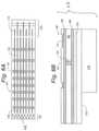
- FIG. 6Ashows the flexible printed circuit in plan view
- FIG. 6Bshows the flexible printed circuit in cross-section
- FIG. 7shows a metallization layer of the flexible printed circuit
- FIG. 7Ashows a portion of the metallization layer of the flexible printed circuit of FIG. 7 ;
- FIG. 7Bshows a portion of the metallization layer of the flexible printed circuit of FIG. 7 ;
- FIG. 7Cshows a portion of the metallization layer of the flexible printed circuit of FIG. 7 ;
- FIG. 8Ashows the spline assembly formed from a flexible printed circuit in plan view
- FIG. 8Bshows the spline assembly formed from a flexible printed circuit in cross-section view
- FIG. 8Cshows a distal array segment in projection view
- FIG. 8Dshows a spline in cross section
- FIG. 8Edepicts a portion of a spline of FIG. 8D ;
- FIG. 9Ashows the spline assembly formed from a flexible printed circuit in plan view
- FIG. 9Bshows the spline assembly formed from a flexible printed circuit in cross-section view
- FIG. 9Cshows a distal array segment in projection view
- FIG. 9Dshows a spline in cross section
- FIG. 9Edepicts a portion of the spline shown in FIG. 9D ;
- FIG. 10Ashows a first embodiment of the deployment actuator
- FIG. 10Bshows a first embodiment of the deployment actuator
- FIG. 11shows a distal array segment in projection view
- FIG. 12shows a distal array segment in projection view
- FIG. 13shows a distal array segment in projection view
- FIG. 14shows a partial section of a distal segment with an additional feature
- FIG. 15shows simplified schematic of second embodiment of the deployment actuator showing complimentary distal and proximal springs
- FIG. 15Ashows a portion of the actuator of FIG. 15 ;
- FIG. 16Ais a simplified schematic of the catheter
- FIG. 16Bis a simplified schematic of the catheter
- FIG. 16Cis a simplified schematic of the catheter.
- FIG. 17is a plot of force against displacement of several structures in the catheter.
- FIG. 1depicts the context of the invention.
- the figureshows a highly schematic view of the overall system that includes the physician, patient, catheters, and related electrophysiology equipment located within an operating room.
- the physician 16introduces the catheter 10 into the vasculature of the patient 11 at the patient's leg and advances it along a blood vessel ultimately, entering the patient's heart 12 .
- Other catheters that may be used in the procedureare represented by companion catheter 18 .
- Each catheteris coupled to signal conditioning hardware 20 with appropriate catheter cabling typified by catheter cable 17 .
- the signal, conditioning hardware 20performs various interface functions applicable to the mapping, tracking, and registration procedures that are performed in conjunction with the workstation class computer-processing unit 24 .
- conditioning hardwarealso forms an interface to an RF ablation unit (not illustrated).
- RF ablation unitnot illustrated.
- the physicianlooks at a computer display 26 .
- Present on the displayis a substantial amount of information.
- a large windowpresents an image of the heart chamber 13 along with an image of the catheter 10 .
- the physicianwill manipulate and control the catheter 10 based in part on the images and other data presented on the display 26 .
- the image 27 seen in FIG. 1is schematic and depicts the distal array of the catheter 10 deployed, occupying a small portion of the heart chamber 13 volume.
- the representation of the heart chamber 13may use color, wire frame, or other techniques to depict the structure of the heart chamber 13 and to simultaneously portray electrical activity of the patient's heart. It is regarded as useful to display chamber geometry, catheter location, and electrical activity in an integrated fashion on the display 26 .
- the physicianwill observe the display 26 and interact with the workstation processing unit 24 and the catheters 10 and 18 , to direct the therapy as a medical procedure.
- FIG. 2A through FIG. 2Cdepicts array deployment and catheter articulation along with the associated positions of the handle controls.
- FIG. 2Ashows the catheter 10 in isolation.
- the catheter 10has an elongate body 31 with a distal end 37 and a proximal end 39 .
- the elongate body 31includes a tubular sheath 35 .
- the proximal end 39connects to an assembly that includes a handle segment 30 .
- the physicianmay manipulate the handle segment 30 to selectively deflect, deploy, and rotate the catheter to perform the medical procedure.
- the handle segment 30is coupled to an elongate intermediate section or segment 32 .
- the intermediate sectionis coupled to a deflection segment 34 , which in turn is coupled to a distal array segment 36 , located at the distal tip or end 37 .
- a catheter cable 17used to connect the electrodes on the distal array segment 36 to the-Signal conditioning hardware 20 .
- FIG. 2Athe catheter 10 is in the undeflected and undeployed state where the distal array segment 36 is collapsed and the deflection segment 34 is straight. In this configuration, the catheter is introduced into the body using the familiar Seldinger technique.
- FIG. 2Bshows the catheter 10 with the handle segment 30 manipulated to deploy the distal array segment 36 into the open or deployed state.
- the pommel 33 of the handle assembly 30is moved retrograde with respect to the handle assembly as indicated by motion arrow 38 to deploy the distal electrode array segment 36 .
- the pommel 33will lock into position to deploy the array 36 .
- the pommel 33will have to be pulled enough to overcome a modest spring force to reach a detent position.
- the distal array segment 36opens to place electrodes into the operating position.
- the deployment controlmay be-turned or rotated to deploy the electrode array.
- FIG. 2Cshows activation of the deflection segment 34 .
- Antegrade motion of the handle ferrule 42 of the handle segment 30 depicted by motion arrow 40deflects or articulates the deflection segment 34 .
- the catheter 10responds to this motion and the deflection segment 34 forms an arc confined to a single plane.
- the articulation or deflection motionlies in the plane of the page.
- the deflection operationcauses the distal array segment 36 to be pointed up to 180.degree. from the initial direction shown in panel 2 A.
- articulation or deflection of the segment 34moves a pull wire from the center axis of the catheter and it moves off to the side within the catheter body. This displacement of the pull wire reduces tension in the pull wire and leads to the deflection.
- the catheter 10has an elongate body 31 having a distal end 37 , and a proximal end 39 , and an elongate central axis.
- a proximal handle segment 30having an articulation control 42 and a deployment control 33 are attached to the proximal end 39 .
- the deflectable segment 34will articulate in a plane through an angle in response to the articulation control.
- a distal array segment 36is connected to the deflectable segment 34 .
- This distal array segment 36includes a deployable distal electrode array that can move from a first retracted position depicted in FIG.
- the deployment mechanism coupled to said deployment controlcouples the motion of the deployment control to operate the distal electrode array segment which causes the distal array segment to deploy into said second deployed position, independently of the operation of said articulation control.
- the physiciancan rotate the handle segment 30 and operate ferrule 42 to position and “aim” the distal array segment 36 toward any part of the cardiac anatomy within the heart chamber.
- the various splines typified by spline 50carry various electrodes into specific highly stable and reproducible spatial locations.
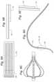
- FIG. 3A and FIG. 3Bdepict the distal array segment 36 in the deployed and undeployed states and serve to illustrate the location of the electrodes.
- FIG. 3Ashows the distal array segment 36 in isolation and in the retracted or undeployed 43 state or condition.
- the drawingshows a uniform and symmetrical distribution of the electrode sites as typified by electrode 54 along the length of a typical spline 50 . It may be useful to place more of the sensing electrodes near the most distal end or tip 37 of the distal array segment 36 . An asymmetrical electrode distribution may be advantageous for non-contact mapping functions.
- current injecting locator electrodestypified by locator electrode 55 , may be placed at a location along the spline 50 .
- locator electrodesIn general it is preferred to position locator electrodes so that they are far apart in the deployed state. Current sourcing or sinking for the locator electrodes may also take place from ring electrodes 57 and tip electrode 53 . Tip electrode 53 may also be provided for cardiac stimulation, ablation or as a locator electrode.
- the splines 50 of the distal electrode array segment 36may carry various sets of independent electrodes 54 . Typically sixty-four sensing electrodes will be distributed over and along the various splines 50 . Several locator electrodes may be positioned diametrically opposed to each other as illustrated by example, on the meridian of the deployed shape. Optionally other electrodes may occupy space in the distal electrode array. In use, sets of the electrodes are used at various times or concurrently during the medical procedure.
- FIG. 3Bshows the distal array segment 36 in the deployed state 41 .
- FIGS. 3A and 3Bshow the motion of the several splines that make up the distal electrode array 36 as they move from the undeployed state 43 to the deployed state 41 . While in the undeployed state 43 , the splines lie together along side each other in a roughly tubular shape seen in FIG. 3A .
- the splinestypified by spline 50 deflect and blossom moving outwardly in a radial direction as the array is deployed to the deployed state 41 as seen in FIG. 3B .
- This spline motionmay be driven by a pull wire ( FIG. 15 element 52 ) in a pull wire embodiment.
- the spline motionmay be driven by a rotating screw 153 that moves the screw driven pull member 159 seen within the array in FIGS. 10A and 10B .
- a rotatable memberis used as a torque transmitting device from the handle to the screw member in the distal section.
- the rotatable memberneeds to be able to transfer torque while in a curved environment.
- the rotatable membercan be implemented in the form of a torque transmitting wire, coil, braid reinforced plastic tube or laser cut hypotube.
- the term rotatable memberis intended to describe all of these alternative constructions. This alternative embodiment is called the rotary screw embodiment.
- the pull wire 52is pulled back into the catheter body of the deflectable segment 34 and the splines deform into a shape reminiscent of a bulb of garlic.
- the pommel control 33 and the proximal spring 402are connected to the pull wire 52 and motion of the pommel control 33 moves the splines to the deployed state.
- the individual splinesmay carry several types of electrodes.
- the array of sensing electrodes typified by spline electrode 54are used for non-contact mapping and may also be used for assisting in the detection and location of companion catheters in the heart chamber. These non-contact electrodes are in the blood pool and they must receive and detect very small voltages to perform the mapping operation.
- Locator electrode 55is typical of such a spline electrode used for location purposes (also shown in FIG. 3A ). Typically locator electrodes will lie on the greatest meridian of the deployed array 41 so that once deployed they are quite far from each other as seen in FIG. 3B . However not every spline need carry a locator electrode.
- Each electrode on a splineis electrically connected to the cabling in the handle. It is preferred that the signal from each individual electrode be independently available to the hardware interface 20 . This may be achieved by passing a conductor for each electrode through the connection cable 17 . As an alternative, the electrical connections may be multiplexed in the catheter device 10 to minimize conductors.
- the high-density electrode arraybe deployed into a known, reproducible, and relatively stiff shape.
- the number of electrodes, their distribution and deployment shape, and stability in shapedetermine the limits of system performance. As electrode number and deployment volume increase, the performance is improved. However it is both difficult and important to balance complexity, cost, and performance with usability and patient benefit.
- An increase in electrode number and deployment sizeincreases catheter 10 complexity and maneuverability of the catheter 10 is compromised. Experimental work suggests that a typical catheter 10 should have sixty-four sensing electrodes and deploy to a three dimensional somewhat spherical shape with a diameter of 18 mm. In order to know electrode locations for analysis by the processing unit 24 , the deployment shape must be tightly controlled. Therefore, several critical design features must be tightly controlled.
- the location of the electrodes 54 within the arraymust be accurately placed. These electrodes 54 should also be placed in a manner that facilitates their use in close proximity to the endocardial surface when the array is deployed. This requirement may necessitate a non-uniform distribution of the electrodes 54 as certain regions of the deployed array are more likely to be positioned closely to the endocardium.
- the deployed shape of the electrode arraymust be repeatable through multiple deployment cycles. For example, electrode locations need to be known to within 1 mm between multiple deployments.
- the arrayshould be capable of deploying to a known shape and subsequently dosing to a low profile (e.g. 8 French) for retraction.
- This shape changemay be binary or continuous, but in either situation, the shape must be repeatable and have a known geometry at the time of data collection.
- the repeatable shape requirementis applicable to the electrode array shape in both the circumferential and radial directions and represent a significant design challenges.
- the inventive combination of fabrication technology, structural design and material choicescooperate together to achieve the design goal.
- locator sensor 59Also seen in FIG. 3B is a locator sensor 59 .
- 3-D location systemsavailable for use in medical devices. In general location of the locator sensor 59 in space is reported by a base station located near the patient. This technology is widely used in robotic surgery and need not be described in detail. Typically the locator sensor 59 would take the place of locator electrode 55 .
- FIG. 4A through FIG. 9Ddepict the formation of the array structure from a flexible printed circuit.
- FIG. 4Ashows a step in a preferred construction methodology for the distal array segment 36 .
- the distal array segment 36is manufactured in part from a flexible printed circuit 60 (“FPC”).
- FPCflexible printed circuit 60
- This construction methodologyhas the advantage of repeatable high accuracy and low manufacturing cost.
- the materialis initially fabricated in a planar form seen in FIG. 4A .
- a series of apertures 62are cut through the FPC 60 at one end typified by hole 62 . Together the series of apertures 62 form a bonding band 70 .
- a termination band 106At the opposite more proximal end of the FPC 60 there is formed a termination band 106 .
- the planar FPC 60is also slit to free the individual splines. Conventional laser processing is well suited to this fabrication step.
- FIG. 4Bshows a process where the planar FPC 60 is wound around a major axis 61 bringing first edge 63 toward second edge 65 .
- FIG. 4Cshows the two edges juxtaposed with both ends fixed. Together the bonding band 70 and the termination band or section 106 complete a cylindrical form. In general the distal bonding band 70 is fixed by encapsulation and the termination band is fixed by anchoring or bonding it to the deflection segment of the catheter.
- FIG. 4Dshows that with both ends fixed, the splines typified by spline 50 may be moved radially with respect to the axis 61 .
- FIG. 5Ashows that the ring of apertures 62 that together from a bonding band 70 .
- the edges of the gapare seen in close proximity at reference numeral 72 ;
- FIG. 5Bshows the use of the bonding band 70 . Note that the edges may be held together with a melted polymer or adhesive or other plastic or thermoplastic material that is applied to the interior and exterior of the tubular structure.
- This thermoplastic formed-in-place plug 74encapsulates the inside and outside of the FPC 60 providing an unusually robust and durable structure that permits reliable deployment of the splines.
- FIG. 6Ashows the FPC 60 in plan view. This view reveals the several slits typified by slot or slit 108 which taken together form the individual splines such as spline 50 . These slits 108 extend from the distal bonding section or band 70 to the termination section 106 . Holes 62 appear in the bonding band 70 and additional slits 110 are formed within the termination section 106 to facilitate attachment to the deflectable section of the catheter.
- the splines typified by spline 50 of the FPC 60serve to position the electrodes typified by electrode 54 along the length of the FPC 60 .
- the splines 50also carry interconnecting metal traces (not shown) that serve to electrically connect the electrodes to pads in the termination section 106 .
- the splines 50are separated from each other using slits 108 .
- the slitsare thin gaps that are cut in the FPC using one of many cutting techniques that may include laser cutting, die cutting or chemical etching.
- the slits 108 of the exemplary FPCare cut using a laser so as, to position slit location precisely.
- the distribution of the electrodes 54may be tightly controlled in the design of the FPC 60 .
- FIG. 6Awe note that electrodes are distributed more densely in the distal tip area. It should be appreciated that any desirable electrode distribution may be accomplished using this method.
- FIG. 6Bshows the FPC 60 in cross-section.
- the various layersare not to scale. Some layers described are very thin while other thick, not all layers are depicted in the figure for clarity. In particular, very thin layers are not shown explicitly in the drawings.
- the FPCis constructed using a relatively thick core insulating layer 86 .
- the core layer 86 of the exemplary circuitis constructed of a 50 um layer of polyimide. Alternative materials and thickness core layers may be used to obtain the desired mechanical and process characteristics.
- the core insulating layer 86is coated with a top metallization layer 88 and a bottom metallization layer 90 .
- Each of the exemplary metallization layersis deposited by first sputtering a thin layer (.about.0.1 um) of titanium over the core insulating layer 86 .
- the titanium layerserves as an interface layer to adhere additional metallization to the core insulating layer 86 .
- the metallization layers 88 and 90can be added by further sputtering and/or plating of additional metal over the titanium layers.
- the exemplary metallization layers 88 and 90are sputtered with a gold layer over the titanium layer and then further plated with gold until the total thickness of the metal layers measures 2 um. It should be noted that other conductors such as copper may also be used. It is also necessary to provide electrical connection between metal layers 88 and 90 for the purpose of connecting circuit features that reside on each layer.
- a connectioncan be formed by constructing a via 96 between the two metallization layers.
- a viacan be formed by creating a hole through both metallization layers 88 and 90 and the core insulating layer 86 . Electrical connection is then made by plating the walls of the hole between the two metallization layers forming a metal connection 96 between the metallization layers 88 and 90 .
- the FPCis further constructed by providing a top covercoat 92 over the top metallization layer 90 .
- the top covercoat 92serves to insulate portions of the top metal layer 88 from external contact.
- the top covercoathas openings 98 placed in regions where it is desired to have the top metal layer exposed to external contact.
- a mapping electrode 54may have the covercoat above it exposed and be sputtered or plated onto the top metal layer 88 as seen in FIG. 6B .
- the covercoat 92 of the FPCis formed by a 25 um layer of liquid photoimageable polyimide.
- the photoimageable polyimide covercoatis exposed and developed to precisely locate geometric features on the exterior surface to create blood contacting electrodes, using similar registration and optical techniques used to fabricate other features on the FPC.
- a bottom cover coat 100is applied to the bottom metal layer 90 in order to insulate the bottom metal layer 90 from external contact. It may be necessary in some applications to enable the bottom covercoat 100 to have openings similar to the openings 98 of the top covercoat 92 . Such applications may require external contact to the bottom metal layer 90 .
- One important application for the mapping electrodes 54is to sense low voltage biological signals. The biological signals of interest are generally in the tens of microvolts to several millivolt range in amplitude and are time varying in the frequency range of 0.05 Hz to several kHz.
- the detailed design of the Flexible Printed Circuit (FPC) layers and electrodesin particular impact the noise level of the measurement system. Reducing the impedance of the electrochemical interface between the electrode and blood reduces overall system noise.
- FPCFlexible Printed Circuit
- Electrode materialsare selected from a small group which have demonstrated to us that they are especially well suited for this design.
- FPC 60 and electrode constructionincludes an FPC with a polyimide core layer with gold metal layers.
- the blood contacting electrodesare gold coated with iridium oxide.
- electrode areahas a profound impact on impedance and in the design the electrode area may be increased to a width limited by the dimension of the spline and further limited by the presence of other metal features including traces.
- FIG. 6Balso shows that a stiffener layer 102 may be applied over the bottom covecoat 100 as seen in FIG. 6B .
- the stiffener layer 102may have various thickness and material compositions in order to achieve the desired rigidity of the FPC in order to control the deployed shape.
- the exemplary FPC of the inventionis comprised of a 50 um thick polyimide stiffener 102 over the bottom covercoat 100 . It should be appreciated that other materials such as PEEK or Nitinol may be used as a stiffener.
- the stiffener 102is adhered to the to the bottom covercoat using a polyimide adhesive layer. Other adhesives, and in particular, pressure sensitive adhesives may also be used for this purpose. Additional stiffener layers may be applied over stiffener layer 102 .
- Stiffener layer 120serves to increase the stiffness of the circuit in selected areas.
- the termination section 106also serves to provide a region where the FPC may be bonded to the outer catheter shaft during installation.
- FIG. 7shows a metallization layer in plan view.
- the dark areas in FIG. 7are the metallization traces created by the processes described in connection with FIG. 6A , but the core layer and other layers are not shown for clarity.
- Subpanels seen in the figureare enlargements of the metallization trace pattern to show various features.
- the termination section 106 of the FPC of FIG. 6Ais shown as traces 108 in this figure.
- the tracesare metallic layers that serve to create a region where the FPC can be connected to wire or cabling that serve to electrically connect the FPC to circuitry or connectors in the proximal section of the catheter.
- the wire or cablingmay be attached to the FPC at a series of termination lines as designated by reference numeral 112 .
- metallization layersranging from 1 to 16 may be used.
- the addition of layersis helpful in carrying additional signals given a width constraint such as the spline width.
- FIG. 8Ashows how to increase the stiffness of the exemplary FPC of FIG. 6 forming areas of high stiffness 124 and areas of lower stiffness 126 .
- FIG. 8Bshows how to control the deployed shape of the array by controlling the stiffness of the exemplary FPC forming areas of high stiffness 124 and areas of lower stiffness 126 .
- FIG. 8Cshows a representative shape where stiff zones 124 or areas interspersed with less stiff areas 126 can create a complex array shape upon deployment. In the figure, there is more stress in the thin areas 126 which bend more readily than in the stiffer regions 124 .
- FIG. 8Dshows thicker regions with additional stiffener layers forming stiff zones 124 while less stiff material yields a less thick more flexible area 126 .
- the use of alternating stiffness areashelps to control the distribution of stress as well as determine deployed shape.
- the spline shapeis segmented into relatively rigid “straight” sections 124 followed by “hinged” areas 126 .
- the detail drawing of FIG. 8Eshows the high stiffness area 124 next t 0 a lower stiffness area 126 .
- FIG. 9Ashows how to increase the stiffness of the exemplary FPC of FIG. 6 forming areas of high stiffness 124 and areas of lower stiffness 126 that are spaced along the spline.
- FIG. 9Bshows that a stiffener layer 102 may be applied over the bottom covercoat 100 as described in connection with FIG. 8B .
- FIG. 9Cshows a representative shape where stiff zones 124 or areas combined with less stiff areas 126 can create a complex array shape upon deployment. In the figure there is more stress in the thin areas that bend more readily than in the stiffer regions 124 . Together the added material allows for a smoothly varying distribution of stress along the spline.
- FIG. 9Dshows thicker regions with additional stiffener layers forming stiff zones 124 while less stiffener material yields a less thick more flexible area 126 .
- the use of alternating stiffness areashelps to control the distribution of stress as well as determine deployed shape yielding a continuously curved spline having a smoothly varying distribution of stress along the spline.
- the detail drawing in FIG. 9Eshows a stiff area 124 next to a less stiff area 126 .
- distal deployable electrode array segmentis formed from a multiple layer flexible printed circuit slit to form splines and rolled about said longitudinal central axis to form said distal electrode array
- the slitsmay be wider or narrower along the length of the spline and this non-uniform shape characteristic results in control of the shape of the electrode array in the deployed position.
- the stiffer elements along the splinesalso create a non-uniform shape characteristic that results in control of the final shape of the electrode array in the deployed position or state.
- the circuitmay be made from and enhanced with an additional layer made from materials that are, in themselves, radiopaque such as gold, platinum, and/or tungsten, including others.
- a radiopaque substratecan be added to the array to enhance visualization upon deployment. This substrate can be in the form of marker bands, coiled wire, or radiopaque ink.
- the radiopaque inkmay contain suspended tungsten that has radiopaque properties. This type of ink could be applied through a printing process on the undeployed electrode assembly while in the FPC configuration.
- FIG. 11 , FIG. 12 , and FIG. 13show differing strategies to reduce blood clotting on the array. It is conventional practice to administer anticoagulants to a patient undergoing these procedures. However is very useful to eliminate blood clotting on the catheter itself.
- FIG. 11 , FIG. 12 , and FIG. 13show several techniques that may be adopted to achieve this goal. Continuous or episodic injection of saline or heprinized saline are contemplated with the embodiments of FIG. 11 and FIG. 12 . It should be noted that various coating such as hydrophilic coatings, heprinized coatings, and parylene may also be applied to catheter surface alone or in combination with the techniques presented in the figures in order to reduce clot.
- FIG. 11shows a distal segment having a fluid supply lumen associated with the pull wire feature 52 .
- Fluid 57 introduced into a hub at the proximal end of the catheteremerges from aperture 53 and aperture 55 to flood the array and prevent blood clots from adhering to the splines.
- FIG. 12shows a porous membrane associated with the pull wire feature location in the distal array segment to allow fluid introduced into the catheter under pressure to emerge from the porous sheath 200 and flood the array to prevent blood clots from adhering to the splines.
- FIG. 13shows a collapsible corrugated section 202 preventing blood from entering the catheter opening in the distal array structures
- FIG. 14shows a strategy for constraining the deployment providing tight control over the final shape of the deployed array.
- tether 300may emerge from the central shaft in FIG. 14 to restrain the motion of the splines or limbs.
- FIG. 15 and FIG. 10describe two different embodiments that meet this requirement.
- the mechanism in FIG. 15relies on a spring to accomplish independence of the two mechanisms, while the mechanism of FIG. 10 relies on threads in distal array segment 36 to accomplish the same goals.
- FIG. 15is a simplified schematic diagram of the catheter that serves to describe the interaction between the articulation and deflection aspects of the catheter.
- the figureserves to explain the operation of one embodiment of the array deployment construction.
- the arrayis pulled open with a pull wire.
- the arrayis biased by a spring 400 to return to the undeployed state.
- the pull wire 52extends from the handle 30 where it is anchored to a proximal spring. 402 to the distal tip 37 where it is anchored in the distal tip.
- the proximal spring 402is in turn connected to the pommel or deployment control 33 .
- the pull wirepulls the distal tip 37 toward the handle 30 .
- the tip motionis guided by tube 406 sliding over a bushing 408 .
- This motioncan continue until the tube bottoms out on surface 404 .
- This mechanical stopdetermines the amount of shortening of the distal segment. As a consequence this stop also serves to limit the deployed state of the deployable array. In this figure the splines are not shown for clarity (for comparison see FIG. 168 ).
- This motionalso compresses the distal spring 400 . If tension of the pull wire is eased then the distal spring 400 restores the array to the undeployed state.
- the pull wire 5 and the proximal compensator spring 402have a nominal length that gets longer or increases as the deployment control moves into the locked 30 position. The increase in length comes from the tension supplied to the spring that increases spring length. This process is seen clearly comparing FIG. 16A to FIG. 16B .
- FIG. 16Ccorresponds to deflection or articulation of the catheter deflectable segment 34 .
- the deflection controlcauses the catheter to deflect in the plane of the figure and this displaces the pull wire 52 within the elongate catheter body 32 .
- the pull wiremoves from a concentric to an offset position within the body 34 the relative length of the pull wire compared to the length of the shaft changes. This is seen most clearly at reference numeral 410 .
- the proximal spring 402compensates for and takes up this motion by contracting slightly while still providing enough tension in the pull wire to keep the distal array fully deployed.
- FIG. 17shows the interplay of tension in the pull wire and displacement of catheter components.
- tensionrises in the wire as seen at panel A.
- the mechanical stopengages the proximal spring and force preferably remains constant as the control reaches the deployed state depicted in panel B. In this state, the catheter is in the state depicted in FIG. 16B .
- the relative motion of the pull wire and its housingcauses the spring tension to falloff in the proximal spring as seen in panel C to D, while the distal array remains against its stop. In this fashion, the distal spring and its mechanical stop cooperate with the proximal spring force to stabilize the array deployment during catheter deflection.
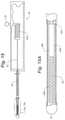
- FIG. 10A and FIG. 10Bshow an alternative embodiment for deploying the array of the catheter.
- a screw 153is positioned in the distal segment of the catheter.
- This screw 153is rotated by a rotatable member or shaft 161 driven by a knob located in the handle which is not illustrated in the figures.
- the rotatable member 161is keyed to the distal array segment 36 with the construction in section 155 .
- the constructionprovides the counter-force against which distal array segment 26 is deployed and retracted.
- This constructionalso isolates the screw 153 and prevents it from being influenced by tension in the rotatable member 161 .
- a complimentary nutforms a pull member 159 is free to slide over the stationary screw.
- the pull member 159has an end anchored in the distal tip of the array and the traction supplied by the screw 153 causes the pull member 159 to move retrograde deploying the splines 50 of the array as seen in FIG. 10B .
- This constructionrenders the deployment function independent of the articulation function of the catheter since the deployment function is unaffected by the tension on rotatable member 161 .
- this embodimentpermits the array to deploy to known continuous intermediate states or positions between the fully retracted and fully deployed states. These continuous intermediate positions are useful in mapping operations where it is desirable to introduce the catheter into structures smaller than its fully deployed diameter while maintaining accurate knowledge of electrode locations. Electrode locations are determined from the amount of deployment which can be derived from the number of rotations employed by the rotatable member during deployment.
Landscapes
- Health & Medical Sciences (AREA)
- Life Sciences & Earth Sciences (AREA)
- Engineering & Computer Science (AREA)
- Veterinary Medicine (AREA)
- General Health & Medical Sciences (AREA)
- Biomedical Technology (AREA)
- Heart & Thoracic Surgery (AREA)
- Public Health (AREA)
- Animal Behavior & Ethology (AREA)
- Biophysics (AREA)
- Surgery (AREA)
- Molecular Biology (AREA)
- Medical Informatics (AREA)
- Physics & Mathematics (AREA)
- Pathology (AREA)
- Anesthesiology (AREA)
- Pulmonology (AREA)
- Hematology (AREA)
- Cardiology (AREA)
- Mechanical Engineering (AREA)
- Physiology (AREA)
- Nuclear Medicine, Radiotherapy & Molecular Imaging (AREA)
- Robotics (AREA)
- Measurement And Recording Of Electrical Phenomena And Electrical Characteristics Of The Living Body (AREA)
- Surgical Instruments (AREA)
- Media Introduction/Drainage Providing Device (AREA)
Abstract
Description
Claims (13)
Priority Applications (1)
| Application Number | Priority Date | Filing Date | Title |
|---|---|---|---|
| US16/046,844US11272886B2 (en) | 2007-12-28 | 2018-07-26 | Cardiac mapping catheter |
Applications Claiming Priority (5)
| Application Number | Priority Date | Filing Date | Title |
|---|---|---|---|
| US12/005,975US8103327B2 (en) | 2007-12-28 | 2007-12-28 | Cardiac mapping catheter |
| US13/289,367US8447377B2 (en) | 2007-12-28 | 2011-11-04 | Cardiac mapping catheter |
| US13/868,151US8755861B2 (en) | 2007-12-28 | 2013-04-23 | Cardiac mapping catheter |
| US14/277,122US10034637B2 (en) | 2007-12-28 | 2014-05-14 | Cardiac mapping catheter |
| US16/046,844US11272886B2 (en) | 2007-12-28 | 2018-07-26 | Cardiac mapping catheter |
Related Parent Applications (1)
| Application Number | Title | Priority Date | Filing Date |
|---|---|---|---|
| US14/277,122ContinuationUS10034637B2 (en) | 2007-12-28 | 2014-05-14 | Cardiac mapping catheter |
Publications (2)
| Publication Number | Publication Date |
|---|---|
| US20180344251A1 US20180344251A1 (en) | 2018-12-06 |
| US11272886B2true US11272886B2 (en) | 2022-03-15 |
Family
ID=40799373
Family Applications (5)
| Application Number | Title | Priority Date | Filing Date |
|---|---|---|---|
| US12/005,975Active2030-06-22US8103327B2 (en) | 2007-12-28 | 2007-12-28 | Cardiac mapping catheter |
| US13/289,367Active2028-03-19US8447377B2 (en) | 2007-12-28 | 2011-11-04 | Cardiac mapping catheter |
| US13/868,151ActiveUS8755861B2 (en) | 2007-12-28 | 2013-04-23 | Cardiac mapping catheter |
| US14/277,122Active2030-09-26US10034637B2 (en) | 2007-12-28 | 2014-05-14 | Cardiac mapping catheter |
| US16/046,844Active2030-06-09US11272886B2 (en) | 2007-12-28 | 2018-07-26 | Cardiac mapping catheter |
Family Applications Before (4)
| Application Number | Title | Priority Date | Filing Date |
|---|---|---|---|
| US12/005,975Active2030-06-22US8103327B2 (en) | 2007-12-28 | 2007-12-28 | Cardiac mapping catheter |
| US13/289,367Active2028-03-19US8447377B2 (en) | 2007-12-28 | 2011-11-04 | Cardiac mapping catheter |
| US13/868,151ActiveUS8755861B2 (en) | 2007-12-28 | 2013-04-23 | Cardiac mapping catheter |
| US14/277,122Active2030-09-26US10034637B2 (en) | 2007-12-28 | 2014-05-14 | Cardiac mapping catheter |
Country Status (5)
| Country | Link |
|---|---|
| US (5) | US8103327B2 (en) |
| EP (1) | EP2234537B1 (en) |
| JP (2) | JP5419890B2 (en) |
| CA (1) | CA2710769A1 (en) |
| WO (1) | WO2009085108A1 (en) |
Cited By (24)
| Publication number | Priority date | Publication date | Assignee | Title |
|---|---|---|---|---|
| US11622806B2 (en) | 2010-04-09 | 2023-04-11 | St Jude Medical International Holding S.À R.L. | Control handle for a contact force ablation catheter |
| US11642063B2 (en) | 2018-08-23 | 2023-05-09 | St. Jude Medical, Cardiology Division, Inc. | Curved high density electrode mapping catheter |
| US11642064B2 (en) | 2015-10-21 | 2023-05-09 | St. Jude Medical, Cardiology Division, Inc. | High density electrode mapping catheter |
| US11647935B2 (en) | 2017-07-24 | 2023-05-16 | St. Jude Medical, Cardiology Division, Inc. | Masked ring electrodes |
| US11672947B2 (en) | 2017-11-28 | 2023-06-13 | St. Jude Medical, Cardiology Division, Inc. | Lumen management catheter |
| US11696716B2 (en) | 2008-12-29 | 2023-07-11 | St. Jude Medical, Atrial Fibrillation Division, Inc. | Non-contact electrode basket catheters with irrigation |
| US11707229B2 (en) | 2015-05-08 | 2023-07-25 | St Jude Medical International Holding S.À R.L. | Integrated sensors for medical devices and method of making integrated sensors for medical devices |
| US11786705B2 (en) | 2016-10-24 | 2023-10-17 | St. Jude Medical, Cardiology Division, Inc. | Catheter insertion devices |
| US11826172B2 (en) | 2014-05-06 | 2023-11-28 | St. Jude Medical, Cardiology Division, Inc. | Electrode support structure assembly |
| US11839424B2 (en) | 2010-05-05 | 2023-12-12 | St. Jude Medical, Atrial Fibrillation Division, Inc | Monitoring, managing and/or protecting system and method for non-targeted tissue |
| US11844910B2 (en) | 2014-06-05 | 2023-12-19 | St. Jude Medical, Cardiology Division, Inc. | Deflectable catheter shaft section |
| US11918762B2 (en) | 2018-10-03 | 2024-03-05 | St. Jude Medical, Cardiology Division, Inc. | Reduced actuation force electrophysiology catheter handle |
| US12011549B2 (en) | 2017-01-19 | 2024-06-18 | St. Jude Medical, Cardiology Division, Inc. | Sheath visualization |
| US12036027B2 (en) | 2016-10-28 | 2024-07-16 | St. Jude Medical, Cardiology Division, Inc. | Flexible high-density mapping catheter |
| US12048545B2 (en) | 2014-10-27 | 2024-07-30 | St. Jude Medical, Cardiology Division, Inc. | Apparatus and method for connecting elements in medical devices |
| US12076079B2 (en) | 2016-05-03 | 2024-09-03 | St. Jude Medical, Cardiology Division, Inc. | Irrigated high density electrode catheter |
| US12082936B2 (en) | 2018-09-27 | 2024-09-10 | St. Jude Medical, Cardiology Division, Inc. | Uniform mapping balloon |
| US12121357B2 (en) | 2015-10-21 | 2024-10-22 | St. Jude Medical, Cardiology Division, Inc. | High density electrode mapping catheter |
| US12156979B2 (en) | 2018-05-21 | 2024-12-03 | St. Jude Medical, Cardiology Division, Inc. | Deflectable catheter shaft with pullwire anchor feature |
| US12263338B2 (en) | 2013-01-16 | 2025-04-01 | St. Jude Medical, Cardiology Division, Inc. | Flexible high-density mapping catheter tips and flexible ablation catheter tips with onboard high-density mapping electrodes |
| US12263014B2 (en) | 2020-08-18 | 2025-04-01 | St. Jude Medical, Cardiology Division, Inc. | High-density electrode catheters with magnetic position tracking |
| US12295649B2 (en) | 2010-12-02 | 2025-05-13 | St. Jude Medical, Atrial Fibrillation Division, Inc. | Catheter electrode assemblies and methods of construction thereof |
| US12376901B2 (en) | 2018-05-21 | 2025-08-05 | St. Jude Medical, Cardiology Division, Inc. | Radio-frequency ablation and direct current electroporation catheters |
| US12383333B2 (en) | 2015-01-28 | 2025-08-12 | St. Jude Medical, Cardiology Division, Inc. | Thermal mapping catheter |
Families Citing this family (245)
| Publication number | Priority date | Publication date | Assignee | Title |
|---|---|---|---|---|
| US9579091B2 (en)* | 2000-01-05 | 2017-02-28 | Integrated Vascular Systems, Inc. | Closure system and methods of use |
| US6461364B1 (en) | 2000-01-05 | 2002-10-08 | Integrated Vascular Systems, Inc. | Vascular sheath with bioabsorbable puncture site closure apparatus and methods of use |
| US7842068B2 (en) | 2000-12-07 | 2010-11-30 | Integrated Vascular Systems, Inc. | Apparatus and methods for providing tactile feedback while delivering a closure device |
| US8758400B2 (en) | 2000-01-05 | 2014-06-24 | Integrated Vascular Systems, Inc. | Closure system and methods of use |
| US6391048B1 (en)* | 2000-01-05 | 2002-05-21 | Integrated Vascular Systems, Inc. | Integrated vascular device with puncture site closure component and sealant and methods of use |
| DE60144328D1 (en)* | 2000-09-08 | 2011-05-12 | Abbott Vascular Inc | Surgical clamp |
| US6626918B1 (en)* | 2000-10-06 | 2003-09-30 | Medical Technology Group | Apparatus and methods for positioning a vascular sheath |
| US8690910B2 (en) | 2000-12-07 | 2014-04-08 | Integrated Vascular Systems, Inc. | Closure device and methods for making and using them |
| US6695867B2 (en) | 2002-02-21 | 2004-02-24 | Integrated Vascular Systems, Inc. | Plunger apparatus and methods for delivering a closure device |
| US7905900B2 (en)* | 2003-01-30 | 2011-03-15 | Integrated Vascular Systems, Inc. | Clip applier and methods of use |
| US7211101B2 (en) | 2000-12-07 | 2007-05-01 | Abbott Vascular Devices | Methods for manufacturing a clip and clip |
| US6623510B2 (en) | 2000-12-07 | 2003-09-23 | Integrated Vascular Systems, Inc. | Closure device and methods for making and using them |
| IES20010547A2 (en)* | 2001-06-07 | 2002-12-11 | Christy Cummins | Surgical Staple |
| IES20030424A2 (en) | 2002-06-04 | 2003-12-10 | Robert Stevenson | Blood vessel closure clip and delivery device |
| US8758398B2 (en)* | 2006-09-08 | 2014-06-24 | Integrated Vascular Systems, Inc. | Apparatus and method for delivering a closure element |
| US8398656B2 (en) | 2003-01-30 | 2013-03-19 | Integrated Vascular Systems, Inc. | Clip applier and methods of use |
| US8821534B2 (en) | 2010-12-06 | 2014-09-02 | Integrated Vascular Systems, Inc. | Clip applier having improved hemostasis and methods of use |
| US8905937B2 (en)* | 2009-02-26 | 2014-12-09 | Integrated Vascular Systems, Inc. | Methods and apparatus for locating a surface of a body lumen |
| US8202293B2 (en) | 2003-01-30 | 2012-06-19 | Integrated Vascular Systems, Inc. | Clip applier and methods of use |
| WO2005067817A1 (en) | 2004-01-13 | 2005-07-28 | Remon Medical Technologies Ltd | Devices for fixing a sensor in a body lumen |
| JP4196875B2 (en)* | 2004-04-26 | 2008-12-17 | ブラザー工業株式会社 | Printed circuit board and inkjet head using the same |
| IES20040368A2 (en)* | 2004-05-25 | 2005-11-30 | James E Coleman | Surgical stapler |
| US10390714B2 (en)* | 2005-01-12 | 2019-08-27 | Remon Medical Technologies, Ltd. | Devices for fixing a sensor in a lumen |
| US8926633B2 (en)* | 2005-06-24 | 2015-01-06 | Abbott Laboratories | Apparatus and method for delivering a closure element |
| US8313497B2 (en)* | 2005-07-01 | 2012-11-20 | Abbott Laboratories | Clip applier and methods of use |
| US8060214B2 (en) | 2006-01-05 | 2011-11-15 | Cardiac Pacemakers, Inc. | Implantable medical device with inductive coil configurable for mechanical fixation |
| US8808310B2 (en)* | 2006-04-20 | 2014-08-19 | Integrated Vascular Systems, Inc. | Resettable clip applier and reset tools |
| US7515954B2 (en) | 2006-06-13 | 2009-04-07 | Rhythmia Medical, Inc. | Non-contact cardiac mapping, including moving catheter and multi-beat integration |
| US7729752B2 (en)* | 2006-06-13 | 2010-06-01 | Rhythmia Medical, Inc. | Non-contact cardiac mapping, including resolution map |
| US10028783B2 (en) | 2006-06-28 | 2018-07-24 | Kardium Inc. | Apparatus and method for intra-cardiac mapping and ablation |
| US8556930B2 (en) | 2006-06-28 | 2013-10-15 | Abbott Laboratories | Vessel closure device |
| US9119633B2 (en) | 2006-06-28 | 2015-09-01 | Kardium Inc. | Apparatus and method for intra-cardiac mapping and ablation |
| US11389232B2 (en) | 2006-06-28 | 2022-07-19 | Kardium Inc. | Apparatus and method for intra-cardiac mapping and ablation |
| WO2008014629A2 (en) | 2006-08-03 | 2008-02-07 | Christoph Scharf | Method and device for determining and presenting surface charge and dipole densities on cardiac walls |
| US20080071248A1 (en)* | 2006-09-15 | 2008-03-20 | Cardiac Pacemakers, Inc. | Delivery stystem for an implantable physiologic sensor |
| JP5156749B2 (en) | 2006-09-15 | 2013-03-06 | カーディアック ペースメイカーズ, インコーポレイテッド | Implantable sensor anchor |
| US8676349B2 (en) | 2006-09-15 | 2014-03-18 | Cardiac Pacemakers, Inc. | Mechanism for releasably engaging an implantable medical device for implantation |
| US20080190438A1 (en)* | 2007-02-08 | 2008-08-14 | Doron Harlev | Impedance registration and catheter tracking |
| US8204599B2 (en) | 2007-05-02 | 2012-06-19 | Cardiac Pacemakers, Inc. | System for anchoring an implantable sensor in a vessel |
| US8588885B2 (en)* | 2007-05-09 | 2013-11-19 | St. Jude Medical, Atrial Fibrillation Division, Inc. | Bendable catheter arms having varied flexibility |
| US8906011B2 (en) | 2007-11-16 | 2014-12-09 | Kardium Inc. | Medical device for use in bodily lumens, for example an atrium |
| US20090157101A1 (en)* | 2007-12-17 | 2009-06-18 | Abbott Laboratories | Tissue closure system and methods of use |
| US8893947B2 (en)* | 2007-12-17 | 2014-11-25 | Abbott Laboratories | Clip applier and methods of use |
| US7841502B2 (en)* | 2007-12-18 | 2010-11-30 | Abbott Laboratories | Modular clip applier |
| US20090187215A1 (en)* | 2007-12-19 | 2009-07-23 | Abbott Laboratories | Methods and apparatus to reduce a dimension of an implantable device in a smaller state |
| US8103327B2 (en)* | 2007-12-28 | 2012-01-24 | Rhythmia Medical, Inc. | Cardiac mapping catheter |
| EP2737849A3 (en) | 2008-01-17 | 2014-10-29 | Christoph Scharf | A device and method for the geometric determination of electrical dipole densities on the cardiac wall |
| US8538509B2 (en) | 2008-04-02 | 2013-09-17 | Rhythmia Medical, Inc. | Intracardiac tracking system |
| US9282965B2 (en)* | 2008-05-16 | 2016-03-15 | Abbott Laboratories | Apparatus and methods for engaging tissue |
| EP2296536A1 (en) | 2008-07-15 | 2011-03-23 | Cardiac Pacemakers, Inc. | Implant assist apparatus for acoustically enabled implantable medical device |
| CN102105780B (en) | 2008-07-24 | 2015-09-23 | 麻省理工学院 | Systems and methods for imaging using absorption |
| US8368649B2 (en)* | 2008-08-29 | 2013-02-05 | Siemens Medical Solutions Usa, Inc. | Control system for use within a sterile environment |
| US8137343B2 (en) | 2008-10-27 | 2012-03-20 | Rhythmia Medical, Inc. | Tracking system using field mapping |
| US8398676B2 (en)* | 2008-10-30 | 2013-03-19 | Abbott Vascular Inc. | Closure device |
| US8323312B2 (en)* | 2008-12-22 | 2012-12-04 | Abbott Laboratories | Closure device |
| US8858594B2 (en)* | 2008-12-22 | 2014-10-14 | Abbott Laboratories | Curved closure device |
| US8808345B2 (en) | 2008-12-31 | 2014-08-19 | Medtronic Ardian Luxembourg S.A.R.L. | Handle assemblies for intravascular treatment devices and associated systems and methods |
| US9089311B2 (en)* | 2009-01-09 | 2015-07-28 | Abbott Vascular Inc. | Vessel closure devices and methods |
| US9414820B2 (en)* | 2009-01-09 | 2016-08-16 | Abbott Vascular Inc. | Closure devices, systems, and methods |
| US20110218568A1 (en)* | 2009-01-09 | 2011-09-08 | Voss Laveille K | Vessel closure devices, systems, and methods |
| US20100179589A1 (en) | 2009-01-09 | 2010-07-15 | Abbott Vascular Inc. | Rapidly eroding anchor |
| US9486191B2 (en) | 2009-01-09 | 2016-11-08 | Abbott Vascular, Inc. | Closure devices |
| US9173644B2 (en)* | 2009-01-09 | 2015-11-03 | Abbott Vascular Inc. | Closure devices, systems, and methods |
| US20100179567A1 (en)* | 2009-01-09 | 2010-07-15 | Abbott Vascular Inc. | Closure devices, systems, and methods |
| US20100185234A1 (en)* | 2009-01-16 | 2010-07-22 | Abbott Vascular Inc. | Closure devices, systems, and methods |
| WO2010093603A1 (en) | 2009-02-11 | 2010-08-19 | Boston Scientific Scimed, Inc. | Insulated ablation catheter devices and methods of use |
| US8694129B2 (en)* | 2009-02-13 | 2014-04-08 | Cardiac Pacemakers, Inc. | Deployable sensor platform on the lead system of an implantable device |
| US9398862B2 (en) | 2009-04-23 | 2016-07-26 | Rhythmia Medical, Inc. | Multi-electrode mapping system |
| US8571647B2 (en)* | 2009-05-08 | 2013-10-29 | Rhythmia Medical, Inc. | Impedance based anatomy generation |
| US8103338B2 (en) | 2009-05-08 | 2012-01-24 | Rhythmia Medical, Inc. | Impedance based anatomy generation |
| US20110054492A1 (en) | 2009-08-26 | 2011-03-03 | Abbott Laboratories | Medical device for repairing a fistula |
| SE0901166A1 (en)* | 2009-09-10 | 2011-03-11 | Cathprint Ab | Flexible catheter lead carrier provided with such lead carrier |
| IT1399677B1 (en)* | 2009-10-26 | 2013-04-26 | Torino Politecnico | SENSOR FOR THE ACQUISITION OF BIOELECTRIC SIGNALS FROM AN ANULAR MUSCLE, IN PARTICULAR FOR MULTI-CHANNEL SURFACE ELECTROMYOGRAPHY |
| US8825129B2 (en)* | 2010-03-05 | 2014-09-02 | Sri International | Indwelling nerve block catheters |
| US9179968B2 (en) | 2010-05-10 | 2015-11-10 | St. Jude Medical Luxembourg Holding S.À.R.L. | Irrigated finned ablation head |
| US8758399B2 (en) | 2010-08-02 | 2014-06-24 | Abbott Cardiovascular Systems, Inc. | Expandable bioabsorbable plug apparatus and method |
| US8603116B2 (en) | 2010-08-04 | 2013-12-10 | Abbott Cardiovascular Systems, Inc. | Closure device with long tines |
| WO2012037341A1 (en) | 2010-09-15 | 2012-03-22 | The United States Of America, As Represented By The Secretary, National Institutes Of Health | Devices for transcatheter cerclage annuloplasty |
| US8903473B2 (en)* | 2010-09-15 | 2014-12-02 | Medtronic, Inc. | Radiopaque markers for implantable medical devices |
| US9277872B2 (en) | 2011-01-13 | 2016-03-08 | Rhythmia Medical, Inc. | Electroanatomical mapping |
| US9002442B2 (en) | 2011-01-13 | 2015-04-07 | Rhythmia Medical, Inc. | Beat alignment and selection for cardiac mapping |
| CA2764494A1 (en) | 2011-01-21 | 2012-07-21 | Kardium Inc. | Enhanced medical device for use in bodily cavities, for example an atrium |
| US9452016B2 (en) | 2011-01-21 | 2016-09-27 | Kardium Inc. | Catheter system |
| US9480525B2 (en) | 2011-01-21 | 2016-11-01 | Kardium, Inc. | High-density electrode-based medical device system |
| US11259867B2 (en)* | 2011-01-21 | 2022-03-01 | Kardium Inc. | High-density electrode-based medical device system |
| US9757044B2 (en) | 2011-03-10 | 2017-09-12 | Acutus Medical, Inc. | Device and method for the geometric determination of electrical dipole densities on the cardiac wall |
| US9149276B2 (en) | 2011-03-21 | 2015-10-06 | Abbott Cardiovascular Systems, Inc. | Clip and deployment apparatus for tissue closure |
| ITRM20110206A1 (en)* | 2011-04-21 | 2012-10-22 | Ab Medica Spa | ACQUISITION AND MONITORING SYSTEM OF BIOELECTRIC SIGNALS FROM THE BRAIN AND INTRACRANIC STIMULATION. |
| AU2014202011B2 (en)* | 2011-04-22 | 2015-05-07 | Topera, Inc. | Basket style cardiac mapping catheter having an atraumatic, metallic two-part distal tip for detection of cardiac rhythm disorders |
| EP2699153B1 (en) | 2011-04-22 | 2015-12-16 | Topera, Inc. | Flexible electrode assembly for insertion into body lumen or organ |
| US8909316B2 (en)* | 2011-05-18 | 2014-12-09 | St. Jude Medical, Cardiology Division, Inc. | Apparatus and method of assessing transvascular denervation |
| US9603659B2 (en) | 2011-09-14 | 2017-03-28 | Boston Scientific Scimed Inc. | Ablation device with ionically conductive balloon |
| JP5579681B2 (en)* | 2011-10-06 | 2014-08-27 | 平河ヒューテック株式会社 | Electrode catheter |
| US8649880B1 (en)* | 2011-10-07 | 2014-02-11 | Autry J. Parker, Jr. | Deployable stimulator array and method of use |
| US9332976B2 (en) | 2011-11-30 | 2016-05-10 | Abbott Cardiovascular Systems, Inc. | Tissue closure device |
| JP2015506234A (en) | 2012-01-10 | 2015-03-02 | ボストン サイエンティフィック サイムド,インコーポレイテッドBoston Scientific Scimed,Inc. | Electrophysiology system |
| USD777926S1 (en) | 2012-01-20 | 2017-01-31 | Kardium Inc. | Intra-cardiac procedure device |
| USD777925S1 (en) | 2012-01-20 | 2017-01-31 | Kardium Inc. | Intra-cardiac procedure device |
| JP5936409B2 (en)* | 2012-03-26 | 2016-06-22 | 国立研究開発法人国立循環器病研究センター | Electrode unit and tissue stimulation system |
| EP2890292B1 (en) | 2012-08-31 | 2021-01-13 | Acutus Medical, Inc. | Catheter system for the heart |
| WO2014066470A1 (en) | 2012-10-24 | 2014-05-01 | Evergreen Medical Technologies, Inc. | Flex circuit ribbon based elongated members and attachments |
| JP2016502885A (en) | 2012-12-20 | 2016-02-01 | ボストン サイエンティフィック サイムド,インコーポレイテッドBoston Scientific Scimed,Inc. | Real-time feedback of electrode contact during mapping |
| US9364209B2 (en) | 2012-12-21 | 2016-06-14 | Abbott Cardiovascular Systems, Inc. | Articulating suturing device |
| CN105073173B (en)* | 2013-01-18 | 2017-05-10 | 斯坦福国际研究院 | anchored nerve block catheter |
| CN103932676A (en)* | 2013-01-23 | 2014-07-23 | 四川锦江电子科技有限公司 | Flexible circuit electrode |
| CN105358070B (en)* | 2013-02-08 | 2018-03-23 | 阿库图森医疗有限公司 | Expandable catheter assembly with flexible printed circuit board |
| US9179971B2 (en) | 2013-02-11 | 2015-11-10 | St. Jude Medical, Atrial Fibrillation Division, Inc. | Printed electrode catheter |
| US10328238B2 (en) | 2013-03-12 | 2019-06-25 | St. Jude Medical, Cardiology Division, Inc. | Catheter system |
| WO2014162660A1 (en)* | 2013-04-01 | 2014-10-09 | テルモ株式会社 | Monitoring device and monitoring device kit |
| EP2994039A1 (en) | 2013-05-06 | 2016-03-16 | Boston Scientific Scimed Inc. | Persistent display of nearest beat characteristics during real-time or play-back electrophysiology data visualization |
| CN105228510B (en) | 2013-05-14 | 2018-12-14 | 波士顿科学医学有限公司 | Representation and identification of activity patterns using vector fields during electrophysiological mapping |
| US9814618B2 (en)* | 2013-06-06 | 2017-11-14 | Boston Scientific Scimed, Inc. | Devices for delivering energy and related methods of use |
| EP2818104B1 (en)* | 2013-06-25 | 2016-01-06 | VascoMed GmbH | Catheter and method for producing same |
| EP3335658B1 (en)* | 2013-08-09 | 2020-04-22 | Boston Scientific Scimed, Inc. | Expandable catheter |
| CA2922941C (en) | 2013-09-13 | 2021-11-16 | Acutus Medical, Inc. | Devices and methods for determination of electrical dipole densities on a cardiac surface |
| EP3057488B1 (en) | 2013-10-14 | 2018-05-16 | Boston Scientific Scimed, Inc. | High resolution cardiac mapping electrode array catheter |
| US20150119878A1 (en)* | 2013-10-24 | 2015-04-30 | St. Jude Medical, Cardiology Division, Inc. | Electrode assembly having asymmetric electrode placement |
| US9730600B2 (en) | 2013-10-31 | 2017-08-15 | Boston Scientific Scimed, Inc. | Medical device for high resolution mapping using localized matching |
| WO2015066322A1 (en) | 2013-11-01 | 2015-05-07 | Boston Scientific Scimed, Inc. | Cardiac mapping using latency interpolation |
| US9987073B2 (en) | 2013-11-19 | 2018-06-05 | Covidien Lp | Electrosurgical coagulation instrument including a suction pipe and a collapsible tip |
| US9993160B2 (en) | 2014-01-07 | 2018-06-12 | Kardium Inc. | Medical device including manipulable portion with connected elongate members |
| EP3079575B1 (en) | 2014-01-28 | 2018-12-26 | St. Jude Medical, Cardiology Division, Inc. | Catheter shaft with electrically-conductive traces |
| WO2015116562A1 (en) | 2014-01-28 | 2015-08-06 | St. Jude Medical, Cardiology Division, Inc. | Medical device with a packaged electronic subassembly and method for fabricating the same |
| WO2015116687A1 (en)* | 2014-01-28 | 2015-08-06 | St. Jude Medical, Cardiology Division, Inc. | Elongate medical devices incorporating a flexible substrate, a sensor, and electrically-conductive traces |
| EP3113671B1 (en) | 2014-03-07 | 2023-10-25 | Boston Scientific Scimed, Inc. | Medical devices for mapping cardiac tissue |
| JP2017509399A (en) | 2014-03-11 | 2017-04-06 | ボストン サイエンティフィック サイムド,インコーポレイテッドBoston Scientific Scimed,Inc. | Medical device for mapping heart tissue |
| JP6739346B2 (en) | 2014-03-25 | 2020-08-12 | アクタス メディカル インクAcutus Medical,Inc. | Method of operating system of cardiac analysis user interface |
| CN106413540A (en)* | 2014-06-03 | 2017-02-15 | 波士顿科学医学有限公司 | Electrode assembly with atraumatic distal tip |
| US9848795B2 (en) | 2014-06-04 | 2017-12-26 | Boston Scientific Scimed Inc. | Electrode assembly |
| US9844645B2 (en) | 2014-06-17 | 2017-12-19 | St. Jude Medical, Cardiology Division, Inc. | Triple coil catheter support |
| JP2016002282A (en)* | 2014-06-17 | 2016-01-12 | オリンパス株式会社 | Electrode unit and tissue stimulation system |
| CN106687168A (en)* | 2014-09-12 | 2017-05-17 | X-节奏有限责任公司 | Multi-electrode mapping catheter |
| US20170296084A1 (en)* | 2014-09-18 | 2017-10-19 | University Of Utah Research Foundation | Cardiac mapping catheter |
| KR102033760B1 (en) | 2014-09-23 | 2019-10-17 | 주식회사 한독칼로스메디칼 | Catheter and manufacturing method thereof |
| KR102033759B1 (en) | 2014-09-23 | 2019-10-17 | 주식회사 한독칼로스메디칼 | Catheter and manufacturing method thereof |
| CN107072708B (en)* | 2014-09-23 | 2020-02-18 | 韩德卡洛斯医药株式会社 | Catheter and method of making the same |
| JP2017529169A (en) | 2014-10-13 | 2017-10-05 | ボストン サイエンティフィック サイムド,インコーポレイテッドBoston Scientific Scimed,Inc. | Tissue diagnosis and treatment using mini-electrodes |
| WO2016065337A1 (en) | 2014-10-24 | 2016-04-28 | Boston Scientific Scimed Inc. | Medical devices with a flexible electrode assembly coupled to an ablation tip |
| US9314208B1 (en)* | 2014-10-28 | 2016-04-19 | Biosense Webster (Israel) Ltd. | Basket catheter with microelectrode array distal tip |
| WO2016065464A1 (en) | 2014-10-30 | 2016-05-06 | Kardium Inc. | Catheter system |
| US9743854B2 (en) | 2014-12-18 | 2017-08-29 | Boston Scientific Scimed, Inc. | Real-time morphology analysis for lesion assessment |
| US20180146925A1 (en)* | 2014-12-29 | 2018-05-31 | Jamil Mogul | Tentacular Electrode Catheter Apparatus |
| US11844615B2 (en) | 2015-03-12 | 2023-12-19 | The Regents Of The University Of Michigan | Catheter and method to localize ectopic and reentrant activity in the heart |
| WO2016168778A1 (en)* | 2015-04-17 | 2016-10-20 | Boston Scientific Scimed Inc. | Tissue diagnosis and treatment using electrodes and mini-electrodes |
| US9757574B2 (en) | 2015-05-11 | 2017-09-12 | Rainbow Medical Ltd. | Dual chamber transvenous pacemaker |
| CN115299988A (en) | 2015-05-12 | 2022-11-08 | 阿库图森医疗有限公司 | Ultrasonic sequencing systems and methods |
| WO2016181317A2 (en) | 2015-05-12 | 2016-11-17 | Navix International Limited | Calculation of an ablation plan |
| US10593234B2 (en) | 2015-05-12 | 2020-03-17 | Acutus Medical, Inc. | Cardiac virtualization test tank and testing system and method |
| US10653318B2 (en) | 2015-05-13 | 2020-05-19 | Acutus Medical, Inc. | Localization system and method useful in the acquisition and analysis of cardiac information |
| US10492857B2 (en) | 2015-08-06 | 2019-12-03 | Boston Scientific Scimed Inc | Deployment control apparatus for a catheter with a deployable array |
| US9931487B2 (en) | 2015-08-06 | 2018-04-03 | Boston Scientific Scimed, Inc. | Bidirectional steering control apparatus for a catheter |
| US10376170B2 (en) | 2015-08-10 | 2019-08-13 | Boston Scientific Scimed, Inc. | Catheter with annular lumen to provide distal flushing |
| AU2016210644A1 (en)* | 2015-08-12 | 2017-03-02 | Biosense Webster (Israel) Ltd. | High electrode density basket catheter |
| EP3337387B1 (en) | 2015-08-20 | 2019-09-25 | Boston Scientific Scimed Inc. | Flexible electrode for cardiac sensing and method for making |
| US20170071543A1 (en)* | 2015-09-14 | 2017-03-16 | Biosense Webster (Israel) Ltd. | Convertible basket catheter |
| WO2017053921A1 (en) | 2015-09-26 | 2017-03-30 | Boston Scientific Scimed Inc. | Intracardiac egm signals for beat matching and acceptance |
| CN108140265B (en) | 2015-09-26 | 2022-06-28 | 波士顿科学医学有限公司 | System and method for anatomical shell editing |
| US10405766B2 (en) | 2015-09-26 | 2019-09-10 | Boston Scientific Scimed, Inc. | Method of exploring or mapping internal cardiac structures |
| EP3352648B1 (en) | 2015-09-26 | 2022-10-26 | Boston Scientific Scimed Inc. | Multiple rhythm template monitoring |
| US10362952B2 (en)* | 2015-12-10 | 2019-07-30 | Biosense Webster (Israel) Ltd. | Stabilized spine electrophysiologic catheter |
| US10362953B2 (en)* | 2015-12-11 | 2019-07-30 | Biosense Webster (Israel) Ltd. | Electrode array catheter with interconnected framework |
| SG11201804773PA (en) | 2015-12-15 | 2018-07-30 | Agency Science Tech & Res | Method and deployable multi-spine apparatus for catheter-based renal denervation |
| CN108366734A (en)* | 2015-12-20 | 2018-08-03 | 波士顿科学医学有限公司 | The automatic mapping of operating speed information |
| US10660700B2 (en)* | 2016-04-28 | 2020-05-26 | Biosense Webster (Israel) Ltd. | Irrigated balloon catheter with flexible circuit electrode assembly |
| WO2017192510A2 (en) | 2016-05-02 | 2017-11-09 | Affera, Inc. | Pulsed radiofrequency ablation |
| CA3022806A1 (en) | 2016-05-03 | 2017-11-09 | Acutus Medical, Inc. | Cardiac mapping system with efficiency algorithm |
| US11039923B2 (en) | 2016-05-06 | 2021-06-22 | Transmural Systems Llc | Annuloplasty procedures, related devices and methods |
| US11007059B2 (en) | 2016-05-06 | 2021-05-18 | Transmural Systems Llc | Annuloplasty procedures, related devices and methods |
| WO2019046205A1 (en) | 2017-08-26 | 2019-03-07 | Macdonald, Stuart | Cardiac annuloplasty and pacing procedures, related devices and methods |
| US11980545B2 (en) | 2016-05-06 | 2024-05-14 | Transmural Systems Llc | Annuloplasty procedures, related devices and methods |
| WO2017197114A1 (en) | 2016-05-11 | 2017-11-16 | Affera, Inc. | Anatomical model generation |
| WO2017197294A1 (en) | 2016-05-12 | 2017-11-16 | Affera, Inc. | Three-dimensional cardiac representation |
| US10772566B2 (en)* | 2016-05-17 | 2020-09-15 | Biosense Weber (Israel) Ltd. | Multi-electrode catheter spine and method of making the same |
| US10905329B2 (en) | 2016-06-09 | 2021-02-02 | Biosense Webster (Israel) Ltd. | Multi-function conducting elements for a catheter |
| US11350996B2 (en) | 2016-07-14 | 2022-06-07 | Navix International Limited | Characteristic track catheter navigation |
| WO2018078540A1 (en) | 2016-10-25 | 2018-05-03 | Navix International Limited | Systems and methods for registration of intra-body electrical readings with a pre-acquired three dimensional image |
| CN110072449B (en) | 2016-11-16 | 2023-02-24 | 纳维斯国际有限公司 | Esophageal position detection by electrical mapping |
| WO2018092071A1 (en) | 2016-11-16 | 2018-05-24 | Navix International Limited | Estimators for ablation effectiveness |
| WO2018092062A1 (en) | 2016-11-16 | 2018-05-24 | Navix International Limited | Real-time display of tissue deformation by interactions with an intra-body probe |
| WO2018092059A1 (en)* | 2016-11-16 | 2018-05-24 | Navix International Limited | Tissue model dynamic visual rendering |
| US10709507B2 (en) | 2016-11-16 | 2020-07-14 | Navix International Limited | Real-time display of treatment-related tissue changes using virtual material |
| EP3554406A1 (en)* | 2016-12-19 | 2019-10-23 | Boston Scientific Scimed Inc. | Distally-facing electrode array with longitudinally mounted splines |
| US20180184982A1 (en)* | 2017-01-05 | 2018-07-05 | Biosense Webster (Israel) Ltd. | Hybrid balloon basket catheter |
| US11344259B2 (en)* | 2017-01-11 | 2022-05-31 | Abbott Cardiovascular Systems Inc. | Expandable member for an electrophysiology catheter |
| US11471067B2 (en) | 2017-01-12 | 2022-10-18 | Navix International Limited | Intrabody probe navigation by electrical self-sensing |
| US11246534B2 (en)* | 2017-01-23 | 2022-02-15 | Biosense Webster (Israel) Ltd. | Basket catheter made from flexible circuit board with mechanical strengthening |
| US11116450B2 (en)* | 2017-03-09 | 2021-09-14 | Biosense Webster (Israel) Ltd. | Electrode assembly having spines with controlled flexibility |
| AU2018266132A1 (en)* | 2017-05-09 | 2019-10-10 | Boston Scientific Scimed, Inc. | Operating room devices, methods, and systems |
| US12029545B2 (en)* | 2017-05-30 | 2024-07-09 | Biosense Webster (Israel) Ltd. | Catheter splines as location sensors |
| US9848906B1 (en) | 2017-06-20 | 2017-12-26 | Joe Michael Eskridge | Stent retriever having an expandable fragment guard |
| EP4226859A3 (en)* | 2017-07-07 | 2023-10-04 | St. Jude Medical, Cardiology Division, Inc. | Layered high density electrode mapping catheter |
| CN111050641B (en) | 2017-08-17 | 2023-06-09 | 纳维斯国际有限公司 | Remote imaging based on field gradients |
| US10874824B2 (en)* | 2017-10-18 | 2020-12-29 | Biosense Webster (Israel) Ltd. | High-volume manufacturing of catheters comprising electrodes having low impedance at low frequency |
| US11147496B2 (en) | 2018-01-16 | 2021-10-19 | Boston Scientific Scimed Inc. | Systems and methods for mapping electrical activity in the heart |
| US20190314083A1 (en) | 2018-04-11 | 2019-10-17 | Biosense Webster (Israel) Ltd. | Flexible Multi-Arm Catheter with Diametrically Opposed Sensing Electrodes |
| US11864825B2 (en) | 2018-05-02 | 2024-01-09 | Biosense Webster (Israel) Ltd. | Ablation catheter with selective radial energy delivery |
| ES2926646T3 (en)* | 2018-06-26 | 2022-10-27 | Berne Univ Of Applied Sciences | Cuff with integrated signal recorder for long-term measurements of biosignals from a living body |
| US12102781B2 (en) | 2018-06-29 | 2024-10-01 | Biosense Webster (Israel) Ltd. | Reinforcement for irrigated electrophysiology balloon catheter with flexible-circuit electrodes |
| US10912484B2 (en) | 2018-07-09 | 2021-02-09 | Biosense Webster (Israel) Ltd. | Multiplexing of high count electrode catheter(s) |
| US12178582B2 (en) | 2018-11-09 | 2024-12-31 | Acutus Medical, Inc. | Systems and methods for calculating patient information |
| US11045628B2 (en) | 2018-12-11 | 2021-06-29 | Biosense Webster (Israel) Ltd. | Balloon catheter with high articulation |
| US11207016B2 (en) | 2018-12-28 | 2021-12-28 | Biosense Webster (Israel) Ltd. | Mapping ECG signals using a multipole electrode assembly |
| US20200205737A1 (en)* | 2018-12-28 | 2020-07-02 | Biosense Webster (Israel) Ltd. | Flexible Nested Sensing Electrodes |
| US12268456B2 (en) | 2019-01-23 | 2025-04-08 | Affera, Inc. | Systems and methods for therapy annotation |
| CN113660911B (en)* | 2019-03-26 | 2024-07-23 | 泰尔茂株式会社 | medical instruments |
| US11850051B2 (en) | 2019-04-30 | 2023-12-26 | Biosense Webster (Israel) Ltd. | Mapping grid with high density electrode array |
| US20220225941A1 (en)* | 2019-05-07 | 2022-07-21 | Auckland Uniservices Limited | Catheter |
| CA3135773A1 (en) | 2019-06-04 | 2020-12-10 | Acutus Medical, Inc. | Systems and methods for performing localization within a body |
| US12178645B2 (en)* | 2019-06-28 | 2024-12-31 | Boston Scientific Scimed, Inc. | Ultrasound device |
| CN114040724B (en)* | 2019-07-02 | 2024-08-13 | 圣犹达医疗用品心脏病学部门有限公司 | Electrode design for reducing impedance |
| US11712172B2 (en) | 2019-07-18 | 2023-08-01 | Biosense Webster (Israel) Ltd. | Visual guidance for positioning a distal end of a medical probe |
| US11547477B2 (en)* | 2019-11-26 | 2023-01-10 | Biosense Webster (Israel) Ltd. | Heat transfer through an ablation electrode |
| US11950930B2 (en) | 2019-12-12 | 2024-04-09 | Biosense Webster (Israel) Ltd. | Multi-dimensional acquisition of bipolar signals from a catheter |
| WO2021126980A1 (en) | 2019-12-16 | 2021-06-24 | Affera, Inc. | Pulmonary vein isolation catheters and associated devices, systems, and methods |
| US12029862B2 (en)* | 2019-12-20 | 2024-07-09 | Biosense Webster (Israel) Ltd. | Expandable assembly catheter |
| US11517218B2 (en) | 2019-12-20 | 2022-12-06 | Biosense Webster (Israel) Ltd. | Selective graphical presentation of electrophysiological parameters |
| US11553961B2 (en)* | 2020-04-30 | 2023-01-17 | Biosense Webster (Israel) Ltd. | Catheter with stretchable irrigation tube |
| US12232874B2 (en) | 2020-05-29 | 2025-02-25 | Biosense Webster (Israel) Ltd. | Electrode apparatus for diagnosis of arrhythmias |
| EP4159124B1 (en)* | 2020-05-29 | 2024-04-03 | Biosense Webster (Israel) Ltd. | Intraluminal reference electrode for cardiovascular treatment apparatus |
| US11987017B2 (en) | 2020-06-08 | 2024-05-21 | Biosense Webster (Israel) Ltd. | Features to assist in assembly and testing of devices |
| US20220016394A1 (en)* | 2020-07-16 | 2022-01-20 | Canon U.S.A., Inc. | Medical Apparatus and Method of Use Thereof |
| IT202000020149A1 (en) | 2020-08-14 | 2022-02-14 | Francesco Solimene | HIGH DENSITY MAPPING CATHETER |
| US20220071695A1 (en)* | 2020-09-10 | 2022-03-10 | Biosense Webster (Israel) Ltd. | Flex Circuit and Surface Mounted Electrode Catheter |
| US12048479B2 (en) | 2020-09-10 | 2024-07-30 | Biosense Webster (Israel) Ltd. | Surface mounted electrode catheter |
| JP7676539B2 (en) | 2020-09-15 | 2025-05-14 | ボストン サイエンティフィック サイムド,インコーポレイテッド | DEVICES AND SYSTEMS FOR ENDOSCOPIC PROCEDURES - Patent application |
| US11950840B2 (en) | 2020-09-22 | 2024-04-09 | Biosense Webster (Israel) Ltd. | Basket catheter having insulated ablation electrodes |
| US11950841B2 (en)* | 2020-09-22 | 2024-04-09 | Biosense Webster (Israel) Ltd. | Basket catheter having insulated ablation electrodes and diagnostic electrodes |
| US20220087736A1 (en)* | 2020-09-23 | 2022-03-24 | Biosense Webster (Israel) Ltd. | Electrode shorting |
| US12082875B2 (en) | 2020-09-24 | 2024-09-10 | Biosense Webster (Israel) Ltd | Balloon catheter having a coil for sensing tissue temperature and position of the balloon |
| US11974803B2 (en) | 2020-10-12 | 2024-05-07 | Biosense Webster (Israel) Ltd. | Basket catheter with balloon |
| US12201786B2 (en) | 2020-12-17 | 2025-01-21 | Biosense Webster (Israel) Ltd. | Measurement of distal end dimension of catheters using magnetic fields |
| US11918383B2 (en) | 2020-12-21 | 2024-03-05 | Biosense Webster (Israel) Ltd. | Visualizing performance of catheter electrodes |
| US12064170B2 (en) | 2021-05-13 | 2024-08-20 | Biosense Webster (Israel) Ltd. | Distal assembly for catheter with lumens running along spines |
| USD1014762S1 (en) | 2021-06-16 | 2024-02-13 | Affera, Inc. | Catheter tip with electrode panel(s) |
| US20230015298A1 (en)* | 2021-07-13 | 2023-01-19 | Biosense Webster (Isreal) Ltd. | Ablation electrodes made from electrical traces of flexible printed circuit board |
| US12364426B2 (en) | 2021-08-12 | 2025-07-22 | Biosense Webster (Israel) Ltd. | Electro-anatomical mapping and annotation presented in electrophysiological procedures |
| US12114905B2 (en) | 2021-08-27 | 2024-10-15 | Biosense Webster (Israel) Ltd. | Reinforcement and stress relief for an irrigated electrophysiology balloon catheter with flexible-circuit electrodes |
| US12004804B2 (en) | 2021-09-09 | 2024-06-11 | Biosense Webster (Israel) Ltd. | Basket catheter with mushroom shape distal tip |
| JP2023064100A (en) | 2021-09-30 | 2023-05-10 | バイオセンス・ウエブスター・(イスラエル)・リミテッド | Device and method for expandable assembly catheter |
| US12011280B2 (en) | 2021-10-04 | 2024-06-18 | Biosense Webster (Israel) Ltd. | Electrophysiological mapping in the presence of injury current |
| US12419683B2 (en) | 2021-12-22 | 2025-09-23 | Biosense Webster (Israel) Ltd. | Irreversible electroporation with shorted electrodes |
| US20240238041A1 (en)* | 2023-01-18 | 2024-07-18 | Boston Scientific Scimed, Inc. | Catheter with asymmetrical field delivery |
| EP4406504A1 (en) | 2023-01-25 | 2024-07-31 | Biosense Webster (Israel) Ltd. | Electrode designs for catheters |
| US20240341843A1 (en)* | 2023-04-14 | 2024-10-17 | Boston Scientific Scimed, Inc. | Wide area focal ablation catheter |
| US20250195133A1 (en)* | 2023-12-19 | 2025-06-19 | Biosense Webster (Israel) Ltd. | Mapping and ablation catheter |
Citations (154)
| Publication number | Priority date | Publication date | Assignee | Title |
|---|---|---|---|---|
| US4649924A (en) | 1984-08-14 | 1987-03-17 | Consiglio Nazionale Delle Ricerche | Method for the detection of intracardiac electrical potential fields |
| US4674518A (en) | 1985-09-06 | 1987-06-23 | Cardiac Pacemakers, Inc. | Method and apparatus for measuring ventricular volume |
| US4840182A (en) | 1988-04-04 | 1989-06-20 | Rhode Island Hospital | Conductance catheter |
| US4890623A (en) | 1988-03-14 | 1990-01-02 | C. R. Bard, Inc. | Biopotential sensing device and method for making |
| US4920490A (en) | 1988-01-28 | 1990-04-24 | Rensselaer Polytechnic Institute | Process and apparatus for distinguishing conductivities by electric current computed tomography |
| US4940064A (en) | 1986-11-14 | 1990-07-10 | Desai Jawahar M | Catheter for mapping and ablation and method therefor |
| US5156151A (en)* | 1991-02-15 | 1992-10-20 | Cardiac Pathways Corporation | Endocardial mapping and ablation system and catheter probe |
| US5228442A (en) | 1991-02-15 | 1993-07-20 | Cardiac Pathways Corporation | Method for mapping, ablation, and stimulation using an endocardial catheter |
| US5255679A (en) | 1992-06-02 | 1993-10-26 | Cardiac Pathways Corporation | Endocardial catheter for mapping and/or ablation with an expandable basket structure having means for providing selective reinforcement and pressure sensing mechanism for use therewith, and method |
| US5284142A (en) | 1991-12-16 | 1994-02-08 | Rensselaer Polytechnic Institute | Three-dimensional impedance imaging processes |
| US5297549A (en) | 1992-09-23 | 1994-03-29 | Endocardial Therapeutics, Inc. | Endocardial mapping system |
| US5300068A (en) | 1992-04-21 | 1994-04-05 | St. Jude Medical, Inc. | Electrosurgical apparatus |
| US5309910A (en) | 1992-09-25 | 1994-05-10 | Ep Technologies, Inc. | Cardiac mapping and ablation systems |
| US5311866A (en) | 1992-09-23 | 1994-05-17 | Endocardial Therapeutics, Inc. | Heart mapping catheter |
| US5313943A (en) | 1992-09-25 | 1994-05-24 | Ep Technologies, Inc. | Catheters and methods for performing cardiac diagnosis and treatment |
| US5341807A (en) | 1992-06-30 | 1994-08-30 | American Cardiac Ablation Co., Inc. | Ablation catheter positioning system |
| US5345936A (en) | 1991-02-15 | 1994-09-13 | Cardiac Pathways Corporation | Apparatus with basket assembly for endocardial mapping |
| US5381333A (en) | 1991-07-23 | 1995-01-10 | Rensselaer Polytechnic Institute | Current patterns for electrical impedance tomography |
| US5415166A (en) | 1991-02-15 | 1995-05-16 | Cardiac Pathways Corporation | Endocardial mapping apparatus and cylindrical semiconductor device mounting structure for use therewith and method |
| WO1995013111A1 (en) | 1993-11-10 | 1995-05-18 | Medtronic Cadiorhythm | Electrode array catheter |
| US5417982A (en) | 1994-02-17 | 1995-05-23 | Modi; Pankaj | Controlled release of drugs or hormones in biodegradable polymer microspheres |
| US5425364A (en) | 1991-02-15 | 1995-06-20 | Cardiac Pathways Corporation | Flexible strip assembly without feedthrough holes and device utilizing the same |
| US5456254A (en) | 1991-02-15 | 1995-10-10 | Cardiac Pathways Corp | Flexible strip assembly having insulating layer with conductive pads exposed through insulating layer and device utilizing the same |
| US5469858A (en) | 1994-03-15 | 1995-11-28 | Hewlett-Packard Corporation | ECG P-QRS-T onset/offset annotation method and apparatus |
| US5471982A (en) | 1992-09-29 | 1995-12-05 | Ep Technologies, Inc. | Cardiac mapping and ablation systems |
| US5480422A (en) | 1993-07-20 | 1996-01-02 | Biosense, Inc. | Apparatus for treating cardiac arrhythmias |
| US5490859A (en) | 1992-11-13 | 1996-02-13 | Scimed Life Systems, Inc. | Expandable intravascular occlusion material removal devices and methods of use |
| US5499981A (en) | 1993-03-16 | 1996-03-19 | Ep Technologies, Inc. | Flexible interlaced multiple electrode assemblies |
| US5500011A (en) | 1986-11-14 | 1996-03-19 | Desai; Jawahar M. | Catheter for mapping and ablation and method therefor |
| US5553611A (en) | 1994-01-06 | 1996-09-10 | Endocardial Solutions, Inc. | Endocardial measurement method |
| WO1996034652A1 (en) | 1995-05-02 | 1996-11-07 | Heart Rhythm Technologies, Inc. | Catheter control system |
| US5577502A (en) | 1995-04-03 | 1996-11-26 | General Electric Company | Imaging of interventional devices during medical procedures |
| JPH08511438A (en) | 1993-03-16 | 1996-12-03 | イーピー テクノロジーズ,インコーポレイテッド | Multiple electrode support mechanism |
| US5588429A (en) | 1991-07-09 | 1996-12-31 | Rensselaer Polytechnic Institute | Process for producing optimal current patterns for electrical impedance tomography |
| US5634469A (en) | 1995-03-29 | 1997-06-03 | Siemens Aktiengesellschaft | Method for localizing a site of origin of an electrical heart activity |
| WO1997025917A1 (en) | 1996-01-19 | 1997-07-24 | Ep Technologies, Inc. | Multi-function electrode structures for electrically analyzing and heating body tissue |
| US5662108A (en) | 1992-09-23 | 1997-09-02 | Endocardial Solutions, Inc. | Electrophysiology mapping system |
| US5681308A (en) | 1994-06-24 | 1997-10-28 | Stuart D. Edwards | Ablation apparatus for cardiac chambers |
| US5687737A (en) | 1992-10-09 | 1997-11-18 | Washington University | Computerized three-dimensional cardiac mapping with interactive visual displays |
| US5697377A (en) | 1995-11-22 | 1997-12-16 | Medtronic, Inc. | Catheter mapping system and method |
| US5699796A (en) | 1993-01-29 | 1997-12-23 | Cardima, Inc. | High resolution intravascular signal detection |
| US5702438A (en) | 1995-06-08 | 1997-12-30 | Avitall; Boaz | Expandable recording and ablation catheter system |
| US5704365A (en) | 1994-11-14 | 1998-01-06 | Cambridge Heart, Inc. | Using related signals to reduce ECG noise |
| US5722402A (en) | 1994-10-11 | 1998-03-03 | Ep Technologies, Inc. | Systems and methods for guiding movable electrode elements within multiple-electrode structures |
| US5782239A (en) | 1992-06-30 | 1998-07-21 | Cordis Webster, Inc. | Unique electrode configurations for cardiovascular electrode catheter with built-in deflection method and central puller wire |
| US5840031A (en) | 1993-07-01 | 1998-11-24 | Boston Scientific Corporation | Catheters for imaging, sensing electrical potentials and ablating tissue |
| US5846198A (en) | 1996-05-31 | 1998-12-08 | Siemens Aktiengesellschaft | Apparatus for localizing action currents in the heart |
| US5848972A (en) | 1995-09-15 | 1998-12-15 | Children's Medical Center Corporation | Method for endocardial activation mapping using a multi-electrode catheter |
| US5893847A (en) | 1993-03-16 | 1999-04-13 | Ep Technologies, Inc. | Multiple electrode support structures with slotted hub and hoop spline elements |
| US5896847A (en) | 1996-10-18 | 1999-04-27 | Mitsubishi Heavy Industries, Inc. | Liquefied fuel vaporizing apparatus and gas engine provided with the same |
| US5911739A (en) | 1994-03-04 | 1999-06-15 | Ep Technologies, Inc. | Structures for supporting diagnostic or therapeutic elements in internal body regions |
| US5921982A (en) | 1993-07-30 | 1999-07-13 | Lesh; Michael D. | Systems and methods for ablating body tissue |
| US5928239A (en) | 1998-03-16 | 1999-07-27 | University Of Washington | Percutaneous surgical cavitation device and method |
| US5928228A (en) | 1993-03-16 | 1999-07-27 | Ep Technologies, Inc. | Flexible high density multiple electrode circuit assemblies employing ribbon cable |
| US5954665A (en) | 1995-06-07 | 1999-09-21 | Biosense, Inc. | Cardiac ablation catheter using correlation measure |
| US5971933A (en) | 1996-09-17 | 1999-10-26 | Cleveland Clinic Foundation | Method and apparatus to correct for electric field non-uniformity in conductance catheter volumetry |
| US5986126A (en) | 1999-01-25 | 1999-11-16 | E. I. Du Pont De Nemours And Company | Process for the production of 6-aminocapronitrile and/or hexamethylenediamine |
| US6014581A (en) | 1998-03-26 | 2000-01-11 | Ep Technologies, Inc. | Interface for performing a diagnostic or therapeutic procedure on heart tissue with an electrode structure |
| US6023638A (en)* | 1995-07-28 | 2000-02-08 | Scimed Life Systems, Inc. | System and method for conducting electrophysiological testing using high-voltage energy pulses to stun tissue |
| US6050267A (en) | 1997-04-28 | 2000-04-18 | American Cardiac Ablation Co. Inc. | Catheter positioning system |
| US6064905A (en) | 1998-06-18 | 2000-05-16 | Cordis Webster, Inc. | Multi-element tip electrode mapping catheter |
| US6095150A (en) | 1994-10-11 | 2000-08-01 | Ep Technologies, Inc. | Systems and methods for locating and guiding operative elements within interior body regions |
| US6167296A (en) | 1996-06-28 | 2000-12-26 | The Board Of Trustees Of The Leland Stanford Junior University | Method for volumetric image navigation |
| US6226542B1 (en) | 1998-07-24 | 2001-05-01 | Biosense, Inc. | Three-dimensional reconstruction of intrabody organs |
| US6236886B1 (en) | 1996-12-11 | 2001-05-22 | Technology Commercialization International | Method for producing a tomographic image of the body and electric impedance tomograph |
| US6240307B1 (en) | 1993-09-23 | 2001-05-29 | Endocardial Solutions, Inc. | Endocardial mapping system |
| US6246898B1 (en) | 1995-03-28 | 2001-06-12 | Sonometrics Corporation | Method for carrying out a medical procedure using a three-dimensional tracking and imaging system |
| US6254536B1 (en) | 1995-08-02 | 2001-07-03 | Ibva Technologies, Inc. | Method and apparatus for measuring and analyzing physiological signals for active or passive control of physical and virtual spaces and the contents therein |
| US6278894B1 (en) | 1999-06-21 | 2001-08-21 | Cardiac Pacemakers, Inc. | Multi-site impedance sensor using coronary sinus/vein electrodes |
| US6298257B1 (en) | 1999-09-22 | 2001-10-02 | Sterotaxis, Inc. | Cardiac methods and system |
| US6308093B1 (en) | 1999-10-07 | 2001-10-23 | Massachusetts Institute Of Technology | Method and apparatus for guiding ablative therapy of abnormal biological electrical excitation |
| US6314310B1 (en) | 1997-02-14 | 2001-11-06 | Biosense, Inc. | X-ray guided surgical location system with extended mapping volume |
| US6317619B1 (en) | 1999-07-29 | 2001-11-13 | U.S. Philips Corporation | Apparatus, methods, and devices for magnetic resonance imaging controlled by the position of a moveable RF coil |
| US6318375B1 (en) | 1999-01-28 | 2001-11-20 | Ministero Dell' Universita' E Della Ricera Scientifica E Tecnologica | Device for locating endocardial electrodes |
| US6360123B1 (en) | 1999-08-24 | 2002-03-19 | Impulse Dynamics N.V. | Apparatus and method for determining a mechanical property of an organ or body cavity by impedance determination |
| JP2002078694A (en) | 2000-07-07 | 2002-03-19 | Biosense Inc | System and method for detecting electrode-tissue contact |
| US6368285B1 (en) | 1999-09-21 | 2002-04-09 | Biosense, Inc. | Method and apparatus for mapping a chamber of a heart |
| US6400981B1 (en) | 2000-06-21 | 2002-06-04 | Biosense, Inc. | Rapid mapping of electrical activity in the heart |
| WO2002043789A2 (en) | 2000-11-29 | 2002-06-06 | Gmp|Vascular, Inc. | Multi-site thermographic profiling catheter |
| US20020151807A1 (en) | 2000-07-07 | 2002-10-17 | Alexander Goldin | Bipolar mapping of intracardiac potentials using recessed electrodes |
| US20020177766A1 (en) | 1999-09-21 | 2002-11-28 | Jamil Mogul | Steerable diagnostic catheters |
| US20030018251A1 (en) | 2001-04-06 | 2003-01-23 | Stephen Solomon | Cardiological mapping and navigation system |
| US20030065271A1 (en) | 2001-09-27 | 2003-04-03 | Baylor College Of Medicine | Cardiac catheter imaging system |
| US6547082B1 (en) | 1999-07-16 | 2003-04-15 | Richco Italia S.R.L. | Support device for boards, in particular for printed circuit boards |
| US20030078509A1 (en) | 2001-10-24 | 2003-04-24 | Scimed Life Systems, Inc. | Systems and processes for refining a registered map of a body cavity |
| US20030076277A1 (en) | 2001-10-19 | 2003-04-24 | Minolta Co., Ltd. | Image displaying device |
| US6556695B1 (en) | 1999-02-05 | 2003-04-29 | Mayo Foundation For Medical Education And Research | Method for producing high resolution real-time images, of structure and function during medical procedures |
| US6574498B1 (en) | 1999-09-16 | 2003-06-03 | Super Dimension Ltd. | Linking of an intra-body tracking system to external reference coordinates |
| US6574492B1 (en) | 1996-01-08 | 2003-06-03 | Biosense, Inc. | Catheter having multiple arms with electrode and position sensor |
| US6593884B1 (en) | 1998-08-02 | 2003-07-15 | Super Dimension Ltd. | Intrabody navigation system for medical applications |
| US6603996B1 (en) | 2000-06-07 | 2003-08-05 | Graydon Ernest Beatty | Software for mapping potential distribution of a heart chamber |
| US6631290B1 (en) | 2000-10-25 | 2003-10-07 | Medtronic, Inc. | Multilayer ceramic electrodes for sensing cardiac depolarization signals |
| US6650927B1 (en) | 2000-08-18 | 2003-11-18 | Biosense, Inc. | Rendering of diagnostic imaging data on a three-dimensional map |
| US20030216630A1 (en) | 2002-01-25 | 2003-11-20 | Inotech Medical Systems, Inc. | Conductivity reconstruction based on inverse finite element measurements in a tissue monitoring system |
| US6690963B2 (en) | 1995-01-24 | 2004-02-10 | Biosense, Inc. | System for determining the location and orientation of an invasive medical instrument |
| US6701176B1 (en) | 1998-11-04 | 2004-03-02 | Johns Hopkins University School Of Medicine | Magnetic-resonance-guided imaging, electrophysiology, and ablation |
| EP0779059B1 (en) | 1995-12-13 | 2004-04-21 | Cordis Corporation | Catheter with plate-like electrode array |
| US20040077942A1 (en) | 2002-03-11 | 2004-04-22 | Hall Andrew F. | 3D imaging for catheter interventions by use of positioning system |
| US20040097806A1 (en) | 2002-11-19 | 2004-05-20 | Mark Hunter | Navigation system for cardiac therapies |
| US6773402B2 (en) | 2001-07-10 | 2004-08-10 | Biosense, Inc. | Location sensing with real-time ultrasound imaging |
| US6807439B2 (en) | 2001-04-03 | 2004-10-19 | Medtronic, Inc. | System and method for detecting dislodgement of an implantable medical device |
| US20040243015A1 (en) | 2001-10-03 | 2004-12-02 | Smith Mark John | Apparatus for monitoring fetal heart-beat |
| EP1484026A1 (en) | 2003-06-02 | 2004-12-08 | Biosense Webster, Inc. | Catheter for mapping a pulmonary vein |
| US20040254437A1 (en) | 1998-06-30 | 2004-12-16 | Hauck John A. | Method and apparatus for catheter navigation and location and mapping in the heart |
| US6839588B1 (en) | 1997-07-31 | 2005-01-04 | Case Western Reserve University | Electrophysiological cardiac mapping system based on a non-contact non-expandable miniature multi-electrode catheter and method therefor |
| US6847839B2 (en) | 2001-07-30 | 2005-01-25 | The Trustees Of Columbia University In The City Of New York | System and method for determining reentrant ventricular tachycardia isthmus location and shape for catheter ablation |
| US20050033136A1 (en) | 2003-08-01 | 2005-02-10 | Assaf Govari | Catheter with electrode strip |
| US20050033137A1 (en) | 2002-10-25 | 2005-02-10 | The Regents Of The University Of Michigan | Ablation catheters and methods for their use |
| US20050038337A1 (en) | 2003-08-11 | 2005-02-17 | Edwards Jerome R. | Methods, apparatuses, and systems useful in conducting image guided interventions |
| US20050054918A1 (en) | 2003-09-04 | 2005-03-10 | Sra Jasbir S. | Method and system for treatment of atrial fibrillation and other cardiac arrhythmias |
| US6872428B2 (en) | 2001-06-11 | 2005-03-29 | General Electric Company | Apparatus and method for large area chemical vapor deposition using multiple expanding thermal plasma generators |
| US6892090B2 (en) | 2002-08-19 | 2005-05-10 | Surgical Navigation Technologies, Inc. | Method and apparatus for virtual endoscopy |
| US6892091B1 (en) | 2000-02-18 | 2005-05-10 | Biosense, Inc. | Catheter, method and apparatus for generating an electrical map of a chamber of the heart |
| US6893588B2 (en) | 2003-06-23 | 2005-05-17 | Graham Packaging Company, L.P. | Nitrogen blow molding to enhance oxygen scavenger shelf-life |
| US20050107834A1 (en) | 2003-11-13 | 2005-05-19 | Freeman Gary A. | Multi-path transthoracic defibrillation and cardioversion |
| US20050154282A1 (en) | 2003-12-31 | 2005-07-14 | Wenguang Li | System and method for registering an image with a representation of a probe |
| US6939309B1 (en) | 1993-09-23 | 2005-09-06 | Endocardial Solutions, Inc. | Electrophysiology mapping system |
| US6957101B2 (en) | 2002-08-21 | 2005-10-18 | Joshua Porath | Transient event mapping in the heart |
| WO2005114720A2 (en) | 2004-05-14 | 2005-12-01 | California Institute Of Technology | Parylene-based flexible multi-electrode arrays for neuronal stimulation and recording and methods for manufacturing the same |
| US6978168B2 (en) | 1992-09-23 | 2005-12-20 | Endocardial Solutions, Inc. | Software for mapping potential distribution of a heart chamber |
| US20050288599A1 (en) | 2004-05-17 | 2005-12-29 | C.R. Bard, Inc. | High density atrial fibrillation cycle length (AFCL) detection and mapping system |
| US7016719B2 (en) | 1997-07-31 | 2006-03-21 | Case Western Reserve University | System and methods for noninvasive electrocardiographic imaging (ECGI) using generalized minimum residual (GMRes) |
| WO2006036408A1 (en) | 2004-09-24 | 2006-04-06 | Boston Scientific Limited | Rf ablation probe with unibody electrode element |
| US20060085049A1 (en) | 2004-10-20 | 2006-04-20 | Nervonix, Inc. | Active electrode, bio-impedance based, tissue discrimination system and methods of use |
| US7043292B2 (en) | 2002-06-21 | 2006-05-09 | Tarjan Peter P | Single or multi-mode cardiac activity data collection, processing and display obtained in a non-invasive manner |
| US20060116575A1 (en) | 2004-12-01 | 2006-06-01 | Scimed Life Systems, Inc. | Method and system for registering an image with a navigation reference catheter |
| US20060122526A1 (en) | 2004-12-02 | 2006-06-08 | Omer Berenfeld | Method and algorithm for spatially identifying sources of cardiac fibrillation |
| US20060173251A1 (en) | 2005-01-07 | 2006-08-03 | Assaf Govari | Current-based position sensing |
| US20060178587A1 (en) | 2005-02-10 | 2006-08-10 | Khoury Dirar S | Conductance-imaging catheter and determination of cavitary volume |
| US20060241401A1 (en) | 2005-01-07 | 2006-10-26 | Assaf Govari | Reference catheter for impedance calibration |
| US20070016007A1 (en) | 2005-07-15 | 2007-01-18 | Assaf Govari | Hybrid magnetic-based and impedance-based position sensing |
| US20070038078A1 (en) | 2005-07-08 | 2007-02-15 | Daniel Osadchy | Relative impedance measurement |
| US20070049821A1 (en) | 2005-08-26 | 2007-03-01 | Boston Scientific Scimed, Inc. | System and method of graphically generating anatomical structures using ultrasound echo information |
| US7198635B2 (en) | 2000-10-17 | 2007-04-03 | Asthmatx, Inc. | Modification of airways by application of energy |
| US20070083194A1 (en) | 2005-06-20 | 2007-04-12 | Kunis Christopher G | Ablation catheter |
| US20070112342A1 (en) | 2001-05-10 | 2007-05-17 | Rita Medical Systems, Inc. | Tissue ablation apparatus and method |
| US20070197929A1 (en) | 2006-01-12 | 2007-08-23 | Joshua Porath | Mapping of complex fractionated atrial electrogram |
| US20070265539A1 (en) | 2006-05-15 | 2007-11-15 | Hastings David F | Monitoring system for sleep disordered breathing |
| US20070270703A1 (en) | 2006-05-10 | 2007-11-22 | Regents Of The University Of Minnesota | Methods and apparatus of three dimensional cardiac electrophysiological imaging |
| US20070287902A1 (en) | 2003-09-01 | 2007-12-13 | Kristine Fuimaono | Method and Device for Visually Assisting an Electrophysiological Use of a Catheter in the Heart |
| US20070299353A1 (en) | 2006-06-13 | 2007-12-27 | Doron Harlev | Non-contact cardiac mapping, including preprocessing |
| US20070299352A1 (en) | 2006-06-13 | 2007-12-27 | Doron Harlev | Non-contact cardiac mapping, including moving catheter and multi-beat integration |
| US20070299351A1 (en) | 2006-06-13 | 2007-12-27 | Doron Harlev | Non-contact cardiac mapping, including resolution map |
| US20080140152A1 (en)* | 2006-12-06 | 2008-06-12 | Spinal Modulation, Inc. | Implantable flexible circuit leads and methods of use |
| US20080190438A1 (en) | 2007-02-08 | 2008-08-14 | Doron Harlev | Impedance registration and catheter tracking |
| US20080221566A1 (en) | 2005-11-29 | 2008-09-11 | Krishnan Subramaniam C | Method and apparatus for detecting and achieving closure of patent foramen ovale |
| US20080234588A1 (en) | 2003-09-09 | 2008-09-25 | Feldman Marc D | Method and Apparatus for Determining Cardiac Performance in a Patient with a Conductance Catheter |
| US20090171274A1 (en) | 2007-12-28 | 2009-07-02 | Doron Harlev | Non contact mapping catheter |
| CN103118619A (en) | 2010-07-30 | 2013-05-22 | 波士顿科学西美德公司 | RF electrodes on multiple flexible wires for renal nerve ablation |
| US20140018880A1 (en) | 2002-04-08 | 2014-01-16 | Medtronic Ardian Luxembourg S.A.R.L. | Methods for monopolar renal neuromodulation |
| CN103813829A (en) | 2011-07-22 | 2014-05-21 | 波士顿科学西美德公司 | Nerve modulation system with a nerve modulation element positionable in a helical guide |
| CN104812325A (en) | 2012-09-26 | 2015-07-29 | 波士顿科学国际有限公司 | Catheter having rib and spine structure supporting multiple electrodes for renal nerve ablation |
| US20150374252A1 (en) | 2007-05-23 | 2015-12-31 | St. Jude Medical, Cardiology Division, Inc. | Flexible high-density mapping catheter tips and flexible ablation catheter tips with onboard high-density mapping electrodes |
| CN105307561A (en) | 2013-05-07 | 2016-02-03 | 波士顿科学医学有限公司 | System for identifying rotor propagation vectors |
Family Cites Families (22)
| Publication number | Priority date | Publication date | Assignee | Title |
|---|---|---|---|---|
| US8728065B2 (en) | 2009-07-02 | 2014-05-20 | St. Jude Medical, Atrial Fibrillation Division, Inc. | Apparatus and methods for contactless electrophysiology studies |
| US5746207A (en)* | 1993-03-23 | 1998-05-05 | Mclaughlin; James Andrew | Profiled biosignal electrode device |
| US5400783A (en)* | 1993-10-12 | 1995-03-28 | Cardiac Pathways Corporation | Endocardial mapping apparatus with rotatable arm and method |
| WO1996034560A1 (en)* | 1995-05-02 | 1996-11-07 | Heart Rhythm Technologies, Inc. | Catheter with expandable probe |
| US6475214B1 (en)* | 2000-05-01 | 2002-11-05 | Biosense Webster, Inc. | Catheter with enhanced ablation electrode |
| WO2001082814A2 (en) | 2000-05-03 | 2001-11-08 | C.R. Bard, Inc. | Apparatus and methods for mapping and ablation in electrophysiology procedures |
| JP2002126096A (en)* | 2000-10-27 | 2002-05-08 | Aisin Seiki Co Ltd | Catheter equipped with electrode |
| US7615049B2 (en)* | 2001-09-19 | 2009-11-10 | Mederi Therapeutics, Inc. | Devices, systems and methods for treating tissue regions of the body |
| US6741878B2 (en)* | 2001-12-14 | 2004-05-25 | Biosense Webster, Inc. | Basket catheter with improved expansion mechanism |
| US6987995B2 (en)* | 2003-03-12 | 2006-01-17 | Biosense Webster, Inc. | Multifunctional catheter handle |
| US8945116B2 (en)* | 2004-05-17 | 2015-02-03 | Boston Scientific Scimed, Inc. | Mapping and ablation method for the treatment of ventricular tachycardia |
| US7753906B2 (en)* | 2004-09-14 | 2010-07-13 | Richard Esposito | Catheter having anchoring and stabilizing devices |
| US8224416B2 (en)* | 2007-05-09 | 2012-07-17 | St. Jude Medical, Atrial Fibrillation Division, Inc. | Basket catheter having multiple electrodes |
| US8538509B2 (en) | 2008-04-02 | 2013-09-17 | Rhythmia Medical, Inc. | Intracardiac tracking system |
| US8128617B2 (en) | 2008-05-27 | 2012-03-06 | Boston Scientific Scimed, Inc. | Electrical mapping and cryo ablating with a balloon catheter |
| US8137343B2 (en) | 2008-10-27 | 2012-03-20 | Rhythmia Medical, Inc. | Tracking system using field mapping |
| US8571647B2 (en) | 2009-05-08 | 2013-10-29 | Rhythmia Medical, Inc. | Impedance based anatomy generation |
| EP2699153B1 (en) | 2011-04-22 | 2015-12-16 | Topera, Inc. | Flexible electrode assembly for insertion into body lumen or organ |
| US8825130B2 (en) | 2011-12-30 | 2014-09-02 | St. Jude Medical, Atrial Fibrillation Division, Inc. | Electrode support structure assemblies |
| WO2014110579A1 (en) | 2013-01-14 | 2014-07-17 | Boston Scientific Scimed, Inc. | Renal nerve ablation catheter |
| CN106413540A (en) | 2014-06-03 | 2017-02-15 | 波士顿科学医学有限公司 | Electrode assembly with atraumatic distal tip |
| US9848795B2 (en) | 2014-06-04 | 2017-12-26 | Boston Scientific Scimed Inc. | Electrode assembly |
- 2007
- 2007-12-28USUS12/005,975patent/US8103327B2/enactiveActive
- 2008
- 2008-12-10EPEP08867908.9Apatent/EP2234537B1/enactiveActive
- 2008-12-10CACA2710769Apatent/CA2710769A1/ennot_activeAbandoned
- 2008-12-10JPJP2010540635Apatent/JP5419890B2/ennot_activeExpired - Fee Related
- 2008-12-10WOPCT/US2008/013553patent/WO2009085108A1/enactiveApplication Filing
- 2011
- 2011-11-04USUS13/289,367patent/US8447377B2/enactiveActive
- 2013
- 2013-04-23USUS13/868,151patent/US8755861B2/enactiveActive
- 2013-10-02JPJP2013207473Apatent/JP2014014713A/enactivePending
- 2014
- 2014-05-14USUS14/277,122patent/US10034637B2/enactiveActive
- 2018
- 2018-07-26USUS16/046,844patent/US11272886B2/enactiveActive
Patent Citations (178)
| Publication number | Priority date | Publication date | Assignee | Title |
|---|---|---|---|---|
| US4649924A (en) | 1984-08-14 | 1987-03-17 | Consiglio Nazionale Delle Ricerche | Method for the detection of intracardiac electrical potential fields |
| US4674518A (en) | 1985-09-06 | 1987-06-23 | Cardiac Pacemakers, Inc. | Method and apparatus for measuring ventricular volume |
| US5500011A (en) | 1986-11-14 | 1996-03-19 | Desai; Jawahar M. | Catheter for mapping and ablation and method therefor |
| US4940064A (en) | 1986-11-14 | 1990-07-10 | Desai Jawahar M | Catheter for mapping and ablation and method therefor |
| US4920490A (en) | 1988-01-28 | 1990-04-24 | Rensselaer Polytechnic Institute | Process and apparatus for distinguishing conductivities by electric current computed tomography |
| US4890623A (en) | 1988-03-14 | 1990-01-02 | C. R. Bard, Inc. | Biopotential sensing device and method for making |
| US4840182A (en) | 1988-04-04 | 1989-06-20 | Rhode Island Hospital | Conductance catheter |
| US5156151A (en)* | 1991-02-15 | 1992-10-20 | Cardiac Pathways Corporation | Endocardial mapping and ablation system and catheter probe |
| US5279299A (en) | 1991-02-15 | 1994-01-18 | Cardiac Pathways Corporation | Endocardial mapping and ablation system and catheter probe |
| US5228442A (en) | 1991-02-15 | 1993-07-20 | Cardiac Pathways Corporation | Method for mapping, ablation, and stimulation using an endocardial catheter |
| US5345936A (en) | 1991-02-15 | 1994-09-13 | Cardiac Pathways Corporation | Apparatus with basket assembly for endocardial mapping |
| US5456254A (en) | 1991-02-15 | 1995-10-10 | Cardiac Pathways Corp | Flexible strip assembly having insulating layer with conductive pads exposed through insulating layer and device utilizing the same |
| US5425364A (en) | 1991-02-15 | 1995-06-20 | Cardiac Pathways Corporation | Flexible strip assembly without feedthrough holes and device utilizing the same |
| US5415166A (en) | 1991-02-15 | 1995-05-16 | Cardiac Pathways Corporation | Endocardial mapping apparatus and cylindrical semiconductor device mounting structure for use therewith and method |
| US5588429A (en) | 1991-07-09 | 1996-12-31 | Rensselaer Polytechnic Institute | Process for producing optimal current patterns for electrical impedance tomography |
| US5381333A (en) | 1991-07-23 | 1995-01-10 | Rensselaer Polytechnic Institute | Current patterns for electrical impedance tomography |
| US5284142A (en) | 1991-12-16 | 1994-02-08 | Rensselaer Polytechnic Institute | Three-dimensional impedance imaging processes |
| US5300068A (en) | 1992-04-21 | 1994-04-05 | St. Jude Medical, Inc. | Electrosurgical apparatus |
| US5255679A (en) | 1992-06-02 | 1993-10-26 | Cardiac Pathways Corporation | Endocardial catheter for mapping and/or ablation with an expandable basket structure having means for providing selective reinforcement and pressure sensing mechanism for use therewith, and method |
| US5782239A (en) | 1992-06-30 | 1998-07-21 | Cordis Webster, Inc. | Unique electrode configurations for cardiovascular electrode catheter with built-in deflection method and central puller wire |
| US5341807A (en) | 1992-06-30 | 1994-08-30 | American Cardiac Ablation Co., Inc. | Ablation catheter positioning system |
| US6990370B1 (en) | 1992-09-23 | 2006-01-24 | Endocardial Solutions, Inc. | Method for mapping heart electrophysiology |
| US5297549A (en) | 1992-09-23 | 1994-03-29 | Endocardial Therapeutics, Inc. | Endocardial mapping system |
| US6640119B1 (en) | 1992-09-23 | 2003-10-28 | Endocardial Solutions, Inc. | Method for orienting an electrode array |
| US6978168B2 (en) | 1992-09-23 | 2005-12-20 | Endocardial Solutions, Inc. | Software for mapping potential distribution of a heart chamber |
| US5662108A (en) | 1992-09-23 | 1997-09-02 | Endocardial Solutions, Inc. | Electrophysiology mapping system |
| US6728562B1 (en) | 1992-09-23 | 2004-04-27 | Endocardial Solutions, Inc. | Method for creating a virtual electrogram |
| US5311866A (en) | 1992-09-23 | 1994-05-17 | Endocardial Therapeutics, Inc. | Heart mapping catheter |
| US5871443A (en) | 1992-09-25 | 1999-02-16 | Ep Technologies, Inc. | Cardiac mapping and ablation systems |
| US6163716A (en) | 1992-09-25 | 2000-12-19 | Ep Technologies, Inc. | Cardiac mapping and ablation systems |
| US5309910A (en) | 1992-09-25 | 1994-05-10 | Ep Technologies, Inc. | Cardiac mapping and ablation systems |
| US5313943A (en) | 1992-09-25 | 1994-05-24 | Ep Technologies, Inc. | Catheters and methods for performing cardiac diagnosis and treatment |
| US5471982A (en) | 1992-09-29 | 1995-12-05 | Ep Technologies, Inc. | Cardiac mapping and ablation systems |
| US5687737A (en) | 1992-10-09 | 1997-11-18 | Washington University | Computerized three-dimensional cardiac mapping with interactive visual displays |
| US5490859A (en) | 1992-11-13 | 1996-02-13 | Scimed Life Systems, Inc. | Expandable intravascular occlusion material removal devices and methods of use |
| US5699796A (en) | 1993-01-29 | 1997-12-23 | Cardima, Inc. | High resolution intravascular signal detection |
| US5893847A (en) | 1993-03-16 | 1999-04-13 | Ep Technologies, Inc. | Multiple electrode support structures with slotted hub and hoop spline elements |
| US5499981A (en) | 1993-03-16 | 1996-03-19 | Ep Technologies, Inc. | Flexible interlaced multiple electrode assemblies |
| US5928228A (en) | 1993-03-16 | 1999-07-27 | Ep Technologies, Inc. | Flexible high density multiple electrode circuit assemblies employing ribbon cable |
| JPH08511438A (en) | 1993-03-16 | 1996-12-03 | イーピー テクノロジーズ,インコーポレイテッド | Multiple electrode support mechanism |
| US5647870A (en) | 1993-03-16 | 1997-07-15 | Ep Technologies, Inc. | Multiple electrode support structures |
| US5840031A (en) | 1993-07-01 | 1998-11-24 | Boston Scientific Corporation | Catheters for imaging, sensing electrical potentials and ablating tissue |
| US5840025A (en) | 1993-07-20 | 1998-11-24 | Biosense, Inc. | Apparatus and method for treating cardiac arrhythmias |
| US5568809A (en) | 1993-07-20 | 1996-10-29 | Biosense, Inc. | Apparatus and method for intrabody mapping |
| US5480422A (en) | 1993-07-20 | 1996-01-02 | Biosense, Inc. | Apparatus for treating cardiac arrhythmias |
| US5921982A (en) | 1993-07-30 | 1999-07-13 | Lesh; Michael D. | Systems and methods for ablating body tissue |
| US6240307B1 (en) | 1993-09-23 | 2001-05-29 | Endocardial Solutions, Inc. | Endocardial mapping system |
| US6939309B1 (en) | 1993-09-23 | 2005-09-06 | Endocardial Solutions, Inc. | Electrophysiology mapping system |
| WO1995013111A1 (en) | 1993-11-10 | 1995-05-18 | Medtronic Cadiorhythm | Electrode array catheter |
| US5553611A (en) | 1994-01-06 | 1996-09-10 | Endocardial Solutions, Inc. | Endocardial measurement method |
| US5417982A (en) | 1994-02-17 | 1995-05-23 | Modi; Pankaj | Controlled release of drugs or hormones in biodegradable polymer microspheres |
| US5911739A (en) | 1994-03-04 | 1999-06-15 | Ep Technologies, Inc. | Structures for supporting diagnostic or therapeutic elements in internal body regions |
| US5469858A (en) | 1994-03-15 | 1995-11-28 | Hewlett-Packard Corporation | ECG P-QRS-T onset/offset annotation method and apparatus |
| US5681308A (en) | 1994-06-24 | 1997-10-28 | Stuart D. Edwards | Ablation apparatus for cardiac chambers |
| US6095150A (en) | 1994-10-11 | 2000-08-01 | Ep Technologies, Inc. | Systems and methods for locating and guiding operative elements within interior body regions |
| US5722402A (en) | 1994-10-11 | 1998-03-03 | Ep Technologies, Inc. | Systems and methods for guiding movable electrode elements within multiple-electrode structures |
| US6516807B1 (en) | 1994-10-11 | 2003-02-11 | Ep Technologies, Inc. | System and methods for locating and guiding operative elements within interior body regions |
| US5704365A (en) | 1994-11-14 | 1998-01-06 | Cambridge Heart, Inc. | Using related signals to reduce ECG noise |
| US6690963B2 (en) | 1995-01-24 | 2004-02-10 | Biosense, Inc. | System for determining the location and orientation of an invasive medical instrument |
| US6246898B1 (en) | 1995-03-28 | 2001-06-12 | Sonometrics Corporation | Method for carrying out a medical procedure using a three-dimensional tracking and imaging system |
| US5634469A (en) | 1995-03-29 | 1997-06-03 | Siemens Aktiengesellschaft | Method for localizing a site of origin of an electrical heart activity |
| US5577502A (en) | 1995-04-03 | 1996-11-26 | General Electric Company | Imaging of interventional devices during medical procedures |
| JPH11504541A (en) | 1995-05-01 | 1999-04-27 | コーディス ウェブスター,インコーポレイティド | Intrinsic electrode configuration for cardiovascular electrode catheters with integrated flexure and central puller wire |
| WO1996034652A1 (en) | 1995-05-02 | 1996-11-07 | Heart Rhythm Technologies, Inc. | Catheter control system |
| US5681280A (en) | 1995-05-02 | 1997-10-28 | Heart Rhythm Technologies, Inc. | Catheter control system |
| US5954665A (en) | 1995-06-07 | 1999-09-21 | Biosense, Inc. | Cardiac ablation catheter using correlation measure |
| US5702438A (en) | 1995-06-08 | 1997-12-30 | Avitall; Boaz | Expandable recording and ablation catheter system |
| US6023638A (en)* | 1995-07-28 | 2000-02-08 | Scimed Life Systems, Inc. | System and method for conducting electrophysiological testing using high-voltage energy pulses to stun tissue |
| US6254536B1 (en) | 1995-08-02 | 2001-07-03 | Ibva Technologies, Inc. | Method and apparatus for measuring and analyzing physiological signals for active or passive control of physical and virtual spaces and the contents therein |
| US5848972A (en) | 1995-09-15 | 1998-12-15 | Children's Medical Center Corporation | Method for endocardial activation mapping using a multi-electrode catheter |
| US5983126A (en) | 1995-11-22 | 1999-11-09 | Medtronic, Inc. | Catheter location system and method |
| US5697377A (en) | 1995-11-22 | 1997-12-16 | Medtronic, Inc. | Catheter mapping system and method |
| EP0779059B1 (en) | 1995-12-13 | 2004-04-21 | Cordis Corporation | Catheter with plate-like electrode array |
| US6600948B2 (en) | 1996-01-08 | 2003-07-29 | Biosense, Inc. | Method for velocity component vector mapping |
| US6574492B1 (en) | 1996-01-08 | 2003-06-03 | Biosense, Inc. | Catheter having multiple arms with electrode and position sensor |
| JP2000504242A (en) | 1996-01-19 | 2000-04-11 | イーピー・テクノロジーズ・インコーポレイテッド | Multifunctional electrode structure for electrically analyzing and heating body tissue |
| WO1997025917A1 (en) | 1996-01-19 | 1997-07-24 | Ep Technologies, Inc. | Multi-function electrode structures for electrically analyzing and heating body tissue |
| US5846198A (en) | 1996-05-31 | 1998-12-08 | Siemens Aktiengesellschaft | Apparatus for localizing action currents in the heart |
| US6167296A (en) | 1996-06-28 | 2000-12-26 | The Board Of Trustees Of The Leland Stanford Junior University | Method for volumetric image navigation |
| US5971933A (en) | 1996-09-17 | 1999-10-26 | Cleveland Clinic Foundation | Method and apparatus to correct for electric field non-uniformity in conductance catheter volumetry |
| US5896847A (en) | 1996-10-18 | 1999-04-27 | Mitsubishi Heavy Industries, Inc. | Liquefied fuel vaporizing apparatus and gas engine provided with the same |
| US6236886B1 (en) | 1996-12-11 | 2001-05-22 | Technology Commercialization International | Method for producing a tomographic image of the body and electric impedance tomograph |
| US6314310B1 (en) | 1997-02-14 | 2001-11-06 | Biosense, Inc. | X-ray guided surgical location system with extended mapping volume |
| US6050267A (en) | 1997-04-28 | 2000-04-18 | American Cardiac Ablation Co. Inc. | Catheter positioning system |
| US6839588B1 (en) | 1997-07-31 | 2005-01-04 | Case Western Reserve University | Electrophysiological cardiac mapping system based on a non-contact non-expandable miniature multi-electrode catheter and method therefor |
| US7016719B2 (en) | 1997-07-31 | 2006-03-21 | Case Western Reserve University | System and methods for noninvasive electrocardiographic imaging (ECGI) using generalized minimum residual (GMRes) |
| US5928239A (en) | 1998-03-16 | 1999-07-27 | University Of Washington | Percutaneous surgical cavitation device and method |
| US6014581A (en) | 1998-03-26 | 2000-01-11 | Ep Technologies, Inc. | Interface for performing a diagnostic or therapeutic procedure on heart tissue with an electrode structure |
| US6064905A (en) | 1998-06-18 | 2000-05-16 | Cordis Webster, Inc. | Multi-element tip electrode mapping catheter |
| US7263397B2 (en) | 1998-06-30 | 2007-08-28 | St. Jude Medical, Atrial Fibrillation Division, Inc. | Method and apparatus for catheter navigation and location and mapping in the heart |
| US20040254437A1 (en) | 1998-06-30 | 2004-12-16 | Hauck John A. | Method and apparatus for catheter navigation and location and mapping in the heart |
| US6226542B1 (en) | 1998-07-24 | 2001-05-01 | Biosense, Inc. | Three-dimensional reconstruction of intrabody organs |
| US6593884B1 (en) | 1998-08-02 | 2003-07-15 | Super Dimension Ltd. | Intrabody navigation system for medical applications |
| US6701176B1 (en) | 1998-11-04 | 2004-03-02 | Johns Hopkins University School Of Medicine | Magnetic-resonance-guided imaging, electrophysiology, and ablation |
| US5986126A (en) | 1999-01-25 | 1999-11-16 | E. I. Du Pont De Nemours And Company | Process for the production of 6-aminocapronitrile and/or hexamethylenediamine |
| US6318375B1 (en) | 1999-01-28 | 2001-11-20 | Ministero Dell' Universita' E Della Ricera Scientifica E Tecnologica | Device for locating endocardial electrodes |
| US6556695B1 (en) | 1999-02-05 | 2003-04-29 | Mayo Foundation For Medical Education And Research | Method for producing high resolution real-time images, of structure and function during medical procedures |
| US6278894B1 (en) | 1999-06-21 | 2001-08-21 | Cardiac Pacemakers, Inc. | Multi-site impedance sensor using coronary sinus/vein electrodes |
| US6547082B1 (en) | 1999-07-16 | 2003-04-15 | Richco Italia S.R.L. | Support device for boards, in particular for printed circuit boards |
| US6317619B1 (en) | 1999-07-29 | 2001-11-13 | U.S. Philips Corporation | Apparatus, methods, and devices for magnetic resonance imaging controlled by the position of a moveable RF coil |
| US6360123B1 (en) | 1999-08-24 | 2002-03-19 | Impulse Dynamics N.V. | Apparatus and method for determining a mechanical property of an organ or body cavity by impedance determination |
| US6574498B1 (en) | 1999-09-16 | 2003-06-03 | Super Dimension Ltd. | Linking of an intra-body tracking system to external reference coordinates |
| US6368285B1 (en) | 1999-09-21 | 2002-04-09 | Biosense, Inc. | Method and apparatus for mapping a chamber of a heart |
| US20020177766A1 (en) | 1999-09-21 | 2002-11-28 | Jamil Mogul | Steerable diagnostic catheters |
| US6298257B1 (en) | 1999-09-22 | 2001-10-02 | Sterotaxis, Inc. | Cardiac methods and system |
| US6308093B1 (en) | 1999-10-07 | 2001-10-23 | Massachusetts Institute Of Technology | Method and apparatus for guiding ablative therapy of abnormal biological electrical excitation |
| US6892091B1 (en) | 2000-02-18 | 2005-05-10 | Biosense, Inc. | Catheter, method and apparatus for generating an electrical map of a chamber of the heart |
| US6603996B1 (en) | 2000-06-07 | 2003-08-05 | Graydon Ernest Beatty | Software for mapping potential distribution of a heart chamber |
| US6400981B1 (en) | 2000-06-21 | 2002-06-04 | Biosense, Inc. | Rapid mapping of electrical activity in the heart |
| US20020151807A1 (en) | 2000-07-07 | 2002-10-17 | Alexander Goldin | Bipolar mapping of intracardiac potentials using recessed electrodes |
| JP2002078694A (en) | 2000-07-07 | 2002-03-19 | Biosense Inc | System and method for detecting electrode-tissue contact |
| US6650927B1 (en) | 2000-08-18 | 2003-11-18 | Biosense, Inc. | Rendering of diagnostic imaging data on a three-dimensional map |
| US7198635B2 (en) | 2000-10-17 | 2007-04-03 | Asthmatx, Inc. | Modification of airways by application of energy |
| US6631290B1 (en) | 2000-10-25 | 2003-10-07 | Medtronic, Inc. | Multilayer ceramic electrodes for sensing cardiac depolarization signals |
| WO2002043789A2 (en) | 2000-11-29 | 2002-06-06 | Gmp|Vascular, Inc. | Multi-site thermographic profiling catheter |
| US6807439B2 (en) | 2001-04-03 | 2004-10-19 | Medtronic, Inc. | System and method for detecting dislodgement of an implantable medical device |
| US20030018251A1 (en) | 2001-04-06 | 2003-01-23 | Stephen Solomon | Cardiological mapping and navigation system |
| US20070112342A1 (en) | 2001-05-10 | 2007-05-17 | Rita Medical Systems, Inc. | Tissue ablation apparatus and method |
| US6872428B2 (en) | 2001-06-11 | 2005-03-29 | General Electric Company | Apparatus and method for large area chemical vapor deposition using multiple expanding thermal plasma generators |
| US6773402B2 (en) | 2001-07-10 | 2004-08-10 | Biosense, Inc. | Location sensing with real-time ultrasound imaging |
| US6847839B2 (en) | 2001-07-30 | 2005-01-25 | The Trustees Of Columbia University In The City Of New York | System and method for determining reentrant ventricular tachycardia isthmus location and shape for catheter ablation |
| US20030065271A1 (en) | 2001-09-27 | 2003-04-03 | Baylor College Of Medicine | Cardiac catheter imaging system |
| US20040243015A1 (en) | 2001-10-03 | 2004-12-02 | Smith Mark John | Apparatus for monitoring fetal heart-beat |
| US20030076277A1 (en) | 2001-10-19 | 2003-04-24 | Minolta Co., Ltd. | Image displaying device |
| US20030078509A1 (en) | 2001-10-24 | 2003-04-24 | Scimed Life Systems, Inc. | Systems and processes for refining a registered map of a body cavity |
| US20030216630A1 (en) | 2002-01-25 | 2003-11-20 | Inotech Medical Systems, Inc. | Conductivity reconstruction based on inverse finite element measurements in a tissue monitoring system |
| US20040077942A1 (en) | 2002-03-11 | 2004-04-22 | Hall Andrew F. | 3D imaging for catheter interventions by use of positioning system |
| US20140018880A1 (en) | 2002-04-08 | 2014-01-16 | Medtronic Ardian Luxembourg S.A.R.L. | Methods for monopolar renal neuromodulation |
| US7043292B2 (en) | 2002-06-21 | 2006-05-09 | Tarjan Peter P | Single or multi-mode cardiac activity data collection, processing and display obtained in a non-invasive manner |
| US6892090B2 (en) | 2002-08-19 | 2005-05-10 | Surgical Navigation Technologies, Inc. | Method and apparatus for virtual endoscopy |
| US6957101B2 (en) | 2002-08-21 | 2005-10-18 | Joshua Porath | Transient event mapping in the heart |
| US20050033137A1 (en) | 2002-10-25 | 2005-02-10 | The Regents Of The University Of Michigan | Ablation catheters and methods for their use |
| US20040097806A1 (en) | 2002-11-19 | 2004-05-20 | Mark Hunter | Navigation system for cardiac therapies |
| EP1484026A1 (en) | 2003-06-02 | 2004-12-08 | Biosense Webster, Inc. | Catheter for mapping a pulmonary vein |
| US6893588B2 (en) | 2003-06-23 | 2005-05-17 | Graham Packaging Company, L.P. | Nitrogen blow molding to enhance oxygen scavenger shelf-life |
| US20050033136A1 (en) | 2003-08-01 | 2005-02-10 | Assaf Govari | Catheter with electrode strip |
| US20050038337A1 (en) | 2003-08-11 | 2005-02-17 | Edwards Jerome R. | Methods, apparatuses, and systems useful in conducting image guided interventions |
| US20070287902A1 (en) | 2003-09-01 | 2007-12-13 | Kristine Fuimaono | Method and Device for Visually Assisting an Electrophysiological Use of a Catheter in the Heart |
| US20050054918A1 (en) | 2003-09-04 | 2005-03-10 | Sra Jasbir S. | Method and system for treatment of atrial fibrillation and other cardiac arrhythmias |
| US20080234588A1 (en) | 2003-09-09 | 2008-09-25 | Feldman Marc D | Method and Apparatus for Determining Cardiac Performance in a Patient with a Conductance Catheter |
| US20050107834A1 (en) | 2003-11-13 | 2005-05-19 | Freeman Gary A. | Multi-path transthoracic defibrillation and cardioversion |
| US20050154282A1 (en) | 2003-12-31 | 2005-07-14 | Wenguang Li | System and method for registering an image with a representation of a probe |
| WO2005114720A2 (en) | 2004-05-14 | 2005-12-01 | California Institute Of Technology | Parylene-based flexible multi-electrode arrays for neuronal stimulation and recording and methods for manufacturing the same |
| US20050288599A1 (en) | 2004-05-17 | 2005-12-29 | C.R. Bard, Inc. | High density atrial fibrillation cycle length (AFCL) detection and mapping system |
| WO2006036408A1 (en) | 2004-09-24 | 2006-04-06 | Boston Scientific Limited | Rf ablation probe with unibody electrode element |
| US20060085049A1 (en) | 2004-10-20 | 2006-04-20 | Nervonix, Inc. | Active electrode, bio-impedance based, tissue discrimination system and methods of use |
| US20060116575A1 (en) | 2004-12-01 | 2006-06-01 | Scimed Life Systems, Inc. | Method and system for registering an image with a navigation reference catheter |
| US20060122526A1 (en) | 2004-12-02 | 2006-06-08 | Omer Berenfeld | Method and algorithm for spatially identifying sources of cardiac fibrillation |
| US20060173251A1 (en) | 2005-01-07 | 2006-08-03 | Assaf Govari | Current-based position sensing |
| US20060241401A1 (en) | 2005-01-07 | 2006-10-26 | Assaf Govari | Reference catheter for impedance calibration |
| US20060178587A1 (en) | 2005-02-10 | 2006-08-10 | Khoury Dirar S | Conductance-imaging catheter and determination of cavitary volume |
| US20070083194A1 (en) | 2005-06-20 | 2007-04-12 | Kunis Christopher G | Ablation catheter |
| US20070038078A1 (en) | 2005-07-08 | 2007-02-15 | Daniel Osadchy | Relative impedance measurement |
| US20070016007A1 (en) | 2005-07-15 | 2007-01-18 | Assaf Govari | Hybrid magnetic-based and impedance-based position sensing |
| US20070049821A1 (en) | 2005-08-26 | 2007-03-01 | Boston Scientific Scimed, Inc. | System and method of graphically generating anatomical structures using ultrasound echo information |
| US20080221566A1 (en) | 2005-11-29 | 2008-09-11 | Krishnan Subramaniam C | Method and apparatus for detecting and achieving closure of patent foramen ovale |
| US20070197929A1 (en) | 2006-01-12 | 2007-08-23 | Joshua Porath | Mapping of complex fractionated atrial electrogram |
| US20070270703A1 (en) | 2006-05-10 | 2007-11-22 | Regents Of The University Of Minnesota | Methods and apparatus of three dimensional cardiac electrophysiological imaging |
| US20070265539A1 (en) | 2006-05-15 | 2007-11-15 | Hastings David F | Monitoring system for sleep disordered breathing |
| US20070299352A1 (en) | 2006-06-13 | 2007-12-27 | Doron Harlev | Non-contact cardiac mapping, including moving catheter and multi-beat integration |
| US20090177072A1 (en) | 2006-06-13 | 2009-07-09 | Rhythmia Medical, Inc. | Non-Contact Cardiac Mapping, Including Moving Catheter and Multi-Beat Integration |
| US20070299353A1 (en) | 2006-06-13 | 2007-12-27 | Doron Harlev | Non-contact cardiac mapping, including preprocessing |
| US7729752B2 (en) | 2006-06-13 | 2010-06-01 | Rhythmia Medical, Inc. | Non-contact cardiac mapping, including resolution map |
| US20070299351A1 (en) | 2006-06-13 | 2007-12-27 | Doron Harlev | Non-contact cardiac mapping, including resolution map |
| US20080249424A1 (en) | 2006-06-13 | 2008-10-09 | Rhythmia Medical, Inc. A Delaware Corporation | Non-Contact Cardiac Mapping, Including Moving Catheter and Multi-Beat Integration |
| US7505810B2 (en) | 2006-06-13 | 2009-03-17 | Rhythmia Medical, Inc. | Non-contact cardiac mapping, including preprocessing |
| US7515954B2 (en) | 2006-06-13 | 2009-04-07 | Rhythmia Medical, Inc. | Non-contact cardiac mapping, including moving catheter and multi-beat integration |
| US20080140152A1 (en)* | 2006-12-06 | 2008-06-12 | Spinal Modulation, Inc. | Implantable flexible circuit leads and methods of use |
| US20080190438A1 (en) | 2007-02-08 | 2008-08-14 | Doron Harlev | Impedance registration and catheter tracking |
| WO2008097767A2 (en) | 2007-02-08 | 2008-08-14 | Rhythmia Medical, Inc. | Impedance registeration and catheter tracking |
| US20150374252A1 (en) | 2007-05-23 | 2015-12-31 | St. Jude Medical, Cardiology Division, Inc. | Flexible high-density mapping catheter tips and flexible ablation catheter tips with onboard high-density mapping electrodes |
| US20090171274A1 (en) | 2007-12-28 | 2009-07-02 | Doron Harlev | Non contact mapping catheter |
| US20120078077A1 (en) | 2007-12-28 | 2012-03-29 | Rhythmia Medical, Inc. | Cardiac mapping catheter |
| US10034637B2 (en) | 2007-12-28 | 2018-07-31 | Boston Scientific Scimed, Inc. | Cardiac mapping catheter |
| CN103118619A (en) | 2010-07-30 | 2013-05-22 | 波士顿科学西美德公司 | RF electrodes on multiple flexible wires for renal nerve ablation |
| CN103813829A (en) | 2011-07-22 | 2014-05-21 | 波士顿科学西美德公司 | Nerve modulation system with a nerve modulation element positionable in a helical guide |
| CN104812325A (en) | 2012-09-26 | 2015-07-29 | 波士顿科学国际有限公司 | Catheter having rib and spine structure supporting multiple electrodes for renal nerve ablation |
| CN105307561A (en) | 2013-05-07 | 2016-02-03 | 波士顿科学医学有限公司 | System for identifying rotor propagation vectors |
Non-Patent Citations (85)
| Title |
|---|
| Adams et al., "Seeded Region Growing", IEEE Transactions on Pattern Analysis and Machine Intelligence, 16 (6):641-647, 1994. |
| Arthur, "Clinical Use of Intracardiac Impedance: Current Applications and Future Perspectives", PACE, vol. 24:500-506, Apr. 2001. |
| Authorized officer Carl H. Layno, International Search Report and the Written Opinion in PCT/US07/70854 dated Sep. 12, 2008, 15 pages. |
| Authorized officer Patricia Jameson, Supplementary Partial European Search Report in Application No. 08867908.9, dated Sep. 6, 2011, 12 pages. |
| Authorized officer, Blaine R. Copenheaver, International Search Report and the Written Opinion in PCT/US2009/061277 dated Apr. 8, 2010, 13 pages. |
| Baan, Jan et al., "Continuous Measurement of Left Ventricular Volume In Animals and Humans By Conductance Catheter", Circulation, 70(5):812-823, 1984. |
| Badics, "Real-Time Reconstruction of Endocardial Potential Maps in Non-Contact Cardiac Mapping", International Journal for computation and Mathematics in Electrical Engineering (COMPEL), vol. 28, No. 4, 2009. |
| Ben-Haim et al., "Nonfluoroscopic, in Vivo Navigation and Mapping Technology", Nature Medicine, 2(12):1393-1395, 1996. |
| Besl et al., "A Method for Registration of 3-D Shapes", IEEE Transaction on Pattern Analysis and Machine Intelligence, 14(2):239-256, 1992. |
| Blomstrom-Lundqvist et al., "ACC/AHA/ESC Guidelines for the Management of Patients with Supraventricular Arrhythmias—Executive Summary", Journal of the American College of Cardiology, 42(8):1493-1531, 2003. |
| Breithardt et al., "AHA Medical/Scientific Statement—Special Report: Standards for Analysis of Ventricular Late Potentials Using High-Resolution or Signal/Averaged Electrocardiography", Circulation, 83(4):1481-1488, 1991. |
| Brooks et al., "Electrical Imaging of the Heart", IEEE Signal Processing Magazine, pp. 24-42, 1997. |
| Caspi et al., "Stem Cell Research: Regenerating the Heart Using Human Embryonic Stem Cells—from Cell to Bedside", IMAJ 8:208-214, 2006. |
| Cheney et al, "Electrical Impedance Tomography," SIAM Review 41, pp. 85-101, 1999. |
| Communication pursuant to Article 94(3) EPC in European Application No. 07798369, dated Nov. 17, 2011, 5 pages (0002EP1). |
| De Groot et al., "Three-Dimensional Catheter Positioning During Radiofrequency Ablation in Patients: First Application of a Real-Time Position Management System", Journal of Cardiovascular Electrophysiology, 11:1183-1192, 2000. |
| Donahue et al., "Focal Modification of Electrical Conduction in the Heart by Viral Gene Transfer", Nature Medicine, 6 (12):1395-1398, 2000. |
| Dong et al., "Integrated Electroanatomic Mapping With Three-Dimensional Computed Tomographic Images for Real-Time Guided Ablations", Circulation 113:186-194, 2006. |
| Durrer et al., "Total Excitation of the Isolated Human Heart", Circulation, XL1:899-912, 1970. |
| Ector, Joris et al., "Cardiac Three-Dimensional Magnetic Resonance Imaging And Fluoroscopy Merging", Circulation, 112:3769-3776, 2005. |
| European Search Report issued in EP Application No. 12815179.2, dated Apr. 28, 2015, 6 pages. |
| Extended European Search Report issued in EP Application No. 09727423.7, dated May 15, 2012, 5 pages. |
| Friedman, "Catheter Cryoablation of Cardiac Arrhythmias", Current Opinion in Cardiology, 20:48-54, 2005. |
| Friedman, "Novel Mapping Techniques for Cardiac Electrophysiology", Heart, 87:575-582, 2002. |
| Geddes et al., "Criteria for the Selection of Materials for Implanted Electrodes," Annals of Biomedical Engineering 31:879-890, 2003. |
| Gepstein et al., "A Novel Method for Nonfluoroscopic Catheter-Based Electroanatomical Mapping of the Heart", Circulation 95:1611-1622, 1997. |
| Haug. E. J. et al.: Design Sensitivity Analysis of Structural Systems, Mathematics in Science and Engineering, vol. 177(1986). |
| Huang, Yi-Chih et al., "Development of a Third Generation Intraventricular Impedance Imaging (Iii) System Evaluation of Hardware Design", Engineering in Medicine and Biology Society, Proceedings of the 19th Annual Internal Conference of the IEEE/EMBS, 6:2442-2444 Oct. 30-Nov. 2, 1997. |
| International Preliminary Report on Patentability issued in PCT/US2008/013553, dated Feb. 5, 2009, 6 pages. |
| International Preliminary Report on Patentability issued in PCT/US2008/052385, dated Aug. 8, 2008, 6 pages. |
| International Preliminary Report on Patentability issued in PCT/US2009/036099, dated Oct. 14, 2010, 20 pages. |
| International Preliminary Report on Patentability issued in PCT/US2014/060137, dated Apr. 28, 2016, 9 pages. |
| International Preliminary Report on Patentability issued in PCT/US2015/032004, dated Dec. 6, 2016, 7 pages. |
| International Preliminary Report on Patentability issued in PCT/US2015/032753, dated Dec. 6, 2016, 10 pages. |
| International Search Report and the Written Opinion in PCT/US08/52385 dated Aug. 8, 2008, 11 pages. |
| International Search Report and Written Opinion issued in PCT/US2009/036099, dated Apr. 28, 2009, 21 pages. |
| International Search Report and Written Opinion issued in PCT/US2014/060137, dated Dec. 10, 2014, 11 pages. |
| International Search Report and Written Opinion issued in PCT/US2015/032004, dated Sep. 4, 2015, 8 pages. |
| International Search Report and Written Opinion issued in PCT/US2015/032753, dated Mar. 9, 2016, 17 pages. |
| Jain et al., "Cell Therapy Attenuates Deleterious Ventricular Remodeling and Improves Cardiac Performance after Myocardial Infarction", Circulation, 103:1920-1927, 2001. |
| Jalife, "Rotors and Spiral Waves in Atrial Fibrillation", Journal of Cardiovascular Electrophysiology, 14:776-780, 2003. |
| Jane et al., Alignment Methods for Averaging of High-Resolution Cardiac Signals: A Comparative Study of Performance, IEEE Transaction on Biomedical Engineering, 38(6):571-579, 1991. |
| Jia et al., "Electrophysiologic Endocardial Mapping from a Noncontact Nonexpandable Catheter: A Validation Study of a Geometry-Based Concept". Journal of Cardiovascular Electrophysiology, 11:1238-1251, 2000. |
| Kikuchi et al., "Targeted Modification of Atrial Electrophysiology by Homogeneous Transmural Artial Gene Transfer", Circulation, 111:264-270, 2005. |
| Kistler et al., "Validation of Three-Dimensional Cardiac Image Integration: Use of Integrated CT Image into Electroanatomic Mapping System to Performa Catheter Ablation of Atrial Fibrillation", Journal of Cardiovascular Electrophysiology, 17:341-348, 2006. |
| Kuklik et al., The reconstruction, from a set of points, and analysis of the interior surface of the heart chamber, Physiological Measurement 25, pp. 617-627, 2004. |
| Kun, Stevan et al., "Conductance Volumetric Model of an Eccentrically Positioned Catheter within a Three-Compartment Ellipsoidal Ventricle", U, IEEE Transactions on Jun. 1993, 40(6); 589-592. |
| L. Piegl, W. Tiller: The NURBS Book, 2nd Edition, Springer (1997). |
| Laciar et al., "Improved Alignment Method for Noisy High-Resolution ECG and Holter Records Using Multiscale Cross-Correlation", IEEE Transactions on Biomedical Engineering, 50(3):344-353, 2003. |
| Liu et al., "Endocardial Potential Mapping from a Noncontact Nonexpandable Catheter: A Feasibility Study", Annals of Biomedical Engineering, 26:994-1009, 1998. |
| Lorensen et al., "Marching Cubes: A High Resolution 3D Surface Construction Algorithm", Computer Graphics 21 (4):163-169, Jul. 1987. |
| Makela et al., "A Review of Cardiac Image Registration Methods", IEEE Transaction on Medical Imaging, 21 (9):1011-1021, 2002. |
| Malladi, R. et al., "A Geometric Approach to Segmentation and Analysis of 3D Medical Images", Mathematical Methods in Biomedical Image Analysis, Proceedings of the Workshop on, Jun. 21-22, 1996, pp. 244-252. |
| Mangan, Alan et al., "Partitioning 3D Surface Meshes Using Watershed Segmentation", IEEE Transactions on Visualization and Computer Graphics, 5(4):308-321, 1999. |
| Meininger et al., "Initial Experience with a Novel Focused Ultrasound Ablation System for Ring Ablation Outside the Pulmonary Vein", Journal of Interventional Cardiac Electrophysiology, 8:141-148, 2003. |
| Merrill, Daniel R. et al., "Electrical stimulation of excitable tissue: design of efficacious and safe protocols", Journal of Neuroscience Methods, 141:171-198, 2005. |
| Miller, "Editor's Forum—Application of Registration for Ablation: A Marriage of Technologies", Journal of Interventional Cardiac Electrophysiology, 11:87-89, 2004. |
| Nademanee et al., "A New Approach for Catheter Ablation of Atrial Fibrillation: Mapping of the Electrophysiologic Substrate", Journal of the American College of Cardiology, 43(11):2044-2053, 2004. |
| Non-Final Office Action in U.S. Appl. No. 11/451,908, dated Sep. 4, 2008, 12 pages. |
| Non-Final Office Action issued in U.S. Appl. No. 11/451,898 dated Sep. 25, 2008, 13 pages. |
| Noseworthy et al., "The Impact of Respiration on Left Atrial and Pulmonary Venous Anatomy: Implications for Image-Guided Intervention", Heart Rhythm, 2:1173-1178, 2005. |
| Pappone et al., "Robotic Magnetic Navigation for Atrial Fibrillation Ablation", Journal of the American College of Cardiology, 47(7): 1390-1400, 2006. |
| Paragios, "A Level Set Approach for Shape-Driven Segmentation and Tracking of the Left Ventricle", IEEE Transactions on Medical Imaging, 22(6):773-776, 2003. |
| Persson et al., "A Simple Mesh Generator in MATLAB", SIAM Review, 46(2):329-345, 2004. |
| Persson, "Mesh Generation for Implicit Geometries", Massachusetts Institute of Technology—Thesis, Feb. 2005. |
| Pham, Dzung, et al., "Current Methods in Medical Image Segmentation", Annu. Rev. Biomed. Eng., 02:315-337, 2000. |
| Rao et al., "Novel Noncontact Catheter System for Endocardial Electrical and Anatomical Imaging", Annals of Biomedical Engineering, 32(4):573-584, 2004. |
| Reddy et al., "Integration of Cardiac Magnetic Resonance Imaging With Three-Dimensional Electroanatomic Mapping to Guide Left Ventricular Catheter Manipulation—Feasibility is a Porcine Model of Healed Myocardial Infarction", Journal of the American College of Cardiology, 44(11):2202-2213, 2004. |
| Reddy et al., "Use of a Diode Laser Balloon Ablation Catheter To Generate Circumferential Pulmonary Venous Lesions in an Open-Thoracotomy Caprine Model", PACE, 27:52-57, 2004. |
| Sanders et al., "Spectral Analysis Identifies Sites of High-Frequency Activity Maintaining Atrial Fibrillation in Humans", Circulation, 112:789-797, 2005. |
| Sethian, "Level Set Methods and Fast Marching Methods: Evolving Interfaces in Computational Geometry, Fluid Mechanics, Computer Vision, and Materials Science", Department of Mathematics—University of California, Berkeley, Cambridge University Press, 1999. |
| Simon et al. "Electroanatomic Mapping of the Right Atrium With a Right Atrial Basket Catheter and Three-Dimensional Intracardiac Echocardiography", PACE, 27: 318-326, 2004. |
| Smits et al., "Catheter-Based Intramyocardial Injection of Autologous Skeletal Myoblasts as a Primary Treatment of Ischemic Heart Failure", Journal of the American College of Cardiology, 42(12):2063-2069, 2003. |
| Solomon et al., "Real-Time Cardiac Catheter Navigation on Three-Dimensional CT Images", Journal of Interventional Cardiac Electrophysiology, 8:27-36, 2003. |
| Sra et al., "Registration of Three-Dimensional Left Atrial Computed Tomographic Images With Projection Images Obtained Using Fluoroscopy", Circulation, 112:3763-3768, 2005. |
| Sra, Jasbir et al, "Registration of 3D Computed Tomographic Images With Interventional Systems: Implications For Catheter Ablation of Atrial Fibrillation", J Interv Card Electrophysiol, 16:141-148, 2006. |
| Stevenson, "Radiofrequency Catheter Ablation of Ventricular Tachycardia After Myocardial Infarction", Circulation, 98:308-314, 1998. |
| Taccardi et al., "A New Intracavitary Probe for Detecting the Site of the Origin of Ectopic Ventricular Beats During One Cardiac Cycle", Circulation, 75(1):272-281, 1987. |
| Thal et al., "Novel Applications in Catheter Ablation", Journal of Interventional Cardiac Electrophysiology, 13:17-21, 2005. |
| Thiagalingam et al., "Noncontact Mapping of the Left Ventricle: Insights from Validation With Transmural Contact Mapping", PACE, 27:570-578, 2004. |
| Voth, "The Inverse Problem of Electrocardiography: Industrial Solutions and Simulations", BEM and NFSI Conference Proceedings, Minneapolis, MN, May 12-15, 2005, pp. 191-194. |
| Wittkampf et al., "LocaLisa: New Technique for Real-Time 3-Dimensional Localization of Regular Intracardiac Electrodes", Circulation, 99:1312-1317, 1999. |
| Written Opinion of International Searching Authority issued in PCT/US2009/061277, dated Apr. 8, 2010, 10 pages. |
| Written Opinion of the International Searching Authority issued in PCT/US208/13553, dated Feb. 5, 2009, 6 pages. |
| Yezzi, Anthony et al., "A Geometric Snake Model For Segmentation", IEEE Transactions on Medical Imaging, 16(2) Apr. 1997. |
Cited By (26)
| Publication number | Priority date | Publication date | Assignee | Title |
|---|---|---|---|---|
| US11696716B2 (en) | 2008-12-29 | 2023-07-11 | St. Jude Medical, Atrial Fibrillation Division, Inc. | Non-contact electrode basket catheters with irrigation |
| US11622806B2 (en) | 2010-04-09 | 2023-04-11 | St Jude Medical International Holding S.À R.L. | Control handle for a contact force ablation catheter |
| US11839424B2 (en) | 2010-05-05 | 2023-12-12 | St. Jude Medical, Atrial Fibrillation Division, Inc | Monitoring, managing and/or protecting system and method for non-targeted tissue |
| US12295649B2 (en) | 2010-12-02 | 2025-05-13 | St. Jude Medical, Atrial Fibrillation Division, Inc. | Catheter electrode assemblies and methods of construction thereof |
| US12263338B2 (en) | 2013-01-16 | 2025-04-01 | St. Jude Medical, Cardiology Division, Inc. | Flexible high-density mapping catheter tips and flexible ablation catheter tips with onboard high-density mapping electrodes |
| US11826172B2 (en) | 2014-05-06 | 2023-11-28 | St. Jude Medical, Cardiology Division, Inc. | Electrode support structure assembly |
| US11844910B2 (en) | 2014-06-05 | 2023-12-19 | St. Jude Medical, Cardiology Division, Inc. | Deflectable catheter shaft section |
| US12048545B2 (en) | 2014-10-27 | 2024-07-30 | St. Jude Medical, Cardiology Division, Inc. | Apparatus and method for connecting elements in medical devices |
| US12383333B2 (en) | 2015-01-28 | 2025-08-12 | St. Jude Medical, Cardiology Division, Inc. | Thermal mapping catheter |
| US11707229B2 (en) | 2015-05-08 | 2023-07-25 | St Jude Medical International Holding S.À R.L. | Integrated sensors for medical devices and method of making integrated sensors for medical devices |
| US12121357B2 (en) | 2015-10-21 | 2024-10-22 | St. Jude Medical, Cardiology Division, Inc. | High density electrode mapping catheter |
| US11642064B2 (en) | 2015-10-21 | 2023-05-09 | St. Jude Medical, Cardiology Division, Inc. | High density electrode mapping catheter |
| US12076079B2 (en) | 2016-05-03 | 2024-09-03 | St. Jude Medical, Cardiology Division, Inc. | Irrigated high density electrode catheter |
| US11786705B2 (en) | 2016-10-24 | 2023-10-17 | St. Jude Medical, Cardiology Division, Inc. | Catheter insertion devices |
| US12036027B2 (en) | 2016-10-28 | 2024-07-16 | St. Jude Medical, Cardiology Division, Inc. | Flexible high-density mapping catheter |
| US12011549B2 (en) | 2017-01-19 | 2024-06-18 | St. Jude Medical, Cardiology Division, Inc. | Sheath visualization |
| US11647935B2 (en) | 2017-07-24 | 2023-05-16 | St. Jude Medical, Cardiology Division, Inc. | Masked ring electrodes |
| US12138059B2 (en) | 2017-07-24 | 2024-11-12 | St. Jude Medical, Cardiology Division, Inc. | Masked ring electrodes |
| US11813410B2 (en) | 2017-11-28 | 2023-11-14 | St. Jude Medical, Cardiology Division, Inc. | Controllable expandable catheter |
| US11672947B2 (en) | 2017-11-28 | 2023-06-13 | St. Jude Medical, Cardiology Division, Inc. | Lumen management catheter |
| US12156979B2 (en) | 2018-05-21 | 2024-12-03 | St. Jude Medical, Cardiology Division, Inc. | Deflectable catheter shaft with pullwire anchor feature |
| US12376901B2 (en) | 2018-05-21 | 2025-08-05 | St. Jude Medical, Cardiology Division, Inc. | Radio-frequency ablation and direct current electroporation catheters |
| US11642063B2 (en) | 2018-08-23 | 2023-05-09 | St. Jude Medical, Cardiology Division, Inc. | Curved high density electrode mapping catheter |
| US12082936B2 (en) | 2018-09-27 | 2024-09-10 | St. Jude Medical, Cardiology Division, Inc. | Uniform mapping balloon |
| US11918762B2 (en) | 2018-10-03 | 2024-03-05 | St. Jude Medical, Cardiology Division, Inc. | Reduced actuation force electrophysiology catheter handle |
| US12263014B2 (en) | 2020-08-18 | 2025-04-01 | St. Jude Medical, Cardiology Division, Inc. | High-density electrode catheters with magnetic position tracking |
Also Published As
| Publication number | Publication date |
|---|---|
| CA2710769A1 (en) | 2010-07-09 |
| EP2234537A1 (en) | 2010-10-06 |
| JP5419890B2 (en) | 2014-02-19 |
| US20120078077A1 (en) | 2012-03-29 |
| JP2014014713A (en) | 2014-01-30 |
| US20090171274A1 (en) | 2009-07-02 |
| US20130253298A1 (en) | 2013-09-26 |
| JP2011507656A (en) | 2011-03-10 |
| US20180344251A1 (en) | 2018-12-06 |
| US20140275921A1 (en) | 2014-09-18 |
| EP2234537B1 (en) | 2019-01-23 |
| US8447377B2 (en) | 2013-05-21 |
| EP2234537A4 (en) | 2011-10-05 |
| WO2009085108A1 (en) | 2009-07-09 |
| US8103327B2 (en) | 2012-01-24 |
| US10034637B2 (en) | 2018-07-31 |
| US8755861B2 (en) | 2014-06-17 |
Similar Documents
| Publication | Publication Date | Title |
|---|---|---|
| US11272886B2 (en) | Cardiac mapping catheter | |
| US12138059B2 (en) | Masked ring electrodes | |
| US12329448B2 (en) | Flexible multi-arm catheter with diametrically opposed sensing electrodes | |
| EP3791816B1 (en) | Balloon catheter with force sensor | |
| EP3941377B1 (en) | Electrode configurations for diagnosis of arrhythmias | |
| EP3797720B1 (en) | Wiring for multi-electrode catheter | |
| US11051708B2 (en) | Catheter spine assembly with closely-spaced bipole microelectrodes | |
| EP3287092B1 (en) | Catheter with bipole electrode spacer and related methods of assembly | |
| CN106852708B (en) | Ablation catheter with light-based contact sensor | |
| JP2004160219A (en) | Catheter having plural operable tip end part |
Legal Events
| Date | Code | Title | Description |
|---|---|---|---|
| FEPP | Fee payment procedure | Free format text:ENTITY STATUS SET TO UNDISCOUNTED (ORIGINAL EVENT CODE: BIG.); ENTITY STATUS OF PATENT OWNER: LARGE ENTITY | |
| STPP | Information on status: patent application and granting procedure in general | Free format text:DOCKETED NEW CASE - READY FOR EXAMINATION | |
| STPP | Information on status: patent application and granting procedure in general | Free format text:NON FINAL ACTION MAILED | |
| AS | Assignment | Owner name:BOSTON SCIENTIFIC SCIMED, INC., MINNESOTA Free format text:ASSIGNMENT OF ASSIGNORS INTEREST;ASSIGNOR:RHYTHMIA MEDICAL, INC.;REEL/FRAME:057808/0052 Effective date:20121009 Owner name:RHYTHMIA MEDICAL, INC., MASSACHUSETTS Free format text:ASSIGNMENT OF ASSIGNORS INTEREST;ASSIGNORS:HARLEV, DORON;CALLAWAY, JUSTIN;SIGNING DATES FROM 20100809 TO 20100824;REEL/FRAME:057808/0030 | |
| STPP | Information on status: patent application and granting procedure in general | Free format text:RESPONSE TO NON-FINAL OFFICE ACTION ENTERED AND FORWARDED TO EXAMINER | |
| STPP | Information on status: patent application and granting procedure in general | Free format text:NOTICE OF ALLOWANCE MAILED -- APPLICATION RECEIVED IN OFFICE OF PUBLICATIONS | |
| STCF | Information on status: patent grant | Free format text:PATENTED CASE |