US11272833B2 - Treatment-instrument insertion aid - Google Patents
Treatment-instrument insertion aidDownload PDFInfo
- Publication number
- US11272833B2 US11272833B2US15/556,670US201515556670AUS11272833B2US 11272833 B2US11272833 B2US 11272833B2US 201515556670 AUS201515556670 AUS 201515556670AUS 11272833 B2US11272833 B2US 11272833B2
- Authority
- US
- United States
- Prior art keywords
- outer tube
- engaged
- inner tube
- treatment
- tube
- Prior art date
- Legal status (The legal status is an assumption and is not a legal conclusion. Google has not performed a legal analysis and makes no representation as to the accuracy of the status listed.)
- Active, expires
Links
Images


Classifications
- A—HUMAN NECESSITIES
- A61—MEDICAL OR VETERINARY SCIENCE; HYGIENE
- A61B—DIAGNOSIS; SURGERY; IDENTIFICATION
- A61B1/00—Instruments for performing medical examinations of the interior of cavities or tubes of the body by visual or photographical inspection, e.g. endoscopes; Illuminating arrangements therefor
- A61B1/005—Flexible endoscopes
- A61B1/0051—Flexible endoscopes with controlled bending of insertion part
- A61B1/0055—Constructional details of insertion parts, e.g. vertebral elements
- A—HUMAN NECESSITIES
- A61—MEDICAL OR VETERINARY SCIENCE; HYGIENE
- A61B—DIAGNOSIS; SURGERY; IDENTIFICATION
- A61B1/00—Instruments for performing medical examinations of the interior of cavities or tubes of the body by visual or photographical inspection, e.g. endoscopes; Illuminating arrangements therefor
- A61B1/00131—Accessories for endoscopes
- A61B1/00135—Oversleeves mounted on the endoscope prior to insertion
- A—HUMAN NECESSITIES
- A61—MEDICAL OR VETERINARY SCIENCE; HYGIENE
- A61B—DIAGNOSIS; SURGERY; IDENTIFICATION
- A61B1/00—Instruments for performing medical examinations of the interior of cavities or tubes of the body by visual or photographical inspection, e.g. endoscopes; Illuminating arrangements therefor
- A61B1/00147—Holding or positioning arrangements
- A61B1/00154—Holding or positioning arrangements using guiding arrangements for insertion
- A—HUMAN NECESSITIES
- A61—MEDICAL OR VETERINARY SCIENCE; HYGIENE
- A61B—DIAGNOSIS; SURGERY; IDENTIFICATION
- A61B1/00—Instruments for performing medical examinations of the interior of cavities or tubes of the body by visual or photographical inspection, e.g. endoscopes; Illuminating arrangements therefor
- A61B1/005—Flexible endoscopes
- A61B1/01—Guiding arrangements therefore
- A—HUMAN NECESSITIES
- A61—MEDICAL OR VETERINARY SCIENCE; HYGIENE
- A61B—DIAGNOSIS; SURGERY; IDENTIFICATION
- A61B1/00—Instruments for performing medical examinations of the interior of cavities or tubes of the body by visual or photographical inspection, e.g. endoscopes; Illuminating arrangements therefor
- A61B1/012—Instruments for performing medical examinations of the interior of cavities or tubes of the body by visual or photographical inspection, e.g. endoscopes; Illuminating arrangements therefor characterised by internal passages or accessories therefor
- A61B1/018—Instruments for performing medical examinations of the interior of cavities or tubes of the body by visual or photographical inspection, e.g. endoscopes; Illuminating arrangements therefor characterised by internal passages or accessories therefor for receiving instruments
- A—HUMAN NECESSITIES
- A61—MEDICAL OR VETERINARY SCIENCE; HYGIENE
- A61B—DIAGNOSIS; SURGERY; IDENTIFICATION
- A61B1/00—Instruments for performing medical examinations of the interior of cavities or tubes of the body by visual or photographical inspection, e.g. endoscopes; Illuminating arrangements therefor
- A61B1/00064—Constructional details of the endoscope body
- A61B1/00071—Insertion part of the endoscope body
- A—HUMAN NECESSITIES
- A61—MEDICAL OR VETERINARY SCIENCE; HYGIENE
- A61B—DIAGNOSIS; SURGERY; IDENTIFICATION
- A61B1/00—Instruments for performing medical examinations of the interior of cavities or tubes of the body by visual or photographical inspection, e.g. endoscopes; Illuminating arrangements therefor
- A61B1/00131—Accessories for endoscopes
- A61B1/00133—Drive units for endoscopic tools inserted through or with the endoscope
- A—HUMAN NECESSITIES
- A61—MEDICAL OR VETERINARY SCIENCE; HYGIENE
- A61B—DIAGNOSIS; SURGERY; IDENTIFICATION
- A61B17/00—Surgical instruments, devices or methods
- A61B17/00234—Surgical instruments, devices or methods for minimally invasive surgery
Definitions
- the present inventionrelates to a treatment-instrument insertion aid for aiding insertion of a treatment instrument such as an endoscope, forceps or the like when the treatment instrument is inserted into a body.
- a treatment-instrument insertion aidis used to aid the insertion of the treatment instrument.
- a multi-lumen tube endoscopewhich includes plural flexible tubes serving as inner tubes integrally fixed by a resin body.
- the tubesform an image guide conduit, a light guide conduit, a channel conduit for a treatment, a channel conduit for air supply/water supply or the like.
- Patent Literature 1Japanese Patent Laid-Open No. S62-167531
- the foregoing treatment-instrument insertion aidhas a disadvantage that it is impossible to change the number, diameter, etc. of inner tubes.
- An object of the present inventionis to overcome the foregoing disadvantages, and provide a treatment-instrument insertion aid that makes it difficult to crush an inner tube and can be easily bent.
- a treatment-instrument insertion aid for aiding insertion of a treatment instrument into a bodycomprises: an inner tube having flexibility into which the treatment instrument is insertable; and an outer tube having flexibility into which the inner tube is insertable, wherein both end portions of the inner tube are formed of a hard material, and an intermediate portion between the both end portions is formed of a soft material softer than the hard material.
- both the end portionsare formed of the hard material, the inner tube can be prevented from being crushed at both the end portions. Furthermore, since the inner tube is formed of the soft material at the intermediate portion thereof and has an easily bendable portion, the inner tube can be easily bent during hand manipulation.
- a bendable bending member having a cylindrical shapeis attached to a distal end portion of the inner tube.
- the treatment instrumentcan be easily turned from the distal end portion of the inner tube to a desired direction.
- the bending memberis formed of a hard material same as or harder than the hard material, and partially has a thin wall part reduced in thickness.
- the bending membersince the bending member has the thin wall part, the bending member can be easily bent in spite of being formed of the hard material.
- the thin wall partmay contain a space whose thickness is equal to zero.
- a cover formed of a soft material softer than the hard material constituting the bending memberis attached to a distal end portion of the bending member.
- both end portions of the outer tubeare formed of a hard material, and an intermediate portion between the both end portions has a portion formed of a soft material softer than the hard material.
- both the end portions of the outer tubeare formed of the hard material, the outer tube can be prevented from being crushed at least at both the end portions. Furthermore, the inner tube in the outer tube can be also prevented from being crushed. In addition, since the outer tube is formed of the soft material and has an easily bendable portion, the outer tube can be also easily bent during hand manipulation.
- the intermediate portionalternately has a portion formed of the soft material and a portion formed of a hard material harder than the soft material.
- the outer tubecan be also prevented from being crushed at this portion. Furthermore, the inner tube in the outer tube can be more effectively prevented from being crushed.
- an engaging portionis provided on an inner peripheral surface of the outer tube, and an engaged portion to be engaged with the engaging portion is provided on an outer peripheral surface of the inner tube.
- the inner tubecan be locked at a predetermined place on the inner peripheral surface of the outer tube, so that the interference among inner tubes can be prevented.
- an engaged portion of a guide member extending in an axial direction from a distal end side to a proximal end sideis engaged with the engaging portion with which the engaged portion of the inner tube is not engaged.
- the interference among the inner tubescan be surely prevented by the guide member.
- a plurality of engaging portionsare circumferentially spaced apart from one another on an inner peripheral surface of the outer tube, engaged portions of rail members each extending in an axial direction from a distal end side to a proximal end side are engaged with the plurality of engaging portions, and an engaged portion to be engaged with an engaging portion formed between the inner peripheral surface of the outer tube and the adjacent rail members is provided on an outer peripheral surface of the inner tube.
- the inner tubecan be locked at a predetermined place by using the rail members locked to the inner peripheral surface of the outer tube, the interference among the inner tubes can be prevented.
- an engaged portion of a guide member extending in the axial direction from the distal end side to the proximal end sideis engaged with the engaging portion with which the engaged portion of the inner tube is not engaged.
- the interference among the inner tubescan be also surely prevented by the guide member.
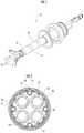
- FIG. 1is a perspective view showing a treatment-instrument insertion aid according to an embodiment of the present invention.
- FIG. 2is a cross-sectional view taken along an A-A line of FIG. 1 .
- FIG. 3Ais an exploded side view of an outer tube, etc.
- FIG. 3Bis a cross-sectional view of a bent outer tube, etc.
- FIG. 4Ais an exploded view of an inner tube, etc.
- FIG. 4Bis a perspective view of a bent inner tube of FIG. 4A , etc.
- FIG. 5Ais a side view of a guide member.
- FIG. 5Bis a cross-sectional view taken along a B-B line of FIG. 5A .
- FIG. 5Cis a cross-sectional view taken along a C-C line of FIG. 5A .
- a treatment-instrument insertion aid 10according to an embodiment of the present invention will be described.
- the treatment-instrument insertion aid 10is used to aid the insertion of a treatment instrument (not shown) such as an endoscope, forceps, a surgical knife or the like into a body.
- the treatment-instrument insertion aid 10mainly includes inner tubes 20 , an outer tube 30 and rail members 40 .
- Plural rail members 40are fitted to the outer tube 30 , and one or plural inner tubes 20 are inserted in the outer tube 30 .
- the outer tube 30is a cylindrical body having flexibility, and has plural guiding portions 31 which extend in the axial direction from a distal end side to a proximal end side on the inner surface.
- the guiding portions 31are dovetail grooves formed on the inner wall surface of the outer tube 30 , and formed at equal intervals in the circumferential direction on the inner wall surface.
- the dovetail groovesare formed at protruding portions protruding to the center axis, and have rectangular cross-sectional shapes at an opening portion and a back side.
- the shape of the dovetail groovesis not limited to the foregoing shape, but may be a substantially trapezoidal shape which spreads further to the back side than the opening portion, or may be rectangular at the opening portion and substantially circular on the back side or the like.
- the outer tube 30is composed of soft portions 30 A and hard portions 30 B alternately coupled to one another in the axial direction as shown in FIGS. 3A and 3B , the soft portions 30 A being formed of soft plastic such as polypropylene or vinyl chloride or a soft material such as rubber while the hard portions 30 B are harder than the soft portions 30 A and formed of hard plastic such as ABS or polycarbonate or a hard material such as hard rubber.
- both the end portions in the axial direction of the outer tube 30include hard portions 30 B.
- the outer tube 30may be constructed to be partially or wholly transparent or translucent.
- a first wire member 51is embedded in the axial direction from the distal end side to the proximal end side on the peripheral wall portion of the outer tube 30 .
- the first wire member 51further extends rearwards from the proximal end portion of the outer tube 30 , and advance or retreat of the first wire member 51 is operated by a first wire member operating unit (not shown), whereby the outer tube 30 can be bent in the circumferential direction to turn the distal end portion of the outer tube 30 to a desired direction.
- the shape of the first wire member 51may be temporarily fixed by temporarily locking the operation of the first wire member operating unit, for example by a ratchet mechanism, thereby maintaining the state where the distal end portion of the outer tube 30 is turned to the desired direction.
- the rail members 40are formed of a hard material which is the same as or equivalent to the hard material of the hard portions 30 B, for example, hard plastic such as ABS or polycarbonate or a hard material such as hard rubber, and constructed as elongated bodies having flexibility.
- the rail member 40has a guided portion 41 which extends in the axial direction from the distal end side to the proximal end side on the outer surface thereof.
- the guided portion 41is a protrusion formed on the outer surface of the rail member 40 .
- the guided portion 41may be intermittently formed.
- the protrusionis formed in such a shape engageable with the guiding portion 31 of the outer tube 30 , and the outside and neck portion thereof have rectangular cross-sectional shapes.
- the cross-sectional shape of the protrusionis not limited to the foregoing shapes, and may be a substantially trapezoidal shape spreading to the back side, or substantially circular at the outside thereof and rectangular at the neck portion.
- the dovetail grooveis formed by the inner peripheral surface of the outer tube 30 and the right and left side surfaces of the adjacent rail members 40 , and this dovetail groove constitutes an engaging portion 50 .
- the dovetail groovehas the rectangular cross-sectional view at both the opening portion and the back side as shown in FIG. 2 .
- the cross-sectional shape of the dovetail groovemay be a substantially trapezoidal shape which spreads further to the back side than the opening portion, or may be rectangular at the opening portion and substantially circular on the back side or the like.
- the distal end portions of the rail members 40are fixed to the hard portion 30 B nearest to the distal end side of the outer tube 30 by adhesive agent or the like while the guided portions 41 are engaged with the guiding portions 31 , but the other portions of the rail members 40 are not fixed to the outer tube 30 .
- the respective rail members 40bend while following the bending of the outer tube 30 , and thus the rail members 40 do not hinder the bending of the outer tube 30 . Accordingly, the outer tube 30 can be bent while maintaining the cross-sectional shape.
- a guide pipe 32 , an air leakage preventing ring 33 , ad a valve sheet 34are fitted to the proximal end side of the outer tube 30 .
- the guide pipe 32is a member for connecting the outer tube 30 and the air leakage preventing ring 33 , and formed of metal such as stainless steel or the like, or a hard material such as resin.
- the air leakage preventing ring 33is adhesively fixed to the valve sheet 34 .
- the air leakage preventing ringis detachably fitted to the guide pipe 32 .
- Plural holes through which the inner tubes 20 are insertedare formed in the valve sheet 34 .
- the inner tube 20is a cylindrical body having flexibility, and a treatment instrument such as an endoscope, forceps or a surgical knife is insertable into the inner tube 20 .
- the inner tube 20may have one channel for inserting the treatment instrument or two or more channels.
- the outer peripheral surface of the inner tube 20may be subjected to a hydrophilic treatment. According to hand manipulation, each inner tube 20 can be inserted into and removed from the outer tube 30 whose inner peripheral surface is engaged with the rail members 40 .
- the inner tubes 20have the same outer diameter, but the inner tubes 20 having different outer diameters may be used.
- the inner tube 20is composed of soft portions 20 A and hard portions 20 B coupled to one another in the axial direction, the soft portions 20 A being formed of soft plastic such as polypropylene or vinyl chloride or a soft material such as rubber while the hard portions 20 B are harder than the soft portions 20 A and formed of hard plastic such as ABS or polycarbonate or a hard material such as hard rubber. Both the end portions in the axial direction of the inner tube 20 include hard portions 20 B, and an intermediate portion between these hard portions 20 B includes a soft portion 20 A.
- the inner tube 20has an engaged portion 21 which is slidably engageable with an engaging portion 50 from the distal end to the proximal end of the outer peripheral surface of the inner tube 20 , and a scale (not shown) for grasping the insertion depth.
- the engaged portion 21is a rectangular wide protrusion protruding to the outer peripheral surface of the inner tube 20 , but it has any shape insofar as it is engageable with the engaging portion 50 .
- the engaged portion 21is continuously provided from the distal end to the proximal end of the inner tube 20 .
- the engaged portion 21may be intermittently provided at a part of the portion between the distal end and the proximal end of the outer peripheral surface of the inner tube 20 , and may be provided at least only at the distal end.
- a second wire member 52is embedded in the axial direction from the distal end side to the proximal end side in the engaged portion 21 of the inner tube 20 .
- the second wire member 52further extends rearwards from the proximal end portion of the inner tube 20 , and advance and retreat thereof can be performed by a slide knob 25 (an operating unit for the second wire member).
- the second wire member 52may be merely fixed to the inner tube 20 , and it may be embedded on the peripheral wall portion of the inner tube 20 instead of being embedded in the engaged portion 21 , or adhesively fixed to the outer peripheral surface of the inner tube 20 .
- a bendable swing pipe (corresponding to a bending member of the present invention) 22 and a nose cover 23 (corresponding to a cover of the present invention, and see FIGS. 4A and 4B )are fitted to the distal end portion of the inner tube 20 .
- the swing pipe 22is formed of a hard material whose hardness is equal to or harder than that of the hard portion 20 A of the inner tube 20 , for example, metal such as stainless steel or the like.
- Plural slits 22 aextending in the axial direction are formed in the swing pipe 22 .
- a thin wall part(s)may be formed in place of formation of the slits 22 a .
- the second wire member 52passes outside the swing pipe.
- the nose cover 23is fixed to the distal end portion of the swing pipe 22 .
- the nose cover 23is formed of a soft material softer than the hard material constituting the swing pipe 22 , for example, soft plastic such as vinyl chloride, rubber or the like. Since the nose cover 23 is formed of the soft material, the nose cover 23 does not damage tissues even when it comes into contact with the tissues.
- the distal end portion of the second wire member 52is fixed to the nose cover 23 .
- a first slide pipe 24 , a slide knob 25 , a slide stopper 26 , a second slide pipe 27 and a deaeration preventing valve 28are fitted to the proximal end portion of the inner tube 20 .
- the first slide pipe 24is connected to the rear end portion of the inner tube 20 , and inserted in the air leakage preventing ring 33 (see FIGS. 3A and 3B ). As a result, air in a body cavity can be prevented from leaking from places where the inner tubes 20 of the outer tube 30 are not inserted, or from the outer peripheral portions of the inserted inner tubes 20 .
- the distal end side of the first slide pipe 24includes a hard portion 24 A formed of a hard material whose hardness is equal or equivalent to the hardness of the hard portion 20 B of the inner tube 20
- the rear end side of the first slide pipe 24includes a semi-hard portion 24 B formed of a semi-hard material such as elastomer, polyurethane or the like whose hardness is softer than the hard portion 20 B of the inner tube 20 and harder than the soft portion 20 A.
- the rear end portion of the second wire member 52is fixed to the slide knob 25 .
- the slide knob 25is constructed to be freely slidable with respect to the second slide pipe 27 , and can be locked at a desired position with respect to the second slide pipe 27 by the slide stopper 26 .
- the deaeration preventing valve 28can prevent occurrence of air leakage from a body cavity, for example, an abdominal cavity from the inner tubes 20 in which no treatment instrument is inserted.
- the deaeration preventing valve 28is freely detachably fitted to the rear end of the second slide pipe 27 .
- the second wire member 52bends the swing pipe 22 to turn the distal end portion of the swing pipe 22 to a desired direction.
- the second wire member 52can bend the outer tube 30 while following bending of the inner tube 20 .
- the shape of the second wire member 52may be temporarily fixed by temporarily locking the operation of the slide knob 25 , for example by a ratchet mechanism, thereby maintaining the state where the distal end portion of the inner tube 20 or the outer tube 30 is turned to a desired direction.
- Engaged portions 61 of guide members 60are engaged with the engaging portions 50 with which the engaged portions 21 of the inner tubes 20 are not engaged.
- the guide member 60is an elongated member including a distal end side portion 60 A at which the engaged portion 61 to be engaged with the engaging portion 50 is formed inside, and a proximal end side portion 60 B.
- the distal end side portion 60 Ais formed of a semi-hard material such as elastomer, polyurethane, a wire or a copper wire which is softer than the hard portion 20 B of the inner tube 20 and harder than the soft portion 20 A.
- the proximal end side portion 60 Bis formed of a hard material whose hardness is equal or equivalent to the hard portion 20 B of the inner tube 20 .
- the engaged portion 61is a rectangular wide protrusion protruding to the outer peripheral surface of the inner tube 20 , but it may have any shape insofar as it is engageable with the engaging portion 50 .
- the main body portion 62 of the distal end side portion 60 Ahas a toroidal cross-section.
- the proximal end side portion 60 Bhas a substantially triangular cross-section having a circular hole at an apex thereof.
- the engaged portions 21 of the inner tubes 20are slid while engaged with the guiding portions 31 extending in the axial direction from the distal end side to the proximal end side, whereby the inner tubes 20 can be smoothly inserted and pulled out while maintaining the positions of the inner tubes 20 in the outer tube 30 , and a desired treatment instrument can be used.
- both the end portions of the inner tube 20include the hard portions 20 B, the inner tube 20 can be prevented from being crushed at both the end portions thereof. Furthermore, since the intermediate portion of the inner tube 20 includes the easily bendable soft portion 20 A, the inner tube can be easily bent during hand manipulation.
- the treatment instrumentcan be easily turned to a desired direction.
- the nose cover 23 formed of the soft materialis fitted to the distal end portion of the swing pipe 22 , a risk of damaging tissues can be prevented.
- both the end portions of the outer tube 30include the hard portions 30 B, the outer tube 30 can be prevented from being crushed at least at both the end portions, and further the inner tubes 20 of the outer tube 30 can be prevented from being crushed. Since the outer tube 30 has the easily bendable soft portions 30 A, the outer tube 30 can be easily bent during hand manipulation.
- the outer tube 30can be also prevented from being crushed at this portion. Furthermore, the inner tubes 20 in the outer tube 30 can be more effectively prevented from being crushed.
- the inner tubes 20can be locked at predetermined places by using the rail members 40 locked on the inner peripheral surface of the outer tube 30 , the interference among the inner tubes 20 can be prevented.
- the guide members 60are engaged with the engaging portions 50 with which no inner tube 20 is engaged, the interference among the inner tubes 20 can be surely prevented by the guide members 60 .
- the plural rail members 40are engaged with the inner peripheral surface of the outer tube 30 to configure the engaging portions 50 .
- the present inventionis not limited to this configuration, and the outer tube 30 and the plural rail members 40 may be integrated with each other to configure the engaging portions 50 .
- the soft material, the hard material and the semi-hard materialmay be materials obtained by changing the blending of the same kind of resin to adjust softness and hardness.
- 10 . . . treatment-instrument insertion aid20 . . . inner tube, 20 A . . . soft portion (intermediate portion), 20 B . . . hard portion (both end portions), 21 . . . engaged portion, 22 . . . swing pipe (bending member), 22 a . . . slit, 23 . . . nose cover (cover), 30 . . . outer tube, 30 A . . . soft portion, 30 B . . . hard portion, 31 . . . guiding portion, 40 . . . rail member, 41 . . . guided portion, 50 . . . engaging portion, 51 . . . first wire member, 52 . . . second wire member, 60 . . . guide member, 61 . . . engaged portion
Landscapes
- Health & Medical Sciences (AREA)
- Life Sciences & Earth Sciences (AREA)
- Surgery (AREA)
- Biomedical Technology (AREA)
- Medical Informatics (AREA)
- Optics & Photonics (AREA)
- Pathology (AREA)
- Radiology & Medical Imaging (AREA)
- Biophysics (AREA)
- Engineering & Computer Science (AREA)
- Physics & Mathematics (AREA)
- Heart & Thoracic Surgery (AREA)
- Nuclear Medicine, Radiotherapy & Molecular Imaging (AREA)
- Molecular Biology (AREA)
- Animal Behavior & Ethology (AREA)
- General Health & Medical Sciences (AREA)
- Public Health (AREA)
- Veterinary Medicine (AREA)
- Endoscopes (AREA)
- Media Introduction/Drainage Providing Device (AREA)
- Instruments For Viewing The Inside Of Hollow Bodies (AREA)
- Surgical Instruments (AREA)
Abstract
Description
Claims (8)
Applications Claiming Priority (1)
| Application Number | Priority Date | Filing Date | Title |
|---|---|---|---|
| PCT/JP2015/057388WO2016143142A1 (en) | 2015-03-12 | 2015-03-12 | Treatment-instrument insertion aid |
Publications (2)
| Publication Number | Publication Date |
|---|---|
| US20180049624A1 US20180049624A1 (en) | 2018-02-22 |
| US11272833B2true US11272833B2 (en) | 2022-03-15 |
Family
ID=56878603
Family Applications (1)
| Application Number | Title | Priority Date | Filing Date |
|---|---|---|---|
| US15/556,670Active2036-01-25US11272833B2 (en) | 2015-03-12 | 2015-03-12 | Treatment-instrument insertion aid |
Country Status (7)
| Country | Link |
|---|---|
| US (1) | US11272833B2 (en) |
| EP (1) | EP3269288B1 (en) |
| JP (1) | JP6623462B2 (en) |
| MY (1) | MY195396A (en) |
| SG (1) | SG11201707256VA (en) |
| TW (1) | TWI652035B (en) |
| WO (1) | WO2016143142A1 (en) |
Families Citing this family (7)
| Publication number | Priority date | Publication date | Assignee | Title |
|---|---|---|---|---|
| MY195396A (en)* | 2015-03-12 | 2023-01-18 | Univ Keio | Treatment-instrument insertion aid |
| JP6712646B2 (en)* | 2016-10-14 | 2020-06-24 | 株式会社メディカロイド | Medical instruments and surgical systems |
| US20180192855A1 (en)* | 2017-01-12 | 2018-07-12 | Olympus Corporation | Insertion assist system and insertion instrument |
| TWI728116B (en)* | 2017-05-31 | 2021-05-21 | 學校法人慶應義塾 | Medical inner tube |
| WO2018220767A1 (en)* | 2017-05-31 | 2018-12-06 | 学校法人慶應義塾 | Inner tube |
| JP7093911B2 (en)* | 2018-06-04 | 2022-07-01 | 慶應義塾 | Inner tube |
| WO2024229428A1 (en)* | 2023-05-04 | 2024-11-07 | Boston Scientific Scimed, Inc. | Devices, systems, and methods for articulation and/or retroflexion of a medical device |
Citations (35)
| Publication number | Priority date | Publication date | Assignee | Title |
|---|---|---|---|---|
| JPS5689233A (en) | 1979-12-24 | 1981-07-20 | Olympus Optical Co | Endoscope |
| JPS62167531A (en) | 1985-09-30 | 1987-07-23 | オリンパス光学工業株式会社 | Multirumen tube endoscope |
| JPH01254138A (en) | 1988-04-01 | 1989-10-11 | Fuji Photo Optical Co Ltd | Soft part of endoscope |
| JP2000037390A (en) | 1998-07-22 | 2000-02-08 | Olympus Optical Co Ltd | Endoscopic therapeutic instrument |
| JP2000166936A (en) | 1998-12-09 | 2000-06-20 | Olympus Optical Co Ltd | Endoscopic treatment instrument |
| US6099464A (en)* | 1995-04-10 | 2000-08-08 | Olympus Optical Co., Ltd. | Bending sheath for probe |
| JP2000325303A (en) | 1999-05-17 | 2000-11-28 | Olympus Optical Co Ltd | Endoscopic therapeutic device |
| US20020028984A1 (en)* | 2000-09-01 | 2002-03-07 | Asahi Kogaku Kogyo Kabushiki Kaisha Tokyo, Japan | Flexible tube for an endoscope and electronic endoscope equipped with the flexible tube |
| JP2003501197A (en) | 1999-06-11 | 2003-01-14 | サイムド ライフ システムズ, インコーポレイテッド | Sheath with large flexible middle for medical devices |
| US20040162568A1 (en)* | 1999-06-25 | 2004-08-19 | Usgi Medical | Apparatus and methods for forming and securing gastrointestinal tissue folds |
| JP2004337617A (en) | 2003-05-16 | 2004-12-02 | Ethicon Endo Surgery Inc | Medical apparatus and guide system for use with endoscope |
| JP2005046273A (en) | 2003-07-31 | 2005-02-24 | Olympus Corp | Overtube for endoscope |
| US6878106B1 (en)* | 1999-02-15 | 2005-04-12 | Ingo F. Herrmann | Deformable fiberscope with a displaceable supplementary device |
| JP2005177517A (en) | 2005-02-10 | 2005-07-07 | Olympus Corp | Endoscope |
| US20070106113A1 (en)* | 2005-11-07 | 2007-05-10 | Biagio Ravo | Combination endoscopic operative delivery system |
| US20080132758A1 (en)* | 2006-12-05 | 2008-06-05 | Ethicon Endo-Surgery, Inc. | Independent Articulating Accessory Channel |
| US20090149710A1 (en)* | 2007-12-07 | 2009-06-11 | Ethicon Endo-Surgery, Inc. | Selective stiffening devices and methods |
| US20090177041A1 (en)* | 2008-01-09 | 2009-07-09 | Ethicon Endo-Surgery, Inc. | Articulating surgical device and method of use |
| US20090221934A1 (en)* | 2006-03-07 | 2009-09-03 | Kuhns Jesse J | Method for endoluminally or laparoscopically excising a tissue sample from areas in a patient's body, traction means and kit |
| US20090259141A1 (en)* | 2008-03-21 | 2009-10-15 | Usgi Medical, Inc. | Steerable tool guide for use with flexible endoscopic medical devices |
| US20100016659A1 (en)* | 2008-07-18 | 2010-01-21 | Barry Weitzner | Endoscope With Guide |
| JP2010200913A (en)* | 2009-03-02 | 2010-09-16 | Olympus Corp | Guide device |
| US7803137B2 (en)* | 2006-03-22 | 2010-09-28 | Ethicon Endo-Surgery, Inc. | Intubation system for use with an endoscope |
| US7815565B2 (en)* | 2003-05-16 | 2010-10-19 | Ethicon Endo-Surgery, Inc. | Endcap for use with an endoscope |
| WO2011046002A1 (en) | 2009-10-14 | 2011-04-21 | オリンパスメディカルシステムズ株式会社 | Flexible medical tube and insertion part of medical instrument |
| US8007432B2 (en)* | 2007-01-26 | 2011-08-30 | Ethicon Endo-Surgery, Inc. | Endoscopic accessory control mechanism |
| US20120232339A1 (en)* | 2009-09-02 | 2012-09-13 | Laszlo Csiky | Surgical device and accessories |
| JP2012200552A (en) | 2011-03-28 | 2012-10-22 | Fujifilm Corp | Insertion assisting tool for endoscope |
| US8491585B2 (en)* | 2009-05-06 | 2013-07-23 | Kambiz Hannani | Methods and systems for minimally invasive lateral decompression |
| WO2014046618A1 (en) | 2012-09-19 | 2014-03-27 | Nanyang Technological University | Flexible master - slave robotic endoscopy system |
| US20140094658A1 (en)* | 2012-03-08 | 2014-04-03 | Olympus Medical Systems Corp. | Guide sheath and medical system |
| US20150080933A1 (en)* | 2013-08-31 | 2015-03-19 | Igor IGOV | Endoscope with shared working channel |
| US9254077B2 (en)* | 2007-04-02 | 2016-02-09 | Cook Medical Technologies Llc | Endoscopic apparatus having an outer rail |
| US20160174814A1 (en)* | 2013-08-31 | 2016-06-23 | Morena Medical Applications Ltd. | Endoscope with shared working channel |
| US20180049624A1 (en)* | 2015-03-12 | 2018-02-22 | KEIO UNIVERSITY, a university of Japan | Treatment-instrument insertion aid |
- 2015
- 2015-03-12MYMYPI2017703342Apatent/MY195396A/enunknown
- 2015-03-12SGSG11201707256VApatent/SG11201707256VA/enunknown
- 2015-03-12USUS15/556,670patent/US11272833B2/enactiveActive
- 2015-03-12WOPCT/JP2015/057388patent/WO2016143142A1/ennot_activeCeased
- 2015-03-12EPEP15884629.5Apatent/EP3269288B1/enactiveActive
- 2015-03-12JPJP2017504543Apatent/JP6623462B2/enactiveActive
- 2015-03-13TWTW104108265Apatent/TWI652035B/enactive
Patent Citations (41)
| Publication number | Priority date | Publication date | Assignee | Title |
|---|---|---|---|---|
| JPS5689233A (en) | 1979-12-24 | 1981-07-20 | Olympus Optical Co | Endoscope |
| JPS62167531A (en) | 1985-09-30 | 1987-07-23 | オリンパス光学工業株式会社 | Multirumen tube endoscope |
| JPH01254138A (en) | 1988-04-01 | 1989-10-11 | Fuji Photo Optical Co Ltd | Soft part of endoscope |
| US6099464A (en)* | 1995-04-10 | 2000-08-08 | Olympus Optical Co., Ltd. | Bending sheath for probe |
| JP2000037390A (en) | 1998-07-22 | 2000-02-08 | Olympus Optical Co Ltd | Endoscopic therapeutic instrument |
| JP2000166936A (en) | 1998-12-09 | 2000-06-20 | Olympus Optical Co Ltd | Endoscopic treatment instrument |
| US6878106B1 (en)* | 1999-02-15 | 2005-04-12 | Ingo F. Herrmann | Deformable fiberscope with a displaceable supplementary device |
| JP2000325303A (en) | 1999-05-17 | 2000-11-28 | Olympus Optical Co Ltd | Endoscopic therapeutic device |
| JP2003501197A (en) | 1999-06-11 | 2003-01-14 | サイムド ライフ システムズ, インコーポレイテッド | Sheath with large flexible middle for medical devices |
| US20040162568A1 (en)* | 1999-06-25 | 2004-08-19 | Usgi Medical | Apparatus and methods for forming and securing gastrointestinal tissue folds |
| US20020028984A1 (en)* | 2000-09-01 | 2002-03-07 | Asahi Kogaku Kogyo Kabushiki Kaisha Tokyo, Japan | Flexible tube for an endoscope and electronic endoscope equipped with the flexible tube |
| JP2004337617A (en) | 2003-05-16 | 2004-12-02 | Ethicon Endo Surgery Inc | Medical apparatus and guide system for use with endoscope |
| US7815565B2 (en)* | 2003-05-16 | 2010-10-19 | Ethicon Endo-Surgery, Inc. | Endcap for use with an endoscope |
| JP2005046273A (en) | 2003-07-31 | 2005-02-24 | Olympus Corp | Overtube for endoscope |
| JP2005177517A (en) | 2005-02-10 | 2005-07-07 | Olympus Corp | Endoscope |
| US20070106113A1 (en)* | 2005-11-07 | 2007-05-10 | Biagio Ravo | Combination endoscopic operative delivery system |
| US20090221934A1 (en)* | 2006-03-07 | 2009-09-03 | Kuhns Jesse J | Method for endoluminally or laparoscopically excising a tissue sample from areas in a patient's body, traction means and kit |
| US7803137B2 (en)* | 2006-03-22 | 2010-09-28 | Ethicon Endo-Surgery, Inc. | Intubation system for use with an endoscope |
| US20080132758A1 (en)* | 2006-12-05 | 2008-06-05 | Ethicon Endo-Surgery, Inc. | Independent Articulating Accessory Channel |
| US7976458B2 (en)* | 2006-12-05 | 2011-07-12 | Ethicon Endo-Surgery, Inc. | Independent articulating accessory channel |
| US8007432B2 (en)* | 2007-01-26 | 2011-08-30 | Ethicon Endo-Surgery, Inc. | Endoscopic accessory control mechanism |
| US9254077B2 (en)* | 2007-04-02 | 2016-02-09 | Cook Medical Technologies Llc | Endoscopic apparatus having an outer rail |
| US9066655B2 (en)* | 2007-12-07 | 2015-06-30 | Ethicon Endo-Surgery, Inc. | Selective stiffening devices and methods |
| US20090149710A1 (en)* | 2007-12-07 | 2009-06-11 | Ethicon Endo-Surgery, Inc. | Selective stiffening devices and methods |
| US20090177041A1 (en)* | 2008-01-09 | 2009-07-09 | Ethicon Endo-Surgery, Inc. | Articulating surgical device and method of use |
| US20090259141A1 (en)* | 2008-03-21 | 2009-10-15 | Usgi Medical, Inc. | Steerable tool guide for use with flexible endoscopic medical devices |
| US20100016659A1 (en)* | 2008-07-18 | 2010-01-21 | Barry Weitzner | Endoscope With Guide |
| JP2010200913A (en)* | 2009-03-02 | 2010-09-16 | Olympus Corp | Guide device |
| US8491585B2 (en)* | 2009-05-06 | 2013-07-23 | Kambiz Hannani | Methods and systems for minimally invasive lateral decompression |
| US9877794B2 (en)* | 2009-09-02 | 2018-01-30 | Laszlo Csiky | Surgical device and accessories |
| US20120232339A1 (en)* | 2009-09-02 | 2012-09-13 | Laszlo Csiky | Surgical device and accessories |
| US20180092635A1 (en)* | 2009-09-02 | 2018-04-05 | Laszlo Csiky | Surgical device and accessories |
| WO2011046002A1 (en) | 2009-10-14 | 2011-04-21 | オリンパスメディカルシステムズ株式会社 | Flexible medical tube and insertion part of medical instrument |
| JP2012200552A (en) | 2011-03-28 | 2012-10-22 | Fujifilm Corp | Insertion assisting tool for endoscope |
| US20140094658A1 (en)* | 2012-03-08 | 2014-04-03 | Olympus Medical Systems Corp. | Guide sheath and medical system |
| US8911359B2 (en)* | 2012-03-08 | 2014-12-16 | Olympus Medical Systems Corp. | Guide sheath and medical system |
| WO2014046618A1 (en) | 2012-09-19 | 2014-03-27 | Nanyang Technological University | Flexible master - slave robotic endoscopy system |
| US20150080933A1 (en)* | 2013-08-31 | 2015-03-19 | Igor IGOV | Endoscope with shared working channel |
| US20170224378A1 (en)* | 2013-08-31 | 2017-08-10 | Morena Medical Appliations Ltd. | Endoscope with shared working channel |
| US20160174814A1 (en)* | 2013-08-31 | 2016-06-23 | Morena Medical Applications Ltd. | Endoscope with shared working channel |
| US20180049624A1 (en)* | 2015-03-12 | 2018-02-22 | KEIO UNIVERSITY, a university of Japan | Treatment-instrument insertion aid |
Non-Patent Citations (2)
| Title |
|---|
| European Search Report dated Oct. 15, 2018, 7 pages. |
| International Search Report, dated Jun. 2, 2015 (Jun. 2, 2015). |
Also Published As
| Publication number | Publication date |
|---|---|
| TW201632134A (en) | 2016-09-16 |
| MY195396A (en) | 2023-01-18 |
| EP3269288B1 (en) | 2020-06-03 |
| EP3269288A4 (en) | 2018-11-14 |
| JPWO2016143142A1 (en) | 2017-12-21 |
| WO2016143142A1 (en) | 2016-09-15 |
| US20180049624A1 (en) | 2018-02-22 |
| SG11201707256VA (en) | 2017-10-30 |
| TWI652035B (en) | 2019-03-01 |
| EP3269288A1 (en) | 2018-01-17 |
| JP6623462B2 (en) | 2019-12-25 |
Similar Documents
| Publication | Publication Date | Title |
|---|---|---|
| US11272833B2 (en) | Treatment-instrument insertion aid | |
| US10493240B2 (en) | Steerable catheter handle | |
| US10271874B2 (en) | Surgical tool insertion aid | |
| US20090062606A1 (en) | Endoscope guiding tube device | |
| EP2574269B1 (en) | Insertion portion rigidity changeable catheter with balloon | |
| JP2011194126A (en) | Guide tube for endoscope or treatment tool | |
| US11122964B2 (en) | Treatment-instrument insertion aid | |
| JP4648785B2 (en) | Endoscopic balloon catheter for endoscope | |
| JP2009056056A (en) | Endoscope guiding tube device | |
| JP2009056054A (en) | Endoscope guiding tube device | |
| JP4344734B2 (en) | Medical treatment instrument insertion port | |
| JP2014018366A (en) | Trocar catheter, and cannula catheter and inner needle used for the same | |
| EP3490428B1 (en) | Steerable catheter handle | |
| WO2010009070A1 (en) | Endoscopic translumenal articulatable and steerable flexible overtube | |
| JP7464923B2 (en) | Treatment tool insertion aid | |
| JP5570370B2 (en) | Surgical endoscope device | |
| JP2009089724A (en) | Separate type endoscope | |
| JP7221482B2 (en) | Inner tube | |
| JP2017099810A (en) | Treatment instrument insertion tool | |
| WO2017195348A1 (en) | Medical overtube | |
| JP2005230085A (en) | Over-tube with balloon | |
| JP2009056055A (en) | Endoscope guiding tube device |
Legal Events
| Date | Code | Title | Description |
|---|---|---|---|
| AS | Assignment | Owner name:KEIO UNIVERSITY, JAPAN Free format text:ASSIGNMENT OF ASSIGNORS INTEREST;ASSIGNORS:WADA, NORIHITO;MIYAZAKI, TAKUYA;HIMURA, YOSHIHIKO;SIGNING DATES FROM 20170828 TO 20170830;REEL/FRAME:043538/0402 Owner name:KABUSHIKI KAISHA TOP, JAPAN Free format text:ASSIGNMENT OF ASSIGNORS INTEREST;ASSIGNORS:WADA, NORIHITO;MIYAZAKI, TAKUYA;HIMURA, YOSHIHIKO;SIGNING DATES FROM 20170828 TO 20170830;REEL/FRAME:043538/0402 | |
| FEPP | Fee payment procedure | Free format text:ENTITY STATUS SET TO UNDISCOUNTED (ORIGINAL EVENT CODE: BIG.); ENTITY STATUS OF PATENT OWNER: LARGE ENTITY | |
| STPP | Information on status: patent application and granting procedure in general | Free format text:DOCKETED NEW CASE - READY FOR EXAMINATION | |
| STPP | Information on status: patent application and granting procedure in general | Free format text:NON FINAL ACTION MAILED | |
| STPP | Information on status: patent application and granting procedure in general | Free format text:RESPONSE TO NON-FINAL OFFICE ACTION ENTERED AND FORWARDED TO EXAMINER | |
| STPP | Information on status: patent application and granting procedure in general | Free format text:FINAL REJECTION MAILED | |
| STPP | Information on status: patent application and granting procedure in general | Free format text:ADVISORY ACTION MAILED | |
| STPP | Information on status: patent application and granting procedure in general | Free format text:NON FINAL ACTION MAILED | |
| STPP | Information on status: patent application and granting procedure in general | Free format text:RESPONSE TO NON-FINAL OFFICE ACTION ENTERED AND FORWARDED TO EXAMINER | |
| STPP | Information on status: patent application and granting procedure in general | Free format text:FINAL REJECTION MAILED | |
| STPP | Information on status: patent application and granting procedure in general | Free format text:RESPONSE AFTER FINAL ACTION FORWARDED TO EXAMINER | |
| STPP | Information on status: patent application and granting procedure in general | Free format text:NOTICE OF ALLOWANCE MAILED -- APPLICATION RECEIVED IN OFFICE OF PUBLICATIONS | |
| STCF | Information on status: patent grant | Free format text:PATENTED CASE | |
| MAFP | Maintenance fee payment | Free format text:PAYMENT OF MAINTENANCE FEE, 4TH YEAR, LARGE ENTITY (ORIGINAL EVENT CODE: M1551); ENTITY STATUS OF PATENT OWNER: LARGE ENTITY Year of fee payment:4 |