US11272282B2 - Wearable audio device - Google Patents
Wearable audio deviceDownload PDFInfo
- Publication number
- US11272282B2 US11272282B2US16/426,267US201916426267AUS11272282B2US 11272282 B2US11272282 B2US 11272282B2US 201916426267 AUS201916426267 AUS 201916426267AUS 11272282 B2US11272282 B2US 11272282B2
- Authority
- US
- United States
- Prior art keywords
- transducer
- magnetic field
- shield
- audio device
- electro
- Prior art date
- Legal status (The legal status is an assumption and is not a legal conclusion. Google has not performed a legal analysis and makes no representation as to the accuracy of the status listed.)
- Active, expires
Links
Images


Classifications
- H—ELECTRICITY
- H04—ELECTRIC COMMUNICATION TECHNIQUE
- H04R—LOUDSPEAKERS, MICROPHONES, GRAMOPHONE PICK-UPS OR LIKE ACOUSTIC ELECTROMECHANICAL TRANSDUCERS; DEAF-AID SETS; PUBLIC ADDRESS SYSTEMS
- H04R1/00—Details of transducers, loudspeakers or microphones
- H04R1/10—Earpieces; Attachments therefor ; Earphones; Monophonic headphones
- H04R1/1041—Mechanical or electronic switches, or control elements
- H—ELECTRICITY
- H04—ELECTRIC COMMUNICATION TECHNIQUE
- H04R—LOUDSPEAKERS, MICROPHONES, GRAMOPHONE PICK-UPS OR LIKE ACOUSTIC ELECTROMECHANICAL TRANSDUCERS; DEAF-AID SETS; PUBLIC ADDRESS SYSTEMS
- H04R1/00—Details of transducers, loudspeakers or microphones
- H04R1/10—Earpieces; Attachments therefor ; Earphones; Monophonic headphones
- H04R1/1058—Manufacture or assembly
- H04R1/1075—Mountings of transducers in earphones or headphones
- G—PHYSICS
- G01—MEASURING; TESTING
- G01R—MEASURING ELECTRIC VARIABLES; MEASURING MAGNETIC VARIABLES
- G01R33/00—Arrangements or instruments for measuring magnetic variables
- G01R33/0047—Housings or packaging of magnetic sensors ; Holders
- G—PHYSICS
- G01—MEASURING; TESTING
- G01R—MEASURING ELECTRIC VARIABLES; MEASURING MAGNETIC VARIABLES
- G01R33/00—Arrangements or instruments for measuring magnetic variables
- G01R33/007—Environmental aspects, e.g. temperature variations, radiation, stray fields
- G01R33/0076—Protection, e.g. with housings against stray fields
- H—ELECTRICITY
- H04—ELECTRIC COMMUNICATION TECHNIQUE
- H04R—LOUDSPEAKERS, MICROPHONES, GRAMOPHONE PICK-UPS OR LIKE ACOUSTIC ELECTROMECHANICAL TRANSDUCERS; DEAF-AID SETS; PUBLIC ADDRESS SYSTEMS
- H04R1/00—Details of transducers, loudspeakers or microphones
- H04R1/10—Earpieces; Attachments therefor ; Earphones; Monophonic headphones
- H04R1/1016—Earpieces of the intra-aural type
- H—ELECTRICITY
- H04—ELECTRIC COMMUNICATION TECHNIQUE
- H04R—LOUDSPEAKERS, MICROPHONES, GRAMOPHONE PICK-UPS OR LIKE ACOUSTIC ELECTROMECHANICAL TRANSDUCERS; DEAF-AID SETS; PUBLIC ADDRESS SYSTEMS
- H04R9/00—Transducers of moving-coil, moving-strip, or moving-wire type
- H04R9/02—Details
- H04R9/025—Magnetic circuit
- H—ELECTRICITY
- H04—ELECTRIC COMMUNICATION TECHNIQUE
- H04R—LOUDSPEAKERS, MICROPHONES, GRAMOPHONE PICK-UPS OR LIKE ACOUSTIC ELECTROMECHANICAL TRANSDUCERS; DEAF-AID SETS; PUBLIC ADDRESS SYSTEMS
- H04R2201/00—Details of transducers, loudspeakers or microphones covered by H04R1/00 but not provided for in any of its subgroups
- H04R2201/10—Details of earpieces, attachments therefor, earphones or monophonic headphones covered by H04R1/10 but not provided for in any of its subgroups
- H—ELECTRICITY
- H04—ELECTRIC COMMUNICATION TECHNIQUE
- H04R—LOUDSPEAKERS, MICROPHONES, GRAMOPHONE PICK-UPS OR LIKE ACOUSTIC ELECTROMECHANICAL TRANSDUCERS; DEAF-AID SETS; PUBLIC ADDRESS SYSTEMS
- H04R2209/00—Details of transducers of the moving-coil, moving-strip, or moving-wire type covered by H04R9/00 but not provided for in any of its subgroups
- H04R2209/022—Aspects regarding the stray flux internal or external to the magnetic circuit, e.g. shielding, shape of magnetic circuit, flux compensation coils
- H—ELECTRICITY
- H04—ELECTRIC COMMUNICATION TECHNIQUE
- H04R—LOUDSPEAKERS, MICROPHONES, GRAMOPHONE PICK-UPS OR LIKE ACOUSTIC ELECTROMECHANICAL TRANSDUCERS; DEAF-AID SETS; PUBLIC ADDRESS SYSTEMS
- H04R2209/00—Details of transducers of the moving-coil, moving-strip, or moving-wire type covered by H04R9/00 but not provided for in any of its subgroups
- H04R2209/024—Manufacturing aspects of the magnetic circuit of loudspeaker or microphone transducers
Definitions
- This disclosurerelates to a wearable audio device such as an earphone.
- Wearable audio devicescan include orientation tracking systems that use a magnetometer to track motions of the head and/or the direction in which the wearer is looking. Magnetometers need to accurately detect the Earth's magnetic field.
- the wearable audio device's electro-acoustic transducertypically includes a magnet.
- the wearable audio devicecan also include a magnet used to dock or park the wearable audio device to another structure. Since some wearable audio devices, such as in-ear headphones (sometimes also called earbuds) are desirably quite small, of necessity the magnetometer is close to the other magnet(s).
- the magnetic field of the other magnet(s)may have a magnetic field strength that is much greater than the Earth's magnetic field. Accordingly, the device's magnetic field(s) can overwhelm the magnetometer and prevent it from working properly.
- a wearable audio deviceincludes an electro-acoustic transducer for creating audio output, the electro-acoustic transducer comprising a transducer magnet that produces a transducer magnetic field, a magnetic field sensor spaced from the electro-acoustic transducer and constructed and arranged to sense the Earth's magnetic field, and a magnetic shield comprising a material with high magnetic permeability, wherein the shield is configured to intercept at least some of the transducer magnetic field before it reaches the magnetic field sensor.
- the wearable audio devicemay comprise an earbud comprising an earbud body, and the electro-acoustic transducer, the magnetic field sensor, and the shield may all be located within the earbud body.
- the earbud bodymay be constructed and arranged to be positioned so as to direct the audio output toward the ear of the wearer.
- the magnetic shieldmay be located between the transducer magnet and the magnetic field sensor.
- the material with high magnetic permeabilitymay comprise mu metal.
- the material with high magnetic permeabilitymay comprise a nickel-iron alloy.
- the wearable audio devicemay further comprise a housing constructed and arranged to be positioned at an ear of a wearer so as to direct the audio output toward the ear of the wearer.
- the transducer and the shieldmay be in the housing.
- the housingmay comprise a wall between the transducer and the magnetic field sensor.
- the shieldmay be coupled to the wall.
- the wallmay define an interior width.
- the shieldmay span the entire interior width of the wall.
- the shieldmay comprise a first portion that spans at least part of the interior width of the wall and a second portion that is located between the first portion and the transducer.
- the second portion of the shieldmay be coupled to the housing wall.
- the shieldmay be coupled to the transducer.
- the shieldmay be coupled to the transducer proximate the transducer magnet.
- the shieldmay comprise openings to allow sound pressure from the transducer to pass through the shield.
- the transducer magnetmay have a magnetic field strength and the magnetic field sensor may have a sensed magnetic field range where it operates linearly.
- the shieldmay reduce the strength of the transducer magnetic field at the magnetic field sensor such that the sensed magnetic field strength is in the sensed magnetic field range where the magnetic field sensor operates linearly.
- an earbudin another aspect includes an electro-acoustic transducer for creating audio output, the electro-acoustic transducer comprising a transducer magnet that produces a transducer magnetic field having a magnetic field strength, a body constructed and arranged to be positioned at an ear of a wearer so as to direct the audio output at the ear of the wearer, a three-axis magnetometer positioned in the body and constructed and arranged to sense the Earth's magnetic field in three orthogonal axes, and a magnetic field shield positioned in the body between the transducer and the magnetometer and configured to intercept the transducer magnetic field before it reaches the magnetometer.
- the magnetometermay have a sensed magnetic field range where it operates linearly, and the shield may reduce the strength of the transducer magnetic field at the magnetometer such that the sensed magnetic field strength is in the sensed magnetic field range where the magnetometer operates linearly.
- the transducer, the magnetometer, and the shieldare all located within the body.
- FIG. 1is a schematic cross-sectional view of a wearable audio device.
- FIG. 2is perspective view of an earphone.
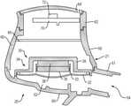
- FIG. 3is a partial cross-sectional view of elements of an earphone.
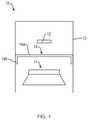
- FIG. 4is a schematic view of the magnetic structure of an earphone and its magnetic field at the location of a magnetic field sensor.
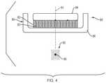
- FIG. 5is a view similar to that of FIG. 4 but including a magnetic field shield.
- FIG. 6is a schematic diagram of an earphone.
- Wearable audio devicescan include a transducer magnet. Some but not all wearable audio devices also include one or both of a docking magnet and a parking magnet. Wearable audio devices many times include magnetic devices, for example a magnetometer, ferrite cores (which may be used in filters, for example), and magnetic reed switches, to name only several of many possible magnetic devices in a wearable audio device such as an earbud. These magnetic devices are typically designed to operate in a stable operational range only if the strength of any stray magnetic field is relatively low. The magnets of a wearable audio device can emit stray magnetic fields that can negatively impact the operation of other magnetic devices of the wearable audio device.
- wearable audio devicese.g., earphones
- the magnetometercan be located close to the transducer magnet and/or other magnets. The magnetic field from any one or more of these magnets can overwhelm the magnetometer and prevent it from properly detecting the strength of the Earth's magnetic field.
- Negative effects on a magnetic device of a wearable audio device due to stray magnetic fields at the location of the magnetic devicecan be reduced with a magnetic shield comprising a material with high magnetic permeability.
- the shieldis configured to intercept at least some of the stray magnetic field(s) before they reach the magnetic device, so that the stray magnetic field(s) at the location of the magnetic device are eliminated or reduced. Any shielding should be sufficient such that the magnetic device can operate in its operational region where stray magnetic field(s) do not overwhelm it.
- the magnetic deviceis a magnetometer
- one or more magnetic shieldscan be used to bring the magnetometer into a region of stable operation where the magnetometer can operate in its operational region where stray magnetic fields do not overwhelm the Earth's magnetic field.
- FIG. 1is a schematic cross-sectional view of a wearable audio device 10 that comprises an electro-acoustic transducer 11 that is configured to create audio output.
- Electro-acoustic transducer 11includes a transducer magnet (not shown) that produces a transducer magnetic field.
- Magnetic field sensor 12is spaced from transducer 11 and is constructed and arranged to sense the Earth's magnetic field.
- Magnetic shield 14comprises a material with high magnetic permeability and is configured to intercept at least some of the transducer magnetic field before it reaches the magnetic field sensor.
- the transducer, the magnetic field sensor and the shieldare all located within device housing 13 .
- device 10is an earbud and housing 13 is an earbud body.
- the earbud bodymay be constructed and arranged to be positioned so as to direct the transducer audio output toward the ear of the wearer.
- the magnetic shield 14is located between the transducer magnet and the magnetic field sensor, such that it intercepts some or all of the magnetic field from the transducer magnet before the field reaches the sensor.
- Shield 14is made from or at least includes a material with high magnetic permeability. Without limiting the scope of this disclosure, high permeability can be defined as a DC permeability of at least about 1,000. Highly permeable materials are able to support the formation of a magnetic field within the material. Accordingly, when such materials are placed in a magnetic field the field couples to the material. The material thus can be considered to intercept the field.
- shield 14comprises or is made from mu metal.
- Mu metalis a known ferromagnetic alloy with high magnetic permeability (typically between about 1,000 and 500,000) and comprises a nickel-iron alloy. Mu metal is soft, so it can be easily formed to a desired shape. Ferrite or other magnetically permeable materials may be used as part of or all of the shield.
- Housing 13may be but need not be constructed and arranged to be positioned at an ear of a wearer so as to direct the audio output toward the ear of the wearer.
- Housing 13has an outer wall located between transducer 11 and magnetic field sensor 12 .
- Shield 14can be coupled to the wall, as shown.
- the walldefines an interior width and shield 14 spans the entire interior width of the wall.
- Shield 14comprises a first portion 14 a that spans at least part of (and in this case all of) the interior width of the wall at a location spaced from the transducer, and a second portion 14 b that is located between the first portion and the transducer.
- the second portion 14 bis coupled to the housing wall. Coupling can be accomplished in any manner, such as by the use of an adhesive or mechanical coupling members such as hooks or fasteners.
- Shield 14can be unitary (one piece) or can comprise two or more separate pieces.
- the shieldis positioned to sufficiently intercept the stray fields before they reach sensor 12 such sensor 12 can operate in its stable operational region where it is able to sense the Earth's magnetic field. In cases where the stray field comes from the transducer magnet, the shield will ideally be located as close to as possible to the transducer magnet, so its field is intercepted before it begins to spread out too far to be intercepted.
- the shieldcan be (but need not be) coupled to the transducer. If it is, it needs to be configured such that it does not unacceptably interfere with the transducer function. For example, if the shield is coupled to the rear side of the transducer, it may need to have openings so that sound pressure can pass through the shield.
- FIG. 2is a perspective view of a wireless in-ear headphone, earphone, or earbud, 15 .
- An earphoneis only one non-limiting example of the subject wearable audio device. Other examples are described elsewhere herein.
- Earbud/earphone 15includes body or housing 16 that houses the active components of the earbud. Portion 17 is coupled to body 16 and is pliable so that it can be inserted into the entrance of the ear canal. Sound is delivered through opening 18 .
- Retaining loop 19is constructed and arranged to be positioned in the outer ear, for example in the antihelix, to help retain the earbud in the ear.
- Earbudsare well known in the field (e.g., as disclosed in U.S. Pat. No.
- An earbud 15is an example of a wearable audio device according to this disclosure, but is not limiting of the scope of this disclosure as stray magnetic fields from one or more magnets at the location of a magnetic device in other types of wearable audio devices can also be resolved in accordance with the present disclosure.
- FIG. 3is a partial cross-sectional view of only certain elements of an earphone 20 that are useful to a better understanding of the present disclosure.
- Earphone 20comprises housing 21 that encloses electro-acoustic transducer 30 .
- Housing 21comprises front housing portion 50 and rear housing portions 60 and 62 .
- Transducer 30has diaphragm 32 that is driven in order to create sound pressure in front acoustic cavity 52 . Sound pressure is directed out of front housing portion 50 via opening 54 .
- earphone 20is an earbud, as shown by earbud 15 in FIG. 2 , there is typically a pliable tip (not shown) that is engaged with neck 51 of housing portion 50 , to help direct the sound into the ear canal and to seal to the ear canal opening.
- Earphone housing 21further comprises a rear enclosure made from rear housing portions 60 and 62 , and grille 64 .
- earphone 20is exemplary of aspects of earphones and are not limiting of the scope of this disclosure, as the present magnetic field reduction at the location of the magnetometer or other magnetic device can be used in varied types and designs of earphones and other wearable audio devices.
- Transducer 30further comprises magnetic structure 34 .
- Magnetic structure 34comprises transducer magnet 38 and magnetic material that functions to confine and guide the magnetic field from magnet 38 , so that the field properly interacts with coil 33 to drive diaphragm 32 , as is well known in the electro-acoustic transducer field.
- the magnetic materialcomprises cup 36 and front plate 35 , both of which are preferably made from a material with relatively high magnetic susceptibility, also as is known in the field.
- Three-axis magnetometer 72is mounted on PCB 70 and is arranged to sense the strength of magnetic fields in three axes at the location of the magnetometer, as is known in the field. Magnetometer 72 is configured to detect the Earth's magnetic field. The output of magnetometer 72 can be used to determine the direction in which the wearer's head is pointed, as described in U.S. Patent Application 62/626,967, filed on Feb. 6, 2018, the entire disclosure of which is incorporated herein by reference. As discussed above, earphone 20 may additionally or alternatively include other magnetic devices that might be adversely impacted by the stray magnetic field from a transducer, coupling, docking and/or parking magnet.
- magnetometer 72is relatively close to transducer magnet 38 (in a wireless earbud magnetometer 72 and transducer magnet 38 may be separated by only about 2 mm) the transducer's magnetic field can overwhelm the magnetometer and prevent it from properly detecting the strength of the Earth's magnetic field.
- the magnetometercan be brought into its specified measurement range (where stray magnetic fields do not overwhelm or skew the desired measurement) with a magnetic shield comprising a material with high magnetic permeability, wherein the shield is configured to intercept at least some of the transducer magnetic field before it reaches the magnetic field sensor.
- Magnetic shield 66is in this non-limiting example coupled to the inside of housing 60 and spans the entire width of the housing.
- Shield 66is located such that it intercepts at least some of the magnetic field from transducer magnet 38 before the field reaches magnetometer 72 , and so partially or fully reduces the transducer magnetic field at the location of magnetometer 72 .
- This transducer magnetic field reductionshould take place in any one, two, or three of the three orthogonal sense axes in which stable operation of the magnetometer is needed. In the present case, stable magnetometer results are desired in all three axes, so shield 66 is desirably configured to sufficiently reduce the magnetic field of transducer magnet 38 in all three axes. It should be understood that the location of shield 66 in FIG. 3 is representative, and shield 66 may actually be located elsewhere in the wearable audio device, somewhere between the transducer and the magnetometer.
- shield 66is located in housing 60 proximate or against the outside of the transducer magnetic structure (which in this non-limiting example comprises cup 36 ).
- the shieldingshould be sufficient such that magnetometer 72 can operate in at least one sense axis in its operational region where stray magnetic fields do not overwhelm the Earth's magnetic field to the point where the Earth's magnetic field can't be properly sensed.
- Linear operation of magnetometers(where there are stray magnetic fields that are not so strong that they overwhelm sensing or detection of the desired field) is known in the technical field, and so is not further described herein.
- shield 66can reduce the magnitude of the transducer magnet's field at magnetometer 72 along only one orthogonal axis, or along two orthogonal axes, ideally to the point where the magnetometer can properly detect the Earth's magnetic field.
- shield 66The configuration, location, and shielding properties of shield 66 can be determined in one non-limiting example as follows. Magnetic fields have both a direction and magnitude. Once the direction and magnitude of the field from transducer magnet 38 (and any other magnets that may have an effect on the magnetometer) at the magnetometer are known, a shield can be chosen and its location and other properties (e.g., its magnetic permeability, thickness, size, shape) determined such that (at the necessary location(s) of the magnetometer where the fields in each axis are sensed), the stray magnetic field(s) at the location of magnetometer 72 are reduced or eliminated in all three axes.
- location and other propertiese.g., its magnetic permeability, thickness, size, shape
- FIGS. 4 and 5illustrate aspects of an earphone.
- Earphone electro-acoustic transducer 80comprises transducer magnet 82 , and a magnetic structure 85 that comprises cup 86 and front member 84 .
- Magnet 82has a magnetic field, which is represented by the generally vertical field line representations 83 . Magnetic fields and field line representations are well known in the art and so are not further described herein.
- the field from magnet 83 in the vicinity of magnetometer 90is schematically represented by field lines 92 .
- the field strength of the magnetic field from magnet 82 in the vicinity of magnetometer 90is about 500 ⁇ T. Note that the field strength is unlikely to be the same in each of the three axes.
- the 500 ⁇ T valueis simply representative of what the field strength may be in any one or more of the three axes.
- the strength of the Earth's magnetic fieldis generally approximately 50 ⁇ T, or about 1/10 th of the field from magnet 82 .
- magnetometer 90can be inaccurate. Accordingly, the look direction sensing involving magnetometer 90 can be inaccurate.
- electro-acoustic magnet transducerscan have varied shapes, sizes, locations, and field strengths, and that the illustrative values set forth in the examples are not limiting of the scope of this disclosure.
- FIG. 5illustrates schematically an effect of shield 94 .
- Shield 94is located between the outside of cup 86 and magnetometer 90 .
- Shield 94has a size, shape, orientation, magnetic permeability, and location relative to transducer 80 and magnetometer 90 such that it intercepts the magnetic field from the transducer magnet 82 sufficiently to fully or partially prevent the transducer magnetic field from reaching the magnetometer in one, two, or three orthogonal axes.
- this field cancellationis indicated by there being no field line representation at magnetometer 90 (i.e., no field lines intersect magnetometer 90 ).
- Shield 94is in this non-limiting example coupled to cup 86 via peripheral portions 95 and 96 . This places the shield very close to the source of the stray magnetic field—the transducer magnet. The shield can thus be effective to intercept and redirect the magnetic field before it reaches the magnetometer.
- the stray field from magnet 82is indicated by field lines 100 and 104 that are redirected into shield 94 and out of the shield back toward the magnet as indicated by return field lines 102 and 106 . Accordingly, the field does not reach magnetometer 90 . Since the shield can help to couple the field back to the transducer magnet, the shield may increase the efficiency of the magnet and thus of the transducer.
- the drawingis schematic and the actual configuration of the shield and the manner in which it is coupled to the cup or to another portion of the transducer (possibly close to the cup) may depend on the particular transducer used. If the shield seals the back of the transducer, it may be desirable to include openings (not shown) that allow sound pressure to pass through the shield. Also, it may be possible to shield a transducer magnet by making the basket or frame of the transducer from a material with high magnetic permeability.
- the field that is interceptedcould be from the transducer magnet and/or from a parking or docking magnet.
- the shieldingshould be sufficient to reduce the stray magnetic field(s) to below the level where the magnetometer can operate in its normal operational range.
- the strength of stray fields that would bring a magnetometer out of its normal operational rangeare dependent on the particular magnetometer used.
- the fielddoes not need to be fully canceled by the shield. Rather, as described above, the strength of the field needs to be reduced sufficiently such that the magnetometer can sense the Earth's magnetic field.
- the reduction in the transducer field at the magnetometer that needs to be accomplished with a shieldwill in part depend on the particular magnetometer used, as would be apparent to one skilled in the field.
- FIGS. 4 and 5are two-dimensional.
- the transducer magnet's field in three dimensionsneeds to be reduced in order for the sensing of the Earth's magnetic field to be accomplished with sufficient accuracy for the particular application of the Earth's magnetic field sensor, and can make an appropriate selection of the shield parameters described above to accomplish such results.
- transducer magnet 82can be a generally cylindrical magnet with a diameter of about 8 mm, and cup 86 can have a diameter of about 10 mm.
- sensor 90can be positioned less than about 10 mm from transducer 80 .
- the magnetic field strength of the transducer magnet at sensor 90is at least about 100 ⁇ T.
- the magnetic field strength outside of transducer 80is as high as 1 ⁇ 10 ⁇ 9 T.
- shield 94made of mu metal, shield 94 can be effective to reduce the magnetic field to about 4 ⁇ 10 ⁇ 11 T. Note that all values are illustrative rather than limiting of the scope of this disclosure.
- FIG. 6is a schematic diagram of in-ear headphone 182 , illustrating in part an additional coupling or parking magnet 186 .
- the described componentscan be located in earbud body 180 .
- Battery 194provides power to powered components.
- Processor 182is used, in part, to drive transducer 184 .
- Processor 192is also used to determine the wearer's look direction, in part using the output of magnetic field sensor 188 . It should be understood that earphones will likely have more components and can have different components than those shown in FIG. 6 .
- Some earphonesinclude one or more magnets other than the transducer magnet. One such other magnet is represented in this non-limiting example by coupling or parking magnet 186 .
- Coupling or parking magnet 186can be used to couple or park earphone 182 to another structure.
- magnet 186can be used to “dock” an earbud to a battery charger.
- magnet 186can be used to park an earbud to another structure, such as a neckband or another earbud.
- Other uses of coupling and/or parking magnetsare known in the field and are included within the scope of the present disclosure.
- Magnetic field shield 190is included. By proper sizing, shaping, orientation and placement of shield 190 , the magnetic field from transducer 184 (and from additional magnet 186 when it is present) at sensor 188 can be reduced such that sensor 188 can detect the Earth's magnetic field, as described above.
- wearable audio deviceincludes headphones and various other types of personal audio devices such as head, shoulder or body-worn acoustic devices (e.g., audio eyeglasses or other head-mounted audio devices) that include one more acoustic transducers to receive and/or produce sound, with or without contacting the ears of a user.
- head, shoulder or body-worn acoustic devicese.g., audio eyeglasses or other head-mounted audio devices
- acoustic transducersto receive and/or produce sound, with or without contacting the ears of a user.
- FIG. 6Elements of FIG. 6 are shown and described as discrete elements in a block diagram. These may be implemented as one or more of analog circuitry or digital circuitry. Alternatively, or additionally, they may be implemented with one or more microprocessors executing software instructions.
- the software instructionscan include digital signal processing instructions. Operations may be performed by analog circuitry or by a microprocessor executing software that performs the equivalent of the analog operation.
- Signal linesmay be implemented as discrete analog or digital signal lines, as a discrete digital signal line with appropriate signal processing that is able to process separate signals, and/or as elements of a wireless communication system.
- the stepsmay be performed by one element or a plurality of elements. The steps may be performed together or at different times.
- the elements that perform the activitiesmay be physically the same or proximate one another, or may be physically separate.
- One elementmay perform the actions of more than one block.
- Audio signalsmay be encoded or not, and may be transmitted in either digital or analog form. Conventional audio signal processing equipment and operations are in some cases omitted from the drawing.
- FIG. 6comprises a processor that is configured to use computer-implemented steps that will be apparent to those skilled in the art.
- the computer-implemented stepsmay be stored as computer-executable instructions on a computer-readable medium such as, for example, floppy disks, hard disks, optical disks, Flash ROMS, nonvolatile ROM, and RAM.
- the computer-executable instructionsmay be executed on a variety of processors such as, for example, microprocessors, digital signal processors, gate arrays, etc.
Landscapes
- Physics & Mathematics (AREA)
- Engineering & Computer Science (AREA)
- Acoustics & Sound (AREA)
- Signal Processing (AREA)
- Condensed Matter Physics & Semiconductors (AREA)
- General Physics & Mathematics (AREA)
- Manufacturing & Machinery (AREA)
- Health & Medical Sciences (AREA)
- Environmental & Geological Engineering (AREA)
- Toxicology (AREA)
- Headphones And Earphones (AREA)
- Shielding Devices Or Components To Electric Or Magnetic Fields (AREA)
Abstract
Description
Claims (22)
Priority Applications (2)
| Application Number | Priority Date | Filing Date | Title |
|---|---|---|---|
| US16/426,267US11272282B2 (en) | 2019-05-30 | 2019-05-30 | Wearable audio device |
| PCT/US2020/034879WO2020243271A1 (en) | 2019-05-30 | 2020-05-28 | Wearable audio device with magnetic field sensor |
Applications Claiming Priority (1)
| Application Number | Priority Date | Filing Date | Title |
|---|---|---|---|
| US16/426,267US11272282B2 (en) | 2019-05-30 | 2019-05-30 | Wearable audio device |
Publications (2)
| Publication Number | Publication Date |
|---|---|
| US20200382857A1 US20200382857A1 (en) | 2020-12-03 |
| US11272282B2true US11272282B2 (en) | 2022-03-08 |
Family
ID=71094885
Family Applications (1)
| Application Number | Title | Priority Date | Filing Date |
|---|---|---|---|
| US16/426,267Active2040-04-17US11272282B2 (en) | 2019-05-30 | 2019-05-30 | Wearable audio device |
Country Status (2)
| Country | Link |
|---|---|
| US (1) | US11272282B2 (en) |
| WO (1) | WO2020243271A1 (en) |
Families Citing this family (1)
| Publication number | Priority date | Publication date | Assignee | Title |
|---|---|---|---|---|
| CN112601149B (en)* | 2020-12-11 | 2024-01-30 | Oppo广东移动通信有限公司 | Earphone, earphone box and earphone box assembly |
Citations (52)
| Publication number | Priority date | Publication date | Assignee | Title |
|---|---|---|---|---|
| US4654486A (en)* | 1983-11-03 | 1987-03-31 | Kurt Adolph | Poor-scatter pot magnet system for magnetic-dynamic loudspeakers or acoustic transducers |
| US4956868A (en)* | 1989-10-26 | 1990-09-11 | Industrial Research Products, Inc. | Magnetically shielded electromagnetic acoustic transducer |
| US5126669A (en) | 1990-11-27 | 1992-06-30 | The United States Of America As Represented By The Administrator, Of The National Aeronautics And Space Administration | Precision measurement of magnetic characteristics of an article with nullification of external magnetic fields |
| US5991085A (en) | 1995-04-21 | 1999-11-23 | I-O Display Systems Llc | Head-mounted personal visual display apparatus with image generator and holder |
| US20050092919A1 (en) | 2002-02-14 | 2005-05-05 | Centre National De La Recherche Scientifique (C.N.R.S.) | Permanent magnet ion trap and a mass spectrometer using such a magnet |
| US20050111673A1 (en) | 2002-08-23 | 2005-05-26 | Rosen Michael D. | Baffle vibration reducing |
| US20060018075A1 (en) | 2004-07-23 | 2006-01-26 | Data Security, Inc. | Permanent magnet bulk degausser |
| US20060034478A1 (en) | 2004-08-11 | 2006-02-16 | Davenport Kevin E | Audio eyeglasses |
| US20070092093A1 (en)* | 2005-10-03 | 2007-04-26 | Youngtack Shim | Electromagnetically-shielded speaker systems and methods |
| US20090296947A1 (en) | 2008-05-30 | 2009-12-03 | Mark Duron | Method and System for a Headset H-Field/E-Field Canceller |
| US20110044485A1 (en) | 2009-07-23 | 2011-02-24 | Starkey Laboratories, Inc. | Method and apparatus for an insulated electromagnetic shield for use in hearing assistance devices |
| US20110206225A1 (en) | 2010-01-29 | 2011-08-25 | Oticon A/S | Hearing aid and handling tool |
| US20110273169A1 (en) | 2006-01-12 | 2011-11-10 | Timken Us Corporation | Magnetic sensor with high and low resolution tracks |
| US20110291497A1 (en) | 2010-05-25 | 2011-12-01 | Samsung Electro-Mechanics Co., Ltd. | Linear vibrator |
| US20120219166A1 (en) | 2011-02-24 | 2012-08-30 | Vibrant Med-El Hearing Technology Gmbh | MRI Safe Actuator for Implantable Floating Mass Transducer |
| EP2645750A1 (en) | 2012-03-30 | 2013-10-02 | GN Store Nord A/S | A hearing device with an inertial measurement unit |
| WO2013155217A1 (en) | 2012-04-10 | 2013-10-17 | Geisner Kevin A | Realistic occlusion for a head mounted augmented reality display |
| US20130272563A1 (en) | 2012-03-23 | 2013-10-17 | Coleridge Design Associates | Magnet-Less Electromagnetic Voice Coil Actuator |
| US20130329910A1 (en) | 2012-06-10 | 2013-12-12 | Apple Inc. | Systems and Methods for Reducing Stray Magnetic Flux |
| WO2014090282A1 (en) | 2012-12-11 | 2014-06-19 | Phonak Ag | Magnetically-shielding housing |
| US20150003662A1 (en) | 2013-06-26 | 2015-01-01 | Sontia Logic Limited | Acoustic Transducer |
| US20150181355A1 (en) | 2013-12-19 | 2015-06-25 | Gn Resound A/S | Hearing device with selectable perceived spatial positioning of sound sources |
| US20150195639A1 (en) | 2014-01-09 | 2015-07-09 | Apple Inc. | Earphones with left/right magnetic asymmetry |
| US9141194B1 (en) | 2012-01-04 | 2015-09-22 | Google Inc. | Magnetometer-based gesture sensing with a wearable device |
| US20150281852A1 (en) | 2014-03-27 | 2015-10-01 | Michael Karl Sacha | Magnetometer in hearing aid |
| US20150326963A1 (en)* | 2014-05-08 | 2015-11-12 | GN Store Nord A/S | Real-time Control Of An Acoustic Environment |
| US20150365755A1 (en) | 2014-06-12 | 2015-12-17 | Kaddan Entertainment, Inc. | System and Method for Managing Headphone Wires |
| US20160057541A1 (en)* | 2014-08-19 | 2016-02-25 | Apple Inc. | Moving coil motor arrangement with a sound outlet for reducing magnetic particle ingress in transducers |
| US9369791B2 (en) | 2012-10-16 | 2016-06-14 | Kenta Tanaka | Earphone device |
| US20170014071A1 (en) | 2015-07-14 | 2017-01-19 | Mark A. Readdie | Magnet-based monitoring system |
| US20170093079A1 (en) | 2015-09-30 | 2017-03-30 | Apple Inc. | Waterproof receptacle connector |
| US20170090003A1 (en) | 2015-09-30 | 2017-03-30 | Apple Inc. | Efficient testing of magnetometer sensor assemblies |
| US20170160086A1 (en) | 2014-04-03 | 2017-06-08 | Nokia Technologies Oy | Magnetometer apparatus and associated methods |
| US20170208382A1 (en) | 2016-01-19 | 2017-07-20 | Apple Inc. | In-ear speaker hybrid audio transparency system |
| US20170295443A1 (en) | 2016-04-08 | 2017-10-12 | Bragi GmbH | Audio Accelerometric Feedback through Bilateral Ear Worn Device System and Method |
| US9854345B2 (en) | 2014-06-03 | 2017-12-26 | Bose Corporation | In-ear headphone with cable exit positioned for improved stability |
| US9883280B2 (en) | 2013-08-12 | 2018-01-30 | Sony Corporation | Headphone and acoustic characteristic adjusting method |
| US20180070166A1 (en) | 2016-09-06 | 2018-03-08 | Apple Inc. | Wireless Ear Buds |
| US20180088185A1 (en) | 2016-09-26 | 2018-03-29 | Magic Leap, Inc. | Calibration of magnetic and optical sensors in a virtual reality or augmented reality display system |
| US20180096770A1 (en) | 2016-10-04 | 2018-04-05 | Logitech Europe S.A | Electronic device having a magnetic on-off switch |
| US20180115839A1 (en) | 2016-10-21 | 2018-04-26 | Bose Corporation | Hearing Assistance using Active Noise Reduction |
| US9996162B2 (en) | 2015-12-21 | 2018-06-12 | Intel Corporation | Wearable sensor system for providing a personal magnetic field and techniques for horizontal localization utilizing the same |
| US20180193728A1 (en) | 2017-01-10 | 2018-07-12 | Sony Interactive Entertainment Inc. | Variable magnetic field-based position |
| US20180211751A1 (en) | 2017-01-26 | 2018-07-26 | Immersion Corporation | Haptic actuator incorporating conductive coil and moving element with magnets |
| US10212507B1 (en) | 2018-03-06 | 2019-02-19 | Bose Corporation | Headphone |
| US20190281376A1 (en) | 2018-03-06 | 2019-09-12 | Bose Corporation | Audio Device |
| US10575107B2 (en) | 2017-02-09 | 2020-02-25 | Oticon A/S | Hearing aid device having wireless communication |
| US20200280788A1 (en) | 2019-03-03 | 2020-09-03 | Bose Corporation | Wearable Audio Device |
| US20200292633A1 (en)* | 2019-03-14 | 2020-09-17 | Bose Corporation | Wearable Audio Device |
| US20200304895A1 (en) | 2019-03-21 | 2020-09-24 | Bose Corporation | Wearable Audio Device |
| US20200300932A1 (en) | 2019-03-21 | 2020-09-24 | Bose Corporation | Wearable Audio Device |
| US10841716B2 (en) | 2019-03-29 | 2020-11-17 | Sonova Ag | Hearing device with two-half loop antenna |
- 2019
- 2019-05-30USUS16/426,267patent/US11272282B2/enactiveActive
- 2020
- 2020-05-28WOPCT/US2020/034879patent/WO2020243271A1/ennot_activeCeased
Patent Citations (55)
| Publication number | Priority date | Publication date | Assignee | Title |
|---|---|---|---|---|
| US4654486A (en)* | 1983-11-03 | 1987-03-31 | Kurt Adolph | Poor-scatter pot magnet system for magnetic-dynamic loudspeakers or acoustic transducers |
| US4956868A (en)* | 1989-10-26 | 1990-09-11 | Industrial Research Products, Inc. | Magnetically shielded electromagnetic acoustic transducer |
| US5126669A (en) | 1990-11-27 | 1992-06-30 | The United States Of America As Represented By The Administrator, Of The National Aeronautics And Space Administration | Precision measurement of magnetic characteristics of an article with nullification of external magnetic fields |
| US5991085A (en) | 1995-04-21 | 1999-11-23 | I-O Display Systems Llc | Head-mounted personal visual display apparatus with image generator and holder |
| US20050092919A1 (en) | 2002-02-14 | 2005-05-05 | Centre National De La Recherche Scientifique (C.N.R.S.) | Permanent magnet ion trap and a mass spectrometer using such a magnet |
| US20050111673A1 (en) | 2002-08-23 | 2005-05-26 | Rosen Michael D. | Baffle vibration reducing |
| US20060018075A1 (en) | 2004-07-23 | 2006-01-26 | Data Security, Inc. | Permanent magnet bulk degausser |
| US20060034478A1 (en) | 2004-08-11 | 2006-02-16 | Davenport Kevin E | Audio eyeglasses |
| US20070092093A1 (en)* | 2005-10-03 | 2007-04-26 | Youngtack Shim | Electromagnetically-shielded speaker systems and methods |
| US20110273169A1 (en) | 2006-01-12 | 2011-11-10 | Timken Us Corporation | Magnetic sensor with high and low resolution tracks |
| US20090296947A1 (en) | 2008-05-30 | 2009-12-03 | Mark Duron | Method and System for a Headset H-Field/E-Field Canceller |
| US20110044485A1 (en) | 2009-07-23 | 2011-02-24 | Starkey Laboratories, Inc. | Method and apparatus for an insulated electromagnetic shield for use in hearing assistance devices |
| US20110206225A1 (en) | 2010-01-29 | 2011-08-25 | Oticon A/S | Hearing aid and handling tool |
| US20110291497A1 (en) | 2010-05-25 | 2011-12-01 | Samsung Electro-Mechanics Co., Ltd. | Linear vibrator |
| US20120219166A1 (en) | 2011-02-24 | 2012-08-30 | Vibrant Med-El Hearing Technology Gmbh | MRI Safe Actuator for Implantable Floating Mass Transducer |
| US9141194B1 (en) | 2012-01-04 | 2015-09-22 | Google Inc. | Magnetometer-based gesture sensing with a wearable device |
| US20130272563A1 (en) | 2012-03-23 | 2013-10-17 | Coleridge Design Associates | Magnet-Less Electromagnetic Voice Coil Actuator |
| EP2645750A1 (en) | 2012-03-30 | 2013-10-02 | GN Store Nord A/S | A hearing device with an inertial measurement unit |
| WO2013155217A1 (en) | 2012-04-10 | 2013-10-17 | Geisner Kevin A | Realistic occlusion for a head mounted augmented reality display |
| US20130329910A1 (en) | 2012-06-10 | 2013-12-12 | Apple Inc. | Systems and Methods for Reducing Stray Magnetic Flux |
| US9369791B2 (en) | 2012-10-16 | 2016-06-14 | Kenta Tanaka | Earphone device |
| WO2014090282A1 (en) | 2012-12-11 | 2014-06-19 | Phonak Ag | Magnetically-shielding housing |
| US20150003662A1 (en) | 2013-06-26 | 2015-01-01 | Sontia Logic Limited | Acoustic Transducer |
| US9883280B2 (en) | 2013-08-12 | 2018-01-30 | Sony Corporation | Headphone and acoustic characteristic adjusting method |
| US20150181355A1 (en) | 2013-12-19 | 2015-06-25 | Gn Resound A/S | Hearing device with selectable perceived spatial positioning of sound sources |
| US20150195639A1 (en) | 2014-01-09 | 2015-07-09 | Apple Inc. | Earphones with left/right magnetic asymmetry |
| US20150281852A1 (en) | 2014-03-27 | 2015-10-01 | Michael Karl Sacha | Magnetometer in hearing aid |
| US20170160086A1 (en) | 2014-04-03 | 2017-06-08 | Nokia Technologies Oy | Magnetometer apparatus and associated methods |
| US20150326963A1 (en)* | 2014-05-08 | 2015-11-12 | GN Store Nord A/S | Real-time Control Of An Acoustic Environment |
| US9854345B2 (en) | 2014-06-03 | 2017-12-26 | Bose Corporation | In-ear headphone with cable exit positioned for improved stability |
| US20150365755A1 (en) | 2014-06-12 | 2015-12-17 | Kaddan Entertainment, Inc. | System and Method for Managing Headphone Wires |
| US20160057541A1 (en)* | 2014-08-19 | 2016-02-25 | Apple Inc. | Moving coil motor arrangement with a sound outlet for reducing magnetic particle ingress in transducers |
| US20170014071A1 (en) | 2015-07-14 | 2017-01-19 | Mark A. Readdie | Magnet-based monitoring system |
| US20170090003A1 (en) | 2015-09-30 | 2017-03-30 | Apple Inc. | Efficient testing of magnetometer sensor assemblies |
| US20170093079A1 (en) | 2015-09-30 | 2017-03-30 | Apple Inc. | Waterproof receptacle connector |
| US20180115816A1 (en) | 2015-09-30 | 2018-04-26 | Apple Inc. | Case with magnetic over-center mechanism |
| US9996162B2 (en) | 2015-12-21 | 2018-06-12 | Intel Corporation | Wearable sensor system for providing a personal magnetic field and techniques for horizontal localization utilizing the same |
| US20170208382A1 (en) | 2016-01-19 | 2017-07-20 | Apple Inc. | In-ear speaker hybrid audio transparency system |
| US20170295443A1 (en) | 2016-04-08 | 2017-10-12 | Bragi GmbH | Audio Accelerometric Feedback through Bilateral Ear Worn Device System and Method |
| US20180070166A1 (en) | 2016-09-06 | 2018-03-08 | Apple Inc. | Wireless Ear Buds |
| US20180088185A1 (en) | 2016-09-26 | 2018-03-29 | Magic Leap, Inc. | Calibration of magnetic and optical sensors in a virtual reality or augmented reality display system |
| US20180096770A1 (en) | 2016-10-04 | 2018-04-05 | Logitech Europe S.A | Electronic device having a magnetic on-off switch |
| US20180115839A1 (en) | 2016-10-21 | 2018-04-26 | Bose Corporation | Hearing Assistance using Active Noise Reduction |
| US20180193728A1 (en) | 2017-01-10 | 2018-07-12 | Sony Interactive Entertainment Inc. | Variable magnetic field-based position |
| US20180211751A1 (en) | 2017-01-26 | 2018-07-26 | Immersion Corporation | Haptic actuator incorporating conductive coil and moving element with magnets |
| US10575107B2 (en) | 2017-02-09 | 2020-02-25 | Oticon A/S | Hearing aid device having wireless communication |
| US10212507B1 (en) | 2018-03-06 | 2019-02-19 | Bose Corporation | Headphone |
| US20190281376A1 (en) | 2018-03-06 | 2019-09-12 | Bose Corporation | Audio Device |
| US20190281377A1 (en) | 2018-03-06 | 2019-09-12 | Bose Corporation | Headphone |
| US10516929B2 (en) | 2018-03-06 | 2019-12-24 | Bose Corporation | Audio device |
| US20200280788A1 (en) | 2019-03-03 | 2020-09-03 | Bose Corporation | Wearable Audio Device |
| US20200292633A1 (en)* | 2019-03-14 | 2020-09-17 | Bose Corporation | Wearable Audio Device |
| US20200304895A1 (en) | 2019-03-21 | 2020-09-24 | Bose Corporation | Wearable Audio Device |
| US20200300932A1 (en) | 2019-03-21 | 2020-09-24 | Bose Corporation | Wearable Audio Device |
| US10841716B2 (en) | 2019-03-29 | 2020-11-17 | Sonova Ag | Hearing device with two-half loop antenna |
Non-Patent Citations (4)
| Title |
|---|
| The International Search Report and The Written Opinion issued by the International Searching Authority for PCT Application No. PCT/US2020/034879 dated Sep. 3, 2020. |
| The International Search Report and the Written Opinion of the International Searching Authority dated Jul. 4, 2019 for PCT Application No. PCT/US2019/020914. |
| The International Search Report and the Written Opinion of the International Searching Authority dated Jun. 29, 2020 for PCT Application No. PCT/US2020/023485. |
| U.S. Appl. No. 62/626,967, filed Feb. 6, 2018; Applicant: Bose Corporation. |
Also Published As
| Publication number | Publication date |
|---|---|
| WO2020243271A1 (en) | 2020-12-03 |
| US20200382857A1 (en) | 2020-12-03 |
Similar Documents
| Publication | Publication Date | Title |
|---|---|---|
| US10986434B2 (en) | Headphone | |
| US11067644B2 (en) | Wearable audio device with nulling magnet | |
| US10516929B2 (en) | Audio device | |
| US10932027B2 (en) | Wearable audio device with docking or parking magnet having different magnetic flux on opposing sides of the magnet | |
| US11061081B2 (en) | Wearable audio device | |
| US11076214B2 (en) | Wearable audio device | |
| EP3400720B1 (en) | Binaural hearing assistance system | |
| US11202137B1 (en) | Wearable audio device placement detection | |
| AU2018239824B2 (en) | A wearable device | |
| WO2022088721A1 (en) | Earphone capable of testing wearing manner and earphone capable of testing earcup material | |
| CN111885446B (en) | Earphone, electronic equipment and earphone in-ear detection method | |
| US11272282B2 (en) | Wearable audio device | |
| CN109792571A (en) | Feedback microphones adapter for Noise canceling headsets | |
| US20210337298A1 (en) | Wearable Audio Device Magnetometer Compensation | |
| KR20150142925A (en) | Stereo audio input apparatus | |
| US20200367000A1 (en) | Hearing instrument | |
| CN222283485U (en) | A sound-generating device | |
| JP5392429B2 (en) | earphone | |
| JP5360321B2 (en) | earphone | |
| JP6460968B2 (en) | earphone | |
| CN107454497A (en) | A kind of earphone with noise reduction function | |
| JP5360315B2 (en) | earphone | |
| JP2013179719A (en) | Earphone | |
| JP2015222987A (en) | Earphone |
Legal Events
| Date | Code | Title | Description |
|---|---|---|---|
| FEPP | Fee payment procedure | Free format text:ENTITY STATUS SET TO UNDISCOUNTED (ORIGINAL EVENT CODE: BIG.); ENTITY STATUS OF PATENT OWNER: LARGE ENTITY | |
| AS | Assignment | Owner name:BOSE CORPORATION, MASSACHUSETTS Free format text:ASSIGNMENT OF ASSIGNORS INTEREST;ASSIGNOR:MALAVER, JOSUE;REEL/FRAME:052760/0357 Effective date:20200305 | |
| STPP | Information on status: patent application and granting procedure in general | Free format text:NON FINAL ACTION MAILED | |
| STPP | Information on status: patent application and granting procedure in general | Free format text:RESPONSE TO NON-FINAL OFFICE ACTION ENTERED AND FORWARDED TO EXAMINER | |
| STPP | Information on status: patent application and granting procedure in general | Free format text:NOTICE OF ALLOWANCE MAILED -- APPLICATION RECEIVED IN OFFICE OF PUBLICATIONS | |
| STPP | Information on status: patent application and granting procedure in general | Free format text:AWAITING TC RESP., ISSUE FEE NOT PAID | |
| STPP | Information on status: patent application and granting procedure in general | Free format text:NOTICE OF ALLOWANCE MAILED -- APPLICATION RECEIVED IN OFFICE OF PUBLICATIONS | |
| STCF | Information on status: patent grant | Free format text:PATENTED CASE | |
| AS | Assignment | Owner name:BANK OF AMERICA, N.A., AS ADMINISTRATIVE AGENT, MASSACHUSETTS Free format text:SECURITY INTEREST;ASSIGNOR:BOSE CORPORATION;REEL/FRAME:070438/0001 Effective date:20250228 | |
| MAFP | Maintenance fee payment | Free format text:PAYMENT OF MAINTENANCE FEE, 4TH YEAR, LARGE ENTITY (ORIGINAL EVENT CODE: M1551); ENTITY STATUS OF PATENT OWNER: LARGE ENTITY Year of fee payment:4 |