US11272144B2 - Large vehicle backup camera apparatus - Google Patents
Large vehicle backup camera apparatusDownload PDFInfo
- Publication number
- US11272144B2 US11272144B2US16/743,011US202016743011AUS11272144B2US 11272144 B2US11272144 B2US 11272144B2US 202016743011 AUS202016743011 AUS 202016743011AUS 11272144 B2US11272144 B2US 11272144B2
- Authority
- US
- United States
- Prior art keywords
- camera
- housing
- coupled
- mounting bracket
- camera housing
- Prior art date
- Legal status (The legal status is an assumption and is not a legal conclusion. Google has not performed a legal analysis and makes no representation as to the accuracy of the status listed.)
- Active
Links
Images


Classifications
- H—ELECTRICITY
- H04—ELECTRIC COMMUNICATION TECHNIQUE
- H04N—PICTORIAL COMMUNICATION, e.g. TELEVISION
- H04N7/00—Television systems
- H04N7/18—Closed-circuit television [CCTV] systems, i.e. systems in which the video signal is not broadcast
- H04N7/183—Closed-circuit television [CCTV] systems, i.e. systems in which the video signal is not broadcast for receiving images from a single remote source
- H04N7/185—Closed-circuit television [CCTV] systems, i.e. systems in which the video signal is not broadcast for receiving images from a single remote source from a mobile camera, e.g. for remote control
- B—PERFORMING OPERATIONS; TRANSPORTING
- B60—VEHICLES IN GENERAL
- B60R—VEHICLES, VEHICLE FITTINGS, OR VEHICLE PARTS, NOT OTHERWISE PROVIDED FOR
- B60R11/00—Arrangements for holding or mounting articles, not otherwise provided for
- B60R11/04—Mounting of cameras operative during drive; Arrangement of controls thereof relative to the vehicle
- B—PERFORMING OPERATIONS; TRANSPORTING
- B60—VEHICLES IN GENERAL
- B60R—VEHICLES, VEHICLE FITTINGS, OR VEHICLE PARTS, NOT OTHERWISE PROVIDED FOR
- B60R1/00—Optical viewing arrangements; Real-time viewing arrangements for drivers or passengers using optical image capturing systems, e.g. cameras or video systems specially adapted for use in or on vehicles
- B60R1/002—Optical viewing arrangements; Real-time viewing arrangements for drivers or passengers using optical image capturing systems, e.g. cameras or video systems specially adapted for use in or on vehicles specially adapted for covering the peripheral part of the vehicle, e.g. for viewing tyres, bumpers or the like
- G—PHYSICS
- G03—PHOTOGRAPHY; CINEMATOGRAPHY; ANALOGOUS TECHNIQUES USING WAVES OTHER THAN OPTICAL WAVES; ELECTROGRAPHY; HOLOGRAPHY
- G03B—APPARATUS OR ARRANGEMENTS FOR TAKING PHOTOGRAPHS OR FOR PROJECTING OR VIEWING THEM; APPARATUS OR ARRANGEMENTS EMPLOYING ANALOGOUS TECHNIQUES USING WAVES OTHER THAN OPTICAL WAVES; ACCESSORIES THEREFOR
- G03B17/00—Details of cameras or camera bodies; Accessories therefor
- G03B17/02—Bodies
- G03B17/08—Waterproof bodies or housings
- G—PHYSICS
- G03—PHOTOGRAPHY; CINEMATOGRAPHY; ANALOGOUS TECHNIQUES USING WAVES OTHER THAN OPTICAL WAVES; ELECTROGRAPHY; HOLOGRAPHY
- G03B—APPARATUS OR ARRANGEMENTS FOR TAKING PHOTOGRAPHS OR FOR PROJECTING OR VIEWING THEM; APPARATUS OR ARRANGEMENTS EMPLOYING ANALOGOUS TECHNIQUES USING WAVES OTHER THAN OPTICAL WAVES; ACCESSORIES THEREFOR
- G03B17/00—Details of cameras or camera bodies; Accessories therefor
- G03B17/56—Accessories
- G03B17/561—Support related camera accessories
- G—PHYSICS
- G03—PHOTOGRAPHY; CINEMATOGRAPHY; ANALOGOUS TECHNIQUES USING WAVES OTHER THAN OPTICAL WAVES; ELECTROGRAPHY; HOLOGRAPHY
- G03B—APPARATUS OR ARRANGEMENTS FOR TAKING PHOTOGRAPHS OR FOR PROJECTING OR VIEWING THEM; APPARATUS OR ARRANGEMENTS EMPLOYING ANALOGOUS TECHNIQUES USING WAVES OTHER THAN OPTICAL WAVES; ACCESSORIES THEREFOR
- G03B30/00—Camera modules comprising integrated lens units and imaging units, specially adapted for being embedded in other devices, e.g. mobile phones or vehicles
- G—PHYSICS
- G03—PHOTOGRAPHY; CINEMATOGRAPHY; ANALOGOUS TECHNIQUES USING WAVES OTHER THAN OPTICAL WAVES; ELECTROGRAPHY; HOLOGRAPHY
- G03B—APPARATUS OR ARRANGEMENTS FOR TAKING PHOTOGRAPHS OR FOR PROJECTING OR VIEWING THEM; APPARATUS OR ARRANGEMENTS EMPLOYING ANALOGOUS TECHNIQUES USING WAVES OTHER THAN OPTICAL WAVES; ACCESSORIES THEREFOR
- G03B37/00—Panoramic or wide-screen photography; Photographing extended surfaces, e.g. for surveying; Photographing internal surfaces, e.g. of pipe
- G03B37/04—Panoramic or wide-screen photography; Photographing extended surfaces, e.g. for surveying; Photographing internal surfaces, e.g. of pipe with cameras or projectors providing touching or overlapping fields of view
- H—ELECTRICITY
- H04—ELECTRIC COMMUNICATION TECHNIQUE
- H04N—PICTORIAL COMMUNICATION, e.g. TELEVISION
- H04N23/00—Cameras or camera modules comprising electronic image sensors; Control thereof
- H04N23/50—Constructional details
- H04N23/51—Housings
- H—ELECTRICITY
- H04—ELECTRIC COMMUNICATION TECHNIQUE
- H04N—PICTORIAL COMMUNICATION, e.g. TELEVISION
- H04N23/00—Cameras or camera modules comprising electronic image sensors; Control thereof
- H04N23/50—Constructional details
- H04N23/54—Mounting of pick-up tubes, electronic image sensors, deviation or focusing coils
- H—ELECTRICITY
- H04—ELECTRIC COMMUNICATION TECHNIQUE
- H04N—PICTORIAL COMMUNICATION, e.g. TELEVISION
- H04N23/00—Cameras or camera modules comprising electronic image sensors; Control thereof
- H04N23/57—Mechanical or electrical details of cameras or camera modules specially adapted for being embedded in other devices
- H04N5/2252—
- H04N5/2253—
- B—PERFORMING OPERATIONS; TRANSPORTING
- B60—VEHICLES IN GENERAL
- B60R—VEHICLES, VEHICLE FITTINGS, OR VEHICLE PARTS, NOT OTHERWISE PROVIDED FOR
- B60R16/00—Electric or fluid circuits specially adapted for vehicles and not otherwise provided for; Arrangement of elements of electric or fluid circuits specially adapted for vehicles and not otherwise provided for
- B60R16/02—Electric or fluid circuits specially adapted for vehicles and not otherwise provided for; Arrangement of elements of electric or fluid circuits specially adapted for vehicles and not otherwise provided for electric constitutive elements
- B60R16/03—Electric or fluid circuits specially adapted for vehicles and not otherwise provided for; Arrangement of elements of electric or fluid circuits specially adapted for vehicles and not otherwise provided for electric constitutive elements for supply of electrical power to vehicle subsystems or for
- B60R16/033—Electric or fluid circuits specially adapted for vehicles and not otherwise provided for; Arrangement of elements of electric or fluid circuits specially adapted for vehicles and not otherwise provided for electric constitutive elements for supply of electrical power to vehicle subsystems or for characterised by the use of electrical cells or batteries
- B—PERFORMING OPERATIONS; TRANSPORTING
- B60—VEHICLES IN GENERAL
- B60R—VEHICLES, VEHICLE FITTINGS, OR VEHICLE PARTS, NOT OTHERWISE PROVIDED FOR
- B60R11/00—Arrangements for holding or mounting articles, not otherwise provided for
- B60R2011/0001—Arrangements for holding or mounting articles, not otherwise provided for characterised by position
- B60R2011/004—Arrangements for holding or mounting articles, not otherwise provided for characterised by position outside the vehicle
- B—PERFORMING OPERATIONS; TRANSPORTING
- B60—VEHICLES IN GENERAL
- B60R—VEHICLES, VEHICLE FITTINGS, OR VEHICLE PARTS, NOT OTHERWISE PROVIDED FOR
- B60R11/00—Arrangements for holding or mounting articles, not otherwise provided for
- B60R2011/0042—Arrangements for holding or mounting articles, not otherwise provided for characterised by mounting means
- B60R2011/0049—Arrangements for holding or mounting articles, not otherwise provided for characterised by mounting means for non integrated articles
- B60R2011/005—Connection with the vehicle part
- B60R2011/0057—Connection with the vehicle part using magnetic means
- B—PERFORMING OPERATIONS; TRANSPORTING
- B60—VEHICLES IN GENERAL
- B60R—VEHICLES, VEHICLE FITTINGS, OR VEHICLE PARTS, NOT OTHERWISE PROVIDED FOR
- B60R11/00—Arrangements for holding or mounting articles, not otherwise provided for
- B60R2011/0042—Arrangements for holding or mounting articles, not otherwise provided for characterised by mounting means
- B60R2011/0049—Arrangements for holding or mounting articles, not otherwise provided for characterised by mounting means for non integrated articles
- B60R2011/005—Connection with the vehicle part
- B60R2011/0063—Connection with the vehicle part using adhesive means, e.g. hook and loop fasteners
- B—PERFORMING OPERATIONS; TRANSPORTING
- B60—VEHICLES IN GENERAL
- B60R—VEHICLES, VEHICLE FITTINGS, OR VEHICLE PARTS, NOT OTHERWISE PROVIDED FOR
- B60R2300/00—Details of viewing arrangements using cameras and displays, specially adapted for use in a vehicle
- B60R2300/80—Details of viewing arrangements using cameras and displays, specially adapted for use in a vehicle characterised by the intended use of the viewing arrangement
- B60R2300/806—Details of viewing arrangements using cameras and displays, specially adapted for use in a vehicle characterised by the intended use of the viewing arrangement for aiding parking
- B—PERFORMING OPERATIONS; TRANSPORTING
- B60—VEHICLES IN GENERAL
- B60R—VEHICLES, VEHICLE FITTINGS, OR VEHICLE PARTS, NOT OTHERWISE PROVIDED FOR
- B60R25/00—Fittings or systems for preventing or indicating unauthorised use or theft of vehicles
- B60R25/10—Fittings or systems for preventing or indicating unauthorised use or theft of vehicles actuating a signalling device
- G—PHYSICS
- G01—MEASURING; TESTING
- G01C—MEASURING DISTANCES, LEVELS OR BEARINGS; SURVEYING; NAVIGATION; GYROSCOPIC INSTRUMENTS; PHOTOGRAMMETRY OR VIDEOGRAMMETRY
- G01C3/00—Measuring distances in line of sight; Optical rangefinders
- G01C3/02—Details
- G01C3/06—Use of electric means to obtain final indication
- G01C3/08—Use of electric radiation detectors
- G—PHYSICS
- G02—OPTICS
- G02B—OPTICAL ELEMENTS, SYSTEMS OR APPARATUS
- G02B13/00—Optical objectives specially designed for the purposes specified below
- G02B13/06—Panoramic objectives; So-called "sky lenses" including panoramic objectives having reflecting surfaces
- H—ELECTRICITY
- H04—ELECTRIC COMMUNICATION TECHNIQUE
- H04N—PICTORIAL COMMUNICATION, e.g. TELEVISION
- H04N23/00—Cameras or camera modules comprising electronic image sensors; Control thereof
- H04N23/56—Cameras or camera modules comprising electronic image sensors; Control thereof provided with illuminating means
- H04N5/2256—
Definitions
- the disclosurerelates to vehicle cameras and more particularly pertains to a new vehicle cameras for assisting tractor-trailer and RV towers while backing up.
- the prior artrelates to vehicle cameras, particularly for assisting drivers while backing up.
- Most existing backup camerasare designed for regular vehicles, and thus require permanent or semi-permanent installation in a central location of the rear of the vehicle.
- Hardwiring to the camerais typical, as is a fixed viewing monitor within the dashboard or rearview mirror.
- Large vehicles, specifically tractors-trailers and long-tow RVs that use and operate a 5th wheel mechanism, a gooseneck hitch, or any other hitch prone to sharp turning or jackknifing during reverse when towinghave a significantly larger blind spot on the rear passenger side.
- Drivers of such vehiclesmay have a different tow vehicle used with multiple trailers and thus do not want a permanent installation.
- An embodiment of the disclosuremeets the needs presented above by generally comprising a camera housing and a camera coupled within the camera housing.
- the camerahas a lens extending through a housing front side of the camera housing. At least one wide-angle light is coupled to the housing front side of the camera housing.
- a batteryis coupled within the camera housing and is in operational communication with the camera and the wide-angle lights.
- a transmitteris coupled within the camera housing and is in operational communication with the camera and configured to transmit video to a personal electronic device.
- a ferrous plateis coupled within the camera housing adjacent a housing back side of the camera housing.
- a mounting brackethas a magnet coupled there within. The magnet is selectively engageable with the ferrous plate and is configured to selectively engage a trailer rear of a tractor-trailer or long-towed RV.
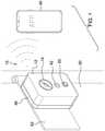
- FIG. 1is an isometric view of a large vehicle backup camera apparatus according to an embodiment of the disclosure.
- FIG. 2is a front elevation view of an embodiment of the disclosure.
- FIG. 3is a side elevation view of an embodiment of the disclosure.
- FIG. 4is a bottom plan view of an embodiment of the disclosure.
- FIG. 5is an in-use view of an embodiment of the disclosure.
- FIG. 6is an in-use view of an embodiment of the disclosure.
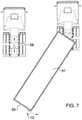
- FIG. 7is an in-use view of an embodiment of the disclosure.
- FIGS. 1 through 7a new vehicle cameras embodying the principles and concepts of an embodiment of the disclosure and generally designated by the reference numeral 10 will be described.
- the large vehicle backup camera apparatus 10generally comprises a camera housing 12 .
- the camera housing 12may be rectangular prismatic and has rounded corners.
- the camera housing 12may be watertight and generally weatherproof.
- a camera 14is coupled within the camera housing 12 and has a lens 16 extending through a housing front side 18 of the camera housing.
- the lens 16may be a fisheye to achieve a wide viewing angle.
- At least one wide-angle light 20is coupled to the housing front side 18 of the camera housing to provide more light than the vehicle reverse lights relied on by most backup cameras.
- the at least one wide-angle light 20may include a pair of upper lights 22 and a medial lower light 24 .
- Each wide-angle light 20may have a cylindrical light diffuser 26 extending from the housing front side 18 and a conical recession 28 within the light diffuser 26 to create the widest possible illuminated area from a diode 30 behind the diffuser 26 .
- a battery 32is coupled within the camera housing 12 and is in operational communication with the camera 14 and the wide-angle lights 20 .
- the battery 32may be rechargeable and may have a charging port 34 extending through a housing bottom side 36 of the camera housing to make the apparatus 10 a portable rechargeable device.
- a ferrous plate 44is coupled within the camera housing 12 adjacent a housing back side 45 of the camera housing.
- a mounting bracket 46has a magnet 48 coupled there within. The magnet 48 selectively engages the ferrous plate 44 to secure the camera housing 12 to the mounting bracket 46 .
- the magnet 48is also configured to selectively engage a trailer rear 50 of a tractor-trailer 51 or long-towed RV 52 .
- the magnet 48may be positioned on a door hinge 53 of the trailer rear 50 .
- the mounting bracket 46is placed towards the lower right corner of the trailer rear 50 to position the apparatus 10 closest to the vehicle's largest blind spot.
- an adhesive layer 54may be coupled to a bracket back side 56 of the mounting bracket.
- the perimeter of the mounting bracket 46may conform to the perimeter of the camera housing 12 to minimize the overall profile of the apparatus 10 when installed.
- the mounting bracket 46is installed on the trailer rear 50 of the tractor-trailer 51 or long-towed RV 52 utilizing a fifth-wheel 58 , a gooseneck hitch, or any other hitch prone to sharp turning or jackknifing during reverse.
- the mounting bracket 46couples with either with the adhesive layer 54 or using the magnet 48 .
- the ferrous plate 44 within the camera housing 12is then engaged with the magnet 48 .
- the usermay then watch a live video feed from the camera 14 on the personal electronic device 40 from within the vehicle while backing up to prevent accidents.
- the usermay remove the camera housing 12 for safekeeping, to be placed on a different trailer 52 or long-towed RV 52 , or to charge the battery 32 via the charging port 34 .
Landscapes
- Engineering & Computer Science (AREA)
- Multimedia (AREA)
- Signal Processing (AREA)
- Physics & Mathematics (AREA)
- General Physics & Mathematics (AREA)
- Mechanical Engineering (AREA)
- Fittings On The Vehicle Exterior For Carrying Loads, And Devices For Holding Or Mounting Articles (AREA)
- Studio Devices (AREA)
Abstract
Description
Claims (8)
Priority Applications (1)
| Application Number | Priority Date | Filing Date | Title |
|---|---|---|---|
| US16/743,011US11272144B2 (en) | 2020-01-15 | 2020-01-15 | Large vehicle backup camera apparatus |
Applications Claiming Priority (1)
| Application Number | Priority Date | Filing Date | Title |
|---|---|---|---|
| US16/743,011US11272144B2 (en) | 2020-01-15 | 2020-01-15 | Large vehicle backup camera apparatus |
Publications (2)
| Publication Number | Publication Date |
|---|---|
| US20210218934A1 US20210218934A1 (en) | 2021-07-15 |
| US11272144B2true US11272144B2 (en) | 2022-03-08 |
Family
ID=76763744
Family Applications (1)
| Application Number | Title | Priority Date | Filing Date |
|---|---|---|---|
| US16/743,011ActiveUS11272144B2 (en) | 2020-01-15 | 2020-01-15 | Large vehicle backup camera apparatus |
Country Status (1)
| Country | Link |
|---|---|
| US (1) | US11272144B2 (en) |
Families Citing this family (4)
| Publication number | Priority date | Publication date | Assignee | Title |
|---|---|---|---|---|
| US11656025B2 (en)* | 2019-12-30 | 2023-05-23 | Whirlpool Corporation | Resilient housing |
| USD983854S1 (en)* | 2021-04-12 | 2023-04-18 | DeepView Corp. | Optical sensor with illuminated brand identification |
| US20250067024A1 (en)* | 2023-08-24 | 2025-02-27 | Caterpillar Inc. | Removable camera mounting system |
| US20250135998A1 (en)* | 2023-10-27 | 2025-05-01 | Oshkosh Corporation | Multiple backup cameras for refuse vehicle |
Citations (28)
| Publication number | Priority date | Publication date | Assignee | Title |
|---|---|---|---|---|
| US5027200A (en) | 1990-07-10 | 1991-06-25 | Edward Petrossian | Enhanced viewing at side and rear of motor vehicles |
| US5126778A (en)* | 1991-07-16 | 1992-06-30 | Eastman Kodak Company | Dedicated photographic flash system for varying flash spread based upon camera-to-subject distance |
| US5761540A (en)* | 1994-10-31 | 1998-06-02 | Northeast Robotics, Inc. | Illumination device with microlouver for illuminating an object with continuous diffuse light |
| US20030178809A1 (en)* | 2002-03-21 | 2003-09-25 | Anderson Elmer G. | Device for visually aligning a vehicle towing hitch and a trailer tongue |
| US6690413B1 (en) | 1999-04-21 | 2004-02-10 | Michael S. Moore | Tractor-trailer viewing system |
| US6880941B2 (en) | 2003-06-11 | 2005-04-19 | Tony R. Suggs | Vehicle blind spot monitoring system |
| US20060209190A1 (en)* | 2005-03-04 | 2006-09-21 | Walters Kenneth S | Vehicle directional monitoring system |
| US20070216136A1 (en)* | 2006-03-15 | 2007-09-20 | Dietz Dan L | Single camera apparatus and methods for alignment of a trailer hitch |
| US20100073478A1 (en)* | 2008-09-23 | 2010-03-25 | Master Lock Company Llc | Vehicle mounted devices and arrangements |
| US7877003B2 (en)* | 2007-06-20 | 2011-01-25 | Microscan Systems, Inc. | Devices, systems, and methods regarding images |
| US20110216199A1 (en)* | 2007-01-25 | 2011-09-08 | Target Hitach LLC | Towing vehicle guidance for trailer hitch connection |
| US20130107044A1 (en) | 2011-10-26 | 2013-05-02 | Anthony Azevedo | Blind Spot Camera System |
| US8670035B2 (en) | 2009-12-22 | 2014-03-11 | Marc Robert | Side mirror system with video display |
| US20150353026A1 (en)* | 2006-01-20 | 2015-12-10 | Old World Industries, Llc | System for Monitoring an Area Adjacent a Vehicle |
| US20160297361A1 (en)* | 2015-04-08 | 2016-10-13 | Jeffrey M. Drazan | Camera array system and method to detect a load status of a semi- trailer truck |
| US20170151846A1 (en)* | 2015-12-01 | 2017-06-01 | GM Global Technology Operations LLC | Guided tow hitch control system and method |
| US20170217372A1 (en)* | 2016-02-02 | 2017-08-03 | Magna Electronics Inc. | Wireless camera system for vehicle and trailer |
| US20180338117A1 (en)* | 2017-05-16 | 2018-11-22 | Telme Electronics Inc. | Surround camera system for autonomous driving |
| US20180365859A1 (en)* | 2016-01-15 | 2018-12-20 | Sony Corporation | Image processing apparatus and method, program, and image processing system |
| US20190033691A1 (en)* | 2016-04-20 | 2019-01-31 | Guangdong Sirui Optical Co., Ltd. | Camera dolly, remote-controlled camera dolly system and camera dolly photographing control method |
| US20190196304A1 (en)* | 2017-12-26 | 2019-06-27 | Richard Henry Jeske | Game Camera Mounting System |
| US20190302764A1 (en)* | 2018-02-21 | 2019-10-03 | Azevtec, Inc. | Systems and methods for automated operation and handling of autonomous trucks and trailers hauled thereby |
| US20200001778A1 (en)* | 2018-06-28 | 2020-01-02 | Paccar Inc | Camera-based automatic turn signal deactivation |
| US20200082175A1 (en)* | 2018-09-07 | 2020-03-12 | TuSimple | Rear-facing perception system for vehicles |
| US20200134939A1 (en)* | 2018-10-25 | 2020-04-30 | Applied Mechatronic Products, Llc | Apparatus and method for vehicular monitoring, analysis, and control |
| US20200134942A1 (en)* | 2018-10-25 | 2020-04-30 | Applied Mechatronic Products, Llc | Apparatus and method for vehicular monitoring, analysis, and control of wheel end systems |
| US10730439B2 (en)* | 2005-09-16 | 2020-08-04 | Digital Ally, Inc. | Vehicle-mounted video system with distributed processing |
| US20200338941A1 (en)* | 2019-04-29 | 2020-10-29 | Grote Industries, Inc. | Cable system for a truck trailer |
- 2020
- 2020-01-15USUS16/743,011patent/US11272144B2/enactiveActive
Patent Citations (29)
| Publication number | Priority date | Publication date | Assignee | Title |
|---|---|---|---|---|
| US5027200A (en) | 1990-07-10 | 1991-06-25 | Edward Petrossian | Enhanced viewing at side and rear of motor vehicles |
| US5126778A (en)* | 1991-07-16 | 1992-06-30 | Eastman Kodak Company | Dedicated photographic flash system for varying flash spread based upon camera-to-subject distance |
| US5761540A (en)* | 1994-10-31 | 1998-06-02 | Northeast Robotics, Inc. | Illumination device with microlouver for illuminating an object with continuous diffuse light |
| US6690413B1 (en) | 1999-04-21 | 2004-02-10 | Michael S. Moore | Tractor-trailer viewing system |
| US20030178809A1 (en)* | 2002-03-21 | 2003-09-25 | Anderson Elmer G. | Device for visually aligning a vehicle towing hitch and a trailer tongue |
| US6880941B2 (en) | 2003-06-11 | 2005-04-19 | Tony R. Suggs | Vehicle blind spot monitoring system |
| US20060209190A1 (en)* | 2005-03-04 | 2006-09-21 | Walters Kenneth S | Vehicle directional monitoring system |
| US10730439B2 (en)* | 2005-09-16 | 2020-08-04 | Digital Ally, Inc. | Vehicle-mounted video system with distributed processing |
| US9637051B2 (en) | 2006-01-20 | 2017-05-02 | Winplus North America, Inc. | System for monitoring an area adjacent a vehicle |
| US20150353026A1 (en)* | 2006-01-20 | 2015-12-10 | Old World Industries, Llc | System for Monitoring an Area Adjacent a Vehicle |
| US20070216136A1 (en)* | 2006-03-15 | 2007-09-20 | Dietz Dan L | Single camera apparatus and methods for alignment of a trailer hitch |
| US20110216199A1 (en)* | 2007-01-25 | 2011-09-08 | Target Hitach LLC | Towing vehicle guidance for trailer hitch connection |
| US7877003B2 (en)* | 2007-06-20 | 2011-01-25 | Microscan Systems, Inc. | Devices, systems, and methods regarding images |
| US20100073478A1 (en)* | 2008-09-23 | 2010-03-25 | Master Lock Company Llc | Vehicle mounted devices and arrangements |
| US8670035B2 (en) | 2009-12-22 | 2014-03-11 | Marc Robert | Side mirror system with video display |
| US20130107044A1 (en) | 2011-10-26 | 2013-05-02 | Anthony Azevedo | Blind Spot Camera System |
| US20160297361A1 (en)* | 2015-04-08 | 2016-10-13 | Jeffrey M. Drazan | Camera array system and method to detect a load status of a semi- trailer truck |
| US20170151846A1 (en)* | 2015-12-01 | 2017-06-01 | GM Global Technology Operations LLC | Guided tow hitch control system and method |
| US20180365859A1 (en)* | 2016-01-15 | 2018-12-20 | Sony Corporation | Image processing apparatus and method, program, and image processing system |
| US20170217372A1 (en)* | 2016-02-02 | 2017-08-03 | Magna Electronics Inc. | Wireless camera system for vehicle and trailer |
| US20190033691A1 (en)* | 2016-04-20 | 2019-01-31 | Guangdong Sirui Optical Co., Ltd. | Camera dolly, remote-controlled camera dolly system and camera dolly photographing control method |
| US20180338117A1 (en)* | 2017-05-16 | 2018-11-22 | Telme Electronics Inc. | Surround camera system for autonomous driving |
| US20190196304A1 (en)* | 2017-12-26 | 2019-06-27 | Richard Henry Jeske | Game Camera Mounting System |
| US20190302764A1 (en)* | 2018-02-21 | 2019-10-03 | Azevtec, Inc. | Systems and methods for automated operation and handling of autonomous trucks and trailers hauled thereby |
| US20200001778A1 (en)* | 2018-06-28 | 2020-01-02 | Paccar Inc | Camera-based automatic turn signal deactivation |
| US20200082175A1 (en)* | 2018-09-07 | 2020-03-12 | TuSimple | Rear-facing perception system for vehicles |
| US20200134939A1 (en)* | 2018-10-25 | 2020-04-30 | Applied Mechatronic Products, Llc | Apparatus and method for vehicular monitoring, analysis, and control |
| US20200134942A1 (en)* | 2018-10-25 | 2020-04-30 | Applied Mechatronic Products, Llc | Apparatus and method for vehicular monitoring, analysis, and control of wheel end systems |
| US20200338941A1 (en)* | 2019-04-29 | 2020-10-29 | Grote Industries, Inc. | Cable system for a truck trailer |
Also Published As
| Publication number | Publication date |
|---|---|
| US20210218934A1 (en) | 2021-07-15 |
Similar Documents
| Publication | Publication Date | Title |
|---|---|---|
| US11272144B2 (en) | Large vehicle backup camera apparatus | |
| US20060098094A1 (en) | Portable wireless rearview camera system for a vehicle | |
| US8976246B1 (en) | Gooseneck or fifth wheel trailer hitch alignment and safety system | |
| JP5316991B2 (en) | Drive recorder and equipment | |
| US9096175B1 (en) | Split screen rear view display | |
| US20020113873A1 (en) | Rear vision system for large vehicles | |
| US20140151979A1 (en) | Fifth Wheel Backup Camera System and Method | |
| US20090166488A1 (en) | Mounting bracket for a vehicle backup camera | |
| CA2742126A1 (en) | Vehicle safety camera system | |
| JP7209321B2 (en) | System and program | |
| JP6308505B2 (en) | Drive recorder body and equipment | |
| US20140111646A1 (en) | Cell Phone Safety Monitor With Interactive Camera | |
| US20190152392A1 (en) | Vehicle mounted collision avoidance systems and related methods | |
| JP6553762B2 (en) | Drive recorder body and equipment | |
| US20130112836A1 (en) | Interior mirror mounting assembly with integrally formed metallic ball and arm | |
| US10596965B2 (en) | Third eye tractor trailer blind side driving system | |
| JP5818181B2 (en) | Drive recorder body and equipment | |
| US20230082856A1 (en) | Rear View Camera Assembly | |
| US20210362661A1 (en) | Permanent Semi Truck and RV Reversing Camera Apparatus | |
| US20210309161A1 (en) | Universal blind spot detection system | |
| US20050151844A1 (en) | Portable baby monitoring system for vehicles | |
| US11991590B2 (en) | Vehicular back-up camera system | |
| JP6056069B2 (en) | Drive recorder body and equipment | |
| US20170210292A1 (en) | Back-Up Panorama Camera | |
| US20080036177A1 (en) | Probe-operated trailer guide with lights |
Legal Events
| Date | Code | Title | Description |
|---|---|---|---|
| FEPP | Fee payment procedure | Free format text:ENTITY STATUS SET TO UNDISCOUNTED (ORIGINAL EVENT CODE: BIG.); ENTITY STATUS OF PATENT OWNER: MICROENTITY | |
| FEPP | Fee payment procedure | Free format text:ENTITY STATUS SET TO MICRO (ORIGINAL EVENT CODE: MICR); ENTITY STATUS OF PATENT OWNER: MICROENTITY | |
| STPP | Information on status: patent application and granting procedure in general | Free format text:RESPONSE AFTER FINAL ACTION FORWARDED TO EXAMINER | |
| STPP | Information on status: patent application and granting procedure in general | Free format text:ADVISORY ACTION MAILED | |
| STCV | Information on status: appeal procedure | Free format text:NOTICE OF APPEAL FILED | |
| STPP | Information on status: patent application and granting procedure in general | Free format text:NOTICE OF ALLOWANCE MAILED -- APPLICATION RECEIVED IN OFFICE OF PUBLICATIONS | |
| STPP | Information on status: patent application and granting procedure in general | Free format text:NOTICE OF ALLOWANCE MAILED -- APPLICATION RECEIVED IN OFFICE OF PUBLICATIONS | |
| STCB | Information on status: application discontinuation | Free format text:ABANDONMENT FOR FAILURE TO CORRECT DRAWINGS/OATH/NONPUB REQUEST | |
| STCF | Information on status: patent grant | Free format text:PATENTED CASE | |
| MAFP | Maintenance fee payment | Free format text:PAYMENT OF MAINTENANCE FEE, 4TH YEAR, MICRO ENTITY (ORIGINAL EVENT CODE: M3551); ENTITY STATUS OF PATENT OWNER: MICROENTITY Year of fee payment:4 |