US11271226B1 - Redox flow battery with improved efficiency - Google Patents
Redox flow battery with improved efficiencyDownload PDFInfo
- Publication number
- US11271226B1 US11271226B1US17/119,427US202017119427AUS11271226B1US 11271226 B1US11271226 B1US 11271226B1US 202017119427 AUS202017119427 AUS 202017119427AUS 11271226 B1US11271226 B1US 11271226B1
- Authority
- US
- United States
- Prior art keywords
- electrode
- electrolyte solution
- circulation loop
- circulating
- manganese
- Prior art date
- Legal status (The legal status is an assumption and is not a legal conclusion. Google has not performed a legal analysis and makes no representation as to the accuracy of the status listed.)
- Active
Links
Images


Classifications
- H—ELECTRICITY
- H01—ELECTRIC ELEMENTS
- H01M—PROCESSES OR MEANS, e.g. BATTERIES, FOR THE DIRECT CONVERSION OF CHEMICAL ENERGY INTO ELECTRICAL ENERGY
- H01M8/00—Fuel cells; Manufacture thereof
- H01M8/04—Auxiliary arrangements, e.g. for control of pressure or for circulation of fluids
- H01M8/04082—Arrangements for control of reactant parameters, e.g. pressure or concentration
- H01M8/04186—Arrangements for control of reactant parameters, e.g. pressure or concentration of liquid-charged or electrolyte-charged reactants
- H—ELECTRICITY
- H01—ELECTRIC ELEMENTS
- H01M—PROCESSES OR MEANS, e.g. BATTERIES, FOR THE DIRECT CONVERSION OF CHEMICAL ENERGY INTO ELECTRICAL ENERGY
- H01M8/00—Fuel cells; Manufacture thereof
- H01M8/04—Auxiliary arrangements, e.g. for control of pressure or for circulation of fluids
- H01M8/04082—Arrangements for control of reactant parameters, e.g. pressure or concentration
- H01M8/04201—Reactant storage and supply, e.g. means for feeding, pipes
- H—ELECTRICITY
- H01—ELECTRIC ELEMENTS
- H01M—PROCESSES OR MEANS, e.g. BATTERIES, FOR THE DIRECT CONVERSION OF CHEMICAL ENERGY INTO ELECTRICAL ENERGY
- H01M8/00—Fuel cells; Manufacture thereof
- H01M8/04—Auxiliary arrangements, e.g. for control of pressure or for circulation of fluids
- H01M8/04276—Arrangements for managing the electrolyte stream, e.g. heat exchange
- H—ELECTRICITY
- H01—ELECTRIC ELEMENTS
- H01M—PROCESSES OR MEANS, e.g. BATTERIES, FOR THE DIRECT CONVERSION OF CHEMICAL ENERGY INTO ELECTRICAL ENERGY
- H01M8/00—Fuel cells; Manufacture thereof
- H01M8/04—Auxiliary arrangements, e.g. for control of pressure or for circulation of fluids
- H01M8/04298—Processes for controlling fuel cells or fuel cell systems
- H01M8/04694—Processes for controlling fuel cells or fuel cell systems characterised by variables to be controlled
- H01M8/04791—Concentration; Density
- H01M8/04798—Concentration; Density of fuel cell reactants
- H—ELECTRICITY
- H01—ELECTRIC ELEMENTS
- H01M—PROCESSES OR MEANS, e.g. BATTERIES, FOR THE DIRECT CONVERSION OF CHEMICAL ENERGY INTO ELECTRICAL ENERGY
- H01M8/00—Fuel cells; Manufacture thereof
- H01M8/08—Fuel cells with aqueous electrolytes
- H—ELECTRICITY
- H01—ELECTRIC ELEMENTS
- H01M—PROCESSES OR MEANS, e.g. BATTERIES, FOR THE DIRECT CONVERSION OF CHEMICAL ENERGY INTO ELECTRICAL ENERGY
- H01M8/00—Fuel cells; Manufacture thereof
- H01M8/18—Regenerative fuel cells, e.g. redox flow batteries or secondary fuel cells
- H01M8/184—Regeneration by electrochemical means
- H01M8/188—Regeneration by electrochemical means by recharging of redox couples containing fluids; Redox flow type batteries
- H—ELECTRICITY
- H01—ELECTRIC ELEMENTS
- H01M—PROCESSES OR MEANS, e.g. BATTERIES, FOR THE DIRECT CONVERSION OF CHEMICAL ENERGY INTO ELECTRICAL ENERGY
- H01M2300/00—Electrolytes
- H01M2300/0002—Aqueous electrolytes
- H—ELECTRICITY
- H01—ELECTRIC ELEMENTS
- H01M—PROCESSES OR MEANS, e.g. BATTERIES, FOR THE DIRECT CONVERSION OF CHEMICAL ENERGY INTO ELECTRICAL ENERGY
- H01M8/00—Fuel cells; Manufacture thereof
- H01M8/04—Auxiliary arrangements, e.g. for control of pressure or for circulation of fluids
- H01M8/04298—Processes for controlling fuel cells or fuel cell systems
- H01M8/04313—Processes for controlling fuel cells or fuel cell systems characterised by the detection or assessment of variables; characterised by the detection or assessment of failure or abnormal function
- H01M8/04664—Failure or abnormal function
- Y—GENERAL TAGGING OF NEW TECHNOLOGICAL DEVELOPMENTS; GENERAL TAGGING OF CROSS-SECTIONAL TECHNOLOGIES SPANNING OVER SEVERAL SECTIONS OF THE IPC; TECHNICAL SUBJECTS COVERED BY FORMER USPC CROSS-REFERENCE ART COLLECTIONS [XRACs] AND DIGESTS
- Y02—TECHNOLOGIES OR APPLICATIONS FOR MITIGATION OR ADAPTATION AGAINST CLIMATE CHANGE
- Y02E—REDUCTION OF GREENHOUSE GAS [GHG] EMISSIONS, RELATED TO ENERGY GENERATION, TRANSMISSION OR DISTRIBUTION
- Y02E60/00—Enabling technologies; Technologies with a potential or indirect contribution to GHG emissions mitigation
- Y02E60/30—Hydrogen technology
- Y02E60/50—Fuel cells
Definitions
- Flow batteriesalso known as redox flow batteries or redox flow cells, are designed to convert electrical energy into chemical energy that can be stored and later released back into electrical energy when there is demand.
- a flow batterymay be used with a renewable energy system, such as a wind-powered system, to store energy that exceeds consumer demand and later release that energy when there is greater demand.
- a typical flow batteryincludes a redox flow cell that has a negative electrode and a positive electrode separated by an electrolyte layer, which may include a separator, such as an ion-exchange membrane.
- a negative fluid electrolyte(sometimes referred to as the anolyte or negolyte) is delivered to the negative electrode and a positive fluid electrolyte (sometimes referred to as the catholyte or posolyte) is delivered to the positive electrode to drive reversible redox reactions between redox pairs.
- the electrical energy suppliedcauses a reduction reaction in one electrolyte and an oxidation reaction in the other electrolyte.
- the separatorprevents the electrolytes from freely and rapidly mixing but selectively permits ions to pass through to complete the redox reactions.
- the chemical energy contained in the liquid electrolytesis released in the reverse reactions and electrical energy is drawn from the electrodes.
- a method for a redox flow batteryincludes using a cell of a redox flow battery to store input electrical energy upon charging and discharge the stored electrical energy upon discharging.
- the cellhas a separator layer arranged between first and second electrodes.
- the usingincludes circulating a first electrolyte solution through a first circulation loop in fluid connection with the first electrode of the cell; circulating a second electrolyte solution through a second circulation loop in fluid connection with the second electrode of the cell; and at least one of a first element from the first electrolyte solution in the first electrode permeates through the separator layer and precipitates as a first solid product in the second electrode and a second element from the second electrolyte solution permeates through the separator layer and precipitates a second solid product in the first electrode, removing at least a portion of the first solid product or the second solid product from the first electrode and the second electrode, respectively, by circulating at least a portion of the first electrolyte solution from the first circulation loop through the second electrode to dissolve, and thereby remove, at least a portion of the first solid product from the second electrode, circulating at least a portion of the second electrolyte solution from the second circulation loop through the first electrode to dissolve, and thereby remove, at least a portion of the second solid product from the first
- At least one of the first solid product and second solid productprecipitates onto the separator layer.
- At least a portion of the first solid productis removed from the separator layer by the step of circulating at least a portion of the first electrolyte solution from the first circulation loop through the second electrode.
- At least a portion of the second solid productis removed from the separator layer by the step of circulating at least a portion of the second electrolyte solution from the second circulation loop through the first electrode.
- At least one of the first and second solid productsare clogged in the separator layer.
- At least a portion of the first solid productis removed from the separator layer by the step of circulating at least a portion of the first electrolyte solution from the first circulation loop through the second electrode.
- At least a portion of the second solid productis removed from the separator layer by the step of circulating at least a portion of the second electrolyte solution from the second circulation loop through the first electrode.
- the steps of circulating at least a portion of the first electrolyte solution from the first circulation loop through the second electrode and circulating at least a portion of the second electrolyte solution from the second circulation loop through the first electrodeare performed sequentially.
- the methodincludes the steps of draining the first electrolyte solution to a first tank and draining the second electrolyte solution to a second tank prior to circulating at least a portion of the first electrolyte solution from the first circulation loop through the second electrode and circulating at least a portion of the second electrolyte solution from the second circulation loop through the first electrode.
- a method for a redox flow batteryincludes using a cell of a redox flow battery to store input electrical energy upon charging and discharge the stored electrical energy upon discharging.
- the cellhas a separator layer arranged between first and second electrodes.
- the usingincludes circulating a polysulfide electrolyte solution through a first circulation loop in fluid connection with the first electrode of the cell; circulating a manganese electrolyte solution through a second circulation loop in fluid connection with the second electrode of the cell; and at least one of sulfur from the polysulfide electrolyte solution in the first electrode permeates through the separator layer and precipitates as a solid sulfur-containing product and manganese from the manganese electrolyte solution permeates through the separator layer and precipitates as solid manganese-containing product, removing at least a portion of the solid sulfur product or the solid manganese product from the separator layer or opposing electrode, by circulating at least a portion of the polysulfide electrolyte solution from the first circulation loop through the second electrode to dissolve, and thereby remove, at least a portion of the solid sulfide product from the separator layer, circulating at least a portion of the manganese electrolyte solution from the second circulation loop through the first electrode to dissolve, and
- the methodincludes passing the polysulfide electrolyte solution with the dissolved solid sulfide product in a first direction through a bi-directional filter and passing the manganese electrolyte solution with the dissolved solid manganese product in a second, opposite direction through the bi-directional filter.
- At least one of the solid sulfur product and the solid manganese productprecipitates onto the separator layer.
- At least one of the solid sulfur product and the solid manganese productdecreases porosity of the separator layer.
- the methodincludes the steps of draining the polysulfide electrolyte to a first tank and draining the manganese electrolyte solution to a second tank prior to circulating at least a portion of the polysulfide electrolyte solution from the first circulation loop through the second electrode and circulating at least a portion of the manganese electrolyte solution from the second circulation loop through the first electrode.
- the methodincludes draining the polysulfide electrolyte solution to the first tank after the step of circulating at least a portion of the polysulfide electrolyte solution from the first circulation loop through the second electrode and prior to the step of circulating at least a portion of the manganese electrolyte solution from the second circulation loop through the first electrode.
- circulating at least a portion of the manganese electrolyte solution from the second circulation loop through the first electroderesults in removing at least a portion of solid manganese product from the first electrode.
- the steps of circulating at least a portion of the polysulfide electrolyte solution from the first circulation loop through the second electrode and circulating at least a portion of the manganese electrolyte solution from the second circulation loop through the first electrodeare performed sequentially.
- a redox flow batteryincludes a cell having first and second electrodes and an ion-exchange layer arranged between the first and second electrodes; a first circulation loop fluidly connected with the first electrode; a polysulfide electrolyte contained in the first recirculation loop; a second circulation loop fluidly connected with the second electrode; a manganese electrolyte contained in the second circulation loop; a bi-directional filter; and a first auxiliary loop connecting the first circulation loop with the second electrode through the bi-directional filter, the first auxiliary loop configured to receive flow of the polysulfide electrolyte.
- the redox flow batteryalso includes a second auxiliary loop connecting the second circulation loop with the first electrode through the bi-directional filter, the second auxiliary loop configured to receive flow of the manganese electrolyte. Flow of the manganese electrolyte through the second auxiliary loop removes solid manganese product from at least one of the ion exchange layer and the first electrode.
- FIG. 1illustrates an example redox flow battery.
- FIG. 2illustrates a method for cleaning the redox flow battery of FIG. 1 .
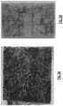
- FIGS. 3 a - bshow images of an electrode of the example redox flow battery of FIG. 1 before and after performing the method of FIG. 2 , respectively.
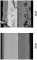
- FIGS. 4 a - bshow images of a cross section of an example separator layer of the example redox flow battery of FIG. 1 before and after performing the method of FIG. 2 , respectively.
- Redox flow batteriesutilize electrochemically active species that include ions of elements that have multiple, reversible oxidation states in a selected liquid solution.
- Example speciesmay include transition metals, such as vanadium, iron, manganese, chromium, zinc, or molybdenum, or other elements such as sulfur, cerium, lead, tin, titanium, germanium, bromine, or chlorine. Although these species have been used, not all of them are compatible for use together. For instance, over time, there is mixing of species due to cross-over of the species through the separator. If incompatible, the cross-over species may react to precipitate as an insoluble solid that could collect within the RFB and negatively affect performance of the RFB.
- FIG. 1schematically shows an example RFB 20 .
- the RFB 20 in this exampleincludes a single, common cell 22 or stack of common cells, though in other examples multiple cells could be used.
- the cell 22includes a first electrode 22 a , a second electrode 22 b , and an ion-selective separator layer 22 c between the electrodes 22 a and 22 b .
- the electrodes 22 a , 22 bmay be porous carbon structures, such as carbon paper or felt.
- the separator layersmay be an ion-selective separator layer 22 c , which permits selected ions to pass through to complete the redox reactions while electrically isolating the electrodes.
- a first circulation loop 26is fluidly connected with the first electrode 22 a of the cell 22
- a second circulation loop 28is fluidly connected with the second electrode 22 b of the cell 22
- a “loop”refers to a continuous, closed circuit fluid passage.
- the first circulation loop 26 and the second circulation loop 28may include respective electrolyte storage tanks 30 and 32 .
- the negative electrolyte solution 34is contained in the first recirculation loop 26 (i.e., fluidly connected to the tank 30 )
- a positive electrolyte solution 36is contained in the second circulation loop 28 (i.e., fluidly connected to the tank 32 ).
- the RFB 20includes a first electrolyte 22 that has at least one electrochemically active species 24 that functions in a redox pair with regard to a second electrolyte 26 that has at least one electrochemically active species 28 .
- first and secondis to differentiate that there are two distinct electrolytes/electrodes. It is to be further understood that terms “first” and “second” are interchangeable in that the first electrolyte/electrode could alternatively be termed as the second electrolyte/electrode, and vice versa.
- electrochemically active speciescan be used in the RFB 20 .
- One example set of species that may be used in RFBs as the first and second electrolytes 34 / 36are sulfur and manganese, respectively.
- a polysulfide electrolyte solution 34is contained in the first recirculation loop 26 (i.e., fluidly connected to the tank 30 ), and a manganese electrolyte solution 36 is contained in the second circulation loop 28 (i.e., fluidly connected to the tank 32 ).
- the polysulfide electrolyte solution 34has a pH greater than 12
- the manganese electrolyte solutionhas a pH greater than 14.
- the electrolytes shown in the figures and described hereinare illustrative only, and this description is not limited to any particular electrolyte chemistry.
- the polysulfide in the polysulfide electrolyte solution 34generally refers to salts of sulfur in a basic pH solution.
- the saltis sodium salt with the formula Na 2 S x , where x is 1 to 8, in sodium hydroxide.
- the polysulfide electrolyte solution 34may be 1M Na 2 S x in 7.5M sodium hydroxide.
- the manganese in the electrolyte solution 36generally refers to permanganate or manganate salts in an alkaline, or basic, solution.
- the manganese electrolyte solution 36may be 1M sodium permanganate (NaMnO 4 ) in 7.5 M sodium hydroxide (NaOH) or in another example 2M NaMnO 4 in 3M NaOH.
- the polysulfide electrolyte solution 34circulates through the first electrode 22 a and the manganese electrolyte solution 36 circulates through the second electrode 22 b.
- Net cell2Na 2 S 2 +2NaMnO 4 ⁇ Na 2 S 4 +2Na 2 MnO 4
- sulfurmay cross over from the first electrode 22 a through the ion-selective separator layer 22 c to the second electrode 22 b .
- the sulfurprecipitates as a solid sulfur or manganese-sulfur species.
- the crossed-over sulfur speciescan reduce permanganate and manganate species to manganese species that disproportionate into solid manganese oxide species (Mn y O z ).
- Permanganate and manganate speciesmay likewise cross over from the second electrode 22 b into the low potential sulfur electrolyte 34 in the first electrode 22 a and reduce to form insoluble manganate hydroxide Mn(OH) 2 , MnO y O z species, or manganese sulfur species.
- an electrolyte takeover method (ETM) 50shown in FIG. 2 , can be used to clean/maintain the RFB 20 , e.g., reduce/minimize the presence of solid precipitates in the electrodes 22 a / 22 b and/or ion-selective separator layer 22 c .
- the method 50generally includes draining the electrolytes 34 / 36 from the cell 22 into their respective tanks 30 / 32 at step 52 .
- the negative (e.g., polysulfide) electrolyte solution 34is pumped through the second electrode 22 b , via connector 84 a , which reduces, dissolves, and recaptures any solids, such as S°, that have a propensity to dissolve when they are exposed to the reducing (e.g., polysulfide) solution.
- the negative (e.g., polysulfide) electrolyte solution 34is passed through connector 86 b through a bi-directional filter 80 (to capture any residual solids such as Mn that precipitates) in a direction 80 b and back to the polysulfide solution reservoir via a first auxiliary loop 82 a.
- the negative (e.g., polysulfide) electrolyte solution 34is drained back to the tank 30 .
- the positive (e g, manganese) electrolyte solution 36is pumped through first electrode 22 a (after draining) via connector 84 a , which oxidizes and dissolves any solids, such as Mn(OH) 2 or manganese oxide precipitate.
- the manganese electrolyte solution 36is routed through connector 86 a to the same bi-directional filter 80 (to capture any residual solids such as S that precipitates) and passed in a second direction 80 a but as a part of a second auxiliary loop 82 b .
- the bi-directional filter 80enables recapture of precipitated species that are filtered out to be recaptured in the negative (e.g., polysulfide) electrolyte solution 34 and the positive (e.g., manganese) electrolyte solution 36 .
- the positive (e.g., manganese) electrolyte solution 36is drained back to the tank 52 .
- the electrolytes 34 / 36can then be reintroduced into the cell for normal RFB 20 operation.
- steps 58 - 60 and 54 - 56are switched, or only one of the two is performed.
- the negative electrolyte solution 34is then transferred back into the first loop 26 and the positive electrolyte solution 36 is transferred back into the second loop 28 .
- FIGS. 3 a - bshow images of an electrode 22 a / 22 b before and after performing the ETM method described above. As shown, the ETM method reduced the amount of solid precipitate buildup in the electrode 22 a / 22 b .
- FIGS. 3 a - bshow images of an electrode 22 a / 22 b before and after performing the ETM method described above. As shown, the ETM method reduced the amount of solid precipitate buildup in the electrode 22 a / 22 b .
- FIGS. 4 a - bshow images of a cross section of an example ion-selective separator layer 22 c , which in this example is a PFSA membrane (perfluorosulfonic acid membrane), before and after performing the ETM method described above, respectively.
- the lightest bandindicates a manganese-rich region.
- the lightest bandhas a decreased thickness compared to the corresponding band in FIG. 4 a , meaning the ETM method reduced the amount of manganese in the ion-selective separator layer 22 c.
- Solid species that become trapped on the electrodes 22 a / 22 bcan block the active species in the electrolytes 34 / 36 from reaching sites on the electrodes 22 a / 22 b , which is what facilitates the reactions discussed above in the RFB 20 . Accordingly, reducing the amount of solid precipitate buildup on the electrodes 22 a / 22 b facilitates more reactions to occur at the electrodes 22 a / 22 b .
- solids that become clogged in the ion-selective separator layer 22 ccan reduce porosity of the membrane 22 c and thereby inhibit ion exchange to balance the reactions described above, which occurs through the membrane 22 c .
- Solidscould become clogged in the ion-selective separator layer 22 c by precipitating directly onto the ion-selective separator layer 22 c or by encountering the ion-selective separator layer 22 c from the electrodes 22 a/b .
- reducing the amount of solid precipitate buildup in or on the ion-selective separator layer 22 cfacilitates ion exchange, which limits cell resistance for the RFB 20 .
- Efficiency of the RFB 20can be expressed as a voltaic efficiency, which is the ratio of the average discharge voltage to the average charge voltage of the RFB 20 . Operation of the RFB 20 results in a reduction of voltaic efficiency over time. In one example, a single pass of the ETM method 50 results in at least 25% recovery of the decrease in voltaic efficiency over the preceding cycles since starting the RFB or the last ETM. The improved voltaic efficiency of the RFB 20 is attributable to the decrease in the amount of solid precipitate on the electrodes 22 a / 22 b and/or ion-selective separator layer 22 c , as discussed above.
- Solids recovered from the filter 80 and/or tanks 30 / 32could be recycled, e.g., provided back to the respective electrolytes 34 / 36 , in some examples, which can replenish the electrolyte 34 / 36 capacity with the RFB. However, in other examples, the solids are not recycled.
- Disproportionation reactionsare a possibility, since Mn has a large number of oxidation states. If manganate disproportionates to Mn(V)O 4 3 ⁇ , the compound rapidly decomposes and precipitates to MnO 2 , but under strongly alkaline conditions, this disproportionation reaction is less of a concern (i.e., pH ⁇ 14). However, at high concentrations of NaOH, the following reaction can occur slowly: 4NaMnO 4 +4NaOH ⁇ 4Na 2 MnO 4 +2H 2 O+O 2
- O 2can be consumed by allowing it to react with the negolyte by connecting the gas space above the posolyte and negolyte reservoirs (this gas space is maintained as a N 2 blanket to prevent discharge of the anolyte): O 2 +2H 2 O+4Na 2 S 2 ⁇ 2Na 2 S 4 +4NaOH
- aqueous vanadium chemistrywhich is known in the art, can form precipitates at high ambient temperatures (typically in the positive electrolyte) or at low ambient temperatures (typically in the negative electrolyte), which can be re-dissolved using the ETM method 50 .
- Other example chemistries for which the ETM method 50 could be employedare Fe/Cr or Ti/Mn chemistry, both of which are in known in the art.
- metal plating on the negative electrodeis a particular concern, and can be mitigated by exposing the materials to oxidative positive electrolyte using the ETM method 50 .
- Oxidative electrolytescan also eliminate filming cause by ligands in metal-ligand chemistries.
Landscapes
- Life Sciences & Earth Sciences (AREA)
- Engineering & Computer Science (AREA)
- Manufacturing & Machinery (AREA)
- Sustainable Development (AREA)
- Sustainable Energy (AREA)
- Chemical & Material Sciences (AREA)
- Chemical Kinetics & Catalysis (AREA)
- Electrochemistry (AREA)
- General Chemical & Material Sciences (AREA)
- Fuel Cell (AREA)
Abstract
Description
This invention was made with government support under Contract No. DE-AR000994, awarded by the Department of Energy. The Government has certain rights in this invention.
Flow batteries, also known as redox flow batteries or redox flow cells, are designed to convert electrical energy into chemical energy that can be stored and later released back into electrical energy when there is demand. As an example, a flow battery may be used with a renewable energy system, such as a wind-powered system, to store energy that exceeds consumer demand and later release that energy when there is greater demand.
A typical flow battery includes a redox flow cell that has a negative electrode and a positive electrode separated by an electrolyte layer, which may include a separator, such as an ion-exchange membrane. A negative fluid electrolyte (sometimes referred to as the anolyte or negolyte) is delivered to the negative electrode and a positive fluid electrolyte (sometimes referred to as the catholyte or posolyte) is delivered to the positive electrode to drive reversible redox reactions between redox pairs. Upon charging, the electrical energy supplied causes a reduction reaction in one electrolyte and an oxidation reaction in the other electrolyte. The separator prevents the electrolytes from freely and rapidly mixing but selectively permits ions to pass through to complete the redox reactions. Upon discharge, the chemical energy contained in the liquid electrolytes is released in the reverse reactions and electrical energy is drawn from the electrodes.
A method for a redox flow battery according to an exemplary embodiment of this disclosure, among other possible things includes using a cell of a redox flow battery to store input electrical energy upon charging and discharge the stored electrical energy upon discharging. The cell has a separator layer arranged between first and second electrodes. The using includes circulating a first electrolyte solution through a first circulation loop in fluid connection with the first electrode of the cell; circulating a second electrolyte solution through a second circulation loop in fluid connection with the second electrode of the cell; and at least one of a first element from the first electrolyte solution in the first electrode permeates through the separator layer and precipitates as a first solid product in the second electrode and a second element from the second electrolyte solution permeates through the separator layer and precipitates a second solid product in the first electrode, removing at least a portion of the first solid product or the second solid product from the first electrode and the second electrode, respectively, by circulating at least a portion of the first electrolyte solution from the first circulation loop through the second electrode to dissolve, and thereby remove, at least a portion of the first solid product from the second electrode, circulating at least a portion of the second electrolyte solution from the second circulation loop through the first electrode to dissolve, and thereby remove, at least a portion of the second solid product from the first electrode, or both. The using results in a decrease in voltaic efficiency. The removing recovers at least a portion of the decrease in voltaic efficiency.
In a further example of the foregoing, at least one of the first solid product and second solid product precipitates onto the separator layer.
In a further example of any of the foregoing, at least a portion of the first solid product is removed from the separator layer by the step of circulating at least a portion of the first electrolyte solution from the first circulation loop through the second electrode.
In a further example of any of the foregoing, at least a portion of the second solid product is removed from the separator layer by the step of circulating at least a portion of the second electrolyte solution from the second circulation loop through the first electrode.
In a further example of any of the foregoing, at least one of the first and second solid products are clogged in the separator layer.
In a further example of any of the foregoing, at least a portion of the first solid product is removed from the separator layer by the step of circulating at least a portion of the first electrolyte solution from the first circulation loop through the second electrode.
In a further example of any of the foregoing, at least a portion of the second solid product is removed from the separator layer by the step of circulating at least a portion of the second electrolyte solution from the second circulation loop through the first electrode.
In a further example of any of the foregoing, the steps of circulating at least a portion of the first electrolyte solution from the first circulation loop through the second electrode and circulating at least a portion of the second electrolyte solution from the second circulation loop through the first electrode are performed sequentially.
In a further example of any of the foregoing, the method includes the steps of draining the first electrolyte solution to a first tank and draining the second electrolyte solution to a second tank prior to circulating at least a portion of the first electrolyte solution from the first circulation loop through the second electrode and circulating at least a portion of the second electrolyte solution from the second circulation loop through the first electrode.
A method for a redox flow battery according to an exemplary embodiment of this disclosure, among other possible things includes using a cell of a redox flow battery to store input electrical energy upon charging and discharge the stored electrical energy upon discharging. The cell has a separator layer arranged between first and second electrodes. The using includes circulating a polysulfide electrolyte solution through a first circulation loop in fluid connection with the first electrode of the cell; circulating a manganese electrolyte solution through a second circulation loop in fluid connection with the second electrode of the cell; and at least one of sulfur from the polysulfide electrolyte solution in the first electrode permeates through the separator layer and precipitates as a solid sulfur-containing product and manganese from the manganese electrolyte solution permeates through the separator layer and precipitates as solid manganese-containing product, removing at least a portion of the solid sulfur product or the solid manganese product from the separator layer or opposing electrode, by circulating at least a portion of the polysulfide electrolyte solution from the first circulation loop through the second electrode to dissolve, and thereby remove, at least a portion of the solid sulfide product from the separator layer, circulating at least a portion of the manganese electrolyte solution from the second circulation loop through the first electrode to dissolve, and thereby remove, at least a portion of solid manganese product from the separator layer, or both.
In a further example of the foregoing, the method includes passing the polysulfide electrolyte solution with the dissolved solid sulfide product in a first direction through a bi-directional filter and passing the manganese electrolyte solution with the dissolved solid manganese product in a second, opposite direction through the bi-directional filter.
In a further example of any of the foregoing, at least one of the solid sulfur product and the solid manganese product precipitates onto the separator layer.
In a further example of any of the foregoing, at least one of the solid sulfur product and the solid manganese product decreases porosity of the separator layer.
In a further example of any of the foregoing, the method includes the steps of draining the polysulfide electrolyte to a first tank and draining the manganese electrolyte solution to a second tank prior to circulating at least a portion of the polysulfide electrolyte solution from the first circulation loop through the second electrode and circulating at least a portion of the manganese electrolyte solution from the second circulation loop through the first electrode.
In a further example of any of the foregoing, the method includes draining the polysulfide electrolyte solution to the first tank after the step of circulating at least a portion of the polysulfide electrolyte solution from the first circulation loop through the second electrode and prior to the step of circulating at least a portion of the manganese electrolyte solution from the second circulation loop through the first electrode.
In a further example of any of the foregoing, wherein the step of circulating at least a portion of the polysulfide electrolyte solution from the first circulation loop through the second electrode results in removing at least a portion of solid sulfur product from the second electrode.
In a further example of any of the foregoing, circulating at least a portion of the manganese electrolyte solution from the second circulation loop through the first electrode results in removing at least a portion of solid manganese product from the first electrode.
In a further example of any of the foregoing, the steps of circulating at least a portion of the polysulfide electrolyte solution from the first circulation loop through the second electrode and circulating at least a portion of the manganese electrolyte solution from the second circulation loop through the first electrode are performed sequentially.
In a further example of any of the foregoing, after the steps of circulating at least a portion of the polysulfide electrolyte solution from the first circulation loop through the second electrode and circulating at least a portion of the manganese electrolyte solution from the second circulation loop through the first electrode, at least 25% of a decrease in voltaic efficiency that resulted from operation.
A redox flow battery according to an exemplary embodiment of this disclosure, among other possible things includes a cell having first and second electrodes and an ion-exchange layer arranged between the first and second electrodes; a first circulation loop fluidly connected with the first electrode; a polysulfide electrolyte contained in the first recirculation loop; a second circulation loop fluidly connected with the second electrode; a manganese electrolyte contained in the second circulation loop; a bi-directional filter; and a first auxiliary loop connecting the first circulation loop with the second electrode through the bi-directional filter, the first auxiliary loop configured to receive flow of the polysulfide electrolyte. Flow of the polysulfide electrolyte through the first auxiliary loop removes solid sulfur product from at least one of the ion exchange layer and the second electrode. The redox flow battery also includes a second auxiliary loop connecting the second circulation loop with the first electrode through the bi-directional filter, the second auxiliary loop configured to receive flow of the manganese electrolyte. Flow of the manganese electrolyte through the second auxiliary loop removes solid manganese product from at least one of the ion exchange layer and the first electrode.
The various features and advantages of the present disclosure will become apparent to those skilled in the art from the following detailed description. The drawings that accompany the detailed description can be briefly described as follows.
Redox flow batteries (“RFB”) utilize electrochemically active species that include ions of elements that have multiple, reversible oxidation states in a selected liquid solution. Example species may include transition metals, such as vanadium, iron, manganese, chromium, zinc, or molybdenum, or other elements such as sulfur, cerium, lead, tin, titanium, germanium, bromine, or chlorine. Although these species have been used, not all of them are compatible for use together. For instance, over time, there is mixing of species due to cross-over of the species through the separator. If incompatible, the cross-over species may react to precipitate as an insoluble solid that could collect within the RFB and negatively affect performance of the RFB.
Afirst circulation loop 26 is fluidly connected with thefirst electrode 22aof thecell 22, and asecond circulation loop 28 is fluidly connected with thesecond electrode 22bof thecell 22. As used herein, a “loop” refers to a continuous, closed circuit fluid passage. Thefirst circulation loop 26 and thesecond circulation loop 28 may include respectiveelectrolyte storage tanks negative electrolyte solution 34 is contained in the first recirculation loop26 (i.e., fluidly connected to the tank30), and apositive electrolyte solution 36 is contained in the second circulation loop28 (i.e., fluidly connected to the tank32).
TheRFB 20 includes afirst electrolyte 22 that has at least one electrochemically active species24 that functions in a redox pair with regard to asecond electrolyte 26 that has at least one electrochemicallyactive species 28. As will be appreciated, the terminology “first” and “second” is to differentiate that there are two distinct electrolytes/electrodes. It is to be further understood that terms “first” and “second” are interchangeable in that the first electrolyte/electrode could alternatively be termed as the second electrolyte/electrode, and vice versa.
As noted above, a variety of electrochemically active species can be used in theRFB 20. One example set of species that may be used in RFBs as the first andsecond electrolytes 34/36 are sulfur and manganese, respectively. In this example, apolysulfide electrolyte solution 34 is contained in the first recirculation loop26 (i.e., fluidly connected to the tank30), and amanganese electrolyte solution 36 is contained in the second circulation loop28 (i.e., fluidly connected to the tank32). Thepolysulfide electrolyte solution 34 has a pH greater than 12, and the manganese electrolyte solution has a pH greater than 14. The electrolytes shown in the figures and described herein are illustrative only, and this description is not limited to any particular electrolyte chemistry.
The polysulfide in thepolysulfide electrolyte solution 34 generally refers to salts of sulfur in a basic pH solution. For example, the salt is sodium salt with the formula Na2Sx, where x is 1 to 8, in sodium hydroxide. In one example, thepolysulfide electrolyte solution 34 may be 1M Na2Sxin 7.5M sodium hydroxide. The manganese in theelectrolyte solution 36 generally refers to permanganate or manganate salts in an alkaline, or basic, solution. In one example, themanganese electrolyte solution 36 may be 1M sodium permanganate (NaMnO4) in 7.5 M sodium hydroxide (NaOH) or in another example 2M NaMnO4in 3M NaOH.
Thepolysulfide electrolyte solution 34 circulates through thefirst electrode 22aand themanganese electrolyte solution 36 circulates through thesecond electrode 22b.
The following equations demonstrate example reactions in thecell 22, as well as the resulting standard electrode potential (E°) versus Standard Hydrogen Electrode (SHE) and Open Cell Voltage (OCV), which is defined herein as the difference between the standard electrode potentials of the two electrode reactions.
Negative: 2Na2S2↔Na2S4+2Na++2e−
E°=−0.492 vs. SHE
Positive: 2NaMnO4+2Na++2e−↔2Na2MnO4
E°=+0.564 vs. SHE
Net cell: 2Na2S2+2NaMnO4↔Na2S4+2Na2MnO4
OCV=1.06 V
During operation of theRFB 20, sulfur may cross over from thefirst electrode 22athrough the ion-selective separator layer 22cto thesecond electrode 22b. The sulfur precipitates as a solid sulfur or manganese-sulfur species. Furthermore, the crossed-over sulfur species can reduce permanganate and manganate species to manganese species that disproportionate into solid manganese oxide species (MnyOz). Permanganate and manganate species may likewise cross over from thesecond electrode 22binto the lowpotential sulfur electrolyte 34 in thefirst electrode 22aand reduce to form insoluble manganate hydroxide Mn(OH)2, MnOyOzspecies, or manganese sulfur species. Over time, the loss of sulfur and manganese species, and clogging from the insoluble sulfur and manganese species could reduce round-trip efficiency to unfeasible levels for use as an RFB. Polysulfide and manganese electrolyte solutions would therefore be generally incompatible in RFBs.
However, an electrolyte takeover method (ETM)50, shown inFIG. 2 , can be used to clean/maintain theRFB 20, e.g., reduce/minimize the presence of solid precipitates in theelectrodes 22a/22band/or ion-selective separator layer 22c. With continued reference toFIGS. 1 and 2 , the method50 generally includes draining theelectrolytes 34/36 from thecell 22 into theirrespective tanks 30/32 atstep 52. Atstep 54, the negative (e.g., polysulfide)electrolyte solution 34 is pumped through thesecond electrode 22b, viaconnector 84a, which reduces, dissolves, and recaptures any solids, such as S°, that have a propensity to dissolve when they are exposed to the reducing (e.g., polysulfide) solution. The negative (e.g., polysulfide)electrolyte solution 34 is passed throughconnector 86bthrough a bi-directional filter80 (to capture any residual solids such as Mn that precipitates) in adirection 80band back to the polysulfide solution reservoir via a firstauxiliary loop 82a.
Atstep 56, the negative (e.g., polysulfide)electrolyte solution 34 is drained back to thetank 30. Then, instep 58, the positive (e g, manganese)electrolyte solution 36 is pumped throughfirst electrode 22a(after draining) viaconnector 84a, which oxidizes and dissolves any solids, such as Mn(OH)2or manganese oxide precipitate. Themanganese electrolyte solution 36 is routed throughconnector 86ato the same bi-directional filter80 (to capture any residual solids such as S that precipitates) and passed in asecond direction 80abut as a part of a secondauxiliary loop 82b. Thebi-directional filter 80 enables recapture of precipitated species that are filtered out to be recaptured in the negative (e.g., polysulfide)electrolyte solution 34 and the positive (e.g., manganese)electrolyte solution 36. Atstep 60, the positive (e.g., manganese)electrolyte solution 36 is drained back to thetank 52. Theelectrolytes 34/36 can then be reintroduced into the cell fornormal RFB 20 operation.
It should be understood that in some examples, steps58-60 and54-56 are switched, or only one of the two is performed.
Once the solid products such as the sulfur and/or manganese products have been removed to a desired level, thenegative electrolyte solution 34 is then transferred back into thefirst loop 26 and thepositive electrolyte solution 36 is transferred back into thesecond loop 28.
It has been discovered via imaging performed after conducting the ETM method50 onelectrodes 22a/22band ion-selective separator layer 22cthat the ETM method50 reduced the amount of solid precipitate on theelectrodes 22a/22band ion-selective separator layer 22c.FIGS. 3a-b show images of anelectrode 22a/22bbefore and after performing the ETM method described above. As shown, the ETM method reduced the amount of solid precipitate buildup in theelectrode 22a/22b.FIGS. 4a-b show images of a cross section of an example ion-selective separator layer 22c, which in this example is a PFSA membrane (perfluorosulfonic acid membrane), before and after performing the ETM method described above, respectively. InFIGS. 4a-b , the lightest band indicates a manganese-rich region. As shown inFIG. 4b , the lightest band has a decreased thickness compared to the corresponding band inFIG. 4a , meaning the ETM method reduced the amount of manganese in the ion-selective separator layer 22c.
Without being bound by any particular theory, removing the solid sulfur and manganese species according to the ETM method50 discussed above improves the efficiency and longevity of theRFB 20 in one or both of the following ways. Solid species that become trapped on theelectrodes 22a/22bcan block the active species in theelectrolytes 34/36 from reaching sites on theelectrodes 22a/22b, which is what facilitates the reactions discussed above in theRFB 20. Accordingly, reducing the amount of solid precipitate buildup on theelectrodes 22a/22bfacilitates more reactions to occur at theelectrodes 22a/22b. Moreover, solids that become clogged in the ion-selective separator layer 22ccan reduce porosity of themembrane 22cand thereby inhibit ion exchange to balance the reactions described above, which occurs through themembrane 22c. Solids could become clogged in the ion-selective separator layer 22cby precipitating directly onto the ion-selective separator layer 22cor by encountering the ion-selective separator layer 22cfrom theelectrodes 22a/b. Similarly, then, reducing the amount of solid precipitate buildup in or on the ion-selective separator layer 22cfacilitates ion exchange, which limits cell resistance for theRFB 20.
Efficiency of theRFB 20 can be expressed as a voltaic efficiency, which is the ratio of the average discharge voltage to the average charge voltage of theRFB 20. Operation of theRFB 20 results in a reduction of voltaic efficiency over time. In one example, a single pass of the ETM method50 results in at least 25% recovery of the decrease in voltaic efficiency over the preceding cycles since starting the RFB or the last ETM. The improved voltaic efficiency of theRFB 20 is attributable to the decrease in the amount of solid precipitate on theelectrodes 22a/22band/or ion-selective separator layer 22c, as discussed above.
If the solids that result from electrolyte crossover collect in thetanks tanks 30 or32 (the solids have significantly higher densities than the liquids and thus sink). It is expected that this process would not need to be done often, if at all, and does not need to be fully automated (i.e., this could be part of annual maintenance procedures). Solids recovered from thefilter 80 and/ortanks 30/32 could be recycled, e.g., provided back to therespective electrolytes 34/36, in some examples, which can replenish theelectrolyte 34/36 capacity with the RFB. However, in other examples, the solids are not recycled.
Disproportionation reactions are a possibility, since Mn has a large number of oxidation states. If manganate disproportionates to Mn(V)O43−, the compound rapidly decomposes and precipitates to MnO2, but under strongly alkaline conditions, this disproportionation reaction is less of a concern (i.e., pH≥14). However, at high concentrations of NaOH, the following reaction can occur slowly:
4NaMnO4+4NaOH→4Na2MnO4+2H2O+O2
4NaMnO4+4NaOH→4Na2MnO4+2H2O+O2
Further reduction of manganate(VI) does not occur. The reaction is slow; measurements with a 4 M solution of MnO4− in 7.5M OH−indicate a capacity retention of 80% after 1 month of storage of a fully charged solution. Nevertheless, this reaction will result in a permanent capacity loss, unless a mitigation strategy, such as one described below, is employed. Oxygen generation is also a concern since the reversible potential of the manganese couple is 157 mV higher than E° for O2evolution (0.401 V vs. SHE) at pH=14. Therefore, the positive electrode material must be chosen to minimize catalysis of O2evolution. H2evolution is not a concern because the reversible potential for polysulfide is above E° for H2evolution.
Small amounts of O2evolved from the disproportionation reaction, or produced by the oxygen-evolution reaction in the positive electrode, can lead to electrolyte imbalance and result in energy capacity fade in the RFB. In this case, O2can be consumed by allowing it to react with the negolyte by connecting the gas space above the posolyte and negolyte reservoirs (this gas space is maintained as a N2blanket to prevent discharge of the anolyte):
O2+2H2O+4Na2S2↔2Na2S4+4NaOH
O2+2H2O+4Na2S2↔2Na2S4+4NaOH
The net of this reaction and the one above is a discharge of both electrolytes, but it results in the electrolytes being maintained at a constant composition. Another result of these reactions will be an increase of the pH ofpolysulfide electrolyte solution 34 and a decrease in themanganese electrolyte solution 36, but changes in water concentrations and [OH−] can be offset eventually by diffusion through the membrane or by active measures.
Though the foregoing description is made with respect to anRFB 20 that employs a sulfur/manganese chemistry, it should be understood that the ETM method50 described above could also be applicable to RFBs that employ different chemistries, even if the solids are formed for reasons other than those discussed above. For example, aqueous vanadium chemistry, which is known in the art, can form precipitates at high ambient temperatures (typically in the positive electrolyte) or at low ambient temperatures (typically in the negative electrolyte), which can be re-dissolved using the ETM method50. Other example chemistries for which the ETM method50 could be employed are Fe/Cr or Ti/Mn chemistry, both of which are in known in the art. In these examples, metal plating on the negative electrode is a particular concern, and can be mitigated by exposing the materials to oxidative positive electrolyte using the ETM method50. Oxidative electrolytes can also eliminate filming cause by ligands in metal-ligand chemistries.
Although a combination of features is shown in the illustrated examples, not all of them need to be combined to realize the benefits of various embodiments of this disclosure. In other words, a system designed according to an embodiment of this disclosure will not necessarily include all of the features shown in any one of the Figures or all of the portions schematically shown in the Figures. Moreover, selected features of one example embodiment may be combined with selected features of other example embodiments.
The preceding description is exemplary rather than limiting in nature. Variations and modifications to the disclosed examples may become apparent to those skilled in the art that do not necessarily depart from this disclosure. The scope of legal protection given to this disclosure can only be determined by studying the following claims.
Claims (20)
1. A method for a redox flow battery, the method comprising:
using a cell of a redox flow battery to store input electrical energy upon charging and discharge the stored electrical energy upon discharging,
wherein the cell has a separator layer arranged between a first electrode and a second electrode,
wherein the using includes
circulating a first electrolyte solution through a first circulation loop in fluid connection with the first electrode of the cell,
circulating a second electrolyte solution through a second circulation loop in fluid connection with the second electrode of the cell, and wherein
at least one of a first element from the first electrolyte solution in the first electrode permeates through the separator layer and precipitates as a first solid product in the second electrode and a second element from the second electrolyte solution permeates through the separator layer and precipitates a second solid product in the first electrode;
removing at least a portion of the first solid product or a portion of the second solid product from the first electrode and the second electrode, respectively, by
circulating at least a portion of the first electrolyte solution from the first circulation loop through the second electrode to dissolve, and thereby remove, at least a portion of the first solid product from the second electrode,
circulating at least a portion of the second electrolyte solution from the second circulation loop through the first electrode to dissolve, and thereby remove, at least a portion of the second solid product from the first electrode, or both;
wherein the using results in a decrease in voltaic efficiency, and wherein the removing recovers at least some of the decrease in voltaic efficiency.
2. The method as recited inclaim 1 , wherein at least one of the first solid product and second solid product precipitates onto the separator layer.
3. The method as recited inclaim 2 , wherein at least a portion of the first solid product is removed from the separator layer by the step of circulating at least a portion of the first electrolyte solution from the first circulation loop through the second electrode.
4. The method as recited inclaim 2 , wherein at least a portion of the second solid product is removed from the separator layer by the step of circulating at least a portion of the second electrolyte solution from the second circulation loop through the first electrode.
5. The method as recited inclaim 1 , wherein at least one of the first and second solid products are clogged in the separator layer.
6. The method as recited inclaim 5 , wherein at least a portion of the first solid product is removed from the separator layer by the step of circulating at least a portion of the first electrolyte solution from the first circulation loop through the second electrode.
7. The method as recited inclaim 5 , wherein at least a portion of the second solid product is removed from the separator layer by the step of circulating at least a portion of the second electrolyte solution from the second circulation loop through the first electrode.
8. The method as recited inclaim 1 , wherein the steps of circulating at least a portion of the first electrolyte solution from the first circulation loop through the second electrode and circulating at least a portion of the second electrolyte solution from the second circulation loop through the first electrode are performed sequentially.
9. The method as recited inclaim 1 , further comprising the steps of draining the first electrolyte solution to a first tank and draining the second electrolyte solution to a second tank prior to circulating at least a portion of the first electrolyte solution from the first circulation loop through the second electrode and circulating at least a portion of the second electrolyte solution from the second circulation loop through the first electrode.
10. A method for a redox flow battery, the method comprising:
using a cell of a redox flow battery to store input electrical energy upon charging and to discharge the stored electrical energy upon discharging,
wherein the cell has a separator layer arranged between a first electrode and a second electrode,
wherein the using includes
circulating a polysulfide electrolyte solution through a first circulation loop in fluid connection with the first electrode of the cell,
circulating a manganese electrolyte solution through a second circulation loop in fluid connection with the second electrode of the cell, and wherein
at least one of sulfur from the polysulfide electrolyte solution in the first electrode permeates through the separator layer and precipitates as a solid sulfur-containing product and manganese from the manganese electrolyte solution permeates through the separator layer and precipitates as solid manganese-containing product;
removing at least a portion of the solid sulfur product or the solid manganese product from the separator layer or opposing electrode, by
circulating at least a portion of the polysulfide electrolyte solution from the first circulation loop through the second electrode to dissolve, and thereby remove, at least a portion of the solid sulfide product from the separator layer,
circulating at least a portion of the manganese electrolyte solution from the second circulation loop through the first electrode to dissolve, and thereby remove, at least a portion the solid manganese product from the separator layer, or both.
11. The method as recited inclaim 10 , further comprising passing the polysulfide electrolyte solution with the dissolved solid sulfide product in a first direction through a bi-directional filter and passing the manganese electrolyte solution with the dissolved solid manganese product in a second, opposite direction through the bi-directional filter.
12. The method as recited inclaim 10 , wherein at least one of the solid sulfur product and the solid manganese product precipitates onto the separator layer.
13. The method as recited inclaim 10 , wherein at least one of the solid sulfur product and the solid manganese product decreases porosity of the separator layer.
14. The method as recited inclaim 10 , further comprising the steps of draining the polysulfide electrolyte to a first tank and draining the manganese electrolyte solution to a second tank prior to circulating at least a portion of the polysulfide electrolyte solution from the first circulation loop through the second electrode and circulating at least a portion of the manganese electrolyte solution from the second circulation loop through the first electrode.
15. The method as recited inclaim 14 , further comprising draining the polysulfide electrolyte solution to the first tank after the step of circulating at least a portion of the polysulfide electrolyte solution from the first circulation loop through the second electrode and prior to the step of circulating at least a portion of the manganese electrolyte solution from the second circulation loop through the first electrode.
16. The method as recited inclaim 10 , wherein the step of circulating at least a portion of the polysulfide electrolyte solution from the first circulation loop through the second electrode results in removing at least some solid sulfur product from the second electrode.
17. The method as recited inclaim 10 , wherein circulating at least a portion of the manganese electrolyte solution from the second circulation loop through the first electrode results in removing at least some solid manganese product from the first electrode.
18. The method as recited inclaim 10 , wherein the steps of circulating at least a portion of the polysulfide electrolyte solution from the first circulation loop through the second electrode and circulating at least a portion of the manganese electrolyte solution from the second circulation loop through the first electrode are performed sequentially.
19. The method as recited inclaim 10 , wherein after the steps of circulating at least a portion of the polysulfide electrolyte solution from the first circulation loop through the second electrode and circulating at least a portion of the manganese electrolyte solution from the second circulation loop through the first electrode, at least 25% of a decrease in voltaic efficiency that resulted from operation.
20. A redox flow battery comprising:
a cell having a first electrode, a second electrode, and an ion-exchange layer arranged between the first electrode and the second electrode;
a first circulation loop fluidly connected with the first electrode;
a polysulfide electrolyte contained in the first circulation loop
a second circulation loop fluidly connected with the second electrode;
a manganese electrolyte contained in the second circulation loop;
a bi-directional filter;
a first auxiliary loop connecting the first circulation loop with the second electrode through the bi-directional filter, the first auxiliary loop configured to receive flow of the polysulfide electrolyte, wherein flow of the polysulfide electrolyte through the first auxiliary loop removes solid sulfur product from at least one of the ion exchange layer and the second electrode; and
a second auxiliary loop connecting the second circulation loop with the first electrode through the bi-directional filter, the second auxiliary loop configured to receive flow of the manganese electrolyte, wherein flow of the manganese electrolyte through the second auxiliary loop removes solid manganese product from at least one of the ion exchange layer and the first electrode.
Priority Applications (6)
| Application Number | Priority Date | Filing Date | Title |
|---|---|---|---|
| US17/119,427US11271226B1 (en) | 2020-12-11 | 2020-12-11 | Redox flow battery with improved efficiency |
| CN202180093614.7ACN117242609A (en) | 2020-12-11 | 2021-12-10 | Redox flow battery with improved efficiency |
| JP2023535310AJP2023554306A (en) | 2020-12-11 | 2021-12-10 | Redox flow battery with improved efficiency |
| KR1020237023570AKR20230156018A (en) | 2020-12-11 | 2021-12-10 | Redox flow battery with improved efficiency |
| PCT/US2021/062858WO2022125931A1 (en) | 2020-12-11 | 2021-12-10 | Redox flow battery with improved efficiency |
| EP21839783.4AEP4260393A1 (en) | 2020-12-11 | 2021-12-10 | Redox flow battery with improved efficiency |
Applications Claiming Priority (1)
| Application Number | Priority Date | Filing Date | Title |
|---|---|---|---|
| US17/119,427US11271226B1 (en) | 2020-12-11 | 2020-12-11 | Redox flow battery with improved efficiency |
Publications (1)
| Publication Number | Publication Date |
|---|---|
| US11271226B1true US11271226B1 (en) | 2022-03-08 |
Family
ID=79282907
Family Applications (1)
| Application Number | Title | Priority Date | Filing Date |
|---|---|---|---|
| US17/119,427ActiveUS11271226B1 (en) | 2020-12-11 | 2020-12-11 | Redox flow battery with improved efficiency |
Country Status (6)
| Country | Link |
|---|---|
| US (1) | US11271226B1 (en) |
| EP (1) | EP4260393A1 (en) |
| JP (1) | JP2023554306A (en) |
| KR (1) | KR20230156018A (en) |
| CN (1) | CN117242609A (en) |
| WO (1) | WO2022125931A1 (en) |
Cited By (2)
| Publication number | Priority date | Publication date | Assignee | Title |
|---|---|---|---|---|
| WO2023200548A1 (en)* | 2022-04-15 | 2023-10-19 | Raytheon Technologies Corporation | Redox flow battery with raman spectrometer |
| CN120149451A (en)* | 2025-03-17 | 2025-06-13 | 山西国润储能科技有限公司 | A device for alleviating capacity attenuation of all-vanadium liquid flow battery |
Families Citing this family (1)
| Publication number | Priority date | Publication date | Assignee | Title |
|---|---|---|---|---|
| KR20250125069A (en)* | 2024-02-14 | 2025-08-21 | 스탠다드에너지(주) | Method for Removing Precipitates from Battery Cells and System for Removing Precipitates Using the Same |
Citations (210)
| Publication number | Priority date | Publication date | Assignee | Title |
|---|---|---|---|---|
| US3152013A (en) | 1960-05-17 | 1964-10-06 | Ionics | Fuel cell |
| US3245836A (en) | 1960-02-23 | 1966-04-12 | Gen Motors Corp | Regenerative battery |
| GB1375437A (en) | 1971-02-25 | 1974-11-27 | ||
| US4053684A (en) | 1972-10-10 | 1977-10-11 | Gel, Inc. | Method of operating a fuel cell |
| US4124478A (en) | 1977-02-07 | 1978-11-07 | Tsien Hsue C | Thin sheet apparatus and a fluid flow device |
| JPS5419228A (en) | 1977-07-14 | 1979-02-13 | Matsushita Electric Works Ltd | Manufacturing of solar heat collector |
| GB2010574A (en) | 1977-12-19 | 1979-06-27 | Lockheed Missiles Space | Electrically rechargeable battery |
| US4407902A (en) | 1980-12-08 | 1983-10-04 | Ford Motor Company | Chemically regenerable redox fuel cell and method of operating the same |
| JPS6047373B2 (en) | 1980-03-05 | 1985-10-21 | グロブ・アンド・カムパニ−・アクチエンゲゼルシヤフト | Held |
| JPS61173468A (en) | 1985-01-28 | 1986-08-05 | Mitsui Eng & Shipbuild Co Ltd | electrolytic or battery equipment |
| JPS63213261A (en) | 1987-02-27 | 1988-09-06 | Nkk Corp | Electrolyte flow type battery |
| US4786567A (en) | 1986-02-11 | 1988-11-22 | Unisearch Limited | All-vanadium redox battery |
| JPH01146267A (en) | 1987-12-03 | 1989-06-08 | Chiyoda Corp | Operation of redox-flow cell |
| WO1989005363A1 (en) | 1987-12-10 | 1989-06-15 | Unisearch Limited | Vanadium compound dissolution processes |
| WO1989005528A1 (en) | 1987-12-10 | 1989-06-15 | Unisearch Limited | Vanadium charging cell and vanadium dual battery system |
| WO1990003666A1 (en) | 1988-09-23 | 1990-04-05 | Unisearch Limited | State of charge of redox cell |
| JPH02148659A (en) | 1988-11-30 | 1990-06-07 | Toyobo Co Ltd | redox flow battery |
| JPH02195657A (en) | 1989-01-23 | 1990-08-02 | Sumitomo Electric Ind Ltd | Electrolyte circulation type secondary battery |
| JPH04223049A (en) | 1990-12-26 | 1992-08-12 | Toyota Motor Corp | Zinc bromine cell |
| EP0517217A1 (en) | 1991-06-06 | 1992-12-09 | Director-General Of The Agency Of Industrial Science And Technology | Redox battery |
| US5188911A (en) | 1991-02-25 | 1993-02-23 | Magnavox Electronic Systems Company | Tapered manifold for batteries requiring forced electrolyte flow |
| US5270132A (en) | 1991-12-26 | 1993-12-14 | International Fuel Cells Corporation | Minimized corrosion fuel cell device and a method of making the same |
| US5298341A (en) | 1992-08-20 | 1994-03-29 | Cerramatec, Inc. | Multiple stack ion conducting devices |
| WO1994009525A1 (en) | 1992-10-14 | 1994-04-28 | National Power Plc | Electrochemical energy storage and power delivery process utilizing iron-sulfur couple |
| WO1994009526A1 (en) | 1992-10-14 | 1994-04-28 | National Power Plc | Electrochemical apparatus for energy storage and/or power delivery comprising multi-compartment cells |
| JPH07192748A (en) | 1993-12-24 | 1995-07-28 | Agency Of Ind Science & Technol | Electrolyte flow-through type cell |
| US5612148A (en) | 1994-04-13 | 1997-03-18 | National Power Plc | Process for energy storage and/or power delivery with means for restoring electrolyte balance |
| JPH09101286A (en) | 1995-10-04 | 1997-04-15 | Kashimakita Kyodo Hatsuden Kk | Method and instrument for measuring atomicity and concentration of vanadium ion of electrolyte for vanadium redox flow battery |
| US5648184A (en) | 1995-04-13 | 1997-07-15 | Toyo Boseki Kabushiki Kaisha | Electrode material for flow-through type electrolytic cell, wherein the electrode comprises carbonaceous material having at least one groove |
| JPH1040944A (en) | 1996-07-24 | 1998-02-13 | Sumitomo Electric Ind Ltd | Redox flow battery and method of operating the same |
| US5830603A (en) | 1993-09-03 | 1998-11-03 | Sumitomo Electric Industries, Ltd. | Separator film for a storage battery |
| US5851694A (en) | 1996-06-19 | 1998-12-22 | Kashima-Kita Electric Power Corporation | Redox flow type battery |
| US6007933A (en) | 1998-04-27 | 1999-12-28 | Plug Power, L.L.C. | Fuel cell assembly unit for promoting fluid service and electrical conductivity |
| JP2000030721A (en) | 1998-07-10 | 2000-01-28 | Sumitomo Electric Ind Ltd | Method for regenerating electrolyte solution for all vanadium redox flow batteries |
| US20010028977A1 (en) | 1995-05-03 | 2001-10-11 | Michael Kazacos | High energy density vanadium electrolyte solutions, methods of preparation thereof and all-vanadium redox cells and batteries containing high energy vanadium electrolyte solutions |
| US6309532B1 (en) | 1994-05-20 | 2001-10-30 | Regents Of The University Of California | Method and apparatus for capacitive deionization and electrochemical purification and regeneration of electrodes |
| US20020014880A1 (en) | 2000-07-21 | 2002-02-07 | Mcandrews Joseph M. | Automatic battery charging system (ABC) |
| WO2002015317A1 (en) | 2000-08-16 | 2002-02-21 | Squirrel Holdings Ltd. | Vanadium electrolyte preparation using asymmetric vanadium reduction cells and use of an asymmetric vanadium reduction cell for rebalancing the state of charge of the electrolytes of an operating vanadium redox battery |
| US6355373B1 (en) | 1996-06-21 | 2002-03-12 | Zoxy Energy Systems Ag | Battery |
| US20020064702A1 (en) | 1998-12-30 | 2002-05-30 | Gibb Peter R. | Fuel cell fluid flow field plate and methods of making fuel cell flow field plates |
| JP2002175822A (en) | 2000-12-07 | 2002-06-21 | Sumitomo Electric Ind Ltd | Redox flow battery and method of operating the same |
| US20020086200A1 (en) | 2000-12-29 | 2002-07-04 | Margiott Paul R. | Hybrid fuel cell reactant flow fields |
| US6416899B1 (en) | 1998-11-06 | 2002-07-09 | Honda Giken Kogyo Kabushiki Kaisha | Fuel cell stack |
| GB2372143A (en) | 2001-02-12 | 2002-08-14 | Morgan Crucible Co | Flow field plate geometries for a fuel cell,including for a polymer electrolyt e fuel cell |
| US20020192513A1 (en) | 2001-05-31 | 2002-12-19 | Kevin Colbow | Method of improving the performance of a direct feed fuel cell |
| US6522919B1 (en) | 1995-08-29 | 2003-02-18 | Vyteris, Inc. | Iontophoretic drug delivery device having high-efficiency DC-to-DC energy conversion circuit |
| JP2003079070A (en) | 2000-09-28 | 2003-03-14 | Kansai Electric Power Co Inc:The | Electric power storage system |
| US20030087156A1 (en) | 2001-04-12 | 2003-05-08 | Squirrel Holdings Ltd. | Porous mat electrodes for electrochemical reactor having electrolyte solution distribution channels |
| WO2003041199A2 (en) | 2001-11-07 | 2003-05-15 | Intelligent Energy Limited | Fuel cell fluid flow field plates |
| JP2003157883A (en) | 2001-11-21 | 2003-05-30 | Sumitomo Electric Ind Ltd | Method for regenerating electrolyte for vanadium redox battery |
| WO2003050900A1 (en) | 2001-12-11 | 2003-06-19 | Powerzyme, Inc. | Electrochemical device with adjustable-area electrodes using a hydrogen peroxide catholyte |
| US20030129468A1 (en) | 2002-01-04 | 2003-07-10 | Honeywell International, Inc. | Gas block mechanism for water removal in fuel cells |
| US20030134163A1 (en) | 2002-01-14 | 2003-07-17 | The Board Of Trustees Of University Of Illinois. | Electrochemical cells comprising laminar flow induced dynamic conducting interfaces, electronic devices comprising such cells, and methods employing same |
| JP2003217607A (en) | 2002-01-21 | 2003-07-31 | Mitsubishi Materials Corp | Separator, method for manufacturing the separator, and solid high polymer fuel cell |
| US6628085B2 (en) | 2001-01-17 | 2003-09-30 | Tai-Her Yang | Limit voltage circuit using light emitting diodes as thermal-loss reducing impedances, especially for matching a saturation voltage of rechargeable cells during charging |
| JP2003303611A (en) | 2002-04-10 | 2003-10-24 | Sumitomo Electric Ind Ltd | How to operate a redox flow battery |
| GB2390738A (en) | 2002-07-09 | 2004-01-14 | Intelligent Energy Ltd | Fuel cell direct water injection |
| US6692862B1 (en) | 2000-03-31 | 2004-02-17 | Squirrel Holdings Ltd. | Redox flow battery and method of operating it |
| US20040070370A1 (en) | 2001-08-03 | 2004-04-15 | Katsuji Emura | Method for operating power source system and power source system comprising secondary battery |
| US20040086763A1 (en) | 2002-10-31 | 2004-05-06 | Stephen Paddison | Hydrophilic side-chain polymer electrolyte membranes |
| US20040126642A1 (en) | 2002-09-12 | 2004-07-01 | Smedley Kent I. | Methods and devices for controlling flow and particle fluidization in a fuel cell |
| US20040151960A1 (en) | 2003-01-31 | 2004-08-05 | Rock Jeffrey Allan | Flow restrictors in fuel cell flow-field |
| WO2004071967A1 (en) | 2003-02-12 | 2004-08-26 | The C & M Group, Llc | Mediated electrochemical oxidation of animal waste materials |
| WO2004079849A1 (en) | 2003-03-04 | 2004-09-16 | Squirrel Holdings Ltd. | Multi voltage tap redox flow battery composed of stacked cell modules of adjustable cell area |
| US20040191623A1 (en) | 2001-06-07 | 2004-09-30 | Michiru Kubata | Electrolyte for redox flow battery, and redox flow battery |
| US20040202915A1 (en) | 2001-06-12 | 2004-10-14 | Hiroyuki Nakaishi | Cell frame for redox-flow cell and redox-flow cell |
| US20040224192A1 (en) | 2003-05-06 | 2004-11-11 | Ballard Power Systems Inc. | Method and apparatus for improving the performance of a fuel cell electric power system |
| US20040241544A1 (en) | 2001-06-12 | 2004-12-02 | Hiroyuki Nakaishi | Cell stack for flow cell |
| US6828055B2 (en) | 2001-07-27 | 2004-12-07 | Hewlett-Packard Development Company, L.P. | Bipolar plates and end plates for fuel cells and methods for making the same |
| US20040256247A1 (en) | 2001-10-22 | 2004-12-23 | Carson Roger W. | Mediated electrochemical oxidation of organic waste materials |
| US6841294B1 (en) | 1999-07-02 | 2005-01-11 | Regenesys Technologies Limited | Electrolyte rebalancing system |
| US20050074653A1 (en) | 2001-06-28 | 2005-04-07 | Squirrel Holdings Ltd. | Redox cell with non-selective permionic separator |
| US20050074649A1 (en) | 2003-10-07 | 2005-04-07 | Tommy Skiba | Fuel cell voltage control |
| US20050106450A1 (en) | 2003-11-14 | 2005-05-19 | Castro Emory S.D. | Structures for gas diffusion materials and methods for their fabrication |
| US20050136301A1 (en) | 2003-12-19 | 2005-06-23 | Ballard Power Systems Inc. | Monitoring fuel cells using RFID devices |
| WO2005057707A1 (en) | 2003-12-12 | 2005-06-23 | Lg Electronics Inc. | Bipolar plate of fuel cell |
| US20050158614A1 (en) | 2004-01-15 | 2005-07-21 | Hennessy Timothy D.J. | System and method for optimizing efficiency and power output from a vanadium redox battery energy storage system |
| JP2005228645A (en) | 2004-02-13 | 2005-08-25 | Sumitomo Electric Ind Ltd | Retaining structure of redox flow battery cell, battery, and electrode |
| US20050244703A1 (en) | 2002-04-23 | 2005-11-03 | Paul Osenar | Membrane based electrochemical cell stacks |
| US20050260473A1 (en) | 2004-05-21 | 2005-11-24 | Sarnoff Corporation | Electrical power source designs and components |
| US20060003210A1 (en) | 2004-05-22 | 2006-01-05 | David Ofer | Solid polymer electrolyte membranes |
| KR20060016399A (en) | 2004-08-17 | 2006-02-22 | 현대모비스 주식회사 | Separation plate of fuel cell |
| WO2006026585A2 (en) | 2004-08-30 | 2006-03-09 | Toyota Technical Center Usa, Inc. | Improvement i cycling stability of li-ion battery with molten salt electrolyte |
| US20060108214A1 (en) | 2004-11-19 | 2006-05-25 | Steven Amendola | Load leveling and electrolysis system |
| JP2006156029A (en) | 2004-11-26 | 2006-06-15 | Kansai Electric Power Co Inc:The | Carbon electrode material for vanadium redox flow battery |
| US20060138996A1 (en) | 2004-12-23 | 2006-06-29 | Graham David R | Modular portable battery charging system using hydrogen fuel cells |
| US20060183016A1 (en) | 2003-04-14 | 2006-08-17 | Michael Kazacos | Novel vanadium halide redox flow battery |
| US7105245B2 (en) | 2002-07-03 | 2006-09-12 | Neah Power Systems, Inc. | Fluid cell system reactant supply and effluent storage cartridges |
| CN1845368A (en) | 2006-03-10 | 2006-10-11 | 清华大学深圳研究生院 | Current collection plate for all vanadium redox flow battery |
| JP2006313691A (en) | 2005-05-09 | 2006-11-16 | Sumitomo Electric Ind Ltd | Redox flow battery system |
| WO2006135958A1 (en) | 2005-06-20 | 2006-12-28 | V-Fuel Pty Ltd | Improved perfluorinated membranes and improved electrolytes for redox cells and batteries |
| US7199550B2 (en) | 2001-05-01 | 2007-04-03 | Sumitomo Electric Industries, Ltd. | Method of operating a secondary battery system having first and second tanks for reserving electrolytes |
| JP2007188729A (en) | 2006-01-12 | 2007-07-26 | Sumitomo Electric Ind Ltd | Regeneration method of vanadium redox flow battery |
| US7250229B2 (en) | 2001-01-25 | 2007-07-31 | Utc Power Corporation | Procedure for starting up a fuel cell system having an anode exhaust recycle loop |
| WO2007086828A2 (en) | 2005-12-28 | 2007-08-02 | Utc Power Corporation | Fuel cell flow field channel with partially closed end |
| US20070178359A1 (en) | 2006-01-27 | 2007-08-02 | Samsung Sdi Co., Ltd. | Bipolar plate for fuel cell |
| US20080115930A1 (en) | 2006-11-22 | 2008-05-22 | Strategic Resource Optimization, Inc. | Electrolytic system and method for enhanced release and deposition of sub-surface and surface components |
| JP2008166164A (en) | 2006-12-28 | 2008-07-17 | Toyota Motor Corp | FUEL CELL SYSTEM AND CONTROL METHOD FOR FUEL CELL SYSTEM |
| US7410712B2 (en) | 2000-12-20 | 2008-08-12 | Utc Power Corporation | Procedure for starting up a fuel cell system using a fuel purge |
| US20080193828A1 (en) | 2007-02-12 | 2008-08-14 | Saroj Kumar Sahu | Apparatus and Methods of Determination of State of Charge in a Redox Flow Battery |
| US20080274393A1 (en) | 2007-04-17 | 2008-11-06 | Markoski Larry J | Hydrogel barrier for fuel cells |
| WO2008148148A1 (en) | 2007-06-07 | 2008-12-11 | V-Fuel Pty Ltd | Efficient energy storage systems using vanadium redox batteries for electricity trading, fossil fuel reduction and electricity power cost savings for consumers |
| CN101325252A (en) | 2007-06-15 | 2008-12-17 | 清华大学 | A bipolar plate for a flow battery |
| WO2009017150A1 (en) | 2007-08-02 | 2009-02-05 | Sony Corporation | Fuel cell stack system, channel structure, fuel cell, electrode, and electronic device |
| US20090071841A1 (en) | 2005-06-16 | 2009-03-19 | Boston University | Waste to hydrogen conversion process and related apparatus |
| US20090092882A1 (en) | 2007-10-09 | 2009-04-09 | University Of Victoria Innovation And Development Corporation | Fuel cell with flow-through porous electrodes |
| US7527886B2 (en) | 2003-12-26 | 2009-05-05 | Utc Power Corporation | Start up of cascaded fuel cell stack |
| US20090136789A1 (en) | 2007-10-31 | 2009-05-28 | Pien Shyhing M | Integrated Flow Field (IFF) Structure |
| JP2009283425A (en) | 2008-05-19 | 2009-12-03 | Yamabishi Ind Co Ltd | Oxidation reduction-type electricity storage device using circulatory regenerated pure water as electrolyte solution |
| US20090311567A1 (en) | 2008-06-16 | 2009-12-17 | Polyplus Battery Company | Hydrogels for aqueous lithium/air battery cells |
| US20100003545A1 (en) | 2008-07-07 | 2010-01-07 | Enervault Corporation | Redox Flow Battery System for Distributed Energy Storage |
| US20100003586A1 (en) | 2008-07-01 | 2010-01-07 | Deeya Energy, Inc. A California C-Corp | Redox flow cell |
| US20100047671A1 (en) | 2008-06-12 | 2010-02-25 | Massachusetts Institute Of Technology | High energy density redox flow device |
| US20100092813A1 (en) | 2008-10-10 | 2010-04-15 | Saroj Kumar Sahu | Thermal Control of a Flow Cell Battery |
| KR20100040606A (en) | 2008-10-10 | 2010-04-20 | 한국과학기술연구원 | Electrode for soluble lead acid redox flow battery and soluble lead acid redox flow battery using the same |
| US20100104904A1 (en) | 2007-04-26 | 2010-04-29 | Vineet Rao | System For Generating Electrical Energy Comprising An Electrochemical Reformer And A Fuel Cell |
| US20100136455A1 (en) | 2008-10-10 | 2010-06-03 | Rick Winter | Common Module Stack Component Design |
| US20100143781A1 (en) | 2008-12-05 | 2010-06-10 | Majid Keshavarz | Methods for the preparation and purification of electrolytes for redox flow batteries |
| WO2010067453A1 (en) | 2008-12-12 | 2010-06-17 | トヨタ自動車株式会社 | Fuel cell |
| US20100178533A1 (en) | 2007-07-02 | 2010-07-15 | Cellstrom Gmbh | Redox flow battery |
| US7790303B2 (en) | 2003-09-23 | 2010-09-07 | Utc Power Corporation | Storage of fuel cell energy during startup and shutdown or other power transitions |
| WO2010107429A1 (en) | 2009-03-18 | 2010-09-23 | Utc Power Corporation | Fuel cell for moisture management at gas inlets |
| JP2010244972A (en) | 2009-04-09 | 2010-10-28 | Sharp Corp | Redox flow battery |
| US7855015B1 (en) | 2003-04-17 | 2010-12-21 | University Of South Florida | Aluminum and solid alkali peroxide galvanic cell |
| US7855020B1 (en) | 2003-08-06 | 2010-12-21 | Utc Power Corporation | Hydrogen passivation shut down system for a fuel cell power plant |
| US20100323264A1 (en) | 2009-04-06 | 2010-12-23 | A123 Systems, Inc. | Fuel system using redox flow battery |
| US20100330451A1 (en) | 2007-06-28 | 2010-12-30 | Kazuma Shinozaki | Electrode catalyst substrate and method for producing the same, and polymer electrolyte fuel cell |
| US20110006737A1 (en) | 2009-07-10 | 2011-01-13 | Narayana Prakash Saligram | Battery charging method and apparatus |
| US20110008706A1 (en) | 2008-04-22 | 2011-01-13 | Cipollini Ned E | Polymer coating of pem fuel cell catalyst layers |
| US20110020732A1 (en) | 2008-04-18 | 2011-01-27 | Robert Mason Darling | Fuel cell component with interdigitated flow fields |
| US20110074357A1 (en) | 2009-05-28 | 2011-03-31 | Parakulam Gopalakrishnan R | Control system for a flow cell battery |
| US20110086247A1 (en) | 2009-05-28 | 2011-04-14 | Majid Keshavarz | Redox flow cell rebalancing |
| US20110087389A1 (en) | 2009-10-09 | 2011-04-14 | Gm Global Technology Operations, Inc. | Standby mode for optimization of efficiency and durability of a fuel cell vehicle application |
| US20110117975A1 (en) | 2009-11-17 | 2011-05-19 | Etymotic Research, Inc. | Two-Way Communication Device |
| US20110119005A1 (en) | 2008-07-11 | 2011-05-19 | Mitsumi Electric Co., Ltd. | Battery-state monitoring apparatus |
| US20110143249A1 (en) | 2008-08-06 | 2011-06-16 | Toyota Jidosha Kabushiki Kaisha | Fuel cell system and method of controlling the fuel cell system |
| WO2011075135A1 (en) | 2009-12-18 | 2011-06-23 | United Technologies Corporation | Flow battery with interdigitated flow field |
| US20110189520A1 (en) | 2008-06-12 | 2011-08-04 | 24M Technologies, Inc. | High energy density redox flow device |
| US20110223451A1 (en) | 2010-09-08 | 2011-09-15 | Primus Power Corporation | Metal electrode assembly for flow batteries |
| US20110223450A1 (en) | 2008-07-07 | 2011-09-15 | Enervault Corporation | Cascade Redox Flow Battery Systems |
| US20110249373A1 (en) | 2008-12-12 | 2011-10-13 | Ionix Power Systems | Active electrolyte electrochemical capacitor |
| US20110248653A1 (en) | 2010-04-07 | 2011-10-13 | Black & Decker Inc. | Controlled power fade for battery powered devices |
| US20110269055A1 (en) | 2009-01-08 | 2011-11-03 | Utc Power Corporation | Multiple transition flow field and method |
| US20110274948A1 (en) | 2010-04-09 | 2011-11-10 | Massachusetts Institute Of Technology | Energy transfer using electrochemically isolated fluids |
| US8062801B2 (en) | 2006-08-31 | 2011-11-22 | Utc Power Corporation | Avoiding coolant slump into reactant fields during PEM fuel cell shutdown |
| EP2395584A1 (en) | 2009-02-06 | 2011-12-14 | Golden Energy Fuel Cell Co., Ltd. | Electrode for a flow battery |
| US20120003562A1 (en) | 2009-01-23 | 2012-01-05 | Utc Power Corporation | Fuel cell |
| US20120030886A1 (en) | 2010-05-31 | 2012-02-09 | Hubner Transportation Gmbh | Device for an extendable reception of a ramp |
| CN102354761A (en) | 2011-10-10 | 2012-02-15 | 中国东方电气集团有限公司 | Redox flow cell system and shutdown protection method as well as device thereof |
| US20120045680A1 (en) | 2010-03-12 | 2012-02-23 | Yongrong Dong | Redox flow battery |
| US20120052347A1 (en) | 2010-08-25 | 2012-03-01 | Applied Materials, Inc. | Flow battery systems |
| US8142950B2 (en) | 2003-08-06 | 2012-03-27 | Utc Power Corporation | Hydrogen passivation shut down system for a fuel cell power plant |
| US20120100461A1 (en) | 2009-06-26 | 2012-04-26 | Nissan Motor Co., Ltd. | Hydrophilic porous layer for fuel cells, gas diffusion electrode and manufacturing method thereof, and membrane electrode assembly |
| US20120149573A1 (en) | 2009-09-09 | 2012-06-14 | Kanu Maganbhai Patel | Herbicidal bus-nitrogen-containing oxo and sulfono heterocycles |
| WO2012088442A2 (en) | 2010-12-23 | 2012-06-28 | 24M Technologies, Inc. | Semi-solid filled battery and method of manufacture |
| US20120202099A1 (en) | 2011-02-08 | 2012-08-09 | United Technologies Corporation | Flow battery having a low resistance membrane |
| US20120203392A1 (en) | 2011-02-07 | 2012-08-09 | United Technologies Corporation | Method and system for operating a flow battery system based on energy costs |
| US20120208061A1 (en) | 2011-01-13 | 2012-08-16 | Deeya Energy, Inc. | Flow cell stack |
| US20120220673A1 (en) | 2007-01-26 | 2012-08-30 | The Secretary Of State For Defence | Anion exchange membranes |
| JP2012164530A (en) | 2011-02-07 | 2012-08-30 | Sumitomo Electric Ind Ltd | Electrolyte circulation type battery |
| US20120244406A1 (en) | 2011-03-25 | 2012-09-27 | Battelle Memorial Institute | Iron-Sulfide Redox Flow Batteries |
| WO2012135473A2 (en) | 2011-03-29 | 2012-10-04 | Enervault Corporation | Monitoring electrolyte concentrations in redox flow battery systems |
| US20120247573A1 (en) | 2009-06-29 | 2012-10-04 | Lomax Jr Franklin D | Method and Manifold for Carrying Reduced Moment Due to Dimensional Change in Pressure Vessel; Removable Insert with Valve Seat; Pressure Assisted Valve Arrangement and Method |
| US20120258345A1 (en) | 2011-02-07 | 2012-10-11 | Rachid Zaffou | Flow battery having electrodes with a plurality of different pore sizes and or different layers |
| WO2012162390A1 (en) | 2011-05-23 | 2012-11-29 | University Of Kentucky Research Foundation | Flow battery and mn/v electrolyte system |
| WO2012160406A1 (en) | 2011-05-26 | 2012-11-29 | Krisada Kampanatsanyakorn | Method of conducting an all vanadium redox flow battery and implementing system |
| US20120306452A1 (en) | 2011-06-02 | 2012-12-06 | Robert Bosch Gmbh | System and method for discharging a high impedance battery |
| US20120308856A1 (en) | 2010-12-08 | 2012-12-06 | Enervault Corporation | Shunt current resistors for flow battery systems |
| US20120321920A1 (en) | 2011-06-14 | 2012-12-20 | Pratt & Whitney Rocketdyne, Inc. | System and method for operating a flow battery system at an elevated temperature |
| US20120328910A1 (en) | 2011-06-27 | 2012-12-27 | Primus Power Corporation | Electrolyte Flow Configuration for a Metal-Halogen Flow Battery |
| US20120326672A1 (en) | 2009-01-16 | 2012-12-27 | Kevin Dennis | Reversible polarity operation and switching method for ZnBr flow battery when connected to common DC bus |
| CN102859775A (en) | 2011-03-25 | 2013-01-02 | 住友电气工业株式会社 | Redox-flow battery and method of operating thereof |
| US20130011704A1 (en) | 2008-07-07 | 2013-01-10 | Enervault Corporation | Redox Flow Battery System with Multiple Independent Stacks |
| US20130022846A1 (en) | 2011-07-19 | 2013-01-24 | Mao-Huang Liu | Electrode structure of vanadium redox flow battery |
| US20130029196A1 (en) | 2011-07-29 | 2013-01-31 | Pratt & Whitney Rocketdyne, Inc. | Flow battery cells arranged between an inlet manifold and an outlet manifold |
| WO2013018383A1 (en) | 2011-08-03 | 2013-02-07 | 日立アプライアンス株式会社 | Air conditioner |
| WO2013027076A1 (en) | 2011-08-23 | 2013-02-28 | Squirrel Holdings Ltd. | "in situ" production of electrolyte solution from vanadium pentoxide for use in a flow redox battery storage system |
| US20130059189A1 (en) | 2010-05-05 | 2013-03-07 | Roger A. Benham | Pressure density differential device |
| CN103000927A (en) | 2012-12-29 | 2013-03-27 | 大连融科储能技术发展有限公司 | Application of small organic molecules as capacity recovery additives for vanadium redox flow batteries |
| US20130084482A1 (en) | 2011-03-29 | 2013-04-04 | Enervault Corporation | Rebalancing electrolytes in redox flow battery systems |
| US20130095362A1 (en) | 2011-10-14 | 2013-04-18 | Deeya Energy, Inc. | Vanadium flow cell |
| WO2013054921A1 (en) | 2011-10-14 | 2013-04-18 | 株式会社ギャラキシー | Vanadium electrolyte, production method therefor, and production device therefor |
| US20130136199A1 (en) | 2010-07-26 | 2013-05-30 | Huawei Technologies Co., Ltd. | Channel estimation method, apparatus and system |
| US20130154364A1 (en) | 2011-12-20 | 2013-06-20 | Jd Holding Inc | Vanadium redox battery energy storage system |
| US20130157155A1 (en) | 2010-08-16 | 2013-06-20 | Foundation Of Soongsil University-Industry Cooperation | Fuel Cell Including Cathode Electrode Using Iron Redox Couple |
| US20130157087A1 (en) | 2011-12-20 | 2013-06-20 | Arun Pandy | Flow battery system with standby mode |
| WO2013095378A1 (en) | 2011-12-20 | 2013-06-27 | United Technologies Corporation | Flow battery with mixed flow |
| WO2013095374A2 (en) | 2011-12-20 | 2013-06-27 | United Technologies Corporation | Flow battery with enhanced durability |
| US20130217851A1 (en) | 2010-08-04 | 2013-08-22 | Michelin Recherche Et Technique S.A. | Triazine polymer that can be used as membrane in a fuel cell |
| WO2013131838A1 (en) | 2012-03-05 | 2013-09-12 | Eos Holding Sa | Redox flow battery for hydrogen generation |
| US20130316199A1 (en) | 2012-05-25 | 2013-11-28 | Deeya Energy, Inc. | Electrochemical balance in a vanadium flow battery |
| US20130316268A1 (en) | 2012-05-25 | 2013-11-28 | Samsung Electronics Co., Ltd. | Ion exchange membrane filling composition, method of preparing ion exchange membrane, ion exchange membrane, and redox flow battery |
| US20140030631A1 (en) | 2012-07-27 | 2014-01-30 | Sun Catalytix Corporation | Electrochemical Energy Storage Systems and Methods Featuring Optimal Membrane Systems |
| US20140127542A1 (en) | 2012-11-05 | 2014-05-08 | Battelle Memorial Institute | Composite Separators and Redox Flow Batteries Based on Porous Separators |
| JP2014098137A (en) | 2012-10-15 | 2014-05-29 | Toray Ind Inc | Block copolymer, method for producing the same, and polymer electrolyte material, polymer electrolyte forming body, and polymer electrolyte fuel cell using block copolymer |
| WO2014088601A1 (en) | 2012-12-09 | 2014-06-12 | United Technologies Corporation | Flow battery with voltage-limiting device |
| WO2014098917A1 (en) | 2012-12-23 | 2014-06-26 | United Technologies Corporation | Carbon electrode and method therefor |
| US20140377687A1 (en) | 2011-12-28 | 2014-12-25 | Asahi Kasei E-Materials Corporation | Redox flow secondary battery and electrolyte membrane for redox flow secondary battery |
| JP2015519718A (en) | 2012-06-15 | 2015-07-09 | ユニバーシティー オブ デラウェア | Multi-membrane, multi-electrolyte redox flow battery design |
| WO2015119272A1 (en) | 2014-02-07 | 2015-08-13 | 東洋紡株式会社 | Ion-exchange membrane for redox battery, complex, and redox battery |
| US9276282B2 (en) | 2009-10-16 | 2016-03-01 | Dalian Rongke Power Co., Ltd. | Aromatic polymer ion exchange membranes, its composite membrane, and its application in acidic electrolyte flow battery |
| US20160126579A1 (en) | 2013-05-16 | 2016-05-05 | United Technologies Corporation | Flow battery with hydrated ion-exchange membrane having maximum water domain cluster sizes |
| US20160233531A1 (en) | 2013-09-25 | 2016-08-11 | Lockheed Martin Advanced Energy Storage, Llc | Electrolyte balancing strategies for flow batteries |
| JP6047373B2 (en) | 2012-10-31 | 2016-12-21 | アイシン・エィ・ダブリュ株式会社 | Vehicle control apparatus and vehicle control method |
| JP2017517101A (en) | 2014-11-17 | 2017-06-22 | 中国科学院大▲連▼化学物理研究所Dalian Institute Of Chemical Physics,Chinese Academy Of Sciences | Quinone polyhalide flow battery |
| US10044058B2 (en) | 2013-03-15 | 2018-08-07 | United Technologies Corporation | Reactivation of flow battery electrode by exposure to oxidizing solution |
| WO2019139566A1 (en) | 2018-01-10 | 2019-07-18 | United Technologies Corporation | Regeneration of flow battery |
| US20200006796A1 (en) | 2018-06-29 | 2020-01-02 | c/o FORM ENERGY INC. | Aqueous polysulfide-based electrochemical cell |
| US20200044267A1 (en)* | 2018-08-02 | 2020-02-06 | United Technologies Corporation | Redox flow battery with electrolyte balancing and compatibility enabling features |
| US10680259B2 (en) | 2014-09-15 | 2020-06-09 | Raytheon Technologies Corporation | Regeneration of flow battery electrode |
Family Cites Families (1)
| Publication number | Priority date | Publication date | Assignee | Title |
|---|---|---|---|---|
| JP6414463B2 (en)* | 2014-12-22 | 2018-10-31 | 住友電気工業株式会社 | Redox flow battery operating method and redox flow battery system |
- 2020
- 2020-12-11USUS17/119,427patent/US11271226B1/enactiveActive
- 2021
- 2021-12-10EPEP21839783.4Apatent/EP4260393A1/enactivePending
- 2021-12-10WOPCT/US2021/062858patent/WO2022125931A1/ennot_activeCeased
- 2021-12-10CNCN202180093614.7Apatent/CN117242609A/enactivePending
- 2021-12-10JPJP2023535310Apatent/JP2023554306A/enactivePending
- 2021-12-10KRKR1020237023570Apatent/KR20230156018A/enactivePending
Patent Citations (232)
| Publication number | Priority date | Publication date | Assignee | Title |
|---|---|---|---|---|
| US3245836A (en) | 1960-02-23 | 1966-04-12 | Gen Motors Corp | Regenerative battery |
| US3152013A (en) | 1960-05-17 | 1964-10-06 | Ionics | Fuel cell |
| GB1375437A (en) | 1971-02-25 | 1974-11-27 | ||
| US4053684A (en) | 1972-10-10 | 1977-10-11 | Gel, Inc. | Method of operating a fuel cell |
| US4124478A (en) | 1977-02-07 | 1978-11-07 | Tsien Hsue C | Thin sheet apparatus and a fluid flow device |
| JPS5419228A (en) | 1977-07-14 | 1979-02-13 | Matsushita Electric Works Ltd | Manufacturing of solar heat collector |
| GB2010574A (en) | 1977-12-19 | 1979-06-27 | Lockheed Missiles Space | Electrically rechargeable battery |
| US4180623A (en) | 1977-12-19 | 1979-12-25 | Lockheed Missiles & Space Company, Inc. | Electrically rechargeable battery |
| JPS6047373B2 (en) | 1980-03-05 | 1985-10-21 | グロブ・アンド・カムパニ−・アクチエンゲゼルシヤフト | Held |
| US4407902A (en) | 1980-12-08 | 1983-10-04 | Ford Motor Company | Chemically regenerable redox fuel cell and method of operating the same |
| JPS61173468A (en) | 1985-01-28 | 1986-08-05 | Mitsui Eng & Shipbuild Co Ltd | electrolytic or battery equipment |
| US4786567A (en) | 1986-02-11 | 1988-11-22 | Unisearch Limited | All-vanadium redox battery |
| JPS63213261A (en) | 1987-02-27 | 1988-09-06 | Nkk Corp | Electrolyte flow type battery |
| JPH01146267A (en) | 1987-12-03 | 1989-06-08 | Chiyoda Corp | Operation of redox-flow cell |
| WO1989005363A1 (en) | 1987-12-10 | 1989-06-15 | Unisearch Limited | Vanadium compound dissolution processes |
| WO1989005528A1 (en) | 1987-12-10 | 1989-06-15 | Unisearch Limited | Vanadium charging cell and vanadium dual battery system |
| WO1990003666A1 (en) | 1988-09-23 | 1990-04-05 | Unisearch Limited | State of charge of redox cell |
| JPH02148659A (en) | 1988-11-30 | 1990-06-07 | Toyobo Co Ltd | redox flow battery |
| JPH02195657A (en) | 1989-01-23 | 1990-08-02 | Sumitomo Electric Ind Ltd | Electrolyte circulation type secondary battery |
| JPH04223049A (en) | 1990-12-26 | 1992-08-12 | Toyota Motor Corp | Zinc bromine cell |
| US5188911A (en) | 1991-02-25 | 1993-02-23 | Magnavox Electronic Systems Company | Tapered manifold for batteries requiring forced electrolyte flow |
| EP0517217A1 (en) | 1991-06-06 | 1992-12-09 | Director-General Of The Agency Of Industrial Science And Technology | Redox battery |
| US5318865A (en) | 1991-06-06 | 1994-06-07 | Director-General, Agency Of Industrial Science And Technology | Redox battery |
| US5270132A (en) | 1991-12-26 | 1993-12-14 | International Fuel Cells Corporation | Minimized corrosion fuel cell device and a method of making the same |
| US5298341A (en) | 1992-08-20 | 1994-03-29 | Cerramatec, Inc. | Multiple stack ion conducting devices |
| WO1994009526A1 (en) | 1992-10-14 | 1994-04-28 | National Power Plc | Electrochemical apparatus for energy storage and/or power delivery comprising multi-compartment cells |
| WO1994009525A1 (en) | 1992-10-14 | 1994-04-28 | National Power Plc | Electrochemical energy storage and power delivery process utilizing iron-sulfur couple |
| US5830603A (en) | 1993-09-03 | 1998-11-03 | Sumitomo Electric Industries, Ltd. | Separator film for a storage battery |
| JPH07192748A (en) | 1993-12-24 | 1995-07-28 | Agency Of Ind Science & Technol | Electrolyte flow-through type cell |
| US5612148A (en) | 1994-04-13 | 1997-03-18 | National Power Plc | Process for energy storage and/or power delivery with means for restoring electrolyte balance |
| US6309532B1 (en) | 1994-05-20 | 2001-10-30 | Regents Of The University Of California | Method and apparatus for capacitive deionization and electrochemical purification and regeneration of electrodes |
| US5648184A (en) | 1995-04-13 | 1997-07-15 | Toyo Boseki Kabushiki Kaisha | Electrode material for flow-through type electrolytic cell, wherein the electrode comprises carbonaceous material having at least one groove |
| US20010028977A1 (en) | 1995-05-03 | 2001-10-11 | Michael Kazacos | High energy density vanadium electrolyte solutions, methods of preparation thereof and all-vanadium redox cells and batteries containing high energy vanadium electrolyte solutions |
| US6522919B1 (en) | 1995-08-29 | 2003-02-18 | Vyteris, Inc. | Iontophoretic drug delivery device having high-efficiency DC-to-DC energy conversion circuit |
| JPH09101286A (en) | 1995-10-04 | 1997-04-15 | Kashimakita Kyodo Hatsuden Kk | Method and instrument for measuring atomicity and concentration of vanadium ion of electrolyte for vanadium redox flow battery |
| US5851694A (en) | 1996-06-19 | 1998-12-22 | Kashima-Kita Electric Power Corporation | Redox flow type battery |
| US6355373B1 (en) | 1996-06-21 | 2002-03-12 | Zoxy Energy Systems Ag | Battery |
| JPH1040944A (en) | 1996-07-24 | 1998-02-13 | Sumitomo Electric Ind Ltd | Redox flow battery and method of operating the same |
| US6007933A (en) | 1998-04-27 | 1999-12-28 | Plug Power, L.L.C. | Fuel cell assembly unit for promoting fluid service and electrical conductivity |
| JP2000030721A (en) | 1998-07-10 | 2000-01-28 | Sumitomo Electric Ind Ltd | Method for regenerating electrolyte solution for all vanadium redox flow batteries |
| US6416899B1 (en) | 1998-11-06 | 2002-07-09 | Honda Giken Kogyo Kabushiki Kaisha | Fuel cell stack |
| US20020064702A1 (en) | 1998-12-30 | 2002-05-30 | Gibb Peter R. | Fuel cell fluid flow field plate and methods of making fuel cell flow field plates |
| US6841294B1 (en) | 1999-07-02 | 2005-01-11 | Regenesys Technologies Limited | Electrolyte rebalancing system |
| US6692862B1 (en) | 2000-03-31 | 2004-02-17 | Squirrel Holdings Ltd. | Redox flow battery and method of operating it |
| US20020014880A1 (en) | 2000-07-21 | 2002-02-07 | Mcandrews Joseph M. | Automatic battery charging system (ABC) |
| US6476583B2 (en) | 2000-07-21 | 2002-11-05 | Jomahip, Llc | Automatic battery charging system for a battery back-up DC power supply |
| JP2004519814A (en) | 2000-08-16 | 2004-07-02 | スクワレル・ホールディングス・リミテッド | Preparation of Vanadium Electrolyte Using Asymmetric Vanadium Reduction Cell and Use of Asymmetric Vanadium Reduction Cell to Rebalance the State of Charge in Electrolyte of Running Vanadium Redox Battery |
| WO2002015317A1 (en) | 2000-08-16 | 2002-02-21 | Squirrel Holdings Ltd. | Vanadium electrolyte preparation using asymmetric vanadium reduction cells and use of an asymmetric vanadium reduction cell for rebalancing the state of charge of the electrolytes of an operating vanadium redox battery |
| JP2003079070A (en) | 2000-09-28 | 2003-03-14 | Kansai Electric Power Co Inc:The | Electric power storage system |
| JP2002175822A (en) | 2000-12-07 | 2002-06-21 | Sumitomo Electric Ind Ltd | Redox flow battery and method of operating the same |
| US7410712B2 (en) | 2000-12-20 | 2008-08-12 | Utc Power Corporation | Procedure for starting up a fuel cell system using a fuel purge |
| US6472095B2 (en) | 2000-12-29 | 2002-10-29 | Utc Fuel Cells, Llc | Hybrid fuel cell reactant flow fields |
| US20020086200A1 (en) | 2000-12-29 | 2002-07-04 | Margiott Paul R. | Hybrid fuel cell reactant flow fields |
| US6628085B2 (en) | 2001-01-17 | 2003-09-30 | Tai-Her Yang | Limit voltage circuit using light emitting diodes as thermal-loss reducing impedances, especially for matching a saturation voltage of rechargeable cells during charging |
| US7250229B2 (en) | 2001-01-25 | 2007-07-31 | Utc Power Corporation | Procedure for starting up a fuel cell system having an anode exhaust recycle loop |
| GB2372143A (en) | 2001-02-12 | 2002-08-14 | Morgan Crucible Co | Flow field plate geometries for a fuel cell,including for a polymer electrolyt e fuel cell |
| US20030087156A1 (en) | 2001-04-12 | 2003-05-08 | Squirrel Holdings Ltd. | Porous mat electrodes for electrochemical reactor having electrolyte solution distribution channels |
| US7199550B2 (en) | 2001-05-01 | 2007-04-03 | Sumitomo Electric Industries, Ltd. | Method of operating a secondary battery system having first and second tanks for reserving electrolytes |
| US20020192513A1 (en) | 2001-05-31 | 2002-12-19 | Kevin Colbow | Method of improving the performance of a direct feed fuel cell |
| US20040191623A1 (en) | 2001-06-07 | 2004-09-30 | Michiru Kubata | Electrolyte for redox flow battery, and redox flow battery |
| US20040202915A1 (en) | 2001-06-12 | 2004-10-14 | Hiroyuki Nakaishi | Cell frame for redox-flow cell and redox-flow cell |
| US20040241544A1 (en) | 2001-06-12 | 2004-12-02 | Hiroyuki Nakaishi | Cell stack for flow cell |
| US20050074653A1 (en) | 2001-06-28 | 2005-04-07 | Squirrel Holdings Ltd. | Redox cell with non-selective permionic separator |
| US6828055B2 (en) | 2001-07-27 | 2004-12-07 | Hewlett-Packard Development Company, L.P. | Bipolar plates and end plates for fuel cells and methods for making the same |
| US20040070370A1 (en) | 2001-08-03 | 2004-04-15 | Katsuji Emura | Method for operating power source system and power source system comprising secondary battery |
| US20040256247A1 (en) | 2001-10-22 | 2004-12-23 | Carson Roger W. | Mediated electrochemical oxidation of organic waste materials |
| WO2003041199A2 (en) | 2001-11-07 | 2003-05-15 | Intelligent Energy Limited | Fuel cell fluid flow field plates |
| JP2003157883A (en) | 2001-11-21 | 2003-05-30 | Sumitomo Electric Ind Ltd | Method for regenerating electrolyte for vanadium redox battery |
| US20040028989A1 (en) | 2001-12-11 | 2004-02-12 | Sun Hoi-Cheong Steve | Electrochemical device with adjustable-area electrodes using a hydrogen peroxide catholyte |
| WO2003050900A1 (en) | 2001-12-11 | 2003-06-19 | Powerzyme, Inc. | Electrochemical device with adjustable-area electrodes using a hydrogen peroxide catholyte |
| US20030129468A1 (en) | 2002-01-04 | 2003-07-10 | Honeywell International, Inc. | Gas block mechanism for water removal in fuel cells |
| US20030134163A1 (en) | 2002-01-14 | 2003-07-17 | The Board Of Trustees Of University Of Illinois. | Electrochemical cells comprising laminar flow induced dynamic conducting interfaces, electronic devices comprising such cells, and methods employing same |
| JP2003217607A (en) | 2002-01-21 | 2003-07-31 | Mitsubishi Materials Corp | Separator, method for manufacturing the separator, and solid high polymer fuel cell |
| JP2003303611A (en) | 2002-04-10 | 2003-10-24 | Sumitomo Electric Ind Ltd | How to operate a redox flow battery |
| US20050244703A1 (en) | 2002-04-23 | 2005-11-03 | Paul Osenar | Membrane based electrochemical cell stacks |
| US7105245B2 (en) | 2002-07-03 | 2006-09-12 | Neah Power Systems, Inc. | Fluid cell system reactant supply and effluent storage cartridges |
| GB2390738A (en) | 2002-07-09 | 2004-01-14 | Intelligent Energy Ltd | Fuel cell direct water injection |
| US20040126642A1 (en) | 2002-09-12 | 2004-07-01 | Smedley Kent I. | Methods and devices for controlling flow and particle fluidization in a fuel cell |
| US20040086763A1 (en) | 2002-10-31 | 2004-05-06 | Stephen Paddison | Hydrophilic side-chain polymer electrolyte membranes |
| US20040151960A1 (en) | 2003-01-31 | 2004-08-05 | Rock Jeffrey Allan | Flow restrictors in fuel cell flow-field |
| WO2004071967A1 (en) | 2003-02-12 | 2004-08-26 | The C & M Group, Llc | Mediated electrochemical oxidation of animal waste materials |
| WO2004079849A1 (en) | 2003-03-04 | 2004-09-16 | Squirrel Holdings Ltd. | Multi voltage tap redox flow battery composed of stacked cell modules of adjustable cell area |
| US7976974B2 (en) | 2003-03-14 | 2011-07-12 | Newsouth Innovations Pty Limited | Vanadium halide redox flow battery |
| US20060183016A1 (en) | 2003-04-14 | 2006-08-17 | Michael Kazacos | Novel vanadium halide redox flow battery |
| US7855015B1 (en) | 2003-04-17 | 2010-12-21 | University Of South Florida | Aluminum and solid alkali peroxide galvanic cell |
| US20040224192A1 (en) | 2003-05-06 | 2004-11-11 | Ballard Power Systems Inc. | Method and apparatus for improving the performance of a fuel cell electric power system |
| US8142950B2 (en) | 2003-08-06 | 2012-03-27 | Utc Power Corporation | Hydrogen passivation shut down system for a fuel cell power plant |
| US7855020B1 (en) | 2003-08-06 | 2010-12-21 | Utc Power Corporation | Hydrogen passivation shut down system for a fuel cell power plant |
| US7790303B2 (en) | 2003-09-23 | 2010-09-07 | Utc Power Corporation | Storage of fuel cell energy during startup and shutdown or other power transitions |
| US7955746B2 (en) | 2003-09-23 | 2011-06-07 | Utc Power Corporation | Storage of fuel cell energy during startup and shutdown or other power transitions |
| US20050074649A1 (en) | 2003-10-07 | 2005-04-07 | Tommy Skiba | Fuel cell voltage control |
| US20050106450A1 (en) | 2003-11-14 | 2005-05-19 | Castro Emory S.D. | Structures for gas diffusion materials and methods for their fabrication |
| WO2005057707A1 (en) | 2003-12-12 | 2005-06-23 | Lg Electronics Inc. | Bipolar plate of fuel cell |
| US20050136301A1 (en) | 2003-12-19 | 2005-06-23 | Ballard Power Systems Inc. | Monitoring fuel cells using RFID devices |
| US7527886B2 (en) | 2003-12-26 | 2009-05-05 | Utc Power Corporation | Start up of cascaded fuel cell stack |
| US20050158614A1 (en) | 2004-01-15 | 2005-07-21 | Hennessy Timothy D.J. | System and method for optimizing efficiency and power output from a vanadium redox battery energy storage system |
| JP2005228645A (en) | 2004-02-13 | 2005-08-25 | Sumitomo Electric Ind Ltd | Retaining structure of redox flow battery cell, battery, and electrode |
| US20050260473A1 (en) | 2004-05-21 | 2005-11-24 | Sarnoff Corporation | Electrical power source designs and components |
| US20060003210A1 (en) | 2004-05-22 | 2006-01-05 | David Ofer | Solid polymer electrolyte membranes |
| KR20060016399A (en) | 2004-08-17 | 2006-02-22 | 현대모비스 주식회사 | Separation plate of fuel cell |
| US20060147795A1 (en) | 2004-08-30 | 2006-07-06 | Wen Li | Cycling stability of Li-ion battery with molten salt electrolyte |
| WO2006026585A2 (en) | 2004-08-30 | 2006-03-09 | Toyota Technical Center Usa, Inc. | Improvement i cycling stability of li-ion battery with molten salt electrolyte |
| US20060108214A1 (en) | 2004-11-19 | 2006-05-25 | Steven Amendola | Load leveling and electrolysis system |
| JP2006156029A (en) | 2004-11-26 | 2006-06-15 | Kansai Electric Power Co Inc:The | Carbon electrode material for vanadium redox flow battery |
| US20060138996A1 (en) | 2004-12-23 | 2006-06-29 | Graham David R | Modular portable battery charging system using hydrogen fuel cells |
| JP2006313691A (en) | 2005-05-09 | 2006-11-16 | Sumitomo Electric Ind Ltd | Redox flow battery system |
| US20090071841A1 (en) | 2005-06-16 | 2009-03-19 | Boston University | Waste to hydrogen conversion process and related apparatus |
| JP2008544444A (en) | 2005-06-20 | 2008-12-04 | ヴィ−フューエル ピーティワイ リミテッド | Improved perfluoromembrane and improved electrolyte for redox cells and batteries |
| WO2006135958A1 (en) | 2005-06-20 | 2006-12-28 | V-Fuel Pty Ltd | Improved perfluorinated membranes and improved electrolytes for redox cells and batteries |
| US20080292938A1 (en) | 2005-12-28 | 2008-11-27 | Perry Michael L | Fuel Cell Flow Field Channel with Partially Closed End |
| WO2007086828A2 (en) | 2005-12-28 | 2007-08-02 | Utc Power Corporation | Fuel cell flow field channel with partially closed end |
| JP2007188729A (en) | 2006-01-12 | 2007-07-26 | Sumitomo Electric Ind Ltd | Regeneration method of vanadium redox flow battery |
| US20070178359A1 (en) | 2006-01-27 | 2007-08-02 | Samsung Sdi Co., Ltd. | Bipolar plate for fuel cell |
| CN1845368A (en) | 2006-03-10 | 2006-10-11 | 清华大学深圳研究生院 | Current collection plate for all vanadium redox flow battery |
| US8062801B2 (en) | 2006-08-31 | 2011-11-22 | Utc Power Corporation | Avoiding coolant slump into reactant fields during PEM fuel cell shutdown |
| US20080115930A1 (en) | 2006-11-22 | 2008-05-22 | Strategic Resource Optimization, Inc. | Electrolytic system and method for enhanced release and deposition of sub-surface and surface components |
| JP2008166164A (en) | 2006-12-28 | 2008-07-17 | Toyota Motor Corp | FUEL CELL SYSTEM AND CONTROL METHOD FOR FUEL CELL SYSTEM |
| US20120220673A1 (en) | 2007-01-26 | 2012-08-30 | The Secretary Of State For Defence | Anion exchange membranes |
| US20080193828A1 (en) | 2007-02-12 | 2008-08-14 | Saroj Kumar Sahu | Apparatus and Methods of Determination of State of Charge in a Redox Flow Battery |
| US20080274393A1 (en) | 2007-04-17 | 2008-11-06 | Markoski Larry J | Hydrogel barrier for fuel cells |
| US20100104904A1 (en) | 2007-04-26 | 2010-04-29 | Vineet Rao | System For Generating Electrical Energy Comprising An Electrochemical Reformer And A Fuel Cell |
| WO2008148148A1 (en) | 2007-06-07 | 2008-12-11 | V-Fuel Pty Ltd | Efficient energy storage systems using vanadium redox batteries for electricity trading, fossil fuel reduction and electricity power cost savings for consumers |
| CN101325252A (en) | 2007-06-15 | 2008-12-17 | 清华大学 | A bipolar plate for a flow battery |
| US20100330451A1 (en) | 2007-06-28 | 2010-12-30 | Kazuma Shinozaki | Electrode catalyst substrate and method for producing the same, and polymer electrolyte fuel cell |
| US20100178533A1 (en) | 2007-07-02 | 2010-07-15 | Cellstrom Gmbh | Redox flow battery |
| US20110223496A1 (en) | 2007-08-02 | 2011-09-15 | Sony Corporation | Fuel cell stack system, channel structure, fuel cell, electrode and electronic device |
| WO2009017150A1 (en) | 2007-08-02 | 2009-02-05 | Sony Corporation | Fuel cell stack system, channel structure, fuel cell, electrode, and electronic device |
| US20090092882A1 (en) | 2007-10-09 | 2009-04-09 | University Of Victoria Innovation And Development Corporation | Fuel cell with flow-through porous electrodes |
| US20090136789A1 (en) | 2007-10-31 | 2009-05-28 | Pien Shyhing M | Integrated Flow Field (IFF) Structure |
| US20110020732A1 (en) | 2008-04-18 | 2011-01-27 | Robert Mason Darling | Fuel cell component with interdigitated flow fields |
| US20110008706A1 (en) | 2008-04-22 | 2011-01-13 | Cipollini Ned E | Polymer coating of pem fuel cell catalyst layers |
| JP2009283425A (en) | 2008-05-19 | 2009-12-03 | Yamabishi Ind Co Ltd | Oxidation reduction-type electricity storage device using circulatory regenerated pure water as electrolyte solution |
| US20100047671A1 (en) | 2008-06-12 | 2010-02-25 | Massachusetts Institute Of Technology | High energy density redox flow device |
| US20110189520A1 (en) | 2008-06-12 | 2011-08-04 | 24M Technologies, Inc. | High energy density redox flow device |
| US20090311567A1 (en) | 2008-06-16 | 2009-12-17 | Polyplus Battery Company | Hydrogels for aqueous lithium/air battery cells |
| US20100003586A1 (en) | 2008-07-01 | 2010-01-07 | Deeya Energy, Inc. A California C-Corp | Redox flow cell |
| US7820321B2 (en) | 2008-07-07 | 2010-10-26 | Enervault Corporation | Redox flow battery system for distributed energy storage |
| JP2011527509A (en) | 2008-07-07 | 2011-10-27 | エナボールト コーポレーション | Redox flow battery system for distributed energy storage |
| US20110045332A1 (en) | 2008-07-07 | 2011-02-24 | Enervault Corporation | Redox Flow Battery System for Distributed Energy Storage |
| US20130011704A1 (en) | 2008-07-07 | 2013-01-10 | Enervault Corporation | Redox Flow Battery System with Multiple Independent Stacks |
| US20100003545A1 (en) | 2008-07-07 | 2010-01-07 | Enervault Corporation | Redox Flow Battery System for Distributed Energy Storage |
| US20110223450A1 (en) | 2008-07-07 | 2011-09-15 | Enervault Corporation | Cascade Redox Flow Battery Systems |
| US20110119005A1 (en) | 2008-07-11 | 2011-05-19 | Mitsumi Electric Co., Ltd. | Battery-state monitoring apparatus |
| US20110143249A1 (en) | 2008-08-06 | 2011-06-16 | Toyota Jidosha Kabushiki Kaisha | Fuel cell system and method of controlling the fuel cell system |
| KR20100040606A (en) | 2008-10-10 | 2010-04-20 | 한국과학기술연구원 | Electrode for soluble lead acid redox flow battery and soluble lead acid redox flow battery using the same |
| US20100136455A1 (en) | 2008-10-10 | 2010-06-03 | Rick Winter | Common Module Stack Component Design |
| US20100092813A1 (en) | 2008-10-10 | 2010-04-15 | Saroj Kumar Sahu | Thermal Control of a Flow Cell Battery |
| US20100143781A1 (en) | 2008-12-05 | 2010-06-10 | Majid Keshavarz | Methods for the preparation and purification of electrolytes for redox flow batteries |
| WO2010067453A1 (en) | 2008-12-12 | 2010-06-17 | トヨタ自動車株式会社 | Fuel cell |
| US20110123896A1 (en) | 2008-12-12 | 2011-05-26 | Toyota Jidosha Kabushiki Kaisha | Fuel cell |
| US20110249373A1 (en) | 2008-12-12 | 2011-10-13 | Ionix Power Systems | Active electrolyte electrochemical capacitor |
| US20110269055A1 (en) | 2009-01-08 | 2011-11-03 | Utc Power Corporation | Multiple transition flow field and method |
| US20120326672A1 (en) | 2009-01-16 | 2012-12-27 | Kevin Dennis | Reversible polarity operation and switching method for ZnBr flow battery when connected to common DC bus |
| US20120003562A1 (en) | 2009-01-23 | 2012-01-05 | Utc Power Corporation | Fuel cell |
| EP2395584A1 (en) | 2009-02-06 | 2011-12-14 | Golden Energy Fuel Cell Co., Ltd. | Electrode for a flow battery |
| WO2010107429A1 (en) | 2009-03-18 | 2010-09-23 | Utc Power Corporation | Fuel cell for moisture management at gas inlets |
| US20100323264A1 (en) | 2009-04-06 | 2010-12-23 | A123 Systems, Inc. | Fuel system using redox flow battery |
| JP2010244972A (en) | 2009-04-09 | 2010-10-28 | Sharp Corp | Redox flow battery |
| US20110086247A1 (en) | 2009-05-28 | 2011-04-14 | Majid Keshavarz | Redox flow cell rebalancing |
| US20110074357A1 (en) | 2009-05-28 | 2011-03-31 | Parakulam Gopalakrishnan R | Control system for a flow cell battery |
| US8587255B2 (en) | 2009-05-28 | 2013-11-19 | Deeya Energy, Inc. | Control system for a flow cell battery |
| US20120100461A1 (en) | 2009-06-26 | 2012-04-26 | Nissan Motor Co., Ltd. | Hydrophilic porous layer for fuel cells, gas diffusion electrode and manufacturing method thereof, and membrane electrode assembly |
| US20120247573A1 (en) | 2009-06-29 | 2012-10-04 | Lomax Jr Franklin D | Method and Manifold for Carrying Reduced Moment Due to Dimensional Change in Pressure Vessel; Removable Insert with Valve Seat; Pressure Assisted Valve Arrangement and Method |
| US20110006737A1 (en) | 2009-07-10 | 2011-01-13 | Narayana Prakash Saligram | Battery charging method and apparatus |
| US20120149573A1 (en) | 2009-09-09 | 2012-06-14 | Kanu Maganbhai Patel | Herbicidal bus-nitrogen-containing oxo and sulfono heterocycles |
| US20110087389A1 (en) | 2009-10-09 | 2011-04-14 | Gm Global Technology Operations, Inc. | Standby mode for optimization of efficiency and durability of a fuel cell vehicle application |
| US9276282B2 (en) | 2009-10-16 | 2016-03-01 | Dalian Rongke Power Co., Ltd. | Aromatic polymer ion exchange membranes, its composite membrane, and its application in acidic electrolyte flow battery |
| US20110117975A1 (en) | 2009-11-17 | 2011-05-19 | Etymotic Research, Inc. | Two-Way Communication Device |
| US9166243B2 (en) | 2009-12-18 | 2015-10-20 | United Technologies Corporation | Flow battery with interdigitated flow field |
| WO2011075135A1 (en) | 2009-12-18 | 2011-06-23 | United Technologies Corporation | Flow battery with interdigitated flow field |
| US20120045680A1 (en) | 2010-03-12 | 2012-02-23 | Yongrong Dong | Redox flow battery |
| US20110248653A1 (en) | 2010-04-07 | 2011-10-13 | Black & Decker Inc. | Controlled power fade for battery powered devices |
| US20110274948A1 (en) | 2010-04-09 | 2011-11-10 | Massachusetts Institute Of Technology | Energy transfer using electrochemically isolated fluids |
| US20130059189A1 (en) | 2010-05-05 | 2013-03-07 | Roger A. Benham | Pressure density differential device |
| US20120030886A1 (en) | 2010-05-31 | 2012-02-09 | Hubner Transportation Gmbh | Device for an extendable reception of a ramp |
| US20130136199A1 (en) | 2010-07-26 | 2013-05-30 | Huawei Technologies Co., Ltd. | Channel estimation method, apparatus and system |
| US20130217851A1 (en) | 2010-08-04 | 2013-08-22 | Michelin Recherche Et Technique S.A. | Triazine polymer that can be used as membrane in a fuel cell |
| US20130157155A1 (en) | 2010-08-16 | 2013-06-20 | Foundation Of Soongsil University-Industry Cooperation | Fuel Cell Including Cathode Electrode Using Iron Redox Couple |
| US20120052347A1 (en) | 2010-08-25 | 2012-03-01 | Applied Materials, Inc. | Flow battery systems |
| US20110223451A1 (en) | 2010-09-08 | 2011-09-15 | Primus Power Corporation | Metal electrode assembly for flow batteries |
| US20120308856A1 (en) | 2010-12-08 | 2012-12-06 | Enervault Corporation | Shunt current resistors for flow battery systems |
| WO2012088442A2 (en) | 2010-12-23 | 2012-06-28 | 24M Technologies, Inc. | Semi-solid filled battery and method of manufacture |
| US20120208061A1 (en) | 2011-01-13 | 2012-08-16 | Deeya Energy, Inc. | Flow cell stack |
| US20120258345A1 (en) | 2011-02-07 | 2012-10-11 | Rachid Zaffou | Flow battery having electrodes with a plurality of different pore sizes and or different layers |
| JP2012164530A (en) | 2011-02-07 | 2012-08-30 | Sumitomo Electric Ind Ltd | Electrolyte circulation type battery |
| US20120203392A1 (en) | 2011-02-07 | 2012-08-09 | United Technologies Corporation | Method and system for operating a flow battery system based on energy costs |
| JP2014508384A (en) | 2011-02-08 | 2014-04-03 | ユナイテッド テクノロジーズ コーポレイション | Flow battery with low resistance film |
| US20120202099A1 (en) | 2011-02-08 | 2012-08-09 | United Technologies Corporation | Flow battery having a low resistance membrane |
| CN102859775A (en) | 2011-03-25 | 2013-01-02 | 住友电气工业株式会社 | Redox-flow battery and method of operating thereof |
| US20120244406A1 (en) | 2011-03-25 | 2012-09-27 | Battelle Memorial Institute | Iron-Sulfide Redox Flow Batteries |
| WO2012135473A2 (en) | 2011-03-29 | 2012-10-04 | Enervault Corporation | Monitoring electrolyte concentrations in redox flow battery systems |
| US20130084506A1 (en) | 2011-03-29 | 2013-04-04 | Enervault Corporation | Monitoring electrolyte concentrations in redox flow battery systems |
| US20130084482A1 (en) | 2011-03-29 | 2013-04-04 | Enervault Corporation | Rebalancing electrolytes in redox flow battery systems |
| WO2012162390A1 (en) | 2011-05-23 | 2012-11-29 | University Of Kentucky Research Foundation | Flow battery and mn/v electrolyte system |
| WO2012160406A1 (en) | 2011-05-26 | 2012-11-29 | Krisada Kampanatsanyakorn | Method of conducting an all vanadium redox flow battery and implementing system |
| US20120306452A1 (en) | 2011-06-02 | 2012-12-06 | Robert Bosch Gmbh | System and method for discharging a high impedance battery |
| US20120321920A1 (en) | 2011-06-14 | 2012-12-20 | Pratt & Whitney Rocketdyne, Inc. | System and method for operating a flow battery system at an elevated temperature |
| US20120328910A1 (en) | 2011-06-27 | 2012-12-27 | Primus Power Corporation | Electrolyte Flow Configuration for a Metal-Halogen Flow Battery |
| US20130022846A1 (en) | 2011-07-19 | 2013-01-24 | Mao-Huang Liu | Electrode structure of vanadium redox flow battery |
| US20130029196A1 (en) | 2011-07-29 | 2013-01-31 | Pratt & Whitney Rocketdyne, Inc. | Flow battery cells arranged between an inlet manifold and an outlet manifold |
| WO2013018383A1 (en) | 2011-08-03 | 2013-02-07 | 日立アプライアンス株式会社 | Air conditioner |
| WO2013027076A1 (en) | 2011-08-23 | 2013-02-28 | Squirrel Holdings Ltd. | "in situ" production of electrolyte solution from vanadium pentoxide for use in a flow redox battery storage system |
| CN102354761A (en) | 2011-10-10 | 2012-02-15 | 中国东方电气集团有限公司 | Redox flow cell system and shutdown protection method as well as device thereof |
| WO2013054921A1 (en) | 2011-10-14 | 2013-04-18 | 株式会社ギャラキシー | Vanadium electrolyte, production method therefor, and production device therefor |
| US20130095362A1 (en) | 2011-10-14 | 2013-04-18 | Deeya Energy, Inc. | Vanadium flow cell |
| US20130154364A1 (en) | 2011-12-20 | 2013-06-20 | Jd Holding Inc | Vanadium redox battery energy storage system |
| US20130157087A1 (en) | 2011-12-20 | 2013-06-20 | Arun Pandy | Flow battery system with standby mode |
| WO2013095378A1 (en) | 2011-12-20 | 2013-06-27 | United Technologies Corporation | Flow battery with mixed flow |
| WO2013095374A2 (en) | 2011-12-20 | 2013-06-27 | United Technologies Corporation | Flow battery with enhanced durability |
| US20140377687A1 (en) | 2011-12-28 | 2014-12-25 | Asahi Kasei E-Materials Corporation | Redox flow secondary battery and electrolyte membrane for redox flow secondary battery |
| WO2013131838A1 (en) | 2012-03-05 | 2013-09-12 | Eos Holding Sa | Redox flow battery for hydrogen generation |
| US20130316199A1 (en) | 2012-05-25 | 2013-11-28 | Deeya Energy, Inc. | Electrochemical balance in a vanadium flow battery |
| US20130316268A1 (en) | 2012-05-25 | 2013-11-28 | Samsung Electronics Co., Ltd. | Ion exchange membrane filling composition, method of preparing ion exchange membrane, ion exchange membrane, and redox flow battery |
| EP2856549A1 (en) | 2012-05-25 | 2015-04-08 | Imergy Power Systems, Inc. | Electrochemical balance in a vanadium flow battery |
| WO2013177414A1 (en) | 2012-05-25 | 2013-11-28 | Deeya Energy, Inc. | Electrochemical balance in a vanadium flow battery |
| JP2015519718A (en) | 2012-06-15 | 2015-07-09 | ユニバーシティー オブ デラウェア | Multi-membrane, multi-electrolyte redox flow battery design |
| US20140030631A1 (en) | 2012-07-27 | 2014-01-30 | Sun Catalytix Corporation | Electrochemical Energy Storage Systems and Methods Featuring Optimal Membrane Systems |
| JP2014098137A (en) | 2012-10-15 | 2014-05-29 | Toray Ind Inc | Block copolymer, method for producing the same, and polymer electrolyte material, polymer electrolyte forming body, and polymer electrolyte fuel cell using block copolymer |
| JP6047373B2 (en) | 2012-10-31 | 2016-12-21 | アイシン・エィ・ダブリュ株式会社 | Vehicle control apparatus and vehicle control method |
| US20140127542A1 (en) | 2012-11-05 | 2014-05-08 | Battelle Memorial Institute | Composite Separators and Redox Flow Batteries Based on Porous Separators |
| WO2014088601A1 (en) | 2012-12-09 | 2014-06-12 | United Technologies Corporation | Flow battery with voltage-limiting device |
| WO2014098917A1 (en) | 2012-12-23 | 2014-06-26 | United Technologies Corporation | Carbon electrode and method therefor |
| CN103000927A (en) | 2012-12-29 | 2013-03-27 | 大连融科储能技术发展有限公司 | Application of small organic molecules as capacity recovery additives for vanadium redox flow batteries |
| US10044058B2 (en) | 2013-03-15 | 2018-08-07 | United Technologies Corporation | Reactivation of flow battery electrode by exposure to oxidizing solution |
| US20160126579A1 (en) | 2013-05-16 | 2016-05-05 | United Technologies Corporation | Flow battery with hydrated ion-exchange membrane having maximum water domain cluster sizes |
| US20160233531A1 (en) | 2013-09-25 | 2016-08-11 | Lockheed Martin Advanced Energy Storage, Llc | Electrolyte balancing strategies for flow batteries |
| WO2015119272A1 (en) | 2014-02-07 | 2015-08-13 | 東洋紡株式会社 | Ion-exchange membrane for redox battery, complex, and redox battery |
| US10680259B2 (en) | 2014-09-15 | 2020-06-09 | Raytheon Technologies Corporation | Regeneration of flow battery electrode |
| JP2017517101A (en) | 2014-11-17 | 2017-06-22 | 中国科学院大▲連▼化学物理研究所Dalian Institute Of Chemical Physics,Chinese Academy Of Sciences | Quinone polyhalide flow battery |
| WO2019139566A1 (en) | 2018-01-10 | 2019-07-18 | United Technologies Corporation | Regeneration of flow battery |
| US20200006796A1 (en) | 2018-06-29 | 2020-01-02 | c/o FORM ENERGY INC. | Aqueous polysulfide-based electrochemical cell |
| US20200044267A1 (en)* | 2018-08-02 | 2020-02-06 | United Technologies Corporation | Redox flow battery with electrolyte balancing and compatibility enabling features |
Non-Patent Citations (41)
| Title |
|---|
| Aricò, A.S., Cretì, P., Baglio, V., Modica, E., and Antonucci, V. (2000). Influence of flow field design on the performance of a direct methanol fuel cell. Journal of Power Sources vol. 91. 2000 pp. 202-209. |
| Certified Translation. Japanese Publication of Examined Patent Application No. S52-102887 published Jul. 13, 1979. |
| Certified Translation. Japanese Unexamined Patent Application No. 2006-156029 published Jun. 15, 1990. |
| Certified Translation. Japanese Unexamined Patent Application No. H2-148659 published Jun. 7, 1990. |
| Darling, R., Gallagher, K., Xie, W., Su, Liang, and Brushett, F. (2016). Transport property requirements for flow battery separators. Journal of the Electrochemical Society, 163 (1). pp. A5029-A5040. |
| Declaration of Dr. Toru Kato, Ph D. In re United States Patent Application 9,166,243. Executed Feb. 23, 2017. pp. 1-89. |
| Escribano, S., Blachot, J-F., Etheve, J., Morin, A., and Mosdale, R. (2006). Characterization of PEMFCs gas diffusion layers properties. Journal of Power Sources 156. pp. 8-13. |
| Extended European Search Report for European Patent Application No. 19188587.0 dated Jun. 25, 2020. |
| File History for U.S. Appl. No. 13/513,651 now U.S. Pat. No. 9,166,243 issued Oct. 20, 2015. |
| Final Written Decision. Sumitomo Electric Industries, Ltd., Petitioner, v. United Technologies Corporation, Patent Owner IPR2017-00966. U.S. Pat. No. 9,166,243 Entered Sep. 12, 2018. pp. 1-33. |
| Guo, S.M. (2005). The simulation of a PEMFC with an interdigitated flow field design. Computational Science 5th International Conference. May 2005. pp. 104-111. |
| Haar, D. (2016). Dan Haar: United Technologies battery could upend the power business. Hartford Courant. Retrieved Feb. 22, 2017 from: http://www.courant.com/business/dan-haar/hc-haar-united-technologies-battery-for-electric-grid-20160523-column.html. |
| Hagedorn, N.H. (1984). NASA redox storage system development project. Final Report. DOE/NASA/12726-24. Oct. 1984. pp. 1-43. |
| He, W., Yi, J.S., Nguyen, T.V. (2000). Two-phase flow model of the cathode of PEM fuel ceels using interdigitated flow fields. AIChE Journal vol. 46(10). Oct. 2000. pp. 2053-2064. |
| Kazim, A., Liu, H.T., and Forges, P. (1999). Modelling of performance of PEM fuel cells with conventional and interdigitated flow fields. Journal of Applied Electrochemistry vol. 29(12). 1999. pp. 1409-1416. |
| Laraminie, J. and Dicks, A. (2003). Fuel cell systems explained. Chichester, England: John Wiley & Sons Inc. pp. xv, xvi, 18-9, 88-9, 94-6. |
| Li, X. and Sabir, I. (2004). Review of bipolar plates in PEM fuel cells: Flow-field designs. International Journal of Hydrogen Energy vol. 30. 2005. pp. 359-371. |
| Linden, D. and Reddy, T.B. Eds. (2002). Handbook of batteries. New York, NY: McGraw-Hill. pp. 37.12, 18-23, 42.3-1 3, 43.11-3, Appendix A. |
| Luo, X., Lu, Z., Xi, J., Wu, Z., Zhu, W., Chen, L., and Qiu, X. (2005). Influences of permeation of vanadium ions through PVDF-g PSSA membranes on performances of vanadium redox flow batteries. Journal of Physical Chemistry B, 109. 2005. pp. 20310-20314. |
| Negishi, A. (2003). Redox flow battery. (Certified Translation). Fuel Cells vol. 2(4). 2003. pp. 69-74. |
| Negishi, A. (2003). Redox flow battery. Fuel Cells vol. 2(4). 2003. pp. 69-74. |
| Nozaki, K., Hamamoto, O., Kaneko, H., and Ozawa, T. (1975). (Certified Translation). Prospect of power storage using redox flow type secondary battery. Electrochemical/Electro-thermal Study Group Material. The Institute of Electrical Engineers of Japan. Nov. 28, 1975. pp. 1-16. |
| Nozaki, K., Hamamoto, O., Kaneko, H., and Ozawa, T. (1975). Prospect of power storage using redox flow type secondary battery. Electrochemical/Electro-thermal Study Group Material. The Institute of Electrical Engineers of Japan. Nov. 28, 1975. pp. 1-16. |
| Partial European Search Report for European Patent Application No. 19188587.0 dated Jan. 8, 2020. |
| Petition for Inter Partes Review of U.S. Pat. No. 9,166,243. Sumitomo Electric Industries, Ltd., Petitioner, v. United Technologies Corporation, Patent Owner. Filed Feb. 23, 2017. |
| Ponce de León, C., Frías-Ferrer, A., González-García, Szánto, D.A., and Walsh, F.C. (2006). Redox flow cells for energy conversion. Journal of Power Sources vol. 160. 2006. pp 716-732. |
| Prior Art Claim Chart for U.S. Pat. No. 9,166,243. |
| Product Listing. Toray Paper 090—PTFE Treated. FuelCellsEtc: Commercial Fuel Cell Components Manufacturer. |
| Product Sheet. Toray. Electrode base material for fuel cell Physical property table. Retrieved from: http://www.torayca.com/en/lineup/composites/com_009_01.html. |
| Selvarani, G., Sahu, A.K., Sridhar, P., Pitchumani, S., and Shukla, A.K. (2008). Effect of diffusion-layer porosity on the performance of polymer electrolyte fuel cells. Journal of Applied Electrochemistry, 38. 2008. 357-362. |
| Shigematsu, T. (2011). Redox flow battery for energy storage. SEI Technical Review No. 73. Oct. 2011. pp. 4-13. |
| Skyllas-Kazacos, M., McCann, J., Li, Y., Bao, J., and Tang, A. (2016). The mechanism and modelling of shunt current in the vanadium redox flow battery. Chemistry Select. 2016. pp. 2249-2256. |
| Sumitomo Electric. Redox Flow Battery. Technical Document. Retrieved May 8, 2017 from: http://global-sei.com/products/redox/pdf/redox-flow-battery.pdf. |
| Tokuda, N., Kanno, T., Hara, T., Shigematsu, T., Tsutsui, Y., Ikeuchi, A., Itou, T., et al. (2000). Development of a redox flow battery system. SEI Technical Review No. 73. Jun. 2000. pp. 88-94. |
| Wang, L. and Liu, H. (2004). Performance studies of PEM fuel cells with interdigitated flow fields. Journal of Power Sources vol. 13(2). 2004. pp. 185-196. |
| Wang, W.H., Wang, X.D. (2007). Investigation of Ir-modified carbon felt as the positive electrode of an all-vanadium redox flow battery. Electrochimica Acta 52. 2007. pp. 6755-6762. |
| Weber, A.Z., Mench, M.M., Meyers, J.P., Ross, P.N., Gostick, J.T., and Liu, Q. (2011). Redox flow batteries: A review. Journal of Applied Electrochemistry, 41. 2011. pp 1137-1164. |
| Wei, X., Nie, Z., Luo, Q., Li, B., Sprenkle, V., Wang, W. (2013). Polyvinyl chloride/silica nanoporous composite separator for all-vanadium redox flow battery applications. Journal of the Electrochemical Society, 160(8). 2013. pp. A1215-A1218. |
| Yi, J.S., and Nguyen T.V. (1996). Abstract: Hydrodynamics of reactant gas in the electrode of PEM fuel cells with nter-digitated flow fields. The Electrochemical Society, Inc. Meeting Abstracts. Fall Meeting, San Antonio, TX. Oct. 6-11, 1996. p. 974-6. |
| Yue, L., Li, W., Sun, F., Zhao, L., and Xing, L. (2010). Highly hydroxylated carbon fibres as electrode materials of all-vanadium redox flow battery. Carbon 48. 2010. pp 3079-3090. |
| Zhou, X.L., Zhao, T.S., An, L., Wei, L., and Zhang, C. (2015). The use of polybenzimidazole membranes in vanadium redox flow batteries leading to increased coulombic efficiency and cycling performance. Electrochimica Acta 153. 2015. pp. 492-498. |
Cited By (2)
| Publication number | Priority date | Publication date | Assignee | Title |
|---|---|---|---|---|
| WO2023200548A1 (en)* | 2022-04-15 | 2023-10-19 | Raytheon Technologies Corporation | Redox flow battery with raman spectrometer |
| CN120149451A (en)* | 2025-03-17 | 2025-06-13 | 山西国润储能科技有限公司 | A device for alleviating capacity attenuation of all-vanadium liquid flow battery |
Also Published As
| Publication number | Publication date |
|---|---|
| CN117242609A (en) | 2023-12-15 |
| WO2022125931A1 (en) | 2022-06-16 |
| EP4260393A1 (en) | 2023-10-18 |
| JP2023554306A (en) | 2023-12-27 |
| KR20230156018A (en) | 2023-11-13 |
Similar Documents
| Publication | Publication Date | Title |
|---|---|---|
| US11637298B2 (en) | Redox flow battery with electrolyte balancing and compatibility enabling features | |
| US11271226B1 (en) | Redox flow battery with improved efficiency | |
| US11626608B2 (en) | Redox flow battery systems and methods of manufacture and operation and reduction of metallic impurities | |
| TWI669849B (en) | Redox flow battery operation method and redox flow battery system | |
| US6841294B1 (en) | Electrolyte rebalancing system | |
| Amini et al. | Life-cycle analysis of zinc-cerium redox flow batteries | |
| EP1192680B1 (en) | Electrolyte rebalancing system | |
| JP7595172B2 (en) | Improved efficiency of redox flow batteries | |
| US20200119384A1 (en) | Electrochemical systems with precipitated reactants and related methods | |
| WO2022173785A1 (en) | Aqueous redox flow batteries with redox-active solid additives | |
| US20220166045A1 (en) | Redox flow battery | |
| JP7686084B2 (en) | Alkaline manganese redox flow battery using inhibitors | |
| Pan et al. | Redox Flow Lithium Batteries |
Legal Events
| Date | Code | Title | Description |
|---|---|---|---|
| FEPP | Fee payment procedure | Free format text:ENTITY STATUS SET TO UNDISCOUNTED (ORIGINAL EVENT CODE: BIG.); ENTITY STATUS OF PATENT OWNER: LARGE ENTITY | |
| STCF | Information on status: patent grant | Free format text:PATENTED CASE | |
| MAFP | Maintenance fee payment | Free format text:PAYMENT OF MAINTENANCE FEE, 4TH YEAR, LARGE ENTITY (ORIGINAL EVENT CODE: M1551); ENTITY STATUS OF PATENT OWNER: LARGE ENTITY Year of fee payment:4 |