US11269153B2 - Camera filter tray - Google Patents
Camera filter trayDownload PDFInfo
- Publication number
- US11269153B2 US11269153B2US15/406,687US201715406687AUS11269153B2US 11269153 B2US11269153 B2US 11269153B2US 201715406687 AUS201715406687 AUS 201715406687AUS 11269153 B2US11269153 B2US 11269153B2
- Authority
- US
- United States
- Prior art keywords
- wedge
- filter
- actuator
- carrier body
- filter tray
- Prior art date
- Legal status (The legal status is an assumption and is not a legal conclusion. Google has not performed a legal analysis and makes no representation as to the accuracy of the status listed.)
- Active
Links
Images


Classifications
- G—PHYSICS
- G03—PHOTOGRAPHY; CINEMATOGRAPHY; ANALOGOUS TECHNIQUES USING WAVES OTHER THAN OPTICAL WAVES; ELECTROGRAPHY; HOLOGRAPHY
- G03B—APPARATUS OR ARRANGEMENTS FOR TAKING PHOTOGRAPHS OR FOR PROJECTING OR VIEWING THEM; APPARATUS OR ARRANGEMENTS EMPLOYING ANALOGOUS TECHNIQUES USING WAVES OTHER THAN OPTICAL WAVES; ACCESSORIES THEREFOR
- G03B17/00—Details of cameras or camera bodies; Accessories therefor
- G03B17/02—Bodies
- G03B17/12—Bodies with means for supporting objectives, supplementary lenses, filters, masks, or turrets
- G03B17/14—Bodies with means for supporting objectives, supplementary lenses, filters, masks, or turrets interchangeably
- G—PHYSICS
- G02—OPTICS
- G02B—OPTICAL ELEMENTS, SYSTEMS OR APPARATUS
- G02B7/00—Mountings, adjusting means, or light-tight connections, for optical elements
- G02B7/006—Filter holders
- G—PHYSICS
- G03—PHOTOGRAPHY; CINEMATOGRAPHY; ANALOGOUS TECHNIQUES USING WAVES OTHER THAN OPTICAL WAVES; ELECTROGRAPHY; HOLOGRAPHY
- G03B—APPARATUS OR ARRANGEMENTS FOR TAKING PHOTOGRAPHS OR FOR PROJECTING OR VIEWING THEM; APPARATUS OR ARRANGEMENTS EMPLOYING ANALOGOUS TECHNIQUES USING WAVES OTHER THAN OPTICAL WAVES; ACCESSORIES THEREFOR
- G03B17/00—Details of cameras or camera bodies; Accessories therefor
- G03B17/02—Bodies
- G03B17/12—Bodies with means for supporting objectives, supplementary lenses, filters, masks, or turrets
- G—PHYSICS
- G03—PHOTOGRAPHY; CINEMATOGRAPHY; ANALOGOUS TECHNIQUES USING WAVES OTHER THAN OPTICAL WAVES; ELECTROGRAPHY; HOLOGRAPHY
- G03B—APPARATUS OR ARRANGEMENTS FOR TAKING PHOTOGRAPHS OR FOR PROJECTING OR VIEWING THEM; APPARATUS OR ARRANGEMENTS EMPLOYING ANALOGOUS TECHNIQUES USING WAVES OTHER THAN OPTICAL WAVES; ACCESSORIES THEREFOR
- G03B17/00—Details of cameras or camera bodies; Accessories therefor
- G03B17/56—Accessories
- G03B17/565—Optical accessories, e.g. converters for close-up photography, tele-convertors, wide-angle convertors
- G—PHYSICS
- G03—PHOTOGRAPHY; CINEMATOGRAPHY; ANALOGOUS TECHNIQUES USING WAVES OTHER THAN OPTICAL WAVES; ELECTROGRAPHY; HOLOGRAPHY
- G03B—APPARATUS OR ARRANGEMENTS FOR TAKING PHOTOGRAPHS OR FOR PROJECTING OR VIEWING THEM; APPARATUS OR ARRANGEMENTS EMPLOYING ANALOGOUS TECHNIQUES USING WAVES OTHER THAN OPTICAL WAVES; ACCESSORIES THEREFOR
- G03B17/00—Details of cameras or camera bodies; Accessories therefor
- G03B17/56—Accessories
- G03B17/566—Accessory clips, holders, shoes to attach accessories to camera
- G—PHYSICS
- G03—PHOTOGRAPHY; CINEMATOGRAPHY; ANALOGOUS TECHNIQUES USING WAVES OTHER THAN OPTICAL WAVES; ELECTROGRAPHY; HOLOGRAPHY
- G03B—APPARATUS OR ARRANGEMENTS FOR TAKING PHOTOGRAPHS OR FOR PROJECTING OR VIEWING THEM; APPARATUS OR ARRANGEMENTS EMPLOYING ANALOGOUS TECHNIQUES USING WAVES OTHER THAN OPTICAL WAVES; ACCESSORIES THEREFOR
- G03B11/00—Filters or other obturators specially adapted for photographic purposes
Definitions
- the present specificationrelates to camera filter trays, that is, the trays that hold filters which slide in front of a camera lens usually housing in a matte box.
- FIGS. 1 to 3A known type of filter tray, common to several manufacturers, is shown in FIGS. 1 to 3 .
- the filter tray 10 or holder bodyusually consists of a rectangular frame 12 , and has inward protrusions in the form of wedges 14 around inner circumference of the rectangular frame 12 .
- a continuous lip 17is located around the inner circumference of the rectangular frame 12 substantially coplanar with the rear surface of the rectangular frame 12 .
- a photographic filter 18may then be placed in the frame so that it sits on the lip 17 of the rectangular frame 12 , constrained by the wedges 14 ; the photographic filter 18 is slid downwards whilst slightly inclined so that the lower edge of the photographic filter 18 fits between the wedges 14 and the lip 17 , before being pivoted about its lower edge to lie coplanar with the tray 10 .
- a moveable wedge 20is also provided that can be slid towards the centre of the rectangular frame 12 and retracted back away from the centre of the rectangular frame 12 .
- a photographic filter 18may be mounted on the rectangular frame 12 , resting on the wedges provided on the underside of the rectangular frame 12 , or conversely a photographic filter 18 may be dismounted.
- the moveable wedge 20is urged then inwardly, it abuts the edge of photographic filter 18 and in conjunction with the wedges 14 and lip 17 secures the photographic filter 18 in position in the tray 10 .
- the moveable wedge 20is connected to an actuator knob 24 , and inwardly biased by a spring 22 arranged coaxially with the actuator knob 24 .
- the usergrips the actuator knob 24 and pulls it upwards (that is, away from the rectangular frame 12 ), so that the moveable wedge 20 is drawn towards the rectangular frame 12 releasing the upper edge of the photographic filter 18 .
- the photographic filter 18now be mounted on the rectangular frame 12 by introducing the lower edge of the photographic filter 18 to the rectangular frame 12 while slightly tilted, and then allowed to lay flat before the actuator knob 24 is released, so that the spring 22 urges the moveable wedge 20 against the photographic filter 18 to constrain the photographic filter 18 .
- a photographic filter 18is dismounted by reversing these steps.
- a matte boxusually includes sufficient space for a several trays 10 , 10 ′, 10 ′′, 10 ′′′ to be fitted in series.
- the relatively small size of the actuator knob 24can make it difficult to apply the necessary grip between a thumb and forefinger to overcome the bias of spring 22 to change a photographic filter 18 in the tray 10 . This problem is exacerbated by filming in inhospitable environments, where the camera user may be wearing gloves.
- the present inventionaims to provide a filter tray arrangement that is convenient to use and which reduces these shortcomings.
- a filter trayaccording to the independent claims. This arrangement allows the filter tray thickness to be minimised, yet provides a convenient manner of releasing a photographic filter, most usually by pressing a button.
- FIG. 1is a perspective view of a known filter tray (with a portion cut away);
- FIG. 2is a perspective view of a several filter trays as positioned during use
- FIG. 3is a perspective view of a detail of the known filter tray
- FIG. 4is a sectional view of part of the new filter tray
- FIG. 5is a perspective view of part of the new filter tray in a first position
- FIG. 6is a perspective view of part of the new filter tray in a first position
- FIG. 7is a sectional view of part of the new filter tray with actuators having a slot which engages with a pin to move linearly;
- FIG. 8is a sectional view of part of the new filter tray with a moveable wedge operated by a single actuator.
- FIG. 9is a sectional view of part of the new filter tray with an actuator having a linear reversing mechanism.
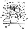
- a rectangular frame 32 of a tray 30has a retainer actuator generally designated 51 , which extends from the top of the rectangular frame 32 in a similar general manner to the actuator mechanism of known filter trays.
- a wedge carrier body 59is generally housed within a retainer body 53 , enclosed on the front surface by a cover plate 54 .
- the wedge carrier body 59includes a sliding cam follower 60 , which is generally triangular shaped, and shoulders 62 , and of course the moveable wedge 40 itself which protrudes from the retainer body 53 .
- the wedge carrier body 59is biased downwards towards the photographic filter (not here shown) by a spring 42 mounted around a guide pin 50 , which acts to urge the moveable wedge 40 downwards.
- the retainer actuator 51also includes two actuators 44 , which are similar but oppositely disposed. Each actuator 44 engages with the retainer body 53 through a pivot boss 52 which allows the actuator 44 to pivot. Each actuator 44 includes an elongate arm 46 which extends substantially away from the pivot boss 52 . Each actuator 44 also includes a levered cam surface 58 , which bears against the sliding cam follower 60 .
- the moveable wedge 40When the retainer actuator 51 is not being manipulated, the moveable wedge 40 is urged downwards, so that it retains any photographic filter that is in position.
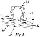
- the camera operatorwishes to either remove a photographic filter present in the rectangular frame 32 or insert a photographic filter (or carry out both operations to swap photographic filters), the operator grips or pinches the two actuators 44 so that both elongate arms 46 are pressed towards the centre line of the retainer actuator 51 , the force exerted by the operator being shown by arrows a in FIG. 5 .
- Thiscauses the actuator 44 to each rotate about their respective pivot bosses 52 as shown in FIG. 6 , and the levered cam surfaces 58 to be urged inwards.
- the retainer actuator 51also includes a guard body 56 including two guard arms 57 which extend over the upper portions of the actuators 44 . These guard arms 57 allow the filter tray 30 to be manipulated by the retainer actuator 51 , in particular, when it is desired to rotate one or more filter trays 30 when fitted in the matte box, without releasing the photographic filter 38 .
- the guard body 56therefore prevents inadvertent release of a photographic filter 38 .
- actuators 69each feature a slot 80 which engages with a pin 79 , so that the actuators 69 are constrained to move linearly.
- each actuator 69has a cam surface 75 which bears against one of two sliding cam followers 77 features on the wedge carrier body 66 .
- the wedge carrier body 66is forced upwards overcoming the bias of the spring 67 of the guide pin 72 , to withdraw the moveable wedge 65 .
- the wedge carrier body 66is forced downwards by the spring 67 until shoulders 82 on the wedge carrier body 66 abut stops 83 present on the retainer body.
- the actuators 69are shielded from inadvertent operation by a guard handle 70 . Two actuators are convenient, though the moveable wedge could be operated by a single actuator, as shown in FIG.
- a single actuator 69has a cam surface 75 which bears against a sliding cam follower 77 , here the cam surface 75 being simplified to a simple inclined edge and the sliding cam follower 77 a circular post that is embossed from the surface of the wedge carrier body 66 that bears it.
- Two springs 67bias the wedge carrier body 66 .
- the convenience of being able to operate the moveable wedge 65 by pressuremay be effected by an actuator 69 that relies on a linear reversing mechanism, here implemented by two actuator ratchets 85 whose translation turn pawls 86 , which in turn moves wedge ratchets 87 , causing the wedge carrier body 66 to move upwards when the actuator 69 is pressed downwards.
- the guard handle 70may include finger grips 71 so that the user can easily gain purchase on the actuator 69 in a similar fashion to depressing a syringe plunger.
Landscapes
- Physics & Mathematics (AREA)
- General Physics & Mathematics (AREA)
- Optics & Photonics (AREA)
- Blocking Light For Cameras (AREA)
Abstract
Description
Claims (8)
Applications Claiming Priority (3)
| Application Number | Priority Date | Filing Date | Title |
|---|---|---|---|
| GB1600821 | 2016-01-15 | ||
| GBGB1600821.1 | 2016-01-15 | ||
| GB1600821.1AGB2554034B (en) | 2016-01-15 | 2016-01-15 | Camera filter tray |
Publications (2)
| Publication Number | Publication Date |
|---|---|
| US20170205599A1 US20170205599A1 (en) | 2017-07-20 |
| US11269153B2true US11269153B2 (en) | 2022-03-08 |
Family
ID=55488055
Family Applications (1)
| Application Number | Title | Priority Date | Filing Date |
|---|---|---|---|
| US15/406,687ActiveUS11269153B2 (en) | 2016-01-15 | 2017-01-14 | Camera filter tray |
Country Status (2)
| Country | Link |
|---|---|
| US (1) | US11269153B2 (en) |
| GB (1) | GB2554034B (en) |
Families Citing this family (1)
| Publication number | Priority date | Publication date | Assignee | Title |
|---|---|---|---|---|
| JP7031098B2 (en)* | 2020-08-03 | 2022-03-08 | エスゼット ディージェイアイ テクノロジー カンパニー リミテッド | Imaging device |
Citations (18)
| Publication number | Priority date | Publication date | Assignee | Title |
|---|---|---|---|---|
| US3270994A (en)* | 1963-08-27 | 1966-09-06 | Meopta Narodni Podnik | Tripod base |
| US4050791A (en)* | 1974-12-28 | 1977-09-27 | Nippon Kogaku K.K. | Filter holder insertable into the lens barrel of a camera |
| US4384767A (en)* | 1980-06-18 | 1983-05-24 | Canon Kabushiki Kaisha | Clamping device for camera accessory or hood |
| US4536057A (en)* | 1981-04-14 | 1985-08-20 | Canon Kabushiki Kaisha | Filter mounting mechanism for an optical assembly |
| US4712897A (en)* | 1985-07-27 | 1987-12-15 | Ernst Leitz Wetzlar Gmbh | Device for adjustment of the viewfinder eyepiece of a camera |
| EP0311358A2 (en)* | 1987-10-06 | 1989-04-12 | Ronald Vickers | Filter arrangements |
| US4938489A (en)* | 1988-12-20 | 1990-07-03 | Robert Nemirovsky | Self-centering holder for optical devices and the like |
| US5201501A (en)* | 1991-02-18 | 1993-04-13 | Essilor International Compagnie Generale D'optique | Unit for grasping and clamping circular objects |
| US5227925A (en)* | 1991-05-20 | 1993-07-13 | Asahi Kogaku Kogyo Kabushiki Kaisha | Filter holder |
| US5746408A (en)* | 1996-02-05 | 1998-05-05 | Minnesota Mining And Manufacturing Company | Hinged, adjustable mounting mechanism for an optical filter screen |
| US6525890B1 (en)* | 2000-02-11 | 2003-02-25 | Hubbell Incorporated | Latch for optical assembly |
| EP1847872A1 (en)* | 2006-04-20 | 2007-10-24 | Vocas Systems B.V. | Mattebox with flag position fixation and tiltable filter unit |
| US7800050B2 (en)* | 2006-12-27 | 2010-09-21 | Konica Minolta Opto, Inc. | Holding structure for optical element including an elastic biasing section and a displacement restricting section (as amneded) |
| US8177265B2 (en)* | 2004-10-22 | 2012-05-15 | Assa Abloy New Zealand Limited | Latch |
| CN203825345U (en)* | 2014-05-15 | 2014-09-10 | 上海臣进数码科技有限公司 | Rapid clamping connection filter frame |
| US8903236B2 (en)* | 2012-04-13 | 2014-12-02 | Andrew Subratie | Camera matte box |
| US20150167707A1 (en)* | 2013-12-16 | 2015-06-18 | Carson Optical, Inc. | Self-centering mechanism, a clamping device for an electronic device and means for their integration |
| US9285659B2 (en)* | 2013-02-21 | 2016-03-15 | Canon Kabushiki Kaisha | Optical accessory adapter |
Family Cites Families (1)
| Publication number | Priority date | Publication date | Assignee | Title |
|---|---|---|---|---|
| DE2553861A1 (en)* | 1975-11-29 | 1977-06-08 | Zeiss Carl Fa | PHOTOGRAPHIC CAMERA WITH INTERCHANGEABLE LENS |
- 2016
- 2016-01-15GBGB1600821.1Apatent/GB2554034B/enactiveActive
- 2017
- 2017-01-14USUS15/406,687patent/US11269153B2/enactiveActive
Patent Citations (18)
| Publication number | Priority date | Publication date | Assignee | Title |
|---|---|---|---|---|
| US3270994A (en)* | 1963-08-27 | 1966-09-06 | Meopta Narodni Podnik | Tripod base |
| US4050791A (en)* | 1974-12-28 | 1977-09-27 | Nippon Kogaku K.K. | Filter holder insertable into the lens barrel of a camera |
| US4384767A (en)* | 1980-06-18 | 1983-05-24 | Canon Kabushiki Kaisha | Clamping device for camera accessory or hood |
| US4536057A (en)* | 1981-04-14 | 1985-08-20 | Canon Kabushiki Kaisha | Filter mounting mechanism for an optical assembly |
| US4712897A (en)* | 1985-07-27 | 1987-12-15 | Ernst Leitz Wetzlar Gmbh | Device for adjustment of the viewfinder eyepiece of a camera |
| EP0311358A2 (en)* | 1987-10-06 | 1989-04-12 | Ronald Vickers | Filter arrangements |
| US4938489A (en)* | 1988-12-20 | 1990-07-03 | Robert Nemirovsky | Self-centering holder for optical devices and the like |
| US5201501A (en)* | 1991-02-18 | 1993-04-13 | Essilor International Compagnie Generale D'optique | Unit for grasping and clamping circular objects |
| US5227925A (en)* | 1991-05-20 | 1993-07-13 | Asahi Kogaku Kogyo Kabushiki Kaisha | Filter holder |
| US5746408A (en)* | 1996-02-05 | 1998-05-05 | Minnesota Mining And Manufacturing Company | Hinged, adjustable mounting mechanism for an optical filter screen |
| US6525890B1 (en)* | 2000-02-11 | 2003-02-25 | Hubbell Incorporated | Latch for optical assembly |
| US8177265B2 (en)* | 2004-10-22 | 2012-05-15 | Assa Abloy New Zealand Limited | Latch |
| EP1847872A1 (en)* | 2006-04-20 | 2007-10-24 | Vocas Systems B.V. | Mattebox with flag position fixation and tiltable filter unit |
| US7800050B2 (en)* | 2006-12-27 | 2010-09-21 | Konica Minolta Opto, Inc. | Holding structure for optical element including an elastic biasing section and a displacement restricting section (as amneded) |
| US8903236B2 (en)* | 2012-04-13 | 2014-12-02 | Andrew Subratie | Camera matte box |
| US9285659B2 (en)* | 2013-02-21 | 2016-03-15 | Canon Kabushiki Kaisha | Optical accessory adapter |
| US20150167707A1 (en)* | 2013-12-16 | 2015-06-18 | Carson Optical, Inc. | Self-centering mechanism, a clamping device for an electronic device and means for their integration |
| CN203825345U (en)* | 2014-05-15 | 2014-09-10 | 上海臣进数码科技有限公司 | Rapid clamping connection filter frame |
Non-Patent Citations (3)
| Title |
|---|
| Bright Tangerine, "Bright Tangerine Gripper Tray," Vimeo, uploaded by Newsshooter, Oct. 5, 2016, https://www.vimeo.com/185737152. (Year: 2016).* |
| Bright Tangerine, "NAB 2016: Bright Tangerine Filter Trays," Vimeo, uploaded by Newsshooter, Apr. 25, 2016, https://www.vimeo.com/164104367. (Year: 2016).* |
| English machine translation of CN-203825345-U (Year: 2014).* |
Also Published As
| Publication number | Publication date |
|---|---|
| GB201600821D0 (en) | 2016-03-02 |
| GB2554034B (en) | 2022-03-02 |
| GB2554034A (en) | 2018-03-28 |
| US20170205599A1 (en) | 2017-07-20 |
Similar Documents
| Publication | Publication Date | Title |
|---|---|---|
| US10122400B2 (en) | Vent blade device mounting assembly | |
| JP6666469B2 (en) | System and method for an adjustable electronic device holder | |
| US20140331541A1 (en) | Quick detachable firearm accessory mount | |
| US6824028B2 (en) | Holder assembly for hand-held device | |
| US5480115A (en) | Hand release bracket | |
| US5169106A (en) | Quick attach/release pole clamp | |
| US10137036B2 (en) | Underwater mask | |
| US9459062B2 (en) | Magazine carrier | |
| FR2967409A1 (en) | TOOL FOR TRANSFERRING COATING FILM | |
| US11269153B2 (en) | Camera filter tray | |
| US20070238013A1 (en) | Portable electronic device | |
| JP3240371U (en) | cookware handles | |
| US20100132199A1 (en) | Cutting knife | |
| US20100252591A1 (en) | Gun holster clamping structure | |
| US9475515B2 (en) | Mountable smart device holder for a shopping cart | |
| US7973257B2 (en) | Rocker switch within a device holder | |
| GB2025641A (en) | Photographic camera | |
| US6668697B2 (en) | Automatic cutting device for an adhesive-tape holder | |
| JP4277107B2 (en) | cutter knife | |
| JP3170568U (en) | Cookware handle | |
| JP2020165860A (en) | Holder for small work equipment | |
| JP7538219B2 (en) | Safety Switch Device | |
| JP5023014B2 (en) | Presser | |
| JP2957934B2 (en) | Cylinder mounting device | |
| JP4612362B2 (en) | Trap with lock mechanism |
Legal Events
| Date | Code | Title | Description |
|---|---|---|---|
| STPP | Information on status: patent application and granting procedure in general | Free format text:FINAL REJECTION MAILED | |
| STPP | Information on status: patent application and granting procedure in general | Free format text:ADVISORY ACTION MAILED | |
| STPP | Information on status: patent application and granting procedure in general | Free format text:DOCKETED NEW CASE - READY FOR EXAMINATION | |
| STPP | Information on status: patent application and granting procedure in general | Free format text:NON FINAL ACTION MAILED | |
| AS | Assignment | Owner name:SUBRATIE, ANDREW, GREAT BRITAIN Free format text:ASSIGNMENT OF ASSIGNORS INTEREST;ASSIGNOR:ELIAS, JAMES HARRISON;REEL/FRAME:051990/0388 Effective date:20191110 | |
| STPP | Information on status: patent application and granting procedure in general | Free format text:RESPONSE TO NON-FINAL OFFICE ACTION ENTERED AND FORWARDED TO EXAMINER | |
| STPP | Information on status: patent application and granting procedure in general | Free format text:DOCKETED NEW CASE - READY FOR EXAMINATION | |
| STPP | Information on status: patent application and granting procedure in general | Free format text:NON FINAL ACTION MAILED | |
| STPP | Information on status: patent application and granting procedure in general | Free format text:RESPONSE TO NON-FINAL OFFICE ACTION ENTERED AND FORWARDED TO EXAMINER | |
| STPP | Information on status: patent application and granting procedure in general | Free format text:NOTICE OF ALLOWANCE MAILED -- APPLICATION RECEIVED IN OFFICE OF PUBLICATIONS | |
| STPP | Information on status: patent application and granting procedure in general | Free format text:NOTICE OF ALLOWANCE MAILED -- APPLICATION RECEIVED IN OFFICE OF PUBLICATIONS | |
| STCF | Information on status: patent grant | Free format text:PATENTED CASE | |
| MAFP | Maintenance fee payment | Free format text:PAYMENT OF MAINTENANCE FEE, 4TH YR, SMALL ENTITY (ORIGINAL EVENT CODE: M2551); ENTITY STATUS OF PATENT OWNER: SMALL ENTITY Year of fee payment:4 |