US11268521B2 - Compressible and expandable blade for a fluid pump - Google Patents
Compressible and expandable blade for a fluid pumpDownload PDFInfo
- Publication number
- US11268521B2 US11268521B2US16/404,800US201916404800AUS11268521B2US 11268521 B2US11268521 B2US 11268521B2US 201916404800 AUS201916404800 AUS 201916404800AUS 11268521 B2US11268521 B2US 11268521B2
- Authority
- US
- United States
- Prior art keywords
- rotor
- lamellae
- helical blade
- continuous helical
- blade
- Prior art date
- Legal status (The legal status is an assumption and is not a legal conclusion. Google has not performed a legal analysis and makes no representation as to the accuracy of the status listed.)
- Active, expires
Links
Images


Classifications
- F—MECHANICAL ENGINEERING; LIGHTING; HEATING; WEAPONS; BLASTING
- F04—POSITIVE - DISPLACEMENT MACHINES FOR LIQUIDS; PUMPS FOR LIQUIDS OR ELASTIC FLUIDS
- F04D—NON-POSITIVE-DISPLACEMENT PUMPS
- F04D15/00—Control, e.g. regulation, of pumps, pumping installations or systems
- F04D15/0055—Rotors with adjustable blades
- F—MECHANICAL ENGINEERING; LIGHTING; HEATING; WEAPONS; BLASTING
- F04—POSITIVE - DISPLACEMENT MACHINES FOR LIQUIDS; PUMPS FOR LIQUIDS OR ELASTIC FLUIDS
- F04D—NON-POSITIVE-DISPLACEMENT PUMPS
- F04D3/00—Axial-flow pumps
- A—HUMAN NECESSITIES
- A61—MEDICAL OR VETERINARY SCIENCE; HYGIENE
- A61M—DEVICES FOR INTRODUCING MEDIA INTO, OR ONTO, THE BODY; DEVICES FOR TRANSDUCING BODY MEDIA OR FOR TAKING MEDIA FROM THE BODY; DEVICES FOR PRODUCING OR ENDING SLEEP OR STUPOR
- A61M60/00—Blood pumps; Devices for mechanical circulatory actuation; Balloon pumps for circulatory assistance
- A61M60/10—Location thereof with respect to the patient's body
- A61M60/122—Implantable pumps or pumping devices, i.e. the blood being pumped inside the patient's body
- A61M60/126—Implantable pumps or pumping devices, i.e. the blood being pumped inside the patient's body implantable via, into, inside, in line, branching on, or around a blood vessel
- A61M60/13—Implantable pumps or pumping devices, i.e. the blood being pumped inside the patient's body implantable via, into, inside, in line, branching on, or around a blood vessel by means of a catheter allowing explantation, e.g. catheter pumps temporarily introduced via the vascular system
- A—HUMAN NECESSITIES
- A61—MEDICAL OR VETERINARY SCIENCE; HYGIENE
- A61M—DEVICES FOR INTRODUCING MEDIA INTO, OR ONTO, THE BODY; DEVICES FOR TRANSDUCING BODY MEDIA OR FOR TAKING MEDIA FROM THE BODY; DEVICES FOR PRODUCING OR ENDING SLEEP OR STUPOR
- A61M60/00—Blood pumps; Devices for mechanical circulatory actuation; Balloon pumps for circulatory assistance
- A61M60/10—Location thereof with respect to the patient's body
- A61M60/122—Implantable pumps or pumping devices, i.e. the blood being pumped inside the patient's body
- A61M60/165—Implantable pumps or pumping devices, i.e. the blood being pumped inside the patient's body implantable in, on, or around the heart
- A61M60/17—Implantable pumps or pumping devices, i.e. the blood being pumped inside the patient's body implantable in, on, or around the heart inside a ventricle, e.g. intraventricular balloon pumps
- A61M60/174—Implantable pumps or pumping devices, i.e. the blood being pumped inside the patient's body implantable in, on, or around the heart inside a ventricle, e.g. intraventricular balloon pumps discharging the blood to the ventricle or arterial system via a cannula internal to the ventricle or arterial system
- A—HUMAN NECESSITIES
- A61—MEDICAL OR VETERINARY SCIENCE; HYGIENE
- A61M—DEVICES FOR INTRODUCING MEDIA INTO, OR ONTO, THE BODY; DEVICES FOR TRANSDUCING BODY MEDIA OR FOR TAKING MEDIA FROM THE BODY; DEVICES FOR PRODUCING OR ENDING SLEEP OR STUPOR
- A61M60/00—Blood pumps; Devices for mechanical circulatory actuation; Balloon pumps for circulatory assistance
- A61M60/20—Type thereof
- A61M60/205—Non-positive displacement blood pumps
- A61M60/216—Non-positive displacement blood pumps including a rotating member acting on the blood, e.g. impeller
- A61M60/237—Non-positive displacement blood pumps including a rotating member acting on the blood, e.g. impeller the blood flow through the rotating member having mainly axial components, e.g. axial flow pumps
- A—HUMAN NECESSITIES
- A61—MEDICAL OR VETERINARY SCIENCE; HYGIENE
- A61M—DEVICES FOR INTRODUCING MEDIA INTO, OR ONTO, THE BODY; DEVICES FOR TRANSDUCING BODY MEDIA OR FOR TAKING MEDIA FROM THE BODY; DEVICES FOR PRODUCING OR ENDING SLEEP OR STUPOR
- A61M60/00—Blood pumps; Devices for mechanical circulatory actuation; Balloon pumps for circulatory assistance
- A61M60/80—Constructional details other than related to driving
- A61M60/802—Constructional details other than related to driving of non-positive displacement blood pumps
- A61M60/804—Impellers
- A61M60/806—Vanes or blades
- A61M60/808—Vanes or blades specially adapted for deformable impellers, e.g. expandable impellers
- A—HUMAN NECESSITIES
- A61—MEDICAL OR VETERINARY SCIENCE; HYGIENE
- A61M—DEVICES FOR INTRODUCING MEDIA INTO, OR ONTO, THE BODY; DEVICES FOR TRANSDUCING BODY MEDIA OR FOR TAKING MEDIA FROM THE BODY; DEVICES FOR PRODUCING OR ENDING SLEEP OR STUPOR
- A61M60/00—Blood pumps; Devices for mechanical circulatory actuation; Balloon pumps for circulatory assistance
- A61M60/80—Constructional details other than related to driving
- A61M60/855—Constructional details other than related to driving of implantable pumps or pumping devices
- A61M60/857—Implantable blood tubes
- B—PERFORMING OPERATIONS; TRANSPORTING
- B23—MACHINE TOOLS; METAL-WORKING NOT OTHERWISE PROVIDED FOR
- B23H—WORKING OF METAL BY THE ACTION OF A HIGH CONCENTRATION OF ELECTRIC CURRENT ON A WORKPIECE USING AN ELECTRODE WHICH TAKES THE PLACE OF A TOOL; SUCH WORKING COMBINED WITH OTHER FORMS OF WORKING OF METAL
- B23H9/00—Machining specially adapted for treating particular metal objects or for obtaining special effects or results on metal objects
- B23H9/10—Working turbine blades or nozzles
- B—PERFORMING OPERATIONS; TRANSPORTING
- B23—MACHINE TOOLS; METAL-WORKING NOT OTHERWISE PROVIDED FOR
- B23K—SOLDERING OR UNSOLDERING; WELDING; CLADDING OR PLATING BY SOLDERING OR WELDING; CUTTING BY APPLYING HEAT LOCALLY, e.g. FLAME CUTTING; WORKING BY LASER BEAM
- B23K26/00—Working by laser beam, e.g. welding, cutting or boring
- B23K26/20—Bonding
- B23K26/21—Bonding by welding
- B—PERFORMING OPERATIONS; TRANSPORTING
- B23—MACHINE TOOLS; METAL-WORKING NOT OTHERWISE PROVIDED FOR
- B23K—SOLDERING OR UNSOLDERING; WELDING; CLADDING OR PLATING BY SOLDERING OR WELDING; CUTTING BY APPLYING HEAT LOCALLY, e.g. FLAME CUTTING; WORKING BY LASER BEAM
- B23K26/00—Working by laser beam, e.g. welding, cutting or boring
- B23K26/36—Removing material
- B23K26/38—Removing material by boring or cutting
- F—MECHANICAL ENGINEERING; LIGHTING; HEATING; WEAPONS; BLASTING
- F04—POSITIVE - DISPLACEMENT MACHINES FOR LIQUIDS; PUMPS FOR LIQUIDS OR ELASTIC FLUIDS
- F04D—NON-POSITIVE-DISPLACEMENT PUMPS
- F04D29/00—Details, component parts, or accessories
- F04D29/18—Rotors
- F04D29/181—Axial flow rotors
- F—MECHANICAL ENGINEERING; LIGHTING; HEATING; WEAPONS; BLASTING
- F04—POSITIVE - DISPLACEMENT MACHINES FOR LIQUIDS; PUMPS FOR LIQUIDS OR ELASTIC FLUIDS
- F04D—NON-POSITIVE-DISPLACEMENT PUMPS
- F04D29/00—Details, component parts, or accessories
- F04D29/18—Rotors
- F04D29/22—Rotors specially for centrifugal pumps
- F04D29/24—Vanes
- F04D29/247—Vanes elastic or self-adjusting
- F—MECHANICAL ENGINEERING; LIGHTING; HEATING; WEAPONS; BLASTING
- F04—POSITIVE - DISPLACEMENT MACHINES FOR LIQUIDS; PUMPS FOR LIQUIDS OR ELASTIC FLUIDS
- F04D—NON-POSITIVE-DISPLACEMENT PUMPS
- F04D3/00—Axial-flow pumps
- F04D3/02—Axial-flow pumps of screw type
- A—HUMAN NECESSITIES
- A61—MEDICAL OR VETERINARY SCIENCE; HYGIENE
- A61M—DEVICES FOR INTRODUCING MEDIA INTO, OR ONTO, THE BODY; DEVICES FOR TRANSDUCING BODY MEDIA OR FOR TAKING MEDIA FROM THE BODY; DEVICES FOR PRODUCING OR ENDING SLEEP OR STUPOR
- A61M2207/00—Methods of manufacture, assembly or production
- A—HUMAN NECESSITIES
- A61—MEDICAL OR VETERINARY SCIENCE; HYGIENE
- A61M—DEVICES FOR INTRODUCING MEDIA INTO, OR ONTO, THE BODY; DEVICES FOR TRANSDUCING BODY MEDIA OR FOR TAKING MEDIA FROM THE BODY; DEVICES FOR PRODUCING OR ENDING SLEEP OR STUPOR
- A61M60/00—Blood pumps; Devices for mechanical circulatory actuation; Balloon pumps for circulatory assistance
- A61M60/10—Location thereof with respect to the patient's body
- A61M60/122—Implantable pumps or pumping devices, i.e. the blood being pumped inside the patient's body
- A61M60/126—Implantable pumps or pumping devices, i.e. the blood being pumped inside the patient's body implantable via, into, inside, in line, branching on, or around a blood vessel
- A61M60/135—Implantable pumps or pumping devices, i.e. the blood being pumped inside the patient's body implantable via, into, inside, in line, branching on, or around a blood vessel inside a blood vessel, e.g. using grafting
- A—HUMAN NECESSITIES
- A61—MEDICAL OR VETERINARY SCIENCE; HYGIENE
- A61M—DEVICES FOR INTRODUCING MEDIA INTO, OR ONTO, THE BODY; DEVICES FOR TRANSDUCING BODY MEDIA OR FOR TAKING MEDIA FROM THE BODY; DEVICES FOR PRODUCING OR ENDING SLEEP OR STUPOR
- A61M60/00—Blood pumps; Devices for mechanical circulatory actuation; Balloon pumps for circulatory assistance
- A61M60/10—Location thereof with respect to the patient's body
- A61M60/122—Implantable pumps or pumping devices, i.e. the blood being pumped inside the patient's body
- A61M60/126—Implantable pumps or pumping devices, i.e. the blood being pumped inside the patient's body implantable via, into, inside, in line, branching on, or around a blood vessel
- A61M60/148—Implantable pumps or pumping devices, i.e. the blood being pumped inside the patient's body implantable via, into, inside, in line, branching on, or around a blood vessel in line with a blood vessel using resection or like techniques, e.g. permanent endovascular heart assist devices
- A—HUMAN NECESSITIES
- A61—MEDICAL OR VETERINARY SCIENCE; HYGIENE
- A61M—DEVICES FOR INTRODUCING MEDIA INTO, OR ONTO, THE BODY; DEVICES FOR TRANSDUCING BODY MEDIA OR FOR TAKING MEDIA FROM THE BODY; DEVICES FOR PRODUCING OR ENDING SLEEP OR STUPOR
- A61M60/00—Blood pumps; Devices for mechanical circulatory actuation; Balloon pumps for circulatory assistance
- A61M60/40—Details relating to driving
- A61M60/403—Details relating to driving for non-positive displacement blood pumps
- A61M60/408—Details relating to driving for non-positive displacement blood pumps the force acting on the blood contacting member being mechanical, e.g. transmitted by a shaft or cable
- A61M60/411—Details relating to driving for non-positive displacement blood pumps the force acting on the blood contacting member being mechanical, e.g. transmitted by a shaft or cable generated by an electromotor
- A61M60/414—Details relating to driving for non-positive displacement blood pumps the force acting on the blood contacting member being mechanical, e.g. transmitted by a shaft or cable generated by an electromotor transmitted by a rotating cable, e.g. for blood pumps mounted on a catheter
- Y—GENERAL TAGGING OF NEW TECHNOLOGICAL DEVELOPMENTS; GENERAL TAGGING OF CROSS-SECTIONAL TECHNOLOGIES SPANNING OVER SEVERAL SECTIONS OF THE IPC; TECHNICAL SUBJECTS COVERED BY FORMER USPC CROSS-REFERENCE ART COLLECTIONS [XRACs] AND DIGESTS
- Y10—TECHNICAL SUBJECTS COVERED BY FORMER USPC
- Y10T—TECHNICAL SUBJECTS COVERED BY FORMER US CLASSIFICATION
- Y10T29/00—Metal working
- Y10T29/49—Method of mechanical manufacture
- Y10T29/49316—Impeller making
- Y10T29/49336—Blade making
- Y10T29/49337—Composite blade
Definitions
- the present inventionresides in the field of mechanics or micromechanics and can be applied advantageously in particular in medical technology.
- the inventionrelates to a blade for a pump and the design thereof.
- a pumphaving a rotor, the rotor being compressible and expandable in order to be able possibly to change the overall dimensions of the pump.
- the pumpcan be pushed through not readily accessible openings or into narrow pipe systems, for which purpose it is firstly compressed and, after it has been moved to the location of use, is expanded again.
- Such a pumpcan be used particularly advantageously in medical technology in the field of heart pumps or other pumps for body fluids which are normally used with catheters.
- micropumpswhich pumps can be introduced in the compressed state with a catheter through a naturally occurring body vessel into the body of a patient and can be expanded in situ.
- various effectscan be used in the construction and the structure of the pump housing and the pump rotor, such as e.g. the use of so-called memory alloys which change their shape as a function of the ambient temperature or control the pump diameter specifically by providing specific transmission mechanisms which allow it.
- a rotoris known from the US patent specification U.S. Pat. No. 7,393,181, the blade of which can be subdivided into a plurality of partial blades or rows of partial blades for improved compressibility/collapsibility.
- the individual partial bladesare smaller than a one-part blade and almost flat so that they can be rolled in easily.
- the ability to be subdividedis restricted by the intrinsic stability of the partial blades which requires to be ensured.
- the object underlying the present inventionis to produce a rotor which can be produced as simply and economically as possible or a blade for such a rotor, high compressibility being paramount with as little as possible of a force expenditure so that, in order to withdraw the pump from the vessel, the compression of the pump rotor can be achieved without greater external resistances.
- the corresponding pumpis intended to be designed to be efficient and low-consumption.
- the inventionprovides a blade having a plurality of lamellae which are disposed adjacently, are moveable relative to each other and pivotable relative to an axis of rotation of the rotor, the lamellae abutting against each other in the expanded state of the blade such that they form together a continuous blade surface.
- lamellae of this typecan be pivoted individually very easily into a space-saving state and, in the pivoted-out, expanded state of the blade or of the rotor, form a closed blade surface which is designed such that it fulfils the required technical flow conditions with respect to shape and surface design.
- the blade consisting of individual lamellaehas the advantage that its components can, both in the compressed and in the expanded state, assume a defined shape and arrangement.
- the individual lamellaecan respectively be mounted rotatably on the shaft of the rotor and in fact advantageously pivotable in a plane which includes the longitudinal axis of the rotor shaft or an axis parallel to such a shaft, the mounting points being able to extend around the rotor shaft in a spiral in order to produce a spiral blade in the unfolded state.
- the lamellaeare mounted for example on one or more webs or transverse spars which are connected, for their part, to the rotor shaft.
- the individual lamellaecan be of equal length but can also be designed to be of different lengths according to which final shape the blade is intended to assume.
- the pivotability of the individual lamellaeis restricted so that these, in the opened state, can withstand the flow counterpressure of a fluid to be conveyed.
- the lamellaecan also be mutually supported in that they abut against each other and possibly engage in each other forming a lock.
- the lamellaecan be designed in the manner of the elements of a bird feather, the quill of the feather corresponding comparatively to the rotor shaft.
- the construction of the bladecan be designed such that the blade expands during rotation in the operating direction due to the fluid counterpressure and, when rotating in the opposite direction, is compressed by the effect of the medium in which the blade moves. This makes the compression- and expansion movement particularly simple without greater forces requiring to be overcome. During application in the medical field, such a pump can hence be removed again in a simple manner and without the danger of damaging body vessels.
- a particular embodiment of the inventionprovides that at least two lamellae, in particular each of the lamellae, have per se a dimensionally stable, in particular rigid configuration.
- the bladeobtains its flexibility not from the flexibility of a membrane but from the movability of the individual lamellae relative to each other.
- the lamellaemust not exceed a specific width.
- the bladefor example can consist of at least 10 or at least 50 lamellae.
- Such a bladecan have in total a very small constructional size in order to be inserted into a blood vessel, preferably less than 5 mm for example in the compressed state, a diameter of 2 mm.
- a further advantageous embodiment of the inventioncan provide that respectively adjacent lamellae abut against each other to form a seal along a longitudinal side which extends at least partially radially relative to the rotor axis.
- lamellae which are mutually directly adjacentabut against each other in such a manner that they are not pivotable relative to each other about the rotor axis in at least one direction.
- the individual lamellaecan support each other mutually and, during operation, entirely withstand the counterpressure of the fluid to be pumped.
- the lamellaeare distributed in a spiral on the circumference of the rotor shaft, support is provided in the azimuthal direction.
- the inventioncan be designed in addition such that respectively adjacent lamellae mutually overlap in the region of the longitudinal side. As a result of overlapping of the lamellae, particularly high impermeability is produced and, in addition, the support function of the lamellae can be mutually exerted in the overlapping region.
- Particularly high stability and impermeability between the lamellaeis achieved in that respectively adjacent lamellae engage one in the other in the region of the longitudinal side.
- Any type of form-fitting design of adjacent lamellaecan thereby be provided, for example respectively the provision of a fold along the longitudinal sides of the lamellae, for example also in the form of a thin sealing lip.
- At least one lamellain particular all the lamellae, have a convex shape, in cross-section, on one of the longitudinal sides thereof and a concave shape on the other longitudinal side.
- the corresponding convex or concave structurecan, in cross-section, be round, elliptical or also configured as a groove or notch.
- respectively adjacent lamellaecan be connected to each other by a flexible element, in particular a strip or a membrane.
- a flexible elementin particular a strip or a membrane.
- the ability of the blade to be opened outis then produced in the manner of a fan, in the case of which broad, rigid support bars are connected to each other by narrow membranes or strips.
- the individual lamellaecan respectively have a stiffening structure in cross-section, which provides for example a web extending in the longitudinal direction.
- the individual lamellaeare configured to be hollow with a round or square cross-section.
- the inventioncan be configured by a blade in which at least two lamellae are connected to each other by a chain-like connection.
- a chain-like connectionconsists of small hook-like elements on the one side and blade-like elements on the respectively other side, which can be configured advantageously to be microscopically small.
- connectionis detachable by applying a load on the blade in the axial direction of the rotor and/or by a relative movement of two adjacent lamellae along their respective longitudinal sides and in the longitudinal direction of the lamellae.
- the longitudinal direction of the lamellaeis thereby dictated by the direction in which the respective lamella extends away from the rotor shaft.
- said bladecan be designed to be particularly stable and compressible in a defined manner, as a result of which in particular good compressibility and a small final diameter of the rotor can be achieved in the compressed form.
- a developmentprovides that a compressible and expandable blade for the rotor of a fluid pump, in particular a catheter pump, is provided, at least two lamellae which are disposed adjacently being pivotable respectively relative to an axis of rotation of the rotor and being moveable relative to each other and abutting against each other in the expanded state in such a manner that they form together a continuous blade surface, the at least two adjacently-disposed lamellae belonging to different rotor segments, one rotor segment comprising at least one lamella and also a hub segment.
- the rotor segmentscan be made of different materials, for example from shape memory materials, in particular shape memory metals or shape memory plastic materials.
- shape memory materialsin particular shape memory metals or shape memory plastic materials.
- Nitinolpolymers with the desired properties are hereby possible.
- the advantage of the “bird feather” principleis ensured, on the one hand, that the placing-around of individual lamellae frictionally (in particular when introducing into a lock) is associated with low complexity, however, on the other hand (due to the mutual support effect), a high fluid counterpressure can be produced.
- the at least one lamella and also the hub segment of the rotor segmentare in one part. This means that these can be produced integrally or from a unified body, preferably a pipe or a flat material (raw material).
- the thickness of the raw materialis preferably 5 ⁇ m to 500 ⁇ m, more preferably 20 ⁇ m to 200 ⁇ m.
- a developmentprovides that at least two adjacent rotor segments are connected to each other non-rotatably in a form-fit. This can be ensured by corresponding engagement elements (raised portions/depressions). As a result, the mounting is significantly simplified in addition.
- an individual rotor segmenthas here a single hub element and also one, two (or even more) lamellae.
- the rotor segmentcan have an individual lamella, however also a “wing arrangement” is conceivable in which two lamellae (preferably situated one opposite the other) protrude.
- wing arrangementis conceivable in which two lamellae (preferably situated one opposite the other) protrude.
- a method for the production of a rotor segment or a blade having a plurality of rotor segmentsprovides that structures for hub segments and also lamellae are cut out (for instance by means of a laser by wire eroding or etching) from a (for instance tubular or flat) basic body, a connection web between hub segment and lamellae remaining in order to ensure the advantages of the one-part state. Subsequently, the lamellae can be plastically deformed in their radially protruding normal state by corresponding shaping tools, as a result of which they correspond to the expanded (but not yet subjected to fluid pressure) state of the subsequent blade.
- a chemical etching treatment or a further laser treatment of the lamellaecan be effected in order to ensure for example smooth or different surfaces in order to influence the technical flow properties of the lamella.
- a profile of the lamellacan be adapted here to assist the flow.
- the rotor segmentscan subsequently be joined axially to form a rotor shaft.
- these rotor segmentseven when a form-fit is provided in advance by complementary concavities/raised portions, are connected to each other by means of material joining methods, for example gluing or welding.
- rotor segments with connection webs disposed between the rotor segmentscan be worked out of a flat material and are to be disposed on a rotor shaft by folding the flat material out of the surface plane in such a manner that automatically a helix shape of the blade is produced.
- a further developmentprovides that a plurality of lamellae are part of one lamella body, these being connected to each other merely in their foot region.
- the lamella bodycan thus be introducible into a hub body such that, in the unloaded state of the outer tips of the lamellae, a helix shape of the blade is formed.
- the hub bodyis configured as a shell with spiral longitudinal slots into which the lamella body is introduced so that later the hub body represents the outer circumference of the rotor shaft in the case of a finished catheter pump/fluid pump.
- the lamella body in the foot region of the lamellaehas weak portions in order to achieve higher tangential deflections of the lamellae with the same force application (compared with the state in which there are no weak portions).
- good rigidity of the lamellais achieved, on the one hand, relative to the fluid but, on the other hand, sufficient flexibility is ensured during the first deformation of the lamella body into the helix shape.
- a developmentprovides that, on the flow pressure side, the proximal region of a distal lamella covers the distal region of an adjacently-situated proximal lamella.
- the type of “stepping” of the lamellaeis fixed.
- the advantageis that a stepping of this kind is very blood-compatible.
- the erythrocytesdo not collide with the step in pumping/flow direction; instead, they “fall down the steps”.
- a further developmentprovides that application of the lamellae in a compressed state is effected essentially by deflecting the lamellae. This is achieve (for example in an embodiment according to FIG. 13 d ) in a way that proximally of the rotor a sheath is positioned and the rotor is introduced into the sheath in proximal direction, wherein the lamellae basically one after another (first the most proximal, then the one distally neighboring the most proximal and so on) are bent (i.e. the blades are not bent in total at once, instead the lamellae are bent one after another which has the advantage of lower force requirements).
- the sheathmay have a tube-shape cross-section.
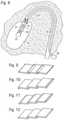
- FIG. 1schematically in a three-dimensional view, a rotor shaft and also a blade
- FIG. 2schematically, a part of a blade with a plurality of lamellae
- FIG. 3a rotor shaft in cross-section with a lamella in two positions
- FIG. 4a rotor shaft in cross-section with two lamellae in respectively two positions
- FIG. 5a view of a rotor shaft with four lamellae
- FIG. 6a view of a rotor shaft with two configurations of lamellae
- FIG. 7a view of a rotor shaft with two configurations of lamellae
- FIG. 8a schematic representation of a heart catheter pump with a rotor and blades in a ventricle
- FIGS. 9 to 12show schematic 3-dimensional illustrations of overlapping lamellae.
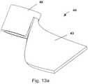
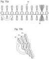
- FIGS. 13 a to 13 lan embodiment of the blades according to the invention, these blades consisting of lamellae of adjacently-situated rotor segments,
- FIGS. 14 a to 14 dembodiments of a blade in which a lamella body is inserted into a spiral incision of a shell body
- FIGS. 15 a and 15 ba further embodiment of a blade which is constructed from rotor segments.
- FIG. 1shows a rotor shaft 1 having a blade 2 which is composed of individual, schematically indicated lamellae 3 , 4 , 5 .
- the individual lamellaeare mounted pivotably respectively by their feet 3 a , 4 a , 5 a on the rotor shaft 1 , the feet of the lamellae together extending around the rotor shaft 1 in a spiral.
- FIG. 2The particular embodiment of the blade according to the invention emerges in more detail from FIG. 2 .
- the lamellae 3 , 4 , 5are represented there in the deployed, expanded shape of the blade, the adjacent lamellae abutting closely against each other by their longitudinal sides and hence forming a surface which is smooth and sealed for the flowing fluid.
- the individual lamellaeare folded a little far onto the rotor shaft 1 , it being totally important for the deformability of the blade that the individual lamellae 3 , 4 , 5 are moveable relative to each other, in particular are displaceable in the longitudinal direction. Consequently, folding of the corresponding surface is unnecessary but the individual lamellae can be folded quite far towards the rotor shaft, as is represented in the further position 8 of the lamellae.
- the bladecan be extensively compressed, i.e. can be reduced with respect to the radius, relative to the rotor shaft 1 or the longitudinal axis 1 a thereof.
- FIG. 2if pivotability of the individual lamellae in the longitudinal direction of the rotor shaft 1 in the plane of the rotor shaft axis is indicated, then the invention is not however restricted hereto.
- FIG. 3shows pivotability of a lamella 3 in the azimuthal direction, as indicated by the arrow 9 .
- FIG. 4shows a further variant of such an embodiment, webs 10 , 11 being provided on the rotor shaft and the lamellae 3 , 4 being mounted pivotably on the webs 10 , 11 which extend around the rotor shaft 1 in a spiral.
- the pivoted positionsare represented respectively in broken lines in FIG. 4 .
- the individual lamellaecan also be mounted on transverse spars of the rotor shaft 1 and extend in the deployed state parallel to the longitudinal axis of the rotor shaft. It is important that they can be collapsed correspondingly individually in order to reduce the diameter of the rotor.
- FIG. 5a plan view on four lamellae 12 , 13 , 14 , 15 is shown schematically, said lamellae having respectively, in cross-section, a rectangular and hollow configuration in order to produce greater longitudinal rigidity of the individual lamellae.
- the objectivethereby is that, despite the rigidity of the individual lamellae, the blade in total can be collapsed easily.
- FIG. 6shows two configurations of lamellae, on the left side respectively lamellae 16 , 17 which have an overlapping lip 18 , 19 being illustrated, adjacent lamellae respectively forming a seal on the overlapping lip 18 , 19 of the adjacent lamella, on the one hand, and being supported, on the other hand.
- rigidity of the blade in totalis produced so that the blade withstands an increased fluid counter-pressure during operation.
- each of the lamellaehaving a web 20 a , 21 a , 22 a extending in the radial direction of the rotor shaft 1 .
- FIG. 7shows, on left side of the plan view on the rotor shaft 1 , three lamellae 23 , 24 , 25 which have, on one side 26 , a convex protuberance and, on the other side 27 , a concave depression in order that adjacent lamellae engage one in the other and thus can be mutually supported relative to an azimuthal pivoting position.
- Lamellae 28 , 29are illustrated on the right side of FIG. 7 , each of the lamellae having, on their longitudinal sides, a concave and a convex protuberance with a round cross-section.
- This designhas the advantage that adjacent lamellae are rotatable about their longitudinal axis in a mutually restricted manner.
- the individual lamellaecan be mounted on the rotor shaft 1 either by means of a pivoting articulation or have a bendable or flexible configuration in their foot region such that they are pivotable in any case as a whole relative to the rotor shaft.
- the individual lamellaecan also be glued by their foot ends respectively individually on a flexible strip or can be mounted on the latter in a different way, the strip with the lamellae being able as a whole to be mounted on the rotor. As a result of the flexibility of the strip, the pivotability of the individual lamellae can then be ensured.
- FIG. 8the use of a fluid pump with a blade according to the invention is represented schematically, the pump 30 being positioned in a ventricle 31 and, as indicated by the arrows 32 , sucks in blood which is conveyed into a vessel 33 , as is shown by the arrows 34 .
- the pump 30is mounted on a catheter 35 , through which a shaft 1 illustrated only in the region of the pump 30 extends centrally and is actuated rotationally by means of a motor 36 .
- the shaftmoves a rotor 37 which has a blade, illustrated merely schematically.
- the pump 30 in the expanded statehas a diameter which can be possibly also be greater, in the extreme case, than the inner diameter of the vessel 33 .
- the impelleris expanded fully.
- itcan also be compressed in order to introduce or remove the pump 30 , the individual lamellae, as illustrated above, being able to be folded against the rotor shaft 1 and, at the same time, the housing of the pump 30 being correspondingly collapsed.
- this housingcan for example consist of a membrane which is deployed by a frame or by the fluid pressure produced in the pump 30 .
- FIG. 9shows three flat lamellae which overlap at their longitudinal sides and can have for example a burr-like connection in their overlapping region.
- FIG. 10shows lamellae which have edges angled by 90 degrees along their longitudinal sides respectively and with which they hook one into the other, whilst a variant, in FIG. 11 , is illustrated with an angle of less than 90 degrees which likewise allows fixing of the lamellae relative to each other.
- FIG. 12finally represents a variant with a curved edge which serves for the same purpose of mutual fixing.
- FIG. 13 ashows a rotor segment 40 which consists of a hub segment 46 and also a lamella 43 connected thereto in one part.
- the rotor segmentis produced from a pipe material, the hub segment 46 essentially still having the diameter of the pipe (of concern hereby is also a ring closed in regions) and the lamella being bent therefrom.
- the lamellais cut out firstly in its original form by means of a laser beam and subsequently plastic deformability on a moulded body is achieved in which the deformation state shown in FIG. 13 a is produced. Subsequently, the result is also an etching treatment and for other surface treatment of the lamellae.
- a plurality of rotor segmentsare then disposed axially relative to each other.
- an individual lamellacan hereby be covered with a plastic material or metal foil/membrane or also can be sprayed-around and/or molded in order to achieve a greater surface.
- FIG. 13 bshows another view of the rotor segment 40 , it can be seen here how tension relieving slots 54 are shown in the foot region of the lamella 43 .
- the rotor segment shown in FIG. 13 a / 13 bhas a closed annular shape in the lower region of the hub segment.
- the rotor segmentconnects the hub segment and also the lamella in one part.
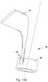
- FIG. 13 dshows a further embodiment of a rotor segment which is cut from a pipe material and is not yet completely finished, in the case of which rotor segment the lamellae 43 , 43 a are not yet spread out.
- tension-relieving slots 54can however already be seen, in particular also form-fitting elements 47 in the form of raised portions can be seen, which can engage in corresponding depressions of axially adjacent rotor segments in order hence to fix the position of the lamellae (later radially spread out).
- a rotor with a blade 42 according to the inventionis shown in detail again in FIG. 13 d .
- the preferred conveying direction of the rotoris hereby characterised by the right-side rotational arrow, it consequently results that the flow pressure side 51 and the (opposite side of the lamellae) is the flow suction side 52 .
- a plurality of rotor segments 40is disposed axially adjacently by their respective hub segments 46 .
- This rotor shown in FIG. 13 dcan be part of a fluid pump shown in FIG. 8 , in particular an intraventricular catheter pump.
- the proximal region of the distal lamella 44covers the distal region of the proximal lamella 43 .
- the resultconsequently is formation of a closed blade, at least in the radial outer region of the lamellae.
- the lamellaeare hereby configured “in the shape of an ice hockey stick”. Consequently a very good overlap in the relevant flow region is produced, in addition good collapsibility.
- only a small flow lossresults due to the above-mentioned orientation of the stepping of the lamellae.
- FIG. 13 dit is shown in FIG. 13 d that application of the lamellae 43 , 44 , 45 in a compressed state is effected essentially by deflecting the lamellae in the direction of the flow pressure (see arrow 53 ). This arrow is shown once in the distal and once in the proximal region of the rotor.
- the “ice hockey stick-shaped” design of the lamellaeoffers the advantage in addition that, when inserting into a lock situated proximally of the rotor, a low-force and entanglement-free insertion of the rotor is produced.
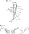
- FIG. 13 eshows a further embodiment of a rotor according to the invention in which two blades 42 and 42 a are provided.
- the rotor shown in FIG. 13 eis a combination of a plurality of rotor segments according to FIG. 13 c.
- FIG. 13 fshows a combination of three rotor segments 40 which form parts of a rotor shaft 41 , also three hub segments are hereby disposed in succession, a common blade 42 is produced.
- FIG. 13 gshows a simple embodiment of a rotor segment 40 with two lamellae protruding radially therefrom.
- FIGS. 13 hshows further embodiments of rotors according to the invention.
- FIGS. 13 l and 13 jagain show the rotor segment shown in FIG. 13 c , here once again the tension-relieving slots 54 and also the form-fitting end serving for the form-fit being shown even better with 47 (raised portion) and also 48 (concavity).
- FIG. 13 kshows a blade 42 on a rotor shaft 41
- FIG. 13 lshows two photographs in which, in the left picture, a blade 42 made of a plurality of lamellae is drawn into an insertion lock 55 , the rotor shaft 41 can be seen on the right side. In the right-side picture, the blade 42 is completely inserted in the insertion lock 55 .
- FIG. 14 ashows a further embodiment of a rotor in which a hub body 50 has two spiral slots (see FIG. 14 b ) into which a lamella body 49 (see FIG. 14 c ) is inserted.
- the view of a flat material from which the lamella body 49 is cut by means of a lasercan be seen in FIG. 14 d .
- a possible spraying-around/covering of a lamellais also shown once again in FIGS. 14 d and/or 15 a (with cross hatching).
- the cross hatchingcan, in another embodiment, be understood that the entire cross-hatched area is made of flat material.
- FIGS. 15 a and 15 ba further embodiment of a blade is shown.
- a lamella basic body 49is hereby cut from a flat material, connection struts being provided between individual rotor segments.
- connection strutsbeing provided between individual rotor segments.
- the individual rotor segmentsare tilted out of the surface plane and recombined with each other, a helical structure is then produced automatically. This functions for example in such a manner that, according to FIG. 15 a , the rotor segment disposed on the left side is rotated out of the plane and placed on the next element from the left (and so on for the other rotor elements) such that the openings of the hub segment overlap each other.
- a helical arrangement of the lamellae 42 , 43 , 44is produced automatically.
- the lamellaemay, in a subsequent forming process, be rotated in respect of their longitudinal axis in order to achieve overlapping of the lamellae.
Landscapes
- Engineering & Computer Science (AREA)
- Health & Medical Sciences (AREA)
- Mechanical Engineering (AREA)
- Heart & Thoracic Surgery (AREA)
- Cardiology (AREA)
- General Health & Medical Sciences (AREA)
- Animal Behavior & Ethology (AREA)
- Veterinary Medicine (AREA)
- Public Health (AREA)
- Anesthesiology (AREA)
- Biomedical Technology (AREA)
- Hematology (AREA)
- Life Sciences & Earth Sciences (AREA)
- General Engineering & Computer Science (AREA)
- Physics & Mathematics (AREA)
- Optics & Photonics (AREA)
- Plasma & Fusion (AREA)
- Vascular Medicine (AREA)
- Thermal Sciences (AREA)
- Structures Of Non-Positive Displacement Pumps (AREA)
- External Artificial Organs (AREA)
Abstract
Description
Claims (20)
Priority Applications (3)
| Application Number | Priority Date | Filing Date | Title |
|---|---|---|---|
| US16/404,800US11268521B2 (en) | 2009-06-25 | 2019-05-07 | Compressible and expandable blade for a fluid pump |
| US17/582,676US11994133B2 (en) | 2009-06-25 | 2022-01-24 | Compressible and expandable blade for a fluid pump |
| US18/640,529US12372092B2 (en) | 2009-06-25 | 2024-04-19 | Compressible and expandable blade for a fluid pump |
Applications Claiming Priority (7)
| Application Number | Priority Date | Filing Date | Title |
|---|---|---|---|
| US22029209P | 2009-06-25 | 2009-06-25 | |
| EP09075276.7 | 2009-06-25 | ||
| EP09075276 | 2009-06-25 | ||
| EP09075276AEP2266640A1 (en) | 2009-06-25 | 2009-06-25 | Compressible and expandable turbine blade for a fluid pump |
| PCT/EP2010/004023WO2010149393A1 (en) | 2009-06-25 | 2010-06-25 | Compressible and expandable blade for a fluid pump |
| US14/754,395US10330101B2 (en) | 2009-06-25 | 2015-06-29 | Compressible and expandable blade for a fluid pump |
| US16/404,800US11268521B2 (en) | 2009-06-25 | 2019-05-07 | Compressible and expandable blade for a fluid pump |
Related Parent Applications (1)
| Application Number | Title | Priority Date | Filing Date |
|---|---|---|---|
| US14/754,395ContinuationUS10330101B2 (en) | 2009-06-25 | 2015-06-29 | Compressible and expandable blade for a fluid pump |
Related Child Applications (1)
| Application Number | Title | Priority Date | Filing Date |
|---|---|---|---|
| US17/582,676ContinuationUS11994133B2 (en) | 2009-06-25 | 2022-01-24 | Compressible and expandable blade for a fluid pump |
Publications (2)
| Publication Number | Publication Date |
|---|---|
| US20190316591A1 US20190316591A1 (en) | 2019-10-17 |
| US11268521B2true US11268521B2 (en) | 2022-03-08 |
Family
ID=41162697
Family Applications (5)
| Application Number | Title | Priority Date | Filing Date |
|---|---|---|---|
| US13/261,100Active2031-04-21US9067006B2 (en) | 2009-06-25 | 2010-06-25 | Compressible and expandable blade for a fluid pump |
| US14/754,395ActiveUS10330101B2 (en) | 2009-06-25 | 2015-06-29 | Compressible and expandable blade for a fluid pump |
| US16/404,800Active2031-01-06US11268521B2 (en) | 2009-06-25 | 2019-05-07 | Compressible and expandable blade for a fluid pump |
| US17/582,676Active2030-09-11US11994133B2 (en) | 2009-06-25 | 2022-01-24 | Compressible and expandable blade for a fluid pump |
| US18/640,529ActiveUS12372092B2 (en) | 2009-06-25 | 2024-04-19 | Compressible and expandable blade for a fluid pump |
Family Applications Before (2)
| Application Number | Title | Priority Date | Filing Date |
|---|---|---|---|
| US13/261,100Active2031-04-21US9067006B2 (en) | 2009-06-25 | 2010-06-25 | Compressible and expandable blade for a fluid pump |
| US14/754,395ActiveUS10330101B2 (en) | 2009-06-25 | 2015-06-29 | Compressible and expandable blade for a fluid pump |
Family Applications After (2)
| Application Number | Title | Priority Date | Filing Date |
|---|---|---|---|
| US17/582,676Active2030-09-11US11994133B2 (en) | 2009-06-25 | 2022-01-24 | Compressible and expandable blade for a fluid pump |
| US18/640,529ActiveUS12372092B2 (en) | 2009-06-25 | 2024-04-19 | Compressible and expandable blade for a fluid pump |
Country Status (4)
| Country | Link |
|---|---|
| US (5) | US9067006B2 (en) |
| EP (1) | EP2266640A1 (en) |
| DE (1) | DE112010002711B4 (en) |
| WO (1) | WO2010149393A1 (en) |
Cited By (14)
| Publication number | Priority date | Publication date | Assignee | Title |
|---|---|---|---|---|
| US11648392B2 (en) | 2016-11-23 | 2023-05-16 | Magenta Medical Ltd. | Blood pumps |
| US11648387B2 (en) | 2015-05-18 | 2023-05-16 | Magenta Medical Ltd. | Blood pump |
| US11648391B2 (en) | 2013-03-13 | 2023-05-16 | Magenta Medical Ltd. | Blood pump |
| US11666747B2 (en) | 2019-01-24 | 2023-06-06 | Magenta Medical Ltd. | Manufacturing an impeller |
| US11684275B2 (en) | 2018-01-10 | 2023-06-27 | Magenta Medical Ltd. | Distal tip element for blood pump |
| US11839540B2 (en) | 2012-06-06 | 2023-12-12 | Magenta Medical Ltd | Vena-caval apparatus and methods |
| US11839754B2 (en) | 2016-10-25 | 2023-12-12 | Magenta Medical Ltd | Ventricular assist device |
| US11883274B2 (en) | 2013-03-13 | 2024-01-30 | Magenta Medical Ltd. | Vena-caval blood pump |
| US12128227B2 (en) | 2020-04-07 | 2024-10-29 | Magenta Medical Ltd. | Manufacture of an impeller |
| US12128228B2 (en) | 2019-05-23 | 2024-10-29 | Magenta Medical Ltd | Blood pumps |
| US12343518B2 (en) | 2018-01-10 | 2025-07-01 | Magenta Medical Ltd. | Blood-pressure-measurement element |
| US12370358B2 (en) | 2018-02-01 | 2025-07-29 | Shifamed Holdings, Llc | Intravascular blood pumps and methods of use and manufacture |
| US12409310B2 (en) | 2019-12-11 | 2025-09-09 | Shifamed Holdings, Llc | Descending aorta and vena cava blood pumps |
| US12440665B2 (en) | 2021-11-22 | 2025-10-14 | Magenta Medical Ltd. | Magnetic phase detection |
Families Citing this family (92)
| Publication number | Priority date | Publication date | Assignee | Title |
|---|---|---|---|---|
| US7393181B2 (en) | 2004-09-17 | 2008-07-01 | The Penn State Research Foundation | Expandable impeller pump |
| CN102380135A (en) | 2006-03-23 | 2012-03-21 | 宾州研究基金会 | Heart assist device with expandable impeller pump |
| EP2194278A1 (en) | 2008-12-05 | 2010-06-09 | ECP Entwicklungsgesellschaft mbH | Fluid pump with a rotor |
| EP2216059A1 (en) | 2009-02-04 | 2010-08-11 | ECP Entwicklungsgesellschaft mbH | Catheter device with a catheter and an actuation device |
| EP2229965A1 (en) | 2009-03-18 | 2010-09-22 | ECP Entwicklungsgesellschaft mbH | Fluid pump with particular form of a rotor blade |
| EP2246078A1 (en) | 2009-04-29 | 2010-11-03 | ECP Entwicklungsgesellschaft mbH | Shaft assembly with a shaft which moves within a fluid-filled casing |
| EP2248544A1 (en) | 2009-05-05 | 2010-11-10 | ECP Entwicklungsgesellschaft mbH | Fluid pump with variable circumference, particularly for medical use |
| EP2266640A1 (en) | 2009-06-25 | 2010-12-29 | ECP Entwicklungsgesellschaft mbH | Compressible and expandable turbine blade for a fluid pump |
| EP2282070B1 (en) | 2009-08-06 | 2012-10-17 | ECP Entwicklungsgesellschaft mbH | Catheter device with a coupling device for a drive device |
| EP2299119B1 (en) | 2009-09-22 | 2018-11-07 | ECP Entwicklungsgesellschaft mbH | Inflatable rotor for a fluid pump |
| EP2298373A1 (en) | 2009-09-22 | 2011-03-23 | ECP Entwicklungsgesellschaft mbH | Fluid pump with at least one turbine blade and a seating device |
| EP2298372A1 (en) | 2009-09-22 | 2011-03-23 | ECP Entwicklungsgesellschaft mbH | Rotor for an axial pump for transporting a fluid |
| EP2298371A1 (en) | 2009-09-22 | 2011-03-23 | ECP Entwicklungsgesellschaft mbH | Function element, in particular fluid pump with a housing and a transport element |
| EP2314330A1 (en) | 2009-10-23 | 2011-04-27 | ECP Entwicklungsgesellschaft mbH | Flexible shaft arrangement |
| EP2314331B1 (en) | 2009-10-23 | 2013-12-11 | ECP Entwicklungsgesellschaft mbH | Catheter pump arrangement and flexible shaft arrangement with a cable core |
| EP2338539A1 (en) | 2009-12-23 | 2011-06-29 | ECP Entwicklungsgesellschaft mbH | Pump device with a detection device |
| EP2338541A1 (en) | 2009-12-23 | 2011-06-29 | ECP Entwicklungsgesellschaft mbH | Radial compressible and expandable rotor for a fluid pump |
| EP2338540A1 (en) | 2009-12-23 | 2011-06-29 | ECP Entwicklungsgesellschaft mbH | Delivery blade for a compressible rotor |
| EP2347778A1 (en) | 2010-01-25 | 2011-07-27 | ECP Entwicklungsgesellschaft mbH | Fluid pump with a radially compressible rotor |
| EP2363157A1 (en) | 2010-03-05 | 2011-09-07 | ECP Entwicklungsgesellschaft mbH | Device for exerting mechanical force on a medium, in particular fluid pump |
| EP2388029A1 (en) | 2010-05-17 | 2011-11-23 | ECP Entwicklungsgesellschaft mbH | Pump array |
| EP2399639A1 (en) | 2010-06-25 | 2011-12-28 | ECP Entwicklungsgesellschaft mbH | System for introducing a pump |
| EP2407185A1 (en) | 2010-07-15 | 2012-01-18 | ECP Entwicklungsgesellschaft mbH | Radial compressible and expandable rotor for a pump with a turbine blade |
| EP2407187A3 (en) | 2010-07-15 | 2012-06-20 | ECP Entwicklungsgesellschaft mbH | Blood pump for invasive application within the body of a patient |
| EP2407186A1 (en) | 2010-07-15 | 2012-01-18 | ECP Entwicklungsgesellschaft mbH | Rotor for a pump, produced with an initial elastic material |
| EP2422735A1 (en) | 2010-08-27 | 2012-02-29 | ECP Entwicklungsgesellschaft mbH | Implantable blood transportation device, manipulation device and coupling device |
| WO2012094641A2 (en) | 2011-01-06 | 2012-07-12 | Thoratec Corporation | Percutaneous heart pump |
| EP2497521A1 (en) | 2011-03-10 | 2012-09-12 | ECP Entwicklungsgesellschaft mbH | Push device for axial insertion of a string-shaped, flexible body |
| EP2564771A1 (en) | 2011-09-05 | 2013-03-06 | ECP Entwicklungsgesellschaft mbH | Medicinal product with a functional element for invasive use in the body of a patient |
| US8926492B2 (en) | 2011-10-11 | 2015-01-06 | Ecp Entwicklungsgesellschaft Mbh | Housing for a functional element |
| JP6139550B2 (en) | 2011-11-28 | 2017-05-31 | ミ‐ヴァド インコーポレイテッド | Auxiliary circulation apparatus and method |
| WO2013082621A1 (en) | 2011-12-03 | 2013-06-06 | Indiana University Research And Technology Corporation | Cavopulmonary viscous impeller assist device and method |
| US11389638B2 (en) | 2012-02-07 | 2022-07-19 | Hridaya, Inc. | Hemodynamic assist device |
| JP2015505515A (en)* | 2012-02-07 | 2015-02-23 | フリダヤ インコーポレーテッドHridaya, Inc. | Blood circulation assist device |
| US9327067B2 (en) | 2012-05-14 | 2016-05-03 | Thoratec Corporation | Impeller for catheter pump |
| EP4218887A1 (en) | 2012-05-14 | 2023-08-02 | Tc1 Llc | Mechanical circulatory support device for stabilizing a patient after cardiogenic shock |
| US8721517B2 (en) | 2012-05-14 | 2014-05-13 | Thoratec Corporation | Impeller for catheter pump |
| US9872947B2 (en) | 2012-05-14 | 2018-01-23 | Tc1 Llc | Sheath system for catheter pump |
| US9446179B2 (en) | 2012-05-14 | 2016-09-20 | Thoratec Corporation | Distal bearing support |
| US20130338690A1 (en)* | 2012-06-15 | 2013-12-19 | Gadal Consulting, LLC | Device and method for removing unwanted material in a vascular conduit |
| EP4186557A1 (en) | 2012-07-03 | 2023-05-31 | Tc1 Llc | Motor assembly for catheter pump |
| US9421311B2 (en) | 2012-07-03 | 2016-08-23 | Thoratec Corporation | Motor assembly for catheter pump |
| US9358329B2 (en) | 2012-07-03 | 2016-06-07 | Thoratec Corporation | Catheter pump |
| US11033728B2 (en) | 2013-03-13 | 2021-06-15 | Tc1 Llc | Fluid handling system |
| US11077294B2 (en) | 2013-03-13 | 2021-08-03 | Tc1 Llc | Sheath assembly for catheter pump |
| WO2014164136A1 (en) | 2013-03-13 | 2014-10-09 | Thoratec Corporation | Fluid handling system |
| US9308302B2 (en) | 2013-03-15 | 2016-04-12 | Thoratec Corporation | Catheter pump assembly including a stator |
| EP4190376A1 (en) | 2013-03-15 | 2023-06-07 | Tc1 Llc | Catheter pump assembly including a stator |
| EP2860849B1 (en) | 2013-10-11 | 2016-09-14 | ECP Entwicklungsgesellschaft mbH | Compressible motor, implanting assembly and method for positioning the motor |
| EP2868331B1 (en) | 2013-11-01 | 2016-07-13 | ECP Entwicklungsgesellschaft mbH | Pump, in particular blood pump |
| EP3110468B1 (en) | 2014-02-25 | 2021-11-03 | Kushwaha, Sudhir | Ventricular assist device and method |
| EP3131599B1 (en) | 2014-04-15 | 2019-02-20 | Tc1 Llc | Catheter pump with access ports |
| EP3131597B1 (en) | 2014-04-15 | 2020-12-02 | Tc1 Llc | Catheter pump introducer systems |
| WO2015160943A1 (en) | 2014-04-15 | 2015-10-22 | Thoratec Corporation | Sensors for catheter pumps |
| US10583232B2 (en) | 2014-04-15 | 2020-03-10 | Tc1 Llc | Catheter pump with off-set motor position |
| EP3583973A1 (en) | 2014-08-18 | 2019-12-25 | Tc1 Llc | Guide features for percutaneous catheter pump |
| EP3200846B1 (en) | 2014-10-01 | 2020-01-15 | Heartware, Inc. | Backup controller system with updating |
| US9770543B2 (en) | 2015-01-22 | 2017-09-26 | Tc1 Llc | Reduced rotational mass motor assembly for catheter pump |
| US9675738B2 (en) | 2015-01-22 | 2017-06-13 | Tc1 Llc | Attachment mechanisms for motor of catheter pump |
| WO2016118781A2 (en) | 2015-01-22 | 2016-07-28 | Thoratec Corporation | Motor assembly with heat exchanger for catheter pump |
| US9907890B2 (en) | 2015-04-16 | 2018-03-06 | Tc1 Llc | Catheter pump with positioning brace |
| CN105032636A (en)* | 2015-08-15 | 2015-11-11 | 重庆联合机器制造有限公司 | Assembly device of laminated gas-liquid spreader plates |
| EP3808401A1 (en) | 2016-07-21 | 2021-04-21 | Tc1 Llc | Gas-filled chamber for catheter pump motor assembly |
| US11160970B2 (en) | 2016-07-21 | 2021-11-02 | Tc1 Llc | Fluid seals for catheter pump motor assembly |
| CN110621851B (en)* | 2017-05-17 | 2021-08-06 | 联邦摩高气门机构公司 | Poppet valve and method of making the same |
| CN110662889B (en)* | 2017-05-17 | 2021-07-23 | 联邦摩高气门机构公司 | Poppet valve and method of manufacturing the same |
| CA3066361A1 (en) | 2017-06-07 | 2018-12-13 | Shifamed Holdings, Llc | Intravascular fluid movement devices, systems, and methods of use |
| WO2019094963A1 (en) | 2017-11-13 | 2019-05-16 | Shifamed Holdings, Llc | Intravascular fluid movement devices, systems, and methods of use |
| DE102018201030B4 (en) | 2018-01-24 | 2025-10-16 | Kardion Gmbh | Magnetic dome element with magnetic bearing function |
| DE102018207575A1 (en) | 2018-05-16 | 2019-11-21 | Kardion Gmbh | Magnetic face turning coupling for the transmission of torques |
| DE102018207611A1 (en) | 2018-05-16 | 2019-11-21 | Kardion Gmbh | Rotor bearing system |
| DE102018208539A1 (en) | 2018-05-30 | 2019-12-05 | Kardion Gmbh | A motor housing module for sealing an engine compartment of a motor of a cardiac assist system and cardiac assistance system and method for mounting a cardiac assist system |
| DE102018208538A1 (en) | 2018-05-30 | 2019-12-05 | Kardion Gmbh | Intravascular blood pump and process for the production of electrical conductors |
| DE102018208541A1 (en) | 2018-05-30 | 2019-12-05 | Kardion Gmbh | Axial pump for a cardiac assist system and method of making an axial pump for a cardiac assist system |
| DE102018208550A1 (en) | 2018-05-30 | 2019-12-05 | Kardion Gmbh | A lead device for directing blood flow to a cardiac assist system, cardiac assist system, and method of making a lead device |
| DE102018210076A1 (en) | 2018-06-21 | 2019-12-24 | Kardion Gmbh | Method and device for detecting a state of wear of a cardiac support system, method and device for operating a cardiac support system and cardiac support system |
| DE102018210058A1 (en) | 2018-06-21 | 2019-12-24 | Kardion Gmbh | Stator blade device for guiding the flow of a fluid flowing out of an outlet opening of a heart support system, heart support system with stator blade device, method for operating a stator blade device and manufacturing method |
| DE102018211327A1 (en) | 2018-07-10 | 2020-01-16 | Kardion Gmbh | Impeller for an implantable vascular support system |
| DE102018212153A1 (en) | 2018-07-20 | 2020-01-23 | Kardion Gmbh | Inlet line for a pump unit of a cardiac support system, cardiac support system and method for producing an inlet line for a pump unit of a cardiac support system |
| US12161857B2 (en) | 2018-07-31 | 2024-12-10 | Shifamed Holdings, Llc | Intravascular blood pumps and methods of use |
| US10851799B2 (en) | 2018-08-02 | 2020-12-01 | Percheron Power, LLC | Screw systems |
| CN112654389A (en) | 2018-08-07 | 2021-04-13 | 开迪恩有限公司 | Bearing device for a cardiac support system and method for flushing an intermediate space in a bearing device for a cardiac support system |
| WO2020073047A1 (en) | 2018-10-05 | 2020-04-09 | Shifamed Holdings, Llc | Intravascular blood pumps and methods of use |
| US12097016B2 (en) | 2019-03-14 | 2024-09-24 | Abiomed, Inc. | Blood flow rate measurement system |
| WO2021011473A1 (en) | 2019-07-12 | 2021-01-21 | Shifamed Holdings, Llc | Intravascular blood pumps and methods of manufacture and use |
| US11654275B2 (en) | 2019-07-22 | 2023-05-23 | Shifamed Holdings, Llc | Intravascular blood pumps with struts and methods of use and manufacture |
| US12121713B2 (en) | 2019-09-25 | 2024-10-22 | Shifamed Holdings, Llc | Catheter blood pumps and collapsible blood conduits |
| WO2021062265A1 (en) | 2019-09-25 | 2021-04-01 | Shifamed Holdings, Llc | Intravascular blood pump systems and methods of use and control thereof |
| EP4501393A3 (en) | 2019-09-25 | 2025-04-09 | Shifamed Holdings, LLC | Catheter blood pumps and collapsible pump housings |
| DE102020102474A1 (en) | 2020-01-31 | 2021-08-05 | Kardion Gmbh | Pump for conveying a fluid and method for manufacturing a pump |
| DE102021120618A1 (en) | 2021-08-09 | 2023-02-23 | Fraunhofer-Gesellschaft zur Förderung der angewandten Forschung eingetragener Verein | Self-adaptive pump with shape memory element |
| US12257426B2 (en)* | 2022-12-02 | 2025-03-25 | Abiomed Europe Gmbh | Compressible rotor |
Citations (191)
| Publication number | Priority date | Publication date | Assignee | Title |
|---|---|---|---|---|
| CA8330A (en) | 1878-01-22 | Alexander Mcdonald | Improvements on stone dressing hammers | |
| CA311977A (en) | 1931-06-02 | William Thomas George | Glazing construction | |
| CA701809A (en) | 1965-01-12 | D. Finch Harry | Preparation of hydroxyalkane sulfonic acid salts | |
| CA701810A (en) | 1965-01-12 | C. Udy Murray | Treating molten metal with an oxygen-containing gaseous stream | |
| US3510229A (en) | 1968-07-23 | 1970-05-05 | Maytag Co | One-way pump |
| US3568659A (en) | 1968-09-24 | 1971-03-09 | James N Karnegis | Disposable percutaneous intracardiac pump and method of pumping blood |
| DE2207296A1 (en) | 1971-02-17 | 1972-08-31 | Somers, S. Brice L., Genf (Schweiz) | Flexible device for conveying granular powdery or liquid goods |
| DE2113986A1 (en) | 1971-03-23 | 1972-09-28 | Svu Textilni | Artificial heart machine - with ptfe or similar inert plastic coated parts,as intracorperal replacement |
| DE2233293A1 (en) | 1971-07-06 | 1973-01-25 | Vni I Ispytatelnyj I Med Techn | DEVICE TO FACILITATE HEARTINESS |
| US3812812A (en) | 1973-06-25 | 1974-05-28 | M Hurwitz | Trolling propeller with self adjusting hydrodynamic spoilers |
| US4014317A (en) | 1972-02-18 | 1977-03-29 | The United States Of America As Represented By The Department Of Health, Education And Welfare | Multipurpose cardiocirculatory assist cannula and methods of use thereof |
| US4207028A (en) | 1979-06-12 | 1980-06-10 | Ridder Sven O | Extendable and retractable propeller for watercraft |
| US4559951A (en) | 1982-11-29 | 1985-12-24 | Cardiac Pacemakers, Inc. | Catheter assembly |
| US4563181A (en) | 1983-02-18 | 1986-01-07 | Mallinckrodt, Inc. | Fused flexible tip catheter |
| US4679558A (en) | 1985-08-12 | 1987-07-14 | Intravascular Surgical Instruments, Inc. | Catheter based surgical methods and apparatus therefor |
| US4686982A (en) | 1985-06-19 | 1987-08-18 | John Nash | Spiral wire bearing for rotating wire drive catheter |
| US4747821A (en) | 1986-10-22 | 1988-05-31 | Intravascular Surgical Instruments, Inc. | Catheter with high speed moving working head |
| US4749376A (en) | 1986-10-24 | 1988-06-07 | Intravascular Surgical Instruments, Inc. | Reciprocating working head catheter |
| US4753221A (en) | 1986-10-22 | 1988-06-28 | Intravascular Surgical Instruments, Inc. | Blood pumping catheter and method of use |
| US4801243A (en) | 1985-12-28 | 1989-01-31 | Bird-Johnson Company | Adjustable diameter screw propeller |
| US4817613A (en) | 1987-07-13 | 1989-04-04 | Devices For Vascular Intervention, Inc. | Guiding catheter |
| EP0364293A2 (en) | 1988-10-13 | 1990-04-18 | Kensey Nash Corporation | Blood pumping catheter |
| US4957504A (en) | 1988-12-02 | 1990-09-18 | Chardack William M | Implantable blood pump |
| US4969865A (en) | 1989-01-09 | 1990-11-13 | American Biomed, Inc. | Helifoil pump |
| US4995857A (en) | 1989-04-07 | 1991-02-26 | Arnold John R | Left ventricular assist device and method for temporary and permanent procedures |
| US5011469A (en) | 1988-08-29 | 1991-04-30 | Shiley, Inc. | Peripheral cardiopulmonary bypass and coronary reperfusion system |
| GB2239675A (en) | 1989-12-05 | 1991-07-10 | Man Fai Shiu | Pump for pumping liquid |
| US5040944A (en) | 1989-09-11 | 1991-08-20 | Cook Einar P | Pump having impeller rotational about convoluted stationary member |
| US5042984A (en) | 1989-08-17 | 1991-08-27 | Kensey Nash Corporation | Catheter with working head having selectable impacting surfaces and method of using the same |
| US5052404A (en) | 1989-03-02 | 1991-10-01 | The Microspring Company, Inc. | Torque transmitter |
| US5061256A (en) | 1987-12-07 | 1991-10-29 | Johnson & Johnson | Inflow cannula for intravascular blood pumps |
| DE4124299A1 (en) | 1990-07-20 | 1992-01-23 | Aymerich Diego Figuera | INTRAVENTRICULAR EXPANDABLE AUXILIARY PUMP |
| WO1992002263A1 (en) | 1989-02-23 | 1992-02-20 | Nimbus Medical, Inc. | Percutaneous axial flow bloodpump |
| US5092844A (en) | 1990-04-10 | 1992-03-03 | Mayo Foundation For Medical Education And Research | Intracatheter perfusion pump apparatus and method |
| US5097849A (en) | 1989-08-17 | 1992-03-24 | Kensey Nash Corporation | Method of use of catheter with working head having selectable impacting surfaces |
| US5108411A (en) | 1990-03-28 | 1992-04-28 | Cardiovascular Imaging Systems, Inc. | Flexible catheter drive cable |
| US5112292A (en) | 1989-01-09 | 1992-05-12 | American Biomed, Inc. | Helifoil pump |
| US5113872A (en) | 1990-04-18 | 1992-05-19 | Cordis Corporation | Guidewire extension system with connectors |
| US5118264A (en) | 1990-01-11 | 1992-06-02 | The Cleveland Clinic Foundation | Purge flow control in rotary blood pumps |
| US5117838A (en) | 1990-04-18 | 1992-06-02 | Cordis Corporation | Rotating guidewire extension system |
| US5145333A (en) | 1990-03-01 | 1992-09-08 | The Cleveland Clinic Foundation | Fluid motor driven blood pump |
| US5151721A (en) | 1990-05-15 | 1992-09-29 | Corning Incorporated | Compression joint for eyeglasses |
| US5163910A (en) | 1990-04-10 | 1992-11-17 | Mayo Foundation For Medical Education And Research | Intracatheter perfusion pump apparatus and method |
| US5183384A (en) | 1988-05-16 | 1993-02-02 | Trumbly Joe H | Foldable propeller assembly |
| WO1993002732A1 (en) | 1991-07-26 | 1993-02-18 | The Regents Of The University Of California | Method and device for retrieving materials from body lumens |
| WO1993003786A1 (en) | 1991-08-26 | 1993-03-04 | Target Therapeutics, Inc. | Extendable guidewire assembly |
| US5191888A (en) | 1990-04-18 | 1993-03-09 | Cordis Corporation | Assembly of an extension guidewire and an alignment tool for same |
| US5201679A (en) | 1991-12-13 | 1993-04-13 | Attwood Corporation | Marine propeller with breakaway hub |
| WO1993014805A1 (en) | 1992-01-28 | 1993-08-05 | Baxter International, Inc. | Guidewire extension system |
| EP0560000A2 (en) | 1991-11-05 | 1993-09-15 | Roberto Parravicini | Ventricular pumping device |
| US5275580A (en) | 1990-03-08 | 1994-01-04 | Kenji Yamazaki | Auxiliary artificial heart of the embedded-in-body type |
| WO1994001148A1 (en) | 1992-07-14 | 1994-01-20 | Aai Corporation | Articulated heart pump and method of use |
| WO1994005347A1 (en) | 1992-09-02 | 1994-03-17 | Reitan Oeyvind | Catheter pump |
| WO1994009835A1 (en) | 1992-10-30 | 1994-05-11 | Robert Jarvik | Cannula pumps for temporary cardiac support |
| WO1994020165A2 (en) | 1993-03-12 | 1994-09-15 | C.R. Bard, Inc. | Anatomically matched steerable ptca guidewire |
| US5373619A (en) | 1987-09-30 | 1994-12-20 | Lake Region Manufacturing Co., Inc. | Method of making a hollow lumen cable |
| EP0629412A2 (en) | 1993-06-03 | 1994-12-21 | Sun Medical Technology Research Corporation | Auxiliary artificial heart embedded in a ventricle of a heart |
| WO1995023000A2 (en) | 1994-02-25 | 1995-08-31 | General Dynamics Corporation | Reciprocating pump arrangement |
| US5501574A (en) | 1993-06-28 | 1996-03-26 | Baxter International Inc. | Blood pump |
| WO1996018358A1 (en) | 1994-12-16 | 1996-06-20 | Robert Jarvik | High reliability cardiac assist system |
| US5531789A (en) | 1993-12-24 | 1996-07-02 | Sun Medical Technology Research Corporation | Sealing system of an artificial internal organ |
| WO1996025969A2 (en) | 1995-02-21 | 1996-08-29 | C. R. Bard, Inc. | High performance wires for use in medical devices and alloys therefor |
| DE19535781A1 (en) | 1995-09-26 | 1997-03-27 | Fraunhofer Ges Forschung | System for active flow support of body fluids |
| EP0768091A1 (en) | 1995-10-16 | 1997-04-16 | Sun Medical Technology Research Corporation | Artificial heart |
| WO1997044071A1 (en) | 1996-05-21 | 1997-11-27 | Amnon Sudai | Apparatus and methods for revascularization and perfusion |
| US5701911A (en) | 1996-04-05 | 1997-12-30 | Medtronic, Inc. | Guide wire extension docking system |
| DE29804046U1 (en) | 1998-03-07 | 1998-04-30 | Günther, Rolf W., Prof. Dr.med., 52074 Aachen | Percutaneously implantable, self-expanding axial pump for temporary heart support |
| US5813405A (en) | 1990-04-18 | 1998-09-29 | Cordis Corporation | Snap-in connection assembly for extension guidewire system |
| US5820571A (en) | 1996-06-24 | 1998-10-13 | C. R. Bard, Inc. | Medical backloading wire |
| WO1998053864A1 (en) | 1997-05-30 | 1998-12-03 | Cardinove Inc. | Ventricular assist device comprising an enclosed-impeller axial flow blood pump |
| EP0884064A2 (en) | 1997-06-12 | 1998-12-16 | Schneider (Usa) Inc. | Balloon Catheter with impeller for perusing blood |
| US5851174A (en) | 1996-09-17 | 1998-12-22 | Robert Jarvik | Cardiac support device |
| US5877566A (en) | 1996-03-22 | 1999-03-02 | Chen; Chi-Der | Submersible magnetic motor having improved rotary blades |
| US5882329A (en) | 1997-02-12 | 1999-03-16 | Prolifix Medical, Inc. | Apparatus and method for removing stenotic material from stents |
| WO1999019017A1 (en) | 1997-10-10 | 1999-04-22 | Advanced Cardiovascular Systems, Inc. | Guidewire with tubular connector |
| EP0914171A2 (en) | 1996-06-26 | 1999-05-12 | University Of Pittsburgh | Magnetically suspended miniature fluid pump and method of making the same |
| EP0916359A1 (en) | 1997-11-13 | 1999-05-19 | Impella Cardiotechnik Aktiengesellschaft | Improved cannula device |
| US5938672A (en) | 1996-07-26 | 1999-08-17 | Kensey Nash Corporation | System and method of use for revascularizing stenotic bypass grafts and other blood vessels |
| EP0951302A2 (en) | 1996-10-04 | 1999-10-27 | States Surgical Corporation United | Circulatory support system |
| US6030397A (en) | 1998-12-16 | 2000-02-29 | Micro Therapeutics, Inc. | Miniaturized medical brush |
| WO2000027446A1 (en) | 1998-11-06 | 2000-05-18 | Nagy Adly Habib | Use of implantable pumps |
| EP1019117A1 (en) | 1997-10-02 | 2000-07-19 | Micromed Technology, Inc. | Implantable pump system |
| WO2000043054A2 (en) | 1999-01-26 | 2000-07-27 | Nimbus, Inc. | Blood pump with profiled outflow region |
| WO2000062842A1 (en) | 1999-04-20 | 2000-10-26 | Berlin Heart Ag | Device for the axial transport of fluid media |
| US6152693A (en) | 1993-12-23 | 2000-11-28 | Gori Marine As | Folding propeller |
| EP1066851A1 (en) | 1999-06-18 | 2001-01-10 | MEDOS Medizintechnik AG | Method for delivering a fluid into a human body vessel and cannula therefore |
| WO2001007787A1 (en) | 1999-07-26 | 2001-02-01 | Impsa International Inc. | Continuous flow rotary pump |
| WO2001007760A1 (en) | 1999-07-26 | 2001-02-01 | Impsa International Inc. | Hydraulic seal for rotary pumps |
| US6254359B1 (en) | 1996-05-10 | 2001-07-03 | The United States Of America As Represented By The Administrator Of The National Aeronautics And Space Administration | Method for providing a jewel bearing for supporting a pump rotor shaft |
| US6302910B1 (en) | 1992-06-23 | 2001-10-16 | Sun Medical Technology Research Corporation | Auxiliary artificial heart of an embedded type |
| US6308632B1 (en) | 1998-11-23 | 2001-10-30 | James E. Shaffer | Deployable folded propeller assembly for aerial projectiles |
| WO2001083016A2 (en) | 2000-05-01 | 2001-11-08 | Flowmedica, Inc. | Apparatus and methods for treating congestive heart disease |
| DE10059714C1 (en) | 2000-12-01 | 2002-05-08 | Impella Cardiotech Ag | Intravasal pump has pump stage fitted with flexible expandible sleeve contricted during insertion through blood vessel |
| US20020094273A1 (en) | 2001-01-16 | 2002-07-18 | Yung-Chung Huang | Blade structure for ceiling fan |
| DE10108810A1 (en) | 2001-02-16 | 2002-08-29 | Berlin Heart Ag | Device for the axial conveyance of liquids |
| US20020123661A1 (en) | 1999-07-29 | 2002-09-05 | Verkerke Gijsbertus Jacob | Catheter pump, catheter and method for supporting organ perfusion |
| US6506025B1 (en) | 1999-06-23 | 2003-01-14 | California Institute Of Technology | Bladeless pump |
| US6517315B2 (en) | 2001-05-29 | 2003-02-11 | Hewlett-Packard Company | Enhanced performance fan with the use of winglets |
| US6527521B2 (en) | 2000-01-26 | 2003-03-04 | Nipro Corporation | Magnetically driven axial-flow pump |
| US6537030B1 (en) | 2000-10-18 | 2003-03-25 | Fasco Industries, Inc. | Single piece impeller having radial output |
| DE10155011A1 (en) | 2001-11-02 | 2003-05-22 | Cardioberlin Gmbh | Intra-aortal pump system for supporting or replacing the heart pumping function is inserted into the heart and aorta using an adjustable guide and support bracket through an incision in the heart apex |
| US6592612B1 (en) | 2000-05-04 | 2003-07-15 | Cardeon Corporation | Method and apparatus for providing heat exchange within a catheter body |
| WO2003057013A2 (en) | 2002-01-08 | 2003-07-17 | Micromed Technology, Inc. | Method and system for detecting ventricular collapse |
| US20030135086A1 (en) | 2001-11-19 | 2003-07-17 | University Of Medicine And Dentistry Of New Jersey | Temporary blood circulation assist device |
| US6652548B2 (en) | 2000-03-31 | 2003-11-25 | Bacchus Vascular Inc. | Expansible shearing catheters for thrombus removal |
| WO2003103745A2 (en) | 2002-06-11 | 2003-12-18 | Walid Aboul-Hosn | Expandable blood pump and related methods |
| US20030231959A1 (en) | 2002-06-12 | 2003-12-18 | William Hackett | Impeller assembly for centrifugal pumps |
| US20040046466A1 (en) | 2000-11-25 | 2004-03-11 | Thorsten Siess | Miniature motor |
| US20040093074A1 (en) | 2000-11-21 | 2004-05-13 | Gesine Hildebrand | Tubular vascular implants (stents) and methods for producing the same |
| RU2229899C2 (en) | 2002-03-20 | 2004-06-10 | Федеральный научно-производственный центр закрытое акционерное общество "Научно-производственный концерн (объединение) "ЭНЕРГИЯ" | Device for supporting assist blood circulation |
| DE10336902B3 (en) | 2003-08-08 | 2004-08-19 | Impella Cardiosystems Ag | Intracardial pumping device has flexible projection on distal side of suction head inlet openings acting as mechanical spacer holding pumping device away from heart chamber walls |
| US6790171B1 (en) | 1999-03-09 | 2004-09-14 | Universitair Medisch Cenrum Utrecht | Method and device for transventricular mechanical circulatory support |
| US20040215222A1 (en) | 2003-04-25 | 2004-10-28 | Michael Krivoruchko | Intravascular material removal device |
| US20040215228A1 (en) | 2003-04-28 | 2004-10-28 | Cardiac Pacemakers, Inc. | Compliant guiding catheter sheath system |
| WO2005002646A1 (en) | 2003-07-01 | 2005-01-13 | Ntu Ventures Private Limited | Pump |
| US6860713B2 (en) | 2002-11-27 | 2005-03-01 | Nidec Corporation | Fan with collapsible blades, redundant fan system, and related method |
| GB2405677A (en) | 2003-09-02 | 2005-03-09 | Hewlett Packard Development Co | Rotor with collapsible fan blade |
| WO2005021078A1 (en) | 2003-09-02 | 2005-03-10 | Intra-Vasc.Nl B.V. | Catheter pump, catheter and fittings therefore and methods of using a catheter pump. |
| WO2005030316A1 (en) | 2003-09-26 | 2005-04-07 | Medtronic, Inc. | Sutureless pump connector |
| WO2005032620A1 (en) | 2003-10-09 | 2005-04-14 | Ventracor Limited | Impeller |
| US20050101200A1 (en) | 2003-09-09 | 2005-05-12 | Chad Townsend | Paddle blade |
| WO2005081681A2 (en) | 2004-02-11 | 2005-09-09 | Fort Wayne Metals Research Products Corporation | Drawn strand filled tubing wire |
| US6945977B2 (en) | 1999-12-06 | 2005-09-20 | Bacchus Vascular, Inc. | Systems and methods for clot disruption and retrieval |
| US20060008349A1 (en) | 2004-05-20 | 2006-01-12 | Kenneth Khaw | Replaceable expandable transmyocardial ventricular assist device |
| WO2006020942A1 (en) | 2004-08-13 | 2006-02-23 | Delgado Reynolds M Iii | Method and apparatus for long-term assisting a left ventricle to pump blood |
| US20060062672A1 (en)* | 2004-09-17 | 2006-03-23 | Mcbride Mark W | Expandable impeller pump |
| US7022100B1 (en) | 1999-09-03 | 2006-04-04 | A-Med Systems, Inc. | Guidable intravascular blood pump and related methods |
| WO2006051023A1 (en) | 2004-11-12 | 2006-05-18 | Abiomed Europe Gmbh | Folding, intravascularly inserted blood pump |
| US7074018B2 (en) | 2003-07-10 | 2006-07-11 | Sheldon Chang | Direct drive linear flow blood pump |
| US20060195004A1 (en) | 2005-02-28 | 2006-08-31 | Robert Jarvik | Minimally invasive transvalvular ventricular assist device |
| WO2006133209A1 (en) | 2005-06-06 | 2006-12-14 | The Cleveland Clinic Foundation | Blood pump |
| WO2007003351A1 (en) | 2005-07-01 | 2007-01-11 | Coras Medical | An axial flow pump with a spiral-shaped vane |
| US7179273B1 (en) | 1999-06-21 | 2007-02-20 | Endovascular Technologies, Inc. | Filter/emboli extractor for use in variable sized blood vessels |
| WO2007103390A2 (en) | 2006-03-06 | 2007-09-13 | Orqis Medical Corporation | Quick priming connectors for blood circuit |
| WO2007103464A2 (en) | 2006-03-08 | 2007-09-13 | Orqis Medical Corporation | Blood conduit connector |
| WO2007112033A2 (en) | 2006-03-23 | 2007-10-04 | The Penn State Research Foundation | Heart assist device with expandable impeller pump |
| US20070270875A1 (en) | 2006-04-13 | 2007-11-22 | Uwe Bacher | Medical Instrument For Spreading Vertebral Bodies Apart |
| WO2008017289A2 (en) | 2006-08-06 | 2008-02-14 | Mustafa Akdis | Blood pump |
| WO2008034068A2 (en) | 2006-09-14 | 2008-03-20 | Circulite, Inc. | Intravascular blood pump and catheter |
| US20080073983A1 (en) | 2006-09-21 | 2008-03-27 | Dezi Krajcir | Resilient motor mounting system and method of use |
| WO2008054699A2 (en) | 2006-10-30 | 2008-05-08 | Medtronic, Inc | Breakaway connectors and systems |
| US20080132747A1 (en) | 2006-12-01 | 2008-06-05 | Medical Value Partners, Llc | Medical Device |
| US20080132748A1 (en) | 2006-12-01 | 2008-06-05 | Medical Value Partners, Llc | Method for Deployment of a Medical Device |
| WO2008106103A2 (en) | 2007-02-26 | 2008-09-04 | Heartware, Inc. | Intravascular ventricular assist device |
| WO2008116765A2 (en) | 2007-03-24 | 2008-10-02 | Abiomed Europe Gmbh | Blood pump comprising a micromotor |
| WO2008124696A1 (en) | 2007-04-05 | 2008-10-16 | Micromed Technology, Inc. | Blood pump system |
| US20080262584A1 (en) | 2007-03-19 | 2008-10-23 | Bottomley Paul A | Methods and apparatus for fabricating leads with conductors and related flexible lead configurations |
| WO2008137352A1 (en) | 2007-05-01 | 2008-11-13 | Medtronic, Inc. | Threaded catheter connector, system, and method |
| WO2008137353A1 (en) | 2007-05-01 | 2008-11-13 | Medtronic, Inc. | Offset catheter connector, system and method for use |
| US20080306327A1 (en) | 2007-06-05 | 2008-12-11 | Medical Value Partners, Llc | Apparatus Comprising a Drive Cable for a Medical Device |
| WO2009015784A1 (en) | 2007-07-30 | 2009-02-05 | Ifw Manfred Otte Gmbh | Mould-integrated plastifying unit |
| US20090062597A1 (en) | 2007-08-29 | 2009-03-05 | Medical Value Partners, Llc | Article Comprising an Impeller |
| US20090093796A1 (en) | 2007-10-08 | 2009-04-09 | Ais Gmbh Aachen Innovative Solutions | Catheter device |
| US20090093764A1 (en) | 2007-10-08 | 2009-04-09 | Ais Gmbh Aachen Innovative Solutions | Catheter device |
| WO2009073037A1 (en) | 2007-12-07 | 2009-06-11 | Medical Value Partners, Llc | Medical device |
| EP2218469A1 (en) | 2009-02-12 | 2010-08-18 | ECP Entwicklungsgesellschaft mbH | Casing for a functional element |
| EP2047872B1 (en) | 2007-10-08 | 2010-09-08 | Ais Gmbh Aachen Innovative Solutions | Catheter device |
| EP2229965A1 (en) | 2009-03-18 | 2010-09-22 | ECP Entwicklungsgesellschaft mbH | Fluid pump with particular form of a rotor blade |
| DE102010011998A1 (en) | 2009-03-24 | 2010-09-30 | Ecp Entwicklungsgesellschaft Mbh | Fluid pumping unit, particularly for medical area for use within body vessel, has fluid pump which consists of pump rotor and drive device for driving fluid pump, where drive device has fluid supply line and drive rotor driven by fluid |
| WO2010133567A1 (en) | 2009-05-18 | 2010-11-25 | Cardiobridge Gmbh | Catheter pump |
| EP2301598A1 (en) | 2007-10-08 | 2011-03-30 | Ais Gmbh Aachen Innovative Solutions | Catheter device |
| EP2343091A1 (en) | 2010-01-08 | 2011-07-13 | ECP Entwicklungsgesellschaft mbH | Fluid pump with a transport device with controllable volume alteration |
| US20110257462A1 (en) | 2008-10-06 | 2011-10-20 | Indiana University and Technology Corporation | Active or passive assistance in the circulatory system |
| US20110275884A1 (en) | 2008-12-05 | 2011-11-10 | Ecp Entwicklungsgesellschaft Mbh | Fluid pump with a rotor |
| US20120046648A1 (en) | 2009-02-04 | 2012-02-23 | Mario Scheckel | Catheter device having a catheter and an actuation device |
| US20120093628A1 (en) | 2009-05-05 | 2012-04-19 | Ecp Entwicklungsgesellschaft Mbh | Fluid pump changeable in diameter, in particular for medical application |
| US20120101455A1 (en) | 2009-04-29 | 2012-04-26 | Ecp Entwicklungsgesellschaft Mbh | Shaft arrangement having a shaft which extends within a fluid-filled casing |
| US20120142994A1 (en) | 2009-06-25 | 2012-06-07 | Ecp[ Entwicklungsgellschaft Mbh | Compressible and expandable blade for a fluid pump |
| US20120184803A1 (en) | 2009-08-06 | 2012-07-19 | Ecp Entwicklungsgesellschaft Mbh | Catheter device having a coupling device for a drive device |
| US20120224970A1 (en) | 2009-09-22 | 2012-09-06 | Ecp Entwicklungsgesellschaft Mbh | Fluid pump having at least one impeller blade and a support device |
| EP2497521A1 (en) | 2011-03-10 | 2012-09-12 | ECP Entwicklungsgesellschaft mbH | Push device for axial insertion of a string-shaped, flexible body |
| US20120237357A1 (en) | 2009-09-22 | 2012-09-20 | Ecp Entwicklungsgesellschaft Mbh | Rotor for an axial flow pump for conveying a fluid |
| US20120237353A1 (en) | 2009-09-22 | 2012-09-20 | Ecp Entwicklungsgesellschaft Mbh | Compressible rotor for a fluid pump |
| US20120234411A1 (en) | 2009-09-22 | 2012-09-20 | Mario Scheckel | Functional element, in particular fluid pump, having a housing and a conveying element |
| US20120265002A1 (en) | 2009-10-23 | 2012-10-18 | Ecp Entwicklungsgesellschaft Mbh | Catheter pump arrangement and flexible shaft arrangement having a core |
| US20120264523A1 (en) | 2009-10-23 | 2012-10-18 | Ecp Entwicklungsgesellschaft Mbh | Flexible shaft arrangement |
| US20120294727A1 (en) | 2009-12-23 | 2012-11-22 | Ecp Entwicklungsegesellschaft Mbh | Radially compressible and expandable rotor for a fluid pump |
| US20120301318A1 (en) | 2009-12-23 | 2012-11-29 | Sami Er | Conveying blades for a compressible rotor |
| US20120308406A1 (en) | 2009-12-23 | 2012-12-06 | Ecp Entwicklungsgesellschaft Mbh | Pump device having a detection device |
| US20130019968A1 (en) | 2010-01-27 | 2013-01-24 | Ecp Entwicklungsegesellschaft Mbh | Conveying device for a fluid |
| US20130041202A1 (en) | 2010-01-25 | 2013-02-14 | Ecp Entwicklungsgesellschaft Mbh | Fluid pump having a radially compressible rotor |
| US20130060077A1 (en) | 2010-05-17 | 2013-03-07 | Ecp Entwicklungsgesellschaft Mbh | Pump arrangement |
| WO2013034547A1 (en) | 2011-09-05 | 2013-03-14 | Ecp Entwicklungsgesellschaft Mbh | Medical product comprising a functional element for the invasive use in a patient's body |
| US20130066139A1 (en) | 2010-03-05 | 2013-03-14 | Ecp Entwicklungsgesellschaft Mbh | Pump or rotary cutter for operation in a fluid |
| US20130085318A1 (en) | 2010-06-25 | 2013-04-04 | Ecp Entwicklungsgesellschaft Mbh | System for introducing a pump |
| EP2607712A1 (en) | 2011-12-22 | 2013-06-26 | ECP Entwicklungsgesellschaft mbH | Pump housing with an interior for holding a pump rotor |
| EP2606920A1 (en) | 2011-12-22 | 2013-06-26 | ECP Entwicklungsgesellschaft mbH | Sluice device for inserting a catheter |
| EP2606919A1 (en) | 2011-12-22 | 2013-06-26 | ECP Entwicklungsgesellschaft mbH | Sluice device for inserting a catheter |
| US20130177432A1 (en) | 2010-07-15 | 2013-07-11 | Ecp Entwicklungsgesellschaft Mbh | Radially compressible and expandable rotor for a pump having an impeller blade |
| US20130177409A1 (en) | 2010-07-15 | 2013-07-11 | Ecp Entwicklungsgesellschaft Mbh | Rotor for a pump, produced with a first elastic material |
| US20130204362A1 (en) | 2010-07-15 | 2013-08-08 | Ecp Entwicklungsgesellschaft Mbh | Blood pump for the invasive application within a body of a patient |
- 2009
- 2009-06-25EPEP09075276Apatent/EP2266640A1/ennot_activeWithdrawn
- 2010
- 2010-06-25DEDE112010002711.0Tpatent/DE112010002711B4/enactiveActive
- 2010-06-25USUS13/261,100patent/US9067006B2/enactiveActive
- 2010-06-25WOPCT/EP2010/004023patent/WO2010149393A1/enactiveIP Right Grant
- 2015
- 2015-06-29USUS14/754,395patent/US10330101B2/enactiveActive
- 2019
- 2019-05-07USUS16/404,800patent/US11268521B2/enactiveActive
- 2022
- 2022-01-24USUS17/582,676patent/US11994133B2/enactiveActive
- 2024
- 2024-04-19USUS18/640,529patent/US12372092B2/enactiveActive
Patent Citations (253)
| Publication number | Priority date | Publication date | Assignee | Title |
|---|---|---|---|---|
| CA311977A (en) | 1931-06-02 | William Thomas George | Glazing construction | |
| CA701809A (en) | 1965-01-12 | D. Finch Harry | Preparation of hydroxyalkane sulfonic acid salts | |
| CA701810A (en) | 1965-01-12 | C. Udy Murray | Treating molten metal with an oxygen-containing gaseous stream | |
| CA8330A (en) | 1878-01-22 | Alexander Mcdonald | Improvements on stone dressing hammers | |
| US3510229A (en) | 1968-07-23 | 1970-05-05 | Maytag Co | One-way pump |
| US3568659A (en) | 1968-09-24 | 1971-03-09 | James N Karnegis | Disposable percutaneous intracardiac pump and method of pumping blood |
| US3802551A (en) | 1971-02-17 | 1974-04-09 | S Somers | Flexible tubular conveyor |
| DE2207296A1 (en) | 1971-02-17 | 1972-08-31 | Somers, S. Brice L., Genf (Schweiz) | Flexible device for conveying granular powdery or liquid goods |
| DE2113986A1 (en) | 1971-03-23 | 1972-09-28 | Svu Textilni | Artificial heart machine - with ptfe or similar inert plastic coated parts,as intracorperal replacement |
| DE2233293A1 (en) | 1971-07-06 | 1973-01-25 | Vni I Ispytatelnyj I Med Techn | DEVICE TO FACILITATE HEARTINESS |
| US4014317A (en) | 1972-02-18 | 1977-03-29 | The United States Of America As Represented By The Department Of Health, Education And Welfare | Multipurpose cardiocirculatory assist cannula and methods of use thereof |
| DE2613696A1 (en) | 1972-02-18 | 1977-10-13 | Anthony Matthew Dr Bruno | HEART CIRCULATION SUPPORT DEVICE |
| US3812812A (en) | 1973-06-25 | 1974-05-28 | M Hurwitz | Trolling propeller with self adjusting hydrodynamic spoilers |
| US4207028A (en) | 1979-06-12 | 1980-06-10 | Ridder Sven O | Extendable and retractable propeller for watercraft |
| US4559951A (en) | 1982-11-29 | 1985-12-24 | Cardiac Pacemakers, Inc. | Catheter assembly |
| US4563181A (en) | 1983-02-18 | 1986-01-07 | Mallinckrodt, Inc. | Fused flexible tip catheter |
| US4686982A (en) | 1985-06-19 | 1987-08-18 | John Nash | Spiral wire bearing for rotating wire drive catheter |
| US4679558A (en) | 1985-08-12 | 1987-07-14 | Intravascular Surgical Instruments, Inc. | Catheter based surgical methods and apparatus therefor |
| US4801243A (en) | 1985-12-28 | 1989-01-31 | Bird-Johnson Company | Adjustable diameter screw propeller |
| US4747821A (en) | 1986-10-22 | 1988-05-31 | Intravascular Surgical Instruments, Inc. | Catheter with high speed moving working head |
| US4753221A (en) | 1986-10-22 | 1988-06-28 | Intravascular Surgical Instruments, Inc. | Blood pumping catheter and method of use |
| US4749376A (en) | 1986-10-24 | 1988-06-07 | Intravascular Surgical Instruments, Inc. | Reciprocating working head catheter |
| US4817613A (en) | 1987-07-13 | 1989-04-04 | Devices For Vascular Intervention, Inc. | Guiding catheter |
| US5373619A (en) | 1987-09-30 | 1994-12-20 | Lake Region Manufacturing Co., Inc. | Method of making a hollow lumen cable |
| US5061256A (en) | 1987-12-07 | 1991-10-29 | Johnson & Johnson | Inflow cannula for intravascular blood pumps |
| US5183384A (en) | 1988-05-16 | 1993-02-02 | Trumbly Joe H | Foldable propeller assembly |
| US5011469A (en) | 1988-08-29 | 1991-04-30 | Shiley, Inc. | Peripheral cardiopulmonary bypass and coronary reperfusion system |
| US4919647A (en) | 1988-10-13 | 1990-04-24 | Kensey Nash Corporation | Aortically located blood pumping catheter and method of use |
| EP0364293A2 (en) | 1988-10-13 | 1990-04-18 | Kensey Nash Corporation | Blood pumping catheter |
| US4957504A (en) | 1988-12-02 | 1990-09-18 | Chardack William M | Implantable blood pump |
| US4969865A (en) | 1989-01-09 | 1990-11-13 | American Biomed, Inc. | Helifoil pump |
| US5112292A (en) | 1989-01-09 | 1992-05-12 | American Biomed, Inc. | Helifoil pump |
| EP0480102A1 (en) | 1989-01-09 | 1992-04-15 | American Biomed, Inc. | Helifoil pump |
| WO1992002263A1 (en) | 1989-02-23 | 1992-02-20 | Nimbus Medical, Inc. | Percutaneous axial flow bloodpump |
| US5052404A (en) | 1989-03-02 | 1991-10-01 | The Microspring Company, Inc. | Torque transmitter |
| US4995857A (en) | 1989-04-07 | 1991-02-26 | Arnold John R | Left ventricular assist device and method for temporary and permanent procedures |
| DE69017784T2 (en) | 1989-07-24 | 1995-11-16 | Lake Region Mfg Co Inc | Wire rope with continuous lumen. |
| US5097849A (en) | 1989-08-17 | 1992-03-24 | Kensey Nash Corporation | Method of use of catheter with working head having selectable impacting surfaces |
| US5042984A (en) | 1989-08-17 | 1991-08-27 | Kensey Nash Corporation | Catheter with working head having selectable impacting surfaces and method of using the same |
| US5040944A (en) | 1989-09-11 | 1991-08-20 | Cook Einar P | Pump having impeller rotational about convoluted stationary member |
| GB2239675A (en) | 1989-12-05 | 1991-07-10 | Man Fai Shiu | Pump for pumping liquid |
| US5118264A (en) | 1990-01-11 | 1992-06-02 | The Cleveland Clinic Foundation | Purge flow control in rotary blood pumps |
| US5145333A (en) | 1990-03-01 | 1992-09-08 | The Cleveland Clinic Foundation | Fluid motor driven blood pump |
| US5275580A (en) | 1990-03-08 | 1994-01-04 | Kenji Yamazaki | Auxiliary artificial heart of the embedded-in-body type |
| DE69103295T2 (en) | 1990-03-08 | 1994-12-01 | Sun Med Tech Res Corp | Artificial auxiliary heart implanted in the body. |
| US5108411A (en) | 1990-03-28 | 1992-04-28 | Cardiovascular Imaging Systems, Inc. | Flexible catheter drive cable |
| US5092844A (en) | 1990-04-10 | 1992-03-03 | Mayo Foundation For Medical Education And Research | Intracatheter perfusion pump apparatus and method |
| US5163910A (en) | 1990-04-10 | 1992-11-17 | Mayo Foundation For Medical Education And Research | Intracatheter perfusion pump apparatus and method |
| US5113872A (en) | 1990-04-18 | 1992-05-19 | Cordis Corporation | Guidewire extension system with connectors |
| US5191888A (en) | 1990-04-18 | 1993-03-09 | Cordis Corporation | Assembly of an extension guidewire and an alignment tool for same |
| US5813405A (en) | 1990-04-18 | 1998-09-29 | Cordis Corporation | Snap-in connection assembly for extension guidewire system |
| US5117838A (en) | 1990-04-18 | 1992-06-02 | Cordis Corporation | Rotating guidewire extension system |
| US5151721A (en) | 1990-05-15 | 1992-09-29 | Corning Incorporated | Compression joint for eyeglasses |
| DE4124299A1 (en) | 1990-07-20 | 1992-01-23 | Aymerich Diego Figuera | INTRAVENTRICULAR EXPANDABLE AUXILIARY PUMP |
| US5169378A (en) | 1990-07-20 | 1992-12-08 | Diego Figuera | Intra-ventricular expansible assist pump |
| WO1993002732A1 (en) | 1991-07-26 | 1993-02-18 | The Regents Of The University Of California | Method and device for retrieving materials from body lumens |
| WO1993003786A1 (en) | 1991-08-26 | 1993-03-04 | Target Therapeutics, Inc. | Extendable guidewire assembly |
| EP0560000A2 (en) | 1991-11-05 | 1993-09-15 | Roberto Parravicini | Ventricular pumping device |
| US5201679A (en) | 1991-12-13 | 1993-04-13 | Attwood Corporation | Marine propeller with breakaway hub |
| WO1993014805A1 (en) | 1992-01-28 | 1993-08-05 | Baxter International, Inc. | Guidewire extension system |
| US6537315B2 (en) | 1992-06-23 | 2003-03-25 | Sun Medical Technology Research Corporation | Auxiliary artificial heart of an embedded type |
| US6387125B1 (en) | 1992-06-23 | 2002-05-14 | Sun Medical Technology Research Corporation | Auxiliary artificial heart of an embedded type |
| US6346120B1 (en) | 1992-06-23 | 2002-02-12 | Sun Medical Technology Research Corporation | Auxiliary artificial heart of an embedded type |
| US6336939B1 (en) | 1992-06-23 | 2002-01-08 | Sun Medical Technology Research Corporation | Auxiliary artificial heart of an embedded type |
| US6302910B1 (en) | 1992-06-23 | 2001-10-16 | Sun Medical Technology Research Corporation | Auxiliary artificial heart of an embedded type |
| WO1994001148A1 (en) | 1992-07-14 | 1994-01-20 | Aai Corporation | Articulated heart pump and method of use |
| WO1994005347A1 (en) | 1992-09-02 | 1994-03-17 | Reitan Oeyvind | Catheter pump |
| US5749855A (en) | 1992-09-02 | 1998-05-12 | Reitan; Oyvind | Catheter pump |
| US5376114A (en) | 1992-10-30 | 1994-12-27 | Jarvik; Robert | Cannula pumps for temporary cardiac support and methods of their application and use |
| US5888241A (en) | 1992-10-30 | 1999-03-30 | Jarvik; Robert | Cannula pumps for temporary cardiac support and methods of their application and use |
| US5776190A (en) | 1992-10-30 | 1998-07-07 | Jarvik; Robert | Cannula pumps for temporary cardiac support and methods of their application and use |
| US5755784A (en) | 1992-10-30 | 1998-05-26 | Jarvik; Robert | Cannula pumps for temporary cardiac support and methods of their application and use |
| WO1994009835A1 (en) | 1992-10-30 | 1994-05-11 | Robert Jarvik | Cannula pumps for temporary cardiac support |
| WO1994020165A2 (en) | 1993-03-12 | 1994-09-15 | C.R. Bard, Inc. | Anatomically matched steerable ptca guidewire |
| EP0629412A2 (en) | 1993-06-03 | 1994-12-21 | Sun Medical Technology Research Corporation | Auxiliary artificial heart embedded in a ventricle of a heart |
| DE69407869T2 (en) | 1993-06-03 | 1998-04-30 | Seiko Epson Corp | Artificial auxiliary heart implanted in a cardiac ventricle |
| DE69431204T2 (en) | 1993-06-28 | 2003-08-07 | Jostra Bentley, Inc. | BLOOD PUMP |
| US5501574A (en) | 1993-06-28 | 1996-03-26 | Baxter International Inc. | Blood pump |
| US6152693A (en) | 1993-12-23 | 2000-11-28 | Gori Marine As | Folding propeller |
| DE69427390T2 (en) | 1993-12-24 | 2001-09-20 | Sun Medical Technology Research Corp., Suwa | Sealing system for an artificial internal organ |
| US5531789A (en) | 1993-12-24 | 1996-07-02 | Sun Medical Technology Research Corporation | Sealing system of an artificial internal organ |
| WO1995023000A2 (en) | 1994-02-25 | 1995-08-31 | General Dynamics Corporation | Reciprocating pump arrangement |
| WO1996018358A1 (en) | 1994-12-16 | 1996-06-20 | Robert Jarvik | High reliability cardiac assist system |
| WO1996025969A2 (en) | 1995-02-21 | 1996-08-29 | C. R. Bard, Inc. | High performance wires for use in medical devices and alloys therefor |
| DE19535781A1 (en) | 1995-09-26 | 1997-03-27 | Fraunhofer Ges Forschung | System for active flow support of body fluids |
| US6508787B2 (en) | 1995-09-26 | 2003-01-21 | Fraunhofer-Gesellschaft Zur Foerderung Der Angewandten Forschung E.V. | System for actively supporting the flow of body fluids |
| DE19711935A1 (en) | 1995-09-26 | 1998-04-02 | Fraunhofer Ges Forschung | Microsurgical apparatus for opening up occluded blood vessel |
| EP0768091A1 (en) | 1995-10-16 | 1997-04-16 | Sun Medical Technology Research Corporation | Artificial heart |
| US5877566A (en) | 1996-03-22 | 1999-03-02 | Chen; Chi-Der | Submersible magnetic motor having improved rotary blades |
| US5701911A (en) | 1996-04-05 | 1997-12-30 | Medtronic, Inc. | Guide wire extension docking system |
| US6254359B1 (en) | 1996-05-10 | 2001-07-03 | The United States Of America As Represented By The Administrator Of The National Aeronautics And Space Administration | Method for providing a jewel bearing for supporting a pump rotor shaft |
| US6168624B1 (en) | 1996-05-21 | 2001-01-02 | Amnon Sudai | Apparatus and methods for revascularization and perfusion |
| WO1997044071A1 (en) | 1996-05-21 | 1997-11-27 | Amnon Sudai | Apparatus and methods for revascularization and perfusion |
| US5820571A (en) | 1996-06-24 | 1998-10-13 | C. R. Bard, Inc. | Medical backloading wire |
| EP0914171A2 (en) | 1996-06-26 | 1999-05-12 | University Of Pittsburgh | Magnetically suspended miniature fluid pump and method of making the same |
| EP1114648A2 (en) | 1996-06-26 | 2001-07-11 | University Of Pittsburgh | Fluid pump |
| US5938672A (en) | 1996-07-26 | 1999-08-17 | Kensey Nash Corporation | System and method of use for revascularizing stenotic bypass grafts and other blood vessels |
| US5851174A (en) | 1996-09-17 | 1998-12-22 | Robert Jarvik | Cardiac support device |
| EP0951302A2 (en) | 1996-10-04 | 1999-10-27 | States Surgical Corporation United | Circulatory support system |
| US5882329A (en) | 1997-02-12 | 1999-03-16 | Prolifix Medical, Inc. | Apparatus and method for removing stenotic material from stents |
| WO1998053864A1 (en) | 1997-05-30 | 1998-12-03 | Cardinove Inc. | Ventricular assist device comprising an enclosed-impeller axial flow blood pump |
| US6503224B1 (en) | 1997-06-12 | 2003-01-07 | Scimed Life Systems, Inc. | Perfusion balloon catheter |
| US6129704A (en) | 1997-06-12 | 2000-10-10 | Schneider (Usa) Inc. | Perfusion balloon catheter having a magnetically driven impeller |
| EP0884064A2 (en) | 1997-06-12 | 1998-12-16 | Schneider (Usa) Inc. | Balloon Catheter with impeller for perusing blood |
| EP1019117A1 (en) | 1997-10-02 | 2000-07-19 | Micromed Technology, Inc. | Implantable pump system |
| WO1999019017A1 (en) | 1997-10-10 | 1999-04-22 | Advanced Cardiovascular Systems, Inc. | Guidewire with tubular connector |
| EP0916359A1 (en) | 1997-11-13 | 1999-05-19 | Impella Cardiotechnik Aktiengesellschaft | Improved cannula device |
| EP1061968A1 (en) | 1998-03-07 | 2000-12-27 | Rolf W. Prof. Dr. Günther | Self-deploying axial-flow pump introduced intravascularly for temporary cardiac support |
| DE29804046U1 (en) | 1998-03-07 | 1998-04-30 | Günther, Rolf W., Prof. Dr.med., 52074 Aachen | Percutaneously implantable, self-expanding axial pump for temporary heart support |
| US6533716B1 (en) | 1998-03-07 | 2003-03-18 | Thomas Schmitz-Rode | Self-deploying axial-flow pump introduced intravascularly for temporary cardiac support |
| WO2000027446A1 (en) | 1998-11-06 | 2000-05-18 | Nagy Adly Habib | Use of implantable pumps |
| US6308632B1 (en) | 1998-11-23 | 2001-10-30 | James E. Shaffer | Deployable folded propeller assembly for aerial projectiles |
| US6030397A (en) | 1998-12-16 | 2000-02-29 | Micro Therapeutics, Inc. | Miniaturized medical brush |
| WO2000043054A2 (en) | 1999-01-26 | 2000-07-27 | Nimbus, Inc. | Blood pump with profiled outflow region |
| US6790171B1 (en) | 1999-03-09 | 2004-09-14 | Universitair Medisch Cenrum Utrecht | Method and device for transventricular mechanical circulatory support |
| US6719791B1 (en) | 1999-04-20 | 2004-04-13 | Berlin Heart Ag | Device for the axial transport of fluid media |
| WO2000062842A1 (en) | 1999-04-20 | 2000-10-26 | Berlin Heart Ag | Device for the axial transport of fluid media |
| EP1066851A1 (en) | 1999-06-18 | 2001-01-10 | MEDOS Medizintechnik AG | Method for delivering a fluid into a human body vessel and cannula therefore |
| US7179273B1 (en) | 1999-06-21 | 2007-02-20 | Endovascular Technologies, Inc. | Filter/emboli extractor for use in variable sized blood vessels |
| US6506025B1 (en) | 1999-06-23 | 2003-01-14 | California Institute Of Technology | Bladeless pump |
| WO2001007760A1 (en) | 1999-07-26 | 2001-02-01 | Impsa International Inc. | Hydraulic seal for rotary pumps |
| WO2001007787A1 (en) | 1999-07-26 | 2001-02-01 | Impsa International Inc. | Continuous flow rotary pump |
| US20020123661A1 (en) | 1999-07-29 | 2002-09-05 | Verkerke Gijsbertus Jacob | Catheter pump, catheter and method for supporting organ perfusion |
| US7731675B2 (en) | 1999-09-03 | 2010-06-08 | Maquet Cardiovascular Llc | Guidable intravascular blood pump and related methods |
| US7022100B1 (en) | 1999-09-03 | 2006-04-04 | A-Med Systems, Inc. | Guidable intravascular blood pump and related methods |
| US6945977B2 (en) | 1999-12-06 | 2005-09-20 | Bacchus Vascular, Inc. | Systems and methods for clot disruption and retrieval |
| US6527521B2 (en) | 2000-01-26 | 2003-03-04 | Nipro Corporation | Magnetically driven axial-flow pump |
| US6652548B2 (en) | 2000-03-31 | 2003-11-25 | Bacchus Vascular Inc. | Expansible shearing catheters for thrombus removal |
| WO2001083016A2 (en) | 2000-05-01 | 2001-11-08 | Flowmedica, Inc. | Apparatus and methods for treating congestive heart disease |
| US6592612B1 (en) | 2000-05-04 | 2003-07-15 | Cardeon Corporation | Method and apparatus for providing heat exchange within a catheter body |
| US6537030B1 (en) | 2000-10-18 | 2003-03-25 | Fasco Industries, Inc. | Single piece impeller having radial output |
| US20040093074A1 (en) | 2000-11-21 | 2004-05-13 | Gesine Hildebrand | Tubular vascular implants (stents) and methods for producing the same |
| US20040046466A1 (en) | 2000-11-25 | 2004-03-11 | Thorsten Siess | Miniature motor |
| US7027875B2 (en) | 2000-12-01 | 2006-04-11 | Impella Cardiosystems Ag | Intravascular pump |
| DE10059714C1 (en) | 2000-12-01 | 2002-05-08 | Impella Cardiotech Ag | Intravasal pump has pump stage fitted with flexible expandible sleeve contricted during insertion through blood vessel |
| US20040044266A1 (en) | 2000-12-01 | 2004-03-04 | Thorsten Siess | Intravascular pump |
| EP1337288A1 (en) | 2000-12-01 | 2003-08-27 | Impella CardioSystems AG | Intravascular pump |
| US20020094273A1 (en) | 2001-01-16 | 2002-07-18 | Yung-Chung Huang | Blade structure for ceiling fan |
| US7934909B2 (en) | 2001-02-16 | 2011-05-03 | Berlin Heart Gmbh | Device for axially conveying fluids |
| US7467929B2 (en) | 2001-02-16 | 2008-12-23 | Berlin Heart Gmbh | Device for axially conveying fluids |
| DE10108810A1 (en) | 2001-02-16 | 2002-08-29 | Berlin Heart Ag | Device for the axial conveyance of liquids |
| US6517315B2 (en) | 2001-05-29 | 2003-02-11 | Hewlett-Packard Company | Enhanced performance fan with the use of winglets |
| DE10155011A1 (en) | 2001-11-02 | 2003-05-22 | Cardioberlin Gmbh | Intra-aortal pump system for supporting or replacing the heart pumping function is inserted into the heart and aorta using an adjustable guide and support bracket through an incision in the heart apex |
| US20030135086A1 (en) | 2001-11-19 | 2003-07-17 | University Of Medicine And Dentistry Of New Jersey | Temporary blood circulation assist device |
| US6981942B2 (en) | 2001-11-19 | 2006-01-03 | University Of Medicine And Dentristy Of New Jersey | Temporary blood circulation assist device |
| WO2003057013A2 (en) | 2002-01-08 | 2003-07-17 | Micromed Technology, Inc. | Method and system for detecting ventricular collapse |
| RU2229899C2 (en) | 2002-03-20 | 2004-06-10 | Федеральный научно-производственный центр закрытое акционерное общество "Научно-производственный концерн (объединение) "ЭНЕРГИЯ" | Device for supporting assist blood circulation |
| WO2003103745A2 (en) | 2002-06-11 | 2003-12-18 | Walid Aboul-Hosn | Expandable blood pump and related methods |
| US20030231959A1 (en) | 2002-06-12 | 2003-12-18 | William Hackett | Impeller assembly for centrifugal pumps |
| US6860713B2 (en) | 2002-11-27 | 2005-03-01 | Nidec Corporation | Fan with collapsible blades, redundant fan system, and related method |
| US20040215222A1 (en) | 2003-04-25 | 2004-10-28 | Michael Krivoruchko | Intravascular material removal device |
| US20040215228A1 (en) | 2003-04-28 | 2004-10-28 | Cardiac Pacemakers, Inc. | Compliant guiding catheter sheath system |
| WO2005002646A1 (en) | 2003-07-01 | 2005-01-13 | Ntu Ventures Private Limited | Pump |
| US7074018B2 (en) | 2003-07-10 | 2006-07-11 | Sheldon Chang | Direct drive linear flow blood pump |
| DE10336902B3 (en) | 2003-08-08 | 2004-08-19 | Impella Cardiosystems Ag | Intracardial pumping device has flexible projection on distal side of suction head inlet openings acting as mechanical spacer holding pumping device away from heart chamber walls |
| US20100268017A1 (en) | 2003-08-08 | 2010-10-21 | Thorsten Siess | Intracardiac Pumping Device |
| WO2005016416A1 (en) | 2003-08-08 | 2005-02-24 | Impella Cardiosystems Gmbh | Intracardiac pump device |
| EP1651290A1 (en) | 2003-08-08 | 2006-05-03 | Impella CardioSystems GmbH | Intracardiac pump device |
| US7054156B2 (en) | 2003-09-02 | 2006-05-30 | Hewlett-Packard Development Company, L.P. | Fan rotor systems having collapsible fan blades |
| WO2005021078A1 (en) | 2003-09-02 | 2005-03-10 | Intra-Vasc.Nl B.V. | Catheter pump, catheter and fittings therefore and methods of using a catheter pump. |
| GB2405677A (en) | 2003-09-02 | 2005-03-09 | Hewlett Packard Development Co | Rotor with collapsible fan blade |
| US20050101200A1 (en) | 2003-09-09 | 2005-05-12 | Chad Townsend | Paddle blade |
| WO2005030316A1 (en) | 2003-09-26 | 2005-04-07 | Medtronic, Inc. | Sutureless pump connector |
| WO2005032620A1 (en) | 2003-10-09 | 2005-04-14 | Ventracor Limited | Impeller |
| WO2005081681A2 (en) | 2004-02-11 | 2005-09-09 | Fort Wayne Metals Research Products Corporation | Drawn strand filled tubing wire |
| US20060008349A1 (en) | 2004-05-20 | 2006-01-12 | Kenneth Khaw | Replaceable expandable transmyocardial ventricular assist device |
| WO2006020942A1 (en) | 2004-08-13 | 2006-02-23 | Delgado Reynolds M Iii | Method and apparatus for long-term assisting a left ventricle to pump blood |
| US20060062672A1 (en)* | 2004-09-17 | 2006-03-23 | Mcbride Mark W | Expandable impeller pump |
| US20110071338A1 (en) | 2004-09-17 | 2011-03-24 | The Penn State Research Foundation | Heart assist device with expandable impeller pump |
| US7927068B2 (en) | 2004-09-17 | 2011-04-19 | Thoratec Corporation | Expandable impeller pump |
| US20110236210A1 (en) | 2004-09-17 | 2011-09-29 | The Penn State Research Foundation | Expandable impeller pump |
| US20090060743A1 (en) | 2004-09-17 | 2009-03-05 | The Penn State Research Foundation | Expandable impeller pump |
| WO2006034158A2 (en) | 2004-09-17 | 2006-03-30 | The Penn State Research Foundation | Expandable impeller pump |
| US7393181B2 (en) | 2004-09-17 | 2008-07-01 | The Penn State Research Foundation | Expandable impeller pump |
| WO2006051023A1 (en) | 2004-11-12 | 2006-05-18 | Abiomed Europe Gmbh | Folding, intravascularly inserted blood pump |
| US20080103591A1 (en) | 2004-11-12 | 2008-05-01 | Thorsten Siess | Foldable Intravascularly Inserted Blood Pump |
| US20060195004A1 (en) | 2005-02-28 | 2006-08-31 | Robert Jarvik | Minimally invasive transvalvular ventricular assist device |
| WO2006133209A1 (en) | 2005-06-06 | 2006-12-14 | The Cleveland Clinic Foundation | Blood pump |
| WO2007003351A1 (en) | 2005-07-01 | 2007-01-11 | Coras Medical | An axial flow pump with a spiral-shaped vane |
| WO2007103390A2 (en) | 2006-03-06 | 2007-09-13 | Orqis Medical Corporation | Quick priming connectors for blood circuit |
| WO2007103464A2 (en) | 2006-03-08 | 2007-09-13 | Orqis Medical Corporation | Blood conduit connector |
| US7841976B2 (en) | 2006-03-23 | 2010-11-30 | Thoratec Corporation | Heart assist device with expandable impeller pump |
| WO2007112033A2 (en) | 2006-03-23 | 2007-10-04 | The Penn State Research Foundation | Heart assist device with expandable impeller pump |
| US20070270875A1 (en) | 2006-04-13 | 2007-11-22 | Uwe Bacher | Medical Instrument For Spreading Vertebral Bodies Apart |
| WO2008017289A2 (en) | 2006-08-06 | 2008-02-14 | Mustafa Akdis | Blood pump |
| US20110238172A1 (en) | 2006-08-06 | 2011-09-29 | Mustafa Akdis | Blood pump |
| WO2008034068A2 (en) | 2006-09-14 | 2008-03-20 | Circulite, Inc. | Intravascular blood pump and catheter |
| US20080073983A1 (en) | 2006-09-21 | 2008-03-27 | Dezi Krajcir | Resilient motor mounting system and method of use |
| WO2008054699A2 (en) | 2006-10-30 | 2008-05-08 | Medtronic, Inc | Breakaway connectors and systems |
| US20080132748A1 (en) | 2006-12-01 | 2008-06-05 | Medical Value Partners, Llc | Method for Deployment of a Medical Device |
| US20080132747A1 (en) | 2006-12-01 | 2008-06-05 | Medical Value Partners, Llc | Medical Device |
| WO2008106103A2 (en) | 2007-02-26 | 2008-09-04 | Heartware, Inc. | Intravascular ventricular assist device |
| US20080262584A1 (en) | 2007-03-19 | 2008-10-23 | Bottomley Paul A | Methods and apparatus for fabricating leads with conductors and related flexible lead configurations |
| WO2008116765A2 (en) | 2007-03-24 | 2008-10-02 | Abiomed Europe Gmbh | Blood pump comprising a micromotor |
| US20100041939A1 (en) | 2007-03-24 | 2010-02-18 | Abiomed Europe Gmbh | Blood pump with micromotor |
| WO2008124696A1 (en) | 2007-04-05 | 2008-10-16 | Micromed Technology, Inc. | Blood pump system |
| WO2008137353A1 (en) | 2007-05-01 | 2008-11-13 | Medtronic, Inc. | Offset catheter connector, system and method for use |
| WO2008137352A1 (en) | 2007-05-01 | 2008-11-13 | Medtronic, Inc. | Threaded catheter connector, system, and method |
| US20080306327A1 (en) | 2007-06-05 | 2008-12-11 | Medical Value Partners, Llc | Apparatus Comprising a Drive Cable for a Medical Device |
| WO2009015784A1 (en) | 2007-07-30 | 2009-02-05 | Ifw Manfred Otte Gmbh | Mould-integrated plastifying unit |
| US20090062597A1 (en) | 2007-08-29 | 2009-03-05 | Medical Value Partners, Llc | Article Comprising an Impeller |
| WO2009029959A2 (en) | 2007-08-29 | 2009-03-05 | Medical Value Partners, Llc | Article comprising an impeller |
| US20120039713A1 (en) | 2007-08-29 | 2012-02-16 | NuCardia, Inc. | Article Comprising an Impeller II |
| US8079948B2 (en)* | 2007-08-29 | 2011-12-20 | NuCardia, Inc. | Article comprising an impeller |
| US20090093796A1 (en) | 2007-10-08 | 2009-04-09 | Ais Gmbh Aachen Innovative Solutions | Catheter device |
| EP2047872B1 (en) | 2007-10-08 | 2010-09-08 | Ais Gmbh Aachen Innovative Solutions | Catheter device |
| EP2301598A1 (en) | 2007-10-08 | 2011-03-30 | Ais Gmbh Aachen Innovative Solutions | Catheter device |
| EP2308524A1 (en) | 2007-10-08 | 2011-04-13 | Ais Gmbh Aachen Innovative Solutions | Catheter device |
| US20090093764A1 (en) | 2007-10-08 | 2009-04-09 | Ais Gmbh Aachen Innovative Solutions | Catheter device |
| US20130237744A1 (en) | 2007-10-08 | 2013-09-12 | Ais Gmbh Aachen Innovative Solutions | Catheter device |
| EP2345440A1 (en) | 2007-10-08 | 2011-07-20 | Ais Gmbh Aachen Innovative Solutions | Catheter device |
| EP2366412A2 (en) | 2007-10-08 | 2011-09-21 | Ais Gmbh Aachen Innovative Solutions | Catheter device |
| WO2009073037A1 (en) | 2007-12-07 | 2009-06-11 | Medical Value Partners, Llc | Medical device |
| US20110257462A1 (en) | 2008-10-06 | 2011-10-20 | Indiana University and Technology Corporation | Active or passive assistance in the circulatory system |
| US20110275884A1 (en) | 2008-12-05 | 2011-11-10 | Ecp Entwicklungsgesellschaft Mbh | Fluid pump with a rotor |
| US20120046648A1 (en) | 2009-02-04 | 2012-02-23 | Mario Scheckel | Catheter device having a catheter and an actuation device |
| EP2218469A1 (en) | 2009-02-12 | 2010-08-18 | ECP Entwicklungsgesellschaft mbH | Casing for a functional element |
| US20120041254A1 (en) | 2009-02-12 | 2012-02-16 | Ecp Entwicklungsgesellschaft Mbh | Housing for a Functional Element |
| EP2229965A1 (en) | 2009-03-18 | 2010-09-22 | ECP Entwicklungsgesellschaft mbH | Fluid pump with particular form of a rotor blade |
| US20120039711A1 (en) | 2009-03-18 | 2012-02-16 | Ecp Entwicklungsgesellschaft Mbh | Fluid pump |
| DE102010011998A1 (en) | 2009-03-24 | 2010-09-30 | Ecp Entwicklungsgesellschaft Mbh | Fluid pumping unit, particularly for medical area for use within body vessel, has fluid pump which consists of pump rotor and drive device for driving fluid pump, where drive device has fluid supply line and drive rotor driven by fluid |
| US20120101455A1 (en) | 2009-04-29 | 2012-04-26 | Ecp Entwicklungsgesellschaft Mbh | Shaft arrangement having a shaft which extends within a fluid-filled casing |
| US20120093628A1 (en) | 2009-05-05 | 2012-04-19 | Ecp Entwicklungsgesellschaft Mbh | Fluid pump changeable in diameter, in particular for medical application |
| WO2010133567A1 (en) | 2009-05-18 | 2010-11-25 | Cardiobridge Gmbh | Catheter pump |
| US20120142994A1 (en) | 2009-06-25 | 2012-06-07 | Ecp[ Entwicklungsgellschaft Mbh | Compressible and expandable blade for a fluid pump |
| US20120184803A1 (en) | 2009-08-06 | 2012-07-19 | Ecp Entwicklungsgesellschaft Mbh | Catheter device having a coupling device for a drive device |
| US20120237357A1 (en) | 2009-09-22 | 2012-09-20 | Ecp Entwicklungsgesellschaft Mbh | Rotor for an axial flow pump for conveying a fluid |
| US20120224970A1 (en) | 2009-09-22 | 2012-09-06 | Ecp Entwicklungsgesellschaft Mbh | Fluid pump having at least one impeller blade and a support device |
| US20120237353A1 (en) | 2009-09-22 | 2012-09-20 | Ecp Entwicklungsgesellschaft Mbh | Compressible rotor for a fluid pump |
| US20120234411A1 (en) | 2009-09-22 | 2012-09-20 | Mario Scheckel | Functional element, in particular fluid pump, having a housing and a conveying element |
| US20120264523A1 (en) | 2009-10-23 | 2012-10-18 | Ecp Entwicklungsgesellschaft Mbh | Flexible shaft arrangement |
| US20120265002A1 (en) | 2009-10-23 | 2012-10-18 | Ecp Entwicklungsgesellschaft Mbh | Catheter pump arrangement and flexible shaft arrangement having a core |
| US20120308406A1 (en) | 2009-12-23 | 2012-12-06 | Ecp Entwicklungsgesellschaft Mbh | Pump device having a detection device |
| US20120301318A1 (en) | 2009-12-23 | 2012-11-29 | Sami Er | Conveying blades for a compressible rotor |
| US20120294727A1 (en) | 2009-12-23 | 2012-11-22 | Ecp Entwicklungsegesellschaft Mbh | Radially compressible and expandable rotor for a fluid pump |
| EP2343091A1 (en) | 2010-01-08 | 2011-07-13 | ECP Entwicklungsgesellschaft mbH | Fluid pump with a transport device with controllable volume alteration |
| US20130041202A1 (en) | 2010-01-25 | 2013-02-14 | Ecp Entwicklungsgesellschaft Mbh | Fluid pump having a radially compressible rotor |
| US20130019968A1 (en) | 2010-01-27 | 2013-01-24 | Ecp Entwicklungsegesellschaft Mbh | Conveying device for a fluid |
| US20130066139A1 (en) | 2010-03-05 | 2013-03-14 | Ecp Entwicklungsgesellschaft Mbh | Pump or rotary cutter for operation in a fluid |
| US20130060077A1 (en) | 2010-05-17 | 2013-03-07 | Ecp Entwicklungsgesellschaft Mbh | Pump arrangement |
| US20130085318A1 (en) | 2010-06-25 | 2013-04-04 | Ecp Entwicklungsgesellschaft Mbh | System for introducing a pump |
| US20130204362A1 (en) | 2010-07-15 | 2013-08-08 | Ecp Entwicklungsgesellschaft Mbh | Blood pump for the invasive application within a body of a patient |
| US20130177432A1 (en) | 2010-07-15 | 2013-07-11 | Ecp Entwicklungsgesellschaft Mbh | Radially compressible and expandable rotor for a pump having an impeller blade |
| US20130177409A1 (en) | 2010-07-15 | 2013-07-11 | Ecp Entwicklungsgesellschaft Mbh | Rotor for a pump, produced with a first elastic material |
| EP2497521A1 (en) | 2011-03-10 | 2012-09-12 | ECP Entwicklungsgesellschaft mbH | Push device for axial insertion of a string-shaped, flexible body |
| US20140039465A1 (en) | 2011-03-10 | 2014-02-06 | Ecp Entwicklungsgesellschaft Mbh | Push device for the axial insertion of an elongate, flexible body |
| WO2013034547A1 (en) | 2011-09-05 | 2013-03-14 | Ecp Entwicklungsgesellschaft Mbh | Medical product comprising a functional element for the invasive use in a patient's body |
| WO2013093001A2 (en) | 2011-12-22 | 2013-06-27 | Ecp Entwicklungsgesellschaft Mbh | Pump housing with an interior for accommodating a pump rotor |
| WO2013093058A1 (en) | 2011-12-22 | 2013-06-27 | Ecp Entwicklungsgesellschaft Mbh | Sheath device for inserting a catheter |
| WO2013092971A1 (en) | 2011-12-22 | 2013-06-27 | Ecp Entwicklungsgesellschaft Mbh | Sheath device for inserting a catheter |
| EP2606919A1 (en) | 2011-12-22 | 2013-06-26 | ECP Entwicklungsgesellschaft mbH | Sluice device for inserting a catheter |
| EP2606920A1 (en) | 2011-12-22 | 2013-06-26 | ECP Entwicklungsgesellschaft mbH | Sluice device for inserting a catheter |
| EP2607712A1 (en) | 2011-12-22 | 2013-06-26 | ECP Entwicklungsgesellschaft mbH | Pump housing with an interior for holding a pump rotor |
Cited By (34)
| Publication number | Priority date | Publication date | Assignee | Title |
|---|---|---|---|---|
| US11839540B2 (en) | 2012-06-06 | 2023-12-12 | Magenta Medical Ltd | Vena-caval apparatus and methods |
| US11850415B2 (en) | 2013-03-13 | 2023-12-26 | Magenta Medical Ltd. | Blood pump |
| US11648391B2 (en) | 2013-03-13 | 2023-05-16 | Magenta Medical Ltd. | Blood pump |
| US12414851B2 (en) | 2013-03-13 | 2025-09-16 | Magenta Medical Ltd | Impeller for blood pump |
| US11883274B2 (en) | 2013-03-13 | 2024-01-30 | Magenta Medical Ltd. | Vena-caval blood pump |
| US11648387B2 (en) | 2015-05-18 | 2023-05-16 | Magenta Medical Ltd. | Blood pump |
| US12390631B2 (en) | 2015-05-18 | 2025-08-19 | Magenta Medical Ltd. | Blood pump |
| US12090314B2 (en) | 2016-10-25 | 2024-09-17 | Magenta Medical Ltd. | Ventricular assist device |
| US11839754B2 (en) | 2016-10-25 | 2023-12-12 | Magenta Medical Ltd | Ventricular assist device |
| US11648392B2 (en) | 2016-11-23 | 2023-05-16 | Magenta Medical Ltd. | Blood pumps |
| US12133978B2 (en) | 2016-11-23 | 2024-11-05 | Magenta Medical Ltd. | Blood pumps |
| US11844592B2 (en) | 2018-01-10 | 2023-12-19 | Magenta Medical Ltd. | Impeller and frame for blood pump |
| US11806117B2 (en) | 2018-01-10 | 2023-11-07 | Magenta Medical Ltd. | Drive cable for blood pump |
| US11944413B2 (en) | 2018-01-10 | 2024-04-02 | Magenta Medical Ltd. | Ventricular assist device |
| US11806116B2 (en) | 2018-01-10 | 2023-11-07 | Magenta Medical Ltd. | Sensor for blood pump |
| US11950889B2 (en) | 2018-01-10 | 2024-04-09 | Magenta Medical Ltd. | Ventricular assist device |
| US11690521B2 (en) | 2018-01-10 | 2023-07-04 | Magenta Medical Ltd. | Impeller for blood pump |
| US12059235B2 (en) | 2018-01-10 | 2024-08-13 | Magenta Medical Ltd. | Blood pump catheter with dual-function continuous lumen |
| US11684275B2 (en) | 2018-01-10 | 2023-06-27 | Magenta Medical Ltd. | Distal tip element for blood pump |
| US12343518B2 (en) | 2018-01-10 | 2025-07-01 | Magenta Medical Ltd. | Blood-pressure-measurement element |
| US12127820B2 (en) | 2018-01-10 | 2024-10-29 | Magenta Medical Ltd. | Ventricular assist device |
| US12207906B2 (en) | 2018-01-10 | 2025-01-28 | Magenta Medical Ltd. | Tube for ventricular assist device |
| US12370358B2 (en) | 2018-02-01 | 2025-07-29 | Shifamed Holdings, Llc | Intravascular blood pumps and methods of use and manufacture |
| US11964143B2 (en) | 2019-01-24 | 2024-04-23 | Magenta Medical Ltd. | Flexible drive cable with rigid axial shaft |
| US12186545B2 (en) | 2019-01-24 | 2025-01-07 | Magenta Medical Ltd. | Impleller and frame for a blood pump |
| US12329957B2 (en) | 2019-01-24 | 2025-06-17 | Magenta Medical Ltd. | Impeller housing |
| US12023476B2 (en) | 2019-01-24 | 2024-07-02 | Magenta Medical Ltd. | Duckbill valve for use with percutaneous medical devices |
| US11944800B2 (en) | 2019-01-24 | 2024-04-02 | Magenta Medical Ltd. | Atraumatic balloon for blood pump |
| US11666747B2 (en) | 2019-01-24 | 2023-06-06 | Magenta Medical Ltd. | Manufacturing an impeller |
| US12128228B2 (en) | 2019-05-23 | 2024-10-29 | Magenta Medical Ltd | Blood pumps |
| US12409310B2 (en) | 2019-12-11 | 2025-09-09 | Shifamed Holdings, Llc | Descending aorta and vena cava blood pumps |
| US12128227B2 (en) | 2020-04-07 | 2024-10-29 | Magenta Medical Ltd. | Manufacture of an impeller |
| US12440665B2 (en) | 2021-11-22 | 2025-10-14 | Magenta Medical Ltd. | Magnetic phase detection |
| US12440663B2 (en) | 2022-04-18 | 2025-10-14 | Magenta Medical Ltd. | Curved tube for a ventricular assist device |
Also Published As
| Publication number | Publication date |
|---|---|
| US20190316591A1 (en) | 2019-10-17 |
| US11994133B2 (en) | 2024-05-28 |
| US20120142994A1 (en) | 2012-06-07 |
| US20250012283A1 (en) | 2025-01-09 |
| US20220228592A1 (en) | 2022-07-21 |
| DE112010002711B4 (en) | 2025-09-04 |
| EP2266640A1 (en) | 2010-12-29 |
| WO2010149393A1 (en) | 2010-12-29 |
| US9067006B2 (en) | 2015-06-30 |
| US20160053763A1 (en) | 2016-02-25 |
| DE112010002711T5 (en) | 2012-08-30 |
| US10330101B2 (en) | 2019-06-25 |
| US12372092B2 (en) | 2025-07-29 |
Similar Documents
| Publication | Publication Date | Title |
|---|---|---|
| US12372092B2 (en) | Compressible and expandable blade for a fluid pump | |
| CN102325554B (en) | Housings for functional elements | |
| EP2185822B1 (en) | Article comprising an impeller | |
| JP7579957B2 (en) | Intravascular blood pump and methods of use and manufacture | |
| JP7470108B2 (en) | Intravascular blood pump and method of use | |
| CN102395391B (en) | Fluid pump | |
| EP3236079B1 (en) | Fluid pump with a rotor | |
| JP2021502847A (en) | Intravascular fluid transfer devices, systems, and usage | |
| JP4553943B2 (en) | Blood pump that can be folded and inserted into blood vessels | |
| JP5139545B2 (en) | Expandable impeller pump | |
| WO2011035926A1 (en) | Rotor for an axial flow pump for conveying a fluid | |
| US20230191106A1 (en) | Catheter blood pumps and collapsible pump housings | |
| CN120053873A (en) | Blood pump | |
| HK1201899B (en) | Fluid pump with a rotor | |
| HK1212264B (en) | Blood pump for the invasive application within a body of a patient |
Legal Events
| Date | Code | Title | Description |
|---|---|---|---|
| FEPP | Fee payment procedure | Free format text:ENTITY STATUS SET TO UNDISCOUNTED (ORIGINAL EVENT CODE: BIG.); ENTITY STATUS OF PATENT OWNER: LARGE ENTITY | |
| AS | Assignment | Owner name:ECP ENTWICKLUNGSGESELLSCHAFT MBH, GERMANY Free format text:ASSIGNMENT OF ASSIGNORS INTEREST;ASSIGNOR:TOELLNER, THOMAS;REEL/FRAME:049710/0498 Effective date:20120126 | |
| STPP | Information on status: patent application and granting procedure in general | Free format text:APPLICATION DISPATCHED FROM PREEXAM, NOT YET DOCKETED | |
| STPP | Information on status: patent application and granting procedure in general | Free format text:DOCKETED NEW CASE - READY FOR EXAMINATION | |
| STPP | Information on status: patent application and granting procedure in general | Free format text:NON FINAL ACTION MAILED | |
| STPP | Information on status: patent application and granting procedure in general | Free format text:RESPONSE TO NON-FINAL OFFICE ACTION ENTERED AND FORWARDED TO EXAMINER | |
| STPP | Information on status: patent application and granting procedure in general | Free format text:NOTICE OF ALLOWANCE MAILED -- APPLICATION RECEIVED IN OFFICE OF PUBLICATIONS | |
| STPP | Information on status: patent application and granting procedure in general | Free format text:AWAITING TC RESP., ISSUE FEE NOT PAID | |
| STPP | Information on status: patent application and granting procedure in general | Free format text:NOTICE OF ALLOWANCE MAILED -- APPLICATION RECEIVED IN OFFICE OF PUBLICATIONS | |
| STCF | Information on status: patent grant | Free format text:PATENTED CASE | |
| CC | Certificate of correction | ||
| MAFP | Maintenance fee payment | Free format text:PAYMENT OF MAINTENANCE FEE, 4TH YEAR, LARGE ENTITY (ORIGINAL EVENT CODE: M1551); ENTITY STATUS OF PATENT OWNER: LARGE ENTITY Year of fee payment:4 |