US11268378B2 - Downhole wireless communication node and sensor/tools interface - Google Patents
Downhole wireless communication node and sensor/tools interfaceDownload PDFInfo
- Publication number
- US11268378B2 US11268378B2US16/269,083US201916269083AUS11268378B2US 11268378 B2US11268378 B2US 11268378B2US 201916269083 AUS201916269083 AUS 201916269083AUS 11268378 B2US11268378 B2US 11268378B2
- Authority
- US
- United States
- Prior art keywords
- communicating
- interface
- acoustic
- interfaces
- devices
- Prior art date
- Legal status (The legal status is an assumption and is not a legal conclusion. Google has not performed a legal analysis and makes no representation as to the accuracy of the status listed.)
- Active
Links
Images


Classifications
- E—FIXED CONSTRUCTIONS
- E21—EARTH OR ROCK DRILLING; MINING
- E21B—EARTH OR ROCK DRILLING; OBTAINING OIL, GAS, WATER, SOLUBLE OR MELTABLE MATERIALS OR A SLURRY OF MINERALS FROM WELLS
- E21B47/00—Survey of boreholes or wells
- E21B47/12—Means for transmitting measuring-signals or control signals from the well to the surface, or from the surface to the well, e.g. for logging while drilling
- E21B47/14—Means for transmitting measuring-signals or control signals from the well to the surface, or from the surface to the well, e.g. for logging while drilling using acoustic waves
- E21B47/16—Means for transmitting measuring-signals or control signals from the well to the surface, or from the surface to the well, e.g. for logging while drilling using acoustic waves through the drill string or casing, e.g. by torsional acoustic waves
- H—ELECTRICITY
- H04—ELECTRIC COMMUNICATION TECHNIQUE
- H04W—WIRELESS COMMUNICATION NETWORKS
- H04W4/00—Services specially adapted for wireless communication networks; Facilities therefor
- H04W4/30—Services specially adapted for particular environments, situations or purposes
- H04W4/38—Services specially adapted for particular environments, situations or purposes for collecting sensor information
- E—FIXED CONSTRUCTIONS
- E21—EARTH OR ROCK DRILLING; MINING
- E21B—EARTH OR ROCK DRILLING; OBTAINING OIL, GAS, WATER, SOLUBLE OR MELTABLE MATERIALS OR A SLURRY OF MINERALS FROM WELLS
- E21B47/00—Survey of boreholes or wells
- E21B47/06—Measuring temperature or pressure
- H—ELECTRICITY
- H04—ELECTRIC COMMUNICATION TECHNIQUE
- H04L—TRANSMISSION OF DIGITAL INFORMATION, e.g. TELEGRAPHIC COMMUNICATION
- H04L67/00—Network arrangements or protocols for supporting network services or applications
- H04L67/01—Protocols
- H04L67/12—Protocols specially adapted for proprietary or special-purpose networking environments, e.g. medical networks, sensor networks, networks in vehicles or remote metering networks
- E—FIXED CONSTRUCTIONS
- E21—EARTH OR ROCK DRILLING; MINING
- E21B—EARTH OR ROCK DRILLING; OBTAINING OIL, GAS, WATER, SOLUBLE OR MELTABLE MATERIALS OR A SLURRY OF MINERALS FROM WELLS
- E21B47/00—Survey of boreholes or wells
- E21B47/01—Devices for supporting measuring instruments on drill bits, pipes, rods or wirelines; Protecting measuring instruments in boreholes against heat, shock, pressure or the like
- E21B47/017—Protecting measuring instruments
- E—FIXED CONSTRUCTIONS
- E21—EARTH OR ROCK DRILLING; MINING
- E21B—EARTH OR ROCK DRILLING; OBTAINING OIL, GAS, WATER, SOLUBLE OR MELTABLE MATERIALS OR A SLURRY OF MINERALS FROM WELLS
- E21B47/00—Survey of boreholes or wells
- E21B47/12—Means for transmitting measuring-signals or control signals from the well to the surface, or from the surface to the well, e.g. for logging while drilling
Definitions
- the present disclosurerelates generally to methods of acoustically communicating and/or to wells that use the methods.
- An acoustic wireless networkmay be used to wirelessly transmit an acoustic signal, such as a vibration, via a tone transmission medium.
- Downhole wireless communication through the casinghas been proven to be a novel and valuable technology for many U/S applications, e.g., optimized drilling, completions, and well management. Three field experiments have been carried out in the past. A low cost long range ( ⁇ 100 feet/hop) ultrasonic acoustic communication has been proven feasible. This unique capability enables real time monitoring of down hole conditions, e.g. temperature, pressure, flow, electric conductivity, pH, acoustics, etc. Meanwhile, there are already sensors available in the market for measurements of those parameters in downhole environment, which are very often integrated in wired communication systems. In addition, there are downhole tools that control production activities that must currently be controlled via wireline or other means that may be integrated with a downhole wireless network. With this new downhole wireless communication system, the interface between the communication node and sensors/tools are still lacking.
- the interfaceis challenging due to harsh conditions in downhole environment, such as high T, high P and corrosive conditions.
- the interfaceitself has to survive these conditions, and provide dual functions: one is to keep the integrity of both the communication node and sensor/tool under such environment, the other is to provide reliable connection for information to flow among sensor/tool and nodes.
- the methodsgenerally use an acoustic wireless network including a plurality of nodes spaced-apart along a length of a tone transmission medium.
- a method of communication using a wireless networksuch as an acoustic wireless network using one or more well components as a tone transmission medium as described herein. Included are: (1) a variety of hardware interfacing methods with sensors and downhole tools; (2) sensing concepts that are enabled by the unique interfaces; (3) physical implementation of the integrated sensor/communication node structures; (4) related software communication protocols.
- the interfacesmay support both data communication and power transfer.
- a downhole communication networkincludes a plurality of communicating devices. Each of the devices transmits and/or receives messages to or from another of the devices using one or more communicating interfaces. Each communicating interface includes at least one of a transmitter and a receiver associated with the device, and a communicating medium through which messages are transmitted and/or received by the device.
- One or more device attributesare determined for one of the devices. Based on the attributes, a least one of a communicating interface and a communicating rate is selected.
- FIG. 1presents a side, cross-sectional view of an illustrative, nonexclusive example of a wellbore, according to the present disclosure
- FIG. 2presents a cross-sectional view of an illustrative, nonexclusive example of wellbore having been completed, according to the present disclosure
- FIG. 3presents a perspective view of an illustrative tubular section of a downhole wireless telemetry system according to aspects of the disclosure
- FIG. 4presents a cross-sectional view of the intermediate communications node of FIG. 3 ;
- FIG. 5is a cross-sectional view of an illustrative embodiment of a sensor communications node according to the present disclosure
- FIG. 6is another cross-sectional view of an illustrative embodiment of a sensor communications node having a sensor positioned along the wellbore external to the sensor communications node, according to the present disclosure
- FIG. 7is a schematic diagram of an interface between a sensor and a communication node according to aspects of the disclosure.
- FIG. 8is a schematic diagram of an interface between a sensor and a communication node according to aspects of the disclosure.
- FIG. 9is a schematic diagram of a sensor according to aspects of the disclosure.
- FIG. 10is a schematic diagram of a sensor according to further aspects of the disclosure.
- the computer-readable storage mediawhen present, also may be referred to herein as non-transitory computer readable storage media.
- This non-transitory computer readable storage mediamay include, define, house, and/or store computer-executable instructions, programs, and/or code; and these computer-executable instructions may direct the acoustic wireless network and/or the nodes thereof to perform any suitable portion, or subset, of any of the methods disclosed herein. Examples of such non-transitory computer-readable storage media include CD-ROMs, disks, hard drives, flash memory, etc.
- storage, or memory, devices and/or media having computer-executable instructions, as well as computer-implemented methods and other methods according to the present disclosureare considered to be within the scope of subject matter deemed patentable in accordance with Section 101 of Title 35 of the United States Code.
- A/anThe articles “a” and “an” as used herein mean one or more when applied to any feature in embodiments and implementations of the present invention described in the specification and claims. The use of “a” and “an” does not limit the meaning to a single feature unless such a limit is specifically stated.
- the term “a” or “an” entityrefers to one or more of that entity. As such, the terms “a” (or “an”), “one or more” and “at least one” can be used interchangeably herein.
- the term “and/or” placed between a first entity and a second entitymeans one of (1) the first entity, (2) the second entity, and (3) the first entity and the second entity.
- Multiple elements listed with “and/or”should be construed in the same fashion, i.e., “one or more” of the elements so conjoined.
- Other elementsmay optionally be present other than the elements specifically identified by the “and/or” clause, whether related or unrelated to those elements specifically identified.
- a reference to “A and/or B”, when used in conjunction with open-ended language such as “comprising”can refer, in one embodiment, to A only (optionally including elements other than B); in another embodiment, to B only (optionally including elements other than A); in yet another embodiment, to both A and B (optionally including other elements).
- “or”should be understood to have the same meaning as “and/or” as defined above. For example, when separating items in a list, “or” or “and/or” shall be interpreted as being inclusive, i.e., the inclusion of at least one, but also including more than one, of a number or list of elements, and, optionally, additional unlisted items.
- the phrase “at least one,” in reference to a list of one or more elements,should be understood to mean at least one element selected from any one or more of the elements in the list of elements, but not necessarily including at least one of each and every element specifically listed within the list of elements and not excluding any combinations of elements in the list of elements.
- This definitionalso allows that elements may optionally be present other than the elements specifically identified within the list of elements to which the phrase “at least one” refers, whether related or unrelated to those elements specifically identified.
- “at least one of A and B”can refer, in one embodiment, to at least one, optionally including more than one, A, with no B present (and optionally including elements other than B); in another embodiment, to at least one, optionally including more than one, B, with no A present (and optionally including elements other than A); in yet another embodiment, to at least one, optionally including more than one, A, and at least one, optionally including more than one, B (and optionally including other elements).
- each of the expressions “at least one of A, B and C”, “at least one of A, B, or C”, “one or more of A, B, and C”, “one or more of A, B, or C” and “A, B, and/or C”means A alone, B alone, C alone, A and B together, A and C together, B and C together, or A, B and C together.
- CoupleAny use of any form of the terms “connect”, “engage”, “couple”, “attach”, or any other term describing an interaction between elements is not meant to limit the interaction to direct interaction between the elements and may also include indirect interaction between the elements described.
- Determiningencompasses a wide variety of actions and therefore “determining” can include calculating, computing, processing, deriving, investigating, looking up (e.g., looking up in a table, a database or another data structure), ascertaining and the like. Also, “determining” can include receiving (e.g., receiving information), accessing (e.g., accessing data in a memory) and the like. Also, “determining” can include resolving, selecting, choosing, establishing and the like.
- EmbodimentsReference throughout the specification to “one embodiment,” “an embodiment,” “some embodiments,” “one aspect,” “an aspect,” “some aspects,” “some implementations,” “one implementation,” “an implementation,” or similar construction means that a particular component, feature, structure, method, or characteristic described in connection with the embodiment, aspect, or implementation is included in at least one embodiment and/or implementation of the claimed subject matter. Thus, the appearance of the phrases “in one embodiment” or “in an embodiment” or “in some embodiments” (or “aspects” or “implementations”) in various places throughout the specification are not necessarily all referring to the same embodiment and/or implementation. Furthermore, the particular features, structures, methods, or characteristics may be combined in any suitable manner in one or more embodiments or implementations.
- Flow diagramExemplary methods may be better appreciated with reference to flow diagrams or flow charts. While for purposes of simplicity of explanation, the illustrated methods are shown and described as a series of blocks, it is to be appreciated that the methods are not limited by the order of the blocks, as in different embodiments some blocks may occur in different orders and/or concurrently with other blocks from that shown and described. Moreover, less than all the illustrated blocks may be required to implement an exemplary method. In some examples, blocks may be combined, may be separated into multiple components, may employ additional blocks, and so on. In some examples, blocks may be implemented in logic.
- processing blocksmay represent functions and/or actions performed by functionally equivalent circuits (e.g., an analog circuit, a digital signal processor circuit, an application specific integrated circuit (ASIC)), or other logic device.
- Blocksmay represent executable instructions that cause a computer, processor, and/or logic device to respond, to perform an action(s), to change states, and/or to make decisions. While the figures illustrate various actions occurring in serial, it is to be appreciated that in some examples various actions could occur concurrently, substantially in series, and/or at substantially different points in time.
- methodsmay be implemented as processor executable instructions.
- a machine-readable mediummay store processor executable instructions that if executed by a machine (e.g., processor) cause the machine to perform a method.
- Operatively connected and/or coupledmeans directly or indirectly connected for transmitting or conducting information, force, energy, or matter.
- OptimizingThe terms “optimal,” “optimizing,” “optimize,” “optimality,” “optimization” (as well as derivatives and other forms of those terms and linguistically related words and phrases), as used herein, are not intended to be limiting in the sense of requiring the present invention to find the best solution or to make the best decision. Although a mathematically optimal solution may in fact arrive at the best of all mathematically available possibilities, real-world embodiments of optimization routines, methods, models, and processes may work towards such a goal without ever actually achieving perfection. Accordingly, one of ordinary skill in the art having benefit of the present disclosure will appreciate that these terms, in the context of the scope of the present invention, are more general.
- the termsmay describe one or more of: 1) working towards a solution which may be the best available solution, a preferred solution, or a solution that offers a specific benefit within a range of constraints; 2) continually improving; 3) refining; 4) searching for a high point or a maximum for an objective; 5) processing to reduce a penalty function; 6) seeking to maximize one or more factors in light of competing and/or cooperative interests in maximizing, minimizing, or otherwise controlling one or more other factors, etc.
- RangesConcentrations, dimensions, amounts, and other numerical data may be presented herein in a range format. It is to be understood that such range format is used merely for convenience and brevity and should be interpreted flexibly to include not only the numerical values explicitly recited as the limits of the range, but also to include all the individual numerical values or sub-ranges encompassed within that range as if each numerical value and sub-range is explicitly recited. For example, a range of about 1 to about 200 should be interpreted to include not only the explicitly recited limits of 1 and about 200, but also to include individual sizes such as 2, 3, 4, etc. and sub-ranges such as 10 to 50, 20 to 100, etc.
- the term “formation”refers to any definable subsurface region.
- the formationmay contain one or more hydrocarbon-containing layers, one or more non-hydrocarbon containing layers, an overburden, and/or an underburden of any geologic formation.
- hydrocarbonrefers to an organic compound that includes primarily, if not exclusively, the elements hydrogen and carbon.
- hydrocarbonsinclude any form of natural gas, oil, coal, and bitumen that can be used as a fuel or upgraded into a fuel.
- hydrocarbon fluidsrefers to a hydrocarbon or mixtures of hydrocarbons that are gases or liquids.
- hydrocarbon fluidsmay include a hydrocarbon or mixtures of hydrocarbons that are gases or liquids at formation conditions, at processing conditions, or at ambient conditions (20° C. and 1 atm pressure).
- Hydrocarbon fluidsmay include, for example, oil, natural gas, gas condensates, coal bed methane, shale oil, shale gas, and other hydrocarbons that are in a gaseous or liquid state.
- pottingrefers to the encapsulation of electrical components with epoxy, elastomeric, silicone, or asphaltic or similar compounds for the purpose of excluding moisture or vapors. Potted components may or may not be hermetically sealed.
- sealing materialrefers to any material that can seal a cover of a housing to a body of a housing sufficient to withstand one or more downhole conditions including but not limited to, for example, temperature, humidity, soil composition, corrosive elements, pH, and pressure.
- the term “sensor”includes any sensing device or gauge.
- the sensormay be capable of monitoring or detecting pressure, temperature, fluid flow, vibration, resistivity, or other formation data.
- the sensormay be a position sensor.
- the term “sensor”may also include devices or gauges that do more than passively sense or monitor a desired condition; such non-passive devices, termed herein as tools, are included in the general concept of a sensor as described herein.
- subsurfacerefers to geologic strata occurring below the earth's surface.
- tubular memberor “tubular body” refer to any pipe, such as a joint of casing, a portion of a liner, a drill string, a production tubing, an injection tubing, a pup joint, a buried pipeline, underwater piping, or above-ground piping, solid lines therein, and any suitable number of such structures and/or features may be omitted from a given embodiment without departing from the scope of the present disclosure.
- wellborerefers to a hole in the subsurface made by drilling or insertion of a conduit into the subsurface.
- a wellboremay have a substantially circular cross section, or other cross-sectional shape.
- wellborewhen referring to an opening in the formation, may be used interchangeably with the term “wellbore.”
- zoneor “zone of interest” refer to a portion of a subsurface formation containing hydrocarbons.
- hydrocarbon-bearing formationmay alternatively be used.
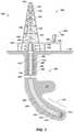
- FIG. 1is a side, cross-sectional view of an illustrative well site 100 .
- the well site 100includes a derrick 120 at an earth surface 101 .
- the well site 100also includes a wellbore 150 extending from the earth surface 101 and down into an earth subsurface 155 .
- the wellbore 150is being formed using the derrick 120 , a drill string 160 below the derrick 120 , and a bottom hole assembly 170 at a lower end of the drill string 160 .
- the derrick 120includes a frame structure 121 that extends up from the earth surface 101 .
- the derrick 120supports drilling equipment including a traveling block 122 , a crown block 123 and a swivel 124 .
- a so-called kelly 125is attached to the swivel 124 .
- the kelly 125has a longitudinally extending bore (not shown) in fluid communication with a kelly hose 126 .
- the kelly hose 126also known as a mud hose, is a flexible, steel-reinforced, high-pressure hose that delivers drilling fluid through the bore of the kelly 125 and down into the drill string 160 .
- the kelly 125includes a drive section 127 .
- the drive section 127is non-circular in cross-section and conforms to an opening 128 longitudinally extending through a kelly drive bushing 129 .
- the kelly drive bushing 129is part of a rotary table.
- the rotary tableis a mechanically driven device that provides clockwise (as viewed from above) rotational force to the kelly 125 and connected drill string 160 to facilitate the process of drilling a borehole 105 . Both linear and rotational movement may thus be imparted from the kelly 125 to the drill string 160 .
- a platform 102is provided for the derrick 120 .
- the platform 102extends above the earth surface 101 .
- the platform 102generally supports rig hands along with various components of drilling equipment such as pumps, motors, gauges, a dope bucket, tongs, pipe lifting equipment and control equipment.
- the platform 102also supports the rotary table.
- platform 102 shown in FIG. 1is somewhat schematic. It is also understood that the platform 102 is merely illustrative and that many designs for drilling rigs and platforms, both for onshore and for offshore operations, exist. These include, for example, top drive drilling systems.
- the claims provided hereinare not limited by the configuration and features of the drilling rig unless expressly stated in the claims.
- BOP 130Placed below the platform 102 and the kelly drive section 127 but above the earth surface 101 is a blow-out preventer, or BOP 130 .
- the BOP 130is a large, specialized valve or set of valves used to control pressures during the drilling of oil and gas wells. Specifically, blowout preventers control the fluctuating pressures emanating from subterranean formations during a drilling process.
- the BOP 130may include upper 132 and lower 134 rams used to isolate flow on the back side of the drill string 160 . Blowout preventers 130 also prevent the pipe joints making up the drill string 160 and the drilling fluid from being blown out of the wellbore 150 in the event of a sudden pressure kick.
- the wellbore 150is being formed down into the subsurface formation 155 .
- the wellbore 150is being shown as a deviated wellbore.
- thisis merely illustrative as the wellbore 150 may be a vertical well or even a horizontal well, as shown later in FIG. 2 .
- a first string of casing 110is placed down from the surface 101 .
- Thisis known as surface casing 110 or, in some instances (particularly offshore), conductor pipe.
- the surface casing 110is secured within the formation 155 by a cement sheath 112 .
- the cement sheath 112resides within an annular region 115 between the surface casing 110 and the surrounding formation 155 .
- additional strings of casingwill be provided. These may include intermediate casing strings and a final production casing string.
- a linermay be employed, that is, a string of casing that is not tied back to the surface 101 .
- the wellbore 150is formed by using a bottom hole assembly 170 .
- the bottom-hole assembly 170allows the operator to control or “steer” the direction or orientation of the wellbore 150 as it is formed.
- the bottom hole assembly 170is known as a rotary steerable drilling system, or RSS.
- the bottom hole assembly 170will include a drill bit 172 .
- the drill bit 172may be turned by rotating the drill string 160 from the platform 102 .
- the drill bit 172may be turned by using so-called mud motors 174 .
- the mud motors 174are mechanically coupled to and turn the nearby drill bit 172 .
- the mud motors 174are used with stabilizers or bent subs 176 to impart an angular deviation to the drill bit 172 . This, in turn, deviates the well from its previous path in the desired azimuth and inclination.
- directional drillingThere are several advantages to directional drilling. These primarily include the ability to complete a wellbore along a substantially horizontal axis of a subsurface formation, thereby exposing a greater formation face. These also include the ability to penetrate into subsurface formations that are not located directly below the wellhead. This is particularly beneficial where an oil reservoir is located under an urban area or under a large body of water. Another benefit of directional drilling is the ability to group multiple wellheads on a single platform, such as for offshore drilling. Finally, directional drilling enables multiple laterals and/or sidetracks to be drilled from a single wellbore in order to maximize reservoir exposure and recovery of hydrocarbons.
- the illustrative well site 100also includes a sensor 178 .
- the sensor 178is part of the bottom hole assembly 170 .
- the sensor 178may be, for example, a set of position sensors that is part of the electronics for an RSS.
- the sensor 178may be a temperature sensor, a pressure sensor, or other sensor for detecting a downhole condition during drilling.
- the sensormay be an induction log or gamma ray log or other log that detects fluid and/or geology downhole.
- the sensor 178may be part of a MWD or a LWD assembly. It is observed that the sensor 178 is located above the mud motors 174 . This is a common practice for MWD assemblies. This allows the electronic components of the sensor 178 to be spaced apart from the high vibration and centrifugal forces acting on the bit 172 .
- the sensorsmay include three inclinometer sensors and three environmental acceleration sensors. Ideally, a temperature sensor and a wear sensor will also be placed in the drill bit 172 . These signals are input into a multiplexer and transmitted.
- a cement bond log(or CBL) uses an acoustic signal that is transmitted by a logging tool at the end of a wireline.
- the logging toolincludes a transmitter, and one or more receivers that “listen” for sound waves generated by the transmitter through the surrounding casing string.
- the logging toolincludes a signal processor that takes a continuous measurement of the amplitude of sound pulses from the transmitter to the receiver. Alternately, the attenuation of the sonic signal may be measured.
- a bond logwill measure acoustic impedance of the material in the annulus directly behind the casing. This may be done through resonant frequency decay.
- Such logsinclude, for example, the USIT log of Schlumberger (of Sugar Land, Tex.) and the CAST-V log of Halliburton (of Houston, Tex.).
- a downhole telemetry systemthat enables the operator to evaluate cement sheath integrity without need of running a CBL line. This enables the operator to check cement sheath integrity as soon as the cement has set in the annular region 115 or as soon as the wellbore 150 is completed.
- one or more sensorsmay be deployed downhole to monitor a wide variety of properties, including, but not limited to, fluid characteristics, temperature, depth, etc., as those skilled in the art will plainly understand.
- the well site 100includes a plurality of battery-powered intermediate communications nodes 180 .
- the battery-powered intermediate communications nodes 180are placed along the outer surface 114 of the surface casing 110 according to a pre-designated spacing.
- the battery-powered intermediate communications nodes 180are configured to receive and then relay acoustic signals along the length of the wellbore 150 in node-to-node arrangement up to the topside communications node 182 .
- the topside communications node 182is placed closest to the surface 101 .
- the topside communications node 182is configured to receive acoustic signals and convert them to electrical or optical signals.
- the topside communications node 182may be above grade or below grade.
- the nodesmay also include a sensor communications node 184 .
- the sensor communications nodeis placed closest to the sensor 178 .
- the sensor communications node 184is configured to communicate with the downhole sensor 178 , and then send a wireless signal using an acoustic wave.
- the well site 100 of FIG. 1also shows a receiver 190 .
- the receiver 190comprises a processor 192 that receives signals sent from the topside communications node 182 .
- the signalsmay be received through a wire (not shown) such as a co-axial cable, a fiber optic cable, a USB cable, or other electrical or optical communications wire.
- the receiver 190may receive the final signals from the topside communications node 182 wirelessly through a modem, a transceiver or other wireless communications link such as Bluetooth or Wi-Fi.
- the receiver 190preferably receives electrical signals via a so-called Class I, Division I conduit, that is, a housing for wiring that is considered acceptably safe in an explosive environment. In some applications, radio, infrared or microwave signals may be utilized.
- the processor 192may include discrete logic, any of various integrated circuit logic types, or a microprocessor. In any event, the processor 192 may be incorporated into a computer having a screen. The computer may have a separate keyboard 194 , as is typical for a desk-top computer, or an integral keyboard as is typical for a laptop or a personal digital assistant. In one aspect, the processor 192 is part of a multi-purpose “smart phone” having specific “apps” and wireless connectivity.
- the intermediate communications nodes 180 of the downhole telemetry systemare powered by batteries and, as such, system energy limitations can be encountered. While the useful life of the network can be extended by placing the nodes into a “sleep” mode when data collection and communication are not needed; heretofore, there have been no methods available to awaken the intermediate communications nodes 180 when data acquisition is required. Thus, prior to the systems and methods of the present disclosure, the downhole telemetry system was always in the active state; consequently, the life of the network was limited to months, not years.
- FIG. 1illustrates the use of a wireless data telemetry system during a drilling operation.
- the wireless telemetry systemmay also be employed after a well is completed.
- the wireless data telemetry system shown in the Figures and described hereinmay be described as having a substantially linear network topology because it generally follows the linear path of a drill string, casing string, wellbore, pipeline, or the like.
- Such a substantially linear network topologymay include multiple drill strings, wellbores, or pipelines, or portions thereof (such as deviations or lateral sections of a wellbore) operationally connected at one or more points.
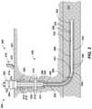
- FIG. 2is a cross-sectional view of an illustrative well site 200 .
- the well site 200includes a wellbore 250 that penetrates into a subsurface formation 255 .
- the wellbore 250has been completed as a cased-hole completion for producing hydrocarbon fluids.
- the well site 200also includes a well head 260 .
- the well head 260is positioned at an earth surface 201 to control and direct the flow of formation fluids from the subsurface formation 255 to the surface 201 .
- the well head 260may be any arrangement of pipes or valves that receive reservoir fluids at the top of the well.
- the well head 260represents a so-called Christmas tree.
- a Christmas treeis typically used when the subsurface formation 255 has enough in situ pressure to drive production fluids from the formation 255 , up the wellbore 250 , and to the surface 201 .
- the illustrative well head 260includes a top valve 262 and a bottom valve 264 .
- the well head 260may alternatively include a motor (or prime mover) at the surface 201 that drives a pump.
- the pumpreciprocates a set of sucker rods and a connected positive displacement pump (not shown) downhole.
- the pumpmay be, for example, a rocking beam unit or a hydraulic piston pumping unit.
- the well head 260may be configured to support a string of production tubing having a downhole electric submersible pump, a gas lift valve, or other means of artificial lift (not shown).
- the present inventionsare not limited by the configuration of operating equipment at the surface unless expressly noted in the claims.
- the wellbore 250has been completed with a series of pipe strings referred to as casing.
- a string of surface casing 210has been cemented into the formation.
- Cementis shown in an annular bore 215 of the wellbore 250 around the casing 210 .
- the cementis in the form of an annular sheath 212 .
- the surface casing 210has an upper end in sealed connection with the lower valve 264 .
- At least one intermediate string of casing 220is cemented into the wellbore 250 .
- the intermediate string of casing 220is in sealed fluid communication with the upper master valve 262 .
- a cement sheath 212is again shown in a bore 215 of the wellbore 250 .
- the combination of the casing 210 / 220 and the cement sheath 212 in the bore 215strengthens the wellbore 250 and facilitates the isolation of formations behind the casing 210 / 220 .
- a wellbore 250may, and typically will, include more than one string of intermediate casing.
- an intermediate string of casingmay be a liner.
- a production string 230is provided.
- the production string 230is hung from the intermediate casing string 230 using a liner hanger 231 .
- the production string 230is a liner that is not tied back to the surface 201 .
- a cement sheath 232is provided around the liner 230 .
- the production liner 230has a lower end 234 that extends to an end 254 of the wellbore 250 . For this reason, the wellbore 250 is said to be completed as a cased-hole well.
- the liner 230may be perforated after cementing to create fluid communication between a bore 235 of the liner 230 and the surrounding rock matrix making up the subsurface formation 255 .
- the production string 230is not a liner but is a casing string that extends back to the surface.
- end 254 of the wellbore 250may include joints of sand screen (not shown).
- sand screenswith gravel packs allows for greater fluid communication between the bore 235 of the liner 230 and the surrounding rock matrix while still providing support for the wellbore 250 .
- the wellbore 250would include a slotted base pipe as part of the sand screen joints.
- the sand screen jointswould not be cemented into place and would not include subsurface communications nodes.
- the wellbore 250optionally also includes a string of production tubing 240 .
- the production tubing 240extends from the well head 260 down to the subsurface formation 255 .
- the production tubing 240terminates proximate an upper end of the subsurface formation 255 .
- a production packer 241is provided at a lower end of the production tubing 240 to seal off an annular region 245 between the tubing 240 and the surrounding production liner 230 .
- the production tubing 240may extend closer to the end 234 of the liner 230 .
- a production tubing 240is not employed. This may occur, for example, when a monobore is in place.
- bottom end 234 of the production string 230is completed substantially horizontally within the subsurface formation 255 .
- a rock matrixwill generally “part” in a direction that is perpendicular to the direction of least principal stress. For deeper wells, that direction is typically substantially vertical.
- the present inventionshave equal utility in vertically completed wells or in multi-lateral deviated wells.
- the well site 200 of FIG. 2includes a telemetry system that utilizes a series of novel communications nodes. This again may be for the purpose of evaluating the integrity of the cement sheath 212 , 232 .
- the communications nodesare placed along the outer diameter of the casing strings 210 , 220 , 230 . These nodes allow for the high speed transmission of wireless signals based on the in situ generation of acoustic waves.
- the nodesfirst include a topside communications node 282 .
- the topside communications node 282is placed closest to the surface 201 .
- the topside node 282is configured to receive acoustic signals.
- the nodesmay also include a sensor communications node 284 .
- the sensor communications node 284may be placed near one or more sensors 290 .
- the sensor communications node 284is configured to communicate with the one or more downhole sensors 290 , and then send a wireless signal using acoustic waves.
- the sensors 290may be, for example, pressure sensors, flow meters, or temperature sensors.
- a pressure sensormay be, for example, a sapphire gauge or a quartz gauge. Sapphire gauges can be used as they are considered more rugged for the high-temperature downhole environment.
- the sensorsmay be microphones for detecting ambient noise, or geophones (such as a tri-axial geophone) for detecting the presence of micro-seismic activity.
- the sensorsmay be fluid flow measurement devices such as a spinners, or fluid composition sensors.
- the nodesinclude a plurality of subsurface battery-powered intermediate communications nodes 280 .
- Each of the subsurface battery-powered intermediate communications nodes 280is configured to receive and then relay acoustic signals along essentially the length of the wellbore 250 .
- the subsurface battery-powered intermediate communications nodes 280can utilize two-way electro-acoustic transducers to receive and relay mechanical waves.
- the subsurface battery-powered intermediate communications nodes 280transmit signals as acoustic waves.
- the acoustic wavescan be at a frequency of, for example, between about 50 kHz and 1 MHz.
- the signalsare delivered up to the topside communications node 282 so that signals indicative of cement integrity are sent from node-to-node.
- a last subsurface battery-powered intermediate communications node 280transmits the signals acoustically to the topside communications node 282 .
- Communicationmay be between adjacent nodes or may skip nodes depending on node spacing or communication range. Preferably, communication is routed around nodes which are not functioning properly.
- the well site 200 of FIG. 2shows a receiver 270 .
- the receiver 270can comprise a processor 272 that receives signals sent from the topside communications node 282 .
- the processor 272may include discrete logic, any of various integrated circuit logic types, or a microprocessor.
- the receiver 270may include a screen and a keyboard 274 (either as a keypad or as part of a touch screen).
- the receiver 270may also be an embedded controller with neither a screen nor a keyboard which communicates with a remote computer such as via wireless, cellular modem, or telephone lines.
- the signalsmay be received by the processor 272 through a wire (not shown) such as a co-axial cable, a fiber optic cable, a USB cable, or other electrical or optical communications wire.
- a wiresuch as a co-axial cable, a fiber optic cable, a USB cable, or other electrical or optical communications wire.
- the receiver 270may receive the final signals from the topside node 282 wirelessly through a modem or transceiver.
- the receiver 270can receive electrical signals via a so-called Class I, Div. 1 conduit, that is, a wiring system or circuitry that is considered acceptably safe in an explosive environment.
- FIGS. 1 and 2present illustrative wellbores 150 , 250 that may receive a downhole telemetry system using acoustic transducers.
- the top of the drawing pageis intended to be toward the surface and the bottom of the drawing page toward the well bottom. While wells commonly are completed in substantially vertical orientation, it is understood that wells may also be inclined and even horizontally completed.
- the descriptive terms “up” and “down” or “upper” and “lower” or similar termsare used in reference to a drawing, they are intended to indicate location on the drawing page, and not necessarily orientation in the ground, as the present inventions have utility no matter how the wellbore is orientated.
- the battery-powered intermediate communications nodes 180 , 280are specially designed to withstand the same corrosive and environmental conditions (for example, high temperature, high pressure) of a wellbore 150 or 250 , as the casing strings, drill string, or production tubing. To do so, it is preferred that the battery-powered intermediate communications nodes 180 , 280 include sealed steel housings for holding the electronics. In one aspect, the steel material is a corrosion resistant alloy.
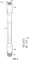
- FIG. 3an enlarged perspective view of an illustrative tubular section 310 of a tubular body, along with an illustrative intermediate communications node 380 is shown.
- the illustrative intermediate communications node 380is shown exploded away from the tubular section 310 .
- the tubular section 310has an elongated wall 314 defining an internal bore 316 .
- the tubular section 310has a box end 318 having internal threads 320 , and a pin end 322 having external threads 324 .
- the illustrative intermediate communications node 380is shown exploded away from the tubular section 310 .
- the intermediate communications node 380is structured and arranged to attach to the wall 314 of the tubular section 310 at a selected location.
- selected tubular sections 310will each have an intermediate communications node 380 between the box end 318 and the pin end 322 .
- the intermediate communications node 380is placed immediately adjacent the box end 318 or, alternatively, immediately adjacent the pin end 322 of every tubular section 310 .
- the intermediate communications node 380is placed at a selected location along every second or every third tubular section 310 .
- more or less than one intermediate communications node 380may be placed per tubular section 310 .
- the intermediate communications node 380 shown in FIG. 3is designed to be pre-welded onto the wall 314 of the tubular section 310 .
- intermediate communications node 380is configured to be selectively attachable to/detachable from an intermediate by mechanical means at a well 100 , 200 (see FIGS. 1-2 ). This may be done, for example, through the use of clamps (not shown). Alternatively, an epoxy or other suitable acoustic couplant may be used for chemical bonding.
- the intermediate communications node 310is an independent wireless communications device that is designed to be attached to an external surface of a tubular.
- the intermediate communications node 380includes a housing 386 .
- the housing 386supports a power source residing within the housing 386 , which may be one or more batteries, as shown schematically at 390 .
- the housing 386also supports a first electro-acoustic transducer, configured to serve as a receiver of acoustic signals and shown schematically at 388 , a second electro-acoustic transducer, configured to serve as a transmitter of acoustic signals and shown schematically at 336 .
- the intermediate communications node 380is intended to represent the plurality of intermediate communications nodes 180 of FIG. 1 , in one embodiment, and the plurality of intermediate communications nodes 280 of FIG. 2 , in another embodiment.
- the first and second electro-acoustic transducers 388 and 336 in each intermediate communications node 380allow acoustic signals to be sent from node-to-node, either up the wellbore or down the wellbore.
- the housing 386may be fabricated from carbon steel. This metallurgical match avoids galvanic corrosion at the coupling.
- FIG. 4provides a cross-sectional view of the intermediate communications node 380 of FIG. 3 .
- the viewis taken along the longitudinal axis of the intermediate communications node 380 .
- the housing 386is dimensioned to be strong enough to protect internal components and other electronics disposed within the interior region.
- the housing 386has an outer wall 330 that may be about 0.2 inches (0.51 cm) in thickness.
- a cavity 332houses the electronics, including, by way of example and not of limitation, a power source 390 such as a battery, a power harvesting device, or the like, a power supply wire 334 , a first electro-acoustic transducer 388 , a second electro-acoustic transducer 336 , and a circuit board 338 .
- the circuit board 338will preferably include a micro-processor or electronics module that processes acoustic signals.
- the first electro-acoustic transducer 388 , and the second electro-acoustic transducer 336are provided to convert acoustical energy to electrical energy (or vice-versa) and are coupled with outer wall 330 on the side attached to the tubular body.
- the second electro-acoustic transducer 336configured to serve as a transmitter, of intermediate communications nodes 380 may also produce acoustic telemetry signals.
- an electrical signalis delivered to the second electro-acoustic transducer 336 , such as through a driver circuit.
- the acoustic wavesrepresent asynchronous packets of information comprising a plurality of separate tones.
- the acoustic telemetry data transferis accomplished using multiple frequency shift keying (MFSK). Any extraneous noise in the signal is moderated by using well-known analog and/or digital signal processing methods.
- This noise removal and signal enhancementmay involve conveying the acoustic signal through a signal conditioning circuit using, for example, a band pass filter.
- the signal generated by the second electro-acoustic transducer 336then passes through the housing 386 to the tubular body 310 , and propagates along the tubular body 310 to other intermediate communications nodes 380 .
- the acoustic signalis generated (first electro-acoustic transducer 388 ) and/or received (second electro-acoustic transducer 336 ) by a magnetostrictive transducer comprising a coil wrapped around a core.
- the acoustic signalis generated and/or received by a piezoelectric ceramic transducer. In either case, the electrically encoded data are transformed into a sonic wave that is carried through the wall 314 of the tubular body 310 in the wellbore.
- a single transducermay serve as both the transmitter and receiver.
- the internals of intermediate communications nodes 380may also be provided with a protective layer 340 .
- the protective layer 340resides internal to the wall 330 and provides an additional thin layer of protection for the electronics. This protective layer provides additional mechanical durability and moisture isolation.
- the intermediate communications nodes 380may also be fluid sealed with the housing 386 to protect the internal electronics. One form of protection for the internal electronics is available using a potting material.
- the intermediate communications nodes 380may also optionally include a shoe 342 . More specifically, the intermediate communications nodes 380 may include a pair of shoes 342 disposed at opposing ends of the wall 330 . Each of the shoes 342 provides a beveled face that helps prevent the node 380 from hanging up on an external tubular body or the surrounding earth formation, as the case may be, during run-in or pull-out.
- FIG. 5provides a cross-sectional view of a sensor communications node 484 .
- the sensor communications node 484is intended to represent the sensor communications node 184 of FIG. 1 , in one embodiment, and the sensor communications nodes 284 of FIG. 2 , in another embodiment. The view is taken along the longitudinal axis of the sensor communications node 484 .
- the sensor communications node 484includes a housing 402 .
- the housing 402is structured and arranged to be attached to an outer wall of a tubular section, such as the tubular section 310 of FIG. 3 . Where the tubular section is formed of a carbon steel, such as a casing or liner, the housing 402 is preferably fabricated from carbon steel. This metallurgical match avoids galvanic corrosion at the coupling.
- the housing 402is dimensioned to be strong enough to protect internal components and other electronics disposed within the interior region.
- the housing 402has an outer wall 404 that may be about 0.2 inches (0.51 cm) in thickness.
- An optional pair of shoes 422may be disposed at opposing ends of the wall 404 .
- Each of the shoes 422may be shaped to provide a beveled face to help prevent the sensor communications node 484 from hanging up on an external tubular body or the surrounding earth formation, as the case may be, during run-in or pull-out.
- a cavity 406houses the electronics, including, by way of example and not of limitation, a power source 408 , a power supply wire 410 , and a circuit board 414 .
- the circuit board 414will preferably include a micro-processor or electronics module that processes acoustic signals.
- a first electro-acoustic transducer 416 and a second electro-acoustic transducer 412are provided to convert acoustical energy to electrical energy (or vice-versa) and are coupled with outer wall 404 on the side attached to the tubular body.
- the first electro-acoustic transducer 416is in electrical communication with at least one sensor 418 , possibly through a shared connection to a micro-processor on circuit board 414 , which may be the at least one sensor 178 of FIG. 1 , in one embodiment. It is noted that in FIG.
- At least one sensor 418resides within the housing 402 of the sensor communications node 484 .
- a single transducermay serve as both the transmitter and receiver.
- a protective layer 420resides internal to the wall 404 and provides an additional thin layer of protection for the electronics. This protective layer provides additional mechanical durability and moisture isolation.
- an at least one sensor 518is shown to reside external to a sensor communications node 584 , such as above or below the sensor communications node 584 along the wellbore.
- the sensor communications node 584is also intended to represent the sensor communications node 184 of FIG. 1 , in one embodiment, and the sensor communications nodes 284 of FIG. 2 , in another embodiment.
- the sensor communications node 584includes a housing 502 , which is structured and arranged to be attached to an outer wall of a tubular section, such as the tubular section 310 of FIG. 3 .
- the housing 502has an outer wall 504 that may be about 0.2 inches (0.51 cm) in thickness.
- An optional pair of beveled shoes 522may be disposed at opposing ends of the wall 504 as described in previous embodiments.
- a cavity 506lined with a protective layer 520 , houses the electronics, including, by way of example and not of limitation, a power source 508 , a power supply wire 510 , and a circuit board 514 .
- the circuit board 514will preferably include a micro-processor or electronics module that processes acoustic signals.
- a first electro-acoustic transducer 516 and a second electro-acoustic transducer 512are provided to convert acoustical energy to electrical energy (or vice-versa) and are coupled with outer wall 504 on the side attached to the tubular body.
- the electro-acoustic transducer 516is in electrical communication with at least one sensor 518 .
- a dashed lineis provided showing an extended connection between the at least one sensor 518 and the electro-acoustic transducer 516 .
- a single transducermay serve as both the transmitter and receiver.
- the sensor communications node 584is in electrical communication with the (one or more) sensors. This may be by means of a wire, or by means of wireless communication such as infrared or radio waves, or by other means as disclosed herein.
- the sensor communications node 584is configured to receive signals from the sensors.
- the sensor communications node 584transmits signals from the sensors as acoustic waves.
- the acoustic wavescan be at a frequency band of about 50 kHz and 1 MHz, from about 50 kHz to about 500 kHz, from about 60 kHz to about 200 kHz, from about 65 kHz to about 175 kHz, from about 70 kHz to about 300 kHz, from about 75 kHz to about 150 kHz, from about 80 kHz to about 140 kHz, from about 85 kHz to about 135 kHz, from about 90 kHz to about 130 kHz, or from about 100 kHz to about 125 kHz, or about 100 kHz.
- the signalsare received by an intermediate communications node, such as intermediate communications node 380 of FIG. 4 . That intermediate communications node 380 , in turn, will relay the signal on to another intermediate communications node so that acoustic waves indicative of the downhole condition are sent from node-to-node.
- a last intermediate communications node 380transmits the signals to the topside node, such as topside node 182 of FIG. 1 , or topside node 282 of FIG. 2 .
- the acoustic wireless network and/or the nodes thereofmay include and/or be any suitable structure, device, and/or devices that may be adapted, configured, designed, constructed, and/or programmed to perform the functions discussed herein with reference to any of the methods disclosed herein.
- the acoustic wireless network and/or the associated nodesmay include one or more of an electronic controller, a dedicated controller, a special-purpose controller, a special-purpose computer, a display device, a logic device, a memory device, and/or a memory device having computer-readable storage media.
- Further aspects of the disclosure relating to the sensors usable in with an acoustic wireless networkinclude: (1) a variety of hardware interfacing methods with sensors and downhole tools; (2) sensing concepts that are enabled by the unique interfaces; (3) physical implementation of the integrated sensor/communication node structures; and (4) related software communication protocols.
- the interfacesmay support both data communication and power transfer.
- the interfaceenables an open architecture of the DWN communication nodes, as shown in FIG. 7 .
- the communicating interface possibilitiesinclude physical connectors, optical windows, and acoustic or electromagnetic wireless communication methods, which are collectively shown at 800 .
- the communication interfacealso includes transmitters and/or receivers 801 a , 801 b . Both communication nodes 802 and individual sensors/tools 804 are instrumented accordingly in this interface.
- software protocolsmay be implemented to control one communication node to work with one or multiple sensors/tools, or one sensor/tool to work with multiple nodes.
- discussion of sensors hereininclude tools as well.
- the term “device”generally includes any object capable of one-way or two-way communication with the disclosed communication network.
- the devicesmay include one or more communication nodes 802 configured to transmit and receive messages to other devices.
- the devicesmay also include one or more sensors 804 that transmit and/or receive messages to other devices.
- the devicesmay also include one or more tools that can transmit and/or receive messages to other devices.
- the toolsmay be any type of downhole tool or wellsite tool that performs a function related to hydrocarbon operations.
- Physical connectorsmay be a mechanical or electric feed through, which is a physical structure directly embedded inside the communication node housing wall and the sensor body.
- a mechanical plugmay be a mechanical screw or connector.
- the screw or connectormay be connected to a pressure sensor, electrodes for conductivity sensor, pH sensor etc.
- An electric plugmay be a high temperature and/or high pressure plug for communication and power to/from the sensor node; on the other hand, the sensor node may also require a high temperature and/or a high pressure matching electric plug.
- the physical connectormay also be a mechanical structure or channel to expose the sensor to the outside environment.
- optical window or optical fiber pigtailto the communication housing wall and sensor body. They can be used for both communication and power transfer if needed. A pressure boundary may be needed surrounding the optical window or fiber for both communication node and sensor.
- An acoustic methodis a non-intrusive interface between the communication node and sensor. Both the communication node and sensor should have acoustic communication capability, i.e. sending and receiving acoustic signals.
- the acoustic frequency used for this interfacemay be selected according to the system requirements, such as communication distance, data rates, etc.
- One communication node itselfmay be converted into a sensor directly, or acoustic communication capability is added to commercial sensors, including both hardware modification and software protocol. There is no penetration for wire feed through in this interface, and therefore the acoustic interface method is highly desirable to survive down hole conditions.
- An electromagnetic wireless communication methodis another non-intrusive interface. Due to the Faraday casing effect on electric field from a metal housing, magnetic field induction may be used for non-ferromagnetic metal wall power transfer and data communication through the non-ferromagnetic metal wall. Exemplary technologies include Hall effect, magnetoresistance, magnetic resonance methods, and the like. Just like a piezoelectric element is required for acoustic communication, a small coil of conductive wire is required to be provided inside the communication housing and sensor body to enable magnetic wireless communication. If the conductive wall of the node and sensor is insulated from ground, an electric capacitive method for wireless communication is also possible. In this case, capacitive electrodes are needed inside communication the housing and the sensor body.
- the various types of communicating interfacesmay be used to advantageously communicate in a wellbore using a plurality of communicating devices.
- the devicestransmit and/or receive messages to or from other devices using one or more communicating interfaces.
- the messagesmay include data, which is broadly defined as any instruction or information.
- the messagesmay include power that can be delivered to batteries in nodes, sensors, or tools.
- the powermay be transmitted and received, for example, using known methods.
- Each communicating interfaceincludes a transmitter and/or receiver associated with each device, and a communicating medium through which messages are transmitted and/or received by the device.
- an acoustic communicating interfacemay comprise a piezoelectric transmitter embedded in a device, and the communicating medium may comprise a wellbore tubular, the contents of the tubular, the geologic formation surrounding the tubular, the sensor housing, the housing of a communication node to which the sensor is sending messages, or other media known for propagating acoustic signals.
- a wired communicating interfacemay include a transmitter and/or receiver connected via a conductive wire to another device.
- a wireless communicating interfacemay include a wireless transmitter and/or receiver in a device, and the communicating medium may include any medium conducive to propagating electromagnetic signals of a desired electromagnetic frequency.
- An optical communicating interfacemay use optical transmitters/receivers, and the optical communicating medium may include a fiber, substantially unobstructed space between two devices, transparent and/or translucent openings in one device to permit an optical signal to travel to another device, and the like.
- the way each device communicates with other devicesmay be modified based on ascertainable attributes of each device.
- attributesmay include, but are not limited to: a type of data in one or more messages to be communicated (i.e., transmitted or received); a size of the messages to be communicated; a power consumption requirement to communicate one or more messages; a battery state of a battery associated with a device; and a type of communicating interface (i.e., wireless, wired, acoustic, optical etc.) available to communicate the message.
- a type of communicating interfacei.e., wireless, wired, acoustic, optical etc.
- the disclosed aspectsare especially useful when a device has access to more one communicating interfaces, such as a wireless acoustic interface and an optical interface.
- Changes in device attributespermit the device to decide what is the most effective or optimal method to transmit and/or receive messages from other devices. For example, if a wireless acoustic interface is currently in use and is determined to be in a failure state because of, for example, a broken acoustic transmitter or a change in the efficacy of the acoustic communicating medium, the device may use the optical interface instead.
- the devicemay communicate to one or more of the other devices in the network that an optical communicating interface must be used when communicating with said device. Such change may necessitate a different communicating rate (i.e., bits per second), and depending on other device attributes. a changed communicating rate may also be messaged to the other devices. Such changed communicating rate may be higher or lower than the previous communicating rate.
- the decision to transmit and/or receive messages using a new communicating interface and/or communicating rate, or maintain the use of a currently running interface and rate,may depend on the available power to transmit and/or receive messages from a device.
- the disclosed aspectsmay select the communicating interface and rate to maximize an effective life of the power source.
- the communicating ratemay be adjusted based on available power.
- the sensing conceptsbecome feasible once existing sensors/tools are modified and integrated with the downhole wireless communication node.
- the sensing conceptsmay be powered by various communication methods, especially wireless communication methods through the metal wall of a pipeline or wellbore.
- modifications of commercial sensors/toolscan be made accordingly.
- the communication node shape and dimensionsshould be considered for the interface design and implementation. Non-limiting examples are provided herein. Generally, simple and direct measurement resulting from the integration of sensors/tools and communication node is always a preferred way of sensing.
- acoustic communication built-in sensors/toolsinclude a communication node 902 , a sensor 904 , and an acoustic interface 906 which includes acoustic transmitters and/or receivers 908 .
- Sensor measurement resultse.g. conductivity, acoustics and chemical
- control commentsare communicated to a communications node through an acoustic medium 909 .
- aspects of these sensorsmay include: electric conductivity for oil/water differentiation; active/passive acoustic sensors for triangulating location of an event/monitoring cement quality/flows/etc., and chemical sensors for composition or addition of chemicals for well conditioning, which may or may not be a sensing activity necessarily.
- magnetic field generation/measurement capabilitiesare built in to the communication node and the sensors/tools.
- the sensormay be magnetized, and the communication node may include a magnetic field detector, such as a coil. Sensor measurement results or control comments from a communications node are communicated through the magnetic communications channel. Since a magnetic field can penetrate deeper in metals with low magnetic permeability and low electric conductivity, if needed, the material may be selected for a section of casing or pipe to enhance communication between sensors and communication nodes, e.g. non-ferromagnetic metals.
- Magnetic wireless communicationis displacement sensing for pressure measurement, as shown in FIG. 9 .
- a magnetized ball 1000is inserted in a one-end sealed small tube 1004 .
- the open end 1006 of the tubeis exposed to the surrounding pressure, thus the location of the ball is an indicator of the pressure.
- multiple Hall Effect sensors 1008 or magnetoresistive sensorsmay be used inside the communication node or sensor 1010 along its length.
- FIG. 10Another example of magnetic wireless communication is a variable area flow meter, e.g.—rotameter, as shown in FIG. 10 .
- the same principleapplies as with the above displacement pressure sensor, but in this case it is actually a position sensor associated with a communication node or sensor 1108 .
- the floating ballis now a plug, piston, flexing vane or flapper 1100 inside a rotameter tube 1102 , and which could be magnetized. Its location may be related to the flow rate of the stream inside the pipe or casing 1106 .
- the difference between pressure measurement above and flow measurementis that both ends of the tube are open in the rotameter.
- Various versions of a rotameterexist, e.g. tapered tube rotameter, or perforated cylinder piston flow meter, flexing vane, disk or flapper flow meter, and any of these versions may be used.
- the disclosed aspectsmay enable a flexible and simple method of deploying a downhole communication network. Because multiple communicating interfaces are possible, sensors and/or tools may be more likely to be placed where they are most effective, and not constrained by the limitations the communicating interfaces place on sensor/tool location. In an aspect, the sensors/tools may be placed anywhere in a three-dimensional radius from one or more nodes, where the radius is defined by an effective communicating distance using one or more of the communicating interfaces.
- the sensors and/or toolsmay be placed in various locations within or near the wellbore, as the following list of non-limiting examples demonstrates: as part of the node package itself, either inserted inside the node housing or coupled to the ends of the housing via a gasket or threaded connection; attached to the interior or exterior of the same casing string that the communication node is attached to; floating in the same annulus as the communication node, i.e., embedded in cement or annular fluid within the annulus; attached to and/or inserted in the geologic formation, in the same or a different annulus as the node, or even in a reservoir; integrated physically into the wall of the casing itself; integrated physically into the coupling between two casing joints, so the communication node and sensor are together to form a sensor gasket for easy installation; attached to or floating in a different annulus, casing string, or downhole tool; physically inserted through a tubular through a gland-type insertion; above grade attached to a well head, blow-out preventer, or other hardware; on or
- Software interfaces and protocols used with the above sensorsmay include or enable one or more features and attributes that provide an advantaged communicating network.
- the sensorsmay advertise available services and capabilities either on-demand or proactively.
- One or more of the nodesmay advertise power availability, clock granularity, available communication/modulation schemes, and other pertinent information to each sensor or tool.
- Sensors and toolsmay provide duty cycle and clock information (speeds available, granularity, etc.), keeping in mind that the node may change sensor duty cycle, clock used, sensor precision, and the like, to maximize availability to the node while also minimizing energy use.
- the node and the sensor/toolmay establish cross-device direct memory access (DMA) in which the sensor/tool may directly deposit sensor readings or other data in a portion of the address space on the node without the need for intervention by the node CPU.
- DMAcross-device direct memory access
- the communication nodemay also be in a reduced power state during DMA.
- the nodemay act as a proxy (pass-through) for one or more sensors/tools such that sensors/tools may appear to interact with more distant devices which the node can reach, but for which the sensor (due to limited energy reserve and/or transmission strength) could not reach directly. Sensors and tools may alert the node regarding operational events such as low power, sensor/tool malfunction, and the like.
- the communication nodemay synchronize multiple sensors/tools such that readings from each sensor/tool occur at the same instant.
- the nodemay apply a mathematical calculation or other data transformation to the combined data from such multiple sensors/tools, to thereby provide derived data not possible via individual sensors/tools.
- Sensors/toolsmay respond to a ping or instruction from a node, or the sensors/tools may be triggered to send data on an event basis.
- Sensor/tool communication to the node, if acoustic,may be at different frequency/timing parameters than the surrounding network of nodes.
- the wells and methods disclosed hereinare applicable to the acoustic wireless communication, to the hydrocarbon exploration, and/or to the hydrocarbon production industries.
Landscapes
- Engineering & Computer Science (AREA)
- Physics & Mathematics (AREA)
- Mining & Mineral Resources (AREA)
- Geology (AREA)
- Life Sciences & Earth Sciences (AREA)
- Geophysics (AREA)
- General Life Sciences & Earth Sciences (AREA)
- Environmental & Geological Engineering (AREA)
- Fluid Mechanics (AREA)
- Geochemistry & Mineralogy (AREA)
- Signal Processing (AREA)
- Computer Networks & Wireless Communication (AREA)
- Remote Sensing (AREA)
- Acoustics & Sound (AREA)
- Health & Medical Sciences (AREA)
- Computing Systems (AREA)
- General Health & Medical Sciences (AREA)
- Medical Informatics (AREA)
- Arrangements For Transmission Of Measured Signals (AREA)
- Earth Drilling (AREA)
Abstract
Description
Claims (46)
Priority Applications (1)
| Application Number | Priority Date | Filing Date | Title |
|---|---|---|---|
| US16/269,083US11268378B2 (en) | 2018-02-09 | 2019-02-06 | Downhole wireless communication node and sensor/tools interface |
Applications Claiming Priority (3)
| Application Number | Priority Date | Filing Date | Title |
|---|---|---|---|
| US201862628603P | 2018-02-09 | 2018-02-09 | |
| US201962800202P | 2019-02-01 | 2019-02-01 | |
| US16/269,083US11268378B2 (en) | 2018-02-09 | 2019-02-06 | Downhole wireless communication node and sensor/tools interface |
Publications (2)
| Publication Number | Publication Date |
|---|---|
| US20190249548A1 US20190249548A1 (en) | 2019-08-15 |
| US11268378B2true US11268378B2 (en) | 2022-03-08 |
Family
ID=67541494
Family Applications (1)
| Application Number | Title | Priority Date | Filing Date |
|---|---|---|---|
| US16/269,083ActiveUS11268378B2 (en) | 2018-02-09 | 2019-02-06 | Downhole wireless communication node and sensor/tools interface |
Country Status (2)
| Country | Link |
|---|---|
| US (1) | US11268378B2 (en) |
| CA (1) | CA3033222C (en) |
Cited By (1)
| Publication number | Priority date | Publication date | Assignee | Title |
|---|---|---|---|---|
| US12247482B2 (en) | 2023-03-17 | 2025-03-11 | Halliburton Energy Services, Inc. | Wellbore downlink communication |
Families Citing this family (11)
| Publication number | Priority date | Publication date | Assignee | Title |
|---|---|---|---|---|
| CA2955381C (en) | 2014-09-12 | 2022-03-22 | Exxonmobil Upstream Research Company | Discrete wellbore devices, hydrocarbon wells including a downhole communication network and the discrete wellbore devices and systems and methods including the same |
| US11293280B2 (en)* | 2018-12-19 | 2022-04-05 | Exxonmobil Upstream Research Company | Method and system for monitoring post-stimulation operations through acoustic wireless sensor network |
| US11952886B2 (en) | 2018-12-19 | 2024-04-09 | ExxonMobil Technology and Engineering Company | Method and system for monitoring sand production through acoustic wireless sensor network |
| US11434748B2 (en) | 2019-04-01 | 2022-09-06 | Schlumberger Technology Corporation | Instrumented rotary tool with sensor in cavity |
| US11668184B2 (en) | 2019-04-01 | 2023-06-06 | Schlumberger Technology Corporation | Instrumented rotary tool with compliant connecting portions |
| GB201913245D0 (en)* | 2019-09-13 | 2019-10-30 | Acoustic Data Ltd | Coupling mechanism |
| US11795937B2 (en)* | 2020-01-08 | 2023-10-24 | Baker Hughes Oilfield Operations, Llc | Torque monitoring of electrical submersible pump assembly |
| CN111396002B (en)* | 2020-03-18 | 2022-04-08 | 弗润联科(北京)石油科技有限公司 | Underground wireless flow control valve tool with wireless duplex communication and system thereof |
| CN114172907A (en)* | 2021-12-27 | 2022-03-11 | 重庆忽米网络科技有限公司 | An edge computing system for equipment status monitoring |
| US20230288371A1 (en)* | 2022-03-14 | 2023-09-14 | Saudi Arabian Oil Company | System and method for real-time drilling fluids ph measuring utilizing electrolyte insulator semiconductor field-effect sensors |
| CN115664380B (en)* | 2022-11-04 | 2025-05-30 | 西南石油大学 | Thick-tail measurement noise filtering model and establishment method for near-bit measurement while drilling system |
Citations (339)
| Publication number | Priority date | Publication date | Assignee | Title |
|---|---|---|---|---|
| US3103643A (en) | 1960-06-29 | 1963-09-10 | David C Kalbfell | Drill pipe module transmitter transducer |
| US3205477A (en) | 1961-12-29 | 1965-09-07 | David C Kalbfell | Electroacoustical logging while drilling wells |
| US3512407A (en) | 1961-08-08 | 1970-05-19 | Schlumberger Technology Corp | Acoustic and radioactivity logging method and apparatus |
| US3637010A (en) | 1970-03-04 | 1972-01-25 | Union Oil Co | Apparatus for gravel-packing inclined wells |
| US3741301A (en) | 1970-03-04 | 1973-06-26 | Union Oil Co | Tool for gravel packing wells |
| US3781783A (en) | 1972-04-18 | 1973-12-25 | Seismograph Service Corp | Borehole logging system with improved display and recording apparatus |
| US3790930A (en) | 1971-02-08 | 1974-02-05 | American Petroscience Corp | Telemetering system for oil wells |
| US3900827A (en) | 1971-02-08 | 1975-08-19 | American Petroscience Corp | Telemetering system for oil wells using reaction modulator |
| US3906434A (en) | 1971-02-08 | 1975-09-16 | American Petroscience Corp | Telemetering system for oil wells |
| US4001773A (en) | 1973-09-12 | 1977-01-04 | American Petroscience Corporation | Acoustic telemetry system for oil wells utilizing self generated noise |
| US4283780A (en) | 1980-01-21 | 1981-08-11 | Sperry Corporation | Resonant acoustic transducer system for a well drilling string |
| US4298970A (en) | 1979-08-10 | 1981-11-03 | Sperry-Sun, Inc. | Borehole acoustic telemetry system synchronous detector |
| US4302826A (en) | 1980-01-21 | 1981-11-24 | Sperry Corporation | Resonant acoustic transducer system for a well drilling string |
| US4314365A (en) | 1980-01-21 | 1982-02-02 | Exxon Production Research Company | Acoustic transmitter and method to produce essentially longitudinal, acoustic waves |
| US4884071A (en) | 1987-01-08 | 1989-11-28 | Hughes Tool Company | Wellbore tool with hall effect coupling |
| US4962489A (en) | 1989-03-31 | 1990-10-09 | Mobil Oil Corporation | Acoustic borehole logging |
| US5128901A (en) | 1988-04-21 | 1992-07-07 | Teleco Oilfield Services Inc. | Acoustic data transmission through a drillstring |
| US5136613A (en) | 1990-09-28 | 1992-08-04 | Dumestre Iii Alex C | Spread Spectrum telemetry |
| US5166908A (en) | 1990-07-16 | 1992-11-24 | Atlantic Richfield Company | Piezoelectric transducer for high speed data transmission and method of operation |
| US5182946A (en) | 1991-11-08 | 1993-02-02 | Amerada Hess Corporation | Portable well analyzer |
| US5234055A (en) | 1991-10-10 | 1993-08-10 | Atlantic Richfield Company | Wellbore pressure differential control for gravel pack screen |
| US5283768A (en) | 1991-06-14 | 1994-02-01 | Baker Hughes Incorporated | Borehole liquid acoustic wave transducer |
| US5373481A (en) | 1992-01-21 | 1994-12-13 | Orban; Jacques | Sonic vibration telemetering system |
| EP0636763A2 (en) | 1993-07-26 | 1995-02-01 | Baker Hughes Incorporated | Method and apparatus for electric/acoustic telemetry in a well |
| US5468025A (en) | 1993-06-25 | 1995-11-21 | Adinolfe; Nicholas | Sewer line vent clamp assembly |
| US5477505A (en)* | 1994-09-09 | 1995-12-19 | Sandia Corporation | Downhole pipe selection for acoustic telemetry |
| US5480201A (en) | 1995-02-13 | 1996-01-02 | Mercer; George L. | Safety pipe handler |
| US5495230A (en) | 1994-06-30 | 1996-02-27 | Sensormatic Electronics Corporation | Magnetomechanical article surveillance marker with a tunable resonant frequency |
| US5562240A (en) | 1995-01-30 | 1996-10-08 | Campbell; Brian R. | Proximity sensor controller mechanism for use with a nail gun or the like |
| US5667650A (en) | 1995-02-14 | 1997-09-16 | E. I. Du Pont De Nemours And Company | High flow gas manifold for high rate, off-axis sputter deposition |
| US5682134A (en)* | 1995-08-18 | 1997-10-28 | Kiekert Ag | Method of operating a device for monitoring the interior of an automotive vehicle |
| US5857146A (en) | 1994-12-16 | 1999-01-05 | Nec Corporation | Circuit and method for controlling a timing of intermittent reception in radio equipment |
| US5881310A (en)* | 1990-07-16 | 1999-03-09 | Atlantic Richfield Company | Method for executing an instruction where the memory locations for data, operation to be performed and storing of the result are indicated by pointers |
| US5924499A (en)* | 1997-04-21 | 1999-07-20 | Halliburton Energy Services, Inc. | Acoustic data link and formation property sensor for downhole MWD system |
| US5960883A (en) | 1995-02-09 | 1999-10-05 | Baker Hughes Incorporated | Power management system for downhole control system in a well and method of using same |
| US5995449A (en) | 1995-10-20 | 1999-11-30 | Baker Hughes Inc. | Method and apparatus for improved communication in a wellbore utilizing acoustic signals |
| US6049508A (en) | 1997-12-08 | 2000-04-11 | Institut Francais Du Petrole | Method for seismic monitoring of an underground zone under development allowing better identification of significant events |
| US6125080A (en) | 1997-08-18 | 2000-09-26 | Divecom Ltd. | Underwater communication apparatus and communication method |
| US6128250A (en) | 1999-06-18 | 2000-10-03 | The United States Of America As Represented By The Secretary Of The Navy | Bottom-deployed, upward looking hydrophone assembly |
| US6177882B1 (en) | 1997-12-01 | 2001-01-23 | Halliburton Energy Services, Inc. | Electromagnetic-to-acoustic and acoustic-to-electromagnetic repeaters and methods for use of same |
| US6236850B1 (en) | 1999-01-08 | 2001-05-22 | Trw Inc. | Apparatus and method for remote convenience function control with increased effective receiver seek time and reduced power consumption |
| US6239690B1 (en) | 1997-11-12 | 2001-05-29 | U.S. Philips Corporation | Battery economizing in a communications system |
| US6281489B1 (en)* | 1997-05-02 | 2001-08-28 | Baker Hughes Incorporated | Monitoring of downhole parameters and tools utilizing fiber optics |
| US6300743B1 (en) | 2000-03-08 | 2001-10-09 | Motorola, Inc. | Single wire radio to charger communications method |
| US6320820B1 (en) | 1999-09-20 | 2001-11-20 | Halliburton Energy Services, Inc. | High data rate acoustic telemetry system |
| US6324904B1 (en) | 1999-08-19 | 2001-12-04 | Ball Semiconductor, Inc. | Miniature pump-through sensor modules |
| US6360769B1 (en) | 1999-01-28 | 2002-03-26 | Halliburton Energy Services, Inc. | Multiple plug container |
| WO2002027139A1 (en) | 2000-09-28 | 2002-04-04 | Tubel Paulo S | Method and system for wireless communications for downhole applications |
| US6388577B1 (en)* | 1997-04-07 | 2002-05-14 | Kenneth J. Carstensen | High impact communication and control system |
| US6394184B2 (en) | 2000-02-15 | 2002-05-28 | Exxonmobil Upstream Research Company | Method and apparatus for stimulation of multiple formation intervals |
| US6400646B1 (en) | 1999-12-09 | 2002-06-04 | Halliburton Energy Services, Inc. | Method for compensating for remote clock offset |
| US6429784B1 (en) | 1999-02-19 | 2002-08-06 | Dresser Industries, Inc. | Casing mounted sensors, actuators and generators |
| US20020126021A1 (en)* | 2000-01-24 | 2002-09-12 | Vinegar Harold J. | Permanent downhole, wireless, two-way telemetry backbone using redundant repeaters |
| US20020136187A1 (en)* | 2000-05-26 | 2002-09-26 | Takahisa Aoyama | Radio base station apparatus and radio communication method |
| US6462672B1 (en) | 1998-08-15 | 2002-10-08 | Schlumberger Technology Corporation | Data acquisition apparatus |
| US20020180613A1 (en) | 2000-05-08 | 2002-12-05 | Pengyu Shi | Digital signal receiver for measurement while drilling system having noise cancellation |
| US20030056953A1 (en) | 2001-05-04 | 2003-03-27 | Weatherford/Lamb, Inc. | Method and apparatus for plugging a wellbore |
| US6543538B2 (en) | 2000-07-18 | 2003-04-08 | Exxonmobil Upstream Research Company | Method for treating multiple wellbore intervals |
| US20030117896A1 (en) | 2001-12-13 | 2003-06-26 | Tokyo Gas Co., Ltd. | Acoustic communication device and acoustic signal communication method |
| US20030151977A1 (en)* | 2002-02-13 | 2003-08-14 | Shah Vimal V. | Dual channel downhole telemetry |
| US20030217138A1 (en)* | 2002-03-13 | 2003-11-20 | Noriko Shimba | Data communication method |
| US6670830B2 (en) | 2000-01-27 | 2003-12-30 | Kanji Otsuka | Driver circuit, receiver circuit, and signal transmission bus system |
| US6679332B2 (en) | 2000-01-24 | 2004-01-20 | Shell Oil Company | Petroleum well having downhole sensors, communication and power |
| US20040020063A1 (en) | 2002-07-30 | 2004-02-05 | Lewis Jonathan Robert | Method and device for the measurement of the drift of a borchole |
| US6695277B1 (en) | 2001-01-12 | 2004-02-24 | Harsco Technologies Corporation | Modular form tube and clamp system |
| US6702019B2 (en) | 2001-10-22 | 2004-03-09 | Halliburton Energy Services, Inc. | Apparatus and method for progressively treating an interval of a wellbore |
| US6717501B2 (en) | 2000-07-19 | 2004-04-06 | Novatek Engineering, Inc. | Downhole data transmission system |
| EP1409839A1 (en) | 2001-06-29 | 2004-04-21 | Shell Internationale Researchmaatschappij B.V. | Method and apparatus for detonating an explosive charge |
| US6727827B1 (en) | 1999-08-30 | 2004-04-27 | Schlumberger Technology Corporation | Measurement while drilling electromagnetic telemetry system using a fixed downhole receiver |
| US6772837B2 (en) | 2001-10-22 | 2004-08-10 | Halliburton Energy Services, Inc. | Screen assembly having diverter members and method for progressively treating an interval of a welibore |
| US20040200613A1 (en) | 2003-04-08 | 2004-10-14 | Fripp Michael L. | Flexible piezoelectric for downhole sensing, actuation and health monitoring |
| US6816082B1 (en) | 1998-11-17 | 2004-11-09 | Schlumberger Technology Corporation | Communications system having redundant channels |
| US20040239521A1 (en) | 2001-12-21 | 2004-12-02 | Zierolf Joseph A. | Method and apparatus for determining position in a pipe |
| US6868037B2 (en) | 2002-08-20 | 2005-03-15 | Saudi Arabian Oil Company | Use of drill bit energy for tomographic modeling of near surface layers |
| US6880634B2 (en) | 2002-12-03 | 2005-04-19 | Halliburton Energy Services, Inc. | Coiled tubing acoustic telemetry system and method |
| US6883608B2 (en) | 2003-08-06 | 2005-04-26 | Schlumberger Technology Corporation | Gravel packing method |
| US6912177B2 (en) | 1990-09-29 | 2005-06-28 | Metrol Technology Limited | Transmission of data in boreholes |
| US6920085B2 (en) | 2001-02-14 | 2005-07-19 | Halliburton Energy Services, Inc. | Downlink telemetry system |
| US6930616B2 (en) | 2000-11-13 | 2005-08-16 | Baker Hughes Incorporated | Method and apparatus for LWD shear velocity measurement |
| US6940420B2 (en) | 2001-12-18 | 2005-09-06 | Schlumberger Technology Corporation | Drill string telemetry system |
| US6940392B2 (en) | 2001-04-24 | 2005-09-06 | Savi Technology, Inc. | Method and apparatus for varying signals transmitted by a tag |
| US6953094B2 (en) | 2002-06-19 | 2005-10-11 | Halliburton Energy Services, Inc. | Subterranean well completion incorporating downhole-parkable robot therein |
| US6956791B2 (en) | 2003-01-28 | 2005-10-18 | Xact Downhole Telemetry Inc. | Apparatus for receiving downhole acoustic signals |
| US20050269083A1 (en) | 2004-05-03 | 2005-12-08 | Halliburton Energy Services, Inc. | Onboard navigation system for downhole tool |
| US6980929B2 (en) | 2001-04-18 | 2005-12-27 | Baker Hughes Incorporated | Well data collection system and method |
| US20050284659A1 (en) | 2004-06-28 | 2005-12-29 | Hall David R | Closed-loop drilling system using a high-speed communications network |
| US20060033638A1 (en) | 2004-08-10 | 2006-02-16 | Hall David R | Apparatus for Responding to an Anomalous Change in Downhole Pressure |
| US20060041795A1 (en) | 2004-08-20 | 2006-02-23 | Gabelmann Jeffrey M | Data-fusion receiver |
| US7006918B2 (en) | 2002-02-08 | 2006-02-28 | University Of Houston | Method for stress and stability related measurements in boreholes |
| US7011157B2 (en) | 2002-10-31 | 2006-03-14 | Schlumberger Technology Corporation | Method and apparatus for cleaning a fractured interval between two packers |
| US7036601B2 (en) | 2002-10-06 | 2006-05-02 | Weatherford/Lamb, Inc. | Apparatus and method for transporting, deploying, and retrieving arrays having nodes interconnected by sections of cable |
| US20060090893A1 (en) | 2004-11-04 | 2006-05-04 | Schlumberger Technology Corporation | Plunger Lift Apparatus That Includes One or More Sensors |
| US7051812B2 (en) | 2003-02-19 | 2006-05-30 | Schlumberger Technology Corp. | Fracturing tool having tubing isolation system and method |
| US7082993B2 (en) | 2002-04-19 | 2006-08-01 | Schlumberger Technology Corporation | Means and method for assessing the geometry of a subterranean fracture during or after a hydraulic fracturing treatment |
| US7090020B2 (en) | 2002-10-30 | 2006-08-15 | Schlumberger Technology Corp. | Multi-cycle dump valve |
| US20060187755A1 (en)* | 2005-02-24 | 2006-08-24 | The Charles Stark Draper Laboratory, Inc. | Methods and systems for communicating data through a pipe |
| US7140434B2 (en) | 2004-07-08 | 2006-11-28 | Schlumberger Technology Corporation | Sensor system |
| US7219762B2 (en) | 2003-06-06 | 2007-05-22 | Schlumberger Technology Corporation | Method and apparatus for acoustic detection of a fluid leak behind a casing of a borehole |
| US7224288B2 (en) | 2003-07-02 | 2007-05-29 | Intelliserv, Inc. | Link module for a downhole drilling network |
| US7228902B2 (en) | 2002-10-07 | 2007-06-12 | Baker Hughes Incorporated | High data rate borehole telemetry system |
| US20070146351A1 (en) | 2005-12-12 | 2007-06-28 | Yuji Katsurahira | Position input device and computer system |
| US20070156359A1 (en) | 2005-12-30 | 2007-07-05 | Varsamis Georgios L | Adaptive equalization of downhole acoustic receivers |
| US7249636B2 (en) | 2004-12-09 | 2007-07-31 | Schlumberger Technology Corporation | System and method for communicating along a wellbore |
| US7252152B2 (en) | 2003-06-18 | 2007-08-07 | Weatherford/Lamb, Inc. | Methods and apparatus for actuating a downhole tool |
| US7257050B2 (en) | 2003-12-08 | 2007-08-14 | Shell Oil Company | Through tubing real time downhole wireless gauge |
| US20070198192A1 (en)* | 2002-09-09 | 2007-08-23 | Schlumberger Technology Corporation | Systems and methods for well data compression |
| US7261154B2 (en) | 2002-08-05 | 2007-08-28 | Intelliserv, Inc. | Conformable apparatus in a drill string |
| US7261162B2 (en) | 2003-06-25 | 2007-08-28 | Schlumberger Technology Corporation | Subsea communications system |
| US20070219758A1 (en) | 2006-03-17 | 2007-09-20 | Bloomfield Dwight A | Processing sensor data from a downhole device |
| US7277026B2 (en) | 2005-05-21 | 2007-10-02 | Hall David R | Downhole component with multiple transmission elements |
| US7275597B2 (en) | 2005-03-01 | 2007-10-02 | Intelliserv, Inc. | Remote power management method and system in a downhole network |
| US20070272411A1 (en) | 2004-12-14 | 2007-11-29 | Schlumberger Technology Corporation | System for completing multiple well intervals |
| US7317990B2 (en) | 2004-10-25 | 2008-01-08 | Schlumberger Technology Corporation | Distributed processing system for subsurface operations |
| USRE40032E1 (en) | 1993-03-06 | 2008-01-22 | Agere Systems Inc. | Wireless data communication system having power saving function |
| US7321788B2 (en) | 2003-09-11 | 2008-01-22 | Honeywell International, Inc. | Synchronizing RF system |
| US20080030365A1 (en) | 2006-07-24 | 2008-02-07 | Fripp Michael L | Multi-sensor wireless telemetry system |
| US20080037485A1 (en)* | 2004-07-15 | 2008-02-14 | Hunter Douglas Inc. | System and Method for Adaptively Controlling a Network of Distributed Devices |
| US7339494B2 (en) | 2004-07-01 | 2008-03-04 | Halliburton Energy Services, Inc. | Acoustic telemetry transceiver |
| US20080060846A1 (en)* | 2005-10-20 | 2008-03-13 | Gary Belcher | Annulus pressure control drilling systems and methods |
| US7348893B2 (en) | 2004-12-22 | 2008-03-25 | Schlumberger Technology Corporation | Borehole communication and measurement system |
| US20080110644A1 (en) | 2006-11-09 | 2008-05-15 | Matt Howell | Sealing and communicating in wells |
| US7385523B2 (en) | 2000-03-28 | 2008-06-10 | Schlumberger Technology Corporation | Apparatus and method for downhole well equipment and process management, identification, and operation |
| US20080185144A1 (en) | 2006-03-30 | 2008-08-07 | Schlumberger Technology Corporation | Providing an expandable sealing element having a slot to receive a sensor array |
| US7411517B2 (en) | 2005-06-23 | 2008-08-12 | Ultima Labs, Inc. | Apparatus and method for providing communication between a probe and a sensor |
| US20080304360A1 (en) | 2007-06-08 | 2008-12-11 | Sensory, Incorporated | Systems and Methods of Sonic Communication |
| US20090003133A1 (en) | 2006-03-22 | 2009-01-01 | Qinetiq Limited | Acoustic Telemetry |
| US7477160B2 (en) | 2004-10-27 | 2009-01-13 | Schlumberger Technology Corporation | Wireless communications associated with a wellbore |
| US20090030614A1 (en) | 2007-07-25 | 2009-01-29 | Andrew John Carnegie | Method, system and apparatus for formation tester data processing |
| US20090034368A1 (en) | 2007-08-02 | 2009-02-05 | Baker Hughes Incorporated | Apparatus and method for communicating data between a well and the surface using pressure pulses |
| US20090045974A1 (en) | 2007-08-14 | 2009-02-19 | Schlumberger Technology Corporation | Short Hop Wireless Telemetry for Completion Systems |
| US20090080291A1 (en) | 2007-09-25 | 2009-03-26 | Tubel Paulo S | Downhole gauge telemetry system and method for a multilateral well |
| US7516792B2 (en) | 2002-09-23 | 2009-04-14 | Exxonmobil Upstream Research Company | Remote intervention logic valving method and apparatus |
| US7551057B2 (en) | 2005-11-04 | 2009-06-23 | Lear Corporation | Remote entry system with increased transmit power and reduced quiescent current |
| US20090171767A1 (en)* | 2007-06-29 | 2009-07-02 | Arbitron, Inc. | Resource efficient research data gathering using portable monitoring devices |
| US20090166031A1 (en) | 2007-01-25 | 2009-07-02 | Intelliserv, Inc. | Monitoring downhole conditions with drill string distributed measurement system |
| US7595737B2 (en) | 2006-07-24 | 2009-09-29 | Halliburton Energy Services, Inc. | Shear coupled acoustic telemetry system |
| US7602668B2 (en) | 2006-11-03 | 2009-10-13 | Schlumberger Technology Corporation | Downhole sensor networks using wireless communication |
| US20090289808A1 (en)* | 2008-05-23 | 2009-11-26 | Martin Scientific Llc | Reliable downhole data transmission system |
| US7649473B2 (en) | 2006-02-16 | 2010-01-19 | Intelliserv, Inc. | Physically segmented logical token network |
| US20100013663A1 (en) | 2008-07-16 | 2010-01-21 | Halliburton Energy Services, Inc. | Downhole Telemetry System Using an Optically Transmissive Fluid Media and Method for Use of Same |
| US20100039898A1 (en)* | 2004-11-29 | 2010-02-18 | Halliburton Energy Services, Inc. | Acoustic telemetry system using passband equalization |
| US20100089141A1 (en) | 2008-10-14 | 2010-04-15 | Schlumberger Technology Corporation | Downhole annular measurement system and method |
| US20100112631A1 (en) | 2007-01-09 | 2010-05-06 | Digital Bio Technology | Chip Having Microchannel For Counting Specific Micro Particles Among Floating Micro Particle Mixture By Optical Means And A Method For Counting Micro Particles Using The Same |
| US20100133004A1 (en) | 2008-12-03 | 2010-06-03 | Halliburton Energy Services, Inc. | System and Method for Verifying Perforating Gun Status Prior to Perforating a Wellbore |
| WO2010074766A1 (en) | 2008-12-24 | 2010-07-01 | S & S Industries, Inc. | Folding underwire for brassiere and brassiere incorporating same |
| US7750808B2 (en) | 2005-05-06 | 2010-07-06 | Halliburton Energy Services, Inc. | Data retrieval tags |
| US20100182161A1 (en) | 2007-04-28 | 2010-07-22 | Halliburton Energy Services, Inc. | Wireless telemetry repeater systems and methods |
| US7775279B2 (en) | 2007-12-17 | 2010-08-17 | Schlumberger Technology Corporation | Debris-free perforating apparatus and technique |
| US20100212891A1 (en) | 2009-02-20 | 2010-08-26 | Halliburton Energy Services, Inc. | Swellable Material Activation and Monitoring in a Subterranean Well |
| US7787327B2 (en) | 2006-11-15 | 2010-08-31 | Baker Hughes Incorporated | Cement bond analysis |
| US7819188B2 (en) | 2007-12-21 | 2010-10-26 | Schlumberger Technology Corporation | Monitoring, controlling and enhancing processes while stimulating a fluid-filled borehole |
| US7828079B2 (en) | 2008-05-12 | 2010-11-09 | Longyear Tm, Inc. | Sonic wireline dry slough barrel |
| US7831283B2 (en) | 2006-09-14 | 2010-11-09 | Hitachi, Ltd. | Sensor network system and sensor node |
| US20110066378A1 (en) | 2007-01-06 | 2011-03-17 | Lerche Nolan C | Apparatus and Methods for Controlling and Communicating with Downhole Devices |
| US20110061862A1 (en) | 2009-09-11 | 2011-03-17 | Schlumberger Technology Corporation | Instrumented swellable element |
| US7913773B2 (en) | 2005-08-04 | 2011-03-29 | Schlumberger Technology Corporation | Bidirectional drill string telemetry for measuring and drilling control |
| US7952487B2 (en) | 2009-02-24 | 2011-05-31 | Sony Ericsson Mobile Communications Ab | Device charging |
| US20110168403A1 (en) | 2010-01-08 | 2011-07-14 | Schlumberger Technology Corporation | Wirelessly actuated hydrostatic set module |
| US20110188345A1 (en) | 2010-02-04 | 2011-08-04 | Smith International, Inc. | Downhole Sonic Logging Tool Including Irregularly Spaced Receivers |
| US7994932B2 (en) | 2003-03-26 | 2011-08-09 | Schlumberger Technology Corporation | Borehole telemetry system |
| US8004421B2 (en) | 2006-05-10 | 2011-08-23 | Schlumberger Technology Corporation | Wellbore telemetry and noise cancellation systems and method for the same |
| US8044821B2 (en) | 2005-09-12 | 2011-10-25 | Schlumberger Technology Corporation | Downhole data transmission apparatus and methods |
| US8049506B2 (en) | 2009-02-26 | 2011-11-01 | Aquatic Company | Wired pipe with wireless joint transceiver |
| US20110297673A1 (en) | 2009-04-03 | 2011-12-08 | Electrolux Home Products Corporation N.V. | wave choke system for a door of a microwave oven |
| US20110301439A1 (en) | 2010-06-08 | 2011-12-08 | AliveUSA LLC | Wireless, ultrasonic personal health monitoring system |
| US20110297376A1 (en) | 2010-06-08 | 2011-12-08 | Halliburton Energy Services, Inc. | Sand Control Screen Assembly Having Control Line Capture Capability |
| US20110315377A1 (en) | 2010-06-25 | 2011-12-29 | Schlumberger Technology Corporation | Sensors in Swellable Materials |
| US8115651B2 (en) | 2007-04-13 | 2012-02-14 | Xact Downhole Telemetry Inc. | Drill string telemetry methods and apparatus |
| US8117907B2 (en) | 2008-12-19 | 2012-02-21 | Pathfinder Energy Services, Inc. | Caliper logging using circumferentially spaced and/or angled transducer elements |
| US20120043079A1 (en) | 2010-08-23 | 2012-02-23 | Schlumberger Technology Corporation | Sand control well completion method and apparatus |
| US8157008B2 (en) | 2006-10-18 | 2012-04-17 | Specialised Petroleum Services Group Limited | Cement evaluation method and tool |
| US8162050B2 (en) | 2007-04-02 | 2012-04-24 | Halliburton Energy Services Inc. | Use of micro-electro-mechanical systems (MEMS) in well treatments |
| US20120126992A1 (en) | 2009-07-31 | 2012-05-24 | Halliburton Energy Services, Inc. | Exploitation Of Sea Floor Rig Structures To Enhance Measurement While Drilling Telemetry Data |
| US20120152562A1 (en) | 2010-12-16 | 2012-06-21 | Baker Hughes Incorporated | Apparatus and Method for Controlling Fluid Flow From a Formation |
| US20120179377A1 (en) | 2009-06-24 | 2012-07-12 | Terje Lenart Lie | Transducer assembly |
| US8220542B2 (en) | 2006-12-04 | 2012-07-17 | Schlumberger Technology Corporation | System and method for facilitating downhole operations |
| US8237585B2 (en) | 2001-11-28 | 2012-08-07 | Schlumberger Technology Corporation | Wireless communication system and method |
| US20120250461A1 (en)* | 2011-03-30 | 2012-10-04 | Guillaume Millot | Transmitter and receiver synchronization for wireless telemetry systems |
| US8284947B2 (en) | 2004-12-01 | 2012-10-09 | Qnx Software Systems Limited | Reverberation estimation and suppression system |
| US8284075B2 (en) | 2003-06-13 | 2012-10-09 | Baker Hughes Incorporated | Apparatus and methods for self-powered communication and sensor network |
| CN102733799A (en) | 2012-06-26 | 2012-10-17 | 中国石油大学(华东) | Well drilling information acoustic wave transmission relay device based on drilling string information channel |
| US8316936B2 (en) | 2007-04-02 | 2012-11-27 | Halliburton Energy Services Inc. | Use of micro-electro-mechanical systems (MEMS) in well treatments |
| US8330617B2 (en) | 2009-01-16 | 2012-12-11 | Schlumberger Technology Corporation | Wireless power and telemetry transmission between connections of well completions |
| US20130003503A1 (en) | 2011-06-29 | 2013-01-03 | Sercel | Method and device of obtaining a node-to-surface distance in a network of acoustic nodes, corresponding computer program product and storage means |
| US20130000981A1 (en) | 2011-06-28 | 2013-01-03 | Baker Hughes Incorporated | Control of downhole safety devices |
| US8347982B2 (en) | 2010-04-16 | 2013-01-08 | Weatherford/Lamb, Inc. | System and method for managing heave pressure from a floating rig |
| US8358220B2 (en) | 2007-03-27 | 2013-01-22 | Shell Oil Company | Wellbore communication, downhole module, and method for communicating |
| US8376065B2 (en) | 2005-06-07 | 2013-02-19 | Baker Hughes Incorporated | Monitoring drilling performance in a sub-based unit |
| US8381822B2 (en) | 2009-11-12 | 2013-02-26 | Halliburton Energy Services, Inc. | Managing pressurized fluid in a downhole tool |
| US8388899B2 (en) | 2009-03-23 | 2013-03-05 | Ibiden Co., Ltd. | Exhaust gas purifying apparatus and method for manufacturing exhaust gas purifying apparatus |
| US8411530B2 (en) | 2008-12-19 | 2013-04-02 | Ysi Incorporated | Multi-frequency, multi-beam acoustic doppler system |
| US20130106615A1 (en) | 2011-10-25 | 2013-05-02 | Martin Scientific Llc | High-speed downhole sensor and telemetry network |
| US8434354B2 (en) | 2009-03-06 | 2013-05-07 | Bp Corporation North America Inc. | Apparatus and method for a wireless sensor to monitor barrier system integrity |
| US20130138254A1 (en) | 2010-08-10 | 2013-05-30 | Halliburton Energy Services, Inc. | Automated controls for pump down operations |
| WO2013079928A2 (en) | 2011-11-28 | 2013-06-06 | Green Gecko Technology Limited | An adaptive method for high data rate communication in wells |
| US8494070B2 (en) | 2010-05-12 | 2013-07-23 | Qualcomm Incorporated | Channel impulse response (CIR)-based and secondary synchronization channel (SSC)-based (frequency tracking loop (FTL)/time tracking loop (TTL)/channel estimation |
| US8496055B2 (en) | 2008-12-30 | 2013-07-30 | Schlumberger Technology Corporation | Efficient single trip gravel pack service tool |
| US20130192823A1 (en) | 2012-01-25 | 2013-08-01 | Bp Corporation North America Inc. | Systems, methods, and devices for monitoring wellbore conditions |
| US8539890B2 (en) | 2010-03-09 | 2013-09-24 | Spinnaker International Limited | Fluid dispensing apparatus |
| US8544564B2 (en) | 2005-04-05 | 2013-10-01 | Halliburton Energy Services, Inc. | Wireless communications in a drilling operations environment |
| US8552597B2 (en) | 2006-03-31 | 2013-10-08 | Siemens Corporation | Passive RF energy harvesting scheme for wireless sensor |
| US8556302B2 (en) | 2011-04-05 | 2013-10-15 | Victaulic Company | Pivoting pipe coupling having a movable gripping body |
| US8559272B2 (en) | 2010-05-20 | 2013-10-15 | Schlumberger Technology Corporation | Acoustic logging while drilling tool having raised transducers |
| US20130278432A1 (en) | 2012-04-23 | 2013-10-24 | Halliburton Energy Services, Inc. | Simultaneous Data Transmission of Multiple Nodes |
| US8596359B2 (en) | 2010-10-19 | 2013-12-03 | Halliburton Energy Services, Inc. | Remotely controllable fluid flow control assembly |
| US20130319102A1 (en) | 2012-06-05 | 2013-12-05 | Halliburton Energy Services, Inc. | Downhole Tools and Oil Field Tubulars having Internal Sensors for Wireless External Communication |
| US8605548B2 (en) | 2008-11-07 | 2013-12-10 | Schlumberger Technology Corporation | Bi-directional wireless acoustic telemetry methods and systems for communicating data along a pipe |
| US8607864B2 (en) | 2008-02-28 | 2013-12-17 | Schlumberger Technology Corporation | Live bottom hole pressure for perforation/fracturing operations |
| EP2677698A2 (en) | 2010-08-06 | 2013-12-25 | Nice S.p.A. | Component of a home automation system operated by a control unit. |
| WO2014018010A1 (en) | 2012-07-24 | 2014-01-30 | Fmc Technologies, Inc. | Wireless downhole feedthrough system |
| US8664958B2 (en) | 2007-04-16 | 2014-03-04 | Schlumberger Technology Corporation | Antenna of an electromagnetic probe for investigating geological formations |
| US20140060840A1 (en) | 2011-05-18 | 2014-03-06 | Schlumberger Technology Corporation | Altering a composition at a location accessed through an elongate conduit |
| US20140062715A1 (en) | 2012-08-28 | 2014-03-06 | Intelliserv, Llc | System and method for determining fault location |
| US8672875B2 (en) | 2003-12-31 | 2014-03-18 | Carefusion 303, Inc. | Medication safety enhancement for secondary infusion |
| US8675779B2 (en) | 2010-09-28 | 2014-03-18 | Landis+Gyr Technologies, Llc | Harmonic transmission of data |
| US20140077964A1 (en)* | 2012-09-19 | 2014-03-20 | Honeywell International Inc. | System and Method for Optimizing an Operation of a Sensor Used with Wellbore Equipment |
| US8683859B2 (en) | 2009-01-09 | 2014-04-01 | Sensor Developments As | Pressure management system for well casing annuli |
| WO2014049360A2 (en) | 2012-09-26 | 2014-04-03 | Petrowell Limited | Well isolation |
| US8689621B2 (en) | 2009-01-12 | 2014-04-08 | Sensor Developments As | Method and apparatus for in-situ wellbore measurements |
| US20140102708A1 (en) | 2012-03-08 | 2014-04-17 | Petrowell Limited | Selective Fracturing System |
| US8701480B2 (en) | 2008-12-02 | 2014-04-22 | Tool-Tech As | Downhole pressure and vibration measuring device integrated in a pipe section as a part of a production tubing |
| US20140133276A1 (en) | 2011-07-08 | 2014-05-15 | Nederlandse Organisatie Voor Toegepast- Natuurwetenschappelijk Onderzoek Tno | Telemetry System, a Pipe and a Method of Transmitting Information |
| US20140153368A1 (en) | 2012-06-07 | 2014-06-05 | California Institute Of Technology | Communication in pipes using acoustic modems that provide minimal obstruction to fluid flow |
| US20140152659A1 (en) | 2012-12-03 | 2014-06-05 | Preston H. Davidson | Geoscience data visualization and immersion experience |
| US8750789B2 (en) | 2009-01-19 | 2014-06-10 | Telefonaktiebolaget L M Ericsson (Publ) | Systems and methods for forwarding a multi-user RF signal |
| US20140166266A1 (en) | 2012-12-17 | 2014-06-19 | Baker Hughes Incorporated | Sensing indicator having rfid tag, downhole tool, and method thereof |
| US20140170025A1 (en) | 2012-12-18 | 2014-06-19 | NeoTek Energy, Inc. | System and method for production reservoir and well management using continuous chemical measurement |
| WO2014100271A1 (en) | 2012-12-19 | 2014-06-26 | Exxonmobil Upstream Research Company | Wired and wireless downhole telemetry using production tubing |
| US8787840B2 (en) | 2006-05-10 | 2014-07-22 | Robert Bosch Gmbh | Method and system employing wideband signals for RF wakeup |
| US20140210633A1 (en)* | 2012-03-09 | 2014-07-31 | Halliburton Energy Services, Inc. | Method for communicating with logging tools |
| US8805632B2 (en) | 2010-04-07 | 2014-08-12 | Baker Hughes Incorporated | Method and apparatus for clock synchronization |
| US8826980B2 (en) | 2012-03-29 | 2014-09-09 | Halliburton Energy Services, Inc. | Activation-indicating wellbore stimulation assemblies and methods of using the same |
| WO2014134741A1 (en) | 2013-03-07 | 2014-09-12 | Evolution Engineering Inc. | Detection of downhole data telemetry signals |
| US8833469B2 (en) | 2007-10-19 | 2014-09-16 | Petrowell Limited | Method of and apparatus for completing a well |
| US20140269744A1 (en)* | 2013-03-12 | 2014-09-18 | Saudi Arabian Oil Company | Oil field process control system |
| US20140266769A1 (en) | 2013-03-15 | 2014-09-18 | Xact Downhole Telemetry, Inc. | Network telemetry system and method |
| US20140327552A1 (en) | 2011-11-24 | 2014-11-06 | Schlumberger Technology Corporation | Surface Communication System for Communication with Downhole Wireless Modem Prior to Deployment |
| US8893784B2 (en) | 2010-06-30 | 2014-11-25 | Schlumberger Technology Corporation | Traced chemicals and method to verify and control formulation composition |
| US20140352955A1 (en) | 2013-05-29 | 2014-12-04 | Tubel, LLC | Downhole integrated well management system |
| US20150003202A1 (en) | 2012-01-05 | 2015-01-01 | The Technology Partnership Plc | Wireless acoustic communications method and apparatus |
| US20150027687A1 (en) | 2013-07-23 | 2015-01-29 | Tubel, LLC. | Wireless Actuation and Data Acquisition with Wireless Communications System |
| US20150041124A1 (en) | 2013-08-06 | 2015-02-12 | A&O Technologies LLC | Automatic packer |
| US20150041137A1 (en) | 2013-08-06 | 2015-02-12 | Alejandro Rodriguez | Automatic driller |
| US20150053484A1 (en)* | 2006-03-02 | 2015-02-26 | Baker Hughes Incorporated | Hole enlargement drilling device and methods for using same |
| US8994550B2 (en) | 2008-08-22 | 2015-03-31 | Schlumberger Technology Corporation | Transmitter and receiver synchronization for wireless telemetry systems |
| US8995837B2 (en) | 2011-06-29 | 2015-03-31 | Mitsubishi Electric Corporation | Subscriber-side optical communication device, communication system, control device, and power-saving control method |
| US20150107855A1 (en)* | 2013-10-23 | 2015-04-23 | Halliburton Energy Services, Inc. | Device that undergoes a change in specific gravity due to release of a weight |
| US20150152727A1 (en) | 2012-12-28 | 2015-06-04 | Michael Linley Fripp | Systems and Methods for Downhole Telecommunication |
| US20150159481A1 (en) | 2010-07-01 | 2015-06-11 | Chevron U.S.A. Inc. | System, apparatus, and method for monitoring a subsea flow device |
| US20150167425A1 (en) | 2013-12-18 | 2015-06-18 | Baker Hughes Incorporated | Completion Systems With a Bi-Directional Telemetry System |
| US9062508B2 (en) | 2012-11-15 | 2015-06-23 | Baker Hughes Incorporated | Apparatus and method for milling/drilling windows and lateral wellbores without locking using unlocked fluid-motor |
| US9062531B2 (en) | 2010-03-16 | 2015-06-23 | Tool Joint Products, Llc | System and method for measuring borehole conditions, in particular, verification of a final borehole diameter |
| US20150176370A1 (en) | 2013-12-23 | 2015-06-25 | Tesco Corporation | Tubular stress measurement system and method |
| US9078055B2 (en) | 2012-09-17 | 2015-07-07 | Blackberry Limited | Localization of a wireless user equipment (UE) device based on single beep per channel signatures |
| US9075155B2 (en) | 2011-04-08 | 2015-07-07 | Halliburton Energy Services, Inc. | Optical fiber based downhole seismic sensor systems and methods |
| US9091153B2 (en) | 2011-12-29 | 2015-07-28 | Schlumberger Technology Corporation | Wireless two-way communication for downhole tools |
| WO2015117060A1 (en) | 2014-01-31 | 2015-08-06 | Schlumberger Canada Limited | Lower completion communication system integrity check |
| US9133705B2 (en) | 2010-12-16 | 2015-09-15 | Exxonmobil Upstream Research Company | Communications module for alternate path gravel packing, and method for completing a wellbore |
| US9140097B2 (en) | 2010-01-04 | 2015-09-22 | Packers Plus Energy Services Inc. | Wellbore treatment apparatus and method |
| US9144894B2 (en) | 2011-11-11 | 2015-09-29 | Target Drilling, Inc. | Drill pipe breakout machine |
| US20150292319A1 (en) | 2012-12-19 | 2015-10-15 | Exxon-Mobil Upstream Research Company | Telemetry for Wireless Electro-Acoustical Transmission of Data Along a Wellbore |
| US20150300159A1 (en) | 2012-12-19 | 2015-10-22 | David A. Stiles | Apparatus and Method for Evaluating Cement Integrity in a Wellbore Using Acoustic Telemetry |
| US20150330200A1 (en) | 2014-05-14 | 2015-11-19 | Baker Hughes Incorporated | Apparatus and Method for Operating a Device in a Wellbore Using Signals Generated in Response to Strain on a Downhole Member |
| US20150337642A1 (en) | 2010-12-20 | 2015-11-26 | Joe Spacek | Oil Well Improvement System - Well Monitor & Control Subsystem |
| US9206645B2 (en) | 2010-11-15 | 2015-12-08 | Welltec A/S | Navigation system |
| US20150354351A1 (en) | 2012-12-19 | 2015-12-10 | Timothy I. Morrow | Apparatus and Method for Monitoring Fluid Flow in a Wellbore Using Acoustic Signals |
| US20150377016A1 (en) | 2014-06-30 | 2015-12-31 | Saudi Arabian Oil Company | Wireless power transmission to downhole well equipment |
| US20160047233A1 (en) | 2013-03-21 | 2016-02-18 | Altan Technologies Inc. | Microwave Communication System for Downhole Drilling |
| US20160047236A1 (en)* | 2014-08-03 | 2016-02-18 | Schlumberger Technology Corporation | Acoustic Communications Network with Frequency Diversification |
| US20160047230A1 (en) | 2013-11-25 | 2016-02-18 | Baker Hughes Incorporated | Real-Time Data Acquisition and Interpretation for Coiled Tubing Fluid Injection Operations |
| US9279301B2 (en) | 2010-03-23 | 2016-03-08 | Halliburton Energy Services, Inc. | Apparatus and method for well operations |
| US9284834B2 (en) | 2009-12-28 | 2016-03-15 | Schlumberger Technology Corporation | Downhole data transmission system |
| US9284819B2 (en) | 2010-05-26 | 2016-03-15 | Exxonmobil Upstream Research Company | Assembly and method for multi-zone fracture stimulation of a reservoir using autonomous tubular units |
| US20160076363A1 (en) | 2014-09-12 | 2016-03-17 | Timothy I. Morrow | Discrete Wellbore Devices, Hydrocarbon Wells Including a Downhole Communication Network and the Discrete Wellbore Devices and Systems and Methods Including the Same |
| US20160084076A1 (en)* | 2014-09-18 | 2016-03-24 | Baker Hughes Incorporated | Communication between downhole tools and a surface processor using a network |
| US9310510B2 (en) | 2009-12-04 | 2016-04-12 | Sensor Developments As | Method and apparatus for in-situ wellbore measurement and control with inductive connectivity |
| US20160109606A1 (en) | 2008-04-03 | 2016-04-21 | Halliburton Energy Services, Inc. | Acoustic Anisotropy and Imaging by Means of High Resolution Azimuthal Sampling |
| US9334696B2 (en) | 2009-08-06 | 2016-05-10 | Halliburton Energy Services, Inc. | Piping communication |
| US9333350B2 (en) | 2008-04-18 | 2016-05-10 | Medtronic, Inc. | Psychiatric disorder therapy control |
| US9363605B2 (en) | 2011-01-18 | 2016-06-07 | Halliburton Energy Services, Inc. | Focused acoustic transducer |
| US9359841B2 (en) | 2012-01-23 | 2016-06-07 | Halliburton Energy Services, Inc. | Downhole robots and methods of using same |
| US20160177673A1 (en)* | 2014-05-15 | 2016-06-23 | Halliburton Energy Services, Inc. | Control of oilfield tools using multiple magnetic signals |
| US9376908B2 (en) | 2009-09-28 | 2016-06-28 | Halliburton Energy Services, Inc. | Pipe conveyed extendable well logging tool |
| US20160215612A1 (en) | 2015-01-26 | 2016-07-28 | Timothy I. Morrow | Real-Time Well Surveillance Using a Wireless Network and an In-Wellbore Tool |
| US9441470B2 (en) | 2004-12-14 | 2016-09-13 | Schlumberger Technology Corporation | Self-locating downhole devices |
| US20160273348A1 (en)* | 2013-11-05 | 2016-09-22 | Halliburton Energy Services, Inc. | Downhole position sensor |
| US9515748B2 (en) | 2013-09-24 | 2016-12-06 | Powervoice Co., Ltd. | Encoding apparatus and method for encoding sound code, decoding apparatus and method for decoding the sound code |
| US20160356152A1 (en)* | 2015-06-05 | 2016-12-08 | Schlumberger Technology Corporation | Backbone network architecture and network management scheme for downhole wireless communications system |
| US9557434B2 (en) | 2012-12-19 | 2017-01-31 | Exxonmobil Upstream Research Company | Apparatus and method for detecting fracture geometry using acoustic telemetry |
| US9617829B2 (en) | 2010-12-17 | 2017-04-11 | Exxonmobil Upstream Research Company | Autonomous downhole conveyance system |
| US9617850B2 (en) | 2013-08-07 | 2017-04-11 | Halliburton Energy Services, Inc. | High-speed, wireless data communication through a column of wellbore fluid |
| US9631485B2 (en) | 2012-12-19 | 2017-04-25 | Exxonmobil Upstream Research Company | Electro-acoustic transmission of data along a wellbore |
| US20170134101A1 (en)* | 2014-07-30 | 2017-05-11 | Halliburton Energy Services, Inc. | Communicating with a downhole tool |
| US20170138185A1 (en) | 2014-04-22 | 2017-05-18 | Cold Bore Technology Inc. | Methods and systems for forward error correction for measurement while drilling (mwd) communication systems |
| US9657564B2 (en) | 2011-10-05 | 2017-05-23 | Halliburton Energy Services, Inc. | Methods and apparatus having borehole seismic waveform compression |
| US20170145811A1 (en) | 2015-11-20 | 2017-05-25 | Weatherford Technology Holdings, Llc | Reservoir analysis with well pumping system |
| US20170152741A1 (en) | 2014-06-27 | 2017-06-01 | Halliburton Energy Services, Inc. | Measuring micro stalls and stick slips in mud motors using fiber optic sensors |
| US20170167249A1 (en) | 2015-12-14 | 2017-06-15 | Baker Hughes Incorporated | Communication using distributed acoustic sensing systems |
| US9683434B2 (en) | 2011-11-28 | 2017-06-20 | Oilsco Technologies Limited | Apparatus and method for controlling a downhole device |
| US9686021B2 (en) | 2011-03-30 | 2017-06-20 | Schlumberger Technology Corporation | Wireless network discovery and path optimization algorithm and system |
| US20170204719A1 (en) | 2014-08-01 | 2017-07-20 | William Marsh Rice University | Systems and methods for monitoring cement quality in a cased well environment with integrated chips |
| US9715031B2 (en) | 2010-09-30 | 2017-07-25 | Schlumberger Technology Corporation | Data retrieval device for downhole to surface telemetry systems |
| US9721448B2 (en) | 2013-12-20 | 2017-08-01 | Massachusetts Institute Of Technology | Wireless communication systems for underground pipe inspection |
| US20170254183A1 (en) | 2014-08-27 | 2017-09-07 | Welltec A/S | Downhole wireless transfer system |
| US20170293044A1 (en) | 2015-11-17 | 2017-10-12 | Halliburton Energy Services, Inc. | Mems-based transducers on a downhole tool |
| US20170314386A1 (en) | 2016-04-29 | 2017-11-02 | Schlumberger Technology Corporation | Acoustic detection of drill pipe connections |
| US9822634B2 (en) | 2012-02-22 | 2017-11-21 | Halliburton Energy Services, Inc. | Downhole telemetry systems and methods with time-reversal pre-equalization |
| US20170335681A1 (en)* | 2015-01-19 | 2017-11-23 | Halliburton Energy Services, Inc. | Downhole Acoustic Telemetry Module with Multiple Communication Modes |
| US9863222B2 (en) | 2015-01-19 | 2018-01-09 | Exxonmobil Upstream Research Company | System and method for monitoring fluid flow in a wellbore using acoustic telemetry |
| US20180010449A1 (en) | 2015-03-27 | 2018-01-11 | Halliburton Energy Services, Inc. | Casing coupling having communcation unit for evaluating downhole conditions |
| US9879525B2 (en) | 2014-09-26 | 2018-01-30 | Exxonmobil Upstream Research Company | Systems and methods for monitoring a condition of a tubular configured to convey a hydrocarbon fluid |
| US20180058202A1 (en) | 2016-08-30 | 2018-03-01 | Mark M. Disko | Reservoir Formation Characterization using a Downhole Wireless Network |
| US20180058208A1 (en) | 2016-08-30 | 2018-03-01 | Limin Song | Hybrid Downhole Acoustic Wireless Network |
| US20180058204A1 (en) | 2016-08-30 | 2018-03-01 | Scott William Clawson | Methods Of Acoustically Communicating And Wells That Utilize The Methods |
| US20180058209A1 (en) | 2016-08-30 | 2018-03-01 | Limin Song | Downhole Multiphase Flow Sensing Methods |
| US20180058191A1 (en) | 2016-08-30 | 2018-03-01 | Michael C. Romer | Plunger Lift Monitoring via a Downhole Wireless Network Field |
| US20180058205A1 (en) | 2016-08-30 | 2018-03-01 | Scott William Clawson | Methods Of Acoustically Communicating And Wells That Utilize The Methods |
| US20180058203A1 (en) | 2016-08-30 | 2018-03-01 | Scott William Clawson | Methods of Acoustically Communicating and Wells that Utilize the Methods |
| US20180058198A1 (en) | 2016-08-30 | 2018-03-01 | Mehmet Deniz Ertas | Zonal Isolation Devices Including Sensing and Wireless Telemetry and Methods of Utilizing the Same |
| US20180058207A1 (en) | 2016-08-30 | 2018-03-01 | Limin Song | Dual Transducer Communications Node for Downhole Acoustic Wireless Networks and Method Employing Same |
| US20180066490A1 (en) | 2015-02-27 | 2018-03-08 | Read As | Method and system for transmitting signals from a distributed acoustic sensor through a one pin solution of a subsea wellhead |
| US20180066510A1 (en) | 2016-08-30 | 2018-03-08 | Katie M. Walker | Acoustic housing for tubulars |
| US9945204B2 (en) | 2010-07-20 | 2018-04-17 | Metrol Technology Limited | Safety mechanism for a well, a well comprising the safety mechanism, and related methods |
| US10103846B2 (en) | 2013-03-15 | 2018-10-16 | Xact Downhole Telemetry, Inc. | Robust telemetry repeater network system and method |
| US10100635B2 (en) | 2012-12-19 | 2018-10-16 | Exxonmobil Upstream Research Company | Wired and wireless downhole telemetry using a logging tool |
| US10132149B2 (en) | 2013-11-26 | 2018-11-20 | Exxonmobil Upstream Research Company | Remotely actuated screenout relief valves and systems and methods including the same |
| US10145228B2 (en) | 2013-08-13 | 2018-12-04 | Landmark Graphics Corporation | Probabilistic methodology for real time drilling |
| US10196862B2 (en) | 2013-09-27 | 2019-02-05 | Cold Bore Technology Inc. | Methods and apparatus for operatively mounting actuators to pipe |
| US20190116085A1 (en)* | 2017-10-13 | 2019-04-18 | Yibing ZHANG | Method and System for Performing Operations Using Communications |
| US20190112917A1 (en) | 2017-10-13 | 2019-04-18 | Mark M. Disko | Method and System for Performing Operations with Communications |
| US20190112919A1 (en) | 2017-10-13 | 2019-04-18 | Limin Song | Method and System for Performing Wireless Ultrasonic Communications Along A Drilling String |
| US20190112915A1 (en) | 2017-10-13 | 2019-04-18 | Mark M. Disko | Method and System for Performing Hydrocarbon Operations with Mixed Communication Networks |
| US20190112918A1 (en) | 2017-10-13 | 2019-04-18 | Xiaohua Yi | Vertical Seismic Profiling |
| US20190112913A1 (en) | 2017-10-13 | 2019-04-18 | Limin Song | Dual Transducer Communications Node Including Piezo Pre-Tensioning for Acoustic Wireless Networks and Method Employing Same |
| US20190112916A1 (en)* | 2017-10-13 | 2019-04-18 | Limin Song | Method and System for Performing Communications Using Aliasing |
| US20190153857A1 (en)* | 2017-11-17 | 2019-05-23 | Xiaohua Yi | Method and System for Performing Hydrocarbon Operations using Communications Associated with Completions |
| US20190153849A1 (en)* | 2017-11-17 | 2019-05-23 | David K. Kent | Method and System for Performing Communications During Cementing Operations |
| US20200141229A1 (en)* | 2017-07-13 | 2020-05-07 | Schlumberger Technology Corporation | Fast recovery network management scheme for a downhole wireless communications system |
| US10858934B2 (en)* | 2018-03-05 | 2020-12-08 | Baker Hughes, A Ge Company, Llc | Enclosed module for a downhole system |
- 2019
- 2019-02-06USUS16/269,083patent/US11268378B2/enactiveActive
- 2019-02-08CACA3033222Apatent/CA3033222C/enactiveActive
Patent Citations (366)
| Publication number | Priority date | Publication date | Assignee | Title |
|---|---|---|---|---|
| US3103643A (en) | 1960-06-29 | 1963-09-10 | David C Kalbfell | Drill pipe module transmitter transducer |
| US3512407A (en) | 1961-08-08 | 1970-05-19 | Schlumberger Technology Corp | Acoustic and radioactivity logging method and apparatus |
| US3205477A (en) | 1961-12-29 | 1965-09-07 | David C Kalbfell | Electroacoustical logging while drilling wells |
| US3637010A (en) | 1970-03-04 | 1972-01-25 | Union Oil Co | Apparatus for gravel-packing inclined wells |
| US3741301A (en) | 1970-03-04 | 1973-06-26 | Union Oil Co | Tool for gravel packing wells |
| US3906434A (en) | 1971-02-08 | 1975-09-16 | American Petroscience Corp | Telemetering system for oil wells |
| US3790930A (en) | 1971-02-08 | 1974-02-05 | American Petroscience Corp | Telemetering system for oil wells |
| US3900827A (en) | 1971-02-08 | 1975-08-19 | American Petroscience Corp | Telemetering system for oil wells using reaction modulator |
| US3781783A (en) | 1972-04-18 | 1973-12-25 | Seismograph Service Corp | Borehole logging system with improved display and recording apparatus |
| US4001773A (en) | 1973-09-12 | 1977-01-04 | American Petroscience Corporation | Acoustic telemetry system for oil wells utilizing self generated noise |
| US4298970A (en) | 1979-08-10 | 1981-11-03 | Sperry-Sun, Inc. | Borehole acoustic telemetry system synchronous detector |
| US4283780A (en) | 1980-01-21 | 1981-08-11 | Sperry Corporation | Resonant acoustic transducer system for a well drilling string |
| US4302826A (en) | 1980-01-21 | 1981-11-24 | Sperry Corporation | Resonant acoustic transducer system for a well drilling string |
| US4314365A (en) | 1980-01-21 | 1982-02-02 | Exxon Production Research Company | Acoustic transmitter and method to produce essentially longitudinal, acoustic waves |
| US4884071A (en) | 1987-01-08 | 1989-11-28 | Hughes Tool Company | Wellbore tool with hall effect coupling |
| US5128901A (en) | 1988-04-21 | 1992-07-07 | Teleco Oilfield Services Inc. | Acoustic data transmission through a drillstring |
| US4962489A (en) | 1989-03-31 | 1990-10-09 | Mobil Oil Corporation | Acoustic borehole logging |
| US5166908A (en) | 1990-07-16 | 1992-11-24 | Atlantic Richfield Company | Piezoelectric transducer for high speed data transmission and method of operation |
| US5881310A (en)* | 1990-07-16 | 1999-03-09 | Atlantic Richfield Company | Method for executing an instruction where the memory locations for data, operation to be performed and storing of the result are indicated by pointers |
| US5136613A (en) | 1990-09-28 | 1992-08-04 | Dumestre Iii Alex C | Spread Spectrum telemetry |
| US6912177B2 (en) | 1990-09-29 | 2005-06-28 | Metrol Technology Limited | Transmission of data in boreholes |
| US5283768A (en) | 1991-06-14 | 1994-02-01 | Baker Hughes Incorporated | Borehole liquid acoustic wave transducer |
| US5850369A (en) | 1991-06-14 | 1998-12-15 | Baker Hughes Incorporated | Method and apparatus for communicating data in a wellbore and for detecting the influx of gas |
| US5592438A (en) | 1991-06-14 | 1997-01-07 | Baker Hughes Incorporated | Method and apparatus for communicating data in a wellbore and for detecting the influx of gas |
| US5234055A (en) | 1991-10-10 | 1993-08-10 | Atlantic Richfield Company | Wellbore pressure differential control for gravel pack screen |
| US5182946A (en) | 1991-11-08 | 1993-02-02 | Amerada Hess Corporation | Portable well analyzer |
| US5373481A (en) | 1992-01-21 | 1994-12-13 | Orban; Jacques | Sonic vibration telemetering system |
| USRE40032E1 (en) | 1993-03-06 | 2008-01-22 | Agere Systems Inc. | Wireless data communication system having power saving function |
| US5468025A (en) | 1993-06-25 | 1995-11-21 | Adinolfe; Nicholas | Sewer line vent clamp assembly |
| EP0636763A2 (en) | 1993-07-26 | 1995-02-01 | Baker Hughes Incorporated | Method and apparatus for electric/acoustic telemetry in a well |
| US5495230A (en) | 1994-06-30 | 1996-02-27 | Sensormatic Electronics Corporation | Magnetomechanical article surveillance marker with a tunable resonant frequency |
| US5477505A (en)* | 1994-09-09 | 1995-12-19 | Sandia Corporation | Downhole pipe selection for acoustic telemetry |
| US5857146A (en) | 1994-12-16 | 1999-01-05 | Nec Corporation | Circuit and method for controlling a timing of intermittent reception in radio equipment |
| US5562240A (en) | 1995-01-30 | 1996-10-08 | Campbell; Brian R. | Proximity sensor controller mechanism for use with a nail gun or the like |
| US5960883A (en) | 1995-02-09 | 1999-10-05 | Baker Hughes Incorporated | Power management system for downhole control system in a well and method of using same |
| US5480201A (en) | 1995-02-13 | 1996-01-02 | Mercer; George L. | Safety pipe handler |
| US5667650A (en) | 1995-02-14 | 1997-09-16 | E. I. Du Pont De Nemours And Company | High flow gas manifold for high rate, off-axis sputter deposition |
| US5682134A (en)* | 1995-08-18 | 1997-10-28 | Kiekert Ag | Method of operating a device for monitoring the interior of an automotive vehicle |
| US5995449A (en) | 1995-10-20 | 1999-11-30 | Baker Hughes Inc. | Method and apparatus for improved communication in a wellbore utilizing acoustic signals |
| US6388577B1 (en)* | 1997-04-07 | 2002-05-14 | Kenneth J. Carstensen | High impact communication and control system |
| US5924499A (en)* | 1997-04-21 | 1999-07-20 | Halliburton Energy Services, Inc. | Acoustic data link and formation property sensor for downhole MWD system |
| US6281489B1 (en)* | 1997-05-02 | 2001-08-28 | Baker Hughes Incorporated | Monitoring of downhole parameters and tools utilizing fiber optics |
| US6125080A (en) | 1997-08-18 | 2000-09-26 | Divecom Ltd. | Underwater communication apparatus and communication method |
| US6239690B1 (en) | 1997-11-12 | 2001-05-29 | U.S. Philips Corporation | Battery economizing in a communications system |
| US6177882B1 (en) | 1997-12-01 | 2001-01-23 | Halliburton Energy Services, Inc. | Electromagnetic-to-acoustic and acoustic-to-electromagnetic repeaters and methods for use of same |
| US6049508A (en) | 1997-12-08 | 2000-04-11 | Institut Francais Du Petrole | Method for seismic monitoring of an underground zone under development allowing better identification of significant events |
| US6462672B1 (en) | 1998-08-15 | 2002-10-08 | Schlumberger Technology Corporation | Data acquisition apparatus |
| US6816082B1 (en) | 1998-11-17 | 2004-11-09 | Schlumberger Technology Corporation | Communications system having redundant channels |
| US6236850B1 (en) | 1999-01-08 | 2001-05-22 | Trw Inc. | Apparatus and method for remote convenience function control with increased effective receiver seek time and reduced power consumption |
| US6360769B1 (en) | 1999-01-28 | 2002-03-26 | Halliburton Energy Services, Inc. | Multiple plug container |
| US6987463B2 (en) | 1999-02-19 | 2006-01-17 | Halliburton Energy Services, Inc. | Method for collecting geological data from a well bore using casing mounted sensors |
| US20070139217A1 (en) | 1999-02-19 | 2007-06-21 | Halliburton Energy Services, Inc., A Delaware Corp | Data relay system for casing mounted sensors, actuators and generators |
| US6429784B1 (en) | 1999-02-19 | 2002-08-06 | Dresser Industries, Inc. | Casing mounted sensors, actuators and generators |
| US6128250A (en) | 1999-06-18 | 2000-10-03 | The United States Of America As Represented By The Secretary Of The Navy | Bottom-deployed, upward looking hydrophone assembly |
| US6324904B1 (en) | 1999-08-19 | 2001-12-04 | Ball Semiconductor, Inc. | Miniature pump-through sensor modules |
| US6727827B1 (en) | 1999-08-30 | 2004-04-27 | Schlumberger Technology Corporation | Measurement while drilling electromagnetic telemetry system using a fixed downhole receiver |
| US6320820B1 (en) | 1999-09-20 | 2001-11-20 | Halliburton Energy Services, Inc. | High data rate acoustic telemetry system |
| US6400646B1 (en) | 1999-12-09 | 2002-06-04 | Halliburton Energy Services, Inc. | Method for compensating for remote clock offset |
| US6679332B2 (en) | 2000-01-24 | 2004-01-20 | Shell Oil Company | Petroleum well having downhole sensors, communication and power |
| US20020126021A1 (en)* | 2000-01-24 | 2002-09-12 | Vinegar Harold J. | Permanent downhole, wireless, two-way telemetry backbone using redundant repeaters |
| US6670830B2 (en) | 2000-01-27 | 2003-12-30 | Kanji Otsuka | Driver circuit, receiver circuit, and signal transmission bus system |
| US6394184B2 (en) | 2000-02-15 | 2002-05-28 | Exxonmobil Upstream Research Company | Method and apparatus for stimulation of multiple formation intervals |
| US6300743B1 (en) | 2000-03-08 | 2001-10-09 | Motorola, Inc. | Single wire radio to charger communications method |
| US7385523B2 (en) | 2000-03-28 | 2008-06-10 | Schlumberger Technology Corporation | Apparatus and method for downhole well equipment and process management, identification, and operation |
| US20020180613A1 (en) | 2000-05-08 | 2002-12-05 | Pengyu Shi | Digital signal receiver for measurement while drilling system having noise cancellation |
| US20020136187A1 (en)* | 2000-05-26 | 2002-09-26 | Takahisa Aoyama | Radio base station apparatus and radio communication method |
| US6543538B2 (en) | 2000-07-18 | 2003-04-08 | Exxonmobil Upstream Research Company | Method for treating multiple wellbore intervals |
| US7064676B2 (en) | 2000-07-19 | 2006-06-20 | Intelliserv, Inc. | Downhole data transmission system |
| US6717501B2 (en) | 2000-07-19 | 2004-04-06 | Novatek Engineering, Inc. | Downhole data transmission system |
| WO2002027139A1 (en) | 2000-09-28 | 2002-04-04 | Tubel Paulo S | Method and system for wireless communications for downhole applications |
| US6899178B2 (en) | 2000-09-28 | 2005-05-31 | Paulo S. Tubel | Method and system for wireless communications for downhole applications |
| US6930616B2 (en) | 2000-11-13 | 2005-08-16 | Baker Hughes Incorporated | Method and apparatus for LWD shear velocity measurement |
| US6695277B1 (en) | 2001-01-12 | 2004-02-24 | Harsco Technologies Corporation | Modular form tube and clamp system |
| US6920085B2 (en) | 2001-02-14 | 2005-07-19 | Halliburton Energy Services, Inc. | Downlink telemetry system |
| US6980929B2 (en) | 2001-04-18 | 2005-12-27 | Baker Hughes Incorporated | Well data collection system and method |
| US6940392B2 (en) | 2001-04-24 | 2005-09-06 | Savi Technology, Inc. | Method and apparatus for varying signals transmitted by a tag |
| US20030056953A1 (en) | 2001-05-04 | 2003-03-27 | Weatherford/Lamb, Inc. | Method and apparatus for plugging a wellbore |
| EP1409839A1 (en) | 2001-06-29 | 2004-04-21 | Shell Internationale Researchmaatschappij B.V. | Method and apparatus for detonating an explosive charge |
| US6772837B2 (en) | 2001-10-22 | 2004-08-10 | Halliburton Energy Services, Inc. | Screen assembly having diverter members and method for progressively treating an interval of a welibore |
| US6702019B2 (en) | 2001-10-22 | 2004-03-09 | Halliburton Energy Services, Inc. | Apparatus and method for progressively treating an interval of a wellbore |
| US8237585B2 (en) | 2001-11-28 | 2012-08-07 | Schlumberger Technology Corporation | Wireless communication system and method |
| US20030117896A1 (en) | 2001-12-13 | 2003-06-26 | Tokyo Gas Co., Ltd. | Acoustic communication device and acoustic signal communication method |
| US6940420B2 (en) | 2001-12-18 | 2005-09-06 | Schlumberger Technology Corporation | Drill string telemetry system |
| US20040239521A1 (en) | 2001-12-21 | 2004-12-02 | Zierolf Joseph A. | Method and apparatus for determining position in a pipe |
| US7006918B2 (en) | 2002-02-08 | 2006-02-28 | University Of Houston | Method for stress and stability related measurements in boreholes |
| US20030151977A1 (en)* | 2002-02-13 | 2003-08-14 | Shah Vimal V. | Dual channel downhole telemetry |
| US6909667B2 (en) | 2002-02-13 | 2005-06-21 | Halliburton Energy Services, Inc. | Dual channel downhole telemetry |
| US20030217138A1 (en)* | 2002-03-13 | 2003-11-20 | Noriko Shimba | Data communication method |
| US7082993B2 (en) | 2002-04-19 | 2006-08-01 | Schlumberger Technology Corporation | Means and method for assessing the geometry of a subterranean fracture during or after a hydraulic fracturing treatment |
| US6953094B2 (en) | 2002-06-19 | 2005-10-11 | Halliburton Energy Services, Inc. | Subterranean well completion incorporating downhole-parkable robot therein |
| US20040020063A1 (en) | 2002-07-30 | 2004-02-05 | Lewis Jonathan Robert | Method and device for the measurement of the drift of a borchole |
| US7261154B2 (en) | 2002-08-05 | 2007-08-28 | Intelliserv, Inc. | Conformable apparatus in a drill string |
| US6868037B2 (en) | 2002-08-20 | 2005-03-15 | Saudi Arabian Oil Company | Use of drill bit energy for tomographic modeling of near surface layers |
| US20070198192A1 (en)* | 2002-09-09 | 2007-08-23 | Schlumberger Technology Corporation | Systems and methods for well data compression |
| US7516792B2 (en) | 2002-09-23 | 2009-04-14 | Exxonmobil Upstream Research Company | Remote intervention logic valving method and apparatus |
| US7036601B2 (en) | 2002-10-06 | 2006-05-02 | Weatherford/Lamb, Inc. | Apparatus and method for transporting, deploying, and retrieving arrays having nodes interconnected by sections of cable |
| US7228902B2 (en) | 2002-10-07 | 2007-06-12 | Baker Hughes Incorporated | High data rate borehole telemetry system |
| US7090020B2 (en) | 2002-10-30 | 2006-08-15 | Schlumberger Technology Corp. | Multi-cycle dump valve |
| US7011157B2 (en) | 2002-10-31 | 2006-03-14 | Schlumberger Technology Corporation | Method and apparatus for cleaning a fractured interval between two packers |
| US6880634B2 (en) | 2002-12-03 | 2005-04-19 | Halliburton Energy Services, Inc. | Coiled tubing acoustic telemetry system and method |
| US6956791B2 (en) | 2003-01-28 | 2005-10-18 | Xact Downhole Telemetry Inc. | Apparatus for receiving downhole acoustic signals |
| US7051812B2 (en) | 2003-02-19 | 2006-05-30 | Schlumberger Technology Corp. | Fracturing tool having tubing isolation system and method |
| US7994932B2 (en) | 2003-03-26 | 2011-08-09 | Schlumberger Technology Corporation | Borehole telemetry system |
| US7325605B2 (en) | 2003-04-08 | 2008-02-05 | Halliburton Energy Services, Inc. | Flexible piezoelectric for downhole sensing, actuation and health monitoring |
| US20040200613A1 (en) | 2003-04-08 | 2004-10-14 | Fripp Michael L. | Flexible piezoelectric for downhole sensing, actuation and health monitoring |
| US7219762B2 (en) | 2003-06-06 | 2007-05-22 | Schlumberger Technology Corporation | Method and apparatus for acoustic detection of a fluid leak behind a casing of a borehole |
| US8284075B2 (en) | 2003-06-13 | 2012-10-09 | Baker Hughes Incorporated | Apparatus and methods for self-powered communication and sensor network |
| US7252152B2 (en) | 2003-06-18 | 2007-08-07 | Weatherford/Lamb, Inc. | Methods and apparatus for actuating a downhole tool |
| US7261162B2 (en) | 2003-06-25 | 2007-08-28 | Schlumberger Technology Corporation | Subsea communications system |
| US7224288B2 (en) | 2003-07-02 | 2007-05-29 | Intelliserv, Inc. | Link module for a downhole drilling network |
| US6883608B2 (en) | 2003-08-06 | 2005-04-26 | Schlumberger Technology Corporation | Gravel packing method |
| US7321788B2 (en) | 2003-09-11 | 2008-01-22 | Honeywell International, Inc. | Synchronizing RF system |
| US7257050B2 (en) | 2003-12-08 | 2007-08-14 | Shell Oil Company | Through tubing real time downhole wireless gauge |
| US8672875B2 (en) | 2003-12-31 | 2014-03-18 | Carefusion 303, Inc. | Medication safety enhancement for secondary infusion |
| US20050269083A1 (en) | 2004-05-03 | 2005-12-08 | Halliburton Energy Services, Inc. | Onboard navigation system for downhole tool |
| US7322416B2 (en) | 2004-05-03 | 2008-01-29 | Halliburton Energy Services, Inc. | Methods of servicing a well bore using self-activating downhole tool |
| US20050284659A1 (en) | 2004-06-28 | 2005-12-29 | Hall David R | Closed-loop drilling system using a high-speed communications network |
| US7339494B2 (en) | 2004-07-01 | 2008-03-04 | Halliburton Energy Services, Inc. | Acoustic telemetry transceiver |
| US7140434B2 (en) | 2004-07-08 | 2006-11-28 | Schlumberger Technology Corporation | Sensor system |
| US20080037485A1 (en)* | 2004-07-15 | 2008-02-14 | Hunter Douglas Inc. | System and Method for Adaptively Controlling a Network of Distributed Devices |
| US20060033638A1 (en) | 2004-08-10 | 2006-02-16 | Hall David R | Apparatus for Responding to an Anomalous Change in Downhole Pressure |
| US20060041795A1 (en) | 2004-08-20 | 2006-02-23 | Gabelmann Jeffrey M | Data-fusion receiver |
| US7317990B2 (en) | 2004-10-25 | 2008-01-08 | Schlumberger Technology Corporation | Distributed processing system for subsurface operations |
| US7477160B2 (en) | 2004-10-27 | 2009-01-13 | Schlumberger Technology Corporation | Wireless communications associated with a wellbore |
| US20060090893A1 (en) | 2004-11-04 | 2006-05-04 | Schlumberger Technology Corporation | Plunger Lift Apparatus That Includes One or More Sensors |
| US20100039898A1 (en)* | 2004-11-29 | 2010-02-18 | Halliburton Energy Services, Inc. | Acoustic telemetry system using passband equalization |
| US8284947B2 (en) | 2004-12-01 | 2012-10-09 | Qnx Software Systems Limited | Reverberation estimation and suppression system |
| US7249636B2 (en) | 2004-12-09 | 2007-07-31 | Schlumberger Technology Corporation | System and method for communicating along a wellbore |
| US9441470B2 (en) | 2004-12-14 | 2016-09-13 | Schlumberger Technology Corporation | Self-locating downhole devices |
| US7387165B2 (en) | 2004-12-14 | 2008-06-17 | Schlumberger Technology Corporation | System for completing multiple well intervals |
| US20070272411A1 (en) | 2004-12-14 | 2007-11-29 | Schlumberger Technology Corporation | System for completing multiple well intervals |
| US8276674B2 (en) | 2004-12-14 | 2012-10-02 | Schlumberger Technology Corporation | Deploying an untethered object in a passageway of a well |
| US7348893B2 (en) | 2004-12-22 | 2008-03-25 | Schlumberger Technology Corporation | Borehole communication and measurement system |
| US20060187755A1 (en)* | 2005-02-24 | 2006-08-24 | The Charles Stark Draper Laboratory, Inc. | Methods and systems for communicating data through a pipe |
| US7590029B2 (en) | 2005-02-24 | 2009-09-15 | The Charles Stark Draper Laboratory, Inc. | Methods and systems for communicating data through a pipe |
| US7275597B2 (en) | 2005-03-01 | 2007-10-02 | Intelliserv, Inc. | Remote power management method and system in a downhole network |
| US8544564B2 (en) | 2005-04-05 | 2013-10-01 | Halliburton Energy Services, Inc. | Wireless communications in a drilling operations environment |
| US7750808B2 (en) | 2005-05-06 | 2010-07-06 | Halliburton Energy Services, Inc. | Data retrieval tags |
| US7277026B2 (en) | 2005-05-21 | 2007-10-02 | Hall David R | Downhole component with multiple transmission elements |
| US8376065B2 (en) | 2005-06-07 | 2013-02-19 | Baker Hughes Incorporated | Monitoring drilling performance in a sub-based unit |
| US7411517B2 (en) | 2005-06-23 | 2008-08-12 | Ultima Labs, Inc. | Apparatus and method for providing communication between a probe and a sensor |
| US7913773B2 (en) | 2005-08-04 | 2011-03-29 | Schlumberger Technology Corporation | Bidirectional drill string telemetry for measuring and drilling control |
| US8044821B2 (en) | 2005-09-12 | 2011-10-25 | Schlumberger Technology Corporation | Downhole data transmission apparatus and methods |
| US20080060846A1 (en)* | 2005-10-20 | 2008-03-13 | Gary Belcher | Annulus pressure control drilling systems and methods |
| US7551057B2 (en) | 2005-11-04 | 2009-06-23 | Lear Corporation | Remote entry system with increased transmit power and reduced quiescent current |
| US20070146351A1 (en) | 2005-12-12 | 2007-06-28 | Yuji Katsurahira | Position input device and computer system |
| US20070156359A1 (en) | 2005-12-30 | 2007-07-05 | Varsamis Georgios L | Adaptive equalization of downhole acoustic receivers |
| US7649473B2 (en) | 2006-02-16 | 2010-01-19 | Intelliserv, Inc. | Physically segmented logical token network |
| US20150053484A1 (en)* | 2006-03-02 | 2015-02-26 | Baker Hughes Incorporated | Hole enlargement drilling device and methods for using same |
| US20070219758A1 (en) | 2006-03-17 | 2007-09-20 | Bloomfield Dwight A | Processing sensor data from a downhole device |
| US20090003133A1 (en) | 2006-03-22 | 2009-01-01 | Qinetiq Limited | Acoustic Telemetry |
| US20080185144A1 (en) | 2006-03-30 | 2008-08-07 | Schlumberger Technology Corporation | Providing an expandable sealing element having a slot to receive a sensor array |
| US8552597B2 (en) | 2006-03-31 | 2013-10-08 | Siemens Corporation | Passive RF energy harvesting scheme for wireless sensor |
| US8004421B2 (en) | 2006-05-10 | 2011-08-23 | Schlumberger Technology Corporation | Wellbore telemetry and noise cancellation systems and method for the same |
| US8787840B2 (en) | 2006-05-10 | 2014-07-22 | Robert Bosch Gmbh | Method and system employing wideband signals for RF wakeup |
| US20080030365A1 (en) | 2006-07-24 | 2008-02-07 | Fripp Michael L | Multi-sensor wireless telemetry system |
| US7595737B2 (en) | 2006-07-24 | 2009-09-29 | Halliburton Energy Services, Inc. | Shear coupled acoustic telemetry system |
| US7831283B2 (en) | 2006-09-14 | 2010-11-09 | Hitachi, Ltd. | Sensor network system and sensor node |
| US8157008B2 (en) | 2006-10-18 | 2012-04-17 | Specialised Petroleum Services Group Limited | Cement evaluation method and tool |
| US7602668B2 (en) | 2006-11-03 | 2009-10-13 | Schlumberger Technology Corporation | Downhole sensor networks using wireless communication |
| US20080110644A1 (en) | 2006-11-09 | 2008-05-15 | Matt Howell | Sealing and communicating in wells |
| US7787327B2 (en) | 2006-11-15 | 2010-08-31 | Baker Hughes Incorporated | Cement bond analysis |
| US8220542B2 (en) | 2006-12-04 | 2012-07-17 | Schlumberger Technology Corporation | System and method for facilitating downhole operations |
| US20110066378A1 (en) | 2007-01-06 | 2011-03-17 | Lerche Nolan C | Apparatus and Methods for Controlling and Communicating with Downhole Devices |
| US20100112631A1 (en) | 2007-01-09 | 2010-05-06 | Digital Bio Technology | Chip Having Microchannel For Counting Specific Micro Particles Among Floating Micro Particle Mixture By Optical Means And A Method For Counting Micro Particles Using The Same |
| US20090166031A1 (en) | 2007-01-25 | 2009-07-02 | Intelliserv, Inc. | Monitoring downhole conditions with drill string distributed measurement system |
| US8358220B2 (en) | 2007-03-27 | 2013-01-22 | Shell Oil Company | Wellbore communication, downhole module, and method for communicating |
| US8162050B2 (en) | 2007-04-02 | 2012-04-24 | Halliburton Energy Services Inc. | Use of micro-electro-mechanical systems (MEMS) in well treatments |
| US8316936B2 (en) | 2007-04-02 | 2012-11-27 | Halliburton Energy Services Inc. | Use of micro-electro-mechanical systems (MEMS) in well treatments |
| US8115651B2 (en) | 2007-04-13 | 2012-02-14 | Xact Downhole Telemetry Inc. | Drill string telemetry methods and apparatus |
| US8664958B2 (en) | 2007-04-16 | 2014-03-04 | Schlumberger Technology Corporation | Antenna of an electromagnetic probe for investigating geological formations |
| US20100182161A1 (en) | 2007-04-28 | 2010-07-22 | Halliburton Energy Services, Inc. | Wireless telemetry repeater systems and methods |
| US20080304360A1 (en) | 2007-06-08 | 2008-12-11 | Sensory, Incorporated | Systems and Methods of Sonic Communication |
| US20090171767A1 (en)* | 2007-06-29 | 2009-07-02 | Arbitron, Inc. | Resource efficient research data gathering using portable monitoring devices |
| US20090030614A1 (en) | 2007-07-25 | 2009-01-29 | Andrew John Carnegie | Method, system and apparatus for formation tester data processing |
| US20090034368A1 (en) | 2007-08-02 | 2009-02-05 | Baker Hughes Incorporated | Apparatus and method for communicating data between a well and the surface using pressure pulses |
| US20090045974A1 (en) | 2007-08-14 | 2009-02-19 | Schlumberger Technology Corporation | Short Hop Wireless Telemetry for Completion Systems |
| US20090080291A1 (en) | 2007-09-25 | 2009-03-26 | Tubel Paulo S | Downhole gauge telemetry system and method for a multilateral well |
| US8833469B2 (en) | 2007-10-19 | 2014-09-16 | Petrowell Limited | Method of and apparatus for completing a well |
| US7775279B2 (en) | 2007-12-17 | 2010-08-17 | Schlumberger Technology Corporation | Debris-free perforating apparatus and technique |
| US7819188B2 (en) | 2007-12-21 | 2010-10-26 | Schlumberger Technology Corporation | Monitoring, controlling and enhancing processes while stimulating a fluid-filled borehole |
| US8607864B2 (en) | 2008-02-28 | 2013-12-17 | Schlumberger Technology Corporation | Live bottom hole pressure for perforation/fracturing operations |
| US20160109606A1 (en) | 2008-04-03 | 2016-04-21 | Halliburton Energy Services, Inc. | Acoustic Anisotropy and Imaging by Means of High Resolution Azimuthal Sampling |
| US9333350B2 (en) | 2008-04-18 | 2016-05-10 | Medtronic, Inc. | Psychiatric disorder therapy control |
| US7828079B2 (en) | 2008-05-12 | 2010-11-09 | Longyear Tm, Inc. | Sonic wireline dry slough barrel |
| US20090289808A1 (en)* | 2008-05-23 | 2009-11-26 | Martin Scientific Llc | Reliable downhole data transmission system |
| US8242928B2 (en) | 2008-05-23 | 2012-08-14 | Martin Scientific Llc | Reliable downhole data transmission system |
| US20100013663A1 (en) | 2008-07-16 | 2010-01-21 | Halliburton Energy Services, Inc. | Downhole Telemetry System Using an Optically Transmissive Fluid Media and Method for Use of Same |
| US8994550B2 (en) | 2008-08-22 | 2015-03-31 | Schlumberger Technology Corporation | Transmitter and receiver synchronization for wireless telemetry systems |
| US20100089141A1 (en) | 2008-10-14 | 2010-04-15 | Schlumberger Technology Corporation | Downhole annular measurement system and method |
| US8605548B2 (en) | 2008-11-07 | 2013-12-10 | Schlumberger Technology Corporation | Bi-directional wireless acoustic telemetry methods and systems for communicating data along a pipe |
| US8701480B2 (en) | 2008-12-02 | 2014-04-22 | Tool-Tech As | Downhole pressure and vibration measuring device integrated in a pipe section as a part of a production tubing |
| US20100133004A1 (en) | 2008-12-03 | 2010-06-03 | Halliburton Energy Services, Inc. | System and Method for Verifying Perforating Gun Status Prior to Perforating a Wellbore |
| US8411530B2 (en) | 2008-12-19 | 2013-04-02 | Ysi Incorporated | Multi-frequency, multi-beam acoustic doppler system |
| US8117907B2 (en) | 2008-12-19 | 2012-02-21 | Pathfinder Energy Services, Inc. | Caliper logging using circumferentially spaced and/or angled transducer elements |
| WO2010074766A1 (en) | 2008-12-24 | 2010-07-01 | S & S Industries, Inc. | Folding underwire for brassiere and brassiere incorporating same |
| US8496055B2 (en) | 2008-12-30 | 2013-07-30 | Schlumberger Technology Corporation | Efficient single trip gravel pack service tool |
| US8683859B2 (en) | 2009-01-09 | 2014-04-01 | Sensor Developments As | Pressure management system for well casing annuli |
| US8689621B2 (en) | 2009-01-12 | 2014-04-08 | Sensor Developments As | Method and apparatus for in-situ wellbore measurements |
| US8330617B2 (en) | 2009-01-16 | 2012-12-11 | Schlumberger Technology Corporation | Wireless power and telemetry transmission between connections of well completions |
| US8750789B2 (en) | 2009-01-19 | 2014-06-10 | Telefonaktiebolaget L M Ericsson (Publ) | Systems and methods for forwarding a multi-user RF signal |
| US20100212891A1 (en) | 2009-02-20 | 2010-08-26 | Halliburton Energy Services, Inc. | Swellable Material Activation and Monitoring in a Subterranean Well |
| US7952487B2 (en) | 2009-02-24 | 2011-05-31 | Sony Ericsson Mobile Communications Ab | Device charging |
| US8049506B2 (en) | 2009-02-26 | 2011-11-01 | Aquatic Company | Wired pipe with wireless joint transceiver |
| US8434354B2 (en) | 2009-03-06 | 2013-05-07 | Bp Corporation North America Inc. | Apparatus and method for a wireless sensor to monitor barrier system integrity |
| US8388899B2 (en) | 2009-03-23 | 2013-03-05 | Ibiden Co., Ltd. | Exhaust gas purifying apparatus and method for manufacturing exhaust gas purifying apparatus |
| US20110297673A1 (en) | 2009-04-03 | 2011-12-08 | Electrolux Home Products Corporation N.V. | wave choke system for a door of a microwave oven |
| US20120179377A1 (en) | 2009-06-24 | 2012-07-12 | Terje Lenart Lie | Transducer assembly |
| US20120126992A1 (en) | 2009-07-31 | 2012-05-24 | Halliburton Energy Services, Inc. | Exploitation Of Sea Floor Rig Structures To Enhance Measurement While Drilling Telemetry Data |
| US9334696B2 (en) | 2009-08-06 | 2016-05-10 | Halliburton Energy Services, Inc. | Piping communication |
| US20110061862A1 (en) | 2009-09-11 | 2011-03-17 | Schlumberger Technology Corporation | Instrumented swellable element |
| US9376908B2 (en) | 2009-09-28 | 2016-06-28 | Halliburton Energy Services, Inc. | Pipe conveyed extendable well logging tool |
| US8381822B2 (en) | 2009-11-12 | 2013-02-26 | Halliburton Energy Services, Inc. | Managing pressurized fluid in a downhole tool |
| US9310510B2 (en) | 2009-12-04 | 2016-04-12 | Sensor Developments As | Method and apparatus for in-situ wellbore measurement and control with inductive connectivity |
| US9284834B2 (en) | 2009-12-28 | 2016-03-15 | Schlumberger Technology Corporation | Downhole data transmission system |
| US9140097B2 (en) | 2010-01-04 | 2015-09-22 | Packers Plus Energy Services Inc. | Wellbore treatment apparatus and method |
| US20110168403A1 (en) | 2010-01-08 | 2011-07-14 | Schlumberger Technology Corporation | Wirelessly actuated hydrostatic set module |
| US20110188345A1 (en) | 2010-02-04 | 2011-08-04 | Smith International, Inc. | Downhole Sonic Logging Tool Including Irregularly Spaced Receivers |
| US8539890B2 (en) | 2010-03-09 | 2013-09-24 | Spinnaker International Limited | Fluid dispensing apparatus |
| US9062531B2 (en) | 2010-03-16 | 2015-06-23 | Tool Joint Products, Llc | System and method for measuring borehole conditions, in particular, verification of a final borehole diameter |
| US9279301B2 (en) | 2010-03-23 | 2016-03-08 | Halliburton Energy Services, Inc. | Apparatus and method for well operations |
| US8805632B2 (en) | 2010-04-07 | 2014-08-12 | Baker Hughes Incorporated | Method and apparatus for clock synchronization |
| US8347982B2 (en) | 2010-04-16 | 2013-01-08 | Weatherford/Lamb, Inc. | System and method for managing heave pressure from a floating rig |
| US8494070B2 (en) | 2010-05-12 | 2013-07-23 | Qualcomm Incorporated | Channel impulse response (CIR)-based and secondary synchronization channel (SSC)-based (frequency tracking loop (FTL)/time tracking loop (TTL)/channel estimation |
| US8559272B2 (en) | 2010-05-20 | 2013-10-15 | Schlumberger Technology Corporation | Acoustic logging while drilling tool having raised transducers |
| US9963955B2 (en) | 2010-05-26 | 2018-05-08 | Exxonmobil Upstream Research Company | Assembly and method for multi-zone fracture stimulation of a reservoir using autonomous tubular units |
| US9284819B2 (en) | 2010-05-26 | 2016-03-15 | Exxonmobil Upstream Research Company | Assembly and method for multi-zone fracture stimulation of a reservoir using autonomous tubular units |
| US20110301439A1 (en) | 2010-06-08 | 2011-12-08 | AliveUSA LLC | Wireless, ultrasonic personal health monitoring system |
| US20110297376A1 (en) | 2010-06-08 | 2011-12-08 | Halliburton Energy Services, Inc. | Sand Control Screen Assembly Having Control Line Capture Capability |
| US20110315377A1 (en) | 2010-06-25 | 2011-12-29 | Schlumberger Technology Corporation | Sensors in Swellable Materials |
| US8893784B2 (en) | 2010-06-30 | 2014-11-25 | Schlumberger Technology Corporation | Traced chemicals and method to verify and control formulation composition |
| US20150159481A1 (en) | 2010-07-01 | 2015-06-11 | Chevron U.S.A. Inc. | System, apparatus, and method for monitoring a subsea flow device |
| US9945204B2 (en) | 2010-07-20 | 2018-04-17 | Metrol Technology Limited | Safety mechanism for a well, a well comprising the safety mechanism, and related methods |
| EP2677698A2 (en) | 2010-08-06 | 2013-12-25 | Nice S.p.A. | Component of a home automation system operated by a control unit. |
| US20130138254A1 (en) | 2010-08-10 | 2013-05-30 | Halliburton Energy Services, Inc. | Automated controls for pump down operations |
| US20120043079A1 (en) | 2010-08-23 | 2012-02-23 | Schlumberger Technology Corporation | Sand control well completion method and apparatus |
| US8675779B2 (en) | 2010-09-28 | 2014-03-18 | Landis+Gyr Technologies, Llc | Harmonic transmission of data |
| US9715031B2 (en) | 2010-09-30 | 2017-07-25 | Schlumberger Technology Corporation | Data retrieval device for downhole to surface telemetry systems |
| US8596359B2 (en) | 2010-10-19 | 2013-12-03 | Halliburton Energy Services, Inc. | Remotely controllable fluid flow control assembly |
| US9206645B2 (en) | 2010-11-15 | 2015-12-08 | Welltec A/S | Navigation system |
| US9133705B2 (en) | 2010-12-16 | 2015-09-15 | Exxonmobil Upstream Research Company | Communications module for alternate path gravel packing, and method for completing a wellbore |
| US20120152562A1 (en) | 2010-12-16 | 2012-06-21 | Baker Hughes Incorporated | Apparatus and Method for Controlling Fluid Flow From a Formation |
| US8910716B2 (en) | 2010-12-16 | 2014-12-16 | Baker Hughes Incorporated | Apparatus and method for controlling fluid flow from a formation |
| US9617829B2 (en) | 2010-12-17 | 2017-04-11 | Exxonmobil Upstream Research Company | Autonomous downhole conveyance system |
| US20150337642A1 (en) | 2010-12-20 | 2015-11-26 | Joe Spacek | Oil Well Improvement System - Well Monitor & Control Subsystem |
| US9363605B2 (en) | 2011-01-18 | 2016-06-07 | Halliburton Energy Services, Inc. | Focused acoustic transducer |
| US20120250461A1 (en)* | 2011-03-30 | 2012-10-04 | Guillaume Millot | Transmitter and receiver synchronization for wireless telemetry systems |
| US9686021B2 (en) | 2011-03-30 | 2017-06-20 | Schlumberger Technology Corporation | Wireless network discovery and path optimization algorithm and system |
| US8556302B2 (en) | 2011-04-05 | 2013-10-15 | Victaulic Company | Pivoting pipe coupling having a movable gripping body |
| US9075155B2 (en) | 2011-04-08 | 2015-07-07 | Halliburton Energy Services, Inc. | Optical fiber based downhole seismic sensor systems and methods |
| US20140060840A1 (en) | 2011-05-18 | 2014-03-06 | Schlumberger Technology Corporation | Altering a composition at a location accessed through an elongate conduit |
| US20130000981A1 (en) | 2011-06-28 | 2013-01-03 | Baker Hughes Incorporated | Control of downhole safety devices |
| US8995837B2 (en) | 2011-06-29 | 2015-03-31 | Mitsubishi Electric Corporation | Subscriber-side optical communication device, communication system, control device, and power-saving control method |
| US20130003503A1 (en) | 2011-06-29 | 2013-01-03 | Sercel | Method and device of obtaining a node-to-surface distance in a network of acoustic nodes, corresponding computer program product and storage means |
| US20140133276A1 (en) | 2011-07-08 | 2014-05-15 | Nederlandse Organisatie Voor Toegepast- Natuurwetenschappelijk Onderzoek Tno | Telemetry System, a Pipe and a Method of Transmitting Information |
| US9657564B2 (en) | 2011-10-05 | 2017-05-23 | Halliburton Energy Services, Inc. | Methods and apparatus having borehole seismic waveform compression |
| US20130106615A1 (en) | 2011-10-25 | 2013-05-02 | Martin Scientific Llc | High-speed downhole sensor and telemetry network |
| US9144894B2 (en) | 2011-11-11 | 2015-09-29 | Target Drilling, Inc. | Drill pipe breakout machine |
| US20140327552A1 (en) | 2011-11-24 | 2014-11-06 | Schlumberger Technology Corporation | Surface Communication System for Communication with Downhole Wireless Modem Prior to Deployment |
| WO2013079928A2 (en) | 2011-11-28 | 2013-06-06 | Green Gecko Technology Limited | An adaptive method for high data rate communication in wells |
| US9683434B2 (en) | 2011-11-28 | 2017-06-20 | Oilsco Technologies Limited | Apparatus and method for controlling a downhole device |
| US20150009040A1 (en) | 2011-11-28 | 2015-01-08 | Green Gecko Technology Limited | Adaptive Method for High Data Rate Communication In Wells |
| US9091153B2 (en) | 2011-12-29 | 2015-07-28 | Schlumberger Technology Corporation | Wireless two-way communication for downhole tools |
| US20150003202A1 (en) | 2012-01-05 | 2015-01-01 | The Technology Partnership Plc | Wireless acoustic communications method and apparatus |
| US9359841B2 (en) | 2012-01-23 | 2016-06-07 | Halliburton Energy Services, Inc. | Downhole robots and methods of using same |
| US20130192823A1 (en) | 2012-01-25 | 2013-08-01 | Bp Corporation North America Inc. | Systems, methods, and devices for monitoring wellbore conditions |
| US9822634B2 (en) | 2012-02-22 | 2017-11-21 | Halliburton Energy Services, Inc. | Downhole telemetry systems and methods with time-reversal pre-equalization |
| US20140102708A1 (en) | 2012-03-08 | 2014-04-17 | Petrowell Limited | Selective Fracturing System |
| US20140210633A1 (en)* | 2012-03-09 | 2014-07-31 | Halliburton Energy Services, Inc. | Method for communicating with logging tools |
| US8826980B2 (en) | 2012-03-29 | 2014-09-09 | Halliburton Energy Services, Inc. | Activation-indicating wellbore stimulation assemblies and methods of using the same |
| US20130278432A1 (en) | 2012-04-23 | 2013-10-24 | Halliburton Energy Services, Inc. | Simultaneous Data Transmission of Multiple Nodes |
| US20130319102A1 (en) | 2012-06-05 | 2013-12-05 | Halliburton Energy Services, Inc. | Downhole Tools and Oil Field Tubulars having Internal Sensors for Wireless External Communication |
| US20140153368A1 (en) | 2012-06-07 | 2014-06-05 | California Institute Of Technology | Communication in pipes using acoustic modems that provide minimal obstruction to fluid flow |
| CN102733799A (en) | 2012-06-26 | 2012-10-17 | 中国石油大学(华东) | Well drilling information acoustic wave transmission relay device based on drilling string information channel |
| WO2014018010A1 (en) | 2012-07-24 | 2014-01-30 | Fmc Technologies, Inc. | Wireless downhole feedthrough system |
| US20140062715A1 (en) | 2012-08-28 | 2014-03-06 | Intelliserv, Llc | System and method for determining fault location |
| US9078055B2 (en) | 2012-09-17 | 2015-07-07 | Blackberry Limited | Localization of a wireless user equipment (UE) device based on single beep per channel signatures |
| US20140077964A1 (en)* | 2012-09-19 | 2014-03-20 | Honeywell International Inc. | System and Method for Optimizing an Operation of a Sensor Used with Wellbore Equipment |
| WO2014049360A2 (en) | 2012-09-26 | 2014-04-03 | Petrowell Limited | Well isolation |
| US9062508B2 (en) | 2012-11-15 | 2015-06-23 | Baker Hughes Incorporated | Apparatus and method for milling/drilling windows and lateral wellbores without locking using unlocked fluid-motor |
| US20140152659A1 (en) | 2012-12-03 | 2014-06-05 | Preston H. Davidson | Geoscience data visualization and immersion experience |
| US20140166266A1 (en) | 2012-12-17 | 2014-06-19 | Baker Hughes Incorporated | Sensing indicator having rfid tag, downhole tool, and method thereof |
| US20140170025A1 (en) | 2012-12-18 | 2014-06-19 | NeoTek Energy, Inc. | System and method for production reservoir and well management using continuous chemical measurement |
| US20150292320A1 (en) | 2012-12-19 | 2015-10-15 | John M. Lynk | Wired and Wireless Downhole Telemetry Using Production Tubing |
| US9631485B2 (en) | 2012-12-19 | 2017-04-25 | Exxonmobil Upstream Research Company | Electro-acoustic transmission of data along a wellbore |
| US10167717B2 (en) | 2012-12-19 | 2019-01-01 | Exxonmobil Upstream Research Company | Telemetry for wireless electro-acoustical transmission of data along a wellbore |
| US9557434B2 (en) | 2012-12-19 | 2017-01-31 | Exxonmobil Upstream Research Company | Apparatus and method for detecting fracture geometry using acoustic telemetry |
| US20150300159A1 (en) | 2012-12-19 | 2015-10-22 | David A. Stiles | Apparatus and Method for Evaluating Cement Integrity in a Wellbore Using Acoustic Telemetry |
| US20150354351A1 (en) | 2012-12-19 | 2015-12-10 | Timothy I. Morrow | Apparatus and Method for Monitoring Fluid Flow in a Wellbore Using Acoustic Signals |
| US20150292319A1 (en) | 2012-12-19 | 2015-10-15 | Exxon-Mobil Upstream Research Company | Telemetry for Wireless Electro-Acoustical Transmission of Data Along a Wellbore |
| US9816373B2 (en) | 2012-12-19 | 2017-11-14 | Exxonmobil Upstream Research Company | Apparatus and method for relieving annular pressure in a wellbore using a wireless sensor network |
| WO2014100271A1 (en) | 2012-12-19 | 2014-06-26 | Exxonmobil Upstream Research Company | Wired and wireless downhole telemetry using production tubing |
| US10100635B2 (en) | 2012-12-19 | 2018-10-16 | Exxonmobil Upstream Research Company | Wired and wireless downhole telemetry using a logging tool |
| US9759062B2 (en) | 2012-12-19 | 2017-09-12 | Exxonmobil Upstream Research Company | Telemetry system for wireless electro-acoustical transmission of data along a wellbore |
| US20150152727A1 (en) | 2012-12-28 | 2015-06-04 | Michael Linley Fripp | Systems and Methods for Downhole Telecommunication |
| US9664037B2 (en) | 2013-03-07 | 2017-05-30 | Evolution Engineering Inc. | Detection of downhole data telemetry signals |
| US20160010446A1 (en) | 2013-03-07 | 2016-01-14 | Evolution Engineering Inc. | Detection of downhole data telemetry signals |
| WO2014134741A1 (en) | 2013-03-07 | 2014-09-12 | Evolution Engineering Inc. | Detection of downhole data telemetry signals |
| US20140269744A1 (en)* | 2013-03-12 | 2014-09-18 | Saudi Arabian Oil Company | Oil field process control system |
| US20140266769A1 (en) | 2013-03-15 | 2014-09-18 | Xact Downhole Telemetry, Inc. | Network telemetry system and method |
| US10103846B2 (en) | 2013-03-15 | 2018-10-16 | Xact Downhole Telemetry, Inc. | Robust telemetry repeater network system and method |
| US20160047233A1 (en) | 2013-03-21 | 2016-02-18 | Altan Technologies Inc. | Microwave Communication System for Downhole Drilling |
| US20140352955A1 (en) | 2013-05-29 | 2014-12-04 | Tubel, LLC | Downhole integrated well management system |
| US20150027687A1 (en) | 2013-07-23 | 2015-01-29 | Tubel, LLC. | Wireless Actuation and Data Acquisition with Wireless Communications System |
| US20150041124A1 (en) | 2013-08-06 | 2015-02-12 | A&O Technologies LLC | Automatic packer |
| US20150041137A1 (en) | 2013-08-06 | 2015-02-12 | Alejandro Rodriguez | Automatic driller |
| US9617850B2 (en) | 2013-08-07 | 2017-04-11 | Halliburton Energy Services, Inc. | High-speed, wireless data communication through a column of wellbore fluid |
| US10145228B2 (en) | 2013-08-13 | 2018-12-04 | Landmark Graphics Corporation | Probabilistic methodology for real time drilling |
| US9515748B2 (en) | 2013-09-24 | 2016-12-06 | Powervoice Co., Ltd. | Encoding apparatus and method for encoding sound code, decoding apparatus and method for decoding the sound code |
| US10196862B2 (en) | 2013-09-27 | 2019-02-05 | Cold Bore Technology Inc. | Methods and apparatus for operatively mounting actuators to pipe |
| US20150107855A1 (en)* | 2013-10-23 | 2015-04-23 | Halliburton Energy Services, Inc. | Device that undergoes a change in specific gravity due to release of a weight |
| US20160273348A1 (en)* | 2013-11-05 | 2016-09-22 | Halliburton Energy Services, Inc. | Downhole position sensor |
| US20160047230A1 (en) | 2013-11-25 | 2016-02-18 | Baker Hughes Incorporated | Real-Time Data Acquisition and Interpretation for Coiled Tubing Fluid Injection Operations |
| US10132149B2 (en) | 2013-11-26 | 2018-11-20 | Exxonmobil Upstream Research Company | Remotely actuated screenout relief valves and systems and methods including the same |
| US20150167425A1 (en) | 2013-12-18 | 2015-06-18 | Baker Hughes Incorporated | Completion Systems With a Bi-Directional Telemetry System |
| US9721448B2 (en) | 2013-12-20 | 2017-08-01 | Massachusetts Institute Of Technology | Wireless communication systems for underground pipe inspection |
| US20150176370A1 (en) | 2013-12-23 | 2015-06-25 | Tesco Corporation | Tubular stress measurement system and method |
| WO2015117060A1 (en) | 2014-01-31 | 2015-08-06 | Schlumberger Canada Limited | Lower completion communication system integrity check |
| US20170138185A1 (en) | 2014-04-22 | 2017-05-18 | Cold Bore Technology Inc. | Methods and systems for forward error correction for measurement while drilling (mwd) communication systems |
| US20150330200A1 (en) | 2014-05-14 | 2015-11-19 | Baker Hughes Incorporated | Apparatus and Method for Operating a Device in a Wellbore Using Signals Generated in Response to Strain on a Downhole Member |
| US20160177673A1 (en)* | 2014-05-15 | 2016-06-23 | Halliburton Energy Services, Inc. | Control of oilfield tools using multiple magnetic signals |
| US20170152741A1 (en) | 2014-06-27 | 2017-06-01 | Halliburton Energy Services, Inc. | Measuring micro stalls and stick slips in mud motors using fiber optic sensors |
| US20150377016A1 (en) | 2014-06-30 | 2015-12-31 | Saudi Arabian Oil Company | Wireless power transmission to downhole well equipment |
| US10404383B2 (en)* | 2014-07-30 | 2019-09-03 | Halliburton Energy Services, Inc. | Communicating with a downhole tool |
| US20170134101A1 (en)* | 2014-07-30 | 2017-05-11 | Halliburton Energy Services, Inc. | Communicating with a downhole tool |
| US20170204719A1 (en) | 2014-08-01 | 2017-07-20 | William Marsh Rice University | Systems and methods for monitoring cement quality in a cased well environment with integrated chips |
| US20160047236A1 (en)* | 2014-08-03 | 2016-02-18 | Schlumberger Technology Corporation | Acoustic Communications Network with Frequency Diversification |
| US9670773B2 (en) | 2014-08-03 | 2017-06-06 | Schlumberger Technology Corporation | Acoustic communications network with frequency diversification |
| US20170254183A1 (en) | 2014-08-27 | 2017-09-07 | Welltec A/S | Downhole wireless transfer system |
| US20160076363A1 (en) | 2014-09-12 | 2016-03-17 | Timothy I. Morrow | Discrete Wellbore Devices, Hydrocarbon Wells Including a Downhole Communication Network and the Discrete Wellbore Devices and Systems and Methods Including the Same |
| US20160084076A1 (en)* | 2014-09-18 | 2016-03-24 | Baker Hughes Incorporated | Communication between downhole tools and a surface processor using a network |
| US9879525B2 (en) | 2014-09-26 | 2018-01-30 | Exxonmobil Upstream Research Company | Systems and methods for monitoring a condition of a tubular configured to convey a hydrocarbon fluid |
| US9863222B2 (en) | 2015-01-19 | 2018-01-09 | Exxonmobil Upstream Research Company | System and method for monitoring fluid flow in a wellbore using acoustic telemetry |
| US20170335681A1 (en)* | 2015-01-19 | 2017-11-23 | Halliburton Energy Services, Inc. | Downhole Acoustic Telemetry Module with Multiple Communication Modes |
| US20160215612A1 (en) | 2015-01-26 | 2016-07-28 | Timothy I. Morrow | Real-Time Well Surveillance Using a Wireless Network and an In-Wellbore Tool |
| US20180066490A1 (en) | 2015-02-27 | 2018-03-08 | Read As | Method and system for transmitting signals from a distributed acoustic sensor through a one pin solution of a subsea wellhead |
| US20180010449A1 (en) | 2015-03-27 | 2018-01-11 | Halliburton Energy Services, Inc. | Casing coupling having communcation unit for evaluating downhole conditions |
| US20160356152A1 (en)* | 2015-06-05 | 2016-12-08 | Schlumberger Technology Corporation | Backbone network architecture and network management scheme for downhole wireless communications system |
| US20170293044A1 (en) | 2015-11-17 | 2017-10-12 | Halliburton Energy Services, Inc. | Mems-based transducers on a downhole tool |
| US20170145811A1 (en) | 2015-11-20 | 2017-05-25 | Weatherford Technology Holdings, Llc | Reservoir analysis with well pumping system |
| US20170167249A1 (en) | 2015-12-14 | 2017-06-15 | Baker Hughes Incorporated | Communication using distributed acoustic sensing systems |
| US20170314386A1 (en) | 2016-04-29 | 2017-11-02 | Schlumberger Technology Corporation | Acoustic detection of drill pipe connections |
| US20180058207A1 (en) | 2016-08-30 | 2018-03-01 | Limin Song | Dual Transducer Communications Node for Downhole Acoustic Wireless Networks and Method Employing Same |
| US20180058209A1 (en) | 2016-08-30 | 2018-03-01 | Limin Song | Downhole Multiphase Flow Sensing Methods |
| US20180058208A1 (en) | 2016-08-30 | 2018-03-01 | Limin Song | Hybrid Downhole Acoustic Wireless Network |
| US20180058202A1 (en) | 2016-08-30 | 2018-03-01 | Mark M. Disko | Reservoir Formation Characterization using a Downhole Wireless Network |
| US20180058198A1 (en) | 2016-08-30 | 2018-03-01 | Mehmet Deniz Ertas | Zonal Isolation Devices Including Sensing and Wireless Telemetry and Methods of Utilizing the Same |
| US20180058203A1 (en) | 2016-08-30 | 2018-03-01 | Scott William Clawson | Methods of Acoustically Communicating and Wells that Utilize the Methods |
| US20180058205A1 (en) | 2016-08-30 | 2018-03-01 | Scott William Clawson | Methods Of Acoustically Communicating And Wells That Utilize The Methods |
| US20180058191A1 (en) | 2016-08-30 | 2018-03-01 | Michael C. Romer | Plunger Lift Monitoring via a Downhole Wireless Network Field |
| US10167716B2 (en) | 2016-08-30 | 2019-01-01 | Exxonmobil Upstream Research Company | Methods of acoustically communicating and wells that utilize the methods |
| US20180058206A1 (en) | 2016-08-30 | 2018-03-01 | Yibing ZHANG | Communication Networks, Relay Nodes for Communication Networks, and Methods of Transmitting Data Among a Plurality of Relay Nodes |
| US10190410B2 (en) | 2016-08-30 | 2019-01-29 | Exxonmobil Upstream Research Company | Methods of acoustically communicating and wells that utilize the methods |
| US20180066510A1 (en) | 2016-08-30 | 2018-03-08 | Katie M. Walker | Acoustic housing for tubulars |
| US20180058204A1 (en) | 2016-08-30 | 2018-03-01 | Scott William Clawson | Methods Of Acoustically Communicating And Wells That Utilize The Methods |
| US20200141229A1 (en)* | 2017-07-13 | 2020-05-07 | Schlumberger Technology Corporation | Fast recovery network management scheme for a downhole wireless communications system |
| US20190112917A1 (en) | 2017-10-13 | 2019-04-18 | Mark M. Disko | Method and System for Performing Operations with Communications |
| US20190112919A1 (en) | 2017-10-13 | 2019-04-18 | Limin Song | Method and System for Performing Wireless Ultrasonic Communications Along A Drilling String |
| US20190112915A1 (en) | 2017-10-13 | 2019-04-18 | Mark M. Disko | Method and System for Performing Hydrocarbon Operations with Mixed Communication Networks |
| US20190112918A1 (en) | 2017-10-13 | 2019-04-18 | Xiaohua Yi | Vertical Seismic Profiling |
| US20190112913A1 (en) | 2017-10-13 | 2019-04-18 | Limin Song | Dual Transducer Communications Node Including Piezo Pre-Tensioning for Acoustic Wireless Networks and Method Employing Same |
| US20190112916A1 (en)* | 2017-10-13 | 2019-04-18 | Limin Song | Method and System for Performing Communications Using Aliasing |
| US20190116085A1 (en)* | 2017-10-13 | 2019-04-18 | Yibing ZHANG | Method and System for Performing Operations Using Communications |
| US20190153857A1 (en)* | 2017-11-17 | 2019-05-23 | Xiaohua Yi | Method and System for Performing Hydrocarbon Operations using Communications Associated with Completions |
| US20190153849A1 (en)* | 2017-11-17 | 2019-05-23 | David K. Kent | Method and System for Performing Communications During Cementing Operations |
| US10858934B2 (en)* | 2018-03-05 | 2020-12-08 | Baker Hughes, A Ge Company, Llc | Enclosed module for a downhole system |
Non-Patent Citations (18)
| Title |
|---|
| Arroyo, Javier et al. (2009) "Forecasting Histogram Time Series with K-Nearest Neighbours Methods," International Journal of Forecasting, v.25, pp. 192-207. |
| Arroyo, Javier et al. (2011) "Forecasting with Interval and Histogram Data Some Financial Applications," Univ. of California, Dept. of Economics, 46 pages. |
| Arroyo, Javier et al. (2011) "Smoothing Methods for Histogram-Valued Time Seriers: An Application to Value-at-Risk," Univ. of California, Dept. of Economics, www.wileyonlinelibrary.com, Mar. 8, 2011, 28 pages. |
| Emerson Process Management (2011), "Roxar downhole Wireless PT sensor system," www.roxar.com, or downbole@roxar.com, 2 pgs. |
| Gonzalez-Rivera, Gloria et al. (2012) "Time Series Modeling of Histogram-Valued Data: The Daily Histogram Time Series of S&P500 Intradaily Returns," International Journal of Forecasting, v.28, 36 pgs. |
| Gutierrez-Estevez, M. A. et al. (2013) "Acoustic Boardband Communications Over Deep Drill Strings using Adaptive OFDM", IEEE Wireless Comm. & Networking Conf., pp. 4089-4094. |
| Qu, X. et al. (2011) "Reconstruction fo Self-Sparse 20 NMR Spectra From undersampled Data in the Indirect Dimension", pp. 8888-8909. |
| U.S. Appl. No. 15/666,334, filed Aug. 1, 2017, Walker, Katie M. et al. |
| U.S. Appl. No. 16/175,441, filed Oct. 30, 2018, Song, Limin et al. |
| U.S. Appl. No. 16/175,467, filed Oct. 30, 2018, Kinn, Timothy F. et al. |
| U.S. Appl. No. 16/175,488, filed Oct. 30, 2018, Yi, Xiaohua et al. |
| U.S. Appl. No. 16/220,327, filed Dec. 14, 2018, Disko, Mark M. et al. |
| U.S. Appl. No. 16/220,332, filed Dec. 14, 2018, Yi, Xiaohua et al. |
| U.S. Appl. No. 16/267,950, filed Feb. 5, 2019, Walker, Katie M. et al. |
| U.S. Appl. No. 16/269,083, filed Feb. 6, 2019, Zhang, Yibing. |
| U.S. Appl. No. 62/782,153, filed Dec. 19, 2019, Yi, Xiaohua et al. |
| U.S. Appl. No. 62/782,160, filed Dec. 19, 2018, Hall, Timothy J. et al. |
| U.S. Department of Defense (1999) "Interoperability and Performance Standards for Medium and High Frequency Radio Systems," MIL-STD-188-141B, Mar. 1, 1999, 584 pages. |
Cited By (1)
| Publication number | Priority date | Publication date | Assignee | Title |
|---|---|---|---|---|
| US12247482B2 (en) | 2023-03-17 | 2025-03-11 | Halliburton Energy Services, Inc. | Wellbore downlink communication |
Also Published As
| Publication number | Publication date |
|---|---|
| US20190249548A1 (en) | 2019-08-15 |
| CA3033222C (en) | 2020-09-01 |
| CA3033222A1 (en) | 2019-08-09 |
Similar Documents
| Publication | Publication Date | Title |
|---|---|---|
| US11268378B2 (en) | Downhole wireless communication node and sensor/tools interface | |
| US10487647B2 (en) | Hybrid downhole acoustic wireless network | |
| US10415376B2 (en) | Dual transducer communications node for downhole acoustic wireless networks and method employing same | |
| US10465505B2 (en) | Reservoir formation characterization using a downhole wireless network | |
| US10167717B2 (en) | Telemetry for wireless electro-acoustical transmission of data along a wellbore | |
| US10344583B2 (en) | Acoustic housing for tubulars | |
| US9631485B2 (en) | Electro-acoustic transmission of data along a wellbore | |
| US10697288B2 (en) | Dual transducer communications node including piezo pre-tensioning for acoustic wireless networks and method employing same | |
| US10837276B2 (en) | Method and system for performing wireless ultrasonic communications along a drilling string | |
| US10480308B2 (en) | Apparatus and method for monitoring fluid flow in a wellbore using acoustic signals | |
| US20150300159A1 (en) | Apparatus and Method for Evaluating Cement Integrity in a Wellbore Using Acoustic Telemetry | |
| CA3032860C (en) | Reservoir formation characterization using a downhole wireless network | |
| US20150292320A1 (en) | Wired and Wireless Downhole Telemetry Using Production Tubing | |
| CA3033363C (en) | Dual transducer communications node for downhole acoustic wireless networks and method employing same | |
| CA3028103C (en) | Energy efficient method of retrieving wireless networked sensor data |
Legal Events
| Date | Code | Title | Description |
|---|---|---|---|
| FEPP | Fee payment procedure | Free format text:ENTITY STATUS SET TO UNDISCOUNTED (ORIGINAL EVENT CODE: BIG.); ENTITY STATUS OF PATENT OWNER: LARGE ENTITY | |
| STPP | Information on status: patent application and granting procedure in general | Free format text:NON FINAL ACTION MAILED | |
| STPP | Information on status: patent application and granting procedure in general | Free format text:RESPONSE TO NON-FINAL OFFICE ACTION ENTERED AND FORWARDED TO EXAMINER | |
| STPP | Information on status: patent application and granting procedure in general | Free format text:FINAL REJECTION MAILED | |
| STPP | Information on status: patent application and granting procedure in general | Free format text:DOCKETED NEW CASE - READY FOR EXAMINATION | |
| STPP | Information on status: patent application and granting procedure in general | Free format text:NON FINAL ACTION MAILED | |
| STPP | Information on status: patent application and granting procedure in general | Free format text:RESPONSE TO NON-FINAL OFFICE ACTION ENTERED AND FORWARDED TO EXAMINER | |
| STPP | Information on status: patent application and granting procedure in general | Free format text:AWAITING TC RESP., ISSUE FEE NOT PAID | |
| STPP | Information on status: patent application and granting procedure in general | Free format text:NOTICE OF ALLOWANCE MAILED -- APPLICATION RECEIVED IN OFFICE OF PUBLICATIONS | |
| STCF | Information on status: patent grant | Free format text:PATENTED CASE | |
| MAFP | Maintenance fee payment | Free format text:PAYMENT OF MAINTENANCE FEE, 4TH YEAR, LARGE ENTITY (ORIGINAL EVENT CODE: M1551); ENTITY STATUS OF PATENT OWNER: LARGE ENTITY Year of fee payment:4 |