US11267555B2 - Methods and unmanned aerial vehicles for longer duration flights - Google Patents
Methods and unmanned aerial vehicles for longer duration flightsDownload PDFInfo
- Publication number
- US11267555B2 US11267555B2US16/241,987US201916241987AUS11267555B2US 11267555 B2US11267555 B2US 11267555B2US 201916241987 AUS201916241987 AUS 201916241987AUS 11267555 B2US11267555 B2US 11267555B2
- Authority
- US
- United States
- Prior art keywords
- uav
- hook
- mac
- antenna
- body assembly
- Prior art date
- Legal status (The legal status is an assumption and is not a legal conclusion. Google has not performed a legal analysis and makes no representation as to the accuracy of the status listed.)
- Active, expires
Links
Images


Classifications
- B—PERFORMING OPERATIONS; TRANSPORTING
- B64—AIRCRAFT; AVIATION; COSMONAUTICS
- B64C—AEROPLANES; HELICOPTERS
- B64C17/00—Aircraft stabilisation not otherwise provided for
- B64C17/02—Aircraft stabilisation not otherwise provided for by gravity or inertia-actuated apparatus
- B—PERFORMING OPERATIONS; TRANSPORTING
- B64—AIRCRAFT; AVIATION; COSMONAUTICS
- B64C—AEROPLANES; HELICOPTERS
- B64C39/00—Aircraft not otherwise provided for
- B64C39/02—Aircraft not otherwise provided for characterised by special use
- B64C39/024—Aircraft not otherwise provided for characterised by special use of the remote controlled vehicle type, i.e. RPV
- B—PERFORMING OPERATIONS; TRANSPORTING
- B64—AIRCRAFT; AVIATION; COSMONAUTICS
- B64U—UNMANNED AERIAL VEHICLES [UAV]; EQUIPMENT THEREFOR
- B64U30/00—Means for producing lift; Empennages; Arrangements thereof
- B64U30/10—Wings
- B64U30/12—Variable or detachable wings, e.g. wings with adjustable sweep
- B64U30/14—Variable or detachable wings, e.g. wings with adjustable sweep detachable
- B—PERFORMING OPERATIONS; TRANSPORTING
- B64—AIRCRAFT; AVIATION; COSMONAUTICS
- B64U—UNMANNED AERIAL VEHICLES [UAV]; EQUIPMENT THEREFOR
- B64U50/00—Propulsion; Power supply
- B64U50/10—Propulsion
- B64U50/13—Propulsion using external fans or propellers
- B—PERFORMING OPERATIONS; TRANSPORTING
- B64—AIRCRAFT; AVIATION; COSMONAUTICS
- B64U—UNMANNED AERIAL VEHICLES [UAV]; EQUIPMENT THEREFOR
- B64U50/00—Propulsion; Power supply
- B64U50/10—Propulsion
- B64U50/19—Propulsion using electrically powered motors
- G—PHYSICS
- G01—MEASURING; TESTING
- G01M—TESTING STATIC OR DYNAMIC BALANCE OF MACHINES OR STRUCTURES; TESTING OF STRUCTURES OR APPARATUS, NOT OTHERWISE PROVIDED FOR
- G01M1/00—Testing static or dynamic balance of machines or structures
- G01M1/12—Static balancing; Determining position of centre of gravity
- G01M1/122—Determining position of centre of gravity
- G01M1/125—Determining position of centre of gravity of aircraft
- G01M1/127—Determining position of centre of gravity of aircraft during the flight
- G—PHYSICS
- G06—COMPUTING OR CALCULATING; COUNTING
- G06G—ANALOGUE COMPUTERS
- G06G7/00—Devices in which the computing operation is performed by varying electric or magnetic quantities
- G06G7/48—Analogue computers for specific processes, systems or devices, e.g. simulators
- G06G7/70—Analogue computers for specific processes, systems or devices, e.g. simulators for vehicles, e.g. to determine permissible loading of ships, centre of gravity, necessary fuel
- B—PERFORMING OPERATIONS; TRANSPORTING
- B64—AIRCRAFT; AVIATION; COSMONAUTICS
- B64C—AEROPLANES; HELICOPTERS
- B64C39/00—Aircraft not otherwise provided for
- B64C39/10—All-wing aircraft
- B64C2039/105—All-wing aircraft of blended wing body type
- B64C2201/042—
- B64C2201/165—
- Y—GENERAL TAGGING OF NEW TECHNOLOGICAL DEVELOPMENTS; GENERAL TAGGING OF CROSS-SECTIONAL TECHNOLOGIES SPANNING OVER SEVERAL SECTIONS OF THE IPC; TECHNICAL SUBJECTS COVERED BY FORMER USPC CROSS-REFERENCE ART COLLECTIONS [XRACs] AND DIGESTS
- Y02—TECHNOLOGIES OR APPLICATIONS FOR MITIGATION OR ADAPTATION AGAINST CLIMATE CHANGE
- Y02T—CLIMATE CHANGE MITIGATION TECHNOLOGIES RELATED TO TRANSPORTATION
- Y02T50/00—Aeronautics or air transport
- Y02T50/10—Drag reduction
Definitions
- the present applicationrelates to unmanned aerial vehicles (UAVs), and more particularly, to methods and UAVs for longer duration flights.
- UAVsare used in various applications, such as taking aerial images, building geographic models, survey and monitoring. For these applications, UAVs may need to fly for a long time or over a long distance. To allow UAVs to do, one approach is to use a higher capacity battery. However, the UAV may not be able to carry a battery of a large capacity. It would be desirable to have methods and UAVs for longer duration flights.
- the UAVincludes a UAV body assembly.
- Exemplary UAVsalso include a flight control system (FCS) coupled to the UAV body assembly.
- FCSflight control system
- the UAVmay further include a motor coupled to the UAV body assembly at one end and coupled to a propeller at the other end.
- the FCSis communicatively connected to the motor.
- the center of gravity (CG) of the UAVis at a point between 21% and 25% of a mean aerodynamic chord (MAC) of the UAV.
- MACmean aerodynamic chord
- the CGis at 23.5% or 24% of the MAC of the UAV for longer flight duration.
- the integrated FCSmay include a flight control computer (FCC), an attitude and heading reference system (AHRS) communicatively connected to the FCC, a communication module communicatively connected to the FCC; and an antenna communicatively connected to the communication module, wherein the antenna is embedded in the UAV body assembly.
- FCCflight control computer
- AHRSattitude and heading reference system
- the UAVmay also include an adjustment assembly configured to adjust the CG at the point between 23% and 25% of the MAC of the UAV.
- the UAVmay further include a pitot tube coupled to the UAV body assembly, and a hook coupled to the UAV body assembly beneath the integrated FCS.
- the hookis for use of launching from a launch rack.
- the pitot tubemay be integrated together with the hook to reduce a wind resistance of the UAV.
- the antenna, the pitot tube and the hookmay be aligned with a central axis of the UAV body assembly.
- the integrated pitot tube and hookmay cause a wind resistance substantially equal to a wind resistance of the pitot tube or a wind resistance of the hook.
- the antennamay be embedded in the hook.
- the antennamay be a flat antenna.
- the hookmay be made of glass fiber.
- exemplary methodsmay include adjusting a position of at least one of a payload, a battery, or a flight control system of the UAV to change the CG within a predetermined range of a MAC of the UAV.
- the predetermined range of the MAC of the UAVmay be between 21% and 25% or between 23% and 25%.
- the predetermined range of the MAC of the UAVmay include a point at 23.5% or 24% of the MAC of the UAV.
- FIG. 1illustrates a top view of an exemplary UAV for a longer duration flight, according to some embodiments of the present disclosure.
- FIG. 2is a schematic diagram of an exemplary adjustment assembly of a UAV for a longer duration flight, according to some embodiments of the present disclosure.
- FIG. 3illustrates a bottom view of an exemplary UAV for a longer duration flight, according to some embodiments of the present disclosure.
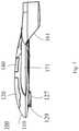
- FIG. 4illustrates an exemplary integrated pitot tube and hook of an exemplary UAV for a longer duration flight, according to some embodiments of the present disclosure.
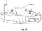
- FIG. 5Aillustrates an exemplary antenna embedded in a body assembly of an exemplary UAV for a longer duration flight, according to some embodiments of the present disclosure.
- FIG. 5Billustrates an exemplary antenna embedded in a hook of an exemplary UAV for a longer duration flight, according to some embodiments of the present disclosure.
- FIG. 5Cillustrates an exemplary indentation for an embedded antenna of an exemplary UAV for a longer duration flight, according to some embodiments of the present disclosure.
- FIG. 6illustrates a side view of an exemplary UAV for a longer duration flight, according to some embodiments of the present disclosure.
- FIG. 7illustrates a side view of an exemplary UAV for a longer duration flight, according to some embodiments of the present disclosure.
- FIG. 8illustrates a front view of an exemplary UAV for a longer duration flight, according to some embodiments of the present disclosure.
- FIG. 9illustrates a rear view of an exemplary UAV for a longer duration flight, according to some embodiments of the present disclosure.
- FIG. 10illustrates a structural diagram of an exemplary UAV assembly for a longer duration flight, according to some embodiments of the present disclosure.
- FIG. 11is a schematic diagram of an exemplary removable left wing assembly, according to some embodiments of the present disclosure.
- FIG. 12is a schematic diagram of an exemplary removable left wing assembly, according to some embodiments of the present disclosure.
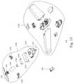
- FIG. 13is a schematic diagram of an exemplary UAV flight system assembly for a longer duration flight, according to some embodiments of the present disclosure.
- FIG. 1illustrates a top view of an exemplary UAV 100 for a longer duration flight, according to some embodiments of the present disclosure.
- UAV 100includes a UAV body assembly 110 , a flight control system (FCS) 120 , a payload 140 , a left wing 171 and a right wing 172 , a left aileron 173 and a right aileron 174 , a left winglet 161 and a right winglet 162 , a left aileron controller 101 and a right aileron controller 102 , a motor 150 , and a propeller 130 .
- Payload 140may be, for example, a camera or a multispectral camera.
- FCS 120is coupled to UAV body assembly 110 .
- Motor 150is coupled to UAV body assembly 110 at one end and coupled to propeller 130 at the other end.
- the FCSis communicatively connected to motor 150 .
- FCS 120may be configured to control left aileron 173 and right aileron 174 by servo motors connected to left aileron controller 101 and right aileron controller 102 , respectively.
- a center of gravity (CG) 115 of UAV 100may be arranged at a point between 21% and 25% of a mean aerodynamic chord (MAC) L MAC of the UAV 100 , i.e., 0.21 ⁇
- a UAV 100 having a wingspan of 1.4 meters and a takeoff weight 2.2 kilogramsmay fly forty to seventy minutes with the CG at the point between 21% and 25% of the MAC.
- UAV 100may include a CG at a point between 23% and 25% of the MAC of UAV 100 .
- a UAV 100 having the wingspan of 1.4 meters and the takeoff weight 2.2 kilogramsmay fly at least sixty minutes with a CG at a point between 23% and 25% of the MAC.
- UAV 100may include a CG at 23.5% of the MAC of UAV 100 .
- a UAV 100 having a wingspan of 1.4 meters and the takeoff weight 2.2 kilogramsmay fly seventy minutes or more with the CG at the point at 23.5% of the MAC.
- UAV 100may include the CG is at 24% of the MAC of UAV 100 for a long flight time.
- a UAV 100 having a wingspan of 1.4 meters and the takeoff weight 2.2 kilogramsmay fly seventy minutes or more with the CG at the point at 24% of the MAC.
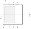
- FIG. 2is a schematic diagram of an exemplary adjustment assembly 200 of UAV 100 for longer duration flights, according to some embodiments of the present disclosure.
- Adjustment assembly 200is a frame that includes three positions at its two sides for fixing FCS 120 , payload 140 , and/or a battery of UAV 100 in order to adjust the CG of UAV 100 at a point between 21% and 25% of the MAC of UAV 100 .
- the three positions of adjustment assembly 200include: fix points A 1 and A 2 , fix points B 1 and B 2 , and fix points C 1 and C 2 , where a position by the fix points A 1 and A 2 is closer to a head of UAV body assembly 110 than a position by the fix points C 1 and C 2 .
- FCS 120when UAV 100 requires adjusting its CG towards 21% of the MAC, FCS 120 may be fixed at the fix positions A 1 and A 2 . In contrast, when UAV 100 requires adjusting its CG towards 25% of the MAC, FCS 120 may be fixed at the fix positions C 1 and C 2 . Likewise, payload 140 and/or the battery of UAV 100 can also be fixed at selectable fix points of their frames to adjust the CG of UAV 100 . In some embodiments, UAV 100 may include one or more frames similar to frame 200 for FCS 120 , payload 140 , and/or the battery, respectively, to adjust the CG at the point between 21% and 25% of the MAC of UAV 100 for a flight duration longer than forty minutes.
- UAV 100may include one or more frames 200 for FCS 120 , payload 140 , and/or the battery, respectively to adjust the CG at the point between 23% and 25% of the MAC of UAV 100 for a flight duration longer than sixty minutes.
- UAV 100may include one or more frames 200 for FCS 120 , payload 140 , and/or the battery, respectively to adjust the CG at 23.5% or 24% of the MAC of UAV 100 for a flight duration of seventy minutes or more.
- FIG. 3illustrates a bottom view of an exemplary UAV for longer flight duration, according to some embodiments of the present disclosure.
- UAV 100includes UAV body assembly 110 , left wing 171 and right wing 172 , left aileron 173 and right aileron 174 , left winglet 161 and right winglet 162 , left aileron controller 101 and right aileron controller 102 , motor 150 , propeller 130 , a hook 127 , a pitot tube 129 , payload 140 , and a parachute 160 .
- Pitot tube 129is coupled to UAV body assembly 110 .
- Hook 127is coupled to UAV body assembly 110 beneath FCS 120 .
- Hook 127is for use of launching UAV 100 from a launch rack.
- Pitot tube 120may be integrated together with hook 127 , which may reduce wind resistance.
- pitot tube 129 and hook 127are integrated together and are of streamlined shapes, thereby protecting pitot tube 129 and reducing unnecessary wind resistance.
- the FCSmay include a flight control computer (FCC), an attitude and heading reference system (AHRS) communicatively connected to the FCC, a communication module communicatively connected to the FCC, an antenna 125 communicatively connected to the communication module.
- Antenna 125may be embedded in UAV body assembly 100 to reduce unnecessary wind resistance of UAV 100 .
- the FCC, antenna 125 , pitot tube 129 and hook 127are aligned with a central axis 111 of UAV body assembly 110 .
- integrated pitot tube 129 and hook 127are arranged on central line 111 of body 110 while payload 140 , parachute 160 , motor 150 , and propeller 130 are also arranged on central line 111 .
- Positioning payload 140 , parachute 160 , motor 150 , and propeller 130 behind integrated pitot tube 129 and hook 127may help to balance UAV 100 and/or to reduce wind resistance caused by these components.
- FIG. 4illustrates exemplary integrated pitot tube 129 and hook 127 of exemplary UAV 100 , according to some embodiments of the present disclosure.
- pitot tube 129may be integrated or embedded in the front of hook 127 .
- antenna 125may be embedded in hook 127 , as illustrated in FIG. 4 , to reduce wind resistance that antenna 125 may cause if antenna 120 is not embedded in UAV assembly body 110 or hook 127 .
- Antenna 125may be implemented to be a flat antenna that can facilitate installation of antenna 125 in hook 127 .
- hook 127is made of glass fiber that provides solid structure for launching from a launch rack. Use of glass fiber has the benefit of not blocking signal transmissions from antenna 125 , and is lightweight.
- integrated pitot tube 129 and hook 127may cause wind resistance substantially equal to the wind resistance of pitot tube 129 alone.
- integrated pitot tube 129 and hook 127may cause wind resistance substantially equal to the wind resistance of pitot tube 129 alone.
- integrated pitot tube 129 and hook 127may cause wind resistance substantially equal to a wind resistance of hook 127 .
- integrated pitot tube 129 and hook 127may cause the wind resistance substantially equal to the wind resistance of hook 127 that is integrated behind pitot tube 129 .
- FIG. 5Aillustrates exemplary antenna 125 embedded in UAV body assembly 110 of exemplary UAV 100 , according to some embodiments of the present disclosure.
- Antenna 125is embedded in UAV body assembly 110 .
- antenna 125is embedded in UAV body assembly 110 and extended to hook 127 .
- hook 127may be made of glass fiber to reduce interference.
- pitot tube 129is aligned with antenna 125 along with central line 111 , thereby reducing wind resistance.
- FIG. 5Billustrates exemplary antenna 125 embedded in hook 127 of exemplary UAV 100 , according to some embodiments of the present disclosure. Further to FIG. 5A , FIG. 5B illustrates how hook 127 , pitot tube 129 , and antenna 125 may be integrated. As noted above in descriptions for FIGS. 3, 4, and 5A , integrated pitot tube 129 and hook 127 may reduce unnecessary wind resistance.
- FIG. 5Cillustrates an exemplary indentation 126 for embedded antenna 125 of exemplary UAV 100 , according to some embodiments of the present disclosure.
- Indentation 126extends from a room 121 for FCS 120 and allows FCS 120 to transmit signals through antenna 125 installed nearby. This exemplary configuration may improve signal transmission efficiency by FCS 120 .
- FIGS. 6 and 7illustrate two side views of exemplary UAV 100 , according to some embodiments of the present disclosure.
- streamlined UAV body assembly 110may reduce certain wind resistance during flight.
- Upper surface of UAV body assembly 110is smooth, and therefore allows air to flow through smoothly.
- FIG. 8illustrates a front view of exemplary UAV 100 , according to some embodiments of the present disclosure.
- a windward side of UAV 110may have a small area, and those surfaces (i.e., UAV body assembly 110 and wings 171 and 172 ) may be streamlined, thereby reducing wind resistance.
- integrated pitot tube 129 and hook 127may inhabit a relatively small area on the windward side of UAV 100 . This configuration may reduce wind resistance of UAV 100 .
- FIG. 9illustrates a rear view of exemplary UAV 100 , according to some embodiments of the present disclosure.
- integrated pitot tube 129 and hook 127may be aligned with a central line of UAV body assembly 110 of UAV 100 . This configuration may help balance UAV 100 .
- FIG. 10illustrates a structural diagram of an exemplary UAV assembly, according to some embodiments of the present disclosure.
- UAV 100includes left wing 171 and right wing 172 , left aileron 173 and right aileron 174 , a payload cover 1004 , a payload frame 1005 , a parachute cover 1006 , a lower body assembly 1003 , and a flight control system cover 1002 .
- FIG. 11is a schematic diagram of an exemplary removable left wing assembly, according to some embodiments of the present disclosure.
- the left wing assemblyincludes left wing 171 , left aileron 173 , left winglet 161 , two removable kits 1110 and 1120 , and left-wing controller 101 .
- Removable kits 1110includes a ping 1111 , a removable ping 1112 , and an O-ring 1113 .
- Removable kits 1120includes a ping 1121 , a removable ping 1122 , and an O-ring 1123 . O-rings 1113 and 1123 may tighten up a combination of the left wing assembly and UAV body assembly 110 firmly.
- FIG. 12is a schematic diagram of the exemplary removable left wing assembly, according to some embodiments of the present disclosure. As shown in FIG. 12 , ping 1111 may be less than 0.5 mm.
- FIG. 13is a schematic diagram of an exemplary UAV flight system assembly, according to some embodiments of the present disclosure.
- This exemplary UAV flight system assemblyincludes a body assembly 1320 , a system module 1340 , and a payload camera 140 .
- Components of body assembly 1320can be referred to FIG. 11 .
- System module 1340includes pitot tube 129 , a FCC 1341 , a batter 1342 , a parachute fixing plate 1343 , a parachute open servo 1344 , parachute 160 , motor 150 , propeller 130 , a left aileron servo 1345 , and a right aileron servo 1346 .
- Payload 140may comprise a camera, a multispectral camera, or a thermal infrared camera.
- Left aileron servo 1345is operatively coupled to left aileron controller 101 .
- Right aileron servo 1346is operatively coupled to right aileron controller 102 .
- FCC 1341is configured to control left aileron servo 1345 and right aileron servo 1346 to control left aileron 173 and right aileron 174 when UAV 100 needs to turn its flight direction, climb, or descent.
- FIG. 2also illustrates an exemplary method for adjusting a CG of UAV 100 for longer duration flights, according to some embodiments of the present disclosure.
- the methodmay include adjusting a position of at least one of payload 140 , a battery, or FCS 120 of the UAV to change the CG within a predetermined range of the MAC of UAV 100 .
- FCS 120when UAV 100 requires adjusting its CG towards 21% of the MAC, one or more of FCS 120 , the battery, and payload 140 may be fixed at the fix positions A 1 and A 2 in corresponding frames of these components.
- one or more of FCS 120 , the battery, and payload 140may be fixed at the fix positions C 1 and C 2 in the corresponding frames. Accordingly, adjusting the position of at least one of payload 140 , the battery, or FCS 120 of the UAV to change the CG at a point between 21% and 25% of the MAC of UAV 100 may include changing fix positions of these components among fix points A 1 and A 2 , B 1 and B 2 , and C 1 and C 2 .
- the method for adjusting the CG of UAV 100 for a longer flight durationmay include adjusting the CG to a point between 21% and 25% of the MAC of UAV 100 by changing fix positions of those components among fix points A 1 and A 2 , B 1 and B 2 , and C 1 and C 2 . Doing so may allow a flight duration more than forty minutes
- a method for adjusting the CG of UAV 100may include adjusting the CG to a point between 23% and 25% of the MAC of UAV 100 by changing fix positions of those components among fix points A 1 and A 2 , B 1 and B 2 , and C 1 and C 2 . Doing so may allow a flight duration more than sixty minutes.
- a method for adjusting the CG of UAV 100may include adjusting the CG to 23.5% or 24% of the MAC of UAV 100 by changing fix positions of those components among fix points A 1 and A 2 , B 1 and B 2 , and C 1 and C 2 . Doing so may allow flight duration of seventy minutes or more.
Landscapes
- Engineering & Computer Science (AREA)
- Aviation & Aerospace Engineering (AREA)
- Chemical & Material Sciences (AREA)
- Combustion & Propulsion (AREA)
- Physics & Mathematics (AREA)
- General Physics & Mathematics (AREA)
- Mechanical Engineering (AREA)
- Theoretical Computer Science (AREA)
- Computer Hardware Design (AREA)
- Mathematical Physics (AREA)
- Toys (AREA)
- Application Of Or Painting With Fluid Materials (AREA)
- Elimination Of Static Electricity (AREA)
Abstract
Description
≤0.25, where LCGis a length from the CG to one end of the MAC at the leading edge of an aerofoil, and LMACis a length of the MAC. In one example, a
Claims (15)
Priority Applications (2)
| Application Number | Priority Date | Filing Date | Title |
|---|---|---|---|
| US16/241,987US11267555B2 (en) | 2018-01-08 | 2019-01-07 | Methods and unmanned aerial vehicles for longer duration flights |
| US17/590,805US12097949B2 (en) | 2018-01-08 | 2022-02-01 | Methods and unmanned aerial vehicles for longer duration flights |
Applications Claiming Priority (2)
| Application Number | Priority Date | Filing Date | Title |
|---|---|---|---|
| US201862614976P | 2018-01-08 | 2018-01-08 | |
| US16/241,987US11267555B2 (en) | 2018-01-08 | 2019-01-07 | Methods and unmanned aerial vehicles for longer duration flights |
Related Child Applications (1)
| Application Number | Title | Priority Date | Filing Date |
|---|---|---|---|
| US17/590,805ContinuationUS12097949B2 (en) | 2018-01-08 | 2022-02-01 | Methods and unmanned aerial vehicles for longer duration flights |
Publications (2)
| Publication Number | Publication Date |
|---|---|
| US20190210713A1 US20190210713A1 (en) | 2019-07-11 |
| US11267555B2true US11267555B2 (en) | 2022-03-08 |
Family
ID=67140537
Family Applications (2)
| Application Number | Title | Priority Date | Filing Date |
|---|---|---|---|
| US16/241,987Active2040-04-06US11267555B2 (en) | 2018-01-08 | 2019-01-07 | Methods and unmanned aerial vehicles for longer duration flights |
| US17/590,805Active2039-03-08US12097949B2 (en) | 2018-01-08 | 2022-02-01 | Methods and unmanned aerial vehicles for longer duration flights |
Family Applications After (1)
| Application Number | Title | Priority Date | Filing Date |
|---|---|---|---|
| US17/590,805Active2039-03-08US12097949B2 (en) | 2018-01-08 | 2022-02-01 | Methods and unmanned aerial vehicles for longer duration flights |
Country Status (3)
| Country | Link |
|---|---|
| US (2) | US11267555B2 (en) |
| TW (1) | TWI804559B (en) |
| WO (1) | WO2019134712A1 (en) |
Families Citing this family (3)
| Publication number | Priority date | Publication date | Assignee | Title |
|---|---|---|---|---|
| US11267555B2 (en)* | 2018-01-08 | 2022-03-08 | GEOSAT Aerospace & Technology | Methods and unmanned aerial vehicles for longer duration flights |
| US11753146B1 (en)* | 2018-07-09 | 2023-09-12 | Pinto Geoffrey P | VTOL aircraft having modular payload |
| CN118270263B (en)* | 2024-06-03 | 2024-08-09 | 浙江华视智检科技有限公司 | Unmanned aerial vehicle with adjustable center of gravity and center of gravity adjusting method |
Citations (39)
| Publication number | Priority date | Publication date | Assignee | Title |
|---|---|---|---|---|
| US3513300A (en)* | 1967-08-23 | 1970-05-19 | Jack Asher Elfenbein | Aircraft weight and center of gravity computer |
| US4060930A (en)* | 1976-09-29 | 1977-12-06 | Mattel, Inc. | Toy airplane launcher |
| US5214586A (en)* | 1992-02-07 | 1993-05-25 | Nance C Kirk | Aircraft weight and center of gravity indicator |
| US5695153A (en)* | 1995-11-16 | 1997-12-09 | Northrop Grumman Corporation | Launcher system for an unmanned aerial vehicle |
| US5980429A (en)* | 1997-03-12 | 1999-11-09 | Neurocom International, Inc. | System and method for monitoring training programs |
| US6176367B1 (en)* | 1998-02-25 | 2001-01-23 | Fata Automation S.P.A. | Device for conveyance along assembly lines and the like |
| US6457673B1 (en)* | 2000-08-16 | 2002-10-01 | Aai Corporation | Mobile aircraft launcher |
| US6851647B1 (en)* | 2003-04-03 | 2005-02-08 | The United States Of America As Represented By The Administrator Of The National Aeronautics And Space Administration | Portable catapult launcher for small aircraft |
| US7210654B1 (en)* | 2003-07-23 | 2007-05-01 | Mission Technologies, Inc. | Unmanned airborne reconnaissance system |
| US7318565B2 (en)* | 2005-12-16 | 2008-01-15 | Itt Manufacturing Enterprises, Inc. | Electric motor assisted takeoff device for an air vehicle |
| US20090114773A1 (en)* | 2007-11-05 | 2009-05-07 | Helou Jr Elie | Methods for fuel-efficient transportation of cargo by aircraft |
| US20110315806A1 (en)* | 2010-05-17 | 2011-12-29 | Piasecki John W | Modular and morphable air vehicle |
| US20120205488A1 (en)* | 2011-02-16 | 2012-08-16 | Sparton Corporation | Unmanned aerial vehicle launch system |
| US8511607B2 (en)* | 2010-07-14 | 2013-08-20 | Arcturus UAV LLC | UAV launch attachment assembly and launch system |
| US8584985B2 (en)* | 2008-05-13 | 2013-11-19 | Bae Systems Plc | Launch system |
| US20140249700A1 (en)* | 2013-03-01 | 2014-09-04 | Honeywell International Inc. | Aircraft gross weight and center of gravity validator |
| US20160070261A1 (en)* | 2014-09-10 | 2016-03-10 | Appareo Systems, Llc | Automated flight control system for unmanned aerial vehicles |
| US20170057635A1 (en)* | 2015-09-02 | 2017-03-02 | The Boeing Company | Drone launch systems and methods |
| US20170173451A1 (en)* | 2015-11-23 | 2017-06-22 | Qfo Labs, Inc. | Method and system for integrated real and virtual game play for multiple remotely-controlled aircraft |
| US20170300054A1 (en)* | 2011-05-12 | 2017-10-19 | Unmanned Innovations, Inc. | Systems and methods for payload integration and control in a multi-mode unmanned vehicle |
| US20180067498A1 (en)* | 2016-09-05 | 2018-03-08 | ZEROTECH (Chongqing) Intelligence Technology Co., Ltd. | Method and apparatus for launching unmanned aerial vehicle and unmanned aerial vehicle incorporating the same |
| US9969504B1 (en)* | 2015-09-08 | 2018-05-15 | The United States Of America, As Represented By The Secretary Of The Navy | Automated multi-plane propulsion system |
| US20180229833A1 (en)* | 2017-02-16 | 2018-08-16 | Amazon Technologies, Inc. | Maintaining attitude control of unmanned aerial vehicles by varying centers of gravity |
| US20180290725A1 (en)* | 2017-04-05 | 2018-10-11 | Raytheon Company | Flight vehicle wing positioning system |
| US10118713B2 (en)* | 2013-08-27 | 2018-11-06 | Engineered Arresting Systems Corporation | Electric unmanned aerial vehicle launcher |
| US20180350258A1 (en)* | 2017-05-30 | 2018-12-06 | Honeywell International Inc. | System and method for adjusting the correlation between a visual display perspective and a flight path of an aircraft |
| US20180362190A1 (en)* | 2017-06-15 | 2018-12-20 | Aurora Flight Sciences Corporation | Autonomous Aircraft Health Systems and Methods |
| US20190031361A1 (en)* | 2016-07-01 | 2019-01-31 | Bell Helicopter Textron Inc. | Line Replaceable Propulsion Assemblies for Aircraft |
| US20190047726A1 (en)* | 2017-08-11 | 2019-02-14 | Ford Global Technologies, Llc | Vehicle mounted launcher for fixed-wing unmanned aerial vehicle |
| US20190144108A1 (en)* | 2016-07-01 | 2019-05-16 | Bell Helicopter Textron Inc. | Aircraft having Hover Stability in Inclined Flight Attitudes |
| US20190220038A1 (en)* | 2018-01-08 | 2019-07-18 | GEOSAT Aerospace & Technology | Methods and systems for launching an unmanned aerial vehicle |
| US10370120B1 (en)* | 2017-04-13 | 2019-08-06 | The Government Of The United States Of America As Represented By The Secretary Of The Navy | Launcher for an unmanned aircraft and methods of use thereof |
| US10377481B2 (en)* | 2012-10-26 | 2019-08-13 | The Boeing Company | Systems and methods to launch aircraft |
| US20190291860A1 (en)* | 2016-10-27 | 2019-09-26 | Mono Aerospace Ip Ltd | Vertical take-off and landing aircraft and control method |
| US20190291857A1 (en)* | 2016-02-17 | 2019-09-26 | Ardn Technology Limited | Multicopter with different purpose propellers |
| US20190371341A1 (en)* | 2018-06-01 | 2019-12-05 | Ge Aviation Systems Limited | Systems and Methods for Secure Commands in Vehicles |
| US20200333779A1 (en)* | 2017-03-10 | 2020-10-22 | Amit REGEV | A Free Wing Multirotor with Vertical and Horizontal Rotors |
| US10831192B1 (en)* | 2016-09-20 | 2020-11-10 | Piasecki Aircraft Corporation | Control system for an aircraft |
| US10940953B1 (en)* | 2016-09-20 | 2021-03-09 | Piasecki Aircraft Corporation | Aircraft self-rescue system |
Family Cites Families (103)
| Publication number | Priority date | Publication date | Assignee | Title |
|---|---|---|---|---|
| US3738595A (en)* | 1969-10-14 | 1973-06-12 | J Bouchnik | Delta-wing aircraft |
| US3656723A (en)* | 1969-12-16 | 1972-04-18 | Piasecki Aircraft Corp | Multiple helicopter lift system |
| US3954231A (en)* | 1974-09-09 | 1976-05-04 | Fraser Norman T L | Control system for forward wing aircraft |
| US3985320A (en)* | 1975-05-19 | 1976-10-12 | Brady De Cordova Maxwell | Platform stabilizing systems |
| JPH02262461A (en)* | 1989-03-31 | 1990-10-25 | Meitec Corp | Water surface air plane |
| US5115996A (en)* | 1990-01-31 | 1992-05-26 | Moller International, Inc. | Vtol aircraft |
| US6119976A (en)* | 1997-01-31 | 2000-09-19 | Rogers; Michael E. | Shoulder launched unmanned reconnaissance system |
| US6260796B1 (en)* | 1997-03-04 | 2001-07-17 | Wallace Neil Klingensmith | Multi-thrustered hover craft |
| US6406409B1 (en)* | 1999-10-19 | 2002-06-18 | Michael I. Silver | Free weight racking system |
| DE19950405C2 (en)* | 1999-10-20 | 2001-11-22 | Ecms Aviat Systems Gmbh | Device for attaching a load to a helicopter |
| GB0006420D0 (en)* | 2000-03-16 | 2000-12-20 | British Aerospace | Flight control system for an aircraft |
| US6609680B2 (en)* | 2000-05-30 | 2003-08-26 | Southwest Research Institute | High altitude airships |
| DE10209881A1 (en)* | 2002-03-06 | 2003-09-18 | Aloys Wobben | aircraft |
| US6923404B1 (en)* | 2003-01-10 | 2005-08-02 | Zona Technology, Inc. | Apparatus and methods for variable sweep body conformal wing with application to projectiles, missiles, and unmanned air vehicles |
| US6742741B1 (en)* | 2003-02-24 | 2004-06-01 | The Boeing Company | Unmanned air vehicle and method of flying an unmanned air vehicle |
| US6913228B2 (en)* | 2003-09-04 | 2005-07-05 | Supersonic Aerospace International, Llc | Aircraft with active center of gravity control |
| US7556219B2 (en)* | 2004-02-24 | 2009-07-07 | Swift Engineering, Inc. | Unmanned aerial vehicle and launch assembly |
| US7185848B2 (en)* | 2004-06-21 | 2007-03-06 | Ltas Holdings, Llc | Mass transfer system for stabilizing an airship and other vehicles subject to pitch and roll moments |
| US20060226281A1 (en)* | 2004-11-17 | 2006-10-12 | Walton Joh-Paul C | Ducted fan vertical take-off and landing vehicle |
| US7825554B2 (en)* | 2005-09-20 | 2010-11-02 | Bastian Family Holdings, Inc. | Stabilizing power source for a vehicle |
| US7337795B2 (en)* | 2005-10-17 | 2008-03-04 | The Boeing Company | Fuel balancing system |
| DE102005051799A1 (en)* | 2005-10-27 | 2007-05-03 | Stefan Reich | Method and device for remote control and stabilization of unmanned aerial vehicles |
| US20070215750A1 (en)* | 2005-11-18 | 2007-09-20 | Michael Shantz | Radio controlled helicopter |
| US7766274B1 (en)* | 2006-03-13 | 2010-08-03 | Lockheed Martin Corporation | Active maple seed flyer |
| US8109802B2 (en)* | 2007-09-15 | 2012-02-07 | Mattel, Inc. | Toy helicopter having a stabilizing bumper |
| US20100278656A1 (en)* | 2007-11-29 | 2010-11-04 | Shigetada Taya | Structure an aircraft rotor blade |
| US8061648B2 (en)* | 2008-02-26 | 2011-11-22 | Lachenmeier Timothy T | System for tactical balloon launch and payload return |
| US8322648B2 (en)* | 2008-05-15 | 2012-12-04 | Aeryon Labs Inc. | Hovering aerial vehicle with removable rotor arm assemblies |
| US8370003B2 (en)* | 2008-05-27 | 2013-02-05 | Wilfred So | System and method for multiple aircraft lifting a common payload |
| GB2462452B (en)* | 2008-08-08 | 2011-02-02 | Univ Manchester | A rotary wing vehicle |
| US8052081B2 (en)* | 2008-08-22 | 2011-11-08 | Draganfly Innovations Inc. | Dual rotor helicopter with tilted rotational axes |
| US8226040B2 (en)* | 2008-08-25 | 2012-07-24 | Embraer S.A. | Continuous fuel management system for automatic control of aircraft center of gravity |
| US8353199B1 (en)* | 2009-04-17 | 2013-01-15 | Arrowhead Center, Inc. | Multi-degree-of-freedom test stand for unmanned air vehicles |
| US8721383B2 (en)* | 2009-09-09 | 2014-05-13 | Aurora Flight Sciences Corporation | Modular miniature unmanned aircraft with vectored thrust control |
| US20110084162A1 (en)* | 2009-10-09 | 2011-04-14 | Honeywell International Inc. | Autonomous Payload Parsing Management System and Structure for an Unmanned Aerial Vehicle |
| US8540183B2 (en)* | 2009-12-12 | 2013-09-24 | Heliplane, Llc | Aerovehicle system including plurality of autogyro assemblies |
| CN101773736B (en)* | 2009-12-31 | 2011-07-13 | 罗之洪 | Two-rotor model helicopter control system |
| FR2959208B1 (en)* | 2010-04-22 | 2012-05-25 | Eurl Jmdtheque | GYROPENDULAR ENGINE WITH COMPENSATORY PROPULSION AND COLLIMATION OF MULTIMODAL MULTI-MEDIUM FLUID FLOWING GRADIENT WITH VERTICAL LANDING AND LANDING |
| DE102010023228B4 (en)* | 2010-06-09 | 2012-07-12 | Deutsches Zentrum für Luft- und Raumfahrt e.V. | stabilizing device |
| US8783607B2 (en)* | 2010-08-06 | 2014-07-22 | Arcturus UAV LLC | UAV recovery system |
| US8646719B2 (en)* | 2010-08-23 | 2014-02-11 | Heliplane, Llc | Marine vessel-towable aerovehicle system with automated tow line release |
| FR2970699B1 (en)* | 2011-01-25 | 2014-11-28 | Lisa Airplanes | MOTORIZED AIRCRAFT WITH HYDRODYNAMIC AND AERODYNAMIC MIXED STRUCTURE FOR TAKING AND LANDING ON WATER, SOIL OR SNOW |
| CN102650851B (en)* | 2011-02-25 | 2013-10-09 | 中国科学院沈阳自动化研究所 | Indoor multi-rotor flying robot test platform |
| WO2013105926A1 (en)* | 2011-03-22 | 2013-07-18 | Aerovironment Inc. | Invertible aircraft |
| JP5816744B2 (en)* | 2011-05-23 | 2015-11-18 | スカイ ウインドパワー コーポレイション | Flying generator |
| US20140197280A1 (en)* | 2011-11-22 | 2014-07-17 | Donald Earl Smith | Delta Wing Unmanned Aerial Vehicle (UAV) and Method of Manufacture of the Same |
| US9650138B2 (en)* | 2012-03-30 | 2017-05-16 | W.Morrison Consulting Group, Inc. | Long range electric aircraft and method of operating same |
| WO2014011255A2 (en)* | 2012-03-30 | 2014-01-16 | W. Morrison Consulting Group, Inc. | Long range electric aircraft and method of operating same |
| DE102012104783B4 (en)* | 2012-06-01 | 2019-12-24 | Quantum-Systems Gmbh | Aircraft, preferably UAV, drone and / or UAS |
| FR2992642B1 (en)* | 2012-06-29 | 2015-06-19 | Novance | PROCESS FOR THE SYNTHESIS OF BIOSOURCES UNSATURATED ACIDS |
| US8794566B2 (en)* | 2012-08-02 | 2014-08-05 | Neurosciences Research Foundation, Inc. | Vehicle capable of stabilizing a payload when in motion |
| JP6122591B2 (en)* | 2012-08-24 | 2017-04-26 | 株式会社トプコン | Photogrammetry camera and aerial photography equipment |
| CA2787279C (en)* | 2012-08-29 | 2013-10-22 | Draganfly Holdings Inc. | Vehicle with aerial and ground mobility |
| JP6055274B2 (en)* | 2012-10-31 | 2016-12-27 | 株式会社トプコン | Aerial photograph measuring method and aerial photograph measuring system |
| CN103921933A (en)* | 2013-01-10 | 2014-07-16 | 深圳市大疆创新科技有限公司 | Deformation structure of air vehicle and micro air vehicle |
| US20140217230A1 (en)* | 2013-02-05 | 2014-08-07 | Biosphere Aerospace, Llc | Drone cargo helicopter |
| JP6367522B2 (en)* | 2013-02-28 | 2018-08-01 | 株式会社トプコン | Aerial photography system |
| US9075415B2 (en)* | 2013-03-11 | 2015-07-07 | Airphrame, Inc. | Unmanned aerial vehicle and methods for controlling same |
| US9352819B2 (en)* | 2013-03-14 | 2016-05-31 | Raven Industries, Inc. | Airship pitch trim and directional control system |
| US20150014475A1 (en)* | 2013-05-03 | 2015-01-15 | Aerovironment, Inc. | Vertical Takeoff and Landing (VTOL) Air Vehicle |
| US9205922B1 (en)* | 2013-07-17 | 2015-12-08 | The Boeing Company | Systems and methods for implementing a payload distribution system |
| DE102013107654A1 (en)* | 2013-07-18 | 2015-01-22 | OIC-GmbH | Aircraft for carrying one or more recording devices through the air |
| US20150032643A1 (en)* | 2013-07-23 | 2015-01-29 | Micropilot Inc. | Product configuration method and system using failure mode design |
| ITRM20130473A1 (en)* | 2013-08-12 | 2013-11-11 | Unit 1 Srl | CONVERTIPLATE WITH NEW TECHNICAL AND AERODYNAMIC SOLUTIONS THAT CAN MAKE THE MEANS ALSO IN SAFE AND ULTRA-LIGHT AIRCRAFT SOLUTIONS |
| WO2015023992A1 (en)* | 2013-08-15 | 2015-02-19 | Traxxas Lp | Rotorcraft with integrated light pipe support members |
| EP3038922B1 (en)* | 2013-08-27 | 2019-09-25 | Engineered Arresting Systems Corporation | Electric unmanned aerial vehicle launcher |
| US9429954B2 (en)* | 2013-12-20 | 2016-08-30 | Google Inc. | Flight control for an airborne wind turbine |
| EP3097014B1 (en)* | 2014-01-20 | 2020-03-18 | Robodub Inc. | Multicopters with variable flight characteristics |
| US9272784B2 (en)* | 2014-05-19 | 2016-03-01 | Brian Dale Nelson | Vertical takeoff winged multicopter |
| US9767701B2 (en)* | 2014-06-26 | 2017-09-19 | Amazon Technologies, Inc. | Ground effect based surface sensing in automated aerial vehicles |
| US9405181B2 (en)* | 2014-07-31 | 2016-08-02 | Disney Enterprises, Inc. | Projection assemblies for use with unmanned aerial vehicles |
| US9704409B2 (en)* | 2014-08-05 | 2017-07-11 | Qualcomm Incorporated | Piggybacking unmanned aerial vehicle |
| US9573701B2 (en)* | 2014-08-06 | 2017-02-21 | Disney Enterprises, Inc. | Robust and autonomous docking and recharging of quadrotors |
| US9550561B1 (en)* | 2014-08-11 | 2017-01-24 | Amazon Technologies, Inc. | Determining center of gravity of an automated aerial vehicle and a payload |
| US20160059958A1 (en)* | 2014-08-19 | 2016-03-03 | Tau Emerald Rotors Inc. | Controlling Rotary Wing Aircraft |
| US9908619B1 (en)* | 2014-09-25 | 2018-03-06 | Amazon Technologies, Inc. | Ballast control mechanisms for aerial vehicles |
| EP3209559B1 (en)* | 2014-10-21 | 2022-06-15 | Lentola Logistics Oy | Aircraft |
| US20160272310A1 (en)* | 2014-12-04 | 2016-09-22 | Elwha Llc | Reconfigurable unmanned aircraft system |
| US9919797B2 (en)* | 2014-12-04 | 2018-03-20 | Elwha Llc | System and method for operation and management of reconfigurable unmanned aircraft |
| US9561849B2 (en)* | 2015-02-19 | 2017-02-07 | Amazon Technologies, Inc. | Vehicle configuration with motors that rotate between a lifting position and a thrusting position |
| US9501061B2 (en)* | 2015-02-24 | 2016-11-22 | Qualcomm Incorporated | Near-flight testing maneuvers for autonomous aircraft |
| US9469394B2 (en)* | 2015-03-10 | 2016-10-18 | Qualcomm Incorporated | Adjustable weight distribution for drone |
| US9738380B2 (en)* | 2015-03-16 | 2017-08-22 | XCraft Enterprises, LLC | Unmanned aerial vehicle with detachable computing device |
| CN107614376B (en)* | 2015-05-19 | 2021-05-28 | 株式会社阿荣奈斯特 | Gyrocopter |
| US10093416B2 (en)* | 2015-05-21 | 2018-10-09 | Khalid Hamad Mutleb ALNAFISAH | Multirotor drone with variable center of lift |
| US9415870B1 (en)* | 2015-09-02 | 2016-08-16 | Amazon Technologies, Inc. | Unmanned aerial vehicle motor driving randomization and feedback for noise abatement |
| US9422055B1 (en)* | 2015-09-02 | 2016-08-23 | Amazon Technologies, Inc. | Unmanned aerial vehicle motor driving randomization for noise abatement |
| WO2017044515A1 (en)* | 2015-09-09 | 2017-03-16 | Thomas Mcnally | Wheel-strut stabilization system for suspended payload aircraft |
| US10322783B2 (en)* | 2015-10-16 | 2019-06-18 | Seabed Geosolutions B.V. | Seismic autonomous underwater vehicle |
| ES2925005T3 (en)* | 2015-12-09 | 2022-10-13 | Ideaforge Tech Pvt Ltd | Multirotor aerial vehicle with redundancy for single arm failure |
| US9630713B1 (en)* | 2015-12-17 | 2017-04-25 | Qualcomm Incorporated | Unmanned aerial vehicle with adjustable aiming component |
| US10553122B1 (en)* | 2016-03-22 | 2020-02-04 | Amazon Technologies, Inc. | Unmanned aerial vehicle data collection for routing |
| JP6639979B2 (en)* | 2016-03-23 | 2020-02-05 | オリンパス株式会社 | Imaging equipment and moving objects for photography |
| CN206255191U (en)* | 2016-12-09 | 2017-06-16 | 北京京东尚科信息技术有限公司 | String wing unmanned plane |
| EP3577497B1 (en)* | 2017-02-06 | 2025-09-24 | Seabed Geosolutions B.V. | Ocean bottom seismic autonomous underwater vehicle |
| AU2018247579A1 (en)* | 2017-04-07 | 2019-09-26 | Douglas Morgan HANNA | Distributed-battery aerial vehicle and a powering method therefor |
| US10322790B2 (en)* | 2017-08-21 | 2019-06-18 | Pinnacle Vista, LLC | Tail tracking antenna |
| US11884406B2 (en)* | 2018-01-08 | 2024-01-30 | GEOSAT Aerospace & Technology | Parachute landing methods and systems for an unmanned aerial vehicle |
| US11267555B2 (en)* | 2018-01-08 | 2022-03-08 | GEOSAT Aerospace & Technology | Methods and unmanned aerial vehicles for longer duration flights |
| GB201811982D0 (en)* | 2018-07-23 | 2018-09-05 | Rolls Royce Plc | A distributed energy storage system |
| US10543905B1 (en)* | 2019-02-05 | 2020-01-28 | Kitty Hawk Corporation | Battery shifting for center of gravity control |
| FR3093994B1 (en)* | 2019-03-18 | 2021-06-11 | Airbus Helicopters | Method and device for moving a center of gravity of an aircraft |
| EP3959131B1 (en)* | 2019-04-24 | 2025-03-26 | Breeze-Eastern LLC | Hoist system and process for sway control |
- 2019
- 2019-01-07USUS16/241,987patent/US11267555B2/enactiveActive
- 2019-01-08WOPCT/CN2019/070908patent/WO2019134712A1/ennot_activeCeased
- 2019-01-08TWTW108100623Apatent/TWI804559B/enactive
- 2022
- 2022-02-01USUS17/590,805patent/US12097949B2/enactiveActive
Patent Citations (39)
| Publication number | Priority date | Publication date | Assignee | Title |
|---|---|---|---|---|
| US3513300A (en)* | 1967-08-23 | 1970-05-19 | Jack Asher Elfenbein | Aircraft weight and center of gravity computer |
| US4060930A (en)* | 1976-09-29 | 1977-12-06 | Mattel, Inc. | Toy airplane launcher |
| US5214586A (en)* | 1992-02-07 | 1993-05-25 | Nance C Kirk | Aircraft weight and center of gravity indicator |
| US5695153A (en)* | 1995-11-16 | 1997-12-09 | Northrop Grumman Corporation | Launcher system for an unmanned aerial vehicle |
| US5980429A (en)* | 1997-03-12 | 1999-11-09 | Neurocom International, Inc. | System and method for monitoring training programs |
| US6176367B1 (en)* | 1998-02-25 | 2001-01-23 | Fata Automation S.P.A. | Device for conveyance along assembly lines and the like |
| US6457673B1 (en)* | 2000-08-16 | 2002-10-01 | Aai Corporation | Mobile aircraft launcher |
| US6851647B1 (en)* | 2003-04-03 | 2005-02-08 | The United States Of America As Represented By The Administrator Of The National Aeronautics And Space Administration | Portable catapult launcher for small aircraft |
| US7210654B1 (en)* | 2003-07-23 | 2007-05-01 | Mission Technologies, Inc. | Unmanned airborne reconnaissance system |
| US7318565B2 (en)* | 2005-12-16 | 2008-01-15 | Itt Manufacturing Enterprises, Inc. | Electric motor assisted takeoff device for an air vehicle |
| US20090114773A1 (en)* | 2007-11-05 | 2009-05-07 | Helou Jr Elie | Methods for fuel-efficient transportation of cargo by aircraft |
| US8584985B2 (en)* | 2008-05-13 | 2013-11-19 | Bae Systems Plc | Launch system |
| US20110315806A1 (en)* | 2010-05-17 | 2011-12-29 | Piasecki John W | Modular and morphable air vehicle |
| US8511607B2 (en)* | 2010-07-14 | 2013-08-20 | Arcturus UAV LLC | UAV launch attachment assembly and launch system |
| US20120205488A1 (en)* | 2011-02-16 | 2012-08-16 | Sparton Corporation | Unmanned aerial vehicle launch system |
| US20170300054A1 (en)* | 2011-05-12 | 2017-10-19 | Unmanned Innovations, Inc. | Systems and methods for payload integration and control in a multi-mode unmanned vehicle |
| US10377481B2 (en)* | 2012-10-26 | 2019-08-13 | The Boeing Company | Systems and methods to launch aircraft |
| US20140249700A1 (en)* | 2013-03-01 | 2014-09-04 | Honeywell International Inc. | Aircraft gross weight and center of gravity validator |
| US10118713B2 (en)* | 2013-08-27 | 2018-11-06 | Engineered Arresting Systems Corporation | Electric unmanned aerial vehicle launcher |
| US20160070261A1 (en)* | 2014-09-10 | 2016-03-10 | Appareo Systems, Llc | Automated flight control system for unmanned aerial vehicles |
| US20170057635A1 (en)* | 2015-09-02 | 2017-03-02 | The Boeing Company | Drone launch systems and methods |
| US9969504B1 (en)* | 2015-09-08 | 2018-05-15 | The United States Of America, As Represented By The Secretary Of The Navy | Automated multi-plane propulsion system |
| US20170173451A1 (en)* | 2015-11-23 | 2017-06-22 | Qfo Labs, Inc. | Method and system for integrated real and virtual game play for multiple remotely-controlled aircraft |
| US20190291857A1 (en)* | 2016-02-17 | 2019-09-26 | Ardn Technology Limited | Multicopter with different purpose propellers |
| US20190031361A1 (en)* | 2016-07-01 | 2019-01-31 | Bell Helicopter Textron Inc. | Line Replaceable Propulsion Assemblies for Aircraft |
| US20190144108A1 (en)* | 2016-07-01 | 2019-05-16 | Bell Helicopter Textron Inc. | Aircraft having Hover Stability in Inclined Flight Attitudes |
| US20180067498A1 (en)* | 2016-09-05 | 2018-03-08 | ZEROTECH (Chongqing) Intelligence Technology Co., Ltd. | Method and apparatus for launching unmanned aerial vehicle and unmanned aerial vehicle incorporating the same |
| US10940953B1 (en)* | 2016-09-20 | 2021-03-09 | Piasecki Aircraft Corporation | Aircraft self-rescue system |
| US10831192B1 (en)* | 2016-09-20 | 2020-11-10 | Piasecki Aircraft Corporation | Control system for an aircraft |
| US20190291860A1 (en)* | 2016-10-27 | 2019-09-26 | Mono Aerospace Ip Ltd | Vertical take-off and landing aircraft and control method |
| US20180229833A1 (en)* | 2017-02-16 | 2018-08-16 | Amazon Technologies, Inc. | Maintaining attitude control of unmanned aerial vehicles by varying centers of gravity |
| US20200333779A1 (en)* | 2017-03-10 | 2020-10-22 | Amit REGEV | A Free Wing Multirotor with Vertical and Horizontal Rotors |
| US20180290725A1 (en)* | 2017-04-05 | 2018-10-11 | Raytheon Company | Flight vehicle wing positioning system |
| US10370120B1 (en)* | 2017-04-13 | 2019-08-06 | The Government Of The United States Of America As Represented By The Secretary Of The Navy | Launcher for an unmanned aircraft and methods of use thereof |
| US20180350258A1 (en)* | 2017-05-30 | 2018-12-06 | Honeywell International Inc. | System and method for adjusting the correlation between a visual display perspective and a flight path of an aircraft |
| US20180362190A1 (en)* | 2017-06-15 | 2018-12-20 | Aurora Flight Sciences Corporation | Autonomous Aircraft Health Systems and Methods |
| US20190047726A1 (en)* | 2017-08-11 | 2019-02-14 | Ford Global Technologies, Llc | Vehicle mounted launcher for fixed-wing unmanned aerial vehicle |
| US20190220038A1 (en)* | 2018-01-08 | 2019-07-18 | GEOSAT Aerospace & Technology | Methods and systems for launching an unmanned aerial vehicle |
| US20190371341A1 (en)* | 2018-06-01 | 2019-12-05 | Ge Aviation Systems Limited | Systems and Methods for Secure Commands in Vehicles |
Also Published As
| Publication number | Publication date |
|---|---|
| US12097949B2 (en) | 2024-09-24 |
| TW201936448A (en) | 2019-09-16 |
| TWI804559B (en) | 2023-06-11 |
| US20190210713A1 (en) | 2019-07-11 |
| WO2019134712A1 (en) | 2019-07-11 |
| US20220153404A1 (en) | 2022-05-19 |
Similar Documents
| Publication | Publication Date | Title |
|---|---|---|
| US12097949B2 (en) | Methods and unmanned aerial vehicles for longer duration flights | |
| CN106184737B (en) | Combined type is laid out vertically taking off and landing flyer and VTOL flying method | |
| US11061415B2 (en) | Maintaining a stable phase difference between multiple tethered vehicles lifting a payload | |
| US20210354821A1 (en) | Flying Apparatus | |
| WO2021023187A1 (en) | Control method of tilt rotor unmanned aerial vehicle, and tilt rotor unmanned aerial vehicle | |
| US11822350B2 (en) | Adjusting load on tethered aircraft | |
| US20110180671A1 (en) | Differential vane vehicle control | |
| CN105129080B (en) | A kind of four rotor wing unmanned aerial vehicle of Contrary compensation attitude stabilization | |
| US8905358B2 (en) | Unmanned aerial vehicle having an improved aerodynamic configuration | |
| KR20200137653A (en) | Aircraft capable of maintaining flight performance using joints | |
| CN110143274A (en) | Airfoil assembly, unmanned aerial vehicle, and method for controlling the airfoil assembly | |
| CN114556250B (en) | Occasional use of commanded rate instead of sensed airspeed to inform flight control decisions | |
| KR102189741B1 (en) | Propeller for unmanned aeriar vehicle for long-term flight at high altitudes | |
| CN117170409A (en) | Fixed wing unmanned aerial vehicle air recovery accurate docking control method based on direct force control | |
| CN114355965B (en) | A control system of a fixed-wing unmanned aerial vehicle and fixed-wing unmanned aerial vehicle equipment | |
| WO2021017018A1 (en) | Built-in antenna for racing unmanned aerial vehicle | |
| CN210149559U (en) | Can stabilize unmanned aerial vehicle who pastes wall | |
| CN111422371B (en) | Ground launching system and control method for fixed-wing unmanned aerial vehicle | |
| TWM513843U (en) | Assembly type unmanned aerial vehicle | |
| CN212829095U (en) | Unmanned aerial vehicle | |
| CN120534506A (en) | Gliding throwing device and assembly method | |
| CN110498042A (en) | Fixed Wing Aerial Survey UAV | |
| Gokulakkrishnana et al. | Multifunctional Uav to Assist Police | |
| CN205952333U (en) | A hemisphere buckler for having more rotor unmanned aerial vehicle | |
| Lozano Rocabeyera | Study of a feasible solution for a specific mission with an unmanned air vehicle (UAV/RPAS) |
Legal Events
| Date | Code | Title | Description |
|---|---|---|---|
| FEPP | Fee payment procedure | Free format text:ENTITY STATUS SET TO UNDISCOUNTED (ORIGINAL EVENT CODE: BIG.); ENTITY STATUS OF PATENT OWNER: SMALL ENTITY | |
| AS | Assignment | Owner name:GEOSAT AEROSPACE & TECHNOLOGY, TAIWAN Free format text:ASSIGNMENT OF ASSIGNORS INTEREST;ASSIGNORS:YANG, FU-KAI;LIAO, CHIEN-HSUN;CHENG, YI-FENG;AND OTHERS;REEL/FRAME:047936/0373 Effective date:20190108 | |
| FEPP | Fee payment procedure | Free format text:ENTITY STATUS SET TO SMALL (ORIGINAL EVENT CODE: SMAL); ENTITY STATUS OF PATENT OWNER: SMALL ENTITY | |
| STPP | Information on status: patent application and granting procedure in general | Free format text:DOCKETED NEW CASE - READY FOR EXAMINATION | |
| FEPP | Fee payment procedure | Free format text:PETITION RELATED TO MAINTENANCE FEES GRANTED (ORIGINAL EVENT CODE: PTGR); ENTITY STATUS OF PATENT OWNER: SMALL ENTITY | |
| FEPP | Fee payment procedure | Free format text:PETITION RELATED TO MAINTENANCE FEES GRANTED (ORIGINAL EVENT CODE: PTGR); ENTITY STATUS OF PATENT OWNER: SMALL ENTITY | |
| STPP | Information on status: patent application and granting procedure in general | Free format text:NON FINAL ACTION MAILED | |
| STPP | Information on status: patent application and granting procedure in general | Free format text:RESPONSE TO NON-FINAL OFFICE ACTION ENTERED AND FORWARDED TO EXAMINER | |
| STPP | Information on status: patent application and granting procedure in general | Free format text:FINAL REJECTION MAILED | |
| STPP | Information on status: patent application and granting procedure in general | Free format text:RESPONSE AFTER FINAL ACTION FORWARDED TO EXAMINER | |
| STPP | Information on status: patent application and granting procedure in general | Free format text:NOTICE OF ALLOWANCE MAILED -- APPLICATION RECEIVED IN OFFICE OF PUBLICATIONS | |
| STCF | Information on status: patent grant | Free format text:PATENTED CASE | |
| FEPP | Fee payment procedure | Free format text:ENTITY STATUS SET TO UNDISCOUNTED (ORIGINAL EVENT CODE: BIG.); ENTITY STATUS OF PATENT OWNER: LARGE ENTITY | |
| MAFP | Maintenance fee payment | Free format text:PAYMENT OF MAINTENANCE FEE, 4TH YEAR, LARGE ENTITY (ORIGINAL EVENT CODE: M1551); ENTITY STATUS OF PATENT OWNER: LARGE ENTITY Year of fee payment:4 |