US11267141B2 - Articulation for surgical robot - Google Patents
Articulation for surgical robotDownload PDFInfo
- Publication number
- US11267141B2 US11267141B2US15/519,381US201515519381AUS11267141B2US 11267141 B2US11267141 B2US 11267141B2US 201515519381 AUS201515519381 AUS 201515519381AUS 11267141 B2US11267141 B2US 11267141B2
- Authority
- US
- United States
- Prior art keywords
- segment
- basal
- joint
- distal
- surgical
- Prior art date
- Legal status (The legal status is an assumption and is not a legal conclusion. Google has not performed a legal analysis and makes no representation as to the accuracy of the status listed.)
- Active, expires
Links
- 150000001875compoundsChemical class0.000claimsabstractdescription40
- 230000033001locomotionEffects0.000claimsdescription34
- 239000012636effectorSubstances0.000claimsdescription16
- 210000000707wristAnatomy0.000description49
- 238000001356surgical procedureMethods0.000description5
- 238000000034methodMethods0.000description3
- 239000000470constituentSubstances0.000description1
- 230000008878couplingEffects0.000description1
- 238000010168coupling processMethods0.000description1
- 238000005859coupling reactionMethods0.000description1
- 238000003780insertionMethods0.000description1
- 230000037431insertionEffects0.000description1
- 238000002955isolationMethods0.000description1
- 238000012986modificationMethods0.000description1
- 230000004048modificationEffects0.000description1
- 210000003857wrist jointAnatomy0.000description1
Images


Classifications
- A—HUMAN NECESSITIES
- A61—MEDICAL OR VETERINARY SCIENCE; HYGIENE
- A61B—DIAGNOSIS; SURGERY; IDENTIFICATION
- A61B34/00—Computer-aided surgery; Manipulators or robots specially adapted for use in surgery
- A61B34/30—Surgical robots
- B—PERFORMING OPERATIONS; TRANSPORTING
- B25—HAND TOOLS; PORTABLE POWER-DRIVEN TOOLS; MANIPULATORS
- B25J—MANIPULATORS; CHAMBERS PROVIDED WITH MANIPULATION DEVICES
- B25J17/00—Joints
- B25J17/02—Wrist joints
- B25J17/0283—Three-dimensional joints
- B25J17/0291—Three-dimensional joints having axes crossing at an oblique angle, i.e. other than 90 degrees
- A—HUMAN NECESSITIES
- A61—MEDICAL OR VETERINARY SCIENCE; HYGIENE
- A61B—DIAGNOSIS; SURGERY; IDENTIFICATION
- A61B34/00—Computer-aided surgery; Manipulators or robots specially adapted for use in surgery
- A61B34/30—Surgical robots
- A61B2034/305—Details of wrist mechanisms at distal ends of robotic arms
Definitions
- This inventionrelates to surgical articulations, for example for use in surgical robotic components.
- FIG. 1illustrates a typical surgical robot arm.
- a patient 1is lying on a bed 2 .
- the robot arm 3extends from a base 4 towards the patient.
- the armhas a series of rigid links 5 , 6 , 7 which are connected to each other and to the base by articulations 8 , 9 , 10 .
- the articulationsprovide a sufficient range of motion that the arm can approach the patient in different ways so as to perform a range of surgical procedures.
- the linkscan be made to move about the articulations by motors 11 which are under the control of a surgeon.
- the final link 7 of the armterminates in a wrist articulation 12 to which a surgical instrument 13 is attached.
- the surgical instrumentis designed for insertion into the patient and terminates in an end effector for performing or aiding the surgery, for example an endoscope or a cutting tool or pinching tool.
- the wrist articulation 12it is desirable for the wrist articulation 12 to be highly mobile, so that the end effector can be placed in a wide range of orientations relative to the final link of the arm. It is also desirable for the wrist joint 12 to be kinematically well-functioning, without there being any attitudes in the core of their range of motion that are difficult to reach or where there could be poor control over the motion of the end effector.
- FIG. 2illustrates a typical wrist articulation.
- This wristcomprises two different types of joints: a “roll” joint which permits rotation about an axis generally along the arm, and a “pitch” joint which permits rotation about an axis generally transverse to the arm.
- the roll jointsare indicated as 21 and 23 and the pitch joint is indicated as 22 .
- the axes of the joints 21 , 22 and 23are indicated as 24 , 25 and 26 respectively.
- This wristgives an instrument 27 the freedom of movement to occupy a hemisphere whose base is centred on axis 24 .
- this wristis not well suited for use in a surgical robotic component.
- a surgical robotic componentcomprising an articulated terminal portion, the terminal portion comprising: a distal segment having an attachment for a surgical tool; a basal segment for attaching the terminal portion to the remainder of the surgical robotic component; and an intermediate compound joint between the distal segment and the basal segment, the intermediate compound joint permitting relative rotation of the distal segment and the basal segment about first, second and third axes; the terminal portion being arranged such that, in at least one configuration of the intermediate compound joint: (i) the axial direction of the basal segment is parallel to the axial direction of the distal segment, and (ii) the first, second and third axes are transverse to the axial directions of the basal and distal segments.
- the first, second and third axesare co-planar with each other.
- the first, second and third axesmay be perpendicular to the axial directions of the basal and distal segments.
- the axial direction of the basal segmentis collinear with the axial direction of the distal segment.
- the first, second and third axesintersect each other.
- the first, second and third axesmay be co-planar with each other and offset from each other in that plane by 60°.
- the intermediate compound jointcomprises: a first revolute joint which enables the distal segment to rotate about the first axis relative to the basal segment; a second revolute joint which enables the distal segment to rotate about the second axis relative to the basal segment; and a third revolute joint which enables the distal segment to rotate about the third axis relative to the basal segment.
- the first, second and third revolute jointsmay be arranged to be independently driven.
- the surgical robotic componentcomprises a first drive shaft located in the basal segment for driving the first revolute joint, a second drive shaft located in the distal segment for driving the second revolute joint, and a third drive shaft located in the basal segment for driving the third revolute joint.
- the terminal portioncomprises an additional revolute joint between the distal segment and the attachment, which permits rotation of the attachment about the axial direction of the distal segment.
- the only means of articulating the attachment relative to the basal segmentare the intermediate compound joint and the additional revolute joint.
- the intermediate compound jointcomprises a first intermediate segment and a second intermediate segment, the first intermediate segment coupled to the basal segment and separately coupled to the second intermediate segment, and the second intermediate segment coupled to the distal segment and separately coupled to the first intermediate segment.
- the first intermediate segmentmay comprise a basal arm portion coupled to the basal segment such that motion of the basal arm portion is restrained to rotation about the first axis relative to the basal segment.
- the second intermediate segmentmay comprise a distal arm portion coupled to the distal segment such that motion of the distal arm portion is restrained to rotation about the second axis relative to the distal segment.
- the first intermediate segmentcomprises a first connecting arm portion and the second intermediate segment comprises a second connecting arm portion, the first connecting arm portion coupled to the second connecting arm portion such that motion of the first connecting arm portion is restrained to rotation about the third axis relative to the second connecting arm portion.
- the surgical robotic componentmay be a surgical robot arm.
- the surgical toolmay be a surgical instrument which terminates in a surgical end effector.
- the surgical robotic componentmay be a surgical instrument suitable for being driven by a surgical robot arm.
- the surgical toolmay be a surgical end effector.
- FIG. 1shows a surgical robot arm
- FIG. 2shows a robotic component wrist
- FIG. 3shows a robot arm having a surgical instrument attached thereto
- FIG. 4shows a surgical instrument
- FIG. 5shows a robotic wrist component.
- the wristis illustrated in three different configurations at FIGS. 5 a , 5 b and 5 c ;
- FIG. 6shows an exemplary configuration in which the robotic wrist component of FIG. 5 can be driven.
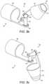
- FIG. 3shows an exemplary robot arm (indicated generally at 30 ) having a surgical instrument 31 attached thereto.
- the robot armextends from a base 32 .
- the basecould be mounted to the floor of an operating theatre, or to a fixed plinth, could be part of a mobile trolley or cart, could be mounted to a bed or could be mounted to the ceiling of an operating room.
- the baseis fixed in place relative to the patient's bed or chair when an operation is being carried out.
- the robot armcomprises a wrist portion shown generally at 33 and a main portion shown generally at 34 .
- the main portionmakes up the majority of the extent of the arm and terminates at its distal end in its attachment to the wrist portion.
- the proximal end of the main portionis attached to the base.
- the wrist portionmakes up the distal part of the arm and is attached to the distal end of the main portion.
- the main portion of the armcomprises four joints 35 , 36 , 37 , 38 and three shaft sections 39 , 40 , 41 .
- the jointsare revolute joints.
- the shaft sectionsare rigid, with the exception of joints 35 and 37 which are set into shaft sections 39 and 40 respectively.
- Each shaft sectionmay have substantial length, and serve to provide the arm with reach and the ability to offset the wrist laterally and/or vertically from the base.
- the first shaft sectioncould be truncated relative to the second and third shaft sections if the base is located in a suitable place; particularly if the base is elevated from the floor.
- the first shaft section 39is attached to the base 32 .
- the first shaft sectioncan conveniently extend in a generally upright direction from the base but it could extend at a significant incline to vertical, or even horizontally.
- Joint 35is located in the first shaft section. Joint 35 permits relative rotation of the proximal part of the first shaft section, which is fixed to the base, and the remainder of the arm about an axis 42 .
- axis 42is parallel with or substantially parallel with the main extent of the first shaft section in forming the arm, which runs from the base towards joint 36 .
- the angle of axis 42 to the main extent of the first shaft section in forming the armcould be less than 30°, less than 20° or less than 10°.
- Axis 42could be vertical or substantially vertical. Axis 42 could extend between the base and joint 36 .
- Joint 36is located at the distal end of the first shaft section 39 .
- Joint 36permits relative rotation of the first shaft section 39 and the second shaft section 40 , which is attached to the distal end of joint 36 , about an axis 43 which is transverse to the first shaft section 39 and/or the second shaft section 40 .
- axis 43is perpendicular or substantially perpendicular to either or both of the first and second shaft sections.
- the angle of axis 43 to the main extents of either or both of the first and second shaft sectionscould be less than 30°, less than 20° or less than 10°.
- Conveniently axis 43is perpendicular or substantially perpendicular to axis 42 and/or to the axis 44 to be described below.
- Joint 37is located in the second shaft section. Joint 37 permits relative rotation of the proximal part of the second shaft section and the remainder of the arm about an axis 44 .
- axis 44is parallel with or substantially parallel with the main extent of the second shaft section.
- the angle of axis 44 to the main extent of the second shaft sectioncould be less than 30°, less than 20° or less than 10°.
- Axis 44could intersect or substantially intersect (e.g. within 50 mm of) axis 43 and the axis 45 that will be described below.
- joint 37is shown located closer to the distal end of the second shaft section than the proximal end. This is advantageous because it reduces the mass that needs to be rotated at joint 37 , but joint 37 could be located at any point on the second shaft section.
- the second shaft sectionis conveniently longer than the first shaft section.
- Joint 38is located at the distal end of the second shaft section 40 .
- Joint 38permits relative rotation of the second shaft section and the third shaft section 41 , which is attached to the distal end of joint 38 , about an axis 45 which is transverse to the second shaft section 40 and/or the third shaft section 41 .
- axis 45is perpendicular or substantially perpendicular to either or both of the second and third shaft sections.
- the angle of axis 45 to the main extents of either or both of the second and third shaft sectionscould be less than 30°, less than 20° or less than 10°.
- Conveniently axis 45is perpendicular or substantially perpendicular to axis 44 .
- the main portion of the armcan be composed as follows, in order from the base to the distal end of the main portion:
- a first shaft section 39having substantial or insubstantial length and containing a joint 35 that permits rotation e.g. about an axis generally along the extent (if any) of the first shaft section in forming the arm (a “roll joint”);
- a joint 36permitting rotation transverse to the first shaft section and/or to the axis of the preceding joint (joint 35 ) and/or to the axis of the succeeding joint (joint 37 ) (a “pitch joint”);
- a second shaft section 40having substantial length and containing a joint 37 that permits rotation about an axis generally along the extent of the second shaft section and/or to the axis of the preceding joint (joint 36 ) and/or to the succeeding joint (joint 38 ) (a roll joint);
- a joint 38permitting rotation transverse to the second shaft section and or to the preceding joint (joint 37 ) and/or to the succeeding joint (joint 38 ) (a pitch joint);
- the wrist portion 33is attached to the distal end of the third shaft section.
- An example of the wrist portionis shown in more detail in FIG. 5 .
- FIG. 4illustrates an exemplary surgical instrument, shown generally at 50 .
- the surgical instrument 50comprises an instrument base 52 , an elongate instrument shaft 51 , a wrist portion 33 , and an end effector 54 .
- the end effector 54can be made to move about the wrist articulation 33 by motor 53 which is under the control of a surgeon via the robot arm.
- the end effectorcould, for example, be a gripper, a pair of shears, a camera, a laser or a knife.
- An example of the wrist portion 33is shown in more detail in FIG. 5 .
- FIGS. 5 a , 5 b and 5 cAn exemplary wrist portion 33 is shown in more details in FIGS. 5 a , 5 b and 5 c .
- the wrist portion 33may be located at the end of the robot arm as shown in FIG. 3 and/or at the end of the instrument as shown in FIG. 4 .
- FIG. 5 ashows the wrist 33 in a straight configuration.
- the wrist 33comprises a basal segment 60 , a distal segment 61 and an intermediate compound joint 62 between the basal segment and the distal segment.
- the distal segmenthas an attachment 63 for connecting to a surgical tool, and the basal segment attaches to the remainder of the robot arm.
- the distal segmenthas an attachment 63 for connecting to an end effector, and the basal segment attaches to the instrument shaft 51 .
- the basal and distal segmentsare rigid.
- the compound joint 62is arranged so as to permit relative rotation of the distal segment 61 and basal segment 60 about three axes: A 1 , A 2 and A 3 .
- the compound jointcomprises three revolute joints 64 , 65 and 66 .
- Revolute joint 64enables distal segment 61 to rotate about axis A 1 relative to the basal segment 60 .
- Revolute joint 65enables distal segment 61 to rotate about axis A 2 relative to the basal segment 60 .
- Revolute joint 66enables distal segment 61 to rotate about axis A 3 relative to the basal segment 60 .
- Compound joint 62comprises two intermediate segments 67 and 68 .
- Intermediate segment 67is coupled to basal segment 60 and intermediate segment 68 .
- Intermediate segment 67is moveably attached to basal segment 60 and to intermediate segment 68 .
- the relative movement of intermediate segment 67 and basal segment 60is restricted to a rotation about axis A 1 .
- the relative motion of intermediate segment 67 and basal segment 60is restricted to a revolute motion about axis A 1 .
- the only way of articulating intermediate segment 67 relative to basal segment 60is rotation about A 1 by means of joint 64 .
- Intermediate segment 68is coupled to distal segment 61 and intermediate segment 67 .
- Intermediate segment 68is moveably attached to distal segment 61 and to intermediate segment 67 .
- the relative movement of intermediate segment 68 and distal segment 61is restricted to a rotation about axis A 2 .
- the relative movement of intermediate segment 68 and distal segment 61is restricted to a revolute motion about axis A 2 .
- the only way of articulating intermediate segment 68 relative to distal segment 61is rotation about A 2 by means of joint 65 .
- Intermediate segment 67 and intermediate segment 68are moveably attached together.
- the relative movement of intermediate segment 67 and intermediate segment 68is restricted to a rotation about axis A 3 .
- the relative movement of intermediate segment 67 and intermediate segment 68is restricted to a revolute motion about axis A 3 .
- the only way of articulating intermediate segment 68 relative to intermediate segment 67is rotation about A 3 by means of joint 66 .
- Each intermediate segment 67 and 68is a rigid link.
- Intermediate segment 67comprises two arms 69 , 70 .
- the two arms 69 and 70are held fast together at a relative angle which corresponds to the angle between the axes A 1 and A 3 when the wrist is in the straight configuration depicted in FIG. 5 a .
- the angle between axial directions of arm 69 and arm 70 of intermediate segment 67is the same as the angle between axes A 1 and A 3 .
- intermediate segment 68comprises two arms 71 and 72 .
- the two arms 71 and 72are held fast together at a relative angle which corresponds to the angle between the axes A 2 and A 3 when the wrist is in the straight configuration depicted in FIG. 5 a .
- the angle between axial directions of arm 71 and arm 72 of intermediate segment 68is the same as the angle between axes A 2 and A 3 .
- Arm 70 of intermediate segment 67is coupled to arm 72 of intermediate segment 68 such that the motion of arm 72 is constrained to rotation about axis A 3 relative to arm 70 .
- arm 72embraces arm 70 .
- Arms 70 and 72are co-axial, and that axis is A 3 .
- the only way of articulating the distal segment 61 relative to the basal segment 60is by motion of the compound joint 62 as described above.
- the axes A 1 , A 2 and A 3are transverse to the axial directions of the basal and distal segments.
- the three axes A 1 , A 2 and A 3are coplanar when the wrist 33 is in the configuration of FIG. 5 a . That plane is perpendicular to the axial directions of the basal and distal segments.
- the axes A 1 , A 2 and A 3intersect each other at a single point on that plane, or substantially intersect at a single point (e.g. by all intersecting a sphere of radius 50 mm).
- the axes A 1 , A 2 and A 3and hence the arms of the intermediate segments which are aligned along those axes, are equally spaced in that plane. In other words, for three axes A 1 , A 2 and A 3 , each axis is offset from each of the other axes by 60°, as shown in FIG. 5 a.
- FIGS. 5 b and 5 cillustrate the wrist 33 in two different bent configurations, resulting from articulation of compound joint 62 from the straight configuration shown in FIG. 5 a .
- Like partsare indicated by the same references.
- FIGS. 5 b and 5 cshow examples of posing the wrist relative to the configuration in FIG. 5 a by rotation around all three of the joints 64 , 65 and 66 about axes A 1 , A 2 and A 3 respectively.
- the compound joint 62enables the attachment (which is either (i) the surgical instrument in the case that the wrist 33 is located at the end of the robot arm, or (ii) the end effector in the case that the wrist 33 is located at the end of the surgical instrument) to face any direction in a hemisphere whose base is perpendicular to the axial direction of the basal segment 60 .
- Each joint of the compound joint 62may be driven independently of the other joints by one or more motive devices such as electric motors or hydraulic pistons.
- the motive device(s)may be located locally at the respective joint, or they may be located closer to the base of the robot and coupled to the joints by couplings such as cables or linkages.
- the motive devicesare controllable by a user of the robot.
- FIG. 6illustrates an exemplary configuration in which joints 64 and 66 are driven from drive shafts extending through the basal segment 60 of the wrist, and joint 65 is driven from a drive shaft extending through the distal segment 61 of the wrist.
- hypoid gearsare used to drive the joints.
- FIG. 6like parts to FIG. 5 are indicated by the same references.
- Joint 64is driven by drive shaft 81 .
- Drive shaft 81terminates in worm 82 which engages gear 83 .
- Gear 83is held fast to intermediate segment 67 .
- Worm 82holds gear 83 (and hence intermediate segment 67 ) fast to basal segment 60 unless driven by drive shaft 81 .
- drive shaft 81When drive shaft 81 is driven by a motor, it causes worm 82 to rotate, which causes gear 83 to rotate, which causes intermediate segment 67 to rotate about axis A 1 relative to the basal segment 60 .
- Joint 65is driven by drive shaft 84 .
- Drive shaft 84terminates in worm 85 which engages with gear 86 .
- Gear 86is held fast to intermediate segment 68 .
- Worm 85holds gear 86 (and hence intermediate segment 68 ) fast to distal segment 61 unless driven by drive shaft 84 .
- drive shaft 84is driven by a motor, it causes worm 85 to rotate, which causes gear 86 to rotate, which causes intermediate segment 68 to rotate about axis A 2 relative to distal segment 61 .
- Joint 66is driven by drive shaft 87 .
- Drive shaft 87terminates in worm 88 which engages with gear 89 .
- Gear 89is held fast to intermediate segment 68 .
- Worm 88holds gear 89 (and hence intermediate segment 68 ) fast to intermediate segment 67 unless driven by drive shaft 87 .
- drive shaft 87is driven by a motor, it causes intermediate segment 68 to rotate about axis A 3 relative to intermediate segment 67 .
- drive shaft 87passes through an opening 90 in intermediate segment 67 .
- Drive shaft 87is articulated using double universal joint 91 so as to cause drive shaft 87 to cooperate with motion of the joints 64 and 65 of the compound joint 62 .
- the double universal joint 91(also known as a DV joint) counteracts motion caused to drive shaft 87 when joint 64 and/or joint 66 is articulated so as to enable worm 88 to remain engaged with gear 89 .
- a helical universal jointmay be used instead of a double universal joint.
- drive shaft 87may reach gear 89 by articulating around intermediate segment 67 .
- an offset hypoid gearmay be used for driving joint 66 so as to avoid passing drive shaft 87 through intermediate segment 67 .
- gear 89may be held fast to intermediate segment 67 and not to intermediate segment 68 , and hence, when driven, cause intermediate segment 67 to rotate about axis A 3 relative to intermediate segment 68 .
- Compound joint 62could consist of only two joints which are transverse both to each other and the basal and distal segments. However, it has been found that when the compound joint consists of only two joints which permit motion transverse to each other and the axial direction of the basal segment, the bend angle of the distal segment relative to the basal segment is limited to about 60 ° . However, by using an additional joint in compound joint 62 such that basal and distal segments are rotatable about the three axes A 1 , A 2 and A 3 , it has been found that a wider range of motion results, with a bend angle of up to 120°.
- ENTear, nose and throat
- the wrist 33is capable of a large bend angle, but is still slim and lightweight.
- the compact arrangement of joints in compound joint 62are much lighter weight than alternative joint configurations which achieve a comparable bend angle.
- a double universal jointcan be used to achieve a comparable bend angle, but is significantly more complex in structure and heavier.
- the more lightweight the compound joint 62the less stiff the shafts of the robot arm and instrument need to be to support the compound joint, and hence the lighter weight the whole robot can be. This makes the robot easier to move around the operating theatre and set up for use.
- Further jointscould be used in the compound joint to further increase the redundancy and hence the range of motion of the compound joint. However, further joints add weight and complexity. Additional drive shafts may be required to drive the additional joints.
- FIG. 6shows the constituent joints of the compound joint 62 being driven using hypoid gears
- other gearingmay be used, for example spiroid gears, bevel gears, conventional robotic drives etc.
- each joint of the compound joint 62is driven using the same gearing.
- the wrist 33 of FIG. 5comprises a further revolute joint 73 attached to the distal end of the distal segment.
- Joint 73permits the attachment to rotate about axis A 4 relative to the remainder of the wrist 33 .
- Axis A 4is the axial direction of distal segment 61 .
- the axis A 4conveniently intersects or substantially intersects (e.g. within 50 mm) axes A 1 , A 2 and A 3 at a single point.
- the only means of articulating the attachment relative to the basal segmentare the compound joint 62 and the joint 73 .
- the instrument base 52is designed cooperatively with the end of the robot arm so that the instrument base can be releasably attached to the robot arm with the shaft 51 extending away from the instrument base.
- the shaft 51extends away from the instrument base in a direction that is parallel or substantially parallel and/or coaxial or substantially coaxial with axis A 4 of the distal segment 61 .
- the end effector 54has substantial range of movement by virtue of the joints of the wrist 33 of the robot arm, and that the joints of the wrist 33 can be used conveniently to position the end effector.
- This arrangementcan permit the end effector to be readily rotated to a desired orientation through motion of the wrist without excessively disrupting a wound channel in the patient.
- the fact that the elongation of the instrument shaft extends away from the wrist as described abovemeans that the wrist has a degree of articulation that is similar to the wrist of a human surgeon.
- One result of thatis that many surgical techniques practised by humans can readily be translated to motions of this robot arm. This can help reduce the need to devise robot-specific versions of known surgical procedures.
Landscapes
- Engineering & Computer Science (AREA)
- Health & Medical Sciences (AREA)
- Life Sciences & Earth Sciences (AREA)
- Robotics (AREA)
- Surgery (AREA)
- Medical Informatics (AREA)
- Biomedical Technology (AREA)
- Heart & Thoracic Surgery (AREA)
- Nuclear Medicine, Radiotherapy & Molecular Imaging (AREA)
- Molecular Biology (AREA)
- Animal Behavior & Ethology (AREA)
- General Health & Medical Sciences (AREA)
- Public Health (AREA)
- Veterinary Medicine (AREA)
- Mechanical Engineering (AREA)
- Manipulator (AREA)
Abstract
Description
Claims (16)
Applications Claiming Priority (4)
| Application Number | Priority Date | Filing Date | Title |
|---|---|---|---|
| GB1418257.0 | 2014-10-15 | ||
| GB1418257 | 2014-10-15 | ||
| GB1418257.0AGB2531994B (en) | 2014-10-15 | 2014-10-15 | Surgical articulation |
| PCT/GB2015/052828WO2016059369A1 (en) | 2014-10-15 | 2015-09-29 | Articulation for surgical roboter |
Publications (2)
| Publication Number | Publication Date |
|---|---|
| US20170245949A1 US20170245949A1 (en) | 2017-08-31 |
| US11267141B2true US11267141B2 (en) | 2022-03-08 |
Family
ID=52001469
Family Applications (1)
| Application Number | Title | Priority Date | Filing Date |
|---|---|---|---|
| US15/519,381Active2038-09-11US11267141B2 (en) | 2014-10-15 | 2015-09-29 | Articulation for surgical robot |
Country Status (3)
| Country | Link |
|---|---|
| US (1) | US11267141B2 (en) |
| GB (1) | GB2531994B (en) |
| WO (1) | WO2016059369A1 (en) |
Cited By (1)
| Publication number | Priority date | Publication date | Assignee | Title |
|---|---|---|---|---|
| US20230240787A1 (en)* | 2013-03-15 | 2023-08-03 | Virtual Incision Corporation | Robotic Surgical Devices, Systems, and Related Methods |
Families Citing this family (300)
| Publication number | Priority date | Publication date | Assignee | Title |
|---|---|---|---|---|
| US20070084897A1 (en) | 2003-05-20 | 2007-04-19 | Shelton Frederick E Iv | Articulating surgical stapling instrument incorporating a two-piece e-beam firing mechanism |
| US9060770B2 (en) | 2003-05-20 | 2015-06-23 | Ethicon Endo-Surgery, Inc. | Robotically-driven surgical instrument with E-beam driver |
| US9072535B2 (en) | 2011-05-27 | 2015-07-07 | Ethicon Endo-Surgery, Inc. | Surgical stapling instruments with rotatable staple deployment arrangements |
| US11998198B2 (en) | 2004-07-28 | 2024-06-04 | Cilag Gmbh International | Surgical stapling instrument incorporating a two-piece E-beam firing mechanism |
| US11890012B2 (en) | 2004-07-28 | 2024-02-06 | Cilag Gmbh International | Staple cartridge comprising cartridge body and attached support |
| US7669746B2 (en) | 2005-08-31 | 2010-03-02 | Ethicon Endo-Surgery, Inc. | Staple cartridges for forming staples having differing formed staple heights |
| US7934630B2 (en) | 2005-08-31 | 2011-05-03 | Ethicon Endo-Surgery, Inc. | Staple cartridges for forming staples having differing formed staple heights |
| US11246590B2 (en) | 2005-08-31 | 2022-02-15 | Cilag Gmbh International | Staple cartridge including staple drivers having different unfired heights |
| US11484312B2 (en) | 2005-08-31 | 2022-11-01 | Cilag Gmbh International | Staple cartridge comprising a staple driver arrangement |
| US10159482B2 (en) | 2005-08-31 | 2018-12-25 | Ethicon Llc | Fastener cartridge assembly comprising a fixed anvil and different staple heights |
| US20070106317A1 (en) | 2005-11-09 | 2007-05-10 | Shelton Frederick E Iv | Hydraulically and electrically actuated articulation joints for surgical instruments |
| US20110295295A1 (en) | 2006-01-31 | 2011-12-01 | Ethicon Endo-Surgery, Inc. | Robotically-controlled surgical instrument having recording capabilities |
| US7845537B2 (en) | 2006-01-31 | 2010-12-07 | Ethicon Endo-Surgery, Inc. | Surgical instrument having recording capabilities |
| US8708213B2 (en) | 2006-01-31 | 2014-04-29 | Ethicon Endo-Surgery, Inc. | Surgical instrument having a feedback system |
| US7753904B2 (en) | 2006-01-31 | 2010-07-13 | Ethicon Endo-Surgery, Inc. | Endoscopic surgical instrument with a handle that can articulate with respect to the shaft |
| US20120292367A1 (en) | 2006-01-31 | 2012-11-22 | Ethicon Endo-Surgery, Inc. | Robotically-controlled end effector |
| US8186555B2 (en) | 2006-01-31 | 2012-05-29 | Ethicon Endo-Surgery, Inc. | Motor-driven surgical cutting and fastening instrument with mechanical closure system |
| US8820603B2 (en) | 2006-01-31 | 2014-09-02 | Ethicon Endo-Surgery, Inc. | Accessing data stored in a memory of a surgical instrument |
| US11793518B2 (en) | 2006-01-31 | 2023-10-24 | Cilag Gmbh International | Powered surgical instruments with firing system lockout arrangements |
| US8992422B2 (en) | 2006-03-23 | 2015-03-31 | Ethicon Endo-Surgery, Inc. | Robotically-controlled endoscopic accessory channel |
| US10568652B2 (en) | 2006-09-29 | 2020-02-25 | Ethicon Llc | Surgical staples having attached drivers of different heights and stapling instruments for deploying the same |
| US11980366B2 (en) | 2006-10-03 | 2024-05-14 | Cilag Gmbh International | Surgical instrument |
| US8684253B2 (en) | 2007-01-10 | 2014-04-01 | Ethicon Endo-Surgery, Inc. | Surgical instrument with wireless communication between a control unit of a robotic system and remote sensor |
| US8632535B2 (en) | 2007-01-10 | 2014-01-21 | Ethicon Endo-Surgery, Inc. | Interlock and surgical instrument including same |
| US11291441B2 (en) | 2007-01-10 | 2022-04-05 | Cilag Gmbh International | Surgical instrument with wireless communication between control unit and remote sensor |
| US20080169333A1 (en) | 2007-01-11 | 2008-07-17 | Shelton Frederick E | Surgical stapler end effector with tapered distal end |
| US7673782B2 (en) | 2007-03-15 | 2010-03-09 | Ethicon Endo-Surgery, Inc. | Surgical stapling instrument having a releasable buttress material |
| US8931682B2 (en) | 2007-06-04 | 2015-01-13 | Ethicon Endo-Surgery, Inc. | Robotically-controlled shaft based rotary drive systems for surgical instruments |
| US11564682B2 (en) | 2007-06-04 | 2023-01-31 | Cilag Gmbh International | Surgical stapler device |
| US7753245B2 (en) | 2007-06-22 | 2010-07-13 | Ethicon Endo-Surgery, Inc. | Surgical stapling instruments |
| US11849941B2 (en) | 2007-06-29 | 2023-12-26 | Cilag Gmbh International | Staple cartridge having staple cavities extending at a transverse angle relative to a longitudinal cartridge axis |
| US8636736B2 (en) | 2008-02-14 | 2014-01-28 | Ethicon Endo-Surgery, Inc. | Motorized surgical cutting and fastening instrument |
| US7866527B2 (en) | 2008-02-14 | 2011-01-11 | Ethicon Endo-Surgery, Inc. | Surgical stapling apparatus with interlockable firing system |
| US9179912B2 (en) | 2008-02-14 | 2015-11-10 | Ethicon Endo-Surgery, Inc. | Robotically-controlled motorized surgical cutting and fastening instrument |
| JP5410110B2 (en) | 2008-02-14 | 2014-02-05 | エシコン・エンド−サージェリィ・インコーポレイテッド | Surgical cutting / fixing instrument with RF electrode |
| US8573465B2 (en) | 2008-02-14 | 2013-11-05 | Ethicon Endo-Surgery, Inc. | Robotically-controlled surgical end effector system with rotary actuated closure systems |
| US7819298B2 (en) | 2008-02-14 | 2010-10-26 | Ethicon Endo-Surgery, Inc. | Surgical stapling apparatus with control features operable with one hand |
| US11986183B2 (en) | 2008-02-14 | 2024-05-21 | Cilag Gmbh International | Surgical cutting and fastening instrument comprising a plurality of sensors to measure an electrical parameter |
| US9585657B2 (en) | 2008-02-15 | 2017-03-07 | Ethicon Endo-Surgery, Llc | Actuator for releasing a layer of material from a surgical end effector |
| US11648005B2 (en) | 2008-09-23 | 2023-05-16 | Cilag Gmbh International | Robotically-controlled motorized surgical instrument with an end effector |
| US9005230B2 (en) | 2008-09-23 | 2015-04-14 | Ethicon Endo-Surgery, Inc. | Motorized surgical instrument |
| US8210411B2 (en) | 2008-09-23 | 2012-07-03 | Ethicon Endo-Surgery, Inc. | Motor-driven surgical cutting instrument |
| US9386983B2 (en) | 2008-09-23 | 2016-07-12 | Ethicon Endo-Surgery, Llc | Robotically-controlled motorized surgical instrument |
| US8608045B2 (en) | 2008-10-10 | 2013-12-17 | Ethicon Endo-Sugery, Inc. | Powered surgical cutting and stapling apparatus with manually retractable firing system |
| US8220688B2 (en) | 2009-12-24 | 2012-07-17 | Ethicon Endo-Surgery, Inc. | Motor-driven surgical cutting instrument with electric actuator directional control assembly |
| US9016542B2 (en) | 2010-09-30 | 2015-04-28 | Ethicon Endo-Surgery, Inc. | Staple cartridge comprising compressible distortion resistant components |
| US12213666B2 (en) | 2010-09-30 | 2025-02-04 | Cilag Gmbh International | Tissue thickness compensator comprising layers |
| US9788834B2 (en) | 2010-09-30 | 2017-10-17 | Ethicon Llc | Layer comprising deployable attachment members |
| US11812965B2 (en) | 2010-09-30 | 2023-11-14 | Cilag Gmbh International | Layer of material for a surgical end effector |
| US9386988B2 (en) | 2010-09-30 | 2016-07-12 | Ethicon End-Surgery, LLC | Retainer assembly including a tissue thickness compensator |
| US10945731B2 (en) | 2010-09-30 | 2021-03-16 | Ethicon Llc | Tissue thickness compensator comprising controlled release and expansion |
| US9629814B2 (en) | 2010-09-30 | 2017-04-25 | Ethicon Endo-Surgery, Llc | Tissue thickness compensator configured to redistribute compressive forces |
| US11298125B2 (en) | 2010-09-30 | 2022-04-12 | Cilag Gmbh International | Tissue stapler having a thickness compensator |
| US9351730B2 (en) | 2011-04-29 | 2016-05-31 | Ethicon Endo-Surgery, Llc | Tissue thickness compensator comprising channels |
| US11925354B2 (en) | 2010-09-30 | 2024-03-12 | Cilag Gmbh International | Staple cartridge comprising staples positioned within a compressible portion thereof |
| US8695866B2 (en) | 2010-10-01 | 2014-04-15 | Ethicon Endo-Surgery, Inc. | Surgical instrument having a power control circuit |
| AU2012250197B2 (en) | 2011-04-29 | 2017-08-10 | Ethicon Endo-Surgery, Inc. | Staple cartridge comprising staples positioned within a compressible portion thereof |
| US11207064B2 (en) | 2011-05-27 | 2021-12-28 | Cilag Gmbh International | Automated end effector component reloading system for use with a robotic system |
| MX358135B (en) | 2012-03-28 | 2018-08-06 | Ethicon Endo Surgery Inc | Tissue thickness compensator comprising a plurality of layers. |
| BR112014024098B1 (en) | 2012-03-28 | 2021-05-25 | Ethicon Endo-Surgery, Inc. | staple cartridge |
| US9101358B2 (en) | 2012-06-15 | 2015-08-11 | Ethicon Endo-Surgery, Inc. | Articulatable surgical instrument comprising a firing drive |
| BR112014032776B1 (en) | 2012-06-28 | 2021-09-08 | Ethicon Endo-Surgery, Inc | SURGICAL INSTRUMENT SYSTEM AND SURGICAL KIT FOR USE WITH A SURGICAL INSTRUMENT SYSTEM |
| US9408606B2 (en) | 2012-06-28 | 2016-08-09 | Ethicon Endo-Surgery, Llc | Robotically powered surgical device with manually-actuatable reversing system |
| US20140001231A1 (en) | 2012-06-28 | 2014-01-02 | Ethicon Endo-Surgery, Inc. | Firing system lockout arrangements for surgical instruments |
| US9282974B2 (en) | 2012-06-28 | 2016-03-15 | Ethicon Endo-Surgery, Llc | Empty clip cartridge lockout |
| US12383267B2 (en) | 2012-06-28 | 2025-08-12 | Cilag Gmbh International | Robotically powered surgical device with manually-actuatable reversing system |
| US9289256B2 (en) | 2012-06-28 | 2016-03-22 | Ethicon Endo-Surgery, Llc | Surgical end effectors having angled tissue-contacting surfaces |
| RU2672520C2 (en) | 2013-03-01 | 2018-11-15 | Этикон Эндо-Серджери, Инк. | Hingedly turnable surgical instruments with conducting ways for signal transfer |
| BR112015021082B1 (en) | 2013-03-01 | 2022-05-10 | Ethicon Endo-Surgery, Inc | surgical instrument |
| US9629629B2 (en) | 2013-03-14 | 2017-04-25 | Ethicon Endo-Surgey, LLC | Control systems for surgical instruments |
| MX2015013147A (en)* | 2013-03-15 | 2016-05-18 | Evoke Innovative Solutions Inc | Articulating arm camera mount. |
| US9826976B2 (en) | 2013-04-16 | 2017-11-28 | Ethicon Llc | Motor driven surgical instruments with lockable dual drive shafts |
| BR112015026109B1 (en) | 2013-04-16 | 2022-02-22 | Ethicon Endo-Surgery, Inc | surgical instrument |
| MX369362B (en) | 2013-08-23 | 2019-11-06 | Ethicon Endo Surgery Llc | Firing member retraction devices for powered surgical instruments. |
| US9775609B2 (en) | 2013-08-23 | 2017-10-03 | Ethicon Llc | Tamper proof circuit for surgical instrument battery pack |
| US20150272580A1 (en) | 2014-03-26 | 2015-10-01 | Ethicon Endo-Surgery, Inc. | Verification of number of battery exchanges/procedure count |
| BR112016021943B1 (en) | 2014-03-26 | 2022-06-14 | Ethicon Endo-Surgery, Llc | SURGICAL INSTRUMENT FOR USE BY AN OPERATOR IN A SURGICAL PROCEDURE |
| US10013049B2 (en) | 2014-03-26 | 2018-07-03 | Ethicon Llc | Power management through sleep options of segmented circuit and wake up control |
| US12232723B2 (en) | 2014-03-26 | 2025-02-25 | Cilag Gmbh International | Systems and methods for controlling a segmented circuit |
| US20150297225A1 (en) | 2014-04-16 | 2015-10-22 | Ethicon Endo-Surgery, Inc. | Fastener cartridges including extensions having different configurations |
| CN106456176B (en) | 2014-04-16 | 2019-06-28 | 伊西康内外科有限责任公司 | Fastener Cartridge Including Extensions With Different Configurations |
| US10327764B2 (en) | 2014-09-26 | 2019-06-25 | Ethicon Llc | Method for creating a flexible staple line |
| BR112016023825B1 (en) | 2014-04-16 | 2022-08-02 | Ethicon Endo-Surgery, Llc | STAPLE CARTRIDGE FOR USE WITH A SURGICAL STAPLER AND STAPLE CARTRIDGE FOR USE WITH A SURGICAL INSTRUMENT |
| CN106456159B (en) | 2014-04-16 | 2019-03-08 | 伊西康内外科有限责任公司 | Fastener Cartridge Assembly and Nail Retainer Cover Arrangement |
| US9855108B2 (en) | 2014-04-22 | 2018-01-02 | Bio-Medical Engineering (HK) Limited | Robotic devices and systems for performing single incision procedures and natural orifice translumenal endoscopic surgical procedures, and methods of configuring robotic devices and systems |
| US11090123B2 (en) | 2014-04-22 | 2021-08-17 | Bio-Medical Engineering (HK) Limited | Robotic devices and systems for performing single incision procedures and natural orifice translumenal endoscopic surgical procedures, and methods of configuring robotic devices and systems |
| US11801099B2 (en) | 2014-04-22 | 2023-10-31 | Bio-Medical Engineering (HK) Limited | Robotic devices and systems for performing single incision procedures and natural orifice translumenal endoscopic surgical procedures, and methods of configuring robotic devices and systems |
| CN105358072B (en) | 2014-04-22 | 2018-11-09 | 香港生物医学工程有限公司 | Single access channel surgical robotic devices and systems and methods of configuring single access channel surgical robotic devices and systems |
| US11154368B2 (en) | 2014-04-22 | 2021-10-26 | Bio-Medical Engineering (HK) Limited | Port assembly for use with robotic devices and systems to perform single incision procedures and natural orifice translumenal endoscopic surgical procedures |
| BR112017004361B1 (en) | 2014-09-05 | 2023-04-11 | Ethicon Llc | ELECTRONIC SYSTEM FOR A SURGICAL INSTRUMENT |
| US11311294B2 (en) | 2014-09-05 | 2022-04-26 | Cilag Gmbh International | Powered medical device including measurement of closure state of jaws |
| US10135242B2 (en) | 2014-09-05 | 2018-11-20 | Ethicon Llc | Smart cartridge wake up operation and data retention |
| US10105142B2 (en) | 2014-09-18 | 2018-10-23 | Ethicon Llc | Surgical stapler with plurality of cutting elements |
| US11523821B2 (en) | 2014-09-26 | 2022-12-13 | Cilag Gmbh International | Method for creating a flexible staple line |
| US9924944B2 (en) | 2014-10-16 | 2018-03-27 | Ethicon Llc | Staple cartridge comprising an adjunct material |
| US10517594B2 (en) | 2014-10-29 | 2019-12-31 | Ethicon Llc | Cartridge assemblies for surgical staplers |
| US11141153B2 (en) | 2014-10-29 | 2021-10-12 | Cilag Gmbh International | Staple cartridges comprising driver arrangements |
| US9844376B2 (en) | 2014-11-06 | 2017-12-19 | Ethicon Llc | Staple cartridge comprising a releasable adjunct material |
| US10736636B2 (en) | 2014-12-10 | 2020-08-11 | Ethicon Llc | Articulatable surgical instrument system |
| MX389118B (en) | 2014-12-18 | 2025-03-20 | Ethicon Llc | SURGICAL INSTRUMENT WITH AN ANVIL THAT CAN BE SELECTIVELY MOVED ON A DISCRETE, NON-MOBILE AXIS RELATIVE TO A STAPLE CARTRIDGE. |
| US9943309B2 (en) | 2014-12-18 | 2018-04-17 | Ethicon Llc | Surgical instruments with articulatable end effectors and movable firing beam support arrangements |
| US10085748B2 (en) | 2014-12-18 | 2018-10-02 | Ethicon Llc | Locking arrangements for detachable shaft assemblies with articulatable surgical end effectors |
| US9844375B2 (en) | 2014-12-18 | 2017-12-19 | Ethicon Llc | Drive arrangements for articulatable surgical instruments |
| US9844374B2 (en) | 2014-12-18 | 2017-12-19 | Ethicon Llc | Surgical instrument systems comprising an articulatable end effector and means for adjusting the firing stroke of a firing member |
| US9987000B2 (en) | 2014-12-18 | 2018-06-05 | Ethicon Llc | Surgical instrument assembly comprising a flexible articulation system |
| US11154301B2 (en) | 2015-02-27 | 2021-10-26 | Cilag Gmbh International | Modular stapling assembly |
| US10548504B2 (en) | 2015-03-06 | 2020-02-04 | Ethicon Llc | Overlaid multi sensor radio frequency (RF) electrode system to measure tissue compression |
| JP2020121162A (en) | 2015-03-06 | 2020-08-13 | エシコン エルエルシーEthicon LLC | Time dependent evaluation of sensor data to determine stability element, creep element and viscoelastic element of measurement |
| US10441279B2 (en) | 2015-03-06 | 2019-10-15 | Ethicon Llc | Multiple level thresholds to modify operation of powered surgical instruments |
| US9993248B2 (en) | 2015-03-06 | 2018-06-12 | Ethicon Endo-Surgery, Llc | Smart sensors with local signal processing |
| US10433844B2 (en) | 2015-03-31 | 2019-10-08 | Ethicon Llc | Surgical instrument with selectively disengageable threaded drive systems |
| US10105139B2 (en) | 2015-09-23 | 2018-10-23 | Ethicon Llc | Surgical stapler having downstream current-based motor control |
| US10238386B2 (en) | 2015-09-23 | 2019-03-26 | Ethicon Llc | Surgical stapler having motor control based on an electrical parameter related to a motor current |
| US10299878B2 (en) | 2015-09-25 | 2019-05-28 | Ethicon Llc | Implantable adjunct systems for determining adjunct skew |
| US11890015B2 (en) | 2015-09-30 | 2024-02-06 | Cilag Gmbh International | Compressible adjunct with crossing spacer fibers |
| US10433846B2 (en) | 2015-09-30 | 2019-10-08 | Ethicon Llc | Compressible adjunct with crossing spacer fibers |
| US10478188B2 (en) | 2015-09-30 | 2019-11-19 | Ethicon Llc | Implantable layer comprising a constricted configuration |
| US10292704B2 (en) | 2015-12-30 | 2019-05-21 | Ethicon Llc | Mechanisms for compensating for battery pack failure in powered surgical instruments |
| US10265068B2 (en) | 2015-12-30 | 2019-04-23 | Ethicon Llc | Surgical instruments with separable motors and motor control circuits |
| BR112018016098B1 (en) | 2016-02-09 | 2023-02-23 | Ethicon Llc | SURGICAL INSTRUMENT |
| US11213293B2 (en) | 2016-02-09 | 2022-01-04 | Cilag Gmbh International | Articulatable surgical instruments with single articulation link arrangements |
| US11224426B2 (en) | 2016-02-12 | 2022-01-18 | Cilag Gmbh International | Mechanisms for compensating for drivetrain failure in powered surgical instruments |
| US10448948B2 (en) | 2016-02-12 | 2019-10-22 | Ethicon Llc | Mechanisms for compensating for drivetrain failure in powered surgical instruments |
| US11576562B2 (en)* | 2016-04-07 | 2023-02-14 | Titan Medical Inc. | Camera positioning method and apparatus for capturing images during a medical procedure |
| US10357247B2 (en) | 2016-04-15 | 2019-07-23 | Ethicon Llc | Surgical instrument with multiple program responses during a firing motion |
| US11607239B2 (en) | 2016-04-15 | 2023-03-21 | Cilag Gmbh International | Systems and methods for controlling a surgical stapling and cutting instrument |
| US10426467B2 (en) | 2016-04-15 | 2019-10-01 | Ethicon Llc | Surgical instrument with detection sensors |
| US10492783B2 (en) | 2016-04-15 | 2019-12-03 | Ethicon, Llc | Surgical instrument with improved stop/start control during a firing motion |
| US10828028B2 (en) | 2016-04-15 | 2020-11-10 | Ethicon Llc | Surgical instrument with multiple program responses during a firing motion |
| US10363037B2 (en) | 2016-04-18 | 2019-07-30 | Ethicon Llc | Surgical instrument system comprising a magnetic lockout |
| US20170296173A1 (en) | 2016-04-18 | 2017-10-19 | Ethicon Endo-Surgery, Llc | Method for operating a surgical instrument |
| US11317917B2 (en) | 2016-04-18 | 2022-05-03 | Cilag Gmbh International | Surgical stapling system comprising a lockable firing assembly |
| GB2552383B (en) | 2016-07-22 | 2022-08-24 | Cmr Surgical Ltd | Gear packaging for robotic joints |
| GB2603881B (en)* | 2016-07-22 | 2023-01-04 | Cmr Surgical Ltd | Gear packaging for robotic joints |
| US10500000B2 (en) | 2016-08-16 | 2019-12-10 | Ethicon Llc | Surgical tool with manual control of end effector jaws |
| CA3022502A1 (en)* | 2016-11-01 | 2018-05-11 | Bio-Medical Engineering (HK) Limited | Robotic devices and systems for performing single incision procedures and natural orifice translumenal endoscopic surgical procedures, and methods of configuring robotic devices and systems |
| JP2018098344A (en) | 2016-12-13 | 2018-06-21 | ソニーセミコンダクタソリューションズ株式会社 | Image sensor and electronic device |
| JP2020501815A (en) | 2016-12-21 | 2020-01-23 | エシコン エルエルシーEthicon LLC | Surgical stapling system |
| US10542982B2 (en) | 2016-12-21 | 2020-01-28 | Ethicon Llc | Shaft assembly comprising first and second articulation lockouts |
| JP7010957B2 (en) | 2016-12-21 | 2022-01-26 | エシコン エルエルシー | Shaft assembly with lockout |
| US10813638B2 (en) | 2016-12-21 | 2020-10-27 | Ethicon Llc | Surgical end effectors with expandable tissue stop arrangements |
| JP6983893B2 (en) | 2016-12-21 | 2021-12-17 | エシコン エルエルシーEthicon LLC | Lockout configuration for surgical end effectors and replaceable tool assemblies |
| US11090048B2 (en) | 2016-12-21 | 2021-08-17 | Cilag Gmbh International | Method for resetting a fuse of a surgical instrument shaft |
| US20180168615A1 (en) | 2016-12-21 | 2018-06-21 | Ethicon Endo-Surgery, Llc | Method of deforming staples from two different types of staple cartridges with the same surgical stapling instrument |
| US11419606B2 (en) | 2016-12-21 | 2022-08-23 | Cilag Gmbh International | Shaft assembly comprising a clutch configured to adapt the output of a rotary firing member to two different systems |
| JP7010956B2 (en) | 2016-12-21 | 2022-01-26 | エシコン エルエルシー | How to staple tissue |
| US10973516B2 (en) | 2016-12-21 | 2021-04-13 | Ethicon Llc | Surgical end effectors and adaptable firing members therefor |
| MX2019007295A (en) | 2016-12-21 | 2019-10-15 | Ethicon Llc | Surgical instrument system comprising an end effector lockout and a firing assembly lockout. |
| US10582928B2 (en) | 2016-12-21 | 2020-03-10 | Ethicon Llc | Articulation lock arrangements for locking an end effector in an articulated position in response to actuation of a jaw closure system |
| US20180168625A1 (en) | 2016-12-21 | 2018-06-21 | Ethicon Endo-Surgery, Llc | Surgical stapling instruments with smart staple cartridges |
| US10779820B2 (en) | 2017-06-20 | 2020-09-22 | Ethicon Llc | Systems and methods for controlling motor speed according to user input for a surgical instrument |
| US10307170B2 (en) | 2017-06-20 | 2019-06-04 | Ethicon Llc | Method for closed loop control of motor velocity of a surgical stapling and cutting instrument |
| US11382638B2 (en) | 2017-06-20 | 2022-07-12 | Cilag Gmbh International | Closed loop feedback control of motor velocity of a surgical stapling and cutting instrument based on measured time over a specified displacement distance |
| US11517325B2 (en) | 2017-06-20 | 2022-12-06 | Cilag Gmbh International | Closed loop feedback control of motor velocity of a surgical stapling and cutting instrument based on measured displacement distance traveled over a specified time interval |
| US11653914B2 (en) | 2017-06-20 | 2023-05-23 | Cilag Gmbh International | Systems and methods for controlling motor velocity of a surgical stapling and cutting instrument according to articulation angle of end effector |
| US10881399B2 (en) | 2017-06-20 | 2021-01-05 | Ethicon Llc | Techniques for adaptive control of motor velocity of a surgical stapling and cutting instrument |
| US10993716B2 (en) | 2017-06-27 | 2021-05-04 | Ethicon Llc | Surgical anvil arrangements |
| US11266405B2 (en) | 2017-06-27 | 2022-03-08 | Cilag Gmbh International | Surgical anvil manufacturing methods |
| US11324503B2 (en) | 2017-06-27 | 2022-05-10 | Cilag Gmbh International | Surgical firing member arrangements |
| US11484310B2 (en) | 2017-06-28 | 2022-11-01 | Cilag Gmbh International | Surgical instrument comprising a shaft including a closure tube profile |
| US10765427B2 (en) | 2017-06-28 | 2020-09-08 | Ethicon Llc | Method for articulating a surgical instrument |
| EP3420947B1 (en) | 2017-06-28 | 2022-05-25 | Cilag GmbH International | Surgical instrument comprising selectively actuatable rotatable couplers |
| USD906355S1 (en) | 2017-06-28 | 2020-12-29 | Ethicon Llc | Display screen or portion thereof with a graphical user interface for a surgical instrument |
| US11564686B2 (en) | 2017-06-28 | 2023-01-31 | Cilag Gmbh International | Surgical shaft assemblies with flexible interfaces |
| US10758232B2 (en) | 2017-06-28 | 2020-09-01 | Ethicon Llc | Surgical instrument with positive jaw opening features |
| US10932772B2 (en) | 2017-06-29 | 2021-03-02 | Ethicon Llc | Methods for closed loop velocity control for robotic surgical instrument |
| US11974742B2 (en) | 2017-08-03 | 2024-05-07 | Cilag Gmbh International | Surgical system comprising an articulation bailout |
| US11471155B2 (en) | 2017-08-03 | 2022-10-18 | Cilag Gmbh International | Surgical system bailout |
| US11304695B2 (en) | 2017-08-03 | 2022-04-19 | Cilag Gmbh International | Surgical system shaft interconnection |
| US11944300B2 (en) | 2017-08-03 | 2024-04-02 | Cilag Gmbh International | Method for operating a surgical system bailout |
| US10743872B2 (en) | 2017-09-29 | 2020-08-18 | Ethicon Llc | System and methods for controlling a display of a surgical instrument |
| US11134944B2 (en) | 2017-10-30 | 2021-10-05 | Cilag Gmbh International | Surgical stapler knife motion controls |
| US10842490B2 (en) | 2017-10-31 | 2020-11-24 | Ethicon Llc | Cartridge body design with force reduction based on firing completion |
| US10779826B2 (en) | 2017-12-15 | 2020-09-22 | Ethicon Llc | Methods of operating surgical end effectors |
| US10835330B2 (en) | 2017-12-19 | 2020-11-17 | Ethicon Llc | Method for determining the position of a rotatable jaw of a surgical instrument attachment assembly |
| US12336705B2 (en) | 2017-12-21 | 2025-06-24 | Cilag Gmbh International | Continuous use self-propelled stapling instrument |
| US11311290B2 (en) | 2017-12-21 | 2022-04-26 | Cilag Gmbh International | Surgical instrument comprising an end effector dampener |
| US11179151B2 (en) | 2017-12-21 | 2021-11-23 | Cilag Gmbh International | Surgical instrument comprising a display |
| US11207065B2 (en) | 2018-08-20 | 2021-12-28 | Cilag Gmbh International | Method for fabricating surgical stapler anvils |
| US20200054321A1 (en) | 2018-08-20 | 2020-02-20 | Ethicon Llc | Surgical instruments with progressive jaw closure arrangements |
| US11291440B2 (en) | 2018-08-20 | 2022-04-05 | Cilag Gmbh International | Method for operating a powered articulatable surgical instrument |
| US11324501B2 (en) | 2018-08-20 | 2022-05-10 | Cilag Gmbh International | Surgical stapling devices with improved closure members |
| EP3934558A4 (en) | 2019-03-07 | 2022-12-14 | PROCEPT BioRobotics Corporation | Robotic arms and methods for tissue resection and imaging |
| US11696761B2 (en) | 2019-03-25 | 2023-07-11 | Cilag Gmbh International | Firing drive arrangements for surgical systems |
| US11426251B2 (en) | 2019-04-30 | 2022-08-30 | Cilag Gmbh International | Articulation directional lights on a surgical instrument |
| US11432816B2 (en) | 2019-04-30 | 2022-09-06 | Cilag Gmbh International | Articulation pin for a surgical instrument |
| US11903581B2 (en) | 2019-04-30 | 2024-02-20 | Cilag Gmbh International | Methods for stapling tissue using a surgical instrument |
| US11452528B2 (en) | 2019-04-30 | 2022-09-27 | Cilag Gmbh International | Articulation actuators for a surgical instrument |
| US11471157B2 (en) | 2019-04-30 | 2022-10-18 | Cilag Gmbh International | Articulation control mapping for a surgical instrument |
| US11648009B2 (en) | 2019-04-30 | 2023-05-16 | Cilag Gmbh International | Rotatable jaw tip for a surgical instrument |
| US11399837B2 (en) | 2019-06-28 | 2022-08-02 | Cilag Gmbh International | Mechanisms for motor control adjustments of a motorized surgical instrument |
| US11376098B2 (en) | 2019-06-28 | 2022-07-05 | Cilag Gmbh International | Surgical instrument system comprising an RFID system |
| US11627959B2 (en) | 2019-06-28 | 2023-04-18 | Cilag Gmbh International | Surgical instruments including manual and powered system lockouts |
| US11298127B2 (en) | 2019-06-28 | 2022-04-12 | Cilag GmbH Interational | Surgical stapling system having a lockout mechanism for an incompatible cartridge |
| US11684434B2 (en) | 2019-06-28 | 2023-06-27 | Cilag Gmbh International | Surgical RFID assemblies for instrument operational setting control |
| US11361176B2 (en) | 2019-06-28 | 2022-06-14 | Cilag Gmbh International | Surgical RFID assemblies for compatibility detection |
| US11464601B2 (en) | 2019-06-28 | 2022-10-11 | Cilag Gmbh International | Surgical instrument comprising an RFID system for tracking a movable component |
| US11241235B2 (en) | 2019-06-28 | 2022-02-08 | Cilag Gmbh International | Method of using multiple RFID chips with a surgical assembly |
| US11523822B2 (en) | 2019-06-28 | 2022-12-13 | Cilag Gmbh International | Battery pack including a circuit interrupter |
| US11660163B2 (en) | 2019-06-28 | 2023-05-30 | Cilag Gmbh International | Surgical system with RFID tags for updating motor assembly parameters |
| US11478241B2 (en) | 2019-06-28 | 2022-10-25 | Cilag Gmbh International | Staple cartridge including projections |
| US11497492B2 (en) | 2019-06-28 | 2022-11-15 | Cilag Gmbh International | Surgical instrument including an articulation lock |
| US11426167B2 (en) | 2019-06-28 | 2022-08-30 | Cilag Gmbh International | Mechanisms for proper anvil attachment surgical stapling head assembly |
| US11638587B2 (en) | 2019-06-28 | 2023-05-02 | Cilag Gmbh International | RFID identification systems for surgical instruments |
| US11553971B2 (en) | 2019-06-28 | 2023-01-17 | Cilag Gmbh International | Surgical RFID assemblies for display and communication |
| US11771419B2 (en) | 2019-06-28 | 2023-10-03 | Cilag Gmbh International | Packaging for a replaceable component of a surgical stapling system |
| US11298132B2 (en) | 2019-06-28 | 2022-04-12 | Cilag GmbH Inlernational | Staple cartridge including a honeycomb extension |
| US12004740B2 (en) | 2019-06-28 | 2024-06-11 | Cilag Gmbh International | Surgical stapling system having an information decryption protocol |
| US11853835B2 (en) | 2019-06-28 | 2023-12-26 | Cilag Gmbh International | RFID identification systems for surgical instruments |
| US11071601B2 (en) | 2019-11-11 | 2021-07-27 | Procept Biorobotics Corporation | Surgical probes for tissue resection with robotic arms |
| US11701111B2 (en) | 2019-12-19 | 2023-07-18 | Cilag Gmbh International | Method for operating a surgical stapling instrument |
| US11911032B2 (en) | 2019-12-19 | 2024-02-27 | Cilag Gmbh International | Staple cartridge comprising a seating cam |
| US11844520B2 (en) | 2019-12-19 | 2023-12-19 | Cilag Gmbh International | Staple cartridge comprising driver retention members |
| US11576672B2 (en) | 2019-12-19 | 2023-02-14 | Cilag Gmbh International | Surgical instrument comprising a closure system including a closure member and an opening member driven by a drive screw |
| US11529139B2 (en) | 2019-12-19 | 2022-12-20 | Cilag Gmbh International | Motor driven surgical instrument |
| US11504122B2 (en) | 2019-12-19 | 2022-11-22 | Cilag Gmbh International | Surgical instrument comprising a nested firing member |
| US12035913B2 (en) | 2019-12-19 | 2024-07-16 | Cilag Gmbh International | Staple cartridge comprising a deployable knife |
| US11464512B2 (en) | 2019-12-19 | 2022-10-11 | Cilag Gmbh International | Staple cartridge comprising a curved deck surface |
| US11559304B2 (en) | 2019-12-19 | 2023-01-24 | Cilag Gmbh International | Surgical instrument comprising a rapid closure mechanism |
| US11607219B2 (en) | 2019-12-19 | 2023-03-21 | Cilag Gmbh International | Staple cartridge comprising a detachable tissue cutting knife |
| US11304696B2 (en)* | 2019-12-19 | 2022-04-19 | Cilag Gmbh International | Surgical instrument comprising a powered articulation system |
| US11446029B2 (en) | 2019-12-19 | 2022-09-20 | Cilag Gmbh International | Staple cartridge comprising projections extending from a curved deck surface |
| US11291447B2 (en) | 2019-12-19 | 2022-04-05 | Cilag Gmbh International | Stapling instrument comprising independent jaw closing and staple firing systems |
| US11529137B2 (en) | 2019-12-19 | 2022-12-20 | Cilag Gmbh International | Staple cartridge comprising driver retention members |
| USD967421S1 (en) | 2020-06-02 | 2022-10-18 | Cilag Gmbh International | Staple cartridge |
| USD976401S1 (en) | 2020-06-02 | 2023-01-24 | Cilag Gmbh International | Staple cartridge |
| USD975850S1 (en) | 2020-06-02 | 2023-01-17 | Cilag Gmbh International | Staple cartridge |
| USD974560S1 (en) | 2020-06-02 | 2023-01-03 | Cilag Gmbh International | Staple cartridge |
| USD975278S1 (en) | 2020-06-02 | 2023-01-10 | Cilag Gmbh International | Staple cartridge |
| USD966512S1 (en) | 2020-06-02 | 2022-10-11 | Cilag Gmbh International | Staple cartridge |
| USD975851S1 (en) | 2020-06-02 | 2023-01-17 | Cilag Gmbh International | Staple cartridge |
| US11096753B1 (en) | 2020-06-26 | 2021-08-24 | Procept Biorobotics Corporation | Systems and methods for defining and modifying range of motion of probe used in patient treatment |
| US11877818B2 (en)* | 2020-06-26 | 2024-01-23 | Procept Biorobotics Corporation | Integration of robotic arms with surgical probes |
| US11871925B2 (en) | 2020-07-28 | 2024-01-16 | Cilag Gmbh International | Surgical instruments with dual spherical articulation joint arrangements |
| US11534259B2 (en) | 2020-10-29 | 2022-12-27 | Cilag Gmbh International | Surgical instrument comprising an articulation indicator |
| US11896217B2 (en) | 2020-10-29 | 2024-02-13 | Cilag Gmbh International | Surgical instrument comprising an articulation lock |
| US11617577B2 (en) | 2020-10-29 | 2023-04-04 | Cilag Gmbh International | Surgical instrument comprising a sensor configured to sense whether an articulation drive of the surgical instrument is actuatable |
| USD980425S1 (en) | 2020-10-29 | 2023-03-07 | Cilag Gmbh International | Surgical instrument assembly |
| US11717289B2 (en) | 2020-10-29 | 2023-08-08 | Cilag Gmbh International | Surgical instrument comprising an indicator which indicates that an articulation drive is actuatable |
| USD1013170S1 (en) | 2020-10-29 | 2024-01-30 | Cilag Gmbh International | Surgical instrument assembly |
| US11517390B2 (en) | 2020-10-29 | 2022-12-06 | Cilag Gmbh International | Surgical instrument comprising a limited travel switch |
| US11844518B2 (en) | 2020-10-29 | 2023-12-19 | Cilag Gmbh International | Method for operating a surgical instrument |
| US12053175B2 (en) | 2020-10-29 | 2024-08-06 | Cilag Gmbh International | Surgical instrument comprising a stowed closure actuator stop |
| US11931025B2 (en) | 2020-10-29 | 2024-03-19 | Cilag Gmbh International | Surgical instrument comprising a releasable closure drive lock |
| US11452526B2 (en) | 2020-10-29 | 2022-09-27 | Cilag Gmbh International | Surgical instrument comprising a staged voltage regulation start-up system |
| US11779330B2 (en) | 2020-10-29 | 2023-10-10 | Cilag Gmbh International | Surgical instrument comprising a jaw alignment system |
| US11849943B2 (en) | 2020-12-02 | 2023-12-26 | Cilag Gmbh International | Surgical instrument with cartridge release mechanisms |
| US11944296B2 (en) | 2020-12-02 | 2024-04-02 | Cilag Gmbh International | Powered surgical instruments with external connectors |
| US11678882B2 (en) | 2020-12-02 | 2023-06-20 | Cilag Gmbh International | Surgical instruments with interactive features to remedy incidental sled movements |
| US11890010B2 (en) | 2020-12-02 | 2024-02-06 | Cllag GmbH International | Dual-sided reinforced reload for surgical instruments |
| US11744581B2 (en) | 2020-12-02 | 2023-09-05 | Cilag Gmbh International | Powered surgical instruments with multi-phase tissue treatment |
| US11737751B2 (en) | 2020-12-02 | 2023-08-29 | Cilag Gmbh International | Devices and methods of managing energy dissipated within sterile barriers of surgical instrument housings |
| US11627960B2 (en) | 2020-12-02 | 2023-04-18 | Cilag Gmbh International | Powered surgical instruments with smart reload with separately attachable exteriorly mounted wiring connections |
| US11653920B2 (en) | 2020-12-02 | 2023-05-23 | Cilag Gmbh International | Powered surgical instruments with communication interfaces through sterile barrier |
| US11653915B2 (en) | 2020-12-02 | 2023-05-23 | Cilag Gmbh International | Surgical instruments with sled location detection and adjustment features |
| US11730473B2 (en) | 2021-02-26 | 2023-08-22 | Cilag Gmbh International | Monitoring of manufacturing life-cycle |
| US11950777B2 (en) | 2021-02-26 | 2024-04-09 | Cilag Gmbh International | Staple cartridge comprising an information access control system |
| US11950779B2 (en) | 2021-02-26 | 2024-04-09 | Cilag Gmbh International | Method of powering and communicating with a staple cartridge |
| US11723657B2 (en) | 2021-02-26 | 2023-08-15 | Cilag Gmbh International | Adjustable communication based on available bandwidth and power capacity |
| US12324580B2 (en) | 2021-02-26 | 2025-06-10 | Cilag Gmbh International | Method of powering and communicating with a staple cartridge |
| US11749877B2 (en) | 2021-02-26 | 2023-09-05 | Cilag Gmbh International | Stapling instrument comprising a signal antenna |
| US11793514B2 (en) | 2021-02-26 | 2023-10-24 | Cilag Gmbh International | Staple cartridge comprising sensor array which may be embedded in cartridge body |
| US11744583B2 (en) | 2021-02-26 | 2023-09-05 | Cilag Gmbh International | Distal communication array to tune frequency of RF systems |
| US11812964B2 (en) | 2021-02-26 | 2023-11-14 | Cilag Gmbh International | Staple cartridge comprising a power management circuit |
| US11701113B2 (en) | 2021-02-26 | 2023-07-18 | Cilag Gmbh International | Stapling instrument comprising a separate power antenna and a data transfer antenna |
| US11751869B2 (en) | 2021-02-26 | 2023-09-12 | Cilag Gmbh International | Monitoring of multiple sensors over time to detect moving characteristics of tissue |
| US11980362B2 (en) | 2021-02-26 | 2024-05-14 | Cilag Gmbh International | Surgical instrument system comprising a power transfer coil |
| US11925349B2 (en) | 2021-02-26 | 2024-03-12 | Cilag Gmbh International | Adjustment to transfer parameters to improve available power |
| US11696757B2 (en) | 2021-02-26 | 2023-07-11 | Cilag Gmbh International | Monitoring of internal systems to detect and track cartridge motion status |
| US12108951B2 (en) | 2021-02-26 | 2024-10-08 | Cilag Gmbh International | Staple cartridge comprising a sensing array and a temperature control system |
| US11717291B2 (en) | 2021-03-22 | 2023-08-08 | Cilag Gmbh International | Staple cartridge comprising staples configured to apply different tissue compression |
| US11826012B2 (en) | 2021-03-22 | 2023-11-28 | Cilag Gmbh International | Stapling instrument comprising a pulsed motor-driven firing rack |
| US11737749B2 (en) | 2021-03-22 | 2023-08-29 | Cilag Gmbh International | Surgical stapling instrument comprising a retraction system |
| US11723658B2 (en) | 2021-03-22 | 2023-08-15 | Cilag Gmbh International | Staple cartridge comprising a firing lockout |
| US11759202B2 (en) | 2021-03-22 | 2023-09-19 | Cilag Gmbh International | Staple cartridge comprising an implantable layer |
| US11806011B2 (en) | 2021-03-22 | 2023-11-07 | Cilag Gmbh International | Stapling instrument comprising tissue compression systems |
| US11826042B2 (en) | 2021-03-22 | 2023-11-28 | Cilag Gmbh International | Surgical instrument comprising a firing drive including a selectable leverage mechanism |
| US11896218B2 (en) | 2021-03-24 | 2024-02-13 | Cilag Gmbh International | Method of using a powered stapling device |
| US11944336B2 (en) | 2021-03-24 | 2024-04-02 | Cilag Gmbh International | Joint arrangements for multi-planar alignment and support of operational drive shafts in articulatable surgical instruments |
| US11849944B2 (en) | 2021-03-24 | 2023-12-26 | Cilag Gmbh International | Drivers for fastener cartridge assemblies having rotary drive screws |
| US12102323B2 (en) | 2021-03-24 | 2024-10-01 | Cilag Gmbh International | Rotary-driven surgical stapling assembly comprising a floatable component |
| US11857183B2 (en) | 2021-03-24 | 2024-01-02 | Cilag Gmbh International | Stapling assembly components having metal substrates and plastic bodies |
| US11832816B2 (en) | 2021-03-24 | 2023-12-05 | Cilag Gmbh International | Surgical stapling assembly comprising nonplanar staples and planar staples |
| US11793516B2 (en) | 2021-03-24 | 2023-10-24 | Cilag Gmbh International | Surgical staple cartridge comprising longitudinal support beam |
| US11786243B2 (en) | 2021-03-24 | 2023-10-17 | Cilag Gmbh International | Firing members having flexible portions for adapting to a load during a surgical firing stroke |
| US11849945B2 (en) | 2021-03-24 | 2023-12-26 | Cilag Gmbh International | Rotary-driven surgical stapling assembly comprising eccentrically driven firing member |
| US11744603B2 (en) | 2021-03-24 | 2023-09-05 | Cilag Gmbh International | Multi-axis pivot joints for surgical instruments and methods for manufacturing same |
| US11786239B2 (en) | 2021-03-24 | 2023-10-17 | Cilag Gmbh International | Surgical instrument articulation joint arrangements comprising multiple moving linkage features |
| US11903582B2 (en) | 2021-03-24 | 2024-02-20 | Cilag Gmbh International | Leveraging surfaces for cartridge installation |
| US11896219B2 (en) | 2021-03-24 | 2024-02-13 | Cilag Gmbh International | Mating features between drivers and underside of a cartridge deck |
| JP2024515193A (en) | 2021-04-20 | 2024-04-05 | プロセプト バイオロボティクス コーポレイション | Surgical probe with independent energy source - Patents.com |
| US11826047B2 (en) | 2021-05-28 | 2023-11-28 | Cilag Gmbh International | Stapling instrument comprising jaw mounts |
| US11980363B2 (en) | 2021-10-18 | 2024-05-14 | Cilag Gmbh International | Row-to-row staple array variations |
| US11957337B2 (en) | 2021-10-18 | 2024-04-16 | Cilag Gmbh International | Surgical stapling assembly with offset ramped drive surfaces |
| US11877745B2 (en) | 2021-10-18 | 2024-01-23 | Cilag Gmbh International | Surgical stapling assembly having longitudinally-repeating staple leg clusters |
| US12239317B2 (en) | 2021-10-18 | 2025-03-04 | Cilag Gmbh International | Anvil comprising an arrangement of forming pockets proximal to tissue stop |
| US12089841B2 (en) | 2021-10-28 | 2024-09-17 | Cilag CmbH International | Staple cartridge identification systems |
| US11937816B2 (en) | 2021-10-28 | 2024-03-26 | Cilag Gmbh International | Electrical lead arrangements for surgical instruments |
| US12432790B2 (en) | 2021-10-28 | 2025-09-30 | Cilag Gmbh International | Method and device for transmitting UART communications over a security short range wireless communication |
| CN118021458B (en)* | 2024-02-28 | 2025-10-03 | 山东威高手术机器人有限公司 | Wrist, main manipulator and surgical robot |
Citations (27)
| Publication number | Priority date | Publication date | Assignee | Title |
|---|---|---|---|---|
| US4686866A (en)* | 1986-01-21 | 1987-08-18 | Rosheim Mark E | Compact robot wrist acuator |
| US4878393A (en)* | 1988-05-27 | 1989-11-07 | Oprea Duta | Dextrous spherical robot wrist |
| US4911033A (en)* | 1989-01-03 | 1990-03-27 | Ross-Hime Designs, Incorporated | Robotic manipulator |
| US5617762A (en)* | 1995-03-10 | 1997-04-08 | Kirsch; Jerry | Miniature positioning device |
| US5735627A (en)* | 1995-08-30 | 1998-04-07 | Tokico Ltd. | Articulating mechanism for robot |
| US5898599A (en)* | 1993-10-01 | 1999-04-27 | Massachusetts Institute Of Technology | Force reflecting haptic interface |
| US5966991A (en)* | 1997-04-23 | 1999-10-19 | Universite Laval | Two degree-of-freedom spherical orienting device |
| US6699235B2 (en)* | 2001-06-29 | 2004-03-02 | Intuitive Surgical, Inc. | Platform link wrist mechanism |
| US6699177B1 (en) | 1996-02-20 | 2004-03-02 | Computer Motion, Inc. | Method and apparatus for performing minimally invasive surgical procedures |
| US6793669B2 (en)* | 2001-07-31 | 2004-09-21 | The University Of Tokyo | Active forceps |
| US20080245175A1 (en) | 2007-04-03 | 2008-10-09 | Terumo Kabushiki Kaisha | Manipulator and control method therefor |
| GB2464147A (en)* | 2008-05-29 | 2010-04-14 | Knowles Kevin | Three Degree-of-Freedom Parallel Spherical Mechanism for Payload Orienting Applications |
| US20110106302A1 (en)* | 2009-10-30 | 2011-05-05 | Hong Fu Jin Precision Industry (Shenzhen) Co., Ltd. | Robot arm assembly and industrial robot using the same |
| US20110130212A1 (en)* | 2008-07-28 | 2011-06-02 | Mordehai Sholev | Variable Axial-Angle Coupling |
| US20120042628A1 (en)* | 2008-05-30 | 2012-02-23 | Ross-Hime Designs, Inc. | Robotic manipulator |
| US20120316560A1 (en) | 2010-03-03 | 2012-12-13 | Basel Hassoun | Surgical instrument |
| CN103029119A (en)* | 2012-12-04 | 2013-04-10 | 天津大学 | Three-RDOF (rotational degree of freedom) parallel mechanism |
| US20130325032A1 (en)* | 2012-06-01 | 2013-12-05 | Intuitive Surgical Operations, Inc. | Surgical instrument manipulator aspects |
| US20140060234A1 (en)* | 2012-09-03 | 2014-03-06 | Fanuc Corporation | Parallel link robot with addtional actuator arranged at driven links |
| US20150082934A1 (en)* | 2013-09-26 | 2015-03-26 | Wen-Der TRUI | Spherical Coordinates Manipulating Mechanism |
| DE102013021830A1 (en)* | 2013-12-21 | 2015-06-25 | Gentis Gmbh & Co. Kg | Hinge device on a manipulator |
| WO2015107326A1 (en) | 2014-01-14 | 2015-07-23 | Cambridge Medical Robotics Ltd | Instrument articulation |
| GB2523224A (en) | 2014-03-07 | 2015-08-19 | Cambridge Medical Robotics Ltd | Surgical arm |
| CN104889976A (en)* | 2015-05-28 | 2015-09-09 | 燕山大学 | Three rotating decoupling spherical surface parallel robot mechanism |
| US20160030268A1 (en)* | 2013-04-03 | 2016-02-04 | Moog Bv | Mechanical linkage |
| WO2016020456A1 (en) | 2014-08-08 | 2016-02-11 | Valuebiotech S.R.L. | Articulated device for robotic systems |
| US9481094B2 (en)* | 2012-10-03 | 2016-11-01 | Yamaha Hatsudoki Kabushiki Kaisha | Arm component and industrial robot employing same |
- 2014
- 2014-10-15GBGB1418257.0Apatent/GB2531994B/ennot_activeExpired - Fee Related
- 2015
- 2015-09-29WOPCT/GB2015/052828patent/WO2016059369A1/enactiveApplication Filing
- 2015-09-29USUS15/519,381patent/US11267141B2/enactiveActive
Patent Citations (29)
| Publication number | Priority date | Publication date | Assignee | Title |
|---|---|---|---|---|
| US4686866A (en)* | 1986-01-21 | 1987-08-18 | Rosheim Mark E | Compact robot wrist acuator |
| US4878393A (en)* | 1988-05-27 | 1989-11-07 | Oprea Duta | Dextrous spherical robot wrist |
| US4911033A (en)* | 1989-01-03 | 1990-03-27 | Ross-Hime Designs, Incorporated | Robotic manipulator |
| US5898599A (en)* | 1993-10-01 | 1999-04-27 | Massachusetts Institute Of Technology | Force reflecting haptic interface |
| US5617762A (en)* | 1995-03-10 | 1997-04-08 | Kirsch; Jerry | Miniature positioning device |
| US5735627A (en)* | 1995-08-30 | 1998-04-07 | Tokico Ltd. | Articulating mechanism for robot |
| US6699177B1 (en) | 1996-02-20 | 2004-03-02 | Computer Motion, Inc. | Method and apparatus for performing minimally invasive surgical procedures |
| US5966991A (en)* | 1997-04-23 | 1999-10-19 | Universite Laval | Two degree-of-freedom spherical orienting device |
| US6699235B2 (en)* | 2001-06-29 | 2004-03-02 | Intuitive Surgical, Inc. | Platform link wrist mechanism |
| US6793669B2 (en)* | 2001-07-31 | 2004-09-21 | The University Of Tokyo | Active forceps |
| US20080245175A1 (en) | 2007-04-03 | 2008-10-09 | Terumo Kabushiki Kaisha | Manipulator and control method therefor |
| GB2464147A (en)* | 2008-05-29 | 2010-04-14 | Knowles Kevin | Three Degree-of-Freedom Parallel Spherical Mechanism for Payload Orienting Applications |
| US20120042628A1 (en)* | 2008-05-30 | 2012-02-23 | Ross-Hime Designs, Inc. | Robotic manipulator |
| US20110130212A1 (en)* | 2008-07-28 | 2011-06-02 | Mordehai Sholev | Variable Axial-Angle Coupling |
| US20110106302A1 (en)* | 2009-10-30 | 2011-05-05 | Hong Fu Jin Precision Industry (Shenzhen) Co., Ltd. | Robot arm assembly and industrial robot using the same |
| US20120316560A1 (en) | 2010-03-03 | 2012-12-13 | Basel Hassoun | Surgical instrument |
| US20130325032A1 (en)* | 2012-06-01 | 2013-12-05 | Intuitive Surgical Operations, Inc. | Surgical instrument manipulator aspects |
| US20140060234A1 (en)* | 2012-09-03 | 2014-03-06 | Fanuc Corporation | Parallel link robot with addtional actuator arranged at driven links |
| US9481094B2 (en)* | 2012-10-03 | 2016-11-01 | Yamaha Hatsudoki Kabushiki Kaisha | Arm component and industrial robot employing same |
| CN103029119A (en)* | 2012-12-04 | 2013-04-10 | 天津大学 | Three-RDOF (rotational degree of freedom) parallel mechanism |
| US20160030268A1 (en)* | 2013-04-03 | 2016-02-04 | Moog Bv | Mechanical linkage |
| US20150082934A1 (en)* | 2013-09-26 | 2015-03-26 | Wen-Der TRUI | Spherical Coordinates Manipulating Mechanism |
| DE102013021830A1 (en)* | 2013-12-21 | 2015-06-25 | Gentis Gmbh & Co. Kg | Hinge device on a manipulator |
| WO2015107326A1 (en) | 2014-01-14 | 2015-07-23 | Cambridge Medical Robotics Ltd | Instrument articulation |
| GB2522951A (en) | 2014-01-14 | 2015-08-12 | Cambridge Medical Robotics Ltd | Instrument articulation |
| WO2015132549A1 (en) | 2014-03-07 | 2015-09-11 | Cambridge Medical Robotics Limited | Surgical arm |
| GB2523224A (en) | 2014-03-07 | 2015-08-19 | Cambridge Medical Robotics Ltd | Surgical arm |
| WO2016020456A1 (en) | 2014-08-08 | 2016-02-11 | Valuebiotech S.R.L. | Articulated device for robotic systems |
| CN104889976A (en)* | 2015-05-28 | 2015-09-09 | 燕山大学 | Three rotating decoupling spherical surface parallel robot mechanism |
Non-Patent Citations (3)
| Title |
|---|
| EP International Search Report for PCT/GB2015/052828 dated Mar. 30, 2016. |
| EP Written Opinion for PCT/GB2015/052828 dated Mar. 30, 2016. |
| GB Search Report for GB Patent Appl. No. 1418257.0, dated Mar. 8, 2016. |
Cited By (1)
| Publication number | Priority date | Publication date | Assignee | Title |
|---|---|---|---|---|
| US20230240787A1 (en)* | 2013-03-15 | 2023-08-03 | Virtual Incision Corporation | Robotic Surgical Devices, Systems, and Related Methods |
Also Published As
| Publication number | Publication date |
|---|---|
| US20170245949A1 (en) | 2017-08-31 |
| WO2016059369A1 (en) | 2016-04-21 |
| GB2531994A (en) | 2016-05-11 |
| GB201418257D0 (en) | 2014-11-26 |
| WO2016059369A4 (en) | 2016-07-14 |
| GB2531994B (en) | 2020-06-24 |
Similar Documents
| Publication | Publication Date | Title |
|---|---|---|
| US11267141B2 (en) | Articulation for surgical robot | |
| US12414825B2 (en) | Surgical arm | |
| US12364564B2 (en) | Torque sensing in a surgical robotic wrist | |
| US20210307853A1 (en) | Robotic surgical systems, instrument drive units, and drive assemblies | |
| US10660713B2 (en) | Wrist and jaw assemblies for robotic surgical systems | |
| US20170265951A1 (en) | Robotic surgical systems and instrument drive units | |
| US10456206B2 (en) | Instrument articulation | |
| CN114795487B (en) | Surgical robot device |
Legal Events
| Date | Code | Title | Description |
|---|---|---|---|
| AS | Assignment | Owner name:CAMBRIDGE MEDICAL ROBOTICS LIMITED, UNITED KINGDOM Free format text:ASSIGNMENT OF ASSIGNORS INTEREST;ASSIGNOR:RANDLE, STEVEN JAMES;REEL/FRAME:042636/0561 Effective date:20170505 | |
| STPP | Information on status: patent application and granting procedure in general | Free format text:DOCKETED NEW CASE - READY FOR EXAMINATION | |
| AS | Assignment | Owner name:CMR SURGICAL LIMITED, UNITED KINGDOM Free format text:CHANGE OF NAME;ASSIGNOR:CAMBRIDGE MEDICAL ROBOTICS LIMITED;REEL/FRAME:045059/0441 Effective date:20180223 | |
| STPP | Information on status: patent application and granting procedure in general | Free format text:NON FINAL ACTION MAILED | |
| FEPP | Fee payment procedure | Free format text:ENTITY STATUS SET TO UNDISCOUNTED (ORIGINAL EVENT CODE: BIG.); ENTITY STATUS OF PATENT OWNER: LARGE ENTITY | |
| STPP | Information on status: patent application and granting procedure in general | Free format text:RESPONSE TO NON-FINAL OFFICE ACTION ENTERED AND FORWARDED TO EXAMINER | |
| STPP | Information on status: patent application and granting procedure in general | Free format text:ADVISORY ACTION MAILED | |
| STPP | Information on status: patent application and granting procedure in general | Free format text:NON FINAL ACTION MAILED | |
| STPP | Information on status: patent application and granting procedure in general | Free format text:RESPONSE TO NON-FINAL OFFICE ACTION ENTERED AND FORWARDED TO EXAMINER | |
| STPP | Information on status: patent application and granting procedure in general | Free format text:FINAL REJECTION MAILED | |
| STPP | Information on status: patent application and granting procedure in general | Free format text:RESPONSE AFTER FINAL ACTION FORWARDED TO EXAMINER | |
| STPP | Information on status: patent application and granting procedure in general | Free format text:NOTICE OF ALLOWANCE MAILED -- APPLICATION RECEIVED IN OFFICE OF PUBLICATIONS | |
| STCF | Information on status: patent grant | Free format text:PATENTED CASE | |
| AS | Assignment | Owner name:TRINITY CAPITAL INC., AS AGENT, ARIZONA Free format text:SECURITY INTEREST;ASSIGNOR:CMR SURGICAL LIMITED;REEL/FRAME:070629/0172 Effective date:20250324 |