US11266770B2 - Wound therapy system with fluid canister volume detection - Google Patents
Wound therapy system with fluid canister volume detectionDownload PDFInfo
- Publication number
- US11266770B2 US11266770B2US16/365,481US201916365481AUS11266770B2US 11266770 B2US11266770 B2US 11266770B2US 201916365481 AUS201916365481 AUS 201916365481AUS 11266770 B2US11266770 B2US 11266770B2
- Authority
- US
- United States
- Prior art keywords
- canister
- volume
- pump
- controller
- pressure
- Prior art date
- Legal status (The legal status is an assumption and is not a legal conclusion. Google has not performed a legal analysis and makes no representation as to the accuracy of the status listed.)
- Active, expires
Links
Images


Classifications
- A61M1/0003—
- A—HUMAN NECESSITIES
- A61—MEDICAL OR VETERINARY SCIENCE; HYGIENE
- A61M—DEVICES FOR INTRODUCING MEDIA INTO, OR ONTO, THE BODY; DEVICES FOR TRANSDUCING BODY MEDIA OR FOR TAKING MEDIA FROM THE BODY; DEVICES FOR PRODUCING OR ENDING SLEEP OR STUPOR
- A61M1/00—Suction or pumping devices for medical purposes; Devices for carrying-off, for treatment of, or for carrying-over, body-liquids; Drainage systems
- A61M1/71—Suction drainage systems
- A61M1/74—Suction control
- A—HUMAN NECESSITIES
- A61—MEDICAL OR VETERINARY SCIENCE; HYGIENE
- A61M—DEVICES FOR INTRODUCING MEDIA INTO, OR ONTO, THE BODY; DEVICES FOR TRANSDUCING BODY MEDIA OR FOR TAKING MEDIA FROM THE BODY; DEVICES FOR PRODUCING OR ENDING SLEEP OR STUPOR
- A61M1/00—Suction or pumping devices for medical purposes; Devices for carrying-off, for treatment of, or for carrying-over, body-liquids; Drainage systems
- A61M1/60—Containers for suction drainage, adapted to be used with an external suction source
- A—HUMAN NECESSITIES
- A61—MEDICAL OR VETERINARY SCIENCE; HYGIENE
- A61M—DEVICES FOR INTRODUCING MEDIA INTO, OR ONTO, THE BODY; DEVICES FOR TRANSDUCING BODY MEDIA OR FOR TAKING MEDIA FROM THE BODY; DEVICES FOR PRODUCING OR ENDING SLEEP OR STUPOR
- A61M1/00—Suction or pumping devices for medical purposes; Devices for carrying-off, for treatment of, or for carrying-over, body-liquids; Drainage systems
- A61M1/90—Negative pressure wound therapy devices, i.e. devices for applying suction to a wound to promote healing, e.g. including a vacuum dressing
- A61M1/96—Suction control thereof
- A61M1/966—Suction control thereof having a pressure sensor on or near the dressing
- A—HUMAN NECESSITIES
- A61—MEDICAL OR VETERINARY SCIENCE; HYGIENE
- A61M—DEVICES FOR INTRODUCING MEDIA INTO, OR ONTO, THE BODY; DEVICES FOR TRANSDUCING BODY MEDIA OR FOR TAKING MEDIA FROM THE BODY; DEVICES FOR PRODUCING OR ENDING SLEEP OR STUPOR
- A61M1/00—Suction or pumping devices for medical purposes; Devices for carrying-off, for treatment of, or for carrying-over, body-liquids; Drainage systems
- A61M1/90—Negative pressure wound therapy devices, i.e. devices for applying suction to a wound to promote healing, e.g. including a vacuum dressing
- A61M1/98—Containers specifically adapted for negative pressure wound therapy
- A61M1/982—Containers specifically adapted for negative pressure wound therapy with means for detecting level of collected exudate
- A—HUMAN NECESSITIES
- A61—MEDICAL OR VETERINARY SCIENCE; HYGIENE
- A61B—DIAGNOSIS; SURGERY; IDENTIFICATION
- A61B5/00—Measuring for diagnostic purposes; Identification of persons
- A61B5/44—Detecting, measuring or recording for evaluating the integumentary system, e.g. skin, hair or nails
- A61B5/441—Skin evaluation, e.g. for skin disorder diagnosis
- A61B5/445—Evaluating skin irritation or skin trauma, e.g. rash, eczema, wound, bed sore
- A—HUMAN NECESSITIES
- A61—MEDICAL OR VETERINARY SCIENCE; HYGIENE
- A61B—DIAGNOSIS; SURGERY; IDENTIFICATION
- A61B5/00—Measuring for diagnostic purposes; Identification of persons
- A61B5/48—Other medical applications
- A61B5/4848—Monitoring or testing the effects of treatment, e.g. of medication
- A—HUMAN NECESSITIES
- A61—MEDICAL OR VETERINARY SCIENCE; HYGIENE
- A61M—DEVICES FOR INTRODUCING MEDIA INTO, OR ONTO, THE BODY; DEVICES FOR TRANSDUCING BODY MEDIA OR FOR TAKING MEDIA FROM THE BODY; DEVICES FOR PRODUCING OR ENDING SLEEP OR STUPOR
- A61M2205/00—General characteristics of the apparatus
- A61M2205/14—Detection of the presence or absence of a tube, a connector or a container in an apparatus
- A—HUMAN NECESSITIES
- A61—MEDICAL OR VETERINARY SCIENCE; HYGIENE
- A61M—DEVICES FOR INTRODUCING MEDIA INTO, OR ONTO, THE BODY; DEVICES FOR TRANSDUCING BODY MEDIA OR FOR TAKING MEDIA FROM THE BODY; DEVICES FOR PRODUCING OR ENDING SLEEP OR STUPOR
- A61M2205/00—General characteristics of the apparatus
- A61M2205/33—Controlling, regulating or measuring
- A61M2205/3331—Pressure; Flow
- A61M2205/3334—Measuring or controlling the flow rate
- A—HUMAN NECESSITIES
- A61—MEDICAL OR VETERINARY SCIENCE; HYGIENE
- A61M—DEVICES FOR INTRODUCING MEDIA INTO, OR ONTO, THE BODY; DEVICES FOR TRANSDUCING BODY MEDIA OR FOR TAKING MEDIA FROM THE BODY; DEVICES FOR PRODUCING OR ENDING SLEEP OR STUPOR
- A61M2205/00—General characteristics of the apparatus
- A61M2205/33—Controlling, regulating or measuring
- A61M2205/3379—Masses, volumes, levels of fluids in reservoirs, flow rates
- A—HUMAN NECESSITIES
- A61—MEDICAL OR VETERINARY SCIENCE; HYGIENE
- A61M—DEVICES FOR INTRODUCING MEDIA INTO, OR ONTO, THE BODY; DEVICES FOR TRANSDUCING BODY MEDIA OR FOR TAKING MEDIA FROM THE BODY; DEVICES FOR PRODUCING OR ENDING SLEEP OR STUPOR
- A61M2205/00—General characteristics of the apparatus
- A61M2205/50—General characteristics of the apparatus with microprocessors or computers
- A61M2205/502—User interfaces, e.g. screens or keyboards
- A—HUMAN NECESSITIES
- A61—MEDICAL OR VETERINARY SCIENCE; HYGIENE
- A61M—DEVICES FOR INTRODUCING MEDIA INTO, OR ONTO, THE BODY; DEVICES FOR TRANSDUCING BODY MEDIA OR FOR TAKING MEDIA FROM THE BODY; DEVICES FOR PRODUCING OR ENDING SLEEP OR STUPOR
- A61M2205/00—General characteristics of the apparatus
- A61M2205/50—General characteristics of the apparatus with microprocessors or computers
- A61M2205/52—General characteristics of the apparatus with microprocessors or computers with memories providing a history of measured variating parameters of apparatus or patient
- A—HUMAN NECESSITIES
- A61—MEDICAL OR VETERINARY SCIENCE; HYGIENE
- A61M—DEVICES FOR INTRODUCING MEDIA INTO, OR ONTO, THE BODY; DEVICES FOR TRANSDUCING BODY MEDIA OR FOR TAKING MEDIA FROM THE BODY; DEVICES FOR PRODUCING OR ENDING SLEEP OR STUPOR
- A61M2205/00—General characteristics of the apparatus
- A61M2205/58—Means for facilitating use, e.g. by people with impaired vision
- A61M2205/583—Means for facilitating use, e.g. by people with impaired vision by visual feedback
- A—HUMAN NECESSITIES
- A61—MEDICAL OR VETERINARY SCIENCE; HYGIENE
- A61M—DEVICES FOR INTRODUCING MEDIA INTO, OR ONTO, THE BODY; DEVICES FOR TRANSDUCING BODY MEDIA OR FOR TAKING MEDIA FROM THE BODY; DEVICES FOR PRODUCING OR ENDING SLEEP OR STUPOR
- A61M2205/00—General characteristics of the apparatus
- A61M2205/70—General characteristics of the apparatus with testing or calibration facilities
Definitions
- the present disclosurerelates generally to a wound therapy system, and more particularly to a wound therapy system configured to estimate a volume of a canister that is attached to a negative pressure wound therapy (“NPWT”) device.
- NGWTnegative pressure wound therapy
- NPWT systemsmay be used with canisters of different sizes, such as 300 ml, 500 ml, and 1,000 ml. In various situations, it may be desirable to know the volume of the canister that is in fluid communication with the NPWT system. Accordingly, in some NPWT systems, a canister may be provided with one or more markings or other identifiable features representative of the volume of the canister. The canister size is then entered into the NPWT system manually or by electronically scanning marking on the canister.
- NPWT systemconfigured to estimate a volume of an attached canister without requiring any user input and/or a scanning element.
- a wound therapy systemincludes a fluid canister, a housing, a pump and a controller.
- the housingincludes a canister receiving attachment to which the canister is releasably secured.
- the pumpis fluidly coupled to the canister and is configured to draw a negative pressure within an interior of the canister.
- the controlleris configured to operate the pump to apply a vacuum to the interior of the canister, obtain one or more measurements representative of a flow of air that is exhausted from the canister interior following the initiation of the operation of the pump and estimate the volume of the canister based on the obtained flow rate measurements.
- the controlleris configured to prevent operation of the wound therapy system in response to estimating that the volume of the fluid canister exceeds a predetermined volume corresponding to an upper limit of a quantity of fluid that may be safely evacuated from a patient.
- the controllercomprises a memory storing model airflow curves representative of the flow of air that is exhausted from a canister interior during the operation of the wound therapy system with canisters defined by varying volumes.
- the controlleris configured to initiate a timer upon initiating operation of the pump.
- the one or more measurements representative of the flow of air obtained by the controllercomprise a flow rate measurement obtained at a predetermined time following the initiation of the operation of the timer.
- the controlleris configured to stop the timer and the operation of the pump in response to the controller obtaining a measurement that the flow of air is below a predetermined flow rate.
- the controlleris configured to estimate the volume of the canister by identifying a model airflow curve that is defined by a flow rate at the predetermined time that is substantially similar to the flow rate measurement obtained by the controller.
- the controlleris configured to estimate the volume of the canister by identifying a model airflow curve that is defined by a flow rate that is substantially the same as the predetermined flow rate at a time corresponding to the time interval defined between the initiation of the pump and the stopping of the pump.
- the wound therapy systemfurther includes a wound dressing configured to be sealed about a wound site and a conduit having a first end attached to the wound dressing and a second end attached to a canister inlet.
- a flow restrictoris positioned between the conduit second end and the canister inlet.
- a wound therapy systemincludes a fluid canister, a housing, and a pump.
- the housingincludes a canister receiving attachment to which the canister is releasably secured.
- the pumpis fluidly coupled to the canister and configured to draw a negative pressure within an interior of the canister.
- the controlleris configured to operate the pump to apply a vacuum to the interior of the canister, obtain one or more measurements representative of a pressure within the canister interior following the initiation of the operation of the pump, and estimate the volume of the canister based on the obtained pressure measurements.
- the controlleris configured to prevent operation of the wound therapy system in response to estimating that the volume of the fluid canister exceeds a predetermined volume corresponding to an upper limit of a quantity of fluid that may be safely evacuated from a patient.
- the controllercomprises a memory storing model pressure curves representative of the change in pressure within a canister interior during the operation of the wound therapy system with canisters defined by varying volumes.
- the controlleris configured to initiate a timer upon initiating operation of the pump.
- the one or more measurements representative of pressure within the canister interiorare obtained by the controller comprise a pressure measurement obtained at a predetermined time following the initiation of the operation of the timer.
- the controllermay be configured to stop the timer and the operation of the pump in response to the controller obtaining a pressure measurement that corresponds to a predetermined pressure.
- the controlleris configured to estimate the volume of the canister by identifying a model pressure curve that is defined by a pressure at the predetermined time that is substantially similar to the pressure measurement obtained by the controller.
- the controllermay be configured to estimate the volume of the canister by identifying a model pressure curve that is defined by a pressure that is substantially the same as the predetermined pressure at a time corresponding to the time interval defined between the initiation of the pump and the stopping of the pump.
- the wound therapy systemfurther includes a wound dressing configured to be sealed about a wound site and a conduit having a first end attached to the wound dressing and a second end attached to a canister inlet.
- a flow restrictormay be positioned between the conduit second end and the canister inlet.
- a method of estimating a volume of a canister attached to a negative pressure wound therapy deviceincludes attaching a first canister to a wound therapy device, attaching a conduit between an inlet of the canister and a first wound dressing, operating a pump of the therapy device to attain a desired predetermined negative pressure within a treatment space defined underneath the wound dressing, obtaining one or more measurements of the airflow from an outlet of the canister following the initiation of the pump, obtaining model airflow data curves representative of the change in the rate of airflow from a canister interior during the operation of a wound therapy system with canisters defined by varying volumes, and estimating a volume of the canister using the measured airflow and the obtained model airflow data curves.
- an alertis generated in response to determining that the estimated volume of the canister exceeds a predetermined volume corresponding to an upper limit of a quantity of fluid that may be safely evacuated from a patient.
- a timeris initiated upon initiating operation of the pump.
- the airflow measurementis obtained at a predetermined time following the initiation of the operation of the timer.
- the timermay be stopped in response to the controller obtaining an airflow measurement that is below a predetermined flow rate.
- the volume of the canisteris estimated by identifying a model airflow curve that is defined by a flow rate at the predetermined time that is substantially similar to the flow rate measurement obtained by the controller.
- the volume of the canisteris estimated by identifying a model airflow curve that is defined by a flow rate that is substantially the same as the predetermined flow rate at a time corresponding to the time interval defined between the initiation of the pump and the stopping of the pump.
- a volume of the canisteris detected using one or more markers or indicators provided on the canister.
- the detected volumeis compared against the estimated volume and an alert is generated if the detected volume and the estimated volume are not substantially the same.
- the first canisteris removed from the wound therapy device after the canister volume has been estimated.
- a second canisteris attached to the wound therapy device.
- a conduitis attached between an inlet of the second canister and a second wound dressing.
- the pump of the therapy deviceis operated to attain a desired predetermined negative pressure within a treatment space defined underneath the second wound dressing.
- One or more measurements of the airflow from an outlet of the second canister following the initiation of the pumpare obtained.
- a volume of the second canisteris estimated using the measured airflow and the obtained model airflow data curves. Estimating the volume of the first canister includes making a binary distinction as to whether the canister volume is greater or less than a predetermined volume.
- a method of estimating a volume of a canister attached to a negative pressure wound therapy deviceincludes attaching a first canister to a wound therapy device, attaching a conduit between an inlet of the canister and a first wound dressing, operating a pump of the therapy device to attain a desired predetermined negative pressure within a treatment space defined underneath the wound dressing, obtaining one or more measurements of pressure within an interior of the canister following the initiation of the pump, obtaining model pressure data curves representative of the change in pressure within the canister interior during the operation of a wound therapy system with canisters defined by varying volumes, and estimating a volume of the canister using the measured pressure and the obtained model pressure data curves.
- an alertis generated in response to determining that the estimated volume of the canister exceeds a predetermined volume corresponding to an upper limit of a quantity of fluid that may be safely evacuated from a patient.
- a timeris initiated upon initiating operation of the pump.
- the pressure measurementis obtained at a predetermined time following the initiation of the operation of the timer.
- the timeris stopped in response to the controller obtaining a pressure measurement that is below a predetermined pressure.
- the volume of the canisteris estimated by identifying a model pressure curve that is defined by a pressure at the predetermined time that is substantially similar to the pressure measurement obtained by the controller.
- the volume of the canistermay be estimated by identifying a model pressure curve that is defined by a pressure that is substantially the same as the predetermined pressure at a time corresponding to the time interval defined between the initiation of the pump and the stopping of the pump.
- a volume of the canisteris detected using one or more markers or indicators provided on the canister.
- the detected volumeis compared against the estimated volume and an alert is generated if the detected volume and the estimated volume are not substantially the same.
- the first canisteris removed from the wound therapy device after the canister volume has been estimated.
- a second canisteris attached to the wound therapy device.
- a conduitis attached between an inlet of the second canister and a second wound dressing.
- the pump of the therapy deviceis operated to attain a desired predetermined negative pressure within a treatment space defined underneath the second wound dressing.
- One or more measurements of the pressure within an interior of the second canister following the initiation of the pumpare obtained.
- a volume of the second canisteris estimated using the measured pressure and the obtained model pressure data curves.
- estimating a volume of the first canisterincludes making a binary distinction as to whether the canister volume is greater or less than a predetermined volume.
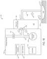
- FIG. 1Aillustrates a negative pressure wound therapy system attached to a wound, according to an exemplary embodiment.
- FIG. 1Bis a block diagram of the negative pressure wound therapy system of FIG. 1A , according to an exemplary embodiment.
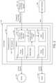
- FIG. 2is a block diagram of the controller of the negative pressure wound therapy system of FIG. 1A , according to an exemplary embodiment.
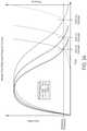
- FIG. 3Ais a model graph representative of changes in pressure and flow rate during an initial draw down of negative pressure wound therapy devices having fluid canisters of differing volumes, according to an exemplary embodiment.
- FIG. 3Bis a table of the pressure measurements on which the model graph of FIG. 3A is based.
- FIG. 3Cis a table of the flow rate measurements on which the model graph of FIG. 3A is based.
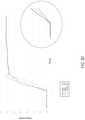
- FIG. 3Dis a graph representative of the pressure measurement values of the table of FIG. 3B .
- FIG. 3Eis a graph representative of the flow rate measurement values of the table of FIG. 3C .
- FIG. 4is a flowchart of a method of operating a negative pressure wound therapy system, according to an exemplary embodiment.
- FIG. 5is a flowchart of a method for estimating a fluid canister volume, according to an exemplary embodiment.
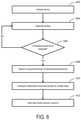
- FIG. 6is a flowchart of a method for estimating a fluid canister volume, according to an exemplary embodiment.
- FIG. 7is a flowchart of a method for estimating a fluid canister volume, according to an exemplary embodiment.
- FIG. 8is a flowchart of a method for verifying a volume of a fluid, according to an exemplary embodiment.
- FIG. 9is a flowchart of a method of operating a negative pressure wound therapy system, according to an exemplary embodiment.
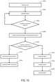
- FIG. 10is a flowchart of a method of operating a negative pressure wound therapy system, according to an exemplary embodiment.
- the NPWT systemgenerally includes a therapy device and a wound dressing.
- a removed fluid canisteris fluidly coupled to each of the therapy device and wound dressing, and is configured to retain fluids (e.g. wound exudate, fluid previously instilled to the wound site during instillation therapy, etc.) removed from the wound site during use of the therapy device.
- the wound therapy deviceis configured to accept and be used with fluid canisters of differing volumes.
- the NPWT systemis configured to estimate the volume of the fluid canister upon initiation of treatment using the NPWT system by observing one or more parameters such as pressure, flow rate, pump ripple decay, etc. as air is evacuated from a negative pressure circuit defined by the wound treatment space volume defined between the wound dressing and a wound site about which the wound dressing is applied, the fluid canister, and fluid tubing extending between the wound site and the fluid canister. These observed changes are compared against previously obtained model data to estimate the volume of the fluid canister.
- the NPWT systemmay provide a more reliable option via which a volume of a canister may be estimated and/or via which a previously obtained volume may be confirmed, and may avoid or entirely prevent errors that could otherwise occur as a result of a canister marker or other identifier representative of a volume of a canister improperly identifying the volume of the canister. Additionally, the ability of the NPWT system to provide a canister volume estimate without requiring that the canister be provided with markings or other volume identifying elements allows the NPWT system to be used to provide volume estimates irrespective of whether the attached canister includes such markings. Furthermore, because the NPWT system is configured to use measurements obtained during an initial draw down of the negative pressure circuit to estimate volume, the NPWT system requires no additional user input to provide such volume estimates than would otherwise be required to operate the NPWT system.
- the NPWT systemmay be used to provide volume estimates independent of any markings provided on a container and intendent of any user input and/or the incorporation of a reader or other scanning element into the NPWT system.
- the NPWT systemmay optionally receive a user input canister volume and/or may include a reader or other scanning element that may be used to read a volume represented by the markings of other volume identifiers provided on a canister that is attached to the therapy device.
- the methods and systems described hereinmay provide the NPWT system with a built in, integrated error-detection system that may alert a user to situations in which there is a discrepancy between the volume estimates.
- the canister volume estimated by the NPWT systemmay be used for any number of purposes, including, e.g. preventing leaks and/or damage to the therapy device; minimizing risks associated with the use of the wound therapy system; monitoring the progress of wound treatment; etc.
- the NPWT systemmay be configured to limit or prevent use of the NPWT system under potentially unsafe conditions during use of the NPWT system in a non-medical setting (e.g., in a home-use setting) or in other situations in which a patient may not be under constant medical supervision.
- the NPWT systemmay be configured to alert a user and/or block operation of the NPWT system in the event that the volume of a canister attached to the therapy device is estimated by the NPWT system to exceed than an upper limit of a quantity of fluid that may be safely evacuated from a wound site.
- the NPWT systemmay prevent a situation in which the use of a large canister with the therapy device would otherwise allow the NPWT system to continue operating to withdraw fluid from the wound site even after this threshold quantity had been exceeded.
- a negative pressure wound therapy (NPWT) system 100is shown according to an exemplary embodiment.
- NPWT system 100is shown to include a therapy device 102 fluidly connected to a wound dressing 112 via a conduit 108 .
- Wound dressing 112may be adhered or sealed to a patient's skin 116 surrounding a wound 115 to define a treatment space 114 .
- wound dressings 112which can be used in combination with NPWT system 100 are described in detail in U.S. Pat. No. 7,651,484 granted Jan. 26, 2010.
- Therapy device 102can be configured to provide negative pressure wound therapy by reducing the pressure within the treatment space 114 .
- Therapy device 102can draw a vacuum within the treatment space 114 (relative to atmospheric pressure) by removing fluids such as wound exudate, air, and other fluids from the wound 115 .
- Wound exudatemay include fluid that filters from a patient's circulatory system into lesions or areas of inflammation.
- wound exudatemay include water and dissolved solutes such as blood, plasma proteins, white blood cells, platelets, and red blood cells.
- Other fluids removed from wound 115may include instillation fluid previously delivered to wound 115 .
- Instillation fluidcan include, for example, a cleansing fluid, a prescribed fluid, a medicated fluid, an antibiotic fluid, or any other type of fluid which can be delivered to wound 115 during wound treatment.
- therapy device 102is configured to deliver instillation fluid to wound 115 , as described in U.S. Provisional Patent Application No. 62/650,132 filed Mar. 29, 2018, the entire disclosure of which is incorporated by reference herein.
- Conduit 108may have a first end coupled to an inlet of the canister 106 and a second end fluidly coupled to the wound treatment space 114 via the wound dressing 112 .
- a restriction element 111may be provided between the opening 109 of the canister 106 and the first end of the conduit 108 and/or elsewhere along the conduit 108 .
- the restriction element 111may define a fixed size opening that is smaller than an opening defined by the inlet of the canister 106 and/or the inlet of the first end of the conduit 108 . In other embodiments, the size of the opening defined by the restriction element 111 may be varied manually and/or automatically as desired.
- the canister 106is configured to collect wound exudate and other fluids removed from wound 115 .
- the canister 106is detachable from therapy device 102 to allow canister 106 to be emptied and replaced as needed.
- the canister 106may be defined by any desired volume, with canisters 106 of differing volumes interchangeably being configured to be attached to and used with the therapy device 102 .
- the canister 106may optionally include one or more markings or other identifiable features via which a user and/or the therapy device 102 may determine the volume of the canister 106 .
- the therapy device 102may optionally include a scanner or other reader configured to read a marking or readable structure provided on or associated with the canister 106 .
- the canister 106may optionally be formed without any markings or other identifiable features indicative of a size or volume of the canister 106 .
- therapy device 102includes a pneumatic pump 120 , and may also optionally include a relief valve 132 , a filter 128 , and a controller 118 .
- Pump 120can be fluidly coupled to canister 106 (e.g., via conduit 126 ) and can be configured to draw a vacuum within canister 106 by pumping air out of canister 106 .
- pump 120is configured to operate in both a forward direction and a reverse direction.
- pump 120can operate in the forward direction to pump air out of canister 106 and decrease the pressure within canister 106 .
- Pump 120can operate in the reverse direction to pump air into canister 106 and increase the pressure within canister 106 and/or to instill fluid to the wound 115 .
- Pump 120can be controlled by controller 118 , described in greater detail below.
- Filter 128can be positioned between canister 106 and pump 120 (e.g., along conduit 126 ) such that the air pumped out of canister 106 passes through filter 128 .
- Filter 128can be configured to prevent liquid or solid particles from entering conduit 126 and reaching pump 120 .
- Filter 128may include, for example, a bacterial filter that is hydrophobic and/or lipophilic such that aqueous and/or oily liquids will bead on the surface of filter 128 .
- Pump 120can be configured to provide sufficient airflow through filter 128 such that the pressure drop across filter 128 is not substantial (e.g., such that the pressure drop will not substantially interfere with the application of negative pressure to the wound treatment space 114 ).
- Valve 132can be fluidly connected with pump 120 and filter 128 via conduit 126 .
- valve 132is configured to control airflow between conduit 126 and the environment around therapy device 102 .
- valve 132can be opened to allow airflow into conduit 126 , and closed to prevent airflow into conduit 126 .
- Valve 132can be opened and closed by controller 118 .
- the negative pressure circuitmay include any component of the NPWT system 100 that can be maintained at a negative pressure when performing negative pressure wound therapy (e.g., conduit 126 , canister 106 , conduit 108 , and/or wound treatment space 114 ).
- therapy device 102includes one or more sensors.
- therapy device 102is shown to include one or more pressure sensors 130 configured to measure the pressure within canister 106 and/or the pressure within the wound treatment space 114 .
- Pressure measurements recorded by pressure sensor 130can be communicated to controller 118 .
- the controller 118may use the pressure measurements from pressure sensor(s) 130 to maintain the wound 115 at a desired negative pressure.
- controller 118can activate pump 120 in response to a pressure measurement from pressure sensor 130 exceeding a negative pressure setpoint in order to reduce the pressure at wound 115 .
- the therapy device 102may additionally, or alternatively, include one or more flow rate sensors 131 configured to measure a rate of airflow into and/or out from the fluid canister 106 and/or conduit 108 .
- controller 118is shown to include a processor 142 and memory 144 .
- Processor 142may be a general purpose or specific purpose processor, an application specific integrated circuit (ASIC), one or more field programmable gate arrays (FPGAs), a group of processing components, or other suitable processing components.
- Processor 142is configured to execute computer code or instructions stored in memory 144 or received from other computer readable media (e.g., CDROM, network storage, a remote server, etc.).
- the processor 142is configured to operate the controller to automatically estimate the volume of a canister 106 that is attached to the therapy device 102 .
- Memory 144may include one or more devices (e.g., memory units, memory devices, storage devices, etc.) for storing data and/or computer code for completing and/or facilitating the various processes described in the present disclosure.
- Memory 144may include random access memory (RAM), read-only memory (ROM), hard drive storage, temporary storage, non-volatile memory, flash memory, optical memory, or any other suitable memory for storing software objects and/or computer instructions.
- Memory 144may include database components, object code components, script components, or any other type of information structure for supporting the various activities and information structures described in the present disclosure.
- Memory 144may be communicably connected to processor 142 and may include computer code for executing (e.g., by processor 142 ) one or more processes described herein. When processor 142 executes instructions stored in memory 144 , processor 142 generally configures controller 118 to complete such activities.
- the memory 144is configured to store canister volume estimation logic 154 , which, when executed, is configured use stored model data 148 and pressure data obtained using pressure sensor 130 , flow rata data obtained using flow rate sensor 131 and/or pump ripple data to estimate a volume of the canister 106 that is attached to the therapy device 102 .
- the canister volume estimation logic 154may optionally additionally be configured to vary the opening defined by the restriction element 111 , such as, e.g., by narrowing the opening of the restriction element 111 during the drawdown of the negative pressure circuit.
- Controller 118is shown to include a pump controller 146 .
- Pump controller 146can be configured to operate pump 120 by generating and providing control signals to pump 120 .
- the control signals provided to pump 120can cause pump 120 to activate, deactivate, or achieve a variable capacity or speed (e.g., operate at half speed, operate at full speed, etc.).
- pump controller 146may receive input from an optionally provided canister sensor configured to detect whether canister 106 is present. Pump controller 146 can be configured to activate pump 120 only when canister 106 is present. For example, pump controller 146 can check whether canister 106 is present and can activate pump 120 in response to a determination that canister 106 is present. However, if canister 106 is not present, pump controller 146 may prevent pump 120 from activating.
- Controller 118is shown to include a pressure monitor 152 .
- Pressure monitor 152can be configured to monitor the pressure within canister 106 and/or the pressure within the wound treatment space 114 using feedback from pressure sensor 130 .
- pressure sensor 130may provide pressure measurements to pressure monitor 152 .
- Pressure monitor 152can use the pressure measurements to determine the pressure within canister 106 and/or the pressure within wound dressing 112 or wound treatment space 114 in real-time.
- the pressure measurement values relied upon in estimating the volume of the fluid canister 106 by the canister volume estimation circuit 154may be pressure measurements provided by the pressure monitor 152 .
- the controller 118may also include a flow rate monitor 153 .
- Flow rate monitor 153can be configured to monitor the flow rate of air into and/or out from the canister 106 a using feedback from flow rate sensor 131 .
- flow rate sensor 131may provide flow rate measurements to flow rate monitor 155 .
- Flow rate monitor 153can use the pressure measurements to determine the rate of flow into and/or out from the canister 106 in real-time.
- the flow rate measurement values relied upon in estimating the volume of the fluid canister 106 by the canister volume estimation circuit 154may be flow rate measurements provided by the flow rate monitor 153 .
- therapy device 102includes a data communications interface 124 (e.g., a USB port, a wireless transceiver, etc.) configured to receive and transmit data.
- Communications interface 124may include wired or wireless communications interfaces (e.g., jacks, antennas, transmitters, receivers, transceivers, wire terminals, etc.) for conducting data communications external systems or devices.
- the communicationsmay be direct (e.g., local wired or wireless communications) or via a communications network (e.g., a WAN, the Internet, a cellular network, etc.).
- communications interface 124can include a USB port or an Ethernet card and port for sending and receiving data via an Ethernet-based communications link or network.
- communications interface 124can include a Wi-Fi transceiver for communicating via a wireless communications network or cellular or mobile phone communications transceivers.
- therapy device 102includes a user interface 136 .
- User interface 136may include one or more buttons, dials, sliders, keys, or other input devices configured to receive input from a user.
- User interface 136may also include one or more display devices (e.g., LEDs, LCD displays, etc.), speakers, tactile feedback devices, or other output devices configured to provide information to a user.
- the pressure measurements recorded by pressure sensor 130 and/or flow rate measurements records by the flow rate sensor 131are presented to a user via user interface 136 .
- User interface 136can also display alerts generated by controller 118 .
- NPWT treatmentis initiated using the NPWT system 100 by closing valve 132 (if included) and operating pump 120 to draw a vacuum within the negative pressure circuit defined by the canister 106 , tubing 108 and wound treatment space 114 defined between the wound 115 and the wound dressing 112 .
- the operation of the pump 120is continued until a desired negative pressure has been attained within the treatment space 114 as, e.g., determined by monitoring pressure using pressure sensor(s) 130 ), at which point operation of the pump 120 may be ceased.
- the NPWT system 100is configured to estimate a volume of the canister 106 attached to (either directly, or via tubing) the therapy device 102 using pressure, flow rate, and/or pump ripple measurement obtained during the initial draw-down of the negative pressure circuit. Following the attainment of the desired negative pressure at the wound space 114 , NPWT treatment using the NPWT system 100 may continue according to any number of desired treatment protocols.
- FIG. 3Aa model graph representative of changes in pressure and flow rate during operation of NPWT systems 100 having varying sized canisters 106 operated under similar operating conditions is shown according to one embodiment.
- the pump 120operates under substantially free flow conditions during an initial phase of the draw down process during which air is being evacuated from the interior of the canister 106 .
- a restriction element 111configured to further narrow and restrict the flow of air being evacuated from the negative pressure circuit may optionally be incorporated between the canister 106 and the conduit 108 .
- the rate of airflowmay be further reduced, resulting in an even more marked and pronounced changed in the measured flow which, which may facilitate the identification of the inflection point in the flow rate curve representative of the time at which all of (or substantially all of) the air in the canister 106 has been evacuated. As illustrated by FIG.
- the time interval between the initiation of the pump 120 and the occurrence of the inflection point in the flow rate curvewill be greater for large canisters 106 than for smaller canisters 106 .
- the inflection point in the pressure curve(representative of the marked increase in pressure occurring upon all, or substantially all, of the air within the canister being evacuated) for a larger container will occur at the later time than the time associated with the inflection point in the pressure curve of smaller canisters 106 .
- the NPWT system 100is configured to utilize the notable and distinguishable inflection points associated with the changing pressure within a canister and the change in the rate of air being evacuated from the negative pressure circuit occurring in response to the evacuation of all (or substantially all) of the air from within a canister, and the variation in the time following initiation of the pump 120 at which these inflection points occur for canisters of differing volumes, to estimate the volume of a canister 106 that is attached to the therapy device 102 .
- the NPWT system 100may be configured to obtain pressure, flow rate and/or pump ripple decay measurements representative of the operation of the NPWT system 100 with canisters of varying volumes and under a variety of different operating conditions (e.g. differing target pressures, differing initial pressure within the negative pressure circuit, relative humidity, differing volumes defined by the conduit 108 and wound treatment space, differing pumps, etc.).
- the pressure and flow rate data of FIGS. 3B and 3Cis representative of the operation of one embodiment of a NPWT system 100 with 300 mL. 500 mL and 1000 mL containers under temperature conditions of approximately 25.2° C. and a relative humidity of approximately 49.8%.
- Graphs representative of the pressure and flow rate data of FIG. 3B and FIG. 3Care provided in FIGS. 3D and 3E , respectively.
- the pressure and flow rate data obtained by the NPWT system 100may exhibit noise owing to any number of different factors, including. e.g. pump ripple. Accordingly, in various embodiments, any number of, or combination of various function approximators, statistical methods, machine learning systems, model generators, etc. may optionally be used to smooth, curve fit, or otherwise process the data to generate model decay curves, such as, e.g., the model decay curves representatively illustrated by the embodiment of the model graph of FIG. 3A .
- canisters 106 of differing volumesexhibit different changes in pressure, flow rate and pump ripple (not shown) over time, during certain intervals during the draw down process, such as, e.g., immediately following the initiation of the pump and/or once the target negative pressure has been substantially attained, the differences between the curves of varying sized canisters may be more difficult to accurately distinguish.
- the NPWT system 100may be configured to identify relevant ranges and/values of flow rate, pressure, ripple decay and/or time that correspond to the inflection points in the flow rate pressure and ripple decay curves against which time, pressure, flow and/or pressure measurements obtained during operation of the NPWT system 100 may be applied to facilitate and increase the accuracy of the estimate of the volume of the canister 106 attached to the therapy device 102 .
- the NPWT system 100is configured to estimate a volume based on one or more parameter measurements obtained following the expiration of a timers (such as, e.g., the method of FIG. 6 and/or the method of FIG.
- the time interval selected for the timermay be selected to correspond to a time range having a lower limit equal to the time at which—according to the model data—an inflection in pressure, flow rate and/or pump ripple is expected to occur for a volume corresponding to the smallest anticipated canister 106 volume that would be expected to be used with the NPWT system 100 and an upper limit equal to the time at which—also according to the model date—an inflection in pressure, flow rate and/or pump ripple is expected to occur for a volume corresponding to the largest anticipated canister 106 volume that would be expected to be used with the NPWT system 100 .
- the pressure value selected as the predetermined pressure valuemay be selected to be between approximately 20% of the pressure at the inflection point on the pressure decay curve.
- the flow rate value selected as the predetermined flow rate valuemay be selected to be between approximately ⁇ 20% of the flow rate at the inflection point on the pressure decay curve.
- the predetermined flow ratemay be between approximately 0.5 L/min and approximately 0.05 L/min. and more specifically, between approximately 0.3 L/min and approximately 0.1 L/min.
- FIGS. 4-10flowcharts of various methods for operating the NPWT system 100 are shown according to various embodiments. Shown in FIG. 4 is a representative embodiment of a method of providing NPWT treatment using the NPWT system 100 according to one embodiment.
- model data representative of changes in pressure, flow rate and/or pump ripple over time during an initial draw down of a negative pressure circuit under a variety of clinically relevant conditions and statese.g. fluid canister volume, wound treatment space volumes, conduit volumes, dressing/foam characteristics, initial pressure within the negative pressure circuit, target negative pressure, etc.
- fluid canister volumee.g. fluid canister volume, wound treatment space volumes, conduit volumes, dressing/foam characteristics, initial pressure within the negative pressure circuit, target negative pressure, etc.
- the model data obtained at step 402may comprise accessing model data 148 previously obtained and stored in the control 118 memory 144 .
- such model datamay be generated using any number of, or combination of various function approximators, statistical method, machine learning systems, etc.
- the model data obtained at step 402may include any number of different pressure decay curves, flow rate curves, pump ripple curves, functions, lookup tables, etc., and may be obtained as pre-existing information that is input and stored by the controller, and/or may be obtained and processed by the controller 118 during an optional, initial training procedure conducted by the controller 118 prior to the use of the NPWT system 100 to treat wound site 114 .
- step 402 of obtaining model datamay be performed as part of the assembly of the NPWT system 100 at the desired treatment site of step 404 .
- various exemplary training procedures by which such relationships may be generated by the controller 118are outlined in related, U.S. Provisional Application 62/650,132, filed Apr. 17, 2018 and titled WOUND THERAPY SYSTEM WITH WOUND VOLUME ESTIMATION, the entire disclosure of which is incorporated by reference herein.
- wound dressing 112is applied to the patient's skin 116 surrounding a wound 115 , and the wound dressing 112 is fluidly connected to a fluid canister 106 that is attached to a therapy device 102 .
- the pump 120is operated to draw a vacuum in the negative pressure circuit.
- the NPWT system 100may optionally be configured to confirm that an initial free flow of air following the initiation of the pump 120 is attributable to the evacuation of air from the fluid canister 106 —as opposed to a problem in the NPWT system 100 .
- the NPWT system 100may be configured to differentiate the initial free flow of evacuated air from a gross leak resulting from the canister 106 being improperly attached to, or entirely omitted from, the therapy device 102 via the incorporation of one or more sensors or other elements configured to detect the attachment of the canister 106 to the therapy device 102 .
- the NPWT system 100may additionally, or alternatively be optionally configured alert a user and/or terminate operation of the NPWT system 100 at step 410 in the event that such a leak in the negative pressure circuit is detected.
- step 412as air is evacuated from the negative pressure circuit during operation of the pump 120 , at least one of a flow rate of the air from the negative pressure circuit, a pressure within the interior of the canister 106 and/or a pump ripple is monitored.
- the measurements obtained from monitoring the one or more parameters during step 412 and the model data obtained at step 402are used by the controller 118 to estimate the volume of the fluid canister 106 . This estimated volume may optionally be recorded at step 416 for future use by the wound therapy system 416 .
- treatment using the NPWT system 100may be continued according to any number of various protocols.
- a method of estimating a volume of a canister 106 using the NPWT system 100is shown according to one embodiment.
- a timeris initiated to mark the start of the operation of the pump 120 at step 504 .
- one or more of the: air flowing out from the negative pressure circuit, the pressure within the canister 106 and/or pump rippleis monitored at step 506 .
- the one or more parametersare monitored until the monitored parameter has attained a predetermined value, at which point, at step 510 , the timer is stopped.
- the predetermined parameter value and the time that was required to attain the determined parameter value as measured at step 510are compared to the model data previously obtained by the NPWT system 100 (such as, e.g. model data 148 stored in the memory 144 ) representative of flow rate, pressure and/or pump ripple decay during operation of NPWT systems having varying sized canister volumes under operating conditions similar to those during step 502 - 510 .
- the volume of the canister 106is estimated based on the identification of a model data set exhibiting a flow rate, pressure and/or pump ripple value reading corresponding to the predetermined value used in step 508 at a time corresponding substantially to the time interval measured at step 510 .
- a method of estimating the volume of a canister 106is shown according to another embodiment.
- a timeris set for a predetermined time.
- operation of the pump 120is initiated at step 604 .
- the predetermined time interval set at step 602may be selected to correspond to a time that is approximately equal to an estimated time that would be required to evacuate air from within the interior of the smallest size canister with which the NPWT system 100 would be expected to be used. Operation of the pump 120 is continued until the time interval set at step 602 has been determined to have expired at step 606 .
- a measurement of at least one or more of the flow rate of air being evacuated from the negative pressure circuit, the pressure in the canister 106 and/or pump rippleis obtained, (e.g., using flow rate sensor(s) 131 and/or pressure sensor(s) 130 ).
- the time interval set at step 602 and the parameter measurement obtained at step 608are compared to the model data previously obtained by the NPWT system 100 (such as, e.g. model data 148 stored in the memory 144 ) representative of flow rate, pressure and/or pump ripple decay during operation of NPWT systems having varying sized canister volumes under operating conditions similar to those during step 602 - 608 .
- the volume of the canister 106is estimated based on the identification of a model data set exhibiting a flow rate, pressure and/or pump ripple value reading corresponding to the parameter measurement obtained at step 608 at a time corresponding to the time interval set at step 602 .
- measured flow rate, pressure and/or pump ripple measurementsmay be compared in real-time to previously obtained model data 148 .
- a real-time comparison of the measured parameters to the model datamay continue until sufficient data has been acquired to determine a statistically meaningful canister 106 volume estimate based on the identification of a model data decay curve that exhibits similar decay to that of the real-time parameter readings obtained at step 704 .
- any number of different types of statistical modeling and analysismay be used as real-time measurements are obtained at step 704 and compared against the model data at step 706 to address any noise in the acquired data and/or to address discrepancies or variations between the acquired parameter measurements and the model data 148 .
- the volume of the canister 106 attached to the therapy device 102may have previously been obtained using any other number of markings provided on the canister 106 and/or other systems for measuring volume.
- the previously obtained volume measurementmay be verified against the canister 106 volume estimated at step 802 .
- an alertmay be generated in the event of a discrepancy between the canister 106 volume estimated at step 804 and the canister volume previously obtained using markings provided on the canister 106 and/or other systems for measuring volume. Otherwise, at step 808 , the verified fluid canister 106 volume may optionally be recorded at step 808 , and operation of the NPWT system 100 may continue at 810 as desired.
- the therapy device 102may be advantageous to prevent use of the therapy device 102 with a fluid canister 106 having a volume that exceeds a predetermined threshold volume, such as, e.g. 500 mL.
- a predetermined threshold volumesuch as, e.g. 500 mL.
- the estimated canister 106 volumemay be compared against the predetermined maximum canister volume at step 904 .
- the estimated canister 106 volumemay be recorded, and at step 908 operation of the NPWT system 100 may be continued as desired (such as, e.g., to provide NPWT to a patient in a home, or other medically unsupervised setting).
- an alertmay be generated.
- the alert generated 910 at stepmay be communicated to one or both of the patient, a medical provider, and/or any other number of individuals that may be involved in the treatment provided by the NPWT system 100 .
- the NPWT system 100may optionally be disabled (either permanently, for a predetermined time, or until re-enabled by an authorized user) to prevent the use of the NPWT system 100 .
- an alert indicating the disablement of the NPWT system 100may optionally be provided to a medical provider and/or any number of other individuals that may be involved in the treatment provided by the NPWT system 100 .
- the method of FIG. 9has been described as being used to prevent the use of the NPWT system 100 with a canister 106 having an estimated volume that exceeds a predetermined maximum allowed volume, according to other embodiments, the method of FIG. 9 may be modified to instead be used to prevent the use of the NPWT system 100 in the event that the volume of the canister 106 is estimated to be less than a minimum, predetermined threshold volume.
- the volume of the canister 106may be used solely for purposes of determining whether a canister 106 exceeds (or alternatively, is less than) an allowed (or required) threshold volume. Accordingly, as illustrated in FIG. 10 , in some embodiments, a method of operating the NPWT system 100 may omit the step of estimating the volume of the canister 106 , and instead may instead be configured to provide a binary assessment as to whether or not the volume of a canister 106 exceeds (or is less than) a threshold volume.
- a timermay be set for a predetermined interval.
- operation of the pump 120is initiated at step 1004 .
- the pump 120continues to operate until the expiration of the time interval set at step 1002 , at which point, at step 1008 , a measurement of at least one of the flow rate of air being evacuated from the negative pressure circuit, the pressure within the canister 106 and/or pump ripple is obtained.
- the parameter measurement(s) obtained at step 1008is compared against a threshold parameter value to provide a binary distinction as to whether the canister 106 volume exceeds a predetermined maximum volume.
- the predetermined parameter value against which the parameter measurement obtained at step 1008 is comparedcorresponds to the expected parameter value that would be measured during operation of the NPWT system 100 having a fluid canister defining the predetermined maximum volume at the same time following the initial operation of the NPWT system pump as the time interval at which the parameter measurement was obtained at step 1008 .
- the determination of the measure parameter value being greater than or less than the threshold parameter valuewill be sufficient for the NPWT system 100 to determine whether to permit continued operation of the wound therapy system at step 1012 and 1014 , or whether to generate an alarm at step 1016 and optionally disable the system at step 1018 and alert a provide or other individual at step 1020 .
- the present disclosurecontemplates methods, systems and program products on any machine-readable media for accomplishing various operations.
- the embodiments of the present disclosurecan be implemented using existing computer processors, or by a special purpose computer processor for an appropriate system, incorporated for this or another purpose, or by a hardwired system.
- Embodiments within the scope of the present disclosureinclude program products comprising machine-readable media for carrying or having machine-executable instructions or data structures stored thereon.
- Such machine-readable mediacan be any available media that can be accessed by a general purpose or special purpose computer or other machine with a processor.
- Such machine-readable mediacan comprise RAM. ROM, EPROM.
- Machine-executable instructionsinclude, for example, instructions and data which cause a general purpose computer, special purpose computer, or special purpose processing machines to perform a certain function or group of functions.
Landscapes
- Health & Medical Sciences (AREA)
- Heart & Thoracic Surgery (AREA)
- Vascular Medicine (AREA)
- Engineering & Computer Science (AREA)
- Anesthesiology (AREA)
- Biomedical Technology (AREA)
- Hematology (AREA)
- Life Sciences & Earth Sciences (AREA)
- Animal Behavior & Ethology (AREA)
- General Health & Medical Sciences (AREA)
- Public Health (AREA)
- Veterinary Medicine (AREA)
- External Artificial Organs (AREA)
Abstract
Description
Claims (24)
Priority Applications (1)
| Application Number | Priority Date | Filing Date | Title |
|---|---|---|---|
| US16/365,481US11266770B2 (en) | 2019-03-11 | 2019-03-26 | Wound therapy system with fluid canister volume detection |
Applications Claiming Priority (2)
| Application Number | Priority Date | Filing Date | Title |
|---|---|---|---|
| US201962816704P | 2019-03-11 | 2019-03-11 | |
| US16/365,481US11266770B2 (en) | 2019-03-11 | 2019-03-26 | Wound therapy system with fluid canister volume detection |
Publications (2)
| Publication Number | Publication Date |
|---|---|
| US20200289719A1 US20200289719A1 (en) | 2020-09-17 |
| US11266770B2true US11266770B2 (en) | 2022-03-08 |
Family
ID=66102279
Family Applications (1)
| Application Number | Title | Priority Date | Filing Date |
|---|---|---|---|
| US16/365,481Active2040-03-02US11266770B2 (en) | 2019-03-11 | 2019-03-26 | Wound therapy system with fluid canister volume detection |
Country Status (3)
| Country | Link |
|---|---|
| US (1) | US11266770B2 (en) |
| EP (1) | EP3938003B1 (en) |
| WO (1) | WO2020185241A1 (en) |
Families Citing this family (2)
| Publication number | Priority date | Publication date | Assignee | Title |
|---|---|---|---|---|
| SE546314C2 (en)* | 2020-10-19 | 2024-10-01 | Thoragen Ab | Improved body drainage apparatus |
| EP4593907A1 (en)* | 2022-09-27 | 2025-08-06 | T.J. Smith and Nephew, Limited | Canister status determination for negative pressure wound therapy devices |
Citations (115)
| Publication number | Priority date | Publication date | Assignee | Title |
|---|---|---|---|---|
| US1355846A (en) | 1920-02-06 | 1920-10-19 | David A Rannells | Medical appliance |
| US2547758A (en) | 1949-01-05 | 1951-04-03 | Wilmer B Keeling | Instrument for treating the male urethra |
| US2632443A (en) | 1949-04-18 | 1953-03-24 | Eleanor P Lesher | Surgical dressing |
| GB692578A (en) | 1949-09-13 | 1953-06-10 | Minnesota Mining & Mfg | Improvements in or relating to drape sheets for surgical use |
| US2682873A (en) | 1952-07-30 | 1954-07-06 | Johnson & Johnson | General purpose protective dressing |
| US2910763A (en) | 1955-08-17 | 1959-11-03 | Du Pont | Felt-like products |
| US2969057A (en) | 1957-11-04 | 1961-01-24 | Brady Co W H | Nematodic swab |
| US3066672A (en) | 1960-09-27 | 1962-12-04 | Jr William H Crosby | Method and apparatus for serial sampling of intestinal juice |
| US3367332A (en) | 1965-08-27 | 1968-02-06 | Gen Electric | Product and process for establishing a sterile area of skin |
| DE2640413A1 (en) | 1976-09-08 | 1978-03-09 | Wolf Gmbh Richard | CATHETER MONITORING DEVICE |
| WO1980002182A1 (en) | 1979-04-06 | 1980-10-16 | J Moss | Portable suction device for collecting fluids from a closed wound |
| US4245630A (en) | 1976-10-08 | 1981-01-20 | T. J. Smith & Nephew, Ltd. | Tearable composite strip of materials |
| US4256109A (en) | 1978-07-10 | 1981-03-17 | Nichols Robert L | Shut off valve for medical suction apparatus |
| US4261363A (en) | 1979-11-09 | 1981-04-14 | C. R. Bard, Inc. | Retention clips for body fluid drains |
| US4275721A (en) | 1978-11-28 | 1981-06-30 | Landstingens Inkopscentral Lic, Ekonomisk Forening | Vein catheter bandage |
| US4284079A (en) | 1979-06-28 | 1981-08-18 | Adair Edwin Lloyd | Method for applying a male incontinence device |
| US4297995A (en) | 1980-06-03 | 1981-11-03 | Key Pharmaceuticals, Inc. | Bandage containing attachment post |
| US4333468A (en) | 1980-08-18 | 1982-06-08 | Geist Robert W | Mesentery tube holder apparatus |
| US4373519A (en) | 1981-06-26 | 1983-02-15 | Minnesota Mining And Manufacturing Company | Composite wound dressing |
| US4382441A (en) | 1978-12-06 | 1983-05-10 | Svedman Paul | Device for treating tissues, for example skin |
| US4392858A (en) | 1981-07-16 | 1983-07-12 | Sherwood Medical Company | Wound drainage device |
| US4392853A (en) | 1981-03-16 | 1983-07-12 | Rudolph Muto | Sterile assembly for protecting and fastening an indwelling device |
| US4419097A (en) | 1981-07-31 | 1983-12-06 | Rexar Industries, Inc. | Attachment for catheter tube |
| EP0100148A1 (en) | 1982-07-06 | 1984-02-08 | Dow Corning Limited | Medical-surgical dressing and a process for the production thereof |
| US4465485A (en) | 1981-03-06 | 1984-08-14 | Becton, Dickinson And Company | Suction canister with unitary shut-off valve and filter features |
| EP0117632A2 (en) | 1983-01-27 | 1984-09-05 | Johnson & Johnson Products Inc. | Adhesive film dressing |
| US4475909A (en) | 1982-05-06 | 1984-10-09 | Eisenberg Melvin I | Male urinary device and method for applying the device |
| US4480638A (en) | 1980-03-11 | 1984-11-06 | Eduard Schmid | Cushion for holding an element of grafted skin |
| US4525374A (en) | 1984-02-27 | 1985-06-25 | Manresa, Inc. | Treating hydrophobic filters to render them hydrophilic |
| US4525166A (en) | 1981-11-21 | 1985-06-25 | Intermedicat Gmbh | Rolled flexible medical suction drainage device |
| US4540412A (en) | 1983-07-14 | 1985-09-10 | The Kendall Company | Device for moist heat therapy |
| US4543100A (en) | 1983-11-01 | 1985-09-24 | Brodsky Stuart A | Catheter and drain tube retainer |
| US4548202A (en) | 1983-06-20 | 1985-10-22 | Ethicon, Inc. | Mesh tissue fasteners |
| US4551139A (en) | 1982-02-08 | 1985-11-05 | Marion Laboratories, Inc. | Method and apparatus for burn wound treatment |
| EP0161865A2 (en) | 1984-05-03 | 1985-11-21 | Smith and Nephew Associated Companies p.l.c. | Adhesive wound dressing |
| US4569348A (en) | 1980-02-22 | 1986-02-11 | Velcro Usa Inc. | Catheter tube holder strap |
| AU550575B2 (en) | 1981-08-07 | 1986-03-27 | Richard Christian Wright | Wound drainage device |
| US4605399A (en) | 1984-12-04 | 1986-08-12 | Complex, Inc. | Transdermal infusion device |
| US4608041A (en) | 1981-10-14 | 1986-08-26 | Frese Nielsen | Device for treatment of wounds in body tissue of patients by exposure to jets of gas |
| US4640688A (en) | 1985-08-23 | 1987-02-03 | Mentor Corporation | Urine collection catheter |
| US4655754A (en) | 1984-11-09 | 1987-04-07 | Stryker Corporation | Vacuum wound drainage system and lipids baffle therefor |
| US4664662A (en) | 1984-08-02 | 1987-05-12 | Smith And Nephew Associated Companies Plc | Wound dressing |
| WO1987004626A1 (en) | 1986-01-31 | 1987-08-13 | Osmond, Roger, L., W. | Suction system for wound and gastro-intestinal drainage |
| US4710165A (en) | 1985-09-16 | 1987-12-01 | Mcneil Charles B | Wearable, variable rate suction/collection device |
| US4733659A (en) | 1986-01-17 | 1988-03-29 | Seton Company | Foam bandage |
| GB2195255A (en) | 1986-09-30 | 1988-04-07 | Vacutec Uk Limited | Method and apparatus for vacuum treatment of an epidermal surface |
| US4743232A (en) | 1986-10-06 | 1988-05-10 | The Clinipad Corporation | Package assembly for plastic film bandage |
| GB2197789A (en) | 1986-11-28 | 1988-06-02 | Smiths Industries Plc | Anti-foaming disinfectants used in surgical suction apparatus |
| US4758220A (en) | 1985-09-26 | 1988-07-19 | Alcon Laboratories, Inc. | Surgical cassette proximity sensing and latching apparatus |
| US4787888A (en) | 1987-06-01 | 1988-11-29 | University Of Connecticut | Disposable piezoelectric polymer bandage for percutaneous delivery of drugs and method for such percutaneous delivery (a) |
| US4826494A (en) | 1984-11-09 | 1989-05-02 | Stryker Corporation | Vacuum wound drainage system |
| US4838883A (en) | 1986-03-07 | 1989-06-13 | Nissho Corporation | Urine-collecting device |
| US4840187A (en) | 1986-09-11 | 1989-06-20 | Bard Limited | Sheath applicator |
| US4863449A (en) | 1987-07-06 | 1989-09-05 | Hollister Incorporated | Adhesive-lined elastic condom cathether |
| US4872450A (en) | 1984-08-17 | 1989-10-10 | Austad Eric D | Wound dressing and method of forming same |
| US4878901A (en) | 1986-10-10 | 1989-11-07 | Sachse Hans Ernst | Condom catheter, a urethral catheter for the prevention of ascending infections |
| GB2220357A (en) | 1988-05-28 | 1990-01-10 | Smiths Industries Plc | Medico-surgical containers |
| US4897081A (en) | 1984-05-25 | 1990-01-30 | Thermedics Inc. | Percutaneous access device |
| US4906240A (en) | 1988-02-01 | 1990-03-06 | Matrix Medica, Inc. | Adhesive-faced porous absorbent sheet and method of making same |
| US4906233A (en) | 1986-05-29 | 1990-03-06 | Terumo Kabushiki Kaisha | Method of securing a catheter body to a human skin surface |
| US4919654A (en) | 1988-08-03 | 1990-04-24 | Kalt Medical Corporation | IV clamp with membrane |
| CA2005436A1 (en) | 1988-12-13 | 1990-06-13 | Glenda G. Kalt | Transparent tracheostomy tube dressing |
| US4941882A (en) | 1987-03-14 | 1990-07-17 | Smith And Nephew Associated Companies, P.L.C. | Adhesive dressing for retaining a cannula on the skin |
| US4953565A (en) | 1986-11-26 | 1990-09-04 | Shunro Tachibana | Endermic application kits for external medicines |
| WO1990010424A1 (en) | 1989-03-16 | 1990-09-20 | Smith & Nephew Plc | Absorbent devices and precursors therefor |
| US4969880A (en) | 1989-04-03 | 1990-11-13 | Zamierowski David S | Wound dressing and treatment method |
| US4985019A (en) | 1988-03-11 | 1991-01-15 | Michelson Gary K | X-ray marker |
| GB2235877A (en) | 1989-09-18 | 1991-03-20 | Antonio Talluri | Closed wound suction apparatus |
| US5037397A (en) | 1985-05-03 | 1991-08-06 | Medical Distributors, Inc. | Universal clamp |
| US5086170A (en) | 1989-01-16 | 1992-02-04 | Roussel Uclaf | Process for the preparation of azabicyclo compounds |
| US5092858A (en) | 1990-03-20 | 1992-03-03 | Becton, Dickinson And Company | Liquid gelling agent distributor device |
| US5100396A (en) | 1989-04-03 | 1992-03-31 | Zamierowski David S | Fluidic connection system and method |
| US5134994A (en) | 1990-02-12 | 1992-08-04 | Say Sam L | Field aspirator in a soft pack with externally mounted container |
| US5149331A (en) | 1991-05-03 | 1992-09-22 | Ariel Ferdman | Method and device for wound closure |
| US5167613A (en) | 1992-03-23 | 1992-12-01 | The Kendall Company | Composite vented wound dressing |
| US5176663A (en) | 1987-12-02 | 1993-01-05 | Pal Svedman | Dressing having pad with compressibility limiting elements |
| WO1993009727A1 (en) | 1991-11-14 | 1993-05-27 | Wake Forest University | Method and apparatus for treating tissue damage |
| US5215522A (en) | 1984-07-23 | 1993-06-01 | Ballard Medical Products | Single use medical aspirating device and method |
| US5232453A (en) | 1989-07-14 | 1993-08-03 | E. R. Squibb & Sons, Inc. | Catheter holder |
| US5261893A (en) | 1989-04-03 | 1993-11-16 | Zamierowski David S | Fastening system and method |
| US5278100A (en) | 1991-11-08 | 1994-01-11 | Micron Technology, Inc. | Chemical vapor deposition technique for depositing titanium silicide on semiconductor wafers |
| US5279550A (en) | 1991-12-19 | 1994-01-18 | Gish Biomedical, Inc. | Orthopedic autotransfusion system |
| US5298015A (en) | 1989-07-11 | 1994-03-29 | Nippon Zeon Co., Ltd. | Wound dressing having a porous structure |
| US5342376A (en) | 1993-05-03 | 1994-08-30 | Dermagraphics, Inc. | Inserting device for a barbed tissue connector |
| US5344415A (en) | 1993-06-15 | 1994-09-06 | Deroyal Industries, Inc. | Sterile system for dressing vascular access site |
| DE4306478A1 (en) | 1993-03-02 | 1994-09-08 | Wolfgang Dr Wagner | Drainage device, in particular pleural drainage device, and drainage method |
| WO1994020041A1 (en) | 1993-03-09 | 1994-09-15 | Wake Forest University | Wound treatment employing reduced pressure |
| US5358494A (en) | 1989-07-11 | 1994-10-25 | Svedman Paul | Irrigation dressing |
| US5437622A (en) | 1992-04-29 | 1995-08-01 | Laboratoire Hydrex (Sa) | Transparent adhesive dressing with reinforced starter cuts |
| US5437651A (en) | 1993-09-01 | 1995-08-01 | Research Medical, Inc. | Medical suction apparatus |
| DE29504378U1 (en) | 1995-03-15 | 1995-09-14 | MTG Medizinisch, technische Gerätebau GmbH, 66299 Friedrichsthal | Electronically controlled low-vacuum pump for chest and wound drainage |
| WO1996005873A1 (en) | 1994-08-22 | 1996-02-29 | Kinetic Concepts Inc. | Wound drainage equipment |
| US5527293A (en) | 1989-04-03 | 1996-06-18 | Kinetic Concepts, Inc. | Fastening system and method |
| US5549584A (en) | 1994-02-14 | 1996-08-27 | The Kendall Company | Apparatus for removing fluid from a wound |
| US5556375A (en) | 1994-06-16 | 1996-09-17 | Hercules Incorporated | Wound dressing having a fenestrated base layer |
| US5607388A (en) | 1994-06-16 | 1997-03-04 | Hercules Incorporated | Multi-purpose wound dressing |
| WO1997018007A1 (en) | 1995-11-14 | 1997-05-22 | Kci Medical Limited | Portable wound treatment apparatus |
| GB2329127A (en) | 1997-09-12 | 1999-03-17 | Kci Medical Ltd | Suction head and drape wound treatment assembly |
| US6071267A (en) | 1998-02-06 | 2000-06-06 | Kinetic Concepts, Inc. | Medical patient fluid management interface system and method |
| US6135116A (en) | 1997-07-28 | 2000-10-24 | Kci Licensing, Inc. | Therapeutic method for treating ulcers |
| US6241747B1 (en) | 1993-05-03 | 2001-06-05 | Quill Medical, Inc. | Barbed Bodily tissue connector |
| US6287316B1 (en) | 1999-03-26 | 2001-09-11 | Ethicon, Inc. | Knitted surgical mesh |
| US20020077661A1 (en) | 2000-12-20 | 2002-06-20 | Vahid Saadat | Multi-barbed device for retaining tissue in apposition and methods of use |
| US20020115951A1 (en) | 2001-02-22 | 2002-08-22 | Core Products International, Inc. | Ankle brace providing upper and lower ankle adjustment |
| US20020120185A1 (en) | 2000-05-26 | 2002-08-29 | Kci Licensing, Inc. | System for combined transcutaneous blood gas monitoring and vacuum assisted wound closure |
| US20020143286A1 (en) | 2001-03-05 | 2002-10-03 | Kci Licensing, Inc. | Vacuum assisted wound treatment apparatus and infection identification system and method |
| US6488643B1 (en) | 1998-10-08 | 2002-12-03 | Kci Licensing, Inc. | Wound healing foot wrap |
| US6493568B1 (en) | 1994-07-19 | 2002-12-10 | Kci Licensing, Inc. | Patient interface system |
| AU755496B2 (en) | 1997-09-12 | 2002-12-12 | Kci Licensing, Inc. | Surgical drape and suction head for wound treatment |
| JP4129536B2 (en) | 2000-02-24 | 2008-08-06 | ヴェネテック インターナショナル,インコーポレイテッド | Highly compatible catheter anchoring system |
| US20130150813A1 (en) | 2007-07-02 | 2013-06-13 | Smith & Nephew Plc | Systems and methods for controlling operation of negative pressure wound therapy apparatus |
| US20160015872A1 (en) | 2014-07-18 | 2016-01-21 | Kci Licensing, Inc. | Disposable cartridge for vacuum actuated fluid delivery |
| EP3222300A1 (en) | 2006-09-19 | 2017-09-27 | KCI Licensing, Inc. | System for determining a fill status of a canister of fluid in a reduced pressure treatment system |
| US20180135235A1 (en)* | 2016-11-14 | 2018-05-17 | Haier Us Appliance Solutions, Inc. | Dryer appliance and method of operation |
| US20200061253A1 (en)* | 2018-08-21 | 2020-02-27 | Kci Licensing, Inc. | System and method for utilizing pressure decay to determine available fluid capacity in a negative pressure dressing |
Family Cites Families (2)
| Publication number | Priority date | Publication date | Assignee | Title |
|---|---|---|---|---|
| EP1986718B1 (en) | 2006-02-06 | 2015-10-28 | KCI Licensing, Inc. | Systems for improved connection to wound dressings in conjunction with reduced pressure wound treatment systems |
| US8394081B2 (en) | 2010-01-29 | 2013-03-12 | Kci Licensing, Inc. | Wound treatment apparatuses and methods for controlled delivery of fluids to a wound |
- 2019
- 2019-03-26USUS16/365,481patent/US11266770B2/enactiveActive
- 2019-03-26WOPCT/US2019/024133patent/WO2020185241A1/ennot_activeCeased
- 2019-03-26EPEP19716705.9Apatent/EP3938003B1/enactiveActive
Patent Citations (127)
| Publication number | Priority date | Publication date | Assignee | Title |
|---|---|---|---|---|
| US1355846A (en) | 1920-02-06 | 1920-10-19 | David A Rannells | Medical appliance |
| US2547758A (en) | 1949-01-05 | 1951-04-03 | Wilmer B Keeling | Instrument for treating the male urethra |
| US2632443A (en) | 1949-04-18 | 1953-03-24 | Eleanor P Lesher | Surgical dressing |
| GB692578A (en) | 1949-09-13 | 1953-06-10 | Minnesota Mining & Mfg | Improvements in or relating to drape sheets for surgical use |
| US2682873A (en) | 1952-07-30 | 1954-07-06 | Johnson & Johnson | General purpose protective dressing |
| US2910763A (en) | 1955-08-17 | 1959-11-03 | Du Pont | Felt-like products |
| US2969057A (en) | 1957-11-04 | 1961-01-24 | Brady Co W H | Nematodic swab |
| US3066672A (en) | 1960-09-27 | 1962-12-04 | Jr William H Crosby | Method and apparatus for serial sampling of intestinal juice |
| US3367332A (en) | 1965-08-27 | 1968-02-06 | Gen Electric | Product and process for establishing a sterile area of skin |
| DE2640413A1 (en) | 1976-09-08 | 1978-03-09 | Wolf Gmbh Richard | CATHETER MONITORING DEVICE |
| US4245630A (en) | 1976-10-08 | 1981-01-20 | T. J. Smith & Nephew, Ltd. | Tearable composite strip of materials |
| US4256109A (en) | 1978-07-10 | 1981-03-17 | Nichols Robert L | Shut off valve for medical suction apparatus |
| US4275721A (en) | 1978-11-28 | 1981-06-30 | Landstingens Inkopscentral Lic, Ekonomisk Forening | Vein catheter bandage |
| US4382441A (en) | 1978-12-06 | 1983-05-10 | Svedman Paul | Device for treating tissues, for example skin |
| WO1980002182A1 (en) | 1979-04-06 | 1980-10-16 | J Moss | Portable suction device for collecting fluids from a closed wound |
| US4284079A (en) | 1979-06-28 | 1981-08-18 | Adair Edwin Lloyd | Method for applying a male incontinence device |
| US4261363A (en) | 1979-11-09 | 1981-04-14 | C. R. Bard, Inc. | Retention clips for body fluid drains |
| US4569348A (en) | 1980-02-22 | 1986-02-11 | Velcro Usa Inc. | Catheter tube holder strap |
| US4480638A (en) | 1980-03-11 | 1984-11-06 | Eduard Schmid | Cushion for holding an element of grafted skin |
| US4297995A (en) | 1980-06-03 | 1981-11-03 | Key Pharmaceuticals, Inc. | Bandage containing attachment post |
| US4333468A (en) | 1980-08-18 | 1982-06-08 | Geist Robert W | Mesentery tube holder apparatus |
| US4465485A (en) | 1981-03-06 | 1984-08-14 | Becton, Dickinson And Company | Suction canister with unitary shut-off valve and filter features |
| US4392853A (en) | 1981-03-16 | 1983-07-12 | Rudolph Muto | Sterile assembly for protecting and fastening an indwelling device |
| US4373519A (en) | 1981-06-26 | 1983-02-15 | Minnesota Mining And Manufacturing Company | Composite wound dressing |
| US4392858A (en) | 1981-07-16 | 1983-07-12 | Sherwood Medical Company | Wound drainage device |
| US4419097A (en) | 1981-07-31 | 1983-12-06 | Rexar Industries, Inc. | Attachment for catheter tube |
| AU550575B2 (en) | 1981-08-07 | 1986-03-27 | Richard Christian Wright | Wound drainage device |
| US4608041A (en) | 1981-10-14 | 1986-08-26 | Frese Nielsen | Device for treatment of wounds in body tissue of patients by exposure to jets of gas |
| US4525166A (en) | 1981-11-21 | 1985-06-25 | Intermedicat Gmbh | Rolled flexible medical suction drainage device |
| US4551139A (en) | 1982-02-08 | 1985-11-05 | Marion Laboratories, Inc. | Method and apparatus for burn wound treatment |
| US4475909A (en) | 1982-05-06 | 1984-10-09 | Eisenberg Melvin I | Male urinary device and method for applying the device |
| EP0100148A1 (en) | 1982-07-06 | 1984-02-08 | Dow Corning Limited | Medical-surgical dressing and a process for the production thereof |
| EP0117632A2 (en) | 1983-01-27 | 1984-09-05 | Johnson & Johnson Products Inc. | Adhesive film dressing |
| US4548202A (en) | 1983-06-20 | 1985-10-22 | Ethicon, Inc. | Mesh tissue fasteners |
| US4540412A (en) | 1983-07-14 | 1985-09-10 | The Kendall Company | Device for moist heat therapy |
| US4543100A (en) | 1983-11-01 | 1985-09-24 | Brodsky Stuart A | Catheter and drain tube retainer |
| US4525374A (en) | 1984-02-27 | 1985-06-25 | Manresa, Inc. | Treating hydrophobic filters to render them hydrophilic |
| EP0161865A2 (en) | 1984-05-03 | 1985-11-21 | Smith and Nephew Associated Companies p.l.c. | Adhesive wound dressing |
| US4897081A (en) | 1984-05-25 | 1990-01-30 | Thermedics Inc. | Percutaneous access device |
| US5215522A (en) | 1984-07-23 | 1993-06-01 | Ballard Medical Products | Single use medical aspirating device and method |
| US4664662A (en) | 1984-08-02 | 1987-05-12 | Smith And Nephew Associated Companies Plc | Wound dressing |
| US4872450A (en) | 1984-08-17 | 1989-10-10 | Austad Eric D | Wound dressing and method of forming same |
| US4826494A (en) | 1984-11-09 | 1989-05-02 | Stryker Corporation | Vacuum wound drainage system |
| US4655754A (en) | 1984-11-09 | 1987-04-07 | Stryker Corporation | Vacuum wound drainage system and lipids baffle therefor |
| US4605399A (en) | 1984-12-04 | 1986-08-12 | Complex, Inc. | Transdermal infusion device |
| US5037397A (en) | 1985-05-03 | 1991-08-06 | Medical Distributors, Inc. | Universal clamp |
| US4640688A (en) | 1985-08-23 | 1987-02-03 | Mentor Corporation | Urine collection catheter |
| US4710165A (en) | 1985-09-16 | 1987-12-01 | Mcneil Charles B | Wearable, variable rate suction/collection device |
| US4758220A (en) | 1985-09-26 | 1988-07-19 | Alcon Laboratories, Inc. | Surgical cassette proximity sensing and latching apparatus |
| US4733659A (en) | 1986-01-17 | 1988-03-29 | Seton Company | Foam bandage |
| WO1987004626A1 (en) | 1986-01-31 | 1987-08-13 | Osmond, Roger, L., W. | Suction system for wound and gastro-intestinal drainage |
| US4838883A (en) | 1986-03-07 | 1989-06-13 | Nissho Corporation | Urine-collecting device |
| US4906233A (en) | 1986-05-29 | 1990-03-06 | Terumo Kabushiki Kaisha | Method of securing a catheter body to a human skin surface |
| US4840187A (en) | 1986-09-11 | 1989-06-20 | Bard Limited | Sheath applicator |
| GB2195255A (en) | 1986-09-30 | 1988-04-07 | Vacutec Uk Limited | Method and apparatus for vacuum treatment of an epidermal surface |
| US4743232A (en) | 1986-10-06 | 1988-05-10 | The Clinipad Corporation | Package assembly for plastic film bandage |
| US4878901A (en) | 1986-10-10 | 1989-11-07 | Sachse Hans Ernst | Condom catheter, a urethral catheter for the prevention of ascending infections |
| US4953565A (en) | 1986-11-26 | 1990-09-04 | Shunro Tachibana | Endermic application kits for external medicines |
| GB2197789A (en) | 1986-11-28 | 1988-06-02 | Smiths Industries Plc | Anti-foaming disinfectants used in surgical suction apparatus |
| US4941882A (en) | 1987-03-14 | 1990-07-17 | Smith And Nephew Associated Companies, P.L.C. | Adhesive dressing for retaining a cannula on the skin |
| US4787888A (en) | 1987-06-01 | 1988-11-29 | University Of Connecticut | Disposable piezoelectric polymer bandage for percutaneous delivery of drugs and method for such percutaneous delivery (a) |
| US4863449A (en) | 1987-07-06 | 1989-09-05 | Hollister Incorporated | Adhesive-lined elastic condom cathether |
| US5176663A (en) | 1987-12-02 | 1993-01-05 | Pal Svedman | Dressing having pad with compressibility limiting elements |
| US4906240A (en) | 1988-02-01 | 1990-03-06 | Matrix Medica, Inc. | Adhesive-faced porous absorbent sheet and method of making same |
| US4985019A (en) | 1988-03-11 | 1991-01-15 | Michelson Gary K | X-ray marker |
| GB2220357A (en) | 1988-05-28 | 1990-01-10 | Smiths Industries Plc | Medico-surgical containers |
| EP0358302A2 (en) | 1988-05-28 | 1990-03-14 | Smiths Industries Public Limited Company | Medico-surgical suction container |
| US4919654A (en) | 1988-08-03 | 1990-04-24 | Kalt Medical Corporation | IV clamp with membrane |
| CA2005436A1 (en) | 1988-12-13 | 1990-06-13 | Glenda G. Kalt | Transparent tracheostomy tube dressing |
| US5086170A (en) | 1989-01-16 | 1992-02-04 | Roussel Uclaf | Process for the preparation of azabicyclo compounds |
| WO1990010424A1 (en) | 1989-03-16 | 1990-09-20 | Smith & Nephew Plc | Absorbent devices and precursors therefor |
| US5100396A (en) | 1989-04-03 | 1992-03-31 | Zamierowski David S | Fluidic connection system and method |
| US4969880A (en) | 1989-04-03 | 1990-11-13 | Zamierowski David S | Wound dressing and treatment method |
| US5527293A (en) | 1989-04-03 | 1996-06-18 | Kinetic Concepts, Inc. | Fastening system and method |
| US5261893A (en) | 1989-04-03 | 1993-11-16 | Zamierowski David S | Fastening system and method |
| US5298015A (en) | 1989-07-11 | 1994-03-29 | Nippon Zeon Co., Ltd. | Wound dressing having a porous structure |
| US5358494A (en) | 1989-07-11 | 1994-10-25 | Svedman Paul | Irrigation dressing |
| US5232453A (en) | 1989-07-14 | 1993-08-03 | E. R. Squibb & Sons, Inc. | Catheter holder |
| GB2235877A (en) | 1989-09-18 | 1991-03-20 | Antonio Talluri | Closed wound suction apparatus |
| US5134994A (en) | 1990-02-12 | 1992-08-04 | Say Sam L | Field aspirator in a soft pack with externally mounted container |
| US5092858A (en) | 1990-03-20 | 1992-03-03 | Becton, Dickinson And Company | Liquid gelling agent distributor device |
| US5149331A (en) | 1991-05-03 | 1992-09-22 | Ariel Ferdman | Method and device for wound closure |
| US5278100A (en) | 1991-11-08 | 1994-01-11 | Micron Technology, Inc. | Chemical vapor deposition technique for depositing titanium silicide on semiconductor wafers |
| WO1993009727A1 (en) | 1991-11-14 | 1993-05-27 | Wake Forest University | Method and apparatus for treating tissue damage |
| US5636643A (en) | 1991-11-14 | 1997-06-10 | Wake Forest University | Wound treatment employing reduced pressure |
| US5645081A (en) | 1991-11-14 | 1997-07-08 | Wake Forest University | Method of treating tissue damage and apparatus for same |
| US5279550A (en) | 1991-12-19 | 1994-01-18 | Gish Biomedical, Inc. | Orthopedic autotransfusion system |
| US5167613A (en) | 1992-03-23 | 1992-12-01 | The Kendall Company | Composite vented wound dressing |
| US5437622A (en) | 1992-04-29 | 1995-08-01 | Laboratoire Hydrex (Sa) | Transparent adhesive dressing with reinforced starter cuts |
| DE4306478A1 (en) | 1993-03-02 | 1994-09-08 | Wolfgang Dr Wagner | Drainage device, in particular pleural drainage device, and drainage method |
| WO1994020041A1 (en) | 1993-03-09 | 1994-09-15 | Wake Forest University | Wound treatment employing reduced pressure |
| US6241747B1 (en) | 1993-05-03 | 2001-06-05 | Quill Medical, Inc. | Barbed Bodily tissue connector |
| US5342376A (en) | 1993-05-03 | 1994-08-30 | Dermagraphics, Inc. | Inserting device for a barbed tissue connector |
| US5344415A (en) | 1993-06-15 | 1994-09-06 | Deroyal Industries, Inc. | Sterile system for dressing vascular access site |
| US5437651A (en) | 1993-09-01 | 1995-08-01 | Research Medical, Inc. | Medical suction apparatus |
| US5549584A (en) | 1994-02-14 | 1996-08-27 | The Kendall Company | Apparatus for removing fluid from a wound |
| US5607388A (en) | 1994-06-16 | 1997-03-04 | Hercules Incorporated | Multi-purpose wound dressing |
| US5556375A (en) | 1994-06-16 | 1996-09-17 | Hercules Incorporated | Wound dressing having a fenestrated base layer |
| US6493568B1 (en) | 1994-07-19 | 2002-12-10 | Kci Licensing, Inc. | Patient interface system |
| WO1996005873A1 (en) | 1994-08-22 | 1996-02-29 | Kinetic Concepts Inc. | Wound drainage equipment |
| DE29504378U1 (en) | 1995-03-15 | 1995-09-14 | MTG Medizinisch, technische Gerätebau GmbH, 66299 Friedrichsthal | Electronically controlled low-vacuum pump for chest and wound drainage |
| WO1997018007A1 (en) | 1995-11-14 | 1997-05-22 | Kci Medical Limited | Portable wound treatment apparatus |
| US6135116A (en) | 1997-07-28 | 2000-10-24 | Kci Licensing, Inc. | Therapeutic method for treating ulcers |
| US6814079B2 (en) | 1997-09-12 | 2004-11-09 | Kci Licensing, Inc. | Surgical drape and suction head for wound treatment |
| EP1018967A1 (en) | 1997-09-12 | 2000-07-19 | KCI Medical Ltd. | Surgical drape and suction head for wound treatment |
| GB2333965A (en) | 1997-09-12 | 1999-08-11 | Kci Medical Ltd | Surgical drape |
| GB2329127A (en) | 1997-09-12 | 1999-03-17 | Kci Medical Ltd | Suction head and drape wound treatment assembly |
| US6345623B1 (en) | 1997-09-12 | 2002-02-12 | Keith Patrick Heaton | Surgical drape and suction head for wound treatment |
| AU745271B2 (en) | 1997-09-12 | 2002-03-14 | Kci Licensing, Inc. | Surgical drape and suction head for wound treatment |
| US6553998B2 (en) | 1997-09-12 | 2003-04-29 | Kci Licensing, Inc. | Surgical drape and suction head for wound treatment |
| AU755496B2 (en) | 1997-09-12 | 2002-12-12 | Kci Licensing, Inc. | Surgical drape and suction head for wound treatment |
| WO1999013793A1 (en) | 1997-09-12 | 1999-03-25 | Kci Medical Limited | Surgical drape and suction head for wound treatment |
| US6071267A (en) | 1998-02-06 | 2000-06-06 | Kinetic Concepts, Inc. | Medical patient fluid management interface system and method |
| US6488643B1 (en) | 1998-10-08 | 2002-12-03 | Kci Licensing, Inc. | Wound healing foot wrap |
| US6287316B1 (en) | 1999-03-26 | 2001-09-11 | Ethicon, Inc. | Knitted surgical mesh |
| JP4129536B2 (en) | 2000-02-24 | 2008-08-06 | ヴェネテック インターナショナル,インコーポレイテッド | Highly compatible catheter anchoring system |
| US20020120185A1 (en) | 2000-05-26 | 2002-08-29 | Kci Licensing, Inc. | System for combined transcutaneous blood gas monitoring and vacuum assisted wound closure |
| US20020077661A1 (en) | 2000-12-20 | 2002-06-20 | Vahid Saadat | Multi-barbed device for retaining tissue in apposition and methods of use |
| US20020115951A1 (en) | 2001-02-22 | 2002-08-22 | Core Products International, Inc. | Ankle brace providing upper and lower ankle adjustment |
| US20020143286A1 (en) | 2001-03-05 | 2002-10-03 | Kci Licensing, Inc. | Vacuum assisted wound treatment apparatus and infection identification system and method |
| EP3222300A1 (en) | 2006-09-19 | 2017-09-27 | KCI Licensing, Inc. | System for determining a fill status of a canister of fluid in a reduced pressure treatment system |
| US9844485B2 (en)* | 2006-09-19 | 2017-12-19 | Kci Licensing, Inc. | System and method for determining a fill status of a canister of fluid in a reduced pressure treatment system |
| US9408954B2 (en)* | 2007-07-02 | 2016-08-09 | Smith & Nephew Plc | Systems and methods for controlling operation of negative pressure wound therapy apparatus |
| US20130150813A1 (en) | 2007-07-02 | 2013-06-13 | Smith & Nephew Plc | Systems and methods for controlling operation of negative pressure wound therapy apparatus |
| US20160015872A1 (en) | 2014-07-18 | 2016-01-21 | Kci Licensing, Inc. | Disposable cartridge for vacuum actuated fluid delivery |
| US20180135235A1 (en)* | 2016-11-14 | 2018-05-17 | Haier Us Appliance Solutions, Inc. | Dryer appliance and method of operation |
| US20200061253A1 (en)* | 2018-08-21 | 2020-02-27 | Kci Licensing, Inc. | System and method for utilizing pressure decay to determine available fluid capacity in a negative pressure dressing |
Non-Patent Citations (41)
| Title |
|---|
| A.A. Safronov, Dissertation Abstract, Vacuum Therapy of Trophic Ulcers of the Lower Leg with Simultaneous Autoplasty of the Skin (Central Scientific Research Institute of Traumatology and Orthopedics, Moscow, U.S.S.R. 1967) (certified translation). |
| Arnljots, Björn et al.: "Irrigation Treatment in Split-Thickness Skin Grafting of Intractable Leg Ulcers", Scand J. Plast Reconstr. Surg., No. 19, 1985, pp. 211-213. |
| C.E. Tennants, "The Use of Hypermia in the Postoperative Treatment of Lesions of the Extremities and Thorax," Journal of the American Medical Association 64 (1915), pp. 1548-1549. |
| Chariker, Mark E., M.D., et al; "Effective Management of incisional and cutaneous fistulae with closed suction wound drainage"; Contemporary Surgery, vol. 34, Jun. 1989, pp. 59-63. |
| Chinn, Steven D. et al.: "Closed Wound Suction Drainage", The Journal of Foot Surgery, vol. 24, No. 1, 1985, pp. 76-81. |
| D.E. Tribble, An Improved Sump Drain-Irrigation Device of Simple Construction, Archives of Surgery 105 (1972) pp. 511-513. |
| Dattilo, Philip P., Jr., et al; "Medical Textiles: Application of an Absorbable Barbed Bi-directional Surgical Suture"; Journal of Textile and Apparel, Technology and Management, vol. 2, Issue 2, Spring 2002, pp. 1-5. |
| Davydov, Yu. A., et al; "Vacuum Therapy in the Treatment of Purulent Lactation Mastitis"; Vestnik Khirurgi, May 14, 1986, pp. 66-70, and 9 page English translation thereof. |
| Davydov, Yu.A., et al; "Bacteriological and Cytological Assessment of Vacuum Therapy for Purulent Wounds"; Vestnik Khirugi, Oct. 1988, pp. 48-52, and 8 page English translation thereof. |
| Davydov, Yu.A., et al; "Concepts for the Clinical-Biological Management of the Wound Process in the Treatment of Purulent Wounds by Means of Vacuum Therapy"; Vestnik Khirurgi, Jul. 7, 1980, pp. 132-136, and 8 page English translation thereof. |
| Egnell Minor, Instruction Book, First Edition, 300 7502, Feb. 1975, pp. 24. |
| Egnell Minor: Addition to the Users Manual Concerning Overflow Protection—Concerns all Egnell Pumps, Feb. 3, 1983, pp. 2. |
| F.E. Johnson, "An Improved Technique for Skin Graft Placement Using a Suction Drain," Surgery, Gynecology, and Obstetrics 159 (1984), pp. 584-585. |
| G. {hacek over (Z)}ivadinovi?, V. ?uki?, {hacek over (Z)}. Maksimovi?, ?. Radak, and P. Pe{hacek over (s)}ka, "Vacuum Therapy in the Treatment of Peripheral Blood Vessels," Timok Medical Journal 11 (1986), pp. 161-164 (certified translation). |
| George V. Letsou, MD., et al; "Stimulation of Adenylate Cyclase Activity in Cultured Endothelial Cells Subjected to Cyclic Stretch"; Journal of Cardiovascular Surgery, 31, 1990, pp. 634-639. |
| International Search Report and Written Opinion in International Application No. PCT/US2019/024133, dated Dec. 2, 2019. |
| International Search Report for PCT International Application PCT/GB95/01983; dated Nov. 23, 1995. |
| James H. Blackburn II, MD et al.: Negative-Pressure Dressings as a Bolster for Skin Grafts; Annals of Plastic Surgery, vol. 40, No. 5, May 1998, pp. 453-457; Lippincott Williams & Wilkins, Inc., Philidelphia, PA, USA. |
| John Masters; "Reliable, Inexpensive and Simple Suction Dressings"; Letter to the Editor, British Journal of Plastic Surgery, 1998, vol. 51 (3), p. 267; Elsevier Science/The British Association of Plastic Surgeons, UK. |
| K.F. Jeter, T.E. Tintle, and M. Chariker, "Managing Draining Wounds and Fistulae: New and Established Methods," Chronic Wound Care, edited by D. Krasner (Health Management Publications, Inc., King of Prussia, PA 1990), pp. 240-246. |
| Kostyuchenok, B.M., et al; "Vacuum Treatment in the Surgical Management of Purulent Wounds"; Vestnik Khirurgi, Sep. 1986, pp. 18-21 and 6 page English translation thereof. |
| Louis C. Argenta, MD and Michael J. Morykwas, PHD; Vacuum-Assisted Closure: A New Method for Wound Control and Treatment: Clinical Experience; Annals of Plastic Surgery; vol. 38, No. 6, Jun. 1997; pp. 563-576. |
| M. Schein, R. Saadia, J.R. Jamieson, and G.A.G. Decker, "The ‘Sandwich Technique’ in the Management of the Open Abdomen," British Journal of Surgery 73 (1986), pp. 369-370. |
| M.J. Morykwas, L.C. Argenta, E.I. Shelton-Brown, and W. McGuirt, "Vacuum-Assisted Closure: A New Method for Wound Control and Treatment: Animal Studies and Basic Foundation," Annals of Plastic Surgery 38 (1997), pp. 553-562 (Morykwas I). |
| N.A. Bagautdinov, "Variant of External Vacuum Aspiration in the Treatment of Purulent Diseases of Soft Tissues," Current Problems in Modern Clinical Surgery: Interdepartmental Collection, edited by V. Ye Volkov et al. (Chuvashia State University, Cheboksary, U.S.S.R. 1986); pp. 94-96 (certified translation). |
| Orringer, Jay, et al; "Management of Wounds in Patients with Complex Enterocutaneous Fistulas"; Surgery, Gynecology & Obstetrics, Jul. 1987, vol. 165, pp. 79-80. |
| PCT International Examination and Search Report, PCT International Application PCT/GB96/02802; dated Jan. 15, 1998 & Apr. 29, 1997. |
| PCT International Search Report for PCT International Application PCT/GB98/02713; dated Jan. 8, 1999. |
| PCT Written Opinion, PCT International Application PCT/GB96/02802; dated Sep. 3, 1997. |
| PCT Written Opinion; PCT International Application PCT/GB98/02713; dated Jun. 8, 1999. |
| S.E. Greer, et al. "The Use of Subatmospheric Pressure Dressing Therapy to Close Lymphocutaneous Fistulas of the Groin" British Journal of Plastic Surgery (2000), 53, pp. 484-487. |
| Selections from W. Meyer and V. Schmieden, Bier's Hyperemic Treatment in Surgery, Medicine, and the Specialties: A Manual of Its Practical Application, (W.B. Saunders Co., Philadelphia, PA 1909), pp. 17-25, 44-64, 90-96, 167-170, and 210-211. |
| Susan Mendez-Eatmen, RN; "When wounds Won't Heal" RN Jan. 1998, vol. 61 (1); Medical Economics Company, Inc., Montvale, NJ, USA; pp. 20-24. |
| Svedman, P. et al: "A Dressing System Providing Fluid Supply and Suction Drainage Used for Continuous of Intermittent Irrigation", Annals of Plastic Surgery, vol. 17, No. 2, Aug. 1986, pp. 125-133. |
| Svedman, P.: "A Dressing Allowing Continuous Treatment of a Biosurface", IRCS Medical Science: Biomedical Technology, Clinical Medicine, Surgery and Transplantation, vol. 7, 1979, p. 221. |
| Svedman, P.: "Irrigation Treatment of Leg Ulcers", The Lancet, Sep. 3, 1983, pp. 532-534. |
| V.A. Kuznetsov & N.a. Bagautdinov, "Vacuum and Vacuum-Sorption Treatment of Open Septic Wounds," in II All-Union Conference on Wounds and Wound Infections: Presentation Abstracts, edited by B.M. Kostyuchenok et al. (Moscow, U.S.S.R. Oct. 28-29, 1986) pp. 91-92 ("Bagautdinov II"). |
| V.A. Solovev et al., Guidelines, The Method of Treatment of Immature External Fistulas in the Upper Gastrointestinal Tract, editor-in-chief Prov. V.I. Parahonyak (S.M. Kirov Gorky State Medical Institute, Gorky, U.S.S.R. 1987) ("Solovev Guidelines"). |
| V.A. Solovev, Dissertation Abstract, Treatment and Prevention of Suture Failures after Gastric Resection (S.M. Kirov Gorky State Medical Institute, Gorky, U.S.S.R. 1988) ("Solovev Abstract"). |
| V.A.C.® Therapy Clinical Guidelines: A Reference Source for Clinicians; Jul. 2007. |
| Yusupov. Yu.N., et al; "Active Wound Drainage", Vestnki Khirurgi, vol. 138, Issue 4, 1987, and 7 page English translation thereof. |
Also Published As
| Publication number | Publication date |
|---|---|
| EP3938003B1 (en) | 2024-09-25 |
| WO2020185241A1 (en) | 2020-09-17 |
| US20200289719A1 (en) | 2020-09-17 |
| EP3938003A1 (en) | 2022-01-19 |
Similar Documents
| Publication | Publication Date | Title |
|---|---|---|
| US11253401B2 (en) | Wound therapy system with wound volume estimation | |
| US20230001070A1 (en) | Wound therapy system with wound volume estimation | |
| US12161530B2 (en) | Wound therapy system with wound volume estimation using geometric approximation | |
| CN111936177B (en) | Wound therapy system with wound volume estimation | |
| US11318244B2 (en) | Negative pressure wound therapy device with automated filter purging | |
| CN112969482B (en) | Wound therapy tube set system for wound volume estimation | |
| US11266770B2 (en) | Wound therapy system with fluid canister volume detection | |
| US20240325621A1 (en) | Wound therapy system with conduit blockage detection | |
| EP3880268B1 (en) | Wound therapy system with blockage and leak detection | |
| EP3946492B1 (en) | Wound therapy system with wound volume estimation |
Legal Events
| Date | Code | Title | Description |
|---|---|---|---|
| FEPP | Fee payment procedure | Free format text:ENTITY STATUS SET TO UNDISCOUNTED (ORIGINAL EVENT CODE: BIG.); ENTITY STATUS OF PATENT OWNER: LARGE ENTITY | |
| AS | Assignment | Owner name:KCI LICENSING, INC., TEXAS Free format text:ASSIGNMENT OF ASSIGNORS INTEREST;ASSIGNOR:LOCKE, CHRISTOPHER BRIAN;REEL/FRAME:053671/0347 Effective date:20190312 | |
| STPP | Information on status: patent application and granting procedure in general | Free format text:NON FINAL ACTION MAILED | |
| STPP | Information on status: patent application and granting procedure in general | Free format text:RESPONSE TO NON-FINAL OFFICE ACTION ENTERED AND FORWARDED TO EXAMINER | |
| STPP | Information on status: patent application and granting procedure in general | Free format text:NOTICE OF ALLOWANCE MAILED -- APPLICATION RECEIVED IN OFFICE OF PUBLICATIONS | |
| STCF | Information on status: patent grant | Free format text:PATENTED CASE | |
| AS | Assignment | Owner name:3M INNOVATIVE PROPERTIES COMPANY, MINNESOTA Free format text:ASSIGNMENT OF ASSIGNORS INTEREST;ASSIGNOR:KCI LICENSING, INC.;REEL/FRAME:064788/0823 Effective date:20230830 | |
| AS | Assignment | Owner name:3M INNOVATIVE PROPERTIES COMPANY, MINNESOTA Free format text:CORRECTIVE ASSIGNMENT TO CORRECT THE APPLICATION LISTED ON SCHEDULE OF IP RIGHTS ATTACHED TO ASSIGNMENT AT LINES 55: 71; 89; 116-129; AND 131 NEED TO BE DELETED PREVIOUSLY RECORDED AT REEL: 064788 FRAME: 0823. ASSIGNOR(S) HEREBY CONFIRMS THE ASSIGNMENT;ASSIGNOR:KCI LICENSING, INC.;REEL/FRAME:064886/0479 Effective date:20230830 | |
| AS | Assignment | Owner name:SOLVENTUM INTELLECTUAL PROPERTIES COMPANY, MINNESOTA Free format text:ASSIGNMENT OF ASSIGNORS INTEREST;ASSIGNOR:3M INNOVATIVE PROPERTIES COMPANY;REEL/FRAME:066432/0345 Effective date:20240201 | |
| CC | Certificate of correction | ||
| MAFP | Maintenance fee payment | Free format text:PAYMENT OF MAINTENANCE FEE, 4TH YEAR, LARGE ENTITY (ORIGINAL EVENT CODE: M1551); ENTITY STATUS OF PATENT OWNER: LARGE ENTITY Year of fee payment:4 |