US11266459B2 - Sealing and/or cutting instrument - Google Patents
Sealing and/or cutting instrumentDownload PDFInfo
- Publication number
- US11266459B2 US11266459B2US15/344,592US201615344592AUS11266459B2US 11266459 B2US11266459 B2US 11266459B2US 201615344592 AUS201615344592 AUS 201615344592AUS 11266459 B2US11266459 B2US 11266459B2
- Authority
- US
- United States
- Prior art keywords
- tissue
- sealing
- arm
- cutting
- sensor
- Prior art date
- Legal status (The legal status is an assumption and is not a legal conclusion. Google has not performed a legal analysis and makes no representation as to the accuracy of the status listed.)
- Active, expires
Links
- 238000007789sealingMethods0.000titleclaimsabstractdescription190
- 239000004020conductorSubstances0.000claimsabstractdescription69
- 239000003302ferromagnetic materialSubstances0.000claimsabstractdescription24
- 230000005294ferromagnetic effectEffects0.000claimsdescription58
- 238000000034methodMethods0.000claimsdescription28
- 238000010438heat treatmentMethods0.000claimsdescription12
- 238000012544monitoring processMethods0.000claimsdescription7
- 230000008859changeEffects0.000claimsdescription3
- 230000007704transitionEffects0.000claimsdescription3
- 230000008878couplingEffects0.000claimsdescription2
- 238000010168coupling processMethods0.000claimsdescription2
- 238000005859coupling reactionMethods0.000claimsdescription2
- 239000000463materialSubstances0.000abstractdescription19
- 238000004891communicationMethods0.000abstractdescription4
- 238000002560therapeutic procedureMethods0.000abstractdescription4
- 210000001519tissueAnatomy0.000description271
- 230000033001locomotionEffects0.000description44
- 210000004204blood vesselAnatomy0.000description24
- 238000000576coating methodMethods0.000description23
- 239000011248coating agentSubstances0.000description21
- 230000007246mechanismEffects0.000description10
- 210000004072lungAnatomy0.000description9
- 210000003101oviductAnatomy0.000description9
- 230000004888barrier functionEffects0.000description8
- 210000004369bloodAnatomy0.000description8
- 239000008280bloodSubstances0.000description8
- XLYOFNOQVPJJNP-UHFFFAOYSA-NwaterSubstancesOXLYOFNOQVPJJNP-UHFFFAOYSA-N0.000description8
- 230000005291magnetic effectEffects0.000description7
- 238000001356surgical procedureMethods0.000description7
- 238000012546transferMethods0.000description7
- 230000008901benefitEffects0.000description6
- 230000006870functionEffects0.000description6
- WFKWXMTUELFFGS-UHFFFAOYSA-NtungstenChemical compound[W]WFKWXMTUELFFGS-UHFFFAOYSA-N0.000description6
- 229910052721tungstenInorganic materials0.000description6
- 239000010937tungstenSubstances0.000description6
- 241001465754MetazoaSpecies0.000description5
- 239000012530fluidSubstances0.000description5
- 230000008569processEffects0.000description5
- 206010028980NeoplasmDiseases0.000description4
- 210000001367arteryAnatomy0.000description4
- 230000000694effectsEffects0.000description4
- 230000001976improved effectEffects0.000description4
- 230000006698inductionEffects0.000description4
- 230000001939inductive effectEffects0.000description4
- 238000009810tubal ligationMethods0.000description4
- 230000003213activating effectEffects0.000description3
- 230000000740bleeding effectEffects0.000description3
- 239000000356contaminantSubstances0.000description3
- 238000011109contaminationMethods0.000description3
- 235000013601eggsNutrition0.000description3
- 238000005516engineering processMethods0.000description3
- 230000013632homeostatic processEffects0.000description3
- 230000002792vascularEffects0.000description3
- MWCLLHOVUTZFKS-UHFFFAOYSA-NMethyl cyanoacrylateChemical compoundCOC(=O)C(=C)C#NMWCLLHOVUTZFKS-UHFFFAOYSA-N0.000description2
- 229920006362Teflon®Polymers0.000description2
- 206010052428WoundDiseases0.000description2
- 208000027418Wounds and injuryDiseases0.000description2
- 230000004913activationEffects0.000description2
- 238000013459approachMethods0.000description2
- 210000000941bileAnatomy0.000description2
- 210000001124body fluidAnatomy0.000description2
- 239000010839body fluidSubstances0.000description2
- 230000000295complement effectEffects0.000description2
- 230000006835compressionEffects0.000description2
- 238000007906compressionMethods0.000description2
- 230000001276controlling effectEffects0.000description2
- 230000007423decreaseEffects0.000description2
- 230000002500effect on skinEffects0.000description2
- 230000037361pathwayEffects0.000description2
- 229920003223poly(pyromellitimide-1,4-diphenyl ether)Polymers0.000description2
- 230000001105regulatory effectEffects0.000description2
- 230000001850reproductive effectEffects0.000description2
- 230000001225therapeutic effectEffects0.000description2
- 210000004291uterusAnatomy0.000description2
- 238000003466weldingMethods0.000description2
- 241000894006BacteriaSpecies0.000description1
- 102000008186CollagenHuman genes0.000description1
- 108010035532CollagenProteins0.000description1
- 229910001030Iron–nickel alloyInorganic materials0.000description1
- 206010042618Surgical procedure repeatedDiseases0.000description1
- 238000002679ablationMethods0.000description1
- 229910045601alloyInorganic materials0.000description1
- 239000000956alloySubstances0.000description1
- 230000004075alterationEffects0.000description1
- 230000003466anti-cipated effectEffects0.000description1
- 230000009286beneficial effectEffects0.000description1
- 230000017531blood circulationEffects0.000description1
- 230000023555blood coagulationEffects0.000description1
- 230000001112coagulating effectEffects0.000description1
- 230000015271coagulationEffects0.000description1
- 238000005345coagulationMethods0.000description1
- 229920001436collagenPolymers0.000description1
- 239000012141concentrateSubstances0.000description1
- 230000002596correlated effectEffects0.000description1
- 230000006378damageEffects0.000description1
- 230000001419dependent effectEffects0.000description1
- 238000010586diagramMethods0.000description1
- 230000005684electric fieldEffects0.000description1
- 230000005611electricityEffects0.000description1
- 210000003038endotheliumAnatomy0.000description1
- 238000001704evaporationMethods0.000description1
- 230000008020evaporationEffects0.000description1
- 210000003608feceAnatomy0.000description1
- 230000005307ferromagnetismEffects0.000description1
- 235000013305foodNutrition0.000description1
- 210000000232gallbladderAnatomy0.000description1
- 230000002496gastric effectEffects0.000description1
- 210000001035gastrointestinal tractAnatomy0.000description1
- 230000023597hemostasisEffects0.000description1
- 208000014674injuryDiseases0.000description1
- 238000002955isolationMethods0.000description1
- 210000000056organAnatomy0.000description1
- 230000010355oscillationEffects0.000description1
- 230000035699permeabilityEffects0.000description1
- 238000007747platingMethods0.000description1
- 230000035935pregnancyEffects0.000description1
- 238000002360preparation methodMethods0.000description1
- 238000012545processingMethods0.000description1
- 230000001737promoting effectEffects0.000description1
- 230000008439repair processEffects0.000description1
- 239000000523sampleSubstances0.000description1
- 238000000926separation methodMethods0.000description1
- 230000000451tissue damageEffects0.000description1
- 231100000827tissue damageToxicity0.000description1
- 238000009834vaporizationMethods0.000description1
- 230000008016vaporizationEffects0.000description1
- 210000003462veinAnatomy0.000description1
Images


Classifications
- A—HUMAN NECESSITIES
- A61—MEDICAL OR VETERINARY SCIENCE; HYGIENE
- A61B—DIAGNOSIS; SURGERY; IDENTIFICATION
- A61B18/00—Surgical instruments, devices or methods for transferring non-mechanical forms of energy to or from the body
- A61B18/04—Surgical instruments, devices or methods for transferring non-mechanical forms of energy to or from the body by heating
- A61B18/08—Surgical instruments, devices or methods for transferring non-mechanical forms of energy to or from the body by heating by means of electrically-heated probes
- A61B18/082—Probes or electrodes therefor
- A61B18/085—Forceps, scissors
- A—HUMAN NECESSITIES
- A61—MEDICAL OR VETERINARY SCIENCE; HYGIENE
- A61B—DIAGNOSIS; SURGERY; IDENTIFICATION
- A61B18/00—Surgical instruments, devices or methods for transferring non-mechanical forms of energy to or from the body
- A61B18/04—Surgical instruments, devices or methods for transferring non-mechanical forms of energy to or from the body by heating
- A61B18/08—Surgical instruments, devices or methods for transferring non-mechanical forms of energy to or from the body by heating by means of electrically-heated probes
- A61B18/10—Power sources therefor
- A—HUMAN NECESSITIES
- A61—MEDICAL OR VETERINARY SCIENCE; HYGIENE
- A61B—DIAGNOSIS; SURGERY; IDENTIFICATION
- A61B17/00—Surgical instruments, devices or methods
- A61B2017/00831—Material properties
- A61B2017/00876—Material properties magnetic
- A—HUMAN NECESSITIES
- A61—MEDICAL OR VETERINARY SCIENCE; HYGIENE
- A61B—DIAGNOSIS; SURGERY; IDENTIFICATION
- A61B18/00—Surgical instruments, devices or methods for transferring non-mechanical forms of energy to or from the body
- A61B2018/00053—Mechanical features of the instrument of device
- A61B2018/00107—Coatings on the energy applicator
- A61B2018/00148—Coatings on the energy applicator with metal
- A—HUMAN NECESSITIES
- A61—MEDICAL OR VETERINARY SCIENCE; HYGIENE
- A61B—DIAGNOSIS; SURGERY; IDENTIFICATION
- A61B18/00—Surgical instruments, devices or methods for transferring non-mechanical forms of energy to or from the body
- A61B2018/00315—Surgical instruments, devices or methods for transferring non-mechanical forms of energy to or from the body for treatment of particular body parts
- A61B2018/00345—Vascular system
- A61B2018/00404—Blood vessels other than those in or around the heart
- A61B2018/00428—Severing
- A—HUMAN NECESSITIES
- A61—MEDICAL OR VETERINARY SCIENCE; HYGIENE
- A61B—DIAGNOSIS; SURGERY; IDENTIFICATION
- A61B18/00—Surgical instruments, devices or methods for transferring non-mechanical forms of energy to or from the body
- A61B2018/00571—Surgical instruments, devices or methods for transferring non-mechanical forms of energy to or from the body for achieving a particular surgical effect
- A61B2018/00607—Coagulation and cutting with the same instrument
- A—HUMAN NECESSITIES
- A61—MEDICAL OR VETERINARY SCIENCE; HYGIENE
- A61B—DIAGNOSIS; SURGERY; IDENTIFICATION
- A61B18/00—Surgical instruments, devices or methods for transferring non-mechanical forms of energy to or from the body
- A61B2018/00571—Surgical instruments, devices or methods for transferring non-mechanical forms of energy to or from the body for achieving a particular surgical effect
- A61B2018/0063—Sealing
- A—HUMAN NECESSITIES
- A61—MEDICAL OR VETERINARY SCIENCE; HYGIENE
- A61B—DIAGNOSIS; SURGERY; IDENTIFICATION
- A61B18/00—Surgical instruments, devices or methods for transferring non-mechanical forms of energy to or from the body
- A61B2018/00636—Sensing and controlling the application of energy
- A61B2018/00642—Sensing and controlling the application of energy with feedback, i.e. closed loop control
- A—HUMAN NECESSITIES
- A61—MEDICAL OR VETERINARY SCIENCE; HYGIENE
- A61B—DIAGNOSIS; SURGERY; IDENTIFICATION
- A61B18/00—Surgical instruments, devices or methods for transferring non-mechanical forms of energy to or from the body
- A61B2018/00636—Sensing and controlling the application of energy
- A61B2018/00666—Sensing and controlling the application of energy using a threshold value
- A61B2018/00678—Sensing and controlling the application of energy using a threshold value upper
- A—HUMAN NECESSITIES
- A61—MEDICAL OR VETERINARY SCIENCE; HYGIENE
- A61B—DIAGNOSIS; SURGERY; IDENTIFICATION
- A61B18/00—Surgical instruments, devices or methods for transferring non-mechanical forms of energy to or from the body
- A61B2018/00636—Sensing and controlling the application of energy
- A61B2018/00696—Controlled or regulated parameters
- A61B2018/00726—Duty cycle
- A—HUMAN NECESSITIES
- A61—MEDICAL OR VETERINARY SCIENCE; HYGIENE
- A61B—DIAGNOSIS; SURGERY; IDENTIFICATION
- A61B18/00—Surgical instruments, devices or methods for transferring non-mechanical forms of energy to or from the body
- A61B2018/00636—Sensing and controlling the application of energy
- A61B2018/00773—Sensed parameters
- A61B2018/00791—Temperature
- A—HUMAN NECESSITIES
- A61—MEDICAL OR VETERINARY SCIENCE; HYGIENE
- A61B—DIAGNOSIS; SURGERY; IDENTIFICATION
- A61B18/00—Surgical instruments, devices or methods for transferring non-mechanical forms of energy to or from the body
- A61B2018/00636—Sensing and controlling the application of energy
- A61B2018/00773—Sensed parameters
- A61B2018/00845—Frequency
- A61B2018/00851—Frequency fundamental
- A—HUMAN NECESSITIES
- A61—MEDICAL OR VETERINARY SCIENCE; HYGIENE
- A61B—DIAGNOSIS; SURGERY; IDENTIFICATION
- A61B18/00—Surgical instruments, devices or methods for transferring non-mechanical forms of energy to or from the body
- A61B2018/00636—Sensing and controlling the application of energy
- A61B2018/00773—Sensed parameters
- A61B2018/00875—Resistance or impedance
- A—HUMAN NECESSITIES
- A61—MEDICAL OR VETERINARY SCIENCE; HYGIENE
- A61B—DIAGNOSIS; SURGERY; IDENTIFICATION
- A61B18/00—Surgical instruments, devices or methods for transferring non-mechanical forms of energy to or from the body
- A61B2018/00636—Sensing and controlling the application of energy
- A61B2018/00898—Alarms or notifications created in response to an abnormal condition
Definitions
- the present inventionrelates to surgical instruments. More specifically, the present invention relates to tissue cutting and sealing instruments.
- ductsfor moving fluids and material, such as blood vessels for carrying blood, the digestive tract for transporting and processing food, reproductive ducts for transporting reproductive fluids and gastric ducts for passing bile and other fluids.
- ductis used broadly to encompass ducts, vessels, tubes and other ducts in a human or animal body. Bodies also include various tissues for performing functions necessary to maintain the body. During surgery, these ducts or tissues may get in the way of the surgical procedure or may need to be cut for a variety of reasons. Additionally, these ducts or tissues may need to be closed and separated.
- these ducts or tissuesare the reason or part of the reason for surgery, such as tubal ligation, gall bladder removal, or resecting tissue of an organ, etc.
- a surgeonmay clamp, block and/or cut ducts or tissue(s) in a variety of situations.
- Separating ducts or sealing and cutting tissuecan take time and require multiple instruments. Sometimes multiple instruments may be needed for each step during a surgical procedure.
- multiple instrumentsmay be needed for each step during a surgical procedure.
- bloodif the surgeon does not adequately clamp, block and cut and tie-off or otherwise seal the blood vessels or other ducts or tissue, blood or other body fluids may leak. This may cause the unfortunate effect of obfuscating the surgical area and create other concerns such as causing blood coagulation and build-up on a surgical instrument. More importantly, the loss of blood can endanger the patient's life. A large bleeder can quickly cause death and even a small bleeder can cause significant injury or death over time. Likewise, the leaking of some body fluids may contaminate the area being operated on.
- Cutting and sealing or tying off a blood vesselcan be a cumbersome process. If a doctor desires to cut a major vessel, he or she will typically clamp both sides of where the cut is to be made. Once each side is clamped, the incision is made and the ends are either tied off or are sealed to prevent blood loss through the vessel after the incision. In a surgery involving many blood vessels, it can be time consuming and tiring to properly clamp, cut and tie off or seal each vessel. This is particularly so if the surgeon has to cut out or cut through tissue. Thus, there is a need for an instrument that can simply cut tissue, ducts, etc. while preventing leakage from any ducts. Additionally, there is a need for an improved method of clamping, cutting and sealing a duct or tissue in a human or animal body.
- sealing and cutting ducts or tissuesAnother consideration in sealing and cutting ducts or tissues is ensuring that the sealing and cutting is done generally consistently across the duct or tissue. If the sealing and cutting is done with a scissor-like instrument, more sealing may be applied on one side of the duct or tissue (i.e. the portion closest to the hinge of the surgical instrument) than on the opposing side because more force is applied adjacent the hinge. Thus, it is believed that it would be preferable to have surfaces which are used to seal and cut ducts or tissue to engage the tissue generally parallel to one another, thereby providing a more consistent seal.
- a surgical instrumentis provided with at least one active surface or thermally active element mechanism which has at least one element such that a portion of the active surface or thermally active element mechanism can be heated to a temperature which seals tissue and a portion of the active surface can be heated to a temperature which cuts tissue to thereby allow tissue to be both sealed and cut by the same device.
- thermally active elementmay be used interchangeably to reference an element which is heated to treat, e.g. seal or cut tissue.
- a physicianmay attach the instrument to a duct or tissue being cut, seal the duct or tissue to prevent leakage and then cut the duct or tissue between sealed portions to disconnect the two parts of the duct or tissue. Sealing the duct prior to or concurrent with cutting it prevents the contents of the duct or tissue from leaking into a patient's body. This is particularly important when dealing with ducts which carry potentially harmful materials like bile or fecal matter.
- an instrumentwhich seals and then cuts a duct. This may be accomplished by a single grasp of the duct, with the active element mechanism applying a first, sealing heat and a second, cutting heat to seal and then cut the duct.
- a single active elementmay seal and cut the duct with the application of heat of sufficient duration to first seal and then cut the duct.
- more than one active elementmay be used. If two elements or more are used, a first element (e.g. an outer element) may seal the duct or tissue first, while a second element (e.g. an inner element) may cut the duct or tissue after it has been sealed, thereby leaving at least a portion of the sealed duct or tissue on either side of the cut.
- a first elemente.g. an outer element
- a second elemente.g. an inner element
- the systemmay monitor indicators, such as temperature, standing wave ratio (“SWR”), etc. of the active element, or the temperature, electrical impedance, capacitance, conductance, moisture content, etc. in the tissue or contents of the duct, to determine when sealing and/or cutting has been adequately applied.
- indicatorssuch as temperature, standing wave ratio (“SWR”), etc. of the active element, or the temperature, electrical impedance, capacitance, conductance, moisture content, etc. in the tissue or contents of the duct, to determine when sealing and/or cutting has been adequately applied.
- the elementsmay be configured for sealing and cutting a duct or other tissue on one side, i.e. cutting a piece of tissue off, or from two or more sides, such as cleaving a piece of tissue along a plane.
- one or more active elementsare disposed on a surgical sealing and cutting instrument which has two treatment surfaces which are disposed generally parallel to each other and remain generally parallel to one another while treatment surfaces are moved into engagement with a duct or tissue to be sealed and/or cut to thereby provide a more consistent seal.
- the systemmay use a parallel surface movement linkage, such as a pantograph linkage to generally equally engage a duct or tissue and to generally equally apply heat and pressure to tissue to ensure adequate and even sealing and cutting has been performed.
- a parallel surface movement linkagesuch as a pantograph linkage to generally equally engage a duct or tissue and to generally equally apply heat and pressure to tissue to ensure adequate and even sealing and cutting has been performed.
- FIG. 1shows a perspective view of a surgical sealing and/or cutting system
- FIG. 2shows a close-up, fragmented view of a single element tip of a surgical sealing and/or cutting instrument
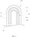
- FIG. 3shows a close-up, fragmented view of a double element tip of a surgical sealing instrument
- FIG. 4shows a close-up, fragmented view of a surgical sealing instrument showing a sealing barrier
- FIG. 5shows a close-up, fragmented view of a surgical sealing instrument with two sealing elements in an alternate configuration
- FIG. 6shows a close-up, fragmented view of a surgical sealing instrument with three elements in a configuration similar to that of FIG. 5 ;
- FIG. 7shows a close-up, fragmented view of the active surface of a surgical sealing instrument with four elements in a configuration similar to that of FIG. 6 ;
- FIG. 8Ashows a fragmented, cross-sectional view of an alternate configuration for the tip of a surgical sealing instrument according to principles of the present invention
- FIG. 8Bshows a close close-up, fragmented view of the active surface of the surgical sealing instrument shown in FIG. 8A ;
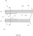
- FIG. 8Cshows a fragmented, side cross-sectional view of an another alternate configuration for the tip of a surgical sealing instrument according to principles of the present invention
- FIG. 8Dshows an end cross-sectional view of the tip of the surgical sealing instrument of FIG. 8C .
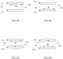
- FIGS. 8E through 8Pshow end views of alternate configurations of active elements structures which may be used on tips of a surgical sealing and/or cutting instrument according to principles of the present invention
- FIG. 9shows a close-up, fragmented view of yet another alternate configuration of the tips of a surgical sealing instrument
- FIG. 10Ashows a close-up, fragmented view of a tip of a surgical sealing instrument having a heat dispersing element
- FIG. 10Bshows an end view of the tip of FIG. 10A ;
- FIG. 11shows a close-up, fragmented view of an alternate tip of a surgical sealing instrument
- FIG. 12shows a fragmented, side view of another tip of a surgical sealing instrument according to principles of the present invention.
- FIG. 13shows a fragmented, top view of the tip of FIG. 12 ;
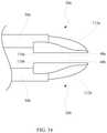
- FIG. 14shows a fragmented, side view of the tips of a surgical sealing instrument
- FIG. 15shows a perspective view of a surgical instrument having cooperating elements
- FIG. 16shows a perspective view of another surgical instrument made in accordance with the present invention.
- FIG. 17shows a perspective view of another surgical instrument having cooperating elements
- FIGS. 18 and 19show surgical instruments being used on tissue in accordance with the present invention.
- FIG. 20shows a close-up, side view of the parallel movement surgical sealing and cutting tool in a nearly closed position
- FIG. 21shows a side view of the parallel movement surgical sealing and cutting tool of in an open position
- FIG. 22shows a side, fragmented view of a parallel movement surgical sealing and cutting tool operable through a catheter or cannula with pistol grip, the sealing tool being in an open position;
- FIG. 23shows the surgical sealing and cutting tool of FIG. 22 in a closed position
- FIG. 24shows a side, plan view of the surgical sealing and cutting tool of FIG. 22 ;
- FIG. 25shows a close-up, side view of a parallel movement end for a surgical sealing and cutting tool
- FIG. 26shows a parallel movement surgical sealing and cutting tool with finger rings
- FIG. 27shows a parallel movement surgical sealing and cutting tool with a squeeze grip
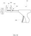
- FIG. 28shows a side view of an alternate embodiment of a surgical instrument made in accordance with principles of the present invention.
- FIG. 29shows a chart correlating estimated tissue effects with temperature.
- Tissue sealingmay be used to construct a barrier between two or more portions of tissue or duct, or may be used to repair damaged tissue.
- the tissue or ductmay provide a pathway for delivery of material, such as eggs in a fallopian tube or blood in a blood vessel.
- a barriermay thus prevent functional operation, in the case of the fallopian tube, or even prevent leakage, such as in the case of the blood vessel.
- the barriermay also prevent contamination, by closing a potential entrance or exit for contaminants.
- the tissue sealmay act as a barrier to prevent contents of the tissue exiting and/or other contaminants entering the cut tissue.
- tissue having an open wound or otherwise needing to be sealed offcan be sealed to close the wound and prevent entry of contaminants or to prevent exit of material from the tissue.
- tissue sealing and cuttingmay be used for tubal ligation.
- a fallopian tubemay be sealed and then cut.
- eggsmay be prevented from navigating the fallopian tubes and entering the uterus.
- the sealed tubeis ligated as well.
- blood vesselsmay be sealed to stop blood flow prior to being cut to prevent bleeding during and immediately after the cut.
- ferromagnetic covered conductorsmay provide advantages in sealing and cutting ducts and other tissues, including reduced cost, simplicity of operation and increased effectiveness in tissue sealing and cutting instruments.
- FIGS. 1 to 19there are shown tissue sealing and cutting instruments in accordance with one aspect of the present invention.
- FIGS. 20 to 28there are shown surgical instruments in accordance with another aspect of the present invention, and which may be used in conjunction with the tissue sealing and cutting instruments discussed in FIGS. 1 to 19 .
- Parallel surface movementmay include a ferromagnetic covered conductor based tissue sealing and cutting instrument described in FIGS. 1 to 19 , along with other sealing and cutting technologies.
- FIG. 29a chart of estimated temperature correlation to tissue effects is shown.
- FIG. 1a perspective view of a handheld sealing and cutting instrument 10 and system 15 is shown.
- Many surgical proceduresrequire cutting or ligating ducts, such as blood vessels, or other vascular tissue. Due to the inherent spatial considerations of the surgical cavity, surgeons often have difficulty suturing vessels or performing other traditional methods of controlling bleeding, e.g., clamping and/or tying-off transected blood vessels.
- a surgical sealing and/or cutting instrument 10a surgeon can cauterize, coagulate/desiccate and/or simply reduce or slow bleeding.
- Tissue sealingis fundamentally different than simply coagulating or cauterizing vessels.
- coagulationis defined as a process of desiccating tissue wherein the tissue cells are ruptured and dried.
- Duct sealing“vessel sealing” or “tissue sealing” is defined as the process of liquefying the collagen in the duct, vessel, tissue, etc. so that it reforms into a fused mass with limited demarcation between adjacent tissue structures.
- tissue sealingtwo predominant parameters must be accurately controlled—the pressure applied to the duct or tissue and the amount of heat which is conducted from the tip 20 A and/or tip 20 B to the duct or tissue.
- the surgical sealing and cutting instrument 10varies from many prior art electrosurgical tools in that in the instrument of the present invention heat is generated directly in an active element 110 located on tip 20 A and/or 20 B.
- heatis generated directly in an active element 110 located on tip 20 A and/or 20 B.
- electrosurgical instrumentssuch as bipolar or monopolar instruments, which use one or more probes to direct electrical current into tissue where the resistance to the electrical current generates heat in the tissue rather than at a thermal element.
- a thermal instrumentgenerates heat and applies the heat to the tissue, while monopolar and bipolar devices pass electricity into the tissue which results in heat being developed in the tissue.
- the sealing and/or cutting instrument 10has tips 20 A, 20 B which may be placed around or on opposing sides of a duct or tissue to be sealed.
- the tips 20 A and 20 Bmay be placed at the end of arms 30 A, 30 B which are held in a user's hand.
- a usermay squeeze the arms 30 A, 30 B of the instrument together causing the tips 20 A, 20 B to provide pressure on the duct or tissue.
- Electrical energymay then be directed to an active element 120 on the active surface 40 of tip 20 A and/or 20 B to heat the thermally active element 120 .
- the active elementcould be applied hot to the duct, or could by applied and then heated).
- the heat generated in the active elementis applied to the duct or tissue to cause the duct or tissue to seal.
- a second energy levelmay be applied to the active element 110 (or a separate active element) to heat the active element 110 to a second temperature that is sufficient to cut the duct or tissue apart. This may be accomplished using one element 110 or by separate elements 110 , 120 . Power may be received by the instrument 10 through a cable 50 .
- active element 110may be configured to provide a higher thermal density as compared to the thermal density provided by active element 120 .
- thermal densitymeans the rate at which thermal energy is conducted into a duct or tissue.
- the active element 110(and/or active element 120 ) may be formed by a conductor having a ferromagnetic coating to form a thermally active element.
- ferromagneticrefers to any ferromagnetic-like material that is capable of producing heat via magnetic induction, including but not limited to ferromagnets and ferrimagnets. It is not intended that such materials must be heated exclusively by magnetic induction unless otherwise indicated and such may acquire heat from resistive heating, eddy currents, etc., in addition to magnetic induction.
- Powersuch as a radio frequency (RF) waveform, may be provided to the conductor.
- RFradio frequency
- the RF energymay travel along the conductor's surface in a manner known as the “skin effect”.
- the current densityis generally greatest at the surface and decreases in magnitude further into the material where the electric field approaches zero.
- the depth at which the skin effect current is reduced to about 37 percent of its surface valueis referred to as the skin depth and is a function of the electrical resistivity, the magnetic permeability of the material conducting the current, and the frequency of the applied alternating RF current.
- the alternating RF current in the conductor's surfaceproduces an alternating magnetic field, which may excite the domains in the ferromagnetic portion 65 .
- hysteresis losses in the coatingmay cause inductive heating. Heating of the ferromagnetic portion 65 due to hysteresis loss ceases above the Curie point because the material loses its magnetic properties.
- the ferromagnetic coatingmay have a thickness of approximately 4 to 5 skin depths.
- heatis produced in the ferromagnetic material.
- the heat produced in the ferromagnetic materialmay be referred to as “ferromagnetic heat” or “ferromagnetic heating” and includes heat produced by magnetic induction or related mechanisms caused by delivering electrical energy from a power source to a ferromagnetic coated conductor in a closed circuit.
- ferromagnetic heat and ferromagnetic heatingexcludes heat generated by an electrosurgical element that is used to direct electrical energy into tissue to cause heating of the tissue directly, such as a bipolar or monopolar instrument.
- an electrosurgical elementthat is used to direct electrical energy into tissue to cause heating of the tissue directly, such as a bipolar or monopolar instrument.
- the ferromagnetic coatingWhen the ferromagnetic coating is thin relative to the conductor, the ferromagnetic coating can quickly heat to temperatures which will seal and/or cut tissue, and then rapidly cool to a temperature where the ferromagnetic coating will not even burn the skin within a very short time period.
- a tungsten conductor having a diameter of about 0.375 mm and a ferromagnetic coating of a Nickel Iron alloy (such as NIRONTM available from Enthone, Inc. of West Haven, Conn.) about the tungsten conductor about 0.0375 mm thickcan be used as the element.
- Multiple different frequenciescan be used, including frequencies from 5 megahertz to 24 gigahertz.
- a ferromagnetic covered conductormay be comprised of a ferromagnetic material generally surrounding an electrical conductor (either touching or not touching the conductor), and which produces heat when electrical energy is supplied to the conductor.
- a more detailed discussion of powering ferromagnetic coated/covered conductors to generate heat sufficient to seal and/or cut through tissueis described in more detail in U.S. Publication No. US-2010-0268207-A1 and US-2010-0268210-A1, which are expressly incorporated herein in their entirety. It will be appreciated that improved heat may be obtained by a ferromagnetic coating which completely circumscribes the conductor along the portion desired to be heated.
- Energymay be provided by a power supply 60 through the cable 50 to the handheld sealing and/or cutting instrument 10 .
- the energymay be, for example, an oscillating current, such as an alternating RF signal.
- the power supplymay include settings 70 , displays 80 and one or more cables, such as cable 50 .
- the current power settingmay be controlled by a switch 90 on the forceps or foot pedal 100 connected to the power supply by a cable or through wireless communication.
- Currentmay be passed from the power supply 60 , through the cable 50 , through the instrument 10 and along the conductor through the ferromagnetic portion and back to the power supply with the vast majority of the current staying in the conductive pathway of the tool rather than being transmitted through tissue.
- the handheld sealing and/or cutting instrument 10may have one or more active surfaces 40 .
- the active surfaceis only on tip 20 A.
- an active surfacemay be on both tips 20 A and 20 B.
- tip 20 Bmay be a mirror image of tip 20 A.
- a single active surface 40may be desirable and cost efficient for smaller ducts or tissues to be sealed. Multiple active surfaces may be desirable for work on larger tissues, as the heat may be more consistently presented to the tissue.
- the active surface 40may include one or more active element 110 , 120 .
- the active elementmay be embedded in a layer of material at the active surface 40 or may extend outwardly from or located adjacent to the active surface 40 so that it is positioned away from the surface of the forceps tips 20 A, 20 B.
- the elements 110 , 120may be configured to seal and/or cut when the surface 40 touches tissue, or may seal or cut prior to the surface 40 engaging the tissue.
- the element(s) 110 , 120may themselves be the surface which engages the tissue.
- the active element(s) 110 , 120 on each of the tips 20 A and 20 Bmay be activated at the same time, or one or both may be operated separately.
- a surgeonmay activate sealing tip 20 A or 20 B and then activate both when encountering a larger vessel or duct.
- tip 20 Amay include an active surface 40 with a single active element 110 , which may be loop or shaped as an elongated arch, i.e. an arch with two arms extending from the curved portion.
- the active element 110may be a material which will heat sufficiently to seal and/or cut human or animal ducts or tissue.
- the active element 110may be, for example, a conductor 104 forming a closed circuit with a power source and having a ferromagnetic coating 114 disposed on the conductor.
- the single active element 110may be able to function with at least two energy settings: a setting for sealing tissue together and a setting for cutting through tissue.
- a surgeonmay use pressure to apply the active surface 40 to a blood vessel or other duct. This may include the blood vessel being disposed across the arms of the active element extending from the art. The surgeon may then control power delivered to the ferromagnetic covered conductor forming the active element 110 by activating a first power setting causing the blood vessel or other duct to seal or weld closed, at two locations depending on the distance between the arms. If needed, the surgeon may repeat the sealing on adjacent blood vessel tissue to provide a wider seal. The surgeon may then place the active surface 40 in the middle of the sealed tissue (or leave the active surface 40 where it is, if the surgeon did not move it).
- the surgeonmay activate a second power setting to cause a portion of the sealed blood vessel or other duct to be cut with heat generated in the ferromagnetic coating of the active element 110 .
- the blood vessel or other ductmay be sealed closed from contamination and/or leakage while being separated into two parts (or being sealed before being cut and then having the open end cut off distal to the seal).
- there are several ways for controlling whether sealing or cutting heat is appliedsuch as by regulating the duty cycle to control the amount of heat being generated in the ferromagnetic coating 114 .
- a tip 20 Amay include an active surface 40 with two active elements 110 , 120 which are controlled together or separately, or by two active sub-elements 130 A, 130 B (i.e. two portions of a common element) which may be controlled together, such as a pair of ferromagnetic covered conductors.
- the conductorsmay be referred to as separate elements 110 , 120 regardless of whether a single element with two parts or two separate elements etc., is used, unless specifically designated as one or the other.
- sub-elementsmay include an active element comprising a conductor having a plurality of spaced apart ferromagnetic coatings thereon, an active element comprising a conductor having a first coating of a first ferromagnetic material and a second coating of a second ferromagnetic material different than the first ferromagnetic material, etc. It will be further appreciated that while two elements or sub-elements are shown, an active surface 40 having a larger number of elements or sub-elements may be used for a variety of purposes.
- the active element(s) 110 , 120may use a separate power setting for each sub-element 130 A, 130 B or conductor 104 .
- the outer sub-element 130 A or element 120may be configured for a sealing temperature range, such as a temperature range sufficient to heat the tissue to about 58° C. to 200° C. or more preferably 58° C. to 62° C.
- the inner element 130 B or element 110may be configured for a cutting temperature, such as a temperature range sufficient to heat the tissue to about 200° C. to 500° C., or more preferably 200° C. to 400° C.
- the inner element/sub-elementmay avoid cutting the sealed portions of a duct or vessel by cutting in between the seals.
- inner and outerare used for convenience only and are not intended to limit the geometry of the active elements 110 , 120 .
- the sealing elementmay be above, below, on either side or any other position relative to the cutting element which is desired by the surgeon.
- the result of a duct being disposed across the active elements 110 , 120will be two seals and two cuts between the seals, thus clearly terminating flow through the duct and sealing the duct adjacent the cut which minimizes the risk of accidentally cutting through the seal.
- Elements 110 and 120are shown as having a generally loop or curve-shape end with arms extending therefrom. Additionally, the thermally active elements 110 , 120 are shown as being generally parallel to one another. This allows the element 100 , 120 to be placed on a duct with the length of the loop generally perpendicular to the duct with the outer element 120 sealing the duct and the inner element 110 cutting the duct to remove a small segment and leave sealed segments on either site of the cuts. It will also be appreciated that in certain surgeries, different configurations may be desirable depending on the orientation of the ducts which are to be sealed. Any such geometries are intended to be covered by the claims unless specifically limited therein.)
- a surgeonmay use pressure to apply the active surface 40 to a blood vessel.
- the surgeonmay then cause the outer element 120 , which may be a ferromagnetic covered or coated conductor, to receive a first power setting causing the blood vessel to seal or weld closed.
- the surgeonmay then activate a second power setting to the inner element 110 , which may be a ferromagnetic covered or coated conductor, causing an inner portion of the sealed blood vessel to be cut out of the blood vessel.
- the same proceduremay be used with other ducts as well.
- the active surfacemay be used both to cut an intact duct, for example to both seal and cut a fallopian tube, or to seal and then cut off the end of a duct which has already been cut, such as sealing off a severed blood vessel and then cutting off the excess vessel beyond the seal, if necessary.
- the blood vesselmay be sealed closed from contamination and/or leakage while being separated into two parts or cleaned up after being cut, if necessary.
- FIG. 4a side view of a sealing barrier distance 140 of a handheld sealing instrument is shown.
- the sealing barrier distance 140 between the outer sub-element 130 A (or element 120 ) and inner sub-element 130 B (or element 110 )may determine the amount of sealed tissue remaining on each side of a cut performed by the inner sub-element 130 B.
- the sealing barrier distance 140may be adjusted. This may be done by selecting forceps 10 ( FIG.
- tips 20 A or 20 b having sub-elements 130 A and 130 B at a desired distanceby having one of the sub-elements be adjustable, or by having forceps with one tip 20 A having a first distance between the sub-elements, and the other tip 20 B having a different distance between the sub-elements so that the surgeon can choose which tip to use.
- the distancemay be adjusted as the outer and/or inner active elements may be malleable.
- a tip linkagemay move the outer and/or inner active elements to increase or decrease distance between the outer and inner active elements.
- Active elementsmay include multiple different technologies. In some cases, two technologies may be combined. For example, a bipolar element may be used as the outer sealing element, while a ferromagnetic covered conductor may be used to cut the tissue as an inner element, or vice versa. Ferromagnetic covered conductors may be desirable for many applications because of their ability to quickly heat and cool, as well as the small amount of tissue damage beyond the point of contact. In one embodiment the ferromagnetic coating circumscribes the conductor to facilitate inductive heating.
- the systemmay also incorporate sensors to aid in the determination of appropriate sealing times and cutting application times.
- the systemmay monitor the temperature, standing wave ratio (“SWR”), etc. of each active element, or the temperature, conductivity, moisture content, or impedance or some combination thereof, of the tissue.
- SWRstanding wave ratio
- the systemautomatically seals and then cuts the tissue when the surgeon applies the instrument to tissue and activates the instrument. This could be done, for example, by monitoring the moisture content of the tissue.
- the tissuewill lose moisture content to a point, at which cutting will begin. Thus, moisture content passing beyond a desired threshold can be used to raise an indicia that sealing is complete and cutting has or will begin.
- the systemmay monitor temperature over time (using, for example, a sensor as shown in FIG. 17 ) and determine when appropriate sealing has been completed before the cut energy is applied. This can be done by monitoring the temperature of the element which will tend to stay near a fixed temperature until sealing is complete, and then suddenly rise as it cuts.
- the systemmay monitor may monitor the temperature, electrical properties, or some other characteristic, of the tissue or duct, using a sensor (see e.g. FIG. 17 ) located on one or both of the tips 20 A and 20 B.
- a sensorsee e.g. FIG. 17
- a light or soundmay be emitted from the instrument or power supply to notify the surgeon when a phase appears to be completed.
- the surgeonmay listen for a first sound or see a first light to know that a sealing phase is completed.
- the surgeonmay then activate the cutting phase and await a second light or sound to know that the cutting phase is completed and the instrument may be removed, or the instrument may automatically perform each step and provide notification when each is complete.
- power delivery to the sealing instrument 10may be controlled by varying the amplitude, frequency or duty cycle of the alternating current waveform, or alteration of the circuit to affect the standing wave driving the ferromagnetic coated conductor.
- FIG. 5there is shown an alternate arrangement of an active surface 40 .
- the active element(s) 110 , 120were generally U-shaped as may be beneficial for sealing and cutting out a portion of a duct.
- FIG. 5shows active elements which may be generally linear and generally parallel and which may be used in a manner somewhat analogous to use of a pair of scissors.
- the active element(s) 110 , 120 shown in FIGS. 5-7may be formed from a flattened conductor 104 covered by a ferromagnetic coating 114 .) If desired one or both conductors 104 and/or the coatings may be flattened.
- one element 120may be used for sealing, while another element 110 may be used for cutting.
- a surgeon or other userwould engage the tissue and activate the sealing element 120 and the cutting element 110 . This may be done simultaneously or sequentially depending on the time necessary for the sealing element 120 to adequately seal off fluid flow through the tissue.
- the tissue on the side of element 110 opposite element 120would be cut off.
- active surface 40While reference is made to an active surface 40 , it will be appreciated that the active element may be in the active surface or extend outwardly from the active surface depending on the intended use and the desires of the user. Thus, it will be appreciated that active surface 40 itself need not seal or cut tissue.
- the active surface 40may include two sealing active elements 120 and a cutting active element 110 disposed therebetween.
- a sealing active elementis a thermally active element which is heated to seal tissue and a cutting active element is a thermally active element heated sufficiently to cut tissue. It will be appreciated that one element could function as both depending on how it is controlled.
- the active surface 40may be placed along a tissue to be cut.
- the sealing active elements 120may be used to seal the tissue on either side of the cutting active element 110 and the cutting active element used to cut the tissue to ensure that flow between opposing sides does not continue. Thus, for example, if flow through a duct needed to be prevented, the duct will be sealed on either side of the cut, thereby ensuring both sealing and cutting of the duct.
- the active surface 40may include two sealing active elements 120 which are spaced apart and two cutting active elements 110 which are spaced apart a desired distance 126 .
- the active surfacecan be placed on a tissue or duct to be cut (with the length generally perpendicular to the length of the duct) and the active elements 110 , 120 energized to seal and cut the tissue or duct.
- the arrangement of the cutting active elements 110will cut out a strip of the tissue or duct.
- the tip 20 Amay include a thermally active element 110 comprised of a conductor 104 having a ferromagnetic coating 114 disposed thereabout to form a ferromagnetic heating region.
- the active element 110may form a generally flat, planar surface.
- the generally planar surface of the active elementmay be formed by flattening a section of a conductor wire 104 and plating a coating of ferromagnetic material 114 on the flattened conductor 104 such that the ferromagnetic coating 114 substantially covers the entire outer surface of a length of the flattened conductor 104 .
- the coating 114may extend completely around the conductor 104 if desired).
- the flattened conductor 104may form a closed circuit with a power source directly or via intervening conductors such that applying electrical energy across the flattened conductor causes substantial uniform ferromagnetic heating along the ferromagnetic region of the active element 110 .
- the flattened conductormay extend along an arm 30 A of a sealing and/or cutting instrument of the present invention, such that electrical energy supplied from a power source travels towards the ferromagnetic material 114 through section 104 a of the conductor 104 , away from the ferromagnetic material 114 through section 104 b of the conductor 104 , and back to the power supply. (It will be appreciated that, alternatively, electrical energy could travel towards the ferromagnetic material 114 through section 104 b and away from the conductor through section 104 a ).
- Arm 30 Amay include a thermally and/or electrically isolating material 106 to substantially prevent transfer of heat and/or electrical current to the arm 30 A of the surgical sealing and/or cutting instrument. Additionally, an electrically isolating material 113 may be disposed between sections 104 a , 104 b of the conductor 104 to prevent current from bypassing the ferromagnetic material.
- the active element 110 shown in FIGS. 8A and 8Bwill have a larger surface area for contacting a duct or tissue to be sealed and/or cut.
- a better sealmay be created along the duct or tissue.
- FIG. 8Cthere is shown a fragmented, side cross-sectional view of another configuration for tips of a surgical sealing and/or cutting instrument according to principles of the present invention.
- the cross-hatching of the active elements 110 , 120has been removed.
- FIG. 8Dshows an end, cross-sectional view of the thermally active elements of FIG. 8C .
- the tips 20 A, 20 Bmay include active element(s) 110 , 120 .
- Each active element 110 , 120may comprise a conductor 104 having a ferromagnetic coating 114 disposed thereon, similar to the active element shown in FIGS. 8A and 8B .
- the active element 110may be formed such that there is a cutting zone 115 , formed by a protrusion, rib, etc., and a sealing zone 103 in the ferromagnetic heating region.
- the cutting zone 115is a protrusion which extends away from the generally planar surface which forms the sealing zone 103 of the active element.
- the protrusionmay provide increased pressure applied to the duct or tissue at the location of the cutting zone 115 , thereby allowing the duct or tissue to be cut along the cutting zone 115 while being sealed along sealing zones 103 .
- a single applicationcan be used to both cut and seal.
- Active elementsmay be constructed to have a variety of shapes in order to create a cutting zone and sealing zone similar to the cutting zone 115 and 103 discussed in connection with FIG. 8C .
- FIGS. 8E through 8Pshow various active elements having different shapes or elements which may be used to create a cutting zone and sealing zone. These active elements could be used in conjunction with forceps or other thermally active surgical instruments shown herein.
- FIGS. 8E through 8Pare being provided for illustrative purposes only.
- FIGS. 8E through 8Ponly show the active elements 110 , 120 , but it will be understood that the other elements of a sealing and/or cutting instrument according to principles of the present invention disclosed herein (e.g. the sealing and/or cutting instrument of FIG. 8C ) would be associated with the active elements 110 , 120 shown in FIGS. 8E through 8P .
- FIG. 8Eshows an active element 110 (similar to the active element 110 shown in FIG. 8B ) having a ridge extending along the planar surface of the upper active element 110 to form the cutting zone 115 and sealing zones 103 adjacent to the cutting zone 115
- the projection forming the cutting zone 115could be on the lower active element 120 .
- elements 110 and 120 as shown in FIGS. 8A-8Pcan function both as a cutting element and a sealing element or portions thereof.
- the structure shown as element 120may not be a ferromagnetic coated conductor.
- the structure 120may only be a support structure (e.g. not a thermal element) which provides a compressive surface opposite active element 110 .
- the active element 120may generate heat to seal and/or cut a duct or tissue and have a ridge forming a cutting zone 115
- the active element 110is a support structure for use as a compressive surface opposite active element 120 as shown in FIG. 8F .
- FIG. 8Gshows and active element 110 similar to that shown in FIG. 8E .
- the active element 120differs from the active element 120 shown in FIG. 8E in that the active element 120 of FIG. 8G comprises a recess 117 , or quasi-complimentary receptacle, to alter the compression force applied to a duct or tissue when the active elements 110 and 120 are squeezed together to engage the duct or tissue.
- FIG. 8Hshows and active element 120 with a sharp cutting zone 115 to facilitate cutting of a duct or tissue.
- the compressive force applied to a duct or tissue along the cutting zone 115may be altered by including a recess 117 on active element 110 positioned generally opposite the cutting zone 115 .
- the active element 110 of FIG. 8Gcould be combined with the active element 120 of FIG. 8H to form protrusions in alignment or out of alignment with one another to provide a desired cutting dynamic.
- FIGS. 8I and 8Jshow an arcuate active element 110 and an arcuate active element 120 , respectively.
- a cutting zone 115may be formed about the apex of the curved or arcuate active elements 110 ( FIG. 8I ) and 120 ( FIG. 8J ) due to the increased amount of compressive force that will be applied to a duct or tissue at this location as compared to the compressive force that will be applied to the duct or tissue adjacent the cutting zone 115 at sealing zones 103 .
- the compressive force applied along the cutting zone 115 shown in FIGS. 8I and 8Jmay be altered by matching the curved or arcuate active elements with an opposing active element that is also curved, as shown in FIGS. 8K and 8L .
- the arcuate active element 120 shown in FIG. 8Kmay be paired with an arcuate active element 110 .
- the degree of curvature of the arcuate active element 110may be less than the degree of curvature of active element 120 , and the degree of curvature of either (or both) the active element 120 and 110 can be adjusted to alter the compressive force applied to a duct or tissue. As shown in FIG.
- the arcuate active element 120may curve in the same direction as arcuate active element 110 in a quasi-complimentary orientation.
- the compressive force along cutting zone 115may be substantially increased relative to the compressive force applied along sealing zone 103 by having arcuate active elements curved in opposite directions from each other, such as is shown in FIG. 8P .
- Cutting zones 115 and sealing zones 103may also be created by altering the thermal conductivity along the surface of one of the active elements, as shown in FIGS. 8M and 8N .
- active element 120 in FIG. 8Mmay be a support structure for providing a compressive surface opposite active element 110 .
- One or more heat sinks 121may be disposed adjacent the active element 110 ( FIG. 8M ) or 120 ( FIG. 8N ) to form a sealing zone 103 along a portion of the active element 110 to draw away a greater amount of heat from the active element on a portion thereof. As shown in FIGS.
- a the spaced apart heat sinks 121 disposed adjacent to the active element 120 and 110may be used to create a cutting zone 115 located generally in the center of the active elements with sealing zones 103 on both sides of the cutting zone 115 , as the heat in the center portion is not drawn away by the heat sinks.
- FIG. 8Oalso shows an active element 110 having a cutting zone and sealing zones 103 .
- a heat spreader 123 of moderate thermal conductivitymay be used to concentrate a greater amount of heat along a cutting zone 115 as compared to a sealing zone 103 .
- the heat spreader 123may be disposed adjacent the active element 110 in a central location so as to create a cutting zone 115 located generally in the center of the active element 110 with a sealing zones 103 on both sides of the cutting zone 115
- tip 20 A in FIG. 9may have an active element 110 comprised of only a rigid loop 116 forming a sealing and/or cutting element.
- the rigid loop 116may be opposed to surface 44 of tip 20 B and aligned in a generally horizontal orientation which would provide sealing and/or cutting at two points when disposed perpendicular to a duct. It will be appreciated, however, that the rigid loop 116 may be aligned in different orientations to achieve a more specific therapeutic effect, such as aligned vertically to achieve a single, more rapid cut.
- Rigid loop 116may be formed of a conductor wire having a ferromagnetic material disposed along at least a portion thereof, typically circumferentially about a portion of the conductor wire.
- the conductor wiremay be of a sufficiently large gauge so that the rigid loop 116 substantially resists deformation when tips 20 A and 20 B are used to apply pressure about a tissue or duct.
- to seal an arteryit is important that sufficient pressure be applied to the artery so that the endothelium of opposing walls of the artery are adjacent each other. Then power may be supplied to the active element 110 to seal the artery.
- conductor wireis used herein for convenience only and those skilled in the art will appreciate that other conductive material may be used to form the rigid loop 116 .
- Sealing and cutting of a tissue or duct using tips 20 A and 20 Bmay occur sequentially.
- the tips 20 A, 20 Bmay be placed around tissue to be sealed and the tips forced together so as to provide pressure on the tissue.
- Powermay then be supplied to active element 110 to heat the tissue or duct.
- sealing of the tissue or ductwill occur as the active element and/or the tissue or duct may not exceed approximately 100° C. as water evaporates from the tissue or duct, i.e. the temperature of the active element and/or the tissue or duct may be limited by the phase change of water in the tissue or duct as it evaporates. Once all water has evaporated, the temperature may then quickly rise to cut the tissue or duct.
- sealing and cutting of a tissue or ductmay be accomplished by supplying a constant power to the active element 110 .
- a low wattagemay be supplied to the active element 110 to coapt lung tissue.
- the temperature of the active elementmay be about 100° C. until all water in the lung tissue evaporates. This may take approximately 40 seconds when the active element 110 is supplied with about 30 watts of electrical energy. Once the lung tissue becomes desiccated the temperature of the active element 110 may suddenly rise to commence cutting of the tissue.
- Tip 20 Amay have an active element 110 disposed in a heat dispersing member 118 .
- the heat dispersing member 118conducts heat away from the active element 110 so that heat may be applied to a tissue or duct more uniformly along an outer surface of the heat dispersing element 118 .
- Use of a tip 20 A having a heat dispersing member 118may be more desirable when a therapeutic procedure does not require cutting of the tissue or duct. Because heat is less concentrated at a discrete location along the tissue or duct, it may be treated using tip 20 A without being cut.
- the heat dispersing member 118may be a material that resists sticking to a tissue when thermal energy is applied to the tissue by active element 110 , such as Teflon®, Kapton®, etc. It will be appreciated that tissue may stick to the active element 110 until it reaches a sufficiently high temperature, e.g. 300° C. However, active element 110 may not be used at such high temperatures during some therapeutic procedures, such as vascular shrinkage in aneurism preparation for clipping. Thus, use of a non-stick heat dispersing member 118 during such procedures may be necessary to avoid tissue sticking to the active element 110 .
- non-stick materialsuch as Teflon®, Kapton®, etc.
- a non-stick materialsuch as Teflon®, Kapton®, etc.
- a non-stick materialmay be desirable in therapeutic procedures involving welding, sealing, coapting, and/or homeostasis which involve temperatures at or below approximately 100° C.
- Tip 20 Amay include active element comprised of a ferromagnetic material in sheet form, such as Alloy 152.
- the sheet of ferromagnetic materialmay be placed over a surface mounted inductive coil (not shown) to form an active element 110 and achieve a broad active surface that may be used to treat tissue.
- direct electrical connectionmay be provided to the sheet of ferromagnetic material, instead of inductive coupling. This may produce sufficient heat to deliver the desired therapeutic effect. It will be appreciated that it may be desirable to use a thin sheet of ferromagnetic material as the time to heat and cool the tip 20 A is dependent on the thermal mass of the material.
- Tip 20 Amay be attached to an arm 30 A and include an active element 110 having a sealing member 48 and a cutting member 112 .
- Sealing member 110may have a relatively broad surface which may be used to seal, weld, or coapt tissue or a duct or to achieve homeostasis.
- Sealing member 110may, for example, be a sheet of ferromagnetic material disposed on a conductor similar to that described in FIG. 11 , or a ferromagnetic coating plated on a flattened conductor as described, for example, in FIGS. 8A-8C .
- the cutting member 112may be a thin wire, such as a wire coated with a ferromagnetic material which may allow a surgeon to cut a tissue or duct at a more precise location.
- a surgeonmay be able to cut a tissue or duct using cutting member 112 and then use the reverse side of the tip, the sealing member 48 , to achieve homeostasis.
- a surgeonmay use the sealing member 48 to seal a tissue or duct and then flip the tip 20 A over to make a precise cut using the cutting member 112 .
- a surgical instrumentmay include more than one of the tips shown in FIGS. 12 and 13 which are disposed opposite each other as is more clearly shown in FIG. 14 .
- Tissue or a ductmay be grasped between sealing members 48 A and 48 B.
- Sealing members 48 A and 48 Bmay then be used to apply pressure to the tissue or duct.
- Powermay then be supplied to the sealing members to seal the tissue or duct.
- a surgeonmay use either of the cutting members 112 A, 112 B to cut and/or remove tissue if needed or desired, or the sealed tissue may be left as is if there is no need to remove tissue.
- FIGS. 1-13show a single active surfaces or elements on one side of the instrument, it will be appreciated that an instrument may have complementary active surfaces 40 or elements 110 which either align with or are slightly offset from the other active surface to ensure sealing and cutting of thicker ducts and tissues, such as that which is in FIG. 14 .
- Thismay be in the context of forceps, scissor-like instruments or a host of other surgical devices.
- FIG. 15shows a perspective view of a surgical instrument 200 having cooperating opposed active surfaces 40 with sealing and cutting elements 110 , 120 disposed on or extending from the active surfaces in order to seal and cut a duct, tissue, etc., from opposing sides.
- the surgical instrument 200may be powered by a cable 50 in a manner similar to that discussed with respect to FIG. 1 .
- the surgical instrument 200can be used similar to forceps to seal and cut veins and ducts, or can be used in a manner more analogous to scissors.
- active element(s) of the surgical instrument 200are being selectively activated to seal and cut tissue, such as lung tissue, or other tissue in the body.
- tissuesuch as lung tissue, or other tissue in the body.
- diseased or damaged tissuecan be cut out of the body while also sealing the remaining tissue against the loss of blood or other fluid and against the entry of bacteria, etc.
- the surgical instrument 200can be placed on an initial portion of tissue and the sealing active element(s) (e.g. 120 ) activated to seal the tissue and then the cutting active element(s) (e.g. 110 or the sealing active element at different power) activated to cut through the tissue.
- the surgical instrument 200may be advanced and the procedure repeated until the undesired tissue is completely cut away.
- FIG. 16there is shown a perspective view of an alternate configuration of a surgical instrument 250 for use in the present invention. Rather than operating like a pair of forceps as shown in FIG. 15 , the surgical instrument 250 functions in a manner more analogous to scissors.
- Each active surface 40is attached to an arm 254 which extends to a pivot point 260 and then to a handle portion 264 formed by finger holes 270 or some other gripping structure.
- the active surfaces 40 and/or active elements 110 , 120may be formed as part of the arms 254 , or may be attached to the arms, such as by pivots 268 , to allow the active surfaces or elements to adjust relative to one another and apply pressure more uniformly on a tissue than would occur in a scissors where there may be greater pressure adjacent the pivot point 260 .
- the sealingmay be more consistent as the active surfaces 40 and elements 110 , 120 remain more parallel.
- the surgeonwould position the active surfaces 40 along the area to be cut and apply force on the handle portion 264 while power is delivered through the cable(s) 50 from a power supply to the active elements to thereby seal and cut tissue. If necessary, the active surfaces 40 could then be advanced along the tissue and the process repeated.
- FIG. 17shows a perspective view of a surgical instrument 200 having a rigid loop 116 cooperatively opposed to a surface 44 .
- the surgical instrument 200may be powered by a cable 50 connected to a power supply in a manner similar to that discussed with respect to FIG. 1 .
- One advantage of surgical instrument 200 having a rigid loop 116is that a user of the surgical instrument 200 may be able to better view the tissue or duct that is to be sealed and/or cut.
- a sensor 119may be disposed in communication with the surgical instrument 200 . As shown, the sensor 119 may be disposed on the surface 44 and used to monitor electrical properties of the tissue or duct. For example, when the surgical instrument 200 is being used to seal and cut a tissue, evaporation of water may cause the capacitance of the tissue to change and shift the standing wave ratio (“SWR”) of the applied electrical energy. The sensor may detect the shift in the SWR and provide a signal of the transition from sealing to cutting of the tissue by the surgical instrument. Thus, the sensor 119 may provide the surgeon with an indication of the effectiveness of the seal and the status of the sealing/cutting taking place.
- SWRstanding wave ratio
- the sensor 119may also monitor temperature of the interface between the active element 110 and the tissue. Once a sufficient temperature is achieved to cut the tissue, a signal may be generated to notify the surgeon that the tissue has been cut or is being cut. Thus, for example, the element 110 may hold at 100° C. for a period of time. If pressure is being applied to duct, etc., this will correspond with sealing. Once sealing it complete, the water in the tissue will be consumed and the temperature of the element 110 will suddenly rise, indicating transition in to the cutting phase. To provide control, the instrument 200 , or some related structure, may advise the physician which phase is currently being undertaken, or it may advise the physician that sealing is complete and that cutting can commence.
- the surgical instrument 200may include additional, or alternate, sensors to monitor sealing and cutting of a tissue or duct.
- a thermocouplemay be disposed integrally with the surgical instrument to monitor temperature as the procedure progresses from sealing to cutting and/or when cutting of the tissue is complete.
- the electrical properties of the conductor of active element 110may indicate when sealing and/or cutting of the tissue is complete.
- active element 110is comprised of a tungsten conductor coated with a ferromagnetic material, then the resistivity of the tungsten conductor may be monitored to determine when sealing and/or cutting is complete. As water evaporates from the tissue, the resistivity of the tungsten conductor may increase. Thus, the resistivity of the tungsten conductor may be correlated with the completion of tissue sealing.
- FIG. 18shows a surgical sealing and/or cutting instrument 200 being used to treat tissue 208 .
- the surgeonmay position the tissue 208 between the active elements 110 , 120 .
- the active elementsare then actuated to seal off a section of the tissue 212 . If so desired the section of tissue 212 can be cut using the instrument 200 and removed from the surgical site, thereby leaving the main tissue 208 sealed along the incision.
- FIG. 19shows an alternate configuration of a surgical instrument 270 being used to cut a tumor 274 from lung tissue.
- the active surface 40 and/or active elements 110 / 120need not be linear and may be bendable.
- the elementsare disposed in a generally semi-circular configuration so as to enable sealing around and cutting out of a tumor. (A complementary portion to that shown may engage the tissue on the opposing side and may lack any active elements so that it merely engages the tissue, or may have one to two elements for promoting sealing and cutting).
- the active elements 110 , 120are positioned on the lung tissue just beyond the area to be removed.
- the elementsare then powered from a power supply via cable 50 to seal off the lung tissue 280 (along thermally active element 120 ) and to cut the portion of the lung tissue containing the tumor 274 (along thermally active element 110 ).
- the tumoris cut away as the remaining lung tissue is sealed to thereby prevent air and blood leakage, etc.
- FIGS. 20-28various tools with parallel linkages are shown which can be used, in accordance with one aspect of the invention, in conjunction with tissue sealing/cutting elements to selectively seal and cut or cut and seal ducts in a human or animal.
- tissue sealing/cutting elementsto selectively seal and cut or cut and seal ducts in a human or animal.
- tissue bundles or ducts to be sealedare larger, parallel surface movement of the one or more treatment surfaces may be desirable. If an angular movement instrument is used with a larger tissue bundle, more pressure may be placed on the proximate portion, i.e. the portion of the bundle or duct that is closest to the pivot. This leaves the distal portion, i.e. away from the pivot, with less pressure.
- the distal portionmay receive little to no energy or pressure from one or more of the treatment surfaces 40 , or may not be held in sufficient contact with adjacent tissue to form a good seal.
- the tissue bundleWith parallel movement surfaces, the tissue bundle may receive more-equal pressure on the proximate and distal portions. Thus the heat may be approximately equally distributed along the tissue bundle surface. This is particularly important when sealing large ducts or tissues.
- FIGS. 20 and 21a side view of a parallel movement surgical sealing and/or cutting instrument, generally indicated at 10 , is shown with the instrument in a nearly closed position ( FIG. 20 ) and in an open position ( FIG. 21 ).
- the instrumentmay include a parallel movement linkage, generally indicated at 165 .
- Such a parallel linkagehas been referred to as a pantograph linkage.
- Two instrument halves 160 A, 160 Bare connected by the parallel movement linkage 165 so as to enable a treatment or active surface 40 A (or active elements 110 which may be embedded in or extend from the treatment surface and a treatment or active surface 40 B—which may have similar active elements) to move in parallel with one another.
- the linkagehas two arms or bars 180 A, 180 B that are fixed at one end via fasteners 190 A, 190 B to the two instrument halves 160 A and 160 B, respectively, and connected in the middle via a fastener 190 C.
- the opposing end of the bars 180 A, 180 Bmay include fasteners 210 A, 210 B, respectively, or other connectors which move in linear tracks 200 A, 200 B ( FIG. 6 ) in the two instrument halves 160 A and 160 B.
- the linkageWhen operated, the linkage causes a line defined by fastener 190 A and second bar end fastener 210 B to remain parallel to fastener 190 B and second bar end fastener 210 A while the distance between these lines are adjusted.
- This X linkagehas been referred to as a pantograph linkage.
- the instrument 10may be operated with one hand.
- a usermay insert their fingers into the openings 220 A, 220 B. Using the fingers, the user may separate the instrument halves 160 A, 160 B causing the instrument tips 20 A, 20 B to separate as well.
- the instrument halves 160 A, 160 Bmay be biased by a spring in the open position.
- a tissue bundlemay be placed between the active surfaces 40 A, 40 B while the user may cause the instrument tips 20 A, 20 B to apply pressure to the tissue bundle by squeezing the instrument halves 160 A, 160 B together.
- One or both of the active surfaces 40 A, 40 Bmay contain one or more active elements 110 that may be activated at a first energy setting to seal the tissue bundle.
- the usermay then activate the one or more active elements 110 ( 120 , etc.) to cut the tissue bundle after sealing.
- the instrumentmay then be removed from the tissue bundle.
- the instrument 10can move through tissue in a manner similar to scissors, but enables a physician to seal and cut the tissue, thereby avoiding the need to tie off blood vessel or sew up the tissue because the tissue was sealed as well as being cut.
- FIGS. 22 through 24side views of a parallel movement sealing and/or cutting instrument 240 operable through a small access port with a pistol grip are shown.
- the sealing and/or cutting instrument 240may be biased into either the open or closed position depending on the use desired by the physician.
- a parallel movement sealing instrumentmay include a configuration to fit within an access port when closed, while facilitating movement of the control mechanism outside the access port and actuation of the sealing elements at the opposing end of the sealing and/or cutting instrument. While the neck 290 shown in the figures may be short, it should be recognized that the neck may be extended for applications requiring longer access distance.
- the parallel movement sealing instrument 240may include a grip 260 trigger 272 , bias mechanism 282 , neck 290 and instrument end 300 .
- the bias mechanism 282may aid the instrument to reset to a known state, such as open or closed.
- the bias mechanismmay be a spring or elastic member that resists stretching and/or compression.
- the neck 290may be relatively short or long and may include a movement transfer linkage to take force applied by the trigger 270 and/or bias mechanism 282 and transfer the movement to the instrument end 300 .
- the instrument end 300may include the parallel movement linkage 165 that enables a first treatment surface 40 A to move in parallel with a second treatment surface 40 B, such as the linkage described in FIGS. 20 and 21 .
- One or both of the treatment surfaces 40 A, 40 Bmay include active elements 110 , 120 , etc.
- the treatment surfaces 40 A, 40 Bmay reside on tips 230 A, 230 B.
- a usermay apply the instrument by one or more of the following steps: selecting a surgical instrument having substantially parallel surface movement; causing the surfaces to be above and below a tissue to treat; reducing the distance between the surfaces so that the surfaces (or the elements if the elements extend from the surfaces) engage the tissue; and/or activating an active element on at least one of the surfaces to thereby seal and/or cut the tissue.
- some forceis applied to the tissue by the treatment surfaces or active elements while the tissue is being sealed and/or cut.
- a usermay cause the instrument end 300 to become closed.
- the usermay then insert the instrument 240 into an access port in the body.
- the instrument end 300may then be opened and placed around a tissue bundle, duct, vessel, etc.
- the usermay then apply the trigger 270 such that the tips 230 A, 230 B place pressure on the tissue being treated.
- One or both of the treatment surfaces 40 A, 40 Bmay contain an active element 110 that may be activated at a first energy setting to seal the tissue (via an electric current from a power source as discussed above).
- the usermay then activate the one or more active elements 110 to cut the tissue bundle after sealing.
- the instrument 240may then be removed from or advanced along the tissue bundle.
- a normally open parallel movement sealing instrument 240is shown.
- the normally open parallel movement sealing instrumentmay have the advantage of transferring the pressure applied to the trigger 272 to the tips 230 A, 230 B, such that the pressure on the tissue bundle may be regulated by the user's squeeze on the trigger 272 .
- a normally closed parallel movement sealing instrument 240is shown.
- the normally closed parallel movement sealing instrumentmay have the advantage of consistent applied pressure by the bias mechanism 282 and the fact that a user would not be required to maintain pressure on the trigger 270 when closed on the tissue being treated.
- FIG. 24a mechanical diagram of FIG. 22 is shown.
- An activation button 310 and trigger linkage 320may be seen more clearly.
- the activation buttonmay be used to apply power to the thermally active element 110 .
- the trigger linkage 320may include a post in a track allowing trigger 272 movements to be translated into linear movement of a rod 330 .
- the rod 330may be connected to the parallel movement linkage 165 , allowing the transfer of force from the trigger 272 to parallel movement linkage 165 .
- the parallel movement end 380may be configured in a module 390 .
- the module 390may be added to instruments that use forward and backward linear movement of a rod.
- a sleevecould be attached to the module 390 and the rod attached to one of the bars 180 a or 180 b .
- the tips 230 A, 230 Bmove toward and away from one another.
- FIG. 26shows a movement transfer linkage with finger rings. Separation of a moving ring 410 from the stationary rings 420 may cause motion to be applied to the parallel linkage 430 . Depending on how the moving ring and stationary ring are attached to the bars 180 A, 180 B forming the parallel linkage, moving the moving ring 410 toward the stationary ring 420 will either open or close the space between the tips 230 A, 230 B.
- FIG. 27shows a sealing instrument 450 with a movement transfer linkage 430 connected to a handle 440 with a squeeze grip trigger.
- Application of pressure to a front end 470 of the gripmay cause the movement of the squeeze trigger to be transferred to the parallel linkage 430 .
- FIG. 28shows a side view of an alternate embodiment of a surgical instrument 335 made in accordance with principles of the present invention.
- the instrument 335is configured with a parallel movement linkage to keep the active surfaces parallel to one another.
- the parallel linkagemay include a direct linkage 340 .
- the linkage 340may rotate, advance or otherwise cause a movable tip 370 to approach a stationary tip 360 .
- the movable tip 370may withdraw from the stationary tip 360 .
- the instrument 335may include one or more active surfaces 40 on tips 360 , 370 .
- the active surfaces 40may apply pressure to seal and cut tissue, including ducts such as blood vessels, fallopian tubes, etc., as described above.
- thermally active elementswould be disposed on opposing sides of the tips and would be disposed in communication with a power source to selectively heat the active elements.
- FIG. 29a chart correlating estimated tissue effects with temperature is shown. It should be recognized that these temperature ranges are estimates, and that temperatures may vary depending on multiple factors that may include tissue type, tissue make-up, and water content.
- Vascular weldingis estimated to occur near the range of 58° C. to 62° C.
- Hemostasisis estimated to occur near the range of 70° C. and 80° C.
- Searing and sealingis estimated to occur near the range of 80° C. and 200° C.
- Incisionis estimated to occur near the range of 200° C. and 400° C. Rapid ablation and vaporization is estimated to occur near the range of 400° C. and 500° C.
- the surgical instrument of the present inventionhas a wide variety of uses. As the tips are applied to a piece of tissue, the surgical instrument is aligned with respect to the tissue so as to extend across the area to be sealed and/or cut. The active surfaces will typically firmly engage the tissue and then the physician will activate the thermally active elements to cut and/or seal the tissue. It will be appreciated that the cutting could be done first, or the sealing can be done first, depending on the particular desires of the physician. Alternatively, a surgical instrument could be made in accordance with the present invention that operates with programmed order, such as sealing for a given amount of time and then cutting the tissue without the physician having to activate each step.
- respective elementscan be heated to seal and/or cut the tissue. While it is preferred that the active surfaces be parallel and very close to one another, it will be appreciated that such is not necessary in accordance with the principles of the present invention.
Landscapes
- Health & Medical Sciences (AREA)
- Surgery (AREA)
- Engineering & Computer Science (AREA)
- Life Sciences & Earth Sciences (AREA)
- Biomedical Technology (AREA)
- Molecular Biology (AREA)
- Nuclear Medicine, Radiotherapy & Molecular Imaging (AREA)
- Plasma & Fusion (AREA)
- Physics & Mathematics (AREA)
- Heart & Thoracic Surgery (AREA)
- Medical Informatics (AREA)
- Otolaryngology (AREA)
- Animal Behavior & Ethology (AREA)
- General Health & Medical Sciences (AREA)
- Public Health (AREA)
- Veterinary Medicine (AREA)
- Surgical Instruments (AREA)
- Magnetic Treatment Devices (AREA)
Abstract
Description
Claims (17)
Priority Applications (1)
| Application Number | Priority Date | Filing Date | Title |
|---|---|---|---|
| US15/344,592US11266459B2 (en) | 2011-09-13 | 2016-11-07 | Sealing and/or cutting instrument |
Applications Claiming Priority (4)
| Application Number | Priority Date | Filing Date | Title |
|---|---|---|---|
| US201161534047P | 2011-09-13 | 2011-09-13 | |
| US201161534322P | 2011-09-13 | 2011-09-13 | |
| US13/614,226US9526558B2 (en) | 2011-09-13 | 2012-09-13 | Sealing and/or cutting instrument |
| US15/344,592US11266459B2 (en) | 2011-09-13 | 2016-11-07 | Sealing and/or cutting instrument |
Related Parent Applications (1)
| Application Number | Title | Priority Date | Filing Date |
|---|---|---|---|
| US13/614,226ContinuationUS9526558B2 (en) | 2011-09-13 | 2012-09-13 | Sealing and/or cutting instrument |
Publications (3)
| Publication Number | Publication Date |
|---|---|
| US20170209200A1 US20170209200A1 (en) | 2017-07-27 |
| US20200289186A9 US20200289186A9 (en) | 2020-09-17 |
| US11266459B2true US11266459B2 (en) | 2022-03-08 |
Family
ID=47830499
Family Applications (2)
| Application Number | Title | Priority Date | Filing Date |
|---|---|---|---|
| US13/614,226Active2033-07-14US9526558B2 (en) | 2011-09-13 | 2012-09-13 | Sealing and/or cutting instrument |
| US15/344,592Active2035-09-23US11266459B2 (en) | 2011-09-13 | 2016-11-07 | Sealing and/or cutting instrument |
Family Applications Before (1)
| Application Number | Title | Priority Date | Filing Date |
|---|---|---|---|
| US13/614,226Active2033-07-14US9526558B2 (en) | 2011-09-13 | 2012-09-13 | Sealing and/or cutting instrument |
Country Status (2)
| Country | Link |
|---|---|
| US (2) | US9526558B2 (en) |
| WO (1) | WO2013040255A2 (en) |
Families Citing this family (22)
| Publication number | Priority date | Publication date | Assignee | Title |
|---|---|---|---|---|
| US9131977B2 (en) | 2009-04-17 | 2015-09-15 | Domain Surgical, Inc. | Layered ferromagnetic coated conductor thermal surgical tool |
| US9107666B2 (en) | 2009-04-17 | 2015-08-18 | Domain Surgical, Inc. | Thermal resecting loop |
| US9730749B2 (en) | 2009-04-17 | 2017-08-15 | Domain Surgical, Inc. | Surgical scalpel with inductively heated regions |
| US9345541B2 (en) | 2009-09-08 | 2016-05-24 | Medtronic Advanced Energy Llc | Cartridge assembly for electrosurgical devices, electrosurgical unit and methods of use thereof |
| WO2013040255A2 (en) | 2011-09-13 | 2013-03-21 | Domain Surgical, Inc. | Sealing and/or cutting instrument |
| WO2015022919A1 (en)* | 2013-08-16 | 2015-02-19 | オリンパスメディカルシステムズ株式会社 | Treatment tool and treatment system |
| JP6274881B2 (en)* | 2014-01-24 | 2018-02-07 | オリンパス株式会社 | Therapeutic treatment device |
| US10357306B2 (en) | 2014-05-14 | 2019-07-23 | Domain Surgical, Inc. | Planar ferromagnetic coated surgical tip and method for making |
| WO2016067950A1 (en)* | 2014-10-31 | 2016-05-06 | オリンパス株式会社 | Gripping and treating unit, gripping and treating instrument, and gripping and treating system |
| EP3222239B1 (en)* | 2014-11-18 | 2022-04-20 | Olympus Corporation | Treatment tool and treatment system |
| WO2016129119A1 (en)* | 2015-02-13 | 2016-08-18 | オリンパス株式会社 | Medical treatment device |
| DE102015218485A1 (en) | 2015-09-25 | 2017-03-30 | Robert Bosch Gmbh | A surgical instrument, method for controlling heating of a contact surface of a surgical instrument, and method for coagulating protein in a human or animal tissue |
| US10716612B2 (en) | 2015-12-18 | 2020-07-21 | Medtronic Advanced Energy Llc | Electrosurgical device with multiple monopolar electrode assembly |
| WO2019003346A1 (en)* | 2017-06-28 | 2019-01-03 | オリンパス株式会社 | Method of manufacturing handpiece of operation system, method of setting handpiece characteristics of operation system, handpiece of operation system, and operation system |
| US12023082B2 (en) | 2017-10-06 | 2024-07-02 | Medtronic Advanced Energy Llc | Hemostatic thermal sealer |
| US11986201B2 (en)* | 2019-12-30 | 2024-05-21 | Cilag Gmbh International | Method for operating a surgical instrument |
| US20210244465A1 (en)* | 2020-02-07 | 2021-08-12 | Covidien Lp | Electrosurgical instruments and systems including thermal cutting elements |
| CN113967064A (en)* | 2020-03-27 | 2022-01-25 | 广州派若弥医疗器械有限公司 | Hot-melt welding knife capable of enhancing blood vessel sealing function |
| WO2022046412A1 (en)* | 2020-08-31 | 2022-03-03 | Covidien Lp | Electrosurgical instruments including thermal cutting elements |
| WO2022046414A1 (en)* | 2020-08-31 | 2022-03-03 | Covidien Lp | Electrosurgical instruments, systems, and methods including use of thermal cutting elements |
| US20230329768A1 (en)* | 2020-09-22 | 2023-10-19 | Covidien Lp | Electrosurgical instruments including thermal cutting elements |
| US12251155B2 (en)* | 2021-05-27 | 2025-03-18 | Covidien Lp | Methods for open dissection using sealing instrument |
Citations (332)
| Publication number | Priority date | Publication date | Assignee | Title |
|---|---|---|---|---|
| US300155A (en) | 1884-06-10 | stabr | ||
| US770368A (en) | 1904-09-20 | Surgical instrument | ||
| US1104053A (en) | 1912-09-28 | 1914-07-21 | Donald Henry Lea | Tool for uncapping honey and like purposes. |
| US1280052A (en) | 1916-12-18 | 1918-09-24 | Tiodolf Lidberg | Therapeutic instrument. |
| US1335987A (en) | 1919-05-27 | 1920-04-06 | Kienle | Dental instrument |
| US1366231A (en) | 1917-09-08 | 1921-01-18 | Kny Scheerer Corp | Sterilizable cautery |
| US1401104A (en) | 1920-03-15 | 1921-12-20 | Kruesheld Henry | Surgical instrument |
| US1794296A (en) | 1927-08-24 | 1931-02-24 | Mortimer N Hyams | Surgical instrument |
| US2027854A (en) | 1934-11-14 | 1936-01-14 | Gen Tire & Rubber Co | Tube splicer |
| US2050904A (en) | 1934-11-26 | 1936-08-11 | Trice Spencer Talley | Electric hemostat or cautery |
| US2120598A (en) | 1937-03-06 | 1938-06-14 | George H Beuoy | Electrical cutting instrument |
| US2250602A (en) | 1939-08-21 | 1941-07-29 | Paul W Pierce | Honey uncapping knife |
| US2278633A (en) | 1940-08-15 | 1942-04-07 | American Telephone & Telegraph | Temperature control apparatus |
| US2375154A (en) | 1943-10-07 | 1945-05-01 | Metals & Controls Corp | Electric furnace |
| US2412977A (en) | 1943-11-19 | 1946-12-24 | Robertshaw Thermostat Co | Flame sensitive device |
| US2501499A (en) | 1947-12-20 | 1950-03-21 | Gen Electric | Electric heating device and control therefor |
| US2670425A (en) | 1952-05-01 | 1954-02-23 | Norton Co | Gas heater |
| US2735797A (en) | 1956-02-21 | Method of heat sealing and severing | ||
| US2782290A (en) | 1954-09-28 | 1957-02-19 | Westinghouse Electric Corp | Temperature responsive control device |
| US2831242A (en) | 1953-03-25 | 1958-04-22 | Schwarzkopf Dev Co | Sintered electric resistance heating element |
| US2846560A (en) | 1957-05-31 | 1958-08-05 | Gen Electric | Heater wire |
| US2863036A (en) | 1957-06-19 | 1958-12-02 | Donald O Mitchell | Electrically heated butchering knives |
| US2947345A (en) | 1958-10-08 | 1960-08-02 | Schjeldahl Co G T | Machine for making articles from multiple thermoplastic webs |
| US2960592A (en) | 1959-10-12 | 1960-11-15 | Paul W Pierce | Knife for decapping honeycomb |
| US3084242A (en) | 1961-11-14 | 1963-04-02 | Essex Wire Corp | Electric heater wire |
| US3213259A (en) | 1961-05-23 | 1965-10-19 | Gen Electric | Electrode for electrical resistance heating tool |
| US3350544A (en) | 1964-05-01 | 1967-10-31 | Arc O Vec Inc | Thermo-electrically controlled electrical heater |
| US3352011A (en) | 1966-04-22 | 1967-11-14 | Wells Mfg Corp | Electrically heated flexible knife |
| US3400252A (en) | 1965-10-20 | 1968-09-03 | Matsushita Electric Industrial Co Ltd | Electrical heating device |
| US3404202A (en) | 1964-11-06 | 1968-10-01 | Basic Inc | Electric resistance heater and method of making |
| US3413442A (en) | 1965-07-15 | 1968-11-26 | Texas Instruments Inc | Self-regulating thermal apparatus |
| US3414705A (en) | 1965-10-24 | 1968-12-03 | Texas Instruments Inc | Component oven |
| US3434476A (en) | 1966-04-07 | 1969-03-25 | Robert F Shaw | Plasma arc scalpel |
| US3501619A (en) | 1965-07-15 | 1970-03-17 | Texas Instruments Inc | Self-regulating thermal apparatus |
| US3515837A (en) | 1966-04-01 | 1970-06-02 | Chisso Corp | Heat generating pipe |
| US3520043A (en) | 1966-06-17 | 1970-07-14 | Johnson Matthey Co Ltd | Self-regulating heating elements |
| US3556953A (en) | 1964-10-19 | 1971-01-19 | Werner P Schulz | Microsurgery suture-needle and of its method of manufacture |
| US3768482A (en) | 1972-10-10 | 1973-10-30 | R Shaw | Surgical cutting instrument having electrically heated cutting edge |
| US3825004A (en) | 1972-09-13 | 1974-07-23 | Durden Enterprises Ltd | Disposable electrosurgical cautery |
| US3826263A (en) | 1970-08-13 | 1974-07-30 | R Shaw | Electrically heated surgical cutting instrument |
| US3834392A (en) | 1973-02-01 | 1974-09-10 | Kli Inc | Laparoscopy system |
| US3978312A (en) | 1974-10-17 | 1976-08-31 | Concept, Inc. | Variable temperature electric cautery assembly |
| USRE29088E (en) | 1972-10-10 | 1976-12-28 | Surgical cutting instrument having electrically heated cutting edge | |
| US4089336A (en) | 1970-08-13 | 1978-05-16 | Robert F. Shaw | Electrically heated surgical cutting instrument and method of using the same |
| US4091813A (en) | 1975-03-14 | 1978-05-30 | Robert F. Shaw | Surgical instrument having self-regulated electrical proximity heating of its cutting edge and method of using the same |
| GB1546624A (en) | 1975-03-14 | 1979-05-23 | Shaw R F | Surgical cutting instrument heving relf-regulated electrical indoction heating of its cutting edge |
| GB2022974A (en) | 1978-04-20 | 1979-12-19 | Shaw R F | Improved electrically heated apparatus and method and material |
| USRE30190E (en) | 1967-11-09 | 1980-01-15 | Electrically heated surgical cutting instrument | |
| US4185632A (en) | 1970-08-13 | 1980-01-29 | Shaw Robert F | Surgical instrument having self-regulated electrical skin-depth heating of its cutting edge and method of using the same |
| US4196734A (en) | 1978-02-16 | 1980-04-08 | Valleylab, Inc. | Combined electrosurgery/cautery system and method |
| US4198957A (en) | 1967-11-09 | 1980-04-22 | Robert F. Shaw | Method of using an electrically heated surgical cutting instrument |
| US4206759A (en) | 1970-08-13 | 1980-06-10 | Shaw Robert F | Surgical instrument having self-regulated vapor condensation heating of its cutting edge and method of using the same |
| US4207896A (en) | 1970-08-13 | 1980-06-17 | Shaw Robert F | Surgical instrument having self-regulating dielectric heating of its cutting edge |
| US4209017A (en) | 1970-08-13 | 1980-06-24 | Shaw Robert F | Surgical instrument having self-regulating radiant heating of its cutting edge and method of using the same |
| US4256945A (en) | 1979-08-31 | 1981-03-17 | Iris Associates | Alternating current electrically resistive heating element having intrinsic temperature control |
| EP0033958A1 (en) | 1980-02-08 | 1981-08-19 | Sumitomo Electric Industries Limited | A laser knife |
| WO1982000746A1 (en) | 1980-08-20 | 1982-03-04 | D Blackmore | Skin effect heat generating unit having convective and conductive transfer of heat |
| US4359052A (en) | 1976-01-26 | 1982-11-16 | Concept Inc. | Removable tip cautery |
| US4364390A (en) | 1975-03-14 | 1982-12-21 | Shaw Robert F | Surgical instrument having self-regulating dielectric heating of its cutting edge and method of using the same |
| US4371861A (en) | 1980-12-11 | 1983-02-01 | Honeywell Inc. | Ni-fe thin-film temperature sensor |
| US4374517A (en) | 1980-06-10 | 1983-02-22 | Olympus Optical Co., Ltd. | Endoscope type high frequency surgical apparatus |
| USRE31723E (en) | 1967-11-09 | 1984-11-06 | Surgical cutting instrument having electrically heated cutting edge | |
| US4481057A (en) | 1980-10-28 | 1984-11-06 | Oximetrix, Inc. | Cutting device and method of manufacture |
| US4485810A (en) | 1980-10-28 | 1984-12-04 | Oximetrix, Inc. | Surgical cutting blade |
| US4492231A (en) | 1982-09-17 | 1985-01-08 | Auth David C | Non-sticking electrocautery system and forceps |
| EP0130671A2 (en) | 1983-05-26 | 1985-01-09 | Metcal Inc. | Multiple temperature autoregulating heater |
| US4493320A (en) | 1982-04-02 | 1985-01-15 | Treat Michael R | Bipolar electrocautery surgical snare |
| US4523084A (en) | 1981-09-02 | 1985-06-11 | Oximetrix, Inc. | Controller for resistive heating element |
| US4549073A (en) | 1981-11-06 | 1985-10-22 | Oximetrix, Inc. | Current controller for resistive heating element |
| US4600018A (en) | 1982-06-02 | 1986-07-15 | National Research Development Corporation | Electromagnetic medical applicators |
| US4622966A (en) | 1981-06-30 | 1986-11-18 | Abbott Laboratories | Surgical cutting device |
| US4658820A (en) | 1985-02-22 | 1987-04-21 | Valleylab, Inc. | Electrosurgical generator with improved circuitry for generating RF drive pulse trains |
| US4658819A (en) | 1983-09-13 | 1987-04-21 | Valleylab, Inc. | Electrosurgical generator |
| US4701587A (en) | 1979-08-31 | 1987-10-20 | Metcal, Inc. | Shielded heating element having intrinsic temperature control |
| US4752673A (en) | 1982-12-01 | 1988-06-21 | Metcal, Inc. | Autoregulating heater |
| US4807620A (en) | 1987-05-22 | 1989-02-28 | Advanced Interventional Systems, Inc. | Apparatus for thermal angioplasty |
| US4839501A (en) | 1984-12-21 | 1989-06-13 | Metcal, Inc. | Cartridge soldering iron |
| US4848337A (en) | 1979-09-10 | 1989-07-18 | Shaw Robert F | Abherent surgical instrument and method |
| US4860745A (en) | 1986-07-17 | 1989-08-29 | Erbe Elektromedizin Gmbh | High frequency electrosurgical apparatus for thermal coagulation of biologic tissues |
| US4877944A (en) | 1987-06-08 | 1989-10-31 | Metcal, Inc. | Self regulating heater |
| US4914267A (en) | 1982-12-01 | 1990-04-03 | Metcal, Inc. | Connector containing fusible material and having intrinsic temperature control |
| US4915100A (en) | 1988-12-19 | 1990-04-10 | United States Surgical Corporation | Surgical stapler apparatus with tissue shield |
| US4927413A (en) | 1987-08-24 | 1990-05-22 | Progressive Angioplasty Systems, Inc. | Catheter for balloon angioplasty |
| US4938761A (en) | 1989-03-06 | 1990-07-03 | Mdt Corporation | Bipolar electrosurgical forceps |
| US5003991A (en) | 1987-03-31 | 1991-04-02 | Olympus Optical Co., Ltd. | Hyperthermia apparatus |
| US5047025A (en) | 1990-01-12 | 1991-09-10 | Metcal, Inc. | Thermal atherectomy device |
| US5053595A (en) | 1982-12-01 | 1991-10-01 | Metcal, Inc. | Heat shrink sleeve with high mu material |
| US5057106A (en) | 1986-02-27 | 1991-10-15 | Kasevich Associates, Inc. | Microwave balloon angioplasty |
| US5071419A (en) | 1990-04-30 | 1991-12-10 | Everest Medical Corporation | Percutaneous laparoscopic cholecystectomy instrument |
| US5087804A (en) | 1990-12-28 | 1992-02-11 | Metcal, Inc. | Self-regulating heater with integral induction coil and method of manufacture thereof |
| US5098429A (en) | 1990-04-17 | 1992-03-24 | Mmtc, Inc. | Angioplastic technique employing an inductively-heated ferrite material |
| US5107095A (en) | 1982-12-01 | 1992-04-21 | Metcal, Inc. | Clam shell heater employing high permeability material |
| WO1992017121A1 (en) | 1991-04-05 | 1992-10-15 | Metcal, Inc. | Instrument for cutting, coagulating and ablating tissue |
| US5182427A (en) | 1990-09-20 | 1993-01-26 | Metcal, Inc. | Self-regulating heater utilizing ferrite-type body |
| US5189271A (en) | 1982-12-01 | 1993-02-23 | Metcal, Inc. | Temperature self-regulating induction apparatus |
| US5197649A (en) | 1991-10-29 | 1993-03-30 | The Trustees Of Columbia University In The City Of New York | Gastrointestinal endoscoptic stapler |
| US5203782A (en) | 1990-04-02 | 1993-04-20 | Gudov Vasily F | Method and apparatus for treating malignant tumors by local hyperpyrexia |
| US5209725A (en) | 1991-04-11 | 1993-05-11 | Roth Robert A | Prostatic urethra dilatation catheter system and method |
| US5211646A (en) | 1990-03-09 | 1993-05-18 | Alperovich Boris I | Cryogenic scalpel |
| US5217460A (en) | 1991-03-22 | 1993-06-08 | Knoepfler Dennis J | Multiple purpose forceps |
| WO1993021839A1 (en) | 1992-05-01 | 1993-11-11 | Hemostatix Corporation | Surgical instruments having auto-regulating heater |
| US5300750A (en) | 1988-03-16 | 1994-04-05 | Metcal, Inc. | Thermal induction heater |
| US5300068A (en) | 1992-04-21 | 1994-04-05 | St. Jude Medical, Inc. | Electrosurgical apparatus |
| WO1994008524A1 (en) | 1992-10-09 | 1994-04-28 | Hemostatix Corporation | Electrosurgical instruments having a detachable working end |
| US5308311A (en) | 1992-05-01 | 1994-05-03 | Robert F. Shaw | Electrically heated surgical blade and methods of making |
| US5318564A (en) | 1992-05-01 | 1994-06-07 | Hemostatic Surgery Corporation | Bipolar surgical snare and methods of use |
| US5364392A (en) | 1993-05-14 | 1994-11-15 | Fidus Medical Technology Corporation | Microwave ablation catheter system with impedance matching tuner and method |
| US5370675A (en) | 1992-08-12 | 1994-12-06 | Vidamed, Inc. | Medical probe device and method |
| US5370645A (en) | 1993-04-19 | 1994-12-06 | Valleylab Inc. | Electrosurgical processor and method of use |
| US5376094A (en) | 1993-08-19 | 1994-12-27 | Boston Scientific Corporation | Improved actuating handle with pulley system for providing mechanical advantage to a surgical working element |
| US5382247A (en) | 1994-01-21 | 1995-01-17 | Valleylab Inc. | Technique for electrosurgical tips and method of manufacture and use |
| US5400267A (en) | 1992-12-08 | 1995-03-21 | Hemostatix Corporation | Local in-device memory feature for electrically powered medical equipment |
| US5423808A (en) | 1991-11-08 | 1995-06-13 | Ep Technologies, Inc. | Systems and methods for radiofrequency ablation with phase sensitive power detection |
| US5445635A (en) | 1992-05-01 | 1995-08-29 | Hemostatic Surgery Corporation | Regulated-current power supply and methods for resistively-heated surgical instruments |
| US5472443A (en) | 1991-06-07 | 1995-12-05 | Hemostatic Surgery Corporation | Electrosurgical apparatus employing constant voltage and methods of use |
| US5475203A (en) | 1994-05-18 | 1995-12-12 | Gas Research Institute | Method and woven mesh heater comprising insulated and noninsulated wire for fusion welding of plastic pieces |
| US5480398A (en) | 1992-05-01 | 1996-01-02 | Hemostatic Surgery Corporation | Endoscopic instrument with disposable auto-regulating heater |
| US5496314A (en) | 1992-05-01 | 1996-03-05 | Hemostatic Surgery Corporation | Irrigation and shroud arrangement for electrically powered endoscopic probes |
| US5496312A (en) | 1993-10-07 | 1996-03-05 | Valleylab Inc. | Impedance and temperature generator control |
| US5507743A (en) | 1993-11-08 | 1996-04-16 | Zomed International | Coiled RF electrode treatment apparatus |
| US5540681A (en) | 1992-04-10 | 1996-07-30 | Medtronic Cardiorhythm | Method and system for radiofrequency ablation of tissue |
| US5540679A (en) | 1992-10-05 | 1996-07-30 | Boston Scientific Corporation | Device and method for heating tissue in a patient's body |
| US5542916A (en) | 1992-08-12 | 1996-08-06 | Vidamed, Inc. | Dual-channel RF power delivery system |
| WO1996026677A1 (en) | 1995-03-02 | 1996-09-06 | Eggers Philip E | Resistively heated cutting and coagulating surgical instrument |
| US5571153A (en) | 1991-09-20 | 1996-11-05 | Wallst+E,Acu E+Ee N; Hans I. | Device for hyperthermia treatment |
| US5573533A (en) | 1992-04-10 | 1996-11-12 | Medtronic Cardiorhythm | Method and system for radiofrequency ablation of cardiac tissue |
| US5593406A (en) | 1992-05-01 | 1997-01-14 | Hemostatic Surgery Corporation | Endoscopic instrument with auto-regulating heater and method of using same |
| RU2072118C1 (en) | 1995-05-23 | 1997-01-20 | Александр Модестович Шамашкин | Induction heater for ferromagnetic material |
| US5595565A (en) | 1994-06-30 | 1997-01-21 | The Trustees Of Columbia University In The City Of New York | Self-propelled endoscope using pressure driven linear actuators |
| US5628771A (en) | 1993-05-12 | 1997-05-13 | Olympus Optical Co., Ltd. | Electromagnetic-wave thermatological device |
| US5674219A (en) | 1994-10-06 | 1997-10-07 | Donaldson Company, Inc. | Electrosurgical smoke evacuator |
| US5707369A (en) | 1995-04-24 | 1998-01-13 | Ethicon Endo-Surgery, Inc. | Temperature feedback monitor for hemostatic surgical instrument |
| US5707402A (en) | 1995-05-09 | 1998-01-13 | Team Medical, L.L.C. | Directed energy surgical method and assembly |
| US5807393A (en) | 1992-12-22 | 1998-09-15 | Ethicon Endo-Surgery, Inc. | Surgical tissue treating device with locking mechanism |
| JPH10277050A (en) | 1997-04-04 | 1998-10-20 | Olympus Optical Co Ltd | High-frequency treating implement for endscope |
| US5827269A (en) | 1996-12-31 | 1998-10-27 | Gynecare, Inc. | Heated balloon having a reciprocating fluid agitator |
| US5836874A (en) | 1996-04-08 | 1998-11-17 | Ep Technologies, Inc. | Multi-function electrode structures for electrically analyzing and heating body tissue |
| US5836943A (en) | 1996-08-23 | 1998-11-17 | Team Medical, L.L.C. | Electrosurgical generator |
| US5843019A (en) | 1992-01-07 | 1998-12-01 | Arthrocare Corporation | Shaped electrodes and methods for electrosurgical cutting and ablation |
| US5855061A (en) | 1996-06-05 | 1999-01-05 | Valley Forge Scientific Corporation | Method of making flat loop bipolar electrode tips for electrosurgical instrument |
| US5911719A (en) | 1997-06-05 | 1999-06-15 | Eggers; Philip E. | Resistively heating cutting and coagulating surgical instrument |
| WO1999037227A1 (en) | 1998-01-26 | 1999-07-29 | Boston Scientific Limited | Tissue resection using resistance heating |
| US5951546A (en) | 1994-12-13 | 1999-09-14 | Lorentzen; Torben | Electrosurgical instrument for tissue ablation, an apparatus, and a method for providing a lesion in damaged and diseased tissue from a mammal |
| US5964759A (en) | 1992-10-27 | 1999-10-12 | Ortho Development Corporation | Electroconvergent cautery system |
| US6004316A (en) | 1996-10-30 | 1999-12-21 | Hearten Medical, Inc. | Method for the treatment of patent ductus arteriosus |
| US6006755A (en) | 1994-06-24 | 1999-12-28 | Edwards; Stuart D. | Method to detect and treat aberrant myoelectric activity |
| US6015415A (en) | 1999-03-09 | 2000-01-18 | General Science And Technology | Polypectomy snare instrument |
| US6035238A (en) | 1997-08-13 | 2000-03-07 | Surx, Inc. | Noninvasive devices, methods, and systems for shrinking of tissues |
| US6038017A (en) | 1996-05-31 | 2000-03-14 | Pinsukanjana; Paul Ruengrit | Method of controlling multi-species epitaxial deposition |
| US6039733A (en) | 1995-09-19 | 2000-03-21 | Valleylab, Inc. | Method of vascular tissue sealing pressure control |
| US6066138A (en) | 1998-05-27 | 2000-05-23 | Sheffer; Yehiel | Medical instrument and method of utilizing same for eye capsulotomy |
| US6161048A (en) | 1997-06-26 | 2000-12-12 | Radionics, Inc. | Method and system for neural tissue modification |
| WO2001006943A1 (en) | 1999-07-27 | 2001-02-01 | Neotonus, Inc. | Electromagnetic scalpel for the heating of biological tissue |
| US6190382B1 (en) | 1998-12-14 | 2001-02-20 | Medwaves, Inc. | Radio-frequency based catheter system for ablation of body tissues |
| US6210403B1 (en) | 1993-10-07 | 2001-04-03 | Sherwood Services Ag | Automatic control for energy from an electrosurgical generator |
| US6228084B1 (en) | 1999-04-06 | 2001-05-08 | Kirwan Surgical Products, Inc. | Electro-surgical forceps having recessed irrigation channel |
| US6241723B1 (en) | 1997-10-15 | 2001-06-05 | Team Medical Llc | Electrosurgical system |
| US20010014804A1 (en) | 2000-02-08 | 2001-08-16 | Goble Colin C.O. | Electrosurgical instrument and an electrosurgery system including such an instrument |
| US6287305B1 (en) | 1997-12-23 | 2001-09-11 | Team Medical, L.L.C. | Electrosurgical instrument |
| US6290697B1 (en) | 1998-12-01 | 2001-09-18 | Irvine Biomedical, Inc. | Self-guiding catheter system for tissue ablation |
| US20020016591A1 (en) | 2000-07-06 | 2002-02-07 | Seedling Enterprises, Llc | Cooled electrosurgical forceps |
| US20020019627A1 (en) | 2000-06-13 | 2002-02-14 | Maguire Mark A. | Surgical ablation probe for forming a circumferential lesion |
| US20020019644A1 (en) | 1999-07-12 | 2002-02-14 | Hastings Roger N. | Magnetically guided atherectomy |
| US6350262B1 (en) | 1997-10-22 | 2002-02-26 | Oratec Interventions, Inc. | Method and apparatus for applying thermal energy to tissue asymetrically |
| US20020026188A1 (en) | 2000-03-31 | 2002-02-28 | Balbierz Daniel J. | Tissue biopsy and treatment apparatus and method |
| US20020029037A1 (en) | 2000-09-06 | 2002-03-07 | Kim Young D. | Method and apparatus for percutaneous trans-endocardial reperfusion |
| US20020029062A1 (en) | 2000-09-07 | 2002-03-07 | Shutaro Satake | Balloon catheter for pulmonary vein isolation |
| US6358273B1 (en) | 1999-04-09 | 2002-03-19 | Oratec Inventions, Inc. | Soft tissue heating apparatus with independent, cooperative heating sources |
| US20020068931A1 (en) | 1999-06-04 | 2002-06-06 | Engineering & Research Associates, Inc. | Apparatus and method for real time determination of materials' electrical properties |
| US20020087156A1 (en) | 1997-07-08 | 2002-07-04 | Maguire Mark A. | Medical device with sensor cooperating with expandable member |
| US20020120261A1 (en) | 2001-02-28 | 2002-08-29 | Morris David L. | Tissue surface treatment apparatus and method |
| US20020133148A1 (en) | 2001-01-11 | 2002-09-19 | Daniel Steven A. | Bone-treatment instrument and method |
| US6454781B1 (en) | 1999-05-26 | 2002-09-24 | Ethicon Endo-Surgery, Inc. | Feedback control in an ultrasonic surgical instrument for improved tissue effects |
| US20020165529A1 (en) | 2001-04-05 | 2002-11-07 | Danek Christopher James | Method and apparatus for non-invasive energy delivery |
| US20020173787A1 (en) | 1997-11-12 | 2002-11-21 | Buysse Steven P. | Bipolar electrosurgical instrument for sealing vessels |
| US20030004507A1 (en) | 2001-04-26 | 2003-01-02 | Medtronic, Inc. | Ablation system and method of use |
| US6533781B2 (en) | 1997-12-23 | 2003-03-18 | Team Medical Llc | Electrosurgical instrument |
| US20030055417A1 (en) | 2001-09-19 | 2003-03-20 | Csaba Truckai | Surgical system for applying ultrasonic energy to tissue |
| US20030055424A1 (en) | 2001-09-18 | 2003-03-20 | Scott Ciarrocca | Combination bipolar forceps and scissors instrument |
| US20030060818A1 (en) | 1999-04-21 | 2003-03-27 | Oratec Interventions, Inc. | Method and apparatus for controlling a temperature-controlled probe |
| US20030073987A1 (en) | 2001-10-16 | 2003-04-17 | Olympus Optical Co., Ltd. | Treating apparatus and treating device for treating living-body tissue |
| US20030073989A1 (en) | 1998-07-07 | 2003-04-17 | Medtronic, Inc. | Apparatus and method for creating, maintaining, and controlling a virtual electrode used for the ablation of tissue |
| US20030109871A1 (en) | 2000-07-25 | 2003-06-12 | Johnson Theodore C. | Apparatus for detecting and treating tumors using locaIized impedance measurement |
| US20030139741A1 (en) | 2000-10-31 | 2003-07-24 | Gyrus Medical Limited | Surgical instrument |
| US20030144660A1 (en) | 2002-01-03 | 2003-07-31 | Starion Instruments Corp. | Combined dissecting, cauterizing, and stapling device |
| US6604003B2 (en) | 2000-09-07 | 2003-08-05 | Sherwood Services Ag | Apparatus and method for treatment of an intervertebral disc |
| US20030171747A1 (en) | 1999-01-25 | 2003-09-11 | Olympus Optical Co., Ltd. | Medical treatment instrument |
| US20030176873A1 (en) | 2002-03-12 | 2003-09-18 | Lithotech Medical Ltd. | Method for intracorporeal lithotripsy fragmentation and apparatus for its implementation |
| US6626901B1 (en) | 1997-03-05 | 2003-09-30 | The Trustees Of Columbia University In The City Of New York | Electrothermal instrument for sealing and joining or cutting tissue |
| US6632182B1 (en) | 1998-10-23 | 2003-10-14 | The Trustees Of Columbia University In The City Of New York | Multiple bit, multiple specimen endoscopic biopsy forceps |
| US20030195499A1 (en) | 2002-04-16 | 2003-10-16 | Mani Prakash | Microwave antenna having a curved configuration |
| US20030199755A1 (en) | 1998-11-04 | 2003-10-23 | Johns Hopkins University School Of Medicine | System and method for magnetic-resonance-guided electrophysiologic and ablation procedures |
| US20030208199A1 (en) | 1999-09-15 | 2003-11-06 | David Keane | Coiled ablation catheter system |
| US20030212389A1 (en) | 1998-10-26 | 2003-11-13 | Durgin Russell F. | Multi-function surgical instrument |
| US20040006335A1 (en) | 2002-07-08 | 2004-01-08 | Garrison Lawrence L. | Cauterizing surgical saw |
| US20040030330A1 (en) | 2002-04-18 | 2004-02-12 | Brassell James L. | Electrosurgery systems |
| US6692489B1 (en) | 1999-07-21 | 2004-02-17 | Team Medical, Llc | Electrosurgical mode conversion system |
| WO2004014217A2 (en) | 2002-08-09 | 2004-02-19 | Marchitto, Kevin | Activated surgical fasteners, devices therefor and uses thereof |
| US20040034349A1 (en) | 2002-08-15 | 2004-02-19 | Kirwan Lawrence T. | Electro-surgical forceps having fully plated tines and process for manufacturing same |
| US20040049185A1 (en) | 2002-07-02 | 2004-03-11 | Gyrus Medical, Inc. | Bipolar electrosurgical instrument for cutting desiccating and sealing tissue |
| US20040059345A1 (en) | 2001-01-12 | 2004-03-25 | Nakao Naomi L. | Medical cauterization snare assembly and associated methodology |
| US6723094B1 (en) | 1998-12-18 | 2004-04-20 | Kai Desinger | Electrode assembly for a surgical instrument provided for carrying out an electrothermal coagulation of tissue |
| US6726683B1 (en) | 1967-11-09 | 2004-04-27 | Robert F. Shaw | Electrically heated surgical cutting instrument |
| US20040167506A1 (en) | 2003-02-25 | 2004-08-26 | Scimed Life Systems, Inc. | Medical devices employing ferromagnetic heating |
| US20040176756A1 (en) | 2003-03-07 | 2004-09-09 | Mcgaffigan Thomas H. | Tubular resistance heater with electrically insulating high thermal conductivity core for use in a tissue welding device |
| US20040187875A1 (en) | 2001-05-01 | 2004-09-30 | He Sheng Ding | Method and apparatus for altering conduction properties along pathways in the heart and in vessels in conductive communication with the heart. |
| US20040243120A1 (en) | 1997-12-10 | 2004-12-02 | Orszulak James Henry | Smart recognition apparatus and method |
| US20050021016A1 (en) | 2003-03-27 | 2005-01-27 | Cierra, Inc. | Energy based devices and methods for treatment of anatomic tissue defects |
| US20050033338A1 (en) | 2003-06-19 | 2005-02-10 | Ferree Bret A. | Surgical instruments particularly suited to severing ligaments and fibrous tissues |
| US20050090817A1 (en) | 2003-10-22 | 2005-04-28 | Scimed Life Systems, Inc. | Bendable endoscopic bipolar device |
| US20050107776A1 (en) | 2003-11-14 | 2005-05-19 | Starion Instruments Corporation | Thermal cautery devices with improved heating profiles |
| US20050113824A1 (en) | 2003-11-20 | 2005-05-26 | Sartor Joe D. | Electrosurgical pencil with improved controls |
| US6912911B2 (en) | 2002-04-30 | 2005-07-05 | Sung J. Oh | Inductively coupled stress/strain sensor |
| US20050197661A1 (en) | 2004-03-03 | 2005-09-08 | Scimed Life Systems, Inc. | Tissue removal probe with sliding burr in cutting window |
| US20050245919A1 (en) | 2004-04-29 | 2005-11-03 | Van Der Weide Daniel W | Triaxial antenna for microwave tissue ablation |
| US20050273111A1 (en) | 1999-10-08 | 2005-12-08 | Ferree Bret A | Methods and apparatus for intervertebral disc removal and endplate preparation |
| US20050283149A1 (en) | 2004-06-08 | 2005-12-22 | Thorne Jonathan O | Electrosurgical cutting instrument |
| US20050283067A1 (en) | 2004-06-21 | 2005-12-22 | Mediguide Ltd. | Inductor for catheter |
| US6980865B1 (en) | 2002-01-22 | 2005-12-27 | Nanoset, Llc | Implantable shielded medical device |
| US20050288659A1 (en) | 2004-06-22 | 2005-12-29 | Olympus Corporation | Ultrasonic surgical apparatus with treatment modes selectable |
| US20060004356A1 (en) | 2002-11-26 | 2006-01-05 | Bilski W J | Cooling Element for electrosurgery |
| WO2006017517A2 (en) | 2004-08-04 | 2006-02-16 | Cardio-Optics, Inc. | Transparent electrode for the radiofrequency ablation of tissue |
| WO2006029649A1 (en) | 2004-09-15 | 2006-03-23 | Commissariat A L'energie Atomique | Microwave oscillator tuned with a ferromagnetic thin film |
| US7025065B2 (en) | 2003-11-14 | 2006-04-11 | Starion Instruments Corporation | Method of testing thermal cautery devices |
| US20060127706A1 (en) | 2004-12-10 | 2006-06-15 | Goebel Steven G | Reactant feed for nested stamped plates for a compact fuel cell |
| US20060142824A1 (en) | 2004-12-20 | 2006-06-29 | Zikorus Arthur W | Systems and methods for treating a hollow anatomical structure |
| US20060161149A1 (en) | 2005-01-18 | 2006-07-20 | Salvatore Privitera | Surgical ablation device |
| US20060167450A1 (en) | 2005-01-14 | 2006-07-27 | Johnson Kristin D | Vessel sealer and divider with rotating sealer and cutter |
| US7083613B2 (en) | 1997-03-05 | 2006-08-01 | The Trustees Of Columbia University In The City Of New York | Ringed forceps |
| US20060212030A1 (en) | 2005-03-16 | 2006-09-21 | Mcgaffigan Thomas H | Integrated metalized ceramic heating element for use in a tissue cutting and sealing device |
| US7112201B2 (en) | 2001-10-22 | 2006-09-26 | Surgrx Inc. | Electrosurgical instrument and method of use |
| US20060217706A1 (en)* | 2005-03-25 | 2006-09-28 | Liming Lau | Tissue welding and cutting apparatus and method |
| US20060217700A1 (en) | 2005-03-28 | 2006-09-28 | Garito Jon C | Electrosurgical instrument with enhanced capability |
| US7122030B2 (en) | 2004-07-13 | 2006-10-17 | University Of Florida Research Foundation, Inc. | Ferroelectric hyperthermia system and method for cancer therapy |
| US20060241589A1 (en) | 2004-07-20 | 2006-10-26 | Surginetics, Llc | Battery Powered Electrosurgical System |
| US20060271037A1 (en) | 2005-05-25 | 2006-11-30 | Forcept, Inc. | Assisted systems and methods for performing transvaginal hysterectomies |
| US20060287649A1 (en) | 1998-12-14 | 2006-12-21 | Ormsby Theodore C | Radio-frequency based catheter system and method for ablating biological tissues |
| US20070005060A1 (en) | 2005-06-30 | 2007-01-04 | Surginetics, Llc | Method For Conducting Electrosurgery With Increased Crest Factor |
| US20070005059A1 (en) | 2005-06-30 | 2007-01-04 | Surginetics, Llc | Electrosurgical Needle Electrode |
| US20070005056A1 (en) | 2005-06-30 | 2007-01-04 | Surginetics, Llc | Electrosurgical Instrument With Blade Profile For Reduced Tissue Damage |
| US20070005058A1 (en) | 2005-06-30 | 2007-01-04 | Surginetics, Llc | Electrosurgical Instrument With Needle Electrode |
| US20070005055A1 (en) | 2005-06-30 | 2007-01-04 | Surginetics, Llc | Electrosurgical Blade |
| US20070005057A1 (en) | 2005-06-30 | 2007-01-04 | Surginetics, Llc | Electrosurgical Blade With Profile For Minimizing Tissue Damage |
| US7164968B2 (en) | 2002-04-05 | 2007-01-16 | The Trustees Of Columbia University In The City Of New York | Robotic scrub nurse |
| US20070016272A1 (en) | 2004-09-27 | 2007-01-18 | Thompson Russell B | Systems and methods for treating a hollow anatomical structure |
| US20070016181A1 (en) | 2004-04-29 | 2007-01-18 | Van Der Weide Daniel W | Microwave tissue resection tool |
| US20070060920A1 (en) | 2005-08-25 | 2007-03-15 | Boston Scientific Scimed, Inc. | Endoscopic resection method |
| US20070073282A1 (en) | 2005-09-26 | 2007-03-29 | Starion Instruments Corporation | Resistive heating device and method for turbinate ablation |
| US20070100405A1 (en) | 2005-07-21 | 2007-05-03 | Thompson Russell B | Systems and methods for treating a hollow anatomical structure |
| US20070100336A1 (en) | 2005-10-27 | 2007-05-03 | Mcfarlin Kevin | Micro-resecting and evoked potential monitoring system and method |
| US20070106294A1 (en) | 2002-12-12 | 2007-05-10 | Orion Industries, Ltd. | Anti-microbial electrosurgical electrode and method of manufacturing same |
| US20070127897A1 (en) | 2005-10-24 | 2007-06-07 | John Randy C | Subsurface heaters with low sulfidation rates |
| WO2007080578A2 (en) | 2006-01-09 | 2007-07-19 | Biospiral Ltd. | System and method for thermally treating tissues |
| US20070173811A1 (en) | 2006-01-24 | 2007-07-26 | Sherwood Services Ag | Method and system for controlling delivery of energy to divide tissue |
| US20070208339A1 (en) | 2006-03-03 | 2007-09-06 | Sherwood Services Ag | System and method for controlling electrosurgical snares |
| US20070219544A1 (en) | 2003-11-07 | 2007-09-20 | Visualase, Inc. | Cooled laser fiber for improved thermal therapy |
| US20070239151A1 (en) | 2006-04-06 | 2007-10-11 | Baylor College Of Medicine | Method and apparatus for the detachment of catheters or puncturing of membranes and intraluminal devices within the body |
| US20070270924A1 (en) | 2006-04-04 | 2007-11-22 | Mccann Claire | Coil electrode apparatus for thermal therapy |
| US7300452B2 (en) | 2002-08-24 | 2007-11-27 | Koninklijke Philips Electronics N.V. | Method for local heating by means of magnetic particles |
| US7317275B2 (en) | 2003-09-30 | 2008-01-08 | The Trustees Of Columbia University In The City Of New York | Harmonic propulsion and harmonic controller |
| US20080017380A1 (en) | 2006-04-21 | 2008-01-24 | Vinegar Harold J | Non-ferromagnetic overburden casing |
| US20080033419A1 (en) | 2006-08-04 | 2008-02-07 | Nields Morgan W | Method for planning, performing and monitoring thermal ablation |
| US7329255B2 (en) | 2003-12-23 | 2008-02-12 | Starion Instruments Corporation | System for regulating heating in a tissue sealing and cutting device |
| US20080077129A1 (en) | 2006-09-27 | 2008-03-27 | Van Wyk Robert A | Electrosurgical Device Having Floating Potential Electrode and Adapted for Use With a Resectoscope |
| US20080119841A1 (en) | 2006-01-03 | 2008-05-22 | Geisel Donald J | High, efficiency, precision electrosurgical apparatus and method |
| US7377919B2 (en) | 2003-11-10 | 2008-05-27 | Surginetics, Inc. | Electrosurgical instrument |
| US20080128134A1 (en) | 2006-10-20 | 2008-06-05 | Ramesh Raju Mudunuri | Producing drive fluid in situ in tar sands formations |
| US20080161800A1 (en) | 2006-12-29 | 2008-07-03 | Huisun Wang | Ablation catheter tip for generating an angled flow |
| US20080187989A1 (en) | 2007-02-01 | 2008-08-07 | Mcgreevy Francis T | Apparatus and method for rapid reliable electrothermal tissue fusion |
| US20080228135A1 (en) | 2007-03-05 | 2008-09-18 | Elizabeth Ann Snoderly | Apparatus for treating a damaged spinal disc |
| US7435249B2 (en) | 1997-11-12 | 2008-10-14 | Covidien Ag | Electrosurgical instruments which reduces collateral damage to adjacent tissue |
| US20080255642A1 (en) | 2006-06-28 | 2008-10-16 | Ardian, Inc. | Methods and systems for thermally-induced renal neuromodulation |
| US20080281386A1 (en) | 2007-05-09 | 2008-11-13 | Tessaron Medical, Inc. | Systems and methods for treating body tissue |
| US20080281310A1 (en) | 2007-05-11 | 2008-11-13 | Tyco Healthcare Group Lp | Temperature monitoring return electrode |
| US20080281315A1 (en) | 1997-04-09 | 2008-11-13 | David Lee Gines | Electrosurgical Generator With Adaptive Power Control |
| US20080319438A1 (en) | 2007-06-22 | 2008-12-25 | Decarlo Arnold V | Electrosurgical systems and cartridges for use therewith |
| US7473250B2 (en) | 2004-05-21 | 2009-01-06 | Ethicon Endo-Surgery, Inc. | Ultrasound medical system and method |
| US7473253B2 (en) | 2001-04-06 | 2009-01-06 | Covidien Ag | Vessel sealer and divider with non-conductive stop members |
| US7494492B2 (en) | 2004-12-10 | 2009-02-24 | Therative, Inc. | Skin treatment device |
| EP2036512A1 (en) | 2007-09-13 | 2009-03-18 | Vivant Medical, Inc. | Frequency tuning in a microwave electrosurgical system |
| US20090093811A1 (en) | 2007-10-09 | 2009-04-09 | Josef Koblish | Cooled ablation catheter devices and methods of use |
| US20090112200A1 (en) | 2007-10-30 | 2009-04-30 | Hemostatix Medical Technologies Llc | Hemostatic surgical blade, system and method of blade manufacture |
| US20090118729A1 (en) | 2007-11-07 | 2009-05-07 | Mirabilis Medica Inc. | Hemostatic spark erosion tissue tunnel generator with integral treatment providing variable volumetric necrotization of tissue |
| US7553309B2 (en) | 2004-10-08 | 2009-06-30 | Covidien Ag | Electrosurgical system employing multiple electrodes and method thereof |
| US7578815B2 (en) | 2002-03-13 | 2009-08-25 | Starion Instruments Corporation | Power supply for identification and control of electrical surgical tools |
| US7588565B2 (en) | 2002-05-15 | 2009-09-15 | Rocky Mountain Biosystems, Inc. | Method and device for anastomoses |
| US20090248002A1 (en) | 2008-04-01 | 2009-10-01 | Tomoyuki Takashino | Treatment system, and treatment method for living tissue using energy |
| US7613523B2 (en) | 2003-12-11 | 2009-11-03 | Apsara Medical Corporation | Aesthetic thermal sculpting of skin |
| US20090292347A1 (en) | 2008-05-21 | 2009-11-26 | Boston Scientific Scimed, Inc. | Systems and methods for heating and cooling during stent crimping |
| US20090306644A1 (en) | 2008-05-09 | 2009-12-10 | Innovative Pulmonary Solutions, Inc. | Systems, assemblies, and methods for treating a bronchial tree |
| US20090312753A1 (en) | 2000-12-09 | 2009-12-17 | Tsunami Medtech, Llc | Thermotherapy device |
| US20100004650A1 (en) | 2008-07-01 | 2010-01-07 | Medwaves, Inc. | Angioplasty and tissue ablation apparatus and method |
| US7678105B2 (en) | 2005-09-16 | 2010-03-16 | Conmed Corporation | Method and apparatus for precursively controlling energy during coaptive tissue fusion |
| US20100082022A1 (en) | 2008-09-30 | 2010-04-01 | Haley Kaylen J | Delivered energy generator for microwave ablation |
| US20100152725A1 (en) | 2008-12-12 | 2010-06-17 | Angiodynamics, Inc. | Method and system for tissue treatment utilizing irreversible electroporation and thermal track coagulation |
| US20100198216A1 (en) | 2009-02-02 | 2010-08-05 | Palanker Daniel V | Electro-thermotherapy of tissue using penetrating microelectrode array |
| US7776035B2 (en) | 2004-10-08 | 2010-08-17 | Covidien Ag | Cool-tip combined electrode introducer |
| US20100228244A1 (en) | 2006-10-10 | 2010-09-09 | Microoncology Limited | Tissue measurement and ablation antenna |
| US20100268206A1 (en) | 2009-04-17 | 2010-10-21 | Kim Manwaring | Method of treatment with multi-mode surgical tool |
| US20100268218A1 (en) | 2009-04-15 | 2010-10-21 | Medwaves, Inc. | Electrically Tunable Tissue Ablation system and Method |
| US7828798B2 (en) | 1997-11-14 | 2010-11-09 | Covidien Ag | Laparoscopic bipolar electrosurgical instrument |
| US20110004204A1 (en) | 2006-01-25 | 2011-01-06 | The Regents Of The University Of Michigan | Surgical Instrument and Method for Use Thereof |
| US7871406B2 (en) | 2006-08-04 | 2011-01-18 | INTIO, Inc. | Methods for planning and performing thermal ablation |
| US7879033B2 (en) | 2003-11-20 | 2011-02-01 | Covidien Ag | Electrosurgical pencil with advanced ES controls |
| US7887535B2 (en) | 1999-10-18 | 2011-02-15 | Covidien Ag | Vessel sealing wave jaw |
| US7922713B2 (en) | 2006-01-03 | 2011-04-12 | Geisel Donald J | High efficiency, precision electrosurgical apparatus and method |
| US7931649B2 (en) | 2002-10-04 | 2011-04-26 | Tyco Healthcare Group Lp | Vessel sealing instrument with electrical cutting mechanism |
| US7951149B2 (en) | 2006-10-17 | 2011-05-31 | Tyco Healthcare Group Lp | Ablative material for use with tissue treatment device |
| US20110152857A1 (en) | 2009-12-19 | 2011-06-23 | Frank Ingle | Apparatus and Methods For Electrophysiology Procedures |
| US7972334B2 (en) | 2007-10-16 | 2011-07-05 | Conmed Corporation | Coaptive tissue fusion method and apparatus with energy derivative precursive energy termination control |
| US7972335B2 (en) | 2007-10-16 | 2011-07-05 | Conmed Corporation | Coaptive tissue fusion method and apparatus with current derivative precursive energy termination control |
| US7981113B2 (en) | 2001-10-22 | 2011-07-19 | Surgrx, Inc. | Electrosurgical instrument |
| US8100896B2 (en) | 2004-09-21 | 2012-01-24 | Covidien Ag | Method for treatment of an intervertebral disc |
| US8104956B2 (en) | 2003-10-23 | 2012-01-31 | Covidien Ag | Thermocouple measurement circuit |
| US8105323B2 (en) | 1998-10-23 | 2012-01-31 | Covidien Ag | Method and system for controlling output of RF medical generator |
| US20120071870A1 (en) | 2008-11-11 | 2012-03-22 | Amr Salahieh | Low Profile Electrode Assembly |
| US20120071712A1 (en) | 2009-04-17 | 2012-03-22 | Kim Manwaring | Heated balloon catheter |
| US8211105B2 (en) | 1997-11-12 | 2012-07-03 | Covidien Ag | Electrosurgical instrument which reduces collateral damage to adjacent tissue |
| US20120226270A1 (en) | 2009-04-17 | 2012-09-06 | Kim Manwaring | Thermally adjustable surgical tool, balloon catheters and sculpting of biologic materials |
| US20120259323A1 (en) | 2011-04-08 | 2012-10-11 | Preston Manwaring | Impedance Matching Circuit |
| US8287528B2 (en) | 1998-10-23 | 2012-10-16 | Covidien Ag | Vessel sealing system |
| US20120330295A1 (en) | 2009-04-17 | 2012-12-27 | Kim Manwaring | Thermal Resecting Loop |
| US20130006240A1 (en) | 2011-05-16 | 2013-01-03 | Mcnally David J | Surgical instrument guide |
| US20130012934A1 (en) | 2009-04-17 | 2013-01-10 | Kim Manwaring | Layered Ferromagnetic Coated Conductor Thermal Surgical Tool |
| US20130023866A1 (en) | 2011-04-08 | 2013-01-24 | Mark Stringham | System and method for cooling of a heated surgical instrument and/or surgical site and treating tissue |
| US8460870B2 (en) | 2005-01-20 | 2013-06-11 | The Regents Of The University Of California | Allosteric control of proteins by manipulating mechanical tension |
| US20130158535A1 (en) | 2009-04-17 | 2013-06-20 | Domain Surgical, Inc. | System and method of controlling power delivery to a surgical instrument |
| US8480666B2 (en) | 2007-01-31 | 2013-07-09 | Covidien Lp | Thermal feedback systems and methods of using the same |
| US20140052119A1 (en) | 2012-08-17 | 2014-02-20 | Medtronic Ablation Frontiers Llc | Electrophysiology catheter design |
| US8667674B2 (en) | 2008-06-09 | 2014-03-11 | Covidien Lp | Surface ablation process with electrode cooling methods |
| US8672938B2 (en) | 2009-07-23 | 2014-03-18 | Covidien Lp | Active cooling system and apparatus for controlling temperature of a fluid used during treatment of biological tissue |
| US20150327907A1 (en) | 2014-05-14 | 2015-11-19 | Domain Surgical, Inc. | Planar ferromagnetic coated surgical tip and method for making |
Family Cites Families (1)
| Publication number | Priority date | Publication date | Assignee | Title |
|---|---|---|---|---|
| WO2013040255A2 (en) | 2011-09-13 | 2013-03-21 | Domain Surgical, Inc. | Sealing and/or cutting instrument |
- 2012
- 2012-09-13WOPCT/US2012/055229patent/WO2013040255A2/enactiveApplication Filing
- 2012-09-13USUS13/614,226patent/US9526558B2/enactiveActive
- 2016
- 2016-11-07USUS15/344,592patent/US11266459B2/enactiveActive
Patent Citations (446)
| Publication number | Priority date | Publication date | Assignee | Title |
|---|---|---|---|---|
| US300155A (en) | 1884-06-10 | stabr | ||
| US770368A (en) | 1904-09-20 | Surgical instrument | ||
| US2735797A (en) | 1956-02-21 | Method of heat sealing and severing | ||
| US1104053A (en) | 1912-09-28 | 1914-07-21 | Donald Henry Lea | Tool for uncapping honey and like purposes. |
| US1280052A (en) | 1916-12-18 | 1918-09-24 | Tiodolf Lidberg | Therapeutic instrument. |
| US1366231A (en) | 1917-09-08 | 1921-01-18 | Kny Scheerer Corp | Sterilizable cautery |
| US1335987A (en) | 1919-05-27 | 1920-04-06 | Kienle | Dental instrument |
| US1401104A (en) | 1920-03-15 | 1921-12-20 | Kruesheld Henry | Surgical instrument |
| US1794296A (en) | 1927-08-24 | 1931-02-24 | Mortimer N Hyams | Surgical instrument |
| US2027854A (en) | 1934-11-14 | 1936-01-14 | Gen Tire & Rubber Co | Tube splicer |
| US2050904A (en) | 1934-11-26 | 1936-08-11 | Trice Spencer Talley | Electric hemostat or cautery |
| US2120598A (en) | 1937-03-06 | 1938-06-14 | George H Beuoy | Electrical cutting instrument |
| US2250602A (en) | 1939-08-21 | 1941-07-29 | Paul W Pierce | Honey uncapping knife |
| US2278633A (en) | 1940-08-15 | 1942-04-07 | American Telephone & Telegraph | Temperature control apparatus |
| US2375154A (en) | 1943-10-07 | 1945-05-01 | Metals & Controls Corp | Electric furnace |
| US2412977A (en) | 1943-11-19 | 1946-12-24 | Robertshaw Thermostat Co | Flame sensitive device |
| US2501499A (en) | 1947-12-20 | 1950-03-21 | Gen Electric | Electric heating device and control therefor |
| US2670425A (en) | 1952-05-01 | 1954-02-23 | Norton Co | Gas heater |
| US2831242A (en) | 1953-03-25 | 1958-04-22 | Schwarzkopf Dev Co | Sintered electric resistance heating element |
| US2782290A (en) | 1954-09-28 | 1957-02-19 | Westinghouse Electric Corp | Temperature responsive control device |
| US2846560A (en) | 1957-05-31 | 1958-08-05 | Gen Electric | Heater wire |
| US2863036A (en) | 1957-06-19 | 1958-12-02 | Donald O Mitchell | Electrically heated butchering knives |
| US2947345A (en) | 1958-10-08 | 1960-08-02 | Schjeldahl Co G T | Machine for making articles from multiple thermoplastic webs |
| US2960592A (en) | 1959-10-12 | 1960-11-15 | Paul W Pierce | Knife for decapping honeycomb |
| US3213259A (en) | 1961-05-23 | 1965-10-19 | Gen Electric | Electrode for electrical resistance heating tool |
| US3084242A (en) | 1961-11-14 | 1963-04-02 | Essex Wire Corp | Electric heater wire |
| US3350544A (en) | 1964-05-01 | 1967-10-31 | Arc O Vec Inc | Thermo-electrically controlled electrical heater |
| US3556953A (en) | 1964-10-19 | 1971-01-19 | Werner P Schulz | Microsurgery suture-needle and of its method of manufacture |
| US3404202A (en) | 1964-11-06 | 1968-10-01 | Basic Inc | Electric resistance heater and method of making |
| US3413442A (en) | 1965-07-15 | 1968-11-26 | Texas Instruments Inc | Self-regulating thermal apparatus |
| US3501619A (en) | 1965-07-15 | 1970-03-17 | Texas Instruments Inc | Self-regulating thermal apparatus |
| US3400252A (en) | 1965-10-20 | 1968-09-03 | Matsushita Electric Industrial Co Ltd | Electrical heating device |
| US3414705A (en) | 1965-10-24 | 1968-12-03 | Texas Instruments Inc | Component oven |
| US3515837A (en) | 1966-04-01 | 1970-06-02 | Chisso Corp | Heat generating pipe |
| US3434476A (en) | 1966-04-07 | 1969-03-25 | Robert F Shaw | Plasma arc scalpel |
| US3352011A (en) | 1966-04-22 | 1967-11-14 | Wells Mfg Corp | Electrically heated flexible knife |
| US3520043A (en) | 1966-06-17 | 1970-07-14 | Johnson Matthey Co Ltd | Self-regulating heating elements |
| USRE31723E (en) | 1967-11-09 | 1984-11-06 | Surgical cutting instrument having electrically heated cutting edge | |
| USRE30190E (en) | 1967-11-09 | 1980-01-15 | Electrically heated surgical cutting instrument | |
| US4198957A (en) | 1967-11-09 | 1980-04-22 | Robert F. Shaw | Method of using an electrically heated surgical cutting instrument |
| US6726683B1 (en) | 1967-11-09 | 2004-04-27 | Robert F. Shaw | Electrically heated surgical cutting instrument |
| US4209017A (en) | 1970-08-13 | 1980-06-24 | Shaw Robert F | Surgical instrument having self-regulating radiant heating of its cutting edge and method of using the same |
| US4089336A (en) | 1970-08-13 | 1978-05-16 | Robert F. Shaw | Electrically heated surgical cutting instrument and method of using the same |
| US3826263A (en) | 1970-08-13 | 1974-07-30 | R Shaw | Electrically heated surgical cutting instrument |
| US4207896A (en) | 1970-08-13 | 1980-06-17 | Shaw Robert F | Surgical instrument having self-regulating dielectric heating of its cutting edge |
| US4185632A (en) | 1970-08-13 | 1980-01-29 | Shaw Robert F | Surgical instrument having self-regulated electrical skin-depth heating of its cutting edge and method of using the same |
| US4206759A (en) | 1970-08-13 | 1980-06-10 | Shaw Robert F | Surgical instrument having self-regulated vapor condensation heating of its cutting edge and method of using the same |
| US3825004A (en) | 1972-09-13 | 1974-07-23 | Durden Enterprises Ltd | Disposable electrosurgical cautery |
| USRE29088E (en) | 1972-10-10 | 1976-12-28 | Surgical cutting instrument having electrically heated cutting edge | |
| US3768482A (en) | 1972-10-10 | 1973-10-30 | R Shaw | Surgical cutting instrument having electrically heated cutting edge |
| US3834392A (en) | 1973-02-01 | 1974-09-10 | Kli Inc | Laparoscopy system |
| US3978312A (en) | 1974-10-17 | 1976-08-31 | Concept, Inc. | Variable temperature electric cautery assembly |
| GB1546624A (en) | 1975-03-14 | 1979-05-23 | Shaw R F | Surgical cutting instrument heving relf-regulated electrical indoction heating of its cutting edge |
| US4091813A (en) | 1975-03-14 | 1978-05-30 | Robert F. Shaw | Surgical instrument having self-regulated electrical proximity heating of its cutting edge and method of using the same |
| US4364390A (en) | 1975-03-14 | 1982-12-21 | Shaw Robert F | Surgical instrument having self-regulating dielectric heating of its cutting edge and method of using the same |
| US4359052A (en) | 1976-01-26 | 1982-11-16 | Concept Inc. | Removable tip cautery |
| US4196734A (en) | 1978-02-16 | 1980-04-08 | Valleylab, Inc. | Combined electrosurgery/cautery system and method |
| GB2022974A (en) | 1978-04-20 | 1979-12-19 | Shaw R F | Improved electrically heated apparatus and method and material |
| JPH0351179B2 (en) | 1978-04-20 | 1991-08-06 | Shaw Robert F | |
| US4256945A (en) | 1979-08-31 | 1981-03-17 | Iris Associates | Alternating current electrically resistive heating element having intrinsic temperature control |
| US4701587A (en) | 1979-08-31 | 1987-10-20 | Metcal, Inc. | Shielded heating element having intrinsic temperature control |
| US4848337A (en) | 1979-09-10 | 1989-07-18 | Shaw Robert F | Abherent surgical instrument and method |
| EP0033958A1 (en) | 1980-02-08 | 1981-08-19 | Sumitomo Electric Industries Limited | A laser knife |
| US4374517A (en) | 1980-06-10 | 1983-02-22 | Olympus Optical Co., Ltd. | Endoscope type high frequency surgical apparatus |
| WO1982000746A1 (en) | 1980-08-20 | 1982-03-04 | D Blackmore | Skin effect heat generating unit having convective and conductive transfer of heat |
| US4485810A (en) | 1980-10-28 | 1984-12-04 | Oximetrix, Inc. | Surgical cutting blade |
| US4481057A (en) | 1980-10-28 | 1984-11-06 | Oximetrix, Inc. | Cutting device and method of manufacture |
| US4371861A (en) | 1980-12-11 | 1983-02-01 | Honeywell Inc. | Ni-fe thin-film temperature sensor |
| US4622966A (en) | 1981-06-30 | 1986-11-18 | Abbott Laboratories | Surgical cutting device |
| US4523084A (en) | 1981-09-02 | 1985-06-11 | Oximetrix, Inc. | Controller for resistive heating element |
| US4549073A (en) | 1981-11-06 | 1985-10-22 | Oximetrix, Inc. | Current controller for resistive heating element |
| US4493320A (en) | 1982-04-02 | 1985-01-15 | Treat Michael R | Bipolar electrocautery surgical snare |
| US4600018A (en) | 1982-06-02 | 1986-07-15 | National Research Development Corporation | Electromagnetic medical applicators |
| US4492231A (en) | 1982-09-17 | 1985-01-08 | Auth David C | Non-sticking electrocautery system and forceps |
| US4752673A (en) | 1982-12-01 | 1988-06-21 | Metcal, Inc. | Autoregulating heater |
| US5189271A (en) | 1982-12-01 | 1993-02-23 | Metcal, Inc. | Temperature self-regulating induction apparatus |
| US5107095A (en) | 1982-12-01 | 1992-04-21 | Metcal, Inc. | Clam shell heater employing high permeability material |
| US4914267A (en) | 1982-12-01 | 1990-04-03 | Metcal, Inc. | Connector containing fusible material and having intrinsic temperature control |
| US5053595A (en) | 1982-12-01 | 1991-10-01 | Metcal, Inc. | Heat shrink sleeve with high mu material |
| EP0130671A2 (en) | 1983-05-26 | 1985-01-09 | Metcal Inc. | Multiple temperature autoregulating heater |
| US4658819A (en) | 1983-09-13 | 1987-04-21 | Valleylab, Inc. | Electrosurgical generator |
| US4839501A (en) | 1984-12-21 | 1989-06-13 | Metcal, Inc. | Cartridge soldering iron |
| US4658820A (en) | 1985-02-22 | 1987-04-21 | Valleylab, Inc. | Electrosurgical generator with improved circuitry for generating RF drive pulse trains |
| US5057106A (en) | 1986-02-27 | 1991-10-15 | Kasevich Associates, Inc. | Microwave balloon angioplasty |
| US4860745A (en) | 1986-07-17 | 1989-08-29 | Erbe Elektromedizin Gmbh | High frequency electrosurgical apparatus for thermal coagulation of biologic tissues |
| US5003991A (en) | 1987-03-31 | 1991-04-02 | Olympus Optical Co., Ltd. | Hyperthermia apparatus |
| US4807620A (en) | 1987-05-22 | 1989-02-28 | Advanced Interventional Systems, Inc. | Apparatus for thermal angioplasty |
| US4877944A (en) | 1987-06-08 | 1989-10-31 | Metcal, Inc. | Self regulating heater |
| US4927413A (en) | 1987-08-24 | 1990-05-22 | Progressive Angioplasty Systems, Inc. | Catheter for balloon angioplasty |
| US5300750A (en) | 1988-03-16 | 1994-04-05 | Metcal, Inc. | Thermal induction heater |
| US4915100A (en) | 1988-12-19 | 1990-04-10 | United States Surgical Corporation | Surgical stapler apparatus with tissue shield |
| US4938761A (en) | 1989-03-06 | 1990-07-03 | Mdt Corporation | Bipolar electrosurgical forceps |
| US5047025A (en) | 1990-01-12 | 1991-09-10 | Metcal, Inc. | Thermal atherectomy device |
| US5087256A (en) | 1990-01-12 | 1992-02-11 | Metcal Inc. | Thermal atherectomy device |
| US5211646A (en) | 1990-03-09 | 1993-05-18 | Alperovich Boris I | Cryogenic scalpel |
| US5203782A (en) | 1990-04-02 | 1993-04-20 | Gudov Vasily F | Method and apparatus for treating malignant tumors by local hyperpyrexia |
| US5098429A (en) | 1990-04-17 | 1992-03-24 | Mmtc, Inc. | Angioplastic technique employing an inductively-heated ferrite material |
| US5071419A (en) | 1990-04-30 | 1991-12-10 | Everest Medical Corporation | Percutaneous laparoscopic cholecystectomy instrument |
| US5182427A (en) | 1990-09-20 | 1993-01-26 | Metcal, Inc. | Self-regulating heater utilizing ferrite-type body |
| US5087804A (en) | 1990-12-28 | 1992-02-11 | Metcal, Inc. | Self-regulating heater with integral induction coil and method of manufacture thereof |
| US5217460A (en) | 1991-03-22 | 1993-06-08 | Knoepfler Dennis J | Multiple purpose forceps |
| JP2558584B2 (en) | 1991-04-05 | 1996-11-27 | メトカル・インコーポレーテッド | Instruments for cutting, coagulating and removing body tissue |
| US5425731A (en) | 1991-04-05 | 1995-06-20 | Metcal, Inc. | Instrument for cutting, coagulating and ablating tissue |
| WO1992017121A1 (en) | 1991-04-05 | 1992-10-15 | Metcal, Inc. | Instrument for cutting, coagulating and ablating tissue |
| US5209725A (en) | 1991-04-11 | 1993-05-11 | Roth Robert A | Prostatic urethra dilatation catheter system and method |
| US5472443A (en) | 1991-06-07 | 1995-12-05 | Hemostatic Surgery Corporation | Electrosurgical apparatus employing constant voltage and methods of use |
| US5571153A (en) | 1991-09-20 | 1996-11-05 | Wallst+E,Acu E+Ee N; Hans I. | Device for hyperthermia treatment |
| US5411508A (en) | 1991-10-29 | 1995-05-02 | The Trustees Of Columbia University In The City Of New York | Gastrointestinal approximating and tissue attaching device |
| US5197649A (en) | 1991-10-29 | 1993-03-30 | The Trustees Of Columbia University In The City Of New York | Gastrointestinal endoscoptic stapler |
| US5423808A (en) | 1991-11-08 | 1995-06-13 | Ep Technologies, Inc. | Systems and methods for radiofrequency ablation with phase sensitive power detection |
| US5843019A (en) | 1992-01-07 | 1998-12-01 | Arthrocare Corporation | Shaped electrodes and methods for electrosurgical cutting and ablation |
| US5573533A (en) | 1992-04-10 | 1996-11-12 | Medtronic Cardiorhythm | Method and system for radiofrequency ablation of cardiac tissue |
| US5540681A (en) | 1992-04-10 | 1996-07-30 | Medtronic Cardiorhythm | Method and system for radiofrequency ablation of tissue |
| US5300068A (en) | 1992-04-21 | 1994-04-05 | St. Jude Medical, Inc. | Electrosurgical apparatus |
| US5593406A (en) | 1992-05-01 | 1997-01-14 | Hemostatic Surgery Corporation | Endoscopic instrument with auto-regulating heater and method of using same |
| WO1993021839A1 (en) | 1992-05-01 | 1993-11-11 | Hemostatix Corporation | Surgical instruments having auto-regulating heater |
| US5308311A (en) | 1992-05-01 | 1994-05-03 | Robert F. Shaw | Electrically heated surgical blade and methods of making |
| US5445635A (en) | 1992-05-01 | 1995-08-29 | Hemostatic Surgery Corporation | Regulated-current power supply and methods for resistively-heated surgical instruments |
| US5318564A (en) | 1992-05-01 | 1994-06-07 | Hemostatic Surgery Corporation | Bipolar surgical snare and methods of use |
| US5496314A (en) | 1992-05-01 | 1996-03-05 | Hemostatic Surgery Corporation | Irrigation and shroud arrangement for electrically powered endoscopic probes |
| US5480398A (en) | 1992-05-01 | 1996-01-02 | Hemostatic Surgery Corporation | Endoscopic instrument with disposable auto-regulating heater |
| US5480397A (en) | 1992-05-01 | 1996-01-02 | Hemostatic Surgery Corporation | Surgical instrument with auto-regulating heater and method of using same |
| US5542916A (en) | 1992-08-12 | 1996-08-06 | Vidamed, Inc. | Dual-channel RF power delivery system |
| US5370675A (en) | 1992-08-12 | 1994-12-06 | Vidamed, Inc. | Medical probe device and method |
| US5540679A (en) | 1992-10-05 | 1996-07-30 | Boston Scientific Corporation | Device and method for heating tissue in a patient's body |
| WO1994008524A1 (en) | 1992-10-09 | 1994-04-28 | Hemostatix Corporation | Electrosurgical instruments having a detachable working end |
| US5964759A (en) | 1992-10-27 | 1999-10-12 | Ortho Development Corporation | Electroconvergent cautery system |
| US5400267A (en) | 1992-12-08 | 1995-03-21 | Hemostatix Corporation | Local in-device memory feature for electrically powered medical equipment |
| US5807393A (en) | 1992-12-22 | 1998-09-15 | Ethicon Endo-Surgery, Inc. | Surgical tissue treating device with locking mechanism |
| US5370645A (en) | 1993-04-19 | 1994-12-06 | Valleylab Inc. | Electrosurgical processor and method of use |
| US5628771A (en) | 1993-05-12 | 1997-05-13 | Olympus Optical Co., Ltd. | Electromagnetic-wave thermatological device |
| US5364392A (en) | 1993-05-14 | 1994-11-15 | Fidus Medical Technology Corporation | Microwave ablation catheter system with impedance matching tuner and method |
| US5376094A (en) | 1993-08-19 | 1994-12-27 | Boston Scientific Corporation | Improved actuating handle with pulley system for providing mechanical advantage to a surgical working element |
| US6210403B1 (en) | 1993-10-07 | 2001-04-03 | Sherwood Services Ag | Automatic control for energy from an electrosurgical generator |
| US5496312A (en) | 1993-10-07 | 1996-03-05 | Valleylab Inc. | Impedance and temperature generator control |
| US5507743A (en) | 1993-11-08 | 1996-04-16 | Zomed International | Coiled RF electrode treatment apparatus |
| US5382247A (en) | 1994-01-21 | 1995-01-17 | Valleylab Inc. | Technique for electrosurgical tips and method of manufacture and use |
| US5475203A (en) | 1994-05-18 | 1995-12-12 | Gas Research Institute | Method and woven mesh heater comprising insulated and noninsulated wire for fusion welding of plastic pieces |
| US6006755A (en) | 1994-06-24 | 1999-12-28 | Edwards; Stuart D. | Method to detect and treat aberrant myoelectric activity |
| US5595565A (en) | 1994-06-30 | 1997-01-21 | The Trustees Of Columbia University In The City Of New York | Self-propelled endoscope using pressure driven linear actuators |
| US5674219A (en) | 1994-10-06 | 1997-10-07 | Donaldson Company, Inc. | Electrosurgical smoke evacuator |
| US5951546A (en) | 1994-12-13 | 1999-09-14 | Lorentzen; Torben | Electrosurgical instrument for tissue ablation, an apparatus, and a method for providing a lesion in damaged and diseased tissue from a mammal |
| EP2070486A1 (en) | 1994-12-13 | 2009-06-17 | Torben Lorentzen | An electrosurgical instrument for tissue ablation, an apparatus, and a method for providing a lesion in damaged and diseased tissue from a mammal |
| US5807392A (en) | 1995-03-02 | 1998-09-15 | Eggers; Philip E. | Resistively heated cutting and coagulating surgical instrument |
| US5611798A (en) | 1995-03-02 | 1997-03-18 | Eggers; Philip E. | Resistively heated cutting and coagulating surgical instrument |
| WO1996026677A1 (en) | 1995-03-02 | 1996-09-06 | Eggers Philip E | Resistively heated cutting and coagulating surgical instrument |
| US5707369A (en) | 1995-04-24 | 1998-01-13 | Ethicon Endo-Surgery, Inc. | Temperature feedback monitor for hemostatic surgical instrument |
| US5707402A (en) | 1995-05-09 | 1998-01-13 | Team Medical, L.L.C. | Directed energy surgical method and assembly |
| RU2072118C1 (en) | 1995-05-23 | 1997-01-20 | Александр Модестович Шамашкин | Induction heater for ferromagnetic material |
| US6039733A (en) | 1995-09-19 | 2000-03-21 | Valleylab, Inc. | Method of vascular tissue sealing pressure control |
| US5836874A (en) | 1996-04-08 | 1998-11-17 | Ep Technologies, Inc. | Multi-function electrode structures for electrically analyzing and heating body tissue |
| US6038017A (en) | 1996-05-31 | 2000-03-14 | Pinsukanjana; Paul Ruengrit | Method of controlling multi-species epitaxial deposition |
| US5855061A (en) | 1996-06-05 | 1999-01-05 | Valley Forge Scientific Corporation | Method of making flat loop bipolar electrode tips for electrosurgical instrument |
| US5836943A (en) | 1996-08-23 | 1998-11-17 | Team Medical, L.L.C. | Electrosurgical generator |
| US6004316A (en) | 1996-10-30 | 1999-12-21 | Hearten Medical, Inc. | Method for the treatment of patent ductus arteriosus |
| US5827269A (en) | 1996-12-31 | 1998-10-27 | Gynecare, Inc. | Heated balloon having a reciprocating fluid agitator |
| US7211079B2 (en) | 1997-03-05 | 2007-05-01 | The Trustees Of Columbia University In The City Of New York | Ringed forceps |
| US6626901B1 (en) | 1997-03-05 | 2003-09-30 | The Trustees Of Columbia University In The City Of New York | Electrothermal instrument for sealing and joining or cutting tissue |
| US6860880B2 (en) | 1997-03-05 | 2005-03-01 | The Trustees Of Columbia University In The City Of New York | Electrothermal instrument for sealing and joining or cutting tissue |
| US6908463B2 (en) | 1997-03-05 | 2005-06-21 | The Trustees Of Columbia University In The City Of New York | Electrothermal device for coagulating, sealing and cutting tissue during surgery |
| US7211080B2 (en) | 1997-03-05 | 2007-05-01 | The Trustees Of Columbia University In The City Of New York | Electrothermal instrument for sealing and joining or cutting tissue |
| US7083613B2 (en) | 1997-03-05 | 2006-08-01 | The Trustees Of Columbia University In The City Of New York | Ringed forceps |
| US7588566B2 (en) | 1997-03-05 | 2009-09-15 | The Trustees Of Columbia University In The City Of New York | Electrothermal instrument for sealing and joining or cutting tissue |
| JPH10277050A (en) | 1997-04-04 | 1998-10-20 | Olympus Optical Co Ltd | High-frequency treating implement for endscope |
| US20080281315A1 (en) | 1997-04-09 | 2008-11-13 | David Lee Gines | Electrosurgical Generator With Adaptive Power Control |
| US5911719A (en) | 1997-06-05 | 1999-06-15 | Eggers; Philip E. | Resistively heating cutting and coagulating surgical instrument |
| US6161048A (en) | 1997-06-26 | 2000-12-12 | Radionics, Inc. | Method and system for neural tissue modification |
| US20020087156A1 (en) | 1997-07-08 | 2002-07-04 | Maguire Mark A. | Medical device with sensor cooperating with expandable member |
| US6035238A (en) | 1997-08-13 | 2000-03-07 | Surx, Inc. | Noninvasive devices, methods, and systems for shrinking of tissues |
| US6241723B1 (en) | 1997-10-15 | 2001-06-05 | Team Medical Llc | Electrosurgical system |
| US6350262B1 (en) | 1997-10-22 | 2002-02-26 | Oratec Interventions, Inc. | Method and apparatus for applying thermal energy to tissue asymetrically |
| US8211105B2 (en) | 1997-11-12 | 2012-07-03 | Covidien Ag | Electrosurgical instrument which reduces collateral damage to adjacent tissue |
| US7963965B2 (en) | 1997-11-12 | 2011-06-21 | Covidien Ag | Bipolar electrosurgical instrument for sealing vessels |
| US7435249B2 (en) | 1997-11-12 | 2008-10-14 | Covidien Ag | Electrosurgical instruments which reduces collateral damage to adjacent tissue |
| US20020173787A1 (en) | 1997-11-12 | 2002-11-21 | Buysse Steven P. | Bipolar electrosurgical instrument for sealing vessels |
| US7828798B2 (en) | 1997-11-14 | 2010-11-09 | Covidien Ag | Laparoscopic bipolar electrosurgical instrument |
| US20040243120A1 (en) | 1997-12-10 | 2004-12-02 | Orszulak James Henry | Smart recognition apparatus and method |
| US6287305B1 (en) | 1997-12-23 | 2001-09-11 | Team Medical, L.L.C. | Electrosurgical instrument |
| US6533781B2 (en) | 1997-12-23 | 2003-03-18 | Team Medical Llc | Electrosurgical instrument |
| WO1999037227A1 (en) | 1998-01-26 | 1999-07-29 | Boston Scientific Limited | Tissue resection using resistance heating |
| US6066138A (en) | 1998-05-27 | 2000-05-23 | Sheffer; Yehiel | Medical instrument and method of utilizing same for eye capsulotomy |
| US20030073989A1 (en) | 1998-07-07 | 2003-04-17 | Medtronic, Inc. | Apparatus and method for creating, maintaining, and controlling a virtual electrode used for the ablation of tissue |
| US20140100559A1 (en) | 1998-10-23 | 2014-04-10 | Covidien Ag | Vessel sealing system |
| US20140058381A1 (en) | 1998-10-23 | 2014-02-27 | Covidien Ag | Vessel sealing system |
| US20120130256A1 (en) | 1998-10-23 | 2012-05-24 | Covidien Ag | Method and System for Controlling Output of RF Medical Generator |
| US6632182B1 (en) | 1998-10-23 | 2003-10-14 | The Trustees Of Columbia University In The City Of New York | Multiple bit, multiple specimen endoscopic biopsy forceps |
| US8287528B2 (en) | 1998-10-23 | 2012-10-16 | Covidien Ag | Vessel sealing system |
| US20120150170A1 (en) | 1998-10-23 | 2012-06-14 | Covidien Ag | Method and System for Controlling Output of RF Medical Generator |
| US20130041367A1 (en) | 1998-10-23 | 2013-02-14 | Covidien Ag | Vessel sealing system |
| US8105323B2 (en) | 1998-10-23 | 2012-01-31 | Covidien Ag | Method and system for controlling output of RF medical generator |
| US20140058385A1 (en) | 1998-10-23 | 2014-02-27 | Covidien Ag | Vessel sealing system |
| US20030212389A1 (en) | 1998-10-26 | 2003-11-13 | Durgin Russell F. | Multi-function surgical instrument |
| US20030199755A1 (en) | 1998-11-04 | 2003-10-23 | Johns Hopkins University School Of Medicine | System and method for magnetic-resonance-guided electrophysiologic and ablation procedures |
| US6290697B1 (en) | 1998-12-01 | 2001-09-18 | Irvine Biomedical, Inc. | Self-guiding catheter system for tissue ablation |
| US6190382B1 (en) | 1998-12-14 | 2001-02-20 | Medwaves, Inc. | Radio-frequency based catheter system for ablation of body tissues |
| US20060287649A1 (en) | 1998-12-14 | 2006-12-21 | Ormsby Theodore C | Radio-frequency based catheter system and method for ablating biological tissues |
| US6723094B1 (en) | 1998-12-18 | 2004-04-20 | Kai Desinger | Electrode assembly for a surgical instrument provided for carrying out an electrothermal coagulation of tissue |
| US20030171747A1 (en) | 1999-01-25 | 2003-09-11 | Olympus Optical Co., Ltd. | Medical treatment instrument |
| US6015415A (en) | 1999-03-09 | 2000-01-18 | General Science And Technology | Polypectomy snare instrument |
| US6228084B1 (en) | 1999-04-06 | 2001-05-08 | Kirwan Surgical Products, Inc. | Electro-surgical forceps having recessed irrigation channel |
| US6358273B1 (en) | 1999-04-09 | 2002-03-19 | Oratec Inventions, Inc. | Soft tissue heating apparatus with independent, cooperative heating sources |
| US20030060818A1 (en) | 1999-04-21 | 2003-03-27 | Oratec Interventions, Inc. | Method and apparatus for controlling a temperature-controlled probe |
| US6454781B1 (en) | 1999-05-26 | 2002-09-24 | Ethicon Endo-Surgery, Inc. | Feedback control in an ultrasonic surgical instrument for improved tissue effects |
| US20020068931A1 (en) | 1999-06-04 | 2002-06-06 | Engineering & Research Associates, Inc. | Apparatus and method for real time determination of materials' electrical properties |
| US6911026B1 (en) | 1999-07-12 | 2005-06-28 | Stereotaxis, Inc. | Magnetically guided atherectomy |
| US20020019644A1 (en) | 1999-07-12 | 2002-02-14 | Hastings Roger N. | Magnetically guided atherectomy |
| US6692489B1 (en) | 1999-07-21 | 2004-02-17 | Team Medical, Llc | Electrosurgical mode conversion system |
| US7175621B2 (en) | 1999-07-21 | 2007-02-13 | Surginetics, Llc | Electrosurgical mode conversion system |
| WO2001006943A1 (en) | 1999-07-27 | 2001-02-01 | Neotonus, Inc. | Electromagnetic scalpel for the heating of biological tissue |
| US20030208199A1 (en) | 1999-09-15 | 2003-11-06 | David Keane | Coiled ablation catheter system |
| US20050273111A1 (en) | 1999-10-08 | 2005-12-08 | Ferree Bret A | Methods and apparatus for intervertebral disc removal and endplate preparation |
| US7887535B2 (en) | 1999-10-18 | 2011-02-15 | Covidien Ag | Vessel sealing wave jaw |
| US20010014804A1 (en) | 2000-02-08 | 2001-08-16 | Goble Colin C.O. | Electrosurgical instrument and an electrosurgery system including such an instrument |
| US20020026188A1 (en) | 2000-03-31 | 2002-02-28 | Balbierz Daniel J. | Tissue biopsy and treatment apparatus and method |
| US20020019627A1 (en) | 2000-06-13 | 2002-02-14 | Maguire Mark A. | Surgical ablation probe for forming a circumferential lesion |
| US20020016591A1 (en) | 2000-07-06 | 2002-02-07 | Seedling Enterprises, Llc | Cooled electrosurgical forceps |
| US20030109871A1 (en) | 2000-07-25 | 2003-06-12 | Johnson Theodore C. | Apparatus for detecting and treating tumors using locaIized impedance measurement |
| US20020029037A1 (en) | 2000-09-06 | 2002-03-07 | Kim Young D. | Method and apparatus for percutaneous trans-endocardial reperfusion |
| US6604003B2 (en) | 2000-09-07 | 2003-08-05 | Sherwood Services Ag | Apparatus and method for treatment of an intervertebral disc |
| US6980862B2 (en) | 2000-09-07 | 2005-12-27 | Sherwood Services Ag | Apparatus and method for treatment of an intervertebral disc |
| US7702397B2 (en) | 2000-09-07 | 2010-04-20 | Covidien Ag | Apparatus and method for treatment of an intervertebral disc |
| US20020029062A1 (en) | 2000-09-07 | 2002-03-07 | Shutaro Satake | Balloon catheter for pulmonary vein isolation |
| US20030139741A1 (en) | 2000-10-31 | 2003-07-24 | Gyrus Medical Limited | Surgical instrument |
| US20090312753A1 (en) | 2000-12-09 | 2009-12-17 | Tsunami Medtech, Llc | Thermotherapy device |
| US20020133148A1 (en) | 2001-01-11 | 2002-09-19 | Daniel Steven A. | Bone-treatment instrument and method |
| US20040059345A1 (en) | 2001-01-12 | 2004-03-25 | Nakao Naomi L. | Medical cauterization snare assembly and associated methodology |
| US20020120261A1 (en) | 2001-02-28 | 2002-08-29 | Morris David L. | Tissue surface treatment apparatus and method |
| US20020165529A1 (en) | 2001-04-05 | 2002-11-07 | Danek Christopher James | Method and apparatus for non-invasive energy delivery |
| US8241284B2 (en) | 2001-04-06 | 2012-08-14 | Covidien Ag | Vessel sealer and divider with non-conductive stop members |
| US7473253B2 (en) | 2001-04-06 | 2009-01-06 | Covidien Ag | Vessel sealer and divider with non-conductive stop members |
| US20120303026A1 (en) | 2001-04-06 | 2012-11-29 | Covidien Ag | Vessel Sealer and Divider With Non-Conductive Stop Members |
| US20030004507A1 (en) | 2001-04-26 | 2003-01-02 | Medtronic, Inc. | Ablation system and method of use |
| US20040187875A1 (en) | 2001-05-01 | 2004-09-30 | He Sheng Ding | Method and apparatus for altering conduction properties along pathways in the heart and in vessels in conductive communication with the heart. |
| US20030055424A1 (en) | 2001-09-18 | 2003-03-20 | Scott Ciarrocca | Combination bipolar forceps and scissors instrument |
| US20030055417A1 (en) | 2001-09-19 | 2003-03-20 | Csaba Truckai | Surgical system for applying ultrasonic energy to tissue |
| US7938779B2 (en) | 2001-10-16 | 2011-05-10 | Olympus Corporation | Treating apparatus and treating device for treating living-body tissue |
| US20030073987A1 (en) | 2001-10-16 | 2003-04-17 | Olympus Optical Co., Ltd. | Treating apparatus and treating device for treating living-body tissue |
| US7112201B2 (en) | 2001-10-22 | 2006-09-26 | Surgrx Inc. | Electrosurgical instrument and method of use |
| US7981113B2 (en) | 2001-10-22 | 2011-07-19 | Surgrx, Inc. | Electrosurgical instrument |
| US20030144660A1 (en) | 2002-01-03 | 2003-07-31 | Starion Instruments Corp. | Combined dissecting, cauterizing, and stapling device |
| US6602252B2 (en) | 2002-01-03 | 2003-08-05 | Starion Instruments Corporation | Combined dissecting, cauterizing, and stapling device |
| US20050072827A1 (en) | 2002-01-03 | 2005-04-07 | Starion Instruments Corporation | Combined dissecting, cauterizing, and stapling device |
| US20090118730A1 (en) | 2002-01-03 | 2009-05-07 | Starion Instruments Corporation | Combined Dissecting, Cauterizing, and Stapling Device |
| US6980865B1 (en) | 2002-01-22 | 2005-12-27 | Nanoset, Llc | Implantable shielded medical device |
| US20030176873A1 (en) | 2002-03-12 | 2003-09-18 | Lithotech Medical Ltd. | Method for intracorporeal lithotripsy fragmentation and apparatus for its implementation |
| US7578815B2 (en) | 2002-03-13 | 2009-08-25 | Starion Instruments Corporation | Power supply for identification and control of electrical surgical tools |
| US7164968B2 (en) | 2002-04-05 | 2007-01-16 | The Trustees Of Columbia University In The City Of New York | Robotic scrub nurse |
| US20030195499A1 (en) | 2002-04-16 | 2003-10-16 | Mani Prakash | Microwave antenna having a curved configuration |
| US20040030330A1 (en) | 2002-04-18 | 2004-02-12 | Brassell James L. | Electrosurgery systems |
| US6912911B2 (en) | 2002-04-30 | 2005-07-05 | Sung J. Oh | Inductively coupled stress/strain sensor |
| US7588565B2 (en) | 2002-05-15 | 2009-09-15 | Rocky Mountain Biosystems, Inc. | Method and device for anastomoses |
| US20040049185A1 (en) | 2002-07-02 | 2004-03-11 | Gyrus Medical, Inc. | Bipolar electrosurgical instrument for cutting desiccating and sealing tissue |
| US20040006335A1 (en) | 2002-07-08 | 2004-01-08 | Garrison Lawrence L. | Cauterizing surgical saw |
| WO2004014217A2 (en) | 2002-08-09 | 2004-02-19 | Marchitto, Kevin | Activated surgical fasteners, devices therefor and uses thereof |
| US20040073256A1 (en) | 2002-08-09 | 2004-04-15 | Kevin Marchitto | Activated surgical fasteners, devices therefor and uses thereof |
| US20040034349A1 (en) | 2002-08-15 | 2004-02-19 | Kirwan Lawrence T. | Electro-surgical forceps having fully plated tines and process for manufacturing same |
| US7300452B2 (en) | 2002-08-24 | 2007-11-27 | Koninklijke Philips Electronics N.V. | Method for local heating by means of magnetic particles |
| US7931649B2 (en) | 2002-10-04 | 2011-04-26 | Tyco Healthcare Group Lp | Vessel sealing instrument with electrical cutting mechanism |
| US20060004356A1 (en) | 2002-11-26 | 2006-01-05 | Bilski W J | Cooling Element for electrosurgery |
| US20070106294A1 (en) | 2002-12-12 | 2007-05-10 | Orion Industries, Ltd. | Anti-microbial electrosurgical electrode and method of manufacturing same |
| WO2004076146A2 (en) | 2003-02-25 | 2004-09-10 | Boston Scientific Limited | Medical device comprising a ferromagnetic heating device |
| US20040167506A1 (en) | 2003-02-25 | 2004-08-26 | Scimed Life Systems, Inc. | Medical devices employing ferromagnetic heating |
| US20040176756A1 (en) | 2003-03-07 | 2004-09-09 | Mcgaffigan Thomas H. | Tubular resistance heater with electrically insulating high thermal conductivity core for use in a tissue welding device |
| US20050021016A1 (en) | 2003-03-27 | 2005-01-27 | Cierra, Inc. | Energy based devices and methods for treatment of anatomic tissue defects |
| US20050033338A1 (en) | 2003-06-19 | 2005-02-10 | Ferree Bret A. | Surgical instruments particularly suited to severing ligaments and fibrous tissues |
| US7317275B2 (en) | 2003-09-30 | 2008-01-08 | The Trustees Of Columbia University In The City Of New York | Harmonic propulsion and harmonic controller |
| US20050090817A1 (en) | 2003-10-22 | 2005-04-28 | Scimed Life Systems, Inc. | Bendable endoscopic bipolar device |
| US8104956B2 (en) | 2003-10-23 | 2012-01-31 | Covidien Ag | Thermocouple measurement circuit |
| US20070219544A1 (en) | 2003-11-07 | 2007-09-20 | Visualase, Inc. | Cooled laser fiber for improved thermal therapy |
| US7377919B2 (en) | 2003-11-10 | 2008-05-27 | Surginetics, Inc. | Electrosurgical instrument |
| US7025065B2 (en) | 2003-11-14 | 2006-04-11 | Starion Instruments Corporation | Method of testing thermal cautery devices |
| US20050107776A1 (en) | 2003-11-14 | 2005-05-19 | Starion Instruments Corporation | Thermal cautery devices with improved heating profiles |
| US20060212031A1 (en) | 2003-11-14 | 2006-09-21 | Starion Instruments, Inc. | Thermal cautery devices with improved heating profiles |
| US8100908B2 (en) | 2003-11-14 | 2012-01-24 | Microline Surgical, Inc. | Thermal cautery devices with improved heating profiles |
| US7959633B2 (en) | 2003-11-20 | 2011-06-14 | Covidien Ag | Electrosurgical pencil with improved controls |
| US7879033B2 (en) | 2003-11-20 | 2011-02-01 | Covidien Ag | Electrosurgical pencil with advanced ES controls |
| US20050113824A1 (en) | 2003-11-20 | 2005-05-26 | Sartor Joe D. | Electrosurgical pencil with improved controls |
| US20110092971A1 (en) | 2003-11-20 | 2011-04-21 | Covidien Ag | Electrosurgical Pencil with Advanced ES Controls |
| US7613523B2 (en) | 2003-12-11 | 2009-11-03 | Apsara Medical Corporation | Aesthetic thermal sculpting of skin |
| US7329255B2 (en) | 2003-12-23 | 2008-02-12 | Starion Instruments Corporation | System for regulating heating in a tissue sealing and cutting device |
| US20050197661A1 (en) | 2004-03-03 | 2005-09-08 | Scimed Life Systems, Inc. | Tissue removal probe with sliding burr in cutting window |
| US20050245919A1 (en) | 2004-04-29 | 2005-11-03 | Van Der Weide Daniel W | Triaxial antenna for microwave tissue ablation |
| US20070016181A1 (en) | 2004-04-29 | 2007-01-18 | Van Der Weide Daniel W | Microwave tissue resection tool |
| US7473250B2 (en) | 2004-05-21 | 2009-01-06 | Ethicon Endo-Surgery, Inc. | Ultrasound medical system and method |
| US20050283149A1 (en) | 2004-06-08 | 2005-12-22 | Thorne Jonathan O | Electrosurgical cutting instrument |
| US20050283067A1 (en) | 2004-06-21 | 2005-12-22 | Mediguide Ltd. | Inductor for catheter |
| US20050288659A1 (en) | 2004-06-22 | 2005-12-29 | Olympus Corporation | Ultrasonic surgical apparatus with treatment modes selectable |
| US7122030B2 (en) | 2004-07-13 | 2006-10-17 | University Of Florida Research Foundation, Inc. | Ferroelectric hyperthermia system and method for cancer therapy |
| US7632295B2 (en) | 2004-07-13 | 2009-12-15 | University Of Florida Research Foundation, Inc. | Ferroelectric hyperthermia method for cancer treatment |
| US20060241588A1 (en) | 2004-07-20 | 2006-10-26 | Surginetics, Llc | Multielectrode Electrosurgical Blade |
| US20060241587A1 (en) | 2004-07-20 | 2006-10-26 | Surginetics, Llc | Multielectrode Electrosurgical Instrument |
| US20060241589A1 (en) | 2004-07-20 | 2006-10-26 | Surginetics, Llc | Battery Powered Electrosurgical System |
| WO2006017517A2 (en) | 2004-08-04 | 2006-02-16 | Cardio-Optics, Inc. | Transparent electrode for the radiofrequency ablation of tissue |
| WO2006029649A1 (en) | 2004-09-15 | 2006-03-23 | Commissariat A L'energie Atomique | Microwave oscillator tuned with a ferromagnetic thin film |
| US7528663B2 (en) | 2004-09-15 | 2009-05-05 | Commissariat A L'energie Atomique | Microwave oscillator tuned with a ferromagnetic thin film |
| US8100896B2 (en) | 2004-09-21 | 2012-01-24 | Covidien Ag | Method for treatment of an intervertebral disc |
| US20070016272A1 (en) | 2004-09-27 | 2007-01-18 | Thompson Russell B | Systems and methods for treating a hollow anatomical structure |
| US7553309B2 (en) | 2004-10-08 | 2009-06-30 | Covidien Ag | Electrosurgical system employing multiple electrodes and method thereof |
| US8062290B2 (en) | 2004-10-08 | 2011-11-22 | Covidien Ag | Electrosurgical system employing multiple electrodes |
| US7776035B2 (en) | 2004-10-08 | 2010-08-17 | Covidien Ag | Cool-tip combined electrode introducer |
| US8377057B2 (en) | 2004-10-08 | 2013-02-19 | Covidien Ag | Cool-tip combined electrode introducer |
| US20120059367A1 (en) | 2004-10-08 | 2012-03-08 | Covidien Ag | Electrosurgical System Employing Multiple Electrodes |
| US7699842B2 (en) | 2004-10-08 | 2010-04-20 | Covidien Ag | Electrosurgical system employing multiple electrodes and method thereof |
| US20060127706A1 (en) | 2004-12-10 | 2006-06-15 | Goebel Steven G | Reactant feed for nested stamped plates for a compact fuel cell |
| US7494492B2 (en) | 2004-12-10 | 2009-02-24 | Therative, Inc. | Skin treatment device |
| US20060142824A1 (en) | 2004-12-20 | 2006-06-29 | Zikorus Arthur W | Systems and methods for treating a hollow anatomical structure |
| US7951150B2 (en) | 2005-01-14 | 2011-05-31 | Covidien Ag | Vessel sealer and divider with rotating sealer and cutter |
| US20060167450A1 (en) | 2005-01-14 | 2006-07-27 | Johnson Kristin D | Vessel sealer and divider with rotating sealer and cutter |
| US20060161149A1 (en) | 2005-01-18 | 2006-07-20 | Salvatore Privitera | Surgical ablation device |
| US8460870B2 (en) | 2005-01-20 | 2013-06-11 | The Regents Of The University Of California | Allosteric control of proteins by manipulating mechanical tension |
| US20090198224A1 (en) | 2005-03-16 | 2009-08-06 | Starion Instruments | Integrated Metalized Ceramic Heating Element for Use in a Tissue Cutting and Sealing Device |
| US20060212030A1 (en) | 2005-03-16 | 2006-09-21 | Mcgaffigan Thomas H | Integrated metalized ceramic heating element for use in a tissue cutting and sealing device |
| US20060217706A1 (en)* | 2005-03-25 | 2006-09-28 | Liming Lau | Tissue welding and cutting apparatus and method |
| US20060217700A1 (en) | 2005-03-28 | 2006-09-28 | Garito Jon C | Electrosurgical instrument with enhanced capability |
| US20060271037A1 (en) | 2005-05-25 | 2006-11-30 | Forcept, Inc. | Assisted systems and methods for performing transvaginal hysterectomies |
| US20070005055A1 (en) | 2005-06-30 | 2007-01-04 | Surginetics, Llc | Electrosurgical Blade |
| US20070005056A1 (en) | 2005-06-30 | 2007-01-04 | Surginetics, Llc | Electrosurgical Instrument With Blade Profile For Reduced Tissue Damage |
| US20070005059A1 (en) | 2005-06-30 | 2007-01-04 | Surginetics, Llc | Electrosurgical Needle Electrode |
| US20070005058A1 (en) | 2005-06-30 | 2007-01-04 | Surginetics, Llc | Electrosurgical Instrument With Needle Electrode |
| US20070005054A1 (en) | 2005-06-30 | 2007-01-04 | Surginetics, Llc | Electrosurgical Instrument |
| US20070005057A1 (en) | 2005-06-30 | 2007-01-04 | Surginetics, Llc | Electrosurgical Blade With Profile For Minimizing Tissue Damage |
| US20070005060A1 (en) | 2005-06-30 | 2007-01-04 | Surginetics, Llc | Method For Conducting Electrosurgery With Increased Crest Factor |
| US20110054456A1 (en) | 2005-07-21 | 2011-03-03 | Tyco Healthcare Group, Lp | Systems for treating a hollow anatomical structure |
| US20070100405A1 (en) | 2005-07-21 | 2007-05-03 | Thompson Russell B | Systems and methods for treating a hollow anatomical structure |
| US20070060920A1 (en) | 2005-08-25 | 2007-03-15 | Boston Scientific Scimed, Inc. | Endoscopic resection method |
| US7678105B2 (en) | 2005-09-16 | 2010-03-16 | Conmed Corporation | Method and apparatus for precursively controlling energy during coaptive tissue fusion |
| US20070073282A1 (en) | 2005-09-26 | 2007-03-29 | Starion Instruments Corporation | Resistive heating device and method for turbinate ablation |
| US7635025B2 (en) | 2005-10-24 | 2009-12-22 | Shell Oil Company | Cogeneration systems and processes for treating hydrocarbon containing formations |
| US20070131428A1 (en) | 2005-10-24 | 2007-06-14 | Willem Cornelis Den Boestert J | Methods of filtering a liquid stream produced from an in situ heat treatment process |
| US7591310B2 (en) | 2005-10-24 | 2009-09-22 | Shell Oil Company | Methods of hydrotreating a liquid stream to remove clogging compounds |
| US7549470B2 (en) | 2005-10-24 | 2009-06-23 | Shell Oil Company | Solution mining and heating by oxidation for treating hydrocarbon containing formations |
| US7584789B2 (en) | 2005-10-24 | 2009-09-08 | Shell Oil Company | Methods of cracking a crude product to produce additional crude products |
| US7556095B2 (en) | 2005-10-24 | 2009-07-07 | Shell Oil Company | Solution mining dawsonite from hydrocarbon containing formations with a chelating agent |
| US7556096B2 (en) | 2005-10-24 | 2009-07-07 | Shell Oil Company | Varying heating in dawsonite zones in hydrocarbon containing formations |
| US7559368B2 (en) | 2005-10-24 | 2009-07-14 | Shell Oil Company | Solution mining systems and methods for treating hydrocarbon containing formations |
| US7559367B2 (en) | 2005-10-24 | 2009-07-14 | Shell Oil Company | Temperature limited heater with a conduit substantially electrically isolated from the formation |
| US7562706B2 (en) | 2005-10-24 | 2009-07-21 | Shell Oil Company | Systems and methods for producing hydrocarbons from tar sands formations |
| US20070127897A1 (en) | 2005-10-24 | 2007-06-07 | John Randy C | Subsurface heaters with low sulfidation rates |
| US7581589B2 (en) | 2005-10-24 | 2009-09-01 | Shell Oil Company | Methods of producing alkylated hydrocarbons from an in situ heat treatment process liquid |
| US20070100336A1 (en) | 2005-10-27 | 2007-05-03 | Mcfarlin Kevin | Micro-resecting and evoked potential monitoring system and method |
| US7922713B2 (en) | 2006-01-03 | 2011-04-12 | Geisel Donald J | High efficiency, precision electrosurgical apparatus and method |
| US20080119841A1 (en) | 2006-01-03 | 2008-05-22 | Geisel Donald J | High, efficiency, precision electrosurgical apparatus and method |
| WO2007080578A2 (en) | 2006-01-09 | 2007-07-19 | Biospiral Ltd. | System and method for thermally treating tissues |
| US20070173811A1 (en) | 2006-01-24 | 2007-07-26 | Sherwood Services Ag | Method and system for controlling delivery of energy to divide tissue |
| US20110004204A1 (en) | 2006-01-25 | 2011-01-06 | The Regents Of The University Of Michigan | Surgical Instrument and Method for Use Thereof |
| US20070208339A1 (en) | 2006-03-03 | 2007-09-06 | Sherwood Services Ag | System and method for controlling electrosurgical snares |
| US20070270924A1 (en) | 2006-04-04 | 2007-11-22 | Mccann Claire | Coil electrode apparatus for thermal therapy |
| US20070239151A1 (en) | 2006-04-06 | 2007-10-11 | Baylor College Of Medicine | Method and apparatus for the detachment of catheters or puncturing of membranes and intraluminal devices within the body |
| US7610962B2 (en) | 2006-04-21 | 2009-11-03 | Shell Oil Company | Sour gas injection for use with in situ heat treatment |
| US7635023B2 (en) | 2006-04-21 | 2009-12-22 | Shell Oil Company | Time sequenced heating of multiple layers in a hydrocarbon containing formation |
| US20080017380A1 (en) | 2006-04-21 | 2008-01-24 | Vinegar Harold J | Non-ferromagnetic overburden casing |
| US7533719B2 (en) | 2006-04-21 | 2009-05-19 | Shell Oil Company | Wellhead with non-ferromagnetic materials |
| US20080035346A1 (en) | 2006-04-21 | 2008-02-14 | Vijay Nair | Methods of producing transportation fuel |
| US20080038144A1 (en) | 2006-04-21 | 2008-02-14 | Maziasz Phillip J | High strength alloys |
| US7631689B2 (en) | 2006-04-21 | 2009-12-15 | Shell Oil Company | Sulfur barrier for use with in situ processes for treating formations |
| US20080035705A1 (en) | 2006-04-21 | 2008-02-14 | Menotti James L | Welding shield for coupling heaters |
| US20080035347A1 (en) | 2006-04-21 | 2008-02-14 | Brady Michael P | Adjusting alloy compositions for selected properties in temperature limited heaters |
| US7604052B2 (en) | 2006-04-21 | 2009-10-20 | Shell Oil Company | Compositions produced using an in situ heat treatment process |
| US20080173444A1 (en) | 2006-04-21 | 2008-07-24 | Francis Marion Stone | Alternate energy source usage for in situ heat treatment processes |
| US7597147B2 (en) | 2006-04-21 | 2009-10-06 | Shell Oil Company | Temperature limited heaters using phase transformation of ferromagnetic material |
| WO2008060668A2 (en) | 2006-04-21 | 2008-05-22 | Shell Oil Company | Temperature limited heaters using phase transformation of ferromagnetic material |
| US20080174115A1 (en) | 2006-04-21 | 2008-07-24 | Gene Richard Lambirth | Power systems utilizing the heat of produced formation fluid |
| US20080255642A1 (en) | 2006-06-28 | 2008-10-16 | Ardian, Inc. | Methods and systems for thermally-induced renal neuromodulation |
| US20080033419A1 (en) | 2006-08-04 | 2008-02-07 | Nields Morgan W | Method for planning, performing and monitoring thermal ablation |
| US7871406B2 (en) | 2006-08-04 | 2011-01-18 | INTIO, Inc. | Methods for planning and performing thermal ablation |
| US20080077129A1 (en) | 2006-09-27 | 2008-03-27 | Van Wyk Robert A | Electrosurgical Device Having Floating Potential Electrode and Adapted for Use With a Resectoscope |
| US20100228244A1 (en) | 2006-10-10 | 2010-09-09 | Microoncology Limited | Tissue measurement and ablation antenna |
| US7951149B2 (en) | 2006-10-17 | 2011-05-31 | Tyco Healthcare Group Lp | Ablative material for use with tissue treatment device |
| US20080185147A1 (en) | 2006-10-20 | 2008-08-07 | Vinegar Harold J | Wax barrier for use with in situ processes for treating formations |
| US20080128134A1 (en) | 2006-10-20 | 2008-06-05 | Ramesh Raju Mudunuri | Producing drive fluid in situ in tar sands formations |
| US20080277113A1 (en) | 2006-10-20 | 2008-11-13 | George Leo Stegemeier | Heating tar sands formations while controlling pressure |
| US20080135253A1 (en) | 2006-10-20 | 2008-06-12 | Vinegar Harold J | Treating tar sands formations with karsted zones |
| US7562707B2 (en) | 2006-10-20 | 2009-07-21 | Shell Oil Company | Heating hydrocarbon containing formations in a line drive staged process |
| US7635024B2 (en) | 2006-10-20 | 2009-12-22 | Shell Oil Company | Heating tar sands formations to visbreaking temperatures |
| US20080142216A1 (en) | 2006-10-20 | 2008-06-19 | Vinegar Harold J | Treating tar sands formations with dolomite |
| US7631690B2 (en) | 2006-10-20 | 2009-12-15 | Shell Oil Company | Heating hydrocarbon containing formations in a spiral startup staged sequence |
| US20080142217A1 (en) | 2006-10-20 | 2008-06-19 | Roelof Pieterson | Using geothermal energy to heat a portion of a formation for an in situ heat treatment process |
| US20080236831A1 (en) | 2006-10-20 | 2008-10-02 | Chia-Fu Hsu | Condensing vaporized water in situ to treat tar sands formations |
| US20080135254A1 (en) | 2006-10-20 | 2008-06-12 | Vinegar Harold J | In situ heat treatment process utilizing a closed loop heating system |
| US20090014180A1 (en) | 2006-10-20 | 2009-01-15 | George Leo Stegemeier | Moving hydrocarbons through portions of tar sands formations with a fluid |
| US7540324B2 (en) | 2006-10-20 | 2009-06-02 | Shell Oil Company | Heating hydrocarbon containing formations in a checkerboard pattern staged process |
| US20080217016A1 (en) | 2006-10-20 | 2008-09-11 | George Leo Stegemeier | Creating fluid injectivity in tar sands formations |
| US20090014181A1 (en) | 2006-10-20 | 2009-01-15 | Vinegar Harold J | Creating and maintaining a gas cap in tar sands formations |
| US20080217003A1 (en) | 2006-10-20 | 2008-09-11 | Myron Ira Kuhlman | Gas injection to inhibit migration during an in situ heat treatment process |
| US20080161800A1 (en) | 2006-12-29 | 2008-07-03 | Huisun Wang | Ablation catheter tip for generating an angled flow |
| US8480666B2 (en) | 2007-01-31 | 2013-07-09 | Covidien Lp | Thermal feedback systems and methods of using the same |
| US8568402B2 (en) | 2007-01-31 | 2013-10-29 | Covidien Lp | Thermal feedback systems and methods of using the same |
| US20140058384A1 (en) | 2007-01-31 | 2014-02-27 | Covidien Lp | Thermal feedback systems and methods of using the same |
| US20080187989A1 (en) | 2007-02-01 | 2008-08-07 | Mcgreevy Francis T | Apparatus and method for rapid reliable electrothermal tissue fusion |
| US20080228135A1 (en) | 2007-03-05 | 2008-09-18 | Elizabeth Ann Snoderly | Apparatus for treating a damaged spinal disc |
| US20080281386A1 (en) | 2007-05-09 | 2008-11-13 | Tessaron Medical, Inc. | Systems and methods for treating body tissue |
| US20080281310A1 (en) | 2007-05-11 | 2008-11-13 | Tyco Healthcare Group Lp | Temperature monitoring return electrode |
| US20080319438A1 (en) | 2007-06-22 | 2008-12-25 | Decarlo Arnold V | Electrosurgical systems and cartridges for use therewith |
| EP2036512A1 (en) | 2007-09-13 | 2009-03-18 | Vivant Medical, Inc. | Frequency tuning in a microwave electrosurgical system |
| US20090093811A1 (en) | 2007-10-09 | 2009-04-09 | Josef Koblish | Cooled ablation catheter devices and methods of use |
| US7972334B2 (en) | 2007-10-16 | 2011-07-05 | Conmed Corporation | Coaptive tissue fusion method and apparatus with energy derivative precursive energy termination control |
| US7972335B2 (en) | 2007-10-16 | 2011-07-05 | Conmed Corporation | Coaptive tissue fusion method and apparatus with current derivative precursive energy termination control |
| US20090112200A1 (en) | 2007-10-30 | 2009-04-30 | Hemostatix Medical Technologies Llc | Hemostatic surgical blade, system and method of blade manufacture |
| US20090118729A1 (en) | 2007-11-07 | 2009-05-07 | Mirabilis Medica Inc. | Hemostatic spark erosion tissue tunnel generator with integral treatment providing variable volumetric necrotization of tissue |
| US20090248002A1 (en) | 2008-04-01 | 2009-10-01 | Tomoyuki Takashino | Treatment system, and treatment method for living tissue using energy |
| US20090306644A1 (en) | 2008-05-09 | 2009-12-10 | Innovative Pulmonary Solutions, Inc. | Systems, assemblies, and methods for treating a bronchial tree |
| US20090292347A1 (en) | 2008-05-21 | 2009-11-26 | Boston Scientific Scimed, Inc. | Systems and methods for heating and cooling during stent crimping |
| US8667674B2 (en) | 2008-06-09 | 2014-03-11 | Covidien Lp | Surface ablation process with electrode cooling methods |
| US20100004650A1 (en) | 2008-07-01 | 2010-01-07 | Medwaves, Inc. | Angioplasty and tissue ablation apparatus and method |
| US20100082022A1 (en) | 2008-09-30 | 2010-04-01 | Haley Kaylen J | Delivered energy generator for microwave ablation |
| US20120071870A1 (en) | 2008-11-11 | 2012-03-22 | Amr Salahieh | Low Profile Electrode Assembly |
| US20100152725A1 (en) | 2008-12-12 | 2010-06-17 | Angiodynamics, Inc. | Method and system for tissue treatment utilizing irreversible electroporation and thermal track coagulation |
| US20100198216A1 (en) | 2009-02-02 | 2010-08-05 | Palanker Daniel V | Electro-thermotherapy of tissue using penetrating microelectrode array |
| US20100268218A1 (en) | 2009-04-15 | 2010-10-21 | Medwaves, Inc. | Electrically Tunable Tissue Ablation system and Method |
| US20130197502A1 (en) | 2009-04-17 | 2013-08-01 | Domain Surgical, Inc. | Thermally adjustable surgical system and method |
| US20100268212A1 (en) | 2009-04-17 | 2010-10-21 | Kim Manwaring | Method for inductively heating a surgical implement |
| US20120226270A1 (en) | 2009-04-17 | 2012-09-06 | Kim Manwaring | Thermally adjustable surgical tool, balloon catheters and sculpting of biologic materials |
| US20170196617A1 (en) | 2009-04-17 | 2017-07-13 | Domain Surgical, Inc. | System and method of controlling power delivery to a surgical instrument |
| US20100268206A1 (en) | 2009-04-17 | 2010-10-21 | Kim Manwaring | Method of treatment with multi-mode surgical tool |
| US20130296838A1 (en) | 2009-04-17 | 2013-11-07 | Domain Surgical, Inc. | Inductively heated multi-mode surgical tool |
| US20100268205A1 (en) | 2009-04-17 | 2010-10-21 | Kim Manwaring | Method of treatment with adjustable ferromagnetic coated conductor thermal surgical tool |
| US20120330295A1 (en) | 2009-04-17 | 2012-12-27 | Kim Manwaring | Thermal Resecting Loop |
| US20170189094A9 (en) | 2009-04-17 | 2017-07-06 | Domain Surgical, Inc. | Thermally adjustable surgical system and method |
| US20130012934A1 (en) | 2009-04-17 | 2013-01-10 | Kim Manwaring | Layered Ferromagnetic Coated Conductor Thermal Surgical Tool |
| US20160249971A1 (en) | 2009-04-17 | 2016-09-01 | Domain Surgical, Inc. | Multi-mode surgical tool |
| US20100268215A1 (en) | 2009-04-17 | 2010-10-21 | Kim Manwaring | Catheter with inductively heated regions |
| US20100268210A1 (en) | 2009-04-17 | 2010-10-21 | Kim Manwaring | Inductively heated surgical implement driver |
| US20100268214A1 (en) | 2009-04-17 | 2010-10-21 | Kim Manwaring | Surgical tool with inductively heated regions |
| US20130158535A1 (en) | 2009-04-17 | 2013-06-20 | Domain Surgical, Inc. | System and method of controlling power delivery to a surgical instrument |
| US20100268213A1 (en) | 2009-04-17 | 2010-10-21 | Kim Manwaring | Inductively heated multi-mode surgical tool |
| US20120071712A1 (en) | 2009-04-17 | 2012-03-22 | Kim Manwaring | Heated balloon catheter |
| US20130218152A1 (en) | 2009-04-17 | 2013-08-22 | Domain Surgical, Inc. | Thermal surgical tool |
| US20160192977A1 (en) | 2009-04-17 | 2016-07-07 | Domain Surgical, Inc. | Thermal surgical tool |
| US20100268208A1 (en) | 2009-04-17 | 2010-10-21 | Kim Manwaring | Surgical scalpel with inductively heated regions |
| US20120296326A1 (en) | 2009-04-17 | 2012-11-22 | Kim Manwaring | Adjustable ferromagnetic coated conductor thermal surgical tool |
| US20160030102A1 (en) | 2009-04-17 | 2016-02-04 | Domain Surgical, Inc. | Thermal resecting loop |
| US20100268207A1 (en) | 2009-04-17 | 2010-10-21 | Kim Manwaring | Adjustable ferromagnetic coated conductor thermal surgical tool |
| US20100268216A1 (en) | 2009-04-17 | 2010-10-21 | Kim Manwaring | Inductively heated multi-mode ultrasonic surgical tool |
| US20100268209A1 (en) | 2009-04-17 | 2010-10-21 | Kim Manwaring | Inductively heated snare |
| US20100268211A1 (en) | 2009-04-17 | 2010-10-21 | Kim Manwaring | Inductively Heated Multi-Mode Bipolar Surgical Tool |
| US20140074082A1 (en) | 2009-04-17 | 2014-03-13 | Domain Surgical, Inc. | System and method of controlling power delivery to a surgical instrument |
| US20160030103A1 (en) | 2009-04-17 | 2016-02-04 | Domain Surgical, Inc. | Layered ferromagnetic coated conductor thermal surgical tool |
| US20130226165A1 (en) | 2009-04-17 | 2013-08-29 | Domain Surgical, Inc. | Multi-mode surgical tool |
| US20140180266A1 (en) | 2009-07-23 | 2014-06-26 | Covidien Lp | Active cooling system and apparatus for controlling temperature of a fluid used during treatment of biological tissue |
| US8672938B2 (en) | 2009-07-23 | 2014-03-18 | Covidien Lp | Active cooling system and apparatus for controlling temperature of a fluid used during treatment of biological tissue |
| US20110152857A1 (en) | 2009-12-19 | 2011-06-23 | Frank Ingle | Apparatus and Methods For Electrophysiology Procedures |
| US20130023866A1 (en) | 2011-04-08 | 2013-01-24 | Mark Stringham | System and method for cooling of a heated surgical instrument and/or surgical site and treating tissue |
| US20120259323A1 (en) | 2011-04-08 | 2012-10-11 | Preston Manwaring | Impedance Matching Circuit |
| US20130006240A1 (en) | 2011-05-16 | 2013-01-03 | Mcnally David J | Surgical instrument guide |
| US20140052119A1 (en) | 2012-08-17 | 2014-02-20 | Medtronic Ablation Frontiers Llc | Electrophysiology catheter design |
| US20150327907A1 (en) | 2014-05-14 | 2015-11-19 | Domain Surgical, Inc. | Planar ferromagnetic coated surgical tip and method for making |
Non-Patent Citations (30)
| Title |
|---|
| De Cupis et al., "Electromagnetic Probes for Living Tissue Cauterization," URSI International Symposium on Electromagnetic Theory, Pisa, Italy, May 23-27, 2004, pp. 489-491. |
| Denis et al., "System and Method of Controlling Power Delivery to an Electrosurgical Instrument," U.S. Appl. No. 61/669,671, filed Jul. 10, 2012, 59 pages. |
| Denis et al., "Thermal Surgical Tool," U.S. Appl. No. 61/567,603, filed Dec. 6, 2011, 33 pages. |
| European Supplementary Search Report, dated Jan. 30, 2015, for European Application No. 12 76 7458, 3 pages. |
| Extended European Search Report, dated Nov. 10, 2016, for European Application No. 10765134.1-1659, 8 pages. |
| Extended European Search Report, dated Nov. 28, 2014, for European Application No. 12865504.0-1652, 9 pages. |
| High Temp Metals, NI 200/201 Technical Data, URL=http://www.hightempmetals.com/techdata/hitempNi200data.php, download date Jul. 16, 2012, 2 pages. |
| International Preliminary Report on Patentability, dated Apr. 1, 2014, for International Application No. PCT/US2012/055229, 9 pages. |
| International Preliminary Report on Patentability, dated Jun. 10, 2014, for International Application No. PCT/US2012/068027, 7 pages. |
| International Preliminary Report on Patentability, dated May 23, 2013, for International Application No. PCT/US2011/050417, 8 pages. |
| International Preliminary Report on Patentability, dated Nov. 1, 2011, for International Application No. PCT/US2010/031114, 7 pages. |
| International Preliminary Report on Patentability, dated Nov. 19, 2013, for International Application No. PCT/US2012/038005, 7 pages. |
| International Preliminary Report on Patentability, dated Oct. 8, 2013, for International Application No. PCT/US2012/032656, 7 pages. |
| International Preliminary Report on Patentability, dated Oct. 8, 2013, for International Application No. PCT/US2012/032659, 9 pages. |
| International Preliminary Report on Patentability, dated Oct. 8, 2013, for International Application No. PCT/US2012/032661, 8 pages. |
| International Search Report and Written Opinion, dated Apr. 12, 2012, for International Application No. PCT/US2011/050417, 12 pages. |
| International Search Report and Written Opinion, dated Aug. 19, 2013, for International Application No. PCT/US2012/032661, 10 pages. |
| International Search Report and Written Opinion, dated Feb. 1, 2013, for International Application No. PCT/US2012/055229, 11 pages. |
| International Search Report and Written Opinion, dated Feb. 15, 2013, for International Application No. PCT/US2012/068027, 8 pages. |
| International Search Report and Written Opinion, dated Jan. 21, 2011, for International Application No. PCT/US2010/031114, 12 pages. |
| International Search Report and Written Opinion, dated Nov. 23, 2012, for International Application No. PCT/US2012/032659, 12 pages. |
| International Search Report and Written Opinion, dated Nov. 23, 2012, for International Application No. PCT/US2012/038005, 9 pages. |
| International Search Report and Written Opinion, dated Oct. 23, 2012, for International Application No. PCT/US2012/032656, 13 pages. |
| Japanese Office Action, dated Dec. 11, 2013, for Japanese Application No. 2012-506188, 13 pages. (with English Translation). |
| Manwaring et al., "Adjustable Ferromagnetic Coated Conductor Thermal Surgical Tool," U.S. Appl. No. 61/170,203, filed Apr. 17, 2009, 36 pages. |
| Manwaring et al., "Surgical Multi-Mode Tool With Ferromagnetic Coated Conductor for Adjustable Thermal Energy Delivery," U.S. Appl. No. 61/170,207, filed Apr. 17, 2009, 43 pages. |
| Manwaring et al., "Thermally Adjustable Surgical or Therapeutic Tool and Method of Use," U.S. Appl. No. 61/170,220, filed Apr. 17, 2009, 41 pages. |
| Metcal, "Soldering, Desoldering and Rework Systems," Product Catalog, 2006, 28 pages. |
| Smith et al., "A Domain Wall Model for Ferroelectric Hysteresis," Proceedings of the SPIE Conference on Mathematics and Control in Smart Structures 3667, Newport Beach, California, USA, Mar. 1, 1999, pp. 150-161. |
| Visioli, Practical PID Control, Springer-Verlag, London, United Kingdom, 2006, pp. 1-18. (20 pages). |
Also Published As
| Publication number | Publication date |
|---|---|
| US20130066310A1 (en) | 2013-03-14 |
| US20170209200A1 (en) | 2017-07-27 |
| WO2013040255A3 (en) | 2014-05-15 |
| US9526558B2 (en) | 2016-12-27 |
| WO2013040255A2 (en) | 2013-03-21 |
| US20200289186A9 (en) | 2020-09-17 |
Similar Documents
| Publication | Publication Date | Title |
|---|---|---|
| US11266459B2 (en) | Sealing and/or cutting instrument | |
| US9931157B2 (en) | Methods and devices for creating thermal zones within an electrosurgical instrument | |
| US8016820B2 (en) | Electrothermal instrument for sealing and joining or cutting tissue | |
| JP5147211B2 (en) | Flexible endoscope catheter with LIGASURE | |
| US20120330308A1 (en) | Forceps | |
| US10888368B2 (en) | Electrosurgical dissector with thermal management | |
| US20060212031A1 (en) | Thermal cautery devices with improved heating profiles | |
| JP2006504472A (en) | Fluid-assisted electrosurgical scissors and method | |
| US20190282252A1 (en) | Medical instrument | |
| CA2545995C (en) | Thermal cautery devices with improved heating profiles and method of testing thermal cautery devices |
Legal Events
| Date | Code | Title | Description |
|---|---|---|---|
| STPP | Information on status: patent application and granting procedure in general | Free format text:DOCKETED NEW CASE - READY FOR EXAMINATION | |
| AS | Assignment | Owner name:SOLAR CAPITAL LTD., AS AGENT, NEW YORK Free format text:INTELLECTUAL PROPERTY SECURITY AGREEMENT;ASSIGNOR:DOMAIN SURGICAL, INC.;REEL/FRAME:046662/0635 Effective date:20180730 | |
| STPP | Information on status: patent application and granting procedure in general | Free format text:NON FINAL ACTION MAILED | |
| STPP | Information on status: patent application and granting procedure in general | Free format text:RESPONSE TO NON-FINAL OFFICE ACTION ENTERED AND FORWARDED TO EXAMINER | |
| FEPP | Fee payment procedure | Free format text:PETITION RELATED TO MAINTENANCE FEES GRANTED (ORIGINAL EVENT CODE: PTGR); ENTITY STATUS OF PATENT OWNER: SMALL ENTITY | |
| STPP | Information on status: patent application and granting procedure in general | Free format text:FINAL REJECTION MAILED | |
| STPP | Information on status: patent application and granting procedure in general | Free format text:DOCKETED NEW CASE - READY FOR EXAMINATION | |
| STPP | Information on status: patent application and granting procedure in general | Free format text:NON FINAL ACTION MAILED | |
| STPP | Information on status: patent application and granting procedure in general | Free format text:RESPONSE TO NON-FINAL OFFICE ACTION ENTERED AND FORWARDED TO EXAMINER | |
| STPP | Information on status: patent application and granting procedure in general | Free format text:NOTICE OF ALLOWANCE MAILED -- APPLICATION RECEIVED IN OFFICE OF PUBLICATIONS | |
| STCF | Information on status: patent grant | Free format text:PATENTED CASE |