US11266456B2 - Cryogenic ablation system with rotatable and translatable catheter - Google Patents
Cryogenic ablation system with rotatable and translatable catheterDownload PDFInfo
- Publication number
- US11266456B2 US11266456B2US16/171,233US201816171233AUS11266456B2US 11266456 B2US11266456 B2US 11266456B2US 201816171233 AUS201816171233 AUS 201816171233AUS 11266456 B2US11266456 B2US 11266456B2
- Authority
- US
- United States
- Prior art keywords
- connector
- delivery tube
- handle
- balloon
- diffuser
- Prior art date
- Legal status (The legal status is an assumption and is not a legal conclusion. Google has not performed a legal analysis and makes no representation as to the accuracy of the status listed.)
- Active, expires
Links
Images


Classifications
- A—HUMAN NECESSITIES
- A61—MEDICAL OR VETERINARY SCIENCE; HYGIENE
- A61B—DIAGNOSIS; SURGERY; IDENTIFICATION
- A61B18/00—Surgical instruments, devices or methods for transferring non-mechanical forms of energy to or from the body
- A61B18/02—Surgical instruments, devices or methods for transferring non-mechanical forms of energy to or from the body by cooling, e.g. cryogenic techniques
- A—HUMAN NECESSITIES
- A61—MEDICAL OR VETERINARY SCIENCE; HYGIENE
- A61B—DIAGNOSIS; SURGERY; IDENTIFICATION
- A61B90/00—Instruments, implements or accessories specially adapted for surgery or diagnosis and not covered by any of the groups A61B1/00 - A61B50/00, e.g. for luxation treatment or for protecting wound edges
- A61B90/90—Identification means for patients or instruments, e.g. tags
- A61B90/98—Identification means for patients or instruments, e.g. tags using electromagnetic means, e.g. transponders
- G—PHYSICS
- G06—COMPUTING OR CALCULATING; COUNTING
- G06K—GRAPHICAL DATA READING; PRESENTATION OF DATA; RECORD CARRIERS; HANDLING RECORD CARRIERS
- G06K19/00—Record carriers for use with machines and with at least a part designed to carry digital markings
- G06K19/06—Record carriers for use with machines and with at least a part designed to carry digital markings characterised by the kind of the digital marking, e.g. shape, nature, code
- G06K19/06009—Record carriers for use with machines and with at least a part designed to carry digital markings characterised by the kind of the digital marking, e.g. shape, nature, code with optically detectable marking
- G06K19/06018—Record carriers for use with machines and with at least a part designed to carry digital markings characterised by the kind of the digital marking, e.g. shape, nature, code with optically detectable marking one-dimensional coding
- G06K19/06028—Record carriers for use with machines and with at least a part designed to carry digital markings characterised by the kind of the digital marking, e.g. shape, nature, code with optically detectable marking one-dimensional coding using bar codes
- A—HUMAN NECESSITIES
- A61—MEDICAL OR VETERINARY SCIENCE; HYGIENE
- A61B—DIAGNOSIS; SURGERY; IDENTIFICATION
- A61B17/00—Surgical instruments, devices or methods
- A61B2017/00017—Electrical control of surgical instruments
- A—HUMAN NECESSITIES
- A61—MEDICAL OR VETERINARY SCIENCE; HYGIENE
- A61B—DIAGNOSIS; SURGERY; IDENTIFICATION
- A61B17/00—Surgical instruments, devices or methods
- A61B2017/00367—Details of actuation of instruments, e.g. relations between pushing buttons, or the like, and activation of the tool, working tip, or the like
- A61B2017/00398—Details of actuation of instruments, e.g. relations between pushing buttons, or the like, and activation of the tool, working tip, or the like using powered actuators, e.g. stepper motors, solenoids
- A—HUMAN NECESSITIES
- A61—MEDICAL OR VETERINARY SCIENCE; HYGIENE
- A61B—DIAGNOSIS; SURGERY; IDENTIFICATION
- A61B17/00—Surgical instruments, devices or methods
- A61B2017/0046—Surgical instruments, devices or methods with a releasable handle; with handle and operating part separable
- A—HUMAN NECESSITIES
- A61—MEDICAL OR VETERINARY SCIENCE; HYGIENE
- A61B—DIAGNOSIS; SURGERY; IDENTIFICATION
- A61B17/00—Surgical instruments, devices or methods
- A61B2017/00477—Coupling
- A—HUMAN NECESSITIES
- A61—MEDICAL OR VETERINARY SCIENCE; HYGIENE
- A61B—DIAGNOSIS; SURGERY; IDENTIFICATION
- A61B17/00—Surgical instruments, devices or methods
- A61B2017/00973—Surgical instruments, devices or methods pedal-operated
- A—HUMAN NECESSITIES
- A61—MEDICAL OR VETERINARY SCIENCE; HYGIENE
- A61B—DIAGNOSIS; SURGERY; IDENTIFICATION
- A61B18/00—Surgical instruments, devices or methods for transferring non-mechanical forms of energy to or from the body
- A61B2018/00005—Cooling or heating of the probe or tissue immediately surrounding the probe
- A61B2018/00041—Heating, e.g. defrosting
- A—HUMAN NECESSITIES
- A61—MEDICAL OR VETERINARY SCIENCE; HYGIENE
- A61B—DIAGNOSIS; SURGERY; IDENTIFICATION
- A61B18/00—Surgical instruments, devices or methods for transferring non-mechanical forms of energy to or from the body
- A61B2018/00053—Mechanical features of the instrument of device
- A61B2018/00184—Moving parts
- A61B2018/00202—Moving parts rotating
- A61B2018/00208—Moving parts rotating actively driven, e.g. by a motor
- A—HUMAN NECESSITIES
- A61—MEDICAL OR VETERINARY SCIENCE; HYGIENE
- A61B—DIAGNOSIS; SURGERY; IDENTIFICATION
- A61B18/00—Surgical instruments, devices or methods for transferring non-mechanical forms of energy to or from the body
- A61B2018/00053—Mechanical features of the instrument of device
- A61B2018/00214—Expandable means emitting energy, e.g. by elements carried thereon
- A61B2018/0022—Balloons
- A—HUMAN NECESSITIES
- A61—MEDICAL OR VETERINARY SCIENCE; HYGIENE
- A61B—DIAGNOSIS; SURGERY; IDENTIFICATION
- A61B18/00—Surgical instruments, devices or methods for transferring non-mechanical forms of energy to or from the body
- A61B2018/00315—Surgical instruments, devices or methods for transferring non-mechanical forms of energy to or from the body for treatment of particular body parts
- A61B2018/00482—Digestive system
- A61B2018/00488—Esophagus
- A—HUMAN NECESSITIES
- A61—MEDICAL OR VETERINARY SCIENCE; HYGIENE
- A61B—DIAGNOSIS; SURGERY; IDENTIFICATION
- A61B18/00—Surgical instruments, devices or methods for transferring non-mechanical forms of energy to or from the body
- A61B2018/00315—Surgical instruments, devices or methods for transferring non-mechanical forms of energy to or from the body for treatment of particular body parts
- A61B2018/00482—Digestive system
- A61B2018/00494—Stomach, intestines or bowel
- A—HUMAN NECESSITIES
- A61—MEDICAL OR VETERINARY SCIENCE; HYGIENE
- A61B—DIAGNOSIS; SURGERY; IDENTIFICATION
- A61B18/00—Surgical instruments, devices or methods for transferring non-mechanical forms of energy to or from the body
- A61B2018/00315—Surgical instruments, devices or methods for transferring non-mechanical forms of energy to or from the body for treatment of particular body parts
- A61B2018/00553—Sphincter
- A—HUMAN NECESSITIES
- A61—MEDICAL OR VETERINARY SCIENCE; HYGIENE
- A61B—DIAGNOSIS; SURGERY; IDENTIFICATION
- A61B18/00—Surgical instruments, devices or methods for transferring non-mechanical forms of energy to or from the body
- A61B2018/00571—Surgical instruments, devices or methods for transferring non-mechanical forms of energy to or from the body for achieving a particular surgical effect
- A61B2018/00577—Ablation
- A—HUMAN NECESSITIES
- A61—MEDICAL OR VETERINARY SCIENCE; HYGIENE
- A61B—DIAGNOSIS; SURGERY; IDENTIFICATION
- A61B18/00—Surgical instruments, devices or methods for transferring non-mechanical forms of energy to or from the body
- A61B2018/00636—Sensing and controlling the application of energy
- A61B2018/00642—Sensing and controlling the application of energy with feedback, i.e. closed loop control
- A61B2018/00648—Sensing and controlling the application of energy with feedback, i.e. closed loop control using more than one sensed parameter
- A—HUMAN NECESSITIES
- A61—MEDICAL OR VETERINARY SCIENCE; HYGIENE
- A61B—DIAGNOSIS; SURGERY; IDENTIFICATION
- A61B18/00—Surgical instruments, devices or methods for transferring non-mechanical forms of energy to or from the body
- A61B2018/00636—Sensing and controlling the application of energy
- A61B2018/00696—Controlled or regulated parameters
- A61B2018/00714—Temperature
- A—HUMAN NECESSITIES
- A61—MEDICAL OR VETERINARY SCIENCE; HYGIENE
- A61B—DIAGNOSIS; SURGERY; IDENTIFICATION
- A61B18/00—Surgical instruments, devices or methods for transferring non-mechanical forms of energy to or from the body
- A61B2018/00636—Sensing and controlling the application of energy
- A61B2018/00696—Controlled or regulated parameters
- A61B2018/00744—Fluid flow
- A—HUMAN NECESSITIES
- A61—MEDICAL OR VETERINARY SCIENCE; HYGIENE
- A61B—DIAGNOSIS; SURGERY; IDENTIFICATION
- A61B18/00—Surgical instruments, devices or methods for transferring non-mechanical forms of energy to or from the body
- A61B2018/00636—Sensing and controlling the application of energy
- A61B2018/00773—Sensed parameters
- A61B2018/00791—Temperature
- A61B2018/00815—Temperature measured by a thermistor
- A—HUMAN NECESSITIES
- A61—MEDICAL OR VETERINARY SCIENCE; HYGIENE
- A61B—DIAGNOSIS; SURGERY; IDENTIFICATION
- A61B18/00—Surgical instruments, devices or methods for transferring non-mechanical forms of energy to or from the body
- A61B2018/0091—Handpieces of the surgical instrument or device
- A61B2018/00916—Handpieces of the surgical instrument or device with means for switching or controlling the main function of the instrument or device
- A—HUMAN NECESSITIES
- A61—MEDICAL OR VETERINARY SCIENCE; HYGIENE
- A61B—DIAGNOSIS; SURGERY; IDENTIFICATION
- A61B18/00—Surgical instruments, devices or methods for transferring non-mechanical forms of energy to or from the body
- A61B18/02—Surgical instruments, devices or methods for transferring non-mechanical forms of energy to or from the body by cooling, e.g. cryogenic techniques
- A61B2018/0212—Surgical instruments, devices or methods for transferring non-mechanical forms of energy to or from the body by cooling, e.g. cryogenic techniques using an instrument inserted into a body lumen, e.g. catheter
- A—HUMAN NECESSITIES
- A61—MEDICAL OR VETERINARY SCIENCE; HYGIENE
- A61B—DIAGNOSIS; SURGERY; IDENTIFICATION
- A61B18/00—Surgical instruments, devices or methods for transferring non-mechanical forms of energy to or from the body
- A61B18/02—Surgical instruments, devices or methods for transferring non-mechanical forms of energy to or from the body by cooling, e.g. cryogenic techniques
- A61B2018/0231—Characteristics of handpieces or probes
- A61B2018/0262—Characteristics of handpieces or probes using a circulating cryogenic fluid
- A61B2018/0268—Characteristics of handpieces or probes using a circulating cryogenic fluid with restriction of flow
- A—HUMAN NECESSITIES
- A61—MEDICAL OR VETERINARY SCIENCE; HYGIENE
- A61B—DIAGNOSIS; SURGERY; IDENTIFICATION
- A61B90/00—Instruments, implements or accessories specially adapted for surgery or diagnosis and not covered by any of the groups A61B1/00 - A61B50/00, e.g. for luxation treatment or for protecting wound edges
- A61B90/06—Measuring instruments not otherwise provided for
- A61B2090/064—Measuring instruments not otherwise provided for for measuring force, pressure or mechanical tension
- A—HUMAN NECESSITIES
- A61—MEDICAL OR VETERINARY SCIENCE; HYGIENE
- A61B—DIAGNOSIS; SURGERY; IDENTIFICATION
- A61B90/00—Instruments, implements or accessories specially adapted for surgery or diagnosis and not covered by any of the groups A61B1/00 - A61B50/00, e.g. for luxation treatment or for protecting wound edges
- A61B90/08—Accessories or related features not otherwise provided for
- A61B2090/0807—Indication means
- A61B2090/0809—Indication of cracks or breakages
- A—HUMAN NECESSITIES
- A61—MEDICAL OR VETERINARY SCIENCE; HYGIENE
- A61B—DIAGNOSIS; SURGERY; IDENTIFICATION
- A61B90/00—Instruments, implements or accessories specially adapted for surgery or diagnosis and not covered by any of the groups A61B1/00 - A61B50/00, e.g. for luxation treatment or for protecting wound edges
- A61B90/08—Accessories or related features not otherwise provided for
- A61B2090/0807—Indication means
- A61B2090/0811—Indication means for the position of a particular part of an instrument with respect to the rest of the instrument, e.g. position of the anvil of a stapling instrument
Definitions
- GERDgastric reflux disease
- cryogenic ablationvia a direct spray of liquid nitrogen.
- One challenge in treating these types of lesions with cryogenic ablationrelates to delivery of sufficient refrigerant for ablation over a large lesion area.
- An ablation assembly 10includes a controller assembly 13 and a cryogenic ablation catheter 12 .
- the controller assembly 13comprises a handle assembly 14 , a controller 50 , and a user control assembly 15 coupled to the controller.
- the handle assemblycomprises a connector receptacle 99 .
- the cryogenic ablation catheter 12comprises a catheter shaft 16 , a connector 22 , an expandable and collapsible balloon 24 , and a delivery tube assembly.
- the catheter shaft 16has proximal and distal ends and a catheter shaft lumen extending between the proximal and distal ends.
- the connector 22is at the proximal end of the catheter shaft and is selectively connected to a first connector element of the handle assembly.
- the connectorcomprises a connector body 23 and a plug 38 , also called second connector element 38 .
- the expandable and collapsible balloon 24is mounted to the distal end of the catheter shaft, the balloon having an inner surface defining a balloon interior.
- a delivery tube assemblycomprises a delivery tube 30 and a diffuser 36 .
- the delivery tube 30is housed within the catheter shaft for axial and rotational movement relative to the catheter shaft.
- the delivery tubehas a proximal end connected to the plug.
- the diffuser 36is within the balloon and is fluidly coupled to the delivery tube.
- the handle assemblycomprises a handle assembly body 90 , the controller connector 100 , a traveler 110 , a refrigerant fluid source 96 , the linear driver 104 , 108 , 106 , and a rotary motion driver 120 , 124 , 122 .
- the controller connector 100is mounted to the handle assembly body and defines the first connector element, the connector body being securable to the controller connector.
- the traveler 110is movably mounted to the handle assembly body for movement along an axis towards and away from the controller connector, the plug being securable to the traveler for axial movement therewith.
- the refrigerant fluid source 96is selectively fluidly coupled to a delivery line 118 by the refrigerant controller 130 , 128 .
- the delivery linehas a distal end connected to the traveler, whereby the refrigerant delivery source can be fluidly coupled to the delivery tube at the plug/second connector element.
- the linear driver 104 , 108 , 106is operably coupled to the traveler for moving the traveler along the axis.
- the rotary motion driver 120 , 124 , 122is operably coupled to the plug for selective rotation of the plug and the proximal end of the delivery tube therewith about the axis.
- the user control assemblyis operably coupled to the refrigerant controller, the linear driver and the rotary motion driver.
- the user control assemblyincludes user inputs permitting the user to actuate the refrigerant controller, the linear driver and the rotary motion driver. Whereby the user can control the rotation and translation of the diffuser within the balloon to direct refrigerant outwardly in a desired pattern towards the inner surface of the balloon according to, for example, the size and location of the treatment site.
- the ablation assemblycan include one or more the following.
- the user control assembly 15also called a foot pedal assembly 15 , spaced apart from the handle assembly 14 and connected to the handle assembly by a line 17 , the foot pedal assembly comprising foot actuated input devices.
- the foot pedal assembly 15can comprise a left movement foot pedal 140 , a right movement foot pedal 142 and movement mode button 144 by which the user can change the mode of operation of the left and right movement foot pedals to actuate either the linear driver or the rotary motion driver.
- the foot pedal assembly 15can also include a refrigerant delivery foot pedal 132 by which a user can actuate the refrigerant controller to supply refrigerant to the balloon 24 and a balloon deflation button 134 .
- the ablation assemblycan also include one or more the following.
- the travelercan be positionable along the axis at a first, eject position, a second, load position, and at a range of third, operational positions, the first, eject position being closest to the controller connector, the second, load position being between the first, eject positions and the third, operational positions.
- the ablation assemblycan further comprise: means for automatically securing the connector body 23 to the controller connector 100 and the plug 38 , also called the second connector element 38 , to the traveler 110 when the connector is inserted into the first connector element and the traveler is at the second, load position; and means for automatically releasing the connector body from the controller connector and the plug from the traveler when the traveler is at the first, eject position to permit removal of the connector from the handle assembly body.
- the ablation assemblycan also include one or more the following.
- the refrigerant fluid source 96can include a removable and replaceable refrigerant cartridge having a tip 178 through which refrigerant can pass to the delivery line 118 via the refrigerant controller 130 , 128 when the refrigerant fluid source is at an operational position.
- the handle assembly body 90can include a refrigerant venting chamber 180 and a pathway 182 , 184 , 186 fluidly connecting the interior of the refrigerant venting chamber to a region adjacent to the tip of the refrigerant cartridge when the refrigerant cartridge has been displaced from the operational position during removal of the refrigerant cartridge from the handle assembly body 90 .
- the refrigerant venting chamberhaving an exit port 192 to permit the refrigerant gas to exit the refrigerant venting chamber.
- the exit port 192opens into the handle assembly body 90 , the handle assembly body having a plurality of exhaust ports 133 , 135 opening into the ambient atmosphere.
- the ablation assemblycan include one or more the following.
- the travelercan be positionable along the axis at a first, eject position, a second, load position, in the range of third, operational positions, the first, eject position being closest to the controller connector, the second, load position being between the first, eject positions and the third, operational positions.
- the rotary motion drivercan include a rotation motor 120 , a drive gear 126 and gear teeth 85 .
- Rotation motor 120can be drivingly connected to a non-cylindrical rotation shaft 122 .
- the drive gear 126can be mounted to traveler 110 for axial movement with the traveler, the drive gear also slideably mounted to the rotation shaft.
- the linear drivercan include a linear drive motor 104 connected to a threaded shaft 106 by a threaded shaft coupler 108 , the threaded shaft threadably engaging the traveler 110 so that rotation of the threaded shaft causes the traveler to move axially.
- the ablation assemblycan include one or more the following.
- the connector 22can include an RFID device 198 containing information relating to the cryogenic ablation catheter 12
- handle assemblycan include an RFID reader 200 used to obtain information from the RFID device.
- the RFID reader 200can be mounted to the controller connector 100 , the connector body 23 being made of PEEK (polyetheretherketone) to enhance the communication between the RFID reader and the RFID device 198 .
- the controller assemblycan include a controller 50 , and the user control assembly can be operably coupled to the refrigerant controller, the linear driver, and the rotary motion driver through the controller.
- a pressure detecting lumen 32can extend along the catheter shaft 16 fluidly coupling the balloon interior and the connector body 23 , and the controller 50 can be configured to use input received from a pressure transducer 143 operably coupled to the pressure detecting lumen 32 through the connector body 23 to detect a pressure within the balloon 24 .
- the controller 50can be configured to monitor the pressure and temperature of the refrigerant fluid source 96 , whereby the status of the refrigerant can be monitored.
- the first connector elementcan include a connector receptacle and the second connector element can include a plug.
- An example of a second ablation assemblyincludes a handle assembly 14 , a catheter 12 , and a connector locking assembly.
- the catheter 12includes a catheter shaft 16 having distal and proximal ends, a balloon 24 at the distal end of the catheter shaft, a connector 22 at the proximal end of the catheter shaft, and a delivery tube 30 extending between the balloon and the proximal end of the catheter shaft.
- the connectorincludes a connector body 23 secured to the proximal end of the catheter shaft and a plug 38 secured to the delivery tube, the plug and delivery tube therewith movable axially and rotationally relative to the catheter shaft.
- the handleincludes an open portion for receipt of the plug and at least a portion of the connector body.
- the connector locking assemblyincludes connector body and plug clocking slots.
- the connector body locking slot 74is formed in and circumscribes the connector body 23 .
- the plug locking slot 84is formed in and circumscribes the plug 38 .
- the connector locking assemblyalso includes connector body and plug locking elements.
- the connector body locking element 160is mounted to the handle and positioned to engage the connector body locking slot 74 when the connector 22 is in a load state.
- the plug locking element 152 , 154is mounted to the handle and positioned to simultaneously engage the plug locking slot 84 when the connector is in the load state, thereby simultaneously automatically connecting the plug 38 and the connector body 23 to the handle to place the connector in a load state prior to use.
- the connector body locking element 160it is mounted to the handle and positioned to disengage from the body locking slot when the connector is being placed in an eject state.
- the plug locking element 152 , 154is mounted to the handle and positioned to disengage from the body locking slot when the connector is in the eject state, thereby automatically releasing the connector body 23 and thereafter the plug 38 from the handle to permit the connector to be removed from the handle.
- the second ablation assemblycan include one or more the following.
- the connector body locking elementcan include a first spring 160 and the plug locking element can include a second spring 152 , 154 .
- the connector body 23can include a tapered surface 162 engageable by the first spring 160 when the connector is placed into the load state, and the plug 38 can include a tapered surface 156 engageable by the second spring 152 , 154 when the connector is placed into the load state.
- the connector locking assemblycan include a ramp 170 engageable by the first spring 160 when the connector is placed into the eject state; and can include the connector locking assembly comprises a ramp 174 engageable by the second spring 152 , 154 when the connector is placed into the load state.
- An example of a third ablation assemblyincludes a handle assembly 14 , a catheter 12 and a connector locking assembly.
- the catheter 12includes: a catheter shaft 16 having distal and proximal ends, a balloon 24 at the distal end of the catheter shaft, a connector 22 at the proximal end of the catheter shaft, and a delivery tube 30 extending between the balloon and the proximal end of the catheter shaft.
- the connectorincludes a connector body 23 secured to the proximal end of the catheter shaft and a plug 38 secured to the delivery tube, the plug and delivery tube therewith movable axially and rotationally relative to the catheter shaft.
- the handleincludes an open portion for receipt of the plug and at least a portion of the connector body.
- the connector locking assemblyincludes: means for simultaneously automatically connecting the plug 38 ( 84 , 152 , 154 , 156 , 158 ) and the connector body 23 ( 160 , 174 , 162 ) to the handle to place the connector in a load state prior to use, and means for automatically releasing the connector body ( 74 , 110 , 160 , 170 ) and thereafter the plug ( 84 , 110 , 152 , 154 , 174 ) from the handle to place the connector in an eject state to permit the connector to be removed from the handle.
- An example of a handle assembly for use with a cryogenic ablation assembly 10includes a handle body 90 , having anterior, and a refrigerant fluid source 96 within the interior.
- the refrigerant fluid source 96includes a refrigerant discharge portion 178 .
- the refrigerant fluid sourceincludes a removable and replaceable refrigerant cartridge 96 from which refrigerant can pass for use by the cryogenic ablation assembly 10 when the refrigerant fluid source is at an operational position.
- the handle body 90includes a refrigerant venting chamber 180 and a pathway 182 , 184 , 186 fluidly connecting the interior of the refrigerant venting chamber to a region adjacent to the refrigerant discharge portion of the refrigerant cartridge when the refrigerant cartridge has been displaced from the operational position during removal of the refrigerant cartridge from the handle body 90 .
- the handle bodyincludes an exhaust port 133 , 135 opening into the ambient atmosphere. Residual liquid refrigerant from the refrigerant cartridge can flow into the refrigerant venting chamber for transformation into a refrigerant gas.
- the refrigerant venting chamberhas an exit port 192 to permit the refrigerant gas to exit the refrigerant venting chamber and into a region external of the refrigerant venting chamber 180 and within the handle body 90 , for passage through the exhaust port to the ambient atmosphere.
- the handle assemblycan include one or more the following.
- the refrigerant venting chamber 180can be filled with a material with an entrance path 188 and an exit path 190 formed in the material, the entrance path connected to the pathway and the exit path 190 terminating at the exit port 192 . Whereby under a reduced pressure within the refrigerant venting chamber 180 , the liquid refrigerant can be absorbed by the foam material and transformed into a gas for collection within the exit path 190 , passage through exit port 192 into said region external of the refrigerant venting chamber 180 and within the handle body 90 .
- a thermal insulation material 194can be used between the refrigerant venting chamber 180 and the handle body 90
- spacers 196can be used between the thermal insulation material 194 and the handle body 90 .
- An example of a catheter identification structurefor a cryogenic ablation assembly 10 of the type including a handle assembly 14 and a catheter assembly, the catheter 12 including a catheter shaft 16 having distal and proximal ends, a connector 22 at the proximal end of the catheter shaft, and a connector 22 , the handle assembly 14 including an open portion for receipt of at least a portion of the connector, the catheter identification structure including an RFID device 198 and an RFID reader 200 .
- the RFID device 198is carried by the connector 22 and contains information relating to the catheter 12 .
- the RFID reader 200is carried by the handle assembly and is used to obtain information from the RFID device.
- the connector 22includes a connector body 23 made of PEEK to enhance the communication between the RFID reader 200 and the RFID device 198 .
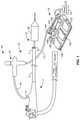
- FIG. 1is a simplified schematic overall view of an example of an ablation system including a cryogenic balloon ablation assembly and an endoscope.
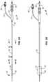
- FIG. 2Aillustrates an ablation catheter with a deflated balloon in tension.
- FIG. 2Billustrates an ablation catheter with an inflated balloon with the diffuser located at a distal region of the balloon.
- FIG. 2Cillustrates an ablation catheter with an inflated balloon with the diffuser located in a proximal region of the balloon.
- FIG. 3is a cross-sectional view taken along line 3 - 3 of FIG. 2A .
- FIG. 4Ais a cross-sectional view taken along line 4 A- 4 A of FIG. 2A .
- FIG. 4Bis a cross-sectional view taken along line 4 B- 4 B of FIG. 4A .
- FIG. 5Aillustrates an external view of the diffuser.
- FIG. 5Bis a cross section of the diffuser of FIG. 5A .
- FIG. 5Cis a cross section of the diffuser of FIG. 5A showing flow paths.
- FIG. 6Ais a detailed view of the balloon of FIG. 2A .
- FIG. 6Bis an isometric cross section view of the balloon of FIG. 2B .
- FIG. 6Cis a cross section view of the balloon of FIG. 2B
- FIG. 6Dis an isometric cross section view of the balloon of FIG. 2C
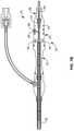
- FIG. 7Aillustrates an enlarged cross section view of the connector of FIG. 2A .
- FIG. 7Billustrates the connector of FIG. 7A with flow lines.
- FIG. 7Cillustrates an enlarged cross section view of the connector of FIG. 2B omitting the flow paths and showing the plug pulled distally in short distance.
- FIG. 7Dis an enlarged isometric view of the plug of FIG. 7C .
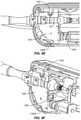
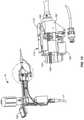
- FIG. 8is a partially exploded isometric view of portions of the ablation assembly of FIG. 1 .
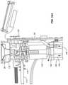
- FIG. 8Ais a right side cross section view of the handle assembly.
- FIG. 8Bis a left side cross section view of the handle assembly.
- FIGS. 8C and 8Dshow the relationship of the catheter plug locking wire relative to the plug locking slot of the plug when the ablation assembly is in the catheter connector disconnect state of FIGS. 13 and 13A .
- FIG. 8Eis a simplified schematic cross section the connector body locking wire biased away from the body locking slot of the connector body.
- FIG. 9is a cross-sectional view of the handle assembly in the controller load position
- FIG. 9Ais an enlarged view of a portion of the structure of FIG. 9 .
- FIGS. 9B and 9Cshow the catheter plug locking wire engaging the plug locking slot.
- FIG. 9Dshows the structure of FIG. 8E but with the connector body locking wire engaging the body locking slot of the catheter body.
- FIGS. 9E and 9Fillustrate how the pressure within the balloon is communicated to a pressure transducer in the controller connector.
- FIG. 10is a partial cross-sectional view of the traveler of FIG. 8A showing the idler gear connecting the drive gear and the purity of the plug.
- FIG. 11shows isometric views of portions of the handle assembly at the start of treatment.
- FIG. 12shows the structure of FIG. 11 at the end of treatment.
- FIG. 13shows the structure of FIG. 12 in a catheter connector disconnect state.
- FIG. 13Ais a left side partial cross-sectional view of the handle assembly in the catheter-disconnect state of FIG. 13 .
- FIG. 13B and 13Care top views of the structure of FIG. 13 .
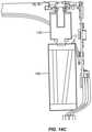
- FIGS. 14, 14A, 14B and 14Cillustrates how excess liquid refrigerant is directed into a refrigerant venting chamber: removal of the refrigerant canister from the handle assembly.
- FIG. 15illustrates how the handgrip portion of the handle assembly body is thermally insulated from the refrigerant venting chamber.
- FIGS. 16 and 17illustrate a linear positioner used to ensure the proper linear position of the traveler relative to the controller connector.
- FIG. 18is a simplified controller hardware architecture design chart.
- FIG. 1An embodiment of an ablation system with improved refrigerant delivery area is shown in FIG. 1 and comprises an endoscope 1 and a cryogenic balloon ablation assembly 10 .
- the endoscope 1may be conventional and include an endoscopic tube 3 having proximal and distal ends 5 , 7 defining a channel 8 extending between the proximal and distal ends.
- an ablation assembly 10comprises a cryogenic ablation catheter 12 and a controller assembly 13 .
- Controller assembly 13includes a handle assembly 14 and a foot pedal assembly 15 connected to handle assembly 14 by a power and control line 17 .
- Poweris supplied to controller assembly 13 by a power source 19 connected to foot pedal assembly 15 .
- Ablation catheter 12includes a catheter shaft 16 mounted to and extending from handle assembly 14 .
- FIGS. 2A, 2B and 2Cshow an embodiment of a cryogenic ablation catheter in three states that will be discussed below.
- Catheter 12includes a catheter shaft 16 having a proximal end 18 and a distal end 20 .
- a connector 22to be received in the handle assembly 14 .
- Connector 22includes a connector body 23 and a plug 38 , also called the second connector element 38 .
- a balloon 24At the distal end 20 is a balloon 24 that is inflatable by a refrigerant delivered from a refrigerant fluid source in the handle assembly 14 to a diffuser 36 located within the balloon.
- Diffuser 36is secured to and is fluidly coupled to the distal end of a delivery tube 30 .
- the diffuser 36translates within the balloon through the axial movement of delivery tube 30 as is discussed in greater detail below. As illustrated in FIGS. 2B and 2C , translation of the diffuser 36 is caused by translation of a plug 38 affixed and fluidly coupled to the delivery tube 30 at the connector end of the catheter 12 . As suggested by FIGS. 2B and 2C , plug 38 and delivery tube 30 and diffuser 36 therewith can be rotated to direct refrigerant in selected rotational directions and along selected rotational paths.
- the catheter shaft 16comprises a circular tube with a circular central lumen.
- the catheter shaft 16may, for example, range from 120 cm to 350 cm in length and have an outer diameter ranging from, for example, 0.100′′ to 0.138′′.
- the proximal end of the catheter shaft 16is affixed to the connector 22 , and the distal end is affixed to the balloon 24 .
- FIG. 3shows cross-section taken along line 3 - 3 of FIG. 2A .
- a pressure detecting tube 26located within the catheter shaft 16 is a pressure detecting tube 26 .
- the cavity between the inner wall of the catheter shaft and the outer wall of the pressure detecting tubedefines an exhaust lumen 28 for the passage of gases from the balloon interior for discharge through the connector 22 and exhaust passageway 138 in controller connector 100 , see FIG. 9A , which will be discussed in greater detail below.
- the pressure detecting tube 26includes a circular central lumen containing a delivery tube 30 .
- the cavity between the inner wall of the pressure detecting tube 26 and the outer wall of the delivery tube 30defines a pressure detecting lumen 32 used to detect the pressure within the balloon 24 .
- the pressure detecting tube 26extends from near the balloon end of the catheter shaft 16 to the connector 22 .
- the pressure detecting tube 26is affixed to the catheter shaft 16 near the distal end 20 of the catheter shaft 16 to be concentric to the catheter shaft lumen.
- the affixing meansincludes a bracket 34 with minimal flow obstruction of the exhaust lumen as shown in FIGS. 4A and 4B .
- the bracket 34is positioned a distance within the end of the catheter shaft 16 so that the a portion of the diffuser 36 may enter a portion of the catheter shaft 16 to allow delivery of refrigerant to portions of the balloon 24 located proximate to the distal end 20 of the catheter shaft 16 .
- the pressure detecting tube 26is a guide for the delivery tube 30 ensuring consistent 1:1 translation and rotation of the delivery tube within the pressure detecting tube without backlash.
- the interior surface of pressure detecting tube 26is a low friction surface, such as can be achieved by coating the interior surface with PTFE and the exterior surface of the delivery tube 30 with PTFE. For example when the proximal or plug end of the delivery tube 30 is translated 4 mm and rotated 90°, then the diffuser end, and this diffuser 36 , is also translated 4 mm and rotated 90°.
- the delivery tube 30extends from the plug 38 through the connector 22 ; through the pressure detecting tube 26 , and to the diffuser 36 .
- the delivery tube 30is made of a strong, flexible tubing or tubing assembly.
- the delivery tube 30may be comprised of a tubing assembly including an outer nitinol tube, which is very elastic and does not plastically deform (e.g. kink) easily, and an inner thin-walled polyimide tube.
- the nitinol tubingprovides structural support for the tubing assembly.
- the nitinol tubingprovides the strength necessary to prevent buckling during axial translation of the delivery tube. Further, the nitinol tubing transmits torque well which allows for rotational movement of the delivery tube.
- the outer tube of a delivery tube assemblyis a torque tube comprising stainless steel wires that undergo processes such as swaging, stretching, annealing, and then is wound around the inner tube to form a tubing assembly with good rotational and axial translation capabilities.
- the thin-walled polyimide inner tubeis made with tight tolerances which allows for consist flow of refrigerant through the delivery tube.
- the delivery tube during usemay experience internal pressures of 600 psi to 1200 psi and may be configured to have a wall thickness to withstand internal pressures up to 1500 psi.
- the delivery tube 30translates within the pressure detecting tube 26 in response to movement of the plug/second connector element 38 relative to the connector 22 .
- FIG. 2Ashows a state of the plug 38 , wherein the plug 38 abuts the connector body 23 and the diffuser 36 is located at a position toward the distal end of the balloon 24 , which is shown in a deflated state.
- FIG. 2Bshows a state of the plug 38 , wherein the plug 38 is located at a first intermediate position relative to the connector 22 and the diffuser 36 is located at a position in the balloon 24 , shown in an inflated state.
- FIG. 2Cshows a state of the plug 38 , wherein the plug 38 is located at a proximal position and rotated 90° which changes the orientation of nozzle port 40 90°.
- FIGS. 5A -5Can alternative example of diffuser 36 is shown.
- the outer diffuser tube 44 of the diffuser 36 of FIGS. 5A-5Chas a number of nozzle ports 40 arranged to direct refrigerant in a generally 360° rotary pattern in contrast with the limited rotary pattern created by the single nozzle port 40 shown in FIGS. 2A-2C and 6A-6D .
- the internal flow pathsdiscussed below with reference to FIGS. 5B and 5C , can be the same with both embodiments.
- the diffuser 36comprises a hollow internal cavity 45 fluidly connected to the delivery tube 30 . Cavity 45 has, in this example, four lateral passageways 47 extending from internal cavity 45 to a cylindrical cavity 49 .
- Nozzle ports 40extends through the outer surface of outer diffuser tube 44 and into cylindrical cavity 49 to permit refrigerant to flow as indicated by the refrigerant path 42 in FIG. 5C . This allows refrigerant supplied from a refrigerant fluid source in the handle assembly to be sprayed on the interior wall of the balloon 24 .
- the nozzle ports 40may be comprised of one or more slits located around the outer diffuser tube 44 .
- the slitsmay be stacked in multiple rows to allow openings in the wall at all radial position, for example in embodiments where spray is to be delivered 360 degrees. In embodiments the desired delivery angle of the spray may be less than 360, for example 45 degrees, 90 degrees or 180 degrees.
- the nozzle ports 40will be sized and positioned to deliver the desired angle of spray.
- the nozzle ports 40includes slits with a preferred height of 4 thousandths of an inch, but may range from 0.001′′ to 0.010′′.
- the path 42as shown in FIG. 5C , is configured to allow for even distribution of refrigerant by the point the refrigerant is at the nozzle port end of the diffuser 36 so that the pressure is equal radially around the inner cavity.
- the single, circular nozzle port 40 shown in FIGS. 6A-6Dmay have a diameter of about 0.020′′ to 0.060′′, typically about 0.040′′. Additionally, the single port shape is not limited to a circle, but may be other shapes including ellipses and rectangles.
- the balloon 24is expandable and collapsible and is mounted to the distal end of the catheter shaft 16 .
- FIG. 2Ashows a schematic of the balloon 24 in a deflated tension state
- FIGS. 2B and 2Cshow the balloon 24 in an inflated state.
- Balloon 24can be an elastic material, such as polyurethane, and can have an operating diameter in the range of 20 to 35 mm when inflated with less than 5 psi.
- Balloon 24has an inner surface defining a balloon interior.
- the balloon 24includes a tapered distal end secured to a flexible tip 48 .
- refrigerantflows out through one or more nozzle ports 40 of the diffuser 36 generally radially outwardly to create refrigerant spray directed at a target site along the inner surface of the balloon 24 .
- the target site of the inflated balloonis in contact with tissue and the delivery of refrigerant typically causes cryogenic ablation of tissue abutting target site of the balloon 24 .
- the target siteis larger than the area of spray delivery to the interior wall of the balloon 24 and the diffuser 36 translates along the length of the balloon and/or rotates within the balloon 24 while spraying to deliver refrigerant to the entire target site.
- the portion of the balloon capable of receiving refrigerant spray and shaped to be capable of contacting tissueis referred to as the working length of the balloon.
- the working length of the balloon 24includes straight wall portions, as shown in FIGS. 2B and 2C .
- the balloonmay further include tapered wall portions that usually do not contact tissue or receive refrigerant spray, as shown in FIGS. 2B and 2C .
- balloon 24can have an hourglass shape with its smallest diameter, its waist, being smallest at a position spaced apart from either end. The balloon with this configuration can be selected because it facilitates properly locating and cryogenically ablating target tissue which extends inwardly within the hollow body structure being treated.
- tissue at the sphincter between the esophagus and stomachexamples include tissue at the sphincter between the esophagus and stomach, and other tissue structures and shapes which are difficult to conform to using a balloon having, for example, a cylindrical outer surface. Therefore, during use a balloon can be selected having a non-cylindrical shape, such as an hourglass shape, which facilitates conforming the outer surface of the balloon to the tissue being treated. Balloons having shapes other than the moderate hourglass shape shown in FIGS. 6B-6D could be selected depending on the tissue being treated. For example, a balloon having two reduced diameter, waist portions could be chosen; the waist portions could have the same or different diameters.
- the balloon 24may include strain gauges used as input into a controller 50 , which is discussed below.
- the balloon 24is shown in detail in FIGS. 6A, 6B, 6C and 6D .
- the flexible tip 48is configured to assist in guiding the balloon end of the catheter while inserting the distal end of catheter 12 into a device, such as an endoscope, or into a bodily passage, such as an esophagus.
- a devicesuch as an endoscope
- endoscopescommonly have a kink in the port at which the catheter is inserted.
- the flexible tip 48is more flexible than the delivery tube 30 and prevents damage to the delivery tube 30 and balloon 24 during insertion of the catheter 12 .
- the flexible tip 48may encounter an obstacle causing it to bend a substantial amount. This amount of bending may cause damage to the delivery tube 30 and render it inoperable.
- the flexible tip 48may act as a sacrificial bending point which may be caused to bend a large amount during initial insertion and not have an effect on the operability of the overall device because the delivery tube 30 will be able to pass by the obstacle with a more gentle bend because the flexible tip 48 is further along the path of insertion and able to guide the remainder of the catheter 12 . Further, the flexible tip 48 may prevent damage to tissue in the body if during insertion the tip impacts tissue.
- Flexible tip 48includes a cylindrical cavity 49 slideably housing a delivery tube extension 51 .
- Extension 51is affixed to and extends from diffuser 36 .
- Extension 51is preferably made from a flexible material which resists kinking, such as nitinol.
- extension 51has a reduced diameter distal portion 52 to enhance the flexibility of the flexible, atraumatic tip 48 .
- One way to create the reduced diameter portion 52is through the use of centerless grinding.
- the flexible tip 48includes a rounded end 55 .
- Translating the delivery tube 30 toward the flexible tip 48can cause rounded and 55 to contact the distal end of flexible tip 48 . This can cause the balloon 24 to stretch in tension to the collapsed, minimum diameter position shown in FIG. 2A . The uses and benefits of this stretched position will be discussed in detail below.
- FIGS. 7A-7Cshow the connector 22 .
- the proximal end of the catheter shaft 16 and the pressure detecting tube 26are affixed to positions 53 and 54 within the connector body 23 .
- the connector 22includes an exhaust passage 62 that fluidly couples the exhaust lumen 28 to a radial exhaust port 64 on the exterior of the connector body 23 .
- the connector body 23includes a pressure detecting passage 66 that fluidly couples the pressure detecting lumen 32 , see FIGS. 4A and 4B , to a radial pressure detecting port 68 on the exterior of the connector body 23 .
- the connector body 23further includes a central passage 70 that the delivery tube 30 passes through between the pressure detecting passage 66 at the proximal end of the connecter 22 .
- the delivery tube 30is free to translate and rotate in the central passage 70 as well as pressure detecting tube 26 .
- the central passage 70is separated from the pressure detecting passage 66 by one or more seals 72 that allow the delivery tube 30 to translate and rotate in the pressure detecting tube 26 and pressure detecting passage 66 but prevents gas from the pressure detecting passage 66 being leaked out the central passage 70 .
- Connector body 23also includes a circumferentially extending body locking slot 74 used to secure connector body 23 to handle assembly 14 . This will be described in more detail below.
- Balloon 24can be deflated by connecting the interior of the balloon 24 to the ambient atmosphere through exhaust lumen 28 for the passage of gas into handle assembly 14 and then out to the ambient atmosphere. Doing this does not necessarily fully collapse the balloon.
- a syringe, or other appropriate devicecan be fluidly coupled to the exhaust lumen 28 within connector body 23 through a syringe coupler 56 connected to connector body 23 by tubing 57 .
- Syringe coupler 56includes a one-way valve which opens only when a syringe, or other vacuum/pressure application structure, is mounted to syringe coupler 56 .
- a syringecan be used to expand the balloon, or expand and contract the balloon, such as during placement of the balloon.
- FIG. 7Dis an enlarged perspective view of the plug 38 with delivery tube 30 passing through the plug and extending distally therefrom.
- delivery tube 30is affixed to plug 38 , such as with an epoxy type adhesive.
- Plug 38has a circumferentially extending plug locking slot 84 used to pull plug 38 proximally and push plug 38 distally along the delivery tube axis 87 . This causes corresponding movement of the delivery tube 30 and diffuser 36 .
- Plug 38also has gear teeth 85 used to allow plug 38 , and delivery tube 30 therewith, to be rotated about the delivery tube axis 87 .
- FIG. 8is a partially exploded isometric view of portions of ablation assembly 10 .
- Handle assembly 14is shown to include a handle assembly body 90 having a handgrip portion 92 to which power and control line 17 is attached.
- Body 90also includes a hollow, externally threaded tower 94 used to receive a refrigerant source 96 , typically a nitrous cartridge with a preferred size of ⁇ 50 mL containing about 36 grams of nitrous oxide.
- a hollow, internally threaded cap 98secures refrigerant source 96 within handle assembly body 90 .
- Handle assembly 14also includes a connector receptacle 99 , also called first connector element 99 , of controller connector 100 , see FIG. 8A , for receipt of connector 22 .
- FIG. 8Ais a right side view of the structure shown in FIG. 8 in a partially assembled form with the right side of the handle assembly body 90 removed to show internal components.
- Controller 50shown mounted to a main printed circuit board 101 .
- Connector 22is shown in the process of being fully inserted into connector receptacle 99 to be placed in the load position.
- Assembly 14includes a heater 102 used to heat nitrous cartridge 96 when needed.
- a linear drive motor 104is connected to a rotatable, threaded shaft 106 by a threaded shaft coupler 108 . Threaded shaft 106 passes through and is threadably connected to a traveler 110 , also referred to as the traversing member, resulting in the linear, axial movement of the traveler.
- Traveler 110is supported by and guided by a pair of bearing shafts 112 , 113 along which traveler 110 slides.
- Bearing shaft 113is shown in FIG. 8B .
- Extending from connector 22is a balloon inflation/deflation line 114 terminating at the connector 116 , typically configured to attach to a syringe. The syringe is typically used when desired to completely deflate balloon 24 .
- Refrigerant from cartridge 96passes through a delivery line 118 terminating at traveler 110 .
- Delivery line 118is a flexible delivery line and can be looped around bearing shafts 112 , 113 without kinking to accommodate the linear, axial movement of traveler 110 .
- the rotation of linear drive motor 104is monitored by controller 50 through the use of a counter wheel 119 , having light and dark segments, and an appropriately located light sensor to monitor the rotation of counter wheel 119 .
- FIG. 8Bcorresponds to FIG. 8A but illustrates the left side of the structure.
- Handle assembly 14includes a rotation motor 120 connected to a rotation shaft 122 by a rotation coupler 124 .
- Rotation of rotation motor 120is monitored by controller 50 through the use of a counter wheel 125 and an appropriately located light sensor in a manner similar to that used with linear drive motor 104 .
- Rotation shaft 122has, in this example, a square cross-sectional shape; other rotationally driving shapes can also be used.
- Rotation shaft 122passes through traveler 110 a manner which allows shaft 122 to freely rotate within traveler 110 and allows traveler 110 to move freely in a linear, axial manner.
- a drive gear 126is bracketed by traveler 110 to move with the traveler.
- Drive gear 126is rotationally coupled to rotation shaft 122 so that rotation of shaft 122 causes drive gear 126 to rotate.
- Drive gear 126is slideably mounted to rotation shaft 122 so that the drive gear slides along rotation shaft 122 as traveler 110 moves in its linear, axial manner. As will be explained below, when connector 22 is mounted to handle assembly 14 , rotation of shaft 122 causes the plug 38 and delivery tube 30 therewith to rotate.
- Refrigerant from refrigerant source 96passes through a manifold 128 ( FIG. 8B ) under the control of the refrigerant controlling delivery solenoid 130 , through a delivery line coupler 129 , see FIG. 9 , and into delivery line 118 .
- the pressure within refrigerant source 96is monitored by controller 50 through a pressure transducer 141 .
- the operation of delivery solenoid 130can be controlled by the operator using foot pedal assembly 15 .
- tapping refrigerant delivery foot pedal 132typically provides enough refrigerant to expand balloon 24 and provide visualization of the location of the refrigerant port.
- Foot pedal assembly 15also includes a foot-actuated deflation button 134 which allows the operator to deflate the balloon, typically placing the balloon interior of the balloon at atmospheric pressure. Pressing deflation button 134 actuates an exhaust solenoid valve 136 , see FIG.
- FIG. 9Awhich is connected to exhaust passage 62 ( FIG. 7B ) of connector body 23 by a passageway 138 .
- the exhaust from the balloon 24 through the actuation of exhaust solenoid valve 136enters the interior of handle assembly body 90 .
- Body 90has two, redundant ports 133 , 135 to help ensure that gases vented into the interior of handle assembly body 90 can escape to the ambient environment regardless of how handle assembly body 90 is being held.
- pressure relief valve 145will actuate, mitigating the risk of balloon over pressurization. See FIGS. 9E and 9F .
- Pressure relief valve 145also enables the balloon to remain statically inflated at a regulated pressure of, for example, 2.9 psig.
- Controller 50controls and monitors the pressure of the refrigerant within refrigerant source 96 using a temperature sensor such as a thermistor 137 , see FIG. 14 , and pressure transducer 141 , see FIG. 9 . Having accurate pressure and temperature information for the refrigerant within refrigerant source 96 allows the system to determine if the nitrous oxide cylinder contains liquid based on the saturated liquid/gas properties of the refrigerant. Additionally, the temperature sensor can be used to detect a malfunction in the heater circuit that may result in overheating and hence over pressurization of the refrigerant cartridge. If overheating is detected, the controller will turn of the heater and/or completely disconnect itself from power.
- a temperature sensorsuch as a thermistor 137 , see FIG. 14 , and pressure transducer 141 , see FIG. 9 .
- Foot pedal assembly 15also includes the left and right movement foot pedals 140 , 142 .
- Left and right foot pedals 140 , 142are used to control linear drive motor 104 and rotation motor 120 .
- the userselects which function left and right foot pedals 140 , 142 will be used for, that is linear movement or rotational movement.
- movement mode button 144foot pedal assembly 15 provides the operator with an indication of which mode has been selected by the illumination of either straight arrows 146 , 147 , or curved arrows 148 , 149 .
- Depressing movement mode button 144again changes the mode from linear motion to rotational motion.
- counterclockwise curved arrow 148 and clockwise curved arrow 149are illuminated indicating the direction of rotation of delivery tube 30 and diffuser 36 associate with pressing left and right foot pedals 140 , 142 .
- Depressing the left foot pedal 140provides a signal to rotation motor 120 to rotate rotation shaft 122 in a counterclockwise direction thus causing delivery tube 30 and diffuser 36 therewith to rotate in a counterclockwise direction.
- Depressing right foot pedal 142provides a signal to rotation motor 120 to rotate rotation shaft 122 in a clockwise direction thus causing delivery tube 30 and diffuser 36 to rotate in a clockwise direction.
- Typical operational parameters for ablation assembly 10include the following. Translation at a rate between 0.25 mm/sec to 2.5 mm/sec, wherein the rate of translation for therapeutic use is between 0.5 mm/sec and 1.5 mm/sec. Rotation can be at a rate between 1 and 10 RPM.
- controller 50could create a visual indication of the selection on an LCD display 150 on handle assembly 14 .
- an audible indication of the selectioncan be provided by broadcasting a verbal alert, such as linear movement selected, or by a nonverbal alert, for example a single beep for counterclockwise rotation, and a double beep for clockwise rotation, a long tone for proximal linear movement, and a double long tone for distal linear movement.
- FIG. 9Bis a simplified illustration showing the relationship of catheter plug locking wire 152 relative to plug locking slot 84 of plug 38 when assembly 10 is in the connector-attachment state of FIGS. 9 and 9A . This state is also shown in FIG. 9C .
- the legs 154are expanded outward while riding along tapered surface 156 of plug 38 , see FIG. 7D , and the tapered leading edges 158 of gear teeth 85 .
- the legs 154 of catheter plug locking wire 152will snap into plug locking slot 84 as shown in FIGS. 9B and 9C .
- FIG. 9Dis a simplified illustration showing the relationship of connector body locking wire 160 relative to body locking slot 74 of connector body 23 when ablation assembly 10 is in the connector attachment state of FIGS. 9 and 9A .
- connector body locking wire 160is deflected away, FIG. 8E , as it rides along tapered surface 162 of connector body 23 , see FIG. 7A .
- FIG. 9Dillustrates that when connector 22 is fully inserted into handle assembly body 90 , connector body locking wire 160 will snap into body locking slot 74 as shown in FIG. 9D .
- examples of ablation assembly 10provide for the automatic attachment of connector 22 to handle assembly 14 .
- FIG. 10illustrates the relationship among drive gear 126 , driven by rotation shaft 122 , gear teeth 85 of plug 38 , and an idler gear 166 coupling the two.
- Drive gear 126 and idler gear 166are both mounted to traveler 110 at fixed locations relative to traveler 110 , but are free to rotate, and remain engaged as traveler 110 is moved in a linear manner by the rotation of threaded shaft 106 .
- the ends 168 of the gear teeth of idler gear 166have a V-shaped taper to promote the proper engagement with gear teeth 85 as plug 38 is inserted through first connector element 99 when ablation assembly 10 is in the connector attachment state of FIG. 9 .
- FIG. 11illustrates a portion of the structure of FIG. 9 after movement of traveler 110 a short distance proximally, to the left in FIG. 11 , placing assembly 10 in a distal, typically starting, treatment position corresponding to FIG. 2B .
- FIG. 12shows the structure of FIG. 11 after further movement of traveler 110 in a proximal direction, that is to the left in FIG. 12 , placing assembly 10 in a proximal, typically ending, treatment position corresponding FIG. 2C . Because refrigerant is sprayed into the interior of the balloon 24 during treatment, the exhaust valve 136 can remain open during the treatment.
- FIGS. 13, 13A, 13B and 13Cshow handle assembly 14 in a connector disconnect state with traveler 110 moved in the distal direction, that is to the right in FIG. 13 , to a catheter disconnect position. Doing so causes connector locking wire 160 , mounted to controller connector 100 , be deflected outwardly by the engagement of ramp 170 , ramp 170 being a part of traveler 110 , so that it moves out of body locking slot 74 as shown in FIG. 8E . Continued movement of traveler 110 to the catheter disconnect position also causes catheter plug locking wire 152 , which moves with traveler 110 , to be engaged by a ramp 174 causing plug locking wire 152 to move out of plug locking slot 84 from the plug engaged position of FIGS.
- Examples of ablation assembly 10provide for the automatic detachment/ejection of connector 22 from handle assembly 14 .
- Handle assembly 14has a liquid path, shown in FIGS. 14, 14A, 14B, and 14C , for the passage of liquid refrigerant from a region 176 adjacent to the tip 178 to a refrigerant venting chamber 180 .
- Liquid pathincludes first, second and third portion 182 , 184 , 186 .
- First portion 182extends to region 176
- second portion 184connects first portion 182 to third portion 186 .
- Third portion 186extends to refrigerant venting chamber 180 .
- Refrigerant venting chamber 180is filled with a foam material, typically open cell polyurethane foam, and has an entrance path 188 and an exit path 190 formed in the foam material. Exit path 190 opens into the interior of handle assembly 14 at an exit port 192 . Under the reduced pressure within venting chamber 180 , the liquid refrigerant is absorbed by the foam material and transformed into a gas for collection within exit path 190 , passage through exit port 192 into the interior of handle assembly body 90 . The gas exits through one or more of the exhaust ports 133 , 135 in the handle assembly body.
- a foam materialtypically open cell polyurethane foam
- refrigerant venting chamber 180is wrapped with a thermal insulation material 194 , see FIG. 15 , and is spaced apart from the handle assembly body by insulating spacers 196 .
- thermal insulation materialcan be made of, for example, air
- insulating spacers 196can be made of, for example, neoprene.
- the pressure within the balloon 24is communicated to a pressure transducer 143 in the controller connector 100 . See FIGS. 9E and 9F .
- the pressure detecting lumen 32 of the catheteris fluidly coupled to the pressure transducer 143 in the controller through the pressure detecting passage 66 and the pressure detection port 68 of the connector body 23 .
- the pressure detecting passage 66 and the pressure detecting port 68are shown in FIG. 7B .
- the O-rings 88 on either side of the pressure detection port 68form a seal within the controller connector 100 , as shown in FIG. 9A .
- Pressure transducer 143is coupled to controller 50 to provide a pressure signal thereto. For clarity connection wires from components to the controller 50 are omitted from the figures.
- the controller 50may be used to control the delivery of refrigerant and the rotation and translation of the delivery tube 30 and diffuser 36 within the balloon 24 .
- the controller 50includes circuitry connected to components including the foot pedal assembly 15 , delivery solenoid 130 , exhaust solenoid 136 , linear drive motor 104 , rotation motor 120 , counter wheels 119 , 125 , pressure transducers 141 , 143 , heater 102 , thermistor 137 , optical sensor 165 , current sensors, and accelerometer,
- the controller 50during release of refrigerant into the balloon 24 the controller 50 generates a pressure response curve from pressure data from the pressure transducer 141 , which correlates to the inner diameter of the lumen to be treated.
- the controller 50uses a pressure algorithm to determine the rate of speed for the linear actuator appropriate for treatment.
- a strain gauge or gauges on the balloon 24may be used by the controller 50 to derive balloon diameter which corresponds to the inner diameter of the treated lumen.
- the controllermay be attached to forms of user interfaces in addition to or instead of those provided by foot pedal assembly 15 and LCD display 150 , including buttons on the housing of the handle assembly and remote touch displays.
- FIG. 18is a simplified diagram showing the basic organization of control electronics of the controller 50 .
- control electronicsmay be connected to additional components including user outputs including lights and displays, additional temperature sensors, heater controllers, accelerometers, detector switches, and solenoid valves.
- the controllermay contain treatment algorithms and the inputs of components may be used by the algorithms to adjust treatment parameters, for example duration, flow rate of refrigerant, translation distance and speed, and rotational angles and speed.
- the catheter 12may include an RFID tag or chip 198 , see FIG. 9A , identifying properties of the catheter including size of balloon, angle of spray of diffuser.
- the controller 50may receive this information from an RFID reader 200 in the handle assembly 14 and input the information into a treatment algorithm to adjust treatment parameters depending on the properties of the attached catheter.
- the RFIDmay be used for authentication purposes. For example, a non-conforming catheter (e.g. reused or overused catheter, or catheter made by an uncertified manufacturer) may be detected by the controller and the controller will lock out the device from operating with the non-conforming catheter attached.
- the RFIDmay further be used for orientation purposes to ensure catheter is oriented properly.
- handle assembly 14can be considered universal handle for use with a wide variety of catheters 12 because information regarding the catheter can be automatically provided to controller 50 within handle assembly 14 through the use of RFID chips 198 and RFID reader 200 .
- the usermay select a treatment algorithm prior to initiating the treatment. Additionally the user may be able to input various parameters to be used in the selected treatment algorithm.
- the informationmay include patient data, catheter information and number of treatments performed.
- the user interface for selecting and setting a treatmentmay the input on a separate device to permit programming remotely with reception by the controller wirelessly, wired or, for example, via a removable memory card.
- the controllermay record the number of uses of a catheter and save this information, or transmit this information to a central database to ensure no overuse of catheters.
- RFID tags on the cathetermay be writeable so the controller can program catheter to be read in the future.
- the written materialmay include a lockout or a time of last use.
- a cryogenic ablation catheter 12is selected according to the treatment to be undertaken.
- An endoscopeis inserted in the esophagus of a patient.
- Ablation catheter 12 with the plug 38 in the most distal position as shown in FIG. 2Ais inserted into the proximal end 5 of the channel 8 of endoscopic tube 3 .
- the plug 38 in the most distal positioncauses the diffuser 36 to push the flexible tip 48 away from the catheter shaft 16 causing the deflated balloon 24 to be in tension.
- the catheter 12is inserted through the channel 8 until the balloon 24 exits the distal end 7 . Using the monitor attached to the endoscope the user is able to see the balloon exit.
- traveler 110With the system powered on, traveler 110 is translated by linear drive motor 104 to the connector load position of FIG. 9 .
- a linear positioner 163is used to ensure the proper linear position of traveler 110 relative to controller connector 100 .
- Traveler 110has a length of finely spaced lines 164 , such as about 250 per inch, which are sensed by one or more optical sensors 165 carried by controller connector 100 . See FIGS. 16 and 17 .
- the userselects, if desired, a treatment algorithm, inputs any necessary parameters, and taps on the refrigerant delivery foot pedal 132 to initially inflate the balloon 24 .
- This initial inflationis required to visualize the location of target site relative to the lesion to be ablated.
- This initial inflationmay include translating the diffuser to a position to allow for the balloon to be relaxed and no longer in tension.
- a syringe mounted to syringe coupler 56could be used to initially inflate the balloon. An example of this position is shown in FIG. 2B .
- balloon 24can be repositioned axially; this may or may not require the partial deflation balloon 24 followed by re-inflation of the balloon.
- refrigerantis delivered to the diffuser to be sprayed on the interior wall of the balloon 24 . While the refrigerant is being sprayed the diffuser can be translated toward the proximal end of the balloon or rotated about its axis using the pedal assembly 15 .
- the flow rate of refrigerant, rotation rate and translation rate of the diffuser 36are ideally set so that an ideal amount of refrigeration energy is received by each portion of the lesion to ensure ablation of the entire desired area. If the movement of the delivery tube assembly jams for any reason the controller will stop the delivery of refrigerant to prevent over ablation of tissue that may cause damage. Jams can be detected from the counter wheel 119 or monitoring current to the motors 104 , 120 .
- An ablation assemblycomprising:
- the user control assembly 15comprises a foot pedal assembly 15 spaced apart from the handle assembly 14 and connected to the handle assembly by a line 17 , the foot pedal assembly comprising foot actuated input devices.
- the foot pedal assembly 15comprises a left movement foot pedal 140 , a right movement foot pedal 142 and movement mode button 144 by which the user can change the mode of operation of the left and right movement foot pedals to actuate either the linear driver or the rotary motion driver.
- controller assemblycomprises a controller 50
- user control assemblyis operably coupled to the refrigerant controller, the linear driver, and the rotary motion driver through the controller.
- controller 50is configured to monitor the pressure and temperature of the refrigerant fluid source 96 , whereby the status of the refrigerant can be monitored.
- An ablation assemblycomprising:
- An ablation assemblycomprising:
- a handle assembly 14 for use with a cryogenic ablation assembly 10comprising:
- Catheter identification structure for a cryogenic ablation assembly 10 of the typeincluding a handle assembly 14 and a catheter assembly, the catheter 12 comprising a catheter shaft 16 having distal and proximal ends, a connector 22 at the proximal end of the catheter shaft, the handle assembly 14 comprising an open portion for receipt of at least a portion of the connector, the catheter identification structure comprising:
Landscapes
- Health & Medical Sciences (AREA)
- Surgery (AREA)
- Life Sciences & Earth Sciences (AREA)
- Nuclear Medicine, Radiotherapy & Molecular Imaging (AREA)
- Engineering & Computer Science (AREA)
- Animal Behavior & Ethology (AREA)
- Veterinary Medicine (AREA)
- Public Health (AREA)
- General Health & Medical Sciences (AREA)
- Molecular Biology (AREA)
- Medical Informatics (AREA)
- Biomedical Technology (AREA)
- Heart & Thoracic Surgery (AREA)
- Physics & Mathematics (AREA)
- Otolaryngology (AREA)
- Pathology (AREA)
- Oral & Maxillofacial Surgery (AREA)
- Electromagnetism (AREA)
- General Physics & Mathematics (AREA)
- Theoretical Computer Science (AREA)
- Surgical Instruments (AREA)
- Media Introduction/Drainage Providing Device (AREA)
Abstract
Description
- a
controller assembly 13 comprising ahandle assembly 14, acontroller 50, and auser control assembly 15 coupled to the controller, the handle assembly comprising afirst connector element 99; - a
cryogenic ablation catheter 12 comprising: - a
catheter shaft 16 having proximal and distal ends and a catheter shaft lumen extending between the proximal and distal ends; - a
connector 22 at the proximal end of the catheter shaft selectively connected to the first connector element of the handle assembly, the connector comprising aconnector body 23 and asecond connector element 38, the first and second connector elements being mating connector elements; - an expandable and
collapsible balloon 24 mounted to the distal end of the catheter shaft, the balloon having an inner surface defining a balloon interior; - a delivery tube assembly comprising:
- a
delivery tube 30 housed within the catheter shaft for axial and rotational movement relative to the catheter shaft, the delivery tube having a proximal end connected to the second connector element; and - a
diffuser 36, within the balloon, fluidly coupled to the delivery tube; and - the handle assembly comprising:
- a
handle assembly body 90; - a
controller connector 100 mounted to the handle assembly body and defining the first connector element, the connector body securable to the controller connector; - a
traveler 110 movably mounted to the handle assembly body for movement along an axis towards and away from the controller connector, the second connector element securable to the traveler for axial movement therewith; - a
refrigerant fluid source 96 selectively fluidly coupled to adelivery line 118 by therefrigerant controller - a
linear driver - a
rotary motion driver - the user control assembly operably coupled to the refrigerant controller, the linear driver and the rotary motion driver, the user control assembly comprising user inputs permitting the user to actuate the refrigerant controller, the linear driver and the rotary motion driver;
- whereby the user can control the rotation and translation of the diffuser within the balloon to direct refrigerant outwardly in a desired pattern towards the inner surface of the balloon according to the size and location of the treatment site.
- a
- the
cryogenic ablation catheter 12 comprises anexhaust lumen 28 between thecatheter shaft 16 and thedelivery tube 30, the exhaust lumen having a distal end opening into the interior of the balloon; - the
foot pedal assembly 15 comprises: - a refrigerant
delivery foot pedal 132 by which a user can actuate the refrigerant controller to supply refrigerant to theballoon 24; and - a
deflation button 134; - the handle assembly comprises an
exhaust solenoid 136 operably coupled to the deflation button to permit the user to selectively exhaust gas from the balloon interior.
- the
- the traveler is positionable along the axis at a first, eject position, a second, load position, and at a range of third, operational positions, the first, eject position being closest to the controller connector, the second, load position being between the first, eject positions and the third, operational positions, and further comprising:
- means for automatically securing the
connector body 23 to thecontroller connector 100 and thesecond connector element 38 to thetraveler 110 when the connector is inserted into the connector receptacle and the traveler is at the second, load position; and - means for automatically releasing the connector body from the controller connector and the second connector element from the traveler when the traveler is at the first, eject position to permit removal of the connector from the handle assembly body.
- the automatically securing means comprises means for simultaneously automatically securing the
connector body 23 to thecontroller connector 100 and thesecond connector element 38 to thetraveler 110 when the connector is inserted into the connector receptacle and the traveler is at the second, load position; and - the automatically releasing means comprises means for automatically releasing the connector body from the controller connector as the traveler moves to the first, eject position, and thereafter releasing the second connector element from the traveler to permit removal of the connector from the handle assembly body.
- the automatically securing means comprises means for simultaneously automatically securing the
- the
refrigerant fluid source 96 comprises a removable and replaceable refrigerant cartridge having a refrigerant discharge portion/tip 178 through which refrigerant can pass to thedelivery line 118 via therefrigerant controller - the
handle assembly body 90 comprises arefrigerant venting chamber 180 and apathway handle assembly body 90; - whereby residual liquid refrigerant from the refrigerant cartridge can flow into the refrigerant venting chamber for transformation into a refrigerant gas, the refrigerant venting chamber having an
exit port 192 to permit the refrigerant gas to exit the refrigerant venting chamber.
- the
- the traveler is positionable along the axis at a first, eject position, a second, load position, in the range of third, operational positions, the first, eject position being closest to the controller connector, the second, load position being between the first, eject positions and the third, operational positions, and further comprising:
- the rotary motion driver comprises:
- a
rotation motor 120 drivingly connected to anon-cylindrical rotation shaft 122; - a
drive gear 126 mounted totraveler 110 for axial movement with the traveler, the drive gear also slideably mounted to the rotation shaft, whereby rotation of the rotation shaft causes the drive gear to rotate while axial movement of the traveler causes the drive gear to slide along the rotation shaft; and gear teeth 85 formed onsecond connector element 38 and rotatably coupled to the drive gear when the traveler is in either the second, load position or the third, operational position, so that rotation of the drive gear causes thesecond connector element 38 to rotate; and- the linear driver comprises a
linear drive motor 104 connected to a threadedshaft 106 by a threadedshaft coupler 108, the threaded shaft threadably engaging thetraveler 110 so that rotation of the threaded shaft causes the traveler to move axially.
- the
connector 22 comprises anRFID device 198 containing information relating to thecryogenic ablation catheter 12; and - the handle assembly comprises an
RFID reader 200 used to obtain information from the RFID device.
- the
- a
pressure detecting lumen 32 extends along thecatheter shaft 16 fluidly coupling the balloon interior and theconnector body 23; and - the
controller 50 is configured to use input received from apressure transducer 143 operably coupled to thepressure detecting lumen 32 through theconnector body 23 to detect a pressure within theballoon 24.
- a
- a
handle assembly 14; and - a
catheter 12 comprising: - a
catheter shaft 16 having distal and proximal ends; - a
balloon 24 at the distal end of the catheter shaft; - a
connector 22 at the proximal end of the catheter shaft; - a
delivery tube 30 extending between the balloon and the proximal end of the catheter shaft; and - the connector comprising a
connector body 23 secured to the proximal end of the catheter shaft and aplug 38 secured to the delivery tube, the plug and delivery tube therewith movable axially and rotationally relative to the catheter shaft; - the handle comprising an open portion for receipt of the plug and at least a portion of the connector body; and
- a connector locking assembly comprising:
- a connector
body locking slot 74 formed in and circumscribing theconnector body 23; - a
plug locking slot 84 formed in and circumscribing theplug 38; - a connector
body locking element 160 mounted to the handle and positioned to engage the connectorbody locking slot 74 when theconnector 22 is in a load state; - a
plug locking element plug locking slot 84 when the connector is in the load state, thereby simultaneously automatically connecting theplug 38 and theconnector body 23 to the handle to place the connector in a load state prior to use; and - a connector
body locking element 160 mounted to the handle and positioned to disengage from the body locking slot when the connector is being placed in an eject state, and aplug locking element connector body 23 and thereafter theplug 38 from the handle to permit the connector to be removed from the handle.
- a
- the
connector body 23 comprises atapered surface 162 engageable by thefirst spring 160 when the connector is placed into the load state; and - the
plug 38 comprises atapered surface 156 engageable by thesecond spring
- the
- the connector locking assembly comprises a
ramp 170 engageable by thefirst spring 160 when the connector is placed into the eject state; and - the connector locking assembly comprises a
ramp 174 engageable by thesecond spring
- the connector locking assembly comprises a
- a
handle assembly 14; and - a
catheter 12 comprising: - a
catheter shaft 16 having distal and proximal ends; - a
balloon 24 at the distal end of the catheter shaft; - a
connector 22 at the proximal end of the catheter shaft; - a
delivery tube 30 extending between the balloon and the proximal end of the catheter shaft; and - the connector comprising a
connector body 23 secured to the proximal end of the catheter shaft and aplug 38 secured to the delivery tube, the plug and delivery tube therewith movable axially and rotationally relative to the catheter shaft; - the handle comprising an open portion for receipt of the plug and at least a portion of the connector body; and
- a connector locking assembly comprising:
- means for simultaneously automatically connecting the plug38 (84,152,154,156,158) and the connector body23 (160,174,162) to the handle to place the connector in a load state prior to use; and
- means for automatically releasing the connector body (74,110,160,170) and thereafter the plug (84,110,152,154,174) from the handle to place the connector in an eject state to permit the connector to be removed from the handle.
- a
- a
handle body 90 having an interior; - a
refrigerant fluid source 96 within the interior comprising a removable and replaceablerefrigerant cartridge 96 from which refrigerant can pass for use by thecryogenic ablation assembly 10 when the refrigerant fluid source is at an operational position, the refrigerant source comprising arefrigerant discharge portion 178; - the
handle body 90 containing arefrigerant venting chamber 180 and apathway handle body 90; - the handle body comprising an
exhaust port - whereby residual liquid refrigerant from the refrigerant cartridge can flow into the refrigerant venting chamber for transformation into a refrigerant gas, the refrigerant venting chamber having an
exit port 192 to permit the refrigerant gas to exit the refrigerant venting chamber and into a region external of therefrigerant venting chamber 180 and within thehandle body 90, for passage through the exhaust port to the ambient atmosphere.
- a
- the
refrigerant venting chamber 180 is filled with a material with anentrance path 188 and anexit path 190 formed in the material, the entrance path connected to the pathway; and - the
exit path 190 terminating at theexit port 192; - whereby under a reduced pressure within the
refrigerant venting chamber 180, the liquid refrigerant is absorbed by the foam material and transformed into a gas for collection within theexit path 190, passage throughexit port 192 into said region external of therefrigerant venting chamber 180 and within thehandle body 90.
- the
- a
thermal insulation material 194 between therefrigerant venting chamber 180 and thehandle body 90; and spacers 196 between thethermal insulation material 194 and thehandle body 90.
- a
- an
RFID device 198 carried by theconnector 22 containing information relating to thecatheter 12; and - an
RFID reader 200 carried by the handle assembly used to obtain information from the RFID device.
- an
Claims (19)
Priority Applications (1)
| Application Number | Priority Date | Filing Date | Title |
|---|---|---|---|
| US16/171,233US11266456B2 (en) | 2016-05-20 | 2018-10-25 | Cryogenic ablation system with rotatable and translatable catheter |
Applications Claiming Priority (3)
| Application Number | Priority Date | Filing Date | Title |
|---|---|---|---|
| US201662339611P | 2016-05-20 | 2016-05-20 | |
| US15/593,790US10251693B2 (en) | 2016-05-20 | 2017-05-12 | Cryogenic ablation system with rotatable and translatable catheter |
| US16/171,233US11266456B2 (en) | 2016-05-20 | 2018-10-25 | Cryogenic ablation system with rotatable and translatable catheter |
Related Parent Applications (1)
| Application Number | Title | Priority Date | Filing Date |
|---|---|---|---|
| US15/593,790ContinuationUS10251693B2 (en) | 2016-05-20 | 2017-05-12 | Cryogenic ablation system with rotatable and translatable catheter |
Publications (2)
| Publication Number | Publication Date |
|---|---|
| US20190059970A1 US20190059970A1 (en) | 2019-02-28 |
| US11266456B2true US11266456B2 (en) | 2022-03-08 |
Family
ID=60326079
Family Applications (2)
| Application Number | Title | Priority Date | Filing Date |
|---|---|---|---|
| US15/593,790ActiveUS10251693B2 (en) | 2016-05-20 | 2017-05-12 | Cryogenic ablation system with rotatable and translatable catheter |
| US16/171,233Active2038-08-14US11266456B2 (en) | 2016-05-20 | 2018-10-25 | Cryogenic ablation system with rotatable and translatable catheter |
Family Applications Before (1)
| Application Number | Title | Priority Date | Filing Date |
|---|---|---|---|
| US15/593,790ActiveUS10251693B2 (en) | 2016-05-20 | 2017-05-12 | Cryogenic ablation system with rotatable and translatable catheter |
Country Status (8)
| Country | Link |
|---|---|
| US (2) | US10251693B2 (en) |
| EP (1) | EP3457969B1 (en) |
| JP (2) | JP7021113B2 (en) |
| KR (1) | KR102366631B1 (en) |
| CN (2) | CN109414284B (en) |
| AU (2) | AU2017267476B2 (en) |
| BR (1) | BR112018073746A8 (en) |
| WO (1) | WO2017200877A1 (en) |
Families Citing this family (25)
| Publication number | Priority date | Publication date | Assignee | Title |
|---|---|---|---|---|
| US8382746B2 (en) | 2008-11-21 | 2013-02-26 | C2 Therapeutics, Inc. | Cryogenic ablation system and method |
| JP7021113B2 (en) | 2016-05-20 | 2022-02-16 | ペンタックス・オブ・アメリカ・インコーポレイテッド | Cryogenic excision system with rotatable and translatable catheter |
| US10695060B2 (en) | 2017-09-01 | 2020-06-30 | RevMedica, Inc. | Loadable power pack for surgical instruments |
| US11331099B2 (en) | 2017-09-01 | 2022-05-17 | Rev Medica, Inc. | Surgical stapler with removable power pack and interchangeable battery pack |
| US10966720B2 (en)* | 2017-09-01 | 2021-04-06 | RevMedica, Inc. | Surgical stapler with removable power pack |
| WO2019126342A1 (en)* | 2017-12-21 | 2019-06-27 | Cryterion Medical, Inc. | Foot control assembly and method |
| US10994039B2 (en)* | 2017-12-26 | 2021-05-04 | Asp Global Manufacturing Gmbh | Storage apparatus and method for identifying a position of an object |
| USD902872S1 (en)* | 2018-11-07 | 2020-11-24 | Steute Technologies Gmbh & Co. Kg | Foot switch |
| US20200146858A1 (en)* | 2018-11-08 | 2020-05-14 | Ostial Corporation | Dual balloon catheters and methods for use |
| US12290257B2 (en) | 2019-07-19 | 2025-05-06 | RevMedica, Inc. | Surgical clip applier with removable power pack |
| EP3998960A4 (en) | 2019-07-19 | 2022-12-14 | Revmedica, Inc. | Surgical stapler with removable power pack |
| US12279771B2 (en) | 2019-07-19 | 2025-04-22 | RevMedica, Inc. | Power pack for activating surgical instruments and providing user feedback |
| US12357307B2 (en) | 2022-05-13 | 2025-07-15 | RevMedica, Inc. | Power pack for activating surgical instruments and providing user feedback |
| US12279770B2 (en) | 2019-07-19 | 2025-04-22 | RevMedica, Inc. | Power pack for activating surgical instruments and providing user feedback |
| USD902873S1 (en)* | 2019-07-24 | 2020-11-24 | Xuan Chen | Electronic panel with four buttons |
| WO2021171891A1 (en)* | 2020-02-27 | 2021-09-02 | テルモ株式会社 | Article having communication function, and communication system |
| CN111631807B (en)* | 2020-06-09 | 2025-09-23 | 上海导向医疗系统有限公司 | A cryoinflated balloon |
| CN112263321B (en)* | 2020-06-23 | 2022-04-01 | 上海微创电生理医疗科技股份有限公司 | Cryoablation temperature control method, system and medium |
| US12178535B2 (en) | 2021-03-01 | 2024-12-31 | RevMedica, Inc. | Power pack for activating surgical instruments |
| WO2022261146A1 (en)* | 2021-06-07 | 2022-12-15 | Agil Therapeutics, Inc. | Cryogenic catheter probe, system, and method for selective ablation of mucosa and submucosa of the gastrointestinal tract |
| CN113768609B (en)* | 2021-11-10 | 2022-02-22 | 海杰亚(北京)医疗器械有限公司 | Cold and hot ablation device |
| CN114343822B (en)* | 2021-12-16 | 2022-09-30 | 上海玮启医疗器械有限公司 | Variable-resistance ablation control handle and ablation catheter |
| US20230255635A1 (en)* | 2022-02-14 | 2023-08-17 | Bolt Medical, Inc. | Manifold integrated handle assembly for intravascular lithotripsy device |
| WO2024123945A2 (en)* | 2022-12-06 | 2024-06-13 | Agil Therapeutics, Inc. | Cryogenic catheter, system, and method for selective ablation of mucosa and submucosa of the gastrointestinal tract |
| US20250099715A1 (en)* | 2023-09-22 | 2025-03-27 | Becton, Dickinson And Company | Delivery Device for Probe With Asymmetric Tip |
Citations (102)
| Publication number | Priority date | Publication date | Assignee | Title |
|---|---|---|---|---|
| US4333452A (en) | 1977-06-24 | 1982-06-08 | Au Anthony S | Pressure control systems |
| US4924862A (en) | 1987-08-19 | 1990-05-15 | Gary Levinson | Pressure controller and leak detector for tracheal tube cuff |
| US5035705A (en) | 1989-01-13 | 1991-07-30 | Scimed Life Systems, Inc. | Method of purging a balloon catheter |
| US5342301A (en) | 1992-08-13 | 1994-08-30 | Advanced Polymers Incorporated | Multi-lumen balloons and catheters made therewith |
| WO1998004221A1 (en) | 1996-07-23 | 1998-02-05 | Endocare, Inc. | Cryoprobe |
| WO1998036783A1 (en) | 1997-02-21 | 1998-08-27 | Intella Interventional Systems, Inc. | Plasticized nylon balloons for medical devices |
| US5868735A (en) | 1997-03-06 | 1999-02-09 | Scimed Life Systems, Inc. | Cryoplasty device and method |
| WO1999027862A1 (en) | 1997-12-02 | 1999-06-10 | Odyssey Technologies, Inc. | Apparatus and method for cryogenic inhibition of hyperplasia |
| WO1999055401A1 (en) | 1998-04-27 | 1999-11-04 | Computer Controlled Syringe Inc. | Syringe with detachable syringe barrel |
| US6027499A (en) | 1997-05-23 | 2000-02-22 | Fiber-Tech Medical, Inc. (Assignee Of Jennifer B. Cartledge) | Method and apparatus for cryogenic spray ablation of gastrointestinal mucosa |
| JP2000504967A (en) | 1996-09-10 | 2000-04-25 | ゲーベル,フレット,ゲー | Stomach probe |
| US6283959B1 (en) | 1999-08-23 | 2001-09-04 | Cyrocath Technologies, Inc. | Endovascular cryotreatment catheter |
| US20020007179A1 (en) | 1998-01-23 | 2002-01-17 | Innercool Therapies, Inc. | Method and apparatus for cell necrosis |
| US20020010460A1 (en) | 1999-03-15 | 2002-01-24 | James Joye | Cryosurgical fluid supply |
| US6383203B1 (en) | 1999-09-27 | 2002-05-07 | Nidek Co., Ltd. | Surgical apparatus for a vitreous |
| US20020062122A1 (en) | 1997-02-27 | 2002-05-23 | Lehmann John W. | Cryosurgical catheter |
| US6428534B1 (en) | 1999-02-24 | 2002-08-06 | Cryovascular Systems, Inc. | Cryogenic angioplasty catheter |
| US6443947B1 (en) | 2000-03-01 | 2002-09-03 | Alexei Marko | Device for thermal ablation of a cavity |
| US6468297B1 (en) | 1999-02-24 | 2002-10-22 | Cryovascular Systems, Inc. | Cryogenically enhanced intravascular interventions |
| US6514245B1 (en) | 1999-03-15 | 2003-02-04 | Cryovascular Systems, Inc. | Safety cryotherapy catheter |
| US6537271B1 (en) | 2000-07-06 | 2003-03-25 | Cryogen, Inc. | Balloon cryogenic catheter |
| US20030060762A1 (en) | 2001-09-27 | 2003-03-27 | Galil Medical Ltd. | Cryoplasty apparatus and method |
| US20030060813A1 (en) | 2001-09-22 | 2003-03-27 | Loeb Marvin P. | Devices and methods for safely shrinking tissues surrounding a duct, hollow organ or body cavity |
| US6551274B2 (en) | 2000-02-29 | 2003-04-22 | Biosense Webster, Inc. | Cryoablation catheter with an expandable cooling chamber |
| US20030088240A1 (en) | 2001-11-02 | 2003-05-08 | Vahid Saadat | Methods and apparatus for cryo-therapy |
| US6626861B1 (en) | 1998-04-22 | 2003-09-30 | Applied Medical Resources | Balloon catheter apparatus and method |
| US6666858B2 (en) | 2001-04-12 | 2003-12-23 | Scimed Life Systems, Inc. | Cryo balloon for atrial ablation |
| US6709431B2 (en) | 2001-12-18 | 2004-03-23 | Scimed Life Systems, Inc. | Cryo-temperature monitoring |
| JP2004516042A (en) | 2000-07-25 | 2004-06-03 | ボストン サイエンティフィック リミテッド | Cryotherapy device and method |
| US6746465B2 (en) | 2001-12-14 | 2004-06-08 | The Regents Of The University Of California | Catheter based balloon for therapy modification and positioning of tissue |
| US20040210281A1 (en) | 2003-03-17 | 2004-10-21 | Elizabeth Dzeng | Transesophageal heat exchange catheter for cooling of the heart |
| US20040215296A1 (en) | 1999-11-16 | 2004-10-28 | Barrx, Inc. | System and method for treating abnormal epithelium in an esophagus |
| US20040243119A1 (en) | 1999-08-23 | 2004-12-02 | Cryocath Technologies Inc. | Endovascular cryotreatment catheter |
| US6905510B2 (en) | 1992-08-13 | 2005-06-14 | Mark A. Saab | Heat transfer catheters and methods of making and using same |
| US20050137619A1 (en) | 2003-12-19 | 2005-06-23 | Scott Schewe | Molds and related methods and articles |
| US6929639B2 (en) | 2002-08-30 | 2005-08-16 | Scimed Life Systems, Inc. | Cryo ablation coil |
| US6953469B2 (en) | 2001-08-30 | 2005-10-11 | Ethicon, Inc, | Device and method for treating intraluminal tissue |
| US20060030843A1 (en) | 1999-08-23 | 2006-02-09 | Cryocath Technologies Inc. | Endovascular cryotreatment catheter |
| US20060041256A1 (en) | 1998-01-14 | 2006-02-23 | Curon Medical, Inc. | GERD treatment apparatus and method |
| US7025762B2 (en) | 1997-05-23 | 2006-04-11 | Crymed Technologies, Inc. | Method and apparatus for cryogenic spray ablation of gastrointestinal mucosa |
| US20060086362A1 (en) | 2004-10-22 | 2006-04-27 | Stephen Solomon | Intestinal ablation to limit food absorption |
| US20060259029A1 (en) | 1996-10-11 | 2006-11-16 | Utley David S | Method for Cryogenic Tissue Ablation |
| US7156860B2 (en) | 2000-05-26 | 2007-01-02 | Wallsten Medical S.A. | Balloon catheter |
| US20070066962A1 (en) | 2005-09-21 | 2007-03-22 | Rutter Michael J | Airway Balloon Dilator |
| US20070299433A1 (en) | 2006-06-27 | 2007-12-27 | C2 Therapeutics | Barrett's Esophagus Cryogenic Ablation System |
| US20070299443A1 (en) | 2006-06-09 | 2007-12-27 | Endius, Inc. | Methods and apparatus for access to and/or treatment of the spine |
| JP2008000553A (en) | 2006-06-26 | 2008-01-10 | Asahi Intecc Co Ltd | Balloon catheter manufacturing method and balloon catheter |
| WO2008042890A1 (en) | 2006-10-02 | 2008-04-10 | Boston Scientific Limited . | Common bond, double-balloon catheter |
| JP2008523897A (en) | 2004-12-15 | 2008-07-10 | クリオヴァスキュラー・システムズ・インコーポレイテッド | Controlled and efficient delivery of cryogenic water to balloon catheters and other therapeutic devices |
| JP4117958B2 (en) | 1998-12-28 | 2008-07-16 | シチズンミヨタ株式会社 | IC tag structure |
| JP2008245954A (en) | 2007-03-30 | 2008-10-16 | Dgs Computer:Kk | Cryogenic medical instrument |
| US20080262476A1 (en) | 2007-04-16 | 2008-10-23 | Smith & Nephew, Inc. | Powered Surgical System |
| US20080312644A1 (en) | 2007-06-14 | 2008-12-18 | Boston Scientific Scimed, Inc. | Cryogenic balloon ablation instruments and systems |
| US20090099639A1 (en) | 2006-10-25 | 2009-04-16 | Arterial Remodeling Technologies, S.A. | Method for expansion and deployment of polymeric structures including stents |
| US20090099638A1 (en)* | 2007-10-11 | 2009-04-16 | Med Institute, Inc. | Motorized deployment system |
| US20090118723A1 (en) | 2005-05-13 | 2009-05-07 | Jean-Pierre Lalonde | Coolant injection tube |
| US20090182317A1 (en) | 2008-01-11 | 2009-07-16 | Bencini Robert F | Ablation devices and methods of use |
| US20090209949A1 (en) | 2008-02-19 | 2009-08-20 | Boston Scientific Scimed, Inc. | Apparatus and methods for uniformly distributing coolant within a cryo-ablation device |
| US20090234345A1 (en) | 2008-03-13 | 2009-09-17 | Raphael Hon | Cryo-ablation refrigerant distribution catheter |
| CN101584602A (en) | 2008-05-20 | 2009-11-25 | 上海导向医疗系统有限公司 | Multi-stage pre-cooling cryoablation method and equipment |
| US20100130970A1 (en) | 2008-11-21 | 2010-05-27 | C2 Therapeutics | Cryogenic Ablation System and Method |
| US7727228B2 (en) | 2004-03-23 | 2010-06-01 | Medtronic Cryocath Lp | Method and apparatus for inflating and deflating balloon catheters |
| WO2010078175A1 (en) | 2008-12-31 | 2010-07-08 | Ardian, Inc. | Apparatus, systems and methods for achieving intravascular, thermally-induced renal neuromodulation |
| US20100249601A1 (en) | 2009-03-31 | 2010-09-30 | Brian Kent Courtney | Medical device with means to improve transmission of torque along a rotational drive shaft |
| CN101972513A (en) | 2004-10-05 | 2011-02-16 | 阿迪安公司 | Methods and apparatus for renal neuromodulation |
| US20110184398A1 (en) | 2010-01-27 | 2011-07-28 | Medtronic Cryocath Lp | Cryoballoon refrigerant dispersion control |
| US8038598B2 (en) | 2006-05-15 | 2011-10-18 | Baystate Health, Inc. | Balloon endoscope device |
| US20120101485A1 (en) | 2010-10-22 | 2012-04-26 | Medtronic Cryocath Lp | Balloon catheter with deformable fluid delivery conduit |
| US8172747B2 (en) | 2003-09-25 | 2012-05-08 | Hansen Medical, Inc. | Balloon visualization for traversing a tissue wall |
| US20120130458A1 (en) | 2010-10-26 | 2012-05-24 | Medtronic Ardian Luxembourg S.A.R.L. | Neuromodulation cryotherapeutic devices and associated systems and methods |
| US20120143177A1 (en) | 2010-12-07 | 2012-06-07 | Boaz Avitall | Catheter Systems for Cardiac Arrhythmia Ablation |
| US20120172072A1 (en) | 2009-08-02 | 2012-07-05 | Cameron International Corporation | ARC RFID Antenna |
| US20120197245A1 (en) | 2011-02-01 | 2012-08-02 | Channel Medsystems, Inc. | Methods and apparatus for cyrogenic treatment of a body cavity or lumen |
| CN102639077A (en) | 2009-10-27 | 2012-08-15 | 创新肺部方案公司 | Delivery device with coolable energy emitting assembly |
| WO2012162829A1 (en) | 2011-05-27 | 2012-12-06 | Colibri Technologies Inc. | Medical probe with fluid rotary joint |
| US20130012772A1 (en) | 2008-11-12 | 2013-01-10 | Gunday Erhan H | Resector balloon system |
| CN102883659A (en) | 2010-01-19 | 2013-01-16 | 美敦力阿迪安卢森堡有限公司 | Methods and apparatus for renal neuromodulation via stereotactic radiotherapy |
| US20130018366A1 (en) | 2011-07-11 | 2013-01-17 | C2 Therapeutics | Focal Ablation Assembly |
| US20130030425A1 (en) | 2011-07-29 | 2013-01-31 | Stewart Mark T | Mesh-overlayed ablation and mapping device |
| US20130110100A1 (en) | 2011-10-28 | 2013-05-02 | Medtronic Cryocath Lp | Systems and methods for variable injection flow |
| CN103200891A (en) | 2010-10-28 | 2013-07-10 | 麦德托尼克消融前沿有限公司 | Cryo-ablation device with deployable injection tube |
| WO2013110156A1 (en) | 2012-01-27 | 2013-08-01 | Medtronic Cryocath Lp | Balloon design to enhance cooling uniformity |
| US20130231651A1 (en) | 2012-03-02 | 2013-09-05 | Ron Burr | Cryosurgery system |
| US20130231650A1 (en) | 2008-05-29 | 2013-09-05 | Boston Scientific Scimed, Inc. | Regulating internal pressure of a cryotherapy balloon catheter |
| US20130253491A1 (en) | 2012-03-02 | 2013-09-26 | Csa Medical, Inc. | Cryosurgery System |
| US20130289549A1 (en) | 2012-04-27 | 2013-10-31 | Medtronic Ardian Luxembourg S.A.R.L. | Shafts with pressure relief in cryotherapeutic catheters and associated devices, systems, and methods |
| US20130304061A1 (en) | 2012-05-11 | 2013-11-14 | Medtronic Ardian Luxembourg S.A.R.L. | Multi-Electrode Catheter Assemblies for Renal Neuromodulation and Associated Systems and Methods |
| US20130345688A1 (en) | 2010-08-26 | 2013-12-26 | Cryomedix, Llc | Cryoablation balloon catheter and related method |
| WO2014026055A1 (en) | 2012-08-09 | 2014-02-13 | Fractyl Laboratories Inc. | Ablation systems, devices and methods for the treatment of tissue |
| WO2014089380A2 (en) | 2012-12-07 | 2014-06-12 | Boston Scientific Scimed, Inc. | Irrigated catheter |
| WO2014137383A1 (en) | 2013-03-04 | 2014-09-12 | Csa Medical, Inc. | Cryospray catheters |
| CN104271064A (en) | 2012-04-19 | 2015-01-07 | 皇家飞利浦有限公司 | energy application device |
| US20150045826A1 (en) | 2013-08-06 | 2015-02-12 | Intervalve, Inc. | Bulbous Balloon With Mechanical Pressure Regulator |
| WO2015066521A1 (en) | 2013-11-01 | 2015-05-07 | C2 Therapeutics, Inc. | Cryogenic balloon ablation system |
| US20150190036A1 (en) | 2005-02-02 | 2015-07-09 | Intuitive Surgical Operations, Inc. | Tissue Visualization And Manipulation System |
| US20150230700A1 (en) | 2013-12-17 | 2015-08-20 | Biovision Technologies, Llc | Stabilized surgical device for performing a sphenopalatine ganglion block procedure |
| US20150265329A1 (en) | 2014-03-21 | 2015-09-24 | Medtronic Cryocath Lp | Shape changing ablation balloon |
| US20150342660A1 (en) | 2014-05-28 | 2015-12-03 | Kyphon SÀRL | Cryogenic kyphoplasty instrument and methods of use |
| WO2015188013A1 (en) | 2014-06-04 | 2015-12-10 | Csa Medical, Inc. | Method and system for consistent, repeatable, and safe cryospray treatment of airway tissue |
| WO2016025964A1 (en) | 2014-08-14 | 2016-02-18 | Novartis Ag | Multi-lumen co-radial pneumatic connector |
| US9414878B1 (en) | 2015-05-15 | 2016-08-16 | C2 Therapeutics, Inc. | Cryogenic balloon ablation system |
| WO2017200877A1 (en) | 2016-05-20 | 2017-11-23 | C2 Therapeutics, Inc. | Cryogenic ablation system with rotatable and translatable catheter |
Family Cites Families (3)
| Publication number | Priority date | Publication date | Assignee | Title |
|---|---|---|---|---|
| JP4021141B2 (en) | 2000-10-20 | 2007-12-12 | 株式会社ニデック | Vitreous surgery device |
| TWI235073B (en) | 2002-08-20 | 2005-07-01 | Toray Industries | Catheter for treating cardiac arrhythmias |
| WO2015188012A1 (en)* | 2014-06-04 | 2015-12-10 | Oversignal, Llc | Systems, apparatuses and methods for using virtual keyboards |
- 2017
- 2017-05-12JPJP2018561003Apatent/JP7021113B2/enactiveActive
- 2017-05-12WOPCT/US2017/032467patent/WO2017200877A1/ennot_activeCeased
- 2017-05-12AUAU2017267476Apatent/AU2017267476B2/enactiveActive
- 2017-05-12CNCN201780039970.4Apatent/CN109414284B/enactiveActive
- 2017-05-12BRBR112018073746Apatent/BR112018073746A8/ennot_activeApplication Discontinuation
- 2017-05-12KRKR1020187036573Apatent/KR102366631B1/enactiveActive
- 2017-05-12EPEP17799918.2Apatent/EP3457969B1/enactiveActive
- 2017-05-12USUS15/593,790patent/US10251693B2/enactiveActive
- 2017-05-12CNCN202110839126.8Apatent/CN113893022A/enactivePending
- 2018
- 2018-10-25USUS16/171,233patent/US11266456B2/enactiveActive
- 2021
- 2021-12-14AUAU2021286271Apatent/AU2021286271A1/ennot_activeAbandoned
- 2022
- 2022-02-03JPJP2022015831Apatent/JP7436531B2/enactiveActive
Patent Citations (146)
| Publication number | Priority date | Publication date | Assignee | Title |
|---|---|---|---|---|
| US4333452A (en) | 1977-06-24 | 1982-06-08 | Au Anthony S | Pressure control systems |
| US4924862A (en) | 1987-08-19 | 1990-05-15 | Gary Levinson | Pressure controller and leak detector for tracheal tube cuff |
| US5035705A (en) | 1989-01-13 | 1991-07-30 | Scimed Life Systems, Inc. | Method of purging a balloon catheter |
| US5342301A (en) | 1992-08-13 | 1994-08-30 | Advanced Polymers Incorporated | Multi-lumen balloons and catheters made therewith |
| US6905510B2 (en) | 1992-08-13 | 2005-06-14 | Mark A. Saab | Heat transfer catheters and methods of making and using same |
| EP0925045A1 (en) | 1996-07-23 | 1999-06-30 | Endocare, Inc. | Cryoprobe |
| WO1998004221A1 (en) | 1996-07-23 | 1998-02-05 | Endocare, Inc. | Cryoprobe |
| JP2000516696A (en) | 1996-07-23 | 2000-12-12 | エンドケア・インコーポレイテッド | Cryoprobe |
| JP2000504967A (en) | 1996-09-10 | 2000-04-25 | ゲーベル,フレット,ゲー | Stomach probe |
| US20060259029A1 (en) | 1996-10-11 | 2006-11-16 | Utley David S | Method for Cryogenic Tissue Ablation |
| JP2001511690A (en) | 1997-02-21 | 2001-08-14 | インテラ インターヴェンショナル システムズ インコーポレイテッド | Plasticized nylon balloon for medical devices |
| WO1998036783A1 (en) | 1997-02-21 | 1998-08-27 | Intella Interventional Systems, Inc. | Plasticized nylon balloons for medical devices |
| US20020062122A1 (en) | 1997-02-27 | 2002-05-23 | Lehmann John W. | Cryosurgical catheter |
| US5868735A (en) | 1997-03-06 | 1999-02-09 | Scimed Life Systems, Inc. | Cryoplasty device and method |
| US7022120B2 (en) | 1997-03-06 | 2006-04-04 | Scimed Life Systems, Inc. | Cryoplasty device and method |
| US6648878B2 (en) | 1997-03-06 | 2003-11-18 | Scimed Life Systems, Inc. | Cryoplasty device and method |
| US7025762B2 (en) | 1997-05-23 | 2006-04-11 | Crymed Technologies, Inc. | Method and apparatus for cryogenic spray ablation of gastrointestinal mucosa |
| US6027499A (en) | 1997-05-23 | 2000-02-22 | Fiber-Tech Medical, Inc. (Assignee Of Jennifer B. Cartledge) | Method and apparatus for cryogenic spray ablation of gastrointestinal mucosa |
| US6383181B1 (en) | 1997-05-23 | 2002-05-07 | Frank Majerowicz | Method and apparatus for cryogenic spray ablation of gastrointestinal mucosa |
| US6355029B1 (en) | 1997-12-02 | 2002-03-12 | Cryovascular Systems, Inc. | Apparatus and method for cryogenic inhibition of hyperplasia |
| US20020026182A1 (en) | 1997-12-02 | 2002-02-28 | James Joye | Apparatus and method for cryogenic inhibition of hyperplasia |
| WO1999027862A1 (en) | 1997-12-02 | 1999-06-10 | Odyssey Technologies, Inc. | Apparatus and method for cryogenic inhibition of hyperplasia |
| US5971979A (en) | 1997-12-02 | 1999-10-26 | Odyssey Technologies, Inc. | Method for cryogenic inhibition of hyperplasia |
| US20050209587A1 (en)* | 1997-12-02 | 2005-09-22 | Cryovascular Systems,Inc. | Apparatus and method for cryogenic inhibition of hyperplasia |
| US6908462B2 (en) | 1997-12-02 | 2005-06-21 | Cryovascular Systems, Inc. | Apparatus and method for cryogenic inhibition of hyperplasia |
| JP2001524345A (en) | 1997-12-02 | 2001-12-04 | オデュッセイ・テクノロジーズ・インコーポレイテッド | Apparatus and method for cryosuppression of hyperplasia |
| US20060041256A1 (en) | 1998-01-14 | 2006-02-23 | Curon Medical, Inc. | GERD treatment apparatus and method |
| US20020007179A1 (en) | 1998-01-23 | 2002-01-17 | Innercool Therapies, Inc. | Method and apparatus for cell necrosis |
| US6626861B1 (en) | 1998-04-22 | 2003-09-30 | Applied Medical Resources | Balloon catheter apparatus and method |
| WO1999055401A1 (en) | 1998-04-27 | 1999-11-04 | Computer Controlled Syringe Inc. | Syringe with detachable syringe barrel |
| JP4117958B2 (en) | 1998-12-28 | 2008-07-16 | シチズンミヨタ株式会社 | IC tag structure |
| US6428534B1 (en) | 1999-02-24 | 2002-08-06 | Cryovascular Systems, Inc. | Cryogenic angioplasty catheter |
| US6468297B1 (en) | 1999-02-24 | 2002-10-22 | Cryovascular Systems, Inc. | Cryogenically enhanced intravascular interventions |
| US6786901B2 (en) | 1999-03-15 | 2004-09-07 | Cryovascular Systems, Inc. | Cryosurgical fluid supply |
| US20020010460A1 (en) | 1999-03-15 | 2002-01-24 | James Joye | Cryosurgical fluid supply |
| US6514245B1 (en) | 1999-03-15 | 2003-02-04 | Cryovascular Systems, Inc. | Safety cryotherapy catheter |
| US6283959B1 (en) | 1999-08-23 | 2001-09-04 | Cyrocath Technologies, Inc. | Endovascular cryotreatment catheter |
| US20060030843A1 (en) | 1999-08-23 | 2006-02-09 | Cryocath Technologies Inc. | Endovascular cryotreatment catheter |
| US20040243119A1 (en) | 1999-08-23 | 2004-12-02 | Cryocath Technologies Inc. | Endovascular cryotreatment catheter |
| US6383203B1 (en) | 1999-09-27 | 2002-05-07 | Nidek Co., Ltd. | Surgical apparatus for a vitreous |
| US20040215296A1 (en) | 1999-11-16 | 2004-10-28 | Barrx, Inc. | System and method for treating abnormal epithelium in an esophagus |
| US6551274B2 (en) | 2000-02-29 | 2003-04-22 | Biosense Webster, Inc. | Cryoablation catheter with an expandable cooling chamber |
| US6443947B1 (en) | 2000-03-01 | 2002-09-03 | Alexei Marko | Device for thermal ablation of a cavity |
| US7156860B2 (en) | 2000-05-26 | 2007-01-02 | Wallsten Medical S.A. | Balloon catheter |
| US6537271B1 (en) | 2000-07-06 | 2003-03-25 | Cryogen, Inc. | Balloon cryogenic catheter |
| US8409266B2 (en) | 2000-07-25 | 2013-04-02 | Boston Scientific Scimed, Inc. | Cryotreatment device and method |
| US20070250050A1 (en) | 2000-07-25 | 2007-10-25 | Scimed Life Systems, Inc. A Minnesota Corporation | Cryotreatment device and method |
| JP2004516042A (en) | 2000-07-25 | 2004-06-03 | ボストン サイエンティフィック リミテッド | Cryotherapy device and method |
| US7220257B1 (en) | 2000-07-25 | 2007-05-22 | Scimed Life Systems, Inc. | Cryotreatment device and method |
| US6666858B2 (en) | 2001-04-12 | 2003-12-23 | Scimed Life Systems, Inc. | Cryo balloon for atrial ablation |
| US6953469B2 (en) | 2001-08-30 | 2005-10-11 | Ethicon, Inc, | Device and method for treating intraluminal tissue |
| US20030060813A1 (en) | 2001-09-22 | 2003-03-27 | Loeb Marvin P. | Devices and methods for safely shrinking tissues surrounding a duct, hollow organ or body cavity |
| US20030060762A1 (en) | 2001-09-27 | 2003-03-27 | Galil Medical Ltd. | Cryoplasty apparatus and method |
| US20050245943A1 (en) | 2001-09-27 | 2005-11-03 | Galil Medical Ltd. | Method of controlling the temperature of gasses passing through a Joule-Thomson orifice |
| US6875209B2 (en) | 2001-09-27 | 2005-04-05 | Galil Medical Ltd. | Cryoplasty apparatus and method |
| WO2003026719A2 (en) | 2001-09-27 | 2003-04-03 | Galil Medical Ltd. | Cryoplasty apparatus and method |
| JP2005503241A (en) | 2001-09-27 | 2005-02-03 | ガリル メディカル リミテッド | Cryoplasty apparatus and method |
| US20030088240A1 (en) | 2001-11-02 | 2003-05-08 | Vahid Saadat | Methods and apparatus for cryo-therapy |
| US20040147811A1 (en) | 2001-12-14 | 2004-07-29 | Diederich Chris J | Catheter based balloon for therapy modification and positioning of tissue |
| US6746465B2 (en) | 2001-12-14 | 2004-06-08 | The Regents Of The University Of California | Catheter based balloon for therapy modification and positioning of tissue |
| US6709431B2 (en) | 2001-12-18 | 2004-03-23 | Scimed Life Systems, Inc. | Cryo-temperature monitoring |
| US6929639B2 (en) | 2002-08-30 | 2005-08-16 | Scimed Life Systems, Inc. | Cryo ablation coil |
| US20040210281A1 (en) | 2003-03-17 | 2004-10-21 | Elizabeth Dzeng | Transesophageal heat exchange catheter for cooling of the heart |
| US8172747B2 (en) | 2003-09-25 | 2012-05-08 | Hansen Medical, Inc. | Balloon visualization for traversing a tissue wall |
| US20050137619A1 (en) | 2003-12-19 | 2005-06-23 | Scott Schewe | Molds and related methods and articles |
| US7727228B2 (en) | 2004-03-23 | 2010-06-01 | Medtronic Cryocath Lp | Method and apparatus for inflating and deflating balloon catheters |
| CN101972513A (en) | 2004-10-05 | 2011-02-16 | 阿迪安公司 | Methods and apparatus for renal neuromodulation |
| US20060086362A1 (en) | 2004-10-22 | 2006-04-27 | Stephen Solomon | Intestinal ablation to limit food absorption |
| JP2008523897A (en) | 2004-12-15 | 2008-07-10 | クリオヴァスキュラー・システムズ・インコーポレイテッド | Controlled and efficient delivery of cryogenic water to balloon catheters and other therapeutic devices |
| US20150190036A1 (en) | 2005-02-02 | 2015-07-09 | Intuitive Surgical Operations, Inc. | Tissue Visualization And Manipulation System |
| US20090118723A1 (en) | 2005-05-13 | 2009-05-07 | Jean-Pierre Lalonde | Coolant injection tube |
| US20070066962A1 (en) | 2005-09-21 | 2007-03-22 | Rutter Michael J | Airway Balloon Dilator |
| US8038598B2 (en) | 2006-05-15 | 2011-10-18 | Baystate Health, Inc. | Balloon endoscope device |
| US20070299443A1 (en) | 2006-06-09 | 2007-12-27 | Endius, Inc. | Methods and apparatus for access to and/or treatment of the spine |
| JP2008000553A (en) | 2006-06-26 | 2008-01-10 | Asahi Intecc Co Ltd | Balloon catheter manufacturing method and balloon catheter |
| US20070299433A1 (en) | 2006-06-27 | 2007-12-27 | C2 Therapeutics | Barrett's Esophagus Cryogenic Ablation System |
| WO2008042890A1 (en) | 2006-10-02 | 2008-04-10 | Boston Scientific Limited . | Common bond, double-balloon catheter |
| US20090099639A1 (en) | 2006-10-25 | 2009-04-16 | Arterial Remodeling Technologies, S.A. | Method for expansion and deployment of polymeric structures including stents |
| JP2008245954A (en) | 2007-03-30 | 2008-10-16 | Dgs Computer:Kk | Cryogenic medical instrument |
| US20080262476A1 (en) | 2007-04-16 | 2008-10-23 | Smith & Nephew, Inc. | Powered Surgical System |
| US20160066975A1 (en) | 2007-06-14 | 2016-03-10 | Boston Scientific Scimed, Inc. | Cryogenic balloon ablation instruments and systems |
| US20080312644A1 (en) | 2007-06-14 | 2008-12-18 | Boston Scientific Scimed, Inc. | Cryogenic balloon ablation instruments and systems |
| US20090099638A1 (en)* | 2007-10-11 | 2009-04-16 | Med Institute, Inc. | Motorized deployment system |
| US20090182317A1 (en) | 2008-01-11 | 2009-07-16 | Bencini Robert F | Ablation devices and methods of use |
| US20090209949A1 (en) | 2008-02-19 | 2009-08-20 | Boston Scientific Scimed, Inc. | Apparatus and methods for uniformly distributing coolant within a cryo-ablation device |
| US20090234345A1 (en) | 2008-03-13 | 2009-09-17 | Raphael Hon | Cryo-ablation refrigerant distribution catheter |
| CN101584602A (en) | 2008-05-20 | 2009-11-25 | 上海导向医疗系统有限公司 | Multi-stage pre-cooling cryoablation method and equipment |
| US20130231650A1 (en) | 2008-05-29 | 2013-09-05 | Boston Scientific Scimed, Inc. | Regulating internal pressure of a cryotherapy balloon catheter |
| US20130012772A1 (en) | 2008-11-12 | 2013-01-10 | Gunday Erhan H | Resector balloon system |
| CN102223848A (en) | 2008-11-21 | 2011-10-19 | C2治疗公司 | Cryogenic ablation system and method |
| JP2012509146A (en) | 2008-11-21 | 2012-04-19 | シートゥー・セラピューティクス・インコーポレイテッド | Cryogenic ablation system and method |
| US20160302841A1 (en) | 2008-11-21 | 2016-10-20 | C2 Therapeutics, Inc. | Cryogenic Ablation System and Method |
| US20100130970A1 (en) | 2008-11-21 | 2010-05-27 | C2 Therapeutics | Cryogenic Ablation System and Method |
| WO2010059519A1 (en) | 2008-11-21 | 2010-05-27 | C2 Therapeutics, Inc. | Cryogenic ablation system and method |
| US8382746B2 (en) | 2008-11-21 | 2013-02-26 | C2 Therapeutics, Inc. | Cryogenic ablation system and method |
| US20130197500A1 (en) | 2008-11-21 | 2013-08-01 | C2 Therapeutics, Inc. | Cryogenic Ablation System and Method |
| US9168081B2 (en) | 2008-11-21 | 2015-10-27 | C2 Therapeutics, Inc. | Cryogenic ablation system and method |
| WO2010078175A1 (en) | 2008-12-31 | 2010-07-08 | Ardian, Inc. | Apparatus, systems and methods for achieving intravascular, thermally-induced renal neuromodulation |
| US20100249601A1 (en) | 2009-03-31 | 2010-09-30 | Brian Kent Courtney | Medical device with means to improve transmission of torque along a rotational drive shaft |
| US20120172072A1 (en) | 2009-08-02 | 2012-07-05 | Cameron International Corporation | ARC RFID Antenna |
| CN102639077A (en) | 2009-10-27 | 2012-08-15 | 创新肺部方案公司 | Delivery device with coolable energy emitting assembly |
| US9017324B2 (en) | 2009-10-27 | 2015-04-28 | Holaira, Inc. | Delivery devices with coolable energy emitting assemblies |
| US8740895B2 (en) | 2009-10-27 | 2014-06-03 | Holaira, Inc. | Delivery devices with coolable energy emitting assemblies |
| CN102883659A (en) | 2010-01-19 | 2013-01-16 | 美敦力阿迪安卢森堡有限公司 | Methods and apparatus for renal neuromodulation via stereotactic radiotherapy |
| US20110184398A1 (en) | 2010-01-27 | 2011-07-28 | Medtronic Cryocath Lp | Cryoballoon refrigerant dispersion control |
| US20130345688A1 (en) | 2010-08-26 | 2013-12-26 | Cryomedix, Llc | Cryoablation balloon catheter and related method |
| US20120101485A1 (en) | 2010-10-22 | 2012-04-26 | Medtronic Cryocath Lp | Balloon catheter with deformable fluid delivery conduit |
| CN102715950A (en) | 2010-10-26 | 2012-10-10 | 美敦力阿迪安卢森堡有限责任公司 | Neuromodulation cryotherapeutic devices and associated systems and methods |
| US20120130458A1 (en) | 2010-10-26 | 2012-05-24 | Medtronic Ardian Luxembourg S.A.R.L. | Neuromodulation cryotherapeutic devices and associated systems and methods |
| CN103200891A (en) | 2010-10-28 | 2013-07-10 | 麦德托尼克消融前沿有限公司 | Cryo-ablation device with deployable injection tube |
| US20120143177A1 (en) | 2010-12-07 | 2012-06-07 | Boaz Avitall | Catheter Systems for Cardiac Arrhythmia Ablation |
| US20120197245A1 (en) | 2011-02-01 | 2012-08-02 | Channel Medsystems, Inc. | Methods and apparatus for cyrogenic treatment of a body cavity or lumen |
| US20130023770A1 (en) | 2011-05-27 | 2013-01-24 | Colibri Technologies Inc. | Medical probe with fluid rotary joint |
| WO2012162829A1 (en) | 2011-05-27 | 2012-12-06 | Colibri Technologies Inc. | Medical probe with fluid rotary joint |
| US20130018366A1 (en) | 2011-07-11 | 2013-01-17 | C2 Therapeutics | Focal Ablation Assembly |
| US20130030425A1 (en) | 2011-07-29 | 2013-01-31 | Stewart Mark T | Mesh-overlayed ablation and mapping device |
| CN103930153A (en) | 2011-10-28 | 2014-07-16 | 美敦力 | Systems and methods for variable injection flow |
| US20130110100A1 (en) | 2011-10-28 | 2013-05-02 | Medtronic Cryocath Lp | Systems and methods for variable injection flow |
| WO2013110156A1 (en) | 2012-01-27 | 2013-08-01 | Medtronic Cryocath Lp | Balloon design to enhance cooling uniformity |
| US20130253491A1 (en) | 2012-03-02 | 2013-09-26 | Csa Medical, Inc. | Cryosurgery System |
| US20130231651A1 (en) | 2012-03-02 | 2013-09-05 | Ron Burr | Cryosurgery system |
| JP2015509791A (en) | 2012-03-02 | 2015-04-02 | シーエスエイ・メディカル・インコーポレイテッドCsa Medical, Inc. | Cryosurgery system |
| CN104271064A (en) | 2012-04-19 | 2015-01-07 | 皇家飞利浦有限公司 | energy application device |
| CN104244854A (en) | 2012-04-27 | 2014-12-24 | 美敦力阿迪安卢森堡有限公司 | Shafts with pressure relief in cryotherapeutic catheters and associated devices, systems, and methods |
| US20130289549A1 (en) | 2012-04-27 | 2013-10-31 | Medtronic Ardian Luxembourg S.A.R.L. | Shafts with pressure relief in cryotherapeutic catheters and associated devices, systems, and methods |
| WO2013163325A2 (en) | 2012-04-27 | 2013-10-31 | Medtronic Ardian Luxembourg Sarl | Shafts with pressure relief in cryotherapeutic catheters and associated devices, systems, and methods |
| US20130304061A1 (en) | 2012-05-11 | 2013-11-14 | Medtronic Ardian Luxembourg S.A.R.L. | Multi-Electrode Catheter Assemblies for Renal Neuromodulation and Associated Systems and Methods |
| WO2014026055A1 (en) | 2012-08-09 | 2014-02-13 | Fractyl Laboratories Inc. | Ablation systems, devices and methods for the treatment of tissue |
| WO2014089380A2 (en) | 2012-12-07 | 2014-06-12 | Boston Scientific Scimed, Inc. | Irrigated catheter |
| WO2014137383A1 (en) | 2013-03-04 | 2014-09-12 | Csa Medical, Inc. | Cryospray catheters |
| US20150045826A1 (en) | 2013-08-06 | 2015-02-12 | Intervalve, Inc. | Bulbous Balloon With Mechanical Pressure Regulator |
| US20150196345A1 (en) | 2013-11-01 | 2015-07-16 | C2 Therapeutics, Inc. | Cryogenic balloon ablation system |
| WO2015066521A1 (en) | 2013-11-01 | 2015-05-07 | C2 Therapeutics, Inc. | Cryogenic balloon ablation system |
| US20150126985A1 (en)* | 2013-11-01 | 2015-05-07 | C2 Therapeutics, Inc. | Cryogenic balloon ablation system |
| JP6402317B2 (en) | 2013-11-01 | 2018-10-10 | ペンタックス・オブ・アメリカ・インコーポレイテッドPentax Of America, Inc. | Frozen balloon ablation system |
| US9050073B2 (en) | 2013-11-01 | 2015-06-09 | C2 Therapeutics, Inc. | Cryogenic balloon ablation system |
| CN105705108A (en) | 2013-11-01 | 2016-06-22 | C2治疗公司 | Cryogenic balloon ablation system |
| CN105705108B (en) | 2013-11-01 | 2017-12-01 | C2治疗公司 | Low temperature balloon ablation system |
| US20150230700A1 (en) | 2013-12-17 | 2015-08-20 | Biovision Technologies, Llc | Stabilized surgical device for performing a sphenopalatine ganglion block procedure |
| US20150265329A1 (en) | 2014-03-21 | 2015-09-24 | Medtronic Cryocath Lp | Shape changing ablation balloon |
| US20150342660A1 (en) | 2014-05-28 | 2015-12-03 | Kyphon SÀRL | Cryogenic kyphoplasty instrument and methods of use |
| WO2015188013A1 (en) | 2014-06-04 | 2015-12-10 | Csa Medical, Inc. | Method and system for consistent, repeatable, and safe cryospray treatment of airway tissue |
| WO2016025964A1 (en) | 2014-08-14 | 2016-02-18 | Novartis Ag | Multi-lumen co-radial pneumatic connector |
| WO2016186964A1 (en) | 2015-05-15 | 2016-11-24 | C2 Therapeutics, Inc. | Cryogenic balloon ablation system |
| US9414878B1 (en) | 2015-05-15 | 2016-08-16 | C2 Therapeutics, Inc. | Cryogenic balloon ablation system |
| WO2017200877A1 (en) | 2016-05-20 | 2017-11-23 | C2 Therapeutics, Inc. | Cryogenic ablation system with rotatable and translatable catheter |
Non-Patent Citations (93)
| Title |
|---|
| AU 2017267476—First Office Action dated Jun. 3, 2021, 4 pages. |
| AU 2017267476—Request for Exam and Amendment filed on Oct. 29, 2020, 17 pages. |
| CN 200980146533.8—1st Office Action dated Dec. 5, 2012, 9 pages with translation included. |
| CN 200980146533.8—2nd Office Action dated Aug. 19, 2013, 11 pages with translation included. |
| CN 200980146533.8—Notice of Allowance dated Feb. 25, 2014, 2 pages. |
| CN 200980146533.8—Response to 1st Office Action dated Dec. 5, 2012 filed Apr. 9, 2013, 14 pages with translation included. |
| CN 200980146533.8—Response to 2nd Office Action dated Aug. 19, 2013 filed Oct. 21, 2013, 11 pages with translation included. |
| CN 201480058955.0—First Office Action dated Feb. 28, 2017, 9 pages. |
| CN 201480058955.0—Notice of Allowance dated Sep. 8, 2017, 4 pages. |
| CN 201480058955.0—Response to First Office Action dated Feb. 28, 2017 filed Jul. 14, 2017, 15 pages. |
| CN 201680024610.2—First Office Action dated Aug. 1, 2018, 8 pages. |
| CN 201711084674.4—First Office Action dated Sep. 26, 2019, 19 pages. |
| CN 201711084674.4—Second Office Action dated Mar. 16, 2021, 16 pages. |
| CN 201780039970.4—Certificate of Grant dated Aug. 11, 2021, 4 pages. |
| CN 201780039970.4—First Office Action dated Dec. 3, 2020, 11 pages. |
| CN 201780039970.4—First Office Action dated Dec. 3, 2020, 13 pages. |
| EP 09828054.8—1st Office Action dated Jan. 23, 2013, 4 pages. |
| EP 09828054.8—Extended EP Search Report dated Apr. 19, 2012, 8 pgs. |
| EP 09828054.8—Notice of Allowance dated Jul. 15, 2013, 75 pages. |
| EP 09828054.8—Response to Extended EP Search Report dated Apr. 19, 2012 filed Nov. 16, 2012, 30 pages. |
| EP 09828054.8—Response to first Office Action dated Jan. 23, 2013 filed May 16, 2013, 11 pages. |
| EP 14858416.2—Communication Under Rule 71(3) EPC dated Oct. 26, 2020, 38 pages. |
| EP 14858416.2—Extended European Search Report dated Jun. 22, 2017, 16 pages. |
| EP 14858416.2—First Office Action dated Jun. 27, 2018, 7 pages. |
| EP 14858416.2—Response to Extended European Search Report dated Jun. 22, 2017 filed Jan. 19, 2018, 24 pages. |
| EP 14858416.2—Second Office Action dated May 18, 2020, 11 pages. |
| EP 16796979.9—First Office Action dated Jan. 25, 2019, 9 pages. |
| EP 17799918-2—Extended European Search Report dated Jan. 23, 2020, 10 pages. |
| EP 17799918-2—Voluntary Amendments filed Jul. 23, 2019, 16 pages. |
| JP 2011537520—1st Office Action dated Dec. 20, 2012, 8 pages. |
| JP 2011537520—2nd Office Action dated Oct. 10, 2013, 5 pages with translation included. |
| JP 2011537520—Notice of Allowance dated Jun. 5, 2014, 3 pages. |
| JP 2011537520—Response to 1st Office Action dated Dec. 20, 2012 filed Apr. 22, 2013, 16 pages with translation included. |
| JP 2011537520—Response to 2nd Office Action dated Oct. 10, 2013 filed Apr. 10, 2014, 13 pages. |
| JP 2014080934—1st Office Action dated Jan. 6, 2015, 6 pages with translation included. |
| JP 2015076854—1st Office Action dated Jan. 9, 2016, 5 pages. |
| JP 2015076854—Notice of Allowance dated Sep. 27, 2016, 3 pages. |
| JP 2015076854—Response to first Office Action dated Jan. 9, 2016 filed Apr. 25, 2016, 7 pages. |
| JP 2016-230681—Notice of Allowance dated Sep. 26, 2017, 3 pages. |
| JP 2016-230681—Request for Examination and voluntary amendment filed Dec. 28, 2016, 17 pages. |
| JP 2016-526033—First Office Action dated Jan. 9, 2018, 7 pages. |
| JP 2016-526033—Request for Examination and Voluntary Amendment filed Sep. 26, 2017, 32 pages. |
| JP 2016-526033—Response to First Office Action dated Jan. 9, 2018, as filed Mar. 29, 2018, 24 pages. |
| JP 2017-559683—1st Office Action dated Apr. 24, 2018, 5 pages. |
| JP 2017-559683—First Office Action dated Apr. 24, 2018, 4 pages. |
| JP 2018-140150—First Office Action dated Sep. 24, 2019, 8 pages. |
| JP 2018-140150—Request for Examination and Voluntary Amendment filed Aug. 24, 2018, 23 pages. |
| JP 2018-140150—Second Office Action dated Jun. 2, 2020, 5 pages. |
| JP 2018-561003—First Office Action dated May 25, 2021, 17 pages. |
| JP 2018-561003—Request for Examination filed May 11, 2020, 12 pages. |
| KR 10-2018-7036573—First Office Action dated May 25, 2021, 17 pages. |
| PCT/US2009/064395—International Preliminary Report on Patentability dated Jun. 3, 2011, 9 pages. |
| PCT/US2009/064395—Search Report and Written Opinion dated Feb. 3, 2010, 14 pages. |
| PCT/US2014/063518—International Preliminary Report on Patentability dated May 3, 2016, 9 pages. |
| PCT/US2014/063518—International Search Report and Written Opinion dated Feb. 9, 2015; 15 pages. |
| PCT/US2016/032125—International Preliminary Report on Patentability dated Nov. 30, 2017, 5 pages. |
| PCT/US2016/032125—International Search Report and Written Opinion dated Aug. 25, 2016, 5 pages. |
| PCT/US2017/032467—International Preliminary Report on Patentability dated Nov. 20, 2018. |
| PCT/US2017/032467—International Search Report and Written Opinion dated Aug. 21, 2017, 17 pages. |
| U.S. Appl. No. 12/611,057—Notice of Allowance dated Nov. 5, 2012, 11 pages. |
| U.S. Appl. No. 12/611,057—Office Action dated Jun. 19, 2012, 22 pages. |
| U.S. Appl. No. 12/611,057—Response to Office Action dated Jun. 19, 2012 filed Oct. 18, 2012, 22 pages. |
| U.S. Appl. No. 12/611,057—Response to Restriction Requirement dated Apr. 28, 2012 filed May 24, 2012, 11 pages. |
| U.S. Appl. No. 12/611,057—Restriction Requirement dated Apr. 27, 2012, 11 pages. |
| U.S. Appl. No. 13/766,567—Notice of Allowance dated Jun. 22, 2015, 9 pages. |
| U.S. Appl. No. 13/766,567—Office Action dated Dec. 1, 2014, 10 pages. |
| U.S. Appl. No. 13/766,567—Office Action dated Mar. 12, 2014, 9 pages. |
| U.S. Appl. No. 13/766,567—Response to Office Action dated Dec. 1, 2014 filed Feb. 11, 2015, 8 pages. |
| U.S. Appl. No. 13/766,567—Response to Office Action dated Mar. 12, 2014 filed Sep. 4, 2014, 9 pages. |
| U.S. Appl. No. 13/766,567—Response to Restriction Requirement dated Nov. 19, 2013 filed Dec. 11, 2013, 6 pages. |
| U.S. Appl. No. 13/766,567—Restriction Requirement dated Nov. 19, 2013, 11 pages. |
| U.S. Appl. No. 14/530,288—Notice of Allowance dated Mar. 31, 2015, 8 pages. |
| U.S. Appl. No. 14/530,288—Office Action dated Jan. 14, 2015, 12 pages. |
| U.S. Appl. No. 14/530,288—Response to Office Action dated Jan. 14, 2015 filed Mar. 18, 2015, 15 pages. |
| U.S. Appl. No. 14/667,421—Final Office Action dated Feb. 3, 2016, 10 pages. |
| U.S. Appl. No. 14/667,421—Final Office Action dated Nov. 10, 2016, 12 pages. |
| U.S. Appl. No. 14/667,421—Notice of Allowance dated Mar. 6, 2017, 8 pages. |
| U.S. Appl. No. 14/667,421—Office Action dated Jun. 13, 2016, 10 pages. |
| U.S. Appl. No. 14/667,421—Office Action dated May 14, 2015, 9 pages. |
| U.S. Appl. No. 14/667,421—Response to Final Office Action dated Feb. 3, 2016 Office filed May 3, 2016, 6 pages. |
| U.S. Appl. No. 14/667,421—Response to Final Office Action dated Nov. 10, 2016 filed Feb. 10, 2017, 7 pages. |
| U.S. Appl. No. 14/667,421—Response to Office Action dated Jun. 13, 2016 filed Aug. 9, 2016, 6 pages. |
| U.S. Appl. No. 14/667,421—Response to Office Action dated May 14, 2015 filed Sep. 24, 2015, 6 pages. |
| U.S. Appl. No. 14/714,101—Notice of Allowance dated Apr. 18, 2016, 9 pages. |
| U.S. Appl. No. 14/714,101—Office Action dated Nov. 27, 2015, 12 pages. |
| U.S. Appl. No. 14/714,101—Response to Office Action dated Nov. 27, 2015 filed Feb. 23, 2016, 8 pages. |
| U.S. Appl. No. 14/876,035—Final Office Action dated Jan. 4, 2019, 8 pages. |
| U.S. Appl. No. 14/876,035—Notice of Allowance dated Apr. 9, 2019, 8 pages. |
| U.S. Appl. No. 14/876,035—Office Action dated May 29, 2018, 9 pages. |
| U.S. Appl. No. 15/211,365—Notice of Allowance dated Jun. 13, 2018, 43 pages. |
| U.S. Appl. No. 15/593,790—Notice of Allowance dated Nov. 23, 2018, 7 pages. |
| U.S. Appl. No. 15/593,790—Office Action dated Dec. 14, 2017, 19 pages. |
| U.S. Appl. No. 15/593,790—Office Action dated May 29, 2018, 19 pages. |
Also Published As
| Publication number | Publication date |
|---|---|
| AU2017267476B2 (en) | 2021-10-14 |
| CN109414284B (en) | 2021-08-10 |
| BR112018073746A8 (en) | 2023-03-14 |
| EP3457969A1 (en) | 2019-03-27 |
| US10251693B2 (en) | 2019-04-09 |
| US20190059970A1 (en) | 2019-02-28 |
| JP7021113B2 (en) | 2022-02-16 |
| AU2017267476A1 (en) | 2019-01-03 |
| BR112018073746A2 (en) | 2019-02-26 |
| JP2022048358A (en) | 2022-03-25 |
| EP3457969A4 (en) | 2020-02-26 |
| EP3457969B1 (en) | 2024-07-03 |
| CN109414284A (en) | 2019-03-01 |
| CN113893022A (en) | 2022-01-07 |
| JP2019517852A (en) | 2019-06-27 |
| AU2021286271A1 (en) | 2022-01-06 |
| US20170333105A1 (en) | 2017-11-23 |
| KR20190010873A (en) | 2019-01-31 |
| KR102366631B1 (en) | 2022-02-22 |
| JP7436531B2 (en) | 2024-02-21 |
| AU2017267476A2 (en) | 2019-02-21 |
| WO2017200877A1 (en) | 2017-11-23 |
Similar Documents
| Publication | Publication Date | Title |
|---|---|---|
| US11266456B2 (en) | Cryogenic ablation system with rotatable and translatable catheter | |
| EP3294170B1 (en) | Cryogenic balloon ablation system | |
| EP3062720B1 (en) | Cryogenic balloon ablation system | |
| US10786296B2 (en) | Shape changing ablation balloon | |
| US9445859B2 (en) | Multifunctional ablation device |
Legal Events
| Date | Code | Title | Description |
|---|---|---|---|
| FEPP | Fee payment procedure | Free format text:ENTITY STATUS SET TO UNDISCOUNTED (ORIGINAL EVENT CODE: BIG.); ENTITY STATUS OF PATENT OWNER: LARGE ENTITY | |
| STPP | Information on status: patent application and granting procedure in general | Free format text:DOCKETED NEW CASE - READY FOR EXAMINATION | |
| STPP | Information on status: patent application and granting procedure in general | Free format text:NON FINAL ACTION MAILED | |
| STPP | Information on status: patent application and granting procedure in general | Free format text:RESPONSE TO NON-FINAL OFFICE ACTION ENTERED AND FORWARDED TO EXAMINER | |
| STPP | Information on status: patent application and granting procedure in general | Free format text:FINAL REJECTION MAILED | |
| STPP | Information on status: patent application and granting procedure in general | Free format text:RESPONSE AFTER FINAL ACTION FORWARDED TO EXAMINER | |
| STPP | Information on status: patent application and granting procedure in general | Free format text:ADVISORY ACTION MAILED | |
| STPP | Information on status: patent application and granting procedure in general | Free format text:DOCKETED NEW CASE - READY FOR EXAMINATION | |
| STPP | Information on status: patent application and granting procedure in general | Free format text:NOTICE OF ALLOWANCE MAILED -- APPLICATION RECEIVED IN OFFICE OF PUBLICATIONS | |
| AS | Assignment | Owner name:C2 THERAPEUTICS, INC., CALIFORNIA Free format text:ASSIGNMENT OF ASSIGNORS INTEREST;ASSIGNORS:NEWELL, GABRIEL F.W.;WU, PATRICK P.;HOLLAND, TIMOTHY DOUGLAS;AND OTHERS;REEL/FRAME:058286/0933 Effective date:20170417 Owner name:PENTAX OF AMERICA, INC., NEW JERSEY Free format text:MERGER;ASSIGNOR:C2 THERAPEUTICS, INC.;REEL/FRAME:058286/0925 Effective date:20180531 | |
| STCF | Information on status: patent grant | Free format text:PATENTED CASE | |
| MAFP | Maintenance fee payment | Free format text:PAYMENT OF MAINTENANCE FEE, 4TH YEAR, LARGE ENTITY (ORIGINAL EVENT CODE: M1551); ENTITY STATUS OF PATENT OWNER: LARGE ENTITY Year of fee payment:4 |