US11266418B2 - Integrated medical device constraining lumen - Google Patents
Integrated medical device constraining lumenDownload PDFInfo
- Publication number
- US11266418B2 US11266418B2US15/670,494US201715670494AUS11266418B2US 11266418 B2US11266418 B2US 11266418B2US 201715670494 AUS201715670494 AUS 201715670494AUS 11266418 B2US11266418 B2US 11266418B2
- Authority
- US
- United States
- Prior art keywords
- medical device
- implantable medical
- constraining line
- constraining
- graft
- Prior art date
- Legal status (The legal status is an assumption and is not a legal conclusion. Google has not performed a legal analysis and makes no representation as to the accuracy of the status listed.)
- Active
Links
Images


Classifications
- A—HUMAN NECESSITIES
- A61—MEDICAL OR VETERINARY SCIENCE; HYGIENE
- A61B—DIAGNOSIS; SURGERY; IDENTIFICATION
- A61B17/00—Surgical instruments, devices or methods
- A61B17/12—Surgical instruments, devices or methods for ligaturing or otherwise compressing tubular parts of the body, e.g. blood vessels or umbilical cord
- A61B17/12022—Occluding by internal devices, e.g. balloons or releasable wires
- A61B17/12099—Occluding by internal devices, e.g. balloons or releasable wires characterised by the location of the occluder
- A61B17/12109—Occluding by internal devices, e.g. balloons or releasable wires characterised by the location of the occluder in a blood vessel
- A61B17/12113—Occluding by internal devices, e.g. balloons or releasable wires characterised by the location of the occluder in a blood vessel within an aneurysm
- A61B17/12118—Occluding by internal devices, e.g. balloons or releasable wires characterised by the location of the occluder in a blood vessel within an aneurysm for positioning in conjunction with a stent
- A—HUMAN NECESSITIES
- A61—MEDICAL OR VETERINARY SCIENCE; HYGIENE
- A61F—FILTERS IMPLANTABLE INTO BLOOD VESSELS; PROSTHESES; DEVICES PROVIDING PATENCY TO, OR PREVENTING COLLAPSING OF, TUBULAR STRUCTURES OF THE BODY, e.g. STENTS; ORTHOPAEDIC, NURSING OR CONTRACEPTIVE DEVICES; FOMENTATION; TREATMENT OR PROTECTION OF EYES OR EARS; BANDAGES, DRESSINGS OR ABSORBENT PADS; FIRST-AID KITS
- A61F2/00—Filters implantable into blood vessels; Prostheses, i.e. artificial substitutes or replacements for parts of the body; Appliances for connecting them with the body; Devices providing patency to, or preventing collapsing of, tubular structures of the body, e.g. stents
- A61F2/95—Instruments specially adapted for placement or removal of stents or stent-grafts
- A61F2/962—Instruments specially adapted for placement or removal of stents or stent-grafts having an outer sleeve
- A61F2/966—Instruments specially adapted for placement or removal of stents or stent-grafts having an outer sleeve with relative longitudinal movement between outer sleeve and prosthesis, e.g. using a push rod
- A61F2/9662—Instruments specially adapted for placement or removal of stents or stent-grafts having an outer sleeve with relative longitudinal movement between outer sleeve and prosthesis, e.g. using a push rod the middle portion of the stent or stent-graft is released first
- A—HUMAN NECESSITIES
- A61—MEDICAL OR VETERINARY SCIENCE; HYGIENE
- A61F—FILTERS IMPLANTABLE INTO BLOOD VESSELS; PROSTHESES; DEVICES PROVIDING PATENCY TO, OR PREVENTING COLLAPSING OF, TUBULAR STRUCTURES OF THE BODY, e.g. STENTS; ORTHOPAEDIC, NURSING OR CONTRACEPTIVE DEVICES; FOMENTATION; TREATMENT OR PROTECTION OF EYES OR EARS; BANDAGES, DRESSINGS OR ABSORBENT PADS; FIRST-AID KITS
- A61F2/00—Filters implantable into blood vessels; Prostheses, i.e. artificial substitutes or replacements for parts of the body; Appliances for connecting them with the body; Devices providing patency to, or preventing collapsing of, tubular structures of the body, e.g. stents
- A61F2/02—Prostheses implantable into the body
- A61F2/04—Hollow or tubular parts of organs, e.g. bladders, tracheae, bronchi or bile ducts
- A61F2/06—Blood vessels
- A61F2/07—Stent-grafts
- A—HUMAN NECESSITIES
- A61—MEDICAL OR VETERINARY SCIENCE; HYGIENE
- A61F—FILTERS IMPLANTABLE INTO BLOOD VESSELS; PROSTHESES; DEVICES PROVIDING PATENCY TO, OR PREVENTING COLLAPSING OF, TUBULAR STRUCTURES OF THE BODY, e.g. STENTS; ORTHOPAEDIC, NURSING OR CONTRACEPTIVE DEVICES; FOMENTATION; TREATMENT OR PROTECTION OF EYES OR EARS; BANDAGES, DRESSINGS OR ABSORBENT PADS; FIRST-AID KITS
- A61F2/00—Filters implantable into blood vessels; Prostheses, i.e. artificial substitutes or replacements for parts of the body; Appliances for connecting them with the body; Devices providing patency to, or preventing collapsing of, tubular structures of the body, e.g. stents
- A61F2/95—Instruments specially adapted for placement or removal of stents or stent-grafts
- A61F2/958—Inflatable balloons for placing stents or stent-grafts
- A—HUMAN NECESSITIES
- A61—MEDICAL OR VETERINARY SCIENCE; HYGIENE
- A61B—DIAGNOSIS; SURGERY; IDENTIFICATION
- A61B17/00—Surgical instruments, devices or methods
- A61B17/12—Surgical instruments, devices or methods for ligaturing or otherwise compressing tubular parts of the body, e.g. blood vessels or umbilical cord
- A61B17/12022—Occluding by internal devices, e.g. balloons or releasable wires
- A61B2017/1205—Introduction devices
- A—HUMAN NECESSITIES
- A61—MEDICAL OR VETERINARY SCIENCE; HYGIENE
- A61F—FILTERS IMPLANTABLE INTO BLOOD VESSELS; PROSTHESES; DEVICES PROVIDING PATENCY TO, OR PREVENTING COLLAPSING OF, TUBULAR STRUCTURES OF THE BODY, e.g. STENTS; ORTHOPAEDIC, NURSING OR CONTRACEPTIVE DEVICES; FOMENTATION; TREATMENT OR PROTECTION OF EYES OR EARS; BANDAGES, DRESSINGS OR ABSORBENT PADS; FIRST-AID KITS
- A61F2/00—Filters implantable into blood vessels; Prostheses, i.e. artificial substitutes or replacements for parts of the body; Appliances for connecting them with the body; Devices providing patency to, or preventing collapsing of, tubular structures of the body, e.g. stents
- A61F2/95—Instruments specially adapted for placement or removal of stents or stent-grafts
- A61F2002/9505—Instruments specially adapted for placement or removal of stents or stent-grafts having retaining means other than an outer sleeve, e.g. male-female connector between stent and instrument
- A61F2002/9511—Instruments specially adapted for placement or removal of stents or stent-grafts having retaining means other than an outer sleeve, e.g. male-female connector between stent and instrument the retaining means being filaments or wires
- A—HUMAN NECESSITIES
- A61—MEDICAL OR VETERINARY SCIENCE; HYGIENE
- A61F—FILTERS IMPLANTABLE INTO BLOOD VESSELS; PROSTHESES; DEVICES PROVIDING PATENCY TO, OR PREVENTING COLLAPSING OF, TUBULAR STRUCTURES OF THE BODY, e.g. STENTS; ORTHOPAEDIC, NURSING OR CONTRACEPTIVE DEVICES; FOMENTATION; TREATMENT OR PROTECTION OF EYES OR EARS; BANDAGES, DRESSINGS OR ABSORBENT PADS; FIRST-AID KITS
- A61F2210/00—Particular material properties of prostheses classified in groups A61F2/00 - A61F2/26 or A61F2/82 or A61F9/00 or A61F11/00 or subgroups thereof
- A61F2210/0076—Particular material properties of prostheses classified in groups A61F2/00 - A61F2/26 or A61F2/82 or A61F9/00 or A61F11/00 or subgroups thereof multilayered, e.g. laminated structures
- A—HUMAN NECESSITIES
- A61—MEDICAL OR VETERINARY SCIENCE; HYGIENE
- A61F—FILTERS IMPLANTABLE INTO BLOOD VESSELS; PROSTHESES; DEVICES PROVIDING PATENCY TO, OR PREVENTING COLLAPSING OF, TUBULAR STRUCTURES OF THE BODY, e.g. STENTS; ORTHOPAEDIC, NURSING OR CONTRACEPTIVE DEVICES; FOMENTATION; TREATMENT OR PROTECTION OF EYES OR EARS; BANDAGES, DRESSINGS OR ABSORBENT PADS; FIRST-AID KITS
- A61F2230/00—Geometry of prostheses classified in groups A61F2/00 - A61F2/26 or A61F2/82 or A61F9/00 or A61F11/00 or subgroups thereof
- A61F2230/0002—Two-dimensional shapes, e.g. cross-sections
- A61F2230/0028—Shapes in the form of latin or greek characters
- A61F2230/0034—D-shaped
Definitions
- the present disclosurerelates generally to implantable medical devices. More specifically, the present disclosure relates to apparatuses, systems, and methods of constraining implantable medicals.
- Implantable medical devicesare frequently used to treat the anatomy of patients. Such devices can be permanently or semi-permanently implanted in the anatomy to provide treatment to the patient. Frequently, these devices, including stents, grafts, stent-grafts, filters, valves, occluders, markers, mapping devices, therapeutic agent delivery devices, prostheses, pumps, bandages, and other endoluminal and implantable devices, are inserted into the body at an insertion point and deployed to a treatment area using a catheter.
- the implantable medical devicesmay be configured in a constrained configuration in order to direct the implantable medical device through the vasculature of the patient to the desired treatment area. Once the implantable device reaches the treatment area, the device is properly oriented and deployed, from the constrained configuration, to provide treatment. Such orientation and deployment is actuated by a physician using elements outside of the body of the patient.
- Various aspects of the present disclosureare directed toward apparatuses, systems, and methods that include an implantable medical device and a constraining line conduit arranged around a circumference of the implantable medical device.
- the apparatuses, systems, and methodsmay also include a constraining line arranged through the constraining line conduit.
- the constraining linemay be configured to constrain at least a portion of the implantable medical device in response to tensioning of the constraining line
- FIG. 1is a partial perspective view of an implantable medical device and constraining line in accordance with various aspects of the present disclosure.
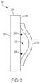
- FIG. 2is a cross-sectional view of an implantable medical device and constraining line conduit in accordance with various aspects of the present disclosure.
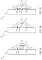
- FIG. 3Ais a cross-sectional view of the implantable medical device and constraining line conduit with a wire that may be used to form the constraining line conduit in accordance with various aspects of the present disclosure.
- FIG. 3Bis a cross-sectional view of the implantable medical device and constraining line conduit, as shown in FIG. 3A , with a constraining line arranged through the constraining line conduit in accordance with various aspects of the present disclosure.
- FIG. 3Cis a cross-sectional view of the implantable medical device and constraining line conduit, and the constraining line, as shown in FIGS. 3A-B , with an optional additional graft layer in accordance with various aspects of the present disclosure.
- FIG. 4Ais a cross-sectional view of an implantable medical device and a constraining line conduit in accordance with various aspects of the present disclosure.
- FIG. 4Bis a cross-sectional view of the implantable medical device and the constraining line conduit, as shown in FIG. 4A , with a wire arranged through the constraining line conduit in accordance with various aspects of the present disclosure.
- FIG. 4Cis a cross-sectional view of the implantable medical device and the constraining line conduit, as shown in FIGS. 4A-B , with a constraining line arranged through the constraining line conduit in accordance with various aspects of the present disclosure.
- FIG. 5is an illustration of a catheter arrangement that includes an implantable medical device, a constraining line conduit, and a constraining line arranged through the constraining line conduit in accordance with various aspects of the present disclosure.
- FIG. 6illustrates a perspective view of a catheter assembly and implantable medical device in accordance with the present disclosure.
- FIG. 1is a partial perspective view of an implantable medical device 100 and constraining line 102 in accordance with various aspects of the present disclosure.
- the implantable medical device 100may include a graft component 104 and a stent component 106 arranged along an exterior surface of the graft component 104 .
- the stent component 106may include a stent pattern 108 having straight segments 110 and apices 112 .
- the constraining line 102can be arranged over the alternating straight segments 110 and/or alternating apices 112 around the circumference of implantable medical device 100 at the proximal end and perpendicular to a longitudinal axis of the implantable medical device 100 .
- the constraining line 102can be arranged over the alternating straight segments 110 and/or alternating apices 112 at an angle relative to the longitudinal axis of the implantable medical device 100 .
- the implantable medical device 100may further include a constraining line conduit 118 as is discussed in further detail with respect to FIGS. 2-3 and 5 .
- the constraining line conduit 118provides a pathway through which the constraining line 102 may be arranged, as opposed to threading the constraining line 102 through the alternating straight segments 110 and/or alternating apices 112 of the stent pattern 108 and/or through the graft component 104 .
- the constraining line conduit 118may mitigate against the constraining line 102 catching on the stent pattern 108 and/or through the graft component 104 and mitigate against adverse interaction with other components (e.g. guidewires, catheters, balloons) that may be introduced during the implantation and delivery of the implantable medical device 100 .
- other componentse.g. guidewires, catheters, balloons
- the implantable medical device 100is inserted into the vasculature of the patient in a collapsed configuration and directed to a treatment area of the patient. Upon reaching the treatment area, the implantable medical device 100 is expanded to deployed configuration.
- the constraining line 102may constrain or assist in constraining the implantable medical device 100 in the collapsed configuration.
- the constraining line 102may include or form a loop 114 .
- the constraining line 102may extend through the loop 114 to form a slip knot and travel to a distal end 116 of the implantable medical device 100 to the outside of the body of the patient.
- the loop 114can comprise an end loop, such that when constraining line 102 passes through loop 114 , it forms a slip knot.
- the constraining line 102comprises a line or wire looped into the loop 114 , thereby creating two segments. Both segments pass through loop 114 to form the slip knot, and then travel back along the length of the delivery device and outside of the patient.
- the resulting slip knotcan extend about and releasably restrain the proximal end of the implantable medical device 100 axially and/or radially.
- the constraining line 102may include two segments (as shown). In order to tension the constraining line 102 and constrain the implantable medical device 100 axially and/or radially, an operator can release one of the segments of constraining line 102 and provide tension to the other segment in a first direction 120 . Pulling the constraining line 102 in the first direction 120 may close the loop 114 , and constrain the implantable medical device 100 axially and/or radially. In order to deploy the implantable medical device 100 from the constrained configuration, the tension applied in the first direction 120 may be released. Further, the constraining line 102 may be uncoupled or removed from the implantable medical device 100 .
- the released segmentcan travel in the second direction 122 and pass through the constraining line conduit 118 , and travel back to the operator.
- one or more segments of the constraining line 102can be removably coupled to a catheter handle.
- the catheter handlecan comprise a release button that, when activated, releases one of the segments of the constraining line 102 for removal thereof.
- FIG. 2is a cross-sectional view of an implantable medical device 200 and constraining line conduit 202 in accordance with various aspects of the present disclosure.
- the implantable medical device 200may include a graft portion 204 and a stent portion 206 .
- the stent portion 206may be arranged on an exterior surface 208 of the graft portion 204 .
- the graft portion 204also includes an interior surface 210 , which forms an internal lumen of the implantable medical device 200 .
- the constraining line conduit 202may be arranged around a circumference of the implantable medical device 200 (e.g., as shown in FIG.
- the constraining line conduit 202may include a discontinuity or gap at some point around the circumference of the implantable medical device 200 .
- the discontinuity or gap in the constraining line conduit 202may allow for a constraining line to be arranged through the constraining line conduit 202 .
- the constraining line conduit 202may be formed by a graft portion 212 that is attached to the exterior surface 208 of the graft portion 204 .
- the constraining line conduit 202may include a first boundary and a second boundary. As shown in FIG. 2 , the first boundary of the constraining line conduit 202 is the exterior surface 208 of the graft portion 204 , and the second boundary is formed by the graft portion 212 .
- the constraining line conduit 202may provide a pathway through which a constraining line (not shown) may be arranged. The constraining line may constrain the implantable medical device 200 axially and/or radially in response to tension applied thereto.
- FIG. 3Ais a cross-sectional view of the implantable medical device 300 and constraining line conduit 302 .
- the implantable medical device 300may include a graft portion 304 and a stent portion 306 .
- the stent portion 306may be arranged on an exterior surface of the graft portion 304 .
- the constraining line conduit 302may be formed by a first graft portion 308 that is attached to the exterior surface of the graft portion 304 .
- the first graft portion 308may be bonded on the exterior surface of the graft portion 304 .
- a wire 310may be arranged between the exterior surface of the graft portion 304 and the first graft portion 308 .
- the wire 310may provide an obstruction during bonding of the first graft portion 308 to the exterior surface of the graft portion 304 such that end portions of the first graft portion 308 is bonded to the exterior surface of the graft portion 304 .
- FIG. 3Bis a cross-sectional view of the implantable medical device 300 and the constraining line conduit 302 , as shown in FIG. 3A , that results from the wire 310 providing an obstruction to bond the end portions of the first graft portion 308 is bonded to the exterior surface of the graft portion 304 .
- the wire 310leaves behind a passage of the constraining line conduit 302 through which a constraining line 312 may be arranged.
- the constraining line conduit 302may include a first boundary and a second boundary.
- the first boundary of the constraining line conduit 302is the exterior surface of the graft portion 304
- the second boundaryis formed by the first graft portion 308 .
- a second graft portion 314may be arranged over the stent 306 within the bounds of the first graft portion 308 .
- the second graft portion 314may be bonded to the exterior surface of the graft portion similar to manner in which the first graft portion 308 is bonded to the exterior surface of the graft portion (e.g., an FEP adhesive).
- FIG. 3Cis a cross-sectional view of the implantable medical device 300 , the constraining line conduit 302 , and the constraining line 312 , as shown in FIGS. 3A-B , with second (additional) graft portion 314 in accordance with various aspects of the present disclosure.
- the constraining line conduit 302may include a discontinuity or gap at some point around the circumference of the implantable medical device 300 .
- the discontinuity or gap in the constraining line conduit 302may allow for the constraining line 312 to be arranged through the constraining line conduit 302 .
- the circumference of the implantable medical device 300may be between 25 mm and 50 mm.
- the discontinuity or gap in the constraining line conduit 302may be between 0.5 mm and 3 mm.
- the remaining portions of the constraining line conduit 302are continuous about the circumference of the implantable medical device 300 .
- the constraining line 312may constrain the implantable medical device 300 axially and/or radially in response to tension applied thereto.
- the implantable medical device 300may be constrained and unconstrained using the constraining line 312 between a constrained configuration (e.g., for delivery of the implantable medical device 300 ) and a deployed configuration (e.g., an operative state at a target therapy region).
- the implantable device 300may be constrained and unconstrained multiple times to allow for repositioning of the implantable device 300 at the therapy location if the positioning is not desirable.
- FIG. 4Ais a cross-sectional view of an implantable medical device 400 and a constraining line conduit 402 in accordance with various aspects of the present disclosure.
- the implantable medical device 400may include a graft portion 404 and a stent portion 406 (arranged on an exterior surface of the graft portion 404 ).
- the constraining line conduit 402may be formed from a hollow fiber 410 .
- the hollow fiber 410may be attached to the exterior surface of the graft portion 404 by way of a graft layer 408 .
- the graft layer 408is attached to the exterior surface of the graft portion 404 around the hollow fiber 410 .
- the graft layer 408may also be attached to the hollow fiber 410 .
- the hollow fiber 410forms boundaries of the constraining line conduit 402 .
- the graft layer 408may be attached to the graft portion 404 and/or the hollow fiber 410 using an adhesive or the graft layer 408 may include a material layer (such as FEP) that acts as adhesive after heating and bond to the graft portion 404 and/or the hollow fiber 410 .
- a material layersuch as FEP
- the hollow fiber 410may include discontinuity or gap to allow for a constraining line 414 (shown in FIG. 4C ) to be arranged through the hollow fiber 410 . More specifically, the circumference of the implantable medical device 400 may be between 25 mm and 50 mm. The discontinuity or gap in the hollow fiber 410 may be between 0.5 mm and 3 mm. The remaining portions of the hollow fiber 410 and the constraining line conduit 402 are continuous about the circumference of the implantable medical device 400 .
- a wire 412may be used to form the constraining line conduit 402 , as shown in FIG. 4A .
- the wire 412which may be a Nitinol or stainless steel wire, may be arranged through the hollow fiber 410 .
- the wire 412may assist in threading a constraining line 414 through the hollow fiber 410 as shown in FIG. 4C .
- the constraining line 414is arranged through the hollow fiber 410 in place of the wire 412 .
- the constraining line 414may constrain the implantable medical device 400 to a constrained configuration (e.g., between approximately between 5% and 20% of an unconstrained diameter of the implantable medical device 400 ) in response to tension applied to the constraining line 414 .
- the implantable medical device 400may be constrained and unconstrained multiple times to allow for repositioning of the implantable device 400 at the therapy location if the positioning is not desirable.
- the constrained configuration of the implantable device 400may be used for delivery of the implantable medical device 400 and a deployed configuration may be an operative state at a target therapy region).
- the implantable device 400may be partially constrained between the constrained configuration and the deployed configuration based on the amount of tension applied to the constraining line 414 .
- the implantable device 400may be imaged during an implantation procedure to determine if the implantable medical device 400 is implanted at the desired location and with the desired position. As such, an operator may view the amount the implantable medical device 400 is constrained via the constraining line 414 and adjust the amount of tension applied to the constraining line 414 .
- FIGS. 2-4are not intended to suggest any limitation as to the scope of use or functionality of embodiments of the disclosed subject matter. Neither should the illustrative components be interpreted as having any dependency or requirement related to any single component or combination of components illustrated therein. Additionally, any one or more of the components depicted in any of the FIGS. 2-4 may be, in embodiments, integrated with various other components depicted therein (and/or components not illustrated), all of which are considered to be within the ambit of the disclosed subject matter. More specifically, the constraining lines discussed with reference to FIGS. 2-4 may include similar structural aspects and capabilities as the constraining lines discussed with reference to FIGS. 1, 5, and 6 .
- FIG. 5is an illustration of a catheter arrangement 500 that includes an implantable medical device 502 , a constraining line conduit 504 , and a constraining line 506 arranged through the constraining line conduit 504 in accordance with various aspects of the present disclosure.
- the catheter arrangement 500may include a catheter shaft 510 with the implantable medical device 502 positioned at a distal end thereof.
- the implantable medical device 502may be removably coupled to catheter shaft 510 by the constraining line 506 .
- the implantable medical device 502may be concentrically surrounded by at least one constraining sleeve, such as sleeve 512 .
- the constraining line 506may constrain the implantable medical device 502 to a constrained configuration (e.g., between approximately between 5% and 20% of an unconstrained diameter of the implantable medical device 502 ) in response to tension applied to the constraining line 506 .
- the entirety of the implantable medical device 502may be constrained toward the catheter shaft 510 in response to tension applied to the constraining line 506 due to the arrangement of the constraining line 506 along the catheter shaft 510 for the length of the implantable medical device 502 .
- the constraining line 506may be arranged such that only a portion of the implantable medical device 400 is constrained in response to tension applied to the constraining line 506 .
- the implantable medical device 502may be constrained and unconstrained multiple times to allow for repositioning of the implantable medical device 502 at the therapy location if the positioning is not desirable.
- the constrained configuration of the implantable medical device 502may be used for delivery of the implantable medical device 502 and a deployed configuration may be an operative state at a target therapy region).
- the implantable medical device 502may be partially constrained between the constrained configuration and the deployed configuration based on the amount of tension applied to the constraining line 506 .
- the implantable medical device 502may be imaged during an implantation procedure to determine if the implantable medical device 502 is implanted at the desired location and with the desired position. As such, an operator may view the amount the implantable medical device 502 is constrained via the constraining line 506 and adjust the amount of tension applied to the constraining line 506 .
- the constraining line conduit 504may mitigate against the constraining line 506 catching on aspects of the implantable medical device 502 (e.g., stent pattern) by providing a pathway through which the constraining line 506 may be arranged.
- the constraining line 506may have been weaved through the implantable medical device 502 (e.g., through the stent pattern or graft component). Weaving the constraining line 506 in this manner may increase the amount of force or tension needed to apply to the constraining line 506 in constraining the implantable medical device 502 toward the catheter shaft 510 .
- the constraining line conduit 504mitigates against adverse interaction with other components of the catheter arrangement 500 such as the catheter shaft 510 or a guidewire 514 .
- FIG. 6illustrates a perspective view of a catheter assembly 600 and implantable medical device 604 in accordance with the present disclosure.
- the catheter assembly 600may include a catheter shaft 602 with the implantable medical device 604 is positioned at a distal end of and removably coupled to catheter shaft 602 by a constraining line 620 .
- the implantable medical device 604may be concentrically surrounded by at least one constraining sleeve, such as sleeve 610 .
- the implantable medical device 604is inserted into the vasculature of the patient in a collapsed configuration, wherein implantable medical device 604 is surrounded by sleeve 610 and held in a desired position relative to catheter shaft 602 by the constraining line 620 .
- the implantable medical device 604is then directed to a treatment area of the patient.
- the implantable medical device 604is deployed.
- deployment of the implantable medical device 604may include removing the sleeve 610 and removing the constraining line 620 from implantable medical device 604 .
- the implantable medical device 604is collapsed and/or compressed and positioned at the distal end of catheter shaft 602 .
- the Implantable medical device 604can then be navigated through the body of the patient to the treatment area.
- the implantable medical device 604can comprise a radially collapsed configuration suitable for delivery to the treatment area of the vasculature of a patient.
- the Implantable medical device 604can be constrained in a radially collapsed configuration and mounted onto the catheter shaft 602 .
- the diameter of the implantable medical device 604 in the collapsed configurationis small enough for the implant to be delivered through the vasculature to the treatment area.
- the diameter of the collapsed configurationis small enough to minimize the crossing profile of the catheter assembly 600 and minimize tissue damage to the patient.
- the implantable medical device 604can be guided by the catheter shaft 602 through the vasculature. Once the implantable medical device 604 is in position in the treatment area of the vasculature, the implantable medical device 604 can be expanded to a radially expanded configuration.
- the implantable medical device 604can comprise a radially expanded configuration suitable for implanting the device in the treatment area of a patient's vasculature.
- the diameter of the implantable medical device 604can be approximately the same as the vessel to be repaired.
- the diameter of implantable medical device 604 in the expanded configurationcan be slightly larger than the vessel to be treated to provide a traction fit within the vessel.
- the implantable medical device 604can comprise a self-expandable device, such as a self-expandable stent-graft. Such devices dilate from a radially collapsed configuration to a radially expanded configuration when unrestrained.
- the implantable medical device 604can comprise a device that is expanded with the assistance of a secondary device such as, for example, a balloon.
- the catheter assembly 600may carry a plurality of implantable medical devices 604 . The use of a catheter assembly 600 with any number of implantable medical devices is within the scope of the present disclosure.
- Various medical devices in accordance with the disclosurecomprise a sleeve or multiple sleeves.
- the sleeve or sleevescan constrain an implantable medical device in a collapsed configuration for endoluminal delivery of the implant to a treatment portion of the vasculature of a patient.
- the catheter assembly 600includes the sleeve 610 .
- the sleeve 610may assist the constraining line 620 in constraining the implantable medical device 604 to a reduced diameter.
- the sleeve or sleevescan be unconstrained in order to allow the implantable medical device to expand to its functional diameter and achieve the desired therapeutic outcome.
- the sleeve or sleevescan remain implanted while not interfering with the implantable medical device.
- the sleeve or sleevescan be removed from the body of the patient after successful deployment of the implantable medical device.
- the sleeve 610may be formed from a sheet of one or more materials wrapped or folded about the implantable medical device. While the illustrative aspects herein are described as including one or more tubular sleeves, sleeves of any non-tubular shape that corresponds to an underlying implantable medical device or that are otherwise appropriately shaped for a given application are also within the scope of the present disclosure.
- coupling member 612can be disengaged from the sleeve or sleeves from outside of the body of the patient, which allows the sleeve(s) to open and the implantable medical device to expand.
- the implantable medical devicecan be self-expanding, or the implant can be expanded by a device, such as a balloon.
- the coupling member 612may be, for example, a woven fiber. In other instances, the coupling member 612 can comprise a monofilament fiber. Any type of string, cord, thread, fiber, or wire that is capable of maintaining a sleeve in a tubular shape is within the scope of the present disclosure.
- the coupling member 612 or memberscan be disengaged from the sleeve or sleeves by a mechanical mechanism operated from outside of the body of the patient.
- the coupling member 612may be disengaged by applying sufficient tension to the coupling member 612 .
- a dial or rotational element of a catheter handlecan be attached to the coupling member 612 outside of the body. Rotation of the dial or rotational element can provide sufficient tension to, displace and disengage the coupling member 612 .
- various components of the devices disclosed hereinare steerable.
- one or more of the elongated segmentscan be configured with a removable steering system that allows an end of the elongated segment to be biased or directed by a user.
- a removable steering systemin accordance with various embodiments can facilitate independent positioning of an elongated segment and can provide for the ability of a user to accomplish any of the types of movements previously described, such as longitudinal movement, rotational movement, lateral movement, or angular movement.
- FIGS. 1-6are not intended to suggest any limitation as to the scope of use or functionality of embodiments of the disclosed subject matter. Neither should the illustrative components be interpreted as having any dependency or requirement related to any single component or combination of components illustrated therein. Additionally, any one or more of the components depicted in any of the FIGS. 1-6 may be, in embodiments, integrated with various other components depicted therein (and/or components not illustrated), all of which are considered to be within the ambit of the disclosed subject matter.
Landscapes
- Health & Medical Sciences (AREA)
- Engineering & Computer Science (AREA)
- Biomedical Technology (AREA)
- Life Sciences & Earth Sciences (AREA)
- Veterinary Medicine (AREA)
- Public Health (AREA)
- General Health & Medical Sciences (AREA)
- Animal Behavior & Ethology (AREA)
- Heart & Thoracic Surgery (AREA)
- Vascular Medicine (AREA)
- Transplantation (AREA)
- Oral & Maxillofacial Surgery (AREA)
- Cardiology (AREA)
- Surgery (AREA)
- Pulmonology (AREA)
- Gastroenterology & Hepatology (AREA)
- Neurosurgery (AREA)
- Reproductive Health (AREA)
- Nuclear Medicine, Radiotherapy & Molecular Imaging (AREA)
- Medical Informatics (AREA)
- Molecular Biology (AREA)
- Prostheses (AREA)
- Media Introduction/Drainage Providing Device (AREA)
Abstract
Description
Claims (17)
Priority Applications (2)
| Application Number | Priority Date | Filing Date | Title |
|---|---|---|---|
| US15/670,494US11266418B2 (en) | 2016-08-05 | 2017-08-07 | Integrated medical device constraining lumen |
| US17/587,602US20220151633A1 (en) | 2016-08-05 | 2022-01-28 | Integrated medical device constraining lumen |
Applications Claiming Priority (2)
| Application Number | Priority Date | Filing Date | Title |
|---|---|---|---|
| US201662371372P | 2016-08-05 | 2016-08-05 | |
| US15/670,494US11266418B2 (en) | 2016-08-05 | 2017-08-07 | Integrated medical device constraining lumen |
Related Child Applications (1)
| Application Number | Title | Priority Date | Filing Date |
|---|---|---|---|
| US17/587,602ContinuationUS20220151633A1 (en) | 2016-08-05 | 2022-01-28 | Integrated medical device constraining lumen |
Publications (2)
| Publication Number | Publication Date |
|---|---|
| US20180036011A1 US20180036011A1 (en) | 2018-02-08 |
| US11266418B2true US11266418B2 (en) | 2022-03-08 |
Family
ID=59687020
Family Applications (2)
| Application Number | Title | Priority Date | Filing Date |
|---|---|---|---|
| US15/670,494ActiveUS11266418B2 (en) | 2016-08-05 | 2017-08-07 | Integrated medical device constraining lumen |
| US17/587,602PendingUS20220151633A1 (en) | 2016-08-05 | 2022-01-28 | Integrated medical device constraining lumen |
Family Applications After (1)
| Application Number | Title | Priority Date | Filing Date |
|---|---|---|---|
| US17/587,602PendingUS20220151633A1 (en) | 2016-08-05 | 2022-01-28 | Integrated medical device constraining lumen |
Country Status (8)
| Country | Link |
|---|---|
| US (2) | US11266418B2 (en) |
| EP (1) | EP3493767B1 (en) |
| JP (1) | JP6761109B2 (en) |
| CN (1) | CN109561957B (en) |
| AU (1) | AU2017307628C1 (en) |
| CA (1) | CA3030781C (en) |
| ES (1) | ES2841326T3 (en) |
| WO (1) | WO2018027215A1 (en) |
Families Citing this family (3)
| Publication number | Priority date | Publication date | Assignee | Title |
|---|---|---|---|---|
| JP6940594B2 (en)* | 2016-08-24 | 2021-09-29 | ダブリュ.エル.ゴア アンド アソシエイツ,インコーポレイティドW.L. Gore & Associates, Incorporated | Sleeve for dilated medical devices |
| WO2020018697A1 (en)* | 2018-07-18 | 2020-01-23 | W. L. Gore & Associates, Inc. | Implantable medical device deployment system |
| US20240197506A1 (en) | 2021-04-16 | 2024-06-20 | W. L. Gore & Associates, Inc. | An implantable device for branched lumens with associated systems and methods |
Citations (50)
| Publication number | Priority date | Publication date | Assignee | Title |
|---|---|---|---|---|
| WO1998011847A1 (en) | 1996-09-20 | 1998-03-26 | Houser Russell A | Radially expanding prostheses and systems for their deployment |
| US6168618B1 (en) | 1998-01-27 | 2001-01-02 | Endotex Interventional Systems, Inc. | Electrolytic stent delivery system and methods of use |
| US6203550B1 (en) | 1998-09-30 | 2001-03-20 | Medtronic, Inc. | Disposable delivery device for endoluminal prostheses |
| US20020151953A1 (en)* | 2001-04-11 | 2002-10-17 | Trivascular, Inc. | Delivery system and method for bifurcated endovascular graft |
| US6520986B2 (en)* | 1995-12-14 | 2003-02-18 | Gore Enterprise Holdings, Inc. | Kink resistant stent-graft |
| WO2003053495A2 (en) | 2001-12-20 | 2003-07-03 | Trivascular, Inc. | Method and apparatus for manufacturing an endovascular graft section |
| US6733521B2 (en) | 2001-04-11 | 2004-05-11 | Trivascular, Inc. | Delivery system and method for endovascular graft |
| US6911039B2 (en) | 2002-04-23 | 2005-06-28 | Medtronic Vascular, Inc. | Integrated mechanical handle with quick slide mechanism |
| US6974471B2 (en) | 2001-10-26 | 2005-12-13 | Cook Incorporated | Prostheses for curved lumens |
| US7081132B2 (en) | 2002-05-16 | 2006-07-25 | Cook Incorporated | Flexible barb for anchoring a prosthesis |
| US7147661B2 (en) | 2001-12-20 | 2006-12-12 | Boston Scientific Santa Rosa Corp. | Radially expandable stent |
| US20070225797A1 (en) | 2006-03-24 | 2007-09-27 | Medtronic Vascular, Inc. | Prosthesis With Adjustable Opening for Side Branch Access |
| US20080269866A1 (en) | 2007-04-24 | 2008-10-30 | Hamer Rochelle M | Side Branched Endoluminal Prostheses and Methods fo Delivery Thereof |
| US20090132026A1 (en) | 2007-11-16 | 2009-05-21 | Boston Scientific Corporation | Delivery system and method for bifurcated graft |
| WO2009148607A1 (en) | 2008-06-04 | 2009-12-10 | Gore Enterprise Holdings, Inc. | Controlled deployable medical device and method of making the same |
| US7655034B2 (en) | 2006-11-14 | 2010-02-02 | Medtronic Vascular, Inc. | Stent-graft with anchoring pins |
| EP1915113B1 (en) | 2005-08-17 | 2010-03-03 | C.R. Bard, Inc. | Variable speed stent delivery system |
| GB2464978A (en) | 2008-10-31 | 2010-05-05 | Cook William Europ | Introducer for deploying a stent graft in a curved lumen |
| US20100114291A1 (en) | 2008-10-31 | 2010-05-06 | William Cook Europe Aps | Introducer for Deploying a Stent Graft in a Curved Lumen and Stent Graft Therefor |
| US7837724B2 (en) | 2002-02-11 | 2010-11-23 | Anson Medical Ltd. | Control device for medical catheters |
| US7938851B2 (en) | 2005-06-08 | 2011-05-10 | Xtent, Inc. | Devices and methods for operating and controlling interventional apparatus |
| US7976575B2 (en) | 2008-02-11 | 2011-07-12 | William A. Cook Australia Pty. Ltd. | Curve forming apparatus and curvable stent graft |
| US20110276062A1 (en) | 2001-11-28 | 2011-11-10 | Aptus Endosystems, Inc. | Devices, systems, and methods for prosthesis delivery and implantation, including the use of a fastener tool |
| US8241346B2 (en) | 2001-12-20 | 2012-08-14 | Trivascular, Inc. | Endovascular graft and method of delivery |
| US8257431B2 (en) | 2006-11-01 | 2012-09-04 | Boston Scientific Scimed, Inc. | Multi-furcated ePTFE grafts and stent-graft prostheses and methods of making the same |
| US8262671B2 (en) | 2003-03-14 | 2012-09-11 | Oscor Inc. | Vascular introducer having hemostatic valve with integral seal |
| US8361135B2 (en) | 2003-09-16 | 2013-01-29 | Cook Medical Technologies Llc | Prosthesis deployment system |
| US20130123896A1 (en) | 2011-11-14 | 2013-05-16 | W. L. Gore & Associates, Inc. | External steerable fiber for use in endoluminal deployment of expandable devices |
| US20140148895A1 (en) | 2012-11-27 | 2014-05-29 | Cook Medical Technologies Llc | Assembly of stent grafts with diameter reducing ties |
| EP2745812A1 (en) | 2012-12-19 | 2014-06-25 | Cook Medical Technologies LLC | Repositionable Diameter Constraints |
| US20140180385A1 (en) | 2012-12-21 | 2014-06-26 | Cordis Corporation | Stent cannulation guiding device and method of use |
| US20140194968A1 (en) | 2008-06-04 | 2014-07-10 | W. L. Gore & Associates, Inc. | Controlled deployable medical device and method of making the same |
| US8808355B2 (en) | 2012-11-27 | 2014-08-19 | Cook Medical Technologies Llc | Stent graft having a closeable fenestration |
| US8968384B2 (en) | 2012-04-27 | 2015-03-03 | Medtronic Vascular, Inc. | Circumferentially constraining sutures for a stent-graft |
| US9060895B2 (en) | 2009-10-20 | 2015-06-23 | Cook Medical Technologies Llc | Rotational controlled deployment device |
| US9125764B2 (en) | 2010-11-15 | 2015-09-08 | W, L. Gore & Associates, Inc. | Stent-graft having facing side branch portals |
| US9132025B2 (en) | 2012-06-15 | 2015-09-15 | Trivascular, Inc. | Bifurcated endovascular prosthesis having tethered contralateral leg |
| US9254204B2 (en) | 2013-03-15 | 2016-02-09 | Cook Medical Technologies Llc | Stents having barbs protected during delivery |
| US9308349B2 (en) | 2013-02-08 | 2016-04-12 | Vention Medical Advanced Components, Inc. | Universal catheter handle |
| US9358142B2 (en) | 2007-04-24 | 2016-06-07 | W. L. Gore & Associates, Inc. | Catheter having guidewire channel |
| US20160184118A1 (en) | 2014-12-30 | 2016-06-30 | Cook Medical Technologies Llc | Low profile prosthesis delivery device |
| US20160193032A1 (en) | 2011-08-16 | 2016-07-07 | W. L. Gore & Associates, Inc. | Branched stent graft device and deployment |
| EP2749251B1 (en) | 2012-12-26 | 2016-07-20 | Cook Medical Technologies LLC | Expandable stent-graft system having diameter reducing connectors |
| US9585743B2 (en) | 2006-07-31 | 2017-03-07 | Edwards Lifesciences Cardiaq Llc | Surgical implant devices and methods for their manufacture and use |
| US9681968B2 (en) | 2008-03-02 | 2017-06-20 | Venus Medtech (Hangzhou), Inc. | Stent which is reduceable again in its diameter from an expanded state in a controlled manner |
| US9700701B2 (en) | 2008-07-01 | 2017-07-11 | Endologix, Inc. | Catheter system and methods of using same |
| US20170281382A1 (en) | 2016-04-05 | 2017-10-05 | Bolton Medical, Inc. | Delivery systems with introducer and distal sheaths and methods of use |
| US9782284B2 (en) | 2003-10-14 | 2017-10-10 | Cook Medical Technologies Llc | Introducer for an iliac side branch device |
| EP2956198B1 (en) | 2013-05-07 | 2017-11-08 | St. Jude Medical Atrial Fibrillation Division Inc. | Steering actuator for deflectable catheter |
| US9937070B2 (en) | 2014-12-04 | 2018-04-10 | Cook Medical Technologies Llc | Delivery device handle assembly for the sequential deployment of a prosthesis |
Family Cites Families (9)
| Publication number | Priority date | Publication date | Assignee | Title |
|---|---|---|---|---|
| ATE372745T1 (en)* | 1995-12-14 | 2007-09-15 | Gore Enterprise Holdings Inc | Kink-resistant Stent Graft |
| GB9703859D0 (en)* | 1997-02-25 | 1997-04-16 | Plante Sylvain | Expandable intravascular stent |
| CN101283937B (en)* | 2008-05-21 | 2010-08-18 | 微创医疗器械(上海)有限公司 | Overlay film frame with an opening and bonding method of the overlay film frame |
| US8474120B2 (en)* | 2009-10-09 | 2013-07-02 | W. L. Gore & Associates, Inc. | Bifurcated highly conformable medical device branch access |
| US9414944B2 (en)* | 2010-11-11 | 2016-08-16 | W. L. Gore & Associates, Inc. | Deployment sleeve shortening mechanism |
| US10117765B2 (en)* | 2011-06-14 | 2018-11-06 | W.L. Gore Associates, Inc | Apposition fiber for use in endoluminal deployment of expandable implants |
| US9877858B2 (en)* | 2011-11-14 | 2018-01-30 | W. L. Gore & Associates, Inc. | External steerable fiber for use in endoluminal deployment of expandable devices |
| US9364359B2 (en)* | 2011-12-08 | 2016-06-14 | W. L. Gore & Associates, Inc. | Systems and methods for delivery of a medical device |
| CN105662650B (en)* | 2016-03-21 | 2018-08-14 | 中国医科大学附属第一医院 | Integral type overlay film branch vessel holder and its transport system |
- 2017
- 2017-08-07WOPCT/US2017/045722patent/WO2018027215A1/ennot_activeCeased
- 2017-08-07AUAU2017307628Apatent/AU2017307628C1/enactiveActive
- 2017-08-07JPJP2019506382Apatent/JP6761109B2/enactiveActive
- 2017-08-07EPEP17755593.5Apatent/EP3493767B1/enactiveActive
- 2017-08-07USUS15/670,494patent/US11266418B2/enactiveActive
- 2017-08-07ESES17755593Tpatent/ES2841326T3/enactiveActive
- 2017-08-07CACA3030781Apatent/CA3030781C/enactiveActive
- 2017-08-07CNCN201780047939.5Apatent/CN109561957B/enactiveActive
- 2022
- 2022-01-28USUS17/587,602patent/US20220151633A1/enactivePending
Patent Citations (66)
| Publication number | Priority date | Publication date | Assignee | Title |
|---|---|---|---|---|
| US6520986B2 (en)* | 1995-12-14 | 2003-02-18 | Gore Enterprise Holdings, Inc. | Kink resistant stent-graft |
| WO1998011847A1 (en) | 1996-09-20 | 1998-03-26 | Houser Russell A | Radially expanding prostheses and systems for their deployment |
| US6168618B1 (en) | 1998-01-27 | 2001-01-02 | Endotex Interventional Systems, Inc. | Electrolytic stent delivery system and methods of use |
| US6203550B1 (en) | 1998-09-30 | 2001-03-20 | Medtronic, Inc. | Disposable delivery device for endoluminal prostheses |
| US6761733B2 (en) | 2001-04-11 | 2004-07-13 | Trivascular, Inc. | Delivery system and method for bifurcated endovascular graft |
| US6733521B2 (en) | 2001-04-11 | 2004-05-11 | Trivascular, Inc. | Delivery system and method for endovascular graft |
| US20020151953A1 (en)* | 2001-04-11 | 2002-10-17 | Trivascular, Inc. | Delivery system and method for bifurcated endovascular graft |
| EP1441668B1 (en) | 2001-10-26 | 2008-01-23 | Cook Incorporated | Prostheses for curved lumens |
| US6974471B2 (en) | 2001-10-26 | 2005-12-13 | Cook Incorporated | Prostheses for curved lumens |
| US20110276062A1 (en) | 2001-11-28 | 2011-11-10 | Aptus Endosystems, Inc. | Devices, systems, and methods for prosthesis delivery and implantation, including the use of a fastener tool |
| US8241346B2 (en) | 2001-12-20 | 2012-08-14 | Trivascular, Inc. | Endovascular graft and method of delivery |
| WO2003053495A2 (en) | 2001-12-20 | 2003-07-03 | Trivascular, Inc. | Method and apparatus for manufacturing an endovascular graft section |
| US7147661B2 (en) | 2001-12-20 | 2006-12-12 | Boston Scientific Santa Rosa Corp. | Radially expandable stent |
| US8167927B2 (en) | 2001-12-20 | 2012-05-01 | Trivascular, Inc. | Barbed radially expandable stent |
| US7837724B2 (en) | 2002-02-11 | 2010-11-23 | Anson Medical Ltd. | Control device for medical catheters |
| EP1474074B1 (en) | 2002-02-11 | 2014-04-16 | Anson Medical Limited | Control mechanism for medical catheters |
| US6911039B2 (en) | 2002-04-23 | 2005-06-28 | Medtronic Vascular, Inc. | Integrated mechanical handle with quick slide mechanism |
| EP1358903B1 (en) | 2002-04-23 | 2011-11-02 | Medtronic Vascular, Inc. | Integrated mechanical handle with quick slide mechanism |
| US7081132B2 (en) | 2002-05-16 | 2006-07-25 | Cook Incorporated | Flexible barb for anchoring a prosthesis |
| US8262671B2 (en) | 2003-03-14 | 2012-09-11 | Oscor Inc. | Vascular introducer having hemostatic valve with integral seal |
| US8361135B2 (en) | 2003-09-16 | 2013-01-29 | Cook Medical Technologies Llc | Prosthesis deployment system |
| US9782284B2 (en) | 2003-10-14 | 2017-10-10 | Cook Medical Technologies Llc | Introducer for an iliac side branch device |
| US7938851B2 (en) | 2005-06-08 | 2011-05-10 | Xtent, Inc. | Devices and methods for operating and controlling interventional apparatus |
| EP1915113B1 (en) | 2005-08-17 | 2010-03-03 | C.R. Bard, Inc. | Variable speed stent delivery system |
| US20070225797A1 (en) | 2006-03-24 | 2007-09-27 | Medtronic Vascular, Inc. | Prosthesis With Adjustable Opening for Side Branch Access |
| US9585743B2 (en) | 2006-07-31 | 2017-03-07 | Edwards Lifesciences Cardiaq Llc | Surgical implant devices and methods for their manufacture and use |
| US20170172724A1 (en) | 2006-07-31 | 2017-06-22 | Edwards Lifesciences Cardiaq Llc | Surgical implant devices and methods for their manufacture and use |
| US8257431B2 (en) | 2006-11-01 | 2012-09-04 | Boston Scientific Scimed, Inc. | Multi-furcated ePTFE grafts and stent-graft prostheses and methods of making the same |
| US7655034B2 (en) | 2006-11-14 | 2010-02-02 | Medtronic Vascular, Inc. | Stent-graft with anchoring pins |
| US20080269866A1 (en) | 2007-04-24 | 2008-10-30 | Hamer Rochelle M | Side Branched Endoluminal Prostheses and Methods fo Delivery Thereof |
| US9358142B2 (en) | 2007-04-24 | 2016-06-07 | W. L. Gore & Associates, Inc. | Catheter having guidewire channel |
| US20090132026A1 (en) | 2007-11-16 | 2009-05-21 | Boston Scientific Corporation | Delivery system and method for bifurcated graft |
| US8328861B2 (en) | 2007-11-16 | 2012-12-11 | Trivascular, Inc. | Delivery system and method for bifurcated graft |
| US7976575B2 (en) | 2008-02-11 | 2011-07-12 | William A. Cook Australia Pty. Ltd. | Curve forming apparatus and curvable stent graft |
| US9681968B2 (en) | 2008-03-02 | 2017-06-20 | Venus Medtech (Hangzhou), Inc. | Stent which is reduceable again in its diameter from an expanded state in a controlled manner |
| WO2009148607A1 (en) | 2008-06-04 | 2009-12-10 | Gore Enterprise Holdings, Inc. | Controlled deployable medical device and method of making the same |
| US20140194968A1 (en) | 2008-06-04 | 2014-07-10 | W. L. Gore & Associates, Inc. | Controlled deployable medical device and method of making the same |
| US9700701B2 (en) | 2008-07-01 | 2017-07-11 | Endologix, Inc. | Catheter system and methods of using same |
| US8480725B2 (en) | 2008-10-31 | 2013-07-09 | Cook Medical Technologies Llc | Introducer for deploying a stent graft in a curved lumen |
| JP2012507345A (en) | 2008-10-31 | 2012-03-29 | ウィリアム クック ユーロープ アーペーエス | Introducer for deploying a stent-graft within a curved lumen |
| WO2010062362A1 (en) | 2008-10-31 | 2010-06-03 | William Cook Europe Aps | Introducer for deploying a stent graft in a curved lumen |
| US20100114290A1 (en) | 2008-10-31 | 2010-05-06 | William Cook Europe Aps | Introducer for Deploying a Stent Graft in a Curved Lumen |
| US20100114291A1 (en) | 2008-10-31 | 2010-05-06 | William Cook Europe Aps | Introducer for Deploying a Stent Graft in a Curved Lumen and Stent Graft Therefor |
| GB2464978A (en) | 2008-10-31 | 2010-05-05 | Cook William Europ | Introducer for deploying a stent graft in a curved lumen |
| US9060895B2 (en) | 2009-10-20 | 2015-06-23 | Cook Medical Technologies Llc | Rotational controlled deployment device |
| US9125764B2 (en) | 2010-11-15 | 2015-09-08 | W, L. Gore & Associates, Inc. | Stent-graft having facing side branch portals |
| US20160193032A1 (en) | 2011-08-16 | 2016-07-07 | W. L. Gore & Associates, Inc. | Branched stent graft device and deployment |
| WO2013074266A1 (en) | 2011-11-14 | 2013-05-23 | W.L. Gore & Associates, Inc. | External steerable fiber for use in endoluminal deployment of expandable devices |
| JP2014533189A (en) | 2011-11-14 | 2014-12-11 | ダブリュ.エル.ゴア アンド アソシエイツ,インコーポレイティドW.L. Gore & Associates, Incorporated | Externally manipulable fiber for use with expandable devices in intraluminal deployment |
| US20130123896A1 (en) | 2011-11-14 | 2013-05-16 | W. L. Gore & Associates, Inc. | External steerable fiber for use in endoluminal deployment of expandable devices |
| US8968384B2 (en) | 2012-04-27 | 2015-03-03 | Medtronic Vascular, Inc. | Circumferentially constraining sutures for a stent-graft |
| US9132025B2 (en) | 2012-06-15 | 2015-09-15 | Trivascular, Inc. | Bifurcated endovascular prosthesis having tethered contralateral leg |
| US9585774B2 (en) | 2012-06-15 | 2017-03-07 | Trivascular, Inc. | Bifurcated endovascular prosthesis having tethered contralateral leg |
| US8808355B2 (en) | 2012-11-27 | 2014-08-19 | Cook Medical Technologies Llc | Stent graft having a closeable fenestration |
| US20140148895A1 (en) | 2012-11-27 | 2014-05-29 | Cook Medical Technologies Llc | Assembly of stent grafts with diameter reducing ties |
| EP2745812A1 (en) | 2012-12-19 | 2014-06-25 | Cook Medical Technologies LLC | Repositionable Diameter Constraints |
| US9498361B2 (en) | 2012-12-19 | 2016-11-22 | Cook Medical Technologies Llc | Repositionable diameter constraints |
| JP2014121612A (en) | 2012-12-21 | 2014-07-03 | Cordis Corp | Stent cannulation guiding device and method of use |
| US20140180385A1 (en) | 2012-12-21 | 2014-06-26 | Cordis Corporation | Stent cannulation guiding device and method of use |
| EP2749251B1 (en) | 2012-12-26 | 2016-07-20 | Cook Medical Technologies LLC | Expandable stent-graft system having diameter reducing connectors |
| US9308349B2 (en) | 2013-02-08 | 2016-04-12 | Vention Medical Advanced Components, Inc. | Universal catheter handle |
| US9254204B2 (en) | 2013-03-15 | 2016-02-09 | Cook Medical Technologies Llc | Stents having barbs protected during delivery |
| EP2956198B1 (en) | 2013-05-07 | 2017-11-08 | St. Jude Medical Atrial Fibrillation Division Inc. | Steering actuator for deflectable catheter |
| US9937070B2 (en) | 2014-12-04 | 2018-04-10 | Cook Medical Technologies Llc | Delivery device handle assembly for the sequential deployment of a prosthesis |
| US20160184118A1 (en) | 2014-12-30 | 2016-06-30 | Cook Medical Technologies Llc | Low profile prosthesis delivery device |
| US20170281382A1 (en) | 2016-04-05 | 2017-10-05 | Bolton Medical, Inc. | Delivery systems with introducer and distal sheaths and methods of use |
Non-Patent Citations (1)
| Title |
|---|
| International Search Report and Written Opinion of PCT/US2017/045722, dated Oct. 10, 2017, 11 pages. |
Also Published As
| Publication number | Publication date |
|---|---|
| ES2841326T3 (en) | 2021-07-08 |
| CA3030781A1 (en) | 2018-02-08 |
| CA3030781C (en) | 2022-07-19 |
| AU2017307628A1 (en) | 2019-01-24 |
| US20180036011A1 (en) | 2018-02-08 |
| AU2017307628C1 (en) | 2020-09-03 |
| CN109561957B (en) | 2021-06-15 |
| AU2017307628B2 (en) | 2020-03-12 |
| JP2019524292A (en) | 2019-09-05 |
| US20220151633A1 (en) | 2022-05-19 |
| EP3493767B1 (en) | 2020-11-11 |
| EP3493767A1 (en) | 2019-06-12 |
| CN109561957A (en) | 2019-04-02 |
| WO2018027215A1 (en) | 2018-02-08 |
| JP6761109B2 (en) | 2020-09-23 |
Similar Documents
| Publication | Publication Date | Title |
|---|---|---|
| US12257166B2 (en) | External steerable fiber for use in endoluminal deployment of expandable devices | |
| US20240390132A1 (en) | External steerable fiber for use in endoluminal deployment of expandable devices | |
| US20220395386A1 (en) | External steerable fiber for use in endoluminal deployment of expandable devices | |
| US20220151633A1 (en) | Integrated medical device constraining lumen | |
| CA3031572C (en) | Sleeves for expandable medical devices | |
| KR101968357B1 (en) | Apposition fiber for use in endoluminal deployment of expandable implants | |
| EP4464278A2 (en) | External steerable fiber for use in endoluminal deployment of expandable devices | |
| HK1197532B (en) | Apposition fiber for use in endoluminal deployment of expandable implants |
Legal Events
| Date | Code | Title | Description |
|---|---|---|---|
| AS | Assignment | Owner name:W. L. GORE & ASSOCIATES, INC., DELAWARE Free format text:ASSIGNMENT OF ASSIGNORS INTEREST;ASSIGNORS:LEHNHARDT, ERIC C.;SECTOR, MARTIN J.;WETHERELL, FRANKLIN C.;AND OTHERS;SIGNING DATES FROM 20171109 TO 20180129;REEL/FRAME:045188/0784 | |
| STPP | Information on status: patent application and granting procedure in general | Free format text:NON FINAL ACTION MAILED | |
| STPP | Information on status: patent application and granting procedure in general | Free format text:RESPONSE TO NON-FINAL OFFICE ACTION ENTERED AND FORWARDED TO EXAMINER | |
| STPP | Information on status: patent application and granting procedure in general | Free format text:FINAL REJECTION MAILED | |
| STPP | Information on status: patent application and granting procedure in general | Free format text:DOCKETED NEW CASE - READY FOR EXAMINATION | |
| STPP | Information on status: patent application and granting procedure in general | Free format text:NON FINAL ACTION MAILED | |
| STPP | Information on status: patent application and granting procedure in general | Free format text:RESPONSE TO NON-FINAL OFFICE ACTION ENTERED AND FORWARDED TO EXAMINER | |
| STPP | Information on status: patent application and granting procedure in general | Free format text:ADVISORY ACTION MAILED | |
| STPP | Information on status: patent application and granting procedure in general | Free format text:FINAL REJECTION MAILED | |
| STPP | Information on status: patent application and granting procedure in general | Free format text:RESPONSE AFTER FINAL ACTION FORWARDED TO EXAMINER | |
| STPP | Information on status: patent application and granting procedure in general | Free format text:ADVISORY ACTION MAILED | |
| STPP | Information on status: patent application and granting procedure in general | Free format text:DOCKETED NEW CASE - READY FOR EXAMINATION | |
| STPP | Information on status: patent application and granting procedure in general | Free format text:FINAL REJECTION MAILED | |
| STPP | Information on status: patent application and granting procedure in general | Free format text:RESPONSE AFTER FINAL ACTION FORWARDED TO EXAMINER | |
| STPP | Information on status: patent application and granting procedure in general | Free format text:NOTICE OF ALLOWANCE MAILED -- APPLICATION RECEIVED IN OFFICE OF PUBLICATIONS | |
| STCF | Information on status: patent grant | Free format text:PATENTED CASE | |
| MAFP | Maintenance fee payment | Free format text:PAYMENT OF MAINTENANCE FEE, 4TH YEAR, LARGE ENTITY (ORIGINAL EVENT CODE: M1551); ENTITY STATUS OF PATENT OWNER: LARGE ENTITY Year of fee payment:4 |