US11263921B2 - Medicament delivery device configured to produce wireless and audible outputs - Google Patents
Medicament delivery device configured to produce wireless and audible outputsDownload PDFInfo
- Publication number
- US11263921B2 US11263921B2US16/196,685US201816196685AUS11263921B2US 11263921 B2US11263921 B2US 11263921B2US 201816196685 AUS201816196685 AUS 201816196685AUS 11263921 B2US11263921 B2US 11263921B2
- Authority
- US
- United States
- Prior art keywords
- circuit system
- electronic circuit
- housing
- medicament
- medicament delivery
- Prior art date
- Legal status (The legal status is an assumption and is not a legal conclusion. Google has not performed a legal analysis and makes no representation as to the accuracy of the status listed.)
- Active, expires
Links
Images


Classifications
- G—PHYSICS
- G09—EDUCATION; CRYPTOGRAPHY; DISPLAY; ADVERTISING; SEALS
- G09B—EDUCATIONAL OR DEMONSTRATION APPLIANCES; APPLIANCES FOR TEACHING, OR COMMUNICATING WITH, THE BLIND, DEAF OR MUTE; MODELS; PLANETARIA; GLOBES; MAPS; DIAGRAMS
- G09B23/00—Models for scientific, medical, or mathematical purposes, e.g. full-sized devices for demonstration purposes
- G09B23/28—Models for scientific, medical, or mathematical purposes, e.g. full-sized devices for demonstration purposes for medicine
- G09B23/285—Models for scientific, medical, or mathematical purposes, e.g. full-sized devices for demonstration purposes for medicine for injections, endoscopy, bronchoscopy, sigmoidscopy, insertion of contraceptive devices or enemas
- A—HUMAN NECESSITIES
- A61—MEDICAL OR VETERINARY SCIENCE; HYGIENE
- A61M—DEVICES FOR INTRODUCING MEDIA INTO, OR ONTO, THE BODY; DEVICES FOR TRANSDUCING BODY MEDIA OR FOR TAKING MEDIA FROM THE BODY; DEVICES FOR PRODUCING OR ENDING SLEEP OR STUPOR
- A61M15/00—Inhalators
- A—HUMAN NECESSITIES
- A61—MEDICAL OR VETERINARY SCIENCE; HYGIENE
- A61M—DEVICES FOR INTRODUCING MEDIA INTO, OR ONTO, THE BODY; DEVICES FOR TRANSDUCING BODY MEDIA OR FOR TAKING MEDIA FROM THE BODY; DEVICES FOR PRODUCING OR ENDING SLEEP OR STUPOR
- A61M5/00—Devices for bringing media into the body in a subcutaneous, intra-vascular or intramuscular way; Accessories therefor, e.g. filling or cleaning devices, arm-rests
- A61M5/178—Syringes
- A61M5/20—Automatic syringes, e.g. with automatically actuated piston rod, with automatic needle injection, filling automatically
- A61M5/2053—Media being expelled from injector by pressurised fluid or vacuum
- A—HUMAN NECESSITIES
- A61—MEDICAL OR VETERINARY SCIENCE; HYGIENE
- A61M—DEVICES FOR INTRODUCING MEDIA INTO, OR ONTO, THE BODY; DEVICES FOR TRANSDUCING BODY MEDIA OR FOR TAKING MEDIA FROM THE BODY; DEVICES FOR PRODUCING OR ENDING SLEEP OR STUPOR
- A61M5/00—Devices for bringing media into the body in a subcutaneous, intra-vascular or intramuscular way; Accessories therefor, e.g. filling or cleaning devices, arm-rests
- A61M5/178—Syringes
- A61M5/31—Details
- A61M5/315—Pistons; Piston-rods; Guiding, blocking or restricting the movement of the rod or piston; Appliances on the rod for facilitating dosing ; Dosing mechanisms
- A61M5/31565—Administration mechanisms, i.e. constructional features, modes of administering a dose
- A61M5/31566—Means improving security or handling thereof
- A61M5/3157—Means providing feedback signals when administration is completed
- H—ELECTRICITY
- H04—ELECTRIC COMMUNICATION TECHNIQUE
- H04R—LOUDSPEAKERS, MICROPHONES, GRAMOPHONE PICK-UPS OR LIKE ACOUSTIC ELECTROMECHANICAL TRANSDUCERS; DEAF-AID SETS; PUBLIC ADDRESS SYSTEMS
- H04R1/00—Details of transducers, loudspeakers or microphones
- H04R1/02—Casings; Cabinets ; Supports therefor; Mountings therein
- H04R1/028—Casings; Cabinets ; Supports therefor; Mountings therein associated with devices performing functions other than acoustics, e.g. electric candles
- A—HUMAN NECESSITIES
- A61—MEDICAL OR VETERINARY SCIENCE; HYGIENE
- A61M—DEVICES FOR INTRODUCING MEDIA INTO, OR ONTO, THE BODY; DEVICES FOR TRANSDUCING BODY MEDIA OR FOR TAKING MEDIA FROM THE BODY; DEVICES FOR PRODUCING OR ENDING SLEEP OR STUPOR
- A61M15/00—Inhalators
- A61M15/009—Inhalators using medicine packages with incorporated spraying means, e.g. aerosol cans
- A—HUMAN NECESSITIES
- A61—MEDICAL OR VETERINARY SCIENCE; HYGIENE
- A61M—DEVICES FOR INTRODUCING MEDIA INTO, OR ONTO, THE BODY; DEVICES FOR TRANSDUCING BODY MEDIA OR FOR TAKING MEDIA FROM THE BODY; DEVICES FOR PRODUCING OR ENDING SLEEP OR STUPOR
- A61M5/00—Devices for bringing media into the body in a subcutaneous, intra-vascular or intramuscular way; Accessories therefor, e.g. filling or cleaning devices, arm-rests
- A61M5/178—Syringes
- A61M5/20—Automatic syringes, e.g. with automatically actuated piston rod, with automatic needle injection, filling automatically
- A61M2005/206—With automatic needle insertion
- A—HUMAN NECESSITIES
- A61—MEDICAL OR VETERINARY SCIENCE; HYGIENE
- A61M—DEVICES FOR INTRODUCING MEDIA INTO, OR ONTO, THE BODY; DEVICES FOR TRANSDUCING BODY MEDIA OR FOR TAKING MEDIA FROM THE BODY; DEVICES FOR PRODUCING OR ENDING SLEEP OR STUPOR
- A61M5/00—Devices for bringing media into the body in a subcutaneous, intra-vascular or intramuscular way; Accessories therefor, e.g. filling or cleaning devices, arm-rests
- A61M5/178—Syringes
- A61M5/20—Automatic syringes, e.g. with automatically actuated piston rod, with automatic needle injection, filling automatically
- A61M2005/2073—Automatic syringes, e.g. with automatically actuated piston rod, with automatic needle injection, filling automatically preventing premature release, e.g. by making use of a safety lock
- A—HUMAN NECESSITIES
- A61—MEDICAL OR VETERINARY SCIENCE; HYGIENE
- A61M—DEVICES FOR INTRODUCING MEDIA INTO, OR ONTO, THE BODY; DEVICES FOR TRANSDUCING BODY MEDIA OR FOR TAKING MEDIA FROM THE BODY; DEVICES FOR PRODUCING OR ENDING SLEEP OR STUPOR
- A61M2205/00—General characteristics of the apparatus
- A61M2205/43—General characteristics of the apparatus making noise when used correctly
- A—HUMAN NECESSITIES
- A61—MEDICAL OR VETERINARY SCIENCE; HYGIENE
- A61M—DEVICES FOR INTRODUCING MEDIA INTO, OR ONTO, THE BODY; DEVICES FOR TRANSDUCING BODY MEDIA OR FOR TAKING MEDIA FROM THE BODY; DEVICES FOR PRODUCING OR ENDING SLEEP OR STUPOR
- A61M2205/00—General characteristics of the apparatus
- A61M2205/50—General characteristics of the apparatus with microprocessors or computers
- A—HUMAN NECESSITIES
- A61—MEDICAL OR VETERINARY SCIENCE; HYGIENE
- A61M—DEVICES FOR INTRODUCING MEDIA INTO, OR ONTO, THE BODY; DEVICES FOR TRANSDUCING BODY MEDIA OR FOR TAKING MEDIA FROM THE BODY; DEVICES FOR PRODUCING OR ENDING SLEEP OR STUPOR
- A61M2205/00—General characteristics of the apparatus
- A61M2205/58—Means for facilitating use, e.g. by people with impaired vision
- A61M2205/581—Means for facilitating use, e.g. by people with impaired vision by audible feedback
- A—HUMAN NECESSITIES
- A61—MEDICAL OR VETERINARY SCIENCE; HYGIENE
- A61M—DEVICES FOR INTRODUCING MEDIA INTO, OR ONTO, THE BODY; DEVICES FOR TRANSDUCING BODY MEDIA OR FOR TAKING MEDIA FROM THE BODY; DEVICES FOR PRODUCING OR ENDING SLEEP OR STUPOR
- A61M2205/00—General characteristics of the apparatus
- A61M2205/58—Means for facilitating use, e.g. by people with impaired vision
- A61M2205/583—Means for facilitating use, e.g. by people with impaired vision by visual feedback
- A—HUMAN NECESSITIES
- A61—MEDICAL OR VETERINARY SCIENCE; HYGIENE
- A61M—DEVICES FOR INTRODUCING MEDIA INTO, OR ONTO, THE BODY; DEVICES FOR TRANSDUCING BODY MEDIA OR FOR TAKING MEDIA FROM THE BODY; DEVICES FOR PRODUCING OR ENDING SLEEP OR STUPOR
- A61M2205/00—General characteristics of the apparatus
- A61M2205/82—Internal energy supply devices
- A61M2205/8206—Internal energy supply devices battery-operated
- A—HUMAN NECESSITIES
- A61—MEDICAL OR VETERINARY SCIENCE; HYGIENE
- A61M—DEVICES FOR INTRODUCING MEDIA INTO, OR ONTO, THE BODY; DEVICES FOR TRANSDUCING BODY MEDIA OR FOR TAKING MEDIA FROM THE BODY; DEVICES FOR PRODUCING OR ENDING SLEEP OR STUPOR
- A61M2209/00—Ancillary equipment
- A61M2209/06—Packaging for specific medical equipment
- A—HUMAN NECESSITIES
- A61—MEDICAL OR VETERINARY SCIENCE; HYGIENE
- A61M—DEVICES FOR INTRODUCING MEDIA INTO, OR ONTO, THE BODY; DEVICES FOR TRANSDUCING BODY MEDIA OR FOR TAKING MEDIA FROM THE BODY; DEVICES FOR PRODUCING OR ENDING SLEEP OR STUPOR
- A61M5/00—Devices for bringing media into the body in a subcutaneous, intra-vascular or intramuscular way; Accessories therefor, e.g. filling or cleaning devices, arm-rests
- A61M5/178—Syringes
- A61M5/31—Details
- A61M5/32—Needles; Details of needles pertaining to their connection with syringe or hub; Accessories for bringing the needle into, or holding the needle on, the body; Devices for protection of needles
- A61M5/3202—Devices for protection of the needle before use, e.g. caps
- A—HUMAN NECESSITIES
- A61—MEDICAL OR VETERINARY SCIENCE; HYGIENE
- A61M—DEVICES FOR INTRODUCING MEDIA INTO, OR ONTO, THE BODY; DEVICES FOR TRANSDUCING BODY MEDIA OR FOR TAKING MEDIA FROM THE BODY; DEVICES FOR PRODUCING OR ENDING SLEEP OR STUPOR
- A61M5/00—Devices for bringing media into the body in a subcutaneous, intra-vascular or intramuscular way; Accessories therefor, e.g. filling or cleaning devices, arm-rests
- A61M5/50—Devices for bringing media into the body in a subcutaneous, intra-vascular or intramuscular way; Accessories therefor, e.g. filling or cleaning devices, arm-rests having means for preventing re-use, or for indicating if defective, used, tampered with or unsterile
- A61M5/5086—Devices for bringing media into the body in a subcutaneous, intra-vascular or intramuscular way; Accessories therefor, e.g. filling or cleaning devices, arm-rests having means for preventing re-use, or for indicating if defective, used, tampered with or unsterile for indicating if defective, used, tampered with or unsterile
Definitions
- the inventionrelates generally to a medical device, and more particularly to a medicament delivery device having an electronic circuit system that produces an audible output.
- a medicament delivery devicesuch as, for example, an auto-inject
- the usermay be required to execute a series of operations.
- the usermust remove a protective cap, remove a locking device, place the auto-injector in a proper position against the body and then press a button to actuate the auto-injector. Failure to complete these operations properly can result in an incomplete injection and/or injection into an undesired location of the body.
- users who have become confused in the operation of some known auto-injectorshave inadvertently injected the medicament into their thumb by improperly positioning the auto-injector.
- known medicament delivery devicescan be compounded by the nature of the user and/or the circumstances under which such devices are used. For example, many users are not trained medical professionals and may have never been trained in the operation of such devices. Moreover, in certain situations, the user may not be the patient, and may therefore have no experience with the medicament delivery device. Similarly, because some known medicament delivery devices are configured to be used relatively infrequently in response to an allergic reaction or the like, even those users familiar with the device and/or who have been trained may not be well practiced at operating the device. Finally, such devices are often used during an emergency situation, during which even experienced and/or trained users may be subject to confusion, panic, and/or the physiological effects of the condition requiring treatment.
- Some known medicament delivery devicesinclude printed instructions to inform the user of the steps required to properly deliver the medicament. Such printed instructions, however, can be inadequate for the class of users and/or the situations described above. Moreover, because some known medicament delivery devices, such as, for example, auto-injectors, pen injectors, inhalers or the like, can be compact, such printed instructions may be too small to read and comprehend during an emergency situation.
- Some known medicament delivery devicescan produce sounds, such as a beep or a click, that can be used as prompts to users of medicament delivery devices.
- the sounds of such know devices and the manner in which the sounds are producedprovide limited information to the user.
- some known medicament delivery devicesproduce a single tone to indicate that a proper dosage has been set but cannot provide a user with instructions associated with the use of the device.
- the sound level and/or the quality of the sound produced by such known medicament delivery devicesis limited by the size, performance, and/or cost associated with the speaker and/or electronic components necessary to produce the sounds.
- an apparatusincludes a medicament delivery device and an electronic circuit system.
- the medicament delivery deviceincludes a housing, a medicament container, and a medicament delivery member.
- the electronic circuit systemis coupled to the housing and includes an audible output device and a cover.
- the housing of the medicament delivery device and the cover of the electronic circuit systemcollectively define an acoustic enclosure.
- the audible output deviceis configured to be disposed within the acoustic enclosure.
- FIG. 1is a schematic illustration of a medicament delivery device having an acoustic enclosure, according to an embodiment of the invention.
- FIG. 2is a schematic illustration of a medicament delivery device having a ported acoustic enclosure, according to an embodiment of the invention.
- FIG. 3is a schematic illustration of a medicament delivery device according to an embodiment of the invention.
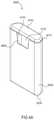
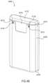
- FIGS. 4A and 4Bare perspective views of a medicament delivery device according to an embodiment of the invention, in a first configuration.
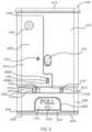
- FIG. 5is a front view of the medicament delivery device illustrated in FIGS. 4A and 4B with the cover removed.
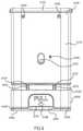
- FIG. 6is a back view of the medicament delivery device illustrated in FIGS. 4A and 4B with the cover removed.
- FIG. 7is a front view of a portion of the medicament delivery device illustrated in FIGS. 4A and 4B .
- FIG. 8is a perspective view of a portion of the medicament delivery device illustrated in FIGS. 4A and 4B .
- FIG. 9is a bottom perspective view of a housing of the medicament delivery device illustrated in FIGS. 4A and 4B .
- FIG. 10is a top perspective view of a housing of the medicament delivery device illustrated in FIGS. 4A and 4B .
- FIG. 11is a perspective view of a proximal cap of the medicament delivery device illustrated in FIGS. 4A and 4B .
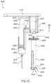
- FIG. 12is a front view of a medicament delivery mechanism of the medicament delivery device illustrated in FIGS. 4A and 4B .
- FIG. 13is a back view of an electronic circuit system of the medicament delivery device illustrated in FIGS. 4A and 4B .
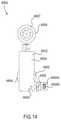
- FIG. 14is a front view of a portion of the electronic circuit system of the medicament delivery device illustrated in FIG. 13 .
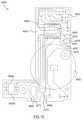
- FIG. 15is a back view of a printed circuit board of the electronic circuit system shown in FIG. 14 .
- FIG. 16is a schematic illustration of the electronic circuit system shown in FIG. 13 .
- FIG. 17is a side view of the electronic circuit system of the medicament delivery device illustrated in FIG. 13 .
- FIG. 18is a front view of a cover of the electronic circuit system illustrated in FIG. 13 .
- FIG. 19is a perspective view of the cover of the electronic circuit system illustrated in FIG. 13 .
- FIG. 20is a perspective view of a battery clip of the electronic circuit system illustrated in FIG. 13 .
- FIG. 20Ais a perspective view of a portion of an electronic circuit system of the medical injector illustrated in FIGS. 4A and 4B , in a first configuration.
- FIG. 21is a front view of the medicament delivery device illustrated in FIGS. 4A and 4B in a first configuration showing the electronic circuit system.
- FIGS. 21A, 21B, and 21Care front views of a portion of the electronic circuit system of the medical injector labeled as Region Z in FIG. 21 in a first configuration, a second configuration, and a third configuration, respectively.
- FIGS. 22 and 23are perspective views of a cover of the medicament delivery device illustrated in FIGS. 4A and 4B .
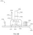
- FIG. 24Ais a perspective view of a safety lock of the medicament delivery device illustrated in FIGS. 4A and 4B .
- FIG. 24Bis a front view of the safety lock of the medical injector illustrated in FIG. 24A .
- FIG. 25is a bottom view of the safety lock of the medicament delivery device illustrated in FIGS. 24A and 24B .
- FIG. 26is a perspective view of a base of the medicament delivery device illustrated in FIGS. 4A and 4B .
- FIG. 26Ais a front view of the base of the medical injector illustrated in FIGS. 4A and 4B .
- FIG. 27is a back view of the medicament delivery device illustrated in FIGS. 4A and 4B in a second configuration.
- FIG. 28is a back view of the medicament delivery device illustrated in FIGS. 4A and 4B in a third configuration.
- FIG. 29is a back view of the medicament delivery device illustrated in FIGS. 4A and 4B in a fourth configuration.
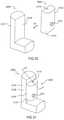
- FIG. 30is a schematic illustration of a medicament delivery device and an electronic circuit system assembly according to an embodiment of the invention.
- FIG. 31is a schematic illustration of the electronic circuit system assembly shown in FIG. 30 coupled to the medicament delivery device shown in FIG. 30 .
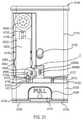
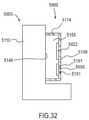
- FIG. 32is a cross-sectional view of the electronic circuit system assembly and the medicament delivery device shown in FIG. 31 , taken along a plane including line X-X.
- an apparatusin some embodiments, includes a medicament delivery device and an electronic circuit system.
- the medicament delivery deviceincludes a housing, a medicament container, and a medicament delivery member.
- the medicament container and at least a portion of the medicament delivery memberare disposed within the housing.
- the electronic circuit systemis coupled to the housing and includes an audible output device and a cover.
- the housing of the medicament delivery device and the cover of the electronic circuit systemcollectively define an acoustic enclosure.
- the audible output devicewhich can be, for example, a speaker, is configured to be disposed within the acoustic enclosure.
- an apparatusin some embodiments, includes a medicament delivery device and an electronic circuit system.
- the medicament delivery deviceincludes a housing and a medicament container.
- the medicament containeris disposed within the housing.
- the electronic circuit systemis coupled to the housing and includes a speaker and a cover.
- the speakerincludes a front portion and a back portion.
- the front portion of the speakeris configured to output a first audible output including a first set of sound waves.
- the back portion of the speakeris configured to output a second audible output including a second set of sound waves.
- the housing of the medicament delivery devicedefines a first opening through which the first set of sound waves is configured to travel.
- the cover of the electronic circuit systemdefines a second opening through which the second set of sound waves is configured to travel.
- an apparatusin some embodiments, includes a medicament delivery device and an electronic circuit system, the medicament delivery device including a housing, a medicament container, and a medicament delivery member.
- the medicament container and at least a portion of the medicament delivery memberare disposed within the housing.
- the electronic circuit systemis coupled to the housing and includes an audio processor and an audible output device.
- the audio processoris configured to output an electronic signal associated with recorded speech to the audible output device via an electronic path devoid of an amplifier.
- the audible output devicecan be configured to output an audible output in response to the electronic signal.
- an apparatusincludes a simulated medicament delivery device and an electronic circuit system coupled to the simulated medicament delivery device.
- the simulated medicament delivery devicecan be configured, for example, to simulate the look, feel and/or functionality associated with a pen injector, an auto-injector, an inhaler and/or a transdermal delivery device.
- the electronic circuit systemis configured to output an electronic output associated with a use of the simulated medicament delivery device.
- the electronic outputcan include, for example, a signal associated with a visual output, an audible output, a haptic output, an olfactory output and/or a taste output.
- the electronic outputcan include, for example, an instruction for using the simulated medicament delivery device and/or a medicament delivery device.
- proximal and distalrefer to direction closer to and away from, respectively, an operator (e.g., surgeon, physician, nurse, technician, etc.) of the medical device.
- an operatore.g., surgeon, physician, nurse, technician, etc.
- the end of the medicament delivery device contacting the patient's bodywould be the distal end of the medicament delivery device, while the end opposite the distal end would be the proximal end of the medicament delivery device.
- FIG. 1is a schematic illustration of a medicament delivery device 1000 having an acoustic enclosure, according to an embodiment of the invention.
- the medicament delivery device 1000includes a housing 1110 , a medicament container 1560 , a medicament delivery member 1512 , and an electronic circuit system 1900 .
- the medicament container 1560which can be, for example, a pre-filled cartridge, a vial, an ampule, or the like, is disposed within the housing 1110 . At least a portion of the medicament delivery member 1512 is disposed within the housing 1110 . In some configurations, the medicament delivery member 1512 can be in fluid communication with the medicament container 1560 .
- a medicamentcan be conveyed from the medicament container 1560 to a region outside the housing 1110 via the medicament delivery member 1512 .
- the medicament delivery member 1512can include, for example, a needle, a nozzle, a mouthpiece, or the like.
- the medicament delivery device 1000can be any suitable medical injector for injecting a medicament into a body of a patient.
- the medicament delivery device 1000can be a syringe, pen injector, auto-injector, or the like.
- the medicament delivery device 1000can be an inhaler.
- the medicament delivery device 1000can be a transdermal delivery system.
- the medicament delivery device 1000can be a chronic-care medicament delivery device. Said another way, the medicament delivery device 1000 can be a reusable device containing multiple doses of medicament.
- a medicament delivery device 1000 having multiple doses of medicamentcan be used to manage insulin delivery or the delivery of other medicaments (e.g., to treat Multiple Sclerosis, Anemia, Rheumatoid Arthritis, Osteoporosis or the like), which can, in some instances, require daily, weekly, and/or monthly dosages.
- the medicament delivery device 1000can be a single-use device. Said another way, the medicament delivery device 1000 can contain a single dose of medicament.
- the medicament delivery device 1000can be a simulated medicament delivery device or trainer similar to the simulated medicament delivery devices or trainers described in U.S. Patent Publication Number 2008/0059133, entitled “Medical Injector Simulation Device,” filed Feb. 27, 2007, which is incorporated herein by reference in its entirety.
- the electronic circuit system 1900includes an audible output device 1956 and a cover 1170 coupled to the housing 1110 .
- the audible output device 1956which can be, for example, a microspeaker, is configured to produce an audible output OP 11 .
- the audible output device 1956is configured to produce a set of sound waves in response to an electronic signal from the electronic circuit system 1900 .
- the electronic circuit system 1900 and the audible output device 1956can produce the audible output OP 11 in association with the use of the medicament delivery device 1000 .
- the electronic circuit system 1900can include any suitable electronic components operatively coupled to produce and/or output the audible output OP 11 and/or to perform the functions described herein.
- the electronic circuit system 1900can be similar to the electronic circuit systems described in U.S. Patent Publication Number 2008/0033393, entitled “Devices, Systems and Methods for Medicament Delivery,” filed Jan. 9, 2007, which is incorporated herein by reference in its entirety.
- the housing 1110 and the cover 1170 of the electronic circuit system 1900collectively define a region 1153 .
- the region 1153is illustrated in FIG. 1 as a two-dimensional area, the region 1153 is associated with an enclosed volume or space within the housing 1110 .
- the region 1153can be a cavity, a chamber, or an enclosure defined by the housing 1110 and the cover 1170 .
- the region 1153can be associated with a volume or space within the housing 1110 having at least one opening (not shown in FIG. 1 ) to an area outside of the housing 1110 .
- At least a portion of the electronic circuit system 1900is disposed within the region 1153 of the housing 1110 .
- the electronic circuit system 1900is coupled to the housing 1110 such that the audible output device 1956 is disposed within the region 1153 defined by the housing 1110 and the cover 1170 .
- the volume associated with the region 1153is larger than the volume of the audible output device 1956 .
- the region 1153can function as an acoustic enclosure for the audible output device 1956 .
- the region 1153can be used to minimize or attenuate noise and/or to enhance the audible output OP 11 of the audible output device 1956 .
- the region 1153can reduce noise by isolating and/or absorbing sound and/or vibration associated with the audible output device 1956 .
- the region 1153can enhance the audible output OP 11 of an audible output device 1956 by acoustically amplifying the audible output at one or more acoustic resonant frequencies defined by the physical characteristics of the region 1153 (e.g., volume, shape, or the like).
- the region 1153defines at least one resonant acoustic frequency within the acoustic frequency range of the audible output device 1956 .
- the audible output OP 11can be, for example, an audible representation of a recorded message or speech, a single tone or a sequence of tones, and/or the like.
- the audible output OP 11can be associated with a pre-recorded speech, instruction, or prompt for using the medicament delivery device 1000 .
- the audible output OP 11can be associated with post-use instructions or prompts, such as, for example, a recorded message notifying the user that the medicament delivery event is complete, instructing the user on post-medicament delivery disposal and safety procedures, instructing the user to seek post-medicament delivery medical treatment, and/or the like.
- the audible output OP 11can be associated with the patient's compliance in using the medicament delivery device 1000 . In some embodiments, the audible output OP 11 can be associated with an actuation of the medicament delivery device 1000 . Said another way, the audible output device 1956 can be configured to output the audible output OP 11 in response to the triggering or activating of a function, procedure, and/or mode associated with the medicament delivery device 1000 .
- the electronic circuit system 1900can produce an electronic output associated with the patient's compliance in using medicament the delivery device 1000 .
- such an electronic outputcan be associated with an actuation of the medicament delivery device 1000 .
- the electronic circuit system 1900can be configured to output an electronic output in response to actuation of the medicament delivery device 1000 .
- Such electronic outputscan be, for example, a visual output such as, for example, a text message to display on a screen (not shown), and/or an LED.
- an electronic outputcan be an audio output as described herein, such as, for example, recorded speech, a series of tones, and/or the like.
- an electronic outputcan be a wireless signal configured to be received by a remote device.
- the electronic outputcan be a signal sent to a compliance tracking monitor to record the data and/or time of use of the medicament delivery device 1000 .
- the region 1153is shown as being fully enclosed, in other embodiments the region 1153 can be partially enclosed.
- the cover 1170 and/or the housing 1110define an opening (not shown) through which the audible output device 1956 can be disposed within the region 1153 .
- the shape of the audible output device 1956can substantially match the shape of the partially enclosed region 1153 .
- the volume of the audible output device 1956 disposed within the partially enclosed region 1153is smaller than the volume of the partially enclosed region 1153 .
- FIG. 2is a schematic illustration of a medicament delivery device 2000 having a ported acoustic enclosure, according to an embodiment of the invention.
- the medicament delivery device 2000includes a housing 2110 , a medicament container 2560 , and an electronic circuit system 2900 .
- the medicament container 2560which can be, for example, a pre-filled cartridge, a vial, an ampule, or the like, is disposed within the housing 2110 .
- the medicament delivery device 2000can be a reusable device containing multiple doses of medicament.
- a medicament delivery device 2000 having multiple doses of medicamentcan be used to manage insulin delivery or the delivery of other medicaments (e.g., to treat Multiple Sclerosis, Anemia, Rheumatoid Arthritis, Osteoporosis or the like), which can, in some instances, require daily, weekly, and/or monthly dosage.
- the medicament delivery device 2000can be a single-use device. Said another way, the medicament delivery device 2000 can contain a single dose of medicament.
- the medicament delivery device 2000can be a simulated medicament delivery device or trainer.
- the electronic circuit system 2900can include any suitable electronic components operatively coupled to produce and/or output the audible output and/or to perform the functions described herein.
- the electronic circuit system 2900includes an audible output device 2956 and a cover 2170 coupled to the housing 2110 .
- the audible output device 2956which can be, for example, a microspeaker, includes a front portion 2004 and a back portion 2003 .
- the front portion 2004 of the audible output device 2956is configured to output a first audible output OP 21 that includes a first set of sound waves.
- the back portion 2003 of the audible output device 2956is configured to output a second audible output OP 22 that includes a second set of sound waves.
- the first set sound waves associated with the first audible output OP 21can result from changes in air pressure that occur at the front portion 2004 of the audible output device 2956 from, for example, a controlled movement of a portion of the audible output device 2956 (e.g., a cone, membrane, diaphragm, or the like).
- the second set of sound waves associated with the second audible output OP 22can result from changes in air pressure that occur at the back portion 2003 of the audible output device 2956 from, for example, the movement of a portion of the audible output device 2956 .
- a single moving portione.g., a speaker cone
- a movement of the cone that produces an increase in air pressure at the front portion 2004 of the audible output device 2956results in a corresponding decrease in air pressure at the back portion 2003 of the audible output device 2956 .
- a movement of the cone that produces a decrease in air pressure at the front portion 2004 of the audible output device 2956results in a corresponding increase in air pressure at the back portion 2003 of the audible output device 2956 .
- the first set of sound waves produced at the front portion 2004 of the audible output device 2956can be out-of-phase with the second set of sound waves produced at the back portion 2003 of the audible output device 2956 . In this manner, the electronic circuit system 2900 and the audible output device 2956 can produce an audible output associated with the use of the medicament delivery device 2000 .
- the housing 2110 and the cover 2170 of the electronic circuit system 2900collectively define a region 2153 .
- the region 2153is illustrated in FIG. 2 as a two-dimensional area, the region 2153 is associated with an enclosed volume or space within the housing 2110 .
- the region 2153can be a cavity, a chamber, or an enclosure defined by the housing 2110 and the cover 2170 .
- At least a portion of the electronic circuit system 2900 and/or the audible output device 2956is disposed within the region 2153 of the housing 2110 . In this manner, the region 2153 can function as an acoustic enclosure for the audible output device 2956 .
- the cover 2170defines an opening 2001 through which the first set of sound waves associated with the audible output OP 21 can travel.
- the housing 2110defines an opening 2002 through which the second set of sound waves associated with the audible output OP 22 can travel.
- the opening 2002can be referred to, for example, as a “port” of the acoustic enclosure associated with the region 2153 .
- the opening 2001 and the opening 2002can be collectively configured such that the first set of sound waves associated with the audible output OP 21 when exiting the housing 2110 through the opening 2001 is substantially in phase with the second set of sound waves associated with the audible output OP 22 when exiting the housing 2110 through the opening 2002 .
- the opening 2002can be positioned and/or oriented relative to the opening 2001 to compensate, reduce and/or eliminate the phase difference that can exist between the first set of sound waves of the audible output OP 21 and the second set of sound waves of the audible output OP 22 within the housing 2110 .
- the distance that the first set of sound waves of the audible output OP 21 travels to exit through the opening 2001e.g., the distance between the front portion 2004 of the audible output device 2956 and the exit of the opening 2001
- the distance that the second set of sound waves of the audible output OP 22 travels to exit through the opening 2002is such that the first set of sound waves associated with the audible output OP 21 when exiting the housing 2110 is substantially in phase with the second set of sound waves associated with the audible output OP 22 when exiting the housing 2110 through the opening 2002 .
- phase compensation that results from the difference between the exit path of the first set of sound waves of the audible output OP 21 and the exit path of the second set of sound waves of the audible output OP 22can increase (e.g., constructively interfere) the overall sound level of the audible output device 2956 outside the housing 2110 .
- the housing 2110can define both the opening 2001 and the opening 2002 .
- the cover 2170is described as defining a single opening 2001 , in other embodiments, the cover 2170 can define multiple openings.
- the housing 2110can define multiple “ports” or openings.
- the opening 2002is configured to be selectively covered by a moveable member (not shown) of the medicament delivery device 2000 .
- the opening 2002can be selectively covered by at least one of a sleeve, a safety lock, or a needle guard.
- the audible outputs OP 21 and OP 22can be related to instructions, notifications, messages, actuations, and/or compliance associated with using the medicament delivery device 2000 .
- the audible output OP 21 and the audible output OP 22can be, for example, a recorded message or speech, a single tone or a sequence of tones, and/or the like.
- the electronic circuit system 2900can output information to the user through the audile outputs OP 21 and OP 22 in an unobtrusive manner and/or without impeding the delivery of the medicaments.
- the audible outputs OP 21 and OP 22can be, for example, audible representations of a recorded message or speech, single tones or sequences of tones, and/or the like.
- the audible outputs OP 21 and OP 22can be associated with a pre-recorded speech, instruction, or prompt for using the medicament delivery device 2000 .
- the audible outputs OP 21 and OP 22can be associated with post-use instructions or prompts, such as, for example, a recorded message notifying the user that the medicament delivery is complete, instructing the user on post-medicament delivery disposal and safety procedures, instructing the user to seek post-medicament delivery medical treatment, and/or the like.
- the audible outputs OP 21 and OP 22can be associated with the patient's compliance in using the medicament delivery device 2000 .
- the audible outputs OP 21 and OP 22can be associated with an actuation of the medicament delivery device 2000 .
- the audible output device 2956can be configured to output the audible outputs OP 21 and OP 22 in response to the triggering or activating of a function, procedure, and/or mode associated with the medicament delivery device 2000 .
- FIG. 3is a schematic illustration of a medicament delivery device 3000 according to an embodiment of the invention.
- the medicament delivery device 3000includes a housing 3110 , a medicament container 3560 , a medicament delivery member 3512 , and an electronic circuit system 3900 .
- the medicament container 3560is disposed within the housing 3110 .
- At least a portion of the medicament delivery member 3512is disposed within the housing 3110 .
- the medicament container 3560 and/or the medicament delivery member 3512can be substantially similar to the medicament container 1560 and/or the medicament delivery member 1512 , respectively, as shown and described above with reference to FIG. 1 .
- the electronic circuit system 3900which can be can be similar to the electronic circuit system 1900 shown and described above with reference to FIG. 1 , includes an audio processor 3010 and an audible output device 3956 .
- the audio processor 3010is configured to output an electronic output S 31 to the audible output device 3956 .
- the audio processor 3010can be software-based (e.g., set of instructions executable at a processor, software code) and/or hardware-based (e.g., circuit system, processor, application-specific integrated circuit (ASIC), field programmable gate array (FPGA)).
- the electronic output S 31can be associated with, for example, a recorded message or speech, a single tone or a sequence of tones, and/or the like.
- the electronic circuit system 3900 and/or the audio processor 3010can include a separate memory (not shown) in which information associated with a recorded message or speech, tones, or the like can be stored. In this manner, the audio processor 3010 can receive the recorded message or tone information from the memory for processing and to produce the electronic output S 31 .
- the audio processor 3010can include an embedded or built-in memory module in which information associated with the recorded message or tone is stored.
- the electronic output S 31is conveyed from the audio processor 3010 to the audible output device 3956 via an electronic path 3001 devoid of an amplifier.
- no amplifiers and/or drivers external to the audio processor 3010are used to boost or increase the electronic output S 31 .
- the electronic path 3001can be defined by any suitable electronic components.
- the electronic circuit system 3900can have the audio processor 3010 , the audible output device 3956 , and/or the electronic path 3001 disposed on one or more printed circuit boards (PCBs). Such an arrangement can reduce the cost and/or complexity of the electronic circuit system 3900 .
- PCBsprinted circuit boards
- the audible output device 3956which can be, for example, a microspeaker, is configured to produce the audible output OP 31 in response to the electronic output S 31 . In this manner, the electronic circuit system 3900 and the audible output device 3956 can produce an audible output associated with the use of the medicament delivery device 3000 , as discussed above.
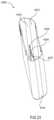
- FIGS. 4A-29show a medicament delivery device 4000 , according to an embodiment of the invention.
- FIGS. 4A-4Bare perspective views of the medicament delivery device 4000 in a first configuration (i.e., prior to use).
- the medicament delivery device 4000is similar to the medical injectors described in U.S. patent application Ser. No. 12/119,016, entitled “Medicament Delivery Device Having an Electronic Circuit System,” filed May 12, 2008, which is incorporated herein by reference in its entirety.
- the medicament delivery device 4000includes a housing 4110 , a medicament delivery mechanism 4500 (see e.g., FIG. 12 ), an electronic circuit system 4900 (see e.g., FIGS. 13-21 ), a cover 4200 (see e.g., FIGS.
- the medicament delivery device 4000is a medical injector.
- the housing 4110has a proximal end portion 4140 and a distal end portion 4120 .
- the housing 4110defines a first status indicator aperture 4150 and a second status indicator aperture 4151 .
- the status indicator apertures 4150 , 4151can allow a patient to monitor the status and/or contents of a medicament container 4560 . For example, by visually inspecting the status indicator apertures 4150 , 4151 , a patient can determine whether the medicament container 4560 contains a medicament and/or whether a medicament has been dispensed.
- the housing 4110defines a gas cavity 4154 , a medicament cavity 4157 , and an electronic circuit system cavity 4153 .
- the gas cavity 4154has a proximal end portion 4155 and a distal end portion 4156 .
- the gas cavity 4154is configured to receive the gas container 4570 and the release member 4540 of the medicament delivery mechanism 4500 (see e.g., FIG. 12 ), as described in further detail herein.
- the proximal end portion 4155 of the gas cavity 4154is configured to receive the gas container retention member 4580 of the proximal cap 4112 of the housing 4110 , as described in further detail herein.
- the gas cavity 4154is in fluid communication with the medicament cavity 4157 via a gas passageway 4144 (see e.g., FIG. 11 ), as described in further detail herein, and the gas cavity 4154 is in fluid communication with a region outside the housing 4110 via a safety lock aperture 4128 .
- the medicament cavity 4157is configured to receive a portion of the medicament delivery mechanism 4500 .
- the carrier 4520 , the moveable member 4530 and the needle 4512 of the medicament delivery mechanism 4500are movably disposed in the medicament cavity 4157 .
- the medicament cavity 4157is in fluid communication with a region outside the housing 4110 via a needle aperture 4122 .
- the electronic circuit system cavity 4153is configured to receive the electronic circuit system 4900 .
- the electronic circuit system cavity 4153is isolated from the gas cavity 4154 and/or the medicament cavity 4157 via a side wall 4148 (see e.g., FIG. 10 ). Said another way, the electronic circuit system cavity 4153 is acoustically separated from and/or fluidically isolated from the gas cavity 4154 and/or the medicament cavity 4157 .
- the electronic circuit system cavity 4153can function as an acoustic enclosure to enhance the magnitude and/or quality of the audible output produced by the electronic circuit system 4900 .
- the housing 4110has protrusions 4149 (see e.g., FIG. 8 ) configured to stabilize the electronic circuit system 4900 when the electronic circuit system 4900 is disposed within the electronic circuit system cavity 4153 .
- the housing 4110also defines connection apertures 4152 configured to receive connection protrusions 4171 A and 4171 B (see e.g., FIG. 13 ) of the electronic circuit system 4900 , and aperture 4145 (see e.g., FIG. 6 ) configured to receive a portion of a protrusion 4174 of the electronic circuit system 4900 .
- the electronic circuit system 4900can be coupled to the housing 4110 within the electronic circuit system cavity 4153 .
- the electronic circuit system 4900can be coupled within the electronic circuit system cavity 4153 by other suitable means such as an adhesive, a clip and/or the like.
- the proximal end portion 4140 of the housing 4110includes a proximal cap 4112 , a speaker protrusion 4147 (see e.g., FIGS. 8 and 9 ), and cover retention protrusions 4142 (see e.g., FIGS. 4B and 6 ).
- the speaker protrusion 4147is configured to maintain a position of an audible output device 4956 relative to the housing 4110 and/or an electronic circuit system cover 4170 when the electronic circuit system 4900 is attached to the housing 4110 .
- the speaker protrusion 4147can press the front portion 4957 of the audible output device 4956 against the electronic circuit system cover 4170 to form a substantially airtight (e.g., a substantially hermetic) seal between the front portion 4957 of the audible output device 4956 and the electronic circuit system cover 4170 .
- a substantially airtight sealcan reduce undesirable audible noise that can result from air leaking through a gap between the front portion 4957 of the audible output device 4956 and the electronic circuit system cover 4170 .
- the speaker protrusion 4147can reduce or minimize undesirable vibration of the audible output device 4956 by holding the audible output device 4956 in a substantially fixed position relative to the electronic circuit system cover 4170 .
- the cover retention protrusions 4142are configured to be received within corresponding openings 4215 on the cover 4200 . In this manner, as described in more detail herein, the cover 4200 can be removably coupled to and disposed about at least a portion of the housing 4110 .
- the proximal cap 4112includes a gas container retention member 4580 and defines a gas passageway 4144 .
- the gas container retention member 4580is configured to receive and/or retain a gas container 4570 that can contain a pressurized gas.
- the gas passageway 4144is configured to allow for the passage of gas contained in the gas container 4570 from the gas cavity 4154 to the medicament cavity 4157 , as further described herein. Said another way, the gas passageway 4144 places the gas cavity 4154 in fluid communication with the medicament cavity 4157 .
- the distal end portion 4120 of the housing 4110defines a battery isolation protrusion aperture 4121 , a needle aperture 4122 , a safety lock actuator groove 4123 , a safety lock aperture 4128 , a base actuator groove 4124 , base retention recesses 4125 A, 4125 B, and base rail grooves 4127 .
- the base 4300is moveably coupled to the distal end portion 4120 of the housing 4110 .
- the battery isolation protrusion aperture 4121is configured to receive the battery isolation protrusion 4235 of the cover 4200 (see e.g., FIG. 23 ) when the cover 4200 is disposed about the housing 4110 , as described in further detail herein.
- the battery isolation protrusion aperture 4121places the electronic circuit system cavity 4153 in fluid communication with a region outside of the housing 4110 . Said another way, when the cover 4200 is moved relative to the housing 4100 , the battery isolation protrusion aperture 4121 defines an opening through which sound waves produced by a back portion 4955 of the audible output device 4956 can exit the housing 4110 .
- the needle aperture 4122is configured to allow the needle 4512 (see e.g., FIG. 12 ) to exit the housing 4110 when the medical injector 4000 is actuated.
- the portion of the sidewall of the housing 4110 that defines the needle aperture 4122includes multiple sheath retention protrusions 4126 .
- the sheath retention protrusionscan interact with the plurality of ribs 4728 of the needle sheath 4720 (see e.g. FIGS. 24A and 24B ) to maintain a position of the needle sheath 4720 relative to the safety lock 4700 when the safety lock 4700 is coupled to the housing 4110 and/or when the safety lock 4700 is being removed from the housing 4110 .
- the safety lock actuator groove 4123is configured to receive an actuator 4744 of the safety lock 4700 .
- the actuator 4744is configured to engage and/or activate the electronic circuit system 4900 when the safety lock 4700 is moved with respect to the housing 4110 .
- the safety lock aperture 4128is configured to receive a safety lock protrusion 4742 (see e.g., FIGS. 25 and 26 ).
- the safety lock protrusion 4742is received within an opening 4554 between extensions 4552 of a release member 4540 such that activation of the medical injector 4000 is prevented when the safety lock 4700 is in place.
- the safety lock 4700its components and functions are further described herein.
- the distal base retention recesses 4125 Aare configured to receive the base connection knobs 4358 of the base (see e.g., FIG. 26 ) when the base is in a first position relative to the housing 4110 .
- the proximal base retention recesses 4125 Bare configured to receive the base connection knobs 4358 of the base when the base is in a second position relative to the housing 4110 .
- the base retention recesses 4125 A, 4125 Bhave a tapered proximal sidewall and a non-tapered distal sidewall. This allows the base retention recesses 4125 A, 4125 B to receive the base connection knobs 4358 such that the base can move proximally relative to the housing 4110 , but cannot move distally relative to the housing 4110 .
- the distal base retention recesses 4125 Aare configured to prevent the base from moving distally when the base is in a first position and the proximal base retention recesses 4125 B are configured to prevent the base from moving distally when the base is in a second position.
- the proximal base retention recesses 4125 B and the base connection knobs 4358cooperatively prevent “kickback” after the medical injector 4000 is actuated.
- the base actuator groove 4124is configured to receive an actuator 4311 of the base.
- the actuator 4311 of the baseis configured to engage the electronic circuit system 4900 when the base 4100 is moved with respect to the housing 4110 .
- the base rail grooves 4127are configured to receive the guide members 4312 of the base.
- the guide members 4312 of the base and the base rail grooves 4127 of the housing 4110engage each other in a way that allows the guide members 4312 of the base to slide in a proximal and/or distal direction within the base rail grooves 4127 while limiting lateral movement of the guide members 4312 .
- This arrangementallows the base to move in a proximal and/or distal direction with respect to the housing 4110 but prevents the base from moving in a lateral direction with respect to the housing 4110 .
- FIG. 12shows the medicament delivery mechanism 4500 of the medicament delivery device 4000 .
- the medicament delivery device 4000is similar to the auto-injectors described in U.S. Patent Application Publication Number 2007/0149925, entitled “Devices, Systems and Methods for Medicament Delivery,” filed Nov. 21, 2006, which is incorporated herein by reference in its entirety. Accordingly, only an overview of the medicament delivery mechanism 4500 and related operation of the medicament delivery device 4000 is included below.
- the medicament delivery mechanism 4500includes a needle 4512 , a carrier 4520 , a movable member 4530 , a medicament container 4560 , a gas container 4570 , and a release member 4540 .
- the needle 4512 , carrier 4520 , movable member 4530 and medicament container 4560are disposed within the medicament cavity 4157 of the housing 4110 .
- the gas container 4570 and the release member 4540are disposed within the gas cavity 4154 of the housing 4110 .
- the release member 4540is movably disposed within the distal end portion 4156 of the gas cavity 4154 .
- a proximal end portion 4542 of the release member 4540includes a sealing member 4545 and a puncturer 4541 .
- the sealing member 4545is configured to engage the sidewall of the housing 4110 defining the gas cavity 4154 such that the proximal end portion 4155 of the gas cavity 4154 is fluidically isolated from the distal end portion 4156 of the gas cavity 4154 . In this manner, when gas is released from the gas container 4570 , the gas contained in the proximal end portion 4155 of the gas cavity 4154 is unable to enter the distal end portion 4156 of the gas cavity 4154 .
- the puncturer 4541is configured to contact and puncture a frangible seal 4573 on the gas container 4570 when the release member 4540 moves proximally within the gas cavity 4154 , as shown by the arrow BB in FIG. 12 .
- a distal end portion 4544 of the release member 4540includes extensions 4552 .
- the extensions 4552include projections 4547 that include tapered surfaces 4549 and engagement surfaces 4548 . Further, the extensions 4552 define an opening 4554 between the extensions 4552 .
- the engagement surfaces 4548 of the projections 4547are configured to extend through the safety lock aperture 4128 of the housing 4110 and contact a distal surface of the housing 4110 . In this manner, the engagement surfaces 4548 of the projections 4547 limit proximal movement of the release member 4540 when the engagement surfaces 4548 are in contact with the distal surface of the housing 4110 .
- the tapered surfaces 4549 of the projections 4547are configured to contact protrusions 4313 on a proximal surface 4310 of the base 4300 (see e.g., FIG. 26 ). In this manner, proximal movement of the base 4300 causes the extensions 4552 to move together, thereby releasing the engagement surfaces 4548 from the housing 4110 and allowing the release member 4540 to move proximally within the gas cavity 4154 .
- the opening 4554 defined by the extensions 4552is configured to receive the safety lock protrusion 4742 of the safety lock 4700 (see e.g., FIGS. 24A and 24B ).
- the safety lock protrusion 4742is configured to ensure that the extensions 4552 remain apart and the engagement surfaces 4548 of the projections 4547 remain in contact with the distal end portion 4120 of the housing 4110 .
- the release member 4540 and/or the extensions 4552can be constructed from any suitable material configured to withstand deformation that may occur when exposed to a load over an extended period of time.
- the gas container 4570is configured to contain a pressurized gas, and has a frangible seal 4573 at the distal end thereof.
- the frangible seal 4573is configured to break when the puncturer 4541 of the proximal end portion 4542 of the release member 4540 contacts the frangible seal 4573 .
- the gas container retention member 4580 of the proximal cap 4112 of the housing 4110is configured to receive and/or retain the proximal end portion 4576 of the gas container 4570 to maintain the position of the gas container 4570 .
- the medicament container 4560 of the medicament delivery mechanism 4500is configured to contain a medicament.
- a distal end portion 4562 of the medicament container 4560contains a seal 4523 configured to burst when punctured by a proximal end 4516 of the needle 4512 , as described below.
- a proximal end portion 4566 of the medicament container 4560is configured to receive a piston portion 4534 of the movable member 4530 .
- the movable member 4530 of the medicament delivery mechanism 4500is movably disposed within the medicament cavity 4157 .
- the movable member 4530includes the piston portion 4534 having a plunger (not shown) at the distal end portion of the piston portion 4534 .
- the piston portion 4534is configured to move within the medicament container 4560 . In this manner, the piston portion 4534 of the movable member 4530 can apply or exert pressure to a medicament contained in the medicament container 4560 .
- the piston portion 4534can be constructed of a resilient, durable, and/or sealing material, such as a rubber, for example.
- the carrier 4520 of the medicament delivery mechanism 4500includes a distal end portion 4522 and a proximal end portion 4526 .
- the medicament container 4560is coupled to the carrier 4520 via a “snap-fit” connection (not shown) such that the medicament container 4560 can move relative to the carrier 4520 between a first configuration and a second configuration during an injection event.
- the carrier 4520is configured to move within the medicament cavity 4157 such that movement of the carrier 4520 within the medicament cavity 4157 causes contemporaneous movement of the medicament container 4560 within the medicament cavity 4157 .
- the proximal end portion 4516 of the needle 4512is spaced apart from the seal 4523 of the medicament container 4560 when the carrier 4520 is in the first configuration.
- the medicament container 4560releases from the “snap-fit” causing the medicament container 4560 to move distally with respect to the carrier 4520 , causing the proximal end portion 4516 of the needle 4512 to pierce the seal 4523 .
- the needle 4512can be selectively placed in fluid communication with the medicament container 4560 to define a medicament delivery path (not shown).
- FIGS. 13-20show the electronic circuit system 4900 .
- the electronic circuit systemis configured to produce and/or output an audible output associated with a use of the medicament delivery device 4000 .
- the electronic circuit system 4900 of the medicament delivery device 4000includes the electronic circuit system cover 4170 shown and described above with reference to FIG. 7 , a printed circuit board 4922 , a processor 4950 , a battery assembly 4962 , an audible output device 4956 , two light emitting diodes (LEDs) 4958 A and 4958 B, and a battery clip 4910 .
- the electronic circuit system 4900is configured to fit within the electronic circuit system cavity 4153 of the housing 4110 . Accordingly, as described above, the electronic circuit system 4900 is physically, acoustically, and/or fluidically isolated from the medicament cavity 4157 and/or the gas cavity 4154 .
- the electronic componentsare mounted to the electronic circuit system cover 4170 .
- the electronic circuit system cover 4170includes a distal end portion 4180 and a proximal end portion 4190 .
- the proximal end portion 4190includes connection protrusions 4171 A and a battery clip protrusion 4173 .
- the connection protrusions 4171 Aextend from the proximal end portion 4190 of the electronic circuit system cover 4170 , and are configured to be disposed within the connection apertures 4152 of the housing 4110 , as described above.
- the electronic circuit system 4900can be coupled to the housing 4110 within the electronic circuit system cavity 4153 .
- the electronic circuit system 4900can be coupled to the housing 4110 by other suitable means such as an adhesive, a clip and/or the like.
- the proximal end portion 4190 of the electronic circuit system cover 4170defines multiple sound apertures 4191 .
- the audible output device 4956is disposed against the proximal end portion 4190 of the electronic circuit system cover 4170 such that the front portion 4957 of the audible output device 4956 is disposed adjacent the sound apertures 4191 . In this manner, sound waves from the audible output device 4956 can travel from the audible output device 4956 to a region outside of the housing 4110 via the sound apertures 4191 .
- a sealing materiale.g., a compressible adhesive foam, an elastomeric o-ring, or the like
- a substantially airtight sealis formed between the front portion 4957 of the audible output device 4956 and the electronic circuit system cover 4170 .
- the sealing materialis a compressible adhesive foam approximately 3 ⁇ 4 millimeters in thickness that covers approximately 10 percent of the front portion 4957 of the audible output device 4956 .
- the distal end portion 4180 of the electronic circuit system cover 4170includes a connection protrusion 4171 B, a stiffening protrusion 4174 , and defines an LED aperture 4181 and an aperture 4172 .
- the LED aperture 4181is configured to receive the LEDs 4958 A, 4958 B such that a user can view the LEDs 4958 A, 4958 B, which are described in more detail herein.
- the connection protrusion 4171 Bextends from the distal end portion 4180 of the electronic circuit system cover 4170 , and is configured to attach the electronic circuit system 4900 to the housing 4110 , as described above.
- the stiffening protrusion 4174is configured to have at least a portion received within and/or accessible via the aperture 4145 in the housing 4110 (see e.g., FIG. 6 ).
- the stiffening protrusion 4174is configured to limit the bending (e.g., buckling) of the electronic circuit system cover 4170 when the electronic circuit system cover 4170 is coupled to the housing 4110 .
- the electronic circuit system cover 4170is matingly coupled to the housing 4110 such that the electronic circuit system cover 4170 and the electronic circuit system cavity 4153 collectively define an acoustic enclosure within which the audible output device 4956 is disposed. Said another way, the electronic circuit system cover 4170 and the electronic circuit system cavity 4153 collectively form a region, volume and/or space that is configured to minimize or attenuate noise and/or enhance the audible output of the audible output device 4956 . Moreover, the volume associated with the region defined by the electronic circuit system cover 4170 and the electronic circuit system cavity 4153 is larger than the volume of the audible output device 4956 and/or the electronic circuit system 4900 disposed within the region. In this manner, the acoustic enclosure defined by the electronic circuit system cover 4170 and the electronic circuit system cavity 4153 is configured to contain a volume of air behind the audible output device 4956 .
- the safety lock actuator groove 4182 of the electronic circuit system housing 4170is configured to be disposed adjacent the safety lock actuator groove 4123 of the distal end portion 4120 of the housing 4110 . In this manner, the safety lock actuator groove 4182 of the electronic circuit system housing 4170 and the safety lock actuator groove 4123 of the distal end portion 4120 of the housing 4110 collectively receive the actuator 4744 of the safety lock 4700 , which is described in more detail herein.
- the base actuator groove 4183 of the electronic circuit system housing 4170is configured to be disposed about the base actuator groove 4124 of the distal end portion 4120 of the housing 4110 .
- the base actuator groove 4183 of the electronic circuit system housing 4170 and the base actuator groove 4124 of the distal end portion 4120 of the housing 4110collectively receive the actuator 4311 of the base, which is described in more detail herein.
- the audible output device 4956 and the electronic circuit system cavity 4153are collectively configured to enhance the quality and/or magnitude of the sound produced by the audible output device 4956 .
- the size and/or shape of the electronic circuit system cavity 4153can be configured such that the electronic circuit system cavity 4153 defines an acoustic resonant frequency that is within a predefined frequency range of the audible output device 4956 .
- the electronic circuit system cavity 4153can be configured such that the electronic circuit system cavity 4153 defines an acoustic resonant frequency that is substantially the same as a resonant frequency of the audible output device 4956 .
- the quality and/or magnitude of the sound produced by the audible output device 4956can be enhanced for a particular range of frequencies. In some embodiments, the quality and/or magnitude of the sound produced by the audible output device 4956 can be enhanced for a frequency range corresponding to the frequency range of a recorded speech output.
- the printed circuit board 4922 of the electronic circuit system 4900includes a substrate 4924 , a first actuation portion 4926 and a second actuation portion 4946 .
- the printed circuit board 4922provides the structure upon which at least a portion of the electronic components of the electronic circuit system 4900 are mounted.
- the printed circuit board 4922includes conductive portions (e.g., copper traces, insulated wires, flexible wires or the like) to electronically couple the components.
- the first actuation portion 4926includes a first electrical conductor 4934 and defines an opening 4928 having a boundary 4929 .
- the opening 4928 of the first actuation portion 4926is configured to receive a protrusion 4746 of the actuator 4744 of the safety lock 4700 .
- the boundary 4929 of the first opening 4928has a discontinuous shape, such as, for example, a teardrop shape, that includes a stress concentration riser 4927 .
- the discontinuity and/or the stress concentration riser 4927 of the boundary 4929can be of any suitable shape to cause the substrate 4924 to deform in a predetermined direction when the protrusion 4746 of the actuator 4744 of the safety lock 4700 is moved relative to the opening 4928 , as shown by the arrow CC in FIG. 21B .
- the opening 4928is defined adjacent the first electrical conductor 4934 that electronically couples the components included in the electronic circuit system 4900 .
- the first electrical conductor 4934includes a first switch 4972 , which can be, for example a frangible portion of the first electrical conductor 4934 .
- the actuator 4744moves in a direction substantially parallel to a plane defined by a surface of the first actuation portion 4926 of the substrate 4924 .
- the movement of the actuator 4744causes the protrusion 4746 to move within the first opening 4928 , as indicated by the arrow CC in FIG. 21B .
- the actuator 4744moves irreversibly the first switch 4972 from a first state (e.g., a state of electrical continuity) to a second state (e.g., a state of electrical discontinuity).
- a first statee.g., a state of electrical continuity
- a second statee.g., a state of electrical discontinuity
- the second actuation portion 4946includes a second electrical conductor 4935 and defines an opening 4945 , having a boundary 4949 and a tear propagation limit aperture 4948 .
- the opening 4945 of the second actuation portion 4946is configured to receive a portion of an actuator 4311 of the base.
- the boundary 4949 of the opening 4945has a discontinuous shape that includes a stress concentration riser 4947 .
- the discontinuity and/or the stress concentration riser 4947 of the boundary 4949can be of any suitable shape to cause the substrate 4924 to deform in a predetermined direction when the actuator 4311 of the base is moved in a proximal direction relative to the opening 4945 , as shown by the arrow DD in FIG. 21C .
- the second electrical conductor 4935includes a second switch 4973 disposed between the opening 4945 and the tear propagation limit aperture 4948 , which can be, for example, a frangible portion of the second electrical conductor 4935 .
- the actuator 4311moves in a proximal direction, substantially parallel to a plane defined by a surface of the second actuation portion 4946 of the substrate 4924 .
- the proximal movement of the actuator 4311tears the second actuation portion 4946 of the substrate 4924 , thereby separating the portion of the second electrical conductor 4935 including the second switch 4973 .
- the tear propagation limit aperture 4948is configured to limit the propagation of the tear in the substrate 4924 in the proximal direction. Said another way, the tear propagation limit aperture 4948 is configured to ensure that the tear in the substrate 4924 does not extend beyond the tear propagation limit aperture 4948 .
- the tear propagation limit aperture 4948can be any shape configured to stop the propagation of a tear and/or disruption of the substrate 4924 .
- the tear propagation limit aperture 4948can be oval shaped.
- the proximal boundary of the tear propagation limit aperture 4948can be reinforced to ensure that the tear in the substrate 4924 does not extend beyond the tear propagation limit aperture 4948 .
- the processor 4950is configured to process electronic inputs (e.g., from input switches) and produce electronic signals and/or outputs. As described herein, such electronic signals can include signals related to audio or visual outputs associated with a use of the medicament delivery device 4000 . More particularly, the processor 4950 is configured to output an electronic signal to the audible output device 4956 , which then converts the electronic signal into sound waves. Said another way, the processor 4950 is configured to output an electronic signal associated with an audible output to the audible output device 4956 , which is configured to output the audible output.
- the electronic signalcan be associated with, for example, recorded speech, a single tone, a sequence of tones, and/or the like. In this manner, the electronic circuit system 4900 can produce and/or output an audible output associated with a use of the medicament delivery device 4000 .
- the electronic signals produced by the processor 4950are conveyed to the audible output device 4956 via one or more electronic paths (not identified in FIG. 15 ) defined by the printed circuit board 4922 (e.g., conductive traces or the like). As shown in FIG. 16 , the electronic paths between the processor 4950 and the audible output device 4956 are devoid of an amplifier. Similarly stated, no amplifiers and/or drivers external to the processor 4956 are used to amplify or increase the electronic signals produced by the processor 4950 . This arrangement can reduce the cost and/or complexity of the electronic circuit system 4900 . Moreover, by being devoid of external amplification, the power of the electronic signals conveyed to the audible output device 4956 can be relatively low.
- the battery assembly 4962can include smaller batteries and/or the battery assembly 4962 can include fewer batteries.
- the electronic signal produced by the processor 4950can have a power of less than 500 milliwatts (mW). In other embodiments, the electronic signal produced by the processor 4950 can have a power of less than 100 milliwatts (mW). In yet other embodiments, the electronic signal produced by the processor 4950 can have a power of approximately 80 milliwatts (mW).
- the processor 4950can be a commercially-available processing device dedicated to performing one or more specific tasks.
- the processor 4950can be a commercially-available microprocessor, such as the Sonix SNC 12060 voice synthesizer.
- the processor 4950can be an application-specific integrated circuit (ASIC) or a combination of ASICs, which are designed to perform one or more specific functions.
- the processor 4950can be an analog or digital circuit, or a combination of multiple circuits.
- the processor 4950can be programmed through, for example, an internal controller (not shown) such that varied applications, including voice section combination, key trigger arrangement, and/or output control, for example, can be implemented.
- the processor 4950can include a memory device (not shown) configured to receive and store information, such as a series of instructions, processor-readable code, a digitized signal, or the like.
- the memory devicecan store operating code, recorded speech or voice code, and/or data code.
- the memory devicecan include one or more types of memory.
- the memory devicecan include a read only memory (ROM) component and a random access memory (RAM) component.
- the memory devicecan also include other types of memory suitable for storing data in a form retrievable by the processor 4950 , for example, electronically-programmable read only memory (EPROM), erasable electronically-programmable read only memory (EEPROM), or flash memory.
- EPROMelectronically-programmable read only memory
- EEPROMerasable electronically-programmable read only memory
- flash memorya memory device separate from the processor 4950 can be used to receive and store information.
- the battery assembly 4962 of the electronic circuit system 4900includes two batteries stacked on top of one another.
- the batteriescan be, for example, three volt, “watch-style” lithium batteries.
- the battery assembly 4962has a first surface 4964 and a second surface 4966 .
- the first surface 4964 of the battery assembly 4962can contact an electrical contact (not shown) disposed on the substrate 4924 .
- the second surface 4966 of the battery assembly 4962is configured to contact a contact portion 4918 of a distal end portion 4916 of a battery clip 4910 .
- the batteries of the battery assembly 4962are placed in electrical communication with the electronic circuit system 4900 . Said another way, when the electrical contact of the substrate 4924 and the contact portion 4918 of the distal end portion 4916 of the battery clip 4910 contact the battery assembly 4962 , the battery assembly 4962 is configured to supply power to the electronic circuit system 4900 .
- the battery clip 4910(shown in FIG. 20 ) includes a proximal end portion 4912 and a distal end portion 4916 .
- the proximal end portion 4912defines a retention aperture 4913 .
- the retention aperture 4913is configured to receive the battery clip protrusion 4173 of the electronic circuit system cover 4170 . In this manner, the battery clip protrusion 4173 maintains the position of the battery clip 4910 with respect to the electronic circuit system cover 4170 and/or the battery assembly 4962 .
- the distal end portion 4916 of the battery clip 4910includes a contact portion 4918 and an angled portion 4917 .
- the contact portion 4918is configured to contact the second surface 4916 of the battery assembly 4962 to place the battery assembly 4962 in electrical communication with the electronic circuit system 4900 .
- the angled portion 4917 of the distal end portion 4916 of the battery clip 4910is configured to allow a proximal end portion 4236 of a battery isolation protrusion 4235 (see e.g., FIG. 23 ) to be disposed between the second surface 4966 of the battery assembly 4962 and the contact portion 4918 of the distal end portion 4916 of the battery clip 4910 .
- the electrical path between the battery assembly 4962 and the remainder of the electrical circuit system 4900is severed, thereby removing power from the electronic circuit system 4900 .
- the contact portion 4918 of the distal end portion 4916 of the battery clip 4910is biased such that when the battery isolation protrusion 4235 is removed, the contact portion 4918 will move into contact the second surface 4916 of the battery assembly 4962 , thereby restoring electrical communication between the battery assembly 4962 and the electronic circuit system 4900 .
- the battery isolation protrusion 4235can be repeatedly removed from between the second surface 4966 of the battery assembly 4962 and the contact portion 4918 of the distal end portion 4916 of the battery clip 4910 and reinserted. Said another way, the battery isolation protrusion 4235 and the battery clip 4910 collectively form a reversible on/off switch.
- the battery isolation protrusion 4235When the battery isolation protrusion 4235 is disposed between the second surface 4966 of the battery assembly 4962 and the contact portion 4918 of the distal end portion 4916 of the battery clip 4910 , a portion of the battery isolation protrusion 4235 is also disposed within the battery isolation protrusion aperture 4121 . Conversely, when the battery isolation protrusion 4235 is removed from between the second surface 4966 of the battery assembly 4962 and the contact portion 4918 of the distal end portion 4916 of the battery clip 4910 the battery isolation protrusion aperture 4121 is opened. In this manner, the battery isolation protrusion 4235 can selectively open and/or close the battery isolation protrusion aperture 4121 .
- the battery isolation protrusion aperture 4121can selectively function as a port to allow sound waves produced by the audible output device 4956 to exit the electronic circuit system cavity 4153 to an area outside the housing 4110 .
- the location of the battery isolation protrusion aperture 4121 with respect to the location of the audible output device 4956 and/or the sound apertures 4191is such that the sound waves that exit through the multiple sound apertures 4191 are substantially in phase with the sound waves that exit through the battery isolation protrusion aperture 4121 .
- the audible output device 4956 of the electronic circuit system 4900is configured to output audible sound associated with a use of the medicament delivery device 4000 .
- the audible output device 4956can have any suitable performance characteristics to produce the desired audible output (e.g., an audible output having a predefined frequency range, a predefined sound pressure level, etc.) based on the electronic signals produced by the processor 4950 , as described above.
- the audible output device 4956can have a specified resonance frequency, a specified output sound pressure level (e.g., Watts/meter), a specified maximum input power rating, and/or a specified frequency response range.
- the audible output device 4956can have one or more resonant frequencies within the specified frequency response range.
- the audible output device 4956can be a commercially-available micro-speaker such as an M0015N07K01F micro-speaker manufactured by Dain (International) Co., Ltd. In other embodiments, the audible output device 4956 can be an RS-1511A micro-speaker manufactured by Regal Electronics, Inc., for example.
- the audible output device 4956includes a front portion 4957 and a back portion 4955 .
- the audible output device 4956can include a movable portion (e.g., a cone, membrane, diaphragm, or the like; not shown in FIGS. 13 and 14 ) such that the audible output device 4956 can produce a first set of sound waves from the front portion 4957 and a second set of sound waves from the back portion 4955 .
- the sound waves produced by the front portion 4957 and the sound waves produced by the back portion 4955collectively define the audible output of the audible output device 4956 .
- the audible output of the audible output device 4956is characterized by the sound waves produced by the front portion 4957 and the sound waves produced by the back portion 4955 as they exit the electronic circuit system cavity 4153 through the sound apertures 4191 and the battery isolation protrusion aperture 4121 , respectively.
- the audible output device 4956 and the electronic circuit system cavity 4153are collectively configured to enhance the quality and/or magnitude of the sound produced by the audible output device 4956 .
- the size, shape and/or number and location of openings (e.g., the sound apertures 4191 and the battery isolation protrusion aperture 4121 ) of the electronic circuit system cavity 4153are configured to enhance the quality of the audible output produced by the audible output device 4956 having predefined performance characteristics.
- the electronic circuit system cavity 4153 and the electronic circuit system cover 4170are configured such that the sound waves produced by the front portion 4957 as they exit through the sound apertures 4191 are substantially in phase with the sound waves produced by the back portion 4955 as they exit through the battery isolation protrusion aperture 4121 . This can be accomplished, for example, by spacing the sound apertures 4191 apart from the battery isolation protrusion aperture 4121 by a predetermined distance.
- the distance through which the sound waves produced by the front portion 4957 travel to exit through the sound apertures 4191 and the distance through which the sound waves produced by the back portion 4955 travel to exit through the battery isolation protrusion aperture 4121can be set to predetermined values such that the sound waves produced by the front portion 4957 are substantially in phase with the sound waves produced by the back portion 4955 as they exit the sound apertures 4191 and the battery isolation protrusion aperture 4121 , respectively.
- the sound apertures 4191can be spaced apart from the battery isolation protrusion aperture 4121 by approximately 2.5 inches to 3 inches. In other embodiments, the sound apertures 4191 can be spaced apart from the battery isolation protrusion aperture 4121 by approximately 1 inch to 3 inches.
- the audible output device 4956 and the electronic circuit system cavity 4153can be collectively “tuned” to enhance the quality of an audible output having a specific frequency range.
- the audible output device 4956 and the electronic circuit system cavity 4153can be collectively “tuned” to enhance the quality of a recorded speech output.
- the size and/or shape of the electronic circuit system cavity 4153can be configured such that the electronic circuit system cavity 4153 defines an acoustic resonant frequency that is within a frequency range of the audible output device 4956 and/or a frequency range of a recorded speech output.
- the electronic circuit system cavity 4153can define at least one acoustic resonant frequency of between about 100 hertz and about 1000 hertz. In other embodiments, the electronic circuit system cavity 4153 can define at least one acoustic resonant frequency of between about 100 hertz and about 3000 hertz.
- the medicament delivery device 4000can produce audible outputs associated with recorded speech having sufficient volume (e.g., sound pressure level) and without external amplification. In this manner, the power required to produce such audible outputs can be minimized.
- the processor 4950can be configured to output an electronic output to the audible output device 4956 such that the audible output device 4956 outputs an audible output having a sound pressure level in a range between about 61 decibels (dB) and about 65 dB.
- the audible outputcan have a sound pressure level in a range between about 61 decibels (dB) and about 65 dB at a distance of about 6 inches from the audible output device 4956 . In yet other embodiments, the audible output can have a sound pressure level in a range between about 61 decibels (dB) and about 65 dB within a distance of about 20 feet from the audible output device 4956 .
- the processor 4950can be configured to output an electronic output to the audible output device 4956 such that the audible output device 4956 outputs an audible output that has a sound pressure level greater than about 61 dB.
- the audible outputcan have a sound pressure level greater than about 61 dB at a distance of about 6 inches from the audible output device 4956 .
- the audible outputcan have a sound pressure level greater than about 61 dB within a distance of about 20 feet from the audible output device 4956 .
- the processor 4950can output an electronic output having a power of less than 100 milliwatts (mW) to the audible output device 4956 , and the audible output device 4956 can output an audible output that has a sound pressure level greater than about 61 dB.
- the electronic outputcan have a power of less than 100 mW and the audible output can have a sound pressure level greater than about 61 dB at a distance of about 6 inches from the audible output device 4956 .
- the electronic outputcan have a power of less than 100 mW and the audible output can have a sound pressure level greater than about 61 dB within a distance of about 20 feet from the audible output device 4956 .
- the medicament delivery device (or medical injector) 4000can have a network interface device (not shown) configured to operatively connect the electronic circuit system 4900 to a remote device (not shown) and/or a communications network (not shown).
- the electronic circuit system 4900can send information to and/or receive information from the remote device.
- the remote devicecan be, for example, a remote communications network, a computer, a compliance monitoring device, a cell phone, a personal digital assistant (PDA) or the like.
- PDApersonal digital assistant
- the electronic circuit system 4900can download information associated with the medicament delivery device 4000 , such as an expiration date, a recall notice, updated use instructions or the like. Similarly, in some embodiments, the electronic circuit system 4900 can upload compliance information associated with the use of the medicament delivery device 4000 via the network interface device.
- FIGS. 22 and 23show the cover 4200 of the medicament delivery device 4000 .
- the cover 4200includes a proximal end portion 4210 and a distal end portion 4230 , and defines a cavity 4242 .
- the cavity 4242 of the cover 4200is configured to receive at least a portion of the housing 4110 .
- the proximal end portion 4210defines apertures 4215 configured to receive the cover retention protrusions 4142 of the housing 4110 (shown in FIGS. 4B and 6 ). In this manner, the apertures 4215 and the cover retention protrusions 4142 of the housing 4110 removably retain the cover 4200 about at least a portion of the housing 4110 .
- the apertures 4215 and the cover retention protrusions 4142 of the housing 4110are configured such that the cover 4200 can be removed from a portion of the housing 4110 and then replaced about the portion of the housing 4110 .
- the distal end portion 4230 of the cover 4200includes a battery isolation protrusion 4235 .
- the battery isolation protrusion 4235includes a proximal end portion 4236 and a tapered portion 4237 .
- the proximal end portion 4236 of the battery isolation protrusion 4235is configured to be removably disposed between the second surface 4966 of the battery assembly 4962 and the contact portion 4918 of the distal end portion 4916 of the battery clip 4910 , as described above.
- the opening or port associated with the battery isolation protrusion aperture 4121is opened such that sound waves produced by the audible output device 4956 within the electronic circuit system cavity 4153 can exit the electronic circuit system cavity 4153 to an area outside the housing 4110 .
- FIGS. 22-23show the safety lock 4700 of the medicament delivery device 4000 .
- the safety lock 4700 of the medicament delivery device 4000includes a proximal surface 4740 , a distal surface 4760 opposite the proximal surface 4740 and a needle sheath 4720 .
- the safety lock 4700defines a needle sheath aperture 4770 and a battery isolation protrusion aperture 4775 .
- the battery isolation protrusion aperture 4775is configured to receive the battery isolation protrusion 4235 of the cover 4200 such that the battery isolation protrusion 4235 can be disposed within the electronic circuit system cavity 4153 or the electronic circuit system 4900 , as described above.
- the battery isolation protrusion aperture 4775 of the safety lock 4700is aligned with the battery isolation protrusion aperture 4121 of the housing 4110 , such that the battery isolation protrusion 4235 can be disposed within the electronic circuit system cavity 4153 when the cover 4200 is disposed about a portion of the housing 4110 .
- the battery isolation protrusion aperture 4775is aligned with the battery isolation protrusion aperture 4121 such that sound waves produced by the audible output device 4956 within the electronic circuit system cavity 4153 that exit through the battery isolation protrusion aperture 4121 can travel through the battery isolation protrusion aperture 4775 .
- the proximal surface 4740 of the safety lock 4700includes a safety lock protrusion 4742 , a stopper 4743 , an actuator 4744 and two opposing pull tabs 4741 .
- the safety lock protrusion 4742is configured to be disposed in the opening 4554 defined by the extensions 4552 of the distal end portion 4544 of the release member 4540 .
- the safety lock protrusion 4742is configured to prevent the extensions 4552 from moving closer to each other, thereby preventing proximal movement of the release member 4540 of the medicament delivery mechanism 4500 and/or delivery of a medicament.
- the stopper 4743 of the safety lock 4700is a protrusion extending from the proximal surface 4740 of the safety lock 4700 .
- the stopper 4743is configured to contact a portion of the housing 4110 to limit the proximal movement of the safety lock 4700 relative to the housing 4110 .
- the stopper 4743can be any structure configured to limit the proximal movement of the safety lock 4700 .
- the actuator 4744 of the safety lock 4700has an elongated portion 4745 and a protrusion 4746 .
- the elongated portion 4745extends in a proximal direction from the proximal surface 4740 . In this manner, the elongated portion 4745 can extend through a safety lock actuator opening 4356 of the base 4300 (see e.g., FIG. 26 ).
- the protrusion 4746extends in a direction substantially transverse to the elongated portion 4745 and/or substantially parallel to the proximal surface 4740 of the safety lock 4700 .
- the pull tabs 4741 of the safety lock 4700include a grip portion 4747 and indicia 4748 .
- the grip portion 4747 of the pull tabs 4741provides an area for the user to grip and/or remove the safety lock 4700 from the rest of the medicament delivery device 4000 .
- the indicia 4748provide instruction on how to remove the safety lock 4700 .
- the needle sheath 4720 of the safety lock 4700includes a distal end portion 4724 , a proximal end portion 4722 and a plurality of ribs 4728 .
- the needle sheath 4720can also define a lumen 4729 configured to receive the needle 4512 . In this manner, the needle sheath 4720 can protect the user from the needle 4512 and/or can keep the needle 4512 sterile before the user uses the medicament delivery device 4000 .
- the distal end portion 4724 of the needle sheath 4720has an angled ridge 4725 .
- the angled ridge 4725is configured to allow the proximal end portion 4722 of the needle sheath 4720 to irreversibly move through the needle sheath aperture 4770 of the safety lock 4700 in a distal direction.
- the needle sheath aperture 4770has retaining tabs 4771 configured to prevent the proximal movement of the needle sheath with respect to the safety lock 4700 .
- the needle sheath 4720is removed from the needle 4512 when the safety lock 4700 is moved in a distal direction with respect to the housing 4110 .
- FIGS. 24A and 24Bshow the base 4300 of the medicament delivery device 4000 .
- the base 4300includes a proximal surface 4310 , a distal surface 4330 and base connection knobs 4358 .
- the base 4300defines a needle aperture 4350 , a safety lock protrusion aperture 4352 , a battery isolation protrusion aperture 4354 , a safety lock actuator opening 4356 , and pull tab openings 4360 .
- the needle aperture 4350is configured to receive the needle 4512 when the medical injector 4000 is actuated.
- the safety lock protrusion aperture 4352 of the base 4300receives the safety lock protrusion 4742 of the safety lock 4700 .
- the battery isolation protrusion aperture 4354 of the base 4300receives the battery isolation protrusion 4235 of the cover 4200 and the stopper 4743 of the safety lock 4700 .
- the safety lock actuator opening 4356receives the safety lock actuator 4744 of the safety lock 4700 .
- the pull tab openings 4360are configured to receive the pull tabs 4741 of the safety lock 4700 .
- the battery isolation protrusion aperture 4354is aligned with the battery isolation protrusion aperture 4121 such that sound waves produced by the audible output device 4956 within the electronic circuit system cavity 4153 that exit through the battery isolation protrusion aperture 4121 can travel through the battery isolation protrusion aperture 4354 .
- the proximal surface 4310 of the base 4300includes an actuator 4311 , and protrusions 4313 .
- the actuator 4311is an elongate member configured to engage the substrate 4924 of the electronic circuit system 4900 .
- the protrusions 4313 of the base 4300are configured to engage the tapered surfaces 4549 of the extensions 4552 of the release member 4540 .
- the protrusion 4313 of the base 4300are configured to move the extensions 4552 of the release member 4540 closer to each other, actuating the medicament delivery mechanism 4500 .
- the base connection knobs 4358are configured to engage the base retention recesses 4125 A, 4125 B in a way that allows proximal movement of the base 4300 but limits distal movement of the base 4300 .
- the medicament delivery device 4000is first enabled by moving the medicament delivery device 4000 from a first configuration to a second configuration by moving the cover 4200 from a first position to a second position.
- the cover 4200is moved from the first position to the second position by moving it with respect to the housing 4110 in the direction shown by the arrow CC in FIG. 27 .
- the battery isolation protrusion 4235is removed from the area between the battery clip 4910 and the second surface 4966 of the battery assembly 4962 .
- the battery assembly 4962can be operatively coupled to the electronic circuit system 4900 when the cover 4200 is removed, thereby providing power to the electronic circuit system 4900 .
- the electronic circuit system 4900can output one or more predetermined electronic outputs and/or audible outputs.
- the electronic circuit system 4900can output an electronic signal associated with recorded speech to the audible output device 4956 such that the audible output device 4956 outputs an audible output.
- Such an electronic signalcan be, for example, associated with a .WAV file that contains a recorded instruction instructing (e.g., prompting) the user in the operation of the medicament delivery device 4000 .
- Such an instructioncan state, for example, “remove the safety tab near the base of the auto-injector.”
- the electronic circuit system 4900can simultaneously output an electronic signal to one and/or both of the LEDs 4958 A, 4958 B thereby causing one and/or both of the LEDs 4958 A, 4958 B to flash a particular color.
- the electronic circuit system 4900can provide both audible and visual instructions to assist the user in the initial operation of the medical injector 4000 .
- an audible output by the audible output device 4956can include sound waves produced within the electronic circuit system cavity 4153 that exit through the battery isolation protrusion aperture 4121 .
- the electronic circuit system 4900can output an electronic output and/or an audible output associated with a description and/or status of the medicament delivery device 4000 and/or the medicament contained therein.
- the electronic circuit system 4900can output an audible message indicating the type of medicament contained in the medicament delivery device 4000 , the expiration date of the medicament, the dosage of the medicament or the like.
- Such an audible messagecan state, for example, “You have removed an auto-injector containing DOSE mg of Epinephrine. The expiration date of this device is EXPIRATION DATE.
- the audible messagecan be a message providing the user with use instructions or other information that is uniquely associated with the medicament delivery device 4000 .
- a messagecan prompt a user to call a phone number unique to the manufacturer of the medicament delivery device 4000 for assistance before, during or after the use of the medicament delivery device 4000 .
- an electronic circuit systemcan automatically call such a phone number when the medicament delivery device 4000 is removed from its container.
- the medicament delivery device 4000can be repeatedly moved between the first configuration and the second configuration when the cover 4200 is moved repeatedly between the first position and the second position respectively. Said another way, the cover 4200 can be removed and replaced about the housing 4110 any number of times.
- the cover 4200is moved from the second position to the first position, the battery isolation protrusion 4235 is inserted between the battery clip 4910 and the second surface 4966 of the battery assembly 4962 , deactivating the electronic circuit system 4900 and closing the acoustic port associated with the battery isolation protrusion aperture 4121 .
- the electronic circuit system 4900is once again activated and the acoustic port is opened. In this manner, the cover 4200 can be removed and the electronic circuit system 4900 can output an electronic output without compromising the sterility of the needle 4512 .
- the medicament delivery device 4000can be moved from the second configuration to a third configuration by moving the safety lock 4700 from a first position to a second position.
- the safety lock 4700is moved from a first position to a second position by moving the safety lock 4700 with respect to the housing 4110 in the direction shown by the arrow DD in FIG. 28 .
- the safety lock protrusion 4742is removed from between the extensions 4552 of the release member 4540 , thereby enabling the medicament delivery mechanism 4500 .
- the electronic circuit system 4900can output one or more predetermined electronic outputs and/or audible outputs.
- a processor(not shown) can output an electronic signal associated with recorded speech to the audible output device 4956 .
- Such an electronic signalcan be, for example, associated with a recorded message notifying the user of the status of the medicament delivery device 4000 .
- Such a status messagecan state, for example, “The medical injector is now enabled.”
- the electronic circuit system 4900can also simultaneously output an electronic signal to one and/or both of the LEDs 4958 A, 4958 B, thereby causing one and/or both of the LEDs 4958 A, 4958 B to stop flashing, change color, produce a particular lighting sequence, or the like.
- the first actuation portion 4926 and the actuator 4744can be configured such that the actuator 4744 must move a predetermined distance before the actuator 4744 engages the boundary 4929 of the opening 4928 .
- the actuator 4744must move approximately 0.200 inches before the actuator 4744 engages the boundary 4929 of the opening 4928 .
- the safety lock 4700can be moved slightly without irreversibly moving the first switch 4972 of the electronic circuit system 4900 to the second state. Accordingly, this arrangement will permit the user to inadvertently and/or accidentally move the safety lock 4700 without actuating the electronic circuit system 4900 .
- switchese.g., the first switch 4972 and the second switch 4973
- an electrical circuit systemcan include a series of first electrical conductors having a first set of characteristics (e.g., the width, height, material from which the conductor is fabricated or the like) and a switch constructed from a second electrical conductor having a second set of characteristics different than the first set of characteristics.
- a switchcan be a separate component, such as, for example, a microswitch, that is mounted to the printed circuit board.
- an electrical circuit systemcan include a “pop-out” switch that includes a biasing member to bias the switch in a predetermined state.
- an electrical circuit systemcan include a switch that is disposed at a location other than on a printed circuit board.
- switchese.g., the first switch 4972 and the second switch 4973
- switchesare shown and described as being irreversibly movable from a first state to a second state
- a switchcan be reversibly movable between a first state and a second state.
- a switchcan have more than two distinct states.
- the electronic circuit system 4900can be configured to output the status message for a predetermined time period, such as, for example, five seconds. After the predetermined time period has elapsed, the electronic circuit system 4900 can output an audible message further instructing the user in the operation of the medicament delivery device 4000 .
- a predetermined time periodsuch as, for example, five seconds.
- the electronic circuit system 4900can output an audible message further instructing the user in the operation of the medicament delivery device 4000 .
- Such an instructioncan state, for example, “Place the base of the auto-injector against the patient's thigh.
- the electronic circuit system 4900can simultaneously output an electronic signal to one and/or both of the LEDs 4958 A, 4958 B, thereby causing one and/or both of the LEDs 4958 A, 4958 B to flash a particular color and/or produce a particular lighting sequence. In this manner, the electronic circuit system 4900 can provide both audible and/or visual instructions to assist the user in the placement and actuation of the medicament delivery device 4000 . In some embodiments, the electronic circuit system 4900 can be configured to repeat the instructions after a predetermined time period has elapsed.
- the medical injector 4000can have a network interface device (not shown) configured to operatively connect the electronic circuit system 4900 to a remote device (not shown) and/or a communications network (not shown). In this manner, the electronic circuit system 4900 can send a wireless signal notifying a remote device that the safety lock 4700 of the medical injector 4000 has been removed and that the medical injector 4000 has been armed.
- the medicament delivery device 4000can be moved from the third configuration to a fourth configuration by moving the base 4300 from a first position to a second position.
- the base 4300is moved from its first position to its second position by placing the medicament delivery device 4000 against the body of the patient and moving the base 4300 with respect to the housing 4110 in the direction shown by the arrow EE in FIG. 29 .
- Moving the base 4300 from the first position to the second positioncauses the protrusions 4313 on the proximal surface 4310 of the base 4300 to engage the tapered surfaces 4549 of the extensions 4552 of the release member 4540 , causing the release member 4540 to actuate the medicament delivery mechanism 4500 and deliver a medicament to a body of a patient.
- the medicament delivery mechanism 4500When the base 4300 is moved from the first position to the second position, the medicament delivery mechanism 4500 is actuated such that the puncturer 4541 of the release member 4540 is brought in contact with and/or punctures the frangible seal 4573 of the gas container 4570 .
- the movement of the release member 4540can be caused by a spring (not shown in FIG. 12 ).
- an actuating portion of a compressed gascan escape from the gas container 4570 and flow via the gas passageway 4144 into the medicament cavity 4157 .
- the gasapplies gas pressure to the movable member 4530 causing the movable member 4530 and the carrier 4520 to move in a distal direction within the medicament cavity 4157 .
- the carrier 4520moves distally within the medicament cavity 4157 , the carrier 4520 and the medicament container 4560 are in a first configuration. Accordingly, as described above, the medicament container 4560 is connected to the carrier 4520 by a “snap fit” connection. In this manner, the medicament container 4560 and the needle 4512 contemporaneously move with movable member 4530 and/or the carrier 4520 in a distal direction. As described above, the proximal end portion 4516 of the needle 4512 is connected to the distal end portion 4522 of the carrier 4520 and is spaced from the seal 4523 of the medicament container 4560 when the carrier 4520 is in its first configuration.
- the medicament container 4560 and the needle 4512do not define a medicament delivery path when the carrier 4520 is in the first configuration.
- the movement of the needle 4512 in a distal directioncauses a distal end portion 4514 of the needle 4512 to exit the housing 4110 and enter the body of a patient prior to administering a medicament.
- the carrier 4520 and the medicament container 4560are moved from the first configuration to a second configuration.
- the medicament container 4560is released from the “snap-fit” allowing the medicament container 4560 and the movable member 4530 to continue to move in a distal direction relative to the carrier 4520 .
- the medicament container 4560is configured to slidably move within the carrier 4520 when the carrier is moved from the first configuration to the second configuration.
- the proximal end portion 4516 of the needle 4512contacts and punctures the seal 4523 of the medicament container 4560 . This allows the medicament contained in the medicament container 4560 to flow into the lumen (not shown) defined by the needle 4512 , thereby defining a medicament delivery path.
- the medicament container 4560contacts the distal end of the carrier 4520 , the medicament container 4560 stops moving within the carrier 4520 while the movable member 4530 continues to move in a distal direction. This causes the piston portion 4534 of the movable member 4530 to sealingly slide and/or move within the medicament container 4560 containing a liquid medicament. As the piston portion 4534 of the movable member 4530 sealingly slides and/or moves within the medicament container 4560 , the piston portion 4534 generates a pressure upon the medicament contained within the medicament container 4560 , thereby allowing at least a portion of the medicament to flow out of the medicament container 4560 and into the lumen defined by the needle 4512 . The medicament is delivered to a body of a user via the medicament delivery path defined by the medicament container 4560 and the needle 4512 .
- the actuator 4311 of the base 4300actuates the electronic circuit 4900 to trigger a predetermined output or sequence of outputs when the base 4520 is moved from its first position to its second position (see, e.g., FIG. 21 ).
- the electronic circuit system 4900is actuated to output one or more predetermined electronic outputs and/or audible outputs.
- the electronic circuit system 4900can output an electronic signal associated with recorded speech to the audible output device 4956 .
- Such an electronic signalcan be, for example, associated with an audible countdown timer, instructing the user on the duration of the injection procedure.
- an audible countdown timercan count from ten to zero ensuring that the user maintains the medicament delivery device 4000 in place for the full ten seconds.
- the electronic signalcan be, for example, associated with a recorded message notifying the user that the injection is complete, instructing the user on post-injection disposal and safety procedures, instructing the user on post-injection medical treatment or the like.
- a status messagecan state, for example, “The injection is now complete.
- the electronic circuit system 4900can also simultaneously output an electronic signal to one and/or both LEDs 4958 A, 4958 B, thereby causing one and/or both LEDs 4958 A, 4958 B to stop flashing, change color, produce a particular lighting sequence, or the like, to provide a visual indication that the injection is complete.
- the electronic circuit system 4900can send a wireless signal notifying a remote device that the injection is complete. In this manner, a patient's compliance can be monitored.
- the housing 4110is shown and described above as defining the electronic circuit system cavity 4153 , in other embodiments, the housing 4110 need not define the electronic circuit system cavity 4153 .
- the electronic circuit system assemblycan include a housing that defines a cavity and/or an acoustic enclosure within which a speaker is disposed.
- FIGS. 30-32are schematic illustrations of medicament delivery device 5000 and an electronic circuit system assembly 5900 according to an embodiment.
- the medicament delivery device 5000can be any suitable device for delivering a medicament into a body of a patient.
- the medicament delivery device 5000can be an inhaler, a medical injector (e.g., a syringe, pen injector, auto-injector, or the like), a transdermal medicament delivery system or the like.
- the medicament delivery device 5000includes a housing 5110 containing a medicament container (not shown in FIGS. 30-32 ) and/or a medicament delivery mechanism (not shown in FIG. 30-32 ) for delivering the medicament into the body.
- the electronic circuit system assembly 5900is configured to be coupled to the housing 5110 of the medicament delivery device 5000 .
- the electronic circuit system assembly 5900can be configured to be coupled to a particular medicament delivery device as a kit (e.g., a retrofit kit).
- the electronic circuit system assembly 5900can be configured to be coupled to multiple different medicament delivery devices.
- the electronic circuit system assembly 5900can be a part of a “universal” retrofit kit.
- the electronic circuit system 5900is configured to produce and/or output an audible output associated with a use of the medicament delivery device 5000 .
- the electronic circuit system assembly 5900includes at least a housing 5170 , a printed circuit board 5922 , and a speaker 5956 .
- the printed circuit board 5922includes electronic components (e.g., a processor, a battery assembly, or the like; not shown in FIGS. 30-32 ) operatively coupled to produce and/or output an audible output.
- the printed circuit board 5922 , the speaker 5956 and the associated electronic componentscan be similar to those included in the electronic circuit system 4900 shown and described above.
- the housing 5170 of the electronic circuit system assembly 5900includes a side wall 5159 that defines a cavity 5158 , an end opening 5174 and multiple sound apertures 5191 .
- the printed circuit board 5922 and the speaker 5956are coupled to the housing 5170 of the electronic circuit system assembly 5900 within the cavity 5158 .
- the speaker 5956is disposed against the side wall 5159 such that a first side (e.g., a front side) of the speaker 5956 is disposed adjacent the sound apertures 5191 . In this manner, sound waves from the first side of speaker 5956 can travel from the speaker 5956 to a region outside of the housing 5170 of the electronic circuit system assembly 5900 via the sound apertures 5191 .
- the housing 5170 of the electronic circuit system assembly 5900is coupled to the housing 5110 of the medicament delivery device 5000 , as shown by the arrow FF in FIG. 30 .
- the housing 5170can be coupled to the housing 5110 by any suitable mechanism (e.g., by mating protrusions and recesses, by heat staking, using an adhesive bond, or the like).
- the housing 5110 of the medicament delivery device 5000 and the cavity 5158 of the housing 5170 of the electronic circuit system assembly 5900collectively define an acoustic enclosure within which the speaker 5956 is disposed.
- a surface 5148 of the housing 5110 and the side wall 5159collectively define the boundary of a region, volume and/or space that is configured to minimize or attenuate noise and/or enhance the audible output of the speaker 5956 , in a manner as described above.
- the opening 5174can function as a port to allow sound waves produced by a second side (e.g., a back side) of the speaker 5956 to exit the cavity 5158 of the housing 5170 to an area outside the housing 5170 .
- the opening 5174can be spaced a predetermined distance from the speaker 5956 to enhance the quality of the audible output produced by the speaker 5956 .
- the electronic circuit system 5900includes the electronic components (e.g., a processor configured to produce an electronic signal, the speaker 5956 and the like) and defines the cavity 5158 , the electronic components and the cavity 5158 can be complimentarily selected and/or configured to enhance the quality of the audible output produced by the speaker 5956 . Similarly stated, this arrangement allows the sound performance of the electronic circuit system 5900 to be optimized substantially independent of the housing 5110 of the medicament delivery device 5900 .
- the housing 5170 of the electronic circuit system assembly 5900can define a substantially enclosed cavity 5158 configured to function as an acoustic chamber.
- a housing 5170can include a sidewall configured to be disposed against a portion of the medicament delivery device 5000 and define a boundary of an acoustic enclosure.
- the side wallcan be any suitable side wall for coupling the housing 5170 of the electronic circuit system assembly 5900 to the medicament delivery device 5000 and/or enhancing the audible output produced by the speaker 5956 .
- the side wallcan be an elastic side wall.
- the side wallcan be a porous side wall.
- the cavity 5158 of the housing 5170 of the electronic circuit system assembly 5900is shown as being disposed adjacent the medicament delivery device 5000 , in some embodiments, a portion of the medicament delivery device can be disposed within the cavity.
- the electronic circuit system assemblycan be disposed about a portion of the medicament delivery device.
- an audio device 4956is shown and described as having front portion 4957 configured to produce a first set of sound waves and a back portion 4955 opposite the front portion configured to produce a second set of sound waves
- an audio devicecan have a first portion configured to produce a first set of sound waves and a second portion configured to produce a second set of sound waves wherein the first portion is not opposite the second portion.
- an audio output devicecan have a first surface configured to produce a first set of sound waves and a second surface adjacent and/or in contact with the first surface, the second surface configured to produce a second set of sound waves.
- a medicament delivery devicecan define an acoustic enclosure having any suitable shape.
- a medicament delivery devicecan define a substantially cylindrical acoustic enclosure.
- the electronic circuit system cover 4170is matingly coupled to the housing 4110 such that the electronic circuit system cover 4170 and the electronic circuit system cavity 4153 collectively define an acoustic enclosure within which the audible output device 4956 is disposed. Said another way, the electronic circuit system cover 4170 and the electronic circuit system cavity 4153 collectively form a region, volume and/or space that is configured to minimize or attenuate noise and/or enhance the audible output of the audible output device 4956 . Moreover, the volume associated with the region defined by the electronic circuit system cover 4170 and the electronic circuit system cavity 4153 is larger than the volume of the audible output device 4956 and/or the electronic circuit system 4900 disposed within the region. In this manner, the acoustic enclosure defined by the electronic circuit system cover 4170 and the electronic circuit system cavity 4153 is configured to contain a volume of air behind the audible output device 4956 .
- a medicament delivery devicecan define an acoustic enclosure that is separate from a cavity within which a portion of the electronic circuit system is disposed.
- a housingcan define a first cavity within which a printed circuit board of an electronic circuit system is disposed and a second cavity distinct from the first cavity within which a portion of an audio output device is disposed.
- the first cavitycan include, for example, potting material to enhance the reliability and/or performance of the printed circuit board.
- the second cavitycan be devoid of internal structure and can function as an acoustic enclosure.
- an electronic circuit system cavity 4153can include components therein to enhance the performance of the cavity as an acoustic enclosure.
- an electronic circuit system cavitycan include a set of baffles. In this manner, the length through which sound waves produced by a back portion of an audio output device can be increased to a value greater than an overall length of the electronic circuit system cavity.
- an electronic circuit system cavity 4153is shown and described as having a single “port” (i.e., the battery isolation protrusion aperture 4121 ) disposed at the distal end thereof, in other embodiments, an electronic circuit system cavity 4153 can include a port disposed in any suitable location.
- an electronic circuit system cavitycan include a port disposed at the proximal end thereof.
- an electronic circuit system cavity 4153can include multiple openings at multiple different locations.
- the housing shown in the current embodimentis rigid, a portion of the housing can be made flexible such that the flexible portion of the housing operates as a passive counterpart to the active operation of the audible output device.
- the flexible portion of the housingcan dynamically adjust the acoustic enclosure size and/or shape to improve the sound pressure level produced by the audible output device.
- the sidewall of the housing that defines a portion of an acoustic enclosurecan be a movable member such as, for example, a piston.
- the sidewallcan be a flexible member such as, for example, a diaphragm.
- the sidewallcan be integrally formed with the housing or can be separately formed.
- a battery assemblycan include two or more batteries that are not arranged in a stacked fashion.
- a battery assemblycan include two or more batteries that are arranged end-to-end such that an edge of one battery is in contact with an edge of another battery.
- a battery assemblycan include two or more batteries that are spaced apart from each other.
- the battery clip 4910is shown and described as having a single contact portion 4918 at the distal end thereof, in other embodiments (e.g., embodiments in which the battery assembly includes batteries in an unstacked relationship), a battery clip can include more than one contact portion.
- the battery assembly 4962is shown and described above as including three volt, “watch-style” batteries, in other embodiments, the electronic circuit system 4900 can be powered by any suitable power source.
- the battery assembly 4962can include one or more rechargeable batteries. Such an arrangement is well-suited for multiple-use medicament delivery devices (e.g., chronic-care devices).
- an electronic circuit systemcan be devoid of a battery assembly 4962 .
- electrical powercan be provided to an electronic circuit system by a source other than batteries (e.g., a solar power supply, a capacitance-based power supply, a bio-active power supply that produces electricity by breaking down organic materials, a small-scale mechanical generator, a small-scale fuel cell or the like).
- a source other than batteriese.g., a solar power supply, a capacitance-based power supply, a bio-active power supply that produces electricity by breaking down organic materials, a small-scale mechanical generator, a small-scale fuel cell or the like.
- the housing 4110 and/or the electronic circuit system 4900can be associated with a simulated medicament delivery device.
- simulated devicescan be devoid of medicament and/or needles, and can be used, for example, to train users in the operation of a corresponding actual medicament delivery device.
- the simulated medicament delivery devicecan include an electronic circuit system configured to output an electronic output associated with the use of the simulated medicament delivery device.
- the electronic outputcan be associated with an identification of the simulated medicament delivery device, an identification of certain components of the simulated medicament delivery device (e.g., a top portion, a safety lock, or the like), an identification of a physical condition for which a patient may require the medicament delivery device and/or an instruction for using the simulated medicament delivery device and/or the corresponding actual medicament delivery device.
- the electronic outputcan include any type of electronic output and/or signal discussed herein, such as, for example, a visual output, an audible output and/or a haptic output.
- the electronic outputcan be a signal associated with an audible message (e.g., recorded speech) identifying the simulated medicament delivery device.
- an audible messagecan state, for example, “You have removed an auto-injector trainer that will teach you how to use an actual auto-injector. This trainer does not contain any medicament. If this is an actual emergency, please dial 911 or locate an actual auto-injector.”
- an audible outputcan instruct a user in the use of the simulated medicament delivery device.
- Such an audible messagecan state, for example, “The first step in using an actual auto-injector is to identify the key features of the auto-injector.
- the key features of the auto-injectorare the safety lock and the actuator button . . . .”
- the electronic outputcan be associated with a visual indicator that identifies one or more components of the simulated medicament delivery device.
- the simulated medicament delivery devicecan simulate the actual medicament delivery device in any number of ways.
- the simulated medicament delivery devicecan have a shape corresponding to a shape of the actual medicament delivery device, a size corresponding to a size of the actual medicament delivery device and/or a weight corresponding to a weight of the actual medicament delivery device.
- the simulated medicament delivery devicecan include components that correspond to the components of the actual medicament delivery device. In this manner, the simulated medicament delivery device can simulate the look, feel and sounds of the actual medicament delivery device.
- the simulated medicament delivery devicecan include external components (e.g., a housing, a needle guard, a sterile cover, a safety lock or the like) that correspond to external components of the actual medicament delivery device.
- the simulated medicament delivery devicecan include internal components (e.g., an actuation mechanism, a spring, a compressed gas source, a medicament container or the like) that correspond to internal components of the actual medicament delivery device.
- the simulated medicament delivery devicecan be devoid of a medicament and/or those components that cause the medicament to be delivered (e.g., a needle, a nozzle or the like). In this manner, the simulated medicament delivery device can be used to train a user in the use of the actual medicament delivery device without exposing the user to a needle and/or a medicament.
- the simulated medicament delivery devicecan have features to identify it as a training device to prevent a user from mistakenly believing that the simulated medicament delivery device can be used to deliver a medicament.
- the simulated medicament delivery devicecan be of a different color than a corresponding actual medicament delivery device.
- the simulated medicament delivery devicecan include a label clearly identifying it as a training device.
- the simulated medicament delivery devicecan repeatedly simulate the actual medicament delivery device. In this manner, the simulated medicament delivery device can be configured to repeat the electronic output or predetermined sequence of electronic outputs during subsequent simulations.
- a simulated medicament delivery devicecan be devoid of certain components, such as, for example, springs, actuation mechanisms or the like.
- a simulated medicament delivery devicecan include an electronic circuit system configured to output an electronic output to simulate any one of a tactile sensation, an audible sensation, a visual sensation, an olfactory sensation and/or a taste sensation associated with a use of the medicament delivery device.
- the simulated medicament delivery devicecan simulate a medicament delivery device without mechanical components and/or medicament, which can be make the simulated medicament delivery device expensive, unsafe to use, difficult to use, difficult to reset for repeated use or the like.
- Some embodimentsinclude a processor and a related processor-readable medium having instructions or computer code thereon for performing various processor-implemented operations.
- processorscan be implemented as hardware modules such as embedded microprocessors, microprocessors as part of a computer system, Application-Specific Integrated Circuits (“ASICs”), and Programmable Logic Devices (“PLDs”).
- ASICsApplication-Specific Integrated Circuits
- PLDsProgrammable Logic Devices
- Such processorscan also be implemented as one or more software modules in programming languages as Java, C++, C, assembly, a hardware description language, or any other suitable programming language.
- a processorincludes media and computer code (also can be referred to as code) specially designed and constructed for the specific purpose or purposes.
- processor-readable mediainclude, but are not limited to: magnetic storage media such as hard disks, floppy disks, and magnetic tape; optical storage media such as Compact Disc/Digital Video Discs (“CD/DVDs”), Compact Disc-Read Only Memories (“CD-ROMs”), and holographic devices; magneto-optical storage media such as optical disks, and read-only memory (“ROM”) and random-access memory (“RAM”) devices.
- Examples of computer codeinclude, but are not limited to, micro-code or micro-instructions, machine instructions, such as produced by a compiler, and files containing higher-level instructions that are executed by a computer using an interpreter.
- an embodiment of the inventioncan be implemented using Java, C++, or other object-oriented programming language and development tools.
- Additional examples of computer codeinclude, but are not limited to, control signals, encrypted code, and compressed code.
- the medicament delivery device 4000is shown and described as including an electronic circuit system cavity 4153 that can function as an acoustic enclosure and an electronic circuit system devoid of a signal amplifier, in other embodiments, a medicament delivery device can include an acoustic enclosure and an electronic circuit system having a signal amplifier.
- the electronic signal produced by a processor(which can have a power of less than 100 milliwatts) can be amplified to provide an input signal to a speaker having a power level of greater than the power level of the signal produced by the processor.
Landscapes
- Health & Medical Sciences (AREA)
- Engineering & Computer Science (AREA)
- General Health & Medical Sciences (AREA)
- Physics & Mathematics (AREA)
- Anesthesiology (AREA)
- Heart & Thoracic Surgery (AREA)
- Hematology (AREA)
- Life Sciences & Earth Sciences (AREA)
- Animal Behavior & Ethology (AREA)
- Biomedical Technology (AREA)
- Public Health (AREA)
- Veterinary Medicine (AREA)
- General Physics & Mathematics (AREA)
- Pulmonology (AREA)
- Vascular Medicine (AREA)
- Medicinal Chemistry (AREA)
- Pure & Applied Mathematics (AREA)
- Chemical & Material Sciences (AREA)
- Algebra (AREA)
- Computational Mathematics (AREA)
- Radiology & Medical Imaging (AREA)
- Mathematical Analysis (AREA)
- Mathematical Optimization (AREA)
- Mathematical Physics (AREA)
- Medical Informatics (AREA)
- Business, Economics & Management (AREA)
- Educational Administration (AREA)
- Educational Technology (AREA)
- Theoretical Computer Science (AREA)
- Bioinformatics & Cheminformatics (AREA)
- Acoustics & Sound (AREA)
- Signal Processing (AREA)
- Infusion, Injection, And Reservoir Apparatuses (AREA)
Abstract
Description
Claims (9)
Priority Applications (1)
| Application Number | Priority Date | Filing Date | Title |
|---|---|---|---|
| US16/196,685US11263921B2 (en) | 2008-07-28 | 2018-11-20 | Medicament delivery device configured to produce wireless and audible outputs |
Applications Claiming Priority (4)
| Application Number | Priority Date | Filing Date | Title |
|---|---|---|---|
| US12/180,708US8021344B2 (en) | 2008-07-28 | 2008-07-28 | Medicament delivery device configured to produce an audible output |
| US13/234,649US8622973B2 (en) | 2008-07-28 | 2011-09-16 | Simulated medicament delivery device configured to produce an audible output |
| US14/148,268US10192464B2 (en) | 2008-07-28 | 2014-01-06 | Medicament delivery device configured to produce wireless and audible outputs |
| US16/196,685US11263921B2 (en) | 2008-07-28 | 2018-11-20 | Medicament delivery device configured to produce wireless and audible outputs |
Related Parent Applications (1)
| Application Number | Title | Priority Date | Filing Date |
|---|---|---|---|
| US14/148,268ContinuationUS10192464B2 (en) | 2008-07-28 | 2014-01-06 | Medicament delivery device configured to produce wireless and audible outputs |
Publications (2)
| Publication Number | Publication Date |
|---|---|
| US20190139453A1 US20190139453A1 (en) | 2019-05-09 |
| US11263921B2true US11263921B2 (en) | 2022-03-01 |
Family
ID=41569299
Family Applications (4)
| Application Number | Title | Priority Date | Filing Date |
|---|---|---|---|
| US12/180,708Active2029-11-02US8021344B2 (en) | 2008-05-12 | 2008-07-28 | Medicament delivery device configured to produce an audible output |
| US13/234,649Active2028-09-24US8622973B2 (en) | 2008-07-28 | 2011-09-16 | Simulated medicament delivery device configured to produce an audible output |
| US14/148,268Active2031-02-16US10192464B2 (en) | 2008-07-28 | 2014-01-06 | Medicament delivery device configured to produce wireless and audible outputs |
| US16/196,685Active2030-06-05US11263921B2 (en) | 2008-07-28 | 2018-11-20 | Medicament delivery device configured to produce wireless and audible outputs |
Family Applications Before (3)
| Application Number | Title | Priority Date | Filing Date |
|---|---|---|---|
| US12/180,708Active2029-11-02US8021344B2 (en) | 2008-05-12 | 2008-07-28 | Medicament delivery device configured to produce an audible output |
| US13/234,649Active2028-09-24US8622973B2 (en) | 2008-07-28 | 2011-09-16 | Simulated medicament delivery device configured to produce an audible output |
| US14/148,268Active2031-02-16US10192464B2 (en) | 2008-07-28 | 2014-01-06 | Medicament delivery device configured to produce wireless and audible outputs |
Country Status (1)
| Country | Link |
|---|---|
| US (4) | US8021344B2 (en) |
Cited By (3)
| Publication number | Priority date | Publication date | Assignee | Title |
|---|---|---|---|---|
| USD1007676S1 (en) | 2021-11-16 | 2023-12-12 | Regeneron Pharmaceuticals, Inc. | Wearable autoinjector |
| US12226614B2 (en) | 2020-12-31 | 2025-02-18 | Regeneron Pharmaceuticals, Inc. | Auto-injector and related methods of use |
| US12226613B2 (en) | 2017-05-05 | 2025-02-18 | Regeneron Pharmaceuticals, Inc. | Auto-injector and related methods of use |
Families Citing this family (59)
| Publication number | Priority date | Publication date | Assignee | Title |
|---|---|---|---|---|
| US8034026B2 (en) | 2001-05-18 | 2011-10-11 | Deka Products Limited Partnership | Infusion pump assembly |
| EP1815879A3 (en) | 2001-05-18 | 2007-11-14 | Deka Products Limited Partnership | Infusion set for a fluid pump |
| GB0414054D0 (en) | 2004-06-23 | 2004-07-28 | Owen Mumford Ltd | Improvements relating to automatic injection devices |
| US7947017B2 (en) | 2004-11-22 | 2011-05-24 | Intelliject, Inc. | Devices, systems and methods for medicament delivery |
| AU2006210865B2 (en)* | 2005-02-01 | 2008-12-04 | Kaleo, Inc. | Devices, systems, and methods for medicament delivery |
| US8361026B2 (en) | 2005-02-01 | 2013-01-29 | Intelliject, Inc. | Apparatus and methods for self-administration of vaccines and other medicaments |
| US8231573B2 (en) | 2005-02-01 | 2012-07-31 | Intelliject, Inc. | Medicament delivery device having an electronic circuit system |
| US8206360B2 (en) | 2005-02-01 | 2012-06-26 | Intelliject, Inc. | Devices, systems and methods for medicament delivery |
| US9022980B2 (en) | 2005-02-01 | 2015-05-05 | Kaleo, Inc. | Medical injector simulation device |
| KR101396797B1 (en) | 2006-06-30 | 2014-05-26 | 애브비 바이오테크놀로지 리미티드 | Automatic injection device |
| EP2125075A2 (en) | 2007-01-22 | 2009-12-02 | Intelliject, Inc. | Medical injector with compliance tracking and monitoring |
| US8021344B2 (en) | 2008-07-28 | 2011-09-20 | Intelliject, Inc. | Medicament delivery device configured to produce an audible output |
| USD994111S1 (en) | 2008-05-12 | 2023-08-01 | Kaleo, Inc. | Medicament delivery device cover |
| US12186531B2 (en) | 2008-10-10 | 2025-01-07 | Deka Products Limited Partnership | Infusion pump assembly |
| US8262616B2 (en) | 2008-10-10 | 2012-09-11 | Deka Products Limited Partnership | Infusion pump assembly |
| US8066672B2 (en)* | 2008-10-10 | 2011-11-29 | Deka Products Limited Partnership | Infusion pump assembly with a backup power supply |
| US12370327B2 (en) | 2008-10-10 | 2025-07-29 | Deka Products Limited Partnership | Infusion pump methods, systems and apparatus |
| US8016789B2 (en) | 2008-10-10 | 2011-09-13 | Deka Products Limited Partnership | Pump assembly with a removable cover assembly |
| US9180245B2 (en) | 2008-10-10 | 2015-11-10 | Deka Products Limited Partnership | System and method for administering an infusible fluid |
| US8267892B2 (en) | 2008-10-10 | 2012-09-18 | Deka Products Limited Partnership | Multi-language / multi-processor infusion pump assembly |
| US8223028B2 (en) | 2008-10-10 | 2012-07-17 | Deka Products Limited Partnership | Occlusion detection system and method |
| US8708376B2 (en) | 2008-10-10 | 2014-04-29 | Deka Products Limited Partnership | Medium connector |
| GB0821492D0 (en)* | 2008-11-25 | 2008-12-31 | Team Holdings Uk Ltd | Integrated auto-injector cartridge system |
| EP2455120A1 (en)* | 2010-11-19 | 2012-05-23 | Sanofi-Aventis Deutschland GmbH | Medical device comprising mechanical-electrical transducing means |
| BR112013018905B1 (en) | 2011-01-24 | 2021-07-13 | Abbvie Biotechnology Ltd | AUTOMATIC INJECTION DEVICES THAT HAVE OVERMOLDED HANDLE SURFACES. |
| US8627816B2 (en) | 2011-02-28 | 2014-01-14 | Intelliject, Inc. | Medicament delivery device for administration of opioid antagonists including formulations for naloxone |
| US9173999B2 (en)* | 2011-01-26 | 2015-11-03 | Kaleo, Inc. | Devices and methods for delivering medicaments from a multi-chamber container |
| US8939943B2 (en) | 2011-01-26 | 2015-01-27 | Kaleo, Inc. | Medicament delivery device for administration of opioid antagonists including formulations for naloxone |
| US9088843B2 (en)* | 2011-10-01 | 2015-07-21 | Adam Todd Ettinger | Speaker system |
| ES2587993T3 (en) | 2012-03-02 | 2016-10-28 | Abbvie Inc. | Automatic injection learning device |
| WO2014037946A1 (en) | 2012-09-05 | 2014-03-13 | Elcam Medical Agricultural Cooperative Association Ltd. | Electronic auto-injection device |
| US20140155827A1 (en) | 2012-12-03 | 2014-06-05 | Mylan, Inc. | Medicament information system and method |
| US9179260B2 (en) | 2012-12-03 | 2015-11-03 | Mylan Inc. | Medicament information system and method |
| US9692829B2 (en) | 2012-12-03 | 2017-06-27 | Mylan Inc. | Medication delivery system and method |
| US9643770B2 (en) | 2012-12-03 | 2017-05-09 | Mylan Inc. | System and method for medicament storage, dispensing, and administration |
| GB2526948A (en) | 2012-12-27 | 2015-12-09 | Kaleo Inc | Systems for locating and interacting with medicament delivery devices |
| US20140276413A1 (en)* | 2013-03-15 | 2014-09-18 | Jeff Baker | Medicament delivery and simulation system with a removable disposable container for medicament and a rotatable actuation component |
| EP2784766A1 (en) | 2013-03-28 | 2014-10-01 | F. Hoffmann-La Roche AG | Training device for medicine injection devices and reset device for resetting such a training device |
| CA2952167C (en) | 2014-06-13 | 2023-06-13 | Aterica Inc. | System and device for management of medication delivery devices |
| US9517307B2 (en) | 2014-07-18 | 2016-12-13 | Kaleo, Inc. | Devices and methods for delivering opioid antagonists including formulations for naloxone |
| US20160051494A1 (en)* | 2014-08-21 | 2016-02-25 | Mylan, Inc. | Multi-dose medication kit for treating anaphylaxis |
| US10971260B2 (en) | 2014-09-14 | 2021-04-06 | Becton, Dickinson And Company | System and method for capturing dose information |
| US10704944B2 (en) | 2014-09-14 | 2020-07-07 | Becton, Dickinson And Company | System and method for capturing dose information |
| US10795973B2 (en) | 2014-10-03 | 2020-10-06 | Noble International, Inc. | Medicament training device and system |
| CN108475479B (en)* | 2014-10-03 | 2021-08-13 | 杰夫·贝克 | Drug training device and system |
| US12154453B2 (en) | 2014-10-03 | 2024-11-26 | Noble International, Llc | Medicament training device and system |
| CN107530502B (en) | 2015-02-20 | 2021-01-15 | 里珍纳龙药品有限公司 | Syringe system, piston sealing system, stopper system |
| IL295010B1 (en) | 2015-03-10 | 2025-06-01 | Regeneron Pharma | Pollution-free piercing system and method |
| GB2542606A (en)* | 2015-09-25 | 2017-03-29 | Run Angel Ltd | Personal protection device |
| JP7082568B2 (en)* | 2015-12-09 | 2022-06-08 | アムジエン・インコーポレーテツド | Automatic syringe with signal transduction cap |
| US10300203B2 (en)* | 2016-08-03 | 2019-05-28 | Min Wei | Priming mechanism for automatic injection device |
| EP3532131A4 (en) | 2016-10-31 | 2020-06-17 | Summit Street Medical LLC | Wearable drug delivery device |
| EP3333832A1 (en)* | 2016-12-07 | 2018-06-13 | Carebay Europe Ltd. | Training device |
| CA3046354A1 (en) | 2017-01-17 | 2018-07-26 | Kaleo, Inc. | Medicament delivery devices with wireless connectivity and event detection |
| CA3063921A1 (en) | 2017-06-23 | 2018-12-27 | Amgen Inc. | Electronic drug delivery device comprising a cap activated by a switch assembly |
| WO2019182745A1 (en) | 2018-03-19 | 2019-09-26 | Bryn Pharma, LLC | Epinephrine spray formulations |
| US11929160B2 (en) | 2018-07-16 | 2024-03-12 | Kaleo, Inc. | Medicament delivery devices with wireless connectivity and compliance detection |
| WO2022010856A1 (en) | 2020-07-08 | 2022-01-13 | Letsundoit, Llc | Contingent aid device, system, and method for communicating with an emergency contact |
| IL312017A (en)* | 2021-10-11 | 2024-06-01 | Congruence Medical Solutions Llc | Automatic injection device |
Citations (382)
| Publication number | Priority date | Publication date | Assignee | Title |
|---|---|---|---|---|
| US2277907A (en) | 1940-08-15 | 1942-03-31 | Bell Telephone Labor Inc | Telephone set |
| US2960087A (en) | 1954-02-16 | 1960-11-15 | Auguste Rooseboom | Hypodermic injection apparatus |
| US3055362A (en) | 1956-05-16 | 1962-09-25 | Auguste Rooseboom | Hypodermic injection apparatus |
| US3115133A (en) | 1962-05-15 | 1963-12-24 | Morando Emilio Donald | Needleless prefilled disposable hypodermic injector |
| US3426448A (en) | 1967-02-02 | 1969-02-11 | Stanley J Sarnoff | Training injection device |
| US3688765A (en) | 1969-10-03 | 1972-09-05 | Jack S Gasaway | Hypodermic injection device |
| US3768472A (en) | 1972-02-07 | 1973-10-30 | M Hodosh | Fluid dispensing gun |
| US3795061A (en) | 1973-03-21 | 1974-03-05 | Survival Technology | Training injector |
| US3797489A (en) | 1972-02-10 | 1974-03-19 | Survival Technology | Hypodermic injection device with shock absorbing spring |
| US3945379A (en) | 1974-08-08 | 1976-03-23 | Smithkline Corporation | Injection device |
| US4360019A (en) | 1979-02-28 | 1982-11-23 | Andros Incorporated | Implantable infusion device |
| US4424057A (en) | 1982-04-01 | 1984-01-03 | House Hugh A | Wet-dry syringe |
| US4441629A (en) | 1982-08-10 | 1984-04-10 | Mackal Glenn H | Compressed gas powered caulking gun |
| US4484910A (en) | 1983-12-21 | 1984-11-27 | Survival Technology, Inc. | Dual mode automatic injector |
| US4524243A (en) | 1983-07-07 | 1985-06-18 | Lifeline Systems, Inc. | Personal alarm system |
| US4573976A (en) | 1984-05-24 | 1986-03-04 | Dolores A. Smith | Shielded needle |
| US4596556A (en) | 1985-03-25 | 1986-06-24 | Bioject, Inc. | Hypodermic injection apparatus |
| US4610666A (en) | 1985-06-24 | 1986-09-09 | Pizzino Joanne L | Dual syringe |
| US4617557A (en) | 1984-11-08 | 1986-10-14 | National Patent Development Corporation | Medication compliance aid for unit dose packaging |
| US4624660A (en) | 1984-11-02 | 1986-11-25 | Duphar International Research B.V. | Automatic injection device |
| US4640686A (en) | 1986-02-24 | 1987-02-03 | Survival Technology, Inc. | Audible signal autoinjector training device |
| US4643721A (en) | 1984-11-20 | 1987-02-17 | Poutrait-Morin | Multiple compartment ampule for automatic hypodermic syringes |
| US4666430A (en) | 1984-12-05 | 1987-05-19 | I-Flow Corporation | Infusion pump |
| US4673657A (en) | 1983-08-26 | 1987-06-16 | The Regents Of The University Of California | Multiple assay card and system |
| US4689042A (en) | 1985-05-20 | 1987-08-25 | Survival Technology, Inc. | Automatic medicament ingredient mixing and injecting apparatus |
| US4693708A (en) | 1986-10-16 | 1987-09-15 | Wanderer Alan A | Combination needle shield/needle guard device for a hypodermic syringe with a permanently attached needle |
| US4795433A (en) | 1985-05-20 | 1989-01-03 | Survival Technology, Inc. | Automatic injector for emergency treatment |
| US4822340A (en) | 1985-10-11 | 1989-04-18 | Duphar International Research B.V. | Automatic injector |
| US4826489A (en) | 1988-01-14 | 1989-05-02 | Habley Medical Technology Corporation | Disposable safety syringe having means for retracting its needle cannula into its medication cartridge |
| US4853521A (en) | 1987-12-28 | 1989-08-01 | Claeys Ronald W | System for verifying and recording drug administration to a patient |
| US4874382A (en) | 1987-10-15 | 1989-10-17 | Servetus Partnership | Safety syringe |
| US4894054A (en) | 1988-06-20 | 1990-01-16 | Miskinyar Shir A | Preloaded automatic disposable syringe |
| US4906235A (en) | 1988-08-22 | 1990-03-06 | Roberts Christopher W | Needle guard |
| US4915695A (en) | 1988-09-12 | 1990-04-10 | Koobs David C | Multiple barrel syringe |
| US4941880A (en) | 1987-06-19 | 1990-07-17 | Bioject, Inc. | Pre-filled ampule and non-invasive hypodermic injection device assembly |
| US4959056A (en) | 1988-06-14 | 1990-09-25 | Wayne State University | Digital dispenser |
| US4968302A (en) | 1986-07-01 | 1990-11-06 | Eberhardt Schluter | Automatic injection device, including an ampoule or a cartridge for an injection device |
| US4983164A (en) | 1987-04-14 | 1991-01-08 | Astra Meditec Ab | Automatic two-chamber injector |
| US5000736A (en) | 1990-03-22 | 1991-03-19 | Harry Kaufhold, Jr. | Disposable syringe with automatic needle retraction |
| US5024656A (en) | 1988-08-30 | 1991-06-18 | Injet Medical Products, Inc. | Gas-pressure-regulated needleless injection system |
| US5037306A (en) | 1989-10-24 | 1991-08-06 | Duphar International Research B.V. | Training device for an automatic injector |
| US5038023A (en) | 1989-06-28 | 1991-08-06 | C. Itoh Information Systems Development, Inc. | System for storing and monitoring bar coded articles such as keys in a drawer |
| US5041088A (en) | 1988-08-23 | 1991-08-20 | Medimech International Ltd. | Multiple chamber automatic injector |
| US5062603A (en) | 1990-04-25 | 1991-11-05 | Dow Brands Inc. | Vacuum drum purge method and apparatus |
| US5064413A (en) | 1989-11-09 | 1991-11-12 | Bioject, Inc. | Needleless hypodermic injection device |
| US5071353A (en) | 1989-10-16 | 1991-12-10 | Duphar International Research B.V. | Training device for an automatic injector |
| US5085642A (en) | 1989-07-17 | 1992-02-04 | Survival Technology, Inc. | Conveniently carried frequent use autoinjector |
| US5092842A (en) | 1987-05-08 | 1992-03-03 | Wilhelm Haselmeier Gmbh & Co. | Injection device with a cocking element and a second setting element |
| US5092843A (en) | 1990-04-12 | 1992-03-03 | Survival Technology, Inc. | Dispersion multichamber auto-injector |
| US5125898A (en) | 1990-03-22 | 1992-06-30 | Harry Kaufhold, Jr. | Disposable syringe with automatic needle retraction |
| US5167641A (en) | 1991-05-29 | 1992-12-01 | Arnis, Inc. | Auto-retracting needle injector system |
| US5199949A (en) | 1991-03-08 | 1993-04-06 | Habley Medical Technology Corp. | Multiple pharmaceutical syringe |
| US5224936A (en) | 1992-10-15 | 1993-07-06 | Brian Gallagher | Automatic self-protecting hypodermic needle assembly |
| US5240146A (en) | 1990-12-14 | 1993-08-31 | Smedley William H | Variable proportion dispenser |
| US5279514A (en) | 1992-11-16 | 1994-01-18 | David Lacombe | Gift with personalized audio message |
| US5281198A (en) | 1992-05-04 | 1994-01-25 | Habley Medical Technology Corporation | Pharmaceutical component-mixing delivery assembly |
| US5286258A (en) | 1991-03-08 | 1994-02-15 | Habley Medical Technology Corporation | Multipharmaceutical delivery system |
| US5298023A (en) | 1991-03-08 | 1994-03-29 | Habley Medical Technology Corporation | Multiple pharmaceutical dispenser with accumulator |
| US5312326A (en) | 1992-06-02 | 1994-05-17 | Alza Corporation | Iontophoretic drug delivery apparatus |
| US5314406A (en) | 1992-10-09 | 1994-05-24 | Symbiosis Corporation | Endoscopic electrosurgical suction-irrigation instrument |
| US5314412A (en) | 1991-04-17 | 1994-05-24 | Novo Nordisk A S | Manifold for a two barrel syringe |
| US5318533A (en) | 1992-02-21 | 1994-06-07 | Scimed Life Systems, Inc. | Balloon catheter inflation device including apparatus for monitoring and wireless transmission of inflation data, and system |
| US5343519A (en) | 1993-09-07 | 1994-08-30 | Peter Feldman | Autodialer with pin feature |
| US5344407A (en) | 1993-05-04 | 1994-09-06 | Ryan Dana W | Safety holder for pre-filled disposable syringe cartridge |
| US5347453A (en) | 1992-03-30 | 1994-09-13 | Maestre Federico A | Portable programmable medication alarm device and method and apparatus for programming and using the same |
| US5354284A (en) | 1992-06-09 | 1994-10-11 | Habley Medical Technology Corporation | Multiple injection syringe system |
| US5356376A (en) | 1990-03-08 | 1994-10-18 | Zoran Milijasevic | Flow controllers for fluid infusion sets |
| US5363842A (en) | 1991-12-20 | 1994-11-15 | Circadian, Inc. | Intelligent inhaler providing feedback to both patient and medical professional |
| US5380281A (en) | 1991-04-09 | 1995-01-10 | Bracco, S.P.A. | Device for the administration of drugs, particularly two-component drugs |
| US5383851A (en) | 1992-07-24 | 1995-01-24 | Bioject Inc. | Needleless hypodermic injection device |
| US5387108A (en) | 1993-02-05 | 1995-02-07 | Crowell; Christopher S. | Multi-purpose, universally applicable re-recordable, audible, message delivery system |
| US5394866A (en) | 1991-03-05 | 1995-03-07 | Aradigm Corporation | Automatic aerosol medication delivery system and methods |
| US5399823A (en) | 1993-11-10 | 1995-03-21 | Minimed Inc. | Membrane dome switch with tactile feel regulator shim |
| US5417660A (en) | 1992-02-03 | 1995-05-23 | T. A. Kershenstine | Self-locking syringe holder for use with a hypodermic syringe |
| WO1995026009A1 (en) | 1994-03-21 | 1995-09-28 | Ibv Technologies, Inc. | Programmable voice instructed medication delivery and outcomes monitoring system |
| US5466217A (en) | 1992-06-02 | 1995-11-14 | Alza Corporation | Iontophoretic drug delivery apparatus |
| US5505192A (en) | 1993-11-12 | 1996-04-09 | New-Med Corporation | Dispenser monitoring system |
| US5544647A (en) | 1994-11-29 | 1996-08-13 | Iep Group, Inc. | Metered dose inhalator |
| WO1996025965A1 (en) | 1995-02-22 | 1996-08-29 | Mark Timothy Smith | Electronic syringe |
| US5558679A (en) | 1995-08-21 | 1996-09-24 | Micron Communications, Inc. | Method for mounting a battery on a substrate |
| WO1996031106A1 (en) | 1995-03-28 | 1996-10-03 | The Round Company | Helmholtz resonator loudspeaker |
| US5568555A (en) | 1992-02-12 | 1996-10-22 | Colorcode Unlimited, Inc. | Multi-color information encoding system |
| US5567160A (en) | 1995-10-26 | 1996-10-22 | Survival Technology, Inc. | Autoinjector training device |
| US5569192A (en) | 1992-03-27 | 1996-10-29 | Duphar International Research B.V. | Automatic injector |
| US5584815A (en) | 1993-04-02 | 1996-12-17 | Eli Lilly And Company | Multi-cartridge medication injection device |
| US5610992A (en) | 1995-03-17 | 1997-03-11 | Hewlett-Packard Company | Portable electronic device having a ported speaker enclosure |
| US5615771A (en) | 1992-05-18 | 1997-04-01 | Smiths Industries Medical Systems, Inc. | Safety needle cartridge system |
| US5616132A (en) | 1995-06-09 | 1997-04-01 | Subot, Inc. | Injection device |
| US5642731A (en) | 1990-01-17 | 1997-07-01 | Informedix, Inc. | Method of and apparatus for monitoring the management of disease |
| US5645534A (en) | 1994-06-24 | 1997-07-08 | Becton Dickinson And Company | Time of last injection indicator for medication delivery pen |
| US5662612A (en) | 1993-11-24 | 1997-09-02 | Liebel Flarsheim Company | Controlling plunger drives for fluid injections in animals |
| US5692492A (en) | 1993-02-16 | 1997-12-02 | Valois S.A. | Hand-held inhalation-actuated spray device |
| US5695476A (en) | 1993-11-09 | 1997-12-09 | Harris; Ivan Paul | Needle protection assemblies |
| US5697916A (en) | 1995-11-21 | 1997-12-16 | Stat Medical Devices Inc. | Hypodermic dosage measuring device |
| US5716338A (en) | 1993-10-20 | 1998-02-10 | Pharmacia & Upjohn Aktiebolag | Dual-chamber type injection cartridge with bypass connection |
| US5728074A (en) | 1994-03-09 | 1998-03-17 | Visionary Medical Products, Inc. | Pen-type injector with a microprocessor and blood characteristic monitor |
| US5740794A (en) | 1994-09-21 | 1998-04-21 | Inhale Therapeutic Systems | Apparatus and methods for dispersing dry powder medicaments |
| US5752235A (en) | 1990-01-17 | 1998-05-12 | Informedix, Inc. | Electronic medication monitoring and dispensing method |
| US5772635A (en) | 1995-05-15 | 1998-06-30 | Alaris Medical Systems, Inc. | Automated infusion system with dose rate calculator |
| US5792190A (en) | 1995-08-01 | 1998-08-11 | Survivalink Corporation | Automated external defibrillator operator interface |
| US5800397A (en) | 1995-04-20 | 1998-09-01 | Invasatec, Inc. | Angiographic system with automatic high/low pressure switching |
| US5805423A (en) | 1996-05-17 | 1998-09-08 | United Technologies Automotive | Battery contact and retention apparatus for printed circuit boards |
| US5809997A (en) | 1995-05-18 | 1998-09-22 | Medtrac Technologies, Inc. | Electronic medication chronolog device |
| US5813397A (en) | 1991-03-05 | 1998-09-29 | Aradigm Corporation | Delivery of aerosol medication for inspiration |
| US5820602A (en) | 1995-09-08 | 1998-10-13 | Visionary Medical Products, Inc. | Pen-type injector drive mechanism |
| US5823346A (en) | 1997-08-04 | 1998-10-20 | Weiner; Steven L. | Medicine bottle reminder attachment |
| US5832488A (en) | 1995-03-29 | 1998-11-03 | Stuart S. Bowie | Computer system and method for storing medical histories using a smartcard to store data |
| WO1998052632A1 (en) | 1997-05-19 | 1998-11-26 | Bioject, Inc. | Injection apparatus |
| US5846089A (en) | 1993-07-01 | 1998-12-08 | Weiss; Richard C. | Medicine container for indicating patient information |
| US5848988A (en) | 1996-07-26 | 1998-12-15 | Alaris Medical Systems, Inc. | Infusion device with audible data output |
| US5852590A (en) | 1996-12-20 | 1998-12-22 | De La Huerga; Carlos | Interactive label for medication containers and dispensers |
| US5853292A (en) | 1996-05-08 | 1998-12-29 | Gaumard Scientific Company, Inc. | Computerized education system for teaching patient care |
| US5868721A (en) | 1995-10-19 | 1999-02-09 | Meridian Medical Technologies | Injection device having anti-coring needle |
| US5868713A (en) | 1997-04-03 | 1999-02-09 | L.O.M. Laboratories Inc. | Pneumatic retractable syringe |
| WO1999010031A1 (en) | 1997-08-27 | 1999-03-04 | Farrens Frank L | Device for injecting material beneath the skin of a human or animal |
| US5928195A (en) | 1996-01-31 | 1999-07-27 | Malamud; Daniel | Remote control drug delivery device |
| US5941857A (en) | 1997-09-12 | 1999-08-24 | Becton Dickinson And Company | Disposable pen needle |
| WO1999043283A1 (en) | 1998-02-26 | 1999-09-02 | Raimo Juselius | Device and method for indicating an event of administration |
| US5954641A (en) | 1997-09-08 | 1999-09-21 | Informedix, Inc. | Method, apparatus and operating system for managing the administration of medication and medical treatment regimens |
| US5964739A (en) | 1998-06-18 | 1999-10-12 | Champ; Raynido A. | Safety disposable needle structure |
| US5970457A (en) | 1995-10-25 | 1999-10-19 | Johns Hopkins University | Voice command and control medical care system |
| US5971953A (en) | 1998-01-09 | 1999-10-26 | Bachynsky; Nicholas | Dual chamber syringe apparatus |
| US6002781A (en) | 1993-02-24 | 1999-12-14 | Matsushita Electric Industrial Co., Ltd. | Speaker system |
| US6015438A (en) | 1997-11-14 | 2000-01-18 | Retractable Technologies Inc. | Full displacement retractable syringe |
| US6030363A (en) | 1994-12-02 | 2000-02-29 | Science Incorporated | Medicament dispenser |
| US6039713A (en) | 1997-08-28 | 2000-03-21 | Mdc Investment Holdings, Inc. | Pre-filled retractable needle injection device |
| US6045534A (en) | 1997-10-27 | 2000-04-04 | Sarcos, Inc. | Disposable fluid injection module |
| US6062901A (en) | 1997-11-27 | 2000-05-16 | Hon Hai Precision Ind. Co., Ltd. | Low profile battery holder assembly for printed circuit board |
| US6063053A (en) | 1995-10-10 | 2000-05-16 | Visionary Medical Products Corp. Inc. | Gas pressured needle-less injection device and method |
| US6074213A (en) | 1998-08-17 | 2000-06-13 | Hon; David C. | Fractional process simulator with remote apparatus for multi-locational training of medical teams |
| US6077106A (en) | 1997-06-05 | 2000-06-20 | Micron Communications, Inc. | Thin profile battery mounting contact for printed circuit boards |
| US6084526A (en) | 1999-05-12 | 2000-07-04 | Time Warner Entertainment Co., L.P. | Container with means for displaying still and moving images |
| US6086562A (en) | 1997-10-27 | 2000-07-11 | Sarcos, Inc. | Disposable automatic injection device |
| US6119684A (en) | 1994-06-29 | 2000-09-19 | Boehringer Ingelheim Kg | Aerosol inhaler |
| US6144310A (en) | 1999-01-26 | 2000-11-07 | Morris; Gary Jay | Environmental condition detector with audible alarm and voice identifier |
| US6158613A (en) | 1998-06-04 | 2000-12-12 | Voice Based Products, Inc. | Voice based pharmaceutical container apparatus and method for programming |
| US6165155A (en) | 1997-02-07 | 2000-12-26 | Sarcos, Lc | Multipathway electronically-controlled drug delivery system |
| US6175752B1 (en) | 1998-04-30 | 2001-01-16 | Therasense, Inc. | Analyte monitoring device and methods of use |
| US6179812B1 (en) | 1989-07-11 | 2001-01-30 | Mdc Investment Holdings, Inc. | Retractable needle medical devices |
| US6190326B1 (en) | 1999-04-23 | 2001-02-20 | Medtrac Technologies, Inc. | Method and apparatus for obtaining patient respiratory data |
| US6193695B1 (en) | 2000-01-14 | 2001-02-27 | Wayland J. Rippstein, Jr. | Disposable safety syringe having a retractable needle |
| US6200289B1 (en) | 1998-04-10 | 2001-03-13 | Milestone Scientific, Inc. | Pressure/force computer controlled drug delivery system and the like |
| US6202642B1 (en) | 1999-04-23 | 2001-03-20 | Medtrac Technologies, Inc. | Electronic monitoring medication apparatus and method |
| WO2001026020A1 (en) | 1999-10-01 | 2001-04-12 | Glaxo Group Limited | Patient data monitoring system |
| US6219587B1 (en) | 1998-05-27 | 2001-04-17 | Nextrx Corporation | Automated pharmaceutical management and dispensing system |
| US6245046B1 (en) | 1999-05-03 | 2001-06-12 | University Of New Mexico | Reciprocating syringes |
| WO2001041849A2 (en) | 1999-12-11 | 2001-06-14 | Glaxo Group Limited | Medicament dispenser |
| US6249717B1 (en) | 1996-11-08 | 2001-06-19 | Sangstat Medical Corporation | Liquid medication dispenser apparatus |
| US20010005781A1 (en) | 1998-10-26 | 2001-06-28 | Thomas Bergens | Autoinjector |
| EP1113700A2 (en) | 1999-12-28 | 2001-07-04 | Murata Manufacturing Co., Ltd. | Speaker system |
| US6259654B1 (en) | 1997-03-28 | 2001-07-10 | Telaric, L.L.C. | Multi-vial medication organizer and dispenser |
| US6258063B1 (en) | 1997-01-17 | 2001-07-10 | Roche Diagnostics Gmbh | Hypodermic injection system |
| US6264629B1 (en) | 1998-11-18 | 2001-07-24 | Bioject, Inc. | Single-use needle-less hypodermic jet injection apparatus and method |
| US6270455B1 (en) | 1997-03-28 | 2001-08-07 | Health Hero Network, Inc. | Networked system for interactive communications and remote monitoring of drug delivery |
| US6277098B1 (en) | 1996-03-12 | 2001-08-21 | Novo Nordisk A/S | Injection device with electronic presentation of set doses |
| US6285757B1 (en) | 1997-11-07 | 2001-09-04 | Via, Inc. | Interactive devices and methods |
| US6297737B1 (en) | 2000-04-03 | 2001-10-02 | Ericsson Inc | Object locating system |
| US6317630B1 (en) | 1999-01-29 | 2001-11-13 | Yossi Gross | Drug delivery device |
| US6321070B1 (en) | 1998-05-14 | 2001-11-20 | Motorola, Inc. | Portable electronic device with a speaker assembly |
| WO2001088828A2 (en) | 2000-05-18 | 2001-11-22 | Alaris Medical Systems, Inc. | Distributed remote asset and medication management drug delivery system |
| US6323780B1 (en) | 1998-10-14 | 2001-11-27 | Gary J. Morris | Communicative environmental alarm system with voice indication |
| WO2001093926A2 (en) | 2000-06-08 | 2001-12-13 | Mayo Foundation For Medical Education And Research | Automated injection device for administration of liquid medicament |
| US6334070B1 (en) | 1998-11-20 | 2001-12-25 | Medtronic Physio-Control Manufacturing Corp. | Visual and aural user interface for an automated external defibrillator |
| US20020000225A1 (en) | 2000-06-02 | 2002-01-03 | Carlos Schuler | Lockout mechanism for aerosol drug delivery devices |
| US6364866B1 (en) | 1999-01-22 | 2002-04-02 | Douglas Furr | Syringe loading aid |
| US6387078B1 (en) | 2000-12-21 | 2002-05-14 | Gillespie, Iii Richard D. | Automatic mixing and injecting apparatus |
| US6398760B1 (en) | 1999-10-01 | 2002-06-04 | Baxter International, Inc. | Volumetric infusion pump with servo valve control |
| US20020074345A1 (en) | 2000-10-17 | 2002-06-20 | Schneider Patricia G. | Emergency medical dispensing card |
| US20020076679A1 (en) | 2000-12-19 | 2002-06-20 | Aman Craig S. | Web enabled medical device training |
| US6411567B1 (en) | 2000-07-07 | 2002-06-25 | Mark A. Niemiec | Drug delivery management system |
| US20020079326A1 (en) | 2000-12-23 | 2002-06-27 | Karl-Heinz Fuchs | Device for detecting the operation of a dispenser and the dispenser |
| US20020090601A1 (en) | 1998-01-30 | 2002-07-11 | 1263152 Ontario Inc. | Aerosol dispensing inhaler training device |
| US20020096543A1 (en) | 2001-01-19 | 2002-07-25 | Raimo Juselius | Device for monitoring the administration of doses and system for monitoring the administration of doses |
| US6425897B2 (en) | 2000-01-18 | 2002-07-30 | Sulzer Orthopedics Ltd. | Pistol for the pressing out of bone cement with an attachable cement syringe |
| US6427684B2 (en) | 2000-02-12 | 2002-08-06 | Ing. Erich Pfeiffer Gmbh | Discharge apparatus for media |
| US6428528B2 (en) | 1998-08-11 | 2002-08-06 | Antares Pharma, Inc. | Needle assisted jet injector |
| US6428517B1 (en) | 1999-05-10 | 2002-08-06 | Milestone Scientific, Inc. | Hand-piece for injection device with a retractable and rotating needle |
| US6475181B1 (en) | 1997-07-04 | 2002-11-05 | Powderject Research Limited | Drug particle delivery |
| US6478769B1 (en) | 2000-02-22 | 2002-11-12 | The Board Of Trustees Of The University Of Arkansas | Anatomical fluid evacuation apparatus and method |
| US6478771B1 (en) | 1998-11-13 | 2002-11-12 | Elan Pharma International Limited | Drug delivery systems and methods |
| US6482185B1 (en) | 1999-03-17 | 2002-11-19 | B. Braun Melsungen Ag | Injection device comprising a pen |
| WO2002100469A2 (en) | 2001-06-11 | 2002-12-19 | Glaxo Group Limited | Medicament dispenser for containers of varying sizes |
| US6500150B1 (en) | 1997-06-16 | 2002-12-31 | Elan Pharma International Limited | Pre-filled drug-delivery device and method of manufacture and assembly of same |
| US6514230B1 (en) | 1999-10-12 | 2003-02-04 | Novo Nordisk A/S | Air shot mechanism for electronic injection devices |
| US20030028145A1 (en) | 1995-04-20 | 2003-02-06 | Duchon Douglas J. | Angiographic injector system with multiple processor redundancy |
| US20030040717A1 (en) | 2001-08-09 | 2003-02-27 | Becton, Dickinson And Company, A New Jersey Corporation | Retracting needle safety device |
| US6529446B1 (en) | 1996-12-20 | 2003-03-04 | Telaric L.L.C. | Interactive medication container |
| EP1287840A1 (en) | 2001-08-30 | 2003-03-05 | Japan Servo Co. Ltd. | Liquid infusion apparatus |
| US6530900B1 (en) | 1997-05-06 | 2003-03-11 | Elan Pharma International Limited | Drug delivery device |
| US6530904B1 (en) | 2000-08-15 | 2003-03-11 | Evan T. Edwards | Medical injector |
| US6535714B2 (en) | 2000-06-30 | 2003-03-18 | University Of Florida | Method, system, and apparatus for medical device training |
| US6539281B2 (en) | 2001-04-23 | 2003-03-25 | Accenture Global Services Gmbh | Online medicine cabinet |
| US20030060765A1 (en) | 2000-02-16 | 2003-03-27 | Arthur Campbell | Infusion device menu structure and method of using the same |
| US6540675B2 (en) | 2000-06-27 | 2003-04-01 | Rosedale Medical, Inc. | Analyte monitor |
| US20030065536A1 (en) | 2001-08-13 | 2003-04-03 | Hansen Henrik Egesborg | Portable device and method of communicating medical data information |
| US6544234B1 (en) | 1998-01-24 | 2003-04-08 | B D Medico S.A.R.L. | Injection device |
| US6551298B1 (en) | 2000-11-21 | 2003-04-22 | Jack Y. Zhang | Controlled medicament security enclosure system |
| US6551276B1 (en) | 1998-08-18 | 2003-04-22 | Medtronic Minimed, Inc. | External infusion device with remote programming bolus estimator and/or vibration alarm capabilities |
| US6558320B1 (en) | 2000-01-20 | 2003-05-06 | Medtronic Minimed, Inc. | Handheld personal data assistant (PDA) with a medical device and method of using the same |
| US6560471B1 (en) | 2001-01-02 | 2003-05-06 | Therasense, Inc. | Analyte monitoring device and methods of use |
| US6569123B2 (en) | 1999-10-14 | 2003-05-27 | Becton, Dickinson And Company | Prefillable intradermal injector |
| US6572584B1 (en) | 2000-08-07 | 2003-06-03 | Retractable Technologies, Inc. | Retractable syringe with reduced retraction force |
| US6575939B1 (en) | 1998-02-04 | 2003-06-10 | Sanofi-Synthelabo | Device for automatic injection of a dose of medicinal product |
| US20030106824A1 (en) | 2001-11-02 | 2003-06-12 | Meridian Medical Technologies, Inc. | Medicament container, a medicament dispensing kit for administering medication and a method for packaging the same |
| US20030120212A1 (en) | 2001-01-18 | 2003-06-26 | Dedig James Albert | Syringe interfaces and adapters for use with medical injectors |
| US6585698B1 (en) | 1999-11-01 | 2003-07-01 | Becton, Dickinson & Company | Electronic medical delivery pen having a multifunction actuator |
| US6589158B2 (en) | 1999-08-06 | 2003-07-08 | Proxima Therapeutics, Inc. | Radiation shield for a syringe |
| US6589229B1 (en) | 2000-07-31 | 2003-07-08 | Becton, Dickinson And Company | Wearable, self-contained drug infusion device |
| US20030130853A1 (en) | 2000-08-09 | 2003-07-10 | Bruno Maire | Device and method for dosing substances |
| USRE38189E1 (en) | 1995-07-12 | 2003-07-15 | Docusys, Inc. | Medication delivery and monitoring system and methods |
| US20030135388A1 (en) | 2002-01-11 | 2003-07-17 | James Martucci | Medication delivery system |
| WO2003057283A1 (en) | 2002-01-12 | 2003-07-17 | Dca Design International Limited | Improvements in and relating to medicament injection apparatus |
| US20030132128A1 (en) | 2002-01-11 | 2003-07-17 | Mazur David P. | Container for syringe |
| US6597794B2 (en) | 2001-01-23 | 2003-07-22 | Hewlett-Packard Development Company, L.P. | Portable electronic device having an external speaker chamber |
| US6595956B1 (en) | 1998-03-23 | 2003-07-22 | Joseph Gross | Drug delivery device |
| US6633796B1 (en) | 2000-06-14 | 2003-10-14 | Dan B. Pool | Medication timing device |
| US6659980B2 (en) | 2000-03-29 | 2003-12-09 | Medtronic Minimed Inc | Methods, apparatuses, and uses for infusion pump fluid pressure and force detection |
| US20030233070A1 (en) | 2001-11-09 | 2003-12-18 | De La Serna Pedro E. | Pneumatic powered autoinjector |
| US6676630B2 (en) | 2002-06-04 | 2004-01-13 | Bioject Medical Technologies, Inc. | Needle-free injection system |
| US20040010207A1 (en) | 2002-07-15 | 2004-01-15 | Flaherty J. Christopher | Self-contained, automatic transcutaneous physiologic sensing system |
| US6679862B2 (en) | 2001-02-23 | 2004-01-20 | Stryker Instruments | Integrated medication delivery system |
| US20040015125A1 (en) | 2000-10-23 | 2004-01-22 | Patrick Alexandre | Compact architecture needleless syringe |
| US20040019326A1 (en) | 2002-06-24 | 2004-01-29 | Scott Gilbert | Reusable, spring driven autoinjector |
| US6689093B2 (en) | 1998-11-18 | 2004-02-10 | Bioject, Inc. | Single-use needle-less hypodermic jet injection apparatus and method |
| US20040039368A1 (en) | 2002-06-25 | 2004-02-26 | Reilly David M. | Devices, systems and methods for injecting multiple fluids into a patient |
| US20040039337A1 (en) | 2002-08-21 | 2004-02-26 | Letzing Michael Alexander | Portable safety auto-injector |
| US20040039336A1 (en) | 2000-12-14 | 2004-02-26 | Mikael Amark | Auto-injector |
| US6702778B2 (en) | 2000-06-08 | 2004-03-09 | Meridian Medical Technologies, Inc. | Wet/dry automatic injector assembly |
| US6708050B2 (en) | 2002-03-28 | 2004-03-16 | 3M Innovative Properties Company | Wireless electrode having activatable power cell |
| US6707763B2 (en) | 2001-02-02 | 2004-03-16 | Diduminder Corporation | Closure cap including timer and cooperating switch member and associated methods |
| US20040069667A1 (en) | 2000-05-12 | 2004-04-15 | Tomellini Dalita R. | Cases for medication delivery devices |
| US6723077B2 (en) | 2001-09-28 | 2004-04-20 | Hewlett-Packard Development Company, L.P. | Cutaneous administration system |
| US6736796B2 (en) | 2001-11-26 | 2004-05-18 | Nili-Med Ltd. | Fluid drug delivery device |
| WO2004041330A2 (en) | 2002-11-05 | 2004-05-21 | M 2 Medical A/S | A disposable wearable insulin dispensing device, a combination of such a device and a programming controller and a method of controlling the operation of such a device |
| US6743635B2 (en) | 2002-04-25 | 2004-06-01 | Home Diagnostics, Inc. | System and methods for blood glucose sensing |
| US6749437B2 (en) | 2001-02-05 | 2004-06-15 | Thinking Technology, Inc. | Electronic display materials associated with products |
| US6752781B2 (en) | 2001-06-08 | 2004-06-22 | Sergio Landau | Durable hypodermic jet injector apparatus and method |
| US6767336B1 (en) | 2003-01-09 | 2004-07-27 | Sheldon Kaplan | Automatic injector |
| US20040147818A1 (en) | 2002-11-18 | 2004-07-29 | Andrew Levy | Portable system for monitoring and processing patient parameters in multiple oprational modes |
| US6770052B2 (en) | 2000-10-10 | 2004-08-03 | Meridian Medical Technologies, Inc. | Wet/dry automatic injector assembly |
| US6770056B2 (en) | 2000-01-28 | 2004-08-03 | Novartis Ag | Dispensing device |
| US20040159364A1 (en) | 2003-02-19 | 2004-08-19 | Bioject Inc. | Needle-free injection system |
| US6783509B1 (en) | 1998-11-18 | 2004-08-31 | Bioject Inc. | Single-use needle-less hypodermic jet injection apparatus and method |
| US6793646B1 (en) | 1999-04-16 | 2004-09-21 | Becton Dickinson And Company | Pen style injector with automated substance combining feature |
| EP1462134A1 (en) | 2001-12-13 | 2004-09-29 | Matsushita Electric Industrial Co., Ltd. | Administration instrument for medical use |
| US6803856B1 (en) | 2000-09-07 | 2004-10-12 | Hewlett-Packard Development Company, L.P. | Storage apparatus |
| US6805686B1 (en) | 2003-05-06 | 2004-10-19 | Abbott Laboratories | Autoinjector with extendable needle protector shroud |
| US20040210199A1 (en) | 2001-05-16 | 2004-10-21 | Atterbury William Goodwin | Medication injector apparatus with drive assembly that facilitates reset |
| US6809653B1 (en) | 1998-10-08 | 2004-10-26 | Medtronic Minimed, Inc. | Telemetered characteristic monitor system and method of using the same |
| US20040225255A1 (en) | 2003-04-28 | 2004-11-11 | Nemoto Kyorindo Co., Ltd. | Leak detector for detecting leak of liquid injected into blood vessel using pulse signal |
| US6817986B2 (en) | 2001-04-13 | 2004-11-16 | Avant Medical Corp. | Jet injector with data logging system for use in compliance and dose monitoring programs |
| US20040267204A1 (en) | 2003-06-26 | 2004-12-30 | Brustowicz Robert M. | On-demand needle retaining and locking mechanism for use in intravenous catheter assemblies |
| US20050027255A1 (en) | 2003-07-31 | 2005-02-03 | Sid Technologies, Llc | Automatic injector |
| US20050033386A1 (en) | 2001-12-26 | 2005-02-10 | Osborn Brett A. | System and method for remote programming of a medical device |
| US20050033234A1 (en) | 2002-02-11 | 2005-02-10 | Sadowski Peter L. | Intradermal injector |
| US20050062603A1 (en) | 2003-08-06 | 2005-03-24 | Oren Fuerst | Secure, networked and wireless access, storage and retrival system and method utilizing tags and modular nodes |
| WO2005039673A2 (en) | 2003-10-21 | 2005-05-06 | Novo Nordisk A/S | Medical injection device mountable to the skin |
| WO2005050526A2 (en) | 2003-11-13 | 2005-06-02 | Hospira, Inc. | System for maintaining drug information and communicating with medication delivery devices |
| US20050134433A1 (en) | 2003-12-18 | 2005-06-23 | Alysis Interactive Corporation | Remote identification of container contents by means of multiple radio frequency identification systems |
| US20050150488A1 (en) | 2002-02-22 | 2005-07-14 | Dave Rajiv B. | Dose dispensing system and apparatus |
| US20050168337A1 (en) | 2004-01-30 | 2005-08-04 | Mahoney Jerome R. | Wirelessly loaded speaking medicine container |
| US20050171477A1 (en) | 2002-05-23 | 2005-08-04 | Seedlings Life Science Ventures | Apparatus and method for rapid auto-injection of medication |
| US20050182358A1 (en) | 2003-11-06 | 2005-08-18 | Veit Eric D. | Drug delivery pen with event notification means |
| WO2005074790A1 (en) | 2004-02-06 | 2005-08-18 | Koninklijke Philips Electronics, N.V. | Telemetry system with out of range notification features |
| US20050183982A1 (en) | 2004-02-24 | 2005-08-25 | Harry Giewercer | Extended use reminder device |
| US6937150B2 (en) | 2001-07-31 | 2005-08-30 | Medtronic Physio-Control Manufacturing Corp. | Method and system for locating a portable medical device |
| US20050190941A1 (en) | 2004-02-03 | 2005-09-01 | Benq Corporation | Resonance chamber of a cellular phone |
| US20050197654A1 (en) | 2003-12-12 | 2005-09-08 | Edman Carl F. | Multiple section parenteral drug delivery apparatus |
| US6942646B2 (en) | 2000-12-22 | 2005-09-13 | Dca Design International Limited | Pen-type injector having an electronic control unit |
| US20050203466A1 (en) | 2003-12-18 | 2005-09-15 | Edgar Hommann | Auto-injector with active agent container latching |
| US6945961B2 (en) | 2002-07-10 | 2005-09-20 | Novo Nordisk A/S | Injection device |
| US6946299B2 (en) | 2002-04-25 | 2005-09-20 | Home Diagnostics, Inc. | Systems and methods for blood glucose sensing |
| US20050209569A1 (en) | 2002-07-02 | 2005-09-22 | Tokumi Ishikawa | Medical automatic medicator |
| US20050209558A1 (en) | 2002-06-03 | 2005-09-22 | Eduard Marx | Dose indicators and dispensing canister-indicator assemblies |
| US6952604B2 (en) | 2001-12-21 | 2005-10-04 | Becton, Dickinson And Company | Minimally-invasive system and method for monitoring analyte levels |
| US6961285B2 (en) | 2000-07-07 | 2005-11-01 | Ddms Holdings L.L.C. | Drug delivery management system |
| US6969259B2 (en) | 1999-01-29 | 2005-11-29 | Cardiac Science, Inc. | Programmable AED-CPR training device |
| US20050267403A1 (en) | 2004-05-28 | 2005-12-01 | Sergio Landau | Needle-free injection system |
| US20050273059A1 (en) | 2002-12-23 | 2005-12-08 | M 2 Medical A/S | Disposable, wearable insulin dispensing device, a combination of such a device and a programming controller and a method of controlling the operation of such a device |
| US20060022806A1 (en) | 2004-08-02 | 2006-02-02 | Auerbach David M | Medicament container |
| JP2006034845A (en) | 2004-07-30 | 2006-02-09 | Terumo Corp | Radio automatic recognition device (rfid) and medicine automatic recognition system |
| US20060030819A1 (en) | 2004-08-06 | 2006-02-09 | Meridian Medical Technologies Inc. | Automatic injector |
| US6997911B2 (en) | 2000-05-30 | 2006-02-14 | Novo Nordisk A/S | Medication delivery device with replaceable cooperating modules and a method of making same |
| US20060058848A1 (en) | 1998-11-20 | 2006-03-16 | Medtronic Emergency Response Systems, Inc. | AED with user inputs in response to prompts |
| US20060074519A1 (en) | 2004-08-27 | 2006-04-06 | Barker Kenneth N | Medication accuracy comparison system |
| US20060089592A1 (en) | 2004-10-21 | 2006-04-27 | Cardiac Pacemakers, Inc. | Systems and methods for drug therapy enhancement using expected pharmacodynamic models |
| WO2006045525A1 (en) | 2004-10-21 | 2006-05-04 | Novo Nordisk A/S | Injection device with a processor for collecting ejection information |
| AU2004231230A1 (en) | 2004-11-23 | 2006-06-08 | Anbil, Llc | Powered automatic injection device |
| US7072738B2 (en) | 2001-04-02 | 2006-07-04 | Glaxo Group Limited | Medicament dispenser |
| US7074211B1 (en) | 1999-06-07 | 2006-07-11 | Tecpharma Licensing Ag | Apparatus for subcutaneous administration of an injectable product |
| US20060169773A1 (en) | 2005-01-31 | 2006-08-03 | Lyons Nicholas P | Providing information regarding a product |
| US20060189938A1 (en) | 2005-02-18 | 2006-08-24 | Edgar Hommann | Automatic injector with a release lock |
| US7102526B2 (en) | 2003-04-25 | 2006-09-05 | Stephen Eliot Zweig | Electronic time-temperature indicator and logger |
| US7104972B2 (en) | 2002-07-10 | 2006-09-12 | Novo Nordisk A/S | Injection device with a dose setting limiter |
| US20060204939A1 (en) | 2003-04-14 | 2006-09-14 | Bardsley Ryan S | Inoculation training kit |
| US7113101B2 (en) | 2001-12-31 | 2006-09-26 | Intelligent Devices, Inc. | Blister package with electronic content monitoring system |
| US7116233B2 (en) | 2002-06-07 | 2006-10-03 | Mars Llc | Package provided with a sound-reproducing device |
| WO2006109778A1 (en) | 2005-04-11 | 2006-10-19 | Nemoto Kyorindo Co., Ltd. | Medical liquid injection system |
| US7126879B2 (en) | 2003-03-10 | 2006-10-24 | Healthtrac Systems, Inc. | Medication package and method |
| US20060247578A1 (en) | 2003-08-11 | 2006-11-02 | Andrew Arguedas | Powered automatic injection device |
| WO2006123956A1 (en) | 2005-05-20 | 2006-11-23 | Nexus6 Limited | A reminder system for a medicament inhaler |
| US20060265186A1 (en) | 2003-10-07 | 2006-11-23 | Holland Geoffrey N | Medication management system |
| WO2006125692A1 (en) | 2005-05-26 | 2006-11-30 | Novo Nordisk A/S | A dosing operation in a medical device |
| US20060281435A1 (en) | 2005-06-08 | 2006-12-14 | Firefly Power Technologies, Inc. | Powering devices using RF energy harvesting |
| US7158011B2 (en) | 2003-02-14 | 2007-01-02 | Brue Vesta L | Medication compliance device |
| US20070008113A1 (en) | 2005-06-20 | 2007-01-11 | Eastman Kodak Company | System to monitor the ingestion of medicines |
| US7191916B2 (en) | 2003-03-06 | 2007-03-20 | Alcon, Inc. | Device for dispensing fluid medicine |
| US20070074722A1 (en) | 2005-09-21 | 2007-04-05 | Kurve Technology, Inc. | Medicament delivery control, monitoring, and reporting system and method |
| EP1777984A1 (en) | 2005-02-25 | 2007-04-25 | Matsushita Electric Industrial Co., Ltd. | Speaker device |
| US20070111175A1 (en) | 2005-11-03 | 2007-05-17 | Raven Sophie R | Training device for an automatic injector |
| US7229458B2 (en) | 2002-04-19 | 2007-06-12 | Pelikan Technologies, Inc. | Method and apparatus for penetrating tissue |
| US20070149954A1 (en) | 2005-11-09 | 2007-06-28 | Searete Llc., A Limited Liability Corporation Of The State Of Delaware | Acoustically controlled substance delivery device |
| WO2007087304A1 (en) | 2006-01-25 | 2007-08-02 | Eveready Battery Company, Inc. | Improved battery hold down mechanism |
| US20070184847A1 (en) | 2004-02-26 | 2007-08-09 | Novo Nordisk A/S | Method and a system for safe pairing of wireless communication devices |
| US20070186923A1 (en) | 2006-01-06 | 2007-08-16 | Aceirx Pharmaceuticals, Inc. | Drug storage and dispensing devices and systems comprising the same |
| US20070210147A1 (en) | 2006-03-09 | 2007-09-13 | Jack Morrone | Pocket-size talking card or pamphlet device and packages containing the same |
| US7278983B2 (en) | 2002-07-24 | 2007-10-09 | Medtronic Minimed, Inc. | Physiological monitoring device for controlling a medication infusion device |
| US20070239140A1 (en) | 2006-03-22 | 2007-10-11 | Revascular Therapeutics Inc. | Controller system for crossing vascular occlusions |
| US20070239116A1 (en) | 2004-04-30 | 2007-10-11 | Mark Follman | Systems and methods for administering a medical regimen |
| US20070260210A1 (en) | 2006-05-02 | 2007-11-08 | Another Way Products, Inc. | Vibrating tampon apparatus with remote control |
| US7299981B2 (en) | 2001-05-21 | 2007-11-27 | Scott Laboratories, Inc. | Smart supplies, components and capital equipment |
| US20070276320A1 (en) | 2004-02-17 | 2007-11-29 | Wall Eric J | Injection Device for Administering a Vaccine |
| US20070285258A1 (en) | 2006-06-13 | 2007-12-13 | Hartman Kevin L | Device for Tethering a Person Wirelessly with a Cellular Telephone |
| US20070285238A1 (en) | 2006-06-12 | 2007-12-13 | Intelleflex Corporation | Rfid sensor tag with manual modes and functions |
| WO2008005315A2 (en) | 2006-06-30 | 2008-01-10 | Abbott Biotechnology Ltd. | Automatic injection device |
| WO2008008451A2 (en) | 2006-07-13 | 2008-01-17 | Henry Schein, Inc. | Injection device and case with reporting ability |
| US20080021521A1 (en) | 2006-07-18 | 2008-01-24 | Cardiac Pacemakers, Inc. | Implantable Medical Device Communication System |
| EP1883268A2 (en) | 2006-07-28 | 2008-01-30 | Samsung Electronics Co., Ltd. | Speaker device for mobile terminal |
| US7343914B2 (en) | 2001-09-06 | 2008-03-18 | Microdose Technologies, Inc. | Adaptors for inhalers to improve performance |
| US20080111685A1 (en) | 2006-09-18 | 2008-05-15 | Olson Josiah N | Verbal warning systems and other audible warning systems for use with various types of devices, containers, products and other things |
| US20080140018A1 (en) | 2004-10-21 | 2008-06-12 | Novo Nordisk A/S | Medication Delivery System with a Detector for Providing a Signal Indicative of an Amount of a Set and/or Ejected Dose of Drug |
| US20080147006A1 (en) | 2006-12-13 | 2008-06-19 | Shl Medical Ab | Auto-Injector |
| US20080160492A1 (en) | 2006-08-08 | 2008-07-03 | Insulet Corporation | Interactive training system and method |
| US7416540B2 (en) | 2004-11-22 | 2008-08-26 | Intelliject, Llc | Devices systems and methods for medicament delivery |
| US20080228143A1 (en) | 2004-01-23 | 2008-09-18 | The Medical House Plc | Injection Device |
| US20080234625A1 (en) | 2006-10-16 | 2008-09-25 | Bruno Dacquay | Fuse Assembly For Single Use Medical Device |
| WO2008148864A1 (en) | 2007-06-08 | 2008-12-11 | Tecpharma Licensing Ag | Administration device comprising an axially movable display member |
| US20090030285A1 (en) | 2007-07-25 | 2009-01-29 | Andersen Bjorn K | Monitoring of use status and automatic power management in medical devices |
| US20090062728A1 (en) | 2007-09-01 | 2009-03-05 | Sang Hoon Woo | Control of Body Fluid Condition Using Diuretics, Based on Weight Measurement |
| US20090131875A1 (en) | 2005-06-16 | 2009-05-21 | Novo Nordisk A/S | Method and Apparatus For Assisting Patients In Self-Administration of Medication |
| US20090143761A1 (en) | 2005-06-03 | 2009-06-04 | Transdermal Patents Company, Llc | Agent delivery system and uses of same |
| US7544188B2 (en) | 2001-07-19 | 2009-06-09 | Intelliject, Inc. | Medical injector |
| US20090194104A1 (en) | 2008-02-01 | 2009-08-06 | John David Van Sickle | Device and method to monitor, track, map, and analyze usage of metered-dose inhalers in real-time |
| US7648483B2 (en) | 2004-11-22 | 2010-01-19 | Intelliject, Inc. | Devices, systems and methods for medicament delivery |
| US7648482B2 (en) | 2004-11-22 | 2010-01-19 | Intelliject, Inc. | Devices, systems, and methods for medicament delivery |
| US20100060464A1 (en) | 2004-12-29 | 2010-03-11 | Novo Nordisk A/S | Medication Delivery Device With Reminder Unit |
| US7731686B2 (en) | 2005-02-01 | 2010-06-08 | Intelliject, Inc. | Devices, systems and methods for medicament delivery |
| US20100169111A1 (en) | 2006-12-22 | 2010-07-01 | Vesta Dauber Brue | Portable Health & Safety Monitoring Device |
| US7749194B2 (en) | 2005-02-01 | 2010-07-06 | Intelliject, Inc. | Devices, systems, and methods for medicament delivery |
| US20100192948A1 (en) | 2009-02-05 | 2010-08-05 | Nexus6 Limited | Medicament Inhalers |
| US20100211005A1 (en) | 2005-02-01 | 2010-08-19 | Edwards Eric S | Apparatus and methods for self-administration of vaccines and other medicaments |
| US20100214095A1 (en) | 2009-02-20 | 2010-08-26 | Davide Vicki C | Locator system with audible location indicator |
| US20100250280A1 (en) | 2009-03-27 | 2010-09-30 | Nexus6 Limited | Medicament Delivery Systems |
| US20100250697A1 (en) | 2001-08-13 | 2010-09-30 | Novo Nordisk A/S | Portable Device And Method Of Communicating Medical Data Information |
| WO2010114392A1 (en) | 2009-04-01 | 2010-10-07 | Nexus6 Limited | Improvements in or relating to medicament delivery devices |
| US20100286612A1 (en) | 2009-05-06 | 2010-11-11 | William Cirillo | Medication injection supervisor device |
| US7875022B2 (en) | 2007-12-12 | 2011-01-25 | Asante Solutions, Inc. | Portable infusion pump and media player |
| US7938802B2 (en) | 2004-06-23 | 2011-05-10 | Abbott Biotechnology Ltd. | Automatic injection devices |
| US7947017B2 (en) | 2004-11-22 | 2011-05-24 | Intelliject, Inc. | Devices, systems and methods for medicament delivery |
| US20110144574A1 (en) | 2006-02-09 | 2011-06-16 | Deka Research & Development Corp. | Apparatus, Systems and Methods for An Infusion Pump Assembly |
| US8021344B2 (en) | 2008-07-28 | 2011-09-20 | Intelliject, Inc. | Medicament delivery device configured to produce an audible output |
| US20110264033A1 (en) | 2007-08-17 | 2011-10-27 | Novo Nordisk A/S | Medical device with value sensor |
| US20110295215A1 (en) | 2008-10-01 | 2011-12-01 | Novo Nordisk A/S | Medical assembly with monitoring device |
| US20120052837A1 (en) | 2010-08-27 | 2012-03-01 | Don Reich | Emergency call notification system and method |
| US8149111B2 (en) | 2006-07-13 | 2012-04-03 | Henry Schein, Inc. | Central facility that communicates with portable container via mobile device |
| US8206360B2 (en) | 2005-02-01 | 2012-06-26 | Intelliject, Inc. | Devices, systems and methods for medicament delivery |
| US8226610B2 (en) | 2005-02-01 | 2012-07-24 | Intelliject, Inc. | Medical injector with compliance tracking and monitoring |
| US8231573B2 (en) | 2005-02-01 | 2012-07-31 | Intelliject, Inc. | Medicament delivery device having an electronic circuit system |
| US20120233834A1 (en) | 2011-03-18 | 2012-09-20 | Abbott Biotechnology Ltd. | Systems, devices and methods for assembling automatic injection devices and sub-assemblies thereof |
| WO2013044172A1 (en) | 2011-09-22 | 2013-03-28 | Abbvie Inc. | Automatic injection device |
| WO2013043063A1 (en) | 2011-09-23 | 2013-03-28 | Nexus6 Limited | A compliance monitor |
| US20130079718A1 (en) | 2011-09-22 | 2013-03-28 | Owen Mumford | Automatic injection device |
| US20130266919A1 (en) | 2012-04-04 | 2013-10-10 | Jeff Baker | Medicament Delivery Training Device |
| US8556865B2 (en) | 2009-02-27 | 2013-10-15 | Lifescan, Inc. | Medical module for drug delivery pen |
| US20140243749A1 (en) | 2012-12-27 | 2014-08-28 | Intelliject, Inc. | Devices, systems and methods for locating and interacting with medicament delivery systems |
| US20140276385A1 (en) | 2013-03-15 | 2014-09-18 | Windgap Medical, Inc. | Portable drug mixing and delivery system and method |
| US8932252B2 (en) | 2005-02-01 | 2015-01-13 | Kaleo, Inc. | Medical injector simulation device |
| US9084849B2 (en) | 2011-01-26 | 2015-07-21 | Kaleo, Inc. | Medicament delivery devices for administration of a medicament within a prefilled syringe |
| US20180158374A1 (en) | 2007-05-21 | 2018-06-07 | Jc3 Innovations, Llc | Medical device and procedure simulation and training |
| US20190279756A1 (en) | 2017-01-17 | 2019-09-12 | Kaleo, Inc. | Medicament delivery devices with wireless connectivity and event detection |
| US20190358399A1 (en) | 2016-12-23 | 2019-11-28 | Kaleo, Inc. | Medicament delivery device and methods for delivering drugs to infants and children |
| US20210257075A1 (en) | 2018-07-16 | 2021-08-19 | Kaleo, Inc. | Medicament delivery devices with wireless connectivity and compliance detection |
Family Cites Families (3)
| Publication number | Priority date | Publication date | Assignee | Title |
|---|---|---|---|---|
| US7908520B2 (en)* | 2000-06-23 | 2011-03-15 | A. Avizienis And Associates, Inc. | Self-testing and -repairing fault-tolerance infrastructure for computer systems |
| US20080298188A1 (en) | 2004-07-21 | 2008-12-04 | Koninklijke Philips Electronics, N.V. | Device for and Method of Recording Information on a Record Carrier |
| US8087345B2 (en) | 2007-04-27 | 2012-01-03 | Checkpoint Fluidic Systems International, Ltd. | Positive displacement injection pump |
- 2008
- 2008-07-28USUS12/180,708patent/US8021344B2/enactiveActive
- 2011
- 2011-09-16USUS13/234,649patent/US8622973B2/enactiveActive
- 2014
- 2014-01-06USUS14/148,268patent/US10192464B2/enactiveActive
- 2018
- 2018-11-20USUS16/196,685patent/US11263921B2/enactiveActive
Patent Citations (456)
| Publication number | Priority date | Publication date | Assignee | Title |
|---|---|---|---|---|
| US2277907A (en) | 1940-08-15 | 1942-03-31 | Bell Telephone Labor Inc | Telephone set |
| US2960087A (en) | 1954-02-16 | 1960-11-15 | Auguste Rooseboom | Hypodermic injection apparatus |
| US3055362A (en) | 1956-05-16 | 1962-09-25 | Auguste Rooseboom | Hypodermic injection apparatus |
| US3115133A (en) | 1962-05-15 | 1963-12-24 | Morando Emilio Donald | Needleless prefilled disposable hypodermic injector |
| US3426448A (en) | 1967-02-02 | 1969-02-11 | Stanley J Sarnoff | Training injection device |
| US3688765A (en) | 1969-10-03 | 1972-09-05 | Jack S Gasaway | Hypodermic injection device |
| US3768472A (en) | 1972-02-07 | 1973-10-30 | M Hodosh | Fluid dispensing gun |
| US3797489A (en) | 1972-02-10 | 1974-03-19 | Survival Technology | Hypodermic injection device with shock absorbing spring |
| US3795061A (en) | 1973-03-21 | 1974-03-05 | Survival Technology | Training injector |
| US3945379A (en) | 1974-08-08 | 1976-03-23 | Smithkline Corporation | Injection device |
| US4360019A (en) | 1979-02-28 | 1982-11-23 | Andros Incorporated | Implantable infusion device |
| US4424057A (en) | 1982-04-01 | 1984-01-03 | House Hugh A | Wet-dry syringe |
| US4441629A (en) | 1982-08-10 | 1984-04-10 | Mackal Glenn H | Compressed gas powered caulking gun |
| US4524243A (en) | 1983-07-07 | 1985-06-18 | Lifeline Systems, Inc. | Personal alarm system |
| US4673657A (en) | 1983-08-26 | 1987-06-16 | The Regents Of The University Of California | Multiple assay card and system |
| US4484910A (en) | 1983-12-21 | 1984-11-27 | Survival Technology, Inc. | Dual mode automatic injector |
| US4573976A (en) | 1984-05-24 | 1986-03-04 | Dolores A. Smith | Shielded needle |
| US4624660A (en) | 1984-11-02 | 1986-11-25 | Duphar International Research B.V. | Automatic injection device |
| US4617557A (en) | 1984-11-08 | 1986-10-14 | National Patent Development Corporation | Medication compliance aid for unit dose packaging |
| US4643721A (en) | 1984-11-20 | 1987-02-17 | Poutrait-Morin | Multiple compartment ampule for automatic hypodermic syringes |
| US4666430A (en) | 1984-12-05 | 1987-05-19 | I-Flow Corporation | Infusion pump |
| US4596556A (en) | 1985-03-25 | 1986-06-24 | Bioject, Inc. | Hypodermic injection apparatus |
| US4689042A (en) | 1985-05-20 | 1987-08-25 | Survival Technology, Inc. | Automatic medicament ingredient mixing and injecting apparatus |
| US4795433A (en) | 1985-05-20 | 1989-01-03 | Survival Technology, Inc. | Automatic injector for emergency treatment |
| US4610666A (en) | 1985-06-24 | 1986-09-09 | Pizzino Joanne L | Dual syringe |
| US4822340A (en) | 1985-10-11 | 1989-04-18 | Duphar International Research B.V. | Automatic injector |
| US4640686A (en) | 1986-02-24 | 1987-02-03 | Survival Technology, Inc. | Audible signal autoinjector training device |
| US4968302A (en) | 1986-07-01 | 1990-11-06 | Eberhardt Schluter | Automatic injection device, including an ampoule or a cartridge for an injection device |
| US4693708A (en) | 1986-10-16 | 1987-09-15 | Wanderer Alan A | Combination needle shield/needle guard device for a hypodermic syringe with a permanently attached needle |
| US4983164A (en) | 1987-04-14 | 1991-01-08 | Astra Meditec Ab | Automatic two-chamber injector |
| US5092842A (en) | 1987-05-08 | 1992-03-03 | Wilhelm Haselmeier Gmbh & Co. | Injection device with a cocking element and a second setting element |
| US4941880A (en) | 1987-06-19 | 1990-07-17 | Bioject, Inc. | Pre-filled ampule and non-invasive hypodermic injection device assembly |
| US4874382A (en) | 1987-10-15 | 1989-10-17 | Servetus Partnership | Safety syringe |
| US4853521A (en) | 1987-12-28 | 1989-08-01 | Claeys Ronald W | System for verifying and recording drug administration to a patient |
| US4826489A (en) | 1988-01-14 | 1989-05-02 | Habley Medical Technology Corporation | Disposable safety syringe having means for retracting its needle cannula into its medication cartridge |
| US4959056A (en) | 1988-06-14 | 1990-09-25 | Wayne State University | Digital dispenser |
| US4894054A (en) | 1988-06-20 | 1990-01-16 | Miskinyar Shir A | Preloaded automatic disposable syringe |
| US4906235A (en) | 1988-08-22 | 1990-03-06 | Roberts Christopher W | Needle guard |
| US5041088A (en) | 1988-08-23 | 1991-08-20 | Medimech International Ltd. | Multiple chamber automatic injector |
| US5024656A (en) | 1988-08-30 | 1991-06-18 | Injet Medical Products, Inc. | Gas-pressure-regulated needleless injection system |
| US4915695A (en) | 1988-09-12 | 1990-04-10 | Koobs David C | Multiple barrel syringe |
| US5038023A (en) | 1989-06-28 | 1991-08-06 | C. Itoh Information Systems Development, Inc. | System for storing and monitoring bar coded articles such as keys in a drawer |
| US6179812B1 (en) | 1989-07-11 | 2001-01-30 | Mdc Investment Holdings, Inc. | Retractable needle medical devices |
| US5085642A (en) | 1989-07-17 | 1992-02-04 | Survival Technology, Inc. | Conveniently carried frequent use autoinjector |
| US5071353A (en) | 1989-10-16 | 1991-12-10 | Duphar International Research B.V. | Training device for an automatic injector |
| US5037306A (en) | 1989-10-24 | 1991-08-06 | Duphar International Research B.V. | Training device for an automatic injector |
| US5064413A (en) | 1989-11-09 | 1991-11-12 | Bioject, Inc. | Needleless hypodermic injection device |
| US5642731A (en) | 1990-01-17 | 1997-07-01 | Informedix, Inc. | Method of and apparatus for monitoring the management of disease |
| US5752235A (en) | 1990-01-17 | 1998-05-12 | Informedix, Inc. | Electronic medication monitoring and dispensing method |
| US5356376A (en) | 1990-03-08 | 1994-10-18 | Zoran Milijasevic | Flow controllers for fluid infusion sets |
| US5125898A (en) | 1990-03-22 | 1992-06-30 | Harry Kaufhold, Jr. | Disposable syringe with automatic needle retraction |
| US5000736A (en) | 1990-03-22 | 1991-03-19 | Harry Kaufhold, Jr. | Disposable syringe with automatic needle retraction |
| US5092843A (en) | 1990-04-12 | 1992-03-03 | Survival Technology, Inc. | Dispersion multichamber auto-injector |
| US5062603A (en) | 1990-04-25 | 1991-11-05 | Dow Brands Inc. | Vacuum drum purge method and apparatus |
| US5240146A (en) | 1990-12-14 | 1993-08-31 | Smedley William H | Variable proportion dispenser |
| US5813397A (en) | 1991-03-05 | 1998-09-29 | Aradigm Corporation | Delivery of aerosol medication for inspiration |
| US5394866A (en) | 1991-03-05 | 1995-03-07 | Aradigm Corporation | Automatic aerosol medication delivery system and methods |
| US5199949A (en) | 1991-03-08 | 1993-04-06 | Habley Medical Technology Corp. | Multiple pharmaceutical syringe |
| US5286258A (en) | 1991-03-08 | 1994-02-15 | Habley Medical Technology Corporation | Multipharmaceutical delivery system |
| US5298023A (en) | 1991-03-08 | 1994-03-29 | Habley Medical Technology Corporation | Multiple pharmaceutical dispenser with accumulator |
| US5380281A (en) | 1991-04-09 | 1995-01-10 | Bracco, S.P.A. | Device for the administration of drugs, particularly two-component drugs |
| US5314412A (en) | 1991-04-17 | 1994-05-24 | Novo Nordisk A S | Manifold for a two barrel syringe |
| US5167641A (en) | 1991-05-29 | 1992-12-01 | Arnis, Inc. | Auto-retracting needle injector system |
| US5363842A (en) | 1991-12-20 | 1994-11-15 | Circadian, Inc. | Intelligent inhaler providing feedback to both patient and medical professional |
| US5417660A (en) | 1992-02-03 | 1995-05-23 | T. A. Kershenstine | Self-locking syringe holder for use with a hypodermic syringe |
| US5568555A (en) | 1992-02-12 | 1996-10-22 | Colorcode Unlimited, Inc. | Multi-color information encoding system |
| US5318533A (en) | 1992-02-21 | 1994-06-07 | Scimed Life Systems, Inc. | Balloon catheter inflation device including apparatus for monitoring and wireless transmission of inflation data, and system |
| US5569192A (en) | 1992-03-27 | 1996-10-29 | Duphar International Research B.V. | Automatic injector |
| US5347453A (en) | 1992-03-30 | 1994-09-13 | Maestre Federico A | Portable programmable medication alarm device and method and apparatus for programming and using the same |
| US5281198A (en) | 1992-05-04 | 1994-01-25 | Habley Medical Technology Corporation | Pharmaceutical component-mixing delivery assembly |
| US5615771A (en) | 1992-05-18 | 1997-04-01 | Smiths Industries Medical Systems, Inc. | Safety needle cartridge system |
| US5466217A (en) | 1992-06-02 | 1995-11-14 | Alza Corporation | Iontophoretic drug delivery apparatus |
| US5312326A (en) | 1992-06-02 | 1994-05-17 | Alza Corporation | Iontophoretic drug delivery apparatus |
| US5354284A (en) | 1992-06-09 | 1994-10-11 | Habley Medical Technology Corporation | Multiple injection syringe system |
| US5399163A (en) | 1992-07-24 | 1995-03-21 | Bioject Inc. | Needleless hypodermic injection methods and device |
| US5383851A (en) | 1992-07-24 | 1995-01-24 | Bioject Inc. | Needleless hypodermic injection device |
| US5314406A (en) | 1992-10-09 | 1994-05-24 | Symbiosis Corporation | Endoscopic electrosurgical suction-irrigation instrument |
| US5224936A (en) | 1992-10-15 | 1993-07-06 | Brian Gallagher | Automatic self-protecting hypodermic needle assembly |
| US5279514A (en) | 1992-11-16 | 1994-01-18 | David Lacombe | Gift with personalized audio message |
| US5387108A (en) | 1993-02-05 | 1995-02-07 | Crowell; Christopher S. | Multi-purpose, universally applicable re-recordable, audible, message delivery system |
| US5692492A (en) | 1993-02-16 | 1997-12-02 | Valois S.A. | Hand-held inhalation-actuated spray device |
| US6002781A (en) | 1993-02-24 | 1999-12-14 | Matsushita Electric Industrial Co., Ltd. | Speaker system |
| US5584815A (en) | 1993-04-02 | 1996-12-17 | Eli Lilly And Company | Multi-cartridge medication injection device |
| US5344407A (en) | 1993-05-04 | 1994-09-06 | Ryan Dana W | Safety holder for pre-filled disposable syringe cartridge |
| US5846089A (en) | 1993-07-01 | 1998-12-08 | Weiss; Richard C. | Medicine container for indicating patient information |
| US5343519A (en) | 1993-09-07 | 1994-08-30 | Peter Feldman | Autodialer with pin feature |
| US5716338A (en) | 1993-10-20 | 1998-02-10 | Pharmacia & Upjohn Aktiebolag | Dual-chamber type injection cartridge with bypass connection |
| US5695476A (en) | 1993-11-09 | 1997-12-09 | Harris; Ivan Paul | Needle protection assemblies |
| US5399823A (en) | 1993-11-10 | 1995-03-21 | Minimed Inc. | Membrane dome switch with tactile feel regulator shim |
| US5505192A (en) | 1993-11-12 | 1996-04-09 | New-Med Corporation | Dispenser monitoring system |
| US5662612A (en) | 1993-11-24 | 1997-09-02 | Liebel Flarsheim Company | Controlling plunger drives for fluid injections in animals |
| US5728074A (en) | 1994-03-09 | 1998-03-17 | Visionary Medical Products, Inc. | Pen-type injector with a microprocessor and blood characteristic monitor |
| US5925021A (en) | 1994-03-09 | 1999-07-20 | Visionary Medical Products, Inc. | Medication delivery device with a microprocessor and characteristic monitor |
| WO1995026009A1 (en) | 1994-03-21 | 1995-09-28 | Ibv Technologies, Inc. | Programmable voice instructed medication delivery and outcomes monitoring system |
| US5645534A (en) | 1994-06-24 | 1997-07-08 | Becton Dickinson And Company | Time of last injection indicator for medication delivery pen |
| US6119684A (en) | 1994-06-29 | 2000-09-19 | Boehringer Ingelheim Kg | Aerosol inhaler |
| US5740794A (en) | 1994-09-21 | 1998-04-21 | Inhale Therapeutic Systems | Apparatus and methods for dispersing dry powder medicaments |
| US5544647A (en) | 1994-11-29 | 1996-08-13 | Iep Group, Inc. | Metered dose inhalator |
| US6030363A (en) | 1994-12-02 | 2000-02-29 | Science Incorporated | Medicament dispenser |
| WO1996025965A1 (en) | 1995-02-22 | 1996-08-29 | Mark Timothy Smith | Electronic syringe |
| US5610992A (en) | 1995-03-17 | 1997-03-11 | Hewlett-Packard Company | Portable electronic device having a ported speaker enclosure |
| WO1996031106A1 (en) | 1995-03-28 | 1996-10-03 | The Round Company | Helmholtz resonator loudspeaker |
| US5832488A (en) | 1995-03-29 | 1998-11-03 | Stuart S. Bowie | Computer system and method for storing medical histories using a smartcard to store data |
| US20030028145A1 (en) | 1995-04-20 | 2003-02-06 | Duchon Douglas J. | Angiographic injector system with multiple processor redundancy |
| US5800397A (en) | 1995-04-20 | 1998-09-01 | Invasatec, Inc. | Angiographic system with automatic high/low pressure switching |
| US5772635A (en) | 1995-05-15 | 1998-06-30 | Alaris Medical Systems, Inc. | Automated infusion system with dose rate calculator |
| US5809997A (en) | 1995-05-18 | 1998-09-22 | Medtrac Technologies, Inc. | Electronic medication chronolog device |
| US5616132A (en) | 1995-06-09 | 1997-04-01 | Subot, Inc. | Injection device |
| USRE38189E1 (en) | 1995-07-12 | 2003-07-15 | Docusys, Inc. | Medication delivery and monitoring system and methods |
| US5792190A (en) | 1995-08-01 | 1998-08-11 | Survivalink Corporation | Automated external defibrillator operator interface |
| US5558679A (en) | 1995-08-21 | 1996-09-24 | Micron Communications, Inc. | Method for mounting a battery on a substrate |
| US5820602A (en) | 1995-09-08 | 1998-10-13 | Visionary Medical Products, Inc. | Pen-type injector drive mechanism |
| US6063053A (en) | 1995-10-10 | 2000-05-16 | Visionary Medical Products Corp. Inc. | Gas pressured needle-less injection device and method |
| US5868721A (en) | 1995-10-19 | 1999-02-09 | Meridian Medical Technologies | Injection device having anti-coring needle |
| US5970457A (en) | 1995-10-25 | 1999-10-19 | Johns Hopkins University | Voice command and control medical care system |
| US5567160A (en) | 1995-10-26 | 1996-10-22 | Survival Technology, Inc. | Autoinjector training device |
| US5697916A (en) | 1995-11-21 | 1997-12-16 | Stat Medical Devices Inc. | Hypodermic dosage measuring device |
| US5928195A (en) | 1996-01-31 | 1999-07-27 | Malamud; Daniel | Remote control drug delivery device |
| US6277098B1 (en) | 1996-03-12 | 2001-08-21 | Novo Nordisk A/S | Injection device with electronic presentation of set doses |
| US5853292A (en) | 1996-05-08 | 1998-12-29 | Gaumard Scientific Company, Inc. | Computerized education system for teaching patient care |
| US5805423A (en) | 1996-05-17 | 1998-09-08 | United Technologies Automotive | Battery contact and retention apparatus for printed circuit boards |
| US5848988A (en) | 1996-07-26 | 1998-12-15 | Alaris Medical Systems, Inc. | Infusion device with audible data output |
| US6249717B1 (en) | 1996-11-08 | 2001-06-19 | Sangstat Medical Corporation | Liquid medication dispenser apparatus |
| US6529446B1 (en) | 1996-12-20 | 2003-03-04 | Telaric L.L.C. | Interactive medication container |
| US5852590A (en) | 1996-12-20 | 1998-12-22 | De La Huerga; Carlos | Interactive label for medication containers and dispensers |
| US6258063B1 (en) | 1997-01-17 | 2001-07-10 | Roche Diagnostics Gmbh | Hypodermic injection system |
| US6165155A (en) | 1997-02-07 | 2000-12-26 | Sarcos, Lc | Multipathway electronically-controlled drug delivery system |
| US6259654B1 (en) | 1997-03-28 | 2001-07-10 | Telaric, L.L.C. | Multi-vial medication organizer and dispenser |
| US6270455B1 (en) | 1997-03-28 | 2001-08-07 | Health Hero Network, Inc. | Networked system for interactive communications and remote monitoring of drug delivery |
| US5868713A (en) | 1997-04-03 | 1999-02-09 | L.O.M. Laboratories Inc. | Pneumatic retractable syringe |
| US6530900B1 (en) | 1997-05-06 | 2003-03-11 | Elan Pharma International Limited | Drug delivery device |
| WO1998052632A1 (en) | 1997-05-19 | 1998-11-26 | Bioject, Inc. | Injection apparatus |
| US6077106A (en) | 1997-06-05 | 2000-06-20 | Micron Communications, Inc. | Thin profile battery mounting contact for printed circuit boards |
| US6500150B1 (en) | 1997-06-16 | 2002-12-31 | Elan Pharma International Limited | Pre-filled drug-delivery device and method of manufacture and assembly of same |
| US6475181B1 (en) | 1997-07-04 | 2002-11-05 | Powderject Research Limited | Drug particle delivery |
| US5823346A (en) | 1997-08-04 | 1998-10-20 | Weiner; Steven L. | Medicine bottle reminder attachment |
| WO1999010031A1 (en) | 1997-08-27 | 1999-03-04 | Farrens Frank L | Device for injecting material beneath the skin of a human or animal |
| US6039713A (en) | 1997-08-28 | 2000-03-21 | Mdc Investment Holdings, Inc. | Pre-filled retractable needle injection device |
| US5954641A (en) | 1997-09-08 | 1999-09-21 | Informedix, Inc. | Method, apparatus and operating system for managing the administration of medication and medical treatment regimens |
| US5941857A (en) | 1997-09-12 | 1999-08-24 | Becton Dickinson And Company | Disposable pen needle |
| US6045534A (en) | 1997-10-27 | 2000-04-04 | Sarcos, Inc. | Disposable fluid injection module |
| US6086562A (en) | 1997-10-27 | 2000-07-11 | Sarcos, Inc. | Disposable automatic injection device |
| US6285757B1 (en) | 1997-11-07 | 2001-09-04 | Via, Inc. | Interactive devices and methods |
| US6015438A (en) | 1997-11-14 | 2000-01-18 | Retractable Technologies Inc. | Full displacement retractable syringe |
| US6062901A (en) | 1997-11-27 | 2000-05-16 | Hon Hai Precision Ind. Co., Ltd. | Low profile battery holder assembly for printed circuit board |
| US5971953A (en) | 1998-01-09 | 1999-10-26 | Bachynsky; Nicholas | Dual chamber syringe apparatus |
| US6544234B1 (en) | 1998-01-24 | 2003-04-08 | B D Medico S.A.R.L. | Injection device |
| US20020090601A1 (en) | 1998-01-30 | 2002-07-11 | 1263152 Ontario Inc. | Aerosol dispensing inhaler training device |
| US6575939B1 (en) | 1998-02-04 | 2003-06-10 | Sanofi-Synthelabo | Device for automatic injection of a dose of medicinal product |
| WO1999043283A1 (en) | 1998-02-26 | 1999-09-02 | Raimo Juselius | Device and method for indicating an event of administration |
| US6595956B1 (en) | 1998-03-23 | 2003-07-22 | Joseph Gross | Drug delivery device |
| US6200289B1 (en) | 1998-04-10 | 2001-03-13 | Milestone Scientific, Inc. | Pressure/force computer controlled drug delivery system and the like |
| US20020016567A1 (en) | 1998-04-10 | 2002-02-07 | Mark Hochman | Pressure/force computer controlled drug delivery system with exit pressure control |
| US6786885B2 (en) | 1998-04-10 | 2004-09-07 | Milestone Scientific Inc | Pressure/force computer controlled drug delivery system with exit pressure control |
| US6175752B1 (en) | 1998-04-30 | 2001-01-16 | Therasense, Inc. | Analyte monitoring device and methods of use |
| US6321070B1 (en) | 1998-05-14 | 2001-11-20 | Motorola, Inc. | Portable electronic device with a speaker assembly |
| US6219587B1 (en) | 1998-05-27 | 2001-04-17 | Nextrx Corporation | Automated pharmaceutical management and dispensing system |
| US6158613A (en) | 1998-06-04 | 2000-12-12 | Voice Based Products, Inc. | Voice based pharmaceutical container apparatus and method for programming |
| US5964739A (en) | 1998-06-18 | 1999-10-12 | Champ; Raynido A. | Safety disposable needle structure |
| US20040220524A1 (en) | 1998-08-11 | 2004-11-04 | Antares Pharma, Inc. | Needle assisted jet injector |
| US6428528B2 (en) | 1998-08-11 | 2002-08-06 | Antares Pharma, Inc. | Needle assisted jet injector |
| US6074213A (en) | 1998-08-17 | 2000-06-13 | Hon; David C. | Fractional process simulator with remote apparatus for multi-locational training of medical teams |
| US6872200B2 (en) | 1998-08-18 | 2005-03-29 | Medtronic Minimed, Inc. | External infusion device with remote programming, bolus estimator and/or vibration alarm capabilities |
| US6554798B1 (en) | 1998-08-18 | 2003-04-29 | Medtronic Minimed, Inc. | External infusion device with remote programming, bolus estimator and/or vibration alarm capabilities |
| US6936029B2 (en) | 1998-08-18 | 2005-08-30 | Medtronic Minimed, Inc. | External infusion device with remote programming, bolus estimator and/or vibration alarm capabilities |
| US6551276B1 (en) | 1998-08-18 | 2003-04-22 | Medtronic Minimed, Inc. | External infusion device with remote programming bolus estimator and/or vibration alarm capabilities |
| US6979326B2 (en) | 1998-08-18 | 2005-12-27 | Medtronic Minimed, Inc. | External infusion device with remote programming, bolus estimator and/or vibration alarm capabilities |
| US6809653B1 (en) | 1998-10-08 | 2004-10-26 | Medtronic Minimed, Inc. | Telemetered characteristic monitor system and method of using the same |
| US6323780B1 (en) | 1998-10-14 | 2001-11-27 | Gary J. Morris | Communicative environmental alarm system with voice indication |
| US6371939B2 (en) | 1998-10-26 | 2002-04-16 | Pharmacia Ab | Autoinjector |
| US20010005781A1 (en) | 1998-10-26 | 2001-06-28 | Thomas Bergens | Autoinjector |
| US6478771B1 (en) | 1998-11-13 | 2002-11-12 | Elan Pharma International Limited | Drug delivery systems and methods |
| US6783509B1 (en) | 1998-11-18 | 2004-08-31 | Bioject Inc. | Single-use needle-less hypodermic jet injection apparatus and method |
| US6689093B2 (en) | 1998-11-18 | 2004-02-10 | Bioject, Inc. | Single-use needle-less hypodermic jet injection apparatus and method |
| US6264629B1 (en) | 1998-11-18 | 2001-07-24 | Bioject, Inc. | Single-use needle-less hypodermic jet injection apparatus and method |
| US20060058848A1 (en) | 1998-11-20 | 2006-03-16 | Medtronic Emergency Response Systems, Inc. | AED with user inputs in response to prompts |
| US20050261742A1 (en) | 1998-11-20 | 2005-11-24 | Nova Richard C | Visual and aural user interface for an automated external defibrillator |
| US20040143298A1 (en) | 1998-11-20 | 2004-07-22 | Nova Richard C. | Visual and aural user interface for an automated external defibrillator |
| US6334070B1 (en) | 1998-11-20 | 2001-12-25 | Medtronic Physio-Control Manufacturing Corp. | Visual and aural user interface for an automated external defibrillator |
| US6364866B1 (en) | 1999-01-22 | 2002-04-02 | Douglas Furr | Syringe loading aid |
| US6144310A (en) | 1999-01-26 | 2000-11-07 | Morris; Gary Jay | Environmental condition detector with audible alarm and voice identifier |
| US6317630B1 (en) | 1999-01-29 | 2001-11-13 | Yossi Gross | Drug delivery device |
| US6969259B2 (en) | 1999-01-29 | 2005-11-29 | Cardiac Science, Inc. | Programmable AED-CPR training device |
| US6482185B1 (en) | 1999-03-17 | 2002-11-19 | B. Braun Melsungen Ag | Injection device comprising a pen |
| US6793646B1 (en) | 1999-04-16 | 2004-09-21 | Becton Dickinson And Company | Pen style injector with automated substance combining feature |
| US6202642B1 (en) | 1999-04-23 | 2001-03-20 | Medtrac Technologies, Inc. | Electronic monitoring medication apparatus and method |
| US6190326B1 (en) | 1999-04-23 | 2001-02-20 | Medtrac Technologies, Inc. | Method and apparatus for obtaining patient respiratory data |
| US6245046B1 (en) | 1999-05-03 | 2001-06-12 | University Of New Mexico | Reciprocating syringes |
| US6428517B1 (en) | 1999-05-10 | 2002-08-06 | Milestone Scientific, Inc. | Hand-piece for injection device with a retractable and rotating needle |
| US6084526A (en) | 1999-05-12 | 2000-07-04 | Time Warner Entertainment Co., L.P. | Container with means for displaying still and moving images |
| US7074211B1 (en) | 1999-06-07 | 2006-07-11 | Tecpharma Licensing Ag | Apparatus for subcutaneous administration of an injectable product |
| US6589158B2 (en) | 1999-08-06 | 2003-07-08 | Proxima Therapeutics, Inc. | Radiation shield for a syringe |
| US6398760B1 (en) | 1999-10-01 | 2002-06-04 | Baxter International, Inc. | Volumetric infusion pump with servo valve control |
| WO2001024690A2 (en) | 1999-10-01 | 2001-04-12 | Glaxo Group Limited | Medicament delivery system |
| US6958691B1 (en) | 1999-10-01 | 2005-10-25 | Smithkline Beecham Corporation | Medicament delivery system |
| WO2001026020A1 (en) | 1999-10-01 | 2001-04-12 | Glaxo Group Limited | Patient data monitoring system |
| EP1712178A2 (en) | 1999-10-01 | 2006-10-18 | Glaxo Group Limited | Medicament delivery system |
| US6726661B2 (en) | 1999-10-12 | 2004-04-27 | Novo Nordisk A/S | Air shot mechanism for electronic injection devices |
| US6514230B1 (en) | 1999-10-12 | 2003-02-04 | Novo Nordisk A/S | Air shot mechanism for electronic injection devices |
| US6569123B2 (en) | 1999-10-14 | 2003-05-27 | Becton, Dickinson And Company | Prefillable intradermal injector |
| US6585698B1 (en) | 1999-11-01 | 2003-07-01 | Becton, Dickinson & Company | Electronic medical delivery pen having a multifunction actuator |
| WO2001041849A2 (en) | 1999-12-11 | 2001-06-14 | Glaxo Group Limited | Medicament dispenser |
| EP1113700A2 (en) | 1999-12-28 | 2001-07-04 | Murata Manufacturing Co., Ltd. | Speaker system |
| US6193695B1 (en) | 2000-01-14 | 2001-02-27 | Wayland J. Rippstein, Jr. | Disposable safety syringe having a retractable needle |
| US6425897B2 (en) | 2000-01-18 | 2002-07-30 | Sulzer Orthopedics Ltd. | Pistol for the pressing out of bone cement with an attachable cement syringe |
| US6558320B1 (en) | 2000-01-20 | 2003-05-06 | Medtronic Minimed, Inc. | Handheld personal data assistant (PDA) with a medical device and method of using the same |
| US6770056B2 (en) | 2000-01-28 | 2004-08-03 | Novartis Ag | Dispensing device |
| US6427684B2 (en) | 2000-02-12 | 2002-08-06 | Ing. Erich Pfeiffer Gmbh | Discharge apparatus for media |
| US20050137530A1 (en) | 2000-02-16 | 2005-06-23 | Minimed Inc. | Infusion device menu structure and method of using the same |
| US20030060765A1 (en) | 2000-02-16 | 2003-03-27 | Arthur Campbell | Infusion device menu structure and method of using the same |
| US6478769B1 (en) | 2000-02-22 | 2002-11-12 | The Board Of Trustees Of The University Of Arkansas | Anatomical fluid evacuation apparatus and method |
| US6659980B2 (en) | 2000-03-29 | 2003-12-09 | Medtronic Minimed Inc | Methods, apparatuses, and uses for infusion pump fluid pressure and force detection |
| US6297737B1 (en) | 2000-04-03 | 2001-10-02 | Ericsson Inc | Object locating system |
| US20040069667A1 (en) | 2000-05-12 | 2004-04-15 | Tomellini Dalita R. | Cases for medication delivery devices |
| WO2001088828A2 (en) | 2000-05-18 | 2001-11-22 | Alaris Medical Systems, Inc. | Distributed remote asset and medication management drug delivery system |
| US20060053036A1 (en) | 2000-05-18 | 2006-03-09 | Alaris Medical Systems, Inc. | Distributed remote asset and medication management drug delivery system |
| US6997911B2 (en) | 2000-05-30 | 2006-02-14 | Novo Nordisk A/S | Medication delivery device with replaceable cooperating modules and a method of making same |
| US20020000225A1 (en) | 2000-06-02 | 2002-01-03 | Carlos Schuler | Lockout mechanism for aerosol drug delivery devices |
| WO2001093926A2 (en) | 2000-06-08 | 2001-12-13 | Mayo Foundation For Medical Education And Research | Automated injection device for administration of liquid medicament |
| US6702778B2 (en) | 2000-06-08 | 2004-03-09 | Meridian Medical Technologies, Inc. | Wet/dry automatic injector assembly |
| US6633796B1 (en) | 2000-06-14 | 2003-10-14 | Dan B. Pool | Medication timing device |
| US6923764B2 (en) | 2000-06-27 | 2005-08-02 | Rosedale Medical, Inc. | Analyte monitor |
| US6540675B2 (en) | 2000-06-27 | 2003-04-01 | Rosedale Medical, Inc. | Analyte monitor |
| US6535714B2 (en) | 2000-06-30 | 2003-03-18 | University Of Florida | Method, system, and apparatus for medical device training |
| US6574166B2 (en) | 2000-07-07 | 2003-06-03 | Ddms Holdings, L.L.C. | Drug delivery management system |
| US6961285B2 (en) | 2000-07-07 | 2005-11-01 | Ddms Holdings L.L.C. | Drug delivery management system |
| US6839304B2 (en) | 2000-07-07 | 2005-01-04 | Ddms Holdings, L.L.C. | Drug delivery management system |
| US6411567B1 (en) | 2000-07-07 | 2002-06-25 | Mark A. Niemiec | Drug delivery management system |
| US6589229B1 (en) | 2000-07-31 | 2003-07-08 | Becton, Dickinson And Company | Wearable, self-contained drug infusion device |
| US6572584B1 (en) | 2000-08-07 | 2003-06-03 | Retractable Technologies, Inc. | Retractable syringe with reduced retraction force |
| US20030130853A1 (en) | 2000-08-09 | 2003-07-10 | Bruno Maire | Device and method for dosing substances |
| US6530904B1 (en) | 2000-08-15 | 2003-03-11 | Evan T. Edwards | Medical injector |
| US6803856B1 (en) | 2000-09-07 | 2004-10-12 | Hewlett-Packard Development Company, L.P. | Storage apparatus |
| US6770052B2 (en) | 2000-10-10 | 2004-08-03 | Meridian Medical Technologies, Inc. | Wet/dry automatic injector assembly |
| US6808514B2 (en) | 2000-10-17 | 2004-10-26 | Patricia G. Schneider | Emergency medical dispensing card |
| US20020074345A1 (en) | 2000-10-17 | 2002-06-20 | Schneider Patricia G. | Emergency medical dispensing card |
| US20040015125A1 (en) | 2000-10-23 | 2004-01-22 | Patrick Alexandre | Compact architecture needleless syringe |
| US6964650B2 (en) | 2000-10-23 | 2005-11-15 | Crossject | Needleless Safety Syringe of Compact Architecture |
| US6551298B1 (en) | 2000-11-21 | 2003-04-22 | Jack Y. Zhang | Controlled medicament security enclosure system |
| US20040039336A1 (en) | 2000-12-14 | 2004-02-26 | Mikael Amark | Auto-injector |
| US20020076679A1 (en) | 2000-12-19 | 2002-06-20 | Aman Craig S. | Web enabled medical device training |
| US20040054327A1 (en) | 2000-12-21 | 2004-03-18 | Innoject Holdings, Inc. | Automatic mixing and injecting apparatus |
| US6387078B1 (en) | 2000-12-21 | 2002-05-14 | Gillespie, Iii Richard D. | Automatic mixing and injecting apparatus |
| US6942646B2 (en) | 2000-12-22 | 2005-09-13 | Dca Design International Limited | Pen-type injector having an electronic control unit |
| US6949082B2 (en) | 2000-12-22 | 2005-09-27 | Lea Design International Limited | Dosing means for an injection device |
| US20020079326A1 (en) | 2000-12-23 | 2002-06-27 | Karl-Heinz Fuchs | Device for detecting the operation of a dispenser and the dispenser |
| US6560471B1 (en) | 2001-01-02 | 2003-05-06 | Therasense, Inc. | Analyte monitoring device and methods of use |
| US20030120212A1 (en) | 2001-01-18 | 2003-06-26 | Dedig James Albert | Syringe interfaces and adapters for use with medical injectors |
| US20020096543A1 (en) | 2001-01-19 | 2002-07-25 | Raimo Juselius | Device for monitoring the administration of doses and system for monitoring the administration of doses |
| US6597794B2 (en) | 2001-01-23 | 2003-07-22 | Hewlett-Packard Development Company, L.P. | Portable electronic device having an external speaker chamber |
| US6707763B2 (en) | 2001-02-02 | 2004-03-16 | Diduminder Corporation | Closure cap including timer and cooperating switch member and associated methods |
| US6749437B2 (en) | 2001-02-05 | 2004-06-15 | Thinking Technology, Inc. | Electronic display materials associated with products |
| US6679862B2 (en) | 2001-02-23 | 2004-01-20 | Stryker Instruments | Integrated medication delivery system |
| US7072738B2 (en) | 2001-04-02 | 2006-07-04 | Glaxo Group Limited | Medicament dispenser |
| US6817986B2 (en) | 2001-04-13 | 2004-11-16 | Avant Medical Corp. | Jet injector with data logging system for use in compliance and dose monitoring programs |
| US6539281B2 (en) | 2001-04-23 | 2003-03-25 | Accenture Global Services Gmbh | Online medicine cabinet |
| US20040210199A1 (en) | 2001-05-16 | 2004-10-21 | Atterbury William Goodwin | Medication injector apparatus with drive assembly that facilitates reset |
| US7299981B2 (en) | 2001-05-21 | 2007-11-27 | Scott Laboratories, Inc. | Smart supplies, components and capital equipment |
| US6752781B2 (en) | 2001-06-08 | 2004-06-22 | Sergio Landau | Durable hypodermic jet injector apparatus and method |
| WO2002100469A2 (en) | 2001-06-11 | 2002-12-19 | Glaxo Group Limited | Medicament dispenser for containers of varying sizes |
| US7544188B2 (en) | 2001-07-19 | 2009-06-09 | Intelliject, Inc. | Medical injector |
| US6937150B2 (en) | 2001-07-31 | 2005-08-30 | Medtronic Physio-Control Manufacturing Corp. | Method and system for locating a portable medical device |
| US20030040717A1 (en) | 2001-08-09 | 2003-02-27 | Becton, Dickinson And Company, A New Jersey Corporation | Retracting needle safety device |
| US20030065536A1 (en) | 2001-08-13 | 2003-04-03 | Hansen Henrik Egesborg | Portable device and method of communicating medical data information |
| US20100250697A1 (en) | 2001-08-13 | 2010-09-30 | Novo Nordisk A/S | Portable Device And Method Of Communicating Medical Data Information |
| EP1287840A1 (en) | 2001-08-30 | 2003-03-05 | Japan Servo Co. Ltd. | Liquid infusion apparatus |
| US7343914B2 (en) | 2001-09-06 | 2008-03-18 | Microdose Technologies, Inc. | Adaptors for inhalers to improve performance |
| US6723077B2 (en) | 2001-09-28 | 2004-04-20 | Hewlett-Packard Development Company, L.P. | Cutaneous administration system |
| US20030106824A1 (en) | 2001-11-02 | 2003-06-12 | Meridian Medical Technologies, Inc. | Medicament container, a medicament dispensing kit for administering medication and a method for packaging the same |
| US20030233070A1 (en) | 2001-11-09 | 2003-12-18 | De La Serna Pedro E. | Pneumatic powered autoinjector |
| US6736796B2 (en) | 2001-11-26 | 2004-05-18 | Nili-Med Ltd. | Fluid drug delivery device |
| US20050090781A1 (en) | 2001-12-13 | 2005-04-28 | Tokumi Baba | Administration instrument for medical use |
| EP1462134A1 (en) | 2001-12-13 | 2004-09-29 | Matsushita Electric Industrial Co., Ltd. | Administration instrument for medical use |
| US6952604B2 (en) | 2001-12-21 | 2005-10-04 | Becton, Dickinson And Company | Minimally-invasive system and method for monitoring analyte levels |
| US20050033386A1 (en) | 2001-12-26 | 2005-02-10 | Osborn Brett A. | System and method for remote programming of a medical device |
| US7113101B2 (en) | 2001-12-31 | 2006-09-26 | Intelligent Devices, Inc. | Blister package with electronic content monitoring system |
| US20030132128A1 (en) | 2002-01-11 | 2003-07-17 | Mazur David P. | Container for syringe |
| US6985870B2 (en) | 2002-01-11 | 2006-01-10 | Baxter International Inc. | Medication delivery system |
| US20030135388A1 (en) | 2002-01-11 | 2003-07-17 | James Martucci | Medication delivery system |
| WO2003057283A1 (en) | 2002-01-12 | 2003-07-17 | Dca Design International Limited | Improvements in and relating to medicament injection apparatus |
| US20050033234A1 (en) | 2002-02-11 | 2005-02-10 | Sadowski Peter L. | Intradermal injector |
| US20050150488A1 (en) | 2002-02-22 | 2005-07-14 | Dave Rajiv B. | Dose dispensing system and apparatus |
| US6708050B2 (en) | 2002-03-28 | 2004-03-16 | 3M Innovative Properties Company | Wireless electrode having activatable power cell |
| US7229458B2 (en) | 2002-04-19 | 2007-06-12 | Pelikan Technologies, Inc. | Method and apparatus for penetrating tissue |
| US6743635B2 (en) | 2002-04-25 | 2004-06-01 | Home Diagnostics, Inc. | System and methods for blood glucose sensing |
| US6959247B2 (en) | 2002-04-25 | 2005-10-25 | Home Diagnostics, Inc. | Systems and methods for blood glucose sensing |
| US6953693B2 (en) | 2002-04-25 | 2005-10-11 | Home Diagnostics, Inc. | Systems and methods for blood glucose sensing |
| US6946299B2 (en) | 2002-04-25 | 2005-09-20 | Home Diagnostics, Inc. | Systems and methods for blood glucose sensing |
| US6979316B1 (en) | 2002-05-23 | 2005-12-27 | Seedlings Life Science Ventures Llc | Apparatus and method for rapid auto-injection of medication |
| US20050171477A1 (en) | 2002-05-23 | 2005-08-04 | Seedlings Life Science Ventures | Apparatus and method for rapid auto-injection of medication |
| US20050209558A1 (en) | 2002-06-03 | 2005-09-22 | Eduard Marx | Dose indicators and dispensing canister-indicator assemblies |
| US6676630B2 (en) | 2002-06-04 | 2004-01-13 | Bioject Medical Technologies, Inc. | Needle-free injection system |
| US7116233B2 (en) | 2002-06-07 | 2006-10-03 | Mars Llc | Package provided with a sound-reproducing device |
| US20040019326A1 (en) | 2002-06-24 | 2004-01-29 | Scott Gilbert | Reusable, spring driven autoinjector |
| US20040039368A1 (en) | 2002-06-25 | 2004-02-26 | Reilly David M. | Devices, systems and methods for injecting multiple fluids into a patient |
| US20050209569A1 (en) | 2002-07-02 | 2005-09-22 | Tokumi Ishikawa | Medical automatic medicator |
| US6945961B2 (en) | 2002-07-10 | 2005-09-20 | Novo Nordisk A/S | Injection device |
| US7104972B2 (en) | 2002-07-10 | 2006-09-12 | Novo Nordisk A/S | Injection device with a dose setting limiter |
| US20040010207A1 (en) | 2002-07-15 | 2004-01-15 | Flaherty J. Christopher | Self-contained, automatic transcutaneous physiologic sensing system |
| US7278983B2 (en) | 2002-07-24 | 2007-10-09 | Medtronic Minimed, Inc. | Physiological monitoring device for controlling a medication infusion device |
| US20040039337A1 (en) | 2002-08-21 | 2004-02-26 | Letzing Michael Alexander | Portable safety auto-injector |
| WO2004041330A2 (en) | 2002-11-05 | 2004-05-21 | M 2 Medical A/S | A disposable wearable insulin dispensing device, a combination of such a device and a programming controller and a method of controlling the operation of such a device |
| US20040147818A1 (en) | 2002-11-18 | 2004-07-29 | Andrew Levy | Portable system for monitoring and processing patient parameters in multiple oprational modes |
| US20050273059A1 (en) | 2002-12-23 | 2005-12-08 | M 2 Medical A/S | Disposable, wearable insulin dispensing device, a combination of such a device and a programming controller and a method of controlling the operation of such a device |
| US6767336B1 (en) | 2003-01-09 | 2004-07-27 | Sheldon Kaplan | Automatic injector |
| US7158011B2 (en) | 2003-02-14 | 2007-01-02 | Brue Vesta L | Medication compliance device |
| US20040159364A1 (en) | 2003-02-19 | 2004-08-19 | Bioject Inc. | Needle-free injection system |
| US7191916B2 (en) | 2003-03-06 | 2007-03-20 | Alcon, Inc. | Device for dispensing fluid medicine |
| US7126879B2 (en) | 2003-03-10 | 2006-10-24 | Healthtrac Systems, Inc. | Medication package and method |
| US20060204939A1 (en) | 2003-04-14 | 2006-09-14 | Bardsley Ryan S | Inoculation training kit |
| US7102526B2 (en) | 2003-04-25 | 2006-09-05 | Stephen Eliot Zweig | Electronic time-temperature indicator and logger |
| US20040225255A1 (en) | 2003-04-28 | 2004-11-11 | Nemoto Kyorindo Co., Ltd. | Leak detector for detecting leak of liquid injected into blood vessel using pulse signal |
| US6805686B1 (en) | 2003-05-06 | 2004-10-19 | Abbott Laboratories | Autoinjector with extendable needle protector shroud |
| US20040267204A1 (en) | 2003-06-26 | 2004-12-30 | Brustowicz Robert M. | On-demand needle retaining and locking mechanism for use in intravenous catheter assemblies |
| US20050027255A1 (en) | 2003-07-31 | 2005-02-03 | Sid Technologies, Llc | Automatic injector |
| US20050062603A1 (en) | 2003-08-06 | 2005-03-24 | Oren Fuerst | Secure, networked and wireless access, storage and retrival system and method utilizing tags and modular nodes |
| US20060247578A1 (en) | 2003-08-11 | 2006-11-02 | Andrew Arguedas | Powered automatic injection device |
| US20060265186A1 (en) | 2003-10-07 | 2006-11-23 | Holland Geoffrey N | Medication management system |
| WO2005039673A2 (en) | 2003-10-21 | 2005-05-06 | Novo Nordisk A/S | Medical injection device mountable to the skin |
| US20050182358A1 (en) | 2003-11-06 | 2005-08-18 | Veit Eric D. | Drug delivery pen with event notification means |
| US20070213598A1 (en) | 2003-11-13 | 2007-09-13 | Howard Gary A | System for maintaining drug information and communicating with medication delivery devices |
| WO2005050526A2 (en) | 2003-11-13 | 2005-06-02 | Hospira, Inc. | System for maintaining drug information and communicating with medication delivery devices |
| US20050197654A1 (en) | 2003-12-12 | 2005-09-08 | Edman Carl F. | Multiple section parenteral drug delivery apparatus |
| US20050134433A1 (en) | 2003-12-18 | 2005-06-23 | Alysis Interactive Corporation | Remote identification of container contents by means of multiple radio frequency identification systems |
| US20050203466A1 (en) | 2003-12-18 | 2005-09-15 | Edgar Hommann | Auto-injector with active agent container latching |
| US20080228143A1 (en) | 2004-01-23 | 2008-09-18 | The Medical House Plc | Injection Device |
| US20050168337A1 (en) | 2004-01-30 | 2005-08-04 | Mahoney Jerome R. | Wirelessly loaded speaking medicine container |
| US20050190941A1 (en) | 2004-02-03 | 2005-09-01 | Benq Corporation | Resonance chamber of a cellular phone |
| WO2005074790A1 (en) | 2004-02-06 | 2005-08-18 | Koninklijke Philips Electronics, N.V. | Telemetry system with out of range notification features |
| US20070276320A1 (en) | 2004-02-17 | 2007-11-29 | Wall Eric J | Injection Device for Administering a Vaccine |
| US20050183982A1 (en) | 2004-02-24 | 2005-08-25 | Harry Giewercer | Extended use reminder device |
| US20070184847A1 (en) | 2004-02-26 | 2007-08-09 | Novo Nordisk A/S | Method and a system for safe pairing of wireless communication devices |
| US20070239116A1 (en) | 2004-04-30 | 2007-10-11 | Mark Follman | Systems and methods for administering a medical regimen |
| US20050267403A1 (en) | 2004-05-28 | 2005-12-01 | Sergio Landau | Needle-free injection system |
| US7938802B2 (en) | 2004-06-23 | 2011-05-10 | Abbott Biotechnology Ltd. | Automatic injection devices |
| JP2006034845A (en) | 2004-07-30 | 2006-02-09 | Terumo Corp | Radio automatic recognition device (rfid) and medicine automatic recognition system |
| US20060022806A1 (en) | 2004-08-02 | 2006-02-02 | Auerbach David M | Medicament container |
| US20060030819A1 (en) | 2004-08-06 | 2006-02-09 | Meridian Medical Technologies Inc. | Automatic injector |
| US20060074519A1 (en) | 2004-08-27 | 2006-04-06 | Barker Kenneth N | Medication accuracy comparison system |
| US20080140018A1 (en) | 2004-10-21 | 2008-06-12 | Novo Nordisk A/S | Medication Delivery System with a Detector for Providing a Signal Indicative of an Amount of a Set and/or Ejected Dose of Drug |
| US20060089592A1 (en) | 2004-10-21 | 2006-04-27 | Cardiac Pacemakers, Inc. | Systems and methods for drug therapy enhancement using expected pharmacodynamic models |
| WO2006045525A1 (en) | 2004-10-21 | 2006-05-04 | Novo Nordisk A/S | Injection device with a processor for collecting ejection information |
| US7648482B2 (en) | 2004-11-22 | 2010-01-19 | Intelliject, Inc. | Devices, systems, and methods for medicament delivery |
| US7648483B2 (en) | 2004-11-22 | 2010-01-19 | Intelliject, Inc. | Devices, systems and methods for medicament delivery |
| US9149579B2 (en) | 2004-11-22 | 2015-10-06 | Kaleo, Inc. | Devices, systems and methods for medicament delivery |
| US7416540B2 (en) | 2004-11-22 | 2008-08-26 | Intelliject, Llc | Devices systems and methods for medicament delivery |
| US7731690B2 (en) | 2004-11-22 | 2010-06-08 | Intelliject, Inc. | Devices, systems and methods for medicament delivery |
| US7947017B2 (en) | 2004-11-22 | 2011-05-24 | Intelliject, Inc. | Devices, systems and methods for medicament delivery |
| US9056170B2 (en) | 2004-11-22 | 2015-06-16 | Kaleo, Inc. | Devices, systems and methods for medicament delivery |
| US8920377B2 (en) | 2004-11-22 | 2014-12-30 | Kaleo, Inc. | Devices, systems and methods for medicament delivery |
| AU2004231230A1 (en) | 2004-11-23 | 2006-06-08 | Anbil, Llc | Powered automatic injection device |
| US20100060464A1 (en) | 2004-12-29 | 2010-03-11 | Novo Nordisk A/S | Medication Delivery Device With Reminder Unit |
| US20060169773A1 (en) | 2005-01-31 | 2006-08-03 | Lyons Nicholas P | Providing information regarding a product |
| US8206360B2 (en) | 2005-02-01 | 2012-06-26 | Intelliject, Inc. | Devices, systems and methods for medicament delivery |
| US8899987B2 (en) | 2005-02-01 | 2014-12-02 | Kaleo, Inc. | Simulated medicament delivery device having an electronic circuit system |
| US20210244894A1 (en) | 2005-02-01 | 2021-08-12 | Kaleo, Inc. | Devices, systems and methods for medicament delivery |
| US10835673B2 (en) | 2005-02-01 | 2020-11-17 | Kaleo, Inc. | Devices, systems, and methods for medicament delivery |
| US20200353180A1 (en) | 2005-02-01 | 2020-11-12 | Kaleo, Inc. | Medicament delivery device having an electronic circuit system |
| US20190030247A1 (en) | 2005-02-01 | 2019-01-31 | Kaleo, Inc. | Medical injector with compliance tracking and monitoring |
| US20190030265A1 (en) | 2005-02-01 | 2019-01-31 | Kaleo, Inc. | Devices, systems and methods for medicament delivery |
| US20180369506A1 (en) | 2005-02-01 | 2018-12-27 | Kaleo, Inc. | Medicament delivery device having an electronic circuit system |
| US20180102066A1 (en) | 2005-02-01 | 2018-04-12 | Kaleo, Inc. | Medical injector simulation device |
| US20170312433A1 (en) | 2005-02-01 | 2017-11-02 | Kaleo, Inc. | Devices, systems, and methods for medicament delivery |
| US20160235916A1 (en) | 2005-02-01 | 2016-08-18 | Kaleo, Inc. | Medical injector with compliance tracking and monitoring |
| US20160184535A1 (en) | 2005-02-01 | 2016-06-30 | Kaleo, Inc. | Devices, systems and methods for medicament delivery |
| US20160121056A1 (en) | 2005-02-01 | 2016-05-05 | Kaleo, Inc. | Medicament delivery device having an electronic circuit system |
| US9327077B2 (en) | 2005-02-01 | 2016-05-03 | Kaleo, Inc. | Medical injector with compliance tracking and monitoring |
| US20150302779A1 (en) | 2005-02-01 | 2015-10-22 | Kaleo, Inc. | Medical injector simulation device |
| US20100211005A1 (en) | 2005-02-01 | 2010-08-19 | Edwards Eric S | Apparatus and methods for self-administration of vaccines and other medicaments |
| US20150196711A1 (en) | 2005-02-01 | 2015-07-16 | Kaleo, Inc. | Medical injector with compliance tracking and monitoring |
| US9022980B2 (en) | 2005-02-01 | 2015-05-05 | Kaleo, Inc. | Medical injector simulation device |
| US8932252B2 (en) | 2005-02-01 | 2015-01-13 | Kaleo, Inc. | Medical injector simulation device |
| US20150011973A1 (en) | 2005-02-01 | 2015-01-08 | Kaleo, Inc. | Devices, systems, and methods for medicament delivery |
| US8926594B2 (en) | 2005-02-01 | 2015-01-06 | Kaleo, Inc. | Devices, systems and methods for medicament delivery |
| US20140371714A1 (en) | 2005-02-01 | 2014-12-18 | Kaleo, Inc. | Devices, systems and methods for medicament delivery |
| US8123719B2 (en) | 2005-02-01 | 2012-02-28 | Intelliject, Inc. | Devices, systems and methods for medicament delivery |
| US20140296824A1 (en) | 2005-02-01 | 2014-10-02 | Intelliject, Inc. | Apparatus and methods for self-administration of vaccines and other medicaments |
| US8690827B2 (en) | 2005-02-01 | 2014-04-08 | Kaleo, Inc. | Devices, systems, and methods for medicament delivery |
| US8544645B2 (en) | 2005-02-01 | 2013-10-01 | Intelliject, Inc. | Devices, systems and methods for medicament delivery |
| US7731686B2 (en) | 2005-02-01 | 2010-06-08 | Intelliject, Inc. | Devices, systems and methods for medicament delivery |
| US8231573B2 (en) | 2005-02-01 | 2012-07-31 | Intelliject, Inc. | Medicament delivery device having an electronic circuit system |
| US8226610B2 (en) | 2005-02-01 | 2012-07-24 | Intelliject, Inc. | Medical injector with compliance tracking and monitoring |
| US7749194B2 (en) | 2005-02-01 | 2010-07-06 | Intelliject, Inc. | Devices, systems, and methods for medicament delivery |
| US8172082B2 (en) | 2005-02-01 | 2012-05-08 | Intelliject, Inc. | Devices, systems and methods for medicament delivery |
| US20060189938A1 (en) | 2005-02-18 | 2006-08-24 | Edgar Hommann | Automatic injector with a release lock |
| EP1777984A1 (en) | 2005-02-25 | 2007-04-25 | Matsushita Electric Industrial Co., Ltd. | Speaker device |
| WO2006109778A1 (en) | 2005-04-11 | 2006-10-19 | Nemoto Kyorindo Co., Ltd. | Medical liquid injection system |
| WO2006123956A1 (en) | 2005-05-20 | 2006-11-23 | Nexus6 Limited | A reminder system for a medicament inhaler |
| US20080230057A1 (en) | 2005-05-20 | 2008-09-25 | Garth Campbell Sutherland | Reminder For a Medicament Inhaler |
| WO2006125692A1 (en) | 2005-05-26 | 2006-11-30 | Novo Nordisk A/S | A dosing operation in a medical device |
| US20090143761A1 (en) | 2005-06-03 | 2009-06-04 | Transdermal Patents Company, Llc | Agent delivery system and uses of same |
| US20060281435A1 (en) | 2005-06-08 | 2006-12-14 | Firefly Power Technologies, Inc. | Powering devices using RF energy harvesting |
| US20090131875A1 (en) | 2005-06-16 | 2009-05-21 | Novo Nordisk A/S | Method and Apparatus For Assisting Patients In Self-Administration of Medication |
| US20070008113A1 (en) | 2005-06-20 | 2007-01-11 | Eastman Kodak Company | System to monitor the ingestion of medicines |
| US20070074722A1 (en) | 2005-09-21 | 2007-04-05 | Kurve Technology, Inc. | Medicament delivery control, monitoring, and reporting system and method |
| US20070111175A1 (en) | 2005-11-03 | 2007-05-17 | Raven Sophie R | Training device for an automatic injector |
| US7682155B2 (en) | 2005-11-03 | 2010-03-23 | Meridian Medical Technologies, Inc. | Training device for an automatic injector |
| US20070149954A1 (en) | 2005-11-09 | 2007-06-28 | Searete Llc., A Limited Liability Corporation Of The State Of Delaware | Acoustically controlled substance delivery device |
| US20070186923A1 (en) | 2006-01-06 | 2007-08-16 | Aceirx Pharmaceuticals, Inc. | Drug storage and dispensing devices and systems comprising the same |
| WO2007087304A1 (en) | 2006-01-25 | 2007-08-02 | Eveready Battery Company, Inc. | Improved battery hold down mechanism |
| US20110144574A1 (en) | 2006-02-09 | 2011-06-16 | Deka Research & Development Corp. | Apparatus, Systems and Methods for An Infusion Pump Assembly |
| US20070210147A1 (en) | 2006-03-09 | 2007-09-13 | Jack Morrone | Pocket-size talking card or pamphlet device and packages containing the same |
| US20070239140A1 (en) | 2006-03-22 | 2007-10-11 | Revascular Therapeutics Inc. | Controller system for crossing vascular occlusions |
| US20070260210A1 (en) | 2006-05-02 | 2007-11-08 | Another Way Products, Inc. | Vibrating tampon apparatus with remote control |
| US20070285238A1 (en) | 2006-06-12 | 2007-12-13 | Intelleflex Corporation | Rfid sensor tag with manual modes and functions |
| US20070285258A1 (en) | 2006-06-13 | 2007-12-13 | Hartman Kevin L | Device for Tethering a Person Wirelessly with a Cellular Telephone |
| US20120107783A1 (en) | 2006-06-30 | 2012-05-03 | Julian Joseph F | Automatic injection device |
| WO2008005315A2 (en) | 2006-06-30 | 2008-01-10 | Abbott Biotechnology Ltd. | Automatic injection device |
| US8212658B2 (en) | 2006-07-13 | 2012-07-03 | Henry Schein, Inc. | Product container for use with device capable of long-range and short-range communications |
| WO2008008451A2 (en) | 2006-07-13 | 2008-01-17 | Henry Schein, Inc. | Injection device and case with reporting ability |
| US7871393B2 (en) | 2006-07-13 | 2011-01-18 | Henry Schein, Inc. | Injection device with reporting ability |
| US8149111B2 (en) | 2006-07-13 | 2012-04-03 | Henry Schein, Inc. | Central facility that communicates with portable container via mobile device |
| US20080021521A1 (en) | 2006-07-18 | 2008-01-24 | Cardiac Pacemakers, Inc. | Implantable Medical Device Communication System |
| EP1883268A2 (en) | 2006-07-28 | 2008-01-30 | Samsung Electronics Co., Ltd. | Speaker device for mobile terminal |
| US20080160492A1 (en) | 2006-08-08 | 2008-07-03 | Insulet Corporation | Interactive training system and method |
| US20080111685A1 (en) | 2006-09-18 | 2008-05-15 | Olson Josiah N | Verbal warning systems and other audible warning systems for use with various types of devices, containers, products and other things |
| US20080234625A1 (en) | 2006-10-16 | 2008-09-25 | Bruno Dacquay | Fuse Assembly For Single Use Medical Device |
| US20080147006A1 (en) | 2006-12-13 | 2008-06-19 | Shl Medical Ab | Auto-Injector |
| US20100169111A1 (en) | 2006-12-22 | 2010-07-01 | Vesta Dauber Brue | Portable Health & Safety Monitoring Device |
| US20160166768A1 (en) | 2007-01-22 | 2016-06-16 | Kaleo, Inc. | Apparatus and methods for self-administration of vaccines and other medicaments |
| US20170049954A1 (en) | 2007-02-05 | 2017-02-23 | Kaleo, Inc. | Apparatus and methods for self-administration of vaccines and other medicaments |
| US20190217004A1 (en) | 2007-02-05 | 2019-07-18 | Kaleo, Inc. | Apparatus and methods for self-administration of vaccines and other medicaments |
| US20180158374A1 (en) | 2007-05-21 | 2018-06-07 | Jc3 Innovations, Llc | Medical device and procedure simulation and training |
| WO2008148864A1 (en) | 2007-06-08 | 2008-12-11 | Tecpharma Licensing Ag | Administration device comprising an axially movable display member |
| US20090030285A1 (en) | 2007-07-25 | 2009-01-29 | Andersen Bjorn K | Monitoring of use status and automatic power management in medical devices |
| US20110264033A1 (en) | 2007-08-17 | 2011-10-27 | Novo Nordisk A/S | Medical device with value sensor |
| US20090062728A1 (en) | 2007-09-01 | 2009-03-05 | Sang Hoon Woo | Control of Body Fluid Condition Using Diuretics, Based on Weight Measurement |
| US7875022B2 (en) | 2007-12-12 | 2011-01-25 | Asante Solutions, Inc. | Portable infusion pump and media player |
| US20090194104A1 (en) | 2008-02-01 | 2009-08-06 | John David Van Sickle | Device and method to monitor, track, map, and analyze usage of metered-dose inhalers in real-time |
| US8622973B2 (en) | 2008-07-28 | 2014-01-07 | Intelliject, Inc. | Simulated medicament delivery device configured to produce an audible output |
| US20140309616A1 (en) | 2008-07-28 | 2014-10-16 | Kaleo, Inc. | Simulated medicament delivery device configured to produce an audible output |
| US8021344B2 (en) | 2008-07-28 | 2011-09-20 | Intelliject, Inc. | Medicament delivery device configured to produce an audible output |
| US20110295215A1 (en) | 2008-10-01 | 2011-12-01 | Novo Nordisk A/S | Medical assembly with monitoring device |
| US20100192948A1 (en) | 2009-02-05 | 2010-08-05 | Nexus6 Limited | Medicament Inhalers |
| US20100214095A1 (en) | 2009-02-20 | 2010-08-26 | Davide Vicki C | Locator system with audible location indicator |
| US8556867B2 (en) | 2009-02-27 | 2013-10-15 | Lifescan, Inc. | Drug delivery management systems and methods |
| US8556865B2 (en) | 2009-02-27 | 2013-10-15 | Lifescan, Inc. | Medical module for drug delivery pen |
| US20100250280A1 (en) | 2009-03-27 | 2010-09-30 | Nexus6 Limited | Medicament Delivery Systems |
| US8424517B2 (en) | 2009-04-01 | 2013-04-23 | Nexus6 Limited | Medicament delivery devices |
| WO2010114392A1 (en) | 2009-04-01 | 2010-10-07 | Nexus6 Limited | Improvements in or relating to medicament delivery devices |
| US20100286612A1 (en) | 2009-05-06 | 2010-11-11 | William Cirillo | Medication injection supervisor device |
| US20120052837A1 (en) | 2010-08-27 | 2012-03-01 | Don Reich | Emergency call notification system and method |
| US9084849B2 (en) | 2011-01-26 | 2015-07-21 | Kaleo, Inc. | Medicament delivery devices for administration of a medicament within a prefilled syringe |
| US20120233834A1 (en) | 2011-03-18 | 2012-09-20 | Abbott Biotechnology Ltd. | Systems, devices and methods for assembling automatic injection devices and sub-assemblies thereof |
| US20130079725A1 (en) | 2011-09-22 | 2013-03-28 | Abbvie Inc. | Automatic injection device |
| WO2013044172A1 (en) | 2011-09-22 | 2013-03-28 | Abbvie Inc. | Automatic injection device |
| US20130079718A1 (en) | 2011-09-22 | 2013-03-28 | Owen Mumford | Automatic injection device |
| WO2013043063A1 (en) | 2011-09-23 | 2013-03-28 | Nexus6 Limited | A compliance monitor |
| US20130266919A1 (en) | 2012-04-04 | 2013-10-10 | Jeff Baker | Medicament Delivery Training Device |
| US20140243749A1 (en) | 2012-12-27 | 2014-08-28 | Intelliject, Inc. | Devices, systems and methods for locating and interacting with medicament delivery systems |
| US20190206220A1 (en) | 2012-12-27 | 2019-07-04 | Kaleo, Inc. | Devices, systems and methods for locating and interacting with medicament delivery systems |
| US20170092101A1 (en) | 2012-12-27 | 2017-03-30 | Kaleo, Inc. | Devices, systems and methods for locating and interacting with medicament delivery systems |
| US20140276385A1 (en) | 2013-03-15 | 2014-09-18 | Windgap Medical, Inc. | Portable drug mixing and delivery system and method |
| US20190358399A1 (en) | 2016-12-23 | 2019-11-28 | Kaleo, Inc. | Medicament delivery device and methods for delivering drugs to infants and children |
| US20190279756A1 (en) | 2017-01-17 | 2019-09-12 | Kaleo, Inc. | Medicament delivery devices with wireless connectivity and event detection |
| US20210257075A1 (en) | 2018-07-16 | 2021-08-19 | Kaleo, Inc. | Medicament delivery devices with wireless connectivity and compliance detection |
Non-Patent Citations (37)
| Title |
|---|
| "Anaphylaxis Canada Product Catalogue," Anaphylaxis Canada > Living with Anaphylaxis > Tools and Resources [online] [retrieved on Jan. 24, 2007] Retrieved from the Internet <URL: http://anaphylaxis.org/content/livingwith/product catalogue.asp >, 9 pages. |
| "Flex Circuits/flexible circuits design guide," [online] [retrieved on Aug. 28, 2006] Retrieved from the Internet <URL: http://flexiblecircuit.co.uk/Flex Circuits Design Guide.htm >, 7 pages. |
| "Flexible circuits / Flex circuits / Flexible Technology Ltd.," Flexible Technology Limited [online] [retrieved on Aug. 28, 2006] Retrieved from the Internet <URL: http://www.flexibletechnology.com/ >, 2 pages. |
| "Flexible circuits capabilities of Flexible Technology Limited," Our Flexible Circuits Capabilities [online] [retrieved on Aug. 28, 2006] Retrieved from the Internet <URL: http://www.flexibletechnology.com/Flexible circuits Capability.htm >, 2 pages. |
| "Merck Serono Launches easypod(R), First Electronic Growth Hormone Injection Device," Jan. 30, 2007 [online] [retrieved on Feb. 5, 2007] Retrieved from the Internet <URL: http://www.biz.yahoo.com/prnews/070130/ukm028.html?.v=8>, 3 pages. |
| Amgen, "Using Aranesp prefilled SureClick autoinjector is a simple 3-step process," 2006. [retrieved on Feb. 16, 2007] Retrieved from the Internet <URL: http://www.aranesp.com/patient/cia/sureclick/using_three_steps.jsp/>, 4 pages. |
| CliniSense Corporation, "Drug delivery devices A potentially harsh environment for drugs," Stability [online] [retrieved on Jun. 1, 2007] Retrieved from the Internet <URL: http://www.clinisense.com/devices.htm>, 2 pages. |
| CliniSense Corporation, "LifeTrack Technology A new method to detect improper storage." Stability [online] [retrieved on Jun. 1, 2007] Retrieved from the Internet <URL: http://www.clinisense.com/tech.htm>, 2 pages. |
| English Translation of Office Action for Chinese Patent Application No. 200980124254.1, dated Oct. 30, 2012. |
| Examination Report for British Patent Application No. 1213906.9, dated Jan. 14, 2013. |
| Extended European Search Report for EP Application No. 18741166.5, dated Sep. 21, 2020. |
| Extended European Search Report for European Patent Application No. 07754184.5, dated Feb. 2, 2018. |
| Final Office Action for U.S. Appl. No. 14/993,234, dated Nov. 2, 2017. |
| Final Office for U.S. Appl. No. 16/145,974, dated Aug. 24, 2020. |
| Gosbee, L. L., "Nuts! I Can't Figure Out How to Use My Life-Saving Epinephrine Auto-Injector," Joint Commision Journal on Quality and Safety, 30(4):220-223 (Apr. 2004). |
| International Preliminary Report on Patentability for Patent Application No. PCT/US2009/043578, dated Nov. 17, 2010. |
| International Search Report and Written Opinion for Internatonal Patent Application No. PCT/US06/03415, dated Jul. 13, 2006, 10 pages. |
| Knapp, Louise. "A Faster Way to Call 911," Wired.com [online], [retrieved Jul. 26, 2017] Retrieved from the Internet <https://www.wired.com/2001/03/a-faster-way-to-call-911> (Mar. 10, 2001), 9 pages. |
| Libov, Charlotte. "EpiPen 101," Everyday Health [online], [retrieved Jul. 26, 2017] Retrieved from the internet <http://www.everydayhealth.com/allergy/epipen-101.aspx> (Feb. 23, 2012), 2 pages. |
| Meridian Medical Technologies, Inc., "Pralidoxime Chloride Trainer," 2006. [retrieved on Feb. 16, 2007] Retrieved from the Internet <URL: http://www.meridianmeds.com/auto-injectors/2pamcl_trainer.html/>, 1 pages. |
| Office Action for Australia Patent Application No. 2015249064, dated Aug. 25, 2017. |
| Office Action for CA Application No. 3,029,371, dated Dec. 8, 2020. |
| Office Action for Japanese Patent Application No. 2009-502964, dated May 21, 2012 (English Translation). |
| Office Action for U.S. Appl. No. 11/671,025, dated Mar. 24, 2011. |
| Office Action for U.S. Appl. No. 12/017,405, dated Dec. 7, 2011. |
| Office Action for U.S. Appl. No. 12/180,708, dated Feb. 28, 2011. |
| Office Action for U.S. Appl. No. 13/234,649, dated May 28, 2013. |
| Office Action for U.S. Appl. No. 13/550,893, dated Apr. 28, 2015. |
| Office Action for U.S. Appl. No. 13/924,037, dated Feb. 13, 2014. |
| Office Action for U.S. Appl. No. 14/142,287, dated Apr. 6, 2017. |
| Office Action for U.S. Appl. No. 14/148,268 dated Dec. 13, 2017. |
| Office Action for U.S. Appl. No. 14/148,268 dated Jun. 15, 2017. |
| Office Action for U.S. Appl. No. 14/665,659, dated Jun. 23, 2015. |
| Office Action for U.S. Appl. No. 15/061,462, dated Feb. 28, 2018. |
| Office Action for U.S. Appl. No. 15/139,826, dated Dec. 4, 2017. |
| Office Action for U.S. Appl. No. 15/379,282, dated Feb. 23, 2017. |
| Search and Examination Report for British Patent Application No. 1213906.9, dated Sep. 21, 2012. |
Cited By (3)
| Publication number | Priority date | Publication date | Assignee | Title |
|---|---|---|---|---|
| US12226613B2 (en) | 2017-05-05 | 2025-02-18 | Regeneron Pharmaceuticals, Inc. | Auto-injector and related methods of use |
| US12226614B2 (en) | 2020-12-31 | 2025-02-18 | Regeneron Pharmaceuticals, Inc. | Auto-injector and related methods of use |
| USD1007676S1 (en) | 2021-11-16 | 2023-12-12 | Regeneron Pharmaceuticals, Inc. | Wearable autoinjector |
Also Published As
| Publication number | Publication date |
|---|---|
| US20100022963A1 (en) | 2010-01-28 |
| US8622973B2 (en) | 2014-01-07 |
| US20140309616A1 (en) | 2014-10-16 |
| US10192464B2 (en) | 2019-01-29 |
| US8021344B2 (en) | 2011-09-20 |
| US20190139453A1 (en) | 2019-05-09 |
| US20120008811A1 (en) | 2012-01-12 |
Similar Documents
| Publication | Publication Date | Title |
|---|---|---|
| US11263921B2 (en) | Medicament delivery device configured to produce wireless and audible outputs | |
| EP2285360B1 (en) | Medicament delivery device having an electronic circuit system | |
| US20200353180A1 (en) | Medicament delivery device having an electronic circuit system | |
| US20210244894A1 (en) | Devices, systems and methods for medicament delivery | |
| US7731686B2 (en) | Devices, systems and methods for medicament delivery | |
| AU2015264857B2 (en) | Medicament delivery device having an electronic circuit system |
Legal Events
| Date | Code | Title | Description |
|---|---|---|---|
| FEPP | Fee payment procedure | Free format text:ENTITY STATUS SET TO UNDISCOUNTED (ORIGINAL EVENT CODE: BIG.); ENTITY STATUS OF PATENT OWNER: LARGE ENTITY | |
| AS | Assignment | Owner name:INTELLIJECT, LLC, VIRGINIA Free format text:ASSIGNMENT OF ASSIGNORS INTEREST;ASSIGNOR:EBAP, INC., D.B.A. STREAMLINE DESIGN;REEL/FRAME:047663/0686 Effective date:20081008 Owner name:INTELLIJECT, LLC, VIRGINIA Free format text:ASSIGNMENT OF ASSIGNORS INTEREST;ASSIGNOR:NORTH POLE ENGINEERING, INC.;REEL/FRAME:047663/0690 Effective date:20080807 Owner name:INTELLIJECT, LLC, VIRGINIA Free format text:ASSIGNMENT OF ASSIGNORS INTEREST;ASSIGNORS:EDWARDS, ERIC S.;EDWARDS, EVAN T.;LICATA, MARK J.;REEL/FRAME:047663/0665 Effective date:20080623 Owner name:EBAP, INC., D.B.A. STREAMLINE DESIGN, INDIANA Free format text:ASSIGNMENT OF ASSIGNORS INTEREST;ASSIGNOR:MEYERS, PAUL F.;REEL/FRAME:047663/0678 Effective date:20081008 Owner name:NORTH POLE ENGINEERING, INC., MINNESOTA Free format text:ASSIGNMENT OF ASSIGNORS INTEREST;ASSIGNOR:WEINZIERL, DAVID A.;REEL/FRAME:047663/0682 Effective date:20080722 Owner name:INTELLIJECT, INC., VIRGINIA Free format text:MERGER;ASSIGNOR:INTELLIJECT, LLC;REEL/FRAME:047663/0694 Effective date:20081230 Owner name:KALEO, INC., VIRGINIA Free format text:CHANGE OF NAME;ASSIGNOR:INTELLIJECT, INC.;REEL/FRAME:047713/0977 Effective date:20131203 | |
| STPP | Information on status: patent application and granting procedure in general | Free format text:DOCKETED NEW CASE - READY FOR EXAMINATION | |
| AS | Assignment | Owner name:U.S. BANK NATIONAL ASSOCIATION, MASSACHUSETTS Free format text:SECURITY INTEREST;ASSIGNOR:KALEO, INC.;REEL/FRAME:057076/0316 Effective date:20210803 | |
| STPP | Information on status: patent application and granting procedure in general | Free format text:NON FINAL ACTION MAILED | |
| STPP | Information on status: patent application and granting procedure in general | Free format text:RESPONSE TO NON-FINAL OFFICE ACTION ENTERED AND FORWARDED TO EXAMINER | |
| STPP | Information on status: patent application and granting procedure in general | Free format text:NOTICE OF ALLOWANCE MAILED -- APPLICATION RECEIVED IN OFFICE OF PUBLICATIONS | |
| STCF | Information on status: patent grant | Free format text:PATENTED CASE | |
| MAFP | Maintenance fee payment | Free format text:PAYMENT OF MAINTENANCE FEE, 4TH YEAR, LARGE ENTITY (ORIGINAL EVENT CODE: M1551); ENTITY STATUS OF PATENT OWNER: LARGE ENTITY Year of fee payment:4 |