US11262587B2 - Optical system and method for improvement of light field uniformity - Google Patents
Optical system and method for improvement of light field uniformityDownload PDFInfo
- Publication number
- US11262587B2 US11262587B2US17/044,418US201917044418AUS11262587B2US 11262587 B2US11262587 B2US 11262587B2US 201917044418 AUS201917044418 AUS 201917044418AUS 11262587 B2US11262587 B2US 11262587B2
- Authority
- US
- United States
- Prior art keywords
- intensity
- map
- optical system
- pupil
- transfer function
- Prior art date
- Legal status (The legal status is an assumption and is not a legal conclusion. Google has not performed a legal analysis and makes no representation as to the accuracy of the status listed.)
- Active
Links
Images


Classifications
- G—PHYSICS
- G02—OPTICS
- G02F—OPTICAL DEVICES OR ARRANGEMENTS FOR THE CONTROL OF LIGHT BY MODIFICATION OF THE OPTICAL PROPERTIES OF THE MEDIA OF THE ELEMENTS INVOLVED THEREIN; NON-LINEAR OPTICS; FREQUENCY-CHANGING OF LIGHT; OPTICAL LOGIC ELEMENTS; OPTICAL ANALOGUE/DIGITAL CONVERTERS
- G02F1/00—Devices or arrangements for the control of the intensity, colour, phase, polarisation or direction of light arriving from an independent light source, e.g. switching, gating or modulating; Non-linear optics
- G02F1/01—Devices or arrangements for the control of the intensity, colour, phase, polarisation or direction of light arriving from an independent light source, e.g. switching, gating or modulating; Non-linear optics for the control of the intensity, phase, polarisation or colour
- G02F1/011—Devices or arrangements for the control of the intensity, colour, phase, polarisation or direction of light arriving from an independent light source, e.g. switching, gating or modulating; Non-linear optics for the control of the intensity, phase, polarisation or colour in optical waveguides, not otherwise provided for in this subclass
- G—PHYSICS
- G02—OPTICS
- G02B—OPTICAL ELEMENTS, SYSTEMS OR APPARATUS
- G02B27/00—Optical systems or apparatus not provided for by any of the groups G02B1/00 - G02B26/00, G02B30/00
- G02B27/0081—Optical systems or apparatus not provided for by any of the groups G02B1/00 - G02B26/00, G02B30/00 with means for altering, e.g. enlarging, the entrance or exit pupil
- G—PHYSICS
- G02—OPTICS
- G02B—OPTICAL ELEMENTS, SYSTEMS OR APPARATUS
- G02B27/00—Optical systems or apparatus not provided for by any of the groups G02B1/00 - G02B26/00, G02B30/00
- G02B27/0093—Optical systems or apparatus not provided for by any of the groups G02B1/00 - G02B26/00, G02B30/00 with means for monitoring data relating to the user, e.g. head-tracking, eye-tracking
- G—PHYSICS
- G02—OPTICS
- G02B—OPTICAL ELEMENTS, SYSTEMS OR APPARATUS
- G02B27/00—Optical systems or apparatus not provided for by any of the groups G02B1/00 - G02B26/00, G02B30/00
- G02B27/01—Head-up displays
- G—PHYSICS
- G02—OPTICS
- G02B—OPTICAL ELEMENTS, SYSTEMS OR APPARATUS
- G02B27/00—Optical systems or apparatus not provided for by any of the groups G02B1/00 - G02B26/00, G02B30/00
- G02B27/01—Head-up displays
- G02B27/017—Head mounted
- G02B27/0172—Head mounted characterised by optical features
- G—PHYSICS
- G02—OPTICS
- G02B—OPTICAL ELEMENTS, SYSTEMS OR APPARATUS
- G02B6/00—Light guides; Structural details of arrangements comprising light guides and other optical elements, e.g. couplings
- G—PHYSICS
- G02—OPTICS
- G02B—OPTICAL ELEMENTS, SYSTEMS OR APPARATUS
- G02B6/00—Light guides; Structural details of arrangements comprising light guides and other optical elements, e.g. couplings
- G02B6/10—Light guides; Structural details of arrangements comprising light guides and other optical elements, e.g. couplings of the optical waveguide type
- G—PHYSICS
- G06—COMPUTING OR CALCULATING; COUNTING
- G06T—IMAGE DATA PROCESSING OR GENERATION, IN GENERAL
- G06T19/00—Manipulating 3D models or images for computer graphics
- G06T19/006—Mixed reality
- G—PHYSICS
- G06—COMPUTING OR CALCULATING; COUNTING
- G06T—IMAGE DATA PROCESSING OR GENERATION, IN GENERAL
- G06T3/00—Geometric image transformations in the plane of the image
- G06T3/40—Scaling of whole images or parts thereof, e.g. expanding or contracting
- G—PHYSICS
- G02—OPTICS
- G02B—OPTICAL ELEMENTS, SYSTEMS OR APPARATUS
- G02B27/00—Optical systems or apparatus not provided for by any of the groups G02B1/00 - G02B26/00, G02B30/00
- G02B27/01—Head-up displays
- G02B27/0101—Head-up displays characterised by optical features
- G02B2027/011—Head-up displays characterised by optical features comprising device for correcting geometrical aberrations, distortion
- G—PHYSICS
- G02—OPTICS
- G02B—OPTICAL ELEMENTS, SYSTEMS OR APPARATUS
- G02B27/00—Optical systems or apparatus not provided for by any of the groups G02B1/00 - G02B26/00, G02B30/00
- G02B27/01—Head-up displays
- G02B27/0101—Head-up displays characterised by optical features
- G02B2027/0118—Head-up displays characterised by optical features comprising devices for improving the contrast of the display / brillance control visibility
- G—PHYSICS
- G02—OPTICS
- G02B—OPTICAL ELEMENTS, SYSTEMS OR APPARATUS
- G02B27/00—Optical systems or apparatus not provided for by any of the groups G02B1/00 - G02B26/00, G02B30/00
- G02B27/01—Head-up displays
- G02B27/0101—Head-up displays characterised by optical features
- G02B2027/0123—Head-up displays characterised by optical features comprising devices increasing the field of view
- G02B2027/0125—Field-of-view increase by wavefront division
- G—PHYSICS
- G02—OPTICS
- G02B—OPTICAL ELEMENTS, SYSTEMS OR APPARATUS
- G02B27/00—Optical systems or apparatus not provided for by any of the groups G02B1/00 - G02B26/00, G02B30/00
- G02B27/01—Head-up displays
- G02B27/0101—Head-up displays characterised by optical features
- G02B2027/014—Head-up displays characterised by optical features comprising information/image processing systems
Definitions
- the present inventionis generally in the field of optical techniques for improving light field uniformity within a field of view of the optical system.
- the inventionis particularly useful in near-eye displays for displaying virtual images, based on lightguide couplers.
- the main physical principle of the operation of a lightguide coupler used in near-eye displaysis that light waves, indicative of a virtual image, are trapped inside a substrate by total internal reflections from the major surfaces of the substrate, and are coupled out into the eyes of the viewer by one or more (internal) at least partially reflecting or diffracting surfaces.
- One of the important factors defining the performance of the NEDis associated with a requirement for uniformity of illumination formed by light output from the lightguide coupler.
- the non-uniformities, or irregularities,are intrinsic to the lightguide based NEDs, regardless of the physics of the coupling-out.
- the irregularitiescan look like fringes, or bands of lower/higher intensity over the image, with angular frequencies lay roughly in a range between % of the field of view (FOV) and FOV/100. In light-guide architectures that address colors independently, these appear as color variations across the scene.
- FOVfield of view
- uniformity of illumination/brightness across the field of view of the system outputis an important requirement for the system performance, and especially for a display devices including a virtual imaging system.
- the above mentioned earlier techniquessolved this problem by utilizing coatings on various surfaces along the light propagation path averaging up the brightness of the dark and light areas of the image.
- a masking optical elementwhich is optically coupled to an output of an optical unit, which produces light of non-uniform intensity profile across the field of view of the optical unit.
- the masking elementis configured with a spatially varying transmission profile across the element in accordance with the non-uniform intensity profile, such that light interaction with (e.g. passage through) the masking element affects regions of relatively high light intensity within the intensity profile to apply intensity modulation to light passing through the masking optical element and improve the light intensity uniformity.
- the present inventionprovides a novel approach for improving intensity/brightness uniformity of an image produced by the system as observed by a viewer.
- the inventionis particularly useful for optical systems of the kind utilizing a light-guiding optical element (LOE) for guiding light propagation therethrough.
- LOElight-guiding optical element
- Such LOEis used in near-eye display devices for projecting a virtual image.
- the LOEis configured for guiding virtual-image light propagation through the LOE by total internal reflection from major surfaces thereof, and may include one or more light directing surfaces (e.g. at least partially reflective surfaces) embedded therein for directing the virtual-image light towards one or more output directions.
- the illumination uniformity profile of an image as observed by a vieweris improved (i.e., the image at an eye pupil of the viewer) by applying intensity modulation to an image-carrying optical field which is to be input to the optical system, via the entry pupil of the optical system.
- the input field intensity modulationis applied electronically (e.g. via operation of a spatial light modulator), which may be performed concurrently with the creation of the image data to be input into the optical system or is applied to the previously created image data prior to be input in the optical system.
- data about the optical systemis provided, i.e. measured, or simulated based on the known configuration of a light propagation channel defined by the optical system.
- data about the optical systemincludes a characterizing intensity transfer function map I 1 (x, ⁇ ) across a lateral dimension x of an exit pupil of the optical system and an angular span ⁇ of a field of view (FOV) corresponding to an image to be presented to the viewer by the optical system.
- FOVfield of view
- the optical systemhas its characteristic intensity profile in an angular-spatial space.
- This datais analyzed to properly affect the image data which is to be input in the optical system, such that the image being displayed is viewed by observer with improved intensity uniformity.
- a display devicefor producing images to be viewed by an observer.
- the display devicecomprises an optical system, and a control unit.
- the optical systemcomprises a light propagation channel having an exit pupil, and is configured and operable to receive input light indicative of an image and produce, at the exit pupil, output light having a field of view (FOV) corresponding to the image to be presented to the observer, while configuration of the light propagation channel defines a characterizing intensity transfer function map I 1 (x, ⁇ ) of the optical system across a lateral dimension x of the exit pupil and an angular span ⁇ of the FOV.
- the control unitis configured and operable to affect the image data which is to be input in the optical system by applying thereto intensity modulation based on a correction intensity map configured to at least partially compensate intensity non-uniformity in the characterizing intensity transfer function map I 1 (x, ⁇ ) of the optical system, such that the light output at the exit pupil of the optical system and indicative of the image, has a modulated intensity map which is observed by the viewer with improved intensity uniformity.
- control unitincludes an intensity map generator module which is configured and operable to analyze the characterizing intensity transfer function map I 1 (x, ⁇ ) of the optical system and predetermined eye pupil related data, to determine a corresponding intensity transfer function map indicative of angular intensity transfer from the exit pupil to the eye pupil, and generate the correction intensity map.
- the correction intensity mapis analyzed by an intensity map modulator utility which utilizes the correction intensity map to generate corresponding intensity modulation and apply this intensity modulation to the image data being input to the optical system.
- the intensity modulation applied to the imageis applied as an inversion of data indicative of at least a portion of the correction intensity map.
- the predetermined eye pupil related datacomprises data indicative of eye pupil dimension x′ (either given or measured for a specific observer), and/or data indicative of a distance z between the exit pupil and the eye pupil (which might be fixed for a specific head mounted near-eye display device) or measured during the use of the device, and also data indicative of a lateral offset (x′ ⁇ x) between the exit pupil and the eye pupil.
- the intensity map generator modulecomprises an integrator module configured to convolve the characterizing intensity transfer function map I 1 (x, ⁇ ) over a predetermined eye pupil dimension x′ and a predetermined lateral offset (x′ ⁇ x) between the exit pupil and the eye pupil to obtain data indicative of convolved intensity transfer function map I′ 1 ((x′ ⁇ x), ⁇ ) indicative of angular intensity transfer from the exit pupil to the predetermined eye pupil dimension x′.
- control unitmay utilize given data indicative of the eye pupil dimension x′.
- the data indicative of the convolved intensity transfer function map I′ 1 ((x′ ⁇ x), ⁇ )includes a plurality of convolved intensity transfer function maps corresponding to different pupil extents x′.
- the intensity map generator modulemay include a selector module/utility configured and operable to utilize data indicative of a distance z between the exit pupil and the eye pupil and a lateral offset (x′ ⁇ x) between the exit and eye pupils, and analyze the convolved intensity transfer function map I′ 1 ((x′ ⁇ x), ⁇ ) to identify, in the convolved intensity transfer function map I′ 1 ((x′ ⁇ x), ⁇ ), a region corresponding to the specific distance z and offset (x ⁇ x′) values, and generate the correction intensity map.
- a selector module/utilityconfigured and operable to utilize data indicative of a distance z between the exit pupil and the eye pupil and a lateral offset (x′ ⁇ x) between the exit and eye pupils, and analyze the convolved intensity transfer function map I′ 1 ((x′ ⁇ x), ⁇ ) to identify, in the convolved intensity transfer function map I′ 1 ((x′ ⁇ x), ⁇ ), a region corresponding to the specific distance z and offset (x ⁇ x′)
- the intensity map modulator utilityis configured to generate the intensity modulation as an inversion of the selected region of the convolved intensity transfer function map I′ 1 ((x′ ⁇ x), ⁇ ).
- the systemincludes an eye position controller configured and operable to monitor one or more parameters of the eye pupil of the observer, and determine the eye pupil related data, to thereby enable the control unit to dynamically adjust the correction intensity map.
- the display deviceis configured as a near-eye display device for displaying virtual images, or through-see display device to additionally and concurrently displaying real scene images.
- the optical system of such near-eye display devicemay include a light-guiding optical element (LOE) comprising a waveguide configured for guiding light propagation therethrough by total internal reflections from major surfaces of the waveguide and comprising one or more light directing surfaces embedded in the waveguide and arranged to define the exit pupil for directing light out of the waveguide.
- LOElight-guiding optical element
- control unitis configured to communicate with a storage device to receive the data indicative of the characterizing intensity transfer function map of the optical system.
- the control unitmay include a simulator module configured and operable to receive data indicative of the configuration of the light propagation channel of the optical system and determine simulated data comprising the data indicative of the characterizing intensity transfer function map of the optical system.
- control systemfor controlling illumination uniformity of an image observed by a viewer from a display device having an optical system.
- the control systemis configured as a computer system comprising a data processor and analyzer which comprises an intensity map generator module, and an intensity map modulator utility in data communication with the intensity map generator module.
- the intensity map generator moduleis configured and operable to receive and analyze input data comprising viewer's eye pupil related data and characterizing intensity transfer function map I 1 (x, ⁇ ) of the optical system across a lateral dimension x of an exit pupil of the optical system and an angular span ⁇ of a field of view (FOV) corresponding to an image to be presented to the viewer by the optical system.
- I 1 (x, ⁇ )intensity transfer function map
- FOVfield of view
- the intensity map generator moduledetermines a corresponding intensity transfer function map indicative of angular intensity transfer from the exit pupil to the eye pupil, and generates a correction intensity map.
- the intensity map modulator utilityis configured and operable to utilize the correction intensity map and generate corresponding intensity modulation to be applied to image data being input to the optical system to affect the image data to at least partially compensate intensity non-uniformity in the characterizing intensity transfer function map of the optical system, to provide that output light at the exit pupil of the optical system, which is indicative of the image, has a modulated intensity map observed by the viewer with improved intensity uniformity.
- FIG. 1is a block diagram of a display device, configured according to the invention, for displaying images to be viewed by an observer;
- FIG. 2is a block diagram of the configuration of a control system of the invention for use in the system of FIG. 1 to control illumination uniformity of an image being displayed, as observed by a viewer;
- FIGS. 3A to 3Dexemplify the technique of the invention for improving illumination uniformity in observing images being displayed by a near-eye display utilizing an LOE-based optical system
- FIGS. 4A-4C and 5A-5Cexemplify how the light scheme propagation through an exemplified LOE-based optical system affects the intensity map at the exit pupil of the LOE, which can be used to simulate the intensity map of the LOE-based optical system;
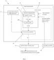
- FIG. 6exemplifies how a characterizing intensity transfer function map I 1 (x, ⁇ ) of the optical system in the angular-spatial space can be measured using a line CCD scan.
- FIG. 1illustrating, by way of a block diagram a display device 10 of the present invention.
- the display device 10includes an optical system 14 associated with an image data generator 12 .
- the latteris configured an operable to receive image data from an image data provider and generate corresponding optical field (structured light with light intensity map).
- Thiscan be implemented by using a spatial light modulator, e.g. LCD-based modulator, or generally a matrix of light sources (e.g. OLED).
- the optical system 14includes one or more optical elements (now shown) defining a light propagation channel 14 A for guiding the structured light, corresponding to the image to be displayed, through the light propagation channel 14 A towards an exit pupil 14 B with a field of view (FOV) which corresponds to the image of the optical system to be presented to/viewed by the viewer/observer's eye 18 .
- the configuration of the light propagation channel 14 Adefines a characterizing intensity transfer function map I 1 (x, ⁇ ) of the optical system across a lateral dimension x of the exit pupil 14 B and an angular span ⁇ of the FOV.
- control unit 20configured and operable according to the invention to control illumination/intensity uniformity of the image as observed by the viewer. It should be understood that the present invention is aimed at improving the intensity profile of the image as observed by the viewer, namely at the eye pupil 18 . This will be described more specifically further below.
- the control unit 20may be part of the image data generator 12 or a separate unit.
- the control unit 20receives image data ID indicative of light intensity map which is to be input to the optical system and affects this image data by applying intensity modulation thereto to generate intensity modulated image data ID mod .
- This intensity modulated image data ID modis transformed into corresponding optical field (structured light), by any suitable known configuration of spatial light modulator (SLM), e.g. LCD-based modulator, to propagate through the optical system 14 .
- SLMspatial light modulator
- the intensity modulation applied by the control unit 20is based on a correction intensity map which is determined by the control unit and is configured to at least partially compensate intensity non-uniformity in the characterizing intensity transfer function map I 1 (x, ⁇ ) of the optical system, such that the image-carrying output light at the exit pupil 14 B of the optical system 14 has a modulated intensity map I mod which is observed by the viewer with improved intensity uniformity.
- the control unit 20receives input data (e.g. accesses a storage device where such data is stored), from a data provider 22 (e.g. storage device), including data indicative of the characterizing intensity transfer function map I 1 (x, ⁇ ) of the optical system.
- data indicative of the characterizing intensity transfer function map I 1 (x, ⁇ )may include such map data itself previously created (e.g. simulated or measured) and stored in the storage device; or such data indicative of characterizing intensity transfer function map I 1 (x, ⁇ ) may include data about the configuration of the light propagation channel of the given optical system.
- the control unit 20includes a simulator module configured and operable to analyze the configuration of the light propagation channel and determine simulated data characterizing intensity transfer function map I 1 (x, ⁇ ) of the optical system. This will also be described further below.
- control unit 20also could utilize eye pupil related data in order to generate the intensity modulated image data ID mod .
- eye pupil related dataincludes one or more of such parameters as a lateral dimension x′ of the eye pupil, a distance z between the exit pupil 14 B and the eye pupil 18 , and a lateral offset (x′ ⁇ x) between the exit pupil 14 B and the eye pupil 18 .
- one or more of these parametersmay be given, i.e. of the typical values (e.g. lateral dimension x′ of the eye pupil is typically of about 3 mm); values for the distance z and lateral offset (x′ ⁇ x) between the exit pupil 14 B and the eye pupil 18 may be almost fixed in case the position of the display device with respect to the viewer is fixed, such as in case of head mounted display device.
- the display devicemay alternatively or additionally include an eye pupil controller equipped with appropriate eye tracker that monitors/measures changes in the distance z and/or lateral offset (x′ ⁇ x) values during image displaying sessions, and generates respective data, to which the control unit is responsive to dynamically adjust/update the intensity modulated image data ID mod .
- the eye pupil controllermay also include a measurement unit to measure the viewer's eye pupil size x′.
- the optical system of the invention or at least a part thereofcan be of a very compact configuration, and can be used with a head-up display (HUD), being mounted on HUD or being a separate module.
- HUDhead-up display
- Another possible application of the present inventionis as a part of a smart phone, which would be installed with a predetermined software application.
- An examples of such configurations, e.g. a hand-held light guiding element connectable to the HUD, etc.are described in U.S. Pat. No. 8,004,765 assigned to the assignee of the present application.
- FIG. 2shows a block diagram of the configuration of an exemplary control unit 20 .
- the control unit 20includes data input and output utilities and a memory, which are not specifically shown.
- the control unit 20may be part of the image data provider 22 or may be a separate unit/circuit 20 configured to be in data communication with the image data generator 12 which is in turn a part of or connectable to the image data provider 22 .
- the control unit 20includes an intensity map generator module 24 which is configured and operable to analyze data indicative of the characterizing intensity transfer function map I 1 (x, ⁇ ) of the optical system (e.g. given or simulated) and viewer's eye pupil related data, as described above, and determine corresponding intensity transfer function map indicative of angular intensity transfer from the exit pupil to the eye pupil, and generate a correction intensity map I 2 (x, ⁇ ).
- an intensity map generator module 24which is configured and operable to analyze data indicative of the characterizing intensity transfer function map I 1 (x, ⁇ ) of the optical system (e.g. given or simulated) and viewer's eye pupil related data, as described above, and determine corresponding intensity transfer function map indicative of angular intensity transfer from the exit pupil to the eye pupil, and generate a correction intensity map I 2 (x, ⁇ ).
- the intensity map generator module 24includes an integrator module 24 A which is configured to convolve the characterizing intensity transfer function map I 1 (x, ⁇ ) over a predetermined eye pupil dimension x′ and a predetermined lateral offset (x′ ⁇ x) between the exit pupil and the eye pupil and obtain data indicative of convolved intensity transfer function map I′ 1 ((x′ ⁇ x), ⁇ ).
- Such convolved intensity transfer function map I′ 1 ((x′ ⁇ x), ⁇ )is indicative of angular intensity transfer from the exit pupil 14 B to the eye pupil 18 of the predetermined lateral dimension and relative location with respect to the exit pupil.
- the intensity map generator module 24further includes a selector module 24 B which is configured and operable to utilize the data indicative of distance z between the exit pupil 14 B and the eye pupil 18 and the lateral offset (x′ ⁇ x) between the exit and eye pupils, to identify in the convolved intensity transfer function map I′ 1 ((x′ ⁇ x), ⁇ ) a region corresponding to the distance z and the offset (x ⁇ x′) values, and generate the correction intensity map I 2 (x, ⁇ ).
- an intensity map modulator utility 26which receives image data ID (e.g. virtual image) from the image data generator 12 , and receives the correction intensity map I 2 (x, ⁇ ) from the intensity map generator module 24 .
- the intensity map modulator utility 26is configured and operable to analyze the correction intensity map I 2 (x, ⁇ ) and generate corresponding intensity modulation and apply this modulation to the image data ID, to thereby produce the intensity modulated image data ID mod .
- the intensity modulationis produced and applied to the image data ID for example as an inversion (or some approximation of inversion) of the correction intensity map, i.e. inversion of the selected region of the convolved intensity transfer function map I′ 1 ((x′ ⁇ x), ⁇ ).
- the so-created intensity modulated image data ID modis transformed into the corresponding light field (structured light) which enters the optical system 14 with the characterizing intensity transfer function map I 1 (x, ⁇ ), to at least partially compensate intensity non-uniformity in the characterizing intensity transfer function map I 1 (x, ⁇ ) of the optical system.
- output light at the exit pupil of the optical system, indicative of the original imagehas a modulated intensity map, such that a corresponding image with improved intensity map I′ 2 (x, ⁇ ) is viewed by observer (at eye pupil).
- the display devicetypically includes an eye pupil controller (eye tracker) 28 which dynamically adjusts/updates one or more of the eye pupil related parameters (typically, distance z and lateral offset (x ⁇ x′)).
- eye pupil controllereye tracker
- the control unit 20(its intensity map generator 24 ) dynamically adjusts the correction intensity map I 2 (x, ⁇ ).
- FIGS. 3A to 3Eexemplify the technique of the invention for controlling operation of an LOE-based optical system used in near-eye displays.
- FIG. 3Aexemplifies a head up display device 30 , which includes the optical system 14 utilizing an LOE 16 having major surfaces 32 and 34 and light directing elements 31 and 35 (at least partially reflective) embedded therein, and a collimating module 17 , defining together a light propagation channel 14 A through the optical system 14 .
- the display device 30includes an image creation device 36 configured as described above (e.g. includes projector, e.g. SLM-based) to transform the image data into the corresponding image-carrying light.
- the image creation deviceis operated by the image data provider 22 (configured for example as described above) including or connectable to the control unit 20 .
- image-carrying lightpasses through the collimating module 17 , enters the LOE (waveguide/substrate) 16 , is reflected from light directing element (reflector) 31 and is trapped in the substrate/body of the LOE, where the light is guided by total internal reflection from major surface 32 and 34 and successively interact with at least partially reflective elements 35 which couple the light out of the substrate to propagate towards a pupil 18 of viewer's eye.
- LOElight directing element
- FIG. 3Bexemplifies the characterizing intensity transfer function map I 1 (x, ⁇ ) of the optical system across a lateral dimension x of the exit pupil and an angular span ⁇ of the FOV corresponding to the image to be presented to the observer, and also along distance z between the exit pupil and the eye pupil of the observer.
- line A and its angular orientation acorrespond to, respectively, the lateral dimension x′ of the eye pupil and eye pupil position z with respect to the exit pupil of the optical system.
- FIG. 3Cshows the convolved intensity transfer function map I′ 1 ((x′ ⁇ x), ⁇ ), which is obtained by convolving the characterizing intensity transfer function map I 1 (x, ⁇ ) of FIG. 3B over the predetermined eye pupil dimension x′ and the predetermined lateral offset (x′ ⁇ x) between the exit pupil and the eye pupil.
- Such convolved intensity transfer function map I′ 1 ((x′ ⁇ x), ⁇ )is indicative of angular intensity transfer from the exit pupil to the predetermined eye pupil dimension x′.
- FIG. 3Dshows the correction intensity map I 2 (x, ⁇ ), which is obtained by utilizing distance z and lateral offset (x′ ⁇ x) to extract from the convolved intensity transfer function map I′ 1 ((x′ ⁇ x), ⁇ ), a region corresponding to these distance z and offset (x ⁇ x′) values.
- the so-obtained correction intensity map I 2 (x, ⁇ )is then used to apply the intensity modulation to image data as an inversion of the correction intensity map I 2 (x, ⁇ ) and operate the image creation device 36 (e.g. projector) accordingly.
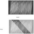
- FIGS. 4A-4C and 5A-5Cwhich exemplify how the light scheme propagation through the exemplified LOE-based optical system affects the intensity map at the exit pupil of the optical system (i.e. of the LOE), which can be used to simulate the characterizing intensity transfer function map I 1 (x, ⁇ ) of the optical system across a lateral dimension x of the exit pupil and an angular span 4 of the FOV corresponding to the image to be presented to the observer.
- These figuresillustrate the nature of dark-band effects and their representation in the angular-spatial space, i.e. in the intensity transfer function map I 1 (x, ⁇ ) characterizing the specific optical system.
- FIG. 4Ashows the so-called “structural bands” associated effect: due to the difference in light interaction with light directing elements 30 for rays of entering the LOE with different angles, over the FOV, some rays undergo more attenuation than others. More specifically, structural bands are multiplied by each total internal reflection, as a result at a higher number of light directing element/facet (in the order of successively arranged facets in a general direction of light propagation through the LOE), e.g. at 3 rd facet, they add up resulting in a visually prominent band. This is shown in FIG. 5A .
- FIGS. 4B and 5Bshow the “illumination non-uniformity” related band: uneven illumination over the entrance pupil is replicated by the LOE and form periodic variations of brightness.
- FIGS. 4C and 5Cshow a so-called “underlap bands effect”: at lower angles there are thin areas that rays cannot fill, while at higher angles there are similar areas rays fill twice.
- the characterizing intensity transfer function map I 1 (x, ⁇ ) of the optical systemcan be used to determine the complete data about dark bands over the field of view, for any pupil lateral dimension and z distances. Using this data, the correction map can be determined, and the dark bands effects can be compensated electronically (with accuracy depending on eye position knowledge).
- the technique of the inventioncan be used in addition to the above-described coating-based solution.
- the inventorhas found that for the LOE-based optical system, the most problematic dark bands effects appear at the center of pupil dimension/FOV map, and this can be improved/by proper coating design, while the other effects can be compensated/improved electronically by the correction map as described above.
- the characterizing intensity transfer function map I 1 (x, ⁇ ) of a given optical systemmay be measured.
- Such measurementscan be implemented, for example, by scanning the exit pupil output using a line CCD.
- FIG. 6shows the line CCD map, i.e. measured intensity profile in the angular-spatial space (across a lateral dimension x of the exit pupil, along distance z from the exit pupil, and an angular span ⁇ of the FOV).
- the line profileis the intensity variation over the FOV across the pupil x, and the slope a corresponds to the eye relief or distance z.
- Such mapeither measured or simulated, contains all the intensity data for the eye relief (z distance), eye position (lateral offset) and the eye pupil diameter (lateral dimension). Therefore, this map, being the characterizing intensity transfer function map I 1 (x, ⁇ ) of the optical system in the angular-spatial space, can be used to compensate (dynamically via eye tracker or statically) for the intensity non-uniformity sources (dark bands effects).
Landscapes
- Physics & Mathematics (AREA)
- General Physics & Mathematics (AREA)
- Optics & Photonics (AREA)
- Engineering & Computer Science (AREA)
- Theoretical Computer Science (AREA)
- Nonlinear Science (AREA)
- Computer Graphics (AREA)
- Computer Hardware Design (AREA)
- General Engineering & Computer Science (AREA)
- Software Systems (AREA)
- Control Of Indicators Other Than Cathode Ray Tubes (AREA)
- Exposure Of Semiconductors, Excluding Electron Or Ion Beam Exposure (AREA)
Abstract
Description
Claims (17)
Applications Claiming Priority (3)
| Application Number | Priority Date | Filing Date | Title |
|---|---|---|---|
| IL259518 | 2018-05-22 | ||
| IL259518AIL259518B2 (en) | 2018-05-22 | 2018-05-22 | Optical system and method for improvement of light field uniformity |
| PCT/IB2019/054230WO2019224740A1 (en) | 2018-05-22 | 2019-05-22 | Optical system and method for improvement of light field uniformity |
Related Parent Applications (1)
| Application Number | Title | Priority Date | Filing Date |
|---|---|---|---|
| PCT/IB2019/054230A-371-Of-InternationalWO2019224740A1 (en) | 2018-05-22 | 2019-05-22 | Optical system and method for improvement of light field uniformity |
Related Child Applications (1)
| Application Number | Title | Priority Date | Filing Date |
|---|---|---|---|
| US17/683,507ContinuationUS11567331B2 (en) | 2018-05-22 | 2022-03-01 | Optical system and method for improvement of light field uniformity |
Publications (2)
| Publication Number | Publication Date |
|---|---|
| US20210033872A1 US20210033872A1 (en) | 2021-02-04 |
| US11262587B2true US11262587B2 (en) | 2022-03-01 |
Family
ID=66624843
Family Applications (2)
| Application Number | Title | Priority Date | Filing Date |
|---|---|---|---|
| US17/044,418ActiveUS11262587B2 (en) | 2018-05-22 | 2019-05-22 | Optical system and method for improvement of light field uniformity |
| US17/683,507ActiveUS11567331B2 (en) | 2018-05-22 | 2022-03-01 | Optical system and method for improvement of light field uniformity |
Family Applications After (1)
| Application Number | Title | Priority Date | Filing Date |
|---|---|---|---|
| US17/683,507ActiveUS11567331B2 (en) | 2018-05-22 | 2022-03-01 | Optical system and method for improvement of light field uniformity |
Country Status (7)
| Country | Link |
|---|---|
| US (2) | US11262587B2 (en) |
| JP (1) | JP7360178B2 (en) |
| KR (1) | KR102748404B1 (en) |
| CN (1) | CN112136078B (en) |
| IL (1) | IL259518B2 (en) |
| TW (1) | TWI888348B (en) |
| WO (1) | WO2019224740A1 (en) |
Cited By (2)
| Publication number | Priority date | Publication date | Assignee | Title |
|---|---|---|---|---|
| US11927765B2 (en)* | 2017-04-17 | 2024-03-12 | Akonia Holographics Llc | Skew mirror auxiliary imaging |
| US12055385B1 (en)* | 2021-07-26 | 2024-08-06 | Lumus Ltd. | Methods and systems for validating parallelism between internal facets |
Families Citing this family (50)
| Publication number | Priority date | Publication date | Assignee | Title |
|---|---|---|---|---|
| US10261321B2 (en) | 2005-11-08 | 2019-04-16 | Lumus Ltd. | Polarizing optical system |
| IL232197B (en) | 2014-04-23 | 2018-04-30 | Lumus Ltd | Compact head-mounted display system |
| IL237337B (en) | 2015-02-19 | 2020-03-31 | Amitai Yaakov | Compact head-mounted display system having uniform image |
| CN110431467A (en) | 2017-01-28 | 2019-11-08 | 鲁姆斯有限公司 | Augmented reality imaging system |
| EP4215980A1 (en) | 2017-07-19 | 2023-07-26 | Lumus Ltd. | Lcos illumination via loe |
| US11513352B2 (en) | 2017-09-29 | 2022-11-29 | Lumus Ltd. | Augmented reality display |
| WO2019077614A1 (en) | 2017-10-22 | 2019-04-25 | Lumus Ltd. | ENHANCED REALITY DEVICE MOUNTED ON THE HEAD AND USING AN OPTICAL BENCH |
| CN111417883B (en) | 2017-12-03 | 2022-06-17 | 鲁姆斯有限公司 | Optical equipment alignment method |
| KR20200102408A (en) | 2018-01-02 | 2020-08-31 | 루머스 리미티드 | Augmented Reality Display with Active Alignment and Corresponding Method |
| US10551544B2 (en) | 2018-01-21 | 2020-02-04 | Lumus Ltd. | Light-guide optical element with multiple-axis internal aperture expansion |
| MY203244A (en) | 2018-04-08 | 2024-06-19 | Lumus Ltd | Optical sample characterization |
| KR102752134B1 (en) | 2018-05-14 | 2025-01-08 | 루머스 리미티드 | Projector configuration with sub-optical aperture for near-eye display and corresponding optical system |
| IL278511B2 (en) | 2018-05-17 | 2025-01-01 | Lumus Ltd | Near-eye display having overlapping projector assemblies |
| IL259518B2 (en) | 2018-05-22 | 2023-04-01 | Lumus Ltd | Optical system and method for improvement of light field uniformity |
| MX2020012512A (en) | 2018-05-23 | 2021-02-16 | Lumus Ltd | Optical system including light-guide optical element with partially-reflective internal surfaces. |
| CN119595595A (en) | 2018-06-21 | 2025-03-11 | 鲁姆斯有限公司 | Technique for measuring refractive index non-uniformity between plates of light-guiding optical element (LOE) |
| EP3824335B1 (en) | 2018-07-16 | 2023-10-18 | Lumus Ltd. | Light-guide optical element employing polarized internal reflectors |
| CN112601993A (en) | 2018-08-26 | 2021-04-02 | 鲁姆斯有限公司 | Reflection suppression in near-eye displays |
| CN116184666A (en) | 2018-09-09 | 2023-05-30 | 鲁姆斯有限公司 | Optical system comprising a light-guiding optical element with two-dimensional expansion |
| US11947130B2 (en) | 2018-11-08 | 2024-04-02 | Lumus Ltd. | Optical devices and systems with dichroic beamsplitter color combiner |
| TWM642752U (en) | 2018-11-08 | 2023-06-21 | 以色列商魯姆斯有限公司 | Light-guide display with reflector |
| JP3226277U (en) | 2018-11-11 | 2020-05-14 | ルムス エルティーディー. | Near eye display with intermediate window |
| MX2021008808A (en) | 2019-01-24 | 2021-08-24 | Lumus Ltd | Optical systems including loe with three stage expansion. |
| WO2020174433A1 (en) | 2019-02-28 | 2020-09-03 | Lumus Ltd. | Compact collimated image projector |
| TWI800657B (en) | 2019-03-12 | 2023-05-01 | 以色列商魯姆斯有限公司 | Image projector |
| TWI845670B (en) | 2019-05-06 | 2024-06-21 | 以色列商魯姆斯有限公司 | Transparent lightguide for viewing a scene and a near-eye display |
| CN114008512B (en) | 2019-06-23 | 2024-05-24 | 鲁姆斯有限公司 | Display with foveal optical correction |
| CA3137994A1 (en) | 2019-06-27 | 2020-12-30 | Lumus Ltd | Apparatus and methods for eye tracking based on eye imaging via a light-guide optical element |
| TWI858170B (en) | 2019-10-23 | 2024-10-11 | 以色列商魯姆斯有限公司 | Displays employing astigmatic optics and aberration compensation |
| US11288503B2 (en) | 2019-11-04 | 2022-03-29 | Facebook Technologies, Llc | Systems and methods for image adjustment based on pupil size |
| WO2021105982A1 (en) | 2019-11-25 | 2021-06-03 | Lumus Ltd. | Method of polishing a surface of a waveguide |
| IL270991B (en) | 2019-11-27 | 2020-07-30 | Lumus Ltd | Lightguide optical element for polarization scrambling |
| TWI884834B (en) | 2019-12-05 | 2025-05-21 | 以色列商魯姆斯有限公司 | Optical device and method of fabricating optical device |
| US11523092B2 (en) | 2019-12-08 | 2022-12-06 | Lumus Ltd. | Optical systems with compact image projector |
| CN114787687B (en) | 2019-12-25 | 2024-07-30 | 鲁姆斯有限公司 | Systems and methods for eye tracking based on redirection of light from the eye using an optical arrangement associated with a light guide optical element |
| CN218848473U (en) | 2020-05-12 | 2023-04-11 | 鲁姆斯有限公司 | Equipment including projection optics and light guides |
| US11410272B2 (en) | 2020-07-01 | 2022-08-09 | Facebook Technologies, Llc. | Dynamic uniformity correction |
| US11410580B2 (en) | 2020-08-20 | 2022-08-09 | Facebook Technologies, Llc. | Display non-uniformity correction |
| AU2021331833A1 (en) | 2020-08-23 | 2023-03-09 | Lumus Ltd. | Optical system for two-dimensional expansion of an image reducing glints and ghosts from the waveguide |
| WO2022044006A1 (en) | 2020-08-26 | 2022-03-03 | Lumus Ltd. | Generation of color images using white light as source |
| DE202021104723U1 (en) | 2020-09-11 | 2021-10-18 | Lumus Ltd. | Image projector coupled to an optical light guide element |
| US11733773B1 (en) | 2020-12-29 | 2023-08-22 | Meta Platforms Technologies, Llc | Dynamic uniformity correction for boundary regions |
| KR20230148324A (en) | 2021-03-01 | 2023-10-24 | 루머스 리미티드 | Optical system with compact coupling from projector to waveguide |
| US11681363B2 (en) | 2021-03-29 | 2023-06-20 | Meta Platforms Technologies, Llc | Waveguide correction map compression |
| KR102676604B1 (en) | 2021-07-04 | 2024-06-18 | 루머스 리미티드 | Display with stacked light guiding elements providing different parts of the field of view |
| JP2024536392A (en)* | 2021-10-06 | 2024-10-04 | ヴィヴィッドキュー リミテッド | Eyebox targeting using image duplication combiner |
| US11710212B1 (en) | 2022-01-21 | 2023-07-25 | Meta Platforms Technologies, Llc | Display non-uniformity correction |
| US11754846B2 (en) | 2022-01-21 | 2023-09-12 | Meta Platforms Technologies, Llc | Display non-uniformity correction |
| US11741861B1 (en) | 2022-02-08 | 2023-08-29 | Lumus Ltd. | Optical system including selectively activatable facets |
| WO2024038458A1 (en) | 2022-08-18 | 2024-02-22 | Lumus Ltd. | Image projector with polarizing catadioptric collimator |
Citations (399)
| Publication number | Priority date | Publication date | Assignee | Title |
|---|---|---|---|---|
| BE357371A (en) | 1929-01-15 | 1929-02-28 | ||
| US2748659A (en) | 1951-02-26 | 1956-06-05 | Jenaer Glaswerk Schott & Gen | Light source, searchlight or the like for polarized light |
| US2958258A (en) | 1953-09-21 | 1960-11-01 | Technicolor Corp | Optical projection of beam controlled object fields |
| DE1422172B1 (en) | 1961-12-07 | 1970-11-12 | Kopperschmidt & Co Carl W | periscope |
| US3626394A (en) | 1970-04-09 | 1971-12-07 | Magnavox Co | Magneto-optical system |
| US3658405A (en) | 1969-05-26 | 1972-04-25 | Maksvmilian Pluta | Variable phase-contrast and interference microscope |
| US3667621A (en) | 1970-10-20 | 1972-06-06 | Wisconsin Foundry And Machine | Fluid power system for a self-contained unloading unit |
| US3677621A (en) | 1969-11-24 | 1972-07-18 | Vickers Ltd | Optical field flattening devices |
| US3737212A (en) | 1970-12-14 | 1973-06-05 | Gen Electric | Diffraction optics head up display |
| GB1321303A (en) | 1970-03-31 | 1973-06-27 | Pilkington Perkin Elmer Ltd | Optical systems |
| US3807849A (en) | 1970-05-15 | 1974-04-30 | Redifon Ltd | Visual display arrangements |
| US3873209A (en) | 1973-12-10 | 1975-03-25 | Bell Telephone Labor Inc | Measurement of thin films by optical waveguiding technique |
| US3940204A (en) | 1975-01-23 | 1976-02-24 | Hughes Aircraft Company | Optical display systems utilizing holographic lenses |
| US4084883A (en) | 1977-02-28 | 1978-04-18 | The University Of Rochester | Reflective polarization retarder and laser apparatus utilizing same |
| US4233526A (en) | 1977-04-08 | 1980-11-11 | Nippon Electric Co., Ltd. | Semiconductor memory device having multi-gate transistors |
| US4240738A (en) | 1979-06-14 | 1980-12-23 | Vivitar Corporation | Light mixing system for a photographic enlarger |
| US4309070A (en) | 1979-01-19 | 1982-01-05 | Smiths Industries Limited | Display apparatus |
| US4331387A (en) | 1980-07-03 | 1982-05-25 | Westinghouse Electric Corp. | Electro-optical modulator for randomly polarized light |
| FR2496905A1 (en) | 1980-12-24 | 1982-06-25 | France Etat | EPISCOPE WITH MULTIMODES REFLECTIONS |
| US4372639A (en) | 1981-06-03 | 1983-02-08 | Hughes Aircraft Company | Directional diffusing screen |
| US4383740A (en) | 1980-10-31 | 1983-05-17 | Rediffusion Simulation Incorporated | Infinity image visual display system |
| US4516828A (en) | 1982-05-03 | 1985-05-14 | General Motors Corporation | Duplex communication on a single optical fiber |
| US4613216A (en) | 1984-03-27 | 1986-09-23 | L'etat Francais | Device for observation through a wall in two opposite directions |
| US4711512A (en) | 1985-07-12 | 1987-12-08 | Environmental Research Institute Of Michigan | Compact head-up display |
| US4755667A (en) | 1986-10-10 | 1988-07-05 | Avl Ag | Sensor element for determination of concentration of substances |
| US4775217A (en) | 1981-10-14 | 1988-10-04 | Gec Avionics Limited | Night vision viewing system |
| US4798448A (en) | 1988-02-16 | 1989-01-17 | General Electric Company | High efficiency illumination system for display devices |
| US4799765A (en) | 1986-03-31 | 1989-01-24 | Hughes Aircraft Company | Integrated head-up and panel display unit |
| US4805988A (en) | 1987-07-24 | 1989-02-21 | Nelson Dones | Personal video viewing device |
| GB2220081A (en) | 1988-06-21 | 1989-12-28 | Hall & Watts Defence Optics Lt | Periscope apparatus |
| EP0365406A1 (en) | 1988-10-21 | 1990-04-25 | Thomson-Csf | Optical collimating system for a helmet visual |
| FR2638242A1 (en) | 1988-10-21 | 1990-04-27 | Thomson Csf | Optical collimation system, especially for a helmet display |
| US4932743A (en) | 1988-04-18 | 1990-06-12 | Ricoh Company, Ltd. | Optical waveguide device |
| EP0380035A2 (en) | 1989-01-23 | 1990-08-01 | Hughes Optical Products, Inc. | Helmet mounted display system |
| EP0399865A1 (en) | 1989-05-23 | 1990-11-28 | Thomson-Csf | Optical device for introduction of a collimated image into the field of view of an observer and helmet comprising such a device |
| US5033828A (en) | 1988-12-02 | 1991-07-23 | Mitsui Petrochemical Industries, Ltd. | Optical output controlling method and apparatus |
| US5096520A (en) | 1990-08-01 | 1992-03-17 | Faris Sades M | Method for producing high efficiency polarizing filters |
| EP0543718A1 (en) | 1991-11-19 | 1993-05-26 | Thomson-Csf | Constituent material for sighting glasses and gun using these sighting glasses |
| WO1993014393A1 (en) | 1992-01-11 | 1993-07-22 | Fisons Plc | Analytical device with light scattering |
| US5231642A (en) | 1992-05-08 | 1993-07-27 | Spectra Diode Laboratories, Inc. | Semiconductor ring and folded cavity lasers |
| EP0566004A2 (en) | 1992-04-07 | 1993-10-20 | Hughes Aircraft Company | Virtual image display having a high efficiency grid beamsplitter |
| US5278532A (en) | 1987-09-14 | 1994-01-11 | Hughes Aircraft Company | Automotive instrument virtual image display |
| EP0580952A1 (en) | 1992-07-31 | 1994-02-02 | Hoshizaki Denki Kabushiki Kaisha | Ice making machine |
| US5301067A (en) | 1992-05-06 | 1994-04-05 | Plx Inc. | High accuracy periscope assembly |
| GB2272980A (en) | 1992-11-26 | 1994-06-01 | Electro Optics Ind Ltd | Optical beam splitting lens |
| GB2278222A (en) | 1993-05-20 | 1994-11-23 | Sharp Kk | Spatial light modulator |
| US5369415A (en) | 1992-06-29 | 1994-11-29 | Motorola, Inc. | Direct retinal scan display with planar imager |
| GB2278888A (en) | 1993-06-07 | 1994-12-14 | Ford Motor Co | A fuel pump with curved vapour channel |
| WO1995010106A1 (en) | 1993-10-07 | 1995-04-13 | Virtual Vision, Inc. | Binocular head mounted display system |
| US5430505A (en) | 1992-01-30 | 1995-07-04 | Mak Technologies, Inc. | High speed eye tracking device and method |
| US5481385A (en) | 1993-07-01 | 1996-01-02 | Alliedsignal Inc. | Direct view display device with array of tapered waveguide on viewer side |
| FR2721872A1 (en) | 1994-07-01 | 1996-01-05 | Renault Nationale Usines | DEVICE FOR IMPROVING THE VISION OF A ROAD SCENE |
| US5499138A (en) | 1992-05-26 | 1996-03-12 | Olympus Optical Co., Ltd. | Image display apparatus |
| US5537260A (en) | 1993-01-26 | 1996-07-16 | Svg Lithography Systems, Inc. | Catadioptric optical reduction system with high numerical aperture |
| US5539578A (en) | 1993-03-02 | 1996-07-23 | Olympus Optical Co., Ltd. | Image display apparatus |
| US5543877A (en) | 1992-10-23 | 1996-08-06 | Olympus Optical Co., Ltd. | Means for controlling driving of a driving fork and take-up spool for automatic feeding and rewinding of a film in a camera |
| US5555329A (en) | 1993-11-05 | 1996-09-10 | Alliesignal Inc. | Light directing optical structure |
| JPH08313843A (en) | 1995-05-16 | 1996-11-29 | Agency Of Ind Science & Technol | Wide visual field and high resolution video presentation device in line of sight followup system |
| US5594830A (en) | 1992-03-23 | 1997-01-14 | Minnesota Mining And Manufacturing Co. | Luminaire device |
| US5619601A (en) | 1993-12-28 | 1997-04-08 | Fujitsu Limited | Optical switch and optical distributor using polarization control and partial reflection |
| EP0770818A2 (en) | 1995-10-24 | 1997-05-02 | SHARP Corporation | Illuminator |
| US5650873A (en) | 1995-01-30 | 1997-07-22 | Lockheed Missiles & Space Company, Inc. | Micropolarization apparatus |
| US5680209A (en) | 1992-08-13 | 1997-10-21 | Maechler; Meinrad | Spectroscopic systems for the analysis of small and very small quantities of substances |
| US5712694A (en) | 1994-09-16 | 1998-01-27 | Kabushiki Kaisha Toshiba | LCD comprising a light separating element including a cholesteric liquid crystal sheet |
| US5724163A (en) | 1996-11-12 | 1998-03-03 | Yariv Ben-Yehuda | Optical system for alternative or simultaneous direction of light originating from two scenes to the eye of a viewer |
| WO1998015868A1 (en) | 1996-10-08 | 1998-04-16 | The Microoptical Corporation | Image combining system for eyeglasses and face masks |
| US5751480A (en) | 1991-04-09 | 1998-05-12 | Canon Kabushiki Kaisha | Plate-like polarizing element, a polarizing conversion unit provided with the element, and a projector provided with the unit |
| US5764412A (en) | 1994-10-15 | 1998-06-09 | Fujitsu Limited | Polarization separation/conversion device for polarized lighting apparatus and projection display unit |
| US5808800A (en) | 1994-12-22 | 1998-09-15 | Displaytech, Inc. | Optics arrangements including light source arrangements for an active matrix liquid crystal image generator |
| DE19725262A1 (en) | 1997-06-13 | 1998-12-24 | Vitaly Dr Lissotschenko | Optical beam transformation apparatus |
| US5896232A (en) | 1997-08-07 | 1999-04-20 | International Business Machines Corporation | Highly efficient and compact frontlighting for polarization-based reflection light valves |
| US5909325A (en) | 1995-06-26 | 1999-06-01 | Olympus Optical Co., Ltd. | Image display apparatus |
| US5966223A (en) | 1993-02-26 | 1999-10-12 | Yeda Research & Development Co., Ltd. | Planar holographic optical device |
| WO1999052002A1 (en) | 1998-04-02 | 1999-10-14 | Elop Electro-Optics Industries Ltd. | Holographic optical devices |
| US5982536A (en) | 1995-10-17 | 1999-11-09 | Barr & Stroud Limited | Display system |
| US6007225A (en) | 1997-10-16 | 1999-12-28 | Advanced Optical Technologies, L.L.C. | Directed lighting system utilizing a conical light deflector |
| WO2000004407A1 (en) | 1998-07-17 | 2000-01-27 | Brookhaven Science Associates | Small inlet optical panel and a method of making a small inlet optical panel |
| US6021239A (en) | 1996-10-31 | 2000-02-01 | Sharp Kabushiki Kaisha | Photocoupler and method for producing the same |
| US6034750A (en) | 1998-02-10 | 2000-03-07 | Sanyo Electric Co., Ltd. | Liquid crystal display having detachable light source |
| US6052500A (en) | 1996-12-03 | 2000-04-18 | Mitsubishi Gas Chemical Company, Inc. | Optical waveguide device for connections without optical axis adjustment |
| US6091548A (en) | 1997-10-01 | 2000-07-18 | Raytheon Company | Optical system with two-stage aberration correction |
| WO2000055676A1 (en) | 1999-03-17 | 2000-09-21 | The Microoptical Corporation | Compact image display system for eyeglasses or other head-borne frames |
| WO2000063738A1 (en) | 1999-04-21 | 2000-10-26 | U.S. Precision Lens Incorporated | Optical systems for reflective lcd's |
| US6144347A (en) | 1992-10-09 | 2000-11-07 | Sony Corporation | Head-mounted image display apparatus |
| US6154321A (en) | 1998-01-20 | 2000-11-28 | University Of Washington | Virtual retinal display with eye tracking |
| US6204975B1 (en) | 1998-12-22 | 2001-03-20 | Virtual Vision, Inc. | Reflective micro-display system |
| WO2001027685A2 (en) | 1999-10-14 | 2001-04-19 | Stratos Product Development Company Llc | Virtual imaging system |
| US6222676B1 (en) | 1998-12-22 | 2001-04-24 | Olympus Optical Co., Ltd. | Image display apparatus |
| EP1096293A2 (en) | 1999-10-26 | 2001-05-02 | Agilent Technologies Inc | Folded optical system adapted for head-mounted displays |
| US6239092B1 (en) | 1997-09-30 | 2001-05-29 | Reckitt Benckiser Inc. | Thickened acidic, hard surface cleaning and disinfecting compositions particularly useful for ceramic surfaces |
| US6256151B1 (en) | 2000-06-28 | 2001-07-03 | Agilent Technologies Inc. | Compact microdisplay illumination system |
| US6266108B1 (en) | 1997-03-25 | 2001-07-24 | Sony Corporation | Reflective liquid crystal display device with a panel, a light guide plate and polarizing plate |
| US20010013972A1 (en) | 1997-04-07 | 2001-08-16 | Fuad Elias Doany | Optical system for miniature personal displays using reflective light valves |
| US20010030860A1 (en) | 2000-04-12 | 2001-10-18 | Hajime Kimura | Illumination apparatus |
| US6307612B1 (en) | 2000-06-08 | 2001-10-23 | Three-Five Systems, Inc. | Liquid crystal display element having a precisely controlled cell gap and method of making same |
| US6324330B1 (en) | 2000-07-10 | 2001-11-27 | Ultratech Stepper, Inc. | Folded light tunnel apparatus and method |
| EP1158336A2 (en) | 2000-05-21 | 2001-11-28 | Elop Electro-Optics Industries Ltd. | System and method for varying the transmittance of light through a media |
| WO2001095027A2 (en) | 2000-06-05 | 2001-12-13 | Lumus Ltd. | Substrate-guided optical beam expander |
| US20010055152A1 (en) | 2000-06-26 | 2001-12-27 | Angus Richards | Multi-mode display device |
| US20020015233A1 (en) | 2000-07-31 | 2002-02-07 | Daeyang E&C Co., Ltd. | Optical system for head mounted display |
| US6349001B1 (en) | 1997-10-30 | 2002-02-19 | The Microoptical Corporation | Eyeglass interface system |
| EP1180711A1 (en) | 2000-01-28 | 2002-02-20 | Seiko Epson Corporation | Optical reflection polarizer and projector comprising the same |
| US20020021498A1 (en) | 2000-04-28 | 2002-02-21 | Keiji Ohtaka | Image display apparatus and optical system |
| US6362861B1 (en) | 2000-05-02 | 2002-03-26 | Agilent Technologies, Inc. | Microdisplay system |
| US6388814B2 (en) | 1999-12-28 | 2002-05-14 | Rohm Co., Ltd. | Head mounted display |
| US6404947B1 (en) | 1999-11-16 | 2002-06-11 | Matsushita Electric Industrial Co., Ltd. | Demultiplexer and demultiplexer-receiver |
| US6404550B1 (en) | 1996-07-25 | 2002-06-11 | Seiko Epson Corporation | Optical element suitable for projection display apparatus |
| US6406149B2 (en) | 1997-02-13 | 2002-06-18 | Canon Kabushiki Kaisha | Illuminating apparatus and projecting apparatus |
| US20020080615A1 (en) | 2000-12-22 | 2002-06-27 | Thomas Marshall | LED collimation optics with improved performance and reduced size |
| US20020080622A1 (en) | 2000-12-21 | 2002-06-27 | Philips Electronics North America Corporation | Faceted multi-chip package to provide a beam of uniform white light from multiple monochrome LEDs |
| US20020085281A1 (en) | 2000-12-29 | 2002-07-04 | Matthew Dubin | Optical devices employing beam folding with polarizing splitters |
| US6421031B1 (en) | 1993-10-22 | 2002-07-16 | Peter A. Ronzani | Camera display system |
| US6433339B1 (en) | 1999-09-30 | 2002-08-13 | Advantest Corp. | Surface state monitoring method and apparatus |
| WO2002082168A1 (en) | 2001-04-07 | 2002-10-17 | Cambridge Flat Projection Displays Limited | Display |
| WO2002088825A2 (en) | 2001-04-27 | 2002-11-07 | Koninklijke Philips Electronics N.V. | Compact display device |
| US6480174B1 (en) | 1999-10-09 | 2002-11-12 | Optimize Incorporated | Eyeglass-mount display having personalized fit module |
| US20020176173A1 (en) | 2001-04-30 | 2002-11-28 | Song Young-Ran | Wearable display system and process thereof |
| US6490104B1 (en) | 2000-09-15 | 2002-12-03 | Three-Five Systems, Inc. | Illumination system for a micro display |
| JP2002350771A (en) | 2001-05-25 | 2002-12-04 | Nikon Corp | Head mounted display device |
| WO2002097515A1 (en) | 2001-05-26 | 2002-12-05 | Thales Optics Ltd | Optical device using a polarizing beam splitter |
| US20020186179A1 (en) | 2001-06-07 | 2002-12-12 | Knowles Gary R. | Optical display device |
| US20020191297A1 (en) | 2000-10-20 | 2002-12-19 | Gleckman Philip L. | Compact near-eye illumination system |
| JP2002368762A (en) | 2001-06-06 | 2002-12-20 | Olympus Optical Co Ltd | Local network system, network system and video conference system, and mobile communication unit |
| US20030007157A1 (en) | 2001-07-03 | 2003-01-09 | Hulse Charles Andrew | Rhomb interleaver |
| US6509982B2 (en) | 2000-01-07 | 2003-01-21 | Honeywell International Inc. | Holographic diffusers |
| US20030020006A1 (en) | 2001-07-24 | 2003-01-30 | Janeczko Donald John | Planar diffractive relay |
| US20030030912A1 (en) | 2000-10-20 | 2003-02-13 | Gleckman Philip Landon | Compact wide field of view imaging system |
| US20030063042A1 (en) | 1999-07-29 | 2003-04-03 | Asher A. Friesem | Electronic utility devices incorporating a compact virtual image display |
| US6556282B2 (en) | 2001-09-04 | 2003-04-29 | Rosemount Aerospace, Inc. | Combined LOAS and LIDAR system |
| JP2003140081A (en) | 2001-11-06 | 2003-05-14 | Nikon Corp | Hologram combiner optical system |
| US20030090439A1 (en) | 2001-09-07 | 2003-05-15 | Spitzer Mark B. | Light weight, compact, remountable face-supported electronic display |
| JP2003149643A (en) | 2001-11-16 | 2003-05-21 | Goyo Paper Working Co Ltd | Front light for liquid crystal display |
| US6577411B1 (en) | 1996-11-12 | 2003-06-10 | Planop-Planar Optics Ltd. | Optical system for alternative or simultaneous direction of light originating from two scenes to the eye of a viewer |
| EP1326102A1 (en) | 2000-07-24 | 2003-07-09 | Mitsubishi Rayon Co., Ltd. | Surface illuminant device and prism sheet used therefor |
| WO2003058320A1 (en) | 2002-01-11 | 2003-07-17 | Essilor International (Compagnie Générale d'Optique) | Ophthalmic lens with a projection insert |
| US6606173B2 (en) | 2000-08-01 | 2003-08-12 | Riake Corporation | Illumination device and method for laser projector |
| WO2003081320A1 (en) | 2002-03-21 | 2003-10-02 | Lumus Ltd. | Light guide optical device |
| US20030197938A1 (en) | 2002-04-12 | 2003-10-23 | Dietrich Schmidt | Arrangement for polarization of light |
| EP1385023A1 (en) | 2002-07-17 | 2004-01-28 | C.R.F. Società Consortile per Azioni | A light guide for display devices of the head-mounted or head-up type |
| US20040033528A1 (en) | 2000-06-18 | 2004-02-19 | Yaakov Amitai | Dynamic optical devices |
| US20040032660A1 (en) | 2000-10-05 | 2004-02-19 | Yaakov Amitai | Optical switching devices |
| US6704052B1 (en) | 1998-05-22 | 2004-03-09 | Olympus Corporation | Image pickup optical system comprising a prism fixing member for preventing a deterioration in the capability of correcting decentration abberation, and apparatus therefore |
| US6704065B1 (en) | 1995-04-07 | 2004-03-09 | Colorlink, Inc. | Optical system for producing a modulated color image |
| US6710902B2 (en) | 2001-04-13 | 2004-03-23 | Olympus Corporation | Observation optical system |
| US20040080718A1 (en) | 2002-08-20 | 2004-04-29 | Seiko Epson Corporation | Image display device and projector |
| WO2004053541A1 (en) | 2002-12-03 | 2004-06-24 | Essilor International | Polarization separator, method for making same and ophthalmic lens including projection inserts comprising same |
| US20040137189A1 (en) | 2002-11-08 | 2004-07-15 | Tellini Serena R. P. | Optical device and light guide system comprising it |
| US6775432B2 (en) | 2001-10-19 | 2004-08-10 | Santanu Basu | Method and apparatus for optical wavelength demultiplexing, multiplexing and routing |
| JP2004233909A (en) | 2003-01-31 | 2004-08-19 | Nikon Corp | Head mounted display |
| US6798579B2 (en) | 1999-04-27 | 2004-09-28 | Optical Products Development Corp. | Real imaging system with reduced ghost imaging |
| US20040218271A1 (en) | 2001-07-18 | 2004-11-04 | Carl Zeiss Smt Ag | Retardation element made from cubic crystal and an optical system therewith |
| WO2004109349A2 (en) | 2003-06-10 | 2004-12-16 | Elop Electro-Optics Industries Ltd. | Method and system for displaying an informative image against a background image |
| US20040264185A1 (en) | 2003-04-29 | 2004-12-30 | Osram Opto Semiconductors Gmbh | Light source |
| US20040263842A1 (en) | 2001-06-12 | 2004-12-30 | Puppels Gerwin Jan | Spectrometer for measuring inelastically scattered light |
| US20050018308A1 (en) | 2003-05-22 | 2005-01-27 | Cassarly William J. | Light distribution apparatus and methods for illuminating optical systems |
| US20050023545A1 (en) | 2003-07-31 | 2005-02-03 | Lumileds Lighting U.S., Llc | Light emitting devices with improved light extraction efficiency |
| US20050024849A1 (en) | 1999-02-23 | 2005-02-03 | Parker Jeffery R. | Methods of cutting or forming cavities in a substrate for use in making optical films, components or wave guides |
| WO2005024491A1 (en) | 2003-09-10 | 2005-03-17 | Lumus Ltd. | Substrate-guided optical devices |
| WO2005024485A1 (en) | 2003-09-10 | 2005-03-17 | Lumus Ltd. | Optical devices particularly for remote viewing applications |
| JP2005084522A (en) | 2003-09-10 | 2005-03-31 | Nikon Corp | Combiner optics |
| US6879443B2 (en) | 2003-04-25 | 2005-04-12 | The Microoptical Corporation | Binocular viewing system |
| CN1606712A (en) | 2001-11-09 | 2005-04-13 | 3M创新有限公司 | Optical devices having reflective and transmissive modes for display |
| US20050083592A1 (en) | 2003-09-10 | 2005-04-21 | Yaakov Amitai | High Brightness optical device |
| US20050084210A1 (en) | 2003-10-17 | 2005-04-21 | Samsung Electronics Co., Ltd. | Light tunnel, uniform light illuminating device and projector employing the same |
| US6926429B2 (en) | 2002-01-30 | 2005-08-09 | Delphi Technologies, Inc. | Eye tracking/HUD system |
| US20050173719A1 (en) | 2004-02-10 | 2005-08-11 | Seiko Epson Corporation | Light source, method for manufacturing light source, and projector |
| US20050174658A1 (en) | 2004-02-05 | 2005-08-11 | Michael Long | Systems and methods for integrating light |
| US6950220B2 (en) | 2002-03-18 | 2005-09-27 | E Ink Corporation | Electro-optic displays, and methods for driving same |
| WO2005093493A1 (en) | 2004-03-29 | 2005-10-06 | Sony Corporation | Optical device and virtual image display device |
| US20050248852A1 (en) | 2004-05-06 | 2005-11-10 | Olympus Corporation | Head-mounted display apparatus |
| US20050265044A1 (en) | 2004-05-28 | 2005-12-01 | Yi-Ming Chen | Planar light-emitting device |
| WO2005124427A1 (en) | 2004-06-17 | 2005-12-29 | Lumus Ltd. | High brightness optical device |
| WO2006013565A1 (en) | 2004-08-05 | 2006-02-09 | Lumus Ltd. | Optical device for light coupling |
| US20060052146A1 (en) | 2004-09-09 | 2006-03-09 | Shu-Fong Ou | Heated mounted display device with mobile phone functions |
| US7016113B2 (en) | 1997-05-28 | 2006-03-21 | Lg.Philips Lcd Co., Ltd. | Large scale polarizer and polarizer system employing it |
| US20060061555A1 (en) | 2004-08-20 | 2006-03-23 | Mullen Jeffrey D | Wireless devices with flexible monitors and keyboards |
| US7025464B2 (en) | 2004-03-30 | 2006-04-11 | Goldeneye, Inc. | Projection display systems utilizing light emitting diodes and light recycling |
| US20060091784A1 (en) | 2004-10-29 | 2006-05-04 | Conner Arlie R | LED package with non-bonded optical element |
| US20060103590A1 (en) | 2004-10-21 | 2006-05-18 | Avner Divon | Augmented display system and methods |
| JP2006145644A (en) | 2004-11-17 | 2006-06-08 | Hitachi Ltd | Polarization separator and projection display device using the same |
| WO2006061927A1 (en) | 2004-12-06 | 2006-06-15 | Nikon Corporation | Image display optical system, image display unit, lighting optical system, and liquid crystral display unit |
| US20060126182A1 (en) | 2004-12-13 | 2006-06-15 | Nokia Corporation | General diffractive optics method for expanding an exit pupil |
| CN1795399A (en) | 2003-05-22 | 2006-06-28 | 伊斯曼柯达公司 | Optical element with nanoparticles |
| EP1691547A1 (en) | 2003-12-03 | 2006-08-16 | Nikon Corporation | Information display device and wireless remote controller |
| WO2006085309A1 (en) | 2005-02-10 | 2006-08-17 | Lumus Ltd. | Substrate-guided optical device utilizing thin transparent layer |
| WO2006085308A1 (en) | 2005-02-10 | 2006-08-17 | Lumus Ltd. | Substrate-guide optical device utilizing polarization beam splitters |
| WO2006085310A1 (en) | 2005-02-10 | 2006-08-17 | Lumus Ltd. | Substrate-guided optical device particularly for vision enhanced optical systems |
| WO2006087709A1 (en) | 2005-02-17 | 2006-08-24 | Lumus Ltd. | Personal navigation system |
| US20060268421A1 (en) | 2005-05-30 | 2006-11-30 | Konic Minolta Holdings, Inc. | Image display apparatus and head mount display |
| US20070035706A1 (en) | 2005-06-20 | 2007-02-15 | Digital Display Innovations, Llc | Image and light source modulation for a digital display system |
| US20070070859A1 (en) | 2004-05-17 | 2007-03-29 | Nikon Corporation | Optical elements and combiner optical systems and image-display units comprising same |
| US7205960B2 (en) | 2003-02-19 | 2007-04-17 | Mirage Innovations Ltd. | Chromatic planar optic display system |
| WO2007054928A1 (en) | 2005-11-08 | 2007-05-18 | Lumus Ltd. | Polarizing optical system |
| US20070153344A1 (en) | 2005-12-30 | 2007-07-05 | Industrial Technology Research Institute | System and method for recording and reproducing holographic interferogram with optical servo |
| US20070155277A1 (en) | 2005-07-25 | 2007-07-05 | Avi Amitai | Mobile/portable and personal pre-recorded sound effects electronic amplifier device/gadget |
| US20070159673A1 (en) | 2005-11-21 | 2007-07-12 | Freeman Mark O | Substrate-guided display with improved image quality |
| US7245273B2 (en) | 2001-01-30 | 2007-07-17 | David Parker Dickerson | Interactive data view and command system |
| US20070165192A1 (en)* | 2006-01-13 | 2007-07-19 | Silicon Optix Inc. | Reduced field angle projection display system |
| WO2007093983A2 (en) | 2006-02-14 | 2007-08-23 | Lumus Ltd. | Substrate-guided imaging lens |
| US20070206390A1 (en) | 2006-03-06 | 2007-09-06 | Brukilacchio Thomas J | Light emitting diode projection system |
| US7285903B2 (en) | 2004-07-15 | 2007-10-23 | Honeywell International, Inc. | Display with bright backlight |
| US7307791B2 (en) | 2004-09-30 | 2007-12-11 | Himax Technologies Limited | Head mounted device |
| US20070285663A1 (en) | 2006-06-12 | 2007-12-13 | The Boeing Company | Efficient and accurate alignment of stereoscopic displays |
| US20070284565A1 (en) | 2006-06-12 | 2007-12-13 | 3M Innovative Properties Company | Led device with re-emitting semiconductor construction and optical element |
| US20070291491A1 (en) | 2006-06-13 | 2007-12-20 | Li Kenneth K | Illumination system and method for recycling light to increase the brightness of the light source |
| US20080013051A1 (en) | 2006-07-14 | 2008-01-17 | 3M Innovative Properties Company | Polarizing beam splitters incorporating reflective and absorptive polarizers and image display systems thereof |
| US20080030974A1 (en) | 2006-08-02 | 2008-02-07 | Abu-Ageel Nayef M | LED-Based Illumination System |
| WO2008023367A1 (en) | 2006-08-22 | 2008-02-28 | Lumus Ltd. | Substrate-guided optical device |
| US20080062686A1 (en) | 2004-09-24 | 2008-03-13 | Koninklijke Philips Electronics, N.V. | Illumination System |
| US20080068852A1 (en) | 2006-09-15 | 2008-03-20 | Patent-Treuhand-Gesellschaft Fur Elektrische Gluhlampen Mbh | Illuminating unit comprising an optical element |
| US7355795B1 (en) | 1994-06-13 | 2008-04-08 | Canon Kabushiki Kaisha | Head-up display device with curved optical surface having total reflection |
| US20080151375A1 (en) | 2006-12-26 | 2008-06-26 | Ching-Bin Lin | Light guide means as dually effected by light concentrating and light diffusing |
| US7392917B2 (en) | 2005-11-14 | 2008-07-01 | Avraham Alalu | Roll of disposable pieces of hygienic paper |
| US20080192239A1 (en) | 2004-03-23 | 2008-08-14 | Tetsuya Otosaka | Measurement Method of Non-Circularity of Core Optical Fiber Base Material and Apparatus Therefor |
| US20080198471A1 (en) | 2004-06-17 | 2008-08-21 | Lumus Ltd. | Substrate-Guided Optical Device with Wide Aperture |
| US20080198604A1 (en) | 2007-02-20 | 2008-08-21 | Sekonix Co., Ltd. | Lighting apparatus using filter and condenser for led illumination |
| US7430355B2 (en) | 2003-12-08 | 2008-09-30 | University Of Cincinnati | Light emissive signage devices based on lightwave coupling |
| WO2008129539A2 (en) | 2007-04-22 | 2008-10-30 | Lumus Ltd. | A collimating optical device and system |
| US7448170B2 (en) | 2002-01-16 | 2008-11-11 | Mara-Institut D.O.O. | Indirectly prestressed, concrete, roof-ceiling construction with flat soffit |
| WO2008149339A1 (en) | 2007-06-04 | 2008-12-11 | Lumus Ltd. | Distributed head-mounted display system |
| US20090010023A1 (en) | 2007-07-05 | 2009-01-08 | I2Ic Corporation | Light source having transparent layers |
| US20090009719A1 (en) | 2007-06-19 | 2009-01-08 | Lucent Technologies Inc. | Compact image projector |
| US20090153437A1 (en) | 2006-03-08 | 2009-06-18 | Lumus Ltd. | Device and method for alignment of binocular personal display |
| WO2009074638A2 (en) | 2007-12-13 | 2009-06-18 | Optinvent | Optical guide and ocular vision optical system |
| US20090165017A1 (en) | 2007-12-24 | 2009-06-25 | Yahoo! Inc. | Stateless proportionally consistent addressing |
| US7554737B2 (en) | 2000-12-20 | 2009-06-30 | Riake Corporation | Illumination device and method using adaptable source and output format |
| US7576918B2 (en) | 2004-07-20 | 2009-08-18 | Pixalen, Llc | Matrical imaging method and apparatus |
| CN101542346A (en) | 2006-11-28 | 2009-09-23 | 康宁光缆系统有限公司 | Fiber optic cable having a dry insert and methods of making the same |
| US20090275157A1 (en) | 2006-10-02 | 2009-11-05 | Illumitex, Inc. | Optical device shaping |
| US20100002465A1 (en) | 2008-07-07 | 2010-01-07 | Advanced Optoelectronic Technology Inc. | Light emitting diode device and backlight module using the same |
| US20100020291A1 (en) | 2005-06-20 | 2010-01-28 | Panasonic Corporation | 2-dimensional image display device, illumination light source and exposure illumination device |
| US20100027289A1 (en) | 2008-08-01 | 2010-02-04 | Sony Corporation | Illumination optical device and virtual image display |
| US20100046234A1 (en) | 2008-01-16 | 2010-02-25 | Abu-Ageel Nayef M | Illumination Systems Utilizing Wavelength Conversion Materials |
| US20100053148A1 (en) | 2008-09-02 | 2010-03-04 | Qualcomm Mems Technologies, Inc. | Light turning device with prismatic light turning features |
| US20100202129A1 (en) | 2009-01-21 | 2010-08-12 | Abu-Ageel Nayef M | Illumination system utilizing wavelength conversion materials and light recycling |
| US20100202128A1 (en) | 2008-12-11 | 2010-08-12 | Robert Saccomanno | Non-invasive injection of light into a transparent substrate, such as a window pane through its face |
| US7777960B2 (en) | 2007-09-10 | 2010-08-17 | Microvision, Inc. | Wide field of view head-up display system |
| US20100214635A1 (en) | 2007-11-22 | 2010-08-26 | Kabushiki Kaisha Toshiba | Display device, display method and head-up display |
| CN101846799A (en) | 2009-03-25 | 2010-09-29 | 奥林巴斯株式会社 | Image display device mounted on head |
| US20100278480A1 (en) | 2009-04-21 | 2010-11-04 | Vasylyev Sergiy V | Light collection and illumination systems employing planar waveguide |
| US20100291489A1 (en) | 2009-05-15 | 2010-11-18 | Api Nanofabrication And Research Corp. | Exposure methods for forming patterned layers and apparatus for performing the same |
| US20100302276A1 (en) | 2009-06-02 | 2010-12-02 | Nokia Corporation | Apparatus for enabling users to view images, methods and computer readable storage mediums |
| US20110007243A1 (en) | 2009-07-08 | 2011-01-13 | Jun Tanaka | Liquid crystal display device |
| US20110010988A1 (en) | 2009-07-16 | 2011-01-20 | Michael Lanoha | Universal Underground Receptacle for a Cemetery Flower Vase Cylinder |
| US20110019250A1 (en) | 2009-07-22 | 2011-01-27 | Sony Corporation | Image displaying apparatus and optical Apparatus |
| US20110096566A1 (en) | 2009-10-28 | 2011-04-28 | Coretronic Corporation | Backlight module |
| US20110109880A1 (en) | 2006-01-26 | 2011-05-12 | Ville Nummela | Eye Tracker Device |
| US20110149547A1 (en) | 2008-05-15 | 2011-06-23 | Bruzzone Charles L | Optical element and color combiner |
| US7995275B2 (en) | 2005-08-18 | 2011-08-09 | Ricoh Company, Ltd. | Polarization conversion element, polarization conversion optical system and image projecting apparatus |
| US20110228511A1 (en) | 2008-11-19 | 2011-09-22 | Weber Michael F | Brewster angle film for light management in luminaires and other lighting systems |
| US8035872B2 (en) | 2004-06-29 | 2011-10-11 | Nikon Corporation | Image combiner and image display device |
| WO2011130720A2 (en) | 2010-04-16 | 2011-10-20 | Flex Lighting Ii, Llc | Sign comprising a film-based lightguide |
| JP2011221235A (en) | 2010-04-08 | 2011-11-04 | Sony Corp | Optical position adjusting method in head-mounted display |
| WO2012008966A1 (en) | 2010-07-16 | 2012-01-19 | Hewlett-Packard Development Company, L.P. | Systems and methods for eye tracking using retroreflector-encoded information |
| JP2012037761A (en) | 2010-08-09 | 2012-02-23 | Sony Corp | Display device assembly |
| US20120069547A1 (en) | 2009-05-28 | 2012-03-22 | Koninklijke Philips Electronics N.V. | Illumination device with an envelope enclosing a light source |
| US8187481B1 (en) | 2005-05-05 | 2012-05-29 | Coho Holdings, Llc | Random texture anti-reflection optical surface treatment |
| US20120147361A1 (en) | 2010-12-13 | 2012-06-14 | Mitsubishi Electric Corporation | Wavelength monitor |
| US20120194781A1 (en) | 2011-01-28 | 2012-08-02 | Light Prescriptions Innovators, Llc | Autofocusing eyewear, especially for presbyopia correction |
| JP2012163659A (en) | 2011-02-04 | 2012-08-30 | Seiko Epson Corp | Virtual image display device |
| US20120218301A1 (en) | 2010-02-28 | 2012-08-30 | Osterhout Group, Inc. | See-through display with an optical assembly including a wedge-shaped illumination system |
| US20120281389A1 (en) | 2011-05-06 | 2012-11-08 | Teledyne Technologies Incorporated | Light source with secondary emitter conversion element |
| US20120287621A1 (en) | 2011-05-11 | 2012-11-15 | Dicon Fiberoptics, Inc. | Zoom spotlight using led array |
| US20130022316A1 (en) | 2011-07-19 | 2013-01-24 | Teraxion Inc. | Fiber Coupling Technique on a Waveguide |
| US20130038933A1 (en) | 2011-08-09 | 2013-02-14 | Lite-On Technology Corp. | Beam splitter and method for manufacturing the same |
| WO2013065656A1 (en) | 2011-10-31 | 2013-05-10 | シャープ株式会社 | Pseudo-solar radiation device |
| US20130120986A1 (en) | 2011-11-12 | 2013-05-16 | Raydex Technology, Inc. | High efficiency directional light source with concentrated light output |
| US20130135749A1 (en) | 2011-11-30 | 2013-05-30 | Sony Corporation | Light reflecting member, light beam extension device, image display device, and optical device |
| WO2013112705A1 (en) | 2012-01-24 | 2013-08-01 | The Arizona Board Of Regents On Behalf Of The University Of Arizona | Compact eye-tracked head-mounted display |
| US20130201690A1 (en) | 2010-09-30 | 2013-08-08 | Koninklijke Philips Electronics N.V. | Illumination device and luminaire |
| US20130208498A1 (en) | 2010-11-08 | 2013-08-15 | 3M Innovative Properties Company | Illumination converter |
| US20130208362A1 (en) | 2012-02-15 | 2013-08-15 | David D. Bohn | Laser illumination scanning |
| US20130215361A1 (en) | 2012-02-16 | 2013-08-22 | Yewen Wang | Light Guide Plate, Backlight Module and LCD Device |
| US20130242392A1 (en) | 2012-03-15 | 2013-09-19 | Google Inc. | Near-to-eye display with diffractive lens |
| US20130257832A1 (en) | 2012-03-30 | 2013-10-03 | Exelis, Inc. | Image pickoff apparatus system and method |
| WO2013175465A1 (en) | 2012-05-21 | 2013-11-28 | Lumus Ltd. | Head -mounted display with an eyeball - tracker integrated system |
| US8611015B2 (en) | 2011-11-22 | 2013-12-17 | Google Inc. | User interface |
| US20130334504A1 (en) | 2008-08-19 | 2013-12-19 | Plextronics, Inc. | Organic light emitting diode lighting devices |
| WO2013188464A1 (en) | 2012-06-11 | 2013-12-19 | Magic Leap, Inc. | Multiple depth plane three-dimensional display using a wave guide reflector array projector |
| US20140019801A1 (en) | 2012-07-12 | 2014-01-16 | International Business Machines Corporation | Multiple hyperswap replication sessions |
| US20140043688A1 (en) | 2012-08-07 | 2014-02-13 | Nokia Corporation | Display Illumination Light Guide |
| US8655178B2 (en) | 2007-05-08 | 2014-02-18 | The Boeing Company | Method and apparatus for clearing an optical channel |
| US8665178B1 (en) | 2012-03-01 | 2014-03-04 | Google, Inc. | Partially-reflective waveguide stack and heads-up display using same |
| US20140104852A1 (en) | 2010-09-24 | 2014-04-17 | IlIlumitex, Inc. | Led homogenizer |
| US20140140654A1 (en) | 2012-11-16 | 2014-05-22 | Sbg Labs, Inc. | Transparent waveguide display |
| WO2014076599A1 (en) | 2012-11-16 | 2014-05-22 | Koninklijke Philips N.V. | Reflective or transflective autostereoscopic display with reduced banding effects. |
| US20140177049A1 (en) | 2009-09-03 | 2014-06-26 | Laser Light Engines, Inc. | Low Etendue Illumination |
| US20140192539A1 (en) | 2013-03-15 | 2014-07-10 | Xicato, Inc. | Led-based light source reflector with shell elements |
| US8786519B2 (en) | 2008-03-04 | 2014-07-22 | Elbit Systems Ltd. | Head up display utilizing an LCD and a diffuser |
| US8783893B1 (en) | 2011-12-24 | 2014-07-22 | Princeton Optronics Inc. | Optical illuminator |
| US20140226215A1 (en) | 2013-02-13 | 2014-08-14 | Seiko Epson Corporation | Virtual image display device |
| US20140226361A1 (en) | 2012-02-14 | 2014-08-14 | Sergiy Victorovich Vasylyev | Face-lit waveguide illumination systems |
| US20140240834A1 (en) | 2011-10-04 | 2014-08-28 | Bae Systems Plc | Optical waveguide and display device |
| US20140264420A1 (en) | 2013-03-15 | 2014-09-18 | Intematix Corporation | Photoluminescence wavelength conversion components |
| US20140293434A1 (en) | 2011-12-06 | 2014-10-02 | Beijing Institute Of Technology | Display apparatus and system and display method thereof |
| WO2014155096A1 (en) | 2013-03-28 | 2014-10-02 | Bae Systems Plc | Improvements in and relating to displays |
| US8854734B2 (en) | 2009-11-12 | 2014-10-07 | Vela Technologies, Inc. | Integrating optical system and methods |
| US20140334126A1 (en) | 2012-09-13 | 2014-11-13 | Quarkstar Llc | Light-emitting device with total internal reflection (tir) extractor |
| KR101470387B1 (en) | 2013-09-12 | 2014-12-08 | 한국광기술원 | Lighting device using cone type reflection mirror |
| US8913865B1 (en) | 2013-06-27 | 2014-12-16 | Microsoft Corporation | Waveguide including light turning gaps |
| US8917453B2 (en) | 2011-12-23 | 2014-12-23 | Microsoft Corporation | Reflective array waveguide |
| DE102013106392A1 (en) | 2013-06-19 | 2014-12-24 | Fraunhofer-Gesellschaft zur Förderung der angewandten Forschung e.V. | Process for producing an antireflection coating |
| US20150009687A1 (en) | 2013-07-04 | 2015-01-08 | Era Optoelectronics Inc. | Structure for guiding light into guide light plate to conduct total internal reflection |
| US20150009682A1 (en) | 2013-07-03 | 2015-01-08 | Christian James Clough | Led light |
| US20150016777A1 (en) | 2012-06-11 | 2015-01-15 | Magic Leap, Inc. | Planar waveguide apparatus with diffraction element(s) and system employing same |
| WO2015012280A1 (en) | 2013-07-24 | 2015-01-29 | コニカミノルタ株式会社 | Sight line detection device |
| US20150049486A1 (en) | 2012-03-14 | 2015-02-19 | Seoul Semiconductor Co., Ltd | Led illumination module |
| US20150081313A1 (en) | 2013-09-16 | 2015-03-19 | Sunedison Llc | Methods and systems for photovoltaic site installation, commissioining, and provisioning |
| US8988776B2 (en) | 2008-11-19 | 2015-03-24 | 3M Innovative Properties Company | Multilayer optical film with output confinement in both polar and azimuthal directions and related constructions |
| US8998414B2 (en) | 2011-09-26 | 2015-04-07 | Microsoft Technology Licensing, Llc | Integrated eye tracking and display system |
| US20150098206A1 (en) | 2013-10-03 | 2015-04-09 | Cree, Inc. | Led lamp |
| US20150103151A1 (en) | 2012-04-25 | 2015-04-16 | 3M Innovative Properties Company | Two imager projection device |
| US20150103306A1 (en) | 2013-10-16 | 2015-04-16 | Magic Leap, Inc. | Virtual or augmented reality headsets having adjustable interpupillary distance |
| US20150153569A1 (en) | 2013-12-02 | 2015-06-04 | Seiko Epson Corporation | Optical device and virtual image display apparatus |
| WO2015081313A2 (en) | 2013-11-27 | 2015-06-04 | Magic Leap, Inc. | Virtual and augmented reality systems and methods |
| US20150160529A1 (en) | 2013-12-11 | 2015-06-11 | Sbg Labs Inc. | Holographic Waveguide Display |
| US20150185475A1 (en) | 2013-12-26 | 2015-07-02 | Pasi Saarikko | Eye tracking apparatus, method and system |
| US20150182348A1 (en) | 2010-07-15 | 2015-07-02 | Nlt Spine Ltd | Laterally Deflectable Implant |
| US20150219834A1 (en) | 2010-04-16 | 2015-08-06 | Flex Lighting Ii, Llc | Display with a film-based lightguide and light redirecting optical element |
| US20150247617A1 (en) | 2012-05-08 | 2015-09-03 | The Hong Kong University Of Science And Technology | Patterned Polarization Grating Polarization Converter |
| US20150260992A1 (en) | 2014-03-13 | 2015-09-17 | Google Inc. | Eyepiece with switchable reflector for head wearable display |
| US20150289762A1 (en) | 2012-05-11 | 2015-10-15 | Milan Momcilo Popovich | Apparatus for eye tracking |
| US20150355481A1 (en) | 2012-12-31 | 2015-12-10 | Esight Corp. | Apparatus and method for fitting head mounted vision augmentation systems |
| US20160018943A1 (en) | 2013-03-13 | 2016-01-21 | Clarion Co., Ltd. | Display Device |
| US20160109712A1 (en) | 2010-10-21 | 2016-04-21 | Lockheed Martin Corporation | Head-mounted display apparatus employing one or more fresnel lenses |
| US20160161740A1 (en) | 2010-11-08 | 2016-06-09 | Microsoft Technology Licensing, Llc | Automatic variable virtual focus for augmented reality displays |
| US20160189432A1 (en) | 2010-11-18 | 2016-06-30 | Microsoft Technology Licensing, Llc | Automatic focus improvement for augmented reality displays |
| WO2016103251A1 (en) | 2014-12-25 | 2016-06-30 | Lumus Ltd. | Substrate-guided optical device |
| US20160209648A1 (en) | 2010-02-28 | 2016-07-21 | Microsoft Technology Licensing, Llc | Head-worn adaptive display |
| US20160209657A1 (en) | 2013-05-20 | 2016-07-21 | Digilens, Inc. | Holographic waveguide eye tracker |
| US20160215956A1 (en) | 2013-09-12 | 2016-07-28 | Quarkstar Llc | Light-Emitting Device and Luminaire Incorporating Same |
| US20160234485A1 (en) | 2015-02-09 | 2016-08-11 | Steven John Robbins | Display System |
| WO2016132347A1 (en) | 2015-02-19 | 2016-08-25 | Lumus Ltd. | Compact head-mounted display system having uniform image |
| US20160266387A1 (en) | 2013-11-27 | 2016-09-15 | Magic Leap, Inc. | Virtual and augmented reality systems and methods having improved diffractive grating structures |
| US20160313567A1 (en) | 2013-12-13 | 2016-10-27 | Dai Nippon Printing Co., Ltd. | Optical scanning device, illumination device, projection apparatus and optical device |
| US20160314564A1 (en)* | 2015-04-22 | 2016-10-27 | Esight Corp. | Methods and devices for optical aberration correction |
| US20160327906A1 (en) | 2014-01-07 | 2016-11-10 | Seereal Technologies S.A. | Display device for holographic reconstruction |
| US20160341964A1 (en) | 2007-08-03 | 2016-11-24 | Lumus Ltd. | Substrate-guide optical device |
| US20160370534A1 (en) | 2014-03-07 | 2016-12-22 | 3M Innovative Properties Company | Light source incorporating multilayer optical film |
| US20170003504A1 (en)* | 2015-06-30 | 2017-01-05 | Tuomas Vallius | Diffractive optical elements with graded edges |
| US20170011555A1 (en) | 2015-07-06 | 2017-01-12 | Seiko Epson Corporation | Head-mounted display device and computer program |
| US20170017095A1 (en) | 2014-04-02 | 2017-01-19 | Essilor International (Compagnie Generale D'optique) | Method Of Calculating An Optical System According To A Given Spectacle Frame |
| US20170045666A1 (en) | 2015-08-14 | 2017-02-16 | Sergiy Vasylyev | Face-lit waveguide illumination systems |
| US20170045744A1 (en) | 2014-04-23 | 2017-02-16 | Lumus Ltd. | Compact head-mounted display system |
| US20170052377A1 (en) | 2005-11-08 | 2017-02-23 | Lumus Ltd. | Polarizing optical system |
| US20170122725A1 (en)* | 2015-11-04 | 2017-05-04 | Magic Leap, Inc. | Light field display metrology |
| WO2017106873A1 (en) | 2015-12-18 | 2017-06-22 | Ostendo Technologies, Inc. | Systems and methods for augmented near-eye wearable displays |
| US20170242249A1 (en) | 2016-02-19 | 2017-08-24 | Richard Andrew Wall | Waveguide Pupil Relay |
| US20170276947A1 (en) | 2016-03-23 | 2017-09-28 | Seiko Epson Corporation | Image display apparatus and optical element |
| US20170299860A1 (en) | 2016-04-13 | 2017-10-19 | Richard Andrew Wall | Waveguide-Based Displays With Exit Pupil Expander |
| US9805633B2 (en) | 2014-03-31 | 2017-10-31 | Lenovo (Beijing) Co., Ltd. | Display device and electronic apparatus |
| US20170336636A1 (en) | 2014-11-11 | 2017-11-23 | Lumus Ltd. | Compact head-mounted display system protected by a hyperfine structure |
| US20170343822A1 (en) | 2016-05-24 | 2017-11-30 | Osterhout Group, Inc. | Robust optics for a head-worn display |
| US20170353714A1 (en) | 2016-06-06 | 2017-12-07 | Navid Poulad | Self-calibrating display system |
| US20170363799A1 (en) | 2014-12-25 | 2017-12-21 | Lumus Ltd. | Method for fabricating a substrate-guided optical device |
| TW201809798A (en) | 2016-08-18 | 2018-03-16 | 盧姆斯有限公司 | Compact head-mounted display system having uniform image |
| US20180120559A1 (en) | 2016-10-28 | 2018-05-03 | Magic Leap, Inc. | Method and system for large field of view display with scanning reflector |
| US20180157057A1 (en) | 2016-12-02 | 2018-06-07 | Lumus Ltd. | Optical system with compact collimating image projector |
| US20180210202A1 (en) | 2016-10-09 | 2018-07-26 | Lumus Ltd. | Aperture multiplier using a rectangular waveguide |
| WO2018138714A1 (en) | 2017-01-28 | 2018-08-02 | Lumus Ltd. | Augmented reality imaging system |
| US20180275384A1 (en) | 2016-11-08 | 2018-09-27 | Lumus Ltd | Light-guide device with optical cutoff edge and corresponding production methods |
| US20180275409A1 (en) | 2017-03-21 | 2018-09-27 | Magic Leap, Inc. | Eye-imaging apparatus using diffractive optical elements |
| US20180292592A1 (en) | 2017-02-22 | 2018-10-11 | Lumus Ltd. | Light guide optical assembly |
| US20180292599A1 (en) | 2017-04-06 | 2018-10-11 | Lumus Ltd | Light-guide optical element and method of its manufacture |
| US20190056600A1 (en) | 2016-12-31 | 2019-02-21 | Lumus Ltd | Eye tracker based on retinal imaging via light-guide optical element |
| US10222535B2 (en) | 2013-07-02 | 2019-03-05 | 3M Innovative Properties Company | Flat light guide |
| US10302957B2 (en) | 2016-02-24 | 2019-05-28 | Magic Leap, Inc. | Polarizing beam splitter with low light leakage |
| US20190170327A1 (en) | 2017-12-03 | 2019-06-06 | Lumus Ltd. | Optical illuminator device |
| US20190208187A1 (en) | 2018-01-02 | 2019-07-04 | Lumus Ltd. | Augmented reality displays with active alignment and corresponding methods |
| US20190212487A1 (en) | 2017-03-22 | 2019-07-11 | Lumus Ltd. | Overlapping facets |
| US20190227215A1 (en) | 2018-01-21 | 2019-07-25 | Lumus Ltd. | Light-guide optical element with multiple-axis internal aperture expansion |
| US20190278086A1 (en) | 2016-05-18 | 2019-09-12 | Lumus Ltd. | Head-mounted imaging device |
| US20190346609A1 (en) | 2018-05-14 | 2019-11-14 | Lumus Ltd. | Projector configuration with subdivided optical aperture for near-eye displays, and corresponding optical systems |
| US20190361240A1 (en) | 2018-05-27 | 2019-11-28 | Lumus Ltd | Substrate-guide based optical systems with field curvature effect mitigation |
| US20190377187A1 (en) | 2017-01-04 | 2019-12-12 | Lumus Ltd. | Optical system for near-eye displays |
| US20190391408A1 (en) | 2018-06-26 | 2019-12-26 | Lumus Ltd. | Compact collimating optical device and system |
| US10571699B1 (en) | 2017-06-14 | 2020-02-25 | Facebook Technologies, Llc | Multi-layered substrates for waveguide displays |
| WO2020082168A1 (en) | 2018-10-23 | 2020-04-30 | Abk Biomedical Incorporated | Delivery device |
| US20200150330A1 (en) | 2018-11-11 | 2020-05-14 | Lumus Ltd | Near eye display with intermediate window |
| US20200200963A1 (en) | 2018-09-09 | 2020-06-25 | Lumus Ltd. | Optical systems including light-guide optical elements with two-dimensional expansion |
| US20200209667A1 (en) | 2017-07-19 | 2020-07-02 | Lumus Ltd. | Lcos illumination via loe |
| US20200249481A1 (en) | 2017-09-29 | 2020-08-06 | Lumus Ltd. | Augmented Reality Display |
| US20200278557A1 (en) | 2017-10-22 | 2020-09-03 | Lumus Ltd. | Head-Mounted Augmented Reality Device Employing An Optical Bench |
| US20200292819A1 (en) | 2017-11-21 | 2020-09-17 | Lumus Ltd. | Optical aperture expansion arrangement for near-eye displays |
| US20200292818A1 (en) | 2017-10-16 | 2020-09-17 | Oorym Optics Ltd. | Highly efficient compact head-mounted display system |
| US20200292417A1 (en) | 2017-12-03 | 2020-09-17 | Lumus Ltd. | Optical device testing method and apparatus |
| US20200310024A1 (en) | 2019-01-24 | 2020-10-01 | Lumus Ltd. | Optical Systems including Light-Guide Optical Elements with Two-Dimensional Expansion |
| US20200371311A1 (en) | 2017-12-03 | 2020-11-26 | Lumus Ltd. | Optical device alignment methods |
| US20210033872A1 (en) | 2018-05-22 | 2021-02-04 | Lumus Ltd. | Optical system and method for improvement of light field uniformity |
| US20210033862A1 (en) | 2018-07-16 | 2021-02-04 | Lumus Ltd. | Light-Guide Optical Element Employing Polarized Internal Reflectors |
| US20210055561A1 (en) | 2018-05-17 | 2021-02-25 | Lumus Ltd. | Near-eye display having overlapping projector assemblies |
| US20210055218A1 (en) | 2018-04-08 | 2021-02-25 | Lumus Ltd. | Optical Sample Characterization |
| US20210063733A1 (en) | 2018-05-23 | 2021-03-04 | Lumus Ltd. | Optical system including light-guide optical element with partially-reflective internal surfaces |
| US20210072553A1 (en) | 2017-12-10 | 2021-03-11 | Lumus Ltd. | Image Projector |
| US20210099691A1 (en) | 2018-01-02 | 2021-04-01 | Lumus Ltd. | Augmented reality displays with active alignment and corresponding methods |
| US20210109351A1 (en) | 2018-09-06 | 2021-04-15 | Lumus Ltd. | Near-Eye Display with Laser Diode Illumination |
| US20210116367A1 (en) | 2018-06-21 | 2021-04-22 | Lumus Ltd. | Measurement Technique for Refractive Index Inhomogeneity Between Plates of a Lightguide Optical Element (LOE) |
| US20210149204A1 (en) | 2016-02-18 | 2021-05-20 | Oorym Optics Ltd. | Compact head-mounted display system |
| US20210165231A1 (en) | 2019-05-06 | 2021-06-03 | Lumus Ltd | Transparent lightguide for viewing a scene and a near-eye display |
Family Cites Families (80)
| Publication number | Priority date | Publication date | Assignee | Title |
|---|---|---|---|---|
| US4720189A (en) | 1986-01-07 | 1988-01-19 | Northern Telecom Limited | Eye-position sensor |
| JPH04219657A (en) | 1990-04-13 | 1992-08-10 | Ricoh Co Ltd | Magneto-optical information recording/reproducing device and mode splitter |
| JPH04289531A (en) | 1990-05-21 | 1992-10-14 | Ricoh Co Ltd | Optical information recording/reproducing device and prism coupler |
| JPH04159503A (en) | 1990-10-24 | 1992-06-02 | Ricoh Co Ltd | prism coupler |
| US5745199A (en) | 1995-01-26 | 1998-04-28 | Toray Industries, Inc. | Liquid crystal display device |
| US5999836A (en) | 1995-06-06 | 1999-12-07 | Nelson; Robert S. | Enhanced high resolution breast imaging device and method utilizing non-ionizing radiation of narrow spectral bandwidth |
| US5701132A (en) | 1996-03-29 | 1997-12-23 | University Of Washington | Virtual retinal display with expanded exit pupil |
| IL121067A0 (en) | 1997-06-12 | 1997-11-20 | Yeda Res & Dev | Compact planar optical correlator |
| US6264328B1 (en) | 1999-10-21 | 2001-07-24 | University Of Rochester | Wavefront sensor with off-axis illumination |
| GB2371405B (en) | 2001-01-23 | 2003-10-15 | Univ Glasgow | Improvements in or relating to semiconductor lasers |
| US6927694B1 (en) | 2001-08-20 | 2005-08-09 | Research Foundation Of The University Of Central Florida | Algorithm for monitoring head/eye motion for driver alertness with one camera |
| US6636363B2 (en) | 2002-03-11 | 2003-10-21 | Eastman Kodak Company | Bulk complex polymer lens light diffuser |
| JP4394919B2 (en) | 2002-10-04 | 2010-01-06 | 恵和株式会社 | Optical sheet and backlight unit using the same |
| US7298940B2 (en) | 2003-06-10 | 2007-11-20 | Abu-Ageel Nayef M | Illumination system and display system employing same |
| US7475992B2 (en) | 2003-06-10 | 2009-01-13 | Abu-Ageel Nayef M | Light recycler and color display system including same |
| JP4845336B2 (en) | 2003-07-16 | 2011-12-28 | 株式会社半導体エネルギー研究所 | Display device with imaging function and bidirectional communication system |
| US7400447B2 (en) | 2003-09-03 | 2008-07-15 | Canon Kabushiki Kaisha | Stereoscopic image display device |
| CA2967756C (en) | 2004-04-01 | 2018-08-28 | Google Inc. | Biosensors, communicators, and controllers monitoring eye movement and methods for using them |
| US7413328B2 (en) | 2004-12-30 | 2008-08-19 | Honeywell International Inc. | Remotely coupled hybrid HUD backlight |
| JP2006201637A (en) | 2005-01-21 | 2006-08-03 | Canon Inc | Transmission screen device |
| US7364306B2 (en) | 2005-06-20 | 2008-04-29 | Digital Display Innovations, Llc | Field sequential light source modulation for a digital display system |
| FR2903503B1 (en) | 2006-07-06 | 2009-06-12 | Essilor Int | OPHTHALMIC LENS WITH INTEGRATED OPTICAL INSERT INTENDED TO ALLOW THE PROJECTION OF INFORMATION |
| JP2008053517A (en) | 2006-08-25 | 2008-03-06 | Sharp Corp | Array substrate manufacturing method and array substrate |
| EP1975679A1 (en) | 2007-03-31 | 2008-10-01 | Sony Deutschland Gmbh | Image generating apparatus |
| JP5140869B2 (en)* | 2007-08-06 | 2013-02-13 | 株式会社リコー | Image projection method and image projection apparatus |
| EP2217792B1 (en) | 2007-10-23 | 2012-03-28 | Vestas Wind Systems A/S | A wind turbine, a method for coupling a first drive train component of the drive train of a wind turbine to a second drive train component of the drive train and use of a wind turbine |
| JP2010044172A (en)* | 2008-08-11 | 2010-02-25 | Sony Corp | Virtual image display device |
| WO2010062479A1 (en)* | 2008-11-02 | 2010-06-03 | David Chaum | System and apparatus for eyeglass appliance platform |
| US7949252B1 (en) | 2008-12-11 | 2011-05-24 | Adobe Systems Incorporated | Plenoptic camera with large depth of field |
| EP2373924B2 (en) | 2008-12-12 | 2022-01-05 | BAE Systems PLC | Improvements in or relating to waveguides |
| WO2010123934A1 (en) | 2009-04-20 | 2010-10-28 | The Arizona Board Of Regents On Behalf Of The University Of Arizona | Optical see-through free-form head-mounted display |
| JP5471986B2 (en) | 2010-09-07 | 2014-04-16 | 株式会社島津製作所 | Optical component and display device using the same |
| US8649099B2 (en) | 2010-09-13 | 2014-02-11 | Vuzix Corporation | Prismatic multiple waveguide for near-eye display |
| AU2011343660A1 (en)* | 2010-12-16 | 2013-07-04 | Lockheed Martin Corporation | Collimating display with pixel lenses |
| US9291828B2 (en) | 2010-12-22 | 2016-03-22 | Seereal Technologies S.A. | Combined light modulation device for tracking users |
| WO2012088478A1 (en) | 2010-12-24 | 2012-06-28 | Chunyu Gao | An ergonomic head mounted display device and optical system |
| JP5703876B2 (en) | 2011-03-18 | 2015-04-22 | セイコーエプソン株式会社 | Light guide plate, virtual image display device including the same, and method for manufacturing light guide plate |
| EP2693027A4 (en) | 2011-03-31 | 2014-10-08 | Toyota Motor Co Ltd | CONTROL DEVICE FOR INTERNAL COMBUSTION ENGINE AND VEHICLE EQUIPPED WITH SAME |
| JP6120838B2 (en) | 2011-06-28 | 2017-04-26 | フェデラル−モーグル・イグニション・カンパニーFederal−Mogul Ignition Company | Spark plug electrode configuration |
| US9595009B2 (en) | 2011-06-29 | 2017-03-14 | International Business Machines Corporation | Code reviewer selection in a distributed software development environment |
| TW201302600A (en) | 2011-07-04 | 2013-01-16 | Univ Nat Taiwan Science Tech | 矽Nami line array manufacturing method |
| US20130021226A1 (en) | 2011-07-21 | 2013-01-24 | Jonathan Arnold Bell | Wearable display devices |
| US8548290B2 (en)* | 2011-08-23 | 2013-10-01 | Vuzix Corporation | Dynamic apertured waveguide for near-eye display |
| US9311883B2 (en) | 2011-11-11 | 2016-04-12 | Microsoft Technology Licensing, Llc | Recalibration of a flexible mixed reality device |
| CN206649211U (en)* | 2017-02-24 | 2017-11-17 | 北京耐德佳显示技术有限公司 | A kind of nearly eye display device using Waveguide mode optical element |
| CN106125308B (en) | 2012-04-25 | 2019-10-25 | 罗克韦尔柯林斯公司 | Device and method for displaying images |
| WO2014074202A2 (en) | 2012-08-20 | 2014-05-15 | The Regents Of The University Of California | Monocentric lens designs and associated imaging systems having wide field of view and high resolution |
| KR20150054967A (en) | 2012-09-11 | 2015-05-20 | 매직 립, 인코포레이티드 | Ergonomic head mounted display device and optical system |
| US10365768B2 (en) | 2012-12-20 | 2019-07-30 | Flatfrog Laboratories Ab | TIR-based optical touch systems of projection-type |
| US9625723B2 (en) | 2013-06-25 | 2017-04-18 | Microsoft Technology Licensing, Llc | Eye-tracking system using a freeform prism |
| US10345903B2 (en) | 2013-07-30 | 2019-07-09 | Microsoft Technology Licensing, Llc | Feedback for optic positioning in display devices |
| US20160020965A1 (en) | 2013-08-07 | 2016-01-21 | Hitachi, Ltd. | Method and apparatus for dynamic monitoring condition control |
| JP6369017B2 (en) | 2013-12-03 | 2018-08-08 | セイコーエプソン株式会社 | Virtual image display device |
| CA2941655C (en) | 2014-03-05 | 2021-03-09 | Arizona Board Of Regents On Behalf Of The University Of Arizona | Wearable 3d augmented reality display with variable focus and/or object recognition |
| US10139636B2 (en) | 2014-03-20 | 2018-11-27 | Essilor International | Methods for augmented reality |
| WO2015150269A1 (en) | 2014-04-01 | 2015-10-08 | Essilor International (Compagnie Generale D'optique) | Multifocal ophthalmic spectacle lens arranged to output a supplementary image |
| JP2017511509A (en) | 2014-04-14 | 2017-04-20 | エシロール アンテルナシオナル (コンパニー ジェネラル ドプティック) | Method for calculating an optical system of a progressive addition ophthalmic lens configured to output an auxiliary image |
| AU2015266670B2 (en) | 2014-05-30 | 2019-05-09 | Magic Leap, Inc. | Methods and systems for displaying stereoscopy with a freeform optical system with addressable focus for virtual and augmented reality |
| US20150362733A1 (en)* | 2014-06-13 | 2015-12-17 | Zambala Lllp | Wearable head-mounted display and camera system with multiple modes |
| EP2958074A1 (en)* | 2014-06-17 | 2015-12-23 | Thomson Licensing | A method and a display device with pixel repartition optimization |
| US10198865B2 (en) | 2014-07-10 | 2019-02-05 | Seiko Epson Corporation | HMD calibration with direct geometric modeling |
| US9606354B2 (en) | 2014-07-17 | 2017-03-28 | Google Inc. | Heads-up display with integrated display and imaging system |
| JP2016033867A (en) | 2014-07-31 | 2016-03-10 | ソニー株式会社 | Optical member, illumination unit, wearable display, and image display apparatus |
| US9681804B2 (en) | 2015-01-12 | 2017-06-20 | X Development Llc | Hybrid lens system for head wearable display |
| WO2016181459A1 (en) | 2015-05-11 | 2016-11-17 | オリンパス株式会社 | Prism optical system, image display device using prism optical system, and imaging device using prism optical system |
| US10007115B2 (en) | 2015-08-12 | 2018-06-26 | Daqri, Llc | Placement of a computer generated display with focal plane at finite distance using optical devices and a see-through head-mounted display incorporating the same |
| US9927614B2 (en) | 2015-12-29 | 2018-03-27 | Microsoft Technology Licensing, Llc | Augmented reality display system with variable focus |
| US10993824B2 (en) | 2016-01-01 | 2021-05-04 | Intact Vascular, Inc. | Delivery device and method of delivery |
| JP2017135605A (en)* | 2016-01-28 | 2017-08-03 | コニカミノルタ株式会社 | Image display device |
| TW201732373A (en) | 2016-02-24 | 2017-09-16 | Omron Tateisi Electronics Co | Display device |
| KR102530558B1 (en) | 2016-03-16 | 2023-05-09 | 삼성전자주식회사 | See-through type display apparatus |
| WO2018013307A1 (en) | 2016-06-21 | 2018-01-18 | Ntt Docomo, Inc. | An illuminator for a wearable display |
| EP3296793B1 (en) | 2016-09-19 | 2025-05-21 | Essilor International | Method of determining a correcting optical function to a virtual image |
| CA3053990A1 (en) | 2017-03-15 | 2018-09-20 | Magic Leap, Inc. | Techniques for improving a fiber scanning system |
| CN117930510A (en) | 2017-04-17 | 2024-04-26 | 阿科尼亚全息有限责任公司 | Imaging assisted by oblique mirror |
| CN207020398U (en)* | 2017-06-26 | 2018-02-16 | 京东方科技集团股份有限公司 | Display system |
| EP3685215B1 (en) | 2017-09-21 | 2024-01-03 | Magic Leap, Inc. | Augmented reality display with waveguide configured to capture images of eye and/or environment |
| US11112613B2 (en) | 2017-12-18 | 2021-09-07 | Facebook Technologies, Llc | Integrated augmented reality head-mounted display for pupil steering |
| US11175518B2 (en) | 2018-05-20 | 2021-11-16 | Neurolens, Inc. | Head-mounted progressive lens simulator |
| US11202563B2 (en) | 2019-03-07 | 2021-12-21 | Neurolens, Inc. | Guided lens design exploration system for a progressive lens simulator |
- 2018
- 2018-05-22ILIL259518Apatent/IL259518B2/enunknown
- 2019
- 2019-05-21TWTW108117529Apatent/TWI888348B/enactive
- 2019-05-22CNCN201980033731.7Apatent/CN112136078B/enactiveActive
- 2019-05-22KRKR1020207036985Apatent/KR102748404B1/enactiveActive
- 2019-05-22WOPCT/IB2019/054230patent/WO2019224740A1/ennot_activeCeased
- 2019-05-22USUS17/044,418patent/US11262587B2/enactiveActive
- 2019-05-22JPJP2020564903Apatent/JP7360178B2/enactiveActive
- 2022
- 2022-03-01USUS17/683,507patent/US11567331B2/enactiveActive
Patent Citations (529)
| Publication number | Priority date | Publication date | Assignee | Title |
|---|---|---|---|---|
| BE357371A (en) | 1929-01-15 | 1929-02-28 | ||
| US2748659A (en) | 1951-02-26 | 1956-06-05 | Jenaer Glaswerk Schott & Gen | Light source, searchlight or the like for polarized light |
| US2958258A (en) | 1953-09-21 | 1960-11-01 | Technicolor Corp | Optical projection of beam controlled object fields |
| DE1422172B1 (en) | 1961-12-07 | 1970-11-12 | Kopperschmidt & Co Carl W | periscope |
| US3658405A (en) | 1969-05-26 | 1972-04-25 | Maksvmilian Pluta | Variable phase-contrast and interference microscope |
| US3677621A (en) | 1969-11-24 | 1972-07-18 | Vickers Ltd | Optical field flattening devices |
| GB1321303A (en) | 1970-03-31 | 1973-06-27 | Pilkington Perkin Elmer Ltd | Optical systems |
| US3626394A (en) | 1970-04-09 | 1971-12-07 | Magnavox Co | Magneto-optical system |
| US3807849A (en) | 1970-05-15 | 1974-04-30 | Redifon Ltd | Visual display arrangements |
| US3667621A (en) | 1970-10-20 | 1972-06-06 | Wisconsin Foundry And Machine | Fluid power system for a self-contained unloading unit |
| US3737212A (en) | 1970-12-14 | 1973-06-05 | Gen Electric | Diffraction optics head up display |
| US3873209A (en) | 1973-12-10 | 1975-03-25 | Bell Telephone Labor Inc | Measurement of thin films by optical waveguiding technique |
| US3940204A (en) | 1975-01-23 | 1976-02-24 | Hughes Aircraft Company | Optical display systems utilizing holographic lenses |
| US4084883A (en) | 1977-02-28 | 1978-04-18 | The University Of Rochester | Reflective polarization retarder and laser apparatus utilizing same |
| US4233526A (en) | 1977-04-08 | 1980-11-11 | Nippon Electric Co., Ltd. | Semiconductor memory device having multi-gate transistors |
| US4309070A (en) | 1979-01-19 | 1982-01-05 | Smiths Industries Limited | Display apparatus |
| US4240738A (en) | 1979-06-14 | 1980-12-23 | Vivitar Corporation | Light mixing system for a photographic enlarger |
| US4331387A (en) | 1980-07-03 | 1982-05-25 | Westinghouse Electric Corp. | Electro-optical modulator for randomly polarized light |
| US4383740A (en) | 1980-10-31 | 1983-05-17 | Rediffusion Simulation Incorporated | Infinity image visual display system |
| FR2496905A1 (en) | 1980-12-24 | 1982-06-25 | France Etat | EPISCOPE WITH MULTIMODES REFLECTIONS |
| US4372639A (en) | 1981-06-03 | 1983-02-08 | Hughes Aircraft Company | Directional diffusing screen |
| US4775217A (en) | 1981-10-14 | 1988-10-04 | Gec Avionics Limited | Night vision viewing system |
| US4516828A (en) | 1982-05-03 | 1985-05-14 | General Motors Corporation | Duplex communication on a single optical fiber |
| US4613216A (en) | 1984-03-27 | 1986-09-23 | L'etat Francais | Device for observation through a wall in two opposite directions |
| US4711512A (en) | 1985-07-12 | 1987-12-08 | Environmental Research Institute Of Michigan | Compact head-up display |
| US4799765A (en) | 1986-03-31 | 1989-01-24 | Hughes Aircraft Company | Integrated head-up and panel display unit |
| US4755667A (en) | 1986-10-10 | 1988-07-05 | Avl Ag | Sensor element for determination of concentration of substances |
| US4805988A (en) | 1987-07-24 | 1989-02-21 | Nelson Dones | Personal video viewing device |
| US5278532A (en) | 1987-09-14 | 1994-01-11 | Hughes Aircraft Company | Automotive instrument virtual image display |
| US4798448A (en) | 1988-02-16 | 1989-01-17 | General Electric Company | High efficiency illumination system for display devices |
| US4932743A (en) | 1988-04-18 | 1990-06-12 | Ricoh Company, Ltd. | Optical waveguide device |
| GB2220081A (en) | 1988-06-21 | 1989-12-28 | Hall & Watts Defence Optics Lt | Periscope apparatus |
| FR2638242A1 (en) | 1988-10-21 | 1990-04-27 | Thomson Csf | Optical collimation system, especially for a helmet display |
| EP0365406A1 (en) | 1988-10-21 | 1990-04-25 | Thomson-Csf | Optical collimating system for a helmet visual |
| US5453877A (en) | 1988-10-21 | 1995-09-26 | Thomson-Csf | Optical system of collimation notably for helmet display unit |
| US5033828A (en) | 1988-12-02 | 1991-07-23 | Mitsui Petrochemical Industries, Ltd. | Optical output controlling method and apparatus |
| EP0380035A2 (en) | 1989-01-23 | 1990-08-01 | Hughes Optical Products, Inc. | Helmet mounted display system |
| EP0399865A1 (en) | 1989-05-23 | 1990-11-28 | Thomson-Csf | Optical device for introduction of a collimated image into the field of view of an observer and helmet comprising such a device |
| US5076664A (en) | 1989-05-23 | 1991-12-31 | Thomson-Csf | Optical device enabling the introduction of a collimated image in an observer's field of vision |
| US5096520A (en) | 1990-08-01 | 1992-03-17 | Faris Sades M | Method for producing high efficiency polarizing filters |
| US5751480A (en) | 1991-04-09 | 1998-05-12 | Canon Kabushiki Kaisha | Plate-like polarizing element, a polarizing conversion unit provided with the element, and a projector provided with the unit |
| US5353134A (en) | 1991-11-19 | 1994-10-04 | Thomson-Csf | Weapon aiming device |
| EP0543718A1 (en) | 1991-11-19 | 1993-05-26 | Thomson-Csf | Constituent material for sighting glasses and gun using these sighting glasses |
| WO1993014393A1 (en) | 1992-01-11 | 1993-07-22 | Fisons Plc | Analytical device with light scattering |
| US5430505A (en) | 1992-01-30 | 1995-07-04 | Mak Technologies, Inc. | High speed eye tracking device and method |
| US5594830A (en) | 1992-03-23 | 1997-01-14 | Minnesota Mining And Manufacturing Co. | Luminaire device |
| EP0566004A2 (en) | 1992-04-07 | 1993-10-20 | Hughes Aircraft Company | Virtual image display having a high efficiency grid beamsplitter |
| US5301067A (en) | 1992-05-06 | 1994-04-05 | Plx Inc. | High accuracy periscope assembly |
| US5231642A (en) | 1992-05-08 | 1993-07-27 | Spectra Diode Laboratories, Inc. | Semiconductor ring and folded cavity lasers |
| US5499138A (en) | 1992-05-26 | 1996-03-12 | Olympus Optical Co., Ltd. | Image display apparatus |
| US5369415A (en) | 1992-06-29 | 1994-11-29 | Motorola, Inc. | Direct retinal scan display with planar imager |
| EP0580952A1 (en) | 1992-07-31 | 1994-02-02 | Hoshizaki Denki Kabushiki Kaisha | Ice making machine |
| US5680209A (en) | 1992-08-13 | 1997-10-21 | Maechler; Meinrad | Spectroscopic systems for the analysis of small and very small quantities of substances |
| US6144347A (en) | 1992-10-09 | 2000-11-07 | Sony Corporation | Head-mounted image display apparatus |
| US5543877A (en) | 1992-10-23 | 1996-08-06 | Olympus Optical Co., Ltd. | Means for controlling driving of a driving fork and take-up spool for automatic feeding and rewinding of a film in a camera |
| GB2272980A (en) | 1992-11-26 | 1994-06-01 | Electro Optics Ind Ltd | Optical beam splitting lens |
| US5537260A (en) | 1993-01-26 | 1996-07-16 | Svg Lithography Systems, Inc. | Catadioptric optical reduction system with high numerical aperture |
| US5966223A (en) | 1993-02-26 | 1999-10-12 | Yeda Research & Development Co., Ltd. | Planar holographic optical device |
| US5539578A (en) | 1993-03-02 | 1996-07-23 | Olympus Optical Co., Ltd. | Image display apparatus |
| GB2278222A (en) | 1993-05-20 | 1994-11-23 | Sharp Kk | Spatial light modulator |
| GB2278888A (en) | 1993-06-07 | 1994-12-14 | Ford Motor Co | A fuel pump with curved vapour channel |
| US5481385A (en) | 1993-07-01 | 1996-01-02 | Alliedsignal Inc. | Direct view display device with array of tapered waveguide on viewer side |
| WO1995010106A1 (en) | 1993-10-07 | 1995-04-13 | Virtual Vision, Inc. | Binocular head mounted display system |
| US5708449A (en) | 1993-10-07 | 1998-01-13 | Virtual Vision, Inc. | Binocular head mounted display system |
| US6421031B1 (en) | 1993-10-22 | 2002-07-16 | Peter A. Ronzani | Camera display system |
| US5555329A (en) | 1993-11-05 | 1996-09-10 | Alliesignal Inc. | Light directing optical structure |
| US5619601A (en) | 1993-12-28 | 1997-04-08 | Fujitsu Limited | Optical switch and optical distributor using polarization control and partial reflection |
| US7355795B1 (en) | 1994-06-13 | 2008-04-08 | Canon Kabushiki Kaisha | Head-up display device with curved optical surface having total reflection |
| FR2721872A1 (en) | 1994-07-01 | 1996-01-05 | Renault Nationale Usines | DEVICE FOR IMPROVING THE VISION OF A ROAD SCENE |
| US5712694A (en) | 1994-09-16 | 1998-01-27 | Kabushiki Kaisha Toshiba | LCD comprising a light separating element including a cholesteric liquid crystal sheet |
| US5764412A (en) | 1994-10-15 | 1998-06-09 | Fujitsu Limited | Polarization separation/conversion device for polarized lighting apparatus and projection display unit |
| US5808800A (en) | 1994-12-22 | 1998-09-15 | Displaytech, Inc. | Optics arrangements including light source arrangements for an active matrix liquid crystal image generator |
| US5650873A (en) | 1995-01-30 | 1997-07-22 | Lockheed Missiles & Space Company, Inc. | Micropolarization apparatus |
| US6704065B1 (en) | 1995-04-07 | 2004-03-09 | Colorlink, Inc. | Optical system for producing a modulated color image |
| JPH08313843A (en) | 1995-05-16 | 1996-11-29 | Agency Of Ind Science & Technol | Wide visual field and high resolution video presentation device in line of sight followup system |
| US5909325A (en) | 1995-06-26 | 1999-06-01 | Olympus Optical Co., Ltd. | Image display apparatus |
| US5982536A (en) | 1995-10-17 | 1999-11-09 | Barr & Stroud Limited | Display system |
| EP0770818A2 (en) | 1995-10-24 | 1997-05-02 | SHARP Corporation | Illuminator |
| US5808709A (en) | 1995-10-24 | 1998-09-15 | Sharp Kabushiki Kaisha | Illuminator with polarization separating anisotropic layer between light guide and reflector |
| US6404550B1 (en) | 1996-07-25 | 2002-06-11 | Seiko Epson Corporation | Optical element suitable for projection display apparatus |
| WO1998015868A1 (en) | 1996-10-08 | 1998-04-16 | The Microoptical Corporation | Image combining system for eyeglasses and face masks |
| US6384982B1 (en) | 1996-10-08 | 2002-05-07 | The Microoptical Corporation | Compact image display system for eyeglasses or other head-borne frames |
| US6021239A (en) | 1996-10-31 | 2000-02-01 | Sharp Kabushiki Kaisha | Photocoupler and method for producing the same |
| US5724163A (en) | 1996-11-12 | 1998-03-03 | Yariv Ben-Yehuda | Optical system for alternative or simultaneous direction of light originating from two scenes to the eye of a viewer |
| US6577411B1 (en) | 1996-11-12 | 2003-06-10 | Planop-Planar Optics Ltd. | Optical system for alternative or simultaneous direction of light originating from two scenes to the eye of a viewer |
| US6052500A (en) | 1996-12-03 | 2000-04-18 | Mitsubishi Gas Chemical Company, Inc. | Optical waveguide device for connections without optical axis adjustment |
| US6406149B2 (en) | 1997-02-13 | 2002-06-18 | Canon Kabushiki Kaisha | Illuminating apparatus and projecting apparatus |
| US6266108B1 (en) | 1997-03-25 | 2001-07-24 | Sony Corporation | Reflective liquid crystal display device with a panel, a light guide plate and polarizing plate |
| US6310713B2 (en) | 1997-04-07 | 2001-10-30 | International Business Machines Corporation | Optical system for miniature personal displays using reflective light valves |
| US20010013972A1 (en) | 1997-04-07 | 2001-08-16 | Fuad Elias Doany | Optical system for miniature personal displays using reflective light valves |
| US7016113B2 (en) | 1997-05-28 | 2006-03-21 | Lg.Philips Lcd Co., Ltd. | Large scale polarizer and polarizer system employing it |
| DE19725262A1 (en) | 1997-06-13 | 1998-12-24 | Vitaly Dr Lissotschenko | Optical beam transformation apparatus |
| US5896232A (en) | 1997-08-07 | 1999-04-20 | International Business Machines Corporation | Highly efficient and compact frontlighting for polarization-based reflection light valves |
| US6239092B1 (en) | 1997-09-30 | 2001-05-29 | Reckitt Benckiser Inc. | Thickened acidic, hard surface cleaning and disinfecting compositions particularly useful for ceramic surfaces |
| US6091548A (en) | 1997-10-01 | 2000-07-18 | Raytheon Company | Optical system with two-stage aberration correction |
| US6007225A (en) | 1997-10-16 | 1999-12-28 | Advanced Optical Technologies, L.L.C. | Directed lighting system utilizing a conical light deflector |
| US6349001B1 (en) | 1997-10-30 | 2002-02-19 | The Microoptical Corporation | Eyeglass interface system |
| US6154321A (en) | 1998-01-20 | 2000-11-28 | University Of Washington | Virtual retinal display with eye tracking |
| US6034750A (en) | 1998-02-10 | 2000-03-07 | Sanyo Electric Co., Ltd. | Liquid crystal display having detachable light source |
| WO1999052002A1 (en) | 1998-04-02 | 1999-10-14 | Elop Electro-Optics Industries Ltd. | Holographic optical devices |
| US6704052B1 (en) | 1998-05-22 | 2004-03-09 | Olympus Corporation | Image pickup optical system comprising a prism fixing member for preventing a deterioration in the capability of correcting decentration abberation, and apparatus therefore |
| WO2000004407A1 (en) | 1998-07-17 | 2000-01-27 | Brookhaven Science Associates | Small inlet optical panel and a method of making a small inlet optical panel |
| US6222971B1 (en) | 1998-07-17 | 2001-04-24 | David Slobodin | Small inlet optical panel and a method of making a small inlet optical panel |
| US6204975B1 (en) | 1998-12-22 | 2001-03-20 | Virtual Vision, Inc. | Reflective micro-display system |
| US6222676B1 (en) | 1998-12-22 | 2001-04-24 | Olympus Optical Co., Ltd. | Image display apparatus |
| US20050024849A1 (en) | 1999-02-23 | 2005-02-03 | Parker Jeffery R. | Methods of cutting or forming cavities in a substrate for use in making optical films, components or wave guides |
| JP2002539498A (en) | 1999-03-17 | 2002-11-19 | ザ マイクロオプティカル コーポレイション | Eyeglasses and other head / bone / frame compact image display systems |
| WO2000055676A1 (en) | 1999-03-17 | 2000-09-21 | The Microoptical Corporation | Compact image display system for eyeglasses or other head-borne frames |
| US6490087B1 (en) | 1999-04-21 | 2002-12-03 | U.S. Precision Lens Incorporated | Optical systems for reflective LCD's |
| WO2000063738A1 (en) | 1999-04-21 | 2000-10-26 | U.S. Precision Lens Incorporated | Optical systems for reflective lcd's |
| US6798579B2 (en) | 1999-04-27 | 2004-09-28 | Optical Products Development Corp. | Real imaging system with reduced ghost imaging |
| US20030063042A1 (en) | 1999-07-29 | 2003-04-03 | Asher A. Friesem | Electronic utility devices incorporating a compact virtual image display |
| US6433339B1 (en) | 1999-09-30 | 2002-08-13 | Advantest Corp. | Surface state monitoring method and apparatus |
| US6480174B1 (en) | 1999-10-09 | 2002-11-12 | Optimize Incorporated | Eyeglass-mount display having personalized fit module |
| JP2003520984A (en) | 1999-10-14 | 2003-07-08 | ストラトス プロダクト ディヴェロップメント エルエルシー | Virtual imaging system |
| US6671100B1 (en) | 1999-10-14 | 2003-12-30 | Stratos Product Development Llc | Virtual imaging system |
| WO2001027685A2 (en) | 1999-10-14 | 2001-04-19 | Stratos Product Development Company Llc | Virtual imaging system |
| US6400493B1 (en) | 1999-10-26 | 2002-06-04 | Agilent Technologies, Inc. | Folded optical system adapted for head-mounted displays |
| EP1096293A2 (en) | 1999-10-26 | 2001-05-02 | Agilent Technologies Inc | Folded optical system adapted for head-mounted displays |
| US6404947B1 (en) | 1999-11-16 | 2002-06-11 | Matsushita Electric Industrial Co., Ltd. | Demultiplexer and demultiplexer-receiver |
| US6388814B2 (en) | 1999-12-28 | 2002-05-14 | Rohm Co., Ltd. | Head mounted display |
| US6509982B2 (en) | 2000-01-07 | 2003-01-21 | Honeywell International Inc. | Holographic diffusers |
| EP1180711A1 (en) | 2000-01-28 | 2002-02-20 | Seiko Epson Corporation | Optical reflection polarizer and projector comprising the same |
| US20010030860A1 (en) | 2000-04-12 | 2001-10-18 | Hajime Kimura | Illumination apparatus |
| US20020021498A1 (en) | 2000-04-28 | 2002-02-21 | Keiji Ohtaka | Image display apparatus and optical system |
| US6362861B1 (en) | 2000-05-02 | 2002-03-26 | Agilent Technologies, Inc. | Microdisplay system |
| US20020008708A1 (en) | 2000-05-21 | 2002-01-24 | Elop Electro-Optics Industries Ltd. | System and method for varying the transmittance of light through a media |
| EP1158336A2 (en) | 2000-05-21 | 2001-11-28 | Elop Electro-Optics Industries Ltd. | System and method for varying the transmittance of light through a media |
| JP2003536102A (en) | 2000-06-05 | 2003-12-02 | ラマス リミテッド | Optical beam expander guided by substrate |
| WO2001095027A2 (en) | 2000-06-05 | 2001-12-13 | Lumus Ltd. | Substrate-guided optical beam expander |
| US20030165017A1 (en) | 2000-06-05 | 2003-09-04 | Yaakov Amitai | Substrate-guided optical beam expander |
| WO2001095025A1 (en) | 2000-06-08 | 2001-12-13 | Three-Five Systems, Inc. | Liquid crystal display element having a precisely controlled cell gap and method of making same |
| US6307612B1 (en) | 2000-06-08 | 2001-10-23 | Three-Five Systems, Inc. | Liquid crystal display element having a precisely controlled cell gap and method of making same |
| US20040033528A1 (en) | 2000-06-18 | 2004-02-19 | Yaakov Amitai | Dynamic optical devices |
| US20010055152A1 (en) | 2000-06-26 | 2001-12-27 | Angus Richards | Multi-mode display device |
| US6256151B1 (en) | 2000-06-28 | 2001-07-03 | Agilent Technologies Inc. | Compact microdisplay illumination system |
| US6324330B1 (en) | 2000-07-10 | 2001-11-27 | Ultratech Stepper, Inc. | Folded light tunnel apparatus and method |
| EP1326102A1 (en) | 2000-07-24 | 2003-07-09 | Mitsubishi Rayon Co., Ltd. | Surface illuminant device and prism sheet used therefor |
| US20020015233A1 (en) | 2000-07-31 | 2002-02-07 | Daeyang E&C Co., Ltd. | Optical system for head mounted display |
| US6606173B2 (en) | 2000-08-01 | 2003-08-12 | Riake Corporation | Illumination device and method for laser projector |
| US6490104B1 (en) | 2000-09-15 | 2002-12-03 | Three-Five Systems, Inc. | Illumination system for a micro display |
| US20040032660A1 (en) | 2000-10-05 | 2004-02-19 | Yaakov Amitai | Optical switching devices |
| US6542307B2 (en) | 2000-10-20 | 2003-04-01 | Three-Five Systems, Inc. | Compact near-eye illumination system |
| US20020191297A1 (en) | 2000-10-20 | 2002-12-19 | Gleckman Philip L. | Compact near-eye illumination system |
| US20030030912A1 (en) | 2000-10-20 | 2003-02-13 | Gleckman Philip Landon | Compact wide field of view imaging system |
| US7554737B2 (en) | 2000-12-20 | 2009-06-30 | Riake Corporation | Illumination device and method using adaptable source and output format |
| US20020080622A1 (en) | 2000-12-21 | 2002-06-27 | Philips Electronics North America Corporation | Faceted multi-chip package to provide a beam of uniform white light from multiple monochrome LEDs |
| US20020080615A1 (en) | 2000-12-22 | 2002-06-27 | Thomas Marshall | LED collimation optics with improved performance and reduced size |
| US20020085281A1 (en) | 2000-12-29 | 2002-07-04 | Matthew Dubin | Optical devices employing beam folding with polarizing splitters |
| US7245273B2 (en) | 2001-01-30 | 2007-07-17 | David Parker Dickerson | Interactive data view and command system |
| WO2002082168A1 (en) | 2001-04-07 | 2002-10-17 | Cambridge Flat Projection Displays Limited | Display |
| US20040130797A1 (en) | 2001-04-07 | 2004-07-08 | Leigh Travis Adrian Robert | Far-field display |
| US6710902B2 (en) | 2001-04-13 | 2004-03-23 | Olympus Corporation | Observation optical system |
| WO2002088825A2 (en) | 2001-04-27 | 2002-11-07 | Koninklijke Philips Electronics N.V. | Compact display device |
| US20020176173A1 (en) | 2001-04-30 | 2002-11-28 | Song Young-Ran | Wearable display system and process thereof |
| JP2002350771A (en) | 2001-05-25 | 2002-12-04 | Nikon Corp | Head mounted display device |
| JP2004527801A (en) | 2001-05-26 | 2004-09-09 | テイリズ オプティクス リミテッド | Optical device using polarizing bees splitter |
| WO2002097515A1 (en) | 2001-05-26 | 2002-12-05 | Thales Optics Ltd | Optical device using a polarizing beam splitter |
| US20040145814A1 (en) | 2001-05-26 | 2004-07-29 | Rogers Philip J | Optical device using a polarizing beam splitter |
| JP2002368762A (en) | 2001-06-06 | 2002-12-20 | Olympus Optical Co Ltd | Local network system, network system and video conference system, and mobile communication unit |
| US20020186179A1 (en) | 2001-06-07 | 2002-12-12 | Knowles Gary R. | Optical display device |
| US20040263842A1 (en) | 2001-06-12 | 2004-12-30 | Puppels Gerwin Jan | Spectrometer for measuring inelastically scattered light |
| US6690513B2 (en) | 2001-07-03 | 2004-02-10 | Jds Uniphase Corporation | Rhomb interleaver |
| US20030007157A1 (en) | 2001-07-03 | 2003-01-09 | Hulse Charles Andrew | Rhomb interleaver |
| US20040218271A1 (en) | 2001-07-18 | 2004-11-04 | Carl Zeiss Smt Ag | Retardation element made from cubic crystal and an optical system therewith |
| US20030020006A1 (en) | 2001-07-24 | 2003-01-30 | Janeczko Donald John | Planar diffractive relay |
| US6791760B2 (en) | 2001-07-24 | 2004-09-14 | Itt Manufacturing Enterprises, Inc. | Planar diffractive relay |
| US6556282B2 (en) | 2001-09-04 | 2003-04-29 | Rosemount Aerospace, Inc. | Combined LOAS and LIDAR system |
| US20030090439A1 (en) | 2001-09-07 | 2003-05-15 | Spitzer Mark B. | Light weight, compact, remountable face-supported electronic display |
| US6775432B2 (en) | 2001-10-19 | 2004-08-10 | Santanu Basu | Method and apparatus for optical wavelength demultiplexing, multiplexing and routing |
| JP2003140081A (en) | 2001-11-06 | 2003-05-14 | Nikon Corp | Hologram combiner optical system |
| US6894821B2 (en) | 2001-11-09 | 2005-05-17 | 3M Innovative Properties Company | Optical devices having reflective and transmissive modes for display |
| CN1606712A (en) | 2001-11-09 | 2005-04-13 | 3M创新有限公司 | Optical devices having reflective and transmissive modes for display |
| JP2003149643A (en) | 2001-11-16 | 2003-05-21 | Goyo Paper Working Co Ltd | Front light for liquid crystal display |
| US20030218718A1 (en) | 2002-01-11 | 2003-11-27 | Renaud Moliton | Ophthalmic lens having a projection insert |
| US6880931B2 (en) | 2002-01-11 | 2005-04-19 | Essilor International | Ophthalmic lens having a projection insert |
| WO2003058320A1 (en) | 2002-01-11 | 2003-07-17 | Essilor International (Compagnie Générale d'Optique) | Ophthalmic lens with a projection insert |
| US7448170B2 (en) | 2002-01-16 | 2008-11-11 | Mara-Institut D.O.O. | Indirectly prestressed, concrete, roof-ceiling construction with flat soffit |
| US6926429B2 (en) | 2002-01-30 | 2005-08-09 | Delphi Technologies, Inc. | Eye tracking/HUD system |
| US6950220B2 (en) | 2002-03-18 | 2005-09-27 | E Ink Corporation | Electro-optic displays, and methods for driving same |
| WO2003081320A1 (en) | 2002-03-21 | 2003-10-02 | Lumus Ltd. | Light guide optical device |
| US20090052046A1 (en) | 2002-03-21 | 2009-02-26 | Lumus Ltd. | Light guide optical device |
| US20050180687A1 (en) | 2002-03-21 | 2005-08-18 | Yaakov Amitai | Light guide optical device |
| EP1562066A2 (en) | 2002-03-21 | 2005-08-10 | Lumus Ltd | Light guide optical device |
| EP1485747A1 (en) | 2002-03-21 | 2004-12-15 | Lumus Ltd | Light guide optical device |
| US20090097127A1 (en) | 2002-03-21 | 2009-04-16 | Lumus Ltd. | Light guide optical device |
| US20030197938A1 (en) | 2002-04-12 | 2003-10-23 | Dietrich Schmidt | Arrangement for polarization of light |
| US6825987B2 (en) | 2002-07-17 | 2004-11-30 | C.R.F. Societa Consortile Per Azioni | Light guide for display devices of the head-mounted or head-up type |
| EP1385023A1 (en) | 2002-07-17 | 2004-01-28 | C.R.F. Società Consortile per Azioni | A light guide for display devices of the head-mounted or head-up type |
| US20040085649A1 (en) | 2002-07-17 | 2004-05-06 | C.R.F. Societa Consortile Per Azioni | Light guide for display devices of the head-mounted or head-up type |
| US20040080718A1 (en) | 2002-08-20 | 2004-04-29 | Seiko Epson Corporation | Image display device and projector |
| US20040137189A1 (en) | 2002-11-08 | 2004-07-15 | Tellini Serena R. P. | Optical device and light guide system comprising it |
| US20040136082A1 (en) | 2002-12-03 | 2004-07-15 | Herve Cado | Polarization splitter, method of manufacturing same and ophthalmic lens incorporating projection inserts containing it |
| WO2004053541A1 (en) | 2002-12-03 | 2004-06-24 | Essilor International | Polarization separator, method for making same and ophthalmic lens including projection inserts comprising same |
| US7163291B2 (en) | 2002-12-03 | 2007-01-16 | Essilor International (Compagnie Generale D'optique) | Polarization splitter, method of manufacturing same and ophthalmic lens incorporating projection inserts containing it |
| JP2004233909A (en) | 2003-01-31 | 2004-08-19 | Nikon Corp | Head mounted display |
| US7205960B2 (en) | 2003-02-19 | 2007-04-17 | Mirage Innovations Ltd. | Chromatic planar optic display system |
| US6879443B2 (en) | 2003-04-25 | 2005-04-12 | The Microoptical Corporation | Binocular viewing system |
| US20040264185A1 (en) | 2003-04-29 | 2004-12-30 | Osram Opto Semiconductors Gmbh | Light source |
| US20050018308A1 (en) | 2003-05-22 | 2005-01-27 | Cassarly William J. | Light distribution apparatus and methods for illuminating optical systems |
| CN1795399A (en) | 2003-05-22 | 2006-06-28 | 伊斯曼柯达公司 | Optical element with nanoparticles |
| WO2004109349A2 (en) | 2003-06-10 | 2004-12-16 | Elop Electro-Optics Industries Ltd. | Method and system for displaying an informative image against a background image |
| US20050023545A1 (en) | 2003-07-31 | 2005-02-03 | Lumileds Lighting U.S., Llc | Light emitting devices with improved light extraction efficiency |
| US20080285140A1 (en) | 2003-09-10 | 2008-11-20 | Lumus Ltd. | Substrate-guided optical devices |
| WO2005024491A1 (en) | 2003-09-10 | 2005-03-17 | Lumus Ltd. | Substrate-guided optical devices |
| US20050083592A1 (en) | 2003-09-10 | 2005-04-21 | Yaakov Amitai | High Brightness optical device |
| US20080106775A1 (en) | 2003-09-10 | 2008-05-08 | Lumus Ltd. | High brightness optical device |
| US7724442B2 (en) | 2003-09-10 | 2010-05-25 | Lumus Ltd. | Substrate-guided optical devices |
| US20050078388A1 (en) | 2003-09-10 | 2005-04-14 | Yaakov Amitai | Optical devices particularly for remote viewing applications |
| US20070091445A1 (en) | 2003-09-10 | 2007-04-26 | Yaakov Amitai | Substrate-guided optical devices |
| JP2005084522A (en) | 2003-09-10 | 2005-03-31 | Nikon Corp | Combiner optics |
| WO2005024485A1 (en) | 2003-09-10 | 2005-03-17 | Lumus Ltd. | Optical devices particularly for remote viewing applications |
| WO2005024969A2 (en) | 2003-09-10 | 2005-03-17 | Lumus Ltd. | Substrate-guided optical devices |
| US20070097513A1 (en) | 2003-09-10 | 2007-05-03 | Yaakov Amitai | Substrate-guided optical devices |
| US20050084210A1 (en) | 2003-10-17 | 2005-04-21 | Samsung Electronics Co., Ltd. | Light tunnel, uniform light illuminating device and projector employing the same |
| EP1691547A1 (en) | 2003-12-03 | 2006-08-16 | Nikon Corporation | Information display device and wireless remote controller |
| US7430355B2 (en) | 2003-12-08 | 2008-09-30 | University Of Cincinnati | Light emissive signage devices based on lightwave coupling |
| US20050174658A1 (en) | 2004-02-05 | 2005-08-11 | Michael Long | Systems and methods for integrating light |
| US20050173719A1 (en) | 2004-02-10 | 2005-08-11 | Seiko Epson Corporation | Light source, method for manufacturing light source, and projector |
| US20080192239A1 (en) | 2004-03-23 | 2008-08-14 | Tetsuya Otosaka | Measurement Method of Non-Circularity of Core Optical Fiber Base Material and Apparatus Therefor |
| WO2005093493A1 (en) | 2004-03-29 | 2005-10-06 | Sony Corporation | Optical device and virtual image display device |
| US20060228073A1 (en) | 2004-03-29 | 2006-10-12 | Hiroshi Mukawa | Optical device and virtual image display device |
| US9541762B2 (en) | 2004-03-29 | 2017-01-10 | Sony Corporation | Optical device, and virtual image display |
| US7418170B2 (en) | 2004-03-29 | 2008-08-26 | Sony Corporation | Optical device and virtual image display device |
| US7025464B2 (en) | 2004-03-30 | 2006-04-11 | Goldeneye, Inc. | Projection display systems utilizing light emitting diodes and light recycling |
| US7199934B2 (en) | 2004-05-06 | 2007-04-03 | Olympus Corporation | Head-mounted display apparatus |
| US20050248852A1 (en) | 2004-05-06 | 2005-11-10 | Olympus Corporation | Head-mounted display apparatus |
| US20070070859A1 (en) | 2004-05-17 | 2007-03-29 | Nikon Corporation | Optical elements and combiner optical systems and image-display units comprising same |
| US20050265044A1 (en) | 2004-05-28 | 2005-12-01 | Yi-Ming Chen | Planar light-emitting device |
| WO2005124427A1 (en) | 2004-06-17 | 2005-12-29 | Lumus Ltd. | High brightness optical device |
| US20080198471A1 (en) | 2004-06-17 | 2008-08-21 | Lumus Ltd. | Substrate-Guided Optical Device with Wide Aperture |
| US8035872B2 (en) | 2004-06-29 | 2011-10-11 | Nikon Corporation | Image combiner and image display device |
| US7285903B2 (en) | 2004-07-15 | 2007-10-23 | Honeywell International, Inc. | Display with bright backlight |
| US7576918B2 (en) | 2004-07-20 | 2009-08-18 | Pixalen, Llc | Matrical imaging method and apparatus |
| EP1779159A1 (en) | 2004-08-05 | 2007-05-02 | Lumus Ltd | Optical device for light coupling |
| US20080025667A1 (en) | 2004-08-05 | 2008-01-31 | Yaakov Amitai | Optical Device for Light Coupling |
| WO2006013565A1 (en) | 2004-08-05 | 2006-02-09 | Lumus Ltd. | Optical device for light coupling |
| US20060061555A1 (en) | 2004-08-20 | 2006-03-23 | Mullen Jeffrey D | Wireless devices with flexible monitors and keyboards |
| US7667962B2 (en) | 2004-08-20 | 2010-02-23 | Mullen Jeffrey D | Wireless devices with flexible monitors and keyboards |
| US20060052146A1 (en) | 2004-09-09 | 2006-03-09 | Shu-Fong Ou | Heated mounted display device with mobile phone functions |
| US20080062686A1 (en) | 2004-09-24 | 2008-03-13 | Koninklijke Philips Electronics, N.V. | Illumination System |
| US7307791B2 (en) | 2004-09-30 | 2007-12-11 | Himax Technologies Limited | Head mounted device |
| US20060103590A1 (en) | 2004-10-21 | 2006-05-18 | Avner Divon | Augmented display system and methods |
| US20060091784A1 (en) | 2004-10-29 | 2006-05-04 | Conner Arlie R | LED package with non-bonded optical element |
| JP2006145644A (en) | 2004-11-17 | 2006-06-08 | Hitachi Ltd | Polarization separator and projection display device using the same |
| WO2006061927A1 (en) | 2004-12-06 | 2006-06-15 | Nikon Corporation | Image display optical system, image display unit, lighting optical system, and liquid crystral display unit |
| US20060126182A1 (en) | 2004-12-13 | 2006-06-15 | Nokia Corporation | General diffractive optics method for expanding an exit pupil |
| US9977244B2 (en) | 2005-02-10 | 2018-05-22 | Lumus Ltd. | Substrate-guide optical device |
| US9551874B2 (en) | 2005-02-10 | 2017-01-24 | Lumus Ltd. | Substrate-guide optical device |
| US20190361241A1 (en) | 2005-02-10 | 2019-11-28 | Lumus Ltd. | Substrate-guide optical device |
| US20130229717A1 (en) | 2005-02-10 | 2013-09-05 | Lumus Ltd. | Substrate-Guide Optical Device |
| US20130279017A1 (en) | 2005-02-10 | 2013-10-24 | Lumus Ltd. | Substrate-guided optical device |
| US20160116743A1 (en) | 2005-02-10 | 2016-04-28 | Lumus Ltd. | Substrate-guide optical device |
| US20080151379A1 (en) | 2005-02-10 | 2008-06-26 | Lumus Ltd. | Substrate-Guide Optical Device Utilizing Polarization Beam Splitters |
| US20130276960A1 (en) | 2005-02-10 | 2013-10-24 | Lumus Ltd. | Method of Making a Substrate-Guided Optical Device Utilizing Polarization Beam Splitters |
| US20160170212A1 (en) | 2005-02-10 | 2016-06-16 | Lumus Ltd. | Substrate-guide optical device |
| US20080186604A1 (en) | 2005-02-10 | 2008-08-07 | Lumus Ltd | Substrate-Guided Optical Device Particularly for Vision Enhanced Optical Systems |
| US20190285900A1 (en) | 2005-02-10 | 2019-09-19 | Lumus Ltd. | Substrate-guide optical device |
| US20190011710A1 (en) | 2005-02-10 | 2019-01-10 | Lumus Ltd. | Substrate-guide optical device |
| US20160170214A1 (en) | 2005-02-10 | 2016-06-16 | Lumus Ltd. | Substrate-guide optical device |
| US20180267317A1 (en) | 2005-02-10 | 2018-09-20 | Lumus Ltd | Substrate-guide optical device |
| US9910283B2 (en) | 2005-02-10 | 2018-03-06 | Lumus Ltd | Substrate-guide optical device |
| US20160170213A1 (en) | 2005-02-10 | 2016-06-16 | Lumus Ltd. | Substrate-guide optical device |
| WO2006085309A1 (en) | 2005-02-10 | 2006-08-17 | Lumus Ltd. | Substrate-guided optical device utilizing thin transparent layer |
| WO2006085310A1 (en) | 2005-02-10 | 2006-08-17 | Lumus Ltd. | Substrate-guided optical device particularly for vision enhanced optical systems |
| US20090122414A1 (en) | 2005-02-10 | 2009-05-14 | Lumus Ltd. | Substrate-Guided Optical Device Utilzing Thin Transparent Layer |
| US20190339530A1 (en) | 2005-02-10 | 2019-11-07 | Lumus Ltd. | Substrate-guide optical device |
| WO2006085308A1 (en) | 2005-02-10 | 2006-08-17 | Lumus Ltd. | Substrate-guide optical device utilizing polarization beam splitters |
| US7751122B2 (en) | 2005-02-10 | 2010-07-06 | Lumus Ltd. | Substrate-guided optical device particularly for vision enhanced optical systems |
| WO2006087709A1 (en) | 2005-02-17 | 2006-08-24 | Lumus Ltd. | Personal navigation system |
| US20120179369A1 (en) | 2005-02-17 | 2012-07-12 | Lumus Ltd. | Personal navigation system |
| US8187481B1 (en) | 2005-05-05 | 2012-05-29 | Coho Holdings, Llc | Random texture anti-reflection optical surface treatment |
| US20060268421A1 (en) | 2005-05-30 | 2006-11-30 | Konic Minolta Holdings, Inc. | Image display apparatus and head mount display |
| US20100020291A1 (en) | 2005-06-20 | 2010-01-28 | Panasonic Corporation | 2-dimensional image display device, illumination light source and exposure illumination device |
| US20070035706A1 (en) | 2005-06-20 | 2007-02-15 | Digital Display Innovations, Llc | Image and light source modulation for a digital display system |
| US20070155277A1 (en) | 2005-07-25 | 2007-07-05 | Avi Amitai | Mobile/portable and personal pre-recorded sound effects electronic amplifier device/gadget |
| US7995275B2 (en) | 2005-08-18 | 2011-08-09 | Ricoh Company, Ltd. | Polarization conversion element, polarization conversion optical system and image projecting apparatus |
| US20180373039A1 (en) | 2005-11-08 | 2018-12-27 | Lumus Ltd. | Polarizing optical system |
| WO2007054928A1 (en) | 2005-11-08 | 2007-05-18 | Lumus Ltd. | Polarizing optical system |
| US20080278812A1 (en) | 2005-11-08 | 2008-11-13 | Lumus Ltd. | Polarizing Optical System |
| US20170052377A1 (en) | 2005-11-08 | 2017-02-23 | Lumus Ltd. | Polarizing optical system |
| US20170052376A1 (en) | 2005-11-08 | 2017-02-23 | Lumus Ltd. | Polarizing optical system |
| US20200285060A1 (en) | 2005-11-08 | 2020-09-10 | Lumus Ltd. | Polarizing optical system |
| US9551880B2 (en) | 2005-11-08 | 2017-01-24 | Lumus Ltd. | Polarizing optical system |
| US7392917B2 (en) | 2005-11-14 | 2008-07-01 | Avraham Alalu | Roll of disposable pieces of hygienic paper |
| US20070159673A1 (en) | 2005-11-21 | 2007-07-12 | Freeman Mark O | Substrate-guided display with improved image quality |
| US20100201953A1 (en) | 2005-11-21 | 2010-08-12 | Microvision, Inc. | Substrate-Guided Display Having Polarization Selective Input Structure |
| US7710655B2 (en) | 2005-11-21 | 2010-05-04 | Microvision, Inc. | Display with image-guiding substrate |
| US20070153344A1 (en) | 2005-12-30 | 2007-07-05 | Industrial Technology Research Institute | System and method for recording and reproducing holographic interferogram with optical servo |
| US20070165192A1 (en)* | 2006-01-13 | 2007-07-19 | Silicon Optix Inc. | Reduced field angle projection display system |
| US20110109880A1 (en) | 2006-01-26 | 2011-05-12 | Ville Nummela | Eye Tracker Device |
| WO2007093983A2 (en) | 2006-02-14 | 2007-08-23 | Lumus Ltd. | Substrate-guided imaging lens |
| US20090052047A1 (en) | 2006-02-14 | 2009-02-26 | Lumus Ltd. | Substrate-guided imaging lens |
| US20070206390A1 (en) | 2006-03-06 | 2007-09-06 | Brukilacchio Thomas J | Light emitting diode projection system |
| US20090153437A1 (en) | 2006-03-08 | 2009-06-18 | Lumus Ltd. | Device and method for alignment of binocular personal display |
| US20070284565A1 (en) | 2006-06-12 | 2007-12-13 | 3M Innovative Properties Company | Led device with re-emitting semiconductor construction and optical element |
| US20070285663A1 (en) | 2006-06-12 | 2007-12-13 | The Boeing Company | Efficient and accurate alignment of stereoscopic displays |
| US20070291491A1 (en) | 2006-06-13 | 2007-12-20 | Li Kenneth K | Illumination system and method for recycling light to increase the brightness of the light source |
| US20080013051A1 (en) | 2006-07-14 | 2008-01-17 | 3M Innovative Properties Company | Polarizing beam splitters incorporating reflective and absorptive polarizers and image display systems thereof |
| US20080030974A1 (en) | 2006-08-02 | 2008-02-07 | Abu-Ageel Nayef M | LED-Based Illumination System |
| US9488840B2 (en) | 2006-08-22 | 2016-11-08 | Lumus Ltd. | Optical device having a light transmitting substrate with external light coupling means |
| US20150205141A1 (en) | 2006-08-22 | 2015-07-23 | Lumus Ltd. | Optical device having a light transmitting substrate with external light coupling means |
| WO2008023367A1 (en) | 2006-08-22 | 2008-02-28 | Lumus Ltd. | Substrate-guided optical device |
| US20150205140A1 (en) | 2006-08-22 | 2015-07-23 | Lumus Ltd. | Optical device having a light transmitiing substrate with external light coupling means |
| US20150198805A1 (en) | 2006-08-22 | 2015-07-16 | Lumus Ltd. | Optical device having a light transmitting substrate with external light coupling means |
| US20080068852A1 (en) | 2006-09-15 | 2008-03-20 | Patent-Treuhand-Gesellschaft Fur Elektrische Gluhlampen Mbh | Illuminating unit comprising an optical element |
| US20090275157A1 (en) | 2006-10-02 | 2009-11-05 | Illumitex, Inc. | Optical device shaping |
| CN101542346A (en) | 2006-11-28 | 2009-09-23 | 康宁光缆系统有限公司 | Fiber optic cable having a dry insert and methods of making the same |
| US20080151375A1 (en) | 2006-12-26 | 2008-06-26 | Ching-Bin Lin | Light guide means as dually effected by light concentrating and light diffusing |
| US20080198604A1 (en) | 2007-02-20 | 2008-08-21 | Sekonix Co., Ltd. | Lighting apparatus using filter and condenser for led illumination |
| US20140118837A1 (en) | 2007-04-22 | 2014-05-01 | Lumus Ltd. | Collimating optical device and system |
| US20150293360A1 (en) | 2007-04-22 | 2015-10-15 | Lumus Ltd. | Collimating optical device and system |
| US20150277127A1 (en) | 2007-04-22 | 2015-10-01 | Lumus Ltd. | Collimating optical device and system |
| US20140118836A1 (en) | 2007-04-22 | 2014-05-01 | Lumus Ltd. | Collimating optical device and system |
| US20160349518A1 (en) | 2007-04-22 | 2016-12-01 | Lumus Ltd. | Collimating optical device and system |
| US20140126056A1 (en) | 2007-04-22 | 2014-05-08 | Lumus Ltd. | Collimating optical device and system |
| WO2008129539A2 (en) | 2007-04-22 | 2008-10-30 | Lumus Ltd. | A collimating optical device and system |
| US20140126052A1 (en) | 2007-04-22 | 2014-05-08 | Lumus Ltd. | Collimating optical device and system |
| US20140126175A1 (en) | 2007-04-22 | 2014-05-08 | Lumus Ltd. | Collimating optical device and system |
| US20140126051A1 (en) | 2007-04-22 | 2014-05-08 | Lumus Ltd. | Collimating optical device and system |
| US20140126057A1 (en) | 2007-04-22 | 2014-05-08 | Lumus Ltd. | Collimating optical device and system |
| US20160187656A1 (en) | 2007-04-22 | 2016-06-30 | Lumus Ltd. | Collimating optical device and system |
| US20100202048A1 (en) | 2007-04-22 | 2010-08-12 | Yaakov Amitai | Collimating optical device and system |
| US9513481B2 (en) | 2007-04-22 | 2016-12-06 | Lumus Ltd. | Collimating optical device and system |
| US20140118813A1 (en) | 2007-04-22 | 2014-05-01 | Lumus Ltd | Collimating optical device and system |
| US8655178B2 (en) | 2007-05-08 | 2014-02-18 | The Boeing Company | Method and apparatus for clearing an optical channel |
| US20100171680A1 (en) | 2007-06-04 | 2010-07-08 | Lumus Ltd. | Distributed head-mounted display system |
| IL183637A (en) | 2007-06-04 | 2013-06-27 | Zvi Lapidot | Distributed head-mounted display |
| US8405573B2 (en) | 2007-06-04 | 2013-03-26 | Lumus Ltd. | Distributed head-mounted display system |
| WO2008149339A1 (en) | 2007-06-04 | 2008-12-11 | Lumus Ltd. | Distributed head-mounted display system |
| US20090009719A1 (en) | 2007-06-19 | 2009-01-08 | Lucent Technologies Inc. | Compact image projector |
| US20090010023A1 (en) | 2007-07-05 | 2009-01-08 | I2Ic Corporation | Light source having transparent layers |
| US20160341964A1 (en) | 2007-08-03 | 2016-11-24 | Lumus Ltd. | Substrate-guide optical device |
| US7777960B2 (en) | 2007-09-10 | 2010-08-17 | Microvision, Inc. | Wide field of view head-up display system |
| US20100214635A1 (en) | 2007-11-22 | 2010-08-26 | Kabushiki Kaisha Toshiba | Display device, display method and head-up display |
| WO2009074638A2 (en) | 2007-12-13 | 2009-06-18 | Optinvent | Optical guide and ocular vision optical system |
| US20090165017A1 (en) | 2007-12-24 | 2009-06-25 | Yahoo! Inc. | Stateless proportionally consistent addressing |
| US20100046234A1 (en) | 2008-01-16 | 2010-02-25 | Abu-Ageel Nayef M | Illumination Systems Utilizing Wavelength Conversion Materials |
| US8786519B2 (en) | 2008-03-04 | 2014-07-22 | Elbit Systems Ltd. | Head up display utilizing an LCD and a diffuser |
| US20110149547A1 (en) | 2008-05-15 | 2011-06-23 | Bruzzone Charles L | Optical element and color combiner |
| US20100002465A1 (en) | 2008-07-07 | 2010-01-07 | Advanced Optoelectronic Technology Inc. | Light emitting diode device and backlight module using the same |
| US20100027289A1 (en) | 2008-08-01 | 2010-02-04 | Sony Corporation | Illumination optical device and virtual image display |
| US20130334504A1 (en) | 2008-08-19 | 2013-12-19 | Plextronics, Inc. | Organic light emitting diode lighting devices |
| US20100053148A1 (en) | 2008-09-02 | 2010-03-04 | Qualcomm Mems Technologies, Inc. | Light turning device with prismatic light turning features |
| US20110228511A1 (en) | 2008-11-19 | 2011-09-22 | Weber Michael F | Brewster angle film for light management in luminaires and other lighting systems |
| US8988776B2 (en) | 2008-11-19 | 2015-03-24 | 3M Innovative Properties Company | Multilayer optical film with output confinement in both polar and azimuthal directions and related constructions |
| US20100202128A1 (en) | 2008-12-11 | 2010-08-12 | Robert Saccomanno | Non-invasive injection of light into a transparent substrate, such as a window pane through its face |
| US20100202129A1 (en) | 2009-01-21 | 2010-08-12 | Abu-Ageel Nayef M | Illumination system utilizing wavelength conversion materials and light recycling |
| CN101846799A (en) | 2009-03-25 | 2010-09-29 | 奥林巴斯株式会社 | Image display device mounted on head |
| US20100278480A1 (en) | 2009-04-21 | 2010-11-04 | Vasylyev Sergiy V | Light collection and illumination systems employing planar waveguide |
| US20100291489A1 (en) | 2009-05-15 | 2010-11-18 | Api Nanofabrication And Research Corp. | Exposure methods for forming patterned layers and apparatus for performing the same |
| US20120069547A1 (en) | 2009-05-28 | 2012-03-22 | Koninklijke Philips Electronics N.V. | Illumination device with an envelope enclosing a light source |
| US20100302276A1 (en) | 2009-06-02 | 2010-12-02 | Nokia Corporation | Apparatus for enabling users to view images, methods and computer readable storage mediums |
| US20110007243A1 (en) | 2009-07-08 | 2011-01-13 | Jun Tanaka | Liquid crystal display device |
| US20110010988A1 (en) | 2009-07-16 | 2011-01-20 | Michael Lanoha | Universal Underground Receptacle for a Cemetery Flower Vase Cylinder |
| US20110019250A1 (en) | 2009-07-22 | 2011-01-27 | Sony Corporation | Image displaying apparatus and optical Apparatus |
| US20140177049A1 (en) | 2009-09-03 | 2014-06-26 | Laser Light Engines, Inc. | Low Etendue Illumination |
| US20110096566A1 (en) | 2009-10-28 | 2011-04-28 | Coretronic Corporation | Backlight module |
| US8854734B2 (en) | 2009-11-12 | 2014-10-07 | Vela Technologies, Inc. | Integrating optical system and methods |
| US20160209648A1 (en) | 2010-02-28 | 2016-07-21 | Microsoft Technology Licensing, Llc | Head-worn adaptive display |
| US20120218301A1 (en) | 2010-02-28 | 2012-08-30 | Osterhout Group, Inc. | See-through display with an optical assembly including a wedge-shaped illumination system |
| US8467133B2 (en) | 2010-02-28 | 2013-06-18 | Osterhout Group, Inc. | See-through display with an optical assembly including a wedge-shaped illumination system |
| US20200192089A1 (en) | 2010-02-28 | 2020-06-18 | Microsoft Technology Licensing, Llc | Head-worn adaptive display |
| US9709809B2 (en) | 2010-04-08 | 2017-07-18 | Sony Corporation | Head mounted display and optical position adjustment method of the same |
| JP2011221235A (en) | 2010-04-08 | 2011-11-04 | Sony Corp | Optical position adjusting method in head-mounted display |
| US20150219834A1 (en) | 2010-04-16 | 2015-08-06 | Flex Lighting Ii, Llc | Display with a film-based lightguide and light redirecting optical element |
| WO2011130720A2 (en) | 2010-04-16 | 2011-10-20 | Flex Lighting Ii, Llc | Sign comprising a film-based lightguide |
| US20150182348A1 (en) | 2010-07-15 | 2015-07-02 | Nlt Spine Ltd | Laterally Deflectable Implant |
| WO2012008966A1 (en) | 2010-07-16 | 2012-01-19 | Hewlett-Packard Development Company, L.P. | Systems and methods for eye tracking using retroreflector-encoded information |
| JP2012037761A (en) | 2010-08-09 | 2012-02-23 | Sony Corp | Display device assembly |
| US20140104852A1 (en) | 2010-09-24 | 2014-04-17 | IlIlumitex, Inc. | Led homogenizer |
| US20130201690A1 (en) | 2010-09-30 | 2013-08-08 | Koninklijke Philips Electronics N.V. | Illumination device and luminaire |
| US20160109712A1 (en) | 2010-10-21 | 2016-04-21 | Lockheed Martin Corporation | Head-mounted display apparatus employing one or more fresnel lenses |
| US20130208498A1 (en) | 2010-11-08 | 2013-08-15 | 3M Innovative Properties Company | Illumination converter |
| US20160161740A1 (en) | 2010-11-08 | 2016-06-09 | Microsoft Technology Licensing, Llc | Automatic variable virtual focus for augmented reality displays |
| US20160189432A1 (en) | 2010-11-18 | 2016-06-30 | Microsoft Technology Licensing, Llc | Automatic focus improvement for augmented reality displays |
| US20120147361A1 (en) | 2010-12-13 | 2012-06-14 | Mitsubishi Electric Corporation | Wavelength monitor |
| US20120194781A1 (en) | 2011-01-28 | 2012-08-02 | Light Prescriptions Innovators, Llc | Autofocusing eyewear, especially for presbyopia correction |
| JP2012163659A (en) | 2011-02-04 | 2012-08-30 | Seiko Epson Corp | Virtual image display device |
| US20120281389A1 (en) | 2011-05-06 | 2012-11-08 | Teledyne Technologies Incorporated | Light source with secondary emitter conversion element |
| US20120287621A1 (en) | 2011-05-11 | 2012-11-15 | Dicon Fiberoptics, Inc. | Zoom spotlight using led array |
| US20130022316A1 (en) | 2011-07-19 | 2013-01-24 | Teraxion Inc. | Fiber Coupling Technique on a Waveguide |
| US20130038933A1 (en) | 2011-08-09 | 2013-02-14 | Lite-On Technology Corp. | Beam splitter and method for manufacturing the same |
| US8998414B2 (en) | 2011-09-26 | 2015-04-07 | Microsoft Technology Licensing, Llc | Integrated eye tracking and display system |
| US20140240834A1 (en) | 2011-10-04 | 2014-08-28 | Bae Systems Plc | Optical waveguide and display device |
| WO2013065656A1 (en) | 2011-10-31 | 2013-05-10 | シャープ株式会社 | Pseudo-solar radiation device |
| US20130120986A1 (en) | 2011-11-12 | 2013-05-16 | Raydex Technology, Inc. | High efficiency directional light source with concentrated light output |
| US8611015B2 (en) | 2011-11-22 | 2013-12-17 | Google Inc. | User interface |
| US20130135749A1 (en) | 2011-11-30 | 2013-05-30 | Sony Corporation | Light reflecting member, light beam extension device, image display device, and optical device |
| US20140293434A1 (en) | 2011-12-06 | 2014-10-02 | Beijing Institute Of Technology | Display apparatus and system and display method thereof |
| US8917453B2 (en) | 2011-12-23 | 2014-12-23 | Microsoft Corporation | Reflective array waveguide |
| US8783893B1 (en) | 2011-12-24 | 2014-07-22 | Princeton Optronics Inc. | Optical illuminator |
| WO2013112705A1 (en) | 2012-01-24 | 2013-08-01 | The Arizona Board Of Regents On Behalf Of The University Of Arizona | Compact eye-tracked head-mounted display |
| US20140226361A1 (en) | 2012-02-14 | 2014-08-14 | Sergiy Victorovich Vasylyev | Face-lit waveguide illumination systems |
| US20130208362A1 (en) | 2012-02-15 | 2013-08-15 | David D. Bohn | Laser illumination scanning |
| US20130215361A1 (en) | 2012-02-16 | 2013-08-22 | Yewen Wang | Light Guide Plate, Backlight Module and LCD Device |
| US8665178B1 (en) | 2012-03-01 | 2014-03-04 | Google, Inc. | Partially-reflective waveguide stack and heads-up display using same |
| US20150049486A1 (en) | 2012-03-14 | 2015-02-19 | Seoul Semiconductor Co., Ltd | Led illumination module |
| US20130242392A1 (en) | 2012-03-15 | 2013-09-19 | Google Inc. | Near-to-eye display with diffractive lens |
| US20130257832A1 (en) | 2012-03-30 | 2013-10-03 | Exelis, Inc. | Image pickoff apparatus system and method |
| US20150103151A1 (en) | 2012-04-25 | 2015-04-16 | 3M Innovative Properties Company | Two imager projection device |
| US20150247617A1 (en) | 2012-05-08 | 2015-09-03 | The Hong Kong University Of Science And Technology | Patterned Polarization Grating Polarization Converter |
| US20150289762A1 (en) | 2012-05-11 | 2015-10-15 | Milan Momcilo Popovich | Apparatus for eye tracking |
| US20150138451A1 (en) | 2012-05-21 | 2015-05-21 | Lumus Ltd. | Head-mounted display with an eyeball-tracker integrated system |
| US20200133008A1 (en) | 2012-05-21 | 2020-04-30 | Lumus Ltd. | Head-mounted display eyeball tracker integrated system |
| WO2013175465A1 (en) | 2012-05-21 | 2013-11-28 | Lumus Ltd. | Head -mounted display with an eyeball - tracker integrated system |
| US20170357095A1 (en) | 2012-05-21 | 2017-12-14 | Lumus Ltd. | Head-mounted display eyeball tracker integrated system |
| US20140003762A1 (en) | 2012-06-11 | 2014-01-02 | Magic Leap, Inc. | Multiple depth plane three-dimensional display using a wave guide reflector array projector |
| WO2013188464A1 (en) | 2012-06-11 | 2013-12-19 | Magic Leap, Inc. | Multiple depth plane three-dimensional display using a wave guide reflector array projector |
| US20150016777A1 (en) | 2012-06-11 | 2015-01-15 | Magic Leap, Inc. | Planar waveguide apparatus with diffraction element(s) and system employing same |
| US20140019801A1 (en) | 2012-07-12 | 2014-01-16 | International Business Machines Corporation | Multiple hyperswap replication sessions |
| US20140043688A1 (en) | 2012-08-07 | 2014-02-13 | Nokia Corporation | Display Illumination Light Guide |
| US20140334126A1 (en) | 2012-09-13 | 2014-11-13 | Quarkstar Llc | Light-emitting device with total internal reflection (tir) extractor |
| US20140140654A1 (en) | 2012-11-16 | 2014-05-22 | Sbg Labs, Inc. | Transparent waveguide display |
| WO2014076599A1 (en) | 2012-11-16 | 2014-05-22 | Koninklijke Philips N.V. | Reflective or transflective autostereoscopic display with reduced banding effects. |
| US20150355481A1 (en) | 2012-12-31 | 2015-12-10 | Esight Corp. | Apparatus and method for fitting head mounted vision augmentation systems |
| US20140226215A1 (en) | 2013-02-13 | 2014-08-14 | Seiko Epson Corporation | Virtual image display device |
| US20160018943A1 (en) | 2013-03-13 | 2016-01-21 | Clarion Co., Ltd. | Display Device |
| US20140192539A1 (en) | 2013-03-15 | 2014-07-10 | Xicato, Inc. | Led-based light source reflector with shell elements |
| US20140264420A1 (en) | 2013-03-15 | 2014-09-18 | Intematix Corporation | Photoluminescence wavelength conversion components |
| WO2014155096A1 (en) | 2013-03-28 | 2014-10-02 | Bae Systems Plc | Improvements in and relating to displays |
| US20160041387A1 (en) | 2013-03-28 | 2016-02-11 | Bae Systems Plc | Improvements in and relating to displays |
| US20160209657A1 (en) | 2013-05-20 | 2016-07-21 | Digilens, Inc. | Holographic waveguide eye tracker |
| US10209517B2 (en) | 2013-05-20 | 2019-02-19 | Digilens, Inc. | Holographic waveguide eye tracker |
| DE102013106392A1 (en) | 2013-06-19 | 2014-12-24 | Fraunhofer-Gesellschaft zur Förderung der angewandten Forschung e.V. | Process for producing an antireflection coating |
| US20140374377A1 (en) | 2013-06-19 | 2014-12-25 | Fraunhofer-Gesellschaft zur Förderung der angewandten Forschung e.V. | Method for Producing an Antireflection Coating |
| US8913865B1 (en) | 2013-06-27 | 2014-12-16 | Microsoft Corporation | Waveguide including light turning gaps |
| US10222535B2 (en) | 2013-07-02 | 2019-03-05 | 3M Innovative Properties Company | Flat light guide |
| US20150009682A1 (en) | 2013-07-03 | 2015-01-08 | Christian James Clough | Led light |
| US20150009687A1 (en) | 2013-07-04 | 2015-01-08 | Era Optoelectronics Inc. | Structure for guiding light into guide light plate to conduct total internal reflection |
| WO2015012280A1 (en) | 2013-07-24 | 2015-01-29 | コニカミノルタ株式会社 | Sight line detection device |
| KR101470387B1 (en) | 2013-09-12 | 2014-12-08 | 한국광기술원 | Lighting device using cone type reflection mirror |
| US20160215956A1 (en) | 2013-09-12 | 2016-07-28 | Quarkstar Llc | Light-Emitting Device and Luminaire Incorporating Same |
| US20150081313A1 (en) | 2013-09-16 | 2015-03-19 | Sunedison Llc | Methods and systems for photovoltaic site installation, commissioining, and provisioning |
| US20150098206A1 (en) | 2013-10-03 | 2015-04-09 | Cree, Inc. | Led lamp |
| US20150103306A1 (en) | 2013-10-16 | 2015-04-16 | Magic Leap, Inc. | Virtual or augmented reality headsets having adjustable interpupillary distance |
| WO2015081313A2 (en) | 2013-11-27 | 2015-06-04 | Magic Leap, Inc. | Virtual and augmented reality systems and methods |
| US20160266387A1 (en) | 2013-11-27 | 2016-09-15 | Magic Leap, Inc. | Virtual and augmented reality systems and methods having improved diffractive grating structures |
| US20150153569A1 (en) | 2013-12-02 | 2015-06-04 | Seiko Epson Corporation | Optical device and virtual image display apparatus |
| US20150160529A1 (en) | 2013-12-11 | 2015-06-11 | Sbg Labs Inc. | Holographic Waveguide Display |
| US20160313567A1 (en) | 2013-12-13 | 2016-10-27 | Dai Nippon Printing Co., Ltd. | Optical scanning device, illumination device, projection apparatus and optical device |
| US20150185475A1 (en) | 2013-12-26 | 2015-07-02 | Pasi Saarikko | Eye tracking apparatus, method and system |
| US20160327906A1 (en) | 2014-01-07 | 2016-11-10 | Seereal Technologies S.A. | Display device for holographic reconstruction |
| US20160370534A1 (en) | 2014-03-07 | 2016-12-22 | 3M Innovative Properties Company | Light source incorporating multilayer optical film |
| US20150260992A1 (en) | 2014-03-13 | 2015-09-17 | Google Inc. | Eyepiece with switchable reflector for head wearable display |
| US9805633B2 (en) | 2014-03-31 | 2017-10-31 | Lenovo (Beijing) Co., Ltd. | Display device and electronic apparatus |
| US20170017095A1 (en) | 2014-04-02 | 2017-01-19 | Essilor International (Compagnie Generale D'optique) | Method Of Calculating An Optical System According To A Given Spectacle Frame |
| US20170045744A1 (en) | 2014-04-23 | 2017-02-16 | Lumus Ltd. | Compact head-mounted display system |
| US20210157150A1 (en) | 2014-04-23 | 2021-05-27 | Lumus Ltd. | Compact head-mounted display system |
| US20190155035A1 (en) | 2014-04-23 | 2019-05-23 | Lumus Ltd. | Compact head-mounted display system |
| US20200089001A1 (en) | 2014-11-11 | 2020-03-19 | Lumus Ltd. | Compact head-mounted display system protected by a hyperfine structure |
| US20170336636A1 (en) | 2014-11-11 | 2017-11-23 | Lumus Ltd. | Compact head-mounted display system protected by a hyperfine structure |
| US20210003849A1 (en) | 2014-11-11 | 2021-01-07 | Lumus Ltd. | Compact head-mounted display system protected by a hyperfine structure |
| US20200183170A1 (en) | 2014-12-25 | 2020-06-11 | Lumus Ltd. | Substrate-guided optical device |
| US20180067315A1 (en) | 2014-12-25 | 2018-03-08 | Lumus Ltd. | Substrate-guided optical device |
| WO2016103251A1 (en) | 2014-12-25 | 2016-06-30 | Lumus Ltd. | Substrate-guided optical device |
| US20170363799A1 (en) | 2014-12-25 | 2017-12-21 | Lumus Ltd. | Method for fabricating a substrate-guided optical device |
| US20200326545A1 (en) | 2014-12-25 | 2020-10-15 | Lumus Ltd. | Substrate-guided optical device |
| US20160234485A1 (en) | 2015-02-09 | 2016-08-11 | Steven John Robbins | Display System |
| US20210018755A1 (en) | 2015-02-19 | 2021-01-21 | Lumus Ltd. | Compact head-mounted display system having uniform image |
| WO2016132347A1 (en) | 2015-02-19 | 2016-08-25 | Lumus Ltd. | Compact head-mounted display system having uniform image |
| US20180039082A1 (en) | 2015-02-19 | 2018-02-08 | Lumus Ltd. | Compact head-mounted display system having uniform image |
| US20160314564A1 (en)* | 2015-04-22 | 2016-10-27 | Esight Corp. | Methods and devices for optical aberration correction |
| US20170003504A1 (en)* | 2015-06-30 | 2017-01-05 | Tuomas Vallius | Diffractive optical elements with graded edges |
| US20170011555A1 (en) | 2015-07-06 | 2017-01-12 | Seiko Epson Corporation | Head-mounted display device and computer program |
| US20170045666A1 (en) | 2015-08-14 | 2017-02-16 | Sergiy Vasylyev | Face-lit waveguide illumination systems |
| US20170122725A1 (en)* | 2015-11-04 | 2017-05-04 | Magic Leap, Inc. | Light field display metrology |
| WO2017106873A1 (en) | 2015-12-18 | 2017-06-22 | Ostendo Technologies, Inc. | Systems and methods for augmented near-eye wearable displays |
| US20170176755A1 (en) | 2015-12-18 | 2017-06-22 | Ostendo Technologies, Inc. | Systems and Methods for Augmented Near-Eye Wearable Displays |
| US20210149204A1 (en) | 2016-02-18 | 2021-05-20 | Oorym Optics Ltd. | Compact head-mounted display system |
| US20170242249A1 (en) | 2016-02-19 | 2017-08-24 | Richard Andrew Wall | Waveguide Pupil Relay |
| US10302957B2 (en) | 2016-02-24 | 2019-05-28 | Magic Leap, Inc. | Polarizing beam splitter with low light leakage |
| US20170276947A1 (en) | 2016-03-23 | 2017-09-28 | Seiko Epson Corporation | Image display apparatus and optical element |
| US20170299860A1 (en) | 2016-04-13 | 2017-10-19 | Richard Andrew Wall | Waveguide-Based Displays With Exit Pupil Expander |
| US20190278086A1 (en) | 2016-05-18 | 2019-09-12 | Lumus Ltd. | Head-mounted imaging device |
| US20170343822A1 (en) | 2016-05-24 | 2017-11-30 | Osterhout Group, Inc. | Robust optics for a head-worn display |
| US20170353714A1 (en) | 2016-06-06 | 2017-12-07 | Navid Poulad | Self-calibrating display system |
| TW201809798A (en) | 2016-08-18 | 2018-03-16 | 盧姆斯有限公司 | Compact head-mounted display system having uniform image |
| US20180210202A1 (en) | 2016-10-09 | 2018-07-26 | Lumus Ltd. | Aperture multiplier using a rectangular waveguide |
| US20200183159A1 (en) | 2016-10-09 | 2020-06-11 | Lumus Ltd. | Aperture Multiplier with Depolarizer |
| US20190064518A1 (en) | 2016-10-09 | 2019-02-28 | Lumus Ltd. | Aperture multiplier using a rectangular waveguide |
| US20180120559A1 (en) | 2016-10-28 | 2018-05-03 | Magic Leap, Inc. | Method and system for large field of view display with scanning reflector |
| US20200033572A1 (en) | 2016-11-08 | 2020-01-30 | Lumus Ltd. | Light-guide device with optical cutoff edge and corresponding production methods |
| US20180275384A1 (en) | 2016-11-08 | 2018-09-27 | Lumus Ltd | Light-guide device with optical cutoff edge and corresponding production methods |
| US20180157057A1 (en) | 2016-12-02 | 2018-06-07 | Lumus Ltd. | Optical system with compact collimating image projector |
| US20200241308A1 (en) | 2016-12-31 | 2020-07-30 | Lumus Ltd. | Eye tracker based on retinal imaging via light-guide optical element |
| US20190056600A1 (en) | 2016-12-31 | 2019-02-21 | Lumus Ltd | Eye tracker based on retinal imaging via light-guide optical element |
| US20190377187A1 (en) | 2017-01-04 | 2019-12-12 | Lumus Ltd. | Optical system for near-eye displays |
| WO2018138714A1 (en) | 2017-01-28 | 2018-08-02 | Lumus Ltd. | Augmented reality imaging system |
| US20190293856A1 (en) | 2017-02-22 | 2019-09-26 | Lumus Ltd. | Light guide optical assembly |
| US20180292592A1 (en) | 2017-02-22 | 2018-10-11 | Lumus Ltd. | Light guide optical assembly |
| US20200292744A1 (en) | 2017-02-22 | 2020-09-17 | Lumus Ltd. | Light guide optical assembly |
| US20200041713A1 (en) | 2017-02-22 | 2020-02-06 | Lumus Ltd. | Light guide optical assembly |
| US20180275409A1 (en) | 2017-03-21 | 2018-09-27 | Magic Leap, Inc. | Eye-imaging apparatus using diffractive optical elements |
| US20190212487A1 (en) | 2017-03-22 | 2019-07-11 | Lumus Ltd. | Overlapping facets |
| US20200110211A1 (en) | 2017-03-22 | 2020-04-09 | Lumus Ltd. | Overlapping facets |
| US20180292599A1 (en) | 2017-04-06 | 2018-10-11 | Lumus Ltd | Light-guide optical element and method of its manufacture |
| US10571699B1 (en) | 2017-06-14 | 2020-02-25 | Facebook Technologies, Llc | Multi-layered substrates for waveguide displays |
| US20200209667A1 (en) | 2017-07-19 | 2020-07-02 | Lumus Ltd. | Lcos illumination via loe |
| US20200249481A1 (en) | 2017-09-29 | 2020-08-06 | Lumus Ltd. | Augmented Reality Display |
| US20200292818A1 (en) | 2017-10-16 | 2020-09-17 | Oorym Optics Ltd. | Highly efficient compact head-mounted display system |
| US20200278557A1 (en) | 2017-10-22 | 2020-09-03 | Lumus Ltd. | Head-Mounted Augmented Reality Device Employing An Optical Bench |
| US20200292819A1 (en) | 2017-11-21 | 2020-09-17 | Lumus Ltd. | Optical aperture expansion arrangement for near-eye displays |
| US20190170327A1 (en) | 2017-12-03 | 2019-06-06 | Lumus Ltd. | Optical illuminator device |
| US20200371311A1 (en) | 2017-12-03 | 2020-11-26 | Lumus Ltd. | Optical device alignment methods |
| US20200292417A1 (en) | 2017-12-03 | 2020-09-17 | Lumus Ltd. | Optical device testing method and apparatus |
| US20210072553A1 (en) | 2017-12-10 | 2021-03-11 | Lumus Ltd. | Image Projector |
| US20210099691A1 (en) | 2018-01-02 | 2021-04-01 | Lumus Ltd. | Augmented reality displays with active alignment and corresponding methods |
| US20200120329A1 (en) | 2018-01-02 | 2020-04-16 | Lumus Ltd. | Augmented reality displays with active alignment and corresponding methods |
| US20190208187A1 (en) | 2018-01-02 | 2019-07-04 | Lumus Ltd. | Augmented reality displays with active alignment and corresponding methods |
| US20190227215A1 (en) | 2018-01-21 | 2019-07-25 | Lumus Ltd. | Light-guide optical element with multiple-axis internal aperture expansion |
| US20210033773A1 (en) | 2018-01-21 | 2021-02-04 | Lumus Ltd. | Light-guide optical element with multiple-axis internal aperture expansion |
| US20210055218A1 (en) | 2018-04-08 | 2021-02-25 | Lumus Ltd. | Optical Sample Characterization |
| US20190346609A1 (en) | 2018-05-14 | 2019-11-14 | Lumus Ltd. | Projector configuration with subdivided optical aperture for near-eye displays, and corresponding optical systems |
| US20210055466A1 (en) | 2018-05-14 | 2021-02-25 | Lumus Ltd. | Projector configuration with subdivided optical aperture for near-eye displays, and corresponding optical systems |
| US20210055561A1 (en) | 2018-05-17 | 2021-02-25 | Lumus Ltd. | Near-eye display having overlapping projector assemblies |
| US20210033872A1 (en) | 2018-05-22 | 2021-02-04 | Lumus Ltd. | Optical system and method for improvement of light field uniformity |
| US20210063733A1 (en) | 2018-05-23 | 2021-03-04 | Lumus Ltd. | Optical system including light-guide optical element with partially-reflective internal surfaces |
| US20190361240A1 (en) | 2018-05-27 | 2019-11-28 | Lumus Ltd | Substrate-guide based optical systems with field curvature effect mitigation |
| US20210116367A1 (en) | 2018-06-21 | 2021-04-22 | Lumus Ltd. | Measurement Technique for Refractive Index Inhomogeneity Between Plates of a Lightguide Optical Element (LOE) |
| US20190391408A1 (en) | 2018-06-26 | 2019-12-26 | Lumus Ltd. | Compact collimating optical device and system |
| US20210033862A1 (en) | 2018-07-16 | 2021-02-04 | Lumus Ltd. | Light-Guide Optical Element Employing Polarized Internal Reflectors |
| US20210109351A1 (en) | 2018-09-06 | 2021-04-15 | Lumus Ltd. | Near-Eye Display with Laser Diode Illumination |
| US20200200963A1 (en) | 2018-09-09 | 2020-06-25 | Lumus Ltd. | Optical systems including light-guide optical elements with two-dimensional expansion |
| WO2020082168A1 (en) | 2018-10-23 | 2020-04-30 | Abk Biomedical Incorporated | Delivery device |
| US20200150330A1 (en) | 2018-11-11 | 2020-05-14 | Lumus Ltd | Near eye display with intermediate window |
| US20210141141A1 (en) | 2018-11-11 | 2021-05-13 | Lumus Ltd. | Near eye display with intermediate window |
| US20200310024A1 (en) | 2019-01-24 | 2020-10-01 | Lumus Ltd. | Optical Systems including Light-Guide Optical Elements with Two-Dimensional Expansion |
| US20210165231A1 (en) | 2019-05-06 | 2021-06-03 | Lumus Ltd | Transparent lightguide for viewing a scene and a near-eye display |
Non-Patent Citations (4)
| Title |
|---|
| "Lenses and Simple Optics", http://www.nightlase.com.au/education/optics/index.html (Year: 2004). |
| International Commission On Non-Ionizing Radiation Protection "ICNIRP Guidelines for Limiting Exposure To Time-Varying Electric, Magnetic and Electromagnetic Fields (Up To 300 Ghz)" Published In: Health Physics 74 (4):494-522; 1998. |
| Jan van de Kraats et al. "Directional and nondirectional spectral reflection from the human fovea" journal of biomedical optics 13(2), 024010 (Mar./Apr. 2008. |
| Mukawa et al. A full-color eyewear display using planar waveguides with reflection volume holograms. Journal of The Society for Information Display—J SOC INF DISP. Mar. 17, 2009. 10.1889/JSID17.3.185-187 Mar. 31, 2009 (Mar. 31, 2009) pp. 285-287. |
Cited By (5)
| Publication number | Priority date | Publication date | Assignee | Title |
|---|---|---|---|---|
| US11927765B2 (en)* | 2017-04-17 | 2024-03-12 | Akonia Holographics Llc | Skew mirror auxiliary imaging |
| US20240103290A1 (en)* | 2017-04-17 | 2024-03-28 | Akonia Holographics Llc | Skew Mirror Auxiliary Imaging |
| US12216287B2 (en)* | 2017-04-17 | 2025-02-04 | Akonia Holographics Llc | Skew mirror auxiliary imaging |
| US12055385B1 (en)* | 2021-07-26 | 2024-08-06 | Lumus Ltd. | Methods and systems for validating parallelism between internal facets |
| US20240263940A1 (en)* | 2021-07-26 | 2024-08-08 | Lumus Ltd. | Methods and systems for validating parallelism between internal facets |
Also Published As
| Publication number | Publication date |
|---|---|
| WO2019224740A1 (en) | 2019-11-28 |
| TWI888348B (en) | 2025-07-01 |
| KR102748404B1 (en) | 2024-12-30 |
| CN112136078A (en) | 2020-12-25 |
| IL259518A (en) | 2018-06-28 |
| TW202011077A (en) | 2020-03-16 |
| US20220187608A1 (en) | 2022-06-16 |
| KR20210014135A (en) | 2021-02-08 |
| JP2021526236A (en) | 2021-09-30 |
| CN112136078B (en) | 2024-03-26 |
| JP7360178B2 (en) | 2023-10-12 |
| IL259518B2 (en) | 2023-04-01 |
| US11567331B2 (en) | 2023-01-31 |
| US20210033872A1 (en) | 2021-02-04 |
| IL259518B (en) | 2022-12-01 |
Similar Documents
| Publication | Publication Date | Title |
|---|---|---|
| US11567331B2 (en) | Optical system and method for improvement of light field uniformity | |
| KR102750567B1 (en) | Near-Eye Display with Overlapping Projector Assembly | |
| JP7515149B2 (en) | Near-eye display with laser diode illumination | |
| TWI769210B (en) | Optical system for near-eye displays | |
| KR102512258B1 (en) | Holographic Image Alignment | |
| CN102576115B (en) | Lighting unit for direct view display | |
| EP3175293B1 (en) | Image and wave field projection through diffusive media | |
| US10989880B2 (en) | Waveguide grating with spatial variation of optical phase | |
| US20110019258A1 (en) | Display device and a method for illuminating a light modulator array of a display device | |
| US10795164B1 (en) | Diffractive optics beam shaping for structured light generator | |
| JP2017500605A5 (en) | ||
| WO2020036838A1 (en) | Display device with throughput calibration | |
| US10908441B2 (en) | System and method for a retinal projector based on a scattering reflector | |
| US12099190B2 (en) | Waveguide with polarization volume hologram grating | |
| CN115166968A (en) | Method and device for controlling coupled light brightness based on time sequence signal duty ratio | |
| US20190025666A1 (en) | Systems and Methods for Light Field Generation | |
| CN101467107A (en) | Method of reducing effective pixel pitch in electroholographic display and electroholographic display including the same | |
| US12282182B2 (en) | Reflector orientation of geometrical and mixed waveguide for reducing grating conspicuity for near-eye displays | |
| TW201827891A (en) | Compact head-mounted display system having uniform image | |
| US20230045957A1 (en) | Multi-source light-guiding illuminator | |
| US12436062B2 (en) | Techniques for examination of light optical elements | |
| US20240337832A1 (en) | Static uniformity correction for a scanning projector performing consecutive non-linear scan with multi-ridge light sources | |
| TW202332946A (en) | High performance backlight device using photonic integrated circuits |
Legal Events
| Date | Code | Title | Description |
|---|---|---|---|
| AS | Assignment | Owner name:LUMUS LTD., ISRAEL Free format text:ASSIGNMENT OF ASSIGNORS INTEREST;ASSIGNORS:RUBIN, YUVAL;SHARLIN, ELAD;SIGNING DATES FROM 20200913 TO 20200916;REEL/FRAME:053944/0694 | |
| FEPP | Fee payment procedure | Free format text:ENTITY STATUS SET TO UNDISCOUNTED (ORIGINAL EVENT CODE: BIG.); ENTITY STATUS OF PATENT OWNER: LARGE ENTITY | |
| STPP | Information on status: patent application and granting procedure in general | Free format text:APPLICATION DISPATCHED FROM PREEXAM, NOT YET DOCKETED | |
| STPP | Information on status: patent application and granting procedure in general | Free format text:DOCKETED NEW CASE - READY FOR EXAMINATION | |
| STPP | Information on status: patent application and granting procedure in general | Free format text:NON FINAL ACTION MAILED | |
| STPP | Information on status: patent application and granting procedure in general | Free format text:RESPONSE TO NON-FINAL OFFICE ACTION ENTERED AND FORWARDED TO EXAMINER | |
| STPP | Information on status: patent application and granting procedure in general | Free format text:NOTICE OF ALLOWANCE MAILED -- APPLICATION RECEIVED IN OFFICE OF PUBLICATIONS | |
| STPP | Information on status: patent application and granting procedure in general | Free format text:NOTICE OF ALLOWANCE MAILED -- APPLICATION RECEIVED IN OFFICE OF PUBLICATIONS | |
| STCF | Information on status: patent grant | Free format text:PATENTED CASE | |
| MAFP | Maintenance fee payment | Free format text:PAYMENT OF MAINTENANCE FEE, 4TH YEAR, LARGE ENTITY (ORIGINAL EVENT CODE: M1551); ENTITY STATUS OF PATENT OWNER: LARGE ENTITY Year of fee payment:4 |