US11261654B2 - Control method for tintable windows - Google Patents
Control method for tintable windowsDownload PDFInfo
- Publication number
- US11261654B2 US11261654B2US15/742,015US201615742015AUS11261654B2US 11261654 B2US11261654 B2US 11261654B2US 201615742015 AUS201615742015 AUS 201615742015AUS 11261654 B2US11261654 B2US 11261654B2
- Authority
- US
- United States
- Prior art keywords
- tint
- window
- control logic
- tintable window
- feed data
- Prior art date
- Legal status (The legal status is an assumption and is not a legal conclusion. Google has not performed a legal analysis and makes no representation as to the accuracy of the status listed.)
- Active
Links
Images


Classifications
- G—PHYSICS
- G02—OPTICS
- G02F—OPTICAL DEVICES OR ARRANGEMENTS FOR THE CONTROL OF LIGHT BY MODIFICATION OF THE OPTICAL PROPERTIES OF THE MEDIA OF THE ELEMENTS INVOLVED THEREIN; NON-LINEAR OPTICS; FREQUENCY-CHANGING OF LIGHT; OPTICAL LOGIC ELEMENTS; OPTICAL ANALOGUE/DIGITAL CONVERTERS
- G02F1/00—Devices or arrangements for the control of the intensity, colour, phase, polarisation or direction of light arriving from an independent light source, e.g. switching, gating or modulating; Non-linear optics
- G02F1/01—Devices or arrangements for the control of the intensity, colour, phase, polarisation or direction of light arriving from an independent light source, e.g. switching, gating or modulating; Non-linear optics for the control of the intensity, phase, polarisation or colour
- G02F1/15—Devices or arrangements for the control of the intensity, colour, phase, polarisation or direction of light arriving from an independent light source, e.g. switching, gating or modulating; Non-linear optics for the control of the intensity, phase, polarisation or colour based on an electrochromic effect
- G02F1/163—Operation of electrochromic cells, e.g. electrodeposition cells; Circuit arrangements therefor
- E—FIXED CONSTRUCTIONS
- E06—DOORS, WINDOWS, SHUTTERS, OR ROLLER BLINDS IN GENERAL; LADDERS
- E06B—FIXED OR MOVABLE CLOSURES FOR OPENINGS IN BUILDINGS, VEHICLES, FENCES OR LIKE ENCLOSURES IN GENERAL, e.g. DOORS, WINDOWS, BLINDS, GATES
- E06B3/00—Window sashes, door leaves, or like elements for closing wall or like openings; Layout of fixed or moving closures, e.g. windows in wall or like openings; Features of rigidly-mounted outer frames relating to the mounting of wing frames
- E06B3/66—Units comprising two or more parallel glass or like panes permanently secured together
- E06B3/67—Units comprising two or more parallel glass or like panes permanently secured together characterised by additional arrangements or devices for heat or sound insulation or for controlled passage of light
- E—FIXED CONSTRUCTIONS
- E06—DOORS, WINDOWS, SHUTTERS, OR ROLLER BLINDS IN GENERAL; LADDERS
- E06B—FIXED OR MOVABLE CLOSURES FOR OPENINGS IN BUILDINGS, VEHICLES, FENCES OR LIKE ENCLOSURES IN GENERAL, e.g. DOORS, WINDOWS, BLINDS, GATES
- E06B9/00—Screening or protective devices for wall or similar openings, with or without operating or securing mechanisms; Closures of similar construction
- E06B9/24—Screens or other constructions affording protection against light, especially against sunshine; Similar screens for privacy or appearance; Slat blinds
- E—FIXED CONSTRUCTIONS
- E06—DOORS, WINDOWS, SHUTTERS, OR ROLLER BLINDS IN GENERAL; LADDERS
- E06B—FIXED OR MOVABLE CLOSURES FOR OPENINGS IN BUILDINGS, VEHICLES, FENCES OR LIKE ENCLOSURES IN GENERAL, e.g. DOORS, WINDOWS, BLINDS, GATES
- E06B9/00—Screening or protective devices for wall or similar openings, with or without operating or securing mechanisms; Closures of similar construction
- E06B9/56—Operating, guiding or securing devices or arrangements for roll-type closures; Spring drums; Tape drums; Counterweighting arrangements therefor
- E06B9/68—Operating devices or mechanisms, e.g. with electric drive
- E—FIXED CONSTRUCTIONS
- E06—DOORS, WINDOWS, SHUTTERS, OR ROLLER BLINDS IN GENERAL; LADDERS
- E06B—FIXED OR MOVABLE CLOSURES FOR OPENINGS IN BUILDINGS, VEHICLES, FENCES OR LIKE ENCLOSURES IN GENERAL, e.g. DOORS, WINDOWS, BLINDS, GATES
- E06B9/00—Screening or protective devices for wall or similar openings, with or without operating or securing mechanisms; Closures of similar construction
- E06B9/24—Screens or other constructions affording protection against light, especially against sunshine; Similar screens for privacy or appearance; Slat blinds
- E06B2009/2417—Light path control; means to control reflection
- E—FIXED CONSTRUCTIONS
- E06—DOORS, WINDOWS, SHUTTERS, OR ROLLER BLINDS IN GENERAL; LADDERS
- E06B—FIXED OR MOVABLE CLOSURES FOR OPENINGS IN BUILDINGS, VEHICLES, FENCES OR LIKE ENCLOSURES IN GENERAL, e.g. DOORS, WINDOWS, BLINDS, GATES
- E06B9/00—Screening or protective devices for wall or similar openings, with or without operating or securing mechanisms; Closures of similar construction
- E06B9/24—Screens or other constructions affording protection against light, especially against sunshine; Similar screens for privacy or appearance; Slat blinds
- E06B2009/2464—Screens or other constructions affording protection against light, especially against sunshine; Similar screens for privacy or appearance; Slat blinds featuring transparency control by applying voltage, e.g. LCD, electrochromic panels
- E—FIXED CONSTRUCTIONS
- E06—DOORS, WINDOWS, SHUTTERS, OR ROLLER BLINDS IN GENERAL; LADDERS
- E06B—FIXED OR MOVABLE CLOSURES FOR OPENINGS IN BUILDINGS, VEHICLES, FENCES OR LIKE ENCLOSURES IN GENERAL, e.g. DOORS, WINDOWS, BLINDS, GATES
- E06B9/00—Screening or protective devices for wall or similar openings, with or without operating or securing mechanisms; Closures of similar construction
- E06B9/56—Operating, guiding or securing devices or arrangements for roll-type closures; Spring drums; Tape drums; Counterweighting arrangements therefor
- E06B9/68—Operating devices or mechanisms, e.g. with electric drive
- E06B2009/6809—Control
- E06B2009/6818—Control using sensors
- E06B2009/6827—Control using sensors sensing light
- Y—GENERAL TAGGING OF NEW TECHNOLOGICAL DEVELOPMENTS; GENERAL TAGGING OF CROSS-SECTIONAL TECHNOLOGIES SPANNING OVER SEVERAL SECTIONS OF THE IPC; TECHNICAL SUBJECTS COVERED BY FORMER USPC CROSS-REFERENCE ART COLLECTIONS [XRACs] AND DIGESTS
- Y02—TECHNOLOGIES OR APPLICATIONS FOR MITIGATION OR ADAPTATION AGAINST CLIMATE CHANGE
- Y02B—CLIMATE CHANGE MITIGATION TECHNOLOGIES RELATED TO BUILDINGS, e.g. HOUSING, HOUSE APPLIANCES OR RELATED END-USER APPLICATIONS
- Y02B80/00—Architectural or constructional elements improving the thermal performance of buildings
Definitions
- the embodiments disclosed hereinrelate generally to window controllers and related control logic for implementing methods of controlling tint and other functions of tintable windows (e.g., electrochromic windows).
- Electrochromismis a phenomenon in which a material exhibits a reversible electrochemically-mediated change in an optical property when placed in a different electronic state, typically by being subjected to a voltage change.
- the optical propertyis typically one or more of color, transmittance, absorbance, and reflectance.
- One well known electrochromic materialis tungsten oxide (WO 3 ).
- Tungsten oxideis a cathodic electrochromic material in which a coloration transition, transparent to blue, occurs by electrochemical reduction.
- Electrochromic materialsmay be incorporated into, for example, windows for home, commercial and other uses.
- the color, transmittance, absorbance, and/or reflectance of such windowsmay be changed by inducing a change in the electrochromic material, that is, electrochromic windows are windows that can be darkened or lightened electronically.
- electrochromic windowsare windows that can be darkened or lightened electronically.
- a small voltage applied to an electrochromic device of the windowwill cause them to darken; reversing the voltage causes them to lighten. This capability allows control of the amount of light that passes through the windows, and presents an opportunity for electrochromic windows to be used as energy-saving devices.
- electrochromismwas discovered in the 1960s, electrochromic devices, and particularly electrochromic windows, still unfortunately suffer various problems and have not begun to realize their full commercial potential despite many recent advances in electrochromic technology, apparatus and related methods of making and/or using electrochromic devices.
- embodimentsinclude control logic for implementing methods of controlling tint levels of electrochromic windows or other tintable windows.
- the control logiccan be used in a building or other architecture having one or more electrochromic windows located between the interior and exterior of the building.
- the windowsmay have different configurations. For example, some may be vertical windows in offices or lobbies and others may be skylights in hallways.
- disclosed embodimentsinclude control logic that implement methods for determining tint levels for one or more tintable windows that account for occupant comfort. In some cases, certain methods can determine a tint level for a tintable window that is appropriate at a time in the future, for example, to allow for transition time to the tint level.
- control logicmay also make use of considerations for energy conservation.
- control logicmay include one or more modules with at least one of the modules being associated with occupant comfort considerations. One or more of the modules may be concerned with energy consumption as well.
- one or more modules of the control logicmay determine a tint level that is determined based on occupant comfort from direct sunlight or glare on the occupant or their activity area such as their desk. These modules may determine how far into the room the sunlight penetrates at a particular instant in time. The modules may then determine an appropriate tint level that will transmit the level of light that will be comfortable to the occupant.
- one or more modules of the control logicmay modify the tint level determined based on occupant comfort to also take into account energy considerations from calculated irradiance under clear sky conditions.
- the tint levelmay be darkened to make sure that it performs at least as well as a reference window required in the building as specified by the local municipality codes or standards.
- the modified tint levelwill provide at least as much energy savings in cooling as the reference window.
- the tint levelmay be lightened instead to provide energy savings in heating.
- one or more modules of the control logicmay modify the tint level determined based on occupant comfort and calculated clear sky irradiance to account for actual irradiance.
- the actual irradiancemay be different than the calculated irradiance irradiance due to obstructions and reflection of light.
- a photosensor or other sensor that can measure radiation levelscan be used to determine the actual irradiance.
- These one or more modulesdetermine the lightest tint level that transmits as much or less light into the room than the tint level determined based on occupant comfort and calculated clear sky irradiance.
- One embodimentis a method of controlling tint of a tintable window to account for occupant comfort in a room of a building.
- the tintable windowis located between the interior and exterior of the building.
- the methoddetermines an appropriate tint level for the tintable window at a future time based on a penetration depth of sunlight through the tintable window into the room at the future time and space type in the room.
- the methodprovides instructions over a network to transition tint of the tintable window to the tint level.
- Another embodimentis a controller for controlling tint of a tintable window to account for occupant comfort in a room of a building.
- the tintable windowis located between the interior and exterior of the building.
- the controllercomprises a processor configured to determine a tint level for the tintable window based on a penetration depth of direct sunlight through the tintable window into a room and space type in the room.
- the controlleralso comprises a pulse width modulator (“PWM”) in communication with the processor and with the tintable window over a network.
- PWMpulse width modulator
- the pulse width modulatoris configured to receive the tint level from the processor and send a signal with tint instructions over the network to transition the tint of the tintable window to the determined tint level.
- Another embodimentis a master controller for controlling tint of a tintable window to account for occupant comfort in a building.
- the tintable windowis located between the interior and exterior of the building.
- the master controllercomprises a computer readable medium and a processor in communication with the computer readable medium and in communication with a local window controller for the tintable window.
- the computer readable mediumhas a configuration file with a space type associated with the tintable window.
- the processoris configured to receive the space type from the computer readable medium, determine a tint level for the tintable window based on a penetration depth of direct sunlight through the tintable window into a room and the space type, and send tint instructions over a network to the local window controller to transition tint of the tintable window to the determined tint level.
- Another embodimentis a method of controlling tint of one or more tintable windows in a zone of a building to account for occupant comfort.
- the methodcalculates a future time based on a current time and based on a calculated transition time of a representative window of the zone.
- the methodalso calculates a solar position at the future time and determines a program designated by a user in schedule.
- the programincludes logic for determining a tint level based on one or more independent variables.
- the methodalso employs the determined program to determining the tint level based on the calculated solar position at the future time and occupant comfort.
- the methodalso communicates instructions to the one or more tintable windows to transition tint to the determined tint level.
- the window controllerfor controlling tint of one or more tintable windows in a zone of a building to account for occupant comfort.
- the window controllercomprises a computer readable medium having control logic, and site data and zone/group data associated with the zone.
- the window controllerfurther comprises a processor in communication with the computer readable medium and in communication with the tintable window.
- the processoris configured to calculate a future time based on a current time and a calculated transition time of a representative window of the zone.
- the processoris also configured to calculate a solar position at the future time and determine a program designated by a user in a schedule.
- the programincludes logic for determining a tint level based on one or more independent variables.
- the processoris also configured to employ the determined program to determine a tint level using the calculated solar position at the future time and based on occupant comfort.
- the processoris also configured to communicate instructions to the one or more tintable windows in the zone to transition tint to the determined tint level.
- Certain aspectspertain to control methods of controlling tint of a tintable window.
- the methodscomprise receiving weather feed data from one or more weather services (or other data sources) over a communication network and determining a weather condition based on the weather feed data.
- the methodsfurther comprise, if a current time is within in a time delay period at sunrise or sunset, determining a tint level for the tintable window based on the weather condition.
- the methodsfurther comprise sending a tint command to transition the tintable window to the tint level.
- the methodsfurther comprise calculating a solar azimuthal angle based on the current time and the latitude and longitude of a building having the tintable window.
- the weather conditionis determined based on whether the cloud coverage percentage is above a threshold, for example, the weather condition may be a cloudy condition if it is determined that the cloud coverage percentage is above the threshold, and the weather condition may be a not cloudy condition if it is determined that the cloud coverage percentage is at or below the threshold.
- Certain aspectspertain to control methods for controlling tint of a tintable window to account for occupancy comfort in a building with the tintable window.
- the control methodscomprise if a current time is before a sunrise time or after a time delay after a sunrise time, then determining whether a light sensor reading is between a lower limit and an upper limit, and if the light sensor reading is between a lower limit and an upper limit, determining an end tint level based on sunlight penetration and/or clear sky irradiance calculation, and if the light sensor reading is not between a lower limit and an upper limit, determining the end tint level based on the light sensor reading.
- the current timeis after the sunrise time and before the time delay after the sunrise time or the tintable window is in a demo mode, determining whether it is a cloudy condition or a not cloudy condition based on weather feed data received from one or more weather services (or other data sources) over a communication network, wherein if it is determined to be the cloudy condition, then setting the end state to a clear state and wherein if it is determined to be the not cloudy condition, then determining the end state based on a predicted sunlight penetration and/or a clear sky prediction.
- controllersfor controlling tint of a tintable window to account for occupancy comfort in a building having the tintable window, the controller comprising.
- the controllerscomprise an interface with a communication network and a processor a processor in communication with the interface.
- the processoris configured to execute instructions to determine whether a current time is before a sunrise time or after a time delay after the sunrise time.
- the processordetermines whether a light sensor reading received from a light sensor is between a lower limit and an upper limit, wherein if the light sensor reading is between a lower limit and an upper limit, the processor determines an end tint level based on direct sunlight penetration and/or clear sky prediction, and if the light sensor reading is not between a lower limit and an upper limit, the processor determines the end tint level based on the light sensor reading.
- the processordetermines whether it is a cloudy condition or a not cloudy condition based on weather feed data received from one or more weather services (or other data sources) over the communication network, wherein the processor determines it to be the cloudy condition, the processor sets the end state to a clear state and wherein if the processor determines it to be the not cloudy condition, then the processor determines the end state based on a predicted sunlight penetration and/or a clear sky prediction.
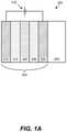
- FIG. 1Adepicts a schematic cross-section of an electrochromic device.
- FIG. 1Bdepicts a schematic cross-section of an electrochromic device in a bleached state (or transitioning to a bleached state).
- FIG. 1Cdepicts a schematic cross-section of the electrochromic device shown in FIG. 1B , but in a colored state (or transitioning to a colored state).
- FIG. 2depicts a simplified block diagram of components of a window controller.
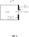
- FIG. 3depicts a schematic diagram of a room including a tintable window and at least one sensor, according to disclosed embodiments.
- FIGS. 4A-4Cinclude diagrams depicting information collected by each of three Modules A, B, and C of an exemplary control logic, according to disclosed embodiments.
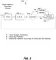
- FIG. 5is a flowchart showing some operations of control logic for a method of controlling one or more electrochromic windows in a building, according to disclosed embodiments.
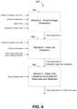
- FIG. 6is a flowchart showing a particular implementation of a portion of the control logic shown in FIG. 5 .
- FIG. 7is a flowchart showing details of Module A according to disclosed embodiments.
- FIG. 8is an example of an occupancy lookup table according to disclosed embodiments.
- FIG. 9Adepicts a schematic diagram of a room including an electrochromic window with a space type based on a Desk 1 located near the window, according to disclosed embodiments.
- FIG. 9Bdepicts a schematic diagram of a room including an electrochromic window with a space type based on a Desk 2 located further away from the window than in FIG. 9A , according to disclosed embodiments.
- FIG. 10is a diagram showing another implementation of a portion of the control logic shown in FIG. 5 .
- FIG. 11depicts a schematic diagram of an embodiment of a building management system.
- FIG. 12is a block diagram of components of a system for controlling functions of one or more tintable windows of a building.
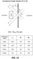
- FIG. 13is an example of an occupancy lookup table and a schematic diagram of a room with a desk and window showing the relationship between acceptance angle, sun angle, and penetration depth, according to embodiments.
- FIG. 14Ais a flowchart showing a particular implementation of a portion of the control logic shown in FIG. 5 .
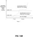
- FIG. 14Bis a graph of illumination readings during a day that is cloudy early in the day and then sunny later in the day and the corresponding upper and lower limits.
- FIG. 15depicts a room having a desk and the critical angle of the room within which the sun is shining onto an occupant sitting at the desk
- FIG. 16is a flowchart showing a particular implementation of the control logic shown in FIG. 5 , according to an embodiment.
- FIG. 17is a flowchart showing a particular implementation of the control logic shown in FIG. 5 , according to an embodiment.
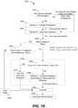
- FIG. 18is a flowchart showing a particular implementation of the control logic shown in FIG. 5 , according to an embodiment.
- FIG. 19is a flowchart showing a particular implementation of the control logic shown in FIG. 5 , according to an embodiment.
- FIG. 20is a flowchart showing a particular implementation of the control logic shown in FIG. 5 , according to an embodiment.
- FIG. 21is a flowchart of the operations within Module C 2 of the flowchart in FIG. 20 , according to an embodiment.
- electrochromic windowsalso referred to as smart windows
- the concepts disclosed hereinmay apply to other types of tintable windows.
- a tintable window incorporating a liquid crystal device or a suspended particle deviceinstead of an electrochromic device could be incorporated in any of the disclosed embodiments.
- electrochromic devicesIn order to orient the reader to the embodiments of systems, window controllers, and methods disclosed herein, a brief discussion of electrochromic devices is provided. This initial discussion of electrochromic devices is provided for context only, and the subsequently described embodiments of systems, window controllers, and methods are not limited to the specific features and fabrication processes of this initial discussion.
- FIG. 1Aschematically depicts an electrochromic device 300 , in cross-section.
- Electrochromic device 300includes a substrate 302 , a first conductive layer (CL) 304 , an electrochromic layer (EC) 306 , an ion conducting layer (IC) 308 , a counter electrode layer (CE) 310 , and a second conductive layer (CL) 314 .
- Layers 304 , 306 , 308 , 310 , and 314are collectively referred to as an electrochromic stack 320 .
- a voltage source 316 operable to apply an electric potential across electrochromic stack 320effects the transition of the electrochromic device from, for example, a bleached state to a colored state (depicted). The order of layers can be reversed with respect to the substrate.
- Electrochromic devices having distinct layers as describedcan be fabricated as all solid state devices and/or all inorganic devices having low defectivity. Such devices and methods of fabricating them are described in more detail in U.S. patent application Ser. No. 12/645,111, titled “Fabrication of Low-Defectivity Electrochromic Devices,” filed on Dec. 22, 2009, and naming Mark Kozlowski et al. as inventors, and in U.S. patent application Ser. No. 12/645,159, titled, “Electrochromic Devices,” filed on Dec. 22, 2009 and naming Zhongchun Wang et al. as inventors, both of which are hereby incorporated by reference in their entireties.
- any one or more of the layers in the stackmay contain some amount of organic material.
- liquidsthat may be present in one or more layers in small amounts.
- solid state materialmay be deposited or otherwise formed by processes employing liquid components such as certain processes employing sol-gels or chemical vapor deposition.
- the reference to a transition between a bleached state and colored stateis non-limiting and suggests only one example, among many, of an electrochromic transition that may be implemented. Unless otherwise specified herein (including the foregoing discussion), whenever reference is made to a bleached-colored transition, the corresponding device or process encompasses other optical state transitions such as non-reflective-reflective, transparent-opaque, etc. Further, the term “bleached” refers to an optically neutral state, for example, uncolored, transparent, or translucent. Still further, unless specified otherwise herein, the “color” of an electrochromic transition is not limited to any particular wavelength or range of wavelengths. As understood by those of skill in the art, the choice of appropriate electrochromic and counter electrode materials governs the relevant optical transition.
- the electrochromic devicereversibly cycles between a bleached state and a colored state.
- a potentialis applied to the electrochromic stack 320 such that available ions in the stack reside primarily in the counter electrode 310 .
- the potential on the electrochromic stackis reversed, the ions are transported across the ion conducting layer 308 to the electrochromic material 306 and cause the material to transition to the colored state.
- the electrochromic device of embodiments described hereincan be reversibly cycled between different tint levels (e.g., bleached state, darkest colored state, and intermediate levels between the bleached state and the darkest colored state).
- voltage source 316may be configured to operate in conjunction with radiant and other environmental sensors. As described herein, voltage source 316 interfaces with a device controller (not shown in this figure). Additionally, voltage source 316 may interface with an energy management system that controls the electrochromic device according to various criteria such as the time of year, time of day, and measured environmental conditions. Such an energy management system, in conjunction with large area electrochromic devices (e.g., an electrochromic window), can dramatically lower the energy consumption of a building.
- substrate 302Any material having suitable optical, electrical, thermal, and mechanical properties may be used as substrate 302 .
- substratesinclude, for example, glass, plastic, and mirror materials.
- Suitable glassesinclude either clear or tinted soda lime glass, including soda lime float glass. The glass may be tempered or untempered.
- the substrateis a glass pane sized for residential window applications.
- the size of such glass panecan vary widely depending on the specific needs of the residence.
- the substrateis architectural glass.
- Architectural glassis typically used in commercial buildings, but may also be used in residential buildings, and typically, though not necessarily, separates an indoor environment from an outdoor environment.
- architectural glassis at least 20 inches by 20 inches, and can be much larger, for example, as large as about 80 inches by 120 inches.
- Architectural glassis typically at least about 2 mm thick, typically between about 3 mm and about 6 mm thick.
- electrochromic devicesare scalable to substrates smaller or larger than architectural glass. Further, the electrochromic device may be provided on a mirror of any size and shape.
- conductive layer 304On top of substrate 302 is conductive layer 304 .
- one or both of the conductive layers 304 and 314is inorganic and/or solid.
- Conductive layers 304 and 314may be made from a number of different materials, including conductive oxides, thin metallic coatings, conductive metal nitrides, and composite conductors.
- conductive layers 304 and 314are transparent at least in the range of wavelengths where electrochromism is exhibited by the electrochromic layer.
- Transparent conductive oxidesinclude metal oxides and metal oxides doped with one or more metals.
- metal oxides and doped metal oxidesexamples include indium oxide, indium tin oxide, doped indium oxide, tin oxide, doped tin oxide, zinc oxide, aluminum zinc oxide, doped zinc oxide, ruthenium oxide, doped ruthenium oxide and the like. Since oxides are often used for these layers, they are sometimes referred to as “transparent conductive oxide” (TCO) layers. Thin metallic coatings that are substantially transparent may also be used, as well as combinations of TCOs and metallic coatings.
- TCOtransparent conductive oxide
- the function of the conductive layersis to spread an electric potential provided by voltage source 316 over surfaces of the electrochromic stack 320 to interior regions of the stack, with relatively little ohmic potential drop.
- the electric potentialis transferred to the conductive layers though electrical connections to the conductive layers.
- bus barsone in contact with conductive layer 304 and one in contact with conductive layer 314 , provide the electric connection between the voltage source 316 and the conductive layers 304 and 314 .
- the conductive layers 304 and 314may also be connected to the voltage source 316 with other conventional means.
- electrochromic layer 306is inorganic and/or solid.
- the electrochromic layermay contain any one or more of a number of different electrochromic materials, including metal oxides.
- metal oxidesinclude tungsten oxide (WO 3 ), molybdenum oxide (MoO 3 ), niobium oxide (Nb 2 O 5 ), titanium oxide (TiO 2 ), copper oxide (CuO), iridium oxide (Ir2O 3 ), chromium oxide (Cr 2 O 3 ), manganese oxide (Mn 2 O 3 ), vanadium oxide (V 2 O 5 ), nickel oxide (Ni 2 O 3 ), cobalt oxide (Co 2 O 3 ) and the like.
- electrochromic layer 306transfers ions to and receives ions from counter electrode layer 310 to cause optical transitions.
- the colorization (or change in any optical property—e.g., absorbance, reflectance, and transmittance) of the electrochromic materialis caused by reversible ion insertion into the material (e.g., intercalation) and a corresponding injection of a charge balancing electron.
- a charge balancing electrontypically some fraction of the ions responsible for the optical transition is irreversibly bound up in the electrochromic material. Some or all of the irreversibly bound ions are used to compensate “blind charge” in the material.
- suitable ionsinclude lithium ions (Li+) and hydrogen ions (H+) (that is, protons). In some cases, however, other ions will be suitable.
- lithium ionsare used to produce the electrochromic phenomena. Intercalation of lithium ions into tungsten oxide (WO 3-y ) (0 ⁇ y ⁇ ⁇ 0.3)) causes the tungsten oxide to change from transparent (bleached state) to blue (colored state).
- ion conducting layer 308is sandwiched between electrochromic layer 306 and counter electrode layer 310 .
- counter electrode layer 310is inorganic and/or solid.
- the counter electrode layermay comprise one or more of a number of different materials that serve as a reservoir of ions when the electrochromic device is in the bleached state.
- the counter electrode layertransfers some or all of the ions it holds to the electrochromic layer, changing the electrochromic layer to the colored state.
- the counter electrode layercolors with the loss of ions.
- suitable materials for the counter electrode complementary to WO 3include nickel oxide (NiO), nickel tungsten oxide (NiWO), nickel vanadium oxide, nickel chromium oxide, nickel aluminum oxide, nickel manganese oxide, nickel magnesium oxide, chromium oxide (Cr 2 O 3 ), manganese oxide (MnO 2 ), and Prussian blue.
- a counter electrode 310 made of nickel tungsten oxidethat is, ions are transported from counter electrode 310 to electrochromic layer 306
- the counter electrode layerwill transition from a transparent state to a colored state.
- Ion conducting layer 308serves as a medium through which ions are transported (in the manner of an electrolyte) when the electrochromic device transitions between the bleached state and the colored state.
- ion conducting layer 308is highly conductive to the relevant ions for the electrochromic and the counter electrode layers, but has sufficiently low electron conductivity that negligible electron transfer takes place during normal operation.
- a thin ion conducting layer with high ionic conductivitypermits fast ion conduction and hence fast switching for high performance electrochromic devices.
- the ion conducting layer 308is inorganic and/or solid.
- ion conducting layersfor electrochromic devices having a distinct IC layer
- suitable ion conducting layersinclude silicates, silicon oxides, tungsten oxides, tantalum oxides, niobium oxides, and borates. These materials may be doped with different dopants, including lithium. Lithium doped silicon oxides include lithium silicon-aluminum-oxide.
- the ion conducting layercomprises a silicate-based structure.
- a silicon-aluminum-oxide (SiAlO)is used for the ion conducting layer 308 .
- Electrochromic device 300may include one or more additional layers (not shown), such as one or more passive layers. Passive layers used to improve certain optical properties may be included in electrochromic device 300 . Passive layers for providing moisture or scratch resistance may also be included in electrochromic device 300 . For example, the conductive layers may be treated with anti-reflective or protective oxide or nitride layers. Other passive layers may serve to hermetically seal electrochromic device 300 .
- FIG. 1Bis a schematic cross-section of an electrochromic device in a bleached state (or transitioning to a bleached state).
- an electrochromic device 400includes a tungsten oxide electrochromic layer (EC) 406 and a nickel-tungsten oxide counter electrode layer (CE) 410 .
- Electrochromic device 400also includes a substrate 402 , a conductive layer (CL) 404 , an ion conducting layer (IC) 408 , and conductive layer (CL) 414 .
- a power source 416is configured to apply a potential and/or current to an electrochromic stack 420 through suitable connections (e.g., bus bars) to the conductive layers 404 and 414 .
- the voltage sourceis configured to apply a potential of a few volts in order to drive a transition of the device from one optical state to another.
- the polarity of the potential as shown in FIG. 1Ais such that the ions (lithium ions in this example) primarily reside (as indicated by the dashed arrow) in nickel-tungsten oxide counter electrode layer 410
- FIG. 1Cis a schematic cross-section of electrochromic device 400 shown in FIG. 3B but in a colored state (or transitioning to a colored state).
- the polarity of voltage source 416is reversed, so that the electrochromic layer is made more negative to accept additional lithium ions, and thereby transition to the colored state.
- lithium ionsare transported across ion conducting layer 408 to tungsten oxide electrochromic layer 406 .
- Tungsten oxide electrochromic layer 406is shown in the colored state.
- Nickel-tungsten oxide counter electrode 410is also shown in the colored state. As explained, nickel-tungsten oxide becomes progressively more opaque as it gives up (deintercalates) lithium ions.
- there is a synergistic effectwhere the transition to colored states for both layers 406 and 410 are additive toward reducing the amount of light transmitted through the stack and substrate.
- an electrochromic devicemay include an electrochromic (EC) electrode layer and a counter electrode (CE) layer separated by an ionically conductive (IC) layer that is highly conductive to ions and highly resistive to electrons.
- ECelectrochromic
- CEcounter electrode
- ICionically conductive
- the ionically conductive layerallows the electrochromic and counter electrodes to hold a charge and thereby maintain their bleached or colored states.
- the componentsform a stack which includes the ion conducting layer sandwiched between the electrochromic electrode layer and the counter electrode layer. The boundaries between these three stack components are defined by abrupt changes in composition and/or microstructure. Thus, the devices have three distinct layers with two abrupt interfaces.
- the counter electrode and electrochromic electrodesare formed immediately adjacent one another, sometimes in direct contact, without separately depositing an ionically conducting layer.
- electrochromic deviceshaving an interfacial region rather than a distinct IC layer are employed. Such devices, and methods of fabricating them, are described in U.S. Pat. Nos. 8,300,298, 8,582,193, 8,764,950, and 8,764,951—each of the patents is titled “Electrochromic Devices,” each names Zhongchun Wang et al. as inventors, and each is incorporated by reference herein in its entirety.
- an electrochromic devicemay be integrated into an insulated glass unit (IGU) of an electrochromic window or may be in a single pane electrochromic window.
- an electrochromic windowmay have an IGU including a first electrochromic lite and a second lite.
- the IGUalso includes a spacer separating the first electrochromic lite and the second lite.
- the second lite in the IGUmay be a non-electrochromic lite or otherwise.
- the second litemay have an electrochromic device thereon and/or one or more coatings such as low-E coatings and the like. Either of the lites can also be laminated glass.
- the IGUalso includes bus bar wiring for connection to a window controller. In some embodiments, one or both of the bus bars are inside the finished IGU, however in one embodiment one bus bar is outside the seal of the IGU and one bus bar is inside the IGU. In the former embodiment, an area is used to make the seal with one face of the spacer used to form the IGU.
- the wires or other connection to the bus barsruns between the spacer and the glass.
- spacersare made of metal, e.g., stainless steel, which is conductive, it is desirable to take steps to avoid short circuiting due to electrical communication between the bus bar and connector thereto and the metal spacer.
- a window controlleris used to control the tint level of the electrochromic device of an electrochromic window.
- the window controlleris able to transition the electrochromic window between two tint states (levels), a bleached state and a colored state.
- the controllercan additionally transition the electrochromic window (e.g., having a single electrochromic device) to intermediate tint levels.
- the window controlleris able to transition the electrochromic window to four or more tint levels. Certain electrochromic windows allow intermediate tint levels by using two (or more) electrochromic lites in a single IGU, where each lite is a two-state lite. This is described in reference to FIGS. 1A and 1B in this section.
- an electrochromic windowcan include an electrochromic device 300 on one lite of an IGU and another electrochromic device 300 on the other lite of the IGU. If the window controller is able to transition each electrochromic device between two states, a bleached state and a colored state, the electrochromic window is able to attain four different states (tint levels), a colored state with both electrochromic devices being colored, a first intermediate state with one electrochromic device being colored, a second intermediate state with the other electrochromic device being colored, and a bleached state with both electrochromic devices being bleached.
- statessuch astint levels
- Embodiments of multi-pane electrochromic windowsare further described in U.S. Pat. No. 8,270,059, naming Robin Friedman et al. as inventors, titled “MULTI-PANE ELECTROCHROMIC WINDOWS,” which is hereby incorporated by reference in its entirety.
- the window controlleris able to transition an electrochromic window having an electrochromic device capable of transitioning between two or more tint levels.
- a window controllermay be able to transition the electrochromic window to a bleached state, one or more intermediate levels, and a colored state.
- the window controlleris able to transition an electrochromic window incorporating an electrochromic device between any number of tint levels between the bleached state and the colored state.
- a window controllercan power one or more electrochromic devices in an electrochromic window.
- this function of the window controlleris augmented with one or more other functions described in more detail below.
- Window controllers described hereinare not limited to those that have the function of powering an electrochromic device to which it is associated for the purposes of control. That is, the power source for the electrochromic window may be separate from the window controller, where the controller has its own power source and directs application of power from the window power source to the window. However, it is convenient to include a power source with the window controller and to configure the controller to power the window directly, because it obviates the need for separate wiring for powering the electrochromic window.
- window controllers described in this sectionare described as standalone controllers which may be configured to control the functions of a single window or a plurality of electrochromic windows, without integration of the window controller into a building control network or a building management system (BMS).
- Window controllersmay be integrated into a building control network or a BMS, as described further in the Building Management System section of this disclosure.
- FIG. 2depicts a block diagram of some components of a window controller 450 and other components of a window controller system of disclosed embodiments.
- FIG. 2is a simplified block diagram of a window controller, and more detail regarding window controllers can be found in U.S. patent application Ser. Nos. 13/449,248 and 13/449,251, both naming Stephen Brown as inventor, both titled “CONTROLLER FOR OPTICALLY-SWITCHABLE WINDOWS,” and both filed on Apr. 17, 2012, and in U.S. patent Ser. No. 13/449,235, titled “CONTROLLING TRANSITIONS IN OPTICALLY SWITCHABLE DEVICES,” naming Stephen Brown et al. as inventors and filed on Apr. 17, 2012, all of which are hereby incorporated by reference in their entireties.
- the illustrated components of the window controller 450include a window controller 450 having a microprocessor 455 or other processor, a pulse width modulator 460 , a signal conditioning module 465 , and a computer readable medium (e.g., memory) having a configuration file 475 .
- Window controller 450is in electronic communication with one or more electrochromic devices 400 in an electrochromic window through network 480 (wired or wireless) to send instructions to the one or more electrochromic devices 400 .
- the window controller 450may be a local window controller in communication through a network (wired or wireless) to a master window controller.
- a buildingmay have at least one room having an electrochromic window between the exterior and interior of a building.
- One or more sensorsmay be located to the exterior of the building and/or inside the room.
- the output from the one or more sensorsmay be input to the signal conditioning module 465 of the window controller 450 .
- the output from the one or more sensorsmay be input to a BMS, as described further in the Building Management Systems section.
- the sensors of depicted embodimentsare shown as located on the outside vertical wall of the building, this is for the sake of simplicity, and the sensors may be in other locations, such as inside the room or on other surfaces to the exterior, as well.
- two or more sensorsmay be used to measure the same input, which can provide redundancy in case one sensor fails or has an otherwise erroneous reading.
- FIG. 3depicts a schematic (side view) diagram of a room 500 having an electrochromic window 505 with at least one electrochromic device.
- the electrochromic window 505is located between the exterior and the interior of a building, which includes the room 500 .
- the room 500also includes a window controller 450 connected to and configured to control the tint level of the electrochromic window 505 .
- An exterior sensor 510is located on a vertical surface in the exterior of the building.
- an interior sensormay also be used to measure the ambient light in room 500 .
- an occupant sensormay also be used to determine when an occupant is in the room 500 .
- Exterior sensor 510is a device, such as a photosensor, that is able to detect radiant light incident upon the device flowing from a light source such as the sun or from light reflected to the sensor from a surface, particles in the atmosphere, clouds, etc.
- the exterior sensor 510may generate a signal in the form of electrical current that results from the photoelectric effect and the signal may be a function of the light incident on the sensor 510 .
- the devicemay detect radiant light in terms of irradiance in units of watts/m 2 or other similar units.
- the devicemay detect light in the visible range of wavelengths in units of foot candles or similar units. In many cases, there is a linear relationship between these values of irradiance and visible light.
- Irradiance values from sunlightcan be determined based on the time of day and time of year as the angle at which sunlight strikes the earth changes.
- Exterior sensor 510can detect radiant light in real-time, which accounts for reflected and obstructed light due to buildings, changes in weather (e.g., clouds), etc. For example, on cloudy days, sunlight would be blocked by the clouds and the radiant light detected by an exterior sensor 510 would be lower than on cloudless days.
- Output from the one or more exterior sensors 510could be compared to one another to determine, for example, if one of exterior sensors 510 is shaded by an object, such as by a bird that landed on exterior sensor 510 .
- a single sensor or a few sensorsmay be employed to determine the current level of radiant light from the sun impinging on the building or perhaps one side of the building.
- a cloudmay pass in front of the sun or a construction vehicle may park in front of the setting sun. These will result in deviations from the amount of radiant light from the sun calculated to normally impinge on the building.
- Exterior sensor 510may be a type of photosensor.
- exterior sensor 510may be a charge coupled device (CCD), photodiode, photoresistor, or photovoltaic cell.
- CCDcharge coupled device
- photodiodephotodiode
- photoresistorphotoresistor
- photovoltaic cellOne of ordinary skill in the art would appreciate that future developments in photosensor and other sensor technology would also work, as they measure light intensity and provide an electrical output representative of the light level.
- output from exterior sensor 510may be input to the signal conditioning module 465 .
- the inputmay be in the form of a voltage signal to signal conditioning module 465 .
- Signal conditioning module 465passes an output signal to the window controller 450 .
- Window controller 450determines a tint level of the electrochromic window 505 , based on various information from the configuration file 475 , output from the signal conditioning module 465 , override values. Window controller 450 and then instructs the PWM 460 , to apply a voltage and/or current to electrochromic window 505 to transition to the desired tint level.
- window controller 450can instruct the PWM 460 , to apply a voltage and/or current to electrochromic window 505 to transition it to any one of four or more different tint levels.
- electrochromic window 505can be transitioned to at least eight different tint levels described as: 0 (lightest), 5, 10, 15, 20, 25, 30, and 35 (darkest). The tint levels may linearly correspond to visual transmittance values and solar heat gain coefficient (SHGC) values of light transmitted through the electrochromic window 505 .
- SHGCsolar heat gain coefficient
- the lightest tint level of 0may correspond to an SHGC value of 0.80
- the tint level of 5may correspond to an SHGC value of 0.70
- the tint level of 10may correspond to an SHGC value of 0.60
- the tint level of 15may correspond to an SHGC value of 0.50
- the tint level of 20may correspond to an SHGC value of 0.40
- the tint level of 25may correspond to an SHGC value of 0.30
- the tint level of 30may correspond to an SHGC value of 0.20
- the tint level of 35 (darkest)may correspond to an SHGC value of 0.10.
- Window controller 450 or a master controller in communication with the window controller 450may employ any one or more control logic components to determine a desired tint level based on signals from the exterior sensor 510 and/or other input.
- the window controller 450can instruct the PWM 460 to apply a voltage and/or current to electrochromic window 505 to transition it to the desired tint level.
- control logicis used to implement methods for determining and controlling a desired tint level for an electrochromic window or other tintable window that accounts for occupant comfort and/or energy conservation considerations.
- the control logicemploys one or more logic modules.
- FIGS. 4A-4Cinclude diagrams depicting some general information collected by each of three logic Modules A, B, and C of an exemplary control logic of disclosed embodiments.
- FIG. 4Ashows the penetration depth of direct sunlight into a room 500 through an electrochromic window 505 between the exterior and the interior of a building, which includes the room 500 .
- Penetration depthis a measure of how far direct sunlight will penetrate into the room 500 .
- penetration depthis measured in a horizontal direction away from the sill (bottom) of window 505 .
- the windowdefines an aperture that provides an acceptance angle for direct sunlight.
- the penetration depthis calculated based upon the geometry of the window (e.g., window dimensions), its position and orientation in the room, any fins or other exterior shading outside of the window, and the position of the sun (e.g. angle of direct sunlight for a particular time of day and date).
- Exterior shading to an electrochromic window 505may be due to any type of structure that can shade the window such as an overhang, a fin, etc.
- FIG. 4Athere is an overhang 520 above the electrochromic window 505 that blocks a portion of the direct sunlight entering the room 500 thus shortening the penetration depth.
- the room 500also includes a local window controller 450 connected to and configured to control the tint level of the electrochromic window 505 .
- An exterior sensor 510is located on a vertical surface in the exterior of the building.
- Module Acan be used to determine a tint level that considers occupant comfort from direct sunlight through the electrochromic window 505 onto an occupant or their activity area.
- the tint levelis determined based on a calculated penetration depth of direct sunlight into the room and the space type (e.g., desk near window, lobby, etc.) in the room at a particular instant in time. In some cases, the tint level may also be based on providing sufficient natural lighting into the room. In many cases, the penetration depth is the value calculated at a time in the future to account for glass transition time (the time required for the window to tint, e.g. to 80%, 90% or 100% of the desired tint level).
- the issue addressed in Module Ais that direct sunlight may penetrate so deeply into the room 500 as to show directly on an occupant working at a desk or other work surface in a room. Publicly available programs can provide calculation of the sun's position and allow for easy calculation of penetration depth.
- FIG. 4Aalso shows a desk in the room 500 as an example of a space type associated with an activity area (i.e. desk) and location of the activity area (i.e. location of desk).
- Each space typeis associated with different tint levels for occupant comfort. For example, if the activity is a critical activity such as work in an office being done at a desk or computer, and the desk is located near the window, the desired tint level may be higher than if the desk were further away from the window. As another example, if the activity is non-critical, such as the activity in a lobby, the desired tint level may be lower than for the same space having a desk.
- FIG. 4Bshows direct sunlight and radiation under clear sky conditions entering the room 500 through the electrochromic window 505 .
- the radiationmay be from sunlight scattered by molecules and particles in the atmosphere.
- Module Bdetermines a tint level based on calculated values of irradiance under clear sky conditions flowing through the electrochromic window 505 under consideration.
- Various softwaresuch as open source RADIANCE program, can be used to calculate clear sky irradiance at a certain latitude, longitude, time of year, and time of day, and for a given window orientation.
- FIG. 4Cshows radiant light from the sky that is measured in real-time by an exterior sensor 510 to account for light that may be obstructed by or reflected from objects such as buildings or weather conditions (e.g., clouds) that are not accounted for in the clear sky radiation determinations.
- the tint level determined by Module Cis based on the real-time irradiance based on measurements taken by the exterior sensor 510 .
- the operations of Module Bwill determine a tint level that darkens (or does not change) the tint level determined by Module A and the operations of Module C will determine a tint level that lightens (or does not change) the tint level determined by Module B.
- the control logicmay implement one or more of the logic Modules A, B and C separately for each electrochromic window 505 in the building.
- Each electrochromic window 505can have a unique set of dimensions, orientation (e.g., vertical, horizontal, tilted at an angle), position, associated space type, etc.
- a configuration file with this information and other informationcan be maintained for each electrochromic window 505 .
- the configuration file 475(refer to FIG. 2 ) may be stored in the computer readable medium 470 of the local window controller 450 of the electrochromic window 505 or in the building management system (“BMS”) described later in this disclosure.
- the configuration file 475can include information such as a window configuration, an occupancy lookup table, information about an associated datum glass, and/or other data used by the control logic.
- the window configurationmay include information such as the dimensions of the electrochromic window 505 , the orientation of the electrochromic window 505 , the position of the electrochromic window 505 , etc.
- a lookup tabledescribes tint levels that provide occupant comfort for certain space types and penetration depths. That is, the tint levels in the occupancy lookup table are designed to provide comfort to occupant(s) that may be in the room 500 from direct sunlight on the occupant(s) or their workspace.
- An example of an occupancy lookup tableis shown in FIG. 8 .
- the space typeis a measure to determine how much tinting will be required to address occupant comfort concerns for a given penetration depth and/or provide comfortable natural lighting in the room.
- the space type parametermay take into consideration many factors. Among these factors is the type of work or other activity being conducted in a particular room and the location of the activity. Close work associated with detailed study requiring great attention might be at one space type, while a lounge or a conference room might have a different space type. Additionally, the position of the desk or other work surface in the room with respect to the window is a consideration in defining the space type.
- the space typemay be associated with an office of a single occupant having a desk or other workspace located near the electrochromic window 505 . As another example, the space type may be a lobby.
- one or more modules of the control logiccan determine desired tint levels while accounting for energy conservation in addition to occupant comfort. These modules may determine energy savings associated with a particular tint level by comparing the performance of the electrochromic window 505 at that tint level to a datum glass or other standard reference window. The purpose of using this reference window can be to ensure that the control logic conforms to requirements of the municipal building code or other requirements for reference windows used in the locale of the building. Often municipalities define reference windows using conventional low emissivity glass to control the amount of air conditioning load in the building.
- control logicmay be designed so that the irradiance coming through a given electrochromic window 505 is never greater than the maximum irradiance coming through a reference window as specified by the respective municipality.
- control logicmay use the solar heat gain coefficient (SHGC) value of the electrochromic window 505 at a particular tint level and the SHGC of the reference window to determine the energy savings of using the tint level.
- SHGCsolar heat gain coefficient
- the value of the SHGCis the fraction of incident light of all wavelengths transmitted through the window.
- a datum glassis described in many embodiments, other standard reference windows can be used.
- the SHGC of the reference windowe.g., datum glass
- the SHGC of the reference windowis a variable that can be different for different geographical locations and window orientations, and is based on code requirements specified by the respective municipality.
- HVACheating, ventilation, and air conditioning
- the calculation of required capacitymay take into consideration the datum glass or reference window required in a building at the particular location where the building is being constructed. Therefore, it is important that the control logic meet or exceed the functional requirements of the datum glass in order to allow building designers to confidently determine how much HVAC capacity to put into a particular building. Since the control logic can be used to tint the window to provide additional energy savings over the datum glass, the control logic could be useful in allowing building designers to have a lower HVAC capacity than would have been required using the datum glass specified by the codes and standards.
- control logichas only two independent variables that can be controlled by an occupant (end user), building designer, or building operator. These are the space types for a given window and the datum glass associated with the given window. Often the datum glass is specified when the control logic is implemented for a given building.
- the space typecan vary, but is typically static.
- the space typemay be part of the configuration file maintained by the building or stored in the local window controller 450 . In some cases, the configuration file may be updated to account for various changes in the building.
- an updated configuration file with a modified occupancy lookup tablemay be stored in the computer readable medium 470 .
- the configuration filemay be updated to reflect the manual override.
- FIG. 5is a flowchart showing control logic for a method of controlling one or more electrochromic windows 505 in a building, according to embodiments.
- the control logicuses one or more of the Modules A, B, and C to calculate tint levels for the window(s) and sends instructions to transition the window(s).
- the calculations in the control logicare run 1 to n times at intervals timed by the timer at operation 610 .
- nis the number of recalculations performed and n can be at least 1.
- the logic calculationscan be done at constant time intervals in some cases. In one cases, the logic calculations may be done every 2 to 5 minutes. However, tint transition for large pieces of electrochromic glass (e.g. up to 6′ ⁇ 10 feet) can take up to 30 minutes or more. For these large windows, calculations may be done on a less frequent basis such as every 30 minutes.
- logic Modules A, B, and Cperform calculations to determine a tint level for each electrochromic window 505 at a single instant in time t i . These calculations can be performed by the window controller 450 .
- the control logiccalculates how the window should transition in advance of the actual transition.
- the calculations in Modules A, B, and Care based on a future time, for example, around or after transition is complete.
- the future time used in the calculationsmay be a time in the future that is sufficient to allow the transition to be completed after receiving the tint instructions.
- the controllercan send tint instructions in the present time in advance of the actual transition. By the completion of the transition, the window will have transitioned to a tint level that is desired for that time.
- the control logicallows for certain types of overrides that disengage the algorithm at Modules A, B, and C and define override tint levels at operation 640 based on some other consideration.
- One type of overrideis a manual override. This is an override implemented by an end user who is occupying a room and determines that a particular tint level (override value) is desirable. There may be situations where the user's manual override is itself overridden.
- An example of an overrideis a high demand (or peak load) override, which is associated with a requirement of a utility that energy consumption in the building be reduced.
- the buildingmay override the tint level from the control logic described herein to ensure that all windows have a particularly high level of tinting.
- Another example of an overridemay be if there is no occupant in the room example weekends in a commercial office building.
- the buildingmay disengage one or more Modules that relate to occupant comfort and all the windows may have a low level of tinting in cold weather and high level of tinting in warm weather.
- the tint levelsare transmitted over a network to electrochromic device(s) in one or more electrochromic windows 505 in the building.
- the transmission of tint levels to all windows of a buildingmay be implemented with efficiency in mind. For example, if the recalculation of tint level suggests that no change in tint from the current tint level is required, then there is no transmission of instructions with an updated tint level.
- the buildingmay be divided into zones based on window size and/or location in the building. In one case, control logic recalculates tint levels for zones with smaller windows more frequently than for zones with larger windows.
- control logic in FIG. 5 for implementing the control method(s) for multiple electrochromic windows in an entire buildingcan be on a single device, for example, a single master window controller.
- This devicecan perform the calculations for each and every tintable window in the building and also provide an interface for transmitting tint levels to one or more electrochromic devices in individual electrochromic windows 505 , for example, in multi-zone windows or on multiple EC lites of an insulated glass unit.
- multi-zone windowscan be found in PCT application No. PCT/US14/71314 titled “MULTI-ZONE EC WINDOWS,” which is hereby incorporated by reference in its entirety.
- control logicmay determine how an end user (e.g. occupant) tries to override the algorithm at particular times of day and makes use of this information in a more predictive manner to determine desired tint levels.
- the end usermay be using a wall switch to override the tint level provided by the control logic at a certain time each day to an override value.
- the control logicmay receive information about these instances and change the control logic to change the tint level to the override value at that time of day.
- FIG. 6is a diagram showing a particular implementation of block 620 from FIG. 5 .
- This diagramshows a method of performing all three Modules A, B, and C in sequence to calculate a final tint level of a particular electrochromic window 505 for a single instant in time t i .
- the final tint levelmay be the maximum permissible transmissivity of the window under consideration.
- FIG. 6also includes some exemplary inputs and outputs of Modules A, B, and C.
- the calculations in Modules A, B, and Care performed by window controller 450 in local window controller 450 in embodiments. In other embodiments, one or more of the modules can be performed by another processor.
- illustrated embodimentsshow all three Modules A, B, and C being used, other embodiments may use one or more of the Modules A, B, and C or may use additional modules.
- window controller 450uses Module A to determine a tint level for occupant comfort to prevent direct glare from sunlight penetrating the room 500 .
- Window controller 450uses Module A to calculate the penetration depth of direct sunlight into the room 500 based on the sun's position in the sky and the window configuration from the configuration file. The position of the sun is calculated based on the latitude and longitude of the building and the time of day and date. The occupancy lookup table and space type are input from a configuration file for the particular window.
- Module Aoutputs the Tint level from A to Module B.
- Module AThe goal of Module A is generally to ensure that direct sunlight or glare does not strike the occupant or his or her workspace.
- the tint level from Module Ais determined to accomplish this purpose. Subsequent calculations of tint level in Modules B and C can reduce energy consumption and may require even greater tint. However, if subsequent calculations of tint level based on energy consumption suggest less tinting than required to avoid interfering with the occupant, the logic prevents the calculated greater level of transmissivity from being executed to assure occupant comfort.
- the tint level calculated in Module Ais input into Module B.
- Module Bdetermines a tint level that darkens (or does not change) the tint level calculated in Module B.
- a tint levelis calculated based on calculations of irradiance under clear sky conditions (clear sky irradiance).
- Window controller 450uses Module B to calculate clear sky irradiance for the electrochromic window 505 based on window orientation from the configuration file and based on latitude and longitude of the building. These calculations are also based on a time of day and date.
- Publicly available softwaresuch as the RADIANCE program, which is an open-source program, can provide the calculations for calculating clear sky irradiance.
- the SHGC of the datum glassis also input into Module B from the configuration file.
- Window controller 450uses Module B to determine a tint level that is darker than the tint level in A and transmits less heat than the datum glass is calculated to transmit under maximum clear sky irradiance.
- Maximum clear sky irradianceis the highest level of irradiance for all times calculated for clear sky conditions.
- a tint level from Module B and calculated clear sky irradianceare input to Module C.
- Real-time irradiance valuesare input to Module C based on measurements from an exterior sensor 510 .
- Window controller 450uses Module C to calculate irradiance transmitted into the room if the window were tinted to the Tint level from Module B under clear sky conditions.
- Window controller 450uses Module C to find the appropriate tint level where the actual irradiance through the window with this tint level is less than or equal to the irradiance through the window with the Tint level from Module B.
- the operations of Module Cwill determine a tint level that lightens (or does not change) the tint level determined by the operations of Module B.
- the tint level determined in Module Cis the final tint level in this example.
- Much of the information input to the control logicis determined from fixed information about the latitude and longitude, time and date. This information describes where the sun is with respect to the building, and more particularly with respect to the window for which the control logic is being implemented.
- the position of the sun with respect to the windowprovides information such as the penetration depth of direct sunlight into the room assisted with the window. It also provides an indication of the maximum irradiance or solar radiant energy flux coming through the window.
- This calculated level of irradiancecan be modified by sensor input which might indicate that there is a reduction from the maximum amount of irradiance. Again, such reduction might be caused by a cloud or other obstruction between the window and the sun.
- FIG. 7is a flowchart showing details of operation 700 of FIG. 6 .
- Module Abegins.
- the window controller 450uses Module A to calculate the position of the sun for the latitude and longitude coordinates of the building and the date and time of day of a particular instant in time, t i .
- the latitude and longitude coordinatesmay be input from the configuration file.
- the date and time of daymay be based on the current time provided by the timer.
- the sun positionis calculated at the particular instant in time, t i , which may be in the future in some cases. In other embodiments, the position of the sun is calculated in another component (e.g., module) of the control logic.
- window controller 450uses Module A to calculate the penetration depth of direct sunlight into the room 500 at the particular instant in time used in operation 710 .
- Module Acalculates the penetration depth based on the calculated position of the sun and window configuration information including the position of the window, dimensions of the window, orientation of the window (i.e. direction facing), and the details of any exterior shading.
- the window configuration informationis input from the configuration file associated with the electrochromic window 505 .
- Module Acan be used to calculate the penetration depth of the vertical window shown in FIG. 4A by first calculating the angle ⁇ of the direct sunlight based on the position of the sun calculated at the particular instant in time. The penetration depth can be determined based on calculated angle ⁇ and the location of the lintel (top of the window).
- a tint levelis determined that will provide occupant comfort for the penetration depth calculated in operation 720 .
- the occupancy lookup tableis used to find a desired tint level for the space type associated with the window, for the calculated penetration depth, and for the acceptance angle of the window.
- the space type and occupancy lookup tableare provided as input from the configuration file for the particular window.
- FIG. 8An example of an occupancy lookup table is provided in FIG. 8 .
- the values in the tableare in terms of a Tint level and associated SHGC values in parenthesis.
- FIG. 8shows the different tint levels (SHGC values) for different combinations of calculated penetration values and space types.
- the tableis based on eight tint levels including 0 (lightest), 5, 10, 15, 20, 25, 30, and 35 (lightest).
- the lightest tint level of 0corresponds to an SHGC value of 0.80
- the tint level of 5corresponds to an SHGC value of 0.70
- the tint level of 10corresponds to an SHGC value of 0.60
- the tint level of 15corresponds to an SHGC value of 0.50
- the tint level of 20corresponds to an SHGC value of 0.40
- the tint level of 25corresponds to an SHGC value of 0.30
- the tint level of 30corresponds to an SHGC value of 0.20
- the tint level of 35 (darkest)corresponds to an SHGC value of 0.10.
- the illustrated exampleincludes three space types: Desk 1 , Desk 2 , and Lobby and six penetration depths.
- FIG. 9Ashows the location of Desk 1 in the room 500 .
- FIG. 9Bshows the location of Desk 2 in the room 500 .
- the tint levels for Desk 1 close to the windoware higher than the tint levels for Desk 2 far from window to prevent glare when the desk is closer to the window.
- Occupancy lookup tables with other valuesmay be used in other embodiments.
- one other occupancy lookup tablemay include only four tint levels associated with the penetration values.
- Another example of an occupancy table with four tint levels associated with four penetration depthsis shown in FIG. 13 .
- FIG. 10is a diagram includes an example of an implementation of the logic in block 620 shown in FIG. 5 .
- This diagramshows control logic for a method of performing Modules A, B, and C of embodiments.
- the position of the sunis calculated based on the latitude and longitude coordinates of the building for a single instant in time t i .
- the penetration depthis calculated in Module A based on the window configuration including a position of the window, dimensions of the window, orientation of the window, and information about any external shading.
- Module Auses a lookup table to determine the tint level from Module A based on the calculated penetration and the space type. The tint level from Module A is then input into Module B.
- a program such as the open source program Radianceis used to determine clear sky irradiance based on window orientation and latitude and longitude coordinates of the building for both a single instant in time t i , and a maximum value for all times.
- the datum glass SHGC and calculated maximum clear sky irradianceare input into Module B.
- Module Acalculates the maximum tint of the glass
- module Bdoesn't change the tint to make it lighter.
- the tint level calculated in Module Bis then input into Module C.
- the calculated clear sky irradianceis also input into Module C.
- a BMSis a computer-based control system installed in a building that monitors and controls the building's mechanical and electrical equipment such as ventilation, lighting, power systems, elevators, fire systems, and security systems.
- a BMSconsists of hardware, including interconnections by communication channels to a computer or computers, and associated software for maintaining conditions in the building according to preferences set by the occupants and/or by the building manager.
- a BMSmay be implemented using a local area network, such as Ethernet.
- the softwarecan be based on, for example, internet protocols and/or open standards.
- One exampleis software from Tridium, Inc. (of Richmond, Va.).
- One communications protocol commonly used with a BMSis BACnet (building automation and control networks).
- a BMSis most common in a large building, and typically functions at least to control the environment within the building.
- a BMSmay control temperature, carbon dioxide levels, and humidity within a building.
- mechanical devicesthat are controlled by a BMS such as heaters, air conditioners, blowers, vents, and the like.
- a BMSmay turn on and off these various devices under defined conditions.
- a core function of a typical modern BMSis to maintain a comfortable environment for the building's occupants while minimizing heating and cooling costs/demand.
- a modern BMSis used not only to monitor and control, but also to optimize the synergy between various systems, for example, to conserve energy and lower building operation costs.
- a window controlleris integrated with a BMS, where the window controller is configured to control one or more electrochromic windows 505 or other tintable windows.
- the one or more electrochromic windowsinclude at least one all solid state and inorganic electrochromic device, but may include more than one electrochromic device, e.g. where each lite or pane of an IGU is tintable.
- the one or more electrochromic windowsinclude only all solid state and inorganic electrochromic devices.
- the electrochromic windowsare multistate electrochromic windows, as described in U.S. patent application Ser. No. 12/851,514, filed on Aug. 5, 2010, and titled “Multipane Electrochromic Windows.”
- FIG. 11depicts a schematic diagram of an embodiment of a BMS 1100 , that manages a number of systems of a building 1101 , including security systems, heating/ventilation/air conditioning (HVAC), lighting of the building, power systems, elevators, fire systems, and the like.
- Security systemsmay include magnetic card access, turnstiles, solenoid driven door locks, surveillance cameras, burglar alarms, metal detectors, and the like.
- Fire systemsmay include fire alarms and fire suppression systems including a water plumbing control.
- Lighting systemsmay include interior lighting, exterior lighting, emergency warning lights, emergency exit signs, and emergency floor egress lighting.
- Power systemsmay include the main power, backup power generators, and uninterrupted power source grids.
- BMS 1100manages a master window controller 1102 .
- master window controller 1102is depicted as a distributed network of window controllers including a master network controller, 1103 , intermediate network controllers, 1105 a and 1105 b , and end or leaf controllers 1110 .
- End or leaf controllers 1110may be similar to window controller 450 described with respect to FIG. 2 .
- master network controller 1103may be in proximity to the BMS 1100 , and each floor of building 1101 may have one or more intermediate network controllers 1105 a and 1105 b , while each window of the building has its own end controller 1110 .
- each of controllers 1110controls a specific electrochromic window of building 1101 .
- Each of controllers 1110can be in a separate location from the electrochromic window that it controls, or be integrated into the electrochromic window. For simplicity, only ten electrochromic windows of building 1101 are depicted as controlled by master window controller 1102 . In a typical setting there may be a large number of electrochromic windows in a building controlled by master window controller 1102 . Master window controller 1102 need not be a distributed network of window controllers. For example, a single end controller which controls the functions of a single electrochromic window also falls within the scope of the embodiments disclosed herein, as described above.
- a BMSincluding a multipurpose electrochromic window controller as described herein.
- a BMScan provide, for example, enhanced: 1) environmental control, 2) energy savings, 3) security, 4) flexibility in control options, 5) improved reliability and usable life of other systems due to less reliance thereon and therefore less maintenance thereof, 6) information availability and diagnostics, 7) effective use of, and higher productivity from, staff, and various combinations of these, because the electrochromic windows can be automatically controlled.
- a BMSmay not be present or a BMS may be present but may not communicate with a master network controller or communicate at a high level with a master network controller. In certain embodiments, maintenance on the BMS would not interrupt control of the electrochromic windows.
- the systems of a BMS or another building networkmay run according to daily, monthly, quarterly, or yearly schedules.
- the lighting control system, the window control system, the HVAC, and the security systemmay operate on a twenty four (24) hour schedule accounting for when people are in the building during the work day.
- the buildingmay enter an energy savings mode, and during the day, the systems may operate in a manner that minimizes the energy consumption of the building while providing for occupant comfort.
- the systemsmay shut down or enter an energy savings mode over a holiday period.
- Geographical informationmay include the latitude and longitude of the building. Geographical information also may include information about the direction that each side of the building faces. Using such information, different rooms on different sides of the building may be controlled in different manners. For example, for east facing rooms of the building in the winter, the window controller may instruct the windows to have no tint in the morning so that the room warms up due to sunlight shining in the room and the lighting control panel may instruct the lights to be dim because of the lighting from the sunlight.
- the west facing windowsmay be controllable by the occupants of the room in the morning because the tint of the windows on the west side may have no impact on energy savings. However, the modes of operation of the east facing windows and the west facing windows may switch in the evening (e.g., when the sun is setting, the west facing windows are not tinted to allow sunlight in for both heat and lighting).
- a buildingfor example, like building 1101 in FIG. 11 , including a building network or a BMS, tintable windows for the exterior windows of the building (i.e., windows separating the interior of the building from the exterior of the building), and a number of different sensors.
- Light from exterior windows of a buildinggenerally has an effect on the interior lighting in the building about 20 feet or about 30 feet from the windows. That is, space in a building that is more that about 20 feet or about 30 feet from an exterior window receives little light from the exterior window. Such spaces away from exterior windows in a building are lit by lighting systems of the building.
- the temperature within a buildingmay be influenced by exterior light and/or the exterior temperature. For example, on a cold day and with the building being heated by a heating system, rooms closer to doors and/or windows will lose heat faster than the interior regions of the building and be cooler compared to the interior regions.
- the buildingmay include exterior sensors on the roof of the building.
- the buildingmay include an exterior sensor associated with each exterior window (e.g., as described in relation to FIG. 3 , room 500 ) or an exterior sensor on each side of the building.
- An exterior sensor on each side of the buildingcould track the irradiance on a side of the building as the sun changes position throughout the day.
- outputs from exterior sensors 510may be input to a network of BMS and provided as input to the local window controller 450 .
- output signals from any two or more sensorsare received.
- only one output signalis received, and in some other embodiments, three, four, five, or more outputs are received. These output signals may be received over a building network or a BMS.
- the output signals receivedinclude a signal indicating energy or power consumption by a heating system, a cooling system, and/or lighting within the building.
- the energy or power consumption of the heating system, the cooling system, and/or the lighting of the buildingmay be monitored to provide the signal indicating energy or power consumption.
- Devicesmay be interfaced with or attached to the circuits and/or wiring of the building to enable this monitoring.
- the power systems in the buildingmay be installed such that the power consumed by the heating system, a cooling system, and/or lighting for an individual room within the building or a group of rooms within the building can be monitored.
- Tint instructionscan be provided to change to tint of the tintable window to the determined level of tint.
- thismay include master network controller 1103 issuing commands to one or more intermediate network controllers 1105 a and 1105 b , which in turn issue commands to end controllers 1110 that control each window of the building.
- End controllers 1100may apply voltage and/or current to the window to drive the change in tint pursuant to the instructions.
- a building including electrochromic windows and a BMSmay be enrolled in or participate in a demand response program run by the utility or utilities providing power to the building.
- the programmay be a program in which the energy consumption of the building is reduced when a peak load occurrence is expected.
- the utilitymay send out a warning signal prior to an expected peak load occurrence. For example, the warning may be sent on the day before, the morning of, or about one hour before the expected peak load occurrence. A peak load occurrence may be expected to occur on a hot summer day when cooling systems/air conditioners are drawing a large amount of power from the utility, for example.
- the warning signalmay be received by the BMS of the building or by window controllers configured to control the electrochromic windows in the building.
- This warning signalcan be an override mechanism that disengages the Modules A, B, and C as shown in FIG. 5 .
- the BMScan then instruct the window controller(s) to transition the appropriate electrochromic device in the electrochromic windows 505 to a dark tint level aid in reducing the power draw of the cooling systems in the building at the time when the peak load is expected.
- tintable windows for the exterior windows of the buildingmay be grouped into zones, with tintable windows in a zone being instructed in a similar manner.
- groups of electrochromic windows on different floors of the building or different sides of the buildingmay be in different zones.
- all of the east facing electrochromic windowsmay be in zone 1
- all of the south facing electrochromic windowsmay be in zone 2
- all of the west facing electrochromic windowsmay be in zone 3
- all of the north facing electrochromic windowsmay be in zone 4 .
- all of the electrochromic windows on the first floor of the buildingmay be in zone 1
- all of the electrochromic windows on the second floormay be in zone 2
- all of the electrochromic windows on the third floormay be in zone 3 .
- all of the east facing electrochromic windowsmay be in zone 1
- all of the south facing electrochromic windowsmay be in zone 2
- all of the west facing electrochromic windowsmay be in zone 3
- all of the north facing electrochromic windowsmay be in zone 4 .
- east facing electrochromic windows on one floorcould be divided into different zones. Any number of tintable windows on the same side and/or different sides and/or different floors of the building may be assigned to a zone. In embodiments where individual tintable windows have independently controllable zones, tinting zones may be created on a building façade using combinations of zones of individual windows, e.g. where individual windows may or may not have all of their zones tinted.
- electrochromic windows in a zonemay be controlled by the same window controller. In some other embodiments, electrochromic windows in a zone may be controlled by different window controllers, but the window controllers may all receive the same output signals from sensors and use the same function or lookup table to determine the level of tint for the windows in a zone.
- electrochromic windows in a zonemay be controlled by a window controller or controllers that receive an output signal from a transmissivity sensor.
- the transmissivity sensormay be mounted proximate the windows in a zone.
- the transmissivity sensormay be mounted in or on a frame containing an IGU (e.g., mounted in or on a mullion, the horizontal sash of a frame) included in the zone.
- electrochromic windows in a zone that includes the windows on a single side of the buildingmay be controlled by a window controller or controllers that receive an output signal from a transmissivity sensor.
- a sensormay provide an output signal to a window controller to control the electrochromic windows of a first zone (e.g., a master control zone).
- the window controllermay also control the electrochromic windows in a second zone (e.g., a slave control zone) in the same manner as the first zone.
- another window controllermay control the electrochromic windows in the second zone in the same manner as the first zone.
- a building manager, occupants of rooms in the second zone, or other personmay manually instruct (using a tint or clear command or a command from a user console of a BMS, for example) the electrochromic windows in the second zone (i.e., the slave control zone) to enter a tint level such as a colored state (level) or a clear state.
- the electrochromic windows in the first zonei.e., the master control zone
- the electrochromic windows in the first zoneremain under control of the window controller receiving output from the transmissivity sensor.
- the second zonemay remain in a manual command mode for a period of time and then revert back to be under control of the window controller receiving output from the transmissivity sensor.
- the second zonemay stay in a manual mode for one hour after receiving an override command, and then may revert back to be under control of the window controller receiving output from the transmissivity sensor.
- a building manager, occupants of rooms in the first zone, or other personmay manually instruct (using a tint command or a command from a user console of a BMS, for example) the windows in the first zone (i.e., the master control zone) to enter a tint level such as a colored state or a clear state.
- the electrochromic windows in the second zonei.e., the slave control zone
- the first zonemay remain in a manual command mode for a period of time and then revert back to be under control of window controller receiving output from the transmissivity sensor.
- the first zonemay stay in a manual mode for one hour after receiving an override command, and then may revert back to be under control of the window controller receiving output from the transmissivity sensor.
- the electrochromic windows in the second zonemay remain in the tint level that they are in when the manual override for the first zone is received.
- the first zonemay remain in a manual command mode for a period of time and then both the first zone and the second zone may revert back to be under control of the window controller receiving output from the transmissivity sensor.
- any of the methods described herein of control of a tintable windowmay be used control the tint of a tintable window.
- window controllers described hereininclude components for wired or wireless communication between the window controller, sensors, and separate communication nodes. Wireless or wired communications may be accomplished with a communication interface that interfaces directly with the window controller. Such interface could be native to the microprocessor or provided via additional circuitry enabling these functions.
- a separate communication node for wireless communicationscan be, for example, another wireless window controller, an end, intermediate, or master window controller, a remote control device, or a BMS.
- Wireless communicationis used in the window controller for at least one of the following operations: programming and/or operating the electrochromic window, collecting data from the electrochromic window from the various sensors and protocols described herein, and using the electrochromic window as a relay point for wireless communication.
- Data collected from electrochromic windowsalso may include count data such as number of times an electrochromic device has been activated, efficiency of the electrochromic device over time, and the like.
- wireless communicationis used to operate the associated electrochromic windows, for example, via an infrared (IR), and/or radio frequency (RF) signal.
- the controllerwill include a wireless protocol chip, such as Bluetooth, EnOcean, WiFi, Zigbee, and the like.
- Window controllersmay also have wireless communication via a network. Input to the window controller can be manually input by an end user at a wall switch, either directly or via wireless communication, or the input can be from a BMS of a building of which the electrochromic window is a component.
- wireless communicationis used to transfer data to and from each of a plurality of electrochromic windows via the distributed network of controllers, each having wireless communication components.
- master network controller 1103communicates wirelessly with each of intermediate network controllers 1105 a and 1105 b , which in turn communicate wirelessly with end controllers 1110 , each associated with an electrochromic window.
- Master network controller 1103may also communicate wirelessly with the BMS 1100 .
- at least one level of communication in the window controlleris performed wirelessly.
- more than one mode of wireless communicationis used in the window controller distributed network.
- a master window controllermay communicate wirelessly to intermediate controllers via WiFi or Zigbee, while the intermediate controllers communicate with end controllers via Bluetooth, Zigbee, EnOcean, or other protocol.
- window controllershave redundant wireless communication systems for flexibility in end user choices for wireless communication.
- Wireless communication between, for example, master and/or intermediate window controllers and end window controllersoffers the advantage of obviating the installation of hard communication lines. This is also true for wireless communication between window controllers and BMS.
- wireless communication in these rolesis useful for data transfer to and from electrochromic windows for operating the window and providing data to, for example, a BMS for optimizing the environment and energy savings in a building. Window location data as well as feedback from sensors are synergized for such optimization. For example, granular level (window-by-window) microclimate information is fed to a BMS in order to optimize the building's various environments.
- FIG. 12is a block diagram of components of a system 1400 for controlling functions (e.g., transitioning to different tint levels) of one or more tintable windows of a building (e.g., building 1101 shown in FIG. 11 ), according to embodiments.
- System 1400may be one of the systems managed by a BMS (e.g., BMS 1100 shown in FIG. 11 ) or may operate independently of a BMS.
- System 1400includes a master window controller 1402 that can send control signals to the tintable windows to control its functions.
- System 1400also includes a network 1410 in electronic communication with master window controller 1402 .
- the control logic, other control logic and instructions for controlling functions of the tintable window(s), and/or sensor datamay be communicated to the master window controller 1402 through the network 1410 .
- Network 1410can be a wired or wireless network (e.g. cloud network).
- network 1410may be in communication with a BMS to allow the BMS to send instructions for controlling the tintable window(s) through network 1410 to the tintable window(s) in a building.
- System 1400also includes EC devices 400 of the tintable windows (not shown) and wall switches 1490 , which are both in electronic communication with master window controller 1402 .
- master window controller 1402can send control signals to EC device(s) 400 to control the tint level of the tintable windows having the EC device(s) 400 .
- Each wall switch 1490is also in communication with EC device(s) 400 and master window controller 1402 .
- An end usere.g., occupant of a room having the tintable window
- master window controller 1402is depicted as a distributed network of window controllers including a master network controller 1403 , a plurality of intermediate network controllers 1405 in communication with the master network controller 1403 , and multiple pluralities of end or leaf window controllers 1410 . Each plurality of end or leaf window controllers 1410 is in communication with a single intermediate network controller 1405 .
- master window controller 1402is illustrated as a distributed network of window controllers, master window controller 1402 could also be a single window controller controlling the functions of a single tintable window in other embodiments.
- the components of the system 1400 in FIG. 12may be similar in some respects to components described with respect to FIG. 11 .
- master network controller 1403may be similar to master network controller 1103 and intermediate network controllers 1405 may be similar to intermediate network controllers 1105 .
- Each of the window controllers in the distributed network of FIG. 12may include a processor (e.g., microprocessor) and a computer readable medium in electrical communication with the processor.
- each leaf or end window controller 1410is in communication with EC device(s) 400 of a single tintable window to control the tint level of that tintable window in the building.
- the leaf or end window controller 1410may be in communication with EC devices 400 on multiple lites of the IGU control the tint level of the IGU.
- each leaf or end window controller 1410may be in communication with a plurality of tintable windows.
- the leaf or end window controller 1410may be integrated into the tintable window or may be separate from the tintable window that it controls.
- Leaf and end window controllers 1410 in FIG. 12may be similar to the end or leaf controllers 1110 in FIG. 11 and/or may also be similar to window controller 450 described with respect to FIG. 2 .
- Each wall switch 1490can be operated by an end user (e.g., occupant of the room) to control the tint level and other functions of the tintable window in communication with the wall switch 1490 .
- the end usercan operate the wall switch 1490 to communicate control signals to the EC devices 400 in the associated tintable window.
- These signals from the wall switch 1490may override signals from master window controller 1402 in some cases. In other cases (e.g., high demand cases), control signals from the master window controller 1402 may override the control signals from wall switch 1490 .
- Each wall switch 1490is also in communication with the leaf or end window controller 1410 to send information about the control signals (e.g. time, date, tint level requested, etc.) sent from wall switch 1490 back to master window controller 1402 .
- wall switches 1490may be manually operated. In other cases, wall switches 1490 may be wirelessly controlled by the end user using a remote device (e.g., cell phone, tablet, etc.) sending wireless communications with the control signals, for example, using infrared (IR), and/or radio frequency (RF) signals. In some cases, wall switches 1490 may include a wireless protocol chip, such as Bluetooth, EnOcean, WiFi, Zigbee, and the like. Although wall switches 1490 depicted in FIG. 12 are located on the wall(s), other embodiments of system 1400 may have switches located elsewhere in the room.
- a wireless protocol chipsuch as Bluetooth, EnOcean, WiFi, Zigbee, and the like.
- FIG. 13is an illustration including an example of an occupancy lookup table.
- the tint level in the tableis in terms of T vis (visible transmission).
- the tableis based on four tint levels including 4% (lightest), 20%, 40%, and 63%.
- FIG. 13also shows a diagram of a desk near a window and the acceptance angle of the window to sunlight having an angle ⁇ Sun between the angle of ⁇ 1 and ⁇ 2 . This diagram shows the relationship between the sun angle ⁇ Sun and the location of the desk.
- FIG. 14Ais a flowchart 3600 showing a particular implementation of the control logic shown in FIG. 5 .
- the control logicdetermines whether the current time is between sunrise and sunset. If it is either before sunrise or after sunset at operation 3610 , the control logic sends a signal to clear the tint in the tintable window and proceeds to operation 3920 to determine whether there is an override, for example, an override command received in a signal from an operator. If it is determined by the control logic to be between sunrise and sunset at operation 3610 , the control logic goes on to determine whether the sun azimuth is between critical angles (operation 3620 ) of the tintable window.
- certain control methodsare described with respect to a single tintable window, it would be understood that these control methods can be used to control one or more tintable windows or a zone of one or more tintable windows.
- FIG. 15depicts a room having a desk and the critical angles of the tintable window within which solar radiation shines through the tintable window in the room to the occupancy region.
- the sun's azimuthis within these critical angles, the sun's glare may shine on the occupancy region defined in this case by an occupant sitting at the desk.
- FIG. 25Bthe sun's azimuth is shown outside the illustrated critical angles.
- Module Ais bypassed, does bypassed, a “clear” tint level is passed to Module B, and Module B is used to make calculations at operation 3800 . If it is determined that the sun azimuth is between the critical angles, Module A is used to make calculations at operation 3700 , the tint level from Module A is passed to Module B, and then Module B is used to make calculations at operation 3800 , and the tint level from Module B is output.
- the control logicdetermines whether the sensor value is below a first threshold 1 or above a second threshold 2 . If the sensor value is below the first threshold 1 or above the second threshold 2 , then the control logic does not use Module C (operation 3900 ) to make determinations. If the sensor value is above the first threshold 1 and below the second threshold 2 , then the control logic uses Module C to make determinations. In either case, the control logic proceeds to operation 3920 to determine whether there is an override in place.
- FIG. 14Bis a graph of illumination readings from a sensor taken over time, t, during a day that is cloudy (e.g., foggy) early in the day and sunny (clear sky) later in the day.
- cloudye.g., foggy
- the values of the illumination readingsare below a lower limit before 7 a.m., rise above the lower limit and then above the upper limit, and then as the clouds burn off after 10 a.m. the illumination readings become much higher later in the day.
- the sensorreads illumination levels below a lower limit (e.g., 10 Watts/m 2 ) before 7 a.m., the amount of radiation through the tintable window is not significant enough to affect occupant comfort.
- tint leveldoes not need to be made and a defined tint level (e.g., maximum window transmissivity) is applied.
- a defined tint levele.g., maximum window transmissivity
- the sensorreads between the lower and upper limit (e.g., 100 Watts/m 2 ) after 7 a.m. and before 10 a.m.
- Modules A, B, and Cwill be used to calculate an end tint state (level).
- the sensorreads above the upper limit (e.g., 100 Watts/m2) after 10 a.m., modules A and B will be used to calculate an end tint state.
- FIG. 15depicts a room having a desk and the critical angles of the occupancy region within which glare from the sun can shine through the tintable window and in the occupancy region defined by the workspace of an occupant sitting at the desk.
- the suncurrently has an azimuthal angle outside the critical angles.
- the control logicdetermines that the sun angle(s) are outside the critical angles, then the control logic uses Module B to determine tint level. If within the critical angles, the control logic uses Modules A and B to determine tint level. If the illumination value is above the lower limit and below the upper limit, the control logic determines whether the sun angle(s) is outside the critical angles. If outside the critical angles, the control logic uses Modules B and C to determine tint level. If within the critical angles, Modules A, B, and C are used to determine tint level.
- Certain aspectsare directed to control methods that implement control logic that makes tinting decisions based on weather feed data received from one or more weather services and/or other data sources.
- Weather feed datagenerally includes data associated with weather conditions such as, for example, cloud coverage percentage, visibility data, wind speed data, temperature data, percentage probability of precipitation, and/or humidity.
- weather feed datais received in a signal through a communication network by a window controller.
- the window controllerhas a processor for performing instructions for carrying out the control logic that can use the weather feed data to make tinting decisions.
- the tint decisionsare sent in a control signal to one or more tintable windows.
- the instructions for performing the operations of the control logicare stored on memory of the window controller or another memory accessible by the window controller.
- the window controllercan send a signal with a request for the weather feed data through a communication interface over the communication network to one or more weather services (e.g., two weather services).
- the requestusually includes at least the longitude and latitude of the location of the tintable window(s) being controlled by the control method implementing the control logic.
- the one or more weather servicessend a signal with weather feed data based on the specified longitude and latitude through the communication network through a communication interface to the window controller.
- the communication interface and networkmay be in wired or wireless form.
- a weather servicemay be accessible through a weather website.
- An example of a weather websitecan be found at www.forecast.io. Another example is the National Weather Service (www.weather.gov).
- the weather feed datamay be based on a current time or may be forecasted at a future time.
- control logicuses weather feed data from multiple weather services.
- the control logicmay use weather feed data from two weather services.
- the control logicto use weather feed data from three weather services, and so on.
- Using weather feed data from multiple weather servicesmay be preferable in certain cases to account for the difference sources of data that are used by the weather services to generate the weather feed data.
- weather servicesmay also differ in their granularity of their weather feed data based on location. That is, certain weather services may offer more accurate data based on a specific location than other services.
- a control logiccan analyze data from multiple weather services using statistical techniques to determine a probable weather condition.
- control methodsinclude a preferential selection of weather services to use for weather feed data.
- a control methodmay retrieve a stored listing of an order of preference of its weather services and then select available weather services based on this preferential order.
- weather servicesmay be placed in a preferential order based on historical accuracy or location granularity of weather feed data provided by those services.
- the control methodsends a signal(s) with requests for weather feed data to the selected weather services over the communication network.
- an override commandmay override the use of the preferential order of the multiple weather sources.
- an operator of the window controllermay issue an override command to select a particular weather source in making tint decisions instead of using the weather sources selected based on the preferential order.
- control logiccombines weather feed data from multiple weather data sources, and/or combine multiple types of weather feed data (e.g., cloud coverage percentage, visibility data, wind speed data, temperature data, percentage probability of precipitation, and humidity) from the same weather source to use in making a tinting decision.
- control logicmay apply different threshold levels or weighting factors to the weather feed data from different weather services.
- control logicmay apply different filters to weather feed data depending on the weather source.
- Control logic that use weather feed data to make tinting decisionsmay use one type of weather feed data or may use a combination of different types of weather feed data. For example, certain control logic use cloud coverage percentage as a metric in tinting decisions. In another example, certain control logic uses a combination of wind speed and percentage of cloud cover to make tint decisions. In some cases, the control logic can infer an accurate metric of determining cloudiness for use in its tinting decisions by using a percentage cloud cover, wind speed, and/or other weather feed data.
- a control methodimplements control logic that makes tinting decisions by combining weather feed data received from a communication network with data received from another local source such as a rooftop camera (e.g. a ring sensor) and/or terrestrial data.
- a rooftop camerae.g. a ring sensor
- the combined datamay be preferred for a particular location.
- control logicuses weather feed data to determine a tint level at (or just after) sunrise and/or at (or just before) sunset based on a determination of whether it is dark outside due to lack of sun or due to clouds based on cloud coverage percentage from weather feed data. For example, if the cloud cover percentage is higher than a predetermined threshold level, the control logic determines that it is “cloudy.” If the cloud cover percentage is lower than the predetermined low threshold level, the control logic determines it is “not cloudy.” In one case, the method may send a control signal to increase tint if it is just after sunrise and it is determined to be “not cloudy.” Similarly, the control logic may send a control signal to decrease tint (e.g., clear window) if it is determined to be “cloudy.”
- tint levele.g., clear window
- control logicthat uses weather feed data are described, in many cases, with respect to weather feed data associated with the current time, some control methods can forecast weather feed data at a future time based on the weather feed data received from one or more weather services or other data sources. For example, the control logic may analyze trends in the weather feed data from selected one or more weather sources and extrapolate a forecasted future value.
- a control methoduses control logic that refers to a table (e.g., lookup table) listing tint levels corresponding to different ranges of cloud coverage percentages and/or other ranges of values of weather feed data.
- a tablee.g., lookup table
- the tablemay list a darkest tint level corresponding to a range of 0%-10% cloud coverage percentage and a clear tint level corresponding to a range of 80%-100% cloud coverage percentage.
- control logicmay determine a value of the cloud coverage percentage from weather feed data received from one or more weather services, determine the range of cloud coverage percentage within which the determined value belongs, and then determine the tint level in that table that corresponds to that determined range.
- control logicuses weather feed data to augment tint decisions made based on current time of day calculations.
- control logicuses weather feed data to augment tinting decisions made by Module A and/or Module B (e.g., control logic shown in FIG. 5 , FIG. 14A , and FIG. 17-21 ) based on the current time of day calculations made at or near sunrise and sunset.
- control logicuses weather feed data to determine a tint level in advance of sunrise and/or sunset based on a determination of whether it is dark outside due to lack of sun or due to clouds based on cloud coverage percentage from weather feed data. If the cloud cover percentage is higher than a predetermined threshold level (e.g., 80%, 70%, 60%, 90%, etc.), the control logic determines that it is “cloudy.” If the cloud cover percentage is lower than the predetermined threshold level, the control method determines it is “not cloudy.” In one case, the control logic may send a control signal to increase tint if it is approaching sunrise and it is determined to be “not cloudy.” Similarly, the control logic may send a control signal to decrease tint (e.g., clear window) if it is approaching sunset and it is determined to be “cloudy.”
- a predetermined threshold levele.g., 80%, 70%, 60%, 90%, etc.
- control logicuses weather feed data from one or more weather services to determine whether it is “cloudy” or “not cloudy.”
- the time delay period before sunsetis determined by: the period between the calculated time of sunset and the calculated time of sunset—the predefined time delay (T delay2 ).
- the time delay period after sunriseis determined by: the period between the calculated time of sunrise and the calculated time of sunrise+time delay 1 (T delay1 ).
- T delay1T delay2 in certain cases.
- the calculated time of sunrise/sunsetmay be determined based on the current date (day and year) and latitude and longitude at the location of the tintable window. If the control logic determines that a cloud coverage percentage is higher than a predetermined threshold level (e.g., 80%, 70%, 60%, 90%, etc.), the control logic makes the determination that it is “cloudy.” If the control logic determines the cloud cover percentage to be lower than the predetermined threshold level, the control logic determines that it is “not cloudy.” If the control logic determines that it is “not cloudy” during the time delay period, the control logic sends a signal to use the tint level output from Module B. If the control logic determines that it is “cloudy” during the time delay period, the control logic sends a signal to clear glass.
- a predetermined threshold levele.g., 80%, 70%, 60%, 90%, etc.
- sensor readingsmay not be available to determine the current solar radiation level at the tintable window.
- a tintable windowmay not have a sensor for measuring solar radiation levels.
- the tintable windowmay have a sensor, but the sensor may not be functioning (e.g. turned off or malfunctioning).
- the control logicmay include monitoring operations to determine when the sensor is not functioning.
- the tintable windowdoes not have sensor readings available, its window controller can perform instructions with logic for certain control methods described herein that can make tinting decisions without sensor readings based on weather feed data received over a communication network from one or more weather services or other sources of data.
- the control logicsends request(s) for weather feed data over the communication network to the one or more weather services.
- the one or more weather servicessend signal(s) with weather feed data over the communication network to the window controller.
- the control logicdetermines whether it is “cloudy” or “not cloudy” based on the received weather feed data.
- the control logicmay determine whether it is “cloudy” or “not cloudy” based on cloud coverage percentage from the one or more weather services. If the cloud cover percentage is determined to be higher than a threshold level (e.g., 80% cloud cover), the control logic determines that it is “cloudy.” If the cloud cover percentage is determined to be lower than a threshold level, the control logic determines that it is “not cloudy.”
- the threshold level of cloudinessmay be about 70% in some cases, about 80% in some cases, about 90% in some cases, or about 95% in some cases.
- the control methodoverrides (does not use) the clear sky radiation determinations from Module B and/or penetration level calculations from Module A and decreases the tint level. In one case, the control logic decreases the tint level based on the level of cloud coverage percentage. For example, the control logic may lookup an end tint level corresponding to a particular cloud coverage percentage in a lookup table stored in memory at the window controller.
- control logicincludes a Module C delay operation that sets a time delay before performing operations of Module C that may decrease tint level.
- Implementation of the Module C delay operationcan avoid an inappropriately low tint level in certain situations. For example, there may be a situation where Module C has sent a tint command to decrease tint level just before sunrise and the duration of time that it would take to transition (transition time) to the lower tint level is long enough that the transition is complete after sunrise. In this situation the tintable window may be tinted inappropriately low just after sunrise when the sun radiation may shine at a low angle through the tintable window causing glare. In these cases, the control logic can implement a Module C delay operation to delay implementing the operations of Module C that might reduce tint level inappropriately.
- the time delay (T delay )is for a period of time such as, for example, from sunrise until just after sunrise or as another example, just before sunset until sunset. In another example, the time delay (T delay ) is for a period of time such as, for example, just before sunrise until just after sunrise or as another example, just before sunset until just after sunset.
- the control logicuses the results from the determinations made in Modules A and/or B to determine the tint level and Module C is bypassed.
- the value of the T delaycan be, for example, one hour, two hours, three hours, 15 minutes, 20 minutes, 30 minutes, etc.
- the T delayis set to the transition time of the tintable window which is stored in memory at the window controller.
- FIG. 16is a flowchart 2100 showing a particular implementation of control logic shown in FIG. 5 , according to an embodiment.
- the control logicuses Modules A, B, and C to determine tint levels for a tintable window and sends instructions to transition the tintable window.
- the control logicis for a control method that uses a Module C delay.
- control logic in FIG. 16 and other control logic described hereine.g., logic in FIGS. 14A, 16, 17, 18, 19, 20, 21
- control logiccan be used to determine the tint level for multiple tintable windows or a zone of one or more tintable windows.
- a representative tintable windowmay be used in certain logic operations to determine the tint level and the determined tint level may be implemented at the one or more windows of that zone.
- the control logicdetermines whether the sun azimuth is between the critical angles of the tintable window at the current time.
- An example of a room having a desk and the associated critical angles of the sun shining through the tintable windowis illustrated in FIG. 15 . If the sun's azimuth is within the critical angles, then the sun's glare is shining on the occupancy region. In FIG. 15 , the occupancy region is defined by an occupant sitting at the desk and the sun's azimuth angle is shown outside the critical angles of the tintable window.
- control logicbypasses the operations of Module A, passing a “clear” level to Module B.
- the control logicuses the operations of Module B to determine and output a tint level based on a clear sky irradiance calculation (“T 2 ”) (operation 2130 ).
- the operations of Module Aare used to determine and output a tint level (“T 1 ”) based on sunlight penetration (operation 2120 ). Then, the operations of Module B are used (operation 2130 ) to determine and output a tint level from Module B based on a clear sky irradiance calculation (“T 2 ”), and the control logic proceeds to operation 2140 .
- the operations of Module Bincrease the tint from the tint level (“T 1 ”) output from the operations of Module A.
- the control logichas a Module C delay that avoids using (bypasses) the operations of Module C which might reduce tint level from the output in Modules A/B, for a Module C delay time period, which is a period of time near sunrise or sunset based on the Module C delay, T delay .
- the control logicdetermines whether the current time is within the Module C delay by determining whether the current time is within the time delay period.
- the Module C delay time periodmay be defined as a period of time starting at sunrise and lasting a T delay after sunrise.
- the control logicdetermines whether Sunrise ⁇ Current Time ⁇ Sunrise+T delay1 .
- the Module C delay time periodmay be defined as a period of time starting at a predefined time before sunset and lasting until sunset.
- the control logicdetermines whether Sunset ⁇ T delay2 ⁇ Current Time ⁇ Sunset.
- the control logiccalculates the time of sunrise and/or sunset based on an astronomical calculator using the current date.
- T delaycan be, for example, one hour, two hours, three hours, 15 minutes, 20 minutes, 30 minutes, etc.
- T delaycan be set to the transition time of the window.
- control logic described in FIGS. 16-21is described with a Module C time delay at sunrise and/or at sunset, other time delay periods may be used with this control logic according to another aspect.
- the tint level output from Module B determined at operation 2130is used ( 2170 ), Module C is bypassed, and the control logic proceeds to operation 2180 to determine whether there is an override in place. If an override is determined to be in place, the control logic sends a control command at operation 2190 to the voltage source of the tintable window to provide a voltage profile that transitions tint to the override tint level. If no override is in place, the control logic sends a control command at operation 2190 to the voltage source for the tintable window to provide a voltage profile that transitions tint to the tint level determined by Module B at operation 2130 .
- the control logicdetermines whether the current sensor reading is between a lower limit (Threshold 2 ) and an upper limit (Threshold 1 ) (i.e. Lower Limit (Threshold 2 ) ⁇ Current Sensor Reading ⁇ Upper Limit (Threshold 1 ) at operation 2150 . If the current sensor reading is between the lower limit (Threshold 2 ) and the upper limit (Threshold 1 ), the tint level output from Module B is used (operation 2170 ), Module C is bypassed, and the control logic proceeds to operation 2180 to determine whether there is an override in place.
- control logicsends a control command at operation 2190 to the voltage source of the tintable window to provide a voltage profile that transitions tint to the override tint level. If no override is in place, the control logic sends a control command at operation 2190 to the voltage source for the tintable window to provide a voltage profile that transitions tint to the tint level determined by Module B at operation 2130 .
- the control logicdetermines at operation 2150 that the current sensor reading is above the upper limit (Threshold 1 ) or below the lower limit (Threshold 2 ), then the operations of Module C are implemented (operation 2160 ) to augment the tint level based on the current sensor reading of irradiance to account for obstructed and/or reflected radiation. Generally, Module C reduces tint from the tint level output from Module AB since it accounts for obstructed and reflected radiation. The control logic then proceeds to operation 2180 to determine whether there is an override in place. If an override is determined to be in place, the control logic sends a control command at operation 2190 to the voltage source of the tintable window to provide a voltage profile that transitions tint to the override tint level. If no override is in place, the control logic sends a control command at operation 2190 to the voltage source of the tintable window to provide a voltage profile that transitions tint to the tint level output by Module C at operation 2160 .
- FIG. 17is a flowchart 2200 showing a particular implementation of the control logic shown in FIG. 5 , according to an embodiment.
- the control logicuses Modules A, B, and C to determine tint levels for a tintable window and sends instructions to transition the window.
- the control logicis for a control method that uses a Module C delay.
- the control logicis described in terms of a single tintable window, it would be understood that the control logic can be used to determine the tint level for multiple tintable windows or a zone of one or more tintable windows.
- a representative tintable windowmay be used in certain logic operations to determine the tint level and the determined tint level may be implemented at the one or more windows of that zone.
- the control logicdetermines whether the sun azimuth is between the critical angles of the tintable window at the current time.
- the control logicbypasses the operations of Module A, passing a “clear” level is passed to Module B.
- the control logicuses the operations of Module B to determine and output a tint level based on a clear sky irradiance calculation (“T 2 ”).
- the operations of Module Adetermine and output a tint level (“T 1 ”) based on sunlight penetration (operation 2220 ). Then, the operations of Module B are used (operation 2230 ) to determine and output a tint level from Module B based on a clear sky irradiance calculation (“T 2 ”), and the control logic proceeds to operation 2232 . Then, Module B is used at operation 2230 to determine a tint level from Module B based on a clear sky irradiance calculation (“T 2 ”), and the control logic proceeds to operation 2232 . Typically, the operations of Module B increase the tint from the tint level (“T 1 ”) output from the operations of Module A.
- the control logicdetermines whether there are no sensor readings available (e.g., when the tintable window is in demonstration mode). For example, the control logic may determine that sensor readings are not available if the tintable window is a demonstration window or an infill window without a sensor. In another example, the control logic may determine that sensor readings are not available if the tintable window has a sensor, but the sensor is not functioning.
- control logicdetermines that the tintable window does not have sensor readings available, the control logic proceeds to set the tint level to clear the glass at operation 2234 , and then proceeds to operation 2280 to determine whether there is an override in place. If an override is determined to be in place, the control logic sends a control command at operation 2290 to the voltage source of the tintable window to provide a voltage profile that transitions tint to the override tint level. If no override is in place, the control logic sends a control command at operation 2190 to the voltage source for the tintable window to provide a voltage profile that transitions tint to the tint level to clear the glass.
- the control logicdetermines whether the current time is within the time period of the Module C delay.
- the Module C delay time periodmay be defined as a period of time starting at sunrise and lasting a T delay after sunrise. In this example, the control logic determines whether Sunrise ⁇ Current Time ⁇ Sunrise+T delay1 .
- the Module C delay time periodmay be defined as a period of time starting at a predefined time before sunset and lasting until sunset. In this example, the control logic determines whether Sunset ⁇ T delay2 ⁇ Current Time ⁇ Sunset.
- the control logiccalculates the time of sunrise and/or sunset based on an astronomical calculator using the current date.
- T delaycan be, for example, one hour, two hours, three hours, 15 minutes, 20 minutes, 30 minutes, etc.
- T delaycan be set to the transition time of the window.
- the tint level output from Module B determined at operation 2230is used ( 2270 ), Module C is bypassed, and the control logic proceeds to operation 2280 to determine whether there is an override in place. If an override is determined to be in place, the control logic sends a control command at operation 2290 to the voltage source of the tintable window to provide a voltage profile that transitions tint to the override tint level. If no override is in place, the control logic sends a control command at operation 2290 to the voltage source for the tintable window to provide a voltage profile that transitions tint to the tint level determined by Module B at operation 2230 .
- control logicsends a command at operation 2290 to the voltage source of the window to provide a voltage profile that transitions tint to the override tint level at operation 2290 . If it is determined that no override is in place, the control logic sends a control command at operation 2290 to the voltage source for window to provide a voltage profile that transitions tint to the tint level determined by Modules B.
- the control logicdetermines whether the current sensor reading is between a lower limit (Threshold 2 ) and an upper limit (Threshold 1 ) (i.e. Lower Limit (Threshold 2 ) ⁇ Current Sensor Reading ⁇ Upper Limit (Threshold 1 ) at operation 2250 .
- the tint level output from Module Bis used (operation 2270 ), Module C is bypassed, and the control logic proceeds to operation 2280 to determine whether there is an override in place. If an override is determined to be in place, the control logic sends a control command at operation 2290 to the voltage source of the tintable window to provide a voltage profile that transitions tint to the override tint level. If no override is in place, the control logic sends a control command at operation 2290 to the voltage source for the tintable window to provide a voltage profile that transitions tint to the tint level determined by Module B at operation 2230 .
- the control logicdetermines at operation 2250 that the current sensor reading is above the upper limit (Threshold 1 ) or below the lower limit (Threshold 2 ), then the operations of Module C are implemented (operation 2260 ) to augment the tint level based on the current sensor reading of irradiance to account for obstructed and/or reflected radiation. Generally, Module C reduces tint from the tint level output from Module A/B since it accounts for obstructed and reflected radiation. Then, the control logic proceeds to operation 2280 to determine whether there is an override in place. If an override is in place, the control method sends a command operation 2290 to the voltage source of the window to provide a voltage profile that transitions tint to the override tint level. If no override is in place, the control method sends a control command operation 2290 to the voltage source for window or zone to provide a voltage profile that transitions tint to the tint level output by Module C at operation 2160 .
- FIG. 18is a flowchart 2300 showing a particular implementation of control logic shown in FIG. 5 , according to an embodiment.
- the control logicuses Modules A, B, and C to determine tint levels for a tintable window and sends instructions to transition the window.
- the control logicis for a control method that uses a Module C delay and weather feed data.
- the control logicis described in terms of a single tintable window, it would be understood that the control logic can be used to determine the tint level for multiple tintable windows or a zone of one or more tintable windows.
- a representative tintable windowmay be used in certain logic operations to determine the tint level and the determined tint level may be implemented at the one or more windows of that zone.
- the control logicdetermines whether the sun azimuth is between the critical angles of the tintable window at the current time. If it is determined at operation 2310 that the sun azimuth is outside the critical angles at the current time, the control logic bypasses the operations of Module A, passing a “clear” level is passed to Module B. The control logic then uses the operations of Module B to determine and output a tint level based on a clear sky irradiance calculation (“T 2 ”).
- the operations of Module Adetermine and output a tint level (“T 1 ”) based on sunlight penetration (operation 2320 ). Then, the operations of Module B are used (operation 2330 ) to determine and output a tint level from Module B based on a clear sky irradiance calculation (“T 2 ”), and the control logic proceeds to operation 2340 . Then, Module B is used at operation 2330 to determine a tint level from Module B based on a clear sky irradiance calculation (“T 2 ”), and the control logic proceeds to operation 2232 . Typically, the operations of Module B increase the tint from the tint level (“T 1 ”) output from the operations of Module A.
- the control logicsets a Module C delay that bypasses the operations of Module C which might reduce tint level for a period of time (T delay ) at sunrise and/or sunset.
- T delaya period of time
- the control logicdetermines whether the current time is within the time period of the Module C delay period.
- the Module C delay time periodmay be defined as a period of time starting at sunrise and lasting a T delay after sunrise.
- the control logicdetermines whether Sunrise ⁇ Current Time ⁇ Sunrise+T delay1 .
- the Module C delay time periodmay be defined as a period of time starting at a predefined time before sunset and lasting until sunset.
- the control logicdetermines whether Sunset ⁇ T delay2 ⁇ Current Time ⁇ Sunset.
- the control logiccalculates the time of sunrise and/or sunset based on an astronomical calculator using the current date.
- T delaycan be, for example, one hour, two hours, three hours, 15 minutes, 20 minutes, 30 minutes, etc.
- T delaycan be set to the transition time of the window.
- the control logicdetermines whether there is cloud cover at operation 2342 .
- the control logicsends a request for weather feed data to one or more weather services over a communication network.
- the one or more weather servicessends weather feed data to the window controller executing the instructions for the control logic.
- the control logicdetermines the current cloud over percentage from the weather feed data.
- the control logicdetermines whether the current cloud cover percentage is less than a threshold percentage level such as, for example, 80%. If the control logic determines that the cloud cover percentage is less than the threshold level, the control logic determines that it is a “not cloudy” condition and proceeds to operation 2370 to use the tint level output from Module B at operation 2330 . Then, the control logic proceeds to operation 2380 to determine whether there is an override in place. If an override is determined to be in place, the control logic sends a control command at operation 2390 to the voltage source of the tintable window to provide a voltage profile that transitions tint to the override tint level. If no override is in place, the control logic sends a control command at operation 2390 to the voltage source for the tintable window to provide a voltage profile that transitions tint to the tint level output from Module B at operation 2330 .
- a threshold percentage levelsuch as, for example, 80%.
- control logicdetermines that the cloud cover percentage is greater than the threshold level, the control logic determines it is a “cloudy” condition and determines sets the tint level to clear the tintable window at operation 2344 . Then, the control logic proceeds to operation 2380 to determine whether there is an override in place. If an override is determined to be in place, the control logic sends a control command at operation 2390 to the voltage source of the tintable window to provide a voltage profile that transitions tint to the override tint level.
- control logicsends a control command at operation 2390 to the voltage source for the tintable window to provide a voltage profile that transitions tint to the tint level to clear the tintable window (e.g., transition to a bleached end state).
- the control logicdetermines whether the current sensor reading is between a lower limit (Threshold 2 ) and an upper limit (Threshold 1 ) (i.e. Lower Limit (Threshold 2 ) ⁇ Current Sensor Reading ⁇ Upper Limit (Threshold 1 ) at operation 2350 . If the current sensor reading is between the lower limit (Threshold 2 ) and the upper limit (Threshold 1 ), the tint level output from Module B is used (operation 2370 ), Module C is bypassed, and the control logic proceeds to operation 2380 to determine whether there is an override in place.
- control logicsends a control command at operation 2390 to the voltage source of the tintable window to provide a voltage profile that transitions tint to the override tint level. If no override is in place, the control logic sends a control command at operation 2390 to the voltage source for the tintable window to provide a voltage profile that transitions tint to the tint level determined by Module B at operation 2330 .
- the control logicdetermines at operation 2350 that the current sensor reading is above the upper limit (Threshold 1 ) or below the lower limit (Threshold 2 ), then the operations of Module C are implemented (operation 2360 ) to augment the tint level based on the current sensor reading of irradiance to account for obstructed and/or reflected radiation. Generally, Module C reduces tint from the tint level output from Module A/B since it accounts for obstructed and reflected radiation. The control logic then proceeds to operation 2380 to determine whether there is an override in place. If an override is determined to be in place, the control logic sends a control command at operation 2390 to the voltage source of the tintable window to provide a voltage profile that transitions tint to the override tint level. If no override is in place, the control logic sends a control command at operation 2390 to the voltage source of the tintable window to provide a voltage profile that transitions tint to the tint level output by Module C at operation 2360 .
- FIG. 19is a flowchart 2400 showing a particular implementation of control logic shown in FIG. 5 , according to an embodiment.
- the control logicuses Modules A, B, and C to determine tint levels for a tintable window and sends instructions to transition the window.
- the control logicis for a control method that uses a Module C delay and weather feed data.
- the control logicdetermines whether the sun azimuth is between the critical angles of the tintable window at the current time. If it is determined at operation 2410 that the sun azimuth is outside the critical angles at the current time, the control logic bypasses the operations of Module A, passing a “clear” level is passed to Module B. The control logic then uses the operations of Module B to determine and output a tint level based on a clear sky irradiance calculation (“T 2 ”) (operation 2430 ) and the control logic proceeds to operation 2432 .
- T 2clear sky irradiance calculation
- the operations of Module Aare used to determine and output a tint level (“T 1 ”) based on sunlight penetration (operation 2420 ). Then, the operations of Module B are used (operation 2430 ) to determine and output a tint level from Module B based on a clear sky irradiance calculation (“T 2 ”), and the control logic proceeds to operation 2432 . Typically, the operations of Module B increase the tint from the tint level (“T 1 ”) output from the operations of Module A.
- the control logicdetermines whether there are no sensor readings available (e.g., when the tintable window is in demonstration mode). For example, the control logic may determine that sensor readings are not available if the tintable window is a demonstration window or an infill window without a sensor. In another example, the control logic may determine that sensor readings are not available if the tintable window has a sensor, but the sensor is not functioning.
- control logicdetermines whether there is cloud cover.
- the control logicdetermines whether there is cloud cover by determining whether the cloud cover percentage is less than a threshold level such as, for example, 80%. If the control logic determines that the cloud cover percentage is less than the threshold level, the control logic determines that it is a “not cloudy” condition and proceeds to operation 2470 to use the tint level output from Module B at operation 2430 . Then, the control logic proceeds to operation 2480 to determine whether there is an override in place.
- a threshold levelsuch as, for example, 80%.
- control logicsends a control command at operation 2490 to the voltage source of the tintable window to provide a voltage profile that transitions tint to the override tint level. If no override is in place, the control logic sends a control command at operation 2490 to the voltage source for the tintable window to provide a voltage profile that transitions tint to the tint level output from Module B at operation 2430 .
- control logicdetermines that the cloud cover percentage is greater than the threshold level, the control logic determines it is a “cloudy” condition and determines sets the tint level to clear the tintable window at operation 2436 . Then, the control logic proceeds to operation 2480 to determine whether there is an override in place. If an override is determined to be in place, the control logic sends a control command at operation 2490 to the voltage source of the tintable window to provide a voltage profile that transitions tint to the override tint level.
- control logicsends a control command at operation 2490 to the voltage source for the tintable window to provide a voltage profile that transitions tint to the tint level to clear the tintable window (e.g., transition to a bleached end state).
- the control logicdetermines whether the current time is within the Module C delay period.
- the Module C delay time periodmay be defined as a period of time starting at sunrise and lasting a T delay after sunrise. In this example, the control logic determines whether Sunrise ⁇ Current Time ⁇ Sunrise+T delay1 .
- the Module C delay time periodmay be defined as a period of time starting at a predefined time before sunset and lasting until sunset. In this example, the control logic determines whether Sunset ⁇ T delay2 ⁇ Current Time ⁇ Sunset.
- the control logiccalculates the time of sunrise and/or sunset based on an astronomical calculator using the current date.
- T delaycan be, for example, one hour, two hours, three hours, 15 minutes, 20 minutes, 30 minutes, etc.
- T delaycan be set to the transition time of the window.
- the control logicmay send a request for weather feed data to one or more weather services over a communication network.
- the one or more weather servicessends weather feed data to the window controller executing the instructions for the control logic.
- the control logicdetermines the current cloud over percentage from the weather feed data.
- the control logicdetermines whether the current sensor reading is between a lower limit (Threshold 2 ) and an upper limit (Threshold 1 ) (i.e. Lower Limit (Threshold 2 ) ⁇ Current Sensor Reading ⁇ Upper Limit (Threshold 1 ) at operation 2450 . If the current sensor reading is between the lower limit (Threshold 2 ) and the upper limit (Threshold 1 ), the tint level output from Module B is used (operation 2470 ), Module C is bypassed, and the control logic proceeds to operation 2480 to determine whether there is an override in place.
- control logicsends a control command at operation 2490 to the voltage source of the tintable window to provide a voltage profile that transitions tint to the override tint level. If no override is in place, the control logic sends a control command at operation 2490 to the voltage source for the tintable window to provide a voltage profile that transitions tint to the tint level determined by Module B at operation 2430 .
- the control logicdetermines at operation 2450 that the current sensor reading is above the upper limit (Threshold 1 ) or below the lower limit (Threshold 2 ), then the operations of Module C are implemented (operation 2460 ) to augment the tint level based on the current sensor reading of irradiance to account for obstructed and/or reflected radiation. Generally, Module C reduces tint from the tint level output from Module A/B since it accounts for obstructed and reflected radiation. The control logic then proceeds to operation 2480 to determine whether there is an override in place. If an override is determined to be in place, the control logic sends a control command at operation 2490 to the voltage source of the tintable window to provide a voltage profile that transitions tint to the override tint level. If no override is in place, the control logic sends a control command at operation 2490 to the voltage source of the tintable window to provide a voltage profile that transitions tint to the tint level output by Module C at operation 2460 .
- FIG. 20is a flowchart 2500 showing a particular implementation of control logic shown in FIG. 5 , according to an embodiment.
- FIG. 21is a flowchart of the operations within Module C 2 2560 of the flowchart shown in FIG. 20 , according to an embodiment.
- the control logicuses Modules A, B, and C 2 to determine tint levels for a tintable window and sends instructions to transition the tintable window.
- the control logicis for a control method that uses a Module C 2 delay and weather feed data.
- the control logicis described in terms of a single tintable window, it would be understood that the control logic can be used to determine the tint level for multiple tintable windows or a zone of one or more tintable windows.
- the control logicdetermines whether the sun azimuth is between the critical angles of the tintable window at the current time. If it is determined at operation 2510 that the sun azimuth is outside the critical angles at the current time, the control logic bypasses the operations of Module A, passing a “clear” level to Module B. The control logic then uses the operations of Module B to determine and output a tint level based on a clear sky irradiance calculation (“T 2 ”) (operation 2530 ).
- T 2clear sky irradiance calculation
- the operations of Module Aare used to determine and output a tint level (“T 1 ”) based on sunlight penetration (operation 2520 ). Then, the operations of Module B are used (operation 2530 ) to determine and output a tint level from Module B based on a clear sky irradiance calculation (“T 2 ”), and the control logic proceeds to operation 2532 . Typically, the operations of Module B increase the tint from the tint level (“T 1 ”) output from the operations of Module A.
- the control logicdetermines whether there are no sensor readings available (e.g., when the tintable window is in demonstration mode). For example, the control logic may determine that sensor readings are not available if the tintable window is a demonstration window or an infill window without a sensor. In another example, the control logic may determine that sensor readings are not available if the tintable window has a sensor, but the sensor is not functioning.
- control logicdetermines whether there is cloud cover.
- the control logicdetermines whether there is cloud cover by determining whether the cloud cover percentage is less than a threshold level such as, for example, 80%. If the control logic determines that the cloud cover percentage is less than the threshold level, the control logic determines that it is a “not cloudy” condition and proceeds to operation 2570 to use the tint level output from Module B at operation 2530 . Then, the control logic proceeds to operation 2580 to determine whether there is an override in place.
- a threshold levelsuch as, for example, 80%.
- control logicsends a control command at operation 2590 to the voltage source of the tintable window to provide a voltage profile that transitions tint to the override tint level. If no override is in place, the control logic sends a control command at operation 2590 to the voltage source for the tintable window to provide a voltage profile that transitions tint to the tint level output from Module B at operation 2530 .
- control logicdetermines that the cloud cover percentage is greater than the threshold level, the control logic determines it is a “cloudy” condition and determines sets the tint level to clear the tintable window at operation 2536 . Then, the control logic proceeds to operation 2580 to determine whether there is an override in place. If an override is determined to be in place, the control logic sends a control command at operation 2590 to the voltage source of the tintable window to provide a voltage profile that transitions tint to the override tint level.
- control logicsends a control command at operation 2590 to the voltage source for the tintable window to provide a voltage profile that transitions tint to the tint level to clear the tintable window (e.g., transition to a bleached end state).
- the control logicdetermines whether the current time is within the Module C 2 delay by determining whether the current time is within the time delay period.
- the Module C 2 delay time periodmay be defined as a period of time starting at sunrise and lasting a T delay after sunrise. In this example, the control logic determines whether Sunrise ⁇ Current Time ⁇ Sunrise+T delay1 .
- the Module C delay time periodmay be defined as a period of time starting at a predefined time before sunset and lasting until sunset. In this example, the control logic determines whether Sunset ⁇ T delay2 ⁇ Current Time ⁇ Sunset.
- the control logiccalculates the time of sunrise and/or sunset based on an astronomical calculator using the current date.
- T delaycan be, for example, one hour, two hours, three hours, 15 minutes, 20 minutes, 30 minutes, etc.
- T delaycan be set to the transition time of the window.
- Module C 2is bypassed, and the control logic proceeds to operation 2534 to use weather feed data to determine cloud cover.
- the control logicmay send a request for weather feed data to one or more weather services over a communication network.
- the one or more weather servicessends weather feed data to the window controller executing the instructions for the control logic.
- the control logicdetermines the current cloud over percentage from the weather feed data.
- the control logicdetermines whether the current sensor reading is between a lower limit (Threshold 2 ) and an upper limit (Threshold 1 ) (i.e. Lower Limit (Threshold 2 ) ⁇ Current Sensor Reading ⁇ Upper Limit (Threshold 1 ) at operation 2550 . If the current sensor reading is between the lower limit (Threshold 2 ) and the upper limit (Threshold 1 ), the tint level output from Module B is used (operation 2570 ), Module C 2 is bypassed, and the control logic proceeds to operation 2580 to determine whether there is an override in place.
- control logicsends a control command at operation 2590 to the voltage source of the tintable window to provide a voltage profile that transitions tint to the override tint level. If no override is in place, the control logic sends a control command at operation 2590 to the voltage source for the tintable window to provide a voltage profile that transitions tint to the tint level determined by Module B at operation 2530 .
- Module C 2If the control logic determines at operation 2550 that the current sensor reading is above the upper limit (Threshold 1 ) or below the lower limit (Threshold 2 ), then the operations of Module C 2 are implemented (operation 2560 ) to augment the tint level based on the current sensor reading of irradiance to account for obstructed and/or reflected radiation. Generally, Module C 2 reduces tint from the tint level output from Module AB since it accounts for obstructed and reflected radiation. Depending on the operations from Module C 2 as described with reference to FIG.
- the control logicmay proceed to operation 2570 to use the tint level output from Module B, to operation 2536 to set a tint level to clear (“clear the glass”), or to operation 2580 to determine whether there is an override in place. If the operations of Module C 2 in FIG. 21 indicate that the control logic proceeds to operation 2580 and an override is determined to be in place, the control logic sends a control command at operation 2590 to the voltage source of the tintable window to provide a voltage profile that transitions tint to the override tint level. If the operations of Module C 2 in FIG.
- control logic 21indicate that the control logic proceeds to operation 2580 and no override is in place, the control logic sends a control command at operation 2590 to the voltage source of the tintable window to provide a voltage profile that transitions tint to the tint level output by Module C 2 at operation 2560 .
- FIG. 21illustrates the details of the operations of Module C 2 .
- the control logicsends a signal to a sensor to take a reading.
- the sensortakes a measurement and sends a signal to the window controller with the sensor reading.
- the control logicsends a signal with a request for weather feed data to the one or more weather services (or other sources of weather feed data) over a communications network.
- the one or more weather servicessend a signal or signals with weather feed data to the window controller.
- the control logicalso applies a median filter to the weather feed data if multiple weather services are used.
- the medial filtercalculates a single value from the multiple values received from multiple weather feed services.
- a median filtermay determine a mean value from the weather feed data received from multiple weather services.
- a median filtermay determine an average value of the weather feed data received from multiple weather services.
- control logicdetermines whether the sensor readings and the weather feed data are good. In some cases, information is considered good if it is available.
- the control logicdetermines whether the sensor readings agree with the weather feed data.
- the control logicmay determine what condition the sensor readings are showing and what condition the weather feed data is showing. For example, the control logic may determine that cloud coverage percentage of the weather feed data is showing “cloudy” if it is above a cloud coverage threshold level and “not cloudy/sunny” if it is below a cloud coverage threshold level. In this example, the control logic may also determine that the sensor readings are showing “cloudy” if below a radiation threshold level and “not cloudy/sunny” if above a radiation threshold level.
- control logicdetermines that the sensor readings agree with the weather feed data by showing the same condition (both “cloudy” or both “not cloudy/sunny”), the control logic proceeds to operation 2540 . If the control logic determines that the sensor readings do not agree with the weather feed data, the control logic proceeds to operation 2650 .
- the control logicdetermines whether the sensor readings are showing “sunny” and the cloud coverage percentage is showing “cloudy.” If the sensor readings are showing “sunny” and the cloud coverage percentage is showing “cloudy,” then the control logic uses sensor readings and not the cloud coverage percentage to determine a tint level and the control logic proceeds to operation 2580 . If the sensor readings are showing “cloudy” and the cloud coverage percentage is showing “sunny,” then the control logic uses the cloud coverage percentage to determine a tint level and the control logic proceeds to operation 2540 . In this way, the control logic uses the more conservative (darker) tint level for a “sunny” condition if the sensor readings do not agree with the cloud coverage data.
- control logicdetermines whether the sensor readings are bad. If the sensor readings are not bad, then the control logic proceeds to operation 2692 to use the good sensor data, and proceed to operation 2580 . The data may be considered bad if it is not available.
- control logicdetermines whether there is percentage cloud coverage data available. If the percentage cloud coverage data is available, the control logic uses the cloud coverage data at operation 2720 and proceeds to operation 2540 . If the percentage cloud coverage data is not available, the control logic uses the sensor readings at operation 2710 and proceeds to operation 2580 .
- tint decisions based by the control methodmay also take into account micro-oscillations such as by including box cars.
- An example of control methods that use boxcarscan be found in PCT application PCT/US15/29675 titled “CONTROL METHOD FOR TINTABLE WINDOWS,” and filed on Nov. 12, 2015, which is hereby incorporated by reference in its entirety.
- any of the software components or functions described in this applicationmay be implemented as software code to be executed by a processor using any suitable computer language such as, for example, Java, C++ or Python using, for example, conventional or object-oriented techniques.
- the software codemay be stored as a series of instructions, or commands on a computer readable medium, such as a random access memory (RAM), a read only memory (ROM), a magnetic medium such as a hard-drive or a floppy disk, or an optical medium such as a CD-ROM.
- RAMrandom access memory
- ROMread only memory
- magnetic mediumsuch as a hard-drive or a floppy disk
- optical mediumsuch as a CD-ROM.
- Any such computer readable mediummay reside on or within a single computational apparatus, and may be present on or within different computational apparatuses within a system or network.
Landscapes
- Structural Engineering (AREA)
- Engineering & Computer Science (AREA)
- Physics & Mathematics (AREA)
- Nonlinear Science (AREA)
- Civil Engineering (AREA)
- Architecture (AREA)
- Optics & Photonics (AREA)
- General Physics & Mathematics (AREA)
- Electrochromic Elements, Electrophoresis, Or Variable Reflection Or Absorption Elements (AREA)
- Power-Operated Mechanisms For Wings (AREA)
- Medicines Containing Material From Animals Or Micro-Organisms (AREA)
- Measurement Of The Respiration, Hearing Ability, Form, And Blood Characteristics Of Living Organisms (AREA)
- Catching Or Destruction (AREA)
Abstract
Description
Claims (27)
Priority Applications (1)
| Application Number | Priority Date | Filing Date | Title |
|---|---|---|---|
| US15/742,015US11261654B2 (en) | 2015-07-07 | 2016-07-07 | Control method for tintable windows |
Applications Claiming Priority (3)
| Application Number | Priority Date | Filing Date | Title |
|---|---|---|---|
| US201562189673P | 2015-07-07 | 2015-07-07 | |
| US15/742,015US11261654B2 (en) | 2015-07-07 | 2016-07-07 | Control method for tintable windows |
| PCT/US2016/041344WO2017007942A1 (en) | 2015-07-07 | 2016-07-07 | Control methods for tintable windows |
Related Parent Applications (2)
| Application Number | Title | Priority Date | Filing Date |
|---|---|---|---|
| PCT/US2015/029675Continuation-In-PartWO2015171886A1 (en) | 2012-04-13 | 2015-05-07 | Control method for tintable windows |
| PCT/US2016/041344A-371-Of-InternationalWO2017007942A1 (en) | 2012-04-13 | 2016-07-07 | Control methods for tintable windows |
Related Child Applications (2)
| Application Number | Title | Priority Date | Filing Date |
|---|---|---|---|
| US14/391,122Continuation-In-PartUS10365531B2 (en) | 2012-04-13 | 2013-04-12 | Applications for controlling optically switchable devices |
| PCT/US2013/036456Continuation-In-PartWO2013155467A1 (en) | 2011-03-16 | 2013-04-12 | Applications for controlling optically switchable devices |
Publications (2)
| Publication Number | Publication Date |
|---|---|
| US20180307114A1 US20180307114A1 (en) | 2018-10-25 |
| US11261654B2true US11261654B2 (en) | 2022-03-01 |
Family
ID=57685758
Family Applications (1)
| Application Number | Title | Priority Date | Filing Date |
|---|---|---|---|
| US15/742,015ActiveUS11261654B2 (en) | 2015-07-07 | 2016-07-07 | Control method for tintable windows |
Country Status (7)
| Country | Link |
|---|---|
| US (1) | US11261654B2 (en) |
| EP (2) | EP4086697A1 (en) |
| CN (2) | CN107850815B (en) |
| CA (1) | CA2991419A1 (en) |
| HK (1) | HK1254924A1 (en) |
| TW (2) | TWI746446B (en) |
| WO (1) | WO2017007942A1 (en) |
Cited By (13)
| Publication number | Priority date | Publication date | Assignee | Title |
|---|---|---|---|---|
| US11520207B2 (en) | 2011-03-16 | 2022-12-06 | View, Inc. | Controlling transitions in optically switchable devices |
| US11635666B2 (en) | 2012-03-13 | 2023-04-25 | View, Inc | Methods of controlling multi-zone tintable windows |
| US11674843B2 (en) | 2015-10-06 | 2023-06-13 | View, Inc. | Infrared cloud detector systems and methods |
| US11719990B2 (en) | 2013-02-21 | 2023-08-08 | View, Inc. | Control method for tintable windows |
| US11899331B2 (en) | 2013-02-21 | 2024-02-13 | View, Inc. | Control method for tintable windows |
| US11940705B2 (en) | 2013-02-21 | 2024-03-26 | View, Inc. | Control method for tintable windows |
| US11950340B2 (en) | 2012-03-13 | 2024-04-02 | View, Inc. | Adjusting interior lighting based on dynamic glass tinting |
| US11960190B2 (en) | 2013-02-21 | 2024-04-16 | View, Inc. | Control methods and systems using external 3D modeling and schedule-based computing |
| US11966142B2 (en) | 2013-02-21 | 2024-04-23 | View, Inc. | Control methods and systems using outside temperature as a driver for changing window tint states |
| US12298644B2 (en) | 2011-03-16 | 2025-05-13 | View Operating Corporation | Controlling transitions in optically switchable devices |
| US12372846B2 (en) | 2013-02-21 | 2025-07-29 | View Operating Corporation | Control methods and systems using external 3D modeling and schedule-based computing |
| US12422725B2 (en) | 2013-02-21 | 2025-09-23 | View Operating Corporation | Control methods and systems using outside temperature as a driver for changing window tint states |
| US12429742B2 (en) | 2012-03-13 | 2025-09-30 | View Operating Corporation | Methods of controlling multi-zone tintable windows |
Families Citing this family (51)
| Publication number | Priority date | Publication date | Assignee | Title |
|---|---|---|---|---|
| US10690540B2 (en) | 2015-10-06 | 2020-06-23 | View, Inc. | Multi-sensor having a light diffusing element around a periphery of a ring of photosensors |
| US10533892B2 (en) | 2015-10-06 | 2020-01-14 | View, Inc. | Multi-sensor device and system with a light diffusing element around a periphery of a ring of photosensors and an infrared sensor |
| US10303035B2 (en) | 2009-12-22 | 2019-05-28 | View, Inc. | Self-contained EC IGU |
| US20210063836A1 (en) | 2017-04-26 | 2021-03-04 | View, Inc. | Building network |
| WO2015134789A1 (en) | 2014-03-05 | 2015-09-11 | View, Inc. | Monitoring sites containing switchable optical devices and controllers |
| US11054792B2 (en) | 2012-04-13 | 2021-07-06 | View, Inc. | Monitoring sites containing switchable optical devices and controllers |
| US10989977B2 (en) | 2011-03-16 | 2021-04-27 | View, Inc. | Onboard controller for multistate windows |
| WO2013155467A1 (en) | 2012-04-13 | 2013-10-17 | View, Inc. | Applications for controlling optically switchable devices |
| US9454055B2 (en) | 2011-03-16 | 2016-09-27 | View, Inc. | Multipurpose controller for multistate windows |
| US8705162B2 (en) | 2012-04-17 | 2014-04-22 | View, Inc. | Controlling transitions in optically switchable devices |
| CN106930675B (en) | 2011-10-21 | 2019-05-28 | 唯景公司 | Mitigate the thermal shock in pigmentable window |
| US12124147B2 (en) | 2012-04-13 | 2024-10-22 | View, Inc. | Control methods and systems using external 3D modeling and neural networks |
| WO2018200702A1 (en)* | 2017-04-26 | 2018-11-01 | View, Inc. | Tintable window system computing platform |
| US12345568B2 (en) | 2012-04-13 | 2025-07-01 | View Operating Corporation | Predictive modeling for tintable windows |
| US11868103B2 (en) | 2014-03-05 | 2024-01-09 | View, Inc. | Site monitoring system |
| US11003041B2 (en) | 2014-06-30 | 2021-05-11 | View, Inc. | Power management for electrochromic window networks |
| US11743071B2 (en) | 2018-05-02 | 2023-08-29 | View, Inc. | Sensing and communications unit for optically switchable window systems |
| US10481459B2 (en) | 2014-06-30 | 2019-11-19 | View, Inc. | Control methods and systems for networks of optically switchable windows during reduced power availability |
| US10365532B2 (en) | 2015-09-18 | 2019-07-30 | View, Inc. | Power distribution networks for electrochromic devices |
| US10859887B2 (en) | 2015-09-18 | 2020-12-08 | View, Inc. | Power distribution networks for electrochromic devices |
| US11566938B2 (en) | 2014-09-29 | 2023-01-31 | View, Inc. | Methods and systems for controlling tintable windows with cloud detection |
| TW202130977A (en) | 2014-09-29 | 2021-08-16 | 美商唯景公司 | Combi-sensor systems |
| US11781903B2 (en) | 2014-09-29 | 2023-10-10 | View, Inc. | Methods and systems for controlling tintable windows with cloud detection |
| US10234596B2 (en) | 2014-09-29 | 2019-03-19 | View, Inc. | Sunlight intensity or cloud detection with variable distance sensing |
| US11740948B2 (en) | 2014-12-08 | 2023-08-29 | View, Inc. | Multiple interacting systems at a site |
| RU2711515C2 (en) | 2014-12-08 | 2020-01-17 | Вью, Инк. | Plurality of interacting systems on object |
| TWI746446B (en) | 2015-07-07 | 2021-11-21 | 美商唯景公司 | Viewcontrol methods for tintable windows |
| EP3350651B1 (en) | 2015-09-18 | 2023-07-26 | View, Inc. | Power distribution networks for electrochromic devices |
| US12366111B2 (en) | 2015-09-18 | 2025-07-22 | View Operating Corporation | Trunk line window controllers |
| US11384596B2 (en) | 2015-09-18 | 2022-07-12 | View, Inc. | Trunk line window controllers |
| US11255722B2 (en) | 2015-10-06 | 2022-02-22 | View, Inc. | Infrared cloud detector systems and methods |
| CA3047093A1 (en)* | 2016-12-15 | 2018-06-21 | View, Inc. | Control method for tintable windows |
| WO2018152249A1 (en) | 2017-02-16 | 2018-08-23 | View, Inc. | Solar power dynamic glass for heating and cooling buildings |
| WO2018170675A1 (en)* | 2017-03-20 | 2018-09-27 | 廖建强 | Window dimming device and control method therefor |
| CN106948708B (en)* | 2017-04-14 | 2018-04-06 | 湖南人文科技学院 | Intelligent electric push-pull type window |
| US12147142B2 (en) | 2017-04-26 | 2024-11-19 | View, Inc. | Remote management of a facility |
| US10961774B2 (en)* | 2018-05-07 | 2021-03-30 | Johnson Controls Technology Company | Systems and methods for window setting adjustment |
| CA3109581A1 (en)* | 2018-08-15 | 2020-02-20 | View, Inc. | Control methods and systems using external 3d modeling and neural networks |
| US12271868B2 (en) | 2018-08-15 | 2025-04-08 | View Operating Corporation | Failure prediction of at least one tintable window |
| US11567386B2 (en) | 2018-10-10 | 2023-01-31 | Sage Electrochromics, Inc. | Electrochromic devices and methods associated therewith |
| US10921675B2 (en)* | 2019-02-13 | 2021-02-16 | Kinestral Technologies, Inc. | Cloud-based system for controlling electrochromic devices |
| EP3966963A2 (en) | 2019-05-09 | 2022-03-16 | View, Inc. | Antenna systems for controlled coverage in buildings |
| US11631493B2 (en) | 2020-05-27 | 2023-04-18 | View Operating Corporation | Systems and methods for managing building wellness |
| US12176596B2 (en) | 2019-05-31 | 2024-12-24 | View, Inc. | Building antenna |
| CN114631053A (en)* | 2019-08-23 | 2022-06-14 | 唯景公司 | Control method and system using outdoor temperature as driving factor for changing window tone state |
| US11860500B2 (en) | 2019-10-15 | 2024-01-02 | Sage Electrochromics, Inc. | Common database for supervisory control and on-site commissioning of an electrically switchable glass system |
| CN114729559A (en)* | 2019-10-24 | 2022-07-08 | 唯景公司 | Method and system for controlling tintable windows using cloud detection |
| TW202206925A (en) | 2020-03-26 | 2022-02-16 | 美商視野公司 | Access and messaging in a multi client network |
| US11970904B2 (en)* | 2020-08-14 | 2024-04-30 | International Business Machines Corporation | Flexible sensor curtain |
| AT524200B1 (en) | 2020-10-27 | 2022-03-15 | Hella Sonnen Und Wetterschutztechnik Gmbh | Shading and lighting system |
| WO2023220438A1 (en)* | 2022-05-13 | 2023-11-16 | View, Inc. | Intelligence |
Citations (332)
| Publication number | Priority date | Publication date | Assignee | Title |
|---|---|---|---|---|
| US4355896A (en) | 1980-06-27 | 1982-10-26 | Nasa | Cloud cover sensor |
| JPS6122897U (en) | 1984-07-17 | 1986-02-10 | 鹿島建設株式会社 | window solar shading device |
| JPS6282194A (en) | 1985-10-04 | 1987-04-15 | 日立照明株式会社 | Window light control system for visual sensation display apparatus work |
| JPS63208830A (en) | 1987-02-25 | 1988-08-30 | Nikon Corp | How to drive an electrochromic device |
| JPH02132420A (en) | 1988-11-14 | 1990-05-21 | Nikon Corp | Electrochromic device control circuit |
| EP0445314A1 (en) | 1990-03-03 | 1991-09-11 | Youhichiro Aoyagi | Color changing transparent plate device |
| JPH0431833A (en) | 1990-05-29 | 1992-02-04 | Kajima Corp | solar control window |
| US5124833A (en) | 1989-07-11 | 1992-06-23 | Saint-Gobain Vitrage | Electrochromic system with less than 30 seconds switching time |
| US5170108A (en) | 1991-01-31 | 1992-12-08 | Daylighting, Inc. | Motion control method and apparatus for motorized window blinds and and the like |
| JPH04363495A (en) | 1991-06-11 | 1992-12-16 | Mitsui Constr Co Ltd | Blind opening and closing control device |
| US5204778A (en) | 1992-04-06 | 1993-04-20 | Gentex Corporation | Control system for automatic rearview mirrors |
| US5220317A (en) | 1990-12-11 | 1993-06-15 | Donnelly Corporation | Electrochromic device capable of prolonged coloration |
| JPH05178645A (en) | 1990-09-14 | 1993-07-20 | Saint Gobain Vitrage Internatl | Electrochromic windowpane |
| US5290986A (en) | 1991-10-22 | 1994-03-01 | International Business Machines Corporation | Thermally assisted shorts removal process for glass ceramic product using an RF field |
| US5353148A (en) | 1991-09-16 | 1994-10-04 | Corning Incorporated | Electrochromic device |
| US5365365A (en) | 1992-04-30 | 1994-11-15 | Saint Gobain Vitrage International | Electrochromic system with measurement of charge to be transferred |
| US5379146A (en) | 1992-04-28 | 1995-01-03 | Saint-Gobain Vitrage International | Electrochromic pane |
| US5402144A (en) | 1992-08-12 | 1995-03-28 | Saint-Gobain Vitrage International | Electrical supply for an electrochromic cell |
| US5451822A (en) | 1991-03-15 | 1995-09-19 | Gentex Corporation | Electronic control system |
| WO1996032560A1 (en) | 1995-04-10 | 1996-10-17 | Paolo Wolters | Window assembly for screening and lighting inner rooms |
| US5598000A (en) | 1996-02-22 | 1997-01-28 | Popat; Pradeep P. | Dual-mode automatic window covering system responsive to AC-induced flicker in ambient illumination |
| US5621526A (en) | 1994-05-30 | 1997-04-15 | Nec Corporation | Interferometer to eliminate the influence of clouds |
| US5663621A (en) | 1996-01-24 | 1997-09-02 | Popat; Pradeep P. | Autonomous, low-cost, automatic window covering system for daylighting applications |
| US5673028A (en) | 1993-01-07 | 1997-09-30 | Levy; Henry A. | Electronic component failure indicator |
| US5694144A (en) | 1994-05-16 | 1997-12-02 | Saint-Gobain Vitrage | Electrochromic system and its supply process |
| JPH1063216A (en) | 1996-08-23 | 1998-03-06 | Nikon Corp | Driving device for electrochromic device |
| WO1998016870A1 (en) | 1996-10-16 | 1998-04-23 | Sustainable Technologies Australia Limited | Control of electrochromic devices |
| US5760558A (en) | 1995-07-24 | 1998-06-02 | Popat; Pradeep P. | Solar-powered, wireless, retrofittable, automatic controller for venetian blinds and similar window converings |
| US5764402A (en) | 1994-04-29 | 1998-06-09 | Glaverbel | Optical cell control system |
| JPH10159465A (en) | 1996-11-29 | 1998-06-16 | Toshiba Lighting & Technol Corp | Shading device and lighting control device |
| EP0869032A2 (en) | 1997-04-02 | 1998-10-07 | Donnelly Corporation | Digital electrochromic mirror system |
| US5822107A (en) | 1994-12-23 | 1998-10-13 | Saint-Gobain Vitrage | Electrically drivable glazing |
| US5900720A (en) | 1993-09-10 | 1999-05-04 | Kallman; William R. | Micro-electronic power supply for electrochromic eyewear |
| EP0920210A1 (en) | 1997-11-21 | 1999-06-02 | Kazuya Deguchi | Remote monitoring and security system and method |
| US5956012A (en) | 1997-04-02 | 1999-09-21 | Gentex Corporation | Series drive circuit |
| US5973818A (en) | 1998-09-21 | 1999-10-26 | Ppg Industries Ohio, Inc. | Method and apparatus for controlling an electrochromic device |
| US5973819A (en) | 1998-09-21 | 1999-10-26 | Ppg Industries Ohio, Inc. | Method and apparatus for controlling an electrochromic device |
| US5978126A (en) | 1998-09-21 | 1999-11-02 | Ppg Industries Ohio, Inc. | Apparatus for controlling an electrochromic device |
| US6002511A (en) | 1993-02-26 | 1999-12-14 | Donnelly Corporation | Electrochromic polymeric solid films, manufacturing electrochromic devices using such solid films, and processes for making such solid films and devices |
| JP2000008476A (en) | 1998-06-26 | 2000-01-11 | Asahi Chem Ind Co Ltd | Sunshine simulation device |
| US6039390A (en) | 1996-08-20 | 2000-03-21 | Donnelly Corporation | Chromogenic window assembly construction and other chromogenic devices |
| US6039850A (en) | 1995-12-05 | 2000-03-21 | Minnesota Mining And Manufacturing Company | Sputtering of lithium |
| JP2000096956A (en) | 1998-09-22 | 2000-04-04 | Toso Co Ltd | Electric blind control device |
| US6055089A (en) | 1999-02-25 | 2000-04-25 | Minnesota Mining And Manufacturing Company | Photovoltaic powering and control system for electrochromic windows |
| US6064949A (en) | 1996-02-29 | 2000-05-16 | Zumtobel Licht Gmbh | Method and apparatus for controlling a screening device based on more than one set of factors |
| US6084700A (en) | 1998-04-29 | 2000-07-04 | Gentex Corporation | Reflectance control of an electrochromic element using a variable duty cycle drive |
| US6084231A (en) | 1997-12-22 | 2000-07-04 | Popat; Pradeep P. | Closed-loop, daylight-sensing, automatic window-covering system insensitive to radiant spectrum produced by gaseous-discharge lamps |
| US6130772A (en) | 1997-06-06 | 2000-10-10 | Cava; Frank James | Electrochromic device and method |
| US6130448A (en) | 1998-08-21 | 2000-10-10 | Gentex Corporation | Optical sensor package and method of making same |
| EP1078818A2 (en) | 1999-08-25 | 2001-02-28 | Donnelly Corporation | Interior rearview mirror sound processing system |
| US6222177B1 (en) | 1999-01-19 | 2001-04-24 | Gentex Corporation | Electrochromic element driver with negative output resistance |
| US6262831B1 (en) | 1999-10-22 | 2001-07-17 | Gentex Corporation | Power supply for electrochromic mirrors in high voltage automotive power systems |
| CN1333807A (en) | 1998-11-10 | 2002-01-30 | 聚同公司 | Daylight-nightglow colored phosphorescent plastic compositions and articles |
| WO2002009338A2 (en) | 2000-07-25 | 2002-01-31 | Gentex Corporation | System to control variable transmission windows |
| WO2002013052A2 (en) | 2000-08-03 | 2002-02-14 | Newerhome Technologies Canada, Inc. | Method of interactively profiling a structure |
| US6386713B1 (en) | 1997-09-16 | 2002-05-14 | Gentex Corporation | Individual mirror control system |
| JP2002148573A (en) | 2000-11-15 | 2002-05-22 | Nissan Motor Co Ltd | Light control glass with solar cell |
| US6398118B1 (en) | 1999-01-29 | 2002-06-04 | Howard B. Rosen | Thermostat incorporating thin film carbon dioxide sensor and environmental control system |
| US6407468B1 (en) | 2000-05-25 | 2002-06-18 | Gentex Corporation | Rearview mirror with buttons incorporating display |
| US6407847B1 (en) | 2000-07-25 | 2002-06-18 | Gentex Corporation | Electrochromic medium having a color stability |
| US20020075472A1 (en) | 2000-09-22 | 2002-06-20 | Holton Carvel E. | Optical fiber ceilometer for meteorological cloud altitude sensing |
| CN1359479A (en) | 1999-04-06 | 2002-07-17 | 里维奥公司 | Electro-optical glazing structures having scatthering and transparent modes of operation |
| US6449082B1 (en) | 1998-07-02 | 2002-09-10 | Donnelly Corporation | Busbars for electrically powered cells |
| US20020135881A1 (en) | 2000-08-03 | 2002-09-26 | Rukavina Thomas G. | Switchable electrochromic devices with uniform switching and preferential area shading |
| US20020152298A1 (en) | 2001-01-12 | 2002-10-17 | Christopher Kikta | Small building automation control system |
| CN1380482A (en) | 2001-04-06 | 2002-11-20 | 吴水森 | Light adjustable universal colour-changing glass door and window |
| DE10124673A1 (en) | 2001-05-18 | 2002-11-21 | Flabeg Gmbh & Co Kg | Varying at least one control variable influencing at least one optical property of switchable element involves limiting temperature gradient produced by absorption of electromagnetic radiation |
| CN1097760C (en) | 1994-11-02 | 2003-01-01 | 西门子公司 | Analysis methods for process data of technical plants |
| US6535126B2 (en) | 2000-12-15 | 2003-03-18 | Ppg Industries Ohio, Inc. | Electrochromic transparency incorporating security system |
| RU29501U1 (en) | 2002-04-01 | 2003-05-20 | Общество с ограниченной ответстенностью "Интерфейс" | Light shields on vehicle windows |
| US20030142140A1 (en) | 2002-01-28 | 2003-07-31 | International Business Machines Corporation | Adjusting the tint of a translucent window to convey status |
| US6614577B1 (en) | 2000-08-23 | 2003-09-02 | Ppg Industries Ohio, Inc. | Method and apparatus for controlling an electrochromic device |
| US20030210449A1 (en) | 2002-05-10 | 2003-11-13 | Ingalls James F. | Inferential temperature measurement of an electrochromic device |
| CN2590732Y (en) | 2002-12-31 | 2003-12-10 | 湖北省荆门市龙华实业有限公司 | Sandwich light modulating colour change glass |
| US20030227663A1 (en) | 2000-05-04 | 2003-12-11 | Anoop Agrawal | Chromogenic glazing |
| US20030227664A1 (en) | 2000-05-24 | 2003-12-11 | Anoop Agrawal | Electrochromic devices |
| US20040001056A1 (en) | 2002-06-28 | 2004-01-01 | Honeywell International Inc. | Electrochromic window driver |
| US20040108191A1 (en) | 2002-11-21 | 2004-06-10 | Exon Science Inc. | Automatic actuation of device according to UV intensity |
| JP2004170350A (en) | 2002-11-22 | 2004-06-17 | Horiba Ltd | Observation device and observation method for cloud or the like |
| US20040135989A1 (en) | 2003-01-09 | 2004-07-15 | Klebe Dimitri I | Cloud sensor |
| EP1441269A2 (en) | 2003-01-24 | 2004-07-28 | Somfy | Configuration method for an installation comprising solar protection and/or lighting device |
| US20040160322A1 (en) | 2003-02-03 | 2004-08-19 | Stilp Louis A. | RFID reader for a security system |
| EP0835475B1 (en) | 1995-06-26 | 2004-09-01 | Minnesota Mining And Manufacturing Company | Optical panel capable of switching between reflective and transmissive states |
| JP2004245985A (en) | 2003-02-13 | 2004-09-02 | Olympus Corp | Method for driving dimmer element, driving program, dimmer device, and camera using the dimmer device |
| US6819367B1 (en) | 2001-10-19 | 2004-11-16 | Frank James Cava | Shade-free light control system and method |
| EP1510854A1 (en) | 2002-05-31 | 2005-03-02 | Sony Corporation | Display device drive method |
| US20050046920A1 (en) | 2002-10-30 | 2005-03-03 | William Freeman | Control system for electrochromic devices |
| JP2005054356A (en) | 2003-08-01 | 2005-03-03 | Cloud Nine:Kk | Electric blind remote control system |
| CN1659080A (en) | 2001-07-31 | 2005-08-24 | Ppg工业俄亥俄公司 | Switchable electrochromic devices for use in aircraft transparency windows |
| US20050200934A1 (en) | 2004-03-12 | 2005-09-15 | The Boeing Company | Dimming control system for an array of electrochromic devices |
| TW200532346A (en) | 2004-03-31 | 2005-10-01 | Exon Science Inc | A controlling system and method for controlling an electrochromic element |
| JP2005282106A (en) | 2004-03-29 | 2005-10-13 | Kyocera Corp | Dimmable glass window system |
| WO2005098811A1 (en) | 2004-03-17 | 2005-10-20 | Siemens Aktiengesellschaft | Control of electrochromic displays |
| WO2005103807A2 (en) | 2004-04-09 | 2005-11-03 | Saint-Gobain Glass France | Method of powering an electrically-controlled device with variable optical and/or energy properties |
| JP2005314870A (en) | 2004-04-26 | 2005-11-10 | Aisin Seiki Co Ltd | Natural light awakening device |
| US6965813B2 (en) | 2000-09-04 | 2005-11-15 | Forskarpatent I Uppsala Ab | Climate control system and method for controlling such |
| CN1704556A (en) | 2004-06-01 | 2005-12-07 | 乐金电子(沈阳)有限公司 | Adjustable staining device using liquid and control method thereof |
| US20050268629A1 (en) | 2004-03-25 | 2005-12-08 | Osman Ahmed | Method and apparatus for controlling building component characteristics |
| US20050270620A1 (en) | 2004-06-08 | 2005-12-08 | Bauer Frederick T | Rearview mirror element having a circuit mounted to the rear surface of the element |
| US20050278047A1 (en) | 2004-03-25 | 2005-12-15 | Siemens Building Technologies, Inc | Method and apparatus for generating a building system model |
| JP2006009281A (en) | 2004-06-22 | 2006-01-12 | Nichibei Co Ltd | Electric blind control device |
| EP1619546A2 (en) | 2004-07-23 | 2006-01-25 | Sage Electrochromics, Inc. | Control system for electrochromic devices |
| JP2006029027A (en) | 2004-07-21 | 2006-02-02 | Nichibei Co Ltd | Slat angle control device for electric blind |
| KR200412640Y1 (en) | 2006-01-16 | 2006-03-30 | 박기건 | Glass window with shading control |
| US20060107616A1 (en) | 2004-10-08 | 2006-05-25 | Carlo Ratti | Programmable window: a device for controlling the opacity of small-scale areas within a large scale transparent membrane |
| US20060170376A1 (en) | 2005-01-24 | 2006-08-03 | Color Kinetics Incorporated | Methods and apparatus for providing workspace lighting and facilitating workspace customization |
| CN1822951A (en) | 2003-07-16 | 2006-08-23 | 法国圣戈班玻璃厂 | Glazing with functional safety |
| US20060187608A1 (en) | 2002-03-22 | 2006-08-24 | Stark David H | Insulated glazing units |
| US20060207730A1 (en) | 2004-05-06 | 2006-09-21 | Joel Berman | Automated shade control method and system |
| US20060209007A1 (en) | 2005-03-16 | 2006-09-21 | Uksun Pyo | Method and apparatus for controlling electrochromic device |
| US7111952B2 (en) | 2003-03-24 | 2006-09-26 | Lutron Electronics Co., Inc. | System to control daylight and artificial illumination and sun glare in a space |
| US20070002007A1 (en) | 2005-07-04 | 2007-01-04 | Seiko Epson Corporation | Electro-optical arrangement |
| WO2007016546A2 (en) | 2005-07-29 | 2007-02-08 | Kestrel Wireless Inc. | Stable electro-chromic device |
| US20070055757A1 (en) | 2005-08-22 | 2007-03-08 | Mairs Susan M | Building automation system facilitating user customization |
| US7215318B2 (en) | 2002-06-24 | 2007-05-08 | Gentex Corporation | Electrochromic element drive control circuit |
| JP2007120090A (en) | 2005-10-26 | 2007-05-17 | Matsushita Electric Works Ltd | Solar radiation shielding control device |
| US20070162233A1 (en) | 2006-01-06 | 2007-07-12 | Robert Schwenke | Printable sensors for plastic glazing |
| JP2007308971A (en) | 2006-05-18 | 2007-11-29 | Panahome Corp | Structure of opening |
| US7304787B2 (en) | 2004-07-27 | 2007-12-04 | E Ink Corporation | Electro-optic displays |
| US20070285759A1 (en) | 2006-06-09 | 2007-12-13 | Ash Kevin L | Variable Transmission Window System |
| WO2007146862A2 (en) | 2006-06-09 | 2007-12-21 | Gentex Corporation | Variable transmission window system |
| US20080043316A2 (en) | 2005-09-08 | 2008-02-21 | Spd Control Systems Corporation | Building window control system |
| KR20080022319A (en) | 2006-09-06 | 2008-03-11 | 주식회사 엘지화학 | Electrochromic device driving device and control method thereof |
| WO2008048181A1 (en) | 2006-10-17 | 2008-04-24 | Chromogenics Ab | Indoor light balancing |
| CN201104273Y (en) | 2007-07-13 | 2008-08-20 | 中国人民解放军理工大学气象学院 | Cloud-detection sensor based on infrared |
| WO2008147322A1 (en) | 2007-06-01 | 2008-12-04 | Chromogenics Sweden Ab | Control of electrochromic device |
| US20090020233A1 (en) | 2004-05-06 | 2009-01-22 | Mechoshade Systems, Inc. | Automated shade control method and system |
| US20090027759A1 (en) | 2007-07-23 | 2009-01-29 | University Of Kuwait | Electronic Window Shading System for Houses, Transport Vehicles and the Like |
| US20090066157A1 (en) | 2006-08-05 | 2009-03-12 | Min Ming Tarng | Green Technology: Green circuit and device designs of green chip |
| WO2009044330A1 (en) | 2007-10-02 | 2009-04-09 | Koninklijke Philips Electronics N.V. | Lighting system, and method and computer program for controlling the lighting system |
| CN101421558A (en) | 2003-03-24 | 2009-04-29 | 路创电子公司 | System for controlling sunlight and artificial lighting and sun glare in a space |
| TW200920987A (en) | 2007-09-26 | 2009-05-16 | Koninkl Philips Electronics Nv | Window system combining window and illumination functionalities |
| US20090139669A1 (en) | 2009-02-05 | 2009-06-04 | Les Jardins | Shadeline personal shade |
| US20090143141A1 (en) | 2002-08-06 | 2009-06-04 | Igt | Intelligent Multiplayer Gaming System With Multi-Touch Display |
| US7548833B2 (en) | 2004-03-25 | 2009-06-16 | Siemens Building Technologies, Inc. | Method and apparatus for graphical display of a condition in a building system with a mobile display unit |
| KR100904847B1 (en) | 2008-12-23 | 2009-06-25 | 박기건 | Shading Glass |
| US20090187287A1 (en) | 2008-01-21 | 2009-07-23 | Visiocorp Patents S.A.R.L. | Climate control system |
| US20090231092A1 (en) | 2008-03-13 | 2009-09-17 | Kabushiki Kaisha Toshiba | Facility equipment cooperation system, equipment control method, and agent apparatus |
| US20090243802A1 (en) | 2006-05-30 | 2009-10-01 | Andreas Wolf | Insulating Glass Unit With An Electronic Device and Process For Its Production |
| US20090243732A1 (en) | 2006-08-05 | 2009-10-01 | Min Ming Tarng | SDOC with FPHA & FPXC: System Design On Chip with Field Programmable Hybrid Array of FPAA, FPGA, FPLA, FPMA, FPRA, FPTA and Frequency Programmable Xtaless ClockChip with Trimless/Trimfree Self-Adaptive Bandgap Reference Xtaless ClockChip |
| WO2009124647A1 (en) | 2008-04-10 | 2009-10-15 | Saint-Gobain Glass France | Control device for at least one electrochromic window, control system for one or more electrochromic windows, means of transport with at least one electrochromic window and with at least one control device, and method of |
| US20090296188A1 (en) | 2008-05-30 | 2009-12-03 | The Board Of Trustees Of The University Of Illinois | Energy-Efficient Optoelectronic Smart Window |
| US20090323160A1 (en) | 2008-06-25 | 2009-12-31 | Peter Egerton | Multi-Pane Dynamic Window and Method For Making Same |
| US20100039410A1 (en) | 2006-10-12 | 2010-02-18 | Ntera, Inc. | Distributed display apparatus |
| GB2462754A (en) | 2004-05-06 | 2010-02-24 | Mechoshade Systems Inc | Automated shade control method and system |
| EP2161615A1 (en) | 2008-09-04 | 2010-03-10 | EControl-Glas GmbH & Co. KG | Process and apparatus for switching large-area electrochromic devices |
| US20100066484A1 (en) | 2008-09-15 | 2010-03-18 | Commtiva Technology Corporation | Remote monitor/control for billboard lighting or standby power system |
| CN101678209A (en) | 2007-05-31 | 2010-03-24 | 皇家飞利浦电子股份有限公司 | Method and system for providing illumination and physiological stimuli |
| US20100071856A1 (en) | 2008-09-25 | 2010-03-25 | Lutron Electronics Co., Inc. | Method of Automatically Controlling a Motorized Window Treatment While Minimizing Occupant Distractions |
| US20100082081A1 (en) | 2006-12-19 | 2010-04-01 | Koninklijke Philips Electronics N.V. | Electrochromic device and photodynamic treatment device comprising such an electrochromic device |
| KR20100034361A (en) | 2008-09-23 | 2010-04-01 | 이종오 | A automatic sunshine filter control unit for a glass door and method thereof |
| CN101702036A (en) | 2009-11-16 | 2010-05-05 | 中国科学院大气物理研究所 | Infrared celestial instrument |
| JP2010101151A (en) | 2008-09-26 | 2010-05-06 | Sekisui Chem Co Ltd | Light quantity control system |
| CN101762920A (en) | 2009-10-26 | 2010-06-30 | 杭州六易科技有限公司 | Controller of light-operated color-changing glass window |
| US20100172009A1 (en) | 2009-01-02 | 2010-07-08 | Econtrol-Glas Gmbh & Co. Kg | Process and apparatus for switching large-area electrochromic devices |
| WO2010079388A1 (en) | 2009-01-07 | 2010-07-15 | Koninklijke Philips Electronics N.V. | Intelligent controllable lighting networks and schemata therefore |
| US20100188057A1 (en) | 2006-08-05 | 2010-07-29 | Min Ming Tarng | Zilinx : the 11Less Green Technology for FPIC of Smart Window |
| TW201029838A (en) | 2008-12-12 | 2010-08-16 | Applied Materials Inc | Laminated electrically tintable windows |
| US20100235206A1 (en) | 2008-11-14 | 2010-09-16 | Project Frog, Inc. | Methods and Systems for Modular Buildings |
| US20100245973A1 (en) | 2009-03-31 | 2010-09-30 | Soladigm, Inc. | Electrochromic devices |
| US20100245972A1 (en) | 2009-03-30 | 2010-09-30 | Aaron Wright | Variable attenuated transmittance device control system |
| US7817326B1 (en) | 2009-04-08 | 2010-10-19 | Stmicroelectronics Design And Application Gmbh | Electrochrome element driver |
| WO2010120771A1 (en) | 2009-04-15 | 2010-10-21 | DiMi, Inc. | Remote building monitoring and controlling system and method |
| US20100294330A1 (en) | 2009-05-25 | 2010-11-25 | Industrial Technology Research Institute | Photovoltaic electrochromic device and method of manufacturing the same |
| US20100315693A1 (en) | 2009-06-11 | 2010-12-16 | Switch Materials, Inc. | Variable transmittance optical filter and uses thereof |
| KR20110003698A (en) | 2009-07-06 | 2011-01-13 | 한국전자통신연구원 | Transparent Information Delivery Window |
| US7873490B2 (en) | 2005-12-28 | 2011-01-18 | Solmetric Corporation | Solar access measurement device |
| CN101969207A (en) | 2010-09-16 | 2011-02-09 | 国网电力科学研究院 | Photovoltaic ultra-short term power predicting method based on satellite remote sensing and meteorology telemetry technology |
| US20110035061A1 (en) | 2009-07-30 | 2011-02-10 | Lutron Electronics Co., Inc. | Load Control System Having An Energy Savings Mode |
| WO2011020478A1 (en) | 2009-08-17 | 2011-02-24 | Vkr Holding A/S | Method and apparatus for control of household devices |
| US20110066302A1 (en) | 2009-09-16 | 2011-03-17 | Mcewan John Arthur | Intelligent energy-saving system and method |
| US7941245B1 (en) | 2007-05-22 | 2011-05-10 | Pradeep Pranjivan Popat | State-based system for automated shading |
| KR20110052721A (en) | 2008-08-25 | 2011-05-18 | 메코쉐이드 시스템즈, 인크. | Automated shade control |
| JP4694816B2 (en) | 2004-09-17 | 2011-06-08 | 政安 宮崎 | Multi-layer high airtight insulation member |
| US20110148218A1 (en) | 2009-12-22 | 2011-06-23 | Soladigm, Inc. | Wireless powered electrochromic windows |
| US7972021B2 (en) | 2005-08-23 | 2011-07-05 | Airbus Deutschland Gmbh | Transmission-controlled window glazing |
| US20110164304A1 (en) | 2009-07-07 | 2011-07-07 | Brown G Z | Weather-responsive shade control system |
| US20110167617A1 (en) | 2008-07-04 | 2011-07-14 | Saint-Gobain Glass France | Method for electrically securing an electrical power supply of an electrically controlled lighting system or system with variable optical properties and use of the electrically secured system |
| WO2011087684A1 (en) | 2010-01-13 | 2011-07-21 | Masco Corporation | Low voltage control systems and associated methods |
| WO2011087687A1 (en) | 2010-01-13 | 2011-07-21 | Masco Corporation | Low voltage control systems and associated methods |
| EP2357544A2 (en) | 2009-11-03 | 2011-08-17 | VKR Holding A/S | Shading means control |
| KR20110094672A (en) | 2010-02-17 | 2011-08-24 | 박기건 | High thermal efficiency window system |
| CN102183237A (en) | 2011-03-04 | 2011-09-14 | 中国气象局气象探测中心 | Device and method for measuring two-waveband cloud height of foundation |
| WO2011127015A1 (en) | 2010-04-05 | 2011-10-13 | Alphamicron Incorporated | Electronically switchable optical device with a multi-functional optical control apparatus and methods for operating the same |
| WO2011124720A2 (en) | 2010-04-09 | 2011-10-13 | Siemens Concentrated Solar Power Ltd. | Clouds managing system for a solar field, method for operating the clouds management system and solar field with the clouds managing system |
| US20110249313A1 (en) | 2008-12-20 | 2011-10-13 | Philippe Letocart | Optically active glazing with overvoltage protection |
| JP4799113B2 (en) | 2005-10-05 | 2011-10-26 | 株式会社村上開明堂 | Electrochromic device and driving method thereof |
| US20110267674A1 (en) | 2010-04-30 | 2011-11-03 | Soladigm, Inc. | Electrochromic devices |
| US20110266137A1 (en) | 2010-04-30 | 2011-11-03 | Soladigm, Inc. | Electrochromic devices |
| US20110266138A1 (en) | 2010-04-30 | 2011-11-03 | Soladigm, Inc. | Electrochromic devices |
| US20110267675A1 (en) | 2010-04-30 | 2011-11-03 | Soladigm, Inc. | Electrochromic devices |
| US20110266419A1 (en) | 2010-05-03 | 2011-11-03 | Gm Global Technology Operations, Inc. | Methods and systems for controlling a reflectance of mirror in a vehicle |
| US20110292488A1 (en) | 2010-06-01 | 2011-12-01 | RavenBrick LLC. | Multifunctional building component |
| US20110304898A1 (en) | 2008-12-10 | 2011-12-15 | Philippe Letocart | Assembly and method for adapting the polarity of a power source to an electrochromic device |
| CN202110359U (en) | 2011-05-25 | 2012-01-11 | 王麒 | Intelligent nanometer glass |
| US20120007507A1 (en) | 2010-07-08 | 2012-01-12 | Hella Kgaa Hueck & Co. | Method and sensor arrangement for detecting the visibility outside of a motor vehicle |
| CN102330530A (en) | 2011-06-20 | 2012-01-25 | 何凯 | Energy saving method using window and energy-saving window |
| US20120026573A1 (en) | 2010-11-08 | 2012-02-02 | Soladigm, Inc. | Electrochromic window fabrication methods |
| US20120033287A1 (en) | 2010-08-05 | 2012-02-09 | Soladigm, Inc. | Multi-pane electrochromic windows |
| US20120062975A1 (en) | 2011-03-16 | 2012-03-15 | Soladigm, Inc. | Controlling transitions in optically switchable devices |
| US20120095601A1 (en) | 2009-07-30 | 2012-04-19 | Lutron Electronics Co., Inc. | Dynamic Keypad for Controlling Energy-Savings Modes of a Load Control System |
| CN202230346U (en) | 2011-08-16 | 2012-05-23 | 西安理工大学 | Rope-driving and air-actuating combinative control system used for shadow play performance |
| US20120133315A1 (en) | 2004-05-06 | 2012-05-31 | Mechoshade Systems, Inc. | Automated shade control in connection with electrochromic glass |
| US20120147449A1 (en) | 2010-12-08 | 2012-06-14 | Soladigm, Inc. | Spacers for insulated glass units |
| WO2012080656A1 (en) | 2010-12-16 | 2012-06-21 | Saint-Gobain Glass France | System for controlling active glazing units for managing the colour of light in a building |
| WO2012080589A1 (en) | 2010-12-16 | 2012-06-21 | Schneider Electric Industries Sas | Method for the individual and automated control of means for covering at least one window, control assembly for implementing said method and parameterizing tool for said assembly |
| WO2012079159A1 (en) | 2010-12-15 | 2012-06-21 | Switch Materials Inc. | Variable transmittance optical devices |
| WO2012080657A1 (en) | 2010-12-16 | 2012-06-21 | Saint-Gobain Glass France | System for controlling active glass panels including a glare sensor |
| WO2012080618A1 (en) | 2010-12-16 | 2012-06-21 | Saint-Gobain Glass France | System for controlling active glass panels in a building using glare, temperature, and luminosity |
| US8213074B1 (en) | 2011-03-16 | 2012-07-03 | Soladigm, Inc. | Onboard controller for multistate windows |
| US20120190386A1 (en) | 2008-02-05 | 2012-07-26 | Victor Thomas Anderson | Wireless location establishing device |
| US20120188627A1 (en) | 2011-01-21 | 2012-07-26 | E Ink Holdings Inc. | Smart window and smart window system using the same |
| US20120194895A1 (en) | 2011-01-24 | 2012-08-02 | Sage Electrochromics, Inc. | Control system for electrochromic device |
| US20120200908A1 (en) | 2011-02-09 | 2012-08-09 | Bergh Howard S | Electrochromic multi-layer devices with spatially coordinated switching |
| WO2012125332A2 (en) | 2011-03-16 | 2012-09-20 | Soladigm, Inc. | Multipurpose controller for multistate windows |
| US20120261078A1 (en) | 2011-03-11 | 2012-10-18 | Adams Jason O | Motorized window treatment |
| US8292228B2 (en) | 2007-03-30 | 2012-10-23 | The Boeing Company | Control system for dimmable windows |
| US20120268803A1 (en) | 2011-04-20 | 2012-10-25 | Sage Electrochromics, Inc. | Electrochromic systems and controls comprising unique identifiers |
| US20120275008A1 (en) | 2010-04-30 | 2012-11-01 | Soladigm, Inc. | Electrochromic devices |
| US8380393B1 (en) | 2010-09-03 | 2013-02-19 | The Boeing Company | Variably dimmable window system and method |
| KR20130018527A (en) | 2011-08-01 | 2013-02-25 | 주식회사 동진쎄미켐 | Window system and method with dye-sensitized solar cell manufacturing method thereof |
| US20130057157A1 (en) | 2011-09-02 | 2013-03-07 | Nxp B.V. | Lighting System |
| US20130057937A1 (en) | 2004-05-06 | 2013-03-07 | Mechoshade Systems, Inc. | Automated shade control in connection with electrochromic glass |
| CN202794021U (en) | 2012-09-19 | 2013-03-13 | 上海新中佳精密仪器有限公司 | Spectroscopic analysis system of photochromic lens |
| JP2013057975A (en) | 2008-04-14 | 2013-03-28 | E Ink Corp | Method for driving electro-optic display |
| WO2013059674A1 (en) | 2011-10-21 | 2013-04-25 | View, Inc. | Mitigating thermal shock in tintable windows |
| EP2590095A1 (en) | 2011-11-07 | 2013-05-08 | Somfy SAS | Method for configuring and operating a solar protection facility in a building |
| US20130158790A1 (en) | 2011-12-16 | 2013-06-20 | Continental Automotive Systems, Inc. | Photo-electrochromic window tinter |
| WO2013102932A2 (en) | 2011-12-23 | 2013-07-11 | Mzaya Private Limited | System and method facilitating forecasting, optimization and visualization of energy data for an industry |
| WO2013105244A1 (en) | 2012-01-12 | 2013-07-18 | 株式会社日立製作所 | Shadow location predict system and shadow location predict method |
| WO2013109881A2 (en) | 2012-01-20 | 2013-07-25 | Sage Electrochromics, Inc. | Electrical connectivity within architectural glazing frame systems |
| WO2013130781A1 (en) | 2012-02-28 | 2013-09-06 | Sage Electrochromics, Inc. | Multi-zone electrochromic devices |
| US20130271815A1 (en) | 2012-04-17 | 2013-10-17 | View, Inc. | Driving thin film switchable optical devices |
| US20130271814A1 (en) | 2012-04-17 | 2013-10-17 | View, Inc. | Controller for optically-switchable windows |
| US20130271813A1 (en) | 2012-04-17 | 2013-10-17 | View, Inc. | Controller for optically-switchable windows |
| WO2013155467A1 (en) | 2012-04-13 | 2013-10-17 | View, Inc. | Applications for controlling optically switchable devices |
| US20130271812A1 (en)* | 2012-04-17 | 2013-10-17 | View, Inc. | Controlling transitions in optically switchable devices |
| CN103370192A (en) | 2010-07-16 | 2013-10-23 | 赛捷电变色股份有限公司 | Electrochemical glass with electrically controllable optical and energy-related properties |
| CN203271490U (en) | 2013-04-22 | 2013-11-06 | 浙江工业大学 | Adjustable solar smart window |
| US20130321923A1 (en) | 2010-11-15 | 2013-12-05 | Massachusetts Institute Of Technology | Passive louver-based daylighting system |
| US20140043667A1 (en) | 2012-08-08 | 2014-02-13 | Kinestral Technologies, Inc. | Electrochromic multi-layer devices with composite electrically conductive layers |
| US20140067733A1 (en) | 2012-08-31 | 2014-03-06 | George Loisos | Expert system for prediction of changes to local environment |
| US20140104667A1 (en) | 2012-10-12 | 2014-04-17 | Sage Electrochromics, Inc. | Partially tinted clear state for improved color and solar-heat gain control of electrochromic devices |
| US20140177028A1 (en) | 2012-03-13 | 2014-06-26 | View, Inc. | Multi-zone ec windows |
| EP2764998A1 (en) | 2013-02-06 | 2014-08-13 | ISOCLIMA S.p.A. | Window construction |
| WO2014121863A1 (en) | 2013-02-05 | 2014-08-14 | Siemens Aktiengesellschaft | Method and device for controlling an energy-generating system which can be operated with a renewable energy source |
| US20140236323A1 (en) | 2013-02-21 | 2014-08-21 | View, Inc. | Control method for tintable windows |
| WO2014134451A2 (en) | 2013-03-01 | 2014-09-04 | New Energy Technologies, Inc. | Building intergrated photovoltaic devices as smart sensors for intelligent building energy management systems |
| US20140262057A1 (en) | 2013-03-15 | 2014-09-18 | Lutron Electronics Co., Inc. | Method of controlling a window treatment using a light sensor |
| US20140259931A1 (en) | 2013-03-15 | 2014-09-18 | Andersen Corporation | Glazing units with cartridge-based control units |
| CN203870367U (en) | 2014-05-04 | 2014-10-08 | 浙江省松阳县职业中等专业学校 | Solar photochromic glass |
| US20140303788A1 (en) | 2013-04-04 | 2014-10-09 | Lutron Electronics Co., Inc. | Dynamic façade system consisting of controllable windows, automated shades and dimmable electric lights |
| WO2014165692A1 (en) | 2013-04-04 | 2014-10-09 | Circadian Management, Inc. | Lighting systems for protecting circadian neuroendocrine function |
| US8902486B1 (en) | 2013-11-20 | 2014-12-02 | Ashwin-Ushas Corporation, Inc. | Method and apparatus for control of electrochromic devices |
| CN104181612A (en) | 2014-08-13 | 2014-12-03 | 中国人民解放军理工大学 | Foundation cloud measuring method combining infrared and lasers |
| KR20140139894A (en) | 2013-05-28 | 2014-12-08 | 이기익 | Thermal blocking fabric of film for roll-up blind, and roll-up blind having the same |
| US20140371931A1 (en) | 2013-06-16 | 2014-12-18 | Mei-Jech Lin | W5RS: Anlinx & Milinx & Zilinx - the 23Less Green Technology for FSOC of Scalable iPindow of iPhome & Scalable Smart Window of Smart Home with Wire/Wireless/Solar/Battery Communication, Power Supplies & Conversions |
| WO2014209812A1 (en) | 2013-06-28 | 2014-12-31 | View, Inc. | Controlling transitions in optically switchable devices |
| US8934170B2 (en) | 2011-10-27 | 2015-01-13 | Fujifilm Corporation | Photochromic polarizing plate and shutter polarizing plate |
| US20150035440A1 (en) | 2003-07-14 | 2015-02-05 | Yechezkal Evan Spero | Detector controlled illuminating system |
| WO2015023842A2 (en) | 2013-08-15 | 2015-02-19 | Ethical Solutions, Llc | Viscosity reduction of heavy oils by cashew nut shell liquid formulations |
| US8976440B2 (en) | 2012-02-03 | 2015-03-10 | Itn Energy Systems, Inc. | Autonomous electrochromic assembly |
| US20150070745A1 (en) | 2011-03-16 | 2015-03-12 | View, Inc. | Controlling transitions in optically switchable devices |
| CN104429162A (en) | 2012-05-24 | 2015-03-18 | 皇家飞利浦有限公司 | Lighting system, particularly for delirium reduction in intensive care units |
| US20150092259A1 (en) | 2013-10-01 | 2015-04-02 | Sage Electrochromics, Inc. | Control System For Color Rendering Of Optical Glazings |
| US20150122474A1 (en) | 2012-04-27 | 2015-05-07 | Sl Holding, Kolding Aps | Temperature-controlled window and mehtod of controlling thereof |
| CN104685428A (en) | 2012-08-28 | 2015-06-03 | 戴尔斯生活有限责任公司 | Systems, methods, and articles of manufacture for improving well-being associated with liveable environments |
| US9078299B2 (en) | 2011-04-14 | 2015-07-07 | Suntracker Technologies Ltd | Predictive daylight harvesting system |
| CN104781493A (en) | 2012-11-13 | 2015-07-15 | 唯景公司 | Multi-zone electrochromic windows |
| US20150219975A1 (en) | 2012-08-23 | 2015-08-06 | Roger W. Phillips | Photonic-powered ec devices |
| WO2015171886A1 (en) | 2014-05-09 | 2015-11-12 | View, Inc. | Control method for tintable windows |
| US20150338713A1 (en) | 2012-11-26 | 2015-11-26 | View, Inc. | Multi-pane windows including electrochromic devices and electromechanical systems devices |
| US20150368967A1 (en) | 2014-06-23 | 2015-12-24 | Lutron Electronics Co., Inc. | Controlling motorized window treatments in response to multiple sensors |
| WO2016029156A1 (en) | 2014-08-22 | 2016-02-25 | Lutron Electronics Co., Inc. | Load control system responsive to sensors and mobile devices |
| WO2016029165A2 (en) | 2014-08-22 | 2016-02-25 | Lutron Electronics Co., Inc. | Load control system responsive to location of an occupant and mobile devices |
| US20160054633A1 (en) | 2011-03-16 | 2016-02-25 | View Inc. | Controlling transitions in optically switchable devices |
| US9298203B2 (en) | 2011-09-30 | 2016-03-29 | Johnson Controls Technology Company | Systems and methods for controlling energy use in a building management system using energy budgets |
| WO2016054112A1 (en) | 2014-09-29 | 2016-04-07 | View, Inc. | Sunlight intensity or cloud detection with variable distance sensing |
| WO2016053960A1 (en) | 2014-09-29 | 2016-04-07 | View, Inc. | Combi-sensor systems |
| DE102014220818A1 (en) | 2014-10-14 | 2016-04-14 | Signum Bildtechnik GmbH | Apparatus and method for reducing glare |
| CN105549293A (en) | 2016-03-08 | 2016-05-04 | 北京工业大学 | Designing and constructing method for human engineering smart window system |
| US20160154290A1 (en) | 2009-12-22 | 2016-06-02 | View, Inc. | Self-contained ec igu |
| WO2016085964A1 (en) | 2014-11-25 | 2016-06-02 | View, Inc. | Window antennas |
| WO2016094445A1 (en) | 2014-12-08 | 2016-06-16 | View, Inc. | Multiple interacting systems at a site |
| US20160202589A1 (en) | 2015-01-12 | 2016-07-14 | Kinestral Technologies, Inc. | Distributed device network-based control system with decoupled intelligence for smart windows |
| US20160203403A1 (en) | 2015-01-12 | 2016-07-14 | Kinestral Technologies, Inc. | Install mode and cloud learning for smart windows |
| US9404793B2 (en) | 2011-05-04 | 2016-08-02 | National Cheng Kung University | Method and system for adjusting brightness |
| WO2016191406A1 (en) | 2015-05-26 | 2016-12-01 | Guardian Industries Corp. | Glazing with heat flux sensor and method of making the same |
| EP3114903A1 (en) | 2014-02-28 | 2017-01-11 | Bombardier Inc. | Method, system, and executable program product for controlling lighting |
| WO2017007942A1 (en) | 2015-07-07 | 2017-01-12 | View, Inc. | Control methods for tintable windows |
| US9546515B2 (en) | 2014-04-08 | 2017-01-17 | David R. Hall | Smart device position and orientation synchronization function |
| US9574934B2 (en) | 2012-10-16 | 2017-02-21 | Philips Lighting Holding B.V. | Illumination sensor for distinguishing between different contributions to a sensed light level |
| US20170053068A1 (en) | 2014-02-28 | 2017-02-23 | Delos Living Llc | Methods for enhancing wellness associated with habitable environments |
| US20170075183A1 (en) | 2013-02-21 | 2017-03-16 | View, Inc. | Control method for tintable windows |
| WO2017059362A1 (en) | 2015-10-01 | 2017-04-06 | View, Inc. | Methods of controlling multi-zone tintable windows |
| US20170097259A1 (en) | 2015-10-06 | 2017-04-06 | View, Inc. | Multi-sensor |
| US20170122802A1 (en) | 2015-10-06 | 2017-05-04 | View, Inc. | Multi-sensor |
| WO2017075472A1 (en) | 2015-10-28 | 2017-05-04 | View, Inc. | Photovoltaic-electrochromic windows |
| US9668315B2 (en) | 2013-04-19 | 2017-05-30 | Lutron Electronics Co., Inc. | Systems and methods for controlling color temperature |
| US9674924B2 (en) | 2011-10-25 | 2017-06-06 | Philips Lighting Holding B.V. | Methods and apparatus for control of illumination in an interior space |
| US9709869B2 (en) | 2010-08-09 | 2017-07-18 | Gentex Corporation | Electro-optic system configured to reduce a perceived color change |
| US20170279876A1 (en) | 2016-03-23 | 2017-09-28 | Lutron Electronics Co., Inc. | Configuring control devices operable for a load control environment |
| US9807857B2 (en) | 2013-03-22 | 2017-10-31 | International Mobile Iot Corp. | Illumination control system |
| WO2017189437A1 (en) | 2016-04-28 | 2017-11-02 | The Regents Of The University Of California | A dynamic-shading system for a window/skylight |
| KR101815919B1 (en) | 2015-11-30 | 2018-01-30 | 최은솔 | The Control method For Smart Glass And Home Appliances |
| WO2018034935A1 (en) | 2016-08-19 | 2018-02-22 | Pcms Holdings, Inc. | System and method for utilization of device-independent scenes in a smart home environment |
| WO2018038972A1 (en) | 2016-08-22 | 2018-03-01 | Pcms Holdings, Inc. | System and method for crowdsourcing generalized smart home automation scenes |
| WO2018039433A1 (en) | 2016-08-24 | 2018-03-01 | Delos Living Llc | Systems, methods and articles for enhancing wellness associated with habitable environments |
| US20180073712A1 (en) | 2014-12-16 | 2018-03-15 | Philips Lighting Holding B.V. | Lighting device, lighting system and use thereof |
| US9938765B2 (en) | 2004-05-06 | 2018-04-10 | Mechoshade Systems, Llc | Automated shade control system interaction with building management system |
| WO2018067996A1 (en) | 2016-10-06 | 2018-04-12 | View, Inc. | Infrared cloud detector systems and methods |
| US20180129172A1 (en)* | 2012-04-13 | 2018-05-10 | View, Inc. | Monitoring sites containing switchable optical devices and controllers |
| WO2018098089A1 (en) | 2016-11-23 | 2018-05-31 | View, Inc. | Automated commissioning of controllers in a window network |
| WO2018112095A2 (en) | 2016-12-15 | 2018-06-21 | View, Inc. | Control method for tintable windows |
| WO2018140495A1 (en) | 2017-01-25 | 2018-08-02 | Sage Electrochromics, Inc. | Apparatus including a control device and a method of using the same |
| WO2018157063A1 (en) | 2017-02-27 | 2018-08-30 | View, Inc. | Adjusting interior lighting based on dynamic glass tinting |
| US20180284555A1 (en)* | 2012-03-13 | 2018-10-04 | View, Inc. | Methods of controlling multi-zone tintable windows |
| US20190025661A9 (en) | 2015-10-06 | 2019-01-24 | View, Inc. | Controllers for optically-switchable devices |
| US20190171081A1 (en) | 2016-05-31 | 2019-06-06 | View, Inc. | Control methods for tintable windows implementing intermediate tint states |
| US20190230776A1 (en) | 2016-12-09 | 2019-07-25 | Lutron Technology Company Llc | Controlling lighting loads to achieve a desired lighting pattern |
| US20190250029A1 (en) | 2015-10-06 | 2019-08-15 | View, Inc. | Infrared cloud detector systems and methods |
| US20190257143A1 (en)* | 2015-01-12 | 2019-08-22 | Kinestral Technologies, Inc. | Security focused system for smart windows |
| WO2019183289A1 (en) | 2018-03-21 | 2019-09-26 | View, Inc. | Control methods and systems using external 3d modeling and schedule-based computing |
| US20200057346A1 (en) | 2013-02-21 | 2020-02-20 | View, Inc. | Control method for tintable windows |
| US20200063490A1 (en) | 2004-05-06 | 2020-02-27 | Mechoshade Systems, Llc | Sky Camera for Tracking Clouds |
| US20200072674A1 (en) | 2018-09-04 | 2020-03-05 | Lutron Technology Company Llc | Control of motorized window treatments and lighting color |
| US10605970B2 (en) | 2011-01-17 | 2020-03-31 | University Of Utah Research Foundation | Methods, systems, and apparatus for modulating circadian cycles |
| US20200260556A1 (en) | 2012-03-13 | 2020-08-13 | View, Inc. | Adjusting interior lighting based on dynamic glass tinting |
| US20210003899A1 (en) | 2013-02-21 | 2021-01-07 | View, Inc. | Control methods and systems using external 3d modeling and schedule-based computing |
| US10921675B2 (en) | 2019-02-13 | 2021-02-16 | Kinestral Technologies, Inc. | Cloud-based system for controlling electrochromic devices |
| US20210080319A1 (en) | 2014-09-29 | 2021-03-18 | View, Inc. | Methods and systems for controlling tintable windows with cloud detection |
| US10982487B2 (en) | 2019-08-23 | 2021-04-20 | Victor Ramirez | Systems and methods for tintable car windows having display capabilities |
Family Cites Families (2)
| Publication number | Priority date | Publication date | Assignee | Title |
|---|---|---|---|---|
| US20020144831A1 (en)* | 2001-02-28 | 2002-10-10 | Kalt Charles G. | Environmentally green shelter structure for commercial and residential use |
| WO2015023843A1 (en)* | 2013-08-14 | 2015-02-19 | Lutron Electronics Co., Inc. | Window treatment control using bright override |
- 2016
- 2016-07-06TWTW105121480Apatent/TWI746446B/enactive
- 2016-07-06TWTW110140343Apatent/TWI823168B/enactive
- 2016-07-07CNCN201680043725.6Apatent/CN107850815B/enactiveActive
- 2016-07-07WOPCT/US2016/041344patent/WO2017007942A1/ennot_activeCeased
- 2016-07-07HKHK18114024.1Apatent/HK1254924A1/enunknown
- 2016-07-07CNCN202110942136.4Apatent/CN114609841A/ennot_activeWithdrawn
- 2016-07-07USUS15/742,015patent/US11261654B2/enactiveActive
- 2016-07-07CACA2991419Apatent/CA2991419A1/enactivePending
- 2016-07-07EPEP22161794.7Apatent/EP4086697A1/enactivePending
- 2016-07-07EPEP16821984.8Apatent/EP3320391B1/enactiveActive
Patent Citations (483)
| Publication number | Priority date | Publication date | Assignee | Title |
|---|---|---|---|---|
| US4355896A (en) | 1980-06-27 | 1982-10-26 | Nasa | Cloud cover sensor |
| JPS6122897U (en) | 1984-07-17 | 1986-02-10 | 鹿島建設株式会社 | window solar shading device |
| JPS6282194A (en) | 1985-10-04 | 1987-04-15 | 日立照明株式会社 | Window light control system for visual sensation display apparatus work |
| JPS63208830A (en) | 1987-02-25 | 1988-08-30 | Nikon Corp | How to drive an electrochromic device |
| JPH02132420A (en) | 1988-11-14 | 1990-05-21 | Nikon Corp | Electrochromic device control circuit |
| US5124833A (en) | 1989-07-11 | 1992-06-23 | Saint-Gobain Vitrage | Electrochromic system with less than 30 seconds switching time |
| EP0445314A1 (en) | 1990-03-03 | 1991-09-11 | Youhichiro Aoyagi | Color changing transparent plate device |
| JPH0431833A (en) | 1990-05-29 | 1992-02-04 | Kajima Corp | solar control window |
| JPH05178645A (en) | 1990-09-14 | 1993-07-20 | Saint Gobain Vitrage Internatl | Electrochromic windowpane |
| US5220317A (en) | 1990-12-11 | 1993-06-15 | Donnelly Corporation | Electrochromic device capable of prolonged coloration |
| US5384578A (en) | 1990-12-11 | 1995-01-24 | Donnelly Corporation | Electrochromic device capable of prolonged coloration |
| US5170108A (en) | 1991-01-31 | 1992-12-08 | Daylighting, Inc. | Motion control method and apparatus for motorized window blinds and and the like |
| US5451822A (en) | 1991-03-15 | 1995-09-19 | Gentex Corporation | Electronic control system |
| JPH04363495A (en) | 1991-06-11 | 1992-12-16 | Mitsui Constr Co Ltd | Blind opening and closing control device |
| US5353148A (en) | 1991-09-16 | 1994-10-04 | Corning Incorporated | Electrochromic device |
| US5290986A (en) | 1991-10-22 | 1994-03-01 | International Business Machines Corporation | Thermally assisted shorts removal process for glass ceramic product using an RF field |
| US5204778A (en) | 1992-04-06 | 1993-04-20 | Gentex Corporation | Control system for automatic rearview mirrors |
| US5379146A (en) | 1992-04-28 | 1995-01-03 | Saint-Gobain Vitrage International | Electrochromic pane |
| US5365365A (en) | 1992-04-30 | 1994-11-15 | Saint Gobain Vitrage International | Electrochromic system with measurement of charge to be transferred |
| US5402144A (en) | 1992-08-12 | 1995-03-28 | Saint-Gobain Vitrage International | Electrical supply for an electrochromic cell |
| US5673028A (en) | 1993-01-07 | 1997-09-30 | Levy; Henry A. | Electronic component failure indicator |
| US6002511A (en) | 1993-02-26 | 1999-12-14 | Donnelly Corporation | Electrochromic polymeric solid films, manufacturing electrochromic devices using such solid films, and processes for making such solid films and devices |
| US5900720A (en) | 1993-09-10 | 1999-05-04 | Kallman; William R. | Micro-electronic power supply for electrochromic eyewear |
| US5764402A (en) | 1994-04-29 | 1998-06-09 | Glaverbel | Optical cell control system |
| US5694144A (en) | 1994-05-16 | 1997-12-02 | Saint-Gobain Vitrage | Electrochromic system and its supply process |
| US5621526A (en) | 1994-05-30 | 1997-04-15 | Nec Corporation | Interferometer to eliminate the influence of clouds |
| CN1097760C (en) | 1994-11-02 | 2003-01-01 | 西门子公司 | Analysis methods for process data of technical plants |
| US5822107A (en) | 1994-12-23 | 1998-10-13 | Saint-Gobain Vitrage | Electrically drivable glazing |
| WO1996032560A1 (en) | 1995-04-10 | 1996-10-17 | Paolo Wolters | Window assembly for screening and lighting inner rooms |
| EP0835475B1 (en) | 1995-06-26 | 2004-09-01 | Minnesota Mining And Manufacturing Company | Optical panel capable of switching between reflective and transmissive states |
| US5760558A (en) | 1995-07-24 | 1998-06-02 | Popat; Pradeep P. | Solar-powered, wireless, retrofittable, automatic controller for venetian blinds and similar window converings |
| US6039850A (en) | 1995-12-05 | 2000-03-21 | Minnesota Mining And Manufacturing Company | Sputtering of lithium |
| US5663621A (en) | 1996-01-24 | 1997-09-02 | Popat; Pradeep P. | Autonomous, low-cost, automatic window covering system for daylighting applications |
| US5598000A (en) | 1996-02-22 | 1997-01-28 | Popat; Pradeep P. | Dual-mode automatic window covering system responsive to AC-induced flicker in ambient illumination |
| US6064949A (en) | 1996-02-29 | 2000-05-16 | Zumtobel Licht Gmbh | Method and apparatus for controlling a screening device based on more than one set of factors |
| US6493128B1 (en) | 1996-08-20 | 2002-12-10 | Donnelly Corporation | Chromogenic window assembly construction and other chromogenic devices |
| US6039390A (en) | 1996-08-20 | 2000-03-21 | Donnelly Corporation | Chromogenic window assembly construction and other chromogenic devices |
| JPH1063216A (en) | 1996-08-23 | 1998-03-06 | Nikon Corp | Driving device for electrochromic device |
| WO1998016870A1 (en) | 1996-10-16 | 1998-04-23 | Sustainable Technologies Australia Limited | Control of electrochromic devices |
| JPH10159465A (en) | 1996-11-29 | 1998-06-16 | Toshiba Lighting & Technol Corp | Shading device and lighting control device |
| US5956012A (en) | 1997-04-02 | 1999-09-21 | Gentex Corporation | Series drive circuit |
| EP0869032A2 (en) | 1997-04-02 | 1998-10-07 | Donnelly Corporation | Digital electrochromic mirror system |
| US6130772A (en) | 1997-06-06 | 2000-10-10 | Cava; Frank James | Electrochromic device and method |
| US6386713B1 (en) | 1997-09-16 | 2002-05-14 | Gentex Corporation | Individual mirror control system |
| EP0920210A1 (en) | 1997-11-21 | 1999-06-02 | Kazuya Deguchi | Remote monitoring and security system and method |
| US6084231A (en) | 1997-12-22 | 2000-07-04 | Popat; Pradeep P. | Closed-loop, daylight-sensing, automatic window-covering system insensitive to radiant spectrum produced by gaseous-discharge lamps |
| US6084700A (en) | 1998-04-29 | 2000-07-04 | Gentex Corporation | Reflectance control of an electrochromic element using a variable duty cycle drive |
| JP2000008476A (en) | 1998-06-26 | 2000-01-11 | Asahi Chem Ind Co Ltd | Sunshine simulation device |
| US6449082B1 (en) | 1998-07-02 | 2002-09-10 | Donnelly Corporation | Busbars for electrically powered cells |
| US6130448A (en) | 1998-08-21 | 2000-10-10 | Gentex Corporation | Optical sensor package and method of making same |
| US5973819A (en) | 1998-09-21 | 1999-10-26 | Ppg Industries Ohio, Inc. | Method and apparatus for controlling an electrochromic device |
| US5973818A (en) | 1998-09-21 | 1999-10-26 | Ppg Industries Ohio, Inc. | Method and apparatus for controlling an electrochromic device |
| US5978126A (en) | 1998-09-21 | 1999-11-02 | Ppg Industries Ohio, Inc. | Apparatus for controlling an electrochromic device |
| JP2000096956A (en) | 1998-09-22 | 2000-04-04 | Toso Co Ltd | Electric blind control device |
| CN1333807A (en) | 1998-11-10 | 2002-01-30 | 聚同公司 | Daylight-nightglow colored phosphorescent plastic compositions and articles |
| US6222177B1 (en) | 1999-01-19 | 2001-04-24 | Gentex Corporation | Electrochromic element driver with negative output resistance |
| US6398118B1 (en) | 1999-01-29 | 2002-06-04 | Howard B. Rosen | Thermostat incorporating thin film carbon dioxide sensor and environmental control system |
| US6055089A (en) | 1999-02-25 | 2000-04-25 | Minnesota Mining And Manufacturing Company | Photovoltaic powering and control system for electrochromic windows |
| CN1359479A (en) | 1999-04-06 | 2002-07-17 | 里维奥公司 | Electro-optical glazing structures having scatthering and transparent modes of operation |
| US6897936B1 (en) | 1999-04-06 | 2005-05-24 | Inventqjaya Sdn. Bhd | Electro-optical glazing structures having scattering and transparent modes of operation |
| EP1078818A2 (en) | 1999-08-25 | 2001-02-28 | Donnelly Corporation | Interior rearview mirror sound processing system |
| US6262831B1 (en) | 1999-10-22 | 2001-07-17 | Gentex Corporation | Power supply for electrochromic mirrors in high voltage automotive power systems |
| US6795226B2 (en) | 2000-05-04 | 2004-09-21 | Schott Corporation | Chromogenic glazing |
| US20030227663A1 (en) | 2000-05-04 | 2003-12-11 | Anoop Agrawal | Chromogenic glazing |
| US20030227664A1 (en) | 2000-05-24 | 2003-12-11 | Anoop Agrawal | Electrochromic devices |
| US6407468B1 (en) | 2000-05-25 | 2002-06-18 | Gentex Corporation | Rearview mirror with buttons incorporating display |
| US7085609B2 (en) | 2000-07-25 | 2006-08-01 | Gentex Corporation | Variable transmission window constructions |
| US6407847B1 (en) | 2000-07-25 | 2002-06-18 | Gentex Corporation | Electrochromic medium having a color stability |
| US20070067048A1 (en) | 2000-07-25 | 2007-03-22 | Bechtel Jon H | Variable Transmission Window Constructions |
| US7822490B2 (en) | 2000-07-25 | 2010-10-26 | Gentex Corporation | Variable transmission window constructions |
| US7542809B2 (en) | 2000-07-25 | 2009-06-02 | Gentex Corporation | Variable transmission window constructions |
| US20050063036A1 (en) | 2000-07-25 | 2005-03-24 | Bechtel Jon H. | Variable transmission window constructions |
| US6567708B1 (en) | 2000-07-25 | 2003-05-20 | Gentex Corporation | System to interconnect, link, and control variable transmission windows and variable transmission window constructions |
| US20090204269A1 (en) | 2000-07-25 | 2009-08-13 | Bechtel Jon H | Variable Transmission Window Constructions |
| WO2002009338A2 (en) | 2000-07-25 | 2002-01-31 | Gentex Corporation | System to control variable transmission windows |
| US20110046810A1 (en) | 2000-07-25 | 2011-02-24 | Bechtel Jon H | Variable Transmission Window Constructions |
| US20030191546A1 (en) | 2000-07-25 | 2003-10-09 | Bechtel Jon H. | System to control variable transmission windows having a security system interface |
| US6829511B2 (en) | 2000-07-25 | 2004-12-07 | Gentex Corporation | System to control variable transmission windows having a security system interface |
| US6471360B2 (en) | 2000-08-03 | 2002-10-29 | Ppg Industries Ohio, Inc. | Switchable electrochromic devices with uniform switching and preferential area shading |
| US20020135881A1 (en) | 2000-08-03 | 2002-09-26 | Rukavina Thomas G. | Switchable electrochromic devices with uniform switching and preferential area shading |
| WO2002013052A2 (en) | 2000-08-03 | 2002-02-14 | Newerhome Technologies Canada, Inc. | Method of interactively profiling a structure |
| US6614577B1 (en) | 2000-08-23 | 2003-09-02 | Ppg Industries Ohio, Inc. | Method and apparatus for controlling an electrochromic device |
| US20030210450A1 (en) | 2000-08-23 | 2003-11-13 | Yu Phillip C. | Method and apparatus for controlling an electrochromic device |
| US6965813B2 (en) | 2000-09-04 | 2005-11-15 | Forskarpatent I Uppsala Ab | Climate control system and method for controlling such |
| US20020075472A1 (en) | 2000-09-22 | 2002-06-20 | Holton Carvel E. | Optical fiber ceilometer for meteorological cloud altitude sensing |
| JP2002148573A (en) | 2000-11-15 | 2002-05-22 | Nissan Motor Co Ltd | Light control glass with solar cell |
| US6535126B2 (en) | 2000-12-15 | 2003-03-18 | Ppg Industries Ohio, Inc. | Electrochromic transparency incorporating security system |
| US20020152298A1 (en) | 2001-01-12 | 2002-10-17 | Christopher Kikta | Small building automation control system |
| CN1380482A (en) | 2001-04-06 | 2002-11-20 | 吴水森 | Light adjustable universal colour-changing glass door and window |
| DE10124673A1 (en) | 2001-05-18 | 2002-11-21 | Flabeg Gmbh & Co Kg | Varying at least one control variable influencing at least one optical property of switchable element involves limiting temperature gradient produced by absorption of electromagnetic radiation |
| EP1417535A2 (en) | 2001-07-31 | 2004-05-12 | PPG Industries Ohio, Inc. | Switchable electrochromic devices |
| CN1659080A (en) | 2001-07-31 | 2005-08-24 | Ppg工业俄亥俄公司 | Switchable electrochromic devices for use in aircraft transparency windows |
| US6819367B1 (en) | 2001-10-19 | 2004-11-16 | Frank James Cava | Shade-free light control system and method |
| US20030142140A1 (en) | 2002-01-28 | 2003-07-31 | International Business Machines Corporation | Adjusting the tint of a translucent window to convey status |
| US20060187608A1 (en) | 2002-03-22 | 2006-08-24 | Stark David H | Insulated glazing units |
| RU29501U1 (en) | 2002-04-01 | 2003-05-20 | Общество с ограниченной ответстенностью "Интерфейс" | Light shields on vehicle windows |
| US6856444B2 (en) | 2002-05-10 | 2005-02-15 | Sage Electrochromics, Inc. | Inferential temperature measurement of an electrochromic device |
| US20030210449A1 (en) | 2002-05-10 | 2003-11-13 | Ingalls James F. | Inferential temperature measurement of an electrochromic device |
| EP1510854A1 (en) | 2002-05-31 | 2005-03-02 | Sony Corporation | Display device drive method |
| US7215318B2 (en) | 2002-06-24 | 2007-05-08 | Gentex Corporation | Electrochromic element drive control circuit |
| WO2004003649A1 (en) | 2002-06-28 | 2004-01-08 | Sage Electrochromics, Inc. | Driving circuit for an electrochromic window |
| US20040001056A1 (en) | 2002-06-28 | 2004-01-01 | Honeywell International Inc. | Electrochromic window driver |
| US20090143141A1 (en) | 2002-08-06 | 2009-06-04 | Igt | Intelligent Multiplayer Gaming System With Multi-Touch Display |
| US20050046920A1 (en) | 2002-10-30 | 2005-03-03 | William Freeman | Control system for electrochromic devices |
| US6940627B2 (en) | 2002-10-30 | 2005-09-06 | Finisar Corporation | Control system for electrochromic devices |
| US20040108191A1 (en) | 2002-11-21 | 2004-06-10 | Exon Science Inc. | Automatic actuation of device according to UV intensity |
| JP2004170350A (en) | 2002-11-22 | 2004-06-17 | Horiba Ltd | Observation device and observation method for cloud or the like |
| CN2590732Y (en) | 2002-12-31 | 2003-12-10 | 湖北省荆门市龙华实业有限公司 | Sandwich light modulating colour change glass |
| US20040135989A1 (en) | 2003-01-09 | 2004-07-15 | Klebe Dimitri I | Cloud sensor |
| EP1441269A2 (en) | 2003-01-24 | 2004-07-28 | Somfy | Configuration method for an installation comprising solar protection and/or lighting device |
| CN1534413A (en) | 2003-01-24 | 2004-10-06 | Somfy | Location method of equipment including sun protection and/or lighting device |
| US20040160322A1 (en) | 2003-02-03 | 2004-08-19 | Stilp Louis A. | RFID reader for a security system |
| JP2004245985A (en) | 2003-02-13 | 2004-09-02 | Olympus Corp | Method for driving dimmer element, driving program, dimmer device, and camera using the dimmer device |
| US7111952B2 (en) | 2003-03-24 | 2006-09-26 | Lutron Electronics Co., Inc. | System to control daylight and artificial illumination and sun glare in a space |
| CN102168517A (en) | 2003-03-24 | 2011-08-31 | 路创电子公司 | Electrically controllable window treatment system to control sun glare in a space |
| CN101421558A (en) | 2003-03-24 | 2009-04-29 | 路创电子公司 | System for controlling sunlight and artificial lighting and sun glare in a space |
| US7588067B2 (en) | 2003-03-24 | 2009-09-15 | Lutron Electronics Co., Inc. | Electrically controllable window treatment system to control sun glare in a space |
| US7963675B2 (en) | 2003-03-24 | 2011-06-21 | Lutron Electronics Co | Electrically controllable window treatment system to control sun glare in a space |
| US7950827B2 (en) | 2003-03-24 | 2011-05-31 | Lutron Electronics Co., Inc. | Electrically controllable window treatment system to control sun glare in a space |
| US20150035440A1 (en) | 2003-07-14 | 2015-02-05 | Yechezkal Evan Spero | Detector controlled illuminating system |
| CN1822951A (en) | 2003-07-16 | 2006-08-23 | 法国圣戈班玻璃厂 | Glazing with functional safety |
| JP2005054356A (en) | 2003-08-01 | 2005-03-03 | Cloud Nine:Kk | Electric blind remote control system |
| US20050200934A1 (en) | 2004-03-12 | 2005-09-15 | The Boeing Company | Dimming control system for an array of electrochromic devices |
| WO2005098811A1 (en) | 2004-03-17 | 2005-10-20 | Siemens Aktiengesellschaft | Control of electrochromic displays |
| US7610910B2 (en) | 2004-03-25 | 2009-11-03 | Siemens Building Technologies, Inc. | Method and apparatus for controlling building component characteristics |
| US7548833B2 (en) | 2004-03-25 | 2009-06-16 | Siemens Building Technologies, Inc. | Method and apparatus for graphical display of a condition in a building system with a mobile display unit |
| US20050268629A1 (en) | 2004-03-25 | 2005-12-08 | Osman Ahmed | Method and apparatus for controlling building component characteristics |
| US20050278047A1 (en) | 2004-03-25 | 2005-12-15 | Siemens Building Technologies, Inc | Method and apparatus for generating a building system model |
| JP2005282106A (en) | 2004-03-29 | 2005-10-13 | Kyocera Corp | Dimmable glass window system |
| US20050225830A1 (en) | 2004-03-31 | 2005-10-13 | Exon Science Inc. | Controlling system with fixed frequency driver for controlling an electrochromic element and method for the same |
| TW200532346A (en) | 2004-03-31 | 2005-10-01 | Exon Science Inc | A controlling system and method for controlling an electrochromic element |
| WO2005103807A2 (en) | 2004-04-09 | 2005-11-03 | Saint-Gobain Glass France | Method of powering an electrically-controlled device with variable optical and/or energy properties |
| US20080018979A1 (en) | 2004-04-09 | 2008-01-24 | Saint-Gobain Glass France | Method of Powering an Electrically-Controlled Device with Variable Optical and/or Energy Properties |
| JP2005314870A (en) | 2004-04-26 | 2005-11-10 | Aisin Seiki Co Ltd | Natural light awakening device |
| US20060207730A1 (en) | 2004-05-06 | 2006-09-21 | Joel Berman | Automated shade control method and system |
| US8723467B2 (en) | 2004-05-06 | 2014-05-13 | Mechoshade Systems, Inc. | Automated shade control in connection with electrochromic glass |
| US7977904B2 (en) | 2004-05-06 | 2011-07-12 | Mechoshade Systems, Inc. | Automated shade control method and system |
| GB2462754A (en) | 2004-05-06 | 2010-02-24 | Mechoshade Systems Inc | Automated shade control method and system |
| US20090020233A1 (en) | 2004-05-06 | 2009-01-22 | Mechoshade Systems, Inc. | Automated shade control method and system |
| US20120133315A1 (en) | 2004-05-06 | 2012-05-31 | Mechoshade Systems, Inc. | Automated shade control in connection with electrochromic glass |
| US7417397B2 (en) | 2004-05-06 | 2008-08-26 | Mechoshade Systems, Inc. | Automated shade control method and system |
| US20200063490A1 (en) | 2004-05-06 | 2020-02-27 | Mechoshade Systems, Llc | Sky Camera for Tracking Clouds |
| US9938765B2 (en) | 2004-05-06 | 2018-04-10 | Mechoshade Systems, Llc | Automated shade control system interaction with building management system |
| US20130057937A1 (en) | 2004-05-06 | 2013-03-07 | Mechoshade Systems, Inc. | Automated shade control in connection with electrochromic glass |
| US8836263B2 (en) | 2004-05-06 | 2014-09-16 | Mechoshade Systems, Inc. | Automated shade control in connection with electrochromic glass |
| CN1704556A (en) | 2004-06-01 | 2005-12-07 | 乐金电子(沈阳)有限公司 | Adjustable staining device using liquid and control method thereof |
| US20050270620A1 (en) | 2004-06-08 | 2005-12-08 | Bauer Frederick T | Rearview mirror element having a circuit mounted to the rear surface of the element |
| JP2006009281A (en) | 2004-06-22 | 2006-01-12 | Nichibei Co Ltd | Electric blind control device |
| JP2006029027A (en) | 2004-07-21 | 2006-02-02 | Nichibei Co Ltd | Slat angle control device for electric blind |
| US7277215B2 (en) | 2004-07-23 | 2007-10-02 | Sage Electrochromics, Inc. | Control system for electrochromic devices |
| US20060018000A1 (en) | 2004-07-23 | 2006-01-26 | Greer Bryan D | Control system for electrochromic devices |
| US7133181B2 (en) | 2004-07-23 | 2006-11-07 | Sage Electrochromics, Inc. | Control system for electrochromic devices |
| US20060245024A1 (en) | 2004-07-23 | 2006-11-02 | Sage Electrochromics, Inc. | Control system for electrochromic devices |
| EP1619546A2 (en) | 2004-07-23 | 2006-01-25 | Sage Electrochromics, Inc. | Control system for electrochromic devices |
| US7304787B2 (en) | 2004-07-27 | 2007-12-04 | E Ink Corporation | Electro-optic displays |
| JP4694816B2 (en) | 2004-09-17 | 2011-06-08 | 政安 宮崎 | Multi-layer high airtight insulation member |
| US20060107616A1 (en) | 2004-10-08 | 2006-05-25 | Carlo Ratti | Programmable window: a device for controlling the opacity of small-scale areas within a large scale transparent membrane |
| US20060170376A1 (en) | 2005-01-24 | 2006-08-03 | Color Kinetics Incorporated | Methods and apparatus for providing workspace lighting and facilitating workspace customization |
| US20060209007A1 (en) | 2005-03-16 | 2006-09-21 | Uksun Pyo | Method and apparatus for controlling electrochromic device |
| US20070002007A1 (en) | 2005-07-04 | 2007-01-04 | Seiko Epson Corporation | Electro-optical arrangement |
| WO2007016546A2 (en) | 2005-07-29 | 2007-02-08 | Kestrel Wireless Inc. | Stable electro-chromic device |
| US20070055757A1 (en) | 2005-08-22 | 2007-03-08 | Mairs Susan M | Building automation system facilitating user customization |
| US7972021B2 (en) | 2005-08-23 | 2011-07-05 | Airbus Deutschland Gmbh | Transmission-controlled window glazing |
| US20120091315A1 (en) | 2005-09-08 | 2012-04-19 | Spd Control Systems Corporation | Electronic operations of a suspended particle device |
| JP2009508387A (en) | 2005-09-08 | 2009-02-26 | エスピーディー コントロール システムズ コーポレーション | Intelligent SPD controller with enhanced networking capable of adapting to windows and multimedia applications |
| US20080043316A2 (en) | 2005-09-08 | 2008-02-21 | Spd Control Systems Corporation | Building window control system |
| US7800812B2 (en) | 2005-09-08 | 2010-09-21 | SPD Control Systems Corp. | Intelligent SPD control apparatus with scalable networking capabilities for window and multimedia applications |
| JP4799113B2 (en) | 2005-10-05 | 2011-10-26 | 株式会社村上開明堂 | Electrochromic device and driving method thereof |
| JP2007120090A (en) | 2005-10-26 | 2007-05-17 | Matsushita Electric Works Ltd | Solar radiation shielding control device |
| US7873490B2 (en) | 2005-12-28 | 2011-01-18 | Solmetric Corporation | Solar access measurement device |
| US7567183B2 (en) | 2006-01-06 | 2009-07-28 | Exatec Llc | Printable sensors for plastic glazing |
| US20070162233A1 (en) | 2006-01-06 | 2007-07-12 | Robert Schwenke | Printable sensors for plastic glazing |
| CN101600604A (en) | 2006-01-06 | 2009-12-09 | 埃克阿泰克有限责任公司 | Printable sensor for window glass |
| KR200412640Y1 (en) | 2006-01-16 | 2006-03-30 | 박기건 | Glass window with shading control |
| JP2007308971A (en) | 2006-05-18 | 2007-11-29 | Panahome Corp | Structure of opening |
| US20090243802A1 (en) | 2006-05-30 | 2009-10-01 | Andreas Wolf | Insulating Glass Unit With An Electronic Device and Process For Its Production |
| US20110255142A1 (en) | 2006-06-09 | 2011-10-20 | Ash Kevin L | Variable transmission window system |
| US20070285759A1 (en) | 2006-06-09 | 2007-12-13 | Ash Kevin L | Variable Transmission Window System |
| CN102749781A (en) | 2006-06-09 | 2012-10-24 | 金泰克斯公司 | Variable transmission window system |
| WO2007146862A2 (en) | 2006-06-09 | 2007-12-21 | Gentex Corporation | Variable transmission window system |
| US8547624B2 (en) | 2006-06-09 | 2013-10-01 | Gentex Corporation | Variable transmission window system |
| KR20090026181A (en) | 2006-06-09 | 2009-03-11 | 젠텍스 코포레이션 | Transmittance Window System for Vehicles |
| CN101501757A (en) | 2006-06-09 | 2009-08-05 | 金泰克斯公司 | Variable transmission window system |
| US7990603B2 (en) | 2006-06-09 | 2011-08-02 | Gentex Corporation | Variable transmission window system |
| US20100188057A1 (en) | 2006-08-05 | 2010-07-29 | Min Ming Tarng | Zilinx : the 11Less Green Technology for FPIC of Smart Window |
| US20090066157A1 (en) | 2006-08-05 | 2009-03-12 | Min Ming Tarng | Green Technology: Green circuit and device designs of green chip |
| US20090243732A1 (en) | 2006-08-05 | 2009-10-01 | Min Ming Tarng | SDOC with FPHA & FPXC: System Design On Chip with Field Programmable Hybrid Array of FPAA, FPGA, FPLA, FPMA, FPRA, FPTA and Frequency Programmable Xtaless ClockChip with Trimless/Trimfree Self-Adaptive Bandgap Reference Xtaless ClockChip |
| WO2008030018A1 (en) | 2006-09-06 | 2008-03-13 | Lg Chem, Ltd. | Apparatus for driving electrochromic device and method thereof |
| KR20080022319A (en) | 2006-09-06 | 2008-03-11 | 주식회사 엘지화학 | Electrochromic device driving device and control method thereof |
| KR100931183B1 (en) | 2006-09-06 | 2009-12-10 | 주식회사 엘지화학 | Electrochromic device driving device and control method thereof |
| US20100039410A1 (en) | 2006-10-12 | 2010-02-18 | Ntera, Inc. | Distributed display apparatus |
| US20100296081A1 (en) | 2006-10-17 | 2010-11-25 | Chromogenics Ab | Indoor light balancing |
| WO2008048181A1 (en) | 2006-10-17 | 2008-04-24 | Chromogenics Ab | Indoor light balancing |
| US20100082081A1 (en) | 2006-12-19 | 2010-04-01 | Koninklijke Philips Electronics N.V. | Electrochromic device and photodynamic treatment device comprising such an electrochromic device |
| US9016630B2 (en) | 2007-03-30 | 2015-04-28 | The Boeing Company | Control system for dimmable windows |
| US8292228B2 (en) | 2007-03-30 | 2012-10-23 | The Boeing Company | Control system for dimmable windows |
| US7941245B1 (en) | 2007-05-22 | 2011-05-10 | Pradeep Pranjivan Popat | State-based system for automated shading |
| CN101678209A (en) | 2007-05-31 | 2010-03-24 | 皇家飞利浦电子股份有限公司 | Method and system for providing illumination and physiological stimuli |
| US20100172010A1 (en) | 2007-06-01 | 2010-07-08 | Chromogenics Sweden Ab | Control of electrochromic device |
| JP2010529488A (en) | 2007-06-01 | 2010-08-26 | クロモゲニクス アクティエボラーグ | Control of electrochromic devices |
| WO2008147322A1 (en) | 2007-06-01 | 2008-12-04 | Chromogenics Sweden Ab | Control of electrochromic device |
| CN101707892A (en) | 2007-06-01 | 2010-05-12 | 显色公司 | Control of electrochromic device |
| US8018644B2 (en) | 2007-06-01 | 2011-09-13 | Chromogenics Ab | Control of electrochromic device |
| CN201104273Y (en) | 2007-07-13 | 2008-08-20 | 中国人民解放军理工大学气象学院 | Cloud-detection sensor based on infrared |
| US20090027759A1 (en) | 2007-07-23 | 2009-01-29 | University Of Kuwait | Electronic Window Shading System for Houses, Transport Vehicles and the Like |
| US8102586B2 (en) | 2007-07-23 | 2012-01-24 | Kuwait University | Electronic window shading system for houses, transport vehicles and the like |
| TW200920987A (en) | 2007-09-26 | 2009-05-16 | Koninkl Philips Electronics Nv | Window system combining window and illumination functionalities |
| WO2009044330A1 (en) | 2007-10-02 | 2009-04-09 | Koninklijke Philips Electronics N.V. | Lighting system, and method and computer program for controlling the lighting system |
| US20090187287A1 (en) | 2008-01-21 | 2009-07-23 | Visiocorp Patents S.A.R.L. | Climate control system |
| US20120190386A1 (en) | 2008-02-05 | 2012-07-26 | Victor Thomas Anderson | Wireless location establishing device |
| US20090231092A1 (en) | 2008-03-13 | 2009-09-17 | Kabushiki Kaisha Toshiba | Facility equipment cooperation system, equipment control method, and agent apparatus |
| US20110235152A1 (en) | 2008-04-10 | 2011-09-29 | Philippe Letocart | Control device for at least one electrochromic window and method for activating the same |
| WO2009124647A1 (en) | 2008-04-10 | 2009-10-15 | Saint-Gobain Glass France | Control device for at least one electrochromic window, control system for one or more electrochromic windows, means of transport with at least one electrochromic window and with at least one control device, and method of |
| US8004739B2 (en) | 2008-04-10 | 2011-08-23 | Saint-Gobain Glass France | Control device for at least one electrochromic window and method for activating the same |
| US20110063708A1 (en) | 2008-04-10 | 2011-03-17 | Philippe Letocart | Control device for at least one electrochromic window, control system for one or more electrochromic windows, means of transport with at least one electrochromic window and with at least one control device, and method of |
| JP2013057975A (en) | 2008-04-14 | 2013-03-28 | E Ink Corp | Method for driving electro-optic display |
| US20090296188A1 (en) | 2008-05-30 | 2009-12-03 | The Board Of Trustees Of The University Of Illinois | Energy-Efficient Optoelectronic Smart Window |
| CN102203370A (en) | 2008-06-25 | 2011-09-28 | 索拉迪格姆公司 | Multi-pane dynamic window and method of making same |
| US20090323160A1 (en) | 2008-06-25 | 2009-12-31 | Peter Egerton | Multi-Pane Dynamic Window and Method For Making Same |
| US20110167617A1 (en) | 2008-07-04 | 2011-07-14 | Saint-Gobain Glass France | Method for electrically securing an electrical power supply of an electrically controlled lighting system or system with variable optical properties and use of the electrically secured system |
| KR20110052721A (en) | 2008-08-25 | 2011-05-18 | 메코쉐이드 시스템즈, 인크. | Automated shade control |
| EP2161615A1 (en) | 2008-09-04 | 2010-03-10 | EControl-Glas GmbH & Co. KG | Process and apparatus for switching large-area electrochromic devices |
| US20100066484A1 (en) | 2008-09-15 | 2010-03-18 | Commtiva Technology Corporation | Remote monitor/control for billboard lighting or standby power system |
| KR20100034361A (en) | 2008-09-23 | 2010-04-01 | 이종오 | A automatic sunshine filter control unit for a glass door and method thereof |
| US8288981B2 (en) | 2008-09-25 | 2012-10-16 | Lutron Electronics Co., Inc. | Method of automatically controlling a motorized window treatment while minimizing occupant distractions |
| US20100071856A1 (en) | 2008-09-25 | 2010-03-25 | Lutron Electronics Co., Inc. | Method of Automatically Controlling a Motorized Window Treatment While Minimizing Occupant Distractions |
| JP2010101151A (en) | 2008-09-26 | 2010-05-06 | Sekisui Chem Co Ltd | Light quantity control system |
| US20100235206A1 (en) | 2008-11-14 | 2010-09-16 | Project Frog, Inc. | Methods and Systems for Modular Buildings |
| US20110304898A1 (en) | 2008-12-10 | 2011-12-15 | Philippe Letocart | Assembly and method for adapting the polarity of a power source to an electrochromic device |
| US20110304899A1 (en) | 2008-12-12 | 2011-12-15 | Applied Materials, Inc. | Laminated electrically tintable windows |
| TW201029838A (en) | 2008-12-12 | 2010-08-16 | Applied Materials Inc | Laminated electrically tintable windows |
| US20110249313A1 (en) | 2008-12-20 | 2011-10-13 | Philippe Letocart | Optically active glazing with overvoltage protection |
| KR100904847B1 (en) | 2008-12-23 | 2009-06-25 | 박기건 | Shading Glass |
| US20100172009A1 (en) | 2009-01-02 | 2010-07-08 | Econtrol-Glas Gmbh & Co. Kg | Process and apparatus for switching large-area electrochromic devices |
| KR20110118783A (en) | 2009-01-07 | 2011-11-01 | 코닌클리케 필립스 일렉트로닉스 엔.브이. | Intelligent Controllable Lighting Networks and Schema for It |
| WO2010079388A1 (en) | 2009-01-07 | 2010-07-15 | Koninklijke Philips Electronics N.V. | Intelligent controllable lighting networks and schemata therefore |
| US20090139669A1 (en) | 2009-02-05 | 2009-06-04 | Les Jardins | Shadeline personal shade |
| US20100245972A1 (en) | 2009-03-30 | 2010-09-30 | Aaron Wright | Variable attenuated transmittance device control system |
| US20100245973A1 (en) | 2009-03-31 | 2010-09-30 | Soladigm, Inc. | Electrochromic devices |
| US9664974B2 (en) | 2009-03-31 | 2017-05-30 | View, Inc. | Fabrication of low defectivity electrochromic devices |
| US20100243427A1 (en) | 2009-03-31 | 2010-09-30 | Soladigm, Inc. | Fabrication of low defectivity electrochromic devices |
| US8432603B2 (en) | 2009-03-31 | 2013-04-30 | View, Inc. | Electrochromic devices |
| US7817326B1 (en) | 2009-04-08 | 2010-10-19 | Stmicroelectronics Design And Application Gmbh | Electrochrome element driver |
| WO2010120771A1 (en) | 2009-04-15 | 2010-10-21 | DiMi, Inc. | Remote building monitoring and controlling system and method |
| US20100294330A1 (en) | 2009-05-25 | 2010-11-25 | Industrial Technology Research Institute | Photovoltaic electrochromic device and method of manufacturing the same |
| US20100315693A1 (en) | 2009-06-11 | 2010-12-16 | Switch Materials, Inc. | Variable transmittance optical filter and uses thereof |
| KR20110003698A (en) | 2009-07-06 | 2011-01-13 | 한국전자통신연구원 | Transparent Information Delivery Window |
| US20110164304A1 (en) | 2009-07-07 | 2011-07-07 | Brown G Z | Weather-responsive shade control system |
| US8456729B2 (en) | 2009-07-07 | 2013-06-04 | The State Of Oregon Acting By And Through The State Board Of Higher Education On Behalf Of The University Of Oregon | Weather-responsive shade control system |
| US20110035061A1 (en) | 2009-07-30 | 2011-02-10 | Lutron Electronics Co., Inc. | Load Control System Having An Energy Savings Mode |
| US20120095601A1 (en) | 2009-07-30 | 2012-04-19 | Lutron Electronics Co., Inc. | Dynamic Keypad for Controlling Energy-Savings Modes of a Load Control System |
| WO2011020478A1 (en) | 2009-08-17 | 2011-02-24 | Vkr Holding A/S | Method and apparatus for control of household devices |
| US20110066302A1 (en) | 2009-09-16 | 2011-03-17 | Mcewan John Arthur | Intelligent energy-saving system and method |
| CN101762920A (en) | 2009-10-26 | 2010-06-30 | 杭州六易科技有限公司 | Controller of light-operated color-changing glass window |
| EP2357544A2 (en) | 2009-11-03 | 2011-08-17 | VKR Holding A/S | Shading means control |
| CN101702036A (en) | 2009-11-16 | 2010-05-05 | 中国科学院大气物理研究所 | Infrared celestial instrument |
| US9081246B2 (en) | 2009-12-22 | 2015-07-14 | View, Inc. | Wireless powered electrochromic windows |
| US20150049378A1 (en) | 2009-12-22 | 2015-02-19 | View, Inc. | Onboard controller for multistate windows |
| US20120293855A1 (en) | 2009-12-22 | 2012-11-22 | Soladigm, Inc. | Onboard controller for multistate windows |
| US9128346B2 (en) | 2009-12-22 | 2015-09-08 | View, Inc. | Onboard controller for multistate windows |
| US20160154290A1 (en) | 2009-12-22 | 2016-06-02 | View, Inc. | Self-contained ec igu |
| US20110148218A1 (en) | 2009-12-22 | 2011-06-23 | Soladigm, Inc. | Wireless powered electrochromic windows |
| WO2011087687A1 (en) | 2010-01-13 | 2011-07-21 | Masco Corporation | Low voltage control systems and associated methods |
| WO2011087684A1 (en) | 2010-01-13 | 2011-07-21 | Masco Corporation | Low voltage control systems and associated methods |
| KR20110094672A (en) | 2010-02-17 | 2011-08-24 | 박기건 | High thermal efficiency window system |
| WO2011127015A1 (en) | 2010-04-05 | 2011-10-13 | Alphamicron Incorporated | Electronically switchable optical device with a multi-functional optical control apparatus and methods for operating the same |
| WO2011124720A2 (en) | 2010-04-09 | 2011-10-13 | Siemens Concentrated Solar Power Ltd. | Clouds managing system for a solar field, method for operating the clouds management system and solar field with the clouds managing system |
| US20110266137A1 (en) | 2010-04-30 | 2011-11-03 | Soladigm, Inc. | Electrochromic devices |
| US8764950B2 (en) | 2010-04-30 | 2014-07-01 | View, Inc. | Electrochromic devices |
| US20120275008A1 (en) | 2010-04-30 | 2012-11-01 | Soladigm, Inc. | Electrochromic devices |
| US8300298B2 (en) | 2010-04-30 | 2012-10-30 | Soladigm, Inc. | Electrochromic devices |
| US8582193B2 (en) | 2010-04-30 | 2013-11-12 | View, Inc. | Electrochromic devices |
| US8764951B2 (en) | 2010-04-30 | 2014-07-01 | View, Inc. | Electrochromic devices |
| US20110267674A1 (en) | 2010-04-30 | 2011-11-03 | Soladigm, Inc. | Electrochromic devices |
| US20110266138A1 (en) | 2010-04-30 | 2011-11-03 | Soladigm, Inc. | Electrochromic devices |
| US20110267675A1 (en) | 2010-04-30 | 2011-11-03 | Soladigm, Inc. | Electrochromic devices |
| US9261751B2 (en) | 2010-04-30 | 2016-02-16 | View, Inc. | Electrochromic devices |
| US20110266419A1 (en) | 2010-05-03 | 2011-11-03 | Gm Global Technology Operations, Inc. | Methods and systems for controlling a reflectance of mirror in a vehicle |
| US20110292488A1 (en) | 2010-06-01 | 2011-12-01 | RavenBrick LLC. | Multifunctional building component |
| US20120007507A1 (en) | 2010-07-08 | 2012-01-12 | Hella Kgaa Hueck & Co. | Method and sensor arrangement for detecting the visibility outside of a motor vehicle |
| CN103370192A (en) | 2010-07-16 | 2013-10-23 | 赛捷电变色股份有限公司 | Electrochemical glass with electrically controllable optical and energy-related properties |
| US8270059B2 (en) | 2010-08-05 | 2012-09-18 | Soladigm, Inc. | Multi-pane electrochromic windows |
| CN103168269A (en) | 2010-08-05 | 2013-06-19 | 唯景公司 | Multi-pane electrochromic windows |
| TW201215981A (en) | 2010-08-05 | 2012-04-16 | Soladigm Inc | Multi-pane electrochromic windows |
| US20120033287A1 (en) | 2010-08-05 | 2012-02-09 | Soladigm, Inc. | Multi-pane electrochromic windows |
| US20130021659A1 (en) | 2010-08-05 | 2013-01-24 | Soladigm, Inc. | Multi-pane electrochromic windows |
| US9709869B2 (en) | 2010-08-09 | 2017-07-18 | Gentex Corporation | Electro-optic system configured to reduce a perceived color change |
| US8380393B1 (en) | 2010-09-03 | 2013-02-19 | The Boeing Company | Variably dimmable window system and method |
| CN101969207A (en) | 2010-09-16 | 2011-02-09 | 国网电力科学研究院 | Photovoltaic ultra-short term power predicting method based on satellite remote sensing and meteorology telemetry technology |
| US20120026573A1 (en) | 2010-11-08 | 2012-02-02 | Soladigm, Inc. | Electrochromic window fabrication methods |
| US20130321923A1 (en) | 2010-11-15 | 2013-12-05 | Massachusetts Institute Of Technology | Passive louver-based daylighting system |
| US20120147449A1 (en) | 2010-12-08 | 2012-06-14 | Soladigm, Inc. | Spacers for insulated glass units |
| WO2012079159A1 (en) | 2010-12-15 | 2012-06-21 | Switch Materials Inc. | Variable transmittance optical devices |
| CN103370986A (en) | 2010-12-16 | 2013-10-23 | 法国圣戈班玻璃厂 | System for controlling active glazing units for managing the colour of light in a building |
| WO2012080589A1 (en) | 2010-12-16 | 2012-06-21 | Schneider Electric Industries Sas | Method for the individual and automated control of means for covering at least one window, control assembly for implementing said method and parameterizing tool for said assembly |
| US9226366B2 (en) | 2010-12-16 | 2015-12-29 | Saint-Gobain Glass France | Control system for active window glass managing the colour of the light in a building |
| US20130264948A1 (en) | 2010-12-16 | 2013-10-10 | Saint-Gobain Glass France | Control system for active window glass managing the colour of the light in a building |
| WO2012080657A1 (en) | 2010-12-16 | 2012-06-21 | Saint-Gobain Glass France | System for controlling active glass panels including a glare sensor |
| US20130263510A1 (en) | 2010-12-16 | 2013-10-10 | Romain Gassion | Method for the individualized and automated control of the means for closing off at least one window, control assembly for implementing said method, and parameter-setting tool for said assembly |
| CN103370490A (en) | 2010-12-16 | 2013-10-23 | 施耐德电器工业公司 | Method for individualized and automated control of a device for closing at least one window, control assembly for implementing said method, and parameter setting tool for said assembly |
| WO2012080656A1 (en) | 2010-12-16 | 2012-06-21 | Saint-Gobain Glass France | System for controlling active glazing units for managing the colour of light in a building |
| WO2012080618A1 (en) | 2010-12-16 | 2012-06-21 | Saint-Gobain Glass France | System for controlling active glass panels in a building using glare, temperature, and luminosity |
| US10605970B2 (en) | 2011-01-17 | 2020-03-31 | University Of Utah Research Foundation | Methods, systems, and apparatus for modulating circadian cycles |
| US20120188627A1 (en) | 2011-01-21 | 2012-07-26 | E Ink Holdings Inc. | Smart window and smart window system using the same |
| TW201231789A (en) | 2011-01-21 | 2012-08-01 | E Ink Holdings Inc | Smart window and smart window system using the same |
| US20120194895A1 (en) | 2011-01-24 | 2012-08-02 | Sage Electrochromics, Inc. | Control system for electrochromic device |
| US20120200908A1 (en) | 2011-02-09 | 2012-08-09 | Bergh Howard S | Electrochromic multi-layer devices with spatially coordinated switching |
| CN103370649A (en) | 2011-02-09 | 2013-10-23 | 基内斯托技术公司 | Electrochromic multi-layer devices with spatially coordinated switching |
| CN102183237A (en) | 2011-03-04 | 2011-09-14 | 中国气象局气象探测中心 | Device and method for measuring two-waveband cloud height of foundation |
| CN102183237B (en) | 2011-03-04 | 2012-08-22 | 中国气象局气象探测中心 | Device and method for measuring two-waveband cloud height of foundation |
| US20120261078A1 (en) | 2011-03-11 | 2012-10-18 | Adams Jason O | Motorized window treatment |
| US20140160550A1 (en) | 2011-03-16 | 2014-06-12 | View, Inc. | Multipurpose controller for multistate windows |
| US20120236386A1 (en) | 2011-03-16 | 2012-09-20 | Soladigm, Inc. | Controlling transitions in optically switchable devices |
| US8254013B2 (en) | 2011-03-16 | 2012-08-28 | Soladigm, Inc. | Controlling transitions in optically switchable devices |
| US10908470B2 (en) | 2011-03-16 | 2021-02-02 | View, Inc. | Multipurpose controller for multistate windows |
| US20160054633A1 (en) | 2011-03-16 | 2016-02-25 | View Inc. | Controlling transitions in optically switchable devices |
| US20200355977A1 (en) | 2011-03-16 | 2020-11-12 | View, Inc. | Controlling transitions in optically switchable devices |
| US20160054634A1 (en) | 2011-03-16 | 2016-02-25 | View, Inc. | Multipurpose controller for multistate windows |
| US20180157141A1 (en) | 2011-03-16 | 2018-06-07 | View, Inc. | Multipurpose controller for multistate windows |
| WO2012125332A2 (en) | 2011-03-16 | 2012-09-20 | Soladigm, Inc. | Multipurpose controller for multistate windows |
| US20120239209A1 (en) | 2011-03-16 | 2012-09-20 | Soladigm, Inc. | Multipurpose controller for multistate windows |
| US20120062975A1 (en) | 2011-03-16 | 2012-03-15 | Soladigm, Inc. | Controlling transitions in optically switchable devices |
| US8864321B2 (en) | 2011-03-16 | 2014-10-21 | View, Inc. | Controlling transitions in optically switchable devices |
| US20170168368A1 (en) | 2011-03-16 | 2017-06-15 | View, Inc. | Controlling transitions in optically switchable devices |
| US9927674B2 (en) | 2011-03-16 | 2018-03-27 | View, Inc. | Multipurpose controller for multistate windows |
| US9454055B2 (en) | 2011-03-16 | 2016-09-27 | View, Inc. | Multipurpose controller for multistate windows |
| US8213074B1 (en) | 2011-03-16 | 2012-07-03 | Soladigm, Inc. | Onboard controller for multistate windows |
| US20150070745A1 (en) | 2011-03-16 | 2015-03-12 | View, Inc. | Controlling transitions in optically switchable devices |
| TW201243470A (en) | 2011-03-16 | 2012-11-01 | Soladigm Inc | Multipurpose controller for multistate windows |
| TW201248286A (en) | 2011-03-16 | 2012-12-01 | Soladigm Inc | Controlling transitions in optically switchable devices |
| US10712627B2 (en) | 2011-03-16 | 2020-07-14 | View, Inc. | Controlling transitions in optically switchable devices |
| US9645465B2 (en) | 2011-03-16 | 2017-05-09 | View, Inc. | Controlling transitions in optically switchable devices |
| US9078299B2 (en) | 2011-04-14 | 2015-07-07 | Suntracker Technologies Ltd | Predictive daylight harvesting system |
| WO2012145155A1 (en) | 2011-04-20 | 2012-10-26 | Sage Electrochromics, Inc. | System for controlling electrochromic glazings based on identifiers |
| US20120268803A1 (en) | 2011-04-20 | 2012-10-25 | Sage Electrochromics, Inc. | Electrochromic systems and controls comprising unique identifiers |
| US9404793B2 (en) | 2011-05-04 | 2016-08-02 | National Cheng Kung University | Method and system for adjusting brightness |
| CN202110359U (en) | 2011-05-25 | 2012-01-11 | 王麒 | Intelligent nanometer glass |
| US20130242370A1 (en) | 2011-05-25 | 2013-09-19 | Qi Wang | Nano smart glass system |
| CN102330530A (en) | 2011-06-20 | 2012-01-25 | 何凯 | Energy saving method using window and energy-saving window |
| KR20130018527A (en) | 2011-08-01 | 2013-02-25 | 주식회사 동진쎄미켐 | Window system and method with dye-sensitized solar cell manufacturing method thereof |
| CN202230346U (en) | 2011-08-16 | 2012-05-23 | 西安理工大学 | Rope-driving and air-actuating combinative control system used for shadow play performance |
| US20130057157A1 (en) | 2011-09-02 | 2013-03-07 | Nxp B.V. | Lighting System |
| US9298203B2 (en) | 2011-09-30 | 2016-03-29 | Johnson Controls Technology Company | Systems and methods for controlling energy use in a building management system using energy budgets |
| US20140300945A1 (en) | 2011-10-21 | 2014-10-09 | View, Inc. | Mitigating thermal shock in tintable windows |
| US10254618B2 (en) | 2011-10-21 | 2019-04-09 | View, Inc. | Mitigating thermal shock in tintable windows |
| CN103987909A (en) | 2011-10-21 | 2014-08-13 | 唯景公司 | Mitigating thermal shock in tintable windows |
| US9523902B2 (en) | 2011-10-21 | 2016-12-20 | View, Inc. | Mitigating thermal shock in tintable windows |
| WO2013059674A1 (en) | 2011-10-21 | 2013-04-25 | View, Inc. | Mitigating thermal shock in tintable windows |
| US20170123286A1 (en) | 2011-10-21 | 2017-05-04 | View, Inc. | Mitigating thermal shock in tintable windows |
| US9674924B2 (en) | 2011-10-25 | 2017-06-06 | Philips Lighting Holding B.V. | Methods and apparatus for control of illumination in an interior space |
| US8934170B2 (en) | 2011-10-27 | 2015-01-13 | Fujifilm Corporation | Photochromic polarizing plate and shutter polarizing plate |
| EP2590095A1 (en) | 2011-11-07 | 2013-05-08 | Somfy SAS | Method for configuring and operating a solar protection facility in a building |
| US20130158790A1 (en) | 2011-12-16 | 2013-06-20 | Continental Automotive Systems, Inc. | Photo-electrochromic window tinter |
| WO2013102932A2 (en) | 2011-12-23 | 2013-07-11 | Mzaya Private Limited | System and method facilitating forecasting, optimization and visualization of energy data for an industry |
| WO2013105244A1 (en) | 2012-01-12 | 2013-07-18 | 株式会社日立製作所 | Shadow location predict system and shadow location predict method |
| WO2013109881A2 (en) | 2012-01-20 | 2013-07-25 | Sage Electrochromics, Inc. | Electrical connectivity within architectural glazing frame systems |
| US8976440B2 (en) | 2012-02-03 | 2015-03-10 | Itn Energy Systems, Inc. | Autonomous electrochromic assembly |
| WO2013130781A1 (en) | 2012-02-28 | 2013-09-06 | Sage Electrochromics, Inc. | Multi-zone electrochromic devices |
| WO2015095615A1 (en) | 2012-03-13 | 2015-06-25 | View, Inc. | Multi-zone ec windows |
| US20200260556A1 (en) | 2012-03-13 | 2020-08-13 | View, Inc. | Adjusting interior lighting based on dynamic glass tinting |
| US20140177028A1 (en) | 2012-03-13 | 2014-06-26 | View, Inc. | Multi-zone ec windows |
| US20170130523A1 (en) | 2012-03-13 | 2017-05-11 | View, Inc. | Multi-zone ec windows |
| US9341912B2 (en) | 2012-03-13 | 2016-05-17 | View, Inc. | Multi-zone EC windows |
| US20180284555A1 (en)* | 2012-03-13 | 2018-10-04 | View, Inc. | Methods of controlling multi-zone tintable windows |
| US20150116811A1 (en) | 2012-04-13 | 2015-04-30 | View, Inc. | Applications for controlling optically switchable devices |
| WO2013155467A1 (en) | 2012-04-13 | 2013-10-17 | View, Inc. | Applications for controlling optically switchable devices |
| US20180129172A1 (en)* | 2012-04-13 | 2018-05-10 | View, Inc. | Monitoring sites containing switchable optical devices and controllers |
| US20150293422A1 (en) | 2012-04-17 | 2015-10-15 | View, Inc. | Driving thin film switchable optical devices |
| US20140268287A1 (en) | 2012-04-17 | 2014-09-18 | View, Inc. | Controlling transitions in optically switchable devices |
| US20130271813A1 (en) | 2012-04-17 | 2013-10-17 | View, Inc. | Controller for optically-switchable windows |
| US9030725B2 (en) | 2012-04-17 | 2015-05-12 | View, Inc. | Driving thin film switchable optical devices |
| US20130271814A1 (en) | 2012-04-17 | 2013-10-17 | View, Inc. | Controller for optically-switchable windows |
| US9423664B2 (en) | 2012-04-17 | 2016-08-23 | View, Inc. | Controlling transitions in optically switchable devices |
| US8705162B2 (en) | 2012-04-17 | 2014-04-22 | View, Inc. | Controlling transitions in optically switchable devices |
| US20150185581A1 (en) | 2012-04-17 | 2015-07-02 | View, Inc. | Driving thin film switchable optical devices |
| US20160124283A1 (en) | 2012-04-17 | 2016-05-05 | View, Inc. | Controlling transitions in optically switchable devices |
| US20150060648A1 (en) | 2012-04-17 | 2015-03-05 | View, Inc. | Controlling transitions in optically switchable devices |
| US9081247B1 (en) | 2012-04-17 | 2015-07-14 | View, Inc. | Driving thin film switchable optical devices |
| US10520784B2 (en) | 2012-04-17 | 2019-12-31 | View, Inc. | Controlling transitions in optically switchable devices |
| US9348192B2 (en) | 2012-04-17 | 2016-05-24 | View, Inc. | Controlling transitions in optically switchable devices |
| CN104321497A (en) | 2012-04-17 | 2015-01-28 | 唯景公司 | Controlling the Switching of Optically Switchable Devices |
| US20130271815A1 (en) | 2012-04-17 | 2013-10-17 | View, Inc. | Driving thin film switchable optical devices |
| US20130271812A1 (en)* | 2012-04-17 | 2013-10-17 | View, Inc. | Controlling transitions in optically switchable devices |
| US20150122474A1 (en) | 2012-04-27 | 2015-05-07 | Sl Holding, Kolding Aps | Temperature-controlled window and mehtod of controlling thereof |
| CN104429162A (en) | 2012-05-24 | 2015-03-18 | 皇家飞利浦有限公司 | Lighting system, particularly for delirium reduction in intensive care units |
| US20140043667A1 (en) | 2012-08-08 | 2014-02-13 | Kinestral Technologies, Inc. | Electrochromic multi-layer devices with composite electrically conductive layers |
| US20150219975A1 (en) | 2012-08-23 | 2015-08-06 | Roger W. Phillips | Photonic-powered ec devices |
| CN104685428A (en) | 2012-08-28 | 2015-06-03 | 戴尔斯生活有限责任公司 | Systems, methods, and articles of manufacture for improving well-being associated with liveable environments |
| US9406028B2 (en) | 2012-08-31 | 2016-08-02 | Christian Humann | Expert system for prediction of changes to local environment |
| US20140067733A1 (en) | 2012-08-31 | 2014-03-06 | George Loisos | Expert system for prediction of changes to local environment |
| CN202794021U (en) | 2012-09-19 | 2013-03-13 | 上海新中佳精密仪器有限公司 | Spectroscopic analysis system of photochromic lens |
| US20140104667A1 (en) | 2012-10-12 | 2014-04-17 | Sage Electrochromics, Inc. | Partially tinted clear state for improved color and solar-heat gain control of electrochromic devices |
| US9574934B2 (en) | 2012-10-16 | 2017-02-21 | Philips Lighting Holding B.V. | Illumination sensor for distinguishing between different contributions to a sensed light level |
| CN104781493A (en) | 2012-11-13 | 2015-07-15 | 唯景公司 | Multi-zone electrochromic windows |
| US20150338713A1 (en) | 2012-11-26 | 2015-11-26 | View, Inc. | Multi-pane windows including electrochromic devices and electromechanical systems devices |
| WO2014121863A1 (en) | 2013-02-05 | 2014-08-14 | Siemens Aktiengesellschaft | Method and device for controlling an energy-generating system which can be operated with a renewable energy source |
| EP2764998A1 (en) | 2013-02-06 | 2014-08-13 | ISOCLIMA S.p.A. | Window construction |
| US10802372B2 (en) | 2013-02-21 | 2020-10-13 | View, Inc. | Control method for tintable windows |
| US10539854B2 (en) | 2013-02-21 | 2020-01-21 | View, Inc. | Control method for tintable windows |
| US20140236323A1 (en) | 2013-02-21 | 2014-08-21 | View, Inc. | Control method for tintable windows |
| WO2014130471A1 (en) | 2013-02-21 | 2014-08-28 | View, Inc. | Control method for tintable windows |
| US10048561B2 (en) | 2013-02-21 | 2018-08-14 | View, Inc. | Control method for tintable windows |
| JP2016516921A (en) | 2013-02-21 | 2016-06-09 | ビュー, インコーポレイテッド | Control method for tint adjustable window |
| US20210003899A1 (en) | 2013-02-21 | 2021-01-07 | View, Inc. | Control methods and systems using external 3d modeling and schedule-based computing |
| US20200393733A1 (en) | 2013-02-21 | 2020-12-17 | View, Inc. | Control method for tintable windows |
| US20180373111A1 (en) | 2013-02-21 | 2018-12-27 | View, Inc. | Control method for tintable windows |
| US20170219907A1 (en) | 2013-02-21 | 2017-08-03 | View, Inc. | Control method for tintable windows |
| US20200057346A1 (en) | 2013-02-21 | 2020-02-20 | View, Inc. | Control method for tintable windows |
| US9638978B2 (en) | 2013-02-21 | 2017-05-02 | View, Inc. | Control method for tintable windows |
| US20200096831A1 (en) | 2013-02-21 | 2020-03-26 | View, Inc. | Control method for tintable windows |
| TW201447089A (en) | 2013-02-21 | 2014-12-16 | View Inc | Control method for tintable windows |
| US20170075183A1 (en) | 2013-02-21 | 2017-03-16 | View, Inc. | Control method for tintable windows |
| US20140330538A1 (en) | 2013-03-01 | 2014-11-06 | New Energy Technologies, Inc. | Building integrated photovoltaic devices as smart sensors for intelligent building energy management systems |
| WO2014134451A2 (en) | 2013-03-01 | 2014-09-04 | New Energy Technologies, Inc. | Building intergrated photovoltaic devices as smart sensors for intelligent building energy management systems |
| US20140262057A1 (en) | 2013-03-15 | 2014-09-18 | Lutron Electronics Co., Inc. | Method of controlling a window treatment using a light sensor |
| US20140259931A1 (en) | 2013-03-15 | 2014-09-18 | Andersen Corporation | Glazing units with cartridge-based control units |
| WO2014150153A1 (en) | 2013-03-15 | 2014-09-25 | Lutron Electronics Co., Inc. | Method of controlling a window treatment using a light sensor |
| US9807857B2 (en) | 2013-03-22 | 2017-10-31 | International Mobile Iot Corp. | Illumination control system |
| US20140303788A1 (en) | 2013-04-04 | 2014-10-09 | Lutron Electronics Co., Inc. | Dynamic façade system consisting of controllable windows, automated shades and dimmable electric lights |
| WO2014165692A1 (en) | 2013-04-04 | 2014-10-09 | Circadian Management, Inc. | Lighting systems for protecting circadian neuroendocrine function |
| US9668315B2 (en) | 2013-04-19 | 2017-05-30 | Lutron Electronics Co., Inc. | Systems and methods for controlling color temperature |
| CN203271490U (en) | 2013-04-22 | 2013-11-06 | 浙江工业大学 | Adjustable solar smart window |
| KR20140139894A (en) | 2013-05-28 | 2014-12-08 | 이기익 | Thermal blocking fabric of film for roll-up blind, and roll-up blind having the same |
| US20140371931A1 (en) | 2013-06-16 | 2014-12-18 | Mei-Jech Lin | W5RS: Anlinx & Milinx & Zilinx - the 23Less Green Technology for FSOC of Scalable iPindow of iPhome & Scalable Smart Window of Smart Home with Wire/Wireless/Solar/Battery Communication, Power Supplies & Conversions |
| WO2014209812A1 (en) | 2013-06-28 | 2014-12-31 | View, Inc. | Controlling transitions in optically switchable devices |
| US20150002919A1 (en) | 2013-06-28 | 2015-01-01 | View, Inc. | Controlling transitions in optically switchable devices |
| WO2015023842A2 (en) | 2013-08-15 | 2015-02-19 | Ethical Solutions, Llc | Viscosity reduction of heavy oils by cashew nut shell liquid formulations |
| US20150092259A1 (en) | 2013-10-01 | 2015-04-02 | Sage Electrochromics, Inc. | Control System For Color Rendering Of Optical Glazings |
| WO2015077097A1 (en) | 2013-11-20 | 2015-05-28 | Ashwin-Ushas Corporation, Inc. | Method and apparatus for control of electrochromic devices |
| US8902486B1 (en) | 2013-11-20 | 2014-12-02 | Ashwin-Ushas Corporation, Inc. | Method and apparatus for control of electrochromic devices |
| EP3114903A1 (en) | 2014-02-28 | 2017-01-11 | Bombardier Inc. | Method, system, and executable program product for controlling lighting |
| US20170053068A1 (en) | 2014-02-28 | 2017-02-23 | Delos Living Llc | Methods for enhancing wellness associated with habitable environments |
| US9546515B2 (en) | 2014-04-08 | 2017-01-17 | David R. Hall | Smart device position and orientation synchronization function |
| CN203870367U (en) | 2014-05-04 | 2014-10-08 | 浙江省松阳县职业中等专业学校 | Solar photochromic glass |
| CN106462023A (en) | 2014-05-09 | 2017-02-22 | 唯景公司 | Control method for tintable windows |
| WO2015171886A1 (en) | 2014-05-09 | 2015-11-12 | View, Inc. | Control method for tintable windows |
| US20150368967A1 (en) | 2014-06-23 | 2015-12-24 | Lutron Electronics Co., Inc. | Controlling motorized window treatments in response to multiple sensors |
| CN104181612A (en) | 2014-08-13 | 2014-12-03 | 中国人民解放军理工大学 | Foundation cloud measuring method combining infrared and lasers |
| WO2016029156A1 (en) | 2014-08-22 | 2016-02-25 | Lutron Electronics Co., Inc. | Load control system responsive to sensors and mobile devices |
| WO2016029165A2 (en) | 2014-08-22 | 2016-02-25 | Lutron Electronics Co., Inc. | Load control system responsive to location of an occupant and mobile devices |
| US10234596B2 (en) | 2014-09-29 | 2019-03-19 | View, Inc. | Sunlight intensity or cloud detection with variable distance sensing |
| US20170276542A1 (en)* | 2014-09-29 | 2017-09-28 | View, Inc. | Combi-sensor systems |
| WO2016054112A1 (en) | 2014-09-29 | 2016-04-07 | View, Inc. | Sunlight intensity or cloud detection with variable distance sensing |
| WO2016053960A1 (en) | 2014-09-29 | 2016-04-07 | View, Inc. | Combi-sensor systems |
| US20210190991A1 (en) | 2014-09-29 | 2021-06-24 | View, Inc. | Sunlight intensity or cloud detection with variable distance sensing |
| US20210080319A1 (en) | 2014-09-29 | 2021-03-18 | View, Inc. | Methods and systems for controlling tintable windows with cloud detection |
| WO2016058695A1 (en) | 2014-10-14 | 2016-04-21 | Signum Bildtechnik GmbH | Device and method for reducing the dazzle effect in a room of a building |
| DE102014220818A1 (en) | 2014-10-14 | 2016-04-14 | Signum Bildtechnik GmbH | Apparatus and method for reducing glare |
| US20170365908A1 (en) | 2014-11-25 | 2017-12-21 | View, Inc. | Window antennas |
| WO2016085964A1 (en) | 2014-11-25 | 2016-06-02 | View, Inc. | Window antennas |
| WO2016094445A1 (en) | 2014-12-08 | 2016-06-16 | View, Inc. | Multiple interacting systems at a site |
| US20180073712A1 (en) | 2014-12-16 | 2018-03-15 | Philips Lighting Holding B.V. | Lighting device, lighting system and use thereof |
| US20190257143A1 (en)* | 2015-01-12 | 2019-08-22 | Kinestral Technologies, Inc. | Security focused system for smart windows |
| US20160202589A1 (en) | 2015-01-12 | 2016-07-14 | Kinestral Technologies, Inc. | Distributed device network-based control system with decoupled intelligence for smart windows |
| US20160203403A1 (en) | 2015-01-12 | 2016-07-14 | Kinestral Technologies, Inc. | Install mode and cloud learning for smart windows |
| WO2016191406A1 (en) | 2015-05-26 | 2016-12-01 | Guardian Industries Corp. | Glazing with heat flux sensor and method of making the same |
| WO2017007942A1 (en) | 2015-07-07 | 2017-01-12 | View, Inc. | Control methods for tintable windows |
| WO2017059362A1 (en) | 2015-10-01 | 2017-04-06 | View, Inc. | Methods of controlling multi-zone tintable windows |
| US20190025661A9 (en) | 2015-10-06 | 2019-01-24 | View, Inc. | Controllers for optically-switchable devices |
| US20170097259A1 (en) | 2015-10-06 | 2017-04-06 | View, Inc. | Multi-sensor |
| US20190250029A1 (en) | 2015-10-06 | 2019-08-15 | View, Inc. | Infrared cloud detector systems and methods |
| WO2017062592A1 (en) | 2015-10-06 | 2017-04-13 | View, Inc. | Multi-sensor |
| US20170122802A1 (en) | 2015-10-06 | 2017-05-04 | View, Inc. | Multi-sensor |
| WO2017075472A1 (en) | 2015-10-28 | 2017-05-04 | View, Inc. | Photovoltaic-electrochromic windows |
| KR101815919B1 (en) | 2015-11-30 | 2018-01-30 | 최은솔 | The Control method For Smart Glass And Home Appliances |
| CN105549293A (en) | 2016-03-08 | 2016-05-04 | 北京工业大学 | Designing and constructing method for human engineering smart window system |
| US20170279876A1 (en) | 2016-03-23 | 2017-09-28 | Lutron Electronics Co., Inc. | Configuring control devices operable for a load control environment |
| WO2017189437A1 (en) | 2016-04-28 | 2017-11-02 | The Regents Of The University Of California | A dynamic-shading system for a window/skylight |
| US20190171081A1 (en) | 2016-05-31 | 2019-06-06 | View, Inc. | Control methods for tintable windows implementing intermediate tint states |
| WO2018034935A1 (en) | 2016-08-19 | 2018-02-22 | Pcms Holdings, Inc. | System and method for utilization of device-independent scenes in a smart home environment |
| WO2018038972A1 (en) | 2016-08-22 | 2018-03-01 | Pcms Holdings, Inc. | System and method for crowdsourcing generalized smart home automation scenes |
| WO2018039433A1 (en) | 2016-08-24 | 2018-03-01 | Delos Living Llc | Systems, methods and articles for enhancing wellness associated with habitable environments |
| WO2018067996A1 (en) | 2016-10-06 | 2018-04-12 | View, Inc. | Infrared cloud detector systems and methods |
| WO2018098089A1 (en) | 2016-11-23 | 2018-05-31 | View, Inc. | Automated commissioning of controllers in a window network |
| US20190230776A1 (en) | 2016-12-09 | 2019-07-25 | Lutron Technology Company Llc | Controlling lighting loads to achieve a desired lighting pattern |
| WO2018112095A2 (en) | 2016-12-15 | 2018-06-21 | View, Inc. | Control method for tintable windows |
| US20180231860A1 (en)* | 2017-01-25 | 2018-08-16 | Sage Electrochromics, Inc. | Apparatus including a control device and a method of using the same |
| WO2018140495A1 (en) | 2017-01-25 | 2018-08-02 | Sage Electrochromics, Inc. | Apparatus including a control device and a method of using the same |
| WO2018157063A1 (en) | 2017-02-27 | 2018-08-30 | View, Inc. | Adjusting interior lighting based on dynamic glass tinting |
| WO2019183289A1 (en) | 2018-03-21 | 2019-09-26 | View, Inc. | Control methods and systems using external 3d modeling and schedule-based computing |
| US20200072674A1 (en) | 2018-09-04 | 2020-03-05 | Lutron Technology Company Llc | Control of motorized window treatments and lighting color |
| US10921675B2 (en) | 2019-02-13 | 2021-02-16 | Kinestral Technologies, Inc. | Cloud-based system for controlling electrochromic devices |
| US10982487B2 (en) | 2019-08-23 | 2021-04-20 | Victor Ramirez | Systems and methods for tintable car windows having display capabilities |
Non-Patent Citations (311)
| Title |
|---|
| "Halio Rooftop Sensor Kit (Model SR500)," Product Data Sheet, Kinestral Technologies, 2020, 4 pp. |
| "Halio Smart-Tinting Glass System," Product Data Sheet, Kinestral Technologies, www.kinestral.com, copyright 2017, 4 pp. |
| "How Cleantech wants to make a 2012 comeback" http://mountainview.patch.com/articles/how-cleantech-wants-to-make-a-2012-comeback, Jan. 23, 2012. |
| "New from Pella: Windows with Smartphone-run blinds", Pella Corp., http://www.desmoinesregister.com/article/20120114/BUSINESS/301140031/0/biggame/?odyssey=nav%7Chead, Jan. 13, 2012. |
| "Remote Sensing: Clouds," Department of Atmospheric and Ocean Science, University of Maryland, (undated) [http://www.atmos.umd.edu/˜pinker/remote_sensing_clouds.htm]. |
| "SageGlass helps Solar Decathlon- and AIA award-winning home achieve net-zero energy efficiency" in MarketWatch.com, http://www.marketwatch.com/story/sageglass-helps-solar-decathlon-and-aia-award-winning-home-achieve-net-zero-energy-efficiency-2012-06-07, Jun. 7, 2012. |
| "Smart Glazing: Making smart-tinting glazing even smarter", Daylighting: Design & Technology for Better Buildings, Issue 20 (Jan./Feb. 2020), 5 pages. |
| "SPN1 Sunshine Pyranometer," Product Overview, Specification, Accessories and Product Resources, Delta-T Devices, May 5, 2016, 9 pp. <<https://www.delta-t.co.uk/product/spn1/ >> (downloaded Apr. 28, 2020). |
| American Chemical Society, "Solar smart window could offer privacy and light control on demand (video)," EurakAlert! Pub Release, Nov. 16, 2016 [https://www.eurekalert.org/pub_releases/2016-11/acs-ssw111616.php]. |
| APC by Schneider Electric, Smart-UPS 120V Product Brochure, 2013, 8 pp. |
| AU Examination Report dated Aug. 28, 2021, in the AU Application No. 2020202011. |
| Australian Examination Report dated Dec. 19, 2018 in AU Application No. 2017270472. |
| Australian Examination Report dated Feb. 21, 2019 in AU Application No. 2018201341. |
| Australian Examination Report dated Mar. 31, 2017 in AU Application No. 2014219076. |
| Australian Examination Report dated May 20, 2021 in AU Application No. 2020202135. |
| Australian Examination Report dated Sep. 9, 2016 in AU Application No. 2013249621. |
| Australian Examination Report No. 2 dated Feb. 12, 2020 in AU Application No. 2018201341. |
| Australian Notice of Acceptance for Patent Application, dated Sep. 29, 2020, for Australian Patent Application No. 2015255913. |
| Australian Office Action dated Jul. 1, 2019 in AU Application No. 2015255913. |
| Benson D. K. et al., "Design goals and challenges for a photovoltaic-powered electrochromic window covering", Solar Energy Materials and Solar Cells, vol. 39, No. 2/04, Dec. 1995, pp. 203-211. |
| Boltwood Cloud Sensor II by Diffraction Limited, 2016, [online], [retrieved Dec. 15, 2016]. Retrieved from the internet <URL http://diffractionlimited.com/product/boltwood-cloud-sensor-ii/>. |
| Campbell-Burns, Peter, "Building a Cloud Sensor", Farnham Astronomical Society, (Apr. 15, 2013), Retrieved from the internet: URL: https://www.farnham-as.co.uk/2813/84/building-a-cloud-sensor/ [retrieved on 2828-84-24]. |
| Canadian Notice of Allowance dated Aug. 12, 2020 in Canadian Application No. 2,902,106. |
| Canadian Notice of Allowance dated Jan. 18, 2021 in Canadian Application No. 2,902,106. |
| Canadian Office Action dated Feb. 11, 2021 in CA Application No. 2,870,627. |
| Canadian Office Action dated Jan. 28, 2020 in Canadian Application No. 2,902,106. |
| Canadian Office Action dated Jun. 10, 2021 in CA Application No. 2,948,668. |
| Chinese Notice of Allowance & Search Report dated Sep. 12, 2019 in CN Application No. 201580035315.2. |
| Chinese Notice of Allowance dated Jun. 3, 2021 in CN Application No. 201680043725.6, with English Translation. |
| Chinese Office Action dated Apr. 5, 2016 in Chinese Application No. 201280023631.4. |
| Chinese Office Action dated Aug. 19, 2019 in CN Application No. 201610645398.3. |
| Chinese Office Action dated Aug. 23, 2019 in CN Application No. 201680063892.7. |
| Chinese Office Action dated Dec. 1, 2016 in Chinese Application No. 201280023631.4. |
| Chinese Office Action dated Dec. 16, 2020 in CN Application No. 201680063892.7, with English Translation. |
| Chinese Office Action dated Dec. 19, 2018 in CN Application No. 201610645398.3. |
| Chinese Office Action dated Dec. 25, 2018 in CN Application No. 201710111979.3. |
| Chinese Office Action dated Feb. 2, 2021 in Chinese Application No. 201880022572.6, with English Translation. |
| Chinese Office Action dated Feb. 3, 2020 in Chinese Application No. 201710600395.2, with English Translation. |
| Chinese Office Action dated Feb. 9, 2018 in CN Application No. 201480022064.X. |
| Chinese Office Action dated Jan. 12, 2021 in CN Application No. 201780065447.9 with Translation. |
| Chinese Office Action dated Jan. 13, 2021 in Chinese Application No. 20181123277.4, with English Translation. |
| Chinese Office Action dated Jan. 14, 2019 in CN Application No. 201580035315.2. |
| Chinese Office Action dated Jan. 21, 2020 in Chinese Application No. 20181123277.4, with English Translation. |
| Chinese Office Action dated Jul. 14, 2020 in CN Application No. 201680063892.7, with English Translation. |
| Chinese Office Action dated Jul. 2, 2018 in Chinese Application No. 201710111979.3. |
| Chinese Office Action dated Jun. 23, 2021 in Chinese Application No. 20181123277.4, with English Translation. |
| Chinese Office Action dated Jun. 26, 2015 in Chinese Application No. 201280023631.4. |
| Chinese Office Action dated Jun. 27, 2016 in Chinese Application No. 201480022064.X. |
| Chinese Office Action dated Jun. 28, 2020 in CN Application No. 201680043725.6. |
| Chinese Office Action dated Mar. 10, 2020 in CN Application No. 201610645398.3, with English Translation. |
| Chinese Office Action dated Mar. 26, 2015 in Chinese Application No. 2015032301101560. |
| Chinese Office Action dated May 15, 2017 in Chinese Application No. 201480022064.X. |
| Chinese Office Action dated May 20, 2021 in Chinese Application No. 201710600395.2, with English Translation. |
| Chinese Office Action dated Nov. 27, 2015 in Chinese Application No. 2015032301101560. |
| Chinese Office Action dated Nov. 3, 2020 in Chinese Application No. 201710600395.2, with English Translation. |
| Chinese Office Action dated Oct. 10, 2015 in Chinese Application No. 201380026428.7. |
| CN Office Action dated Aug. 17, 2021, in CN Application No. 201680063892.7 with English translation. |
| CN Office Action dated Aug. 4, 2021, in CN Application No. 201780039437.8 with English translation. |
| CN Office Action dated Nov. 10, 2021, in Application No. CN201811232377.4 with English Translation. |
| CN office action dated Nov. 24, 2021, in application No. CN20178084583. |
| CN Office action dated Oct. 29, 2021 in CN Application No. CN201710600395.2 with English translation. |
| CN Office action dated Oct. 29, 2021 in CN Application No. CN201710600395.2. |
| Communication re Third-Party Observation dated Dec. 4, 2014 and Third-Party Observation dated Dec. 3, 2014 in PCT/US2014/016974. |
| Decision to Grant, dated Oct. 27, 2020, for Japanese Patent Application No. JP 2019-031229, with partial translation. |
| Duchon, Claude E. et al., "Estimating Cloud Type from Pyranometer Observations," Journal of Applied Meteorology, vol. 38, Jan. 1999, pp. 132-141. |
| English translation of CN201104273 description form worldwide.espacenet.com. |
| English translation of JP2004170350 description form worldwide.espacenet.com. |
| EP Extended Search Report dated Apr. 29, 2020 in EP Application No. 17881918.1. |
| EP Extended Search Report dated Dec. 4, 2020 in EP Application No. 18756696.3. |
| EP Extended Search Report dated Mar. 23, 2020 in EP Application No. 17807428.2. |
| EP Extended Search Report dated May 12, 2020 in EP Application No. 17859286.1. |
| EP Extended Search Report dated May 16, 2019 in EP Application No. 16852784.4. |
| EP Invitation to Indicate Search dated Jun. 22, 2016 in EP Application No. 14753897.9. |
| EP Office Action dated Oct. 1, 2021, in application No. EP17807428.2. |
| EP Partial Supplemental Search Report dated Apr. 12, 2019 in EP Application No. 16852784.4. |
| EP Search Report dated Nov. 25, 2021, in Application No. EP21171305.2. |
| EPO Communication dated Sep. 2, 2015 in European Application No. 14753897.9 re Third-Party Observations. |
| European (Partial) Search Report dated Dec. 17, 2019 in EP Application No. 17807428.2. |
| European Extended Search Report dated Jan. 17, 2019 in EP Application No. 16821984.8. |
| European Extended Search Report dated Jan. 18, 2019 in EP Application No. 18208971.4. |
| European Extended Search Report dated Jun. 18, 2019 in EP Application No. 19165771.7. |
| European Extended Search Report dated Oct. 12, 2016 in EP Application No. 14753897.9. |
| European Intention to Grant, dated Jan. 18, 2021, in EP Application No. 18208971.4. |
| European Intention to Grant, dated Jul. 9, 2020, in EP Application No. 18208971.4. |
| European Intention to Grant, dated Mar. 23, 2021, in EP Application No. 18208971.4. |
| European Intention to Grant, dated Sep. 21, 2020, in EP Application No. 19165771.7. |
| European Office Action dated Dec. 12, 2017 in EP Application No. 14753897.9. |
| European Office Action dated Dec. 2, 2015 in EP Application No. 12841714.4. |
| European Office Action dated Jul. 15, 2019 in EP Application No. 13777540.9. |
| European Office Action dated Mar. 12, 2021 in EP Application No. 16852784.4. |
| European Office Action dated Mar. 20, 2020 in EP Application No. 16852784.4. |
| European Office Action dated May 15, 2017 in EP Application No. EP 12841714.4. |
| European Office Action dated May 3, 2021 in EP Application No. 17881918.1. |
| European Office Action dated Oct. 2, 2020 in EP Application No. 13777540.9. |
| European Search Report dated Aug. 11, 2014 in European Application No. 12757877.1. |
| European Search Report dated Jul. 23, 2014 in European Application No. 12756917.6. |
| European Search Report dated Jul. 29, 2014 in European Application No. 12758250.0. |
| European Search Report dated Mar. 5, 2015 in European Application No. 12841714.4. |
| European Search Report dated May 11, 2016 in European Application No. 13777540.9. |
| Ex Parté Quayle Action, dated Feb. 2, 2021, in U.S. Appl. No. 16/335,222. |
| Extended European Search Report dated Apr. 3, 2018 in EP Application No. 15789108.6. |
| Extended European Search Report dated Oct. 13, 2021, for EP Application No. EP21163294.8. |
| Extended European Search Report dated Oct. 15, 2020 in EP Application No. 20182982.7. |
| Graham, Steve, "Clouds & Radiation," Mar. 1, 1999. [http://earthobservatory.nasa.gov/Features/Clouds/]. |
| Haby, Jeff, "Cloud Detection (IR v. VIS)," (undated) [http://theweatherprediction.com/habyhints2/512/]. |
| Halio Automation Brochure, halioglass.com, dated Aug. 2019, 13 pages. |
| Hoosier Energy, "How do they do that? Measuring Real-Time Cloud Activity" Hoosier Energy Current Connections, undated. (http://members.questline.com/Article.aspx?articleID=18550&accountID=196000&n1=11774). |
| Idso, Sherwood B., "Humidity measurement by infrared thermometry," Remote Sensing of Environment, vol. 12, 1982, pp. 87-91. |
| IN First Examination Report dated Jul. 7, 2021 in Indian Patent Application No. 201917013204. |
| IN Office Action dated Dec. 17, 2021, in Application No. IN201917027304. |
| Indian Office Action dated Dec. 18, 2019 in IN Application No. 2371/KOLNP/2014. |
| Indian Office Action dated Jul. 7, 2021, in IN Application No. 201917013204. |
| Indian Office Action dated Jul. 9, 2020 in IN Application No. 201637038970. |
| Indian Office Action dated Jun. 10, 2021, in IN Application No. 202038025893. |
| Indian Office Action dated Sep. 3, 2019 in IN Application No. 3074/KOLNP/2015. |
| International Preliminary Report on Patentability dated Apr. 12, 2018, issued in PCT/US16/55005. |
| International Preliminary Report on Patentability dated Apr. 18, 2019 in PCT/US17/55631. |
| International Preliminary Report on Patentability dated Dec. 13, 2018 in PCT/US17/35290. |
| International Preliminary Report on Patentability dated Feb. 19, 2015 issued in PCT/US2013/053625. |
| International Preliminary Report on Patentability dated Jan. 18, 2018 in PCT/US2016/041344. |
| International Preliminary Report on Patentability dated Jun. 17, 2019 in PCT/US2017/066198. |
| International Preliminary Report on Patentability dated May 1, 2014 in PCT/US2012/061137. |
| International Preliminary Report on Patentability dated Nov. 24, 2016 in PCT/US2015/029675. |
| International Preliminary Report on Patentability dated Oct. 23, 2014 issued in PCT/US2013/036456. |
| International Preliminary Report on Patentability dated Oct. 30, 2014 issued in PCT/US2013/034998. |
| International Preliminary Report on Patentability dated Oct. 30, 2014 issued in PCT/US2013/036235. |
| International Preliminary Report on Patentability dated Sep. 22, 2020, issued in PCT/US2019/023268. |
| International Preliminary Report on Patentability dated Sep. 26, 2013, issued in PCT/US2012/027742. |
| International Preliminary Report on Patentability dated Sep. 26, 2013, issued in PCT/US2012/027828. |
| International Preliminary Report on Patentability dated Sep. 26, 2013, issued in PCT/US2012/027909. |
| International Preliminary Report on Patentability dated Sep. 3, 2015, issued in PCT/US2014/016974. |
| International Preliminary Report on Patentability dated Sep. 6, 2019 issued in PCT/US2018/019737. |
| International Search Report and Written Opinion (ISA: KIPO) dated Jun. 11, 2018 issued in PCT/US2018/019737. |
| International Search Report and Written Opinion dated Dec. 13, 2016, issued in PCT/US16/55005. |
| International Search Report and Written Opinion dated Dec. 26, 2013, issued in PCT/US2013/053625. |
| International Search Report and Written Opinion dated Jan. 25, 2018 in PCT/US17/55631. |
| International Search Report and Written Opinion dated Jul. 11, 2013, issued in PCT/US2013/034998. |
| International Search Report and Written Opinion dated Jul. 23, 2013, issued in PCT/US2013/036235. |
| International Search Report and Written Opinion dated Jul. 23, 2015 in PCT/US2015/029675. |
| International Search Report and Written Opinion dated Jul. 26, 2013, issued in PCT/US2013/036456. |
| International Search Report and Written Opinion dated Mar. 28, 2013 in PCT/U52012/061137. |
| International Search Report and Written Opinion dated Mar. 30, 2018 in PCT/US2017/066198. |
| International Search Report and Written Opinion dated May 26, 2014 in PCT/US2014/016974. |
| International Search Report and Written Opinion dated Oct. 13, 2016, issued in PCT/US2016/041344. |
| International Search Report and Written Opinion dated Oct. 16, 2014, issued in PCT/US2014/043514. |
| International Search Report and Written Opinion dated Sep. 24, 2012, issued in PCT/US2012/027742. |
| International Search Report and Written Opinion dated Sep. 24, 2012, issued in PCT/US2012/027909. |
| International Search Report and Written Opinion dated Sep. 26, 2012, issued in PCT/US2012/027828. |
| International Search Report and Written Opinion dated Sep. 4, 2019, issued in PCT/US2019/023268. |
| International Search Report and Written Opinion dated Sep. 8, 2017, issued in PCT/US17/35290. |
| Invitation to Pay Fees and Communication Relating to the Result of the Partial International Search, dated Jul. 12, 2019, issued in PCT/US2019/023268. |
| Japanese Decision of Rejection dated Oct. 24, 2018 in JP Application No. JP 2015-558909. |
| Japanese Office Action dated Apr. 2, 2019 in JP Application No. 2016-567021. |
| Japanese Office Action dated Feb. 6, 2018 in JP Application No. 2015-558909. |
| Japanese Office Action dated Jan. 27, 2021 in JP Application No. 2019-232669. |
| Japanese Office Action dated Mar. 10, 2020 in JP Application No. 2019-031229. |
| JP Decision to Grant a Patent dated Jul. 29, 2021, in JP Application No. 2019-232669. |
| JP Office Action dated Oct. 12, 2021, in application No. JP2019531271 with Machine Translation. |
| Kipp & Zonen, "Solar Radiation" (undated) [http://www.kippzonen.com/Knowledge-Center/Theoretical-info/Solar-Radiation]. |
| Kleissl, Jan et al., "Recent Advances in Solar Variability Modeling and Solar Forecasting at UC San Diego," Proceedings, American Solar Energy Society, 2013 Solar Conference, Apr. 16-20, 2013, Baltimore, MD. |
| Korean Notice of Decision to Grant dated Jun. 22, 2021 in KR Application No. KR10-2015-7026041, with English Translation. |
| Korean Notice of First Refusal dated Feb. 18, 2021 in KR Application No. KR10-2015-7026041. |
| Korean Notification of Provisional Rejection dated Jun. 22, 2021 in KR Application No. KR10-2016-7032512. |
| Korean Office Action dated Mar. 30, 2020 in KR Application No. KR 10-2015-7026041, no translation. |
| Korean Office Action, dated Feb. 16, 2021, for Korean Patent Application No. 10-2020-7002032 with English Translation. |
| Korean Office Action, dated Jun. 15, 2020, for Korean Patent Application No. 10-2020-7002032 with English Translation. |
| Korean Office Action, dated Jun. 15, 2020, for Korean Patent Application No. 10-2020-7002032. |
| Korean Office Action, dated Jun. 7, 2021, for Korean Patent Application No. 10-2020-7002032, with English Translation. |
| Letter dated Dec. 1, 2014 re Prior Art re U.S. Appl. No. 13/772,969 from Ryan D. Ricks representing MechoShade Systems, Inc. |
| Lim, Sunnie H.N. et al., "Modeling of optical and energy performance of tungsten-oxide-based electrochromic windows including their intermediate states," Solar Energy Materials & Solar Cells, vol. 108, Oct. 16, 2012, pp. 129-135. |
| Maghrabi, A., et al., "Design and development of a simple infrared monitor for cloud detection," Energy Conversion and Management, vol. 50, 2009, pp. 2732-2737. |
| Maghrabi, A., et al., "Precipitable water vapour estimation on the basis of sky temperatures measured by a single-pixel IR detector and screen temperatures under clear skies," Meteorological Applications, vol. 17, 2010, pp. 279-286. |
| Melexis "MLX90614 family Datasheet" (3901090614, Rev. 004), Jul. 30, 2008, 42 pp. |
| Mims III, Forrest M., et al., "Measuring total column water vapor by pointing an infrared thermometer at the sky," Bulletin of the American Meteorological Society, Oct. 2011, pp. 1311-1320. |
| Morris, V.R. et al., "Deployment of an infrared thermometer network at the atmospheric radiation measurement program southern great plains climate research facility," Sixteenth ARM Science Team Meeting Proceedings, Albuquerque, NM, Mar. 27-31, 2006, 11 pp. |
| National Aeronautics & Space Administration, "Cloud Radar System (CRS)," (undated) [http://har.gsfc.nasa.gov/index.php?section=12]. |
| National Aeronautics & Space Administration, "Cloud Remote Sensing and Modeling," (undated) [http://atmospheres.gsfc.nasa.gov/climate/index.php?section=134]. |
| Notice of Allowability (corrected) dated Jul. 28, 2016 in U.S. Appl. No. 14/163,026. |
| Notice of Allowance dated Apr. 4, 2016 in U.S. Appl. No. 14/535,080. |
| Notice of Allowance dated Jan. 27, 2017 in U.S. Appl. No. 14/931,390. |
| Notice of Allowance dated Jun. 17, 2014 in U.S. Appl. No. 13/309,990. |
| Notice of Allowance dated Jun. 8, 2016 in U.S. Appl. No. 14/163,026. |
| Notice of Allowance dated Oct. 27, 2021 in U.S. Appl. No. 16/335,222. |
| Notice of Allowance, dated Jun. 18, 2020 in CN Application No. 201610645398.3, No Translation. |
| Partial European Search Report dated Jul. 6, 2021 for EP Application No. EP21163294.8. |
| Partial Supplemental Search Report dated Nov. 29, 2017 in EP Application No. 15789108.6. |
| Preliminary Amendment dated Aug. 21, 2019 for U.S. Appl. No. 16/487,802. |
| Preliminary Amendment dated Jul. 1, 2021, in U.S. Appl. No. 17/305,132. |
| Preliminary Amendment dated Jul. 10, 2020 for U.S. Appl. No. 15/929,958. |
| Preliminary Amendment dated Mar. 8, 2021, in U.S. Appl. No. 17/249,595. |
| Preliminary Amendment dated Nov. 1, 2019 for U.S. Appl. No. 16/469,851. |
| Preliminary Amendment dated Nov. 26, 2019 for U.S. Appl. No. 16/695,004. |
| Preliminary Amendment dated Nov. 9, 2020 for U.S. Appl. No. 17/008,342. |
| Preliminary Amendment dated Sep. 18, 2020 for U.S. Appl. No. 16/982,535. |
| Preliminary Amendment No. 2, dated Dec. 9, 2020 for U.S. Appl. No. 16/695,004. |
| Russian Decision to Grant with Search Report dated Feb. 28, 2018 in RU Application No. 2015139884. |
| Russian Office Action dated Apr. 13, 2017 in Russian Application No. 2014144632. |
| Russian Office Action dated Dec. 7, 2018 in RU Application No. 2016148196. |
| Russian Office Action dated Nov. 22, 2017 in Russian Application No. 2014144632. |
| Science and Technology Facilities Council. "Cloud Radar: Predicting the Weather More Accurately." ScienceDaily, Oct. 1, 2008. [www.sciencedaily.com/releases/2008/09/080924085200.htm]. |
| Selkowitz, S. et al., "Dynamic, Integrated Façade Systems for Energy Efficiency and Comfort," Journal of Buiding Enclosure Design, Summer 2006, pp. 11-17. |
| Singapore Search Report dated May 29, 2020 in SG Application No. 10201608572S. |
| Singapore Supplementary Examination Report dated Dec. 7, 2016 in SG Application No. 11201406676Q. |
| Smith, et al. "Measuring Cloud Cover and Brightness Temperature with a Ground Based Thermal Infrared Camera", (Feb. 2008), American Meteorological Society, vol. 47, pp. 683-693. |
| Taiwan Office Action dated Jul. 30, 2020 in ROC (Taiwan) Pat. Appln. No. 105121480. No translation. |
| Taiwanese Office Action dated Aug. 22, 2017 in Taiwan Application No. 103105957. |
| Taiwanese Office Action dated in TW Application No. TW 107102210, no translation, dated Apr. 17, 2020. |
| Taiwanese Office Action dated Jan. 11, 2016 in TW Application No. 101108958. |
| Taiwanese Office Action dated Jan. 30, 2019 in TW Application No. 104114812. |
| Taiwanese Office Action dated Jun. 21, 2021 in TW Application No. TW 107106439, No Translation. |
| Taiwanese Office Action dated May 13, 2021 in TW Application No. TW 106134521, with English translation. |
| Taiwanese Office Action dated May 8, 2019 in TW Application No. 107122055. |
| Taiwanese Office Action dated Nov. 23, 2016 in TW Application No. 105129854. |
| Taiwanese Office Action dated Oct. 17, 2017 in TW Application No. 106115702. |
| Taiwanese Office Action dated Sep. 11, 2020 in TW Application No. 109103256. |
| Taiwanese Office Action dated Sep. 16, 2020 in TW Application No. 108143706, with English Translation. |
| Taiwanese Reissued Office Action dated Jul. 8, 2021 in TW Application No. TW 107106439, No Translation. |
| Third-Party Submission dated Feb. 2, 2015 and Feb. 18, 2015 PTO Notice re Third-Party Submission for U.S. Appl. No. 13/772,969. |
| Thompson, Marcus, "Boltwood cloud sensor," Cloudynights.com, Nov. 25, 2005, 6 pp. [online], [retrieved Dec. 15, 2016]. Retrieved from the internet <URL http://www.cloudynights.com/page/articles/cat/user-reviews/photography/photography-accessories/boltwood-cloud-sensor-r1222>. |
| TW Notice of Allowance dated Sep. 9, 2021, in application No. TW110106134. |
| TW Office Action dated Oct. 26, 2021 in TW Application No. TW20170143996. |
| U.S. Appl. No. 63/080,899, filed Sep. 21, 2020, Makker et atl. |
| U.S. Final Office Action dated Apr. 30, 2012 in U.S. Appl. No. 13/049,750. |
| U.S. Final Office Action dated Apr. 30, 2020 in U.S. Appl. No. 15/891,866. |
| U.S. Final Office Action dated Aug. 19, 2013 in U.S. Appl. No. 13/049,756. |
| U.S. Final Office Action dated Feb. 26, 2015 in U.S. Appl. No. 13/479,137. |
| U.S. Final Office Action dated Jan. 11, 2019 in U.S. Appl. No. 15/891,866. |
| U.S. Final Office Action dated Jan. 27, 2014 in U.S. Appl. No. 13/479,137. |
| U.S. Final Office Action dated Jul. 2, 2015 in U.S. Appl. No. 13/049,756. |
| U.S. Final Office Action dated Jul. 29, 2016 in U.S. Appl. No. 13/772,969. |
| U.S. Final Office Action dated Jun. 5, 2015 U.S. Appl. No. 13/968,258. |
| U.S. Final Office Action dated May 15, 2014 in U.S. Appl. No. 13/449,251. |
| U.S. Final Office Action dated May 16, 2014 in U.S. Appl. No. 13/449,248. |
| U.S. Notice of Allowance (corrected) dated Jun. 9, 2020 in U.S. Appl. No. 15/442,509. |
| U.S. Notice of Allowance (supplemental) dated Jun. 12, 2015 in U.S. Appl. No. 13/479,137. |
| U.S. Notice of Allowance dated Apr. 13, 2015 in U.S. Appl. No. 14/657,380. |
| U.S. Notice of Allowance dated Apr. 14, 2021 in U.S. Appl. No. 16/335,222. |
| U.S. Notice of Allowance dated Aug. 12, 2016 in U.S. Appl. No. 14/352,973. |
| U.S. Notice of Allowance dated Aug. 12, 2020 in U.S. Appl. No. 16/013,770. |
| U.S. Notice of Allowance dated Aug. 12, 2021 in U.S. Appl. No. 16/335,222. |
| U.S. Notice of Allowance dated Aug. 16, 2018 in U.S. Appl. No. 15/349,860. |
| U.S. Notice of Allowance dated Aug. 3, 2021 in U.S. Appl. No. 16/335,222. |
| U.S. Notice of Allowance dated Aug. 7, 2020 in U.S. Appl. No. 15/891,866. |
| U.S. Notice of Allowance dated Dec. 22, 2016 in U.S. Appl. No. 13/772,969. |
| U.S. Notice of Allowance dated Jan. 10, 2014 in U.S. Appl. No. 13/449,235. |
| U.S. Notice of Allowance dated Jan. 12, 2018 in U.S. Appl. No. 14/932,474. |
| U.S. Notice of Allowance dated Jan. 22, 2015 in U.S. Appl. No. 13/682,618. |
| U.S. Notice of Allowance dated Jan. 22, 2018 in U.S. Appl. No. 15/464,837. |
| U.S. Notice of Allowance dated Jan. 8, 2016 in U.S. Appl. No. 13/049,756. |
| U.S. Notice of Allowance dated Jul. 20, 2012 in U.S. Appl. No. 13/049,623. |
| U.S. Notice of Allowance dated Jul. 23, 2020 in U.S. Appl. No. 16/013,770. |
| U.S. Notice of Allowance dated Jun. 22, 2016 in U.S. Appl. No. 13/049,756. |
| U.S. Notice of Allowance dated Mar. 20, 2018 in U.S. Appl. No. 15/347,677. |
| U.S. Notice of Allowance dated May 12, 2021 in U.S. Appl. No. 15/762,077. |
| U.S. Notice of Allowance dated May 13, 2021 in U.S. Appl. No. 16/695,004. |
| U.S. Notice of Allowance dated May 14, 2015 in U.S. Appl. No. 13/479,137. |
| U.S. Notice of Allowance dated May 27, 2020 in U.S. Appl. No. 15/442,509. |
| U.S. Notice of Allowance dated May 3, 2018 in U.S. Appl. No. 14/993,822. |
| U.S. Notice of Allowance dated May 8, 2012 in U.S. Appl. No. 13/049,750. |
| U.S. Notice of Allowance dated Nov. 16, 2018 in U.S. Appl. No. 15/349,860. |
| U.S. Notice of Allowance dated Oct. 2, 2019 in U.S. Appl. No. 15/464,837. |
| U.S. Notice of Allowance dated Sep. 25, 2018 in U.S. Appl. No. 15/442,509. |
| U.S. Notice of Allowance dated Sep. 3, 2019 in U.S. Appl. No. 15/442,509. |
| U.S. Notice of Allowance dated Sep. 6, 2019 in U.S. Appl. No. 14/993,822. |
| U.S. Office Action dated Apr. 14, 2016 in U.S. Appl. No. 14/163,026. |
| U.S. Office Action dated Aug. 28, 2017 in U.S. Appl. No. 14/932,474. |
| U.S. Office Action dated Dec. 10, 2020 in U.S. Appl. No. 16/695,004. |
| U.S. Office Action dated Dec. 24, 2013 in U.S. Appl. No. 13/309,990. |
| U.S. Office Action dated Feb. 22, 2016 in U.S. Appl. No. 14/535,080. |
| U.S. Office Action dated Feb. 24, 2015 in U.S. Appl. No. 14/163,026. |
| U.S. Office Action dated Feb. 3, 2012 in U.S. Appl. No. 13/049,750. |
| U.S. Office Action dated Jan. 16, 2015 in U.S. Appl. No. 14/468,778. |
| U.S. Office Action dated Jan. 18, 2013 in U.S. Appl. No. 13/049,756. |
| U.S. Office Action dated Jan. 2, 2020 in U.S. Appl. No. 15/442,509. |
| U.S. Office Action dated Jan. 23, 2020 in U.S. Appl. No. 15/762,077. |
| U.S. Office Action dated Jan. 5, 2016 in U.S. Appl. No. 13/772,969. |
| U.S. Office Action dated Jan. 5, 2018 in U.S. Appl. No. 15/442,509. |
| U.S. Office Action dated Jul. 3, 2014 in U.S. Appl. No. 13/479,137. |
| U.S. Office Action dated Jun. 11, 2020 in U.S. Appl. No. 16/303,384. |
| U.S. Office Action dated Jun. 3, 2015 in U.S. Appl. No. 13/449,251. |
| U.S. Office Action dated Jun. 6, 2017 in U.S. Appl. No. 15/442,509. |
| U.S. Office Action dated Mar. 12, 2019 in U.S. Appl. No. 15/464,837. |
| U.S. Office Action dated Mar. 18, 2020 in U.S. Appl. No. 16/013,770. |
| U.S. Office Action dated Mar. 27, 2012 in U.S. Appl. No. 13/049,623. |
| U.S. Office Action dated Mar. 27, 2019 in U.S. Appl. No. 14/993,822. |
| U.S. Office Action dated Mar. 3, 2021 in U.S. Appl. No. 16/303,384. |
| U.S. Office Action dated Mar. 5, 2019 in U.S. Appl. No. 15/442,509. |
| U.S. Office Action dated Mar. 8, 2017 in U.S. Appl. No. 14/993,822. |
| U.S. Office Action dated May 18, 2018 in U.S. Appl. No. 15/891,866. |
| U.S. Office Action dated May 30, 2018 in U.S. Appl. No. 15/464,837. |
| U.S. Office Action dated Nov. 19, 2015 in U.S. Appl. No. 14/535,080. |
| U.S. Office Action dated Nov. 2, 2017 in U.S. Appl. No. 15/349,860. |
| U.S. Office Action dated Nov. 27, 2015 in U.S. Appl. No. 14/163,026. |
| U.S. Office Action dated Nov. 27, 2015 in U.S. Appl. No. 14/352,973. |
| U.S. Office Action dated Nov. 29, 2013 in U.S. Appl. No. 13/449,248. |
| U.S. Office Action dated Nov. 29, 2013 in U.S. Appl. No. 13/449,251. |
| U.S. Office Action dated Oct. 11, 2013 in U.S. Appl. No. 13/449,235. |
| U.S. Office Action dated Oct. 11, 2017 in U.S. Appl. No. 14/993,822. |
| U.S. Office Action dated Oct. 27, 2020 in U.S. Appl. No. 15/762,077. |
| U.S. Office Action dated Oct. 28, 2014 in U.S. Appl. No. 13/449,251. |
| U.S. Office Action dated Oct. 6, 2014 in U.S. Appl. No. 13/049,756. |
| U.S. Office Action dated Oct. 6, 2014 in U.S. Appl. No. 13/968,258. |
| U.S. Office Action dated Sep. 14, 2018 in U.S. Appl. No. 14/993,822. |
| U.S. Office Action dated Sep. 15, 2014 in U.S. Appl. No. 13/682,618. |
| U.S. Office Action dated Sep. 16, 2021, in U.S. Appl. No. 16/469,851. |
| U.S. Office Action dated Sep. 19, 2019 in U.S. Appl. No. 15/891,866. |
| U.S. Office Action dated Sep. 21, 2021, in U.S. Appl. No. 16/487,802. |
| U.S. Office Action dated Sep. 23, 2013 in U.S. Appl. No. 13/479,137. |
| U.S. Office Action dated Sep. 29, 2014 in U.S. Appl. No. 13/449,248. |
| U.S. Preliminary Amendment dated Oct. 30, 2019 for U.S. Appl. No. 16/013,770. |
| Werner, Christian, "Automatic cloud cover indicator system," Journal of Applied Meteorology, vol. 12, Dec. 1973, pp. 1394-1400. |
Cited By (14)
| Publication number | Priority date | Publication date | Assignee | Title |
|---|---|---|---|---|
| US11520207B2 (en) | 2011-03-16 | 2022-12-06 | View, Inc. | Controlling transitions in optically switchable devices |
| US12298644B2 (en) | 2011-03-16 | 2025-05-13 | View Operating Corporation | Controlling transitions in optically switchable devices |
| US11950340B2 (en) | 2012-03-13 | 2024-04-02 | View, Inc. | Adjusting interior lighting based on dynamic glass tinting |
| US11635666B2 (en) | 2012-03-13 | 2023-04-25 | View, Inc | Methods of controlling multi-zone tintable windows |
| US12429742B2 (en) | 2012-03-13 | 2025-09-30 | View Operating Corporation | Methods of controlling multi-zone tintable windows |
| US11719990B2 (en) | 2013-02-21 | 2023-08-08 | View, Inc. | Control method for tintable windows |
| US11940705B2 (en) | 2013-02-21 | 2024-03-26 | View, Inc. | Control method for tintable windows |
| US11960190B2 (en) | 2013-02-21 | 2024-04-16 | View, Inc. | Control methods and systems using external 3D modeling and schedule-based computing |
| US11966142B2 (en) | 2013-02-21 | 2024-04-23 | View, Inc. | Control methods and systems using outside temperature as a driver for changing window tint states |
| US12210261B2 (en) | 2013-02-21 | 2025-01-28 | View, Inc. | Control method for tintable windows |
| US11899331B2 (en) | 2013-02-21 | 2024-02-13 | View, Inc. | Control method for tintable windows |
| US12372846B2 (en) | 2013-02-21 | 2025-07-29 | View Operating Corporation | Control methods and systems using external 3D modeling and schedule-based computing |
| US12422725B2 (en) | 2013-02-21 | 2025-09-23 | View Operating Corporation | Control methods and systems using outside temperature as a driver for changing window tint states |
| US11674843B2 (en) | 2015-10-06 | 2023-06-13 | View, Inc. | Infrared cloud detector systems and methods |
Also Published As
| Publication number | Publication date |
|---|---|
| WO2017007942A1 (en) | 2017-01-12 |
| CN107850815A (en) | 2018-03-27 |
| HK1254924A1 (en) | 2019-08-02 |
| US20180307114A1 (en) | 2018-10-25 |
| TWI746446B (en) | 2021-11-21 |
| CA2991419A1 (en) | 2017-01-12 |
| TW201708917A (en) | 2017-03-01 |
| CN114609841A (en) | 2022-06-10 |
| EP3320391A1 (en) | 2018-05-16 |
| EP4086697A1 (en) | 2022-11-09 |
| EP3320391B1 (en) | 2022-03-16 |
| TWI823168B (en) | 2023-11-21 |
| EP3320391A4 (en) | 2019-02-20 |
| TW202232213A (en) | 2022-08-16 |
| CN107850815B (en) | 2021-09-03 |
Similar Documents
| Publication | Publication Date | Title |
|---|---|---|
| US11261654B2 (en) | Control method for tintable windows | |
| US11940705B2 (en) | Control method for tintable windows | |
| US20220214592A1 (en) | Control method for tintable windows | |
| US10048561B2 (en) | Control method for tintable windows | |
| US20190171081A1 (en) | Control methods for tintable windows implementing intermediate tint states | |
| HK40007647A (en) | Control method for tintable windows | |
| HK1214848B (en) | Control method for tintable windows |
Legal Events
| Date | Code | Title | Description |
|---|---|---|---|
| FEPP | Fee payment procedure | Free format text:ENTITY STATUS SET TO UNDISCOUNTED (ORIGINAL EVENT CODE: BIG.); ENTITY STATUS OF PATENT OWNER: LARGE ENTITY | |
| STPP | Information on status: patent application and granting procedure in general | Free format text:DOCKETED NEW CASE - READY FOR EXAMINATION | |
| AS | Assignment | Owner name:VIEW, INC., CALIFORNIA Free format text:ASSIGNMENT OF ASSIGNORS INTEREST;ASSIGNORS:BROWN, STEPHEN CLARK;ZEDLITZ, JASON;SIGNING DATES FROM 20180118 TO 20180125;REEL/FRAME:050449/0672 | |
| STPP | Information on status: patent application and granting procedure in general | Free format text:NON FINAL ACTION MAILED | |
| AS | Assignment | Owner name:GREENSILL CAPITAL (UK) LIMITED, ENGLAND Free format text:SECURITY INTEREST;ASSIGNOR:VIEW, INC.;REEL/FRAME:051012/0359 Effective date:20191023 | |
| STPP | Information on status: patent application and granting procedure in general | Free format text:RESPONSE TO NON-FINAL OFFICE ACTION ENTERED AND FORWARDED TO EXAMINER | |
| STPP | Information on status: patent application and granting procedure in general | Free format text:FINAL REJECTION MAILED | |
| STPP | Information on status: patent application and granting procedure in general | Free format text:ADVISORY ACTION MAILED | |
| AS | Assignment | Owner name:VIEW, INC., CALIFORNIA Free format text:RELEASE BY SECURED PARTY;ASSIGNOR:GREENSILL CAPITAL (UK) LIMITED;REEL/FRAME:055542/0516 Effective date:20210308 | |
| STPP | Information on status: patent application and granting procedure in general | Free format text:DOCKETED NEW CASE - READY FOR EXAMINATION | |
| STPP | Information on status: patent application and granting procedure in general | Free format text:NOTICE OF ALLOWANCE MAILED -- APPLICATION RECEIVED IN OFFICE OF PUBLICATIONS | |
| STPP | Information on status: patent application and granting procedure in general | Free format text:AWAITING TC RESP., ISSUE FEE NOT PAID | |
| STPP | Information on status: patent application and granting procedure in general | Free format text:DOCKETED NEW CASE - READY FOR EXAMINATION | |
| STPP | Information on status: patent application and granting procedure in general | Free format text:NOTICE OF ALLOWANCE MAILED -- APPLICATION RECEIVED IN OFFICE OF PUBLICATIONS | |
| STPP | Information on status: patent application and granting procedure in general | Free format text:AWAITING TC RESP., ISSUE FEE NOT PAID | |
| STPP | Information on status: patent application and granting procedure in general | Free format text:NOTICE OF ALLOWANCE MAILED -- APPLICATION RECEIVED IN OFFICE OF PUBLICATIONS | |
| STPP | Information on status: patent application and granting procedure in general | Free format text:PUBLICATIONS -- ISSUE FEE PAYMENT RECEIVED | |
| STCF | Information on status: patent grant | Free format text:PATENTED CASE | |
| AS | Assignment | Owner name:CANTOR FITZGERALD SECURITIES, NEW YORK Free format text:SECURITY INTEREST;ASSIGNOR:VIEW, INC.;REEL/FRAME:065266/0810 Effective date:20231016 | |
| FEPP | Fee payment procedure | Free format text:ENTITY STATUS SET TO SMALL (ORIGINAL EVENT CODE: SMAL); ENTITY STATUS OF PATENT OWNER: SMALL ENTITY | |
| FEPP | Fee payment procedure | Free format text:ENTITY STATUS SET TO UNDISCOUNTED (ORIGINAL EVENT CODE: BIG.); ENTITY STATUS OF PATENT OWNER: LARGE ENTITY | |
| AS | Assignment | Owner name:VIEW OPERATING CORPORATION, CALIFORNIA Free format text:MERGER AND CHANGE OF NAME;ASSIGNORS:VIEW, INC.;PVMS MERGER SUB, INC.;VIEW OPERATING CORPORATION;REEL/FRAME:069743/0586 Effective date:20210308 |