US11260777B2 - Recliner heart for seat recliner assembly - Google Patents
Recliner heart for seat recliner assemblyDownload PDFInfo
- Publication number
- US11260777B2 US11260777B2US16/542,369US201916542369AUS11260777B2US 11260777 B2US11260777 B2US 11260777B2US 201916542369 AUS201916542369 AUS 201916542369AUS 11260777 B2US11260777 B2US 11260777B2
- Authority
- US
- United States
- Prior art keywords
- locking plate
- pawls
- locking
- cam
- plate
- Prior art date
- Legal status (The legal status is an assumption and is not a legal conclusion. Google has not performed a legal analysis and makes no representation as to the accuracy of the status listed.)
- Active, expires
Links
Images


Classifications
- B—PERFORMING OPERATIONS; TRANSPORTING
- B60—VEHICLES IN GENERAL
- B60N—SEATS SPECIALLY ADAPTED FOR VEHICLES; VEHICLE PASSENGER ACCOMMODATION NOT OTHERWISE PROVIDED FOR
- B60N2/00—Seats specially adapted for vehicles; Arrangement or mounting of seats in vehicles
- B60N2/02—Seats specially adapted for vehicles; Arrangement or mounting of seats in vehicles the seat or part thereof being movable, e.g. adjustable
- B60N2/0224—Non-manual adjustments, e.g. with electrical operation
- B60N2/02246—Electric motors therefor
- B—PERFORMING OPERATIONS; TRANSPORTING
- B60—VEHICLES IN GENERAL
- B60N—SEATS SPECIALLY ADAPTED FOR VEHICLES; VEHICLE PASSENGER ACCOMMODATION NOT OTHERWISE PROVIDED FOR
- B60N2/00—Seats specially adapted for vehicles; Arrangement or mounting of seats in vehicles
- B60N2/02—Seats specially adapted for vehicles; Arrangement or mounting of seats in vehicles the seat or part thereof being movable, e.g. adjustable
- B60N2/20—Seats specially adapted for vehicles; Arrangement or mounting of seats in vehicles the seat or part thereof being movable, e.g. adjustable the back-rest being tiltable, e.g. to permit easy access
- B—PERFORMING OPERATIONS; TRANSPORTING
- B60—VEHICLES IN GENERAL
- B60N—SEATS SPECIALLY ADAPTED FOR VEHICLES; VEHICLE PASSENGER ACCOMMODATION NOT OTHERWISE PROVIDED FOR
- B60N2/00—Seats specially adapted for vehicles; Arrangement or mounting of seats in vehicles
- B60N2/02—Seats specially adapted for vehicles; Arrangement or mounting of seats in vehicles the seat or part thereof being movable, e.g. adjustable
- B60N2/22—Seats specially adapted for vehicles; Arrangement or mounting of seats in vehicles the seat or part thereof being movable, e.g. adjustable the back-rest being adjustable
- B60N2/2245—Seats specially adapted for vehicles; Arrangement or mounting of seats in vehicles the seat or part thereof being movable, e.g. adjustable the back-rest being adjustable provided with a lock mechanism on the upper part of the back-rest
- B—PERFORMING OPERATIONS; TRANSPORTING
- B60—VEHICLES IN GENERAL
- B60N—SEATS SPECIALLY ADAPTED FOR VEHICLES; VEHICLE PASSENGER ACCOMMODATION NOT OTHERWISE PROVIDED FOR
- B60N2/00—Seats specially adapted for vehicles; Arrangement or mounting of seats in vehicles
- B60N2/02—Seats specially adapted for vehicles; Arrangement or mounting of seats in vehicles the seat or part thereof being movable, e.g. adjustable
- B60N2/0224—Non-manual adjustments, e.g. with electrical operation
- B60N2/02246—Electric motors therefor
- B60N2/02258—Electric motors therefor characterised by the mounting of the electric motor for adjusting the seat
- B—PERFORMING OPERATIONS; TRANSPORTING
- B60—VEHICLES IN GENERAL
- B60N—SEATS SPECIALLY ADAPTED FOR VEHICLES; VEHICLE PASSENGER ACCOMMODATION NOT OTHERWISE PROVIDED FOR
- B60N2/00—Seats specially adapted for vehicles; Arrangement or mounting of seats in vehicles
- B60N2/02—Seats specially adapted for vehicles; Arrangement or mounting of seats in vehicles the seat or part thereof being movable, e.g. adjustable
- B60N2/22—Seats specially adapted for vehicles; Arrangement or mounting of seats in vehicles the seat or part thereof being movable, e.g. adjustable the back-rest being adjustable
- B60N2/2227—Seats specially adapted for vehicles; Arrangement or mounting of seats in vehicles the seat or part thereof being movable, e.g. adjustable the back-rest being adjustable and provided with braking systems
- B—PERFORMING OPERATIONS; TRANSPORTING
- B60—VEHICLES IN GENERAL
- B60N—SEATS SPECIALLY ADAPTED FOR VEHICLES; VEHICLE PASSENGER ACCOMMODATION NOT OTHERWISE PROVIDED FOR
- B60N2/00—Seats specially adapted for vehicles; Arrangement or mounting of seats in vehicles
- B60N2/02—Seats specially adapted for vehicles; Arrangement or mounting of seats in vehicles the seat or part thereof being movable, e.g. adjustable
- B60N2/22—Seats specially adapted for vehicles; Arrangement or mounting of seats in vehicles the seat or part thereof being movable, e.g. adjustable the back-rest being adjustable
- B60N2/225—Seats specially adapted for vehicles; Arrangement or mounting of seats in vehicles the seat or part thereof being movable, e.g. adjustable the back-rest being adjustable by cycloidal or planetary mechanisms
- B60N2/2252—Seats specially adapted for vehicles; Arrangement or mounting of seats in vehicles the seat or part thereof being movable, e.g. adjustable the back-rest being adjustable by cycloidal or planetary mechanisms in which the central axis of the gearing lies inside the periphery of an orbital gear, e.g. one gear without sun gear
- B—PERFORMING OPERATIONS; TRANSPORTING
- B60—VEHICLES IN GENERAL
- B60N—SEATS SPECIALLY ADAPTED FOR VEHICLES; VEHICLE PASSENGER ACCOMMODATION NOT OTHERWISE PROVIDED FOR
- B60N2/00—Seats specially adapted for vehicles; Arrangement or mounting of seats in vehicles
- B60N2/02—Seats specially adapted for vehicles; Arrangement or mounting of seats in vehicles the seat or part thereof being movable, e.g. adjustable
- B60N2/22—Seats specially adapted for vehicles; Arrangement or mounting of seats in vehicles the seat or part thereof being movable, e.g. adjustable the back-rest being adjustable
- B60N2/235—Seats specially adapted for vehicles; Arrangement or mounting of seats in vehicles the seat or part thereof being movable, e.g. adjustable the back-rest being adjustable by gear-pawl type mechanisms
- B60N2/2356—Seats specially adapted for vehicles; Arrangement or mounting of seats in vehicles the seat or part thereof being movable, e.g. adjustable the back-rest being adjustable by gear-pawl type mechanisms with internal pawls
- B60N2/236—Seats specially adapted for vehicles; Arrangement or mounting of seats in vehicles the seat or part thereof being movable, e.g. adjustable the back-rest being adjustable by gear-pawl type mechanisms with internal pawls linearly movable
Definitions
- the present disclosurerelates to a recliner heart for a seat recliner assembly.
- Vehicle seatsoften include a recliner heart that can rotate a seatback relative to a seat bottom.
- vehicle seatscan also include a release mechanism (or dump mechanism) to enable the seatback to be quickly moved from a relatively upright position to a forward dump position (e.g., to enable a passenger to ingress into and egress out of a space behind the seat such as a rear seating row).
- a release lever(or actuation lever) can be mounted on an upper, outboard portion of the seatback and can be connected to the release mechanism by a cable and/or link. The release lever can be manually moved by a user to actuate the release mechanism.
- Actuation of the release levermay also cause movement of a manual recliner handle (i.e., the handle that a user can actuate to adjust a position of the seatback between upright and reclined positions) and/or a spring attached to the manual recliner handle. Because the actuation of the release lever also moves the spring and/or manual recliner handle, a large amount of force may be necessary to actuate the release lever.
- a manual recliner handlei.e., the handle that a user can actuate to adjust a position of the seatback between upright and reclined positions
- a spring attached to the manual recliner handleBecause the actuation of the release lever also moves the spring and/or manual recliner handle, a large amount of force may be necessary to actuate the release lever.
- the present disclosureprovides a recliner heart.
- the recliner heartincludes first, second and third locking plates and a pawl.
- the first locking platedefines a recess.
- the second locking plateincludes a first inner diametrical surface having first teeth formed thereon.
- the third locking plateis disposed between the first and second locking plates and includes a second inner diametrical surface and an outer diametrical surface.
- the second inner diametrical surfacehas a notch formed therein.
- the outer diametrical surfacehas second teeth formed thereon. Some of the second teeth are meshingly engaged with some of the first teeth.
- the pawlis slidably disposed in the recess between a secure position in which the pawl is engaged with the notch of the third locking plate and a release position in which the pawl is disengaged from the notch of the third locking plate.
- the third locking plateincludes a first section and a second section.
- the first sectionincludes the second inner diametrical surface having a notch formed therein and the second section includes the outer diametrical surface having second teeth formed thereon.
- the first sectiondefines a first opening and the second section defines a second opening.
- the first openinghas a diameter that is larger than a diameter of the second opening.
- the first locking plateincludes a plurality of protrusions.
- the pawlis disposed in the recess defined between two of the plurality of protrusions.
- a first camengages the pawl and causes the pawl to slide to the secure position.
- the first camextends through the first locking plate.
- a springengages the first cam and biases the pawl to the secure position.
- a pivot plateextends through the second locking plate.
- a second camis rotationally fixed to the pivot plate.
- the second and third locking plates, the pivot plate and the second camare permitted to rotate without corresponding rotation of the first cam and the first locking plate when the pawl is disengaged from the notch of the third locking plate.
- the second locking plate, the pivot plate and the second camare permitted to rotate without corresponding rotation of the first cam and the first and third locking plates when the pawl is engaged with the notch of the third locking plate.
- a center point of the third locking plateis offset from a center point of the second locking plate.
- an encapsulating ringis attached to the first locking plate and covers a periphery of the first, second and third locking plates.
- the present disclosureprovided another recliner heart.
- the recliner heartincludes first, second and third locking plates and a first pawl.
- the first locking platedefines a first recess.
- the third locking plateis disposed between the first and second locking plates and includes a first inner diametrical surface and a second inner diametrical surface.
- the first inner diametrical surfacehas a notch formed therein.
- the first pawlis slidably disposed in the first recess between a secure position in which the first pawl is engaged with the notch of the third locking plate and a release position in which the first pawl is disengaged from the notch of the third locking plate.
- the third locking plateincludes a partition disposed between the first and second inner diametrical surfaces.
- the partitionextends radially inward.
- the first locking plateincludes a plurality of first protrusions.
- the first pawlis disposed in the first recess defined between two of the plurality of first protrusions.
- a camengages the first pawl and causes the first pawl to slide to the secure position.
- the camextends through the first locking plate.
- a springengages the cam and biases the first pawl to the secure position.
- a second pawlis slidably disposed in the second recess between a secure state in which the second pawl is engaged with the teeth of the third locking plate and a release state in which the second pawl is disengaged from the teeth of the third locking plate.
- the first locking plateis permitted to rotate without corresponding rotation of the second and third locking plates when the first pawl is disengaged from the notch of the third locking plate and the second pawl is engaged with the teeth of the third locking plate.
- the first and third locking platesare permitted to rotate without corresponding rotation of the second locking plate when the second pawl is disengaged from the teeth of the third locking plate and the first pawl is engaged with the notch of the first locking plate.
- the second locking plateincludes a plurality of second protrusions.
- the second pawlis disposed in the second recess defined between two of the plurality of second protrusions.
- a camengages the second pawl and causes the second pawl to slide to the secure state.
- a connector diskrotationally fixed to the cam.
- the cam and the connector diskare disposed between the first and second locking plates.
- a springengages the connector disk and biases the second pawl to the secure state.
- an encapsulating ringis attached to the second locking plate and covers a periphery of the first and third locking plates.
- FIG. 1is a side view of a vehicle seat assembly in an upright position according to the principles of the present disclosure
- FIG. 2is a side view of the vehicle seat assembly of FIG. 1 with a seatback in a forward dump position;
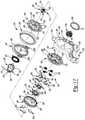
- FIG. 3is an exploded perspective view of a recliner assembly of a seat adjustment mechanism of FIG. 1 ;
- FIG. 4is another exploded perspective view of the recliner assembly of the seat adjustment mechanism of FIG. 3 ;
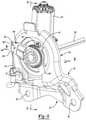
- FIG. 5is a perspective view of the recliner assembly with a recliner heart in a locked state
- FIG. 6is a cross-sectional view of the recliner assembly taken along line 6 - 6 of FIG. 5 ;
- FIG. 7is another cross-sectional view of the recliner assembly taken along line 7 - 7 of FIG. 5 ;
- FIG. 8is another cross-sectional view of the recliner heart in the position of FIG. 5 ;
- FIG. 9is a perspective view of the recliner assembly with the recliner heart in an unlocked and forward dump position
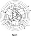
- FIG. 10is a cross-sectional view of the recliner assembly taken along line 10 - 10 of FIG. 9 ;
- FIG. 11is another cross-sectional view of the recliner assembly taken along line 11 - 11 of FIG. 9 ;
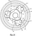
- FIG. 12is a perspective view of the recliner assembly with the recliner heart is an unlocked and forward position
- FIG. 13is cross-sectional view of the recliner assembly taken along line 13 - 13 of FIG. 12 ;
- FIG. 14is a side view of another vehicle seat assembly in an upright position according to the principles of the present disclosure.
- FIG. 15is a side view of the vehicle seat assembly of FIG. 14 with a seatback in a forward dump position;
- FIG. 16is an exploded perspective view of a recliner assembly of a seat adjustment mechanism of FIG. 14 ;
- FIG. 17is another exploded perspective view of the recliner assembly of the seat adjustment mechanism of FIG. 14 ;
- FIG. 18is a perspective view of the recliner assembly with a recliner heart in a locked state
- FIG. 19is a cross-sectional view of the recliner assembly of FIG. 18 ;
- FIG. 20is another cross-sectional view of the recliner assembly of FIG. 18 ;
- FIG. 21is another cross-sectional view of the recliner assembly of FIG. 18 ;
- FIG. 22is a perspective view of the recliner assembly with the recliner heart in an unlocked and forward dump position
- FIG. 23is a cross-sectional view of the recliner assembly of FIG. 22 ;
- FIG. 24is a perspective view of the recliner assembly with the recliner heart is an unlocked and forward dump position
- FIG. 25is another cross-sectional view of the recliner assembly of FIG. 24 ;
- FIG. 26is another cross-sectional view of the recliner assembly of FIG. 24 .
- Example embodimentsare provided so that this disclosure will be thorough, and will fully convey the scope to those who are skilled in the art. Numerous specific details are set forth such as examples of specific components, devices, and methods, to provide a thorough understanding of embodiments of the present disclosure. It will be apparent to those skilled in the art that specific details need not be employed, that example embodiments may be embodied in many different forms and that neither should be construed to limit the scope of the disclosure. In some example embodiments, well-known processes, well-known device structures, and well-known technologies are not described in detail.
- first, second, third, etc.may be used herein to describe various elements, components, regions, layers and/or sections, these elements, components, regions, layers and/or sections should not be limited by these terms. These terms may be only used to distinguish one element, component, region, layer or section from another region, layer or section. Terms such as “first,” “second,” and other numerical terms when used herein do not imply a sequence or order unless clearly indicated by the context. Thus, a first element, component, region, layer or section discussed below could be termed a second element, component, region, layer or section without departing from the teachings of the example embodiments.
- Spatially relative termssuch as “inner,” “outer,” “beneath,” “below,” “lower,” “above,” “upper,” and the like, may be used herein for ease of description to describe one element or feature's relationship to another element(s) or feature(s) as illustrated in the figures. Spatially relative terms may be intended to encompass different orientations of the device in use or operation in addition to the orientation depicted in the figures. For example, if the device in the figures is turned over, elements described as “below” or “beneath” other elements or features would then be oriented “above” the other elements or features. Thus, the example term “below” can encompass both an orientation of above and below. The device may be otherwise oriented (rotated 90 degrees or at other orientations) and the spatially relative descriptors used herein interpreted accordingly.
- a vehicle seat assembly 10is shown.
- the vehicle seat assembly 10may be positioned within a vehicle (not shown) and may include a seatback 11 attached to a seat bottom 12 .
- a seat adjustment mechanism 14may be operatively attached to the vehicle seat assembly 10 and may include a recliner assembly 16 , a cable 18 , and an actuation assembly 20 .
- the recliner assembly 16may be connected to the actuation assembly 20 via the cable 18 and/or one or more links (not shown).
- the recliner assembly 16may also be attached to the seatback 11 and the seat bottom 12 of the vehicle seat assembly 10 .
- the recliner assembly 16may be operable in a locked state preventing relative rotation between the seatback 11 and the seat bottom 12 and an unlocked state permitting relative rotation between the seatback 11 and the seat bottom 12 among an upright position ( FIG. 1 ), a rearward reclined position (not shown) and a forward dump position ( FIG. 2 ).
- the recliner assembly 16may include a housing plate 22 , a recliner heart 24 ( FIGS. 3 and 4 ) and an unlock lever 30 .
- the housing plate 22may be attached to the seat bottom 12 of the vehicle seat assembly 10 .
- the housing plate 22may include a first portion 32 and a second portion 34 .
- the first portion 32may include a plurality of apertures 36 and a tab 38 .
- Fasteners(not shown) may extend through the plurality of apertures 36 to securely attach the housing plate 22 to the seat bottom 12 .
- the tab 38includes a first member 38 a and a second member 38 b that may limit or restrict the rotation of the seatback 11 in the rearward recline position and the forward dump position.
- the tab 38may also define a slot 39 between the first member 38 a and the second member 38 b for mounting a spring (not shown) that provides a torque to return the seatback 11 from the rearward recline position (not shown) to the upright position ( FIG. 1 ).
- the second portion 34may be substantially circular and define an opening 40 in a central portion thereof. As shown in FIGS. 3 and 4 , the second portion 34 may include a tab 43 that is positioned above the opening 40 and extend outwardly from a periphery of the second portion 34 .
- the recliner heart 24may be mounted to the housing plate 22 and may selectively permit relative rotation between the seatback 11 and the seat bottom 12 .
- the recliner heart 24may be a round recliner heart, for example, or any other suitable type of recliner heart.
- the recliner heart 24may include a first locking plate 44 , a second locking plate 45 , a third locking plate 46 , a locking assembly 48 and an encapsulating ring 49 .
- the first locking plate 44may be rotationally fixed relative to the seat bottom 12 and may be attached (e.g., laser welded) to the encapsulating ring 49 ( FIGS. 7 and 11 ). In some configurations, the first locking plate 44 may also be attached to the housing plate 22 .
- the first locking plate 44may be a generally circular shape and may include a main body 52 having a plurality of protrusions 54 ( FIG. 4 ), a spring post 56 , and a central aperture 58 formed therethrough.
- the first protrusions 54may extend from the main body 52 and are generally arcuate in shape.
- the first protrusions 54may cooperate to form a plurality of guide recesses 59 that support at least a portion of the locking assembly 48 .
- the spring post 56may extend from the main body 52 opposite the direction of the protrusions 54 .
- An attachment plate 60may be attached (e.g., laser welded) to and between the seat back frame (not shown) and the second locking plate 45 such that the attachment plate 60 is operatively connected with the seatback 11 . In this way, rotation of the seatback 11 causes corresponding rotation of the attachment plate 60 and the second locking plate 45 .
- the attachment plate 60may include a first opening 61 extending through a center portion thereof, second openings 62 and a pair of wings 63 a , 63 b protruding from a periphery of the attachment plate 60 .
- the locking assembly 48may extend through the first opening 61 .
- the wing 63 acontacts the first member 38 a of the tab 38 when the seatback 11 is in the rearward recline position to limit further rotation of the seatback 11 in the rearward recline position and the wing 63 b contacts the second member 38 b of the tab 38 when the seatback 11 is in the forward dump positon to further limit rotation of the seatback 11 in the forward dump position.
- the second locking plate 45may be a generally circular shape and may include a plate body 64 , a hub 65 ( FIG. 3 ) and a rim 66 .
- the plate body 64may include projections 68 and teeth 69 .
- the projections 68may extend from a surface of the plate body 64 and may be received in respective second openings 62 of the attachment plate 60 ( FIGS. 7 and 11 ), thereby further coupling the second locking plate 45 and the attachment plate 60 .
- the teeth 69may extend 360 degrees around an outer diametrical surface 70 of the plate body 64 .
- the hub 65may extend from a center portion of the plate body 64 in a direction opposite of the projections 68 and may define an opening 71 extending therethrough.
- the rim 66may extend 360 degrees around a periphery of the plate body 64 and may include teeth 72 that extends 360 degrees around an inner diametrical surface 73 of the rim 66 .
- the third locking plate 46may include a generally circular shape and may be disposed between the first and second locking plates 44 , 45 . As shown in FIGS. 4, 7 and 11 , the third locking plate 46 may include an inner section 78 , an intermediate section 80 and an outer section 82 . As shown in FIG. 4 , the inner section 78 may define an opening 84 and may include an outer diametrical surface 86 having teeth 88 formed thereon. At least a portion of the teeth 88 may be meshingly engaged with at least a portion of the teeth 72 of the second locking plate 45 .
- the intermediate section 80may define an opening that has a diameter that is larger than a diameter of the opening of the inner section 78 .
- the outer section 82may define an opening and may include an inner diametrical surface 92 having notches 94 formed therein.
- the locking assembly 48may include a first cam 96 , pawls 98 , a pivot plate 100 , a second cam 102 and wedges 104 .
- the first cam 96may extend through the aperture 58 of the first locking plate 44 and may engage the unlock lever 30 ( FIGS. 7 and 11 ).
- the first cam 96may include a shaft portion 110 and a disk portion 112 .
- the shaft portion 110may engage the unlock lever 30 such that actuation of the actuation assembly 20 rotates the unlock lever 30 and the first cam 96 .
- the shaft portion 110may include radially extending projections 114 that extend through grooves 115 at a periphery of the aperture 58 of the first locking plate 44 .
- the disk portion 112may include a plurality of first cam lobes 117 and a plurality of second cam lobes 119 that may selectively engage the pawls 98 ( FIG. 6 ).
- the pawls 98may be radially disposed around the central aperture 58 of the first locking plate 44 with each pawl 98 slidably mounted in a corresponding guide recess 59 between a secure position ( FIG. 6 ) and a release position ( FIG. 10 ; note seatback 11 is in forward dump position in FIG. 10 ).
- Each pawl 98may include a pair of engagement members 118 , 120 and a locking member 122 formed generally on an opposite end of the pawls 98 relative to the engagement members 118 , 120 .
- a coiled spring 124may be attached to the spring post 56 at one end and received in a groove 126 formed in one of the projections 114 of the shaft portion 110 at another end such that the unlock lever 30 is rotationally biased toward a locked position.
- the coiled spring 124may also engage the shaft portion 110 such that the first cam 96 is rotationally biased in a manner that causes the engagement members 118 to force the pawls 98 outwardly to the secure position ( FIG. 6 ).
- the pivot plate 100may extend through the opening 71 of the second locking plate 45 ( FIGS. 7 and 11 ) and may include a body 128 , a stem portion 130 and an aperture 131 extending through the body 128 and the stem portion 130 .
- the body 128may be a generally circular shape and may have a first aperture 132 , a second aperture 133 and third apertures 134 formed therein.
- a circular shaped partition member 136( FIGS. 3 and 4 ) may be disposed between the body 128 of the pivot plate 100 and the first cam 96 such that rotation of the first cam 96 does not cause rotation of the pivot plate 100 and vice versa.
- the stem portion 130may extend from a center of the body 128 through the opening 71 of the second locking plate 45 .
- a cross rod 135may be received in the aperture 131 of the pivot plate 100 such that the pivot plate 100 is drivingly engaged thereto. In this way, rotation of the cross rod 135 causes corresponding rotation of the pivot plate 100 .
- the second cam 102may be disposed over the hub 65 of the second locking plate 45 and may include a body 138 , an attachment portion 140 and a distal portion 142 .
- the body 138may be circular in shape and may define an aperture 144 that receives the hub 65 of the second locking plate 45 .
- the body 138may have a first portion 145 and a second portion 146 .
- the first portion 145may have a thickness that is greater than a thickness of the second portion 146 of the body 138 .
- Grooves 147may be formed in an inner diametrical surface 148 of the body 138 ( FIGS. 3 and 4 ).
- the attachment portion 140may be rectangular-shaped and may be integrally attached to an outer surface of the second portion 146 of the body 138 .
- the attachment portion 140may include an end that extends through the second aperture 133 of the body 128 ( FIGS. 7 and 11 ) such that the second cam 102 and the pivot plate 100 are rotationally fixed to each other.
- the distal portion 142may be integrally attached to an outer surface of the first portion 145 such that it is 180 degrees opposite the attachment portion 140 .
- wedges 104are disposed between the body 138 and a bushing ring 150 .
- Each wedge 104has a first end that extends into a respective third aperture 134 of the pivot plate 100 .
- Each wedge 104also has a groove 155 that receives a respective end 152 of a spring 153 such that the spring 153 forces the wedges 104 outwardly and away from the distal portion 142 . In this way, the wedges 104 are wedged between the first portion 145 of the body 138 and the busing ring 150 and rotation of the pivot plate 100 and the second cam 102 causes rotation of the wedges 104 .
- the encapsulating ring 49may be attached (e.g., by laser welding) to the first locking plate 44 and the housing plate 22 to hold the recliner heart 24 together and also to cover a periphery of the recliner heart 24 , thereby preventing debris and fluid from infiltrating and damaging the recliner heart 24 .
- the unlock lever 30may engage the cable 18 and the shaft portion 110 of the first cam 96 . Rotation of the unlock lever 30 may rotate the first cam 96 to move the pawls 98 between the secure position and the release position without corresponding rotation of the pivot plate 100 and the second cam 102 .
- the unlock lever 30includes a shaft portion 154 and a lever portion 156 .
- the shaft portion 154may extend at least partially through an opening 158 of the first cam 96 .
- the unlock lever 30may be rotatable relative to the housing plate 22 about a longitudinal axis of the shaft portion 154 .
- the lever portion 156may extend radially outward from the shaft portion 154 and include a radially outer end 160 having an aperture 162 .
- a first end 164 of the cable 18may include a perpendicularly extending engaging member 166 that is securely received in the aperture 162 of the outer end 160 causing the cable 18 and the unlock lever 30 to be engaged.
- the actuation assembly 20may be mounted on the seatback 11 (e.g., at or near an upper end of the seatback) and may be engaged to a second end 168 of the cable 18 ( FIGS. 1 and 2 ). In this way, the actuation assembly 20 may be operably connected to the unlock lever 30 and include an actuation lever 170 and a spring 172 .
- the actuation lever 170may be movable between a lock state and an unlock state which causes corresponding rotation of the unlock lever 30 and the first cam 96 .
- the spring 172may bias the actuation lever 170 toward the lock state.
- the seat adjustment mechanism 14When a passenger (not shown) ingress into or egress out of a space (e.g., a rear seating row) behind the vehicle seat assembly 10 , the passenger may facilitate entry into or departure out of the space by either the actuation lever 170 or an actuation switch 173 .
- a spacee.g., a rear seating row
- the passengermay facilitate entry into or departure out of the space by either the actuation lever 170 or an actuation switch 173 .
- Movement of the actuation lever 170 from the lock state to the unlock statecauses rotation of the unlock lever 30 connected thereto via the cable 18 .
- Rotation of the unlock lever 30rotates the first cam 96 in a way that causes the pawls 98 to slide to the release position (i.e., the locking members 122 of the pawls 98 are disengaged from the notches 94 of the third locking plate 46 ) without causing corresponding rotation of the pivot plate 100 and the second cam 102 .
- the seatback 11may then be rotated in Direction B ( FIG. 1 ), which causes rotation of the second and third locking plates 45 , 46 , the pivot plate 100 and the second cam 102 relative to the first locking plate 44 and the first cam 96 .
- actuation of the actuation switch 173causes a motor 174 to drive the cross bar 135 .
- Thiscauses the pivot plate 100 , the second cam 102 and the wedges 104 to rotate without corresponding rotation of the first cam 96 and the first and third locking plates 44 , 46 .
- Rotation of the pivot plate 100 , the second cam 102 and the wedges 104causes rotation of the second locking plate 45 relative to the first cam 96 and the first and third locking plates 44 , 46 .
- a center point X of the third locking plate 46 and a center point Y of the second locking plate 45are offset ( FIG. 13 ) such that rotation of pivot plate 100 , the second cam 102 and the wedges 104 causes the second locking plate 45 to rotate about the center point X of the third locking plate 46 .
- FIGS. 14-26another seat adjustment mechanism 214 is provided.
- the structure and function of the seat adjustment mechanism 214may be similar or identical to the seat adjustment mechanism 14 described above, apart from any exceptions described below.
- a vehicle seat assembly 210is shown.
- the vehicle seat assembly 210may be positioned within a vehicle (not shown) and may include a seatback 211 attached to a seat bottom 212 .
- the seat adjustment mechanism 214may be operatively attached to the vehicle seat assembly 210 and may include a recliner assembly 216 , a cable 218 , and an actuation assembly 220 .
- the recliner assembly 216may be connected to the actuation assembly 220 via the cable 218 and/or one or more links (not shown).
- the recliner assembly 216may also be attached to the seatback 211 and the seat bottom 212 of the vehicle seat assembly 210 .
- the recliner assembly 216may be operable in a locked state preventing relative rotation between the seatback 211 and the seat bottom 212 and an unlocked state permitting relative rotation between the seatback 211 and the seat bottom 212 among an upright position ( FIG. 14 ), a rearward reclined position (not shown) and a forward dump position ( FIG. 15 ).
- the recliner assembly 216may include a housing plate 222 , a recliner heart 224 ( FIGS. 16 and 17 ), a recliner handle assembly 226 and an unlock lever 230 .
- the housing plate 222may be attached to the seat bottom 212 of the vehicle seat assembly 210 .
- the housing plate 222may include a first portion 232 and a second portion 234 .
- the first portion 232may include a plurality of apertures 236 and a tab 238 ( FIG. 16 ).
- Fasteners(not shown) may extend through the plurality of apertures 236 to securely attach the housing plate 222 to the seat bottom 212 .
- the tab 238includes a first member 238 a and a second member 238 b that may limit or restrict the rotation of the seatback 211 in the rearward recline position and the forward dump position.
- the tab 238may also define a slot 239 between the first member 238 a and the second member 238 b for mounting a spring (not shown) that provides a torque to return the seatback 211 from the rearward recline position (not shown) to the upright position ( FIG. 1 ).
- the second portion 234may be substantially circular and define an opening 240 in a central portion thereof. As shown in FIGS. 16 and 17 , the second portion 234 may include first and second flanges 241 , 242 and a tab 243 .
- the first and second flanges 241 , 242may extend perpendicularly from a periphery of the opening 240 toward each other.
- the tab 243may be positioned above the opening 240 and extend outwardly from a periphery of the second portion 234 .
- the recliner heart 224may be mounted to the housing plate 222 and may selectively permit relative rotation between the seatback 211 and the seat bottom 212 .
- the recliner heart 224may be a round recliner heart, for example, or any other suitable type of recliner heart.
- the recliner heart 224may include a first locking plate 244 , a second locking plate 245 a third locking plate 246 , a locking assembly 248 and an encapsulating ring 249 .
- the first locking plate 244may include a generally circular shape having a main body 252 and a rim 253 .
- the main body 252may include a plurality of first protrusions 254 , a plurality of second protrusions 255 , a spring post 256 , and a central aperture 258 formed therethrough.
- the first protrusions 254may extend from the main body 252 and are generally arcuate in shape.
- the first protrusions 254may cooperate to form a plurality of guide recesses 260 that support at least a portion of the locking assembly 248 .
- the plurality of second protrusions 255may extend from the main body 252 opposite the direction of the first protrusions 254 .
- the spring post 256may also extend from the main body 252 opposite the direction of the first protrusions 254 .
- the rim 253may extend 360 degrees around a periphery of the main body 252 .
- An attachment plate 261may be attached (e.g., laser welded) to and between the seat back frame (not shown) and the first locking plate 244 such that the attachment plate 261 is operatively connected with the seatback 211 . In this way, rotation of the seatback 211 causes corresponding rotation of the attachment plate 261 and the first locking plate 244 .
- the attachment plate 261may include an opening 262 extending through a center portion thereof and a pair of wings 263 a , 263 b protruding from a periphery of the attachment plate 261 .
- the opening 262may have grooves 264 formed at a periphery thereof.
- At least two grooves 264may receive respective second protrusions 255 of the first locking plate 244 once the attachment plate 261 is attached to the first locking plate 244 .
- the wing 263 acontacts the first member 238 a of the tab 238 when the seatback 211 is in the rearward recline position to limit further rotation of the seatback 211 in the rearward recline position and the wing 263 b contacts the second member 238 b of the tab 238 when the seatback 211 is in the forward dump positon to further limit rotation of the seatback 211 in the forward dump position.
- the second locking plate 245may be rotationally fixed relative to the seat bottom 212 and may be attached (e.g., laser welded) to the housing plate 222 and the encapsulating ring 249 ( FIGS. 20 and 26 ).
- the second locking plate 245may include a generally circular shape and may include a plate surface 265 and a rim 266 .
- the plate surface 265may include an aperture 267 , a plurality of first projections 268 and a plurality of second projections 270 . As shown in FIGS. 16 and 17 , the aperture 267 may extend through a center portion of the plate surface 265 .
- the first projections 268may be disposed radially around the aperture 267 and may extend from the plate surface 265 , thereby defining first recesses 274 .
- the second projections 270may extend from the plate surface 265 opposite the direction of the first projections 268 , thereby forming second recesses 276 .
- the first recesses 274 and the second recesses 276are adjacent to each other.
- the rim 266may extend 360 degrees around a periphery of the plate surface 265 and may be attached (e.g., laser welded) to the housing plate 222 and the encapsulating ring 249 .
- the third locking plate 246may include a generally circular shape and may be disposed between the first and second locking plates 244 , 245 .
- the third locking plate 246may include a first section 278 ( FIG. 16 ), a second section 280 ( FIG. 17 ) and a partition 282 .
- the first section 278may define an opening 284 and may include an inner surface 286 having notches 288 formed therein.
- the second section 280may define an opening 290 and may include an inner surface 292 having teeth 294 formed thereon.
- the opening 290includes a diameter that is larger than a diameter of the opening 284 .
- the teeth 294may extend 360 degrees around the inner diametrical surface 292 .
- the partition 282may be circular-shaped and may be disposed between the first section 278 and the second section 280 .
- the partition 282may extend radially inwardly and may define an opening 296 that has a diameter that is smaller than the diameters of the openings 284 , 290 .
- the opening 296may have a rectangular-shaped groove 298 formed at a periphery thereof.
- the locking assembly 248may include a first cam 300 , first and second pawls 302 , 303 , an actuator 304 and a second cam 306 .
- the first cam 300may extend through the aperture 258 of the first locking plate 244 ( FIGS. 20 and 26 ) and may engage the unlock lever 230 .
- the first cam 300may include a shaft portion 310 and a disk portion 312 .
- the shaft portion 310may engage the unlock lever 230 such that actuation of the actuation assembly 220 rotates the unlock lever 230 and the first cam 300 .
- the shaft portion 310may include radially extending projections 313 that extend through grooves 315 at a periphery of the aperture 258 of the first locking plate 244 .
- the disk portion 312may include a plurality of first cam lobes 314 and a plurality of second cam lobes 316 that may selectively engage the first pawls 302 ( FIGS. 19 and 23 ).
- the first pawls 302may be radially disposed around the central aperture 258 of the first locking plate 244 with each first pawl 302 slidably mounted in a corresponding guide recess 260 between a secure position and a release position.
- Each first pawl 302may include a pair of engagement members 318 , 320 and a locking member 322 formed generally on an opposite end of the first pawls 302 relative to the engagement members 318 , 320 .
- a coiled spring 327may be attached to the spring post 256 at one end and attached to the shaft portion 310 at another end such that the unlock lever 230 is rotationally biased toward a locked position.
- the coiled spring 327may also engage the shaft portion 310 such that the first cam 300 is rotationally biased in a manner that causes the engagement members 318 to force the first pawls 302 outwardly to the secure position.
- the second pawls 303may be radially disposed around the aperture 267 of the second locking plate 245 with each second pawl 303 slidably mounted in a corresponding first recess 274 defined by two of the first projections 268 between a secure state and a release state.
- an edge of each second pawl 303may include teeth 330 adapted for meshing engagement with the teeth 294 of the third locking plate 246 .
- the edgemay include a generally arcuate shape to improve engagement between the second pawls 303 and the teeth 294 of the third locking plate 246 when the second pawls 303 are in the secure state.
- a portion of each second pawl 303may include a latch 333 .
- the actuator 304may be engaged with the second cam 306 .
- the actuator 304may include a bushing portion 334 and a generally round disk portion 336 .
- the bushing portion 334may include a plurality of radial latches 338 and a plurality of lobes 340 .
- the radial latches 338may selectively engage the latches 333 of the second pawls 303 to move the second pawls 303 into the release state ( FIG. 25 ).
- the second cam 306may be engaged with the actuator 304 and the recliner handle assembly 226 .
- the second cam 306may include a disk portion 342 and an extrusion 344 extending perpendicularly from the disk portion 342 .
- the disk portion 342may have a plurality of flanges 346 extending therefrom.
- Each flange 346may include a circular projection 348 extending therefrom that is engaged to a corresponding coiled spring 350 disposed in the second recess 276 .
- the second cam 306rotationally biases the actuator 304 in a manner that causes the lobes 340 to force the second pawls 303 outwardly into the secure state (i.e., engaging the teeth 294 of the third locking plate 246 ).
- the encapsulating ring 249may be attached (e.g., by laser welding) to the first locking plate 244 and the housing plate 222 to hold the recliner heart 224 together and also to cover a periphery of the recliner heart 224 , thereby preventing debris and fluid from infiltrating and damaging the recliner heart 224 .
- the recliner handle assembly 226may include a first connecting member 352 , a second connecting member or hub 354 and a recliner handle 356 .
- the first connecting member 352may be attached to the recliner handle 356 and the second connecting member 354 .
- the second connecting member 354may be attached to the second cam 306 and the first connecting member 354 .
- the recliner handle 356may be rotatable between a locked position in which the second pawls 303 are in the secure state and an unlocked position in which the second pawls 303 are in the release state.
- the recliner handle 356may permit rotation of the seatback 211 in Direction A (or Direction B) once the recliner handle 356 is in the unlocked position and the second pawls 303 are in the release state.
- a spring 358is engaged with the second connecting member 354 to bias the recliner handle 356 toward the locked position.
- the unlock lever 230may engage the cable 218 and the shaft portion 310 of the first cam 300 . Rotation of the unlock lever 230 may rotate the first cam 300 to move the first pawls 302 between the secure position and the release position without corresponding rotation of the actuator 304 , the second cam 306 and the recliner handle assembly 226 .
- the unlock lever 230includes a shaft portion 360 and a lever portion 362 .
- the shaft portion 360may extend at least partially through an opening 364 of the first cam 300 .
- the unlock lever 230may be rotatable relative to the housing plate 222 about a longitudinal axis of the shaft portion 360 .
- the lever portion 362may extend radially outward from the shaft portion 360 and include a radially outer end 366 having an aperture 368 .
- a first end 370 of the cable 218may include a perpendicularly extending engaging member 372 that is securely received in the aperture 368 of the outer end 366 causing the cable 218 and the unlock lever to be engaged.
- the actuation assembly 220may be mounted on the seatback 211 (e.g., at or near an upper end of the seatback) and may be engaged to a second end 374 of the cable 218 ( FIGS. 1 and 2 ). In this way, the actuation assembly 220 may be operably connected to the unlock lever 230 and include an actuation lever 376 and a spring 378 .
- the actuation lever 376may be movable between a lock state and an unlock state which causes corresponding rotation of the unlock lever 230 and the first cam 300 .
- the spring 378may bias the actuation lever 376 toward the lock state.
- the seat adjustment mechanism 214When a passenger (not shown) ingress into or egress out of a space (e.g., a rear seating row) behind the vehicle seat assembly 210 , the passenger may facilitate entry into or departure out of the space by either the actuation lever 376 or the recliner handle 356 .
- a spacee.g., a rear seating row
- the passengermay facilitate entry into or departure out of the space by either the actuation lever 376 or the recliner handle 356 .
- Movement of the actuation lever 376 from the lock state to the unlock statecauses rotation of the unlock lever 230 connected thereto via the cable 218 .
- Rotation of the unlock lever 230rotates the first cam 300 in a way that causes the first pawls 302 to slide to the release position (i.e., the locking members 322 of the first pawls 302 are disengaged from the notches 288 of the third locking plate 246 ) without causing corresponding rotation of the actuator 304 , the second cam 306 and the recliner handle assembly 226 .
- rotation of the seatback 211 in Direction Bcauses rotation of the first locking plate 244 relative to the second and third locking plates 245 , 246 , the actuator 304 , the second cam 306 and the recliner handle assembly 226 .
- rotation of the seatback 211causes the first locking plate 244 to rotate relative to the second and third locking plates 245 , 246 , the actuator 304 , the second cam 306 and the recliner handle assembly 226 .
- Rotation of the recliner handle 356 from the locked position to the unlocked positioncauses rotation of the second cam 306 .
- Rotation of the second cam 306rotates the actuator 304 in way that causes the latches 338 to move the second pawls 303 inwardly. This causes the teeth 330 to disengage from the teeth 294 of the third locking plate 246 without causing corresponding rotation of the first cam 300 .
- rotation of the seatback 211causes rotation of the first and third locking plates 244 , 246 , the first cam 300 and the unlock lever 230 relative to the second locking plate 245 , the actuator 304 and the second cam 306 .
Landscapes
- Engineering & Computer Science (AREA)
- Aviation & Aerospace Engineering (AREA)
- Transportation (AREA)
- Mechanical Engineering (AREA)
- Chairs For Special Purposes, Such As Reclining Chairs (AREA)
- Seats For Vehicles (AREA)
Abstract
Description
Claims (23)
Priority Applications (3)
| Application Number | Priority Date | Filing Date | Title |
|---|---|---|---|
| US16/542,369US11260777B2 (en) | 2018-08-29 | 2019-08-16 | Recliner heart for seat recliner assembly |
| DE102019212517.4ADE102019212517A1 (en) | 2018-08-29 | 2019-08-21 | CORE PIECE OF A SEAT BACK MECHANISM FOR A SEAT BACK ARRANGEMENT |
| CN201910801476.8ACN110871716B (en) | 2018-08-29 | 2019-08-28 | Recliner core for seat recliner assembly |
Applications Claiming Priority (2)
| Application Number | Priority Date | Filing Date | Title |
|---|---|---|---|
| US201862724068P | 2018-08-29 | 2018-08-29 | |
| US16/542,369US11260777B2 (en) | 2018-08-29 | 2019-08-16 | Recliner heart for seat recliner assembly |
Publications (2)
| Publication Number | Publication Date |
|---|---|
| US20200070689A1 US20200070689A1 (en) | 2020-03-05 |
| US11260777B2true US11260777B2 (en) | 2022-03-01 |
Family
ID=69527469
Family Applications (1)
| Application Number | Title | Priority Date | Filing Date |
|---|---|---|---|
| US16/542,369Active2039-09-15US11260777B2 (en) | 2018-08-29 | 2019-08-16 | Recliner heart for seat recliner assembly |
Country Status (3)
| Country | Link |
|---|---|
| US (1) | US11260777B2 (en) |
| CN (1) | CN110871716B (en) |
| DE (1) | DE102019212517A1 (en) |
Families Citing this family (14)
| Publication number | Priority date | Publication date | Assignee | Title |
|---|---|---|---|---|
| US10864830B2 (en) | 2018-04-25 | 2020-12-15 | Fisher & Company, Incorporated | Recliner mechanism having welded encapsulating ring |
| US11124093B2 (en) | 2018-08-08 | 2021-09-21 | Fisher & Company, Incorporated | Recliner mechanism for seat assembly and method of manufacturing |
| US11364577B2 (en) | 2019-02-11 | 2022-06-21 | Fisher & Company, Incorporated | Recliner mechanism for seat assembly and method of manufacturing |
| US11845367B2 (en) | 2019-04-18 | 2023-12-19 | Fisher & Company, Incorporated | Recliner heart having lubricant member |
| US11052797B2 (en) | 2019-08-09 | 2021-07-06 | Fisher & Company, Incorporated | Recliner heart for seat assembly |
| US11192473B2 (en) | 2019-08-30 | 2021-12-07 | Fisher & Company, Incorporated | Release handle for recliner mechanism of vehicle seat |
| US11607976B2 (en) | 2020-03-06 | 2023-03-21 | Fisher & Company, Incorporated | Recliner mechanism having bracket |
| CN111546960B (en)* | 2020-06-10 | 2024-11-12 | 江苏全盛座舱技术股份有限公司 | Discontinuous angle adjuster device capable of reducing gap |
| EP4210998A1 (en)* | 2020-09-14 | 2023-07-19 | KEIPER Seating Mechanisms Co., Ltd. | Adjustment fitting for a vehicle seat, and vehicle seat |
| US11766957B2 (en) | 2021-02-16 | 2023-09-26 | Fisher & Company, Incorporated | Release mechanism for seat recliner assembly |
| US11897372B2 (en) | 2021-05-06 | 2024-02-13 | Fisher & Company, Incorporated | Recliner heart having biasing members |
| US12145474B2 (en) | 2021-05-06 | 2024-11-19 | Fisher & Company, Incorporated | Cross rod for vehicle seat recliner assembly |
| US11850975B2 (en) | 2021-06-11 | 2023-12-26 | Fisher & Company, Incorporated | Vehicle seat recliner mechanism with welded spring |
| JP2024055639A (en)* | 2022-10-07 | 2024-04-18 | トヨタ紡織株式会社 | Vehicle seats |
Citations (193)
| Publication number | Priority date | Publication date | Assignee | Title |
|---|---|---|---|---|
| US3736026A (en) | 1970-06-25 | 1973-05-29 | Volkswagenwerk Ag | Device for positioning a seating arrangement especially in motor vehicles |
| US3953069A (en) | 1972-10-25 | 1976-04-27 | Nissan Motor Company Limited | Vehicle seat back tilt control mechanism |
| GB1546104A (en) | 1977-01-12 | 1979-05-16 | Turner Ltd H | Folding seats |
| US4219234A (en) | 1978-09-28 | 1980-08-26 | Fisher Corporation | Reclining and emergency latch mechanism for vehicle seats |
| US4243264A (en) | 1979-03-12 | 1981-01-06 | Fisher Corporation | Reclining seat latch |
| US4279442A (en) | 1980-01-14 | 1981-07-21 | Fisher Corporation | Reclining seat latch |
| US4372610A (en) | 1980-09-25 | 1983-02-08 | Fisher Corporation | Silent seat back recliner mechanism |
| US4457557A (en) | 1981-12-30 | 1984-07-03 | Toshiaki Une | Reclining device for use in a vehicle |
| US4484779A (en) | 1981-07-15 | 1984-11-27 | Aisin Seiki Kabushiki Kaisha | Double folding mechanism for vehicle seats |
| US4579387A (en) | 1984-03-14 | 1986-04-01 | Fisher Dynamics Corporation | Motor vehicle seat hinge |
| US4634182A (en) | 1985-08-09 | 1987-01-06 | P.L. Porter Co. | Seatback recliner mechanism and inertia operated lock |
| US4684174A (en) | 1984-04-20 | 1987-08-04 | Fisher Dynamics Corporation | Quick release mechanism for gear operated seat recliner |
| US4705319A (en) | 1985-07-01 | 1987-11-10 | Fisher Dynamics Corporation | Seat recliner mechanism with spring coil actuator and creep eliminator feature |
| US4720145A (en) | 1984-03-29 | 1988-01-19 | Fisher Dynamics Corporation | Motor vehicle seat hinge |
| US4733912A (en) | 1986-10-30 | 1988-03-29 | Fisher Dynamics Corporation | Inertia sensitive seat hinge mechanism |
| US4747641A (en) | 1987-08-26 | 1988-05-31 | Fisher Dynamics Corporation | Seat recliner mechanism |
| US4795213A (en) | 1985-02-13 | 1989-01-03 | Fisher Dynamics Corporation | Gear operated seat recliner with redundant positioning |
| US4822100A (en) | 1984-07-19 | 1989-04-18 | Fisher Dynamics Corporation | Quick release mechanism for gear operated seat recliner |
| US4919482A (en) | 1987-01-20 | 1990-04-24 | Lear Siegler Seating Corp. | Inertia latch for vehicle seats |
| US4928374A (en) | 1988-06-01 | 1990-05-29 | General Motors Corporation | Method of vehicle seat latch |
| US5007680A (en) | 1988-10-28 | 1991-04-16 | Ikeda Bussan Co., Ltd. | Vehicular seat with seatback inclining mechanism |
| US5044647A (en) | 1989-11-17 | 1991-09-03 | Folio Products, Inc. | Stabilized reclining wheelchair seat |
| US5154476A (en) | 1991-02-21 | 1992-10-13 | Hoover Universal, Inc. | Locking seat recliner |
| US5240309A (en) | 1990-04-23 | 1993-08-31 | Keiper Recaro Gmbh & Co. | Vehicle seat, especially a motor vehicle seat |
| US5248184A (en) | 1991-12-11 | 1993-09-28 | Itt Corporation | Seat back inertia latch and sector system |
| US5265937A (en) | 1992-06-29 | 1993-11-30 | General Motors Corporation | Seat back inertia lock |
| DE4324734A1 (en) | 1993-07-23 | 1995-01-26 | Keiper Recaro Gmbh Co | Hinge fitting for seats with an adjustable backrest, in particular motor vehicle seats |
| US5393116A (en) | 1993-10-25 | 1995-02-28 | General Motors Corporation | Van-type vehicle multi-positional seat |
| US5419616A (en) | 1993-05-03 | 1995-05-30 | Mercedes-Benz Ag | Locking device for a seat back of a motor vehicle seat |
| US5435624A (en) | 1993-10-12 | 1995-07-25 | Ford Motor Company | Powered vehicle seat |
| US5460429A (en) | 1994-01-31 | 1995-10-24 | Fisher Dynamics Corporation | Inertia latch assembly for seat hinge mechanism |
| US5489141A (en) | 1993-07-20 | 1996-02-06 | The C. E. White Co. | Pivotable and slidable storable seat |
| WO1996020848A1 (en) | 1995-01-07 | 1996-07-11 | Tricom Automotive Limited | Seat locking mechanism and seat incorporating same |
| US5577805A (en) | 1995-10-10 | 1996-11-26 | General Motors Corporation | Van-type vehicle seat |
| US5590932A (en) | 1994-11-07 | 1997-01-07 | Fisher Dynamics Corporation | Anti-chuck seat recliner |
| US5622410A (en) | 1994-10-21 | 1997-04-22 | Fisher Dynamics Corporation | Seat recliner for reducing chucking |
| US5628215A (en) | 1995-11-13 | 1997-05-13 | Brown; Hugh | Front seat locking device |
| US5660440A (en) | 1996-02-28 | 1997-08-26 | Fisher Dynamics Corporation | Linear recliner with easy entry memory feature |
| US5718481A (en) | 1995-03-28 | 1998-02-17 | Fisher Dynamics Corporation | Seat recliner mechanism |
| US5769493A (en) | 1996-02-28 | 1998-06-23 | Fisher Dynamics Corporation | Linear recliner with easy entry memory feature |
| US5788330A (en) | 1997-03-27 | 1998-08-04 | Fisher Dynamics Corporation | Seat hinge mechanism with easy entry memory feature |
| US5823622A (en) | 1997-05-08 | 1998-10-20 | Fisher Dynamics Corporation | Linear recliner with memory dump mechanism |
| US5857659A (en) | 1995-12-04 | 1999-01-12 | Tokai Rubber Industries, Ltd. | Mounting component for a cylindrical bushing and a mounting body |
| US5918939A (en) | 1997-03-27 | 1999-07-06 | Fisher Dynamics Corporation | Seat recliner with memory dump mechanism |
| US5927809A (en) | 1996-12-09 | 1999-07-27 | Atoma International, Inc. | Easy entry seat with seat back lockout until full return |
| US5941591A (en) | 1995-09-25 | 1999-08-24 | Chuo Hatsujo Kabushiki Kaisha | Foldable device for a recline seat of an automobile |
| US5947560A (en) | 1998-04-27 | 1999-09-07 | Fisher Dynamics Corporation | Linear recliner with single position memory |
| US5979986A (en) | 1996-02-28 | 1999-11-09 | Fisher Dynamics Corporation | Linear seat recliner with easy entry memory feature |
| US6007152A (en) | 1997-12-02 | 1999-12-28 | Aisin Seiki Kabushiki Kaisha | Seat reclining mechanism for vehicles |
| US6023994A (en) | 1997-08-22 | 2000-02-15 | Ikeda Bussan Co., Ltd, | Double-sided reclining apparatus |
| JP2000084684A (en) | 1998-09-09 | 2000-03-28 | Mitsubishi Electric Corp | Energy beam welding apparatus and energy beam welding method |
| US6047444A (en) | 1998-09-14 | 2000-04-11 | Fisher Dynamics Corporation | Positive lock armrest mechanism |
| US6068341A (en) | 1997-11-24 | 2000-05-30 | Trw Occupant Restraint Systems Gmbh & Co. Kg | Belt retractor for incorporating in a fold-down type backrest |
| US6074009A (en) | 1997-07-24 | 2000-06-13 | Farino; Joseph | Vehicle theft prevention device |
| US6106067A (en) | 1996-07-25 | 2000-08-22 | P.L. Porter Co., | Seat adjustment and dumping mechanism with memory adjustment coordinated with seat positioning |
| US6123380A (en) | 1999-06-11 | 2000-09-26 | Lear Corporation | Automotive seat assembly with folding structural supports for storage in a foot well for an automotive vehicle body |
| US6139104A (en) | 1999-01-29 | 2000-10-31 | Johnson Controls Technology Company | Multiple function seat back adjusting mechanism |
| US6161899A (en) | 1998-08-18 | 2000-12-19 | Fisher Dynamics Corporation | Seatback latch mechanism with locking pin |
| EP1074426A2 (en) | 1999-08-02 | 2001-02-07 | Araco Kabushiki Kaisha | Reclining mechanism for vehicle seat |
| US6199953B1 (en) | 1999-05-18 | 2001-03-13 | Fisher Dynamics Corporation | Sector recliner with single position memory |
| US6250704B1 (en) | 1999-08-12 | 2001-06-26 | Dura Automotive Systems Inc. | Release mechanism for fold and flip seat assembly |
| US6290297B1 (en) | 1998-08-18 | 2001-09-18 | Fisher Dynamics Corporation | Latch assembly and seat hinge with interlock |
| US6328381B1 (en) | 1997-04-08 | 2001-12-11 | Bertrand Faure Components Ltd. | Single control handle release mechanism for use with a vehicle seat |
| US6345867B1 (en) | 2000-06-02 | 2002-02-12 | Fisher Dynamics Corporation | Seat recliner and floor latch with interlock |
| US20020043852A1 (en) | 2000-10-13 | 2002-04-18 | Araco Kabushiki Kaisha | Reclining device for a seat |
| US6447066B1 (en) | 1999-07-08 | 2002-09-10 | Grupo Antolin-Ingenieria, S.A. | Device for adjusting a double-jointed seatback |
| US6511129B1 (en) | 2001-06-05 | 2003-01-28 | Fisher Dynamics Corporation | Folding seat hinge assembly with lift and push handle activation |
| US6533357B2 (en) | 2001-04-03 | 2003-03-18 | Fisher Dynamics Corporation | Dual-cam seat-hinge assembly |
| US6550864B1 (en) | 1998-08-18 | 2003-04-22 | Fisher Dynamics Corporation | Seatback latch mechanism with pivoting locking pin |
| US6554362B1 (en) | 2001-04-03 | 2003-04-29 | Fisher Dynamics Corporation | Manual fold-flat seat hinge assembly |
| US20030127898A1 (en) | 2001-12-25 | 2003-07-10 | Naoki Niimi | Seat device |
| US6634713B2 (en) | 2000-12-12 | 2003-10-21 | Nhk Spring Co., Ltd. | Reclining apparatus |
| CN1457306A (en) | 2001-02-06 | 2003-11-19 | 凯波两合公司 | Fitting for vehicle seat |
| US20030230923A1 (en)* | 2000-10-13 | 2003-12-18 | Araco Kabushiki Kaisha | Reclining device for a seat |
| US6669299B2 (en) | 2001-04-03 | 2003-12-30 | Fisher Dynamics Corporation | Fold-flat seat hinge assembly |
| US6669296B2 (en) | 2001-07-19 | 2003-12-30 | Aisin Seiki Kabushiki Kaisha | Seat reclining device |
| US6698837B2 (en) | 2001-11-30 | 2004-03-02 | Fisher Dynamics Corproration | Seat assembly with integrated recliner and floor-latch mechanism |
| US6740845B2 (en) | 2002-05-24 | 2004-05-25 | Alcoa Inc. | Laser welding with beam oscillation |
| US20040134055A1 (en) | 2002-10-31 | 2004-07-15 | Jiro Aizaki | Methods and apparatus for adjusting clearance |
| US20050029806A1 (en) | 2003-08-07 | 2005-02-10 | Satoru Yamanashi | Pipe joint structure and manufacturing method thereof |
| US6854802B2 (en) | 2002-10-01 | 2005-02-15 | Fujikiko Kabushiki Kaisha | Seat recliner for vehicle |
| US6857703B2 (en) | 2002-11-05 | 2005-02-22 | Fisher Dynamics Corporation | Fold, tumble and kneel seat assembly |
| US6860562B2 (en) | 2002-11-05 | 2005-03-01 | Fisher Dynamics Corporation | Fold, tumble, and kneel seat assembly |
| US6869143B2 (en) | 2003-04-01 | 2005-03-22 | Bae Industries, Inc. | Recliner clutch mechanism for vehicle seat |
| US6908156B1 (en) | 2003-02-18 | 2005-06-21 | Yoon Young Co., Ltd. | Round recliner for vehicle |
| US20050253439A1 (en) | 2004-04-30 | 2005-11-17 | Kazutaka Sasaki | Reclining mechanism of a reclining seat |
| US20060006718A1 (en) | 2004-07-07 | 2006-01-12 | Kiyonori Umezaki | Recliner adjuster for a seat |
| US20060012232A1 (en) | 2004-07-15 | 2006-01-19 | Coughlin Craig G | Round recliner with sliding pin mechanism |
| US20060055223A1 (en) | 2003-04-03 | 2006-03-16 | Keiper Gmbh & Co. Kg | Fitting system for a vehicle seat |
| US7025422B2 (en) | 2004-03-11 | 2006-04-11 | Fisher Dynamics Corporation | Round recliner assembly with rear folding latch |
| KR100601809B1 (en) | 2005-12-21 | 2006-07-19 | 주식회사 오스템 | Folding recliner of car seat |
| US20060170269A1 (en) | 2004-12-28 | 2006-08-03 | Yasukazu Oki | Recliner adjuster |
| US7093901B2 (en) | 2001-08-27 | 2006-08-22 | Aisin Seiki Kabushiki Kaisha | Seat frame of a vehicle seat |
| US7097253B2 (en) | 2004-03-11 | 2006-08-29 | Fisher Dynamics Corporation | Round recliner assembly with rear folding latch |
| US7100987B2 (en) | 2004-08-31 | 2006-09-05 | Dura Global Technologies, Inc. | Reclining vehicle seat hinge assembly |
| CN1840382A (en) | 2005-04-01 | 2006-10-04 | 富尔夏汽车座椅股份有限公司 | Pivot mechanism, method for manufacturing it, and vehicle seat incorporating the mechanism |
| US7121624B2 (en) | 2005-01-13 | 2006-10-17 | Fisher Dynamics Corporation | Seat assembly having manual tumble with interlock and powered recline, fold and kneel |
| US7154065B2 (en) | 2002-05-24 | 2006-12-26 | Alcon Inc. | Laser-hybrid welding with beam oscillation |
| US7152924B1 (en) | 2006-04-28 | 2006-12-26 | Tachi-S Co., Ltd. | Unlocking mechanism of reclining device for seat |
| US7172253B2 (en) | 2004-11-24 | 2007-02-06 | Faurecia Autositze Gmbh & Co. Kg | Vehicle seat |
| US7198330B2 (en) | 2003-08-06 | 2007-04-03 | Keiper Gmbh & Co. Kg | Fitting for a vehicle seat |
| US20070200408A1 (en) | 2006-02-28 | 2007-08-30 | Fuji Kiko Co., Ltd. | Seat reclining apparatus for vehicle |
| US7293838B2 (en) | 2005-02-14 | 2007-11-13 | Toyota Shatai Kabushiki Kaisha | Seat for vehicle |
| US7296857B2 (en) | 2002-07-05 | 2007-11-20 | Ts Tech Co., Ltd. | Vehicle seat reclining device |
| US7300109B2 (en) | 2002-09-27 | 2007-11-27 | Brose Fahrzeugteile Gmbh & Co. Kg, Coburg | Seat assembly for a motor vehicle seat |
| US7306286B2 (en) | 2005-02-10 | 2007-12-11 | Chrysler Llc | Hold-open assembly for a recliner seat locking mechanism |
| US20080001458A1 (en) | 2004-07-28 | 2008-01-03 | Aisin Seiki Kabushiki Kaisha | Seat Reclining Apparatus |
| KR100817000B1 (en) | 2006-11-23 | 2008-03-27 | (주)케이엠앤아이 | Foldable Car Recliner |
| US7360838B2 (en) | 2005-03-03 | 2008-04-22 | Faurecia Automotive Seating Canada Limited | Rotary recliner mechanism for use with a vehicle seat assembly |
| US20080164741A1 (en) | 2005-01-27 | 2008-07-10 | Delta Tooling Co., Ltd. | Reclining Adjuster |
| DE102007002366B3 (en) | 2007-01-13 | 2008-07-17 | Keiper Gmbh & Co.Kg | Fitting system for a vehicle seat |
| US7419217B2 (en) | 2006-01-12 | 2008-09-02 | Tachi-S Co. Ltd. | Reclining device of two-point hinged type for seat |
| US7458639B2 (en)* | 2004-10-14 | 2008-12-02 | Keiper Gmbh & Co. Kg | Fitting for a vehicle seat |
| US7490907B2 (en) | 2005-08-05 | 2009-02-17 | Aisin Seiki Kabushiki Kaisha | Seat for vehicle |
| US20090056124A1 (en) | 2007-08-30 | 2009-03-05 | Micropump, Inc., A Unit Of Idex Corporation | Methods for manufacturing pump-heads having a desired internal clearance for rotary member |
| US7503099B2 (en) | 2005-10-25 | 2009-03-17 | Fisher Dynamics Corporation | Memory mechanism for an adjustment mechanism |
| US20090072602A1 (en) | 2006-05-19 | 2009-03-19 | Keiper Gmbh & Co. Kg | Motor-driven actuator for a vehicle seat |
| KR20090035633A (en) | 2006-08-03 | 2009-04-09 | 존슨 컨트롤스 테크놀러지 컴퍼니 | Recliner Mechanism |
| US7527336B2 (en) | 2003-03-19 | 2009-05-05 | Johnson Controls Technology Company | Recliner mechanism |
| US7578556B2 (en) | 2005-11-01 | 2009-08-25 | Fuji Kiko Co., Ltd. | Seat reclining apparatus |
| US7604297B2 (en) | 2004-10-01 | 2009-10-20 | Johnson Controls Gmbh | Adjusting mechanism and vehicle seat |
| DE102008026176A1 (en) | 2008-05-28 | 2009-12-03 | Keiper Gmbh & Co. Kg | Fitting system for a vehicle seat |
| DE102008029438A1 (en) | 2008-06-16 | 2009-12-17 | Keiper Gmbh & Co. Kg | Fitting for a vehicle seat |
| CN101616820A (en) | 2007-02-21 | 2009-12-30 | 凯波有限责任两合公司 | Accessories for saddles |
| US20100072802A1 (en) | 2008-09-23 | 2010-03-25 | Keiper Gmbh & Co. Kg | Fitting for a vehicle seat |
| US7695068B2 (en) | 2007-03-29 | 2010-04-13 | Aisin Seiki Kabushiki Kaisha | Seat reclining apparatus for vehicle |
| US20100096896A1 (en) | 2008-10-20 | 2010-04-22 | Masaaki Nonomiya | Seat back frame structure of seat for vehicle and seat for vehicle with seat back frame structure |
| US20100231021A1 (en) | 2007-01-24 | 2010-09-16 | Myers Timothy S | Vehicle seat |
| US20100308635A1 (en) | 2008-01-24 | 2010-12-09 | Tame Omar D | Full memory i-disk |
| US20100320823A1 (en) | 2008-08-18 | 2010-12-23 | Peter Thiel | Arrangement for a vehicle seat |
| US20110068612A1 (en) | 2008-02-08 | 2011-03-24 | Peter Thiel | Fitting for a vehicle seat |
| US20110127814A1 (en) | 2008-02-08 | 2011-06-02 | Peter Thiel | Locking device, in particular for a vehicle seat |
| WO2011069107A2 (en) | 2009-12-04 | 2011-06-09 | Fisher & Company, Incorporated | Seat mechanism with easy-entry feature |
| US7976103B2 (en) | 2008-09-23 | 2011-07-12 | Lear Corporation | Seat assembly having a switch and method of operation |
| US20110227386A1 (en) | 2010-03-17 | 2011-09-22 | Fisher & Company, Incorporated | Recliner mechanism with mounting feature |
| US8052215B2 (en) | 2008-05-08 | 2011-11-08 | Aisin Seiki Kabushiki Kaisha | Seat reclining apparatus for vehicle |
| US20120086253A1 (en) | 2010-10-06 | 2012-04-12 | Lear Corporation | Synchronizer for manual recliner |
| DE102011108976A1 (en) | 2011-07-26 | 2013-01-31 | Keiper Gmbh & Co. Kg | A method of manufacturing a bearing assembly and fitting for a vehicle seat having a bearing assembly made hereafter |
| CN103025568A (en) | 2010-09-22 | 2013-04-03 | 凯波有限责任两合公司 | Fitting for a vehicle seat |
| US20130161995A1 (en) | 2011-01-14 | 2013-06-27 | Aisin Seiki Kabushiki Kaisha | Seat reclining device and seat device |
| US20130207434A1 (en) | 2010-08-20 | 2013-08-15 | Keiper Gmbh & Co Kg | Fitting for a vehicle seat |
| JP5290789B2 (en) | 2009-01-30 | 2013-09-18 | 富士機工株式会社 | Vehicle seat reclining device |
| US20130270884A1 (en) | 2012-04-11 | 2013-10-17 | Fisher & Company, Incorporated | Recliner mechanism with dump feature |
| CA2869816A1 (en)* | 2012-04-12 | 2013-10-17 | Magna Seating Inc. | Quick adjust continuously engaged recliner |
| DE102012008940A1 (en) | 2012-05-08 | 2013-11-14 | Fraunhofer-Gesellschaft zur Förderung der angewandten Forschung e.V. | Method and device for joining at least two workpieces |
| US20140001807A1 (en)* | 2012-06-27 | 2014-01-02 | Lear Corporation | Recliner mechanism |
| KR20140001651A (en) | 2012-06-28 | 2014-01-07 | 주식회사다스 | Recliner of vehicle seet |
| CN103702860A (en) | 2011-09-08 | 2014-04-02 | 麦格纳座椅公司 | Quick Adjust Continuous Engagement Recliner |
| US20140091607A1 (en) | 2012-10-02 | 2014-04-03 | Shiroki Corporation | Seat reclining apparatus |
| US20140138998A1 (en) | 2011-07-01 | 2014-05-22 | Keiper Gmbh & Co. Kg | Fitting system for a vehicle seat |
| US20140159458A1 (en) | 2011-08-24 | 2014-06-12 | Hubei Aviation Precision Machinery Technology Co., | Seat angle adjustment device and seat having the same |
| KR101420164B1 (en) | 2014-02-21 | 2014-07-17 | 대원정밀공업(주) | Recliner with improved structure for preventing gap and good assembly capacity |
| JP5555969B2 (en) | 2008-01-17 | 2014-07-23 | フィッシャー・ダイナミクス・コーポレイション | Circular reclining mechanism |
| US20140239691A1 (en) | 2013-02-26 | 2014-08-28 | Fisher & Company, Incorporated | Recliner mechanism with backdriving feature |
| US20150015044A1 (en) | 2012-05-22 | 2015-01-15 | Johnson Controls Components Gmbh & Co. Kg | Fitting for a vehicle seat and vehicle seat |
| US20150091354A1 (en) | 2013-09-30 | 2015-04-02 | Toyota Boshoku Kabushiki Kaisha | Recliner |
| US20150123444A1 (en) | 2011-03-04 | 2015-05-07 | Keiper Gmbh & Co. Kg | Fitting for vehicle seat |
| US9108541B2 (en) | 2010-06-22 | 2015-08-18 | Keiper Gmbh & Co. Kg | Recliner system for a vehicle seat |
| US20150266398A1 (en) | 2012-09-18 | 2015-09-24 | Shiroki Corporation | Seat reclining apparatus |
| US20150306986A1 (en) | 2012-12-05 | 2015-10-29 | Faurecia Sieges D'automobile | Hinging assembly for a vehicle seat |
| US20150321585A1 (en)* | 2014-05-12 | 2015-11-12 | Lear Corporation | Recliner Mechanism |
| CN105189196A (en) | 2013-03-22 | 2015-12-23 | 爱信精机株式会社 | Seat reclining device for vehicles |
| US9227532B2 (en) | 2011-07-22 | 2016-01-05 | C. Rob. Hammerstein Gmbh & Co. Kg | Seat fitting for a motor vehicle seat |
| CN205097989U (en) | 2014-06-11 | 2016-03-23 | 费舍尔和同伴有限公司 | Breech lock mechanism and have seat subassembly of this breech lock mechanism with lock -in feature |
| CN205130981U (en) | 2014-10-20 | 2016-04-06 | 李尔公司 | Seat subassembly with breech lock mechanism |
| KR101655777B1 (en) | 2015-09-11 | 2016-09-23 | 주식회사 오스템 | Recliner for vehicle seat |
| US20160339810A1 (en) | 2014-01-10 | 2016-11-24 | Johnson Controls Components Gmbh & Co. Kg | Vehicle seat |
| US9527410B2 (en)* | 2014-03-03 | 2016-12-27 | Faurecia Sieges D'automobiles | Hinge mechanism and vehicle seat comprising such a mechanism |
| US9527419B2 (en) | 2014-03-31 | 2016-12-27 | Ford Global Technologies, Llc | Vehicle seating assembly with manual cushion tilt |
| US9555725B2 (en) | 2012-07-31 | 2017-01-31 | Johnson Controls Gmbh | Adjustable vehicle seat |
| US20170037945A1 (en) | 2015-08-07 | 2017-02-09 | Shiroki Corporation | Reclining device |
| US20170080828A1 (en) | 2015-09-22 | 2017-03-23 | Ford Global Technologies, Llc | Ball bearing application for seat recliner disk mechanisms |
| US20170088021A1 (en) | 2015-09-30 | 2017-03-30 | Aisin Seiki Kabushiki Kaisha | Seat reclining device |
| US20170136921A1 (en) | 2014-07-03 | 2017-05-18 | Johnson Controls Components Gmbh & Co. Kg | Backrest adjuster for a seat, and vehicle seat |
| US9701222B2 (en) | 2014-04-25 | 2017-07-11 | Toyota Boshoku Kabushiki Kaisha | Vehicle seat and method for manufacturing the same |
| US9731633B2 (en)* | 2015-07-21 | 2017-08-15 | Lear Corporation | Recliner mechanism |
| US9751432B2 (en) | 2013-04-05 | 2017-09-05 | Johnson Controls Components Gmbh & Co. Kg | Fitting system for a vehicle seat and vehicle seat |
| US9873357B1 (en)* | 2017-01-03 | 2018-01-23 | Lear Corporation | Recliner mechanism |
| US9889774B2 (en) | 2015-08-07 | 2018-02-13 | Fisher & Company, Incorporated | Release mechanism for seat recliner assembly |
| US20180056819A1 (en) | 2016-08-29 | 2018-03-01 | Fisher & Company, Incorporated | Seat Recliner Assembly With Hollow Cross Member |
| US20180103760A1 (en) | 2015-09-13 | 2018-04-19 | Delta Kogyo Co., Ltd. | Seat reclining device and seat |
| US10279709B2 (en) | 2016-05-23 | 2019-05-07 | Toyota Boshoku Kabushiki Kaisha | Recliner |
| US20190255979A1 (en) | 2018-02-22 | 2019-08-22 | Lear Corporation | Recliner retention ring and method of making the same |
| US20190329674A1 (en) | 2018-04-25 | 2019-10-31 | Fisher & Company, Incorporated | Recliner Mechanism Having Welded Encapsulating Ring |
| US20190337424A1 (en) | 2018-05-02 | 2019-11-07 | Hyundai Transys Incorporated | Seat recliner for vehicle |
| US20190358694A1 (en) | 2018-05-23 | 2019-11-28 | Toyota Boshoku Kabushiki Kaisha | Forming method of disk-shaped member |
| US20200047644A1 (en) | 2018-08-08 | 2020-02-13 | Fisher & Company, Incorporated | Recliner Mechanism For Seat Assembly And Method Of Manufacturing |
| US10610018B1 (en) | 2018-11-13 | 2020-04-07 | Lear Corporation | Dual cam recliner mechanism |
| US20200253380A1 (en) | 2019-02-11 | 2020-08-13 | Fisher & Company, Incorporated | Recliner Mechanism For Seat Assembly And Method Of Manufacturing |
| US20200282879A1 (en) | 2019-03-06 | 2020-09-10 | Fisher & Company, Incorporated | Recliner Heart For Seat Assembly |
| US20200331367A1 (en) | 2019-04-18 | 2020-10-22 | Fisher & Company, Incorporated | Recliner Heart Having Lubricant Member |
| CN112339625A (en) | 2019-08-09 | 2021-02-09 | 费舍尔和同伴有限公司 | Recliner core for seat assembly |
| US20210061139A1 (en) | 2019-08-30 | 2021-03-04 | Fisher & Company, Incorporated | Release Handle For Recliner Mechanism Of Vehicle Seat |
Family Cites Families (4)
| Publication number | Priority date | Publication date | Assignee | Title |
|---|---|---|---|---|
| US6883869B2 (en)* | 2003-03-10 | 2005-04-26 | Porter Group, Llc | Vehicle seat back recliner |
| DE102011078216A1 (en)* | 2011-06-28 | 2013-01-03 | Lear Corporation | Seat adjustment device with double cams |
| US8864234B2 (en)* | 2012-05-30 | 2014-10-21 | Lear Corporation | Discontinuous recliner with movable internal memory stop |
| CN105050453B (en)* | 2013-03-18 | 2017-07-07 | 麦格纳座椅公司 | Disc recliner with tapered pin cam face |
- 2019
- 2019-08-16USUS16/542,369patent/US11260777B2/enactiveActive
- 2019-08-21DEDE102019212517.4Apatent/DE102019212517A1/enactivePending
- 2019-08-28CNCN201910801476.8Apatent/CN110871716B/ennot_activeExpired - Fee Related
Patent Citations (226)
| Publication number | Priority date | Publication date | Assignee | Title |
|---|---|---|---|---|
| US3736026A (en) | 1970-06-25 | 1973-05-29 | Volkswagenwerk Ag | Device for positioning a seating arrangement especially in motor vehicles |
| US3953069A (en) | 1972-10-25 | 1976-04-27 | Nissan Motor Company Limited | Vehicle seat back tilt control mechanism |
| GB1546104A (en) | 1977-01-12 | 1979-05-16 | Turner Ltd H | Folding seats |
| US4219234A (en) | 1978-09-28 | 1980-08-26 | Fisher Corporation | Reclining and emergency latch mechanism for vehicle seats |
| US4243264A (en) | 1979-03-12 | 1981-01-06 | Fisher Corporation | Reclining seat latch |
| US4279442A (en) | 1980-01-14 | 1981-07-21 | Fisher Corporation | Reclining seat latch |
| US4372610A (en) | 1980-09-25 | 1983-02-08 | Fisher Corporation | Silent seat back recliner mechanism |
| US4484779A (en) | 1981-07-15 | 1984-11-27 | Aisin Seiki Kabushiki Kaisha | Double folding mechanism for vehicle seats |
| US4457557A (en) | 1981-12-30 | 1984-07-03 | Toshiaki Une | Reclining device for use in a vehicle |
| US4579387A (en) | 1984-03-14 | 1986-04-01 | Fisher Dynamics Corporation | Motor vehicle seat hinge |
| US4720145A (en) | 1984-03-29 | 1988-01-19 | Fisher Dynamics Corporation | Motor vehicle seat hinge |
| US4684174A (en) | 1984-04-20 | 1987-08-04 | Fisher Dynamics Corporation | Quick release mechanism for gear operated seat recliner |
| US4822100A (en) | 1984-07-19 | 1989-04-18 | Fisher Dynamics Corporation | Quick release mechanism for gear operated seat recliner |
| US4795213A (en) | 1985-02-13 | 1989-01-03 | Fisher Dynamics Corporation | Gear operated seat recliner with redundant positioning |
| US4705319A (en) | 1985-07-01 | 1987-11-10 | Fisher Dynamics Corporation | Seat recliner mechanism with spring coil actuator and creep eliminator feature |
| US4634182A (en) | 1985-08-09 | 1987-01-06 | P.L. Porter Co. | Seatback recliner mechanism and inertia operated lock |
| US4733912A (en) | 1986-10-30 | 1988-03-29 | Fisher Dynamics Corporation | Inertia sensitive seat hinge mechanism |
| US4919482A (en) | 1987-01-20 | 1990-04-24 | Lear Siegler Seating Corp. | Inertia latch for vehicle seats |
| US4747641A (en) | 1987-08-26 | 1988-05-31 | Fisher Dynamics Corporation | Seat recliner mechanism |
| US4928374A (en) | 1988-06-01 | 1990-05-29 | General Motors Corporation | Method of vehicle seat latch |
| US5007680A (en) | 1988-10-28 | 1991-04-16 | Ikeda Bussan Co., Ltd. | Vehicular seat with seatback inclining mechanism |
| US5044647A (en) | 1989-11-17 | 1991-09-03 | Folio Products, Inc. | Stabilized reclining wheelchair seat |
| US5240309A (en) | 1990-04-23 | 1993-08-31 | Keiper Recaro Gmbh & Co. | Vehicle seat, especially a motor vehicle seat |
| US5154476A (en) | 1991-02-21 | 1992-10-13 | Hoover Universal, Inc. | Locking seat recliner |
| US5248184A (en) | 1991-12-11 | 1993-09-28 | Itt Corporation | Seat back inertia latch and sector system |
| US5265937A (en) | 1992-06-29 | 1993-11-30 | General Motors Corporation | Seat back inertia lock |
| US5419616A (en) | 1993-05-03 | 1995-05-30 | Mercedes-Benz Ag | Locking device for a seat back of a motor vehicle seat |
| US5489141A (en) | 1993-07-20 | 1996-02-06 | The C. E. White Co. | Pivotable and slidable storable seat |
| DE4324734A1 (en) | 1993-07-23 | 1995-01-26 | Keiper Recaro Gmbh Co | Hinge fitting for seats with an adjustable backrest, in particular motor vehicle seats |
| US5435624A (en) | 1993-10-12 | 1995-07-25 | Ford Motor Company | Powered vehicle seat |
| US5393116A (en) | 1993-10-25 | 1995-02-28 | General Motors Corporation | Van-type vehicle multi-positional seat |
| US5460429A (en) | 1994-01-31 | 1995-10-24 | Fisher Dynamics Corporation | Inertia latch assembly for seat hinge mechanism |
| US5622410A (en) | 1994-10-21 | 1997-04-22 | Fisher Dynamics Corporation | Seat recliner for reducing chucking |
| US5590932A (en) | 1994-11-07 | 1997-01-07 | Fisher Dynamics Corporation | Anti-chuck seat recliner |
| WO1996020848A1 (en) | 1995-01-07 | 1996-07-11 | Tricom Automotive Limited | Seat locking mechanism and seat incorporating same |
| US5718481A (en) | 1995-03-28 | 1998-02-17 | Fisher Dynamics Corporation | Seat recliner mechanism |
| US6158800A (en) | 1995-09-25 | 2000-12-12 | Chuo Hatsujo Kabushiki Kaisha | Foldable device for a recline seat of an automobile |
| US5941591A (en) | 1995-09-25 | 1999-08-24 | Chuo Hatsujo Kabushiki Kaisha | Foldable device for a recline seat of an automobile |
| US5577805A (en) | 1995-10-10 | 1996-11-26 | General Motors Corporation | Van-type vehicle seat |
| US5628215A (en) | 1995-11-13 | 1997-05-13 | Brown; Hugh | Front seat locking device |
| US5857659A (en) | 1995-12-04 | 1999-01-12 | Tokai Rubber Industries, Ltd. | Mounting component for a cylindrical bushing and a mounting body |
| US5769493A (en) | 1996-02-28 | 1998-06-23 | Fisher Dynamics Corporation | Linear recliner with easy entry memory feature |
| US5979986A (en) | 1996-02-28 | 1999-11-09 | Fisher Dynamics Corporation | Linear seat recliner with easy entry memory feature |
| US5660440A (en) | 1996-02-28 | 1997-08-26 | Fisher Dynamics Corporation | Linear recliner with easy entry memory feature |
| US6106067A (en) | 1996-07-25 | 2000-08-22 | P.L. Porter Co., | Seat adjustment and dumping mechanism with memory adjustment coordinated with seat positioning |
| US5927809A (en) | 1996-12-09 | 1999-07-27 | Atoma International, Inc. | Easy entry seat with seat back lockout until full return |
| US5918939A (en) | 1997-03-27 | 1999-07-06 | Fisher Dynamics Corporation | Seat recliner with memory dump mechanism |
| US5788330A (en) | 1997-03-27 | 1998-08-04 | Fisher Dynamics Corporation | Seat hinge mechanism with easy entry memory feature |
| US6095609A (en) | 1997-03-27 | 2000-08-01 | Fisher Dynamics Corporation | Seat recliner with memory dump mechanism |
| US6328381B1 (en) | 1997-04-08 | 2001-12-11 | Bertrand Faure Components Ltd. | Single control handle release mechanism for use with a vehicle seat |
| US5823622A (en) | 1997-05-08 | 1998-10-20 | Fisher Dynamics Corporation | Linear recliner with memory dump mechanism |
| US6074009A (en) | 1997-07-24 | 2000-06-13 | Farino; Joseph | Vehicle theft prevention device |
| US6023994A (en) | 1997-08-22 | 2000-02-15 | Ikeda Bussan Co., Ltd, | Double-sided reclining apparatus |
| US6068341A (en) | 1997-11-24 | 2000-05-30 | Trw Occupant Restraint Systems Gmbh & Co. Kg | Belt retractor for incorporating in a fold-down type backrest |
| US6007152A (en) | 1997-12-02 | 1999-12-28 | Aisin Seiki Kabushiki Kaisha | Seat reclining mechanism for vehicles |
| US5947560A (en) | 1998-04-27 | 1999-09-07 | Fisher Dynamics Corporation | Linear recliner with single position memory |
| US6550864B1 (en) | 1998-08-18 | 2003-04-22 | Fisher Dynamics Corporation | Seatback latch mechanism with pivoting locking pin |
| US6290297B1 (en) | 1998-08-18 | 2001-09-18 | Fisher Dynamics Corporation | Latch assembly and seat hinge with interlock |
| US6161899A (en) | 1998-08-18 | 2000-12-19 | Fisher Dynamics Corporation | Seatback latch mechanism with locking pin |
| JP2000084684A (en) | 1998-09-09 | 2000-03-28 | Mitsubishi Electric Corp | Energy beam welding apparatus and energy beam welding method |
| US6047444A (en) | 1998-09-14 | 2000-04-11 | Fisher Dynamics Corporation | Positive lock armrest mechanism |
| US6139104A (en) | 1999-01-29 | 2000-10-31 | Johnson Controls Technology Company | Multiple function seat back adjusting mechanism |
| US6199953B1 (en) | 1999-05-18 | 2001-03-13 | Fisher Dynamics Corporation | Sector recliner with single position memory |
| US6123380A (en) | 1999-06-11 | 2000-09-26 | Lear Corporation | Automotive seat assembly with folding structural supports for storage in a foot well for an automotive vehicle body |
| US6447066B1 (en) | 1999-07-08 | 2002-09-10 | Grupo Antolin-Ingenieria, S.A. | Device for adjusting a double-jointed seatback |
| CN1291566A (en) | 1999-08-02 | 2001-04-18 | 亚乐克株式会社 | Seat back inclining mechanism for vehicle |
| EP1074426A2 (en) | 1999-08-02 | 2001-02-07 | Araco Kabushiki Kaisha | Reclining mechanism for vehicle seat |
| US6250704B1 (en) | 1999-08-12 | 2001-06-26 | Dura Automotive Systems Inc. | Release mechanism for fold and flip seat assembly |
| US6345867B1 (en) | 2000-06-02 | 2002-02-12 | Fisher Dynamics Corporation | Seat recliner and floor latch with interlock |
| JP2002119349A (en) | 2000-10-13 | 2002-04-23 | Araco Corp | Reclining device |
| US20020043852A1 (en) | 2000-10-13 | 2002-04-18 | Araco Kabushiki Kaisha | Reclining device for a seat |
| US20030230923A1 (en)* | 2000-10-13 | 2003-12-18 | Araco Kabushiki Kaisha | Reclining device for a seat |
| US6758525B2 (en) | 2000-10-13 | 2004-07-06 | Araco Kabushiki Kaisha | Reclining device for a seat |
| US6634713B2 (en) | 2000-12-12 | 2003-10-21 | Nhk Spring Co., Ltd. | Reclining apparatus |
| CN1457306A (en) | 2001-02-06 | 2003-11-19 | 凯波两合公司 | Fitting for vehicle seat |
| US6554362B1 (en) | 2001-04-03 | 2003-04-29 | Fisher Dynamics Corporation | Manual fold-flat seat hinge assembly |
| US6533357B2 (en) | 2001-04-03 | 2003-03-18 | Fisher Dynamics Corporation | Dual-cam seat-hinge assembly |
| US6669299B2 (en) | 2001-04-03 | 2003-12-30 | Fisher Dynamics Corporation | Fold-flat seat hinge assembly |
| US6511129B1 (en) | 2001-06-05 | 2003-01-28 | Fisher Dynamics Corporation | Folding seat hinge assembly with lift and push handle activation |
| US6669296B2 (en) | 2001-07-19 | 2003-12-30 | Aisin Seiki Kabushiki Kaisha | Seat reclining device |
| US7093901B2 (en) | 2001-08-27 | 2006-08-22 | Aisin Seiki Kabushiki Kaisha | Seat frame of a vehicle seat |
| US6698837B2 (en) | 2001-11-30 | 2004-03-02 | Fisher Dynamics Corproration | Seat assembly with integrated recliner and floor-latch mechanism |
| US20030127898A1 (en) | 2001-12-25 | 2003-07-10 | Naoki Niimi | Seat device |
| US7154065B2 (en) | 2002-05-24 | 2006-12-26 | Alcon Inc. | Laser-hybrid welding with beam oscillation |
| US6740845B2 (en) | 2002-05-24 | 2004-05-25 | Alcoa Inc. | Laser welding with beam oscillation |
| US7296857B2 (en) | 2002-07-05 | 2007-11-20 | Ts Tech Co., Ltd. | Vehicle seat reclining device |
| US7300109B2 (en) | 2002-09-27 | 2007-11-27 | Brose Fahrzeugteile Gmbh & Co. Kg, Coburg | Seat assembly for a motor vehicle seat |
| US6854802B2 (en) | 2002-10-01 | 2005-02-15 | Fujikiko Kabushiki Kaisha | Seat recliner for vehicle |
| US20040134055A1 (en) | 2002-10-31 | 2004-07-15 | Jiro Aizaki | Methods and apparatus for adjusting clearance |
| US6860562B2 (en) | 2002-11-05 | 2005-03-01 | Fisher Dynamics Corporation | Fold, tumble, and kneel seat assembly |
| US6857703B2 (en) | 2002-11-05 | 2005-02-22 | Fisher Dynamics Corporation | Fold, tumble and kneel seat assembly |
| US6908156B1 (en) | 2003-02-18 | 2005-06-21 | Yoon Young Co., Ltd. | Round recliner for vehicle |
| US7527336B2 (en) | 2003-03-19 | 2009-05-05 | Johnson Controls Technology Company | Recliner mechanism |
| US6869143B2 (en) | 2003-04-01 | 2005-03-22 | Bae Industries, Inc. | Recliner clutch mechanism for vehicle seat |
| US20060055223A1 (en) | 2003-04-03 | 2006-03-16 | Keiper Gmbh & Co. Kg | Fitting system for a vehicle seat |
| US7198330B2 (en) | 2003-08-06 | 2007-04-03 | Keiper Gmbh & Co. Kg | Fitting for a vehicle seat |
| US20050029806A1 (en) | 2003-08-07 | 2005-02-10 | Satoru Yamanashi | Pipe joint structure and manufacturing method thereof |
| US7025422B2 (en) | 2004-03-11 | 2006-04-11 | Fisher Dynamics Corporation | Round recliner assembly with rear folding latch |
| US7097253B2 (en) | 2004-03-11 | 2006-08-29 | Fisher Dynamics Corporation | Round recliner assembly with rear folding latch |
| US7328954B2 (en) | 2004-04-30 | 2008-02-12 | Shiroki Corporation | Reclining mechanism of a reclining seat |
| US20050253439A1 (en) | 2004-04-30 | 2005-11-17 | Kazutaka Sasaki | Reclining mechanism of a reclining seat |
| US20060006718A1 (en) | 2004-07-07 | 2006-01-12 | Kiyonori Umezaki | Recliner adjuster for a seat |
| US20060012232A1 (en) | 2004-07-15 | 2006-01-19 | Coughlin Craig G | Round recliner with sliding pin mechanism |
| US20080001458A1 (en) | 2004-07-28 | 2008-01-03 | Aisin Seiki Kabushiki Kaisha | Seat Reclining Apparatus |
| US7100987B2 (en) | 2004-08-31 | 2006-09-05 | Dura Global Technologies, Inc. | Reclining vehicle seat hinge assembly |
| US7604297B2 (en) | 2004-10-01 | 2009-10-20 | Johnson Controls Gmbh | Adjusting mechanism and vehicle seat |
| US7458639B2 (en)* | 2004-10-14 | 2008-12-02 | Keiper Gmbh & Co. Kg | Fitting for a vehicle seat |
| US7172253B2 (en) | 2004-11-24 | 2007-02-06 | Faurecia Autositze Gmbh & Co. Kg | Vehicle seat |
| US20060170269A1 (en) | 2004-12-28 | 2006-08-03 | Yasukazu Oki | Recliner adjuster |
| US7121624B2 (en) | 2005-01-13 | 2006-10-17 | Fisher Dynamics Corporation | Seat assembly having manual tumble with interlock and powered recline, fold and kneel |
| US20080164741A1 (en) | 2005-01-27 | 2008-07-10 | Delta Tooling Co., Ltd. | Reclining Adjuster |
| US7306286B2 (en) | 2005-02-10 | 2007-12-11 | Chrysler Llc | Hold-open assembly for a recliner seat locking mechanism |
| US7293838B2 (en) | 2005-02-14 | 2007-11-13 | Toyota Shatai Kabushiki Kaisha | Seat for vehicle |
| US7360838B2 (en) | 2005-03-03 | 2008-04-22 | Faurecia Automotive Seating Canada Limited | Rotary recliner mechanism for use with a vehicle seat assembly |
| CN1840382A (en) | 2005-04-01 | 2006-10-04 | 富尔夏汽车座椅股份有限公司 | Pivot mechanism, method for manufacturing it, and vehicle seat incorporating the mechanism |
| US7490907B2 (en) | 2005-08-05 | 2009-02-17 | Aisin Seiki Kabushiki Kaisha | Seat for vehicle |
| US7503099B2 (en) | 2005-10-25 | 2009-03-17 | Fisher Dynamics Corporation | Memory mechanism for an adjustment mechanism |
| US7578556B2 (en) | 2005-11-01 | 2009-08-25 | Fuji Kiko Co., Ltd. | Seat reclining apparatus |
| KR100601809B1 (en) | 2005-12-21 | 2006-07-19 | 주식회사 오스템 | Folding recliner of car seat |
| US20070138854A1 (en) | 2005-12-21 | 2007-06-21 | Hyun-Sung Paing | Folding recliner of seat for vehicles |
| US7419217B2 (en) | 2006-01-12 | 2008-09-02 | Tachi-S Co. Ltd. | Reclining device of two-point hinged type for seat |
| US20070200408A1 (en) | 2006-02-28 | 2007-08-30 | Fuji Kiko Co., Ltd. | Seat reclining apparatus for vehicle |
| US7152924B1 (en) | 2006-04-28 | 2006-12-26 | Tachi-S Co., Ltd. | Unlocking mechanism of reclining device for seat |
| US20090072602A1 (en) | 2006-05-19 | 2009-03-19 | Keiper Gmbh & Co. Kg | Motor-driven actuator for a vehicle seat |
| KR20090035633A (en) | 2006-08-03 | 2009-04-09 | 존슨 컨트롤스 테크놀러지 컴퍼니 | Recliner Mechanism |
| KR100817000B1 (en) | 2006-11-23 | 2008-03-27 | (주)케이엠앤아이 | Foldable Car Recliner |
| DE102007002366B3 (en) | 2007-01-13 | 2008-07-17 | Keiper Gmbh & Co.Kg | Fitting system for a vehicle seat |
| US7775591B2 (en) | 2007-01-13 | 2010-08-17 | Keiper Gmbh & Co. Kg | Fitting system for a vehicle seat |
| US20100231021A1 (en) | 2007-01-24 | 2010-09-16 | Myers Timothy S | Vehicle seat |
| CN101616820A (en) | 2007-02-21 | 2009-12-30 | 凯波有限责任两合公司 | Accessories for saddles |
| US7695068B2 (en) | 2007-03-29 | 2010-04-13 | Aisin Seiki Kabushiki Kaisha | Seat reclining apparatus for vehicle |
| US20090056124A1 (en) | 2007-08-30 | 2009-03-05 | Micropump, Inc., A Unit Of Idex Corporation | Methods for manufacturing pump-heads having a desired internal clearance for rotary member |
| JP5555969B2 (en) | 2008-01-17 | 2014-07-23 | フィッシャー・ダイナミクス・コーポレイション | Circular reclining mechanism |
| US8449034B2 (en) | 2008-01-24 | 2013-05-28 | Magna Seating Inc. | Full memory I-disk |
| CN101925485A (en) | 2008-01-24 | 2010-12-22 | 麦格纳座椅公司 | Full memory I-disk |
| US20100308635A1 (en) | 2008-01-24 | 2010-12-09 | Tame Omar D | Full memory i-disk |
| US20110127814A1 (en) | 2008-02-08 | 2011-06-02 | Peter Thiel | Locking device, in particular for a vehicle seat |
| US20110068612A1 (en) | 2008-02-08 | 2011-03-24 | Peter Thiel | Fitting for a vehicle seat |
| US8052215B2 (en) | 2008-05-08 | 2011-11-08 | Aisin Seiki Kabushiki Kaisha | Seat reclining apparatus for vehicle |
| DE102008026176A1 (en) | 2008-05-28 | 2009-12-03 | Keiper Gmbh & Co. Kg | Fitting system for a vehicle seat |
| US8360527B2 (en) | 2008-05-28 | 2013-01-29 | Keiper Gmbh & Co. Kg | Fitting system for a vehicle seat |
| DE102008029438A1 (en) | 2008-06-16 | 2009-12-17 | Keiper Gmbh & Co. Kg | Fitting for a vehicle seat |
| US20100283304A1 (en) | 2008-06-16 | 2010-11-11 | Peter Thiel | Fitting for a vehicle seat |
| US20100320823A1 (en) | 2008-08-18 | 2010-12-23 | Peter Thiel | Arrangement for a vehicle seat |
| US20100072802A1 (en) | 2008-09-23 | 2010-03-25 | Keiper Gmbh & Co. Kg | Fitting for a vehicle seat |
| US7976103B2 (en) | 2008-09-23 | 2011-07-12 | Lear Corporation | Seat assembly having a switch and method of operation |
| US20100096896A1 (en) | 2008-10-20 | 2010-04-22 | Masaaki Nonomiya | Seat back frame structure of seat for vehicle and seat for vehicle with seat back frame structure |
| JP5290789B2 (en) | 2009-01-30 | 2013-09-18 | 富士機工株式会社 | Vehicle seat reclining device |
| US20120248841A1 (en) | 2009-12-04 | 2012-10-04 | Hellrung Jacob P | Seat mechanism with easy-entry feature |
| WO2011069107A2 (en) | 2009-12-04 | 2011-06-09 | Fisher & Company, Incorporated | Seat mechanism with easy-entry feature |
| CN202086037U (en) | 2010-03-17 | 2011-12-28 | 费舍尔和同伴有限公司 | Recliner mechanism having installation characteristics |
| US20110227386A1 (en) | 2010-03-17 | 2011-09-22 | Fisher & Company, Incorporated | Recliner mechanism with mounting feature |
| US9108541B2 (en) | 2010-06-22 | 2015-08-18 | Keiper Gmbh & Co. Kg | Recliner system for a vehicle seat |
| US20130207434A1 (en) | 2010-08-20 | 2013-08-15 | Keiper Gmbh & Co Kg | Fitting for a vehicle seat |
| CN103025568A (en) | 2010-09-22 | 2013-04-03 | 凯波有限责任两合公司 | Fitting for a vehicle seat |
| US9221364B2 (en) | 2010-10-06 | 2015-12-29 | Lear Corporation | Synchronizer for manual recliner |
| CN102442228A (en) | 2010-10-06 | 2012-05-09 | 李尔公司 | Synchronizer for manual recliner |
| US20120086253A1 (en) | 2010-10-06 | 2012-04-12 | Lear Corporation | Synchronizer for manual recliner |
| CN203228664U (en) | 2011-01-14 | 2013-10-09 | 爱信精机株式会社 | Seat reclining device and seat device |
| US8985690B2 (en) | 2011-01-14 | 2015-03-24 | Aisin Seiki Kabushiki Kaisha | Seat reclining device and seat device |
| US20130161995A1 (en) | 2011-01-14 | 2013-06-27 | Aisin Seiki Kabushiki Kaisha | Seat reclining device and seat device |
| US20150123444A1 (en) | 2011-03-04 | 2015-05-07 | Keiper Gmbh & Co. Kg | Fitting for vehicle seat |
| US20140138998A1 (en) | 2011-07-01 | 2014-05-22 | Keiper Gmbh & Co. Kg | Fitting system for a vehicle seat |
| US9227532B2 (en) | 2011-07-22 | 2016-01-05 | C. Rob. Hammerstein Gmbh & Co. Kg | Seat fitting for a motor vehicle seat |
| US20140301682A1 (en) | 2011-07-26 | 2014-10-09 | Keiper Gmbh & Co. Kg | Method for producing a bearing assembly and fitting for a vehicle seat having a bearing assembly produced according to said method |
| DE102011108976A1 (en) | 2011-07-26 | 2013-01-31 | Keiper Gmbh & Co. Kg | A method of manufacturing a bearing assembly and fitting for a vehicle seat having a bearing assembly made hereafter |
| US20140159458A1 (en) | 2011-08-24 | 2014-06-12 | Hubei Aviation Precision Machinery Technology Co., | Seat angle adjustment device and seat having the same |
| CN103702860A (en) | 2011-09-08 | 2014-04-02 | 麦格纳座椅公司 | Quick Adjust Continuous Engagement Recliner |
| US20140225411A1 (en) | 2011-09-08 | 2014-08-14 | Magna Seating Inc. | Quick Adjust Continuously Engaged Recliner |
| US9102248B2 (en)* | 2011-09-08 | 2015-08-11 | Magna Seating Inc. | Quick adjust continuously engaged recliner |
| US20130270884A1 (en) | 2012-04-11 | 2013-10-17 | Fisher & Company, Incorporated | Recliner mechanism with dump feature |
| CA2869816A1 (en)* | 2012-04-12 | 2013-10-17 | Magna Seating Inc. | Quick adjust continuously engaged recliner |
| US20150069809A1 (en) | 2012-04-12 | 2015-03-12 | Magna Seating Inc. | Quick Adjust Continuously Engaged Recliner |
| WO2013167240A1 (en) | 2012-05-08 | 2013-11-14 | Fraunhofer-Gesellschaft zur Förderung der angewandten Forschung e.V. | Method and device for laser-joining at least two workpieces using a vapor capillary and oscillation of the laser beam |
| DE102012008940A1 (en) | 2012-05-08 | 2013-11-14 | Fraunhofer-Gesellschaft zur Förderung der angewandten Forschung e.V. | Method and device for joining at least two workpieces |
| US20150015044A1 (en) | 2012-05-22 | 2015-01-15 | Johnson Controls Components Gmbh & Co. Kg | Fitting for a vehicle seat and vehicle seat |
| US20140001807A1 (en)* | 2012-06-27 | 2014-01-02 | Lear Corporation | Recliner mechanism |
| KR20140001651A (en) | 2012-06-28 | 2014-01-07 | 주식회사다스 | Recliner of vehicle seet |
| US9555725B2 (en) | 2012-07-31 | 2017-01-31 | Johnson Controls Gmbh | Adjustable vehicle seat |
| US20150266398A1 (en) | 2012-09-18 | 2015-09-24 | Shiroki Corporation | Seat reclining apparatus |
| US20140091607A1 (en) | 2012-10-02 | 2014-04-03 | Shiroki Corporation | Seat reclining apparatus |
| US20150306986A1 (en) | 2012-12-05 | 2015-10-29 | Faurecia Sieges D'automobile | Hinging assembly for a vehicle seat |
| CN203974603U (en) | 2013-02-26 | 2014-12-03 | 费舍尔和同伴有限公司 | Adjusting mechanism |
| US9296315B2 (en) | 2013-02-26 | 2016-03-29 | Fisher & Company, Incorporated | Recliner mechanism with backdriving feature |
| US20140239691A1 (en) | 2013-02-26 | 2014-08-28 | Fisher & Company, Incorporated | Recliner mechanism with backdriving feature |
| US9623774B2 (en) | 2013-03-22 | 2017-04-18 | Aisin Seiki Kabushiki Kaisha | Seat reclining device for vehicles |
| CN105189196A (en) | 2013-03-22 | 2015-12-23 | 爱信精机株式会社 | Seat reclining device for vehicles |
| US20160023577A1 (en) | 2013-03-22 | 2016-01-28 | Aisin Seiki Kabushiki Kaisha | Seat reclining device for vehicles |
| US9751432B2 (en) | 2013-04-05 | 2017-09-05 | Johnson Controls Components Gmbh & Co. Kg | Fitting system for a vehicle seat and vehicle seat |
| US20150091354A1 (en) | 2013-09-30 | 2015-04-02 | Toyota Boshoku Kabushiki Kaisha | Recliner |
| US20160339810A1 (en) | 2014-01-10 | 2016-11-24 | Johnson Controls Components Gmbh & Co. Kg | Vehicle seat |
| KR101420164B1 (en) | 2014-02-21 | 2014-07-17 | 대원정밀공업(주) | Recliner with improved structure for preventing gap and good assembly capacity |
| US9527410B2 (en)* | 2014-03-03 | 2016-12-27 | Faurecia Sieges D'automobiles | Hinge mechanism and vehicle seat comprising such a mechanism |
| US9527419B2 (en) | 2014-03-31 | 2016-12-27 | Ford Global Technologies, Llc | Vehicle seating assembly with manual cushion tilt |
| US9701222B2 (en) | 2014-04-25 | 2017-07-11 | Toyota Boshoku Kabushiki Kaisha | Vehicle seat and method for manufacturing the same |
| US20150321585A1 (en)* | 2014-05-12 | 2015-11-12 | Lear Corporation | Recliner Mechanism |
| CN205097989U (en) | 2014-06-11 | 2016-03-23 | 费舍尔和同伴有限公司 | Breech lock mechanism and have seat subassembly of this breech lock mechanism with lock -in feature |
| US20170136921A1 (en) | 2014-07-03 | 2017-05-18 | Johnson Controls Components Gmbh & Co. Kg | Backrest adjuster for a seat, and vehicle seat |
| CN205130981U (en) | 2014-10-20 | 2016-04-06 | 李尔公司 | Seat subassembly with breech lock mechanism |
| US9616779B2 (en) | 2014-10-20 | 2017-04-11 | Lear Corporation | Seat assembly having a latch mechanism |
| US20160107546A1 (en) | 2014-10-20 | 2016-04-21 | Lear Corporation | Seat assembly having a latch mechanism |
| US9731633B2 (en)* | 2015-07-21 | 2017-08-15 | Lear Corporation | Recliner mechanism |
| US20170037945A1 (en) | 2015-08-07 | 2017-02-09 | Shiroki Corporation | Reclining device |
| US9889774B2 (en) | 2015-08-07 | 2018-02-13 | Fisher & Company, Incorporated | Release mechanism for seat recliner assembly |
| KR101655777B1 (en) | 2015-09-11 | 2016-09-23 | 주식회사 오스템 | Recliner for vehicle seat |
| US20180103760A1 (en) | 2015-09-13 | 2018-04-19 | Delta Kogyo Co., Ltd. | Seat reclining device and seat |
| US20170080828A1 (en) | 2015-09-22 | 2017-03-23 | Ford Global Technologies, Llc | Ball bearing application for seat recliner disk mechanisms |
| US20170088021A1 (en) | 2015-09-30 | 2017-03-30 | Aisin Seiki Kabushiki Kaisha | Seat reclining device |
| US10279709B2 (en) | 2016-05-23 | 2019-05-07 | Toyota Boshoku Kabushiki Kaisha | Recliner |
| US10800296B2 (en) | 2016-08-29 | 2020-10-13 | Fisher & Company, Incorporated | Seat recliner assembly with hollow cross member |
| US20180056819A1 (en) | 2016-08-29 | 2018-03-01 | Fisher & Company, Incorporated | Seat Recliner Assembly With Hollow Cross Member |
| US9873357B1 (en)* | 2017-01-03 | 2018-01-23 | Lear Corporation | Recliner mechanism |
| US20190255979A1 (en) | 2018-02-22 | 2019-08-22 | Lear Corporation | Recliner retention ring and method of making the same |
| US20190329674A1 (en) | 2018-04-25 | 2019-10-31 | Fisher & Company, Incorporated | Recliner Mechanism Having Welded Encapsulating Ring |
| US10864830B2 (en) | 2018-04-25 | 2020-12-15 | Fisher & Company, Incorporated | Recliner mechanism having welded encapsulating ring |
| US20190337424A1 (en) | 2018-05-02 | 2019-11-07 | Hyundai Transys Incorporated | Seat recliner for vehicle |
| US20190358694A1 (en) | 2018-05-23 | 2019-11-28 | Toyota Boshoku Kabushiki Kaisha | Forming method of disk-shaped member |
| US20200047644A1 (en) | 2018-08-08 | 2020-02-13 | Fisher & Company, Incorporated | Recliner Mechanism For Seat Assembly And Method Of Manufacturing |
| US10610018B1 (en) | 2018-11-13 | 2020-04-07 | Lear Corporation | Dual cam recliner mechanism |
| US20200253380A1 (en) | 2019-02-11 | 2020-08-13 | Fisher & Company, Incorporated | Recliner Mechanism For Seat Assembly And Method Of Manufacturing |
| US20200282879A1 (en) | 2019-03-06 | 2020-09-10 | Fisher & Company, Incorporated | Recliner Heart For Seat Assembly |
| US20200331367A1 (en) | 2019-04-18 | 2020-10-22 | Fisher & Company, Incorporated | Recliner Heart Having Lubricant Member |
| CN112339625A (en) | 2019-08-09 | 2021-02-09 | 费舍尔和同伴有限公司 | Recliner core for seat assembly |
| US20210039528A1 (en) | 2019-08-09 | 2021-02-11 | Fisher & Company, Incorporated | Recliner Heart For Seat Assembly |
| US11052797B2 (en) | 2019-08-09 | 2021-07-06 | Fisher & Company, Incorporated | Recliner heart for seat assembly |
| US20210061139A1 (en) | 2019-08-30 | 2021-03-04 | Fisher & Company, Incorporated | Release Handle For Recliner Mechanism Of Vehicle Seat |
Non-Patent Citations (20)
| Title |
|---|
| First Chinese Office Action regarding Application No. 201910801476.8 dated Aug. 10, 2021. Partial English translation provided by Unitalen Attorneys at Law. |
| International Search Report regarding International Application No. PCT/US2020/021377, dated Jun. 30, 2020. |
| Office Action regarding Canadian Patent Application No. 2,812,408, dated Jun. 17, 2016. |
| Office Action regarding Chinese Patent Application No. 201910334168.9, dated Apr. 30, 2021. Translation provided by Unitalen Attorneys at Law. |
| Office Action regarding Chinese Patent Application No. 201910801476.8, dated Dec. 17, 2021. |
| Office Action regarding German Patent Application No. 102013103671.6, dated May 20, 2021. Translation provided by Witte, Weller & Partner Patentanwälte mbB. |
| Office Action regarding German Patent Application No. 102016114406.1, dated Apr. 27, 2020. Translation provided by Witte, Weller & Partner Patentanwälte mbB. |
| Office Action regarding German Patent Application No. 102019211855.0, dated Feb. 4, 2021. Partial translation provided by Bardehle Pagenberg Partnerschaft mbB. |
| Office Action regarding German Patent Application No. 102019212517.4, dated Mar. 11, 2021. Partial translation provided by Bardehle Pagenberg Partnerschaft mbB. |
| Office Action regarding Indian Patent Application No. 201921032346, dated Mar. 18, 2021. |
| SPI Lasers UK Ltd., "Opening new possibilities with single mode oscillation welding (CW)." Presented at: Laser World of Photonics China; Shanghai, China (Mar. 2008). |
| U.S. Appl. No. 16/378,950, filed Apr. 9, 2019, Ralph L. Schmitz et al. |
| U.S. Appl. No. 16/524,325, filed Jul. 29, 2019, Ralph L. Schmitz et al. |
| U.S. Appl. No. 16/740,874, filed Jan. 13, 2020, Ralph L. Schmitz et al. |
| U.S. Appl. No. 16/811,112, filed Mar. 6, 2020, Ralph L. Schmitz et al. |
| U.S. Appl. No. 16/842,135, filed Apr. 7, 2020, Ralph L. Schmitz et al. |
| U.S. Appl. No. 16/914,569, filed Jun. 29, 2020, Sapan Mahendra Poptani et al. |
| U.S. Appl. No. 16/996,991, filed Aug. 19, 2020, Ralph L. Schmitz et al. |
| U.S. Appl. No. 17/181,189, filed Feb. 22, 2021, Ralph L. Schmitz et al. |
| Written Opinion of the International Searching Authority regarding International Application No. PCT/US2020/021377, dated Jun. 30, 2020. |
Also Published As
| Publication number | Publication date |
|---|---|
| DE102019212517A1 (en) | 2020-03-05 |
| CN110871716A (en) | 2020-03-10 |
| US20200070689A1 (en) | 2020-03-05 |
| CN110871716B (en) | 2022-05-03 |
Similar Documents
| Publication | Publication Date | Title |
|---|---|---|
| US11260777B2 (en) | Recliner heart for seat recliner assembly | |
| US9889774B2 (en) | Release mechanism for seat recliner assembly | |
| US11052797B2 (en) | Recliner heart for seat assembly | |
| US7100987B2 (en) | Reclining vehicle seat hinge assembly | |
| US20200282879A1 (en) | Recliner Heart For Seat Assembly | |
| US11124093B2 (en) | Recliner mechanism for seat assembly and method of manufacturing | |
| US11192473B2 (en) | Release handle for recliner mechanism of vehicle seat | |
| CA2832350C (en) | Disc recliner with internal leaf springs | |
| EP1890906B1 (en) | Disc recliner with memory | |
| US6149235A (en) | Rotary-cam type reclining device | |
| US7261379B2 (en) | Reclining vehicle seat hinge assembly | |
| US11766957B2 (en) | Release mechanism for seat recliner assembly | |
| US20130270884A1 (en) | Recliner mechanism with dump feature | |
| CA2955703C (en) | Recliner assembly with improved chuck performance | |
| US11142103B2 (en) | Cross member for seat recliner assembly | |
| US20060082204A1 (en) | Latch mechanism | |
| WO2000006414A1 (en) | A recliner assembly | |
| CA2512177C (en) | Recliner assembly for an automotive vehicle seat having a floating cam | |
| CN113815499B (en) | Latch mechanism for seat assembly | |
| US11850975B2 (en) | Vehicle seat recliner mechanism with welded spring | |
| EP2814691B1 (en) | Clutching device for a vehicle armrest assembly | |
| CA2812408C (en) | Recliner mechanism with dump feature | |
| US20250128647A1 (en) | Clip For Vehicle Seat Cable Assembly | |
| CN114940108A (en) | Release mechanism for seat recliner assembly |
Legal Events
| Date | Code | Title | Description |
|---|---|---|---|
| FEPP | Fee payment procedure | Free format text:ENTITY STATUS SET TO UNDISCOUNTED (ORIGINAL EVENT CODE: BIG.); ENTITY STATUS OF PATENT OWNER: LARGE ENTITY | |
| STPP | Information on status: patent application and granting procedure in general | Free format text:DOCKETED NEW CASE - READY FOR EXAMINATION | |
| STPP | Information on status: patent application and granting procedure in general | Free format text:NON FINAL ACTION MAILED | |
| STPP | Information on status: patent application and granting procedure in general | Free format text:RESPONSE TO NON-FINAL OFFICE ACTION ENTERED AND FORWARDED TO EXAMINER | |
| AS | Assignment | Owner name:FISHER & COMPANY, INCORPORATED, MICHIGAN Free format text:ASSIGNMENT OF ASSIGNORS INTEREST;ASSIGNORS:NAIK, FIROZ DIVAN;POPTANI, SAPAN MAHENDRA;SATHYANARAYANASETTY, RAGHU BELAGUR;REEL/FRAME:056095/0652 Effective date:20210429 | |
| STPP | Information on status: patent application and granting procedure in general | Free format text:NON FINAL ACTION MAILED | |
| STPP | Information on status: patent application and granting procedure in general | Free format text:RESPONSE TO NON-FINAL OFFICE ACTION ENTERED AND FORWARDED TO EXAMINER | |
| STPP | Information on status: patent application and granting procedure in general | Free format text:FINAL REJECTION MAILED | |
| STPP | Information on status: patent application and granting procedure in general | Free format text:RESPONSE AFTER FINAL ACTION FORWARDED TO EXAMINER | |
| STPP | Information on status: patent application and granting procedure in general | Free format text:NOTICE OF ALLOWANCE MAILED -- APPLICATION RECEIVED IN OFFICE OF PUBLICATIONS | |
| STPP | Information on status: patent application and granting procedure in general | Free format text:DOCKETED NEW CASE - READY FOR EXAMINATION | |
| STPP | Information on status: patent application and granting procedure in general | Free format text:NOTICE OF ALLOWANCE MAILED -- APPLICATION RECEIVED IN OFFICE OF PUBLICATIONS | |
| STPP | Information on status: patent application and granting procedure in general | Free format text:PUBLICATIONS -- ISSUE FEE PAYMENT VERIFIED | |
| STCF | Information on status: patent grant | Free format text:PATENTED CASE | |
| STPP | Information on status: patent application and granting procedure in general | Free format text:WITHDRAW FROM ISSUE AWAITING ACTION | |
| STCF | Information on status: patent grant | Free format text:PATENTED CASE | |
| AS | Assignment | Owner name:GREAT ROCK CAPITAL MANAGEMENT, LLC, CONNECTICUT Free format text:SECURITY INTEREST;ASSIGNOR:FISHER & COMPANY, INCORPORATED;REEL/FRAME:064998/0276 Effective date:20230922 | |
| AS | Assignment | Owner name:JPMORGAN CHASE BANK, N.A., AS ADMINISTRATIVE AGENT, OHIO Free format text:SECURITY INTEREST;ASSIGNOR:FISHER & COMPANY, INCORPORATED;REEL/FRAME:065033/0126 Effective date:20230922 | |
| MAFP | Maintenance fee payment | Free format text:PAYMENT OF MAINTENANCE FEE, 4TH YEAR, LARGE ENTITY (ORIGINAL EVENT CODE: M1551); ENTITY STATUS OF PATENT OWNER: LARGE ENTITY Year of fee payment:4 |