US11260582B2 - Methods and apparatus for manufacturing optimized panels and other composite structures - Google Patents
Methods and apparatus for manufacturing optimized panels and other composite structuresDownload PDFInfo
- Publication number
- US11260582B2 US11260582B2US16/162,301US201816162301AUS11260582B2US 11260582 B2US11260582 B2US 11260582B2US 201816162301 AUS201816162301 AUS 201816162301AUS 11260582 B2US11260582 B2US 11260582B2
- Authority
- US
- United States
- Prior art keywords
- panel
- core
- printed
- feature
- face sheet
- Prior art date
- Legal status (The legal status is an assumption and is not a legal conclusion. Google has not performed a legal analysis and makes no representation as to the accuracy of the status listed.)
- Active, expires
Links
Images


Classifications
- B—PERFORMING OPERATIONS; TRANSPORTING
- B22—CASTING; POWDER METALLURGY
- B22F—WORKING METALLIC POWDER; MANUFACTURE OF ARTICLES FROM METALLIC POWDER; MAKING METALLIC POWDER; APPARATUS OR DEVICES SPECIALLY ADAPTED FOR METALLIC POWDER
- B22F10/00—Additive manufacturing of workpieces or articles from metallic powder
- B—PERFORMING OPERATIONS; TRANSPORTING
- B22—CASTING; POWDER METALLURGY
- B22F—WORKING METALLIC POWDER; MANUFACTURE OF ARTICLES FROM METALLIC POWDER; MAKING METALLIC POWDER; APPARATUS OR DEVICES SPECIALLY ADAPTED FOR METALLIC POWDER
- B22F3/00—Manufacture of workpieces or articles from metallic powder characterised by the manner of compacting or sintering; Apparatus specially adapted therefor ; Presses and furnaces
- B22F3/10—Sintering only
- B22F3/11—Making porous workpieces or articles
- B22F3/1103—Making porous workpieces or articles with particular physical characteristics
- B22F3/1115—Making porous workpieces or articles with particular physical characteristics comprising complex forms, e.g. honeycombs
- B—PERFORMING OPERATIONS; TRANSPORTING
- B22—CASTING; POWDER METALLURGY
- B22F—WORKING METALLIC POWDER; MANUFACTURE OF ARTICLES FROM METALLIC POWDER; MAKING METALLIC POWDER; APPARATUS OR DEVICES SPECIALLY ADAPTED FOR METALLIC POWDER
- B22F7/00—Manufacture of composite layers, workpieces, or articles, comprising metallic powder, by sintering the powder, with or without compacting wherein at least one part is obtained by sintering or compression
- B22F7/06—Manufacture of composite layers, workpieces, or articles, comprising metallic powder, by sintering the powder, with or without compacting wherein at least one part is obtained by sintering or compression of composite workpieces or articles from parts, e.g. to form tipped tools
- B22F7/062—Manufacture of composite layers, workpieces, or articles, comprising metallic powder, by sintering the powder, with or without compacting wherein at least one part is obtained by sintering or compression of composite workpieces or articles from parts, e.g. to form tipped tools involving the connection or repairing of preformed parts
- B—PERFORMING OPERATIONS; TRANSPORTING
- B22—CASTING; POWDER METALLURGY
- B22F—WORKING METALLIC POWDER; MANUFACTURE OF ARTICLES FROM METALLIC POWDER; MAKING METALLIC POWDER; APPARATUS OR DEVICES SPECIALLY ADAPTED FOR METALLIC POWDER
- B22F7/00—Manufacture of composite layers, workpieces, or articles, comprising metallic powder, by sintering the powder, with or without compacting wherein at least one part is obtained by sintering or compression
- B22F7/06—Manufacture of composite layers, workpieces, or articles, comprising metallic powder, by sintering the powder, with or without compacting wherein at least one part is obtained by sintering or compression of composite workpieces or articles from parts, e.g. to form tipped tools
- B22F7/08—Manufacture of composite layers, workpieces, or articles, comprising metallic powder, by sintering the powder, with or without compacting wherein at least one part is obtained by sintering or compression of composite workpieces or articles from parts, e.g. to form tipped tools with one or more parts not made from powder
- B—PERFORMING OPERATIONS; TRANSPORTING
- B29—WORKING OF PLASTICS; WORKING OF SUBSTANCES IN A PLASTIC STATE IN GENERAL
- B29C—SHAPING OR JOINING OF PLASTICS; SHAPING OF MATERIAL IN A PLASTIC STATE, NOT OTHERWISE PROVIDED FOR; AFTER-TREATMENT OF THE SHAPED PRODUCTS, e.g. REPAIRING
- B29C64/00—Additive manufacturing, i.e. manufacturing of three-dimensional [3D] objects by additive deposition, additive agglomeration or additive layering, e.g. by 3D printing, stereolithography or selective laser sintering
- B29C64/10—Processes of additive manufacturing
- B29C64/106—Processes of additive manufacturing using only liquids or viscous materials, e.g. depositing a continuous bead of viscous material
- B29C64/118—Processes of additive manufacturing using only liquids or viscous materials, e.g. depositing a continuous bead of viscous material using filamentary material being melted, e.g. fused deposition modelling [FDM]
- B—PERFORMING OPERATIONS; TRANSPORTING
- B29—WORKING OF PLASTICS; WORKING OF SUBSTANCES IN A PLASTIC STATE IN GENERAL
- B29C—SHAPING OR JOINING OF PLASTICS; SHAPING OF MATERIAL IN A PLASTIC STATE, NOT OTHERWISE PROVIDED FOR; AFTER-TREATMENT OF THE SHAPED PRODUCTS, e.g. REPAIRING
- B29C64/00—Additive manufacturing, i.e. manufacturing of three-dimensional [3D] objects by additive deposition, additive agglomeration or additive layering, e.g. by 3D printing, stereolithography or selective laser sintering
- B29C64/10—Processes of additive manufacturing
- B29C64/141—Processes of additive manufacturing using only solid materials
- B29C64/153—Processes of additive manufacturing using only solid materials using layers of powder being selectively joined, e.g. by selective laser sintering or melting
- B—PERFORMING OPERATIONS; TRANSPORTING
- B29—WORKING OF PLASTICS; WORKING OF SUBSTANCES IN A PLASTIC STATE IN GENERAL
- B29C—SHAPING OR JOINING OF PLASTICS; SHAPING OF MATERIAL IN A PLASTIC STATE, NOT OTHERWISE PROVIDED FOR; AFTER-TREATMENT OF THE SHAPED PRODUCTS, e.g. REPAIRING
- B29C64/00—Additive manufacturing, i.e. manufacturing of three-dimensional [3D] objects by additive deposition, additive agglomeration or additive layering, e.g. by 3D printing, stereolithography or selective laser sintering
- B29C64/30—Auxiliary operations or equipment
- B29C64/386—Data acquisition or data processing for additive manufacturing
- B29C64/393—Data acquisition or data processing for additive manufacturing for controlling or regulating additive manufacturing processes
- B—PERFORMING OPERATIONS; TRANSPORTING
- B32—LAYERED PRODUCTS
- B32B—LAYERED PRODUCTS, i.e. PRODUCTS BUILT-UP OF STRATA OF FLAT OR NON-FLAT, e.g. CELLULAR OR HONEYCOMB, FORM
- B32B7/00—Layered products characterised by the relation between layers; Layered products characterised by the relative orientation of features between layers, or by the relative values of a measurable parameter between layers, i.e. products comprising layers having different physical, chemical or physicochemical properties; Layered products characterised by the interconnection of layers
- B32B7/02—Physical, chemical or physicochemical properties
- B32B7/022—Mechanical properties
- B—PERFORMING OPERATIONS; TRANSPORTING
- B33—ADDITIVE MANUFACTURING TECHNOLOGY
- B33Y—ADDITIVE MANUFACTURING, i.e. MANUFACTURING OF THREE-DIMENSIONAL [3-D] OBJECTS BY ADDITIVE DEPOSITION, ADDITIVE AGGLOMERATION OR ADDITIVE LAYERING, e.g. BY 3-D PRINTING, STEREOLITHOGRAPHY OR SELECTIVE LASER SINTERING
- B33Y10/00—Processes of additive manufacturing
- B—PERFORMING OPERATIONS; TRANSPORTING
- B33—ADDITIVE MANUFACTURING TECHNOLOGY
- B33Y—ADDITIVE MANUFACTURING, i.e. MANUFACTURING OF THREE-DIMENSIONAL [3-D] OBJECTS BY ADDITIVE DEPOSITION, ADDITIVE AGGLOMERATION OR ADDITIVE LAYERING, e.g. BY 3-D PRINTING, STEREOLITHOGRAPHY OR SELECTIVE LASER SINTERING
- B33Y50/00—Data acquisition or data processing for additive manufacturing
- B—PERFORMING OPERATIONS; TRANSPORTING
- B33—ADDITIVE MANUFACTURING TECHNOLOGY
- B33Y—ADDITIVE MANUFACTURING, i.e. MANUFACTURING OF THREE-DIMENSIONAL [3-D] OBJECTS BY ADDITIVE DEPOSITION, ADDITIVE AGGLOMERATION OR ADDITIVE LAYERING, e.g. BY 3-D PRINTING, STEREOLITHOGRAPHY OR SELECTIVE LASER SINTERING
- B33Y80/00—Products made by additive manufacturing
- C—CHEMISTRY; METALLURGY
- C22—METALLURGY; FERROUS OR NON-FERROUS ALLOYS; TREATMENT OF ALLOYS OR NON-FERROUS METALS
- C22C—ALLOYS
- C22C1/00—Making non-ferrous alloys
- C22C1/04—Making non-ferrous alloys by powder metallurgy
- C22C1/0408—Light metal alloys
- C22C1/0416—Aluminium-based alloys
- G—PHYSICS
- G06—COMPUTING OR CALCULATING; COUNTING
- G06T—IMAGE DATA PROCESSING OR GENERATION, IN GENERAL
- G06T17/00—Three dimensional [3D] modelling, e.g. data description of 3D objects
- B—PERFORMING OPERATIONS; TRANSPORTING
- B22—CASTING; POWDER METALLURGY
- B22F—WORKING METALLIC POWDER; MANUFACTURE OF ARTICLES FROM METALLIC POWDER; MAKING METALLIC POWDER; APPARATUS OR DEVICES SPECIALLY ADAPTED FOR METALLIC POWDER
- B22F10/00—Additive manufacturing of workpieces or articles from metallic powder
- B22F10/10—Formation of a green body
- B22F10/18—Formation of a green body by mixing binder with metal in filament form, e.g. fused filament fabrication [FFF]
- B—PERFORMING OPERATIONS; TRANSPORTING
- B22—CASTING; POWDER METALLURGY
- B22F—WORKING METALLIC POWDER; MANUFACTURE OF ARTICLES FROM METALLIC POWDER; MAKING METALLIC POWDER; APPARATUS OR DEVICES SPECIALLY ADAPTED FOR METALLIC POWDER
- B22F10/00—Additive manufacturing of workpieces or articles from metallic powder
- B22F10/20—Direct sintering or melting
- B22F10/25—Direct deposition of metal particles, e.g. direct metal deposition [DMD] or laser engineered net shaping [LENS]
- B—PERFORMING OPERATIONS; TRANSPORTING
- B22—CASTING; POWDER METALLURGY
- B22F—WORKING METALLIC POWDER; MANUFACTURE OF ARTICLES FROM METALLIC POWDER; MAKING METALLIC POWDER; APPARATUS OR DEVICES SPECIALLY ADAPTED FOR METALLIC POWDER
- B22F10/00—Additive manufacturing of workpieces or articles from metallic powder
- B22F10/20—Direct sintering or melting
- B22F10/28—Powder bed fusion, e.g. selective laser melting [SLM] or electron beam melting [EBM]
- B—PERFORMING OPERATIONS; TRANSPORTING
- B22—CASTING; POWDER METALLURGY
- B22F—WORKING METALLIC POWDER; MANUFACTURE OF ARTICLES FROM METALLIC POWDER; MAKING METALLIC POWDER; APPARATUS OR DEVICES SPECIALLY ADAPTED FOR METALLIC POWDER
- B22F10/00—Additive manufacturing of workpieces or articles from metallic powder
- B22F10/30—Process control
- B22F10/38—Process control to achieve specific product aspects, e.g. surface smoothness, density, porosity or hollow structures
- B—PERFORMING OPERATIONS; TRANSPORTING
- B22—CASTING; POWDER METALLURGY
- B22F—WORKING METALLIC POWDER; MANUFACTURE OF ARTICLES FROM METALLIC POWDER; MAKING METALLIC POWDER; APPARATUS OR DEVICES SPECIALLY ADAPTED FOR METALLIC POWDER
- B22F10/00—Additive manufacturing of workpieces or articles from metallic powder
- B22F10/40—Structures for supporting workpieces or articles during manufacture and removed afterwards
- B22F10/47—Structures for supporting workpieces or articles during manufacture and removed afterwards characterised by structural features
- B—PERFORMING OPERATIONS; TRANSPORTING
- B22—CASTING; POWDER METALLURGY
- B22F—WORKING METALLIC POWDER; MANUFACTURE OF ARTICLES FROM METALLIC POWDER; MAKING METALLIC POWDER; APPARATUS OR DEVICES SPECIALLY ADAPTED FOR METALLIC POWDER
- B22F10/00—Additive manufacturing of workpieces or articles from metallic powder
- B22F10/80—Data acquisition or data processing
- B22F10/85—Data acquisition or data processing for controlling or regulating additive manufacturing processes
- B—PERFORMING OPERATIONS; TRANSPORTING
- B22—CASTING; POWDER METALLURGY
- B22F—WORKING METALLIC POWDER; MANUFACTURE OF ARTICLES FROM METALLIC POWDER; MAKING METALLIC POWDER; APPARATUS OR DEVICES SPECIALLY ADAPTED FOR METALLIC POWDER
- B22F12/00—Apparatus or devices specially adapted for additive manufacturing; Auxiliary means for additive manufacturing; Combinations of additive manufacturing apparatus or devices with other processing apparatus or devices
- B22F12/40—Radiation means
- B22F12/49—Scanners
- B—PERFORMING OPERATIONS; TRANSPORTING
- B22—CASTING; POWDER METALLURGY
- B22F—WORKING METALLIC POWDER; MANUFACTURE OF ARTICLES FROM METALLIC POWDER; MAKING METALLIC POWDER; APPARATUS OR DEVICES SPECIALLY ADAPTED FOR METALLIC POWDER
- B22F12/00—Apparatus or devices specially adapted for additive manufacturing; Auxiliary means for additive manufacturing; Combinations of additive manufacturing apparatus or devices with other processing apparatus or devices
- B22F12/50—Means for feeding of material, e.g. heads
- B22F12/53—Nozzles
- B—PERFORMING OPERATIONS; TRANSPORTING
- B22—CASTING; POWDER METALLURGY
- B22F—WORKING METALLIC POWDER; MANUFACTURE OF ARTICLES FROM METALLIC POWDER; MAKING METALLIC POWDER; APPARATUS OR DEVICES SPECIALLY ADAPTED FOR METALLIC POWDER
- B22F2999/00—Aspects linked to processes or compositions used in powder metallurgy
- B—PERFORMING OPERATIONS; TRANSPORTING
- B22—CASTING; POWDER METALLURGY
- B22F—WORKING METALLIC POWDER; MANUFACTURE OF ARTICLES FROM METALLIC POWDER; MAKING METALLIC POWDER; APPARATUS OR DEVICES SPECIALLY ADAPTED FOR METALLIC POWDER
- B22F5/00—Manufacture of workpieces or articles from metallic powder characterised by the special shape of the product
- B22F5/10—Manufacture of workpieces or articles from metallic powder characterised by the special shape of the product of articles with cavities or holes, not otherwise provided for in the preceding subgroups
- B—PERFORMING OPERATIONS; TRANSPORTING
- B29—WORKING OF PLASTICS; WORKING OF SUBSTANCES IN A PLASTIC STATE IN GENERAL
- B29C—SHAPING OR JOINING OF PLASTICS; SHAPING OF MATERIAL IN A PLASTIC STATE, NOT OTHERWISE PROVIDED FOR; AFTER-TREATMENT OF THE SHAPED PRODUCTS, e.g. REPAIRING
- B29C64/00—Additive manufacturing, i.e. manufacturing of three-dimensional [3D] objects by additive deposition, additive agglomeration or additive layering, e.g. by 3D printing, stereolithography or selective laser sintering
- B29C64/20—Apparatus for additive manufacturing; Details thereof or accessories therefor
- B29C64/205—Means for applying layers
- B29C64/209—Heads; Nozzles
- B—PERFORMING OPERATIONS; TRANSPORTING
- B29—WORKING OF PLASTICS; WORKING OF SUBSTANCES IN A PLASTIC STATE IN GENERAL
- B29L—INDEXING SCHEME ASSOCIATED WITH SUBCLASS B29C, RELATING TO PARTICULAR ARTICLES
- B29L2031/00—Other particular articles
- B29L2031/26—Sealing devices, e.g. packaging for pistons or pipe joints
- B—PERFORMING OPERATIONS; TRANSPORTING
- B32—LAYERED PRODUCTS
- B32B—LAYERED PRODUCTS, i.e. PRODUCTS BUILT-UP OF STRATA OF FLAT OR NON-FLAT, e.g. CELLULAR OR HONEYCOMB, FORM
- B32B2262/00—Composition or structural features of fibres which form a fibrous or filamentary layer or are present as additives
- B32B2262/10—Inorganic fibres
- B32B2262/106—Carbon fibres, e.g. graphite fibres
- B—PERFORMING OPERATIONS; TRANSPORTING
- B32—LAYERED PRODUCTS
- B32B—LAYERED PRODUCTS, i.e. PRODUCTS BUILT-UP OF STRATA OF FLAT OR NON-FLAT, e.g. CELLULAR OR HONEYCOMB, FORM
- B32B2305/00—Condition, form or state of the layers or laminate
- B32B2305/02—Cellular or porous
- B32B2305/024—Honeycomb
- B—PERFORMING OPERATIONS; TRANSPORTING
- B32—LAYERED PRODUCTS
- B32B—LAYERED PRODUCTS, i.e. PRODUCTS BUILT-UP OF STRATA OF FLAT OR NON-FLAT, e.g. CELLULAR OR HONEYCOMB, FORM
- B32B2307/00—Properties of the layers or laminate
- B32B2307/50—Properties of the layers or laminate having particular mechanical properties
- B32B2307/54—Yield strength; Tensile strength
- B—PERFORMING OPERATIONS; TRANSPORTING
- B32—LAYERED PRODUCTS
- B32B—LAYERED PRODUCTS, i.e. PRODUCTS BUILT-UP OF STRATA OF FLAT OR NON-FLAT, e.g. CELLULAR OR HONEYCOMB, FORM
- B32B2307/00—Properties of the layers or laminate
- B32B2307/50—Properties of the layers or laminate having particular mechanical properties
- B32B2307/546—Flexural strength; Flexion stiffness
- B—PERFORMING OPERATIONS; TRANSPORTING
- B32—LAYERED PRODUCTS
- B32B—LAYERED PRODUCTS, i.e. PRODUCTS BUILT-UP OF STRATA OF FLAT OR NON-FLAT, e.g. CELLULAR OR HONEYCOMB, FORM
- B32B2307/00—Properties of the layers or laminate
- B32B2307/50—Properties of the layers or laminate having particular mechanical properties
- B32B2307/558—Impact strength, toughness
- B—PERFORMING OPERATIONS; TRANSPORTING
- B32—LAYERED PRODUCTS
- B32B—LAYERED PRODUCTS, i.e. PRODUCTS BUILT-UP OF STRATA OF FLAT OR NON-FLAT, e.g. CELLULAR OR HONEYCOMB, FORM
- B32B2307/00—Properties of the layers or laminate
- B32B2307/50—Properties of the layers or laminate having particular mechanical properties
- B32B2307/56—Damping, energy absorption
- B—PERFORMING OPERATIONS; TRANSPORTING
- B32—LAYERED PRODUCTS
- B32B—LAYERED PRODUCTS, i.e. PRODUCTS BUILT-UP OF STRATA OF FLAT OR NON-FLAT, e.g. CELLULAR OR HONEYCOMB, FORM
- B32B2307/00—Properties of the layers or laminate
- B32B2307/70—Other properties
- B32B2307/706—Anisotropic
- B—PERFORMING OPERATIONS; TRANSPORTING
- B32—LAYERED PRODUCTS
- B32B—LAYERED PRODUCTS, i.e. PRODUCTS BUILT-UP OF STRATA OF FLAT OR NON-FLAT, e.g. CELLULAR OR HONEYCOMB, FORM
- B32B2307/00—Properties of the layers or laminate
- B32B2307/70—Other properties
- B32B2307/732—Dimensional properties
- B—PERFORMING OPERATIONS; TRANSPORTING
- B32—LAYERED PRODUCTS
- B32B—LAYERED PRODUCTS, i.e. PRODUCTS BUILT-UP OF STRATA OF FLAT OR NON-FLAT, e.g. CELLULAR OR HONEYCOMB, FORM
- B32B2309/00—Parameters for the laminating or treatment process; Apparatus details
- B32B2309/70—Automated, e.g. using a computer or microcomputer
- B—PERFORMING OPERATIONS; TRANSPORTING
- B32—LAYERED PRODUCTS
- B32B—LAYERED PRODUCTS, i.e. PRODUCTS BUILT-UP OF STRATA OF FLAT OR NON-FLAT, e.g. CELLULAR OR HONEYCOMB, FORM
- B32B2310/00—Treatment by energy or chemical effects
- B32B2310/08—Treatment by energy or chemical effects by wave energy or particle radiation
- B32B2310/0806—Treatment by energy or chemical effects by wave energy or particle radiation using electromagnetic radiation
- B32B2310/0843—Treatment by energy or chemical effects by wave energy or particle radiation using electromagnetic radiation using laser
- B—PERFORMING OPERATIONS; TRANSPORTING
- B32—LAYERED PRODUCTS
- B32B—LAYERED PRODUCTS, i.e. PRODUCTS BUILT-UP OF STRATA OF FLAT OR NON-FLAT, e.g. CELLULAR OR HONEYCOMB, FORM
- B32B2603/00—Vanes, blades, propellers, rotors with blades
- B—PERFORMING OPERATIONS; TRANSPORTING
- B32—LAYERED PRODUCTS
- B32B—LAYERED PRODUCTS, i.e. PRODUCTS BUILT-UP OF STRATA OF FLAT OR NON-FLAT, e.g. CELLULAR OR HONEYCOMB, FORM
- B32B2605/00—Vehicles
- B—PERFORMING OPERATIONS; TRANSPORTING
- B32—LAYERED PRODUCTS
- B32B—LAYERED PRODUCTS, i.e. PRODUCTS BUILT-UP OF STRATA OF FLAT OR NON-FLAT, e.g. CELLULAR OR HONEYCOMB, FORM
- B32B2607/00—Walls, panels
- B—PERFORMING OPERATIONS; TRANSPORTING
- B32—LAYERED PRODUCTS
- B32B—LAYERED PRODUCTS, i.e. PRODUCTS BUILT-UP OF STRATA OF FLAT OR NON-FLAT, e.g. CELLULAR OR HONEYCOMB, FORM
- B32B27/00—Layered products comprising a layer of synthetic resin
- B32B27/12—Layered products comprising a layer of synthetic resin next to a fibrous or filamentary layer
- B—PERFORMING OPERATIONS; TRANSPORTING
- B32—LAYERED PRODUCTS
- B32B—LAYERED PRODUCTS, i.e. PRODUCTS BUILT-UP OF STRATA OF FLAT OR NON-FLAT, e.g. CELLULAR OR HONEYCOMB, FORM
- B32B3/00—Layered products comprising a layer with external or internal discontinuities or unevennesses, or a layer of non-planar shape; Layered products comprising a layer having particular features of form
- B32B3/10—Layered products comprising a layer with external or internal discontinuities or unevennesses, or a layer of non-planar shape; Layered products comprising a layer having particular features of form characterised by a discontinuous layer, i.e. formed of separate pieces of material
- B32B3/12—Layered products comprising a layer with external or internal discontinuities or unevennesses, or a layer of non-planar shape; Layered products comprising a layer having particular features of form characterised by a discontinuous layer, i.e. formed of separate pieces of material characterised by a layer of regularly- arranged cells, e.g. a honeycomb structure
- B—PERFORMING OPERATIONS; TRANSPORTING
- B32—LAYERED PRODUCTS
- B32B—LAYERED PRODUCTS, i.e. PRODUCTS BUILT-UP OF STRATA OF FLAT OR NON-FLAT, e.g. CELLULAR OR HONEYCOMB, FORM
- B32B3/00—Layered products comprising a layer with external or internal discontinuities or unevennesses, or a layer of non-planar shape; Layered products comprising a layer having particular features of form
- B32B3/26—Layered products comprising a layer with external or internal discontinuities or unevennesses, or a layer of non-planar shape; Layered products comprising a layer having particular features of form characterised by a particular shape of the outline of the cross-section of a continuous layer; characterised by a layer with cavities or internal voids ; characterised by an apertured layer
- B32B3/263—Layered products comprising a layer with external or internal discontinuities or unevennesses, or a layer of non-planar shape; Layered products comprising a layer having particular features of form characterised by a particular shape of the outline of the cross-section of a continuous layer; characterised by a layer with cavities or internal voids ; characterised by an apertured layer characterised by a layer having non-uniform thickness
- B—PERFORMING OPERATIONS; TRANSPORTING
- B32—LAYERED PRODUCTS
- B32B—LAYERED PRODUCTS, i.e. PRODUCTS BUILT-UP OF STRATA OF FLAT OR NON-FLAT, e.g. CELLULAR OR HONEYCOMB, FORM
- B32B37/00—Methods or apparatus for laminating, e.g. by curing or by ultrasonic bonding
- B32B37/12—Methods or apparatus for laminating, e.g. by curing or by ultrasonic bonding characterised by using adhesives
- B—PERFORMING OPERATIONS; TRANSPORTING
- B32—LAYERED PRODUCTS
- B32B—LAYERED PRODUCTS, i.e. PRODUCTS BUILT-UP OF STRATA OF FLAT OR NON-FLAT, e.g. CELLULAR OR HONEYCOMB, FORM
- B32B37/00—Methods or apparatus for laminating, e.g. by curing or by ultrasonic bonding
- B32B37/14—Methods or apparatus for laminating, e.g. by curing or by ultrasonic bonding characterised by the properties of the layers
- B32B37/146—Methods or apparatus for laminating, e.g. by curing or by ultrasonic bonding characterised by the properties of the layers whereby one or more of the layers is a honeycomb structure
- B—PERFORMING OPERATIONS; TRANSPORTING
- B33—ADDITIVE MANUFACTURING TECHNOLOGY
- B33Y—ADDITIVE MANUFACTURING, i.e. MANUFACTURING OF THREE-DIMENSIONAL [3-D] OBJECTS BY ADDITIVE DEPOSITION, ADDITIVE AGGLOMERATION OR ADDITIVE LAYERING, e.g. BY 3-D PRINTING, STEREOLITHOGRAPHY OR SELECTIVE LASER SINTERING
- B33Y50/00—Data acquisition or data processing for additive manufacturing
- B33Y50/02—Data acquisition or data processing for additive manufacturing for controlling or regulating additive manufacturing processes
- E—FIXED CONSTRUCTIONS
- E04—BUILDING
- E04C—STRUCTURAL ELEMENTS; BUILDING MATERIALS
- E04C2/00—Building elements of relatively thin form for the construction of parts of buildings, e.g. sheet materials, slabs, or panels
- E04C2/30—Building elements of relatively thin form for the construction of parts of buildings, e.g. sheet materials, slabs, or panels characterised by the shape or structure
- E04C2/34—Building elements of relatively thin form for the construction of parts of buildings, e.g. sheet materials, slabs, or panels characterised by the shape or structure composed of two or more spaced sheet-like parts
- E04C2/36—Building elements of relatively thin form for the construction of parts of buildings, e.g. sheet materials, slabs, or panels characterised by the shape or structure composed of two or more spaced sheet-like parts spaced apart by transversely-placed strip material, e.g. honeycomb panels
- E04C2/365—Building elements of relatively thin form for the construction of parts of buildings, e.g. sheet materials, slabs, or panels characterised by the shape or structure composed of two or more spaced sheet-like parts spaced apart by transversely-placed strip material, e.g. honeycomb panels by honeycomb structures
- Y—GENERAL TAGGING OF NEW TECHNOLOGICAL DEVELOPMENTS; GENERAL TAGGING OF CROSS-SECTIONAL TECHNOLOGIES SPANNING OVER SEVERAL SECTIONS OF THE IPC; TECHNICAL SUBJECTS COVERED BY FORMER USPC CROSS-REFERENCE ART COLLECTIONS [XRACs] AND DIGESTS
- Y02—TECHNOLOGIES OR APPLICATIONS FOR MITIGATION OR ADAPTATION AGAINST CLIMATE CHANGE
- Y02P—CLIMATE CHANGE MITIGATION TECHNOLOGIES IN THE PRODUCTION OR PROCESSING OF GOODS
- Y02P10/00—Technologies related to metal processing
- Y02P10/25—Process efficiency
Definitions
- the present disclosurerelates to panels and other components used in transport structures such as automobiles, trucks, trains, boats, aircraft, motorcycles, and the like.
- Structural panelsare commonly made by fabricating a honeycomb core using dedicated tooling and then adhering two outer structural skins, also known as face sheets, on respective sides of the core.
- Honeycomb structuresare used in numerous applications, including as the core, or interior portion, of panels and other composite structures used in transport structures. Attributes of a honeycomb-based core may include minimal density and relatively high out-of-plane compression and shear properties. In some configurations, alternative lattice-based structures can be used as the core or a portion thereof and may provide similar benefits.
- honeycomb and lattice manufacturing processesare unfortunately labor and tooling intensive, and can therefore be time-consuming and expensive.
- the resulting honeycomb panelsalso may include anisotropic properties, which can be highly undesirable in many applications involving transport structures.
- traditional core materials used for providing support in the panel interiorare generally only stiff in one direction, such as in a compressional direction orthogonal to the panel.
- expected loadsmay include anticipated forces applied in other directions that the panel, with the anisotropic properties of its core, cannot support. Stiffness is but one example of many properties in a panel core whose values may be necessary for proper panel operation given a global set of expected loads.
- Numerous other material propertiese.g., strength, flexibility, rigidity, etc.
- Design problemsmay include an increased overall mass of the panel with which the composite core is associated, and sharp gradients in material characteristics at layer borders. Panels and other composite structures are ubiquitous in modern vehicles and other transportation systems. The cumulative effect of this problem can compromise overall performance of the transport structure.
- the manufactureris by definition limited to the geometrical attributes of the honeycomb.
- the characteristics and properties of the resulting sandwich panelare circumscribed by the inherent characteristics and properties of the honeycomb geometry.
- Custom panels for use in transport structures and the manufacture thereofwill be described more fully hereinafter with reference to various illustrative aspects of the present disclosure.
- a panel for use in a transport structureincludes at least one face sheet, and an additively manufactured (AM) core affixed to the at least one face sheet and optimized to provide a varying strength across at least a portion of the AM core for supporting expected load conditions.
- AMadditively manufactured
- a method for producing a panel for use in a transport structureincludes additively manufacturing a core, including optimizing the additively manufactured (AM) core to provide a varying strength across at least a portion thereof for supporting expected load conditions, and affixing the AM core to at least one face sheet.
- AMadditively manufactured
- FIG. 1illustrates an exemplary embodiment of certain aspects of a Direct Metal Deposition (DMD) 3-D printer.
- DMDDirect Metal Deposition
- FIG. 2illustrates a conceptual flow diagram of a 3-D printing process using a 3-D printer.
- FIGS. 3A-Dillustrate an exemplary powder bed fusion (PBF) system during different stages of operation.
- PPFpowder bed fusion
- FIG. 4illustrates a conceptual view of a multi-aspect printer (MAP) in accordance with an aspect of the disclosure.
- MAPmulti-aspect printer
- FIG. 5illustrates a flow diagram of different exemplary methods for assembling a vehicle panel including a 3-D printed core and face sheets.
- FIG. 6illustrates a flow diagram of an exemplary method for producing a component using a multi-aspect printer (MAP).
- MAPmulti-aspect printer
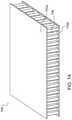
- FIG. 7Aillustrates a perspective view of an exemplary panel using a honeycomb lattice core.
- FIG. 7Billustrates a perspective view of another exemplary panel using a custom optimized core.
- FIG. 8illustrates a front cross-sectional view of an exemplary partially-completed AM panel having a custom internal structure and having the top face sheet detached from the core to show the core upper surface.
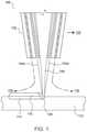
- FIG. 9illustrates a front cross-sectional view of an exemplary AM honeycomb panel using lattice branching to reduce sag.
- FIG. 10illustrates a front view of an exemplary AM honeycomb panel connected to different types of structures using connection features.
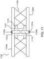
- FIG. 11illustrates a front cross-sectional view of an exemplary carbon sandwich panel having printed core material and a co-printed fastener insert.
- FIG. 12illustrates an exemplary flow diagram of various exemplary methods for constructing a panel with an optimized core and for use in a transport structure.
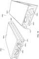
- FIG. 13is a perspective view of a an exemplary panel having a curved custom core and curved face sheets.
- FIG. 14is a perspective view of an exemplary panel having a curved upper face sheet having a variable thickness, a custom core contoured to the upper face sheet, and a generally planar lower face sheet.
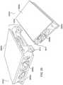
- FIG. 15is a perspective view of another exemplary panel having a curved upper face sheet with a variable thickness, a generally planar lower face sheet, and a custom core that matches the contour of the face sheets.
- FIG. 16is a perspective view of another exemplary panel having curved upper and lower face sheets of variable thicknesses, and a custom core shaped to match the contour of the face sheets.
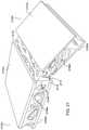
- FIG. 17is a perspective view of an exemplary AM panel having a cutout in the panel face sheet for incorporating features for fixturing.
- FIG. 18is a perspective view of an exemplary AM panel having features for fixturing at a panel edge.
- FIG. 19is a perspective view of two exemplary panel sections having custom cores and configured to attach to one another via a slide-in feature using a receiving section at an interface of one panel and a protruding section at an interface of the other panel.
- FIG. 20is a perspective view of two exemplary panel sections having custom cores and configured to attach to one another via a slide-in feature using another receiving section at one panel interface and a protruding section at an interface of the other panel.
- FIG. 21is a perspective view of two panels sections attached at a panel interface using a slide-in feature including a protruding and a receiving section.
- FIG. 22is a perspective view of two panel sections having a core with plates and apertures for threading screws to affix the sections together.
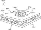
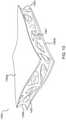
- FIG. 23is a diagram illustrating an example of an automotive subframe comprising tri-axially optimized composite structure.
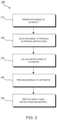
- FIG. 24is a flowchart illustrating an example method in accordance with the systems and methods described herein.
- This disclosureis directed to the manufacture of panel structures using specific additive manufacturing techniques to realize optimized core structures for said panel structures.
- certain components of such transport structurescan represent modular components including composites having tri-axially optimized characteristics.
- the combination of the additive manufacturing techniques with the modular and tri-axially optimized properties of the constituent transport structure componentsmay be used to add overall value and efficiency to the end product and the assembly process.
- such techniquescan provide distinct advantages to a user.
- Manufacturers that stand to benefit from this proposed combination of featuresinclude those that manufacture virtually any mechanized form of transport, the assembly of which often relies heavily on complex and labor intensive machine tools and molding techniques, and whose products often require the development of complex panels, nodes, and interconnects to be integrated with intricate machinery such as combustion engines, transmissions and increasingly sophisticated electronic techniques.
- transport structuresinclude, among others, cars, trucks, trains, boats, aircraft, tractors, motorcycles, busses, trains, and the like.
- tri-axially optimized core-based structuresincluding the tri-axially optimized core-based structures and systems, methods, and apparatus, for forming tri-axially optimized core-based structures.
- systems, methods, and apparatusare generally described with respect to tri-axially optimized core-based structures, it will be understood that these systems and methods may be used to optimize core-based structures in only two dimensions when necessary.
- traditional composite materialsmay provide an inner core that is stiff in only a single direction.
- “optimized” in a particular directionmay mean strengthened, stiffened, supported, reinforced, braced, or hardened in the particular direction, as applicable in the context and/or based on an objective or a given panel application.
- tri-axially optimizedmay mean strengthening, stiffening, supporting, reinforcing, bracing, or hardening as much as is needed in each of three-axes.
- the strengthening, stiffening, supporting, reinforcing, bracing, or hardeningmay vary from direction to direction.
- the strengthening, stiffening, supporting, reinforcing, bracing, or hardeningmay include some increase with respect to the needed support for a given design.
- structuresmay be designed for 100%, 150%, 200%, 500% or some other percentage of the expected load for along a particular axis. The percentage may vary from axis to axis.
- a controllermay be integrated into a 3-D printer or embodied in a separate workstation and may be configured to execute one or more algorithms for optimizing the structural portions of cores depending on the intended application of the panels incorporating the cores.
- a data modelmay be created that includes a 3-D version of the optimized core. The data model may be provided to the 3-D printer for rendering.
- the coreis co-printed with the face sheets (skins) and optionally, one or more joining features (e.g., at a panel interface).
- the controllermay include the face sheets and/or joining features as part of the same data model, or the controller may link the data models together to thereby enable the co-printing of the structures. (Thereafter, as demonstrated below, the structures may be joined via adhesives or mechanical fasteners to produce a finished panel section with the appropriate interfaces configured to interlock with adjacent panel sections).
- the controller 329may be configured to optimize the core for the intended structural application and then print the entire panel (core and face sheets) as one integrated unit. In this case, there may not be a need for subsequent assembly of the panel sections.
- the optimized panel sectionsmay be configured to include protrusions, sliding features, fasteners, and other mechanisms that enable adjacent panel sections to lock together at fixed angles.
- the optimized coreneed not be rectangular or planar, and need not take on a fixed shape.
- the optimized coremay be organically created with custom parts designed to provide the necessary structural support along all three coordinate axes (x, y, z) and may be designed to handle loads from any applicable direction without adding excessive or unnecessary mass to the panel.
- the coremay also vary in thickness at any point.
- the coremay have different densities in different regions and may incorporate both solid regions and empty or void regions at different locations. The flexibility to optimize the core based on any of these variables, together with the ability to shape the panel sections in any manner desirable, allows the resulting panel to be used in a virtually unlimited array of applications.
- the face sheetsmay be 3-D printed (separately from the core or co-printed with the core) or conventionally formed (i.e., using traditional techniques). As will be illustrated herein, the face sheets need not be planar and instead can be curved or contoured in any geometrical configuration appropriate for the desired solution.
- the face sheetsmay be formed independently or by using the core as a tool.
- the face sheetsmay, but need not, have a uniform thickness and in other embodiments either one or both face sheets may vary widely in thickness.
- AMadditive manufacturing
- 3-D printing techniquesprovide manufacturers with the flexibility to design and build parts having intricate internal lattice structures and/or profiles that may not be possible to manufacture via traditional manufacturing processes or may be cost prohibitive to manufacture via traditional manufacturing processes.
- a variety of different AM techniqueshave been used to 3-D print components composed of various types of materials. Numerous available techniques exist, and more are being developed.
- DEDDirected Energy Deposition
- AM systemsuse directed energy sourced from laser or electron beams to melt metal. These systems utilize both powder and wire feeds. The wire feed systems advantageously have higher deposition rates than other prominent AM techniques.
- Single Pass Jettingcombines two powder spreaders and a single print unit to spread metal powder and to print a structure in a single pass with apparently no wasted motion.
- electron beam additive manufacturing processesuse an electron beam to deposit metal via wire feedstock or sintering on a powder bed in a vacuum chamber.
- Single Pass Jettingis another exemplary technology claimed by its developers to be much quicker than conventional laser-based systems.
- Atomic Diffusion Additive Manufacturing(ADAM) is still another recently developed technology in which components are printed, layer-by-layer, using a metal powder in a plastic binder. After printing, plastic binders are removed and the entire part is sintered at once.
- Other AM technologiesinclude direct metal deposition (DMD) and powder bed fusion (PBF).
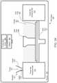
- FIG. 1illustrates an exemplary embodiment of certain aspects of a DMD 3-D printer 100 .
- DMD printer 100uses feed nozzle 102 moving in a predefined direction 120 to propel powder streams 104 a and 104 b into a laser beam 106 , which is directed toward a workpiece 112 that may be supported by a substrate.
- Feed nozzlemay also include mechanisms for streaming a shield gas 116 to protect the welded area from oxygen, water vapor, or other components.
- the powdered metalis then fused by the laser 106 in a melt pool region 108 , which may then bond to the workpiece 112 as a region of deposited material 110 .
- the dilution area 114may include a region of the workpiece where the deposited powder is integrated with the local material of the workpiece.
- the feed nozzle 102may be supported by a computer numerical controlled (CNC) robot or a gantry, or other computer-controlled mechanism.
- the feed nozzle 102may be moved under computer control multiple times along a predetermined direction of the substrate until an initial layer of the deposited material 110 is formed over a desired area of the workpiece 112 .
- the feed nozzle 102can then scan the region immediately above the prior layer to deposit successive layers until the desired structure is formed.
- the feed nozzle 102may be configured to move with respect to all three axes, and in some instances to rotate on its own axis by a predetermined amount.
- FIG. 2is a flow diagram 200 illustrating an exemplary process of 3-D printing.
- a data model of the desired 3-D object to be printedis rendered (step 210 ).
- a data modelis a virtual design of the 3-D object.
- the data modelmay reflect the geometrical and structural features of the 3-D object, as well as its material composition.
- the data modelmay be created using a variety of methods, including CAE-based optimization, 3-D modeling, photogrammetry software, and camera imaging.
- CAE-based optimizationmay include, for example, cloud-based optimization, fatigue analysis, linear or non-linear finite element analysis (FEA), and durability analysis.
- FEAlinear or non-linear finite element analysis
- 3-D modeling softwaremay include one of numerous commercially available 3-D modeling software applications.
- Data modelsmay be rendered using a suitable computer-aided design (CAD) package, for example in an STL format.
- STLstereolithography
- STLstereolithography
- a CAD programmay be used to create the data model of the 3-D object as an STL file. Thereupon, the STL file may undergo a process whereby errors in the file are identified and resolved.
- the data modelcan be “sliced” by a software application known as a slicer to thereby produce a set of instructions for 3-D printing the object, with the instructions being compatible and associated with the particular 3-D printing technology to be utilized (step 220 ).
- a slicera software application known as a slicer to thereby produce a set of instructions for 3-D printing the object, with the instructions being compatible and associated with the particular 3-D printing technology to be utilized (step 220 ).
- Numerous slicer programsare commercially available.
- the slicer programconverts the data model into a series of individual layers representing thin slices (e.g., 100 microns thick) of the object be printed, along with a file containing the printer-specific instructions for 3-D printing these successive individual layers to produce an actual 3-D printed representation of the data model.
- the layers associated with 3-D printers and related print instructionsneed not be planar or identical in thickness.
- the layers in a 3-D printed structuremay be non-planar and/or may vary in one or more instances with respect to their individual thicknesses.
- a build piecemay be additively manufactured using PBF, after which DMD may be applied to change a region of the build piece using a non-flat layer structure and/or layers having different thicknesses.
- a common type of file used for slicing data models into layersis a G-code file, which is a numerical control programming language that includes instructions for 3-D printing the object.
- the G-code file, or other file constituting the instructionsis uploaded to the 3-D printer (step 230 ). Because the file containing these instructions is typically configured to be operable with a specific 3-D printing process, it will be appreciated that many formats of the instruction file are possible depending on the 3-D printing technology used.
- the appropriate physical materials necessary for use by the 3-D printer in rendering the objectare loaded into the 3-D printer using any of several conventional and often printer-specific methods (step 240 ).
- DMD techniquesfor example, one or more metal powders may be selected for layering structures with such metals or metal alloys.
- SLMselective laser melting
- SLSselective laser sintering
- PBF-based AM methodsthe materials may be loaded as powders into chambers that feed the powders to a build platform.
- other techniques for loading printing materialsmay be used.
- the respective data slices of the 3-D objectare then printed based on the provided instructions using the material(s) (step 250 ).
- a laserscans a powder bed and melts the powder together where structure is desired, and avoids scanning areas where the sliced data indicates that nothing is to be printed. This process may be repeated thousands of times until the desired structure is formed, after which the printed part is removed from a fabricator.
- fused deposition modellingas described above, parts are printed by applying successive layers of model and support materials to a substrate.
- any suitable 3-D printing technologymay be employed for purposes of this disclosure.
- PBFpowder-bed fusion
- a layer or ‘slice’is formed by depositing a layer of powder and exposing portions of the powder to an energy beam.
- the energy beamis applied to melt areas of the powder layer that coincide with the cross-section of the build piece in the layer.
- the melted powdercools and fuses to form a slice of the build piece.
- the processcan be repeated to form the next slice of the build piece, and so on.
- Each layeris deposited on top of the previous layer.
- the resulting structureis a build piece assembled slice-by-slice from the ground up.
- FIGS. 3A-Dillustrate respective side views of an exemplary PBF system 300 during different stages of operation.
- the particular embodiment illustrated in FIGS. 3A-Dis one of many suitable examples of a PBF system employing principles of this disclosure.
- elements of FIGS. 3A-D and the other figures in this disclosureare not necessarily drawn to scale, but may be drawn larger or smaller for the purpose of better illustration of concepts described herein.
- PBF system 300can include a depositor 301 that can deposit each layer of metal powder, an energy beam source 303 that can generate an energy beam, a deflector 305 that can apply the energy beam to fuse the powder, and a build plate 307 that can support one or more build pieces, such as a build piece 309 .
- PBF system 300can also include a build floor 311 positioned within a powder bed receptacle.
- the walls of the powder bed receptacle 312generally define the boundaries of the powder bed receptacle, which is sandwiched between the walls 312 from the side and abuts a portion of the build floor 311 below.
- Build floor 311can progressively lower build plate 307 so that depositor 301 can deposit a next layer.
- the entire mechanismmay reside in a chamber 313 that can enclose the other components, thereby protecting the equipment, enabling atmospheric and temperature regulation and mitigating contamination risks.
- Depositor 301can include a hopper 315 that contains a powder 317 , such as a metal powder, and a leveler 319 that can level the top of each layer of deposited powder.
- FIG. 3Ashows PBF system 300 after a slice of build piece 309 has been fused, but before the next layer of powder has been deposited.
- FIG. 3Aillustrates a time at which PBF system 300 has already deposited and fused slices in multiple layers, e.g., 150 layers, to form the current state of build piece 309 , e.g., formed of 150 slices.
- the multiple layers already depositedhave created a powder bed 321 , which includes powder that was deposited but not fused.
- FIG. 3Bshows PBF system 300 at a stage in which build floor 311 can lower by a powder layer thickness 323 .
- the lowering of build floor 311causes build piece 309 and powder bed 321 to drop by powder layer thickness 323 , so that the top of the build piece and powder bed are lower than the top of powder bed receptacle wall 312 by an amount equal to the powder layer thickness.
- a space with a consistent thickness equal to powder layer thickness 323can be created over the tops of build piece 309 and powder bed 321 .
- FIG. 3Cshows PBF system 300 at a stage in which depositor 301 is positioned to deposit powder 317 in a space created over the top surfaces of build piece 309 and powder bed 321 and bounded by powder bed receptacle walls 312 .
- depositor 301progressively moves over the defined space while releasing powder 317 from hopper 315 .
- Leveler 319can level the released powder to form a powder layer 325 that has a thickness substantially equal to the powder layer thickness 323 (see FIG. 3B ).
- the powder in a PBF systemcan be supported by a powder support structure, which can include, for example, a build plate 307 , a build floor 311 , a build piece 309 , walls 312 , and the like.
- the illustrated thickness of powder layer 325i.e., powder layer thickness 323 ( FIG. 3B )
- the illustrated thickness of powder layer 325is greater than an actual thickness used for the example involving 150 previously-deposited layers discussed above with reference to FIG. 3A
- FIG. 3Dshows PBF system 300 at a stage in which, following the deposition of powder layer 325 ( FIG. 3C ), energy beam source 303 generates an energy beam 327 and deflector 305 applies the energy beam to fuse the next slice in build piece 309 .
- energy beam source 303can be an electron beam source, in which case energy beam 327 constitutes an electron beam.
- Deflector 305can include deflection plates that can generate an electric field or a magnetic field that selectively deflects the electron beam to cause the electron beam to scan across areas 330 designated to be fused.
- energy beam source 303can be a laser, in which case energy beam 327 is a laser beam.
- Deflector 305can include an optical system that uses reflection and/or refraction to manipulate the laser beam to scan selected areas 330 to be fused.
- the deflector 305can include one or more gimbals and actuators that can rotate and/or translate the energy beam source to position the energy beam.
- energy beam source 303 and/or deflector 305can modulate the energy beam, e.g., turn the energy beam on and off as the deflector scans so that the energy beam is applied only in the appropriate areas of the powder layer.
- the energy beamcan be modulated by a digital signal processor (DSP).
- DSPdigital signal processor
- the PBF system 300may also include a controller 329 , which may direct the printing functions, such as optimizing the panel structure and/or controlling the build from the ground up. In some cases, these tasks are performed using different computers.
- the data model of the panel, including the optimized coremay be provided using a remote server, which can then be received at the printer and compiled as a set of printing instructions compatible with the printer in use.
- the controller 329may include one or more processors and memory for executing printing instructions for performing some or all the steps described above.
- the controller 329may execute code configured to direct the energy beam source 303 and/or deflector 305 to fuse selected regions of deposited layers of powder, code configured to direct the depositor 301 to deposit layers of material, to control leveler 319 , and to control the vertical motion of the build floor 311 , etc.
- the controller 329may in some embodiments be fully integrated within the 3-D printer 300 . In other embodiments, the controller 329 may be partially integrated within the 3-D printer 300 , and/or the controller 329 may execute code on a computer system coupled to 3-D printer 300 for performing one or more of these functions.
- the controllermay physically constitute one or more processors that reside locally or that are distributed throughout relevant portions of the 3-D printer 300 .
- the processorsmay be connected by electrical connections, including one or more busses for routing electrical signals and digital logic to appropriate locations of the 3-D printer 300 .
- the processorsmay include one or more microprocessors, digital signal processors, digital logic circuits, and/or any physical hardware or circuitry necessary to conduct the operation of the 3-D printer 300 .
- the controllermay be coupled to or include static or dynamic read only memory and/or random access memory, the memory may be volatile (e.g., DRAM) or non-volatile (e.g., EEPROMs), where the non-volatile memory may store code native to the 3-D printer 300 , including firmware and startup routines.
- the core material discussed aboveneed not be limited in application to panels. Rather, it will be understood that the core material may be used as part of or an interior of, or in connection with, other types of components in transport structures that may require isotropic features. In other exemplary embodiments, the core material may itself be considered a separate component to which the principles of the disclosure are applicable. Because the panel is ubiquitous in all types of transport structures, this structure will be used in connection with most embodiments throughout the disclosure.
- One or more of the systems described with respect to FIGS. 3A-Dmay provide an apparatus for manufacturing an additively manufactured core material or other components.
- the system 300may provide a controller, computer, or processing system (whether integrated into the PBF or standalone, in part or in whole) for receiving one or more design files characterizing a composite structure based on an analysis of expected loads on the composite structure including the core material within, or otherwise part of, the structure.
- the system 300may include memory, storage, and/or communications subsystems for receiving the design file(s).
- the system 300may further provide an AM device similar to the one described in FIGS.
- the system 300may further provide the AM device for use in co-additively manufacturing at least one face sheet and the additively manufactured core material, where the core material and the at least one face sheet constitute the composite structure.
- the system 300may be configured to 3-D print both the core material and the at least one face sheet in separate print runs, or in parallel using more than one 3-D printer.
- the AM devicemay be configured to 3-D print just the core material base on the received design file(s).
- the system 300 or a separate processing systeme.g., one or more processors and a memory system (including, for example, any of, or any combination of, a read only memory (ROM), random access memory (RAM), programmable read only memory (PROM), erasable programmable read only memory (EPROM), and/or electrically erasable programmable read only memory (EEPROM), and including a volatile memory (e.g., static RAM (SRAM) or dynamic RAM (DRAM) and a non-volatile memory (e.g., magnetic hard drives, solid-state drives (SSD), flash memory, etc., or any combination of the above), or Enterprise Server System, a personal computer, a workstation, a controller integrated into the system 300 , etc.
- a volatile memorye.g., static RAM (SRAM) or dynamic RAM (DRAM)
- non-volatile memorye.g., magnetic hard drives, solid-state drives (SSD), flash memory, etc., or any combination of the above
- the system 300 or a separate processing system as described abovemay be configured to allow expected loads to be input (in a simulation or an actual build) and processing components to analyze the expected loads on the panel structure.
- the mechanism for analyzing the expected loads on the composite structuremay include code executed by the processor(s), thereby causing the processor to perform the analyses.
- Such analysesmay include determining an expected load, e.g., based on calculations or inputs provided, or conditions provided sufficient for the program to render the determination of the expect load, and determining the magnitude and direction of that load at various load points on the composite structure.
- the processing hardware and codemay also determine how the expected loads will apply forces to the composite structure in one or more directions.
- the expected loadmay be an average load, a load over time, a determination of maximum and minimum loads, or some combination of these or other parameters.
- parameters other than the expected loadmay be considered, calculated, and considered in the determination of the core or the composite structure design.
- the system 300 or a separate processing systemmay provide or utilize code for determining a design for the core material based on the analysis of the expected loads.
- the mechanism for determining a design for the core material based on the analysis of the expected loadsmay include code executed by the processor causing the processor to determine a design for the core material based on the analysis of the expected loads.
- determining the designmay include further breaking down the concept of loading on the composite structure as a singular unit into loading on the composite structure at a range of locations within the composite structure.
- Analyses using multi-physics modelscan determine failure points of a structure based on the loads the structure is expected to experience during actual use. By obtaining the failure points, materials can be chosen, and the analysis can run again. Typically, material properties (material, densities, strength, etc.) are inputs to the analysis. Results of the analyses can be used by the optimization algorithm. The optimization algorithm would optimize the layout of material in a given space for a given set of loads and boundary conditions. These loads and boundary conditions may be determined through analyses described previously. Accordingly, in an embodiment, an optimization algorithm can be run as follows:
- a structuree.g., a panel and/or core
- a structureis modeled.
- Inputs for the structureare identified based on specifically identified material properties.
- the material propertiesordinarily correspond to the properties of the initial physical material(s) used in the panel or core. Additional or alternative inputs deemed relevant to the analysis may also be used.
- the structureis subject to a plurality of loads (which may include, for example one or more load/force vectors asserted at various points of the structure, over a period of time or otherwise), and to boundary conditions.
- loadswhich may include, for example one or more load/force vectors asserted at various points of the structure, over a period of time or otherwise
- Failure pointsare identified. Failure points may include, for example, locations of the core or panel where the material cracks, gets crushed, deforms, or breaks. In some embodiment, these failure points may include times of failure.
- one or more materialscan be chosen for use in the panel/core.
- the subsequent choice of material(s)can be performed by the optimization algorithm, or it can be performed manually. In either case, the material(s) are generally chosen that are anticipated to address the failure points. Critical failure points may require materials that are stronger or more robust.
- the geometrical parameters of the panelmay be modified, if appropriate. For example, the core geometry is changed to address the failure points.
- the optimization algorithmis rerun based on inputs corresponding to the chosen one or more materials.
- the optimization algorithmcan be run any number of times until it converges on an acceptable solution.
- An acceptable solutionmay include, for example, a core composition and geometry that is conducive to receiving and withstanding different loads in different directions and that has a more gradual load-bearing gradient, in contrast than a panel portion being strong in a single direction and an immediately adjacent panel portion being strong in the opposite direction, as is often seen in conventional approaches.
- the panel geometry (including the core geometry) and constituent materialscan be identified and used in a data model to print the desired AM core.
- the system 300 or a separate processing systemmay utilize code for generating the design file(s) based on the determination of the overall design.
- a design filemay, for example, include a matrix of locations and material densities or specific energy beam processing parameters that correspond to the locations or specific energy beam processing parameters.
- the material densitiesmay, in turn, be based on strength needs, flexibility requirements, etc. at a given location within the composite structure.
- the composite structuremay be designed to be stronger than the needed strength by some factor, e.g., 200%.
- the actual design of the coremay include additional or different calculations involving other parameters or material properties not specifically referenced herein.
- other parameters and material propertiesmay be considered by the processing system and are deemed to fall within the scope of one or more embodiments herein.
- the processing and calculations leading to the structural design of the core as disclosed hereincan advantageously account for desired values of properties in each location and in each of the X, Y and Z directions and any intermediate direction therebetween.
- the variable of timemay also be considered.
- the material composition of the core and its attributes at each location and directionmay therefore be precisely determined.
- the codemay provide instructions to the 3-D printer to build the core in accordance with the composition and attributes.
- the above-described techniqueis in contrast to conventional solutions in which cores or similar components comprise multiple separate layers, sections, or regions of material, wherein each layer is individually manufactured to provide a desired material characteristic that is prominent in a single direction.
- the end result using conventional approachesis a multi-tiered core whose desired material properties are segregated throughout the different layers, sections or regions.
- the conventional approachmay lend itself to compromises in performance in that, among other potential problems, different layers or regions may adversely affect the properties of other layers or regions in the same composite structure.
- the conventional approachfurther tends to result in components having a potentially significantly greater mass, which increases fuel consumption.
- the conventional approachfurther increases production times, because it may require multiple individual builds to create each layer, section or region. Additional manufacturing steps may be necessary to adhere the layers together.
- the embodiments disclosed hereinprovide a solution to these problems by allowing the composite structure to be formed in many or most cases as a single build, or a substantially limited number of builds, whereby all of the desired traits and directional attributes of the core are integrated into a single structure.
- Core structures for composite materialsmay be formed using AM.
- AMis non-design specific, which offers geometric and design flexibility that conventional manufacturing processes cannot.
- 3-D printing technologiescan produce parts with very small feature sizes and geometries that are either significantly difficult or impossible to produce using conventional manufacturing processes.
- Very large components that exceed printer size specificationscan be segregated at the design phase, 3-D printed in parallel and combined.
- 3-D printer sizes, and therefore printed object sizescontinue to increase to drive demand.
- the versatility of AM and its ability to create highly complex structuresrepresent a major impetus driving AM's increased adoption by the industry.
- Multi-aspect printingTo streamline the manufacturing process and maximize efficiency in accordance with an aspect of the disclosure, multi-aspect printing is used. It may be desirable or necessary in many cases to produce components using a plurality of manufacturing processes. Conventionally, to accomplish this result, different dedicated machines are used. Thus, for example, a panel may be produced in part using DMD or PBF-based AM techniques, and then portions of the panel may undergo a finishing technique using FDM or spray forming processes. Additionally, subtractive manufacturing processes may also be implemented, for example, to remove unwanted materials from the 3-D printed panel or to further define features within a component.
- a single multi-aspect printerincludes two or more AM features.
- the machinemay include various subtractive manufacturing (SM) functions.
- the MAPmay incorporate functions performed by a CNC machine.
- MAPmay include a robotic arm coupled to a tool for cutting material from a component on a substrate. The arm may alternatively be configured to receive one of a plurality of tools operable for performing different SM procedures.
- the integration of multiple technologies into a single machinecan substantially increase manufacturing speed and capacity, while reducing costs of labor otherwise incurred from moving the components and capital used for purchasing dedicated AM machines. Additionally, the combined functionality enables components to be printed in series or in parallel, increasing design flexibility and further maximizing production efficiency. Generally, the AM and SM operations of the MAP may be performed in any order.
- MAPmay include a single printer having a single print area using multiple print heads, including one or more DMD print heads, operable to print multiple areas simultaneously. MAP may be used to achieve greater versatility and speed in printing 3-D structures. MAP has the capability to set up and implement local PBF processing. MAP may also additively manufacture custom build plates needed for AM operations. In some embodiments, MAP can use DMD to produce “build plate supports” that attach to the printer plates and that support the attached build plate. These build plate supports may be attached below the build plate and can be made to be breakable from the build plate to enable the build plate to become part of the printed structure, if desired.
- MAPmay further include a robotic arm that introduces a build plate where needed in regions requiring the feature sizes and properties available with PBF.
- MAPmay further include a robotic arm that may be used to introduce a build plate where needed locally in a larger chamber.
- a robotic coating armmay then coat the build plate and subsequent layers between sintering operations.
- MAPmay further include a vacuum arm for removing excess powder upon completion of operations, allowing DMD onto PBF regions.
- the print headsmay be printed in place by DMD.
- MAPmay incorporate fused deposition modeling (FDM) print capability including FDM extruders which heat and eject melted filament materials provided from FDM spools for printing thermoplastics and other materials ideal for internal supports and other functions where plastics may be beneficial.
- FDMfused deposition modeling
- FIG. 4illustrates a conceptual view of a multi-aspect printer (MAP) 400 in accordance with an aspect of the disclosure.
- MAPmay include, as noted, one or more DMD heads or applicators 416 on a robotic arm assembly for 3-D printing a DMD structure.
- MAPmay further include PBF equipment such as electron or laser beam sources.
- PBF laser 414is shown disposed on a separate robotic arm assembly.
- the PBF equipmentmay further include deflectors (not shown), a local powder applicator 412 on another robotic arm assembly, and an FDM robotic arm assembly 415 .
- more than one print head or applicatormay be included on a robotic arm.
- more than one robotic armmay include a print head supporting the same technology (e.g., DMD, PBF, FDM, etc.)
- PBFPBF
- FDMFDM
- PBF technologiesemployed on one or more robotic arm assemblies (e.g., SLS, SLM, etc.).
- One or more of the applicators and robotic arm assemblies of FIG. 4may be performing operations on a structure which in the embodiment shown includes a PBF structure 408 upon which a larger DMD structure 410 has been formed.
- the PBF structure 408may be connected to FDM- and PBF-formed support structure 406 for supporting the PBF structure 408 and DMD structure 410 .
- the PBF structure 408is arranged on a local DMD build plate sub-structure 404 which is further supported by a larger DMD build plate support structure 402 .
- MAPmay also include one or more tools for milling. MAP may also use FDM on the top layers of a build piece for surface finishing. Structures for facilitating SM techniques may also be provided, such as automated milling tools and the like.
- MAPmay print a structure using DMD and, concurrently or subsequently, add a part with a build plate and an immobile supporting structure.
- MAPmay 3-D print the build plate and then apply a robotic arm containing powder to implement a PBF process while having a laser positioned over the powder bed.
- the lasermay point to a mirror, which can be mobile or stationary.
- MAPcan have wide applicability to the manufacture of transport structures and other mechanical assemblies.
- MAPcan print lattice panels located in non-crushable areas using PBF or FDM (in the case of plastic lattice panels).
- MAPcan print metal vehicle panels using DMD.
- MAPcan also use FDM to 3-D print support features.
- FDMmay be needed to print the corresponding lattice structures for supporting the panel.
- FDMcan also be used to provide surface finishing to increase quality of the 3-D printed parts.
- MAPcan 3-D print support materials using a combination of FDM and PBF technologies. These supports can optionally be broken off following the AM process on the object being printed.
- MAPmay include spray form capability.
- Spray formingis the inert gas atomization of a liquid metal stream into variously sized droplets (10-500 microns) that are then propelled away from the region of atomization by the fast-flowing atomizing gas.
- the droplet trajectoriesare interrupted by a substrate which collects and solidifies the droplets into a coherent, near fully dense preform.
- a robotic arm for spray formingprovides yet additional versatility to MAP.
- MAPmay incorporate one or more SM processes.
- MAPmay include a CNC computer-controlled arm for use in accurately removing material or structure where needed.
- MAPmay include multiple arms and/or print heads for performing the same AM functions in a faster manner.
- MAPmay provide a plurality of DMD print heads for performing metal deposition in parallel, or more than one energy beam for implementing a PBF process.
- one section of the panelmay be undergoing PBF processing while another section to which PBF techniques have already been applied may simultaneously undergo spray forming.
- Partsmay also be 3-D printed in series, with one process immediately following another without delays associated with mobilizing the component to another printer or another production area.
- MAPmay be under the general control of a central processing system, controller or computer that executes instructions corresponding to each of MAP's different capabilities.
- the processing systemmay be operable to integrate these instructions together to provide a meaningful sequence of instructions that incorporate a plurality of MAP's capabilities into one overall manufacturing operation.
- MAPmay include, for example, controller 429 , which may be an integrated controller or it may be a distributed series of processors that control various portions of a MAP.
- Controller 429may execute code to perform one or more of the functions of controller 329 discussed above with reference to FIG. 3D .
- Controller 429may also include or may be linked to one or more memory systems that receive CAD or CAE files comprising data models and/or printing/processing/manufacturing instructions.
- controller 429can receive an optimized data model of a core for use in a panel.
- the MAPmay receive one or more data models externally from a separate CAD or CAE application, e.g., through a wireless or wired network connection.
- Controller 429may also receive, via a network and memory, code for manufacturing one or more joining features for use with one or more panel sections.
- MAPmay include a number of modes for using individual AM or SM technologies.
- MAPcan be used in FDM printing mode to additively manufacture a plurality of exclusively FDM-based objects.
- the processing systemmay, in general, include a variety of processing modes whereby different capabilities of MAP are exploited for specific applications. These modes may also include specific modes that utilize a plurality of MAP's features concurrently, where desired for efficiency or as an inherently-desired aspect of rendering a particular object.
- the capability to additively manufacture partsenables the manufacturer to generate shapes, configurations, and structures that are not available in conventional manufacturing processes. Further, advances in AM technologies are expected to continue. Print speed is continually increasing. 3-D printer form factor has also seen regular advances. This means, among other things, that the area of the build platform as compared with the size of the component to be printed is becoming progressively larger as relevant as build plates and printer profiles cross unprecedented boundaries in size, speed and sophistication. The availability and suitability of candidate materials and chemical compounds for use in AM is likewise increasing, meaning among other things that the versatility of AM should continue to impact other applications and other parts of the transport structures.
- complete transport structuresare additively manufactured.
- AM techniques with automobilesare used to demonstrate the capabilities of these advanced manufacturing techniques.
- analogous patterns and identical principlescan apply with equal force to numerous classes of transport structures—planes, trains, busses, boats, motorcycles, and aircraft to name only a few.
- AMalso provides modularity processes with the capability to define and build complex and efficient interfacing features that define partitions or borders between panels. These features can include indentations, tongue and groove techniques, adhesives, nuts/bolts, and the like.
- a further advantage of implementing a modular design for vehiclesis ease of repair. Modular designs ensure easy access to virtually any component in the vehicle. In the event of a crash, the affected modular block simply can be replaced. The block(s) can also be co-printed with the remaining structure to save assembly time. The blocks can even incorporate in-situ scanning and observation to ensure accurate joining and repair of the modules.
- Modular panel interfacescan be 3-D printed to include ports, protrusions, receiving slots, integrated fasteners, threading solutions, fastener receiving solutions, and/or panel orientation fixturing features. These solutions can provide alignment of adjoining panels at different angles, including right angles. More specifically, two panels can be joined together such that the cores of the panels include one or more structures that maintain the angle between the panels.
- the structures for implementing the interfacemay vary widely and may include a slide-in feature using a protrusion and a slot, an interlock solution using a fastener, a plurality of ports for glue, 3-D printed structure, a plate with threads that can mate with another plate using bolts, all of which are collectively used to implement the interface ( FIG. 17 ). Examples of 3-D frames having various modular panel interfaces for connecting panels are shown further below with reference to FIGS. 17-22 , below.
- the AM vehiclemay be assembled as a collection of 3-D printed and non-printed components integrated together via some interconnection means for attaching the components at defined borders or transitions as noted above. Individual components may be added and removed without requiring changes to other components of the vehicle.
- the vehiclemay be considered as a replaceable collection of assembled parts connectable into a functional transport structure via standard interconnects.
- the entire frame of the vehicle(and optionally other parts integrated within the frame) may be printed in a single pass or in a few renderings. Smaller parts of the frame may be printed if the frame is further subdivided into smaller modules.
- Such a modular frame structurein certain embodiments, can make it easier to access parts of the vehicle underneath the frame.
- 3-D printed vehicular componentscan be easily manufactured, and later reprinted and replaced as necessary. Repair and replacement is made possible for parts regardless of their complexity or of their current availability in inventory.
- Custom modular panels and other parts having a unique shapemay be manufactured and assembled into an AM vehicle. Unlike conventional techniques in which adjacent parts of the automobile need to be replaced as well if one part is damaged during an impact, the parts to be replaced using the techniques herein may be limited to those that were affected by the impact.
- panels and other parts having modular featuresare not limited to being 3-D printed, but may also be constructed using other techniques, including the use of tooling or molding techniques, or other non-AM techniques, where necessary or desirable. Conversely, it will be appreciated that in still other embodiments involving specific conditions or manufacturing criteria, certain AM parts need not be defined by modular features.
- FIG. 5illustrates a flow diagram 500 of exemplary methods for assembling an AM vehicle.
- FIG. 5depicts three different manufacturing techniques: (1) 3-D printing the optimized core structure and then adding the skins using various techniques, to be subsequently assembled into the 3-D printed frame (i.e., 502 ( 1 ) et. al); (2) Co-printing the skins and optimized core structure together, to be subsequently assembled into the 3-D printed frame (i.e., 502 ( 2 ) et. al) and (3) 3-D printing the core and skins as a single integrated and assembled 3-D printed frame structure (also shown in 502 ( 2 ) et. al).
- the optimized core structurecan be 3-D printed.
- the skinsface sheets
- the skinsmay, but need not, be planar.
- the skinsmay instead be curved or otherwise shaped to include a variety of non-planar geometrical features.
- the 3-D printed core structure in step 502 ( 1 )may have curved surfaces on each side, and the skins added in 504 ( 1 ) may be curved such that they fit into the respective sides of the core.
- the materials comprising the skinsare laid on the core surfaces using the cores as a tool ( 504 ( 2 )).
- the skinsmay be 3-D printed in a manner such that they are formed to fit the contour of the 3-D printed core surfaces ( 504 )( 3 )).
- the skinsmay be 3-D printed to match the non-planar contour of the respective core surfaces.
- the 3-D printed cores and/or skinsmay be configured to include additional structures including cavities housing components that require an external interface, such as various types of joining features.
- the skins and optimized lattice coremay be co-printed.
- the co-printed cores and skinsmay be configured to include additional structures including cavities housing components that require an external interface.
- steps 504 ( 1 )-( 3 )may also include using an adhesive, sealant, or mechanical fixture, as appropriate per the desired configuration, to bond the skins to the core.
- the assembled printed panelmay be used in an intended application ( 506 ).
- FIG. 6illustrates a flow diagram 600 of an exemplary method for producing a component using a multi-aspect printer (MAP).
- a first portion of a component on a substrate of the MAPmay be additively manufactured via a first AM technology.
- a portion of a panelmay be 3-D printed using selective laser melting (SLM) or another PBF technology.
- SLMselective laser melting
- SMsubtractive manufacturing
- a second portion of the component on the MAP substratemay be additively manufactured via the first AM technology.
- step 604material may be cut away or removed to produce a hinge.
- the SM process 604may be performed by the MAP in an embodiment.
- step 604may be performed subsequent to the AM operations in steps 602 and 606 .
- step 604may be performed in parallel with one or both of steps 602 and 606 .
- a plurality of SM stepsare applied at different times in the process.
- PBF or DMD technologiesmay be used in step 602 to produce a metal panel. While one portion or region of the metal panel is being printed in step 602 , another portion of the metal panel that has already undergone 3-D printing via PBF or DMD may be further 3-D printed using FDM, for example, to provide a smooth finish. Alternatively, spray forming may be used to provide finishing in step 606 .
- the AM steps 602 and 606may be performed in different orders.
- the AM steps 602 and 606may, for example, be performed concurrently (in whole or in part), in series, or in any suitable order.
- FIG. 7Aillustrates a perspective view of an exemplary honeycomb panel 700 with an additively manufactured core.
- conventional honeycomb panelshave wide application in the automobile and aircraft industries (among many others).
- the panelscan be used for floors.
- the panelscan also be formed for use as components in interior and exterior doors, the hood, trunk area, fuselage (of an aircraft), frame of a boat, ship or spacecraft, and generally any area of a transport structure where paneling is needed.
- the panel 700is a generally flat panel including a top face sheet 702 a , a bottom face sheet 702 b , and a core 708 disposed between the top and bottom face sheets 702 a - b .
- the additively manufactured core 708may include a matrix of evenly distributed hexagonal aluminum honeycomb, if desired. While a flat panel is shown, the panel may be curved or may include any appropriate geometrical shape. In an embodiment, the core 708 is additively manufactured. The panels, core or both can also be formed using other non-AM methods. The core can be formed with curved surfaces and it may vary in cross-sectional thickness or other non-planar characteristics. Skins or face sheets 702 a - b can be formed on the curved surface. In some cases the skins can be formed using the core as a tool. In other embodiments, the skins can be additively manufactured, or separately manufactured using traditional methods.
- the additively manufactured core 708may include unique arrays of lattice structures and/or custom honeycomb structures.
- FIG. 7Billustrates a perspective view of another exemplary panel using a custom optimized core.
- the panel section in FIG. 7Bincludes face sheets 702 a and 702 b formed above and beneath the AM core.
- the top face sheet 702 a and the bottom face sheet 702 bmay be co-printed.
- the face sheets 702 a - bmay be formed using traditional methods. In either case, the face sheets 702 a - b may be adhered to the additively manufactured core 708 using an adhesive.
- the face sheets 702 a and/or 702 bmay be formed over the AM core 708 using the AM core 708 as a tool.
- the face sheetsmay be made of any material, such as, for instance, aluminum or a composite.
- the custom AM core 708shows a number of generally vertical core connections forming semi-elliptical empty regions e.g., beginning at the left side of the arrow 723 . Moving further along 723 in the direction of the arrow, the holes and protrusions begin to become diagonal.
- These different shapes of the AM coremay account for different types of forces expected in the panel section, e.g., more vertical forces relative to face sheets 702 a - b towards the left of 723 , and greater shear forces along the panel as the core connections begin to veer diagonally. Any number of custom or patterned core material may be used and optimized for the panel at issue.
- the AM core materialin general may take on any of a variety of conventional or organic shapes, or somewhere in between, depending on the most ideal structural optimization for the panel application at issue.
- Conventional core materialmay include, for example, foam cores, which may include open or closed cell, and which may provide generally homogenous support of the skins.
- Other conventional core materialmay provide more structured, non-homogenous support of the skins including textile cores for punctual support, cup-shaped cores for providing regional support to both skins, corrugated cores that provide unidirectional support and honeycomb cores, which provide bi-directional support.
- any type of custom core patterncan be generated and used on its own, or combined with any one or more conventional patterns.
- the optimization of the panelcan take into account a number of parameters and the structural patterns of support can differ as a function of position at any point on the panel. Thus, different load magnitudes and directions can be accommodated at each point on an operational panel in an optimal manner.
- the face sheets 702 a - bmay be additively manufactured, or in some embodiments, co-printed with the panel core.
- the face sheets 702 a - bmay be manufactured using conventional methods.
- the face sheets 702 a - bmay be manufactured using a hand or automated composite layup, which includes laying dry fabric layers or prepreg plies onto a tool to form a laminate stack.
- the dry fiber laminate stackis infused with resin in a wet layup procedure, and the resulting materials are allowed to cure.
- a pre-preg laminate stackmay be compacted after placement onto the tool and heated to allow curing.
- the face sheetsare produced using resin transfer molding (RTM).
- a preform materialmay be placed into a mold, which is then closed.
- a specific resin mixture including a low viscosity resin for quick permeation and even distributionmay be added to the mold via inlet ports. Vacuum may be used to facilitate the resin injection process.
- the partis then cured to produce one or both face sheets 702 a - b.
- the face sheets 702 a - bare produced using resin injection molding (RIM), vacuum assisted resin transfer molding (VARTM), resin film infusion (RFI), compression molding, injection molding, and the like.
- RIMresin injection molding
- VARTMvacuum assisted resin transfer molding
- RFIDresin film infusion
- compression moldinginjection molding, and the like.
- the face sheetsmay be adhered to the additively manufactured core 708 as described.
- the face sheets 702 a - bmay be co-printed with the additively manufactured core 708 .
- the face sheets 702 a - bmay be adhered to the additively manufactured core 708 via an adhesive after the AM process has concluded.
- the face sheets 702 a - bmay be affixed to the additively manufactured core 708 using another conventional method, such as via thermal fusion or the like.
- the face sheets and coremay also be built as one continuous AM build.
- the panel componentsmay be co-printed, with the joining of the components done by an alternative AM process, if assembled in a MAP or similar process.
- the MAPcan co-print the panel components and then join the components, e.g., by applying an adhesive.
- the joining of the componentscan also be performed using a separate procedure, e.g., if a MAP is not used.
- the face sheets 702 a - b of FIG. 7A-Bare discussed as being affixed to additively manufactured core 708 directly or via an adhesive layer, one or more additional plies or layers of material(s) may be deposited between the additively manufactured core 708 (or adhesive layer) and the face sheets to optimize the core for the intended structural application without departing from the spirit and scope of the claimed invention.
- the additively manufactured coreis a lattice-type structure. In general, however, any suitable core geometry may be used, with some geometries being desirable over others depending on factors like the target design objectives of the panel and the overall assembly of the transport structural into which the panel may be assembled.
- face sheets 702 a - bmay be connected to respective sides of the additively manufactured core 708 during the AM process, as opposed to after the AM process.
- the core 708may use different inputs.
- the core 708may be additively manufactured as a honeycomb structure or another structure such as an optimized structure based on multiple inputs across physics models.
- the AM processbeing non-design specific, may use instructions provided to a 3-D printer containing an optimized design of the additively manufactured core 708 to meet the objectives of an intended structural application.
- the optimizationwould enable the specification physical parameters (e.g., tensile strength, rigidity, thickness, force vectors including shear forces and vertical forces etc., pressures and gradients thereof, energy absorption characteristics by crush direction, etc.) and other potential geometrical, thermal, and material-based properties relevant to manufacturing the panel 700 for the intended structural application.
- the panel 700may be a section of a fuselage or vehicle exterior, in which case various aerodynamic characteristics may be optimized for that intended application by varying the shape of the face sheets in three dimensions.
- customizing the additively manufactured core for an applicationmay simply involve describing the geometry of the desired structure in a data model.
- the instructions to the 3-D printermay provide a modified honeycomb structure (or other custom structure, e.g., lattice structure) that changes the properties of the panel to make it more suitable for a given application.
- This optimization processmay conventionally be complex and involve substantial experimentation and design effort. However, according to certain aspects of the present disclosure, this potentially arduous process can be replaced wholesale, or at least substantially accelerated, using CAD or other software suites to form the core.
- the resulting data and instructionscan be included as part of a data model representing the core along with the other parts, if any, to be additively manufactured.
- the optimized data model with the corresponding instructionscan then be provided to the 3-D printer, which then renders the physical structure.
- the CAD instructions and/or the data model of the structurecan also be varied to produce corresponding variations of the honeycomb structure.
- One advantage at this pointis that no tooling or other hardware is needed through this period; the design process can advantageously be replaced with algorithms for optimizing the panel itself, instead of the conventional time-consuming process involved in identifying or constructing expensive tooling to produce the core. More generally, what is conventionally accomplished using complex physical tooling and labor-intensive manpower, and in some cases inefficient trial and error methods, can now be accomplished in software and easily and efficiently converted to a hardware structure at a lower price using less labor.
- the core 708can be additively manufactured using any type of structure optimized for the intended application, as will be described with examples below.
- a panel 700may be formed by adhering plates 702 a and 702 b to opposing sides.
- the entire sandwich panel(additively manufactured core and face sheets) may be additively manufactured together, potentially with other co-printed structures. That is to say, in an exemplary embodiment, these structures can be additively manufactured together with the face sheets (like the panel 700 of FIG. 7 ).
- these structurescan be manufactured as individual core structures. These core structures may thereafter be incorporated into traditional honeycomb sandwich panel construction.
- the printed or formed face sheetscan in some embodiments vary in thickness at different locations, similar to the variable thickness of the core.
- some face sheetscan both vary in thickness in contour. This enables a curved panel or panel with substantially any contour to be produced using the principles described herein.
- anisotropic propertiesare directionally dependent in that they vary in different directions. Different types of anisotropic properties may be important to panel design considerations in transport structures. Exemplary anisotropic properties differ per the material at issue and may include, for example, tensile strength, heat conduction, shearing forces, and other material-dependent properties. While anisotropic properties may be present in certain useful and high-quality materials such as, for example, carbon fiber composites, these properties are often an undesirable artifact for the applications of a custom honeycomb panel to which this disclosure is directed.
- Additively manufacturing cores for sandwich panelsinstead of using conventional manufacturing processes to fabricate the cores, can result in structurally optimized cores.
- panels with additively manufactured core structuresadvantageously can offer quasi-isotropic properties, while maintaining the same or similar weight characteristics as conventionally manufactured honeycomb cores.
- Quasi-isotropic propertiesare those properties that are not directionally dependent in-plane.
- a panelmay exhibit quasi-isotropic features when the tensile stiffness and strength of the panel remain generally the same regardless of the direction in which the panel is pulled or otherwise subject to a tensile force in-plane.
- FIG. 8illustrates a front cross-sectional view of an exemplary partially-completed AM panel having a custom internal structure and having the top face sheet detached from the core to show the core upper surface. More specifically, referring to FIG. 8 , a front view of an exemplary AM honeycomb panel edge 800 is shown having a custom honeycomb structure with face sheets 802 a and 802 b , AM core 808 , and an outer edge 805 .
- a print mechanism 812 from a 3-D printer(such as an extruder or an energy source, depending on the printer type) may render the layers of the structure.
- the face sheets 802 a and 802 bare being co-printed with the core 808 .
- the 3-D printeris a MAP, where the core and face sheets are made from the same metallic material, and other cases.
- the face sheets 802 a - bneed not appear in this example.
- the 3-D printermay print the AM core 808 without the face sheets 802 a - b or, in other embodiments, with the face sheets 802 a - b .
- the additively manufactured coreis a segment.
- the core 808can be additively manufactured to include a wide variety of geometries.
- a number of hollow, generally hexagonal structures 810are printed in a direction orthogonal to an inner surface of the face sheets 802 a - b . These structures can, for example, be used to provide support without contributing excess mass to the panel. A larger number of hexagonal structures 810 in a region may suggest that additional strength is needed in that area of the panel.
- the different hexagonal structures 810may also be made using different radial sizes such that the density (i.e., number of vertically-disposed hexagonal structures) may vary over different positions in the core 808 .
- one or more of the hexagonal cores 810 or the cylindrical core 820may not be hollow and may instead be solid. These structures can have different heights, widths and densities.
- An additional cylindrical-shaped structure 820 of height h1is shown.
- a plurality of elongated core structures 818are shown running laterally between structures 820 and 810 . The densities of these structures may vary.
- structure 818may include one or more solid regions. Between the laterally-running structures includes an empty region 815 .
- the shape and mass of these core materialsmay include virtually any configuration depending on the optimal load for the panel at issue.
- skins 802 a - bare shown as planar for purposes of simplicity, in practice skins 802 a , 802 b , or both of them, may be contoured to fit the core, and may be implemented with different thicknesses.
- the skins 802 a - bmay also include recesses to accommodate protrusions in the core that may be configured to interface with other structures.
- connection features or fastenersmay be included in order to connect sections of panel 800 together at predetermined orientations.
- the flexibility due to the 3-D renderingopens the protrusions of the face sheets 802 a - b and outer edge 805 to constructing or co-printing connection features for connecting to fasteners on other structures, such as 3-D joint members, fixtures, nodes, extrusions, other panels, etc.
- the intricate work associated with joining the panelscan be performed quickly and efficiently by using additive manufacturing as a basis for constructing the core 808 .
- the geometry of the AM core 808 of FIG. 8 described abovemay result from performing an iterative algorithm in which the core material and/or geometry is optimized based on identified failure points when modelling the structures using load-bearing and boundary conditions as per the exemplary algorithm described herein.
- FIG. 9illustrates a front view of an exemplary AM honeycomb panel using lattice branching to reduce sag or panel deformation.
- FIG. 9is not necessarily drawn to scale and may be made in any suitable orientation, width, length, height, etc.
- a custom panelmay need to be a very light weight.
- the amount of conventional honeycomb material in the coreis reduced to reduce the overall weight, this may cause the panel to sag in certain portions of the face sheet that receive forces but that have insufficient material to prevent deformation of the panel shape due to the sag.
- the deformed shapemay change the aerodynamic properties of a wing or other critical part of the aircraft where the panel resides.
- numerous additional applicationsmay also be contemplated.
- panel 900includes face sheets 902 a and 902 b , additively manufactured core 904 , lower lattice structures 908 a , upper lattice structures 908 b , adhesive region 910 a and adhesive region 910 b .
- the additively manufactured core 904is additively manufactured using different geometries and based in some embodiments on a lattice design, including lower and upper lattice structures 908 a and 908 b . It should be noted that, while this illustration and other panel illustrations in certain figures may be in two dimensions, it will be appreciated that additively manufactured core 904 may include simple segments or alternatively, more sophisticated elliptical or other-shaped cross sections of lattice material. In other words, the lattice elements can take on any suitable shape. The lattice elements themselves may be complex, topologically-optimized structures that may have hollow regions on their interiors.
- the intended applicationincludes minimizing the overall mass of the panel (including additively manufactured core 904 ) while preventing deformation.
- more materialmay be positioned in the lattice structure on the bottom face sheet 902 b , or more support may be provided by adhering the lower lattice segments 910 b together via expanded adhesive region 910 b .
- the segments and materialmay branch out to provide support to face sheet 902 a , but at a reduced mass and volume.
- the panelmay be constructed such that face sheet 902 a will be interior to the transport structure and face sheet 902 b will be exterior, or vice versa, or the panel may be entirely internal in the transport structure's interior.
- the designermay recognize that the panel may experience a variety of forces. Gravity is one example. Additionally, the designer may recognize that in the embodiment at issue, the areas on the face sheet 902 a designated as A and B may experience substantial vertical F A and F B forces on a regular basis. Accordingly, the panel may be custom designed such that the lattice provides additional support in those regions sufficient to prevent substantial panel deformation.
- the designermay recognize that the applied force FD will typically be smaller or in a direction closer to parallel to face sheet 902 a , such that the panel need not require the same level of support at point D.
- itmay be determined that certain deformation is permitted in region D.
- a similar analysismay be applicable to region C.
- a variable force F Cmay be applied, including in the direction shown. From the illustration it is evident that face sheet 910 b , together with lower lattice structure 908 a , may assist in resisting the force and preventing any substantial deformation. The point is that a large amount of flexibility is available to the designer in addressing solutions to problems using the techniques and panels herein, one of which may be reducing panel weight while addressing panel deformation caused by applied forces over time.
- adhesive regions 910 a and 910 bmay be present on respective face sheets 902 a and 902 b .
- adhesivemay be applied continuously over the panel regions.
- the face sheets 902 a - bmay be applied to the core 904 in a conventional layup, with the adhesive applied and allowed to cure.
- Alternative mechanisms of adhering the face sheets to the panelare possible.
- FIG. 10illustrates a front view of an exemplary AM honeycomb panel connected to different types of structures using connection features.
- Panel 1000is not necessarily drawn to scale.
- Panel 1000may include an additively manufactured core 1008 , which may also be a custom honeycomb structure.
- the additively manufactured core 1008may be additively manufactured out of a thermoplastic material.
- a connection feature 1021which may constitute a tongue for fastening with another feature 1027 , is also printed.
- connection feature 1021may be co-printed with additively manufactured core 1008 .
- connection feature 1021may be metal and the structures may alternatively be printed separately.
- the additively manufactured coremay be co-printed using the MAP ( FIG.
- metal connection feature 1021may be 3-D printed using a PBF 3-D printer ( FIGS. 3A-D ) and the additively manufactured core 1008 may be 3-D printed using a FDM printer. It is noted that the structures need not be limited to plastic and metal as described above, and any number of materials may be equally suitable.
- panel 1000includes face sheets 1002 a - b that may also be co-printed, or that may be conventionally manufactured, e.g., by being overlaid with an adhesive between the face sheet and additively manufactured core 1008 after the AM process has concluded.
- Panel 1000further includes connection feature 1023 , which may be a groove for receiving a tongue-like protrusion that is coupled to a connecting tube 1029 .
- connection feature 1023which may be a groove for receiving a tongue-like protrusion that is coupled to a connecting tube 1029 .
- 3-D joint member 1031coupled to the connecting tube or extrusion 1029 .
- joint member 1031is a type of node used for connecting a plurality of structures together.
- node 1031is used to attach connecting tube or extrusion 1029 to tongue 1033 and the tongue 1033 is a connection feature that is part of node 1031 .
- feature 1027is a connection feature coupled to a separate node.
- connection feature 1027is additively manufactured.
- connection feature 1027may be co-printed with panel 1000 .
- Connection features 1027 and 1021may be made of metal.
- connection feature 1021may be secured to additively manufactured core 1008 via an adhesive.
- connection feature 1021may be integrated into the additively manufactured core in the AM portion of the manufacturing process.
- FIG. 11illustrates a front cross-sectional view of an exemplary carbon sandwich panel 1100 having printed core material and a co-printed fastener insert.
- Panel 1100is not necessarily drawn to scale and is shown for illustrative purposes.
- Panel 1100includes additively manufactured core 1108 , which may, as usual include a custom or modified honeycomb structure. Face sheets 1102 a - b are coupled to respective sides of additively manufactured core 1108 as previously discussed.
- panel 1100further includes an additively manufactured fastener 1110 with an insert 1115 .
- the fastener 1110 with insert 1115are co-printed with and integrated into the additively manufactured core 1108 . Insert 1115 may be threaded or non-threaded.
- Apertures 1151 a and 1151 bwhich may be any kind of opening that enables access to insert 1115 , are punctured into or otherwise built in the respective face sheets 1102 a and 1102 b . As shown by arrows 1120 a and 1120 b , the insert is accessible to an external connection feature of any suitable kind (e.g., bolt/nut combination, tongue, etc.).
- the panel 1100 of FIG. 11is shown as a cross-section in two dimensions, it should be understood that in additional embodiments, the panel 1100 may include a plurality of fasteners 1110 dispersed in appropriate locations on the three-dimensional panel.
- a plurality of fastenersmay surround a periphery or portion thereof of the panel.
- an array of fastenersmay be implemented across the surface of the panel 1100 to provide high connection strength throughout the panel to other features in the transport structure. In other configurations, the use of fasteners may be minimal to reduce weight while sufficiently securing the panel to adjacent structures.
- connection features and fastening devicesmay be co-printed with panel 1100 .
- a structure similar to fastener 1110is used except that, instead of the insert 1115 being used to fasten the panel to other structures, the insert 1115 may be a channel for enabling fluid flow to or from different sides of the panel.
- Insert 1115may alternatively be filled with a solid material of a type dissimilar to the face sheets 1102 a - b to provide panel 1100 with some thermal or structural characteristic.
- insertneed not be limited to a round or elliptical region, but rather it may be a region that includes depth relative to the cross-sectional view in FIG. 11 .
- the panelmay have one or more openings that are elongated across the surface of the panel, or that are arranged in other orientations along the panel.
- openings in the panelwhich may be motivated by a variety of considerations and are application specific, may be efficiently realized using the techniques described herein.
- additively manufactured core 1108provides a plurality of “X”-shaped characters to demonstrate the core's general presence rather than to define or limit its shape.
- X-shape 1141is presented in dashed lines to indicate that the relevant portion of the additively manufactured core in the area of the fastener may be vacated to provide room to print the feature to accept the fastener.
- the fastener 1110may be integrated into the additively manufactured core 1108 using different materials in the AM process, or the fastener may be adhered to the additively manufactured core 1108 through some other means, such as applying an adhesive between the fastener and core via an adhesive inlet and vacuum channels (not shown to avoid obscuring the illustration).
- the adhesive channelsmay be co-printed with the additively manufactured core 1108 and/or the panel 1100 or built using conventional means.
- FIG. 12illustrates an exemplary flow diagram of a method 1200 for constructing a panel for use in a transport structure or other mechanized assembly.
- a data modelis first created of the 3-D additively manufactured core using a CAD application ( 1202 ).
- the coremay be uniformly shaped or it may vary in contour, shape, or thickness.
- the data modelmay include the face sheets or the entire custom panel as integrated. Instructions for optimizing the additively manufactured core for an intended structural application may be present in the data model or in other locations as known in the art.
- These instructionsmay include (1) designating the overall architecture of the additively manufactured core (e.g., specifying the geometry and specific physical dimensions of each element of the structure) and (2) specifying the material(s)/composite(s) to be used for each area.
- the instructionsmay also include identifying other properties, such as temperature ranges, various material coefficients, etc.
- identifying other propertiessuch as temperature ranges, various material coefficients, etc.
- some or much of this informationmay already be inherently incorporated into the instructions once the geometry, physical dimensions, and materials to be used are identified. This is because the materials used may already have certain known properties or specifications.
- composition and geometry of the panel or coremay be determined using an iterative algorithm in which failure points are identified in a simulation, and the inputs for the panel are progressively fine-tuned until a desired structure is obtained, e.g., one that is configured to withstand specific structural loads without incorporating excess mass.
- connection featuresmay be included with the data model identified in 1202 (or if the application requires, new data models for the features may be created and linked) ( 1204 ).
- connection features and fastenersmay be 3-D printed, conventionally manufactured separately or otherwise received from a supplier, and subsequently combined with the panel.
- the face sheetsmay be 3-D printed provided from a supplier, or conventionally formed ( 1206 ).
- the face sheetsmay be planar or custom-formed, and may have consistent or variable contours and other properties (e.g., thickness).
- one or more data modelsmay be created, and the face sheets may be 3-D printed.
- the panel elementsincluding the core and face sheets
- the face sheetsmay be co-printed or alternatively a single integrated panel may be printed.
- the face sheetsmay be included as part of the data model identified in 1202 ; alternatively, they may be included in a separate data model.
- the face sheetsmay be custom formed and manufactured through conventional means, e.g., machining, tooling, casting, etc.
- the AM coremay be additively manufactured using the data model(s) described above ( 1208 ). Also, based on the data models, the face sheets may be 3-D printed individually or they may be co-printed with the core or as part of the panel. Any 3-D printer-specific procedures to effect the AM of the core are addressed, performed, and resolved.
- the face sheetsmay be adhered or affixed to respective sides of the additively manufactured core ( 1210 ) in embodiments requiring this procedure.
- the face sheets and coremay be joined in this step. This step may also apply to other embodiments where the face sheet is formed using the core as a mold. By contrast, where a single integrated panel is 3-D printed, this step may not be necessary.
- the face sheetsmay be joined using additional mechanical fasteners. In some embodiments an intermediary layer is used. In various embodiments, panel connection features may be adhered or connected to the sides of the core. In other embodiments described above, the face sheets may be co-printed with the additively manufactured core and affixed to/integrated with the additively manufactured core during the AM process.
- joining features, fasteners, panel orientation fixturing features and other structuresmay also be adhered to the core to form a panel interface.
- the featuresmay be 3-D printed with the skins or and/or the core such that it is already physically attached.
- the manufactured panelmay then be integrated with the transport structure ( 1212 ).
- the panelmay be used as an interior or exterior panel in an automobile, boat, train, bus, or aircraft.
- the panelmay be used as an exterior wing or fuselage panel in an aircraft.
- the panelalso has a variety of applications in the manufacture of trucks, trains, boats, and the like.
- the core structuremay be optimized for use in any intended application.
- the conventional core materials described abovemay use a uniform distribution.
- 3-D printingmay allow for distributions other than a uniform distribution.
- distributionsmay vary in two (x, y) directions or three (x, y, z) directions.
- a core that may be used as a support material for a composite structuremay be designed to provide support in two or three directions.
- tri-axially optimized core-based structuresmay be designed using the systems and methods described herein.
- the shape of an object and the forces applied to the objectmay be considered in all three directions.
- an analysis of forces in all three directionsmay be performed prior to designing the object to withstand the forces in all three directions, either manually or through optimization.
- a tri-axially optimized core-based structuremay be designed to provide support in the x-direction, the y-direction, and the z-direction following analyses of forces.
- the tri-axially optimized core-based structuresmay be designed to provide 100% of the expected load or greater support, e.g., 100%, 150%, 200%, 300%, 500%, or any other percentage that may be selected.
- Each directionmay be designed for a different load and/or a different percentage of the highest expected load.
- the x-directionmay be designed for 200% of the expected load
- the y-directionmay be designed for 300% of the expected load
- the z-directionmay be designed for 500% of the expected load. (Other numerical values may be selected.)
- the percentage selected for a particular directionmay be selected based on how often a maximum or near maximum load is expected to occur in a given direction.
- the expected load on a core or other component in the context of a tri-axial optimization algorithmmay be measured as an array of force vectors (e.g., each having a magnitude in pound-force, Newton, etc. and having a direction expressed using x-y-z coordinates, angular values relative to a reference plane, etc.).
- the expected loadmay also be evaluated as a force per unit time.
- the expected loadmay be seen as a pressure (force per unit area) on different regions.
- a variety of anticipated or expected load measurement typesmay be used by the tri-axial optimization code as governed by the application and intended objectives.
- the output determinationsmay be equally flexible and may be provided as a proportion or density as a function of direction, or a percentage as reflected in the example above. Output determinations may also specify material types and their geometries, shapes of cells within materials and any variance on those shapes in three dimensions, and other known parameters.
- the outputincludes a component level design model of the entire core structure, with relevant features of the identified core material either illustrated at pertinent locations in the design model or separately specified in a manner that can be converted into 3-D print instructions compatible with the 3-D printer to be used in the rendering phase.
- Any structuremay have load cases in all three directions (x, y, z) based on the function the structure is performing. (One exception may be when the structure is being tensile tested in a single direction).
- a load in two or more directionse.g., three directions (x, y, z) may be analyzed.
- the analysis of loads in all three directionsmay be used to design an optimized core for the structure.
- the design of the structuremay be based on expected loads in all three directions.
- “optimize” a coremay mean designing the core based on the expected loads of the core, e.g., in all three directions.
- the loadsmay be average values, maximum values, or varying values over time.
- the loads designed formay be a percentage of the expected loads, such as 200% of the expected loads.
- the coremay be optimized to give varying support and stiffness as determined by the anticipated, simulated, or actual measured global loads in all three axes and can transition seamlessly between the various methods of support.
- an algorithm that computes loads in three dimensions in any reference or coordinate systemis deemed to compute the loads across all three axes (x, y, z) in the Cartesian coordinate system, since the angular, cylindrical and spherical coordinate systems, and any other coordinate system, can all be converted into Cartesian coordinates.
- Printing the coremay provide for a 3-D printed part that may be generated all at once rather than formed by gluing together different parts of a core in different directions to provide strength in different directions, as noted above.
- the systems and methods described hereinmay provide for cores to be generated during a single printing or by fewer printings as compared to using different cores, core layers, or core segments to provide strength to an area for a particular axis.
- the core and the face sheet of the composite partmay be co-printed.
- the system 300 in FIGS. 3A-Dmay use AM to integrate a core with other functional interfaces of a part to seamlessly transition from the core into the functional interface of the part.
- Printing some combination of the core, the interface, and/or the face sheet(s)may reduce discontinuities or sharp gradients in the loads, which may otherwise be undesirable when implemented.
- the coremay be used in an exterior panel assembled into a boat or aircraft. In that situation, a variety of fluid-based forces may be continually changing in direction and time. These fluids contribute stresses to the panel that can be significantly exacerbated at the discontinuity regions, which are not optimized to support them. Problems of this kind are often inherent in traditional manufacturing techniques, which may assemble cores and then use abrupt transitions to another material to provide an interface.
- a coremay be printed such that density of material may be increased across the core until a solid interface is formed, e.g., at an end of the core using additive manufacturing.
- 3-D printingmay allow for a gradual transition from, e.g., a low-density core, to an intermediate density core, and ultimately to a complete fill density core (solid interface part).
- Outer skinsmay be added directly as part of 3-D printing, or they may be assembled using RTM or another conventional process, whereafter they may be added to the core.
- AMmay be used rather than the piecewise manufacturing processes typifying conventional approaches. While piecewise manufacturing may use adhesion, AM may use all adhesion with face sheets bonded to a structural core piece. With AM, a core is not bonded to an interface; rather, the core is part of the interface. With 3-D printing, carbon fiber may be laminated onto a metal part rather than using a glue layer to secondarily bond metal to the core. The cores can also be bonded to cured composite face sheets.
- optimization of a coremay be incorporated into a homogeneous structure including external face sheets.
- Aspectsmay also include a transition to non-cored functional and/or structural elements.
- Aspects that include a transition to non-cored functional and/or structural elementsmay be used in a variety of panel applications in transport structures and other mechanized assemblies.
- FIG. 13is a perspective view of an exemplary panel 1300 having a curved custom core 1308 and curved face sheets 1302 a - b .
- the AM core 1308may be additively manufactured based on an intended structural application of the panel/panel section.
- Face sheets/skins 1302 a - bmay, as before, be 3-D printed, traditionally formed and/or formed using the curved AM core 1308 as a tool.
- face sheets 1302 a and 1302 bare contoured in a manner to meet the requirements of the application.
- the entire panel sectionmay be co-printed and later joined, or co-printed as an assembled unit (e.g., in MAP applications or where the core/skin material is identical, and it certain other applications.
- the AM core 1308 of FIG. 13is a good illustration of the ability to use AM to shape the structure of the core in any manner needed for an intended application, such as to optimally provide load bearing structures without unnecessary mass, and to provide different structures at different locations of the panel section.
- certain core elementssuch as member 1305 generally run orthogonal to its respective meeting points at the face sheets 2012 a and 1302 b .
- core member 1303may run substantially along the path of the face sheets, and at a right angle to member 1305 .
- core 1308may provide any type of member or elemental structure between these two extremes, such as core element 1307 which runs diagonally relative to face sheets 1302 a - b . As is evident from FIG.
- the core 1308may include a number of empty regions where no mass is needed.
- the applicable physics models and main inputse.g., forces, torques, etc.
- FIG. 14is a perspective view of an exemplary panel 1400 having a curved upper face sheet 1402 a having a variable thickness, a custom core contoured to the upper face sheet 1402 a , and a generally planar lower face sheet 1402 b .
- face sheet 1402 bis printed or formed as generally planar (or rectangular), whereas the upper face sheet 1402 a is curved in specific geometrical directions.
- the thickness of the lower skin 1402 b in this embodimentis generally uniform, the thickness of upper skin 1402 a varies across the panel section.
- the panelmay be optimized using an algorithm that considers the load on the entire panel, and that provides recommended dimensions of the face sheets 1402 a and 1402 b in addition to the structural optimization of the core 1408 .
- a designermay select a curved shape and variable thickness, at least in part, based on an aesthetic value of design of the face sheets, and these chosen dimensions of the face sheets 1402 a - b may become inputs in the algorithm that optimizes the structural makeup of AM core 1408 .
- the makeup of the core(e.g., its variable thickness) may be optimized by the algorithm based on a selected curvature of the face-sheet of the designer.
- FIG. 15is a perspective view of another exemplary panel section 1500 having a curved upper face sheet 1502 a with a variable thickness, a generally planar lower face sheet 1502 b , and a custom core 1508 that matches the contour of the face sheets.
- the embodiment of FIG. 15bears similarities to that of FIG. 14 .
- One differenceis that the thickness of upper skin 1502 a appears to be substantially greater than the corresponding thickness in lower skin 1502 b .
- the AM core 1508otherwise appears to have similar organic features that may be developed based on one or more physics models.
- FIG. 16is a perspective view of another exemplary panel section 1600 having curved upper and lower face sheets 1602 a - b of variable thicknesses, and a custom core 1608 shaped to match the contour of the face sheets.
- the face sheets 1602 a - bappear to be very thick and at least skin 1602 a has a more substantial curvature than the corresponding skin of FIG. 15 .
- the lower skin 1602 balso appears to have a similar thickness in most regions except on the far right.
- the panels as described hereinmay have both unique optimized AM cores as well as unique face sheets, all of which can be generated, customized and optimized from the ground up to ensure a panel that functions as intended when incorporated in a vehicle, transport structure or other mechanized assembly.
- custom AM panelsinclude panel interfaces that provide the ability to incorporate ports, protrusions, receiving slots, integrated fasteners, threading solutions, fastener receiving solutions, orientation fixturing features, inserts, or other features for connecting to fasteners of other structure, or for other purposes.
- incorporation of these structuresis a laborious process involving a significant amount of machining.
- these featuresmay instead be additively manufactured with the core.
- the bulk of the additively manufactured coremay be a plastic material, while the inserts constituting the features for connecting to fasteners may be printed or co-printed using a metal or metal alloy.
- the structuresmay be assembled and adhered together using different AM techniques or a combination of AM and SM.
- the panel interface features discussed hereinmay be separate components that can be 3-D printed, co-printed with the panel (core and/or face sheets), or traditionally formed.
- the panel interface featurescan thereafter be bonded to the core.
- the panel interface featuresare part of the custom core and can be printed during AM of the core.
- FIG. 17is a perspective view of an exemplary AM honeycomb panel 1700 having a cutout in the panel face sheet 1702 for incorporating features for fixturing.
- FIG. 17is not necessarily drawn to scale, but rather to emphasize various important features.
- Additively manufactured core 1706is arranged between face sheets 1702 and 1704 as described above.
- Face sheet 1702includes a cutout 1710 , which may be a circular (or other) region in face sheet 1702 from which print material was not deposited or fused in an AM process. In the case where face sheet 1702 is formed using conventional techniques, cutout 1710 may actually be cut from the face sheet, or a hole may be punched to produce the cutout using a suitable tool.
- AM core 1706may be 3-D printed to include a protruding portion 1707 that extends upward.
- a feature 1708 for fixturingmay be provided on a surface of the protruding portion 1707 .
- the fixturing feature 1708may be adhered to the protruding portion 1707 using an adhesive or otherwise secured to protruding portion 1707 using fasteners, screws, bolts, or similar hardware.
- the core structuremay be heated and fused to the fixturing feature 1708 to realize the connection.
- panel section 1700may be 3-D printed as a single unitary structure.
- the feature 1708may be co-printed with AM core 1706 , with face sheets 1702 and 1704 , or with the entire assembly.
- the panel 1700may thus be securely fixture to a node (not shown) or may provide other functionality.
- the circular regions 1712 on feature 1707may be receptacles for receiving tubes, extrusions, etc.
- fixturing feature 1708may be used to secure the panel 1700 to an interior portion of a vehicle.
- Feature 1708may engage with an external structure affixed to or otherwise associated with the vehicle.
- a secure connection between fixturing feature 1708 and the external structuremay be used to help secure and stabilize the panel with respect to the transport structure.
- the fixturing feature 1708may be used for other purposes altogether as well.
- FIG. 18is a perspective view of an exemplary AM panel section 1800 having features for fixturing at a panel edge.
- FIG. 18is not necessarily drawn to scale.
- the embodiment of FIG. 18is similar to that of FIG. 17 in that the panel includes an AM core arranged between two face sheets 1802 and 1804 , as well as a protrusion portion 1821 to which a feature for fixturing 1807 is adhered or otherwise connected.
- the feature 1807further includes circular regions 1812 (e.g., for providing a receptacle for a fastener or connector).
- FIGS. 17 and 18is that in FIG.
- the feature 1807 for fixturingis disposed on the edge of the panel 1800 rather than on the top through a face sheet, as in FIG. 17 .
- This configurationobviates the need for a cutout region 1707 as seen in FIG. 17 .
- the AM core 1806like in FIG. 17 , can be 3-D printed alone or co-printed with one or more other features, such as face sheets 1802 , 1804 and feature 1807 in accordance with all of the manufacturing possibilities described in this disclosure.
- the choice of which configuration to usemay depend on the magnitude and direction of the relevant forces expected to act on the panel 1800 when the panel 1800 is incorporated into a transport structure for prospective daily use.
- the fixturing feature 1807may include the circular receptacles 1812 for providing an interface to another structure (e.g., a tube, node, another panel, etc.) using a fastener or other element.
- FIGS. 17 and 18Modifications to the arrangements in FIGS. 17 and 18 may be contemplated.
- another AM panelmay have a plurality of such protrusions and features.
- the AM coremay include portions through both a cutout of the face sheet as in FIG. 17 and stemming from the panel edge as in FIG. 18 , in which case multiple features for fixturing may be used with different orientations in a single panel.
- the AM core protrusions and associated featuresneed not be limited to vertical or horizontal orientations, but rather may be inclined in any direction. Such embodiments may be useful, for example, to connect different panel sections together at a fixed angle.
- the design of such a panelmay be optimized by a CAD or CAE optimization program after analyzing the various forces expected to be asserted on or by the different panels, e.g., through its use as assembled in a vehicle or other transport structure.
- FIG. 19is a perspective view of two exemplary panel sections 1900 a and 1900 b having custom cores 1906 a and 1906 b , respectively, generally planar upper and lower face sheets ( 1902 a , 1904 a for panel section 1900 a , and 1902 b , 1904 b for panel section 1900 b ) and configured to fixably attach to one another via a slide-in feature 1915 using a receiving section 1945 at an interface of one panel 1900 a and a protruding section 1917 at an interface of the other panel 1900 b .
- holes for adhesivemay be provided to secure the bond between the panel sections after they are slidably connected.
- FIG. 20is a perspective view of two exemplary panel sections 2000 a and 2000 b having custom cores 2006 a and 2006 b , respectively, generally planar upper and lower face sheets ( 2002 a , 2004 a for panel section 2000 a , and 2002 b , 2004 b for panel section 2000 b ) and configured to attach to one another via a slide-in feature 2015 using another receiving section 2045 at an interface of one panel 2000 a and a protruding section 2017 at an interface of the other panel 2000 b .
- the receiving section 2045 and associated slide-in feature 2015may be 3-D printed as part of core 2006 a , although in other embodiments receiving section 2045 may be co-printed, or traditionally formed and bonded to core 2006 a .
- Receiving section 2045is designed to affix to panel section 2000 b by sliding the protruding section 2017 through the two receiving section portions 2015 . Similar to FIG. 19 , apertures may be included as adhesive or vacuum channels to fixably attach the two panel sections 2000 a and 2000 b in a desired aligned position relative to one another.
- FIG. 21is a perspective view of two panels sections 2100 a and 2100 b attached at a panel interface 2145 using a slide-in feature including a protruding and a receiving section.
- the protruding section 2117may be part of core 2106 a or may be co-printed of formed and subsequently bonded to core 2106 a .
- Panel 2100 aincludes upper and lower face sheets 2102 a and 2104 a , respectively, and custom AM core 2106 a .
- Panel 2100 bincludes upper and lower face sheets 2102 b and 2104 b , respectively, and custom AM core 2106 b .
- the panel 2100 bmay slide seamlessly into the receiving section 2115 and be aligned at a particular angle. Adhesive or other fasteners may thereafter be used to join the protruding and receiving sections 2117 and 2115 via one or more channels. In this manner, the panel sections 2100 a and 2100 b can be fixably attached and securely aligned at a predetermined angle relative to each other.
- FIG. 22is a perspective view of two panel sections 2200 a and 2200 b , respectively, having AM cores 2206 a and 2206 b , respectively, with plates 2252 A and 2252 B at interface 2200 i and apertures 2288 for threading screws or other fasteners to affix the sections together. Screws can be inserted along the opposing aligned apertures 2288 . Alternatively or in addition, adhesive can be applied to the plates 2252 A and 2252 B. Using screws in this embodiment, the fastening features of panels 2200 a and 2200 b (i.e., plates 2252 A and 2252 B, respectively) can be joined directly to fixably attach the panels along the same axis.
- panel sections 2200 a and 2200 bmay be aligned in a planar fashion using the plates as fixturing features.
- the plates 2252 A-Bmay be part of the respective AM cores 2206 a - b . Alternatively, they may be co-printed with their AM cores 2206 a - b or otherwise joined using glue.
- Apertures 2288may in some embodiments accommodate bolts with threads in order to securely fasten the plates together to ensure proper alignment.
- FIG. 23is a diagram illustrating an example tri-axially optimized composite structure 2300 .
- the example tri-axially optimized composite structure 2300may be an automotive subframe. Additionally, the example tri-axially optimized composite structure 2300 of FIG. 23 may include two example composite structures. Each of the two example composite structures may include a tri-axially optimized core 2302 .
- the tri-axially optimized core 2302may provide a homogenous transition from a structural hardpoint to an optimized core, which may dramatically reduce or eliminate the sharp gradients found in conventional panels. Additionally, each core may be covered by a carbon fiber composite skin 2304 .
- the members in FIG. 23may include panels that include optimized AM cores 2302 and face sheet(s) 2304 .
- the systems and methods described hereinmay be used for an automotive subframe.
- hardpointsmay be integral to and transition into the tri-axially optimized core 2302 .
- the spans between the functional hardpointsmay be part of the tri-axially optimized core 2302 .
- the tri-axially optimized core 2302may transition to structural hardpoints.
- the tri-axially optimized core 2302may be adapted to interface to other skin materials such as carbon fiber sheets.
- the optimized 3D printed coremay include vacuum and/or resin infusion ports or sealant ports.
- the portsare included with the structure at the design stage and co-printed at the AM stage. These ports may be used for the co-molding process, for example, where the composite skin is directly formed over the core.
- integral co-printed fastenersmay be integrated.
- a universal fastener interfacecan be included that would allow the attachment of various attachment fasteners.
- FIG. 24is a flowchart 2400 illustrating an example method in accordance with the systems and methods described herein. Dashed blocks show optional embodiments.
- a system implementing the methodmay analyze the expected loads on the composite structure. For example, a processing system within the system 300 may analyze the expected loads on the panel structure. Alternatively, a processing system separate from the system 300 may analyze the expected loads on the composite structure. This analysis may be part of the optimization algorithm described herein, or an initial step of the analysis.
- a system implementing the methodmay determine a design for the core material based on the analysis of the expected loads. For example, a processing system within the system 300 ( FIGS. 3A-D ) or on a separate workstation/server may determine a design for the core material based on specific inputs and the analysis of the expected loads. The expected loads may vary based on the intended design or application of the parts. Failure points may be determined based on the loads as described above. The failure points may be used as inputs in the next set of iterative-based optimizations.
- a system implementing the methodmay generate the design file based on the determination of the design. For example, a processing system within the system 300 may generate the design file based on the determination of the design. Alternatively, a processing system separate from the system 300 may generate the design file based on the determination of the design.
- a system implementing the methodmay receive a design file based on an analysis of expected loads on a composite structure including the core material.
- a processing system within the system 300may receive a design file based on an analysis of expected loads on a composite structure including the core material.
- the design file based on an analysis of expected loads on a composite structure including the core materialmay be received from a processing system separate from the system 300 .
- the design fileas discussed above, may be generated by a processor in the system 300 .
- the design filemay be stored in a memory and received from the memory, e.g., at block 2408 .
- a system implementing the methodmay additively manufacture the additively manufactured core material based on the received design file.
- a processing system within the system 300may additively manufacture the additively manufactured core material based on the received design file.
- Control circuitry associated with the 3-D printermay receive the design file and convert it to a series of instructions that are compatible with the language of the 3-D printer.
- a separate processing systemmay run an application that converts the design model into the printer-specific instructions, which may then be passed to the 3-D printer via a network.
- a system implementing the methodmay co-additively manufacture at least one skin or face sheet, the additively manufactured core material and the at least one skin/face sheet including the composite structure.
- a processing system within the system 300may co-additively manufacture at least one skin, the additively manufactured core material and the at least one skin including the composite structure.
- skinsmay be planar or non-planar and may include variable contours, variable thicknesses, or both.
- a composite structuremay include an additively manufactured core material, the additively manufactured core material strengthened in at least a first direction and a second direction based on an analysis of expected loads of the resulting composite structure formed using the core and at least one structural skin co-molded to the core material to form the composite structure.
- the additively manufactured core materialis strengthened in a third direction.
- first direction, the second direction, and the third directionare perpendicular to each other.
- the additively manufactured core materialincludes a homogeneous structure.
- the composite structureincludes a homogeneous structure.
- the composite structurefurther includes a transition to a non-cored functional element or a non-cored structural element.
- the composite structureincludes a complete inner structure.
- An aspectmay include at least one of a heater blanket channel, a bonding interface for at least one of titanium, stainless steel, or other metal material, or at least one of integral vacuum or adhesive ports.
- An aspectmay further include at least one integrated hardpoint made of material that transitions into the core.
- An aspectmay further include at least one integrated hardpoint made of material that transitions into the core.
- An aspectmay further include at least one of a vacuum port, a resin infusion port, an exhaust port, a sealant port, or another type of port or channel.
- An aspectmay further include at least one co-printed fastener.
- a 3D printed coremay include an additively manufactured core material, the additively manufactured core material strengthened in at least a first direction and a second direction based on an analysis of expected loads of a composite structure formed using the core.
- the additively manufactured core materialis strengthened in a third direction.
- first direction, the second direction, and the third directionare perpendicular to each other.
- the additively manufactured core materialincludes a homogeneous structure.
- An aspectmay further include at least one structural skin co-molded to the core material to form the composite structure.
- the composite structureincludes a homogeneous structure.
- the composite structurefurther includes a transition to a non-cored functional element or a non-cored structural element.
- the composite structureincludes a complete inner structure.
- An aspectmay further include at least one of a heater blanket channel, a bonding interface for at least one of titanium, stainless steel, or other metal material, or at least one of integral vacuum or adhesive ports.
Landscapes
- Engineering & Computer Science (AREA)
- Chemical & Material Sciences (AREA)
- Materials Engineering (AREA)
- Manufacturing & Machinery (AREA)
- Mechanical Engineering (AREA)
- Physics & Mathematics (AREA)
- Optics & Photonics (AREA)
- Composite Materials (AREA)
- Organic Chemistry (AREA)
- Metallurgy (AREA)
- Computer Graphics (AREA)
- Geometry (AREA)
- Software Systems (AREA)
- General Physics & Mathematics (AREA)
- Theoretical Computer Science (AREA)
- Powder Metallurgy (AREA)
Abstract
Description
Claims (41)
Priority Applications (6)
| Application Number | Priority Date | Filing Date | Title |
|---|---|---|---|
| US16/162,301US11260582B2 (en) | 2018-10-16 | 2018-10-16 | Methods and apparatus for manufacturing optimized panels and other composite structures |
| CN201910984853.6ACN111069598B (en) | 2018-10-16 | 2019-10-16 | Method and apparatus for manufacturing optimized panels and other composite structures |
| PCT/US2019/056475WO2020081645A1 (en) | 2018-10-16 | 2019-10-16 | Methods and apparatus for manufacturing optimized panels and other composite structures |
| EP19873612.6AEP3866998A4 (en) | 2018-10-16 | 2019-10-16 | METHODS AND APPARATUS FOR MAKING OPTIMIZED PANELS AND OTHER COMPOSITE STRUCTURES |
| CN201921737302.1UCN212264532U (en) | 2018-10-16 | 2019-10-16 | Composite structure |
| US17/583,109US20220355569A1 (en) | 2018-10-16 | 2022-01-24 | Methods and apparatus for manufacturing optimized panels and other composite structures |
Applications Claiming Priority (1)
| Application Number | Priority Date | Filing Date | Title |
|---|---|---|---|
| US16/162,301US11260582B2 (en) | 2018-10-16 | 2018-10-16 | Methods and apparatus for manufacturing optimized panels and other composite structures |
Related Child Applications (1)
| Application Number | Title | Priority Date | Filing Date |
|---|---|---|---|
| US17/583,109ContinuationUS20220355569A1 (en) | 2018-10-16 | 2022-01-24 | Methods and apparatus for manufacturing optimized panels and other composite structures |
Publications (2)
| Publication Number | Publication Date |
|---|---|
| US20200114573A1 US20200114573A1 (en) | 2020-04-16 |
| US11260582B2true US11260582B2 (en) | 2022-03-01 |
Family
ID=70159728
Family Applications (2)
| Application Number | Title | Priority Date | Filing Date |
|---|---|---|---|
| US16/162,301Active2039-09-09US11260582B2 (en) | 2018-10-16 | 2018-10-16 | Methods and apparatus for manufacturing optimized panels and other composite structures |
| US17/583,109AbandonedUS20220355569A1 (en) | 2018-10-16 | 2022-01-24 | Methods and apparatus for manufacturing optimized panels and other composite structures |
Family Applications After (1)
| Application Number | Title | Priority Date | Filing Date |
|---|---|---|---|
| US17/583,109AbandonedUS20220355569A1 (en) | 2018-10-16 | 2022-01-24 | Methods and apparatus for manufacturing optimized panels and other composite structures |
Country Status (4)
| Country | Link |
|---|---|
| US (2) | US11260582B2 (en) |
| EP (1) | EP3866998A4 (en) |
| CN (2) | CN212264532U (en) |
| WO (1) | WO2020081645A1 (en) |
Cited By (2)
| Publication number | Priority date | Publication date | Assignee | Title |
|---|---|---|---|---|
| US20220411038A1 (en)* | 2021-06-29 | 2022-12-29 | Airbus Operations (S.A.S.) | Linking member between a first and a second structural member of a fuselage of an aircraft allowing improved dissipation of stresses |
| US20240367371A1 (en)* | 2023-05-01 | 2024-11-07 | Blue Origin, Llc | System and technique for fabricating a three-dimensional composite structure |
Families Citing this family (20)
| Publication number | Priority date | Publication date | Assignee | Title |
|---|---|---|---|---|
| US10633976B2 (en) | 2017-07-25 | 2020-04-28 | Bell Helicopter Textron Inc. | Methods of customizing, manufacturing, and repairing a rotor blade using additive manufacturing processes |
| US11427350B2 (en)* | 2019-01-31 | 2022-08-30 | Textron Innovations Inc. | Methods of forming and assembling a rotor blade using additive manufacturing processes |
| WO2020223291A1 (en)* | 2019-04-30 | 2020-11-05 | Carbon, Inc. | Mass customization in additive manufacturing |
| FR3104488B1 (en)* | 2019-12-17 | 2022-04-01 | Electricite De France | Intermediate deformation layer with adjustable macroscopic stiffness for bonded assembly |
| KR102398676B1 (en)* | 2020-07-15 | 2022-05-17 | 이이엘씨이이주식회사 | 3d structure and manufacturing method thereof |
| US20220048109A1 (en)* | 2020-08-17 | 2022-02-17 | Honeywell International Inc. | Lightweight stiffened panels made using additive manufacturing techniques |
| WO2022070121A1 (en)* | 2020-10-02 | 2022-04-07 | Yam Tech S.R.L. | A method for producing a shell-like or plate like supporting structure |
| FR3117387B1 (en)* | 2020-12-14 | 2024-03-29 | Addup | Additively manufactured and topologically optimized part, in particular for its manufacture with an additive manufacturing process. |
| CN114683531A (en)* | 2020-12-30 | 2022-07-01 | 北京鉴衡认证中心有限公司 | Fan blade, fan blade sandwich and manufacturing method thereof |
| WO2022170113A1 (en)* | 2021-02-04 | 2022-08-11 | Brown University | Deep operator network |
| US20220347928A1 (en)* | 2021-04-29 | 2022-11-03 | Raytheon Company | Additive manufacturing system for lightweight large scale sandwich structures with tailorable core densities |
| CN114834103A (en)* | 2022-05-11 | 2022-08-02 | 重庆茂通新能源有限公司 | Low-density alloy wind power blade |
| US20230398762A1 (en)* | 2022-06-09 | 2023-12-14 | GM Global Technology Operations LLC | Composite panel including a tailored composite core via additive manufacturing |
| FR3141673A1 (en)* | 2022-11-09 | 2024-05-10 | Psa Automobiles Sa | METHOD for implementing functional interfaces on motor vehicle parts by 3D printing |
| US20240253324A1 (en)* | 2023-02-01 | 2024-08-01 | General Electric Company | Composite panels and methods for making the same |
| WO2024192057A1 (en)* | 2023-03-14 | 2024-09-19 | Divergent Technologies, Inc. | Joint design for daps adhesive fixturing |
| CN116423826A (en)* | 2023-04-25 | 2023-07-14 | 华中科技大学 | Additive manufacturing method and manufacturing device for complex structure of fiber-reinforced composite material |
| US20250035147A1 (en)* | 2023-07-28 | 2025-01-30 | Rtx Corporation | Additive processing-enabled threaded inserts |
| US20250303662A1 (en)* | 2024-03-28 | 2025-10-02 | General Electric Company | Composite panels having an integrated attachment feature and methods for making the same |
| US20250303663A1 (en)* | 2024-03-28 | 2025-10-02 | General Electric Company | Composite panel assemblies having interlocking joints and methods for making the same |
Citations (310)
| Publication number | Priority date | Publication date | Assignee | Title |
|---|---|---|---|---|
| US5203226A (en) | 1990-04-17 | 1993-04-20 | Toyoda Gosei Co., Ltd. | Steering wheel provided with luminous display device |
| WO1996036455A1 (en) | 1995-05-16 | 1996-11-21 | Edag Engineering + Design Ag | Device for feeding welding bolts to a welding gun |
| WO1996036525A1 (en) | 1995-05-19 | 1996-11-21 | Edag Engineering + Design Ag | Process for automatically fitting a motor vehicle body component |
| WO1996038260A1 (en) | 1995-05-30 | 1996-12-05 | Edag Engineering + Design Ag | Container changer |
| US5742385A (en) | 1996-07-16 | 1998-04-21 | The Boeing Company | Method of airplane interiors assembly using automated rotating laser technology |
| US5990444A (en) | 1995-10-30 | 1999-11-23 | Costin; Darryl J. | Laser method and system of scribing graphics |
| US6010155A (en) | 1996-12-31 | 2000-01-04 | Dana Corporation | Vehicle frame assembly and method for manufacturing same |
| US6096249A (en) | 1996-12-05 | 2000-08-01 | Teijin Limited | Method for molding fiber aggregate |
| US6140602A (en) | 1997-04-29 | 2000-10-31 | Technolines Llc | Marking of fabrics and other materials using a laser |
| US6252196B1 (en) | 1996-10-11 | 2001-06-26 | Technolines Llc | Laser method of scribing graphics |
| US6250533B1 (en) | 1999-02-18 | 2001-06-26 | Edag Engineering & Design Ag | Clamping device for use in motor vehicle production lines and production line having such a clamping device |
| US6318642B1 (en) | 1999-12-22 | 2001-11-20 | Visteon Global Tech., Inc | Nozzle assembly |
| US6365057B1 (en) | 1999-11-01 | 2002-04-02 | Bmc Industries, Inc. | Circuit manufacturing using etched tri-metal media |
| US6391251B1 (en) | 1999-07-07 | 2002-05-21 | Optomec Design Company | Forming structures from CAD solid models |
| US6409930B1 (en) | 1999-11-01 | 2002-06-25 | Bmc Industries, Inc. | Lamination of circuit sub-elements while assuring registration |
| US6468439B1 (en) | 1999-11-01 | 2002-10-22 | Bmc Industries, Inc. | Etching of metallic composite articles |
| WO2003024641A1 (en) | 2001-08-31 | 2003-03-27 | Edag Engineering + Design Aktiengesellschaft | Roller folding head and method for folding a flange |
| US6554345B2 (en) | 1997-10-23 | 2003-04-29 | Ssab Hardtech Ab | Lightweight beam |
| US6585151B1 (en) | 2000-05-23 | 2003-07-01 | The Regents Of The University Of Michigan | Method for producing microporous objects with fiber, wire or foil core and microporous cellular objects |
| US6644721B1 (en) | 2002-08-30 | 2003-11-11 | Ford Global Technologies, Llc | Vehicle bed assembly |
| US6811744B2 (en) | 1999-07-07 | 2004-11-02 | Optomec Design Company | Forming structures from CAD solid models |
| WO2004108343A1 (en) | 2003-06-05 | 2004-12-16 | Erwin Martin Heberer | Device for shielding coherent electromagnetic radiation and laser booth provided with such a device |
| US6866497B2 (en) | 2001-06-13 | 2005-03-15 | Kabushiki Kaisha Tokai Rika Denki Seisakusho | Molding apparatus having a projecting bulge located in a die half |
| US6919035B1 (en) | 2001-05-18 | 2005-07-19 | Ensci Inc. | Metal oxide coated polymer substrates |
| US6926970B2 (en) | 2001-11-02 | 2005-08-09 | The Boeing Company | Apparatus and method for forming weld joints having compressive residual stress patterns |
| WO2005093773A1 (en) | 2004-03-25 | 2005-10-06 | Audi Ag | System comprising an automotive fuse and an a/d converter |
| US20060108783A1 (en) | 2004-11-24 | 2006-05-25 | Chi-Mou Ni | Structural assembly for vehicles and method of making same |
| WO2007003375A1 (en) | 2005-06-30 | 2007-01-11 | Edag Engineering + Design Ag | Method and device for joining joining structures, particularly during the assembly of vehicle components |
| WO2007110236A1 (en) | 2006-03-28 | 2007-10-04 | Edag Gmbh & Co. Kgaa | Clamping device for holding and clamping components |
| WO2007110235A1 (en) | 2006-03-28 | 2007-10-04 | Edag Gmbh & Co. Kgaa | Clamping device for holding and clamping components |
| WO2007128586A2 (en) | 2006-05-10 | 2007-11-15 | Edag Gmbh & Co. Kgaa | Energy beam brazing or welding of components |
| WO2008019847A1 (en) | 2006-08-18 | 2008-02-21 | Fft Edag Produktionssysteme Gmbh & Co. Kg | Monitoring device for a laser machining device |
| US7344186B1 (en) | 2007-01-08 | 2008-03-18 | Ford Global Technologies, Llc | A-pillar structure for an automotive vehicle |
| WO2008068314A2 (en) | 2006-12-08 | 2008-06-12 | Edag Gmbh & Co. Kgaa | Flanging hand tool |
| WO2008087024A1 (en) | 2007-01-18 | 2008-07-24 | Toyota Motor Corporation | Composite of sheet metal parts |
| WO2008086994A1 (en) | 2007-01-15 | 2008-07-24 | Edag Gmbh & Co. Kgaa | Sheet-metal composite, method for joining sheets and joining device |
| WO2008107130A1 (en) | 2007-03-02 | 2008-09-12 | Edag Gmbh & Co. Kgaa | Automobile with facilitated passenger exit |
| WO2008138503A1 (en) | 2007-05-11 | 2008-11-20 | Edag Gmbh & Co. Kgaa | Crimping components in series production having short cycle times |
| WO2008145396A1 (en) | 2007-06-01 | 2008-12-04 | Edag Gmbh & Co. Kgaa | Edge curling tool |
| US7500373B2 (en) | 2004-09-24 | 2009-03-10 | Edag Gmbh & Co. Kgaa | Flanging device and flanging method with component protection |
| WO2009083609A2 (en) | 2008-01-03 | 2009-07-09 | Edag Gmbh & Co. Kgaa | Method for bending a workpiece |
| WO2009098285A1 (en) | 2008-02-07 | 2009-08-13 | Edag Gmbh & Co. Kgaa | Rotating table |
| WO2009112520A1 (en) | 2008-03-11 | 2009-09-17 | Edag Gmbh & Co. Kgaa | Tool, system and method for the manufacture of a cable harness |
| WO2009135938A1 (en) | 2008-05-09 | 2009-11-12 | Edag Gmbh & Co. Kgaa | Method and tool for producing a fixed connection to components joined in a form-fitted manner |
| WO2009140977A1 (en) | 2008-05-21 | 2009-11-26 | Edag Gmbh & Co. Kgaa | Clamping frame-less joining of components |
| US7637134B2 (en) | 2005-01-31 | 2009-12-29 | Edag Gmbh & Co. Kgaa | Flanging with a leading and following flanging die |
| US7710347B2 (en) | 2007-03-13 | 2010-05-04 | Raytheon Company | Methods and apparatus for high performance structures |
| US7716802B2 (en) | 2006-01-03 | 2010-05-18 | The Boeing Company | Method for machining using sacrificial supports |
| US7745293B2 (en) | 2004-06-14 | 2010-06-29 | Semiconductor Energy Laboratory Co., Ltd | Method for manufacturing a thin film transistor including forming impurity regions by diagonal doping |
| US7766123B2 (en) | 2006-03-29 | 2010-08-03 | Yamaha Hatsudoki Kabushiki Kaisha | Vehicle exhaust system |
| WO2010125057A2 (en) | 2009-04-27 | 2010-11-04 | Edag Gmbh & Co. Kgaa | Robot support |
| WO2010125058A1 (en) | 2009-04-27 | 2010-11-04 | Edag Gmbh & Co. Kgaa | Clamping device, system, and method for processing changing component types |
| US7852388B2 (en) | 2006-05-23 | 2010-12-14 | Panasonic Corporation | Imaging device |
| WO2010142703A2 (en) | 2009-06-09 | 2010-12-16 | Edag Gmbh & Co. Kgaa | Method and tool for edging a workpiece |
| US7908922B2 (en) | 2008-01-24 | 2011-03-22 | Delphi Technologies, Inc. | Silicon integrated angular rate sensor |
| WO2011032533A1 (en) | 2009-09-15 | 2011-03-24 | Edag Gmbh & Co. Kgaa | Vehicle body component composed of an exterior element and a fibre-reinforced plastic structural component connected to the rear side of said exterior element |
| US7951324B2 (en) | 2006-09-14 | 2011-05-31 | Ibiden Co., Ltd. | Method for manufacturing honeycomb structure |
| US20110223372A1 (en)* | 2006-10-16 | 2011-09-15 | Csp Systems, Inc. | Non-Planar Composite Structural Panel |
| US8163077B2 (en) | 2005-09-28 | 2012-04-24 | Yissum Research Development Company Of The Hebrew University Of Jerusalem | Ink providing etch-like effect for printing on ceramic surfaces |
| US8286236B2 (en) | 2007-12-21 | 2012-10-09 | The Invention Science Fund I, Llc | Manufacturing control system |
| US8289352B2 (en) | 2010-07-15 | 2012-10-16 | HJ Laboratories, LLC | Providing erasable printing with nanoparticles |
| US8297096B2 (en) | 2007-07-20 | 2012-10-30 | Nippon Steel Corporation | Method for hydroforming and hydroformed product |
| US8354170B1 (en) | 2009-10-06 | 2013-01-15 | Hrl Laboratories, Llc | Elastomeric matrix composites |
| US8383028B2 (en) | 2008-11-13 | 2013-02-26 | The Boeing Company | Method of manufacturing co-molded inserts |
| US8429754B2 (en) | 2007-12-21 | 2013-04-23 | The Invention Science Fund I, Llc | Control technique for object production rights |
| US8437513B1 (en) | 2012-08-10 | 2013-05-07 | EyeVerify LLC | Spoof detection for biometric authentication |
| US8444903B2 (en) | 2007-07-13 | 2013-05-21 | The Boeing Company | Method of fabricating three dimensional printed part |
| US8452073B2 (en) | 2009-04-08 | 2013-05-28 | The United States Of America As Represented By The Administrator Of The National Aeronautics And Space Administration | Closed-loop process control for electron beam freeform fabrication and deposition processes |
| US8599301B2 (en) | 2006-04-17 | 2013-12-03 | Omnivision Technologies, Inc. | Arrayed imaging systems having improved alignment and associated methods |
| US8606540B2 (en) | 2009-11-10 | 2013-12-10 | Projectionworks, Inc. | Hole measurement apparatuses |
| US8610761B2 (en) | 2009-11-09 | 2013-12-17 | Prohectionworks, Inc. | Systems and methods for optically projecting three-dimensional text, images and/or symbols onto three-dimensional objects |
| WO2014016437A1 (en) | 2012-07-27 | 2014-01-30 | Fft Edag Produktionssysteme Gmbh & Co. Kg | Hemming press |
| US8678060B2 (en) | 2011-03-04 | 2014-03-25 | Fft Edag Produktionssysteme Gmbh & Co. Kg | Joining surface treatment device and method |
| US8686997B2 (en) | 2009-12-18 | 2014-04-01 | Sassault Systemes | Method and system for composing an assembly |
| US20140093678A1 (en) | 2010-08-24 | 2014-04-03 | James Walker | Ventilated structural panels and method of construction with ventilated structural panels |
| US8694284B2 (en) | 2010-04-02 | 2014-04-08 | Dassault Systemes | Part modeled by parallel geodesic curves |
| US8752166B2 (en) | 2007-12-21 | 2014-06-10 | The Invention Science Fund I, Llc | Security-activated operational components |
| US8755923B2 (en) | 2009-12-07 | 2014-06-17 | Engineering Technology Associates, Inc. | Optimization system |
| US8818771B2 (en) | 2010-06-21 | 2014-08-26 | Johan Gielis | Computer implemented tool box systems and methods |
| US20140277669A1 (en) | 2013-03-15 | 2014-09-18 | Sikorsky Aircraft Corporation | Additive topology optimized manufacturing for multi-functional components |
| US8873238B2 (en) | 2012-06-11 | 2014-10-28 | The Boeing Company | Chassis system and method for holding and protecting electronic modules |
| WO2014187720A1 (en) | 2013-05-22 | 2014-11-27 | Fft Edag Produktionssysteme Gmbh & Co. Kg | Joining a workpiece with a concealed joint seam |
| WO2014195340A1 (en) | 2013-06-07 | 2014-12-11 | Fft Produktionssyteme Gmbh & Co. Kg | Device for use in the handling of a load and method for producing such a device |
| US8978535B2 (en) | 2010-08-11 | 2015-03-17 | Massachusetts Institute Of Technology | Articulating protective system for resisting mechanical loads |
| US9071436B2 (en) | 2007-12-21 | 2015-06-30 | The Invention Science Fund I, Llc | Security-activated robotic system |
| US9101979B2 (en) | 2011-10-31 | 2015-08-11 | California Institute Of Technology | Methods for fabricating gradient alloy articles with multi-functional properties |
| US9126365B1 (en) | 2013-03-22 | 2015-09-08 | Markforged, Inc. | Methods for composite filament fabrication in three dimensional printing |
| US9128476B2 (en) | 2007-12-21 | 2015-09-08 | The Invention Science Fund I, Llc | Secure robotic operational system |
| US9138924B2 (en) | 2014-01-06 | 2015-09-22 | Prior Company Limited | Manufacturing method of decorated molding article and manufacturing method of decorated film |
| US9149988B2 (en) | 2013-03-22 | 2015-10-06 | Markforged, Inc. | Three dimensional printing |
| US9156205B2 (en) | 2013-03-22 | 2015-10-13 | Markforged, Inc. | Three dimensional printer with composite filament fabrication |
| US20150298423A1 (en) | 2013-09-03 | 2015-10-22 | The Boeing Company | Structural Inserts for Honeycomb Structures |
| US9186848B2 (en) | 2013-03-22 | 2015-11-17 | Markforged, Inc. | Three dimensional printing of composite reinforced structures |
| US20150344142A1 (en) | 2014-06-02 | 2015-12-03 | Mra Systems, Inc. | Acoustically attenuating sandwich panel constructions |
| WO2015193331A1 (en) | 2014-06-17 | 2015-12-23 | Fft Produktionssysteme Gmbh & Co. Kg | Segmented retaining plate for a workpiece |
| US9222229B1 (en) | 2013-10-10 | 2015-12-29 | Hrl Laboratories, Llc | Tunable sandwich-structured acoustic barriers |
| US9244986B2 (en) | 2013-01-11 | 2016-01-26 | Buckyball Mobile, Inc. | Method and system for interactive geometric representations, configuration and control of data |
| US9248611B2 (en) | 2013-10-07 | 2016-02-02 | David A. Divine | 3-D printed packaging |
| US9254535B2 (en) | 2014-06-20 | 2016-02-09 | Velo3D, Inc. | Apparatuses, systems and methods for three-dimensional printing |
| US20160039225A1 (en) | 2013-03-14 | 2016-02-11 | Philip Russell James Smith | Print table |
| US9269022B2 (en) | 2013-04-11 | 2016-02-23 | Digimarc Corporation | Methods for object recognition and related arrangements |
| US9266566B2 (en) | 2014-04-09 | 2016-02-23 | Hyundai Motor Company | Front body member for vehicle |
| US9329020B1 (en) | 2013-01-02 | 2016-05-03 | Lockheed Martin Corporation | System, method, and computer program product to provide wireless sensing based on an aggregate magnetic field reading |
| US20160153658A1 (en) | 2014-07-22 | 2016-06-02 | United Technologies Corporation | Combustor wall for a gas turbine engine and method of acoustic dampening |
| US9389315B2 (en) | 2012-12-19 | 2016-07-12 | Basf Se | Detector comprising a transversal optical sensor for detecting a transversal position of a light beam from an object and a longitudinal optical sensor sensing a beam cross-section of the light beam in a sensor region |
| WO2016116414A1 (en) | 2015-01-19 | 2016-07-28 | Fft Produktionssysteme Gmbh & Co. Kg | Flanging system, flanging unit and flanging method for autonomous flanging |
| US9457514B2 (en) | 2012-03-08 | 2016-10-04 | Klaus Schwärzler | Method and device for layered buildup of a shaped element |
| US9469057B2 (en) | 2012-05-18 | 2016-10-18 | 3D Systems, Inc. | Support structures and deposition techniques for 3D printing |
| US9481402B1 (en) | 2015-05-26 | 2016-11-01 | Honda Motor Co., Ltd. | Methods and apparatus for supporting vehicle components |
| US9486960B2 (en) | 2014-12-19 | 2016-11-08 | Palo Alto Research Center Incorporated | System for digital fabrication of graded, hierarchical material structures |
| US9502993B2 (en) | 2011-02-07 | 2016-11-22 | Ion Geophysical Corporation | Method and apparatus for sensing signals |
| US9525262B2 (en) | 2011-08-04 | 2016-12-20 | Martin A. Stuart | Slab laser and amplifier and method of use |
| US9533526B1 (en) | 2012-06-15 | 2017-01-03 | Joel Nevins | Game object advances for the 3D printing entertainment industry |
| US9555580B1 (en) | 2013-03-21 | 2017-01-31 | Temper Ip, Llc. | Friction stir welding fastener |
| US9557856B2 (en) | 2013-08-19 | 2017-01-31 | Basf Se | Optical detector |
| US9555315B2 (en) | 2013-12-05 | 2017-01-31 | Aaron Benjamin Aders | Technologies for transportation |
| US9566758B2 (en) | 2010-10-19 | 2017-02-14 | Massachusetts Institute Of Technology | Digital flexural materials |
| US9566742B2 (en) | 2012-04-03 | 2017-02-14 | Massachusetts Institute Of Technology | Methods and apparatus for computer-assisted spray foam fabrication |
| US20170050677A1 (en)* | 2014-07-02 | 2017-02-23 | Divergent Technologies, Inc. | Systems and methods for vehicle subassembly and fabrication |
| WO2017036461A1 (en) | 2015-09-04 | 2017-03-09 | Edag Engineering Gmbh | Mobile communication device and software code, and traffic entity |
| US9595795B2 (en) | 2014-12-09 | 2017-03-14 | Te Connectivity Corporation | Header assembly |
| US9600929B1 (en) | 2014-12-01 | 2017-03-21 | Ngrain (Canada) Corporation | System, computer-readable medium and method for 3D-differencing of 3D voxel models |
| US9597843B2 (en) | 2014-05-15 | 2017-03-21 | The Boeing Company | Method and apparatus for layup tooling |
| US9609755B2 (en) | 2013-01-17 | 2017-03-28 | Hewlett-Packard Development Company, L.P. | Nanosized particles deposited on shaped surface geometries |
| US9610737B2 (en) | 2015-03-04 | 2017-04-04 | Ebert Composites Corporation | 3D thermoplastic composite pultrusion system and method |
| US9611667B2 (en) | 2015-05-05 | 2017-04-04 | West Virginia University | Durable, fire resistant, energy absorbing and cost-effective strengthening systems for structural joints and members |
| US9626487B2 (en) | 2007-12-21 | 2017-04-18 | Invention Science Fund I, Llc | Security-activated production device |
| US9626489B2 (en) | 2013-03-13 | 2017-04-18 | Intertrust Technologies Corporation | Object rendering systems and methods |
| US20170113344A1 (en) | 2015-10-21 | 2017-04-27 | Fft Produktionssysteme Gmbh & Co. Kg | Absolute Robot-Assisted Positioning Method |
| US9643361B2 (en) | 2014-05-27 | 2017-05-09 | Jian Liu | Method and apparatus for three-dimensional additive manufacturing with a high energy high power ultrafast laser |
| US9665182B2 (en) | 2013-08-19 | 2017-05-30 | Basf Se | Detector for determining a position of at least one object |
| US9662840B1 (en) | 2015-11-06 | 2017-05-30 | Velo3D, Inc. | Adept three-dimensional printing |
| US9672389B1 (en) | 2012-06-26 | 2017-06-06 | The Mathworks, Inc. | Generic human machine interface for a graphical model |
| US9672550B2 (en) | 2010-09-24 | 2017-06-06 | Amazon Technologies, Inc. | Fulfillment of orders for items using 3D manufacturing on demand |
| US9684919B2 (en) | 2010-09-24 | 2017-06-20 | Amazon Technologies, Inc. | Item delivery using 3D manufacturing on demand |
| US9688032B2 (en) | 2013-07-01 | 2017-06-27 | GM Global Technology Operations LLC | Thermoplastic component repair |
| US9690286B2 (en) | 2012-06-21 | 2017-06-27 | Massachusetts Institute Of Technology | Methods and apparatus for digital material skins |
| US20170182741A1 (en)* | 2014-03-30 | 2017-06-29 | Veera AYITHI | Systems and methods of producing a structural and non-structural homogeneous and hybrid composite panels, prepregs, hand layup panels with "basalt" fiber, various composite materials, and additives |
| US9703896B2 (en) | 2014-03-11 | 2017-07-11 | Microsoft Technology Licensing, Llc | Generation of custom modular objects |
| US9718302B2 (en) | 2015-09-22 | 2017-08-01 | The Boeing Company | Decorative laminate with non-visible light activated material and system and method for using the same |
| US9718434B2 (en) | 2015-01-21 | 2017-08-01 | GM Global Technology Operations LLC | Tunable energy absorbers |
| US9725178B2 (en) | 2015-05-08 | 2017-08-08 | Raymond R M Wang | Airflow modification apparatus and method |
| US9724877B2 (en) | 2013-06-23 | 2017-08-08 | Robert A. Flitsch | Methods and apparatus for mobile additive manufacturing of advanced structures and roadways |
| US9731773B2 (en) | 2015-03-11 | 2017-08-15 | Caterpillar Inc. | Node for a space frame |
| US9731730B2 (en) | 2014-09-24 | 2017-08-15 | Holland Lp | Grating connector and spacer apparatus, system, and methods of using the same |
| US9741954B2 (en) | 2013-06-13 | 2017-08-22 | Basf Se | Optical detector and method for manufacturing the same |
| US9765226B2 (en) | 2014-03-27 | 2017-09-19 | Disney Enterprises, Inc. | Ultraviolet printing with luminosity control |
| US9764415B2 (en) | 2013-03-15 | 2017-09-19 | The United States Of America As Represented By The Administrator Of Nasa | Height control and deposition measurement for the electron beam free form fabrication (EBF3) process |
| US9773393B2 (en) | 2015-10-07 | 2017-09-26 | Michael D. Velez | Flow alarm |
| US9783977B2 (en) | 2015-11-20 | 2017-10-10 | University Of South Florida | Shape-morphing space frame apparatus using unit cell bistable elements |
| US9782936B2 (en) | 2014-03-01 | 2017-10-10 | Anguleris Technologies, Llc | Method and system for creating composite 3D models for building information modeling (BIM) |
| US9783324B2 (en) | 2014-08-26 | 2017-10-10 | The Boeing Company | Vessel insulation assembly |
| US9789922B2 (en) | 2014-12-18 | 2017-10-17 | The Braun Corporation | Modified door opening of a motorized vehicle for accommodating a ramp system and method thereof |
| US9789548B2 (en) | 2015-08-31 | 2017-10-17 | The Boeing Company | Geodesic structure forming systems and methods |
| US9796137B2 (en) | 2015-06-08 | 2017-10-24 | The Boeing Company | Additive manufacturing methods |
| US9802108B2 (en) | 2013-12-05 | 2017-10-31 | Aaron Benjamin Aders | Technologies for transportation |
| US9809977B2 (en) | 2015-05-07 | 2017-11-07 | Massachusetts Institute Of Technology | Digital material assembly by passive means and modular isotropic lattice extruder system |
| US9817922B2 (en) | 2014-03-01 | 2017-11-14 | Anguleris Technologies, Llc | Method and system for creating 3D models from 2D data for building information modeling (BIM) |
| US9818071B2 (en) | 2007-12-21 | 2017-11-14 | Invention Science Fund I, Llc | Authorization rights for operational components |
| US9823143B2 (en) | 2013-10-07 | 2017-11-21 | United Technologies Corporation | Additively grown enhanced impact resistance features for improved structure and joint protection |
| US9821339B2 (en) | 2014-12-19 | 2017-11-21 | Palo Alto Research Center Incorporated | System and method for digital fabrication of graded, hierarchical material structures |
| US9829564B2 (en) | 2013-06-13 | 2017-11-28 | Basf Se | Detector for optically detecting at least one longitudinal coordinate of one object by determining a number of illuminated pixels |
| US20170341309A1 (en) | 2016-05-24 | 2017-11-30 | Airbus Operations Gmbh | System and method for handling a component |
| US20170355138A1 (en) | 2013-03-22 | 2017-12-14 | Markforged, Inc. | Wear resistance in 3d printing of composites |
| US9846933B2 (en) | 2015-11-16 | 2017-12-19 | General Electric Company | Systems and methods for monitoring components |
| US9854828B2 (en) | 2014-09-29 | 2018-01-02 | William Langeland | Method, system and apparatus for creating 3D-printed edible objects |
| US9858604B2 (en) | 2010-09-24 | 2018-01-02 | Amazon Technologies, Inc. | Vendor interface for item delivery via 3D manufacturing on demand |
| US9862833B2 (en) | 2014-09-09 | 2018-01-09 | Graphene Platform Corporation | Composite reinforcing material and method of producing a composite reinforcing material |
| US9863885B2 (en) | 2015-10-07 | 2018-01-09 | The Regents Of The University Of Californa | Graphene-based multi-modal sensors |
| US9870629B2 (en) | 2008-06-20 | 2018-01-16 | New Bis Safe Luxco S.À R.L | Methods, apparatus and systems for data visualization and related applications |
| US9879981B1 (en) | 2016-12-02 | 2018-01-30 | General Electric Company | Systems and methods for evaluating component strain |
| US9884663B2 (en) | 2014-05-16 | 2018-02-06 | Divergent Technologies, Inc. | Modular formed nodes for vehicle chassis and their methods of use |
| EP3034208B1 (en) | 2014-12-15 | 2018-02-07 | Opt'alm | Method for obtaining highly anisotropic sandwich structure incorporating mechanical and thermal functions, and structure core and skins obtained by metallurgical or composite gradient |
| US9898776B2 (en) | 2010-09-24 | 2018-02-20 | Amazon Technologies, Inc. | Providing services related to item delivery via 3D manufacturing on demand |
| US20180058016A1 (en) | 2014-09-19 | 2018-03-01 | Quality Mat Company | Industrial mats having side protection |
| US9914150B2 (en) | 2010-09-22 | 2018-03-13 | Hexagon Technology Center Gmbh | Graphical application system |
| US9919360B2 (en) | 2016-02-18 | 2018-03-20 | Velo3D, Inc. | Accurate three-dimensional printing |
| US9933031B2 (en) | 2015-11-21 | 2018-04-03 | Ats Mer, Llc | Systems and methods for forming a layer onto a surface of a solid substrate and products formed thereby |
| US9933092B2 (en) | 2016-08-18 | 2018-04-03 | Deflecto, LLC | Tubular structures and knurling systems and methods of manufacture and use thereof |
| US9957031B2 (en) | 2015-08-31 | 2018-05-01 | The Boeing Company | Systems and methods for manufacturing a tubular structure |
| US9963978B2 (en) | 2015-06-09 | 2018-05-08 | Ebert Composites Corporation | 3D thermoplastic composite pultrusion system and method |
| US9962767B2 (en) | 2015-12-10 | 2018-05-08 | Velo3D, Inc. | Apparatuses for three-dimensional printing |
| US9976063B2 (en) | 2016-03-11 | 2018-05-22 | The Boeing Company | Polyarylether ketone imide sulfone adhesives |
| US9988136B2 (en) | 2014-11-06 | 2018-06-05 | Airbus Operations Gmbh | Structural component and method for producing a structural component |
| US9996890B1 (en) | 2017-07-14 | 2018-06-12 | Synapse Technology Corporation | Detection of items |
| US9996945B1 (en) | 2016-12-12 | 2018-06-12 | Fyusion, Inc. | Live augmented reality guides |
| US20180169993A1 (en) | 2015-06-22 | 2018-06-21 | Sikorsky Aircraft Corporation | Core material for composite structures |
| US10006156B2 (en) | 2014-03-21 | 2018-06-26 | Goodrich Corporation | Systems and methods for calculated tow fiber angle |
| US10011685B2 (en) | 2016-03-11 | 2018-07-03 | The Boeing Company | Polyarylether ketone imide adhesives |
| US10013777B2 (en) | 2013-11-25 | 2018-07-03 | 7D Surgical Inc. | System and method for generating partial surface from volumetric data for registration to surface topology image data |
| US10015908B2 (en) | 2016-12-07 | 2018-07-03 | The Boeing Company | System and method for cryogenic cooling of electromagnetic induction filter |
| US10011089B2 (en) | 2011-12-31 | 2018-07-03 | The Boeing Company | Method of reinforcement for additive manufacturing |
| US10016852B2 (en) | 2014-11-13 | 2018-07-10 | The Boeing Company | Apparatuses and methods for additive manufacturing |
| US10018576B2 (en) | 2014-04-09 | 2018-07-10 | Texas Instruments Incorporated | Material detection and analysis using a dielectric waveguide |
| US10017384B1 (en) | 2017-01-06 | 2018-07-10 | Nanoclear Technologies Inc. | Property control of multifunctional surfaces |
| US10022912B2 (en) | 2015-11-13 | 2018-07-17 | GM Global Technology Operations LLC | Additive manufacturing of a unibody vehicle |
| US10027376B2 (en) | 2015-09-11 | 2018-07-17 | Texas Instruments Incorporated | Guided near field communication for short range data communication |
| US10022792B2 (en) | 2014-11-13 | 2018-07-17 | The Indian Institute of Technology | Process of dough forming of polymer-metal blend suitable for shape forming |
| US10029415B2 (en) | 2012-08-16 | 2018-07-24 | Stratasys, Inc. | Print head nozzle for use with additive manufacturing system |
| US10040239B2 (en) | 2015-03-20 | 2018-08-07 | Chevron Phillips Chemical Company Lp | System and method for writing an article of manufacture into bulk material |
| US10048769B2 (en) | 2015-11-18 | 2018-08-14 | Ted Selker | Three-dimensional computer-aided-design system user interface |
| US10046412B2 (en) | 2013-08-02 | 2018-08-14 | Rolls-Royce Plc | Method of manufacturing a component |
| US10052712B2 (en) | 2013-08-02 | 2018-08-21 | Rolls-Royce Plc | Method of manufacturing a component |
| US10052820B2 (en) | 2013-09-13 | 2018-08-21 | Made In Space, Inc. | Additive manufacturing of extended structures |
| US10055536B2 (en) | 2012-07-30 | 2018-08-21 | Materialise, Nv | Systems and methods for forming and utilizing bending maps for object design |
| US10065367B2 (en) | 2015-03-20 | 2018-09-04 | Chevron Phillips Chemical Company Lp | Phonon generation in bulk material for manufacturing |
| US10065361B2 (en) | 2017-02-07 | 2018-09-04 | Thermwood Corporation | Apparatus and method for printing long composite thermoplastic parts on a dual gantry machine during additive manufacturing |
| US10068316B1 (en) | 2017-03-03 | 2018-09-04 | Fyusion, Inc. | Tilts as a measure of user engagement for multiview digital media representations |
| US10074128B2 (en) | 2014-06-08 | 2018-09-11 | Shay C. Colson | Pre-purchase mechanism for autonomous vehicles |
| US10072179B2 (en) | 2013-04-26 | 2018-09-11 | Dsm Ip Assets B.V. | Vinyl functionalized urethane resins for powder coating compositions |
| US10076876B2 (en) | 2013-03-22 | 2018-09-18 | Markforged, Inc. | Three dimensional printing |
| US10081140B2 (en) | 2014-10-29 | 2018-09-25 | The Boeing Company | Apparatus for and method of compaction of a prepreg |
| US10081431B2 (en) | 2013-12-20 | 2018-09-25 | Airbus Operations Gmbh | Load bearing element and a method for manufacturing a load bearing element |
| US10086568B2 (en) | 2013-10-21 | 2018-10-02 | Made In Space, Inc. | Seamless scanning and production devices and methods |
| US10087320B2 (en) | 2017-02-17 | 2018-10-02 | Polydrop, Llc | Conductive polymer-matrix compositions and uses thereof |
| US10087556B2 (en) | 2013-11-21 | 2018-10-02 | Sabic Global Technologies B.V. | Reduced density article |
| US10108766B2 (en) | 2014-11-05 | 2018-10-23 | The Boeing Company | Methods and apparatus for analyzing fatigue of a structure and optimizing a characteristic of the structure based on the fatigue analysis |
| US10118579B2 (en) | 2015-01-28 | 2018-11-06 | Jaguar Land Rover Limited | Impact energy absorbing device for a vehicle |
| US10124546B2 (en) | 2015-03-04 | 2018-11-13 | Ebert Composites Corporation | 3D thermoplastic composite pultrusion system and method |
| US10124570B2 (en) | 2015-07-31 | 2018-11-13 | The Boeing Company | Methods for additively manufacturing composite parts |
| US10138354B2 (en) | 2014-12-10 | 2018-11-27 | Fraunhofer-Gesellschaft zur Förderung der angewandten Forschung e.V. | Polymer composition having delayed crystallization behavior, additive composition that influences the crystallization behavior, method for reducing the crystallization point and/or the crystallization speed, and use of an additive composition |
| US10137500B2 (en) | 2013-08-02 | 2018-11-27 | Rolls-Royce Plc | Method of manufacturing a component |
| US10144126B2 (en) | 2015-08-26 | 2018-12-04 | Airbus Operations Gmbh | Robot system and method of operating a robot system |
| US10152661B2 (en) | 2014-08-11 | 2018-12-11 | Brian Kieser | Structurally encoded component and method of manufacturing structurally encoded component |
| US10161021B2 (en) | 2016-04-20 | 2018-12-25 | Arconic Inc. | FCC materials of aluminum, cobalt and nickel, and products made therefrom |
| US10160278B2 (en) | 2014-12-16 | 2018-12-25 | Aktv8 LLC | System and method for vehicle stabilization |
| US10171578B1 (en) | 2017-06-29 | 2019-01-01 | Texas Instruments Incorporated | Tapered coax launch structure for a near field communication system |
| US10173255B2 (en) | 2016-06-09 | 2019-01-08 | Divergent Technologies, Inc. | Systems and methods for arc and node design and manufacture |
| US10178800B2 (en) | 2017-03-30 | 2019-01-08 | Honeywell International Inc. | Support structure for electronics having fluid passageway for convective heat transfer |
| US10179640B2 (en) | 2016-08-24 | 2019-01-15 | The Boeing Company | Wing and method of manufacturing |
| US10200677B2 (en) | 2017-05-22 | 2019-02-05 | Fyusion, Inc. | Inertial measurement unit progress estimation |
| US10197338B2 (en) | 2013-08-22 | 2019-02-05 | Kevin Hans Melsheimer | Building system for cascading flows of matter and energy |
| US10196539B2 (en) | 2013-11-21 | 2019-02-05 | Dsm Ip Assets B.V. | Thermosetting powder coating compositions comprising methyl-substituted benzoyl peroxide |
| US10202673B2 (en) | 2016-04-20 | 2019-02-12 | Arconic Inc. | Fcc materials of aluminum, cobalt, iron and nickel, and products made therefrom |
| US10204216B2 (en) | 2014-02-24 | 2019-02-12 | Singapore University Of Technology And Design | Verification methods and verification devices |
| US10201941B2 (en) | 2015-07-31 | 2019-02-12 | The Boeing Company | Systems for additively manufacturing composite parts |
| WO2019030248A1 (en) | 2017-08-09 | 2019-02-14 | Edag Engineering Gmbh | BEARING STORAGE FOR A VEHICLE |
| US10210662B2 (en) | 2016-12-09 | 2019-02-19 | Fyusion, Inc. | Live augmented reality using tracking |
| US10209065B2 (en) | 2014-11-17 | 2019-02-19 | The Boeing Company | Detachable protective coverings and protection methods |
| US10214275B2 (en) | 2013-06-13 | 2019-02-26 | Airbus Operations Gmbh | Method of installing a fixture |
| US10214252B2 (en) | 2014-11-13 | 2019-02-26 | Sabic Global Technologies B.V. | Drag reducing aerodynamic vehicle components and methods of making the same |
| US10214248B2 (en) | 2016-11-14 | 2019-02-26 | Hall Labs Llc | Tripartite support mechanism for frame-mounted vehicle components |
| US10213837B2 (en) | 2014-01-24 | 2019-02-26 | Hi-Lex Corporation | Titanium powder containing solid-soluted nitrogen, titanium material, and method for producing titanium powder containing solid-soluted nitrogen |
| US10220575B2 (en) | 2011-06-02 | 2019-03-05 | A. Raymond Et Cie | Method of making nut fasteners |
| US10220881B2 (en) | 2016-08-26 | 2019-03-05 | Ford Global Technologies, Llc | Cellular structures with fourteen-cornered cells |
| US10221530B2 (en) | 2017-06-12 | 2019-03-05 | Driskell Holdings, LLC | Directional surface marking safety and guidance devices and systems |
| WO2019042504A1 (en) | 2017-09-01 | 2019-03-07 | Fft Produktionssysteme Gmbh & Co. Kg | VEHICLE FOR CARRYING AND POSITIONING AN AIRCRAFT PARTS |
| WO2019048498A1 (en) | 2017-09-05 | 2019-03-14 | Edag Engineering Gmbh | SWIVEL JOINT WITH ADDITIONAL FREEDOM |
| WO2019048010A1 (en) | 2017-09-05 | 2019-03-14 | Fft Produktionssysteme Gmbh & Co. Kg | FILLING DEVICE FOR FILLING AIR CONDITIONING WITH CO2 |
| WO2019048680A1 (en) | 2017-09-08 | 2019-03-14 | Edag Engineering Gmbh | MATERIAL-OPTIMIZED CONNECTION NODES |
| WO2019048682A1 (en) | 2017-09-08 | 2019-03-14 | Edag Engineering Gmbh | GENERATED BATTERY MOUNT |
| US10234342B2 (en) | 2016-04-04 | 2019-03-19 | Xerox Corporation | 3D printed conductive compositions anticipating or indicating structural compromise |
| US10237477B2 (en) | 2017-05-22 | 2019-03-19 | Fyusion, Inc. | Loop closure |
| US10232550B2 (en) | 2015-07-31 | 2019-03-19 | The Boeing Company | Systems for additively manufacturing composite parts |
| US10252336B2 (en) | 2016-06-29 | 2019-04-09 | Velo3D, Inc. | Three-dimensional printing and three-dimensional printers |
| US10254499B1 (en) | 2016-08-05 | 2019-04-09 | Southern Methodist University | Additive manufacturing of active devices using dielectric, conductive and magnetic materials |
| US10257499B2 (en) | 2015-01-08 | 2019-04-09 | Kenneth J Hintz | Motion sensor |
| US10272862B2 (en) | 2015-08-14 | 2019-04-30 | Scrape Armor, Inc. | Vehicle protection apparatus |
| US10275564B2 (en) | 2016-06-17 | 2019-04-30 | The Boeing Company | System for analysis of a repair for a structure |
| US10272860B2 (en) | 2014-07-25 | 2019-04-30 | Sabic Global Technologies B.V. | Crushable polymeric rail extension, systems, and methods of making and using the same |
| US10285219B2 (en) | 2014-09-25 | 2019-05-07 | Aurora Flight Sciences Corporation | Electrical curing of composite structures |
| US10286961B2 (en) | 2015-08-28 | 2019-05-14 | Edag Engineering Gmbh | Lightweight vehicle structure flexibly manufactured |
| US10289263B2 (en) | 2016-01-08 | 2019-05-14 | The Boeing Company | Data acquisition and encoding process linking physical objects with virtual data for manufacturing, inspection, maintenance and repair |
| US10291193B2 (en) | 2016-09-02 | 2019-05-14 | Texas Instruments Incorporated | Combining power amplifiers at millimeter wave frequencies |
| US10289875B2 (en) | 2015-07-31 | 2019-05-14 | Portland State University | Embedding data on objects using surface modulation |
| US10294982B2 (en) | 2014-03-28 | 2019-05-21 | The Boeing Company | Systems, methods, and apparatus for supported shafts |
| US10294552B2 (en) | 2016-01-27 | 2019-05-21 | GM Global Technology Operations LLC | Rapidly solidified high-temperature aluminum iron silicon alloys |
| US10303159B2 (en) | 2016-05-24 | 2019-05-28 | Divergent Technologies, Inc. | Systems and methods for additive manufacturing of transport structures |
| US10313651B2 (en) | 2017-05-22 | 2019-06-04 | Fyusion, Inc. | Snapshots at predefined intervals or angles |
| US10307824B2 (en) | 2014-01-10 | 2019-06-04 | Katsuyoshi Kondoh | Titanium powder, titanium material, and method for producing titanium powder containing solid-soluted oxygen |
| US10310197B1 (en) | 2018-09-17 | 2019-06-04 | Waymo Llc | Transmitter devices having bridge structures |
| US10315252B2 (en) | 2017-03-02 | 2019-06-11 | Velo3D, Inc. | Three-dimensional printing of three-dimensional objects |
| US10337542B2 (en) | 2017-02-28 | 2019-07-02 | The Boeing Company | Curtain retention bracket |
| US10339266B2 (en) | 2016-02-16 | 2019-07-02 | Board Of Regents Of The University Of Texas Systems | Mechanisms for constructing spline surfaces to provide inter-surface continuity |
| US10337952B2 (en) | 2014-09-16 | 2019-07-02 | The Boeing Company | Systems and methods for icing flight tests |
| US10336050B2 (en) | 2016-03-07 | 2019-07-02 | Thermwood Corporation | Apparatus and methods for fabricating components |
| US10343355B2 (en) | 2015-07-31 | 2019-07-09 | The Boeing Company | Systems for additively manufacturing composite parts |
| US10343330B2 (en) | 2015-07-31 | 2019-07-09 | The Boeing Company | Systems for additively manufacturing composite parts |
| US10343725B2 (en) | 2017-03-03 | 2019-07-09 | GM Global Technology Operations LLC | Automotive structural component and method of manufacture |
| US10343331B2 (en) | 2015-12-22 | 2019-07-09 | Carbon, Inc. | Wash liquids for use in additive manufacturing with dual cure resins |
| US10343724B2 (en) | 2017-06-02 | 2019-07-09 | Gm Global Technology Operations Llc. | System and method for fabricating structures |
| US10350823B2 (en) | 2015-12-22 | 2019-07-16 | Carbon, Inc. | Dual precursor resin systems for additive manufacturing with dual cure resins |
| US10356341B2 (en) | 2017-10-13 | 2019-07-16 | Fyusion, Inc. | Skeleton-based effects and background replacement |
| US10356395B2 (en) | 2017-03-03 | 2019-07-16 | Fyusion, Inc. | Tilts as a measure of user engagement for multiview digital media representations |
| US10359756B2 (en) | 2016-08-23 | 2019-07-23 | Echostar Technologies Llc | Dynamic 3D object recognition and printing |
| US10382739B1 (en) | 2018-04-26 | 2019-08-13 | Fyusion, Inc. | Visual annotation using tagging sessions |
| US10389410B2 (en) | 2017-06-29 | 2019-08-20 | Texas Instruments Incorporated | Integrated artificial magnetic launch surface for near field communication system |
| US10384393B2 (en) | 2016-05-27 | 2019-08-20 | Florida State University Research Foundation, Inc. | Polymeric ceramic precursors, apparatuses, systems, and methods |
| US10392131B2 (en) | 2016-08-26 | 2019-08-27 | The Boeing Company | Additive manufactured tool assembly |
| US10393315B2 (en) | 2016-04-26 | 2019-08-27 | Ford Global Technologies, Llc | Cellular structures with twelve-cornered cells |
| US10392097B2 (en) | 2017-02-16 | 2019-08-27 | The Boeing Company | Efficient sub-structures |
| US10391710B2 (en) | 2017-06-27 | 2019-08-27 | Arevo, Inc. | Deposition of non-uniform non-overlapping curvilinear segments of anisotropic filament to form non-uniform layers |
| US10400080B2 (en) | 2015-03-16 | 2019-09-03 | Sabic Global Technologies B.V. | Fibrillated polymer compositions and methods of their manufacture |
| US10401832B2 (en) | 2013-10-21 | 2019-09-03 | Made In Space, Inc. | Terrestrial and space-based manufacturing systems |
| US10412283B2 (en) | 2015-09-14 | 2019-09-10 | Trinamix Gmbh | Dual aperture 3D camera and method using differing aperture areas |
| US10406750B2 (en) | 2016-08-04 | 2019-09-10 | The Regents Of The University Of Michigan | Fiber-reinforced 3D printing |
| US10422478B2 (en) | 2014-08-04 | 2019-09-24 | Washington State University | Vapor cooled shielding liner for cryogenic storage in composite pressure vessels |
| US10421496B2 (en) | 2017-09-15 | 2019-09-24 | Honda Motor Co., Ltd. | Panoramic roof stiffener reinforcement |
| US10425793B2 (en) | 2017-06-29 | 2019-09-24 | Texas Instruments Incorporated | Staggered back-to-back launch topology with diagonal waveguides for field confined near field communication system |
| US10429006B2 (en) | 2016-10-12 | 2019-10-01 | Ford Global Technologies, Llc | Cellular structures with twelve-cornered cells |
| US10427364B2 (en) | 2017-01-09 | 2019-10-01 | Ford Global Technologies, Llc | Smoothing of a surface of an article formed from a plastic |
| US10436038B2 (en) | 2015-12-07 | 2019-10-08 | General Electric Company | Turbine engine with an airfoil having a tip shelf outlet |
| US10440351B2 (en) | 2017-03-03 | 2019-10-08 | Fyusion, Inc. | Tilts as a measure of user engagement for multiview interactive digital media representations |
| US10438407B2 (en) | 2017-04-05 | 2019-10-08 | Aerion Intellectual Property Management Corporation | Solid modeler that provides spatial gradients of 3D CAD models of solid objects |
| US10442002B2 (en) | 2014-11-19 | 2019-10-15 | Airbus Operations Gmbh | Manufacturing of components of a vehicle using additive layer manufacturing |
| US10449737B2 (en) | 2015-03-04 | 2019-10-22 | Ebert Composites Corporation | 3D thermoplastic composite pultrusion system and method |
| US10449696B2 (en) | 2017-03-28 | 2019-10-22 | Velo3D, Inc. | Material manipulation in three-dimensional printing |
| US10461810B2 (en) | 2017-06-29 | 2019-10-29 | Texas Instruments Incorporated | Launch topology for field confined near field communication system |
| US20190337220A1 (en)* | 2018-05-02 | 2019-11-07 | Northrop Grumman Innovation Systems, Inc. | Assemblies formed by additive manufacturing, radar absorbing structures, and related methods |
| US20190351642A1 (en)* | 2018-05-15 | 2019-11-21 | Divergent Technologies, Inc. | Self-supporting lattice structure |
Family Cites Families (11)
| Publication number | Priority date | Publication date | Assignee | Title |
|---|---|---|---|---|
| BE551841A (en)* | 1955-10-17 | |||
| US6361092B1 (en)* | 2000-11-13 | 2002-03-26 | Daimlerchrysler Corporation | Automotive frame bumper interface for discriminated deceleration response |
| US6823918B2 (en)* | 2001-12-28 | 2004-11-30 | Lockheed Martin Corporation | Integrally reinforced composite sandwich joint and process for making the same |
| WO2008118649A1 (en)* | 2007-03-27 | 2008-10-02 | Dynastrosi Laboratories, Inc. | Method for bonding a facing skin to a freeform-fabricated composite core |
| CA2668999C (en) | 2008-06-06 | 2012-11-20 | Paul Dagesse | Rig mat system using panels of composite material |
| US9457537B1 (en)* | 2013-11-26 | 2016-10-04 | Hrl Laboratories, Llc | Methods for embedding fasteners in an open cellular sandwich structure |
| US9751287B2 (en)* | 2014-04-17 | 2017-09-05 | GM Global Technology Operations LLC | Low energy process for making curved sandwich structures with little or no residual stress |
| CN105034361A (en)* | 2015-06-15 | 2015-11-11 | 清华大学 | Honeycomb core sandwich and preparation method thereof |
| US10450054B2 (en)* | 2016-02-08 | 2019-10-22 | Bell Textron Inc. | Adhesively joining airframe members at solid insert |
| US10906248B2 (en)* | 2016-12-20 | 2021-02-02 | Textron Innovations, Inc. | Additive manufacturing method for improved core structure |
| US10611454B2 (en)* | 2017-03-06 | 2020-04-07 | The Boeing Company | Aircraft cabin panel and method of manufacturing the same |
- 2018
- 2018-10-16USUS16/162,301patent/US11260582B2/enactiveActive
- 2019
- 2019-10-16CNCN201921737302.1Upatent/CN212264532U/enactiveActive
- 2019-10-16CNCN201910984853.6Apatent/CN111069598B/enactiveActive
- 2019-10-16EPEP19873612.6Apatent/EP3866998A4/ennot_activeWithdrawn
- 2019-10-16WOPCT/US2019/056475patent/WO2020081645A1/ennot_activeCeased
- 2022
- 2022-01-24USUS17/583,109patent/US20220355569A1/ennot_activeAbandoned
Patent Citations (403)
| Publication number | Priority date | Publication date | Assignee | Title |
|---|---|---|---|---|
| US5203226A (en) | 1990-04-17 | 1993-04-20 | Toyoda Gosei Co., Ltd. | Steering wheel provided with luminous display device |
| WO1996036455A1 (en) | 1995-05-16 | 1996-11-21 | Edag Engineering + Design Ag | Device for feeding welding bolts to a welding gun |
| WO1996036525A1 (en) | 1995-05-19 | 1996-11-21 | Edag Engineering + Design Ag | Process for automatically fitting a motor vehicle body component |
| WO1996038260A1 (en) | 1995-05-30 | 1996-12-05 | Edag Engineering + Design Ag | Container changer |
| US5990444A (en) | 1995-10-30 | 1999-11-23 | Costin; Darryl J. | Laser method and system of scribing graphics |
| US5742385A (en) | 1996-07-16 | 1998-04-21 | The Boeing Company | Method of airplane interiors assembly using automated rotating laser technology |
| US6252196B1 (en) | 1996-10-11 | 2001-06-26 | Technolines Llc | Laser method of scribing graphics |
| US6096249A (en) | 1996-12-05 | 2000-08-01 | Teijin Limited | Method for molding fiber aggregate |
| US6010155A (en) | 1996-12-31 | 2000-01-04 | Dana Corporation | Vehicle frame assembly and method for manufacturing same |
| US6140602A (en) | 1997-04-29 | 2000-10-31 | Technolines Llc | Marking of fabrics and other materials using a laser |
| US6554345B2 (en) | 1997-10-23 | 2003-04-29 | Ssab Hardtech Ab | Lightweight beam |
| US6250533B1 (en) | 1999-02-18 | 2001-06-26 | Edag Engineering & Design Ag | Clamping device for use in motor vehicle production lines and production line having such a clamping device |
| US6391251B1 (en) | 1999-07-07 | 2002-05-21 | Optomec Design Company | Forming structures from CAD solid models |
| US6811744B2 (en) | 1999-07-07 | 2004-11-02 | Optomec Design Company | Forming structures from CAD solid models |
| US6365057B1 (en) | 1999-11-01 | 2002-04-02 | Bmc Industries, Inc. | Circuit manufacturing using etched tri-metal media |
| US6409930B1 (en) | 1999-11-01 | 2002-06-25 | Bmc Industries, Inc. | Lamination of circuit sub-elements while assuring registration |
| US6468439B1 (en) | 1999-11-01 | 2002-10-22 | Bmc Industries, Inc. | Etching of metallic composite articles |
| US6318642B1 (en) | 1999-12-22 | 2001-11-20 | Visteon Global Tech., Inc | Nozzle assembly |
| US6585151B1 (en) | 2000-05-23 | 2003-07-01 | The Regents Of The University Of Michigan | Method for producing microporous objects with fiber, wire or foil core and microporous cellular objects |
| US6919035B1 (en) | 2001-05-18 | 2005-07-19 | Ensci Inc. | Metal oxide coated polymer substrates |
| US6866497B2 (en) | 2001-06-13 | 2005-03-15 | Kabushiki Kaisha Tokai Rika Denki Seisakusho | Molding apparatus having a projecting bulge located in a die half |
| WO2003024641A1 (en) | 2001-08-31 | 2003-03-27 | Edag Engineering + Design Aktiengesellschaft | Roller folding head and method for folding a flange |
| US7152292B2 (en) | 2001-08-31 | 2006-12-26 | Edag Engineering + Design Ag | Roller folding head |
| US6926970B2 (en) | 2001-11-02 | 2005-08-09 | The Boeing Company | Apparatus and method for forming weld joints having compressive residual stress patterns |
| US6644721B1 (en) | 2002-08-30 | 2003-11-11 | Ford Global Technologies, Llc | Vehicle bed assembly |
| WO2004108343A1 (en) | 2003-06-05 | 2004-12-16 | Erwin Martin Heberer | Device for shielding coherent electromagnetic radiation and laser booth provided with such a device |
| US7586062B2 (en) | 2003-06-05 | 2009-09-08 | Fft Edag Produktionssysteme Gmbh & Co. Kg | Laser booth with device for shielding coherent electromagnetic radiation |
| WO2005093773A1 (en) | 2004-03-25 | 2005-10-06 | Audi Ag | System comprising an automotive fuse and an a/d converter |
| US7745293B2 (en) | 2004-06-14 | 2010-06-29 | Semiconductor Energy Laboratory Co., Ltd | Method for manufacturing a thin film transistor including forming impurity regions by diagonal doping |
| US7500373B2 (en) | 2004-09-24 | 2009-03-10 | Edag Gmbh & Co. Kgaa | Flanging device and flanging method with component protection |
| US20060108783A1 (en) | 2004-11-24 | 2006-05-25 | Chi-Mou Ni | Structural assembly for vehicles and method of making same |
| US7637134B2 (en) | 2005-01-31 | 2009-12-29 | Edag Gmbh & Co. Kgaa | Flanging with a leading and following flanging die |
| WO2007003375A1 (en) | 2005-06-30 | 2007-01-11 | Edag Engineering + Design Ag | Method and device for joining joining structures, particularly during the assembly of vehicle components |
| US8163077B2 (en) | 2005-09-28 | 2012-04-24 | Yissum Research Development Company Of The Hebrew University Of Jerusalem | Ink providing etch-like effect for printing on ceramic surfaces |
| US7716802B2 (en) | 2006-01-03 | 2010-05-18 | The Boeing Company | Method for machining using sacrificial supports |
| WO2007110235A1 (en) | 2006-03-28 | 2007-10-04 | Edag Gmbh & Co. Kgaa | Clamping device for holding and clamping components |
| WO2007110236A1 (en) | 2006-03-28 | 2007-10-04 | Edag Gmbh & Co. Kgaa | Clamping device for holding and clamping components |
| US8720876B2 (en) | 2006-03-28 | 2014-05-13 | Edag Gmbh & Co. Kgaa | Clamping device for holding and clamping components |
| US7766123B2 (en) | 2006-03-29 | 2010-08-03 | Yamaha Hatsudoki Kabushiki Kaisha | Vehicle exhaust system |
| US10002215B2 (en) | 2006-04-17 | 2018-06-19 | Omnivision Technologies, Inc. | Arrayed imaging systems having improved alignment and associated methods |
| US8599301B2 (en) | 2006-04-17 | 2013-12-03 | Omnivision Technologies, Inc. | Arrayed imaging systems having improved alignment and associated methods |
| US9418193B2 (en) | 2006-04-17 | 2016-08-16 | Omnivision Technologies, Inc. | Arrayed imaging systems having improved alignment and associated methods |
| US8686314B2 (en) | 2006-05-10 | 2014-04-01 | Fft Edag Produktionssysteme Gmbh & Co. Kg | Method of soldering or welding components |
| WO2007128586A3 (en) | 2006-05-10 | 2008-06-05 | Edag Gmbh & Co Kgaa | Energy beam brazing or welding of components |
| WO2007128586A2 (en) | 2006-05-10 | 2007-11-15 | Edag Gmbh & Co. Kgaa | Energy beam brazing or welding of components |
| US7852388B2 (en) | 2006-05-23 | 2010-12-14 | Panasonic Corporation | Imaging device |
| WO2008019847A1 (en) | 2006-08-18 | 2008-02-21 | Fft Edag Produktionssysteme Gmbh & Co. Kg | Monitoring device for a laser machining device |
| US8094036B2 (en) | 2006-08-18 | 2012-01-10 | Fft Edag Produktionssysteme Gmbh & Co. Kg | Monitoring device for a laser machining device |
| US7951324B2 (en) | 2006-09-14 | 2011-05-31 | Ibiden Co., Ltd. | Method for manufacturing honeycomb structure |
| US20110223372A1 (en)* | 2006-10-16 | 2011-09-15 | Csp Systems, Inc. | Non-Planar Composite Structural Panel |
| WO2008068314A2 (en) | 2006-12-08 | 2008-06-12 | Edag Gmbh & Co. Kgaa | Flanging hand tool |
| US7344186B1 (en) | 2007-01-08 | 2008-03-18 | Ford Global Technologies, Llc | A-pillar structure for an automotive vehicle |
| WO2008086994A1 (en) | 2007-01-15 | 2008-07-24 | Edag Gmbh & Co. Kgaa | Sheet-metal composite, method for joining sheets and joining device |
| US9006605B2 (en) | 2007-01-15 | 2015-04-14 | Fft Produktionssysteme Gmbh & Co. Kg | Sheet-metal composite, method for joining sheets and joining device |
| WO2008087024A1 (en) | 2007-01-18 | 2008-07-24 | Toyota Motor Corporation | Composite of sheet metal parts |
| US8631996B2 (en) | 2007-01-18 | 2014-01-21 | Toyota Motor Corporation | Composite of sheet metal parts |
| WO2008107130A1 (en) | 2007-03-02 | 2008-09-12 | Edag Gmbh & Co. Kgaa | Automobile with facilitated passenger exit |
| US7710347B2 (en) | 2007-03-13 | 2010-05-04 | Raytheon Company | Methods and apparatus for high performance structures |
| WO2008138503A1 (en) | 2007-05-11 | 2008-11-20 | Edag Gmbh & Co. Kgaa | Crimping components in series production having short cycle times |
| US8408036B2 (en) | 2007-06-01 | 2013-04-02 | Fft Edag Produktionssysteme Gmbh & Co. Kg | Edge curling tool |
| WO2008145396A1 (en) | 2007-06-01 | 2008-12-04 | Edag Gmbh & Co. Kgaa | Edge curling tool |
| US8444903B2 (en) | 2007-07-13 | 2013-05-21 | The Boeing Company | Method of fabricating three dimensional printed part |
| US8297096B2 (en) | 2007-07-20 | 2012-10-30 | Nippon Steel Corporation | Method for hydroforming and hydroformed product |
| US8429754B2 (en) | 2007-12-21 | 2013-04-23 | The Invention Science Fund I, Llc | Control technique for object production rights |
| US9818071B2 (en) | 2007-12-21 | 2017-11-14 | Invention Science Fund I, Llc | Authorization rights for operational components |
| US8286236B2 (en) | 2007-12-21 | 2012-10-09 | The Invention Science Fund I, Llc | Manufacturing control system |
| US9071436B2 (en) | 2007-12-21 | 2015-06-30 | The Invention Science Fund I, Llc | Security-activated robotic system |
| US9626487B2 (en) | 2007-12-21 | 2017-04-18 | Invention Science Fund I, Llc | Security-activated production device |
| US9128476B2 (en) | 2007-12-21 | 2015-09-08 | The Invention Science Fund I, Llc | Secure robotic operational system |
| US8752166B2 (en) | 2007-12-21 | 2014-06-10 | The Invention Science Fund I, Llc | Security-activated operational components |
| WO2009083609A2 (en) | 2008-01-03 | 2009-07-09 | Edag Gmbh & Co. Kgaa | Method for bending a workpiece |
| US7908922B2 (en) | 2008-01-24 | 2011-03-22 | Delphi Technologies, Inc. | Silicon integrated angular rate sensor |
| WO2009098285A1 (en) | 2008-02-07 | 2009-08-13 | Edag Gmbh & Co. Kgaa | Rotating table |
| WO2009112520A1 (en) | 2008-03-11 | 2009-09-17 | Edag Gmbh & Co. Kgaa | Tool, system and method for the manufacture of a cable harness |
| WO2009135938A1 (en) | 2008-05-09 | 2009-11-12 | Edag Gmbh & Co. Kgaa | Method and tool for producing a fixed connection to components joined in a form-fitted manner |
| WO2009140977A1 (en) | 2008-05-21 | 2009-11-26 | Edag Gmbh & Co. Kgaa | Clamping frame-less joining of components |
| US9870629B2 (en) | 2008-06-20 | 2018-01-16 | New Bis Safe Luxco S.À R.L | Methods, apparatus and systems for data visualization and related applications |
| US8383028B2 (en) | 2008-11-13 | 2013-02-26 | The Boeing Company | Method of manufacturing co-molded inserts |
| US8452073B2 (en) | 2009-04-08 | 2013-05-28 | The United States Of America As Represented By The Administrator Of The National Aeronautics And Space Administration | Closed-loop process control for electron beam freeform fabrication and deposition processes |
| WO2010125058A1 (en) | 2009-04-27 | 2010-11-04 | Edag Gmbh & Co. Kgaa | Clamping device, system, and method for processing changing component types |
| WO2010125057A2 (en) | 2009-04-27 | 2010-11-04 | Edag Gmbh & Co. Kgaa | Robot support |
| WO2010142703A2 (en) | 2009-06-09 | 2010-12-16 | Edag Gmbh & Co. Kgaa | Method and tool for edging a workpiece |
| WO2011032533A1 (en) | 2009-09-15 | 2011-03-24 | Edag Gmbh & Co. Kgaa | Vehicle body component composed of an exterior element and a fibre-reinforced plastic structural component connected to the rear side of said exterior element |
| US8354170B1 (en) | 2009-10-06 | 2013-01-15 | Hrl Laboratories, Llc | Elastomeric matrix composites |
| US9332251B2 (en) | 2009-11-09 | 2016-05-03 | Delta Sigma Company | Systems and methods for optically projecting three-dimensional text, images and/or symbols onto three-dimensional objects |
| US8610761B2 (en) | 2009-11-09 | 2013-12-17 | Prohectionworks, Inc. | Systems and methods for optically projecting three-dimensional text, images and/or symbols onto three-dimensional objects |
| US8606540B2 (en) | 2009-11-10 | 2013-12-10 | Projectionworks, Inc. | Hole measurement apparatuses |
| US8755923B2 (en) | 2009-12-07 | 2014-06-17 | Engineering Technology Associates, Inc. | Optimization system |
| US8686997B2 (en) | 2009-12-18 | 2014-04-01 | Sassault Systemes | Method and system for composing an assembly |
| US8694284B2 (en) | 2010-04-02 | 2014-04-08 | Dassault Systemes | Part modeled by parallel geodesic curves |
| US8818771B2 (en) | 2010-06-21 | 2014-08-26 | Johan Gielis | Computer implemented tool box systems and methods |
| US8289352B2 (en) | 2010-07-15 | 2012-10-16 | HJ Laboratories, LLC | Providing erasable printing with nanoparticles |
| US8978535B2 (en) | 2010-08-11 | 2015-03-17 | Massachusetts Institute Of Technology | Articulating protective system for resisting mechanical loads |
| US20140093678A1 (en) | 2010-08-24 | 2014-04-03 | James Walker | Ventilated structural panels and method of construction with ventilated structural panels |
| US9914150B2 (en) | 2010-09-22 | 2018-03-13 | Hexagon Technology Center Gmbh | Graphical application system |
| US9858604B2 (en) | 2010-09-24 | 2018-01-02 | Amazon Technologies, Inc. | Vendor interface for item delivery via 3D manufacturing on demand |
| US9684919B2 (en) | 2010-09-24 | 2017-06-20 | Amazon Technologies, Inc. | Item delivery using 3D manufacturing on demand |
| US9672550B2 (en) | 2010-09-24 | 2017-06-06 | Amazon Technologies, Inc. | Fulfillment of orders for items using 3D manufacturing on demand |
| US9898776B2 (en) | 2010-09-24 | 2018-02-20 | Amazon Technologies, Inc. | Providing services related to item delivery via 3D manufacturing on demand |
| US9566758B2 (en) | 2010-10-19 | 2017-02-14 | Massachusetts Institute Of Technology | Digital flexural materials |
| US10384416B2 (en) | 2010-10-19 | 2019-08-20 | Massachusetts Institute Of Technology | Digital flexural materials |
| US9502993B2 (en) | 2011-02-07 | 2016-11-22 | Ion Geophysical Corporation | Method and apparatus for sensing signals |
| US8678060B2 (en) | 2011-03-04 | 2014-03-25 | Fft Edag Produktionssysteme Gmbh & Co. Kg | Joining surface treatment device and method |
| US10220575B2 (en) | 2011-06-02 | 2019-03-05 | A. Raymond Et Cie | Method of making nut fasteners |
| US9525262B2 (en) | 2011-08-04 | 2016-12-20 | Martin A. Stuart | Slab laser and amplifier and method of use |
| US9101979B2 (en) | 2011-10-31 | 2015-08-11 | California Institute Of Technology | Methods for fabricating gradient alloy articles with multi-functional properties |
| US10011089B2 (en) | 2011-12-31 | 2018-07-03 | The Boeing Company | Method of reinforcement for additive manufacturing |
| US9457514B2 (en) | 2012-03-08 | 2016-10-04 | Klaus Schwärzler | Method and device for layered buildup of a shaped element |
| US9566742B2 (en) | 2012-04-03 | 2017-02-14 | Massachusetts Institute Of Technology | Methods and apparatus for computer-assisted spray foam fabrication |
| US10189187B2 (en) | 2012-04-03 | 2019-01-29 | Massachusetts Institute Of Technology | Methods and apparatus for computer-assisted spray foam fabrication |
| US9469057B2 (en) | 2012-05-18 | 2016-10-18 | 3D Systems, Inc. | Support structures and deposition techniques for 3D printing |
| US8873238B2 (en) | 2012-06-11 | 2014-10-28 | The Boeing Company | Chassis system and method for holding and protecting electronic modules |
| US10268181B1 (en) | 2012-06-15 | 2019-04-23 | Joel Nevins | Advancing the 3D printing industry with temporarily-viewable content, including advertisements, sculptures, indicia, and dynamically-changing presentations |
| US10295989B1 (en) | 2012-06-15 | 2019-05-21 | Joel Nevins | Surprise object advances for the 3D printing entertainment industry |
| US10226900B1 (en) | 2012-06-15 | 2019-03-12 | Joel Nevins | Synchronizing instructional media with object builds to advance the 3D printing industry |
| US9533526B1 (en) | 2012-06-15 | 2017-01-03 | Joel Nevins | Game object advances for the 3D printing entertainment industry |
| US9690286B2 (en) | 2012-06-21 | 2017-06-27 | Massachusetts Institute Of Technology | Methods and apparatus for digital material skins |
| US9672389B1 (en) | 2012-06-26 | 2017-06-06 | The Mathworks, Inc. | Generic human machine interface for a graphical model |
| US9776234B2 (en) | 2012-07-27 | 2017-10-03 | Fft Produktionssysteme Gmbh & Co. Kg | Flanging press |
| WO2014016437A1 (en) | 2012-07-27 | 2014-01-30 | Fft Edag Produktionssysteme Gmbh & Co. Kg | Hemming press |
| US10055536B2 (en) | 2012-07-30 | 2018-08-21 | Materialise, Nv | Systems and methods for forming and utilizing bending maps for object design |
| US8675925B2 (en) | 2012-08-10 | 2014-03-18 | EyeVerify LLC | Spoof detection for biometric authentication |
| US8437513B1 (en) | 2012-08-10 | 2013-05-07 | EyeVerify LLC | Spoof detection for biometric authentication |
| US8787628B1 (en) | 2012-08-10 | 2014-07-22 | EyeVerify LLC | Spoof detection for biometric authentication |
| US9104921B2 (en) | 2012-08-10 | 2015-08-11 | EyeVerify, LLC. | Spoof detection for biometric authentication |
| US9971920B2 (en) | 2012-08-10 | 2018-05-15 | EyeVerify LLC | Spoof detection for biometric authentication |
| US10029415B2 (en) | 2012-08-16 | 2018-07-24 | Stratasys, Inc. | Print head nozzle for use with additive manufacturing system |
| US9389315B2 (en) | 2012-12-19 | 2016-07-12 | Basf Se | Detector comprising a transversal optical sensor for detecting a transversal position of a light beam from an object and a longitudinal optical sensor sensing a beam cross-section of the light beam in a sensor region |
| US10120078B2 (en) | 2012-12-19 | 2018-11-06 | Basf Se | Detector having a transversal optical sensor and a longitudinal optical sensor |
| US9329020B1 (en) | 2013-01-02 | 2016-05-03 | Lockheed Martin Corporation | System, method, and computer program product to provide wireless sensing based on an aggregate magnetic field reading |
| US9244986B2 (en) | 2013-01-11 | 2016-01-26 | Buckyball Mobile, Inc. | Method and system for interactive geometric representations, configuration and control of data |
| US9747352B2 (en) | 2013-01-11 | 2017-08-29 | Sharada Kalanidhi Karmarkar | Method and system for interactive geometric representations, configuration and control of data |
| US9609755B2 (en) | 2013-01-17 | 2017-03-28 | Hewlett-Packard Development Company, L.P. | Nanosized particles deposited on shaped surface geometries |
| US9626489B2 (en) | 2013-03-13 | 2017-04-18 | Intertrust Technologies Corporation | Object rendering systems and methods |
| US10061906B2 (en) | 2013-03-13 | 2018-08-28 | Intertrust Technologies Corporation | Object rendering systems and methods |
| US20160039225A1 (en) | 2013-03-14 | 2016-02-11 | Philip Russell James Smith | Print table |
| US20140277669A1 (en) | 2013-03-15 | 2014-09-18 | Sikorsky Aircraft Corporation | Additive topology optimized manufacturing for multi-functional components |
| US9764415B2 (en) | 2013-03-15 | 2017-09-19 | The United States Of America As Represented By The Administrator Of Nasa | Height control and deposition measurement for the electron beam free form fabrication (EBF3) process |
| US9555580B1 (en) | 2013-03-21 | 2017-01-31 | Temper Ip, Llc. | Friction stir welding fastener |
| US9327452B2 (en) | 2013-03-22 | 2016-05-03 | Markforged, Inc. | Methods for composite filament fabrication in three dimensional printing |
| US10076875B2 (en) | 2013-03-22 | 2018-09-18 | Markforged, Inc. | Methods for composite filament fabrication in three dimensional printing |
| US9149988B2 (en) | 2013-03-22 | 2015-10-06 | Markforged, Inc. | Three dimensional printing |
| US10099427B2 (en) | 2013-03-22 | 2018-10-16 | Markforged, Inc. | Three dimensional printer with composite filament fabrication |
| US9156205B2 (en) | 2013-03-22 | 2015-10-13 | Markforged, Inc. | Three dimensional printer with composite filament fabrication |
| US10016942B2 (en) | 2013-03-22 | 2018-07-10 | Markforged, Inc. | Three dimensional printing |
| US10076876B2 (en) | 2013-03-22 | 2018-09-18 | Markforged, Inc. | Three dimensional printing |
| US9186848B2 (en) | 2013-03-22 | 2015-11-17 | Markforged, Inc. | Three dimensional printing of composite reinforced structures |
| US20170355138A1 (en) | 2013-03-22 | 2017-12-14 | Markforged, Inc. | Wear resistance in 3d printing of composites |
| US9126365B1 (en) | 2013-03-22 | 2015-09-08 | Markforged, Inc. | Methods for composite filament fabrication in three dimensional printing |
| US9269022B2 (en) | 2013-04-11 | 2016-02-23 | Digimarc Corporation | Methods for object recognition and related arrangements |
| US9990565B2 (en) | 2013-04-11 | 2018-06-05 | Digimarc Corporation | Methods for object recognition and related arrangements |
| US9478063B2 (en) | 2013-04-11 | 2016-10-25 | Digimarc Corporation | Methods for object recognition and related arrangements |
| US10072179B2 (en) | 2013-04-26 | 2018-09-11 | Dsm Ip Assets B.V. | Vinyl functionalized urethane resins for powder coating compositions |
| US9700966B2 (en) | 2013-05-22 | 2017-07-11 | Fft Produktionssysteme Gmbh & Co. Kg | Joining a workpiece in a concealed joining seam |
| WO2014187720A1 (en) | 2013-05-22 | 2014-11-27 | Fft Edag Produktionssysteme Gmbh & Co. Kg | Joining a workpiece with a concealed joint seam |
| WO2014195340A1 (en) | 2013-06-07 | 2014-12-11 | Fft Produktionssyteme Gmbh & Co. Kg | Device for use in the handling of a load and method for producing such a device |
| US10173327B2 (en) | 2013-06-07 | 2019-01-08 | Fft Produktionssysteme Gmbh & Co. Kg | Device for use in the handling of a load and method for producing such a device |
| US9741954B2 (en) | 2013-06-13 | 2017-08-22 | Basf Se | Optical detector and method for manufacturing the same |
| US9989623B2 (en) | 2013-06-13 | 2018-06-05 | Basf Se | Detector for determining a longitudinal coordinate of an object via an intensity distribution of illuminated pixels |
| US9829564B2 (en) | 2013-06-13 | 2017-11-28 | Basf Se | Detector for optically detecting at least one longitudinal coordinate of one object by determining a number of illuminated pixels |
| US10214275B2 (en) | 2013-06-13 | 2019-02-26 | Airbus Operations Gmbh | Method of installing a fixture |
| US10201932B2 (en) | 2013-06-23 | 2019-02-12 | Robert A. Flitsch | Methods and apparatus for mobile additive manufacturing |
| US9987792B2 (en) | 2013-06-23 | 2018-06-05 | Robert A. Flitsch | Methods and apparatus for mobile additive manufacturing |
| US9724877B2 (en) | 2013-06-23 | 2017-08-08 | Robert A. Flitsch | Methods and apparatus for mobile additive manufacturing of advanced structures and roadways |
| US9688032B2 (en) | 2013-07-01 | 2017-06-27 | GM Global Technology Operations LLC | Thermoplastic component repair |
| US10052712B2 (en) | 2013-08-02 | 2018-08-21 | Rolls-Royce Plc | Method of manufacturing a component |
| US10046412B2 (en) | 2013-08-02 | 2018-08-14 | Rolls-Royce Plc | Method of manufacturing a component |
| US10137500B2 (en) | 2013-08-02 | 2018-11-27 | Rolls-Royce Plc | Method of manufacturing a component |
| US9557856B2 (en) | 2013-08-19 | 2017-01-31 | Basf Se | Optical detector |
| US10012532B2 (en) | 2013-08-19 | 2018-07-03 | Basf Se | Optical detector |
| US9958535B2 (en) | 2013-08-19 | 2018-05-01 | Basf Se | Detector for determining a position of at least one object |
| US9665182B2 (en) | 2013-08-19 | 2017-05-30 | Basf Se | Detector for determining a position of at least one object |
| US10197338B2 (en) | 2013-08-22 | 2019-02-05 | Kevin Hans Melsheimer | Building system for cascading flows of matter and energy |
| US20150298423A1 (en) | 2013-09-03 | 2015-10-22 | The Boeing Company | Structural Inserts for Honeycomb Structures |
| US10052820B2 (en) | 2013-09-13 | 2018-08-21 | Made In Space, Inc. | Additive manufacturing of extended structures |
| US10435185B2 (en) | 2013-10-07 | 2019-10-08 | David A. Divine | 3-D printed packaging |
| US9823143B2 (en) | 2013-10-07 | 2017-11-21 | United Technologies Corporation | Additively grown enhanced impact resistance features for improved structure and joint protection |
| US9248611B2 (en) | 2013-10-07 | 2016-02-02 | David A. Divine | 3-D printed packaging |
| US9994339B2 (en) | 2013-10-07 | 2018-06-12 | Shay C. Colson | 3-D printed packaging |
| US9222229B1 (en) | 2013-10-10 | 2015-12-29 | Hrl Laboratories, Llc | Tunable sandwich-structured acoustic barriers |
| US10401832B2 (en) | 2013-10-21 | 2019-09-03 | Made In Space, Inc. | Terrestrial and space-based manufacturing systems |
| US10086568B2 (en) | 2013-10-21 | 2018-10-02 | Made In Space, Inc. | Seamless scanning and production devices and methods |
| US10087556B2 (en) | 2013-11-21 | 2018-10-02 | Sabic Global Technologies B.V. | Reduced density article |
| US10196539B2 (en) | 2013-11-21 | 2019-02-05 | Dsm Ip Assets B.V. | Thermosetting powder coating compositions comprising methyl-substituted benzoyl peroxide |
| US10403009B2 (en) | 2013-11-25 | 2019-09-03 | 7D Surgical Inc. | System and method for generating partial surface from volumetric data for registration to surface topology image data |
| US10013777B2 (en) | 2013-11-25 | 2018-07-03 | 7D Surgical Inc. | System and method for generating partial surface from volumetric data for registration to surface topology image data |
| US9802108B2 (en) | 2013-12-05 | 2017-10-31 | Aaron Benjamin Aders | Technologies for transportation |
| US10058764B2 (en) | 2013-12-05 | 2018-08-28 | Aaron Benjamin Aders | Technologies for transportation |
| US9555315B2 (en) | 2013-12-05 | 2017-01-31 | Aaron Benjamin Aders | Technologies for transportation |
| US10081431B2 (en) | 2013-12-20 | 2018-09-25 | Airbus Operations Gmbh | Load bearing element and a method for manufacturing a load bearing element |
| US9138924B2 (en) | 2014-01-06 | 2015-09-22 | Prior Company Limited | Manufacturing method of decorated molding article and manufacturing method of decorated film |
| US10307824B2 (en) | 2014-01-10 | 2019-06-04 | Katsuyoshi Kondoh | Titanium powder, titanium material, and method for producing titanium powder containing solid-soluted oxygen |
| US10213837B2 (en) | 2014-01-24 | 2019-02-26 | Hi-Lex Corporation | Titanium powder containing solid-soluted nitrogen, titanium material, and method for producing titanium powder containing solid-soluted nitrogen |
| US10204216B2 (en) | 2014-02-24 | 2019-02-12 | Singapore University Of Technology And Design | Verification methods and verification devices |
| US9817922B2 (en) | 2014-03-01 | 2017-11-14 | Anguleris Technologies, Llc | Method and system for creating 3D models from 2D data for building information modeling (BIM) |
| US9782936B2 (en) | 2014-03-01 | 2017-10-10 | Anguleris Technologies, Llc | Method and system for creating composite 3D models for building information modeling (BIM) |
| US9703896B2 (en) | 2014-03-11 | 2017-07-11 | Microsoft Technology Licensing, Llc | Generation of custom modular objects |
| US10006156B2 (en) | 2014-03-21 | 2018-06-26 | Goodrich Corporation | Systems and methods for calculated tow fiber angle |
| US9765226B2 (en) | 2014-03-27 | 2017-09-19 | Disney Enterprises, Inc. | Ultraviolet printing with luminosity control |
| US10294982B2 (en) | 2014-03-28 | 2019-05-21 | The Boeing Company | Systems, methods, and apparatus for supported shafts |
| US20170182741A1 (en)* | 2014-03-30 | 2017-06-29 | Veera AYITHI | Systems and methods of producing a structural and non-structural homogeneous and hybrid composite panels, prepregs, hand layup panels with "basalt" fiber, various composite materials, and additives |
| US10416095B2 (en) | 2014-04-09 | 2019-09-17 | Texas Instruments Incorporated | Material detection and analysis using a dielectric waveguide |
| US10018576B2 (en) | 2014-04-09 | 2018-07-10 | Texas Instruments Incorporated | Material detection and analysis using a dielectric waveguide |
| US9266566B2 (en) | 2014-04-09 | 2016-02-23 | Hyundai Motor Company | Front body member for vehicle |
| US10118347B2 (en) | 2014-05-15 | 2018-11-06 | The Boeing Company | Apparatuses for layup tooling |
| US9597843B2 (en) | 2014-05-15 | 2017-03-21 | The Boeing Company | Method and apparatus for layup tooling |
| US9884663B2 (en) | 2014-05-16 | 2018-02-06 | Divergent Technologies, Inc. | Modular formed nodes for vehicle chassis and their methods of use |
| US9770760B2 (en) | 2014-05-27 | 2017-09-26 | Jian Liu | Method and apparatus for three-dimensional additive manufacturing with a high energy high power ultrafast laser |
| US9643361B2 (en) | 2014-05-27 | 2017-05-09 | Jian Liu | Method and apparatus for three-dimensional additive manufacturing with a high energy high power ultrafast laser |
| US20150344142A1 (en) | 2014-06-02 | 2015-12-03 | Mra Systems, Inc. | Acoustically attenuating sandwich panel constructions |
| US10074128B2 (en) | 2014-06-08 | 2018-09-11 | Shay C. Colson | Pre-purchase mechanism for autonomous vehicles |
| WO2015193331A1 (en) | 2014-06-17 | 2015-12-23 | Fft Produktionssysteme Gmbh & Co. Kg | Segmented retaining plate for a workpiece |
| US9346127B2 (en) | 2014-06-20 | 2016-05-24 | Velo3D, Inc. | Apparatuses, systems and methods for three-dimensional printing |
| US9399256B2 (en) | 2014-06-20 | 2016-07-26 | Velo3D, Inc. | Apparatuses, systems and methods for three-dimensional printing |
| US9586290B2 (en) | 2014-06-20 | 2017-03-07 | Velo3D, Inc. | Systems for three-dimensional printing |
| US9254535B2 (en) | 2014-06-20 | 2016-02-09 | Velo3D, Inc. | Apparatuses, systems and methods for three-dimensional printing |
| US10195693B2 (en) | 2014-06-20 | 2019-02-05 | Vel03D, Inc. | Apparatuses, systems and methods for three-dimensional printing |
| US9821411B2 (en) | 2014-06-20 | 2017-11-21 | Velo3D, Inc. | Apparatuses, systems and methods for three-dimensional printing |
| US9573193B2 (en) | 2014-06-20 | 2017-02-21 | Velo3D, Inc. | Apparatuses, systems and methods for three-dimensional printing |
| US9573225B2 (en) | 2014-06-20 | 2017-02-21 | Velo3D, Inc. | Apparatuses, systems and methods for three-dimensional printing |
| US9403235B2 (en) | 2014-06-20 | 2016-08-02 | Velo3D, Inc. | Apparatuses, systems and methods for three-dimensional printing |
| US9486878B2 (en) | 2014-06-20 | 2016-11-08 | Velo3D, Inc. | Apparatuses, systems and methods for three-dimensional printing |
| US20170050677A1 (en)* | 2014-07-02 | 2017-02-23 | Divergent Technologies, Inc. | Systems and methods for vehicle subassembly and fabrication |
| US20160153658A1 (en) | 2014-07-22 | 2016-06-02 | United Technologies Corporation | Combustor wall for a gas turbine engine and method of acoustic dampening |
| US10272860B2 (en) | 2014-07-25 | 2019-04-30 | Sabic Global Technologies B.V. | Crushable polymeric rail extension, systems, and methods of making and using the same |
| US10422478B2 (en) | 2014-08-04 | 2019-09-24 | Washington State University | Vapor cooled shielding liner for cryogenic storage in composite pressure vessels |
| US10152661B2 (en) | 2014-08-11 | 2018-12-11 | Brian Kieser | Structurally encoded component and method of manufacturing structurally encoded component |
| US9783324B2 (en) | 2014-08-26 | 2017-10-10 | The Boeing Company | Vessel insulation assembly |
| US9862833B2 (en) | 2014-09-09 | 2018-01-09 | Graphene Platform Corporation | Composite reinforcing material and method of producing a composite reinforcing material |
| US10421863B2 (en) | 2014-09-09 | 2019-09-24 | Graphene Platform Corporation | Composite reinforcing material and molding material |
| US9862834B2 (en) | 2014-09-09 | 2018-01-09 | Graphene Platform Corporation | Composite reinforcing material and molding material |
| US10337952B2 (en) | 2014-09-16 | 2019-07-02 | The Boeing Company | Systems and methods for icing flight tests |
| US20180058016A1 (en) | 2014-09-19 | 2018-03-01 | Quality Mat Company | Industrial mats having side protection |
| US9731730B2 (en) | 2014-09-24 | 2017-08-15 | Holland Lp | Grating connector and spacer apparatus, system, and methods of using the same |
| US10285219B2 (en) | 2014-09-25 | 2019-05-07 | Aurora Flight Sciences Corporation | Electrical curing of composite structures |
| US9854828B2 (en) | 2014-09-29 | 2018-01-02 | William Langeland | Method, system and apparatus for creating 3D-printed edible objects |
| US10081140B2 (en) | 2014-10-29 | 2018-09-25 | The Boeing Company | Apparatus for and method of compaction of a prepreg |
| US10108766B2 (en) | 2014-11-05 | 2018-10-23 | The Boeing Company | Methods and apparatus for analyzing fatigue of a structure and optimizing a characteristic of the structure based on the fatigue analysis |
| US9988136B2 (en) | 2014-11-06 | 2018-06-05 | Airbus Operations Gmbh | Structural component and method for producing a structural component |
| US10022792B2 (en) | 2014-11-13 | 2018-07-17 | The Indian Institute of Technology | Process of dough forming of polymer-metal blend suitable for shape forming |
| US10016852B2 (en) | 2014-11-13 | 2018-07-10 | The Boeing Company | Apparatuses and methods for additive manufacturing |
| US10214252B2 (en) | 2014-11-13 | 2019-02-26 | Sabic Global Technologies B.V. | Drag reducing aerodynamic vehicle components and methods of making the same |
| US10209065B2 (en) | 2014-11-17 | 2019-02-19 | The Boeing Company | Detachable protective coverings and protection methods |
| US10442002B2 (en) | 2014-11-19 | 2019-10-15 | Airbus Operations Gmbh | Manufacturing of components of a vehicle using additive layer manufacturing |
| US9600929B1 (en) | 2014-12-01 | 2017-03-21 | Ngrain (Canada) Corporation | System, computer-readable medium and method for 3D-differencing of 3D voxel models |
| US9595795B2 (en) | 2014-12-09 | 2017-03-14 | Te Connectivity Corporation | Header assembly |
| US10138354B2 (en) | 2014-12-10 | 2018-11-27 | Fraunhofer-Gesellschaft zur Förderung der angewandten Forschung e.V. | Polymer composition having delayed crystallization behavior, additive composition that influences the crystallization behavior, method for reducing the crystallization point and/or the crystallization speed, and use of an additive composition |
| EP3034208B1 (en) | 2014-12-15 | 2018-02-07 | Opt'alm | Method for obtaining highly anisotropic sandwich structure incorporating mechanical and thermal functions, and structure core and skins obtained by metallurgical or composite gradient |
| US10160278B2 (en) | 2014-12-16 | 2018-12-25 | Aktv8 LLC | System and method for vehicle stabilization |
| US9789922B2 (en) | 2014-12-18 | 2017-10-17 | The Braun Corporation | Modified door opening of a motorized vehicle for accommodating a ramp system and method thereof |
| US9713903B2 (en) | 2014-12-19 | 2017-07-25 | Palo Alto Research Center Incorporated | System for digital fabrication of graded, hierarchical material structures |
| US9486960B2 (en) | 2014-12-19 | 2016-11-08 | Palo Alto Research Center Incorporated | System for digital fabrication of graded, hierarchical material structures |
| US9821339B2 (en) | 2014-12-19 | 2017-11-21 | Palo Alto Research Center Incorporated | System and method for digital fabrication of graded, hierarchical material structures |
| US10257499B2 (en) | 2015-01-08 | 2019-04-09 | Kenneth J Hintz | Motion sensor |
| WO2016116414A1 (en) | 2015-01-19 | 2016-07-28 | Fft Produktionssysteme Gmbh & Co. Kg | Flanging system, flanging unit and flanging method for autonomous flanging |
| US9718434B2 (en) | 2015-01-21 | 2017-08-01 | GM Global Technology Operations LLC | Tunable energy absorbers |
| US10118579B2 (en) | 2015-01-28 | 2018-11-06 | Jaguar Land Rover Limited | Impact energy absorbing device for a vehicle |
| US10124546B2 (en) | 2015-03-04 | 2018-11-13 | Ebert Composites Corporation | 3D thermoplastic composite pultrusion system and method |
| US9764520B2 (en) | 2015-03-04 | 2017-09-19 | Ebert Composites Corporation | 3D thermoplastic composite pultrusion system and method |
| US9724881B2 (en) | 2015-03-04 | 2017-08-08 | Ebert Composites Corporation | 3D thermoplastic composite pultrusion system and method |
| US9610737B2 (en) | 2015-03-04 | 2017-04-04 | Ebert Composites Corporation | 3D thermoplastic composite pultrusion system and method |
| US9616623B2 (en) | 2015-03-04 | 2017-04-11 | Ebert Composites Corporation | 3D thermoplastic composite pultrusion system and method |
| US10449737B2 (en) | 2015-03-04 | 2019-10-22 | Ebert Composites Corporation | 3D thermoplastic composite pultrusion system and method |
| US9731773B2 (en) | 2015-03-11 | 2017-08-15 | Caterpillar Inc. | Node for a space frame |
| US10400080B2 (en) | 2015-03-16 | 2019-09-03 | Sabic Global Technologies B.V. | Fibrillated polymer compositions and methods of their manufacture |
| US10040239B2 (en) | 2015-03-20 | 2018-08-07 | Chevron Phillips Chemical Company Lp | System and method for writing an article of manufacture into bulk material |
| US10065367B2 (en) | 2015-03-20 | 2018-09-04 | Chevron Phillips Chemical Company Lp | Phonon generation in bulk material for manufacturing |
| US10100542B2 (en) | 2015-05-05 | 2018-10-16 | West Virginia University | Durable, fire resistant, energy absorbing and cost-effective strengthening systems for structural joints and members |
| US9611667B2 (en) | 2015-05-05 | 2017-04-04 | West Virginia University | Durable, fire resistant, energy absorbing and cost-effective strengthening systems for structural joints and members |
| US9809977B2 (en) | 2015-05-07 | 2017-11-07 | Massachusetts Institute Of Technology | Digital material assembly by passive means and modular isotropic lattice extruder system |
| US10145110B2 (en) | 2015-05-07 | 2018-12-04 | Massachusetts Institute Of Technology | Digital material assembly by passive means and modular isotropic lattice extruder system |
| US9725178B2 (en) | 2015-05-08 | 2017-08-08 | Raymond R M Wang | Airflow modification apparatus and method |
| US9481402B1 (en) | 2015-05-26 | 2016-11-01 | Honda Motor Co., Ltd. | Methods and apparatus for supporting vehicle components |
| US9796137B2 (en) | 2015-06-08 | 2017-10-24 | The Boeing Company | Additive manufacturing methods |
| US10190424B2 (en) | 2015-06-09 | 2019-01-29 | Ebert Composites Corporation | 3D thermoplastic composite pultrusion system and method |
| US9963978B2 (en) | 2015-06-09 | 2018-05-08 | Ebert Composites Corporation | 3D thermoplastic composite pultrusion system and method |
| US20180169993A1 (en) | 2015-06-22 | 2018-06-21 | Sikorsky Aircraft Corporation | Core material for composite structures |
| US10343330B2 (en) | 2015-07-31 | 2019-07-09 | The Boeing Company | Systems for additively manufacturing composite parts |
| US10279580B2 (en) | 2015-07-31 | 2019-05-07 | The Boeing Company | Method for additively manufacturing composite parts |
| US10189242B2 (en) | 2015-07-31 | 2019-01-29 | The Boeing Company | Methods for additively manufacturing composite parts |
| US10289875B2 (en) | 2015-07-31 | 2019-05-14 | Portland State University | Embedding data on objects using surface modulation |
| US10189241B2 (en) | 2015-07-31 | 2019-01-29 | The Boeing Company | Methods for additively manufacturing composite parts |
| US10183478B2 (en) | 2015-07-31 | 2019-01-22 | The Boeing Company | Methods for additively manufacturing composite parts |
| US10189240B2 (en) | 2015-07-31 | 2019-01-29 | The Boeing Company | Methods for additively manufacturing composite parts |
| US10232550B2 (en) | 2015-07-31 | 2019-03-19 | The Boeing Company | Systems for additively manufacturing composite parts |
| US10124570B2 (en) | 2015-07-31 | 2018-11-13 | The Boeing Company | Methods for additively manufacturing composite parts |
| US10166752B2 (en) | 2015-07-31 | 2019-01-01 | The Boeing Company | Methods for additively manufacturing composite parts |
| US10201941B2 (en) | 2015-07-31 | 2019-02-12 | The Boeing Company | Systems for additively manufacturing composite parts |
| US10166753B2 (en) | 2015-07-31 | 2019-01-01 | The Boeing Company | Systems and methods for additively manufacturing composite parts |
| US10343355B2 (en) | 2015-07-31 | 2019-07-09 | The Boeing Company | Systems for additively manufacturing composite parts |
| US10272862B2 (en) | 2015-08-14 | 2019-04-30 | Scrape Armor, Inc. | Vehicle protection apparatus |
| US10144126B2 (en) | 2015-08-26 | 2018-12-04 | Airbus Operations Gmbh | Robot system and method of operating a robot system |
| US10286961B2 (en) | 2015-08-28 | 2019-05-14 | Edag Engineering Gmbh | Lightweight vehicle structure flexibly manufactured |
| US9957031B2 (en) | 2015-08-31 | 2018-05-01 | The Boeing Company | Systems and methods for manufacturing a tubular structure |
| US9789548B2 (en) | 2015-08-31 | 2017-10-17 | The Boeing Company | Geodesic structure forming systems and methods |
| WO2017036461A1 (en) | 2015-09-04 | 2017-03-09 | Edag Engineering Gmbh | Mobile communication device and software code, and traffic entity |
| US10027376B2 (en) | 2015-09-11 | 2018-07-17 | Texas Instruments Incorporated | Guided near field communication for short range data communication |
| US10412283B2 (en) | 2015-09-14 | 2019-09-10 | Trinamix Gmbh | Dual aperture 3D camera and method using differing aperture areas |
| US9718302B2 (en) | 2015-09-22 | 2017-08-01 | The Boeing Company | Decorative laminate with non-visible light activated material and system and method for using the same |
| US9773393B2 (en) | 2015-10-07 | 2017-09-26 | Michael D. Velez | Flow alarm |
| US9863885B2 (en) | 2015-10-07 | 2018-01-09 | The Regents Of The University Of Californa | Graphene-based multi-modal sensors |
| US10269225B2 (en) | 2015-10-07 | 2019-04-23 | Michael D. Velez | Flow alarm |
| US20170113344A1 (en) | 2015-10-21 | 2017-04-27 | Fft Produktionssysteme Gmbh & Co. Kg | Absolute Robot-Assisted Positioning Method |
| US10357957B2 (en) | 2015-11-06 | 2019-07-23 | Velo3D, Inc. | Adept three-dimensional printing |
| US10065270B2 (en) | 2015-11-06 | 2018-09-04 | Velo3D, Inc. | Three-dimensional printing in real time |
| US9662840B1 (en) | 2015-11-06 | 2017-05-30 | Velo3D, Inc. | Adept three-dimensional printing |
| US9676145B2 (en) | 2015-11-06 | 2017-06-13 | Velo3D, Inc. | Adept three-dimensional printing |
| US10022912B2 (en) | 2015-11-13 | 2018-07-17 | GM Global Technology Operations LLC | Additive manufacturing of a unibody vehicle |
| US9846933B2 (en) | 2015-11-16 | 2017-12-19 | General Electric Company | Systems and methods for monitoring components |
| US10048769B2 (en) | 2015-11-18 | 2018-08-14 | Ted Selker | Three-dimensional computer-aided-design system user interface |
| US9783977B2 (en) | 2015-11-20 | 2017-10-10 | University Of South Florida | Shape-morphing space frame apparatus using unit cell bistable elements |
| US10100890B2 (en) | 2015-11-21 | 2018-10-16 | Ats Mer, Llc | Systems and methods for forming a layer onto a surface of a solid substrate and products formed thereby |
| US9933031B2 (en) | 2015-11-21 | 2018-04-03 | Ats Mer, Llc | Systems and methods for forming a layer onto a surface of a solid substrate and products formed thereby |
| US10107344B2 (en) | 2015-11-21 | 2018-10-23 | Ats Mer, Llc | Systems and methods for forming a layer onto a surface of a solid substrate and products formed thereby |
| US10151363B2 (en) | 2015-11-21 | 2018-12-11 | Ats Mer, Llc | Systems and methods for forming a layer onto a surface of a solid substrate and products formed thereby |
| US10113600B2 (en) | 2015-11-21 | 2018-10-30 | Ats Mer, Llc | Systems and methods for forming a layer onto a surface of a solid substrate and products formed thereby |
| US10436038B2 (en) | 2015-12-07 | 2019-10-08 | General Electric Company | Turbine engine with an airfoil having a tip shelf outlet |
| US9962767B2 (en) | 2015-12-10 | 2018-05-08 | Velo3D, Inc. | Apparatuses for three-dimensional printing |
| US10058920B2 (en) | 2015-12-10 | 2018-08-28 | Velo3D, Inc. | Skillful three-dimensional printing |
| US10071422B2 (en) | 2015-12-10 | 2018-09-11 | Velo3D, Inc. | Skillful three-dimensional printing |
| US10207454B2 (en) | 2015-12-10 | 2019-02-19 | Velo3D, Inc. | Systems for three-dimensional printing |
| US10286603B2 (en) | 2015-12-10 | 2019-05-14 | Velo3D, Inc. | Skillful three-dimensional printing |
| US10183330B2 (en) | 2015-12-10 | 2019-01-22 | Vel03D, Inc. | Skillful three-dimensional printing |
| US10350823B2 (en) | 2015-12-22 | 2019-07-16 | Carbon, Inc. | Dual precursor resin systems for additive manufacturing with dual cure resins |
| US10343331B2 (en) | 2015-12-22 | 2019-07-09 | Carbon, Inc. | Wash liquids for use in additive manufacturing with dual cure resins |
| US10289263B2 (en) | 2016-01-08 | 2019-05-14 | The Boeing Company | Data acquisition and encoding process linking physical objects with virtual data for manufacturing, inspection, maintenance and repair |
| US10294552B2 (en) | 2016-01-27 | 2019-05-21 | GM Global Technology Operations LLC | Rapidly solidified high-temperature aluminum iron silicon alloys |
| US10435773B2 (en) | 2016-01-27 | 2019-10-08 | GM Global Technology Operations LLC | Rapidly solidified high-temperature aluminum iron silicon alloys |
| US10339266B2 (en) | 2016-02-16 | 2019-07-02 | Board Of Regents Of The University Of Texas Systems | Mechanisms for constructing spline surfaces to provide inter-surface continuity |
| US10252335B2 (en) | 2016-02-18 | 2019-04-09 | Vel03D, Inc. | Accurate three-dimensional printing |
| US9919360B2 (en) | 2016-02-18 | 2018-03-20 | Velo3D, Inc. | Accurate three-dimensional printing |
| US9931697B2 (en) | 2016-02-18 | 2018-04-03 | Velo3D, Inc. | Accurate three-dimensional printing |
| US10434573B2 (en) | 2016-02-18 | 2019-10-08 | Velo3D, Inc. | Accurate three-dimensional printing |
| US10336050B2 (en) | 2016-03-07 | 2019-07-02 | Thermwood Corporation | Apparatus and methods for fabricating components |
| US10011685B2 (en) | 2016-03-11 | 2018-07-03 | The Boeing Company | Polyarylether ketone imide adhesives |
| US9976063B2 (en) | 2016-03-11 | 2018-05-22 | The Boeing Company | Polyarylether ketone imide sulfone adhesives |
| US10234342B2 (en) | 2016-04-04 | 2019-03-19 | Xerox Corporation | 3D printed conductive compositions anticipating or indicating structural compromise |
| US10202673B2 (en) | 2016-04-20 | 2019-02-12 | Arconic Inc. | Fcc materials of aluminum, cobalt, iron and nickel, and products made therefrom |
| US10161021B2 (en) | 2016-04-20 | 2018-12-25 | Arconic Inc. | FCC materials of aluminum, cobalt and nickel, and products made therefrom |
| US10393315B2 (en) | 2016-04-26 | 2019-08-27 | Ford Global Technologies, Llc | Cellular structures with twelve-cornered cells |
| US10303159B2 (en) | 2016-05-24 | 2019-05-28 | Divergent Technologies, Inc. | Systems and methods for additive manufacturing of transport structures |
| US20170341309A1 (en) | 2016-05-24 | 2017-11-30 | Airbus Operations Gmbh | System and method for handling a component |
| US10384393B2 (en) | 2016-05-27 | 2019-08-20 | Florida State University Research Foundation, Inc. | Polymeric ceramic precursors, apparatuses, systems, and methods |
| US10173255B2 (en) | 2016-06-09 | 2019-01-08 | Divergent Technologies, Inc. | Systems and methods for arc and node design and manufacture |
| US10275564B2 (en) | 2016-06-17 | 2019-04-30 | The Boeing Company | System for analysis of a repair for a structure |
| US10259044B2 (en) | 2016-06-29 | 2019-04-16 | Velo3D, Inc. | Three-dimensional printing and three-dimensional printers |
| US10252336B2 (en) | 2016-06-29 | 2019-04-09 | Velo3D, Inc. | Three-dimensional printing and three-dimensional printers |
| US10286452B2 (en) | 2016-06-29 | 2019-05-14 | Velo3D, Inc. | Three-dimensional printing and three-dimensional printers |
| US10406750B2 (en) | 2016-08-04 | 2019-09-10 | The Regents Of The University Of Michigan | Fiber-reinforced 3D printing |
| US10254499B1 (en) | 2016-08-05 | 2019-04-09 | Southern Methodist University | Additive manufacturing of active devices using dielectric, conductive and magnetic materials |
| US9933092B2 (en) | 2016-08-18 | 2018-04-03 | Deflecto, LLC | Tubular structures and knurling systems and methods of manufacture and use thereof |
| US10359756B2 (en) | 2016-08-23 | 2019-07-23 | Echostar Technologies Llc | Dynamic 3D object recognition and printing |
| US10179640B2 (en) | 2016-08-24 | 2019-01-15 | The Boeing Company | Wing and method of manufacturing |
| US10392131B2 (en) | 2016-08-26 | 2019-08-27 | The Boeing Company | Additive manufactured tool assembly |
| US10220881B2 (en) | 2016-08-26 | 2019-03-05 | Ford Global Technologies, Llc | Cellular structures with fourteen-cornered cells |
| US10291193B2 (en) | 2016-09-02 | 2019-05-14 | Texas Instruments Incorporated | Combining power amplifiers at millimeter wave frequencies |
| US10429006B2 (en) | 2016-10-12 | 2019-10-01 | Ford Global Technologies, Llc | Cellular structures with twelve-cornered cells |
| US10214248B2 (en) | 2016-11-14 | 2019-02-26 | Hall Labs Llc | Tripartite support mechanism for frame-mounted vehicle components |
| US9879981B1 (en) | 2016-12-02 | 2018-01-30 | General Electric Company | Systems and methods for evaluating component strain |
| US10015908B2 (en) | 2016-12-07 | 2018-07-03 | The Boeing Company | System and method for cryogenic cooling of electromagnetic induction filter |
| US10210662B2 (en) | 2016-12-09 | 2019-02-19 | Fyusion, Inc. | Live augmented reality using tracking |
| US9996945B1 (en) | 2016-12-12 | 2018-06-12 | Fyusion, Inc. | Live augmented reality guides |
| US10017384B1 (en) | 2017-01-06 | 2018-07-10 | Nanoclear Technologies Inc. | Property control of multifunctional surfaces |
| US10427364B2 (en) | 2017-01-09 | 2019-10-01 | Ford Global Technologies, Llc | Smoothing of a surface of an article formed from a plastic |
| US10071525B2 (en) | 2017-02-07 | 2018-09-11 | Thermwood Corporation | Apparatus and method for printing long composite thermoplastic parts on a dual gantry machine during additive manufacturing |
| US10065361B2 (en) | 2017-02-07 | 2018-09-04 | Thermwood Corporation | Apparatus and method for printing long composite thermoplastic parts on a dual gantry machine during additive manufacturing |
| US10392097B2 (en) | 2017-02-16 | 2019-08-27 | The Boeing Company | Efficient sub-structures |
| US10087320B2 (en) | 2017-02-17 | 2018-10-02 | Polydrop, Llc | Conductive polymer-matrix compositions and uses thereof |
| US10337542B2 (en) | 2017-02-28 | 2019-07-02 | The Boeing Company | Curtain retention bracket |
| US10315252B2 (en) | 2017-03-02 | 2019-06-11 | Velo3D, Inc. | Three-dimensional printing of three-dimensional objects |
| US10369629B2 (en) | 2017-03-02 | 2019-08-06 | Veo3D, Inc. | Three-dimensional printing of three-dimensional objects |
| US10442003B2 (en) | 2017-03-02 | 2019-10-15 | Velo3D, Inc. | Three-dimensional printing of three-dimensional objects |
| US10357829B2 (en) | 2017-03-02 | 2019-07-23 | Velo3D, Inc. | Three-dimensional printing of three-dimensional objects |
| US10068316B1 (en) | 2017-03-03 | 2018-09-04 | Fyusion, Inc. | Tilts as a measure of user engagement for multiview digital media representations |
| US10343725B2 (en) | 2017-03-03 | 2019-07-09 | GM Global Technology Operations LLC | Automotive structural component and method of manufacture |
| US10356395B2 (en) | 2017-03-03 | 2019-07-16 | Fyusion, Inc. | Tilts as a measure of user engagement for multiview digital media representations |
| US10440351B2 (en) | 2017-03-03 | 2019-10-08 | Fyusion, Inc. | Tilts as a measure of user engagement for multiview interactive digital media representations |
| US10449696B2 (en) | 2017-03-28 | 2019-10-22 | Velo3D, Inc. | Material manipulation in three-dimensional printing |
| US10178800B2 (en) | 2017-03-30 | 2019-01-08 | Honeywell International Inc. | Support structure for electronics having fluid passageway for convective heat transfer |
| US10438407B2 (en) | 2017-04-05 | 2019-10-08 | Aerion Intellectual Property Management Corporation | Solid modeler that provides spatial gradients of 3D CAD models of solid objects |
| US10313651B2 (en) | 2017-05-22 | 2019-06-04 | Fyusion, Inc. | Snapshots at predefined intervals or angles |
| US10237477B2 (en) | 2017-05-22 | 2019-03-19 | Fyusion, Inc. | Loop closure |
| US10200677B2 (en) | 2017-05-22 | 2019-02-05 | Fyusion, Inc. | Inertial measurement unit progress estimation |
| US10343724B2 (en) | 2017-06-02 | 2019-07-09 | Gm Global Technology Operations Llc. | System and method for fabricating structures |
| US10221530B2 (en) | 2017-06-12 | 2019-03-05 | Driskell Holdings, LLC | Directional surface marking safety and guidance devices and systems |
| US10391710B2 (en) | 2017-06-27 | 2019-08-27 | Arevo, Inc. | Deposition of non-uniform non-overlapping curvilinear segments of anisotropic filament to form non-uniform layers |
| US10461810B2 (en) | 2017-06-29 | 2019-10-29 | Texas Instruments Incorporated | Launch topology for field confined near field communication system |
| US10389410B2 (en) | 2017-06-29 | 2019-08-20 | Texas Instruments Incorporated | Integrated artificial magnetic launch surface for near field communication system |
| US10171578B1 (en) | 2017-06-29 | 2019-01-01 | Texas Instruments Incorporated | Tapered coax launch structure for a near field communication system |
| US10425793B2 (en) | 2017-06-29 | 2019-09-24 | Texas Instruments Incorporated | Staggered back-to-back launch topology with diagonal waveguides for field confined near field communication system |
| US9996890B1 (en) | 2017-07-14 | 2018-06-12 | Synapse Technology Corporation | Detection of items |
| WO2019030248A1 (en) | 2017-08-09 | 2019-02-14 | Edag Engineering Gmbh | BEARING STORAGE FOR A VEHICLE |
| WO2019042504A1 (en) | 2017-09-01 | 2019-03-07 | Fft Produktionssysteme Gmbh & Co. Kg | VEHICLE FOR CARRYING AND POSITIONING AN AIRCRAFT PARTS |
| WO2019048498A1 (en) | 2017-09-05 | 2019-03-14 | Edag Engineering Gmbh | SWIVEL JOINT WITH ADDITIONAL FREEDOM |
| WO2019048010A1 (en) | 2017-09-05 | 2019-03-14 | Fft Produktionssysteme Gmbh & Co. Kg | FILLING DEVICE FOR FILLING AIR CONDITIONING WITH CO2 |
| WO2019048680A1 (en) | 2017-09-08 | 2019-03-14 | Edag Engineering Gmbh | MATERIAL-OPTIMIZED CONNECTION NODES |
| WO2019048682A1 (en) | 2017-09-08 | 2019-03-14 | Edag Engineering Gmbh | GENERATED BATTERY MOUNT |
| US10421496B2 (en) | 2017-09-15 | 2019-09-24 | Honda Motor Co., Ltd. | Panoramic roof stiffener reinforcement |
| US10356341B2 (en) | 2017-10-13 | 2019-07-16 | Fyusion, Inc. | Skeleton-based effects and background replacement |
| US10382739B1 (en) | 2018-04-26 | 2019-08-13 | Fyusion, Inc. | Visual annotation using tagging sessions |
| US20190337220A1 (en)* | 2018-05-02 | 2019-11-07 | Northrop Grumman Innovation Systems, Inc. | Assemblies formed by additive manufacturing, radar absorbing structures, and related methods |
| US20190351642A1 (en)* | 2018-05-15 | 2019-11-21 | Divergent Technologies, Inc. | Self-supporting lattice structure |
| US10310197B1 (en) | 2018-09-17 | 2019-06-04 | Waymo Llc | Transmitter devices having bridge structures |
Non-Patent Citations (6)
| Title |
|---|
| Alain Toufine, machine translation of EP 3034208 Description, Jun. 22, 2016 (Year: 2016).* |
| First Notification for Making Rectifications received in Chinese Patent Application No. 201921737302.1 dated Jun. 2, 2020. |
| International Search Report & Written Opinion received in PCT/US2019/056475 dated Jan. 10, 2020. |
| US 10,449,880 B2, 10/2019, Mizobata et al. (withdrawn) |
| US 9,202,136 B2, 12/2015, Schmidt et al. (withdrawn) |
| US 9,809,265 B2, 11/2017, Kinjo (withdrawn) |
Cited By (3)
| Publication number | Priority date | Publication date | Assignee | Title |
|---|---|---|---|---|
| US20220411038A1 (en)* | 2021-06-29 | 2022-12-29 | Airbus Operations (S.A.S.) | Linking member between a first and a second structural member of a fuselage of an aircraft allowing improved dissipation of stresses |
| US12049293B2 (en)* | 2021-06-29 | 2024-07-30 | Airbus Operations (S.A.S.) | Linking member between a first and a second structural member of a fuselage of an aircraft allowing improved dissipation of stresses |
| US20240367371A1 (en)* | 2023-05-01 | 2024-11-07 | Blue Origin, Llc | System and technique for fabricating a three-dimensional composite structure |
Also Published As
| Publication number | Publication date |
|---|---|
| EP3866998A4 (en) | 2022-08-03 |
| WO2020081645A1 (en) | 2020-04-23 |
| CN212264532U (en) | 2021-01-01 |
| EP3866998A1 (en) | 2021-08-25 |
| CN111069598B (en) | 2023-07-21 |
| CN111069598A (en) | 2020-04-28 |
| US20220355569A1 (en) | 2022-11-10 |
| US20200114573A1 (en) | 2020-04-16 |
Similar Documents
| Publication | Publication Date | Title |
|---|---|---|
| US20220355569A1 (en) | Methods and apparatus for manufacturing optimized panels and other composite structures | |
| US10751800B2 (en) | Methods and apparatus for additively manufactured exoskeleton-based transport structures | |
| Vicente et al. | Large-format additive manufacturing of polymer extrusion-based deposition systems: review and applications | |
| US20230241861A1 (en) | Custom additively manufactured core structures | |
| JP7182620B2 (en) | Structures and methods for mass production of complex structures using interface nodes | |
| US11584094B2 (en) | Composite material inlay in additively manufactured structures | |
| US11155005B2 (en) | 3D-printed tooling and methods for producing same | |
| US10759090B2 (en) | Methods for producing panels using 3D-printed tooling shells | |
| JP2019059226A (en) | Integral nut holding cradle for nut plate assembly, and manufacturing method using additive manufacture | |
| US7496424B2 (en) | Method of manufacturing a pressure intensifying tool and tool produced thereby | |
| US10836120B2 (en) | Hybrid composite structures with integrated 3-D printed elements | |
| Mulkerrins | An investigation of cost-effective rapid tooling for fibre reinforced polymer parts using low-cost 3D printing | |
| dos Santos | Additive manufacturing of thermoplastic matrix composites | |
| Das | Development of a Large Format Additive Manufacturing System Based on an Off-the-Shelf Pellet Extruder | |
| Sen et al. | Innovative manufacturing processes for a lightweight, affordable composite helicopter airframe |
Legal Events
| Date | Code | Title | Description |
|---|---|---|---|
| FEPP | Fee payment procedure | Free format text:ENTITY STATUS SET TO UNDISCOUNTED (ORIGINAL EVENT CODE: BIG.); ENTITY STATUS OF PATENT OWNER: SMALL ENTITY | |
| FEPP | Fee payment procedure | Free format text:ENTITY STATUS SET TO SMALL (ORIGINAL EVENT CODE: SMAL); ENTITY STATUS OF PATENT OWNER: SMALL ENTITY | |
| AS | Assignment | Owner name:DIVERGENT TECHNOLOGIES, INC., CALIFORNIA Free format text:ASSIGNMENT OF ASSIGNORS INTEREST;ASSIGNORS:BOWDEN, THOMAS SAMUEL, JR.;GUNNER, JON PAUL;REEL/FRAME:049051/0250 Effective date:20190425 | |
| AS | Assignment | Owner name:DIVERGENT TECHNOLOGIES, INC., CALIFORNIA Free format text:ASSIGNMENT OF ASSIGNORS INTEREST;ASSIGNOR:TENHOUTEN, BROC WILLIAM;REEL/FRAME:049465/0096 Effective date:20190612 | |
| STPP | Information on status: patent application and granting procedure in general | Free format text:NON FINAL ACTION MAILED | |
| STPP | Information on status: patent application and granting procedure in general | Free format text:RESPONSE TO NON-FINAL OFFICE ACTION ENTERED AND FORWARDED TO EXAMINER | |
| STPP | Information on status: patent application and granting procedure in general | Free format text:NOTICE OF ALLOWANCE MAILED -- APPLICATION RECEIVED IN OFFICE OF PUBLICATIONS | |
| STPP | Information on status: patent application and granting procedure in general | Free format text:PUBLICATIONS -- ISSUE FEE PAYMENT VERIFIED | |
| STCF | Information on status: patent grant | Free format text:PATENTED CASE | |
| AS | Assignment | Owner name:WESTERN ALLIANCE BANK, ARIZONA Free format text:SECURITY INTEREST;ASSIGNOR:DIVERGENT TECHNOLOGIES, INC.;REEL/FRAME:062152/0613 Effective date:20220629 | |
| AS | Assignment | Owner name:WESTERN ALLIANCE BANK, CALIFORNIA Free format text:SECURITY INTEREST;ASSIGNOR:DIVERGENT TECHNOLOGIES, INC.;REEL/FRAME:067569/0171 Effective date:20240529 | |
| AS | Assignment | Owner name:DIVERGENT TECHNOLOGIES, INC., DELAWARE Free format text:RELEASE BY SECURED PARTY;ASSIGNOR:WESTERN ALLIANCE BANK;REEL/FRAME:070048/0543 Effective date:20250128 | |
| MAFP | Maintenance fee payment | Free format text:PAYMENT OF MAINTENANCE FEE, 4TH YR, SMALL ENTITY (ORIGINAL EVENT CODE: M2551); ENTITY STATUS OF PATENT OWNER: SMALL ENTITY Year of fee payment:4 |