US11259923B2 - Methods and devices for delivery of a prosthetic valve - Google Patents
Methods and devices for delivery of a prosthetic valveDownload PDFInfo
- Publication number
- US11259923B2 US11259923B2US16/240,435US201916240435AUS11259923B2US 11259923 B2US11259923 B2US 11259923B2US 201916240435 AUS201916240435 AUS 201916240435AUS 11259923 B2US11259923 B2US 11259923B2
- Authority
- US
- United States
- Prior art keywords
- valve
- support frame
- valve anchor
- anchor
- anchoring
- Prior art date
- Legal status (The legal status is an assumption and is not a legal conclusion. Google has not performed a legal analysis and makes no representation as to the accuracy of the status listed.)
- Active, expires
Links
Images


Classifications
- A—HUMAN NECESSITIES
- A61—MEDICAL OR VETERINARY SCIENCE; HYGIENE
- A61F—FILTERS IMPLANTABLE INTO BLOOD VESSELS; PROSTHESES; DEVICES PROVIDING PATENCY TO, OR PREVENTING COLLAPSING OF, TUBULAR STRUCTURES OF THE BODY, e.g. STENTS; ORTHOPAEDIC, NURSING OR CONTRACEPTIVE DEVICES; FOMENTATION; TREATMENT OR PROTECTION OF EYES OR EARS; BANDAGES, DRESSINGS OR ABSORBENT PADS; FIRST-AID KITS
- A61F2/00—Filters implantable into blood vessels; Prostheses, i.e. artificial substitutes or replacements for parts of the body; Appliances for connecting them with the body; Devices providing patency to, or preventing collapsing of, tubular structures of the body, e.g. stents
- A61F2/02—Prostheses implantable into the body
- A61F2/24—Heart valves ; Vascular valves, e.g. venous valves; Heart implants, e.g. passive devices for improving the function of the native valve or the heart muscle; Transmyocardial revascularisation [TMR] devices; Valves implantable in the body
- A61F2/2427—Devices for manipulating or deploying heart valves during implantation
- A61F2/2436—Deployment by retracting a sheath
- A—HUMAN NECESSITIES
- A61—MEDICAL OR VETERINARY SCIENCE; HYGIENE
- A61F—FILTERS IMPLANTABLE INTO BLOOD VESSELS; PROSTHESES; DEVICES PROVIDING PATENCY TO, OR PREVENTING COLLAPSING OF, TUBULAR STRUCTURES OF THE BODY, e.g. STENTS; ORTHOPAEDIC, NURSING OR CONTRACEPTIVE DEVICES; FOMENTATION; TREATMENT OR PROTECTION OF EYES OR EARS; BANDAGES, DRESSINGS OR ABSORBENT PADS; FIRST-AID KITS
- A61F2/00—Filters implantable into blood vessels; Prostheses, i.e. artificial substitutes or replacements for parts of the body; Appliances for connecting them with the body; Devices providing patency to, or preventing collapsing of, tubular structures of the body, e.g. stents
- A61F2/02—Prostheses implantable into the body
- A61F2/24—Heart valves ; Vascular valves, e.g. venous valves; Heart implants, e.g. passive devices for improving the function of the native valve or the heart muscle; Transmyocardial revascularisation [TMR] devices; Valves implantable in the body
- A61F2/2427—Devices for manipulating or deploying heart valves during implantation
- A61F2/243—Deployment by mechanical expansion
- A—HUMAN NECESSITIES
- A61—MEDICAL OR VETERINARY SCIENCE; HYGIENE
- A61F—FILTERS IMPLANTABLE INTO BLOOD VESSELS; PROSTHESES; DEVICES PROVIDING PATENCY TO, OR PREVENTING COLLAPSING OF, TUBULAR STRUCTURES OF THE BODY, e.g. STENTS; ORTHOPAEDIC, NURSING OR CONTRACEPTIVE DEVICES; FOMENTATION; TREATMENT OR PROTECTION OF EYES OR EARS; BANDAGES, DRESSINGS OR ABSORBENT PADS; FIRST-AID KITS
- A61F2/00—Filters implantable into blood vessels; Prostheses, i.e. artificial substitutes or replacements for parts of the body; Appliances for connecting them with the body; Devices providing patency to, or preventing collapsing of, tubular structures of the body, e.g. stents
- A61F2/02—Prostheses implantable into the body
- A61F2/24—Heart valves ; Vascular valves, e.g. venous valves; Heart implants, e.g. passive devices for improving the function of the native valve or the heart muscle; Transmyocardial revascularisation [TMR] devices; Valves implantable in the body
- A61F2/2412—Heart valves ; Vascular valves, e.g. venous valves; Heart implants, e.g. passive devices for improving the function of the native valve or the heart muscle; Transmyocardial revascularisation [TMR] devices; Valves implantable in the body with soft flexible valve members, e.g. tissue valves shaped like natural valves
- A61F2/2418—Scaffolds therefor, e.g. support stents
- A—HUMAN NECESSITIES
- A61—MEDICAL OR VETERINARY SCIENCE; HYGIENE
- A61F—FILTERS IMPLANTABLE INTO BLOOD VESSELS; PROSTHESES; DEVICES PROVIDING PATENCY TO, OR PREVENTING COLLAPSING OF, TUBULAR STRUCTURES OF THE BODY, e.g. STENTS; ORTHOPAEDIC, NURSING OR CONTRACEPTIVE DEVICES; FOMENTATION; TREATMENT OR PROTECTION OF EYES OR EARS; BANDAGES, DRESSINGS OR ABSORBENT PADS; FIRST-AID KITS
- A61F2/00—Filters implantable into blood vessels; Prostheses, i.e. artificial substitutes or replacements for parts of the body; Appliances for connecting them with the body; Devices providing patency to, or preventing collapsing of, tubular structures of the body, e.g. stents
- A61F2/02—Prostheses implantable into the body
- A61F2/24—Heart valves ; Vascular valves, e.g. venous valves; Heart implants, e.g. passive devices for improving the function of the native valve or the heart muscle; Transmyocardial revascularisation [TMR] devices; Valves implantable in the body
- A61F2/2442—Annuloplasty rings or inserts for correcting the valve shape; Implants for improving the function of a native heart valve
- A61F2/2466—Delivery devices therefor
- A—HUMAN NECESSITIES
- A61—MEDICAL OR VETERINARY SCIENCE; HYGIENE
- A61F—FILTERS IMPLANTABLE INTO BLOOD VESSELS; PROSTHESES; DEVICES PROVIDING PATENCY TO, OR PREVENTING COLLAPSING OF, TUBULAR STRUCTURES OF THE BODY, e.g. STENTS; ORTHOPAEDIC, NURSING OR CONTRACEPTIVE DEVICES; FOMENTATION; TREATMENT OR PROTECTION OF EYES OR EARS; BANDAGES, DRESSINGS OR ABSORBENT PADS; FIRST-AID KITS
- A61F2/00—Filters implantable into blood vessels; Prostheses, i.e. artificial substitutes or replacements for parts of the body; Appliances for connecting them with the body; Devices providing patency to, or preventing collapsing of, tubular structures of the body, e.g. stents
- A61F2/02—Prostheses implantable into the body
- A61F2/24—Heart valves ; Vascular valves, e.g. venous valves; Heart implants, e.g. passive devices for improving the function of the native valve or the heart muscle; Transmyocardial revascularisation [TMR] devices; Valves implantable in the body
- A61F2/2409—Support rings therefor, e.g. for connecting valves to tissue
- A—HUMAN NECESSITIES
- A61—MEDICAL OR VETERINARY SCIENCE; HYGIENE
- A61F—FILTERS IMPLANTABLE INTO BLOOD VESSELS; PROSTHESES; DEVICES PROVIDING PATENCY TO, OR PREVENTING COLLAPSING OF, TUBULAR STRUCTURES OF THE BODY, e.g. STENTS; ORTHOPAEDIC, NURSING OR CONTRACEPTIVE DEVICES; FOMENTATION; TREATMENT OR PROTECTION OF EYES OR EARS; BANDAGES, DRESSINGS OR ABSORBENT PADS; FIRST-AID KITS
- A61F2/00—Filters implantable into blood vessels; Prostheses, i.e. artificial substitutes or replacements for parts of the body; Appliances for connecting them with the body; Devices providing patency to, or preventing collapsing of, tubular structures of the body, e.g. stents
- A61F2/02—Prostheses implantable into the body
- A61F2/24—Heart valves ; Vascular valves, e.g. venous valves; Heart implants, e.g. passive devices for improving the function of the native valve or the heart muscle; Transmyocardial revascularisation [TMR] devices; Valves implantable in the body
- A61F2/2442—Annuloplasty rings or inserts for correcting the valve shape; Implants for improving the function of a native heart valve
- A61F2/2463—Implants forming part of the valve leaflets
- A—HUMAN NECESSITIES
- A61—MEDICAL OR VETERINARY SCIENCE; HYGIENE
- A61F—FILTERS IMPLANTABLE INTO BLOOD VESSELS; PROSTHESES; DEVICES PROVIDING PATENCY TO, OR PREVENTING COLLAPSING OF, TUBULAR STRUCTURES OF THE BODY, e.g. STENTS; ORTHOPAEDIC, NURSING OR CONTRACEPTIVE DEVICES; FOMENTATION; TREATMENT OR PROTECTION OF EYES OR EARS; BANDAGES, DRESSINGS OR ABSORBENT PADS; FIRST-AID KITS
- A61F2/00—Filters implantable into blood vessels; Prostheses, i.e. artificial substitutes or replacements for parts of the body; Appliances for connecting them with the body; Devices providing patency to, or preventing collapsing of, tubular structures of the body, e.g. stents
- A61F2/95—Instruments specially adapted for placement or removal of stents or stent-grafts
- A61F2/962—Instruments specially adapted for placement or removal of stents or stent-grafts having an outer sleeve
- A61F2/966—Instruments specially adapted for placement or removal of stents or stent-grafts having an outer sleeve with relative longitudinal movement between outer sleeve and prosthesis, e.g. using a push rod
- A61F2002/9665—Instruments specially adapted for placement or removal of stents or stent-grafts having an outer sleeve with relative longitudinal movement between outer sleeve and prosthesis, e.g. using a push rod with additional retaining means
- A—HUMAN NECESSITIES
- A61—MEDICAL OR VETERINARY SCIENCE; HYGIENE
- A61F—FILTERS IMPLANTABLE INTO BLOOD VESSELS; PROSTHESES; DEVICES PROVIDING PATENCY TO, OR PREVENTING COLLAPSING OF, TUBULAR STRUCTURES OF THE BODY, e.g. STENTS; ORTHOPAEDIC, NURSING OR CONTRACEPTIVE DEVICES; FOMENTATION; TREATMENT OR PROTECTION OF EYES OR EARS; BANDAGES, DRESSINGS OR ABSORBENT PADS; FIRST-AID KITS
- A61F2220/00—Fixations or connections for prostheses classified in groups A61F2/00 - A61F2/26 or A61F2/82 or A61F9/00 or A61F11/00 or subgroups thereof
- A61F2220/0008—Fixation appliances for connecting prostheses to the body
- A—HUMAN NECESSITIES
- A61—MEDICAL OR VETERINARY SCIENCE; HYGIENE
- A61F—FILTERS IMPLANTABLE INTO BLOOD VESSELS; PROSTHESES; DEVICES PROVIDING PATENCY TO, OR PREVENTING COLLAPSING OF, TUBULAR STRUCTURES OF THE BODY, e.g. STENTS; ORTHOPAEDIC, NURSING OR CONTRACEPTIVE DEVICES; FOMENTATION; TREATMENT OR PROTECTION OF EYES OR EARS; BANDAGES, DRESSINGS OR ABSORBENT PADS; FIRST-AID KITS
- A61F2220/00—Fixations or connections for prostheses classified in groups A61F2/00 - A61F2/26 or A61F2/82 or A61F9/00 or A61F11/00 or subgroups thereof
- A61F2220/0025—Connections or couplings between prosthetic parts, e.g. between modular parts; Connecting elements
- A61F2220/0075—Connections or couplings between prosthetic parts, e.g. between modular parts; Connecting elements sutured, ligatured or stitched, retained or tied with a rope, string, thread, wire or cable
- A—HUMAN NECESSITIES
- A61—MEDICAL OR VETERINARY SCIENCE; HYGIENE
- A61F—FILTERS IMPLANTABLE INTO BLOOD VESSELS; PROSTHESES; DEVICES PROVIDING PATENCY TO, OR PREVENTING COLLAPSING OF, TUBULAR STRUCTURES OF THE BODY, e.g. STENTS; ORTHOPAEDIC, NURSING OR CONTRACEPTIVE DEVICES; FOMENTATION; TREATMENT OR PROTECTION OF EYES OR EARS; BANDAGES, DRESSINGS OR ABSORBENT PADS; FIRST-AID KITS
- A61F2230/00—Geometry of prostheses classified in groups A61F2/00 - A61F2/26 or A61F2/82 or A61F9/00 or A61F11/00 or subgroups thereof
- A61F2230/0002—Two-dimensional shapes, e.g. cross-sections
- A61F2230/0004—Rounded shapes, e.g. with rounded corners
- A61F2230/0013—Horseshoe-shaped, e.g. crescent-shaped, C-shaped, U-shaped
- A—HUMAN NECESSITIES
- A61—MEDICAL OR VETERINARY SCIENCE; HYGIENE
- A61F—FILTERS IMPLANTABLE INTO BLOOD VESSELS; PROSTHESES; DEVICES PROVIDING PATENCY TO, OR PREVENTING COLLAPSING OF, TUBULAR STRUCTURES OF THE BODY, e.g. STENTS; ORTHOPAEDIC, NURSING OR CONTRACEPTIVE DEVICES; FOMENTATION; TREATMENT OR PROTECTION OF EYES OR EARS; BANDAGES, DRESSINGS OR ABSORBENT PADS; FIRST-AID KITS
- A61F2230/00—Geometry of prostheses classified in groups A61F2/00 - A61F2/26 or A61F2/82 or A61F9/00 or A61F11/00 or subgroups thereof
- A61F2230/0002—Two-dimensional shapes, e.g. cross-sections
- A61F2230/0028—Shapes in the form of latin or greek characters
- A61F2230/0054—V-shaped
- A—HUMAN NECESSITIES
- A61—MEDICAL OR VETERINARY SCIENCE; HYGIENE
- A61F—FILTERS IMPLANTABLE INTO BLOOD VESSELS; PROSTHESES; DEVICES PROVIDING PATENCY TO, OR PREVENTING COLLAPSING OF, TUBULAR STRUCTURES OF THE BODY, e.g. STENTS; ORTHOPAEDIC, NURSING OR CONTRACEPTIVE DEVICES; FOMENTATION; TREATMENT OR PROTECTION OF EYES OR EARS; BANDAGES, DRESSINGS OR ABSORBENT PADS; FIRST-AID KITS
- A61F2230/00—Geometry of prostheses classified in groups A61F2/00 - A61F2/26 or A61F2/82 or A61F9/00 or A61F11/00 or subgroups thereof
- A61F2230/0063—Three-dimensional shapes
- A61F2230/0067—Three-dimensional shapes conical
- A—HUMAN NECESSITIES
- A61—MEDICAL OR VETERINARY SCIENCE; HYGIENE
- A61F—FILTERS IMPLANTABLE INTO BLOOD VESSELS; PROSTHESES; DEVICES PROVIDING PATENCY TO, OR PREVENTING COLLAPSING OF, TUBULAR STRUCTURES OF THE BODY, e.g. STENTS; ORTHOPAEDIC, NURSING OR CONTRACEPTIVE DEVICES; FOMENTATION; TREATMENT OR PROTECTION OF EYES OR EARS; BANDAGES, DRESSINGS OR ABSORBENT PADS; FIRST-AID KITS
- A61F2250/00—Special features of prostheses classified in groups A61F2/00 - A61F2/26 or A61F2/82 or A61F9/00 or A61F11/00 or subgroups thereof
- A61F2250/0058—Additional features; Implant or prostheses properties not otherwise provided for
- A61F2250/006—Additional features; Implant or prostheses properties not otherwise provided for modular
- A61F2250/0063—Nested prosthetic parts
Definitions
- the present subject matter described hereinrelates to prosthetic heart valve delivery systems and methods for transcatheter delivery of a valve through the venous system.
- Prosthetic heart valvesare used to replace damaged or diseased heart valves.
- the heartis a muscular organ with four pumping chambers: the left and right atria and the left and right ventricles each provided with its own one-way valve.
- the natural heart valvesare identified as the aortic, mitral (or bicuspid), tricuspid and pulmonary valves.
- Prosthetic heart valvescan be used to replace any of these naturally occurring valves, although repair or replacement of the aortic or mitral valves is more common since they reside in the left side of the heart where pressures are the greatest.
- a conventional heart valve replacement surgeryinvolves accessing the heart in the patient's thoracic cavity through a longitudinal incision in the chest. For example, a median sternotomy requires cutting through the sternum and forcing the two opposing halves of the rib cage to be spread apart, allowing access to the thoracic cavity and heart within. The patient is then placed on cardiopulmonary bypass, which involves stopping the heart to permit access to the internal chambers.
- Such open-heart surgeryis particularly invasive and involves a lengthy and difficult recovery period.
- aortic valvePercutaneous delivery of an aortic valve has recently emerged as a promising alternative to surgical valve replacement.
- transcatheter implantationis accomplished by a transfemoral pathway with retrograde access to the native aortic valve.
- This minimally invasive aortic valve replacementhas resulted in decreased hospitalization, reduction in sternal wound complications, reduced surgical trauma and improved cosmesis.
- transcatheter delivery through the femoral arterythere are significant drawbacks, especially in the elderly population, which is a population that benefits greatly from minimally invasive procedures.
- Transcatheter delivery of a valve prosthesis to the hearttraditionally involves delivery through the vena cava and through the chambers of the heart. Due to the heart structure, such delivery requires that the system catheters be able to maneuver tight turns without damaging the surrounding tissue or the system itself. Described below are prosthetic valve delivery systems, valve prostheses, and methods of using the same, which provide increased flexibility for such transcatheter delivery in addition to the reduced diameter, which makes transcatheter delivery possible. Further, such systems, valve prostheses, and methods permit a clinician to more easily control expansion, placement, and release of a valve prosthesis. Further, some embodiments provide for systems and valve prostheses that can be delivered in a radially compact delivery configuration that achieves numerous advantages over conventional systems and devices, as described herein.
- the valve prosthesiscan comprise a radially expandable valve anchor, a support frame positionable within the valve anchor, and a plurality of valve leaflets coupled to the support frame.
- the delivery systemcan comprise a core member and an engagement mechanism for releasably engaging the valve anchor.
- the engagement mechanismcan optionally be slidably coupled to the core member.
- the engagement mechanismcan engage with a lock component, which can optionally be slidably coupled along the core member. Accordingly, in some embodiments, the engagement mechanism can be displaced or moved relative to the core member to releasably engage one or more features of the valve prosthesis.
- the engagement mechanismcan permit one or more aspects of the valve anchor to radially expand while radially restricting expansion of or engaging with one or more adjacent aspects of the support frame.
- the delivery systemcan engage one or more anchoring legs of the valve anchor with an engagement mechanism while being disengaged from one or more U-shaped member, anchoring member, valve clasper, sinus locator, valve positioner, or valve hangers of the valve anchor.
- the U-shaped memberscan each comprise a base portion that can be used to engage with certain aspects of the native valve structure, such as the aortic sinus, including the posterior aortic sinus, the left aortic sinus, and/or the right aortic sinus, of a native aortic valve.
- the base portionscan have rounded or atraumatic shapes that permit the base portions to be expanded and fitted into respective sinuses of the valve.
- the delivery systemcan engage one or more anchoring legs of the valve anchor while the base portions of the U-shaped members expand relative to the one or more anchoring legs, thereby allowing a clinician manipulate or move the base portions relative to the native valve structure to properly seat the valve anchor relative to the native valve structure.
- the base portions and the anchoring legscan extend in a longitudinal direction along the valve anchor.
- the valve anchorcan comprise three base portions and three anchoring legs.
- Each of the anchoring legscan be interconnected with and alternatingly interposed between respective base portions.
- First end sections of the anchoring legscan be interconnected with respective first end sections of the base portions.
- second end sections of the anchoring legscan be releasably couplable to the delivery system using the engagement mechanism while second end sections of the U-shaped members (or base portions) can move independently of the second end sections of the anchoring legs (i.e., the second end sections of the anchoring legs may be coupled to the delivery system and the base portions of the U-shaped members can expand relative to the engaged second end sections of the anchoring legs).
- the second end sections or base portions of the U-shaped memberscan be maintained in a compressed configuration using a sheath.
- the sheathcan be slidably positioned over the valve anchor and be retractable in order to permit the U-shaped members of the valve anchor to expand relative to the anchoring legs.
- the cliniciancan maneuver the base portions of the U-shaped members into position relative to the native valve structure. Once the base portions are properly positioned relative to the native valve structure (e.g., at a desired final position), the anchoring legs can be disengaged, thereby permitting the valve anchor to fully expand and be released from the delivery system.
- the support framecan be positioned longitudinally within the lumen of the valve anchor, expanded, and released into engagement with the valve anchor.
- Other features and steps of the delivery system, the valve anchor, and methods of assembling and delivering the valve prosthesisare discussed further herein.
- the engagement mechanismcan comprise a pin assembly.
- the pin assemblycan include (i) a tubular component having current proximal and distal sections, and (ii) at least one pin coupled to the distal section.
- the pincan extend proximally from the distal section toward the proximal section and be radially spaced apart from the tubular component.
- the lock componentcan include at least one lock aperture (i) proximal to the tubular component distal section and (ii) configured to permit the at least one pin to extend therethrough.
- the valve anchorcan include at least one anchoring leg.
- the anchoring legcan have a coupling portion with a connection aperture disposed therethrough to permit the engagement mechanism to engage the anchoring leg.
- the tubular component distal sectionin an engaged configuration, can be axially spaced apart from the lock component at a first distance to permit the at least one pin to extend through the connection aperture of the anchoring leg and the lock component lock aperture to interconnect the valve anchor leg with the engagement mechanism.
- the anchoring legin the engaged position, can be engaged with the pin and interposed between the tubular component distal section and the lock component.
- the tubular component distal sectionin a released configuration, can be axially spaced apart from the lock component at a second distance, greater than the first distance, to position or release the at least one pin outside of the lock aperture to permit the anchoring leg to disengage from the at least one pin.
- methods for delivering a valve prosthesis to a target location in a vessel of a subjectcan include introducing a delivery system into the vessel to position a valve anchor at the target location.
- a sheath of the delivery systemcan be proximally retracted to permit the U-shaped members of the valve anchor to expand at the target location for positioning the valve anchor relative to the native valve structure.
- the anchoring legs of the valve anchorcan be released to permit the valve anchor to fully expand within the native valve structure.
- a support frame of the valve prosthesiscan be positioned within a lumen of the valve anchor, expanded, and engaged with the valve anchor. The delivery system can thereafter be removed from the patient.
- the valve anchorcan be released by disengaging an engagement mechanism of the delivery system.
- the engagement mechanismcan comprise a pin assembly that engages with one or more anchoring legs of the valve anchor.
- the pin assemblycan comprise a lock pin carrier that is coupled to a plurality of pins.
- the lock pin carriercan be contacted by a lock activator in order to move the lock pin carrier relative to the anchoring legs in order to slide the pins out of engagement with the anchoring legs.
- the lock pin carriercan slide along and relative to a core member of the delivery system.
- the delivery systemcan comprise a nose cone having an engagement area and a plurality of apertures through which the pins can extend to permit the anchoring legs of the valve anchor to be engaged and restrained within the engagement area.
- the lock pin carriercan be at least partially disposed within a cavity of the nose cone and slide there within in order to move the pins into or out of the engagement area.
- the lock pin carriercan be distally advanced relative to the engagement area of the nose cone, thereby withdrawing the pins from the engagement area and disengaging the pins from the anchoring legs of the valve anchor.
- movement of the engagement mechanismcan cause disengagement of the delivery system from the anchoring legs of the valve anchor, thereby permitting release of the valve anchor from the delivery system.
- valve prostheses, delivery devices, actuation handles, other devices, systems, and methodswhich can be implemented with the valve prostheses, delivery devices, actuation handles, other devices, systems, and methods discussed in the present disclosure, can implement features of and/or be used in combination with other features of valve prostheses, delivery devices, actuation handles, other devices, systems, and methods described for example in International Application No. PCT/US2019/012406, entitled HEART VALVE PROSTHESIS AND DELIVERY, filed on Jan. 4, 2019, by Ji Zhang, Brandon G. Walsh, Cheng Yong Yang, Jinhua Zhu, and Dennis Michael McMahon, and in International Application No.
- FIG. 1illustrates a cross-sectional view of a human heart, and in particular, the implantation of an aortic valve prosthesis into a native valve structure of the heart, according to some embodiments.
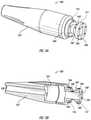
- FIG. 2illustrates a delivery system in a delivery configuration for delivering the valve prosthesis, including a radially expandable valve anchor and a support frame, using an engagement mechanism for releasable engaging the expandable valve anchor, according to some embodiments.
- FIG. 3Ais an illustration of a nose cone of the valve anchor of the delivery system of FIG. 2 , according to some embodiments.
- FIG. 3Billustrates a cross-sectional view of the nose cone of the valve of FIG. 3 , according to some embodiments.
- FIG. 4Aillustrates a pin assembly of the delivery system of FIG. 2 , according to some embodiments.
- FIG. 4Billustrates an alternative pin assembly, according to some embodiments.
- FIG. 5Aillustrates a pusher component of the delivery system of FIG. 2 , according to some embodiments.
- FIG. 5Billustrates an alternative pusher component, according to some embodiments.
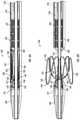
- FIG. 6Aillustrates the support frame and the valve anchor housed in a compact state within a sheath of the delivery system of FIG. 2 , according to some embodiments.
- FIG. 6Billustrates the valve anchor in an expanded configuration, partially released from the sheath and engaged with the engagement mechanism, which is in a pre-released configuration, according to some embodiments.
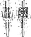
- FIG. 6Cillustrates the distal advancement of the support frame and a pusher component of the engagement mechanism to initiate disengagement of the valve anchor from the engagement device, according to some embodiments.
- FIG. 6Dillustrates the valve anchor and the engagement mechanism in a released configuration, prior to release of the support frame from the sheath of the delivery system, according to some embodiments.
- FIG. 6Eillustrates the sheath being proximally retracted to permit the valve prosthesis to begin expansion, according to some embodiments.
- FIG. 6Fillustrates the valve prosthesis fully expanded within the valve anchor, according to some embodiments.
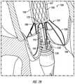
- FIGS. 7A-7Fillustrate steps in a method for delivering the valve prosthesis through the aorta to the native aortic valve using a valve prosthesis delivery system, according to some embodiments.
- a healthy aortic valvewill open to allow blood flow and close to prevent backflow of blood.
- disease and dysfunction of the valvecan result in regurgitation or decreased blood flow.
- a replacement valve prosthesismust be used to perform the functions of a healthy aortic valve.
- a suitable replacement valve prosthesisin order to overcome the problem of regurgitation or decreased blood flow, a suitable replacement valve prosthesis must provide an acceptable seal and anchoring against the native valve tissue when positioned and released against the native valve structure, such as the native valve annulus.
- the architecture of the aortic valve annulusalso creates a challenge in the design of an aortic valve prosthesis. Indeed, the aortic valve prosthesis must conform to the unique anatomical structure of the aortic valve and remain anchored in the presence of the continuous contractions of a functioning heart.
- the present disclosuredescribes systems, devices, and methods for implanting an aortic valve prosthesis using a minimally invasive surgical technique.
- the systemsaccommodate the complex structure of the aortic valve to ensure that the implanted valve prosthesis is properly positioned and securely maintained in place after implantation.
- some embodimentsalso provide an aortic valve prosthesis delivery system that can comprise an aortic valve prosthesis.
- the valve prosthesiscan comprise an expandable valve anchor, a support frame that can be coupled to the valve anchor, and a plurality of valve leaflets coupled to the support frame.
- the implantcan have a plurality of prosthetic valve leaflets attached to an internal surface thereof that can mimic the function of a native aortic valve.
- the implant and valve anchorcan have a compact configuration for delivery to a diseased valve, and an unfolded or expanded configuration upon release and implantation in the diseased valve annulus.
- the implant and the valve anchorcan be positioned relative to each other to minimize the diameter of the valve component during delivery.
- the implantcan be flexibly coupled to the valve anchor to provide efficient positioning of both the valve anchor and the implant.
- the implant and the valve anchorcan be connected by a flexible element such that prior to releasing and expanding the valve component in the heart or native valve structure, the implant and the valve anchor can be longitudinally or rotationally displaced relative to one another. Further, the implant and the valve anchor can expand from a compact state to an expanded state, and in some embodiments, independently of each other.
- FIG. 1illustrates a cross-sectional view of a human heart in which an aortic valve prosthesis has been implanted in a native valve structure of the heart.
- the heart 10can comprise a right atrium 12 , a right ventricle 14 , a left ventricle 16 , and a left atrium 18 .
- Oxygen-depleted bloodenters the right atrium 12 through the superior and inferior vena cava 20 , 22 .
- the oxygen-depleted bloodis pumped from the right atrium, through a tricuspid valve 24 , which separates the right atrium 12 from the right ventricle 14 , and into the right ventricle 14 .
- the right ventricle 14then pumps the oxygen-depleted blood through a pulmonary valve 26 and into pulmonary arteries 28 that direct the oxygen-depleted blood to the lungs for oxygen transfer to the oxygen-depleted blood. Thereafter, oxygen-rich blood is transported from the lungs through pulmonary veins 30 to the left atrium 18 . The oxygen-rich blood is pumped from the left atrium 18 through a mitral valve 32 and into the left ventricle 16 . The left ventricle 16 then pumps the oxygen-rich blood through an aortic valve 34 and into the aorta 36 . The oxygen-rich blood is carried by the aorta to a series of arteries that transport the blood to various organs in the body.
- Implantation of a prosthetic aortic valve via a minimally invasive transcatheter approachmay be accomplished, e.g., through the femoral artery and aortic arch into the left atrium or through the femoral vein and inferior vena cava by way of a transseptal punch.
- the aortic valve, between the left atrium and left ventriclemay be the most difficult valve to repair percutaneously because it can be difficult to reach.
- the aortic valvecan be reached via the left ventricle and mitral valve, manipulation of catheters that have to make two approximately 180° turns is cumbersome.
- various embodimentsare provided that allow a clinician to overcome these disadvantages and effectively deliver a prosthetic valve to a target location in the heart.
- the present disclosureprovides devices, systems, and methods for valve replacement, preferably using a minimally invasive surgical technique. While the systems and methods will have application in a number of different vessels in various parts of the body, they are particularly well suited for replacement of a malfunctioning cardiac valve, and in particular an aortic valve. The systems and methods will also have application in other malfunctioning cardiac valves, e.g., a pulmonary valve or a mitral valve.
- the systems and methods disclosed hereincan be particularly advantageous in their ability to provide a more flexible prosthetic heart valve delivery system, ensure accurate and precise placement of the prosthetic heart valve or valve prosthesis with reduced reliance on imaging, and provide additional anchoring of the valve prosthesis, reducing the incidence of valve migration.
- Another advantage of the systems and methods disclosed hereinis the ability to deliver and implant the valve prosthesis through the aorta, which has a smaller diameter than the inferior vena cava, through which surgeons typically proceed to access the heart.
- the present disclosurealso provides improved systems and methods for implanting a prosthetic heart valve.
- improved minimally invasive methods and systemsare provided for retrograde implantation of expansible prosthetic heart valves within or adjacent a valved anatomic site within the heart.
- the improved prosthetic heart valve delivery systems and methods of the present disclosureprovide more flexibility in the valve replacement procedure, ensure accurate and precise placement of the prosthetic heart valve with reduced reliance on imaging, and provide additional anchoring of the prosthetic valve, reducing the incidence of valve migration or misalignment.
- a delivery systemcapable of maneuvering tight turns, and including a compactly configured valve prosthesis, which can comprise a valve anchor, a support frame that can be coupled to the valve anchor, and an engagement mechanism for releasable engaging the valve anchor.
- a compactly configured valve prosthesiswhich can comprise a valve anchor, a support frame that can be coupled to the valve anchor, and an engagement mechanism for releasable engaging the valve anchor.
- the valve anchor and support frameare delivered to a target location in a collapsed configuration serially (or longitudinally spaced relative to each other), rather than concentrically positioned relative to one another, thereby minimizing the outer profile or diameter of valve prosthesis and that of delivery system during delivery.
- the valve prosthesis delivery system described hereinthus facilitates delivery of a valve prosthesis to the heart while minimizing trauma or damage to the vessels and tissues of a patient.
- the various embodiments described hereinprovide a means for both pushing and pulling the valve prosthesis delivery system through the tight turns presented by the heart chambers. It is noted that for the purposes of describing the disclosed systems and methods, the term “proximal” refers to a relative position closer to a control unit whereas the term “distal” refers to a relative position further away from a control unit.
- FIG. 2illustrates a valve prosthesis delivery system 100 that can support and deliver a valve prosthesis 105 .
- the valve prosthesis 105can comprise a support frame 107 and a valve anchor 120 .
- the delivery system 100may include a core member 110 and an engagement mechanism 115 that can be configured for releasably engaging the valve anchor 120 relative to the core member 110 .
- the delivery system 100can also comprise a sheath 150 that can extend distally to cover the support frame 107 and the valve anchor 120 . The sheath 150 can maintain the support frame 107 and the valve anchor 120 in a compressed configuration during delivery of the system 100 to the target location.
- the clinicianWhen positioned at the target location, the clinician can proximally retract the sheath 150 in order to permit the support frame 107 to begin expanding. Thereafter, additional actuation of the engagement mechanism 115 and further proximal retraction of the sheath 150 can enable a clinician to release the valve prosthesis 105 at the target location.
- the engagement mechanism 115may include a pin assembly 125 slidably coupled to the core member 110 and a lock component 140 . Together, the pin assembly 125 and the lock component 140 can engage one or more structures of the valve anchor 120 and, when released by the clinician, can disengage from the valve anchor 120 to permit the valve anchor 120 to fully expand or be released at the target location. In this manner, the clinician can precisely control the release of the valve anchor 120 from the delivery system 100 .
- the valve anchor 120may be positioned serially with a support frame 107 of the valve prosthesis 105 .
- Both the support frame 107 and the valve anchor 120can be made from a shape memory material such that they can be compressed to a radius which allows delivery through, for example, arteries and veins, then expanded as needed for expansion and placement of the valve prosthesis 105 in a desired position.
- the support frame 107 and/or the valve anchor 120can optionally be balloon-expandable or be further expandable using a balloon
- the embodiment illustrated in FIG. 2is configured such that the support frame 107 or the valve anchor 120 self-expand when the sheath 150 is proximally retracted to position in which the sheath 150 does not longitudinally overlap the respective one of the frame 107 or the valve anchor 120 .
- the support frame 107 and/or the valve anchor 120can comprise a braided frame, a wire frame, or a laser-cut frame, as shown in FIG. 2 .
- the support frame 107 and/or the valve anchor 120can comprise a shape-memory metal, which can change shape at a designated temperature or temperature range or by inducing stress.
- the self-expanding framescan include those having a spring-bias.
- the material from which either the support frame 107 and/or the valve anchor 120 is fabricatedcan allow the support frame 107 and/or the valve anchor 120 to automatically expand to its functional size and shape when deployed but also allows the support frame 107 and/or the valve anchor 120 to be radially compressed to a smaller profile for delivery through the patient's vasculature.
- suitable materials for self-expanding components described hereininclude, but are not limited to, medical grade stainless steel, titanium, nickel titanium alloys, tantalum, platinum alloys, niobium alloys, cobalt alloys, alginate, or combinations thereof.
- self-expanding components described hereincan include materials including, but not limited to shape memory plastics, polymers, and thermoplastic materials, which are inert in the body.
- either the support frame 107 and/or the valve anchor 120is not self-expanding, and may be expanded, for example, using a balloon catheter as is well known in the art.
- the valve anchor 120may be movably coupled to the support frame 107 such that the valve anchor 120 may be moved from a concentric position with the support frame 107 to a proximal or distal position from the support frame 107 .
- the distance from which the valve anchor 120 may be serially displaced from the support frame 107is variable, such that the valve anchor 120 may be adjacent to the support frame 107 , or potentially inches away from the support frame 107 during the delivery procedure.
- the valve anchor 120is physically fixed to the support frame, such as by welding or otherwise adhering.
- the delivery system 100can be configured such that components of the heart valve prosthesis to be advanced in series while still being movably connected, movably attached, flexibly connected, displaceably connected, linked, or coupled to each other, thereby minimizing a passing profile or cross section of the delivery system.
- the interconnection of components of the heart valve prosthesiscan allow different degrees of motion and can be set into an engaged or retained position that provides a limited range of motion.
- the engaged positioncan also provide a preset relative positioning of the components of the heart valve prosthesis to facilitate proper placement and release of the heart valve prosthesis.
- some embodimentscan provide a clinician with a high degree of control and enhance the maneuverability of the heart valve prosthesis when implanting the heart valve prosthesis at the target location.
- the valve anchor 120can be coupled to the support frame 107 when the support frame 107 is in the compact configuration prior to delivery and expansion. In some embodiments, the valve anchor 120 is not fixed to the support frame 107 . Further, the valve anchor 120 can be separate from the support frame 107 or formed separately from and later coupled to the support frame 107 . Thus, although a least a portion of the valve anchor, e.g., the anchoring leg, may be in contact with or otherwise reversibly attached or connected to the support frame, no part of the valve anchor is fixed, e.g., welded or otherwise irreversibly adhered, to the support frame. Alternatively stated, the valve anchor, which may be in contact with or otherwise reversibly attached to the support frame, is not irreversibly fixed to the support frame.
- the valve anchor 120can be movably coupled to the support frame 107 in a manner that prevents the entire valve anchor 120 from being radially displaced from the support frame 107 when the valve anchor 120 is initially expanded. For example, portions of the valve anchor 120 can be radially displaced from the support frame during initial “landing” of the valve anchor 120 against the native valve structure at the target location.
- the support frame 107can be deployed or expanded within the native heart valve structure, and the valve anchor 120 can become sandwiched between the support frame and the native valve tissue, becoming at least partially, and possibly fully, immobilized (as shown, for example, in FIGS. 7E and 7F ).
- the valve anchor 120can function to hold the expanded support frame 107 in place within the native valve structure.
- the valve anchor 120can comprise at least one U-shaped member, anchoring member, valve clasper, sinus locator, valve positioner, or valve hanger 126 and at least one anchoring leg 122 .
- the U-shaped member 126 and the anchoring leg 122can extend along a longitudinal axis of the valve anchor 120 .
- the valve anchor 120can comprise a plurality of U-shaped members 126 , such as three U-shaped members 126 , but can have fewer or more.
- the U-shaped members 126can be coupled to the anchoring legs 122 at peak portions or apices 128 of the valve anchor 120 . Further, adjacent U-shaped members 126 can be coupled to each other at a respective apex 128 .
- the U-shaped members 126can each comprise first and second legs 146 , 148 that meet or join at a base portion 144 thereof.
- the base portions 144 of the U-shaped members 126can be configured to engage with or fit inside the posterior aortic sinus, the left aortic sinus, and the right aortic sinus of a native aortic valve.
- the first and second legs 146 , 148 of the adjacent U-shaped members 126can be interconnected at the peak portions 128 thereof.
- the valve anchor 120may include at least one anchoring leg 122 .
- the anchoring leg 122can include a coupling portion 124 having a connector or connection aperture 127 .
- the connectorcan comprise structures, such as slots or holes extending through the coupling portion 124 .
- the anchoring leg 122 of the valve anchor 120is positioned approximately parallel relative to the longitudinal axis of the support frame 107 and is attached to U-shaped member 126 at an apex 128 .
- the apex 128may be a vertex where the U-shaped member(s) 126 joins with the anchoring leg 122 .
- two U-shaped members 126may curve to join the anchoring leg 122 at the vertex or apex 128 .
- the vertices of the valve anchor 120may be configured such that two anchoring legs 122 extend approximately parallel relative to each other.
- the valve anchor 120includes at least two U-shaped members 126 and two anchoring legs 122 .
- each of the first or proximal ends of the two anchoring legs 122are joined to the U-shaped member 126 .
- the second or distal end of one or more of the anchoring legs 122terminates in a coupling portion 124 . That is, the coupling portion 124 of the valve anchor 120 is positioned at an end portion of the valve anchor anchoring leg 122 .
- the coupling portion 124may be made of a shape memory alloy such as nitinol.
- the coupling portion 124may be oriented parallel relative to a longitudinal axis of the valve prosthesis 105 , while for other applications, the coupling portion 124 may be oriented to form an angle with respect to the longitudinal axis.
- the coupling portion 124may be approximately parallel relative to the longitudinal axis of the support frame 107 in the compact position and/or when the valve prosthesis 105 is encased in a sheath 150 .
- the coupling portion 124may form an angle with respect to the longitudinal axis of the valve prosthesis 105 or the anchoring leg 122 when the valve prosthesis 105 is in an expanded condition.
- the detentscan help to secure the valve anchor 120 to the support frame 107 after the valve prosthesis 105 is expanded in the native valve.
- the shape of the base portion 144 joining the two anchoring legs 122 of the U-shaped member 126is not limited to being a U-shaped or rounded.
- the base portion 144may have other shapes including, but not limited to, rectangle, square, diamond, triangle, oval, circle, or a combination of these shapes.
- the base portion 144may be of any shape that allows it to engage and/or rest adjacent to the commissure of the native valve leaflets 190 .
- the valve anchor 120may comprise a plurality of U-shaped members 126 coupled to the support frame 107 . That is, the delivery system 100 may include, but is not limited to, two, three, four, five, or more plurality of U-shaped members 126 , to accommodate different valve replacement procedures or according to the anatomical structure of the native valve that is to be replaced. In the various embodiments disclosed in the figures, the number of plurality of U-shaped members 126 in the valve prosthesis is three.
- the valve prosthesis 105can be configured such that the support frame 107 is coupled to the valve anchor 120 .
- the valve prosthesis 105can comprise at least one suture 170 that couples the support frame 107 to the valve anchor.
- a distal end portion of the support frame 107can be coupled to the valve anchor 120 via the suture 170 .
- the portion of the suture 170 that attaches to the valve anchor 120can be coupled to and anchoring leg 122 of the valve anchor 120 .
- the anchoring leg 122can comprise a longitudinal slot 123 that extends along the length of the anchoring leg.
- the suture 170can loop into the slot 123 and be coupled with the anchoring leg 122 . This can enable the suture 170 to slide along the length of the slot 123 during expansion of the valve prosthesis 105 , as discussed further herein.
- FIGS. 3A and 3Bare illustrations of perspective and cross-sectional views of an embodiment of a nose cone 156 of the valve anchor delivery system 100 of FIG. 2 .
- the delivery system 100may include a nose cone 156 at a distal end thereof.
- the nose cone 156may have a substantially tubular and/or conical profile that tapers towards a distal end of the nose cone 156 .
- the nose cone 156can comprise a lock component 140 and a cavity 141 .
- the nose cone 156can interact as part of the engagement mechanism 115 , to permit the lock component 140 and the pin assembly 125 to engage the valve anchor 120 .
- the nose cone 156may be configured to be coupled to or mate with a distal end of the valve sheath 150 in order to reduce any seam along the outer surface of the delivery system 100 between the nose cone 156 and the sheath 150 .
- the mating engagement between the nose cone 156 and the sheath 150can thereby provide a smooth, continuous outer surface of the delivery system 100 .
- the nose cone 156may include a radial depression 154 against which the distal end of the valve sheath 150 can be positioned in a delivery configuration.
- the radial depression 154can permit at least a portion of the nose cone 156 , including the lock component 140 , to be inserted into a lumen 152 of the valve sheath 150 to detachably couple the nose cone 156 to the valve sheath 150 .
- the radial depression 154is illustrated as having a generally conical profile, the radial depression 154 can also comprise a stepped profile in which the outer diameter of the nose cone 156 steps down from a diameter approximately equal to an outer diameter of the sheath 150 to a diameter that is approximately equal to an inner diameter of the sheath 150 . In this manner, the nose cone 156 can fit inside of the sheath lumen and engage with the sheath 150 while both having a common or approximately equal outer diameter.
- the lock component 140can be integrally formed with nose cone 156 .
- the nose cone 156can be an assembly of components, including a distal cone component 157 and the lock component 140 .
- the lock component 140can comprise an aperture 158 through which the pin assembly may be engaged or moved by the pusher component, as discussed below.
- a proximal end portion of the distal cone component 157can be coupled with a distal end portion of the lock component 140 by welding, frictional engagement, or other adhesive means.
- the distal cone component 157 and the lock component 140can collectively form the cavity 141 .
- both the distal cone component 157 and the lock component 140can comprise inner cavities that combined to form the cavity 141 when the distal cone component 157 and the lock component 140 are coupled together.
- the cavity 141can provide a volume in which the pin assembly 125 of the engagement mechanism can reciprocate.
- the nose cone 156may further include a channel or passageway 155 extending centrally along a longitudinal axis of the nose cone.
- the channel 155may be configured to receive the core member 110 as the core member reciprocates proximally and distally along the longitudinal axis in order to cause a corresponding motion of the support frame 107 and the valve anchor 120 .
- the lock component 140may include at least one lock aperture 145 .
- the lock aperture 145may be disposed proximal to the cavity 141 .
- the pin assembly 125can include a plurality of pins 135
- the lock component 140can include a plurality of lock apertures 145 , each corresponding to one of the plurality of pins 135 .
- the lock component 140can comprise an engagement region 143 interposed between a proximal flange 147 and a distal flange 149 .
- the lock aperture 145can extend through both the proximal flange 147 and the distal flange 149 .
- the lock aperture 145 that extends through the distal flange 149can extend into the cavity 141 . Accordingly, a pin extending from the pin assembly 125 can pass through the distal flange 149 , extend across the engagement region 143 , and pass through the proximal flange 147 .
- a pin of the pin assembly 125can be radially constrained by the lock aperture 145 extending through the distal flange 149 and the proximal flange 147 and engage with a portion of the valve anchor 120 that extends into the engagement region 143 .
- the pin assembly 125can reciprocate within the cavity 141 between an engaged configuration (shown in FIGS. 6A-6C ) and a disengaged configuration (shown in FIGS. 6D-6F ).
- an engaged configurationshown in FIGS. 6A-6C
- a disengaged configurationshown in FIGS. 6D-6F
- pins 135 of the pin assembly 125can slide out of engagement with the lock apertures 145 of the lock component 140 .
- the pins 135can be distally advanced out of the engagement region 143 and received into the cavity 141 and the distal flange 149 , thus disengaging with valve anchor 120 and permitting the valve anchor 120 to expand out of the engagement region 143 .
- the pin assembly 125 and the lock component 140can engage the valve anchor 120 in an engaged configuration.
- the valve anchor 120remains engaged with the delivery system 100 , thereby permitting the clinician to rotate, repositioning, or otherwise maneuver the U-shaped members of the valve anchor 120 into a desired position relative to the native valve structure.
- FIGS. 4A and 4Billustrate a pin assembly 125 and an alternative pin assembly 125 ′, either of which can be used with the delivery system 100 of FIG. 2 , according to some embodiments.
- the pin assembly 125may comprise a tubular component 130 having a proximal section 132 and a distal section 134 .
- both pin assemblies 125 , 125 ′can comprise an annular component, such as a piston member 136 , and at least one pin 135 coupled to the annular component or piston member 136 .
- the annular componentcan have the shape of a disc, a cylinder, a torus, or others that can be coupled to and at least partially surround the core member 110 .
- the pin assembly 125can also be configured such that the distal section 134 of the tubular component 130 is coupled to the piston member 136 .
- the alternative pin assembly 125 ′can be identical to the pin assembly 125 of FIG. 4A in all respects except for the absence of the tubular component 130 .
- the pin assemblies 125 , 125 ′can slide along the core member 110 of the delivery system 100 .
- the core member 110can be configured to extend through the lumen 133 of the pin assembly 125 .
- the lumen 133can extend through both the tubular component 130 and the piston member 136 .
- pin assembly 125may lie in the presence of the tubular component 130 , which can assist in maintaining axial alignment of the piston member 136 and the pins 135 relative to the longitudinal axis of the delivery system 100 during use.
- the longitudinal extent of the lumen 133 through the piston member 136can be of a sufficient length in order to prevent misalignment or wobbling of the piston member 136 relative to the core member 110 .
- both pin assemblies 125 , 125 ′can advantageously maintain the pins 135 in an alignment that is approximately parallel relative to the core member 110 . In this manner, the pins 135 can slide smoothly out of engagement with the lock apertures 145 of the lock component 140 .
- proximal ends of the pins 135can be advanced distally through the engagement region 143 sufficiently to permit the valve anchor 120 to disengage therefrom.
- the valve anchor 120may be able to disengage therefrom.
- the proximal ends of the pins 135may be fully received into the lock apertures 145 such that the pins 135 do not extend into the engagement region 143 in the disengaged configuration.
- pins 135Although only one or two pins 135 may be used, the illustrated embodiments provide for three pins 135 to be used.
- the pins 135extend proximally from the piston member 136 and can be radially spaced apart from the tubular component 130 .
- the piston member 136can comprise two plates or discs that are coupled to each other.
- the pins 135may be positioned to extend through a proximal plate with distal end portions of the pins 135 being sandwiched between the proximal plate and a distal plate of the piston member 136 , thereby engaging the distal end portions of the pins 135 therebetween.
- the distal end portions of the pins 135may be bent at angles, as illustrated in FIGS. 6A-6F , and at least one of the two piston members 136 may have a groove formed therein to accommodate and hold the bent distal end portions of the pins 135 in a fixed position with respect to the pin assembly 125 when the proximal and distal plates of the piston member 136 are coupled together.
- the pinscan be welded, mechanically fastened, or otherwise adhesively coupled to the piston member 136 . Accordingly, the piston member 136 and the pins 135 can slide along the core member 110 as a unit between engaged and disengaged positions, as discussed herein.
- FIGS. 5A and 5Billustrate a pusher component 165 and an alternative pusher component 165 ′, either of which can be used with the delivery system 100 of FIG. 2 , according to some embodiments.
- the pusher component 165can be used in combination with the pin assembly 125 , shown in FIG. 4A .
- the pusher component 165 ′can be used in combination with the pin assembly 125 ′, shown in FIG. 4B .
- the pusher component 165may vary from the pusher component 165 by including a shaft component 167 that can extend through the aperture 158 of the lock component 140 of the nose cone 156 .
- the shaft component 167 of the pusher component 165 ′can extend through or into the aperture 158 to facilitate movement and disengagement of the pin assembly 125 ′.
- these components 125 , 125 ′, 165 , 165 ′can be interchanged or modified in any of the embodiments disclosed herein.
- the pusher component 165can be contacted against the tubular component 130 of the pusher component 165 extending through the aperture 158 of the lock component 140 .
- the shaft component 167 of the pusher component 165 ′can extend through the aperture 158 of the lock component 140 to contact against the pin assembly 125 ′.
- the pusher component 165 and the pusher component 165 ′may each comprise a lumen 166 through which the core member 110 can pass, thereby permitting the pusher component 165 and the pusher component 165 ′ to be slidably disposed along the core member 110 .
- the pusher component 165(whether the pusher component 165 and the pusher component 165 ′) can be disposed distally relative to the support frame 107 .
- the pusher component 165can be contacted against the tubular component 130 of the pusher component 165 , which extends through the aperture 158 of the lock component 140 .
- the pusher component 165can have an outer diameter or profile that is about equal to a compressed diameter of the support frame 107 .
- the pusher component 165 and the support frame 107can be received within the lumen of the sheath 150 . Further, the distal end portion of the support frame 107 can abut or contact a proximal face 172 of the pusher component 165 .
- some embodimentscan permit the support frame 107 to be pressed distally against the proximal face 172 of the pusher component 165 in order to exert a distally directed force against the pusher component 165 , which can then cause the pusher component 165 to contact the pin assembly 125 and cause disengagement of the pins 135 from the valve anchor 120 .
- the pusher component 165comprises a flange 175 .
- the flange 175may be a radial flange that defines the proximal face 172 .
- the pusher component 165can comprise a distal face 174 having a generally sloped or conical profile. The conical profile of the distal face 174 can tend to allow the pusher component 165 to avoid catching or otherwise engaging with the valve anchor 120 during distal advancement of the pusher component through the valve anchor 120 , as discussed below.
- distal advancement of the pusher component 165can be achieved by contacting the distal end of the support frame 107 against the proximal face 172 of the pusher component 165 .
- the delivery system 100can comprise a pushing block 178 that is coupled to a pusher tube 179 .
- the pusher tube 179 and the pushing block 178can each comprise lumens through which the core member 110 can pass.
- the pusher tube 179 and the pushing block 178can be slidably positioned along the core member 110 .
- the pusher tube 179 and the pushing block 178can be distally advanced by the clinician along with the sheath 150 , which can exert a distal force against the support frame 107 and the pusher component 165 .
- This distally oriented forcecan urge the pusher component 165 toward a proximal contact face or area 137 of the pin assembly 125 , 125 ′, shown illustratively by the movement depicted from FIGS. 6B to 6C .
- the distal face 174 of the pusher component 165 , 165 ′can contact the proximal contact face 137 of the pin assembly 125 , 125 ′ and urge the pin assembly 125 , 125 ′ in a distal direction relative to the lock component 140 .
- the tubular sectioncan be coupled to either the pusher component or the pin assembly or to both. Movement of the pin assembly 125 , 125 ′ in the distal direction results in shifting of the engagement mechanism 115 from the engaged configuration (shown in FIG. 6C ) to the released configuration (shown in FIG. 6D ).
- the pusher tube 179 and the pushing block 178can be actuated via a control unit (not shown) that can be operated by the clinician.
- the control unitcan be communicatively coupled to the core member 110 and to the pusher tube 179 to allow the clinician to actuate or move the core member 110 relative to the pusher tube 179 .
- the pusher tube 179can be distally advanced over the core member 110 in order to cause the pusher component 165 to contact the pin assembly 125 and cause the pin assembly 125 to move within the cavity 141 of the nose cone 156 , thereby distally advancing the pins 135 through the engagement region 143 .
- control unitcan be communicatively coupled to the pusher component 165 to selectively actuate the pusher component 165 without requiring interaction from the pusher block 178 and the support frame 107 .
- the pusher component 165can be directly coupled to the pusher tube 179 in order to directly actuate the pusher component 165 to contact and urge the pin assembly 125 in the distal direction relative to the lock component 140 . Similar to the embodiment illustrated in figures, such an embodiment can move the engagement mechanism 115 from the engaged configuration to the released configuration.
- the lumen 166 of the pusher component 165can have an inner diameter that is smaller than an inner diameter of the tubular component 130 or the lumen 133 of the pin assembly 125 . Such embodiments can thus allow the pusher component 165 to have a sufficient cross-sectional profile to allow the pusher component 165 to advance distally and contact and eventually urge or push the pin assembly 125 distally.
- FIGS. 6A-6Cillustrate the valve anchor 120 of the delivery system 100 in the engaged configuration.
- the legs 122 of the valve anchor 120are inserted into the engagement region 143 and locked in place via the engagement mechanism 115 , this is referred to the engaged configuration (see FIGS. 6A-6C ).
- the pins 135are positioned extending from the cavity 141 of the nose cone 156 , through the connection aperture 126 of the valve anchor leg 122 , and into and through the lock apertures 145 of the lock component 140 of nose cone 156 .
- the at least one leg 122 of the valve anchor 120is locked in engagement at a position between the lock component 140 of the nose cone 156 and the rest of the nose cone 156 .
- FIG. 6Aillustrates the valve prosthesis 105 and the valve anchor 120 housed in a compact state within the sheath 150 of the delivery system 100 , according to some embodiments.
- the delivery system 100is initially introduced into the target location of the defective valve, the delivery system 100 is delivered in the compact state, as illustrated in FIG. 6A .
- FIG. 6Billustrates the valve anchor 120 in an engaged configuration, but released from the sheath 150 of the delivery system 100 of FIG. 2 , according to some embodiments.
- the sheath 150 of the delivery system 100is proximally retracted relative to the core member 110 via, for example, a control unit including at least one controller or processor. Retraction of the sheath 150 from over the valve anchor 120 allows the valve anchor 120 to expand radially.
- the U-shaped members 126can thereafter be guided and maneuvered into a desired position relative to the surrounding native valve structure, as discussed herein.
- FIG. 6Cillustrates the first step and releasing the valve anchor 120 .
- the pusher block 178 , the sheath 150 , and the support frame 107can be urged in a distal direction, thereby distally advancing the pusher component 165 towards the pin assembly 125 of the delivery system 100 .
- This distal movement of the pusher component 165 into the lumen of the valve anchor 120is possible because the valve anchor 120 has already expanded radially, despite being locked in the engaged configuration by the engagement mechanism 115 .
- the at least one U-shaped member 126 of the valve anchor 120may extend radially from the anchoring leg 122 of the valve anchor 120 and the longitudinal axis of support frame 107 .
- the tubular component distal section 134 or a proximal surface of the piston member 136is axially spaced apart from a proximal surface of the lock component 140 at a first distance D 1 .
- the first distance D 1is sufficient to permit the pins 135 to extend from the cavity 141 through the lock apertures 145 and the engagement region 143 ; as such, the pins 135 can extend through the leg connection aperture 127 of the valve anchor 120 and the lock component lock aperture 145 to interconnect the valve anchor anchoring leg 122 with the engagement mechanism 115 .
- the first distance D 1may be between about 1 mm and about 20 mm, between about 2 mm and about 15 mm, between about 4 mm and about 12 mm, between about 6 mm and about 10 mm, between about 8 mm and about 10 mm, or about 2 mm, about 2 mm, about 4 mm, about 6 mm, about 8 mm, about 10 mm, about 12 mm, about 14 mm, about 16 mm, about 18 mm, about 20 mm, about 22 mm, about 24 mm, about 26 mm, about 28 mm, about 30 mm, about 35 mm, or about 40 mm.
- FIG. 6Dis an illustration of the valve anchor 120 in a released configuration.
- the tubular component distal section 134 or the proximal surface of the piston member 136can be axially spaced apart from the proximal surface of the lock component 140 at a second distance D 2 , which is greater than the first distance D 1 .
- the second distance D 2is sufficient to position the pins 135 outside of the lock aperture 145 to permit the valve anchor leg 122 to disengage from the pins 135 of the pin assembly 135 .
- the second distance D 2may be between about 1 mm and about 20 mm, between about 2 mm and about 15 mm, between about 4 mm and about 12 mm, between about 6 mm and about 10 mm, between about 8 mm and about 10 mm, or about 2 mm, about 2 mm, about 4 mm, about 6 mm, about 8 mm, about 10 mm, about 12 mm, about 14 mm, about 16 mm, about 18 mm, about 20 mm, about 22 mm, about 24 mm, about 26 mm, about 28 mm, about 30 mm, about 35 mm, or about 40 mm.
- the pins 135are displaced a distance corresponding to the difference between D 2 and D 1 , thereby releasing the valve anchor 120 from engagement with the pin assembly 125 , and allowing the valve anchor 120 to radially expand in preparation for positioning the support frame 107 therewithin.
- the support frame 107continues to be housed within the sheath 150 of the delivery system 100 .
- the cliniciancan thereafter initiate release and expansion of the support frame 107 within the lumen of the valve anchor 120 .
- the clinicianmay distally advance the support frame 107 .
- the clinicianmay advance the support frame 107 to a position longitudinally distal to the valve anchor 120 and thereafter proximally retract the support frame 107 . Such a motion may ensure that the native valve leaflets are drawn upwardly between a space between the valve anchor 120 and the support frame 107 . Thereafter, the expansion and release of the support frame 107 can be initiated by the clinician, as discussed further below.
- FIG. 6Eillustrates the sheath 150 being proximally retracted to expose and permit initial expansion of the support frame 107 .
- FIG. 6Fillustrates the sheath 150 being further retracted to permit the support frame 107 to be fully expanded within the valve anchor 120 .
- further retraction of the sheath 150causes the valve prosthesis 105 to be completely exposed, thereby allowing the valve prosthesis to expand radially within the valve anchor 120 .
- the outward force of the self-expanding support frame 107can cause the support frame 107 to spring open after the sheath 150 has been partially proximally withdrawn (i.e., reaching a position distal to that illustrated in FIG. 6F ).
- Methods for implanting an aortic valve prosthesis using the delivery system described hereininvolve non-surgical delivery and implantation of an aortic valve prosthesis wherein a self-expandable implant with prosthetic leaflets is flexibly coupled to a valve anchor, and wherein the support frame and the valve anchor are delivered in a compact condition.
- delivery systems disclosed hereincan be operated to release the valve anchor prior to expansion of the support frame.
- the valve anchormay be manipulated and re-positioned after expansion to ensure proper placement before expanding or releasing the support frame.
- the systemcan be operated using any of a variety of imaging techniques, including ultrasound, fluoroscopy, or pulsatile feedback, such as electric pulses or ultrasound pulses.
- the valve anchorcan be positioned using imaging techniques, if desired.
- the cliniciancan determine or feel, via tactile pressure, that valve anchor has been properly seated or engaged with the native valve structure to confirm proper positioning of the valve anchor relative to the native valve structure.
- the support framecan be moved distally along the longitudinal axis toward the valve anchor had eventually be positioned approximately concentric with the valve anchor.
- the support framemay be released, and the delivery system can be removed from the patient.
- the support framecan be implanted over the existing native valve leaflets.
- FIGS. 7A-7Fillustrate a method for operating a valve prosthesis delivery system.
- the delivery systemcan be advances through the aorta to the native aortic valve using a delivery system, such as the embodiment described above in FIGS. 6A-6F .
- a guiding mechanisme.g., a guidewire 180 may be advanced towards the target location and fed through the core member 110 to permit the delivery system 100 to advance toward the target location along the guidewire 180 . Entry of the delivery system 100 into the vasculature can occur through a variety of paths.
- the guidewire 180can be introduced into the aorta and advanced towards the aortic arch.
- the delivery system 100can then be advanced along the guide wire 180 until reaching the target location, e.g., the aortic valve of the heart.
- FIG. 7Aillustrates the delivery system 100 after reaching the aortic valve.
- the delivery system 100can be delivered to the target location a delivery configuration ( FIG. 6A ) and later manipulated to permit expansion of various components of the valve prosthesis 105 .
- FIG. 6Aillustrates the delivery system 100 as it is configured prior to inserting the delivery system into the patient and during advancement of the delivery system through the patient's vasculature toward the target location.
- the valve prosthesis 105is packed within the delivery system 100 in a compact configuration such that the support frame 107 and the valve anchor 120 of the valve prosthesis 105 are packed serially within the sheath 150 .
- the guidewireis first introduced into the patient, e.g., into the femoral artery or, if using a transapical procedure, into the left ventricle, and advanced to the appropriate heart chamber, past or beyond the native cardiac valve in need of repair.
- the present disclosurecan also provide for transapical delivery of the valve prosthesis 105 .
- a method of delivering a valve prosthesis to a target location having a damaged or defective valveincludes advancing the delivery system 100 into a blood vessel, e.g., the aorta, to position the valve anchor 120 at the target location.
- the target locationis a position adjacent to an aortic valve of a patient's heart.
- the target locationmay be a position directly above the native aortic leaflets 190 , as illustrated in FIG. 7A .
- the advancing of the delivery system 100may be achieved by advancing a distal end thereof to the target location in a direction opposite to that of blood flow.
- the cliniciancan control the delivery system 100 by actuating one or more actuators on the control unit.
- the actuator(s)may be, but is not limited to a knob, a lever, a trigger, a slider, a button, and/or a handle of the control unit. Actuation of the actuator can cause the sheath 150 to retract proximally and reveal at least a portion of the valve anchor 120 at the target location (as shown in FIGS. 6A to 6B and 7A ). Proximal retraction of the sheath 150 permits the U-shaped members 126 of the valve anchor 120 to expand at the target location for positioning the valve anchor 120 in a desired orientation.
- the U-shaped member 126As portions of the U-shaped member 126 are exposed, they will tend to expand radially away from the central axis (or guidewire axis). The radial extension of the U-shaped members 126 can permit the clinician to at least initially align, position, and/or rotate the delivery system 100 into proper alignment within the native valve. In some situations, advancement of the delivery system 100 through the native vasculature can tend to cause the U-shaped member to bend backwards or evert in a direction opposite that shown in FIG. 7A .
- the sheath 150can be distally advanced relative to the valve anchor 120 to push or urge the U-shaped members into a forward-pointing or non-everted orientation, as shown in FIG. 7A .
- FIG. 7Aillustrates placement of the distal end of delivery system 100 including the nose cone 156 within the aorta past the native aortic valve.
- the distal end section of the delivery system 100including the nose cone 156 , can be advanced and positioned in the aorta past the native aortic valve leaflets 190 .
- the valve sheath 150can be pulled in a proximal direction to uncover the valve anchor 120 . This allows the base portions 144 of the U-shaped members 126 of the valve anchor 120 to radially expand towards the interior wall of the aorta.
- the base portions 144 of the valve anchor 120function as “feelers” which allow the clinician to properly place the valve anchor 120 and support frame 107 within the native valve structure with minimal or no imaging during the time of expansion (see FIGS. 7A and 7B ).
- the valve anchor 120may be made of, but not limited to, a shape memory material or metal, such as nitinol, as discussed herein.
- the delivery system 100is further advanced distally and/or rotates until the valve anchor 120 gently sits in the native aortic structure, such as the annulus or sinuses, at the target location. While the valve anchor 120 is advanced distally, it rotates and can self-align according to the anatomical orientation of the native aortic leaflets 190 , as shown in FIG. 7B .
- the cliniciancan distally advance the pusher component 165 to contact and distally advance the pin assembly 125 relative to the lock component 140 .
- the distal advancement of the pusher component 165comprises distally advancing the pusher block 178 to contact and displace the support frame 107 and the pusher component 165 in a distal direction until contacting the pin assembly 135 . This causes an increase in the axial spacing between the lock component 140 and the piston member 136 (not shown), as illustrated by distances D 1 and D 2 in FIGS. 6C and 6D , thereby distally advancing the pins 135 out of the engagement region 143 .
- the distally advancement of the pusher component 165comprises contacting and distally displacing the proximal face 172 of the radial flange 175 (not shown, but see FIGS. 6B-6D ) of the pusher component 165 relative to the core member 110 , by distally advancing the support frame 107 in the collapsed state by advancing the pusher block 178 and the sheath 150 relative to the core member 110 .
- Distal advancement of the pin assembly 125 relative to the lock component 140causes the pins 135 of the pin assembly 125 to disengage from the lock aperture 145 of the lock component, thereby permitting release of the valve anchor 120 from the delivery system 100 .
- the delivery system 100can optionally be distally advanced within the valve anchor 120 in order to position the support frame 107 at a desired longitudinal position within the lumen of the valve anchor 120 . Thereafter, the valve sheath 150 (which at this time, continues to extend over or cover the support frame 107 ) can be retracted distally relative to the core member 110 towards the lock component 140 , as illustrated in FIGS. 7E and 7F .
- the delivery system 100can also be advantageously configured to position portions of the valve anchor 120 on opposing sides of the native valve leaflets. Such an ability enables the delivery system 100 to create a more secure engagement between the valve anchor 120 and the native valve structure. Such configurations and advantages can be achieved by using the engagement mechanism, which can constrain a portion of the anchoring legs of the valve anchor. Further, other embodiments can also provide additional features that facilitate engagement of the opposing sides of the native valve leaflets.
- the support frame 107can be slidably coupled to the anchoring leg 122 of the valve anchor 120 via a suture 170 , which can create a radial restriction against expansion of the proximal portion of the valve anchor 120 .
- the suture 170is accordingly moved distally along the anchoring leg 122 of the valve anchor 120 toward the lock component 140 (see FIGS. 7B-7D ).
- the relief of the radial restriction created by the sutures 170thereby permits the proximal end portion of the valve anchor 120 to expand radially outwards while holding distal ends of the valve anchor 120 stationary along a longitudinal axis thereof as the valve anchor 120 expands radially.
- the anchoring legs 122 of the valve anchor 120can thus be positioned radially inside of or central to the valve leaflets and the base portions 144 of the U-shaped members 126 can be positioned directly against the aortic wall (e.g., within the valve sinuses), radially outside of or about the periphery of the valve leaflets.
- FIG. 7Dillustrates a positioning of the support frame 107 in a final, pre-release position.
- the distal advancement of the sheath 150 and the support frame 107 to the position directly above the lock component 140also positions the support frame 107 at a pre-release position, which can be adjusted as needed after releasing the valve anchor 120 .
- the pre-release positionis a position in which the support frame 107 is disposed within the sheath 105 and longitudinally within a passage of the valve anchor 120 .
- the cliniciancan then further advance the pusher component 165 to distally advance the pin assembly 125 and thereby release the valve anchor 120 from engagement with the pin assembly 125 . That is, the anchoring legs 122 can be released from being locked or engaged in the engagement region 143 between the lock apertures 145 of the lock component 140 and the connection aperture 127 of the pin assembly 125 , as illustrated in FIG. 7E .
- FIG. 7Ealso illustrates the support frame 107 in a partially expanded configuration.
- the control unitis then activated to retract the sheath 150 proximally along the core member 110 to expose or reveal the support frame 107 and permit the support frame 107 to begin to expand.
- the support frame 107can be circumferentially constrained (i.e., the rotational orientation of the support frame 107 ) relative to the valve anchor 120 via the sutures 170 .
- the sutures 170can cause expansion of the support frame 107 can be automatically guided and secured in the proper position by the valve anchor 120 .
- the valve prosthesis 105can comprise a plurality of prosthetic valve leaflets 109 coupled to the support frame 107 .
- the valve leaflets 109can have surfaces that form a reversibly sealable opening for unidirectional flow of a liquid through the valve prosthesis 105 .
- the valve prosthesis 105can include three valve leaflets 109 for a tri-leaflet configuration. As appreciated, mono-leaflet, bi-leaflet, and/or multi-leaflet configurations are also possible.
- valve leaflets 109can be coupled to the support frame 107 to span and control fluid flow through the lumen of the valve prosthesis 105 .
- the valve prosthesis 105can comprise a membrane or sealing layer 108 that is coupled to the support frame 107 and the valve leaflets 109 .
- the membrane 108can tend to ensure that blood flows through the central aperture or lumen of the valve prosthesis 105 .
- the valve prostheses as described hereinmay be used in various aspects of implantation systems described herein or in any method or system known by one with ordinary skill in the art to implant a valve prosthesis into a subject.
- valve leaflets 190facilitates anchoring of the valve prosthesis 105 in the native valve structure and can be applicable to all coronary valves (i.e., aortic, pulmonary, tricuspid and mitral).
- the number of valve anchors 120can be equal to the number of native leaflets 190 within the native valve being treated.
- FIG. 7Fillustrates the support frame 107 in the fully expanded, released configuration.
- the support frame 107may be properly placed within the native valve structure when the base portions 144 of the U-shaped members 126 of the valve anchor 120 are approximately adjacent to the distal end of support frame 107 . Further, the support frame 107 may be properly placed within the native valve structure when expansion of support frame 107 will result in a sandwiching of the native aortic valve leaflets 190 between the expanded support frame 107 and valve anchor 120 .
- the control unitmay be actuated to retract the rest of the delivery system 100 , other than the support frame 107 and the valve anchor 120 .
- the sheath 150can be distally advanced over the core member 110 to mate the radial depression 154 of the nose cone 156 against the distal end of the sheath 150 .
- the delivery system 100can assume the delivery configuration in which the delivery system 100 has a generally smooth outer profile that will avoid catching or otherwise damaging the vasculature during removal. The delivery system 100 can thereafter be removed from the patient.
- the support frame 107when expanded and released, can comprise a first end portion 210 and a second end portion 212 .
- the first end portion 210can be positioned upstream of the second end portion 212 when the prosthesis 105 is released within the native valve structure.
- the first end portion 210 of the support frame 107can be shaped as a generally flat end of a cylinder, where first apices 214 of the support frame 107 lie generally in a common plane, which can be oriented substantially perpendicular relative to a longitudinal axis of the prosthesis 105 .
- the second end portion 212can be shaped to include a series of peaks 230 and valleys 232 , where second apices 236 of the support frame 107 collectively form contours of the peaks 230 and valleys 232 .
- the peaks 230 and valleys 232 of the second end portion 212can be positioned downstream of the first end portion 210 when the prosthesis is seated within the native valve annulus.
- the prosthetic leaflets 109can be coupled relative to the support frame 107 at locations circumferentially aligned with the peaks 230 of the second end portion 212 , as shown in FIG. 7F .
- This unique configurationcan advantageously enable the prosthesis 100 to more fully approximate the native valve structures, permit a more natural blood flow without limiting or otherwise constraining movement of the valve leaflets 109 , and more seamlessly integrate with surrounding architecture of the heart.
- an axial end of the membrane 108can be shaped to cover the major peaks 230 and valleys 232 of the second end portion 212 .
- the membrane 108can be shaped to cover the second apices or minor peaks 236 within the valleys 232 between the major peaks 230 .
- the configuration of the minor peaks 236 between the major peaks 230can allow improved access to and prevent obstructions of the ostia compared to prior art valve prostheses.
- a prior art valve prosthesis, implanted within an aortamay block or obstruct the coronary ostia disposed a distance away from the valve annulus due to the geometry of the valve frame and the membrane, as discussed in Applicant's copending patent applications U.S. Patent Application No. 62/614,488, filed on Jan. 7, 2018 (122271-5025), U.S. Patent Application No. 62/614,489, filed on Jan. 7, 2018 (122271-5040), U.S. Patent Application No. 62/756,556, filed on Nov. 6, 2018 (122271-5127), and U.S. Patent Application No. 62/781,537, filed on Dec. 18, 2018 (122271-5129), the entireties of which are incorporated herein by reference.
- the difference in height between the major peaks 230 and the minor peaks 236facilitates access to the coronary ostia while allowing for desired operation of the valve prosthesis 105 .
- the minor peaks 236are configured to be low enough to allow a variety of sizes and locations of the coronary ostia with respect to the native valve annulus location of a patient.
- the minor peaks 236allow for access to ostia that are less than 10 mm, less than 8 mm, or less than 6 mm in coronary ostia height, which are typically excluded by conventional available prostheses.
- the ostia heightcan be measured as the vertical distance between the inferior edge of the coronary artery ostium and the aortic annular plane.
- the minor peaks 236allow for access to ostia that are disposed at a lower axial distance (or ostia height) relative to the valve annulus.
- the valve prosthesis 105can be arranged to be disposed lower in the valve annulus to allow greater access to the ostia.
- the axial length of the support frame 107can vary between the major peaks 230 , the minor peaks 236 , and the valleys 232 .
- the axial length of the support frame 107 measured at the major peaks 230can be about 10% to about 50%, about 20% to about 40%, about 25% to about 35%, or about 33% greater than the axial length measured at the minor peaks 236 .
- the axial length of the support frame 107 measured at the major peaks 230can be about 50% to about 150%, about 70% to about 130%, about 90% to about 110%, or about 100% greater than the axial length measured at the valleys 232 .
- the membrane 108can also extend along the individual struts or frame members of the support frame 107 .
- the individual struts forming the support frame 107can define approximately the boundary of the membrane 108 .
- the membrane 108can be formed or manufactured by cutting the membrane 108 from a woven or mesh fabric.
- the membrane fabriccan be a fabric formed from woven fiber, such as woven polyester.
- the membrane fabriccan be woven together with fibers in a warp direction and a weft direction that are oriented transverse, and in some cases, perpendicular, relative to each other.
- a fabricmay resist stretching in the warp and weft directions while allowing stretching and compliance in directions oblique to or biased from the warp and weft directions.
- the membrane 108 and frame 107can be configured as also disclosed in some of Applicant's copending applications noted above.
- one or more membranes 108can be cut from the membrane fabric using templates that are generally in the shape of the membrane.
- One or more templatescan be placed on the membrane fabric to cut out the membrane.
- the templatecan be oriented at an angle relative to the membrane fabric so that the membrane, when coupled to the support frame 107 , defines a bias angle between the warp or weft directions of the fibers of the membrane and the longitudinal axis of the support frame 107 .
- the bias anglecan be from about 30 degrees to about 60 degrees, such as about 35 degrees, about 40 degrees, about 45 degrees, about 50 degrees, or about 55 degrees.
- the warp and weft of the woven membrane 108can be oriented relative to the longitudinal axis at a bias angle between 0 and 90 degrees. In some embodiments, the woven membrane 108 can be oriented at a bias angle between about 15 and about 75 degrees relative to the longitudinal axis. In some embodiments, the woven membrane 108 can be oriented at a bias angle between about 30 degrees and about 60 degrees relative to the longitudinal axis. In some embodiments, the woven membrane 108 can be oriented at a bias angle of about 45 degrees relative to the longitudinal axis.
- the resulting membrane 108can be cut on the bias with the bias angle with respect to the warp and weft directions of the membrane fabric.
- the membrane 108can be cut at the bias angle by spiral wrapping the membrane fabric onto the support frame 107 and cutting the membrane fabric.
- the membrane 108can more easily radially compress and axially elongate in tandem with the support frame 107 , thus permitting the membrane 108 and the support frame 107 to operate as a single unit, in some embodiments.
- the membrane 108can more readily elongate along longitudinal axis to obtain a smaller cross-sectional profile, which can prevent flaring, bunching, or pleating, thereby minimizing the cross-sectional profile of the valve prosthesis 105 in a compressed configuration.
- a method of assembly for valve prosthesis deliverycomprising: coupling at least one suture to a support frame; and looping the at least one suture to an anchoring leg of a valve anchor so that the at least one suture is slidable along the anchoring leg.
- Clause 2The method of Clause 1, further comprising compacting the support frame and the valve anchor; and housing the compacted support frame and the compacted valve anchor within a sheath with the support frame coupled to the valve anchor via the at least one suture.
- Clause 3The method of Clause 1, further comprising inserting a pin through a connection aperture of the anchoring leg to constrain a portion of the anchoring leg.
- Clause 4The method of Clause 1, further comprising sliding the pin through the connection aperture and through a lock aperture.
- Clause 5The method of Clause 3, further comprising positioning the portion of the anchoring leg between a first flange and a second flange.
- a method of assembly for valve prosthesis deliverycomprising: coupling a plurality of sutures to an end of a support frame; looping the plurality of sutures to a plurality of anchoring legs of a valve anchor so that the plurality of sutures are slidable along the plurality of anchoring legs, wherein each of the anchoring legs is interconnected between a pair of U-shaped members of the valve frame, and wherein each of the plurality of sutures are looped in a respective longitudinal slot extending along a length of the respective anchoring leg; compacting the support frame and the valve anchor; and housing the compacted valve anchor and the compacted support frame slidably coupled to the compacted valve anchor within an outer sheath.
- Clause 7The method of Clause 6, further comprising arranging the compacted valve anchor and the compacted support frame serially within the outer sheath.
- Clause 8The method of Clause 6, further comprising inserting a plurality of pins of a pin assembly through a plurality of connection apertures of the plurality of anchoring legs to radially constrain an end of each of the anchoring legs.
- Clause 9The method of Clause 8, further comprising sliding the plurality of pins through the plurality of connection apertures and through a plurality of lock apertures.
- Clause 10The method of Clause 8, further comprising positioning the end of each of the anchoring legs between a first flange and a second flange.
- a system for valve prosthesis deliverycomprising: a support frame; a valve anchor comprising an anchoring leg and a plurality of U-shaped members; and a suture coupled to the support frame and slidably coupled to the anchoring leg.
- Clause 12The system of Clause 11, wherein the anchoring leg comprises a longitudinal slot extending along a length of the anchoring leg, wherein the suture is slidably coupled along the longitudinal slot.
- Clause 13The system of Clause 11, further comprising a pin, wherein the anchoring leg comprises a connection aperture and the pin extends through the connection aperture to constrain a portion of the anchoring leg.
- Clause 14The system of Clause 11, further comprising a lock component comprising a lock aperture, wherein the pin further extends through the lock aperture.
- Clause 15The system of Clause 14, wherein the lock component comprises a first flange portion, a second flange portion, and an engagement region interposed between the first flange portion and the second flange portion, wherein the lock aperture extends through the first flange portion and the second flange portion, and wherein the portion of the anchoring leg is disposed in the engagement region.
- connection aperturecomprises a hole at an end of the anchoring leg.
- Clause 17The system of Clause 11, wherein the support frame has a first end portion and a second end portion opposite to the first end portion, the suture is coupled to the first end portion, and the second end portion has a plurality of major peaks and valleys and a plurality of minor peaks between the plurality of major peaks.
- Clause 18The system of Clause 17, further comprising a membrane shaped to cover the minor peaks.
- Clause 20The system of Clause 19, wherein the valve anchor and the support frame coupled to the valve anchor are positioned serially within the outer sheath.
- a system for valve prosthesis deliverycomprising: a support frame; a valve anchor comprising three anchoring legs and three U-shaped members interconnected between the three anchoring legs, wherein each of the anchoring legs has a proximal end attached to a U-shaped member, a distal end having a connection aperture, and a longitudinal slot extending along a length of the anchoring leg, such that the three anchoring legs have three connection apertures and three longitudinal slots; and three suture loops coupled to the support frame and slidably coupled to the three anchoring legs along the three longitudinal slots.
- Clause 22The system of Clause 21, further comprising a pin assembly having an annular component and three pins extending proximally from a proximal face of the annular component, wherein the three pins extend through the three connection apertures to radially constrain the distal ends of the three anchoring legs.
- Clause 23The system of Clause 22, further comprising a lock component comprising three lock apertures, wherein the three pins further extend through the three lock apertures.
- Clause 24The system of Clause 23, wherein the lock component comprises a distal flange portion, a proximal flange portion, and an engagement region interposed between the distal flange portion and the proximal flange portion, wherein the three lock apertures extend through the distal flange portion and the proximal flange portion, and wherein the distal ends of the three anchoring legs are disposed in the engagement region.
- Clause 25The system of Clause 21, wherein the three connection apertures comprise three holes extending through the distal ends of the three anchoring legs.
- Clause 26The system of Clause 21, wherein the support frame has a distal end portion and a proximal end portion, the three suture loops are coupled to the distal end portion, and the proximal end portion has a plurality of major peaks and valleys and a plurality of minor peaks between the plurality of major peaks.
- Clause 27The system of Clause 26, further comprising a membrane covering the minor peaks.
- Clause 28The system of Clause 21, wherein the valve anchor and the support frame are compacted within an outer sheath.
- Clause 29The system of Clause 28, wherein the valve anchor and the support frame coupled to the valve anchor are positioned serially within the outer sheath with the valve anchor disposed distal to the support frame.
- Clause 32The system of Clause 21, further comprising a pin assembly having an annular component and three pins extending proximally from a proximal face of the annular component; and a lock component comprising a distal flange portion, a proximal flange portion, an engagement region interposed between the distal flange portion and the proximal flange portion, and three lock apertures extending through the distal flange portion and the proximal flange portion, wherein the three pins extend through the three connection apertures and through the three lock apertures with the distal ends of the three anchoring legs disposed in the engagement region to radially constrain the distal ends of the three anchoring legs, and wherein each of the valve anchor and the support frame are self-expanding components.
- a method for delivering a valve prosthesis to a target location in a vessel of a subjectcomprising: introducing a delivery system into the vessel to position a valve anchor of the valve prosthesis at the target location; proximally retracting a sheath of the delivery system to permit anchoring members of the valve anchor to expand for anchoring the valve anchor at the target location; distally advancing a support frame of the valve prosthesis within the valve anchor while distally sliding a suture coupled to the support frame along an anchoring leg of the valve anchor; and expanding the support frame within the valve anchor.
- Clause 34The method of Clause 33, wherein distally sliding the suture comprises moving the suture from a proximal position in which the suture provides a radial restriction on a proximal portion of the valve anchor to a distal position in which the radial restriction is relieved to thereby permit radial expansion of the proximal portion of the valve anchor.
- Clause 35The method of Clause 34, further comprising: radially restricting a distal portion of the anchoring leg with a pin extending through a connection aperture of the anchoring leg when the suture is in the proximal position; and disengaging the pin from the connection aperture when the suture is in the distal position to permit radial expansion of the distal portion of the anchoring leg.
- Clause 36The method of Clause 33, wherein distally sliding the suture comprises sliding the suture along a longitudinal slot extending along a length of the anchoring leg.
- Clause 37The method of Clause 33, further comprising: radially restricting a distal portion of the anchoring leg with an engagement mechanism during the distally sliding of the suture.
- Clause 38The method of Clause 33, wherein the expanding the support frame comprises proximally retracting the sheath from over the support frame to permit the support frame to self-expand within the valve anchor.
- Clause 39The method of Clause 33, wherein the target location comprises an aortic valve, wherein the anchoring members each comprise a U-shaped member, and wherein the method further comprises advancing the U-shaped members into respective aortic valve sinuses of the aortic valve.
- any of the clauses hereinmay depend from any one of the independent clauses or any one of the dependent clauses. In some embodiments, any of the clauses (e.g., dependent or independent clauses) may be combined with any other one or more clauses (e.g., dependent or independent clauses).
- a claimmay include some or all of the words (e.g., steps, operations, means or components) recited in a clause, a sentence, a phrase or a paragraph. In some embodiments, a claim may include some or all of the words recited in one or more clauses, sentences, phrases or paragraphs. In some embodiments, some of the words in each of the clauses, sentences, phrases or paragraphs may be removed.
- additional words or elementsmay be added to a clause, a sentence, a phrase or a paragraph.
- the subject technologymay be implemented without utilizing some of the components, elements, functions or operations described herein. In some embodiments, the subject technology may be implemented utilizing additional components, elements, functions or operations.
- distalcan denote a location or direction that is away from a point of interest, such as a control unit or region of the delivery system that will be used to deliver a valve prosthesis to a native valve annulus.
- proximalcan denote a location or direction that is closer to a point of interest, such as a control unit or region of the delivery system that will be used to deliver a valve prosthesis.
- the phrase “at least one of” preceding a series of items, with the term “and” or “or” to separate any of the items,modifies the list as a whole, rather than each member of the list (i.e., each item).
- the phrase “at least one of”does not require selection of at least one of each item listed; rather, the phrase allows a meaning that includes at least one of any one of the items, and/or at least one of any combination of the items, and/or at least one of each of the items.
- phrases “at least one of A, B, and C” or “at least one of A, B, or C”each refer to only A, only B, or only C; any combination of A, B, and C; and/or at least one of each of A, B, and C.
- topshould be understood as referring to an arbitrary frame of reference, rather than to the ordinary gravitational frame of reference.
- a top surface, a bottom surface, a front surface, and a rear surfacemay extend upwardly, downwardly, diagonally, or horizontally in a gravitational frame of reference.
Landscapes
- Health & Medical Sciences (AREA)
- Cardiology (AREA)
- Engineering & Computer Science (AREA)
- Biomedical Technology (AREA)
- Heart & Thoracic Surgery (AREA)
- Transplantation (AREA)
- Oral & Maxillofacial Surgery (AREA)
- Vascular Medicine (AREA)
- Life Sciences & Earth Sciences (AREA)
- Animal Behavior & Ethology (AREA)
- General Health & Medical Sciences (AREA)
- Public Health (AREA)
- Veterinary Medicine (AREA)
- Mechanical Engineering (AREA)
- Prostheses (AREA)
Abstract
Description
Claims (21)
Priority Applications (3)
| Application Number | Priority Date | Filing Date | Title |
|---|---|---|---|
| US16/240,435US11259923B2 (en) | 2013-03-14 | 2019-01-04 | Methods and devices for delivery of a prosthetic valve |
| US17/684,336US11938024B2 (en) | 2013-03-14 | 2022-03-01 | Methods and devices for delivery of a prosthetic valve |
| US18/616,047US20240225833A1 (en) | 2013-03-14 | 2024-03-25 | Methods and devices for delivery of a prosthetic valve |
Applications Claiming Priority (4)
| Application Number | Priority Date | Filing Date | Title |
|---|---|---|---|
| US201361784973P | 2013-03-14 | 2013-03-14 | |
| PCT/US2014/029315WO2014153152A1 (en) | 2013-03-14 | 2014-03-14 | Sutureless valve prosthesis delivery device and methods of use thereof |
| US201862614488P | 2018-01-07 | 2018-01-07 | |
| US16/240,435US11259923B2 (en) | 2013-03-14 | 2019-01-04 | Methods and devices for delivery of a prosthetic valve |
Related Parent Applications (2)
| Application Number | Title | Priority Date | Filing Date |
|---|---|---|---|
| PCT/US2014/029315Continuation-In-PartWO2014153152A1 (en) | 2013-03-14 | 2014-03-14 | Sutureless valve prosthesis delivery device and methods of use thereof |
| US14/774,037Continuation-In-PartUS10507104B2 (en) | 2013-03-14 | 2014-03-14 | Sutureless valve prosthesis delivery device and methods of use thereof |
Related Child Applications (1)
| Application Number | Title | Priority Date | Filing Date |
|---|---|---|---|
| US17/684,336DivisionUS11938024B2 (en) | 2013-03-14 | 2022-03-01 | Methods and devices for delivery of a prosthetic valve |
Publications (2)
| Publication Number | Publication Date |
|---|---|
| US20190133757A1 US20190133757A1 (en) | 2019-05-09 |
| US11259923B2true US11259923B2 (en) | 2022-03-01 |
Family
ID=66326459
Family Applications (3)
| Application Number | Title | Priority Date | Filing Date |
|---|---|---|---|
| US16/240,435Active2034-09-26US11259923B2 (en) | 2013-03-14 | 2019-01-04 | Methods and devices for delivery of a prosthetic valve |
| US17/684,336ActiveUS11938024B2 (en) | 2013-03-14 | 2022-03-01 | Methods and devices for delivery of a prosthetic valve |
| US18/616,047PendingUS20240225833A1 (en) | 2013-03-14 | 2024-03-25 | Methods and devices for delivery of a prosthetic valve |
Family Applications After (2)
| Application Number | Title | Priority Date | Filing Date |
|---|---|---|---|
| US17/684,336ActiveUS11938024B2 (en) | 2013-03-14 | 2022-03-01 | Methods and devices for delivery of a prosthetic valve |
| US18/616,047PendingUS20240225833A1 (en) | 2013-03-14 | 2024-03-25 | Methods and devices for delivery of a prosthetic valve |
Country Status (1)
| Country | Link |
|---|---|
| US (3) | US11259923B2 (en) |
Cited By (2)
| Publication number | Priority date | Publication date | Assignee | Title |
|---|---|---|---|---|
| US20200306038A1 (en)* | 2014-06-06 | 2020-10-01 | Edwards Lifesciences Corporation | Prosthetic valve for replacing a native mitral or tricuspid valve |
| US12226313B2 (en) | 2021-10-12 | 2025-02-18 | Laguna Tech Usa, Inc. | Prosthetic heart valve device, delivery system, interventional system and related method |
Families Citing this family (34)
| Publication number | Priority date | Publication date | Assignee | Title |
|---|---|---|---|---|
| US20140277427A1 (en)* | 2013-03-14 | 2014-09-18 | Cardiaq Valve Technologies, Inc. | Prosthesis for atraumatically grasping intralumenal tissue and methods of delivery |
| CA2975361A1 (en)* | 2015-02-02 | 2016-08-11 | Symetis Sa | Stent seals and method of production |
| US11833034B2 (en) | 2016-01-13 | 2023-12-05 | Shifamed Holdings, Llc | Prosthetic cardiac valve devices, systems, and methods |
| WO2019195860A2 (en) | 2018-04-04 | 2019-10-10 | Vdyne, Llc | Devices and methods for anchoring transcatheter heart valve |
| AU2019325548B2 (en) | 2018-08-21 | 2025-06-26 | Shifamed Holdings, Llc | Prosthetic cardiac valve devices, systems, and methods |
| US11278437B2 (en) | 2018-12-08 | 2022-03-22 | Vdyne, Inc. | Compression capable annular frames for side delivery of transcatheter heart valve replacement |
| US12186187B2 (en) | 2018-09-20 | 2025-01-07 | Vdyne, Inc. | Transcatheter deliverable prosthetic heart valves and methods of delivery |
| US10321995B1 (en) | 2018-09-20 | 2019-06-18 | Vdyne, Llc | Orthogonally delivered transcatheter heart valve replacement |
| US11071627B2 (en) | 2018-10-18 | 2021-07-27 | Vdyne, Inc. | Orthogonally delivered transcatheter heart valve frame for valve in valve prosthesis |
| US11344413B2 (en) | 2018-09-20 | 2022-05-31 | Vdyne, Inc. | Transcatheter deliverable prosthetic heart valves and methods of delivery |
| US10595994B1 (en) | 2018-09-20 | 2020-03-24 | Vdyne, Llc | Side-delivered transcatheter heart valve replacement |
| CN113260337A (en) | 2018-10-05 | 2021-08-13 | 施菲姆德控股有限责任公司 | Prosthetic heart valve devices, systems, and methods |
| CN113056302B (en) | 2018-10-19 | 2023-03-28 | 施菲姆德控股有限责任公司 | Adjustable medical device |
| US11109969B2 (en) | 2018-10-22 | 2021-09-07 | Vdyne, Inc. | Guidewire delivery of transcatheter heart valve |
| US11253359B2 (en) | 2018-12-20 | 2022-02-22 | Vdyne, Inc. | Proximal tab for side-delivered transcatheter heart valves and methods of delivery |
| US10653522B1 (en) | 2018-12-20 | 2020-05-19 | Vdyne, Inc. | Proximal tab for side-delivered transcatheter heart valve prosthesis |
| WO2020146842A1 (en) | 2019-01-10 | 2020-07-16 | Vdyne, Llc | Anchor hook for side-delivery transcatheter heart valve prosthesis |
| US11273032B2 (en) | 2019-01-26 | 2022-03-15 | Vdyne, Inc. | Collapsible inner flow control component for side-deliverable transcatheter heart valve prosthesis |
| US11185409B2 (en) | 2019-01-26 | 2021-11-30 | Vdyne, Inc. | Collapsible inner flow control component for side-delivered transcatheter heart valve prosthesis |
| WO2020181154A2 (en) | 2019-03-05 | 2020-09-10 | Vdyne, Inc. | Tricuspid regurgitation control devices for orthogonal transcatheter heart valve prosthesis |
| US10758346B1 (en) | 2019-03-14 | 2020-09-01 | Vdyne, Inc. | A2 clip for side-delivered transcatheter mitral valve prosthesis |
| US10631983B1 (en) | 2019-03-14 | 2020-04-28 | Vdyne, Inc. | Distal subannular anchoring tab for side-delivered transcatheter valve prosthesis |
| US11076956B2 (en) | 2019-03-14 | 2021-08-03 | Vdyne, Inc. | Proximal, distal, and anterior anchoring tabs for side-delivered transcatheter mitral valve prosthesis |
| US11173027B2 (en) | 2019-03-14 | 2021-11-16 | Vdyne, Inc. | Side-deliverable transcatheter prosthetic valves and methods for delivering and anchoring the same |
| EP3941391B1 (en) | 2019-03-19 | 2024-12-04 | Shifamed Holdings, LLC | Prosthetic cardiac valve devices, systems |
| CA3138875A1 (en) | 2019-05-04 | 2020-11-12 | Vdyne, Inc. | Cinch device and method for deployment of a side-delivered prosthetic heart valve in a native annulus |
| EP4480458A3 (en) | 2019-08-20 | 2025-04-09 | Vdyne, Inc. | Delivery devices for side-deliverable transcatheter prosthetic valves |
| CN120531525A (en) | 2019-08-26 | 2025-08-26 | 维迪内股份有限公司 | Laterally deliverable transcatheter prosthetic valve and method for its delivery and anchoring |
| US11234813B2 (en) | 2020-01-17 | 2022-02-01 | Vdyne, Inc. | Ventricular stability elements for side-deliverable prosthetic heart valves and methods of delivery |
| CN116456937A (en) | 2020-08-31 | 2023-07-18 | 施菲姆德控股有限责任公司 | Prosthetic Valve Delivery System |
| US12329635B2 (en) | 2020-12-04 | 2025-06-17 | Shifamed Holdings, Llc | Flared prosthetic cardiac valve delivery devices and systems |
| US12201521B2 (en) | 2021-03-22 | 2025-01-21 | Shifamed Holdings, Llc | Anchor position verification for prosthetic cardiac valve devices |
| CA3237479A1 (en)* | 2021-11-22 | 2023-05-25 | Edwards Lifesciences Corporation | Systems and methods for implant deployment |
| US20240033078A1 (en)* | 2022-07-26 | 2024-02-01 | St. Jude Medical, Cardiology Division, Inc. | Stretchable Member Transcatheter Valve |
Citations (188)
| Publication number | Priority date | Publication date | Assignee | Title |
|---|---|---|---|---|
| US4655771A (en) | 1982-04-30 | 1987-04-07 | Shepherd Patents S.A. | Prosthesis comprising an expansible or contractile tubular body |
| US5261263A (en) | 1992-12-21 | 1993-11-16 | Whitesell Eric J | Crimping pliers with radially opposed jaws |
| FR2779939A1 (en) | 1998-06-17 | 1999-12-24 | Perouse Implant Lab | Tubular mesh-support for a vein or artery insertion device |
| US6202272B1 (en) | 1998-02-26 | 2001-03-20 | Advanced Cardiovascular Systems, Inc. | Hand-held stent crimping device |
| US6309383B1 (en) | 2000-01-20 | 2001-10-30 | Isostent, Inc. | Stent crimper apparatus with radiation shied |
| US20020004663A1 (en) | 1999-01-15 | 2002-01-10 | Ventrica, Inc. | Methods and devices for placing a conduit in fluid communication with a target vessel |
| US6338740B1 (en) | 1999-01-26 | 2002-01-15 | Edwards Lifesciences Corporation | Flexible heart valve leaflets |
| US6517558B2 (en) | 1999-01-15 | 2003-02-11 | Ventrica, Inc. | Methods and devices for forming vascular anastomoses |
| US6568235B1 (en) | 2000-08-10 | 2003-05-27 | Advanced Cardiovascular Systems, Inc. | Assembly for crimping an intraluminal device or measuring the radial strength of the intraluminal device and method of use |
| US20030176912A1 (en)* | 2002-02-26 | 2003-09-18 | Chuter Timothy A.M. | Endovascular graft device and methods for attaching components thereof |
| US20040093063A1 (en) | 2002-06-07 | 2004-05-13 | Wright Michael T. | Controlled deployment delivery system |
| US20040128818A1 (en) | 2002-08-31 | 2004-07-08 | Thomas Motsenbocker | Hand held stent crimping apparatus and method |
| US20040148008A1 (en) | 2003-01-24 | 2004-07-29 | Goodson Harry B. | Stent-graft delivery system |
| WO2005002466A2 (en) | 2003-07-08 | 2005-01-13 | Ventor Technologies Ltd. | Implantable prosthetic devices particularly for transarterial delivery in the treatment of aortic stenosis, and methods of implanting such devices |
| US20050075720A1 (en) | 2003-10-06 | 2005-04-07 | Nguyen Tuoc Tan | Minimally invasive valve replacement system |
| US20050137687A1 (en) | 2003-12-23 | 2005-06-23 | Sadra Medical | Heart valve anchor and method |
| US20050137691A1 (en) | 2003-12-23 | 2005-06-23 | Sadra Medical | Two piece heart valve and anchor |
| CN1631338A (en) | 2004-11-17 | 2005-06-29 | 大连大学 | Wing plate cylindrical mesh support isometric shrinker |
| US20050288764A1 (en) | 2004-06-28 | 2005-12-29 | Xtent, Inc. | Devices and methods for controlling expandable prosthesis during develoyment |
| US7011671B2 (en) | 2001-07-18 | 2006-03-14 | Atritech, Inc. | Cardiac implant device tether system and method |
| US7018406B2 (en) | 1999-11-17 | 2006-03-28 | Corevalve Sa | Prosthetic valve for transluminal delivery |
| US7070616B2 (en) | 2003-10-31 | 2006-07-04 | Cordis Corporation | Implantable valvular prosthesis |
| US20070068216A1 (en) | 2002-12-26 | 2007-03-29 | Arkady Kokish | Assembly for crimping an intraluminal device and method of use |
| US20080071361A1 (en) | 2006-09-19 | 2008-03-20 | Yosi Tuval | Leaflet-sensitive valve fixation member |
| US7347869B2 (en) | 2003-10-31 | 2008-03-25 | Cordis Corporation | Implantable valvular prosthesis |
| US7399315B2 (en) | 2003-03-18 | 2008-07-15 | Edwards Lifescience Corporation | Minimally-invasive heart valve with cusp positioners |
| US20080262590A1 (en) | 2007-04-19 | 2008-10-23 | Medtronic Vascular, Inc. | Delivery System for Stent-Graft |
| US20080264102A1 (en) | 2004-02-23 | 2008-10-30 | Bolton Medical, Inc. | Sheath Capture Device for Stent Graft Delivery System and Method for Operating Same |
| US20090099637A1 (en) | 2006-11-09 | 2009-04-16 | Barthold Franz-Peter | Stent delivery system |
| US20090216310A1 (en) | 2008-02-26 | 2009-08-27 | Helmut Straubinger | Stent for the positioning and anchoring of a valvular prosthesis in an implantation site in the heart of a patient |
| US20090240320A1 (en) | 2008-03-18 | 2009-09-24 | Yosi Tuval | Valve suturing and implantation procedures |
| US20090270971A1 (en)* | 2008-04-24 | 2009-10-29 | Medtronic Vascular, Inc. | Prosthesis Fixation Apparatus and Methods |
| JP2010503497A (en) | 2006-09-15 | 2010-02-04 | エンドロジックス、インク | Multiple division graft deployment system |
| US7748389B2 (en) | 2003-12-23 | 2010-07-06 | Sadra Medical, Inc. | Leaflet engagement elements and methods for use thereof |
| US20100234932A1 (en) | 2009-03-13 | 2010-09-16 | Bolton Medical, Inc. | System and method for deploying an endoluminal prosthesis at a surgical site |
| US20100249915A1 (en) | 2009-03-30 | 2010-09-30 | Ji Zhang | Valve prosthesis with movably attached claspers with apex |
| WO2010121076A2 (en) | 2009-04-15 | 2010-10-21 | Cardiaq Valve Technologies, Inc. | Vascular implant and delivery system |
| US20100268315A1 (en) | 2009-04-17 | 2010-10-21 | Medtronic Vascular, Inc. | Castellated Sleeve Stent-Graft Delivery System and Method |
| US20100324647A1 (en) | 2009-06-23 | 2010-12-23 | Cesar Rincon | Stent-graft securement device |
| US20110022157A1 (en)* | 2007-10-25 | 2011-01-27 | Jacques Essinger | Stents, Valved-Stents, and Methods and Systems for Delivery Thereof |
| US7914575B2 (en) | 2007-04-13 | 2011-03-29 | Jenavalve Technology, Inc. | Medical device for treating a heart valve insufficiency |
| US7947075B2 (en) | 2006-02-16 | 2011-05-24 | Transcatheter Technologies Gmbh | Minimally invasive heart valve replacement |
| CN102083392A (en) | 2008-07-04 | 2011-06-01 | 扩凡科技有限公司 | Device and method for providing a stent for implantation |
| US7959666B2 (en) | 2003-12-23 | 2011-06-14 | Sadra Medical, Inc. | Methods and apparatus for endovascularly replacing a heart valve |
| US20110257720A1 (en) | 2010-04-20 | 2011-10-20 | Medtronic Vascular, Inc. | Controlled Tip Release Stent Graft Delivery System and Method |
| US20110264203A1 (en) | 2010-04-27 | 2011-10-27 | Medtronic Vascular, Inc. | Transcatheter Prosthetic Heart Valve Delivery Device With Passive Trigger Release |
| US20120071969A1 (en)* | 2010-09-20 | 2012-03-22 | St. Jude Medical, Cardiology Division, Inc.d/b/a St. Jude Medical, Cardiovascular Division | Valve leaflet attachment in collapsible prosthetic valves |
| WO2012095445A1 (en) | 2011-01-13 | 2012-07-19 | Federal-Mogul Nürnberg GmbH | Piston for use in internal combustion engines |
| US8303653B2 (en) | 2001-08-03 | 2012-11-06 | Philipp Bonhoeffer | Implant implantation unit and procedure for implanting the unit |
| US8353953B2 (en) | 2009-05-13 | 2013-01-15 | Sorin Biomedica Cardio, S.R.L. | Device for the in situ delivery of heart valves |
| US8403981B2 (en) | 2006-02-27 | 2013-03-26 | CardiacMC, Inc. | Methods and devices for delivery of prosthetic heart valves and other prosthetics |
| EP2319458B1 (en) | 2005-02-10 | 2013-04-24 | Sorin Group Italia S.r.l. | Cardiac-valve prosthesis |
| WO2013059747A1 (en) | 2011-10-19 | 2013-04-25 | Foundry Newco Xii, Inc. | Prosthetic heart valve devices, prosthetic mitral valves and associated systems and methods |
| US20130172992A1 (en) | 2010-07-21 | 2013-07-04 | Mitraltech Ltd. | Techniques for percutaneous mitral valve replacement and sealing |
| US20130213185A1 (en) | 2004-01-23 | 2013-08-22 | Daniel P. Brown | Adjustable gripping tool |
| US20130274860A1 (en) | 2012-04-13 | 2013-10-17 | Medtronic Vascular, Inc. | Stent-graft delivery system having a rotatable single shaft tip capture mechanism |
| US8585755B2 (en) | 2009-12-04 | 2013-11-19 | Edwards Lifesciences Corporation | Prosthetic apparatus for implantation at mitral valve |
| US8652204B2 (en) | 2010-04-01 | 2014-02-18 | Medtronic, Inc. | Transcatheter valve with torsion spring fixation and related systems and methods |
| US8657872B2 (en) | 2010-07-19 | 2014-02-25 | Jacques Seguin | Cardiac valve repair system and methods of use |
| US8728155B2 (en) | 2011-03-21 | 2014-05-20 | Cephea Valve Technologies, Inc. | Disk-based valve apparatus and method for the treatment of valve dysfunction |
| US8834564B2 (en) | 2006-09-19 | 2014-09-16 | Medtronic, Inc. | Sinus-engaging valve fixation member |
| US8840661B2 (en) | 2008-05-16 | 2014-09-23 | Sorin Group Italia S.R.L. | Atraumatic prosthetic heart valve prosthesis |
| US8870950B2 (en) | 2009-12-08 | 2014-10-28 | Mitral Tech Ltd. | Rotation-based anchoring of an implant |
| US8951299B2 (en) | 2003-12-23 | 2015-02-10 | Sadra Medical, Inc. | Medical devices and delivery systems for delivering medical devices |
| US8961597B2 (en) | 2008-04-16 | 2015-02-24 | Heart Repair Technologies, Inc. | Percutaneous transvalvular intraannular band for mitral valve repair |
| US8992604B2 (en) | 2010-07-21 | 2015-03-31 | Mitraltech Ltd. | Techniques for percutaneous mitral valve replacement and sealing |
| US9050188B2 (en) | 2013-10-23 | 2015-06-09 | Caisson Interventional, LLC | Methods and systems for heart valve therapy |
| US9078747B2 (en) | 2011-12-21 | 2015-07-14 | Edwards Lifesciences Corporation | Anchoring device for replacing or repairing a heart valve |
| JP2015128626A (en) | 2006-09-28 | 2015-07-16 | エイチエルティー, インコーポレイテッド | Delivery tool for percutaneous delivery of prosthesis |
| US9186249B2 (en) | 2012-08-10 | 2015-11-17 | Sorin Group Italia S.R.L. | Valve prosthesis and kit |
| US9248014B2 (en) | 2010-05-05 | 2016-02-02 | Neovasc Tiara Inc. | Transcatheter mitral valve prosthesis |
| US9277993B2 (en) | 2011-12-20 | 2016-03-08 | Boston Scientific Scimed, Inc. | Medical device delivery systems |
| US20160067040A1 (en) | 2014-09-09 | 2016-03-10 | Boston Scientific Scimed, Inc. | Valve locking mechanism |
| US9308087B2 (en) | 2011-04-28 | 2016-04-12 | Neovasc Tiara Inc. | Sequentially deployed transcatheter mitral valve prosthesis |
| EP2237746B1 (en) | 2007-12-28 | 2016-05-04 | Boston Scientific Limited | Percutaneous heart valve and system |
| US9387078B2 (en) | 2011-08-05 | 2016-07-12 | Mitraltech Ltd. | Percutaneous mitral valve replacement and sealing |
| US9393114B2 (en) | 2011-12-20 | 2016-07-19 | Boston Scientific Scimed Inc. | Apparatus for endovascularly replacing a heart valve |
| EP2618779B1 (en) | 2010-09-24 | 2016-08-03 | Symetis SA | Stent valve and delivery apparatus |
| US9427315B2 (en) | 2012-04-19 | 2016-08-30 | Caisson Interventional, LLC | Valve replacement systems and methods |
| US9445897B2 (en) | 2012-05-01 | 2016-09-20 | Direct Flow Medical, Inc. | Prosthetic implant delivery device with introducer catheter |
| US9474599B2 (en) | 2012-01-24 | 2016-10-25 | Medtentia International Ltd Oy | Arrangement, a loop-shaped support, a prosthetic heart valve and a method of repairing or replacing a native heart valve |
| EP3085340A1 (en) | 2013-12-17 | 2016-10-26 | MicroPort Endovascular (Shanghai) Co., Ltd. | Stent delivery system and post release assembly thereof |
| US9492273B2 (en) | 2014-12-09 | 2016-11-15 | Cephea Valve Technologies, Inc. | Replacement cardiac valves and methods of use and manufacture |
| US9554903B2 (en) | 2005-05-24 | 2017-01-31 | Edwards Lifesciences Corporation | Rapid deployment prosthetic heart valve |
| US9561103B2 (en) | 2013-07-17 | 2017-02-07 | Cephea Valve Technologies, Inc. | System and method for cardiac valve repair and replacement |
| US9572665B2 (en) | 2013-04-04 | 2017-02-21 | Neovasc Tiara Inc. | Methods and apparatus for delivering a prosthetic valve to a beating heart |
| US9579199B2 (en) | 2006-06-01 | 2017-02-28 | Edwards Lifesciences Corporation | Method for treating a mitral valve |
| US9585751B2 (en) | 2011-06-21 | 2017-03-07 | Twelve, Inc. | Prosthetic heart valve devices and associated systems and methods |
| US9622863B2 (en) | 2013-11-22 | 2017-04-18 | Edwards Lifesciences Corporation | Aortic insufficiency repair device and method |
| US9622858B2 (en) | 2009-04-10 | 2017-04-18 | Lon Sutherland ANNEST | Device and method for temporary or permanent suspension of an implantable scaffolding containing an orifice for placement of a prosthetic or bio-prosthetic valve |
| US9649212B2 (en) | 2012-08-30 | 2017-05-16 | Biotronik Ag | Release device for releasing a medical implant from a catheter and catheter comprising a release device |
| EP3025682B1 (en) | 2004-06-16 | 2017-05-31 | Boston Scientific Scimed, Inc. | Everting heart valve |
| US9675454B2 (en) | 2012-07-30 | 2017-06-13 | Tendyne Holdings, Inc. | Delivery systems and methods for transcatheter prosthetic valves |
| US20170209268A1 (en) | 2016-01-27 | 2017-07-27 | Medtronic, Inc. | Systems and methods for repositioning a fully deployed valve assembly |
| US20170218382A1 (en) | 2014-07-31 | 2017-08-03 | National University Corporation Kobe University | Secretion Signal Peptide, And Protein Secretory Production And Cell Surface Display Using Said Secretion Signal Peptide |
| US9750605B2 (en) | 2014-10-23 | 2017-09-05 | Caisson Interventional, LLC | Systems and methods for heart valve therapy |
| US9763657B2 (en) | 2010-07-21 | 2017-09-19 | Mitraltech Ltd. | Techniques for percutaneous mitral valve replacement and sealing |
| US9763778B2 (en) | 2014-03-18 | 2017-09-19 | St. Jude Medical, Cardiology Division, Inc. | Aortic insufficiency valve percutaneous valve anchoring |
| US9763782B2 (en) | 2005-04-21 | 2017-09-19 | Edwards Lifesciences Ag | Apparatus for treating a heart valve |
| US9782256B2 (en) | 2015-04-27 | 2017-10-10 | Venus Medtech (Hangzhou) Inc | Heart valve assembly |
| US9788931B2 (en) | 2014-09-24 | 2017-10-17 | Sorin Group Italia S.R.L. | Holder for heart valve prostheses, corresponding storage arrangement, delivery instrument and kit |
| US9788941B2 (en) | 2010-03-10 | 2017-10-17 | Mitraltech Ltd. | Axially-shortening prosthetic valve |
| US9801715B2 (en) | 2012-08-13 | 2017-10-31 | Medtronic, Inc. | Heart valve prosthesis |
| US9833315B2 (en) | 2011-08-11 | 2017-12-05 | Tendyne Holdings, Inc. | Prosthetic valves and related inventions |
| US9839515B2 (en) | 2005-12-22 | 2017-12-12 | Symetis, SA | Stent-valves for valve replacement and associated methods and systems for surgery |
| US9861479B2 (en) | 2010-09-27 | 2018-01-09 | Edwards Lifesciences Corporation | Methods of delivery of flexible heart valves |
| US9861475B2 (en) | 2000-09-20 | 2018-01-09 | Mvrx Inc. | Devices, systems, and methods for reshaping a heart valve annulus |
| US9861473B2 (en) | 2005-04-15 | 2018-01-09 | Boston Scientific Scimed Inc. | Valve apparatus, system and method |
| US9867695B2 (en) | 2004-03-03 | 2018-01-16 | Sorin Group Italia S.R.L. | Minimally-invasive cardiac-valve prosthesis |
| US20180025311A1 (en) | 2016-07-25 | 2018-01-25 | Dexter Herbert Thomas | System and method for managing one or more inventories |
| US9907652B2 (en) | 2012-09-06 | 2018-03-06 | Edwards Lifesciences Corporation | Heart valve sealing devices |
| US9913716B2 (en) | 2011-10-21 | 2018-03-13 | Edwards Lifesciences Cardiaq Llc | Actively controllable stent, stent graft, heart valve and method of controlling same |
| EP3294221A1 (en) | 2015-05-14 | 2018-03-21 | Cephea Valve Technologies, Inc. | Replacement mitral valves |
| WO2018055389A2 (en) | 2016-09-21 | 2018-03-29 | Imperial Innovations Limited | Apparatus for securing a device in a vascular lumen |
| US9931204B2 (en) | 2015-12-10 | 2018-04-03 | Medtronic, Inc. | Transcatheter heart valve replacement systems, heart valve prostheses, and methods for percutaneous heart valve replacement |
| US9962259B2 (en) | 2013-06-25 | 2018-05-08 | National University Of Singapore | Stent member, artificial valve, and method of implanting the same |
| US9974651B2 (en) | 2015-02-05 | 2018-05-22 | Mitral Tech Ltd. | Prosthetic valve with axially-sliding frames |
| US9974647B2 (en) | 2014-06-12 | 2018-05-22 | Caisson Interventional, LLC | Two stage anchor and mitral valve assembly |
| WO2018099484A1 (en) | 2016-12-02 | 2018-06-07 | Sino Medical Sciences Technology Inc. | Low profile heart valve and delivery system |
| US10004599B2 (en) | 2014-02-21 | 2018-06-26 | Edwards Lifesciences Cardiaq Llc | Prosthesis, delivery device and methods of use |
| US10010414B2 (en) | 2014-06-06 | 2018-07-03 | Edwards Lifesciences Corporation | Prosthetic valve for replacing a mitral valve |
| US10010417B2 (en) | 2015-04-16 | 2018-07-03 | Edwards Lifesciences Corporation | Low-profile prosthetic heart valve for replacing a mitral valve |
| US10010418B2 (en) | 2006-09-08 | 2018-07-03 | Edwards Lifesciences Corporation | Integrated heart valve delivery system |
| US10034749B2 (en) | 2013-08-12 | 2018-07-31 | Mitral Valve Technologies Sarl | Apparatus and methods for implanting a replacement heart valve |
| US10034747B2 (en) | 2015-08-27 | 2018-07-31 | Medtronic Vascular, Inc. | Prosthetic valve system having a docking component and a prosthetic valve component |
| US10052204B2 (en) | 2011-10-19 | 2018-08-21 | Twelve, Inc. | Prosthetic heart valve devices, prosthetic mitral valves and associated systems and methods |
| US10052199B2 (en) | 2014-02-21 | 2018-08-21 | Mitral Valve Technologies Sarl | Devices, systems and methods for delivering a prosthetic mitral valve and anchoring device |
| US10064718B2 (en) | 2015-04-16 | 2018-09-04 | Edwards Lifesciences Corporation | Low-profile prosthetic heart valve for replacing a mitral valve |
| EP3372199A1 (en) | 2017-03-08 | 2018-09-12 | Epygon | Delivery system for transcatheter prosthetic heart valves |
| US10085837B2 (en) | 2007-09-07 | 2018-10-02 | Edwards Lifesciences Corporation | Methods of delivering and releasing a cardiac implant to a native valve annulus |
| WO2018187805A1 (en) | 2017-04-07 | 2018-10-11 | Cornell University | Transcatheter mitral valve |
| US10098733B2 (en) | 2008-12-23 | 2018-10-16 | Sorin Group Italia S.R.L. | Expandable prosthetic valve having anchoring appendages |
| WO2018217525A1 (en) | 2017-05-22 | 2018-11-29 | Edwards Lifesciences Corporation | Valve anchor and installation method |
| US20180338832A1 (en) | 2017-05-26 | 2018-11-29 | Caisson Interventional, LLC | Systems and methods for heart valve therapy |
| US10143550B2 (en) | 2013-08-08 | 2018-12-04 | Sorin Group Italia S.R.L. | Heart valve prosthesis |
| US10149759B2 (en) | 2013-05-09 | 2018-12-11 | Mitrassist Medical Ltd. | Heart valve assistive prosthesis |
| EP3415119A1 (en) | 2010-11-12 | 2018-12-19 | Innovheart S.r.l. | Prosthesis for cardiovascular valve |
| US20190000615A1 (en) | 2017-06-30 | 2019-01-03 | Edwards Lifesciences Corporation | Docking stations for transcatheter valves |
| US10179042B2 (en) | 2015-06-12 | 2019-01-15 | St. Jude Medical, Cardiology Division, Inc. | Heart valve repair and replacement |
| US10188517B2 (en) | 2011-05-16 | 2019-01-29 | Hlt, Inc. | Inversion delivery device and method for a prosthesis |
| US20190029854A1 (en) | 2017-07-28 | 2019-01-31 | Boston Scientific Scimed, Inc. | Handle with direct drive mechanism |
| US10265166B2 (en) | 2015-12-30 | 2019-04-23 | Caisson Interventional, LLC | Systems and methods for heart valve therapy |
| US10265172B2 (en) | 2016-04-29 | 2019-04-23 | Medtronic Vascular, Inc. | Prosthetic heart valve devices with tethered anchors and associated systems and methods |
| US10278820B2 (en) | 2016-04-25 | 2019-05-07 | Valfix Medical Ltd. | Percutaneous valve repair and replacement |
| US10321992B2 (en) | 2016-02-01 | 2019-06-18 | Medtronic, Inc. | Heart valve prostheses having multiple support arms and methods for percutaneous heart valve replacement |
| US20190183643A1 (en) | 2016-07-01 | 2019-06-20 | Lifetech Scientific (Shenzhen) Co., Ltd | Delivery device |
| US10327899B2 (en) | 2015-03-13 | 2019-06-25 | Medtronic Vascular, Inc. | Delivery device for prosthetic heart valve with capsule adjustment device |
| US10350062B2 (en) | 2016-07-21 | 2019-07-16 | Edwards Lifesciences Corporation | Replacement heart valve prosthesis |
| US10363133B2 (en) | 2012-02-14 | 2019-07-30 | Neovac Tiara Inc. | Methods and apparatus for engaging a valve prosthesis with tissue |
| US10413408B2 (en) | 2015-08-06 | 2019-09-17 | Evalve, Inc. | Delivery catheter systems, methods, and devices |
| US10433961B2 (en) | 2017-04-18 | 2019-10-08 | Twelve, Inc. | Delivery systems with tethers for prosthetic heart valve devices and associated methods |
| US10433952B2 (en) | 2016-01-29 | 2019-10-08 | Neovasc Tiara Inc. | Prosthetic valve for avoiding obstruction of outflow |
| US10449039B2 (en) | 2015-03-19 | 2019-10-22 | Caisson Interventional, LLC | Systems and methods for heart valve therapy |
| US10449043B2 (en) | 2015-01-16 | 2019-10-22 | Boston Scientific Scimed, Inc. | Displacement based lock and release mechanism |
| US10449041B2 (en) | 2015-11-12 | 2019-10-22 | Valmy Holding | Mitral or tricuspid heart valve prosthesis |
| US10463489B2 (en) | 2013-04-02 | 2019-11-05 | Tendyne Holdings, Inc. | Prosthetic heart valve and systems and methods for delivering the same |
| US10470876B2 (en) | 2015-11-10 | 2019-11-12 | Edwards Lifesciences Corporation | Transcatheter heart valve for replacing natural mitral valve |
| US10500047B2 (en) | 2010-07-23 | 2019-12-10 | Edwards Lifesciences Corporation | Methods for delivering prosthetic valves to native heart valves |
| US10500038B1 (en)* | 2011-05-20 | 2019-12-10 | Tel Hashomer Medical Research Infrastructure And Services Ltd. | Prosthetic mitral valve, and methods and devices for deploying the prosthetic mitral valve |
| US10543081B2 (en) | 2014-11-17 | 2020-01-28 | Mitrassist Medical Ltd. | Heart valve prosthesis |
| US10555812B2 (en) | 2015-02-17 | 2020-02-11 | Medtronic Vascular, Inc. | Methods for anchoring a heart valve prosthesis in a transcatheter valve implantation procedure |
| US10575951B2 (en) | 2015-08-26 | 2020-03-03 | Edwards Lifesciences Cardiaq Llc | Delivery device and methods of use for transapical delivery of replacement mitral valve |
| US10583002B2 (en) | 2013-03-11 | 2020-03-10 | Neovasc Tiara Inc. | Prosthetic valve with anti-pivoting mechanism |
| US10583005B2 (en) | 2016-05-13 | 2020-03-10 | Boston Scientific Scimed, Inc. | Medical device handle |
| US10617520B2 (en) | 2008-05-01 | 2020-04-14 | Edwards Lifesciences Corporation | Method of replacing mitral valve |
| US10624740B2 (en) | 2016-05-13 | 2020-04-21 | St. Jude Medical, Cardiology Division, Inc. | Mitral valve delivery device |
| US10631977B2 (en) | 2015-08-24 | 2020-04-28 | Edwards Lifesciences Corporation | Covering and assembly method for transcatheter valve |
| US10639143B2 (en) | 2016-08-26 | 2020-05-05 | Edwards Lifesciences Corporation | Multi-portion replacement heart valve prosthesis |
| US10646340B2 (en) | 2016-08-19 | 2020-05-12 | Edwards Lifesciences Corporation | Steerable delivery system for replacement mitral valve |
| US10646333B2 (en) | 2013-10-24 | 2020-05-12 | Medtronic, Inc. | Two-piece valve prosthesis with anchor stent and valve component |
| US10667905B2 (en) | 2015-04-16 | 2020-06-02 | Tendyne Holdings, Inc. | Apparatus and methods for delivery, repositioning, and retrieval of transcatheter prosthetic valves |
| US10716668B2 (en) | 2017-04-05 | 2020-07-21 | Medtronic, Inc. | Delivery system with anchoring nosecone and method of delivery |
| US10729541B2 (en) | 2017-07-06 | 2020-08-04 | Twelve, Inc. | Prosthetic heart valve devices and associated systems and methods |
| US10786352B2 (en) | 2017-07-06 | 2020-09-29 | Twelve, Inc. | Prosthetic heart valve devices and associated systems and methods |
| US10799343B2 (en) | 2015-02-12 | 2020-10-13 | Medtronic, Inc. | Integrated valve assembly and method of delivering and deploying an integrated valve assembly |
| US10813750B2 (en) | 2013-07-31 | 2020-10-27 | Medtronic Vascular Galway | Mitral valve prosthesis for transcatheter valve implantation |
| US10813757B2 (en) | 2017-07-06 | 2020-10-27 | Edwards Lifesciences Corporation | Steerable rail delivery system |
| US10828150B2 (en) | 2016-07-08 | 2020-11-10 | Edwards Lifesciences Corporation | Docking station for heart valve prosthesis |
| US10849746B2 (en) | 2015-05-14 | 2020-12-01 | Cephea Valve Technologies, Inc. | Cardiac valve delivery devices and systems |
| US10869758B2 (en) | 2017-02-06 | 2020-12-22 | Caisson Interventional Llc | Systems and methods for heart valve therapy |
| US10898325B2 (en) | 2017-08-01 | 2021-01-26 | Boston Scientific Scimed, Inc. | Medical implant locking mechanism |
| US20210038385A1 (en) | 2011-02-25 | 2021-02-11 | Edwards Lifesciences Corporation | Prosthetic heart valve delivery apparatus |
| US10959840B2 (en) | 2010-01-20 | 2021-03-30 | Micro Interventional Devices, Inc. | Systems and methods for affixing a prosthesis to tissue |
| US10966824B2 (en) | 2015-11-06 | 2021-04-06 | Micor Limited | Mitral valve prosthesis delivery system |
| US10966829B2 (en) | 2017-03-14 | 2021-04-06 | Boston Scientific Scimed, Inc. | Medical device shaft including a liner |
| US10973634B2 (en) | 2017-04-26 | 2021-04-13 | Edwards Lifesciences Corporation | Delivery apparatus for a prosthetic heart valve |
| US11007057B2 (en) | 2016-03-08 | 2021-05-18 | Dura Llc | Heart valve leaflet replacement system and method for same |
| US11058535B2 (en) | 2017-01-23 | 2021-07-13 | Cephea Valve Technologies, Inc. | Replacement mitral valves |
Family Cites Families (5)
| Publication number | Priority date | Publication date | Assignee | Title |
|---|---|---|---|---|
| US8323335B2 (en) | 2008-06-20 | 2012-12-04 | Edwards Lifesciences Corporation | Retaining mechanisms for prosthetic valves and methods for using |
| WO2014153152A1 (en) | 2013-03-14 | 2014-09-25 | Cardiovantage Medical, Inc. | Sutureless valve prosthesis delivery device and methods of use thereof |
| CN103598939A (en) | 2013-10-17 | 2014-02-26 | 杭州启明医疗器械有限公司 | Safety improved pulmonary artery stent and pulmonary artery valve replacement device |
| US10376363B2 (en) | 2015-04-30 | 2019-08-13 | Edwards Lifesciences Cardiaq Llc | Replacement mitral valve, delivery system for replacement mitral valve and methods of use |
| CN109069282A (en) | 2016-04-05 | 2018-12-21 | 波顿医疗公司 | Delivery system and application method with guide and distal sheath |
- 2019
- 2019-01-04USUS16/240,435patent/US11259923B2/enactiveActive
- 2022
- 2022-03-01USUS17/684,336patent/US11938024B2/enactiveActive
- 2024
- 2024-03-25USUS18/616,047patent/US20240225833A1/enactivePending
Patent Citations (247)
| Publication number | Priority date | Publication date | Assignee | Title |
|---|---|---|---|---|
| US4655771A (en) | 1982-04-30 | 1987-04-07 | Shepherd Patents S.A. | Prosthesis comprising an expansible or contractile tubular body |
| US4655771B1 (en) | 1982-04-30 | 1996-09-10 | Medinvent Ams Sa | Prosthesis comprising an expansible or contractile tubular body |
| US5261263A (en) | 1992-12-21 | 1993-11-16 | Whitesell Eric J | Crimping pliers with radially opposed jaws |
| US6202272B1 (en) | 1998-02-26 | 2001-03-20 | Advanced Cardiovascular Systems, Inc. | Hand-held stent crimping device |
| FR2779939A1 (en) | 1998-06-17 | 1999-12-24 | Perouse Implant Lab | Tubular mesh-support for a vein or artery insertion device |
| US20020004663A1 (en) | 1999-01-15 | 2002-01-10 | Ventrica, Inc. | Methods and devices for placing a conduit in fluid communication with a target vessel |
| US6517558B2 (en) | 1999-01-15 | 2003-02-11 | Ventrica, Inc. | Methods and devices for forming vascular anastomoses |
| US7025773B2 (en) | 1999-01-15 | 2006-04-11 | Medtronic, Inc. | Methods and devices for placing a conduit in fluid communication with a target vessel |
| US6338740B1 (en) | 1999-01-26 | 2002-01-15 | Edwards Lifesciences Corporation | Flexible heart valve leaflets |
| US7018406B2 (en) | 1999-11-17 | 2006-03-28 | Corevalve Sa | Prosthetic valve for transluminal delivery |
| US6309383B1 (en) | 2000-01-20 | 2001-10-30 | Isostent, Inc. | Stent crimper apparatus with radiation shied |
| US6568235B1 (en) | 2000-08-10 | 2003-05-27 | Advanced Cardiovascular Systems, Inc. | Assembly for crimping an intraluminal device or measuring the radial strength of the intraluminal device and method of use |
| US9861475B2 (en) | 2000-09-20 | 2018-01-09 | Mvrx Inc. | Devices, systems, and methods for reshaping a heart valve annulus |
| US7011671B2 (en) | 2001-07-18 | 2006-03-14 | Atritech, Inc. | Cardiac implant device tether system and method |
| US8585756B2 (en) | 2001-08-03 | 2013-11-19 | Jenavalve Technology, Inc. | Methods of treating valves |
| US8303653B2 (en) | 2001-08-03 | 2012-11-06 | Philipp Bonhoeffer | Implant implantation unit and procedure for implanting the unit |
| US20030176912A1 (en)* | 2002-02-26 | 2003-09-18 | Chuter Timothy A.M. | Endovascular graft device and methods for attaching components thereof |
| US20040093063A1 (en) | 2002-06-07 | 2004-05-13 | Wright Michael T. | Controlled deployment delivery system |
| US20040128818A1 (en) | 2002-08-31 | 2004-07-08 | Thomas Motsenbocker | Hand held stent crimping apparatus and method |
| US20070068216A1 (en) | 2002-12-26 | 2007-03-29 | Arkady Kokish | Assembly for crimping an intraluminal device and method of use |
| US20040148008A1 (en) | 2003-01-24 | 2004-07-29 | Goodson Harry B. | Stent-graft delivery system |
| US7399315B2 (en) | 2003-03-18 | 2008-07-15 | Edwards Lifescience Corporation | Minimally-invasive heart valve with cusp positioners |
| WO2005002466A2 (en) | 2003-07-08 | 2005-01-13 | Ventor Technologies Ltd. | Implantable prosthetic devices particularly for transarterial delivery in the treatment of aortic stenosis, and methods of implanting such devices |
| US7429269B2 (en) | 2003-07-08 | 2008-09-30 | Ventor Technologies Ltd. | Aortic prosthetic devices |
| US20050075720A1 (en) | 2003-10-06 | 2005-04-07 | Nguyen Tuoc Tan | Minimally invasive valve replacement system |
| US20050075726A1 (en) | 2003-10-06 | 2005-04-07 | Oleg Svanidze | Minimally invasive valve replacement system |
| US7044966B2 (en) | 2003-10-06 | 2006-05-16 | 3F Therapeutics, Inc. | Minimally invasive valve replacement system |
| US7347869B2 (en) | 2003-10-31 | 2008-03-25 | Cordis Corporation | Implantable valvular prosthesis |
| US7070616B2 (en) | 2003-10-31 | 2006-07-04 | Cordis Corporation | Implantable valvular prosthesis |
| US20050137687A1 (en) | 2003-12-23 | 2005-06-23 | Sadra Medical | Heart valve anchor and method |
| US20050137691A1 (en) | 2003-12-23 | 2005-06-23 | Sadra Medical | Two piece heart valve and anchor |
| US7959666B2 (en) | 2003-12-23 | 2011-06-14 | Sadra Medical, Inc. | Methods and apparatus for endovascularly replacing a heart valve |
| US8951299B2 (en) | 2003-12-23 | 2015-02-10 | Sadra Medical, Inc. | Medical devices and delivery systems for delivering medical devices |
| US9956075B2 (en) | 2003-12-23 | 2018-05-01 | Boston Scientific Scimed Inc. | Methods and apparatus for endovascularly replacing a heart valve |
| US7748389B2 (en) | 2003-12-23 | 2010-07-06 | Sadra Medical, Inc. | Leaflet engagement elements and methods for use thereof |
| US20130213185A1 (en) | 2004-01-23 | 2013-08-22 | Daniel P. Brown | Adjustable gripping tool |
| US20080264102A1 (en) | 2004-02-23 | 2008-10-30 | Bolton Medical, Inc. | Sheath Capture Device for Stent Graft Delivery System and Method for Operating Same |
| US9867695B2 (en) | 2004-03-03 | 2018-01-16 | Sorin Group Italia S.R.L. | Minimally-invasive cardiac-valve prosthesis |
| EP3025682B1 (en) | 2004-06-16 | 2017-05-31 | Boston Scientific Scimed, Inc. | Everting heart valve |
| US20050288764A1 (en) | 2004-06-28 | 2005-12-29 | Xtent, Inc. | Devices and methods for controlling expandable prosthesis during develoyment |
| CN1631338A (en) | 2004-11-17 | 2005-06-29 | 大连大学 | Wing plate cylindrical mesh support isometric shrinker |
| EP2319458B1 (en) | 2005-02-10 | 2013-04-24 | Sorin Group Italia S.r.l. | Cardiac-valve prosthesis |
| US9486313B2 (en) | 2005-02-10 | 2016-11-08 | Sorin Group Italia S.R.L. | Cardiac valve prosthesis |
| US9861473B2 (en) | 2005-04-15 | 2018-01-09 | Boston Scientific Scimed Inc. | Valve apparatus, system and method |
| US9763782B2 (en) | 2005-04-21 | 2017-09-19 | Edwards Lifesciences Ag | Apparatus for treating a heart valve |
| US10130468B2 (en) | 2005-05-24 | 2018-11-20 | Edwards Lifesciences Corporation | Replacement prosthetic heart valves |
| US9554903B2 (en) | 2005-05-24 | 2017-01-31 | Edwards Lifesciences Corporation | Rapid deployment prosthetic heart valve |
| US9839515B2 (en) | 2005-12-22 | 2017-12-12 | Symetis, SA | Stent-valves for valve replacement and associated methods and systems for surgery |
| US7947075B2 (en) | 2006-02-16 | 2011-05-24 | Transcatheter Technologies Gmbh | Minimally invasive heart valve replacement |
| US8403981B2 (en) | 2006-02-27 | 2013-03-26 | CardiacMC, Inc. | Methods and devices for delivery of prosthetic heart valves and other prosthetics |
| EP2032080B1 (en) | 2006-06-01 | 2017-05-03 | Edwards Lifesciences Corporation | Prosthetic insert for improving heart valve function |
| US9579199B2 (en) | 2006-06-01 | 2017-02-28 | Edwards Lifesciences Corporation | Method for treating a mitral valve |
| US20210030540A1 (en) | 2006-09-08 | 2021-02-04 | Edwards Lifesciences Corporation | Introducer device for medical procedures |
| US20200397574A1 (en) | 2006-09-08 | 2020-12-24 | Edwards Lifesciences Corporation | Delivery apparatus for prosthetic heart valve |
| US10278815B2 (en) | 2006-09-08 | 2019-05-07 | Edwards Lifesciences Corporation | Integrated heart valve delivery system |
| US10179048B2 (en) | 2006-09-08 | 2019-01-15 | Edwards Lifesciences Corporation | Integrated heart valve delivery system |
| US10010418B2 (en) | 2006-09-08 | 2018-07-03 | Edwards Lifesciences Corporation | Integrated heart valve delivery system |
| JP2010503497A (en) | 2006-09-15 | 2010-02-04 | エンドロジックス、インク | Multiple division graft deployment system |
| US8348995B2 (en) | 2006-09-19 | 2013-01-08 | Medtronic Ventor Technologies, Ltd. | Axial-force fixation member for valve |
| US9827097B2 (en) | 2006-09-19 | 2017-11-28 | Medtronic Ventor Technologies Ltd. | Sinus-engaging valve fixation member |
| US20080071361A1 (en) | 2006-09-19 | 2008-03-20 | Yosi Tuval | Leaflet-sensitive valve fixation member |
| US10543077B2 (en) | 2006-09-19 | 2020-01-28 | Medtronic, Inc. | Sinus-engaging valve fixation member |
| US9301834B2 (en) | 2006-09-19 | 2016-04-05 | Medtronic Ventor Technologies Ltd. | Sinus-engaging valve fixation member |
| US8348996B2 (en) | 2006-09-19 | 2013-01-08 | Medtronic Ventor Technologies Ltd. | Valve prosthesis implantation techniques |
| US9913714B2 (en) | 2006-09-19 | 2018-03-13 | Medtronic, Inc. | Sinus-engaging valve fixation member |
| US9387071B2 (en) | 2006-09-19 | 2016-07-12 | Medtronic, Inc. | Sinus-engaging valve fixation member |
| US9138312B2 (en) | 2006-09-19 | 2015-09-22 | Medtronic Ventor Technologies Ltd. | Valve prostheses |
| US8052750B2 (en) | 2006-09-19 | 2011-11-08 | Medtronic Ventor Technologies Ltd | Valve prosthesis fixation techniques using sandwiching |
| US10195033B2 (en) | 2006-09-19 | 2019-02-05 | Medtronic Ventor Technologies Ltd. | Valve prosthesis fixation techniques using sandwiching |
| US9642704B2 (en) | 2006-09-19 | 2017-05-09 | Medtronic Ventor Technologies Ltd. | Catheter for implanting a valve prosthesis |
| US10004601B2 (en) | 2006-09-19 | 2018-06-26 | Medtronic Ventor Technologies Ltd. | Valve prosthesis fixation techniques using sandwiching |
| EP2068767B1 (en) | 2006-09-19 | 2015-07-15 | Medtronic Ventor Technologies Ltd. | Fixation member for valve |
| US8747460B2 (en) | 2006-09-19 | 2014-06-10 | Medtronic Ventor Technologies Ltd. | Methods for implanting a valve prothesis |
| US8771345B2 (en) | 2006-09-19 | 2014-07-08 | Medtronic Ventor Technologies Ltd. | Valve prosthesis fixation techniques using sandwiching |
| US8771346B2 (en) | 2006-09-19 | 2014-07-08 | Medtronic Ventor Technologies Ltd. | Valve prosthetic fixation techniques using sandwiching |
| US8414643B2 (en) | 2006-09-19 | 2013-04-09 | Medtronic Ventor Technologies Ltd. | Sinus-engaging valve fixation member |
| US8834564B2 (en) | 2006-09-19 | 2014-09-16 | Medtronic, Inc. | Sinus-engaging valve fixation member |
| US8876894B2 (en) | 2006-09-19 | 2014-11-04 | Medtronic Ventor Technologies Ltd. | Leaflet-sensitive valve fixation member |
| US8876895B2 (en) | 2006-09-19 | 2014-11-04 | Medtronic Ventor Technologies Ltd. | Valve fixation member having engagement arms |
| JP2015128626A (en) | 2006-09-28 | 2015-07-16 | エイチエルティー, インコーポレイテッド | Delivery tool for percutaneous delivery of prosthesis |
| US20090099637A1 (en) | 2006-11-09 | 2009-04-16 | Barthold Franz-Peter | Stent delivery system |
| US9339386B2 (en) | 2007-04-13 | 2016-05-17 | Jenavalve Technology, Inc. | Medical device for treating a heart valve insufficency |
| US10543084B2 (en) | 2007-04-13 | 2020-01-28 | Jenavalve Technology, Inc. | Medical device for treating a heart valve insufficiency |
| US7914575B2 (en) | 2007-04-13 | 2011-03-29 | Jenavalve Technology, Inc. | Medical device for treating a heart valve insufficiency |
| US9918835B2 (en) | 2007-04-13 | 2018-03-20 | Jenavalve Technology, Inc. | Medical device for treating a heart valve insufficency |
| US8685085B2 (en) | 2007-04-13 | 2014-04-01 | JenaValve Technologies GmbH | Medical device for treating a heart valve insufficiency |
| US20080262590A1 (en) | 2007-04-19 | 2008-10-23 | Medtronic Vascular, Inc. | Delivery System for Stent-Graft |
| US10085837B2 (en) | 2007-09-07 | 2018-10-02 | Edwards Lifesciences Corporation | Methods of delivering and releasing a cardiac implant to a native valve annulus |
| US20110022157A1 (en)* | 2007-10-25 | 2011-01-27 | Jacques Essinger | Stents, Valved-Stents, and Methods and Systems for Delivery Thereof |
| EP2237746B1 (en) | 2007-12-28 | 2016-05-04 | Boston Scientific Limited | Percutaneous heart valve and system |
| US20090216310A1 (en) | 2008-02-26 | 2009-08-27 | Helmut Straubinger | Stent for the positioning and anchoring of a valvular prosthesis in an implantation site in the heart of a patient |
| US20090240320A1 (en) | 2008-03-18 | 2009-09-24 | Yosi Tuval | Valve suturing and implantation procedures |
| US8961597B2 (en) | 2008-04-16 | 2015-02-24 | Heart Repair Technologies, Inc. | Percutaneous transvalvular intraannular band for mitral valve repair |
| US20090270971A1 (en)* | 2008-04-24 | 2009-10-29 | Medtronic Vascular, Inc. | Prosthesis Fixation Apparatus and Methods |
| US10617520B2 (en) | 2008-05-01 | 2020-04-14 | Edwards Lifesciences Corporation | Method of replacing mitral valve |
| US8840661B2 (en) | 2008-05-16 | 2014-09-23 | Sorin Group Italia S.R.L. | Atraumatic prosthetic heart valve prosthesis |
| CN102083392A (en) | 2008-07-04 | 2011-06-01 | 扩凡科技有限公司 | Device and method for providing a stent for implantation |
| US10098733B2 (en) | 2008-12-23 | 2018-10-16 | Sorin Group Italia S.R.L. | Expandable prosthetic valve having anchoring appendages |
| US20100234932A1 (en) | 2009-03-13 | 2010-09-16 | Bolton Medical, Inc. | System and method for deploying an endoluminal prosthesis at a surgical site |
| US20100249915A1 (en) | 2009-03-30 | 2010-09-30 | Ji Zhang | Valve prosthesis with movably attached claspers with apex |
| US8540767B2 (en) | 2009-03-30 | 2013-09-24 | Causper Medical Inc. | Devices and methods for delivery of aortic and mitral valve prostheses |
| US9622858B2 (en) | 2009-04-10 | 2017-04-18 | Lon Sutherland ANNEST | Device and method for temporary or permanent suspension of an implantable scaffolding containing an orifice for placement of a prosthetic or bio-prosthetic valve |
| US9339378B2 (en) | 2009-04-15 | 2016-05-17 | Edwards Lifesciences Cardiaq Llc | Vascular implant and delivery system |
| WO2010121076A2 (en) | 2009-04-15 | 2010-10-21 | Cardiaq Valve Technologies, Inc. | Vascular implant and delivery system |
| US8795356B2 (en) | 2009-04-15 | 2014-08-05 | Cardiaq Valve Technologies, Inc. | Vascular implant |
| US20100268315A1 (en) | 2009-04-17 | 2010-10-21 | Medtronic Vascular, Inc. | Castellated Sleeve Stent-Graft Delivery System and Method |
| US8353953B2 (en) | 2009-05-13 | 2013-01-15 | Sorin Biomedica Cardio, S.R.L. | Device for the in situ delivery of heart valves |
| US20100324647A1 (en) | 2009-06-23 | 2010-12-23 | Cesar Rincon | Stent-graft securement device |
| US8585755B2 (en) | 2009-12-04 | 2013-11-19 | Edwards Lifesciences Corporation | Prosthetic apparatus for implantation at mitral valve |
| US9433500B2 (en) | 2009-12-04 | 2016-09-06 | Edwards Lifesciences Corporation | Prosthetic valve for replacing mitral valve |
| US8870950B2 (en) | 2009-12-08 | 2014-10-28 | Mitral Tech Ltd. | Rotation-based anchoring of an implant |
| US10959840B2 (en) | 2010-01-20 | 2021-03-30 | Micro Interventional Devices, Inc. | Systems and methods for affixing a prosthesis to tissue |
| US20190015202A1 (en) | 2010-03-10 | 2019-01-17 | Cardiovalve Ltd. | Axially-shortening prosthetic valve |
| US9788941B2 (en) | 2010-03-10 | 2017-10-17 | Mitraltech Ltd. | Axially-shortening prosthetic valve |
| EP2544626B1 (en) | 2010-03-11 | 2015-10-21 | Medtronic Inc. | Sinus-engaging fixation member |
| US8652204B2 (en) | 2010-04-01 | 2014-02-18 | Medtronic, Inc. | Transcatheter valve with torsion spring fixation and related systems and methods |
| US20110257720A1 (en) | 2010-04-20 | 2011-10-20 | Medtronic Vascular, Inc. | Controlled Tip Release Stent Graft Delivery System and Method |
| US20110264203A1 (en) | 2010-04-27 | 2011-10-27 | Medtronic Vascular, Inc. | Transcatheter Prosthetic Heart Valve Delivery Device With Passive Trigger Release |
| US9248014B2 (en) | 2010-05-05 | 2016-02-02 | Neovasc Tiara Inc. | Transcatheter mitral valve prosthesis |
| US9770329B2 (en) | 2010-05-05 | 2017-09-26 | Neovasc Tiara Inc. | Transcatheter mitral valve prosthesis |
| US10813752B2 (en) | 2010-07-19 | 2020-10-27 | Bmeye B.V. | Cardiac valve repair system and methods of use |
| US10383724B2 (en) | 2010-07-19 | 2019-08-20 | Bmeye B.V. | Cardiac valve repair system and methods of use |
| US10743988B2 (en) | 2010-07-19 | 2020-08-18 | Bmeye B.V. | Cardiac valve repair system and methods of use |
| US8657872B2 (en) | 2010-07-19 | 2014-02-25 | Jacques Seguin | Cardiac valve repair system and methods of use |
| US9629716B2 (en) | 2010-07-19 | 2017-04-25 | Bmeye B.V. | Cardiac valve repair system and methods of use |
| US9132009B2 (en) | 2010-07-21 | 2015-09-15 | Mitraltech Ltd. | Guide wires with commissural anchors to advance a prosthetic valve |
| US8992604B2 (en) | 2010-07-21 | 2015-03-31 | Mitraltech Ltd. | Techniques for percutaneous mitral valve replacement and sealing |
| US9017399B2 (en) | 2010-07-21 | 2015-04-28 | Mitraltech Ltd. | Techniques for percutaneous mitral valve replacement and sealing |
| US10512456B2 (en) | 2010-07-21 | 2019-12-24 | Cardiovalve Ltd. | Techniques for percutaneous mitral valve replacement and sealing |
| US10531872B2 (en) | 2010-07-21 | 2020-01-14 | Cardiovalve Ltd. | Valve prosthesis configured for deployment in annular spacer |
| US9763657B2 (en) | 2010-07-21 | 2017-09-19 | Mitraltech Ltd. | Techniques for percutaneous mitral valve replacement and sealing |
| US20130172992A1 (en) | 2010-07-21 | 2013-07-04 | Mitraltech Ltd. | Techniques for percutaneous mitral valve replacement and sealing |
| US10500047B2 (en) | 2010-07-23 | 2019-12-10 | Edwards Lifesciences Corporation | Methods for delivering prosthetic valves to native heart valves |
| US20120071969A1 (en)* | 2010-09-20 | 2012-03-22 | St. Jude Medical, Cardiology Division, Inc.d/b/a St. Jude Medical, Cardiovascular Division | Valve leaflet attachment in collapsible prosthetic valves |
| EP2618779B1 (en) | 2010-09-24 | 2016-08-03 | Symetis SA | Stent valve and delivery apparatus |
| US9861479B2 (en) | 2010-09-27 | 2018-01-09 | Edwards Lifesciences Corporation | Methods of delivery of flexible heart valves |
| EP3415119A1 (en) | 2010-11-12 | 2018-12-19 | Innovheart S.r.l. | Prosthesis for cardiovascular valve |
| WO2012095445A1 (en) | 2011-01-13 | 2012-07-19 | Federal-Mogul Nürnberg GmbH | Piston for use in internal combustion engines |
| US20210038385A1 (en) | 2011-02-25 | 2021-02-11 | Edwards Lifesciences Corporation | Prosthetic heart valve delivery apparatus |
| US8728155B2 (en) | 2011-03-21 | 2014-05-20 | Cephea Valve Technologies, Inc. | Disk-based valve apparatus and method for the treatment of valve dysfunction |
| US9308087B2 (en) | 2011-04-28 | 2016-04-12 | Neovasc Tiara Inc. | Sequentially deployed transcatheter mitral valve prosthesis |
| US10188517B2 (en) | 2011-05-16 | 2019-01-29 | Hlt, Inc. | Inversion delivery device and method for a prosthesis |
| US10500038B1 (en)* | 2011-05-20 | 2019-12-10 | Tel Hashomer Medical Research Infrastructure And Services Ltd. | Prosthetic mitral valve, and methods and devices for deploying the prosthetic mitral valve |
| US9585751B2 (en) | 2011-06-21 | 2017-03-07 | Twelve, Inc. | Prosthetic heart valve devices and associated systems and methods |
| US9387078B2 (en) | 2011-08-05 | 2016-07-12 | Mitraltech Ltd. | Percutaneous mitral valve replacement and sealing |
| US9833315B2 (en) | 2011-08-11 | 2017-12-05 | Tendyne Holdings, Inc. | Prosthetic valves and related inventions |
| US10052204B2 (en) | 2011-10-19 | 2018-08-21 | Twelve, Inc. | Prosthetic heart valve devices, prosthetic mitral valves and associated systems and methods |
| WO2013059747A1 (en) | 2011-10-19 | 2013-04-25 | Foundry Newco Xii, Inc. | Prosthetic heart valve devices, prosthetic mitral valves and associated systems and methods |
| US9913716B2 (en) | 2011-10-21 | 2018-03-13 | Edwards Lifesciences Cardiaq Llc | Actively controllable stent, stent graft, heart valve and method of controlling same |
| US9393114B2 (en) | 2011-12-20 | 2016-07-19 | Boston Scientific Scimed Inc. | Apparatus for endovascularly replacing a heart valve |
| US9277993B2 (en) | 2011-12-20 | 2016-03-08 | Boston Scientific Scimed, Inc. | Medical device delivery systems |
| US9078747B2 (en) | 2011-12-21 | 2015-07-14 | Edwards Lifesciences Corporation | Anchoring device for replacing or repairing a heart valve |
| US9474599B2 (en) | 2012-01-24 | 2016-10-25 | Medtentia International Ltd Oy | Arrangement, a loop-shaped support, a prosthetic heart valve and a method of repairing or replacing a native heart valve |
| US10363133B2 (en) | 2012-02-14 | 2019-07-30 | Neovac Tiara Inc. | Methods and apparatus for engaging a valve prosthesis with tissue |
| US20130274860A1 (en) | 2012-04-13 | 2013-10-17 | Medtronic Vascular, Inc. | Stent-graft delivery system having a rotatable single shaft tip capture mechanism |
| US9427315B2 (en) | 2012-04-19 | 2016-08-30 | Caisson Interventional, LLC | Valve replacement systems and methods |
| US9445897B2 (en) | 2012-05-01 | 2016-09-20 | Direct Flow Medical, Inc. | Prosthetic implant delivery device with introducer catheter |
| US9675454B2 (en) | 2012-07-30 | 2017-06-13 | Tendyne Holdings, Inc. | Delivery systems and methods for transcatheter prosthetic valves |
| US9186249B2 (en) | 2012-08-10 | 2015-11-17 | Sorin Group Italia S.R.L. | Valve prosthesis and kit |
| US9801715B2 (en) | 2012-08-13 | 2017-10-31 | Medtronic, Inc. | Heart valve prosthesis |
| US9649212B2 (en) | 2012-08-30 | 2017-05-16 | Biotronik Ag | Release device for releasing a medical implant from a catheter and catheter comprising a release device |
| US9907652B2 (en) | 2012-09-06 | 2018-03-06 | Edwards Lifesciences Corporation | Heart valve sealing devices |
| US10583002B2 (en) | 2013-03-11 | 2020-03-10 | Neovasc Tiara Inc. | Prosthetic valve with anti-pivoting mechanism |
| US10463489B2 (en) | 2013-04-02 | 2019-11-05 | Tendyne Holdings, Inc. | Prosthetic heart valve and systems and methods for delivering the same |
| US9572665B2 (en) | 2013-04-04 | 2017-02-21 | Neovasc Tiara Inc. | Methods and apparatus for delivering a prosthetic valve to a beating heart |
| US10149759B2 (en) | 2013-05-09 | 2018-12-11 | Mitrassist Medical Ltd. | Heart valve assistive prosthesis |
| US9962259B2 (en) | 2013-06-25 | 2018-05-08 | National University Of Singapore | Stent member, artificial valve, and method of implanting the same |
| US9561103B2 (en) | 2013-07-17 | 2017-02-07 | Cephea Valve Technologies, Inc. | System and method for cardiac valve repair and replacement |
| US10813750B2 (en) | 2013-07-31 | 2020-10-27 | Medtronic Vascular Galway | Mitral valve prosthesis for transcatheter valve implantation |
| US10143550B2 (en) | 2013-08-08 | 2018-12-04 | Sorin Group Italia S.R.L. | Heart valve prosthesis |
| US10034749B2 (en) | 2013-08-12 | 2018-07-31 | Mitral Valve Technologies Sarl | Apparatus and methods for implanting a replacement heart valve |
| US10736736B2 (en) | 2013-10-23 | 2020-08-11 | Caisson Interventional, LLC | Methods and systems for heart valve therapy |
| US10117741B2 (en) | 2013-10-23 | 2018-11-06 | Caisson Interventional, LLC | Methods and systems for heart valve therapy |
| US9050188B2 (en) | 2013-10-23 | 2015-06-09 | Caisson Interventional, LLC | Methods and systems for heart valve therapy |
| US9421094B2 (en) | 2013-10-23 | 2016-08-23 | Caisson Interventional, LLC | Methods and systems for heart valve therapy |
| EP3060173A1 (en) | 2013-10-23 | 2016-08-31 | Caisson Interventional, LLC | Methods and systems for heart valve therapy |
| US10646333B2 (en) | 2013-10-24 | 2020-05-12 | Medtronic, Inc. | Two-piece valve prosthesis with anchor stent and valve component |
| US9622863B2 (en) | 2013-11-22 | 2017-04-18 | Edwards Lifesciences Corporation | Aortic insufficiency repair device and method |
| EP3085340A1 (en) | 2013-12-17 | 2016-10-26 | MicroPort Endovascular (Shanghai) Co., Ltd. | Stent delivery system and post release assembly thereof |
| US10004599B2 (en) | 2014-02-21 | 2018-06-26 | Edwards Lifesciences Cardiaq Llc | Prosthesis, delivery device and methods of use |
| US10052199B2 (en) | 2014-02-21 | 2018-08-21 | Mitral Valve Technologies Sarl | Devices, systems and methods for delivering a prosthetic mitral valve and anchoring device |
| US9763778B2 (en) | 2014-03-18 | 2017-09-19 | St. Jude Medical, Cardiology Division, Inc. | Aortic insufficiency valve percutaneous valve anchoring |
| US10010414B2 (en) | 2014-06-06 | 2018-07-03 | Edwards Lifesciences Corporation | Prosthetic valve for replacing a mitral valve |
| US9974647B2 (en) | 2014-06-12 | 2018-05-22 | Caisson Interventional, LLC | Two stage anchor and mitral valve assembly |
| US20170218382A1 (en) | 2014-07-31 | 2017-08-03 | National University Corporation Kobe University | Secretion Signal Peptide, And Protein Secretory Production And Cell Surface Display Using Said Secretion Signal Peptide |
| US20160067040A1 (en) | 2014-09-09 | 2016-03-10 | Boston Scientific Scimed, Inc. | Valve locking mechanism |
| US9788931B2 (en) | 2014-09-24 | 2017-10-17 | Sorin Group Italia S.R.L. | Holder for heart valve prostheses, corresponding storage arrangement, delivery instrument and kit |
| US9750606B2 (en) | 2014-10-23 | 2017-09-05 | Caisson Interventional, LLC | Systems and methods for heart valve therapy |
| US9750605B2 (en) | 2014-10-23 | 2017-09-05 | Caisson Interventional, LLC | Systems and methods for heart valve therapy |
| US10543081B2 (en) | 2014-11-17 | 2020-01-28 | Mitrassist Medical Ltd. | Heart valve prosthesis |
| US9492273B2 (en) | 2014-12-09 | 2016-11-15 | Cephea Valve Technologies, Inc. | Replacement cardiac valves and methods of use and manufacture |
| US10449043B2 (en) | 2015-01-16 | 2019-10-22 | Boston Scientific Scimed, Inc. | Displacement based lock and release mechanism |
| US9974651B2 (en) | 2015-02-05 | 2018-05-22 | Mitral Tech Ltd. | Prosthetic valve with axially-sliding frames |
| US10799343B2 (en) | 2015-02-12 | 2020-10-13 | Medtronic, Inc. | Integrated valve assembly and method of delivering and deploying an integrated valve assembly |
| US10555812B2 (en) | 2015-02-17 | 2020-02-11 | Medtronic Vascular, Inc. | Methods for anchoring a heart valve prosthesis in a transcatheter valve implantation procedure |
| US10327899B2 (en) | 2015-03-13 | 2019-06-25 | Medtronic Vascular, Inc. | Delivery device for prosthetic heart valve with capsule adjustment device |
| US10449039B2 (en) | 2015-03-19 | 2019-10-22 | Caisson Interventional, LLC | Systems and methods for heart valve therapy |
| US10010417B2 (en) | 2015-04-16 | 2018-07-03 | Edwards Lifesciences Corporation | Low-profile prosthetic heart valve for replacing a mitral valve |
| US10064718B2 (en) | 2015-04-16 | 2018-09-04 | Edwards Lifesciences Corporation | Low-profile prosthetic heart valve for replacing a mitral valve |
| US10667905B2 (en) | 2015-04-16 | 2020-06-02 | Tendyne Holdings, Inc. | Apparatus and methods for delivery, repositioning, and retrieval of transcatheter prosthetic valves |
| US9782256B2 (en) | 2015-04-27 | 2017-10-10 | Venus Medtech (Hangzhou) Inc | Heart valve assembly |
| US10143552B2 (en) | 2015-05-14 | 2018-12-04 | Cephea Valve Technologies, Inc. | Replacement mitral valves |
| US10555808B2 (en) | 2015-05-14 | 2020-02-11 | Cephea Valve Technologies, Inc. | Replacement mitral valves |
| EP3294221A1 (en) | 2015-05-14 | 2018-03-21 | Cephea Valve Technologies, Inc. | Replacement mitral valves |
| US10849746B2 (en) | 2015-05-14 | 2020-12-01 | Cephea Valve Technologies, Inc. | Cardiac valve delivery devices and systems |
| US10179042B2 (en) | 2015-06-12 | 2019-01-15 | St. Jude Medical, Cardiology Division, Inc. | Heart valve repair and replacement |
| US10413408B2 (en) | 2015-08-06 | 2019-09-17 | Evalve, Inc. | Delivery catheter systems, methods, and devices |
| US10631977B2 (en) | 2015-08-24 | 2020-04-28 | Edwards Lifesciences Corporation | Covering and assembly method for transcatheter valve |
| US10575951B2 (en) | 2015-08-26 | 2020-03-03 | Edwards Lifesciences Cardiaq Llc | Delivery device and methods of use for transapical delivery of replacement mitral valve |
| US10034747B2 (en) | 2015-08-27 | 2018-07-31 | Medtronic Vascular, Inc. | Prosthetic valve system having a docking component and a prosthetic valve component |
| US10966824B2 (en) | 2015-11-06 | 2021-04-06 | Micor Limited | Mitral valve prosthesis delivery system |
| US10470876B2 (en) | 2015-11-10 | 2019-11-12 | Edwards Lifesciences Corporation | Transcatheter heart valve for replacing natural mitral valve |
| US10449041B2 (en) | 2015-11-12 | 2019-10-22 | Valmy Holding | Mitral or tricuspid heart valve prosthesis |
| US9931204B2 (en) | 2015-12-10 | 2018-04-03 | Medtronic, Inc. | Transcatheter heart valve replacement systems, heart valve prostheses, and methods for percutaneous heart valve replacement |
| US10265166B2 (en) | 2015-12-30 | 2019-04-23 | Caisson Interventional, LLC | Systems and methods for heart valve therapy |
| US20170209268A1 (en) | 2016-01-27 | 2017-07-27 | Medtronic, Inc. | Systems and methods for repositioning a fully deployed valve assembly |
| US10433952B2 (en) | 2016-01-29 | 2019-10-08 | Neovasc Tiara Inc. | Prosthetic valve for avoiding obstruction of outflow |
| US10321992B2 (en) | 2016-02-01 | 2019-06-18 | Medtronic, Inc. | Heart valve prostheses having multiple support arms and methods for percutaneous heart valve replacement |
| US11007057B2 (en) | 2016-03-08 | 2021-05-18 | Dura Llc | Heart valve leaflet replacement system and method for same |
| US10278820B2 (en) | 2016-04-25 | 2019-05-07 | Valfix Medical Ltd. | Percutaneous valve repair and replacement |
| US10265172B2 (en) | 2016-04-29 | 2019-04-23 | Medtronic Vascular, Inc. | Prosthetic heart valve devices with tethered anchors and associated systems and methods |
| US10624740B2 (en) | 2016-05-13 | 2020-04-21 | St. Jude Medical, Cardiology Division, Inc. | Mitral valve delivery device |
| US10583005B2 (en) | 2016-05-13 | 2020-03-10 | Boston Scientific Scimed, Inc. | Medical device handle |
| US20190183643A1 (en) | 2016-07-01 | 2019-06-20 | Lifetech Scientific (Shenzhen) Co., Ltd | Delivery device |
| US10828150B2 (en) | 2016-07-08 | 2020-11-10 | Edwards Lifesciences Corporation | Docking station for heart valve prosthesis |
| US10350062B2 (en) | 2016-07-21 | 2019-07-16 | Edwards Lifesciences Corporation | Replacement heart valve prosthesis |
| US20180025311A1 (en) | 2016-07-25 | 2018-01-25 | Dexter Herbert Thomas | System and method for managing one or more inventories |
| US10646340B2 (en) | 2016-08-19 | 2020-05-12 | Edwards Lifesciences Corporation | Steerable delivery system for replacement mitral valve |
| US10639143B2 (en) | 2016-08-26 | 2020-05-05 | Edwards Lifesciences Corporation | Multi-portion replacement heart valve prosthesis |
| WO2018055389A2 (en) | 2016-09-21 | 2018-03-29 | Imperial Innovations Limited | Apparatus for securing a device in a vascular lumen |
| WO2018099484A1 (en) | 2016-12-02 | 2018-06-07 | Sino Medical Sciences Technology Inc. | Low profile heart valve and delivery system |
| US11058535B2 (en) | 2017-01-23 | 2021-07-13 | Cephea Valve Technologies, Inc. | Replacement mitral valves |
| US10869758B2 (en) | 2017-02-06 | 2020-12-22 | Caisson Interventional Llc | Systems and methods for heart valve therapy |
| EP3372199A1 (en) | 2017-03-08 | 2018-09-12 | Epygon | Delivery system for transcatheter prosthetic heart valves |
| US10966829B2 (en) | 2017-03-14 | 2021-04-06 | Boston Scientific Scimed, Inc. | Medical device shaft including a liner |
| US10716668B2 (en) | 2017-04-05 | 2020-07-21 | Medtronic, Inc. | Delivery system with anchoring nosecone and method of delivery |
| WO2018187805A1 (en) | 2017-04-07 | 2018-10-11 | Cornell University | Transcatheter mitral valve |
| US10433961B2 (en) | 2017-04-18 | 2019-10-08 | Twelve, Inc. | Delivery systems with tethers for prosthetic heart valve devices and associated methods |
| US10973634B2 (en) | 2017-04-26 | 2021-04-13 | Edwards Lifesciences Corporation | Delivery apparatus for a prosthetic heart valve |
| WO2018217525A1 (en) | 2017-05-22 | 2018-11-29 | Edwards Lifesciences Corporation | Valve anchor and installation method |
| US20180338832A1 (en) | 2017-05-26 | 2018-11-29 | Caisson Interventional, LLC | Systems and methods for heart valve therapy |
| US20190000615A1 (en) | 2017-06-30 | 2019-01-03 | Edwards Lifesciences Corporation | Docking stations for transcatheter valves |
| US10729541B2 (en) | 2017-07-06 | 2020-08-04 | Twelve, Inc. | Prosthetic heart valve devices and associated systems and methods |
| US10786352B2 (en) | 2017-07-06 | 2020-09-29 | Twelve, Inc. | Prosthetic heart valve devices and associated systems and methods |
| US10813757B2 (en) | 2017-07-06 | 2020-10-27 | Edwards Lifesciences Corporation | Steerable rail delivery system |
| US20190029854A1 (en) | 2017-07-28 | 2019-01-31 | Boston Scientific Scimed, Inc. | Handle with direct drive mechanism |
| US10898325B2 (en) | 2017-08-01 | 2021-01-26 | Boston Scientific Scimed, Inc. | Medical implant locking mechanism |
Non-Patent Citations (1)
| Title |
|---|
| International Search Report and Written Opinion from PCT/US2019/012408, dated Apr. 8, 2019, 11 pages. |
Cited By (3)
| Publication number | Priority date | Publication date | Assignee | Title |
|---|---|---|---|---|
| US20200306038A1 (en)* | 2014-06-06 | 2020-10-01 | Edwards Lifesciences Corporation | Prosthetic valve for replacing a native mitral or tricuspid valve |
| US11684471B2 (en)* | 2014-06-06 | 2023-06-27 | Edwards Lifesciences Corporation | Prosthetic valve for replacing a native mitral or tricuspid valve |
| US12226313B2 (en) | 2021-10-12 | 2025-02-18 | Laguna Tech Usa, Inc. | Prosthetic heart valve device, delivery system, interventional system and related method |
Also Published As
| Publication number | Publication date |
|---|---|
| US11938024B2 (en) | 2024-03-26 |
| US20240225833A1 (en) | 2024-07-11 |
| US20190133757A1 (en) | 2019-05-09 |
| US20220183824A1 (en) | 2022-06-16 |
Similar Documents
| Publication | Publication Date | Title |
|---|---|---|
| US11938024B2 (en) | Methods and devices for delivery of a prosthetic valve | |
| US12376962B2 (en) | Methods and devices for delivery of a prosthetic valve | |
| US11406497B2 (en) | Heart valve prosthesis | |
| US20220096230A1 (en) | Heart valve prosthesis | |
| HK40034348A (en) | Prosthetic heart valve delivery system |
Legal Events
| Date | Code | Title | Description |
|---|---|---|---|
| FEPP | Fee payment procedure | Free format text:ENTITY STATUS SET TO UNDISCOUNTED (ORIGINAL EVENT CODE: BIG.); ENTITY STATUS OF PATENT OWNER: SMALL ENTITY | |
| FEPP | Fee payment procedure | Free format text:ENTITY STATUS SET TO SMALL (ORIGINAL EVENT CODE: SMAL); ENTITY STATUS OF PATENT OWNER: SMALL ENTITY | |
| AS | Assignment | Owner name:SUZHOU JIECHENG MEDICAL TECHNOLOGY CO., LTD., CHINA Free format text:ASSIGNMENT OF ASSIGNORS INTEREST;ASSIGNORS:ZHANG, JI;WALSH, BRANDON G.;YANG, CHENG YONG;REEL/FRAME:048550/0816 Effective date:20190104 Owner name:SUZHOU JIECHENG MEDICAL TECHNOLOGY CO., LTD., CHIN Free format text:ASSIGNMENT OF ASSIGNORS INTEREST;ASSIGNORS:ZHANG, JI;WALSH, BRANDON G.;YANG, CHENG YONG;REEL/FRAME:048550/0816 Effective date:20190104 | |
| STPP | Information on status: patent application and granting procedure in general | Free format text:DOCKETED NEW CASE - READY FOR EXAMINATION | |
| AS | Assignment | Owner name:JC MEDICAL, INC., CALIFORNIA Free format text:ASSIGNMENT OF ASSIGNORS INTEREST;ASSIGNOR:SUZHOU JIECHENG MEDICAL TECHNOLOGY CO., LTD.;REEL/FRAME:053123/0660 Effective date:20200609 | |
| STPP | Information on status: patent application and granting procedure in general | Free format text:NON FINAL ACTION MAILED | |
| STPP | Information on status: patent application and granting procedure in general | Free format text:RESPONSE TO NON-FINAL OFFICE ACTION ENTERED AND FORWARDED TO EXAMINER | |
| STPP | Information on status: patent application and granting procedure in general | Free format text:FINAL REJECTION MAILED | |
| STPP | Information on status: patent application and granting procedure in general | Free format text:DOCKETED NEW CASE - READY FOR EXAMINATION | |
| STPP | Information on status: patent application and granting procedure in general | Free format text:NOTICE OF ALLOWANCE MAILED -- APPLICATION RECEIVED IN OFFICE OF PUBLICATIONS | |
| STCF | Information on status: patent grant | Free format text:PATENTED CASE | |
| FEPP | Fee payment procedure | Free format text:ENTITY STATUS SET TO UNDISCOUNTED (ORIGINAL EVENT CODE: BIG.); ENTITY STATUS OF PATENT OWNER: LARGE ENTITY | |
| MAFP | Maintenance fee payment | Free format text:PAYMENT OF MAINTENANCE FEE, 4TH YEAR, LARGE ENTITY (ORIGINAL EVENT CODE: M1551); ENTITY STATUS OF PATENT OWNER: LARGE ENTITY Year of fee payment:4 |