US11259859B2 - Systems and methods for renal denervation - Google Patents
Systems and methods for renal denervationDownload PDFInfo
- Publication number
- US11259859B2 US11259859B2US15/258,167US201615258167AUS11259859B2US 11259859 B2US11259859 B2US 11259859B2US 201615258167 AUS201615258167 AUS 201615258167AUS 11259859 B2US11259859 B2US 11259859B2
- Authority
- US
- United States
- Prior art keywords
- energy
- loop
- tissue
- catheter apparatus
- shaft
- Prior art date
- Legal status (The legal status is an assumption and is not a legal conclusion. Google has not performed a legal analysis and makes no representation as to the accuracy of the status listed.)
- Active, expires
Links
Images


Classifications
- A—HUMAN NECESSITIES
- A61—MEDICAL OR VETERINARY SCIENCE; HYGIENE
- A61B—DIAGNOSIS; SURGERY; IDENTIFICATION
- A61B18/00—Surgical instruments, devices or methods for transferring non-mechanical forms of energy to or from the body
- A61B18/04—Surgical instruments, devices or methods for transferring non-mechanical forms of energy to or from the body by heating
- A61B18/08—Surgical instruments, devices or methods for transferring non-mechanical forms of energy to or from the body by heating by means of electrically-heated probes
- A61B18/082—Probes or electrodes therefor
- A—HUMAN NECESSITIES
- A61—MEDICAL OR VETERINARY SCIENCE; HYGIENE
- A61B—DIAGNOSIS; SURGERY; IDENTIFICATION
- A61B18/00—Surgical instruments, devices or methods for transferring non-mechanical forms of energy to or from the body
- A61B18/04—Surgical instruments, devices or methods for transferring non-mechanical forms of energy to or from the body by heating
- A61B18/12—Surgical instruments, devices or methods for transferring non-mechanical forms of energy to or from the body by heating by passing a current through the tissue to be heated, e.g. high-frequency current
- A61B18/14—Probes or electrodes therefor
- A61B18/1492—Probes or electrodes therefor having a flexible, catheter-like structure, e.g. for heart ablation
- A—HUMAN NECESSITIES
- A61—MEDICAL OR VETERINARY SCIENCE; HYGIENE
- A61B—DIAGNOSIS; SURGERY; IDENTIFICATION
- A61B18/00—Surgical instruments, devices or methods for transferring non-mechanical forms of energy to or from the body
- A61B2018/00315—Surgical instruments, devices or methods for transferring non-mechanical forms of energy to or from the body for treatment of particular body parts
- A61B2018/00345—Vascular system
- A61B2018/00404—Blood vessels other than those in or around the heart
- A—HUMAN NECESSITIES
- A61—MEDICAL OR VETERINARY SCIENCE; HYGIENE
- A61B—DIAGNOSIS; SURGERY; IDENTIFICATION
- A61B18/00—Surgical instruments, devices or methods for transferring non-mechanical forms of energy to or from the body
- A61B2018/00315—Surgical instruments, devices or methods for transferring non-mechanical forms of energy to or from the body for treatment of particular body parts
- A61B2018/00434—Neural system
- A—HUMAN NECESSITIES
- A61—MEDICAL OR VETERINARY SCIENCE; HYGIENE
- A61B—DIAGNOSIS; SURGERY; IDENTIFICATION
- A61B18/00—Surgical instruments, devices or methods for transferring non-mechanical forms of energy to or from the body
- A61B2018/00315—Surgical instruments, devices or methods for transferring non-mechanical forms of energy to or from the body for treatment of particular body parts
- A61B2018/00505—Urinary tract
- A61B2018/00511—Kidney
- A—HUMAN NECESSITIES
- A61—MEDICAL OR VETERINARY SCIENCE; HYGIENE
- A61B—DIAGNOSIS; SURGERY; IDENTIFICATION
- A61B18/00—Surgical instruments, devices or methods for transferring non-mechanical forms of energy to or from the body
- A61B2018/00636—Sensing and controlling the application of energy
- A61B2018/00773—Sensed parameters
- A61B2018/00791—Temperature
- A—HUMAN NECESSITIES
- A61—MEDICAL OR VETERINARY SCIENCE; HYGIENE
- A61B—DIAGNOSIS; SURGERY; IDENTIFICATION
- A61B18/00—Surgical instruments, devices or methods for transferring non-mechanical forms of energy to or from the body
- A61B2018/00636—Sensing and controlling the application of energy
- A61B2018/00773—Sensed parameters
- A61B2018/00875—Resistance or impedance
- A—HUMAN NECESSITIES
- A61—MEDICAL OR VETERINARY SCIENCE; HYGIENE
- A61B—DIAGNOSIS; SURGERY; IDENTIFICATION
- A61B18/00—Surgical instruments, devices or methods for transferring non-mechanical forms of energy to or from the body
- A61B18/04—Surgical instruments, devices or methods for transferring non-mechanical forms of energy to or from the body by heating
- A61B18/12—Surgical instruments, devices or methods for transferring non-mechanical forms of energy to or from the body by heating by passing a current through the tissue to be heated, e.g. high-frequency current
- A61B18/14—Probes or electrodes therefor
- A61B2018/1405—Electrodes having a specific shape
- A61B2018/1407—Loop
- A—HUMAN NECESSITIES
- A61—MEDICAL OR VETERINARY SCIENCE; HYGIENE
- A61B—DIAGNOSIS; SURGERY; IDENTIFICATION
- A61B18/00—Surgical instruments, devices or methods for transferring non-mechanical forms of energy to or from the body
- A61B18/04—Surgical instruments, devices or methods for transferring non-mechanical forms of energy to or from the body by heating
- A61B18/12—Surgical instruments, devices or methods for transferring non-mechanical forms of energy to or from the body by heating by passing a current through the tissue to be heated, e.g. high-frequency current
- A61B18/14—Probes or electrodes therefor
- A61B2018/1405—Electrodes having a specific shape
- A61B2018/142—Electrodes having a specific shape at least partly surrounding the target, e.g. concave, curved or in the form of a cave
- A—HUMAN NECESSITIES
- A61—MEDICAL OR VETERINARY SCIENCE; HYGIENE
- A61B—DIAGNOSIS; SURGERY; IDENTIFICATION
- A61B18/00—Surgical instruments, devices or methods for transferring non-mechanical forms of energy to or from the body
- A61B18/04—Surgical instruments, devices or methods for transferring non-mechanical forms of energy to or from the body by heating
- A61B18/12—Surgical instruments, devices or methods for transferring non-mechanical forms of energy to or from the body by heating by passing a current through the tissue to be heated, e.g. high-frequency current
- A61B18/14—Probes or electrodes therefor
- A61B2018/1405—Electrodes having a specific shape
- A61B2018/1435—Spiral
- A—HUMAN NECESSITIES
- A61—MEDICAL OR VETERINARY SCIENCE; HYGIENE
- A61B—DIAGNOSIS; SURGERY; IDENTIFICATION
- A61B18/00—Surgical instruments, devices or methods for transferring non-mechanical forms of energy to or from the body
- A61B18/04—Surgical instruments, devices or methods for transferring non-mechanical forms of energy to or from the body by heating
- A61B18/12—Surgical instruments, devices or methods for transferring non-mechanical forms of energy to or from the body by heating by passing a current through the tissue to be heated, e.g. high-frequency current
- A61B18/14—Probes or electrodes therefor
- A61B2018/1467—Probes or electrodes therefor using more than two electrodes on a single probe
- A—HUMAN NECESSITIES
- A61—MEDICAL OR VETERINARY SCIENCE; HYGIENE
- A61B—DIAGNOSIS; SURGERY; IDENTIFICATION
- A61B18/00—Surgical instruments, devices or methods for transferring non-mechanical forms of energy to or from the body
- A61B18/04—Surgical instruments, devices or methods for transferring non-mechanical forms of energy to or from the body by heating
- A61B18/12—Surgical instruments, devices or methods for transferring non-mechanical forms of energy to or from the body by heating by passing a current through the tissue to be heated, e.g. high-frequency current
- A61B18/14—Probes or electrodes therefor
- A61B2018/1475—Electrodes retractable in or deployable from a housing
Definitions
- the present disclosurerelates to renal denervation, and more particularly to catheter apparatus and methods for renal denervation of human patients.
- Resistant hypertensionis defined as a blood pressure that remains above goal despite the concomitant use of full doses of three or more antihypertensive drugs from different classes.
- One approach to treat patients with resistant hypertensionis renal denervation for blocking sympathetic nerve around the renal artery of the patients.
- the present disclosureprovides catheter apparatus and methods for renal denervation that effectively and completely destruct a circumferential tissue of renal artery such as renal nerves.
- catheter apparatus for renal denervationincludes: a shaft having a distal end; and a loop disposed near the distal end and configured to curl around a tissue and receive, via the shaft, energy to denervate at least a portion of the tissue.
- a method for renal denervation using a catheter having a loopincludes positioning the loop near a tissue, the loop includes an electrode; curling the loop around the tissue; delivering energy to the electrode, thereby causing the electrode to convert the energy into heat energy; and denervating at least a portion of the tissue using the heat energy.
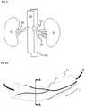
- FIG. 1illustrates anatomy of a human kidney.
- FIG. 2Ais a schematic diagram of human renal nerves and renal artery.
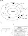
- FIG. 2Bis a cross sectional view of human renal artery and renal nerves.
- FIG. 3is a schematic block diagram of a catheter system for renal denervation according to embodiments of the present invention.
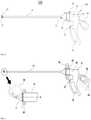
- FIG. 4is a side elevational view of a catheter according to embodiments of the present invention.
- FIG. 5illustrates an exemplary operation of a catheter according to embodiments of the present invention.
- FIG. 6A to 6D and FIG. 7A to 7Dillustrate loops of the catheter in FIG. 4 according to embodiments of the present invention.
- FIG. 8is a schematic diagram of a catheter, illustrating renal denervation using the catheter according to embodiments of the present invention.
- FIG. 9is a flow chart illustrating exemplary steps that may be carried out to denervate renal nerves according to embodiments of the present invention.
- the terms such as “include” and/or “have”may be construed to denote a certain characteristic, number, step, operation, constituent element, component or a combination thereof, but may not be construed to exclude the existence of or a possibility of addition of one or more other characteristics, numbers, steps, operations, constituent elements, components or combinations thereof.
- FIG. 1illustrates a common human renal anatomy.
- the kidneys Kare supplied with oxygenated blood by renal arteries RA, which are connected to the heart by the abdominal aorta AA.
- Deoxygenated bloodflows from the kidneys to the heart via renal veins RV and the inferior vena cava IVC.
- FIG. 2Aillustrates a portion of human renal artery RA and renal nerves RN.
- FIG. 2Billustrates a cross-sectional view taken along the radial plane A-A of FIG. 2A .
- the renal artery RAhas a lumen through which the blood B flows.
- the renal nerves RNare located in proximity to the adventitia of the renal artery ARA and run along the renal artery RA in a lengthwise direction L.
- renal nerves RNare situated in a circumferential tissue 5 surrounding the outer wall of the renal artery RA and the circumferential tissue 5 may include other tissue, such as lymphatics and capillaries.
- a catheteris inserted into the lumen and delivers heat energy to denervate the target renal nerves RN.
- the denervation energymay damage the adventitia ARA of renal artery RA before it reaches the renal nerves RN.
- a portion of the denervation energymay be absorbed by the adventitia of the renal artery ARA, reducing the efficiency in utilizing the energy.
- FIG. 3is a schematic block diagram of a catheter system 300 for renal denervation according to embodiments of the present invention.
- the catheter system 300includes: a catheter apparatus 100 having a distal portion 11 which may make a contact with a target tissue and/or be disposed in proximity to the target tissue for treatment; a control unit 200 for controlling one or more components of the system 300 ; an energy source generator (ESG) 205 for supplying energy to the target tissue through the distal portion 11 of the catheter apparatus 100 ; an imaging system 207 for processing visual images and displaying the images to the users; and wires/cables/buses 204 that connect the components of the system 300 to each other for communication.
- ESGenergy source generator
- the control unit 200may collectively refer to one or more components for controlling various components of the catheter system 300 .
- the control unit 200may include a digital signal processor (DSP) 201 , such as CPU, and a memory 203 .
- DSPdigital signal processor
- the memory 203may store various data and include, but are not limited to: magnetic media such as hard disks, floppy disks, and magnetic tape; optical media such as CD-ROMs and holographic devices; magneto-optical media; and hardware devices that are specially configured to store or to store and execute program code, such as application specific integrated circuits (ASICs), programmable logic devices (PLDs), flash memory devices, and ROM and RAM devices.
- ASICsapplication specific integrated circuits
- PLDsprogrammable logic devices
- flash memory devicesand ROM and RAM devices.
- a data logger 224may be included in the memory 203 and store data (e.g., temperature of the target tissue) measured by the catheter 100 during the denervation procedure. It is noted that the memory 203 may be located outside the control unit 200 and coupled to the control unit 200 via a wire/cable 204 .
- control unit 200may be a computer, a server, or any other suitable computing facility and include other components, such as printer, input device (such as keyboard and mouse), scanner, display device, and a network interface.
- the distal portion 11may include denervation element(s) and optionally an endoscope or some other type of imaging device, coupled to an imaging system 207 , to provide images of the target tissue using suitable imaging techniques.
- the imaging devicemay allow the operator/physician to visually identify the region being ablated/denervated, to monitor the progress of the ablation/denervation in real time, and to address safety concerns during operation.
- the shaft 10has a proximal end 13 coupled to the holder 30 and a distal end 15 removably connected to the distal portion 11 of the catheter apparatus 100 .
- the shaft 10has a shape of tube, forming a channel that extends from the proximal end 13 to the distal end 15 , and is dimensioned to allow a stylet and/or a wire(s) to pass therethrough.
- the distal portion 11may form a passage through which the loop 20 travels, as explained in detail below.
- the shaft 10may be made of silicone, polyurethane (PU), Pebax, or a combination of PU and silicone, or some other biocompatible polymers and/or metallic materials.
- the shaft 10may be sufficiently large enough to house an imaging device, such as an endoscope, as well as components for ablation/denervation.
- the shaft 10may include electrical wires/cables that run from the energy source generator 204 to the electrodes on the loop 20 .
- the shaft 10may include wires/cables for providing electrical energy to the endoscope and transmitting visual images from the endoscope to the control unit 200 .
- the shaft 10may be dimensioned to provide safe and easy treatment of the target tissue with minimal percutaneous access site on the patient, for example, on the abdominal region.
- the loop 20may be removably coupled to the distal end 15 of the shaft 10 and mechanically connected to the shaft 10 .
- the holder 30is connected to the proximal end 13 of the shaft 10 . More specifically, the holder 30 may have a structure for accepting the proximal end 13 of the shaft 10 therein and be electrically coupled to the proximal end 13 . In embodiments, a slider 35 may be rotatably coupled to the holder 30 and the operator may rotate the slider 35 to engage (or disengage) the shaft 10 to (or from) the holder 30 .
- the holder 30may include the butt 50 and a terminal 51 disposed on one side of the butt 50 .
- the terminal 51may receive various types of energy from the energy source generator 205 via the wire/cable 204 and the energy is delivered from the terminal 51 to the loop 20 via suitable wires/cables running through the shaft 10 .
- the energymay be, but not limited to, at least one of a radio-frequency (RF) energy, electrical energy, laser energy, ultrasonic energy, high-intensity focused ultrasound (HIFU) energy, cryogenic energy, and thermal energy.
- RFradio-frequency
- HIFUhigh-intensity focused ultrasound
- a cliniciancan select, via a user interface of the energy source generator 205 , such as an RF generator, a specific electrode to be utilized in the denervation process, where the electrode is disposed in the loop 20 .
- FIG. 5illustrates an example of an operation of a catheter according to an embodiment of the present invention.
- the slider 35may be rotated up to about 360 degrees about the longitudinal axis A of the shaft 10 .
- a rotational direction of the slider 35may be bidirectional or unidirectional.
- the loop 20may also rotate around the longitudinal axis A of the shaft 10 , as indicated by the arrows 90 .
- a rotation of the loop 20 about the longitudinal axis of the shaft 10may be controlled by the rotation of the slider 35 .
- the loop 20may be retracted into the shaft 10 .
- the loop control 90As the loop control 90 is moved forward (or downward), the loop 20 may emerge from the distal portion and become a straight segment or curl into a semi-circle.
- the loop control 90As the loop control 90 is moved backward (or upward), the loop 20 may curl around the target tissue or renal artery RA.
- FIG. 6A to FIG. 6Dshow a loop that curls as it emerges from the shaft 10 of the catheter apparatus according to embodiments of the present invention.
- the loop 20includes a body 21 and one or more electrodes 23 disposed on the body 21 .
- the loop 20may remain inside the shaft 10 and distal portion 11 (retracted position) when the loop control 90 is in the neutral position.
- the loop control 90forward (or downward)
- the loop 20emerges from the distal portion 11 , forming a curved segment.
- the loop 20curls as the tip of the loop 20 proceeds from the position 60 toward the position 64 .
- the body 21may be made of a flexible material. In embodiments, the body 21 may be made of thermally non-conductive elastic material so that the energy delivered to the electrodes 23 is localized only to a portion(s) of the tissue that the electrodes 23 contact. As the localized energy is used to denervate the renal nerves RN (shown in FIG. 3 ), the potential damage caused by the loop 20 to the tissue nearby the renal nerves RN may be significantly reduced during operation.
- the loop 20may be flexible and deformable to curl around a renal artery as discussed in conjunction with FIG. 8 .
- the loop 20may be designed for two different operational modes. In the first mode, the loop 20 may remain flat when the loop 20 is brought into proximity to the target tissue, such as the circumferential tissue 5 of the renal artery. Then, the operator may manipulate the loop control 90 to curl the loop 20 around the circumferential tissue 5 and perform denervation. Upon completing the denervation, the operator may release the loop control 90 to uncurl loop 20 . In the second mode, the loop 20 may remain curled when the distal portion 11 is brought into proximity to the target tissue. Then, the operator may manipulate the loop control 90 to uncurl the loop 20 , position the loop 20 around the target tissue, release the loop control 90 to curl the loop 20 around the renal artery and perform denervation.
- the first modethe loop 20 may remain flat when the loop 20 is brought into proximity to the target tissue, such as the circumferential tissue 5 of the renal artery. Then
- the body 21may be formed of electrically conducting material and the entire surface of the body 21 may be covered with dielectric material except the location where the electrodes 23 are to be located.
- a dielectric bodymay be disposed between the two electrodes 23 to electrically isolate the electrodes 23 from each other.
- the electrodes 23may be formed of electrically-conductive elastic material so that they can deform along with the body 21 as the body 21 is curled/uncurled. In embodiments, the electrodes 23 may contact the circumferential tissue 5 surrounding the outer surface of the renal artery and generate heat energy when electrical energy, such as RF energy, is supplied, where the heat energy may be used to denervate the renal nerve RN.
- electrical energysuch as RF energy
- FIG. 6A to 6Donly two electrodes 23 are shown. However, it should be apparent to those of ordinary skill in the art that any suitable number of electrodes may be used. For instance, if the electrical energy is supplied as unipolar energy, a single electrode may be used. In another example, if the electrical energy is supplied as bipolar energy, two or more electrodes may be used.
- FIG. 7A to 7Dshow a loop 400 according to embodiments of the present invention.
- the loop 400is similar to the loop 20 , with the difference that a sensor 425 is mounted to the body 421 .
- the sensor 425 and the electrodes 423may be disposed on the inner side of the body 421 .
- the senor 425may be mounted in the body 421 formed of dielectric material so that the sensor 425 may be electrically insulated from the electrode 423 .
- the electrodes 423 and sensor 425may move along the body 421 when the loop 420 curls/uncurls around the target tissue.
- the electrode(s) 423 and the sensor 425curl around the circumferential tissue 5 of the renal artery
- the electrode(s) 423 and the sensor 425contact the circumferential tissue 5 .
- the electrode(s) 423may receive electrical energy such as RF energy and generate heat energy.
- the sensor 225may measure the impedance of the electrodes 423 or the temperature of the circumferential tissue.
- the sensor 425may be connected to the central controller 200 via a wire(s) that run through the catheter apparatus 100 , where electrical power for the sensor 425 may be also delivered via a wire(s).
- Information of the measured impedance or temperaturemay be transmitted to the memory 203 of the catheter system 300 .
- the operatormay diagnose the denervation process using the information.
- the power for delivering thermal energymay also be automatically controlled by the energy source generator 205 or the central controller 200 based on the information. It is noted that other types of sensor may be used to measure various quantities, where each quantity may indicate the status of the denervation process and provide guidance to the physician during operation.
- FIG. 8is a schematic diagram of a catheter, illustrating renal denervation using the catheter according to embodiments of the present invention
- the distal portion 11 of the catheteris advanced into proximity of the patient's renal artery RA.
- the operatormay operate the loop control 90 so that the loop 20 (or 420 ) including a plurality of electrodes 23 (or 423 ) may curl around the circumferential tissue 5 of the renal artery to thereby directly or indirectly contact the circumferential tissue of the renal artery RA.
- the electrodes 23 (or 423 )may be positioned on a circumferential treatment zone along a segment of the renal artery RA.
- the electrodes 23 (or 423 )may include a first electrode to deliver thermal energy to a first treatment zone of the renal artery RA a second electrode to deliver thermal energy to a second treatment zone of the renal artery RA.
- each of the electrodesmay deliver thermal energy to a different treatment zone, respectively or deliver thermal energy to the same treatment zone.
- the loop 20may be electrically coupled to energy source generator 205 for delivery of a desired electrical energy to the electrodes 23 (or 423 ).
- the electrical energymay be thermal RF energy using Quantum Molecular Resonance (QMR).
- QMRQuantum Molecular Resonance
- a frequency of the RF energymay be higher than or equal to 4 MHz and may destruct at least a portion of the circumferential tissue 5 of the renal artery RA.
- the temperature range of the electrodes 23 (or 423 ) during operationranges from 60 degrees to 70 degrees.
- the loop 20may supply electrical energy to the circumferential tissue 5 of the renal artery RA to cause renal denervation through the electrode 23 (or 423 ).
- the heat energywhich is generated by the electrodes 23 ( 423 ), may destruct a portion of the circumferential tissue of the renal artery, where the circumferential tissue may include at least one of a renal nerve RN, lymphatics and capillaries. This may be achieved via contact between the loop 20 (or 420 ) and the circumferential tissue 5 of the renal artery RA.
- an impedance of the electrode or a temperature of the circumferential tissuemay be measured using the sensor 425 .
- FIG. 9is a flow chart 900 illustrating exemplary steps that may be carried out to denervate renal nerves according to embodiments of the present invention.
- the processstarts at step 902 .
- the loop 20 (or 420 )that is positioned near a target tissue, such as circumferential tissue 5 of the renal artery RA.
- the loop 20 (or 420 )may include one or more electrode 23 (or 423 ).
- the loop 20 (or 420 )may be curled around the target tissue.
- energymay be delivered to the electrode 23 , where the electrode 23 may convert the energy into heat energy. Then, at step 908 , at least a portion of the target tissue may be denervated by the heat energy.
- the apparatus and methods described hereincan be used to treat not only hypertension, but also other suitable types of diseases, such as chronic renal diseases, cardiovascular disorders, cardiac arrhythmias, and clinical syndromes where the renal afferent activation is involved.
- the physicianmay treat the diseases in an easier and safer manner.
Landscapes
- Health & Medical Sciences (AREA)
- Life Sciences & Earth Sciences (AREA)
- Surgery (AREA)
- Engineering & Computer Science (AREA)
- Plasma & Fusion (AREA)
- General Health & Medical Sciences (AREA)
- Otolaryngology (AREA)
- Physics & Mathematics (AREA)
- Veterinary Medicine (AREA)
- Biomedical Technology (AREA)
- Heart & Thoracic Surgery (AREA)
- Medical Informatics (AREA)
- Molecular Biology (AREA)
- Animal Behavior & Ethology (AREA)
- Nuclear Medicine, Radiotherapy & Molecular Imaging (AREA)
- Public Health (AREA)
- Cardiology (AREA)
- Surgical Instruments (AREA)
Abstract
Description
Claims (12)
Priority Applications (8)
| Application Number | Priority Date | Filing Date | Title |
|---|---|---|---|
| US15/258,167US11259859B2 (en) | 2016-09-07 | 2016-09-07 | Systems and methods for renal denervation |
| US16/239,718US20190133681A1 (en) | 2016-09-07 | 2019-01-04 | Systems and methods for perivascular nerve denervation |
| US17/012,534US12108974B2 (en) | 2016-09-07 | 2020-09-04 | Systems and methods for renal denervation |
| US17/113,935US20210085382A1 (en) | 2016-09-07 | 2020-12-07 | Systems for perivascular nerve denervation |
| US17/190,161US20210177512A1 (en) | 2016-09-07 | 2021-03-02 | Systems and methods for perivascular nerve denervation |
| US17/190,183US20210177486A1 (en) | 2016-09-07 | 2021-03-02 | Systems for perivascular nerve denervation |
| US17/195,011US12274489B2 (en) | 2016-09-07 | 2021-03-08 | Systems and methods for perivascular nerve denervation |
| US17/375,359US12256983B2 (en) | 2016-09-07 | 2021-07-14 | Systems and methods for perivascular nerve denervation |
Applications Claiming Priority (1)
| Application Number | Priority Date | Filing Date | Title |
|---|---|---|---|
| US15/258,167US11259859B2 (en) | 2016-09-07 | 2016-09-07 | Systems and methods for renal denervation |
Related Child Applications (2)
| Application Number | Title | Priority Date | Filing Date |
|---|---|---|---|
| US16/239,718Continuation-In-PartUS20190133681A1 (en) | 2016-09-07 | 2019-01-04 | Systems and methods for perivascular nerve denervation |
| US17/012,534ContinuationUS12108974B2 (en) | 2016-09-07 | 2020-09-04 | Systems and methods for renal denervation |
Publications (2)
| Publication Number | Publication Date |
|---|---|
| US20180064485A1 US20180064485A1 (en) | 2018-03-08 |
| US11259859B2true US11259859B2 (en) | 2022-03-01 |
Family
ID=61281824
Family Applications (2)
| Application Number | Title | Priority Date | Filing Date |
|---|---|---|---|
| US15/258,167Active2038-07-29US11259859B2 (en) | 2016-09-07 | 2016-09-07 | Systems and methods for renal denervation |
| US17/012,534Active2039-08-12US12108974B2 (en) | 2016-09-07 | 2020-09-04 | Systems and methods for renal denervation |
Family Applications After (1)
| Application Number | Title | Priority Date | Filing Date |
|---|---|---|---|
| US17/012,534Active2039-08-12US12108974B2 (en) | 2016-09-07 | 2020-09-04 | Systems and methods for renal denervation |
Country Status (1)
| Country | Link |
|---|---|
| US (2) | US11259859B2 (en) |
Cited By (1)
| Publication number | Priority date | Publication date | Assignee | Title |
|---|---|---|---|---|
| US12256983B2 (en) | 2016-09-07 | 2025-03-25 | Deepqure Inc. | Systems and methods for perivascular nerve denervation |
Families Citing this family (8)
| Publication number | Priority date | Publication date | Assignee | Title |
|---|---|---|---|---|
| KR102579846B1 (en)* | 2019-04-03 | 2023-09-19 | 류지헌 | Medical device |
| AU2019204869B2 (en)* | 2019-07-05 | 2023-11-16 | Antonio Lauto | Improved apparatus and method for treatment of tissue |
| US12179013B2 (en) | 2019-08-29 | 2024-12-31 | Deepqure Inc. | Electrode device for wrapping vessel in the body and method therefor |
| KR102296026B1 (en)* | 2020-12-03 | 2021-09-02 | 주식회사 딥큐어 | Electrode device |
| KR102296027B1 (en)* | 2021-02-10 | 2021-09-01 | 주식회사 딥큐어 | Electrode apparatus for blocking or controlling nerve inside body |
| BR112023017451A2 (en)* | 2021-04-01 | 2023-09-26 | Deepqure Inc | Electrode apparatus for denervation or nerve modulation in vivo |
| JP7699877B2 (en)* | 2021-08-25 | 2025-06-30 | ディープキュア インコーポレイテッド | Electrode device for blocking or modulating nerves in the body |
| KR102818812B1 (en)* | 2022-07-26 | 2025-06-13 | 주식회사 딥큐어 | Electrode apparatus for blocking or controlling nerve inside body |
Citations (27)
| Publication number | Priority date | Publication date | Assignee | Title |
|---|---|---|---|---|
| US3955578A (en)* | 1974-12-23 | 1976-05-11 | Cook Inc. | Rotatable surgical snare |
| US5486183A (en)* | 1990-10-09 | 1996-01-23 | Raychem Corporation | Device or apparatus for manipulating matter |
| US6050995A (en)* | 1998-09-24 | 2000-04-18 | Scimed Lifesystems, Inc. | Polypectomy snare with multiple bipolar electrodes |
| US20030018330A1 (en)* | 1993-10-15 | 2003-01-23 | Swanson David K. | Systems and methods for creating long, thin lesions in body tissue |
| US20040193151A1 (en)* | 2001-06-06 | 2004-09-30 | Oratec Interventions, Inc. | Intervertebral disc device employing looped probe |
| US20050015083A1 (en) | 1994-10-07 | 2005-01-20 | Scimed Life Systems, Inc. | Loop structures for positioning a diagnostic or therapeutic element on the epicardium or other organ surface |
| US6978174B2 (en) | 2002-04-08 | 2005-12-20 | Ardian, Inc. | Methods and devices for renal nerve blocking |
| US20060009759A1 (en)* | 2004-06-02 | 2006-01-12 | Chrisitian Steven C | Loop ablation apparatus and method |
| US20060030919A1 (en)* | 2004-08-04 | 2006-02-09 | Ndi Medical, Llc | Devices, systems, and methods employing a molded nerve cuff electrode |
| US20060041277A1 (en)* | 2002-04-08 | 2006-02-23 | Mark Deem | Methods and apparatus for renal neuromodulation |
| US20100137860A1 (en) | 2002-04-08 | 2010-06-03 | Ardian, Inc. | Apparatus for performing a non-continuous circumferential treatment of a body lumen |
| US20110112400A1 (en) | 2009-11-06 | 2011-05-12 | Ardian, Inc. | High intensity focused ultrasound catheter apparatuses, systems, and methods for renal neuromodulation |
| US8150520B2 (en) | 2002-04-08 | 2012-04-03 | Ardian, Inc. | Methods for catheter-based renal denervation |
| US20120259269A1 (en) | 2011-04-08 | 2012-10-11 | Tyco Healthcare Group Lp | Iontophoresis drug delivery system and method for denervation of the renal sympathetic nerve and iontophoretic drug delivery |
| US8473067B2 (en) | 2010-06-11 | 2013-06-25 | Boston Scientific Scimed, Inc. | Renal denervation and stimulation employing wireless vascular energy transfer arrangement |
| KR101370048B1 (en) | 2013-02-05 | 2014-03-04 | 주식회사 한독 | Catheter for denervation |
| US20140107639A1 (en) | 2011-06-06 | 2014-04-17 | St. Jude Medical Cardiology Division, Inc. | Renal denervation system and method |
| KR101399555B1 (en) | 2013-02-05 | 2014-05-27 | 주식회사 한독 | Catheter for denervation |
| US8740849B1 (en) | 2012-10-29 | 2014-06-03 | Ablative Solutions, Inc. | Peri-vascular tissue ablation catheter with support structures |
| US20140303618A1 (en) | 2010-04-26 | 2014-10-09 | Medtronic Ardian Luxembourg S.A.R.L. | Multi-directional deflectable catheter apparatuses, systems, and methods for renal neuromodulation |
| US20150025524A1 (en) | 2013-07-18 | 2015-01-22 | St. Jude Medical, Cardiology Division, Inc. | Renal denervation monitoring and feedback apparatus, system and method |
| US20150141810A1 (en)* | 2013-11-19 | 2015-05-21 | Ethicon, Inc. | Thoracoscopic Methods for Treatment of Bronchial Disease |
| US20150224326A1 (en)* | 2012-05-29 | 2015-08-13 | Autonomix Medical, Inc. | Endoscopic sympathectomy systems and methods |
| US20160089198A1 (en)* | 2013-05-31 | 2016-03-31 | Covidien Lp | Surgical device with an end-effector assembly and system for monitoring of tissue during a surgical procedure |
| US20160113711A1 (en)* | 2014-10-22 | 2016-04-28 | Oscor Inc. | Ablation catheter and method of forming a circular lesion |
| US20160256218A1 (en)* | 2015-03-04 | 2016-09-08 | The Board Of Trustees Of The Leland Stanford Junior University | Perivascular Electroporation Device and Method for Extending Vascular Patency |
| US20170202467A1 (en) | 2016-01-20 | 2017-07-20 | Ralph J. ZITNIK | Implantable microstimulators and inductive charging systems |
Family Cites Families (2)
| Publication number | Priority date | Publication date | Assignee | Title |
|---|---|---|---|---|
| EP0768842A4 (en) | 1994-06-27 | 1998-05-13 | Ep Technologies | Systems and methods for sensing temperature within the body |
| GB0919950D0 (en) | 2009-11-13 | 2009-12-30 | Btg Int Ltd | Clamp and applicator |
- 2016
- 2016-09-07USUS15/258,167patent/US11259859B2/enactiveActive
- 2020
- 2020-09-04USUS17/012,534patent/US12108974B2/enactiveActive
Patent Citations (27)
| Publication number | Priority date | Publication date | Assignee | Title |
|---|---|---|---|---|
| US3955578A (en)* | 1974-12-23 | 1976-05-11 | Cook Inc. | Rotatable surgical snare |
| US5486183A (en)* | 1990-10-09 | 1996-01-23 | Raychem Corporation | Device or apparatus for manipulating matter |
| US20030018330A1 (en)* | 1993-10-15 | 2003-01-23 | Swanson David K. | Systems and methods for creating long, thin lesions in body tissue |
| US20050015083A1 (en) | 1994-10-07 | 2005-01-20 | Scimed Life Systems, Inc. | Loop structures for positioning a diagnostic or therapeutic element on the epicardium or other organ surface |
| US6050995A (en)* | 1998-09-24 | 2000-04-18 | Scimed Lifesystems, Inc. | Polypectomy snare with multiple bipolar electrodes |
| US20040193151A1 (en)* | 2001-06-06 | 2004-09-30 | Oratec Interventions, Inc. | Intervertebral disc device employing looped probe |
| US8150520B2 (en) | 2002-04-08 | 2012-04-03 | Ardian, Inc. | Methods for catheter-based renal denervation |
| US20060041277A1 (en)* | 2002-04-08 | 2006-02-23 | Mark Deem | Methods and apparatus for renal neuromodulation |
| US20100137860A1 (en) | 2002-04-08 | 2010-06-03 | Ardian, Inc. | Apparatus for performing a non-continuous circumferential treatment of a body lumen |
| US6978174B2 (en) | 2002-04-08 | 2005-12-20 | Ardian, Inc. | Methods and devices for renal nerve blocking |
| US20060009759A1 (en)* | 2004-06-02 | 2006-01-12 | Chrisitian Steven C | Loop ablation apparatus and method |
| US20060030919A1 (en)* | 2004-08-04 | 2006-02-09 | Ndi Medical, Llc | Devices, systems, and methods employing a molded nerve cuff electrode |
| US20110112400A1 (en) | 2009-11-06 | 2011-05-12 | Ardian, Inc. | High intensity focused ultrasound catheter apparatuses, systems, and methods for renal neuromodulation |
| US20140303618A1 (en) | 2010-04-26 | 2014-10-09 | Medtronic Ardian Luxembourg S.A.R.L. | Multi-directional deflectable catheter apparatuses, systems, and methods for renal neuromodulation |
| US8473067B2 (en) | 2010-06-11 | 2013-06-25 | Boston Scientific Scimed, Inc. | Renal denervation and stimulation employing wireless vascular energy transfer arrangement |
| US20120259269A1 (en) | 2011-04-08 | 2012-10-11 | Tyco Healthcare Group Lp | Iontophoresis drug delivery system and method for denervation of the renal sympathetic nerve and iontophoretic drug delivery |
| US20140107639A1 (en) | 2011-06-06 | 2014-04-17 | St. Jude Medical Cardiology Division, Inc. | Renal denervation system and method |
| US20150224326A1 (en)* | 2012-05-29 | 2015-08-13 | Autonomix Medical, Inc. | Endoscopic sympathectomy systems and methods |
| US8740849B1 (en) | 2012-10-29 | 2014-06-03 | Ablative Solutions, Inc. | Peri-vascular tissue ablation catheter with support structures |
| KR101399555B1 (en) | 2013-02-05 | 2014-05-27 | 주식회사 한독 | Catheter for denervation |
| KR101370048B1 (en) | 2013-02-05 | 2014-03-04 | 주식회사 한독 | Catheter for denervation |
| US20160089198A1 (en)* | 2013-05-31 | 2016-03-31 | Covidien Lp | Surgical device with an end-effector assembly and system for monitoring of tissue during a surgical procedure |
| US20150025524A1 (en) | 2013-07-18 | 2015-01-22 | St. Jude Medical, Cardiology Division, Inc. | Renal denervation monitoring and feedback apparatus, system and method |
| US20150141810A1 (en)* | 2013-11-19 | 2015-05-21 | Ethicon, Inc. | Thoracoscopic Methods for Treatment of Bronchial Disease |
| US20160113711A1 (en)* | 2014-10-22 | 2016-04-28 | Oscor Inc. | Ablation catheter and method of forming a circular lesion |
| US20160256218A1 (en)* | 2015-03-04 | 2016-09-08 | The Board Of Trustees Of The Leland Stanford Junior University | Perivascular Electroporation Device and Method for Extending Vascular Patency |
| US20170202467A1 (en) | 2016-01-20 | 2017-07-20 | Ralph J. ZITNIK | Implantable microstimulators and inductive charging systems |
Cited By (2)
| Publication number | Priority date | Publication date | Assignee | Title |
|---|---|---|---|---|
| US12256983B2 (en) | 2016-09-07 | 2025-03-25 | Deepqure Inc. | Systems and methods for perivascular nerve denervation |
| US12274489B2 (en) | 2016-09-07 | 2025-04-15 | Deepqure Inc. | Systems and methods for perivascular nerve denervation |
Also Published As
| Publication number | Publication date |
|---|---|
| US20200397496A1 (en) | 2020-12-24 |
| US20180064485A1 (en) | 2018-03-08 |
| US12108974B2 (en) | 2024-10-08 |
Similar Documents
| Publication | Publication Date | Title |
|---|---|---|
| US12256983B2 (en) | Systems and methods for perivascular nerve denervation | |
| US12108974B2 (en) | Systems and methods for renal denervation | |
| US12343527B2 (en) | System having energy delivering thermocouple assemblies | |
| US20210330380A1 (en) | Ablation targeting nerves in or near the inferior vena cava and/or abdominal aorta for treatment of hypertension | |
| JP7165141B2 (en) | Electroporation system and method of energizing catheter | |
| CN104254366B (en) | Devices, systems and methods for neuromodulation | |
| US6428537B1 (en) | Electrophysiological treatment methods and apparatus employing high voltage pulse to render tissue temporarily unresponsive | |
| US8486063B2 (en) | Ablation catheter | |
| US6212426B1 (en) | Systems and methods for conducting electrophysiological testing using high-voltage energy pulses to stun tissue | |
| EP3175808B1 (en) | Catheter apparatuses and systems for renal neuromodulation | |
| US20160338773A1 (en) | Mapping and ablation of nerves within arteries and tissues | |
| US20140276718A1 (en) | Direct Heat Ablation Catheter | |
| US10441347B2 (en) | Adaptive electrode for bi-polar ablation | |
| JP2008502427A (en) | Ablation catheter and method of use | |
| WO2015100451A1 (en) | Applying electric field treatment to parts of the body | |
| US20210177486A1 (en) | Systems for perivascular nerve denervation | |
| CN113520579A (en) | Ablation of difficult to reach areas | |
| JP2018501837A (en) | System and method for high resolution mapping of tissue | |
| US20210177512A1 (en) | Systems and methods for perivascular nerve denervation |
Legal Events
| Date | Code | Title | Description |
|---|---|---|---|
| AS | Assignment | Owner name:SEOUL NATIONAL UNIVERSITY HOSPITAL, KOREA, REPUBLIC OF Free format text:ASSIGNMENT OF ASSIGNORS INTEREST;ASSIGNOR:JEONG, CHANG WOOK;REEL/FRAME:040004/0966 Effective date:20161013 Owner name:SEOUL NATIONAL UNIVERSITY HOSPITAL, KOREA, REPUBLI Free format text:ASSIGNMENT OF ASSIGNORS INTEREST;ASSIGNOR:JEONG, CHANG WOOK;REEL/FRAME:040004/0966 Effective date:20161013 | |
| STPP | Information on status: patent application and granting procedure in general | Free format text:NON FINAL ACTION MAILED | |
| STPP | Information on status: patent application and granting procedure in general | Free format text:FINAL REJECTION MAILED | |
| STPP | Information on status: patent application and granting procedure in general | Free format text:DOCKETED NEW CASE - READY FOR EXAMINATION | |
| AS | Assignment | Owner name:DEEPQURE INC., KOREA, REPUBLIC OF Free format text:ASSIGNMENT OF ASSIGNORS INTEREST;ASSIGNOR:SEOUL NATIONAL UNIVERSITY HOSPITAL;REEL/FRAME:051953/0444 Effective date:20200218 | |
| STPP | Information on status: patent application and granting procedure in general | Free format text:FINAL REJECTION MAILED | |
| STPP | Information on status: patent application and granting procedure in general | Free format text:ADVISORY ACTION MAILED | |
| STPP | Information on status: patent application and granting procedure in general | Free format text:DOCKETED NEW CASE - READY FOR EXAMINATION | |
| STPP | Information on status: patent application and granting procedure in general | Free format text:NON FINAL ACTION MAILED | |
| STPP | Information on status: patent application and granting procedure in general | Free format text:RESPONSE TO NON-FINAL OFFICE ACTION ENTERED AND FORWARDED TO EXAMINER | |
| STPP | Information on status: patent application and granting procedure in general | Free format text:AWAITING TC RESP., ISSUE FEE NOT PAID | |
| STPP | Information on status: patent application and granting procedure in general | Free format text:NOTICE OF ALLOWANCE MAILED -- APPLICATION RECEIVED IN OFFICE OF PUBLICATIONS | |
| STCF | Information on status: patent grant | Free format text:PATENTED CASE | |
| MAFP | Maintenance fee payment | Free format text:PAYMENT OF MAINTENANCE FEE, 4TH YR, SMALL ENTITY (ORIGINAL EVENT CODE: M2551); ENTITY STATUS OF PATENT OWNER: SMALL ENTITY Year of fee payment:4 |