US11259825B2 - Devices and methods for treatment of tissue - Google Patents
Devices and methods for treatment of tissueDownload PDFInfo
- Publication number
- US11259825B2 US11259825B2US15/628,166US201715628166AUS11259825B2US 11259825 B2US11259825 B2US 11259825B2US 201715628166 AUS201715628166 AUS 201715628166AUS 11259825 B2US11259825 B2US 11259825B2
- Authority
- US
- United States
- Prior art keywords
- needle
- ultrasonic imaging
- imaging device
- needle electrodes
- radiofrequency ablation
- Prior art date
- Legal status (The legal status is an assumption and is not a legal conclusion. Google has not performed a legal analysis and makes no representation as to the accuracy of the status listed.)
- Active, expires
Links
- QMZAFCATJZQUOE-UHFFFAOYSA-NC=C(CCC1C=CC2C1CC2)C1CCCC1Chemical compoundC=C(CCC1C=CC2C1CC2)C1CCCC1QMZAFCATJZQUOE-UHFFFAOYSA-N0.000description1
Images


Classifications
- A—HUMAN NECESSITIES
- A61—MEDICAL OR VETERINARY SCIENCE; HYGIENE
- A61B—DIAGNOSIS; SURGERY; IDENTIFICATION
- A61B8/00—Diagnosis using ultrasonic, sonic or infrasonic waves
- A61B8/08—Clinical applications
- A61B8/0833—Clinical applications involving detecting or locating foreign bodies or organic structures
- A—HUMAN NECESSITIES
- A61—MEDICAL OR VETERINARY SCIENCE; HYGIENE
- A61B—DIAGNOSIS; SURGERY; IDENTIFICATION
- A61B17/00—Surgical instruments, devices or methods
- A61B17/22—Implements for squeezing-off ulcers or the like on inner organs of the body; Implements for scraping-out cavities of body organs, e.g. bones; for invasive removal or destruction of calculus using mechanical vibrations; for removing obstructions in blood vessels, not otherwise provided for
- A61B17/225—Implements for squeezing-off ulcers or the like on inner organs of the body; Implements for scraping-out cavities of body organs, e.g. bones; for invasive removal or destruction of calculus using mechanical vibrations; for removing obstructions in blood vessels, not otherwise provided for for extracorporeal shock wave lithotripsy [ESWL], e.g. by using ultrasonic waves
- A61B17/2256—Implements for squeezing-off ulcers or the like on inner organs of the body; Implements for scraping-out cavities of body organs, e.g. bones; for invasive removal or destruction of calculus using mechanical vibrations; for removing obstructions in blood vessels, not otherwise provided for for extracorporeal shock wave lithotripsy [ESWL], e.g. by using ultrasonic waves with means for locating or checking the concrement, e.g. X-ray apparatus, imaging means
- A—HUMAN NECESSITIES
- A61—MEDICAL OR VETERINARY SCIENCE; HYGIENE
- A61B—DIAGNOSIS; SURGERY; IDENTIFICATION
- A61B18/00—Surgical instruments, devices or methods for transferring non-mechanical forms of energy to or from the body
- A61B18/04—Surgical instruments, devices or methods for transferring non-mechanical forms of energy to or from the body by heating
- A61B18/12—Surgical instruments, devices or methods for transferring non-mechanical forms of energy to or from the body by heating by passing a current through the tissue to be heated, e.g. high-frequency current
- A61B18/14—Probes or electrodes therefor
- A61B18/1477—Needle-like probes
- A—HUMAN NECESSITIES
- A61—MEDICAL OR VETERINARY SCIENCE; HYGIENE
- A61B—DIAGNOSIS; SURGERY; IDENTIFICATION
- A61B8/00—Diagnosis using ultrasonic, sonic or infrasonic waves
- A61B8/08—Clinical applications
- A61B8/0833—Clinical applications involving detecting or locating foreign bodies or organic structures
- A61B8/0841—Clinical applications involving detecting or locating foreign bodies or organic structures for locating instruments
- A—HUMAN NECESSITIES
- A61—MEDICAL OR VETERINARY SCIENCE; HYGIENE
- A61B—DIAGNOSIS; SURGERY; IDENTIFICATION
- A61B8/00—Diagnosis using ultrasonic, sonic or infrasonic waves
- A61B8/08—Clinical applications
- A61B8/0833—Clinical applications involving detecting or locating foreign bodies or organic structures
- A61B8/085—Clinical applications involving detecting or locating foreign bodies or organic structures for locating body or organic structures, e.g. tumours, calculi, blood vessels, nodules
- A—HUMAN NECESSITIES
- A61—MEDICAL OR VETERINARY SCIENCE; HYGIENE
- A61B—DIAGNOSIS; SURGERY; IDENTIFICATION
- A61B8/00—Diagnosis using ultrasonic, sonic or infrasonic waves
- A61B8/12—Diagnosis using ultrasonic, sonic or infrasonic waves in body cavities or body tracts, e.g. by using catheters
- A—HUMAN NECESSITIES
- A61—MEDICAL OR VETERINARY SCIENCE; HYGIENE
- A61B—DIAGNOSIS; SURGERY; IDENTIFICATION
- A61B8/00—Diagnosis using ultrasonic, sonic or infrasonic waves
- A61B8/44—Constructional features of the ultrasonic, sonic or infrasonic diagnostic device
- A—HUMAN NECESSITIES
- A61—MEDICAL OR VETERINARY SCIENCE; HYGIENE
- A61B—DIAGNOSIS; SURGERY; IDENTIFICATION
- A61B8/00—Diagnosis using ultrasonic, sonic or infrasonic waves
- A61B8/44—Constructional features of the ultrasonic, sonic or infrasonic diagnostic device
- A61B8/4411—Device being modular
- A—HUMAN NECESSITIES
- A61—MEDICAL OR VETERINARY SCIENCE; HYGIENE
- A61B—DIAGNOSIS; SURGERY; IDENTIFICATION
- A61B8/00—Diagnosis using ultrasonic, sonic or infrasonic waves
- A61B8/44—Constructional features of the ultrasonic, sonic or infrasonic diagnostic device
- A61B8/4444—Constructional features of the ultrasonic, sonic or infrasonic diagnostic device related to the probe
- A61B8/445—Details of catheter construction
- A—HUMAN NECESSITIES
- A61—MEDICAL OR VETERINARY SCIENCE; HYGIENE
- A61B—DIAGNOSIS; SURGERY; IDENTIFICATION
- A61B18/00—Surgical instruments, devices or methods for transferring non-mechanical forms of energy to or from the body
- A61B18/18—Surgical instruments, devices or methods for transferring non-mechanical forms of energy to or from the body by applying electromagnetic radiation, e.g. microwaves
- A—HUMAN NECESSITIES
- A61—MEDICAL OR VETERINARY SCIENCE; HYGIENE
- A61B—DIAGNOSIS; SURGERY; IDENTIFICATION
- A61B17/00—Surgical instruments, devices or methods
- A61B2017/00017—Electrical control of surgical instruments
- A61B2017/00022—Sensing or detecting at the treatment site
- A61B2017/00106—Sensing or detecting at the treatment site ultrasonic
- A—HUMAN NECESSITIES
- A61—MEDICAL OR VETERINARY SCIENCE; HYGIENE
- A61B—DIAGNOSIS; SURGERY; IDENTIFICATION
- A61B17/00—Surgical instruments, devices or methods
- A61B17/42—Gynaecological or obstetrical instruments or methods
- A61B2017/4216—Operations on uterus, e.g. endometrium
- A—HUMAN NECESSITIES
- A61—MEDICAL OR VETERINARY SCIENCE; HYGIENE
- A61B—DIAGNOSIS; SURGERY; IDENTIFICATION
- A61B18/00—Surgical instruments, devices or methods for transferring non-mechanical forms of energy to or from the body
- A61B2018/00315—Surgical instruments, devices or methods for transferring non-mechanical forms of energy to or from the body for treatment of particular body parts
- A61B2018/00559—Female reproductive organs
- A—HUMAN NECESSITIES
- A61—MEDICAL OR VETERINARY SCIENCE; HYGIENE
- A61B—DIAGNOSIS; SURGERY; IDENTIFICATION
- A61B18/00—Surgical instruments, devices or methods for transferring non-mechanical forms of energy to or from the body
- A61B2018/00571—Surgical instruments, devices or methods for transferring non-mechanical forms of energy to or from the body for achieving a particular surgical effect
- A61B2018/00577—Ablation
- A—HUMAN NECESSITIES
- A61—MEDICAL OR VETERINARY SCIENCE; HYGIENE
- A61B—DIAGNOSIS; SURGERY; IDENTIFICATION
- A61B90/00—Instruments, implements or accessories specially adapted for surgery or diagnosis and not covered by any of the groups A61B1/00 - A61B50/00, e.g. for luxation treatment or for protecting wound edges
- A61B90/36—Image-producing devices or illumination devices not otherwise provided for
- A61B90/37—Surgical systems with images on a monitor during operation
- A61B2090/378—Surgical systems with images on a monitor during operation using ultrasound
- A61B2090/3782—Surgical systems with images on a monitor during operation using ultrasound transmitter or receiver in catheter or minimal invasive instrument
- A61B2090/3784—Surgical systems with images on a monitor during operation using ultrasound transmitter or receiver in catheter or minimal invasive instrument both receiver and transmitter being in the instrument or receiver being also transmitter
Definitions
- the present inventionrelates generally to medical systems and methods. More particularly, the invention relates to delivery systems having an ultrasound probe for improved imaging and a curved needle for ablation treatment, and methods for using the same.
- Fibroidsare benign tumors of the uterine myometria (muscle) and are the most common tumor of the female pelvis. Fibroid tumors affect up to 30% of women of childbearing age and can cause significant symptoms such as discomfort, pelvic pain, mennorhagia, pressure, anemia, compression, infertility, and miscarriage. Fibroids may be located in the myometrium (intramural), adjacent the endometrium (submucosal), or in the outer layer of the uterus (subserosal). Most common fibroids are a smooth muscle overgrowth that arise intramurally and can grow to be several centimeters in diameter.
- Pharmacological treatmentsinclude the administration of medications such as NSAIDS, estrogen-progesterone combinations, and GnRH analogues. All medications are relatively ineffective and are palliative rather than curative.
- Surgical interventionsinclude hysterectomy (surgical removal of the uterus) and myomectomy.
- Surgical myomectomyin which fibroids are removed, is an open surgical procedure requiring laparotomy and general anesthesia. Often these surgical procedures are associated with the typical surgical risks and complications along with significant blood loss and can only remove a portion of the culprit tissue.
- laparoscopic myomectomywas pioneered in the early 1990's.
- laparoscopic myomectomyremains technically challenging, requiring laparoscopic suturing, limiting its performance to only the most skilled of laparoscopic gynecologists.
- Other minimally invasive treatments for uterine fibroidsinclude hysteroscopy, uterine artery ablation, endometrial ablation, and myolysis.
- Hysteroscopyis the process by which a thin fiber optic camera is used to image inside the uterus and an attachment may be used to destroy tissue.
- Hysteroscopic resectionis a surgical technique that uses a variety of devices (loops, roller balls, bipolar electrodes) to ablate or resect uterine tissue. The procedure requires the filling of the uterus with fluid for better viewing, and thus has potential side effects of fluid overload.
- Hysteroscopic ablationis limited by its visualization technique and thus, only appropriate for fibroids which are submucosal and/or protrude into the uterine cavity.
- Uterine artery embolizationwas introduced in the early 1990's and is performed through a groin incision by injecting small particles into the uterine artery to selectively block the blood supply to fibroids and refract its tissue. Complications include pelvic infection, premature menopause and severe pelvic pain. In addition, long term MRI data suggests that incomplete fibroid infarction may result in regrowth of infarcted fibroid tissue and symptomatic recurrence.
- Endometrial ablationis a procedure primarily used for dysfunctional (or abnormal) uterine bleeding and may be used, at times, for management of fibroids. Endometrial ablation relies on various energy sources such as cryo, microwave and radiofrequency energy. Endometrial ablation destroys the endometrial tissue lining the uterus, and although an excellent choice for treatment of dysfunctional uterine bleeding, it does not specifically treat fibroids. This technique is also not suitable treatment of women desiring future childbearing.
- Myolysiswas first performed in the 1980's using lasers or radio frequency (RF) energy to coagulate tissue, denature proteins, and necrose myometrium using laparoscopic visualization.
- Laparoscopic myolysiscan be an alternative to myomectomy, as the fibroids are coagulated and then undergo coagulative necrosis resulting in a dramatic decrease in size.
- myolysis treatmentis limited by the fact that it can only allow for visualization of subserosal fibroids.
- Needle myolysisuses a laparoscope, percutaneous, or open technique to introduce one or more needles into a fibroid tumor under direct visual control. Radio frequency current, cryo energy, or microwave energy is then delivered between two adjacent needles (bipolar), or between a single needle and a distant dispersive electrode affixed to the thigh or back of the patient (unipolar).
- the aim of needle myolysisis to coagulate a significant volume of the tumor, thereby cause substantial shrinkage.
- the traditional techniqueutilizes making multiple passes through different areas of the tumor using the coagulating needle to destroy many cylindrical cores of the abnormal tissue.
- Myolysiscan be an alternative to myomectomy, as the fibroids are coagulated and then undergo coagulative necrosis resulting in a dramatic decrease in size. Myolysis is generally limited by its usage with direct visualization techniques, thus being limited to the treatment of subserosal fibroids.
- the present inventionis directed to delivery systems, and methods using the same, having an ultrasound probe for improved imaging and a needle for ablation treatment of target tissues.
- the needleis straight with the ultrasound probe having an ultrasound array at a distal portion.
- the needleis a curved needle.
- the needlewill be deployed from within a natural or created body cavity or body lumen.
- Exemplary body cavitiesinclude the uterus, the esophagus, the stomach, the bladder, the colon, and the like.
- Exemplary body lumensinclude the ureter, the urethra, fallopian tubes, and the like.
- Created body cavitiesinclude insufflated regions in the abdomen, the thoracic cavity, regions around joints (for arthroscopic procedures), and the like.
- the present inventionwill generally not find use with procedures in blood vessels or other regions of the vasculature. Thus, while the following description will be directed particularly at procedures within the uterus for detecting and treating uterine fibroids, the scope of the present invention is not intended to be so limited.
- the target tissueis a fibroid within a female's uterus.
- a rigid delivery systemcomprises a rigid delivery shaft, an imaging core, and an interventional core.
- the rigid shafthaving a proximal end, a distal end, and an axial passage extending through the rigid shaft.
- the axial passagewill typically extend the entire length of the shaft from the proximal to the distal end, and is open at least at the proximal end.
- the shaftwill usually be rigid along all or a portion of its length, but in other instances may be flexible, deflectable, or steerable.
- the imaging corepreferably comprises an ultrasound imaging insert or probe disposed within the axial passage, usually being removably disposed so that it may be removed and replaced to permit sterilization and re-use.
- the imaging insertwill have an ultrasound array within a distal portion thereof.
- the ultrasound arrayis tilted relative to a shaft axis so as to provide an enhanced field of view, as discussed in more detail below.
- the ultrasound arraymay be tilted at an angle in a range from about 7 degrees to about 15 degrees, preferably in a range from about 7 degrees to about 10 degrees.
- the interventional coremay be adapted for any conventional form of medical imaging, such as optical coherence tomographic imaging, direct optic visualization, and as such is not limited by ultrasonic imaging.
- the ultrasound imaging insertfurther comprises a flat viewing window disposed over the ultrasound array at the distal portion.
- the distal end of the rigid shaftmay comprise a mechanical alignment feature, as for example, a flat viewing surface for axial or rotational orientation of the ultrasound imaging insert within the shaft.
- the flat viewing surfacewill be visually transparent to permit imaging from within the axial passage by the imaging insert. It will be appreciated, however, that the transparent visualization window which aids in physical alignment does not have to be visually transparent for ultrasound.
- at least a portion of the flat viewing surfacemay be composed of an ultrasonically translucent material to permit ultrasonic imaging though the surface of the shaft.
- the re-usable ultrasound imaging insertmay be acoustically coupled to the outer delivery shaft to ensure that the ultrasound energy effectively passes from one component to the other.
- Ultrasonic acoustic couplingmay be accomplished in several ways by one or a combination of means, including a compliant material (e.g., pad, sheet, etc.), fluid (e.g., water, oil, etc.), gel, or close mechanical contact between the rigid shaft and ultrasound imaging insert.
- the rigid delivery shaftpreferably has a deflectable or fixed pre-shaped or pre-angled distal end.
- the delivery shaft distal endmay be deflected or bent at an angle in a range from about 0 degrees to about 80 degrees relative to the shaft axis, preferably in a range from about 10 degrees to about 25 degrees.
- the ultrasound imaging insertwill usually be flexible (and in some instances deflectable or steerable) so that the distal portion of the ultrasound imaging insert is conformable or bendable to the same angle as the shaft deflectable distal end.
- the cumulative effect of array tilting and shaft bendingadvantageously provides an enhanced viewing angle of the ultrasound imaging insert, which is in a range from about 7 degrees (i.e., angle due to tilted ultrasound array) to about 90 degrees relative to the shaft axis.
- the viewing angleis about 20 degrees, wherein the array tilting and shaft bending are at about 10 degrees respectively. It will be appreciated that several geometries of array tilting and shaft bending may be configured so as to provide the desired viewing angle (e.g., distally forward direction, side-viewing or lateral direction), as for example, viewing of the end within the uterus (e.g., cornua and fundus).
- the interventional corepreferably comprises a curved needle coupled to the rigid shaft via a needle guide.
- an angle of needle curvatureis dependent upon (e.g., inversely proportional to) the ultrasound array tilt and the shaft bend. For example, an increase in an angle of array tilting or shaft bending decreases an angle of needle curvature.
- Thisprovides several significant advantages such as allowing a treating physician or medical facility to selectively choose an appropriate needle curvature based upon such indications (e.g., variability in needle curvature).
- a decrease in the angle of needle curvatureprovides for enhanced pushability, deployability, and/or penetrability characteristics as well as simplified manufacturing processes.
- the angle of needle curvaturemay be in a range from about 0 degrees to about 80 degrees relative to an axis, preferably the angle is about 70 degrees when the viewing angle is about 20 degrees.
- the curved needlegenerally comprises a two-piece construction comprising an elongate hollow body and a solid distal tip.
- the solid tipmay comprise an asymmetric or offset trocar tip.
- the tipmay comprise a plurality of beveled edges offset at a variety of angles. It will be appreciated that the needle may take on a variety of geometries in accordance with the intended use.
- the needleextends adjacent an exterior surface of the rigid delivery shaft.
- the needleis disposed within a needle guide which extends along an exterior of the rigid shaft.
- the curved needlemay be removably and replaceably disposed within the guide passage.
- the guide passagewill typically extend approximately the entire length of the shaft and be open at least at the distal end so as to allow the needle to be reciprocatably deployed and penetrated into adjacent solid tissue.
- the needlehas a hollow body and a solid distal tip formed from conductive material.
- the needleoptionally, may be covered, at least along a distal portion of the needle body, with a sheath.
- the sheathis retractable such that the needle distal tip is extendable from a sheath's distal end thereby adjusting the length of the exposed conductive distal tip.
- the sheathis formed from non-conductive material such as parylene.
- the curved needle and needle guidehave a flattened oval shape that has a wideness that is greater than a thickness. This oval cross sectional shape is intended to inhibit lateral deflection during deployment or penetration of the needle.
- the needleis configured to deliver to the target site radio frequency energy (or other ablative energy such as, but not limited to, electromagnetic energy including microwave, resistive heating, cryogenic) generated at a relatively low power and for relatively a short duration of active treatment time.
- a delivery systemin an embodiment, includes a shaft, an imaging core, and an interventional core.
- the delivery shafthas a proximal end, an angled distal tip, and an axial passage therethrough.
- the imaging corecomprises an ultrasound imaging insert disposed within the axial passage.
- the imaging inserthas an ultrasound array within a distal portion thereof, wherein the ultrasound array is tilted relative to a shaft axis.
- the interventional corecomprises a curved ablation needle coupled to the shaft. An angle of needle curvature may be inversely proportional to the ultrasound array tilt and tip angle.
- the geometries of the shaft, imaging insert, treatment needle, and needle guidemay be varied in accordance with the intended use.
- the delivery shaft, ultrasound imaging insert, treatment needle, and/or needle guidemay be integrally formed or fixed with respect to one another or preferably comprise separate, interchangeable modular components that are coupleable to one another to permit selective sterilization or re-use, and to permit the system to be configured individually for patients having different anatomies and needs.
- a sterilizable and re-usable ultrasound insertmay be removably positioned within a disposable shaft.
- the target site undergoing treatmentmay be any target site which may benefit from the treatment devices and methods according to the present invention.
- the target siteis a uterus within a female's body.
- the target site in need of treatmentgenerally has an initial (e.g., prior to treatment) approximate diameter which is greater than about two (2) centimeters (“cm”).
- the target site's initial diameterranges from about 1 to about 6 cm. Normally the initial untreated diameter is about 2 cm.
- the methodcomprises inserting a rigid shaft having a proximal end, a distal end, and an axial passage therethrough within a uterus.
- the distal end of the rigid shaftmay then be selectively deflected.
- An ultrasound imaging insertmay then be loaded within the axial passage prior to, concurrent with, or subsequent to shaft insertion, wherein a distal portion of the insert conforms to the deflected shaft distal end. Loading may further involve axially or rotationally aligning the ultrasound imaging insert within the rigid shaft.
- a needle curvatureis then selected by the physician or medical facility from a plurality of needles (i.e., at least two or more) having different curvatures based on at least an angle of the deflected shaft distal end.
- the selected curved needleis then loaded along the rigid shaft. Under the guidance of the imaging system, the needle is inserted into the tissue site.
- the RF generatoris set to deliver and/or maintain a target temperature at the target site for a treatment period.
- the ultrasound arraymay be tilted or inclined within the distal portion of the insert, wherein selecting the needle curvature further comprises accounting for the ultrasound array tilt.
- the ultrasound arrayis preferably tilted at an angle in a range from about 7 degrees to about 10 degrees relative to a shaft axis.
- Deflectingwill typically comprise pulling a pull or tensioning wire coupled to the shaft distal end in a proximal direction. Deflection occurs at an angle in a range from about 0 degrees to about 80 degrees relative to the shaft axis, wherein the needle curvature is in a range from about 0 degrees to about 90 degrees (i.e., in the case of a non-tilted ultrasound array) relative to an axis.
- the methodfurther comprises imaging the uterus with a viewing angle of the ultrasound array in a range from about 0 degrees to about 90 degrees (i.e., in the case of a straight needle) relative to the shaft axis, wherein the viewing angle is based upon the deflected shaft distal end and the tilted ultrasound array. It will be appreciated that torquing and/or rotating the rigid device in addition to tip deflection and ultrasound tilt will allow a physician to obtain the desired viewing plane.
- methodsfurther include ablating a uterine fibroid within the uterus with the selected curved needle.
- the needlemay be a radiofrequency (RF) electrode, a microwave antenna, a cryogenic probe, or other energy delivery or mediating element intended for ablating or otherwise treating tissue.
- RFradiofrequency
- the distal tip of the needlewill usually be adapted so that it will self-penetrate into the tissue as it is advanced from the needle guide. The direction of advancement will be coordinated with the imaging field of the ultrasound insert so that the penetration of the curved needle can be viewed by the physician, usually in real time.
- an electrolytee.g., saline
- an electrolytee.g., saline
- agentmay be infused within the uterus prior to or concurrently with fibroid ablation so as to enhance the therapeutic effect provided by the treatment needle. This is preferably accomplished by providing at least one or more (e.g., two, three, four, five, etc.) infusion holes or apertures on the needle body.
- the needlecould be a hollow core needle intended for sampling, biopsy, otherwise performing a diagnostic procedure.
- the power and temperatureare generated by a radio frequency energy generator.
- the radio frequency energy generatoris generally configured to deliver energy at a power from about 1 to about 50 watts (“W”), generally from about 1 to about 40 W, usually from about 20 to about 40 W, and normally about 30 W.
- the radio frequency energy generatoris further configured to provide a target temperature at the target site ranging from about 50 to about 110 degrees Celsius (“.degree. C.”), usually from about 60 to about 100.degree. C., normally about 90.degree. C.
- the needle's conductive tipis at approximately body temperature as it is initially disposed within the patient's body.
- the target siteis treated for a period of time ranging from about 1 to about 10 minutes, generally from about 1 to about 8 minutes, usually from about 3 to about 8 minutes, normally about 6 minutes.
- At least one fluid lumenextends along the rigid shaft for delivering fluids to a distal portion of the delivery system.
- the at least one fluid lumenmay be configured for delivery of any one or more of fluids such as those for enhancing acoustic coupling between the ultrasound imaging insert and the target site, contrasting dyes, therapeutic agents, and the like.
- the at least one fluid lumenincludes acoustic coupling lumens including an internal lumen extending along the axial passage and terminating at an internal port within its distal end and an external lumen extending along the axial passage and terminating at an external port in fluid communication with the outside of the axial lumen.
- the external lumenis formed by an external hollow tubular body extending along the needle guide, while the internal lumen is formed by an internal hollow tubular body extending along the underside of the axial hollow tubular body forming the axial passage.
- the external and internal fluid lumensmay be oriented in any other suitable location along the shaft.
- the external lumenis located along the needle guide such that the fluid may exit near the ultrasound window, while the internal lumen extends along the underside of the axial hollow tubular body which forms the axial passage so as to allow the fluid to be delivered to the inner tip without trapping air inside the shaft.
- the present inventionincludes a visualization and ablation system generally having a delivery device, an ultrasound imaging probe detachable from the delivery system, a radio frequency energy generator, and an ultrasound system.
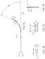
- FIGS. 1A through 1Eillustrate an exemplary embodiment of a delivery system embodying features of the present invention and having an inclined ultrasound array for improved imaging and a curved needle for ablation treatment.
- FIGS. 2A through 2Dillustrate exploded views of the distal portion of the ultrasound imaging insert of FIG. 1A in a straight configuration.
- FIGS. 3A through 3Dillustrate exploded views of the distal portion of the ultrasound imaging insert of FIG. 1A in a bent configuration.
- FIGS. 4A through 4Eillustrate cross-sectional views of the embodiments of exemplary delivery system of FIGS. 1A through 1C taken along their respective lines.
- FIG. 5Aillustrates a visualization and ablation system embodying features of the present invention.
- FIG. 5Billustrates features of an exemplary ultrasound probe of the visualization and ablation system of FIG. 5A .
- FIG. 5Cillustrates features of an exemplary ultrasound system of the visualization and ablation system of FIG. 5A .
- FIG. 5Dillustrates features of an exemplary radio frequency energy generator of the visualization and ablation system of FIG. 5A .
- FIG. 5Eillustrates the visualization and ablation system of FIG. 5A as disposed during operation within a uterus for the treatment of fibroids in accordance with the features of the present invention.
- FIGS. 6A through 6Cillustrate the exemplary features of an ablation needle for use with the visualization and ablation system of FIG. 5A .
- FIGS. 7A through 7Dillustrate the exemplary features of an ablation needle for use with the visualization and ablation system of FIGS. 4A-4C .
- FIG. 8Aillustrates an exemplary ablation needle for use with the visualization and ablation system of FIG. 5A and including an insulating material such as a retractable sheath.
- FIGS. 8B through 8Cillustrate the needle of FIG. 8A with the retractable sheath in a retracted position.
- FIGS. 8D through 8Fare cross-sectional views of the needle of FIG. 8A taken along lines 8 D- 8 D, 8 E- 8 E, and 8 F- 8 F.
- FIGS. 9A through 9Efurther illustrate the asymmetric solid distal tip of FIG. 6A .
- FIGS. 10A through 10Cillustrate use of the system of FIG. 1A within a uterus for the treatment of fibroids in accordance with the principles of the present invention.
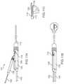
- FIGS. 11A through 11Cillustrate insertion of an imaging core into a sheath where both the imaging core and an interventional core extend axially from a distal end of the sheath, wherein the interventional core comprises a straight needle.
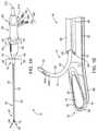
- an exemplary delivery system 10 embodying features of the present inventionis shown having a shaft inclined viewing window 12 for improved imaging and a curved needle 14 for ablation treatment of a target site 16 such as fibroid tissues 18 ( FIG. 5E ) within a female's reproductive system.
- the delivery system 10includes a system distal end 20 , a system proximal end 22 , and a rigid delivery shaft 24 .
- Delivery shaft 24includes a shaft distal end 26 with a bent or deflectable shaft distal tip 28 , a shaft proximal end 30 , and an axial passage 32 extending longitudinally through at least a portion of the delivery shaft 24 .
- the handle 40further includes a longitudinally movable slider 45 for enabling the advancement and retraction of the needle 14 to and from within a needle guide 58 .
- the curved needle 14has a needle body 50 with a shaped needle distal end 52 and a solid needle distal tip 54 , as best seen in FIGS. 1B-1E and 4A -E.
- Needle 14is configured to deliver, to the target site 16 including fibroid 18 (as shown in FIG. 5E ), radio frequency energy generated at a relatively low power and for relatively a short duration of time from an ablative energy generator 400 (such as, but not limited to, electromagnetic energy including microwave, resistive heating, cryogenic) including a radio frequency (RF) energy generator 410 , as shown in and discussed in reference to FIGS. 5A and 5E .
- ablative energy generator 400such as, but not limited to, electromagnetic energy including microwave, resistive heating, cryogenic
- RFradio frequency
- needle body 50is a hollow body forming a needle lumen 51 .
- needle 14is disposed adjacent the exterior of the shaft 24 within the needle guide 58 .
- Needle guide 58includes a guide passage 59 and is attachable to the shaft by way of adhesive, or other means such as laser welding, shrink tubing, and the like.
- Needle 14may include one or more needle apertures 60 .
- the needle 14includes two needle aperture 60 A and 60 B.
- the most distal aperture 60 Aexposes the distal end of a thermocouple pair 59 a and 59 b as shown in FIG. 6C .
- the proximal aperture 60 Bmay be used for delivery of various therapeutic and/or imaging enhancement fluids and contrasting agents/dyes to the target site 16 and fibroid 18 .
- contrasting dyeruns within the lumen 51 of the hollow needle body.
- the thermocouple pair 59 a and 59 bare disposed within the lumen 51 for monitoring the temperature at the target site 16 , while the annular space around the thermocouples within lumen 51 is usable for delivery of dyes.
- the shaft axial passage 32is configured for removably and replaceably receiving and housing an ultrasound imaging insert 70 .
- a sealing element 72may be provided between the ultrasound imaging insert 70 and the shaft handle 40 to provide sufficient sealing around the imaging insert 70 at a proximal end.
- the ultrasound imaging insert 70as shown in FIG. 1B , and as further described below, comprises an insert flexible shaft 74 , an insert proximal end 76 , an insert distal end 78 , an ultrasound array 80 , and an insert flat viewing window 82 disposed at the insert distal end 78 .
- the ultrasound array 80is viewable from the shaft inclined viewing window 12 .
- the shaft viewing windowmay be used for axial and/or rotational orientation of the ultrasound imaging insert 70 within the delivery system shaft 24 .
- a simplified illustration of the delivery shaft 24 as shown in FIG. 1Dcarries the ultrasound imaging insert 70 within its axial passage 32 .
- a viewing plane 11 provided by the tilted and bent ultrasound array 80is further illustrated.
- FIGS. 2A through 2Dexploded views of a distal portion 71 of the ultrasound imaging insert 70 are illustrated.
- FIGS. 2A and 2Cshow isometric and side views respectively of the ultrasound imaging insert 70 in a straight position prior to insertion into the axial passage 32 of the delivery shaft 24 , as will be described in more detail below.
- the ultrasound imaging insert 70comprises a flexible shaft 74 and includes an ultrasound array 80 and a flat viewing window 82 within the distal portion 71 .
- FIGS. 2B and 2Dillustrate transparent isometric and side views respectively of the ultrasound imaging insert 70 , wherein the ultrasound array 80 is shown tilted relative to a shaft axis 39 .
- the ultrasound array 80is tilted or inclined at an angle ⁇ in a range from about 7 degrees to about 15 degrees. It will be appreciated that the angle ⁇ of inclination of the ultrasound array 80 may comprise a variety of angles (e.g., 0 degrees to about 45 degrees) as permitted by an outer diameter of the flexible shaft 74 .
- the ultrasonic array 80may be arranged in a phased array, for example either a linear phased array or a circumferential phased array.
- the ultrasonic imaging array 80may comprise one or more independent elements, such as parabolic or other shaped imaging elements.
- the ultrasonic imaging array 80may be arranged in a rotating mechanism to permit rotational scanning.
- FIGS. 3A through 3Dexploded views of a distal portion 71 of the ultrasound imaging insert 70 are further illustrated.
- FIGS. 3A and 3Cshow isometric and side views respectively of the ultrasound imaging insert 70 in a bent position subsequent to insertion into the axial passage 32 of the delivery shaft 24 .
- the transparent isometric and side views of FIGS. 3B and 3Dillustrate the cumulative effect of tilting the ultrasound array 80 relative to the shaft axis 39 at the angle ⁇ and bending the distal portion 71 of the ultrasound imaging insert 70 .
- the bend angle ⁇may be in a range from about 0 degrees to about 80 degrees relative to the shaft axis 41 , preferably in a range from about 10 degrees to about 13 degrees.
- the bend angle ⁇will be determined by the deflectable distal tip 28 of the delivery shaft 24 as the flexible insert 70 conforms to the deflectable distal tip 28 upon insertion within the shaft 24 .
- the viewing angle ⁇ of the ultrasound imaging insert 70 achieved by this cumulative effectmay be in a range from about 7 degrees (i.e., angle due solely to tilted ultrasound array 12 ) to about 90 degrees relative to the shaft axis 40 . In the illustrated embodiment, the viewing angle is about 20 degrees, wherein the array tilting is approximately 7 degrees and shaft bending is about 13 degrees.
- the deflectable distal tip 28 of the rigid shaft 24may be deflected by the use of pull or tensioning wire(s) housed within the shaft 24 . Deflection may occur at a true mechanical pivot or at a flexible zone at the shaft distal end 26 .
- various needles 14may be used to match the amount of deflection provided by the distal tip 28 as well as the amount of tilt provided by the ultrasound array 80 .
- the needle guide 58will typically be empty until the distal end 26 of the shaft 24 is deflected.
- the shaft 24may be inserted in a straight configuration.
- the distal tip 28may then be deflected until a target anatomy is identified.
- a needle 14is then back loaded within the guide passage 58 that corresponds to the amount of the deflection.
- the delivery system 10includes a plurality of fluid inlet ports 100 in fluidic communication with various portions of the delivery system shaft 24 , needle 14 , and/or imaging insert 70 .
- system 10includes fluid inlet ports 102 , 104 , and 106 .
- Fluid inlet ports 100are configured to direct various fluids to a distal portion 23 of the delivery system 10 .
- fluid inlet port 102is configured to deliver dyes to at least one of the needle apertures 60 , such as aperture 60 B at the needle distal end 52 ; while fluid inlet ports 104 and 106 are configured, respectively, to deliver acoustic coupling fluids through external and internal axial lumens 86 and 88 disposed along axial passage 32 to a shaft external fluid outlet port 90 and a shaft internal fluid outlet port 92 at the shaft distal end 26 .
- Same or different fluid ports, such as fluid port 102may be further utilized to deliver other fluids such as therapeutic agents to any of the other outlet ports or apertures.
- additional aperturesmay be provided at desired locations along lumen 51 of the hollow needle body 50 .
- the shaft 24 of the present inventionmay serve several functions including delivering ultrasound, diagnostic, and/or interventional treatments, bending of the ultrasound insert via the deflectable distal tip, and/or providing a sterile barrier between the ultrasound and/or interventional components. As shown in FIG. 1B , the delivery shaft 24 carries the ultrasound imaging insert 70 within its axial passage 32 .
- the delivery system shaft 24will have a length in a range from about 20 cm to about 40 cm and an outer diameter in a range from about 3 mm to about 10 mm, while the ultrasound imaging insert 70 will have a length in a range from about 50 cm to about 90 cm and an outer diameter in a range from about 2 mm to about 4 mm.
- Delivery system shaft 24 and the ultrasound imaging insert 70may be acoustically coupled in one or more of several ways to enable the effective passage of ultrasound energy from one component to the other.
- the ultrasound insert 70may be placed in close mechanical contact with the shaft 24 so as to provide a dry coupling.
- a thin compliant layer(e.g., pad or sheet) may be disposed between the viewing windows 82 and 12 , of the ultrasound insert 70 and the shaft 24 , respectively, so as to provide further interference between such components. It will be appreciated that a thinner layer may be preferred to minimize unwanted acoustic loss, index of refraction, impedance, and/or other material property effects.
- the shaft axial passage 32 in which the ultrasound imaging insert 70 is disposablemay be filled with a fluid (e.g., water or oil) or gel to further provide a wet coupling between the shaft and the imaging insert which may compensate for any mechanical tolerances.
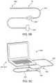
- FIG. 5Aa visualization and ablation system 200 embodying features of the present invention is shown, including a delivery device 210 , an ultrasound imaging probe 300 being detached from the delivery system 210 , the radio frequency energy generator 410 , and an ultrasound system 500 .
- the various components of the exemplary visualization and ablation system 200will be further described in individual detail.
- the ultrasound probe 300 embodying features of the present inventiongenerally includes the imaging insert 70 as generally described above, and is connectable to an imaging insert probe port 212 at the delivery system proximal end 22 .
- the ultrasound probe 300includes an alignment element 320 for removably engaging with the system probe port 212 of the delivery system 210 through a probe cable 310 .
- Alignment element 320is connectable to the ultrasound system 500 by way of an ultrasound probe attachment element 330 .
- the ultrasound system 500embodying features of the present invention, as shown in FIG. 5C , generally includes a CPU 510 such as one shown operable by a laptop computer 512 .
- the CPU 510is connectable to a beam former 520 by way of a communications cable (such as a firewire cable) such as an ultrasound cable 522 .
- the beam former 520 at a beam former distal end 524is connectable to a probe attachment element 530 by a probe extension cable 532 .
- the radio frequency energy 410is generally connectable to the delivery system 210 including needle 14 , through energy outlet port 420 .
- a suitable cable(not shown) removably connects energy outlet port 420 to a needle port 413 at the proximal end 22 of the handle 40 .
- Radiofrequency energyis delivered from the radio frequency generator 410 to fibroid 18 at the target site 16 through needle 14 which is disposed within the needle guide 58 .
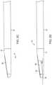
- the curved needle 14generally comprises a two-piece construction including the elongate needle hollow body 50 with the shaped needle distal end 52 and the solid needle distal tip 54 .
- the needle distal tip 54may be laser welded 55 to the needle hollow body 50 as shown in FIG. 6B .
- the needle distal tip 54may also be attached via alternative means, for example, adhesives or mechanical features or fits.
- the needle hollow body 50will have a length 55 in a range from about 20 cm to about 45 cm, an oval cross section having a thickness 57 in a range from about 0.5 mm to about 2 mm, and a wideness 59 in a range from about 1 mm to about 3 mm.
- the oval cross sectionis flattened minimizing lateral deflection during deployment or penetration of the needle 14 .
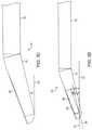
- the infusion apertures 60there are two laser cut infusion apertures 60 within the tubular body 50 for the infusion of agents (e.g., electrolytes, drugs, etc., dyes/contrasts) so as to enhance either or both the visualization and therapeutic effect of the needle 14 prior to, during, or after the ablation treatment.
- agentse.g., electrolytes, drugs, etc., dyes/contrasts
- the infusion apertures 60may be aligned on one side of the tubular body 50 .
- the infusion apertureshave a length 63 in a range from about 0.5 mm to about 2 mm and a width 65 in a range from about 0.5 mm to about 2 mm.
- the hollow tubular body 58may be curved at an angle ⁇ in a range from near 0 degrees (but greater than 0 degrees) to about 80 degrees relative to an axis 65 so as to access side/lateral fibroids.
- the angle ⁇is about 70 degrees.
- the angle of needle curvature ⁇is dependent upon the ultrasound array tilt angle ⁇ and the shaft bend angle ⁇ . For example, an increase in the tilt angle ⁇ or bend angle ⁇ decreases the angle of needle curvature ⁇ . This in turn advantageously allows a treating physician to selectively choose an appropriate needle curvature from a plurality of needles 14 (i.e., at least two or more) having different curvature angles ⁇ .
- the angle ⁇is 0 degrees
- the needleis straight as shown, for example, in FIGS. 11A-11C .
- the solid tip 54may comprise an asymmetric or offset trocar tip.
- the center point of the tip 54may be offset from a centerline of the needle to help compensate for any needle deflections due to tenacious tissue, in effect steering the needle towards the intended target even with the deflection.
- the tip 54may comprise a plurality of beveled edges offset at a variety of angles as illustrated in FIGS. 9D and 9E .
- the needle body 50is formed from an RF energy conductive material such as stainless steel.
- the solid tip 54may comprise a variety of dimensions and shapes and is not limited to FIGS. 9A-9E . It will be further appreciated that the tip 54 need not be a separate component but may alternatively be integrally formed with the needle body 50 .
- the needle 14including the tip 54 and tubular body 50 may be formed from a variety of materials including stainless steel, nitinol, and the like, for transmitting ablation energy.
- the handle 40may have a needle advancement portion to reciprocatably advance or retract the needle 14 from within the needle guide 58 .
- the needle advancement portionas shown, is in partially advanced position for complete deployment of the needle 14 .
- the needle guide 58will further have an oval cross section similar to that of the needle 14 , with a thickness in a range from about 0.5 mm to about 2 mm and a wideness in a range from about 1 mm to about 3 mm.
- the flattened guide 58 and flattened needle 14 as shown in FIG. 4Care intended to minimize lateral deflection during deployment or penetration of the needle 14 into the tissue.
- an insulating material 140extends longitudinally along at least an exterior portion 142 of the needle 14 terminating proximal to the conductive needle distal tip 54 .
- the insulating material 140forms a retractable sheath 144 .
- the conductive needle distal tip 54is extendable from a distal end 146 of the retractable sheath 144 .
- the proximal retraction of the sheath 144may be used to selectively control the length of the needle distal tip 54 .
- the needle distal tip 54is in a configuration distally extended from the distal end 146 of the retracted sheath 144 .
- the insulating sheath 140may be formed from one or more suitable insulating material such as polyester shrink tubing, and parylene coating such as parylene C.
- suitable insulating materialsuch as polyester shrink tubing, and parylene coating such as parylene C.
- the length of the conductive distal tip 54ranges from about 1 to about 4 cm, usually from about 2 to about 3 cm, normally about 2 cm.
- the conductive distal endis a T-type active electrode.
- the radio frequency energy generator 410is configured to deliver power to the fibroid 18 at the target site 16 , in a an amount ranging from about 1 to about 50 W, generally from about 10 to about 40 W, usually from about 20 to about 40 W, normally about 30 W.
- the radio frequency energy generator 410is configured to deliver and/or maintain a target temperature to the target site 16 ranging from about 50 to about 110.degree. C., usually from about 60 to about 100.degree. C., normally about 90.degree. C.
- the target site 16such as fibroid 18 , generally has an initial untreated diameter greater than about 2 cm, usually from about 1 to about 6 cm, normally about 2 cm.
- the needle 14may be inserted one or more times into the tissue as may be necessary.
- the needle distal tip 54may be deployed into the tissue, up to 3 cm as measured from the distal end of the of the delivery device 10 .
- the deployed length of the needle penetrating the tissueis visualized through the ultrasound imaging system 500 .
- the deflectable distal tip 26 of the rigid shaft 24may be deflected by the use of pull or tensioning wire(s) housed within the shaft 24 .
- the distal tipmay have pre-determined deflection as compared to a longitudinal axis at a proximal portion of the device. Deflection may occur at a true mechanical pivot or at a flexible zone at the shaft distal end.
- various needles 14may be used to match the amount of deflection provided by the distal tip 26 as well as the amount of tilt provided by the ultrasound array 80 .
- the needle guide 58may be empty until the distal end 26 of the shaft 24 is deflected.
- the shaft 24may be inserted in a straight configuration.
- the distal tip 26may then be deflected until a target anatomy is identified.
- a needle 14is then back loaded within the guide passage 70 that corresponds to the amount of the deflection.
- the needlemay be pre-loaded in the shaft to provide a sterile and convenient delivery device to the user.
- the therapeutic needle 14 advancement from the guide 58 via needle advancement portion on the shaft handle 40can be viewed in the ultrasound system 500 in real time as it is penetrated into the uterine fibroid 18 inside the uterus 17 .
- the therapeutic needle 14may be penetrated in several configurations (e.g., lateral, side, axially extending) depending on the ultrasound viewing angle.
- tilting of the ultrasound array 80 and angling of the distal tip 26allows a treating physician to image most or all of the cornua and fundus of the uterus 17 with a single device 10 .
- Table I belowillustrates possible viewing angles ⁇ that may be achieved by the cumulative effects of the shaft bending angle ⁇ (e.g., either through active deflection of the distal tip or a pre-shaped or pre-bent distal tip) and the ultrasound tilting angle ⁇ .
- the matching needle angles ⁇ based on the possible viewing angles ⁇are further illustrated.
- the shaft 24is in a straight configuration so that the viewing angle ⁇ is provided solely by the tilting angle ⁇ of the ultrasound array 80 .
- the needle 14will have a straight configuration.
- a non-tilted and non-bent ultrasound array 80 versionis covered.
- the viewing angle ⁇will be more than the bend angle ⁇ of the shaft 24 due to the additive effect of the tilting angle ⁇ of the ultrasound array 80 .
- Thisallows the bend on the distal tip 28 of the shaft 24 to be shallower without compromising the cumulative viewing angle ⁇ , which is of particular benefit for patient insertion considerations.
- the tiled ultrasound angle ⁇still aids in reducing the needle angle ⁇ .
- FIGS. 10A and 10Ca method, embodying features of the present invention, for using the system 10 of FIG. 1A to treat fibroids or tumors 18 within the uterus 19 is illustrated.
- the rigid shaft 24is inserted in a straight configuration within the uterus 19 .
- the distal tip 28 of the rigid shaft 24may then be selectively deflected by a pull wire.
- the ultrasound imaging insert 70may then be loaded within the axial passage 32 of the shaft 24 prior to, concurrent with, or subsequent to shaft 24 insertion, wherein a distal portion of the insert 70 conforms to the deflected shaft distal end 28 . Loading may further involve axially or rotationally aligning the ultrasound imaging insert 70 within the rigid shaft 24 .
- a needle angle ⁇is then selected by the physician from a plurality of needles 14 having different curvatures based on the shaft bending angle ⁇ and the ultrasound tilting angle ⁇ .
- the selected curved needle 14is then loaded within the passage 59 of the needle guide 58 .
- the therapeutic needle 14 advancement from the guide 58 via needle advancement button on the shaft handle 40can be viewed in real time as it is penetrated into the uterine fibroid 18 inside the uterus 19 as illustrated by the viewing plane 11 in FIGS. 10A and 10B .
- the therapeutic needle 14may be penetrated in several configurations (e.g., lateral, side, axially extending) depending on the ultrasound viewing angle ⁇ .
- tilting of the ultrasound array 80 and angling of the distal tip 28allows a treating physician to image most or all of the cornua and fundus of the uterus 19 with a single device 10 . As shown in FIG.
- the device 10may be configured so as to provide the desired viewing angle ⁇ (e.g., distally forward direction, side-viewing or lateral direction).
- desired viewing angle ⁇e.g., distally forward direction, side-viewing or lateral direction.
- manipulation of the device 10as for example, torquing and/or rotating the rigid device 16 in addition to tip deflection and ultrasound tilt a will allow a physician to obtain the desired viewing planes 11 , 11 ′, 11 ′′.
- viewing plane 11 ′′may be achieved if the device 10 was rotated 180° about its axis.
- viewing plane 11 ′may be achieved by torquing the device 10 .
- an embodiment 101 of the needle deployment and imaging system of the present inventionincludes sheath 112 , imaging core 114 , and interventional core 116 which are in many ways the same as described previously except for the distal end deployment configurations.
- imaging core 114is loaded into the sheath 112 where that the sheath 112 does not necessarily include an acoustically or optically transparent window at its distal end.
- both the distal end 130 of the interventional core 116 and the distal end 124 of the imaging core 114are extendable through ports in the distal end of the sheath 112 .
- the distal end 124 of the imaging core 114is deflectable using the control knob 172 of the handle structure 128 , as shown in broken line.
- the distal end of the sheath 112will often be steerable, and the embodiment of the needle deployment and imaging system 101 will allow access to a variety of tissue surfaces within the uterine or other body cavities by steering of the sheath, deflection of the imaging core, and rotation of the imaging core relative to the sheath.
- the handle structure 128 of the imaging core 114is joined to a handle structure 122 of the sheath 112 to properly position the needle 130 relative to the sheath 112 prior to use.
- the handle structure 128may be placed in a cradle 160 of the handle structure 122 so that an assembly handle is formed as shown in FIG. 11B .
Landscapes
- Health & Medical Sciences (AREA)
- Life Sciences & Earth Sciences (AREA)
- Surgery (AREA)
- Engineering & Computer Science (AREA)
- Nuclear Medicine, Radiotherapy & Molecular Imaging (AREA)
- Veterinary Medicine (AREA)
- Public Health (AREA)
- General Health & Medical Sciences (AREA)
- Biomedical Technology (AREA)
- Heart & Thoracic Surgery (AREA)
- Medical Informatics (AREA)
- Molecular Biology (AREA)
- Animal Behavior & Ethology (AREA)
- Physics & Mathematics (AREA)
- Radiology & Medical Imaging (AREA)
- Biophysics (AREA)
- Pathology (AREA)
- Vascular Medicine (AREA)
- Plasma & Fusion (AREA)
- Otolaryngology (AREA)
- Orthopedic Medicine & Surgery (AREA)
- Ultra Sonic Daignosis Equipment (AREA)
- Surgical Instruments (AREA)
Abstract
Description
| TABLE 1 | ||||
| Viewing Angle | Tilt Angle | Bend Angle | Needle Angle | |
| Example | (κ) | (α) | (β) | (θ) |
| 1 | 7°-10° | 7°-10° | 0° | 80° |
| 2 | 20° | 7°-10° | 10°-13° | 70° |
| 3 | 45° | 7°-10° | 35°-38° | 45° |
| 4 | 90° | 7°-10° | 80°-83° | 0° |
| 5 | 0° | 0° | 0° | 90° |
Claims (20)
Priority Applications (2)
| Application Number | Priority Date | Filing Date | Title |
|---|---|---|---|
| US15/628,166US11259825B2 (en) | 2006-01-12 | 2017-06-20 | Devices and methods for treatment of tissue |
| US17/564,041US20220175405A1 (en) | 2006-01-12 | 2021-12-28 | Devices and methods for treatment of tissue |
Applications Claiming Priority (7)
| Application Number | Priority Date | Filing Date | Title |
|---|---|---|---|
| US75888106P | 2006-01-12 | 2006-01-12 | |
| US11/409,496US7815571B2 (en) | 2006-04-20 | 2006-04-20 | Rigid delivery systems having inclined ultrasound and needle |
| US11/564,164US7874986B2 (en) | 2006-04-20 | 2006-11-28 | Methods and devices for visualization and ablation of tissue |
| US11/620,591US7630002B2 (en) | 2007-01-05 | 2007-01-05 | Specular reflection reduction using multiple cameras |
| US12/973,587US8506485B2 (en) | 2006-04-20 | 2010-12-20 | Devices and methods for treatment of tissue |
| US13/667,891US10058342B2 (en) | 2006-01-12 | 2012-11-02 | Devices and methods for treatment of tissue |
| US15/628,166US11259825B2 (en) | 2006-01-12 | 2017-06-20 | Devices and methods for treatment of tissue |
Related Parent Applications (1)
| Application Number | Title | Priority Date | Filing Date |
|---|---|---|---|
| US13/667,891ContinuationUS10058342B2 (en) | 2006-01-12 | 2012-11-02 | Devices and methods for treatment of tissue |
Related Child Applications (1)
| Application Number | Title | Priority Date | Filing Date |
|---|---|---|---|
| US17/564,041ContinuationUS20220175405A1 (en) | 2006-01-12 | 2021-12-28 | Devices and methods for treatment of tissue |
Publications (2)
| Publication Number | Publication Date |
|---|---|
| US20170290626A1 US20170290626A1 (en) | 2017-10-12 |
| US11259825B2true US11259825B2 (en) | 2022-03-01 |
Family
ID=80351191
Family Applications (1)
| Application Number | Title | Priority Date | Filing Date |
|---|---|---|---|
| US15/628,166Active2029-01-05US11259825B2 (en) | 2006-01-12 | 2017-06-20 | Devices and methods for treatment of tissue |
Country Status (1)
| Country | Link |
|---|---|
| US (1) | US11259825B2 (en) |
Cited By (3)
| Publication number | Priority date | Publication date | Assignee | Title |
|---|---|---|---|---|
| US20230218148A1 (en)* | 2018-04-12 | 2023-07-13 | Endosound, Inc. | Steerable ultrasound attachment for endoscope |
| US11950837B2 (en) | 2005-02-02 | 2024-04-09 | Gynesonics, Inc. | Method and device for uterine fibroid treatment |
| US12239382B2 (en) | 2016-11-11 | 2025-03-04 | Gynesonics, Inc. | Controlled treatment of tissue and dynamic interaction with, and comparison of, tissue and/or treatment data |
Families Citing this family (4)
| Publication number | Priority date | Publication date | Assignee | Title |
|---|---|---|---|---|
| CN112638302A (en)* | 2018-08-27 | 2021-04-09 | 内萨梅德得克公司 | System and method for ablating uterine fibroids |
| US11564736B2 (en)* | 2019-01-25 | 2023-01-31 | May Health Sas | Systems and methods for applying energy to ovarian tissue |
| US20210204907A1 (en) | 2020-01-07 | 2021-07-08 | Covidien Lp | Devices, systems, and methods for trans-vaginal, ultrasound-guided hysteroscopic surgical procedures |
| US20220361859A1 (en)* | 2021-05-12 | 2022-11-17 | Boston Scientific Scimed Inc | Devices, Systems, and Methods for Positioning an Elongate Member within a Body Lumen |
Citations (234)
| Publication number | Priority date | Publication date | Assignee | Title |
|---|---|---|---|---|
| US4289132A (en) | 1979-06-25 | 1981-09-15 | Rieman Robert D | Surgical instrument and method of using the same |
| US4802487A (en) | 1987-03-26 | 1989-02-07 | Washington Research Foundation | Endoscopically deliverable ultrasound imaging system |
| US4869258A (en) | 1986-12-05 | 1989-09-26 | Siemens Aktiengesellschaft | Intracavitary ultrasound scanner means |
| US4936281A (en) | 1989-04-13 | 1990-06-26 | Everest Medical Corporation | Ultrasonically enhanced RF ablation catheter |
| US5000185A (en) | 1986-02-28 | 1991-03-19 | Cardiovascular Imaging Systems, Inc. | Method for intravascular two-dimensional ultrasonography and recanalization |
| US5090414A (en) | 1988-08-22 | 1992-02-25 | Kabushiki Kaisha Toshiba | Intracavitary ultrasound probe |
| US5190050A (en) | 1991-11-08 | 1993-03-02 | Electro-Catheter Corporation | Tip deflectable steerable catheter |
| US5315741A (en) | 1992-03-24 | 1994-05-31 | Nicole Durr GmbH | Snap fastener for securing shoe laces |
| US5335663A (en) | 1992-12-11 | 1994-08-09 | Tetrad Corporation | Laparoscopic probes and probe sheaths useful in ultrasonic imaging applications |
| US5372587A (en) | 1989-01-09 | 1994-12-13 | Pilot Cariovascular Systems, Inc. | Steerable medical device |
| US5372138A (en) | 1988-03-21 | 1994-12-13 | Boston Scientific Corporation | Acousting imaging catheters and the like |
| US5456689A (en) | 1993-10-13 | 1995-10-10 | Arnold J. Kresch | Method and device for tissue resection |
| WO1995028129A1 (en) | 1994-04-15 | 1995-10-26 | Tetrad Corporation | Bendable ultrasonic probe and sheath |
| US5471988A (en) | 1993-12-24 | 1995-12-05 | Olympus Optical Co., Ltd. | Ultrasonic diagnosis and therapy system in which focusing point of therapeutic ultrasonic wave is locked at predetermined position within observation ultrasonic scanning range |
| US5474075A (en) | 1993-11-24 | 1995-12-12 | Thomas Jefferson University | Brush-tipped catheter for ultrasound imaging |
| US5492126A (en) | 1994-05-02 | 1996-02-20 | Focal Surgery | Probe for medical imaging and therapy using ultrasound |
| US5531676A (en) | 1992-08-12 | 1996-07-02 | Vidamed, Inc. | Medical probe device and method |
| WO1997017105A1 (en) | 1995-11-09 | 1997-05-15 | Femrx, Inc. | Needle myolysis system for uterine fibroids |
| US5649911A (en) | 1996-05-17 | 1997-07-22 | Indiana University Foundation | Intravenous catheter and delivery system |
| US5662664A (en) | 1992-09-04 | 1997-09-02 | Laurus Medical Corporation | Endoscopic suture system |
| US5666954A (en) | 1991-03-05 | 1997-09-16 | Technomed Medical Systems Inserm-Institut National De La Sante Et De La Recherche Medicale | Therapeutic endo-rectal probe, and apparatus constituting an application thereof for destroying cancer tissue, in particular of the prostate, and preferably in combination with an imaging endo-cavitary-probe |
| US5697897A (en) | 1994-01-14 | 1997-12-16 | Siemens Aktiengesellschaft | Endoscope carrying a source of therapeutic ultrasound |
| US5730752A (en) | 1996-10-29 | 1998-03-24 | Femrx, Inc. | Tubular surgical cutters having aspiration flow control ports |
| WO1998011834A1 (en) | 1996-09-20 | 1998-03-26 | Vidacare, Inc. | Ablation of rectal and other internal body structures |
| WO1998014169A1 (en) | 1996-09-30 | 1998-04-09 | Brigham & Women's Hospital | Methods and compounds for treatment of abnormal uterine bleeding |
| US5741287A (en) | 1996-11-01 | 1998-04-21 | Femrx, Inc. | Surgical tubular cutter having a tapering cutting chamber |
| US5752518A (en) | 1996-10-28 | 1998-05-19 | Ep Technologies, Inc. | Systems and methods for visualizing interior regions of the body |
| US5769880A (en) | 1996-04-12 | 1998-06-23 | Novacept | Moisture transport system for contact electrocoagulation |
| US5842994A (en) | 1997-07-02 | 1998-12-01 | Boston Scientific Technology, Inc. | Multifunction intraluminal ultrasound catheter having a removable core with maximized transducer aperture |
| US5853368A (en) | 1996-12-23 | 1998-12-29 | Hewlett-Packard Company | Ultrasound imaging catheter having an independently-controllable treatment structure |
| US5860974A (en) | 1993-07-01 | 1999-01-19 | Boston Scientific Corporation | Heart ablation catheter with expandable electrode and method of coupling energy to an electrode on a catheter shaft |
| US5863294A (en) | 1996-01-26 | 1999-01-26 | Femrx, Inc. | Folded-end surgical tubular cutter and method for fabrication |
| US5873828A (en) | 1994-02-18 | 1999-02-23 | Olympus Optical Co., Ltd. | Ultrasonic diagnosis and treatment system |
| US5876399A (en) | 1997-05-28 | 1999-03-02 | Irvine Biomedical, Inc. | Catheter system and methods thereof |
| US5876340A (en) | 1997-04-17 | 1999-03-02 | Irvine Biomedical, Inc. | Ablation apparatus with ultrasonic imaging capabilities |
| US5891137A (en) | 1997-05-21 | 1999-04-06 | Irvine Biomedical, Inc. | Catheter system having a tip with fixation means |
| US5906615A (en) | 1997-03-31 | 1999-05-25 | Femrx, Inc. | Serpentine ablation/coagulation electrode |
| US5916198A (en) | 1997-08-05 | 1999-06-29 | Femrx, Inc. | Non-binding surgical valve |
| WO1999043366A1 (en) | 1998-02-27 | 1999-09-02 | Micro Therapeutics, Inc. | Gynecologic embolotherapy methods |
| US5957941A (en) | 1996-09-27 | 1999-09-28 | Boston Scientific Corporation | Catheter system and drive assembly thereof |
| US5964740A (en) | 1996-07-09 | 1999-10-12 | Asahi Kogaku Kogyo Kabushiki Kaisha | Treatment accessory for an endoscope |
| US5979452A (en) | 1995-06-07 | 1999-11-09 | General Surgical Innovations, Inc. | Endoscopic linton procedure using balloon dissectors and retractors |
| US5984942A (en) | 1997-04-02 | 1999-11-16 | Femrx, Inc. | Methods and systems for reducing tissue adhesion |
| US6002968A (en) | 1994-06-24 | 1999-12-14 | Vidacare, Inc. | Uterine treatment apparatus |
| US6007499A (en) | 1997-10-31 | 1999-12-28 | University Of Washington | Method and apparatus for medical procedures using high-intensity focused ultrasound |
| WO2000000098A1 (en) | 1998-06-30 | 2000-01-06 | Arthrocare Corporation | Systems and methods for electrosurgical ablation of viable body structures |
| US6032673A (en) | 1994-10-13 | 2000-03-07 | Femrx, Inc. | Methods and devices for tissue removal |
| US6039748A (en) | 1997-08-05 | 2000-03-21 | Femrx, Inc. | Disposable laparoscopic morcellator |
| US6141577A (en) | 1997-07-28 | 2000-10-31 | University Of Central Florida | Three dimensional optical imaging colposcopy |
| US6146378A (en) | 1999-03-19 | 2000-11-14 | Endocare, Inc. | Placement guide for ablation devices |
| US6146380A (en) | 1998-01-09 | 2000-11-14 | Radionics, Inc. | Bent tip electrical surgical probe |
| US6158250A (en) | 2000-02-14 | 2000-12-12 | Novacept | Flat-bed knitting machine and method of knitting |
| US6171249B1 (en) | 1997-10-14 | 2001-01-09 | Circon Corporation | Ultrasound guided therapeutic and diagnostic device |
| US6190383B1 (en) | 1998-10-21 | 2001-02-20 | Sherwood Services Ag | Rotatable electrode device |
| US6193714B1 (en) | 1997-04-11 | 2001-02-27 | Vidamed, Inc. | Medical probe device with transparent distal extremity |
| US6211153B1 (en) | 1995-12-15 | 2001-04-03 | Praecis Pharmaceuticals, Inc. | Methods for treating LHRH associated disorders with LHRH antagonists |
| US6238336B1 (en) | 1998-03-04 | 2001-05-29 | Asahi Kogaku Kogyo Kabushiki Kaisha | Ultrasonic endoscope including radial scanning and linear scanning ultrasonic transducers |
| US6254601B1 (en) | 1998-12-08 | 2001-07-03 | Hysterx, Inc. | Methods for occlusion of the uterine arteries |
| US6280441B1 (en) | 1997-12-15 | 2001-08-28 | Sherwood Services Ag | Apparatus and method for RF lesioning |
| US6296639B1 (en) | 1999-02-12 | 2001-10-02 | Novacept | Apparatuses and methods for interstitial tissue removal |
| US6306129B1 (en) | 1997-09-22 | 2001-10-23 | Femrx, Inc. | Cryosurgical system and method |
| US6306097B1 (en) | 1999-06-17 | 2001-10-23 | Acuson Corporation | Ultrasound imaging catheter guiding assembly with catheter working port |
| WO2001080723A2 (en) | 2000-04-25 | 2001-11-01 | Curon Medical, Inc. | Ablation of rectal and other internal body structures |
| US20010051802A1 (en) | 1993-05-10 | 2001-12-13 | Arthrocare Corporation | Electrosurgical apparatus and methods for treating tissue |
| US20020002393A1 (en) | 1998-11-16 | 2002-01-03 | James Mitchell | Apparatus for thermal treatment of tissue |
| WO2002011639A1 (en) | 2000-08-09 | 2002-02-14 | Lee Bruce B | Gynecological ablation procedure and system using an ablation needle |
| US6379348B1 (en) | 2000-03-15 | 2002-04-30 | Gary M. Onik | Combined electrosurgical-cryosurgical instrument |
| US20020068871A1 (en) | 1997-08-19 | 2002-06-06 | John D. Mendlein | Ultrasonic transmission films and devices, particularly for hygienic transducer surfaces |
| US6405732B1 (en) | 1994-06-24 | 2002-06-18 | Curon Medical, Inc. | Method to treat gastric reflux via the detection and ablation of gastro-esophageal nerves and receptors |
| US20020077550A1 (en) | 1999-10-05 | 2002-06-20 | Rabiner Robert A. | Apparatus and method for treating gynecological diseases using an ultrasonic medical device operating in a transverse mode |
| US6419048B1 (en) | 2000-05-04 | 2002-07-16 | Laurence Robinson | Adjustable supports |
| US6419648B1 (en) | 2000-04-21 | 2002-07-16 | Insightec-Txsonics Ltd. | Systems and methods for reducing secondary hot spots in a phased array focused ultrasound system |
| US6425867B1 (en) | 1998-09-18 | 2002-07-30 | University Of Washington | Noise-free real time ultrasonic imaging of a treatment site undergoing high intensity focused ultrasound therapy |
| US6447477B2 (en) | 1996-02-09 | 2002-09-10 | Emx, Inc. | Surgical and pharmaceutical site access guide and methods |
| US6461296B1 (en) | 1998-06-26 | 2002-10-08 | 2000 Injectx, Inc. | Method and apparatus for delivery of genes, enzymes and biological agents to tissue cells |
| US6463331B1 (en) | 1999-04-19 | 2002-10-08 | Novasys Medical, Inc. | Application of energy and substances in the treatment of uro-genital disorders |
| US6468228B1 (en) | 1996-06-18 | 2002-10-22 | Vance Products Incorporated | Surgical tissue morcellator |
| US20020156373A1 (en) | 2000-11-29 | 2002-10-24 | Olympus Optical Co., Ltd. | Ultrasound transducer array |
| US6475152B1 (en) | 2000-03-13 | 2002-11-05 | Koninklijke Philips Electronics N.V. | Biopsy needle guide for attachment to an ultrasound transducer |
| US6482203B2 (en) | 1997-09-30 | 2002-11-19 | Scimed Life Systems, Inc. | Deflectable interstitial ablation device |
| US6485413B1 (en) | 1991-04-29 | 2002-11-26 | The General Hospital Corporation | Methods and apparatus for forward-directed optical scanning instruments |
| US20030009164A1 (en) | 1995-06-07 | 2003-01-09 | Arthrocare Corporation | Articulated electrosurgical probe |
| US6506154B1 (en) | 2000-11-28 | 2003-01-14 | Insightec-Txsonics, Ltd. | Systems and methods for controlling a phased array focused ultrasound system |
| US6506171B1 (en) | 2000-07-27 | 2003-01-14 | Insightec-Txsonics, Ltd | System and methods for controlling distribution of acoustic energy around a focal point using a focused ultrasound system |
| US6506156B1 (en) | 2000-01-19 | 2003-01-14 | Vascular Control Systems, Inc | Echogenic coating |
| US6507747B1 (en) | 1998-12-02 | 2003-01-14 | Board Of Regents, The University Of Texas System | Method and apparatus for concomitant structural and biochemical characterization of tissue |
| US20030014046A1 (en) | 1998-01-14 | 2003-01-16 | Conway-Stuart Medical, Inc. | Sphincter treatment device |
| US6508815B1 (en) | 1998-05-08 | 2003-01-21 | Novacept | Radio-frequency generator for powering an ablation device |
| US20030032896A1 (en) | 2000-09-25 | 2003-02-13 | Vance Products, Inc., D/B/A/ Cook Urological, Inc. | Microvolume embryo transfer system |
| US6522142B1 (en) | 2001-12-14 | 2003-02-18 | Insightec-Txsonics Ltd. | MRI-guided temperature mapping of tissue undergoing thermal treatment |
| US20030045768A1 (en)* | 1999-12-08 | 2003-03-06 | Kenji Hirooka | Ultrasonic probe for operation under microscope |
| US6540677B1 (en) | 2000-11-17 | 2003-04-01 | Bjorn A. J. Angelsen | Ultrasound transceiver system for remote operation through a minimal number of connecting wires |
| US6543272B1 (en) | 2000-04-21 | 2003-04-08 | Insightec-Txsonics Ltd. | Systems and methods for testing and calibrating a focused ultrasound transducer array |
| US6550482B1 (en) | 2000-04-21 | 2003-04-22 | Vascular Control Systems, Inc. | Methods for non-permanent occlusion of a uterine artery |
| US6554780B1 (en) | 1999-11-10 | 2003-04-29 | Novacept | System and method for detecting perforations in a body cavity |
| US6554801B1 (en) | 2000-10-26 | 2003-04-29 | Advanced Cardiovascular Systems, Inc. | Directional needle injection drug delivery device and method of use |
| US6559644B2 (en) | 2001-05-30 | 2003-05-06 | Insightec - Txsonics Ltd. | MRI-based temperature mapping with error compensation |
| US6569159B1 (en) | 1993-11-08 | 2003-05-27 | Rita Medical Systems, Inc. | Cell necrosis apparatus |
| US6572613B1 (en) | 2001-01-16 | 2003-06-03 | Alan G. Ellman | RF tissue penetrating probe |
| US20030114732A1 (en) | 2001-12-18 | 2003-06-19 | Advanced Cardiovascular Systems, Inc. | Sheath for guiding imaging instruments |
| US20030130665A1 (en) | 2000-03-10 | 2003-07-10 | Pinczewski Leo Arieh | Method of arthroplastly on a knee joint and apparatus for use in same |
| US20030130575A1 (en) | 1991-10-18 | 2003-07-10 | Ashvin Desai | Method and apparatus for tissue treatment with laser and electromagnetic radiation |
| US20030130655A1 (en) | 1995-06-07 | 2003-07-10 | Arthrocare Corporation | Electrosurgical systems and methods for removing and modifying tissue |
| US6592559B1 (en) | 1998-12-09 | 2003-07-15 | Cook Incorporated | Hollow, curved, superlastic medical needle |
| US6613005B1 (en) | 2000-11-28 | 2003-09-02 | Insightec-Txsonics, Ltd. | Systems and methods for steering a focused ultrasound array |
| US6613004B1 (en) | 2000-04-21 | 2003-09-02 | Insightec-Txsonics, Ltd. | Systems and methods for creating longer necrosed volumes using a phased array focused ultrasound system |
| US6612988B2 (en) | 2000-08-29 | 2003-09-02 | Brigham And Women's Hospital, Inc. | Ultrasound therapy |
| US6623481B1 (en) | 1999-07-21 | 2003-09-23 | Thermo-Med 2000 Kft | Electrosurgical probe for tumor treatment by radiofrequency |
| US6626855B1 (en) | 1999-11-26 | 2003-09-30 | Therus Corpoation | Controlled high efficiency lesion formation using high intensity ultrasound |
| US6626854B2 (en) | 2000-12-27 | 2003-09-30 | Insightec - Txsonics Ltd. | Systems and methods for ultrasound assisted lipolysis |
| US6632193B1 (en) | 1995-06-07 | 2003-10-14 | Arthrocare Corporation | Systems and methods for electrosurgical tissue treatment |
| US20030195496A1 (en) | 2000-05-16 | 2003-10-16 | Maguire Mark A. | Apparatus and method incorporating an ultrasound transducer onto a delivery member |
| US6635055B1 (en) | 1998-05-06 | 2003-10-21 | Microsulis Plc | Microwave applicator for endometrial ablation |
| US6635065B2 (en) | 2000-11-16 | 2003-10-21 | Vascular Control Systems, Inc. | Doppler directed suture ligation device and method |
| US20030199472A1 (en) | 2002-03-19 | 2003-10-23 | Board Of Regents, The University Of Texas System | Adenovirus-mediated therapy for uterine fibroids |
| US6638275B1 (en) | 2000-10-05 | 2003-10-28 | Medironic, Inc. | Bipolar ablation apparatus and method |
| US6638286B1 (en) | 2000-11-16 | 2003-10-28 | Vascular Control Systems, Inc. | Doppler directed suture ligation device and method |
| WO2003088833A1 (en) | 2002-04-22 | 2003-10-30 | The Johns Hopkins University | Apparatus for insertion of a medical device during a medical imaging process |
| US6645162B2 (en) | 2000-12-27 | 2003-11-11 | Insightec - Txsonics Ltd. | Systems and methods for ultrasound assisted lipolysis |
| US20030216725A1 (en) | 1993-05-10 | 2003-11-20 | Arthrocare Corporation | Electrosurgical apparatus and methods for laparoscopy |
| US6654202B2 (en) | 2000-06-20 | 2003-11-25 | Seagate Technology Llc | Disc drive with layered write coil |
| US6652516B1 (en) | 1995-08-15 | 2003-11-25 | Rita Medical Systems, Inc. | Cell necrosis apparatus |
| US6660002B1 (en) | 1993-11-08 | 2003-12-09 | Rita Medical Systems, Inc. | RF treatment apparatus |
| US6660024B1 (en) | 1995-10-13 | 2003-12-09 | Transvascular, Inc. | Tissue penetrating catheters having integral imaging transducers and their methods of use |
| US6662680B2 (en)* | 2000-05-17 | 2003-12-16 | Peter Rocket | Device and method for attaching a supplemental set of handlebars to a bicycle |
| US6666833B1 (en) | 2000-11-28 | 2003-12-23 | Insightec-Txsonics Ltd | Systems and methods for focussing an acoustic energy beam transmitted through non-uniform tissue medium |
| US6669643B1 (en) | 1998-04-13 | 2003-12-30 | Theodore J. Dubinsky | Method and apparatus for sonographic examination, biopsy, and excision |
| US20040002699A1 (en) | 2002-06-27 | 2004-01-01 | Ethicon, Inc. | Helical device and method for aiding the ablation and assessment of tissue |
| US20040006336A1 (en) | 2002-07-02 | 2004-01-08 | Scimed Life Systems, Inc. | Apparatus and method for RF ablation into conductive fluid-infused tissue |
| WO2004002293A2 (en) | 2002-06-27 | 2004-01-08 | Arthrocare Corporation | Systems and methods for electrosurgical tissue treatment |
| US6679855B2 (en) | 2000-11-07 | 2004-01-20 | Gerald Horn | Method and apparatus for the correction of presbyopia using high intensity focused ultrasound |
| US6685639B1 (en) | 1998-01-25 | 2004-02-03 | Chongqing Hifu | High intensity focused ultrasound system for scanning and curing tumor |
| US6689128B2 (en) | 1996-10-22 | 2004-02-10 | Epicor Medical, Inc. | Methods and devices for ablation |
| US6692490B1 (en) | 1999-05-18 | 2004-02-17 | Novasys Medical, Inc. | Treatment of urinary incontinence and other disorders by application of energy and drugs |
| WO2004020011A1 (en) | 2002-08-30 | 2004-03-11 | Boston Scientific Limited | Embolization |
| US6705994B2 (en) | 2002-07-08 | 2004-03-16 | Insightec - Image Guided Treatment Ltd | Tissue inhomogeneity correction in ultrasound imaging |
| US20040054366A1 (en) | 1998-08-11 | 2004-03-18 | Arthrocare Corporation | Instrument for electrosurgical tissue treatment |
| US6712815B2 (en) | 2001-01-16 | 2004-03-30 | Novacept, Inc. | Apparatus and method for treating venous reflux |
| US6728571B1 (en) | 2001-07-16 | 2004-04-27 | Scimed Life Systems, Inc. | Electronically scanned optical coherence tomography with frequency modulated signals |
| WO2004035110A2 (en) | 2002-10-17 | 2004-04-29 | Pro Surg, Inc. | Gel injection apparatus and treatment of breast, fibroids and endometrial ablation |
| US20040082883A1 (en) | 2002-10-18 | 2004-04-29 | Fuji Photo Optical Co., Ltd. | Ultrasound endoscope |
| US6730081B1 (en) | 1991-10-18 | 2004-05-04 | Ashvin H. Desai | Endoscopic surgical instrument |
| US6735461B2 (en) | 2001-06-19 | 2004-05-11 | Insightec-Txsonics Ltd | Focused ultrasound system with MRI synchronization |
| US20040120668A1 (en) | 2002-12-20 | 2004-06-24 | Loeb Marvin P. | Device and method for delivery of long wavelength laser energy to a tissue site |
| US20040143252A1 (en) | 2003-01-16 | 2004-07-22 | Charlotte-Mecklenburg Hospital Authority D/B/A Carolinas Medical Center | Echogenic needle for transvaginal ultrasound directed reduction of uterine fibroids and an associated method |
| US6773431B2 (en) | 1995-06-07 | 2004-08-10 | Arthrocare Corporation | Method for epidermal tissue ablation |
| US20040175399A1 (en) | 2003-03-03 | 2004-09-09 | Allergan, Inc. | Methods for treating uterine disorders |
| US20040176760A1 (en) | 2003-03-05 | 2004-09-09 | Qiu Xue Hua | Electrosurgical apparatus with cooling device |
| US6790180B2 (en) | 2001-12-03 | 2004-09-14 | Insightec-Txsonics Ltd. | Apparatus, systems, and methods for measuring power output of an ultrasound transducer |
| US20040193028A1 (en) | 2003-03-28 | 2004-09-30 | Vascular Control Systems, Inc. | Uterine tissue monitoring device and method |
| US20040193238A1 (en)* | 2003-01-16 | 2004-09-30 | Surx, Inc., A Corporation Of Delaware | Non-surgical incontinence treatment system and method |
| US20040199179A1 (en) | 2003-04-02 | 2004-10-07 | Elliott Christopher J. | Steerable ablation probe |
| US6805129B1 (en) | 1996-10-22 | 2004-10-19 | Epicor Medical, Inc. | Apparatus and method for ablating tissue |
| US6805128B1 (en) | 1996-10-22 | 2004-10-19 | Epicor Medical, Inc. | Apparatus and method for ablating tissue |
| US6813520B2 (en) | 1996-04-12 | 2004-11-02 | Novacept | Method for ablating and/or coagulating tissue using moisture transport |
| US20040230190A1 (en) | 1998-08-11 | 2004-11-18 | Arthrocare Corporation | Electrosurgical apparatus and methods for tissue treatment and removal |
| US20040254572A1 (en) | 2003-04-25 | 2004-12-16 | Mcintyre Jon T. | Self anchoring radio frequency ablation array |
| US6837888B2 (en) | 1995-06-07 | 2005-01-04 | Arthrocare Corporation | Electrosurgical probe with movable return electrode and methods related thereto |
| US20050038340A1 (en) | 1998-09-18 | 2005-02-17 | University Of Washington | Use of contrast agents to increase the effectiveness of high intensity focused ultrasound therapy |
| US20050085730A1 (en) | 2003-10-21 | 2005-04-21 | Aime Flesch | Bi-plane ultrasonic probe |
| US20050096647A1 (en) | 2003-09-12 | 2005-05-05 | Minnow Medical, Inc. | Selectable eccentric remodeling and/or ablation of atherosclerotic material |
| US20050107781A1 (en) | 2003-11-18 | 2005-05-19 | Isaac Ostrovsky | System and method for tissue ablation |
| US20050124882A1 (en) | 2003-02-14 | 2005-06-09 | Igal Ladabaum | System and method of operating microfabricated ultrasonic transducers for harmonic imaging |
| US20050149013A1 (en) | 2000-08-09 | 2005-07-07 | Lee Bruce B. | Gynecological ablation procedure and system |
| US20050177209A1 (en) | 2002-03-05 | 2005-08-11 | Baylis Medical Company Inc. | Bipolar tissue treatment system |
| US6938048B1 (en) | 2001-11-14 | 2005-08-30 | Qgenisys, Inc. | Universal task management system, method and product for automatically managing remote workers, including automatically training the workers |
| US20050197577A1 (en) | 2004-03-08 | 2005-09-08 | Makin Inder Raj S. | Intra-cavitary ultrasound medical system and method |
| US6944490B1 (en) | 2002-09-25 | 2005-09-13 | Advanced Cardiovascular Systems, Inc. | Apparatus and method for positioning and delivering a therapeutic tool to the inside of a heart |
| US20050203410A1 (en)* | 2004-02-27 | 2005-09-15 | Ep Medsystems, Inc. | Methods and systems for ultrasound imaging of the heart from the pericardium |
| US20050215990A1 (en) | 2004-03-24 | 2005-09-29 | Assaf Govari | Phased-array for tissue treatment |
| US20050216039A1 (en) | 2002-11-15 | 2005-09-29 | Lederman Robert J | Method and device for catheter based repair of cardiac valves |
| US20050255039A1 (en) | 1998-06-26 | 2005-11-17 | Pro Surg, Inc., A California Corporation | Gel injection treatment of breast, fibroids & endometrial ablation |
| US20050256405A1 (en) | 2004-05-17 | 2005-11-17 | Makin Inder Raj S | Ultrasound-based procedure for uterine medical treatment |
| US6969354B1 (en) | 2001-09-25 | 2005-11-29 | Acuson Corporation | Adaptable intraoperative or endocavity ultrasound probe |
| US20060010207A1 (en) | 2000-09-25 | 2006-01-12 | Crossbeam Systems, Inc. | Network application apparatus |
| US20060018665A1 (en) | 2003-06-19 | 2006-01-26 | Fujitsu Limited | Route determination method used in optical signal transmission system |
| US6994706B2 (en) | 2001-08-13 | 2006-02-07 | Minnesota Medical Physics, Llc | Apparatus and method for treatment of benign prostatic hyperplasia |
| US20060058680A1 (en) | 2004-08-25 | 2006-03-16 | Stephen Solomon | Needle guide for laparoscopic ultrasonography |
| US20060178665A1 (en) | 2005-02-08 | 2006-08-10 | Todd Sloan | Radio frequency ablation system with integrated ultrasound imaging |
| US20060184049A1 (en) | 2005-01-26 | 2006-08-17 | Fuji Photo Film Co., Ltd. | Apparatus for acquiring tomographic image formed by ultrasound-modulated fluorescence |
| US20060189972A1 (en) | 2005-02-02 | 2006-08-24 | Gynesonics, Inc. | Method and device for uterine fibroid treatment |
| US20070006215A1 (en) | 2005-07-01 | 2007-01-04 | Gordon Epstein | Anchored RF ablation device for the destruction of tissue masses |
| US7160296B2 (en) | 2001-05-10 | 2007-01-09 | Rita Medical Systems, Inc. | Tissue ablation apparatus and method |
| US7229401B2 (en) | 2001-11-23 | 2007-06-12 | Nucletron B. V. | Self controlled image guided device and method for inserting a needle in an animal body for effecting radiation therapy in said body |
| US20070161905A1 (en) | 2006-01-12 | 2007-07-12 | Gynesonics, Inc. | Intrauterine ultrasound and method for use |
| US20070249939A1 (en) | 2006-04-20 | 2007-10-25 | Gynesonics, Inc. | Rigid delivery systems having inclined ultrasound and curved needle |
| US20070249936A1 (en) | 2006-04-20 | 2007-10-25 | Gynesonics, Inc. | Devices and methods for treatment of tissue |
| WO2007149595A2 (en) | 2006-01-12 | 2007-12-27 | Gynesonics, Inc. | Interventional deployment and imaging system |
| US20080033493A1 (en) | 2006-08-01 | 2008-02-07 | Gynesonics, Inc. | Peri-capsular fibroid treatment |
| US7387628B1 (en) | 2000-09-15 | 2008-06-17 | Boston Scientific Scimed, Inc. | Methods and systems for focused bipolar tissue ablation |
| US20080228081A1 (en) | 2004-04-02 | 2008-09-18 | Koninklijke Philips Electronics, N.V. | Ultrasonic Intracavity Probe For 3D Imaging |
| US20090043295A1 (en) | 2005-06-06 | 2009-02-12 | Ams Research Corporation | Fibroid Treatment Methods and Devices |
| US20090131790A1 (en) | 2007-05-15 | 2009-05-21 | Gynesonics, Inc. | Systems and methods for deploying echogenic components in ultrasonic imaging fields |
| US20090287081A1 (en) | 2008-04-29 | 2009-11-19 | Gynesonics , Inc | Submucosal fibroid ablation for the treatment of menorrhagia |
| US20100056926A1 (en) | 2008-08-26 | 2010-03-04 | Gynesonics, Inc. | Ablation device with articulated imaging transducer |
| US20100262133A1 (en) | 2009-02-03 | 2010-10-14 | Tsunami Medtech, Llc | Medical systems and methods for ablating and absorbing tissue |
| US7963941B2 (en) | 2005-04-12 | 2011-06-21 | Wilk Peter J | Intra-abdominal medical method and associated device |
| US8080009B2 (en) | 2005-07-01 | 2011-12-20 | Halt Medical Inc. | Radio frequency ablation device for the destruction of tissue masses |
| US8088072B2 (en) | 2007-10-12 | 2012-01-03 | Gynesonics, Inc. | Methods and systems for controlled deployment of needles in tissue |
| US20120035474A1 (en) | 2008-08-26 | 2012-02-09 | Gynesonics, Inc. | Ablation device with articulated imaging transducer |
| US20120071794A1 (en) | 2010-09-20 | 2012-03-22 | Alma Lasers Ltd. | Robotic System for Delivering Energy for Treatment of Skin of a Subject |
| US8157741B2 (en) | 2006-03-31 | 2012-04-17 | Terumo Kabushiki Kaisha | Rotational imaging probe safety mechanism for conditional rotational speed reduction |
| US8157745B2 (en) | 2004-12-07 | 2012-04-17 | Benedictus Christiaan Schoot | Device and method for examination of a body cavity |
| US8221321B2 (en) | 2002-06-07 | 2012-07-17 | Verathon Inc. | Systems and methods for quantification and classification of fluids in human cavities in ultrasound images |
| US20120209115A1 (en) | 2009-10-30 | 2012-08-16 | Hitachi Medical Corporation | Ultrasonic diagnostic device, method for generating image for evaluating disorder of part to be diagnosed of object, and program for generating image for evaluating disorder of part to be diagnosed of object |
| US8287485B2 (en) | 2009-01-28 | 2012-10-16 | Olympus Medical Systems Corp. | Treatment system for surgery and control method of treatment system for surgery |
| US20120277737A1 (en) | 2011-04-12 | 2012-11-01 | Thermedical, Inc. | Devices and methods for remote temperature monitoring in fluid enhanced ablation therapy |
| US8377041B2 (en) | 2005-02-28 | 2013-02-19 | Olympus Endo Technology America Inc. | Rotate-to-advance catheterization system |
| US8469893B2 (en) | 1995-06-29 | 2013-06-25 | Teratech Corp. | Portable ultrasound imaging system |
| US8512330B2 (en) | 2005-07-01 | 2013-08-20 | Halt Medical Inc. | Ablation method |
| US8540634B2 (en) | 2007-08-15 | 2013-09-24 | Koninklijke Philips N.V. | Method and device for producing images of heating tines near a tissue part |
| US20130281863A1 (en) | 1995-06-29 | 2013-10-24 | Alice Chiang | Portable ultrasound imaging system |
| US20130296699A1 (en) | 2006-01-12 | 2013-11-07 | Gynesonics, Inc. | Devices and methods for treatment of tissue |
| US8585598B2 (en) | 2009-02-17 | 2013-11-19 | Inneroptic Technology, Inc. | Systems, methods, apparatuses, and computer-readable media for image guided surgery |
| US20130317366A1 (en) | 2011-02-01 | 2013-11-28 | Panasonic Corporation | Intracavitary ultrasound probe |
| US8622911B2 (en) | 2007-10-26 | 2014-01-07 | University Of Virginia Patent Foundation | System for treatment and imaging using ultrasonic energy and microbubbles and related method thereof |
| US8663130B2 (en) | 2008-05-28 | 2014-03-04 | Technion Researh & Development Foundation Ltd. | Ultrasound guided robot for flexible needle steering |
| WO2014039795A1 (en) | 2012-09-07 | 2014-03-13 | Gynesonics, Inc. | Methods and systems for controlled deployment of needle structures in tissue |
| US8718339B2 (en) | 2008-03-31 | 2014-05-06 | Hitachi Medical Corporation | Ultrasonic diagnostic arrangements selecting parameters for selecting relevant estimation data for classifying an elasticity image |
| US20140180273A1 (en) | 2012-12-21 | 2014-06-26 | Volcano Corporation | Device, System, and Method for Imaging and Tissue Characterization of Ablated Tissue |
| US8814796B2 (en) | 2012-01-10 | 2014-08-26 | Hologic, Inc. | System and method for tissue ablation in a body cavity |
| US20140276081A1 (en) | 2013-03-12 | 2014-09-18 | St. Jude Medical Puerto Rico Llc | Ultrasound assisted needle puncture mechanism |
| US20150150497A1 (en) | 2012-07-18 | 2015-06-04 | Mor Research Applications Ltd. | Intrauterine device |
| US20150173592A1 (en) | 2013-11-14 | 2015-06-25 | Clph, Llc | Apparatus, systems, and methods for epicardial imaging and injection |
| US9089287B2 (en) | 2008-12-30 | 2015-07-28 | St. Jude Medical, Atrial Fibrillation Division, Inc. | Image-guided ablation system and method for monitoring an ablation procedure |
| US20150257779A1 (en) | 2014-03-12 | 2015-09-17 | Yegor D. Sinelnikov | Carotid body ablation with a transvenous ultrasound imaging and ablation catheter |
| US9198707B2 (en) | 2013-03-15 | 2015-12-01 | Warsaw Orthopedic, Inc. | Nerve and soft tissue ablation device and method |
| US9198719B2 (en) | 2013-09-30 | 2015-12-01 | Gyrus Acmi, Inc. | Electrosurgical fibroid ablation system and method |
| US9247925B2 (en) | 2013-01-31 | 2016-02-02 | Muffin Incorporated | 3D catheter-based ultrasound assembly with gimbal-mount transducer and single-coil drive |
| US20160151041A1 (en) | 2014-12-01 | 2016-06-02 | Samsung Medison Co., Ltd. | Ultrasound image apparatus and method of operating the same |
| US9439627B2 (en) | 2012-05-22 | 2016-09-13 | Covidien Lp | Planning system and navigation system for an ablation procedure |
| US20160278740A1 (en) | 2015-03-23 | 2016-09-29 | Hyland Software, Inc. | Ultrasound imaging system and method |
| US20160310042A1 (en) | 2015-04-22 | 2016-10-27 | Acclarent, Inc. | System and method to map structures of nasal cavity |
| US9516996B2 (en) | 2008-06-27 | 2016-12-13 | Intuitive Surgical Operations, Inc. | Medical robotic system providing computer generated auxiliary views of a camera instrument for controlling the position and orienting of its tip |
- 2017
- 2017-06-20USUS15/628,166patent/US11259825B2/enactiveActive
Patent Citations (309)
| Publication number | Priority date | Publication date | Assignee | Title |
|---|---|---|---|---|
| US4289132A (en) | 1979-06-25 | 1981-09-15 | Rieman Robert D | Surgical instrument and method of using the same |
| US5000185A (en) | 1986-02-28 | 1991-03-19 | Cardiovascular Imaging Systems, Inc. | Method for intravascular two-dimensional ultrasonography and recanalization |
| US4869258A (en) | 1986-12-05 | 1989-09-26 | Siemens Aktiengesellschaft | Intracavitary ultrasound scanner means |
| US4802487A (en) | 1987-03-26 | 1989-02-07 | Washington Research Foundation | Endoscopically deliverable ultrasound imaging system |
| US5372138A (en) | 1988-03-21 | 1994-12-13 | Boston Scientific Corporation | Acousting imaging catheters and the like |
| US5090414A (en) | 1988-08-22 | 1992-02-25 | Kabushiki Kaisha Toshiba | Intracavitary ultrasound probe |
| US5372587A (en) | 1989-01-09 | 1994-12-13 | Pilot Cariovascular Systems, Inc. | Steerable medical device |
| US4936281A (en) | 1989-04-13 | 1990-06-26 | Everest Medical Corporation | Ultrasonically enhanced RF ablation catheter |
| US5666954A (en) | 1991-03-05 | 1997-09-16 | Technomed Medical Systems Inserm-Institut National De La Sante Et De La Recherche Medicale | Therapeutic endo-rectal probe, and apparatus constituting an application thereof for destroying cancer tissue, in particular of the prostate, and preferably in combination with an imaging endo-cavitary-probe |
| US6485413B1 (en) | 1991-04-29 | 2002-11-26 | The General Hospital Corporation | Methods and apparatus for forward-directed optical scanning instruments |
| US7549424B2 (en) | 1991-10-18 | 2009-06-23 | Pro Surg, Inc. | Method and apparatus for tissue treatment with laser and electromagnetic radiation |
| US20030130575A1 (en) | 1991-10-18 | 2003-07-10 | Ashvin Desai | Method and apparatus for tissue treatment with laser and electromagnetic radiation |
| US6730081B1 (en) | 1991-10-18 | 2004-05-04 | Ashvin H. Desai | Endoscopic surgical instrument |
| US5190050A (en) | 1991-11-08 | 1993-03-02 | Electro-Catheter Corporation | Tip deflectable steerable catheter |
| US5315741A (en) | 1992-03-24 | 1994-05-31 | Nicole Durr GmbH | Snap fastener for securing shoe laces |
| US5531676A (en) | 1992-08-12 | 1996-07-02 | Vidamed, Inc. | Medical probe device and method |
| US5800378A (en) | 1992-08-12 | 1998-09-01 | Vidamed, Inc. | Medical probe device and method |
| US6610054B1 (en) | 1992-08-12 | 2003-08-26 | Vidamed, Inc. | Medical probe device and method |
| US6419653B2 (en) | 1992-08-12 | 2002-07-16 | Vidamed, Inc. | Medical probe device and method |
| US5662664A (en) | 1992-09-04 | 1997-09-02 | Laurus Medical Corporation | Endoscopic suture system |
| US5469853A (en) | 1992-12-11 | 1995-11-28 | Tetrad Corporation | Bendable ultrasonic probe and sheath for use therewith |
| US5335663A (en) | 1992-12-11 | 1994-08-09 | Tetrad Corporation | Laparoscopic probes and probe sheaths useful in ultrasonic imaging applications |
| US20020052600A1 (en) | 1993-05-10 | 2002-05-02 | Davison Terry S. | Electrosurgical apparatus and methods for ablating tissue |
| US7331957B2 (en) | 1993-05-10 | 2008-02-19 | Arthrocare Corporation | Electrosurgical apparatus and methods for laparoscopy |
| US6589237B2 (en) | 1993-05-10 | 2003-07-08 | Arthrocare Corp. | Electrosurgical apparatus and methods for treating tissue |
| US6746447B2 (en) | 1993-05-10 | 2004-06-08 | Arthrocare Corporation | Methods for ablating tissue |
| US20010051802A1 (en) | 1993-05-10 | 2001-12-13 | Arthrocare Corporation | Electrosurgical apparatus and methods for treating tissue |
| US20030216725A1 (en) | 1993-05-10 | 2003-11-20 | Arthrocare Corporation | Electrosurgical apparatus and methods for laparoscopy |
| US5860974A (en) | 1993-07-01 | 1999-01-19 | Boston Scientific Corporation | Heart ablation catheter with expandable electrode and method of coupling energy to an electrode on a catheter shaft |
| US5456689A (en) | 1993-10-13 | 1995-10-10 | Arnold J. Kresch | Method and device for tissue resection |
| US5527331A (en) | 1993-10-13 | 1996-06-18 | Femrx | Method for prostatic tissue resection |
| US6663624B2 (en) | 1993-11-08 | 2003-12-16 | Rita Medical Systems, Inc. | RF treatment apparatus |
| US6660002B1 (en) | 1993-11-08 | 2003-12-09 | Rita Medical Systems, Inc. | RF treatment apparatus |
| US6569159B1 (en) | 1993-11-08 | 2003-05-27 | Rita Medical Systems, Inc. | Cell necrosis apparatus |
| US5474075A (en) | 1993-11-24 | 1995-12-12 | Thomas Jefferson University | Brush-tipped catheter for ultrasound imaging |
| US5471988A (en) | 1993-12-24 | 1995-12-05 | Olympus Optical Co., Ltd. | Ultrasonic diagnosis and therapy system in which focusing point of therapeutic ultrasonic wave is locked at predetermined position within observation ultrasonic scanning range |
| US5697897A (en) | 1994-01-14 | 1997-12-16 | Siemens Aktiengesellschaft | Endoscope carrying a source of therapeutic ultrasound |
| US5873828A (en) | 1994-02-18 | 1999-02-23 | Olympus Optical Co., Ltd. | Ultrasonic diagnosis and treatment system |
| WO1995028129A1 (en) | 1994-04-15 | 1995-10-26 | Tetrad Corporation | Bendable ultrasonic probe and sheath |
| US5492126A (en) | 1994-05-02 | 1996-02-20 | Focal Surgery | Probe for medical imaging and therapy using ultrasound |
| US6002968A (en) | 1994-06-24 | 1999-12-14 | Vidacare, Inc. | Uterine treatment apparatus |
| US6405732B1 (en) | 1994-06-24 | 2002-06-18 | Curon Medical, Inc. | Method to treat gastric reflux via the detection and ablation of gastro-esophageal nerves and receptors |
| US6032673A (en) | 1994-10-13 | 2000-03-07 | Femrx, Inc. | Methods and devices for tissue removal |
| US6837887B2 (en) | 1995-06-07 | 2005-01-04 | Arthrocare Corporation | Articulated electrosurgical probe and methods |
| US6632193B1 (en) | 1995-06-07 | 2003-10-14 | Arthrocare Corporation | Systems and methods for electrosurgical tissue treatment |
| US6832996B2 (en) | 1995-06-07 | 2004-12-21 | Arthrocare Corporation | Electrosurgical systems and methods for treating tissue |
| US6837888B2 (en) | 1995-06-07 | 2005-01-04 | Arthrocare Corporation | Electrosurgical probe with movable return electrode and methods related thereto |
| US5979452A (en) | 1995-06-07 | 1999-11-09 | General Surgical Innovations, Inc. | Endoscopic linton procedure using balloon dissectors and retractors |
| US6773431B2 (en) | 1995-06-07 | 2004-08-10 | Arthrocare Corporation | Method for epidermal tissue ablation |
| US20030130655A1 (en) | 1995-06-07 | 2003-07-10 | Arthrocare Corporation | Electrosurgical systems and methods for removing and modifying tissue |
| US20030009164A1 (en) | 1995-06-07 | 2003-01-09 | Arthrocare Corporation | Articulated electrosurgical probe |
| US8469893B2 (en) | 1995-06-29 | 2013-06-25 | Teratech Corp. | Portable ultrasound imaging system |
| US20130281863A1 (en) | 1995-06-29 | 2013-10-24 | Alice Chiang | Portable ultrasound imaging system |
| US6652516B1 (en) | 1995-08-15 | 2003-11-25 | Rita Medical Systems, Inc. | Cell necrosis apparatus |
| US6660024B1 (en) | 1995-10-13 | 2003-12-09 | Transvascular, Inc. | Tissue penetrating catheters having integral imaging transducers and their methods of use |
| WO1997017105A1 (en) | 1995-11-09 | 1997-05-15 | Femrx, Inc. | Needle myolysis system for uterine fibroids |
| US5979453A (en)* | 1995-11-09 | 1999-11-09 | Femrx, Inc. | Needle myolysis system for uterine fibriods |
| US6211153B1 (en) | 1995-12-15 | 2001-04-03 | Praecis Pharmaceuticals, Inc. | Methods for treating LHRH associated disorders with LHRH antagonists |
| US5863294A (en) | 1996-01-26 | 1999-01-26 | Femrx, Inc. | Folded-end surgical tubular cutter and method for fabrication |
| US6447477B2 (en) | 1996-02-09 | 2002-09-10 | Emx, Inc. | Surgical and pharmaceutical site access guide and methods |
| US5769880A (en) | 1996-04-12 | 1998-06-23 | Novacept | Moisture transport system for contact electrocoagulation |
| US6813520B2 (en) | 1996-04-12 | 2004-11-02 | Novacept | Method for ablating and/or coagulating tissue using moisture transport |
| US6419673B1 (en) | 1996-05-06 | 2002-07-16 | Stuart Edwards | Ablation of rectal and other internal body structures |
| US6077257A (en) | 1996-05-06 | 2000-06-20 | Vidacare, Inc. | Ablation of rectal and other internal body structures |
| US5649911A (en) | 1996-05-17 | 1997-07-22 | Indiana University Foundation | Intravenous catheter and delivery system |
| US6468228B1 (en) | 1996-06-18 | 2002-10-22 | Vance Products Incorporated | Surgical tissue morcellator |
| US5964740A (en) | 1996-07-09 | 1999-10-12 | Asahi Kogaku Kogyo Kabushiki Kaisha | Treatment accessory for an endoscope |
| WO1998011834A1 (en) | 1996-09-20 | 1998-03-26 | Vidacare, Inc. | Ablation of rectal and other internal body structures |
| US5957941A (en) | 1996-09-27 | 1999-09-28 | Boston Scientific Corporation | Catheter system and drive assembly thereof |
| WO1998014169A1 (en) | 1996-09-30 | 1998-04-09 | Brigham & Women's Hospital | Methods and compounds for treatment of abnormal uterine bleeding |
| US6805128B1 (en) | 1996-10-22 | 2004-10-19 | Epicor Medical, Inc. | Apparatus and method for ablating tissue |
| US6719755B2 (en) | 1996-10-22 | 2004-04-13 | Epicor Medical, Inc. | Methods and devices for ablation |
| US6701931B2 (en) | 1996-10-22 | 2004-03-09 | Epicor Medical, Inc. | Methods and devices for ablation |
| US6805129B1 (en) | 1996-10-22 | 2004-10-19 | Epicor Medical, Inc. | Apparatus and method for ablating tissue |
| US6689128B2 (en) | 1996-10-22 | 2004-02-10 | Epicor Medical, Inc. | Methods and devices for ablation |
| US5752518A (en) | 1996-10-28 | 1998-05-19 | Ep Technologies, Inc. | Systems and methods for visualizing interior regions of the body |
| US5730752A (en) | 1996-10-29 | 1998-03-24 | Femrx, Inc. | Tubular surgical cutters having aspiration flow control ports |
| US5741287A (en) | 1996-11-01 | 1998-04-21 | Femrx, Inc. | Surgical tubular cutter having a tapering cutting chamber |
| US5853368A (en) | 1996-12-23 | 1998-12-29 | Hewlett-Packard Company | Ultrasound imaging catheter having an independently-controllable treatment structure |
| US5906615A (en) | 1997-03-31 | 1999-05-25 | Femrx, Inc. | Serpentine ablation/coagulation electrode |
| US5984942A (en) | 1997-04-02 | 1999-11-16 | Femrx, Inc. | Methods and systems for reducing tissue adhesion |
| US6193714B1 (en) | 1997-04-11 | 2001-02-27 | Vidamed, Inc. | Medical probe device with transparent distal extremity |
| US5876340A (en) | 1997-04-17 | 1999-03-02 | Irvine Biomedical, Inc. | Ablation apparatus with ultrasonic imaging capabilities |
| US5891137A (en) | 1997-05-21 | 1999-04-06 | Irvine Biomedical, Inc. | Catheter system having a tip with fixation means |
| US5876399A (en) | 1997-05-28 | 1999-03-02 | Irvine Biomedical, Inc. | Catheter system and methods thereof |
| US5842994A (en) | 1997-07-02 | 1998-12-01 | Boston Scientific Technology, Inc. | Multifunction intraluminal ultrasound catheter having a removable core with maximized transducer aperture |
| US6141577A (en) | 1997-07-28 | 2000-10-31 | University Of Central Florida | Three dimensional optical imaging colposcopy |
| US6039748A (en) | 1997-08-05 | 2000-03-21 | Femrx, Inc. | Disposable laparoscopic morcellator |
| US5916198A (en) | 1997-08-05 | 1999-06-29 | Femrx, Inc. | Non-binding surgical valve |
| US20020068871A1 (en) | 1997-08-19 | 2002-06-06 | John D. Mendlein | Ultrasonic transmission films and devices, particularly for hygienic transducer surfaces |
| US20030195420A1 (en) | 1997-08-19 | 2003-10-16 | Mendlein John D. | Ultrasonic transmission films and devices, particularly for hygienic transducer surfaces |
| US6306129B1 (en) | 1997-09-22 | 2001-10-23 | Femrx, Inc. | Cryosurgical system and method |
| US6482203B2 (en) | 1997-09-30 | 2002-11-19 | Scimed Life Systems, Inc. | Deflectable interstitial ablation device |
| US6171249B1 (en) | 1997-10-14 | 2001-01-09 | Circon Corporation | Ultrasound guided therapeutic and diagnostic device |
| US6432067B1 (en) | 1997-10-31 | 2002-08-13 | University Of Washington | Method and apparatus for medical procedures using high-intensity focused ultrasound |
| US6007499A (en) | 1997-10-31 | 1999-12-28 | University Of Washington | Method and apparatus for medical procedures using high-intensity focused ultrasound |
| US6315741B1 (en) | 1997-10-31 | 2001-11-13 | Roy W. Martin | Method and apparatus for medical procedures using high-intensity focused ultrasound |
| US6280441B1 (en) | 1997-12-15 | 2001-08-28 | Sherwood Services Ag | Apparatus and method for RF lesioning |
| US6146380A (en) | 1998-01-09 | 2000-11-14 | Radionics, Inc. | Bent tip electrical surgical probe |
| US20030014046A1 (en) | 1998-01-14 | 2003-01-16 | Conway-Stuart Medical, Inc. | Sphincter treatment device |
| US6685639B1 (en) | 1998-01-25 | 2004-02-03 | Chongqing Hifu | High intensity focused ultrasound system for scanning and curing tumor |
| US6059766A (en) | 1998-02-27 | 2000-05-09 | Micro Therapeutics, Inc. | Gynecologic embolotherapy methods |
| WO1999043366A1 (en) | 1998-02-27 | 1999-09-02 | Micro Therapeutics, Inc. | Gynecologic embolotherapy methods |
| US6238336B1 (en) | 1998-03-04 | 2001-05-29 | Asahi Kogaku Kogyo Kabushiki Kaisha | Ultrasonic endoscope including radial scanning and linear scanning ultrasonic transducers |
| US6669643B1 (en) | 1998-04-13 | 2003-12-30 | Theodore J. Dubinsky | Method and apparatus for sonographic examination, biopsy, and excision |
| US6635055B1 (en) | 1998-05-06 | 2003-10-21 | Microsulis Plc | Microwave applicator for endometrial ablation |
| US6508815B1 (en) | 1998-05-08 | 2003-01-21 | Novacept | Radio-frequency generator for powering an ablation device |
| US20050255039A1 (en) | 1998-06-26 | 2005-11-17 | Pro Surg, Inc., A California Corporation | Gel injection treatment of breast, fibroids & endometrial ablation |
| US6461296B1 (en) | 1998-06-26 | 2002-10-08 | 2000 Injectx, Inc. | Method and apparatus for delivery of genes, enzymes and biological agents to tissue cells |
| WO2000000098A1 (en) | 1998-06-30 | 2000-01-06 | Arthrocare Corporation | Systems and methods for electrosurgical ablation of viable body structures |
| US6663626B2 (en) | 1998-07-13 | 2003-12-16 | Novacept | Apparatuses and methods for interstitial tissue removal |
| US20040054366A1 (en) | 1998-08-11 | 2004-03-18 | Arthrocare Corporation | Instrument for electrosurgical tissue treatment |
| US20040230190A1 (en) | 1998-08-11 | 2004-11-18 | Arthrocare Corporation | Electrosurgical apparatus and methods for tissue treatment and removal |
| US20050038340A1 (en) | 1998-09-18 | 2005-02-17 | University Of Washington | Use of contrast agents to increase the effectiveness of high intensity focused ultrasound therapy |
| US6716184B2 (en) | 1998-09-18 | 2004-04-06 | University Of Washington | Ultrasound therapy head configured to couple to an ultrasound imaging probe to facilitate contemporaneous imaging using low intensity ultrasound and treatment using high intensity focused ultrasound |
| US20030028111A1 (en) | 1998-09-18 | 2003-02-06 | The University Of Washington | Noise-free real time ultrasonic imaging of a treatment site undergoing high intensity focused ultrasound therapy |
| US6425867B1 (en) | 1998-09-18 | 2002-07-30 | University Of Washington | Noise-free real time ultrasonic imaging of a treatment site undergoing high intensity focused ultrasound therapy |
| US6190383B1 (en) | 1998-10-21 | 2001-02-20 | Sherwood Services Ag | Rotatable electrode device |
| US6526320B2 (en) | 1998-11-16 | 2003-02-25 | United States Surgical Corporation | Apparatus for thermal treatment of tissue |
| US20020002393A1 (en) | 1998-11-16 | 2002-01-03 | James Mitchell | Apparatus for thermal treatment of tissue |
| US20040153057A1 (en) | 1998-11-20 | 2004-08-05 | Arthrocare Corporation | Electrosurgical apparatus and methods for ablating tissue |
| US6507747B1 (en) | 1998-12-02 | 2003-01-14 | Board Of Regents, The University Of Texas System | Method and apparatus for concomitant structural and biochemical characterization of tissue |
| US7771357B2 (en) | 1998-12-08 | 2010-08-10 | Vascular Control Systems, Inc. | Devices and methods for occlusion of the uterine arteries |
| US6602251B2 (en) | 1998-12-08 | 2003-08-05 | Vascular Control Systems, Inc. | Device and methods for occlusion of the uterine artieries |
| US20010014805A1 (en)* | 1998-12-08 | 2001-08-16 | Fred Burbank | Devices for occlusion of the uterine arteries |
| US6764488B1 (en) | 1998-12-08 | 2004-07-20 | Vascular Control Systems, Inc. | Devices and methods for occlusion of the uterine arteries |
| US20030216759A1 (en) | 1998-12-08 | 2003-11-20 | Vascular Control Systems, Inc. | Devices and methods for occlusion of the uterine arteries |
| US6254601B1 (en) | 1998-12-08 | 2001-07-03 | Hysterx, Inc. | Methods for occlusion of the uterine arteries |
| US6592559B1 (en) | 1998-12-09 | 2003-07-15 | Cook Incorporated | Hollow, curved, superlastic medical needle |
| US6296639B1 (en) | 1999-02-12 | 2001-10-02 | Novacept | Apparatuses and methods for interstitial tissue removal |
| US6146378A (en) | 1999-03-19 | 2000-11-14 | Endocare, Inc. | Placement guide for ablation devices |
| US6463331B1 (en) | 1999-04-19 | 2002-10-08 | Novasys Medical, Inc. | Application of energy and substances in the treatment of uro-genital disorders |
| US6692490B1 (en) | 1999-05-18 | 2004-02-17 | Novasys Medical, Inc. | Treatment of urinary incontinence and other disorders by application of energy and drugs |
| US6306097B1 (en) | 1999-06-17 | 2001-10-23 | Acuson Corporation | Ultrasound imaging catheter guiding assembly with catheter working port |
| US6623481B1 (en) | 1999-07-21 | 2003-09-23 | Thermo-Med 2000 Kft | Electrosurgical probe for tumor treatment by radiofrequency |
| US20020077550A1 (en) | 1999-10-05 | 2002-06-20 | Rabiner Robert A. | Apparatus and method for treating gynecological diseases using an ultrasonic medical device operating in a transverse mode |
| US6743184B2 (en) | 1999-11-10 | 2004-06-01 | Novacept | System and method for detecting perforations in a body cavity |
| US6554780B1 (en) | 1999-11-10 | 2003-04-29 | Novacept | System and method for detecting perforations in a body cavity |
| US6626855B1 (en) | 1999-11-26 | 2003-09-30 | Therus Corpoation | Controlled high efficiency lesion formation using high intensity ultrasound |
| US20040030268A1 (en) | 1999-11-26 | 2004-02-12 | Therus Corporation (Legal) | Controlled high efficiency lesion formation using high intensity ultrasound |
| US20030045768A1 (en)* | 1999-12-08 | 2003-03-06 | Kenji Hirooka | Ultrasonic probe for operation under microscope |
| US6506156B1 (en) | 2000-01-19 | 2003-01-14 | Vascular Control Systems, Inc | Echogenic coating |
| US6158250A (en) | 2000-02-14 | 2000-12-12 | Novacept | Flat-bed knitting machine and method of knitting |
| US20030130665A1 (en) | 2000-03-10 | 2003-07-10 | Pinczewski Leo Arieh | Method of arthroplastly on a knee joint and apparatus for use in same |
| US6475152B1 (en) | 2000-03-13 | 2002-11-05 | Koninklijke Philips Electronics N.V. | Biopsy needle guide for attachment to an ultrasound transducer |
| US6379348B1 (en) | 2000-03-15 | 2002-04-30 | Gary M. Onik | Combined electrosurgical-cryosurgical instrument |
| US6543272B1 (en) | 2000-04-21 | 2003-04-08 | Insightec-Txsonics Ltd. | Systems and methods for testing and calibrating a focused ultrasound transducer array |
| US6613004B1 (en) | 2000-04-21 | 2003-09-02 | Insightec-Txsonics, Ltd. | Systems and methods for creating longer necrosed volumes using a phased array focused ultrasound system |
| US6550482B1 (en) | 2000-04-21 | 2003-04-22 | Vascular Control Systems, Inc. | Methods for non-permanent occlusion of a uterine artery |
| US6419648B1 (en) | 2000-04-21 | 2002-07-16 | Insightec-Txsonics Ltd. | Systems and methods for reducing secondary hot spots in a phased array focused ultrasound system |
| WO2001080723A2 (en) | 2000-04-25 | 2001-11-01 | Curon Medical, Inc. | Ablation of rectal and other internal body structures |
| WO2001080723A3 (en) | 2000-04-25 | 2002-04-04 | Curon Medical Inc | Ablation of rectal and other internal body structures |
| US20020183735A1 (en) | 2000-04-25 | 2002-12-05 | Edwards Stuart D. | Ablation of rectal and other internal body structures |
| US6419048B1 (en) | 2000-05-04 | 2002-07-16 | Laurence Robinson | Adjustable supports |
| US20030195496A1 (en) | 2000-05-16 | 2003-10-16 | Maguire Mark A. | Apparatus and method incorporating an ultrasound transducer onto a delivery member |
| US6662680B2 (en)* | 2000-05-17 | 2003-12-16 | Peter Rocket | Device and method for attaching a supplemental set of handlebars to a bicycle |
| WO2001095819A1 (en) | 2000-06-09 | 2001-12-20 | Arthrocare Corporation | Electrosurgical apparatus and methods for ablating tissue |
| US6654202B2 (en) | 2000-06-20 | 2003-11-25 | Seagate Technology Llc | Disc drive with layered write coil |
| US6506171B1 (en) | 2000-07-27 | 2003-01-14 | Insightec-Txsonics, Ltd | System and methods for controlling distribution of acoustic energy around a focal point using a focused ultrasound system |
| US20040215182A1 (en) | 2000-08-09 | 2004-10-28 | Lee Bruce B | Gynecological ablation procedure and system using an ablation needle |
| US20050149013A1 (en) | 2000-08-09 | 2005-07-07 | Lee Bruce B. | Gynecological ablation procedure and system |
| US20020022835A1 (en) | 2000-08-09 | 2002-02-21 | Lee Bruce B. | Gynecological ablation procedure and system using an ablation needle |
| US6840935B2 (en) | 2000-08-09 | 2005-01-11 | Bekl Corporation | Gynecological ablation procedure and system using an ablation needle |
| WO2002011639A1 (en) | 2000-08-09 | 2002-02-14 | Lee Bruce B | Gynecological ablation procedure and system using an ablation needle |
| US6612988B2 (en) | 2000-08-29 | 2003-09-02 | Brigham And Women's Hospital, Inc. | Ultrasound therapy |
| US7387628B1 (en) | 2000-09-15 | 2008-06-17 | Boston Scientific Scimed, Inc. | Methods and systems for focused bipolar tissue ablation |
| US8216231B2 (en) | 2000-09-15 | 2012-07-10 | Boston Scientific Scimed, Inc. | Methods and systems for focused bipolar tissue ablation |
| US20030032896A1 (en) | 2000-09-25 | 2003-02-13 | Vance Products, Inc., D/B/A/ Cook Urological, Inc. | Microvolume embryo transfer system |
| US20060010207A1 (en) | 2000-09-25 | 2006-01-12 | Crossbeam Systems, Inc. | Network application apparatus |
| US6638275B1 (en) | 2000-10-05 | 2003-10-28 | Medironic, Inc. | Bipolar ablation apparatus and method |
| US6554801B1 (en) | 2000-10-26 | 2003-04-29 | Advanced Cardiovascular Systems, Inc. | Directional needle injection drug delivery device and method of use |
| US6679855B2 (en) | 2000-11-07 | 2004-01-20 | Gerald Horn | Method and apparatus for the correction of presbyopia using high intensity focused ultrasound |
| US6635065B2 (en) | 2000-11-16 | 2003-10-21 | Vascular Control Systems, Inc. | Doppler directed suture ligation device and method |
| US6638286B1 (en) | 2000-11-16 | 2003-10-28 | Vascular Control Systems, Inc. | Doppler directed suture ligation device and method |
| US6540677B1 (en) | 2000-11-17 | 2003-04-01 | Bjorn A. J. Angelsen | Ultrasound transceiver system for remote operation through a minimal number of connecting wires |
| US6666833B1 (en) | 2000-11-28 | 2003-12-23 | Insightec-Txsonics Ltd | Systems and methods for focussing an acoustic energy beam transmitted through non-uniform tissue medium |
| US6506154B1 (en) | 2000-11-28 | 2003-01-14 | Insightec-Txsonics, Ltd. | Systems and methods for controlling a phased array focused ultrasound system |
| US6613005B1 (en) | 2000-11-28 | 2003-09-02 | Insightec-Txsonics, Ltd. | Systems and methods for steering a focused ultrasound array |
| US20020156373A1 (en) | 2000-11-29 | 2002-10-24 | Olympus Optical Co., Ltd. | Ultrasound transducer array |
| US6645162B2 (en) | 2000-12-27 | 2003-11-11 | Insightec - Txsonics Ltd. | Systems and methods for ultrasound assisted lipolysis |
| US6626854B2 (en) | 2000-12-27 | 2003-09-30 | Insightec - Txsonics Ltd. | Systems and methods for ultrasound assisted lipolysis |
| US6712815B2 (en) | 2001-01-16 | 2004-03-30 | Novacept, Inc. | Apparatus and method for treating venous reflux |
| US6572613B1 (en) | 2001-01-16 | 2003-06-03 | Alan G. Ellman | RF tissue penetrating probe |
| US7160296B2 (en) | 2001-05-10 | 2007-01-09 | Rita Medical Systems, Inc. | Tissue ablation apparatus and method |
| US6559644B2 (en) | 2001-05-30 | 2003-05-06 | Insightec - Txsonics Ltd. | MRI-based temperature mapping with error compensation |
| US6735461B2 (en) | 2001-06-19 | 2004-05-11 | Insightec-Txsonics Ltd | Focused ultrasound system with MRI synchronization |
| WO2003005882A3 (en) | 2001-07-09 | 2003-11-06 | Arthrocare Corp | Articulated electrosurgical probe |
| WO2003005882A2 (en) | 2001-07-09 | 2003-01-23 | Arthrocare Corporation | Articulated electrosurgical probe |
| US6728571B1 (en) | 2001-07-16 | 2004-04-27 | Scimed Life Systems, Inc. | Electronically scanned optical coherence tomography with frequency modulated signals |
| US6994706B2 (en) | 2001-08-13 | 2006-02-07 | Minnesota Medical Physics, Llc | Apparatus and method for treatment of benign prostatic hyperplasia |
| US6969354B1 (en) | 2001-09-25 | 2005-11-29 | Acuson Corporation | Adaptable intraoperative or endocavity ultrasound probe |
| US6938048B1 (en) | 2001-11-14 | 2005-08-30 | Qgenisys, Inc. | Universal task management system, method and product for automatically managing remote workers, including automatically training the workers |
| US7229401B2 (en) | 2001-11-23 | 2007-06-12 | Nucletron B. V. | Self controlled image guided device and method for inserting a needle in an animal body for effecting radiation therapy in said body |
| US6790180B2 (en) | 2001-12-03 | 2004-09-14 | Insightec-Txsonics Ltd. | Apparatus, systems, and methods for measuring power output of an ultrasound transducer |
| US6522142B1 (en) | 2001-12-14 | 2003-02-18 | Insightec-Txsonics Ltd. | MRI-guided temperature mapping of tissue undergoing thermal treatment |
| US20030114732A1 (en) | 2001-12-18 | 2003-06-19 | Advanced Cardiovascular Systems, Inc. | Sheath for guiding imaging instruments |
| WO2003065908A1 (en) | 2002-02-05 | 2003-08-14 | Omnisonics Medical Technologies, Inc. | Apparatus and method for treating gynecological diseases using an ultrsonic medical device operating in a transverse mode |
| US20050177209A1 (en) | 2002-03-05 | 2005-08-11 | Baylis Medical Company Inc. | Bipolar tissue treatment system |
| US20030199472A1 (en) | 2002-03-19 | 2003-10-23 | Board Of Regents, The University Of Texas System | Adenovirus-mediated therapy for uterine fibroids |
| US20060241368A1 (en) | 2002-04-22 | 2006-10-26 | Gabor Fichtinger | Apparatus for insertion of a medical device during a medical imaging process |
| WO2003088833A1 (en) | 2002-04-22 | 2003-10-30 | The Johns Hopkins University | Apparatus for insertion of a medical device during a medical imaging process |
| US8221321B2 (en) | 2002-06-07 | 2012-07-17 | Verathon Inc. | Systems and methods for quantification and classification of fluids in human cavities in ultrasound images |
| WO2004002293A3 (en) | 2002-06-27 | 2005-07-28 | Arthrocare Corp | Systems and methods for electrosurgical tissue treatment |
| US20040002699A1 (en) | 2002-06-27 | 2004-01-01 | Ethicon, Inc. | Helical device and method for aiding the ablation and assessment of tissue |
| WO2004002550A3 (en) | 2002-06-27 | 2004-10-14 | Ethicon Inc | Helical device and method for aiding the ablation and assessment of tissue |
| WO2004002550A2 (en) | 2002-06-27 | 2004-01-08 | Ethicon, Inc. | Helical device and method for aiding the ablation and assessment of tissue |
| WO2004002293A2 (en) | 2002-06-27 | 2004-01-08 | Arthrocare Corporation | Systems and methods for electrosurgical tissue treatment |
| US20040006336A1 (en) | 2002-07-02 | 2004-01-08 | Scimed Life Systems, Inc. | Apparatus and method for RF ablation into conductive fluid-infused tissue |
| US6705994B2 (en) | 2002-07-08 | 2004-03-16 | Insightec - Image Guided Treatment Ltd | Tissue inhomogeneity correction in ultrasound imaging |
| WO2004020011A1 (en) | 2002-08-30 | 2004-03-11 | Boston Scientific Limited | Embolization |
| US6944490B1 (en) | 2002-09-25 | 2005-09-13 | Advanced Cardiovascular Systems, Inc. | Apparatus and method for positioning and delivering a therapeutic tool to the inside of a heart |
| WO2004035110A3 (en) | 2002-10-17 | 2004-06-03 | Pro Surg Inc | Gel injection apparatus and treatment of breast, fibroids and endometrial ablation |
| WO2004035110A2 (en) | 2002-10-17 | 2004-04-29 | Pro Surg, Inc. | Gel injection apparatus and treatment of breast, fibroids and endometrial ablation |
| US20040082883A1 (en) | 2002-10-18 | 2004-04-29 | Fuji Photo Optical Co., Ltd. | Ultrasound endoscope |
| US20050216039A1 (en) | 2002-11-15 | 2005-09-29 | Lederman Robert J | Method and device for catheter based repair of cardiac valves |
| US20040120668A1 (en) | 2002-12-20 | 2004-06-24 | Loeb Marvin P. | Device and method for delivery of long wavelength laser energy to a tissue site |
| WO2004058328A3 (en) | 2002-12-20 | 2004-10-07 | Trimedyne Inc | Device and method for delivery of long wavelength laser energy to a tissue site |
| WO2004058328A2 (en) | 2002-12-20 | 2004-07-15 | Trimedyne, Inc. | Device and method for delivery of long wavelength laser energy to a tissue site |
| US20040193238A1 (en)* | 2003-01-16 | 2004-09-30 | Surx, Inc., A Corporation Of Delaware | Non-surgical incontinence treatment system and method |
| US20040143252A1 (en) | 2003-01-16 | 2004-07-22 | Charlotte-Mecklenburg Hospital Authority D/B/A Carolinas Medical Center | Echogenic needle for transvaginal ultrasound directed reduction of uterine fibroids and an associated method |
| US20050228288A1 (en) | 2003-01-16 | 2005-10-13 | Charlotte-Mecklenburg Hospital Authority D/B/A Carolinas Medical Center | Echogenic needle for transvaginal ultrasound directed reduction of uterine fibroids and an associated method |
| US6936048B2 (en) | 2003-01-16 | 2005-08-30 | Charlotte-Mecklenburg Hospital Authority | Echogenic needle for transvaginal ultrasound directed reduction of uterine fibroids and an associated method |
| WO2004064658A1 (en) | 2003-01-16 | 2004-08-05 | Charlotte-Mecklenburg Hospital Authority D/B/A Carolinas Medical Center | Echogenic needle for transvaginal ultrasound directed reduction of uterine fibroids and an associated method |
| US20050124882A1 (en) | 2003-02-14 | 2005-06-09 | Igal Ladabaum | System and method of operating microfabricated ultrasonic transducers for harmonic imaging |
| US20040175399A1 (en) | 2003-03-03 | 2004-09-09 | Allergan, Inc. | Methods for treating uterine disorders |
| US20040176760A1 (en) | 2003-03-05 | 2004-09-09 | Qiu Xue Hua | Electrosurgical apparatus with cooling device |
| US20040193028A1 (en) | 2003-03-28 | 2004-09-30 | Vascular Control Systems, Inc. | Uterine tissue monitoring device and method |
| US20040199179A1 (en) | 2003-04-02 | 2004-10-07 | Elliott Christopher J. | Steerable ablation probe |
| US20040254572A1 (en) | 2003-04-25 | 2004-12-16 | Mcintyre Jon T. | Self anchoring radio frequency ablation array |
| US20060018665A1 (en) | 2003-06-19 | 2006-01-26 | Fujitsu Limited | Route determination method used in optical signal transmission system |
| US20050096647A1 (en) | 2003-09-12 | 2005-05-05 | Minnow Medical, Inc. | Selectable eccentric remodeling and/or ablation of atherosclerotic material |
| US20050085730A1 (en) | 2003-10-21 | 2005-04-21 | Aime Flesch | Bi-plane ultrasonic probe |
| US20050107781A1 (en) | 2003-11-18 | 2005-05-19 | Isaac Ostrovsky | System and method for tissue ablation |
| US20050203410A1 (en)* | 2004-02-27 | 2005-09-15 | Ep Medsystems, Inc. | Methods and systems for ultrasound imaging of the heart from the pericardium |
| US20050197577A1 (en) | 2004-03-08 | 2005-09-08 | Makin Inder Raj S. | Intra-cavitary ultrasound medical system and method |
| US7247141B2 (en) | 2004-03-08 | 2007-07-24 | Ethicon Endo-Surgery, Inc. | Intra-cavitary ultrasound medical system and method |
| US20050215990A1 (en) | 2004-03-24 | 2005-09-29 | Assaf Govari | Phased-array for tissue treatment |
| US20080228081A1 (en) | 2004-04-02 | 2008-09-18 | Koninklijke Philips Electronics, N.V. | Ultrasonic Intracavity Probe For 3D Imaging |
| US20050256405A1 (en) | 2004-05-17 | 2005-11-17 | Makin Inder Raj S | Ultrasound-based procedure for uterine medical treatment |
| US20060058680A1 (en) | 2004-08-25 | 2006-03-16 | Stephen Solomon | Needle guide for laparoscopic ultrasonography |
| US8157745B2 (en) | 2004-12-07 | 2012-04-17 | Benedictus Christiaan Schoot | Device and method for examination of a body cavity |
| US20060184049A1 (en) | 2005-01-26 | 2006-08-17 | Fuji Photo Film Co., Ltd. | Apparatus for acquiring tomographic image formed by ultrasound-modulated fluorescence |
| US20110087100A1 (en) | 2005-02-02 | 2011-04-14 | Gynesonics, Inc. | Method and device for uterine fibroid treatment |
| US7918795B2 (en) | 2005-02-02 | 2011-04-05 | Gynesonics, Inc. | Method and device for uterine fibroid treatment |
| US20060189972A1 (en) | 2005-02-02 | 2006-08-24 | Gynesonics, Inc. | Method and device for uterine fibroid treatment |
| US20190192217A1 (en) | 2005-02-02 | 2019-06-27 | Gynesonics, Inc. | Method and device for uterine fibroid treatment |
| US10182862B2 (en) | 2005-02-02 | 2019-01-22 | Gynesonics, Inc. | Method and device for uterine fibroid treatment |
| US9987080B2 (en) | 2005-02-02 | 2018-06-05 | Gynesonics, Inc. | Method and device for uterine fibroid treatment |
| US7517346B2 (en) | 2005-02-08 | 2009-04-14 | Boston Scientific Scimed, Inc. | Radio frequency ablation system with integrated ultrasound imaging |
| US20060178665A1 (en) | 2005-02-08 | 2006-08-10 | Todd Sloan | Radio frequency ablation system with integrated ultrasound imaging |
| US8377041B2 (en) | 2005-02-28 | 2013-02-19 | Olympus Endo Technology America Inc. | Rotate-to-advance catheterization system |
| US7963941B2 (en) | 2005-04-12 | 2011-06-21 | Wilk Peter J | Intra-abdominal medical method and associated device |
| US20090043295A1 (en) | 2005-06-06 | 2009-02-12 | Ams Research Corporation | Fibroid Treatment Methods and Devices |
| US20070006215A1 (en) | 2005-07-01 | 2007-01-04 | Gordon Epstein | Anchored RF ablation device for the destruction of tissue masses |
| US8512333B2 (en) | 2005-07-01 | 2013-08-20 | Halt Medical Inc. | Anchored RF ablation device for the destruction of tissue masses |
| US8080009B2 (en) | 2005-07-01 | 2011-12-20 | Halt Medical Inc. | Radio frequency ablation device for the destruction of tissue masses |
| US9510898B2 (en) | 2005-07-01 | 2016-12-06 | Halt Medical, Inc. | Ablation method |
| US8512330B2 (en) | 2005-07-01 | 2013-08-20 | Halt Medical Inc. | Ablation method |
| US20120165813A1 (en) | 2005-07-01 | 2012-06-28 | Halt Medical Inc. | Radio frequency ablation device for the destruction of tissue masses |
| US20070161905A1 (en) | 2006-01-12 | 2007-07-12 | Gynesonics, Inc. | Intrauterine ultrasound and method for use |
| WO2007149595A2 (en) | 2006-01-12 | 2007-12-27 | Gynesonics, Inc. | Interventional deployment and imaging system |
| US20130296699A1 (en) | 2006-01-12 | 2013-11-07 | Gynesonics, Inc. | Devices and methods for treatment of tissue |
| US9357977B2 (en) | 2006-01-12 | 2016-06-07 | Gynesonics, Inc. | Interventional deployment and imaging system |
| US20180078303A1 (en) | 2006-01-12 | 2018-03-22 | Gynesonics, Inc. | Interventional deployment and imaging system |
| US9517047B2 (en) | 2006-01-12 | 2016-12-13 | Gynesonics, Inc. | Interventional deployment and imaging system |
| US8157741B2 (en) | 2006-03-31 | 2012-04-17 | Terumo Kabushiki Kaisha | Rotational imaging probe safety mechanism for conditional rotational speed reduction |
| US20070249939A1 (en) | 2006-04-20 | 2007-10-25 | Gynesonics, Inc. | Rigid delivery systems having inclined ultrasound and curved needle |
| US7874986B2 (en) | 2006-04-20 | 2011-01-25 | Gynesonics, Inc. | Methods and devices for visualization and ablation of tissue |
| US20110288412A1 (en) | 2006-04-20 | 2011-11-24 | Gynesonics, Inc. | Devices and methods for treatment of tissue |
| WO2007124265A2 (en) | 2006-04-20 | 2007-11-01 | Gynesonics, Inc. | Devices and methods for treatment of tissue |
| US7815571B2 (en) | 2006-04-20 | 2010-10-19 | Gynesonics, Inc. | Rigid delivery systems having inclined ultrasound and needle |
| US8506485B2 (en) | 2006-04-20 | 2013-08-13 | Gynesonics, Inc | Devices and methods for treatment of tissue |
| US20070249936A1 (en) | 2006-04-20 | 2007-10-25 | Gynesonics, Inc. | Devices and methods for treatment of tissue |
| US20080033493A1 (en) | 2006-08-01 | 2008-02-07 | Gynesonics, Inc. | Peri-capsular fibroid treatment |
| US20090131790A1 (en) | 2007-05-15 | 2009-05-21 | Gynesonics, Inc. | Systems and methods for deploying echogenic components in ultrasonic imaging fields |
| US8540634B2 (en) | 2007-08-15 | 2013-09-24 | Koninklijke Philips N.V. | Method and device for producing images of heating tines near a tissue part |
| US8088072B2 (en) | 2007-10-12 | 2012-01-03 | Gynesonics, Inc. | Methods and systems for controlled deployment of needles in tissue |
| US20120316440A1 (en) | 2007-10-12 | 2012-12-13 | Gynesonics, Inc. | Methods and systems for controlled deployment of needles in tissue |
| US20120078134A1 (en) | 2007-10-12 | 2012-03-29 | Gynesonics, Inc. | Methods and systems for controlled deployment of needles in tissue |
| US8622911B2 (en) | 2007-10-26 | 2014-01-07 | University Of Virginia Patent Foundation | System for treatment and imaging using ultrasonic energy and microbubbles and related method thereof |
| US8718339B2 (en) | 2008-03-31 | 2014-05-06 | Hitachi Medical Corporation | Ultrasonic diagnostic arrangements selecting parameters for selecting relevant estimation data for classifying an elasticity image |
| US20090287081A1 (en) | 2008-04-29 | 2009-11-19 | Gynesonics , Inc | Submucosal fibroid ablation for the treatment of menorrhagia |
| US8663130B2 (en) | 2008-05-28 | 2014-03-04 | Technion Researh & Development Foundation Ltd. | Ultrasound guided robot for flexible needle steering |
| US9516996B2 (en) | 2008-06-27 | 2016-12-13 | Intuitive Surgical Operations, Inc. | Medical robotic system providing computer generated auxiliary views of a camera instrument for controlling the position and orienting of its tip |
| US20100056926A1 (en) | 2008-08-26 | 2010-03-04 | Gynesonics, Inc. | Ablation device with articulated imaging transducer |
| US20120035474A1 (en) | 2008-08-26 | 2012-02-09 | Gynesonics, Inc. | Ablation device with articulated imaging transducer |
| US9089287B2 (en) | 2008-12-30 | 2015-07-28 | St. Jude Medical, Atrial Fibrillation Division, Inc. | Image-guided ablation system and method for monitoring an ablation procedure |
| US8287485B2 (en) | 2009-01-28 | 2012-10-16 | Olympus Medical Systems Corp. | Treatment system for surgery and control method of treatment system for surgery |
| US20100262133A1 (en) | 2009-02-03 | 2010-10-14 | Tsunami Medtech, Llc | Medical systems and methods for ablating and absorbing tissue |
| US8585598B2 (en) | 2009-02-17 | 2013-11-19 | Inneroptic Technology, Inc. | Systems, methods, apparatuses, and computer-readable media for image guided surgery |
| US20120209115A1 (en) | 2009-10-30 | 2012-08-16 | Hitachi Medical Corporation | Ultrasonic diagnostic device, method for generating image for evaluating disorder of part to be diagnosed of object, and program for generating image for evaluating disorder of part to be diagnosed of object |
| US20120071794A1 (en) | 2010-09-20 | 2012-03-22 | Alma Lasers Ltd. | Robotic System for Delivering Energy for Treatment of Skin of a Subject |
| US20130317366A1 (en) | 2011-02-01 | 2013-11-28 | Panasonic Corporation | Intracavitary ultrasound probe |
| US20120277737A1 (en) | 2011-04-12 | 2012-11-01 | Thermedical, Inc. | Devices and methods for remote temperature monitoring in fluid enhanced ablation therapy |
| US8814796B2 (en) | 2012-01-10 | 2014-08-26 | Hologic, Inc. | System and method for tissue ablation in a body cavity |
| US9439627B2 (en) | 2012-05-22 | 2016-09-13 | Covidien Lp | Planning system and navigation system for an ablation procedure |
| US20150150497A1 (en) | 2012-07-18 | 2015-06-04 | Mor Research Applications Ltd. | Intrauterine device |
| WO2014039795A1 (en) | 2012-09-07 | 2014-03-13 | Gynesonics, Inc. | Methods and systems for controlled deployment of needle structures in tissue |
| US8992427B2 (en) | 2012-09-07 | 2015-03-31 | Gynesonics, Inc. | Methods and systems for controlled deployment of needle structures in tissue |
| US20140180273A1 (en) | 2012-12-21 | 2014-06-26 | Volcano Corporation | Device, System, and Method for Imaging and Tissue Characterization of Ablated Tissue |
| US9247925B2 (en) | 2013-01-31 | 2016-02-02 | Muffin Incorporated | 3D catheter-based ultrasound assembly with gimbal-mount transducer and single-coil drive |
| US20140276081A1 (en) | 2013-03-12 | 2014-09-18 | St. Jude Medical Puerto Rico Llc | Ultrasound assisted needle puncture mechanism |
| US9198707B2 (en) | 2013-03-15 | 2015-12-01 | Warsaw Orthopedic, Inc. | Nerve and soft tissue ablation device and method |
| US9198719B2 (en) | 2013-09-30 | 2015-12-01 | Gyrus Acmi, Inc. | Electrosurgical fibroid ablation system and method |
| US20150173592A1 (en) | 2013-11-14 | 2015-06-25 | Clph, Llc | Apparatus, systems, and methods for epicardial imaging and injection |
| US20150257779A1 (en) | 2014-03-12 | 2015-09-17 | Yegor D. Sinelnikov | Carotid body ablation with a transvenous ultrasound imaging and ablation catheter |
| US20160151041A1 (en) | 2014-12-01 | 2016-06-02 | Samsung Medison Co., Ltd. | Ultrasound image apparatus and method of operating the same |
| US20160278740A1 (en) | 2015-03-23 | 2016-09-29 | Hyland Software, Inc. | Ultrasound imaging system and method |
| US20160310042A1 (en) | 2015-04-22 | 2016-10-27 | Acclarent, Inc. | System and method to map structures of nasal cavity |
Non-Patent Citations (62)
| Title |
|---|
| Alterovitz, et al. Simulating Needle Insertion and Radioactive Seed Implantation for Prostate Brachytherapy. Medicine Meets Virtual Reality 11, Westwood et al. (Eds.), IOS Press, Jan. 2003, pp. 19-25. |
| Bergamini, et al. Laparoscopic Radiofrequency Thermal Ablation: A New Approach to Symptomatic Uterine Myomas. Am. J. Obstetrics and Gynecology (2005) 192: 768-73. |
| CNN.com Health Women. Experimental technique uses lasers to shrink uterine fibroids. Nov. 28, 2000. |
| Co-pending U.S. Appl. No. 15/634,368, filed Jun. 27, 2017. |
| European Office Action dated Apr. 21, 2016 for EP07760319.9. |
| Extended European search report and search opinion dated Nov. 23, 2010 for EP 07760319.9. |
| Hindley, et al. MRI guidance of focused ultrasound therapy of uterine fibroids: Early results. American Journal of Roentgenology, 2004, 183(6): 1173-1719. |
| International Search Report and Written Opinion dated Jan. 17, 2018 for International PCT Patent Application No. PCT/US2017/061366. |
| International search report and written opinion dated Mar. 3, 2008 for PCT/US2007/060306. |
| International search report and written opinion dated Nov. 13, 2007 for PCT/US2007/066235. |
| Kanaoka, et al. Microwave endometrial ablation at a frequency of 2.45 Ghz. A pilot study. J Reprod Med. Jun. 2001; 46(60): 559-63. |
| Law, et al. Magnetic resonance-guided percutaneous laser ablation of uterine fibroids. J Magn Reson Imaging, Oct. 2000; 12(4):565-70. |
| Liu, et al. Catheter-Based Intraluminal Sonography. J. Ultrasound Med., 2004, 23:145-160. |
| Mogami, et al. Usefulness of MR-guided percutaneous cryotherapy. Med. Imaging Technol. 2004, 22(3): 131-6. (English abstract). |
| MSNBC Online Articles, About US: Articles; "Intrauerine Fibroids Can Now Be Treated Nonsurgically" http://www.fibroids.com/news-blog/2004/08/intrauterine-fibroids-can-now-be-treated-nonsurgically/ Aug. 23, 2004. |
| Notice of Allowance dated Aug. 10, 2017 for U.S. Appl. No. 12/973,642. |
| Notice of allowance dated Feb. 25, 2016 for U.S. Appl. No. 11/620,594. |
| Notice of Allowance dated Jul. 19, 2017 for U.S. Appl. No. 12/973,642. |
| Notice of allowance dated Jul. 22, 2010 for U.S. Appl. No. 11/409,496. |
| Notice of Allowance dated Mar. 13, 2018 for U.S. Appl. No. 15/720,199. |
| Notice of allowance dated May 8, 2013 for U.S. Appl. No. 12/973,587. |
| Notice of Allowance dated Oct. 21, 2016 for U.S. Appl. No. 15/150,813. |
| Notice of allowance dated Oct. 5, 2010 for U.S. Appl. No. 11/347,018. |
| Notice of allowance dated Sep. 16, 2010 for U.S. Appl. No. 11/564,164. |
| Notice of Allowance dated Sep. 21, 2016 for U.S. Appl. No. 15/150,813. |
| Office action dated Apr. 2, 2010 for U.S. Appl. No. 11/620,594. |
| Office action dated Apr. 6, 2016 for U.S. Appl. No. 12/973,642. |
| Office action dated Aug. 28, 2012 for U.S. Appl. No. 11/620,594. |
| Office action dated Dec. 22, 2009 for U.S. Appl. No. 11/347,018. |
| Office action dated Dec. 23, 2009 for U.S. Appl. No. 11/409,496. |
| Office action dated Dec. 24, 2008 for U.S. Appl. No. 11/409,496. |
| Office action dated Feb. 25, 2013 for U.S. Appl. No. 12/973,642. |
| Office action dated Feb. 26, 2013 for U.S. Appl. No. 12/973,587. |
| Office action dated Jan. 21, 2015 for U.S. Appl. No. 12/973,642. |
| Office action dated Jan. 23, 2009 for U.S. Appl. No. 11/347,018. |
| Office action dated Jan. 7, 2009 for U.S. Appl. No. 11/564,164. |
| Office action dated Jul. 19, 2010 for U.S. Appl. No. 11/564,164. |
| Office action dated Jul. 22, 2009 for U.S. Appl. No. 11/409,496. |
| Office action dated Jul. 27, 2020 for U.S. Appl. No. 15/824,511. |
| Office action dated Jun. 13, 2012 for U.S. Appl. No. 12/973,587. |
| Office action dated Jun. 18, 2012 for U.S. Appl. No. 11/620,594. |
| Office action dated Jun. 18, 2015 for U.S. Appl. No. 13/667,891. |
| Office action dated Jun. 2, 2020 for U.S. Appl. No. 15/634,368. |
| Office action dated Mar. 20, 2014 for U.S. Appl. No. 12/973,642. |
| Office action dated Mar. 3, 2010 for U.S. Appl. No. 11/564,164. |
| Office action dated May 25, 2012 for U.S. Appl. No. 12/973,642. |
| Office Action dated Nov. 17, 2017 for U.S. Appl. No. 15/720,199. |
| Office action dated Nov. 3, 2010 for U.S. Appl. No. 11/620,594. |
| Office action dated Nov. 3, 2014 for U.S. Appl. No. 13/667,891. |
| Office action dated Nov. 6, 2013 for U.S. Appl. No. 12/973,642. |
| Office Action dated Oct. 21, 2016 for U.S. Appl. No. 12/973,642. |
| Office action dated Oct. 22, 2015 for U.S. Appl. No. 12/973,642. |
| Office action dated Sep. 17, 2009 for U.S. Appl. No. 11/347,018. |
| Office action dated Sep. 23, 2009 for U.S. Appl. No. 11/564,164. |
| Office action dated Sep. 24, 2012 for U.S. Appl. No. 12/973,587. |
| Okamura, et al. Force Modeling for Needle Insertion into Soft Tissue. IEEE Transactions on Biomedical Engineering, Oct. 2001, 10 (51): 1707-1716. |
| RSNA 2000 Explore News Release. Lasers Liquefy Uterine Fibroid Tumors. 11:30 a.m. CST, Monday, Nov. 27, 2000. |
| Senoh, et al. Saline Infusion Contrast Intrauterine Sonographic Assessment of the Endometrium with High-Frequency, Real-Time Miniature Transducer Normal Menstrual Cycle: a Preliminary Report. Human Reproduction, 14 (10): 2600-2603, 1999. |
| Supplementary European search report and search opinion dated Oct. 29, 2009 for EP 07797073.9. |
| U.S. Appl. No. 13/667,891 Notice of Allowance dated Mar. 1, 2018. |
| Vascular and Interventional Radiology, SRSC; Nonsurgical Treatment of Uterine Fibroids. Available at http://www.drfibroid.com/treatment.htm. Accessed Apr. 11, 2011. |
| WebSand, Inc., New treatment options for fibroid tumors, Copyright 2002 by WebSand, Inc. |
Cited By (4)
| Publication number | Priority date | Publication date | Assignee | Title |
|---|---|---|---|---|
| US11950837B2 (en) | 2005-02-02 | 2024-04-09 | Gynesonics, Inc. | Method and device for uterine fibroid treatment |
| US12414813B2 (en) | 2005-02-02 | 2025-09-16 | Gynesonics, Inc. | Method and device for uterine fibroid treatment |
| US12239382B2 (en) | 2016-11-11 | 2025-03-04 | Gynesonics, Inc. | Controlled treatment of tissue and dynamic interaction with, and comparison of, tissue and/or treatment data |
| US20230218148A1 (en)* | 2018-04-12 | 2023-07-13 | Endosound, Inc. | Steerable ultrasound attachment for endoscope |
Also Published As
| Publication number | Publication date |
|---|---|
| US20170290626A1 (en) | 2017-10-12 |
Similar Documents
| Publication | Publication Date | Title |
|---|---|---|
| US8506485B2 (en) | Devices and methods for treatment of tissue | |
| US10058342B2 (en) | Devices and methods for treatment of tissue | |
| US7815571B2 (en) | Rigid delivery systems having inclined ultrasound and needle | |
| US9517047B2 (en) | Interventional deployment and imaging system | |
| US12414813B2 (en) | Method and device for uterine fibroid treatment | |
| US11259825B2 (en) | Devices and methods for treatment of tissue | |
| US20220175405A1 (en) | Devices and methods for treatment of tissue | |
| US8298145B2 (en) | Peri-capsular fibroid treatment | |
| EP3453335B1 (en) | Ablation device with articulated imaging transducer | |
| US20090131790A1 (en) | Systems and methods for deploying echogenic components in ultrasonic imaging fields | |
| JP2025521812A (en) | Systems and methods for uterine fibroid ablation - Patents.com |
Legal Events
| Date | Code | Title | Description |
|---|---|---|---|
| AS | Assignment | Owner name:GYNESONICS, INC., CALIFORNIA Free format text:ASSIGNMENT OF ASSIGNORS INTEREST;ASSIGNORS:DECKMAN, ROBERT K.;GERBI, CRAIG;MUNROW, MICHAEL;AND OTHERS;SIGNING DATES FROM 20121115 TO 20130117;REEL/FRAME:042760/0079 | |
| STPP | Information on status: patent application and granting procedure in general | Free format text:DOCKETED NEW CASE - READY FOR EXAMINATION | |
| STPP | Information on status: patent application and granting procedure in general | Free format text:NON FINAL ACTION MAILED | |
| STPP | Information on status: patent application and granting procedure in general | Free format text:RESPONSE TO NON-FINAL OFFICE ACTION ENTERED AND FORWARDED TO EXAMINER | |
| STPP | Information on status: patent application and granting procedure in general | Free format text:FINAL REJECTION MAILED | |
| STCV | Information on status: appeal procedure | Free format text:NOTICE OF APPEAL FILED | |
| STCV | Information on status: appeal procedure | Free format text:APPEAL BRIEF (OR SUPPLEMENTAL BRIEF) ENTERED AND FORWARDED TO EXAMINER | |
| STPP | Information on status: patent application and granting procedure in general | Free format text:NOTICE OF ALLOWANCE MAILED -- APPLICATION RECEIVED IN OFFICE OF PUBLICATIONS | |
| STPP | Information on status: patent application and granting procedure in general | Free format text:PUBLICATIONS -- ISSUE FEE PAYMENT VERIFIED | |
| STCF | Information on status: patent grant | Free format text:PATENTED CASE | |
| CC | Certificate of correction | ||
| AS | Assignment | Owner name:BANK OF AMERICA, N.A., AS COLLATERAL AGENT, NORTH CAROLINA Free format text:SECURITY INTEREST;ASSIGNOR:GYNESONICS, INC.;REEL/FRAME:070236/0154 Effective date:20250214 | |
| FEPP | Fee payment procedure | Free format text:ENTITY STATUS SET TO UNDISCOUNTED (ORIGINAL EVENT CODE: BIG.); ENTITY STATUS OF PATENT OWNER: LARGE ENTITY | |
| MAFP | Maintenance fee payment | Free format text:PAYMENT OF MAINTENANCE FEE, 4TH YEAR, LARGE ENTITY (ORIGINAL EVENT CODE: M1551); ENTITY STATUS OF PATENT OWNER: LARGE ENTITY Year of fee payment:4 |