US11259795B2 - Method and apparatus for passing suture through tissue - Google Patents
Method and apparatus for passing suture through tissueDownload PDFInfo
- Publication number
- US11259795B2 US11259795B2US15/666,994US201715666994AUS11259795B2US 11259795 B2US11259795 B2US 11259795B2US 201715666994 AUS201715666994 AUS 201715666994AUS 11259795 B2US11259795 B2US 11259795B2
- Authority
- US
- United States
- Prior art keywords
- suture
- arm
- distal end
- passer
- tissue
- Prior art date
- Legal status (The legal status is an assumption and is not a legal conclusion. Google has not performed a legal analysis and makes no representation as to the accuracy of the status listed.)
- Active, expires
Links
Images


Classifications
- A—HUMAN NECESSITIES
- A61—MEDICAL OR VETERINARY SCIENCE; HYGIENE
- A61B—DIAGNOSIS; SURGERY; IDENTIFICATION
- A61B17/00—Surgical instruments, devices or methods
- A61B17/04—Surgical instruments, devices or methods for suturing wounds; Holders or packages for needles or suture materials
- A61B17/0485—Devices or means, e.g. loops, for capturing the suture thread and threading it through an opening of a suturing instrument or needle eyelet
- A—HUMAN NECESSITIES
- A61—MEDICAL OR VETERINARY SCIENCE; HYGIENE
- A61B—DIAGNOSIS; SURGERY; IDENTIFICATION
- A61B17/00—Surgical instruments, devices or methods
- A61B17/04—Surgical instruments, devices or methods for suturing wounds; Holders or packages for needles or suture materials
- A61B17/0469—Suturing instruments for use in minimally invasive surgery, e.g. endoscopic surgery
- A—HUMAN NECESSITIES
- A61—MEDICAL OR VETERINARY SCIENCE; HYGIENE
- A61B—DIAGNOSIS; SURGERY; IDENTIFICATION
- A61B17/00—Surgical instruments, devices or methods
- A61B17/04—Surgical instruments, devices or methods for suturing wounds; Holders or packages for needles or suture materials
- A61B17/0483—Hand-held instruments for holding sutures
- A—HUMAN NECESSITIES
- A61—MEDICAL OR VETERINARY SCIENCE; HYGIENE
- A61B—DIAGNOSIS; SURGERY; IDENTIFICATION
- A61B17/00—Surgical instruments, devices or methods
- A61B2017/00831—Material properties
- A61B2017/00862—Material properties elastic or resilient
- A—HUMAN NECESSITIES
- A61—MEDICAL OR VETERINARY SCIENCE; HYGIENE
- A61B—DIAGNOSIS; SURGERY; IDENTIFICATION
- A61B17/00—Surgical instruments, devices or methods
- A61B2017/00831—Material properties
- A61B2017/00867—Material properties shape memory effect
- A—HUMAN NECESSITIES
- A61—MEDICAL OR VETERINARY SCIENCE; HYGIENE
- A61B—DIAGNOSIS; SURGERY; IDENTIFICATION
- A61B17/00—Surgical instruments, devices or methods
- A61B17/04—Surgical instruments, devices or methods for suturing wounds; Holders or packages for needles or suture materials
- A61B17/06—Needles ; Sutures; Needle-suture combinations; Holders or packages for needles or suture materials
- A61B17/06004—Means for attaching suture to needle
- A61B2017/06042—Means for attaching suture to needle located close to needle tip
- A—HUMAN NECESSITIES
- A61—MEDICAL OR VETERINARY SCIENCE; HYGIENE
- A61B—DIAGNOSIS; SURGERY; IDENTIFICATION
- A61B17/00—Surgical instruments, devices or methods
- A61B17/04—Surgical instruments, devices or methods for suturing wounds; Holders or packages for needles or suture materials
- A61B17/06—Needles ; Sutures; Needle-suture combinations; Holders or packages for needles or suture materials
- A61B17/06066—Needles, e.g. needle tip configurations
- A61B2017/061—Needles, e.g. needle tip configurations hollow or tubular
- A—HUMAN NECESSITIES
- A61—MEDICAL OR VETERINARY SCIENCE; HYGIENE
- A61B—DIAGNOSIS; SURGERY; IDENTIFICATION
- A61B17/00—Surgical instruments, devices or methods
- A61B17/30—Surgical pincettes, i.e. surgical tweezers without pivotal connections
- A61B2017/306—Surgical pincettes, i.e. surgical tweezers without pivotal connections holding by means of suction
Definitions
- This inventionrelates to surgical apparatus and procedures in general, and more particularly to surgical apparatus and procedures for passing suture through tissue.
- sutureIn many situations suture must be passed through tissue. In open surgical procedures, the suture is typically attached to a needle and the needle is then used to draw the suture through the tissue.
- closed surgical procedurese.g., so-called “keyhole” surgeries, where an interior surgical site is accessed through a narrow cannula
- Conventional needlesare typically inadequate for these situations.
- suture passersare dedicated suture passing instruments generally comprising a shaft, a tissue-penetrating and suture-carrying working tip set at the distal end of the shaft, and a handle set at the proximal end of the shaft.
- suture passersall tend to suffer from one or more deficiencies, including but not limited to: (i) size; (ii) a need to place the suture adjacent to an edge of the tissue; (iii) difficulty in picking up suture on the far side of the tissue; (iv) complexity of operation; (v) cost of manufacture, etc.
- the present inventionprovides a new and improved method and apparatus for passing suture through tissue.
- a suture passercomprising:
- the hollow tubecomprising a distal end, a proximal end, a lumen extending from the distal end to the proximal end, and a window formed in the sidewall of the hollow tube, the window communicating with the lumen;
- a clamping rodslidably received in the lumen of the hollow tube, the clamping rod comprising a distal end and a proximal end, the distal end being bifurcated into a first arm and a second arm, one of the first and second arms extending distally of the other of the first and second arms and including a clamping surface, and at least one of the first and second arms being outwardly biased such that when the clamping rod is moved distally so that the distal end of the at least one outwardly biased arm is adjacent to the window, the distal end of the at least one outwardly biased arm extends outwardly through the window.
- a method for passing suture through an objectcomprising:
- a suture passercomprising:
- a suture passercomprising:
- the hollow tubecomprising a pointed distal end, a proximal end and a lumen extending from the distal end to the proximal end;
- a clamping rodslidably received in the lumen of the hollow tube, the clamping rod comprising a distal end and a proximal end, the distal end being bifurcated into a first arm and a second arm, the first arm extending distally of the second arm and including a clamping surface, and the second arm being outwardly biased such that when the clamping rod is moved distally so that the distal end of the second arm extends out of the distal end of the hollow tube, the distal end of the second arm extends laterally of the hollow tube.
- a method for passing suture through an objectcomprising:
- a suture passercomprising:
- a suture passercomprising:
- a shaftcomprising a distal end, a proximal end, a lumen extending from the proximal end toward the distal end, and a window formed in the sidewall of the shaft, the window communicating with the lumen;
- suture spearmovable within the lumen of the shaft, the suture spear comprising a distal end and a proximal end, the distal end being pointed to pierce a suture located in the window.
- a method for passing suture through an objectcomprising:
- a suture passercomprising:
- a suture passercomprising:
- the hollow tubecomprising a distal end, a proximal end, a lumen extending from the distal end to the proximal end, and a window formed in the sidewall of the hollow tube, the window communicating with the lumen;
- a clamping rodslidably received in the lumen of the hollow tube, the clamping rod comprising a distal end and a proximal end, the distal end including a clamping surface, and the distal end being outwardly biased such that when the clamping rod is moved distally so that the distal end of the clamping rod is adjacent to the window, the distal end of the clamping rod extends outwardly through the window.
- a method for passing suture through an objectcomprising:
- a suture passercomprising:
- a suture passercomprising:
- the hollow tubecomprising a distal end, a proximal end, and a lumen extending from the distal end to the proximal end;
- clamping rodslidably received in the lumen of the hollow tube, the clamping rod comprising a distal end and a proximal end, the distal end being bifurcated into a first arm and a second arm, one of the first and second arms extending distally of the other of the first and second arms and including a clamping surface;
- At least one of the first arm and the second armcomprises a friction-enhancing surface for facilitating manipulation of a suture via engagement of the suture with the friction-enhancing surface.
- a method for passing suture through an objectcomprising:
- a suture passercomprising:
- a suture passercomprising:
- the hollow tubecomprising a pointed distal end, a proximal end and a lumen extending from the distal end to the proximal end;
- a clamping rodslidably received in the lumen of the hollow tube, the clamping rod comprising a distal end and a proximal end, the distal end being bifurcated into a first arm and a second arm, the first arm extending distally of the second arm and including a clamping surface, and the second arm being outwardly biased such that when the clamping rod is moved distally, the distal end of the second arm extends laterally of the hollow tube, and wherein the second arm is configured to releasably hold a suture to the distal end of the second arm.
- a method for passing suture through an objectcomprising:
- a suture passercomprising:
- FIGS. 1-11are schematic views showing a novel suture passer formed in accordance with the present invention.
- FIGS. 12-25are schematic views showing an exemplary manner of passing suture using the novel suture passer of FIGS. 1-11 ;
- FIGS. 26-29are schematic views showing various configurations for the clamping surface of the first arm of the clamping rod of the suture passer of FIGS. 1-11 ;
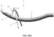
- FIGS. 29A and 29Bare schematic views showing a modified form of the novel suture passer of FIGS. 1 - 11 , wherein an arm of the suture passer includes a plurality of suture-engaging projections on its distal side;
- FIGS. 29C and 29Dare schematic views showing a modified form of the novel suture passer of FIGS. 1-11 , wherein an arm of the suture passer includes a plurality of suture-engaging projections on its proximal side;
- FIGS. 30 and 31are schematic views showing another configuration for the suture passer of the present invention, wherein the clamping rod and hollow tube are configured so as to allow suture to slide between the clamping rod and the hollow tube;
- FIGS. 32 and 33are schematic views showing another configuration for the suture passer of the present invention, wherein the clamping rod is configured to pierce the suture when the clamping rod is moved proximally;
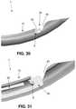
- FIGS. 34 and 35are schematic views illustrating how the lengths of the first and second arms of the bifurcated distal end of the clamping rod can vary from the construction shown in FIGS. 1-11 ;
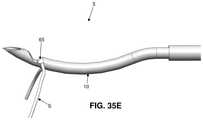
- FIGS. 35A-35Care schematic views showing another novel form of suture passer formed in accordance with the present invention.
- FIGS. 35D-35Fare schematic views showing the novel suture passer of FIGS. 35A-35C securing a suture to the distal end of the suture passer;
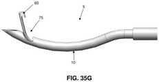
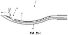
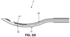
- FIGS. 35G-35Iare schematic views showing another novel form of suture passer formed in accordance with the present invention.
- FIGS. 35J-35Lare schematic views showing the novel suture passer of FIGS. 35G-35I securing a suture to the distal end of the suture passer;
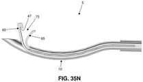
- FIGS. 35M-350are schematic views showing another novel form of suture passer formed in accordance with the present invention.
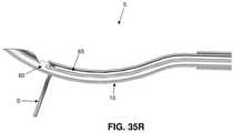
- FIGS. 35P-35Rare schematic views showing the novel suture passer of FIGS. 35M-350 securing a suture to the distal end of the suture passer;
- FIGS. 36-40are schematic views showing another novel form of suture passer formed in accordance with the present invention.
- FIGS. 40A and 40Bare schematic views showing a modified form of the novel suture passer of FIGS. 36-40 , wherein an arm of the suture passer includes a plurality of suture-engaging projections on its distal side;
- FIGS. 41-47are schematic views showing still another novel form of suture passer formed in accordance with the present invention.
- FIGS. 48-60are schematic views showing yet another novel form of suture passer formed in accordance with the present invention.
- FIGS. 61-64are schematic views showing an exemplary manner of passing suture using the novel suture passer of FIGS. 48-60 ;
- FIGS. 65-67show variations of the novel suture passer shown in FIGS. 48-60 ;
- FIGS. 68-81are schematic views showing another novel form of suture passer formed in accordance with the present invention.
- FIGS. 82-84are schematic views showing another novel form of suture passer formed in accordance with the present invention.
- FIGS. 85 and 86are schematic views showing still another novel form of suture passer formed in accordance with the present invention.
- the present inventionprovides a new and improved method and apparatus for passing suture through tissue.
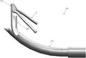
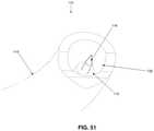
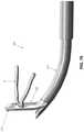
- Suture passer 5formed in accordance with the present invention.
- Suture passer 5generally comprises a hollow tube 10 and a clamping rod 15 slidably disposed within the lumen of hollow tube 10 , as will hereinafter be discussed in further detail.
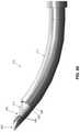
- hollow tube 10comprises a distal end 20 preferably terminating in a sharp point 22 , and a proximal end 25 preferably terminating in a handle 23 , with a lumen 30 extending therebetween.
- the pointed hollow tube 10essentially comprises a hollow needle adapted to pierce tissue.
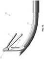
- Hollow tube 10further comprises a window 35 which extends radially into the hollow tube and communicates with lumen 30 .
- Window 35is sized so as to selectively receive a suture S therein, as will hereinafter be discussed in further detail.
- Window 35preferably comprises an inclined distal surface 40 and an inclined proximal surface 45 .
- distal surface 40 and proximal surface 45are inclined in the same direction, and preferably both surfaces are inclined distally (e.g., in the manner shown in FIGS. 1-11 ).
- the forward incline of inclined distal surface 40allows suture to more easily pass into and out of window 35 .
- the forward incline of inclined proximal surface 45provides an undercut which helps to trap the suture S between the clamping surface 47 of clamping rod 15 and the inclined proximal surface 45 of window 35 , as will hereinafter be discussed in further detail.
- Hollow tube 10is preferably formed out of a substantially rigid material (e.g., stainless steel) so as to maintain rigidity when passing through tissue, particularly relatively tough fibrous tissue (e.g., the labrum of the hip).
- a substantially rigid materiale.g., stainless steel
- hollow tube 10is curved, however, it should be appreciated that hollow tube 10 can be formed in other configurations well known in the art (e.g., straight, etc.).
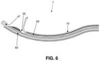
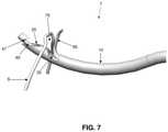
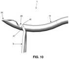
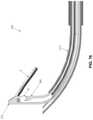
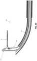
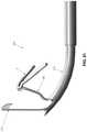
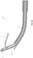
- Clamping rod 15comprises a distal end 50 ( FIG. 9 ) and a proximal end 55 ( FIG. 9 ). Distal end 50 of clamping rod 15 is bifurcated so as to form a first arm 60 and a second arm 65 .
- First arm 60comprises the aforementioned clamping surface 47 , with clamping surface 47 extending radially from the longitudinal axis of clamping rod 15 .
- Clamping surface 47may take the form of a hook, as shown in FIGS. 1-11 . This hook helps trap the suture S between clamping surface 47 of clamping rod 15 and inclined proximal surface 45 of window 35 , in the manner shown in FIGS. 10 and 11 .
- Second arm 65extends parallel to first arm 60 when clamping rod 15 is disposed within lumen 30 of hollow tube 10 , with second arm 65 terminating proximally of first arm 60 , shy of clamping surface 47 .
- Second arm 65is outwardly biased so that when second arm 65 advances past window 35 , second arm 65 passes radially outwardly through window 35 so as to project at an angle of approximately 10-120 degrees relative to the longitudinal axis of first arm 60 ( FIG. 6 ), and more preferably at an angle of approximately 30-90 degrees to the longitudinal axis of first arm 60 , whereby to create a funnel region 75 between hollow tube 10 and second arm 65 when second arm 65 extends out window 35 .
- second arm 65is preferably formed out of a material consistent with this spring bias (e.g., a superelastic material such as Nitinol, etc.).
- the entire clamping rod 15is formed out of a superelastic material such as Nitinol.
- clamping rod 15extends through lumen 30 of hollow tube 10 and is connected to an actuator 72 ( FIG. 1 ) which is movably mounted to handle 23 , such that movement of actuator 72 relative to handle 23 will cause movement of clamping rod 15 relative to hollow tube 10 .
- a piece of suture Smay be clamped to the distal end of suture passer 5 by (i) moving clamping rod 15 to the position shown in FIGS. 5 and 6 (e.g., by moving actuator 72 distally relative to handle 23 ) so that clamping surface 47 of first arm 60 is distal to window 35 , and so that second arm 65 extends out of window 35 ; (ii) positioning the suture S in window 35 ( FIGS.
- a clamped piece of suturemay thereafter be released from suture passer 5 by (a) moving clamping rod 15 distally ( FIGS. 8 and 9 ) so as to space clamping surface 47 of first arm 60 away from proximal surface 45 of window 35 ; and (b) causing suture S to be withdrawn from window 35 ( FIG. 7 ), either by moving suture S relative to suture passer 5 or by moving suture passer 5 relative to suture S or by moving both suture S and suture passer 5 relative to one another.
- both first arm 60 and second arm 65are disposed within lumen 30 of hollow tube 10 , so that the distal end of suture passer 5 presents a smooth outer surface, whereby to facilitate passage of the distal end of suture passer 5 through tissue.
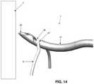
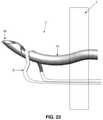
- the novel suture passer 5can be used to pass suture S from the near side of tissue T to the far side of tissue T (i.e., in an “antegrade” manner).
- the preliminary loading of suture S into suture passer 5may be performed away from the surgical site (e.g., outside of the patient) or it may be performed adjacent to the near side of the tissue T which is to be sutured (e.g., inside of the patient).
- clamping rod 15is advanced to its most distal position so that second arm 65 advances out of window 35 , whereby to project out of the axis of hollow tube 10 and create the aforementioned funnel region 75 .
- Suture Sis then guided into window 35 using this funnel effect, as seen in FIG. 13 , either by moving suture S relative to suture passer 5 or by moving suture passer 5 relative to suture S or by moving both suture S and suture passer 5 relative to one another.
- Clamping rod 15is then retracted proximally so that clamping surface 47 clamps suture S between clamping surface 47 of first arm 60 and proximal surface 45 of window 35 . See FIG. 14 .
- Suture passer 5is then advanced distally so that window 35 passes through tissue T, whereby to carry suture S through the tissue ( FIG. 15 ).
- clamping rod 15is advanced distally so that clamping surface 47 is disposed distal to window 35 , thereby releasing suture S from suture passer 5 .
- Suture passer 5 and/or suture Sare then manipulated so that suture S is clear of window 35 ( FIG. 17 ).
- Clamping rod 15is then moved proximally so as to retract first arm 60 and second arm 65 back into hollow tube 10 .
- Suture passer 5may then be withdrawn back through tissue T, leaving suture S extending through tissue T, as shown in FIG. 18 .
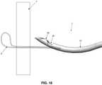
- the novel suture passer 5can be used to draw suture S from the far side of tissue T to the near side of tissue T (i.e., in a “retrograde” manner).
- the suture Sis loaded into suture passer 5 on the far side of the tissue T. This is done by first passing suture passer 5 through tissue T so that window 35 resides on the far side of the tissue, and then moving clamping rod 15 distally so that second arm 65 extends out of window 35 , substantially perpendicularly to hollow tube 10 , whereby to create the aforementioned funnel region 75 ( FIGS. 19 and 20 ). This funnel effect is then used to guide free suture (disposed on the far side of tissue T) into window 35 (see FIG. 21 ), either by moving suture S relative to suture passer 5 or by moving suture passer 5 relative to suture S or by moving both suture S and suture passer 5 relative to one another. If desired, the suture S may be tensioned so as to help draw it into the window 35 .
- clamping rod 15is retracted proximally so as to releasably secure suture S between clamping surface 47 and proximal surface 45 of window 35 ( FIG. 22 ).
- Hollow tube 10is then retracted proximally through tissue T, carrying suture S therethrough ( FIG. 23 ). If desired, suture S can then be released from suture passer 5 by moving clamping rod 15 distally ( FIGS. 24 and 25 ).
- a mattress stitchmay be placed in the tissue ( FIG. 25 ).
- the novel suture passer 5may also be used to pass suture S around a side edge of the tissue T, rather than passing the suture S through the tissue.
- the suture passercould then be used to retrieve the suture on the far side of the tissue and draw it back around the side edge of the tissue so that the suture is brought to the near side of the tissue.
- the novel suture passer 5has the ability to both pass (advance) and retrieve (draw) the suture S through and/or around the tissue in a continuous series of steps. This allows the surgeon to complete the desired suture passing without having to remove the suture passer 5 from the portal through which the suture passer 5 is being used.
- this passing/retrieving processcan be accomplished with a single instrument, rather than requiring one instrument for passing and a separate instrument for retrieving. This offers significant advantages in convenience and in reducing surgery time.
- clamping surface 47 of clamping rod 15may take the form of a hook, as shown in FIGS. 1-11 .
- This hookmay have various degrees of depth and return, as seen in FIGS. 26-28 .
- clamping surface 47may be substantially flat, as shown in FIG. 29 .
- second arm 65 of suture passer 5may include a plurality of suture-engaging projections 76 on its distal side.
- Suture-engaging projections 76allow the user to more aggressively engage (e.g., in a contact or frictional sense) suture S with second arm 65 , whereby to facilitate manipulation of suture S via engagement with second arm 65 .
- the usercan “grip” the suture S with the suture-engaging projections 76 of second arm 65 and “drag” the suture S into a desired position.
- the suture-engaging projections 76 of second arm 65can assist in dragging suture S into window 35 . More particularly, as the clamping rod 15 is moved proximally in hollow tube 10 , the second arm 65 retracts into the lumen of the hollow tube 10 . As it does so, if the suture S is in contact with the suture-engaging projections 76 of second arm 65 , suture S will be drawn into window 35 . Once in window 35 , the suture S is then clamped between clamping surface 47 of clamping rod 15 and inclined proximal surface 45 of window 35 as described above.
- second arm 65 of suture passer 5may include a plurality of suture-engaging projections 76 on its proximal side.
- suture-engaging projections 76allow the user to more aggressively engage (e.g., in a contact or frictional sense) suture S with second arm 65 , whereby to facilitate manipulation of suture S via engagement with second arm 65 .
- suture-engaging projections 76may also be provided on both the distal and proximal sides of second arm 65 , and/or on one or both of the lateral sides of second arm 65 .
- suture-engaging projections 76essentially constitute a friction-enhancing surface on second arm 65 so as to allow second arm 65 to engage and “drag” suture S about a surgical site.
- the friction-enhancing surface(s) on second arm 65may be formed with a variety of geometries, e.g., barbs, fingers, ribs, threads or other surface texturing which increases the frictional aspects of second arm 65 at a desired location or locations.
- the suture passermay be constructed so that the suture S is slidably captured—but not clamped—between clamping surface 47 of clamping rod 15 and inclined proximal surface 45 of window 35 .
- suture Sis slidably captured between the two surfaces (i.e., clamping surface 47 and proximal surface 45 ), in the manner shown in FIGS. 30 and 31 .
- clamping rod 15may be limited in its proximal travel (e.g., by means of interaction between actuator 72 and handle 23 ) in order to provide a gap sufficient to slidingly capture, but not bind, suture S. This gap may be equal to, or larger than, the diameter of suture S.
- first arm 60 of clamping rod 15may include a pointed return 77 , with pointed return 77 being configured and located such that it will spear suture S when clamping rod 15 is moved proximally.
- first and second arms 60 , 65 of clamping rod 15can vary from the construction shown in FIGS. 1-11 .
- the distance between the distal tip of second arm 65 and clamping surface 47is approximately the length of window 35 , as shown in FIG. 34 .
- only a nominal gapis provided between the distal tip of second arm 65 and clamping surface 47 ( FIG. 35 ). This construction can provide for improved capturing of suture S to suture passer 5 .
- suctionmay be applied to lumen 30 of hollow tube 10 proximal to window 35 . This suction will draw fluid into window 35 , and the fluid entering window 35 will assist suture S in seating itself into window 35 as the suture S approaches window 35 .
- fluidis delivered down lumen 30 of hollow tube 10 so as to assist ejection of suture S from window 35 once the clamping rod 15 has released suture S.
- hollow tube 10comprises a second window 35 opposite first window 35 , and the distal end of clamping rod 15 is trifurcated so as to form a first arm 60 carrying a pair of clamping surfaces 47 and a pair of second arms 65 , with each of the second arms 65 being outboard of first arm 60 and being biased out a window 35 .
- suturecan be clamped on either side of hollow tube 10 .
- the suture passermay further comprise a push rod to assist in ejecting suture S from window 35 .
- the push rodmay be a component separate from clamping rod 15 (but slidably movable relative thereto), or it may be integrated with clamping rod 15 (e.g., slidably movable thereon).
- FIGS. 35A-35Cit is also possible to form novel suture passer 5 so that (i) first arm 60 is shorter than second arm 65 , and (ii) clamping surface 47 is formed on the outwardly biased second arm 65 (rather than on first arm 60 ).
- funnel region 75is formed between the distal end of shaft 10 and first arm 60 .
- FIGS. 35D-35Fshow the novel suture passer of FIGS. 35A-35C securing a suture S to the distal end of the suture passer.
- first arm 60may be omitted entirely, in which case the distal end of clamping rod 15 preferably comprises only outwardly biased second arm 65 .
- novel suture passer 5may be constructed so that first arm 60 (carrying clamping surface 47 ) is outwardly biased, so that first arm 60 (and clamping surface 47 ) extends out window 35 when clamping rod 15 is moved distally.
- the funnel region 75is formed between the distal end of shaft 10 and first arm 60 .
- FIGS. 35J-35Lshow the novel suture passer of FIGS. 35G-35I securing a suture S to the distal end of the suture passer.
- first arm 60is outwardly biased and carries clamping surface 47 (e.g., in the manner shown in FIGS. 35G-35I and FIGS. 35J-35L )
- second arm 65may be omitted entirely, in which case the distal end of clamping rod 15 preferably comprises only outwardly biased first arm 60 (with clamping surface 47 ).
- novel suture passer 5may be constructed so that both first arm 60 (carrying clamping surface 47 ) and second arm 65 are outwardly biased, so that both first arm 60 (and clamping surface 47 ) and second arm 65 extend out window 35 when clamping rod 15 is moved distally.
- funnel region 75is formed between first arm 60 and second arm 65 .
- FIGS. 35P-35Rshow the novel suture passer of FIGS. 35M-350 securing a suture S to the distal end of the suture passer.
- window 35may be eliminated, and clamping rod 15 may clamp suture S against the distal end surface 80 of hollow tube 10 .
- second arm 65 of suture passer 5may include a plurality of suture-engaging projections 76 on its distal side.
- suture-engaging projections 76allow the user to more aggressively engage (e.g., in a contact or frictional sense) suture S with second arm 65 , whereby to facilitate manipulation of suture S via engagement with second arm 65 .
- the usercan “grip” the suture S with the suture-engaging projections 76 of second arm 65 and “drag” the suture S into a desired position.
- the suture-engaging projections 76 of second arm 65can assist in dragging suture S against the distal end of hollow tube 10 . More particularly, as the clamping rod 15 is moved proximally in hollow tube 10 , the second arm 65 retracts into the lumen of hollow tube 10 . As it does so, if the suture S is in contact with the suture-engaging projections 76 of second arm 65 , suture S will be drawn into engagement with the distal end of hollow tube 10 and then clamped in place by first arm 60 .
- second arm 65 of suture passer 5may include a plurality of suture-engaging projections 76 on its proximal side (e.g., in a manner analogous to that shown in FIGS. 29C and 29D ).
- suture-engaging projections 76allow the user to more aggressively engage (e.g., in a contact or frictional sense) suture S with second arm 65 , whereby to facilitate manipulation of suture S via engagement with second arm 65 .
- suture-engaging projections 76may also be provided on both the distal and proximal sides of second arm 65 , and/or on one or both lateral sides of second arm 65 .
- suture-engaging projections 76essentially constitute a suture engaging surface on second arm 65 so as to allow second arm 65 to engage and “drag” suture S about a surgical site.
- the suture engaging surface(s) on second arm 65may be formed with a variety of geometries, e.g., barbs, fingers or other surface texturing which increases the frictional aspects of second arm 65 at a desired location or locations.
- the distal end surface 80 of hollow tube 10can be disposed substantially perpendicular to the longitudinal axis of hollow tube 10 , whereby to enhance clamping of suture S against distal end surface 80 of hollow tube 10 .
- suture passer 5preferably comprises a handle 23
- handle 23preferably comprises an actuator 72 which actuates clamping rod 15 so as to clamp and/or release suture S.
- actuator 72may comprise a lock or detent which maintains the position of clamping rod 15 relative to hollow tube 10 .
- the lock or detentmay hold the clamping rod in a distal position and/or in a proximal position (e.g., while it is clamping suture S).
- Actuator 72may also comprise a spring to bias clamping rod 15 proximally or distally. In one preferred form of the invention, this spring biases the clamping rod in a proximal direction (for example, to clamp suture S between clamping surface 47 and inclined surface 45 ).
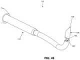
- FIGS. 48-60there is shown a novel suture passer 105 also formed in accordance with the present invention.
- Suture passer 105will sometimes hereinafter be referred to as the “spear” suture passer.
- the spear suture passer 105generally comprises an outer shaft tube 110 , an inner guide tube 112 fixedly disposed within the interior of outer shaft tube 110 , and a suture spear 116 slidably disposed within the lumen of inner guide tube 112 , as will hereinafter be discussed in further detail.
- outer shaft tube 110comprises a distal end 120 preferably terminating in a sharp point 122 , and a proximal end 125 preferably terminating in a handle 123 , with a lumen 130 extending therebetween.
- the pointed outer shaft tube 110essentially comprises a hollow needle adapted to pierce tissue.
- Outer shaft tube 110further comprises a window 135 which extends radially into the outer shaft tube and communicates with lumen 130 .
- Window 135is sized so as to selectively receive a suture S therein, as will hereinafter be discussed in further detail.
- Window 135comprises a pair of distal surfaces 140 , a pair of proximal surfaces 145 , and a pair of side surfaces 146 .
- distal surfaces 140 and proximal surfaces 145extend substantially perpendicular to the longitudinal axis of outer shaft tube 110 ( FIG. 49 ), and side surfaces 146 preferably extend substantially parallel to the longitudinal axis of outer shaft tube 110 ( FIG. 50 ).
- Distal surfaces 140are preferably spaced from proximal surfaces 145 by a distance which is somewhat larger than the diameter of suture S, so that window 135 provides an adequate seat for suture S, as will hereinafter be discussed in further detail.
- Outer shaft tube 110is preferably formed out of a substantially rigid material (e.g., stainless steel) so as to maintain rigidity when passing through tissue, particularly relatively tough fibrous tissue (e.g., the labrum of the hip).
- a substantially rigid materiale.g., stainless steel
- the distal end 120 of outer shaft tube 110is curved (see, for example, FIGS. 49, 58 and 59 ), however, it should also be appreciated that outer shaft tube 110 can be formed in other configurations well known in the art (e.g., straight, etc.).
- Inner guide tube 112comprises a distal end 150 and a proximal end 155 , with a lumen 156 extending therebetween.
- Inner guide tube 112is fixedly disposed within outer shaft tube 110 so that the distal end 150 of inner guide tube 112 terminates proximal to window 135 in outer shaft tube 110 , with lumen 156 of inner guide tube 112 being substantially aligned with the center of window 135 .
- the distal end 150 of inner guide tube 112preferably terminates just proximal to window 135 of outer shaft tube 110 . See, for example, FIGS. 50, 52 and 53 .
- inner guide tube 112acts as a guide and stiffening member for suture spear 116 , which is selectively extendable out of the inner guide tube (and hence selectively extendable across window 135 ) and selectively withdrawable back into the inner guide tube (and hence selectively withdrawable out of window 135 ).
- Suture spear 116comprises a distal end 158 and a proximal end 159 .
- Distal end 158 of suture spear 116terminates in a point 161 .
- suture spear 116essentially comprises a needle which, as will hereinafter be discussed, is adapted to pierce suture.
- Suture spear 116is slidably disposed within lumen 156 of inner guide tube 112 , such that suture spear 116 can extend across window 135 ( FIG. 52 ) or be withdrawn from window 135 ( FIG. 53 ).
- the proximal end 159 of suture spear 116extends out of the proximal end 155 of inner guide tube 112 and is connected to an actuator 172 (e.g., a thumb slide) which is movably mounted to handle 123 , such that movement of actuator 172 relative to handle 123 will cause movement of suture spear 116 relative to inner guide tube 112 (and hence relative to outer shaft tube 110 ). Specifically, movement of actuator 172 relative to handle 123 will cause the distal end of suture spear 116 to intrude across, or be withdrawn from, window 135 of outer shaft tube 110 .
- an actuator 172e.g., a thumb slide
- inner guide tube 112is positioned within outer shaft tube 110 so that the inner guide tube (and hence the suture spear 116 ) is aligned with a suture S that is laid in window 135 so as to ensure that suture spear 116 can securely pierce the suture S, as will hereinafter be discussed.
- a piece of suture Smay be clamped to the distal end of suture passer 105 by (i) moving suture spear 116 proximally so that the distal end 158 of suture spear 116 is withdrawn from window 135 of outer shaft tube 110 , in the manner shown in FIG. 54 (e.g., by moving actuator 172 proximally relative to handle 123 ); (ii) positioning the suture S in window 135 ( FIG. 54
- suture spear 116distally (e.g., by moving actuator 172 distally relative to handle 123 ) so as to cause suture spear 116 to “spear” (e.g., penetrate) suture S, as shown in FIG. 56 , whereby to secure suture S to suture passer 105 .
- peare.g., penetrate
- a speared piece of suture Smay thereafter be released from suture passer 105 by (a) moving suture spear 116 proximally ( FIG. 57 ) so as to “unspear” suture S; and (b) causing suture S to be withdrawn from window 135 .
- the novel suture passer 105can be used to pass suture S from the near side of tissue T to the far side of tissue T (i.e., in an “antegrade” manner).
- the preliminary loading of suture S into suture passer 105may be performed away from the surgical site (e.g., outside of the patient) or it may be performed adjacent to the near side of the tissue T which is to be sutured (e.g., inside of the patient).
- suture Smay be loaded into suture passer 105 by retracting suture spear 116 out of window 135 of outer shaft tube 110 ( FIG. 54 ), guiding suture S into window 135 ( FIG. 55 ), and then advancing suture spear 116 distally through suture S ( FIG. 56 ), whereby to secure suture S to suture passer 105 . See FIG. 61 .
- Suture passer 105is then advanced distally so that window 135 passes through tissue T, whereby to carry suture S through the tissue ( FIG. 62 ). With suture S extending through tissue T, and looking now at FIG. 63 , suture spear 116 is retracted proximally so as to release suture S from suture passer 105 , and then suture passer 105 and/or suture S are manipulated so that suture S is clear of window 135 ( FIG. 63 ). Suture passer 105 may then be withdrawn back through tissue T, leaving suture S extending through tissue T, as shown in FIG. 64 .
- the spear suture passer 105can be used to draw suture S from the far side of tissue T to the near side of tissue T (i.e., in a “retrograde” manner).
- the suture Sis loaded into suture passer 5 on the far side of the tissue T. This is done by first passing suture passer 105 through tissue T so that window 135 resides on the far side of the tissue, and then moving suture spear 116 proximally so that suture spear 116 is withdrawn from window 135 (if the suture spear has not already been withdrawn from window 135 ). Suture S (disposed on the far side of tissue T) is then positioned into window 135 , and suture spear 116 is advanced distally so as to spear suture S and secure the suture to suture passer 105 . Outer shaft tube 110 is then retracted proximally through tissue T, carrying suture S therethrough. If desired, suture S can then be released from suture passer 105 by moving suture spear 116 distally.
- a mattress stitchmay be placed in the tissue, as will be appreciated by one skilled in the art.
- the spear suture passer 105may also be used to pass suture S around a side edge of the tissue T, rather than passing the suture S through the tissue.
- the suture passercould then be used to retrieve the suture on the far side of the tissue and draw it back around the side edge of the tissue so that the suture is brought to the near side of the tissue.
- the novel suture passer 105has the ability to both pass (advance) and retrieve (draw) the suture S through and/or around the tissue in a continuous series of steps. This allows the surgeon to complete the desired suture passing without having to remove the suture passer 105 from the portal through which the suture passer 105 is being used. Significantly, this passing/retrieving process can be accomplished with a single instrument, rather than requiring one instrument for passing and a separate instrument for retrieving. This offers significant advantages in convenience and in reducing surgery time.
- the function of the inner guide tube 112can be replaced by a rod 186 with a slot 187 , as shown in FIG. 65 .
- This rod 186could also have other cross-sectional shapes (such as that of a ribbon, etc.) that act to constrain the suture spear 116 to the desired position relative to the window 135 .
- This positioning schemecan also take the form of multiple wires filling the space where the suture spear is desired not to go.
- inner guide tube 112can also be incorporated into the outer shaft tube 110 .
- the outer shaft tube 110can have a lumen 130 which is offset towards window 135 , e.g., as shown in FIG. 66 .
- suture spear 116can occupy the entire internal diameter of lumen 130 of outer shaft tube 110 .
- the suture spear 116is a rod with a sharpened feature 188 (e.g., a point) located in the window 135 .
- the inner guide tube 112is not required.
- Suture passer 205generally comprises a hollow tube 210 and a clamping rod 215 slidably disposed within the lumen of hollow tube 210 , as will hereinafter be discussed in further detail.
- hollow tube 210comprises a distal end 220 preferably terminating in a sharp point 225 , and a proximal end 230 preferably terminating in a handle 235 , with a lumen 240 extending therebetween. It will be appreciated that the pointed hollow tube 210 essentially comprises a hollow needle adapted to pierce tissue.
- Hollow tube 210further comprises a cutaway 245 disposed just proximal to sharp point 225 and which communicates with lumen 240 .
- Cutaway 245preferably comprises a pair of longitudinally-extending edges 250 which terminate at their proximal ends at a circumferentially-extending edge 255 .
- circumferentially-extending edge 255is recessed at 260 so as to form seats for a suture grasped by suture passer 205 , as will hereinafter be discussed.
- recess 260can be omitted from circumferentially-extending edge 255 (e.g., circumferentially-extending edge 255 can be formed with a substantially “flat” profile).
- Hollow tube 210is preferably formed out of a substantially rigid material (e.g., stainless steel) so as to maintain rigidity when passing through tissue, particularly relatively tough fibrous tissue (e.g., the labrum of the hip, the capsule of the hip joint, etc.).
- tissueparticularly relatively tough fibrous tissue (e.g., the labrum of the hip, the capsule of the hip joint, etc.).
- hollow tube 210is curved, however, it should be appreciated that hollow tube 210 can be formed in other configurations well known in the art (e.g., straight, compound curves, etc.).
- Clamping rod 215comprises a distal end 265 and a proximal end 270 .
- Distal end 265 of clamping rod 215is bifurcated so as to form a first arm 275 and a second arm 280 .
- the distal ends of first arm 275 and second arm 280are biased laterally so that first arm 275 and second arm 280 will extend both distally and laterally when the distal ends of first arm 275 and second arm 280 are advanced distally out of the distal end of hollow tube 210 , as will hereinafter be discussed in further detail.
- first arm 275 and second arm 280have different degrees of lateral bias so that they will together define a funnel region therebetween when the distal ends of first arm 275 and second arm 280 are advanced distally out of the distal end of hollow tube 210 , as will hereinafter be discussed in further detail.
- first arm 275comprises a clamping surface 285 , with clamping surface 285 extending radially from the longitudinal axis of clamping rod 215 .
- Clamping surface 285may take the form of a hook, as shown in the construction illustrated in FIGS. 68-81 . This hook helps trap the suture S between clamping surface 285 of clamping rod 215 and the aforementioned recesses 260 of circumferentially-extending edge 255 of hollow tube 210 , in the manner shown in FIGS. 77 and 78 .
- First arm 275is outwardly biased so that when first arm 275 advances along cutaway 245 , first arm 275 passes radially outwardly through the cutaway so as to project at an angle of approximately 60 degrees relative to the adjacent longitudinal axis of hollow tube 210 , whereby to create one half of a funnel region 290 established between first arm 275 and second arm 280 when first arm 275 and second arm 280 extend out of cutaway 245 ( FIG. 73 ).
- first arm 275is preferably formed out of a material consistent with this spring bias (e.g., a superelastic material such as Nitinol, etc.).
- the entire clamping rod 215is formed out of a superelastic material such as Nitinol.
- Second arm 280extends parallel to first arm 275 when clamping rod 215 is disposed within lumen 240 of hollow tube 210 , with second arm 280 terminating proximally of first arm 275 , proximal of clamping surface 285 ( FIG. 70 ).
- Second arm 280comprises a recess 295 at its distal tip.
- Recess 295forms a seat for suture S at the distal tip of second arm 280 , such that when a suture S is seated in cutaway 245 and second arm 280 thereafter extends out of cutaway 245 , recess 295 in second arm 280 will engage suture S and carry suture S away from cutaway 245 , whereby to help separate suture S from suture passer 205 .
- recess 295comprises a distal finger 300 , a proximal finger 305 and a groove 310 formed therebetween. If desired, distal finger 300 and proximal finger 305 may have substantially the same length and/or width.
- Second arm 280is outwardly biased so that when second arm 280 advances along cutaway 245 , second arm 280 passes radially outwardly through the cutaway 245 so as to project at an angle of approximately 90 degrees relative to the adjacent longitudinal axis of hollow tube 210 , whereby to create the aforementioned funnel region 290 between first arm 275 and second arm 280 when first arm 275 and second arm 280 extend out of cutaway 245 .
- second arm 280is preferably formed out of a material consistent with this spring bias (e.g., a superelastic material such as Nitinol, etc.).
- the entire clamping rod 215is formed out of a superelastic material such as Nitinol.
- first arm 275 and second arm 280are carefully sized, i.e., it is larger than the diameter of a suture so as to prevent a suture from being inadvertently lodged between first arm 275 and second arm 280 , which could effectively jam the components, but not so large that the transfer of suture S from first arm 275 to second arm 280 is undermined.
- the gap between first arm 275 and second arm 280is approximately 1-3 times the diameter of the suture, and preferably about 1.5 times the diameter of the suture.
- second arm 280may comprise a compound curve 315 ( FIG. 73 ) so as to facilitate proper disposition of second arm 280 when it is projected distally and laterally out of cutaway 245 .
- first arm 275 and second arm 280can be varied from the angles described above, e.g., first arm 275 can extend at an angle of approximately 45 degrees relative to the adjacent longitudinal axis of hollow tube 210 when first arm 275 advances out of the distal end of hollow tube 210 , and second arm 280 can extend at an angle of approximately 135 degrees relative to the adjacent longitudinal axis of hollow tube 210 when second arm 280 advances out of the distal end of hollow tube 210 .
- first arm 275can extend at an angle of 0-90 degrees relative to the adjacent longitudinal axis of hollow tube 210
- second arm 280can extend at an angle of 20-160 degrees relative to the adjacent longitudinal axis of hollow tube 210 (but in any case at an angle which is less than the angle of the first arm so that the two arms do not cross over one another). Still other appropriate constructions will be apparent to those skilled in the art in view of the present disclosure.
- the proximal end 270 of clamping rod 215extends through lumen 240 of hollow tube 210 and is connected to an actuator 320 which is movably mounted to handle 235 , such that movement of actuator 320 relative to handle 235 causes movement of clamping rod 215 relative to hollow tube 210 .
- a piece of suture Smay be clamped to the distal end of suture passer 205 by (i) moving clamping rod 215 to the position shown in FIGS. 72 and 73 (e.g., by moving actuator 320 distally relative to handle 235 ) so that first arm 275 and second arm 285 extend distally and laterally out of cutaway 245 and create the aforementioned funnel region 290 ; (ii) positioning the suture S in funnel region 290 ( FIG.
- a clamped piece of suture Smay thereafter be released from suture passer 205 by (a) moving clamping rod 215 distally ( FIGS. 77-81 ) so as to space clamping surface 285 of first arm 275 away from recesses 260 of circumferentially-extending edge 255 of hollow tube 210 , whereby to release suture S from its clamped condition, and with recess 295 of second arm 280 engaging suture S and driving it distally and laterally, so that suture S moves clear of cutaway 245 ( FIGS.
- suture Sto be withdrawn from the suture passer, either by moving suture S relative to suture passer 205 , or by moving suture passer 205 relative to suture S, or by moving both suture S and suture passer 205 relative to one another.
- both first arm 275 and second arm 280are disposed within lumen 230 of hollow tube 210 , so that the distal end of suture passer 205 presents a smooth outer surface, whereby to facilitate passage of the distal end of suture passer 205 through tissue.
- the novel suture passer 205can be used to pass suture S from the near side of tissue to the far side of tissue (i.e., in an “antegrade” manner).
- the preliminary loading of suture S into suture passer 205may be performed away from the surgical site (e.g., outside of the patient) or it may be performed adjacent to the near side of the tissue which is to be sutured (e.g., inside of the patient). This is achieved by advancing clamping rod 215 to its distalmost position so that first arm 275 and second arm 280 advance out of cutaway 245 , whereby to project the distal ends of the first and second arms out of the axis of hollow tube 210 and create the aforementioned funnel region 290 .
- Suture Sis then guided into cutaway 245 using this funnel effect, either by moving suture S relative to suture passer 205 , or by moving suture passer 205 relative to suture S, or by moving both suture S and suture passer 205 relative to one another.
- the suture Smay be tensioned so as to help draw it into cutaway 245 .
- suture Smay be hooked with clamping surface 285 of first arm 275 .
- Clamping rod 215is then retracted proximally so that clamping surface 285 of first arm 275 clamps suture S between clamping surface 285 of first arm 275 and recesses 260 of circumferentially-extending edge 255 of hollow tube 210 .
- Suture passer 205is then advanced distally so that cutaway 245 passes through tissue, whereby to carry suture S through the tissue.
- clamping rod 215is advanced distally so that first arm 275 and second arm 280 extend out of cutaway 245 , thereby spacing clamping surface 285 from circumferentially-extending edge 255 of hollow tube 210 , whereby to release suture S from suture passer 205 and with second arm 280 driving suture S before it as second arm 280 advances distally and proximally out of cutaway 245 . See FIG. 79 .
- second arm 280can flex proximally slightly at the end of the distal stroke, whereby to allow suture S to “slip off” the distal end of second arm 280 . (see FIG. 81 ).
- second arm 280is flexible, but also has column strength, so that second arm 280 can drive the suture S distally relative to hollow tube 210 , but then, as the portion of second arm 280 projecting out of hollow tube 210 gets longer and longer, the second arm 280 eventually “flops over” under the drag of the suture S which is being pushed by second arm 280 , whereby to cause suture S to fall free of second arm 280 .
- Suture passer 205 and/or suture Sare then manipulated so that suture S is clear of suture passer 205 .
- Clamping rod 215is then moved proximally so as to retract first arm 275 and second arm 280 back into hollow tube 210 .
- Suture passer 205may then be withdrawn back through the tissue, leaving suture S extending through the tissue.
- second arm 280 of clamping rod 215with a recess 295 , the suture being driven forward by second arm 280 of clamping rod 215 can be “controlled” longer during the distal stroke, i.e., the suture can be retained for a longer period of time on the distally-moving second arm 280 of clamping rod 215 . As a result, it is possible to advance longer lengths of suture through the tissue without driving the needle further through the tissue.
- the novel suture passer 205can be used to draw suture S from the far side of tissue to the near side of tissue (i.e., in a “retrograde” manner).
- the suture Sis loaded into suture passer 205 on the far side of the tissue. This is done by first passing suture passer 205 through the tissue so that cutaway 245 resides on the far side of the tissue, and then moving clamping rod 215 distally so that first arm 275 and second arm 280 extend distally and proximally out of cutaway 245 , whereby to create the aforementioned funnel region 290 .
- This funnel effectis then used to guide a free suture (disposed on the far side of the tissue) into cutaway 245 , either by moving suture S relative to suture passer 205 , or by moving suture passer 205 relative to suture S, or by moving both suture S and suture passer 205 relative to one another.
- the suture Smay be tensioned so as to help draw it into cutaway 245 .
- suture Smay be hooked with clamping surface 285 of first arm 275 .
- clamping rod 215is retracted proximally so as to releasably secure suture S between clamping surface 285 of first arm 275 and recesses 260 of circumferentially-extending edge 255 of hollow tube 210 .
- Suture passer 205is then retracted proximally through the tissue, carrying suture S therethrough.
- Suture Scan then be released from suture passer 205 by moving clamping rod 215 distally, whereby to cause second arm 280 to drive suture S out of cutaway 245 and clear of suture passer 205 .
- first arm 275can be formed without an outward bias, so that only second arm 280 has an outward bias.
- the funnel region 290is still formed between the distal ends of first arm 275 and second arm 280 , however, the funnel region 290 will extend at a different angle relative to the longitudinal axis of hollow tube 210 than where both first arm 275 and second arm 280 are outwardly biased.
- second arm 280may be formed without the aforementioned compound curve 315 .
- recess 295 at the distal tip of second arm 280may be formed with a different geometry, e.g., so as to facilitate separation of suture S from second arm 280 at the end of the second arm's distal stroke.
- recess 295may comprise a longer distal finger 300 and a shorter proximal finger 305 , with the groove 310 being formed therebetween.
- second arm 280can be formed with proximal finger 305 omitted, so that second arm 280 comprises only the distal finger 300 .
- recess 295 at the distal end of second arm 280may be replaced by a relatively short spike 325 .
- spike 325 at the distal end of second arm 280piercingly engages suture S and help hold suture S on the distal end of second arm 280 as second arm 280 extends out of cutaway 245 , whereafter the relatively short spike 325 allows suture S to separate from suture passer 205 .
- a mattress stitchmay be placed in the tissue.
- the novel suture passer 205may also be used to pass suture S around a side edge of the tissue, rather than passing the suture S through the tissue.
- the suture passercould then be used to retrieve the suture on the far side of the tissue and draw it back around the side edge of the tissue so that the suture is brought to the near side of the tissue.
- the novel suture passer 205has the ability to both pass (advance) and retrieve (draw) the suture S through and/or around the tissue in a continuous series of steps. This allows the surgeon to complete the desired suture passing without having to remove the suture passer 205 from the portal through which the suture passer 205 is being used. Significantly, this passing/retrieving process can be accomplished with a single instrument, rather than requiring one instrument for passing and a separate instrument for retrieving. This offers significant advantages in convenience and in reducing surgery time.
Landscapes
- Health & Medical Sciences (AREA)
- Life Sciences & Earth Sciences (AREA)
- Surgery (AREA)
- Heart & Thoracic Surgery (AREA)
- Engineering & Computer Science (AREA)
- Biomedical Technology (AREA)
- Nuclear Medicine, Radiotherapy & Molecular Imaging (AREA)
- Medical Informatics (AREA)
- Molecular Biology (AREA)
- Animal Behavior & Ethology (AREA)
- General Health & Medical Sciences (AREA)
- Public Health (AREA)
- Veterinary Medicine (AREA)
- Surgical Instruments (AREA)
Abstract
Description
- a hollow tube, the hollow tube comprising a distal end, a proximal end, a lumen extending from the distal end to the proximal end, and a window formed in the sidewall of the hollow tube, the window communicating with the lumen; and
- a clamping rod slidably received in the lumen of the hollow tube, the clamping rod comprising a distal end and a proximal end, the distal end being bifurcated into a first arm and a second arm, one of the first and second arms extending distally of the other of the first and second arms and including a clamping surface, and at least one of the first and second arms being outwardly biased such that when the clamping rod is moved distally so that the distal end of the at least one outwardly biased arm is adjacent to the window, the distal end of the at least one outwardly biased arm extends outwardly through the window;
- a hollow tube, the hollow tube comprising a pointed distal end, a proximal end and a lumen extending from the distal end to the proximal end; and
- a clamping rod slidably received in the lumen of the hollow tube, the clamping rod comprising a distal end and a proximal end, the distal end being bifurcated into a first arm and a second arm, the first arm extending distally of the second arm and including a clamping surface, and the second arm being outwardly biased such that when the clamping rod is moved distally so that the distal end of the second arm extends out of the distal end of the hollow tube, the distal end of the second arm extends laterally of the hollow tube;
- a shaft comprising a distal end, a proximal end, a lumen extending from the proximal end toward the distal end, and a window formed in the sidewall of the shaft, the window communicating with the lumen; and
- a suture spear movable within the lumen of the shaft, the suture spear comprising a distal end and a proximal end, the distal end being pointed to pierce a suture located in the window.
- a hollow tube, the hollow tube comprising a distal end, a proximal end, a lumen extending from the distal end to the proximal end, and a window formed in the sidewall of the hollow tube, the window communicating with the lumen; and
- a clamping rod slidably received in the lumen of the hollow tube, the clamping rod comprising a distal end and a proximal end, the distal end including a clamping surface, and the distal end being outwardly biased such that when the clamping rod is moved distally so that the distal end of the clamping rod is adjacent to the window, the distal end of the clamping rod extends outwardly through the window;
- a hollow tube, the hollow tube comprising a distal end, a proximal end, and a lumen extending from the distal end to the proximal end; and
- a clamping rod slidably received in the lumen of the hollow tube, the clamping rod comprising a distal end and a proximal end, the distal end being bifurcated into a first arm and a second arm, one of the first and second arms extending distally of the other of the first and second arms and including a clamping surface;
- wherein at least one of the first arm and the second arm comprises a friction-enhancing surface for facilitating manipulation of a suture via engagement of the suture with the friction-enhancing surface;
- a hollow tube, the hollow tube comprising a pointed distal end, a proximal end and a lumen extending from the distal end to the proximal end; and
- a clamping rod slidably received in the lumen of the hollow tube, the clamping rod comprising a distal end and a proximal end, the distal end being bifurcated into a first arm and a second arm, the first arm extending distally of the second arm and including a clamping surface, and the second arm being outwardly biased such that when the clamping rod is moved distally so that the distal end of the second arm extends out of the distal end of the hollow tube, the distal end of the second arm extends laterally of the hollow tube, and wherein the second arm is configured to releasably hold a suture to the distal end thereof;
Claims (11)
Priority Applications (2)
| Application Number | Priority Date | Filing Date | Title |
|---|---|---|---|
| US15/666,994US11259795B2 (en) | 2010-09-10 | 2017-08-02 | Method and apparatus for passing suture through tissue |
| US17/652,900US12201293B2 (en) | 2010-09-10 | 2022-02-28 | Method and apparatus for passing suture through tissue |
Applications Claiming Priority (8)
| Application Number | Priority Date | Filing Date | Title |
|---|---|---|---|
| US38178710P | 2010-09-10 | 2010-09-10 | |
| US38442310P | 2010-09-20 | 2010-09-20 | |
| US201161473219P | 2011-04-08 | 2011-04-08 | |
| US201161495441P | 2011-06-10 | 2011-06-10 | |
| US13/230,652US10123794B2 (en) | 2010-09-10 | 2011-09-12 | Method and apparatus for passing suture through tissue |
| US201261701920P | 2012-09-17 | 2012-09-17 | |
| US13/791,395US10098631B2 (en) | 2010-09-10 | 2013-03-08 | Method and apparatus for passing suture through tissue |
| US15/666,994US11259795B2 (en) | 2010-09-10 | 2017-08-02 | Method and apparatus for passing suture through tissue |
Related Parent Applications (1)
| Application Number | Title | Priority Date | Filing Date |
|---|---|---|---|
| US13/791,395DivisionUS10098631B2 (en) | 2010-09-10 | 2013-03-08 | Method and apparatus for passing suture through tissue |
Related Child Applications (1)
| Application Number | Title | Priority Date | Filing Date |
|---|---|---|---|
| US17/652,900DivisionUS12201293B2 (en) | 2010-09-10 | 2022-02-28 | Method and apparatus for passing suture through tissue |
Publications (2)
| Publication Number | Publication Date |
|---|---|
| US20170325809A1 US20170325809A1 (en) | 2017-11-16 |
| US11259795B2true US11259795B2 (en) | 2022-03-01 |
Family
ID=49879096
Family Applications (5)
| Application Number | Title | Priority Date | Filing Date |
|---|---|---|---|
| US13/791,395ActiveUS10098631B2 (en) | 2010-09-10 | 2013-03-08 | Method and apparatus for passing suture through tissue |
| US15/666,994Active2032-05-14US11259795B2 (en) | 2010-09-10 | 2017-08-02 | Method and apparatus for passing suture through tissue |
| US16/161,770Active2032-07-17US11207063B2 (en) | 2010-09-10 | 2018-10-16 | Method and apparatus for passing suture through tissue |
| US17/561,668Active2032-02-14US12201292B2 (en) | 2010-09-10 | 2021-12-23 | Method and apparatus for passing suture through tissue |
| US17/652,900Active2031-12-03US12201293B2 (en) | 2010-09-10 | 2022-02-28 | Method and apparatus for passing suture through tissue |
Family Applications Before (1)
| Application Number | Title | Priority Date | Filing Date |
|---|---|---|---|
| US13/791,395ActiveUS10098631B2 (en) | 2010-09-10 | 2013-03-08 | Method and apparatus for passing suture through tissue |
Family Applications After (3)
| Application Number | Title | Priority Date | Filing Date |
|---|---|---|---|
| US16/161,770Active2032-07-17US11207063B2 (en) | 2010-09-10 | 2018-10-16 | Method and apparatus for passing suture through tissue |
| US17/561,668Active2032-02-14US12201292B2 (en) | 2010-09-10 | 2021-12-23 | Method and apparatus for passing suture through tissue |
| US17/652,900Active2031-12-03US12201293B2 (en) | 2010-09-10 | 2022-02-28 | Method and apparatus for passing suture through tissue |
Country Status (1)
| Country | Link |
|---|---|
| US (5) | US10098631B2 (en) |
Families Citing this family (31)
| Publication number | Priority date | Publication date | Assignee | Title |
|---|---|---|---|---|
| CA2813597C (en) | 2010-09-10 | 2019-09-03 | Pivot Medical, Inc. | Method and apparatus for passing suture through tissue |
| WO2015066620A1 (en) | 2010-09-10 | 2015-05-07 | Pivot Medical, Inc. | Method and apparatus for passing suture through tissue |
| US10098631B2 (en) | 2010-09-10 | 2018-10-16 | Pivot Medical, Inc. | Method and apparatus for passing suture through tissue |
| WO2012154772A2 (en)* | 2011-05-11 | 2012-11-15 | Babikian George | Cerclage wire insertion device |
| US10213216B2 (en) | 2013-05-28 | 2019-02-26 | Pivot Medical, Inc. | Method and apparatus for providing arthroscopic microfracture therapy |
| US10660636B2 (en)* | 2013-07-16 | 2020-05-26 | Suture Ease, Inc. | Suture apparatus, system and method |
| US10434307B2 (en) | 2013-10-15 | 2019-10-08 | Medtronic, Inc. | Methods and devices for subcutaneous lead implantation |
| US9610436B2 (en) | 2013-11-12 | 2017-04-04 | Medtronic, Inc. | Implant tools with attachment feature and multi-positional sheath and implant techniques utilizing such tools |
| US10792490B2 (en) | 2013-11-12 | 2020-10-06 | Medtronic, Inc. | Open channel implant tools and implant techniques utilizing such tools |
| US9681864B1 (en)* | 2014-01-03 | 2017-06-20 | Harpoon Medical, Inc. | Method and apparatus for transapical procedures on a mitral valve |
| KR101569780B1 (en)* | 2014-05-30 | 2015-11-16 | 동국대학교 산학협력단 | Wire knot delivery device |
| US11083491B2 (en) | 2014-12-09 | 2021-08-10 | Medtronic, Inc. | Extravascular implant tools utilizing a bore-in mechanism and implant techniques using such tools |
| US10349978B2 (en) | 2014-12-18 | 2019-07-16 | Medtronic, Inc. | Open channel implant tool with additional lumen and implant techniques utilizing such tools |
| CN107613884A (en)* | 2015-03-25 | 2018-01-19 | 克拉克伊德解决方案有限公司 | Joint Repair System |
| WO2016154609A1 (en)* | 2015-03-26 | 2016-09-29 | Central Park Diagnostics, Inc. | Suture delivery device, and suture, for facilitating fibrosis and healing |
| US11471153B2 (en)* | 2016-02-01 | 2022-10-18 | Biomet Manufacturing, Llc | Suture capture device and method of capturing a suture |
| US11020161B2 (en)* | 2016-09-18 | 2021-06-01 | Harry B. Skinner | Tactile cerclage wire and cable passer and methods of use |
| US10952767B2 (en)* | 2017-02-06 | 2021-03-23 | Covidien Lp | Connector clip for securing an introducer to a surgical fastener applying apparatus |
| US10898181B2 (en)* | 2017-03-17 | 2021-01-26 | Cypris Medical, Inc. | Suturing system |
| KR102597762B1 (en) | 2017-12-14 | 2023-11-03 | 콘메드 코포레이션 | Suture passing device |
| US10660637B2 (en) | 2018-04-06 | 2020-05-26 | Cypris Medical, Inc. | Suturing system |
| US11583269B2 (en) | 2018-05-04 | 2023-02-21 | Arch Day Design, Llc | Suture passing device |
| EP3787526B1 (en) | 2018-05-04 | 2023-04-19 | Arch Day Design, LLC | Suture passing device |
| US11278274B2 (en) | 2018-05-04 | 2022-03-22 | Arch Day Design, Llc | Suture passing device |
| US11033261B2 (en) | 2018-05-31 | 2021-06-15 | Cypris Medical, Inc. | Suture system |
| AU2019297353A1 (en)* | 2018-07-05 | 2021-01-21 | Smith & Nephew Asia Pacific Pte. Limited | Suture passing device and methods of use thereof |
| US11246586B2 (en) | 2019-08-20 | 2022-02-15 | Arch Day Design, Llc | Instrument to manipulate and pass suture |
| US12369907B2 (en)* | 2019-09-24 | 2025-07-29 | Conmed Corporation | Cannulated tissue needle with suture grasping mechanism |
| JP7709957B2 (en)* | 2019-10-18 | 2025-07-17 | ボストン サイエンティフィック サイムド,インコーポレイテッド | Filament cutting device |
| US12137899B2 (en) | 2020-05-11 | 2024-11-12 | Cypris Medical, Inc. | Multiple suture placement system |
| BR102021003388A2 (en)* | 2021-02-23 | 2022-09-06 | José Leonardo Rocha De Faria | MENISCUS SUTURE DEVICE |
Citations (165)
| Publication number | Priority date | Publication date | Assignee | Title |
|---|---|---|---|---|
| US292195A (en) | 1884-01-22 | Shoe-maker s sewing-needle | ||
| US1545682A (en) | 1924-03-17 | 1925-07-14 | Ole A Nelson | Surgeon's forceps |
| US1583271A (en) | 1925-01-14 | 1926-05-04 | Biro Ladislaus | Surgical instrument |
| US2363334A (en) | 1943-03-02 | 1944-11-21 | William O Jones | Surgical needle holder |
| US2496111A (en) | 1947-09-26 | 1950-01-31 | Turkel Henry | Biopsy needle |
| US2738790A (en) | 1954-08-12 | 1956-03-20 | George P Pilling & Son Company | Suturing instrument |
| US2959172A (en) | 1957-08-27 | 1960-11-08 | American Cystoscope Makers Inc | Self-threading suturing instrument |
| US3630192A (en) | 1969-07-14 | 1971-12-28 | Khosrow Jamshidi | Instrument for internal organ biopsy |
| US3877434A (en) | 1974-02-11 | 1975-04-15 | Sherwood Medical Ind Inc | Vascular tourniquet |
| US3929123A (en) | 1973-02-07 | 1975-12-30 | Khosrow Jamshidi | Muscle biopsy needle |
| DE2532242A1 (en) | 1975-07-18 | 1977-02-10 | Gerhard Seeh | Suturing needle with thread feed and release - has sliding plunger in sealed needle shaft |
| US4174715A (en) | 1977-03-28 | 1979-11-20 | Hasson Harrith M | Multi-pronged laparoscopy forceps |
| US4372302A (en) | 1980-04-09 | 1983-02-08 | Ab Myometricon | Instrument for retrieval of retracted threads of intrauterine contraceptive devices |
| US4427014A (en) | 1981-05-06 | 1984-01-24 | Metallisations Et Traitements Optiques M.T.O. | Biopsy forceps |
| US4602635A (en) | 1983-11-14 | 1986-07-29 | Mulhollan James S | Remote surgical knot tier and method of use |
| US4641652A (en) | 1984-04-12 | 1987-02-10 | Richard Wolf Gmbh | Applicator for tying sewing threads |
| US4712545A (en) | 1984-04-05 | 1987-12-15 | Acufex Microsurgical, Inc. | Surgical instrument |
| US4779616A (en) | 1986-02-04 | 1988-10-25 | Johnson Lanny L | Surgical suture-snagging method |
| US4781190A (en) | 1985-06-18 | 1988-11-01 | Lee Wilson K C | Method of arthroscopic repair of a limb joint |
| US4784139A (en) | 1986-06-23 | 1988-11-15 | Demos Nicholas J | Needle guide instrument |
| US4923461A (en) | 1987-11-05 | 1990-05-08 | Concept, Inc. | Method of arthroscopic suturing of tissue |
| US4957498A (en) | 1987-11-05 | 1990-09-18 | Concept, Inc. | Suturing instrument |
| US4976269A (en) | 1989-10-26 | 1990-12-11 | Creative Research & Manufacturing | Tissue needle |
| US4986279A (en) | 1989-03-01 | 1991-01-22 | National-Standard Company | Localization needle assembly with reinforced needle assembly |
| US5015250A (en) | 1990-01-12 | 1991-05-14 | Vance Products Incorporated | Medical instrument for driving a suture needle |
| US5036860A (en) | 1989-11-24 | 1991-08-06 | Medical Device Technologies, Inc. | Disposable soft tissue biopsy apparatus |
| US5059201A (en) | 1989-11-03 | 1991-10-22 | Asnis Stanley E | Suture threading, stitching and wrapping device for use in open and closed surgical procedures |
| US5090419A (en) | 1990-08-23 | 1992-02-25 | Aubrey Palestrant | Apparatus for acquiring soft tissue biopsy specimens |
| US5149329A (en) | 1990-12-12 | 1992-09-22 | Wayne State University | Surgical suture carrier and method for urinary bladder neck suspension |
| US5176700A (en) | 1991-01-22 | 1993-01-05 | Pod, Inc. | Laparoscopic sponger-dissector forceps |
| US5181919A (en) | 1991-04-23 | 1993-01-26 | Arieh Bergman | Suture ligating device for use with an endoscope |
| US5201741A (en) | 1990-07-24 | 1993-04-13 | Andrew Surgical, Inc. | Surgical snare with shape memory effect wire |
| US5222508A (en) | 1992-10-09 | 1993-06-29 | Osvaldo Contarini | Method for suturing punctures of the human body |
| US5222977A (en) | 1992-02-21 | 1993-06-29 | Esser Rene D | Surgical needle with an adjustable eye |
| US5250055A (en) | 1992-06-08 | 1993-10-05 | Orthopedic Systems Inc. | Method and apparatus for tying suture to bone |
| US5250054A (en) | 1992-05-01 | 1993-10-05 | Li Medical Technologies, Inc. | Intracorporeal knot tying apparatus and method |
| US5281237A (en) | 1992-09-25 | 1994-01-25 | Gimpelson Richard J | Surgical stitching device and method of use |
| US5304203A (en) | 1992-10-20 | 1994-04-19 | Numed Technologies, Inc. | Tissue extracting forceps for laparoscopic surgery |
| US5312422A (en) | 1992-07-16 | 1994-05-17 | Linvatec Corporation | Endoscopic suturing needle |
| US5364410A (en) | 1993-05-28 | 1994-11-15 | Ethicon, Inc. | Percutaneous suture externalizer |
| US5376096A (en) | 1993-12-17 | 1994-12-27 | Vance Products Inc. | Medical instrument for driving a suture needle |
| US5387227A (en) | 1992-09-10 | 1995-02-07 | Grice; O. Drew | Method for use of a laparo-suture needle |
| US5405354A (en) | 1993-08-06 | 1995-04-11 | Vance Products Inc. | Suture driver |
| US5411519A (en) | 1992-09-23 | 1995-05-02 | United States Surgical Corporation | Surgical apparatus having hinged jaw structure |
| US5437681A (en) | 1994-01-13 | 1995-08-01 | Suturtek Inc. | Suturing instrument with thread management |
| US5439467A (en) | 1991-12-03 | 1995-08-08 | Vesica Medical, Inc. | Suture passer |
| US5447512A (en) | 1992-06-23 | 1995-09-05 | Boston Scientific Corporation | Controller for intracorporeal knot tying apparatus |
| US5499991A (en) | 1994-12-19 | 1996-03-19 | Linvatec Corporation | Endoscopic needle with suture retriever |
| US5514148A (en) | 1994-11-04 | 1996-05-07 | Smith, Iii; Ray C. | Surgical clamp and method of use |
| US5520703A (en) | 1993-06-07 | 1996-05-28 | Essig; Mitchell N. | Laparoscopic deschamp and associated suturing technique |
| US5522830A (en) | 1990-10-05 | 1996-06-04 | United States Surgical Corporation | Endoscopic surgical instrument |
| US5569269A (en) | 1993-07-26 | 1996-10-29 | Innovasive Devices, Inc. | Surgical grasping and suturing device and method |
| US5571119A (en) | 1993-10-25 | 1996-11-05 | Children's Medical Center Corporation | Retractable suture needle with self-contained driver |
| US5573542A (en) | 1994-08-17 | 1996-11-12 | Tahoe Surgical Instruments-Puerto Rico | Endoscopic suture placement tool |
| WO1997003615A1 (en) | 1995-07-20 | 1997-02-06 | Applied Medical Resources Corporation | Surgical ligating device and method for using same |
| US5618290A (en) | 1993-10-19 | 1997-04-08 | W.L. Gore & Associates, Inc. | Endoscopic suture passer and method |
| EP0769272A1 (en) | 1995-10-18 | 1997-04-23 | Nissho Corporation | Catheter assembly for intracardiac suture |
| US5626597A (en) | 1995-02-21 | 1997-05-06 | United States Surgical Corporation | Percutaneous introducer |
| US5628757A (en) | 1992-02-04 | 1997-05-13 | Hasson; Harrith M. | Surgical instrument for holding a needle |
| US5643292A (en) | 1995-01-10 | 1997-07-01 | Applied Medical Resources Corporation | Percutaneous suturing device |
| US5649939A (en) | 1992-12-08 | 1997-07-22 | Reddick; Eddie J. | Laparoscopic suture introducer |
| US5653716A (en) | 1994-12-29 | 1997-08-05 | Acufex Microsurgical, Inc. | Suture manipulating instrument with grasping members |
| US5722981A (en) | 1993-10-08 | 1998-03-03 | Tahoe Surgical Instruments | Double needle ligature device |
| US5746759A (en) | 1992-06-24 | 1998-05-05 | Microsurge, Inc. | Reusable endoscopic surgical instrument |
| US5797928A (en) | 1995-01-20 | 1998-08-25 | Olympus Optical Co., Ltd. | Ligating apparatus |
| US5810865A (en) | 1994-09-20 | 1998-09-22 | Koscher; Stefan | Surgical instrument |
| US5817111A (en) | 1996-03-28 | 1998-10-06 | Riza; Erol D. | Open loop suture snare |
| US5827299A (en) | 1993-08-25 | 1998-10-27 | Inlet Medical, Inc | Insertable suture passing grasping probe and methodology for using same |
| US5830220A (en) | 1997-03-13 | 1998-11-03 | Wan; Shaw P. | Suturing instrument |
| US5893873A (en) | 1995-10-23 | 1999-04-13 | Johns Hopkins University | Surgical instrument having a handle with a removable, rotatable tip |
| US5899911A (en) | 1993-08-25 | 1999-05-04 | Inlet Medical, Inc. | Method of using needle-point suture passer to retract and reinforce ligaments |
| US5904692A (en) | 1997-04-14 | 1999-05-18 | Mitek Surgical Products, Inc. | Needle assembly and method for passing suture |
| US5910148A (en) | 1997-08-06 | 1999-06-08 | Mitek Surgical Products, Inc. | Suture retrograder |
| US5919202A (en) | 1989-12-05 | 1999-07-06 | Yoon; Inbae | Surgical instrument with jaws and movable internal needle and method for use thereof |
| US5922002A (en) | 1989-12-05 | 1999-07-13 | Yoon; Inbae | Surgical instrument with jaws and movable internal biopsy device and method for use thereof |
| US5922001A (en) | 1989-12-05 | 1999-07-13 | Yoon; Inbae | Surgical instrument with jaws and a movable internal blade member and method for use thereof |
| US5928255A (en) | 1992-06-24 | 1999-07-27 | Microsurge, Inc. | Reusable endoscopic surgical instrument |
| US5951575A (en) | 1996-03-01 | 1999-09-14 | Heartport, Inc. | Apparatus and methods for rotationally deploying needles |
| US5976161A (en) | 1998-01-07 | 1999-11-02 | University Of New Mexico | Tissue everting apparatus and method |
| US5984938A (en) | 1989-12-05 | 1999-11-16 | Yoon; Inbae | Surgical instrument with jaws and movable internal scissors and method for use thereof |
| US5984939A (en) | 1989-12-05 | 1999-11-16 | Yoon; Inbae | Multifunctional grasping instrument with cutting member and operating channel for use in endoscopic and non-endoscopic procedures |
| US5984932A (en) | 1996-11-27 | 1999-11-16 | Yoon; Inbae | Suturing instrument with one or more spreadable needle holders mounted for arcuate movement |
| US5993466A (en) | 1997-06-17 | 1999-11-30 | Yoon; Inbae | Suturing instrument with multiple rotatably mounted spreadable needle holders |
| US6074403A (en) | 1997-10-29 | 2000-06-13 | Arthrex, Inc. | Suture retriever |
| US6080180A (en) | 1997-05-01 | 2000-06-27 | Yoon; Inbae | Surgical instrument with rotatably mounted offset end effector and method of using the same |
| US6270508B1 (en) | 1998-10-26 | 2001-08-07 | Charles H. Klieman | End effector and instrument for endoscopic and general surgery needle control |
| US6322578B1 (en) | 1997-07-14 | 2001-11-27 | Heartport, Inc. | Endoscopic microsurgical instruments |
| US20010056283A1 (en)* | 1993-08-25 | 2001-12-27 | James E. Carter | Devices for investing within ligaments for retracting and reinforcing the same |
| US20020147456A1 (en)* | 2001-02-26 | 2002-10-10 | Diduch David R. | Superelastic suture passing devices and methods |
| US6503264B1 (en) | 2000-03-03 | 2003-01-07 | Bioenterics Corporation | Endoscopic device for removing an intragastric balloon |
| US6517552B1 (en) | 1997-10-29 | 2003-02-11 | Arthrex, Inc. | Suture retriever |
| US6554829B2 (en) | 2001-01-24 | 2003-04-29 | Ethicon, Inc. | Electrosurgical instrument with minimally invasive jaws |
| US6616683B1 (en) | 2000-05-02 | 2003-09-09 | Duke University | Method of making miniaturized surgical forceps |
| US20030171760A1 (en) | 2000-05-19 | 2003-09-11 | Gambale Richard A | Tissue capturing and suturing device and method |
| US6629984B1 (en) | 1998-07-07 | 2003-10-07 | Kwan-Ho Chan | Surgical repair kit and its method of use |
| US6676673B2 (en) | 2001-05-25 | 2004-01-13 | Yu-Chung Chang | Surgical needle |
| US6716224B2 (en) | 2000-08-28 | 2004-04-06 | Linvatec Corporation | Intracorporeal knot tier |
| US6723107B1 (en) | 1999-04-19 | 2004-04-20 | Orthopaedic Biosystems Ltd. | Method and apparatus for suturing |
| US20040092953A1 (en)* | 2002-08-20 | 2004-05-13 | Olympus Optical Co., Ltd. | Surgical treatment device |
| US6770084B1 (en) | 2002-06-26 | 2004-08-03 | Opus Medical, Inc. | Suture capture device |
| US20040249393A1 (en) | 2003-03-18 | 2004-12-09 | Thomas Weisel | Expandable needle suture apparatus and associated handle assembly |
| US6840900B2 (en) | 1999-10-14 | 2005-01-11 | Scimed Life Systems, Inc. | Endoscopic instrument system having reduced backlash control wire action |
| US6921408B2 (en) | 2002-03-12 | 2005-07-26 | Lsi Solutions, Inc. | Apparatus for sewing tissue and method of use |
| US6936054B2 (en) | 2002-07-22 | 2005-08-30 | Boston Scientific Scimed, Inc. | Placing sutures |
| US6945984B2 (en) | 2001-08-23 | 2005-09-20 | Alcon Grieshaber Ag | Micro surgical instrument |
| US6991636B2 (en) | 2002-08-26 | 2006-01-31 | Arthrex, Inc. | Nitinol loop suture passer |
| US20060069699A1 (en) | 2004-09-10 | 2006-03-30 | Frank Smadja | Authoring and managing personalized searchable link collections |
| US20060069399A1 (en) | 2003-03-18 | 2006-03-30 | Thomas Weisel | Expandable needle suture apparatus and associated handle assembly with rotational suture manipulation system |
| US7033315B2 (en) | 1999-10-14 | 2006-04-25 | Scimed Life Systems, Inc. | Endoscope and endoscopic instrument system having reduced backlash when moving the endoscopic instrument within a working channel of the endoscope |
| US7105000B2 (en) | 2003-03-25 | 2006-09-12 | Ethicon Endo-Surgery, Inc. | Surgical jaw assembly with increased mechanical advantage |
| US7105004B2 (en) | 2002-10-21 | 2006-09-12 | Start Llc | One-hand locking and releasing handheld medical instrument |
| US7131978B2 (en) | 2001-12-11 | 2006-11-07 | Dvl Acquisition Sub, Inc. | Surgical suturing instrument and method of use |
| US7137988B2 (en) | 2001-03-03 | 2006-11-21 | Frye Darrin L | Needle driver |
| US7147650B2 (en) | 2003-10-30 | 2006-12-12 | Woojin Lee | Surgical instrument |
| US7169156B2 (en) | 1993-07-26 | 2007-01-30 | Innovasive Devices, Inc. | Suture grasping device |
| US20070093859A1 (en) | 2005-10-26 | 2007-04-26 | Phillips Edward H | Suture passer device for abdominal or thoracoscopic surgery |
| US20070118153A1 (en) | 2005-08-23 | 2007-05-24 | Sherwood Services Ag | Extraction device and medical suturing device set |
| US7261725B2 (en) | 2005-01-13 | 2007-08-28 | Binmoeller Kenneth F | Endoscopic device with independently actuated legs |
| US20070250112A1 (en) | 2006-03-13 | 2007-10-25 | Sundaram Ravikumar | Minimally Invasive Surgical Assembly and Methods |
| US7338513B2 (en) | 2003-10-30 | 2008-03-04 | Cambridge Endoscopic Devices, Inc. | Surgical instrument |
| US20080154286A1 (en)* | 2006-12-21 | 2008-06-26 | Ryan Abbott | Systems and Methods for Treating Septal Defects with Capture Devices and Other Devices |
| US20090012538A1 (en) | 2007-07-03 | 2009-01-08 | Justin Saliman | Methods and devices for continuous suture passing |
| US20090062743A1 (en) | 2007-08-31 | 2009-03-05 | John Anthony Rotella | Gastropexy Kit |
| US20090131956A1 (en) | 2007-11-08 | 2009-05-21 | Jonathan Dewey | Method and apparatus for passing suture through the labrum of a hip joint in order to secure the labrum to the acetabulum |
| US20100016884A1 (en) | 2006-03-13 | 2010-01-21 | Mini-Lap Techonologies, Inc. | Minimally Invasive Surgical Assembly and Methods |
| US7736372B2 (en) | 2003-11-13 | 2010-06-15 | Usgi Medical, Inc. | Apparatus and methods for endoscopic suturing |
| US20100198235A1 (en) | 2008-09-29 | 2010-08-05 | Javin Cedric Pierce | Surgical suture passer and method for passing suture |
| US20100292724A1 (en) | 2006-03-13 | 2010-11-18 | Sundaram Ravikumar | Minimally Invasive Surgical Clamps, Assemblies and Methods |
| US7883519B2 (en) | 2004-07-06 | 2011-02-08 | Ran Oren | Suture manipulating instrument particularly useful with endoscopes |
| US20110066165A1 (en) | 2009-07-15 | 2011-03-17 | David Skinlo | Method and apparatus for treating a hip joint, including the provision and use of a novel suture passer |
| US20110106124A1 (en) | 2009-06-16 | 2011-05-05 | Marc Beauchamp | Method and apparatus for arthroscopic rotator cuff repair using transosseous tunnels |
| US20110270280A1 (en) | 2007-07-03 | 2011-11-03 | Saliman Justin D | Suturing and repairing tissue using in vivo suture loading |
| US8105350B2 (en) | 2006-05-23 | 2012-01-31 | Cambridge Endoscopic Devices, Inc. | Surgical instrument |
| US8133255B2 (en) | 2006-03-13 | 2012-03-13 | Mini-Lap Technologies, Inc. | Minimally invasive surgical assembly and methods |
| WO2012034131A2 (en) | 2010-09-10 | 2012-03-15 | Pivot Medical, Inc. | Method and apparatus for passing suture through tissue |
| US8157817B2 (en) | 2000-07-21 | 2012-04-17 | Atropos Limited | Surgical instrument |
| US20120172897A1 (en) | 2011-01-05 | 2012-07-05 | Coloplast A/S | Suture system and assembly including a tubular leader having a clasp |
| WO2012093094A1 (en) | 2011-01-07 | 2012-07-12 | Z-Medical Gmbh & Co. Kg | Thread gripper |
| US8230863B2 (en) | 2006-05-30 | 2012-07-31 | Mini-Lap Technologies, Inc. | Platform for fixing surgical instruments during surgery |
| US8308725B2 (en) | 2007-03-20 | 2012-11-13 | Minos Medical | Reverse sealing and dissection instrument |
| US8313507B2 (en) | 2006-03-13 | 2012-11-20 | Mini-Lap Technologies, Inc. | Minimally invasive rake retractor and method for using same |
| US20130116709A1 (en) | 2011-11-07 | 2013-05-09 | C.R. Bard, Inc. | Instruments for delivering transfascial sutures and methods of transfascial suturing |
| US8469992B2 (en) | 2010-06-02 | 2013-06-25 | Covidien Lp | Apparatus for performing an electrosurgical procedure |
| US20130211415A1 (en) | 2012-02-09 | 2013-08-15 | Boston Scientific Scimed, Inc. | Steerable tissue manipulation medical devices and related methods of use |
| US20130218175A1 (en) | 2012-02-16 | 2013-08-22 | Coopersurgical, Inc. | Suture Passers and Related Methods |
| US20130218173A1 (en) | 2012-02-07 | 2013-08-22 | Arthrocare Corporation | Surgical instrument for manipulating and passing suture |
| US20130226200A1 (en) | 2012-02-28 | 2013-08-29 | Boston Scientific Scimed, Inc. | Clip applier |
| US20130253542A1 (en) | 2012-03-22 | 2013-09-26 | Boston Scientific Scimed, Inc. | Suturing device |
| US20130253543A1 (en) | 2012-03-13 | 2013-09-26 | Suture Ease, LLC | Needle and snare guide apparatus for passing suture |
| US8545521B2 (en) | 2009-07-22 | 2013-10-01 | Coloplast A/S | Suturing system and assembly |
| US8556916B2 (en) | 2011-02-14 | 2013-10-15 | Smith & Nephew, Inc. | Method and device for suture manipulation |
| US20140012292A1 (en) | 2010-09-10 | 2014-01-09 | Pivot Medical, Inc. | Method and apparatus for passing suture through tissue |
| US8679135B2 (en) | 2010-05-25 | 2014-03-25 | Biomet Sports Medicine, Llc | Method and apparatus for passing a suture |
| US8758405B2 (en) | 2006-03-23 | 2014-06-24 | Ethicon Endo-Surgery, Inc | Suture tensioning device |
| US20140188138A1 (en) | 2012-12-28 | 2014-07-03 | Cook Medical Technologies Llc | Surgical suture device and methods of using the same |
| US20140222033A1 (en) | 2012-02-07 | 2014-08-07 | Arthrocare Corporation | Surgical instrument for manipulating and passing suture |
| US20150018854A1 (en) | 2013-07-15 | 2015-01-15 | Cook Medical Technologies Llc | Suture Passer And Method Of Operating Same |
| US20150025550A1 (en) | 2013-07-16 | 2015-01-22 | Scott Heneveld | Suture Apparatus, System and Method |
| US20150051622A1 (en) | 2008-03-04 | 2015-02-19 | Cayenne Medical, Inc. | Arthroscopic meniscal repair systems and methods |
| US20150088167A1 (en) | 2013-09-26 | 2015-03-26 | Surgimatix, Inc. | Laparoscopic Suture Device with Autoloading and Suture Capture |
| US20150094739A1 (en) | 2013-09-30 | 2015-04-02 | Biomet Sports Medicine, Llc | Suture Passer Device Including a Blunt Tip and a Sharp Tip |
| US20150112368A1 (en) | 2010-09-10 | 2015-04-23 | Pivot Medical, Inc. | Method and apparatus for passing suture through tissue |
| US20150157317A1 (en) | 2013-12-09 | 2015-06-11 | Teleflex Medical Incorporated | Sliding suture grasper |
| US9066717B2 (en) | 2012-05-18 | 2015-06-30 | Coopersurgical, Inc. | Suture passer guides and related kits and methods |
| US9089323B2 (en) | 2005-02-22 | 2015-07-28 | P Tech, Llc | Device and method for securing body tissue |
Family Cites Families (5)
| Publication number | Priority date | Publication date | Assignee | Title |
|---|---|---|---|---|
| JPS569410A (en)* | 1979-07-03 | 1981-01-30 | Shirou Yamada | Hair planting instrument |
| US6840906B2 (en) | 1996-09-28 | 2005-01-11 | Technische Universitaet Dresden | Arrangement for the determination of the effective pulmonary blood flow |
| US6090056A (en) | 1997-08-27 | 2000-07-18 | Emergency Medical Systems, Inc. | Resuscitation and alert system |
| US20090036905A1 (en) | 2007-01-30 | 2009-02-05 | Reinhold Schmieding | Method of tissue fixation using cinch stitching |
| WO2011037977A1 (en)* | 2009-09-22 | 2011-03-31 | Synthes Usa, Llc | Multi-stitch anchor suture-based soft tissue repair system |
- 2013
- 2013-03-08USUS13/791,395patent/US10098631B2/enactiveActive
- 2017
- 2017-08-02USUS15/666,994patent/US11259795B2/enactiveActive
- 2018
- 2018-10-16USUS16/161,770patent/US11207063B2/enactiveActive
- 2021
- 2021-12-23USUS17/561,668patent/US12201292B2/enactiveActive
- 2022
- 2022-02-28USUS17/652,900patent/US12201293B2/enactiveActive
Patent Citations (207)
| Publication number | Priority date | Publication date | Assignee | Title |
|---|---|---|---|---|
| US292195A (en) | 1884-01-22 | Shoe-maker s sewing-needle | ||
| US1545682A (en) | 1924-03-17 | 1925-07-14 | Ole A Nelson | Surgeon's forceps |
| US1583271A (en) | 1925-01-14 | 1926-05-04 | Biro Ladislaus | Surgical instrument |
| US2363334A (en) | 1943-03-02 | 1944-11-21 | William O Jones | Surgical needle holder |
| US2496111A (en) | 1947-09-26 | 1950-01-31 | Turkel Henry | Biopsy needle |
| US2738790A (en) | 1954-08-12 | 1956-03-20 | George P Pilling & Son Company | Suturing instrument |
| US2959172A (en) | 1957-08-27 | 1960-11-08 | American Cystoscope Makers Inc | Self-threading suturing instrument |
| US3630192A (en) | 1969-07-14 | 1971-12-28 | Khosrow Jamshidi | Instrument for internal organ biopsy |
| US3929123A (en) | 1973-02-07 | 1975-12-30 | Khosrow Jamshidi | Muscle biopsy needle |
| US3877434A (en) | 1974-02-11 | 1975-04-15 | Sherwood Medical Ind Inc | Vascular tourniquet |
| DE2532242A1 (en) | 1975-07-18 | 1977-02-10 | Gerhard Seeh | Suturing needle with thread feed and release - has sliding plunger in sealed needle shaft |
| US4174715A (en) | 1977-03-28 | 1979-11-20 | Hasson Harrith M | Multi-pronged laparoscopy forceps |
| US4372302A (en) | 1980-04-09 | 1983-02-08 | Ab Myometricon | Instrument for retrieval of retracted threads of intrauterine contraceptive devices |
| US4427014A (en) | 1981-05-06 | 1984-01-24 | Metallisations Et Traitements Optiques M.T.O. | Biopsy forceps |
| US4602635A (en) | 1983-11-14 | 1986-07-29 | Mulhollan James S | Remote surgical knot tier and method of use |
| US4712545A (en) | 1984-04-05 | 1987-12-15 | Acufex Microsurgical, Inc. | Surgical instrument |
| US4641652A (en) | 1984-04-12 | 1987-02-10 | Richard Wolf Gmbh | Applicator for tying sewing threads |
| US4781190A (en) | 1985-06-18 | 1988-11-01 | Lee Wilson K C | Method of arthroscopic repair of a limb joint |
| US4779616A (en) | 1986-02-04 | 1988-10-25 | Johnson Lanny L | Surgical suture-snagging method |
| US4784139A (en) | 1986-06-23 | 1988-11-15 | Demos Nicholas J | Needle guide instrument |
| US4957498A (en) | 1987-11-05 | 1990-09-18 | Concept, Inc. | Suturing instrument |
| US4923461A (en) | 1987-11-05 | 1990-05-08 | Concept, Inc. | Method of arthroscopic suturing of tissue |
| US4923461B2 (en) | 1987-11-05 | 1995-06-20 | Linvatec Corp | Method of arthroscopic suturing |
| US4923461B1 (en) | 1987-11-05 | 1994-10-18 | Linvatec Corp | Method of arthroscopic suturing of tissue |
| US4986279A (en) | 1989-03-01 | 1991-01-22 | National-Standard Company | Localization needle assembly with reinforced needle assembly |
| US4976269A (en) | 1989-10-26 | 1990-12-11 | Creative Research & Manufacturing | Tissue needle |
| US5059201A (en) | 1989-11-03 | 1991-10-22 | Asnis Stanley E | Suture threading, stitching and wrapping device for use in open and closed surgical procedures |
| US5036860A (en) | 1989-11-24 | 1991-08-06 | Medical Device Technologies, Inc. | Disposable soft tissue biopsy apparatus |
| US5984939A (en) | 1989-12-05 | 1999-11-16 | Yoon; Inbae | Multifunctional grasping instrument with cutting member and operating channel for use in endoscopic and non-endoscopic procedures |
| US5919202A (en) | 1989-12-05 | 1999-07-06 | Yoon; Inbae | Surgical instrument with jaws and movable internal needle and method for use thereof |
| US5922002A (en) | 1989-12-05 | 1999-07-13 | Yoon; Inbae | Surgical instrument with jaws and movable internal biopsy device and method for use thereof |
| US5922001A (en) | 1989-12-05 | 1999-07-13 | Yoon; Inbae | Surgical instrument with jaws and a movable internal blade member and method for use thereof |
| US5984938A (en) | 1989-12-05 | 1999-11-16 | Yoon; Inbae | Surgical instrument with jaws and movable internal scissors and method for use thereof |
| US5015250A (en) | 1990-01-12 | 1991-05-14 | Vance Products Incorporated | Medical instrument for driving a suture needle |
| US5201741A (en) | 1990-07-24 | 1993-04-13 | Andrew Surgical, Inc. | Surgical snare with shape memory effect wire |
| US5090419A (en) | 1990-08-23 | 1992-02-25 | Aubrey Palestrant | Apparatus for acquiring soft tissue biopsy specimens |
| US5522830A (en) | 1990-10-05 | 1996-06-04 | United States Surgical Corporation | Endoscopic surgical instrument |
| US5149329A (en) | 1990-12-12 | 1992-09-22 | Wayne State University | Surgical suture carrier and method for urinary bladder neck suspension |
| US5176700A (en) | 1991-01-22 | 1993-01-05 | Pod, Inc. | Laparoscopic sponger-dissector forceps |
| US5181919A (en) | 1991-04-23 | 1993-01-26 | Arieh Bergman | Suture ligating device for use with an endoscope |
| US5439467A (en) | 1991-12-03 | 1995-08-08 | Vesica Medical, Inc. | Suture passer |
| US5628757A (en) | 1992-02-04 | 1997-05-13 | Hasson; Harrith M. | Surgical instrument for holding a needle |
| US5222977A (en) | 1992-02-21 | 1993-06-29 | Esser Rene D | Surgical needle with an adjustable eye |
| US5250054A (en) | 1992-05-01 | 1993-10-05 | Li Medical Technologies, Inc. | Intracorporeal knot tying apparatus and method |
| US5250055A (en) | 1992-06-08 | 1993-10-05 | Orthopedic Systems Inc. | Method and apparatus for tying suture to bone |
| US5447512A (en) | 1992-06-23 | 1995-09-05 | Boston Scientific Corporation | Controller for intracorporeal knot tying apparatus |
| US5746759A (en) | 1992-06-24 | 1998-05-05 | Microsurge, Inc. | Reusable endoscopic surgical instrument |
| US5928255A (en) | 1992-06-24 | 1999-07-27 | Microsurge, Inc. | Reusable endoscopic surgical instrument |
| US5312422A (en) | 1992-07-16 | 1994-05-17 | Linvatec Corporation | Endoscopic suturing needle |
| US5387227A (en) | 1992-09-10 | 1995-02-07 | Grice; O. Drew | Method for use of a laparo-suture needle |
| US5411519A (en) | 1992-09-23 | 1995-05-02 | United States Surgical Corporation | Surgical apparatus having hinged jaw structure |
| US5281237A (en) | 1992-09-25 | 1994-01-25 | Gimpelson Richard J | Surgical stitching device and method of use |
| US5222508A (en) | 1992-10-09 | 1993-06-29 | Osvaldo Contarini | Method for suturing punctures of the human body |
| US5304203A (en) | 1992-10-20 | 1994-04-19 | Numed Technologies, Inc. | Tissue extracting forceps for laparoscopic surgery |
| US5649939A (en) | 1992-12-08 | 1997-07-22 | Reddick; Eddie J. | Laparoscopic suture introducer |
| US5364410A (en) | 1993-05-28 | 1994-11-15 | Ethicon, Inc. | Percutaneous suture externalizer |
| US5520703A (en) | 1993-06-07 | 1996-05-28 | Essig; Mitchell N. | Laparoscopic deschamp and associated suturing technique |
| US8328824B2 (en) | 1993-07-26 | 2012-12-11 | Depuy Mitek, Inc. | Suture grasping device |
| US7169156B2 (en) | 1993-07-26 | 2007-01-30 | Innovasive Devices, Inc. | Suture grasping device |
| US5569269A (en) | 1993-07-26 | 1996-10-29 | Innovasive Devices, Inc. | Surgical grasping and suturing device and method |
| US20070185505A1 (en) | 1993-07-26 | 2007-08-09 | Depuy Mitek, Inc. | Suture grasping device |
| US5405354A (en) | 1993-08-06 | 1995-04-11 | Vance Products Inc. | Suture driver |
| US5954734A (en) | 1993-08-25 | 1999-09-21 | Inlet Medical, Inc. | Insertable suture passing grasping probe and methodology for using same |
| US6383199B2 (en) | 1993-08-25 | 2002-05-07 | Inlet Medical, Inc. | Devices for investing within ligaments for retracting and reinforcing the same |
| US20010056283A1 (en)* | 1993-08-25 | 2001-12-27 | James E. Carter | Devices for investing within ligaments for retracting and reinforcing the same |
| US5899911A (en) | 1993-08-25 | 1999-05-04 | Inlet Medical, Inc. | Method of using needle-point suture passer to retract and reinforce ligaments |
| US5827299A (en) | 1993-08-25 | 1998-10-27 | Inlet Medical, Inc | Insertable suture passing grasping probe and methodology for using same |
| US5722981A (en) | 1993-10-08 | 1998-03-03 | Tahoe Surgical Instruments | Double needle ligature device |
| US5618290A (en) | 1993-10-19 | 1997-04-08 | W.L. Gore & Associates, Inc. | Endoscopic suture passer and method |
| US5772672A (en) | 1993-10-19 | 1998-06-30 | W.L. Gore & Associates, Inc. | Endoscopic suture passer |
| US5571119A (en) | 1993-10-25 | 1996-11-05 | Children's Medical Center Corporation | Retractable suture needle with self-contained driver |
| US5376096A (en) | 1993-12-17 | 1994-12-27 | Vance Products Inc. | Medical instrument for driving a suture needle |
| US5437681A (en) | 1994-01-13 | 1995-08-01 | Suturtek Inc. | Suturing instrument with thread management |
| US5573542A (en) | 1994-08-17 | 1996-11-12 | Tahoe Surgical Instruments-Puerto Rico | Endoscopic suture placement tool |
| US5741278A (en) | 1994-08-17 | 1998-04-21 | Tahoe Surgical Instruments | Endoscopic suture placement tool |
| US5810865A (en) | 1994-09-20 | 1998-09-22 | Koscher; Stefan | Surgical instrument |
| US5514148A (en) | 1994-11-04 | 1996-05-07 | Smith, Iii; Ray C. | Surgical clamp and method of use |
| US5499991A (en) | 1994-12-19 | 1996-03-19 | Linvatec Corporation | Endoscopic needle with suture retriever |
| US5653716A (en) | 1994-12-29 | 1997-08-05 | Acufex Microsurgical, Inc. | Suture manipulating instrument with grasping members |
| US5643292A (en) | 1995-01-10 | 1997-07-01 | Applied Medical Resources Corporation | Percutaneous suturing device |
| US5797928A (en) | 1995-01-20 | 1998-08-25 | Olympus Optical Co., Ltd. | Ligating apparatus |
| US5626597A (en) | 1995-02-21 | 1997-05-06 | United States Surgical Corporation | Percutaneous introducer |
| US5658299A (en) | 1995-07-20 | 1997-08-19 | Applied Medical Resources | Surgical ligating device and method for using same |
| WO1997003615A1 (en) | 1995-07-20 | 1997-02-06 | Applied Medical Resources Corporation | Surgical ligating device and method for using same |
| US5716367A (en) | 1995-10-18 | 1998-02-10 | Nissho Corporation | Catheter assembly for intracardiac suture |
| EP0769272A1 (en) | 1995-10-18 | 1997-04-23 | Nissho Corporation | Catheter assembly for intracardiac suture |
| US5893873A (en) | 1995-10-23 | 1999-04-13 | Johns Hopkins University | Surgical instrument having a handle with a removable, rotatable tip |
| US5951575A (en) | 1996-03-01 | 1999-09-14 | Heartport, Inc. | Apparatus and methods for rotationally deploying needles |
| US5817111A (en) | 1996-03-28 | 1998-10-06 | Riza; Erol D. | Open loop suture snare |
| US5984932A (en) | 1996-11-27 | 1999-11-16 | Yoon; Inbae | Suturing instrument with one or more spreadable needle holders mounted for arcuate movement |
| US5830220A (en) | 1997-03-13 | 1998-11-03 | Wan; Shaw P. | Suturing instrument |
| US5904692A (en) | 1997-04-14 | 1999-05-18 | Mitek Surgical Products, Inc. | Needle assembly and method for passing suture |
| US6080180A (en) | 1997-05-01 | 2000-06-27 | Yoon; Inbae | Surgical instrument with rotatably mounted offset end effector and method of using the same |
| US5993466A (en) | 1997-06-17 | 1999-11-30 | Yoon; Inbae | Suturing instrument with multiple rotatably mounted spreadable needle holders |
| US6322578B1 (en) | 1997-07-14 | 2001-11-27 | Heartport, Inc. | Endoscopic microsurgical instruments |
| US6022360A (en) | 1997-08-06 | 2000-02-08 | Ethicon, Inc. | Suture retrograder |
| US5910148A (en) | 1997-08-06 | 1999-06-08 | Mitek Surgical Products, Inc. | Suture retrograder |
| US6074403A (en) | 1997-10-29 | 2000-06-13 | Arthrex, Inc. | Suture retriever |
| US6517552B1 (en) | 1997-10-29 | 2003-02-11 | Arthrex, Inc. | Suture retriever |
| US5976161A (en) | 1998-01-07 | 1999-11-02 | University Of New Mexico | Tissue everting apparatus and method |
| US6629984B1 (en) | 1998-07-07 | 2003-10-07 | Kwan-Ho Chan | Surgical repair kit and its method of use |
| US6270508B1 (en) | 1998-10-26 | 2001-08-07 | Charles H. Klieman | End effector and instrument for endoscopic and general surgery needle control |
| US6723107B1 (en) | 1999-04-19 | 2004-04-20 | Orthopaedic Biosystems Ltd. | Method and apparatus for suturing |
| US7033315B2 (en) | 1999-10-14 | 2006-04-25 | Scimed Life Systems, Inc. | Endoscope and endoscopic instrument system having reduced backlash when moving the endoscopic instrument within a working channel of the endoscope |
| US6840900B2 (en) | 1999-10-14 | 2005-01-11 | Scimed Life Systems, Inc. | Endoscopic instrument system having reduced backlash control wire action |
| US6503264B1 (en) | 2000-03-03 | 2003-01-07 | Bioenterics Corporation | Endoscopic device for removing an intragastric balloon |
| US6616683B1 (en) | 2000-05-02 | 2003-09-09 | Duke University | Method of making miniaturized surgical forceps |
| US20030171760A1 (en) | 2000-05-19 | 2003-09-11 | Gambale Richard A | Tissue capturing and suturing device and method |
| US8157817B2 (en) | 2000-07-21 | 2012-04-17 | Atropos Limited | Surgical instrument |
| US6716224B2 (en) | 2000-08-28 | 2004-04-06 | Linvatec Corporation | Intracorporeal knot tier |
| US7063699B2 (en) | 2001-01-24 | 2006-06-20 | Ethicon, Inc. | Electrosurgical instrument with minimally invasive jaws |
| US6554829B2 (en) | 2001-01-24 | 2003-04-29 | Ethicon, Inc. | Electrosurgical instrument with minimally invasive jaws |
| US20020147456A1 (en)* | 2001-02-26 | 2002-10-10 | Diduch David R. | Superelastic suture passing devices and methods |
| US20110071550A1 (en) | 2001-02-26 | 2011-03-24 | Diduch David R | Suture Passing Devices and Methods |
| US7842050B2 (en) | 2001-02-26 | 2010-11-30 | Diduch David R | Suture passing devices |
| US7137988B2 (en) | 2001-03-03 | 2006-11-21 | Frye Darrin L | Needle driver |
| US6676673B2 (en) | 2001-05-25 | 2004-01-13 | Yu-Chung Chang | Surgical needle |
| US6945984B2 (en) | 2001-08-23 | 2005-09-20 | Alcon Grieshaber Ag | Micro surgical instrument |
| US7131978B2 (en) | 2001-12-11 | 2006-11-07 | Dvl Acquisition Sub, Inc. | Surgical suturing instrument and method of use |
| US6921408B2 (en) | 2002-03-12 | 2005-07-26 | Lsi Solutions, Inc. | Apparatus for sewing tissue and method of use |
| US20040236353A1 (en) | 2002-06-26 | 2004-11-25 | Opus Medical, Inc. | Suture capture device |
| US6770084B1 (en) | 2002-06-26 | 2004-08-03 | Opus Medical, Inc. | Suture capture device |
| US7879048B2 (en) | 2002-06-26 | 2011-02-01 | Arthrocare Corporation | Suture capture device |
| US6936054B2 (en) | 2002-07-22 | 2005-08-30 | Boston Scientific Scimed, Inc. | Placing sutures |
| US20150100073A1 (en) | 2002-07-22 | 2015-04-09 | Boston Scientific Scimed, Inc. | Placing sutures |
| US8906041B2 (en) | 2002-07-22 | 2014-12-09 | Boston Scientific Scimed, Inc. | Placing sutures |
| US7815654B2 (en) | 2002-07-22 | 2010-10-19 | Boston Scientific Scimed, Inc. | Placing sutures |
| US8361089B2 (en) | 2002-07-22 | 2013-01-29 | Boston Scientific Scimed, Inc. | Placing sutures |
| US8764771B2 (en) | 2002-07-22 | 2014-07-01 | Boston Scientific Scimed, Inc. | Placing sutures |
| US20040092953A1 (en)* | 2002-08-20 | 2004-05-13 | Olympus Optical Co., Ltd. | Surgical treatment device |
| US6991636B2 (en) | 2002-08-26 | 2006-01-31 | Arthrex, Inc. | Nitinol loop suture passer |
| US7105004B2 (en) | 2002-10-21 | 2006-09-12 | Start Llc | One-hand locking and releasing handheld medical instrument |
| US20060069399A1 (en) | 2003-03-18 | 2006-03-30 | Thomas Weisel | Expandable needle suture apparatus and associated handle assembly with rotational suture manipulation system |
| US8758368B2 (en) | 2003-03-18 | 2014-06-24 | Depuy Mitek, Llc | Expandable needle suture apparatus and associated handle assembly |
| US20040249393A1 (en) | 2003-03-18 | 2004-12-09 | Thomas Weisel | Expandable needle suture apparatus and associated handle assembly |
| US8585714B2 (en) | 2003-03-18 | 2013-11-19 | Depuy Mitek, Llc | Expandable needle suture apparatus and associated handle assembly with rotational suture manipulation system |
| US8066718B2 (en) | 2003-03-18 | 2011-11-29 | Depuy Mitek, Inc. | Expandable needle suture apparatus and associated handle assembly |
| US20140228865A1 (en) | 2003-03-18 | 2014-08-14 | Depuy Mitek, Llc | Expandable Needle Suture Apparatus and Associated Handle Assembly With Rotational Suture Manipulation System |
| US20140303653A1 (en) | 2003-03-18 | 2014-10-09 | Depuy Mitek, Llc | Expandable Needle Suture Apparatus and Associated Handle Assembly |
| US7105000B2 (en) | 2003-03-25 | 2006-09-12 | Ethicon Endo-Surgery, Inc. | Surgical jaw assembly with increased mechanical advantage |
| US7338513B2 (en) | 2003-10-30 | 2008-03-04 | Cambridge Endoscopic Devices, Inc. | Surgical instrument |
| US7364582B2 (en) | 2003-10-30 | 2008-04-29 | Cambridge Endoscopic Devices, Inc. | Surgical instrument |
| US7147650B2 (en) | 2003-10-30 | 2006-12-12 | Woojin Lee | Surgical instrument |
| US7736372B2 (en) | 2003-11-13 | 2010-06-15 | Usgi Medical, Inc. | Apparatus and methods for endoscopic suturing |
| US7883519B2 (en) | 2004-07-06 | 2011-02-08 | Ran Oren | Suture manipulating instrument particularly useful with endoscopes |
| US20060069699A1 (en) | 2004-09-10 | 2006-03-30 | Frank Smadja | Authoring and managing personalized searchable link collections |
| US7261725B2 (en) | 2005-01-13 | 2007-08-28 | Binmoeller Kenneth F | Endoscopic device with independently actuated legs |
| US20150282804A1 (en) | 2005-02-22 | 2015-10-08 | P Tech, Llc | Device and method for securing body tissue |
| US9089323B2 (en) | 2005-02-22 | 2015-07-28 | P Tech, Llc | Device and method for securing body tissue |
| US20070118153A1 (en) | 2005-08-23 | 2007-05-24 | Sherwood Services Ag | Extraction device and medical suturing device set |
| US20070093859A1 (en) | 2005-10-26 | 2007-04-26 | Phillips Edward H | Suture passer device for abdominal or thoracoscopic surgery |
| US8313507B2 (en) | 2006-03-13 | 2012-11-20 | Mini-Lap Technologies, Inc. | Minimally invasive rake retractor and method for using same |
| US20100292724A1 (en) | 2006-03-13 | 2010-11-18 | Sundaram Ravikumar | Minimally Invasive Surgical Clamps, Assemblies and Methods |
| US7766937B2 (en) | 2006-03-13 | 2010-08-03 | Mini-Lap Technologies, Inc. | Minimally invasive surgical assembly and methods |
| US20070250112A1 (en) | 2006-03-13 | 2007-10-25 | Sundaram Ravikumar | Minimally Invasive Surgical Assembly and Methods |
| US20100016884A1 (en) | 2006-03-13 | 2010-01-21 | Mini-Lap Techonologies, Inc. | Minimally Invasive Surgical Assembly and Methods |
| US8133255B2 (en) | 2006-03-13 | 2012-03-13 | Mini-Lap Technologies, Inc. | Minimally invasive surgical assembly and methods |
| US8758405B2 (en) | 2006-03-23 | 2014-06-24 | Ethicon Endo-Surgery, Inc | Suture tensioning device |
| US8105350B2 (en) | 2006-05-23 | 2012-01-31 | Cambridge Endoscopic Devices, Inc. | Surgical instrument |
| US8230863B2 (en) | 2006-05-30 | 2012-07-31 | Mini-Lap Technologies, Inc. | Platform for fixing surgical instruments during surgery |
| US20080154286A1 (en)* | 2006-12-21 | 2008-06-26 | Ryan Abbott | Systems and Methods for Treating Septal Defects with Capture Devices and Other Devices |
| US8308725B2 (en) | 2007-03-20 | 2012-11-13 | Minos Medical | Reverse sealing and dissection instrument |
| US20090012538A1 (en) | 2007-07-03 | 2009-01-08 | Justin Saliman | Methods and devices for continuous suture passing |
| US20110270280A1 (en) | 2007-07-03 | 2011-11-03 | Saliman Justin D | Suturing and repairing tissue using in vivo suture loading |
| US20090062743A1 (en) | 2007-08-31 | 2009-03-05 | John Anthony Rotella | Gastropexy Kit |
| US20090131956A1 (en) | 2007-11-08 | 2009-05-21 | Jonathan Dewey | Method and apparatus for passing suture through the labrum of a hip joint in order to secure the labrum to the acetabulum |
| US20150051622A1 (en) | 2008-03-04 | 2015-02-19 | Cayenne Medical, Inc. | Arthroscopic meniscal repair systems and methods |
| US20100198235A1 (en) | 2008-09-29 | 2010-08-05 | Javin Cedric Pierce | Surgical suture passer and method for passing suture |
| US20110106124A1 (en) | 2009-06-16 | 2011-05-05 | Marc Beauchamp | Method and apparatus for arthroscopic rotator cuff repair using transosseous tunnels |
| US20110066165A1 (en) | 2009-07-15 | 2011-03-17 | David Skinlo | Method and apparatus for treating a hip joint, including the provision and use of a novel suture passer |
| US8545521B2 (en) | 2009-07-22 | 2013-10-01 | Coloplast A/S | Suturing system and assembly |
| US8679135B2 (en) | 2010-05-25 | 2014-03-25 | Biomet Sports Medicine, Llc | Method and apparatus for passing a suture |
| US20140207158A1 (en) | 2010-05-25 | 2014-07-24 | Biomet Sports Medicine, Llc | Method And Apparatus For Passing A Suture |
| US8469992B2 (en) | 2010-06-02 | 2013-06-25 | Covidien Lp | Apparatus for performing an electrosurgical procedure |
| US10123794B2 (en) | 2010-09-10 | 2018-11-13 | Pivot Medical, Inc. | Method and apparatus for passing suture through tissue |
| US20170360434A1 (en) | 2010-09-10 | 2017-12-21 | Pivot Medical, Inc. | Method and apparatus for passing suture through tissue |
| US20150112368A1 (en) | 2010-09-10 | 2015-04-23 | Pivot Medical, Inc. | Method and apparatus for passing suture through tissue |
| US9931114B2 (en) | 2010-09-10 | 2018-04-03 | Pivot Medical, Inc. | Method and apparatus for passing suture through tissue |
| US20150320417A1 (en) | 2010-09-10 | 2015-11-12 | Pivot Medical, Inc. | Method and apparatus for passing suture through tissue |
| US20190110790A1 (en) | 2010-09-10 | 2019-04-18 | Pivot Medical, Inc. | Method and apparatus for passing suture through tissue |
| US20140012292A1 (en) | 2010-09-10 | 2014-01-09 | Pivot Medical, Inc. | Method and apparatus for passing suture through tissue |
| US10828023B2 (en) | 2010-09-10 | 2020-11-10 | Stryker Corporation | Method and apparatus for passing suture through tissue |
| US20170325809A1 (en) | 2010-09-10 | 2017-11-16 | Pivot Medical, Inc. | Method and apparatus for passing suture through tissue |
| US20210052269A1 (en) | 2010-09-10 | 2021-02-25 | Stryker Corporation | Method and apparatus for passing suture through tissue |
| US20120123448A1 (en) | 2010-09-10 | 2012-05-17 | James Flom | Method and apparatus for passing suture through tissue |
| WO2012034131A2 (en) | 2010-09-10 | 2012-03-15 | Pivot Medical, Inc. | Method and apparatus for passing suture through tissue |
| US20120172897A1 (en) | 2011-01-05 | 2012-07-05 | Coloplast A/S | Suture system and assembly including a tubular leader having a clasp |
| WO2012093094A1 (en) | 2011-01-07 | 2012-07-12 | Z-Medical Gmbh & Co. Kg | Thread gripper |
| US20140039529A1 (en) | 2011-02-14 | 2014-02-06 | Smith & Nephew, Inc. | Method and device for suture removal |
| US8870897B2 (en) | 2011-02-14 | 2014-10-28 | Smith & Nephew, Inc. | Method and device for suture removal |
| US8556916B2 (en) | 2011-02-14 | 2013-10-15 | Smith & Nephew, Inc. | Method and device for suture manipulation |
| US20140039530A1 (en) | 2011-02-14 | 2014-02-06 | Smith & Nephew, Inc. | Method and device for suture removal |
| US20130116709A1 (en) | 2011-11-07 | 2013-05-09 | C.R. Bard, Inc. | Instruments for delivering transfascial sutures and methods of transfascial suturing |
| US20130218173A1 (en) | 2012-02-07 | 2013-08-22 | Arthrocare Corporation | Surgical instrument for manipulating and passing suture |
| US20140222033A1 (en) | 2012-02-07 | 2014-08-07 | Arthrocare Corporation | Surgical instrument for manipulating and passing suture |
| US20130211415A1 (en) | 2012-02-09 | 2013-08-15 | Boston Scientific Scimed, Inc. | Steerable tissue manipulation medical devices and related methods of use |
| US20130218175A1 (en) | 2012-02-16 | 2013-08-22 | Coopersurgical, Inc. | Suture Passers and Related Methods |
| US20130226200A1 (en) | 2012-02-28 | 2013-08-29 | Boston Scientific Scimed, Inc. | Clip applier |
| US20130253543A1 (en) | 2012-03-13 | 2013-09-26 | Suture Ease, LLC | Needle and snare guide apparatus for passing suture |
| US20130253542A1 (en) | 2012-03-22 | 2013-09-26 | Boston Scientific Scimed, Inc. | Suturing device |
| US9066717B2 (en) | 2012-05-18 | 2015-06-30 | Coopersurgical, Inc. | Suture passer guides and related kits and methods |
| US20140188138A1 (en) | 2012-12-28 | 2014-07-03 | Cook Medical Technologies Llc | Surgical suture device and methods of using the same |
| US20150018854A1 (en) | 2013-07-15 | 2015-01-15 | Cook Medical Technologies Llc | Suture Passer And Method Of Operating Same |
| US20150025550A1 (en) | 2013-07-16 | 2015-01-22 | Scott Heneveld | Suture Apparatus, System and Method |
| US20150088167A1 (en) | 2013-09-26 | 2015-03-26 | Surgimatix, Inc. | Laparoscopic Suture Device with Autoloading and Suture Capture |
| US20150094739A1 (en) | 2013-09-30 | 2015-04-02 | Biomet Sports Medicine, Llc | Suture Passer Device Including a Blunt Tip and a Sharp Tip |
| US20150157317A1 (en) | 2013-12-09 | 2015-06-11 | Teleflex Medical Incorporated | Sliding suture grasper |
Non-Patent Citations (53)
| Title |
|---|
| Acufex Microsurgical Product Catalog, 1995. |
| Caborn, D. et al., Arthroscopic Repair Of A Bankhart Lesion Using TAG® Suture Anchors, Smith & Nephew Endoscopy, 1996. |
| Decision to Grant dated Mar. 8, 2018, directed to EP Application No. 11 824 246.0; 2 pages. |
| Examination Report No. 1 dated Jun. 27, 2018, directed to AU Application No. 2014341911; 4 pages. |
| Examination Report No. 2 dated Mar. 5, 2019, directed to AU Application No. 2014341911; 3 pages. |
| Extended European Search Report dated Nov. 24, 2015, directed to EP Application No. 11824246.0; 10 pages. |
| Extended European Search Report dated Nov. 24, 2016, directed to EP Application No. 13837709.8; 8 pages. |
| Extended European Search Report dated Oct. 28, 2021, directed to EP Application No. 21179735.2; 6 pages. |
| Flom et al., Office Action dated Feb. 25, 2016, directed to U.S. Appl. No. 13/230,652; 10 pages. |
| Flom et al., Office Action dated Feb. 6, 2018, directed to U.S. Appl. No. 13/230,652; 8 pages. |
| Flom et al., Office Action dated Jul. 28, 2015, directed to U.S. Appl. No. 13/230,652; 8 pages. |
| Flom et al., Office Action dated Jun. 27, 2017, directed to U.S. Appl. No. 13/230,652; 11 pages. |
| Flom et al., Office Action dated Nov. 1, 2016, directed to U.S. Appl. No. 13/230,652; 11 pages. |
| Flom et al., Office Action dated Oct. 10, 2014, directed to U.S. Appl. No. 13/230,652; 7 pages. |
| Flom et al., U.S. Notice of Allowance and Fee(s) Due dated Jul. 9, 2018, directed to U.S. Appl. No. 13/230,652; 10 pages. |
| Flom et al., U.S. Restriction Requirement dated Apr. 29, 2014, directed to U.S. Appl. No. 13/230,652; 9 pages. |
| Intention to Grant dated Nov. 2, 2017, directed to EP Application No. 11 824 246.0; 5 pages. |
| International Preliminary Report on Patentability dated Mar. 12, 2013, directed to International Application No. PCT/US2011/051257; 10 pages. |
| International Preliminary Report on Patentability dated Mar. 17, 2015, directed to International Application No. PCT/US2013/060167; 9 pages. |
| International Preliminary Report on Patentability dated May 12, 2016, directed to International Application No. PCT/US2014/063703; 5 pages. |
| International Search Report and Written Opinion dated Feb. 12, 2015, directed to International Application No. PCT/US2014/063703; 10 pages. |
| International Search Report and Written Opinion dated Mar. 26, 2012, directed to International Application No. PCT/US11/51257; 15 pages. |
| International Search Report dated Jan. 10, 2014, directed to International Application No. PCT/US2013/060167; 11 pages. |
| Invitation to Pay Additional Fees dated Jan. 10, 2012, directed to International Application No. PCT/US2011/051257; 2 pages. |
| Notice of Acceptance dated May 18, 2015, directed to AU Application No. 2011298986; 2 pages. |
| Notice of Acceptance for patent application dated Apr. 2, 2019, directed to AU Application No. 2014341911; 3 pages. |
| Notice of Allowance dated Feb. 8, 2019, directed to CA Application No. 2,813,597; 1 page. |
| Office Action dated Jan. 2, 2017, directed to EP Application No. 11 824 246.0; 7 pages. |
| Office Action dated Jan. 22, 2020, directed to EP Application No. 14 858 480.8; 6 pages. |
| Office Action dated Jan. 29, 2021, directed to CA Application No. 2,915,912; 5 pages. |
| Office Action dated Jul. 16, 2018, directed to CA Application No. 2,813,597; 4 pages. |
| Office Action dated Jul. 4, 2017, directed to CA Application No. 2,813,597; 4 pages. |
| Office Action dated Nov. 20, 2020, directed to EP Application No. 13837709.8; 3 pages. |
| Office Action dated Sep. 26, 2019, directed to EP Application No. 13837709.8; 3 pages. |
| Patent Examination Report No. 1 dated May 9, 2014, directed to AU Application No. 2011298986; 4 pages. |
| Stewart et al., Office Action dated Apr. 19, 2017, directed to U.S. Appl. No. 13/791,395; 14 pages. |
| Stewart et al., Office Action dated Feb. 21, 2018, directed to U.S. Appl. No. 14/531,531; 14 pages. |
| Stewart et al., Office Action dated Feb. 6, 2020, directed to U.S. Appl. No. 15/692,839; 13 pages. |
| Stewart et al., Office Action dated Jun. 14, 2017, directed to U.S. Appl. No. 14/531,531; 10 pages. |
| Stewart et al., Office Action dated Jun. 23, 2016, directed to U.S. Appl. No. 13/791,395; 10 pages. |
| Stewart et al., Office Action dated Mar. 10, 2015, directed to U.S. Appl. No. 13/791,395; 7 pages. |
| Stewart et al., Office Action dated Nov. 19, 2015, directed to U.S. Appl. No. 13/791,395; 12 pages. |
| Stewart et al., Office Action dated Oct. 3, 2017, directed to U.S. Appl. No. 13/791,395; 10 pages. |
| Stewart et al., Office Action dated Oct. 3, 2018, directed to U.S. Appl. No. 14/531,531; 7 pages. |
| Stewart et al., U.S. Notice of Allowance and Fee(s) Due dated Aug. 20, 2021, directed to U.S. Appl. No. 16/161,770; 11 pages. |
| Stewart et al., U.S. Notice of Allowance and Fee(s) due dated Jun. 30, 2020, directed to U.S. Appl. No. 15/692,839; 9 pages. |
| Stewart et al., U.S. Office Action dated Apr. 15, 2021, directed to U.S. Appl. No. 16/161,770; 9 pages. |
| Stewart et al., U.S. Office Action dated Sep. 17, 2020, directed to U.S. Appl. No. 16/161,770; 13 pages. |
| Stewart et al., U.S. Restriction Requirement dated Jan. 12, 2017, directed to U.S. Appl. No. 14/428,856; 9 pages. |
| Stewart et al., U.S. Restriction Requirement dated Sep. 19, 2019, directed to U.S. Appl. No. 15/692,839; 5 pages. |
| Stewart, Office Action dated Jun. 20, 2017, directed to U.S. Appl. No. 14/428,856; 8 pages. |
| Stewart, U.S. Notice of Allowance and Fee(s) due dated Nov. 20, 2017, directed to U.S. Appl. No. 14/428,856; 9 pages. |
| Supplemental European Search Report dated May 30, 2017, directed to EP Application No. 14858480.8; 11 pages. |
Also Published As
| Publication number | Publication date |
|---|---|
| US12201293B2 (en) | 2025-01-21 |
| US11207063B2 (en) | 2021-12-28 |
| US20140012292A1 (en) | 2014-01-09 |
| US12201292B2 (en) | 2025-01-21 |
| US20220192657A1 (en) | 2022-06-23 |
| US10098631B2 (en) | 2018-10-16 |
| US20220183675A1 (en) | 2022-06-16 |
| US20190110790A1 (en) | 2019-04-18 |
| US20170325809A1 (en) | 2017-11-16 |
Similar Documents
| Publication | Publication Date | Title |
|---|---|---|
| US20220192657A1 (en) | Method and apparatus for passing suture through tissue | |
| US9931114B2 (en) | Method and apparatus for passing suture through tissue | |
| US11793507B2 (en) | Method and apparatus for passing suture through tissue | |
| EP3900643B1 (en) | Method and apparatus for passing suture through tissue | |
| US5474565A (en) | Endoscopic suturing needle | |
| EP2341841B1 (en) | Endoscopic suturing device | |
| EP3021764B1 (en) | Suture passer | |
| US10973510B2 (en) | Needle loading unit for surgical suturing apparatus |
Legal Events
| Date | Code | Title | Description |
|---|---|---|---|
| AS | Assignment | Owner name:PIVOT MEDICAL, INC., CALIFORNIA Free format text:ASSIGNMENT OF ASSIGNORS INTEREST;ASSIGNOR:KELLY, BRYAN;REEL/FRAME:044460/0095 Effective date:20130806 Owner name:PIVOT MEDICAL, INC., CALIFORNIA Free format text:ASSIGNMENT OF ASSIGNORS INTEREST;ASSIGNORS:STEWART, DAREN;PISARNWONGS, ROGER;FLOM, JAMES;SIGNING DATES FROM 20130806 TO 20131003;REEL/FRAME:044460/0010 | |
| STPP | Information on status: patent application and granting procedure in general | Free format text:DOCKETED NEW CASE - READY FOR EXAMINATION | |
| STPP | Information on status: patent application and granting procedure in general | Free format text:NON FINAL ACTION MAILED | |
| STPP | Information on status: patent application and granting procedure in general | Free format text:RESPONSE TO NON-FINAL OFFICE ACTION ENTERED AND FORWARDED TO EXAMINER | |
| STPP | Information on status: patent application and granting procedure in general | Free format text:NON FINAL ACTION MAILED | |
| AS | Assignment | Owner name:STRYKER CORPORATION, MICHIGAN Free format text:ASSIGNMENT OF ASSIGNORS INTEREST;ASSIGNOR:PIVOT MEDICAL, INC.;REEL/FRAME:050301/0556 Effective date:20190904 | |
| STPP | Information on status: patent application and granting procedure in general | Free format text:RESPONSE TO NON-FINAL OFFICE ACTION ENTERED AND FORWARDED TO EXAMINER | |
| STPP | Information on status: patent application and granting procedure in general | Free format text:FINAL REJECTION MAILED | |
| STPP | Information on status: patent application and granting procedure in general | Free format text:RESPONSE AFTER FINAL ACTION FORWARDED TO EXAMINER | |
| STPP | Information on status: patent application and granting procedure in general | Free format text:ADVISORY ACTION MAILED | |
| STPP | Information on status: patent application and granting procedure in general | Free format text:NON FINAL ACTION MAILED | |
| STPP | Information on status: patent application and granting procedure in general | Free format text:RESPONSE TO NON-FINAL OFFICE ACTION ENTERED AND FORWARDED TO EXAMINER | |
| STPP | Information on status: patent application and granting procedure in general | Free format text:FINAL REJECTION MAILED | |
| STPP | Information on status: patent application and granting procedure in general | Free format text:RESPONSE AFTER FINAL ACTION FORWARDED TO EXAMINER | |
| STPP | Information on status: patent application and granting procedure in general | Free format text:ADVISORY ACTION MAILED | |
| STPP | Information on status: patent application and granting procedure in general | Free format text:DOCKETED NEW CASE - READY FOR EXAMINATION | |
| STPP | Information on status: patent application and granting procedure in general | Free format text:NOTICE OF ALLOWANCE MAILED -- APPLICATION RECEIVED IN OFFICE OF PUBLICATIONS | |
| STPP | Information on status: patent application and granting procedure in general | Free format text:AWAITING TC RESP., ISSUE FEE NOT PAID | |
| STPP | Information on status: patent application and granting procedure in general | Free format text:NOTICE OF ALLOWANCE MAILED -- APPLICATION RECEIVED IN OFFICE OF PUBLICATIONS | |
| STCF | Information on status: patent grant | Free format text:PATENTED CASE | |
| AS | Assignment | Owner name:STRYKER CORPORATION, MICHIGAN Free format text:CHANGE OF ADDRESS;ASSIGNOR:STRYKER CORPORATION;REEL/FRAME:069737/0184 Effective date:20241217 | |
| MAFP | Maintenance fee payment | Free format text:PAYMENT OF MAINTENANCE FEE, 4TH YEAR, LARGE ENTITY (ORIGINAL EVENT CODE: M1551); ENTITY STATUS OF PATENT OWNER: LARGE ENTITY Year of fee payment:4 |