US11259737B2 - Systems and methods for performing neurophysiologic monitoring during spine surgery - Google Patents
Systems and methods for performing neurophysiologic monitoring during spine surgeryDownload PDFInfo
- Publication number
- US11259737B2 US11259737B2US14/073,772US201314073772AUS11259737B2US 11259737 B2US11259737 B2US 11259737B2US 201314073772 AUS201314073772 AUS 201314073772AUS 11259737 B2US11259737 B2US 11259737B2
- Authority
- US
- United States
- Prior art keywords
- patient
- stimulation
- electrode
- abdominal
- target site
- Prior art date
- Legal status (The legal status is an assumption and is not a legal conclusion. Google has not performed a legal analysis and makes no representation as to the accuracy of the status listed.)
- Active
Links
Images


Classifications
- A—HUMAN NECESSITIES
- A61—MEDICAL OR VETERINARY SCIENCE; HYGIENE
- A61B—DIAGNOSIS; SURGERY; IDENTIFICATION
- A61B5/00—Measuring for diagnostic purposes; Identification of persons
- A61B5/24—Detecting, measuring or recording bioelectric or biomagnetic signals of the body or parts thereof
- A61B5/316—Modalities, i.e. specific diagnostic methods
- A61B5/389—Electromyography [EMG]
- A—HUMAN NECESSITIES
- A61—MEDICAL OR VETERINARY SCIENCE; HYGIENE
- A61B—DIAGNOSIS; SURGERY; IDENTIFICATION
- A61B5/00—Measuring for diagnostic purposes; Identification of persons
- A61B5/48—Other medical applications
- A61B5/4887—Locating particular structures in or on the body
- A61B5/4893—Nerves
- A—HUMAN NECESSITIES
- A61—MEDICAL OR VETERINARY SCIENCE; HYGIENE
- A61B—DIAGNOSIS; SURGERY; IDENTIFICATION
- A61B17/00—Surgical instruments, devices or methods
- A61B17/02—Surgical instruments, devices or methods for holding wounds open, e.g. retractors; Tractors
- A—HUMAN NECESSITIES
- A61—MEDICAL OR VETERINARY SCIENCE; HYGIENE
- A61B—DIAGNOSIS; SURGERY; IDENTIFICATION
- A61B17/00—Surgical instruments, devices or methods
- A61B17/02—Surgical instruments, devices or methods for holding wounds open, e.g. retractors; Tractors
- A61B17/0206—Surgical instruments, devices or methods for holding wounds open, e.g. retractors; Tractors with antagonistic arms as supports for retractor elements
- A—HUMAN NECESSITIES
- A61—MEDICAL OR VETERINARY SCIENCE; HYGIENE
- A61B—DIAGNOSIS; SURGERY; IDENTIFICATION
- A61B5/00—Measuring for diagnostic purposes; Identification of persons
- A61B5/24—Detecting, measuring or recording bioelectric or biomagnetic signals of the body or parts thereof
- A61B5/25—Bioelectric electrodes therefor
- A61B5/279—Bioelectric electrodes therefor specially adapted for particular uses
- A61B5/296—Bioelectric electrodes therefor specially adapted for particular uses for electromyography [EMG]
- A—HUMAN NECESSITIES
- A61—MEDICAL OR VETERINARY SCIENCE; HYGIENE
- A61B—DIAGNOSIS; SURGERY; IDENTIFICATION
- A61B5/00—Measuring for diagnostic purposes; Identification of persons
- A61B5/40—Detecting, measuring or recording for evaluating the nervous system
- A61B5/4029—Detecting, measuring or recording for evaluating the nervous system for evaluating the peripheral nervous systems
- A61B5/4041—Evaluating nerves condition
- A—HUMAN NECESSITIES
- A61—MEDICAL OR VETERINARY SCIENCE; HYGIENE
- A61B—DIAGNOSIS; SURGERY; IDENTIFICATION
- A61B5/00—Measuring for diagnostic purposes; Identification of persons
- A61B5/40—Detecting, measuring or recording for evaluating the nervous system
- A61B5/4058—Detecting, measuring or recording for evaluating the nervous system for evaluating the central nervous system
- A61B5/407—Evaluating the spinal cord
- A—HUMAN NECESSITIES
- A61—MEDICAL OR VETERINARY SCIENCE; HYGIENE
- A61B—DIAGNOSIS; SURGERY; IDENTIFICATION
- A61B17/00—Surgical instruments, devices or methods
- A61B2017/00017—Electrical control of surgical instruments
- A61B2017/00022—Sensing or detecting at the treatment site
- A61B2017/00039—Electric or electromagnetic phenomena other than conductivity, e.g. capacity, inductivity, Hall effect
- A—HUMAN NECESSITIES
- A61—MEDICAL OR VETERINARY SCIENCE; HYGIENE
- A61B—DIAGNOSIS; SURGERY; IDENTIFICATION
- A61B17/00—Surgical instruments, devices or methods
- A61B2017/00017—Electrical control of surgical instruments
- A61B2017/00115—Electrical control of surgical instruments with audible or visual output
- A—HUMAN NECESSITIES
- A61—MEDICAL OR VETERINARY SCIENCE; HYGIENE
- A61B—DIAGNOSIS; SURGERY; IDENTIFICATION
- A61B17/00—Surgical instruments, devices or methods
- A61B2017/00017—Electrical control of surgical instruments
- A61B2017/00199—Electrical control of surgical instruments with a console, e.g. a control panel with a display
- A—HUMAN NECESSITIES
- A61—MEDICAL OR VETERINARY SCIENCE; HYGIENE
- A61B—DIAGNOSIS; SURGERY; IDENTIFICATION
- A61B17/00—Surgical instruments, devices or methods
- A61B2017/00017—Electrical control of surgical instruments
- A61B2017/00225—Systems for controlling multiple different instruments, e.g. microsurgical systems
- A—HUMAN NECESSITIES
- A61—MEDICAL OR VETERINARY SCIENCE; HYGIENE
- A61B—DIAGNOSIS; SURGERY; IDENTIFICATION
- A61B17/00—Surgical instruments, devices or methods
- A61B2017/00831—Material properties
- A61B2017/00929—Material properties isolating electrical current
- A—HUMAN NECESSITIES
- A61—MEDICAL OR VETERINARY SCIENCE; HYGIENE
- A61B—DIAGNOSIS; SURGERY; IDENTIFICATION
- A61B17/00—Surgical instruments, devices or methods
- A61B17/02—Surgical instruments, devices or methods for holding wounds open, e.g. retractors; Tractors
- A61B17/025—Joint distractors
- A61B2017/0256—Joint distractors for the spine
- A61B2017/0262—Joint distractors for the spine with a provision for protecting nerves
- A—HUMAN NECESSITIES
- A61—MEDICAL OR VETERINARY SCIENCE; HYGIENE
- A61B—DIAGNOSIS; SURGERY; IDENTIFICATION
- A61B90/00—Instruments, implements or accessories specially adapted for surgery or diagnosis and not covered by any of the groups A61B1/00 - A61B50/00, e.g. for luxation treatment or for protecting wound edges
- A61B90/08—Accessories or related features not otherwise provided for
- A61B2090/0814—Preventing re-use
- A—HUMAN NECESSITIES
- A61—MEDICAL OR VETERINARY SCIENCE; HYGIENE
- A61B—DIAGNOSIS; SURGERY; IDENTIFICATION
- A61B2505/00—Evaluating, monitoring or diagnosing in the context of a particular type of medical care
- A61B2505/05—Surgical care
- A—HUMAN NECESSITIES
- A61—MEDICAL OR VETERINARY SCIENCE; HYGIENE
- A61B—DIAGNOSIS; SURGERY; IDENTIFICATION
- A61B5/00—Measuring for diagnostic purposes; Identification of persons
- A61B5/74—Details of notification to user or communication with user or patient; User input means
- A61B5/742—Details of notification to user or communication with user or patient; User input means using visual displays
- A61B5/743—Displaying an image simultaneously with additional graphical information, e.g. symbols, charts, function plots
Definitions
- This disclosurerelates to a surgical retraction system and related instrumentation and methods for accessing and maintaining a surgical target site for the purpose of performing surgical procedures.
- the spinal columnis a highly complex system of bones and connective tissues that provide support for the body and protect the delicate spinal cord and nerves.
- the spinal columnincludes a series of vertebral bodies stacked one atop the other, each vertebral body including an inner or central portion of relatively weak cancellous bone and an outer portion of relatively strong cortical bone. Situated between each vertebral body is an intervertebral disc that cushions and dampens compressive forces exerted upon the spinal column.
- a vertebral canal containing the spinal cordis located behind the vertebral bodies.
- spinal column disordersincluding scoliosis (abnormal lateral curvature of the spine), excess kyphosis (abnormal forward curvature of the spine), excess lordosis (abnormal backward curvature of the spine), spondylothesis (forward displacement of one vertebra over another), and other disorders caused by abnormalities, disease or trauma, such as ruptured or slipped discs, degenerative disc disease, fractured vertebra and the like. Patients that suffer from such conditions usually experience extreme and debilitating pain, as well as diminished nerve function.
- Open surgical techniquesare generally undesirable in that they typically require large incisions and high amounts of tissue displacement to gain access to the surgical target site, which produces concomitantly high amounts of pain, lengthened hospitalization (increasing health care costs), and high morbidity in the patient population.
- Less-invasive surgical techniquesincluding so-called “minimal access” and “minimally invasive” techniques are gaining favor due to the fact that they involve accessing the surgical target site via incisions of substantially smaller size with greatly reduced tissue displacement requirements. This, in turn, reduces the pain, morbidity, and cost associated with such procedures.
- the surgical access systemmay include a sequential dilation assembly of increasing diameter and a tissue retraction assembly.
- the sequential dilation assemblyis advanced to the target site first and the retractor assembly is then advanced to the target site over the sequential dilation system.
- Stimulating electrodesmay be provided on the distal tip of one or more of the different components of the surgical access system. Nerve monitoring may be performed while advancing one or more components of the dilation and retraction assemblies to the target site to detect the presence of, and thereby avoid, nerves lying in the trans-psoas path to the target site.
- a nervemay become compromised due to a variety of factors including, but not limited to, compression of the nerve due to inadvertent contact with the retractor blade and patient positioning on the surgical table. Stimulating within the surgical site provides information regarding the health and status of nearby nerves within the surgical site during maintenance of a lateral access corridor. However, the portion of a nerve that is compressed or otherwise affected might not lie within the surgical site such that information regarding the health and status of a greater portion of the motor neural pathway is desirable.
- transcranial electric motor evoked potential (MEP) monitoringuse high stimulus intensities and depolarize all nerves along the corticospinal pathway and result in muscle activity of many muscles of the head, upper extremities, torso, and lower extremities sometimes leading to large amounts of patient movement during the procedure. It is generally preferable to conduct nerve monitoring with the least amount of stimulation intensity (and patient movement) as possible necessary (and patient movement) resulting in often excessive patient movement due to contraction of many or all muscles of the head, upper extremities, abdomen, and lower extremities. Furthermore, information regarding each specific nerve root is also desirable because it provides specific information regarding the health and/or status of each nerve root comprising the lumbar plexus. Therefore, a need exists for methods of performing nerve monitoring on a greater portion of the motor neural pathway with the lower amounts of stimulation and greater specificity of the at-risk nerve roots.
- MEPtranscranial electric motor evoked potential
- the present disclosureaccomplishes this goal by providing novel methods and systems to evaluate the health and status of the lower motor neural pathway before, during, and after the establishment of an operative corridor through (or near) any of a variety of tissues having such neural structures which, if contacted or impinged, may otherwise result in neural impairment for the patient. It is expressly noted that, although described herein largely in terms of use in spinal surgery, the access system of the present disclosure is suitable for use in any number of additional surgical procedures wherein tissue having significant neural structures must be passed through (or near) in order to establish an operative corridor.
- an access systemcomprising a tissue distraction assembly and a tissue retraction assembly, both of which may be equipped with one or more electrodes for use in detecting the existence of (and optionally the distance and/or direction to) neural structures.
- the tissue distraction assembly(in conjunction with one or more elements of the tissue retraction assembly) is capable of, as an initial step, distracting a region of tissue between the skin of the patient and the surgical target site.
- the tissue retraction assemblyis capable of, as a secondary step, being introduced into this distracted region to thereby define and establish the operative corridor. Once established, any of a variety of surgical instruments, devices, or implants may be passed through and/or manipulated within the operative corridor depending upon the given surgical procedure.
- the electrode(s)are capable of, during both tissue distraction and retraction, detecting the existence of (and optionally the distance and/or direction to) neural structures such that the operative corridor may be established through (or near) any of a variety of tissues having such neural structures which, if contacted or impinged, may otherwise result in neural impairment for the patient.
- the access system of the present disclosuremay be used to traverse tissue that would ordinarily be deemed unsafe or undesirable, thereby broadening the number of manners in which a given surgical target site may be accessed.
- the tissue distraction assemblymay include any number of components capable of performing the necessary distraction.
- the tissue distraction assemblymay include a K-wire and one or more dilators (e.g., sequentially dilating cannulae) for performing the necessary tissue distraction to receive the remainder of the tissue retractor assembly thereafter.
- One or more electrodesmay be provided on one or more of the K-wire and dilator(s) to detect the presence of (and optionally the distance and/or direction to) neural structures during tissue distraction.
- the tissue retraction assemblymay include any number of components capable of performing the necessary retraction.
- the tissue retraction assemblymay include one or more retractor blades extending from a handle assembly.
- the handle assemblymay be manipulated to open the retractor assembly; that is, allowing the retractor blades to separate from one another (simultaneously or sequentially) to create an operative corridor to the surgical target site. In a preferred embodiment, this is accomplished by maintaining a posterior retractor blade in a fixed position relative to the surgical target site (so as to avoid having it impinge upon any exiting nerve roots near the posterior elements of the spine) while the additional retractor blades (i.e.
- cephalad-most and caudal-most bladesare moved or otherwise translated away from the posterior retractor blade (and each other) so as to create the operative corridor in a fashion that does not impinge upon the region of the exiting nerve roots.
- the cephalad-most and/or caudal-most bladesmay pivot or rotate outward from a central axis of insertion, such that the operative corridor may be further expanded.
- the retractormay include a locking element to maintain the blades in an initial alignment during insertion, and a variable-stop mechanism to allow the user to control the degree of expansion of the operative corridor.
- a blade expander toolmay be provided to facilitate manual pivoting of the retractor blades.
- the retractor bladesmay be optionally dimensioned to receive and direct a locking shim element to augment the structural stability of the retractor blades and thereby ensure the operative corridor, once established, will not decrease or become more restricted, such as may result if distal ends of the retractor blades were permitted to “slide” or otherwise move in response to the force exerted by the displaced tissue.
- only the posterior retractor bladeis equipped with such a rigid shim element.
- this shim elementmay be advanced into the disc space after the posterior retractor blade is positioned, but before the retractor is opened into the fully retracted position.
- the rigid shim elementis preferably oriented within the disc space such that is distracts the adjacent vertebral bodies, which serves to restore disc height. It also preferably advances a sufficient distance within the disc space (preferably past the midline), which advantageously forms a protective barrier that prevents the migration of tissue (such as nerve roots) into the operative field and the inadvertent advancement of instruments outside the operative field.
- the caudal-most and/or cephalad-most bladesmay be fitted with any number of retractor extenders for extending (laterally or length-wise) the blades, which advantageously forms a protective barrier that prevents the migration of tissue (such as muscle and soft tissue) into the operative field and the inadvertent advancement of instruments outside the operative field.
- the retractor bladesmay optionally be equipped with a mechanism for transporting or emitting light at or near the surgical target site to aid the surgeon's ability to visualize the surgical target site, instruments and/or implants during the given surgical procedure.
- this mechanismmay comprise, but need not be limited to, coupling one or more light sources to the retractor blades such that the terminal ends are capable of emitting light at or near the surgical target site.
- this mechanismmay comprise, but need not be limited to, constructing the retractor blades of suitable material (such as clear polycarbonate) and configuration such that light may be transmitted generally distally through the walls of the retractor blade light to shine light at or near the surgical target site.
- Thismay be performed by providing the retractor blades having light-transmission characteristics (such as with clear polycarbonate construction) and transmitting the light almost entirely within the walls of the retractor blade (such as by frosting or otherwise rendering opaque portions of the exterior and/or interior) until it exits a portion along the interior (or medially-facing) surface of the retractor blade to shine at or near the surgical target site.
- the exit portionmay be optimally configured such that the light is directed towards the approximate center of the surgical target site and may be provided along the entire inner periphery of the retractor blade or one or more portions therealong.
- a method for performing transcutaneous, trans-abdominal stimulation of nerve rootsto provide neurophysiologic information as to the health and status of the motor neural pathways of the lower extremities superior and inferior to a surgical target site.
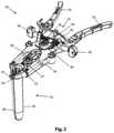
- FIG. 1is a perspective view of one example of a tissue retraction assembly forming part of a surgical access system according to one embodiment of the present disclosure, shown in a fully retracted or “open” position;
- FIG. 2is a perspective view of the tissue retraction assembly of FIG. 1 shown in a fully closed position
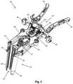
- FIG. 3is a perspective view of the tissue retraction assembly of FIG. 1 shown in a partially open position according to the present disclosure
- FIGS. 4-5are front perspective and back perspective views, respectively, of one example of a locking shim forming part of the surgical access system of the present disclosure
- FIG. 6is a top view of the locking shim of FIG. 4 ;
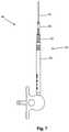
- FIG. 7is a side plan view of a tissue distraction assembly (comprising a plurality of dilating cannulae over a K-wire) used to distract tissue between the skin of the patient and the surgical target site according to one embodiment of the present disclosure;
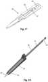
- FIGS. 8-9are side and perspective views, respectively, of an example of a disposable electrode forming part of the tissue retraction system of FIG. 1 according to one embodiment of the present disclosure
- FIGS. 10-11are perspective views of an example of a retractor blade forming part of the tissue retraction system of FIG. 1 configured to releasably couple with the disposable electrode of FIG. 9 ;
- FIG. 12is top perspective view of the retractor blade of FIG. 10 ;
- FIGS. 13-14are perspective views of an assembly comprising the disposable electrode of FIG. 8 coupled to the retractor blade of FIG. 10 ;
- FIGS. 15-16are perspective views of the tissue retraction assembly of FIG. 1 including the disposable electrode/blade assembly of FIG. 13 ;
- FIGS. 17-18are perspective views of an example of an insulated locking shim for use with the posterior blade forming part of the tissue retraction system of FIG. 1 to prevent current shunting from the posterior blade when neurophysiologic monitoring is performed from the posterior blade;
- FIG. 19is a perspective view of an example of a neuromonitoring system programmed to perform nerve monitoring before, during and after the creation of an operative corridor to a surgical target site in accordance with the present disclosure
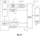
- FIG. 20is a block diagram of the neuromonitoring system shown in FIG. 19 ;
- FIGS. 21-22are examples of screen displays illustrating exemplary features and information communicated to a user during the use of the neuromonitoring system of FIG. 19 ;
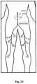
- FIG. 23is a partial diagram of a patient depicting an example electrode placement pattern required for performing transcutaneous, trans-abdominal nerve root stimulation.
- FIG. 24is an example screen display illustrating exemplary features and information communicated to a user during the use of the neuromonitoring system of FIG. 19 using the transcutaneous, trans-abdominal nerve root stimulation feature in accordance with the present disclosure.
- the access system of the present disclosuremay be employed in any number of other spine surgery access approaches, including but not limited to posterior, postero-lateral, anterior, and antero-lateral access, and may be employed in the lumbar, thoracic and/or cervical spine, all without departing from the present disclosure.
- the surgical access system disclosed hereinboasts a variety of inventive features and components that warrant patent protection, both individually and in combination.
- the present disclosureinvolves accessing a surgical target site in a fashion less invasive than traditional “open” surgeries and doing so in a manner that provides access in spite of the neural structures required to be passed through (or near) in order to establish an operative corridor to the surgical target site.
- the surgical access system of the present disclosureaccomplishes this by providing a tissue distraction assembly and a tissue retraction assembly, both of which may be equipped with one or more electrodes for use in detecting the existence of (and optionally the distance and/or direction to) neural structures.
- Electrodesare preferably provided for use with a nerve surveillance system such as, by way of example, the type shown and described in the above referenced '045 patent.
- this nerve surveillance systemis capable of detecting the existence of (and optionally the distance and/or direction to) neural structures during the distraction and retraction of tissue by detecting the presence of nerves by applying a stimulation signal to such instruments and monitoring the evoked EMG signals from the myotomes associated with the nerves being passed by the distraction and retraction systems of the present disclosure.
- the system as a wholemay be used to form an operative corridor through (or near) any of a variety of tissues having such neural structures, particularly those which, if contacted or impinged, may otherwise result in neural impairment for the patient.
- the access system of the present disclosuremay be used to traverse tissue that would ordinarily be deemed unsafe or undesirable, thereby broadening the number of manners in which a given surgical target site may be accessed.
- the neuromonitoring systemmay perform neuromonitoring as the lateral access corridor is maintained during the surgical procedure. Aspects of the neuromonitoring systems used to facilitate performance of these functions are also described in the following commonly owned patent applications, collectively referred to as the “Neuromonitoring PCT Applications,” the entire contents of each of which are hereby incorporated by reference as if set forth fully herein: U.S. Pat. No. 8,068,912, entitled “System and Methods for Determining Nerve Proximity, Direction, and Pathology During Surgery,” filed on Jan. 9, 2004; U.S. Pat. No. 7,522,953, entitled “System and Methods for Performing Surgical Procedures and Assessments,” filed on Mar. 25, 2004; U.S. Pat. No. 7,905,840, entitled Surgical Access System and Related Methods,” filed Oct. 18, 2004; and U.S. Pat. No. 8,255,045, entitled “Neurophysiologic Monitoring System,” filed on Apr. 4, 2008,
- the tissue distraction assembly of the present disclosureincluding a plurality of sequential dilators and a k-wire, is employed to distract the tissues extending between the skin of the patient and a given surgical target site (preferably along the posterior region of the target intervertebral disc). Once distracted, the resulting void or distracted region within the patient is of sufficient size to accommodate a tissue retraction assembly of the present disclosure. More specifically, the tissue retraction assembly (comprising a plurality of retractor blades extending from a handle assembly) may be advanced, with the blades in a first generally closed position, over the exterior of the outer dilator. At that point, the handle assembly may be operated to move the retractor blades into a second, open or “retracted” position to create an operative corridor to the surgical target site.
- a posterior shim element(which is preferably slidably engaged with the posterior retractor blade) may be advanced such that a distal shim extension is positioned within the posterior region of the disc space. If done before retraction, this helps ensure that the posterior retractor blade will not move posteriorly during the retraction process, even though the other retractor blades (e.g. cephalad-most and caudal-most) are able to move and thereby create an operative corridor. Fixing the posterior retractor blade in this fashion serves several important functions. First, the distal end of the shim element serves to distract the adjacent vertebral bodies, thereby restoring disc height.
- the posterior shim elementalso helps ensure that surgical instruments employed within the operative corridor are incapable of being advanced outside the operative corridor, preventing inadvertent contact with the exiting nerve roots during the surgery.
- the cephalad-most and caudal-most retractor bladesmay be locked in position and, thereafter, retractor extenders advanced therealong to prevent the ingress or egress of instruments or biological structures (e.g. nerves, vasculature, etc.) into or out of the operative corridor.
- the cephalad-most and/or caudal-most retractor bladesmay be pivoted in an outward direction to further expand the operative corridor.
- FIGS. 1-3illustrate a tissue retraction assembly 10 forming part of a surgical access system according to the present disclosure, including a plurality of retractor blades 12 , 16 , 18 extending from a handle assembly 20 .
- the handle assembly 20is provided with a first retractor blade 12 , a second retractor blade 16 , and a third retractor blade 18 .
- FIG. 1illustrates the tissue retraction assembly 10 in a fully retracted or “open” configuration, with the retractor blades 12 , 16 , 18 positioned a distance from one another so as to form an operative corridor 15 therebetween which extends to a surgical target site (e.g. an annulus of an intervertebral disc).
- a surgical target sitee.g. an annulus of an intervertebral disc
- the blades 16 , 18are capable of being pivoted or rotated relative to the handle 20 , as best appreciated with combined reference to FIGS. 1 & 2 .
- FIG. 2shows the tissue retraction assembly 10 in an initial “closed” configuration, with the retractor blades 12 , 16 , 18 generally abutting one another.
- FIG. 3shows the tissue retraction assembly 10 in a “partially open” configuration.
- tissue retraction assembly 10 of the present disclosuremay find use in any number of different surgical approaches, including generally posterior, generally postero-lateral, generally anterior and generally antero-lateral.
- the handle assembly 20may be coupled to any number of mechanisms for rigidly registering the handle assembly 20 in fixed relation to the operative site, such as through the use of an articulating arm mounted to the operating table (not shown).
- the handle assembly 20includes first and second arm members 26 , 28 hingedly coupled via coupling mechanism shown generally at 30 .
- the second retractor blade 16is rigidly coupled (generally perpendicularly) to the end of the first arm member 26 .
- the third retractor blade 18is rigidly coupled (generally perpendicularly) to the end of the second arm member 28 .
- the first retractor blade 12is rigidly coupled (generally perpendicularly to) a translating member 17 , which is coupled to the handle assembly 20 via a linkage assembly shown generally at 14 .
- the linkage assembly 14includes a roller member 34 having a pair of manual knob members 36 which, when rotated via manual actuation by a user, causes teeth 35 on the roller member 34 to engage within ratchet-like grooves 37 in the translating member 17 .
- manual operation of the knobs 36causes the translating member 17 to move relative to the first and second arm members 26 , 28 .
- the arms 26 , 28may be simultaneously opened such that the second and third retractor blades 16 , 18 move away from one another.
- the dimension and/or shape of the operative corridor 15may be tailored depending upon the degree to which the translating member 17 is manipulated relative to the arms 26 , 28 . That is, the operative corridor 15 may be tailored to provide any number of suitable cross-sectional shapes, including but not limited to a generally circular cross-section, a generally ellipsoidal cross-section, a generally triangular cross-section, and/or an oval cross-section.
- Optional light emitting devicesmay be coupled to one or more of the retractor blades 12 , 16 , 18 to direct light down the operative corridor 15 .
- the retractor blades 12 , 16 , 18may be composed of any material suitable for introduction into the human body, including but not limited to aluminum, titanium, and/or clear polycarbonate, that would ensure rigidity during tissue distraction.
- the retractor blades 12 , 16 , 18may be optionally coated with a carbon fiber reinforced coating to increase strength and durability.
- the retractor blades 12 , 16 , 18may be optionally constructed from partially or wholly radiolucent materials (e.g. aluminum, PEEK, carbon-fiber, and titanium) to improve the visibility of the surgeon during imaging (e.g. radiographic, MRI, CT, fluoroscope, etc.).
- the retractor blades 12 , 16 , 18may be provided in any number of suitable lengths, depending upon the anatomical environment and surgical approach, such as (for example) the range from 20 mm to 150 mm. Based on this range of sizes, the tissue retraction assembly 10 of the present disclosure is extremely versatile and may be employed in any of a variety of desired surgical approaches, including but not limited to lateral, posterior, postero-lateral, anterior, and antero-lateral, by simply selecting the desired size retractor blades 12 , 16 , 18 and attaching them to the handle assembly 20 as will be described herein.
- the retractor blades 12 , 16 , 18may be equipped with various additional features or components.
- one or more of the retractor blades 12 , 16 , 18may be equipped with a shim, such as a locking shim 56 as shown in FIGS. 4-6 .
- the intradiscal locking shim 56is suitable for engagement with the posterior blade 12 .
- any shim 56may be used with any blade 12 , 16 , 18 without departing from the scope of the present disclosure.
- the locking intradiscal shim 56has a distal tapered region 58 which may be advanced into the disc space for the purpose of distracting the adjacent vertebral bodies (thereby restoring disc height) and/or anchoring the blade 12 relative to the spine.
- the locking intradiscal shim 56also forms a protective barrier to prevent the ingress or egress of instruments or biological structures (e.g. nerves, vasculature, etc.) into or out of the operative corridor 15 .
- the locking intradiscal shim 56locks in position on the retractor blade 12 to prevent the shim from dislodging and allowing the retractor to move from the targeted location.
- the shim 56has a flexible engagement tab 60 with a ramped leading edge 62 that allows it to advance down indentations 63 on the inner surface of the retractor blade 12 ( FIG. 11 ).
- the trailing edge 64 of the engagement tab 60is squared to prevent disengagement (thus preventing unwanted backout of the shim) from the indentation 63 without use of a removal tool (not shown).
- the engagement tab 60also includes a T-shaped removal lip 66 configured to engage a shim removal tool, an example of which is shown and described in PCT App. No. PCT/US01/01489 (incorporated by reference).
- the T-shaped lip 66 of the engagement tab 60allows the removal tool to lift the trailing edge 64 away from the retractor blade 12 and remove the shim 56 .
- the locking intradiscal shim 56has a pair of elongated tab members 68 that are configured to slideably engage elongated slot members 65 that run the length of the inside surface of the retractor blade 12 ( FIG. 11 ).
- the locking intradiscal shim 56includes a dimple or aperture 56 located near the proximal end of the shim 56 configured for engagement with a shim removal tool.
- the locking intradiscal shim 56may be made from any material suitable for use in the human body, including but not limited to biologically compatible plastic and/or metal, preferably partially or wholly radiolucent in nature material (such as aluminum, PEEK, carbon-fibers and titanium).
- the intradiscal shim 56may also be coated with an insulative coating (e.g. a parylene coating) to prevent current shunting or density changes from electrodes situated at the distal end of the retractor blade 12 .
- the shim element 56may be composed of a material that would destruct when autoclaved (such as polymer containing a portion of glass particles), which may be advantageous in preventing the unauthorized re-use of the shim element 56 (which would be provided to the user in a sterile state).
- the locking intradiscal shim 56may be provided with one or more electrodes (e.g. at or near their distal regions) equipped for use with a neuromonitoring system.
- a neuromonitoring systemmay be capable of detecting the existence of (and optionally the distance and/or direction to) neural structures during the retraction of tissue by detecting the presence of nerves by applying a stimulation signal to the electrodes and monitoring the evoked EMG signals from the myotomes associated with the nerves in the vicinity of the tissue retraction system 10 of the present disclosure.
- the system as a wholemay be used to form an operative corridor through (or near) any of a variety of tissues having such neural structures, particularly those that, if contacted or impinged, may otherwise result in neural impairment for the patient.
- the access system of the present disclosuremay be used to traverse tissue that would ordinarily be deemed unsafe or undesirable, thereby broadening the number of manners in which a given surgical target site may be accessed.
- the nerve monitoring component of the retractor systemis the posterior retractor blade 12 , which may be made of a conductive material (e.g. aluminum) and coated with a insulative coating to direct stimulation from the neuromonitoring system 17 to the tissue adjacent the distal end.
- the nerve monitoring feature of the tissue retraction assemblyincludes two main components: a center (posterior) blade that forms part of a tissue retraction assembly 10 and an electrode body 70 .
- the electrode body 70 shown and describedis slideably coupled to the posterior blade 12 .
- the electrode body 70 shownis disposable.
- a clip cable 72may be used to connect the electrode body 70 to the neuromonitoring system.
- One potential advantage of the electrode body 70 and accompanying posterior blade 12is the increased ability to attain consistent and repeatable neuromonitoring functionality throughout the course of a single surgery and from surgery to surgery (since there is no risk of erosion of the insulative coating on the blade which can lead to current shunting).
- FIG. 7illustrates an example of a tissue distraction system 40 according to one embodiment.
- the tissue distraction system 40includes a K-wire 42 and initial dilator 44 , as well as a secondary dilation assembly 50 .
- the secondary dilation assembly 50includes at least two nesting cannulae 52 , 54 .
- FIGS. 8-16illustrate an example of one embodiment of a removably couplable disposable electrode 70 and retractor blade 12 for use with the tissue retraction assembly 10 according to the present disclosure.
- the electrode 70assists in the detection of the depth of nerves relative to the length of the posterior blade after the tissue retraction assembly is placed.
- the electrode 70also assists in assessing the health and status of the nerves closest to the posterior blade 12 after the tissue retractor 10 is fully retracted in the open position and throughout the surgical procedure. (Open position refers to the level of retraction utilized to maintain the operative corridor to the spine during surgery.)
- Using a disposable electrode 70permits the retractor blade 12 to be sterilized and reused endlessly without the possibility of degradation to the electrode.
- FIG. 15illustrates the electrode 70 in use with only the posterior retractor blade 12 , the electrode 70 could be used with each of the retractor blades 12 , 16 , and/or 18 without departing from the scope of this disclosure.
- FIGS. 8-9illustrate one example of an electrode 70 that includes a molded plastic part with a conductive trace 74 deposited generally along the length of the electrode 70 .
- the conductive trace 74may include a discrete trace for each electrode contact 76 on the electrode body 70 .
- the electrode 70is made out of a generally stiff material that can also withstand bending without breaking, such as, for example, PVC.
- the conductive trace 74provides a conductive pathway for the delivery of current from a current delivery source (such as a clip cable 72 ) to each electrode as well as for the delivery of electrical activity from nerve tissue at or near the surgical site to the neuromonitoring system.
- the proximal end of the electrode 70has a first exposed area 78 that may wrap around the circumference of the proximal end of the electrode 70 to ensure a conductive path between the electrode 70 and a current delivery device or a current recording device (such as, for example, a clip cable 72 ).
- the first exposed area 78can act as a stimulation conduit and allow a current delivery source to deliver an electric current to the conductive trace 74 and as a recording conduit that transmits changes in electrical current from the conductive trace 74 to the control unit 172 of the neuromonitoring system.
- the distal end of the electrode 70has at least one electrode contact 76 (shown by way of example as a triangular patch) within the conductive trace 74 that can act as a stimulation conduit and allow the emitting of current to nearby tissue and as a recording conduit for recording changes in electrical current from nearby tissue. Both functions of the first exposed area 78 and distal electrode contact 76 will be explained in greater detail below. Other than the exposed areas 76 , 78 , the remainder of the conductive trace 74 is insulated with a dielectric coating to prevent current shunting. Any number of conductive materials suitable for completing the current pathway, such as, for example, silver, or copper may be used in the conductive trace 74 without departing from the scope of this disclosure.
- the first exposed area 78 of the disposable electrodemay have a generally cylindrical shape for facilitating the connection between the electrode and a neuromonitoring system.
- an electrical coupleris shown in the form of a plunger-style clip cable 72 .
- the connection site for a current delivery device or a current recording devicemay be any size and shape necessary for making a quality electrical connection without departing from the scope of the current disclosure.
- the remainder of the body of the electrode 70may be generally flat with minimal thickness and a variety of features for engaging and securing the electrode 70 to a retractor blade 12 .
- wings 80may extend from the sides of the electrode 70 for engaging positioning features within the retractor blade 12 , as will be discussed in more detail below. Additionally, the distal end of the electrode 70 may have a ledge 82 for engaging a feature of the retractor blade 12 for further secure positioning of the electrode 70 relative to the retractor blade 12 , as will also be discussed in more detail below.
- a single sized electrode 70may be designed for use with a variety of retractor blade 12 sizes and shapes (for example, retractor blade lengths generally ranging from 20 to 180 mm), but the electrodes may also be available in a variety of shapes and sizes.
- FIGS. 13-14illustrate one example assembly of an electrode 70 releasably coupled to retractor blade 12 .
- at least the posterior blade 12is configured to enable the coupling of an electrode body 70 .
- the proximal end of the electrode 70(more specifically, adjacent the first exposed area 78 end of the electrode 70 ) is inserted into generally the distal end of the retractor blade 12 .
- the wings 80 of the electrode 70mate with and are constrained by the dovetail grooves 84 which extend longitudinally from the distal end to the proximal end of the retractor blade 12 .
- the dovetail grooves 84provide an insertion guide for the disposable electrode 70 as it is inserted and assists in maintaining proper positioning of the electrode 70 while coupled to the retractor blade 12 .
- the ledge 82 near the distal end of the disposable electrode 70may engage the cut-out 86 generally near the distal end of the retractor blade 12 to further assist in securing the positioning of the electrode 70 relative to the retractor blade 12 .
- the electrode 70is adapted to the retractor blade 12 so that the electrode contact 76 (shown by way of example as triangular in FIGS. 9 and 13 ) is exposed generally along the outer surface of the blade (best shown in FIG. 13 ).
- the proximal end of the electrode body 70protrudes from a machined cavity 88 (best shown in FIG. 12 ) at the proximal end of the retractor blade 12 . Depending on the height of the blade, the proximal end may be bent or folded so as not to obstruct the surgical corridor.
- FIG. 17is illustrates a locking intradiscal shim 83 according to a second example embodiment.
- the locking intradiscal shim 83is similar to the shim 56 of FIGS. 4-6 such that a description of all the like elements will not be repeated here.
- the locking intradiscal shim 83 of FIG. 17is preferably coated with an insulative parylene coating to mitigate current shunting and changes to current density at the distal tip of the disposable electrode.
- Paryleneis the trade name for a variety of chemical vapor deposited poly (p-xylylene) polymers used as moisture barriers and electrical insulators. Among such polymers, Parylene C is highly desirable due to its combination of barrier properties and manufacturing advantages.
- the locking intradiscal shim 83includes a deflectable tab 85 with a lip member 87 that serves as a locking feature.
- the shim 83further includes a cut-out 89 that receives an engagement tab of a removal tool.
- FIG. 18illustrates the locking intradiscal shim 83 of FIG. 17 attached adjacent to the distal end of the disposable electrode 70 that is removably coupled to the posterior blade 12 described in relation to FIGS. 9-16 above.
- any number of distraction components and/or retraction componentsmay be equipped to detect the presence of (and optionally the distance and/or direction to) neural structures during tissue distraction and/or retraction. This is accomplished by employing the following steps: (1) one or more stimulation electrodes are provided on the various distraction and/or retraction components; (2) a stimulation source (e.g. voltage or current) is coupled to the stimulation electrodes; (3) a stimulation signal is emitted from the stimulation electrodes as the various components are advanced towards or maintained at or near the surgical target site; and (4) the patient is monitored to determine if the stimulation signal causes muscles associated with nerves or neural structures within the tissue to innervate. If the nerves innervate, this may indicate that neural structures may be in close proximity to the distraction and/or retraction components.
- a stimulation sourcee.g. voltage or current
- FIGS. 19-20illustrate, by way of example only, a monitoring system 170 suitable for use with the surgical access system 10 of the present disclosure.
- the monitoring system 170includes a control unit 172 , a patient module 174 , and an EMG harness 176 and return electrode 178 coupled to the patient module 174 , and a cable 182 for establishing electrical communication between the patient module 174 and any number of surgical accessories 196 , including the surgical access system of the present disclosure (retractor assembly 10 of FIG. 1 and distraction assemblies 40 , 50 of FIG. 7 , including K-wire 42 , initial dilator 44 and sequentially dilating cannulae 52 , 54 ).
- the surgical accessories 196may further include, but are not necessarily limited to, devices for performing pedicle screw tests (such as a screw test probe 198 ), neural pathology monitoring devices (such as a nerve root retractor 200 ), coupling devices for electronically coupling surgical instruments to the system 170 (such as electric coupling devices 202 , 204 and stimulator driver 206 ), and pilot hole forming components (such as a tap member 208 , pedicle access probe 210 , or other similar device).
- devices for performing pedicle screw testssuch as a screw test probe 198
- neural pathology monitoring devicessuch as a nerve root retractor 200
- coupling devices for electronically coupling surgical instruments to the system 170such as electric coupling devices 202 , 204 and stimulator driver 206
- pilot hole forming componentssuch as a tap member 208 , pedicle access probe 210 , or other similar device.
- this electrical communicationcan be achieved by providing, by way of example only, a hand-held stimulation driver 206 capable of selectively providing a stimulation signal (due to the operation of manually operated buttons on the hand-held stimulation controller 206 ) to one or more connectors (e.g., coupling devices 202 , 204 ).
- the coupling devices 202 , 204are suitable to establish electrical communication between the hand-held stimulation controller 206 and (by way of example only) the stimulation electrodes on the K-wire 42 , the dilators 44 , 52 , 54 , the retractor blades 12 , 16 , 18 , and/or the shim element 56 (collectively “surgical access instruments”).
- these surgical access instrumentsmust be connected to at least one of coupling devices 202 , 204 (or similar couplers including multi-contact regions, not shown), at which point the user may selectively initiate a stimulation signal (preferably, a current signal) from the control unit 172 to a particular surgical access instruments. Stimulating the electrode(s) on these surgical access instruments before, during, and/or after establishing operative corridor will cause nerves that come into close or relative proximity to the surgical access instruments to depolarize, producing a response in a myotome associated with the innervated nerve.
- a stimulation signalpreferably, a current signal
- the control unit 172includes a touch screen display 190 and a base 192 , which collectively contain the essential processing capabilities (software and/or hardware) for controlling the neuromonitoring system 170 .
- the control unit 172may include an audio unit 168 that emits sounds according to a location of a surgical element with respect to a nerve.
- the patient module 174is connected to the control unit 172 via a data cable 194 , which establishes the electrical connections and communications (digital and/or analog) between the control unit 172 and patient module 174 .
- the main functions of the control unit 172include receiving user commands via the touch screen display 190 , activating stimulation electrodes on the surgical access instruments, processing signal data according to defined algorithms, displaying received parameters and processed data, and neuromonitoring system status and report fault conditions.
- the touch screen display 190is preferably equipped with a graphical user interface (GUI) capable of communicating information to the user and receiving instructions from the user.
- GUIgraphical user interface
- the display 190 and/or base 192may contain patient module interface circuitry (hardware and/or software) that commands the stimulation sources, receives digitized signals and other information from the patient module 174 , processes the EMG responses to extract characteristic information for each muscle group, and displays the processed data to the operator via the display 190 .
- the neuromonitoring system 170is capable of determining nerve direction relative to one or more of the K-wire 42 , the dilators 44 , 52 , 54 , the retractor blades 12 , 16 , 18 , and/or the shim element 56 before, during and/or following the creation of an operative corridor to a surgical target site.
- Neuromonitoring system 170accomplishes this by having the control unit 172 and patient module 174 cooperate to send electrical stimulation signals to one or more of the stimulation electrodes provided on these instruments.
- the stimulation signalsmay cause nerves adjacent to or in the general proximity of the surgical access system 10 to depolarize.
- the nerve direction feature of the system 170is based on assessing the evoked response of the various muscle myotomes monitored by the system 170 via the EMG harness 176 .
- the surgical access system 10is capable of detecting the presence of (and optionally the distant and/or direction to) such nerves. This provides the ability to actively negotiate around or past such nerves to safely and reproducibly form the operative corridor to a particular surgical target site, as well as monitor to ensure that no neural structures migrate into contact with the surgical access system 10 after the operative corridor has been established.
- the surgical access system 10may be particularly suited for establishing an operative corridor to an intervertebral target site in a postero-lateral, trans-psoas fashion so as to avoid the bony posterior elements of the spinal column.
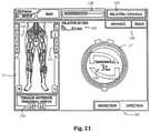
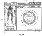
- FIGS. 21-22are exemplary screen displays (to be shown on the display 190 ) illustrating one embodiment of the nerve direction feature of the neuromonitoring system 170 shown and described with reference to FIG. 19-20 . These screen displays are intended to communicate a variety of information to the surgeon in an easy-to-interpret fashion.
- This informationmay include, but is not necessarily limited to, a display of the function 230 (in this case “DIRECTION”), a graphical representation of a patient 231 , the myotome levels being monitored 232 , the nerve or group associated with a displayed myotome 233 , the name of the instrument being used 234 (in this case, a dilator 52 , 54 ), the size of the instrument being used 235 , the stimulation threshold current 236 , a graphical representation of the instrument being used 237 (in this case, a cross-sectional view of a dilator 52 , 54 ) to provide a reference point from which to illustrate relative direction of the instrument to the nerve, the stimulation current being applied to the stimulation electrodes 238 , instructions for the user 239 (in this case, “ADVANCE” and/or “HOLD”), and an arrow 240 indicating the direction from the instrument to a nerve.
- a display of the function 230in this case “DIRECTION”
- This informationmay be communicated in any number of suitable fashions, including but not limited to the use of visual indicia (such as alpha-numeric characters, light-emitting elements, and/or graphics) and audio communications (such as a speaker element).
- visual indiciasuch as alpha-numeric characters, light-emitting elements, and/or graphics
- audio communicationssuch as a speaker element.
- a dilating cannulasuch as at 234
- the present disclosureis deemed to include providing similar information on the display 190 during the use of any or all of the various instruments forming the surgical access system 10 of the present disclosure, including the distraction assembly 40 (i.e. the K-wire 42 and dilators 44 , 52 , 54 ) and/or the retractor blades 12 , 16 , 18 and/or the shim element 56 .
- a method for monitoring the status of the motor neural pathwaythat includes the steps of: (a) stimulating the motor pathways in a transcutaneous and trans-abdominal fashion from a location superior to the surgical site and (b) recording neurophysiologic responses evoked by that transcutaneous, trans-abdominal stimulation from one or more locations inferior to the surgical site.
- the neuromonitoring system 170is capable of ascertaining the health and/or status of at-risk nerves along the motor neural pathway superior and inferior to the surgical site before, during, and/or after the creation of the operative corridor to the surgical target site. Monitoring system 170 accomplishes this by having the control unit 172 and patient module 174 cooperate to transmit electrical stimulation signals to a stimulating cathode placed posteriorly on the patient's lower back above the site of surgery.
- the stimulation signalscause nerves deep to the stimulating electrode to depolarize, evoking activity from muscles innervated by the nerves. Evoked EMG responses of the muscles are recorded by the neuromonitoring system 170 and analyzed in relation to the stimulation signal (discussed below).
- Resulting data from the analysisis conveyed to the surgeon on the GUI display.
- Thisprovides the ability to verify that the patient is positioned in a neutral way and that no neural structures have been impinged upon after the operative corridor has been established.
- thisis particularly advantageous in that the surgical access system 10 may be particularly suited for establishing an operative corridor to an intervertebral target site in a postero-lateral, trans-psoas fashion so as to avoid the bony posterior elements of the spinal column.
- a stimulating cathodeis placed posteriorly and an anode is placed anteriorly at locations superior to the surgical target site and neuromuscular responses are evoked in response to transcutaneous, trans-abdominal nerve root stimulation.
- the stimulating cathodemay be a single cathode adhesive surface electrode placed over the conus medullaris at spinal level L1-2, preferably with the electrode pair oriented side to side and symmetrically over the neural foramen.
- the anode electrodemay be an adhesive surface electrode placed at the anterior abdominal midline below the umbilicus, preferably with the electrode pair oriented side to side, symmetrically across the midline. Implementing a stimulation montage in this way is beneficial for at least two reasons.
- Electrode harness 176may be designed such that the various electrodes may be positioned about the patient as described in Table 1 and shown in FIG. 23 (depicting an example electrode placement diagram indicating electrodes placed on the anterior portion of the body with solid lines and electrodes placed on the posterior portion of the body with dashed lines).
- the steps of performing transcutaneous, trans-abdominal stimulation and recording the resultant evoked potentialsis preferably first performed prior to establishing the lateral access corridor and subsequently performed periodically during the surgical procedure.
- the neuromonitoring system 170is capable of detecting changes to the stimulation threshold intensities of these nerves over time which may be indicative of changes to the health/status of these nerves (e.g. by compression or patient positioning).
- a change in the health or status of a nervemay be deemed significant once the stimulus intensity required to elicit a neuromuscular response from a myotome exceeds pre-determined criteria (e.g. 50 mA greater than the baseline stimulation threshold).
- the neuromonitoring system 170may quickly and accurately determine this data and convey the useful information in a simple and easily comprehensible manner for interpretation by a surgeon, neurophysiologist, or other medical personnel. It is contemplated that the control unit 172 of the neuromonitoring system 170 may automatically ascertain this information and/or communicate any of numerical, graphic, audio, and visual feedback corresponding to one or more of these findings. Armed with this useful information, the surgeon may detect a problem or potential problem early and then act to avoid and/or mitigate the problem.
- FIG. 24is an exemplary screen display (to be shown on the display 190 ) illustrating one embodiment of the transcutaneous, trans-abdominal nerve root stimulation feature of the neuromonitoring system 170 shown and described with reference to FIGS. 19-20 .
- These screen displaysare intended to communicate information to the surgeon or other personnel in an easy-to-interpret fashion.
- This informationmay include, but is not necessarily limited to, a display of the function 230 (in this case “TCNR Stim”), the spinal levels being monitored 250 , the nerve or group of nerves associated with the spinal levels being monitored 252 , waveforms of the evoked EMG responses 254 , stimulation parameters 256 , the stimulation intensity required to elicit a response 258 , and the stimulation intensity required to elicit a baseline (threshold) response 260 .
- This informationmay be communicated in any number of suitable fashions, including but not limited to, the use of visual indicia (such as alpha-numeric characters, light-emitting element, and/or graphics) and audio communications (such as a speaker element).
- transcutaneous, trans-abdominal nerve root stimulation method described hereinmay be used in conjunction with the monitoring method described above during surgical access with a surgical access system.
- the present disclosureaccomplishes the goal of performing nerve monitoring in the tissue or regions superior and/or inferior to the surgical target site during any procedures performed after the operative corridor has been established and does so in a manner that lowers the amount of stimulation delivered to the patient and provides specificity of the at-risk nerve or nerves.
- specific embodiments thereofhave been shown by way of example in the drawings and are herein described in detail. It should be understood, however, that the description herein of specific embodiments is not intended to limit the disclosure to the particular forms disclosed, but on the contrary, the disclosure is to cover all modifications, equivalents, and alternatives falling within the spirit and scope of the disclosure as defined herein. For example, any of the features of a particular example described herein may be used with any other example described herein without departing from the scope of the present disclosure.
Landscapes
- Health & Medical Sciences (AREA)
- Life Sciences & Earth Sciences (AREA)
- Surgery (AREA)
- Animal Behavior & Ethology (AREA)
- Neurology (AREA)
- Veterinary Medicine (AREA)
- Engineering & Computer Science (AREA)
- Biomedical Technology (AREA)
- Heart & Thoracic Surgery (AREA)
- Public Health (AREA)
- General Health & Medical Sciences (AREA)
- Medical Informatics (AREA)
- Molecular Biology (AREA)
- Physics & Mathematics (AREA)
- Biophysics (AREA)
- Pathology (AREA)
- Neurosurgery (AREA)
- Nuclear Medicine, Radiotherapy & Molecular Imaging (AREA)
- Physiology (AREA)
- Orthopedic Medicine & Surgery (AREA)
- Measurement And Recording Of Electrical Phenomena And Electrical Characteristics Of The Living Body (AREA)
- Surgical Instruments (AREA)
- Electrotherapy Devices (AREA)
- Radiology & Medical Imaging (AREA)
- Measuring And Recording Apparatus For Diagnosis (AREA)
Abstract
Description
| TABLE 1 | ||
| Electrode Type | Electrode Placement | Spinal Level |
| Ground | Upper Outer Thigh | — |
| Anode | Abdominal Midline, Below Umbilicus | — |
| Stimulation | Lower Back, over Spinal Level 1-2 | — |
| Recording | Left Adductor Longus | L2, L3, L4 |
| Recording | Left Vastus Medialis | L2, L3, L4 |
| Recording | Left Vastus Lateralis | L2, L3, L4 |
| Recording | Left Tibialis Anterior | L4, L5 |
| Recording | Left Biceps Femoris | L5, S1, S2 |
| Recording | Right Adductor Longus | L2, L3, L4 |
| Recording | Right Vastus Medialis | L2, L3, L4 |
| Recording | Right Vastus Lateralis | L2, L3, L4 |
| Recording | Right Tibialis Anterior | L4, L5 |
| Recording | Right Biceps Femoris | L5, S1, S2 |
Claims (17)
Priority Applications (11)
| Application Number | Priority Date | Filing Date | Title |
|---|---|---|---|
| US14/073,772US11259737B2 (en) | 2012-11-06 | 2013-11-06 | Systems and methods for performing neurophysiologic monitoring during spine surgery |
| EP14859965.7AEP3065634B1 (en) | 2012-11-06 | 2014-11-06 | Neurophysiologic monitoring during spine surgery |
| PCT/US2014/064449WO2015069962A1 (en) | 2012-11-06 | 2014-11-06 | Neuroophysiologic monitoring during spine surgery |
| AU2014346688AAU2014346688B2 (en) | 2012-11-06 | 2014-11-06 | Neuroophysiologic monitoring during spine surgery |
| US14/535,318US11877860B2 (en) | 2012-11-06 | 2014-11-06 | Systems and methods for performing neurophysiologic monitoring during spine surgery |
| JP2016552487AJP2017503620A (en) | 2012-11-06 | 2014-11-06 | System and method for performing neurophysiological monitoring during spinal surgery |
| CN201480060648.6ACN105744887A (en) | 2012-11-06 | 2014-11-06 | Systems and methods for performing neuroophysiologic monitoring during spine surgery |
| AU2019250269AAU2019250269B2 (en) | 2012-11-06 | 2019-10-18 | Systems and methods for performing neurophysiologic monitoring during spine surgery |
| JP2020115395AJP2020168444A (en) | 2012-11-06 | 2020-07-03 | Systems and methods for performing neurophysiological monitoring during spinal cord surgery |
| AU2021203764AAU2021203764B2 (en) | 2012-11-06 | 2021-06-08 | Systems and methods for performing neurophysiologic monitoring during spine surgery |
| US17/579,957US20220142555A1 (en) | 2012-11-06 | 2022-01-20 | Systems and Methods for Performing Neurophysiologic Monitoring During Spine Surgery |
Applications Claiming Priority (2)
| Application Number | Priority Date | Filing Date | Title |
|---|---|---|---|
| US201261722923P | 2012-11-06 | 2012-11-06 | |
| US14/073,772US11259737B2 (en) | 2012-11-06 | 2013-11-06 | Systems and methods for performing neurophysiologic monitoring during spine surgery |
Related Child Applications (2)
| Application Number | Title | Priority Date | Filing Date |
|---|---|---|---|
| US14/535,318Continuation-In-PartUS11877860B2 (en) | 2012-11-06 | 2014-11-06 | Systems and methods for performing neurophysiologic monitoring during spine surgery |
| US17/579,957ContinuationUS20220142555A1 (en) | 2012-11-06 | 2022-01-20 | Systems and Methods for Performing Neurophysiologic Monitoring During Spine Surgery |
Publications (2)
| Publication Number | Publication Date |
|---|---|
| US20150088030A1 US20150088030A1 (en) | 2015-03-26 |
| US11259737B2true US11259737B2 (en) | 2022-03-01 |
Family
ID=52691562
Family Applications (2)
| Application Number | Title | Priority Date | Filing Date |
|---|---|---|---|
| US14/073,772ActiveUS11259737B2 (en) | 2012-11-06 | 2013-11-06 | Systems and methods for performing neurophysiologic monitoring during spine surgery |
| US17/579,957AbandonedUS20220142555A1 (en) | 2012-11-06 | 2022-01-20 | Systems and Methods for Performing Neurophysiologic Monitoring During Spine Surgery |
Family Applications After (1)
| Application Number | Title | Priority Date | Filing Date |
|---|---|---|---|
| US17/579,957AbandonedUS20220142555A1 (en) | 2012-11-06 | 2022-01-20 | Systems and Methods for Performing Neurophysiologic Monitoring During Spine Surgery |
Country Status (6)
| Country | Link |
|---|---|
| US (2) | US11259737B2 (en) |
| EP (1) | EP3065634B1 (en) |
| JP (2) | JP2017503620A (en) |
| CN (1) | CN105744887A (en) |
| AU (3) | AU2014346688B2 (en) |
| WO (1) | WO2015069962A1 (en) |
Cited By (2)
| Publication number | Priority date | Publication date | Assignee | Title |
|---|---|---|---|---|
| US11877860B2 (en) | 2012-11-06 | 2024-01-23 | Nuvasive, Inc. | Systems and methods for performing neurophysiologic monitoring during spine surgery |
| US12167915B2 (en) | 2023-04-18 | 2024-12-17 | Retropsoas Technologies, Llc | Bipolar nerve stimulation/monitoring cuff |
Families Citing this family (61)
| Publication number | Priority date | Publication date | Assignee | Title |
|---|---|---|---|---|
| US8992558B2 (en) | 2008-12-18 | 2015-03-31 | Osteomed, Llc | Lateral access system for the lumbar spine |
| JP6000702B2 (en)* | 2012-07-12 | 2016-10-05 | オリンパス株式会社 | Medical system |
| US11259737B2 (en) | 2012-11-06 | 2022-03-01 | Nuvasive, Inc. | Systems and methods for performing neurophysiologic monitoring during spine surgery |
| US10098585B2 (en) | 2013-03-15 | 2018-10-16 | Cadwell Laboratories, Inc. | Neuromonitoring systems and methods |
| US11229789B2 (en) | 2013-05-30 | 2022-01-25 | Neurostim Oab, Inc. | Neuro activator with controller |
| CA2913074C (en) | 2013-05-30 | 2023-09-12 | Graham H. Creasey | Topical neurological stimulation |
| FR3010628B1 (en) | 2013-09-18 | 2015-10-16 | Medicrea International | METHOD FOR REALIZING THE IDEAL CURVATURE OF A ROD OF A VERTEBRAL OSTEOSYNTHESIS EQUIPMENT FOR STRENGTHENING THE VERTEBRAL COLUMN OF A PATIENT |
| FR3012030B1 (en) | 2013-10-18 | 2015-12-25 | Medicrea International | METHOD FOR REALIZING THE IDEAL CURVATURE OF A ROD OF A VERTEBRAL OSTEOSYNTHESIS EQUIPMENT FOR STRENGTHENING THE VERTEBRAL COLUMN OF A PATIENT |
| US11083387B2 (en) | 2013-11-07 | 2021-08-10 | Safeop Surgical, Inc. | Systems and methods for detecting nerve function |
| US12201436B2 (en) | 2014-08-08 | 2025-01-21 | Medtronic Xomed, Inc. | Wireless nerve integrity monitoring systems and devices |
| US10398369B2 (en) | 2014-08-08 | 2019-09-03 | Medtronic Xomed, Inc. | Wireless stimulation probe device for wireless nerve integrity monitoring systems |
| EP3190982B1 (en)* | 2014-09-10 | 2020-06-24 | Spinal Elements, Inc. | Retractor |
| US11077301B2 (en) | 2015-02-21 | 2021-08-03 | NeurostimOAB, Inc. | Topical nerve stimulator and sensor for bladder control |
| US11980465B2 (en) | 2015-04-03 | 2024-05-14 | Medtronic Xomed, Inc. | System and method for omni-directional bipolar stimulation of nerve tissue of a patient via a bipolar stimulation probe |
| US10039915B2 (en) | 2015-04-03 | 2018-08-07 | Medtronic Xomed, Inc. | System and method for omni-directional bipolar stimulation of nerve tissue of a patient via a surgical tool |
| US11197640B2 (en) | 2015-05-04 | 2021-12-14 | Safeop Surgical, Inc. | System, method, and computer algorithm for measuring, displaying, and accurately detecting changes in electrophysiological evoked potentials |
| US10213192B2 (en) | 2015-07-15 | 2019-02-26 | Warsaw Orthopedic, Inc. | Surgical instrument and method of use |
| US10219798B2 (en) | 2015-07-15 | 2019-03-05 | Warsaw Orthopedic, Inc. | Surgical instrument and method of use |
| US10799226B2 (en) | 2015-07-15 | 2020-10-13 | Warsaw Orthopedic, Inc. | Surgical adaptor and method |
| US10456211B2 (en) | 2015-11-04 | 2019-10-29 | Medicrea International | Methods and apparatus for spinal reconstructive surgery and measuring spinal length and intervertebral spacing, tension and rotation |
| US10339273B2 (en) | 2015-11-18 | 2019-07-02 | Warsaw Orthopedic, Inc. | Systems and methods for pre-operative procedure determination and outcome predicting |
| US10445466B2 (en) | 2015-11-18 | 2019-10-15 | Warsaw Orthopedic, Inc. | Systems and methods for post-operative outcome monitoring |
| EP3426163A4 (en) | 2016-03-09 | 2019-12-11 | Spinal Elements Inc. | RETRACTOR |
| WO2018039228A1 (en) | 2016-08-23 | 2018-03-01 | Stryker European Holdings I, Llc | Instrumentation for the implantation of spinal implants |
| US10849517B2 (en)* | 2016-09-19 | 2020-12-01 | Medtronic Xomed, Inc. | Remote control module for instruments |
| US11986321B2 (en) | 2016-09-22 | 2024-05-21 | Safeop Surgical, Inc. | System and method for detecting and removing periodic non-physiological artifact from evoked potentials |
| EP3537964A4 (en) | 2016-11-14 | 2020-10-21 | SafeOp Surgical, Inc. | SYSTEMS AND METHODS FOR PLACING SPINAL MARINE STIMULATOR LINES |
| WO2018109556A1 (en) | 2016-12-12 | 2018-06-21 | Medicrea International | Systems and methods for patient-specific spinal implants |
| US9935395B1 (en) | 2017-01-23 | 2018-04-03 | Cadwell Laboratories, Inc. | Mass connection plate for electrical connectors |
| US12343069B2 (en) | 2017-02-01 | 2025-07-01 | Avent, Inc. | EMG guidance for probe placement, nearby tissue preservation, and lesion confirmation |
| US11963775B2 (en) | 2017-03-22 | 2024-04-23 | Safeop Surgical, Inc. | Medical systems and methods for detecting changes in electrophysiological evoked potentials |
| EP3612122B1 (en) | 2017-04-21 | 2023-12-20 | Medicrea International | A system for developing one or more patient-specific spinal implants |
| JP7179029B2 (en) | 2017-06-16 | 2022-11-28 | アルファテック スパイン, インコーポレイテッド | System for detecting nerve-muscle response thresholds using variable frequency stimulation |
| WO2019036048A2 (en) | 2017-08-17 | 2019-02-21 | Stryker European Holdings I, Llc | Lateral access bridges, shims and lighting including rod lighting |
| EP3691545A4 (en)* | 2017-10-04 | 2022-02-16 | Mobius Imaging, LLC | SYSTEMS AND METHODS FOR PERFORMING SPINAL SURGERY WITH LATERAL APPROACH |
| CN111601636A (en) | 2017-11-07 | 2020-08-28 | Oab神经电疗科技公司 | Non-invasive neural activator with adaptive circuit |
| US10918422B2 (en) | 2017-12-01 | 2021-02-16 | Medicrea International | Method and apparatus for inhibiting proximal junctional failure |
| EP3545857B1 (en) | 2018-03-30 | 2024-01-03 | Stryker European Operations Holdings LLC | Lateral access retractor and core insertion |
| US11253182B2 (en) | 2018-05-04 | 2022-02-22 | Cadwell Laboratories, Inc. | Apparatus and method for polyphasic multi-output constant-current and constant-voltage neurophysiological stimulation |
| US11992339B2 (en) | 2018-05-04 | 2024-05-28 | Cadwell Laboratories, Inc. | Systems and methods for dynamic neurophysiological stimulation |
| US11166648B2 (en)* | 2018-05-24 | 2021-11-09 | General Electric Company | Method and system for estimating patient recovery time utilizing neuromuscular transmission measurements |
| US11443649B2 (en) | 2018-06-29 | 2022-09-13 | Cadwell Laboratories, Inc. | Neurophysiological monitoring training simulator |
| US11413029B2 (en) | 2018-10-24 | 2022-08-16 | Stryker European Operations Holdings Llc | Anterior to psoas instrumentation |
| US10959716B2 (en) | 2019-02-11 | 2021-03-30 | Warsaw Orthopedic, Inc. | Surgical retractor system and method |
| US11266391B2 (en) | 2019-02-11 | 2022-03-08 | Warsaw Orthopedic, Inc. | Surgical retractor and method |
| US10631842B1 (en) | 2019-02-12 | 2020-04-28 | Edward Rustamzadeh | Lateral retraction system for minimizing muscle damage in spinal surgery |
| US12016543B2 (en) | 2019-02-12 | 2024-06-25 | Edward Rustamzadeh | Lateral retractor system for minimizing muscle damage in spinal surgery |
| CN109758226B (en)* | 2019-03-21 | 2024-05-31 | 武汉金柏威光电技术有限公司 | Neural monitoring bipolar minimally invasive instrument |
| US11877801B2 (en) | 2019-04-02 | 2024-01-23 | Medicrea International | Systems, methods, and devices for developing patient-specific spinal implants, treatments, operations, and/or procedures |
| US11925417B2 (en) | 2019-04-02 | 2024-03-12 | Medicrea International | Systems, methods, and devices for developing patient-specific spinal implants, treatments, operations, and/or procedures |
| US11944385B2 (en) | 2019-04-02 | 2024-04-02 | Medicrea International | Systems and methods for medical image analysis |
| WO2020264214A1 (en) | 2019-06-26 | 2020-12-30 | Neurostim Technologies Llc | Non-invasive nerve activator with adaptive circuit |
| US11564674B2 (en) | 2019-11-27 | 2023-01-31 | K2M, Inc. | Lateral access system and method of use |
| CN114728161A (en) | 2019-12-16 | 2022-07-08 | 神经科学技术有限责任公司 | Non-invasive neural activator with boosted charge delivery |
| US11769251B2 (en) | 2019-12-26 | 2023-09-26 | Medicrea International | Systems and methods for medical image analysis |
| US12318144B2 (en) | 2021-06-23 | 2025-06-03 | Medicrea International SA | Systems and methods for planning a patient-specific spinal correction |
| USD1002842S1 (en) | 2021-06-29 | 2023-10-24 | Edward Rustamzadeh | Combination surgical spinal dilator and retractor system |
| US11457910B1 (en) | 2021-07-30 | 2022-10-04 | Nuvasive, Inc. | Surgical shim |
| US11903572B2 (en) | 2021-09-14 | 2024-02-20 | Nuvasive, Inc. | Surgical instruments, systems, and methods with optical sensors |
| CN115670469A (en)* | 2022-11-14 | 2023-02-03 | 上海诺诚电气股份有限公司 | Consumable for nerve electrophysiology monitoring in operation |
| CN118105034B (en)* | 2024-03-01 | 2024-09-10 | 江苏省人民医院(南京医科大学第一附属医院) | Monitoring and early warning system and method for spine probe |
Citations (213)
| Publication number | Priority date | Publication date | Assignee | Title |
|---|---|---|---|---|
| US208227A (en) | 1878-09-24 | Improvement in vaginal speculums | ||
| US972983A (en) | 1909-05-17 | 1910-10-18 | Lester R Lantz | Dilator. |
| US1328624A (en) | 1917-08-13 | 1920-01-20 | Frank B Graham | Dilator |
| US1548184A (en) | 1923-04-11 | 1925-08-04 | Will J Cameron | Holder and control for pulp testers |
| US2704064A (en) | 1952-09-10 | 1955-03-15 | Meditron Company | Neurosurgical stimulator |
| US2736002A (en) | 1956-02-21 | oriel | ||
| US2808826A (en) | 1956-01-19 | 1957-10-08 | Teca Corp | Electro-diagnostic apparatus and a circuit therefor |
| US3364929A (en) | 1964-12-21 | 1968-01-23 | Burroughs Wellcome Co | Method for administering muscle relaxant drug |
| US3664329A (en) | 1970-03-09 | 1972-05-23 | Concept | Nerve locator/stimulator |
| US3682162A (en) | 1968-12-13 | 1972-08-08 | Wellcome Found | Combined electrode and hypodermic syringe needle |
| US3785368A (en) | 1971-08-23 | 1974-01-15 | Carthy T Mc | Abnormal nerve pressure locus detector and method |
| US3830226A (en) | 1973-06-15 | 1974-08-20 | Concept | Variable output nerve locator |
| US3851641A (en) | 1973-11-29 | 1974-12-03 | J Toole | Method and apparatus for determining internal impedance of animal body part |
| US3957036A (en) | 1975-02-03 | 1976-05-18 | Baylor College Of Medicine | Method and apparatus for recording activity in intact nerves |
| US4099519A (en) | 1977-01-14 | 1978-07-11 | Warren Fred E | Diagnostic device |
| US4164214A (en) | 1977-07-25 | 1979-08-14 | The Regents Of The University Of California | Method and apparatus for measuring the sensitivity of teeth |
| US4207897A (en) | 1976-07-21 | 1980-06-17 | Spembly Limited | Cryosurgical probe |
| US4224949A (en) | 1977-11-17 | 1980-09-30 | Cornell Research Foundation, Inc. | Method and electrical resistance probe for detection of estrus in bovine |
| US4226228A (en) | 1978-11-02 | 1980-10-07 | Shin Hee J | Multiple joint retractor with light |
| US4235242A (en) | 1979-04-02 | 1980-11-25 | Med General, Inc. | Electronic circuit permitting simultaneous use of stimulating and monitoring equipment |
| US4252130A (en) | 1974-10-29 | 1981-02-24 | Agence Nationale De Valorisation De La Recherche | Method and apparatus for monitoring the congelation of a biological body |
| US4285347A (en) | 1979-07-25 | 1981-08-25 | Cordis Corporation | Stabilized directional neural electrode lead |
| US4291705A (en) | 1979-09-10 | 1981-09-29 | The Regents Of The University Of California | Neuromuscular block monitor |
| US4461300A (en) | 1982-01-18 | 1984-07-24 | Sutter Biomedical, Inc. | Bone and tissue healing device including a special electrode assembly and method |
| US4515168A (en) | 1983-07-22 | 1985-05-07 | Chester Martin H | Clamp-on nerve stimulator and locator |
| US4519403A (en) | 1983-04-29 | 1985-05-28 | Medtronic, Inc. | Balloon lead and inflator |
| US4545374A (en) | 1982-09-03 | 1985-10-08 | Jacobson Robert E | Method and instruments for performing a percutaneous lumbar diskectomy |
| US4561445A (en) | 1983-05-25 | 1985-12-31 | Joseph J. Berke | Elongated needle electrode and method of making same |
| US4562832A (en) | 1984-01-21 | 1986-01-07 | Wilder Joseph R | Medical instrument and light pipe illumination assembly |
| US4573448A (en) | 1983-10-05 | 1986-03-04 | Pilling Co. | Method for decompressing herniated intervertebral discs |
| US4592369A (en) | 1982-07-12 | 1986-06-03 | National Research Development Corp. | Method and apparatus for use in temporal analysis of waveforms |
| US4595018A (en) | 1983-06-10 | 1986-06-17 | Instrumentarium Corp. | Method of further developing the measuring of a neuro-muscular junction |
| US4627441A (en)* | 1984-04-27 | 1986-12-09 | Medtronic, Inc. | B medical monitoring circuit |
| US4633889A (en) | 1984-12-12 | 1987-01-06 | Andrew Talalla | Stimulation of cauda-equina spinal nerves |
| US4658835A (en) | 1985-07-25 | 1987-04-21 | Cordis Corporation | Neural stimulating lead with fixation canopy formation |
| US4744371A (en) | 1987-04-27 | 1988-05-17 | Cordis Leads, Inc. | Multi-conductor lead assembly for temporary use |
| US4759377A (en) | 1986-11-26 | 1988-07-26 | Regents Of The University Of Minnesota | Apparatus and method for mechanical stimulation of nerves |
| US4784150A (en) | 1986-11-04 | 1988-11-15 | Research Corporation | Surgical retractor and blood flow monitor |
| US4807642A (en) | 1985-08-16 | 1989-02-28 | Brown David A | Electromyographic repetitive strain injury monitor |
| US4892105A (en) | 1986-03-28 | 1990-01-09 | The Cleveland Clinic Foundation | Electrical stimulus probe |
| US4926865A (en) | 1987-10-01 | 1990-05-22 | Oman Paul S | Microcomputer-based nerve and muscle stimulator |
| US4962766A (en) | 1989-07-19 | 1990-10-16 | Herzon Garrett D | Nerve locator and stimulator |
| US4964411A (en) | 1989-07-13 | 1990-10-23 | Empi, Inc. | Evoked EMG signal processing |
| US5007902A (en) | 1988-03-09 | 1991-04-16 | B. Braun Melsungen Ag | Catheter set for plexus anesthesia |
| US5058602A (en) | 1988-09-30 | 1991-10-22 | Brody Stanley R | Paraspinal electromyography scanning |
| US5081990A (en) | 1990-05-11 | 1992-01-21 | New York University | Catheter for spinal epidural injection of drugs and measurement of evoked potentials |
| US5092344A (en) | 1990-11-19 | 1992-03-03 | Lee Tzium Shou | Remote indicator for stimulator |
| US5127403A (en) | 1988-07-05 | 1992-07-07 | Cardiac Control Systems, Inc. | Pacemaker catheter utilizing bipolar electrodes spaced in accordance to the length of a heart depolarization signal |
| US5161533A (en) | 1991-09-19 | 1992-11-10 | Xomed-Treace Inc. | Break-apart needle electrode system for monitoring facial EMG |
| US5196015A (en) | 1992-04-30 | 1993-03-23 | Neubardt Seth L | Procedure for spinal pedicle screw insertion |
| US5220920A (en) | 1991-11-08 | 1993-06-22 | Via Medical Corporation | Electrochemical measurement system having interference reduction circuit |
| USRE34390E (en) | 1980-12-31 | 1993-09-28 | Nicolet Instrument Corporation | Apparatus and method for topographic display of multichannel EEG data |
| US5255691A (en) | 1991-11-13 | 1993-10-26 | Medtronic, Inc. | Percutaneous epidural lead introducing system and method |
| US5282468A (en) | 1990-06-07 | 1994-02-01 | Medtronic, Inc. | Implantable neural electrode |
| US5284153A (en) | 1992-04-14 | 1994-02-08 | Brigham And Women's Hospital | Method for locating a nerve and for protecting nerves from injury during surgery |
| US5299563A (en) | 1992-07-31 | 1994-04-05 | Seton Joseph Z | Method of using a surgical retractor |
| US5312417A (en) | 1992-07-29 | 1994-05-17 | Wilk Peter J | Laparoscopic cannula assembly and associated method |
| US5313956A (en) | 1990-12-04 | 1994-05-24 | Dorsograf Ab | Apparatus for measuring the transport time of nerve signals |
| US5327902A (en) | 1993-05-14 | 1994-07-12 | Lemmen Roger D | Apparatus for use in nerve conduction studies |
| US5333618A (en) | 1993-06-30 | 1994-08-02 | Gregory Lekhtman | Portable self-contained instrument for the measurement of nerve resistance of a patient |
| US5375067A (en) | 1992-12-11 | 1994-12-20 | Nicolet Instrument Corporation | Method and apparatus for adjustment of acquisition parameters in a data acquisition system such as a digital oscilloscope |
| US5383876A (en) | 1992-11-13 | 1995-01-24 | American Cardiac Ablation Co., Inc. | Fluid cooled electrosurgical probe for cutting and cauterizing tissue |
| US5389069A (en) | 1988-01-21 | 1995-02-14 | Massachusetts Institute Of Technology | Method and apparatus for in vivo electroporation of remote cells and tissue |
| US5450845A (en) | 1993-01-11 | 1995-09-19 | Axelgaard; Jens | Medical electrode system |
| US5474558A (en) | 1992-04-30 | 1995-12-12 | Neubardt; Seth L. | Procedure and system for spinal pedicle screw insertion |
| US5480440A (en) | 1991-08-15 | 1996-01-02 | Smith & Nephew Richards, Inc. | Open surgical technique for vertebral fixation with subcutaneous fixators positioned between the skin and the lumbar fascia of a patient |
| US5482038A (en) | 1994-06-28 | 1996-01-09 | Cadwell Industries, Inc. | Needle electrode assembly |
| US5484437A (en) | 1988-06-13 | 1996-01-16 | Michelson; Gary K. | Apparatus and method of inserting spinal implants |
| US5540235A (en) | 1994-06-30 | 1996-07-30 | Wilson; John R. | Adaptor for neurophysiological monitoring with a personal computer |
| US5549656A (en) | 1993-08-16 | 1996-08-27 | Med Serve Group, Inc. | Combination neuromuscular stimulator and electromyograph system |
| US5560372A (en) | 1994-02-02 | 1996-10-01 | Cory; Philip C. | Non-invasive, peripheral nerve mapping device and method of use |
| US5566678A (en) | 1993-09-10 | 1996-10-22 | Cadwell Industries, Inc. | Digital EEG noise synthesizer |
| US5579781A (en) | 1994-10-13 | 1996-12-03 | Cooke; Thomas H. | Wireless transmitter for needle electrodes as used in electromyography |
| US5593429A (en) | 1994-06-28 | 1997-01-14 | Cadwell Industries, Inc. | Needle electrode with depth of penetration limiter |
| US5599279A (en) | 1994-03-16 | 1997-02-04 | Gus J. Slotman | Surgical instruments and method useful for endoscopic spinal procedures |
| US5601608A (en) | 1995-02-02 | 1997-02-11 | Pacesetter, Inc. | Methods and apparatus for applying charge-balanced antiarrhythmia shocks |
| US5630813A (en) | 1994-12-08 | 1997-05-20 | Kieturakis; Maciej J. | Electro-cauterizing dissector and method for facilitating breast implant procedure |
| US5671752A (en) | 1995-03-31 | 1997-09-30 | Universite De Montreal/The Royal Insitution For The Advancement Of Learning (Mcgill University) | Diaphragm electromyography analysis method and system |
| US5707359A (en) | 1995-11-14 | 1998-01-13 | Bufalini; Bruno | Expanding trocar assembly |
| US5711307A (en) | 1995-04-13 | 1998-01-27 | Liberty Mutual Insurance Company | Method and apparatus for detecting myoelectric activity from the surface of the skin |
| US5728046A (en) | 1995-06-23 | 1998-03-17 | Aesculap Ag | Surgical retractor |
| US5741253A (en) | 1988-06-13 | 1998-04-21 | Michelson; Gary Karlin | Method for inserting spinal implants |
| US5758643A (en) | 1996-07-29 | 1998-06-02 | Via Medical Corporation | Method and apparatus for monitoring blood chemistry |
| US5759159A (en) | 1996-09-25 | 1998-06-02 | Ormco Corporation | Method and apparatus for apical detection with complex impedance measurement |
| US5772661A (en) | 1988-06-13 | 1998-06-30 | Michelson; Gary Karlin | Methods and instrumentation for the surgical correction of human thoracic and lumbar spinal disease from the antero-lateral aspect of the spine |
| US5776144A (en) | 1996-05-10 | 1998-07-07 | Implex Gmbh Spezialhorgerate | Device for positioning and fixing of therapeutic, surgical, or diagnostic instruments |
| US5775331A (en) | 1995-06-07 | 1998-07-07 | Uromed Corporation | Apparatus and method for locating a nerve |
| US5779642A (en) | 1996-01-16 | 1998-07-14 | Nightengale; Christopher | Interrogation device and method |
| US5785658A (en) | 1992-09-14 | 1998-07-28 | Sexant Medical Corporation | In vivo tissue analysis methods and apparatus |
| US5797854A (en) | 1995-08-01 | 1998-08-25 | Hedgecock; James L. | Method and apparatus for testing and measuring current perception threshold and motor nerve junction performance |
| US5806522A (en) | 1995-08-15 | 1998-09-15 | Katims; Jefferson Jacob | Digital automated current perception threshold (CPT) determination device and method |
| US5807272A (en) | 1995-10-31 | 1998-09-15 | Worcester Polytechnic Institute | Impedance spectroscopy system for ischemia monitoring and detection |
| US5814073A (en) | 1996-12-13 | 1998-09-29 | Bonutti; Peter M. | Method and apparatus for positioning a suture anchor |
| US5830151A (en) | 1995-04-10 | 1998-11-03 | Innovative Design Associates | Apparatus for locating and anesthetizing peripheral nerves a method therefor |
| US5851191A (en) | 1997-07-01 | 1998-12-22 | Neurometrix, Inc. | Apparatus and methods for assessment of neuromuscular function |
| US5853373A (en) | 1996-08-05 | 1998-12-29 | Becton, Dickinson And Company | Bi-level charge pulse apparatus to facilitate nerve location during peripheral nerve block procedures |
| US5860973A (en) | 1995-02-27 | 1999-01-19 | Michelson; Gary Karlin | Translateral spinal implant |
| US5862314A (en) | 1996-11-01 | 1999-01-19 | Micron Electronics, Inc. | System and method for remapping defective memory locations |
| US5872314A (en) | 1997-07-25 | 1999-02-16 | Clinton; Robert P. | Method and apparatus for measuring characteristics of meat |
| US5888196A (en) | 1990-03-02 | 1999-03-30 | General Surgical Innovations, Inc. | Mechanically expandable arthroscopic retractors |
| US5902231A (en) | 1996-03-22 | 1999-05-11 | Sdgi Holdings, Inc. | Devices and methods for percutaneous surgery |
| US5928158A (en) | 1997-03-25 | 1999-07-27 | Aristides; Arellano | Medical instrument with nerve sensor |
| US5928159A (en) | 1995-03-03 | 1999-07-27 | Neothermia Corporation | Apparatus and method for characterization and treatment of tumors |
| US5928139A (en) | 1998-04-24 | 1999-07-27 | Koros; Tibor B. | Retractor with adjustable length blades and light pipe guides |
| US5935131A (en) | 1990-06-28 | 1999-08-10 | Bonutti; Peter M. | Apparatus and method for tissue removal |
| US5938688A (en) | 1997-10-22 | 1999-08-17 | Cornell Research Foundation, Inc. | Deep brain stimulation method |
| US5947964A (en) | 1995-03-03 | 1999-09-07 | Neothermia Corporation | Methods and apparatus for therapeutic cauterization of predetermined volumes of biological tissue |
| US6004262A (en) | 1998-05-04 | 1999-12-21 | Ad-Tech Medical Instrument Corp. | Visually-positioned electrical monitoring apparatus |
| US6011985A (en) | 1994-04-01 | 2000-01-04 | University Of South Florida | Medical diagnostic instrument using light-to-frequency converter |
| US6026323A (en) | 1997-03-20 | 2000-02-15 | Polartechnics Limited | Tissue diagnostic system |
| US6027456A (en) | 1998-07-10 | 2000-02-22 | Advanced Neuromodulation Systems, Inc. | Apparatus and method for positioning spinal cord stimulation leads |
| US6038477A (en) | 1998-12-23 | 2000-03-14 | Axon Engineering, Inc. | Multiple channel nerve stimulator with channel isolation |
| US6038469A (en) | 1994-10-07 | 2000-03-14 | Ortivus Ab | Myocardial ischemia and infarction analysis and monitoring method and apparatus |
| US6050992A (en) | 1997-05-19 | 2000-04-18 | Radiotherapeutics Corporation | Apparatus and method for treating tissue with multiple electrodes |
| US6074343A (en) | 1999-04-16 | 2000-06-13 | Nathanson; Michael | Surgical tissue retractor |
| US6104957A (en) | 1998-08-21 | 2000-08-15 | Alo; Kenneth M. | Epidural nerve root stimulation with lead placement method |
| US6104960A (en) | 1998-07-13 | 2000-08-15 | Medtronic, Inc. | System and method for providing medical electrical stimulation to a portion of the nervous system |
| US6119068A (en) | 1996-12-27 | 2000-09-12 | Kannonji; Michihiro | Rear-end collision alarming device and method linked to speed control device of a vehicle |
| US6120503A (en) | 1994-03-28 | 2000-09-19 | Michelson; Gary Karlin | Apparatus instrumentation, and method for spinal fixation |
| US6128576A (en) | 1998-07-13 | 2000-10-03 | Mitsubishi Denki Kabushiki Kaisha | Obstruction detecting apparatus |
| US6132386A (en) | 1997-07-01 | 2000-10-17 | Neurometrix, Inc. | Methods for the assessment of neuromuscular function by F-wave latency |
| US6132387A (en) | 1997-07-01 | 2000-10-17 | Neurometrix, Inc. | Neuromuscular electrode |
| US6135965A (en) | 1996-12-02 | 2000-10-24 | Board Of Regents, The University Of Texas System | Spectroscopic detection of cervical pre-cancer using radial basis function networks |
| US6139493A (en) | 1998-07-08 | 2000-10-31 | Koros; Tibor B. | Retractor with adjustable length blades and light pipe guides |
| US6146335A (en) | 1997-07-01 | 2000-11-14 | Neurometrix, Inc. | Apparatus for methods for the assessment of neuromuscular function of the lower extremity |
| US6161047A (en) | 1998-04-30 | 2000-12-12 | Medtronic Inc. | Apparatus and method for expanding a stimulation lead body in situ |
| US6181961B1 (en) | 1997-12-16 | 2001-01-30 | Richard L. Prass | Method and apparatus for an automatic setup of a multi-channel nerve integrity monitoring system |
| US6206826B1 (en) | 1997-12-18 | 2001-03-27 | Sdgi Holdings, Inc. | Devices and methods for percutaneous surgery |
| US6224549B1 (en) | 1999-04-20 | 2001-05-01 | Nicolet Biomedical, Inc. | Medical signal monitoring and display |
| US6259945B1 (en) | 1999-04-30 | 2001-07-10 | Uromed Corporation | Method and device for locating a nerve |
| US6266558B1 (en) | 1998-12-01 | 2001-07-24 | Neurometrix, Inc. | Apparatus and method for nerve conduction measurements with automatic setting of stimulus intensity |
| US6273905B1 (en) | 1999-03-23 | 2001-08-14 | Jackson Streeter | Method for treating spinal cord transection |
| US6292701B1 (en) | 1998-08-12 | 2001-09-18 | Medtronic Xomed, Inc. | Bipolar electrical stimulus probe with planar electrodes |
| US6306100B1 (en) | 1997-12-16 | 2001-10-23 | Richard L. Prass | Intraoperative neurophysiological monitoring system |
| US6312392B1 (en) | 2000-04-06 | 2001-11-06 | Garrett D. Herzon | Bipolar handheld nerve locator and evaluator |
| US20010039949A1 (en) | 1999-05-04 | 2001-11-15 | Loubser Paul G. | Superglottic and peri-laryngeal apparatus for supraglottic airway insertion |
| US6334068B1 (en) | 1999-09-14 | 2001-12-25 | Medtronic Xomed, Inc. | Intraoperative neuroelectrophysiological monitor |
| US20010056280A1 (en) | 1992-01-07 | 2001-12-27 | Underwood Ronald A. | Systems and methods for electrosurgical spine surgery |
| US6337994B1 (en) | 1998-04-30 | 2002-01-08 | Johns Hopkins University | Surgical needle probe for electrical impedance measurements |
| US20020007129A1 (en) | 2000-06-08 | 2002-01-17 | Marino James F. | Nerve movement and status detection system and method |
| US6393325B1 (en) | 1999-01-07 | 2002-05-21 | Advanced Bionics Corporation | Directional programming for implantable electrode arrays |
| US20020072686A1 (en) | 2000-05-18 | 2002-06-13 | Nuvasive, Inc. | Tissue discrimination and applications in medical procedures |
| US6407335B1 (en) | 1999-11-19 | 2002-06-18 | Alaris Medical Systems, Inc. | Medical device interface system |
| US6425901B1 (en) | 1995-12-07 | 2002-07-30 | Loma Linda University Medical Center | Vascular wound closure system |
| US20020123780A1 (en) | 2000-09-26 | 2002-09-05 | Case Western Reserve University | Waveforms for selective stimulation of central nervous system neurons |
| US6451015B1 (en) | 1998-11-18 | 2002-09-17 | Sherwood Services Ag | Method and system for menu-driven two-dimensional display lesion generator |
| US6466817B1 (en) | 1999-11-24 | 2002-10-15 | Nuvasive, Inc. | Nerve proximity and status detection system and method |
| US20020161415A1 (en) | 2001-04-26 | 2002-10-31 | Ehud Cohen | Actuation and control of limbs through motor nerve stimulation |
| US20020193843A1 (en) | 2000-09-26 | 2002-12-19 | Hill Michael R.S. | Method and system for spinal cord stimulation prior to and during a medical procedure |
| US20030032966A1 (en) | 1999-10-20 | 2003-02-13 | Foley Kevin T. | Methods and instrumentation for distraction of a disc space |
| US6564078B1 (en) | 1998-12-23 | 2003-05-13 | Nuvasive, Inc. | Nerve surveillance cannula systems |
| US20030105503A1 (en) | 2001-06-08 | 2003-06-05 | Nuvasive, Inc. | Relative nerve movement and status detection system and method |
| US6579244B2 (en) | 2001-10-24 | 2003-06-17 | Cutting Edge Surgical, Inc. | Intraosteal ultrasound during surgical implantation |
| US6719692B2 (en) | 1999-05-07 | 2004-04-13 | Aesculap Ag & Co. Kg | Rotating surgical tool |
| US6796985B2 (en) | 1999-07-01 | 2004-09-28 | Spinevision S.A. | Method for drilling bone, in particular for setting a pedicle screw, equipment, instrument and control device for implementing said method |
| US20040199084A1 (en)* | 1999-11-24 | 2004-10-07 | Nuvasive, Inc. | Electromyography system |
| US20040203490A1 (en) | 2002-09-19 | 2004-10-14 | Diego Kaplan | Mobile handset including alert mechanism |
| US20040225228A1 (en)* | 2003-05-08 | 2004-11-11 | Ferree Bret A. | Neurophysiological apparatus and procedures |
| US6819956B2 (en) | 1998-08-05 | 2004-11-16 | Dilorenzo Daniel J. | Optimal method and apparatus for neural modulation for the treatment of neurological disease, particularly movement disorders |
| US6829508B2 (en) | 2001-10-19 | 2004-12-07 | Alfred E. Mann Foundation For Scientific Research | Electrically sensing and stimulating system for placement of a nerve stimulator or sensor |
| US20050004593A1 (en) | 2001-10-30 | 2005-01-06 | Depuy Spine, Inc. | Non cannulated dilators |
| US20050004623A1 (en) | 2002-10-30 | 2005-01-06 | Patrick Miles | System and methods for performing percutaneous pedicle integrity assessments |
| US20050033380A1 (en) | 2003-08-04 | 2005-02-10 | Philip Tanner | Method and device for stimulating the brain |
| US6855105B2 (en) | 2001-07-11 | 2005-02-15 | Jackson, Iii Avery M. | Endoscopic pedicle probe |
| US20050075578A1 (en) | 2001-09-25 | 2005-04-07 | James Gharib | System and methods for performing surgical procedures and assessments |
| US6902569B2 (en) | 2000-08-17 | 2005-06-07 | Image-Guided Neurologics, Inc. | Trajectory guide with instrument immobilizer |
| US20050149035A1 (en) | 2003-10-17 | 2005-07-07 | Nuvasive, Inc. | Surgical access system and related methods |
| US6926728B2 (en) | 2001-07-18 | 2005-08-09 | St. Francis Medical Technologies, Inc. | Curved dilator and method |
| US6929606B2 (en) | 2001-01-29 | 2005-08-16 | Depuy Spine, Inc. | Retractor and method for spinal pedicle screw placement |
| US20050182454A1 (en) | 2001-07-11 | 2005-08-18 | Nuvasive, Inc. | System and methods for determining nerve proximity, direction, and pathology during surgery |
| US20050192575A1 (en) | 2004-02-20 | 2005-09-01 | Pacheco Hector O. | Method of improving pedicle screw placement in spinal surgery |
| US20060025703A1 (en) | 2003-08-05 | 2006-02-02 | Nuvasive, Inc. | System and methods for performing dynamic pedicle integrity assessments |
| US20060052828A1 (en) | 2004-09-08 | 2006-03-09 | Kim Daniel H | Methods for stimulating a nerve root ganglion |
| US20060069315A1 (en) | 2003-09-25 | 2006-03-30 | Patrick Miles | Surgical access system and related methods |
| JP2006512983A (en) | 2003-01-15 | 2006-04-20 | ヌバシブ, インコーポレイテッド | System and method for determining direction to a nerve |
| US7047082B1 (en) | 1999-09-16 | 2006-05-16 | Micronet Medical, Inc. | Neurostimulating lead |
| US7079883B2 (en) | 1998-12-23 | 2006-07-18 | Nuvaslve, Inc. | Nerve surveillance cannulae systems |
| US7089059B1 (en) | 2000-11-03 | 2006-08-08 | Pless Benjamin D | Predicting susceptibility to neurological dysfunction based on measured neural electrophysiology |
| USD533875S1 (en) | 2003-10-17 | 2006-12-19 | Nuvasive, Inc. | Graphic user interface for a medical monitor |
| US20070016097A1 (en) | 2003-01-15 | 2007-01-18 | Nuvasive, Inc. | System and methods for determining nerve direction to a surgical instrument |
| US20070021682A1 (en) | 2005-07-20 | 2007-01-25 | Nuvasive Inc. | System and methods for performing neurophysiologic assessments with pressure monitoring |
| US20070100212A1 (en)* | 2004-10-08 | 2007-05-03 | Nuvasive, Inc. | Surgical access system and related methods |
| US7255680B1 (en) | 1999-10-27 | 2007-08-14 | Cardinal Health 303, Inc. | Positive pressure infusion system having downstream resistance measurement capability |
| US20080058606A1 (en) | 2002-10-08 | 2008-03-06 | Nuvasive, Inc. | Surgical access system and related methods |
| US20080097164A1 (en) | 2003-01-16 | 2008-04-24 | Nuvasive, Inc. | Surgical access system and related methods |
| US20080167574A1 (en) | 2005-09-22 | 2008-07-10 | Allen Farquhar | Multi-Channel Stimulation Threshold Detection Algorithm For Use In Neurophysiology Monitoring |
| US20080221473A1 (en) | 2005-09-22 | 2008-09-11 | Blair Calancie | System and Methods for Performing Pedicle Integrity Assessments of the Thoracic Spine |
| WO2008124079A1 (en) | 2007-04-03 | 2008-10-16 | Nuvasive, Inc. | Neurophysiologic monitoring system |
| US20090018610A1 (en) | 2004-10-07 | 2009-01-15 | James Gharib | System and methods for assessing the neuromuscular pathway prior to nerve testing |
| US20090105604A1 (en) | 2005-02-02 | 2009-04-23 | Nuvasive, Inc. | System and Methods for Monitoring During Anterior Surgery |
| US20090124860A1 (en) | 2003-02-27 | 2009-05-14 | Nuvasive, Inc. | Surgical access system and related methods |
| US20090177112A1 (en) | 2005-02-02 | 2009-07-09 | James Gharib | System and Methods for Performing Neurophysiologic Assessments During Spine Surgery |
| US7582058B1 (en) | 2002-06-26 | 2009-09-01 | Nuvasive, Inc. | Surgical access system and related methods |
| US20100010367A1 (en) | 2004-12-30 | 2010-01-14 | Foley Kevin T | System and methods for monitoring during anterior surgery |
| US20100036384A1 (en) | 2006-05-17 | 2010-02-11 | Josef Gorek | Surgical Trajectory Monitoring System and Related Methods |
| WO2010044880A1 (en) | 2008-10-15 | 2010-04-22 | Nuvasive, Inc. | Neurophysiologic monitoring system and related methods |
| US20100273738A1 (en) | 2009-04-23 | 2010-10-28 | Valcke Christian P | Integrated patient management and control system for medication delivery |
| US20100286554A1 (en)* | 2009-05-11 | 2010-11-11 | Timothy Taylor Davis | Neurologic monitoring system and method |
| US20100286784A1 (en) | 2005-07-28 | 2010-11-11 | Matthew Curran | Total disc replacement system and related methods |
| US20100312103A1 (en) | 2007-10-24 | 2010-12-09 | Josef Gorek | Surgical Trajectory Monitoring System and Related Methods |
| US7857813B2 (en) | 2006-08-29 | 2010-12-28 | Baxano, Inc. | Tissue access guidewire system and method |
| CN101930947A (en) | 2009-06-19 | 2010-12-29 | 中芯国际集成电路制造(上海)有限公司 | CMOS (Complementary Metal-Oxide-Semiconductor) transistor and making method thereof |
| US7878981B2 (en) | 2005-03-01 | 2011-02-01 | Checkpoint Surgical, Llc | Systems and methods for intra-operative stimulation |
| US7887538B2 (en) | 2005-10-15 | 2011-02-15 | Baxano, Inc. | Methods and apparatus for tissue modification |
| US7896815B2 (en) | 2005-03-01 | 2011-03-01 | Checkpoint Surgical, Llc | Systems and methods for intra-operative stimulation |
| US7938830B2 (en) | 2004-10-15 | 2011-05-10 | Baxano, Inc. | Powered tissue modification devices and methods |
| US20120109233A1 (en) | 2008-09-29 | 2012-05-03 | Won Joon Lee | Portable combined stimulation device for alleviating menstrual pain |
| US20120226186A1 (en)* | 2009-11-06 | 2012-09-06 | Baars Jan H | Method for determining the level of analgesia of a sedated or narcotized individual |
| US20120259156A1 (en) | 2011-04-08 | 2012-10-11 | Zoll Medical Corporation | Coordinated Resuscitation Perfusion Support |
| WO2013071309A1 (en) | 2011-11-11 | 2013-05-16 | The Regents Of The University Of California | Transcutaneous spinal cord stimulation: noninvasive tool for activation of locomotor circuitry |
| US20140316484A1 (en)* | 2011-11-11 | 2014-10-23 | Neuroenabling Technologies, Inc. | Non invasive neuromodulation device for enabling recovery of motor, sensory, autonomic, sexual, vasomotor and cognitive function |
| US20150088030A1 (en) | 2012-11-06 | 2015-03-26 | Nuvasive, Inc. | Systems and Methods for Performing Neurophysiologic Monitoring During Spine Surgery |
| US20150230749A1 (en)* | 2012-11-06 | 2015-08-20 | Nuvasive, Inc. | Systems and methods for performing neurophysiologic monitoring during spine surgery |
Family Cites Families (3)
| Publication number | Priority date | Publication date | Assignee | Title |
|---|---|---|---|---|
| US3911930A (en)* | 1974-03-01 | 1975-10-14 | Stimulation Tech | Method and structure of preventing and treating ileus, and reducing acute pain by electrical pulse stimulation |
| DK2240238T3 (en)* | 2008-01-17 | 2019-07-22 | Inovio Pharmaceuticals Inc | Variable current density electroporation system with a single needle |
| EP2473229B1 (en)* | 2009-09-03 | 2015-08-05 | Murdoch Childrens Research Institute | Transcutaneous stimulation system |
- 2013
- 2013-11-06USUS14/073,772patent/US11259737B2/enactiveActive
- 2014
- 2014-11-06JPJP2016552487Apatent/JP2017503620A/enactivePending
- 2014-11-06CNCN201480060648.6Apatent/CN105744887A/enactivePending
- 2014-11-06WOPCT/US2014/064449patent/WO2015069962A1/enactiveApplication Filing
- 2014-11-06EPEP14859965.7Apatent/EP3065634B1/enactiveActive
- 2014-11-06AUAU2014346688Apatent/AU2014346688B2/enactiveActive
- 2019
- 2019-10-18AUAU2019250269Apatent/AU2019250269B2/enactiveActive
- 2020
- 2020-07-03JPJP2020115395Apatent/JP2020168444A/enactivePending
- 2021
- 2021-06-08AUAU2021203764Apatent/AU2021203764B2/enactiveActive
- 2022
- 2022-01-20USUS17/579,957patent/US20220142555A1/ennot_activeAbandoned
Patent Citations (269)
| Publication number | Priority date | Publication date | Assignee | Title |
|---|---|---|---|---|
| US2736002A (en) | 1956-02-21 | oriel | ||
| US208227A (en) | 1878-09-24 | Improvement in vaginal speculums | ||
| US972983A (en) | 1909-05-17 | 1910-10-18 | Lester R Lantz | Dilator. |
| US1328624A (en) | 1917-08-13 | 1920-01-20 | Frank B Graham | Dilator |
| US1548184A (en) | 1923-04-11 | 1925-08-04 | Will J Cameron | Holder and control for pulp testers |
| US2704064A (en) | 1952-09-10 | 1955-03-15 | Meditron Company | Neurosurgical stimulator |
| US2808826A (en) | 1956-01-19 | 1957-10-08 | Teca Corp | Electro-diagnostic apparatus and a circuit therefor |
| US3364929A (en) | 1964-12-21 | 1968-01-23 | Burroughs Wellcome Co | Method for administering muscle relaxant drug |
| US3682162A (en) | 1968-12-13 | 1972-08-08 | Wellcome Found | Combined electrode and hypodermic syringe needle |
| US3664329A (en) | 1970-03-09 | 1972-05-23 | Concept | Nerve locator/stimulator |
| US3785368A (en) | 1971-08-23 | 1974-01-15 | Carthy T Mc | Abnormal nerve pressure locus detector and method |
| US3830226A (en) | 1973-06-15 | 1974-08-20 | Concept | Variable output nerve locator |
| US3851641A (en) | 1973-11-29 | 1974-12-03 | J Toole | Method and apparatus for determining internal impedance of animal body part |
| US4252130A (en) | 1974-10-29 | 1981-02-24 | Agence Nationale De Valorisation De La Recherche | Method and apparatus for monitoring the congelation of a biological body |
| US3957036A (en) | 1975-02-03 | 1976-05-18 | Baylor College Of Medicine | Method and apparatus for recording activity in intact nerves |
| US4207897A (en) | 1976-07-21 | 1980-06-17 | Spembly Limited | Cryosurgical probe |
| US4099519A (en) | 1977-01-14 | 1978-07-11 | Warren Fred E | Diagnostic device |
| US4164214A (en) | 1977-07-25 | 1979-08-14 | The Regents Of The University Of California | Method and apparatus for measuring the sensitivity of teeth |
| US4224949A (en) | 1977-11-17 | 1980-09-30 | Cornell Research Foundation, Inc. | Method and electrical resistance probe for detection of estrus in bovine |
| US4226228A (en) | 1978-11-02 | 1980-10-07 | Shin Hee J | Multiple joint retractor with light |
| US4235242A (en) | 1979-04-02 | 1980-11-25 | Med General, Inc. | Electronic circuit permitting simultaneous use of stimulating and monitoring equipment |
| US4285347A (en) | 1979-07-25 | 1981-08-25 | Cordis Corporation | Stabilized directional neural electrode lead |
| US4291705A (en) | 1979-09-10 | 1981-09-29 | The Regents Of The University Of California | Neuromuscular block monitor |
| USRE34390E (en) | 1980-12-31 | 1993-09-28 | Nicolet Instrument Corporation | Apparatus and method for topographic display of multichannel EEG data |
| US4461300A (en) | 1982-01-18 | 1984-07-24 | Sutter Biomedical, Inc. | Bone and tissue healing device including a special electrode assembly and method |
| US4592369A (en) | 1982-07-12 | 1986-06-03 | National Research Development Corp. | Method and apparatus for use in temporal analysis of waveforms |
| US4545374A (en) | 1982-09-03 | 1985-10-08 | Jacobson Robert E | Method and instruments for performing a percutaneous lumbar diskectomy |
| US4519403A (en) | 1983-04-29 | 1985-05-28 | Medtronic, Inc. | Balloon lead and inflator |
| US4561445A (en) | 1983-05-25 | 1985-12-31 | Joseph J. Berke | Elongated needle electrode and method of making same |
| US4595018A (en) | 1983-06-10 | 1986-06-17 | Instrumentarium Corp. | Method of further developing the measuring of a neuro-muscular junction |
| US4515168A (en) | 1983-07-22 | 1985-05-07 | Chester Martin H | Clamp-on nerve stimulator and locator |
| US4573448A (en) | 1983-10-05 | 1986-03-04 | Pilling Co. | Method for decompressing herniated intervertebral discs |
| US4562832A (en) | 1984-01-21 | 1986-01-07 | Wilder Joseph R | Medical instrument and light pipe illumination assembly |
| US4627441A (en)* | 1984-04-27 | 1986-12-09 | Medtronic, Inc. | B medical monitoring circuit |
| US4633889A (en) | 1984-12-12 | 1987-01-06 | Andrew Talalla | Stimulation of cauda-equina spinal nerves |
| US4658835A (en) | 1985-07-25 | 1987-04-21 | Cordis Corporation | Neural stimulating lead with fixation canopy formation |
| US4807642A (en) | 1985-08-16 | 1989-02-28 | Brown David A | Electromyographic repetitive strain injury monitor |
| US4892105A (en) | 1986-03-28 | 1990-01-09 | The Cleveland Clinic Foundation | Electrical stimulus probe |
| US4784150A (en) | 1986-11-04 | 1988-11-15 | Research Corporation | Surgical retractor and blood flow monitor |
| US4759377A (en) | 1986-11-26 | 1988-07-26 | Regents Of The University Of Minnesota | Apparatus and method for mechanical stimulation of nerves |
| US4744371A (en) | 1987-04-27 | 1988-05-17 | Cordis Leads, Inc. | Multi-conductor lead assembly for temporary use |
| US4926865A (en) | 1987-10-01 | 1990-05-22 | Oman Paul S | Microcomputer-based nerve and muscle stimulator |
| US5389069A (en) | 1988-01-21 | 1995-02-14 | Massachusetts Institute Of Technology | Method and apparatus for in vivo electroporation of remote cells and tissue |
| US5007902A (en) | 1988-03-09 | 1991-04-16 | B. Braun Melsungen Ag | Catheter set for plexus anesthesia |
| US5741253A (en) | 1988-06-13 | 1998-04-21 | Michelson; Gary Karlin | Method for inserting spinal implants |
| US5772661A (en) | 1988-06-13 | 1998-06-30 | Michelson; Gary Karlin | Methods and instrumentation for the surgical correction of human thoracic and lumbar spinal disease from the antero-lateral aspect of the spine |
| US5484437A (en) | 1988-06-13 | 1996-01-16 | Michelson; Gary K. | Apparatus and method of inserting spinal implants |
| US5127403A (en) | 1988-07-05 | 1992-07-07 | Cardiac Control Systems, Inc. | Pacemaker catheter utilizing bipolar electrodes spaced in accordance to the length of a heart depolarization signal |
| US5058602A (en) | 1988-09-30 | 1991-10-22 | Brody Stanley R | Paraspinal electromyography scanning |
| US4964411A (en) | 1989-07-13 | 1990-10-23 | Empi, Inc. | Evoked EMG signal processing |
| US4962766A (en) | 1989-07-19 | 1990-10-16 | Herzon Garrett D | Nerve locator and stimulator |
| US5888196A (en) | 1990-03-02 | 1999-03-30 | General Surgical Innovations, Inc. | Mechanically expandable arthroscopic retractors |
| US5081990A (en) | 1990-05-11 | 1992-01-21 | New York University | Catheter for spinal epidural injection of drugs and measurement of evoked potentials |
| US5282468A (en) | 1990-06-07 | 1994-02-01 | Medtronic, Inc. | Implantable neural electrode |
| US5935131A (en) | 1990-06-28 | 1999-08-10 | Bonutti; Peter M. | Apparatus and method for tissue removal |
| US5092344A (en) | 1990-11-19 | 1992-03-03 | Lee Tzium Shou | Remote indicator for stimulator |
| US5313956A (en) | 1990-12-04 | 1994-05-24 | Dorsograf Ab | Apparatus for measuring the transport time of nerve signals |
| US5480440A (en) | 1991-08-15 | 1996-01-02 | Smith & Nephew Richards, Inc. | Open surgical technique for vertebral fixation with subcutaneous fixators positioned between the skin and the lumbar fascia of a patient |
| US5161533A (en) | 1991-09-19 | 1992-11-10 | Xomed-Treace Inc. | Break-apart needle electrode system for monitoring facial EMG |
| US5220920A (en) | 1991-11-08 | 1993-06-22 | Via Medical Corporation | Electrochemical measurement system having interference reduction circuit |
| US5255691A (en) | 1991-11-13 | 1993-10-26 | Medtronic, Inc. | Percutaneous epidural lead introducing system and method |
| US20010056280A1 (en) | 1992-01-07 | 2001-12-27 | Underwood Ronald A. | Systems and methods for electrosurgical spine surgery |
| US5284153A (en) | 1992-04-14 | 1994-02-08 | Brigham And Women's Hospital | Method for locating a nerve and for protecting nerves from injury during surgery |
| US5284154A (en) | 1992-04-14 | 1994-02-08 | Brigham And Women's Hospital | Apparatus for locating a nerve and for protecting nerves from injury during surgery |
| US5474558A (en) | 1992-04-30 | 1995-12-12 | Neubardt; Seth L. | Procedure and system for spinal pedicle screw insertion |
| US5196015A (en) | 1992-04-30 | 1993-03-23 | Neubardt Seth L | Procedure for spinal pedicle screw insertion |
| US5312417A (en) | 1992-07-29 | 1994-05-17 | Wilk Peter J | Laparoscopic cannula assembly and associated method |
| US5299563A (en) | 1992-07-31 | 1994-04-05 | Seton Joseph Z | Method of using a surgical retractor |
| US5785658A (en) | 1992-09-14 | 1998-07-28 | Sexant Medical Corporation | In vivo tissue analysis methods and apparatus |
| US5383876A (en) | 1992-11-13 | 1995-01-24 | American Cardiac Ablation Co., Inc. | Fluid cooled electrosurgical probe for cutting and cauterizing tissue |
| US5375067A (en) | 1992-12-11 | 1994-12-20 | Nicolet Instrument Corporation | Method and apparatus for adjustment of acquisition parameters in a data acquisition system such as a digital oscilloscope |
| US5450845A (en) | 1993-01-11 | 1995-09-19 | Axelgaard; Jens | Medical electrode system |
| US5327902A (en) | 1993-05-14 | 1994-07-12 | Lemmen Roger D | Apparatus for use in nerve conduction studies |
| US5333618A (en) | 1993-06-30 | 1994-08-02 | Gregory Lekhtman | Portable self-contained instrument for the measurement of nerve resistance of a patient |
| US5549656A (en) | 1993-08-16 | 1996-08-27 | Med Serve Group, Inc. | Combination neuromuscular stimulator and electromyograph system |
| US5566678B1 (en) | 1993-09-10 | 1999-11-30 | Cadwell Ind Inc | Digital eeg noise synthesizer |
| US5566678A (en) | 1993-09-10 | 1996-10-22 | Cadwell Industries, Inc. | Digital EEG noise synthesizer |
| US5560372A (en) | 1994-02-02 | 1996-10-01 | Cory; Philip C. | Non-invasive, peripheral nerve mapping device and method of use |
| US5599279A (en) | 1994-03-16 | 1997-02-04 | Gus J. Slotman | Surgical instruments and method useful for endoscopic spinal procedures |
| US6120503A (en) | 1994-03-28 | 2000-09-19 | Michelson; Gary Karlin | Apparatus instrumentation, and method for spinal fixation |
| US6011985A (en) | 1994-04-01 | 2000-01-04 | University Of South Florida | Medical diagnostic instrument using light-to-frequency converter |
| US5482038A (en) | 1994-06-28 | 1996-01-09 | Cadwell Industries, Inc. | Needle electrode assembly |
| US5593429A (en) | 1994-06-28 | 1997-01-14 | Cadwell Industries, Inc. | Needle electrode with depth of penetration limiter |
| US5540235A (en) | 1994-06-30 | 1996-07-30 | Wilson; John R. | Adaptor for neurophysiological monitoring with a personal computer |
| US6038469A (en) | 1994-10-07 | 2000-03-14 | Ortivus Ab | Myocardial ischemia and infarction analysis and monitoring method and apparatus |
| US5579781A (en) | 1994-10-13 | 1996-12-03 | Cooke; Thomas H. | Wireless transmitter for needle electrodes as used in electromyography |
| US5630813A (en) | 1994-12-08 | 1997-05-20 | Kieturakis; Maciej J. | Electro-cauterizing dissector and method for facilitating breast implant procedure |
| US5601608A (en) | 1995-02-02 | 1997-02-11 | Pacesetter, Inc. | Methods and apparatus for applying charge-balanced antiarrhythmia shocks |
| US5860973A (en) | 1995-02-27 | 1999-01-19 | Michelson; Gary Karlin | Translateral spinal implant |
| US5928159A (en) | 1995-03-03 | 1999-07-27 | Neothermia Corporation | Apparatus and method for characterization and treatment of tumors |
| US5947964A (en) | 1995-03-03 | 1999-09-07 | Neothermia Corporation | Methods and apparatus for therapeutic cauterization of predetermined volumes of biological tissue |
| US5671752A (en) | 1995-03-31 | 1997-09-30 | Universite De Montreal/The Royal Insitution For The Advancement Of Learning (Mcgill University) | Diaphragm electromyography analysis method and system |
| US5830151A (en) | 1995-04-10 | 1998-11-03 | Innovative Design Associates | Apparatus for locating and anesthetizing peripheral nerves a method therefor |
| US5711307A (en) | 1995-04-13 | 1998-01-27 | Liberty Mutual Insurance Company | Method and apparatus for detecting myoelectric activity from the surface of the skin |
| US5775331A (en) | 1995-06-07 | 1998-07-07 | Uromed Corporation | Apparatus and method for locating a nerve |
| US5728046A (en) | 1995-06-23 | 1998-03-17 | Aesculap Ag | Surgical retractor |
| US5797854A (en) | 1995-08-01 | 1998-08-25 | Hedgecock; James L. | Method and apparatus for testing and measuring current perception threshold and motor nerve junction performance |
| US5806522A (en) | 1995-08-15 | 1998-09-15 | Katims; Jefferson Jacob | Digital automated current perception threshold (CPT) determination device and method |
| US5807272A (en) | 1995-10-31 | 1998-09-15 | Worcester Polytechnic Institute | Impedance spectroscopy system for ischemia monitoring and detection |
| US5707359A (en) | 1995-11-14 | 1998-01-13 | Bufalini; Bruno | Expanding trocar assembly |
| US6425901B1 (en) | 1995-12-07 | 2002-07-30 | Loma Linda University Medical Center | Vascular wound closure system |
| US5885219A (en) | 1996-01-16 | 1999-03-23 | Nightengale; Christopher | Interrogation device and method |
| US5779642A (en) | 1996-01-16 | 1998-07-14 | Nightengale; Christopher | Interrogation device and method |
| US6425859B1 (en) | 1996-03-22 | 2002-07-30 | Sdgi Holdings, Inc. | Cannula and a retractor for percutaneous surgery |
| US5902231A (en) | 1996-03-22 | 1999-05-11 | Sdgi Holdings, Inc. | Devices and methods for percutaneous surgery |
| US5776144A (en) | 1996-05-10 | 1998-07-07 | Implex Gmbh Spezialhorgerate | Device for positioning and fixing of therapeutic, surgical, or diagnostic instruments |
| US5758643A (en) | 1996-07-29 | 1998-06-02 | Via Medical Corporation | Method and apparatus for monitoring blood chemistry |
| US5853373A (en) | 1996-08-05 | 1998-12-29 | Becton, Dickinson And Company | Bi-level charge pulse apparatus to facilitate nerve location during peripheral nerve block procedures |
| US6325764B1 (en) | 1996-08-05 | 2001-12-04 | Becton, Dickinson And Company | Bi-level charge pulse apparatus to facilitate nerve location during peripheral nerve block procedures |
| US5759159A (en) | 1996-09-25 | 1998-06-02 | Ormco Corporation | Method and apparatus for apical detection with complex impedance measurement |
| US5862314A (en) | 1996-11-01 | 1999-01-19 | Micron Electronics, Inc. | System and method for remapping defective memory locations |
| US6135965A (en) | 1996-12-02 | 2000-10-24 | Board Of Regents, The University Of Texas System | Spectroscopic detection of cervical pre-cancer using radial basis function networks |
| US5814073A (en) | 1996-12-13 | 1998-09-29 | Bonutti; Peter M. | Method and apparatus for positioning a suture anchor |
| US6119068A (en) | 1996-12-27 | 2000-09-12 | Kannonji; Michihiro | Rear-end collision alarming device and method linked to speed control device of a vehicle |
| US6026323A (en) | 1997-03-20 | 2000-02-15 | Polartechnics Limited | Tissue diagnostic system |
| US5928158A (en) | 1997-03-25 | 1999-07-27 | Aristides; Arellano | Medical instrument with nerve sensor |
| US6050992A (en) | 1997-05-19 | 2000-04-18 | Radiotherapeutics Corporation | Apparatus and method for treating tissue with multiple electrodes |
| US6132387A (en) | 1997-07-01 | 2000-10-17 | Neurometrix, Inc. | Neuromuscular electrode |
| US6132386A (en) | 1997-07-01 | 2000-10-17 | Neurometrix, Inc. | Methods for the assessment of neuromuscular function by F-wave latency |
| US5851191A (en) | 1997-07-01 | 1998-12-22 | Neurometrix, Inc. | Apparatus and methods for assessment of neuromuscular function |
| US5976094A (en) | 1997-07-01 | 1999-11-02 | Neurometrix, Inc. | Apparatus and methods for assessment of neuromuscular function |
| US6146335A (en) | 1997-07-01 | 2000-11-14 | Neurometrix, Inc. | Apparatus for methods for the assessment of neuromuscular function of the lower extremity |
| US5872314A (en) | 1997-07-25 | 1999-02-16 | Clinton; Robert P. | Method and apparatus for measuring characteristics of meat |
| US5938688A (en) | 1997-10-22 | 1999-08-17 | Cornell Research Foundation, Inc. | Deep brain stimulation method |
| US6181961B1 (en) | 1997-12-16 | 2001-01-30 | Richard L. Prass | Method and apparatus for an automatic setup of a multi-channel nerve integrity monitoring system |
| US6306100B1 (en) | 1997-12-16 | 2001-10-23 | Richard L. Prass | Intraoperative neurophysiological monitoring system |
| US6206826B1 (en) | 1997-12-18 | 2001-03-27 | Sdgi Holdings, Inc. | Devices and methods for percutaneous surgery |
| US5928139A (en) | 1998-04-24 | 1999-07-27 | Koros; Tibor B. | Retractor with adjustable length blades and light pipe guides |
| US6161047A (en) | 1998-04-30 | 2000-12-12 | Medtronic Inc. | Apparatus and method for expanding a stimulation lead body in situ |
| US6337994B1 (en) | 1998-04-30 | 2002-01-08 | Johns Hopkins University | Surgical needle probe for electrical impedance measurements |
| US6004262A (en) | 1998-05-04 | 1999-12-21 | Ad-Tech Medical Instrument Corp. | Visually-positioned electrical monitoring apparatus |
| US6139493A (en) | 1998-07-08 | 2000-10-31 | Koros; Tibor B. | Retractor with adjustable length blades and light pipe guides |
| US6027456A (en) | 1998-07-10 | 2000-02-22 | Advanced Neuromodulation Systems, Inc. | Apparatus and method for positioning spinal cord stimulation leads |
| US6128576A (en) | 1998-07-13 | 2000-10-03 | Mitsubishi Denki Kabushiki Kaisha | Obstruction detecting apparatus |
| US6104960A (en) | 1998-07-13 | 2000-08-15 | Medtronic, Inc. | System and method for providing medical electrical stimulation to a portion of the nervous system |
| US6819956B2 (en) | 1998-08-05 | 2004-11-16 | Dilorenzo Daniel J. | Optimal method and apparatus for neural modulation for the treatment of neurological disease, particularly movement disorders |
| US6292701B1 (en) | 1998-08-12 | 2001-09-18 | Medtronic Xomed, Inc. | Bipolar electrical stimulus probe with planar electrodes |
| US6104957A (en) | 1998-08-21 | 2000-08-15 | Alo; Kenneth M. | Epidural nerve root stimulation with lead placement method |
| US6451015B1 (en) | 1998-11-18 | 2002-09-17 | Sherwood Services Ag | Method and system for menu-driven two-dimensional display lesion generator |
| US6266558B1 (en) | 1998-12-01 | 2001-07-24 | Neurometrix, Inc. | Apparatus and method for nerve conduction measurements with automatic setting of stimulus intensity |
| US6038477A (en) | 1998-12-23 | 2000-03-14 | Axon Engineering, Inc. | Multiple channel nerve stimulator with channel isolation |
| US6564078B1 (en) | 1998-12-23 | 2003-05-13 | Nuvasive, Inc. | Nerve surveillance cannula systems |
| US7079883B2 (en) | 1998-12-23 | 2006-07-18 | Nuvaslve, Inc. | Nerve surveillance cannulae systems |
| US6393325B1 (en) | 1999-01-07 | 2002-05-21 | Advanced Bionics Corporation | Directional programming for implantable electrode arrays |
| US6273905B1 (en) | 1999-03-23 | 2001-08-14 | Jackson Streeter | Method for treating spinal cord transection |
| US6074343A (en) | 1999-04-16 | 2000-06-13 | Nathanson; Michael | Surgical tissue retractor |
| US6224549B1 (en) | 1999-04-20 | 2001-05-01 | Nicolet Biomedical, Inc. | Medical signal monitoring and display |
| US6535759B1 (en) | 1999-04-30 | 2003-03-18 | Blue Torch Medical Technologies, Inc. | Method and device for locating and mapping nerves |
| US6259945B1 (en) | 1999-04-30 | 2001-07-10 | Uromed Corporation | Method and device for locating a nerve |
| US20010039949A1 (en) | 1999-05-04 | 2001-11-15 | Loubser Paul G. | Superglottic and peri-laryngeal apparatus for supraglottic airway insertion |
| US6719692B2 (en) | 1999-05-07 | 2004-04-13 | Aesculap Ag & Co. Kg | Rotating surgical tool |
| US6796985B2 (en) | 1999-07-01 | 2004-09-28 | Spinevision S.A. | Method for drilling bone, in particular for setting a pedicle screw, equipment, instrument and control device for implementing said method |
| US6334068B1 (en) | 1999-09-14 | 2001-12-25 | Medtronic Xomed, Inc. | Intraoperative neuroelectrophysiological monitor |
| US7047082B1 (en) | 1999-09-16 | 2006-05-16 | Micronet Medical, Inc. | Neurostimulating lead |
| US20030032966A1 (en) | 1999-10-20 | 2003-02-13 | Foley Kevin T. | Methods and instrumentation for distraction of a disc space |
| US7255680B1 (en) | 1999-10-27 | 2007-08-14 | Cardinal Health 303, Inc. | Positive pressure infusion system having downstream resistance measurement capability |
| US20020134570A1 (en) | 1999-11-19 | 2002-09-26 | David Franklin-Lees | Medical device interface system |
| US6407335B1 (en) | 1999-11-19 | 2002-06-18 | Alaris Medical Systems, Inc. | Medical device interface system |
| US6593528B2 (en) | 1999-11-19 | 2003-07-15 | Alaris Medical Systems, Inc. | Medical device interface system |
| US20070293782A1 (en) | 1999-11-24 | 2007-12-20 | Nu Vasive, Inc. | Electromyography system |
| US7963927B2 (en) | 1999-11-24 | 2011-06-21 | Nuvasive, Inc. | Electromyography system |
| US7470236B1 (en) | 1999-11-24 | 2008-12-30 | Nuvasive, Inc. | Electromyography system |
| US20080071191A1 (en) | 1999-11-24 | 2008-03-20 | Nuvasive, Inc. | Electromyography system |
| US20080064976A1 (en) | 1999-11-24 | 2008-03-13 | Nuvasive, Inc. | Electromyography system |
| US20080065178A1 (en) | 1999-11-24 | 2008-03-13 | Nuvasive, Inc. | Electromyography system |
| US20080064977A1 (en) | 1999-11-24 | 2008-03-13 | Nuvasive, Inc. | Electromyography system |
| US20040199084A1 (en)* | 1999-11-24 | 2004-10-07 | Nuvasive, Inc. | Electromyography system |
| US7177677B2 (en) | 1999-11-24 | 2007-02-13 | Nuvasive, Inc. | Nerve proximity and status detection system and method |
| US6466817B1 (en) | 1999-11-24 | 2002-10-15 | Nuvasive, Inc. | Nerve proximity and status detection system and method |
| US6312392B1 (en) | 2000-04-06 | 2001-11-06 | Garrett D. Herzon | Bipolar handheld nerve locator and evaluator |
| US7050848B2 (en) | 2000-05-18 | 2006-05-23 | Nuvasive, Inc. | Tissue discrimination and applications in medical procedures |
| US6760616B2 (en) | 2000-05-18 | 2004-07-06 | Nu Vasive, Inc. | Tissue discrimination and applications in medical procedures |
| US20020072686A1 (en) | 2000-05-18 | 2002-06-13 | Nuvasive, Inc. | Tissue discrimination and applications in medical procedures |
| US20060224078A1 (en) | 2000-05-18 | 2006-10-05 | Nuvasive, Inc. | Tissue discrimination and applications in medical procedures |
| US6500128B2 (en) | 2000-06-08 | 2002-12-31 | Nuvasive, Inc. | Nerve movement and status detection system and method |
| US20020007129A1 (en) | 2000-06-08 | 2002-01-17 | Marino James F. | Nerve movement and status detection system and method |
| US6902569B2 (en) | 2000-08-17 | 2005-06-07 | Image-Guided Neurologics, Inc. | Trajectory guide with instrument immobilizer |
| US20020193843A1 (en) | 2000-09-26 | 2002-12-19 | Hill Michael R.S. | Method and system for spinal cord stimulation prior to and during a medical procedure |
| US20020123780A1 (en) | 2000-09-26 | 2002-09-05 | Case Western Reserve University | Waveforms for selective stimulation of central nervous system neurons |
| US7089059B1 (en) | 2000-11-03 | 2006-08-08 | Pless Benjamin D | Predicting susceptibility to neurological dysfunction based on measured neural electrophysiology |
| US6929606B2 (en) | 2001-01-29 | 2005-08-16 | Depuy Spine, Inc. | Retractor and method for spinal pedicle screw placement |
| US20020161415A1 (en) | 2001-04-26 | 2002-10-31 | Ehud Cohen | Actuation and control of limbs through motor nerve stimulation |
| US20030105503A1 (en) | 2001-06-08 | 2003-06-05 | Nuvasive, Inc. | Relative nerve movement and status detection system and method |
| US6855105B2 (en) | 2001-07-11 | 2005-02-15 | Jackson, Iii Avery M. | Endoscopic pedicle probe |
| US20090209879A1 (en) | 2001-07-11 | 2009-08-20 | Nuvasive, Inc. | System and Methods for Determining Nerve Proximity, Direction, and Pathology During Surgery |
| US20100152604A1 (en) | 2001-07-11 | 2010-06-17 | Nuvasive, Inc. | System and methods for determining nerve proximity, direction, and pathology during surgery |
| US20050182454A1 (en) | 2001-07-11 | 2005-08-18 | Nuvasive, Inc. | System and methods for determining nerve proximity, direction, and pathology during surgery |
| US8068912B2 (en) | 2001-07-11 | 2011-11-29 | Nuvasive, Inc. | System and methods for determining nerve proximity, direction, and pathology during surgery |
| US6926728B2 (en) | 2001-07-18 | 2005-08-09 | St. Francis Medical Technologies, Inc. | Curved dilator and method |
| US20090192403A1 (en) | 2001-09-25 | 2009-07-30 | Nuvasive, Inc. | System And Methods For Performing Surgical Procedures and Assessments |
| US7522953B2 (en) | 2001-09-25 | 2009-04-21 | Nuvasive, Inc. | System and methods for performing surgical procedures and assessments |
| US20050075578A1 (en) | 2001-09-25 | 2005-04-07 | James Gharib | System and methods for performing surgical procedures and assessments |
| US20100076335A1 (en) | 2001-09-25 | 2010-03-25 | James Gharib | System and Methods for Performing Surgical Procedures and Assessments |
| US20090204016A1 (en) | 2001-09-25 | 2009-08-13 | Nuvasive, Inc. | System And Methods For Performing Surgical Procedures and Assessments |
| US6829508B2 (en) | 2001-10-19 | 2004-12-07 | Alfred E. Mann Foundation For Scientific Research | Electrically sensing and stimulating system for placement of a nerve stimulator or sensor |
| US6849047B2 (en) | 2001-10-24 | 2005-02-01 | Cutting Edge Surgical, Inc. | Intraosteal ultrasound during surgical implantation |
| US6579244B2 (en) | 2001-10-24 | 2003-06-17 | Cutting Edge Surgical, Inc. | Intraosteal ultrasound during surgical implantation |
| US20050004593A1 (en) | 2001-10-30 | 2005-01-06 | Depuy Spine, Inc. | Non cannulated dilators |
| US20090204176A1 (en) | 2001-10-30 | 2009-08-13 | Nuvasive, Inc. | System and Methods for Performing Percutaneous Pedicle Integrity Assessments |
| US20090259108A1 (en) | 2002-06-26 | 2009-10-15 | Nuvasive, Inc. | Surgical Access System and Related Methods |
| US20100105986A1 (en) | 2002-06-26 | 2010-04-29 | Nuvasive, Inc. | Surgical Access System and Related Methods |
| US20100113884A1 (en) | 2002-06-26 | 2010-05-06 | Patrick Miles | Surgical Access System and Related Methods |
| US7582058B1 (en) | 2002-06-26 | 2009-09-01 | Nuvasive, Inc. | Surgical access system and related methods |
| US20100094093A1 (en) | 2002-06-26 | 2010-04-15 | Nuvasive, Inc. | Surgical Access System and Related Methods |
| US7706843B2 (en) | 2002-09-19 | 2010-04-27 | Kyocera Wireless Corp. | Mobile handset including alert mechanism |
| US20040203490A1 (en) | 2002-09-19 | 2004-10-14 | Diego Kaplan | Mobile handset including alert mechanism |
| US20100174146A1 (en) | 2002-10-08 | 2010-07-08 | Patrick Miles | Surgical access system and related methods |
| US20080058606A1 (en) | 2002-10-08 | 2008-03-06 | Nuvasive, Inc. | Surgical access system and related methods |
| US7664544B2 (en) | 2002-10-30 | 2010-02-16 | Nuvasive, Inc. | System and methods for performing percutaneous pedicle integrity assessments |
| US20050004623A1 (en) | 2002-10-30 | 2005-01-06 | Patrick Miles | System and methods for performing percutaneous pedicle integrity assessments |
| US20070016097A1 (en) | 2003-01-15 | 2007-01-18 | Nuvasive, Inc. | System and methods for determining nerve direction to a surgical instrument |
| JP2006512983A (en) | 2003-01-15 | 2006-04-20 | ヌバシブ, インコーポレイテッド | System and method for determining direction to a nerve |
| US20080097164A1 (en) | 2003-01-16 | 2008-04-24 | Nuvasive, Inc. | Surgical access system and related methods |
| US7691057B2 (en) | 2003-01-16 | 2010-04-06 | Nuvasive, Inc. | Surgical access system and related methods |
| US20100137690A1 (en) | 2003-01-16 | 2010-06-03 | Nuvasive, Inc. | Surgical access system and related methods |
| US20100160738A1 (en) | 2003-01-16 | 2010-06-24 | Nuvasive, Inc. | Surgical access system and related methods |
| US20100174148A1 (en) | 2003-01-16 | 2010-07-08 | Nuvasive, Inc. | Surgical access system and related methods |
| US20100174147A1 (en) | 2003-01-16 | 2010-07-08 | Patrick Miles | Surgical access system and related methods |
| US20100152603A1 (en) | 2003-02-27 | 2010-06-17 | Nuvasive, Inc. | Surgical access system and related methods |
| US20090124860A1 (en) | 2003-02-27 | 2009-05-14 | Nuvasive, Inc. | Surgical access system and related methods |
| US7819801B2 (en) | 2003-02-27 | 2010-10-26 | Nuvasive, Inc. | Surgical access system and related methods |
| US20040225228A1 (en)* | 2003-05-08 | 2004-11-11 | Ferree Bret A. | Neurophysiological apparatus and procedures |
| US20050033380A1 (en) | 2003-08-04 | 2005-02-10 | Philip Tanner | Method and device for stimulating the brain |
| US20060025703A1 (en) | 2003-08-05 | 2006-02-02 | Nuvasive, Inc. | System and methods for performing dynamic pedicle integrity assessments |
| US20100249644A1 (en) | 2003-08-05 | 2010-09-30 | Patrick Miles | System and Methods for Performing Dynamic Pedicle Integrity Assessements |
| US7657308B2 (en) | 2003-08-05 | 2010-02-02 | Nuvasive, Inc. | System and methods for performing dynamic pedicle integrity assessments |
| US20100130827A1 (en) | 2003-09-25 | 2010-05-27 | Nuvasive, Inc. | Surgical access system and related methods |
| US20100069783A1 (en) | 2003-09-25 | 2010-03-18 | Nuvasive, Inc. | Surgical access system and related methods |
| US20060069315A1 (en) | 2003-09-25 | 2006-03-30 | Patrick Miles | Surgical access system and related methods |
| US20070198062A1 (en) | 2003-09-25 | 2007-08-23 | Nuvasive, Inc. | Surgical access system and related methods |
| US20100105987A1 (en) | 2003-09-25 | 2010-04-29 | Nuvasive, Inc. | Surgical access system and related method |
| US7207949B2 (en) | 2003-09-25 | 2007-04-24 | Nuvasive, Inc. | Surgical access system and related methods |
| USD533875S1 (en) | 2003-10-17 | 2006-12-19 | Nuvasive, Inc. | Graphic user interface for a medical monitor |
| US7905840B2 (en) | 2003-10-17 | 2011-03-15 | Nuvasive, Inc. | Surgical access system and related methods |
| US20050149035A1 (en) | 2003-10-17 | 2005-07-07 | Nuvasive, Inc. | Surgical access system and related methods |
| US20050192575A1 (en) | 2004-02-20 | 2005-09-01 | Pacheco Hector O. | Method of improving pedicle screw placement in spinal surgery |
| US20060052828A1 (en) | 2004-09-08 | 2006-03-09 | Kim Daniel H | Methods for stimulating a nerve root ganglion |
| US20090018610A1 (en) | 2004-10-07 | 2009-01-15 | James Gharib | System and methods for assessing the neuromuscular pathway prior to nerve testing |
| US20070100212A1 (en)* | 2004-10-08 | 2007-05-03 | Nuvasive, Inc. | Surgical access system and related methods |
| US20090018399A1 (en) | 2004-10-08 | 2009-01-15 | Scot Martinelli | Surgical access system and related methods |
| US7938830B2 (en) | 2004-10-15 | 2011-05-10 | Baxano, Inc. | Powered tissue modification devices and methods |
| US20100010367A1 (en) | 2004-12-30 | 2010-01-14 | Foley Kevin T | System and methods for monitoring during anterior surgery |
| US20090177112A1 (en) | 2005-02-02 | 2009-07-09 | James Gharib | System and Methods for Performing Neurophysiologic Assessments During Spine Surgery |
| US20090105604A1 (en) | 2005-02-02 | 2009-04-23 | Nuvasive, Inc. | System and Methods for Monitoring During Anterior Surgery |
| US7896815B2 (en) | 2005-03-01 | 2011-03-01 | Checkpoint Surgical, Llc | Systems and methods for intra-operative stimulation |
| US7878981B2 (en) | 2005-03-01 | 2011-02-01 | Checkpoint Surgical, Llc | Systems and methods for intra-operative stimulation |
| US20070021682A1 (en) | 2005-07-20 | 2007-01-25 | Nuvasive Inc. | System and methods for performing neurophysiologic assessments with pressure monitoring |
| US20100286784A1 (en) | 2005-07-28 | 2010-11-11 | Matthew Curran | Total disc replacement system and related methods |
| US20080221473A1 (en) | 2005-09-22 | 2008-09-11 | Blair Calancie | System and Methods for Performing Pedicle Integrity Assessments of the Thoracic Spine |
| US20080167574A1 (en) | 2005-09-22 | 2008-07-10 | Allen Farquhar | Multi-Channel Stimulation Threshold Detection Algorithm For Use In Neurophysiology Monitoring |
| US7887538B2 (en) | 2005-10-15 | 2011-02-15 | Baxano, Inc. | Methods and apparatus for tissue modification |
| US20100036384A1 (en) | 2006-05-17 | 2010-02-11 | Josef Gorek | Surgical Trajectory Monitoring System and Related Methods |
| US7857813B2 (en) | 2006-08-29 | 2010-12-28 | Baxano, Inc. | Tissue access guidewire system and method |
| WO2008124079A1 (en) | 2007-04-03 | 2008-10-16 | Nuvasive, Inc. | Neurophysiologic monitoring system |
| US20090054804A1 (en)* | 2007-04-03 | 2009-02-26 | Nuvasive Inc. | Neurophysiologic monitoring system |
| US20100312103A1 (en) | 2007-10-24 | 2010-12-09 | Josef Gorek | Surgical Trajectory Monitoring System and Related Methods |
| US20120109233A1 (en) | 2008-09-29 | 2012-05-03 | Won Joon Lee | Portable combined stimulation device for alleviating menstrual pain |
| JP2012505707A (en) | 2008-10-15 | 2012-03-08 | ニューヴェイジヴ,インコーポレイテッド | Neurophysiological monitoring system and related methods |
| WO2010044880A1 (en) | 2008-10-15 | 2010-04-22 | Nuvasive, Inc. | Neurophysiologic monitoring system and related methods |
| US20100273738A1 (en) | 2009-04-23 | 2010-10-28 | Valcke Christian P | Integrated patient management and control system for medication delivery |
| US20100286554A1 (en)* | 2009-05-11 | 2010-11-11 | Timothy Taylor Davis | Neurologic monitoring system and method |
| JP2012526614A (en) | 2009-05-11 | 2012-11-01 | デイビス,ティモシー・テイラー | Nerve monitoring system and method |
| CN101930947A (en) | 2009-06-19 | 2010-12-29 | 中芯国际集成电路制造(上海)有限公司 | CMOS (Complementary Metal-Oxide-Semiconductor) transistor and making method thereof |
| US20120226186A1 (en)* | 2009-11-06 | 2012-09-06 | Baars Jan H | Method for determining the level of analgesia of a sedated or narcotized individual |
| US20120259156A1 (en) | 2011-04-08 | 2012-10-11 | Zoll Medical Corporation | Coordinated Resuscitation Perfusion Support |
| WO2013071309A1 (en) | 2011-11-11 | 2013-05-16 | The Regents Of The University Of California | Transcutaneous spinal cord stimulation: noninvasive tool for activation of locomotor circuitry |
| US20140316484A1 (en)* | 2011-11-11 | 2014-10-23 | Neuroenabling Technologies, Inc. | Non invasive neuromodulation device for enabling recovery of motor, sensory, autonomic, sexual, vasomotor and cognitive function |
| US20150088030A1 (en) | 2012-11-06 | 2015-03-26 | Nuvasive, Inc. | Systems and Methods for Performing Neurophysiologic Monitoring During Spine Surgery |
| US20150230749A1 (en)* | 2012-11-06 | 2015-08-20 | Nuvasive, Inc. | Systems and methods for performing neurophysiologic monitoring during spine surgery |
Non-Patent Citations (22)
| Title |
|---|
| "Electromyography System," International Search Report from International Application No. PCT/US00/32329, dated Apr. 27, 2001, 9 pages. |
| "Multi-Channel Stimulation Threshold Detection Algorithm for Use in Neurophysiology Monitoring," International Search Report from International Application No. PCT/US06/37013, dated Mar. 19, 2007, 6 pages. |
| "Nerve Proximity and Status Detection System and Method," International Search Report from International Application No. PCT/US01/18606, dated Oct. 18, 2001, 6 pages. |
| "Neurophysiologic Monitoring System," International Search Report and the Written Opinion from International Application No. PCT/US08/04427, dated Jul. 28, 2008, 6 pages. |
| "Neurovision SE Nerve Locator/Monitor," RLN Systems Inc. Operator's Manual, 1999, 22 pages. |
| "Relative Nerve Movement and Status Detection System and Method," International Search Report from International Application No. PCT/US01/18579, dated Jan. 15, 2002, 6 pages. |
| "System and Method for Determining Nerve Proximity Direction and Pathology During Surgery," International Search Report from International Application No. PCT/US02/22247, dated Mar. 27, 2003, 4 pages. |
| "System and Methods for Determining Nerve Direction to a Surgical Instrument," International Search Report from International Application No. PCT/US03/02056, dated Aug. 12, 2003, 5 pages. |
| "Systems and Methods for Performing Neurophysiologic Assessments During Spine Surgery," International Search Report from International Application No. PCT/US06/03966, dated Oct. 23, 2006, 5 pages. |
| "Systems and Methods for Performing Neurophysiologic Monitoring During Spine Surgery," International Search Report and Written Opinion from International Application No. PCT/US14/64449, dated Feb. 2, 2015, 8 pages. |
| "Systems and Methods for Performing Percutaneous Pedicle Integrity Assessments," International Search Report from International Application No. PCT/US02/35047, dated Aug. 11, 2003, 5 pages. |
| "Systems and Methods for Performing Surgery Procedures and Assessments," International Search Report from International Application No. PCT/US02/30617, dated Jun. 5, 2003, 4 pages. |
| Calancie et al., "Stimulus-Evoked EMG Monitoring During Transpedicular Lumbosacral Spine Instrumentation," Spine, 1994, 19(24): 2780-2786. |
| Deletis et al., "Intraoperative neurophysiological monitoring of the spinal cord during spinal cord and spine surgery: A review focus on the corticospinal tracts", Clinical Neurophsiology, Elsevier Science, vol. 119, No. 2, pp. 248-264, Dec. 22, 2007. |
| Gonzalez et al., "Intraoperative Neurophysiological Monitoring during Spine Surgery: A Review," Neurosurg Focus. (2009) 27(4):E6. |
| Gregoire Courtine et al. Modulation of multisegmental monosynaptic responses in a variety of leg muscles during walking and running in humans, The Journal of Physiology, 2007, vol. 582, Edition 3, pp. 1125-1139. |
| Holland et al., "Higher Electrical Stimulus Intensities are Required to Activate Chronically Compressed Nerve Roots. Implications for Intraoperative Electromyographic Pedicle Screw Testing," Spine, 1998, 23(2): 224-227. |
| Ladenbauer et al., "Stimulation of the Human Lumbar Spinal Cord With Implanted and Surface Electrodes: A Computer Simulation Study," (2010) IEEE Transactions 18(6): 637-645. |
| Minassian et al., "Human lumbar cord circuitries can be activated by extrinsic tonic input to generate locomotor-like activity," (2007) Human Movement Science 26(2): 275-295. |
| Minassian et al., "Neuromodulation of lower limb motor control in restorative neurology," (2012) Clinical Neurology and Neurosurgery 114:489-497. |
| Minassian et al., "Posterior Root-Muscle Reflexes Elicited by Transcutaneous Stimulation of the Human Lumbosacral Cord", (2007) Muscle Nerve 35:327-336. |
| Swash and Snooks, "Slowed motor conduction in lumbosacral nerve roots in cauda equina lesions: a new diagnostic technique,", (1986) J Neurol Neurosurg Psychiatry 49:808-816. |
Cited By (2)
| Publication number | Priority date | Publication date | Assignee | Title |
|---|---|---|---|---|
| US11877860B2 (en) | 2012-11-06 | 2024-01-23 | Nuvasive, Inc. | Systems and methods for performing neurophysiologic monitoring during spine surgery |
| US12167915B2 (en) | 2023-04-18 | 2024-12-17 | Retropsoas Technologies, Llc | Bipolar nerve stimulation/monitoring cuff |
Also Published As
| Publication number | Publication date |
|---|---|
| US20150088030A1 (en) | 2015-03-26 |
| JP2020168444A (en) | 2020-10-15 |
| JP2017503620A (en) | 2017-02-02 |
| EP3065634B1 (en) | 2024-03-27 |
| AU2014346688A1 (en) | 2016-05-19 |
| WO2015069962A1 (en) | 2015-05-14 |
| AU2019250269B2 (en) | 2021-04-08 |
| EP3065634A1 (en) | 2016-09-14 |
| AU2021203764A1 (en) | 2021-07-08 |
| AU2021203764B2 (en) | 2022-10-06 |
| EP3065634A4 (en) | 2017-06-28 |
| AU2019250269A1 (en) | 2019-11-07 |
| US20220142555A1 (en) | 2022-05-12 |
| AU2014346688B2 (en) | 2019-07-18 |
| CN105744887A (en) | 2016-07-06 |
Similar Documents
| Publication | Publication Date | Title |
|---|---|---|
| US20220142555A1 (en) | Systems and Methods for Performing Neurophysiologic Monitoring During Spine Surgery | |
| US9066701B1 (en) | Systems and methods for performing neurophysiologic monitoring during spine surgery | |
| US9655505B1 (en) | Systems and methods for performing neurophysiologic monitoring during spine surgery | |
| US11723644B2 (en) | Surgical access system and related methods | |
| US10653308B2 (en) | Surgical access system and related methods | |
| US8827900B1 (en) | Surgical access system and related methods | |
| US9265493B2 (en) | Surgical access system and related methods | |
| US8137284B2 (en) | Surgical access system and related methods | |
| AU2016200573B2 (en) | Surgical access system and related methods |
Legal Events
| Date | Code | Title | Description |
|---|---|---|---|
| AS | Assignment | Owner name:NUVASIVE, INC., CALIFORNIA Free format text:ASSIGNMENT OF ASSIGNORS INTEREST;ASSIGNOR:TAYLOR, WILLIAM;REEL/FRAME:032084/0627 Effective date:20140117 | |
| AS | Assignment | Owner name:BANK OF AMERICA, N.A., AS ADMINISTRATIVE AGENT, CALIFORNIA Free format text:NOTICE OF GRANT OF SECURITY INTEREST IN PATENTS;ASSIGNORS:NUVASIVE, INC.;IMPULSE MONITORING, INC.;REEL/FRAME:040634/0404 Effective date:20160208 Owner name:BANK OF AMERICA, N.A., AS ADMINISTRATIVE AGENT, CA Free format text:NOTICE OF GRANT OF SECURITY INTEREST IN PATENTS;ASSIGNORS:NUVASIVE, INC.;IMPULSE MONITORING, INC.;REEL/FRAME:040634/0404 Effective date:20160208 | |
| AS | Assignment | Owner name:BANK OF AMERICA, N.A., AS ADMINISTRATIVE AGENT, TE Free format text:NOTICE OF GRANT OF SECURITY INTEREST IN PATENTS;ASSIGNORS:NUVASIVE, INC.;BIOTRONIC NATIONAL, LLC;NUVASIVE CLINICAL SERVICES MONITORING, INC.;AND OTHERS;REEL/FRAME:042490/0236 Effective date:20170425 Owner name:BANK OF AMERICA, N.A., AS ADMINISTRATIVE AGENT, TEXAS Free format text:NOTICE OF GRANT OF SECURITY INTEREST IN PATENTS;ASSIGNORS:NUVASIVE, INC.;BIOTRONIC NATIONAL, LLC;NUVASIVE CLINICAL SERVICES MONITORING, INC.;AND OTHERS;REEL/FRAME:042490/0236 Effective date:20170425 | |
| STPP | Information on status: patent application and granting procedure in general | Free format text:DOCKETED NEW CASE - READY FOR EXAMINATION | |
| STPP | Information on status: patent application and granting procedure in general | Free format text:NON FINAL ACTION MAILED | |
| STPP | Information on status: patent application and granting procedure in general | Free format text:RESPONSE TO NON-FINAL OFFICE ACTION ENTERED AND FORWARDED TO EXAMINER | |
| AS | Assignment | Owner name:BANK OF AMERICA, N.A., AS ADMINISTRATIVE AGENT, NORTH CAROLINA Free format text:SECURITY INTEREST;ASSIGNORS:NUVASIVE, INC.;NUVASIVE CLINICAL SERVICES MONITORING, INC.;NUVASIVE CLINICAL SERVICES, INC.;AND OTHERS;REEL/FRAME:052918/0595 Effective date:20200224 | |
| STPP | Information on status: patent application and granting procedure in general | Free format text:RESPONSE AFTER FINAL ACTION FORWARDED TO EXAMINER | |
| STPP | Information on status: patent application and granting procedure in general | Free format text:ADVISORY ACTION MAILED | |
| STPP | Information on status: patent application and granting procedure in general | Free format text:RESPONSE TO NON-FINAL OFFICE ACTION ENTERED AND FORWARDED TO EXAMINER | |
| STPP | Information on status: patent application and granting procedure in general | Free format text:FINAL REJECTION MAILED | |
| STPP | Information on status: patent application and granting procedure in general | Free format text:DOCKETED NEW CASE - READY FOR EXAMINATION | |
| STPP | Information on status: patent application and granting procedure in general | Free format text:NON FINAL ACTION MAILED | |
| STPP | Information on status: patent application and granting procedure in general | Free format text:RESPONSE TO NON-FINAL OFFICE ACTION ENTERED AND FORWARDED TO EXAMINER | |
| STPP | Information on status: patent application and granting procedure in general | Free format text:NOTICE OF ALLOWANCE MAILED -- APPLICATION RECEIVED IN OFFICE OF PUBLICATIONS | |
| STCF | Information on status: patent grant | Free format text:PATENTED CASE | |
| MAFP | Maintenance fee payment | Free format text:PAYMENT OF MAINTENANCE FEE, 4TH YEAR, LARGE ENTITY (ORIGINAL EVENT CODE: M1551); ENTITY STATUS OF PATENT OWNER: LARGE ENTITY Year of fee payment:4 |