US11255533B2 - Head wearable devices and methods - Google Patents
Head wearable devices and methodsDownload PDFInfo
- Publication number
- US11255533B2 US11255533B2US16/230,210US201816230210AUS11255533B2US 11255533 B2US11255533 B2US 11255533B2US 201816230210 AUS201816230210 AUS 201816230210AUS 11255533 B2US11255533 B2US 11255533B2
- Authority
- US
- United States
- Prior art keywords
- luminaire
- housing
- wearable device
- ball joint
- head wearable
- Prior art date
- Legal status (The legal status is an assumption and is not a legal conclusion. Google has not performed a legal analysis and makes no representation as to the accuracy of the status listed.)
- Active, expires
Links
Images


Classifications
- F—MECHANICAL ENGINEERING; LIGHTING; HEATING; WEAPONS; BLASTING
- F21—LIGHTING
- F21V—FUNCTIONAL FEATURES OR DETAILS OF LIGHTING DEVICES OR SYSTEMS THEREOF; STRUCTURAL COMBINATIONS OF LIGHTING DEVICES WITH OTHER ARTICLES, NOT OTHERWISE PROVIDED FOR
- F21V29/00—Protecting lighting devices from thermal damage; Cooling or heating arrangements specially adapted for lighting devices or systems
- F21V29/50—Cooling arrangements
- F21V29/70—Cooling arrangements characterised by passive heat-dissipating elements, e.g. heat-sinks
- A—HUMAN NECESSITIES
- A42—HEADWEAR
- A42B—HATS; HEAD COVERINGS
- A42B1/00—Hats; Caps; Hoods
- A42B1/24—Hats; Caps; Hoods with means for attaching articles thereto, e.g. memorandum tablets or mirrors
- A42B1/242—Means for mounting detecting, signalling or lighting devices
- A42B1/244—Means for mounting lamps
- A—HUMAN NECESSITIES
- A61—MEDICAL OR VETERINARY SCIENCE; HYGIENE
- A61B—DIAGNOSIS; SURGERY; IDENTIFICATION
- A61B90/00—Instruments, implements or accessories specially adapted for surgery or diagnosis and not covered by any of the groups A61B1/00 - A61B50/00, e.g. for luxation treatment or for protecting wound edges
- A61B90/30—Devices for illuminating a surgical field, the devices having an interrelation with other surgical devices or with a surgical procedure
- A61B90/35—Supports therefor
- F—MECHANICAL ENGINEERING; LIGHTING; HEATING; WEAPONS; BLASTING
- F21—LIGHTING
- F21L—LIGHTING DEVICES OR SYSTEMS THEREOF, BEING PORTABLE OR SPECIALLY ADAPTED FOR TRANSPORTATION
- F21L4/00—Electric lighting devices with self-contained electric batteries or cells
- F21L4/04—Electric lighting devices with self-contained electric batteries or cells characterised by the provision of a light source housing portion adjustably fixed to the remainder of the device
- F—MECHANICAL ENGINEERING; LIGHTING; HEATING; WEAPONS; BLASTING
- F21—LIGHTING
- F21V—FUNCTIONAL FEATURES OR DETAILS OF LIGHTING DEVICES OR SYSTEMS THEREOF; STRUCTURAL COMBINATIONS OF LIGHTING DEVICES WITH OTHER ARTICLES, NOT OTHERWISE PROVIDED FOR
- F21V21/00—Supporting, suspending, or attaching arrangements for lighting devices; Hand grips
- F21V21/08—Devices for easy attachment to any desired place, e.g. clip, clamp, magnet
- F21V21/084—Head fittings
- F—MECHANICAL ENGINEERING; LIGHTING; HEATING; WEAPONS; BLASTING
- F21—LIGHTING
- F21V—FUNCTIONAL FEATURES OR DETAILS OF LIGHTING DEVICES OR SYSTEMS THEREOF; STRUCTURAL COMBINATIONS OF LIGHTING DEVICES WITH OTHER ARTICLES, NOT OTHERWISE PROVIDED FOR
- F21V21/00—Supporting, suspending, or attaching arrangements for lighting devices; Hand grips
- F21V21/14—Adjustable mountings
- F21V21/30—Pivoted housings or frames
- A—HUMAN NECESSITIES
- A61—MEDICAL OR VETERINARY SCIENCE; HYGIENE
- A61B—DIAGNOSIS; SURGERY; IDENTIFICATION
- A61B17/00—Surgical instruments, devices or methods
- A61B2017/00681—Aspects not otherwise provided for
- A61B2017/00734—Aspects not otherwise provided for battery operated
- A—HUMAN NECESSITIES
- A61—MEDICAL OR VETERINARY SCIENCE; HYGIENE
- A61B—DIAGNOSIS; SURGERY; IDENTIFICATION
- A61B90/00—Instruments, implements or accessories specially adapted for surgery or diagnosis and not covered by any of the groups A61B1/00 - A61B50/00, e.g. for luxation treatment or for protecting wound edges
- A61B90/30—Devices for illuminating a surgical field, the devices having an interrelation with other surgical devices or with a surgical procedure
- A61B2090/309—Devices for illuminating a surgical field, the devices having an interrelation with other surgical devices or with a surgical procedure using white LEDs
- A—HUMAN NECESSITIES
- A61—MEDICAL OR VETERINARY SCIENCE; HYGIENE
- A61B—DIAGNOSIS; SURGERY; IDENTIFICATION
- A61B90/00—Instruments, implements or accessories specially adapted for surgery or diagnosis and not covered by any of the groups A61B1/00 - A61B50/00, e.g. for luxation treatment or for protecting wound edges
- A61B90/50—Supports for surgical instruments, e.g. articulated arms
- A61B2090/502—Headgear, e.g. helmet, spectacles
- F—MECHANICAL ENGINEERING; LIGHTING; HEATING; WEAPONS; BLASTING
- F21—LIGHTING
- F21V—FUNCTIONAL FEATURES OR DETAILS OF LIGHTING DEVICES OR SYSTEMS THEREOF; STRUCTURAL COMBINATIONS OF LIGHTING DEVICES WITH OTHER ARTICLES, NOT OTHERWISE PROVIDED FOR
- F21V29/00—Protecting lighting devices from thermal damage; Cooling or heating arrangements specially adapted for lighting devices or systems
- F21V29/50—Cooling arrangements
- F21V29/70—Cooling arrangements characterised by passive heat-dissipating elements, e.g. heat-sinks
- F21V29/74—Cooling arrangements characterised by passive heat-dissipating elements, e.g. heat-sinks with fins or blades
- F—MECHANICAL ENGINEERING; LIGHTING; HEATING; WEAPONS; BLASTING
- F21—LIGHTING
- F21W—INDEXING SCHEME ASSOCIATED WITH SUBCLASSES F21K, F21L, F21S and F21V, RELATING TO USES OR APPLICATIONS OF LIGHTING DEVICES OR SYSTEMS
- F21W2131/00—Use or application of lighting devices or systems not provided for in codes F21W2102/00-F21W2121/00
- F21W2131/20—Lighting for medical use
- F21W2131/205—Lighting for medical use for operating theatres
- F—MECHANICAL ENGINEERING; LIGHTING; HEATING; WEAPONS; BLASTING
- F21—LIGHTING
- F21Y—INDEXING SCHEME ASSOCIATED WITH SUBCLASSES F21K, F21L, F21S and F21V, RELATING TO THE FORM OR THE KIND OF THE LIGHT SOURCES OR OF THE COLOUR OF THE LIGHT EMITTED
- F21Y2115/00—Light-generating elements of semiconductor light sources
- F21Y2115/10—Light-emitting diodes [LED]
Definitions
- the present disclosurerelates generally to devices to be adjustably worn on a human head to provide supplemental light for surgical and medical procedures. Specifically, the present disclosure relates to light emitting diode (“LED”) based surgical headlight systems.
- LEDlight emitting diode
- LEDsare semiconductor devices that emit light by application of electrical power (watts). LEDs are a feasible light source for a surgical headlight luminaire.
- electrical powerwatts
- LEDsgenerate heat.
- One of the major challenges LEDs pose in many applicationsis removing the heat from the LED. Excess heat must be removed so that the semiconductor junction temperature does not exceed recommended maximum temperature.
- the efficiencyalso drops. LED light output is limited by its maximum heat junction temperature, so to increase light output without damaging the LED or reducing its operating efficiency, heat must be transferred quickly and efficiently.
- LED surgical headlightswhich allow efficient transfer of heat energy from the LED so that the LED is sufficiently cooled and retains its light output performance and reliability.
- surgical headlightsare worn by healthcare professionals to provide illumination to aid visualization during surgical, diagnostic, or therapeutic procedures.
- Headlight devicestypically include a headband, a luminaire, and other components and accessories, which could cause discomfort or neck and head fatigue in the wearer, particularly when worn in a long procedure.
- a wearere.g., a surgeon
- a head wearable devicecomprising a headpiece; a housing on a top surface of the headpiece; a luminaire attached to the headpiece, the luminaire comprising a luminaire housing and at least one light source thermally connected to a heatsink, the at least one light source and the heatsink being located within the luminaire housing; a duct system connected between the luminaire and the housing; a ball joint rotatably connecting the duct system to the luminaire; an air moving device located configured to induce a cooling air flow through an inlet formed in the luminaire housing, through the heatsink, through the ball joint, through the duct system, and out of an exhaust formed in the housing on the top surface of the headpiece; and a controller configured to monitor a temperature of the at least one light source and to modulate an operational setting of the air moving device to maintain the temperature of the at least one light source within a predetermined operating range.
- a head wearable devicecomprising: a headpiece comprising a headband comprising a top strap and at least two lateral straps; and an occipital basket comprising a strap, the occipital basket being attached to the headband by at least one lateral extension strap pivotably attached by a hinge to a distal end of each respective lateral strap of the headband; a first housing attached to an outer surface of the top strap of the headband; a depth adjuster attached to the first housing, the depth adjuster comprising a first gear rotatably fixed to a first knob;
- the strap of the occipital basketcomprises a slot with a plurality of teeth formed around a longitudinal edge of the slot; wherein the first gear is captively held within the slot and engages with the plurality of teeth; wherein a rotary movement of the first gear causes a longitudinal movement of the strap of the occipital basket to change a distance between the occipital basket and the first housing;
- Still another object of the present disclosureis to provide a method of adjusting a size of a headpiece of a head wearable device to a head size of a wearer, the headpiece comprising a headband and an occipital basket.
- the methodcomprises attaching a first housing to an external surface of a top strap of the headband; inserting a strap of the occipital basket at least partially into the first housing; engaging a first gear with a plurality of teeth formed in a slot, which is longitudinally oriented along a length of the strap of the occipital basket; turning a first knob, which is rotationally locked to the first gear, to adjust a depth of the headpiece; attaching a second housing to an external surface of the occipital basket; inserting an end of at least two lateral extension straps into the second housing, with the end of a first lateral extension strap being inserted from an opposite end of the housing from the end of a second lateral extension strap, wherein the two lateral extension straps are hinged
- headlight devices with a padding systemcomprise a headband having a rear portion, two side portions, and a top portion, each of which have a respective inner surface; a padding system comprising a rear pad, which is attached to the inner surface of the rear portion of the headband; a side pad attached to the inner surfaces of the two side portions of the headband; a top pad attached to the inner surface of the top portion of the headband; and, optionally, a brow pad attached to the inner surface of the headband at an intersection of the top portion and the two side portions; wherein at least one of the rear pad and the brow pad comprises a first layer of a first cushioning material having a first durometer, and a second layer of a second cushioning material having a second durometer that is harder than the first durometer.
- the first cushioning materialis silicone foam having a first durometer
- the second cushioning materialis silicone foam having a second durometer that is harder than the first durometer
- the second layer of the second cushioning materialis closer than the first layer of the first cushioning material to the inner surface of the headband.
- the first layer of the first cushioning material and the second layer of the second cushioning materialare each perforated; the majority of the perforations in the first layer of the first cushioning material may be generally circular, and the majority of the perforations in the second layer of the second cushioning material may be in a shape other than circular.
- the perforations in the second layer of the second cushioning materialare generally square or rectangular, or generally in a grid-like pattern.
- the second layer of the second cushioning materialhas more open space on its upper or lower surface due to perforations than the first layer of the first cushioning material.
- the total volume of cavity due to perforations in the second layer of the second cushioning materialis higher than the total volume of cavity in the first layer of the first cushioning material.
- the rear padhas an inner surface in contact with a wearer and an outer surface attached to the inner surface of the rear portion of the headband, and the rear pad comprises a recess on its inner surface; at least one of the top pad and the side pad may comprises urethane foam and forms segments.
- It is another object of the present disclosure to provide a headlight devicecomprising a headband for encircling the head of a wearer; a padding system comprising a pad removably attached to at least a portion of the headband; wherein the pad comprises a first layer of a first cushioning material having a first durometer, and a second layer of a second cushioning material having a second durometer that is harder than the first durometer; and wherein the first layer is perforated in a first perforation pattern, and the second layer is perforated in a second perforation pattern that differs from the first perforation pattern.
- the perforations in the first layerare generally in a first perforation shape and the perforations in the second layer are generally in a second perforation shape that differs from the first perforation shape.
- the perforation patternscan be chosen taking into consideration the softness and density of each layer specific to the cushioning material used. Punching holes or otherwise creating perforation or cavity in the cushioning material reduces the weight of the padding and thus the stress on the wearer, but the removal of cushioning material may reduce the support that the layer can provide.
- the perforations in the layers of cushioning materialalso improve heat dissipation and air-flow. Perforation patterns are selected to achieve a desired level of support and comfort.
- a headlight devicecomprising: a headband for encircling the head of a wearer; a padding system comprising a rear pad removably attached to at least a portion of the headband; wherein the rear pad comprises a first layer of a first cushioning material having a first durometer, and a second layer of a second cushioning material having a second durometer that is different from the first durometer; wherein the first layer is perforated in a first perforation pattern, and the second layer is perforated in a second perforation pattern that differs from the first perforation pattern; wherein the first layer comprises an inner surface in contact with a wearer; wherein the second layer comprises an outer surface attached to the inner surface of the rear portion of the headband; and wherein the rear pad comprises a recess on an inner surface thereof.
- FIGS. 1-7are respective directional perspective views of an embodiment of the head wearable device, in accordance with the disclosure herein;
- FIGS. 8 and 9Aare partial exploded views of the head wearable device of FIGS. 1-7 , in accordance with the disclosure herein;
- FIG. 9Bis a partial rear assembly view of the front headstrap of the head wearable device of FIGS. 1-7 , in accordance with the disclosure herein;
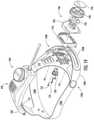
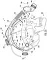
- FIGS. 10-12show various aspects of the thermal management features of the head wearable device of FIGS. 1-7 , in accordance with the disclosure herein;
- FIGS. 13-15show internal views of one of the adjustment devices of the head wearable device of FIGS. 1-7 , in accordance with the disclosure herein;
- FIG. 16is a view of the head wearable device of FIGS. 1-7 showing the padding arranged therein, in accordance with the disclosure herein;
- FIG. 17is an assembly view of the head wearable device of FIGS. 1-7 with the padding omitted, in accordance with the disclosure herein;
- FIGS. 18 and 19are partial exploded views to show the adjustment features of the head wearable device of FIGS. 1-7 , in accordance with the disclosure herein;
- FIG. 20is an exterior view of a rear pad of the padding system shown in the head wearable device of FIGS. 1-7 , in accordance with the disclosure herein;
- FIG. 21is a side view of an example embodiment of the cushioning materials in the rear pad of FIG. 20 , in accordance with the disclosure herein;
- FIG. 22is a plan view of an example embodiment of the first layer of the first cushioning material in the rear pad shown in FIGS. 20 and 21 , in accordance with the disclosure herein;
- FIG. 23is a plan view of an example embodiment of the second layer of the second cushioning material in the rear pad shown in FIGS. 20 and 21 , in accordance with the disclosure herein;
- FIG. 24is a plan front view of a rear pad cover for the rear pad shown in FIGS. 20 and 21 , in accordance with the disclosure herein;
- FIG. 25is a plan rear view of the rear pad cover shown in FIG. 24 , in accordance with the disclosure herein;
- FIG. 26is an assembly view of the panels of the rear pad cover shown in FIGS. 24 and 25 , in accordance with the disclosure herein;
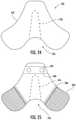
- FIG. 27is a plan view of an example embodiment of a first layer of a first cushioning material of a front pad of the head wearable device shown in FIGS. 1-7 , in accordance with the disclosure herein;
- FIG. 28is a plan view of an example embodiment of a second layer of a second cushioning material in a front pad of the head wearable device shown in FIGS. 1-7 , in accordance with the disclosure herein;
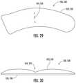
- FIG. 29is a top view of an example embodiment of a side pad of the head wearable device shown in FIGS. 1-7 , in accordance with the disclosure herein;
- FIG. 30is a side view of the side pad of FIG. 29 , in accordance with the disclosure herein;
- FIG. 31is a top view of an example embodiment of a top pad of the head wearable device shown in FIGS. 1-7 , in accordance with the disclosure herein;
- FIG. 32is a side view of the top pad of FIG. 31 , in accordance with the disclosure herein;
- FIG. 33is a side view of the embodiment of the head wearable device shown in FIGS. 1-7 , showing example placement of the padding relative to the sutures formed in a human skull.
- substrateor “submount” as used herein in connection with lighting apparatuses refers to a mounting member or element on which, in which, or over which, multiple solid state light emitters (e.g., LEDs) can be arranged, supported, and/or mounted.
- a substratecan be, e.g., a component substrate, a chip substrate (e.g., a LED substrate), or a sub-panel substrate.
- Example substrates useful with lighting apparatuses as described hereincan, for example, comprise printed circuit boards (PCBs) and/or related components (e.g., including but not limited to metal core printed circuit boards (MCPCBs), flexible circuit boards, dielectric laminates, ceramic based substrates, and the like), ceramic boards having FR4 and/or electrical traces arranged on one or multiple surfaces thereof, high reflectivity ceramics (e.g., alumina) support panels, and/or mounting elements of various materials and conformations arranged to receive, support, and/or conduct electrical power to solid state emitters.
- Electrical traces described hereinprovide electrical power to the emitters for electrically activating and illuminating the emitters. Electrical traces may be visible and/or covered via a reflective covering, such as a solder mask material, Ag, or other suitable reflector.
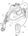
- FIGS. 1-7show several perspective views of a head wearable device, generally designated 1 .
- the head wearable device 1comprises an adjustable headpiece comprising a headband, generally designated 100 , which has a top strap 110 and at least two lateral straps 120 A/ 120 B, and an occipital basket 150 attached to (e.g., removably, fixedly, and/or integrally) the headband 100 ; a luminaire, generally designated 200 , movably attached at the front of the headband 100 , a duct system, generally designated 300 , to direct exhaust air from the luminaire 200 to a hot air exhaust 420 formed in the upper housing, generally designated 400 , that is attached to the top strap 110 of the head wearable device 1 ; rear adjustment straps 130 A/ 130 B; a depth adjuster, generally designated 450 , and a headband adjuster, generally designated 700 , that are for adjusting the size of the headband 100 to the size of a wearer's head; a holster 600 with
- the lateral straps 120 A/ 120 B, together with the rear adjustment straps 130 A/ 130 Bform a thin, flexible plastic ring of an approximately elliptical shape for fitting horizontally on the head of a wearer.
- the upper housing 400can extend from the front to the rear (e.g., the occipital basket 150 ) of the headband 100 , extend between the lateral straps 120 A/ 120 B of the headband 100 , or extend between any two points on the ring. Two or more of these portions may form an integral piece, or operably or adjustably connected to each other.
- Headbandmay be constructed with more or fewer portions or straps than the embodiment shown and may take any shape.
- the headbandsmay cover more or less surface of the wearer's head than the embodiment as shown.
- the headpieceis shown in this embodiment as comprising the headband 100 and the occipital basket 150
- the headpiecemay take any shape and may have a substantially continuous outer cover that is either adjustable to a wearer's head size or of fixed dimensions.
- an outer shellmay be provided around the headpiece, as needed based on the environment in which the head wearable device is to be worn.
- the headband 100comprising the top strap 110 and lateral straps 120 A/ 120 B is integrally formed from a single piece.
- An example of this portion of the headband 100is shown in FIGS. 9A and 9B , with the top strap 110 and lateral straps 120 A/ 120 B being shown in a substantially planar (i.e., flat), unformed, configuration.
- the top strap 110has upper housing 400 affixed thereto, into which the top strap 152 from the occipital basket 150 is inserted to connect the top strap 110 to the occipital basket 150 .
- the upper housing 400has an outer shell 410 , which has a slot, generally designated 412 , formed at a rear of the outer shell 410 , into which slot 412 the strap 152 of the occipital basket 150 is inserted to adjust the depth of the head wearable device 1 .
- the strap 152 of the occipital basket 150has a slot (see 154 , FIGS. 13-15 ) formed along the length thereof, the length of the slot 154 defining a maximum amount of adjustment of the depth of the head wearable device 1 . As can be seen in greater detail in FIGS.
- the slot 154 of the strap 152has, on at least one side thereof, a plurality of teeth 156 that are configured to interface with, and be moved by, a gear 470 that is rotatably mounted within the upper housing 400 in the form of a rack-and-pinion arrangement.
- a rotation of the top adjustment knob 460 and, accordingly, the top adjustment gear 470causes the strap 152 of the occipital basket 150 to be lengthened or shortened relative to the upper housing 400 as the gear 470 draws the strap 152 into, or pushes the strap 152 out of, the upper housing 400 . Due to the rack-and-pinion arrangement, precise size adjustments to the depth of the head wearable device 1 are contemplated.
- a plurality of indexing marksare provided in an externally visible location on the strap 152 of the occipital basket 150 so that the depth of the head wearable device 1 may be easily and repeatably adjusted to a given value for a plurality of wearers of the head wearable device 1 .
- the headband 100is further connected to the occipital basket 150 by lateral extension straps 130 A/ 130 B, which are rotatably coupled to the lateral straps 120 A/ 120 B, respectively, at respective hinges, generally designated 140 A/ 140 B, which in this embodiment are circular hinges.
- Each of the lateral extension straps 130 A/ 130 Bwraps behind the occipital basket 150 and is inserted within a housing of the headband adjuster, generally designated 700 , which is shown on the rear external surface of the occipital basket 150 . As can be seen in FIGS.
- the lateral extension straps 130 A/ 130 Bhave a slot 132 A/ 132 B formed along the length thereof, respectively, the length of the slot 132 A/ 132 B defining a maximum amount of adjustment of the circumference of the head wearable device 1 .
- the slot 132 A/ 132 B of each lateral extension strap 130 A/ 130 Bhas, on at least one side thereof, a plurality of teeth 134 A/ 134 B that are configured to interface with, and be moved by, a gear (see 730 , FIG. 19 ) that is rotatably mounted within the housing of the headband adjuster 700 in the form of a rack-and-pinion arrangement.
- the plurality of teeth 134 A on a first of the lateral extension straps 130 Aare on an opposite side of the slot 132 A from the plurality of teeth 134 B formed in the slot 132 B of the second lateral extension strap 130 B, such that a rotating motion of the occipital basket adjustment gear 730 causes a simultaneous expansion or contraction, depending on the direction in which the knob 740 is rotated, of the headband 100 to correspondingly increase or decrease lateral circumference of the head wearable device 1 . Due to the rack-and-pinion arrangement, precise size adjustments of the head wearable device 1 are contemplated.
- a plurality of indexing marksare provided in an externally visible location on one or more of the lateral extension straps 130 A/ 130 B so that the head wearable device 1 may be easily and repeatably adjusted to a given size for a plurality of wearers of the head wearable device 1 .
- the slots 132 A/ 132 Bare shown as being closed at both ends thereof to prevent the lateral extension straps 130 A/ 130 B from becoming disengaged from the headband adjuster 700 .
- the lateral extension straps 130 A/ 130 Bare captively held within the headband adjuster 700 when worn by a wearer.
- the hinges 140 A/ 140 B connecting the lateral straps 120 A/ 120 B of the headband 100 to the lateral extension straps 130 A/ 130 Bare configured to pivot about an axis defined through the center of each respective hinge 140 A/ 140 B. Any type of hinge may be used and, in fact, the lateral extension straps 130 A/ 130 B may be integrally formed with the lateral straps 120 A/ 120 B of the headband 100 .
- the circular hinges 140 A/ 140 B shownbecause, as the strap 152 is drawn into or pushed out from the upper housing 400 on the headband 100 to alter a depth of the head wearable device 1 , the position of the occipital basket 150 changes at least vertically, relative to the lateral straps 120 A/ 120 B, such that the angle between the lateral straps 120 A/ 120 B and the lateral extension straps lateral extension straps 130 A/ 130 B at the hinges 140 A/ 140 B can be altered without deforming the lateral extension straps 130 A/ 130 B that might cause any distortions or deformations thereof in the region of the slots 132 A/ 132 B, thereby preventing binding of the lateral extension straps 130 A/ 130 B within the housing of the headband adjuster 700 .
- a padding system 500is attached to the inner surfaces of the head wearable device 1 , including the inner surfaces of the headband 100 and the occipital basket 150 where contact would otherwise occur with the head of a wearer of the head wearable device 1 . While any suitable type and configuration of padding may be utilized for the padding system 500 , the embodiment shown has padding segments that are attached to the inner surfaces of the headband 100 and the occipital basket 150 .
- the padding segmentsmay be formed from any suitable material having a suitable degree of padding to provide a desired amount of comfort for a wearer during extended wearing times (e.g., on the order of multiple hours).
- the padding systemcomprises a rear pad 550 , side pads 520 / 530 , and a top pad 540 attached to the corresponding inner surfaces of the occipital basket 150 , the lateral straps 120 A/ 120 B, and the top strap 110 of the head wearable device 1 , respectively.
- the padding system 500may further comprise a brow pad 510 attached to the inner surface of the headband at or about an intersection of the top strap 110 and the lateral straps 120 A/ 120 B.
- Each of the padding segments 510 , 520 , 530 , 540 , and 550 described hereincan be portions of a large integral pad and do not need to be separate pads.
- the padding segments 510 , 520 , 530 , 540 , and 550are attached to the headband 100 or the occipital basket 150 , respectively, by any suitable attachment type, including, for example, adhesive, interlocking snaps, mechanical interlocking tabs, and the like.
- the padding segments 510 , 520 , 530 , 540 , and 550may be contoured to the shape of the respective strap or occipital basket 150 to which the padding segment 510 , 520 , 530 , 540 , and 550 is attached and may have a size less than or greater than a width of the strap(s) to which each such padding segment 510 , 520 , 530 , 540 , and 550 is attached.
- a brow padis provided at the front of the headband 100 at a position that would be against the forehead of a wearer of the head wearable device 1 .
- This brow pad 510may extend, at least to some extent, onto the top strap 110 and the two lateral straps 120 A/ 120 B.
- the strap 152 of the occipital basket 150 and the lateral extension straps 130 A/ 130 Bare devoid of padding segments, not only because these portions are spaced apart from the surface of the wearer's head while being worn, but also so that mechanical interference does not occur between adjacent components as the dimensions (e.g., the depth and/or the circumference) of the head wearable device 1 is adjusted.
- the padding segments 510 , 520 , 530 , 540 , and 550can be removable for cleaning, maintenance, etc.
- One or more of the padding segments 510 , 520 , 530 , 540 , and 550can have a different degree of softness from others of the padding segments 510 , 520 , 530 , 540 , and 550 .
- One or more (e.g., each, or all) padding segments 510 , 520 , 530 , 540 , and 550may have more than two layers of cushioning material.
- the rear pad 550comprises a first layer 570 of a first cushioning material having a first durometer, and a second layer 580 of a second cushioning material having a second durometer that is harder than the first durometer.
- the first cushioning materialis silicone foam
- the second cushioning materialis also silicone foam, but the silicone foam in the second layer 580 has a higher durometer than the silicone foam in the first layer 570 .
- the durometer of the second layer 580can be 5%, 10%, 25%, or up to and including 50% higher than the durometer of the first layer 570 .
- the silicone foam in the second layer 580is harder (e.g., less compliant) than the silicone foam in the first layer 570 .
- the second layer 580 of the second cushioning materialis closer than the first layer 570 of the first cushioning material to the inner surface of the occipital basket 150 .
- the harder second layer 580provides support, while the softer, conforming first layer 570 is in closer contact with the wearer and provides increased comfort to the wearer of the head wearable device 1 .
- FIG. 21shows that the first layer 570 and the second layer 580 of the respective cushioning materials have the same or similar thickness, it is contemplated that the first layer 570 can have a different thickness from the second layer 580 .
- the thickness of each layeris preferably no more than 1 inch (in.) and, more preferably, no more than 0.5 in., for example, about 0.25 in.
- the first layer 570which is oriented towards (e.g., adjacent the head of) the wearer, is 1 ⁇ 4′′ die-cut silicone foam (for example, BISCO® BF-2000, an ultra soft silicone foam manufactured by Rogers Corporation) and the second layer 580 , which is oriented towards (e.g., adjacent the surface of) the occipital basket 150 is 1 ⁇ 4′′ die-cut silicone foam (for example, BISCO® HT-800, a medium cellular silicone foam manufactured by Rogers Corporation), which can be either open cell silicone foam or closed cell silicone foam.
- the respective durometers of the silicone foam layerscan be defined by compression force deflection of the foam silicone.
- the durometeris within a range of about (e.g., ⁇ 1%, ⁇ 2%, ⁇ 5%, ⁇ 10%, ⁇ 25%, or ⁇ 50%) 10-70 Shore A, inclusive.
- HT-800 silicone foamhas a density, as measured according to ASTM D 1056, of 22 pounds per cubic feet (lb/ft 3 ).
- BF-2000 silicone foamhas a density, as measured according to ASTM D 1056, of 10 lb/ft 3 .
- the die-cut silicone foam (BF 2000)can have a compression force deflection of about (e.g., ⁇ 1%, ⁇ 2%, ⁇ 5%, ⁇ 10%, ⁇ 25%, or ⁇ 50%) 1.5 pounds per square inch (psi).
- the compression force deflectionis a measure of the load bearing ability of a foam material and is the force exerted against a flat compression foot that is larger than the specimen to be tested.
- the term compression force deflectionis also sometimes referred to as “compression load deflection”.
- the compression force deflection metricis measured as the force necessary to achieve a 25% deflection according to ASTM D 1056.
- the die-cut silicone foam(for example, BISCO® HT-800) can have a compression force deflection of within a range including, for example, about (e.g., ⁇ 1%, ⁇ 2%, ⁇ 5%, ⁇ 10%, ⁇ 25%, or ⁇ 50%) 6-14 psi.
- the second layer 580 of the second cushioning material 582has more open space on its upper or lower surface due to perforations than the first layer 570 of the first cushioning material 572 , which has, in the embodiment shown, a surface area of about 10.617 square inches (in 2 ).
- the total surface area of the cavities formed by the perforations 584 in the second layer 580 of the second cushioning material 582is higher than the total surface area of the cavities formed by the perforations 574 in the first layer 570 of the first cushioning material 572 , for example, the total surface area of the cavities in the second layer 580 is about 9.249 in 2 .
- the perforation patternscan be chosen taking into consideration the durometer (e.g., hardness) and density of each layer specific to the cushioning material used.
- the perforations in the layers of cushioning materialalso improve heat dissipation and air-flow.
- the volume of the first cushioning material 572 removed from the first layer 570 in forming the plurality of perforations 574is about 1.575 cubic inches (in 3 ) and the volume of the second cushioning material 582 removed from the second layer 580 in forming the plurality of perforations 584 is about 5.112 in 3 .
- the first layer 570 of the first cushioning material 572 and the second layer 580 of the second cushioning material 582are each perforated.
- the first layer 570has a first perforation pattern comprising a plurality of first perforations 574 formed therein.
- FIG. 23shows the second layer 580 , which has a second perforation pattern comprising a plurality of second perforations 584 .
- the first perforation pattern and the first perforations 574differ from the second perforation pattern and the second perforations 584 .
- the first perforations 574 in the first layer 570are generally arranged in a first perforation shape and the second perforations 584 in the second layer 580 are generally in a second perforation shape, which may differ from the first perforation shape.
- the first perforations 574 , or at least the majority of the first perforations 574 , in the first layer 570 of the first cushioning material 572are generally circular
- the second perforations 584 , or at least the majority of the second perforations 584 , in the second layer 580 of the second cushioning material 582are in a shape other than circular, such as generally square, rectangular, and/or triangular, or generally in a grid-like pattern.
- the first and second perforations 574 / 584are holes or apertures that pass through the thickness of the respective first and second cushioning materials 572 / 582 .
- the first and second perforations 574 / 584can be created by die-cutting, piercing, boring, or any other conventional methods.
- a different perforation patterncan be a result of a higher perforation count of the perforation of the same shape, or perforations of a different shape or different shapes, or a combination of the foregoing.
- the second layer 580 of the second cushioning material 582has more open space on its upper or lower surface due to second perforations 584 than the first layer 570 of the first cushioning material 572 .
- the total volume of the cavities formed by the second perforations 584 in the second layer 580 of the second cushioning material 582is higher than the total volume of the cavities formed by the first perforations 574 in the first layer 570 of first cushioning material 572 .
- the second layer 580has a cut-out recess, generally designated 586 , which substantially defines the size, shape, and/or contour of the cut-out recessed region 556 of the rear pad 550 , the cut-out recess 586 and the cut-out recessed region 556 having a size, shape, and/or contour that corresponds to the size, shape, and/or contour of the cut-out 158 of the occipital basket 150 .
- the rear pad 550has an inner surface in contact with a wearer and an outer surface attached to the inner surface of the rear portion of the headband, and the rear pad 550 comprises a recess 576 formed in the first layer 570 .
- the cushioning materialmay be any suitable synthetic foam such as silicone foam, expanded polystyrene, polyurethane, or other types of polymer.
- the cushioning material in both layersare a silicone foam, for example, the silicon foam materials commercially available at Stockwell Elastomerics, Inc.
- the differences in the first and second layers 570 / 580include the durometer of the first and second cushioning materials 572 / 582 . Any suitable material may be used as long as the material has a similar durometer as the materials specified herein.
- the rear pad 550is covered by a rear pad cover 552 , which can be made of fabric, synthetic polymers, or other suitable materials, such as polyethylene, nylon, glass fibers and the like.
- the rear pad 550comprises a recessed area 553 formed therein, between the opposing padding lobes 554 that have, in the embodiment shown, a generally triangular shape.
- the recessed area 553is provided to relieve pressure from the occipital basket 150 being secured over the rear portion of the head of a wearer, thereby accommodating accessories worn by the wearer, such as, for example, straps for the cap, loupe, or glasses and the like, without interfering with the head wearable device 1 being sufficiently secured over the wearer's head and to avoid pressure that may push against the back of the wearer's head.
- Any shape for the rear pad 550is contemplated and, furthermore, the recessed area 553 can be in any shape, including, as shown in FIG. 20 , a generally triangular shape. Recessed area 553 can have a reduced thickness compared to the thickness of the rear pad 550 overall and/or to the padding lobes 554 .
- the rear pad cover 552is able to sufficiently surround a rear pad 550 having a total volume of about 7.18 in 3 .
- the rear pad cover 552is made of Darlington 96630 fabric manufactured by Darlington.
- the Darlington 96630 material used in the example embodimentis a 4-way stretch heavy weight tricot, 356 gsm (grams per square meter) weight, and is available in various colors.
- FIG. 26the back of rear pad cover 552 shown in FIG.
- the rear pad cover 552may be produced by layering a main body piece 558 A, two inner overlap pieces 558 B and two netting pieces 558 C in the order as illustrated, such that the back of the rear pad cover 552 has an elastic netting pocket 564 on the outer surface of each side flap.
- the rear pad cover 552comprises a cut-out recessed region 556 contoured to the shape of the occipital basket 150 and also covers the recess 576 . Regardless of the materials specified herein, it is contemplated that at least a portion of the rear pad cover 552 may be made from a breathable stretch material with an estimated weight within the range of about 300-400 gsm inclusive.
- the front of the rear pad cover 552can be fabric such as Darlington fabrics, 4-way stretch spandex, while the back of the rear pad cover 552 can be nylon/UBL (unbroken loop) fabric 560 , which is a part of a hook-and-loop fastening system, with optional snaps 562 provided to more securely attach the rear pad cover 552 over the rear pad 550 .
- Other materialsare suitable for use in the padding system 500 , and can be selected depending on cleaning and comfort requirements.
- the rear pad 550can be assembled by aligning the front of rear pad cover 552 shown in FIG. 24 , the first layer 570 of the first cushioning material shown in FIG. 22 , the second layer 580 of the second cushioning material shown in FIG. 23 , and the back of the rear pad cover 552 shown in FIG. 25 , and then sewing along the periphery of the covers.
- the stretch-mesh netting pockets 564 on the back of the rear pad cover 552is made of an elastic material, such as spandex mesh, and is removably disposed about the outer surface of the corresponding side flaps of the occipital basket 150 to help secure the rear pad cover 552 to the occipital basket 150 .
- the recess in the rear pad 550can be formed by adding stitches along the corresponding recess 576 in the first layer 570 of the first cushioning material in the rear pad 550 .
- the brow pad 510comprises a first layer 512 of a first cushioning material having a first durometer, and a second layer 516 of a second cushioning material having a second durometer that is different (e.g., harder) than the first durometer.
- the first layer 512is perforated in a first perforation pattern, comprising first perforations 514
- the second layer 516is perforated in a second perforation pattern, comprising second perforations 518 , which differ from the first perforation pattern.
- the first layer 512 of the first cushioning material of the brow pad 510is configured as a comfort layer arranged adjacent the head of the wearer and is formed from 1 ⁇ 4′′ die-cut silicone foam (BF 2000), while the second layer 516 of the second cushioning material is spaced apart from the head of the wearer and is formed 1 ⁇ 4′′ die-cut silicone foam (for example, BISCO® HT-800).
- rear pad 550 and brow pad 510both include a softer, inner, first layer of cushioning material and a harder, outer, second layer of cushioning material
- other layering optionsare contemplated, depending on the cleanability and comfort standards and the desired fit, feel, and comfort level.
- the BISCO® silicone foams disclosed hereincan be described as being a range of materials, including extra firm (HT-840), firm (HT-820), medium (HT-800), soft (HT-870), extra soft (BF-1000), and ultra soft (BF-2000).
- HT-840has a compression force deflection within a range of 16-26 psi and, preferably, a compression force deflection of 22 psi.
- HT-820has a compression force deflection range of 12-20 psi and, preferably, a compression force deflection of 16 psi.
- HT-800has a compression force deflection within a range of 6-14 psi and, preferably, a compression force deflection of 9 psi.
- HT-870has a compression force deflection within a range of 2-7 psi and, preferably, a compression force deflection of 4 psi.
- BF-1000has a compression force deflection within a range of 1-5 psi and, preferably, a compression force deflection of 3 psi.
- BF-2000has a compression force deflection of about 1.5 psi.
- Some other possible combinations of generally hard, medium, and soft layersinclude medium inner-medium outer, hard outer-medium inner, and soft outer-soft outer layering combinations. Any of the extra firm, firm, medium, soft, extra soft, and ultra soft materials may be combined to form the first and second layers of padding.
- Examples of such combinations for any of padding segments 510 , 520 , 530 , 540 , and 550can include a first layer comprising extra firm (having a first durometer with a compression force deflection in a range of 16-26 psi) silicone foam and a second layer comprising silicone foam of any of the following types: firm (having a second durometer with a compression force deflection in a range of 12-20 psi), medium (having a second durometer with a compression force deflection in a range of 6-14 psi), soft (having a second durometer with a compression force deflection in a range of 2-7 psi), extra soft (having a second durometer with a compression force deflection in a range of 1-5 psi), or ultra soft (having a second durometer with a compression force deflection of about 1.5 psi).
- padding segments 510 , 520 , 530 , 540 , and 550can include a first layer comprising firm (having a first durometer with a compression force deflection in a range of 12-20 psi) silicone foam and a second layer comprising silicone foam of any of the following types: extra firm (having a second durometer with a compression force deflection in a range of 16-26 psi), medium (having a second durometer with a compression force deflection in a range of 6-14 psi), soft (having a second durometer with a compression force deflection in a range of 2-7 psi), extra soft (having a second durometer with a compression force deflection in a range of 1-5 psi), or ultra soft (having a second durometer with a compression force deflection of about 1.5 psi).
- Another set of examples of such combinations for any of padding segments 510 , 520 , 530 , 540 , and 550can include a first layer comprising medium (having a first durometer with a compression force deflection in a range of 6-14 psi) silicone foam and a second layer comprising silicone foam of any of the following types: extra firm (having a second durometer with a compression force deflection in a range of 16-26 psi), firm (having a second durometer with a compression force deflection in a range of 12-20 psi), soft (having a second durometer with a compression force deflection in a range of 2-7 psi), extra soft (having a second durometer with a compression force deflection in a range of 1-5 psi), or ultra soft (having a second durometer with a compression force deflection of about 1.5 psi).
- such combinations for any of padding segments 510 , 520 , 530 , 540 , and 550can include a first layer comprising soft (having a first durometer with a compression force deflection in a range of 2-7 psi) silicone foam and a second layer comprising silicone foam of any of the following types: extra firm (having a second durometer with a compression force deflection in a range of 16-26 psi), firm (having a second durometer with a compression force deflection in a range of 12-20 psi), medium (having a second durometer with a compression force deflection in a range of 6-14 psi), extra soft (having a second durometer with a compression force deflection in a range of 1-5 psi), or ultra soft (having a second durometer with a compression force deflection of about 1.5 psi).
- such combinations for any of padding segments 510 , 520 , 530 , 540 , and 550can include a first layer comprising extra soft (having a first durometer with a compression force deflection in a range of 1-5 psi) silicone foam and a second layer comprising silicone foam of any of the following types: extra firm (having a second durometer with a compression force deflection in a range of 16-26 psi), firm (having a second durometer with a compression force deflection in a range of 12-20 psi), medium (having a second durometer with a compression force deflection in a range of 6-14 psi), soft (having a second durometer with a compression force deflection in a range of 2-7 psi), or ultra soft (having a second durometer with a compression force deflection of about 1.5 psi).
- such combinations for any of padding segments 510 , 520 , 530 , 540 , and 550can include a first layer comprising ultra soft (having a first durometer with a compression force deflection of about 1.5 psi) silicone foam and a second layer comprising silicone foam of any of the following types: extra firm (having a second durometer with a compression force deflection in a range of 16-26 psi), firm (having a second durometer with a compression force deflection in a range of 12-20 psi), medium (having a second durometer with a compression force deflection in a range of 6-14 psi), soft (having a second durometer with a compression force deflection in a range of 2-7 psi), or extra soft (having a second durometer with a compression force deflection in a range of 1-5 psi).
- extra firmhaving a second durometer with a compression force deflection in a range of 16-26
- the second layer 516 of the second cushioning materialhas more open space on its upper or lower surface due to perforations than the first layer 512 of the first cushioning material, which has, in the embodiment shown, a surface area of about 7.712 in 2 .
- the total surface area of the cavities formed by the perforations 518 in the second layer 516 of the second cushioning materialis higher than the total surface area of the cavities formed by the perforations 514 in the first layer 512 of the first cushioning material, for example, the total surface area of the cavities in the second layer 516 is about 5.858 in 2 .
- the perforation patternscan be chosen taking into consideration the durometer (e.g., hardness) and density of each layer specific to the cushioning material used.
- the perforations in the layers of cushioning materialalso improve heat dissipation and air-flow.
- the volume of the first cushioning material removed from the first layer 512 in forming the plurality of perforations 514is about 1.179 in 3 and the volume of the second cushioning material removed from the second layer 516 in forming the plurality of perforations 518 is about 3.033 in 3 .
- the differences between the respective first and second perforation patternscan also aid in visually deciphering the first layer 512 from the second layer 516 .
- the outer layer of primarily circle die-cutsmay be laid out over the grid formed by the second perforations 518 formed in the second layer 516 to optimize air-flow between the first layer 512 and the second layer 516 .
- a higher perforation countmay be used in the first layer 512 on the foam to increase the degree of compression and softness of the first compression material.
- the first perforations 514comprise round holes to provide flexibility to explore actual hole count among the different designs, but as described above the first perforations 514 do not have to be circular.
- the actual design and perforation patternsshould take into account the amount of material removed, not simply the shape of the die-cuts.
- the top cover 522 / 532 of the side pads 520 / 530can be made of fabric, for example, Darlington 96630 fabric manufactured by Darlington, which is a 4-way stretch Heavy Weight Tricot with a 356 gsm weight.
- the pad shown hereis a side pad 520 / 530 for one side portion of the headband 100 .
- the side pad 520 / 530 for the other side portion of the headband 100is a mirror image of the side pad 520 / 530 as shown.
- the rear 526 / 536 of the side pad 520 / 530includes an attachment that secures the side pad 520 / 530 to the lateral strap 120 A/ 120 B of the headband 100 .
- An example of a suitable attachmentincludes a hook-and-loop fastener system.
- the side pad 520 / 530is filled with open-cell urethane foam or other suitable cushioning material to provide the desired level of support and comfort.
- a depression 524 / 534can be formed by stitching across the side pad 520 / 530 , thereby creating two or more padding segments in the side pad 520 / 530 .
- the top pad 540can be made of fabric, for example, Darlington 96630 fabric.
- the rear 546 of the top pad 540includes a hook and loop fastener strip.
- Other suitable attachment typesare contemplated.
- the top pad 540is filled with open-cell urethane foam or any other suitable cushioning material, and the foam can be of any suitable thickness, for example, 1 ⁇ 4′′ urethane foam support.
- top pad 540 and the side pad 520 / 530are described herein each in singular form, there may be more than one top pad 540 and at least two side pads 520 / 530 for the two lateral straps 120 A/ 120 B of the headband 100 .
- Each of these padsmay have similar constructions but different shapes, lengths, thickness, curvatures, and the like to adapt the respective pad to the corresponding contour of the strap of the headband 100 for attachment.
- the respective padsare shown as segmented pieces, one or more of the padding segments may be connected or all may be formed as an integral portion of the padding system 500 .
- the padding segments 510 , 520 , 530 , 540 , and 550 in the padding system 500can be attached the headband 100 and the occipital basket 150 in various ways, either permanently or removably, for example, by hook and loop fasteners, snapping members, stitching, adhesive, ties, and any other suitable types of attachment known in the art.
- the brow, side and top pads 510 , 520 , 530 , and 540are all backed with a die-cut loop material to anchor them to the headband 100 .
- the occipital basket 150comprises at least one padding segment 550 removably attached thereto.
- the occipital basket 150comprises a cut-out 158 , or notch, formed at the bottom edge thereof that defines a location where a wearer's hair can exit the occipital basket 150 without substantially interfering with the occipital basket 150 fitting securely against the rear of the wearer's head.
- the cut-out 158is also formed to accommodate any features of a head wearable garment (e.g., a knot used to secure a surgical cap over the head of the wearer). In the embodiment of FIGS.
- the rear pad 550is a unitary (e.g., integral or monolithic) padding segment that is attached to the occipital basket 150 by a retention strap 566 (see FIG. 25 ) and netting 564 (see FIG. 25 ) that contain each of the lower corners of the occipital basket 150 (e.g., on opposite sides of the cut-out) therein and an upper strap 560 (see FIG. 25 ) which passes around the strap 152 of the occipital basket 150 and is secured thereto by snaps 562 (see FIG. 25 ) or any other suitable fastener. As shown at least in FIG.
- the rear pad 550 on the occipital basket 150has an outer contour/profile shape that is substantially similar to that of the occipital basket 150 itself, including the cut-out 158 . Furthermore, the rear pad 550 on the occipital basket 150 comprises a cut-out recessed region 556 to accommodate a wearer's hair style without interfering with the head wearable device 1 being sufficiently secured over the wearer's head and to avoid pressure that may push against the back of the wearer's head.
- FIG. 33shows an embodiment of the head wearable device 1 , similar to that shown in FIGS. 1-7 , fitted on and over a human skull, generally designated 800 , to demonstrate possible and what can be preferred placement of the padding segments (e.g., 510 , 520 , 530 , 540 , 550 ) relative to skull region joinder lines or sutures, such as for example sutures 810 , 820 , 830 , and/or 840 , that exist between adjacent skull plates of the skull 800 and are configured to be positioned on a head without covering or being disposed or positioned over any or a substantial portion of the skull sutures such as sutures 810 shown.
- the padding segmentse.g., 510 , 520 , 530 , 540 , 550
- the padding segmentsare spaced such that, in at least some configurations, the weight of the head wearable device 1 is not placed on or over the skull sutures.
- the shape of the lateral straps 120 A/ 120 B and the hinges 140 A/ 140 Bavoid placement over, and do not contact and/or put pressure on, the squamous suture 830 and the lambdoid suture 820 , while the top pad 540 does not contact at least a portion of the sagittal suture 840 .
- the side pads 520 / 530 of the lateral straps 140 A/ 140 Bdo not contact or apply pressure over any suture (e.g., 810 , 820 , 830 , and/or 840 ) of the skull 800 of the wearer of the head wearable device 1 .
- a gapis present between segments of the top pad 540 so that the top pad 540 does not contact the head of the wearer in a region covering or over the coronal suture 810 of the skull 800 of the wearer.
- the top pad 540is spaced apart from the head of the wearer over one or more sutures 810 of the wearer's skull 800 .
- the top pad 540does not contact the wearer's head at areas of the sutures 810 of the wearer's skull 800 .
- a gapis present between segments of the side pads 520 , 530 so that the side pads 520 , 530 do not contact the head of the wearer in a region covering or over a suture 810 of the skull 800 of the wearer.
- the side pad 520 , 530is therefore against the head but can be laterally spaced apart from the head of the wearer over one or more sutures 810 of the wearer's skull 800 .
- the side pads 520 , 530do not contact the wearer's skull at the sutures 810 of the wearer's skull 800 .
- the top pad 540 and/or the side pads 520 , 530can be adjusted positionally so that the gap 522 , 532 , 542 can be positioned over the suture 810 of the skull of the wearer to provide enhanced comfort for the wearer during extended periods of use of the head wearable device 1 .
- FIG. 33is a view of one side of the head wearable device 1 over a skull 800 of the wearer, the opposing view is identical to (e.g., is a mirror image of) the side view of FIG. 36 , such that the features shown therein and described hereinabove are present for both sides of the head wearable device 1 relative to the skull 800 of the wearer.
- the luminaire 200comprises an external housing 210 and is attached at the forward edge of the headband 100 by any suitable mechanical linkage, generally designated 350 .
- the mechanical linkage 350is a statically attached mounting point to which the luminaire 200 is rigidly and/or pivotably attached.
- the mechanical linkage 350comprises a mount that is connected to the front of the headband 100 and linkage bars 354 that are pivotably connected together by linkage rollers 356 .
- the mechanical linkage 350is secured to the headband 100 by mounting hardware (e.g., screws and washers), generally designated 358 , which pass through the thickness of the headband 100 at the front thereof.
- the mechanical linkage 350is provided to allow the angle of the luminaire 200 relative to the headband 100 and the distance of the luminaire 200 from the headband 100 to be controlled independently.
- the luminaire 200comprises, as is shown at least partially in FIGS. 10-12 , at least one LED 232 (e.g., any suitable light source), which can be mounted on a substrate.
- a substratecan be affixed (e.g., rigidly) to a heatsink 220 located within the luminaire housing 210 to conduct heat generated by the at least one LED 232 into the heatsink 220 .
- a substratecan have surface-mount connection points for the LED's power and sensing electrical needs.
- the substratecan be formed such that the LED 232 and the heatsink 220 are located in opposing first and second regions of the luminaire housing 210 , the first region being adjacent the lens cell and the second region being located away from (e.g., spaced apart from) the LED 232 .
- the substratemay be configured to allow for a straight-line optical cell configuration, as opposed to a bent-configuration, thereby eliminating the need for a mirror to perform the optical bend necessary for such configurations.
- such a substratecan be a laminated printed circuit board (PCB) and/or comprises copper to provide enhanced thermal conductivity between the LED 232 and the heatsink 220 to the substrate.
- PCBprinted circuit board
- the use of copper in such a substratecan be advantageous, as copper's high thermal conductivity allows for the efficient conduction of heat from the LED 232 to the heatsink 220 for dissipation into a cooling air stream flowing into the luminaire housing 210 via the inlet 212 , two of which are formed on opposing sides of the luminaire housing 210 .
- the heatsink 220can be of any suitable construction, including, for example, extrusion, soldering, skiving, and the like, and can comprise any suitably conductive material, such as, for example, aluminum or copper.
- the luminaire housing 210is connected, via a pivoting ball joint 310 , to a duct 300 system.
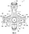
- the ball joint 310is formed of two half-members 311 assembled together to form the ball joint 310 and the luminaire housing 210 is clamped around the outer lateral edges of the ball joint 310 to allow the luminaire housing 210 to rotate independently of and about the ball joint 310 .
- the ball joint 310is rotatable about an axis that is perpendicular to the duct system 300 , unlike known solutions that rotate about an axis parallel to the air flow path to avoid inducing kinks or other obstructions into the air flow path.
- the ball joint 310has a hole 312 formed radially about a portion of the circumference of the ball joint 310 .
- the ball joint 310has an exhaust port 314 formed in the circumference of the ball joint 310 and directed radially away from the center of the ball joint 310 .
- the exhaust port 314 and the hole 312are located around the circumference of the ball joint 310 .
- the ball joint 312defines an airflow path through the body thereof, with the hole 312 and the exhaust port 314 being defined, respectively, as the inlet and the outlet of the airflow path through the ball joint 310 .
- the cross-sectional area of the hole 312has a size to provide sufficient air flow across the heatsink 220 of the luminaire 200 to sufficiently cool the LED 232 .
- the hole 312 and the exhaust port 314are formed such that they are located substantially diametrically opposite each other about the circumference of the ball joint 310 .
- the ball joint 310has locating features 317 formed therein and/or thereon that define a range of rotary movement of the luminaire housing 210 and the ball joint 310 relative to each other. This range of rotary movement defined by the locating features 317 is such that the hole 312 remains positioned internal to the luminaire housing 210 at all operating positions of the luminaire 200 relative to the headband 100 to avoid creating an unwanted air inlet in the luminaire housing 210 upstream of the heatsink 220 .
- the lateral sides 315 of the ball joint 310can be solid or be sealed with a gasket to prevent any air leakage into and/or out of the duct system 300 .
- the hole 312comprises two discrete holes 312 , one hole 312 being formed in each side of the two half-members 311 of the ball joint 10
- the ball joint 310is lockingly connected at the exhaust port 314 thereof to a flexible duct 320 that can have, for example, a corrugated construction that allows for bending deflections as well as elongations or contractions thereof when the position of the luminaire 200 relative to the headband 100 is changed (e.g., by adjusting the position of the mechanical linkage 350 ).
- the exhaust port 314 of the ball joint 310comprises, in the embodiment shown, a snapping interlock system 318 to ensure sufficient mechanical interlocking between the exhaust port 314 and the flexible duct 320 .
- the flexible duct 320is connected at a distal end thereof to a rigid duct 330 attached to the upper housing 400 on the top strap of the headband.
- This rigid duct 330has, at a distal end thereof from the flexible duct 320 , an air moving device 332 attached thereto, the outlet of the air moving device 332 being oriented to blow out from a hot air exhaust 420 .
- the luminaire housing 210has at least two air inlets 212 formed therein (e.g., integrally) at locations configured to draw ambient air across the heatsink 220 .
- the air moving device 332can be of any suitable type, including a fan, blower, piezoelectric device, or the like.
- a sensoris provided to monitor a temperature of the LED, either directly or indirectly, and a controller is provided to thermostatically control the air moving device 332 to maintain the temperature of the LED 232 within a prescribed operating temperature range.
- a controlleris provided to thermostatically control the air moving device 332 to maintain the temperature of the LED 232 within a prescribed operating temperature range.
- the temperature of a substrate to which the LED 232 may be attached and/or mounted, the heatsink 220 , and/or the air flow passing through the duct system 300may be monitored, preferably in conjunction with the operational state (e.g., as a percentage of maximum air flow) of the air moving device 332 .
- Gaskets 335are provided on the inlet and/or the outlet faces of the air moving device 332 to prevent introducing leakage paths within the duct system 300 .
- the ball joint 310comprises two half-members 311 ultrasonically welded together to form the body of the ball joint 310 , which is held in place within an end of the luminaire housing 210 sealingly clamped between flanges thereof, which may, in some embodiments, itself be ultrasonically welded together from separate and discrete housing members 210 A/ 210 B.
- This sealing clamping of the luminaire housing 210 about the ball joint 310can, in some embodiments, be achieved by placing one or more gaskets circumferentially between the ball joint-luminaire housing interface being sealed.
- the one or more gasketscan be installed within a groove formed in a surface of the ball joint 310 , the luminaire housing 210 , or both.
- the two half-members 311have a central cavity, generally designated 313 , formed therein when assembled together.
- the ball joint 310sits loosely (e.g., sufficiently loose to allow the pivoting motion of the luminaire housing 210 relative to the ball join 310 ) at the proximal end (relative to the headpiece) of the luminaire housing 210 , with O-ring gaskets being provided in a recess around central protrusion 316 to produce an air tight interface between the ball joint 310 and the luminaire housing 210 to minimize leakage paths in the airflow path.
- the ball joint 310can pivot freely within the proximal end of the luminaire housing 210 over a range of motion as determined by the vertical position of both the luminaire 200 and any accompanying downstream exhaust components (e.g., the flexible duct 320 , the rigid duct 330 , etc.).
- the housing 210is connected to the mechanical linkage 350 at mounting tab 214 .
- a method of cooling a luminaire 200 of a head wearable device 1comprises providing an LED 232 within a luminaire housing 210 , forming at least one air inlet 212 in the luminaire housing 210 , attaching a heatsink 220 , directly or indirectly (e.g., via a substrate) to the LED 232 , arranging the heatsink 220 adjacent the at least one air inlet 212 of the luminaire housing 210 , connecting the luminaire housing 210 to the ball joint 310 , forming a hole 312 and an exhaust port 314 in the ball joint 310 , connecting a first end of the flexible duct 320 to the ball joint 310 at the exhaust port 314 , connecting a rigid duct 330 to the flexible duct 320 at the second end of the flexible duct 320 , installing the air moving device 332 within a hot air exhaust 420 of the upper housing 400 , monitoring the temperature of the LED 232 within the luminaire 200 , and controlling the air moving device 332
- Powercan be provided to the head wearable device 1 via a power cord 602 attached to the upper housing 400 .
- the power cord 602is of a twist-lock type, such that power cannot be accidentally disconnected from the head wearable device 1 merely by pulling the power cord 602 out of the holster 600 without an accompanying twisting motion at the connector interface.
- the power cord 602may be connected to a holster 600 that is wearably attached to a wearer of the head wearable device 1 .
- the holster 600is configured to have one or more battery packs installed therein, which allows the wearer of the head wearable device 1 unrestricted movement.
- the holster 600is configured to be connected to a substantially continuous power source (e.g., a wall electrical outlet) for substantially indefinite operation.
- the holster 600comprises an intensity control (e.g., a rotary control knob) that regulates power to the LED 232 from either battery or the direct power supply and controls the intensity emitted from the LED 232 and, consequently, also from the luminaire 200 .
- the luminaire 200is configured to produce a pure white light output without a yellow ring being present around the perimeter of the light output area.
- Aperturesmay be used in optical devices such as cameras and telescopes to limit light entering the device.
- Such aperturesmay be manufactured from any suitable material, including from a thin metal and may, in some aspects, advantageously be either anodized black or painted black to minimize unwanted reflections within the optical path. It is known that such apertures may be suspended mechanically within the lens cell in any manner and orientation, as dictated by the optical design and subsequent testing iterations.
- the presently disclosed luminaire 200is thus configured to restrict unwanted stray light (aberrations) from exiting the optical path, thereby ensuring a near ideal white-spot presentation.
- the light projecting portion of the luminaire 200is configured to produce a white-spot presentation having an adjustable focal point and/or focal length, thereby allowing for a white-spot presentation having an adjustable size (e.g., diameter).
- the focal length and spotlight sizeis adjustable by turning the adjustment knob 202 (see FIG. 12 ) provided on the luminaire 200 .
- the outer lens 206is contained within an outer lens structure, generally 204 , at the outlet of the optical train.
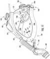
- FIG. 17is a partially exploded view of the head wearable device 1 , showing the attachment of the luminaire 200 , via the mechanical linkage 350 , to the headband 100 and the flexible duct 320 to the rigid duct 330 .
- FIG. 18is a partially exploded view of the components of the depth adjuster 450 for the position of the strap 152 of the occipital basket 150 relative to the upper housing 410 attached to the top strap 110 of the headband 100 .
- the occipital basket 150is pivotable to better adjust to the head shape of the wearer.
- the depth adjuster 450 shown in FIG. 18comprises a gear 470 that engages with teeth 156 (see FIGS. 13-15 ) formed on the inner surface of the slot 154 (see FIGS.
- the gear 470projects through the upper housing 400 and is fixedly and rotationally coupled to an adjustment knob 460 .
- the adjustment knob 460is rotatably locked to the gear 470 by connector plate 462 and screw 472 .
- a cover plate 464is attached to the adjustment knob 460 , but in some embodiments the cover plate 464 can be integrally formed as the adjustment knob 460 . As such, a rotary movement of the knob 460 causes a corresponding rotary movement of the gear 470 and a corresponding lengthening or shortening of the strap 152 which engages with the gear 470 .
- FIG. 19is a partially exploded view of the components of the headband adjuster 700 for the circumference of the head wearable device 1 .
- the headband adjuster 700 shown in FIG. 19is largely similar to the depth adjuster shown in FIG. 18 , but the rear housing comprises a two-part rear housing that has a base 710 that allows for visualization of the engagement of the teeth 134 A/ 134 B of the lateral extension straps 130 A/ 130 B with the gear 730 when assembling the head wearable device 1 .
- This visualization internal to the headband adjuster 700ensures that the lateral extension straps 130 A/ 130 B are each equally engaged around the gear 730 so the components of the head wearable device 1 are symmetrical about a vertical plane arranged along the longitudinal axis of the head wearable device 1 .
- the headband adjuster 700further comprises a cover panel 720 that engages at least partially over the base 710 to obscure the engagement of the gear 730 with the lateral extension straps 130 A/ 130 B during normal operation of the head wearable device 1 .
- the gear 730projects through a hole formed in the occipital basket 150 and the base 710 is secured to the occipital basket 150 at a predetermined mounting point, for example, by screws 722 .
- the gear 730is then fixedly and rotationally coupled to an adjustment knob 740 by screw 732 , which passes through the occipital basket 150 .
- the adjustment knob 460is rotatably locked to the gear 730 by connector plate 742 and screw 732 .
- a cover plate 744is attached to the adjustment knob 740 , but in some embodiments the cover plate 744 can be integrally formed as the adjustment knob 740 . As such, a rotary movement of the adjustment knob 740 causes a corresponding rotary movement of the gear 730 and a corresponding lengthening or shortening of the circumference of the head wearable device 1 .
- a method of adjusting a size of a headpiece of a head wearable device to a head size of a wearer, the headpiece comprising a headband 100 and an occipital basket 150comprises attaching an upper housing 400 to an external surface of a top strap 110 of the headband 100 ; inserting a strap 152 of the occipital basket 150 at least partially into the upper housing 400 ; engaging a first gear 470 with a plurality of teeth 156 formed in a slot 154 , which is longitudinally oriented along a length of the strap 152 of the occipital basket 150 ; turning a first adjustment knob 460 , which is rotationally locked to the first adjustment gear 470 , to adjust a depth of the headpiece; attaching a second housing to an external surface of the occipital basket 150 ; inserting an end of at least two lateral extension straps 130 A/ 130 B into the second housing, with the end of a first lateral extension strap 130 A being inserted from an opposite
- the methodcomprises providing a first visual index along a length of the strap 152 of the occipital basket 150 , the first visual index 157 comprising sequential alphanumeric characters to designate predetermined depth settings for the headpiece; providing a second visual index 136 along a length of at least one of the lateral extension straps 130 A/ 130 B, the second visual index 136 comprising sequential alphanumeric characters to designate predetermined circumference settings for the head wearable device 1 ; determining a wearer preference for the depth and circumference of the head wearable device 1 corresponding to the first and second visual indexes 157 / 136 ; placing the head wearable device 1 on the wearer's head; adjusting the first adjustment knob 460 such that the first visual index 157 indicates that the wearer preference for the depth of the head wearable device 1 has been achieved; and adjusting the second adjustment knob 730 such that the second visual index 136 indicates that the wearer preference for the circumference of the head wearable device 1 has been achieved.
- a head wearable devicecomprises a headpiece; a housing attached to the headpiece; a luminaire attached to the headpiece, the luminaire comprising a luminaire housing and at least one light source located within the luminaire housing; a duct system connecting the luminaire to the housing; a ball joint rotatably connecting the duct system to the luminaire; and an air moving device configured to induce a cooling air flow through an inlet in the luminaire housing, through the heatsink, through the ball joint, through the duct system, and out of an exhaust in the housing on the top surface of the headpiece.
- the housingis attached to a top surface of the headpiece
- the head wearable devicecomprises a controller configured to monitor a temperature of the at least one light source and to modulate an operational setting of the air moving device to maintain the temperature of the at least one light source within a predetermined operating range.
- the headpiececomprises a headband, which has at least a top strap and two lateral straps, and an occipital basket, wherein the headband is connected to the occipital basket and the headband and the occipital basket are independently adjustable relative to each other.
- the at least one light sourcecomprises a light emitting diode (LED).
- the ball jointis pivotably and/or swivelably connected to the luminaire.
- the duct systemcomprises a flexible duct connected to a rigid duct.
- the air moving deviceis positioned inside the housing, within the rigid duct, in a position adjacent to the exhaust in the housing.
- the luminaireis attached to the headpiece by a mechanical linkage such that an angle and/or position of the luminaire relative to the headpiece is adjustable.
- the flexible ductcomprises a corrugated construction such that a length thereof can be shortened or lengthened as the angle and/or position of the luminaire relative to the headpiece is adjusted.
- the ball jointdefines a range of angular motion for the luminaire and comprises a passage and an exhaust port formed in a circumferential wall of the ball joint, the range of angular motion being such that the passage remains in a position to provide an air flow path from the luminaire housing into the ball joint.
- the passage and the exhaust portare arranged on substantially opposite sides of the ball joint.
- the passageis not externally visible from the luminaire housing at any point along the range of angular motion.
- the head wearable devicecomprises a heatsink located within the luminaire housing.
- the luminaireis configured to optimize a projection of white light and restrict both stray light reflections and yellow light from exiting the lens cell.
- the lens cellis configured to produce a substantially homogeneous white-spot presentation.
- the lens cellcomprises an adjustable focal length and/or focal point.
- the head wearable devicecomprises a power cord attached to the upper housing attached to the top strap of the headband, the power cord being configured to receive power from a holster.
- the poweris provided from a rechargeable battery or a continuous power source, and wherein the holster is configured to adjust an intensity of light output from the at least one light source.
- a head wearable devicecomprises a headpiece comprising: a headband comprising a top strap and at least two lateral straps; an occipital basket comprising a strap, the occipital basket being attached to the headband by at least one lateral extension strap pivotably attached by a hinge to a distal end of each respective lateral strap of the headband; a first housing attached to an outer surface of the top strap of the headband; a depth adjuster attached to the first housing, the depth adjuster comprising a first gear rotatably fixed to a first knob; wherein the strap of the occipital basket comprises a slot with a plurality of teeth formed around a longitudinal edge of the slot; wherein the first gear is captively held within the slot and engages with the plurality of teeth; wherein the depth adjuster is configured such that a rotary movement of the first gear causes a longitudinal movement of the strap of the occipital basket to change a distance between the occipital basket and the first housing; wherein
- the first and second visual indexescomprise alphanumeric characters. In some embodiments of the head wearable device, the first visual index and the second visual index comprise different ranges and/or types of alphanumeric characters. In some embodiments of the head wearable device, the first visual index comprises a plurality of sequential letters and the second visual index comprises a plurality of sequential numbers. In some embodiments of the head wearable device, the first visual index comprises a plurality of sequential numbers and the second visual index comprises a plurality of sequential letters. In some embodiments, the head wearable device comprises padding on an inner surface of the headband and the occipital basket.
- a notchis formed into a lower edge of the occipital basket to prevent a wearer's hair from interfering with proper fitment of the headpiece about a head of a wearer.
- the padding on the occipital basketcomprises a recessed area to prevent the wearer's hair from interfering with proper fitment of the headpiece about the head of the wearer.
- the paddingis removably attached to the headband and the occipital basket.
- the paddingis spaced apart from a surface of a head of a wearer of the head wearable device at a suture between adjacent plates of a skull of the wearer of the head wearable device.
- a method of adjusting a size of a headpiece of a head wearable device to a head size of a wearercomprising attaching a first housing to an external surface of a top strap of the headband; inserting a strap of the occipital basket at least partially into the first housing; engaging a first gear with a plurality of teeth formed in a slot, which is longitudinally oriented along a length of the strap of the occipital basket; turning a first knob, which is rotationally locked to the first gear, to adjust a depth of the headpiece; attaching a second housing to an external surface of the occipital basket; inserting an end of at least two lateral extension straps into the second housing, with the end of a first lateral extension strap being inserted from an opposite end of the housing from the end of a second lateral extension strap, wherein the two lateral extension straps are hingedly attached to lateral
- the methodcomprises providing a first visual index along a length of the strap of the occipital basket, the first visual index comprising sequential alphanumeric characters to designate predetermined depth settings for the headpiece; providing a second visual index along a length of at least one of the lateral extension straps, the second visual index comprising sequential alphanumeric characters to designate predetermined circumference settings for the headpiece; determining a wearer preference for the depth and circumference of the headpiece corresponding to the first and second visual indexes; placing the head wearable device on the wearer's head; adjusting the first knob such that the first visual index indicates that the wearer preference for the depth of the headpiece has been achieved; and adjusting the second knob such that the second visual index indicates that the wearer preference for the circumference of the headpiece has been achieved.
- the first visual index and the second visual indexcomprise different ranges and/or types of alphanumeric characters.
- the first visual indexcomprises a plurality of sequential letters
- the second visual indexcomprises a plurality of sequential numbers
- the wearer preferenceis designated by one of the plurality of sequential letters and one of the plurality of sequential numbers.
- the first visual indexcomprises a plurality of sequential numbers
- the second visual indexcomprises a plurality of sequential letters.
- the methodcomprises attaching padding on an inner surface of the headband and the occipital basket.
- the methodcomprises forming a notch into a lower edge of the occipital basket to prevent a wearer's hair from interfering with proper fitment of the headpiece about a head of a wearer. In some embodiments, the method comprises forming a recessed area in the padding on the occipital basket to prevent the wearer's hair from interfering with proper fitment of the headpiece about the head of the wearer. In some embodiments of the method, the padding is removably attached to the headband and the occipital basket. In some embodiments, the method comprises spacing the padding apart from a surface of a head of a wearer of the head wearable device at a suture between adjacent plates of a skull of the wearer of the head wearable device.
- a headlight devicecomprises a headband comprising a rear portion, a side portion and a top portion, the headband having an inner surface; a padding system comprising: a rear pad attached to the inner surface of the rear portion of the headband; a side pad attached to the inner surface of the side portion of the headband; a top pad attached to the inner surface of the top portion of the headband; and, optionally, a brow pad attached to the inner surface of the headband about an intersection of the top portion and the side portion; wherein at least one of the rear pad and the brow pad comprises a first layer of a first cushioning material having a first durometer, and a second layer of a second cushioning material having a second durometer that is harder than the first durometer.
- the first cushioning materialis silicone foam having a first durometer
- the second cushioning materialis silicone foam having a second durometer that is harder than the first durometer.
- the second layer of the second cushioning materialis closer than the first layer of the first cushioning material to the inner surface of the rear portion of the headband.
- the first layer of the first cushioning material and the second layer of the second cushioning materialare each perforated.
- the majority of the perforations in the first layer of the first cushioning materialare generally circular, and the majority of the perforations in the second layer of the second cushioning material are in a shape other than circular.
- the perforations in the second layer of the second cushioning materialare generally square or rectangular, or generally in a grid-like pattern.
- the second layer of the second cushioning materialhas more open space on its upper or lower surface due to perforations than the first layer of the first cushioning material.
- the total volume of cavity due to perforations in the second layer of the second cushioning materialis higher than the total volume of cavity in the first layer of the first cushioning material.
- the rear padhas an inner surface in contact with an wearer and an outer surface attached to the inner surface of the rear portion of the headband, and the rear pad comprises a recess on its inner surface.
- At least one of the top pad and the side padcomprises urethane foam and forms segments. In some embodiments of the headlight device, at least one of the top pad, the side pad, and the rear pad is spaced apart from a surface of a head of a wearer of the head wearable device at a suture between adjacent plates of a skull of the wearer of the head wearable device.
- the first cushioning materialcomprises an extra firm silicone foam, the first durometer of which has a compression force deflection in a range of 16-26 pounds per square inch (psi), and wherein the second cushioning material comprises a different silicone foam, the second durometer of which has a compression force deflection in a range of 1-20 psi.
- the first cushioning materialcomprises a firm silicone foam, the first durometer of which has a compression force deflection in a range of 12-20 pounds per square inch (psi), and wherein the second cushioning material comprises a different silicone foam, the second durometer of which has a compression force deflection in a range of 1-14 or 16-26 psi.
- the first cushioning materialcomprises a medium silicone foam, the first durometer of which has a compression force deflection in a range of 6-14 pounds per square inch (psi), and wherein the second cushioning material comprises a different silicone foam, the second durometer of which has a compression force deflection in a range of 1-7 or 12-26 psi.
- the first cushioning materialcomprises a firm silicone foam, the first durometer of which has a compression force deflection in a range of 2-7 pounds per square inch (psi), and wherein the second cushioning material comprises a different silicone foam, the second durometer of which has a compression force deflection in a range of 1-5 or 6-26 psi.
- the first cushioning materialcomprises a firm silicone foam, the first durometer of which has a compression force deflection in a range of 1-5 pounds per square inch (psi), and wherein the second cushioning material comprises a different silicone foam, the second durometer of which has a compression force deflection in a range of about 1.5 or 2-26 psi.
- the first cushioning materialcomprises a firm silicone foam, the first durometer of which has a compression force deflection of about 1.5 pounds per square inch (psi), and wherein the second cushioning material comprises a different silicone foam, the second durometer of which has a compression force deflection in a range of 1-26 psi.
- a headlight devicecomprises a headband for encircling the head of a wearer; a padding system comprising a pad removably attached to at least a portion of the headband; wherein the pad comprises a first layer of a first cushioning material having a first durometer, and a second layer of a second cushioning material having a second durometer that is harder than the first durometer; and wherein the first layer is perforated in a first perforation pattern, and the second layer is perforated in a second perforation pattern that differs from the first perforation pattern.
- the first layer of the first cushioning materialis a layer of silicone foam having a first durometer
- the second layer of the second cushioning materialis a layer of silicone foam having a second durometer that is harder than the first durometer.
- the second layer of the second cushioning materialis closer than the first layer of the first cushioning material to the inner surface of the rear portion of the headband.
- the majority of the perforations in one of the first and second layersare circular, and the majority of the perforations in the other layer are in a shape other than circular.
- the perforations in the other layerare generally square or rectangular or generally in a grid-like pattern.
- the second layer of the second cushioning materialhas more open space on its upper or lower surface due to perforations than the first layer of the first cushioning material.
- the total volume of cavity due to perforations in the second layer of the second cushioning materialis higher than the total volume of cavity in the first layer of the first cushioning material.
- the padis spaced apart from a surface of a head of a wearer of the head wearable device at a suture between adjacent plates of a skull of the wearer of the head wearable device.
- the first cushioning materialcomprises an extra firm silicone foam, the first durometer of which has a compression force deflection in a range of 16-26 pounds per square inch (psi), and wherein the second cushioning material comprises a different silicone foam, the second durometer of which has a compression force deflection in a range of 1-20 psi.
- the first cushioning materialcomprises a firm silicone foam, the first durometer of which has a compression force deflection in a range of 12-20 pounds per square inch (psi), and wherein the second cushioning material comprises a different silicone foam, the second durometer of which has a compression force deflection in a range of 1-14 or 16-26 psi.
- the first cushioning materialcomprises a medium silicone foam, the first durometer of which has a compression force deflection in a range of 6-14 pounds per square inch (psi), and wherein the second cushioning material comprises a different silicone foam, the second durometer of which has a compression force deflection in a range of 1-7 or 12-26 psi.
- the first cushioning materialcomprises a firm silicone foam, the first durometer of which has a compression force deflection in a range of 2-7 pounds per square inch (psi), and wherein the second cushioning material comprises a different silicone foam, the second durometer of which has a compression force deflection in a range of 1-5 or 6-26 psi.
- the first cushioning materialcomprises a firm silicone foam, the first durometer of which has a compression force deflection in a range of 1-5 pounds per square inch (psi), and wherein the second cushioning material comprises a different silicone foam, the second durometer of which has a compression force deflection in a range of about 1.5 or 2-26 psi.
- the first cushioning materialcomprises a firm silicone foam, the first durometer of which has a compression force deflection of about 1.5 pounds per square inch (psi), and wherein the second cushioning material comprises a different silicone foam, the second durometer of which has a compression force deflection in a range of 1-26 psi.
- the methodcomprises attaching the upper housing to a top surface of a headpiece of the head wearable device. In some embodiments, the method comprises attaching a power cord to the upper housing to receive power from a holster. In some embodiments, the method comprises adjusting an intensity of light output from the at least one light source via the holster, wherein the power comprises a rechargeable battery or a continuous power source.
- the headpiececomprises a headband, which has at least a top strap and two lateral straps, and an occipital basket, wherein the headband is connected to the occipital basket and the headband and the occipital basket are independently adjustable relative to each other.
- the methodcomprises attaching the luminaire to the headpiece via a mechanical linkage, such that an angle and/or position of the luminaire relative to the headpiece is adjustable.
- the flexible ductcomprises a corrugated construction such that a length thereof can be shortened or lengthened as the angle and/or position of the luminaire relative to the headpiece is adjusted.
- the methodcomprises monitoring, via a controller, a temperature of the at least one light source and modulating an operational setting of the air moving device to maintain the temperature of the at least one light source within a predetermined operating range.
- the at least one light sourcecomprises a light emitting diode (LED).
- connecting the luminaire housing to the ball jointcomprises a pivotable and/or swivelable connection.
- the methodcomprises defining, via the ball joint, a range of angular motion for the luminaire and comprises a passage and an exhaust port formed in a circumferential wall of the ball joint, wherein the range of angular motion is such that the passage remains in a position to provide an air flow path from the luminaire housing into the ball joint.
- the methodcomprises arranging the passage and the exhaust port on substantially opposite sides of the ball joint.
- the passageis not externally visible from the luminaire housing at any point along the range of angular motion.
- the methodcomprises arranging a heatsink within the luminaire housing. In some embodiments, the method comprises optimizing a projection of white light and restricting both stray light reflections and yellow light from exiting the lens cell. In some embodiments, the method comprises producing, via the lens cell, a substantially homogeneous white-spot presentation. In some embodiments of the method, the lens cell comprises an adjustable focal length and/or focal point.
- a headlight devicecomprising: a headband for encircling the head of a wearer; a padding system comprising a rear pad removably attached to at least a portion of the headband; wherein the rear pad comprises a first layer of a first cushioning material having a first durometer, and a second layer of a second cushioning material having a second durometer that is different from the first durometer; wherein the first layer is perforated in a first perforation pattern, and the second layer is perforated in a second perforation pattern that differs from the first perforation pattern; wherein the first layer comprises an inner surface in contact with a wearer; wherein the second layer comprises an outer surface attached to the inner surface of the rear portion of the headband; and wherein the rear pad comprises a recess on an inner surface thereof.
Landscapes
- Health & Medical Sciences (AREA)
- Engineering & Computer Science (AREA)
- Life Sciences & Earth Sciences (AREA)
- Surgery (AREA)
- General Engineering & Computer Science (AREA)
- General Health & Medical Sciences (AREA)
- Veterinary Medicine (AREA)
- Biomedical Technology (AREA)
- Heart & Thoracic Surgery (AREA)
- Medical Informatics (AREA)
- Molecular Biology (AREA)
- Animal Behavior & Ethology (AREA)
- Oral & Maxillofacial Surgery (AREA)
- Public Health (AREA)
- Pathology (AREA)
- Nuclear Medicine, Radiotherapy & Molecular Imaging (AREA)
- Helmets And Other Head Coverings (AREA)
- Fastening Of Light Sources Or Lamp Holders (AREA)
- Arrangement Of Elements, Cooling, Sealing, Or The Like Of Lighting Devices (AREA)
- Measurement And Recording Of Electrical Phenomena And Electrical Characteristics Of The Living Body (AREA)
- Golf Clubs (AREA)
- Measuring Pulse, Heart Rate, Blood Pressure Or Blood Flow (AREA)
- Non-Portable Lighting Devices Or Systems Thereof (AREA)
- Professional, Industrial, Or Sporting Protective Garments (AREA)
Abstract
Description
Claims (32)
Priority Applications (2)
| Application Number | Priority Date | Filing Date | Title |
|---|---|---|---|
| US16/230,210US11255533B2 (en) | 2018-10-04 | 2018-12-21 | Head wearable devices and methods |
| US17/565,009US11635198B2 (en) | 2018-10-04 | 2021-12-29 | Head wearable devices and methods |
Applications Claiming Priority (3)
| Application Number | Priority Date | Filing Date | Title |
|---|---|---|---|
| US201862741385P | 2018-10-04 | 2018-10-04 | |
| US201862741636P | 2018-10-05 | 2018-10-05 | |
| US16/230,210US11255533B2 (en) | 2018-10-04 | 2018-12-21 | Head wearable devices and methods |
Related Child Applications (1)
| Application Number | Title | Priority Date | Filing Date |
|---|---|---|---|
| US17/565,009ContinuationUS11635198B2 (en) | 2018-10-04 | 2021-12-29 | Head wearable devices and methods |
Publications (2)
| Publication Number | Publication Date |
|---|---|
| US20200109847A1 US20200109847A1 (en) | 2020-04-09 |
| US11255533B2true US11255533B2 (en) | 2022-02-22 |
Family
ID=65199582
Family Applications (9)
| Application Number | Title | Priority Date | Filing Date |
|---|---|---|---|
| US16/230,361Active2039-01-20US10830428B2 (en) | 2018-10-04 | 2018-12-21 | Head wearable devices and methods |
| US16/230,210Active2039-01-08US11255533B2 (en) | 2018-10-04 | 2018-12-21 | Head wearable devices and methods |
| US16/230,277ActiveUS10724716B2 (en) | 2018-10-04 | 2018-12-21 | Head wearable devices and methods |
| US16/916,502ActiveUS11067267B2 (en) | 2018-10-04 | 2020-06-30 | Head wearable devices and methods |
| US17/093,127ActiveUS11268686B2 (en) | 2018-10-04 | 2020-11-09 | Head wearable devices and methods |
| US17/380,352ActiveUS11555605B2 (en) | 2018-10-04 | 2021-07-20 | Head wearable devices and methods |
| US17/565,009ActiveUS11635198B2 (en) | 2018-10-04 | 2021-12-29 | Head wearable devices and methods |
| US17/680,991ActiveUS11674681B2 (en) | 2018-10-04 | 2022-02-25 | Head wearable devices and methods |
| US18/097,382ActiveUS11835211B2 (en) | 2018-10-04 | 2023-01-16 | Head wearable devices and methods |
Family Applications Before (1)
| Application Number | Title | Priority Date | Filing Date |
|---|---|---|---|
| US16/230,361Active2039-01-20US10830428B2 (en) | 2018-10-04 | 2018-12-21 | Head wearable devices and methods |
Family Applications After (7)
| Application Number | Title | Priority Date | Filing Date |
|---|---|---|---|
| US16/230,277ActiveUS10724716B2 (en) | 2018-10-04 | 2018-12-21 | Head wearable devices and methods |
| US16/916,502ActiveUS11067267B2 (en) | 2018-10-04 | 2020-06-30 | Head wearable devices and methods |
| US17/093,127ActiveUS11268686B2 (en) | 2018-10-04 | 2020-11-09 | Head wearable devices and methods |
| US17/380,352ActiveUS11555605B2 (en) | 2018-10-04 | 2021-07-20 | Head wearable devices and methods |
| US17/565,009ActiveUS11635198B2 (en) | 2018-10-04 | 2021-12-29 | Head wearable devices and methods |
| US17/680,991ActiveUS11674681B2 (en) | 2018-10-04 | 2022-02-25 | Head wearable devices and methods |
| US18/097,382ActiveUS11835211B2 (en) | 2018-10-04 | 2023-01-16 | Head wearable devices and methods |
Country Status (7)
| Country | Link |
|---|---|
| US (9) | US10830428B2 (en) |
| EP (3) | EP3860502B1 (en) |
| JP (5) | JP7288050B2 (en) |
| AU (3) | AU2018444155B2 (en) |
| CA (3) | CA3114516C (en) |
| ES (3) | ES3004537T3 (en) |
| WO (3) | WO2020072087A1 (en) |
Cited By (2)
| Publication number | Priority date | Publication date | Assignee | Title |
|---|---|---|---|---|
| US11555605B2 (en) | 2018-10-04 | 2023-01-17 | Integra Lifesciences Corporation | Head wearable devices and methods |
| USD987145S1 (en) | 2018-10-04 | 2023-05-23 | Integra Lifesciences Corporation | Wearable headgear device |
Families Citing this family (29)
| Publication number | Priority date | Publication date | Assignee | Title |
|---|---|---|---|---|
| JP5380070B2 (en) | 2005-07-14 | 2014-01-08 | ストライカー・コーポレイション | Head unit with adjustable conduit and hood used for the head unit |
| CN105209128A (en) | 2013-03-14 | 2015-12-30 | 史赛克公司 | Personal protection systems for medical/surgical use including UV lamps to purify the air inhaled into the system |
| EP3939459A1 (en) | 2016-04-18 | 2022-01-19 | Stryker Corporation | A garment with a transparent face shield for use as part of a personal protection system, and the personal protection system |
| AU2019293245B2 (en) | 2018-06-27 | 2025-06-05 | Stryker Corporation | A protective apparel system with a lens assembly |
| EP4509002A3 (en) | 2018-10-24 | 2025-04-30 | Stryker Corporation | Surgical helmet assembly having an adjustment mechanism |
| US11864612B2 (en) | 2019-01-23 | 2024-01-09 | Riverpoint Medical, Llc | Headband having suspended comfort element |
| US11147648B2 (en)* | 2019-01-23 | 2021-10-19 | Riverpoint Medical, Llc | Headlamp assembly having comfort element |
| US12295447B2 (en) | 2019-01-25 | 2025-05-13 | Stryker Corporation | Personal protection system including medical garment with a shield |
| US12414591B2 (en) | 2019-05-02 | 2025-09-16 | Stryker Corporation | Surgical helmet assembly with a reconfigurable chin bar |
| JP2022552020A (en) | 2019-10-15 | 2022-12-14 | ジェリカライト エルエルシー | head wearable phototherapy device |
| US11300252B2 (en)* | 2019-11-07 | 2022-04-12 | Ronald C. Nguyen | Illumination devices |
| EP4228467A4 (en)* | 2020-12-15 | 2024-09-04 | Valve Corporation | Head-mounted display |
| JP7713189B2 (en) | 2021-02-08 | 2025-07-25 | サイトフル コンピューターズ リミテッド | Content Sharing in Extended Reality |
| KR20250103813A (en) | 2021-02-08 | 2025-07-07 | 사이트풀 컴퓨터스 리미티드 | Extended reality for productivity |
| EP4288950A4 (en) | 2021-02-08 | 2024-12-25 | Sightful Computers Ltd | User interactions in extended reality |
| EP4281191A4 (en)* | 2021-03-01 | 2024-11-27 | Trion Mask, LLC | FACE MASKS AND METHODS FOR PROTECTION AGAINST AIRBORNE PATHOGENS AND PARTICLES |
| JP1708857S (en)* | 2021-04-20 | 2022-03-02 | Medical lighting equipment | |
| US11957520B1 (en) | 2021-04-22 | 2024-04-16 | Brian Crowe | Surgical headlamp assembly |
| US20220400803A1 (en)* | 2021-06-21 | 2022-12-22 | Aliaksei Chernyshou | Helmet for impact energy displacement and/or absorption |
| TWM619525U (en)* | 2021-06-29 | 2021-11-11 | 廣達電腦股份有限公司 | Head-mounted display |
| WO2023009580A2 (en) | 2021-07-28 | 2023-02-02 | Multinarity Ltd | Using an extended reality appliance for productivity |
| US12175614B2 (en) | 2022-01-25 | 2024-12-24 | Sightful Computers Ltd | Recording the complete physical and extended reality environments of a user |
| US11948263B1 (en) | 2023-03-14 | 2024-04-02 | Sightful Computers Ltd | Recording the complete physical and extended reality environments of a user |
| US12380238B2 (en) | 2022-01-25 | 2025-08-05 | Sightful Computers Ltd | Dual mode presentation of user interface elements |
| WO2024119165A2 (en)* | 2022-12-02 | 2024-06-06 | Jelikalite Llc | Methods and devices for photobiomodulation |
| WO2024097374A2 (en)* | 2022-11-02 | 2024-05-10 | Jelikalite Llc | Methods and devices for photobiomodulation |
| EP4595015A1 (en) | 2022-09-30 | 2025-08-06 | Sightful Computers Ltd | Adaptive extended reality content presentation in multiple physical environments |
| US20250235655A1 (en)* | 2024-01-18 | 2025-07-24 | Dcstar Inc | Headgear for use in the pap field |
| USD1097252S1 (en)* | 2024-03-04 | 2025-10-07 | Walter R. Tucker Enterprises, Ltd | Head light |
Citations (244)
| Publication number | Priority date | Publication date | Assignee | Title |
|---|---|---|---|---|
| US1453006A (en) | 1921-05-26 | 1923-04-24 | Emory C Day | Lighting means for surgical and other purposes |
| US1632851A (en) | 1921-06-07 | 1927-06-21 | Reaves William Perry | Operating headlight |
| US1688113A (en) | 1927-06-09 | 1928-10-16 | Bornkessel Max | Surgical headlight |
| US2217359A (en) | 1939-08-01 | 1940-10-08 | Cooke Benjamin | Head clamp and light reflector |
| US2437748A (en) | 1945-06-11 | 1948-03-16 | Chicago Eye Shield Company | Adjustable headband construction |
| US2883980A (en) | 1957-03-01 | 1959-04-28 | Storz Instr Co | Physician's headlight |
| US2893379A (en) | 1956-02-15 | 1959-07-07 | Henry A Springer | Illuminating devices |
| US3008040A (en) | 1959-01-19 | 1961-11-07 | Welch Allyn Inc | Headlamp |
| US3047876A (en) | 1958-12-08 | 1962-08-07 | Chicago Eye Shield Company | Adjustable head piece |
| US3285242A (en) | 1963-07-01 | 1966-11-15 | American Cystoscope Makers Inc | Surgical headlight and light source |
| US3470570A (en) | 1967-02-03 | 1969-10-07 | Sports Ind Inc | Expansible diver's weight belt |
| US3513481A (en) | 1968-06-25 | 1970-05-26 | Ilc Ind Inc | Adjustable headband |
| US3555560A (en) | 1969-01-16 | 1971-01-19 | Bullard Co | Suspension system for safety hat |
| US3586851A (en) | 1969-02-24 | 1971-06-22 | Robert R Rudolph | Cool light |
| US3645254A (en) | 1970-04-17 | 1972-02-29 | Charles Burton | Surgical light |
| US3745993A (en) | 1972-05-02 | 1973-07-17 | Designs For Vision | Surgical headlight |
| US3763495A (en) | 1971-12-21 | 1973-10-09 | Omnitech Inc | Face shield headgear |
| US3830230A (en) | 1972-09-22 | 1974-08-20 | Weck E & Co | Surgical headlamp |
| US3947676A (en) | 1974-11-01 | 1976-03-30 | The Raymond Lee Organization, Inc. | Portable head lamp |
| US3951139A (en) | 1974-10-07 | 1976-04-20 | Applied Fiberoptics, Incorporated | Fiberoptic headlight |
| US3992722A (en) | 1974-11-27 | 1976-11-23 | Jhoon Goo Rhee | Protective helmet |
| US4104709A (en) | 1977-04-11 | 1978-08-01 | Applied Fiberoptics, Inc. | Surgeons headlight with continuously variable spot size |
| US4130902A (en) | 1977-08-01 | 1978-12-26 | Mackenroth Iii Joseph R | Cooling hatband |
| US4234910A (en) | 1978-03-20 | 1980-11-18 | Price Linda D | Head-supported illumination device |
| US4290422A (en) | 1979-07-05 | 1981-09-22 | Burton Charles V | Surgical headlight system |
| US4321659A (en) | 1980-06-30 | 1982-03-23 | Wheeler Ernest E | Narrow-band, air-cooled light fixture |
| USD266192S (en) | 1979-12-20 | 1982-09-14 | Designs For Vision, Inc. | Surgical headlight or similar article |
| US4593683A (en) | 1983-12-03 | 1986-06-10 | Carl-Zeiss-Stiftung | Medical examination instrument with headband support |
| US4621283A (en) | 1984-08-27 | 1986-11-04 | Designs For Vision, Inc. | Head-mounted coaxial image system for surgeons |
| US4628416A (en) | 1985-05-03 | 1986-12-09 | Coopervision, Inc. | Variable spot size illuminator with constant convergence angle |
| US4729499A (en) | 1986-01-06 | 1988-03-08 | Martin Stanley T | Headband for flashlights |
| FR2604798A1 (en) | 1986-10-03 | 1988-04-08 | Eric Forey | Device for angularly reflecting (returning) a light ray coming from an optical fibre |
| US4766610A (en) | 1987-01-22 | 1988-08-30 | Varo, Inc. | Replaceable cushion liner for military headgear |
| USD300868S (en) | 1985-07-16 | 1989-04-25 | Leona Conforti | Surgical headlamp |
| US4887190A (en) | 1988-10-15 | 1989-12-12 | In Focis Devices Inc. | High intensity fiber optic lighting system |
| US4918583A (en) | 1988-04-25 | 1990-04-17 | Nikon Corporation | Illuminating optical device |
| US4942628A (en) | 1989-09-20 | 1990-07-24 | Mine Safety Appliances Company | Helmet suspension having ratchet adjustment |
| US5001608A (en) | 1987-10-07 | 1991-03-19 | "Harrier" Gmbh Gesellschaft Fur Den Vertrieb Medizinischer Und Technischer Gerate | Therapeutic lamp emitting polarized light |
| US5042930A (en) | 1989-10-11 | 1991-08-27 | Luxtec Corporation | Optical system which allows coincident viewing, illuminating and photographing |
| US5078469A (en) | 1989-10-11 | 1992-01-07 | Luxtec Corporation | Optical system which allows coincident viewing, illuminating and photographing |
| US5099399A (en) | 1991-04-08 | 1992-03-24 | Miller Jack V | High efficiency fiber optics illuminator with thermally controlled light guide bushing |
| US5115382A (en) | 1990-09-28 | 1992-05-19 | Smith Robert C | Headlamp apparatus |
| US5163420A (en) | 1991-03-25 | 1992-11-17 | Bel Frans G V D | Headlight system |
| US5186534A (en) | 1989-03-23 | 1993-02-16 | Gte Rotaflex Limited | Light fitting |
| USD337838S (en) | 1991-06-17 | 1993-07-27 | Surgical headlight | |
| US5268977A (en) | 1992-07-06 | 1993-12-07 | Miller Jack V | Fiber optic zoom-and-dim pin-spot luminaire |
| US5283914A (en)* | 1990-12-20 | 1994-02-08 | Coal Industry (Patents) Limited | Protective helmets |
| US5355285A (en) | 1993-01-12 | 1994-10-11 | Hicks John W | Surgeon's headlight system |
| US5412811A (en) | 1991-10-04 | 1995-05-09 | Carl-Zeiss-Stiftung | Headgear having a holding device for holding an instrument |
| US5428517A (en) | 1992-08-11 | 1995-06-27 | Siemens Aktiengesellschaft | Field of action light for medical, particularly dental practice |
| US5430620A (en) | 1993-10-08 | 1995-07-04 | Cogent Light Technologies, Inc. | Compact surgical illumination system capable of dynamically adjusting the resulting field of illumination |
| US5440462A (en) | 1994-04-06 | 1995-08-08 | General Scientific Corporation | Head-mounted lighting assembly |
| US5465124A (en) | 1994-06-09 | 1995-11-07 | Propper Manufacturing Co., Inc. | Headband with adjustable device for positioning an optical device |
| US5497295A (en) | 1993-06-14 | 1996-03-05 | Lumitek Development, Inc. | Lighting system |
| USD373433S (en) | 1995-03-08 | 1996-09-03 | Designs For Vision, Inc. | Surgical headlight |
| US5558428A (en)* | 1994-09-07 | 1996-09-24 | Lehrer; Robert A. | Portable reading light device |
| JPH08288205A (en) | 1995-04-13 | 1996-11-01 | Nikon Corp | Illumination optical system and projection exposure apparatus including the illumination optical system |
| US5608917A (en) | 1995-02-13 | 1997-03-11 | Op-D-Op, Inc. | Ergonomic head band apparatus |
| US5619754A (en) | 1995-02-13 | 1997-04-15 | Fibre-Metal Products, Co. | Protective cap with reversible headband |
| US5634704A (en) | 1993-05-19 | 1997-06-03 | Mitsubishi Denki Kabushiki Kaisha | Light-source device and projection-type display device |
| US5638551A (en) | 1994-05-10 | 1997-06-17 | Societe A Responsabilite Limitee Dite Overforing | Helmet including a device for fixing the helmet to the occipital portion of a user's head |
| USD383229S (en) | 1996-04-15 | 1997-09-02 | Germain Electronic Ltd. | Cap light |
| US5667291A (en) | 1995-05-23 | 1997-09-16 | Surgical Acuity, Inc. | Illumination assembly for dental and medical applications |
| US5709459A (en) | 1993-10-08 | 1998-01-20 | Cogent Light Technologies, Inc. | Surgical luminaire |
| US5732176A (en) | 1993-06-29 | 1998-03-24 | Savage, Jr.; John M. | Light pipe optical coupling between LED and fiber optics cable |
| US5769523A (en) | 1994-07-28 | 1998-06-23 | Designs For Vision, Inc. | Surgical headlamp with dual aperture control |
| US5774271A (en) | 1996-07-29 | 1998-06-30 | Welch Allyn, Inc. | Lamp assembly |
| USD399580S (en) | 1997-11-21 | 1998-10-13 | Designs For Vision, Inc. | Deluxe surgical head light |
| US5867320A (en) | 1996-08-19 | 1999-02-02 | Samsung Electronics Co., Ltd. | Lens unit for projector |
| USD406371S (en) | 1998-06-12 | 1999-03-02 | Applied Fiberoptics, Inc. | Surgical headlight |
| US5893635A (en) | 1996-03-04 | 1999-04-13 | Luxtec Corporation | Headlamp with enhanced light gathering condenser |
| US5898290A (en) | 1995-09-07 | 1999-04-27 | Norand Corporation | Battery pack with capacity and pre-removal indicators |
| US5950245A (en) | 1997-04-14 | 1999-09-14 | Mine Safety Appliances Company | Adjustable headband with a ratchet mechanism having different resistances |
| USD421148S (en) | 1998-03-30 | 2000-02-22 | Hill-Rom, Inc. | Handle for surgical headlight |
| US6093468A (en) | 1997-03-14 | 2000-07-25 | The Procter & Gamble Company | Flexible lightweight protective pad with energy absorbing inserts |
| US6113281A (en) | 1997-01-22 | 2000-09-05 | Davis; James M. | Fiberoptic cable apparatus with adjustable filter |
| US6120161A (en) | 1998-04-08 | 2000-09-19 | Techman International Corporation | Video headlight and cable |
| US6129662A (en) | 1996-06-03 | 2000-10-10 | Cogent Light Technologies, Inc. | Surgical tool with surgical field illuminator |
| USD441111S1 (en) | 2000-03-13 | 2001-04-24 | Frans G. Van Der Bel | Surgical headband |
| US6224227B1 (en) | 1999-10-20 | 2001-05-01 | Jack Klootz | Surgical headlight assembly with detachable video-camera module |
| US6298497B1 (en) | 1996-11-29 | 2001-10-09 | Bauer Nike Hockey, Inc. | Hockey helmet with self-adjusting padding |
| US6321193B1 (en) | 1998-01-27 | 2001-11-20 | Telefonaktiebolaget Lm Ericsson | Distance and distortion estimation method and apparatus in channel optimized vector quantization |
| US6341382B1 (en) | 2000-11-06 | 2002-01-29 | Jackson Products, Inc. | One-piece adjustable headgear support |
| US20020085372A1 (en)* | 2000-12-28 | 2002-07-04 | Lehrer Robert A. | Portable reading light device |
| US6457838B1 (en) | 1993-08-11 | 2002-10-01 | Designodev Limited | Flashlight adaptor |
| WO2002099332A1 (en) | 2001-04-17 | 2002-12-12 | Ego Scientific, Inc. | Lightweight high-intensity head-mounted illumination source |
| US20030042493A1 (en) | 2001-08-31 | 2003-03-06 | Yuri Kazakevich | Solid-state light source |
| US6567993B2 (en) | 2000-01-09 | 2003-05-27 | Donald R. Robertson | Soccer headband |
| US6639733B2 (en) | 2000-03-16 | 2003-10-28 | Light Prescriptions Innovators, Llc. | High efficiency non-imaging optics |
| US6650538B1 (en) | 2002-07-17 | 2003-11-18 | International Business Machines Corporation | Fin heat sink and airflow tube assembly employing annular airflows, and methods of fabrication thereof |
| USD484436S1 (en) | 2002-10-01 | 2003-12-30 | North Safety Products Ltd. | Length adjustment mechanism for a strap |
| USD484437S1 (en) | 2003-02-26 | 2003-12-30 | North Safety Products Inc. | Knob for a length adjustment mechanism for a strap |
| US6708376B1 (en) | 2002-10-01 | 2004-03-23 | North Safety Products Ltd. | Length adjustment mechanism for a strap |
| USD489838S1 (en) | 2002-09-03 | 2004-05-11 | Zweibruder Optoelectronics Gmbh | Head-band lamp |
| US20040120151A1 (en) | 2002-12-20 | 2004-06-24 | Cao Group, Inc. | Forensic light using semiconductor light source |
| US20040149998A1 (en) | 2002-12-02 | 2004-08-05 | Henson Gordon D. | Illumination system using a plurality of light sources |
| US20040151008A1 (en) | 2003-02-03 | 2004-08-05 | Artsyukhovich Alexander N. | Variable spot size illuminators with enhanced homogeneity and parfocality |
| US6865285B1 (en) | 2000-05-25 | 2005-03-08 | Westinghouse Savannah River Company | LED intense headband light source for fingerprint analysis |
| USD503499S1 (en) | 2003-09-10 | 2005-03-29 | Bacou-Dalloz Eye & Face Protection, Inc. | Protective face shield support |
| US6890086B2 (en) | 2001-12-20 | 2005-05-10 | Gold Coral International Limited | Electronically controlled multi-light flashlight |
| US6896389B1 (en) | 2003-08-22 | 2005-05-24 | Erby Paul | Headmounted light |
| US6896381B2 (en) | 2002-10-11 | 2005-05-24 | Light Prescriptions Innovators, Llc | Compact folded-optics illumination lens |
| US20050128735A1 (en) | 2003-09-26 | 2005-06-16 | Atkins Neil A. | Head-mounted instruments |
| US20050128752A1 (en) | 2002-04-20 | 2005-06-16 | Ewington Christopher D. | Lighting module |
| US6908208B1 (en) | 2004-01-02 | 2005-06-21 | Raymond Quentin Hyde | Light to be worn on head |
| US6955444B2 (en) | 2003-11-12 | 2005-10-18 | Visiled, Inc. | Surgical headlight |
| US6966074B2 (en) | 2003-04-29 | 2005-11-22 | Otos Tech Co., Ltd. | Cushion pad structure for headband |
| US6999318B2 (en) | 2003-07-28 | 2006-02-14 | Honeywell International Inc. | Heatsinking electronic devices |
| US7000262B2 (en) | 2004-07-26 | 2006-02-21 | E.D. Bullard Company | Flexible ratchet mechanism for the headband of protective headgear |
| US7043772B2 (en) | 2004-08-31 | 2006-05-16 | E. D. Bullard Company | Ratchet mechanism with unitary knob and pinion construction |
| JP2006147373A (en) | 2004-11-19 | 2006-06-08 | Sony Corp | Backlight device |
| CN2820148Y (en) | 2005-07-15 | 2006-09-27 | 孔令哲 | Adjustable head belt |
| US20060245175A1 (en) | 2005-04-29 | 2006-11-02 | Heine Optotechnik Gmbh & Co. Kg | Headband apparatus for head-worn optical instruments |
| US7131760B2 (en) | 2004-02-20 | 2006-11-07 | Gelcore Llc | LED luminaire with thermally conductive support |
| US20060250771A1 (en) | 2005-05-06 | 2006-11-09 | Heine Optotechnik Gmbh & Co., Kg | Illuminating apparatus |
| US7134763B2 (en) | 2004-08-17 | 2006-11-14 | Jack Klootz | Illumination for coaxial variable spot headlight |
| US7144140B2 (en) | 2005-02-25 | 2006-12-05 | Tsung-Ting Sun | Heat dissipating apparatus for lighting utility |
| US20060285315A1 (en) | 2005-06-20 | 2006-12-21 | Welch Allyn, Inc. | Hybrid surgical headlight |
| US20060285316A1 (en) | 2005-06-20 | 2006-12-21 | Welch Allyn, Inc. | Hybrid surgical headlight system utilizing dual illumination paths and coaxial optics |
| US20060285323A1 (en) | 2005-06-16 | 2006-12-21 | Optilume Ltd | Lighting device |
| US7153015B2 (en) | 2001-12-31 | 2006-12-26 | Innovations In Optics, Inc. | Led white light optical system |
| US7174575B1 (en) | 2004-07-26 | 2007-02-13 | E.D. Bullard Company | Ratchet mechanism for the headband of protective headgear used in high temperature environments |
| US7192151B2 (en) | 2004-12-21 | 2007-03-20 | Depuy Products, Inc. | Light array for a surgical helmet |
| USD539952S1 (en) | 2005-11-01 | 2007-04-03 | Karl Storz Gmbh & Co. Kg | Medical headlight |
| US7210810B1 (en) | 2004-09-03 | 2007-05-01 | Pmt Corporation | Surgical headlight assembly |
| WO2007051173A2 (en) | 2005-10-27 | 2007-05-03 | Alpha Med-Surge, Inc. | Illumination device |
| US20070097703A1 (en) | 2005-10-28 | 2007-05-03 | Welch Allyn, Inc. | Integral solid-state luminaire with dual light paths and coaxial optics |
| US7229201B2 (en) | 2003-03-26 | 2007-06-12 | Optim Inc. | Compact, high-efficiency, high-power solid state light source using a single solid state light-emitting device |
| US7229202B2 (en) | 2003-08-28 | 2007-06-12 | Leica Microsystems (Schweiz) Ag | Light-emitting diode illumination system for an optical observation device, in particular a stereomicroscope or stereo surgical microscope |
| US7258464B2 (en) | 2002-12-18 | 2007-08-21 | General Electric Company | Integral ballast lamp thermal management method and apparatus |
| US7270459B2 (en) | 2004-11-18 | 2007-09-18 | Waring Patrick S | Method and apparatus for directing light from a light source |
| US20070220649A1 (en) | 2006-03-24 | 2007-09-27 | Otos Tech Co., Ltd. | Multi-function face protector |
| US7286296B2 (en) | 2004-04-23 | 2007-10-23 | Light Prescriptions Innovators, Llc | Optical manifold for light-emitting diodes |
| US20070253202A1 (en) | 2006-04-28 | 2007-11-01 | Chaun-Choung Technology Corp. | LED lamp and heat-dissipating structure thereof |
| US7314300B1 (en) | 2005-04-29 | 2008-01-01 | Sunoptic Technologies Llc | Fiber optic surgical headlight system |
| US7314294B1 (en)* | 2004-10-05 | 2008-01-01 | Moore Nick T | High intensity lamp with an insulated housing |
| USD560009S1 (en) | 2007-06-20 | 2008-01-15 | Eveready Battery Company, Inc. | Headlamp |
| US7380962B2 (en) | 2004-04-23 | 2008-06-03 | Light Prescriptions Innovators, Llc | Optical manifold for light-emitting diodes |
| USD572853S1 (en) | 2005-11-11 | 2008-07-08 | Heine Optotechnik Gmbh & Co. Kg | Lamp |
| JP2008186694A (en) | 2007-01-30 | 2008-08-14 | Hayashi Watch-Works Co Ltd | Lighting device |
| JP2008198468A (en) | 2007-02-13 | 2008-08-28 | Funai Electric Co Ltd | Light source device |
| JP2008227127A (en) | 2007-03-13 | 2008-09-25 | Seiko Epson Corp | Cooling fan drive control system, projector, program, information storage medium, and cooling fan drive control method |
| US20080239707A1 (en) | 2007-03-30 | 2008-10-02 | Designs For Visions, Inc. | Iluminating headlamp providing substantially uniform illumination |
| CN100432526C (en) | 2005-08-10 | 2008-11-12 | 唐曾会 | Headlight for medical use |
| US7465078B2 (en) | 2006-11-01 | 2008-12-16 | General Scientific Corporation | Heat-dissipating head-mounted LED lamp |
| US20080316733A1 (en) | 2007-06-20 | 2008-12-25 | Spartano David A | Lighting device having adjustable spot beam |
| USD586932S1 (en) | 2008-06-16 | 2009-02-17 | Designs For Vision, Inc. | Twin beam headlight |
| CN101377286A (en) | 2007-10-31 | 2009-03-04 | 上海雷硕医疗器械有限公司 | Headlight for operation |
| US7513660B2 (en) | 2007-06-20 | 2009-04-07 | Eveready Battery Company, Inc. | Lighting device having forward directed heat sink assembly |
| WO2009048794A1 (en) | 2007-10-10 | 2009-04-16 | 3M Innovative Properties Company | Head suspension having transition arms and rear support |
| CN201232858Y (en) | 2008-05-20 | 2009-05-06 | 北京市大维同创医疗设备有限公司 | Operation headlamp |
| US20090116252A1 (en) | 2006-05-08 | 2009-05-07 | Koninklijke Philips Electronics N V | Thermal surface mounting of multiple leds onto a heatsink |
| US7565040B2 (en) | 2004-05-28 | 2009-07-21 | Trimatiz Limited | Optical device using variable polarization element |
| US20090227847A1 (en) | 2008-03-07 | 2009-09-10 | John Tepper | Tunable Light Controller |
| US20090225534A1 (en)* | 2008-03-07 | 2009-09-10 | Daniel Thomas | Headlight with directed flow heat sink |
| US20090229041A1 (en) | 2008-03-13 | 2009-09-17 | Welch Allyn, Inc. | Head worn apparatus |
| US7618159B2 (en) | 2007-03-27 | 2009-11-17 | Welch Allyn, Inc. | Vented iris control for luminaire |
| USD608479S1 (en) | 2006-11-13 | 2010-01-19 | Heine Optotechnik Gmbh & Co. Kg | Headlamp with binocular lens and glasses |
| WO2010007785A1 (en) | 2008-07-15 | 2010-01-21 | 合同会社ジャパン・メディカル・クリエーティブ | Lighting device |
| JP2010046566A (en) | 2008-08-19 | 2010-03-04 | Ushikata Shokai:Kk | Led-light radiation apparatus |
| US20100093267A1 (en)* | 2008-10-10 | 2010-04-15 | Airbus Operations Gmbh | Service apparatus for a transportation means |
| US7710569B2 (en) | 2007-04-11 | 2010-05-04 | Remicalm, Llc | Headset mounted apparatus mounting a visor with interchangeable filter sets |
| USD615225S1 (en) | 2009-01-26 | 2010-05-04 | The Coleman Company, Inc. | Headlamp |
| USD615678S1 (en) | 2009-01-26 | 2010-05-11 | The Coleman Company, Inc. | Headlamp |
| USD615679S1 (en) | 2009-02-02 | 2010-05-11 | Ferguson John T | Headlamp |
| US7724440B2 (en) | 2004-04-23 | 2010-05-25 | Light Prescriptions Innovators, Llc | Combining outputs of different light sources |
| US7744219B2 (en) | 2007-05-26 | 2010-06-29 | Andrew Peter Davis | Binocular indirect ophthalmoscope fixation light |
| DE102009020112A1 (en) | 2009-05-06 | 2010-07-29 | Osram Gesellschaft mit beschränkter Haftung | Headlight, has heat exchanger fastened to LED, and pump arranged at distance from LED and heat exchanger, where heat exchanger and pump are interconnected by two flexible cooling agent lines |
| USD621535S1 (en) | 2007-11-05 | 2010-08-10 | Heine Optotechnik Gmbh & Co. Kg | Rechargeable battery with headband |
| USD624221S1 (en) | 2009-01-26 | 2010-09-21 | The Coleman Company, Inc. | Headlamp |
| US20100277894A1 (en) | 2009-05-01 | 2010-11-04 | Kim Paul Y | Lighting device with removable cradle |
| US7829191B2 (en) | 2007-12-26 | 2010-11-09 | Night Operations Systems | Lens for lighting system |
| USD628307S1 (en) | 2007-02-07 | 2010-11-30 | Carl Zeiss Surgical Gmbh | Medical loupe with head set |
| USD630766S1 (en) | 2009-01-29 | 2011-01-11 | Birmingham City University | Medical loupe head set |
| US7871174B2 (en) | 2007-11-07 | 2011-01-18 | Heine Optotechnik Gmbh & Co. Kg | Headband for diagnostic instruments comprising light source and accumulator module |
| US20110013383A1 (en) | 2008-07-21 | 2011-01-20 | Medinis David M | Led lamp with air-cooled heat sink |
| US7874293B2 (en) | 2003-02-21 | 2011-01-25 | Resmed Limited | Nasal assembly |
| US20110051432A1 (en) | 2009-08-25 | 2011-03-03 | Heine Optotechnik Gmbh & Co Kg | LED Lamp |
| USD635286S1 (en) | 2008-04-08 | 2011-03-29 | Carl Zeiss Surgical Gmbh | Light illumination source for loupes and accessories |
| US7926967B2 (en) | 2007-01-23 | 2011-04-19 | Eveready Battery Company, Inc. | Headlight devices and methods |
| US7972028B2 (en) | 2008-10-31 | 2011-07-05 | Future Electronics Inc. | System, method and tool for optimizing generation of high CRI white light, and an optimized combination of light emitting diodes |
| WO2011100193A1 (en) | 2010-02-12 | 2011-08-18 | Cree, Inc. | Lighting device with heat dissipation elements |
| USD648882S1 (en) | 2010-11-02 | 2011-11-15 | Halm Gary V | Combination light and IR detector |
| US8075147B2 (en) | 2003-05-13 | 2011-12-13 | Light Prescriptions Innovators, Llc | Optical device for LED-based lamp |
| US8177384B2 (en) | 2007-04-17 | 2012-05-15 | Boulan Christian | Helmet mounted lighting apparatus and method of manufacture |
| US20120120635A1 (en)* | 2010-11-17 | 2012-05-17 | James Strong | Wearable headlight devices and related methods |
| US20120120636A1 (en)* | 2009-06-09 | 2012-05-17 | Orascoptic, A Division Of Kerr Corporation | User-Wearable Illumination Assembly |
| WO2012087783A1 (en) | 2010-12-23 | 2012-06-28 | Propper Manufacturing Co., Inc. | Binocular indirect ophthalmoscope |
| US20120204870A1 (en)* | 2008-06-12 | 2012-08-16 | Mcauley Alastair Edwin | Breathing assistance apparatus |
| US20120281429A1 (en) | 2011-05-04 | 2012-11-08 | Sunoptic Technologies Llc | Headgear for Mounting Surgical Headlight |
| US8359672B2 (en) | 2008-10-21 | 2013-01-29 | Kimberly-Clark Worldwide, Inc. | Headband with pivotal pad |
| US8427014B2 (en) | 2010-05-11 | 2013-04-23 | The Invention Science Fund I, Llc | System including wearable power receiver and wearable power-output device |
| EP2589308A1 (en) | 2011-11-04 | 2013-05-08 | Otos Wing Co., Ltd. | Cushion for a headband |
| US20130121005A1 (en) | 2011-11-15 | 2013-05-16 | Jan Dahmen | Illuminating lens, observation device and method for producing an illuminating light beam |
| USD685938S1 (en) | 2013-02-27 | 2013-07-09 | Illumagear, Inc. | Light-emitting device for headgear |
| US20130204094A1 (en) | 2012-01-25 | 2013-08-08 | P9 Ventures, LLC | Headlamp |
| US8529082B1 (en) | 2012-02-29 | 2013-09-10 | Illumagear, Inc. | Light-emitting systems for headgear |
| US8550650B1 (en) | 2010-08-10 | 2013-10-08 | Patrick McGinty | Lighted helmet with heat pipe assembly |
| US20130340147A1 (en) | 2012-06-11 | 2013-12-26 | Tate Technology, Llc | Enhanced recoil attenuating safety helmet |
| DE102010047477B4 (en) | 2010-10-06 | 2014-02-27 | Schott Ag | LED head lamp |
| US8696552B2 (en) | 2002-09-30 | 2014-04-15 | Covidien Lp | Self-contained sterilizable surgical system |
| US8729851B2 (en) | 2007-01-12 | 2014-05-20 | Koehler-Bright Star, Inc. | Battery pack for miner's cap lamp with charging and discharging control module |
| USD706474S1 (en) | 2012-11-08 | 2014-06-03 | Riverpoint Medical, Llc | Headlamp |
| USD713575S1 (en) | 2012-12-05 | 2014-09-16 | River Point, Llc | Headlamp |
| US20140275806A1 (en) | 2013-03-15 | 2014-09-18 | Erhan H. Gunday | Compact Light Source |
| WO2014146600A1 (en) | 2013-03-21 | 2014-09-25 | 宁波腾隆户外用品有限公司 | Head lamp |
| US20140334132A1 (en) | 2013-05-13 | 2014-11-13 | River Point, Llc | Medical Headlamp Optics |
| US20140340760A1 (en)* | 2013-05-17 | 2014-11-20 | Harald Baumann | Beam combining device for a light-source device |
| US8900138B2 (en) | 2009-11-05 | 2014-12-02 | James P. Horvath | Headlight apparatus and method |
| US8911130B2 (en) | 2012-11-08 | 2014-12-16 | Sunoptic Technologies, Llc | Light engine for a fiberoptic illuminator |
| WO2014202114A1 (en) | 2013-06-17 | 2014-12-24 | Steiner Marketing Gmbh | Headlamp with separate battery module and lighting module connected by cable |
| USD721842S1 (en) | 2010-03-04 | 2015-01-27 | Zweibrueder Optoelectronics Gmbh | Head lamp |
| US20150059064A1 (en) | 2013-08-30 | 2015-03-05 | Msa Technology, Llc | Adjustment Mechanism for a Headband Arrangement of a Safety Helmet |
| US9033505B2 (en) | 2011-03-15 | 2015-05-19 | Dongguk University Industry-Academic Cooperation Foundation | Method of tracking a position of an eye and a medical head lamp using the same |
| US9039224B2 (en) | 2012-09-28 | 2015-05-26 | University Hospitals Of Cleveland | Head-mounted pointing device |
| US9089296B2 (en) | 2009-11-09 | 2015-07-28 | Heine Optotechnik Gmbh & Co Kg | Illumination device and bottom unit, especially for medical diagnostic instruments |
| US9091428B2 (en) | 2013-05-13 | 2015-07-28 | Riverpoint Medical, Llc | Medical headlamp assembly having interchangeable headlamp types |
| USD739061S1 (en) | 2013-01-14 | 2015-09-15 | Zedel | Adjustable headband |
| US9131744B2 (en) | 2012-06-18 | 2015-09-15 | Kranos Ip Corporation | Football helmet |
| USD742049S1 (en) | 2014-01-13 | 2015-10-27 | Illumagear, Inc. | Light-emitting device for headgear |
| USD743596S1 (en) | 2014-01-06 | 2015-11-17 | Nite Ize, Inc. | Headlamp |
| CN204765540U (en) | 2015-02-13 | 2015-11-18 | 青岛市城阳人民医院 | Examining lamp is used to otolaryngology branch of academic or vocational study |
| US9206969B2 (en) | 2010-03-02 | 2015-12-08 | Glenn Bushee | Long life compact lighting system |
| USD745731S1 (en) | 1920-04-11 | 2015-12-15 | Karl Storz Gmbh & Co. Kg | Head light |
| US9219849B2 (en) | 2013-11-22 | 2015-12-22 | Designs For Vision, Inc. | System for camera viewing and illumination alignment |
| US9234653B2 (en) | 2013-05-13 | 2016-01-12 | Riverpoint Medical, Llc | Medical headlamp optical arrangement permitting variable beam width |
| US9263718B2 (en) | 2013-02-14 | 2016-02-16 | Acuity Ophthalmics, Llc | Battery kit for use with headset |
| US9265295B2 (en) | 2007-04-17 | 2016-02-23 | Highland Innovates, Inc. | Helmet mounted lighting apparatus and method of manufacture |
| US9271636B2 (en) | 2013-09-09 | 2016-03-01 | Enova Illumination, LLC | Surgical illuminator |
| US9326827B2 (en) | 2013-03-26 | 2016-05-03 | SurgiRight LLC | Sterile surgical headlight aperture adjusting device |
| US20160123563A1 (en) | 2013-05-13 | 2016-05-05 | Riverpoint Medical, Llc | Medical headlamp optical arrangement permitting variable beam width |
| US9386912B2 (en) | 2005-10-27 | 2016-07-12 | Vikon Surgical, Llc | Apparatus and method for lighting a surgical field |
| US20170049178A1 (en) | 2015-08-17 | 2017-02-23 | Bauer Hockey Corp. | Helmet for impact protection |
| EP3143888A1 (en) | 2014-05-15 | 2017-03-22 | Otos Wing Co., Ltd. | Headband having integrated functional cushion case |
| US20170157352A1 (en) | 2008-03-04 | 2017-06-08 | Resmed Limited | Mask system |
| US9707707B2 (en) | 2013-10-18 | 2017-07-18 | Riverpoint Medical, Llc | Comfortable medical headlamp assembly |
| US9775394B2 (en) | 2013-03-15 | 2017-10-03 | Playmaker Llc | Three-ply padded helmet |
| US20170340044A1 (en) | 2016-05-26 | 2017-11-30 | Nue Medical Solutions, LLC | Headgear padding with multiple removable liners |
| US20180132556A1 (en) | 2013-12-19 | 2018-05-17 | Bauer Hockey Corp. | Helmet for impact protection |
| USD820468S1 (en) | 2014-08-27 | 2018-06-12 | Acuralabs, Llc | Medical headlamp |
| USD821006S1 (en) | 2016-06-28 | 2018-06-19 | Xiaocheng Chen | Head lamp |
| US20200109840A1 (en) | 2018-10-04 | 2020-04-09 | Integra Lifesciences Corporation | Head wearable devices and methods |
| USD884236S1 (en) | 2018-10-04 | 2020-05-12 | Integra Lifesciences Corporation | Wearable headgear device |
| USD901737S1 (en) | 2018-10-04 | 2020-11-10 | Integra Lifesciences Corporation | Wearable headgear device |
Family Cites Families (7)
| Publication number | Priority date | Publication date | Assignee | Title |
|---|---|---|---|---|
| JPH09144746A (en)* | 1995-11-16 | 1997-06-03 | Sanyo Electric Co Ltd | Flexible supporter |
| JP3056239U (en)* | 1998-07-28 | 1999-02-12 | 陸進昌 | Helmet ventilation cushion |
| WO2011013396A1 (en) | 2009-07-28 | 2011-02-03 | シャープ株式会社 | Liquid crystal display element |
| JP6234749B2 (en) | 2013-09-12 | 2017-11-22 | 中村 正一 | Medical lighting device |
| US10362829B2 (en)* | 2013-12-06 | 2019-07-30 | Bell Sports, Inc. | Multi-layer helmet and method for making the same |
| US20170127748A1 (en)* | 2015-11-05 | 2017-05-11 | Rogers Corporation | Multilayer article with improved impact resistance |
| JP1622773S (en) | 2017-11-13 | 2019-01-21 |
- 2018
- 2018-12-21WOPCT/US2018/067224patent/WO2020072087A1/ennot_activeCeased
- 2018-12-21USUS16/230,361patent/US10830428B2/enactiveActive
- 2018-12-21CACA3114516Apatent/CA3114516C/enactiveActive
- 2018-12-21ESES18840125Tpatent/ES3004537T3/enactiveActive
- 2018-12-21AUAU2018444155Apatent/AU2018444155B2/enactiveActive
- 2018-12-21JPJP2021518096Apatent/JP7288050B2/enactiveActive
- 2018-12-21WOPCT/US2018/067231patent/WO2020072088A1/ennot_activeCeased
- 2018-12-21EPEP18840125.1Apatent/EP3860502B1/enactiveActive
- 2018-12-21JPJP2021518169Apatent/JP7281539B2/enactiveActive
- 2018-12-21EPEP18839575.0Apatent/EP3861250B1/enactiveActive
- 2018-12-21JPJP2021518095Apatent/JP7224449B2/enactiveActive
- 2018-12-21ESES18839574Tpatent/ES2953003T3/enactiveActive
- 2018-12-21EPEP18839574.3Apatent/EP3861249B1/enactiveActive
- 2018-12-21ESES18839575Tpatent/ES3009819T3/enactiveActive
- 2018-12-21AUAU2018444156Apatent/AU2018444156B2/enactiveActive
- 2018-12-21USUS16/230,210patent/US11255533B2/enactiveActive
- 2018-12-21USUS16/230,277patent/US10724716B2/enactiveActive
- 2018-12-21WOPCT/US2018/067220patent/WO2020072086A1/ennot_activeCeased
- 2018-12-21CACA3114580Apatent/CA3114580A1/enactivePending
- 2018-12-21CACA3114581Apatent/CA3114581A1/enactivePending
- 2018-12-21AUAU2018444545Apatent/AU2018444545B2/enactiveActive
- 2020
- 2020-06-30USUS16/916,502patent/US11067267B2/enactiveActive
- 2020-11-09USUS17/093,127patent/US11268686B2/enactiveActive
- 2021
- 2021-07-20USUS17/380,352patent/US11555605B2/enactiveActive
- 2021-12-29USUS17/565,009patent/US11635198B2/enactiveActive
- 2022
- 2022-02-25USUS17/680,991patent/US11674681B2/enactiveActive
- 2023
- 2023-01-16USUS18/097,382patent/US11835211B2/enactiveActive
- 2023-01-31JPJP2023012731Apatent/JP2023052784A/ennot_activeWithdrawn
- 2023-01-31JPJP2023012737Apatent/JP2023052785A/ennot_activeWithdrawn
Patent Citations (290)
| Publication number | Priority date | Publication date | Assignee | Title |
|---|---|---|---|---|
| USD745731S1 (en) | 1920-04-11 | 2015-12-15 | Karl Storz Gmbh & Co. Kg | Head light |
| US1453006A (en) | 1921-05-26 | 1923-04-24 | Emory C Day | Lighting means for surgical and other purposes |
| US1632851A (en) | 1921-06-07 | 1927-06-21 | Reaves William Perry | Operating headlight |
| US1688113A (en) | 1927-06-09 | 1928-10-16 | Bornkessel Max | Surgical headlight |
| US2217359A (en) | 1939-08-01 | 1940-10-08 | Cooke Benjamin | Head clamp and light reflector |
| US2437748A (en) | 1945-06-11 | 1948-03-16 | Chicago Eye Shield Company | Adjustable headband construction |
| US2893379A (en) | 1956-02-15 | 1959-07-07 | Henry A Springer | Illuminating devices |
| US2883980A (en) | 1957-03-01 | 1959-04-28 | Storz Instr Co | Physician's headlight |
| US3047876A (en) | 1958-12-08 | 1962-08-07 | Chicago Eye Shield Company | Adjustable head piece |
| US3008040A (en) | 1959-01-19 | 1961-11-07 | Welch Allyn Inc | Headlamp |
| US3285242A (en) | 1963-07-01 | 1966-11-15 | American Cystoscope Makers Inc | Surgical headlight and light source |
| US3470570A (en) | 1967-02-03 | 1969-10-07 | Sports Ind Inc | Expansible diver's weight belt |
| US3513481A (en) | 1968-06-25 | 1970-05-26 | Ilc Ind Inc | Adjustable headband |
| US3555560A (en) | 1969-01-16 | 1971-01-19 | Bullard Co | Suspension system for safety hat |
| US3586851A (en) | 1969-02-24 | 1971-06-22 | Robert R Rudolph | Cool light |
| US3645254A (en) | 1970-04-17 | 1972-02-29 | Charles Burton | Surgical light |
| US3763495A (en) | 1971-12-21 | 1973-10-09 | Omnitech Inc | Face shield headgear |
| US3745993A (en) | 1972-05-02 | 1973-07-17 | Designs For Vision | Surgical headlight |
| US3830230A (en) | 1972-09-22 | 1974-08-20 | Weck E & Co | Surgical headlamp |
| US3951139A (en) | 1974-10-07 | 1976-04-20 | Applied Fiberoptics, Incorporated | Fiberoptic headlight |
| US3947676A (en) | 1974-11-01 | 1976-03-30 | The Raymond Lee Organization, Inc. | Portable head lamp |
| US3992722A (en) | 1974-11-27 | 1976-11-23 | Jhoon Goo Rhee | Protective helmet |
| US4104709A (en) | 1977-04-11 | 1978-08-01 | Applied Fiberoptics, Inc. | Surgeons headlight with continuously variable spot size |
| US4130902A (en) | 1977-08-01 | 1978-12-26 | Mackenroth Iii Joseph R | Cooling hatband |
| US4234910A (en) | 1978-03-20 | 1980-11-18 | Price Linda D | Head-supported illumination device |
| US4290422A (en) | 1979-07-05 | 1981-09-22 | Burton Charles V | Surgical headlight system |
| USD266192S (en) | 1979-12-20 | 1982-09-14 | Designs For Vision, Inc. | Surgical headlight or similar article |
| US4321659A (en) | 1980-06-30 | 1982-03-23 | Wheeler Ernest E | Narrow-band, air-cooled light fixture |
| US4593683A (en) | 1983-12-03 | 1986-06-10 | Carl-Zeiss-Stiftung | Medical examination instrument with headband support |
| US4621283A (en) | 1984-08-27 | 1986-11-04 | Designs For Vision, Inc. | Head-mounted coaxial image system for surgeons |
| US4628416A (en) | 1985-05-03 | 1986-12-09 | Coopervision, Inc. | Variable spot size illuminator with constant convergence angle |
| USD300868S (en) | 1985-07-16 | 1989-04-25 | Leona Conforti | Surgical headlamp |
| US4729499A (en) | 1986-01-06 | 1988-03-08 | Martin Stanley T | Headband for flashlights |
| FR2604798A1 (en) | 1986-10-03 | 1988-04-08 | Eric Forey | Device for angularly reflecting (returning) a light ray coming from an optical fibre |
| US4766610A (en) | 1987-01-22 | 1988-08-30 | Varo, Inc. | Replaceable cushion liner for military headgear |
| US5001608A (en) | 1987-10-07 | 1991-03-19 | "Harrier" Gmbh Gesellschaft Fur Den Vertrieb Medizinischer Und Technischer Gerate | Therapeutic lamp emitting polarized light |
| US4918583A (en) | 1988-04-25 | 1990-04-17 | Nikon Corporation | Illuminating optical device |
| US4887190A (en) | 1988-10-15 | 1989-12-12 | In Focis Devices Inc. | High intensity fiber optic lighting system |
| US5186534A (en) | 1989-03-23 | 1993-02-16 | Gte Rotaflex Limited | Light fitting |
| US4942628A (en) | 1989-09-20 | 1990-07-24 | Mine Safety Appliances Company | Helmet suspension having ratchet adjustment |
| US5042930A (en) | 1989-10-11 | 1991-08-27 | Luxtec Corporation | Optical system which allows coincident viewing, illuminating and photographing |
| US5078469A (en) | 1989-10-11 | 1992-01-07 | Luxtec Corporation | Optical system which allows coincident viewing, illuminating and photographing |
| US5115382A (en) | 1990-09-28 | 1992-05-19 | Smith Robert C | Headlamp apparatus |
| US5283914A (en)* | 1990-12-20 | 1994-02-08 | Coal Industry (Patents) Limited | Protective helmets |
| US5163420A (en) | 1991-03-25 | 1992-11-17 | Bel Frans G V D | Headlight system |
| US5099399A (en) | 1991-04-08 | 1992-03-24 | Miller Jack V | High efficiency fiber optics illuminator with thermally controlled light guide bushing |
| USD337838S (en) | 1991-06-17 | 1993-07-27 | Surgical headlight | |
| US5412811A (en) | 1991-10-04 | 1995-05-09 | Carl-Zeiss-Stiftung | Headgear having a holding device for holding an instrument |
| US5268977A (en) | 1992-07-06 | 1993-12-07 | Miller Jack V | Fiber optic zoom-and-dim pin-spot luminaire |
| US5428517A (en) | 1992-08-11 | 1995-06-27 | Siemens Aktiengesellschaft | Field of action light for medical, particularly dental practice |
| US5355285A (en) | 1993-01-12 | 1994-10-11 | Hicks John W | Surgeon's headlight system |
| US5634704A (en) | 1993-05-19 | 1997-06-03 | Mitsubishi Denki Kabushiki Kaisha | Light-source device and projection-type display device |
| US5497295A (en) | 1993-06-14 | 1996-03-05 | Lumitek Development, Inc. | Lighting system |
| US5732176A (en) | 1993-06-29 | 1998-03-24 | Savage, Jr.; John M. | Light pipe optical coupling between LED and fiber optics cable |
| US6457838B1 (en) | 1993-08-11 | 2002-10-01 | Designodev Limited | Flashlight adaptor |
| US5430620A (en) | 1993-10-08 | 1995-07-04 | Cogent Light Technologies, Inc. | Compact surgical illumination system capable of dynamically adjusting the resulting field of illumination |
| US5709459A (en) | 1993-10-08 | 1998-01-20 | Cogent Light Technologies, Inc. | Surgical luminaire |
| US5440462A (en) | 1994-04-06 | 1995-08-08 | General Scientific Corporation | Head-mounted lighting assembly |
| US5638551A (en) | 1994-05-10 | 1997-06-17 | Societe A Responsabilite Limitee Dite Overforing | Helmet including a device for fixing the helmet to the occipital portion of a user's head |
| US5465124A (en) | 1994-06-09 | 1995-11-07 | Propper Manufacturing Co., Inc. | Headband with adjustable device for positioning an optical device |
| US5769523A (en) | 1994-07-28 | 1998-06-23 | Designs For Vision, Inc. | Surgical headlamp with dual aperture control |
| US5558428A (en)* | 1994-09-07 | 1996-09-24 | Lehrer; Robert A. | Portable reading light device |
| US5608917A (en) | 1995-02-13 | 1997-03-11 | Op-D-Op, Inc. | Ergonomic head band apparatus |
| US5619754A (en) | 1995-02-13 | 1997-04-15 | Fibre-Metal Products, Co. | Protective cap with reversible headband |
| USD373433S (en) | 1995-03-08 | 1996-09-03 | Designs For Vision, Inc. | Surgical headlight |
| JPH08288205A (en) | 1995-04-13 | 1996-11-01 | Nikon Corp | Illumination optical system and projection exposure apparatus including the illumination optical system |
| US5667291A (en) | 1995-05-23 | 1997-09-16 | Surgical Acuity, Inc. | Illumination assembly for dental and medical applications |
| USRE39162E1 (en) | 1995-05-23 | 2006-07-11 | Kerr Corporation | Illumination assembly for dental and medical applications |
| US5898290A (en) | 1995-09-07 | 1999-04-27 | Norand Corporation | Battery pack with capacity and pre-removal indicators |
| US5893635A (en) | 1996-03-04 | 1999-04-13 | Luxtec Corporation | Headlamp with enhanced light gathering condenser |
| USD383229S (en) | 1996-04-15 | 1997-09-02 | Germain Electronic Ltd. | Cap light |
| US6129662A (en) | 1996-06-03 | 2000-10-10 | Cogent Light Technologies, Inc. | Surgical tool with surgical field illuminator |
| US5774271A (en) | 1996-07-29 | 1998-06-30 | Welch Allyn, Inc. | Lamp assembly |
| US5867320A (en) | 1996-08-19 | 1999-02-02 | Samsung Electronics Co., Ltd. | Lens unit for projector |
| US6298497B1 (en) | 1996-11-29 | 2001-10-09 | Bauer Nike Hockey, Inc. | Hockey helmet with self-adjusting padding |
| US6113281A (en) | 1997-01-22 | 2000-09-05 | Davis; James M. | Fiberoptic cable apparatus with adjustable filter |
| US6093468A (en) | 1997-03-14 | 2000-07-25 | The Procter & Gamble Company | Flexible lightweight protective pad with energy absorbing inserts |
| US5950245A (en) | 1997-04-14 | 1999-09-14 | Mine Safety Appliances Company | Adjustable headband with a ratchet mechanism having different resistances |
| USD399580S (en) | 1997-11-21 | 1998-10-13 | Designs For Vision, Inc. | Deluxe surgical head light |
| US6321193B1 (en) | 1998-01-27 | 2001-11-20 | Telefonaktiebolaget Lm Ericsson | Distance and distortion estimation method and apparatus in channel optimized vector quantization |
| USD421148S (en) | 1998-03-30 | 2000-02-22 | Hill-Rom, Inc. | Handle for surgical headlight |
| US6120161A (en) | 1998-04-08 | 2000-09-19 | Techman International Corporation | Video headlight and cable |
| USD406371S (en) | 1998-06-12 | 1999-03-02 | Applied Fiberoptics, Inc. | Surgical headlight |
| US6224227B1 (en) | 1999-10-20 | 2001-05-01 | Jack Klootz | Surgical headlight assembly with detachable video-camera module |
| US6567993B2 (en) | 2000-01-09 | 2003-05-27 | Donald R. Robertson | Soccer headband |
| USD441111S1 (en) | 2000-03-13 | 2001-04-24 | Frans G. Van Der Bel | Surgical headband |
| US6639733B2 (en) | 2000-03-16 | 2003-10-28 | Light Prescriptions Innovators, Llc. | High efficiency non-imaging optics |
| US6865285B1 (en) | 2000-05-25 | 2005-03-08 | Westinghouse Savannah River Company | LED intense headband light source for fingerprint analysis |
| US6341382B1 (en) | 2000-11-06 | 2002-01-29 | Jackson Products, Inc. | One-piece adjustable headgear support |
| US20020085372A1 (en)* | 2000-12-28 | 2002-07-04 | Lehrer Robert A. | Portable reading light device |
| WO2002099332A1 (en) | 2001-04-17 | 2002-12-12 | Ego Scientific, Inc. | Lightweight high-intensity head-mounted illumination source |
| US6921920B2 (en) | 2001-08-31 | 2005-07-26 | Smith & Nephew, Inc. | Solid-state light source |
| US20030042493A1 (en) | 2001-08-31 | 2003-03-06 | Yuri Kazakevich | Solid-state light source |
| US6890086B2 (en) | 2001-12-20 | 2005-05-10 | Gold Coral International Limited | Electronically controlled multi-light flashlight |
| US7300175B2 (en) | 2001-12-31 | 2007-11-27 | Innovations In Optics, Inc. | LED illuminator with retro reflector |
| US7488101B2 (en) | 2001-12-31 | 2009-02-10 | Innovations In Optics, Inc. | High intensity LED array illuminator |
| US7488088B2 (en) | 2001-12-31 | 2009-02-10 | Innovations In Optics, Inc. | LED white light illuminator |
| US7153015B2 (en) | 2001-12-31 | 2006-12-26 | Innovations In Optics, Inc. | Led white light optical system |
| US20050128752A1 (en) | 2002-04-20 | 2005-06-16 | Ewington Christopher D. | Lighting module |
| US6650538B1 (en) | 2002-07-17 | 2003-11-18 | International Business Machines Corporation | Fin heat sink and airflow tube assembly employing annular airflows, and methods of fabrication thereof |
| USD489838S1 (en) | 2002-09-03 | 2004-05-11 | Zweibruder Optoelectronics Gmbh | Head-band lamp |
| US8696552B2 (en) | 2002-09-30 | 2014-04-15 | Covidien Lp | Self-contained sterilizable surgical system |
| USD484436S1 (en) | 2002-10-01 | 2003-12-30 | North Safety Products Ltd. | Length adjustment mechanism for a strap |
| US6708376B1 (en) | 2002-10-01 | 2004-03-23 | North Safety Products Ltd. | Length adjustment mechanism for a strap |
| US7181378B2 (en) | 2002-10-11 | 2007-02-20 | Light Prescriptions Innovators, Llc | Compact folded-optics illumination lens |
| US6896381B2 (en) | 2002-10-11 | 2005-05-24 | Light Prescriptions Innovators, Llc | Compact folded-optics illumination lens |
| US7163327B2 (en) | 2002-12-02 | 2007-01-16 | 3M Innovative Properties Company | Illumination system using a plurality of light sources |
| US7360924B2 (en) | 2002-12-02 | 2008-04-22 | 3M Innovative Properties Company | Illumination system using a plurality of light sources |
| US20040149998A1 (en) | 2002-12-02 | 2004-08-05 | Henson Gordon D. | Illumination system using a plurality of light sources |
| US7258464B2 (en) | 2002-12-18 | 2007-08-21 | General Electric Company | Integral ballast lamp thermal management method and apparatus |
| US20040120151A1 (en) | 2002-12-20 | 2004-06-24 | Cao Group, Inc. | Forensic light using semiconductor light source |
| US20040151008A1 (en) | 2003-02-03 | 2004-08-05 | Artsyukhovich Alexander N. | Variable spot size illuminators with enhanced homogeneity and parfocality |
| US7874293B2 (en) | 2003-02-21 | 2011-01-25 | Resmed Limited | Nasal assembly |
| USD484437S1 (en) | 2003-02-26 | 2003-12-30 | North Safety Products Inc. | Knob for a length adjustment mechanism for a strap |
| US7229201B2 (en) | 2003-03-26 | 2007-06-12 | Optim Inc. | Compact, high-efficiency, high-power solid state light source using a single solid state light-emitting device |
| US6966074B2 (en) | 2003-04-29 | 2005-11-22 | Otos Tech Co., Ltd. | Cushion pad structure for headband |
| US8075147B2 (en) | 2003-05-13 | 2011-12-13 | Light Prescriptions Innovators, Llc | Optical device for LED-based lamp |
| US6999318B2 (en) | 2003-07-28 | 2006-02-14 | Honeywell International Inc. | Heatsinking electronic devices |
| US6896389B1 (en) | 2003-08-22 | 2005-05-24 | Erby Paul | Headmounted light |
| US7229202B2 (en) | 2003-08-28 | 2007-06-12 | Leica Microsystems (Schweiz) Ag | Light-emitting diode illumination system for an optical observation device, in particular a stereomicroscope or stereo surgical microscope |
| USD503499S1 (en) | 2003-09-10 | 2005-03-29 | Bacou-Dalloz Eye & Face Protection, Inc. | Protective face shield support |
| US20050128735A1 (en) | 2003-09-26 | 2005-06-16 | Atkins Neil A. | Head-mounted instruments |
| US6955444B2 (en) | 2003-11-12 | 2005-10-18 | Visiled, Inc. | Surgical headlight |
| US6908208B1 (en) | 2004-01-02 | 2005-06-21 | Raymond Quentin Hyde | Light to be worn on head |
| US7131760B2 (en) | 2004-02-20 | 2006-11-07 | Gelcore Llc | LED luminaire with thermally conductive support |
| US7380962B2 (en) | 2004-04-23 | 2008-06-03 | Light Prescriptions Innovators, Llc | Optical manifold for light-emitting diodes |
| US7724440B2 (en) | 2004-04-23 | 2010-05-25 | Light Prescriptions Innovators, Llc | Combining outputs of different light sources |
| US7286296B2 (en) | 2004-04-23 | 2007-10-23 | Light Prescriptions Innovators, Llc | Optical manifold for light-emitting diodes |
| US7755838B2 (en) | 2004-04-23 | 2010-07-13 | Light Prescriptions Innovators, Llc | Optical devices |
| US7565040B2 (en) | 2004-05-28 | 2009-07-21 | Trimatiz Limited | Optical device using variable polarization element |
| US7174575B1 (en) | 2004-07-26 | 2007-02-13 | E.D. Bullard Company | Ratchet mechanism for the headband of protective headgear used in high temperature environments |
| US7000262B2 (en) | 2004-07-26 | 2006-02-21 | E.D. Bullard Company | Flexible ratchet mechanism for the headband of protective headgear |
| US7134763B2 (en) | 2004-08-17 | 2006-11-14 | Jack Klootz | Illumination for coaxial variable spot headlight |
| US7043772B2 (en) | 2004-08-31 | 2006-05-16 | E. D. Bullard Company | Ratchet mechanism with unitary knob and pinion construction |
| US7210810B1 (en) | 2004-09-03 | 2007-05-01 | Pmt Corporation | Surgical headlight assembly |
| US7314294B1 (en)* | 2004-10-05 | 2008-01-01 | Moore Nick T | High intensity lamp with an insulated housing |
| US7270459B2 (en) | 2004-11-18 | 2007-09-18 | Waring Patrick S | Method and apparatus for directing light from a light source |
| JP2006147373A (en) | 2004-11-19 | 2006-06-08 | Sony Corp | Backlight device |
| US7192151B2 (en) | 2004-12-21 | 2007-03-20 | Depuy Products, Inc. | Light array for a surgical helmet |
| US7144140B2 (en) | 2005-02-25 | 2006-12-05 | Tsung-Ting Sun | Heat dissipating apparatus for lighting utility |
| US7314300B1 (en) | 2005-04-29 | 2008-01-01 | Sunoptic Technologies Llc | Fiber optic surgical headlight system |
| US20060245175A1 (en) | 2005-04-29 | 2006-11-02 | Heine Optotechnik Gmbh & Co. Kg | Headband apparatus for head-worn optical instruments |
| US7441282B2 (en) | 2005-04-29 | 2008-10-28 | Heine Optotechnik Gmbh & Co. Kg | Headband apparatus for head-worn optical instruments |
| US20060250771A1 (en) | 2005-05-06 | 2006-11-09 | Heine Optotechnik Gmbh & Co., Kg | Illuminating apparatus |
| US20060285323A1 (en) | 2005-06-16 | 2006-12-21 | Optilume Ltd | Lighting device |
| US20060285316A1 (en) | 2005-06-20 | 2006-12-21 | Welch Allyn, Inc. | Hybrid surgical headlight system utilizing dual illumination paths and coaxial optics |
| US20060285315A1 (en) | 2005-06-20 | 2006-12-21 | Welch Allyn, Inc. | Hybrid surgical headlight |
| CN2820148Y (en) | 2005-07-15 | 2006-09-27 | 孔令哲 | Adjustable head belt |
| CN100432526C (en) | 2005-08-10 | 2008-11-12 | 唐曾会 | Headlight for medical use |
| US20070097702A1 (en) | 2005-10-27 | 2007-05-03 | Austin Crowder | Surgical headlight |
| WO2007051173A2 (en) | 2005-10-27 | 2007-05-03 | Alpha Med-Surge, Inc. | Illumination device |
| US8789962B2 (en) | 2005-10-27 | 2014-07-29 | Vikon Surgical, Llc | Surgical headlight |
| US9386912B2 (en) | 2005-10-27 | 2016-07-12 | Vikon Surgical, Llc | Apparatus and method for lighting a surgical field |
| US20070097703A1 (en) | 2005-10-28 | 2007-05-03 | Welch Allyn, Inc. | Integral solid-state luminaire with dual light paths and coaxial optics |
| USD539952S1 (en) | 2005-11-01 | 2007-04-03 | Karl Storz Gmbh & Co. Kg | Medical headlight |
| USD572853S1 (en) | 2005-11-11 | 2008-07-08 | Heine Optotechnik Gmbh & Co. Kg | Lamp |
| US20070220649A1 (en) | 2006-03-24 | 2007-09-27 | Otos Tech Co., Ltd. | Multi-function face protector |
| US20070253202A1 (en) | 2006-04-28 | 2007-11-01 | Chaun-Choung Technology Corp. | LED lamp and heat-dissipating structure thereof |
| US20090116252A1 (en) | 2006-05-08 | 2009-05-07 | Koninklijke Philips Electronics N V | Thermal surface mounting of multiple leds onto a heatsink |
| US7465078B2 (en) | 2006-11-01 | 2008-12-16 | General Scientific Corporation | Heat-dissipating head-mounted LED lamp |
| USD608479S1 (en) | 2006-11-13 | 2010-01-19 | Heine Optotechnik Gmbh & Co. Kg | Headlamp with binocular lens and glasses |
| US8922159B2 (en) | 2007-01-12 | 2014-12-30 | Koehler-Bright Star, Inc. | Battery pack for powering miner's cap lamp |
| US9362762B2 (en) | 2007-01-12 | 2016-06-07 | Koehler-Bright Star LLC | Battery pack and cap lamp system |
| US8729851B2 (en) | 2007-01-12 | 2014-05-20 | Koehler-Bright Star, Inc. | Battery pack for miner's cap lamp with charging and discharging control module |
| US7926967B2 (en) | 2007-01-23 | 2011-04-19 | Eveready Battery Company, Inc. | Headlight devices and methods |
| JP2008186694A (en) | 2007-01-30 | 2008-08-14 | Hayashi Watch-Works Co Ltd | Lighting device |
| USD628307S1 (en) | 2007-02-07 | 2010-11-30 | Carl Zeiss Surgical Gmbh | Medical loupe with head set |
| JP2008198468A (en) | 2007-02-13 | 2008-08-28 | Funai Electric Co Ltd | Light source device |
| JP2008227127A (en) | 2007-03-13 | 2008-09-25 | Seiko Epson Corp | Cooling fan drive control system, projector, program, information storage medium, and cooling fan drive control method |
| US7618159B2 (en) | 2007-03-27 | 2009-11-17 | Welch Allyn, Inc. | Vented iris control for luminaire |
| US20080239707A1 (en) | 2007-03-30 | 2008-10-02 | Designs For Visions, Inc. | Iluminating headlamp providing substantially uniform illumination |
| US7710569B2 (en) | 2007-04-11 | 2010-05-04 | Remicalm, Llc | Headset mounted apparatus mounting a visor with interchangeable filter sets |
| US8177384B2 (en) | 2007-04-17 | 2012-05-15 | Boulan Christian | Helmet mounted lighting apparatus and method of manufacture |
| US8517556B2 (en) | 2007-04-17 | 2013-08-27 | Christian BOULAN | Helmet mounted lighting apparatus and method of manufacture |
| US9265295B2 (en) | 2007-04-17 | 2016-02-23 | Highland Innovates, Inc. | Helmet mounted lighting apparatus and method of manufacture |
| US7744219B2 (en) | 2007-05-26 | 2010-06-29 | Andrew Peter Davis | Binocular indirect ophthalmoscope fixation light |
| US20080316733A1 (en) | 2007-06-20 | 2008-12-25 | Spartano David A | Lighting device having adjustable spot beam |
| US7918578B2 (en) | 2007-06-20 | 2011-04-05 | Eveready Battery Company, Inc. | Lighting device having forward directed heat sink assembly |
| US20090161348A1 (en) | 2007-06-20 | 2009-06-25 | Eveready Battery Company, Inc. | Lighting Device Having Forward Directed Heat Sink Assembly |
| US7513660B2 (en) | 2007-06-20 | 2009-04-07 | Eveready Battery Company, Inc. | Lighting device having forward directed heat sink assembly |
| USD560009S1 (en) | 2007-06-20 | 2008-01-15 | Eveready Battery Company, Inc. | Headlamp |
| WO2009048794A1 (en) | 2007-10-10 | 2009-04-16 | 3M Innovative Properties Company | Head suspension having transition arms and rear support |
| CN101377286A (en) | 2007-10-31 | 2009-03-04 | 上海雷硕医疗器械有限公司 | Headlight for operation |
| USD621535S1 (en) | 2007-11-05 | 2010-08-10 | Heine Optotechnik Gmbh & Co. Kg | Rechargeable battery with headband |
| US7871174B2 (en) | 2007-11-07 | 2011-01-18 | Heine Optotechnik Gmbh & Co. Kg | Headband for diagnostic instruments comprising light source and accumulator module |
| US7829191B2 (en) | 2007-12-26 | 2010-11-09 | Night Operations Systems | Lens for lighting system |
| US20170157352A1 (en) | 2008-03-04 | 2017-06-08 | Resmed Limited | Mask system |
| US20090225534A1 (en)* | 2008-03-07 | 2009-09-10 | Daniel Thomas | Headlight with directed flow heat sink |
| US20120314428A1 (en) | 2008-03-07 | 2012-12-13 | Daniel Thomas | Headlight with directed flow heat sink |
| US8075154B2 (en) | 2008-03-07 | 2011-12-13 | Alpha-Med Surge | Headlight with directed flow heat sink |
| US20090227847A1 (en) | 2008-03-07 | 2009-09-10 | John Tepper | Tunable Light Controller |
| US20090229041A1 (en) | 2008-03-13 | 2009-09-17 | Welch Allyn, Inc. | Head worn apparatus |
| USD635286S1 (en) | 2008-04-08 | 2011-03-29 | Carl Zeiss Surgical Gmbh | Light illumination source for loupes and accessories |
| CN201232858Y (en) | 2008-05-20 | 2009-05-06 | 北京市大维同创医疗设备有限公司 | Operation headlamp |
| US20120204870A1 (en)* | 2008-06-12 | 2012-08-16 | Mcauley Alastair Edwin | Breathing assistance apparatus |
| USD586932S1 (en) | 2008-06-16 | 2009-02-17 | Designs For Vision, Inc. | Twin beam headlight |
| US20110160541A1 (en) | 2008-07-15 | 2011-06-30 | Limited Liability Company Japan Medical Creative | Lighting system |
| US9366401B2 (en) | 2008-07-15 | 2016-06-14 | Limited Liability Company Japan Medical Creative | Lighting system |
| WO2010007785A1 (en) | 2008-07-15 | 2010-01-21 | 合同会社ジャパン・メディカル・クリエーティブ | Lighting device |
| US20110013383A1 (en) | 2008-07-21 | 2011-01-20 | Medinis David M | Led lamp with air-cooled heat sink |
| JP2010046566A (en) | 2008-08-19 | 2010-03-04 | Ushikata Shokai:Kk | Led-light radiation apparatus |
| US20100093267A1 (en)* | 2008-10-10 | 2010-04-15 | Airbus Operations Gmbh | Service apparatus for a transportation means |
| US8359672B2 (en) | 2008-10-21 | 2013-01-29 | Kimberly-Clark Worldwide, Inc. | Headband with pivotal pad |
| US8713718B2 (en) | 2008-10-21 | 2014-05-06 | Kimberly-Clark Worldwide, Inc. | Headband with pivotal pad |
| US7972028B2 (en) | 2008-10-31 | 2011-07-05 | Future Electronics Inc. | System, method and tool for optimizing generation of high CRI white light, and an optimized combination of light emitting diodes |
| USD615225S1 (en) | 2009-01-26 | 2010-05-04 | The Coleman Company, Inc. | Headlamp |
| USD615678S1 (en) | 2009-01-26 | 2010-05-11 | The Coleman Company, Inc. | Headlamp |
| USD624221S1 (en) | 2009-01-26 | 2010-09-21 | The Coleman Company, Inc. | Headlamp |
| USD630766S1 (en) | 2009-01-29 | 2011-01-11 | Birmingham City University | Medical loupe head set |
| USD615679S1 (en) | 2009-02-02 | 2010-05-11 | Ferguson John T | Headlamp |
| US20100277894A1 (en) | 2009-05-01 | 2010-11-04 | Kim Paul Y | Lighting device with removable cradle |
| DE102009020112A1 (en) | 2009-05-06 | 2010-07-29 | Osram Gesellschaft mit beschränkter Haftung | Headlight, has heat exchanger fastened to LED, and pump arranged at distance from LED and heat exchanger, where heat exchanger and pump are interconnected by two flexible cooling agent lines |
| US20120120636A1 (en)* | 2009-06-09 | 2012-05-17 | Orascoptic, A Division Of Kerr Corporation | User-Wearable Illumination Assembly |
| US20110051432A1 (en) | 2009-08-25 | 2011-03-03 | Heine Optotechnik Gmbh & Co Kg | LED Lamp |
| US8900138B2 (en) | 2009-11-05 | 2014-12-02 | James P. Horvath | Headlight apparatus and method |
| US9089296B2 (en) | 2009-11-09 | 2015-07-28 | Heine Optotechnik Gmbh & Co Kg | Illumination device and bottom unit, especially for medical diagnostic instruments |
| WO2011100193A1 (en) | 2010-02-12 | 2011-08-18 | Cree, Inc. | Lighting device with heat dissipation elements |
| US9206969B2 (en) | 2010-03-02 | 2015-12-08 | Glenn Bushee | Long life compact lighting system |
| USD721842S1 (en) | 2010-03-04 | 2015-01-27 | Zweibrueder Optoelectronics Gmbh | Head lamp |
| US8427014B2 (en) | 2010-05-11 | 2013-04-23 | The Invention Science Fund I, Llc | System including wearable power receiver and wearable power-output device |
| US8550650B1 (en) | 2010-08-10 | 2013-10-08 | Patrick McGinty | Lighted helmet with heat pipe assembly |
| DE102010047477B4 (en) | 2010-10-06 | 2014-02-27 | Schott Ag | LED head lamp |
| USD648882S1 (en) | 2010-11-02 | 2011-11-15 | Halm Gary V | Combination light and IR detector |
| US20160334092A1 (en) | 2010-11-17 | 2016-11-17 | Integra Lifesciences Corporation | Wearable headlight devices and related methods |
| AU2011329035B2 (en) | 2010-11-17 | 2015-01-29 | Integra Lifesciences Corporation | Wearable headlight devices and related methods |
| US20120120635A1 (en)* | 2010-11-17 | 2012-05-17 | James Strong | Wearable headlight devices and related methods |
| CA2818152C (en) | 2010-11-17 | 2015-10-06 | Integra Lifesciences Corporation | Wearable headlight devices and related methods |
| US10253964B2 (en) | 2010-11-17 | 2019-04-09 | Integra Lifesciences Corporation | Wearable headlight devices and related methods |
| US20150153035A1 (en) | 2010-11-17 | 2015-06-04 | Integra Lifesciences Corporation | Wearable headlight devices and related methods |
| WO2012068116A1 (en) | 2010-11-17 | 2012-05-24 | Integra Lifesciences Corporation | Wearable headlight devices and related methods |
| JP5627795B2 (en) | 2010-11-17 | 2014-11-19 | インテグラ・ライフサイエンシーズ・コーポレイションIntegra LifeSciences Corporation | Wearable headlight device and related methods |
| EP2641018B1 (en) | 2010-11-17 | 2017-01-11 | Integra LifeSciences Corporation | Wearable headlight devices and related methods |
| US8899774B2 (en) | 2010-11-17 | 2014-12-02 | Integra Lifesciences Corporation | Wearable headlight devices and related methods |
| US9400101B2 (en) | 2010-11-17 | 2016-07-26 | Integra Lifesciences Corporation | Wearable headlight devices and related methods |
| WO2012087783A1 (en) | 2010-12-23 | 2012-06-28 | Propper Manufacturing Co., Inc. | Binocular indirect ophthalmoscope |
| US8262224B2 (en) | 2010-12-23 | 2012-09-11 | Propper Manufacturing Co., Inc. | Binocular indirect ophthalmoscope |
| US9033505B2 (en) | 2011-03-15 | 2015-05-19 | Dongguk University Industry-Academic Cooperation Foundation | Method of tracking a position of an eye and a medical head lamp using the same |
| US8348448B2 (en) | 2011-05-04 | 2013-01-08 | Sunoptic Technologies Llc | Headgear for mounting surgical headlight |
| US20120281429A1 (en) | 2011-05-04 | 2012-11-08 | Sunoptic Technologies Llc | Headgear for Mounting Surgical Headlight |
| EP2589308A1 (en) | 2011-11-04 | 2013-05-08 | Otos Wing Co., Ltd. | Cushion for a headband |
| US20130111648A1 (en) | 2011-11-04 | 2013-05-09 | Otos Wing Co., Ltd. | Cushion for headband |
| US20130121005A1 (en) | 2011-11-15 | 2013-05-16 | Jan Dahmen | Illuminating lens, observation device and method for producing an illuminating light beam |
| US20130204094A1 (en) | 2012-01-25 | 2013-08-08 | P9 Ventures, LLC | Headlamp |
| US8529082B1 (en) | 2012-02-29 | 2013-09-10 | Illumagear, Inc. | Light-emitting systems for headgear |
| US9103539B2 (en) | 2012-02-29 | 2015-08-11 | Illumagear, Inc. | Light-emitting systems for headgear |
| US20130340147A1 (en) | 2012-06-11 | 2013-12-26 | Tate Technology, Llc | Enhanced recoil attenuating safety helmet |
| US9833033B2 (en) | 2012-06-18 | 2017-12-05 | Kranos Ip Corporation | Football helmet with faceguard having raised eyebrow areas |
| US9131744B2 (en) | 2012-06-18 | 2015-09-15 | Kranos Ip Corporation | Football helmet |
| US9039224B2 (en) | 2012-09-28 | 2015-05-26 | University Hospitals Of Cleveland | Head-mounted pointing device |
| US8911130B2 (en) | 2012-11-08 | 2014-12-16 | Sunoptic Technologies, Llc | Light engine for a fiberoptic illuminator |
| USD706474S1 (en) | 2012-11-08 | 2014-06-03 | Riverpoint Medical, Llc | Headlamp |
| USD713575S1 (en) | 2012-12-05 | 2014-09-16 | River Point, Llc | Headlamp |
| USD739061S1 (en) | 2013-01-14 | 2015-09-15 | Zedel | Adjustable headband |
| US9263718B2 (en) | 2013-02-14 | 2016-02-16 | Acuity Ophthalmics, Llc | Battery kit for use with headset |
| USD685938S1 (en) | 2013-02-27 | 2013-07-09 | Illumagear, Inc. | Light-emitting device for headgear |
| US20140275806A1 (en) | 2013-03-15 | 2014-09-18 | Erhan H. Gunday | Compact Light Source |
| US9775394B2 (en) | 2013-03-15 | 2017-10-03 | Playmaker Llc | Three-ply padded helmet |
| WO2014146600A1 (en) | 2013-03-21 | 2014-09-25 | 宁波腾隆户外用品有限公司 | Head lamp |
| US9326827B2 (en) | 2013-03-26 | 2016-05-03 | SurgiRight LLC | Sterile surgical headlight aperture adjusting device |
| US9091428B2 (en) | 2013-05-13 | 2015-07-28 | Riverpoint Medical, Llc | Medical headlamp assembly having interchangeable headlamp types |
| US20140334132A1 (en) | 2013-05-13 | 2014-11-13 | River Point, Llc | Medical Headlamp Optics |
| US9351799B2 (en) | 2013-05-13 | 2016-05-31 | Riverpoint Medical, Llc | Comfortable medical headlamp assembly |
| US20160123563A1 (en) | 2013-05-13 | 2016-05-05 | Riverpoint Medical, Llc | Medical headlamp optical arrangement permitting variable beam width |
| US9234653B2 (en) | 2013-05-13 | 2016-01-12 | Riverpoint Medical, Llc | Medical headlamp optical arrangement permitting variable beam width |
| US20140340760A1 (en)* | 2013-05-17 | 2014-11-20 | Harald Baumann | Beam combining device for a light-source device |
| WO2014202114A1 (en) | 2013-06-17 | 2014-12-24 | Steiner Marketing Gmbh | Headlamp with separate battery module and lighting module connected by cable |
| US20150059064A1 (en) | 2013-08-30 | 2015-03-05 | Msa Technology, Llc | Adjustment Mechanism for a Headband Arrangement of a Safety Helmet |
| US9271636B2 (en) | 2013-09-09 | 2016-03-01 | Enova Illumination, LLC | Surgical illuminator |
| US9707707B2 (en) | 2013-10-18 | 2017-07-18 | Riverpoint Medical, Llc | Comfortable medical headlamp assembly |
| US9219849B2 (en) | 2013-11-22 | 2015-12-22 | Designs For Vision, Inc. | System for camera viewing and illumination alignment |
| US20180132556A1 (en) | 2013-12-19 | 2018-05-17 | Bauer Hockey Corp. | Helmet for impact protection |
| USD743596S1 (en) | 2014-01-06 | 2015-11-17 | Nite Ize, Inc. | Headlamp |
| USD742049S1 (en) | 2014-01-13 | 2015-10-27 | Illumagear, Inc. | Light-emitting device for headgear |
| EP3143888A1 (en) | 2014-05-15 | 2017-03-22 | Otos Wing Co., Ltd. | Headband having integrated functional cushion case |
| USD820468S1 (en) | 2014-08-27 | 2018-06-12 | Acuralabs, Llc | Medical headlamp |
| CN204765540U (en) | 2015-02-13 | 2015-11-18 | 青岛市城阳人民医院 | Examining lamp is used to otolaryngology branch of academic or vocational study |
| US20170049178A1 (en) | 2015-08-17 | 2017-02-23 | Bauer Hockey Corp. | Helmet for impact protection |
| US20170340044A1 (en) | 2016-05-26 | 2017-11-30 | Nue Medical Solutions, LLC | Headgear padding with multiple removable liners |
| USD821006S1 (en) | 2016-06-28 | 2018-06-19 | Xiaocheng Chen | Head lamp |
| WO2020072087A1 (en) | 2018-10-04 | 2020-04-09 | Integra Lifesciences Corporation | Head wearable devices and methods |
| WO2020072086A1 (en) | 2018-10-04 | 2020-04-09 | Integra Lifesciences Corporation | Head wearable devices and methods |
| WO2020072088A1 (en) | 2018-10-04 | 2020-04-09 | Integra Lifesciences Corporation | Head wearable devices and methods |
| US20200109840A1 (en) | 2018-10-04 | 2020-04-09 | Integra Lifesciences Corporation | Head wearable devices and methods |
| US20200109839A1 (en) | 2018-10-04 | 2020-04-09 | Integra Lifesciences Corporation | Head wearable devices and methods |
| USD884236S1 (en) | 2018-10-04 | 2020-05-12 | Integra Lifesciences Corporation | Wearable headgear device |
| US10724716B2 (en) | 2018-10-04 | 2020-07-28 | Integra Lifesciences Corporation | Head wearable devices and methods |
| US20200332995A1 (en) | 2018-10-04 | 2020-10-22 | Integra Lifesciences Corporation | Head wearable devices and methods |
| US10830428B2 (en) | 2018-10-04 | 2020-11-10 | Integra Lifesciences Corporation | Head wearable devices and methods |
| USD901737S1 (en) | 2018-10-04 | 2020-11-10 | Integra Lifesciences Corporation | Wearable headgear device |
| US20210054995A1 (en) | 2018-10-04 | 2021-02-25 | Integra Lifesciences Corporation | Head wearable devices and methods |
Non-Patent Citations (48)
| Title |
|---|
| "LED Surgical Headlight Technical Review," Welch Allyn, Oct. 22, 2009. |
| Australian Examination Report for Application No. 2011329035 dated Apr. 14, 2014. |
| Australian Examination Report for Application No. 2011329035 dated Nov. 6, 2014. |
| Canadian Office Action for Application No. 2,818,152 dated Aug. 12, 2014. |
| Corrected Notice of Allowance and Notice of Consideration for Imporated Citations dated Jun. 17, 2021. |
| Corrected Notice of Allowance and Notice of Consideration for Imported Citations dated May 18, 2021. |
| European Office Action for Application No. 11 801 882.9 dated Feb. 16, 2015. |
| European Office Action for Application No. 11 801 882.9 dated Sep. 23, 2015. |
| Final Office Action for U.S. Appl. No. 13/069,288 dated Jan. 22, 2014. |
| Final Office Action for U.S. Appl. No. 13/069,288 dated Jun. 17, 2013. |
| Final Office Action for U.S. Appl. No. 29/665,581 dated Jan. 10, 2020. |
| Integra LED Headlight System Sell Sheet 2012 [retrieved from https://www.integralife.com/file/general/1453795781 on Jun. 28, 2019]. |
| Integra LED Lighting Tri-Fold Brochure 2014 [retrieved from https://www.integralife.com/file/general/1453798461-1 on Jun. 28, 2019]. |
| Integra Lighting Solutions 2014 [retrieved from https://www. integralife.com/file/general/1453798333 on Jun. 28, 2019]. |
| International Search Report and Written Opinion for Application No. PCT/US2018/067220 dated May 22, 2019. |
| International Search Report and Written Opinion for Application No. PCT/US2018/067224 dated Jun. 4, 2019. |
| International Search Report and Written Opinion for Application No. PCT/US2018/067231 dated Jun. 4, 2019. |
| International Search Report and Written Opinion for PCT/US2011/060799 dated Mar. 29, 2012. |
| International Search Report for Application No. PCT/US 06/60317 dated Apr. 2, 2008. |
| Japanese Office Action and Search Report for Application No. 2013/539950 dated Apr. 17, 2014. |
| Non-Final Office Action and Notice of Consideration for Imporated Citations for U.S. Appl. No. 16/916,502 dated Nov. 24, 2020. |
| Non-Final Office Action for U.S. Appl. No. 12/048,050 dated Mar. 28, 2011. |
| Non-Final Office Action for U.S. Appl. No. 13/069,288 dated Aug. 29, 2013. |
| Non-Final Office Action for U.S. Appl. No. 13/069,288 dated Dec. 13, 2012. |
| Non-Final Office Action for U.S. Appl. No. 15/218,654 dated Mar. 7, 2018. |
| Non-Final Office Action for U.S. Appl. No. 16/230,361 dated Apr. 27, 2020. |
| Non-Final Office Action for U.S. Appl. No. 17/093,127 dated May 20, 2021. |
| Non-Final Office Action for U.S. Appl. No. 29/665,581 dated Oct. 18, 2019. |
| Non-Final Office Action for U.S. Appl. No. 29/665,582 dated Oct. 18, 2019. |
| Non-Final Office Action for U.S. Appl. No. 29/748,382 dated Dec. 4, 2020. |
| Notice of Allowance for U.S. Appl. No. 13/069,288 dated Aug. 1, 2014. |
| Notice of Allowance for U.S. Appl. No. 14/553,512 dated May 24, 2016. |
| Notice of Allowance for U.S. Appl. No. 15/218,654 dated Nov. 23, 2018. |
| Notice of Allowance for U.S. Appl. No. 16/230,277 dated Feb. 10, 2020. |
| Notice of Allowance for U.S. Appl. No. 16/230,361 dated Sep. 10, 2020. |
| Notice of Allowance for U.S. Appl. No. 16/916,502 dated Mar. 17, 2021. |
| Notice of Allowance for U.S. Appl. No. 29/665,581 dated Apr. 15, 2020. |
| Notice of Allowance for U.S. Appl. No. 29/665,581 dated Aug. 7, 2020. |
| Notice of Allowance for U.S. Appl. No. 29/665,582 dated Jan. 15, 2020. |
| Notice of Allowance for U.S. Appl. No. 29/748,382 dated Jul. 6, 2021. |
| Notice of Imported Citations for U.S. Appl. No. 16/916,502 dated Aug. 21, 2020. |
| Petzl Elios Vision Helmet, Spring 2007 Moosejaw Website; http://www.moosejawlowdown.com/moosejaw... (3 pages). |
| SSL 9500 LED Headlight System, Sunoptic Technologies, 2018 [retrieved from http://sunoptictech.com/ssl-9500-led-headlight/on Jun. 28, 2019]. |
| SSL-5500 Wireless LED Headlight, Sunoptic Technologies, 2018 [retrieved from http://sunoptictech.com/ssl-5500-wireless-led-headlight/on Jun. 28, 2019]. |
| Stryker, Flyte Steri-Shield Personal Protection System. Stryker Australia, 2014. |
| Supplemental Notice of Allowance for U.S. Appl. No. 14/553,512 dated Jun. 10, 2016. |
| Surgical Illumination and Visualization Systems, Integra Brochure, 12 pages total, 2016. |
| Titan 9000-II LED Headlight System Operation Manual SSL-9000-II, LIT-224 Sunoptic Surgical, pp. 1-50, 2017. |
Cited By (4)
| Publication number | Priority date | Publication date | Assignee | Title |
|---|---|---|---|---|
| US11555605B2 (en) | 2018-10-04 | 2023-01-17 | Integra Lifesciences Corporation | Head wearable devices and methods |
| US11635198B2 (en) | 2018-10-04 | 2023-04-25 | Integra Lifesciences Corporation | Head wearable devices and methods |
| USD987145S1 (en) | 2018-10-04 | 2023-05-23 | Integra Lifesciences Corporation | Wearable headgear device |
| US11674681B2 (en) | 2018-10-04 | 2023-06-13 | Integra Lifesciences Corporation | Head wearable devices and methods |
Also Published As
Similar Documents
| Publication | Publication Date | Title |
|---|---|---|
| US11835211B2 (en) | Head wearable devices and methods | |
| US20200268073A1 (en) | Surgical helmet | |
| JP2015019886A (en) | Head belt lamp type shadowless lamp |
Legal Events
| Date | Code | Title | Description |
|---|---|---|---|
| FEPP | Fee payment procedure | Free format text:ENTITY STATUS SET TO UNDISCOUNTED (ORIGINAL EVENT CODE: BIG.); ENTITY STATUS OF PATENT OWNER: LARGE ENTITY | |
| AS | Assignment | Owner name:EXCELITAS TECHNOLOGIES CORPORATION, MASSACHUSETTS Free format text:ASSIGNMENT OF ASSIGNORS INTEREST;ASSIGNORS:PRATS, JAIME LUIS;POGGIO, FRANK THOMAS;SIGNING DATES FROM 20191206 TO 20200108;REEL/FRAME:051508/0487 Owner name:INTEGRA LIFESCIENCES CORPORATION, NEW JERSEY Free format text:ASSIGNMENT OF ASSIGNORS INTEREST;ASSIGNORS:PRATS, JAIME LUIS;POGGIO, FRANK THOMAS;SIGNING DATES FROM 20191206 TO 20200108;REEL/FRAME:051508/0487 | |
| AS | Assignment | Owner name:INTEGRA LIFESCIENCES CORPORATION, NEW JERSEY Free format text:ASSIGNMENT OF ASSIGNORS INTEREST;ASSIGNOR:EXCELITAS TECHNOLOGIES CORPORATION;REEL/FRAME:051533/0722 Effective date:20191211 | |
| STPP | Information on status: patent application and granting procedure in general | Free format text:ADVISORY ACTION MAILED | |
| STPP | Information on status: patent application and granting procedure in general | Free format text:DOCKETED NEW CASE - READY FOR EXAMINATION | |
| STPP | Information on status: patent application and granting procedure in general | Free format text:NON FINAL ACTION MAILED | |
| STPP | Information on status: patent application and granting procedure in general | Free format text:NOTICE OF ALLOWANCE MAILED -- APPLICATION RECEIVED IN OFFICE OF PUBLICATIONS | |
| STPP | Information on status: patent application and granting procedure in general | Free format text:PUBLICATIONS -- ISSUE FEE PAYMENT RECEIVED | |
| STPP | Information on status: patent application and granting procedure in general | Free format text:PUBLICATIONS -- ISSUE FEE PAYMENT VERIFIED | |
| STCF | Information on status: patent grant | Free format text:PATENTED CASE | |
| MAFP | Maintenance fee payment | Free format text:PAYMENT OF MAINTENANCE FEE, 4TH YEAR, LARGE ENTITY (ORIGINAL EVENT CODE: M1551); ENTITY STATUS OF PATENT OWNER: LARGE ENTITY Year of fee payment:4 |