US11255147B2 - Single use setting tool for actuating a tool in a wellbore - Google Patents
Single use setting tool for actuating a tool in a wellboreDownload PDFInfo
- Publication number
- US11255147B2 US11255147B2US16/924,504US202016924504AUS11255147B2US 11255147 B2US11255147 B2US 11255147B2US 202016924504 AUS202016924504 AUS 202016924504AUS 11255147 B2US11255147 B2US 11255147B2
- Authority
- US
- United States
- Prior art keywords
- sleeve
- power charge
- piston
- single use
- setting tool
- Prior art date
- Legal status (The legal status is an assumption and is not a legal conclusion. Google has not performed a legal analysis and makes no representation as to the accuracy of the status listed.)
- Active
Links
Images


Classifications
- E—FIXED CONSTRUCTIONS
- E21—EARTH OR ROCK DRILLING; MINING
- E21B—EARTH OR ROCK DRILLING; OBTAINING OIL, GAS, WATER, SOLUBLE OR MELTABLE MATERIALS OR A SLURRY OF MINERALS FROM WELLS
- E21B23/00—Apparatus for displacing, setting, locking, releasing or removing tools, packers or the like in boreholes or wells
- E21B23/04—Apparatus for displacing, setting, locking, releasing or removing tools, packers or the like in boreholes or wells operated by fluid means, e.g. actuated by explosion
- E21B23/0417—Down-hole non-explosive gas generating means, e.g. by chemical reaction
- E—FIXED CONSTRUCTIONS
- E21—EARTH OR ROCK DRILLING; MINING
- E21B—EARTH OR ROCK DRILLING; OBTAINING OIL, GAS, WATER, SOLUBLE OR MELTABLE MATERIALS OR A SLURRY OF MINERALS FROM WELLS
- E21B23/00—Apparatus for displacing, setting, locking, releasing or removing tools, packers or the like in boreholes or wells
- E21B23/04—Apparatus for displacing, setting, locking, releasing or removing tools, packers or the like in boreholes or wells operated by fluid means, e.g. actuated by explosion
- E21B23/0414—Apparatus for displacing, setting, locking, releasing or removing tools, packers or the like in boreholes or wells operated by fluid means, e.g. actuated by explosion using explosives
- E—FIXED CONSTRUCTIONS
- E21—EARTH OR ROCK DRILLING; MINING
- E21B—EARTH OR ROCK DRILLING; OBTAINING OIL, GAS, WATER, SOLUBLE OR MELTABLE MATERIALS OR A SLURRY OF MINERALS FROM WELLS
- E21B23/00—Apparatus for displacing, setting, locking, releasing or removing tools, packers or the like in boreholes or wells
- E21B23/04—Apparatus for displacing, setting, locking, releasing or removing tools, packers or the like in boreholes or wells operated by fluid means, e.g. actuated by explosion
- E21B23/042—Apparatus for displacing, setting, locking, releasing or removing tools, packers or the like in boreholes or wells operated by fluid means, e.g. actuated by explosion using a single piston or multiple mechanically interconnected pistons
- E—FIXED CONSTRUCTIONS
- E21—EARTH OR ROCK DRILLING; MINING
- E21B—EARTH OR ROCK DRILLING; OBTAINING OIL, GAS, WATER, SOLUBLE OR MELTABLE MATERIALS OR A SLURRY OF MINERALS FROM WELLS
- E21B23/00—Apparatus for displacing, setting, locking, releasing or removing tools, packers or the like in boreholes or wells
- E21B23/04—Apparatus for displacing, setting, locking, releasing or removing tools, packers or the like in boreholes or wells operated by fluid means, e.g. actuated by explosion
- E21B23/0411—Apparatus for displacing, setting, locking, releasing or removing tools, packers or the like in boreholes or wells operated by fluid means, e.g. actuated by explosion specially adapted for anchoring tools or the like to the borehole wall or to well tube
- E—FIXED CONSTRUCTIONS
- E21—EARTH OR ROCK DRILLING; MINING
- E21B—EARTH OR ROCK DRILLING; OBTAINING OIL, GAS, WATER, SOLUBLE OR MELTABLE MATERIALS OR A SLURRY OF MINERALS FROM WELLS
- E21B43/00—Methods or apparatus for obtaining oil, gas, water, soluble or meltable materials or a slurry of minerals from wells
- E21B43/11—Perforators; Permeators
- E21B43/116—Gun or shaped-charge perforators
Definitions
- Oil and gasare extracted by subterranean drilling and introduction of machines into the resultant wellbore. It is often advantageous or required that portions of a wellbore be sealed off from other portions of the wellbore.
- a running or setting toolis utilized to place plugs at locations inside the wellbore to seal portions thereof from other portions.
- a plugisolates a part of the wellbore from another part.
- the lower part of the wellboremust be isolated and plugged; this is referred to as zonal isolation.
- Plugscan be temporary or permanent. Temporary plugs can be retrieved whereas permanent or frac plugs can only be removed by destroying them with a drill.
- plugsThere are a number of types of plugs, e.g., bridge plugs, cement plugs, frac plugs and disappearing plugs. Plugs may be set using a setting tool conveyed on wire-line, coiled tubing or drill pipe.
- a plugcan be lowered into a well and positioned at a desired location in the wellbore.
- a setting toolmay be attached to and lowered along with the plug or it may be lowered after the plug, into an operative association therewith.
- the setting toolmay include a power charge and a piston; activation of the power charge results in a substantial force by means of combustion being exerted on the setting tool piston.
- the power chargeis initiated, resulting in the power charge burning, pressure being generated and the piston being subjected to a substantial force.
- the pistonbeing constrained to movement in a single direction, the substantial force causes the piston to move axially and actuate the plug to seal a desired area of the well.
- the substantial force exerted by the power charge on the pistoncan also shear one or more shear pins or similar frangible members that serve certain functions, e.g., holding the piston in place prior to activation and separating the setting tool from the plug.
- the force applied to a plug by the power charge and/or setting tool pistonmust be controlled; it must be sufficient to set the plug or to similarly actuate other tools but excessive force may damage the setting tool, other downhole tools or the wellbore itself. Also, even a very strong explosive force can fail to actuate a tool if delivered over a too short time duration. Even if a strong force over a short time duration will actuate a tool, such a set-up is not ideal. That is, a power charge configured to provide force over a period of a few seconds instead of a few milliseconds is sometimes preferred; such an actuation is referred to as a “slow set”.
- Favorable setting characteristicsmay be provided with either a fast set or a slow set, depending on the tool being set and other parameters.
- Plug setting tools and other components in the tool stringsuch as perforating gun assemblies in particular are also subject to tremendous shock when the plug is detached from the setting tool even in slow set devices.
- combustion of the power chargemay generate gas pressure to urge the piston against a setting sleeve that is locked, e.g., by shear pins, in a first position above the plug.
- the shear pinswill shear under a threshold amount of force and the piston will force the setting sleeve to a second position.
- the plugis set and detached from the setting tool by the time the setting sleeve reaches the second position.
- the sudden detachment and setting of the plug under the force of the pistonmay impart to the piston a drastic accelerative force (i.e., a “kick”) in the opposite direction.
- the degree of the kickmay vary among combinations of known plugs and setting tools from different manufacturers. Some kicks are strong enough to damage the setting sleeve, setting tool, and upstream components.
- the pistonmay also accelerate as it continues its travel, or stroke, until it is mechanically stopped by a barrier or connection to another component of the setting tool. The sudden mechanical stop may create additional damaging forces or deform components.
- Resetting a setting toolinvolves fairly laborious steps performed by a skilled operator to prepare, i.e., clean the used tool, replace the consumable parts and otherwise place the setting tool in ‘usable’ condition.
- Consumable parts in a setting toolmay include the power charge, power charge initiating/boosting elements, elastomers, oil, burst discs and/or shear elements/screws.
- the combustible/explosive nature of the power charge as well as the initiating/booster elementspresent another set of issues regarding the need for a skilled operator/resetting.
- the power chargemay include an initiating or booster element (collectively, “booster element”) connected to the power charge, at a particular position on the power charge.
- the setting tool(or other wellbore tool) may include a detonator or other initiator for initiating the booster element.
- the booster elementmay enhance ignition of the power charge compared to the detonator or initiator alone.
- the booster elementmay be capable of greater energy release than the detonator or initiator and may be in contact with a surface area of the power charge.
- the orientation of the power charge within the wellbore toolmust therefore place the booster element in sufficient proximity to the detonator or initiator.
- many power chargesare symmetrically shaped, and a user may erroneously position a power charge “backwards”—i.e., with the booster element positioned away from the detonator or initiator—within the wellbore tool.
- the disclosurerelates to a single use setting tool for actuating a tool in a wellbore.
- the single use setting toolmay comprise an inner piston with a proximal end and a distal end opposite the proximal end, and an annular wall.
- the piston proximal endmay include a seal adapter portion and the piston annular wall may define a piston cavity.
- the inner pistonmay be slidably positioned in part within an outer sleeve.
- the outer sleevehas a proximal end, a distal end, and a central bore extending from the sleeve proximal end to the sleeve distal end.
- a portion of the inner piston including the piston cavitymay be positioned within the sleeve central bore and a portion of the inner piston may extend beyond the sleeve distal end, and the inner piston and the outer sleeve, in an exemplary embodiment, are configured for axially sliding relative to one another.
- a shock absorbing wedgemay be positioned on the inner piston between the sleeve distal end and the piston distal end, and the sleeve distal end may include a cutout dimensioned for receiving a portion of the shock absorbing wedge.
- the disclosurerelates to a method of actuating a wellbore tool with a single use setting tool.
- the methodmay comprise, among other things, providing a single use setting tool including an inner piston having a piston proximal end, a piston distal end opposite the piston proximal end, and a piston annular wall, with a seal adapter portion on the piston proximal end and a piston cavity defined by the piston annular wall.
- the single use setting toolmay also include an outer sleeve having a sleeve proximal end, a sleeve distal end, and a sleeve central bore extending from the sleeve proximal end to the sleeve distal end.
- a portion of the inner piston including the piston cavitymay be positioned within the sleeve central bore and a portion of the inner piston may extend beyond the sleeve distal end, and the inner piston and the outer sleeve, in an exemplary embodiment, are configured for axially sliding relative to one another.
- a shock absorbing wedgemay be positioned on the portion of the inner piston that extends beyond the sleeve distal end, and the sleeve distal end may include a cutout dimensioned for receiving a portion of the shock absorbing wedge.
- the methodmay further include inserting a bi-directional gas-generating power charge into the piston cavity.
- the bi-directional gas-generating power chargemay include a power charge having a first end and a second end opposite the first end, a first booster positioned in a first indentation in the power charge adjacent the first end, and a second booster positioned in a second indentation in the power charge adjacent the second end.
- the step of inserting the bi-directional gas-generating power charge into the piston cavitymay include inserting either the bi-directional gas-generating power charge first end or the bi-directional gas-generating power charge second end nearest the piston proximal end.
- the methodmay further include inserting an initiator holder into the piston cavity, adjacent to whichever of the first booster and the second booster of the bi-directional gas-generating power charge is positioned nearest the piston proximal end.
- the methodmay further include inserting an initiator into the initiator holder, connecting the single use setting tool to the wellbore tool, deploying the single use setting tool and the wellbore tool into a wellbore, and initiating the initiator.
- the disclosurerelates to a single use setting tool comprising an inner piston with a piston annular wall that defines a piston cavity and an outer sleeve having a sleeve proximal end, a sleeve distal end, and a sleeve central bore extending from the sleeve proximal end to the sleeve distal end.
- a portion of the inner piston including the piston cavitymay be positioned within the sleeve central bore and a bi-directional gas-generating power charge may be positioned within the piston cavity.
- the bi-directional gas-generating power chargemay include a power charge having a first end and a second end opposite the first end, a first booster positioned in a first indentation in the power charge adjacent the first end, and a second booster positioned in a second indentation in the power charge adjacent the second end.
- FIG. 1Ais a plan view of a single use setting tool for actuating a tool in a wellbore, according to an exemplary embodiment
- FIG. 1Bis a perspective, quarter-sectional view of the single use setting tool of FIG. 1 ;
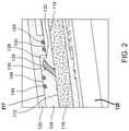
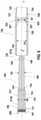
- FIG. 2is a detailed, quarter-sectional view of the single use setting tool of FIG. 1 ;
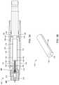
- FIG. 3Ais a side, cross-sectional view of the single use setting tool, according to an exemplary embodiment
- FIG. 3Bis a perspective view of a power charge for use in the single use setting tool
- FIG. 4is a detailed, cross-sectional view of a portion of the single use setting tool, according to an exemplary embodiment
- FIG. 5Ais a detailed, cross-sectional side view of the proximal end of the single use setting tool, according to an exemplary embodiment
- FIG. 5Bis a detailed, cross-sectional side view of the proximal end of the single use setting tool, according to an exemplary embodiment, subsequent to the melting/consumption of the initiator holder during operation of the setting tool thus disconnecting the igniter from the line in;
- FIG. 6is a breakout view of the two-piece, single use setting tool according to an exemplary embodiment
- FIG. 7is a cross sectional view of a single use setting tool including a shock absorbing assembly according to an exemplary embodiment
- FIG. 7Ais a cross sectional view of a single use setting tool including a bi-directional gas-generating power charge, according to an exemplary embodiment
- FIG. 7Bis a cross-sectional view of the bi-directional gas-generating power charge of FIG. 7A
- FIG. 7Cis a perspective view of an outer sleeve for a single use setting tool according to an exemplary embodiment
- FIG. 8is a cross sectional view of a single use setting tool including a shock absorbing assembly according to an exemplary embodiment
- FIG. 9is a cross sectional view of a single use setting tool including a stroke limiting wedge according to an exemplary embodiment
- FIG. 9Ais a cross sectional view of a single use setting tool at mid-stroke including a stroke limiting wedge with retainer according to an exemplary embodiment
- FIG. 9Bis a cross sectional view of a single use setting tool at end of stroke including a stroke limiting wedge with retainer according to an exemplary embodiment
- FIG. 10is a bottom perspective view of a booster holder according to an exemplary embodiment
- FIG. 11is a top perspective view of the booster holder of FIG. 10 ;
- FIG. 12is a side view of the booster holder of FIG. 10 ;
- FIG. 13is a top plan view of the booster holder of FIG. 10 ;
- FIG. 14is a perspective view of a hexagonally shaped power charge and container according to an exemplary embodiment
- FIG. 15is a cross sectional view of a power charge with a booster holder and booster pellet inserted therein, according to an exemplary embodiment
- FIG. 16is a cross-sectional view of a hexagonally shaped power charge positioned within a cavity of an inner piston of a single use setting tool according to an exemplary embodiment
- FIG. 17shows a single use setting tool as part of a wellbore tool string according to an exemplary embodiment
- FIG. 18shows a piston connection to a setting sleeve mandrel according to an exemplary embodiment
- FIG. 19shows a perspective view of a single use setting tool with a shock blocking structure according to an exemplary embodiment
- FIG. 20shows a perspective view of a single use setting tool with a shock blocking structure according to an exemplary embodiment
- FIG. 21shows a cross-sectional view of a single use setting tool with an axial vent according to an exemplary embodiment
- FIG. 22shows a cross-sectional view of a single use setting tool with a brake according to an exemplary embodiment
- FIG. 23is a blown-up view of a portion of the single use setting tool of FIG. 22 ;
- FIGS. 24A-24Dshow an exemplary shock absorbing wedge according to an exemplary embodiment
- FIG. 25shows the single use setting tool of FIG. 22 in the retracted position
- FIG. 26shows a cross-sectional view of a single use setting tool with a brake according to an exemplary embodiment
- FIGS. 27A-27Bshow an exemplary shock absorbing wedge according to an exemplary embodiment
- FIG. 28shows the single use setting tool of FIG. 26 in the retracted position
- FIG. 29is a blown-up view of a portion of the single use setting tool of FIG. 28 ;
- FIG. 30is a non-cross-sectional view of the single use setting tool of FIG. 26 in a semi-retracted position
- FIG. 31is a blown-up view of a portion of the single use setting tool of FIG. 30 ;
- FIG. 32shows a tool string with sleeve adapter according to an exemplary embodiment
- FIG. 33shows a single use setting tool with sleeve adapter according to an exemplary embodiment
- FIG. 34shows a sleeve adapter according to an exemplary embodiment.
- FIGS. 1A and 1Bshow an exemplary embodiment of a single use setting tool 100 according to this disclosure.
- the exemplary embodiment shown in FIGS. 1A and 1Bincludes, among other things and without limitation, an inner piston 104 and an outer sleeve 120 .
- the inner piston 104includes a proximal end 106 and a distal end 108 opposite the proximal end 106 and extends through a central bore 126 formed within the outer sleeve 120 .
- the inner piston 104 and the outer sleeve 120are generally cylindrical and coaxially assembled about a center axis x.
- the proximal end 106 of the inner pistonextends beyond a sleeve proximal end 122 of the outer sleeve 120 .
- the distal end 108 of the inner piston 104 and a portion of a distal rod 109 of the inner piston 104extend beyond a sleeve distal end 124 opposite the sleeve proximal end 122 of the outer sleeve 120 .
- the proximal end 106 of the inner piston 104includes and transitions into a seal adapter portion 107 of the inner piston 104 .
- the seal adapter portion 107is an integral portion of the inner piston 104 formed as an area of increased diameter with an inner threaded portion 508 for receiving and connecting to a seal adapter (e.g., a “tandem seal adapter (TSA)”) 512 ( FIGS. 5A and 5B ).
- a seal adaptere.g., a “tandem seal adapter (TSA)”
- TSAtandem seal adapter
- “integral” and “integrally”respectively mean a single piece and formed as a single piece.
- the distal end 108 of the inner piston 104includes an external threaded portion 105 for connecting to a wellbore tool such as a plug setting sleeve 602 ( FIG. 17 ) as discussed further below.
- the sleeve distal end 124 of the outer sleeve 120includes and transitions into a plug-setting sleeve connecting portion 127 of the outer sleeve 120 .
- the plug-setting sleeve connecting portion 127is an integral portion of the outer sleeve 120 formed as an area of reduced diameter with an outer threaded portion 125 for being received within and connecting to a tool 102 such as a plug-setting sleeve 602 ( FIG. 17 ) as discussed further below.
- the single use setting tool 100may be used or connected according to this disclosure with a variety of actuatable wellbore tools.
- proximal enddistal end
- FIG. 1Billustrates a perspective, partial quarter-sectional view of the single use setting tool 100 for actuating the tool 102 in a wellbore.
- the inner piston 104includes an intermediate section 110 positioned between the proximal end 106 and the distal rod 109 which extends to the distal end 108 .
- the distal rod 109is a portion of the inner piston 104 having an outer diameter D 2 ( FIG. 6 ) that is less than an outer diameter D 4 ( FIG. 6 ) of the intermediate section 110 , as explained further below.
- the inner piston 104may be formed as an integral component.
- the intermediate section 110 of the inner piston 104has an annular wall 112 enclosing a cavity 114 .
- the cavity 114is configured to receive a power charge 116 therein.
- An initiator 118may be wholly positioned in the proximal end 106 of the inner piston 104 adjacent the power charge 116 .
- the initiator 118is used to initiate combustion of the power charge 116 to form a combustion gas pressure inside the cavity 114 .
- the outer sleeve 120is configured to slideably receive the inner piston 104 within the central bore 126 .
- a generally annular expansion chamber 128may be defined by an inner portion 130 ( FIG. 2 ) of the outer sleeve 120 and an outer portion 132 of the annular wall 112 of the inner piston 104 . This generally annular expansion chamber 128 within the single use setting tool 100 is illustrated in greater detail in FIG. 2 .
- FIG. 2a perspective, partial quarter-sectional detail view of a portion of the single use setting tool 100 is shown.
- the outer sleeve 120is the outermost structure shown in FIG. 2 and the expansion chamber 128 , according to an exemplary embodiment, is shown in detail.
- a gas diverter channel 134extending through the annular wall 112 of the inner piston 104 .
- the gas diverter channel 134is configured to allow gas pressure communication between the cavity 114 containing the power charge 116 and the expansion chamber 128 .
- the combustion gaswill pass through the gas diverter channel 134 and into the expansion chamber 128 .
- Increasing amounts of gaseous combustion productswill increase the pressure in the cavity 114 , the gas diverter channel 134 and the expansion chamber 128 .
- the expansion chamber 128is so named because it is adapted to expand in volume as a result of axial movement of the outer sleeve 120 relative to the inner piston 104 .
- the increasing gas pressure in the expansion chamber 128will exert an axial force on outer sleeve 120 and the inner piston 104 , resulting in the outer sleeve 120 sliding axially toward the tool 102 and the expansion chamber 128 increasing in volume.
- the initiator 118is configured for positioning in an initiator holder 138 .
- Initiator 118may be of the type described in U.S. Pat. No. 9,581,422 (previously mentioned), which is incorporated herein by reference in its entirety, and comprise an initiator head 146 and an initiator shell 136 .
- the initiator shell 136may contain an electronic circuit board (not shown) and, ignition element, e.g., a fuse head (not shown), capable of converting an electrical signal into a deflagration, pyrotechnical flame, or combustion, and an ignitable material (not shown) for being ignited by the ignition element.
- ignition elemente.g., a fuse head (not shown)
- the initiator holder 138includes an axial body portion 143 that defines a channel 137 extending axially through the initiator holder 138 and is configured for receiving the initiator shell 136 therein.
- the initiator holder 138further includes an initiator holder head portion 145 which receives the initiator head portion 146 when the initiator 118 is inserted into the initiator holder 138 .
- the initiator head 146includes an electrically contactable line-in portion 147 through which electrical signals may be conveyed to the electronic circuit board of initiator 118 .
- the initiator holder 138may be configured for positioning the initiator shell 136 , and more particularly the ignitable material therein, adjacent the power charge 116 within the inner piston cavity 114 .
- the initiator holder 138may include fins 141 extending radially away from the axial body 143 of the initiator holder 138 .
- the fins 141secure and/or orient the initiator holder 138 within the inner piston cavity 114 by abutting the annular wall 112 , and in certain exemplary embodiments the fins 141 may be fit within corresponding grooves or retaining structures (not shown) on the inner portion 130 of the outer sleeve 120 .
- the energetic portion of initiator 118is positioned sufficiently close to power charge 116 so as ignition thereof will initiate combustion of power charge 116 .
- the material used to fabricate the initiator holder 138may be a material, e.g., a polymer or a low-melting point solid material, that will be consumed, melted, fragmented, disintegrated, or otherwise degraded by initiation of the initiator 118 and/or combustion of power charge 116 .
- combustion of the power charge 116will consume, melt or otherwise degrade initiator holder 138 sufficiently such that initiator holder 138 will, essentially, be consumed during combustion of the power charge 116 .
- FIGS. 5A and 5Bare cross-sectional, side views of proximal end 106 of inner piston 104 containing initiator 118 and initiator holder 138 prior to and after combustion of the power charge, respectively.
- the proximal end 106 of piston 104is adapted, e.g., utilizing threads 508 and/or press fit/o-rings 510 , to receive or otherwise have connected thereto the seal adapter 512 containing a bulkhead assembly 514 .
- Seal adapter 512is not a firing head because it does not house an igniter/initiator.
- Bulkhead assembly 514may be of the type described in U.S. Pat. No. 9,605,937 and/or U.S. Patent Publication No.
- a proximal contact pin 518 of the bulkhead assembly 514is adapted to receive electrical signals from the surface (or an upstream tool as the case may be), which signals are conveyed through the bulkhead assembly 514 to a distal contact pin 516 .
- the bulkhead assembly 514effectively isolates (e.g., from gas pressure, fluid, and the like) the setting tool 100 from an upstream gun or tool.
- the bulkhead assembly 514also functions to align its distal contact pin 516 with the line-in electrical contact 147 of the initiator 118 , thus conveying electrical signals from the surface (or upstream tool) to the initiator 118 .
- a firing headis a device which includes a housing enclosing a variable configuration of elements for detonating an explosive charge.
- the ‘explosive charge’may or may not really be explosive and, for that reason, is more likely to be referred to as a “power charge.”
- the housing of a firing head for use with a setting toolwould either be connected directly to a mandrel or connected to the mandrel via a firing head adapter. Either way, the firing head housing is connected in such a way that the element that begins the detonation is sufficiently close to the power charge.
- the setting tool 100does not require a firing head.
- FIG. 5A and FIG. 5Billustrate a shot confirmation operation of the single use setting tool 100 , in an exemplary embodiment.
- initiator holder 138is present in the proximal end 106 of the single use setting tool 100 before initiation of power charge 116 and distal contact pin 516 of the bulkhead assembly 514 is in electrical contact with the line-in electrical contact 147 of initiator 118 .
- FIG. 5Billustrates in a highly stylized fashion the proximal end 106 after initiation and combustion of the power charge 116 .
- initiator holder 138After initiation and during combustion of power charge 116 , initiator holder 138 is degraded and substantially vanishes, allowing initiator 118 to drop to the bottom of the cavity 114 in inner piston 104 . That is, the initiator 118 is no longer in electrical contact with the distal contact pin 516 of bulkhead assembly 514 .
- the single use setting tool 100may allow shot confirmation based on the initiator 118 having electrically disconnected from the distal contact pin 516 of the bulkhead 514 . Absence of the connection between the initiator 118 and the distal contact pin 516 of the bulkhead 514 may indicate that initiation of the initiator 118 and/or combustion of the power charge 116 has successfully occurred.
- the ignitermay be destroyed to one extent or another by initiation of the igniter and/or the combustion of the power charge.
- an electronic circuit board of the ignitersometimes survives the ignition/burn and remains functional. Thus, electrical signals from the surface may be received and acknowledged by the circuitry of a spent igniter in current setting tools even after an effective ignition and/or combustion of its power charge.
- FIG. 3Ais a side cross-sectional view of the single use setting tool 100 , according to an exemplary embodiment.
- the single use setting tool 100may also include one or more gas flow paths 142 (see also FIG. 16 ) disposed between an exterior surface 144 of the power charge 116 and the annular wall 112 of the inner piston 104 in a radial direction of the single use setting tool 100 .
- the gas flow paths 142may be embodied as a groove(s) formed in the exterior surface 144 of the power charge 116 ( FIG. 3B ), or as a groove(s) formed in the annular wall 112 ( FIG. 3A ) of the inner piston 104 , or a combination of both.
- the one or more gas flow paths 142may extend axially along a substantial length of the power charge 116 .
- the gas flow path 142is configured to allow gas pressure communication along an axial length of the power charge 116 and with the gas diverter channel 134 .
- the power charge 116combusts from the proximal end 116 a ( FIG. 7 ), adjacent the initiator 118 , toward the distal end 116 b ( FIG. 7 and FIG. 7B ), adjacent the gas diverter channel 134 .
- the combustion of the power charge 116is not limited directionally—for example, the power charge 116 may combust from the distal end 116 b toward the proximal end 116 a , such as described in U.S. Provisional Patent Application No. 62/853,824 filed May 29, 2019, which is commonly owned by DynaEnergetics Europe GmbH and incorporated herein by reference, in its entirety.
- the gas flow path 142provides an immediate or far earlier gas pressure path from the combusting proximal end of power charge 116 to the gas diverter channel 134 .
- the gas flow path 142prevents a large build-up of gas pressure in the cavity 114 that is blocked from reaching the gas diverter channel 134 by the unburned power charge 116 .
- the current problem of pressure build-up being delivered as a single pulsemay be avoided with the gas flow path 142 .
- the axial force exerted on outer sleeve 120may be increased relatively gradually, over the course of seconds, thus enabling a simple and economical means of achieving slow set delivery of force by the single use setting tool 100 on tool 102 ( FIG. 1B ).
- the power charge 116may include an indentation 140 adjacent the initiator 118 and/or initiator holder 138 .
- the indentation 140is configured to increase the reliability that the initiator 118 initiates the combustion of the power charge 116 .
- indentation 140may be filled or lined with a booster charge (not shown), the chemical makeup of the booster charge being more sensitive to initiation than the chemical makeup of the power charge 116 .
- FIG. 3Bis a perspective view illustrating the power charge 116 , the gas flow path 142 , and the indentation 140 , according to an exemplary embodiment.
- the indentation or cylindrical recess 140 in the power charge 116may provide igniter room to build a flame.
- the flame from the ignitermay not have the opportunity to achieve a threshold level to initiate combustion of the power charge 116 .
- the surface area increase resulting from the indentation 140may aid ignition of the power charge 116 .
- the power charge of currently available reusable setting toolsmust be a separate unit, provided separately from the setting tool to enable the resetting of a ‘spent’ setting tool.
- the power charge 116may be configured to be integral with and non-removable from the single use setting tool 100 . This configuration has the potential to achieve cost savings in the construction and supply chain for setting tool 100 .
- the power charge 116may include a combustible material selected from the following materials: black powder and a black powder substitute.
- the combustible materialmay also be selected from the following materials: Pyrodex, Goex Clear Shot, binding agents, wheat flour, potassium nitrate, sodium nitrate, epoxy resin, graphite powder, and Triple Seven.
- the initiator 118may be configured to be inserted into the single use setting tool 100 at a wellsite immediately prior to the single use setting tool 100 being inserted into the wellbore.
- a first seal 148 and a second seal 150 positioned at opposite ends of the expansion chamber 128function to seal the expansion chamber 128 .
- the first seal 148 and the second seal 150may be configured for ensuring that the expansion chamber 128 remains gastight but without impairing the ability of the outer sleeve 120 to slide axially relative to the inner piston 104 .
- the first seal 148is positioned relative to the intermediate section 110 of the inner piston 104 and the inner portion 130 of the outer sleeve 120 and the second seal 150 is positioned relative to a sealing section 524 ( FIG. 6 ) of the outer sleeve 120 and the distal rod 109 of the inner piston 104 .
- Each of the first seal 148 and the second seal 150may include one or more O-rings 149 .
- the single use setting tool 100may include a shear element 152 connected to the inner piston 104 and the outer sleeve 120 .
- the shear element 152may be configured to prevent premature axial sliding of the outer sleeve 120 relative to the inner piston 104 . Shearing of the shear element 152 allows the axial sliding of the outer sleeve 120 relative to the inner piston 104 subsequent to the formation of the combustion gas in the expansion chamber 128 exceeding a threshold pressure. That is, once the gas pressure in expansion chamber 128 reaches a threshold pressure, the force pushing axially against outer sleeve 120 will cause the shear pin 152 to shear. The outer sleeve 120 will then be free to move axially relative to inner piston 104 .
- the single use setting tool 100may also include a pressure vent 154 as illustrated in FIG. 3A .
- the pressure vent 154may extend through the outer sleeve 120 adjacent the piston proximal end 122 .
- the pressure vent 154may be configured to release the combustion gas pressure in the expansion chamber 128 subsequent to the axial sliding of the outer sleeve 120 along a sufficient axial distance relative to the inner piston 104 .
- the sufficient axial distancemay include a distance sufficient for outer sleeve 120 to exert a desired force on the tool 102 in the wellbore over a desired distance. For example, movement of the outer sleeve 120 a particular distance results in the pressure vent 154 passing over the first seal 148 portion.
- the gas pressure in the expansion chamber 128may escape therefrom through the pressure vent 154 .
- the venting of the gas pressure in the expansion chamber 128quickly eliminates the axial force being exerted on the outer sleeve 120 .
- a bung(not shown) may be disposed in the pressure vent 154 to the prevent pressure vent 154 from being a route for contaminants to enter the single use setting tool 100 . The bung would be removed automatically by the pressure exerted through the pressure vent 154 when first exposed to the expansion chamber 128 .
- FIG. 4is a cross-sectional, partial, magnified view of an expansion chamber 128 according to an exemplary embodiment.
- the expansion chamber 128 of FIG. 4is generally annular and may be defined by the inner portion 130 of the outer sleeve 120 and the outer portion 132 of the annular wall 112 of the inner piston 104 .
- the assemblymay also include a first seal 148 and a second seal 150 positioned at opposite ends of the expansion chamber 128 and augmented by O-rings 149 .
- the gas diverter channel 135extends a substantial distance along an axial direction of the inner piston 104 of the single use setting tool 100 .
- the effect of one or more such axially extending gas diverter channels 135is very similar to the effect of the gas flow path 142 in FIG. 3A . That is, the pressurized gas developed by the combustion of the power charge 116 is provided with a gas pressure path to the gas diverter channel 135 much earlier than in available setting tools. Thus, the current problem of pressure build-up being delivered as a single pulse may be avoided with the axially extending gas diverter channels 135 .
- the axial force exerted on the outer sleeve 120may be increased relatively gradually, over the course of seconds, thus enabling a simple and economical means of achieving slow set delivery of force by the outer sleeve 120 on the tool 102 .
- the single use setting tool 100 embodiment shown in FIG. 4includes the inner piston intermediate section 110 that includes the annular wall 112 , and the distal rod 109 .
- the annular wall 112 of the inner piston 104is an annular wall of both the intermediate section 110 and the distal rod 109 (see FIG. 1B ) in the integral inner piston 104 piece. Accordingly, a portion of each of the cavity 114 and the power charge 116 may be enclosed by the annular wall 112 with respect to both the intermediate section 110 and the distal rod 109 .
- the intermediate section 110has a greater outside diameter D 4 ( FIG. 6 ) than the outside diameter D 2 of the distal rod 109 .
- the setting toolis single use.
- the choice of materials to be used in the setting toolis completely altered by the fact that the setting tool is for one-time use. Little to no consideration is given to wear and tear issues. Also, any engineering needed as part of resetting, i.e., re-dressing and refilling with consumed parts, is not required.
- the setting devicehas fewer and simpler parts, i.e., going from tens of highly precise machined parts of high quality materials that need to function over and over again (in existing setting tools) to a one time use item of significantly fewer and less highly engineered parts. These factors result in a substantial reduction in unit cost. In addition, there is no requirement for maintenance and training as to reuse/re-dressing/refilling.
- the single use setting tool as disclosed hereinis, compared to currently available setting tools, simpler, comprising fewer parts, far less expensive, works without a firing head, is single use and provides shot confirmation.
- two-piece designrefers generally to the inner piston 104 and the outer sleeve 120 (as shown in FIG. 6 ) being the two major structural components of the exemplary single use setting tool.
- Exemplary embodiments of a single use setting tool according to the disclosureobviate the need for a firing head and therefore allow the inner piston 104 to connect directly to a seal adapter 512 , eliminating not only a firing head mechanism but adapters that many conventional setting tools require for connecting to a firing head.
- the inner piston 104 and the outer sleeve 120 shown in FIG. 6are substantially similar to the exemplary embodiments shown and described with reference to FIGS. 1A-2 .
- the exemplary embodiment of the inner piston 104 shown in FIG. 6includes first and second gas diverter channels 134 in communication with a free volume portion 523 ( FIG. 7 ) of the cavity 114 within the inner piston 104 , as described further below.
- inner piston 104may be inserted distal end 108 first in a direction d into the central bore 126 of the outer sleeve 120 .
- the inner piston 104 and the outer sleeve 120 including the central bore 126are, in an exemplary embodiment, cylindrically shaped and configured to fit together coaxially about an axis x.
- a passage 525 through the sealing section 524 of the outer sleeve 120may have a diameter D 1 that is sufficient for allowing the distal end 108 and the distal rod 109 , having a diameter D 2 , to be received through the passage 525 from the central bore 126 to a distal bore 526 of the outer sleeve 120 while still forming the second seal 150 .
- the central bore 126 of the outer sleeve 120may have a diameter D 3 for receiving the intermediate section 110 , having a diameter D 4 , of the inner piston 104 while still forming the first seal 148 .
- the diameter D 3 of the central bore 126 and the diameter D 4 of the intermediate section 110 of the inner piston 104are each greater than the diameter D 1 of the passage 525 through the sealing section 524 , due to a protrusive shoulder 527 that extends inward from the inner portion 130 of the outer sleeve 120 as part of the sealing section 524 .
- This configurationin certain exemplary embodiments, for example as shown and described with respect to FIG. 2 , defines in part the expansion chamber 128 of the setting tool 100 .
- the outer sleeve 120includes a shear element aperture 513 a extending from an outer surface 125 of the outer sleeve 120 to the central bore 126 and the inner piston 104 includes a shear element notch 513 b in an outer surface 517 of the inner piston 104 .
- the shear element aperture 513 ais aligned with the shear element notch 513 b when the inner piston 104 is positioned within the central bore 126 .
- the shear element aperture 513 a and the seal element notch 513 bare together configured for receiving the shear element 152 that extends between and is positioned within each of the shear element aperture 513 a and the shear element notch 513 b to secure the inner piston 104 within the central bore 126 .
- an exemplary embodiment of a single use setting tool 100may include a configuration substantially as previously described with respect to FIGS. 1A-2 , including an outer sleeve 120 and an inner piston 104 positioned within central bore 126 of the outer sleeve 120 .
- the inner piston 104may include a cavity 114 and a power charge 116 positioned within the cavity 114 as previously discussed.
- First and second pressure vents 154extend through the outer sleeve 120 into the inner bore 126 for venting excess pressure from consumption of the power charge 116 , as previously discussed.
- FIG. 1A-2an exemplary embodiment of a single use setting tool 100 according to the disclosure may include a configuration substantially as previously described with respect to FIGS. 1A-2 , including an outer sleeve 120 and an inner piston 104 positioned within central bore 126 of the outer sleeve 120 .
- the inner piston 104may include a cavity 114 and a power charge 116 positioned within the cavity 114 as previously discussed.
- a free volume portion 523exists within the cavity 114 between a distal end 116 b of the power charge 116 and the first and second gas diverter channels 134 , which are open to each of the cavity 114 and a gas expansion chamber 128 for actuating the outer sleeve 120 and the inner piston 104 to slide axially relative to one another.
- the initiator holder 138is positioned at least in part within the inner piston cavity 114 and receives and retains the initiator 118 therein.
- the initiator holder 138is positioned to receive and retain the initiator 118 substantially coaxially with the seal adapter portion 107 and the inner piston cavity 114 .
- the initiator 118 and/or the initiator holder 138may be positioned such that a portion of the initiator 118 and/or the initiator holder 138 , such as the initiator head 146 and/or the line-in portion 147 of the initiator 118 , may extend into the seal adapter portion 107 of the inner piston 104 ; in particular, an open interior area 519 of the seal adapter portion 107 .
- the initiator 118 and the initiator holder 138may be positioned entirely within the inner piston cavity 114 .
- the initiator holder 138may include a coupling end 139 adjacent to the power charge 116 , for robustly securing the initiator 118 in position for initiating the power charge 116 and keeping pressure contained between the coupling end 139 and the gas diverter channels 134 during consumption of the power charge 116 , for example after the initiator holder 138 has been degraded according to embodiments including a shot confirmation as previously discussed.
- the initiator holder 138may include a fluted section 119 opposite the coupling end 139 .
- the fluted section 119may provide both a wider profile for helping to orient and center the initiator holder 138 within the inner piston cavity 114 and an enlarged surface against which the seal adapter 512 may abut when it is inserted in the seal adapter portion 107 .
- the initiator holder 138may include a ground bar connection 121 that may electrically contact and ground, e.g., the shell 136 of the initiator 118 to the annular wall 112 of the inner piston 104 .
- the exemplary embodiment that FIG. 7 showsincludes a shock absorbing assembly 530 .
- the shock absorbing assembly 530dampens shock that may be generated upon actuation of a wellbore tool by the single use setting tool 100 .
- the single use setting tool 100is used with the plug setting sleeve 602 and the plug 603 (as discussed below)
- separation of the plug 603 from the plug setting sleeve 602results in a substantial amount of shock, as explained further below, that may damage or reduce the lifetime of the reusable setting sleeve 602 and/or a setting sleeve mandrel 610 ( FIG. 18 ) component thereof.
- Excessive shockis known to occur when single use setting tools are used, because single use setting tools do not contain, e.g., oil cushions that are provided but must be refilled/replaced in reusable setting tools.
- the shock absorbing assembly 530 in the exemplary embodiment of FIG. 7includes a shock dampener 531 and a rigid retainer 532 .
- the shock dampener 531 in the exemplary embodimentis a cushioning component that may be formed from, without limitation, a polymer or plastic.
- the shock dampener 531may be cylindrical pad.
- the rigid retainer 532holds the shock dampener 531 in place and is also a stabilizing and shock-distributing component that may be formed from metal or any known material consistent with this disclosure.
- the rigid retainer 532may be, without limitation, a retaining ring such as a steel ring, a c-clip, or the like.
- Each of the shock dampener 531 and the rigid retainer 532 in the exemplary embodimentis formed such that the distal rod 109 of the inner piston 104 may pass through them—for example, the shock dampener 531 and the rigid retainer 532 may be annular elements through which the distal rod 109 passes.
- FIG. 7Ca perspective view of an exemplary outer sleeve 120 for use with a single use setting tool 100 according to, e.g., the exemplary embodiments shown in FIGS. 7 and 8 is shown from the distal end 124 of the outer sleeve 120 .
- the exemplary outer sleeve 120may include a retaining ring groove 655 formed in the inner portion 130 of the outer sleeve 120 and positioned within the distal bore 526 of the outer sleeve 120 .
- the retaining ring groove 655may position and hold the rigid retainer 532 in place. Accordingly, the shock absorber assembly 530 will remain in place relative to the outer sleeve 120 as the outer sleeve 120 strokes over the inner piston 104 .
- the exemplary single use setting tool 100 as described with respect to FIG. 7is shown with an alternative exemplary embodiment of the shock absorbing assembly 530 .
- the shock dampener 531is an o-ring and the rigid retainer is a steel ring 532 according to the same purposes and principles as described with respect to FIG. 7 .
- the shock absorbing assembly 530has been described according to certain exemplary embodiments but is not limited thereto and may include various materials, components, and configurations consistent with the disclosure.
- the exemplary single use setting tool 100 as described with respect to FIG. 7is shown excepting the shock absorbing assembly 530 .
- the distal rod 109 portion of the inner piston 104includes one or more wedges 533 that may be, without limitation, discrete features on the outer surface 517 of the inner piston 104 or a continuous feature about its periphery.
- the one or more wedges 533may be integrally formed or machined as part of the inner piston 104 or may be formed or attached thereto according to any known technique consistent with this disclosure.
- the wedge 533may be made from any material consistent with a particular application.
- the wedge 533may be made from a relatively soft material such as, without limitation, plastic, composite, and the like, to serve as a brake and a shock absorber for the outer sleeve 120 in use as it strokes over the inner piston 104 as explained further below.
- the singular term wedge 533may include the one more wedges as described.
- the wedge 533is an annular and wedge-shaped attachment that is attached to the distal rod 109 portion of the inner piston 104 .
- the wedge 533 in the exemplary embodimentmay be made of plastic and/or composite.
- the wedge 533extends away from the outer surface 517 of the inner piston 104 , e.g., at a position on the distal rod 109 , such that the diameter D 2 of the distal rod 109 at the position of the wedge 533 , plus the length to which the wedge 533 extends away from the outer surface 517 of the distal rod 109 , is greater than the diameter D 1 of the passage 525 through the sealing section 524 of the outer sleeve 120 .
- Reducing the stroke length of the outer sleeve 120may be beneficial for reducing the amount of shock generated during detachment of the actuated tool because reducing the stroke length reduces the amount of distance along which the inner piston 104 can relatively accelerate into the distal bore 526 of the outer sleeve 120 ( FIGS. 9A and 9B ).
- FIGS. 9A and 9Bcross sectional views around the sealing section 524 of the outer sleeve 120 of an exemplary single use setting tool 100 similar to that shown in FIG. 9 are shown as when the outer sleeve 120 is in mid-stroke ( FIG. 9A ) and at the end of the stroke ( FIG. 9B ).
- mid-strokethe wedge 533 has not yet contacted the protrusive shoulder 527 ′ and the outer sleeve 120 continues to stroke.
- the wedge 533has contacted the protrusive shoulder 527 ′ and a portion of the wedge 533 is compressed between the inner piston 104 and the sealing section 524 , within the passage 525 through the sealing section 524 .
- the exemplary embodiments shown in FIGS. 9A and 9Binclude a wedge retaining ring 533 a for keeping the wedge 533 from sliding off of the inner piston 104 , particularly after the wedge 533 contacts the protrusive shoulder 527 ′.
- the wedge retaining ring 533 ais retained in a wedge retaining ring groove 533 b that is formed in the outer surface 517 of the inner piston 104 .
- FIGS. 9A and 9Balso show the retaining ring groove 655 for the retaining ring 532 portion of the shock absorber assembly 530 shown and described with respect to FIGS. 7 and 8 .
- the exemplary embodiments shown in FIGS. 9-9Bmay be used in conjunction with the shock absorbing assembly 530 . In such embodiments, the wedge 533 will prevent further stroking of the outer sleeve 120 when it jams against the shock absorbing assembly 530 .
- the power charge 116 in the exemplary embodiment shown in FIG. 7 , FIG. 7A , and FIG. 7Bincludes the indentation 140 at a proximal end 116 a of the power charge 116 .
- a booster 528 , 528 a , 528 bis positioned within the indentation 140 in sufficient proximity to the initiator 118 such that initiation of the initiator 118 will initiate the booster 528 , 528 a , 528 b to release additional energy.
- Boostersare well-known in the art and the booster 528 , 528 a , 528 b may be any known booster, including charges, energetic materials, or chemically reactive materials.
- the booster 528 , 528 a , 528 bmay be larger and release more energy than an ignition source in the initiator 118 .
- the booster 528 , 528 a , 528 bmay improve the efficiency and/or reliability of igniting the power charge by providing an additional energy source against additional surface area of the power charge 116 .
- the booster 528 , 528 a , 528 bis a booster pellet made from energetic material.
- the booster 528 , 528 a , 528 bis positioned and held in place by a booster holder 529 , 529 a , 529 b .
- the booster holder 529 , 529 a , 529 bis positioned between the initiator 118 and the power charge 116 and is configured for receiving and positioning the booster 528 , 528 a , 528 b within the indentation 140 of the power charge 116 .
- the booster 528 ais a first booster and the booster holder 529 a is a first booster holder.
- the power charge 116includes a second booster 528 b , which may be configured substantially as described hereinabove and illustrated in FIG. 7 , thus for purposes of convenience and not limitation, the details of the second booster 528 b are not repeated hereinbelow.
- the first and second boosters 528 a , 528 b , and their corresponding booster holders 529 a , 529 bmay be positioned within the cavity 114 of the inner piston 104 , such that it is in frictional engagement with a container 170 (described in further detail hereinbelow) ( FIG. 7B and FIGS. 14-15 ) housed in the annular wall 112 of the cavity 114 .
- the second booster 528 bis positioned toward the distal end 116 b of the power charge 116 and is spaced apart from the first booster 528 a (positioned at the proximal end 116 a of the power charge 116 ).
- the second booster 528 bmay be configured to release more energy than the ignition source in the initiator 118 and may improve the efficiency and/or reliability of igniting the power charge 116 by providing an additional energy source against additional surface area of the power charge 116 .
- the second booster 528 bis secured in the second booster holder 529 b and positioned such that it is in line with the free volume portion 523 of the cavity 114 within the inner piston 104 .
- the exemplary power charge 116 including the first booster 528 a and the second booster 528 b as shown in FIGS. 7A and 7Bcan be installed in either direction within the cavity 114 of the inner piston 104 .
- a booster 528 a , 528 bwill be adjacent the initiator 118 whether the power charge 116 is inserted into the cavity 114 proximal-end 116 a first (i.e., nearest to the gas diverter channels 134 ) or the distal-end 116 b first. This prevents installing a power charge in the wrong direction (i.e., “backwards”), that is, with a single booster adjacent only the distal end 116 b and no booster adjacent the initiator 118 .
- the exemplary power charge 116 including the first booster 528 a and the second booster 528 b as shown in FIGS. 7A and 7Bmay be positioned within the cavity 114 by, among other things, inserting, first, either the proximal end 116 a or the distal end 116 b of the power charge 116 , into the cavity 114 .
- exemplary power charge 116 shown in FIGS. 7A and 7B(i.e., “bi-directional power charge 116 ”) has been shown and described in exemplary use with a disposable setting tool, the disclosure is not so limited and the exemplary bi-directional power charge 116 including a first booster 528 a and a second booster 528 b positioned on opposite ends 116 a , 116 b of the power charge 116 may be similarly used with any known wellbore tools consistent with this disclosure. Further, the exemplary bi-directional power charge 116 is not limited to the shape, configuration, assembly of components, particular features, etc. as disclosed for use with the exemplary disposable setting tool 100 , or otherwise. Variations to the exemplary bi-directional power charge 116 are possible within the spirit of this disclosure.
- booster holder 529may include a booster receiver 232 , a booster holder top 234 and an opening 236 in the booster holder top 234 .
- the booster receiver 232may extend from an underside 235 of booster holder top 234 .
- the booster receiver 232is sized to receive and retain a booster 528 of the type previously discussed—for example, a booster pellet in certain exemplary embodiments.
- the booster 528may be of a material in which it is easier to begin deflagration/energetic release than the material in the power charge 116 .
- the power charge 116may be disposed in a container 170 ( FIG. 14 ) that protects and holds together the power charge 116 .
- the power charge 116may be positioned within the container 170 and the booster holder 529 may be inserted into the power charge 116 , e.g., within a body 178 of the power charge 116 .
- the booster holder 529may be completely surrounded, but for the booster holder top 234 , by the energetic material of the power charge body 178 .
- the booster holder 529may be retained in place by engaging the power charge body 178 and/or the power charge container 170 .
- the booster holder top 234may function as the top of the power charge container 170 .
- the material for the power charge container 170may be rigid or semi-rigid so as to retain the desired power charge shape. Many polymers would be an appropriate choice for the container 170 . Exemplary materials may be polypropylene (for standard applications) and polyamide (for high temperature applications). The material and dimensions of the container 170 are selected such that the container 170 will melt or otherwise break-down quickly when exposed to the energy (heat and pressure) generated by combustion of the power charge 116 . Thus, the container 170 will not impede pressurized gas generated by the power charge 116 from accessing the gas diverter channels 134 .
- the booster holder 529functions to retain the booster 528 in close proximity to the power charge body 178 , i.e., the energetic material, at a proximal end 116 a of the power charge 116 .
- the power charge 116 having a booster holder 529 according to FIGS. 14 and 15may be positioned in the cavity 114 of the inner piston 104 of the single use setting tool 100 such that the initiator 118 is adjacent the booster holder 529 .
- the ignition source of the initiator 118may be adjacent and/or aligned with the opening 236 through the booster holder top 234 and thereby with the booster 528 in the booster receiver 232 of the booster holder 529 .
- the exemplary arrangementmay enhance reliability and efficiency for causing deflagration (i.e., ignition) of the power charge 116 .
- the power charge 116(and the container 170 in embodiments including the container 170 ) has, without limitation, a hexagonally-shaped transverse cross-section along, e.g., line A-A in FIG. 14 .
- the phrase “hexagonally-shaped power charge”may refer to a power charge having a hexagonally-shaped transverse cross-section.
- the cross-sectional view of the hexagonally-shaped power charge 116is shown as it would be received in the cavity 114 of the inner piston 104 according to the exemplary embodiments.
- FIG. 16shows a hexagonally-shaped power charge 116
- the power charge 116is not limited to having a hexagonally-shaped transverse cross-section.
- the power charge 116in various exemplary embodiments may have a cross-section according to any shape or configuration including, without limitation, polygonal, circular, symmetric or asymmetric, and the like, consistent with the disclosure.
- the power charge 116is sized and shaped such that vertices 191 of the hexagonally-shaped power charge 116 within the cavity of the inner piston 104 are positioned to abut or contact the annular wall 112 of the cavity 114 to provide a secure fit of the power charge 116 within the cavity 114 .
- Flat sides 192 of the hexagonally-shaped power charge 116i.e., radial outer surfaces of the hexagonally-shaped power charge
- gas flow channels 190that extend axially along the length of the cavity 114 .
- Expanding combustion gas resulting from the combustion of the power charge 116is able to flow into and axially through these gas flow channels 190 to the gas diverter channels 134 and the expansion chamber 128 of the single use setting tool 100 , especially during early stages of combusting the power charge 116 .
- the size, shaped, and configuration of the power charge 116may be varied to provide gas flow channels 190 with a particular volume for achieving a desired speed at which axial movement between the outer sleeve 120 and the inner piston 104 occurs and progresses, based on the speed and volume at which the combustion gases will reach the expansion chamber 128 .
- slow-set setting toolsin which the setting takes place relatively gradually as opposed to abruptly may be preferable for actuating a tool against a resistance created by the tool, or generally reducing the amount of shock created during actuation and/or separation of the tool.
- gas flow channel 190 and the gas flow path 142 discussed with respect to FIGS. 3A and 3Bare similar in form and function.
- an exemplary arrangement of a tool string 600 including a single use setting tool 100may include a perforating gun 601 (which may be the last in a string of perforating guns or other wellbore tools above, i.e., upstream, of the single use setting tool 100 ), the seal adapter 512 , the single use setting tool 100 , a plug setting sleeve 602 , and a plug 603 .
- the perforating gun 601is connected to the second connecting portion 522 of the seal adapter 512 and the seal adapter portion 107 of the inner piston 104 is connected to the first connecting portion 521 of the seal adapter 512 .
- the bulkhead 514is positioned within the bore 515 through the seal adapter 512 and relays an electrical signal from an electrical connector (not shown) in the perforating gun 601 to the line-in portion 147 of the initiator 118 . Accordingly, for purposes of this disclosure, “bulkhead 514 ” and “electrical feedthrough bulkhead 514 ” and variations thereof, such as “electrical feedthrough bulkhead assembly 514 ,” may be used interchangeably.
- the proximal contact pin 518 of the bulkhead 514is in electrical contact with the electrical connector in the perforating gun 601 and, within the bulkhead, the distal contact pin 516 of the bulkhead 514 .
- the proximal contact pin 518relays the electrical signal from the electrical connector in the perforating gun 601 to the line-in portion 147 of the initiator head 146 , via the distal contact pin 516 which is in electrical contact with the line-in portion 147 .
- the electrical signalmay be a signal for triggering initiation of the initiator 118 .
- the single use setting tool 100may connect to the plug setting sleeve 602 by, without limitation, a threaded connection between the external threads 125 of the outer sleeve distal end 124 and complementary threading on a connecting portion 604 of the plug setting sleeve 602 .
- the inner piston 104may connect to a setting sleeve mandrel 610 of the plug setting sleeve 602 as are known in the art.
- the external threads 105 on the distal end 108 of the inner piston 104may threadingly connect to a complementary threaded portion on a connecting portion 611 of the setting sleeve mandrel 610 .
- the plug setting sleeve 602includes a plurality of shear studs 612 that connect the plug setting sleeve 602 to a plug mandrel 605 of the plug 603 , thereby mounting the setting sleeve 602 to the plug 603 .
- releasing the plug 603 from the setting sleeve 602is an abrupt and shock-generating event because release occurs when the outer sleeve 120 has put enough pressure on the plug setting sleeve 602 to break the shear studs 612 .
- the requisite pressureis generated by the inner piston 104 and the outer sleeve 120 exerting respective, opposing forces according to the operation of the single use setting tool 100 as described herein.
- the inner piston 104is exerting a pulling force in a direction ‘b’ on the setting sleeve mandrel 610 while the outer sleeve 120 and the plug setting sleeve 602 are stroking in a direction ‘a’ over the inner piston 104 and the setting sleeve mandrel 610 .
- the shear studs 612break and the plug 603 is released, the sudden removal of resistance against the stroke of the outer sleeve 120 causes rapid acceleration of the outer sleeve 120 in the direction ‘a’ and corresponding relative acceleration of the inner piston 104 and the setting sleeve mandrel 610 in the direction ‘b’.
- the power charge 116is consumed and the outer sleeve 120 is slid axially, relative to the inner piston 104 as previously described, in a direction ‘a’. Accordingly, the outer sleeve 120 pushes the plug setting sleeve 602 in the direction ‘a’ and thereby creates compression forces on the plug 603 which causes the plug 603 to expand and set.
- FIG. 18an isolated view of the connection between the inner piston 104 and the plug setting sleeve 602 is shown according to an exemplary embodiment.
- the view shown in FIG. 18represents the state of the single use setting tool 100 and plug setting sleeve 602 after the plug 603 has been released—i.e., after the outer sleeve 120 has finished its stroke and the shear studs 612 have broken between the setting sleeve 602 and the plug mandrel 605 .
- the inner piston 104 and the connecting portion 611 of the setting sleeve mandrel 610have been retracted into the distal bore 526 at the outer sleeve distal end 124 .
- FIG. 18also shows in further detail the threaded connections between the external threads 125 of the outer sleeve distal end 124 and complementary threading on the connecting portion 604 of the plug setting sleeve 602 and the external threads 105 of the distal end 108 of the inner piston 104 and the complementary threaded portion on the connecting portion 611 of the setting sleeve mandrel 610 .
- an exemplary embodiment of a single use setting tool 100may include a shock blocking structure 650 such as shock blocking pins 650 as will be further explained with respect to FIG. 19 .
- the shock blocking pins 650are positioned adjacent to an end 613 of the mandrel 610 in relatively close proximity, especially when compared with the shock absorbing assemblies 530 discussed with respect to FIGS. 7 and 8 .
- shock blocking structures 650i.e., shock blocking pins 650
- Positioning the shock blocking structures 650 closer to the mandrel 610enhances dissipation of the shock generated during separation of the plug 603 by impacts between, e.g., the outer sleeve 120 and the inner piston 104 and/or the setting sleeve mandrel 610 , and the distal end 108 of the inner piston 104 and the connecting portion 611 of the setting sleeve mandrel 610 , within which the distal end 108 of the inner piston 104 is received.
- the shock blocking pins 650absorb and dissipate the shock at a position adjacent to the end 613 of the setting sleeve mandrel 610 and thereby reduce damaging propagation of the shock forces.
- the disclosureis not limited to any particular spacing or relationship between a shock blocking structure and a mandrel and includes any such configurations consistent with the principle and purpose of the exemplary embodiments.
- a single use setting tool 100 including a shock blocking structure 650 as shown in FIG. 18 and discussed further below with respect to FIGS. 19 and 20may include, in addition to the shock blocking structure 650 , a shock absorbing assembly 530 such as shown and described with respect to FIGS. 7, 8, 9A, and 9B .
- the retaining ring groove 655may be formed in the inner portion 130 of the outer sleeve 120 as previously discussed with respect to FIG. 7C .
- the single use setting tool 100 shown in FIG. 19includes generally the same components and configurations as have been previously described with respect to the exemplary embodiments of a single use setting tool 100 throughout the disclosure and such description will not be repeated here.
- the single use setting tool 100 shown in FIG. 19includes shock blocking pins 650 arranged on the distal rod 109 at a position towards the distal end 108 of the inner piston 104 . As mentioned with respect to FIG.
- plug setting adaptersi.e., plug setting sleeves
- plug setting adaptersmay have mandrel connections that vary by a degree of tolerance such that they are non-standardized.
- mandrelse.g., mandrel 610
- plug setting adaptersfrequently have a set screw 660 to clamp down on a piston to which they are attached and thereby provide a more robust connection than through, e.g., threaded connections alone.
- the set screw 660may seat within a recessed band on the piston, such as the recessed band 651 on the inner piston 104 . It may be beneficial to make the recessed band 651 especially wide in a direction from the distal end 108 to the proximal end 106 of the inner piston, to accommodate different positions of the set screw(s) 660 on mandrels from various manufacturers for use with the shock blocking pins 650 .
- FIG. 20an exemplary embodiment of a single use setting tool 100 including a shock blocking ring 652 is shown.
- the configuration, principles, and purpose of the exemplary embodiment that FIG. 20 showsare the same as discussed with respect to FIG. 19 .
- the shock blocking structure of the exemplary embodiment that FIG. 20 showsis a shock blocking ring 652 extending circumferentially around the inner piston 104 at a position on the distal rod 109 as previously discussed with respect to FIG. 19 .
- the shock blocking ring 652may be a ring of solid material, a spring ring, a coil ring, or other known components consistent with the disclosure.
- the shock blocking ringmay be one shock blocking ring 652 or a plurality of shock blocking rings 652 stacked together or spaced at intervals along the distal rod 109 .
- the shock blocking structures 650 , 652may be made from metal, for example stainless steel, carbon steel, and the like. Other known materials may be substituted without departing from the principles and purpose of the disclosure.
- the exemplary shock blocking structures 650 , 652i.e., pins, rings, spring rings, coil springs—are by way of example and not limitation. Any configuration, shape, number of structures, orientation, etc. of shock blocking structures 650 , 652 may be used consistent with this disclosure.
- the initiator holder 138may be formed from a material that is destructible upon initiation of the initiator 118 , and the initiator 118 and the initiator holder 138 together are positioned such that the initiator 118 will move out of electrical communication with the distal contact 516 and thereby provide a shot confirmation—i.e., confirmation that the initiator 118 has been initiated and a live initiator is no longer present in the setting tool.
- the disclosurealso relates to a method of actuating the wellbore tool 102 with the single use setting tool 100 .
- an exemplary methodmay include connecting the single use setting tool 100 to the wellbore tool 102 , which may occur either before or after the single use setting tool 100 and the wellbore tool 102 has arrived at the well site.
- the initiator 118may be inserted into the initiator holder 138 , which is accessible through the proximal end 106 of the inner piston 104 .
- the seal adapter portion 107 of the inner piston 104may be connected to the first connecting portion 521 of the seal adapter 512 .
- An upstream wellbore tool, wireline connector, or other components as are known in the artmay then be connected to the second connecting portion 522 of the seal adapter 512 .
- the single use setting tool 100may be initiated by relaying an electrical signal through the tool string 600 to the single use setting tool 100 , ultimately via the bulkhead 514 in the seal adapter 512 as previously described.
- the initiator 118may initiate in response to receiving the electrical signal, and in certain embodiments the method further includes confirming, after initiating the initiator, that the electrical communication between the first electrical connection of the electrical feedthrough bulkhead assembly and the initiator has been terminated.
- the confirmationmay be provided by, for example and as discussed above, disintegration of the initiator holder 138 causing the initiator 118 to fall from a first position in which the line-in portion 147 of the initiator head is in contact with the distal contact pin 516 of the bulkhead 514 to a second position in which the line-in portion 147 of the initiator head 146 is not in contact with the distal contact pin 516 of the bulkhead 514 .
- a method of actuating the wellbore tool 102 with a single use setting tool 100may include connecting the single use setting tool 100 to the wellbore tool 102 , for example as shown and described with respect to FIG. 18 , connecting the piston distal end 108 to a wellbore tool connection such as the mandrel connecting portion 611 via a complementary threaded connection to the external threads 105 of the distal end 108 of the inner piston 104 , and connecting the outer sleeve distal end 124 to a plug setting sleeve connecting portion 604 via a complimentary threaded connection to the external threads 125 of the sleeve distal end 124 .
- the single use setting tool 100will be provided with the power charge 116 and the initiator holder 138 already in place within the inner piston cavity 114 . Accordingly, the initiator 118 may be inserted by, e.g., pushing the initiator 118 into the initiator holder 138 .
- the first connecting portion 521 of the seal adapter 512may be connected to the seal adapter portion 107 of the inner piston 104 .
- the seal adapter 512may include the electrical feedthrough bulkhead 514 positioned within the bore 515 of the seal adapter 512 , as previously described.
- the distal contact pin 516 of the bulkhead 514is automatically placed in electrical communication with the line-in portion 147 of the initiator 118 , due to the coaxial alignment of the seal adapter 512 , the bulkhead 514 , and the initiator 118 , in particular the line-in portion 147 of the initiator 118 (as positioned by the initiator holder 138 ).
- the second connecting portion 522 of the seal adapter 512may then be connected to an upstream wellbore tool, and, upon connecting the second connecting portion 522 of the seal adapter 512 to the upstream wellbore tool, the proximal contact pin 518 of the bulkhead 514 is placed in electrical communication with an electrical relay of the upstream wellbore tool, again by an alignment between the electrical relay and the bulkhead 514 /seal adapter 512 .
- the tool string including the upstream wellbore tool(s), the single use setting tool 100 , the wellbore tool 602 , and any other componentsis assembled, the tool string may be deployed into the wellbore.
- the methodUpon reaching the desired position for actuating the wellbore tool 602 , the method includes relaying an electrical signal from the surface or other component within the tool string, through the electrical relay of the upstream wellbore tool, to the initiator 118 via the electrical feedthrough bulkhead 514 .
- the initiator 118is initiated in response to receiving the electrical signal from the distal contact pin 516 of the electrical feedthrough bulkhead 514 at the line-in portion 147 of the initiator 118 .
- an exemplary methodmay further include inserting the power charge 116 and the initiator holder 138 , if they are not already present, into the inner piston cavity 114 by, e.g., inserting through the open proximal end 106 of the inner piston 104 —i.e., through the inner area 519 of the seal adapter portion 107 .
- an exemplary methodmay further include confirming, after initiating the initiator 118 , that the electrical communication between the distal contact pin 516 of the electrical feedthrough bulkhead 514 and the initiator 118 has been terminated.
- the power charge composition(by weight percent (wt. %)) may include, without limitation: NaNO 3 (Sodium Nitrate) (40%-75%) or KNO 3 (Potassium Nitrate) (40%-75%) as 1 to 1 alternatives; Pyrodex (0%-10%); Wheat Flower (15% to 45%); and, Epoxy Binder (10% to 30%).
- the booster materiali.e., fast burning material
- FIG. 21a cross-sectional view of an exemplary embodiment of a single use setting tool 100 according the exemplary embodiments shown and described with respect to FIGS. 18-20 is shown.
- FIG. 21illustrates, similar to FIG. 18 , the outer sleeve 120 and a portion of the inner piston 104 after the plug 603 has been released and the inner piston 104 is retracted within the outer sleeve 120 . As shown in FIG. 21
- the exemplary embodiments according to the disclosuremay provide benefits such as dual pressure vents, which include pressure vents 154 and an axial pressure vent 654 formed as a gap that is created between the sealing section 254 of the outer sleeve 120 , including the second seal 150 , and a tapered region 653 of the distal rod 109 .
- the axial pressure vent 654is formed after the single use setting tool 100 has actuated the tool 102 , such that in the retracted (post-actuation) position of the inner piston 104 relative to the outer sleeve 120 the tapered region 653 of the distal rod 109 is aligned with the sealing section 254 of the outer sleeve 120 .
- the tapered region 653 of the distal rod 109dips low enough below the sealing section 254 and the second seal 150 so as to create a gap, i.e., the axial pressure vent 654 , therebetween.
- the axial pressure vent 654is open to the central bore 126 within the outer sleeve 120 such that excess or remaining pressure in the central bore 126 may escape through the axial pressure vent 654 .
- the dual pressure bleedallows more effective release of pressure from the spent single use setting tool 100 , and the pressure bleed may be done at the surface of the wellbore because oil cushions and other components of a reusable setting tool, or additional components of a more complicated disposable setting tool, do not impede the pressure bleed. While the exemplary embodiment that FIG. 21 shows includes shock blocking structures 650 similar to the exemplary embodiments shown in FIGS. 18-20 , the dual pressure bleed as described above is not limited thereto and forms an aspect of the various exemplary embodiments of a single use setting tool as presented throughout the disclosure.
- the exemplary embodimentsalso do not require a firing head and may be assembled in a “plug and go” fashion due to the configuration of the electrically contactable initiator 118 (i.e., initiator 118 having the electrically connectable line-in portion 147 ) and the seal adapter 512 which puts the initiator 118 in electrical communication with the bulkhead 514 and, thereby, a relay for the electrical initiation signal.
- the modular initiator 118 and bulkhead assembly 514as described herein and, as previously mentioned, with reference to U.S. Pat. Nos.
- 9,581,422 and 9,605,937allows the initiator 118 to be pushed into the initiator holder 138 through the open proximal end 106 of the inner piston 104 , i.e., through the inner area 519 of the seal adapter portion 107 .
- the initiator holder 138positions the initiator 118 and the line-in portion 147 of the initiator head 146 coaxially with the seal adapter portion 107 such that when the seal adapter 512 including the exemplary electrical feedthrough bulkhead 514 is connected to the seal adapter portion 107 , a first electrical contact (e.g., distal contact pin 516 ) is automatically placed in electrical contact with the electrically contactable line-in portion 147 of the initiator head portion 146 .
- a first electrical contacte.g., distal contact pin 516
- the second electrical contacte.g., proximal contact pin 518
- the bulkhead 514is automatically placed in electrical contact with that electrical connection/relay.
- the initiator holder 138by the same aspects of the exemplary embodiments positions the initiator 118 coaxially with the inner piston cavity 114 and the ignition components (such as booster 528 ) and power charge 116 therein.
- the aspects of the exemplary embodiments as presented abovefurther allow the initiator 118 to initiate in response to receiving an electrical signal directly, via the bulkhead 514 , from an upstream tool, in the absence of a firing head.
- the absence of a firing head and any necessary adapters for the firing headalso helps to shorten the length of the single use setting tool 100 .
- FIG. 22an exemplary embodiment of a single use setting tool 100 with a wedge 533 similar in concept to the wedge 533 shown in FIGS. 9-9B is shown.
- the single use setting tool 100is substantially as described with respect to other exemplary embodiments and common features are not necessarily repeated hereinbelow.
- the exemplary embodiment shown in FIG. 22includes, in an aspect, a wedge 533 according to an exemplary embodiment.
- the wedge 533uses a brake with a specialized brake design, discussed further below, to reduce the shock load of a metal surface against metal surface impact being transferred through the single use setting tool 100 to the tool string components above.
- FIG. 23shows the dashed box portion of the single use setting tool 100 in additional detail.
- the wedge 533is retained in a tapered portion 535 of the distal rod 109 portion of the inner piston 104 .
- a wedge barrier 537 adjacent the tapered portion 535 on the distal rod 109may be a retaining ring 533 a as discussed with respect to FIGS. 9-9B or may be an integral projecting portion of the distal rod 109 .
- the wedge barrier 537may retain the wedge 533 in position and orientation.
- the outer sleeve 120is configured to eliminate the distal bore 526 of the outer sleeve 120 as discussed with respect to, e.g., FIGS. 9-9B .
- a cutout 536is formed in the distal end 124 of the outer sleeve 120 .
- the cutout 536is, without limitation, generally frustoconically-shaped.
- the frustoconical shape of the cutout 536may correspond to a shape of the wedge 533 in the exemplary embodiment(s), as part of the specialized brake design of the brake including the wedge 533 , for receiving the wedge 533 as discussed further below.
- the exemplary wedge 533includes a first end 550 and a second end 552 ( FIG. 24B ) opposite the first end and is a generally annular structure with a body portion 553 defining a passage 562 ( FIG. 24B ) extending through the wedge 533 from the first end 550 to the second end 552 , such that the wedge 533 may be connected around the circumference of the tapered portion 535 of the distal rod 109 , with the distal rod 109 passing through the passage 562 of the wedge 533 .
- the wedge 533may have a tapered profile, narrowing in diameter in a direction from the second end 552 towards the first end 550 as shown, e.g., in FIG. 24A .
- the tapered profile of the wedge 533corresponds generally to the frustoconically-shaped cutout 536 of the distal end 124 of the outer sleeve 120 in which the wedge 533 is received as part of the brake design as discussed further below.
- the body portion 553 of the wedge 533may include, in various aspects, alternating ribs 554 and channels 556 around the circumference of the body portion 553 .
- the ribs 554are slightly raised for contacting and frictionally engaging the frustoconically-shaped cutout 536 of the distal end of the outer sleeve 120 to brake the inner piston 104 and absorb the shock after the plug detaches.
- the channels 556provide an open space that will allow communication for venting gas out of the cavity 114 , around the wedge 533 , after the piston 104 is retracted (after plug detachment) and the wedge 533 is lodged within the frustoconically-shaped cutout 536 .
- the wedge 533may also include a seam 560 extending through the body portion 553 , from the first end 550 to the second end 552 , such that the body portion 553 is not a continuous ring.
- the seam 560may provide the wedge 533 with additional pliability to aid in installation, adjustment, removal, etc. of the wedge 533 .
- each rib 554 of the wedge 533may extend from the first end 550 to the second end 552 of the wedge 533 and terminate in an angled incline forming a ridge 564 that plateaus into a finger 555 of the rib 554 .
- Each finger 555may extend above an inner rim 558 of the body portion 553 .
- the wedge 533may thereby be retained within the tapered portion 535 of the distal rod 109 .
- the plurality of fingers 555may extend, by virtue of the angled ridge 554 , over the wedge barrier 537 , and thereby maintain an orientation of the wedge 533 .
- the outer sleeve 120 and the inner piston 104will accelerate relative to each other respectively in the a and b directions, as discussed with respect to FIG. 17 , until the wedge 533 contacts and is received within the cutout 536 under the force of the acceleration.
- the ridge 564may provide a barrier to stop further movement of the outer sleeve 120 and the inner piston 104 relative to one another.
- the channels 556 in the body portion 553 of the wedge 533may provide communication for gas to vent from the cavity 114 of the outer sleeve 120 to an outside of the single use setting tool 100 .
- the o-rings 149 originally sealed against the distal rod 109will not seal against the wedge 533 so as to block gas flow through the channels 556 .
- the wedge 533may be formed with, alternatively or in addition to the channels 556 , holes through otherwise solid portions of the body portion 553 , the holes acting in the same manner as the channels 556 with respect to forming gas vents.
- the wedge 533is also a generally annular structure with a first end 550 , a second end 552 opposite the first end 550 , a body portion 553 with a passage 562 formed therethrough, and a series of ribs 554 and channels 556 arranged around the body portion 553 .
- 27A and 27Balso respectively include angled ridge portions 564 adjacent the second end 552 of the body wedge 533 .
- the angled ridge portions 564each terminate in an outer face 565 of the rib 554 .
- the plurality of outer faces 565 of the ribs 554may be substantially coplanar with an end of the body portion 553 a at the second end 552 of the wedge 533 . Accordingly, the outer faces 565 of the ribs 554 will abut the wedge barrier 537 to retain the wedge 533 within the tapered portion 535 of the distal rod 109 .
- FIG. 28shows the exemplary single use setting tool 100 of FIG. 26 in the retracted position, after detachment of the plug 603 and braking of the inner piston 104 within the outer sleeve 120 .
- FIG. 29is a blown-up view of the circled ‘A’ portion indicated in FIG. 28 .
- the exemplary wedge 533 shown in FIGS. 27A and 27Bis set within a cutout 536 on the distal end 124 of the outer sleeve 120 .
- the outer sleeve 120has been stopped against the angled ridge portions 564 of the ribs 554 on the wedge 533 .
- the braking design including the wedge 533 and the cutout 536stops the movement of the outer sleeve 120 and the inner piston 104 relative to each other and absorbs the shock from the braking.
- FIG. 30shows a non-cross-sectional view of the single use setting tool 100 and wedge 533 according to the exemplary embodiment(s) shown in FIGS. 28 and 29 in a retracted or semi-retracted position.
- FIG. 31shows a blown-up view of the area in the dashed circle of FIG. 30 .
- the wedge 533may not be received in the cutout 536 such that the angled ridge portion 564 abuts the outer sleeve 120 —for example, when dimensional tolerances, thermal expansion of components, or other factors prevent the wedge 533 from being received to such point.
- FIGS. 30 and 31may also represent a mid-state of retraction before the wedge 533 has been received up to the angled ridge portion 564 . In either case, the concept and configuration of the braking design is the same and the wedge 533 will decelerate, stop, and absorb shock when it is received to any degree after contacting outer sleeve 120 within the cutout 536 .
- the wedge 533may be a non-metallic material, for example a material that is softer than a metal, such as steel, used in the outer sleeve 120 and/or inner piston 104 including the distal rod 109 portion.
- allowing the inner piston 104 to retract all the way up to wedge 533 and including a distance into which the wedge is received within the cutout 536minimizes the need to limit the stroke of the outer sleeve 120 relative to the inner piston 104 because the braking and shock absorption provided by the brake design may compensate for even high degrees of shock from industry plug assemblies having the greatest kick upon detaching.
- the exemplary embodiments of a single use setting tool 100 with a brake design including a cutout 536 and wedge 533 according to FIGS. 22-31may have effective braking and shock absorption that reduces the need to reduce stroke as a compromise.
- the wedge barrier 537may also serve as an end point where a plug/setting sleeve mandrel (generally, “plug setting mandrel”) must stop even if a particular mandrel may have additional threads into which the external threads 105 of the inner piston 104 distal end 108 may advance.
- a plug/setting sleeve mandrelgenerally, “plug setting mandrel”
- the single use setting tool 100may standardize such connections to various plug assemblies from different manufacturers without compromising the available stroke length of the single use setting tool 100 .
- the exemplary embodiments of a single use setting tool 100 as shown in FIGS. 22, 26, and 30may include four pressure vents 154 formed through the outer sleeve 120 , the pressure vents 154 placed at 90-degrees apart in a single plane around the outer sleeve 120 .
- the pressure vents 154may also be moved further towards the distal end 124 of the outer sleeve 120 such that the pressure vents 154 encounter the cavity 114 and begin venting gas, as previously discussed, earlier in the stroke of the single use setting tool 100 .
- the exemplary embodiments of a single use setting tool 100may incorporate a sleeve adapter 570 .
- the sleeve adapter 570may assist in disassembly of the single use setting tool 100 such that the plug setting mandrel 610 may be disconnected from the inner piston 104 and the reusable setting sleeve 602 separated for later use.
- the plug setting mandrel 610may be disconnected from the inner piston 104 and the reusable setting sleeve 602 separated for later use.
- plug setting mandrel 610 assembliesfrequently include a set screw(s) 660 to clamp down on a piston (e.g., inner piston 104 ) which may also be attached by threads to the plug setting mandrel 610 , and thereby provide a more robust connection. Operators must access and loosen the set screw 660 to detach the reusable setting sleeve 602 from the single use setting tool 100 . However, once the wedge 533 is retracted into the cutout 536 of the outer sleeve 120 , dislodging the wedge 533 so that the inner piston 104 may be pulled forward and the set screw accessed is nearly impossible to do without specialized machinery because of the force with which the wedge 533 is jammed into the cutout 536 .
- a set screw(s) 660to clamp down on a piston (e.g., inner piston 104 ) which may also be attached by threads to the plug setting mandrel 610 , and thereby provide a more robust connection. Operators must access and loose
- one reason for eliminating the distal bore 526 of the outer sleeve 120 in the exemplary embodiments of FIGS. 22, 26, and 30may be to prevent the set screw 660 from ending up within a portion the outer sleeve 120 , and therefore difficult to access, once the inner piston 104 is in the retracted position and the wedge 533 is jammed in the cutout 536 .
- the outer sleeve 120 in those embodimentsmay not have enough length to push the setting sleeve 602 far enough to actuate the plug 603 .
- the exemplary single use setting tool 100 connection to the setting sleeve 602 and plug 603may, in an aspect, include the sleeve adapter 570 .
- the sleeve adapter 570may be reusable.
- the sleeve adapter 570may include an adapter body 580 with an internal threaded portion 572 for connecting on a first end to the external threads 125 on the distal end 124 of the outer sleeve 120 and an external threaded portion 574 for connecting on a second end, opposite the first end, to the plug setting sleeve connecting portion 604 of the plug setting sleeve 602 , and a bore 576 passing all the way through the adapter body 580 and including a hollow interior portion 578 within the adapter body 580 . Accordingly, the sleeve adapter 570 provides an effective removable extension of the outer sleeve 120 .
- the sleeve adapter 570provides the additional stroke length needed to take the setting sleeve 602 through the setting position but may be unscrewed from the outer sleeve 120 and moved away from the position, within the hollow interior portion 578 of the sleeve adapter 570 , where the set screw 660 connection to the recessed band 651 (see also FIG. 29 ) will end up when the inner piston 104 is in the retracted position after setting the plug 603 .
- the set screw 660may be accessed and removed, and the reusable setting sleeve 602 thereby removed.
- This disclosurein various embodiments, configurations and aspects, includes components, methods, processes, systems, and/or apparatuses as depicted and described herein, including various embodiments, sub-combinations, and subsets thereof.
- This disclosurecontemplates, in various embodiments, configurations and aspects, the actual or optional use or inclusion of, e.g., components or processes as may be well-known or understood in the art and consistent with this disclosure though not depicted and/or described herein.
- each of the expressions “at least one of A, B and C,” “at least one of A, B, or C,” “one or more of A, B, and C,” “one or more of A, B, or C,” and “A, B, and/or C”means A alone, B alone, C alone, A and B together, A and C together, B and C together, or A, B, and C together.
- a value modified by a term such as “about”is not to be limited to the precise value specified. In some instances, the approximating language may correspond to the precision of an instrument for measuring the value. Terms such as “first,” “second,” “upper,” “lower,” etc. are used to identify one element from another, and unless otherwise specified are not meant to refer to a particular order or number of elements.
- the terms “may” and “may be”indicate a possibility of an occurrence within a set of circumstances; a possession of a specified property, characteristic, or function; and/or qualify another verb by expressing one or more of an ability, capability, or possibility associated with the qualified verb. Accordingly, usage of “may” and “may be” indicates that a modified term is apparently appropriate, capable, or suitable for an indicated capacity, function, or usage, while taking into account that in some circumstances the modified term may sometimes not be appropriate, capable, or suitable. For example, in some circumstances an event or capacity can be expected, while in other circumstances the event or capacity cannot occur—this distinction is captured by the terms “may” and “may be.”
- the word “comprises” and its grammatical variantslogically also subtend and include phrases of varying and differing extent such as for example, but not limited thereto, “consisting essentially of” and “consisting of.” Where necessary, ranges have been supplied, and those ranges are inclusive of all sub-ranges therebetween. It is to be expected that the appended claims should cover variations in the ranges except where this disclosure makes clear the use of a particular range in certain embodiments.
Landscapes
- Geology (AREA)
- Life Sciences & Earth Sciences (AREA)
- Engineering & Computer Science (AREA)
- Mining & Mineral Resources (AREA)
- Environmental & Geological Engineering (AREA)
- Fluid Mechanics (AREA)
- Physics & Mathematics (AREA)
- General Life Sciences & Earth Sciences (AREA)
- Geochemistry & Mineralogy (AREA)
- Chemical & Material Sciences (AREA)
- Chemical Kinetics & Catalysis (AREA)
- General Chemical & Material Sciences (AREA)
- Portable Nailing Machines And Staplers (AREA)
Abstract
Description
Claims (20)
Priority Applications (3)
| Application Number | Priority Date | Filing Date | Title |
|---|---|---|---|
| US16/924,504US11255147B2 (en) | 2019-05-14 | 2020-07-09 | Single use setting tool for actuating a tool in a wellbore |
| US17/381,701US11578549B2 (en) | 2019-05-14 | 2021-07-21 | Single use setting tool for actuating a tool in a wellbore |
| US18/166,849US12241326B2 (en) | 2019-05-14 | 2023-02-09 | Single use setting tool for actuating a tool in a wellbore |
Applications Claiming Priority (5)
| Application Number | Priority Date | Filing Date | Title |
|---|---|---|---|
| US201962847488P | 2019-05-14 | 2019-05-14 | |
| US201962862867P | 2019-06-18 | 2019-06-18 | |
| US201962908747P | 2019-10-01 | 2019-10-01 | |
| US16/858,041US10927627B2 (en) | 2019-05-14 | 2020-04-24 | Single use setting tool for actuating a tool in a wellbore |
| US16/924,504US11255147B2 (en) | 2019-05-14 | 2020-07-09 | Single use setting tool for actuating a tool in a wellbore |
Related Parent Applications (1)
| Application Number | Title | Priority Date | Filing Date |
|---|---|---|---|
| US16/858,041Continuation-In-PartUS10927627B2 (en) | 2019-05-14 | 2020-04-24 | Single use setting tool for actuating a tool in a wellbore |
Related Child Applications (1)
| Application Number | Title | Priority Date | Filing Date |
|---|---|---|---|
| US17/381,701Continuation-In-PartUS11578549B2 (en) | 2019-05-14 | 2021-07-21 | Single use setting tool for actuating a tool in a wellbore |
Publications (2)
| Publication Number | Publication Date |
|---|---|
| US20200362654A1 US20200362654A1 (en) | 2020-11-19 |
| US11255147B2true US11255147B2 (en) | 2022-02-22 |
Family
ID=73231122
Family Applications (1)
| Application Number | Title | Priority Date | Filing Date |
|---|---|---|---|
| US16/924,504ActiveUS11255147B2 (en) | 2019-05-14 | 2020-07-09 | Single use setting tool for actuating a tool in a wellbore |
Country Status (1)
| Country | Link |
|---|---|
| US (1) | US11255147B2 (en) |
Cited By (7)
| Publication number | Priority date | Publication date | Assignee | Title |
|---|---|---|---|---|
| US20220081985A1 (en)* | 2020-09-14 | 2022-03-17 | Schlumberger Technology Corporation | Unified setting tool and wireline adapter kit |
| US11753889B1 (en) | 2022-07-13 | 2023-09-12 | DynaEnergetics Europe GmbH | Gas driven wireline release tool |
| US11761281B2 (en) | 2019-10-01 | 2023-09-19 | DynaEnergetics Europe GmbH | Shaped power charge with integrated initiator |
| US12203331B2 (en) | 2021-09-29 | 2025-01-21 | Jon Randall Rasmussen | Electrical connection assembly for downhole wireline |
| US12312925B2 (en) | 2021-12-22 | 2025-05-27 | DynaEnergetics Europe GmbH | Manually oriented internal shaped charge alignment system and method of use |
| USD1082873S1 (en) | 2021-05-13 | 2025-07-08 | XConnect, LLC | Tandem sub for a roller bearing |
| US12378833B2 (en) | 2022-07-13 | 2025-08-05 | DynaEnergetics Europe GmbH | Gas driven wireline release tool |
Families Citing this family (13)
| Publication number | Priority date | Publication date | Assignee | Title |
|---|---|---|---|---|
| US9702680B2 (en) | 2013-07-18 | 2017-07-11 | Dynaenergetics Gmbh & Co. Kg | Perforation gun components and system |
| US11339614B2 (en) | 2020-03-31 | 2022-05-24 | DynaEnergetics Europe GmbH | Alignment sub and orienting sub adapter |
| USD921858S1 (en) | 2019-02-11 | 2021-06-08 | DynaEnergetics Europe GmbH | Perforating gun and alignment assembly |
| USD1041608S1 (en) | 2020-03-20 | 2024-09-10 | DynaEnergetics Europe GmbH | Outer connector |
| US11988049B2 (en) | 2020-03-31 | 2024-05-21 | DynaEnergetics Europe GmbH | Alignment sub and perforating gun assembly with alignment sub |
| US12326069B2 (en) | 2020-10-20 | 2025-06-10 | DynaEnergetics Europe GmbH | Perforating gun and alignment assembly |
| US11713625B2 (en) | 2021-03-03 | 2023-08-01 | DynaEnergetics Europe GmbH | Bulkhead |
| WO2022184732A1 (en) | 2021-03-03 | 2022-09-09 | DynaEnergetics Europe GmbH | Bulkhead and tandem seal adapter |
| US12366142B2 (en) | 2021-03-03 | 2025-07-22 | DynaEnergetics Europe GmbH | Modular perforating gun system |
| CN117425762A (en)* | 2021-06-02 | 2024-01-19 | 狩猎巨人公司 | Top connector for electrically ignited power charges |
| US12000267B2 (en) | 2021-09-24 | 2024-06-04 | DynaEnergetics Europe GmbH | Communication and location system for an autonomous frack system |
| US20250092749A1 (en)* | 2022-01-07 | 2025-03-20 | Harrison Jet Guns II, L.P. | Setting tool adaptor |
| US20240247557A1 (en)* | 2023-01-19 | 2024-07-25 | Dbk Industries, Llc | Dual-Booster Power Charge |
Citations (460)
| Publication number | Priority date | Publication date | Assignee | Title |
|---|---|---|---|---|
| US2142572A (en) | 1935-04-13 | 1939-01-03 | Lane Wells Co | Perforating gun |
| US2216359A (en) | 1939-05-22 | 1940-10-01 | Lane Wells Co | Gun perforator for oil wells |
| US2252270A (en) | 1938-11-05 | 1941-08-12 | American Oil Tool Company | Perforating device |
| US2308004A (en) | 1941-01-10 | 1943-01-12 | Lane Wells Co | Setting tool for bridging plugs |
| US2358466A (en) | 1940-09-12 | 1944-09-19 | Herbert C Otis | Well tool |
| US2418486A (en) | 1944-05-06 | 1947-04-08 | James G Smylie | Gun perforator |
| US2462784A (en) | 1941-11-17 | 1949-02-22 | Lane Wells Co | Well perforating gun |
| US2618343A (en) | 1948-09-20 | 1952-11-18 | Baker Oil Tools Inc | Gas pressure operated well apparatus |
| US2640547A (en) | 1948-01-12 | 1953-06-02 | Baker Oil Tools Inc | Gas-operated well apparatus |
| US2644530A (en) | 1948-09-20 | 1953-07-07 | Baker Oil Tools Inc | Gas-operated well apparatus with expansion retarding device |
| US2681114A (en) | 1950-11-25 | 1954-06-15 | Baker Oil Tools Inc | Well packer and setting apparatus |
| US2692023A (en) | 1949-09-26 | 1954-10-19 | Baker Oil Tools Inc | Pressure operated subsurface well apparatus |
| US2695064A (en) | 1949-08-01 | 1954-11-23 | Baker Oil Tools Inc | Well packer apparatus |
| US2696259A (en) | 1953-01-19 | 1954-12-07 | Haskell M Greene | Apparatus for firing propellent charges in wells |
| US2713910A (en) | 1950-06-19 | 1955-07-26 | Baker Oil Tools Inc | Releasable operating devices for subsurface well tools |
| US2765739A (en) | 1951-01-26 | 1956-10-09 | Welex Jet Services Inc | Jet carrier sealing plug |
| US2769701A (en) | 1952-12-05 | 1956-11-06 | Ici Ltd | Compositions for use in re-utilisable blasting apparatus |
| US2799343A (en) | 1955-06-20 | 1957-07-16 | Baker Oil Tools Inc | Automatically vented fluid pressure operated apparatus |
| US2807325A (en) | 1954-12-27 | 1957-09-24 | Houston Engineers Inc | Gas operated well seal |
| US2815816A (en) | 1955-06-20 | 1957-12-10 | Baker Oil Tools Inc | Automatically relieved gas pressure well apparatus |
| US2889775A (en) | 1955-02-21 | 1959-06-09 | Welex Inc | Open hole perforator firing means |
| US2979904A (en) | 1959-04-27 | 1961-04-18 | Aerojet General Co | Booster device for operating well tools |
| US3024843A (en) | 1957-07-22 | 1962-03-13 | Aerojet General Co | Setting tool-propellant operated |
| US3026939A (en) | 1959-07-30 | 1962-03-27 | William G Sweetman | Explosive-actuated well tool anchor |
| US3031964A (en) | 1955-08-22 | 1962-05-01 | Aerojet General Co | Well perforating method and means therefor |
| US3036636A (en) | 1957-09-26 | 1962-05-29 | Baker Oil Tools Inc | Subsurface well bore apparatus and setting tool therefor |
| US3055430A (en) | 1958-06-09 | 1962-09-25 | Baker Oil Tools Inc | Well packer apparatus |
| US3076507A (en) | 1958-05-16 | 1963-02-05 | William G Sweetman | Chemical cutting method and apparatus for use in wells |
| US3094166A (en) | 1960-07-25 | 1963-06-18 | Ira J Mccullough | Power tool |
| US3140537A (en) | 1961-06-30 | 1964-07-14 | Du Pont | Explosive welding process |
| US3160209A (en) | 1961-12-20 | 1964-12-08 | James W Bonner | Well apparatus setting tool |
| US3170400A (en) | 1960-11-23 | 1965-02-23 | Atlas Chem Ind | Detonating means securing device |
| US3173992A (en) | 1962-11-16 | 1965-03-16 | Technical Drilling Service Inc | Resilient, high temperature resistant multiple conductor seal for conical ports |
| US3186485A (en) | 1962-04-04 | 1965-06-01 | Harrold D Owen | Setting tool devices |
| USRE25846E (en) | 1965-08-31 | Well packer apparatus | ||
| US3211222A (en) | 1963-01-09 | 1965-10-12 | Baker Oil Tools Inc | Pressure actuated fishing apparatus |
| US3220480A (en) | 1961-02-06 | 1965-11-30 | Baker Oil Tools Inc | Subsurface apparatus for operating well tools |
| US3233674A (en) | 1963-07-22 | 1966-02-08 | Baker Oil Tools Inc | Subsurface well apparatus |
| US3244232A (en) | 1963-04-15 | 1966-04-05 | Baker Oil Tools Inc | Pressure actuated pushing apparatus |
| US3246707A (en) | 1964-02-17 | 1966-04-19 | Schlumberger Well Surv Corp | Selective firing system |
| US3264994A (en) | 1963-07-22 | 1966-08-09 | Baker Oil Tools Inc | Subsurface well apparatus |
| US3266575A (en) | 1963-07-01 | 1966-08-16 | Harrold D Owen | Setting tool devices having a multistage power charge |
| US3298437A (en) | 1964-08-19 | 1967-01-17 | Martin B Conrad | Actuator device for well tool |
| US3303884A (en) | 1964-10-19 | 1967-02-14 | Halliburton Co | Mechanism for use in a well bore |
| US3361204A (en) | 1965-06-25 | 1968-01-02 | Pan American Petroleum Corp | Method and apparatus for treating an underground formation |
| US3366179A (en) | 1965-08-18 | 1968-01-30 | John C Kinley | Well tool having safety means to prevent premature firing |
| US3374735A (en) | 1966-09-29 | 1968-03-26 | Lawrence K. Moore | Apparatus for locating collars and the like in well pipe |
| US3398803A (en) | 1967-02-27 | 1968-08-27 | Baker Oil Tools Inc | Single trip apparatus and method for sequentially setting well packers and effecting operation of perforators in well bores |
| US3498376A (en) | 1966-12-29 | 1970-03-03 | Phillip S Sizer | Well apparatus and setting tool |
| US3504723A (en) | 1968-05-27 | 1970-04-07 | Delron Fastener Division Rex C | Floating nut insert |
| US3630284A (en) | 1970-04-02 | 1971-12-28 | Amoco Prod Co | Method for treatment of fluid-bearing formations |
| US3669190A (en) | 1970-12-21 | 1972-06-13 | Otis Eng Corp | Methods of completing a well |
| US3691954A (en) | 1970-07-29 | 1972-09-19 | Commercial Solvents Corp | Explosive cartridge |
| US3712376A (en) | 1971-07-26 | 1973-01-23 | Gearhart Owen Industries | Conduit liner for wellbore and method and apparatus for setting same |
| US3762470A (en) | 1971-04-26 | 1973-10-02 | Tenneco Oil Co | Inflatable packer device and method |
| US3859921A (en) | 1971-07-15 | 1975-01-14 | Allied Chem | Detonator holder |
| US4003433A (en) | 1974-11-06 | 1977-01-18 | Mack Goins | Method for cutting pipe |
| US4007796A (en) | 1974-12-23 | 1977-02-15 | Boop Gene T | Explosively actuated well tool having improved disarmed configuration |
| US4007790A (en) | 1976-03-05 | 1977-02-15 | Henning Jack A | Back-off apparatus and method for retrieving pipe from wells |
| US4058061A (en) | 1966-06-17 | 1977-11-15 | Aerojet-General Corporation | Explosive device |
| US4064935A (en) | 1976-09-13 | 1977-12-27 | Kine-Tech Corporation | Oil well stimulation apparatus |
| US4140188A (en) | 1977-10-17 | 1979-02-20 | Peadby Vann | High density jet perforating casing gun |
| US4172421A (en) | 1978-03-30 | 1979-10-30 | Jet Research Center, Inc. | Fluid desensitized safe/arm detonator assembly |
| US4182216A (en) | 1978-03-02 | 1980-01-08 | Textron, Inc. | Collapsible threaded insert device for plastic workpieces |
| US4250960A (en) | 1977-04-18 | 1981-02-17 | Weatherford/Dmc, Inc. | Chemical cutting apparatus |
| US4266613A (en) | 1979-06-06 | 1981-05-12 | Sie, Inc. | Arming device and method |
| US4269120A (en) | 1977-12-02 | 1981-05-26 | Dynamit Nobel Aktiengesellschaft | Igniter element with a booster charge |
| US4290486A (en) | 1979-06-25 | 1981-09-22 | Jet Research Center, Inc. | Methods and apparatus for severing conduits |
| US4317413A (en) | 1979-01-12 | 1982-03-02 | A/S Raufoss Ammunisjonsfabrikker | Detonator element |
| GB2065750B (en) | 1979-12-19 | 1983-06-02 | Weatherford Dmc | Chemical cutting apparatus |
| US4429741A (en) | 1981-10-13 | 1984-02-07 | Christensen, Inc. | Self powered downhole tool anchor |
| US4457383A (en) | 1982-04-27 | 1984-07-03 | Boop Gene T | High temperature selective fire perforating gun and switch therefor |
| US4485741A (en) | 1983-04-13 | 1984-12-04 | Apache Powder Company | Booster container with isolated and open cord tunnels |
| US4491185A (en) | 1983-07-25 | 1985-01-01 | Mcclure Gerald B | Method and apparatus for perforating subsurface earth formations |
| US4496008A (en) | 1980-08-12 | 1985-01-29 | Schlumberger Technology Corporation | Well perforating apparatus |
| US4512418A (en) | 1983-07-21 | 1985-04-23 | Halliburton Company | Mechanically initiated tubing conveyed perforator system |
| US4523650A (en) | 1983-12-12 | 1985-06-18 | Dresser Industries, Inc. | Explosive safe/arm system for oil well perforating guns |
| US4530396A (en) | 1983-04-08 | 1985-07-23 | Mohaupt Henry H | Device for stimulating a subterranean formation |
| US4535842A (en) | 1983-07-01 | 1985-08-20 | Baker Oil Tools, Inc. | Well tool setting assembly |
| US4574892A (en) | 1984-10-24 | 1986-03-11 | Halliburton Company | Tubing conveyed perforating gun electrical detonator |
| US4598775A (en) | 1982-06-07 | 1986-07-08 | Geo. Vann, Inc. | Perforating gun charge carrier improvements |
| US4609056A (en) | 1983-12-01 | 1986-09-02 | Halliburton Company | Sidewall core gun |
| CN85107897A (en) | 1984-10-29 | 1986-09-10 | 施产默格海外有限公司 | The detonation system of the perforating gun carried by the tubing |
| US4617997A (en) | 1985-08-26 | 1986-10-21 | Mobil Oil Corporation | Foam enhancement of controlled pulse fracturing |
| US4619318A (en) | 1984-09-27 | 1986-10-28 | Gearhart Industries, Inc. | Chemical cutting method and apparatus |
| US4620591A (en) | 1985-04-12 | 1986-11-04 | Gearhart Industries, Inc. | Chemical cutting apparatus having selective pressure bleed-off |
| US4621396A (en) | 1985-06-26 | 1986-11-11 | Jet Research Center, Inc. | Manufacturing of shaped charge carriers |
| US4637478A (en) | 1982-10-20 | 1987-01-20 | Halliburton Company | Gravity oriented perforating gun for use in slanted boreholes |
| US4657089A (en) | 1985-06-11 | 1987-04-14 | Baker Oil Tools, Inc. | Method and apparatus for initiating subterranean well perforating gun firing from bottom to top |
| US4660910A (en) | 1984-12-27 | 1987-04-28 | Schlumberger Technology Corporation | Apparatus for electrically interconnecting multi-sectional well tools |
| US4662450A (en) | 1985-09-13 | 1987-05-05 | Haugen David M | Explosively set downhole apparatus |
| US4747201A (en) | 1985-06-11 | 1988-05-31 | Baker Oil Tools, Inc. | Boosterless perforating gun |
| US4753170A (en) | 1983-06-23 | 1988-06-28 | Jet Research Center | Polygonal detonating cord and method of charge initiation |
| US4754812A (en) | 1987-03-23 | 1988-07-05 | Baker Oil Tools, Inc. | Dual string packer method and apparatus |
| US4756363A (en) | 1987-01-15 | 1988-07-12 | Nl Industries, Inc. | Apparatus for releasing a perforation gun |
| US4776393A (en) | 1987-02-06 | 1988-10-11 | Dresser Industries, Inc. | Perforating gun automatic release mechanism |
| US4790383A (en) | 1987-10-01 | 1988-12-13 | Conoco Inc. | Method and apparatus for multi-zone casing perforation |
| US4798244A (en) | 1987-07-16 | 1989-01-17 | Trost Stephen A | Tool and process for stimulating a subterranean formation |
| US4800815A (en) | 1987-03-05 | 1989-01-31 | Halliburton Company | Shaped charge carrier |
| US4830120A (en) | 1988-06-06 | 1989-05-16 | Baker Hughes Incorporated | Methods and apparatus for perforating a deviated casing in a subterranean well |
| US4840231A (en) | 1988-04-22 | 1989-06-20 | Baker Hughes Incorporated | Method and apparatus for setting an inflatable packer |
| US4852647A (en) | 1985-09-18 | 1989-08-01 | Mohaupt Henry H | Wire line hold down device |
| US4869325A (en) | 1986-06-23 | 1989-09-26 | Baker Hughes Incorporated | Method and apparatus for setting, unsetting, and retrieving a packer or bridge plug from a subterranean well |
| US4889183A (en) | 1988-07-14 | 1989-12-26 | Halliburton Services | Method and apparatus for retaining shaped charges |
| EP0216527B1 (en) | 1985-08-27 | 1990-11-28 | Halliburton Company | Methods and apparatus for well completion operations |
| CA2021396A1 (en) | 1989-07-20 | 1991-01-21 | Stephen B. Murray | Chemical initiation of detonation in fuel-air explosive clouds |
| US5024270A (en) | 1989-09-26 | 1991-06-18 | John Bostick | Well sealing device |
| US5027708A (en) | 1990-02-16 | 1991-07-02 | Schlumberger Technology Corporation | Safe arm system for a perforating apparatus having a transport mode an electric contact mode and an armed mode |
| US5042594A (en) | 1990-05-29 | 1991-08-27 | Schlumberger Technology Corporation | Apparatus for arming, testing, and sequentially firing a plurality of perforation apparatus |
| US5046567A (en) | 1989-11-13 | 1991-09-10 | Mecano-Tech, Inc. | Adiabatically induced ignition of combustible materials |
| US5052489A (en) | 1990-06-15 | 1991-10-01 | Carisella James V | Apparatus for selectively actuating well tools |
| US5060573A (en) | 1990-12-19 | 1991-10-29 | Goex International, Inc. | Detonator assembly |
| US5088413A (en) | 1990-09-24 | 1992-02-18 | Schlumberger Technology Corporation | Method and apparatus for safe transport handling arming and firing of perforating guns using a bubble activated detonator |
| US5105742A (en) | 1990-03-15 | 1992-04-21 | Sumner Cyril R | Fluid sensitive, polarity sensitive safety detonator |
| EP0332287B1 (en) | 1988-02-01 | 1992-07-29 | Air Products And Chemicals, Inc. | Method and apparatus for freezing products |
| US5155293A (en) | 1990-12-13 | 1992-10-13 | Dresser Industries, Inc. | Safety booster for explosive systems |
| US5159145A (en) | 1991-08-27 | 1992-10-27 | James V. Carisella | Methods and apparatus for disarming and arming well bore explosive tools |
| US5211224A (en) | 1992-03-26 | 1993-05-18 | Baker Hughes Incorporated | Annular shaped power charge for subsurface well devices |
| US5303772A (en) | 1991-05-03 | 1994-04-19 | Halliburton Company | Well completion apparatus |
| WO1994009246A1 (en) | 1992-10-16 | 1994-04-28 | Baker Hughes Incorporated | Wellbore actuating tool with non-explosive power charge ignition |
| US5316087A (en) | 1992-08-11 | 1994-05-31 | Halliburton Company | Pyrotechnic charge powered operating system for downhole tools |
| US5322019A (en) | 1991-08-12 | 1994-06-21 | Terra Tek Inc | System for the initiation of downhole explosive and propellant systems |
| US5346014A (en) | 1993-03-15 | 1994-09-13 | Baker Hughes Incorporated | Heat activated ballistic blocker |
| US5347929A (en) | 1993-09-01 | 1994-09-20 | Schlumberger Technology Corporation | Firing system for a perforating gun including an exploding foil initiator and an outer housing for conducting wireline current and EFI current |
| WO1994021882A1 (en) | 1993-03-15 | 1994-09-29 | Baker Hughes Incorporated | Hydrostatic activated ballistic blocker |
| US5379845A (en) | 1994-06-06 | 1995-01-10 | Atlantic Richfield Company | Method for setting a whipstock in a wellbore |
| US5392860A (en) | 1993-03-15 | 1995-02-28 | Baker Hughes Incorporated | Heat activated safety fuse |
| US5398760A (en) | 1993-10-08 | 1995-03-21 | Halliburton Company | Methods of perforating a well using coiled tubing |
| US5436791A (en) | 1993-09-29 | 1995-07-25 | Raymond Engineering Inc. | Perforating gun using an electrical safe arm device and a capacitor exploding foil initiator device |
| US5447202A (en) | 1992-10-01 | 1995-09-05 | Petroleum Engineering Services, Ltd. | Setting tool and related method |
| US5456319A (en) | 1994-07-29 | 1995-10-10 | Atlantic Richfield Company | Apparatus and method for blocking well perforations |
| US5509480A (en) | 1992-06-16 | 1996-04-23 | Terrell Donna K | Chemical cutter and method for high temperature tubular goods |
| US5511620A (en) | 1992-01-29 | 1996-04-30 | Baugh; John L. | Straight Bore metal-to-metal wellbore seal apparatus and method of sealing in a wellbore |
| US5575331A (en) | 1995-06-07 | 1996-11-19 | Halliburton Company | Chemical cutter |
| US5603384A (en) | 1995-10-11 | 1997-02-18 | Western Atlas International, Inc. | Universal perforating gun firing head |
| RU2087693C1 (en) | 1996-11-26 | 1997-08-20 | Научно-техническое общество с ограниченной ответственностью "Волго-Уральский геоэкологический центр" | Method of treating bottom-hole zone of well |
| US5703319A (en) | 1995-10-27 | 1997-12-30 | The Ensign-Bickford Company | Connector block for blast initiation systems |
| US5732869A (en) | 1995-11-27 | 1998-03-31 | Hilti Aktiengesellschaft | Explosive powder charge operated setting tool |
| US5775426A (en) | 1996-09-09 | 1998-07-07 | Marathon Oil Company | Apparatus and method for perforating and stimulating a subterranean formation |
| US5816343A (en) | 1997-04-25 | 1998-10-06 | Sclumberger Technology Corporation | Phased perforating guns |
| US5831204A (en) | 1995-12-01 | 1998-11-03 | Rheinmetall Industrie Aktiengesellschaft | Propellant igniter assembly having a multi-zone booster charge |
| US5871052A (en) | 1997-02-19 | 1999-02-16 | Schlumberger Technology Corporation | Apparatus and method for downhole tool deployment with mud pumping techniques |
| US5992289A (en) | 1998-02-17 | 1999-11-30 | Halliburton Energy Services, Inc. | Firing head with metered delay |
| US6006833A (en) | 1998-01-20 | 1999-12-28 | Halliburton Energy Services, Inc. | Method for creating leak-tested perforating gun assemblies |
| US6012525A (en) | 1997-11-26 | 2000-01-11 | Halliburton Energy Services, Inc. | Single-trip perforating gun assembly and method |
| US6082450A (en) | 1996-09-09 | 2000-07-04 | Marathon Oil Company | Apparatus and method for stimulating a subterranean formation |
| US6085659A (en) | 1995-12-06 | 2000-07-11 | Orica Explosives Technology Pty Ltd | Electronic explosives initiating device |
| US6102120A (en) | 1996-12-13 | 2000-08-15 | Schlumberger Technology Corporation | Zone isolation tools |
| WO2000049271A1 (en) | 1999-02-18 | 2000-08-24 | Owen Oil Tools, Inc. | Circulating gun system |
| US6112666A (en) | 1994-10-06 | 2000-09-05 | Orica Explosives Technology Pty. Ltd. | Explosives booster and primer |
| CA2271620A1 (en) | 1999-05-14 | 2000-11-14 | Baker Hughes (Canada) Ltd. | Downhole magnetic debris collector |
| US6164375A (en) | 1999-05-11 | 2000-12-26 | Carisella; James V. | Apparatus and method for manipulating an auxiliary tool within a subterranean well |
| US6227116B1 (en) | 1995-12-20 | 2001-05-08 | Nitro Nobel Ab | Pyrotechnical charge for detonators |
| US6272782B1 (en) | 1999-01-15 | 2001-08-14 | Hilti Aktiengesellschaft | Cartridge magazine displacement mechanism for an explosive powder charge-operated setting tool |
| US6298915B1 (en) | 1999-09-13 | 2001-10-09 | Halliburton Energy Services, Inc. | Orienting system for modular guns |
| US6305287B1 (en) | 1998-03-09 | 2001-10-23 | Austin Powder Company | Low-energy shock tube connector system |
| US20020020320A1 (en) | 2000-08-17 | 2002-02-21 | Franck Lebaudy | Electropyrotechnic igniter with two ignition heads and use in motor vehicle safety |
| US6349767B2 (en) | 1998-05-13 | 2002-02-26 | Halliburton Energy Services, Inc. | Disconnect tool |
| US6354374B1 (en) | 1996-11-20 | 2002-03-12 | Schlumberger Technology Corp. | Method of performing downhole functions |
| US6385031B1 (en) | 1998-09-24 | 2002-05-07 | Schlumberger Technology Corporation | Switches for use in tools |
| US20020062991A1 (en) | 1998-10-27 | 2002-05-30 | Farrant Simon L. | Communicating with a tool |
| US6412415B1 (en) | 1999-11-04 | 2002-07-02 | Schlumberger Technology Corp. | Shock and vibration protection for tools containing explosive components |
| US6414905B1 (en) | 1990-07-09 | 2002-07-02 | Baker Hughes Incorporated | Method and apparatus for communicating coded messages in a wellbore |
| US6418853B1 (en) | 1999-02-18 | 2002-07-16 | Livbag Snc | Electropyrotechnic igniter with integrated electronics |
| US6435096B1 (en) | 1995-08-04 | 2002-08-20 | Rocktek Limited | Method and apparatus for controlled small-charge blasting by decoupled explosive |
| US20020129940A1 (en) | 2000-12-13 | 2002-09-19 | Wenbo Yang | High temperature explosives for downhole well applications |
| US6467387B1 (en) | 2000-08-25 | 2002-10-22 | Schlumberger Technology Corporation | Apparatus and method for propelling a data sensing apparatus into a subsurface formation |
| US20030000411A1 (en) | 2001-06-29 | 2003-01-02 | Cernocky Edward Paul | Method and apparatus for detonating an explosive charge |
| US6502736B2 (en) | 2001-02-09 | 2003-01-07 | Hilti Aktiengesellschaft | Holder for a drive piston of a setting tool |
| US6506083B1 (en) | 2001-03-06 | 2003-01-14 | Schlumberger Technology Corporation | Metal-sealed, thermoplastic electrical feedthrough |
| RU2204706C1 (en) | 2002-06-26 | 2003-05-20 | Закрытое акционерное общество "Пермский инженерно-технический центр "Геофизика" | Method of treatment of formation well zone and device for method embodiment |
| US6571906B2 (en) | 2001-08-20 | 2003-06-03 | The United States Of America As Represented By The Secretary Of The Navy | Underwater sound mitigation system for explosive testing |
| RU30160U1 (en) | 2003-03-20 | 2003-06-20 | Мовшович Эдуард Борисович | Device for chemical ignition of gas-generating fuel during thermochemical processing of oil and gas wells |
| US6582251B1 (en) | 2000-04-28 | 2003-06-24 | Greene, Tweed Of Delaware, Inc. | Hermetic electrical connector and method of making the same |
| US6591753B1 (en) | 1999-10-14 | 2003-07-15 | Fraunhofer-Gesellschaft zur Förderung der angewandten Forschung e.V. | Propellant device for pipe weapons or ballistic projection |
| US20030155112A1 (en) | 2002-01-11 | 2003-08-21 | Tiernan John P. | Modular propellant assembly for fracturing wells |
| US6651747B2 (en) | 1999-07-07 | 2003-11-25 | Schlumberger Technology Corporation | Downhole anchoring tools conveyed by non-rigid carriers |
| RU2221141C1 (en) | 2002-05-21 | 2004-01-10 | Дыбленко Валерий Петрович | Process of treatment of critical area of formation |
| US6679327B2 (en) | 2001-11-30 | 2004-01-20 | Baker Hughes, Inc. | Internal oriented perforating system and method |
| US6702009B1 (en) | 2002-07-30 | 2004-03-09 | Diamondback Industries, Inc. | Select-fire pressure relief subassembly for a chemical cutter |
| US6719061B2 (en) | 2001-06-07 | 2004-04-13 | Schlumberger Technology Corporation | Apparatus and method for inserting and retrieving a tool string through well surface equipment |
| US6739265B1 (en) | 1995-08-31 | 2004-05-25 | The Ensign-Bickford Company | Explosive device with assembled segments and related methods |
| US6742602B2 (en) | 2001-08-29 | 2004-06-01 | Computalog Limited | Perforating gun firing head with vented block for holding detonator |
| US6752083B1 (en) | 1998-09-24 | 2004-06-22 | Schlumberger Technology Corporation | Detonators for use with explosive devices |
| US6763883B2 (en) | 1995-10-20 | 2004-07-20 | Baker Hughes Incorporated | Method and apparatus for improved communication in a wellbore utilizing acoustic signals |
| US6817298B1 (en) | 2000-04-04 | 2004-11-16 | Geotec Inc. | Solid propellant gas generator with adjustable pressure pulse for well optimization |
| US6843317B2 (en) | 2002-01-22 | 2005-01-18 | Baker Hughes Incorporated | System and method for autonomously performing a downhole well operation |
| US6880637B2 (en) | 2000-11-15 | 2005-04-19 | Baker Hughes Incorporated | Full bore automatic gun release module |
| US20050178282A1 (en) | 2001-11-27 | 2005-08-18 | Schlumberger Technology Corporation | Integrated detonators for use with explosive devices |
| US20050186823A1 (en) | 2004-02-24 | 2005-08-25 | Ring John H. | Hybrid glass-sealed electrical connectors |
| US20050183610A1 (en) | 2003-09-05 | 2005-08-25 | Barton John A. | High pressure exposed detonating cord detonator system |
| US20050194146A1 (en) | 2004-03-04 | 2005-09-08 | Barker James M. | Perforating gun assembly and method for creating perforation cavities |
| US20050229805A1 (en) | 2003-07-10 | 2005-10-20 | Baker Hughes, Incorporated | Connector for perforating gun tandem |
| US20060048664A1 (en) | 2004-09-08 | 2006-03-09 | Tiernan John P | Propellant for fracturing wells |
| US7017672B2 (en) | 2003-05-02 | 2006-03-28 | Go Ii Oil Tools, Inc. | Self-set bridge plug |
| US20060075890A1 (en) | 2004-10-13 | 2006-04-13 | Propellant Fracturing & Stimulation, Llc | Propellant for fracturing wells |
| US20060081374A1 (en) | 2004-09-29 | 2006-04-20 | Baker Hughes Incorporated | Process for downhole heating |
| US7066280B2 (en) | 1995-02-16 | 2006-06-27 | Baker Hughes Incorporated | Method and apparatus for monitoring and recording of the operating condition of a downhole drill bit during drilling operations |
| US7073589B2 (en) | 2002-01-22 | 2006-07-11 | Propellant Fracturing & Stimulation, Llc | System for fracturing wells using supplemental longer-burning propellants |
| US7086481B2 (en) | 2002-10-11 | 2006-08-08 | Weatherford/Lamb | Wellbore isolation apparatus, and method for tripping pipe during underbalanced drilling |
| US7104323B2 (en) | 2003-07-01 | 2006-09-12 | Robert Bradley Cook | Spiral tubular tool and method |
| US7107908B2 (en) | 2003-07-15 | 2006-09-19 | Special Devices, Inc. | Firing-readiness diagnostic of a pyrotechnic device such as an electronic detonator |
| CN2823549Y (en) | 2005-06-15 | 2006-10-04 | 王安仕 | Chemical reaction pneumatic force deep penetration heat-deblocking device for oil-gas well |
| US7128162B2 (en) | 2004-02-20 | 2006-10-31 | Desmond Quinn | Method and apparatus for positioning a sleeve down hole in a hydrocarbon producing well and pipelines |
| CN1284750C (en) | 2003-11-15 | 2006-11-15 | 台州盛世环境工程有限公司 | Pyrotechnic composition for thermal pipe cutter and process for making same |
| US7193527B2 (en) | 2002-12-10 | 2007-03-20 | Intelliserv, Inc. | Swivel assembly |
| US20070079966A1 (en) | 2005-05-16 | 2007-04-12 | Kevin George | Perforation gun with integral debris trap apparatus and method of use |
| US20070084336A1 (en) | 2005-09-30 | 2007-04-19 | Neves John A | Charge tube end plate |
| US20070125540A1 (en) | 2005-12-01 | 2007-06-07 | Schlumberger Technology Corporation | Monitoring an Explosive Device |
| US7228906B2 (en) | 2003-11-08 | 2007-06-12 | Marathon Oil Company | Propellant ignition assembly and process |
| US7243722B2 (en) | 2001-01-26 | 2007-07-17 | E2Tech Limited | Expander device |
| US7246548B2 (en) | 2003-07-01 | 2007-07-24 | Edward Cannoy Kash | Well perforating gun |
| US7278491B2 (en) | 2004-08-04 | 2007-10-09 | Bruce David Scott | Perforating gun connector |
| US7278482B2 (en) | 2004-11-22 | 2007-10-09 | Azar Ghassan R | Anchor and method of using same |
| RU2312981C2 (en) | 2005-11-28 | 2007-12-20 | Равиль Фатыхович Гайсин | Method for reservoir penetration and treatment |
| US20080047456A1 (en) | 2006-08-23 | 2008-02-28 | Schlumberger Technology Corporation | Wireless Perforating Gun |
| US7347278B2 (en) | 1998-10-27 | 2008-03-25 | Schlumberger Technology Corporation | Secure activation of a downhole device |
| US20080110612A1 (en) | 2006-10-26 | 2008-05-15 | Prinz Francois X | Methods and apparatuses for electronic time delay and systems including same |
| WO2008066544A2 (en) | 2006-11-27 | 2008-06-05 | Halliburton Energy Services, Inc. | APPARATUS AND METHODS FOR SIDEWALL PERCUSSªON CORING USING A VOLTAGE ACTIVATED IGNITER |
| US20080134922A1 (en) | 2006-12-06 | 2008-06-12 | Grattan Antony F | Thermally Activated Well Perforating Safety System |
| US20080149338A1 (en) | 2006-12-21 | 2008-06-26 | Schlumberger Technology Corporation | Process For Assembling a Loading Tube |
| US20080173204A1 (en) | 2006-08-24 | 2008-07-24 | David Geoffrey Anderson | Connector for detonator, corresponding booster assembly, and method of use |
| US7428932B1 (en) | 2007-06-20 | 2008-09-30 | Petroquip Energy Services, Llp | Completion system for a well |
| US7431075B2 (en) | 2004-10-05 | 2008-10-07 | Schlumberger Technology Corporation | Propellant fracturing of wells |
| US20080264639A1 (en) | 2001-04-27 | 2008-10-30 | Schlumberger Technology Corporation | Method and Apparatus for Orienting Perforating Devices |
| US7487827B2 (en) | 2005-02-18 | 2009-02-10 | Propellant Fracturing & Stimulation, Llc | Propellant cartridge with restrictor plugs for fracturing wells |
| US7493945B2 (en) | 2002-04-05 | 2009-02-24 | Baker Hughes Incorporated | Expandable packer with mounted exterior slips and seal |
| US20090050322A1 (en) | 2007-08-20 | 2009-02-26 | Baker Hughes Incorporated | Wireless perforating gun initiation |
| US7510017B2 (en) | 2006-11-09 | 2009-03-31 | Halliburton Energy Services, Inc. | Sealing and communicating in wells |
| CN101397890A (en) | 2007-09-28 | 2009-04-01 | 普拉德研究及开发股份有限公司 | Apparatus string for use in a wellbore |
| US7533722B2 (en) | 2004-05-08 | 2009-05-19 | Halliburton Energy Services, Inc. | Surge chamber assembly and method for perforating in dynamic underbalanced conditions |
| US7568429B2 (en) | 2005-03-18 | 2009-08-04 | Orica Explosives Technology Pty Ltd | Wireless detonator assembly, and methods of blasting |
| US7574960B1 (en) | 2005-11-29 | 2009-08-18 | The United States Of America As Represented By The Secretary Of The Navy | Ignition element |
| US7604062B2 (en) | 2004-09-03 | 2009-10-20 | Baker Hughes Incorporated | Electric pressure actuating tool and method |
| US20100000789A1 (en) | 2005-03-01 | 2010-01-07 | Owen Oil Tools Lp | Novel Device And Methods for Firing Perforating Guns |
| US7661474B2 (en) | 2005-08-12 | 2010-02-16 | Schlumberger Technology Corporation | Connector assembly and method of use |
| US20100065302A1 (en) | 2006-10-26 | 2010-03-18 | Romote Marine Systems Limited | Electrical connector with pressure seal |
| US20100089643A1 (en) | 2008-10-13 | 2010-04-15 | Mirabel Vidal | Exposed hollow carrier perforation gun and charge holder |
| EP2177866A1 (en) | 2008-10-20 | 2010-04-21 | S.E.I. Societa Esplosivi Industriali S.p.A. | Booster device for explosives and relative explosive device |
| US20100096131A1 (en) | 2008-02-27 | 2010-04-22 | Baker Hub | Wiper Plug Perforating System |
| US7721650B2 (en) | 2007-04-04 | 2010-05-25 | Owen Oil Tools Lp | Modular time delay for actuating wellbore devices and methods for using same |
| US20100163224A1 (en) | 2008-01-04 | 2010-07-01 | Intelligent Tools Ip, Llc | Downhole Tool Delivery System |
| US7748457B2 (en) | 2006-01-13 | 2010-07-06 | Schlumberger Technology Corporation | Injection of treatment materials into a geological formation surrounding a well bore |
| US7778006B2 (en) | 2006-04-28 | 2010-08-17 | Orica Explosives Technology Pty Ltd. | Wireless electronic booster, and methods of blasting |
| US7779926B2 (en) | 2006-12-05 | 2010-08-24 | Weatherford/Lamb, Inc. | Wellbore plug adapter kit and method of using thereof |
| US20100230104A1 (en) | 2007-05-31 | 2010-09-16 | Noelke Rolf-Dieter | Method for completing a borehole |
| RU98047U1 (en) | 2010-06-17 | 2010-09-27 | Открытое акционерное общество "Всероссийский научно-исследовательский и проектно-конструкторский институт по использованию энергии взрыва в геофизике" (ОАО "ВНИПИвзрывгеофизика") | HEAT AND GAS GENERATOR FOR IMPROVEMENT OF FILTRATION OF THE LAYER IN ITS NEARBORING ZONE |
| US7810430B2 (en) | 2004-11-02 | 2010-10-12 | Orica Explosives Technology Pty Ltd | Wireless detonator assemblies, corresponding blasting apparatuses, and methods of blasting |
| CN201620848U (en) | 2009-11-27 | 2010-11-03 | 中国兵器工业第二一三研究所 | Vertical well orientation multi-pulse increase-benefit perforating device |
| US20100307773A1 (en) | 2008-01-24 | 2010-12-09 | Tinnen Baard Martin | Method and an apparatus for controlling a well barrier |
| US20110024116A1 (en) | 2009-07-29 | 2011-02-03 | Baker Hughes Incorporated | Electric and Ballistic Connection Through A Field Joint |
| US7896077B2 (en) | 2007-09-27 | 2011-03-01 | Schlumberger Technology Corporation | Providing dynamic transient pressure conditions to improve perforation characteristics |
| US7901247B2 (en) | 2009-06-10 | 2011-03-08 | Kemlon Products & Development Co., Ltd. | Electrical connectors and sensors for use in high temperature, high pressure oil and gas wells |
| US7905290B2 (en) | 2004-10-06 | 2011-03-15 | Judith Maria Schicks | Device for the thermal stimulation of gas hydrate formations |
| US7908970B1 (en) | 2007-11-13 | 2011-03-22 | Sandia Corporation | Dual initiation strip charge apparatus and methods for making and implementing the same |
| US7929270B2 (en) | 2005-01-24 | 2011-04-19 | Orica Explosives Technology Pty Ltd | Wireless detonator assemblies, and corresponding networks |
| US7980874B2 (en) | 2005-02-17 | 2011-07-19 | Halliburton Energy Services, Inc. | Connector including isolated conductive paths |
| US8066083B2 (en) | 2009-03-13 | 2011-11-29 | Halliburton Energy Services, Inc. | System and method for dynamically adjusting the center of gravity of a perforating apparatus |
| US8069789B2 (en) | 2004-03-18 | 2011-12-06 | Orica Explosives Technology Pty Ltd | Connector for electronic detonators |
| WO2011160099A1 (en) | 2010-06-18 | 2011-12-22 | Battelle Memorial Instiute | Non-energetics based detonator |
| RU2439312C1 (en) | 2010-06-17 | 2012-01-10 | Открытое акционерное общество "Всероссийский научно-исследовательский и проектно-конструкторский институт по использованию энергии взрыва в геофизике" (ОАО "ВНИПИвзрывгеофизика") | Heat gas generator for improvement of formation filtration in its well bore zone |
| WO2012006357A2 (en) | 2010-07-06 | 2012-01-12 | Schlumberger Canada Limited | Ballistic transfer delay device |
| US8141639B2 (en) | 2009-01-09 | 2012-03-27 | Owen Oil Tools Lp | Detonator for material-dispensing wellbore tools |
| US20120080202A1 (en) | 2008-10-27 | 2012-04-05 | Donald Roy Greenlee | Downhole Apparatus with Packer Cup and Slip |
| US20120085538A1 (en) | 2004-12-14 | 2012-04-12 | Schlumberger Technology Corporation | Method and apparatus for deploying and using self-locating title of the invention downhole devices |
| US8182212B2 (en) | 2006-09-29 | 2012-05-22 | Hayward Industries, Inc. | Pump housing coupling |
| US8181718B2 (en) | 2007-12-17 | 2012-05-22 | Halliburton Energy Services, Inc. | Perforating gun gravitational orientation system |
| US8186425B2 (en) | 2008-03-05 | 2012-05-29 | Schlumberger Technology Corporation | Sympathetic ignition closed packed propellant gas generator |
| US8230946B2 (en) | 2006-11-27 | 2012-07-31 | Halliburton Energy Services, Inc. | Apparatus and methods for sidewall percussion coring using a voltage activated igniter |
| US20120199031A1 (en) | 2011-02-03 | 2012-08-09 | Baker Hughes Incorporated | Device for verifying detonator connection |
| US20120199352A1 (en) | 2011-02-03 | 2012-08-09 | Baker Hughes Incorporated | Connection cartridge for downhole string |
| US8256337B2 (en) | 2008-03-07 | 2012-09-04 | Baker Hughes Incorporated | Modular initiator |
| US20120242135A1 (en) | 2009-09-29 | 2012-09-27 | Orica Explosives Technology Pty Ltd, | Method of underground rock blasting |
| US20120241169A1 (en) | 2011-03-22 | 2012-09-27 | Halliburton Energy Services, Inc. | Well tool assemblies with quick connectors and shock mitigating capabilities |
| US20120247771A1 (en) | 2011-03-29 | 2012-10-04 | Francois Black | Perforating gun and arming method |
| US20120247769A1 (en) | 2011-04-01 | 2012-10-04 | Halliburton Energy Services, Inc. | Selectable, internally oriented and/or integrally transportable explosive assemblies |
| WO2012140102A1 (en) | 2011-04-12 | 2012-10-18 | Dynaenergetics Gmbh & Co. Kg | Igniter with a multifunctional plug |
| US20120298361A1 (en) | 2011-05-26 | 2012-11-29 | Baker Hughes Incorporated | Select-fire stackable gun system |
| US8322426B2 (en) | 2010-04-28 | 2012-12-04 | Halliburton Energy Services, Inc. | Downhole actuator apparatus having a chemically activated trigger |
| US20130048376A1 (en) | 2011-08-31 | 2013-02-28 | Halliburton Energy Services, Inc. | Perforating gun with internal shock mitigation |
| US8387533B2 (en) | 2011-04-07 | 2013-03-05 | Kevin D. Runkel | Downhole perforating gun switch |
| US8395878B2 (en) | 2006-04-28 | 2013-03-12 | Orica Explosives Technology Pty Ltd | Methods of controlling components of blasting apparatuses, blasting apparatuses, and components thereof |
| US20130062055A1 (en) | 2010-05-26 | 2013-03-14 | Randy C. Tolman | Assembly and method for multi-zone fracture stimulation of a reservoir using autonomous tubular units |
| US8397741B2 (en) | 2009-06-10 | 2013-03-19 | Baker Hughes Incorporated | Delay activated valve and method |
| US20130118342A1 (en) | 2011-11-11 | 2013-05-16 | Tassaroli S.A. | Explosive carrier end plates for charge-carriers used in perforating guns |
| US8443915B2 (en) | 2006-09-14 | 2013-05-21 | Schlumberger Technology Corporation | Through drillstring logging systems and methods |
| US8451137B2 (en) | 2008-10-02 | 2013-05-28 | Halliburton Energy Services, Inc. | Actuating downhole devices in a wellbore |
| US8464624B2 (en) | 2009-03-31 | 2013-06-18 | Kobe Steel, Ltd. | Blast treatment method and blast treatment device |
| US8474533B2 (en) | 2010-12-07 | 2013-07-02 | Halliburton Energy Services, Inc. | Gas generator for pressurizing downhole samples |
| US8474381B2 (en) | 2009-12-09 | 2013-07-02 | Robertson Intellectual Properties, LLC | Non-explosive power source for actuating a subsurface tool |
| US20130199843A1 (en) | 2012-02-07 | 2013-08-08 | Baker Hughes Incorporated | Interruptor sub, perforating gun having the same, and method of blocking ballistic transfer |
| US8522863B2 (en) | 2009-04-08 | 2013-09-03 | Propellant Fracturing & Stimulation, Llc | Propellant fracturing system for wells |
| US20130248174A1 (en) | 2010-12-17 | 2013-09-26 | Bruce A. Dale | Autonomous Downhole Conveyance System |
| US8561683B2 (en) | 2010-09-22 | 2013-10-22 | Owen Oil Tools, Lp | Wellbore tubular cutter |
| CN103485750A (en) | 2013-09-18 | 2014-01-01 | 中国石油集团川庆钻探工程有限公司测井公司 | Intermediate connector device for multistage ignition perforating |
| US20140060839A1 (en) | 2012-09-06 | 2014-03-06 | North Schlumberger Oilfield Technologies (Xi'an) Co., Ltd. | Fracturing a well formation |
| US8695716B2 (en) | 2009-07-27 | 2014-04-15 | Baker Hughes Incorporated | Multi-zone fracturing completion |
| US20140131035A1 (en) | 2011-05-23 | 2014-05-15 | Pavlin B. Entchev | Safety System For Autonomous Downhole Tool |
| US8770271B2 (en) | 2009-05-18 | 2014-07-08 | Zeitecs B.V. | Electric submersible pumping system for dewatering gas wells |
| US20140209381A1 (en) | 2013-01-28 | 2014-07-31 | Schlumberger Technology Corporation | Pressure inducing charge |
| US8826821B2 (en) | 2009-08-21 | 2014-09-09 | Crinum Ip Pty Ltd | Explosives container and method |
| US8833441B2 (en) | 2009-05-18 | 2014-09-16 | Zeitecs B.V. | Cable suspended pumping system |
| US8863665B2 (en) | 2012-01-11 | 2014-10-21 | Alliant Techsystems Inc. | Connectors for separable firing unit assemblies, separable firing unit assemblies, and related methods |
| US8869887B2 (en) | 2011-07-06 | 2014-10-28 | Tolteq Group, LLC | System and method for coupling downhole tools |
| US20140318766A1 (en) | 2013-04-15 | 2014-10-30 | Halliburton Energy Services, Inc. | Firing Head Actuator for a Well Perforating System and Method for Use of Same |
| US8875787B2 (en) | 2011-07-22 | 2014-11-04 | Tassaroli S.A. | Electromechanical assembly for connecting a series of guns used in the perforation of wells |
| WO2014178725A1 (en) | 2013-05-03 | 2014-11-06 | Ingineering As | Setting tool and method of using same |
| US8881816B2 (en) | 2011-04-29 | 2014-11-11 | Halliburton Energy Services, Inc. | Shock load mitigation in a downhole perforation tool assembly |
| US8881836B2 (en) | 2007-09-01 | 2014-11-11 | Weatherford/Lamb, Inc. | Packing element booster |
| US8931569B2 (en) | 2009-11-06 | 2015-01-13 | Weatherford/Lamb, Inc. | Method and apparatus for a wellbore assembly |
| CA2821506A1 (en) | 2013-07-18 | 2015-01-18 | Dave Parks | Perforation gun components and system |
| US8950480B1 (en) | 2008-01-04 | 2015-02-10 | Exxonmobil Upstream Research Company | Downhole tool delivery system with self activating perforation gun with attached perforation hole blocking assembly |
| WO2015028204A2 (en) | 2013-08-26 | 2015-03-05 | Dynaenergetics Gmbh & Co. Kg | Perforating gun and detonator assembly |
| CN104481492A (en) | 2014-12-02 | 2015-04-01 | 刘玉明 | Heat source fracturing method and device based on electromagnetic heating excitation |
| CN104499977A (en) | 2014-12-31 | 2015-04-08 | 北方斯伦贝谢油田技术(西安)有限公司 | Horizontal well bushing shaping repair method and device |
| US9057261B2 (en) | 2010-03-19 | 2015-06-16 | Exxonmobil Upstream Research Company | System and method for fracturing rock in tight reservoirs |
| US9065201B2 (en) | 2011-12-20 | 2015-06-23 | Schlumberger Technology Corporation | Electrical connector modules for wellbore devices and related assemblies |
| US20150176386A1 (en) | 2013-12-24 | 2015-06-25 | Baker Hughes Incorporated | Using a Combination of a Perforating Gun with an Inflatable to Complete Multiple Zones in a Single Trip |
| US9080405B2 (en) | 2010-04-23 | 2015-07-14 | James V. Carisella | Wireline pressure setting tool and method of use |
| US20150226533A1 (en) | 2012-09-27 | 2015-08-13 | Halliburton Energy Services, Inc. | Methods of increasing the volume of a perforation tunnel using a shaped charge |
| US20150247375A1 (en) | 2014-02-28 | 2015-09-03 | Completion Tool Developments, Llc | Frac Plug |
| CA2941648A1 (en) | 2014-03-07 | 2015-09-11 | Dynaenergetics Gmbh & Co. Kg | Device and method for positioning a detonator within a perforating gun assembly |
| US9145764B2 (en) | 2011-11-22 | 2015-09-29 | International Strategic Alliance, Lc | Pass-through bulkhead connection switch for a perforating gun |
| CA2848060A1 (en) | 2014-04-04 | 2015-10-04 | Jeffrey D. Wood | Devices and related methods for actuating wellbore tools with a pressurized gas |
| US9181790B2 (en) | 2012-01-13 | 2015-11-10 | Los Alamos National Security, Llc | Detonation command and control |
| US9182199B2 (en) | 2008-07-10 | 2015-11-10 | Nammo Talley, Inc. | Mine defeat system and pyrotechnic dart for same |
| US20150330192A1 (en) | 2012-12-04 | 2015-11-19 | Schlumberger Technology Corporation | Perforating Gun With Integrated Initiator |
| US9194219B1 (en) | 2015-02-20 | 2015-11-24 | Geodynamics, Inc. | Wellbore gun perforating system and method |
| US20150354310A1 (en) | 2014-06-05 | 2015-12-10 | General Plastics & Composites, L.P. | Dissolvable downhole plug |
| US20150356403A1 (en) | 2014-06-06 | 2015-12-10 | Quantico Energy Solutions Llc | Synthetic logging for reservoir stimulation |
| US9222331B2 (en) | 2012-02-21 | 2015-12-29 | Owen Oil Tools Lp | System and method for enhanced sealing of well tubulars |
| US20160040520A1 (en) | 2011-05-26 | 2016-02-11 | Randy C. Tolman | Methods for multi-zone fracture stimulation of a well |
| US20160053560A1 (en) | 2014-08-25 | 2016-02-25 | Diamondback Industries, Inc. | Power charge having a combustible sleeve |
| US20160069163A1 (en) | 2014-09-08 | 2016-03-10 | Randy C. Tolman | Autonomous Wellbore Devices With Orientation-Regulating Structures and Systems and Methods Including the Same |
| US9285199B2 (en) | 2012-03-28 | 2016-03-15 | Orica International Pte Ltd | Shell for explosive |
| US20160084048A1 (en) | 2013-05-03 | 2016-03-24 | Schlumberger Technology Corporation | Cohesively Enhanced Modular Perforating Gun |
| US9328559B2 (en) | 2010-10-30 | 2016-05-03 | Marcus Schwarz | Direct drill bit drive for tools on the basis of a heat engine |
| US20160145990A1 (en) | 2013-07-15 | 2016-05-26 | Los Alamos National Security, Llc | Fluid transport systems for use in a downhole explosive fracturing system |
| US20160153271A1 (en) | 2013-07-15 | 2016-06-02 | Los Alamos National Security, Llc | Multi-stage geologic fracturing |
| US20160153272A1 (en) | 2013-07-15 | 2016-06-02 | Los Almos National Security, Llc | Casings for use in a system for fracturing rock within a bore |
| WO2016100269A1 (en) | 2014-12-15 | 2016-06-23 | Schlumberger Canada Limited | Downhole expandable and contractable ring assembly |
| WO2016100064A1 (en) | 2014-12-17 | 2016-06-23 | Wild Well Control, Inc. | Perforation system for riserless abandonment operation |
| US20160186511A1 (en) | 2014-10-23 | 2016-06-30 | Hydrawell Inc. | Expandable Plug Seat |
| US20160186513A1 (en) | 2012-07-24 | 2016-06-30 | Robertson Intellectual Properties, LLC | Setting tool for downhole applications |
| US20160258240A1 (en) | 2014-05-07 | 2016-09-08 | Halliburton Energy Services, Inc. | Downhole tools comprising oil-degradable sealing elements |
| US9441465B2 (en) | 2011-07-08 | 2016-09-13 | Tassaroli S.A. | Electromechanical assembly for connecting a series of perforating guns for oil and gas wells |
| US9453381B2 (en) | 2005-05-10 | 2016-09-27 | Baker Hughes Incorporated | Downhole drive force generating tool |
| US9453382B2 (en) | 2014-08-25 | 2016-09-27 | Diamondback Industries, Inc. | Power charge igniter having a retainer protrusion |
| WO2016161379A1 (en) | 2015-04-02 | 2016-10-06 | Hunting Titan, Inc. | Opposing piston setting tool |
| US9464495B2 (en) | 2013-05-23 | 2016-10-11 | Baker Hughes Incorporated | Power charge retention and centralizing device for a wireline pressure setting assembly |
| US9476289B2 (en) | 2013-09-12 | 2016-10-25 | G&H Diversified Manufacturing Lp | In-line adapter for a perforating gun |
| US9476275B2 (en) | 2013-09-25 | 2016-10-25 | G&H Diversified Manufacturing, Lp | Cable head with cable shear mechanism for attaching to a wireline to support oilfield equipment in a wellbore |
| US9476272B2 (en) | 2014-12-11 | 2016-10-25 | Neo Products, LLC. | Pressure setting tool and method of use |
| US9482069B2 (en) | 2013-03-07 | 2016-11-01 | Weatherford Technology Holdings, Llc | Consumable downhole packer or plug |
| US9488024B2 (en) | 2012-04-16 | 2016-11-08 | Wild Well Control, Inc. | Annulus cementing tool for subsea abandonment operation |
| US9506316B2 (en) | 2011-11-02 | 2016-11-29 | Diamondback Industries, Inc. | Composite slips for a frac plug |
| US20170030162A1 (en) | 2014-04-04 | 2017-02-02 | Bisn Tech Ltd. | Well casing/tubing disposal |
| US20170037716A1 (en) | 2014-04-09 | 2017-02-09 | Galexum Technologies Ag | A method for the recovery and exploration of hydrocarbons from a subterraneous reservoir by means of gases, a system and an apparatus for the execution of the method |
| US20170044865A1 (en) | 2015-08-12 | 2017-02-16 | Csi Technologies Llc | Riserless abandonment operation using sealant and cement |
| US20170051586A1 (en) | 2015-08-19 | 2017-02-23 | G&H Diversified Manufacturing Lp | Igniter assembly for a setting tool |
| US9587466B2 (en) | 2014-09-16 | 2017-03-07 | Wild Well Control, Inc. | Cementing system for riserless abandonment operation |
| GB2537749B (en) | 2015-04-13 | 2017-03-15 | Spex Eng (Uk) Ltd | Improved tool |
| WO2017041772A1 (en) | 2015-09-10 | 2017-03-16 | Lemenovski Dmitri Anatoljevich | Method for extracting hydrocarbons using exothermic gas generating chemical reactions fracturing the rock formation |
| CN106522886A (en) | 2016-12-28 | 2017-03-22 | 河南东晟环保科技股份有限公司 | Integrated wellhead continuous dosing device |
| US20170138150A1 (en) | 2015-11-16 | 2017-05-18 | Stephen A. Yencho | Repositionable Well Plug |
| US20170145798A1 (en) | 2015-07-20 | 2017-05-25 | Halliburton Energy Services, Inc. | Low-Debris Low-Interference Well Perforator |
| US9689240B2 (en) | 2013-12-19 | 2017-06-27 | Owen Oil Tools Lp | Firing mechanism with time delay and metering system |
| US9695673B1 (en) | 2012-11-28 | 2017-07-04 | Oilfield Solutions and Design, LLC | Down hole wash tool |
| US9702211B2 (en) | 2012-01-30 | 2017-07-11 | Altus Intervention As | Method and an apparatus for retrieving a tubing from a well |
| WO2017125745A1 (en) | 2016-01-19 | 2017-07-27 | Spex Engineering (Uk) Limited | Tool with propellant sections |
| US20170211363A1 (en) | 2014-05-23 | 2017-07-27 | Hunting Titan, Inc. | Box by Pin Perforating Gun System and Methods |
| US20170241244A1 (en) | 2014-09-03 | 2017-08-24 | Halliburton Energy Services, Inc. | Perforating systems with insensitive high explosive |
| US20170268860A1 (en) | 2015-03-18 | 2017-09-21 | Dynaenergetics Gmbh & Co. Kg | Bulkhead assembly having a pivotable electric contact component and integrated ground apparatus |
| US9771769B2 (en) | 2014-04-28 | 2017-09-26 | Owen Oil Tools Lp | Devices and related methods for actuating wellbore tools with a pressurized gas |
| US20170276465A1 (en) | 2013-07-18 | 2017-09-28 | Dynaenergetics Gmbh & Co. Kg | Perforation gun components and system |
| RU2633904C1 (en) | 2016-08-16 | 2017-10-19 | Публичное акционерное общество "Татнефть" имени В.Д. Шашина | Sectional sand jet perforator |
| US20170314372A1 (en) | 2016-04-29 | 2017-11-02 | Randy C. Tolman | System and Method for Autonomous Tools |
| US9810035B1 (en) | 2016-04-29 | 2017-11-07 | Diamondback Industries, Inc. | Disposable setting tool |
| CA3022946A1 (en) | 2016-05-04 | 2017-11-09 | Hunting Titan, Inc. | Directly initiated addressable power charge |
| US20170328134A1 (en) | 2016-05-13 | 2017-11-16 | Baker Hughes Incorporated | System for Extended Use in High Temperature Wellbore |
| US9822618B2 (en) | 2014-05-05 | 2017-11-21 | Dynaenergetics Gmbh & Co. Kg | Initiator head assembly |
| US9822609B2 (en) | 2010-01-15 | 2017-11-21 | Halliburton Energy Services, Inc. | Well tools operable via thermal expansion resulting from reactive materials |
| WO2017199037A1 (en) | 2016-05-18 | 2017-11-23 | Spex Engineering (Uk) Limited | Tool for severing a downhole tubular by a stream of combustion products |
| US20170335646A1 (en) | 2014-10-31 | 2017-11-23 | Schlumberger Technology B.V. | Non-explosive downhole perforating and cutting tools |
| US9835006B2 (en) | 2014-08-13 | 2017-12-05 | Geodynamics, Inc. | Wellbore plug isolation system and method |
| WO2018009223A1 (en) | 2016-07-08 | 2018-01-11 | Halliburton Energy Services, Inc. | Downhole perforating system |
| US9879501B2 (en) | 2014-03-07 | 2018-01-30 | Baker Hughes, A Ge Company, Llc | Multizone retrieval system and method |
| US20180030334A1 (en) | 2016-07-29 | 2018-02-01 | Innovative Defense, Llc | Subterranean Formation Shock Fracturing Charge Delivery System |
| US9890604B2 (en) | 2014-04-04 | 2018-02-13 | Owen Oil Tools Lp | Devices and related methods for actuating wellbore tools with a pressurized gas |
| CA3021913A1 (en) | 2016-08-09 | 2018-02-15 | Sergio F. Goyeneche | Apparatus and method for quick connect of a plurality of guns for well perforation |
| US20180080300A1 (en) | 2015-05-01 | 2018-03-22 | Kinetic Pressure Control, Ltd. | Blowout preventer |
| US9926765B2 (en) | 2015-02-25 | 2018-03-27 | Weatherford Technology Holdings, Llc | Slip configuration for downhole tool |
| US9926750B2 (en) | 2013-03-14 | 2018-03-27 | Halliburton Energy Services, Inc. | Pressure responsive downhole tool having an adjustable shear thread retaining mechanism and related methods |
| US20180087330A1 (en) | 2015-03-11 | 2018-03-29 | Hunting Titan, Inc. | Quick Connect System for Setting Tool |
| US20180120066A1 (en) | 2016-11-01 | 2018-05-03 | Baker Hughes Incorporated | System and method for altering a burn rate of a propellant |
| US9963398B2 (en) | 2012-04-24 | 2018-05-08 | Fike Corporation | Energy transfer device |
| US20180127641A1 (en) | 2015-07-24 | 2018-05-10 | Halliburton Energy Services, Inc. | Microbubbles for heat and/or gas generation in subterranean formations |
| US20180148995A1 (en) | 2016-01-27 | 2018-05-31 | Halliburton Energy Services, Inc. | Autonomous pressure control assembly with state-changing valve system |
| US9995115B2 (en) | 2013-01-10 | 2018-06-12 | Halliburton Energy Services, Inc. | Boost assisted force balancing setting tool |
| US20180171757A1 (en) | 2016-12-20 | 2018-06-21 | Baker Hughes Incorporated | Multifunctional downhole tools |
| US10018018B2 (en) | 2014-05-13 | 2018-07-10 | Baker Hughes, A Ge Company, Llc | System and method for providing a resilient solid fuel source in a wellbore |
| US20180202249A1 (en) | 2017-01-13 | 2018-07-19 | Baker Hughes, A Ge Company, Llc | Downhole Tool Actuation Methods |
| US20180202248A1 (en) | 2017-01-13 | 2018-07-19 | Baker Hughes Incorporated | Setting Tool Power Charge Initiation |
| CA3050712A1 (en) | 2017-01-19 | 2018-07-26 | Hunting Titan, Inc. | Compact setting tool |
| US20180209251A1 (en) | 2015-07-20 | 2018-07-26 | Halliburton Energy Services, Inc. | Low-Debris Low-Interference Well Perforator |
| US10036236B1 (en) | 2017-08-09 | 2018-07-31 | Geodynamics, Inc. | Setting tool igniter system and method |
| US10041321B2 (en) | 2014-11-18 | 2018-08-07 | Spex Corporate Holdings Limited | Downhole tool with a propellant charge |
| US20180238132A1 (en) | 2015-03-03 | 2018-08-23 | Spex Engineering (Uk) Limited | A tool for severing or assisting in the severing of a conduit |
| US10077626B2 (en) | 2016-05-06 | 2018-09-18 | Baker Hughes, A Ge Company, Llc | Fracturing plug and method of fracturing a formation |
| US20180274356A1 (en) | 2017-03-21 | 2018-09-27 | Welltec A/S | Downhole plug and abandonment system |
| US20180274342A1 (en) | 2017-03-27 | 2018-09-27 | ldeasCo LLC | Multi-Shot Charge for Perforating Gun |
| US10087708B2 (en) | 2014-03-20 | 2018-10-02 | Saudi Arabian Oil Company | Sealing an undesirable formation zone in the wall of a wellbore |
| US20180283836A1 (en) | 2015-06-16 | 2018-10-04 | Amtec Less Lethal Systems, Inc. | Diversionary Device |
| WO2018177733A1 (en) | 2017-03-28 | 2018-10-04 | Dynaenergetics Gmbh & Co. Kg | Shaped charge with self-contained and compressed explosive initiation pellet |
| US20180299239A1 (en) | 2017-04-18 | 2018-10-18 | Dynaenergetics Gmbh & Co. Kg | Pressure bulkhead structure with integrated selective electronic switch circuitry, pressure-isolating enclosure containing such selective electronic switch circuitry, and methods of making such |
| US20180305993A1 (en) | 2015-12-16 | 2018-10-25 | Halliburton Energy Services, Inc. | Buoyancy control in monitoring apparatus |
| US20180306010A1 (en) | 2016-12-30 | 2018-10-25 | Halliburton Energy Services, Inc. | Modular charge holder segment |
| WO2018213768A1 (en) | 2017-05-19 | 2018-11-22 | Hunting Titan, Inc. | Piston rod |
| US10151181B2 (en) | 2016-06-23 | 2018-12-11 | Schlumberger Technology Corporation | Selectable switch to set a downhole tool |
| US20180363424A1 (en) | 2017-06-19 | 2018-12-20 | Nuwave Industries Inc. | Downhole welding process and tool therefore |
| US10167691B2 (en) | 2017-03-29 | 2019-01-01 | Baker Hughes, A Ge Company, Llc | Downhole tools having controlled disintegration |
| US20190017356A1 (en) | 2017-07-12 | 2019-01-17 | Baker Hughes, A Ge Company, Llc | Retaining and Positioning End Cap for Downhole Setting Tool Power Charges |
| US10190398B2 (en) | 2013-06-28 | 2019-01-29 | Schlumberger Technology Corporation | Detonator structure and system |
| US20190040722A1 (en) | 2017-08-02 | 2019-02-07 | Geodynamics, Inc. | High density cluster based perforating system and method |
| US20190048693A1 (en) | 2016-02-11 | 2019-02-14 | Hunting Titan, Inc. | Detonation Transfer System |
| US20190106962A1 (en) | 2017-10-06 | 2019-04-11 | G&H Diversified Manufacturing Lp | Systems and methods for sealing a wellbore |
| WO2019071027A1 (en) | 2017-10-06 | 2019-04-11 | G&H Diversified Manufacturing Lp | Systems and methods for setting a downhole plug |
| US10267603B2 (en) | 2017-07-25 | 2019-04-23 | Southwest Research Institute | Off-axis annular precision initiation charge |
| US20190128657A1 (en) | 2017-11-01 | 2019-05-02 | Baker Hughes, A Ge Company, Llc | Igniter and Ignition Device for Downhole Setting Tool Power Charge |
| US20190136673A1 (en) | 2017-08-09 | 2019-05-09 | Geodynamics, Inc. | Setting tool igniter system and method |
| CN208870580U (en) | 2018-09-18 | 2019-05-17 | 宁波精达五金制造有限公司 | a gun barrel |
| US20190195054A1 (en) | 2016-08-02 | 2019-06-27 | Hunting Titan, Inc. | Box by Pin Perforating Gun System |
| US10337270B2 (en) | 2015-12-16 | 2019-07-02 | Neo Products, LLC | Select fire system and method of using same |
| US10352136B2 (en) | 2015-05-15 | 2019-07-16 | Sergio F Goyeneche | Apparatus for electromechanically connecting a plurality of guns for well perforation |
| WO2019148009A2 (en) | 2018-01-25 | 2019-08-01 | Hunting Titan, Inc. | Cluster gun system |
| CN209195374U (en) | 2018-11-05 | 2019-08-02 | 中国石油天然气股份有限公司 | Oil pipe conveying type perforation isolation explosion transfer intermediate joint and perforation device |
| US20190257181A1 (en) | 2016-09-23 | 2019-08-22 | Hunting Titan, Inc. | Select Fire Perforating Cartridge System |
| WO2019165286A1 (en) | 2018-02-23 | 2019-08-29 | Hunting Titan, Inc. | Impact resistant material in setting tool |
| US20190277103A1 (en) | 2018-03-12 | 2019-09-12 | G&H Diversified Manufacturing Lp | Power cartridges for setting tools |
| US20190284889A1 (en) | 2016-10-03 | 2019-09-19 | Owen Oil Tools Lp | Perforating gun |
| US20190292887A1 (en) | 2018-03-26 | 2019-09-26 | Schlumberger Technology Corporation | Universal initiator and packaging |
| WO2019180462A1 (en) | 2018-03-23 | 2019-09-26 | Kaseum Holdings Limited | Downhole tool |
| US20190316449A1 (en) | 2018-04-11 | 2019-10-17 | Thru Tubing Solutions, Inc. | Perforating systems and flow control for use with well completions |
| WO2019204137A1 (en) | 2018-04-20 | 2019-10-24 | Geodynamics, Inc. | Quick connect device and sub |
| US10458213B1 (en) | 2018-07-17 | 2019-10-29 | Dynaenergetics Gmbh & Co. Kg | Positioning device for shaped charges in a perforating gun module |
| US20190338612A1 (en) | 2016-12-16 | 2019-11-07 | Hunting Titan, Inc. | Electronic release tool |
| CN110424930A (en) | 2019-08-20 | 2019-11-08 | 成都若克菲斯科技有限公司 | A kind of quick change perforating gun |
| CN209908471U (en) | 2019-04-25 | 2020-01-07 | 西安瑞兰特石油设备有限公司 | Disposable perforating operation gun string |
| US20200018132A1 (en) | 2018-07-15 | 2020-01-16 | Seafloor Mineral Inc. | Setting tool for use in a subterranean well |
| US20200063537A1 (en) | 2017-05-19 | 2020-02-27 | Hunting Titan, Inc. | Pressure Bulkhead |
| US20200095838A1 (en) | 2018-07-13 | 2020-03-26 | Kingdom Downhole Tools, Llc | Setting tool |
| US10605018B2 (en) | 2015-07-09 | 2020-03-31 | Halliburton Energy Services, Inc. | Wellbore anchoring assembly |
| EP3077612B1 (en) | 2013-12-06 | 2020-05-13 | Services Petroliers Schlumberger | Propellant energy to operate subsea equipment |
| US10689931B2 (en) | 2018-10-10 | 2020-06-23 | Repeat Precision, Llc | Setting tools and assemblies for setting a downhole isolation device such as a frac plug |
| US20200332630A1 (en) | 2019-04-18 | 2020-10-22 | Geodynamics, Inc. | Integrated perforating gun and setting tool system and method |
| US10830566B2 (en) | 2016-09-26 | 2020-11-10 | Guardian Global Technologies Limited | Downhole firing tool |
| US20200362652A1 (en) | 2019-05-14 | 2020-11-19 | DynaEnergetics Europe GmbH | Single use setting tool for actuating a tool in a wellbore |
| US10883327B1 (en) | 2014-08-25 | 2021-01-05 | Diamondback Industries, Inc. | Power charge with exposed propellant |
| WO2021013731A1 (en) | 2019-07-19 | 2021-01-28 | DynaEnergetics Europe GmbH | Ballistically actuated wellbore tool |
| WO2021063920A1 (en) | 2019-10-01 | 2021-04-08 | DynaEnergetics Europe GmbH | Shaped power charge with integrated igniter |
- 2020
- 2020-07-09USUS16/924,504patent/US11255147B2/enactiveActive
Patent Citations (532)
| Publication number | Priority date | Publication date | Assignee | Title |
|---|---|---|---|---|
| USRE25846E (en) | 1965-08-31 | Well packer apparatus | ||
| US2142572A (en) | 1935-04-13 | 1939-01-03 | Lane Wells Co | Perforating gun |
| US2252270A (en) | 1938-11-05 | 1941-08-12 | American Oil Tool Company | Perforating device |
| US2216359A (en) | 1939-05-22 | 1940-10-01 | Lane Wells Co | Gun perforator for oil wells |
| US2358466A (en) | 1940-09-12 | 1944-09-19 | Herbert C Otis | Well tool |
| US2308004A (en) | 1941-01-10 | 1943-01-12 | Lane Wells Co | Setting tool for bridging plugs |
| US2462784A (en) | 1941-11-17 | 1949-02-22 | Lane Wells Co | Well perforating gun |
| US2418486A (en) | 1944-05-06 | 1947-04-08 | James G Smylie | Gun perforator |
| US2640547A (en) | 1948-01-12 | 1953-06-02 | Baker Oil Tools Inc | Gas-operated well apparatus |
| US2644530A (en) | 1948-09-20 | 1953-07-07 | Baker Oil Tools Inc | Gas-operated well apparatus with expansion retarding device |
| US2618343A (en) | 1948-09-20 | 1952-11-18 | Baker Oil Tools Inc | Gas pressure operated well apparatus |
| US2695064A (en) | 1949-08-01 | 1954-11-23 | Baker Oil Tools Inc | Well packer apparatus |
| US2692023A (en) | 1949-09-26 | 1954-10-19 | Baker Oil Tools Inc | Pressure operated subsurface well apparatus |
| US2713910A (en) | 1950-06-19 | 1955-07-26 | Baker Oil Tools Inc | Releasable operating devices for subsurface well tools |
| US2681114A (en) | 1950-11-25 | 1954-06-15 | Baker Oil Tools Inc | Well packer and setting apparatus |
| US2765739A (en) | 1951-01-26 | 1956-10-09 | Welex Jet Services Inc | Jet carrier sealing plug |
| US2769701A (en) | 1952-12-05 | 1956-11-06 | Ici Ltd | Compositions for use in re-utilisable blasting apparatus |
| US2696259A (en) | 1953-01-19 | 1954-12-07 | Haskell M Greene | Apparatus for firing propellent charges in wells |
| US2807325A (en) | 1954-12-27 | 1957-09-24 | Houston Engineers Inc | Gas operated well seal |
| US2889775A (en) | 1955-02-21 | 1959-06-09 | Welex Inc | Open hole perforator firing means |
| US2815816A (en) | 1955-06-20 | 1957-12-10 | Baker Oil Tools Inc | Automatically relieved gas pressure well apparatus |
| US2799343A (en) | 1955-06-20 | 1957-07-16 | Baker Oil Tools Inc | Automatically vented fluid pressure operated apparatus |
| US3031964A (en) | 1955-08-22 | 1962-05-01 | Aerojet General Co | Well perforating method and means therefor |
| US3024843A (en) | 1957-07-22 | 1962-03-13 | Aerojet General Co | Setting tool-propellant operated |
| US3036636A (en) | 1957-09-26 | 1962-05-29 | Baker Oil Tools Inc | Subsurface well bore apparatus and setting tool therefor |
| US3076507A (en) | 1958-05-16 | 1963-02-05 | William G Sweetman | Chemical cutting method and apparatus for use in wells |
| US3055430A (en) | 1958-06-09 | 1962-09-25 | Baker Oil Tools Inc | Well packer apparatus |
| US2979904A (en) | 1959-04-27 | 1961-04-18 | Aerojet General Co | Booster device for operating well tools |
| US3026939A (en) | 1959-07-30 | 1962-03-27 | William G Sweetman | Explosive-actuated well tool anchor |
| US3094166A (en) | 1960-07-25 | 1963-06-18 | Ira J Mccullough | Power tool |
| US3170400A (en) | 1960-11-23 | 1965-02-23 | Atlas Chem Ind | Detonating means securing device |
| US3220480A (en) | 1961-02-06 | 1965-11-30 | Baker Oil Tools Inc | Subsurface apparatus for operating well tools |
| US3140537A (en) | 1961-06-30 | 1964-07-14 | Du Pont | Explosive welding process |
| US3160209A (en) | 1961-12-20 | 1964-12-08 | James W Bonner | Well apparatus setting tool |
| US3186485A (en) | 1962-04-04 | 1965-06-01 | Harrold D Owen | Setting tool devices |
| US3173992A (en) | 1962-11-16 | 1965-03-16 | Technical Drilling Service Inc | Resilient, high temperature resistant multiple conductor seal for conical ports |
| US3211222A (en) | 1963-01-09 | 1965-10-12 | Baker Oil Tools Inc | Pressure actuated fishing apparatus |
| US3244232A (en) | 1963-04-15 | 1966-04-05 | Baker Oil Tools Inc | Pressure actuated pushing apparatus |
| US3266575A (en) | 1963-07-01 | 1966-08-16 | Harrold D Owen | Setting tool devices having a multistage power charge |
| US3233674A (en) | 1963-07-22 | 1966-02-08 | Baker Oil Tools Inc | Subsurface well apparatus |
| US3264994A (en) | 1963-07-22 | 1966-08-09 | Baker Oil Tools Inc | Subsurface well apparatus |
| US3246707A (en) | 1964-02-17 | 1966-04-19 | Schlumberger Well Surv Corp | Selective firing system |
| US3298437A (en) | 1964-08-19 | 1967-01-17 | Martin B Conrad | Actuator device for well tool |
| US3303884A (en) | 1964-10-19 | 1967-02-14 | Halliburton Co | Mechanism for use in a well bore |
| US3361204A (en) | 1965-06-25 | 1968-01-02 | Pan American Petroleum Corp | Method and apparatus for treating an underground formation |
| US3366179A (en) | 1965-08-18 | 1968-01-30 | John C Kinley | Well tool having safety means to prevent premature firing |
| US4058061A (en) | 1966-06-17 | 1977-11-15 | Aerojet-General Corporation | Explosive device |
| US3374735A (en) | 1966-09-29 | 1968-03-26 | Lawrence K. Moore | Apparatus for locating collars and the like in well pipe |
| US3498376A (en) | 1966-12-29 | 1970-03-03 | Phillip S Sizer | Well apparatus and setting tool |
| US3398803A (en) | 1967-02-27 | 1968-08-27 | Baker Oil Tools Inc | Single trip apparatus and method for sequentially setting well packers and effecting operation of perforators in well bores |
| US3504723A (en) | 1968-05-27 | 1970-04-07 | Delron Fastener Division Rex C | Floating nut insert |
| US3630284A (en) | 1970-04-02 | 1971-12-28 | Amoco Prod Co | Method for treatment of fluid-bearing formations |
| US3691954A (en) | 1970-07-29 | 1972-09-19 | Commercial Solvents Corp | Explosive cartridge |
| US3669190A (en) | 1970-12-21 | 1972-06-13 | Otis Eng Corp | Methods of completing a well |
| US3762470A (en) | 1971-04-26 | 1973-10-02 | Tenneco Oil Co | Inflatable packer device and method |
| US3859921A (en) | 1971-07-15 | 1975-01-14 | Allied Chem | Detonator holder |
| US3712376A (en) | 1971-07-26 | 1973-01-23 | Gearhart Owen Industries | Conduit liner for wellbore and method and apparatus for setting same |
| US4003433A (en) | 1974-11-06 | 1977-01-18 | Mack Goins | Method for cutting pipe |
| US4007796A (en) | 1974-12-23 | 1977-02-15 | Boop Gene T | Explosively actuated well tool having improved disarmed configuration |
| US4007790A (en) | 1976-03-05 | 1977-02-15 | Henning Jack A | Back-off apparatus and method for retrieving pipe from wells |
| US4064935A (en) | 1976-09-13 | 1977-12-27 | Kine-Tech Corporation | Oil well stimulation apparatus |
| US4250960A (en) | 1977-04-18 | 1981-02-17 | Weatherford/Dmc, Inc. | Chemical cutting apparatus |
| US4140188A (en) | 1977-10-17 | 1979-02-20 | Peadby Vann | High density jet perforating casing gun |
| US4269120A (en) | 1977-12-02 | 1981-05-26 | Dynamit Nobel Aktiengesellschaft | Igniter element with a booster charge |
| US4182216A (en) | 1978-03-02 | 1980-01-08 | Textron, Inc. | Collapsible threaded insert device for plastic workpieces |
| US4172421A (en) | 1978-03-30 | 1979-10-30 | Jet Research Center, Inc. | Fluid desensitized safe/arm detonator assembly |
| US4317413A (en) | 1979-01-12 | 1982-03-02 | A/S Raufoss Ammunisjonsfabrikker | Detonator element |
| US4266613A (en) | 1979-06-06 | 1981-05-12 | Sie, Inc. | Arming device and method |
| US4290486A (en) | 1979-06-25 | 1981-09-22 | Jet Research Center, Inc. | Methods and apparatus for severing conduits |
| GB2065750B (en) | 1979-12-19 | 1983-06-02 | Weatherford Dmc | Chemical cutting apparatus |
| US4496008A (en) | 1980-08-12 | 1985-01-29 | Schlumberger Technology Corporation | Well perforating apparatus |
| US4429741A (en) | 1981-10-13 | 1984-02-07 | Christensen, Inc. | Self powered downhole tool anchor |
| US4457383A (en) | 1982-04-27 | 1984-07-03 | Boop Gene T | High temperature selective fire perforating gun and switch therefor |
| US4598775A (en) | 1982-06-07 | 1986-07-08 | Geo. Vann, Inc. | Perforating gun charge carrier improvements |
| US4637478A (en) | 1982-10-20 | 1987-01-20 | Halliburton Company | Gravity oriented perforating gun for use in slanted boreholes |
| US4530396A (en) | 1983-04-08 | 1985-07-23 | Mohaupt Henry H | Device for stimulating a subterranean formation |
| US4485741A (en) | 1983-04-13 | 1984-12-04 | Apache Powder Company | Booster container with isolated and open cord tunnels |
| US4753170A (en) | 1983-06-23 | 1988-06-28 | Jet Research Center | Polygonal detonating cord and method of charge initiation |
| US4535842A (en) | 1983-07-01 | 1985-08-20 | Baker Oil Tools, Inc. | Well tool setting assembly |
| US4512418A (en) | 1983-07-21 | 1985-04-23 | Halliburton Company | Mechanically initiated tubing conveyed perforator system |
| US4491185A (en) | 1983-07-25 | 1985-01-01 | Mcclure Gerald B | Method and apparatus for perforating subsurface earth formations |
| US4609056A (en) | 1983-12-01 | 1986-09-02 | Halliburton Company | Sidewall core gun |
| US4523650A (en) | 1983-12-12 | 1985-06-18 | Dresser Industries, Inc. | Explosive safe/arm system for oil well perforating guns |
| US4619318A (en) | 1984-09-27 | 1986-10-28 | Gearhart Industries, Inc. | Chemical cutting method and apparatus |
| US4574892A (en) | 1984-10-24 | 1986-03-11 | Halliburton Company | Tubing conveyed perforating gun electrical detonator |
| CN85107897A (en) | 1984-10-29 | 1986-09-10 | 施产默格海外有限公司 | The detonation system of the perforating gun carried by the tubing |
| US4660910A (en) | 1984-12-27 | 1987-04-28 | Schlumberger Technology Corporation | Apparatus for electrically interconnecting multi-sectional well tools |
| US4620591A (en) | 1985-04-12 | 1986-11-04 | Gearhart Industries, Inc. | Chemical cutting apparatus having selective pressure bleed-off |
| US4657089A (en) | 1985-06-11 | 1987-04-14 | Baker Oil Tools, Inc. | Method and apparatus for initiating subterranean well perforating gun firing from bottom to top |
| US4747201A (en) | 1985-06-11 | 1988-05-31 | Baker Oil Tools, Inc. | Boosterless perforating gun |
| US4621396A (en) | 1985-06-26 | 1986-11-11 | Jet Research Center, Inc. | Manufacturing of shaped charge carriers |
| US4617997A (en) | 1985-08-26 | 1986-10-21 | Mobil Oil Corporation | Foam enhancement of controlled pulse fracturing |
| EP0216527B1 (en) | 1985-08-27 | 1990-11-28 | Halliburton Company | Methods and apparatus for well completion operations |
| US4662450A (en) | 1985-09-13 | 1987-05-05 | Haugen David M | Explosively set downhole apparatus |
| US4852647A (en) | 1985-09-18 | 1989-08-01 | Mohaupt Henry H | Wire line hold down device |
| US4869325A (en) | 1986-06-23 | 1989-09-26 | Baker Hughes Incorporated | Method and apparatus for setting, unsetting, and retrieving a packer or bridge plug from a subterranean well |
| US4756363A (en) | 1987-01-15 | 1988-07-12 | Nl Industries, Inc. | Apparatus for releasing a perforation gun |
| US4776393A (en) | 1987-02-06 | 1988-10-11 | Dresser Industries, Inc. | Perforating gun automatic release mechanism |
| US4800815A (en) | 1987-03-05 | 1989-01-31 | Halliburton Company | Shaped charge carrier |
| US4754812A (en) | 1987-03-23 | 1988-07-05 | Baker Oil Tools, Inc. | Dual string packer method and apparatus |
| US4798244A (en) | 1987-07-16 | 1989-01-17 | Trost Stephen A | Tool and process for stimulating a subterranean formation |
| US4790383A (en) | 1987-10-01 | 1988-12-13 | Conoco Inc. | Method and apparatus for multi-zone casing perforation |
| EP0332287B1 (en) | 1988-02-01 | 1992-07-29 | Air Products And Chemicals, Inc. | Method and apparatus for freezing products |
| US4840231A (en) | 1988-04-22 | 1989-06-20 | Baker Hughes Incorporated | Method and apparatus for setting an inflatable packer |
| US4830120A (en) | 1988-06-06 | 1989-05-16 | Baker Hughes Incorporated | Methods and apparatus for perforating a deviated casing in a subterranean well |
| US4889183A (en) | 1988-07-14 | 1989-12-26 | Halliburton Services | Method and apparatus for retaining shaped charges |
| CA2021396A1 (en) | 1989-07-20 | 1991-01-21 | Stephen B. Murray | Chemical initiation of detonation in fuel-air explosive clouds |
| US5024270A (en) | 1989-09-26 | 1991-06-18 | John Bostick | Well sealing device |
| US5046567A (en) | 1989-11-13 | 1991-09-10 | Mecano-Tech, Inc. | Adiabatically induced ignition of combustible materials |
| US5027708A (en) | 1990-02-16 | 1991-07-02 | Schlumberger Technology Corporation | Safe arm system for a perforating apparatus having a transport mode an electric contact mode and an armed mode |
| US5105742A (en) | 1990-03-15 | 1992-04-21 | Sumner Cyril R | Fluid sensitive, polarity sensitive safety detonator |
| US5042594A (en) | 1990-05-29 | 1991-08-27 | Schlumberger Technology Corporation | Apparatus for arming, testing, and sequentially firing a plurality of perforation apparatus |
| US5052489A (en) | 1990-06-15 | 1991-10-01 | Carisella James V | Apparatus for selectively actuating well tools |
| US6414905B1 (en) | 1990-07-09 | 2002-07-02 | Baker Hughes Incorporated | Method and apparatus for communicating coded messages in a wellbore |
| US5088413A (en) | 1990-09-24 | 1992-02-18 | Schlumberger Technology Corporation | Method and apparatus for safe transport handling arming and firing of perforating guns using a bubble activated detonator |
| US5155293A (en) | 1990-12-13 | 1992-10-13 | Dresser Industries, Inc. | Safety booster for explosive systems |
| US5060573A (en) | 1990-12-19 | 1991-10-29 | Goex International, Inc. | Detonator assembly |
| US5303772A (en) | 1991-05-03 | 1994-04-19 | Halliburton Company | Well completion apparatus |
| US5322019A (en) | 1991-08-12 | 1994-06-21 | Terra Tek Inc | System for the initiation of downhole explosive and propellant systems |
| US5159145A (en) | 1991-08-27 | 1992-10-27 | James V. Carisella | Methods and apparatus for disarming and arming well bore explosive tools |
| US5511620A (en) | 1992-01-29 | 1996-04-30 | Baugh; John L. | Straight Bore metal-to-metal wellbore seal apparatus and method of sealing in a wellbore |
| US5211224A (en) | 1992-03-26 | 1993-05-18 | Baker Hughes Incorporated | Annular shaped power charge for subsurface well devices |
| US5509480A (en) | 1992-06-16 | 1996-04-23 | Terrell Donna K | Chemical cutter and method for high temperature tubular goods |
| US5316087A (en) | 1992-08-11 | 1994-05-31 | Halliburton Company | Pyrotechnic charge powered operating system for downhole tools |
| US5447202A (en) | 1992-10-01 | 1995-09-05 | Petroleum Engineering Services, Ltd. | Setting tool and related method |
| US5396951A (en) | 1992-10-16 | 1995-03-14 | Baker Hughes Incorporated | Non-explosive power charge ignition |
| WO1994009246A1 (en) | 1992-10-16 | 1994-04-28 | Baker Hughes Incorporated | Wellbore actuating tool with non-explosive power charge ignition |
| WO1994021882A1 (en) | 1993-03-15 | 1994-09-29 | Baker Hughes Incorporated | Hydrostatic activated ballistic blocker |
| US5392860A (en) | 1993-03-15 | 1995-02-28 | Baker Hughes Incorporated | Heat activated safety fuse |
| US5346014A (en) | 1993-03-15 | 1994-09-13 | Baker Hughes Incorporated | Heat activated ballistic blocker |
| US5347929A (en) | 1993-09-01 | 1994-09-20 | Schlumberger Technology Corporation | Firing system for a perforating gun including an exploding foil initiator and an outer housing for conducting wireline current and EFI current |
| US5436791A (en) | 1993-09-29 | 1995-07-25 | Raymond Engineering Inc. | Perforating gun using an electrical safe arm device and a capacitor exploding foil initiator device |
| US5398760A (en) | 1993-10-08 | 1995-03-21 | Halliburton Company | Methods of perforating a well using coiled tubing |
| US5379845A (en) | 1994-06-06 | 1995-01-10 | Atlantic Richfield Company | Method for setting a whipstock in a wellbore |
| US5456319A (en) | 1994-07-29 | 1995-10-10 | Atlantic Richfield Company | Apparatus and method for blocking well perforations |
| US6112666A (en) | 1994-10-06 | 2000-09-05 | Orica Explosives Technology Pty. Ltd. | Explosives booster and primer |
| US7066280B2 (en) | 1995-02-16 | 2006-06-27 | Baker Hughes Incorporated | Method and apparatus for monitoring and recording of the operating condition of a downhole drill bit during drilling operations |
| US5575331A (en) | 1995-06-07 | 1996-11-19 | Halliburton Company | Chemical cutter |
| US6435096B1 (en) | 1995-08-04 | 2002-08-20 | Rocktek Limited | Method and apparatus for controlled small-charge blasting by decoupled explosive |
| US6739265B1 (en) | 1995-08-31 | 2004-05-25 | The Ensign-Bickford Company | Explosive device with assembled segments and related methods |
| US5603384A (en) | 1995-10-11 | 1997-02-18 | Western Atlas International, Inc. | Universal perforating gun firing head |
| US6763883B2 (en) | 1995-10-20 | 2004-07-20 | Baker Hughes Incorporated | Method and apparatus for improved communication in a wellbore utilizing acoustic signals |
| US5703319A (en) | 1995-10-27 | 1997-12-30 | The Ensign-Bickford Company | Connector block for blast initiation systems |
| US5732869A (en) | 1995-11-27 | 1998-03-31 | Hilti Aktiengesellschaft | Explosive powder charge operated setting tool |
| US5831204A (en) | 1995-12-01 | 1998-11-03 | Rheinmetall Industrie Aktiengesellschaft | Propellant igniter assembly having a multi-zone booster charge |
| US6085659A (en) | 1995-12-06 | 2000-07-11 | Orica Explosives Technology Pty Ltd | Electronic explosives initiating device |
| US6227116B1 (en) | 1995-12-20 | 2001-05-08 | Nitro Nobel Ab | Pyrotechnical charge for detonators |
| US6082450A (en) | 1996-09-09 | 2000-07-04 | Marathon Oil Company | Apparatus and method for stimulating a subterranean formation |
| US5775426A (en) | 1996-09-09 | 1998-07-07 | Marathon Oil Company | Apparatus and method for perforating and stimulating a subterranean formation |
| US6354374B1 (en) | 1996-11-20 | 2002-03-12 | Schlumberger Technology Corp. | Method of performing downhole functions |
| RU2087693C1 (en) | 1996-11-26 | 1997-08-20 | Научно-техническое общество с ограниченной ответственностью "Волго-Уральский геоэкологический центр" | Method of treating bottom-hole zone of well |
| US6102120A (en) | 1996-12-13 | 2000-08-15 | Schlumberger Technology Corporation | Zone isolation tools |
| US5871052A (en) | 1997-02-19 | 1999-02-16 | Schlumberger Technology Corporation | Apparatus and method for downhole tool deployment with mud pumping techniques |
| US5816343A (en) | 1997-04-25 | 1998-10-06 | Sclumberger Technology Corporation | Phased perforating guns |
| US6012525A (en) | 1997-11-26 | 2000-01-11 | Halliburton Energy Services, Inc. | Single-trip perforating gun assembly and method |
| US6006833A (en) | 1998-01-20 | 1999-12-28 | Halliburton Energy Services, Inc. | Method for creating leak-tested perforating gun assemblies |
| US5992289A (en) | 1998-02-17 | 1999-11-30 | Halliburton Energy Services, Inc. | Firing head with metered delay |
| US6305287B1 (en) | 1998-03-09 | 2001-10-23 | Austin Powder Company | Low-energy shock tube connector system |
| US6349767B2 (en) | 1998-05-13 | 2002-02-26 | Halliburton Energy Services, Inc. | Disconnect tool |
| US6752083B1 (en) | 1998-09-24 | 2004-06-22 | Schlumberger Technology Corporation | Detonators for use with explosive devices |
| US6385031B1 (en) | 1998-09-24 | 2002-05-07 | Schlumberger Technology Corporation | Switches for use in tools |
| US20020062991A1 (en) | 1998-10-27 | 2002-05-30 | Farrant Simon L. | Communicating with a tool |
| US7347278B2 (en) | 1998-10-27 | 2008-03-25 | Schlumberger Technology Corporation | Secure activation of a downhole device |
| US6272782B1 (en) | 1999-01-15 | 2001-08-14 | Hilti Aktiengesellschaft | Cartridge magazine displacement mechanism for an explosive powder charge-operated setting tool |
| WO2000049271A1 (en) | 1999-02-18 | 2000-08-24 | Owen Oil Tools, Inc. | Circulating gun system |
| US6418853B1 (en) | 1999-02-18 | 2002-07-16 | Livbag Snc | Electropyrotechnic igniter with integrated electronics |
| US6164375A (en) | 1999-05-11 | 2000-12-26 | Carisella; James V. | Apparatus and method for manipulating an auxiliary tool within a subterranean well |
| CA2271620A1 (en) | 1999-05-14 | 2000-11-14 | Baker Hughes (Canada) Ltd. | Downhole magnetic debris collector |
| US6651747B2 (en) | 1999-07-07 | 2003-11-25 | Schlumberger Technology Corporation | Downhole anchoring tools conveyed by non-rigid carriers |
| US6298915B1 (en) | 1999-09-13 | 2001-10-09 | Halliburton Energy Services, Inc. | Orienting system for modular guns |
| US6591753B1 (en) | 1999-10-14 | 2003-07-15 | Fraunhofer-Gesellschaft zur Förderung der angewandten Forschung e.V. | Propellant device for pipe weapons or ballistic projection |
| US6412415B1 (en) | 1999-11-04 | 2002-07-02 | Schlumberger Technology Corp. | Shock and vibration protection for tools containing explosive components |
| US6817298B1 (en) | 2000-04-04 | 2004-11-16 | Geotec Inc. | Solid propellant gas generator with adjustable pressure pulse for well optimization |
| US6582251B1 (en) | 2000-04-28 | 2003-06-24 | Greene, Tweed Of Delaware, Inc. | Hermetic electrical connector and method of making the same |
| US20020020320A1 (en) | 2000-08-17 | 2002-02-21 | Franck Lebaudy | Electropyrotechnic igniter with two ignition heads and use in motor vehicle safety |
| US6467387B1 (en) | 2000-08-25 | 2002-10-22 | Schlumberger Technology Corporation | Apparatus and method for propelling a data sensing apparatus into a subsurface formation |
| US6880637B2 (en) | 2000-11-15 | 2005-04-19 | Baker Hughes Incorporated | Full bore automatic gun release module |
| US20020129940A1 (en) | 2000-12-13 | 2002-09-19 | Wenbo Yang | High temperature explosives for downhole well applications |
| US7243722B2 (en) | 2001-01-26 | 2007-07-17 | E2Tech Limited | Expander device |
| US6502736B2 (en) | 2001-02-09 | 2003-01-07 | Hilti Aktiengesellschaft | Holder for a drive piston of a setting tool |
| US6506083B1 (en) | 2001-03-06 | 2003-01-14 | Schlumberger Technology Corporation | Metal-sealed, thermoplastic electrical feedthrough |
| US20080264639A1 (en) | 2001-04-27 | 2008-10-30 | Schlumberger Technology Corporation | Method and Apparatus for Orienting Perforating Devices |
| US6719061B2 (en) | 2001-06-07 | 2004-04-13 | Schlumberger Technology Corporation | Apparatus and method for inserting and retrieving a tool string through well surface equipment |
| US20030000411A1 (en) | 2001-06-29 | 2003-01-02 | Cernocky Edward Paul | Method and apparatus for detonating an explosive charge |
| US6571906B2 (en) | 2001-08-20 | 2003-06-03 | The United States Of America As Represented By The Secretary Of The Navy | Underwater sound mitigation system for explosive testing |
| US6742602B2 (en) | 2001-08-29 | 2004-06-01 | Computalog Limited | Perforating gun firing head with vented block for holding detonator |
| US20050178282A1 (en) | 2001-11-27 | 2005-08-18 | Schlumberger Technology Corporation | Integrated detonators for use with explosive devices |
| US6679327B2 (en) | 2001-11-30 | 2004-01-20 | Baker Hughes, Inc. | Internal oriented perforating system and method |
| US20030155112A1 (en) | 2002-01-11 | 2003-08-21 | Tiernan John P. | Modular propellant assembly for fracturing wells |
| US6843317B2 (en) | 2002-01-22 | 2005-01-18 | Baker Hughes Incorporated | System and method for autonomously performing a downhole well operation |
| US7073589B2 (en) | 2002-01-22 | 2006-07-11 | Propellant Fracturing & Stimulation, Llc | System for fracturing wells using supplemental longer-burning propellants |
| US7493945B2 (en) | 2002-04-05 | 2009-02-24 | Baker Hughes Incorporated | Expandable packer with mounted exterior slips and seal |
| RU2221141C1 (en) | 2002-05-21 | 2004-01-10 | Дыбленко Валерий Петрович | Process of treatment of critical area of formation |
| RU2204706C1 (en) | 2002-06-26 | 2003-05-20 | Закрытое акционерное общество "Пермский инженерно-технический центр "Геофизика" | Method of treatment of formation well zone and device for method embodiment |
| US6702009B1 (en) | 2002-07-30 | 2004-03-09 | Diamondback Industries, Inc. | Select-fire pressure relief subassembly for a chemical cutter |
| US7086481B2 (en) | 2002-10-11 | 2006-08-08 | Weatherford/Lamb | Wellbore isolation apparatus, and method for tripping pipe during underbalanced drilling |
| US7193527B2 (en) | 2002-12-10 | 2007-03-20 | Intelliserv, Inc. | Swivel assembly |
| RU30160U1 (en) | 2003-03-20 | 2003-06-20 | Мовшович Эдуард Борисович | Device for chemical ignition of gas-generating fuel during thermochemical processing of oil and gas wells |
| US7017672B2 (en) | 2003-05-02 | 2006-03-28 | Go Ii Oil Tools, Inc. | Self-set bridge plug |
| US7246548B2 (en) | 2003-07-01 | 2007-07-24 | Edward Cannoy Kash | Well perforating gun |
| US7104323B2 (en) | 2003-07-01 | 2006-09-12 | Robert Bradley Cook | Spiral tubular tool and method |
| US20050229805A1 (en) | 2003-07-10 | 2005-10-20 | Baker Hughes, Incorporated | Connector for perforating gun tandem |
| US7107908B2 (en) | 2003-07-15 | 2006-09-19 | Special Devices, Inc. | Firing-readiness diagnostic of a pyrotechnic device such as an electronic detonator |
| US20050183610A1 (en) | 2003-09-05 | 2005-08-25 | Barton John A. | High pressure exposed detonating cord detonator system |
| US7228906B2 (en) | 2003-11-08 | 2007-06-12 | Marathon Oil Company | Propellant ignition assembly and process |
| CN1284750C (en) | 2003-11-15 | 2006-11-15 | 台州盛世环境工程有限公司 | Pyrotechnic composition for thermal pipe cutter and process for making same |
| US7128162B2 (en) | 2004-02-20 | 2006-10-31 | Desmond Quinn | Method and apparatus for positioning a sleeve down hole in a hydrocarbon producing well and pipelines |
| US20050186823A1 (en) | 2004-02-24 | 2005-08-25 | Ring John H. | Hybrid glass-sealed electrical connectors |
| US7364451B2 (en) | 2004-02-24 | 2008-04-29 | Ring John H | Hybrid glass-sealed electrical connectors |
| US20050194146A1 (en) | 2004-03-04 | 2005-09-08 | Barker James M. | Perforating gun assembly and method for creating perforation cavities |
| US8069789B2 (en) | 2004-03-18 | 2011-12-06 | Orica Explosives Technology Pty Ltd | Connector for electronic detonators |
| US7533722B2 (en) | 2004-05-08 | 2009-05-19 | Halliburton Energy Services, Inc. | Surge chamber assembly and method for perforating in dynamic underbalanced conditions |
| US7278491B2 (en) | 2004-08-04 | 2007-10-09 | Bruce David Scott | Perforating gun connector |
| US7604062B2 (en) | 2004-09-03 | 2009-10-20 | Baker Hughes Incorporated | Electric pressure actuating tool and method |
| US20060048664A1 (en) | 2004-09-08 | 2006-03-09 | Tiernan John P | Propellant for fracturing wells |
| US20060081374A1 (en) | 2004-09-29 | 2006-04-20 | Baker Hughes Incorporated | Process for downhole heating |
| US7431075B2 (en) | 2004-10-05 | 2008-10-07 | Schlumberger Technology Corporation | Propellant fracturing of wells |
| US7905290B2 (en) | 2004-10-06 | 2011-03-15 | Judith Maria Schicks | Device for the thermal stimulation of gas hydrate formations |
| US20060075890A1 (en) | 2004-10-13 | 2006-04-13 | Propellant Fracturing & Stimulation, Llc | Propellant for fracturing wells |
| US7810430B2 (en) | 2004-11-02 | 2010-10-12 | Orica Explosives Technology Pty Ltd | Wireless detonator assemblies, corresponding blasting apparatuses, and methods of blasting |
| US7278482B2 (en) | 2004-11-22 | 2007-10-09 | Azar Ghassan R | Anchor and method of using same |
| US20120085538A1 (en) | 2004-12-14 | 2012-04-12 | Schlumberger Technology Corporation | Method and apparatus for deploying and using self-locating title of the invention downhole devices |
| US7929270B2 (en) | 2005-01-24 | 2011-04-19 | Orica Explosives Technology Pty Ltd | Wireless detonator assemblies, and corresponding networks |
| US7980874B2 (en) | 2005-02-17 | 2011-07-19 | Halliburton Energy Services, Inc. | Connector including isolated conductive paths |
| US7487827B2 (en) | 2005-02-18 | 2009-02-10 | Propellant Fracturing & Stimulation, Llc | Propellant cartridge with restrictor plugs for fracturing wells |
| US20100000789A1 (en) | 2005-03-01 | 2010-01-07 | Owen Oil Tools Lp | Novel Device And Methods for Firing Perforating Guns |
| US7568429B2 (en) | 2005-03-18 | 2009-08-04 | Orica Explosives Technology Pty Ltd | Wireless detonator assembly, and methods of blasting |
| US9453381B2 (en) | 2005-05-10 | 2016-09-27 | Baker Hughes Incorporated | Downhole drive force generating tool |
| US20070079966A1 (en) | 2005-05-16 | 2007-04-12 | Kevin George | Perforation gun with integral debris trap apparatus and method of use |
| CN2823549Y (en) | 2005-06-15 | 2006-10-04 | 王安仕 | Chemical reaction pneumatic force deep penetration heat-deblocking device for oil-gas well |
| US7661474B2 (en) | 2005-08-12 | 2010-02-16 | Schlumberger Technology Corporation | Connector assembly and method of use |
| US20070084336A1 (en) | 2005-09-30 | 2007-04-19 | Neves John A | Charge tube end plate |
| RU2312981C2 (en) | 2005-11-28 | 2007-12-20 | Равиль Фатыхович Гайсин | Method for reservoir penetration and treatment |
| US7574960B1 (en) | 2005-11-29 | 2009-08-18 | The United States Of America As Represented By The Secretary Of The Navy | Ignition element |
| US20070125540A1 (en) | 2005-12-01 | 2007-06-07 | Schlumberger Technology Corporation | Monitoring an Explosive Device |
| US7748457B2 (en) | 2006-01-13 | 2010-07-06 | Schlumberger Technology Corporation | Injection of treatment materials into a geological formation surrounding a well bore |
| US8395878B2 (en) | 2006-04-28 | 2013-03-12 | Orica Explosives Technology Pty Ltd | Methods of controlling components of blasting apparatuses, blasting apparatuses, and components thereof |
| US7778006B2 (en) | 2006-04-28 | 2010-08-17 | Orica Explosives Technology Pty Ltd. | Wireless electronic booster, and methods of blasting |
| US7762172B2 (en) | 2006-08-23 | 2010-07-27 | Schlumberger Technology Corporation | Wireless perforating gun |
| US20080047456A1 (en) | 2006-08-23 | 2008-02-28 | Schlumberger Technology Corporation | Wireless Perforating Gun |
| US7823508B2 (en) | 2006-08-24 | 2010-11-02 | Orica Explosives Technology Pty Ltd | Connector for detonator, corresponding booster assembly, and method of use |
| US20080173204A1 (en) | 2006-08-24 | 2008-07-24 | David Geoffrey Anderson | Connector for detonator, corresponding booster assembly, and method of use |
| US8443915B2 (en) | 2006-09-14 | 2013-05-21 | Schlumberger Technology Corporation | Through drillstring logging systems and methods |
| US8182212B2 (en) | 2006-09-29 | 2012-05-22 | Hayward Industries, Inc. | Pump housing coupling |
| US20100065302A1 (en) | 2006-10-26 | 2010-03-18 | Romote Marine Systems Limited | Electrical connector with pressure seal |
| US20080110612A1 (en) | 2006-10-26 | 2008-05-15 | Prinz Francois X | Methods and apparatuses for electronic time delay and systems including same |
| US7510017B2 (en) | 2006-11-09 | 2009-03-31 | Halliburton Energy Services, Inc. | Sealing and communicating in wells |
| WO2008066544A2 (en) | 2006-11-27 | 2008-06-05 | Halliburton Energy Services, Inc. | APPARATUS AND METHODS FOR SIDEWALL PERCUSSªON CORING USING A VOLTAGE ACTIVATED IGNITER |
| US8230946B2 (en) | 2006-11-27 | 2012-07-31 | Halliburton Energy Services, Inc. | Apparatus and methods for sidewall percussion coring using a voltage activated igniter |
| US7779926B2 (en) | 2006-12-05 | 2010-08-24 | Weatherford/Lamb, Inc. | Wellbore plug adapter kit and method of using thereof |
| US20080134922A1 (en) | 2006-12-06 | 2008-06-12 | Grattan Antony F | Thermally Activated Well Perforating Safety System |
| US7762331B2 (en) | 2006-12-21 | 2010-07-27 | Schlumberger Technology Corporation | Process for assembling a loading tube |
| US20080149338A1 (en) | 2006-12-21 | 2008-06-26 | Schlumberger Technology Corporation | Process For Assembling a Loading Tube |
| US7721650B2 (en) | 2007-04-04 | 2010-05-25 | Owen Oil Tools Lp | Modular time delay for actuating wellbore devices and methods for using same |
| US20100230104A1 (en) | 2007-05-31 | 2010-09-16 | Noelke Rolf-Dieter | Method for completing a borehole |
| US7428932B1 (en) | 2007-06-20 | 2008-09-30 | Petroquip Energy Services, Llp | Completion system for a well |
| US20090050322A1 (en) | 2007-08-20 | 2009-02-26 | Baker Hughes Incorporated | Wireless perforating gun initiation |
| US8074737B2 (en) | 2007-08-20 | 2011-12-13 | Baker Hughes Incorporated | Wireless perforating gun initiation |
| US8881836B2 (en) | 2007-09-01 | 2014-11-11 | Weatherford/Lamb, Inc. | Packing element booster |
| US7896077B2 (en) | 2007-09-27 | 2011-03-01 | Schlumberger Technology Corporation | Providing dynamic transient pressure conditions to improve perforation characteristics |
| CN101397890A (en) | 2007-09-28 | 2009-04-01 | 普拉德研究及开发股份有限公司 | Apparatus string for use in a wellbore |
| US8157022B2 (en) | 2007-09-28 | 2012-04-17 | Schlumberger Technology Corporation | Apparatus string for use in a wellbore |
| US7908970B1 (en) | 2007-11-13 | 2011-03-22 | Sandia Corporation | Dual initiation strip charge apparatus and methods for making and implementing the same |
| US8186259B2 (en) | 2007-12-17 | 2012-05-29 | Halliburton Energy Sevices, Inc. | Perforating gun gravitational orientation system |
| US8181718B2 (en) | 2007-12-17 | 2012-05-22 | Halliburton Energy Services, Inc. | Perforating gun gravitational orientation system |
| US20100163224A1 (en) | 2008-01-04 | 2010-07-01 | Intelligent Tools Ip, Llc | Downhole Tool Delivery System |
| US8950480B1 (en) | 2008-01-04 | 2015-02-10 | Exxonmobil Upstream Research Company | Downhole tool delivery system with self activating perforation gun with attached perforation hole blocking assembly |
| US20100307773A1 (en) | 2008-01-24 | 2010-12-09 | Tinnen Baard Martin | Method and an apparatus for controlling a well barrier |
| US20100096131A1 (en) | 2008-02-27 | 2010-04-22 | Baker Hub | Wiper Plug Perforating System |
| US8127846B2 (en) | 2008-02-27 | 2012-03-06 | Baker Hughes Incorporated | Wiper plug perforating system |
| US8186425B2 (en) | 2008-03-05 | 2012-05-29 | Schlumberger Technology Corporation | Sympathetic ignition closed packed propellant gas generator |
| US8256337B2 (en) | 2008-03-07 | 2012-09-04 | Baker Hughes Incorporated | Modular initiator |
| US9182199B2 (en) | 2008-07-10 | 2015-11-10 | Nammo Talley, Inc. | Mine defeat system and pyrotechnic dart for same |
| US8451137B2 (en) | 2008-10-02 | 2013-05-28 | Halliburton Energy Services, Inc. | Actuating downhole devices in a wellbore |
| US7762351B2 (en) | 2008-10-13 | 2010-07-27 | Vidal Maribel | Exposed hollow carrier perforation gun and charge holder |
| US20100089643A1 (en) | 2008-10-13 | 2010-04-15 | Mirabel Vidal | Exposed hollow carrier perforation gun and charge holder |
| EP2177866A1 (en) | 2008-10-20 | 2010-04-21 | S.E.I. Societa Esplosivi Industriali S.p.A. | Booster device for explosives and relative explosive device |
| US20120080202A1 (en) | 2008-10-27 | 2012-04-05 | Donald Roy Greenlee | Downhole Apparatus with Packer Cup and Slip |
| US8141639B2 (en) | 2009-01-09 | 2012-03-27 | Owen Oil Tools Lp | Detonator for material-dispensing wellbore tools |
| US8066083B2 (en) | 2009-03-13 | 2011-11-29 | Halliburton Energy Services, Inc. | System and method for dynamically adjusting the center of gravity of a perforating apparatus |
| US8464624B2 (en) | 2009-03-31 | 2013-06-18 | Kobe Steel, Ltd. | Blast treatment method and blast treatment device |
| US8522863B2 (en) | 2009-04-08 | 2013-09-03 | Propellant Fracturing & Stimulation, Llc | Propellant fracturing system for wells |
| US8770271B2 (en) | 2009-05-18 | 2014-07-08 | Zeitecs B.V. | Electric submersible pumping system for dewatering gas wells |
| US8833441B2 (en) | 2009-05-18 | 2014-09-16 | Zeitecs B.V. | Cable suspended pumping system |
| US8397741B2 (en) | 2009-06-10 | 2013-03-19 | Baker Hughes Incorporated | Delay activated valve and method |
| US7901247B2 (en) | 2009-06-10 | 2011-03-08 | Kemlon Products & Development Co., Ltd. | Electrical connectors and sensors for use in high temperature, high pressure oil and gas wells |
| US8695716B2 (en) | 2009-07-27 | 2014-04-15 | Baker Hughes Incorporated | Multi-zone fracturing completion |
| US20110024116A1 (en) | 2009-07-29 | 2011-02-03 | Baker Hughes Incorporated | Electric and Ballistic Connection Through A Field Joint |
| US9175553B2 (en) | 2009-07-29 | 2015-11-03 | Baker Hughes Incorporated | Electric and ballistic connection through a field joint |
| US8826821B2 (en) | 2009-08-21 | 2014-09-09 | Crinum Ip Pty Ltd | Explosives container and method |
| US20120242135A1 (en) | 2009-09-29 | 2012-09-27 | Orica Explosives Technology Pty Ltd, | Method of underground rock blasting |
| US8931569B2 (en) | 2009-11-06 | 2015-01-13 | Weatherford/Lamb, Inc. | Method and apparatus for a wellbore assembly |
| CN201620848U (en) | 2009-11-27 | 2010-11-03 | 中国兵器工业第二一三研究所 | Vertical well orientation multi-pulse increase-benefit perforating device |
| US8474381B2 (en) | 2009-12-09 | 2013-07-02 | Robertson Intellectual Properties, LLC | Non-explosive power source for actuating a subsurface tool |
| US8752486B2 (en) | 2009-12-09 | 2014-06-17 | Robertson Intellectual Properties, LLC | Non-explosive power source for actuating a subsurface tool |
| US9822609B2 (en) | 2010-01-15 | 2017-11-21 | Halliburton Energy Services, Inc. | Well tools operable via thermal expansion resulting from reactive materials |
| US9057261B2 (en) | 2010-03-19 | 2015-06-16 | Exxonmobil Upstream Research Company | System and method for fracturing rock in tight reservoirs |
| US9080405B2 (en) | 2010-04-23 | 2015-07-14 | James V. Carisella | Wireline pressure setting tool and method of use |
| US8322426B2 (en) | 2010-04-28 | 2012-12-04 | Halliburton Energy Services, Inc. | Downhole actuator apparatus having a chemically activated trigger |
| US20130062055A1 (en) | 2010-05-26 | 2013-03-14 | Randy C. Tolman | Assembly and method for multi-zone fracture stimulation of a reservoir using autonomous tubular units |
| US9284819B2 (en) | 2010-05-26 | 2016-03-15 | Exxonmobil Upstream Research Company | Assembly and method for multi-zone fracture stimulation of a reservoir using autonomous tubular units |
| RU2439312C1 (en) | 2010-06-17 | 2012-01-10 | Открытое акционерное общество "Всероссийский научно-исследовательский и проектно-конструкторский институт по использованию энергии взрыва в геофизике" (ОАО "ВНИПИвзрывгеофизика") | Heat gas generator for improvement of formation filtration in its well bore zone |
| RU98047U1 (en) | 2010-06-17 | 2010-09-27 | Открытое акционерное общество "Всероссийский научно-исследовательский и проектно-конструкторский институт по использованию энергии взрыва в геофизике" (ОАО "ВНИПИвзрывгеофизика") | HEAT AND GAS GENERATOR FOR IMPROVEMENT OF FILTRATION OF THE LAYER IN ITS NEARBORING ZONE |
| WO2011160099A1 (en) | 2010-06-18 | 2011-12-22 | Battelle Memorial Instiute | Non-energetics based detonator |
| US8661978B2 (en) | 2010-06-18 | 2014-03-04 | Battelle Memorial Institute | Non-energetics based detonator |
| WO2012006357A2 (en) | 2010-07-06 | 2012-01-12 | Schlumberger Canada Limited | Ballistic transfer delay device |
| US8561683B2 (en) | 2010-09-22 | 2013-10-22 | Owen Oil Tools, Lp | Wellbore tubular cutter |
| US9328559B2 (en) | 2010-10-30 | 2016-05-03 | Marcus Schwarz | Direct drill bit drive for tools on the basis of a heat engine |
| US8474533B2 (en) | 2010-12-07 | 2013-07-02 | Halliburton Energy Services, Inc. | Gas generator for pressurizing downhole samples |
| US20130248174A1 (en) | 2010-12-17 | 2013-09-26 | Bruce A. Dale | Autonomous Downhole Conveyance System |
| US20120199352A1 (en) | 2011-02-03 | 2012-08-09 | Baker Hughes Incorporated | Connection cartridge for downhole string |
| US8695506B2 (en) | 2011-02-03 | 2014-04-15 | Baker Hughes Incorporated | Device for verifying detonator connection |
| US20120199031A1 (en) | 2011-02-03 | 2012-08-09 | Baker Hughes Incorporated | Device for verifying detonator connection |
| US9080433B2 (en) | 2011-02-03 | 2015-07-14 | Baker Hughes Incorporated | Connection cartridge for downhole string |
| US20120241169A1 (en) | 2011-03-22 | 2012-09-27 | Halliburton Energy Services, Inc. | Well tool assemblies with quick connectors and shock mitigating capabilities |
| US20120247771A1 (en) | 2011-03-29 | 2012-10-04 | Francois Black | Perforating gun and arming method |
| US9689223B2 (en) | 2011-04-01 | 2017-06-27 | Halliburton Energy Services, Inc. | Selectable, internally oriented and/or integrally transportable explosive assemblies |
| US9677363B2 (en) | 2011-04-01 | 2017-06-13 | Halliburton Energy Services, Inc. | Selectable, internally oriented and/or integrally transportable explosive assemblies |
| US20120247769A1 (en) | 2011-04-01 | 2012-10-04 | Halliburton Energy Services, Inc. | Selectable, internally oriented and/or integrally transportable explosive assemblies |
| US8387533B2 (en) | 2011-04-07 | 2013-03-05 | Kevin D. Runkel | Downhole perforating gun switch |
| US20140033939A1 (en) | 2011-04-12 | 2014-02-06 | Dynaenergetics Gmbh & Co. Kg | Igniter with a multifunctional plug |
| WO2012140102A1 (en) | 2011-04-12 | 2012-10-18 | Dynaenergetics Gmbh & Co. Kg | Igniter with a multifunctional plug |
| US8960093B2 (en) | 2011-04-12 | 2015-02-24 | Dynaenergetics Gmbh & Co. Kg | Igniter with a multifunctional plug |
| US8881816B2 (en) | 2011-04-29 | 2014-11-11 | Halliburton Energy Services, Inc. | Shock load mitigation in a downhole perforation tool assembly |
| US10352144B2 (en) | 2011-05-23 | 2019-07-16 | Exxonmobil Upstream Research Company | Safety system for autonomous downhole tool |
| US20140131035A1 (en) | 2011-05-23 | 2014-05-15 | Pavlin B. Entchev | Safety System For Autonomous Downhole Tool |
| US20180135398A1 (en) | 2011-05-23 | 2018-05-17 | Pavlin B. Entchev | Safety System For Autonomous Downhole Tool |
| US9903192B2 (en) | 2011-05-23 | 2018-02-27 | Exxonmobil Upstream Research Company | Safety system for autonomous downhole tool |
| US20120298361A1 (en) | 2011-05-26 | 2012-11-29 | Baker Hughes Incorporated | Select-fire stackable gun system |
| US20160040520A1 (en) | 2011-05-26 | 2016-02-11 | Randy C. Tolman | Methods for multi-zone fracture stimulation of a well |
| US8869887B2 (en) | 2011-07-06 | 2014-10-28 | Tolteq Group, LLC | System and method for coupling downhole tools |
| US9441465B2 (en) | 2011-07-08 | 2016-09-13 | Tassaroli S.A. | Electromechanical assembly for connecting a series of perforating guns for oil and gas wells |
| US8875787B2 (en) | 2011-07-22 | 2014-11-04 | Tassaroli S.A. | Electromechanical assembly for connecting a series of guns used in the perforation of wells |
| US20130048376A1 (en) | 2011-08-31 | 2013-02-28 | Halliburton Energy Services, Inc. | Perforating gun with internal shock mitigation |
| US9506316B2 (en) | 2011-11-02 | 2016-11-29 | Diamondback Industries, Inc. | Composite slips for a frac plug |
| US8943943B2 (en) | 2011-11-11 | 2015-02-03 | Tassaroli S.A. | Explosive carrier end plates for charge-carriers used in perforating guns |
| US20130118342A1 (en) | 2011-11-11 | 2013-05-16 | Tassaroli S.A. | Explosive carrier end plates for charge-carriers used in perforating guns |
| US9145764B2 (en) | 2011-11-22 | 2015-09-29 | International Strategic Alliance, Lc | Pass-through bulkhead connection switch for a perforating gun |
| US9065201B2 (en) | 2011-12-20 | 2015-06-23 | Schlumberger Technology Corporation | Electrical connector modules for wellbore devices and related assemblies |
| US8863665B2 (en) | 2012-01-11 | 2014-10-21 | Alliant Techsystems Inc. | Connectors for separable firing unit assemblies, separable firing unit assemblies, and related methods |
| US9181790B2 (en) | 2012-01-13 | 2015-11-10 | Los Alamos National Security, Llc | Detonation command and control |
| US9835428B2 (en) | 2012-01-13 | 2017-12-05 | Los Alamos National Security, Llc | Detonation command and control |
| US9702211B2 (en) | 2012-01-30 | 2017-07-11 | Altus Intervention As | Method and an apparatus for retrieving a tubing from a well |
| US20130199843A1 (en) | 2012-02-07 | 2013-08-08 | Baker Hughes Incorporated | Interruptor sub, perforating gun having the same, and method of blocking ballistic transfer |
| US9222331B2 (en) | 2012-02-21 | 2015-12-29 | Owen Oil Tools Lp | System and method for enhanced sealing of well tubulars |
| US9285199B2 (en) | 2012-03-28 | 2016-03-15 | Orica International Pte Ltd | Shell for explosive |
| US9488024B2 (en) | 2012-04-16 | 2016-11-08 | Wild Well Control, Inc. | Annulus cementing tool for subsea abandonment operation |
| US9963398B2 (en) | 2012-04-24 | 2018-05-08 | Fike Corporation | Energy transfer device |
| US20160186513A1 (en) | 2012-07-24 | 2016-06-30 | Robertson Intellectual Properties, LLC | Setting tool for downhole applications |
| US10246961B2 (en) | 2012-07-24 | 2019-04-02 | Robertson Intellectual Properties, LLC | Setting tool for downhole applications |
| US20140060839A1 (en) | 2012-09-06 | 2014-03-06 | North Schlumberger Oilfield Technologies (Xi'an) Co., Ltd. | Fracturing a well formation |
| US20150226533A1 (en) | 2012-09-27 | 2015-08-13 | Halliburton Energy Services, Inc. | Methods of increasing the volume of a perforation tunnel using a shaped charge |
| US9695673B1 (en) | 2012-11-28 | 2017-07-04 | Oilfield Solutions and Design, LLC | Down hole wash tool |
| US10077641B2 (en) | 2012-12-04 | 2018-09-18 | Schlumberger Technology Corporation | Perforating gun with integrated initiator |
| US20150330192A1 (en) | 2012-12-04 | 2015-11-19 | Schlumberger Technology Corporation | Perforating Gun With Integrated Initiator |
| US9995115B2 (en) | 2013-01-10 | 2018-06-12 | Halliburton Energy Services, Inc. | Boost assisted force balancing setting tool |
| US20140209381A1 (en) | 2013-01-28 | 2014-07-31 | Schlumberger Technology Corporation | Pressure inducing charge |
| US9482069B2 (en) | 2013-03-07 | 2016-11-01 | Weatherford Technology Holdings, Llc | Consumable downhole packer or plug |
| US9926750B2 (en) | 2013-03-14 | 2018-03-27 | Halliburton Energy Services, Inc. | Pressure responsive downhole tool having an adjustable shear thread retaining mechanism and related methods |
| US20140318766A1 (en) | 2013-04-15 | 2014-10-30 | Halliburton Energy Services, Inc. | Firing Head Actuator for a Well Perforating System and Method for Use of Same |
| US20160084048A1 (en) | 2013-05-03 | 2016-03-24 | Schlumberger Technology Corporation | Cohesively Enhanced Modular Perforating Gun |
| WO2014178725A1 (en) | 2013-05-03 | 2014-11-06 | Ingineering As | Setting tool and method of using same |
| US9464495B2 (en) | 2013-05-23 | 2016-10-11 | Baker Hughes Incorporated | Power charge retention and centralizing device for a wireline pressure setting assembly |
| US10190398B2 (en) | 2013-06-28 | 2019-01-29 | Schlumberger Technology Corporation | Detonator structure and system |
| US20160153271A1 (en) | 2013-07-15 | 2016-06-02 | Los Alamos National Security, Llc | Multi-stage geologic fracturing |
| US20160145990A1 (en) | 2013-07-15 | 2016-05-26 | Los Alamos National Security, Llc | Fluid transport systems for use in a downhole explosive fracturing system |
| US20160153272A1 (en) | 2013-07-15 | 2016-06-02 | Los Almos National Security, Llc | Casings for use in a system for fracturing rock within a bore |
| US20160168961A1 (en) | 2013-07-18 | 2016-06-16 | Dynaenergetics Gmbh & Co. Kg | Perforation gun components and system |
| US20170276465A1 (en) | 2013-07-18 | 2017-09-28 | Dynaenergetics Gmbh & Co. Kg | Perforation gun components and system |
| CA2821506A1 (en) | 2013-07-18 | 2015-01-18 | Dave Parks | Perforation gun components and system |
| WO2015006869A1 (en) | 2013-07-18 | 2015-01-22 | Dynaenergetics Gmbh & Co. Kg | Perforation gun components and system |
| US9494021B2 (en) | 2013-07-18 | 2016-11-15 | Dynaenergetics Gmbh & Co. Kg | Perforation gun components and system |
| US9581422B2 (en) | 2013-08-26 | 2017-02-28 | Dynaenergetics Gmbh & Co. Kg | Perforating gun and detonator assembly |
| US20160061572A1 (en) | 2013-08-26 | 2016-03-03 | Dynaenergetics Gmbh & Co. Kg | Perforating gun and detonator assembly |
| US20170030693A1 (en)* | 2013-08-26 | 2017-02-02 | Dynaenergetics Gmbh & Co. Kg | Perforating gun and detonator assembly |
| WO2015028204A2 (en) | 2013-08-26 | 2015-03-05 | Dynaenergetics Gmbh & Co. Kg | Perforating gun and detonator assembly |
| US9605937B2 (en) | 2013-08-26 | 2017-03-28 | Dynaenergetics Gmbh & Co. Kg | Perforating gun and detonator assembly |
| US20170009560A1 (en) | 2013-09-12 | 2017-01-12 | G&H Diversified Manufacturing Lp | In-line adapter for a perforating gun |
| US10858920B2 (en) | 2013-09-12 | 2020-12-08 | G&H Diversified Manufacturing Lp | In-line adapter for a perforating gun |
| US9476289B2 (en) | 2013-09-12 | 2016-10-25 | G&H Diversified Manufacturing Lp | In-line adapter for a perforating gun |
| CN103485750A (en) | 2013-09-18 | 2014-01-01 | 中国石油集团川庆钻探工程有限公司测井公司 | Intermediate connector device for multistage ignition perforating |
| US9476275B2 (en) | 2013-09-25 | 2016-10-25 | G&H Diversified Manufacturing, Lp | Cable head with cable shear mechanism for attaching to a wireline to support oilfield equipment in a wellbore |
| EP3077612B1 (en) | 2013-12-06 | 2020-05-13 | Services Petroliers Schlumberger | Propellant energy to operate subsea equipment |
| US9689240B2 (en) | 2013-12-19 | 2017-06-27 | Owen Oil Tools Lp | Firing mechanism with time delay and metering system |
| US20150176386A1 (en) | 2013-12-24 | 2015-06-25 | Baker Hughes Incorporated | Using a Combination of a Perforating Gun with an Inflatable to Complete Multiple Zones in a Single Trip |
| US20150247375A1 (en) | 2014-02-28 | 2015-09-03 | Completion Tool Developments, Llc | Frac Plug |
| US10188990B2 (en) | 2014-03-07 | 2019-01-29 | Dynaenergetics Gmbh & Co. Kg | Device and method for positioning a detonator within a perforating gun assembly |
| US9879501B2 (en) | 2014-03-07 | 2018-01-30 | Baker Hughes, A Ge Company, Llc | Multizone retrieval system and method |
| WO2015134719A1 (en) | 2014-03-07 | 2015-09-11 | Dynaenergetics Gmbh & Co. Kg | Device and method for positioning a detonator within a perforating gun assembly |
| CA2941648A1 (en) | 2014-03-07 | 2015-09-11 | Dynaenergetics Gmbh & Co. Kg | Device and method for positioning a detonator within a perforating gun assembly |
| US20160356132A1 (en) | 2014-03-07 | 2016-12-08 | Dynaenergetics Gmbh & Co. Kg | Device and method for positioning a detonator within a perforating gun assembly |
| US20180318770A1 (en) | 2014-03-07 | 2018-11-08 | Dynaenergetics Gmbh & Co. Kg | Device and method for positioning a detonator within a perforating gun assembly |
| US10087708B2 (en) | 2014-03-20 | 2018-10-02 | Saudi Arabian Oil Company | Sealing an undesirable formation zone in the wall of a wellbore |
| CA2848060A1 (en) | 2014-04-04 | 2015-10-04 | Jeffrey D. Wood | Devices and related methods for actuating wellbore tools with a pressurized gas |
| US20170030162A1 (en) | 2014-04-04 | 2017-02-02 | Bisn Tech Ltd. | Well casing/tubing disposal |
| US9890604B2 (en) | 2014-04-04 | 2018-02-13 | Owen Oil Tools Lp | Devices and related methods for actuating wellbore tools with a pressurized gas |
| US20170037716A1 (en) | 2014-04-09 | 2017-02-09 | Galexum Technologies Ag | A method for the recovery and exploration of hydrocarbons from a subterraneous reservoir by means of gases, a system and an apparatus for the execution of the method |
| US9771769B2 (en) | 2014-04-28 | 2017-09-26 | Owen Oil Tools Lp | Devices and related methods for actuating wellbore tools with a pressurized gas |
| US9822618B2 (en) | 2014-05-05 | 2017-11-21 | Dynaenergetics Gmbh & Co. Kg | Initiator head assembly |
| US10669822B2 (en) | 2014-05-05 | 2020-06-02 | DynaEnergetics Europe GmbH | Method of making an initiator head assembly |
| US10309199B2 (en) | 2014-05-05 | 2019-06-04 | Dynaenergetics Gmbh & Co. Kg | Initiator head assembly |
| US20160258240A1 (en) | 2014-05-07 | 2016-09-08 | Halliburton Energy Services, Inc. | Downhole tools comprising oil-degradable sealing elements |
| US10018018B2 (en) | 2014-05-13 | 2018-07-10 | Baker Hughes, A Ge Company, Llc | System and method for providing a resilient solid fuel source in a wellbore |
| US20190211655A1 (en) | 2014-05-23 | 2019-07-11 | Hunting Titan, Inc. | Box by Pin Perforating Gun System and Methods |
| US20170211363A1 (en) | 2014-05-23 | 2017-07-27 | Hunting Titan, Inc. | Box by Pin Perforating Gun System and Methods |
| US10273788B2 (en) | 2014-05-23 | 2019-04-30 | Hunting Titan, Inc. | Box by pin perforating gun system and methods |
| US20150354310A1 (en) | 2014-06-05 | 2015-12-10 | General Plastics & Composites, L.P. | Dissolvable downhole plug |
| US20150356403A1 (en) | 2014-06-06 | 2015-12-10 | Quantico Energy Solutions Llc | Synthetic logging for reservoir stimulation |
| US9835006B2 (en) | 2014-08-13 | 2017-12-05 | Geodynamics, Inc. | Wellbore plug isolation system and method |
| US9453382B2 (en) | 2014-08-25 | 2016-09-27 | Diamondback Industries, Inc. | Power charge igniter having a retainer protrusion |
| US10107054B2 (en) | 2014-08-25 | 2018-10-23 | Diamondback Industries, Inc. | Power charge having a combustible sleeve |
| US10883327B1 (en) | 2014-08-25 | 2021-01-05 | Diamondback Industries, Inc. | Power charge with exposed propellant |
| US20160053560A1 (en) | 2014-08-25 | 2016-02-25 | Diamondback Industries, Inc. | Power charge having a combustible sleeve |
| US20170241244A1 (en) | 2014-09-03 | 2017-08-24 | Halliburton Energy Services, Inc. | Perforating systems with insensitive high explosive |
| US20160069163A1 (en) | 2014-09-08 | 2016-03-10 | Randy C. Tolman | Autonomous Wellbore Devices With Orientation-Regulating Structures and Systems and Methods Including the Same |
| US10138713B2 (en) | 2014-09-08 | 2018-11-27 | Exxonmobil Upstream Research Company | Autonomous wellbore devices with orientation-regulating structures and systems and methods including the same |
| US9587466B2 (en) | 2014-09-16 | 2017-03-07 | Wild Well Control, Inc. | Cementing system for riserless abandonment operation |
| US20160186511A1 (en) | 2014-10-23 | 2016-06-30 | Hydrawell Inc. | Expandable Plug Seat |
| US20170335646A1 (en) | 2014-10-31 | 2017-11-23 | Schlumberger Technology B.V. | Non-explosive downhole perforating and cutting tools |
| US10041321B2 (en) | 2014-11-18 | 2018-08-07 | Spex Corporate Holdings Limited | Downhole tool with a propellant charge |
| CN104481492A (en) | 2014-12-02 | 2015-04-01 | 刘玉明 | Heat source fracturing method and device based on electromagnetic heating excitation |
| CN104481492B (en) | 2014-12-02 | 2019-06-18 | 刘玉明 | Heat source fracturing method and device based on electromagnetic heating excitation |
| US9476272B2 (en) | 2014-12-11 | 2016-10-25 | Neo Products, LLC. | Pressure setting tool and method of use |
| WO2016100269A1 (en) | 2014-12-15 | 2016-06-23 | Schlumberger Canada Limited | Downhole expandable and contractable ring assembly |
| WO2016100064A1 (en) | 2014-12-17 | 2016-06-23 | Wild Well Control, Inc. | Perforation system for riserless abandonment operation |
| CN104499977A (en) | 2014-12-31 | 2015-04-08 | 北方斯伦贝谢油田技术(西安)有限公司 | Horizontal well bushing shaping repair method and device |
| US9194219B1 (en) | 2015-02-20 | 2015-11-24 | Geodynamics, Inc. | Wellbore gun perforating system and method |
| US9926765B2 (en) | 2015-02-25 | 2018-03-27 | Weatherford Technology Holdings, Llc | Slip configuration for downhole tool |
| US20180238132A1 (en) | 2015-03-03 | 2018-08-23 | Spex Engineering (Uk) Limited | A tool for severing or assisting in the severing of a conduit |
| US10428595B2 (en) | 2015-03-11 | 2019-10-01 | Hunting Titan, Inc. | Quick connect system for setting tool |
| US20180087330A1 (en) | 2015-03-11 | 2018-03-29 | Hunting Titan, Inc. | Quick Connect System for Setting Tool |
| US20180106121A1 (en) | 2015-03-11 | 2018-04-19 | Hunting Titan, Inc. | Setting Tool for Use in Subterranean Wells |
| US10066921B2 (en) | 2015-03-18 | 2018-09-04 | Dynaenergetics Gmbh & Co. Kg | Bulkhead assembly having a pivotable electric contact component and integrated ground apparatus |
| US9784549B2 (en) | 2015-03-18 | 2017-10-10 | Dynaenergetics Gmbh & Co. Kg | Bulkhead assembly having a pivotable electric contact component and integrated ground apparatus |
| US20170268860A1 (en) | 2015-03-18 | 2017-09-21 | Dynaenergetics Gmbh & Co. Kg | Bulkhead assembly having a pivotable electric contact component and integrated ground apparatus |
| US20190049225A1 (en) | 2015-03-18 | 2019-02-14 | Dynaenergetics Gmbh & Co. Kg | Pivotable bulkhead assembly for crimp resistance |
| WO2016161379A1 (en) | 2015-04-02 | 2016-10-06 | Hunting Titan, Inc. | Opposing piston setting tool |
| US20200032603A1 (en) | 2015-04-02 | 2020-01-30 | Hunting Titan, Inc. | Opposing Piston Setting Tool |
| US10538981B2 (en) | 2015-04-02 | 2020-01-21 | Hunting Titan, Inc. | Opposing piston setting tool |
| US20180080298A1 (en)* | 2015-04-02 | 2018-03-22 | Hunting Titan, Inc. | Opposing Piston Setting Tool |
| CA2980935C (en) | 2015-04-02 | 2019-11-12 | Hunting Titan, Inc. | Opposing piston setting tool |
| EP3277913A1 (en) | 2015-04-02 | 2018-02-07 | Hunting Titan Inc. | Opposing piston setting tool |
| CA3040116A1 (en) | 2015-04-02 | 2016-10-06 | Hunting Titan, Inc. | Opposing piston setting tool |
| GB2537749B (en) | 2015-04-13 | 2017-03-15 | Spex Eng (Uk) Ltd | Improved tool |
| US20180163497A1 (en) | 2015-04-13 | 2018-06-14 | Spex Engineering (Uk) Limited | Downhole tool with a propellant charge |
| US20180080300A1 (en) | 2015-05-01 | 2018-03-22 | Kinetic Pressure Control, Ltd. | Blowout preventer |
| US10352136B2 (en) | 2015-05-15 | 2019-07-16 | Sergio F Goyeneche | Apparatus for electromechanically connecting a plurality of guns for well perforation |
| US20180283836A1 (en) | 2015-06-16 | 2018-10-04 | Amtec Less Lethal Systems, Inc. | Diversionary Device |
| US10605018B2 (en) | 2015-07-09 | 2020-03-31 | Halliburton Energy Services, Inc. | Wellbore anchoring assembly |
| US10151180B2 (en) | 2015-07-20 | 2018-12-11 | Halliburton Energy Services, Inc. | Low-debris low-interference well perforator |
| US20180209251A1 (en) | 2015-07-20 | 2018-07-26 | Halliburton Energy Services, Inc. | Low-Debris Low-Interference Well Perforator |
| US20170145798A1 (en) | 2015-07-20 | 2017-05-25 | Halliburton Energy Services, Inc. | Low-Debris Low-Interference Well Perforator |
| US20180127641A1 (en) | 2015-07-24 | 2018-05-10 | Halliburton Energy Services, Inc. | Microbubbles for heat and/or gas generation in subterranean formations |
| US20170044865A1 (en) | 2015-08-12 | 2017-02-16 | Csi Technologies Llc | Riserless abandonment operation using sealant and cement |
| US9598942B2 (en) | 2015-08-19 | 2017-03-21 | G&H Diversified Manufacturing Lp | Igniter assembly for a setting tool |
| US20170051586A1 (en) | 2015-08-19 | 2017-02-23 | G&H Diversified Manufacturing Lp | Igniter assembly for a setting tool |
| WO2017041772A1 (en) | 2015-09-10 | 2017-03-16 | Lemenovski Dmitri Anatoljevich | Method for extracting hydrocarbons using exothermic gas generating chemical reactions fracturing the rock formation |
| US20170138150A1 (en) | 2015-11-16 | 2017-05-18 | Stephen A. Yencho | Repositionable Well Plug |
| US20180305993A1 (en) | 2015-12-16 | 2018-10-25 | Halliburton Energy Services, Inc. | Buoyancy control in monitoring apparatus |
| US10337270B2 (en) | 2015-12-16 | 2019-07-02 | Neo Products, LLC | Select fire system and method of using same |
| WO2017125745A1 (en) | 2016-01-19 | 2017-07-27 | Spex Engineering (Uk) Limited | Tool with propellant sections |
| US20180148995A1 (en) | 2016-01-27 | 2018-05-31 | Halliburton Energy Services, Inc. | Autonomous pressure control assembly with state-changing valve system |
| US20190048693A1 (en) | 2016-02-11 | 2019-02-14 | Hunting Titan, Inc. | Detonation Transfer System |
| US20170314372A1 (en) | 2016-04-29 | 2017-11-02 | Randy C. Tolman | System and Method for Autonomous Tools |
| US9810035B1 (en) | 2016-04-29 | 2017-11-07 | Diamondback Industries, Inc. | Disposable setting tool |
| US20190162057A1 (en) | 2016-05-04 | 2019-05-30 | Hunting Titan, Inc. | Directly Initiated Addressable Power Charge |
| WO2017192878A1 (en) | 2016-05-04 | 2017-11-09 | Hunting Titan, Inc. | Directly initiated addressable power charge |
| CA3022946A1 (en) | 2016-05-04 | 2017-11-09 | Hunting Titan, Inc. | Directly initiated addressable power charge |
| US10077626B2 (en) | 2016-05-06 | 2018-09-18 | Baker Hughes, A Ge Company, Llc | Fracturing plug and method of fracturing a formation |
| US20170328134A1 (en) | 2016-05-13 | 2017-11-16 | Baker Hughes Incorporated | System for Extended Use in High Temperature Wellbore |
| WO2017199037A1 (en) | 2016-05-18 | 2017-11-23 | Spex Engineering (Uk) Limited | Tool for severing a downhole tubular by a stream of combustion products |
| US10151181B2 (en) | 2016-06-23 | 2018-12-11 | Schlumberger Technology Corporation | Selectable switch to set a downhole tool |
| WO2018009223A1 (en) | 2016-07-08 | 2018-01-11 | Halliburton Energy Services, Inc. | Downhole perforating system |
| US20180030334A1 (en) | 2016-07-29 | 2018-02-01 | Innovative Defense, Llc | Subterranean Formation Shock Fracturing Charge Delivery System |
| US20190195054A1 (en) | 2016-08-02 | 2019-06-27 | Hunting Titan, Inc. | Box by Pin Perforating Gun System |
| CA3021913A1 (en) | 2016-08-09 | 2018-02-15 | Sergio F. Goyeneche | Apparatus and method for quick connect of a plurality of guns for well perforation |
| RU2633904C1 (en) | 2016-08-16 | 2017-10-19 | Публичное акционерное общество "Татнефть" имени В.Д. Шашина | Sectional sand jet perforator |
| US20190257181A1 (en) | 2016-09-23 | 2019-08-22 | Hunting Titan, Inc. | Select Fire Perforating Cartridge System |
| US10830566B2 (en) | 2016-09-26 | 2020-11-10 | Guardian Global Technologies Limited | Downhole firing tool |
| US20210048284A1 (en) | 2016-09-26 | 2021-02-18 | Guardian Global Technologies Limited | Downhole firing tool |
| US20190284889A1 (en) | 2016-10-03 | 2019-09-19 | Owen Oil Tools Lp | Perforating gun |
| US10393482B2 (en) | 2016-11-01 | 2019-08-27 | Baker Hughes, A Ge Company, Llc | System and method for altering a burn rate of a propellant |
| US20180120066A1 (en) | 2016-11-01 | 2018-05-03 | Baker Hughes Incorporated | System and method for altering a burn rate of a propellant |
| US20190338612A1 (en) | 2016-12-16 | 2019-11-07 | Hunting Titan, Inc. | Electronic release tool |
| US20180171757A1 (en) | 2016-12-20 | 2018-06-21 | Baker Hughes Incorporated | Multifunctional downhole tools |
| CN106522886B (en) | 2016-12-28 | 2019-12-27 | 濮阳市东昊机械电子有限公司 | Integrated wellhead continuous dosing device |
| CN106522886A (en) | 2016-12-28 | 2017-03-22 | 河南东晟环保科技股份有限公司 | Integrated wellhead continuous dosing device |
| US20180306010A1 (en) | 2016-12-30 | 2018-10-25 | Halliburton Energy Services, Inc. | Modular charge holder segment |
| US20180202248A1 (en) | 2017-01-13 | 2018-07-19 | Baker Hughes Incorporated | Setting Tool Power Charge Initiation |
| US20180202249A1 (en) | 2017-01-13 | 2018-07-19 | Baker Hughes, A Ge Company, Llc | Downhole Tool Actuation Methods |
| CA3050712A1 (en) | 2017-01-19 | 2018-07-26 | Hunting Titan, Inc. | Compact setting tool |
| US20190368293A1 (en)* | 2017-01-19 | 2019-12-05 | Hunting Titan, Inc. | Compact Setting Tool |
| WO2018136808A1 (en) | 2017-01-19 | 2018-07-26 | Hunting Titan, Inc. | Compact setting tool |
| US20180274356A1 (en) | 2017-03-21 | 2018-09-27 | Welltec A/S | Downhole plug and abandonment system |
| US20180274342A1 (en) | 2017-03-27 | 2018-09-27 | ldeasCo LLC | Multi-Shot Charge for Perforating Gun |
| WO2018177733A1 (en) | 2017-03-28 | 2018-10-04 | Dynaenergetics Gmbh & Co. Kg | Shaped charge with self-contained and compressed explosive initiation pellet |
| US10167691B2 (en) | 2017-03-29 | 2019-01-01 | Baker Hughes, A Ge Company, Llc | Downhole tools having controlled disintegration |
| US20180299239A1 (en) | 2017-04-18 | 2018-10-18 | Dynaenergetics Gmbh & Co. Kg | Pressure bulkhead structure with integrated selective electronic switch circuitry, pressure-isolating enclosure containing such selective electronic switch circuitry, and methods of making such |
| US20200063537A1 (en) | 2017-05-19 | 2020-02-27 | Hunting Titan, Inc. | Pressure Bulkhead |
| WO2018213768A1 (en) | 2017-05-19 | 2018-11-22 | Hunting Titan, Inc. | Piston rod |
| US20180363424A1 (en) | 2017-06-19 | 2018-12-20 | Nuwave Industries Inc. | Downhole welding process and tool therefore |
| US20190017356A1 (en) | 2017-07-12 | 2019-01-17 | Baker Hughes, A Ge Company, Llc | Retaining and Positioning End Cap for Downhole Setting Tool Power Charges |
| US10267603B2 (en) | 2017-07-25 | 2019-04-23 | Southwest Research Institute | Off-axis annular precision initiation charge |
| US20190040722A1 (en) | 2017-08-02 | 2019-02-07 | Geodynamics, Inc. | High density cluster based perforating system and method |
| US10036236B1 (en) | 2017-08-09 | 2018-07-31 | Geodynamics, Inc. | Setting tool igniter system and method |
| US20190136673A1 (en) | 2017-08-09 | 2019-05-09 | Geodynamics, Inc. | Setting tool igniter system and method |
| US20190106956A1 (en)* | 2017-10-06 | 2019-04-11 | G&H Diversified Manufacturing Lp | Systems and methods for setting a downhole plug |
| WO2019071027A1 (en) | 2017-10-06 | 2019-04-11 | G&H Diversified Manufacturing Lp | Systems and methods for setting a downhole plug |
| US20190106962A1 (en) | 2017-10-06 | 2019-04-11 | G&H Diversified Manufacturing Lp | Systems and methods for sealing a wellbore |
| US20190128657A1 (en) | 2017-11-01 | 2019-05-02 | Baker Hughes, A Ge Company, Llc | Igniter and Ignition Device for Downhole Setting Tool Power Charge |
| US10365079B2 (en) | 2017-11-01 | 2019-07-30 | Baker Hughes, A Ge Company, Llc | Igniter and ignition device for downhole setting tool power charge |
| WO2019148009A2 (en) | 2018-01-25 | 2019-08-01 | Hunting Titan, Inc. | Cluster gun system |
| WO2019165286A1 (en) | 2018-02-23 | 2019-08-29 | Hunting Titan, Inc. | Impact resistant material in setting tool |
| US20190277103A1 (en) | 2018-03-12 | 2019-09-12 | G&H Diversified Manufacturing Lp | Power cartridges for setting tools |
| WO2019180462A1 (en) | 2018-03-23 | 2019-09-26 | Kaseum Holdings Limited | Downhole tool |
| US20190292887A1 (en) | 2018-03-26 | 2019-09-26 | Schlumberger Technology Corporation | Universal initiator and packaging |
| US20190316449A1 (en) | 2018-04-11 | 2019-10-17 | Thru Tubing Solutions, Inc. | Perforating systems and flow control for use with well completions |
| WO2019204137A1 (en) | 2018-04-20 | 2019-10-24 | Geodynamics, Inc. | Quick connect device and sub |
| US20200095838A1 (en) | 2018-07-13 | 2020-03-26 | Kingdom Downhole Tools, Llc | Setting tool |
| US20200018132A1 (en) | 2018-07-15 | 2020-01-16 | Seafloor Mineral Inc. | Setting tool for use in a subterranean well |
| US10458213B1 (en) | 2018-07-17 | 2019-10-29 | Dynaenergetics Gmbh & Co. Kg | Positioning device for shaped charges in a perforating gun module |
| CN208870580U (en) | 2018-09-18 | 2019-05-17 | 宁波精达五金制造有限公司 | a gun barrel |
| US10689931B2 (en) | 2018-10-10 | 2020-06-23 | Repeat Precision, Llc | Setting tools and assemblies for setting a downhole isolation device such as a frac plug |
| US10941625B2 (en) | 2018-10-10 | 2021-03-09 | Repeat Precision, Llc | Setting tools and assemblies for setting a downhole isolation device such as a frac plug |
| CN209195374U (en) | 2018-11-05 | 2019-08-02 | 中国石油天然气股份有限公司 | Oil pipe conveying type perforation isolation explosion transfer intermediate joint and perforation device |
| US20200332630A1 (en) | 2019-04-18 | 2020-10-22 | Geodynamics, Inc. | Integrated perforating gun and setting tool system and method |
| CN209908471U (en) | 2019-04-25 | 2020-01-07 | 西安瑞兰特石油设备有限公司 | Disposable perforating operation gun string |
| US20200362652A1 (en) | 2019-05-14 | 2020-11-19 | DynaEnergetics Europe GmbH | Single use setting tool for actuating a tool in a wellbore |
| US10927627B2 (en) | 2019-05-14 | 2021-02-23 | DynaEnergetics Europe GmbH | Single use setting tool for actuating a tool in a wellbore |
| WO2021013731A1 (en) | 2019-07-19 | 2021-01-28 | DynaEnergetics Europe GmbH | Ballistically actuated wellbore tool |
| CN110424930A (en) | 2019-08-20 | 2019-11-08 | 成都若克菲斯科技有限公司 | A kind of quick change perforating gun |
| WO2021063920A1 (en) | 2019-10-01 | 2021-04-08 | DynaEnergetics Europe GmbH | Shaped power charge with integrated igniter |
Non-Patent Citations (95)
| Title |
|---|
| Amit Govil, Selective Perforation: A Game Changer in Perforating Technology—Case Study, presented at the 2012 European and West African Perforating Symposium, Schlumberger, Nov. 7-9, 2012, 14 pgs. |
| Austin Powder Company; A-140 F & Block, Detonator & Block Assembly; Jan. 5, 2017; 2 pgs.; https://www.austinpowder.com/wp-content/uploads/2019/01/OilStar_A140Fbk-2.pdf. |
| Baker Hughes, E-4 Wireline Pressure Setting Assembly and BHGE C Firing Heads, Mar. 8, 2018, 16 pages. |
| Baker Hughes; Power charge, Slow set, Size 10 E4; dated Sep. 18, 2020; https://www.shopbakerhughes.com/wireline/power-charge-slow-set-size-10-e4-h437660010.html; 4 pages. |
| Baker Hughes; Power charge, Standard, Size 20 E4; dated Sep. 20, 2020; https://www.shopbakerhughes.com/wireline/power-charge-standard-size-20-e4-h437643223.html; 4 pages. |
| Baker Hughes; SurePerf Rapid Select-Fire System Perforate production zones in a single run; 2012; 2 pages. |
| Brico Oil Tools; BT Tool Inspection, Care and Maintenance Guideline; Setting Tool Inspection Information Product Family No. 41-21; dated Jan. 11, 2014; https://www.bricooiltools.com/pdfs/Brico-Setting-Tool-Inspection-manual.pdf. |
| Core Lab, ZERO180™ Gun SystemAssembly and Arming Procedures, 2015, 33 pgs., https://www.corelab.com/owen/CMS/docs/Manuals/gunsys/zero180/MAN-Z180-000.pdf. |
| Dynaenergetics Europe GMBH; Patent Owner's Preliminary Response for PGR2020-00080; dated Nov. 18, 2020; 119 pages. |
| Dynaenergetics Europe GMBH; Patent Owner's Preliminary Response for PGR2021-00078; dated Aug. 19, 2021; 114 pages. |
| Dynaenergetics Europe GMBH; Principal and Response Brief of Cross-Appellant for United States Court of Appeals case No. 2020-2163, -2191; dated Jan. 11, 2021; 95 pages. |
| Dynaenergetics Europe; Complaint and Demand for Jury Trial, Civil Action No. 6:20-cv-00069; dated Jan. 30, 2020; 9 pages. |
| Dynaenergetics Europe; Complaint and Demand for Jury Trial,Civil Action No. 4:17-cv-03784; dated Dec. 14, 2017; 7 pages. |
| Dynaenergetics Europe; Plaintiffs' Motion to Dismiss Defendants' Counterclaim and to strike Affirmative Defenses, Civil Action No. 4:17-cv-03784; dated Feb. 20, 2018; 9 pages. |
| Dynaenergetics Europe; Plaintiffs' Preliminary Infringement Contentions, Civil Action No. 6:20-cv-00069-ADA; dated Apr. 22, 2020; 32 pages. |
| Dynaenergetics Europe; Plaintiffs' Response to Defendants' Answer to Second Amended Complaint Civil Action No. 6:20-cv-00069-ADA; dated May 26, 2020; 18 pages. |
| Dynaenergetics GMBH & Co. KG, Patent Owner's Response to Hunting Titan's Petition for Inter Parties Review—Case IPR2018-00600, filed Dec. 6, 2018, 73 pages. |
| Dynaenergetics GmbH & Co. KG; Patent Owner's Precedential Opinion Panel Request for Case IPR2018-00600; Sep. 18, 2019, 2 pg. |
| Dynaenergetics, DYNAselect Electronic Detonator 0015 SFDE RDX 1.4B, Product Information, Dec. 16, 2011, 1 pg. |
| Dynaenergetics, DYNAselect Electronic Detonator 0015 SFDE RDX 1.4S, Product Information, Dec. 16, 2011, 1 pg. |
| Dynaenergetics, DYNAselect System, information downloaded from website, Jul. 3, 2013, 2 pages, http://www.dynaenergetics.com/. |
| Dynaenergetics, Through Wire Grounded Bulkhead (DynaTWG). May 25, 2016, 1 pg., https://www.dynaenergetics.com/uploads/files/5756f884e289a_U233%20DynaTWG%20Bulkhead.pdf. |
| Dynaenergetics; DynaStage Solution—Factory Assembled Performance-Assured Perforating Systems; 6 pages. |
| Eric H. Findlay, Jury Trial Demand in Civil Action No. 6:20-cv-00069-ADA, dated Apr. 22, 2020, 32 pages. |
| G&H Diversified Manufacturing, LP; Defendant G&H Diversified Manufacturing, LP's Answer to Counter-Claim Plaintiffs' Counter-Claims for Civil Action No. 3:20-cv-00376; dated Apr. 19, 2021; 13 pages. |
| G&H Diversified Manufacturing, LP; Redated Petition for Post Grant Review for PGR2021-00078; dated May 10, 2021; 20 pages. |
| G&H Diversified Manufacturing, LP; Reply to Preliminary Response for PGR No. PGR2021-00078; dated Sep. 14, 2021; 18 pages. |
| GE Oil & Gas, Pipe Recovery Technology & Wireline Accessories, 2013, 435 pages. |
| Halliburton; Wireline and Perforating Advances in Perforating; dated Nov. 2012; 12 pages. |
| Horizontal Wireline Services, Presentation of a completion method of shale demonstrated through an example of Marcellus Shale, Pennsylvania, USA, Presented at 2012 International Perforating Symposium (Apr. 26-28, 2012), 17 pages. |
| Hunting Energy Service,ControlFire RF Safe ControlFire® RF-Safe Manual, 33 pgs., Jul. 2016, http://www.hunting-intl.com/media/2667160/ControlFire%20RF_Assembly%20Gun%20Loading_Manual.pdf. |
| Hunting Energy Services, Hunting T-Set Animation Web Video Screenshot, 2015, 1 page. |
| Hunting Titan Inc.; Petition for Post Grant Review of U.S. Pat. No. 10,429,161; dated Jun. 30, 2020; 109 pages. |
| Hunting Titan Inc.; Petition for Post Grant Review of U.S. Pat. No. 10,472,938; dated Aug. 12, 2020; 198 pages. |
| Hunting Titan Ltd,; Defendants' Answer and Counterclaims, Civil Action No. 4:19-cv-01611, consolidated to Civil Action No. 4:17-cv-03784; dated May 28, 2019; 21 pages. |
| Hunting Titan Ltd.; Defendants' Answer and Counterclaims, Civil Action No. 6:20-cv-00069; dated Mar. 17, 2020; 30 pages. |
| Hunting Titan Ltd.; Defendants' Answer to First Amended Complaint and Counterclaims, Civil Action No. 6:20-cv-00069; dated Apr. 6, 2020; 30 pages. |
| Hunting Titan Ltd.; Defendants' Answer to Second Amended Complaint and Counterclaims, Civil Action No. 6:20-cv-00069; dated May 12, 2020; 81 pages. |
| Hunting Titan Ltd.; Defendants Invalidity Contentions Pursuant to Patent Rule 3-3, Civil Action No. 4:17-cv-03784; dated Jul. 6, 2018; 29 pages. |
| Hunting Titan Ltd.; Defendants' Objections and Responses to Plaintiffs' First Set of Interrogatories, Civil Action No. 4:17-cv-03784; dated Jun. 11, 2018. |
| Hunting Titan Ltd.; Petition for Inter Partes Review of U.S. Pat. No. 9,581,422 Case No. IPR2018-00600; dated Feb. 16, 2018; 93 pages. |
| Hunting Titan, Inc; Petitioner's Sur-Reply on Patent Owner's Motion to Amend for IPR No. 2018-00600; dated Apr. 11, 2019; 17 pages. |
| Hunting Titan, T-Set Setting Tool Product Catalog, 2015, 87 pgs., http://www.hunting-intl.com/media/1872254/AMG-1054.HT_T-Set_Catalog_LowRes.pdf. |
| Hunting, T-Set® Family of Setting Tools, 2 pages. |
| Hunting, T-Set® Tool Catalog, Sep. 27, 2016, 87 pages. |
| International Searching Authority, International Search Report for International App No. PCT/EP2020/063214, dated Jul. 29, 2020, 17 pages. |
| International Searching Authority; International Search Report and Written Opinion of the International Searching Authority for PCT/EP2020/077180; Jan. 28, 2021; 13 pages. |
| Jet Research Center Inc., JRC Catalog, 2008, 36 pgs., https://www.jetresearch.com/content/dam/jrc/Documents/Books_Catalogs/06_Dets.pdf. |
| Jet Research Center, Plugs and Setting Tools, Alvarado,Texas, 13 pgs., https://www.jetresearch.com/content/dam/jrc/Documents/Books_Catalogs/02_Plugs_STNG_Tool.pdf. |
| Jet Research Center, Velocity™ Perforating System Plug and Play Guns for Pumpdown Operation, Ivarado, Texas, Jul. 2019, 8 pgs., https://www.jetresearch.com/content/dam/jrc/Documents/Brochures/jrc-velocity-perforating-system.pdf. |
| Nextier Completion Solutions Inc.; Defendant Nextier Completion Solutions Inc.'s First Amended Answer and Counterclaims to Plaintiffs' First Amended Complaint for Civil Action No. 6:20-CV-01201; dated Jun. 28, 2021; 17 pages. |
| Norwegian Industrial Property Office, Office Action for NO Application No. 20061842, dated Dec. 21, 2014, 2 pages (Eng. Translation 2 pages). |
| Norwegian Industrial Property Office, Search Report for NO Application No. 20061842, dated Dec. 21, 2014, 2 pages. |
| Owens Oil Tools, E & B Select Fire Side Port Tandem Sub Assembly, 2009, 9 pgs., https://www.corelab.com/owen/CMS/docs/Manuals/gunsys/MAN-30-XXX-0002-96-R00.pdf. |
| Parrot, Robert; Declaration, PGR 2020-00080; dated Aug. 11, 2020; 400 pages. |
| Robert Parrott, Case IPR2018-00600 for U.S. Pat. No. 9,581,422 B2, Declaration regarding Patent Invalidity, dated Jun. 29, 2020, 146 pages. |
| Rodgers, John; Declaration for PGR2020-00080; dated Nov. 18, 2020; 142 pages. |
| Scharf Thilo; Declaration for PGR2020-00080; dated Nov. 16, 2020; 16 pages. |
| Schlumberger, CPST Pressure Setting Tool, 2014, 1 pg., https://www.slb.com/-/media/files/co/product-sheet/cpst-pressure-setting-tool. |
| Schlumberger, Perforating Services Catalog, 2008, 521 pages. |
| Schlumberger; Selective Perforation: A Game Changer in Perforating Technology—Case Study; issued 2012; 14 pages. |
| Thilo Scharf; "DynaEnergetics exhibition and product briefing"; pp. 5-6; presented at 2014 Offshore Technology Conference; May 2014. |
| Thilo Scharf; "DynaStage & BTM Introduction"; pp. 4-5, 9; presented at 2014 Offshore Technology Conference; May 2014. |
| Thru-Tubing Systems, Thru-Tubing Systems Wireline Products Catalog, Apr. 25, 2016, 45 pgs., http://www.thrutubingsystems.com/phire-content/assets/files/Thru%20Tubing%20Systems%20Wireline%20Products.pdf. |
| U.S. Patent Trial and Appeal Board, Institution of Inter Partes Review of U.S. Pat. No. 9,581,422, Case IPR2018-00600,Aug. 21, 2018, 9 pages. |
| United States District Court for the Southern District of Texas Houston Division, Case 4:19-cv-0161 1 for U.S. Pat. No. 9,581,422B2, Plaintiff's Complaint and Exhibits, dated May 2, 2019, 26 pgs. |
| United States District Court for the Southern District of Texas Houston Division, Case 4:19-cv-01611 for U.S. Pat. No. 9,581,422B2, Defendant's Answers, Counterclaims and Exhibits, dated May 28, 2019, 135 pgs. |
| United States District Court for the Southern District of Texas Houston Division, Case 4:19-cv-01611 for U.S. Pat. No. 9,581,422B2, Plaintiffs' Motion to Dismiss and Exhibits, dated Jun. 17, 2019, 63 pgs. |
| United States Patent and Trademark Office, Case IPR2018-00600 for U.S. Pat. No. 9,581,422 B2, Decision of Precedential Opinion Panel, Granting Patent Owner's Request for Hearing and Granting Patent Owner's Motion to Amend, dated Jul. 6, 2020, 27 pgs. |
| United States Patent and Trademark Office, Case IPR2018-00600 for U.S. Pat. No. 9,581,422 B2, DynaEnergetics GmbH & Co. KG's Patent Owner Preliminary Response, dated May 22, 2018, 47 pgs. |
| United States Patent and Trademark Office, Case IPR2018-00600 for U.S. Pat. No. 9,581,422 B2, Order Granting Precedential Opinion Panel, Paper No. 46, dated Nov. 7, 2019, 4 pgs. |
| United States Patent and Trademark Office, Case IPR2018-00600 for U.S. Pat. No. 9,581,422 B2, Patent Owner's Motion to Amend, dated Dec. 6, 2018, 53 pgs. |
| United States Patent and Trademark Office, Case IPR2018-00600 for U.S. Pat. No. 9,581,422 B2, Patent Owner's Opening Submission to Precedential Opinion Panel, dated Dec. 20, 2019, 21 pgs. |
| United States Patent and Trademark Office, Case IPR2018-00600 for U.S. Pat. No. 9,581,422 B2, Patent Owner's Request for Hearing, dated Sep. 18, 2019, 19 pgs. |
| United States Patent and Trademark Office, Case IPR2018-00600 for U.S. Pat. No. 9,581,422 B2, Patent Owner's Responsive Submission to Precedential Opinion Panel, dated Jan. 6, 2020, 16 pgs. |
| United States Patent and Trademark Office, Case IPR2018-00600 for U.S. Pat. No. 9,581,422 B2, Patent Owner's Sur-reply, dated Mar. 21, 2019, 28 pgs. |
| United States Patent and Trademark Office, Case IPR2018-00600 for U.S. Pat. No. 9,581,422 B2, Petitioner's Additional Briefing to the Precedential Opinion Panel, dated Dec. 20, 2019, 23 pgs. |
| United States Patent and Trademark Office, Case IPR2018-00600 for U.S. Pat. No. 9,581,422 B2, Petitioner's Opposition to Patent Owner's Motion to Amend, dated Mar. 7, 2019, 30 pgs. |
| United States Patent and Trademark Office, Case IPR2018-00600 for U.S. Pat. No. 9,581,422 B2, Petitioner's Reply Briefing to the Precedential Opinion Panel, dated Jan. 6, 2020, 17 pgs. |
| United States Patent and Trademark Office, Case IPR2018-00600 for U.S. Pat. No. 9,581,422 B2, Petitioner's Reply in Inter Partes Review of U.S. Pat. No. 9,581,422, dated Mar. 7, 2019, 44 pgs. |
| United States Patent and Trademark Office, Case IPR2018-00600 for U.S. Pat. No. 9,581,422 B2, Reply in Support of Patent Owner's Motion to Amend, dated Mar. 21, 2019, 15 pgs. |
| United States Patent and Trademark Office, Final Written Decision of Case IPR2018-00600 for U.S. Pat. No. 9,581,422 B2, Paper No. 42, dated Aug. 20, 2019, 31 pgs. |
| United States Patent and Trademark Office, Image file wrapper for U.S. Pat. No. 10,429,161; 263 pages. |
| United States Patent and Trademark Office, Image file wrapper for U.S. Pat. No. 10,472,938; 485 pages. |
| United States Patent and Trademark Office, Non-Final Office Action for U.S. Appl. No. 10/573,581, dated Nov. 14, 2008, 7 pages. |
| United States Patent and Trademark Office, Office Action of U.S. Appl. No. 16/858,041, dated Jun. 16, 2020, 11 pgs. |
| United States Patent and Trademark Office, U.S. Appl. No. 61/733,129; filed Dec. 4, 2012; 10 pages. |
| United States Patent and Trademark Office, U.S. Appl. No. 61/819,196; filed May 3, 2013 ; 10 pages. |
| United States Patent and Trademark Office; Image file wrapper for U.S. Pat. No. 9,581,422. |
| United States Patent and Trademark Office; Non Final Office Action for U.S. Appl. No. 16/886,257; dated Jan. 15, 2021; 7 pages. |
| United States Patent and Trademark Office; Non-Final Office Action for U.S. Appl. No. 16/379,341; dated Sep. 21, 2020; 15 pages. |
| United States Patent and Trademark Office; Notice of Allowance for U.S. Appl. No. 16/858,041; dated Oct. 22, 2020; 10 pages. |
| United States Patent Trial and Appeal Board; Decision Denying Institution of Post-Grant Review; PGR No. 2020-00072; dated Jan. 19, 2021; 38 pages. |
| United States Patent Trial and Appeal Board; Record of Oral Hearing held Feb. 18, 2020 for IPR dated 2018-00600; dated Feb. 18, 2020; 27 pages. |
| Yellow Jacket Oil Tools, LLC; Defendant Yellow Jacket Oil Tools, LLC's Answer to Plaintiffs' First Amended Complaint for Civil Action No. 6:20-cv-01110; dated Aug. 10, 2021; 13 pages. |
Cited By (9)
| Publication number | Priority date | Publication date | Assignee | Title |
|---|---|---|---|---|
| US11761281B2 (en) | 2019-10-01 | 2023-09-19 | DynaEnergetics Europe GmbH | Shaped power charge with integrated initiator |
| US20220081985A1 (en)* | 2020-09-14 | 2022-03-17 | Schlumberger Technology Corporation | Unified setting tool and wireline adapter kit |
| US11927064B2 (en)* | 2020-09-14 | 2024-03-12 | Schlumberger Technology Corporation | Unified setting tool and wireline adapter kit |
| USD1082873S1 (en) | 2021-05-13 | 2025-07-08 | XConnect, LLC | Tandem sub for a roller bearing |
| US12203331B2 (en) | 2021-09-29 | 2025-01-21 | Jon Randall Rasmussen | Electrical connection assembly for downhole wireline |
| US12312925B2 (en) | 2021-12-22 | 2025-05-27 | DynaEnergetics Europe GmbH | Manually oriented internal shaped charge alignment system and method of use |
| US11753889B1 (en) | 2022-07-13 | 2023-09-12 | DynaEnergetics Europe GmbH | Gas driven wireline release tool |
| US12065896B2 (en) | 2022-07-13 | 2024-08-20 | DynaEnergetics Europe GmbH | Gas driven wireline release tool |
| US12378833B2 (en) | 2022-07-13 | 2025-08-05 | DynaEnergetics Europe GmbH | Gas driven wireline release tool |
Also Published As
| Publication number | Publication date |
|---|---|
| US20200362654A1 (en) | 2020-11-19 |
Similar Documents
| Publication | Publication Date | Title |
|---|---|---|
| US11255147B2 (en) | Single use setting tool for actuating a tool in a wellbore | |
| US10927627B2 (en) | Single use setting tool for actuating a tool in a wellbore | |
| US11578549B2 (en) | Single use setting tool for actuating a tool in a wellbore | |
| US12241326B2 (en) | Single use setting tool for actuating a tool in a wellbore | |
| EP3268573B1 (en) | Quick connect system for setting tool | |
| EP2147188B1 (en) | Device of a test plug | |
| US4345646A (en) | Apparatus for chemical cutting | |
| US11761281B2 (en) | Shaped power charge with integrated initiator | |
| EP0553998B1 (en) | Well perforating system | |
| US7806035B2 (en) | Safety vent device | |
| US6062310A (en) | Full bore gun system | |
| EP0968353B1 (en) | Full bore gun system | |
| RU2447268C2 (en) | Coupling adapter, perforating system and method of well perforation | |
| US20100032151A1 (en) | Convertible downhole devices | |
| US7278482B2 (en) | Anchor and method of using same | |
| CA2996556A1 (en) | A centralizing and protective adapter for downhole torch and method of use | |
| US11802456B2 (en) | Gas-powered downhole tool with annular charge cannister | |
| CN103174390B (en) | A kind of automatic grappling release device of flame-cutting plant of cable transmission | |
| US20240200415A1 (en) | Setting tool for actuating a tool in a wellbore | |
| GB2124678A (en) | Apparatus for chemical cutting | |
| EP3341558B1 (en) | A centralizing and protective adapter for downhole torch and method of use | |
| HK1257763B (en) | A centralizing and protective adapter for downhole torch and method of use |
Legal Events
| Date | Code | Title | Description |
|---|---|---|---|
| FEPP | Fee payment procedure | Free format text:ENTITY STATUS SET TO UNDISCOUNTED (ORIGINAL EVENT CODE: BIG.); ENTITY STATUS OF PATENT OWNER: LARGE ENTITY | |
| STPP | Information on status: patent application and granting procedure in general | Free format text:DOCKETED NEW CASE - READY FOR EXAMINATION | |
| AS | Assignment | Owner name:DYNAENERGETICS EUROPE GMBH, GERMANY Free format text:ASSIGNMENT OF ASSIGNORS INTEREST;ASSIGNOR:DYNAENERGETICS US, INC.;REEL/FRAME:054844/0495 Effective date:20200514 Owner name:DYNAENERGETICS EUROPE GMBH, GERMANY Free format text:ASSIGNMENT OF ASSIGNORS INTEREST;ASSIGNORS:EITSCHBERGER, CHRISTIAN;MCNELIS, LIAM;SCHARF, THILO;AND OTHERS;SIGNING DATES FROM 20200701 TO 20200910;REEL/FRAME:054844/0438 Owner name:DYNAENERGETICS US, INC., TEXAS Free format text:ASSIGNMENT OF ASSIGNORS INTEREST;ASSIGNORS:SCHROEDER, JASON;STAATS, ROBERT J;REEL/FRAME:054844/0634 Effective date:20200701 | |
| STPP | Information on status: patent application and granting procedure in general | Free format text:EX PARTE QUAYLE ACTION MAILED | |
| STPP | Information on status: patent application and granting procedure in general | Free format text:DOCKETED NEW CASE - READY FOR EXAMINATION | |
| STPP | Information on status: patent application and granting procedure in general | Free format text:NOTICE OF ALLOWANCE MAILED -- APPLICATION RECEIVED IN OFFICE OF PUBLICATIONS | |
| STPP | Information on status: patent application and granting procedure in general | Free format text:PUBLICATIONS -- ISSUE FEE PAYMENT VERIFIED | |
| STCF | Information on status: patent grant | Free format text:PATENTED CASE | |
| MAFP | Maintenance fee payment | Free format text:PAYMENT OF MAINTENANCE FEE, 4TH YEAR, LARGE ENTITY (ORIGINAL EVENT CODE: M1551); ENTITY STATUS OF PATENT OWNER: LARGE ENTITY Year of fee payment:4 |