US11255120B2 - Tester and electrical connectors for insulated glass units - Google Patents
Tester and electrical connectors for insulated glass unitsDownload PDFInfo
- Publication number
- US11255120B2 US11255120B2US16/469,848US201716469848AUS11255120B2US 11255120 B2US11255120 B2US 11255120B2US 201716469848 AUS201716469848 AUS 201716469848AUS 11255120 B2US11255120 B2US 11255120B2
- Authority
- US
- United States
- Prior art keywords
- window
- electrochromic
- tester
- electrochromic device
- igu
- Prior art date
- Legal status (The legal status is an assumption and is not a legal conclusion. Google has not performed a legal analysis and makes no representation as to the accuracy of the status listed.)
- Active, expires
Links
Images


Classifications
- E—FIXED CONSTRUCTIONS
- E06—DOORS, WINDOWS, SHUTTERS, OR ROLLER BLINDS IN GENERAL; LADDERS
- E06B—FIXED OR MOVABLE CLOSURES FOR OPENINGS IN BUILDINGS, VEHICLES, FENCES OR LIKE ENCLOSURES IN GENERAL, e.g. DOORS, WINDOWS, BLINDS, GATES
- E06B9/00—Screening or protective devices for wall or similar openings, with or without operating or securing mechanisms; Closures of similar construction
- E06B9/24—Screens or other constructions affording protection against light, especially against sunshine; Similar screens for privacy or appearance; Slat blinds
- E—FIXED CONSTRUCTIONS
- E06—DOORS, WINDOWS, SHUTTERS, OR ROLLER BLINDS IN GENERAL; LADDERS
- E06B—FIXED OR MOVABLE CLOSURES FOR OPENINGS IN BUILDINGS, VEHICLES, FENCES OR LIKE ENCLOSURES IN GENERAL, e.g. DOORS, WINDOWS, BLINDS, GATES
- E06B3/00—Window sashes, door leaves, or like elements for closing wall or like openings; Layout of fixed or moving closures, e.g. windows in wall or like openings; Features of rigidly-mounted outer frames relating to the mounting of wing frames
- E06B3/66—Units comprising two or more parallel glass or like panes permanently secured together
- E06B3/67—Units comprising two or more parallel glass or like panes permanently secured together characterised by additional arrangements or devices for heat or sound insulation or for controlled passage of light
- E06B3/6715—Units comprising two or more parallel glass or like panes permanently secured together characterised by additional arrangements or devices for heat or sound insulation or for controlled passage of light specially adapted for increased thermal insulation or for controlled passage of light
- E06B3/6722—Units comprising two or more parallel glass or like panes permanently secured together characterised by additional arrangements or devices for heat or sound insulation or for controlled passage of light specially adapted for increased thermal insulation or for controlled passage of light with adjustable passage of light
- G—PHYSICS
- G01—MEASURING; TESTING
- G01R—MEASURING ELECTRIC VARIABLES; MEASURING MAGNETIC VARIABLES
- G01R19/00—Arrangements for measuring currents or voltages or for indicating presence or sign thereof
- G01R19/08—Measuring current density
- G—PHYSICS
- G06—COMPUTING OR CALCULATING; COUNTING
- G06F—ELECTRIC DIGITAL DATA PROCESSING
- G06F3/00—Input arrangements for transferring data to be processed into a form capable of being handled by the computer; Output arrangements for transferring data from processing unit to output unit, e.g. interface arrangements
- G06F3/01—Input arrangements or combined input and output arrangements for interaction between user and computer
- G06F3/048—Interaction techniques based on graphical user interfaces [GUI]
- G06F3/0481—Interaction techniques based on graphical user interfaces [GUI] based on specific properties of the displayed interaction object or a metaphor-based environment, e.g. interaction with desktop elements like windows or icons, or assisted by a cursor's changing behaviour or appearance
- G06F3/0482—Interaction with lists of selectable items, e.g. menus
- H—ELECTRICITY
- H04—ELECTRIC COMMUNICATION TECHNIQUE
- H04L—TRANSMISSION OF DIGITAL INFORMATION, e.g. TELEGRAPHIC COMMUNICATION
- H04L67/00—Network arrangements or protocols for supporting network services or applications
- H04L67/01—Protocols
- H04L67/12—Protocols specially adapted for proprietary or special-purpose networking environments, e.g. medical networks, sensor networks, networks in vehicles or remote metering networks
- H04L67/125—Protocols specially adapted for proprietary or special-purpose networking environments, e.g. medical networks, sensor networks, networks in vehicles or remote metering networks involving control of end-device applications over a network
- H—ELECTRICITY
- H04—ELECTRIC COMMUNICATION TECHNIQUE
- H04Q—SELECTING
- H04Q9/00—Arrangements in telecontrol or telemetry systems for selectively calling a substation from a main station, in which substation desired apparatus is selected for applying a control signal thereto or for obtaining measured values therefrom
- E—FIXED CONSTRUCTIONS
- E06—DOORS, WINDOWS, SHUTTERS, OR ROLLER BLINDS IN GENERAL; LADDERS
- E06B—FIXED OR MOVABLE CLOSURES FOR OPENINGS IN BUILDINGS, VEHICLES, FENCES OR LIKE ENCLOSURES IN GENERAL, e.g. DOORS, WINDOWS, BLINDS, GATES
- E06B9/00—Screening or protective devices for wall or similar openings, with or without operating or securing mechanisms; Closures of similar construction
- E06B9/24—Screens or other constructions affording protection against light, especially against sunshine; Similar screens for privacy or appearance; Slat blinds
- E06B2009/2464—Screens or other constructions affording protection against light, especially against sunshine; Similar screens for privacy or appearance; Slat blinds featuring transparency control by applying voltage, e.g. LCD, electrochromic panels
- G—PHYSICS
- G06—COMPUTING OR CALCULATING; COUNTING
- G06F—ELECTRIC DIGITAL DATA PROCESSING
- G06F3/00—Input arrangements for transferring data to be processed into a form capable of being handled by the computer; Output arrangements for transferring data from processing unit to output unit, e.g. interface arrangements
- G06F3/01—Input arrangements or combined input and output arrangements for interaction between user and computer
- G06F3/048—Interaction techniques based on graphical user interfaces [GUI]
- G06F3/0487—Interaction techniques based on graphical user interfaces [GUI] using specific features provided by the input device, e.g. functions controlled by the rotation of a mouse with dual sensing arrangements, or of the nature of the input device, e.g. tap gestures based on pressure sensed by a digitiser
- G06F3/0488—Interaction techniques based on graphical user interfaces [GUI] using specific features provided by the input device, e.g. functions controlled by the rotation of a mouse with dual sensing arrangements, or of the nature of the input device, e.g. tap gestures based on pressure sensed by a digitiser using a touch-screen or digitiser, e.g. input of commands through traced gestures
- H—ELECTRICITY
- H04—ELECTRIC COMMUNICATION TECHNIQUE
- H04L—TRANSMISSION OF DIGITAL INFORMATION, e.g. TELEGRAPHIC COMMUNICATION
- H04L67/00—Network arrangements or protocols for supporting network services or applications
- H04L67/01—Protocols
- H04L67/12—Protocols specially adapted for proprietary or special-purpose networking environments, e.g. medical networks, sensor networks, networks in vehicles or remote metering networks
- H—ELECTRICITY
- H04—ELECTRIC COMMUNICATION TECHNIQUE
- H04Q—SELECTING
- H04Q2209/00—Arrangements in telecontrol or telemetry systems
- H04Q2209/40—Arrangements in telecontrol or telemetry systems using a wireless architecture
- H—ELECTRICITY
- H04—ELECTRIC COMMUNICATION TECHNIQUE
- H04Q—SELECTING
- H04Q2209/00—Arrangements in telecontrol or telemetry systems
- H04Q2209/60—Arrangements in telecontrol or telemetry systems for transmitting utility meters data, i.e. transmission of data from the reader of the utility meter
Definitions
- Electrochromismis a phenomenon in which a material exhibits a reversible electrochemically-mediated change in an optical property when placed in a different electronic state, typically by being subjected to a voltage change.
- the optical propertyis typically one or more of color, transmittance, absorbance, and reflectance.
- Electrochromic (“EC”) materialsmay be incorporated into, for example, windows for home, commercial and other uses as thin film coatings on the window glass.
- the color, transmittance, absorbance, and/or reflectance of such windowsmay be changed by inducing a change in the electrochromic material, for example, electrochromic windows are windows that can be darkened or lightened electronically.
- a small voltage applied to an electrochromic device of the windowwill cause them to darken; reversing the voltage polarity causes them to lighten. This capability allows control of the amount of light that passes through the windows, and presents an opportunity for electrochromic windows to be used as energy-saving devices.
- electrochromic devicesWhile electrochromism was discovered in the 1960's, electrochromic devices, and particularly electrochromic windows, still, unfortunately, suffer various problems and have not begun to realize their full commercial potential despite many recent advancements in electrochromic technology, apparatus and related methods of making and/or using electrochromic devices.
- Some aspects of the present disclosurepertain to an apparatus having: (1) a housing; (2) a port coupled to the housing, the port configured to couple with a connector of a window having an electrochromic device, where the connector has contacts in electrical communication with the electrochromic device and an associated memory device; (3) a power source within the housing; (4) an input interface configured to receive an input; (5) a controller housed within the housing and electrically coupled to the power source and port, where the controller is configured to receive the input from the input interface, apply a voltage profile to the electrochromic device based on the received input, and receive data from the window; and (6) one or more indicators configured to indicate a status of the window.
- the voltage profile applied by the controlleris applied for about 10 seconds or less, and the data received by the controller includes test data. In some embodiments, application of the voltage profile does not substantially tint the window.
- the apparatusincludes a daughter card coupled to the controller, where the daughter card is configured to connect to an ultra-wideband module, a communications module (e.g., configured for Bluetooth or Wi-Fi communication), or circuitry for charging a rechargeable battery.
- a communications modulee.g., configured for Bluetooth or Wi-Fi communication
- the apparatusincludes a communications module in communication with the controller, where the communications module is configured to send and receive wireless communications.
- the controllermay, in some cases, be configured to send wireless communications to a remote site monitoring system via the communications module.
- the apparatushas Bluetooth Low Energy (BLE) module or an ultra-wideband module configured to provide the controller with location information of the window coupled to the port of the apparatus.
- BLEBluetooth Low Energy
- the controlleris configured to transmit location information of the window to the remote computing device(s) via the communications module for commissioning the window on a window network.
- the apparatusincludes a securing interface coupled to the housing, which is configured to couple with a carabiner and/or lanyard.
- indicatorsmay be coupled to the housing.
- the input interfaceis a button coupled with the housing.
- the power sourceis a rechargeable battery.
- the apparatushas a measurement module electrically coupled to the controller for measuring a current response of the electrochromic device in response to an applied voltage profile.
- the controlleris configured to calculate a current density of the electrochromic device based on an applied voltage profile, a current response in response to the applied voltage profile, and the dimensions of the electrochromic device.
- connection interfaceconfigured to couple with a connector of a window including an electrochromic device
- the connection interfaceincluding (1) a plurality of contacts configured to allow charge to drain from the electrochromic device and (2) a keying interface configured to mechanically couple the connection interface with the window connector.
- the apparatushas 2 pins that are shorted together, and in some embodiments, the connection interface is a 5-pin connection interface. In some embodiments, at least one of the contacts is a spring contact.
- the apparatusincludes an attachment component to protect the connector.
- An attachment componentmay be, e.g., a clip configured to be fastened to the window, or the attachment component may be configured to be placed within a secondary seal of an insulated glass unit.
- Another aspect of the present disclosurepertains to a method for determining a status of a window having an electrochromic device and a connector in electrical communication with the electrochromic device.
- the methodincludes the following operations.
- a testeris connected to the connector via a port on the tester, where the tester includes a power source, a controller configured to apply a voltage profile to the electrochromic device, a measurement module electrically coupled to the controller for measuring a voltage response of the electrochromic device in response to an applied current profile, and one or more indicators.
- a current density of the electrochromic deviceis calculated, where the current density is calculated based on the dimensions of the electrochromic device and a voltage response to an applied current profile.
- a status of the windowis indicated via the indicator(s), where the status is based on the current density.
- the indicator(s)may be coupled to a housing of the tester. In some cases, the dimensions of the electrochromic device are received from memory associated with the connector.
- the methodfurther includes saving the measured voltage response to a memory device associated with the connector or a mobile device that in communication with the tester.
- the mobile devicethen may, in some cases, upload the measured voltage response to cloud-based storage.
- the voltage profilecauses a voltage to be applied to the window for about 10 seconds or less, and in some cases, application of the voltage profile does not substantially tint the window.
- the methodincludes sending window information that includes the window status to a site monitoring system via a communications module of the controller. In some cases, the method further includes determining that a window was installed at an incorrect site or location within a building.
- the methodfurther includes disconnecting the tester from the connector, and, in some cases, connecting a window controller to the connector, where the window controller is not the tester.
- the systemincludes items (1)-(3).
- Item (1)is a tester configured to determine a status of an electrochromic window.
- the testerincludes a port configured to be attached to an electrochromic window connector, circuitry configured to apply a voltage profile to the electrochromic window and monitor a current response, where the status of the electrochromic window is based on the monitored current response, an ultra-wideband module, and a communications module.
- Item (2)includes a plurality of anchors having an ultra-wideband module and a communications module.
- Item (3)is a computer program product configured to determine the position of the electrochromic window based on ultra-wideband signals transmitted between the tester and the anchors, where the computer program product further has instructions to commission the electrochromic window or report the status of the electrochromic window to a site monitoring system.
- the computer program productoperates on a master control or a network controller, and in some embodiments, it operates on a mobile device, on a remote server, or on the cloud.
- Another aspect of the present disclosurepertains to a method for preparing an optically switchable window for installation, where the optically switchable window has a window connector having at least two electrical contacts for delivering charge to an electrochromic device.
- the methodincludes steps of (A) electrically coupling the at least two electrical contacts so that electric charge is drained from the electrochromic device, and (B) electrically decoupling the at least two electrical contacts once the charge has been substantially dissipated from the electrochromic device.
- electrically coupling the at least two electrical contactsincludes attaching a cap to the window connector.
- the capmay, in some cases, have electrically coupled contacts configured to mate with the contacts of the window connector when the cap is attached to the window connector.
- electrically coupling the at least two electrical contactsincludes placing a resistor in series with the at least two electrical contacts to control the rate of which charge is drained from the electrochromic device.
- electrically coupling the at least two electrical contactsincludes placing circuitry in series with the at least two electrical contacts where the circuitry is configured to indicate when charge has been substantially drained from the electrochromic device.
- the at least two electrical contactsare electrically decoupled after the optically switchable window is transported to an installation site.
- the methodfurther includes use of a tester having a power source, a controller configured to apply a voltage profile to the electrochromic device via the two or more electrical contacts, a measurement module electrically coupled to the controller for measuring a voltage response of the electrochromic device in response to an applied current profile, and one or more indicators.
- the methodmay also have include operations (C)-(E).
- operation (C)the tester is connected to the window connector via a port on the tester after electrically decoupling the at least two electrical contacts.
- a current density of the electrochromic deviceis calculated based on the dimensions of the electrochromic device and a voltage response to an applied current profile.
- a status of the optically switchable windowis indicated via the one or more indicators on the tester, where the status is based on the calculated current density.
- electrically coupling the electrical contacts of the window connectorincludes placing a conductor in series with the at least two electrical contacts to control the rate of which charge is drained from the electrochromic device. In some cases, electrical coupling of the contacts of a window connector is maintained until the switchable window is delivered to an installation site.
- FIG. 1is a graph illustrating voltage and current profiles associated with driving an electrochromic device from a clear state to a tinted state and from a tinted state to a clear state.
- FIG. 2is a graph illustrating an implementation of a voltage and current profile associated with driving an electrochromic device from a clear state to a tinted state.
- FIG. 3is a cross-sectional schematic of an electrochromic device.
- FIG. 4Adepicts an example of the operations for fabricating an insulated glass unit.
- FIG. 4Bdepicts an example of incorporating an insulated glass unit into a frame.
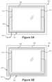
- FIG. 5Ashows one implementation for wiring an insulated glass unit.
- FIG. 5Bshows another implementation for wiring an insulated glass unit.
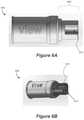
- FIG. 6Adisplays a profile view of a pigtail cap.
- FIG. 6Bdisplays an alternate view of a pigtail cap.
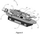
- FIG. 7Adepicts a tester used to check if an insulated glass unit is operating properly.
- FIG. 7Bdepicts a view of a tester with a transparent housing.
- FIG. 8displays the interior components of a tester.
- FIG. 9Ashows a depiction of an example system for controlling and driving a plurality of electrochromic windows.
- FIG. 9Bshows a depiction of another example system for controlling and driving a plurality of electrochromic windows.
- FIG. 9Cshows a block diagram of an example network system, operable to control a plurality of insulated glass units.
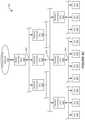
- FIG. 9Ddepicts a hierarchical structure in which insulated glass units may be arranged.
- FIG. 10Adepicts how a network configuration file is used by control logic to perform various functions on a window network.
- FIG. 10Bdepicts a process for creating a network configuration file according to some implementations.
- FIG. 11illustrates a method of using an insulated glass unit tester.
- FIG. 12illustrates a cross-sectional view of an interface between an IGU connector and a cap.
- a liquid crystal device or a suspended particle devicecould be incorporated into some or all of the disclosed implementations.
- the conjunction “or”is intended herein in the inclusive sense where appropriate unless otherwise indicated; for example, the phrase “A, B or C” is intended to include the possibilities of “A,” “B,” “C,” “A and B,” “B and C,” “A and C” and “A, B and C.”
- the terms pane, lite, and substrateare used interchangeably to refer to the surfaces, e.g., glass, where an electrochromic device is placed on or the surfaces of an insulated glass unit (“IGU”).
- An electrochromic windowmay be in the form of a laminate structure, an IGU, or both, i.e., where an IGU includes two substantially transparent substrates, or two panes of glass, where at least one of the substrates includes an electrochromic device disposed thereon, and the substrates have a spacer, or separator, disposed between them.
- One or more of these substratesmay itself be a structure having multiple substrates, e.g., two or more sheets of glass.
- An IGUis typically hermetically sealed, having an interior region that is isolated from the ambient environment.
- a window assemblymay include an IGU, electrical connectors for coupling the one or more electrochromic devices of the IGU to a window controller, and a frame that supports the IGU and related wiring, including an IGU connector, e.g., a pigtail.
- a challenge presented by electrochromic window technologyis ensuring that an IGU arrives at an installation site, or building, in a clear, or bleached, state without any tinting, or coloration. This is true for a number of reasons, including that when IGUs are tinted or colored, customers may think they have the wrong product, and also it is very useful to the installer or the one commissioning the glass to have all the IGUs in the same state upon startup or when hooking up the window controllers. IGUs are typically shipped by a manufacturer to a site where they are to be installed. Oftentimes the manufacturer will have recently tested the IGUs, e.g., during quality control checks by putting the glass into a tinted state.
- a building manager or other installation techniciane.g., glaziers, construction workers, electricians, etc.
- unfamiliar with the operation of electrochromic windowsmay express concern as to why the different IGUs are tinted differently and may even believe that the IGUs are malfunctioning or broken or that the incorrect product was shipped to the site.
- a related challengeis ensuring that electrochromic windows arrive at their installation site without damage to their components, such as, for example, damage caused to pigtail wiring by debris or damage to the lites is caused by a loose pigtail.
- a pigtail capmay be utilized to drain current from an IGU while also protecting the pigtail from debris while the IGU is in transit to an installation site.
- a glazier, or other professional responsible for installing an IGU at a siteis typically one of the first at an installation deployment to work with the IGUs and set up the physical electrochromic window network. Oftentimes, there is a passage of time, days or weeks, before the next tradesman, e.g., a low voltage electrician (“LVE”) arrives at the jobsite to install the window controllers and associated wiring.
- LVElow voltage electrician
- glaziersmay be called back to an installation site after their job has been completed to troubleshoot a problem arising subsequent to their installation work, or, worse yet, may be blamed or penalized for damage to the electrochromic window network arising subsequent to their installation work. Assessing where problems are located in an installed electrochromic window network is difficult without having information such as what windows were functioning properly before and after installation. To facilitate in addressing these challenges, in some implementations, a portable tester may be used to verify that an IGU is properly functioning after being installed. This allows the IGU to be tested without the window controller and associated wiring being installed at the jobsite.
- Such testersare also useful in the factory that makes the IGUs, e.g., for testing the IGUs on the assembly line or in stock, to make sure they are functioning properly prior to shipment or even testing them during shipment to ensure the integrity of the shipment, e.g., if damage is suspected.
- FIG. 1is a graph depicting voltage and current profiles associated with driving an electrochromic device from a clear state to a tinted state and from a tinted state to a clear state.
- FIG. 2is a graph depicting certain voltage and current profiles associated with driving an electrochromic device from a tinted state to a clear state.
- clear and bleachedare used interchangeably when referring to the optical state of the electrochromic device of an IGU, as are the terms tinted and colored.
- FIG. 1shows a complete current profile and voltage profile for an electrochromic device employing a simple voltage control algorithm to cause an optical state transition cycle (coloration followed by bleaching) of an electrochromic device.
- total current density (I)is represented as a function of time.
- the total current densityis a combination of the ionic current density associated with an electrochromic transition and electronic leakage current between the electrochemically active electrodes.
- Many different types of electrochromic devicewill have the depicted current profile.
- a cathodic electrochromic materialsuch as tungsten oxide is used in conjunction with an anodic electrochromic material such as nickel tungsten oxide in counter electrode. In such devices, negative currents indicate coloration of the device.
- lithium ionsflow from a nickel tungsten oxide anodically coloring electrochromic electrode into a tungsten oxide cathodically coloring electrochromic electrode.
- electronsflow into the tungsten oxide electrode to compensate for the positively charged incoming lithium ions. Therefore, the voltage and current are shown to have a negative value.
- the depicted profileresults from ramping up the voltage to a set level and then holding the voltage to maintain the optical state.
- the current peaks 101are associated with changes in optical state, i.e., coloration and bleaching. Specifically, the current peaks represent delivery of the ionic charge needed to color or bleach the device. Mathematically, the shaded area under the peak represents the total charge required to color or bleach the device.
- the portions of the curve after the initial current spikes (portions 103 )represent electronic leakage current while the device is in the new optical state.
- a voltage profile 105is superimposed on the current curve.
- the voltage profilefollows the sequence: negative ramp 107 , negative hold 109 , positive ramp 111 , and positive hold 113 .
- Voltage ramp 107drives the device to its new the colored state and voltage hold 109 maintains the device in the colored state until voltage ramp 111 in the opposite direction drives the transition from colored to bleached states.
- voltage holds 109 and 113may also be referred to as V drive .
- a current capis imposed.
- the coloration speedis a function of not only the applied voltage, but also the temperature and the voltage ramping rate.
- FIG. 2illustrates a voltage control profile in accordance with certain embodiments.
- a voltage control profileis employed to drive the transition from a bleached state to a colored state (or to an intermediate state).
- a similar but inverted profileis used to drive an electrochromic device in the reverse direction, from a colored state to a bleached state (or from a more colored to less colored state).
- the voltage control profile for going from colored to bleachedis a mirror image of the one depicted in FIG. 2 .
- V appThe voltage values depicted in FIG. 2 represent the applied voltage (V app ) values.
- the applied voltage profileis shown by the dashed line.
- the current density in the deviceis shown by the solid line.
- V appincludes four components: a ramp to drive component 203 , which initiates the transition, a V drive component 213 , which continues to drive the transition, a ramp to hold component 215 , and a V hold component 217 .
- the ramp componentsare implemented as variations in V app and the V drive and V hold components provide constant or substantially constant V app magnitudes.
- the ramp to drive componentis characterized by a ramp rate (increasing magnitude) and a magnitude of V drive .
- the V an , componentis characterized by the value of V drive as well as the duration of V drive .
- the magnitude of V drivemay be chosen to maintain V eff with a safe but effective range over the entire face of the electrochromic device as described above.
- the ramp to hold componentis characterized by a voltage ramp rate (decreasing magnitude) and the value of V hold (or optionally the difference between Va., and V hold ). V app drops according to the ramp rate until the value of V hold is reached.
- the V hold componentis characterized by the magnitude of V hold and the duration of V hold . Actually, the duration of V hold is typically governed by the length of time that the device is held in the colored state (or conversely in the bleached state). Unlike the ramp to drive, V drive , and ramp to hold components, the V hold component has an arbitrary length, which is independent of the physics of the optical transition of the device.
- Each type of electrochromic devicewill have its own characteristic components of the voltage profile for driving the optical transition. For example, a relatively large device and/or one with a more resistive conductive layer will require a higher value of V drive and possibly a higher ramp rate in the ramp to drive component. Larger devices may also require higher values of V hold .
- each of the components of an applied voltage profilemay be independently controlled to address real-time conditions such as current temperature, current level of transmissivity, etc.
- the values of each component of the applied voltage profileis set for a particular electrochromic device (having its own bus bar separation, resistivity, etc.) and does vary based on current conditions.
- the voltage profiledoes not take into account feedback such as temperature, current density, and the like.
- the ramp to drive component of the voltage profileis chosen to safely but rapidly induce ionic current to flow between the electrochromic and counter electrodes.
- the current in the devicefollows the profile of the ramp to drive voltage component until the ramp to drive portion of the profile ends and the V drive portion begins. See current component 201 in FIG. 2 .
- Safe levels of current and voltagecan be determined empirically or based on other feedback.
- U.S. Pat. No. 8,254,013, titled “CONTROLLING TRANSITIONS IN OPTICALLY SWITCHABLE DEVICES,” filed Mar. 16, 2011 (Attorney Docket No. VIEWP009)is incorporated herein by reference and presents examples of algorithms for maintaining safe current levels during electrochromic device transitions.
- the value of V driveis chosen based on the considerations described above. Particularly, it is chosen so that the value of V eff over the entire surface of the electrochromic device remains within a range that effectively and safely transitions large electrochromic devices.
- the duration of V drivecan be chosen based on various considerations. One of these ensures that the drive potential is held for a period sufficient to cause the substantial coloration of the device. For this purpose, the duration of V drive may be determined empirically, by monitoring the optical density of the device as a function of the length of time that V drive remains in place. In some embodiments, the duration of V drive is set to a specified time period. In another embodiment, the duration of V drive is set to correspond to a desired amount of ionic charge being passed. As shown, the current ramps down during V drive . See current segment 207 .
- Another considerationis the reduction in current density in the device as the ionic current decays as a consequence of the available lithium ions completing their journey from the anodic coloring electrode to the cathodic coloring electrode (or counter electrode) during the optical transition.
- the transitionis complete, the only current flowing across device is leakage current through the ion conducting material.
- the ohmic drop in potential across the face of the devicedecreases and the local values of V eff increase.
- V effcan damage or degrade the device if the applied voltage is not reduced.
- another consideration in determining the duration of V driveis the goal of reducing the level of V eff associated with leakage current.
- V effBy dropping the applied voltage from V drive to V hold , not only is V eff reduced on the face of the device but leakage current decreases as well. As shown in FIG. 2 , the device current transitions in a segment 205 during the ramp to hold component. The current settles to a stable leakage current 209 during V hold .
- FIG. 3shows an example of a cross-sectional schematic drawing of an electrochromic device, 300 .
- Electrochromic device 300includes a substrate, 305 .
- the substratemay be transparent and may be made of, for example, glass.
- a first transparent conducting oxide (TCO) layer, 310is on substrate 305 , with first TCO layer 310 being the first of two conductive layers used to form the electrodes of electrochromic device 300 .
- TCOtransparent conducting oxide
- Electrochromic stack 315may include (i) an electrochromic (EC) layer, (ii) ion conducting (IC) material, and (iii) a counter electrode (CE) layer to form a stack in which the IC layer separates the EC layer and the CE layer. Electrochromic stack 315 is sandwiched between first TCO layer 310 and a second TCO layer, 320 , TCO layer 320 being the second of two conductive layers used to form the electrodes of electrochromic device 300 . First TCO layer 310 is in contact with a first bus bar, 330 , and second TCO layer 320 is in contact with a second bus bar, 325 .
- ECelectrochromic
- ICion conducting
- CEcounter electrode
- Wires, 331 and 332are connected to bus bars 330 and 325 , respectively, and form a wire assembly 334 which terminates in a connector, 335 .
- Wire assembly 334 and connector 335are collectively known as a pigtail 336 .
- Wires 331 and 332may also be considered part of the pigtail 336 in the sense that wires 331 and 332 may be braided and have an insulated cover over them (or other additional wires in some implementations), such that multiple wires form a single cord, i.e., the wire assembly 334 and thus pigtail 336 .
- Wires of another connector, 340may be connected to a tester or controller that is capable of effecting a transition of electrochromic device 300 , e.g., from a first optical state to a second optical state.
- Pigtail 336 and 340may be coupled, such that the tester or controller may drive the optical state transition for electrochromic device 300 .
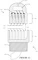
- FIGS. 4A and 4Bshow examples of the operations for fabricating an IGU, 425 , including an electrochromic pane, 405 , and incorporating the IGU 425 into a frame, 427 .
- Electrochromic pane 405has an electrochromic device (not shown, but for example on surface A) and bus bars, 410 , which provide power to the electrochromic device, is matched with another glass pane, 415 .
- the electrochromic panemay include, for example, an electrochromic device similar to the electrochromic device shown in FIG. 3 , as described above. In some embodiments, the electrochromic device is solid state and inorganic.
- a separator, 420is sandwiched in between and registered with glass panes 405 and 415 .
- IGU 425has an associated interior space defined by the faces of the glass panes in contact with separator 420 and the interior surfaces of the separator.
- Separator 420may be a sealing separator, that is, the separator may include a spacer and sealing material (primary seal) between the spacer and each glass pane where the glass panes contact the separator.
- Separator 420may be a pre-wired spacer (discussed below), where pigtail 430 is ran through and ultimately protrudes from the spacer.
- a sealing separator together with the primary sealmay seal, e.g., hermetically, the interior volume enclosed by glass panes 405 and 415 and separator 420 and protect the interior volume from moisture and the like.
- a secondary sealmay be applied around the perimeter edges of IGU 425 in order to impart further sealing from the ambient environment, as well as further structural rigidity to IGU 425 .
- the secondary sealmay be a silicone based sealant, for example.
- IGU 425may be wired to a window controller or tester, 450 , via a pigtail, 430 .
- Pigtail 430includes wires electrically coupled to bus bars 410 and may include other wires for sensors or for other components of IGU 425 .
- insulated wires in a pigtail 430may be braided and have an insulated cover over all of the wires (power, sensor, communications, etc.), such that the multiple wires form a single cord or wire assembly.
- IGU 425may be mounted in frame 427 to create a window assembly, 435 .
- Window assembly 435is connected, via pigtail 430 , to window controller, 450 .
- Window controller 450may also be connected to one or more sensors in frame 427 with one or more communication lines, 445 .
- caremust be taken, e.g., due to the fact that glass panes may be fragile but also because pigtail 430 extends beyond the IGU glass panes and may be damaged.
- FIG. 5Adepicts an IGU 500 with a separator 520 as a pre-wired spacer, where wires 525 make contact with the bus bars 510 , then pass through the body of the spacer 520 to form the pigtail 530 .
- Pre-wired spacersare further described in “CONNECTORS FOR SMART WINDOWS”, PCT International Application No. PCT/US12/68950, filed Dec. 11, 2012 (Attorney Docket No. VIEWP034X1WO), which is hereby incorporated by reference in its entirety and for all purposes.
- FIG. 5Bdepicts an alternative IGU setup 550 , where wires 525 are run in the secondary seal area 505 , external to the spacer 520 .
- a pigtail or other IGU connectorincludes a chip which includes memory and/or logic, e.g., in connector 335 in FIG. 3 .
- This memoryis programmed from the factory to contain window parameters, or fingerprints, that allow a tester or window controller to determine appropriate drive voltages for the electrochromic coating associated with the window.
- Other relevant fingerprint parametersinclude voltage response, current response, drive parameters, communications fidelity, window dimensions, and lite or window IDs.
- a site monitoring system for electrochromic window networksmay reprogram the memory in the pigtail (or other memory) remotely and automatically in certain embodiments while a field monitoring system runs in the cloud and collects data from the different sites.
- Fingerprints and site monitoring systems for electrochromic window networksare described in “MONITORING SITES CONTAINING SWITCHABLE OPTICAL DEVICES AND CONTROLLERS,” PCT International Application No. PCT/US2015/019031, filed Mar. 5, 2015 (Attorney Docket No. VIEWP061WO), which is hereby incorporated by reference in its entirety.
- FIG. 12depicts an example interface between an IGU connector 1200 and a pigtail cap 1220 according to some implementations.
- the IGU connectorhas a connection interface 1210 which is configured to mate with the connection interface of the pigtail cap 1230 .
- the connectormay have a plurality of pins 1212 used to transfer information and/or power between the IGU and an attached device (e.g., a tester, a window controller, or a pigtail cap). Pins for delivering power to the electrochromic window may deliver charge via wiring 1202 . Pins used to transfer information may be connected to window sensors, e.g., through wiring 1202 , or connected to a memory storage device 1204 associated with the connector.
- the memory associated with a connectormay store window parameters including parameters used for controlling an electrochromic device, or parameters which may be used to compare current window conditions to a previous window conditions (e.g., using voltage and/or current response data).
- the pigtail cap 1220has female contacts 1222 which are configured to accept the pins of the connector.
- the pigtail capneed not have female-connectors; mixed male/female connectors and other types of connection interfaces between an IGU connector and a pigtail cap are also contemplated. In some cases, the cap and connector will have a keying interface 1240 or some asymmetric feature which is used to orient mating of the pigtail cap to the IGU connector.
- the capis configured to short the leads of the pigtail that are used to provide charge to the electrochromic device when the cap is attached—allowing current to drain from the electrochromic device. This may be implemented by wire 1206 , or another conductor, placed between contacts of the pigtail cap 1222 . Shorting the IGU connector or pigtail leads that connect to the EC and CE layers of the electrochromic device cause the IGU to clear more quickly than an IGU would clear otherwise. In some cases, an IGU cap may cause an IGU completely clear, where depending on the amount of tint present, a clear state can be achieved on the order of hours or minutes, rather than days.
- Total IGU discharging timewill vary according to size and native leakage levels, but total IGU is discharging time should be less than the transit time from the factory or manufacturer to a customer site.
- An IGU connector or pigtailmay have multiple pins ( 1212 ) and/or sockets (not depicted), e.g., a 5-pin connector as described in U.S. patent application Ser. No. 15/268,204, titled “POWER DISTRIBUTION NETWORKS FOR ELECTROCHROMIC DEVICES,” filed Sep. 16, 2016 (Attorney Docket No. VIEWP085), which is incorporated herein in its entirety.
- resistormay be included in the circuit, e.g., in series with wire 1206 , to drain the device at a specified rate.
- a pigtail capmay include circuitry 1208 that detects if the IGU is completely drained of charge so that the IGU is in a clear state. Once the IGU is drained of charge, an indicator, e.g., LED 12010 , may designate that the window has been cleared of tinting.
- Connection interface 1230may couple with an IGU connector or pigtail in a push-on or snap-fit fashion, or any other type of mechanical connection.
- FIGS. 6A and 6Bdepict different aspects of a pigtail cap according to some implementations.
- Pigtail cap 600includes a connection interface 605 (corresponding to 1230 in FIG. 12 ) that is configured to mate with a pigtail.
- the connection interface 605may include a keying interface 610 (corresponding to 1240 in FIG. 12 ) which is used to orient the pigtail cap 600 such that and contacts 615 are aligned with the corresponding leads from the pigtail.
- contacts on pigtail cap 615may be spatially arranged in a circular pattern, however, this is not necessary. For example, contacts may be arranged in a linear fashion as depicted in FIG. 12 , or any other fashion.
- a pigtail capcouples with a pigtail, the pigtail cap protects the pigtail from debris.
- a pigtail capis typically coupled with a pigtail at the factory before the IGU is ready to be shipped out, thus the pigtail cap protects the pigtail from collecting debris such as dirt and grime inside of its connector at the factory, in transit, or at the installation site and protects the leads of a pigtail from getting damaged.
- the inexpensive pigtail capscan be disposed of once the IGU is ready for installation or returned to the manufacturer for future use.
- the pigtail capmay attach with the IGU via an attachment component to protect the pigtail, e.g., wire assembly 334 and connector 335 in FIG. 3 , from damage and to protect the IGU from damage or scratches inflicted by the pigtail.
- a clipe.g., a U-channel clip, is used to fasten the pigtail cap coupled with the pigtail to an edge or surface of the IGU to prevent the pigtail from flailing about while the IGU is in transit.
- the pigtail cap and pigtailmay reside in the secondary seal region of an IGU, e.g., secondary seal area 505 in FIG. 5B .
- pigtail capsrelate to their efficiency in the deployment cycle. Because floor space and time in a factory are valuable, by leveraging time an IGU is in transit to drain current from the IGU, the IGU is out the door faster, and factory floor space is freed up for other operations. Furthermore, by draining the current from IGUs such that they arrive at their installation site in a clear state, testing an IGU at an installation site will be that much easier as all IGUs will be starting from the same initial clear or bleached state, ensuring a more uniform tint state across tested IGUs at the conclusion of testing.
- the IGUscan be shipped with the pigtail cap installed, e.g., in various tint states, and they will arrive at the installation site all the in the clear or bleached state and with the pigtails protected.
- IGUsare generally installed before an electrochromic window network, including the power distribution and communications networks involved therein are configured.
- a pigtail or other IGU connectoris used to connect wiring from an IGU to a tester before and after installation to verify working window performance.
- a testermay also be used to test IGUs at a factory, a manufacturer, or any other appropriate setting.
- a glaziermay do an initial test with a portable tester to assess whether the IGUs are functioning properly. If the initial test discovers that an IGU is not in working order, the glazier will know that the IGUs were damaged in transit and may notify the appropriate individuals involved with the site installation (e.g., building managers, manufacturers, etc.) of the problem. In some embodiments, the tester may automatically send test results, e.g., through wireless communication means, to the appropriate individuals so that a new IGU of the same specification as the IGU with problems can be ordered and shipped so that the site installation deployment time is minimally impacted.
- test resultse.g., through wireless communication means
- the glaziermay again use the portable tester to confirm that the IGU is functioning properly.
- the data that a glazier acquires from testing each IGUmay later be utilized in commissioning, where physical locations and network IDs of IGUs are paired together to bring the control system of an electrochromic window online.
- Logs of the test datamay be sent to a site monitoring system, e.g., to provide a fingerprint or otherwise a baseline for the history of the IGUs EC device performance.
- FIGS. 7A and 7Billustrate examples of external views of a tester.
- FIG. 7Ashows tester 700 with a housing 701 including the depicted exterior components thereon.
- Tester 700has a port 730 that can couple to a pigtail or other IGU connector.
- the portmay communicate with a window via two contacts (not depicted) that are used to provide charge to the electrochromic device of the IGU.
- the portmay comprise additional pins, for example, 5 pins of a 5-pin connector.
- two contactsare used to power the electrochromic device while other pins are used for communication between the tester and the pigtail.
- Port 730may couple with a pigtail connector with any type of mechanical connection that maintains electrical coupling between the contacts in port 730 and the IGU connector.
- the mechanical connectionmay be a push-on, twist-on, or snap-fit connection.
- Tester 700may be powered on and off by through the input interface button 705 , e.g., where a short press of button 705 turns on tester 700 and a long press of about four seconds of button 705 turns off the tester 700 . Once tester 700 is turned on, another short press of button 705 may initiate testing of the IGU. While the device depicted in FIG. 7A and 7B receives user input via button 705 , other input interfaces such as a touch-sensitive graphical user interface may be used. In some embodiments, a tester may receive user input provided by a user operating a remote device such as a tablet or mobile phone.
- optional status indicators 720e.g., LEDs, will indicate the current status of tester, which include (i) reading the pigtail for fingerprints and other parameters, (ii) IGU test is in progress, and (iii) idle. Tester 700 may also determine whether a lite ID matches a site ID to check if an IGU has been shipped to the correct location. While the status indicator is depicted as an LED on the exterior of the surface of the tester, LED indicators may also be located within the housing when the housing is transparent or translucent. In some embodiments, a securing interface 725 may be made from a translucent material that reflects the color of an LED indicator.
- the indicatormay be an audible indicator (e.g., if the tester has a speaker unit), and in some embodiments, the tester may be configured to transmit wireless signals with instructions for another device, e.g., a phone or tablet to provide the status of an IGU to a user.
- another devicee.g., a phone or tablet to provide the status of an IGU to a user.
- the IGU testmay be initiated via button 705 and completed, e.g., in about 10 seconds or less.
- the testerapplies an aggressive driving voltage profile, i.e., a steeper voltage ramp rates and shorter voltage hold times depending on the magnitude of V drive than FIG. 1 , to the connected IGU, but the tester need not actually tint the IGU.
- an aggressive driving voltage profilei.e., a steeper voltage ramp rates and shorter voltage hold times depending on the magnitude of V drive than FIG. 1 .
- an aggressive driving voltage profile tintsthen clears an IGU and includes a negative voltage ramp 107 and positive voltage ramp 111 lasting, e.g., a fraction of a second long, a negative voltage hold 109 and positive voltage hold 113 lasting, e.g., a second long, and a V drive with a magnitude between, e.g., 0.1 V and 5 V.
- a tester 700may also test an IGU by applying a clearing voltage first then a tinting voltage second. The tester calculates the current density of the IGU based off of the voltage supplied to the IGU, the current consumed by the IGU, and the IGU dimensions which may be read from the pigtail.
- the testerdetermines whether the IGU is functioning properly, i.e., passed or failed the test. For example, a tester might identify whether the current density is within an acceptable range, above a maximum threshold, or below a minimum threshold for an applied voltage profile to determine whether an IGU is functioning properly.
- tester 700may indicate whether the IGU passed or failed the test via pass/fail indicator 710 , e.g., a LED. The tester 700 may then be disconnected from the IGU connector or pigtail without having to be powered down since the tester goes into a high impedance mode at, e.g., 10 seconds after the test has been initiated.
- An IGUmay fail the test if, e.g., there is an open or short in the electrochromic device that affects the performance of the electrochromic device and results in out of range current densities.
- Battery indicators 715e.g., LEDs, show the remaining battery life of tester 700 .
- Securing interface 725allows for glaziers to secure tester 700 to their persons or utility belts, via, e.g., a carabiner, lanyard, or other connection means.
- FIG. 7Bshows an alternative view of tester 700 , where the housing 701 is transparent so that the orientation of the interior components of tester 700 may be observed.
- the discussion of the interior components of tester 700is continued in FIG. 8 .
- FIG. 8displays the interior components 800 of tester 700 .
- Port 830which corresponds to port 730 from FIG. 7 , is electrically coupled (e.g., by wiring, not shown) to controller 811 .
- Interior button components 805shows where button 705 from FIG. 7 couples with the rest of the interior components 800 , e.g., at daughter card 812 .
- indicatorse.g., LEDs, such as pass/fail indicator 810 , battery indicator 815 , and status indicator 820 show where pass/fail indicator 710 , battery indicator 715 , and status indicator 720 couple with the rest of the interior components 800 , e.g., at daughter card 812 , respectively.
- Daughter card 812contains circuitry to increase the number of digital inputs and output points of controller 811 , such as, e.g., inputs to read button 705 and outputs to drive the indicators 710 , 715 , and 720 .
- daughter card 812may monitor and control charging battery 816 .
- daughter card 812includes a communications module 835 , e.g., Bluetooth Smart® or low energy radio, which enables wireless communication with mobile devices.
- Tester results and other relevant datamay be transferred, e.g., automatically, to a mobile device via communications module 835 and a corresponding mobile device application. The tester results and relevant data may then be transferred to the appropriate individuals involved with the site installation, or alternatively, be uploaded to the cloud.
- daughter card 812includes an ultra-wideband (“UWB”) module 840 , e.g., a DecaWave® radio, which has commissioning applications (discussed below).
- UWBultra-wideband
- a daughter cardmay be connected to a UWB module that may be used for positioning and communication to a mobile device.
- Controller 811may have a circuitry for regulating current and/or voltage among the internal components 800 .
- the voltage supplied by the batterymay be regulated to, e.g., 3.3 V.
- the controller 811may regulate the voltage or current provided to a daughter card, a communications module, or a UWB module.
- controller 811 or daughter card 812may include charging circuitry for charging rechargeable batteries.
- Controller 811operates the tester by applying an aggressive voltage driving profile to an IGU connected to port 830 .
- the testerneed not tint the IGU; instead, the controller 811 and/or daughter card 812 makes a calculation of the current density within the electrochromic device of the IGU based on the voltage being supplied to the IGU, the current being consumed by the IGU, and the dimensions of the IGU read from the pigtail to determine whether the IGU is operating correctly.
- the depicted embodimenthas both a controller and daughter card, it should be understood that this is just one of many possible configurations.
- the components and features of the daughter card 812may, in some embodiments, be integrated into controller 811 . Components of the daughter card 812 may also be on the controller 811 and vice versa.
- a controllermay include a communications module and a UWB module, if for instance these components are not on a daughter card, or if the interior components 800 do not include daughter card 812 .
- Batteries 816e.g., Li-ion rechargeable batteries, provide the voltage to the tester and may allow the tester to operate continuously, e.g., for about 16 hours. Batteries 816 are coupled with via battery structure 817 , which is coupled to support structure 802 .
- Daughter card 812couples with controller 811 , which in turn couples with support structure 802 , providing the tester with structural reinforcement and alignment.
- FIG. 11shows a method of using an IGU tester 1100 .
- tester poweris turned on.
- the testerchecks whether it is connected to a pigtail of an IGU. If not, a status indicator of the tester indicates that the tester is waiting for the pigtail in step 1103 .
- the testerreads the pigtail for parameters, e.g., fingerprints, such as IGU dimensions, drive parameters, and lite ID.
- the power buttoncan be pressed once more to begin testing the IGU by applying an aggressive driving voltage profile.
- the testercalculates the current density in the IGU.
- step 1107depending on the measurements taken to calculate the current density of the connected IGU, the tester will determine if the IGU passes or fails.
- step 1108the tester checks if the pigtail has been disconnected. If the pigtail has not been disconnected, the tester breaks off connection with the pigtail by going into a high impedance state and re-checks in step 1109 . After the pigtail has been disconnected, the tester sends IGU and position data to a mobile application via a communications module.
- testing data that a glazier obtainsis useful in commissioning the site (discussed below).
- FIG. 9Ashows a depiction of an example system 900 for controlling and driving a plurality of electrochromic windows 902 . It may also be employed to control the operation of one or more devices associated with an electrochromic window such as a window antenna.
- the system 900can be adapted for use with a building 904 such as a commercial office building or a residential building. In some implementations, the system 900 is designed to function in conjunction with modern heating, ventilation, and air conditioning (“HVAC”) systems 906 , interior lighting systems 907 , security systems 908 and power systems 909 as a single holistic and efficient energy control system for the entire building 904 , or a campus of buildings 904 .
- HVACheating, ventilation, and air conditioning
- the system 900is particularly well-suited for integration with a building management system (“BMS”) 910 .
- the BMS 910is a computer-based control system that can be installed in a building to monitor and control the building's mechanical and electrical equipment such as HVAC systems, lighting systems, power systems, elevators, fire systems, and security systems.
- the BMS 910can include hardware and associated firmware or software for maintaining conditions in the building 904 according to preferences set by the occupants or by a building manager or other administrator.
- the softwarecan be based on, for example, internet protocols or open standards.
- a BMScan typically be used in large buildings where it functions to control the environment within the building.
- the BMS 910can control lighting, temperature, carbon dioxide levels, and humidity within the building 904 .
- the BMS 910can turn on and off these various devices according to rules or in response to conditions. Such rules and conditions can be selected or specified by a building manager or administrator, for example.
- One primary function of the BMS 910is to maintain a comfortable environment for the occupants of the building 904 while minimizing heating and cooling energy losses and costs.
- the BMS 910can be configured not only to monitor and control, but also to optimize the synergy between various systems, for example, to conserve energy and lower building operation costs.
- Some implementationsare alternatively or additionally designed to function responsively or reactively based on feedback sensed through, for example, thermal, optical, or other sensors or through input from, for example, an HVAC or interior lighting system, or an input from a user control. Further information may be found in U.S. Pat. No. 8,705,162, titled “CONTROLLING TRANSITIONS IN OPTICALLY SWITCHABLE DEVICES,” filed Apr. 17, 2012, (Attorney Docket No. VIEWP035), and issued Apr. 22, 2014, which is incorporated herein by reference in its entirety. Some implementations also can be utilized in existing structures, including both commercial and residential structures, having traditional or conventional HVAC or interior lighting systems. Some implementations also can be retrofitted for use in older residential homes.
- the system 900includes a network controller 912 configured to control a plurality of window controllers 914 .
- the network controller 912can control tens, hundreds, or even thousands of window controllers 914 .
- Each window controller 914can control and drive one or more electrochromic windows 902 .
- the network controller 912issues high-level instructions such as the final tint state of an electrochromic window and the window controllers receive these commands and directly control their windows by applying electrical stimuli to appropriately drive tint state transitions and/or maintain tint states.
- the number and size of the electrochromic windows 902 that each window controller 914 can driveis generally limited by the voltage and current characteristics of the load on the window controller 914 controlling the respective electrochromic windows 902 .
- the maximum window size that each window controller 914 can driveis limited by the voltage, current, or power requirements to cause the desired optical transitions in the electrochromic window 902 within a desired time-frame. Such requirements are, in turn, a function of the surface area of the window. In some implementations, this relationship is nonlinear. For example, the voltage, current, or power requirements can increase nonlinearly with the surface area of the electrochromic window 902 . For example, in some cases, the relationship is nonlinear at least in part because the sheet resistances of the first and second conductive layers of an electrochromic stack in an IGU increase nonlinearly with distance across the length and width of the first or second conductive layers. In some implementations, the relationship between the voltage, current, or power requirements required to drive multiple electrochromic windows 902 of equal size and shape is, however, directly proportional to the number of the electrochromic windows 902 being driven.
- FIG. 9Bdepicts another example system 900 for controlling and driving a plurality of electrochromic windows 902 .
- the system 900 shown in FIG. 9Bis similar to the system 900 shown in FIG. 9A .
- the system 900 shown in FIG. 9Bincludes a master controller 911 .
- the master controller 911communicates and functions in conjunction with multiple network controllers 912 , each of which network controllers 912 is capable of addressing a plurality of window controllers 914 as described with reference to FIG. 9A .
- the master controller 911issues the high level instructions (such as the final tint states of the electrochromic windows) to the network controllers 912 , and the network controllers 912 then communicate the instructions to the corresponding window controllers 914 .
- each zonemay correspond to a set of electrochromic windows 902 in a specific location or area of the building that should be tinted (or otherwise transitioned) to the same or similar optical states based on their location.
- each zonecan correspond to the set of electrochromic windows 902 on a particular floor and on a particular one of the four faces.
- each network controller 912can address one or more zones or groups of zones.
- the master controller 911can issue a final tint state command for a particular zone or group of zones to a respective one or more of the network controllers 912 .
- the final tint state commandcan include an abstract identification of each of the target zones.
- the designated network controllers 912 receiving the final tint state commandcan then map the abstract identification of the zone(s) to the specific network addresses of the respective window controllers 914 that control the voltage or current profiles to be applied to the electrochromic windows 902 in the zone(s).
- zones of windows for tinting purposesmay or may not correspond to zones for antenna-related functions.
- a master and/or network controllermay identify two distinct zones of windows for tinting purposes, e.g., two floors of windows on a single side of a building, where each floor has different tinting algorithms based on customer preferences.
- zoningis implemented in a hierarchy of three or more tiers; e.g., at least some windows of a building are grouped into zones, and at least some zones are divided into subzones, with each subzone subject to different control logic and/or user access.
- optically-switchable windowscan form or occupy substantial portions of a building envelope.
- the optically-switchable windowscan form substantial portions of the walls, facades and even roofs of a corporate office building, other commercial building or a residential building.
- a distributed network of controllerscan be used to control the optically-switchable windows.
- FIG. 9Cshows a block diagram of an example network system, 920 , operable to control a plurality of IGUs 922 in accordance with some implementations.
- One primary function of the network system 920is controlling the optical states of the electrochromic devices (or other optically-switchable devices) within the IGUs 922 .
- one or more of the windows 922can be multi-zoned windows, for example, where each window includes two or more independently controllable electrochromic devices or zones.
- the network system 920is operable to control the electrical characteristics of the power signals provided to the IGUs 922 .
- the network system 920can generate and communicate tinting instructions or commands to control voltages applied to the electrochromic devices within the IGUs 922 .
- another function of the network system 920is to acquire status information from the IGUs 922 (hereinafter “information” is used interchangeably with “data”).
- the status information for a given IGUcan include an identification of, or information about, a current tint state of the electrochromic device(s) within the IGU.
- the network system 920also can be operable to acquire data from various sensors, such as temperature sensors, photosensors (also referred to herein as light sensors), humidity sensors, airflow sensors, or occupancy sensors, antennas, whether integrated on or within the IGUs 922 or located at various other positions in, on or around the building.
- the network system 920can include any suitable number of distributed controllers having various capabilities or functions. In some implementations, the functions and arrangements of the various controllers are defined hierarchically. For example, the network system 920 includes a plurality of distributed window controllers (WCs) 924 , a plurality of network controllers (NCs) 926 , and a master controller (MC) 928 . In some implementations, MC 928 can interact and communicate with BMS 910 from FIG. 9B , represented as outward-facing network 934 . In some implementations, the MC 928 can communicate with and control tens or hundreds of NCs 926 .
- WCsdistributed window controllers
- NCsnetwork controllers
- MCmaster controller
- MC 928can interact and communicate with BMS 910 from FIG. 9B , represented as outward-facing network 934 .
- the MC 928can communicate with and control tens or hundreds of NCs 926 .
- the MC 928issues high-level instructions to the NCs 926 over one or more wired or wireless links 946 (hereinafter collectively referred to as “link 946 ”).
- the instructionscan include, for example, tint commands for causing transitions in the optical states of the IGUs 922 controlled by the respective NCs 926 .
- Each NC 926can, in turn, communicate with and control a number of WCs 924 over one or more wired or wireless links 944 (hereinafter collectively referred to as “link 944 ”).
- each NC 926can control tens or hundreds of the WCs 924 .
- Each WC 924can, in turn, communicate with, drive or otherwise control one or more respective IGUs 922 over one or more wired or wireless links 942 (hereinafter collectively referred to as “link 942 ”).
- the MC 928can issue communications including tint commands, status request commands, data (for example, sensor data) request commands or other instructions.
- the MC 928can issue such communications periodically, at certain predefined times of day (which may change based on the day of week or year), or based on the detection of particular events, conditions or combinations of events or conditions (for example, as determined by acquired sensor data or based on the receipt of a request initiated by a user or by an application or a combination of such sensor data and such a request).
- the MC 928determines to cause a tint state change in a set of one or more IGUs 922
- the MC 928generates or selects a tint value corresponding to the desired tint state.
- the set of IGUs 922is associated with a first protocol identifier (“ID”), e.g., a BACnet ID.
- IDe.g., a BACnet ID.
- the MC 928then generates and transmits a communication—referred to herein as a “primary tint command”—including the tint value and the first protocol ID over the link 946 via a first communication protocol (for example, a BACnet compatible protocol).
- the MC 928addresses the primary tint command to the particular NC 926 that controls the particular one or more WCs 924 that, in turn, control the set of IGUs 922 to be transitioned.
- the NC 926receives the primary tint command including the tint value and the first protocol ID and maps the first protocol ID to one or more second protocol IDs.
- each of the second protocol IDsidentifies a corresponding one of the WCs 924 .
- the NC 926subsequently transmits a secondary tint command including the tint value to each of the identified WCs 924 over the link 944 via a second communication protocol.
- each of the WCs 924 that receives the secondary tint commandselects a voltage or current profile from an internal memory based on the tint value to drive its respectively connected IGUs 922 to a tint state consistent with the tint value.
- Each of the WCs 924then generates and provides voltage or current signals over the link 942 to its respectively connected IGUs 922 to apply the voltage or current profile.
- electrochromic windowsmay be arranged in a hierarchical structure as shown in FIG. 9D .
- a hierarchical structurehelps facilitate the control of electrochromic windows at a particular site by allowing rules or user control to be applied to various groupings of electrochromic windows or IGUs. Further, for aesthetics, multiple contiguous windows in a room or other site location must sometimes need to have their optical states correspond and/or tint at the same rate. Treating a group of contiguous windows as a zone can facilitate these goals.
- the various IGUs 922may be grouped into zones 953 of electrochromic windows, each of which zones 953 includes at least one window controller 924 and its respective IGUs 922 .
- each zone of IGUs 922is controlled by one or more respective NCs 926 and one or more respective WCs 924 controlled by these NCs 926 .
- each zone 953can be controlled by a single NC 926 and two or more WCs 924 controlled by the single NC 926 . Said another way, a zone 953 can represent a logical grouping of the IGUs 922 .
- each zone 953may correspond to a set of IGUs 922 in a specific location or area of the building that are driven together based on their location.
- a site 951that is a building having four faces or sides: a North face, a South face, an East Face and a West Face.
- each zonecan correspond to the set of electrochromic windows 900 on a particular floor and on a particular one of the four faces.
- each zone 953may correspond to a set of IGUs 922 that share one or more physical characteristics (for example, device parameters such as size or age).
- a zone 953 of IGUs 922can be grouped based on one or more non-physical characteristics such as, for example, a security designation or a business hierarchy (for example, IGUs 922 bounding managers' offices can be grouped in one or more zones while IGUs 922 bounding non-managers' offices can be grouped in one or more different zones).
- each NC 926can address all of the IGUs 922 in each of one or more respective zones 953 .
- the MC 928can issue a primary tint command to the NC 926 that controls a target zone 953 .
- the primary tint commandcan include an abstract identification of the target zone (hereinafter also referred to as a “zone ID”).
- the zone IDcan be a first protocol ID such as that just described in the example above.
- the NC 926receives the primary tint command including the tint value and the zone ID and maps the zone ID to the second protocol IDs associated with the WCs 924 within the zone.
- the zone IDcan be a higher level abstraction than the first protocol IDs. In such cases, the NC 926 can first map the zone ID to one or more first protocol IDs, and subsequently map the first protocol IDs to the second protocol IDs.
- any devicee.g., instructions for a window controller or an IGU
- a network system 920When instructions relating to the control of any device (e.g., instructions for a window controller or an IGU) are passed through a network system 920 , they are accompanied with a unique network ID of the device they are sent to. Networks IDs are necessary to ensure that instructions reach and are carried out on the intended device.
- a window controller that controls the tint states of more than one IGUdetermines which IGU to control based upon a network ID such as a CAN ID (a form of network ID) that is passed along with the tinting command.
- CAN IDa form of network ID
- the term network IDincludes but is not limited to CAN IDs, and BACnet IDs.
- a network ID for a deviceincludes the network ID of every device that controls it in the hierarchical structure.
- the network ID of an IGUmay include a window controller ID, a network controller ID, and a master controller ID in addition to its CAN ID.
- a master controller, network controller, and/or other controller responsible for tint decisionsmust know the network address of the window controller(s) connected to that specific window or set of windows.
- a function of commissioningis to provide correct assignment of window controller addresses and/or other identifying information to specific windows and window controllers, as well the physical locations of the windows and/or window controllers in buildings.
- a goal of commissioningis to correct mistakes or other problems made in installing windows in the wrong locations or connecting cables to the wrong window controllers.
- a goal of commissioningis to provide semi- or fully-automated installation. In other words, allowing installation with little or no location guidance for installers.
- the commissioning process for a particular window or IGUmay involve associating an ID for the window or other window-related component with its corresponding window controller.
- the processmay also assign a building location and/or absolute location (e.g., latitude, longitude, and elevation) to the window or other component.
- a building location and/or absolute locatione.g., latitude, longitude, and elevation
- Further information related to commissioning and/or configuring a network of electrochromic windowsis presented in International Patent Application No. PCT/US17/62634, titled “AUTOMATED COMMISSIONING OF CONTROLLERS IN A WINDOW NETWORK,” filed Nov. 20, 2017 (Attorney Docket No. VIEWP092WO), which is hereby incorporated by reference in its entirety.
- a commissioning association or linkageis made by comparing an architecturally determined location of a first component with a wirelessly measured location of a second component, which second component is associated with the first component.
- the first componentmay be an optically switchable window and the second component may be a window controller configured to control the optical state of the optically switchable component.
- the first componentis a sensor that provides measured radiation data to a window controller, which is the second component. Often the location of the first component is known with greater accuracy than the location of the second component, which location may be determined by a wireless measurement.
- the commissioning processmay employ alternative sources such as manually-measured post-installation locations of windows or other components. GPS may also be used.
- the component whose location is determined by wireless measuremente.g., a window controller
- the commissioning processmay pair the accurate physical location of the first component with the network ID of the second component.
- the first and second componentsare a single component.
- a window controllermay be such component; e.g., its position may be both determined from an architectural drawing and from wireless measurement. In such case, the commissioning process may simply ascribe the physical location from the architectural drawing with the network ID from the configuration file.
- the associations determined during commissioningare stored in a file, data structure, database, or the like that can be consulted by various window network components and/or associated systems such as mobile applications, window control intelligence algorithms, Building Management Systems (BMSs), security systems, lighting systems, and the like.
- the commissioning linkagesare stored in a network configuration file.
- a network configuration fileis used by the window network to send appropriate commands between components on the network; e.g., a master controller sends a tint command to the window controller for a window designated, by its location in a structure, for a tint change.
- FIG. 10Adepicts an embodiment in which a network configuration file 1003 may be used by control logic 1004 to facilitate various functions on a network. While the following description uses the term “network configuration file,” it should be understood that any suitable file, data structure, database, etc. may be used for the same purpose.
- Such file or other featureprovides linkages between physical components of a window network (e.g., lite positions identified by a Lite ID) and network IDs (which may be or include network addresses) of controllers associated with such physical components (e.g., window controllers that directly control states of lites).
- Control logic 1004refers to any logic that may use for making decisions or other purposes the linkages between physical components and associated controllers.
- such logicmay include logic provided with window network master controllers 1005 , network controllers 1006 , and window controllers 1007 , as well as associated or interfacing systems such as mobile applications for controlling window states, window control intelligence algorithms, Building Management Systems, security systems, lighting systems, and the like.
- a network configuration file 1003is used by control logic 1004 to provide network information to a user interface for controlling the network 1008 , such as an application on a remote wireless device, or to an intelligence system 1009 or a BMS.
- a user interface 1008 of a mobile applicationis configured to use information provided by a network configuration file 1003 to control a master controller 1005 , a network controller 1006 , a window controller 1007 , or other network components.
- FIG. 10BAn example of a process of creating a network configuration file 1000 is shown in FIG. 10B .
- the first operationis to determine the physical layout of a site from building plans such as architectural drawings 1001 so that the layout of a window network can be determined.
- architectural drawings 1001provide building dimensions, locations of electrical closets, and various other structural and architectural features.
- architectural drawingsmay be created by first surveying a site.
- an individual or teamdesigns the wiring infrastructure and power delivery system for the electrochromic window network. This infrastructure, which includes power distribution components, is depicted visually in modified architectural drawings that are sometimes referred to as interconnect drawings 1002 .
- Interconnect drawingsdepict wire routing (e.g., trunk lines) at a site, the positioning of various devices on the network (e.g., controllers, power supplies, control panels, windows, and sensors), and identifying information of network components (e.g., a network ID).
- a network IDe.g., a network ID
- an interconnect drawingis not completed until the lite IDs (WIDs or other IDs) of installed optically switchable windows are matched to the devices installed locations.
- an interconnect drawingmay also depict a hierarchical communications network including windows, window controllers, network controllers, and a master controller at a particular site.
- an interconnect drawing as initially rendereddoes not include network IDs for lites or other components on an optically switchable window network.
- Network configuration file 1003which may be a textual representation of the interconnect drawing.
- Network configuration files 1003may then be provided in a medium that is readable by control logic and/or other interfacing system, which allows the window network to be controlled in its intended fashion. So long as the interconnect drawing and the network configuration file accurately reflect the installed network 1010 , the process of creating a preliminary network configuration file is complete. However, commissioning may add other information to the file to link installed optically switchable windows are matched to corresponding window controller network IDs.
- interconnect drawing and network configuration filedo not match the installed network 1010 , manual user intervention may be required to update the interconnect drawing 1002 with accurate lite ID (or other ID) information 1111 . From the updated interconnect drawing the network configuration file 1003 is then updated to reflect changes that have been made.
- Window controllersand in some instances windows configured with antennas and/or onboard controllers, may be configured with a transmitter to communicate via various forms of wireless electromagnetic transmission; e.g., time-varying electric, magnetic, or electromagnetic fields.
- wireless protocols used for electromagnetic communicationinclude, but are not limited to, Bluetooth, BLE, Wi-Fi, RF, and UWB.
- the relative location between two or more devicesmay be determined from information relating to received transmissions at one or more antennas such as the received strength or power, time of arrival or phase, frequency, and angle of arrival of wirelessly transmitted signals.
- a triangulation algorithmmay be implemented that in some instances accounts for the physical layout of a building, e.g., walls and furniture.
- an accurate location of individual window network componentscan be obtained using such technologies.
- the location of a window controller having a UWB micro-location chipcan be easily determined to within 10 centimeters of its actual location.
- the location of one or more windowsmay be determined using geo-positioning methods such as those described in “WINDOW ANTENNAS,” U.S. patent application Ser. No. 62/340,936, filed on May 24, 2016 (Attorney Docket No. VIEWP072X1P), which is hereby incorporated by reference in its entirety.
- geo-positioning and geolocationmay refer to any method in which the position or relative position of a window or device is determined in part by analysis of electromagnetic signals.
- Pulse-based ultra-wideband technology(ECMA-368 and ECMA-369) is a wireless technology for transmitting large amounts of data at low power (typically less than 0.5 mW) over short distances (up to 230 feet).
- a characteristic of a UWB signalis that it occupies at least 500 MHz of bandwidth spectrum or at least 20% of its center frequency.
- a componentbroadcasts digital signal pulses that are timed very precisely on a carrier signal across a number of frequency channels at the same time.
- Informationmay be transmitted by modulating the timing or positioning of pulses. Alternatively, information may be transmitted by encoding the polarity of the pulse, its amplitude and/or by using orthogonal pulses.
- UWB technologymay provide several advantages for indoor location applications over other wireless protocols.
- the broad range of the UWB spectrumcomprises low frequencies having long wavelengths, which allows UWB signals to penetrate a variety of materials, including walls.
- the wide range of frequencies, including these low penetrating frequenciesdecreases the chance of multipath propagation errors as some wavelengths will typically have a line-of-sight trajectory.
- Another advantage of pulse-based UWB communicationis that pulses are typically very short (less than 60 cm for a 500 MHz-wide pulse, less than 23 cm for a 1.3 GHz-bandwidth pulse) reducing the chances that reflecting pulses will overlap with the original pulse.
- the relative locations of window controllers having micro-location chipscan be determined using the UWB protocol. For example, using micro-location chips, the relative position of each device may be determined to within an accuracy of 10 cm.
- window controllers, and in some cases antennas disposed on or proximate windows or window controllersare configured to communicate via a micro-location chip.
- a window controllermay be equipped with a tag having a micro-location chip configured to broadcast omnidirectional signals.
- Receiving micro-location chips, also known as anchorsmay be located at a variety of locations such as a wireless router, a network controller, or a window controller having a known location.
- window controllersmay be equipped with micro-location chips that are configured to both send and receive UWB signals. By analysis of the received UWB signals at each window controller, the relative distance between each other window controller located within the transmission range limits may be determined. By aggregating this information, the relative locations between all the window controllers may be determined.
- each window controller or other network device having a micro-location chipmay be determined.
- Such antennasmay be employed in an auto-commissioning procedure as described below. However, it should be understood that the disclosure is not limited to UWB technology; any technology for automatically reporting high-resolution location information may be used. Frequently, such technology will employ and one or more antennas associated with the components to be automatically located. Implementation where testers may be configured as tags or anchors is described further below.
- interconnect drawings or other sources of architectural informationoften include location information for various window network components.
- windowsmay have their physical location coordinates listed in x, y, and z dimensions, sometimes with very high accuracy; e.g., to within 1 centimeter.
- files or documents derived from such drawings, such as network configuration filesmay contain accurate physical locations of pertinent window network components.
- coordinateswill correspond to one corner of a lite or IGU as installed in a structure. The choice of a particular corner or other feature for specifying in the interconnect drawing coordinates may be influenced by the placement of an antenna or other location-aware component.
- a window and/or paired window controllermay have a micro-location chip placed near a first corner of an associated IGU (e.g., the lower left corner); in which case the interconnect drawing coordinates for the lite may be specified for the first corner.
- listed coordinates on an interconnect drawingmay represent the location of the antenna on the surface of an IGU lite or a corner proximate the antenna. In some cases, coordinates may be obtained from architectural drawings and knowledge of the antenna placement on larger window components such as an IGU.
- a window's orientationis also included interconnect drawing.
- interconnect drawingsare any similarly accurate representation of component locations in a building or other structure having optically switchable windows.
- Thisincludes files derived from interconnect drawings (e.g., network configuration files) as well as files or drawings produced independently of interconnect drawings, e.g., via manual or automated measurements made during construction of a building.
- interconnect drawingse.g., network configuration files
- files or drawings produced independently of interconnect drawingse.g., via manual or automated measurements made during construction of a building.
- coordinatescannot be determined from architectural drawings, e.g., the vertical position of a window controller on a wall
- unknown coordinatescan be determined by personnel responsible for installation and/or commissioning.
- architectural and interconnect drawingsare widely used in building design and construction, they are used here for convenience, but again the disclosure is not limited to interconnect drawings as a source of physical location information.
- commissioning logicpairs component locations, as specified by interconnect drawings, with the network IDs (or other information not available in interconnect drawings) of components such as window controllers for optically switchable windows. In some embodiments, this is done by comparing the measured relative distances between device locations provided by geo-positioning and the listed coordinates provided on an interconnect drawing. Since the location of network components may be determined with a high accuracy, e.g., better than about 10 cm, automatic commissioning may be performed easily in a manner that avoids the complications that may be introduced by manually commissioning windows.
- the controller network IDs or other information paired with the physical location of a windowcan come from various sources.
- a window controller's network IDis stored on a memory device attached to each window (e.g., a dock for the window controller or a pigtail), or may be downloaded from the cloud based upon a window serial number.
- a controller's network IDis a CAN ID (an identifier used for communicating over a CAN bus).
- other stored window informationmay include the controller's ID (not its network ID), the window's lite ID (e.g., a serial number for the lite), window type, window dimensions, manufacturing date, bus bar length, zone membership, current firmware, and various other window details. Regardless of which information is stored, it may be accessed during the commissioning process. Once accessed, any or all portions of such information are linked to the physical location information obtained from the interconnect drawing, partially completed network configuration file, or other source.
- applications engineeringproduces an interconnect drawing, then uses the location IDs of windows, physical location of windows, and the location IDs of window controllers from an architectural drawing to produce a network configuration file via, e.g., a computer-aided design software.
- This network configuration filewill have zoning information incorporated into it, e.g., zones 953 and zone groups 952 in FIG. 9D . From there, a glazier may utilize a tester to obtain information and measurements from each IGU after installing them.
- a testermay include an UWB module, like UWB module 840 in FIG. 8 .
- UWB modulesmay be DecaWave® radios (DWM1000) and may configure testers to act as tags or anchors that may be implemented for IGU location awareness and mapping used in commissioning with the network configuration file and interconnect drawing described above.
- DWM1000DecaWave® radios
- a glazier or low voltage electricianmay begin the commissioning process by placing up to eight testers configured as anchors around a floor of a building, e.g., at the four corners of a building floor and four other locations as far away from each other as possible, optionally within line of sight of each other, to set up the coordinate system, e.g., the x-axis and y-axis, for that particular floor of the building.
- the glaziermay proceed to utilize a tester configured as a tag to test each IGU as discussed above, e.g., coupling the pigtail of an IGU to the tester and running the test.
- a tester and IGUcan communicate with each other via wireless communication, e.g., Bluetooth Smart® or low energy, during a test, so a glazier may ensure that each IGU test provides the most accurate location testing data by placing the tester against the IGU at the same location on or near the surface of each IGU, e.g., the bottom left corner of the lite, during testing. This also provides some z-axis information as IGU dimensions read from IGU pigtails are factored into where on the IGU the tester was communicating with the IGU at. As the glazier tests each IGU, the tag-configured tester communicates wirelessly, e.g., via communications module 835 in FIG.
- wireless communicatione.g., Bluetooth Smart® or low energy
- the location engine mobile applicationcaptures and processes the position data of each IGU relative to the anchor-configured testers and relative to previously tested IGUs, while making use of information received from the IGU pigtail, e.g., IGU dimensions and lite ID, to establish IGU location mapping on the floor. This process may be repeated to allow for the IGUs of an installation site to be accurately mapped per floor. To get an accurate mapping of an entire building layout, a glazier or other installation technician may move, e.g., two or more anchor-configured testers to the next floor up from the floor previously mapped.
- This processmay also be used to create wire-frame models of buildings.
- the network configuration file produced by applications engineeringmay then be combined with the tester data to match lite IDs with IGU location information.
- the physical location of an IGUmay be determined via user input provided via an application that runs on a mobile device.
- an applicationmay be configured to display an interconnect drawing or a building map that displays the various window locations.
- the applicationprovides a list of window locations, e.g., a list specifying IGU coordinates or describing where the IGUs are located.
- the applicationmay prompt the user to select the location of the IGU.
- the applicationcan be configured to receive the user selection by, e.g., a touch-based selection or a voice-based selection.
- the applicationthen pairs the selected location with the network ID or other ID of the corresponding IGU, as provided by the tester unit, and can used the paring for commissioning methods as described herein.
- the applicationmay also be configured to report the status of the IGU to a site monitoring system.
- the applicationmay receive the network ID from the tester using a wireless connection to the mobile device (e.g., via Wi-Fi or Bluetooth) or, in some cases, using a wired connection to the device (e.g., a USB cable).
- the testermay display a network ID to a user, and the application is configured to display a data field in which a user can manually provide the network ID as input.
- the applicationis configured to use data from one or more sensors on the mobile device (e.g., accelerometers, gyroscopes, compasses, and GPS sensors) to track the movement of the device and provide a suggested location for an IGU based on the tracked movement. For example, if after selecting the location of a first window the application has detected that the mobile device has moved in a northward direction, the application may automatically suggest to a user that an adjacent window in the northward direction be selected.
- sensors on the mobile devicee.g., accelerometers, gyroscopes, compasses, and GPS sensors
- the data obtained from testing the IGUsis transferred to a data center, e.g., the cloud, and processed during commissioning to associate the IGU location data with control applications.
- a field service engineer or technicianmay, during commissioning, match the tester data with or overlay the tester data upon, e.g., interconnect drawing data generated by applications engineering and have lite IDs associated with IGU numbers, IGU locations, and a window controllers.
- the CAN ID of an IGUassociates with its lite ID and thus the IGU location, e.g., x, y, and z-axis coordinates for each IGU, enabling the window control network to know which window or zone commands are being sent to.
Landscapes
- Engineering & Computer Science (AREA)
- Structural Engineering (AREA)
- Civil Engineering (AREA)
- Computer Networks & Wireless Communication (AREA)
- General Physics & Mathematics (AREA)
- General Engineering & Computer Science (AREA)
- Theoretical Computer Science (AREA)
- Physics & Mathematics (AREA)
- Architecture (AREA)
- Human Computer Interaction (AREA)
- Health & Medical Sciences (AREA)
- Computing Systems (AREA)
- General Health & Medical Sciences (AREA)
- Medical Informatics (AREA)
- Signal Processing (AREA)
- Electrochromic Elements, Electrophoresis, Or Variable Reflection Or Absorption Elements (AREA)
Abstract
Description
Claims (20)
Priority Applications (1)
| Application Number | Priority Date | Filing Date | Title |
|---|---|---|---|
| US16/469,848US11255120B2 (en) | 2012-05-25 | 2017-12-14 | Tester and electrical connectors for insulated glass units |
Applications Claiming Priority (5)
| Application Number | Priority Date | Filing Date | Title |
|---|---|---|---|
| US201261652021P | 2012-05-25 | 2012-05-25 | |
| PCT/US2013/042765WO2013177575A1 (en) | 2012-05-25 | 2013-05-24 | Portable power supplies and portable controllers for smart windows |
| US201662434216P | 2016-12-14 | 2016-12-14 | |
| PCT/US2017/066486WO2018112241A1 (en) | 2016-12-14 | 2017-12-14 | Tester and electrical connectors for insulated glass units |
| US16/469,848US11255120B2 (en) | 2012-05-25 | 2017-12-14 | Tester and electrical connectors for insulated glass units |
Related Parent Applications (5)
| Application Number | Title | Priority Date | Filing Date |
|---|---|---|---|
| US14/401,081Continuation-In-PartUS20150103389A1 (en) | 2012-05-25 | 2013-05-24 | Portable power supplies and portable controllers for smart windows |
| US14/401,081ContinuationUS20150103389A1 (en) | 2012-05-25 | 2013-05-24 | Portable power supplies and portable controllers for smart windows |
| PCT/US2013/042765Continuation-In-PartWO2013177575A1 (en) | 2009-12-22 | 2013-05-24 | Portable power supplies and portable controllers for smart windows |
| PCT/US2013/042765ContinuationWO2013177575A1 (en) | 2009-12-22 | 2013-05-24 | Portable power supplies and portable controllers for smart windows |
| PCT/US2017/066486A-371-Of-InternationalWO2018112241A1 (en) | 2012-05-25 | 2017-12-14 | Tester and electrical connectors for insulated glass units |
Related Child Applications (1)
| Application Number | Title | Priority Date | Filing Date |
|---|---|---|---|
| US17/576,862ContinuationUS20220136319A1 (en) | 2012-05-25 | 2022-01-14 | Tester and electrical connectors for insulated glass units |
Publications (2)
| Publication Number | Publication Date |
|---|---|
| US20200080364A1 US20200080364A1 (en) | 2020-03-12 |
| US11255120B2true US11255120B2 (en) | 2022-02-22 |
Family
ID=69718782
Family Applications (1)
| Application Number | Title | Priority Date | Filing Date |
|---|---|---|---|
| US16/469,848Active2033-07-18US11255120B2 (en) | 2012-05-25 | 2017-12-14 | Tester and electrical connectors for insulated glass units |
Country Status (1)
| Country | Link |
|---|---|
| US (1) | US11255120B2 (en) |
Cited By (11)
| Publication number | Priority date | Publication date | Assignee | Title |
|---|---|---|---|---|
| US11352834B2 (en) | 2011-12-14 | 2022-06-07 | View, Inc. | Connectors for smart windows |
| US11668992B2 (en) | 2011-03-16 | 2023-06-06 | View, Inc. | Commissioning window networks |
| US11719039B2 (en) | 2011-12-14 | 2023-08-08 | View, Inc. | Connectors for smart windows |
| US11719992B2 (en) | 2011-03-16 | 2023-08-08 | View, Inc. | Connectors for smart windows |
| US11733579B2 (en) | 2012-08-23 | 2023-08-22 | View, Inc. | Photonic-powered EC devices |
| US11750594B2 (en) | 2020-03-26 | 2023-09-05 | View, Inc. | Access and messaging in a multi client network |
| US11927866B2 (en) | 2009-12-22 | 2024-03-12 | View, Inc. | Self-contained EC IGU |
| US12085818B2 (en) | 2010-12-08 | 2024-09-10 | View, Inc. | Connectors for smart windows |
| US12105394B2 (en) | 2011-03-16 | 2024-10-01 | View, Inc. | Commissioning window networks |
| US12242164B2 (en) | 2016-03-09 | 2025-03-04 | View Operating Corporation | Method of commissioning electrochromic windows |
| US12436438B2 (en) | 2011-03-16 | 2025-10-07 | View Operating Corporation | Multipurpose controller for multistate windows |
Families Citing this family (8)
| Publication number | Priority date | Publication date | Assignee | Title |
|---|---|---|---|---|
| US11137659B2 (en) | 2009-12-22 | 2021-10-05 | View, Inc. | Automated commissioning of controllers in a window network |
| WO2013155467A1 (en) | 2012-04-13 | 2013-10-17 | View, Inc. | Applications for controlling optically switchable devices |
| US10481459B2 (en) | 2014-06-30 | 2019-11-19 | View, Inc. | Control methods and systems for networks of optically switchable windows during reduced power availability |
| US11003041B2 (en) | 2014-06-30 | 2021-05-11 | View, Inc. | Power management for electrochromic window networks |
| WO2018152249A1 (en) | 2017-02-16 | 2018-08-23 | View, Inc. | Solar power dynamic glass for heating and cooling buildings |
| AT524200B1 (en) | 2020-10-27 | 2022-03-15 | Hella Sonnen Und Wetterschutztechnik Gmbh | Shading and lighting system |
| WO2022197985A1 (en)* | 2021-03-17 | 2022-09-22 | Cardinal Ig Company | Electrical connector with shunt for privacy glazing structure |
| CN118033493B (en)* | 2024-02-19 | 2024-09-24 | 深圳市泛玛科技有限公司 | Detection method, device, equipment and storage medium for electric connector |
Citations (316)
| Publication number | Priority date | Publication date | Assignee | Title |
|---|---|---|---|---|
| US253392A (en) | 1882-02-07 | Device for holding letters | ||
| US2121753A (en) | 1935-09-27 | 1938-06-21 | American Radiator Co | Window defroster |
| US3379859A (en) | 1966-05-26 | 1968-04-23 | Libbey Owens Ford Glass Co | Electrically heated transparent panel and prtective circuit therefor |
| DE2113876A1 (en) | 1971-03-23 | 1972-10-12 | Delog Detag Flachglas Ag | Heatable insulating gas pane |
| US3876862A (en) | 1974-02-27 | 1975-04-08 | Irvin Newman | Electrically-energized glass panel and circuit breaker combination |
| GB1437198A (en) | 1972-10-09 | 1976-05-26 | Saint Gobain | Multiple pane assembly |
| US4129861A (en) | 1976-01-27 | 1978-12-12 | American Cyanamid Company | Multiplex addressing of electrochromic displays |
| US4306140A (en) | 1979-11-14 | 1981-12-15 | Anthony's Manufacturing Company, Inc. | Insulative multi-pane heated window structure |
| US4553085A (en) | 1983-05-13 | 1985-11-12 | Canzano Domenic A | Coaxial cable tester device |
| DE3531443A1 (en) | 1984-09-04 | 1986-03-13 | National Research Development Corp., London | OPTICAL DEVICE WITH VARIABLE TRANSMITTANCE OR VARIABLE TRANSMISSION OF RAYS |
| US4691486A (en) | 1982-04-29 | 1987-09-08 | Frank Niekrasz | Glass assembly for refrigerator doors and method of manufacture |
| US4937423A (en) | 1987-08-17 | 1990-06-26 | Canon Kabushiki Kaisha | Method of disconnecting a short-circuited part between mutually opposed electrodes |
| US4941302A (en) | 1989-06-09 | 1990-07-17 | Libbey-Owens-Ford Co. | Insulating double glazed window assembly |
| US4958917A (en) | 1988-01-29 | 1990-09-25 | Central Glass Company, Limited | Electrochromic device for controlling transmittance of light |
| US5017755A (en) | 1988-10-26 | 1991-05-21 | Kabushiki Kaisha Toshiba | Method of repairing liquid crystal display and apparatus using the method |
| US5097358A (en) | 1989-04-27 | 1992-03-17 | Toyoda Gosei Co., Ltd. | Electrochromic element |
| US5124833A (en) | 1989-07-11 | 1992-06-23 | Saint-Gobain Vitrage | Electrochromic system with less than 30 seconds switching time |
| US5170108A (en) | 1991-01-31 | 1992-12-08 | Daylighting, Inc. | Motion control method and apparatus for motorized window blinds and and the like |
| US5313761A (en) | 1992-01-29 | 1994-05-24 | Glass Equipment Development, Inc. | Insulating glass unit |
| US5379146A (en) | 1992-04-28 | 1995-01-03 | Saint-Gobain Vitrage International | Electrochromic pane |
| US5384653A (en) | 1992-11-06 | 1995-01-24 | Midwest Research Institute | Stand-alone photovoltaic (PV) powered electrochromic window |
| US5416617A (en) | 1991-11-22 | 1995-05-16 | Thomson-Csf | Image projection display screen employing polymer dispersed liquid crystal layer and electrochromic layer |
| US5477152A (en) | 1993-06-07 | 1995-12-19 | The United States Of America As Represented By The Administrator Of The National Aeronautics And Space Administration | Device for testing continuity and/or short circuits in a cable |
| US5579149A (en) | 1993-09-13 | 1996-11-26 | Csem Centre Suisse D'electronique Et De Microtechnique Sa | Miniature network of light obturators |
| US5657150A (en) | 1993-09-10 | 1997-08-12 | Eyeonics Corporation | Electrochromic edge isolation-interconnect system, process, and device for its manufacture |
| US5657149A (en) | 1992-05-21 | 1997-08-12 | Saint-Gobain Recherche | Architectural electrochromic pane |
| US5724175A (en) | 1997-01-02 | 1998-03-03 | Optical Coating Laboratory, Inc. | Electrochromic device manufacturing process |
| JPH10215492A (en) | 1996-11-29 | 1998-08-11 | Matsushita Electric Works Ltd | Building management system |
| WO1998042163A1 (en) | 1997-03-19 | 1998-09-24 | Libbey-Owens-Ford Co. | Condensation control system for heated insulating glass units |
| US5822107A (en) | 1994-12-23 | 1998-10-13 | Saint-Gobain Vitrage | Electrically drivable glazing |
| US5877936A (en) | 1996-09-04 | 1999-03-02 | Yazaki Corporation | Expansion structure for door mounted circuit bodies |
| EP0920210A1 (en) | 1997-11-21 | 1999-06-02 | Kazuya Deguchi | Remote monitoring and security system and method |
| US5948195A (en) | 1997-03-11 | 1999-09-07 | Artic Window, Inc. | Process for rapid manufacturing multi-pane glass windows |
| US6001487A (en) | 1996-10-17 | 1999-12-14 | Saint-Gobain Vitrage | Glazing assembly having a thermally, electrically and/or electrochemically active system |
| US6039390A (en) | 1996-08-20 | 2000-03-21 | Donnelly Corporation | Chromogenic window assembly construction and other chromogenic devices |
| US6045896A (en) | 1996-12-12 | 2000-04-04 | Saint-Gobain Vitrage | Glazing assembly comprising a substrate provided with a stack of thin layers for solar protection and/or thermal insulation |
| US6055088A (en) | 1996-08-22 | 2000-04-25 | Saint-Gobain Vitrage | Glazing with variable optical and/or energetic properties |
| US6055089A (en) | 1999-02-25 | 2000-04-25 | Minnesota Mining And Manufacturing Company | Photovoltaic powering and control system for electrochromic windows |
| US6068720A (en) | 1998-07-01 | 2000-05-30 | Edge Seal Technologies, Inc. | Method of manufacturing insulating glass units |
| JP2000257352A (en) | 1999-03-10 | 2000-09-19 | Kokuyo Co Ltd | Wiring device for sliding door |
| US6176715B1 (en) | 1998-08-28 | 2001-01-23 | Delphi Technologies, Inc. | Electrical connection |
| US6204953B1 (en) | 1997-10-07 | 2001-03-20 | Optical Coating Laboratory, Inc. | Protective coating materials for electrochromic devices |
| JP2001193364A (en) | 1999-12-28 | 2001-07-17 | Figla Co Ltd | Insulating structure of electrode part of plate forming heating layer |
| US6262831B1 (en) | 1999-10-22 | 2001-07-17 | Gentex Corporation | Power supply for electrochromic mirrors in high voltage automotive power systems |
| US6337758B1 (en) | 1998-07-10 | 2002-01-08 | Saint-Gobain Vitrage | Method for treating an electrochemical device |
| WO2002008826A1 (en) | 2000-07-25 | 2002-01-31 | Gentex Corporation | Electrochromic windows and method of manufacturing the same |
| WO2002009338A2 (en) | 2000-07-25 | 2002-01-31 | Gentex Corporation | System to control variable transmission windows |
| US6344748B1 (en) | 2000-02-23 | 2002-02-05 | Lucent Technologies Inc. | Coaxial cable connector testing methods and apparatus |
| WO2002013052A2 (en) | 2000-08-03 | 2002-02-14 | Newerhome Technologies Canada, Inc. | Method of interactively profiling a structure |
| US20020027504A1 (en) | 1999-03-18 | 2002-03-07 | James Davis | System and method for controlling communication between a host computer and communication devices associated with remote devices in an automated monitoring system |
| US6369935B1 (en) | 1998-09-01 | 2002-04-09 | Flabeg Gmbh & Co. Kg | Electrochrome glazing |
| US6420071B1 (en) | 2000-03-21 | 2002-07-16 | Midwest Research Institute | Method for improving the durability of ion insertion materials |
| US20020113168A1 (en) | 2000-08-03 | 2002-08-22 | Rukavina Thomas G. | Switchable electrochromic devices for use in aircraft transparency windows |
| US20020149829A1 (en) | 2000-11-10 | 2002-10-17 | Takuo Mochizuka | Solid state electrochromic device, and mirror system and crt display using same |
| US20020152298A1 (en) | 2001-01-12 | 2002-10-17 | Christopher Kikta | Small building automation control system |
| CN1380991A (en) | 2000-05-22 | 2002-11-20 | 株式会社村上开明堂 | Electrode structure of EC mirror |
| EP1267029A1 (en) | 2001-05-21 | 2002-12-18 | Schneider + Fichtel GmbH | Insulative window with a spacer accomodating an electrical circuit |
| WO2002101188A1 (en) | 2001-06-12 | 2002-12-19 | Vlyte Innovations Limited | A window, a method for displaying a character on a window, and a visual display panel |
| EP0676058B1 (en) | 1992-12-22 | 2003-04-09 | Monsanto Company | Electrochromic materials and displays |
| US6559411B2 (en) | 2001-08-10 | 2003-05-06 | First Solar, Llc | Method and apparatus for laser scribing glass sheet substrate coatings |
| US20030111447A1 (en) | 2000-01-27 | 2003-06-19 | Corkum Paul B. | Method and apparatus for repair of defects in materials with short laser pulses |
| US20030169574A1 (en) | 2002-03-08 | 2003-09-11 | Fujitsu Limited | IC card and method of operating the same |
| JP2003284160A (en) | 2002-03-26 | 2003-10-03 | Matsushita Electric Works Ltd | Building management system |
| US20030210450A1 (en)* | 2000-08-23 | 2003-11-13 | Yu Phillip C. | Method and apparatus for controlling an electrochromic device |
| US20030227663A1 (en) | 2000-05-04 | 2003-12-11 | Anoop Agrawal | Chromogenic glazing |
| JP2004504630A (en) | 2000-07-13 | 2004-02-12 | サン−ゴバン グラス フランス | Electrochromic electrochemical device or photovoltaic device and electrical connection means thereof |
| US20040047050A1 (en) | 2000-10-03 | 2004-03-11 | Bauer Frederick T. | Devices incorporating electrochromic elements and optical sensors |
| US6707590B1 (en) | 1999-04-29 | 2004-03-16 | Flabeg Gmbh | Control method for electrochromic glazing |
| US20040208600A1 (en) | 2002-06-04 | 2004-10-21 | Honeywell International Inc. | Optical transceiver |
| US20040215520A1 (en) | 2001-05-25 | 2004-10-28 | Andrew Butler | Remote monitoring system |
| DE10322561A1 (en) | 2003-05-20 | 2004-12-09 | Isolar Isolierglaserzeugung Ges.M.B.H. | Glass element with a light frame has electroluminescent strip light emitting diode or long after light strip as the light element |
| US20050002081A1 (en) | 2001-09-14 | 2005-01-06 | Fabien Beteille | Functional safety glazing unit |
| EP1529922A2 (en) | 2003-11-05 | 2005-05-11 | Saint-Gobain Glass France | Multiple glazing with a cable lead-through |
| US6897936B1 (en) | 1999-04-06 | 2005-05-24 | Inventqjaya Sdn. Bhd | Electro-optical glazing structures having scattering and transparent modes of operation |
| US20050166495A1 (en) | 2004-01-03 | 2005-08-04 | Soo Cho | Sash for windows and doors equipped with anti-dewing hot wire |
| WO2005076061A1 (en) | 2004-02-05 | 2005-08-18 | Saint-Gobain Glass France | Transparent window panel with a field of view that can be partially darkened and method of controlling a surface element that can be electrochromically lightened inside a transparent window panel |
| US20050200937A1 (en) | 2004-03-12 | 2005-09-15 | The Boeing Company | Multi-color electrochromic apparatus and methods |
| TW200532346A (en) | 2004-03-31 | 2005-10-01 | Exon Science Inc | A controlling system and method for controlling an electrochromic element |
| US6965813B2 (en) | 2000-09-04 | 2005-11-15 | Forskarpatent I Uppsala Ab | Climate control system and method for controlling such |
| US20050270621A1 (en) | 2004-06-08 | 2005-12-08 | Gentex Corporation | Rearview assembly having an integral crush zone |
| US20060001683A1 (en) | 2004-06-10 | 2006-01-05 | Alexander May | Structure image generation |
| US20060018000A1 (en) | 2004-07-23 | 2006-01-26 | Greer Bryan D | Control system for electrochromic devices |
| US7002720B2 (en) | 2001-07-12 | 2006-02-21 | Saint-Gobain Glass France | Electrically controllable device having variable optical and/or energy properties |
| US7033655B2 (en) | 2000-10-18 | 2006-04-25 | Saint-Gobain Glass France | Laminated glazing and means for its peripheral sealing |
| US20060107616A1 (en) | 2004-10-08 | 2006-05-25 | Carlo Ratti | Programmable window: a device for controlling the opacity of small-scale areas within a large scale transparent membrane |
| CN1808505A (en) | 2005-01-17 | 2006-07-26 | 英保达股份有限公司 | System and control method for sequence control of multiple wireless switch devices |
| CN1822951A (en) | 2003-07-16 | 2006-08-23 | 法国圣戈班玻璃厂 | Glazing with functional safety |
| US20060187608A1 (en) | 2002-03-22 | 2006-08-24 | Stark David H | Insulated glazing units |
| WO2006133298A2 (en) | 2005-06-07 | 2006-12-14 | Sabrina Llc | Warm window system |
| US20060279527A1 (en) | 1999-05-03 | 2006-12-14 | E Ink Corporation | Machine-readable displays |
| US20070053053A1 (en) | 2005-09-08 | 2007-03-08 | Spd Control Systems Corporation | Intelligent SPD control apparatus with scalable networking capabilities for window and multimedia applications |
| US20070097484A1 (en) | 2004-11-03 | 2007-05-03 | Libretto John | Electrochromic glass control device |
| US20070103761A1 (en) | 2003-07-09 | 2007-05-10 | Saint-Gobain Glass France | Electrically-controllable device with variable optical and/or energy properties |
| JP2007156909A (en) | 2005-12-06 | 2007-06-21 | Ntt Docomo Inc | Local network system, control terminal, controlled apparatus, control method, and program |
| CN101013211A (en) | 2006-01-31 | 2007-08-08 | 日本电气株式会社 | Display device, terminal device, and display panel |
| CN101023711A (en) | 2004-06-10 | 2007-08-22 | 梅金股份有限公司 | Structure image generation |
| US20070236180A1 (en) | 2006-04-11 | 2007-10-11 | Andrew Rodgers | Recharging device for use with portable electronic devices |
| US20070248756A1 (en) | 2006-04-19 | 2007-10-25 | Cardinal Cg Company | Opposed functional coatings having comparable single surface reflectances |
| US20070285759A1 (en) | 2006-06-09 | 2007-12-13 | Ash Kevin L | Variable Transmission Window System |
| US20080018979A1 (en) | 2004-04-09 | 2008-01-24 | Saint-Gobain Glass France | Method of Powering an Electrically-Controlled Device with Variable Optical and/or Energy Properties |
| DE102006042538A1 (en) | 2006-09-11 | 2008-03-27 | Futech Gmbh | Composite glass used as safety glass comprises a first thick glass made from hardened soda-lime glass and a first thin glass having a functionalized surface |
| WO2008043951A2 (en) | 2006-10-09 | 2008-04-17 | Saint-Gobain Glass France | Multiple glazing unit having increased selectivity and use of a substrate for producing such a glazing unit |
| US7362491B2 (en) | 2006-02-10 | 2008-04-22 | Radiant Glass Industries, Llc | Heated glass panels and methods for making electrical contact with electro-conductive films |
| CN101213788A (en) | 2005-07-04 | 2008-07-02 | Vkr控股公司 | System comprising a master unit and a plurality of slave units for operating multiple devices |
| US20080211682A1 (en) | 2006-07-05 | 2008-09-04 | International Business Machines Corporation | Uninterruptible power supply controller and method |
| US20080238706A1 (en) | 2005-09-20 | 2008-10-02 | David Norris Kenwright | Apparatus and Method for Proximity-Responsive Display Materials |
| US20080239452A1 (en) | 2007-03-26 | 2008-10-02 | University Of Washington | Smart sunglasses, helmet faceshields and goggles based on electrochromic polymers |
| US20080310007A1 (en) | 2007-06-18 | 2008-12-18 | Ajjer Llc | Laminated electrochromic devices and processes for forming the same |
| US20090016715A1 (en) | 2007-07-11 | 2009-01-15 | James Furey | Power over optical fiber system |
| CN101365850A (en) | 2005-05-06 | 2009-02-11 | 大卫·H·斯塔克 | Insulating glazing unit and method |
| US20090058295A1 (en) | 2005-08-23 | 2009-03-05 | Saint-Gobain Glass France | Flat coplanar-discharge lamp and uses of same |
| US20090067031A1 (en) | 2005-11-16 | 2009-03-12 | Saint - Gobain Glass France | Electrochemical system on a plastic substrate |
| WO2009042359A1 (en) | 2007-09-27 | 2009-04-02 | The Boeing Company | Window control system |
| US20090097098A1 (en) | 2007-10-16 | 2009-04-16 | Saint Gobain Glass France | Electrochromic layers, device and process of producing same |
| US20090110918A1 (en) | 2005-04-11 | 2009-04-30 | Saint-Gobain Glass France | Microbicidal Substrate |
| US20090114928A1 (en) | 2005-10-21 | 2009-05-07 | Saint- Gobain Glass France | Lighting structure comprising at least one light-emitting diode, method for making same and uses thereof |
| US7531101B2 (en) | 2002-10-09 | 2009-05-12 | Saint-Gobain Glass France | Method for eliminating punctual defects comprised in an electrochemical device |
| US20090130409A1 (en) | 2006-03-06 | 2009-05-21 | Saint-Gobain Glass France | Substrate comprising a stack having thermal properties |
| US20090148642A1 (en) | 2005-10-05 | 2009-06-11 | Saint-Gobain Glass France | Laminated glass pane having an integrated retaining element |
| US20090153208A1 (en) | 2007-12-14 | 2009-06-18 | Supertex, Inc. | Pulse Width Modulation Driver for Electroactive Lens |
| US20090157358A1 (en) | 2003-09-22 | 2009-06-18 | Hyeung-Yun Kim | System for diagnosing and monitoring structural health conditions |
| US20090174300A1 (en) | 2005-12-29 | 2009-07-09 | Saint-Gobain Glass France | Luminous Structure Comprising at Least One Light-Emitting Diode, Its Manufacture and Its Applications |
| US20090181203A1 (en) | 2006-04-10 | 2009-07-16 | Saint-Gobain Glass France | Laminated glazing and sealing and peripheral reinforcing means for same |
| WO2009097001A1 (en) | 2008-02-01 | 2009-08-06 | Cardinal Ig Company | Dual seal photovoltaic glazing assembly and method |
| US7586664B2 (en) | 2005-07-01 | 2009-09-08 | Ppg Industries Ohio, Inc. | Transparent electrode for an electrochromic switchable cell |
| US20090251758A1 (en) | 2006-07-21 | 2009-10-08 | Saint-Gobain Glass France. | Glass type electrochemical/ electrically controllable device with variable optical and/or energetic characteristic |
| US20090257576A1 (en) | 2008-04-15 | 2009-10-15 | Mitel Networks Corporation | Method, system and apparatus for requesting confirmation of a communication handling rule change |
| US20090262411A1 (en) | 2006-07-28 | 2009-10-22 | Chromogenics Sweden Ab | Manufacturing of curved electrochromic devices |
| US20090271042A1 (en) | 2008-02-19 | 2009-10-29 | Keith Voysey | Building optimization system and lighting switch with adaptive blind, window and air quality controls |
| US7610910B2 (en) | 2004-03-25 | 2009-11-03 | Siemens Building Technologies, Inc. | Method and apparatus for controlling building component characteristics |
| US20090297806A1 (en) | 2008-05-30 | 2009-12-03 | David Francis Dawson-Elli | Glass laminated articles and layered articles |
| WO2009148861A2 (en) | 2008-06-06 | 2009-12-10 | Applied Materials, Inc. | Method for manufacturing electrochromic devices |
| JP2009544997A (en) | 2006-07-28 | 2009-12-17 | サン−ゴバン グラス フランス | Active device with variable energy / light transmission characteristics |
| EP2136409A1 (en) | 2008-06-18 | 2009-12-23 | Arima EcoEnergy Technologies Corporation | Concentration photovoltaic cell system with light guide |
| WO2009158510A2 (en) | 2008-06-25 | 2009-12-30 | Soladigm, Inc. | Multi-pane dynamic window and method for making same |
| US20100039410A1 (en) | 2006-10-12 | 2010-02-18 | Ntera, Inc. | Distributed display apparatus |
| US20100066484A1 (en) | 2008-09-15 | 2010-03-18 | Commtiva Technology Corporation | Remote monitor/control for billboard lighting or standby power system |
| US20100067090A1 (en) | 2008-09-17 | 2010-03-18 | Peter Egerton | Electrical Contact Technique For Electrochromic Windows |
| US7684105B2 (en) | 2005-02-24 | 2010-03-23 | National Research Council Of Canada | Microblinds and a method of fabrication thereof |
| US7710671B1 (en) | 2008-12-12 | 2010-05-04 | Applied Materials, Inc. | Laminated electrically tintable windows |
| FR2938289A1 (en) | 2008-11-12 | 2010-05-14 | Mariton Sa | Luminous blind e.g. Roman blind, for use in e.g. window, has sheet made of fabric and connected to suspension unit, and optical fibers arranged on sheet, such that luminous flow emerges from front face of sheet and generates luminous effect |
| US20100146883A1 (en) | 2008-12-17 | 2010-06-17 | Benkel Friedrich K | Muntin bar clip for foam spacer |
| US20100172009A1 (en) | 2009-01-02 | 2010-07-08 | Econtrol-Glas Gmbh & Co. Kg | Process and apparatus for switching large-area electrochromic devices |
| WO2010077409A2 (en) | 2008-12-17 | 2010-07-08 | Cardinal Ig Company | Photovoltaic glazing assembly and method |
| US20100188057A1 (en) | 2006-08-05 | 2010-07-29 | Min Ming Tarng | Zilinx : the 11Less Green Technology for FPIC of Smart Window |
| US20100228854A1 (en) | 2009-03-09 | 2010-09-09 | At&T Mobility Ii Llc | Network operation management |
| US20100243427A1 (en) | 2009-03-31 | 2010-09-30 | Soladigm, Inc. | Fabrication of low defectivity electrochromic devices |
| WO2010120771A1 (en) | 2009-04-15 | 2010-10-21 | DiMi, Inc. | Remote building monitoring and controlling system and method |
| US20100315693A1 (en) | 2009-06-11 | 2010-12-16 | Switch Materials, Inc. | Variable transmittance optical filter and uses thereof |
| US7869114B2 (en) | 2004-08-04 | 2011-01-11 | Saint-Gobain Glass France | Electrochemical system comprising at least one partial making up zone |
| WO2011010067A2 (en) | 2009-07-22 | 2011-01-27 | Saint-Gobain Glass France | Electrochromic device |
| US20110043885A1 (en) | 2009-04-16 | 2011-02-24 | Saint-Gobain Glass France | Controlled-transparency electrochromic device |
| US20110051221A1 (en) | 2009-08-27 | 2011-03-03 | Veerasamy Vijayen S | Electrochromic devices, assemblies incorporating electrochromic devices, and/or methods of making the same |
| US20110071685A1 (en) | 2009-09-03 | 2011-03-24 | Johnson Controls Technology Company | Creation and use of software defined building objects in building management systems and applications |
| US7929194B2 (en) | 2006-12-15 | 2011-04-19 | Saint-Gobain Glass France | Functionalized glazing |
| US20110094585A1 (en) | 2008-05-21 | 2011-04-28 | Technische Universiteit Eindhoven | Optical device with anisotropic luminescent material |
| US20110097081A1 (en) | 2009-10-23 | 2011-04-28 | Fujitsu Limited | Method and System for Protection Switching |
| WO2011050291A2 (en) | 2009-10-23 | 2011-04-28 | Applied Materials, Inc. | Materials and device stack for market viable electrochromic devices |
| TW201115503A (en) | 2009-04-08 | 2011-05-01 | Semiconductor Energy Lab | Method for driving semiconductor device |
| US7941245B1 (en) | 2007-05-22 | 2011-05-10 | Pradeep Pranjivan Popat | State-based system for automated shading |
| US7941982B2 (en) | 2002-10-11 | 2011-05-17 | Anne Elliott Merica | Integrated curtain wall and wireway distribution system |
| RU104808U1 (en) | 2011-02-15 | 2011-05-20 | Общество с ограниченной ответственностью "Стадис" (ООО "Стадис") | INTELLIGENT LIGHTING SYSTEM AND LIGHT INTELLECTUAL LIGHTING SYSTEM |
| US7966078B2 (en) | 1999-02-01 | 2011-06-21 | Steven Hoffberg | Network media appliance system and method |
| US20110148218A1 (en) | 2009-12-22 | 2011-06-23 | Soladigm, Inc. | Wireless powered electrochromic windows |
| US20110164317A1 (en) | 2005-03-04 | 2011-07-07 | Fraunhofer-Gesellschaft Zur Forderung Der Angewandten Forschung E.V. | Contrast-increasing rear projection screen |
| EP2348357A2 (en) | 2008-11-05 | 2011-07-27 | Park, Sun Hoo | Transparent electrochromic plate and method for manufacture thereof |
| US20110184561A1 (en) | 2010-01-28 | 2011-07-28 | Somfy Sas | Method of configuring a home automation installation |
| EP2357544A2 (en) | 2009-11-03 | 2011-08-17 | VKR Holding A/S | Shading means control |
| US20110216389A1 (en) | 2008-12-04 | 2011-09-08 | Saint-Gobain Glass France | Electrically controllable device having a controlled thickness of an electroactive medium and that is of simplified manufacture and manufacturing process thereof |
| WO2011109688A1 (en) | 2010-03-05 | 2011-09-09 | Sage Electrochromics, Inc. | Lamination of electrochromic device to glass substrates |
| US8024073B2 (en) | 2009-08-21 | 2011-09-20 | Allure Energy, Inc. | Energy management system |
| US20110249314A1 (en) | 2010-04-30 | 2011-10-13 | Soladigm, Inc. | Electrochromic devices |
| US20110248014A1 (en) | 2010-04-12 | 2011-10-13 | Chubb Richard A | Spring clip corner key assembly |
| US20110260961A1 (en) | 2010-04-22 | 2011-10-27 | Sage Electrochromics, Inc. | Series connected electrochromic devices |
| US20110267674A1 (en) | 2010-04-30 | 2011-11-03 | Soladigm, Inc. | Electrochromic devices |
| US20110266138A1 (en) | 2010-04-30 | 2011-11-03 | Soladigm, Inc. | Electrochromic devices |
| US20110266137A1 (en) | 2010-04-30 | 2011-11-03 | Soladigm, Inc. | Electrochromic devices |
| US20110279882A1 (en) | 2010-05-11 | 2011-11-17 | Searete Llc, A Limited Liability Corporation Of The State Of Delaware | Optical power source modulation system |
| CN102253559A (en) | 2006-03-03 | 2011-11-23 | 金泰克斯公司 | Electro-optical element including metallic films |
| US20110292488A1 (en) | 2010-06-01 | 2011-12-01 | RavenBrick LLC. | Multifunctional building component |
| CN202108407U (en) | 2011-05-24 | 2012-01-11 | 红门智能科技股份有限公司 | Cable wiring structure of telescopic translational door |
| US20120026573A1 (en) | 2010-11-08 | 2012-02-02 | Soladigm, Inc. | Electrochromic window fabrication methods |
| US20120033287A1 (en) | 2010-08-05 | 2012-02-09 | Soladigm, Inc. | Multi-pane electrochromic windows |
| US20120062975A1 (en) | 2011-03-16 | 2012-03-15 | Soladigm, Inc. | Controlling transitions in optically switchable devices |
| US8149756B2 (en) | 2005-07-14 | 2012-04-03 | Nokia Siemens Networks Oy | Method, apparatus and computer program product providing randomized relay network |
| US20120086363A1 (en) | 2008-09-10 | 2012-04-12 | Jonathan Golding | Intelligent lighting management and building control system |
| KR20120045915A (en) | 2010-11-01 | 2012-05-09 | 엘지전자 주식회사 | Smart window apparatus |
| US20120140492A1 (en) | 2010-12-06 | 2012-06-07 | Guardian Industries Corp. | Insulated glass units incorporating emitters, and/or methods of making the same |
| US20120147449A1 (en) | 2010-12-08 | 2012-06-14 | Soladigm, Inc. | Spacers for insulated glass units |
| WO2012079159A1 (en) | 2010-12-15 | 2012-06-21 | Switch Materials Inc. | Variable transmittance optical devices |
| US8213074B1 (en) | 2011-03-16 | 2012-07-03 | Soladigm, Inc. | Onboard controller for multistate windows |
| US8214494B1 (en) | 2009-05-18 | 2012-07-03 | Alarm.Com Incorporated | Network device management technology |
| US20120190386A1 (en) | 2008-02-05 | 2012-07-26 | Victor Thomas Anderson | Wireless location establishing device |
| US20120188627A1 (en) | 2011-01-21 | 2012-07-26 | E Ink Holdings Inc. | Smart window and smart window system using the same |
| US20120194895A1 (en) | 2011-01-24 | 2012-08-02 | Sage Electrochromics, Inc. | Control system for electrochromic device |
| US20120200908A1 (en) | 2011-02-09 | 2012-08-09 | Bergh Howard S | Electrochromic multi-layer devices with spatially coordinated switching |
| US20120232969A1 (en) | 2010-12-31 | 2012-09-13 | Nest Labs, Inc. | Systems and methods for updating climate control algorithms |
| US20120235493A1 (en) | 2009-11-30 | 2012-09-20 | Kyocera Corporation | Control device, control system, and control method |
| US20120239209A1 (en) | 2011-03-16 | 2012-09-20 | Soladigm, Inc. | Multipurpose controller for multistate windows |
| US20120259583A1 (en) | 2009-06-22 | 2012-10-11 | Johnson Controls Technology Company | Automated fault detection and diagnostics in a building management system |
| US20120268803A1 (en) | 2011-04-20 | 2012-10-25 | Sage Electrochromics, Inc. | Electrochromic systems and controls comprising unique identifiers |
| US20120300280A1 (en) | 2011-05-26 | 2012-11-29 | Sage Electrochromics, Inc. | Bridged bus bar for electrochromic devices |
| US20120327499A1 (en) | 2010-11-08 | 2012-12-27 | Soladigm, Inc. | Electrochromic window fabrication methods |
| US20130060357A1 (en) | 2011-09-01 | 2013-03-07 | Sony Corporation, A Japanese Corporation | Facilitated use of heterogeneous home-automation edge components via a common application programming interface |
| US20130057937A1 (en) | 2004-05-06 | 2013-03-07 | Mechoshade Systems, Inc. | Automated shade control in connection with electrochromic glass |
| US20130085615A1 (en) | 2011-09-30 | 2013-04-04 | Siemens Industry, Inc. | System and device for patient room environmental control and method of controlling environmental conditions in a patient room |
| US20130085616A1 (en) | 2011-09-30 | 2013-04-04 | Johnson Controls Technology Company | Systems and methods for controlling energy use in a building management system using energy budgets |
| US20130085614A1 (en) | 2011-09-30 | 2013-04-04 | Johnson Controls Technology Company | Systems and methods for controlling energy use in a building management system using energy budgets |
| US20130131869A1 (en) | 2011-11-22 | 2013-05-23 | Honeywell International Inc. | Building controller with operating system interaction through an integrated display |
| US20130157493A1 (en) | 2011-12-14 | 2013-06-20 | Soladigm, Inc. | Connectors for smart windows |
| WO2013109881A2 (en) | 2012-01-20 | 2013-07-25 | Sage Electrochromics, Inc. | Electrical connectivity within architectural glazing frame systems |
| US20130196600A1 (en) | 2012-02-01 | 2013-08-01 | Compuware Corporation | System and methods that enable automated testing of mobile devices at a remote monitor site |
| US8509400B2 (en) | 2005-04-20 | 2013-08-13 | Logitech Europe S.A. | System and method for adaptive programming of a remote control |
| RU2012107324A (en) | 2009-07-29 | 2013-09-10 | Конинклейке Филипс Электроникс Н.В. | ENVIRONMENTAL PROGRAM MANAGEMENT FOR ENVIRONMENTAL CREATION SYSTEMS |
| EP2648086A2 (en) | 2012-04-07 | 2013-10-09 | Samsung Electronics Co., Ltd | Object control method performed in device including transparent display, the device, and computer readable recording medium thereof |
| US20130271814A1 (en) | 2012-04-17 | 2013-10-17 | View, Inc. | Controller for optically-switchable windows |
| US20130271815A1 (en) | 2012-04-17 | 2013-10-17 | View, Inc. | Driving thin film switchable optical devices |
| US20130271812A1 (en) | 2012-04-17 | 2013-10-17 | View, Inc. | Controlling transitions in optically switchable devices |
| WO2013155467A1 (en) | 2012-04-13 | 2013-10-17 | View, Inc. | Applications for controlling optically switchable devices |
| US20130271813A1 (en) | 2012-04-17 | 2013-10-17 | View, Inc. | Controller for optically-switchable windows |
| US20130278988A1 (en) | 2012-04-20 | 2013-10-24 | View, Inc. | Angled bus bar |
| WO2013177575A1 (en) | 2012-05-25 | 2013-11-28 | View, Inc. | Portable power supplies and portable controllers for smart windows |
| US20130319756A1 (en) | 2012-06-05 | 2013-12-05 | Sage Electrochromics, Inc. | Electrical feed-through spacer and connectivity |
| TW201351010A (en) | 2012-04-17 | 2013-12-16 | View Inc | Controller for optical switching windows |
| KR101346862B1 (en) | 2013-05-28 | 2014-01-02 | 이재화 | Smart window using electrochromic |
| US20140000191A1 (en) | 2012-06-27 | 2014-01-02 | Sage Electrochromics, Inc. | Shoulder spacer key for insulated glazing units |
| WO2014032023A1 (en) | 2012-08-23 | 2014-02-27 | View, Inc. | Photonic-powered ec devices |
| US20140108647A1 (en) | 2012-10-11 | 2014-04-17 | Brocade Communications Systems, Inc. | User Feedback in Network and Server Monitoring Environments |
| WO2014082092A1 (en) | 2012-11-26 | 2014-05-30 | View, Inc. | Multi-pane windows including electrochromic devices and electromechanical systems devices |
| US20140156097A1 (en) | 2009-06-22 | 2014-06-05 | Johnson Controls Technology Company | Smart building manager |
| US8800221B1 (en) | 2013-05-24 | 2014-08-12 | Gregory Header | Vertical and sloped glazing framing members structured for electrical wiring |
| EP2764998A1 (en) | 2013-02-06 | 2014-08-13 | ISOCLIMA S.p.A. | Window construction |
| US20140236323A1 (en) | 2013-02-21 | 2014-08-21 | View, Inc. | Control method for tintable windows |
| US20140247475A1 (en) | 2010-12-08 | 2014-09-04 | View, Inc. | Spacers and connectors for insulated glass units |
| US20140303788A1 (en) | 2013-04-04 | 2014-10-09 | Lutron Electronics Co., Inc. | Dynamic façade system consisting of controllable windows, automated shades and dimmable electric lights |
| WO2014169253A1 (en) | 2013-04-11 | 2014-10-16 | View, Inc. | Pressure compensated insulated glass units |
| US20140317514A1 (en) | 2013-03-14 | 2014-10-23 | Dmitry Bokotey | Network visualization system and method of using same |
| US20140330538A1 (en) | 2013-03-01 | 2014-11-06 | New Energy Technologies, Inc. | Building integrated photovoltaic devices as smart sensors for intelligent building energy management systems |
| US20140347190A1 (en) | 2012-02-11 | 2014-11-27 | Euchner Gmbh + Co. Kg | Device for monitoring the state of a system |
| US20140368899A1 (en) | 2013-06-18 | 2014-12-18 | Sage Electrochromics, Inc. | Control system trunk line architecture |
| US20150002919A1 (en) | 2013-06-28 | 2015-01-01 | View, Inc. | Controlling transitions in optically switchable devices |
| US20150003822A1 (en) | 2011-11-22 | 2015-01-01 | Nippon Telegraph And Telephone Corporation | Self-diagnostic method for pon protection system, and pon protection system |
| US20150023661A1 (en) | 2013-07-18 | 2015-01-22 | International Business Machines Corporation | Optimal positioning of reflecting optical devices |
| US8976440B2 (en) | 2012-02-03 | 2015-03-10 | Itn Energy Systems, Inc. | Autonomous electrochromic assembly |
| US20150070745A1 (en)* | 2011-03-16 | 2015-03-12 | View, Inc. | Controlling transitions in optically switchable devices |
| WO2015051262A1 (en) | 2013-10-04 | 2015-04-09 | Gentex Corporation | Variable transmittance window system |
| US20150120297A1 (en) | 2013-10-24 | 2015-04-30 | Honeywell International Inc. | Voice-responsive building management system |
| US20150160525A1 (en) | 2013-07-21 | 2015-06-11 | Boe Technology Group Co., Ltd. | Transparent display device |
| WO2015120063A1 (en) | 2014-02-04 | 2015-08-13 | View, Inc. | Connectors for smart windows |
| WO2015134789A1 (en) | 2014-03-05 | 2015-09-11 | View, Inc. | Monitoring sites containing switchable optical devices and controllers |
| US9170008B2 (en) | 2011-10-10 | 2015-10-27 | Saint-Gobain Glass France | Disk having an illuminated switch surface |
| WO2015168626A1 (en) | 2014-05-02 | 2015-11-05 | View, Inc. | Electrochromic devices |
| WO2015171886A1 (en) | 2014-05-09 | 2015-11-12 | View, Inc. | Control method for tintable windows |
| US20150378231A1 (en) | 2014-06-25 | 2015-12-31 | Sage Electrochromics, Inc. | Solar Powered Device With Scalable Size And Power Capacity |
| US20150378230A1 (en) | 2014-06-25 | 2015-12-31 | Sage Electrochromics, Inc. | Method of Pre-Attaching Assemblies to an Electrochromic Glazing for Accurate Fit or Registration After Installation |
| WO2016004109A1 (en) | 2014-06-30 | 2016-01-07 | View, Inc. | Control methods and systems for networks of optically switchable windows during reduced power availability |
| US20160052446A1 (en) | 2014-08-22 | 2016-02-25 | Guardian Industries Corp. | Vehicle sunroof with switchable glazing and side-firing light emitting diodes and/or methods of making the same |
| US20160054633A1 (en) | 2011-03-16 | 2016-02-25 | View Inc. | Controlling transitions in optically switchable devices |
| US9300581B1 (en) | 2015-02-03 | 2016-03-29 | Google Inc. | Mesh network addressing |
| EP3015915A1 (en) | 2014-10-24 | 2016-05-04 | Annax Anzeigesysteme GmbH | Display device having an energy-saving backlight system which is mounted to a window-pane |
| US20160134932A1 (en) | 2014-06-23 | 2016-05-12 | Google Inc. | Camera System API For Third-Party Integrations |
| WO2016085964A1 (en) | 2014-11-25 | 2016-06-02 | View, Inc. | Window antennas |
| US20160154290A1 (en) | 2009-12-22 | 2016-06-02 | View, Inc. | Self-contained ec igu |
| WO2016094445A1 (en) | 2014-12-08 | 2016-06-16 | View, Inc. | Multiple interacting systems at a site |
| US20160202589A1 (en) | 2015-01-12 | 2016-07-14 | Kinestral Technologies, Inc. | Distributed device network-based control system with decoupled intelligence for smart windows |
| US9442338B2 (en) | 2013-04-25 | 2016-09-13 | Lg Display Co., Ltd. | Transparent display device and method of manufacturing the same |
| US20160299210A1 (en) | 2015-04-10 | 2016-10-13 | Ossia Inc. | Techniques for imaging wireless power delivery environments and tracking objects therein |
| WO2016183059A1 (en) | 2015-05-11 | 2016-11-17 | Corning Incorporated | Surface display units with opaque screen |
| US20160344148A1 (en) | 2010-12-08 | 2016-11-24 | View, Inc. | Connectors for smart windows |
| US20160377948A1 (en) | 2013-12-24 | 2016-12-29 | View, Inc. | Obscuring bus bars in electrochromic glass structures |
| US20170006679A1 (en) | 2015-07-03 | 2017-01-05 | Silicon Touch Technology Inc. | Signal generating method and circuit for controlling dimming of led |
| WO2017007841A1 (en) | 2015-07-08 | 2017-01-12 | View, Inc. | Power management for electrochromic window networks |
| US9546515B2 (en) | 2014-04-08 | 2017-01-17 | David R. Hall | Smart device position and orientation synchronization function |
| US20170045795A1 (en) | 2011-03-16 | 2017-02-16 | View, Inc. | Connectors for smart windows |
| US20170075183A1 (en) | 2013-02-21 | 2017-03-16 | View, Inc. | Control method for tintable windows |
| US20170082903A1 (en) | 2015-09-18 | 2017-03-23 | View, Inc. | Power distribution networks for electrochromic devices |
| US20170097553A1 (en)* | 2013-06-28 | 2017-04-06 | View, Inc. | Controlling transitions in optically switchable devices |
| WO2017059362A1 (en) | 2015-10-01 | 2017-04-06 | View, Inc. | Methods of controlling multi-zone tintable windows |
| US20170097259A1 (en) | 2015-10-06 | 2017-04-06 | View, Inc. | Multi-sensor |
| WO2017075059A1 (en) | 2015-10-29 | 2017-05-04 | View, Inc. | Controllers for optically-switchable devices |
| US20170139301A1 (en) | 2015-11-13 | 2017-05-18 | Sage Electrochromics, Inc. | Electrochromic components and methods associated therewith |
| US9677327B1 (en) | 2015-01-12 | 2017-06-13 | Kinestral Technologies, Inc. | Security focused system for smart windows |
| US9690174B2 (en) | 2012-09-14 | 2017-06-27 | Scienstry, Inc. | Switchable projection window |
| US20170200424A1 (en) | 2015-08-28 | 2017-07-13 | Boe Technology Group Co., Ltd. | Transparent display assembly and display device |
| US20170197494A1 (en) | 2015-08-21 | 2017-07-13 | Boe Technology Group Co., Ltd. | Sun shading device, sun shading method and transportation vehicle |
| US9709869B2 (en) | 2010-08-09 | 2017-07-18 | Gentex Corporation | Electro-optic system configured to reduce a perceived color change |
| US20170234067A1 (en) | 2016-02-17 | 2017-08-17 | King Fahd University Of Petroleum And Minerals | System, device, and method for controlling smart windows |
| US9740074B2 (en) | 2003-03-05 | 2017-08-22 | Ajjer Llc | Electrochromic mirrors and other electrooptic devices |
| US20170253801A1 (en) | 2016-03-01 | 2017-09-07 | Merck Patent Gmbh | Liquid-crystal media and light modulation element |
| WO2017155833A1 (en) | 2016-03-09 | 2017-09-14 | View, Inc. | Method of commissioning electrochromic windows |
| US9769459B2 (en) | 2013-11-12 | 2017-09-19 | Microsoft Technology Licensing, Llc | Power efficient laser diode driver circuit and method |
| US20170279930A1 (en) | 2016-03-28 | 2017-09-28 | Lenovo (Beijing) Limited | Network device and information processing method |
| WO2017189618A1 (en) | 2016-04-26 | 2017-11-02 | View, Inc. | Controlling optically-switchable devices |
| WO2017192881A1 (en) | 2016-05-06 | 2017-11-09 | View. Inc. | Window antennas |
| US20170347129A1 (en) | 2016-05-24 | 2017-11-30 | Atti International Services Company, Inc. | World View Window |
| KR101799323B1 (en) | 2015-05-13 | 2017-12-20 | 주식회사 스위스 | Pair glass with the function of electronic display and illumination |
| EP3293941A1 (en) | 2016-09-09 | 2018-03-14 | Johnson Controls Technology Company | Smart gateway devices, systems and methods for providing communication between hvac system networks |
| US20180090992A1 (en) | 2009-12-22 | 2018-03-29 | View, Inc. | Window antennas for emitting radio frequency signals |
| US20180088432A1 (en) | 2011-03-16 | 2018-03-29 | View, Inc. | Commissioning window networks |
| US20180129172A1 (en) | 2012-04-13 | 2018-05-10 | View, Inc. | Monitoring sites containing switchable optical devices and controllers |
| US20180130455A1 (en) | 2016-11-08 | 2018-05-10 | Andersen Corporation | Active noise cancellation systems and methods |
| US20180144712A1 (en) | 2016-11-23 | 2018-05-24 | Travis Threlkel | Integrated building display and shading system |
| WO2018098089A1 (en) | 2016-11-23 | 2018-05-31 | View, Inc. | Automated commissioning of controllers in a window network |
| EP3352053A1 (en) | 2015-09-15 | 2018-07-25 | Samsung Electronics Co., Ltd. | Smart window system and control method therefor |
| US20180284555A1 (en) | 2012-03-13 | 2018-10-04 | View, Inc. | Methods of controlling multi-zone tintable windows |
| WO2018200740A2 (en) | 2017-04-26 | 2018-11-01 | View, Inc. | Tintable window system for building services |
| US10137764B2 (en) | 2016-05-20 | 2018-11-27 | Gentex Corporation | Electro-optic window control system |
| WO2019040809A1 (en) | 2017-08-25 | 2019-02-28 | Guardian Glass, LLC | Modular window assemblies and methods of installation and modification |
| US10322680B2 (en) | 2016-02-05 | 2019-06-18 | Honda Motor Co., Ltd. | Active vibration and noise control device and active vibration and noise control circuit |
| WO2019141749A1 (en) | 2018-01-22 | 2019-07-25 | Saint-Gobain Glass France | Spacer for insulating glazings, comprising an integrated ribbon cable |
| US20190271895A1 (en) | 2009-12-22 | 2019-09-05 | View, Inc. | Onboard controller for multistate windows |
| US20190294018A1 (en) | 2009-12-22 | 2019-09-26 | View, Inc. | Automated commissioning of controllers in a window network |
| WO2019203931A1 (en) | 2018-04-19 | 2019-10-24 | View, Inc. | Trunk line window controllers |
| US20190331978A1 (en) | 2011-03-16 | 2019-10-31 | View, Inc. | Onboard controller for multistate windows |
| WO2020007638A1 (en) | 2018-07-04 | 2020-01-09 | Saint-Gobain Glass France | Covering element for bus bar |
| WO2020084083A1 (en) | 2018-10-26 | 2020-04-30 | Saint-Gobain Glass France | Window or door element provided with connection pads |
- 2017
- 2017-12-14USUS16/469,848patent/US11255120B2/enactiveActive
Patent Citations (462)
| Publication number | Priority date | Publication date | Assignee | Title |
|---|---|---|---|---|
| US253392A (en) | 1882-02-07 | Device for holding letters | ||
| US2121753A (en) | 1935-09-27 | 1938-06-21 | American Radiator Co | Window defroster |
| US3379859A (en) | 1966-05-26 | 1968-04-23 | Libbey Owens Ford Glass Co | Electrically heated transparent panel and prtective circuit therefor |
| DE2113876A1 (en) | 1971-03-23 | 1972-10-12 | Delog Detag Flachglas Ag | Heatable insulating gas pane |
| GB1437198A (en) | 1972-10-09 | 1976-05-26 | Saint Gobain | Multiple pane assembly |
| US3876862A (en) | 1974-02-27 | 1975-04-08 | Irvin Newman | Electrically-energized glass panel and circuit breaker combination |
| US4129861A (en) | 1976-01-27 | 1978-12-12 | American Cyanamid Company | Multiplex addressing of electrochromic displays |
| US4306140A (en) | 1979-11-14 | 1981-12-15 | Anthony's Manufacturing Company, Inc. | Insulative multi-pane heated window structure |
| US4691486A (en) | 1982-04-29 | 1987-09-08 | Frank Niekrasz | Glass assembly for refrigerator doors and method of manufacture |
| US4553085A (en) | 1983-05-13 | 1985-11-12 | Canzano Domenic A | Coaxial cable tester device |
| DE3531443A1 (en) | 1984-09-04 | 1986-03-13 | National Research Development Corp., London | OPTICAL DEVICE WITH VARIABLE TRANSMITTANCE OR VARIABLE TRANSMISSION OF RAYS |
| US4937423A (en) | 1987-08-17 | 1990-06-26 | Canon Kabushiki Kaisha | Method of disconnecting a short-circuited part between mutually opposed electrodes |
| US4958917A (en) | 1988-01-29 | 1990-09-25 | Central Glass Company, Limited | Electrochromic device for controlling transmittance of light |
| US5017755A (en) | 1988-10-26 | 1991-05-21 | Kabushiki Kaisha Toshiba | Method of repairing liquid crystal display and apparatus using the method |
| US5097358A (en) | 1989-04-27 | 1992-03-17 | Toyoda Gosei Co., Ltd. | Electrochromic element |
| US4941302A (en) | 1989-06-09 | 1990-07-17 | Libbey-Owens-Ford Co. | Insulating double glazed window assembly |
| US5124833A (en) | 1989-07-11 | 1992-06-23 | Saint-Gobain Vitrage | Electrochromic system with less than 30 seconds switching time |
| US5170108A (en) | 1991-01-31 | 1992-12-08 | Daylighting, Inc. | Motion control method and apparatus for motorized window blinds and and the like |
| US5416617A (en) | 1991-11-22 | 1995-05-16 | Thomson-Csf | Image projection display screen employing polymer dispersed liquid crystal layer and electrochromic layer |
| US5313761A (en) | 1992-01-29 | 1994-05-24 | Glass Equipment Development, Inc. | Insulating glass unit |
| US5379146A (en) | 1992-04-28 | 1995-01-03 | Saint-Gobain Vitrage International | Electrochromic pane |
| US5657149A (en) | 1992-05-21 | 1997-08-12 | Saint-Gobain Recherche | Architectural electrochromic pane |
| US5384653A (en) | 1992-11-06 | 1995-01-24 | Midwest Research Institute | Stand-alone photovoltaic (PV) powered electrochromic window |
| EP0676058B1 (en) | 1992-12-22 | 2003-04-09 | Monsanto Company | Electrochromic materials and displays |
| US5477152A (en) | 1993-06-07 | 1995-12-19 | The United States Of America As Represented By The Administrator Of The National Aeronautics And Space Administration | Device for testing continuity and/or short circuits in a cable |
| US5657150A (en) | 1993-09-10 | 1997-08-12 | Eyeonics Corporation | Electrochromic edge isolation-interconnect system, process, and device for its manufacture |
| US5579149A (en) | 1993-09-13 | 1996-11-26 | Csem Centre Suisse D'electronique Et De Microtechnique Sa | Miniature network of light obturators |
| US5822107A (en) | 1994-12-23 | 1998-10-13 | Saint-Gobain Vitrage | Electrically drivable glazing |
| US6039390A (en) | 1996-08-20 | 2000-03-21 | Donnelly Corporation | Chromogenic window assembly construction and other chromogenic devices |
| US6055088A (en) | 1996-08-22 | 2000-04-25 | Saint-Gobain Vitrage | Glazing with variable optical and/or energetic properties |
| US5877936A (en) | 1996-09-04 | 1999-03-02 | Yazaki Corporation | Expansion structure for door mounted circuit bodies |
| US6001487A (en) | 1996-10-17 | 1999-12-14 | Saint-Gobain Vitrage | Glazing assembly having a thermally, electrically and/or electrochemically active system |
| JPH10215492A (en) | 1996-11-29 | 1998-08-11 | Matsushita Electric Works Ltd | Building management system |
| US6045896A (en) | 1996-12-12 | 2000-04-04 | Saint-Gobain Vitrage | Glazing assembly comprising a substrate provided with a stack of thin layers for solar protection and/or thermal insulation |
| US5724175A (en) | 1997-01-02 | 1998-03-03 | Optical Coating Laboratory, Inc. | Electrochromic device manufacturing process |
| US5948195A (en) | 1997-03-11 | 1999-09-07 | Artic Window, Inc. | Process for rapid manufacturing multi-pane glass windows |
| WO1998042163A1 (en) | 1997-03-19 | 1998-09-24 | Libbey-Owens-Ford Co. | Condensation control system for heated insulating glass units |
| US6261641B1 (en) | 1997-10-07 | 2001-07-17 | Optical Coating Laboratory, Inc. | Protective coating materials for electrochromic devices |
| US6204953B1 (en) | 1997-10-07 | 2001-03-20 | Optical Coating Laboratory, Inc. | Protective coating materials for electrochromic devices |
| EP0920210A1 (en) | 1997-11-21 | 1999-06-02 | Kazuya Deguchi | Remote monitoring and security system and method |
| US6068720A (en) | 1998-07-01 | 2000-05-30 | Edge Seal Technologies, Inc. | Method of manufacturing insulating glass units |
| US6337758B1 (en) | 1998-07-10 | 2002-01-08 | Saint-Gobain Vitrage | Method for treating an electrochemical device |
| US6529308B2 (en) | 1998-07-10 | 2003-03-04 | Saint-Gobain Glass France | Electrochemical device |
| US6176715B1 (en) | 1998-08-28 | 2001-01-23 | Delphi Technologies, Inc. | Electrical connection |
| US6369935B1 (en) | 1998-09-01 | 2002-04-09 | Flabeg Gmbh & Co. Kg | Electrochrome glazing |
| US7966078B2 (en) | 1999-02-01 | 2011-06-21 | Steven Hoffberg | Network media appliance system and method |
| US6055089A (en) | 1999-02-25 | 2000-04-25 | Minnesota Mining And Manufacturing Company | Photovoltaic powering and control system for electrochromic windows |
| JP2000257352A (en) | 1999-03-10 | 2000-09-19 | Kokuyo Co Ltd | Wiring device for sliding door |
| US20020027504A1 (en) | 1999-03-18 | 2002-03-07 | James Davis | System and method for controlling communication between a host computer and communication devices associated with remote devices in an automated monitoring system |
| US6897936B1 (en) | 1999-04-06 | 2005-05-24 | Inventqjaya Sdn. Bhd | Electro-optical glazing structures having scattering and transparent modes of operation |
| US6707590B1 (en) | 1999-04-29 | 2004-03-16 | Flabeg Gmbh | Control method for electrochromic glazing |
| US20060279527A1 (en) | 1999-05-03 | 2006-12-14 | E Ink Corporation | Machine-readable displays |
| US6262831B1 (en) | 1999-10-22 | 2001-07-17 | Gentex Corporation | Power supply for electrochromic mirrors in high voltage automotive power systems |
| JP2001193364A (en) | 1999-12-28 | 2001-07-17 | Figla Co Ltd | Insulating structure of electrode part of plate forming heating layer |
| US20030111447A1 (en) | 2000-01-27 | 2003-06-19 | Corkum Paul B. | Method and apparatus for repair of defects in materials with short laser pulses |
| US6344748B1 (en) | 2000-02-23 | 2002-02-05 | Lucent Technologies Inc. | Coaxial cable connector testing methods and apparatus |
| US6420071B1 (en) | 2000-03-21 | 2002-07-16 | Midwest Research Institute | Method for improving the durability of ion insertion materials |
| US6795226B2 (en) | 2000-05-04 | 2004-09-21 | Schott Corporation | Chromogenic glazing |
| US20030227663A1 (en) | 2000-05-04 | 2003-12-11 | Anoop Agrawal | Chromogenic glazing |
| US6950221B1 (en) | 2000-05-22 | 2005-09-27 | Murakami Corporation | Electrode structure of EC mirror |
| CN1380991A (en) | 2000-05-22 | 2002-11-20 | 株式会社村上开明堂 | Electrode structure of EC mirror |
| TW526383B (en) | 2000-05-22 | 2003-04-01 | Murakami Corp | Electrode structure of an electrochromic mirror |
| US7230748B2 (en) | 2000-07-13 | 2007-06-12 | Saint-Gobain Glass France | Electrochemical device such as electrochromic or photovoltaic device and electrical connection means thereof |
| JP2004504630A (en) | 2000-07-13 | 2004-02-12 | サン−ゴバン グラス フランス | Electrochromic electrochemical device or photovoltaic device and electrical connection means thereof |
| JP2004505298A (en) | 2000-07-25 | 2004-02-19 | ジェンテクス・コーポレーション | Electrochromic window and method for manufacturing the same |
| US6407847B1 (en) | 2000-07-25 | 2002-06-18 | Gentex Corporation | Electrochromic medium having a color stability |
| WO2002009338A2 (en) | 2000-07-25 | 2002-01-31 | Gentex Corporation | System to control variable transmission windows |
| WO2002008826A1 (en) | 2000-07-25 | 2002-01-31 | Gentex Corporation | Electrochromic windows and method of manufacturing the same |
| US20060077511A1 (en) | 2000-07-25 | 2006-04-13 | Poll David L | Electrochromic windows and method of making the same |
| US20030191546A1 (en) | 2000-07-25 | 2003-10-09 | Bechtel Jon H. | System to control variable transmission windows having a security system interface |
| US20050063036A1 (en) | 2000-07-25 | 2005-03-24 | Bechtel Jon H. | Variable transmission window constructions |
| US6567708B1 (en) | 2000-07-25 | 2003-05-20 | Gentex Corporation | System to interconnect, link, and control variable transmission windows and variable transmission window constructions |
| US20070067048A1 (en) | 2000-07-25 | 2007-03-22 | Bechtel Jon H | Variable Transmission Window Constructions |
| US20020075552A1 (en) | 2000-07-25 | 2002-06-20 | Poll David L. | Electrochromic windows and method of making the same |
| WO2002013052A2 (en) | 2000-08-03 | 2002-02-14 | Newerhome Technologies Canada, Inc. | Method of interactively profiling a structure |
| US20020113168A1 (en) | 2000-08-03 | 2002-08-22 | Rukavina Thomas G. | Switchable electrochromic devices for use in aircraft transparency windows |
| US20030210450A1 (en)* | 2000-08-23 | 2003-11-13 | Yu Phillip C. | Method and apparatus for controlling an electrochromic device |
| US6965813B2 (en) | 2000-09-04 | 2005-11-15 | Forskarpatent I Uppsala Ab | Climate control system and method for controlling such |
| US20040047050A1 (en) | 2000-10-03 | 2004-03-11 | Bauer Frederick T. | Devices incorporating electrochromic elements and optical sensors |
| US7033655B2 (en) | 2000-10-18 | 2006-04-25 | Saint-Gobain Glass France | Laminated glazing and means for its peripheral sealing |
| US20020149829A1 (en) | 2000-11-10 | 2002-10-17 | Takuo Mochizuka | Solid state electrochromic device, and mirror system and crt display using same |
| US20020152298A1 (en) | 2001-01-12 | 2002-10-17 | Christopher Kikta | Small building automation control system |
| EP1267029A1 (en) | 2001-05-21 | 2002-12-18 | Schneider + Fichtel GmbH | Insulative window with a spacer accomodating an electrical circuit |
| US20040215520A1 (en) | 2001-05-25 | 2004-10-28 | Andrew Butler | Remote monitoring system |
| WO2002101188A1 (en) | 2001-06-12 | 2002-12-19 | Vlyte Innovations Limited | A window, a method for displaying a character on a window, and a visual display panel |
| US7259730B2 (en) | 2001-06-12 | 2007-08-21 | Vlyte Innovations, Ltd. | Window, a method for displaying a character on a window, and a visual display panel |
| US7002720B2 (en) | 2001-07-12 | 2006-02-21 | Saint-Gobain Glass France | Electrically controllable device having variable optical and/or energy properties |
| US6559411B2 (en) | 2001-08-10 | 2003-05-06 | First Solar, Llc | Method and apparatus for laser scribing glass sheet substrate coatings |
| US6919530B2 (en) | 2001-08-10 | 2005-07-19 | First Solar Llc | Method and apparatus for laser scribing glass sheet substrate coatings |
| US20050002081A1 (en) | 2001-09-14 | 2005-01-06 | Fabien Beteille | Functional safety glazing unit |
| US20030169574A1 (en) | 2002-03-08 | 2003-09-11 | Fujitsu Limited | IC card and method of operating the same |
| US20060187608A1 (en) | 2002-03-22 | 2006-08-24 | Stark David H | Insulated glazing units |
| US20110059275A1 (en) | 2002-03-22 | 2011-03-10 | Electronics Packaging Solutions, Inc. | Insulated glazing units |
| JP2003284160A (en) | 2002-03-26 | 2003-10-03 | Matsushita Electric Works Ltd | Building management system |
| US20040208600A1 (en) | 2002-06-04 | 2004-10-21 | Honeywell International Inc. | Optical transceiver |
| US7531101B2 (en) | 2002-10-09 | 2009-05-12 | Saint-Gobain Glass France | Method for eliminating punctual defects comprised in an electrochemical device |
| US7941982B2 (en) | 2002-10-11 | 2011-05-17 | Anne Elliott Merica | Integrated curtain wall and wireway distribution system |
| US9740074B2 (en) | 2003-03-05 | 2017-08-22 | Ajjer Llc | Electrochromic mirrors and other electrooptic devices |
| DE10322561A1 (en) | 2003-05-20 | 2004-12-09 | Isolar Isolierglaserzeugung Ges.M.B.H. | Glass element with a light frame has electroluminescent strip light emitting diode or long after light strip as the light element |
| US20070103761A1 (en) | 2003-07-09 | 2007-05-10 | Saint-Gobain Glass France | Electrically-controllable device with variable optical and/or energy properties |
| JP2007516147A (en) | 2003-07-16 | 2007-06-21 | サン−ゴバン グラス フランス | Functionalized and safe glazing |
| US20070020442A1 (en) | 2003-07-16 | 2007-01-25 | Saint-Gobain Glass France | Functionalized security glazing |
| CN1822951A (en) | 2003-07-16 | 2006-08-23 | 法国圣戈班玻璃厂 | Glazing with functional safety |
| US20090157358A1 (en) | 2003-09-22 | 2009-06-18 | Hyeung-Yun Kim | System for diagnosing and monitoring structural health conditions |
| EP1529922A2 (en) | 2003-11-05 | 2005-05-11 | Saint-Gobain Glass France | Multiple glazing with a cable lead-through |
| US20050166495A1 (en) | 2004-01-03 | 2005-08-04 | Soo Cho | Sash for windows and doors equipped with anti-dewing hot wire |
| WO2005076061A1 (en) | 2004-02-05 | 2005-08-18 | Saint-Gobain Glass France | Transparent window panel with a field of view that can be partially darkened and method of controlling a surface element that can be electrochromically lightened inside a transparent window panel |
| US20070133078A1 (en) | 2004-02-05 | 2007-06-14 | Saint-Gobain Glass France | Transparent window panel with a field of view that can be partially darkened and method of controlling a surface element that can be electrochromically lightened inside a transparent window panel |
| US20050200937A1 (en) | 2004-03-12 | 2005-09-15 | The Boeing Company | Multi-color electrochromic apparatus and methods |
| US7610910B2 (en) | 2004-03-25 | 2009-11-03 | Siemens Building Technologies, Inc. | Method and apparatus for controlling building component characteristics |
| TW200532346A (en) | 2004-03-31 | 2005-10-01 | Exon Science Inc | A controlling system and method for controlling an electrochromic element |
| RU2378672C2 (en) | 2004-04-09 | 2010-01-10 | Сэн-Гобэн Гласс Франс | Method of powering electro-driven device with variable optical and/or energy properties |
| US20080018979A1 (en) | 2004-04-09 | 2008-01-24 | Saint-Gobain Glass France | Method of Powering an Electrically-Controlled Device with Variable Optical and/or Energy Properties |
| US20130057937A1 (en) | 2004-05-06 | 2013-03-07 | Mechoshade Systems, Inc. | Automated shade control in connection with electrochromic glass |
| US20050270620A1 (en) | 2004-06-08 | 2005-12-08 | Bauer Frederick T | Rearview mirror element having a circuit mounted to the rear surface of the element |
| US20050270621A1 (en) | 2004-06-08 | 2005-12-08 | Gentex Corporation | Rearview assembly having an integral crush zone |
| US20060001683A1 (en) | 2004-06-10 | 2006-01-05 | Alexander May | Structure image generation |
| CN101023711A (en) | 2004-06-10 | 2007-08-22 | 梅金股份有限公司 | Structure image generation |
| US7133181B2 (en) | 2004-07-23 | 2006-11-07 | Sage Electrochromics, Inc. | Control system for electrochromic devices |
| US20060018000A1 (en) | 2004-07-23 | 2006-01-26 | Greer Bryan D | Control system for electrochromic devices |
| US7869114B2 (en) | 2004-08-04 | 2011-01-11 | Saint-Gobain Glass France | Electrochemical system comprising at least one partial making up zone |
| US20060107616A1 (en) | 2004-10-08 | 2006-05-25 | Carlo Ratti | Programmable window: a device for controlling the opacity of small-scale areas within a large scale transparent membrane |
| US20070097484A1 (en) | 2004-11-03 | 2007-05-03 | Libretto John | Electrochromic glass control device |
| CN1808505A (en) | 2005-01-17 | 2006-07-26 | 英保达股份有限公司 | System and control method for sequence control of multiple wireless switch devices |
| US7684105B2 (en) | 2005-02-24 | 2010-03-23 | National Research Council Of Canada | Microblinds and a method of fabrication thereof |
| US20110164317A1 (en) | 2005-03-04 | 2011-07-07 | Fraunhofer-Gesellschaft Zur Forderung Der Angewandten Forschung E.V. | Contrast-increasing rear projection screen |
| US20090110918A1 (en) | 2005-04-11 | 2009-04-30 | Saint-Gobain Glass France | Microbicidal Substrate |
| US8509400B2 (en) | 2005-04-20 | 2013-08-13 | Logitech Europe S.A. | System and method for adaptive programming of a remote control |
| CN101365850A (en) | 2005-05-06 | 2009-02-11 | 大卫·H·斯塔克 | Insulating glazing unit and method |
| WO2006133298A2 (en) | 2005-06-07 | 2006-12-14 | Sabrina Llc | Warm window system |
| US20060283084A1 (en) | 2005-06-07 | 2006-12-21 | Johnson Steven X | Warm Window System |
| US8669503B2 (en) | 2005-06-07 | 2014-03-11 | Energized Glass, Llc | Warm window buss bar system and safety mechanism |
| WO2006133298A3 (en) | 2005-06-07 | 2007-12-21 | Sabrina Llc | Warm window system |
| US7586664B2 (en) | 2005-07-01 | 2009-09-08 | Ppg Industries Ohio, Inc. | Transparent electrode for an electrochromic switchable cell |
| CN101213788A (en) | 2005-07-04 | 2008-07-02 | Vkr控股公司 | System comprising a master unit and a plurality of slave units for operating multiple devices |
| US8149756B2 (en) | 2005-07-14 | 2012-04-03 | Nokia Siemens Networks Oy | Method, apparatus and computer program product providing randomized relay network |
| US20090058295A1 (en) | 2005-08-23 | 2009-03-05 | Saint-Gobain Glass France | Flat coplanar-discharge lamp and uses of same |
| US7800812B2 (en) | 2005-09-08 | 2010-09-21 | SPD Control Systems Corp. | Intelligent SPD control apparatus with scalable networking capabilities for window and multimedia applications |
| WO2007029215A2 (en) | 2005-09-08 | 2007-03-15 | Spd Control Systems Corporation | Intelligent spd control apparatus with scalable networking capabilities for window and multimedia applications |
| US20080043316A2 (en) | 2005-09-08 | 2008-02-21 | Spd Control Systems Corporation | Building window control system |
| EP1929701A2 (en) | 2005-09-08 | 2008-06-11 | SPD Control Systems Corporation | Intelligent spd control apparatus with scalable networking capabilities for window and multimedia applications |
| US20080186562A2 (en) | 2005-09-08 | 2008-08-07 | Spd Control Systems Corporation | Intelligent SPD control apparatus with scalable networking capabilities for window and multimedia applications |
| US20070053053A1 (en) | 2005-09-08 | 2007-03-08 | Spd Control Systems Corporation | Intelligent SPD control apparatus with scalable networking capabilities for window and multimedia applications |
| US20080238706A1 (en) | 2005-09-20 | 2008-10-02 | David Norris Kenwright | Apparatus and Method for Proximity-Responsive Display Materials |
| US20090148642A1 (en) | 2005-10-05 | 2009-06-11 | Saint-Gobain Glass France | Laminated glass pane having an integrated retaining element |
| US20090114928A1 (en) | 2005-10-21 | 2009-05-07 | Saint- Gobain Glass France | Lighting structure comprising at least one light-emitting diode, method for making same and uses thereof |
| US20090067031A1 (en) | 2005-11-16 | 2009-03-12 | Saint - Gobain Glass France | Electrochemical system on a plastic substrate |
| JP2007156909A (en) | 2005-12-06 | 2007-06-21 | Ntt Docomo Inc | Local network system, control terminal, controlled apparatus, control method, and program |
| US20090174300A1 (en) | 2005-12-29 | 2009-07-09 | Saint-Gobain Glass France | Luminous Structure Comprising at Least One Light-Emitting Diode, Its Manufacture and Its Applications |
| CN101013211A (en) | 2006-01-31 | 2007-08-08 | 日本电气株式会社 | Display device, terminal device, and display panel |
| US7362491B2 (en) | 2006-02-10 | 2008-04-22 | Radiant Glass Industries, Llc | Heated glass panels and methods for making electrical contact with electro-conductive films |
| CN102253559A (en) | 2006-03-03 | 2011-11-23 | 金泰克斯公司 | Electro-optical element including metallic films |
| US20090130409A1 (en) | 2006-03-06 | 2009-05-21 | Saint-Gobain Glass France | Substrate comprising a stack having thermal properties |
| US20090181203A1 (en) | 2006-04-10 | 2009-07-16 | Saint-Gobain Glass France | Laminated glazing and sealing and peripheral reinforcing means for same |
| US20070236180A1 (en) | 2006-04-11 | 2007-10-11 | Andrew Rodgers | Recharging device for use with portable electronic devices |
| US20070248756A1 (en) | 2006-04-19 | 2007-10-25 | Cardinal Cg Company | Opposed functional coatings having comparable single surface reflectances |
| US20070285759A1 (en) | 2006-06-09 | 2007-12-13 | Ash Kevin L | Variable Transmission Window System |
| US20080211682A1 (en) | 2006-07-05 | 2008-09-04 | International Business Machines Corporation | Uninterruptible power supply controller and method |
| US20090251758A1 (en) | 2006-07-21 | 2009-10-08 | Saint-Gobain Glass France. | Glass type electrochemical/ electrically controllable device with variable optical and/or energetic characteristic |
| US7894119B2 (en) | 2006-07-21 | 2011-02-22 | Saint-Gobain Glass France | Glass type electrochemical/electrically controllable device with variable optical and/or energetic characteristic |
| US20090262411A1 (en) | 2006-07-28 | 2009-10-22 | Chromogenics Sweden Ab | Manufacturing of curved electrochromic devices |
| JP2009544997A (en) | 2006-07-28 | 2009-12-17 | サン−ゴバン グラス フランス | Active device with variable energy / light transmission characteristics |
| US20090323162A1 (en) | 2006-07-28 | 2009-12-31 | Saint-Gobain Glass France | Active device having variable energy/optical properties |
| US8035882B2 (en) | 2006-07-28 | 2011-10-11 | Saint-Gobain Glass France | Active device having variable energy/optical properties |
| US20100188057A1 (en) | 2006-08-05 | 2010-07-29 | Min Ming Tarng | Zilinx : the 11Less Green Technology for FPIC of Smart Window |
| DE102006042538A1 (en) | 2006-09-11 | 2008-03-27 | Futech Gmbh | Composite glass used as safety glass comprises a first thick glass made from hardened soda-lime glass and a first thin glass having a functionalized surface |
| WO2008043951A2 (en) | 2006-10-09 | 2008-04-17 | Saint-Gobain Glass France | Multiple glazing unit having increased selectivity and use of a substrate for producing such a glazing unit |
| US20100039410A1 (en) | 2006-10-12 | 2010-02-18 | Ntera, Inc. | Distributed display apparatus |
| US7929194B2 (en) | 2006-12-15 | 2011-04-19 | Saint-Gobain Glass France | Functionalized glazing |
| US20080239452A1 (en) | 2007-03-26 | 2008-10-02 | University Of Washington | Smart sunglasses, helmet faceshields and goggles based on electrochromic polymers |
| US7941245B1 (en) | 2007-05-22 | 2011-05-10 | Pradeep Pranjivan Popat | State-based system for automated shading |
| US20080310007A1 (en) | 2007-06-18 | 2008-12-18 | Ajjer Llc | Laminated electrochromic devices and processes for forming the same |
| US20090016715A1 (en) | 2007-07-11 | 2009-01-15 | James Furey | Power over optical fiber system |
| WO2009042359A1 (en) | 2007-09-27 | 2009-04-02 | The Boeing Company | Window control system |
| US20090097098A1 (en) | 2007-10-16 | 2009-04-16 | Saint Gobain Glass France | Electrochromic layers, device and process of producing same |
| US20090153208A1 (en) | 2007-12-14 | 2009-06-18 | Supertex, Inc. | Pulse Width Modulation Driver for Electroactive Lens |
| WO2009097001A1 (en) | 2008-02-01 | 2009-08-06 | Cardinal Ig Company | Dual seal photovoltaic glazing assembly and method |
| US20120190386A1 (en) | 2008-02-05 | 2012-07-26 | Victor Thomas Anderson | Wireless location establishing device |
| US20090271042A1 (en) | 2008-02-19 | 2009-10-29 | Keith Voysey | Building optimization system and lighting switch with adaptive blind, window and air quality controls |
| US20090257576A1 (en) | 2008-04-15 | 2009-10-15 | Mitel Networks Corporation | Method, system and apparatus for requesting confirmation of a communication handling rule change |
| US20110094585A1 (en) | 2008-05-21 | 2011-04-28 | Technische Universiteit Eindhoven | Optical device with anisotropic luminescent material |
| US20090297806A1 (en) | 2008-05-30 | 2009-12-03 | David Francis Dawson-Elli | Glass laminated articles and layered articles |
| WO2009145876A1 (en) | 2008-05-30 | 2009-12-03 | Corning Incorporated | Glass laminated articles and layered articles |
| WO2009148861A2 (en) | 2008-06-06 | 2009-12-10 | Applied Materials, Inc. | Method for manufacturing electrochromic devices |
| EP2136409A1 (en) | 2008-06-18 | 2009-12-23 | Arima EcoEnergy Technologies Corporation | Concentration photovoltaic cell system with light guide |
| US20090323160A1 (en) | 2008-06-25 | 2009-12-31 | Peter Egerton | Multi-Pane Dynamic Window and Method For Making Same |
| WO2009158510A2 (en) | 2008-06-25 | 2009-12-30 | Soladigm, Inc. | Multi-pane dynamic window and method for making same |
| US20120086363A1 (en) | 2008-09-10 | 2012-04-12 | Jonathan Golding | Intelligent lighting management and building control system |
| US20100066484A1 (en) | 2008-09-15 | 2010-03-18 | Commtiva Technology Corporation | Remote monitor/control for billboard lighting or standby power system |
| US20100067090A1 (en) | 2008-09-17 | 2010-03-18 | Peter Egerton | Electrical Contact Technique For Electrochromic Windows |
| US20110299149A1 (en) | 2008-11-05 | 2011-12-08 | Sun Hoo PARK | Transparent electrochromic plate and method for manufacture thereof |
| EP2348357A2 (en) | 2008-11-05 | 2011-07-27 | Park, Sun Hoo | Transparent electrochromic plate and method for manufacture thereof |
| FR2938289A1 (en) | 2008-11-12 | 2010-05-14 | Mariton Sa | Luminous blind e.g. Roman blind, for use in e.g. window, has sheet made of fabric and connected to suspension unit, and optical fibers arranged on sheet, such that luminous flow emerges from front face of sheet and generates luminous effect |
| US20110216389A1 (en) | 2008-12-04 | 2011-09-08 | Saint-Gobain Glass France | Electrically controllable device having a controlled thickness of an electroactive medium and that is of simplified manufacture and manufacturing process thereof |
| US7710671B1 (en) | 2008-12-12 | 2010-05-04 | Applied Materials, Inc. | Laminated electrically tintable windows |
| US20100208326A1 (en) | 2008-12-12 | 2010-08-19 | Applied Materials, Inc. | Laminated Electrically Tintable Windows |
| US20100146883A1 (en) | 2008-12-17 | 2010-06-17 | Benkel Friedrich K | Muntin bar clip for foam spacer |
| WO2010077409A2 (en) | 2008-12-17 | 2010-07-08 | Cardinal Ig Company | Photovoltaic glazing assembly and method |
| RU2009132962A (en) | 2009-01-02 | 2011-03-10 | Эконтрол-Глас Гмбх Унд Ко. Кг (De) | METHOD AND DEVICE FOR SWITCHING ELECTROCHROMIC DEVICES OF A LARGE AREA |
| US20100172009A1 (en) | 2009-01-02 | 2010-07-08 | Econtrol-Glas Gmbh & Co. Kg | Process and apparatus for switching large-area electrochromic devices |
| US20100228854A1 (en) | 2009-03-09 | 2010-09-09 | At&T Mobility Ii Llc | Network operation management |
| US20100243427A1 (en) | 2009-03-31 | 2010-09-30 | Soladigm, Inc. | Fabrication of low defectivity electrochromic devices |
| US20110211247A1 (en) | 2009-03-31 | 2011-09-01 | Soladigm, Inc. | Fabrication of low defectivity electrochromic devices |
| US20100245973A1 (en) | 2009-03-31 | 2010-09-30 | Soladigm, Inc. | Electrochromic devices |
| TW201115503A (en) | 2009-04-08 | 2011-05-01 | Semiconductor Energy Lab | Method for driving semiconductor device |
| TW201631551A (en) | 2009-04-08 | 2016-09-01 | 半導體能源研究所股份有限公司 | Method for driving semiconductor device |
| WO2010120771A1 (en) | 2009-04-15 | 2010-10-21 | DiMi, Inc. | Remote building monitoring and controlling system and method |
| US20100274366A1 (en) | 2009-04-15 | 2010-10-28 | DiMi, Inc. | Monitoring and control systems and methods |
| US20110043885A1 (en) | 2009-04-16 | 2011-02-24 | Saint-Gobain Glass France | Controlled-transparency electrochromic device |
| US8214494B1 (en) | 2009-05-18 | 2012-07-03 | Alarm.Com Incorporated | Network device management technology |
| US20100315693A1 (en) | 2009-06-11 | 2010-12-16 | Switch Materials, Inc. | Variable transmittance optical filter and uses thereof |
| US20140156097A1 (en) | 2009-06-22 | 2014-06-05 | Johnson Controls Technology Company | Smart building manager |
| US20120259583A1 (en) | 2009-06-22 | 2012-10-11 | Johnson Controls Technology Company | Automated fault detection and diagnostics in a building management system |
| WO2011010067A2 (en) | 2009-07-22 | 2011-01-27 | Saint-Gobain Glass France | Electrochromic device |
| RU2012107324A (en) | 2009-07-29 | 2013-09-10 | Конинклейке Филипс Электроникс Н.В. | ENVIRONMENTAL PROGRAM MANAGEMENT FOR ENVIRONMENTAL CREATION SYSTEMS |
| US8024073B2 (en) | 2009-08-21 | 2011-09-20 | Allure Energy, Inc. | Energy management system |
| WO2011028254A2 (en) | 2009-08-27 | 2011-03-10 | Guardian Industries Corp. | Electrochromic devices, assemblies incorporating electrochromic devices, and/or methods of making the same |
| WO2011028253A2 (en) | 2009-08-27 | 2011-03-10 | Guardian Industries Corp. | Electrochromic devices, assemblies incorporating electrochromic devices, and/or methods of making the same |
| US20110051221A1 (en) | 2009-08-27 | 2011-03-03 | Veerasamy Vijayen S | Electrochromic devices, assemblies incorporating electrochromic devices, and/or methods of making the same |
| US20110048614A1 (en) | 2009-08-27 | 2011-03-03 | Veerasamy Vijayen S | Electrochromic devices, assemblies incorporating electrochromic devices, and/or methods of making the same |
| US20110071685A1 (en) | 2009-09-03 | 2011-03-24 | Johnson Controls Technology Company | Creation and use of software defined building objects in building management systems and applications |
| US20110097081A1 (en) | 2009-10-23 | 2011-04-28 | Fujitsu Limited | Method and System for Protection Switching |
| WO2011050291A2 (en) | 2009-10-23 | 2011-04-28 | Applied Materials, Inc. | Materials and device stack for market viable electrochromic devices |
| EP2357544A2 (en) | 2009-11-03 | 2011-08-17 | VKR Holding A/S | Shading means control |
| US20120235493A1 (en) | 2009-11-30 | 2012-09-20 | Kyocera Corporation | Control device, control system, and control method |
| US20160070151A1 (en) | 2009-12-22 | 2016-03-10 | View, Inc. | Onboard controller for multistate windows |
| US20160154290A1 (en) | 2009-12-22 | 2016-06-02 | View, Inc. | Self-contained ec igu |
| US20190243207A1 (en) | 2009-12-22 | 2019-08-08 | View, Inc. | Self-contained ec igu |
| US20110148218A1 (en) | 2009-12-22 | 2011-06-23 | Soladigm, Inc. | Wireless powered electrochromic windows |
| US20190271895A1 (en) | 2009-12-22 | 2019-09-05 | View, Inc. | Onboard controller for multistate windows |
| US20160091769A1 (en) | 2009-12-22 | 2016-03-31 | View, Inc. | Wireless powered electrochromic windows |
| US20180090992A1 (en) | 2009-12-22 | 2018-03-29 | View, Inc. | Window antennas for emitting radio frequency signals |
| US9442341B2 (en) | 2009-12-22 | 2016-09-13 | View, Inc. | Onboard controller for multistate windows |
| US20120293855A1 (en) | 2009-12-22 | 2012-11-22 | Soladigm, Inc. | Onboard controller for multistate windows |
| US20190155122A1 (en) | 2009-12-22 | 2019-05-23 | View, Inc. | Self-contained ec igu |
| US9128346B2 (en) | 2009-12-22 | 2015-09-08 | View, Inc. | Onboard controller for multistate windows |
| US20190294018A1 (en) | 2009-12-22 | 2019-09-26 | View, Inc. | Automated commissioning of controllers in a window network |
| US9946138B2 (en) | 2009-12-22 | 2018-04-17 | View, Inc. | Onboard controller for multistate windows |
| US20160109778A1 (en) | 2009-12-22 | 2016-04-21 | View, Inc. | Onboard controller for multistate windows |
| US10268098B2 (en) | 2009-12-22 | 2019-04-23 | View, Inc. | Onboard controller for multistate windows |
| US10001691B2 (en) | 2009-12-22 | 2018-06-19 | View, Inc. | Onboard controller for multistate windows |
| US11137659B2 (en) | 2009-12-22 | 2021-10-05 | View, Inc. | Automated commissioning of controllers in a window network |
| US20210149266A1 (en) | 2009-12-22 | 2021-05-20 | View, Inc. | Self-contained ec igu |
| US20180267380A1 (en) | 2009-12-22 | 2018-09-20 | View, Inc. | Onboard controller for multistate windows |
| US9081246B2 (en) | 2009-12-22 | 2015-07-14 | View, Inc. | Wireless powered electrochromic windows |
| US11067869B2 (en) | 2009-12-22 | 2021-07-20 | View, Inc. | Self-contained EC IGU |
| US10303035B2 (en) | 2009-12-22 | 2019-05-28 | View, Inc. | Self-contained EC IGU |
| US20110184561A1 (en) | 2010-01-28 | 2011-07-28 | Somfy Sas | Method of configuring a home automation installation |
| US20110267672A1 (en) | 2010-03-05 | 2011-11-03 | Sage Electrochromics, Inc. | Lamination of electrochromic device to glass substrates |
| WO2011109688A1 (en) | 2010-03-05 | 2011-09-09 | Sage Electrochromics, Inc. | Lamination of electrochromic device to glass substrates |
| US20110248014A1 (en) | 2010-04-12 | 2011-10-13 | Chubb Richard A | Spring clip corner key assembly |
| US20110260961A1 (en) | 2010-04-22 | 2011-10-27 | Sage Electrochromics, Inc. | Series connected electrochromic devices |
| US20110267674A1 (en) | 2010-04-30 | 2011-11-03 | Soladigm, Inc. | Electrochromic devices |
| US20110249314A1 (en) | 2010-04-30 | 2011-10-13 | Soladigm, Inc. | Electrochromic devices |
| US8764950B2 (en) | 2010-04-30 | 2014-07-01 | View, Inc. | Electrochromic devices |
| US20110266138A1 (en) | 2010-04-30 | 2011-11-03 | Soladigm, Inc. | Electrochromic devices |
| US20110266137A1 (en) | 2010-04-30 | 2011-11-03 | Soladigm, Inc. | Electrochromic devices |
| US20110267675A1 (en) | 2010-04-30 | 2011-11-03 | Soladigm, Inc. | Electrochromic devices |
| US20110279882A1 (en) | 2010-05-11 | 2011-11-17 | Searete Llc, A Limited Liability Corporation Of The State Of Delaware | Optical power source modulation system |
| US20110292488A1 (en) | 2010-06-01 | 2011-12-01 | RavenBrick LLC. | Multifunctional building component |
| US20120033287A1 (en) | 2010-08-05 | 2012-02-09 | Soladigm, Inc. | Multi-pane electrochromic windows |
| US9709869B2 (en) | 2010-08-09 | 2017-07-18 | Gentex Corporation | Electro-optic system configured to reduce a perceived color change |
| KR20120045915A (en) | 2010-11-01 | 2012-05-09 | 엘지전자 주식회사 | Smart window apparatus |
| US20120327499A1 (en) | 2010-11-08 | 2012-12-27 | Soladigm, Inc. | Electrochromic window fabrication methods |
| US20120026573A1 (en) | 2010-11-08 | 2012-02-02 | Soladigm, Inc. | Electrochromic window fabrication methods |
| US20150092260A1 (en) | 2010-11-08 | 2015-04-02 | View, Inc. | Electrochromic window fabrication methods |
| US20120140492A1 (en) | 2010-12-06 | 2012-06-07 | Guardian Industries Corp. | Insulated glass units incorporating emitters, and/or methods of making the same |
| US20140247475A1 (en) | 2010-12-08 | 2014-09-04 | View, Inc. | Spacers and connectors for insulated glass units |
| US20140192393A1 (en) | 2010-12-08 | 2014-07-10 | View Inc. | Spacers for insulated glass units |
| US20160344148A1 (en) | 2010-12-08 | 2016-11-24 | View, Inc. | Connectors for smart windows |
| US20120147449A1 (en) | 2010-12-08 | 2012-06-14 | Soladigm, Inc. | Spacers for insulated glass units |
| US8711465B2 (en) | 2010-12-08 | 2014-04-29 | View, Inc. | Spacers for insulated glass units |
| US20200393719A1 (en) | 2010-12-08 | 2020-12-17 | View, Inc. | Connectors for smart windows |
| US20180301858A9 (en) | 2010-12-08 | 2018-10-18 | View, Inc. | Connectors for smart windows |
| US20180314100A1 (en) | 2010-12-08 | 2018-11-01 | View, Inc. | Connectors for smart windows |
| US10678103B2 (en) | 2010-12-08 | 2020-06-09 | View, Inc. | Connectors for smart windows |
| US10180606B2 (en) | 2010-12-08 | 2019-01-15 | View, Inc. | Connectors for smart windows |
| US20130278989A1 (en) | 2010-12-15 | 2013-10-24 | Switch Materials, Inc. | Variable transmittance optical devices |
| WO2012079159A1 (en) | 2010-12-15 | 2012-06-21 | Switch Materials Inc. | Variable transmittance optical devices |
| US20120232969A1 (en) | 2010-12-31 | 2012-09-13 | Nest Labs, Inc. | Systems and methods for updating climate control algorithms |
| US20120188627A1 (en) | 2011-01-21 | 2012-07-26 | E Ink Holdings Inc. | Smart window and smart window system using the same |
| KR20140004175A (en) | 2011-01-24 | 2014-01-10 | 세이지 일렉트로크로믹스, 인크. | Control system for electrochromic device |
| US20120194895A1 (en) | 2011-01-24 | 2012-08-02 | Sage Electrochromics, Inc. | Control system for electrochromic device |
| US20120200908A1 (en) | 2011-02-09 | 2012-08-09 | Bergh Howard S | Electrochromic multi-layer devices with spatially coordinated switching |
| RU104808U1 (en) | 2011-02-15 | 2011-05-20 | Общество с ограниченной ответственностью "Стадис" (ООО "Стадис") | INTELLIGENT LIGHTING SYSTEM AND LIGHT INTELLECTUAL LIGHTING SYSTEM |
| US20140160550A1 (en) | 2011-03-16 | 2014-06-12 | View, Inc. | Multipurpose controller for multistate windows |
| US20190049811A9 (en) | 2011-03-16 | 2019-02-14 | View, Inc. | Commissioning window networks |
| US8254013B2 (en) | 2011-03-16 | 2012-08-28 | Soladigm, Inc. | Controlling transitions in optically switchable devices |
| CN103649826A (en) | 2011-03-16 | 2014-03-19 | 唯景公司 | On-board controller for multiple status windows |
| US9482922B2 (en) | 2011-03-16 | 2016-11-01 | View, Inc. | Multipurpose controller for multistate windows |
| US10175549B2 (en) | 2011-03-16 | 2019-01-08 | View, Inc. | Connectors for smart windows |
| US20120239209A1 (en) | 2011-03-16 | 2012-09-20 | Soladigm, Inc. | Multipurpose controller for multistate windows |
| US20160054633A1 (en) | 2011-03-16 | 2016-02-25 | View Inc. | Controlling transitions in optically switchable devices |
| US10989976B2 (en) | 2011-03-16 | 2021-04-27 | View, Inc. | Commissioning window networks |
| US20120062975A1 (en) | 2011-03-16 | 2012-03-15 | Soladigm, Inc. | Controlling transitions in optically switchable devices |
| US20170045795A1 (en) | 2011-03-16 | 2017-02-16 | View, Inc. | Connectors for smart windows |
| US20190235451A1 (en) | 2011-03-16 | 2019-08-01 | View, Inc. | Monitoring sites containing switchable optical devices and controllers |
| US20200301236A1 (en) | 2011-03-16 | 2020-09-24 | View, Inc. | Multipurpose controller for multistate windows |
| US20150070745A1 (en)* | 2011-03-16 | 2015-03-12 | View, Inc. | Controlling transitions in optically switchable devices |
| US20190196292A1 (en) | 2011-03-16 | 2019-06-27 | View, Inc. | Connectors for smart windows |
| US20210208467A1 (en) | 2011-03-16 | 2021-07-08 | View, Inc. | Commissioning window networks |
| US8213074B1 (en) | 2011-03-16 | 2012-07-03 | Soladigm, Inc. | Onboard controller for multistate windows |
| US20180088432A1 (en) | 2011-03-16 | 2018-03-29 | View, Inc. | Commissioning window networks |
| US20190331978A1 (en) | 2011-03-16 | 2019-10-31 | View, Inc. | Onboard controller for multistate windows |
| WO2012145155A1 (en) | 2011-04-20 | 2012-10-26 | Sage Electrochromics, Inc. | System for controlling electrochromic glazings based on identifiers |
| US20120268803A1 (en) | 2011-04-20 | 2012-10-25 | Sage Electrochromics, Inc. | Electrochromic systems and controls comprising unique identifiers |
| CN202108407U (en) | 2011-05-24 | 2012-01-11 | 红门智能科技股份有限公司 | Cable wiring structure of telescopic translational door |
| US20120300280A1 (en) | 2011-05-26 | 2012-11-29 | Sage Electrochromics, Inc. | Bridged bus bar for electrochromic devices |
| US20130060357A1 (en) | 2011-09-01 | 2013-03-07 | Sony Corporation, A Japanese Corporation | Facilitated use of heterogeneous home-automation edge components via a common application programming interface |
| US8843238B2 (en) | 2011-09-30 | 2014-09-23 | Johnson Controls Technology Company | Systems and methods for controlling energy use in a building management system using energy budgets |
| US20130085614A1 (en) | 2011-09-30 | 2013-04-04 | Johnson Controls Technology Company | Systems and methods for controlling energy use in a building management system using energy budgets |
| US20130085616A1 (en) | 2011-09-30 | 2013-04-04 | Johnson Controls Technology Company | Systems and methods for controlling energy use in a building management system using energy budgets |
| US20130085615A1 (en) | 2011-09-30 | 2013-04-04 | Siemens Industry, Inc. | System and device for patient room environmental control and method of controlling environmental conditions in a patient room |
| US9170008B2 (en) | 2011-10-10 | 2015-10-27 | Saint-Gobain Glass France | Disk having an illuminated switch surface |
| US20150003822A1 (en) | 2011-11-22 | 2015-01-01 | Nippon Telegraph And Telephone Corporation | Self-diagnostic method for pon protection system, and pon protection system |
| US20130131869A1 (en) | 2011-11-22 | 2013-05-23 | Honeywell International Inc. | Building controller with operating system interaction through an integrated display |
| US20150118869A1 (en) | 2011-12-14 | 2015-04-30 | View, Inc. | Connectors for smart windows |
| US10139696B2 (en) | 2011-12-14 | 2018-11-27 | View, Inc. | Connectors for smart windows |
| US9019588B2 (en) | 2011-12-14 | 2015-04-28 | View, Inc. | Connectors for smart windows |
| US20170117674A1 (en) | 2011-12-14 | 2017-04-27 | View, Inc. | Connectors for smart windows |
| US9436054B2 (en) | 2011-12-14 | 2016-09-06 | View, Inc. | Connectors for smart windows |
| US20160357083A1 (en) | 2011-12-14 | 2016-12-08 | View, Inc. | Connectors for smart windows |
| US9728920B2 (en) | 2011-12-14 | 2017-08-08 | View, Inc. | Connectors for smart windows |
| US20170219908A1 (en) | 2011-12-14 | 2017-08-03 | View, Inc. | Connectors for smart windows |
| US20140355097A1 (en) | 2011-12-14 | 2014-12-04 | View, Inc. | Connectors for smart windows |
| WO2013090264A1 (en) | 2011-12-14 | 2013-06-20 | View, Inc. | Connectors for smart windows |
| US20140349497A1 (en) | 2011-12-14 | 2014-11-27 | View, Inc. | Connectors for smart windows |
| US20190121214A1 (en) | 2011-12-14 | 2019-04-25 | View, Inc. | Connectors for smart windows |
| US9690162B2 (en) | 2011-12-14 | 2017-06-27 | View, Inc. | Connectors for smart windows |
| US10591799B2 (en) | 2011-12-14 | 2020-03-17 | View, Inc. | Connectors for smart windows |
| US20190056631A1 (en) | 2011-12-14 | 2019-02-21 | View, Inc. | Connectors for smart windows |
| US8810889B2 (en) | 2011-12-14 | 2014-08-19 | View, Inc. | Connectors for smart windows |
| US20200310214A1 (en) | 2011-12-14 | 2020-10-01 | View, Inc. | Connectors for smart windows |
| US20140170863A1 (en) | 2011-12-14 | 2014-06-19 | View, Inc. | Connectors for smart windows |
| US10139697B2 (en) | 2011-12-14 | 2018-11-27 | View, Inc. | Connectors for smart windows |
| US20170250163A1 (en) | 2011-12-14 | 2017-08-31 | View, Inc. | Connectors for smart windows |
| US9671665B2 (en) | 2011-12-14 | 2017-06-06 | View, Inc. | Connectors for smart windows |
| US20130157493A1 (en) | 2011-12-14 | 2013-06-20 | Soladigm, Inc. | Connectors for smart windows |
| US8643933B2 (en) | 2011-12-14 | 2014-02-04 | View, Inc. | Connectors for smart windows |
| WO2013109881A2 (en) | 2012-01-20 | 2013-07-25 | Sage Electrochromics, Inc. | Electrical connectivity within architectural glazing frame systems |
| US20130241299A1 (en) | 2012-01-20 | 2013-09-19 | Sage Electrochromics, Inc. | Electrical connectivity within architectural glazing frame systems |
| US20140041933A1 (en) | 2012-01-20 | 2014-02-13 | Sage Electrochromics, Inc. | Electrical connectivity within architectural glazing frame systems |
| US20130196600A1 (en) | 2012-02-01 | 2013-08-01 | Compuware Corporation | System and methods that enable automated testing of mobile devices at a remote monitor site |
| US8976440B2 (en) | 2012-02-03 | 2015-03-10 | Itn Energy Systems, Inc. | Autonomous electrochromic assembly |
| US20140347190A1 (en) | 2012-02-11 | 2014-11-27 | Euchner Gmbh + Co. Kg | Device for monitoring the state of a system |
| US20180284555A1 (en) | 2012-03-13 | 2018-10-04 | View, Inc. | Methods of controlling multi-zone tintable windows |
| EP2648086A2 (en) | 2012-04-07 | 2013-10-09 | Samsung Electronics Co., Ltd | Object control method performed in device including transparent display, the device, and computer readable recording medium thereof |
| US20180129172A1 (en) | 2012-04-13 | 2018-05-10 | View, Inc. | Monitoring sites containing switchable optical devices and controllers |
| WO2013155467A1 (en) | 2012-04-13 | 2013-10-17 | View, Inc. | Applications for controlling optically switchable devices |
| US20150116811A1 (en) | 2012-04-13 | 2015-04-30 | View, Inc. | Applications for controlling optically switchable devices |
| US10365531B2 (en) | 2012-04-13 | 2019-07-30 | View, Inc. | Applications for controlling optically switchable devices |
| CN104335595A (en) | 2012-04-13 | 2015-02-04 | 唯景公司 | Applications for controlling optically switchable devices |
| US20190353972A1 (en) | 2012-04-13 | 2019-11-21 | View, Inc. | Applications for controlling optically switchable devices |
| US20130271815A1 (en) | 2012-04-17 | 2013-10-17 | View, Inc. | Driving thin film switchable optical devices |
| US20130271814A1 (en) | 2012-04-17 | 2013-10-17 | View, Inc. | Controller for optically-switchable windows |
| US20130271812A1 (en) | 2012-04-17 | 2013-10-17 | View, Inc. | Controlling transitions in optically switchable devices |
| US20130271813A1 (en) | 2012-04-17 | 2013-10-17 | View, Inc. | Controller for optically-switchable windows |
| TW201351010A (en) | 2012-04-17 | 2013-12-16 | View Inc | Controller for optical switching windows |
| US8705162B2 (en) | 2012-04-17 | 2014-04-22 | View, Inc. | Controlling transitions in optically switchable devices |
| US20130278988A1 (en) | 2012-04-20 | 2013-10-24 | View, Inc. | Angled bus bar |
| US20150103389A1 (en) | 2012-05-25 | 2015-04-16 | View, Inc. | Portable power supplies and portable controllers for smart windows |
| WO2013177575A1 (en) | 2012-05-25 | 2013-11-28 | View, Inc. | Portable power supplies and portable controllers for smart windows |
| US20130319756A1 (en) | 2012-06-05 | 2013-12-05 | Sage Electrochromics, Inc. | Electrical feed-through spacer and connectivity |
| US20140000191A1 (en) | 2012-06-27 | 2014-01-02 | Sage Electrochromics, Inc. | Shoulder spacer key for insulated glazing units |
| US20150219975A1 (en) | 2012-08-23 | 2015-08-06 | Roger W. Phillips | Photonic-powered ec devices |
| US10288971B2 (en) | 2012-08-23 | 2019-05-14 | View, Inc. | Photonic-powered EC devices |
| US20190265571A1 (en) | 2012-08-23 | 2019-08-29 | View, Inc. | Photonic-powered ec devices |
| WO2014032023A1 (en) | 2012-08-23 | 2014-02-27 | View, Inc. | Photonic-powered ec devices |
| US11092868B2 (en) | 2012-08-23 | 2021-08-17 | View, Inc. | Photonic-powered EC devices |
| US9690174B2 (en) | 2012-09-14 | 2017-06-27 | Scienstry, Inc. | Switchable projection window |
| US20140108647A1 (en) | 2012-10-11 | 2014-04-17 | Brocade Communications Systems, Inc. | User Feedback in Network and Server Monitoring Environments |
| WO2014082092A1 (en) | 2012-11-26 | 2014-05-30 | View, Inc. | Multi-pane windows including electrochromic devices and electromechanical systems devices |
| US9778533B2 (en) | 2013-02-06 | 2017-10-03 | Isoclima S.P.A. | Window construction |
| EP2764998A1 (en) | 2013-02-06 | 2014-08-13 | ISOCLIMA S.p.A. | Window construction |
| WO2014121809A1 (en) | 2013-02-06 | 2014-08-14 | Isoclima S.P.A. | Window construction |
| CN105143586A (en) | 2013-02-21 | 2015-12-09 | 唯景公司 | Control method for tintable windows |
| US20170075183A1 (en) | 2013-02-21 | 2017-03-16 | View, Inc. | Control method for tintable windows |
| US20140236323A1 (en) | 2013-02-21 | 2014-08-21 | View, Inc. | Control method for tintable windows |
| WO2014130471A1 (en) | 2013-02-21 | 2014-08-28 | View, Inc. | Control method for tintable windows |
| US20140330538A1 (en) | 2013-03-01 | 2014-11-06 | New Energy Technologies, Inc. | Building integrated photovoltaic devices as smart sensors for intelligent building energy management systems |
| US20140317514A1 (en) | 2013-03-14 | 2014-10-23 | Dmitry Bokotey | Network visualization system and method of using same |
| US20140303788A1 (en) | 2013-04-04 | 2014-10-09 | Lutron Electronics Co., Inc. | Dynamic façade system consisting of controllable windows, automated shades and dimmable electric lights |
| WO2014169253A1 (en) | 2013-04-11 | 2014-10-16 | View, Inc. | Pressure compensated insulated glass units |
| US9442338B2 (en) | 2013-04-25 | 2016-09-13 | Lg Display Co., Ltd. | Transparent display device and method of manufacturing the same |
| US8800221B1 (en) | 2013-05-24 | 2014-08-12 | Gregory Header | Vertical and sloped glazing framing members structured for electrical wiring |
| KR101346862B1 (en) | 2013-05-28 | 2014-01-02 | 이재화 | Smart window using electrochromic |
| US20140368899A1 (en) | 2013-06-18 | 2014-12-18 | Sage Electrochromics, Inc. | Control system trunk line architecture |
| US20150002919A1 (en) | 2013-06-28 | 2015-01-01 | View, Inc. | Controlling transitions in optically switchable devices |
| US20170097553A1 (en)* | 2013-06-28 | 2017-04-06 | View, Inc. | Controlling transitions in optically switchable devices |
| US20150023661A1 (en) | 2013-07-18 | 2015-01-22 | International Business Machines Corporation | Optimal positioning of reflecting optical devices |
| US20150160525A1 (en) | 2013-07-21 | 2015-06-11 | Boe Technology Group Co., Ltd. | Transparent display device |
| WO2015051262A1 (en) | 2013-10-04 | 2015-04-09 | Gentex Corporation | Variable transmittance window system |
| US20150120297A1 (en) | 2013-10-24 | 2015-04-30 | Honeywell International Inc. | Voice-responsive building management system |
| US9769459B2 (en) | 2013-11-12 | 2017-09-19 | Microsoft Technology Licensing, Llc | Power efficient laser diode driver circuit and method |
| US20160377948A1 (en) | 2013-12-24 | 2016-12-29 | View, Inc. | Obscuring bus bars in electrochromic glass structures |
| WO2015120063A1 (en) | 2014-02-04 | 2015-08-13 | View, Inc. | Connectors for smart windows |
| US20170075323A1 (en) | 2014-03-05 | 2017-03-16 | View, Inc. | Monitoring sites containing switchable optical devices and controllers |
| US20170285433A1 (en) | 2014-03-05 | 2017-10-05 | View, Inc. | Monitoring sites containing switchable optical devices and controllers |
| WO2015134789A1 (en) | 2014-03-05 | 2015-09-11 | View, Inc. | Monitoring sites containing switchable optical devices and controllers |
| US9546515B2 (en) | 2014-04-08 | 2017-01-17 | David R. Hall | Smart device position and orientation synchronization function |
| WO2015168626A1 (en) | 2014-05-02 | 2015-11-05 | View, Inc. | Electrochromic devices |
| WO2015171886A1 (en) | 2014-05-09 | 2015-11-12 | View, Inc. | Control method for tintable windows |
| TW201606409A (en) | 2014-05-09 | 2016-02-16 | 唯景公司 | Control method for tintable windows |
| US20160134932A1 (en) | 2014-06-23 | 2016-05-12 | Google Inc. | Camera System API For Third-Party Integrations |
| US20150378231A1 (en) | 2014-06-25 | 2015-12-31 | Sage Electrochromics, Inc. | Solar Powered Device With Scalable Size And Power Capacity |
| US20150378230A1 (en) | 2014-06-25 | 2015-12-31 | Sage Electrochromics, Inc. | Method of Pre-Attaching Assemblies to an Electrochromic Glazing for Accurate Fit or Registration After Installation |
| US20170212400A1 (en) | 2014-06-30 | 2017-07-27 | View, Inc. | Control methods and systems for networks of optically switchable windows during reduced power availability |
| US10481459B2 (en) | 2014-06-30 | 2019-11-19 | View, Inc. | Control methods and systems for networks of optically switchable windows during reduced power availability |
| WO2016004109A1 (en) | 2014-06-30 | 2016-01-07 | View, Inc. | Control methods and systems for networks of optically switchable windows during reduced power availability |
| US20160052446A1 (en) | 2014-08-22 | 2016-02-25 | Guardian Industries Corp. | Vehicle sunroof with switchable glazing and side-firing light emitting diodes and/or methods of making the same |
| EP3015915A1 (en) | 2014-10-24 | 2016-05-04 | Annax Anzeigesysteme GmbH | Display device having an energy-saving backlight system which is mounted to a window-pane |
| WO2016085964A1 (en) | 2014-11-25 | 2016-06-02 | View, Inc. | Window antennas |
| US20170285432A1 (en) | 2014-12-08 | 2017-10-05 | View, Inc. | Multiple interacting systems at a site |
| WO2016094445A1 (en) | 2014-12-08 | 2016-06-16 | View, Inc. | Multiple interacting systems at a site |
| US10514963B2 (en) | 2014-12-08 | 2019-12-24 | View, Inc. | Multiple interacting systems at a site |
| US20190384652A1 (en) | 2014-12-08 | 2019-12-19 | View, Inc. | Multiple interacting systems at a site |
| US20190347141A1 (en) | 2014-12-08 | 2019-11-14 | View, Inc. | Multiple interacting systems at a site |
| US10409652B2 (en) | 2014-12-08 | 2019-09-10 | View, Inc. | Multiple interacting systems at a site |
| US10387221B2 (en) | 2014-12-08 | 2019-08-20 | View, Inc. | Multiple interacting systems at a site |
| US20180189117A1 (en) | 2014-12-08 | 2018-07-05 | View, Inc. | Multiple interacting systems at a site |
| US20170364395A1 (en) | 2014-12-08 | 2017-12-21 | View, Inc. | Multiple interacting systems at a site |
| US20160202589A1 (en) | 2015-01-12 | 2016-07-14 | Kinestral Technologies, Inc. | Distributed device network-based control system with decoupled intelligence for smart windows |
| US9470947B2 (en) | 2015-01-12 | 2016-10-18 | Kinestral Technologies, Inc. | Distributed device network-based control system with decoupled intelligence for smart windows |
| US9677327B1 (en) | 2015-01-12 | 2017-06-13 | Kinestral Technologies, Inc. | Security focused system for smart windows |
| US9300581B1 (en) | 2015-02-03 | 2016-03-29 | Google Inc. | Mesh network addressing |
| US20160299210A1 (en) | 2015-04-10 | 2016-10-13 | Ossia Inc. | Techniques for imaging wireless power delivery environments and tracking objects therein |
| WO2016183059A1 (en) | 2015-05-11 | 2016-11-17 | Corning Incorporated | Surface display units with opaque screen |
| KR101799323B1 (en) | 2015-05-13 | 2017-12-20 | 주식회사 스위스 | Pair glass with the function of electronic display and illumination |
| US20170006679A1 (en) | 2015-07-03 | 2017-01-05 | Silicon Touch Technology Inc. | Signal generating method and circuit for controlling dimming of led |
| WO2017007841A1 (en) | 2015-07-08 | 2017-01-12 | View, Inc. | Power management for electrochromic window networks |
| US20170197494A1 (en) | 2015-08-21 | 2017-07-13 | Boe Technology Group Co., Ltd. | Sun shading device, sun shading method and transportation vehicle |
| US20170200424A1 (en) | 2015-08-28 | 2017-07-13 | Boe Technology Group Co., Ltd. | Transparent display assembly and display device |
| EP3352053A1 (en) | 2015-09-15 | 2018-07-25 | Samsung Electronics Co., Ltd. | Smart window system and control method therefor |
| US20170082903A1 (en) | 2015-09-18 | 2017-03-23 | View, Inc. | Power distribution networks for electrochromic devices |
| WO2017059362A1 (en) | 2015-10-01 | 2017-04-06 | View, Inc. | Methods of controlling multi-zone tintable windows |
| US20170097259A1 (en) | 2015-10-06 | 2017-04-06 | View, Inc. | Multi-sensor |
| WO2017075059A1 (en) | 2015-10-29 | 2017-05-04 | View, Inc. | Controllers for optically-switchable devices |
| US20170139301A1 (en) | 2015-11-13 | 2017-05-18 | Sage Electrochromics, Inc. | Electrochromic components and methods associated therewith |
| US10322680B2 (en) | 2016-02-05 | 2019-06-18 | Honda Motor Co., Ltd. | Active vibration and noise control device and active vibration and noise control circuit |
| US20170234067A1 (en) | 2016-02-17 | 2017-08-17 | King Fahd University Of Petroleum And Minerals | System, device, and method for controlling smart windows |
| US20170253801A1 (en) | 2016-03-01 | 2017-09-07 | Merck Patent Gmbh | Liquid-crystal media and light modulation element |
| US20200310213A1 (en) | 2016-03-09 | 2020-10-01 | View, Inc. | Method of commissioning electrochromic windows |
| US10935864B2 (en) | 2016-03-09 | 2021-03-02 | View, Inc. | Method of commissioning electrochromic windows |
| WO2017155833A1 (en) | 2016-03-09 | 2017-09-14 | View, Inc. | Method of commissioning electrochromic windows |
| US20210116769A1 (en) | 2016-03-09 | 2021-04-22 | View, Inc. | Method of commissioning electrochromic windows |
| US20170279930A1 (en) | 2016-03-28 | 2017-09-28 | Lenovo (Beijing) Limited | Network device and information processing method |
| WO2017189618A1 (en) | 2016-04-26 | 2017-11-02 | View, Inc. | Controlling optically-switchable devices |
| WO2017192881A1 (en) | 2016-05-06 | 2017-11-09 | View. Inc. | Window antennas |
| US10137764B2 (en) | 2016-05-20 | 2018-11-27 | Gentex Corporation | Electro-optic window control system |
| US20170347129A1 (en) | 2016-05-24 | 2017-11-30 | Atti International Services Company, Inc. | World View Window |
| EP3293941A1 (en) | 2016-09-09 | 2018-03-14 | Johnson Controls Technology Company | Smart gateway devices, systems and methods for providing communication between hvac system networks |
| US20180130455A1 (en) | 2016-11-08 | 2018-05-10 | Andersen Corporation | Active noise cancellation systems and methods |
| WO2018098089A1 (en) | 2016-11-23 | 2018-05-31 | View, Inc. | Automated commissioning of controllers in a window network |
| US20180144712A1 (en) | 2016-11-23 | 2018-05-24 | Travis Threlkel | Integrated building display and shading system |
| WO2018200752A1 (en) | 2017-04-26 | 2018-11-01 | View, Inc. | Displays for tintable windows |
| WO2018200740A2 (en) | 2017-04-26 | 2018-11-01 | View, Inc. | Tintable window system for building services |
| WO2018200702A1 (en) | 2017-04-26 | 2018-11-01 | View, Inc. | Tintable window system computing platform |
| WO2019040809A1 (en) | 2017-08-25 | 2019-02-28 | Guardian Glass, LLC | Modular window assemblies and methods of installation and modification |
| WO2019141749A1 (en) | 2018-01-22 | 2019-07-25 | Saint-Gobain Glass France | Spacer for insulating glazings, comprising an integrated ribbon cable |
| WO2019203931A1 (en) | 2018-04-19 | 2019-10-24 | View, Inc. | Trunk line window controllers |
| WO2020007638A1 (en) | 2018-07-04 | 2020-01-09 | Saint-Gobain Glass France | Covering element for bus bar |
| WO2020084083A1 (en) | 2018-10-26 | 2020-04-30 | Saint-Gobain Glass France | Window or door element provided with connection pads |
Non-Patent Citations (261)
| Title |
|---|
| "‘Smart glass’ changes colour and produces electricity", ZeeNewsIndia.com [http://zeenews.india.com/news/sci-tech/smart-glass-changes-colour-and-produces-electricity_1577561.html] Apr. 12, 2015. |
| "Ossia Wireless Charging", screenshot and picture of Cota device, accessed Apr. 20, 2015, 1 page. |
| "Sage Product Highlights" screenshot, accessed Aug. 28, 2015, 1 page. |
| "SageGlass Mobile App" screenshot, accessed Aug. 28, 2015, 1 page. |
| "SageGlass Unplugged" screenshot, accessed Aug. 28, 2015, 1 page. |
| "SageGlass Unplugged™—wireless dynamic glass", 2014, 2 pages. |
| "Velux" Skylights brochure, known as of Jan. 31, 2014, 4 pp. |
| APC by Schneider Electric, Smart-UPS 120V Product Brochure, 2013, 8 pp. |
| Armstrong, Dave, "Smart, energetic glass could take over" in Earth Times, [http://www.earthtimes.org/energy/smart-energetic-glass-take-over/2866/]. Apr. 12, 2015. |
| Boylestad, R., et al., "Electronic devices and circuit theory (7th Edition)," 1999, pp. 76-82. |
| Canadian Office Action dated May 1, 2019 in CA Application No. 2,882,878. |
| Chinese Office Action dated Jan. 13, 2021 for 201780082949.2. |
| Chinese Office Action dated Jan. 15, 2018 in CN Application No. 201380025802.1. |
| Chinese Office Action dated Jan. 4, 2021 in CN Application No. 201780079165.4. |
| Chinese Office Action dated Jun. 21, 2017 in CN Application No. 201380025802.1. |
| Chinese Office Action dated Jun. 3, 2021 in CN Application No. 201780079165.4. |
| Chinese Office Action dated May 20, 2020 in CN Application No. 201810932986.4. |
| Chinese Office Action dated May 26, 2020 for 201780082949.2. |
| Chinese Office Action dated May 26, 2020 in CN Application No. 201780079165.4. |
| Chinese Office Action dated Nov. 23, 2020 in CN Application No. 201810932986.4. |
| CN Office Action dated Aug. 15, 2019 in CN Application No. 201610921855.7. |
| CN Office Action dated Aug. 16, 2019 in CN Application No. 201580015979.2. |
| CN Office Action dated Aug. 28, 2018 in CN Application No. 201580070776.3. |
| CN Office Action dated Dec. 18, 2018 in CN Application No. 201610921855.7. |
| CN Office Action dated Feb. 2, 2019 in CN Application No. 201580015979.2. |
| CN Office Action dated Jun. 3, 2015 in CN Application No. 201280069715.1. |
| CN Office Action dated Mar. 11, 2016 in CN Application No. 201280069715.1. |
| CN Office Action dated Mar. 19, 2019 in CN Application No. 201580070776.3. |
| CN Office Action dated Mar. 27, 2020 in CN Application No. 201610921855.7. |
| CN Office Action dated Mar. 29, 2018 in CN Application No. 201610921855.7. |
| CN Office Action dated Nov. 4, 2020 in CN Application No. 201610921855.7. |
| CN Office Action dated Oct. 9, 2019 in CN Application No. 201580070776.3. |
| Duchon, Claude E. et al., "Estimating Cloud Type From Pyranometer Observations," Journal of Applied of Meteorology, vol. 38, Jan. 1999, pp. 132-141. |
| EP Examination Report dated Mar. 4, 2019 in EP Application No. 15814233.1. |
| EP Extended Search Report dated Feb. 15, 2018 in EP Application No. 15814233.1. |
| EP Extended Search Report dated Jun. 19, 2017 in EP Application No. 15758538.1. |
| EP Extended Search Report dated Jun. 5, 2018 in EP Application No. 15868003.3. |
| EP Extended Search Report dated Nov. 8, 2018 in EP Application No. 15863112.7. |
| EP Extended Search Report, dated Nov. 28, 2019 in EP Application No. 19188907.0. |
| EP Office Action dated Aug. 21, 2018 in EP Application No. 15758538.1. |
| EP Office Action dated Nov. 4, 2013 for EP Application No. 11846667.1. |
| Ernst, Randi, "Gas Filling of IG Units" by FDR Design, Inc. (undated), 37 pages. |
| European (Extended) Search Report dated Aug. 25, 2017 in European Application No. 17156033.7. |
| European (extended) Search Report dated Dec. 4, 2015 in European Application No. 13775052.7. |
| European (Extended) Search Report dated Nov. 2, 2020 in European Application No. 17880595.8. |
| European (extended) Search Report dated Nov. 28, 2019 in European Application No. 17763804.6. |
| European Office Action dated Apr. 30, 2021 for EP Application No. 18194665.8. |
| European Office Action dated Dec. 8, 2017 in EP Application No. 13830992.7. |
| European Office Action dated Jul. 1, 2016 for EP Application No. 12858168.3. |
| European Office Action dated Jul. 18, 2018 in EP Application No. 13830992.7. |
| European Office Action dated Jul. 25, 2019 in EP Application No. 13830992.7. |
| European Office Action dated Mar. 13, 2017 for EP Application No. 12858168.3. |
| European Office Action dated Mar. 19, 2019 in EP Application No. 13830992.7. |
| European Opposition Communication dated Jan. 31, 2020 enclosing Letter from Opponent to EP Patent No. 2,791,451 (EP Application No. 12858168.3) by GEZE Gmbh. |
| European Opposition Communication dated Jun. 2, 2021 from Opponent to EP U.S. Pat. No. 2,791,451 (EP Application No. 12858168.3) by GEZE Gmbh. |
| European Opposition dated Jun. 25, 2019 to EP Patent No. 2,791,451 (EP Application No. 12858168.3) by GEZE Gmbh. |
| European Search Report dated Apr. 2, 2015 for EP Application No. 12858168.3. |
| European Search Report dated Mar. 3, 2014 for EP Application No. 11846667.1. |
| Extended European Search Report dated Dec. 14, 2018 for EP Application No. 18194665.8. |
| Extended European Search Report dated Jul. 15, 2016 for EP Application No. 13830992.7. |
| Final Office Action dated Sep. 11, 2015 for U.S. Appl. No. 14/591,851. |
| Halio Black Insulated Glass Unit, Product Data Sheet, Kinestral Technologies, 2020, 5 pp. |
| Halio Smart-Tinting Glass System, Product Data Sheet, Kinestral Technologies, 2017, 4 pp. |
| Indian Office Action dated Sep. 17, 2019 in Indian Application No. 2533/KOLNP/2014. |
| Indian Office Action dated Sep. 17, 2021 in Indian Application No. 202038045168. |
| International Preliminary Report on Patentability dated Apr. 18, 2019 in PCT/US17/54120. |
| International Preliminary Report on Patentability dated Aug. 9, 2016 for PCT/US2015/014479. |
| International Preliminary Report on Patentability dated Jan. 12, 2017 in PCT Application No. PCT/US15/38667. |
| International Preliminary Report on Patentability dated Jun. 20, 2013, from PCT/US2011/063534. |
| International Preliminary Report on Patentability dated Jun. 22, 2017 in PCT Application No. PCT/US15/64555. |
| International Preliminary Report on Patentability dated Jun. 26, 2014 from PCT/US2012/068950. |
| International Preliminary Report on Patentability dated Jun. 27, 2019 for PCT/US2017/066486. |
| International Preliminary Report on Patentability dated Jun. 8, 2017 in PCT/US2015/062480. |
| International Preliminary Report on Patentability dated Mar. 5, 2015 for PCT/US2013/056506. |
| International Preliminary Report on Patentability dated Nov. 6, 2014 for PCT/US2013/037644. |
| International Preliminary Report on Patentability dated Nov. 7, 2019 in PCT Application No. PCT/US2018/029406. |
| International Preliminary Report on Patentability dated Nov. 7, 2019 in PCT Application No. PCT/US2018/029460. |
| International Preliminary Report on Patentability dated Oct. 23, 2014 issued in PCT/US2013/036456. |
| International Preliminary Report on Patentability dated Sep. 15, 2016 in Application No. PCT/US2015/019031. |
| International Preliminary Report on Patentability dated Sep. 20, 2018, issued in PCT/US17/20805. |
| International Preliminary Report on Patentability for PCT/2013/042765 dated Dec. 4, 2014. |
| International Search Report and Written Opinion (ISA/KR) dated Jan. 9, 2018 in PCT Application No. PCT/US17/54120. |
| International Search Report and Written Opinion (ISA/KR) dated Jun. 14, 2019 in PCT/US2019/019455. |
| International Search Report and Written Opinion dated Apr. 1, 2013 from PCT/US2012/068950. |
| International Search Report and Written Opinion dated Apr. 13, 2018 for PCT/US2017/066486. |
| International Search Report and Written Opinion dated Aug. 12, 2013 for PCT/US2013/037644. |
| International Search Report and Written Opinion dated Aug. 19, 2014 for PCT/US2014/033870. |
| International Search Report and Written Opinion dated Feb. 15, 2016 in PCT/US2015/062480. |
| International Search Report and Written Opinion dated Jul. 11, 2019 in PCT Application No. PCT/US2019/030467. |
| International Search Report and Written Opinion dated Jul. 23, 2012, from PCT/US2011/063534. |
| International Search Report and Written Opinion dated Jul. 26, 2013, issued in PCT/US2013/036456. |
| International Search Report and Written Opinion dated Jun. 5, 2017, issued in PCT/US17/20805. |
| International Search Report and Written Opinion dated May 18, 2015 for PCT/US2015/014479. |
| International Search Report and Written Opinion dated May 29, 2015 in Application No. PCT/US2015/019031. |
| International Search Report and Written Opinion dated Nov. 16, 2018 in PCT Application No. PCT/US2018/029460. |
| International Search Report and Written Opinion dated Nov. 22, 2013 for PCT/US2013/056506. |
| International Search Report and Written Opinion dated Oct. 15, 2018 in PCT Application No. PCT/US2018/029406. |
| International Search Report and Written Opinion dated Oct. 16, 2015 in PCT Application No. PCT/US15/38667. |
| International Search Report and Written Opinion dated Oct. 16, 2015 in PCT Application No. PCT/US15/64555. |
| International Search Report and Written Opinion for PCT/2013/042765 dated Aug. 23, 2013. |
| JP Office Action dated Nov. 19, 2019 in JP Application No. 2017-549175. |
| Kipp & Zonen, "Solar Radiation" (undated) [http://www.kippzonen.com/Knowledge-Center/Theoretical-info/Solar-Radiation]. |
| McManis, C., "H-Bridges: theory and practice," Chuck's Robotics Notebook, 2004, 3 pp. |
| McWane, J., "Introduction to Electronics Technology (2nd Edition)," 1981, p. 12 & pp. 228-233. |
| National Aeronautics & Space Administration, "Cloud Remote Sensing and Modeling," (undated) [http://atmospheres.gsfc.nasa.gov/climate/index.php?section=134]. |
| Notice of Allowance (2nd corrected) dated Aug. 9, 2016 for U.S. Appl. No. 14/591,851. |
| Notice of Allowance (corrected) dated Jun. 30, 2016 for U.S. Appl. No. 14/591,851. |
| Notice of Allowance dated May 9, 2016 for U.S. Appl. No. 14/591,851. |
| Office Action dated Feb. 4, 2015 for U.S. Appl. No. 14/591,851. |
| Partial European Search Report dated Mar. 21, 2016 for EP Application No. 13830992.7. |
| Preliminary Amendment dated Jan. 18, 2017 in U.S. Appl. No. 15/123,069. |
| Preliminary Amendment filed Jun. 22, 2017 for U.S. Appl. No. 15/493,003. |
| Preliminary Amendment filed Jun. 26, 2018 for U.S. Appl. No. 16/016,450. |
| Preliminary Amendment filed Oct. 18, 2016 in U.S. Appl. No. 15/228,992. |
| Preliminary Amendment filed Sep. 26, 2017 for U.S. Appl. No. 15/597,041. |
| RU Office Action dated Sep. 24, 2018 in RU Application No. 2016139012. |
| Russian Office Action dated Jul. 10, 20019 in RU Application No. 2017123902. |
| Russian Office Action dated Mar. 9, 2017 in RU Application No. 2014145565. |
| Taiwanese Office Action dated Apr. 16, 2021 in TW Application No. 106140690. |
| Taiwanese Office Action dated Dec. 12, 2018 in TW Application No. 107129150. |
| Taiwanese Office Action dated May 13, 2019 in TW Application No. 104139217. |
| Taiwanese Office Action dated Nov. 23, 2020 in TW Application No. 106107498. |
| TW Decision of Rejection dated Jan. 30, 2020 in TW Application No. 106129194. |
| TW Office Action dated Aug. 23, 2018 in TW Application No. 106129194. |
| TW Office Action dated Jun. 25, 2019 in TW Application No. 106129194. |
| TW Office Action dated Oct. 28, 2016 in TW Application No. 101147237. |
| TW Search Report received with TW Decision to Grant dated Apr. 27, 2021 in TW Application No. 106129194. |
| U.S. Appl. No. 16/082,793, filed Sep. 6, 2018, Shrivastava et al. |
| U.S. Appl. No. 16/338,403, filed Mar. 29, 2019, Shrivastava et al. |
| U.S. Appl. No. 16/608,159, filed Oct. 24, 2019, Trikha et al. |
| U.S. Appl. No. 16/655,032, filed Oct. 16, 2019, Shrivastava et al. |
| U.S. Appl. No. 16/664,089, filed Oct. 25, 2019, Patterson et al. |
| U.S. Appl. No. 16/883,975, filed May 26, 2020, Mullins et al. |
| U.S. Appl. No. 17/211,697, filed Mar. 24, 2021, Shrivastava et al. |
| U.S. Appl. No. 17/247,662, filed Dec. 18, 2021, Brown et al. |
| U.S. Appl. No. 17/247,823, filed Dec. 23, 2020, Shrivastava et al. |
| U.S. Appl. No. 17/365,900, filed Jul. 1, 2021, Phillips et al. |
| U.S. Appl. No. 17/400,596, filed Aug. 12, 2021, Shrivastava et al. |
| U.S. Appl. No. 62/102,515, filed Jan. 12, 2015, Nagar et al. |
| U.S. Appl. No. 62/102,516, filed Jan. 12, 2015, Nagel et al. |
| U.S. Appl. No. 63/109,306, filed Nov. 3, 2020, Marquez et al. |
| U.S. Appl. No. 63/154,352, filed Feb. 26, 2021, Martinson et al. |
| U.S. Appl. No. 63/170,245, filed Apr. 2, 2021, Martinson et al. |
| U.S. Appl. No. 63/212,483, filed Jun. 18, 2021, Martinson et al. |
| U.S. Appl. No. 63/214,741, filed Jun. 24, 2021, Marquez et al. |
| U.S. Final Office Action dated Aug. 8, 2018 in U.S. Appl. No. 14/423,085. |
| U.S. Final Office Action dated Feb. 26, 2015 in U.S. Appl. No. 13/479,137. |
| U.S. Final Office Action dated Feb. 5, 2020 in U.S. Appl. No. 15/727,258. |
| U.S. Final Office Action dated Feb. 8, 2018 in U.S. Appl. No. 14/391,122. |
| U.S. Final Office Action dated Jan. 10, 2017 for U.S. Appl. No. 14/401,081. |
| U.S. Final Office Action dated Jan. 27, 2014 in U.S. Appl. No. 13/479,137. |
| U.S. Final Office Action dated Jan. 31, 2019 in U.S. Appl. No. 15/534,175. |
| U.S. Final Office Action dated Jan. 6, 2021 in U.S. Appl. No. 16/386,096. |
| U.S. Final Office Action dated Jul. 2, 2019 in U.S. Appl. No. 15/691,468. |
| U.S. Final Office Action dated Jul. 3, 2017 in U.S. Appl. No. 14/391,122. |
| U.S. Final Office Action dated Jul. 3, 2019 in U.S. Appl. No. 15/623,237. |
| U.S. Final Office Action dated Jul. 5, 2018 for U.S. Appl. No. 14/401,081. |
| U.S. Final Office Action dated Jun. 5, 2015 in U.S. Appl. No. 13/968,258. |
| U.S. Final Office Action dated Mar. 15, 2018 in U.S. Appl. No. 14/951,410. |
| U.S. Final Office Action dated Mar. 17, 2017 in U.S. Appl. No. 14/887,178. |
| U.S. Final Office Action dated Mar. 31, 2021 in U.S. Appl. No. 16/407,080. |
| U.S. Final Office Action dated Mar. 6, 2020 in U.S. Appl. No. 16/386,096. |
| U.S. Final Office Action dated Nov. 20, 2018 in U.S. Appl. No. 14/391,122. |
| U.S. Final Office Action dated Nov. 25, 2020 in U.S. Appl. No. 16/407,080. |
| U.S. Final Office Action dated Sep. 19, 2016 in U.S. Appl. No. 14/887,178. |
| U.S. Final Office Action dated Sep. 25, 2017 for U.S. Appl. No. 14/401,081. |
| U.S. Notice of Allowability (Corrected) dated May 10, 2017 for U.S Appl. No. 14/363,769. |
| U.S. Notice of Allowance (corrected) dated Apr. 18, 2019 in U.S. Appl. No. 15/320,725. |
| U.S. Notice of Allowance (corrected) dated Apr. 19, 2019 in U.S. Appl. No. 14/423,085. |
| U.S. Notice of Allowance (supplemental) dated Jun. 12, 2015 in U.S. Appl. No. 13/479,137. |
| U.S. Notice of Allowance dated Apr. 1, 2018 for U.S. Appl. No. 15/243,816. |
| U.S. Notice of Allowance dated Apr. 17, 2019 in U.S. Appl. No. 15/534,175. |
| U.S. Notice of Allowance dated Apr. 17, 2019 in U.S. Appl. No. 15/910,936. |
| U.S. Notice of Allowance dated Apr. 21, 2021 in U.S. Appl. No. 16/386,096. |
| U.S. Notice of Allowance dated Aug. 23, 2018 for U.S. Appl. No. 15/243,816. |
| U.S. Notice of Allowance dated Dec. 11, 2020 in U.S. Appl. No. 15/727,258. |
| U.S. Notice of Allowance dated Dec. 12, 2019 for U.S. Appl. No. 16/163,445. |
| U.S. Notice of Allowance dated Dec. 13, 2013 in U.S. Appl. No. 13/312,057. |
| U.S. Notice of Allowance dated Dec. 13, 2018 in U.S. Appl. No. 15/978,029. |
| U.S. Notice of Allowance dated Dec. 14, 2018 in U.S. Appl. No. 15/910,936. |
| U.S. Notice of Allowance dated Dec. 5, 2017 for U.S. Appl. No. 15/243,816. |
| U.S. Notice of Allowance dated Feb. 15, 2017 for U.S. Appl. No. 15/217,873. |
| U.S. Notice of Allowance dated Feb. 21, 2020 for U.S. Appl. No. 16/016,450. |
| U.S. Notice of Allowance dated Feb. 25, 2015 in U.S. Appl. No. 14/325,290. |
| U.S. Notice of Allowance dated Jan. 25, 2018 for U.S. Appl. No. 15/228,992. |
| U.S. Notice of Allowance dated Jan. 31, 2018 for U.S. Appl. No. 15/493,003. |
| U.S. Notice of Allowance dated Jul. 14, 2021 for U.S. Appl. No. 16/197,178. |
| U.S. Notice of Allowance dated Jul. 17, 2019 in U.S. Appl. No. 15/123,069. |
| U.S. Notice of Allowance dated Jul. 17, 2019 in U.S. Appl. No. 15/320,725. |
| U.S. Notice of Allowance dated Jul. 19, 2018 for U.S. Appl. No. 15/597,041. |
| U.S. Notice of Allowance dated Jul. 23, 2018 for U.S. Appl. No. 15/493,003. |
| U.S. Notice of Allowance dated Jul. 25, 2019 in U.S. Appl. No. 15/534,175. |
| U.S. Notice of Allowance dated Jul. 31, 2019 for U.S. Appl. No. 16/163,445. |
| U.S. Notice of Allowance dated Jun. 13, 2014 in U.S. Appl. No. 14/103,660, and allowed claims. |
| U.S. Notice of Allowance dated Jun. 20, 2016 in U.S. Appl. No. 13/968,258. |
| U.S. Notice of Allowance dated Mar. 11, 2019 in U.S. Appl. No. 14/391,122. |
| U.S. Notice of Allowance dated Mar. 14, 2019 for U.S. Appl. No. 16/163,445. |
| U.S. Notice of Allowance dated Mar. 17, 2017 for U.S. Appl. No. 15/394,637. |
| U.S. Notice of Allowance dated Mar. 20, 2019 in U.S. Appl. No. 15/320,725. |
| U.S. Notice of Allowance dated Mar. 28, 2018 for U.S. Appl. No. 15/597,041. |
| U.S. Notice of Allowance dated Mar. 9, 2018 in U.S. Appl. No. 14/887,178. |
| U.S. Notice of Allowance dated May 13, 2021 in U.S. Appl. No. 16/462,916. |
| U.S. Notice of Allowance dated May 14, 2015 in U.S. Appl. No. 13/479,137. |
| U.S. Notice of Allowance dated May 14, 2019 in U.S. Appl. No. 15/623,235. |
| U.S. Notice of Allowance dated May 19, 2015 in U.S. Appl. No. 14/152,873. |
| U.S. Notice of Allowance dated May 23, 2018 for U.S. Appl. No. 15/228,992. |
| U.S. Notice of Allowance dated Nov. 14, 2019 for U.S. Appl. No. 16/016,450. |
| U.S. Notice of Allowance dated Nov. 18, 2016 for U.S. Appl. No. 14/363,769. |
| U.S. Notice of Allowance dated Nov. 28, 2018 in U.S. Appl. No. 15/123,069. |
| U.S. Notice of Allowance dated Nov. 29, 2018 in U.S. Appl. No. 14/423,085. |
| U.S. Notice of Allowance dated Oct. 11, 2017 for U.S. Appl. No. 15/228,992. |
| U.S. Notice of Allowance dated Oct. 13, 2021 for U.S. Appl. No. 16/883,975. |
| U.S. Notice of Allowance dated Oct. 22, 2018 in U.S. Appl. No. 14/951,410. |
| U.S. Notice of Allowance dated Oct. 3, 2018 U.S. Appl. No. 15/228,992. |
| U.S. Notice of Allowance dated Oct. 5, 2017 for U.S. Appl. No. 15/493,003. |
| U.S. Notice of Allowance dated Oct. 9, 2014 in U.S. Appl. No. 14/325,290. |
| U.S. Notice of Allowance dated Sep. 17, 2021 for U.S. Appl. No. 16/168,720. |
| U.S. Notice of Allowance dated Sep. 18, 2013 in U.S. Appl. No. 13/326,168. |
| U.S. Notice of Allowance dated Sep. 30, 2020 in U.S. Appl. No. 16/082,793. |
| U.S. Office Action dated Apr. 16, 2020 in U.S. Appl. No. 16/407,080. |
| U.S. Office Action dated Apr. 27, 2018 in U.S. Appl. No. 15/123,069. |
| U.S. Office Action dated Aug. 21, 2019 in U.S. Appl. No. 16/508,099. |
| U.S. Office Action dated Aug. 22, 2019 in U.S. Appl. No. 16/298,776. |
| U.S. Office Action dated Aug. 7, 2018 in U.S. Appl. No. 15/910,936. |
| U.S. Office Action dated Aug. 8, 2019 in U.S. Appl. No. 16/386,096. |
| U.S. Office Action dated Dec. 15, 2017 in U.S. Appl. No. 14/423,085. |
| U.S. Office Action dated Dec. 23, 2020 for U.S. Appl. No. 16/197,178. |
| U.S. Office Action dated Feb. 4, 2019 in U.S. Appl. No. 15/623,235. |
| U.S. Office Action dated Feb. 7, 2019 in U.S. Appl. No. 15/623,237. |
| U.S. Office Action dated Feb. 7, 2019 in U.S. Appl. No. 15/691,468. |
| U.S. Office Action dated Jan. 21, 2016 in U.S. Appl. No. 13/968,258. |
| U.S. Office Action dated Jan. 30, 2015 in U.S. Appl. No. 14/152,873. |
| U.S. Office Action dated Jul. 11, 2013 in U.S. Appl. No. 13/312,057. |
| U.S. Office Action dated Jul. 15, 2016 for U.S. Appl. No. 14/401,081. |
| U.S. Office Action dated Jul. 24, 2018 in U.S. Appl. No. 15/978,029. |
| U.S. Office Action dated Jul. 25, 2019 in U.S. Appl. No. 16/253,971. |
| U.S. Office Action dated Jul. 3, 2014 in U.S. Appl. No. 13/479,137. |
| U.S. Office Action dated Jul. 6, 2018 in U.S. Appl. No. 15/534,175. |
| U.S. Office Action dated Jun. 22, 2018 in U.S. Appl. No. 14/391,122. |
| U.S. Office Action dated Jun. 27, 2016 for U.S. Appl. No. 14/363,769. |
| U.S. Office Action dated Jun. 5, 2020 in U.S. Appl. No. 15/727,258. |
| U.S. Office Action dated Mar. 17, 2021 for U.S. Appl. No. 16/168,720. |
| U.S. Office Action dated Mar. 25, 2016 in U.S. Appl. No. 14/887,178. |
| U.S. Office Action dated Mar. 31, 2015 in U.S. Appl. No. 14/196,895. |
| U.S. Office Action dated Mar. 8, 2018 for U.S. Appl. No. 14/401,081. |
| U.S. Office Action dated May 4, 2017 for U.S. Appl. No. 14/401,081. |
| U.S. Office Action dated Nov. 18, 2016 in U.S. Appl. No. 14/391,122. |
| U.S. Office Action dated Nov. 2014 in U.S. Appl. No. 13/456,056. |
| U.S. Office Action dated Nov. 29, 2019 in U.S. Appl. No. 16/407,080. |
| U.S. Office Action dated Oct. 11, 2019 in U.S. Appl. No. 15/727,258. |
| U.S. Office Action dated Oct. 23, 2017 in U.S. Appl. No. 14/887,178. |
| U.S. Office Action dated Oct. 6, 2014 in U.S. Appl. No. 13/968,258. |
| U.S. Office Action dated Sep. 1, 2017 in U.S. Appl. No. 14/391,122. |
| U.S. Office Action dated Sep. 10, 2020 in U.S. Appl. No. 16/386,096. |
| U.S. Office Action dated Sep. 11, 2017 in U.S. Appl. No. 14/951,410. |
| U.S. Office Action dated Sep. 21, 2021 for U.S Appl. No. 16/777,758. |
| U.S. Office Action dated Sep. 23, 2013 in U.S. Appl. No. 13/479,137. |
| U.S. Office Action dated Sep. 4, 2018 in U.S. Appl. No. 15/320,725. |
| U.S. Preliminary Amendment dated Jan. 23, 2020 in U.S. Appl. No. 16/469,848. |
| U.S. Supplemental Notice of Allowance dated Feb. 5, 2021 in U.S. Appl. No. 16/082,793. |
| Westinghouse User's Manual, "LD-325 Series," 2010, 67 pp. |
Cited By (15)
| Publication number | Priority date | Publication date | Assignee | Title |
|---|---|---|---|---|
| US11927866B2 (en) | 2009-12-22 | 2024-03-12 | View, Inc. | Self-contained EC IGU |
| US12085818B2 (en) | 2010-12-08 | 2024-09-10 | View, Inc. | Connectors for smart windows |
| US12436438B2 (en) | 2011-03-16 | 2025-10-07 | View Operating Corporation | Multipurpose controller for multistate windows |
| US11668992B2 (en) | 2011-03-16 | 2023-06-06 | View, Inc. | Commissioning window networks |
| US12105394B2 (en) | 2011-03-16 | 2024-10-01 | View, Inc. | Commissioning window networks |
| US11719992B2 (en) | 2011-03-16 | 2023-08-08 | View, Inc. | Connectors for smart windows |
| US11719039B2 (en) | 2011-12-14 | 2023-08-08 | View, Inc. | Connectors for smart windows |
| US11352834B2 (en) | 2011-12-14 | 2022-06-07 | View, Inc. | Connectors for smart windows |
| US12359501B2 (en) | 2011-12-14 | 2025-07-15 | View Operating Corporation | Connectors for smart windows |
| US11408223B2 (en) | 2011-12-14 | 2022-08-09 | View, Inc. | Connectors for smart windows |
| US11733579B2 (en) | 2012-08-23 | 2023-08-22 | View, Inc. | Photonic-powered EC devices |
| US12242164B2 (en) | 2016-03-09 | 2025-03-04 | View Operating Corporation | Method of commissioning electrochromic windows |
| US11882111B2 (en) | 2020-03-26 | 2024-01-23 | View, Inc. | Access and messaging in a multi client network |
| US11750594B2 (en) | 2020-03-26 | 2023-09-05 | View, Inc. | Access and messaging in a multi client network |
| US12206660B2 (en) | 2020-03-26 | 2025-01-21 | View, Inc. | Access and messaging in a multi client network |
Also Published As
| Publication number | Publication date |
|---|---|
| US20200080364A1 (en) | 2020-03-12 |
Similar Documents
| Publication | Publication Date | Title |
|---|---|---|
| US11255120B2 (en) | Tester and electrical connectors for insulated glass units | |
| US20220136319A1 (en) | Tester and electrical connectors for insulated glass units | |
| EP3568562A1 (en) | Tester and electrical connectors for insulated glass units | |
| US11668992B2 (en) | Commissioning window networks | |
| US20240201553A1 (en) | Automated commissioning of controllers in a window network | |
| US12332533B2 (en) | Automated commissioning of controllers in a window network | |
| US12092517B2 (en) | Multi-sensor for sensing radiation from multiple directions | |
| AU2021201145B2 (en) | Self-contained EC IGU | |
| EP3545159B1 (en) | Automated commissioning of controllers in a window network | |
| TWI778907B (en) | Apparatus, method, and non-transitory computer readable media for controlling optically switchable windows | |
| US12105394B2 (en) | Commissioning window networks | |
| US20240152019A1 (en) | Commissioning window networks | |
| TWI764964B (en) | Tester and electrical connectors for insulated glass units | |
| TW202236248A (en) | Tester and electrical connectors for insulated glass units | |
| HK40001568A (en) | Multi-sensor |
Legal Events
| Date | Code | Title | Description |
|---|---|---|---|
| FEPP | Fee payment procedure | Free format text:ENTITY STATUS SET TO UNDISCOUNTED (ORIGINAL EVENT CODE: BIG.); ENTITY STATUS OF PATENT OWNER: LARGE ENTITY | |
| AS | Assignment | Owner name:GREENSILL CAPITAL (UK) LIMITED, ENGLAND Free format text:SECURITY INTEREST;ASSIGNOR:VIEW, INC.;REEL/FRAME:051012/0359 Effective date:20191023 | |
| AS | Assignment | Owner name:VIEW, INC., CALIFORNIA Free format text:ASSIGNMENT OF ASSIGNORS INTEREST;ASSIGNORS:SHRIVASTAVA, DHAIRYA;BROWN, STEPHEN CLARK;KANESHIRO, KEVIN KAZUO;AND OTHERS;SIGNING DATES FROM 20171218 TO 20180125;REEL/FRAME:054276/0457 | |
| STPP | Information on status: patent application and granting procedure in general | Free format text:NON FINAL ACTION MAILED | |
| AS | Assignment | Owner name:VIEW, INC., CALIFORNIA Free format text:RELEASE BY SECURED PARTY;ASSIGNOR:GREENSILL CAPITAL (UK) LIMITED;REEL/FRAME:055542/0516 Effective date:20210308 | |
| STPP | Information on status: patent application and granting procedure in general | Free format text:RESPONSE TO NON-FINAL OFFICE ACTION ENTERED AND FORWARDED TO EXAMINER | |
| STPP | Information on status: patent application and granting procedure in general | Free format text:NON FINAL ACTION MAILED | |
| STPP | Information on status: patent application and granting procedure in general | Free format text:RESPONSE TO NON-FINAL OFFICE ACTION ENTERED AND FORWARDED TO EXAMINER | |
| STPP | Information on status: patent application and granting procedure in general | Free format text:NOTICE OF ALLOWANCE MAILED -- APPLICATION RECEIVED IN OFFICE OF PUBLICATIONS | |
| STPP | Information on status: patent application and granting procedure in general | Free format text:AWAITING TC RESP., ISSUE FEE NOT PAID | |
| STPP | Information on status: patent application and granting procedure in general | Free format text:NOTICE OF ALLOWANCE MAILED -- APPLICATION RECEIVED IN OFFICE OF PUBLICATIONS | |
| STCF | Information on status: patent grant | Free format text:PATENTED CASE | |
| AS | Assignment | Owner name:CANTOR FITZGERALD SECURITIES, NEW YORK Free format text:SECURITY INTEREST;ASSIGNOR:VIEW, INC.;REEL/FRAME:065266/0810 Effective date:20231016 | |
| FEPP | Fee payment procedure | Free format text:ENTITY STATUS SET TO SMALL (ORIGINAL EVENT CODE: SMAL); ENTITY STATUS OF PATENT OWNER: SMALL ENTITY | |
| FEPP | Fee payment procedure | Free format text:ENTITY STATUS SET TO UNDISCOUNTED (ORIGINAL EVENT CODE: BIG.); ENTITY STATUS OF PATENT OWNER: LARGE ENTITY | |
| AS | Assignment | Owner name:VIEW OPERATING CORPORATION, CALIFORNIA Free format text:MERGER AND CHANGE OF NAME;ASSIGNORS:VIEW, INC.;PVMS MERGER SUB, INC.;VIEW OPERATING CORPORATION;REEL/FRAME:069743/0586 Effective date:20210308 | |
| FEPP | Fee payment procedure | Free format text:SURCHARGE FOR LATE PAYMENT, LARGE ENTITY (ORIGINAL EVENT CODE: M1554); ENTITY STATUS OF PATENT OWNER: LARGE ENTITY | |
| MAFP | Maintenance fee payment | Free format text:PAYMENT OF MAINTENANCE FEE, 4TH YEAR, LARGE ENTITY (ORIGINAL EVENT CODE: M1551); ENTITY STATUS OF PATENT OWNER: LARGE ENTITY Year of fee payment:4 |