US11253640B2 - Fluid management apparatus and method - Google Patents
Fluid management apparatus and methodDownload PDFInfo
- Publication number
- US11253640B2 US11253640B2US15/766,320US201615766320AUS11253640B2US 11253640 B2US11253640 B2US 11253640B2US 201615766320 AUS201615766320 AUS 201615766320AUS 11253640 B2US11253640 B2US 11253640B2
- Authority
- US
- United States
- Prior art keywords
- pressure
- negative
- dressing
- agitator
- distribution component
- Prior art date
- Legal status (The legal status is an assumption and is not a legal conclusion. Google has not performed a legal analysis and makes no representation as to the accuracy of the status listed.)
- Active, expires
Links
Images


Classifications
- H—ELECTRICITY
- H01—ELECTRIC ELEMENTS
- H01H—ELECTRIC SWITCHES; RELAYS; SELECTORS; EMERGENCY PROTECTIVE DEVICES
- H01H35/00—Switches operated by change of a physical condition
- H01H35/24—Switches operated by change of fluid pressure, by fluid pressure waves, or by change of fluid flow
- H01H35/34—Switches operated by change of fluid pressure, by fluid pressure waves, or by change of fluid flow actuated by diaphragm
- H01H35/346—Switches operated by change of fluid pressure, by fluid pressure waves, or by change of fluid flow actuated by diaphragm in which the movable contact is formed or directly supported by the diaphragm
- A—HUMAN NECESSITIES
- A61—MEDICAL OR VETERINARY SCIENCE; HYGIENE
- A61M—DEVICES FOR INTRODUCING MEDIA INTO, OR ONTO, THE BODY; DEVICES FOR TRANSDUCING BODY MEDIA OR FOR TAKING MEDIA FROM THE BODY; DEVICES FOR PRODUCING OR ENDING SLEEP OR STUPOR
- A61M1/00—Suction or pumping devices for medical purposes; Devices for carrying-off, for treatment of, or for carrying-over, body-liquids; Drainage systems
- A61M1/71—Suction drainage systems
- A61M1/73—Suction drainage systems comprising sensors or indicators for physical values
- A61M1/732—Visual indicating means for vacuum pressure
- A—HUMAN NECESSITIES
- A61—MEDICAL OR VETERINARY SCIENCE; HYGIENE
- A61M—DEVICES FOR INTRODUCING MEDIA INTO, OR ONTO, THE BODY; DEVICES FOR TRANSDUCING BODY MEDIA OR FOR TAKING MEDIA FROM THE BODY; DEVICES FOR PRODUCING OR ENDING SLEEP OR STUPOR
- A61M1/00—Suction or pumping devices for medical purposes; Devices for carrying-off, for treatment of, or for carrying-over, body-liquids; Drainage systems
- A61M1/90—Negative pressure wound therapy devices, i.e. devices for applying suction to a wound to promote healing, e.g. including a vacuum dressing
- A61M1/91—Suction aspects of the dressing
- A61M1/912—Connectors between dressing and drainage tube
- A—HUMAN NECESSITIES
- A61—MEDICAL OR VETERINARY SCIENCE; HYGIENE
- A61M—DEVICES FOR INTRODUCING MEDIA INTO, OR ONTO, THE BODY; DEVICES FOR TRANSDUCING BODY MEDIA OR FOR TAKING MEDIA FROM THE BODY; DEVICES FOR PRODUCING OR ENDING SLEEP OR STUPOR
- A61M1/00—Suction or pumping devices for medical purposes; Devices for carrying-off, for treatment of, or for carrying-over, body-liquids; Drainage systems
- A61M1/90—Negative pressure wound therapy devices, i.e. devices for applying suction to a wound to promote healing, e.g. including a vacuum dressing
- A61M1/96—Suction control thereof
- H—ELECTRICITY
- H01—ELECTRIC ELEMENTS
- H01H—ELECTRIC SWITCHES; RELAYS; SELECTORS; EMERGENCY PROTECTIVE DEVICES
- H01H35/00—Switches operated by change of a physical condition
- H01H35/24—Switches operated by change of fluid pressure, by fluid pressure waves, or by change of fluid flow
- H01H35/38—Switches operated by change of fluid pressure, by fluid pressure waves, or by change of fluid flow actuated by piston and cylinder
- A—HUMAN NECESSITIES
- A61—MEDICAL OR VETERINARY SCIENCE; HYGIENE
- A61M—DEVICES FOR INTRODUCING MEDIA INTO, OR ONTO, THE BODY; DEVICES FOR TRANSDUCING BODY MEDIA OR FOR TAKING MEDIA FROM THE BODY; DEVICES FOR PRODUCING OR ENDING SLEEP OR STUPOR
- A61M1/00—Suction or pumping devices for medical purposes; Devices for carrying-off, for treatment of, or for carrying-over, body-liquids; Drainage systems
- A61M1/71—Suction drainage systems
- A61M1/73—Suction drainage systems comprising sensors or indicators for physical values
- A—HUMAN NECESSITIES
- A61—MEDICAL OR VETERINARY SCIENCE; HYGIENE
- A61M—DEVICES FOR INTRODUCING MEDIA INTO, OR ONTO, THE BODY; DEVICES FOR TRANSDUCING BODY MEDIA OR FOR TAKING MEDIA FROM THE BODY; DEVICES FOR PRODUCING OR ENDING SLEEP OR STUPOR
- A61M1/00—Suction or pumping devices for medical purposes; Devices for carrying-off, for treatment of, or for carrying-over, body-liquids; Drainage systems
- A61M1/71—Suction drainage systems
- A61M1/74—Suction control
- A—HUMAN NECESSITIES
- A61—MEDICAL OR VETERINARY SCIENCE; HYGIENE
- A61M—DEVICES FOR INTRODUCING MEDIA INTO, OR ONTO, THE BODY; DEVICES FOR TRANSDUCING BODY MEDIA OR FOR TAKING MEDIA FROM THE BODY; DEVICES FOR PRODUCING OR ENDING SLEEP OR STUPOR
- A61M2205/00—General characteristics of the apparatus
- A61M2205/33—Controlling, regulating or measuring
- A61M2205/3331—Pressure; Flow
- A61M2205/3337—Controlling, regulating pressure or flow by means of a valve by-passing a pump
- H—ELECTRICITY
- H01—ELECTRIC ELEMENTS
- H01H—ELECTRIC SWITCHES; RELAYS; SELECTORS; EMERGENCY PROTECTIVE DEVICES
- H01H35/00—Switches operated by change of a physical condition
- H01H35/24—Switches operated by change of fluid pressure, by fluid pressure waves, or by change of fluid flow
- H01H35/26—Details
- H01H35/2607—Means for adjustment of "ON" or "OFF" operating pressure
- H01H35/2614—Means for adjustment of "ON" or "OFF" operating pressure by varying the bias on the pressure sensitive element
Definitions
- the invention set forth in the appended claimsrelates generally to tissue treatment systems and more particularly, but without limitation, to apparatuses and methods for managing fluid and blockages in tissue treatment systems.
- Negative-pressure therapymay provide a number of benefits, including migration of epithelial and subcutaneous tissues, improved blood flow, and micro-deformation of tissue at a wound site. Together, these benefits can increase development of granulation tissue and reduce healing times.
- a vibration apparatuscan augment and enhance negative-pressure therapy systems.
- the apparatuscan be attached to an external surface of a dressing, fluid conductor, or other components.
- the apparatuscan be actuated to generate low-amplitude vibrations, which can be transmitted through the components.
- the apparatuscan be actuated by a controller based on pressure, time, or other operating parameter.
- the apparatusmay be pneumatically actuated based on pressure changes. Kinetic energy of the oscillations can agitate fluid in the components, which can lower the viscosity of the fluid and reduce the frequency of blockages in fluid conductors. Vibrations may also agitate a tissue site, which can encourage blood flow and granulation.
- the vibrationsmay be generated by a vibration motor.
- the apparatusmay include a circuit comprising a vibration motor coupled to a low-frequency astable oscillator.
- the motorpreferably provides a normalized amplitude in a range of about 0.7-1.9 G, and can be powered by direct current from a small battery to make the apparatus self-contained and disposable.
- the circuitmay be controlled by a single-pole pressure switch, which preferably comprises a moving diaphragm configured to open and close electrical contacts with the motor.
- the devicecan be mounted so that an inlet orifice for the pressure switch is fluidly coupled to a negative-pressure source.
- the inletmay be aligned with an aperture in a dressing to allow the switch to be actuated by pressure in the dressing.
- the apparatusmay be coupled to a dressing interface that connects the dressing with a fluid conductor.
- a tee-fitting or micro-needlecan fluidly couple the switch to negative-pressure in the dressing interface or fluid conductor, for example.
- a filtermay be integrated over the inlet to prevent contaminants from entering the switch.
- a controlling oscillatorcan be used to extend battery life by running the motor on an intermittent duty cycle.
- the pressure switchmay be configured to close electrical contacts and turn on the circuit if negative-pressure is applied to a dressing, and the motor may vibrate on a low duty-cycle while negative-pressure is applied to a dressing. Applying intermittent negative pressure may prolong battery life at a rate determined by the therapy duty cycle. If continuous therapy is applied, an astable oscillator can determine the power consumption.
- an apparatus for managing fluid in a negative-pressure environmentmay comprise an agitator, which may include a pressure switch, a vibration motor, and an electrical energy source.
- the pressure switchmay comprise an input aperture, electrical contacts, and a piston configured to open and close the electrical contacts based on a pressure in the input aperture.
- the vibration motor and electrical energy sourcemay be coupled to the electrical contacts.
- the pistonmay be a flexible diaphragm.
- the apparatusmay additionally comprise a spring configured to bias the piston against negative pressure in the input aperture.
- Some embodimentsmay include a vibration motor, and an astable oscillator may be coupled to the vibration motor. The astable oscillator may be configured to activate and de-activate the motor while the electrical contacts of the pressure switch are closed, for example.
- example embodimentsmay comprise a negative-pressure source and one or more distribution components, such as a dressing or a tube.
- An agitatormay be configured to be coupled to a distribution component, and may be operable to generate vibrations in the distribution component.
- a method of managing fluid in a negative-pressure therapy apparatusis also described herein, wherein some example embodiments include delivering negative pressure to a distribution component and agitating the distribution component, which can reduce viscosity of exudate.
- the distribution componentmay be agitated when negative pressure is delivered to the distribution component. Agitation may comprise selectively providing vibration when negative-pressure is delivered.
- a vibration motormay be intermittently activated for predetermined intervals when negative-pressure is delivered to the distribution component.
- the methodmay comprise fluidly coupling a negative-pressure source to a distribution component, such as a dressing or a fluid conductor; coupling a vibration motor to the distribution component; and delivering negative-pressure from the negative-pressure source to the distribution component.
- the vibration motormay be actuated to generate vibrations, which can be transmitted through the distribution component.
- the vibration motormay be electrically coupled to a switch, and the method may further comprise fluidly coupling the switch to the negative-pressure source and pneumatically actuating the switch to operate the vibration motor.
- FIG. 1is a functional block diagram of an example embodiment of a therapy system that can provide negative-pressure therapy or treatment to a tissue site in accordance with this specification;
- FIG. 2is a schematic diagram illustrating additional details of an agitator that may be associated with some embodiments of the therapy system of FIG. 1 ;
- FIG. 3is a perspective view of an example embodiment of a switch that may be associated with some embodiments of the agitator of FIG. 2 ;
- FIG. 4is a top view of the example switch of FIG. 3 ;
- FIG. 5is a section view of the switch of FIG. 4 ;
- FIG. 6is an assembly view of the switch of FIG. 5 ;
- FIG. 7is a schematic view of another example embodiment of an agitator and a switch.
- FIG. 8is a schematic diagram of an example control circuit.
- FIG. 1is a simplified functional block diagram of an example embodiment of a therapy system 100 that can provide negative-pressure therapy or treatment to a tissue site in accordance with this specification.
- tissue sitein this context broadly refers to a wound, defect, or other treatment target located on or within tissue, including but not limited to, bone tissue, adipose tissue, muscle tissue, neural tissue, dermal tissue, vascular tissue, connective tissue, cartilage, tendons, or ligaments.
- a woundmay include chronic, acute, traumatic, subacute, and dehisced wounds, partial-thickness burns, ulcers (such as diabetic, pressure, or venous insufficiency ulcers), flaps, and grafts, for example.
- tissue sitemay also refer to areas of any tissue that are not necessarily wounded or defective, but are instead areas in which it may be desirable to add or promote the growth of additional tissue. For example, negative pressure may be applied to a tissue site to grow additional tissue that may be harvested and transplanted.
- the therapy system 100may include a negative-pressure supply, and may include or be configured to be coupled to a distribution component, such as a dressing.
- a distribution componentmay refer to any complementary or ancillary component configured to be fluidly coupled to a negative-pressure supply in a fluid path between a negative-pressure supply and a tissue site.
- a distribution componentis preferably detachable, and may be disposable, reusable, or recyclable.
- a dressing 102may be fluidly coupled to a negative-pressure source 104 , as illustrated in FIG. 1 .
- a dressingmay include a cover, a tissue interface, or both in some embodiments.
- the dressing 102for example, may include a cover 106 and a tissue interface 108 .
- a regulator or a controller, such as a controller 110may also be coupled to the negative-pressure source 104 .
- a dressing interfacemay facilitate coupling the negative-pressure source 104 to the dressing 102 .
- a dressing interfacemay be a T.R.A.C.® Pad or Sensa T.R.A.C.® Pad available from KCI of San Antonio, Tex.
- the therapy system 100may optionally include a fluid container, such as a container 112 , coupled to the dressing 102 and to the negative-pressure source 104 .
- the therapy system 100may include sensors to measure operating parameters and provide feedback signals to the controller 110 indicative of the operating parameters.
- the therapy system 100may include a pressure sensor 120 , an electric sensor 122 , or both, coupled to the controller 110 .
- the pressure sensor 120may also be coupled or configured to be coupled to a distribution component and to the negative-pressure source 104 .
- the therapy system 100may additionally include one or more agitators coupled to a distribution component.
- an agitatormay be actuated by the controller 110 based on feedback from the pressure sensor 120 , for example.
- an agitatormay also be fluidly coupled to a negative-pressure source, such as the negative-pressure source 104 , and can be actuated by pressure changes.
- an agitator 114may be fluidly coupled in-line between the dressing 102 and the container 112 , as illustrated in FIG. 1 .
- the agitator 114is generally adapted to generate vibrations and transmit the vibrations to distribution components.
- Componentsmay be fluidly coupled to each other to provide a path for transferring fluids (i.e., liquid and/or gas) between the components.
- componentsmay be fluidly coupled through a fluid conductor, such as a tube.
- a tubeis an elongated, cylindrical structure with some flexibility, but the geometry and rigidity may vary.
- componentsmay also be coupled by virtue of physical proximity, being integral to a single structure, or being formed from the same piece of material.
- some fluid conductorsmay be molded into or otherwise integrally combined with other components. Coupling may also include mechanical, thermal, electrical, or chemical coupling (such as a chemical bond) in some contexts.
- a tubemay mechanically and fluidly couple the dressing 102 to the container 112 in some embodiments.
- components of the therapy system 100may be coupled directly or indirectly.
- the negative-pressure source 104may be directly coupled to the controller 110 , and may be indirectly coupled to the dressing 102 through the container 112 .
- the fluid mechanics of using a negative-pressure source to reduce pressure in another component or location, such as within a sealed therapeutic environment,can be mathematically complex.
- the basic principles of fluid mechanics applicable to negative-pressure therapyare generally well-known to those skilled in the art, and the process of reducing pressure may be described illustratively herein as “delivering,” “distributing,” or “generating” negative pressure, for example.
- exudates and other fluidsflow toward lower pressure along a fluid path.
- downstreamtypically implies something in a fluid path relatively closer to a source of negative pressure or further away from a source of positive pressure.
- upstreamimplies something relatively further away from a source of negative pressure or closer to a source of positive pressure.
- outletor outlet in such a frame of reference. This orientation is generally presumed for purposes of describing various features and components herein.
- the fluid pathmay also be reversed in some applications (such as by substituting a positive-pressure source for a negative-pressure source) and this descriptive convention should not be construed as a limiting convention.
- Negative pressuregenerally refers to a pressure less than a local ambient pressure, such as the ambient pressure in a local environment external to a sealed therapeutic environment provided by the dressing 102 .
- the local ambient pressuremay also be the atmospheric pressure at which a tissue site is located.
- the pressuremay be less than a hydrostatic pressure associated with tissue at the tissue site. Unless otherwise indicated, values of pressure stated herein are gauge pressures.
- references to increases in negative pressuretypically refer to a decrease in absolute pressure, while decreases in negative pressure typically refer to an increase in absolute pressure.
- the pressureis generally a low vacuum, also commonly referred to as a rough vacuum, between ⁇ 5 mm Hg ( ⁇ 667 Pa) and ⁇ 500 mm Hg ( ⁇ 66.7 kPa).
- a rough vacuumbetween ⁇ 5 mm Hg ( ⁇ 667 Pa) and ⁇ 500 mm Hg ( ⁇ 66.7 kPa).
- Common therapeutic rangesare between ⁇ 75 mm Hg ( ⁇ 9.9 kPa) and ⁇ 300 mm Hg ( ⁇ 39.9 kPa).
- a negative-pressure supplysuch as the negative-pressure source 104
- a negative-pressure supplymay be housed within or used in conjunction with other components, such as sensors, processing units, alarm indicators, memory, databases, software, display devices, or user interfaces that further facilitate therapy.
- the negative-pressure source 104may be combined with the controller 110 and other components into a therapy unit.
- a negative-pressure supplymay also have one or more supply ports configured to facilitate coupling and de-coupling the negative-pressure supply to one or more distribution components.
- the tissue interface 108can be generally adapted to contact a tissue site.
- the tissue interface 108may be partially or fully in contact with the tissue site. If the tissue site is a wound, for example, the tissue interface 108 may partially or completely fill the wound, or may be placed over the wound.
- the tissue interface 108may take many forms, and may have many sizes, shapes, or thicknesses depending on a variety of factors, such as the type of treatment being implemented or the nature and size of a tissue site. For example, the size and shape of the tissue interface 108 may be adapted to the contours of deep and irregular shaped tissue sites. Moreover, any or all of the surfaces of the tissue interface 108 may have projections or an uneven, course, or jagged profile that can induce strains and stresses on a tissue site, which can promote granulation at the tissue site.
- the tissue interface 108may be a manifold.
- a “manifold” in this contextgenerally includes any substance or structure providing a plurality of pathways adapted to collect or distribute fluid across a tissue site under pressure.
- a manifoldmay be adapted to receive negative pressure from a source and distribute negative pressure through multiple apertures across a tissue site, which may have the effect of collecting fluid from across a tissue site and drawing the fluid toward the source.
- the fluid pathmay be reversed or a secondary fluid path may be provided to facilitate delivering fluid across a tissue site.
- a manifoldmay be a porous foam material having interconnected cells or pores.
- cellular foam, open-cell foam, reticulated foam, porous tissue collections, and other porous materialsuch as gauze or felted mat generally include pores, edges, and/or walls adapted to form interconnected fluid channels.
- Liquids, gels, and other foamsmay also include or be cured to include apertures and fluid pathways.
- a manifoldmay additionally or alternatively comprise projections that form interconnected fluid pathways.
- a manifoldmay be molded to provide surface projections that define interconnected fluid pathways.
- the average pore size of a foammay vary according to needs of a prescribed therapy.
- the tissue interface 108may be a foam having pore sizes in a range of 400-600 microns.
- the tensile strength of the tissue interface 108may also vary according to needs of a prescribed therapy.
- the tensile strength of a foammay be increased for instillation of topical treatment solutions.
- the tissue interface 108may be an open-cell, reticulated polyurethane foam such as GranuFoam® dressing or VeraFlo® foam, both available from Kinetic Concepts, Inc. of San Antonio, Tex.
- the tissue interface 108may be either hydrophobic or hydrophilic.
- the tissue interface 108may also wick fluid away from a tissue site, while continuing to distribute negative pressure to the tissue site.
- the wicking properties of the tissue interface 108may draw fluid away from a tissue site by capillary flow or other wicking mechanisms.
- An example of a hydrophilic foamis a polyvinyl alcohol, open-cell foam such as V.A.C. WhiteFoam® dressing available from Kinetic Concepts, Inc. of San Antonio, Tex.
- Other hydrophilic foamsmay include those made from polyether.
- Other foams that may exhibit hydrophilic characteristicsinclude hydrophobic foams that have been treated or coated to provide hydrophilicity.
- the tissue interface 108may further promote granulation at a tissue site when pressure within the sealed therapeutic environment is reduced.
- any or all of the surfaces of the tissue interface 108may have an uneven, coarse, or jagged profile that can induce microstrains and stresses at a tissue site if negative pressure is applied through the tissue interface 108 .
- the tissue interface 108may be constructed from bioresorbable materials. Suitable bioresorbable materials may include, without limitation, a polymeric blend of polylactic acid (PLA) and polyglycolic acid (PGA). The polymeric blend may also include without limitation polycarbonates, polyfumarates, and capralactones.
- the tissue interface 108may further serve as a scaffold for new cell-growth, or a scaffold material may be used in conjunction with the tissue interface 108 to promote cell-growth.
- a scaffoldis generally a substance or structure used to enhance or promote the growth of cells or formation of tissue, such as a three-dimensional porous structure that provides a template for cell growth.
- Illustrative examples of scaffold materialsinclude calcium phosphate, collagen, PLA/PGA, coral hydroxy apatites, carbonates, or processed allograft materials.
- the cover 106may provide a bacterial barrier and protection from physical trauma.
- the cover 106may also be constructed from a material that can reduce evaporative losses and provide a fluid seal between two components or two environments, such as between a therapeutic environment and a local external environment.
- the cover 106may be, for example, an elastomeric film or membrane that can provide a seal adequate to maintain a negative pressure at a tissue site for a given negative-pressure source.
- the cover 106may have a high moisture-vapor transmission rate (MVTR) in some applications.
- the MVTRmay be at least 300 g/m ⁇ circumflex over ( ) ⁇ 2 per twenty-four hours in some embodiments.
- the cover 106may be a polymer drape, such as a polyurethane film, that is permeable to water vapor but impermeable to liquid.
- a polymer drapesuch as a polyurethane film
- Such drapestypically have a thickness in the range of 25-50 microns.
- the permeabilitygenerally should be low enough that a desired negative pressure may be maintained.
- An attachment devicemay be used to attach the cover 106 to an attachment surface, such as undamaged epidermis, a gasket, or another cover.
- the attachment devicemay take many forms.
- an attachment devicemay be a medically-acceptable, pressure-sensitive adhesive that extends about a periphery, a portion, or an entire sealing member.
- some or all of the cover 106may be coated with an acrylic adhesive having a coating weight between 25-65 grams per square meter (g.s.m.). Thicker adhesives, or combinations of adhesives, may be applied in some embodiments to improve the seal and reduce leaks.
- Other example embodiments of an attachment devicemay include a double-sided tape, paste, hydrocolloid, hydrogel, silicone gel, or organogel.
- a controllersuch as the controller 110
- the controller 110may be a microcontroller, which generally comprises an integrated circuit containing a processor core and a memory programmed to directly or indirectly control one or more operating parameters of the therapy system 100 . Operating parameters may include the power applied to the negative-pressure source 104 , the pressure generated by the negative-pressure source 104 , or the pressure distributed to the tissue interface 108 , for example.
- the controller 110is also preferably configured to receive one or more input signals, such as a feedback signal, and programmed to modify one or more operating parameters based on the input signals.
- Sensorssuch as the pressure sensor 120 or the electric sensor 122 , are generally known in the art as any apparatus operable to detect or measure a physical phenomenon or property, and generally provide a signal indicative of the phenomenon or property that is detected or measured.
- the pressure sensor 120 and the electric sensor 122may be configured to measure one or more operating parameters of the therapy system 100 .
- the pressure sensor 120may be a transducer configured to measure pressure in a pneumatic pathway and convert the measurement to a signal indicative of the pressure measured.
- the pressure sensor 120may be a piezoresistive strain gauge.
- the electric sensor 122may optionally measure operating parameters of the negative-pressure source 104 , such as the voltage or current, in some embodiments.
- the signals from the pressure sensor 120 and the electric sensor 122are suitable as an input signal to the controller 110 , but some signal conditioning may be appropriate in some embodiments.
- the signalmay need to be filtered or amplified before it can be processed by the controller 110 .
- the signalis an electrical signal, but may be represented in other forms, such as an optical signal.
- the container 112is representative of a container, canister, pouch, or other storage component, which can be used to manage exudates and other fluids withdrawn from a tissue site.
- a rigid containermay be preferred or required for collecting, storing, and disposing of fluids.
- fluidsmay be properly disposed of without rigid container storage, and a re-usable container could reduce waste and costs associated with negative-pressure therapy.
- FIG. 2is a schematic diagram illustrating additional details that may be associated with some example embodiments of the agitator 114 .
- the agitator 114generally includes a vibration motor 202 , a switch 204 , a battery 206 , and a circuit board 208 .
- Electrical conductors 210may electrically couple the vibration motor 202 to the switch 204 through the circuit board 208 .
- the agitator 114may additionally include a housing 212 .
- the housing 212may enclose some or all of the components.
- the housing 212may cover the vibration motor 202 , the switch 204 , the battery 206 , and the circuit board 208 .
- the housing 212may enclose the battery 206 and the circuit board 208 , and be configured to be coupled to the switch 204 .
- the vibration motor 202may be tethered to the circuit board 208 outside the housing 212 .
- the agitatormay also include one or more attachment devices in some embodiments. For example, a first attachment device 214 and a second attachment device 214 are illustrated in the embodiment of FIG. 2 .
- the first attachment device 214may be a double-sided adhesive disk adapted to mechanically couple the vibration motor 202 to a dressing 216
- the second attachment device 214may be a double-sided disk adapted to mechanically couple the switch 204 to the dressing 216
- the second attachment device 214may also include an aperture 218 , through which the switch 204 may be fluidly coupled to other components.
- the aperture 218may be aligned with an aperture 220 in the dressing 216 to fluidly couple the switch 204 to the dressing 216 .
- the vibration motor 202may be a coin vibration motor, having a diameter of less than 10 millimeters in some embodiments. Normalized amplitude in a range of about 0.7-1.9 G may be suitable for some embodiments.
- the switch 204may be a single-pole pressure switch in some embodiments. As illustrated in the example embodiment of FIG. 2 , the switch 204 may be disposed at the base of the agitator 114 .
- the battery 206may be a conventional coin cell battery in some embodiments, and a paper pull-tab (not shown) may isolate the battery 206 until deployed.
- the circuit board 208may include a low-frequency astable oscillator control circuit configured to drive the vibration motor 202 .
- FIG. 3is a perspective view of an example embodiment of the switch 204 .
- the switch 204can generally include a first enclosure 302 , a second enclosure 304 , and electrical conductors 306 .
- One of the conductors 306may be coupled to a battery, such as the battery 206 of FIG. 2 , and the other may be coupled to a circuit board, such as the circuit board 208 .
- the first enclosure 302may be coupled to the second enclosure 304 with suitable fasteners.
- the second enclosure 304may comprise one or more latches 308 adapted to engage corresponding keepers 310 coupled to the first enclosure 302 .
- the electrical conductors 306may pass through the first enclosure 302 through one or more suitable apertures, such as the apertures 312 of FIG. 3 .
- the switch 204may also include one or more pressure orifices, such as the pressure orifice 314 .
- FIG. 4is a top view of the switch 204 of FIG. 3 , illustrating additional details that may be associated with some embodiments, including position and alignment of the apertures 312 , the conductors 306 , and the pressure orifice 314 .
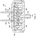
- FIG. 5is a section view of the switch 204 of FIG. 4 taken along line A-A, illustrating additional details that may be associated with some embodiments.
- the switch 204may include a piston, such as a diaphragm 502 , configured to flex or reciprocate within the interior of the switch. Assembled as shown in FIG. 5 , the diaphragm 502 may partition the interior of the switch 204 into a first chamber 504 and a second chamber 506 . Moreover, the diaphragm 502 may engage the first enclosure 302 or the second enclosure 304 to provide a seal between the first chamber 504 and the second chamber 506 .
- a pistonsuch as a diaphragm 502
- the diaphragm 502may partition the interior of the switch 204 into a first chamber 504 and a second chamber 506 .
- the diaphragm 502may engage the first enclosure 302 or the second enclosure 304 to provide a seal between the first chamber 504 and the second chamber
- the second enclosure 304may include a retention support 508 configured to engage the diaphragm 502 and fluidly isolate the first chamber 504 from the second chamber 506 .
- the first chamber 504 and the second chamber 506are also preferably fluidly isolated from the external environment, except through an aperture 510 and the pressure orifice 314 , respectively.
- a hydrophobic filter 511may be disposed between the aperture 510 and the first chamber 504 to substantially reduce or prevent liquid transfer between the aperture 510 and the first chamber 504 while allowing gas transfer.
- a spring 512may also be disposed in the first chamber 504 between the diaphragm 502 and the second enclosure 304 .
- the spring 512may bias the diaphragm 502 away from the aperture 510 .
- a first end of the spring 512may be coupled to a retention boss 514 to restrict lateral movement, and a second end of the spring 512 may be coupled to the diaphragm 502 , as shown in FIG. 5 .
- the aperture 510may extend through the retention boss 514 .
- the second enclosure 304may also include a port 516 .
- the port 516is generally configured to be coupled to another fluid conductor or other distribution component.
- the port 516may protrude from the second enclosure 304 and have a profile suitable for mechanically coupling to a fitting.
- the aperture 510may also pass through the port 516 to fluidly couple the first chamber 504 to a distribution component.
- the switch 204may also include electrically conductive contacts.
- a contact 518may be disposed in the second chamber 506 and coupled to the diaphragm 502 , and a contact 520 may be electrically coupled to each of the conductors 306 .
- the contacts 520are electrically insulated from each other.
- the contacts 520are electrically insulated by air in a gap between them.
- the contact 518electrically couples the contacts 520 .
- the diaphragm 502may be configured to move the contact 518 in some embodiments. For example, assembled as shown in FIG.
- the contact 518may be directly coupled to the diaphragm 502 and configured to move with the diaphragm 502 .
- the spring 512may be configured to bias the diaphragm 502 toward the contacts 520 so that the switch 204 is normally closed.
- the switch 204can be opened, for example, if a pressure differential across the diaphragm 502 is sufficiently large to overcome the force of the spring 512 on the diaphragm 502 and move the contact 518 away from the contacts 520 .
- the pressure differential at which the diaphragm 502 movespreferably corresponds to a threshold negative pressure in the first chamber 504 .
- the switch 204may include an adjustment screw to adjust tension in the spring 512 , which can modify the threshold according to a prescribed therapy.
- FIG. 6is an assembly view of the switch 204 of FIG. 5 , illustrating additional details that may be associated with some embodiments.
- the contact 518may be a disk
- the contacts 520may each be a half of a similarly shaped and sized disk.
- the diaphragm 502may also be rounded and sized to fit within the second enclosure 304 .
- the retention support 508may be an annular support, sized slightly smaller than the diaphragm 502 .
- the first enclosure 302 and the second enclosure 304are preferably formed from a material with sufficient rigidity to maintain a substantially constant internal volume under normal operating conditions.
- a rigid polymermay be suitable for many applications.
- a polymermay also be advantageous for manufacturing purposes, allowing the first enclosure 302 and the second enclosure 304 to be molded.
- a diaphragmsuch as the diaphragm 502 may be constructed from a variety of materials with good damping properties and sufficient flexibility to be responsive to changes in pressure under desired operating conditions.
- An elastic polymer, such as a high-consistency rubbermay be advantageous for many embodiments.
- a silicone rubber with a 45-55 shore A hardness and 650% elongationmay be suitable for some embodiments.
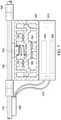
- FIG. 7is a schematic view of another example embodiment of the agitator 114 and the switch 204 .
- the housing 212may enclose the battery 206 and the circuit board 208 .
- the switch 204may include normally open electrical contacts 702 and normally closed electrical contacts 704 .
- the agitator 114may additionally include or be coupled to a tee fitting 706 .
- the tee fitting 706may be pneumatically coupled to the first chamber 504 through the aperture 510 .
- the tee fitting 706may also couple the first chamber 504 to the negative-pressure source 104 or other downstream distribution component through a connector 708 .
- the vibration motor 202is coupled to a tube 710 upstream of the tee fitting 706 .
- FIG. 8is a schematic diagram of a control circuit 800 , illustrating additional details that may be associated with some embodiments of the circuit board 208 .
- the control circuit 800may include an oscillator 804 , such as a low-frequency astable oscillator, for controlling a vibrating motor, such as the vibrating motor 202 .
- the oscillator 804may correspond to a TLC555 LinCMOS timer circuit manufactured by Texas Instruments, but other suitable oscillators may be used.
- the oscillator 804(having pins 1-8) can output a repeating high-low signal (e.g., a 1 or 0, respectively) on pin 3 if the switch 812 is closed, in order to selectively turn the motor 808 on and off as described below in more detail.
- the switch 812may correspond to the pressure switch 204
- the on statemay correspond to a closed state of the pressure switch 204 .
- the switch 812When actuated to an on state, the switch 812 can provide a supply voltage V DD from a battery 816 to the control circuit 800 .
- the battery 816may be a 3V coin cell type battery, corresponding to the battery 206 .
- the oscillator 804can output a high (1) signal on pin 3 to turn on transistor 820 when the supply voltage V DD is received on pins 4 and 8 (i.e., when pins 4 and 8 are high), turning on the motor 808 .
- pins 4 and 8are low, causing the oscillator 804 to output a low (0) signal on pin 3 to turn off the transistor 820 and the motor 808 .
- pin 4corresponds to a reset pin and pin 8 corresponds to a supply voltage pin.
- the control circuit 800may be configured to operate the motor 808 at a desired duty cycle (e.g., 50%) while the switch 812 is on. For example, if the switch 812 is on, the control circuit 800 may control the motor 808 to operate at a 50% duty cycle. In the example embodiment of FIG. 8 , the duty cycle may be controlled according to inputs and configurations of pins 2, 6, 5, and 7 of the oscillator 804 . For example, when the switch 812 is initially turned on, the oscillator 804 turns on the motor 808 , pins 2 and 6 receive a first voltage, and capacitor 824 begins to charge.
- a desired duty cyclee.g. 50%
- the control circuit 800may control the motor 808 to operate at a 50% duty cycle.
- the duty cyclemay be controlled according to inputs and configurations of pins 2, 6, 5, and 7 of the oscillator 804 . For example, when the switch 812 is initially turned on, the oscillator 804 turns on the motor 808 , pins 2 and 6 receive a first
- the capacitor 824After charging for a first time T1, the capacitor 824 is charged sufficiently to provide a second voltage to pins 2 and 6 (e.g., the first voltage increases above respective thresholds associated with pins 2 and 6 to the second voltage), which causes the oscillator 804 to turn the motor 808 off (by outputting a low, or 0, on pin 3).
- the output of the oscillator 804 on pin 3is low, discharge pin 7 of the oscillator 804 provides a discharge path to ground via ground pin 1 of the oscillator 804 , causing the capacitor 824 to discharge.
- the second voltage provided to pins 2 and 6drops below the respective thresholds of pins 2 and 6, causing the oscillator 804 to turn the motor 808 on and repeat the cycle.
- T1 and T2may correspond to values of the capacitor 824 and resistors 828 and 832 , where the duty cycle of the control circuit 800 corresponds to T1/(T1+T2).
- the respective thresholds of pins 2 and 6may be adjusted according to a control voltage applied to pin 5 and the values of the capacitor 824 and resistors 828 and 832 may be further adjusted.
- the tissue interface 108may be placed within, over, on, or otherwise proximate to a tissue site.
- the cover 106may be placed over the tissue interface 108 and sealed to an attachment surface near the tissue site.
- the cover 106may be sealed to undamaged epidermis peripheral to a tissue site.
- the dressing 102can provide a sealed therapeutic environment proximate to a tissue site, substantially isolated from the external environment, and the negative-pressure source 104 can reduce the pressure in the sealed therapeutic environment. Negative pressure applied across the tissue site through the tissue interface 108 in the sealed therapeutic environment can induce macrostrain and microstrain in the tissue site, as well as remove exudates and other fluids from the tissue site, which can be collected in container 112 .
- the agitator 114may be coupled to a distribution component in the fluid path between a tissue site and the negative-pressure source 104 .
- the agitator 114may be coupled directly to the dressing 102 , or may be directly coupled to a tube between the dressing 102 and the negative-pressure source 104 .
- the agitator 114may also be pneumatically coupled to the negative-pressure source 104 , in some embodiments, and can be actuated by pressure changes in the fluid path.
- the agitator 114may be coupled indirectly to the negative-pressure source 104 through an input aperture, such as the aperture 510 , so that movement of the diaphragm 502 is based on pressure in the input aperture 510 or the first chamber 504 .
- the aperture 510may be aligned with an aperture in the cover 106 to fluidly couple the first chamber 504 to negative pressure in the dressing 102 .
- the diaphragm 502may be biased against negative pressure in the input aperture 510 or the first chamber 504 .
- the spring 512may bias the diaphragm 502 against negative pressure in the input aperture 510 , so that the contacts 520 are closed until negative pressure exceeds a target negative pressure. If the negative pressure is reduced below the target, the spring can move the diaphragm 502 and close the contacts 520 .
- the agitator 114may be clamped or otherwise coupled to a tube or dressing interface between the dressing 102 and the negative-pressure source 104 .
- the agitator 114may have a tee fitting or micro-needle to puncture tubing, for example.
- the switch 204may be normally closed. If the switch 204 is normally closed, the control circuit 800 may run the vibration motor 202 until the negative pressure in the first chamber 504 exceeds a threshold, opening the switch 204 . Running the vibration motor 202 during pressure reduction may improve exudate flow.
- the thresholdmay correspond to a prescribed therapy pressure in some embodiments, but may also be greater or less than a prescribed therapy pressure.
- the agitator 114may vibrate on a low duty-cycle until negative-pressure in the first chamber 504 meets or exceeds a prescribed negative-pressure. In other embodiments, such as the example of FIG.
- the agitator 114may be configured with normally-open contacts, and may vibrate only if the negative-pressure in the first chamber 504 meets or exceeds a threshold pressure, such as a prescribed negative-pressure.
- Normally-open contactsmay be advantageous, for example, to maximize battery life.
- the agitator 114can generate low amplitude vibrations, which can be transmitted through distribution components such as plastic tubing or dressing components. These oscillations can direct kinetic energy into exudate to reduce or minimize the size of solids and lower the viscosity of the exudate. Lowering viscosity of exudate can reduce the frequency of blockages, particularly in tubes, which can be particularly useful for removing and managing fluid where blockages can occur. Vibrations may also micro-agitate the wound bed to encourage blood flow and granulation, and in some applications may also be useful for removing air from a fluid conductor.
Landscapes
- Health & Medical Sciences (AREA)
- Heart & Thoracic Surgery (AREA)
- Anesthesiology (AREA)
- Vascular Medicine (AREA)
- Engineering & Computer Science (AREA)
- Biomedical Technology (AREA)
- Hematology (AREA)
- Life Sciences & Earth Sciences (AREA)
- Animal Behavior & Ethology (AREA)
- General Health & Medical Sciences (AREA)
- Public Health (AREA)
- Veterinary Medicine (AREA)
- Fluid Mechanics (AREA)
- Physics & Mathematics (AREA)
- Media Introduction/Drainage Providing Device (AREA)
Abstract
Description
Claims (14)
Priority Applications (1)
| Application Number | Priority Date | Filing Date | Title |
|---|---|---|---|
| US15/766,320US11253640B2 (en) | 2015-11-19 | 2016-11-17 | Fluid management apparatus and method |
Applications Claiming Priority (3)
| Application Number | Priority Date | Filing Date | Title |
|---|---|---|---|
| US201562257292P | 2015-11-19 | 2015-11-19 | |
| US15/766,320US11253640B2 (en) | 2015-11-19 | 2016-11-17 | Fluid management apparatus and method |
| PCT/US2016/062555WO2017087687A1 (en) | 2015-11-19 | 2016-11-17 | Fluid management apparatus and method |
Publications (2)
| Publication Number | Publication Date |
|---|---|
| US20180289870A1 US20180289870A1 (en) | 2018-10-11 |
| US11253640B2true US11253640B2 (en) | 2022-02-22 |
Family
ID=57610372
Family Applications (1)
| Application Number | Title | Priority Date | Filing Date |
|---|---|---|---|
| US15/766,320Active2039-01-25US11253640B2 (en) | 2015-11-19 | 2016-11-17 | Fluid management apparatus and method |
Country Status (3)
| Country | Link |
|---|---|
| US (1) | US11253640B2 (en) |
| EP (2) | EP3377131B1 (en) |
| WO (1) | WO2017087687A1 (en) |
Families Citing this family (5)
| Publication number | Priority date | Publication date | Assignee | Title |
|---|---|---|---|---|
| EP3840794B1 (en) | 2018-08-21 | 2023-10-11 | 3M Innovative Properties Company | System for utilizing pressure decay to determine available fluid capacity in a negative pressure dressing |
| GB201817052D0 (en) | 2018-10-19 | 2018-12-05 | Smith & Nephew | Tissue treatment device |
| EP4025269B1 (en)* | 2019-09-04 | 2025-04-09 | Solventum Intellectual Properties Company | Negative pressure charged vibration mechanism for intermittent wound dressing vibration |
| US20210251627A1 (en)* | 2020-02-19 | 2021-08-19 | DePuy Synthes Products, Inc. | Components for use in combination external fixation and negative pressure wound therapy system and methods of production and use thereof |
| US12259266B1 (en)* | 2024-06-21 | 2025-03-25 | John Vander Horst | Multi-tank indirect liquid level measurement system and method for holding tanks in a recreational vehicle |
Citations (140)
| Publication number | Priority date | Publication date | Assignee | Title |
|---|---|---|---|---|
| US1355846A (en) | 1920-02-06 | 1920-10-19 | David A Rannells | Medical appliance |
| US2547758A (en) | 1949-01-05 | 1951-04-03 | Wilmer B Keeling | Instrument for treating the male urethra |
| US2632443A (en) | 1949-04-18 | 1953-03-24 | Eleanor P Lesher | Surgical dressing |
| GB692578A (en) | 1949-09-13 | 1953-06-10 | Minnesota Mining & Mfg | Improvements in or relating to drape sheets for surgical use |
| US2682873A (en) | 1952-07-30 | 1954-07-06 | Johnson & Johnson | General purpose protective dressing |
| US2910763A (en) | 1955-08-17 | 1959-11-03 | Du Pont | Felt-like products |
| US2969057A (en) | 1957-11-04 | 1961-01-24 | Brady Co W H | Nematodic swab |
| US3066672A (en) | 1960-09-27 | 1962-12-04 | Jr William H Crosby | Method and apparatus for serial sampling of intestinal juice |
| US3367332A (en) | 1965-08-27 | 1968-02-06 | Gen Electric | Product and process for establishing a sterile area of skin |
| FR1543645A (en) | 1966-11-04 | 1968-10-25 | Werner Messmer Kg Spezialfabri | Warning switch for dual circuit brakes |
| US3520300A (en) | 1967-03-15 | 1970-07-14 | Amp Inc | Surgical sponge and suction device |
| GB1204132A (en) | 1967-01-20 | 1970-09-03 | Smiths Industries Ltd | Improvements in or relating to switches operable by fluid pressure |
| US3568675A (en) | 1968-08-30 | 1971-03-09 | Clyde B Harvey | Fistula and penetrating wound dressing |
| US3648692A (en) | 1970-12-07 | 1972-03-14 | Parke Davis & Co | Medical-surgical dressing for burns and the like |
| US3682180A (en) | 1970-06-08 | 1972-08-08 | Coilform Co Inc | Drain clip for surgical drain |
| US3826254A (en) | 1973-02-26 | 1974-07-30 | Verco Ind | Needle or catheter retaining appliance |
| DE2640413A1 (en) | 1976-09-08 | 1978-03-09 | Wolf Gmbh Richard | CATHETER MONITORING DEVICE |
| US4080970A (en) | 1976-11-17 | 1978-03-28 | Miller Thomas J | Post-operative combination dressing and internal drain tube with external shield and tube connector |
| US4096853A (en) | 1975-06-21 | 1978-06-27 | Hoechst Aktiengesellschaft | Device for the introduction of contrast medium into an anus praeter |
| US4139004A (en) | 1977-02-17 | 1979-02-13 | Gonzalez Jr Harry | Bandage apparatus for treating burns |
| GB2004942A (en) | 1977-09-21 | 1979-04-11 | Bosio R | Pump for producing an artificial blood circulation |
| US4165748A (en) | 1977-11-07 | 1979-08-28 | Johnson Melissa C | Catheter tube holder |
| US4184510A (en) | 1977-03-15 | 1980-01-22 | Fibra-Sonics, Inc. | Valued device for controlling vacuum in surgery |
| WO1980002182A1 (en) | 1979-04-06 | 1980-10-16 | J Moss | Portable suction device for collecting fluids from a closed wound |
| US4233969A (en) | 1976-11-11 | 1980-11-18 | Lock Peter M | Wound dressing materials |
| US4245630A (en) | 1976-10-08 | 1981-01-20 | T. J. Smith & Nephew, Ltd. | Tearable composite strip of materials |
| US4256109A (en) | 1978-07-10 | 1981-03-17 | Nichols Robert L | Shut off valve for medical suction apparatus |
| US4261363A (en) | 1979-11-09 | 1981-04-14 | C. R. Bard, Inc. | Retention clips for body fluid drains |
| US4275721A (en) | 1978-11-28 | 1981-06-30 | Landstingens Inkopscentral Lic, Ekonomisk Forening | Vein catheter bandage |
| US4284079A (en) | 1979-06-28 | 1981-08-18 | Adair Edwin Lloyd | Method for applying a male incontinence device |
| US4297995A (en) | 1980-06-03 | 1981-11-03 | Key Pharmaceuticals, Inc. | Bandage containing attachment post |
| US4333468A (en) | 1980-08-18 | 1982-06-08 | Geist Robert W | Mesentery tube holder apparatus |
| US4373519A (en) | 1981-06-26 | 1983-02-15 | Minnesota Mining And Manufacturing Company | Composite wound dressing |
| US4382441A (en) | 1978-12-06 | 1983-05-10 | Svedman Paul | Device for treating tissues, for example skin |
| US4392853A (en) | 1981-03-16 | 1983-07-12 | Rudolph Muto | Sterile assembly for protecting and fastening an indwelling device |
| US4392858A (en) | 1981-07-16 | 1983-07-12 | Sherwood Medical Company | Wound drainage device |
| US4419097A (en) | 1981-07-31 | 1983-12-06 | Rexar Industries, Inc. | Attachment for catheter tube |
| EP0100148A1 (en) | 1982-07-06 | 1984-02-08 | Dow Corning Limited | Medical-surgical dressing and a process for the production thereof |
| US4465485A (en) | 1981-03-06 | 1984-08-14 | Becton, Dickinson And Company | Suction canister with unitary shut-off valve and filter features |
| EP0117632A2 (en) | 1983-01-27 | 1984-09-05 | Johnson & Johnson Products Inc. | Adhesive film dressing |
| US4475909A (en) | 1982-05-06 | 1984-10-09 | Eisenberg Melvin I | Male urinary device and method for applying the device |
| US4480638A (en) | 1980-03-11 | 1984-11-06 | Eduard Schmid | Cushion for holding an element of grafted skin |
| US4525374A (en) | 1984-02-27 | 1985-06-25 | Manresa, Inc. | Treating hydrophobic filters to render them hydrophilic |
| US4525166A (en) | 1981-11-21 | 1985-06-25 | Intermedicat Gmbh | Rolled flexible medical suction drainage device |
| US4540412A (en) | 1983-07-14 | 1985-09-10 | The Kendall Company | Device for moist heat therapy |
| US4543100A (en) | 1983-11-01 | 1985-09-24 | Brodsky Stuart A | Catheter and drain tube retainer |
| US4548202A (en) | 1983-06-20 | 1985-10-22 | Ethicon, Inc. | Mesh tissue fasteners |
| US4551139A (en) | 1982-02-08 | 1985-11-05 | Marion Laboratories, Inc. | Method and apparatus for burn wound treatment |
| EP0161865A2 (en) | 1984-05-03 | 1985-11-21 | Smith and Nephew Associated Companies p.l.c. | Adhesive wound dressing |
| US4569348A (en) | 1980-02-22 | 1986-02-11 | Velcro Usa Inc. | Catheter tube holder strap |
| AU550575B2 (en) | 1981-08-07 | 1986-03-27 | Richard Christian Wright | Wound drainage device |
| US4605399A (en) | 1984-12-04 | 1986-08-12 | Complex, Inc. | Transdermal infusion device |
| US4608041A (en) | 1981-10-14 | 1986-08-26 | Frese Nielsen | Device for treatment of wounds in body tissue of patients by exposure to jets of gas |
| US4640688A (en) | 1985-08-23 | 1987-02-03 | Mentor Corporation | Urine collection catheter |
| US4655754A (en) | 1984-11-09 | 1987-04-07 | Stryker Corporation | Vacuum wound drainage system and lipids baffle therefor |
| US4664662A (en) | 1984-08-02 | 1987-05-12 | Smith And Nephew Associated Companies Plc | Wound dressing |
| WO1987004626A1 (en) | 1986-01-31 | 1987-08-13 | Osmond, Roger, L., W. | Suction system for wound and gastro-intestinal drainage |
| US4710165A (en) | 1985-09-16 | 1987-12-01 | Mcneil Charles B | Wearable, variable rate suction/collection device |
| US4733659A (en) | 1986-01-17 | 1988-03-29 | Seton Company | Foam bandage |
| GB2195255A (en) | 1986-09-30 | 1988-04-07 | Vacutec Uk Limited | Method and apparatus for vacuum treatment of an epidermal surface |
| US4743232A (en) | 1986-10-06 | 1988-05-10 | The Clinipad Corporation | Package assembly for plastic film bandage |
| GB2197789A (en) | 1986-11-28 | 1988-06-02 | Smiths Industries Plc | Anti-foaming disinfectants used in surgical suction apparatus |
| US4758220A (en) | 1985-09-26 | 1988-07-19 | Alcon Laboratories, Inc. | Surgical cassette proximity sensing and latching apparatus |
| US4787888A (en) | 1987-06-01 | 1988-11-29 | University Of Connecticut | Disposable piezoelectric polymer bandage for percutaneous delivery of drugs and method for such percutaneous delivery (a) |
| US4826494A (en) | 1984-11-09 | 1989-05-02 | Stryker Corporation | Vacuum wound drainage system |
| US4838883A (en) | 1986-03-07 | 1989-06-13 | Nissho Corporation | Urine-collecting device |
| US4840187A (en) | 1986-09-11 | 1989-06-20 | Bard Limited | Sheath applicator |
| US4863449A (en) | 1987-07-06 | 1989-09-05 | Hollister Incorporated | Adhesive-lined elastic condom cathether |
| US4872450A (en) | 1984-08-17 | 1989-10-10 | Austad Eric D | Wound dressing and method of forming same |
| US4878901A (en) | 1986-10-10 | 1989-11-07 | Sachse Hans Ernst | Condom catheter, a urethral catheter for the prevention of ascending infections |
| GB2220357A (en) | 1988-05-28 | 1990-01-10 | Smiths Industries Plc | Medico-surgical containers |
| US4897081A (en) | 1984-05-25 | 1990-01-30 | Thermedics Inc. | Percutaneous access device |
| US4906240A (en) | 1988-02-01 | 1990-03-06 | Matrix Medica, Inc. | Adhesive-faced porous absorbent sheet and method of making same |
| US4906233A (en) | 1986-05-29 | 1990-03-06 | Terumo Kabushiki Kaisha | Method of securing a catheter body to a human skin surface |
| US4919654A (en) | 1988-08-03 | 1990-04-24 | Kalt Medical Corporation | IV clamp with membrane |
| CA2005436A1 (en) | 1988-12-13 | 1990-06-13 | Glenda G. Kalt | Transparent tracheostomy tube dressing |
| US4941882A (en) | 1987-03-14 | 1990-07-17 | Smith And Nephew Associated Companies, P.L.C. | Adhesive dressing for retaining a cannula on the skin |
| US4953565A (en) | 1986-11-26 | 1990-09-04 | Shunro Tachibana | Endermic application kits for external medicines |
| WO1990010424A1 (en) | 1989-03-16 | 1990-09-20 | Smith & Nephew Plc | Absorbent devices and precursors therefor |
| US4969880A (en) | 1989-04-03 | 1990-11-13 | Zamierowski David S | Wound dressing and treatment method |
| US4985019A (en) | 1988-03-11 | 1991-01-15 | Michelson Gary K | X-ray marker |
| GB2235877A (en) | 1989-09-18 | 1991-03-20 | Antonio Talluri | Closed wound suction apparatus |
| US5037397A (en) | 1985-05-03 | 1991-08-06 | Medical Distributors, Inc. | Universal clamp |
| US5086170A (en) | 1989-01-16 | 1992-02-04 | Roussel Uclaf | Process for the preparation of azabicyclo compounds |
| US5092858A (en) | 1990-03-20 | 1992-03-03 | Becton, Dickinson And Company | Liquid gelling agent distributor device |
| US5100396A (en) | 1989-04-03 | 1992-03-31 | Zamierowski David S | Fluidic connection system and method |
| US5134994A (en) | 1990-02-12 | 1992-08-04 | Say Sam L | Field aspirator in a soft pack with externally mounted container |
| US5149331A (en) | 1991-05-03 | 1992-09-22 | Ariel Ferdman | Method and device for wound closure |
| US5167613A (en) | 1992-03-23 | 1992-12-01 | The Kendall Company | Composite vented wound dressing |
| US5176663A (en) | 1987-12-02 | 1993-01-05 | Pal Svedman | Dressing having pad with compressibility limiting elements |
| WO1993009727A1 (en) | 1991-11-14 | 1993-05-27 | Wake Forest University | Method and apparatus for treating tissue damage |
| US5215522A (en) | 1984-07-23 | 1993-06-01 | Ballard Medical Products | Single use medical aspirating device and method |
| US5232453A (en) | 1989-07-14 | 1993-08-03 | E. R. Squibb & Sons, Inc. | Catheter holder |
| US5261893A (en) | 1989-04-03 | 1993-11-16 | Zamierowski David S | Fastening system and method |
| US5278100A (en) | 1991-11-08 | 1994-01-11 | Micron Technology, Inc. | Chemical vapor deposition technique for depositing titanium silicide on semiconductor wafers |
| US5279550A (en) | 1991-12-19 | 1994-01-18 | Gish Biomedical, Inc. | Orthopedic autotransfusion system |
| US5298015A (en) | 1989-07-11 | 1994-03-29 | Nippon Zeon Co., Ltd. | Wound dressing having a porous structure |
| US5342376A (en) | 1993-05-03 | 1994-08-30 | Dermagraphics, Inc. | Inserting device for a barbed tissue connector |
| US5344415A (en) | 1993-06-15 | 1994-09-06 | Deroyal Industries, Inc. | Sterile system for dressing vascular access site |
| DE4306478A1 (en) | 1993-03-02 | 1994-09-08 | Wolfgang Dr Wagner | Drainage device, in particular pleural drainage device, and drainage method |
| WO1994020041A1 (en) | 1993-03-09 | 1994-09-15 | Wake Forest University | Wound treatment employing reduced pressure |
| US5358494A (en) | 1989-07-11 | 1994-10-25 | Svedman Paul | Irrigation dressing |
| US5437651A (en) | 1993-09-01 | 1995-08-01 | Research Medical, Inc. | Medical suction apparatus |
| US5437622A (en) | 1992-04-29 | 1995-08-01 | Laboratoire Hydrex (Sa) | Transparent adhesive dressing with reinforced starter cuts |
| DE29504378U1 (en) | 1995-03-15 | 1995-09-14 | MTG Medizinisch, technische Gerätebau GmbH, 66299 Friedrichsthal | Electronically controlled low-vacuum pump for chest and wound drainage |
| WO1996005873A1 (en) | 1994-08-22 | 1996-02-29 | Kinetic Concepts Inc. | Wound drainage equipment |
| US5527293A (en) | 1989-04-03 | 1996-06-18 | Kinetic Concepts, Inc. | Fastening system and method |
| US5549584A (en) | 1994-02-14 | 1996-08-27 | The Kendall Company | Apparatus for removing fluid from a wound |
| US5556375A (en) | 1994-06-16 | 1996-09-17 | Hercules Incorporated | Wound dressing having a fenestrated base layer |
| US5607388A (en) | 1994-06-16 | 1997-03-04 | Hercules Incorporated | Multi-purpose wound dressing |
| WO1997018007A1 (en) | 1995-11-14 | 1997-05-22 | Kci Medical Limited | Portable wound treatment apparatus |
| GB2329127A (en) | 1997-09-12 | 1999-03-17 | Kci Medical Ltd | Suction head and drape wound treatment assembly |
| US6071267A (en) | 1998-02-06 | 2000-06-06 | Kinetic Concepts, Inc. | Medical patient fluid management interface system and method |
| US6135116A (en) | 1997-07-28 | 2000-10-24 | Kci Licensing, Inc. | Therapeutic method for treating ulcers |
| US6241747B1 (en) | 1993-05-03 | 2001-06-05 | Quill Medical, Inc. | Barbed Bodily tissue connector |
| US6287316B1 (en) | 1999-03-26 | 2001-09-11 | Ethicon, Inc. | Knitted surgical mesh |
| US20020077661A1 (en) | 2000-12-20 | 2002-06-20 | Vahid Saadat | Multi-barbed device for retaining tissue in apposition and methods of use |
| US20020115951A1 (en) | 2001-02-22 | 2002-08-22 | Core Products International, Inc. | Ankle brace providing upper and lower ankle adjustment |
| US20020120185A1 (en) | 2000-05-26 | 2002-08-29 | Kci Licensing, Inc. | System for combined transcutaneous blood gas monitoring and vacuum assisted wound closure |
| US20020143286A1 (en) | 2001-03-05 | 2002-10-03 | Kci Licensing, Inc. | Vacuum assisted wound treatment apparatus and infection identification system and method |
| US6488643B1 (en) | 1998-10-08 | 2002-12-03 | Kci Licensing, Inc. | Wound healing foot wrap |
| US6493568B1 (en) | 1994-07-19 | 2002-12-10 | Kci Licensing, Inc. | Patient interface system |
| AU755496B2 (en) | 1997-09-12 | 2002-12-12 | Kci Licensing, Inc. | Surgical drape and suction head for wound treatment |
| WO2005105175A1 (en) | 2004-04-27 | 2005-11-10 | Smith & Nephew, Plc | Wound cleansing apparatus with ultrasound |
| WO2007030601A2 (en) | 2005-09-06 | 2007-03-15 | Tyco Healthcare Group Lp | Self contained wound dressing with micropump |
| JP4129536B2 (en) | 2000-02-24 | 2008-08-06 | ヴェネテック インターナショナル,インコーポレイテッド | Highly compatible catheter anchoring system |
| US20100010477A1 (en)* | 2008-07-08 | 2010-01-14 | Tyco Healthcare Group Lp | Portable Negative Pressure Wound Therapy Device |
| WO2010093753A1 (en) | 2009-02-12 | 2010-08-19 | Perfuzia Medical, Inc. | Devices and methods for manipulating circulation in the circulatory system of a patient |
| US7846141B2 (en) | 2002-09-03 | 2010-12-07 | Bluesky Medical Group Incorporated | Reduced pressure treatment system |
| US8216198B2 (en) | 2009-01-09 | 2012-07-10 | Tyco Healthcare Group Lp | Canister for receiving wound exudate in a negative pressure therapy system |
| US8251979B2 (en) | 2009-05-11 | 2012-08-28 | Tyco Healthcare Group Lp | Orientation independent canister for a negative pressure wound therapy device |
| US8257327B2 (en) | 2003-10-28 | 2012-09-04 | Smith & Nephew Plc | Wound cleansing apparatus with actives |
| US8398614B2 (en) | 2002-10-28 | 2013-03-19 | Smith & Nephew Plc | Apparatus for aspirating, irrigating and cleansing wounds |
| US8449509B2 (en) | 2004-04-05 | 2013-05-28 | Bluesky Medical Group Incorporated | Flexible reduced pressure treatment appliance |
| US8529548B2 (en) | 2004-04-27 | 2013-09-10 | Smith & Nephew Plc | Wound treatment apparatus and method |
| US8551060B2 (en) | 2008-07-17 | 2013-10-08 | Smith & Nephew, Inc. | Subatmospheric pressure mechanism for wound therapy system and related methods therefor |
| US20130338613A1 (en)* | 2005-09-07 | 2013-12-19 | Smith & Nephew, Inc. | Wound dressing with vacuum reservoir |
| US20140066868A1 (en)* | 2011-11-01 | 2014-03-06 | J&M Shuler Medical, Inc. | Mechanical wound therapy for sub-atmospheric wound care system |
| US8926592B2 (en) | 2003-10-28 | 2015-01-06 | Smith & Nephew Plc | Wound cleansing apparatus with heat |
| US9017302B2 (en) | 2008-07-21 | 2015-04-28 | Smith & Nephew, Inc. | Thin film wound dressing |
- 2016
- 2016-11-17USUS15/766,320patent/US11253640B2/enactiveActive
- 2016-11-17WOPCT/US2016/062555patent/WO2017087687A1/ennot_activeCeased
- 2016-11-17EPEP16816777.3Apatent/EP3377131B1/enactiveActive
- 2016-11-17EPEP19201270.6Apatent/EP3613451A1/ennot_activeWithdrawn
Patent Citations (162)
| Publication number | Priority date | Publication date | Assignee | Title |
|---|---|---|---|---|
| US1355846A (en) | 1920-02-06 | 1920-10-19 | David A Rannells | Medical appliance |
| US2547758A (en) | 1949-01-05 | 1951-04-03 | Wilmer B Keeling | Instrument for treating the male urethra |
| US2632443A (en) | 1949-04-18 | 1953-03-24 | Eleanor P Lesher | Surgical dressing |
| GB692578A (en) | 1949-09-13 | 1953-06-10 | Minnesota Mining & Mfg | Improvements in or relating to drape sheets for surgical use |
| US2682873A (en) | 1952-07-30 | 1954-07-06 | Johnson & Johnson | General purpose protective dressing |
| US2910763A (en) | 1955-08-17 | 1959-11-03 | Du Pont | Felt-like products |
| US2969057A (en) | 1957-11-04 | 1961-01-24 | Brady Co W H | Nematodic swab |
| US3066672A (en) | 1960-09-27 | 1962-12-04 | Jr William H Crosby | Method and apparatus for serial sampling of intestinal juice |
| US3367332A (en) | 1965-08-27 | 1968-02-06 | Gen Electric | Product and process for establishing a sterile area of skin |
| FR1543645A (en) | 1966-11-04 | 1968-10-25 | Werner Messmer Kg Spezialfabri | Warning switch for dual circuit brakes |
| GB1204132A (en) | 1967-01-20 | 1970-09-03 | Smiths Industries Ltd | Improvements in or relating to switches operable by fluid pressure |
| US3520300A (en) | 1967-03-15 | 1970-07-14 | Amp Inc | Surgical sponge and suction device |
| US3568675A (en) | 1968-08-30 | 1971-03-09 | Clyde B Harvey | Fistula and penetrating wound dressing |
| US3682180A (en) | 1970-06-08 | 1972-08-08 | Coilform Co Inc | Drain clip for surgical drain |
| US3648692A (en) | 1970-12-07 | 1972-03-14 | Parke Davis & Co | Medical-surgical dressing for burns and the like |
| US3826254A (en) | 1973-02-26 | 1974-07-30 | Verco Ind | Needle or catheter retaining appliance |
| US4096853A (en) | 1975-06-21 | 1978-06-27 | Hoechst Aktiengesellschaft | Device for the introduction of contrast medium into an anus praeter |
| DE2640413A1 (en) | 1976-09-08 | 1978-03-09 | Wolf Gmbh Richard | CATHETER MONITORING DEVICE |
| US4245630A (en) | 1976-10-08 | 1981-01-20 | T. J. Smith & Nephew, Ltd. | Tearable composite strip of materials |
| US4233969A (en) | 1976-11-11 | 1980-11-18 | Lock Peter M | Wound dressing materials |
| US4080970A (en) | 1976-11-17 | 1978-03-28 | Miller Thomas J | Post-operative combination dressing and internal drain tube with external shield and tube connector |
| US4139004A (en) | 1977-02-17 | 1979-02-13 | Gonzalez Jr Harry | Bandage apparatus for treating burns |
| US4184510A (en) | 1977-03-15 | 1980-01-22 | Fibra-Sonics, Inc. | Valued device for controlling vacuum in surgery |
| GB2004942A (en) | 1977-09-21 | 1979-04-11 | Bosio R | Pump for producing an artificial blood circulation |
| US4165748A (en) | 1977-11-07 | 1979-08-28 | Johnson Melissa C | Catheter tube holder |
| US4256109A (en) | 1978-07-10 | 1981-03-17 | Nichols Robert L | Shut off valve for medical suction apparatus |
| US4275721A (en) | 1978-11-28 | 1981-06-30 | Landstingens Inkopscentral Lic, Ekonomisk Forening | Vein catheter bandage |
| US4382441A (en) | 1978-12-06 | 1983-05-10 | Svedman Paul | Device for treating tissues, for example skin |
| WO1980002182A1 (en) | 1979-04-06 | 1980-10-16 | J Moss | Portable suction device for collecting fluids from a closed wound |
| US4284079A (en) | 1979-06-28 | 1981-08-18 | Adair Edwin Lloyd | Method for applying a male incontinence device |
| US4261363A (en) | 1979-11-09 | 1981-04-14 | C. R. Bard, Inc. | Retention clips for body fluid drains |
| US4569348A (en) | 1980-02-22 | 1986-02-11 | Velcro Usa Inc. | Catheter tube holder strap |
| US4480638A (en) | 1980-03-11 | 1984-11-06 | Eduard Schmid | Cushion for holding an element of grafted skin |
| US4297995A (en) | 1980-06-03 | 1981-11-03 | Key Pharmaceuticals, Inc. | Bandage containing attachment post |
| US4333468A (en) | 1980-08-18 | 1982-06-08 | Geist Robert W | Mesentery tube holder apparatus |
| US4465485A (en) | 1981-03-06 | 1984-08-14 | Becton, Dickinson And Company | Suction canister with unitary shut-off valve and filter features |
| US4392853A (en) | 1981-03-16 | 1983-07-12 | Rudolph Muto | Sterile assembly for protecting and fastening an indwelling device |
| US4373519A (en) | 1981-06-26 | 1983-02-15 | Minnesota Mining And Manufacturing Company | Composite wound dressing |
| US4392858A (en) | 1981-07-16 | 1983-07-12 | Sherwood Medical Company | Wound drainage device |
| US4419097A (en) | 1981-07-31 | 1983-12-06 | Rexar Industries, Inc. | Attachment for catheter tube |
| AU550575B2 (en) | 1981-08-07 | 1986-03-27 | Richard Christian Wright | Wound drainage device |
| US4608041A (en) | 1981-10-14 | 1986-08-26 | Frese Nielsen | Device for treatment of wounds in body tissue of patients by exposure to jets of gas |
| US4525166A (en) | 1981-11-21 | 1985-06-25 | Intermedicat Gmbh | Rolled flexible medical suction drainage device |
| US4551139A (en) | 1982-02-08 | 1985-11-05 | Marion Laboratories, Inc. | Method and apparatus for burn wound treatment |
| US4475909A (en) | 1982-05-06 | 1984-10-09 | Eisenberg Melvin I | Male urinary device and method for applying the device |
| EP0100148A1 (en) | 1982-07-06 | 1984-02-08 | Dow Corning Limited | Medical-surgical dressing and a process for the production thereof |
| EP0117632A2 (en) | 1983-01-27 | 1984-09-05 | Johnson & Johnson Products Inc. | Adhesive film dressing |
| US4548202A (en) | 1983-06-20 | 1985-10-22 | Ethicon, Inc. | Mesh tissue fasteners |
| US4540412A (en) | 1983-07-14 | 1985-09-10 | The Kendall Company | Device for moist heat therapy |
| US4543100A (en) | 1983-11-01 | 1985-09-24 | Brodsky Stuart A | Catheter and drain tube retainer |
| US4525374A (en) | 1984-02-27 | 1985-06-25 | Manresa, Inc. | Treating hydrophobic filters to render them hydrophilic |
| EP0161865A2 (en) | 1984-05-03 | 1985-11-21 | Smith and Nephew Associated Companies p.l.c. | Adhesive wound dressing |
| US4897081A (en) | 1984-05-25 | 1990-01-30 | Thermedics Inc. | Percutaneous access device |
| US5215522A (en) | 1984-07-23 | 1993-06-01 | Ballard Medical Products | Single use medical aspirating device and method |
| US4664662A (en) | 1984-08-02 | 1987-05-12 | Smith And Nephew Associated Companies Plc | Wound dressing |
| US4872450A (en) | 1984-08-17 | 1989-10-10 | Austad Eric D | Wound dressing and method of forming same |
| US4655754A (en) | 1984-11-09 | 1987-04-07 | Stryker Corporation | Vacuum wound drainage system and lipids baffle therefor |
| US4826494A (en) | 1984-11-09 | 1989-05-02 | Stryker Corporation | Vacuum wound drainage system |
| US4605399A (en) | 1984-12-04 | 1986-08-12 | Complex, Inc. | Transdermal infusion device |
| US5037397A (en) | 1985-05-03 | 1991-08-06 | Medical Distributors, Inc. | Universal clamp |
| US4640688A (en) | 1985-08-23 | 1987-02-03 | Mentor Corporation | Urine collection catheter |
| US4710165A (en) | 1985-09-16 | 1987-12-01 | Mcneil Charles B | Wearable, variable rate suction/collection device |
| US4758220A (en) | 1985-09-26 | 1988-07-19 | Alcon Laboratories, Inc. | Surgical cassette proximity sensing and latching apparatus |
| US4733659A (en) | 1986-01-17 | 1988-03-29 | Seton Company | Foam bandage |
| WO1987004626A1 (en) | 1986-01-31 | 1987-08-13 | Osmond, Roger, L., W. | Suction system for wound and gastro-intestinal drainage |
| US4838883A (en) | 1986-03-07 | 1989-06-13 | Nissho Corporation | Urine-collecting device |
| US4906233A (en) | 1986-05-29 | 1990-03-06 | Terumo Kabushiki Kaisha | Method of securing a catheter body to a human skin surface |
| US4840187A (en) | 1986-09-11 | 1989-06-20 | Bard Limited | Sheath applicator |
| GB2195255A (en) | 1986-09-30 | 1988-04-07 | Vacutec Uk Limited | Method and apparatus for vacuum treatment of an epidermal surface |
| US4743232A (en) | 1986-10-06 | 1988-05-10 | The Clinipad Corporation | Package assembly for plastic film bandage |
| US4878901A (en) | 1986-10-10 | 1989-11-07 | Sachse Hans Ernst | Condom catheter, a urethral catheter for the prevention of ascending infections |
| US4953565A (en) | 1986-11-26 | 1990-09-04 | Shunro Tachibana | Endermic application kits for external medicines |
| GB2197789A (en) | 1986-11-28 | 1988-06-02 | Smiths Industries Plc | Anti-foaming disinfectants used in surgical suction apparatus |
| US4941882A (en) | 1987-03-14 | 1990-07-17 | Smith And Nephew Associated Companies, P.L.C. | Adhesive dressing for retaining a cannula on the skin |
| US4787888A (en) | 1987-06-01 | 1988-11-29 | University Of Connecticut | Disposable piezoelectric polymer bandage for percutaneous delivery of drugs and method for such percutaneous delivery (a) |
| US4863449A (en) | 1987-07-06 | 1989-09-05 | Hollister Incorporated | Adhesive-lined elastic condom cathether |
| US5176663A (en) | 1987-12-02 | 1993-01-05 | Pal Svedman | Dressing having pad with compressibility limiting elements |
| US4906240A (en) | 1988-02-01 | 1990-03-06 | Matrix Medica, Inc. | Adhesive-faced porous absorbent sheet and method of making same |
| US4985019A (en) | 1988-03-11 | 1991-01-15 | Michelson Gary K | X-ray marker |
| EP0358302A2 (en) | 1988-05-28 | 1990-03-14 | Smiths Industries Public Limited Company | Medico-surgical suction container |
| GB2220357A (en) | 1988-05-28 | 1990-01-10 | Smiths Industries Plc | Medico-surgical containers |
| US4919654A (en) | 1988-08-03 | 1990-04-24 | Kalt Medical Corporation | IV clamp with membrane |
| CA2005436A1 (en) | 1988-12-13 | 1990-06-13 | Glenda G. Kalt | Transparent tracheostomy tube dressing |
| US5086170A (en) | 1989-01-16 | 1992-02-04 | Roussel Uclaf | Process for the preparation of azabicyclo compounds |
| WO1990010424A1 (en) | 1989-03-16 | 1990-09-20 | Smith & Nephew Plc | Absorbent devices and precursors therefor |
| US4969880A (en) | 1989-04-03 | 1990-11-13 | Zamierowski David S | Wound dressing and treatment method |
| US5100396A (en) | 1989-04-03 | 1992-03-31 | Zamierowski David S | Fluidic connection system and method |
| US5527293A (en) | 1989-04-03 | 1996-06-18 | Kinetic Concepts, Inc. | Fastening system and method |
| US5261893A (en) | 1989-04-03 | 1993-11-16 | Zamierowski David S | Fastening system and method |
| US5358494A (en) | 1989-07-11 | 1994-10-25 | Svedman Paul | Irrigation dressing |
| US5298015A (en) | 1989-07-11 | 1994-03-29 | Nippon Zeon Co., Ltd. | Wound dressing having a porous structure |
| US5232453A (en) | 1989-07-14 | 1993-08-03 | E. R. Squibb & Sons, Inc. | Catheter holder |
| GB2235877A (en) | 1989-09-18 | 1991-03-20 | Antonio Talluri | Closed wound suction apparatus |
| US5134994A (en) | 1990-02-12 | 1992-08-04 | Say Sam L | Field aspirator in a soft pack with externally mounted container |
| US5092858A (en) | 1990-03-20 | 1992-03-03 | Becton, Dickinson And Company | Liquid gelling agent distributor device |
| US5149331A (en) | 1991-05-03 | 1992-09-22 | Ariel Ferdman | Method and device for wound closure |
| US5278100A (en) | 1991-11-08 | 1994-01-11 | Micron Technology, Inc. | Chemical vapor deposition technique for depositing titanium silicide on semiconductor wafers |
| WO1993009727A1 (en) | 1991-11-14 | 1993-05-27 | Wake Forest University | Method and apparatus for treating tissue damage |
| US5645081A (en) | 1991-11-14 | 1997-07-08 | Wake Forest University | Method of treating tissue damage and apparatus for same |
| US5636643A (en) | 1991-11-14 | 1997-06-10 | Wake Forest University | Wound treatment employing reduced pressure |
| US5279550A (en) | 1991-12-19 | 1994-01-18 | Gish Biomedical, Inc. | Orthopedic autotransfusion system |
| US5167613A (en) | 1992-03-23 | 1992-12-01 | The Kendall Company | Composite vented wound dressing |
| US5437622A (en) | 1992-04-29 | 1995-08-01 | Laboratoire Hydrex (Sa) | Transparent adhesive dressing with reinforced starter cuts |
| DE4306478A1 (en) | 1993-03-02 | 1994-09-08 | Wolfgang Dr Wagner | Drainage device, in particular pleural drainage device, and drainage method |
| WO1994020041A1 (en) | 1993-03-09 | 1994-09-15 | Wake Forest University | Wound treatment employing reduced pressure |
| US5342376A (en) | 1993-05-03 | 1994-08-30 | Dermagraphics, Inc. | Inserting device for a barbed tissue connector |
| US6241747B1 (en) | 1993-05-03 | 2001-06-05 | Quill Medical, Inc. | Barbed Bodily tissue connector |
| US5344415A (en) | 1993-06-15 | 1994-09-06 | Deroyal Industries, Inc. | Sterile system for dressing vascular access site |
| US5437651A (en) | 1993-09-01 | 1995-08-01 | Research Medical, Inc. | Medical suction apparatus |
| US5549584A (en) | 1994-02-14 | 1996-08-27 | The Kendall Company | Apparatus for removing fluid from a wound |
| US5556375A (en) | 1994-06-16 | 1996-09-17 | Hercules Incorporated | Wound dressing having a fenestrated base layer |
| US5607388A (en) | 1994-06-16 | 1997-03-04 | Hercules Incorporated | Multi-purpose wound dressing |
| US6493568B1 (en) | 1994-07-19 | 2002-12-10 | Kci Licensing, Inc. | Patient interface system |
| WO1996005873A1 (en) | 1994-08-22 | 1996-02-29 | Kinetic Concepts Inc. | Wound drainage equipment |
| DE29504378U1 (en) | 1995-03-15 | 1995-09-14 | MTG Medizinisch, technische Gerätebau GmbH, 66299 Friedrichsthal | Electronically controlled low-vacuum pump for chest and wound drainage |
| WO1997018007A1 (en) | 1995-11-14 | 1997-05-22 | Kci Medical Limited | Portable wound treatment apparatus |
| US6135116A (en) | 1997-07-28 | 2000-10-24 | Kci Licensing, Inc. | Therapeutic method for treating ulcers |
| AU745271B2 (en) | 1997-09-12 | 2002-03-14 | Kci Licensing, Inc. | Surgical drape and suction head for wound treatment |
| AU755496B2 (en) | 1997-09-12 | 2002-12-12 | Kci Licensing, Inc. | Surgical drape and suction head for wound treatment |
| EP1018967A1 (en) | 1997-09-12 | 2000-07-19 | KCI Medical Ltd. | Surgical drape and suction head for wound treatment |
| GB2333965A (en) | 1997-09-12 | 1999-08-11 | Kci Medical Ltd | Surgical drape |
| US6814079B2 (en) | 1997-09-12 | 2004-11-09 | Kci Licensing, Inc. | Surgical drape and suction head for wound treatment |
| US6345623B1 (en) | 1997-09-12 | 2002-02-12 | Keith Patrick Heaton | Surgical drape and suction head for wound treatment |
| WO1999013793A1 (en) | 1997-09-12 | 1999-03-25 | Kci Medical Limited | Surgical drape and suction head for wound treatment |
| US6553998B2 (en) | 1997-09-12 | 2003-04-29 | Kci Licensing, Inc. | Surgical drape and suction head for wound treatment |
| GB2329127A (en) | 1997-09-12 | 1999-03-17 | Kci Medical Ltd | Suction head and drape wound treatment assembly |
| US6071267A (en) | 1998-02-06 | 2000-06-06 | Kinetic Concepts, Inc. | Medical patient fluid management interface system and method |
| US6488643B1 (en) | 1998-10-08 | 2002-12-03 | Kci Licensing, Inc. | Wound healing foot wrap |
| US6287316B1 (en) | 1999-03-26 | 2001-09-11 | Ethicon, Inc. | Knitted surgical mesh |
| JP4129536B2 (en) | 2000-02-24 | 2008-08-06 | ヴェネテック インターナショナル,インコーポレイテッド | Highly compatible catheter anchoring system |
| US20020120185A1 (en) | 2000-05-26 | 2002-08-29 | Kci Licensing, Inc. | System for combined transcutaneous blood gas monitoring and vacuum assisted wound closure |
| US20020077661A1 (en) | 2000-12-20 | 2002-06-20 | Vahid Saadat | Multi-barbed device for retaining tissue in apposition and methods of use |
| US20020115951A1 (en) | 2001-02-22 | 2002-08-22 | Core Products International, Inc. | Ankle brace providing upper and lower ankle adjustment |
| US20020143286A1 (en) | 2001-03-05 | 2002-10-03 | Kci Licensing, Inc. | Vacuum assisted wound treatment apparatus and infection identification system and method |
| US8062273B2 (en) | 2002-09-03 | 2011-11-22 | Bluesky Medical Group Incorporated | Reduced pressure treatment system |
| US7846141B2 (en) | 2002-09-03 | 2010-12-07 | Bluesky Medical Group Incorporated | Reduced pressure treatment system |
| US9211365B2 (en) | 2002-09-03 | 2015-12-15 | Bluesky Medical Group, Inc. | Reduced pressure treatment system |
| US8398614B2 (en) | 2002-10-28 | 2013-03-19 | Smith & Nephew Plc | Apparatus for aspirating, irrigating and cleansing wounds |
| US8535296B2 (en) | 2002-10-28 | 2013-09-17 | Smith & Nephew Plc | Apparatus for aspirating, irrigating and cleansing wounds |
| US8834451B2 (en) | 2002-10-28 | 2014-09-16 | Smith & Nephew Plc | In-situ wound cleansing apparatus |
| US8926592B2 (en) | 2003-10-28 | 2015-01-06 | Smith & Nephew Plc | Wound cleansing apparatus with heat |
| US9289542B2 (en) | 2003-10-28 | 2016-03-22 | Smith & Nephew Plc | Wound cleansing apparatus |
| US8257327B2 (en) | 2003-10-28 | 2012-09-04 | Smith & Nephew Plc | Wound cleansing apparatus with actives |
| US9198801B2 (en) | 2004-04-05 | 2015-12-01 | Bluesky Medical Group, Inc. | Flexible reduced pressure treatment appliance |
| US8449509B2 (en) | 2004-04-05 | 2013-05-28 | Bluesky Medical Group Incorporated | Flexible reduced pressure treatment appliance |
| WO2005105175A1 (en) | 2004-04-27 | 2005-11-10 | Smith & Nephew, Plc | Wound cleansing apparatus with ultrasound |
| US8529548B2 (en) | 2004-04-27 | 2013-09-10 | Smith & Nephew Plc | Wound treatment apparatus and method |
| US20150080788A1 (en) | 2004-04-27 | 2015-03-19 | Smith & Nephew Plc | Wound treatment apparatus and method |
| WO2007030601A2 (en) | 2005-09-06 | 2007-03-15 | Tyco Healthcare Group Lp | Self contained wound dressing with micropump |
| US20130338613A1 (en)* | 2005-09-07 | 2013-12-19 | Smith & Nephew, Inc. | Wound dressing with vacuum reservoir |
| US7569742B2 (en)* | 2005-09-07 | 2009-08-04 | Tyco Healthcare Group Lp | Self contained wound dressing with micropump |
| US20100010477A1 (en)* | 2008-07-08 | 2010-01-14 | Tyco Healthcare Group Lp | Portable Negative Pressure Wound Therapy Device |
| US8551060B2 (en) | 2008-07-17 | 2013-10-08 | Smith & Nephew, Inc. | Subatmospheric pressure mechanism for wound therapy system and related methods therefor |
| US20140163491A1 (en) | 2008-07-17 | 2014-06-12 | Smith & Nephew, Inc. | Subatmospheric pressure mechanism for wound therapy system and related methods therefor |
| US9017302B2 (en) | 2008-07-21 | 2015-04-28 | Smith & Nephew, Inc. | Thin film wound dressing |
| US8679081B2 (en) | 2009-01-09 | 2014-03-25 | Smith & Nephew, Inc. | Canister for receiving wound exudate in a negative pressure therapy system |
| US8216198B2 (en) | 2009-01-09 | 2012-07-10 | Tyco Healthcare Group Lp | Canister for receiving wound exudate in a negative pressure therapy system |
| US20120059294A1 (en)* | 2009-02-12 | 2012-03-08 | Schubert Shai Y | Devices and methods for manipulating circulation in the circulatory system of a patient |
| WO2010093753A1 (en) | 2009-02-12 | 2010-08-19 | Perfuzia Medical, Inc. | Devices and methods for manipulating circulation in the circulatory system of a patient |
| US8568386B2 (en) | 2009-05-11 | 2013-10-29 | Smith & Nephew, Inc. | Orientation independent canister for a negative pressure wound therapy device |
| US8251979B2 (en) | 2009-05-11 | 2012-08-28 | Tyco Healthcare Group Lp | Orientation independent canister for a negative pressure wound therapy device |
| US20140066868A1 (en)* | 2011-11-01 | 2014-03-06 | J&M Shuler Medical, Inc. | Mechanical wound therapy for sub-atmospheric wound care system |
Non-Patent Citations (42)
| Title |
|---|
| A.A. Safronov, Dissertation Abstract, Vacuum Therapy of Trophic Ulcers of the Lower Leg with Simultaneous Autoplasty of the Skin (Central Scientific Research Institute of Traumatology and Orthopedics, Moscow, U.S.S.R. 1967) (copy and certified translation). |
| Arnljots, Bjorn et al.: "Irrigation Treatment in Split-Thickness Skin Grafting of Intractable Leg Ulcers", Scand J. Plast Reconstr. Surg., No. 19, 1985, pp. 211-213. |
| C.E. Tennants, "The Use of Hypermia in the Postoperative Treatment of Lesions of the Extremities and Thorax," Journal of the American Medical Association 64 (1915), pp. 1548-1549. |
| Chariker, Mark E., M.D., et al; "Effective Management of incisional and cutaneous fistulae with closed suction wound drainage"; Contemporary Surgery, vol. 34, Jun. 1989, pp. 59-63. |
| Chinn, Steven D. et al.: "Closed Wound Suction Drainage", The Journal of Foot Surgery, vol. 24, No. 1, 1985, pp. 76-81. |
| D.E. Tribble, An Improved Sump Drain-Irrigation Device of Simple Construction, Archives of Surgery 105 (1972) pp. 511-513. |
| Dattilo, Philip P., Jr., et al.; "Medical Textiles: Application of an Absorbable Barbed Bi-directional Surgical Suture" Journal of Textile and Apparel, Technology and Management, vol. 2, Issue 2, Spring 2002, pp. 1-5. |
| Davydov, Yu. A., et al.; "Vacuum Therapy in the Treatment of Purulent Lactation Mastitis"; Vestnik Khirurgi, May 14, 1986, pp. 66-70, and 9 page English translation thereof. |
| Davydov, Yu.A., et al.; "Concepts for the Clinical-Biological Management of the Wound Process in the Treatment of Purulent Wounds by Means of Vacuum Therapy"; Vestnik Khirurgi, Jul. 7, 1980, pp. 132-136, and 8 page English translation thereof. |
| Davydov, Yu.A., et al; "Bacteriological and Cytological Assessment of Vacuum Therapy for Purulent Wounds"; Vestnik Khirugi, Oct. 1988, pp. 48-52, and 8 page English translation thereof. |
| Egnell Minor, Instruction Book, First Edition, 300 7502, Feb. 1975, pp. 24. |
| Egnell Minor: Addition to the Users Manual Concerning Overflow Protection—Concerns all Egnell Pumps, Feb. 3, 1983, pp. 2. |
| Extended European Search Report for Corresponding Application No. 192012706, dated Jan. 23, 2020. |
| F.E. Johnson, "An Improved Technique for Skin Graft Placement Using a Suction Drain," Surgery, Gynecology, and Obstetrics 159 (1984), pp. 584-585. |
| G. {circumflex over (Z)}ivadinovi?, V. ?uki?, {circumflex over (Z)}. Maksimovi?, ?. Radak, and p. Peŝka, "Vacuum Therapy in the Treatment of Peripheral Blood Vessels," Timok Medical Journal 11 (1986), pp. 161-164 (copy and certified translation). |
| George V. Letsou, MD., et al.; "Stimulation of Adenylate Cyclase Activity in Cultured Endothelial Cells Subjected to Cyclic Stretch"; Journal of Cardiovascular Surgery, 31, 1990, pp. 634-639. |
| International Search Report for PCT International Application PCT/GB95/01983; dated Nov. 23, 1995. |
| ISR and Written Opinion for corresponding PCT/US2016/062555 dated Apr. 19, 2017. |
| James H. Blackburn II, MD et al.: Negative-Pressure Dressings as a Bolster for Skin Grafts; Annals of Plastic Surgery, vol. 40, No. 5, May 1998, pp. 453-457; Lippincott Williams & Wilkins, Inc., Philidelphia, PA, USA. |
| John Masters; "Reliable, Inexpensive and Simple Suction Dressings"; Letter to the Editor, British Journal of Plastic Surgery, 1998, vol. 51 (3), p. 267; Elsevier Science/The British Association of Plastic Surgeons, UK. |
| K.F. Jeter, T.E. Tintle, and M. Chariker, "Managing Draining Wounds and Fistulae: New and Established Methods," Chronic Wound Care, edited by D. Krasner (Health Management Publications, Inc., King of Prussia, PA 1990), pp. 240-246. |
| Kostyuchenok, B.M., et al.; "Vacuum Treatment in the Surgical Management of Purulent Wounds"; Vestnik Khirurgi, Sep. 1986, pp. 18-21 and 6 page English translation thereof. |
| Louis C. Argenta, MD and Michael J. Morykwas, PHD; Vacuum-Assisted Closure: A New Method for Wound Control and Treatment: Clinical Experience; Annals of Plastic Surgery; vol. 38, No. 6, Jun. 1997; pp. 563-576. |
| M. Schein, R. Saadia, J.R. Jamieson, and G.A.G. Decker, "The ‘Sandwich Technique’ in the Management of the Open Abdomen," British Journal of Surgery 73 (1986), pp. 369-370. |
| M.J. Morykwas, L.C. Argenta, E.I. Shelton-Brown, and W. McGuirt, "Vacuum-Assisted Closure: A New Method for Wound Control and Treatment: Animal Studies and Basic Foundation," Annals of Plastic Surgery 38 (1997), pp. 553-562 (Morykwas I). |
| N.A. Bagautdinov, "Variant of External Vacuum Aspiration in the Treatment of Purulent Diseases of Soft Tissues," Current Problems in Modern Clinical Surgery: Interdepartmental Collection, edited by V. Ye Volkov et al. (Chuvashia State University, Cheboksary, U.S.S.R. 1986); pp. 94-96 (copy and certified translation). |
| Orringer, Jay, et al; "Management of Wounds in Patients with Complex Enterocutaneous Fistulas"; Surgery, Gynecology & Obstetrics, Jul. 1987, vol. 165, pp. 79-80. |
| PCT International Examination and Search Report, PCT International Application PCT/GB96/02802; dated Jan. 15, 1998 & Apr. 29, 1997. |
| PCT International Search Report for PCT International Application PCT/GB98/02713; dated Jan. 8, 1999. |
| PCT Written Opinion, PCT International Application PCT/GB96/02802; dated Sep. 3, 1997. |
| PCT Written Opinion; PCT International Application PCT/GB98/02713; dated Jun. 8, 1999. |
| S.E. Greer, et al. "The Use of Subatmospheric Pressure Dressing Therapy to Close Lymphocutaneous Fistulas of the Groin" British Journal of Plastic Surgery (2000), 53, pp. 484-487. |
| Selections from W. Meyer and V. Schmieden, Bier's Hyperemic Treatment in Surgery, Medicine, and the Specialties: A Manual of Its Practical Application, (W.B. Saunders Co., Philadelphia, PA 1909), pp. 17-25, 44-64, 90-96, 167-170, and 210-211. |
| Susan Mendez-Eatmen, RN; "When wounds Won't Heal" RN Jan. 1998, vol. 61 (1); Medical Economics Company, Inc., Montvale, NJ, USA; pp. 20-24. |
| Svedman, P. et al: "A Dressing System Providing Fluid Supply and Suction Drainage Used for Continuous of Intermittent Irrigation", Annals of Plastic Surgery, vol. 17, No. 2, Aug. 1986, pp. 125-133. |
| Svedman, P.: "A Dressing Allowing Continuous Treatment of a Biosurface", IRCS Medical Science: Biomedical Technology, Clinical Medicine, Surgery and Transplantation, vol. 7, 1979, p. 221. |
| Svedman, P.: "Irrigation Treatment of Leg Ulcers", The Lancet, Sep. 3, 1983, pp. 532-534. |
| V.A. Kuznetsov & N.a. Bagautdinov, "Vacuum and Vacuum-Sorption Treatment of Open Septic Wounds," in II All-Union Conference on Wounds and Wound Infections: Presentation Abstracts, edited by B.M. Kostyuchenok et al. (Moscow, U.S.S.R. Oct. 28-29, 1986) pp. 91-92 ("Bagautdinov II"). |
| V.A. Solovev et al., Guidelines, The Method of Treatment of Immature External Fistulas in the Upper Gastrointestinal Tract, editor-in-chief Prov. V.I. Parahonyak (S.M. Kirov Gorky State Medical Institute, Gorky, U.S.S.R. 1987) ("Solovev Guidelines"). |
| V.A. Solovev, Dissertation Abstract, Treatment and Prevention of Suture Failures after Gastric Resection (S.M. Kirov Gorky State Medical Institute, Gorky, U.S.S.R. 1988) ("Solovev Abstract"). |
| V.A.C. ® Therapy Clinical Guidelines: A Reference Source for Clinicians; Jul. 2007. |
| Yusupov. Yu.N., et al; "Active Wound Drainage", Vestnki Khirurgi, vol. 138, Issue 4, 1987, and 7 page English translation thereof. |
Also Published As
| Publication number | Publication date |
|---|---|
| EP3613451A1 (en) | 2020-02-26 |
| WO2017087687A1 (en) | 2017-05-26 |
| EP3377131B1 (en) | 2020-01-01 |
| EP3377131A1 (en) | 2018-09-26 |
| US20180289870A1 (en) | 2018-10-11 |
Similar Documents
| Publication | Publication Date | Title |
|---|---|---|
| US12097093B2 (en) | Dressing bolster with area pressure indicator | |
| US11241338B2 (en) | Apparatus and methods for regulating negative pressure in a negative pressure wound therapy system | |
| US11253640B2 (en) | Fluid management apparatus and method | |
| EP4010044B1 (en) | Electro-mechanical pump controller for negative-pressure treatment | |
| US20220001095A1 (en) | System And Apparatus For Preventing Therapy Unit Contamination | |
| EP4192539B1 (en) | Multi-canister module for negative-pressure therapy | |
| US20250161550A1 (en) | Using a piezo electric pump to detect when a dressing is full and prevent fluid from entering tubing line | |
| US11771817B2 (en) | Systems and methods for instillation purging | |
| US20240424192A1 (en) | Mobility unit for negative-pressure treatment | |
| US20240009375A1 (en) | Systems, methods, and apparatuses to overcome pump-induced pressure excursions and control aliasing with reduced volume, absorbent negative-pressure therapy systems | |
| US20220323667A1 (en) | Negative Pressure Charged Vibration Mechanism For Intermittent Wound Dressing Vibration | |
| EP4536165A1 (en) | Universal negative pressure device, mount, and system | |
| WO2023012551A1 (en) | Negative pressure accumulator to control fluid flow through filter | |
| EP4554635A1 (en) | Closed-loop system for optimal instillation volume determination for instillation with negative-pressure wound therapy | |
| EP4531948A1 (en) | Modular negative pressure wound therapy systems | |
| EP4531949A1 (en) | Modular negative pressure wound therapy devices, systems, and methods | |
| EP4529478A1 (en) | An independent macrostrain device |
Legal Events
| Date | Code | Title | Description |
|---|---|---|---|
| FEPP | Fee payment procedure | Free format text:ENTITY STATUS SET TO UNDISCOUNTED (ORIGINAL EVENT CODE: BIG.); ENTITY STATUS OF PATENT OWNER: LARGE ENTITY | |
| AS | Assignment | Owner name:KCI LICENSING, INC., TEXAS Free format text:ASSIGNMENT OF ASSIGNORS INTEREST;ASSIGNORS:BEASLY, MICHAEL BERNARD;SEDDON, JAMES KILLINGWORTH;LOCKE, CHRISTOPHER BRIAN;REEL/FRAME:045510/0276 Effective date:20151125 | |
| STPP | Information on status: patent application and granting procedure in general | Free format text:DOCKETED NEW CASE - READY FOR EXAMINATION | |
| STPP | Information on status: patent application and granting procedure in general | Free format text:NON FINAL ACTION MAILED | |
| STPP | Information on status: patent application and granting procedure in general | Free format text:RESPONSE TO NON-FINAL OFFICE ACTION ENTERED AND FORWARDED TO EXAMINER | |
| STPP | Information on status: patent application and granting procedure in general | Free format text:NOTICE OF ALLOWANCE MAILED -- APPLICATION RECEIVED IN OFFICE OF PUBLICATIONS | |
| STCF | Information on status: patent grant | Free format text:PATENTED CASE | |
| AS | Assignment | Owner name:3M INNOVATIVE PROPERTIES COMPANY, MINNESOTA Free format text:ASSIGNMENT OF ASSIGNORS INTEREST;ASSIGNOR:KCI LICENSING, INC.;REEL/FRAME:064730/0636 Effective date:20230824 | |
| AS | Assignment | Owner name:SOLVENTUM INTELLECTUAL PROPERTIES COMPANY, MINNESOTA Free format text:ASSIGNMENT OF ASSIGNORS INTEREST;ASSIGNOR:3M INNOVATIVE PROPERTIES COMPANY;REEL/FRAME:066430/0333 Effective date:20240201 | |
| MAFP | Maintenance fee payment | Free format text:PAYMENT OF MAINTENANCE FEE, 4TH YEAR, LARGE ENTITY (ORIGINAL EVENT CODE: M1551); ENTITY STATUS OF PATENT OWNER: LARGE ENTITY Year of fee payment:4 |