US11253316B2 - Microwave coagulation applicator and system - Google Patents
Microwave coagulation applicator and systemDownload PDFInfo
- Publication number
- US11253316B2 US11253316B2US15/979,177US201815979177AUS11253316B2US 11253316 B2US11253316 B2US 11253316B2US 201815979177 AUS201815979177 AUS 201815979177AUS 11253316 B2US11253316 B2US 11253316B2
- Authority
- US
- United States
- Prior art keywords
- applicator
- cooling fluid
- microwave
- applicators
- tissue
- Prior art date
- Legal status (The legal status is an assumption and is not a legal conclusion. Google has not performed a legal analysis and makes no representation as to the accuracy of the status listed.)
- Active, expires
Links
Images


Classifications
- A—HUMAN NECESSITIES
- A61—MEDICAL OR VETERINARY SCIENCE; HYGIENE
- A61B—DIAGNOSIS; SURGERY; IDENTIFICATION
- A61B18/00—Surgical instruments, devices or methods for transferring non-mechanical forms of energy to or from the body
- A61B18/18—Surgical instruments, devices or methods for transferring non-mechanical forms of energy to or from the body by applying electromagnetic radiation, e.g. microwaves
- A61B18/1815—Surgical instruments, devices or methods for transferring non-mechanical forms of energy to or from the body by applying electromagnetic radiation, e.g. microwaves using microwaves
- A—HUMAN NECESSITIES
- A61—MEDICAL OR VETERINARY SCIENCE; HYGIENE
- A61B—DIAGNOSIS; SURGERY; IDENTIFICATION
- A61B18/00—Surgical instruments, devices or methods for transferring non-mechanical forms of energy to or from the body
- A61B2018/00005—Cooling or heating of the probe or tissue immediately surrounding the probe
- A61B2018/00011—Cooling or heating of the probe or tissue immediately surrounding the probe with fluids
- A61B2018/00023—Cooling or heating of the probe or tissue immediately surrounding the probe with fluids closed, i.e. without wound contact by the fluid
- A—HUMAN NECESSITIES
- A61—MEDICAL OR VETERINARY SCIENCE; HYGIENE
- A61B—DIAGNOSIS; SURGERY; IDENTIFICATION
- A61B18/00—Surgical instruments, devices or methods for transferring non-mechanical forms of energy to or from the body
- A61B18/18—Surgical instruments, devices or methods for transferring non-mechanical forms of energy to or from the body by applying electromagnetic radiation, e.g. microwaves
- A61B18/1815—Surgical instruments, devices or methods for transferring non-mechanical forms of energy to or from the body by applying electromagnetic radiation, e.g. microwaves using microwaves
- A61B2018/1869—Surgical instruments, devices or methods for transferring non-mechanical forms of energy to or from the body by applying electromagnetic radiation, e.g. microwaves using microwaves with an instrument interstitially inserted into the body, e.g. needles
- A—HUMAN NECESSITIES
- A61—MEDICAL OR VETERINARY SCIENCE; HYGIENE
- A61B—DIAGNOSIS; SURGERY; IDENTIFICATION
- A61B18/00—Surgical instruments, devices or methods for transferring non-mechanical forms of energy to or from the body
- A61B18/18—Surgical instruments, devices or methods for transferring non-mechanical forms of energy to or from the body by applying electromagnetic radiation, e.g. microwaves
- A61B18/1815—Surgical instruments, devices or methods for transferring non-mechanical forms of energy to or from the body by applying electromagnetic radiation, e.g. microwaves using microwaves
- A61B2018/1892—Details of electrical isolations of the antenna
Definitions
- This inventionrelates to electromagnetic radiation (EMR) therapy and more particularly to applicators and systems for applying electromagnetic energy to a treatment site in a living body to heat tissue needing treatment at the treatment site.
- EMRelectromagnetic radiation
- the inventionis useful particularly for treatments in the nature of microwave coagulation or ablation.
- EMelectromagnetic
- an applicator having a microwave radiating antennais positioned with respect to the tissue to be treated (heated) so that microwave energy radiated from the antenna penetrates and heats the tissue.
- Many microwave applicatorsare known in the art. Death, or necrosis, of living tissue cells occurs at temperatures elevated above a normal cell temperature for a sufficient period of time. The sufficient period of time is generally dependent upon the temperature to which the cells are heated. Above a threshold temperature of about 41.5 degrees C., substantial thermal damage occurs in most malignant cells. At temperatures above about 45 degrees C. thermal damage occurs to most normal cells.
- Heating therapyis sometimes combined with other treatments, such as surgery, ionizing radiation, and chemotherapy.
- other treatmentssuch as surgery, ionizing radiation, and chemotherapy.
- Higher temperaturesare usually undesirable when a combined treatment modality is used because higher temperatures can lead to microvessal collapse causing resistance to radiation therapy and decrease the amount of systemic chemotherapy from reaching the tumor if it has vascular damage.
- Lower temperaturesare undesirable because they can fail to provide adequate therapeutic effect. Therefore, it is important to control the temperature within the desired range for multi-modality treatments and not allow heating of the tissue in the tumor or around the tumor to above 45 degrees C. if such tissue damage from other treatments may be compromised. Treatment within this controlled temperature range is usually referred to as hyperthermia.
- coagulation or ablationforms of thermal therapy that kill the tissue with heating alone are generally referred to as coagulation or ablation.
- coagulation or ablationTo adequately eradicate a cancerous tumor with only the application of heat, it is necessary to ensure adequate heating is accomplished throughout the entire tumor. In cases of a malignant tumor, if viable tumor cells are left behind, the tumor can rapidly grow back leaving the patient with the original problem.
- microwave coagulation or microwave ablationthe diseased tissue is heated to at least about 55 degrees C., and typically above about 60 degrees C., for exposure times sufficient to kill the cells, typically for greater than about one minute. With microwave coagulation and ablation treatments, there is a volume reduction of temperature that ranges from the high temperature in the treated tissue to the normal tissue temperature of 37 degrees C. outside the treated tissue.
- the outer margin of the overall heat distribution in the treated tissue volumemay then result in damage to normal tissue if such normal tissue is overheated. Therefore, for prolonged coagulation or ablation treatments where the coagulation or ablation volume is maintained at very high temperatures, there is a high risk of damage to surrounding normal tissues. For proper treatment of targeted cancerous tumor volumes or other tissue volumes to be treated, it becomes very important to properly deliver the correct thermal distribution over a sufficient time period to eradicate the tumor tissue while minimizing damage to critical surrounding normal tissue. Fortunately, there are tumor locations that reside in normal tissue that can be destroyed by the heating in limited areas without affecting the health of the patient, such as liver tissue. In such situations the coagulation can be applied in an aggressive way to include a margin of safety in destruction of limited surrounding normal tissues to assure that all of the cancerous tumor is destroyed.
- the process of heating very rapidly to high temperatures that is common in coagulation and ablation treatmentsmay utilize a rather short exposure time. In doing so, the resulting temperature distribution becomes primarily a result of the power absorption distribution within the tissue. However, if such treatments continue for multiple minutes, the blood flow and thermal conduction of the tumor and surrounding tissues will modify the temperature distribution to result in a less predictable heat distribution because the changes occurring in bloodflow in such a heated region may not be predictable. Therefore, it is important to optimize the uniformity of the tissue heating power that is absorbed to lead to a more predictable temperature distribution that better corresponds with the treatment prescription.
- pretreatment planning practices prior to and possibly during treatment for calculating the power and temperature distribution resulting from the parameters of power and relative phase of the power applied to the tissuecan be important for not only coagulation and ablation, but also hyperthermia. As higher temperatures are used during treatment, it may increase patient discomfort and pain, so it can be helpful to avoid excessive temperatures to reduce the need of patient sedation.
- Invasive microwave energy applicatorscan be inserted into living body tissue to place the source of heating into or adjacent to a diseased tissue area. Invasive applicators help to overcome some difficulties that surface applicators experience when the target tissue region is located below the skin (e.g., the prostrate). Invasive applicators must be properly placed to localize the heating to the vicinity of the desired treatment area. Even when properly placed, however, it has been difficult to ensure that adequate heat is developed in the diseased tissue without overheating surrounding healthy tissue.
- microwave applicatorsWhile many microwave applicators are known in the art for applying microwave energy to tissue to provide heating to the tissue, there is a need for better applicators that are easy to use, that have more consistent and predictable heating patterns, have effective cooling of the applicator shafts, and can provide track coagulation or ablation, if desired.
- a microwave applicator for use in microwave coagulation and ablation treatmentsincludes an elongate applicator body having an insertion end for insertion into a tissue region of a living body and an attachment end for attachment to a source of microwave energy.
- An antenna for radiating microwave energy into tissue to be treatedis disposed toward the insertion end of the elongate applicator body.
- a coaxial microwave energy transmission lineis disposed within the applicator body to conduct microwave energy from the attachment end of the applicator to the antenna.
- An outer conductive sleeveforms the outside of a portion of the applicator body and is spaced concentrically around the microwave energy transmission line to form a cooling fluid space between the inside surface of the outer conductive sleeve and the outer surface of the microwave energy transmission line.
- a guide sleeveis positioned concentrically within this cooling fluid space and spaced inwardly from the outer conductive sleeve and around the outside of and spaced outwardly from the microwave energy transmission line.
- the guide sleeveguides flow of a circulating cooling fluid along the outside surface of the microwave energy transmission line and the inside surface of the outer conductive sleeve to cool the microwave energy transmission line and the conductive outer sleeve to maintain the portion of the applicator extending between the outside of the living body and the tissue to be treated in the living body at a temperature below that which will damage healthy tissue.
- a temperature sensoris positioned to measure the approximate temperature of the circulating cooling fluid thereby indicating that the microwave energy transmission line and the outer conductive sleeve are being actively cooled during the microwave coagulation or ablation treatment.
- the heating of the tissue along the insertion track of the applicator where inserted into the living body to the diseased tissuecan be better controlled to ensure that damage to surrounding normal tissue is minimized during treatments. Because cooling is not normally needed in the tissue to be heated during coagulation and ablation treatments, cooling is not provided in the area of the radiating antenna of the applicator where the heating of tissue is desired.
- a microwave applicator for heat treatment of diseased tissue within a living bodyincludes a handle by which the applicator can be held and manipulated for insertion into the living body.
- An elongate applicator body having an insertion end for insertion into a tissue region of the living bodyextends from the handle which usually forms the attachment end of the applicator.
- An antennais disposed toward the insertion end of the applicator body.
- Microwave energyis conducted from the handle to the antenna via a microwave energy transmission line in the form of a coaxial cable disposed within the applicator body.
- the coaxial cableincludes an inner conductor and an outer conductor separated by a dielectric material therebetween.
- An outer conductive sleeveextends from the handle to an insertion end of the outer conductive sleeve which is separated from the conductive tip by a gap, usually filled with a dielectric material.
- the outside diameters of the insertion tip, the outer conductive sleeve, and the dielectric material filling the gap therebetweenare all about equal so as to form a substantially smooth continuous elongate applicator body, for insertion into the living body.
- the elongate applicator body, or at least the portion thereof to be inserted into a living bodymay be coated with a stick resistant dielectric material such as Teflon.
- the applicatorcan at least partially reduce the sticking of coagulation tissue to the applicator outer surface, particularly in the areas of tissue coagulation and ablation, to facilitate removal of the applicator after treatment.
- a portion of the dielectric material separating the conductive tip and the outer conductive sleeveremains exposed for direct contact with heated tissue.
- the dielectric materialis a material, such as PEEK (polyetheretherketone), that heated tissue will stick to. This is a relatively small area along the applicator, but upon heating, the tissue will stick to this dielectric material and such sticking will stabilize the applicator to keep it in position during treatment of the tissue.
- the applicatorcan be rotated, such as through between thirty and forty-five degrees of rotation, to release the tissue and permit removal of the applicator.
- the elongate applicator body extending from the handlewill be substantially rigid.
- the outer conductive sleevemay be made of a metal such as stainless steel.
- the conductive insertion tip of the applicatorwill also be metal, such as brass or stainless steel, and may be sharpened sufficiently so that the applicator can be inserted directly into tissue to be treated.
- the applicatorwill generally not be inserted directly through the tough tissue of the skin, but will usually require that a cut or an opening, such as made by a hypodermic needle inserted through the skin, first be made and then the applicator is inserted through such cut or opening.
- a conductive metal shuntis positioned at the insertion end of the conductive outer sleeve to extend toward the insertion tip.
- the shuntis also electrically coupled to the outer conductor of the microwave energy transmission line, thereby electrically coupling the outer conductor of the microwave energy transmission line to the conductive outer sleeve.
- the insertion tipis secured to, but separated from, the insertion end of the shunt by a substantially rigid dielectric spacer that has structural stiffness to prevent bending of the joint between the shunt and tip and to electrically insulate the tip, which is electrically coupled to the microwave energy transmission line inner conductor, from the shunt, which is electrically coupled to the microwave energy transmission line outer conductor.
- the substantially rigid dielectric spaceris bonded to the shunt and applicator tip, such as by an epoxy adhesive.
- the shuntis not used and the dielectric material connects the conductive tip to the outer conductive sleeve.
- the outer conductive sleeveis electrically insulated from both the outer conductive tip and the outer conductor of the microwave energy transmission line.
- a non-conductive guide sleeveextends from the handle and is positioned concentrically within the elongate applicator body inside and spaced inwardly from the outer conductive sleeve and around the outside of and spaced outwardly from the microwave energy transmission line, i.e., outwardly from the outer conductor thereof.
- the guide sleeveguides flow of a circulating cooling fluid from the handle along the outside surface of the coaxial microwave transmission line to the end of the guide sleeve toward the insertion end of the applicator, around the end of the guide sleeve, and back along the inside surface of the outer conductive sleeve to the handle.
- An opposite flow of the cooling fluidcan also be used.
- Circulation of cooling fluidcools the coaxial microwave transmission line and the conductive sleeve to maintain the portion of the applicator extending between the outside of the living body and the tissue to be treated in the living body at a temperature below that which will damage healthy tissue.
- a temperature sensoris positioned, such as in the handle, to measure the approximate temperature of the cooling fluid being circulated in the applicator. The temperature of the cooling fluid in the applicator is an indication of whether or not the fluid circulation system is operating and whether it is cooling sufficiently.
- a connection to connect to a source of microwave poweris also provided in the handle.
- the handleserves as an interface between the more flexible coaxial cable extending from a microwave generator and the more flexible fluid hoses from a source of cooling fluid, and the substantial rigid elongate applicator.
- a sheathis provided to enclose the hoses and flexible coaxial cable as they extend from the handle to keep them together and make handling of the applicator easier.
- An embodiment of the sheath materialis a plastic braid material that will tighten around the enclosed hoses and coaxial cable when stretched.
- the temperature sensor used in the applicatormay be a thermistor.
- the resistance of a thermistorvaries with the temperature of the thermistor.
- the temperature measured by the thermistoris obtained by an external circuit that measures the temperature by causing a constant dc current to flow through the thermistor.
- the resistance of the thermistorthen produces a dc voltage that is indicative of the temperature of the thermistor.
- the temperature sensor in the handle, or a temperature sensor positioned along the applicatormay be coupled to the flexible coaxial cable extending from the microwave generator through a coupling network, such as a resistive and capacitive coupling network.
- the resistive and capacitive coupling networkallows a do current from the coaxial cable conductors to flow to and from the thermistor while isolating the thermistor from the microwave power signals, and allows the microwave power signals to flow to the antenna while isolating the antenna from the de current.
- a coupling networkcan be used at the opposite end of the flexible coaxial cable, such as in power splitting and multiplexing circuitry, to separate the dc temperature signals from the flexible coaxial cable conductors and direct them to temperature sensing circuitry in a system controller while isolating the temperature sensing circuitry from the microwave power signals, and passing the microwave power signals from the system microwave generator while isolating the system microwave generator from the dc temperature signals.
- a computer in the system controllerto sense forward power, reflected power, measure the thermistor temperature, and possibly monitor other variables such as monitoring tissue temperature by one or more independently inserted temperature sensors, provides control and feedback for the applied microwave power and the proper safety and operation of the microwave coagulation or ablation procedure.
- one or more temperature sensorsmay be placed along the elongate applicator body so as to place the one or more temperature sensors at positions to measure the temperature of the tissue of the living body along the applicator. If such additional temperature sensors are provided, it is usually advantageous to position one of such temperature sensors at a position close to an expected outer margin of the desired or allowable heating area in the living body tissue to be heated by the antenna during operation of the applicator. This can be used to provide a warning if the tissue to be protected outside the margin of the area to be treated is approaching an undesirably high temperature. It can also be used to estimate the location of the outer margin of the effective heated volume during treatment.
- phased arrayscan also reduce microwave heating along the shafts of the applicators due to cross coupling of the energy between the antennas that are driven in phase and separated by a distance that provides for partial power cancellation along the outer portion of the inserted applicators and an increase in tissue heating between these inserted applicators.
- This partial power cancellationis accomplished when the distance between approximately parallel inserted antennas is approximately a half of a wavelength so that the cross coupled energy is somewhat out of phase with that on an antenna due to its own radiated energy.
- the wavelength in typical high water content tissues such as muscle and tumorsis approximately 4.3 to 4.7 cm. This means that for an insertion separation of 2.1 to 2.4 cm the separation is about right for this 180 degree relationship.
- phase cancelationfor significant phase differences other than 180 degrees, for example, a 135 or 225 degree phase difference will still provide partial phase cancellation from the cross coupling of the microwave coupled fields to partially cancel microwave energy along the outer portion of the inserted applicators. This would be consistent with an applicator spacing of between about 1.6 to 3.0 cm for the 915 MHz example.
- This partial cancellation of microwave power around the inserted shaftsresults in reduced heating along the inserted shafts during active microwave tissue heating. This also reduces the local power fields locally around the radiating antennas and the outer shafts to reduce tissue sticking to the antennas and shafts.
- the control of the heatingmay further include the systematic use of applicators in phased arrays with optimization computational guidance in the form of pretreatment planning to provide an ideal insertion pattern and power and phase application to the array of applicators to produce and control improved uniformity of power deposition, temperatures, and/or coagulation of tissue throughout the tumor volume, and particularly at the tumor margins.
- the treatmentis thereby optimized and controlled by the aid of a numerical calculation of either the planned insertion pattern and number of antennas or the actual pattern achieved as indicated by various non-invasive imaging processes such as computer tomography (CT), ultrasound, or magnetic resonance imaging (MRI). It also may be feasible to use such planning information to adjust power amplitude and phase of each of the inserted applicators as directed by a computer-controlled system using the predicted power patterns from the computer numerical model.
- CTcomputer tomography
- MRImagnetic resonance imaging
- a single microwave generatoris used to provide the microwave power for all applicators.
- the generatorwill usually operate at 915 MHz, which is an emission frequency commonly licensed for medical applications.
- This single generatoris connected to a passive, non-switching, microwave impedance matched power splitter (divider) which is used to direct power simultaneously to multiple ports that are connected to one or more microwave dipole antennas such as described for the above described applicators.
- This arrangementprovides approximately equal power simultaneously to each of the output connection ports.
- This arrangementalso provides equal phase output of the microwave energy at each of the output ports.
- the cables going to the radiating points on each antennaare maintained at the same electrical length so that the radiated energy from the antennas are phase synchronous and phase coherent.
- the use of phased arrays as describedincreases the heating in the spaces between the antennas by providing improved uniformity of the coagulation of the targeted tissue providing more power absorption than when using channel switching and other non-phase synchronous and non-simultaneous channel operation methods.
- the applicator antennasare inserted in approximately a pattern than corresponds with equal spacing along the circumference of an insertion circle around the tissue to be treated. This provides for approximately equal spacing between the antennas along the perimeter of an insertion pattern.
- a pattern of two antennaswould be inserted at a distance of separation that would represent the diameter of an insertion circle.
- Three antennaswould form a triangle pattern as they are approximately equally spaced around the circumference of a circular insertion pattern.
- Four antennaswould form a square pattern.
- the antennasshould be approximately parallel as inserted with the central point of the radiation from each antenna inserted to approximately the same depth position with respect to the tissue to be treated so as to have the radiation feedpoints approximately aligned side by side.
- the applicator of the inventioncan be used as a single applicator inserted into the diseased tissue, or as an array of more than one applicator positioned in or around the diseased tissue.
- the flow paths of the microwave energy from the microwave generator to the applicator antennasshould be impedance matched and tuned for the number of applicators used. This can require different systems with different power splitters when a single applicator is used or when multiple applicators are used to form an array.
- the present inventioncan provide a special power splitter circuit so that a single system can be used for a single applicator or for a plurality of applicators.
- At least one power splitter circuitfor coupling the microwave energy generator to at least one coaxial microwave energy supply cable for supplying microwave energy from the microwave generator to the microwave applicator.
- the at least one power splitter circuithas a microwave power input connected to the microwave generator and a plurality of output ports, wherein one of the plurality of output ports is a single connection output port for use where only a single coaxial microwave energy supply cable and microwave applicator is connected to the power splitter circuit, and the remaining output ports of the plurality of output ports are multiple connection output ports for use where two or more coaxial microwave energy supply cables and microwave applicators are connected to two or more multiple connection output ports of the power splitter circuit.
- the single connection output portis impedance matched and tuned to provide efficient energy transfer when using a single applicator and the multiple connection outlet ports are impedance matched and tuned to provide efficient energy transfer when using a number of applicators anywhere from two to the total number of multiple connection output ports provided. In this way, if a single applicator is used, it is connected to the single connection output port. If multiple applicators are used, each of the multiple applicators is connected to a different multiple connection output port and nothing is connected to the single output port.
- Meanscan be provided to detect whether or not there is an antenna connected to a particular microwave power output port, and whether such antenna is connected to a correct port. This can be done if thermistor or other resistive temperature sensors are used in the applicators, as previously described, and the substantially dc temperature sensor signals are transmitted to the system controller through the coaxial power supply cable. In such instance, the system controller can detect which of the output ports have applicators attached by detecting whether temperature sensors signals are present at such output ports.
- the system controllercan determine if a single applicator is connected, and if so, whether it is properly connected to the single connection output port, or whether two or more applicators are connected, and if so, whether they are all properly connected to multiple connection output ports.
- the system controllercan provide an alarm signal if one of multiple applicators is attached to the single connection output port or if a single applicator is connected to one of the multiple output ports.
- the inventioncan provide a cooling fluid circulation system adapted to connect to and provide cooling fluid circulation for a single applicator up to a preset number of multiple applicators.
- a cooling fluid circulation system of the inventionincludes a plurality of cooling fluid supply connectors each adapted to be connected to an individual applicator cooling fluid inlet and an equal plurality of cooling fluid return connectors each adapted to be connected to an individual applicator cooling fluid outlet.
- Each of the plurality of cooling fluid supply connectorsincludes a normally closed shut off valve which opens when connected to an applicator cooling fluid inlet. This shut off valve prevents flow of fluid from the cooling fluid supply connector except when connected to a cooling fluid inlet.
- Each of the plurality of cooling fluid return connectorsincludes a one way flow valve allowing flow of fluid only into a cooling fluid return connector. This prevents fluid flow out of the system through a cooling fluid return connector, but will allow return fluid to flow into the system through such connector when connected to an applicator cooling fluid outlet.
- cooling fluid circulation systemwhen only a single applicator is used, one of the plurality of cooling fluid supply connectors is connected to the cooling fluid inlet of the single applicator and one of the plurality of cooling fluid return connectors is connected to the cooling fluid outlet of the single applicator. This will provide flow of cooling fluid through the single applicator. No cooling fluid will flow through any of the cooling fluid supply connectors or the cooling fluid return connectors that are not connected to the applicator.
- one of the plurality of cooling fluid supply connectorsis connected to the cooling fluid inlet of one of the plurality of applicators, and one of the plurality of cooling fluid return connectors is connected to the cooling fluid outlet of one of the plurality of applicators.
- Thiswill provide a cooling fluid supply connector connected to each of the applicator cooling fluid inlets and a cooling fluid return connector connected to each of the applicator cooling fluid outlets and thereby provide a flow of cooling fluid through each of the plurality of applicators attached to the system.
- Any number of applicators up to the number of cooling fluid supply connectors in the fluid supply systemcan be connected to the fluid supply system. Again, no cooling fluid will flow through any of the cooling fluid supply connectors or the cooling fluid return connectors that are not connected to the applicator.
- cooling fluid circulation systemcan also include a cooling fluid reservoir, a pump connected to pump cooling fluid from the cooling fluid reservoir to the plurality of cooling fluid supply connectors, and a fluid conduit connecting the plurality of cooling fluid return connectors to the cooling fluid reservoir to allow flow of fluid from the cooling fluid return connectors to the fluid reservoir.
- the fluid reservoirmay conveniently take the form of a standard IV bag filled with sterile saline solution.
- the design of a narrow separation gap between the conductive applicator insertion tip and the insertion end of the conductive outer sleeveprovides a zone of high microwave intensity at the gap which can be used to coagulate tissues along the insertion track if the microwave power is applied as the microwave antenna is withdrawn from the treated tissue.
- Thisprovides coagulation of tissue and blood vessels that may be along the insertion track as well as any disease tissue that may be along the track as the applicator is removed from the tissue.
- warning markingvisible on the outside of the elongate applicator body at a position a known distance toward the attachment end of the applicator from the portion of the applicator that creates the tissue ablation (heating zone or zone of ablation).
- appearance of this warning markingindicates when the zone of tract ablation or coagulation is getting close to the outer skin surface so that withdrawal of the applicator can be stopped at a desired position short of the skin area to avoid damaging or coagulating tissue in the skin area.
- FIG. 1is a side elevation of an applicator, in accordance with an embodiment of the present invention.
- FIG. 2is a vertical section of a portion of the applicator of FIG. 1 ;
- FIG. 3is a cut away perspective view of a portion of the applicator of FIG. 2 ;
- FIG. 4is a vertical sectional of the handle portion of the applicator of FIG. 1 ;
- FIG. 5is a circuit diagram of the electrical connections within the handle portion of the applicator as shown in FIG. 4 ;
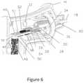
- FIG. 6is a perspective cut away view of another embodiment of handle for the applicator of the invention.
- FIG. 7is a block diagram of a system for microwave therapy using the applicator of the invention.
- FIG. 8is a block diagram of a system of the invention for microwave therapy using an array of applicators of the invention.
- FIG. 9is a side elevation of the applicator shown in FIG. 1 , showing additional depth markings along the applicator;
- FIG. 10is a vertical section similar to that of FIG. 2 of a different embodiment of applicator of the invention.
- FIG. 11is a schematic representation of a cooling fluid circulation system of the invention.
- FIG. 1One embodiment of a microwave applicator of the invention for microwave coagulation and ablation treatment of diseased tissue within living body tissue is illustrated in FIG. 1 .
- the applicatorreferred to generally as 10 , includes a handle 12 from which a substantially rigid elongate applicator body 14 extends with an insertion tip 16 forming the insertion end portion of the applicator for insertion into a tissue region of the living body.
- the substantially rigid elongate applicator body 14includes an outer conductive sleeve 18 extending from the handle 12 , a conductive shunt 20 , the conductive insertion tip 16 , and a dielectric collar 22 positioned between the insertion tip 16 and the shunt 20 .
- the outside diameters of the exposed portions of the outer conductive sleeve 18 , the conductive shunt 20 , the dielectric collar 22 , and the insertion tip 16(which may be sharpened at its insertion end 17 ), are all about equal so as to form a smooth continuous elongate applicator body for insertion into the living body tissue.
- the elongate applicator bodymay be coated with a stick resistant dielectric material such as Teflon, not shown.
- a pistol grip 24allows the handle to be easily held for manipulation of the applicator.
- the applicatorhas a microwave antenna portion 25 toward the insertion tip of the elongate applicator body 14 to radiate microwave energy from the antenna portion into the living body tissue.
- Microwave energyis transmitted from the handle 12 through the elongate applicator body to the antenna portion by a coaxial microwave transmission line 26 , FIGS. 2-4 , within the elongate applicator body and having an inner conductor 29 and an outer conductor 27 separated by a dielectric material 28 positioned therebetween.
- the coaxial transmission line 26may be a semirigid coaxial cable with copper inner and outer conductors and a Teflon or Teflon and air dielectric material. No outer dielectric insulating material is used.
- Such coaxial cablewill usually have about a fifty ohm impedance which provides a good impedance match to the microwave generator and to typical living body tissue characteristics.
- the outer diameter of the coaxial transmission line(also the outer diameter of the outer conductor 27 of the coaxial transmission line) is smaller than the inside diameter of the outer conductive sleeve 18 so a space 82 is provided between the transmission line and the outer conductive sleeve. This space will be referred to as a cooling fluid space.
- Conductive shunt 20is positioned around and in electrical contact with both the insertion end portion 83 of the transmission line outer conductor 27 , and the outer conductive sleeve 18 .
- Shunt 20includes a reduced outer diameter end portion 84 toward the handle end of the applicator dimensioned to fit into the space 82 between the outside surface of the outer conductor 27 of the coaxial transmission line 26 and the inside surface of the outer conductive sleeve 18 .
- Shunt 20can be soldered to both the outer conductor 27 and the outer sleeve 18 to ensure good electrical connection. Soldering will also secure shunt 20 to outer sleeve 18 for a strong connection of shunt 20 to sleeve 18 .
- shunt 20can be secured to sleeve 18 and, if desired, to outer conductor 27 , by a bonding agent, such as an epoxy adhesive material. If the bonding agent is conductive, it can replace soldering. With this connection, shunt 20 closes or blocks cooling fluid space 82 toward the insertion end 85 of the outer conductive sleeve 18 .
- Shunt 20extends beyond the actual end 86 of the outer conductor to form an enlarged inside diameter shunt portion 87 .
- the insertion end of enlarged diameter shunt portion 87can accept a reduced diameter mounting portion 88 of the applicator tip 16 with dielectric collar 22 thereon.
- Dielectric collar 22fits over the reduced diameter mounting portion 88 of the applicator tip 16 , and itself has a reduced diameter insertion portion 89 that fits into enlarged inside diameter shunt portion 87 .
- This interfitting arrangementproduces a strong connection of the tip to the remainder of the applicator, with the dielectric collar 22 being bonded to the tip and the shunt by an adhesive material such as epoxy.
- Dielectric collar 22being positioned between shunt 20 and tip 16 , electrically insulates tip 16 from shunt 20 . Since shunt 20 is electrically connected to the outer conductor 27 of the coaxial transmission line 26 , shunt 20 becomes an extension of the outer conductor 27 and the insertion end 90 of the conductive shunt 20 becomes the effective insertion end of the outer conductor 27 .
- the inner conductor 29 of the coaxial transmission lineextends toward the insertion end of the applicator beyond the insertion end 91 of the coaxial transmission line dielectric material 28 to an inner conductor insertion end 92 .
- both the insertion end 91 of the coaxial transmission line dielectric material and the insertion end 92 of the coaxial transmission line inner conductorare within the enlarged inside diameter shunt portion 87 of shunt 20 and do not extend beyond the insertion end 90 of shunt 20 .
- the reduced diameter mounting portion 88 of applicator tip 16also includes a tip tab 93 extending therefrom toward the handle end of the applicator and the insertion end 91 of the coaxial transmission line dielectric 28 .
- the tip tab 93is positioned so that the extension of the coaxial transmission line inner conductor 29 beyond the end 91 of the coaxial transmission line dielectric 28 is adjacent to and can be secured in electrical contact, such as by soldering, to the tip tab 93 .
- inner conductor 29does not extend into tip 16 , but is merely adjacent to and electrically connected to tip tab 93 .
- the conductive outer sleeve 18may be of a metal material such as stainless steel, the conductive tip and the shunt may be formed of a metal material such brass or stainless steel, and the dielectric insulating collar may be formed of a substantially rigid plastic material. All such parts may be bonded using an epoxy adhesive.
- various other applicator constructionscan be used to form a microwave antenna toward the insertion end of the applicator and to form an insertion end of the applicator.
- FIG. 10shows an alternate embodiment of the insertion portion of the applicator where the shunt is not used. As shown in FIG.
- the conductive applicator insertion tip 16is connected directly to the outer conductive sleeve 18 by dielectric collar 22 which electrically insulates the conductive applicator insertion tip from the conductive outer sleeve 18 .
- the end of dielectric collar 22 toward the attachment end of the applicatorextends into the space 82 between the outer conductive sleeve 18 and the outer conductor 27 of the coaxial microwave transmission line 26 to electrically insulate the outer conductive sleeve 18 from the outer conductor 27 .
- the outer conductive sleeve 18is not electrically connected to the outer conductor 27 .
- Dielectric collar 22also forms the end toward the insertion end of the applicator of the cooling fluid space 82 .
- the insertion tip 16includes tip tab 93 which is coupled to the inner conductor 29 . This construction of the antenna and insertion end of the applicator has also been found satisfactory for use in the invention.
- elongate applicator body 14extends from handle 12 .
- outer conductive sleeve 18is secured in the forward portion 13 of handle body 15 and in the forward end of cooling fluid reservoir 38 , which cooling fluid reservoir 38 is mounted within handle body 15 .
- Cooling fluid reservoir 38includes two reservoir chambers 34 and 36 separated by guide sleeve 40 that extends from connection to reservoir partition 35 into outer conductive sleeve 18 and within outer conductive sleeve 18 toward the insertion end of the applicator.
- the guide sleeve 40may be a thin walled plastic sleeve made of polyimide plastic such as Kapton.
- Coaxial transmission line 26extends through cooling fluid reservoir 38 and into guide sleeve 40 .
- Coaxial transmission line 26extends through the entire length of guide sleeve 40 and beyond the guide sleeve insertion end 41 , FIG. 2 , and into shunt 20 .
- guide sleeve 40extends into cooling fluid space 82 between the outside of coaxial transmission line 26 and the inside of outer conductive sleeve 18 .
- Guide sleeve 40divides cooling fluid space 82 into an inner cooling fluid space 42 and an outer cooling fluid space 43 along the length of guide sleeve 40 in space 82 .
- Inner cooling fluid space 42is formed between the outside surface of coaxial transmission line 26 and the inside surface of guide sleeve 40 and outer cooling fluid space 43 is formed between the outside surface of guide sleeve 40 and the inside surface of outer conductive sleeve 18 .
- Reservoir chamber 34communicates with inner cooling fluid space 42 and reservoir chamber 36 communicates with outer cooling fluid space 43 .
- reservoir chamber 34 or 36could be a cooling fluid inlet or cooling fluid outlet, it has been found for ease of placement of the temperature sensor, as will be explained in respect of the location of temperature sensor 60 , that reservoir chamber 34 can be the cooling fluid inlet reservoir and reservoir chamber 36 can be the cooling fluid outlet reservoir. In such instance, cooling fluid to the applicator will flow from a source of cooling fluid, not shown, through tubing 30 into reservoir chamber 34 . From reservoir chamber 34 , cooling fluid flows through inner cooling fluid space 42 along the outside surface of coaxial transmission line 26 to cool the outside surface of coaxial transmission line 26 . As previously indicated in regard to FIG.
- cooling fluid space 82 into which guide sleeve 40 extendsis blocked at the insertion end portion of outer conductive sleeve 18 by the reduced diameter portion 84 of shunt 20 which fits into and blocks the insertion end of space 82 .
- the insertion end 41 of guide sleeve 40ends before reaching the end of space 82 created by shunt 20 so as to leave an undivided fluid space portion which connects the inner cooling fluid space 42 and the outer cooling fluid space 43 .
- cooling fluid flowing in inner cooling fluid space 42 toward the insertion end of the applicatorreaches the insertion end 41 of guide sleeve 40 , it flows into the undivided space 82 around the insertion end 41 of guide sleeve 40 into outer cooling fluid space 43 and flows along the inside surface of outer conductive sleeve 18 back into reservoir chamber 36 and out fluid outlet tube 32 back to the fluid supply to be cooled and recirculated or to a fluid drain.
- microwave energyis provided to the applicator from a microwave generator, not shown, by a coaxial microwave energy supply cable 46 that provides a path for the microwave energy from the generator to the applicator.
- the coaxial microwave energy supply cable 46is typically a flexible fifty ohm coaxial cable containing an inner or center conductor 48 , an outer conductor 49 , and a dielectric spacer 50 therebetween.
- the connection between the flexible coaxial microwave energy supply cable 46 and the semi-rigid coaxial transmission line 26is provided through a coupling circuit on a printed circuit card 58 which supports small chip capacitors and a resistor, (see also FIG. 5 which is a circuit diagram of the circuitry of FIG. 4 ).
- the coaxial microwave energy supply cable center conductor 48is connected by conductive metal path 51 on the circuit card 58 to capacitor 52 which is connected to inner conductor 29 of coaxial transmission line 26 .
- the coaxial microwave energy supply cable outer conductor 49is connected by conductive element or wire 47 to conductive metal path 53 on the circuit card 58 which is connected to outer conductor 27 of coaxial transmission line 26 . This provides a direct path for the microwave currents to flow between the outer conductors.
- Circuit diagram FIG. 5shows a capacitor 55 connected between the two outer conductors 49 and 27 which is not necessary and not shown in FIG. 4 , but may be advantageous to include to provide further isolation of the microwave antenna from dc currents in the flexible coaxial microwave energy supply cable 46 .
- a temperature sensor in the form of a thermistor 60is placed over the outer conductive sleeve 18 and bonded to it so that it is approximately the same temperature as the outer conductive sleeve 18 .
- Thermistor 60when placed at the location shown in FIG. 4 , measures the temperature of outer conductive sleeve 18 at about its handle end, which will be at approximately the temperature of the cooling fluid after flowing through the elongate applicator body 14 .
- Thermistor 60can be located at other locations that enable it to indicate the approximate temperature of the cooling fluid after or during flow through the applicator.
- thermistor 60measures the approximate temperature of the cooling fluid between guide sleeve 40 and the outer conductive sleeve 18 as the cooling fluid returns to the cooling fluid outlet reservoir chamber 36 after flowing through inner and outer cooling fluid spaces 42 and 43 .
- the cooling fluid at this locationwill have reached approximately its highest temperature.
- Thermistor 60could be located in the cooling fluid itself, if desired, such as in cooling fluid outlet reservoir chamber 36 .
- the function of this thermistor 60is to provide an indication that the cooling fluid is actually flowing inside the applicator whenever the microwave power is applied. During the application of microwave energy, the microwave energy causes self heating of the coaxial transmission line 26 in the applicator.
- a thermistoris a resistive electrical device that varies its resistance depending upon its temperature.
- the two wires 62 a and 62 b from thermistor 60are connected across capacitor 56 .
- Wire 62 aconnects to capacitor 56 and also connects directly to outer conductor 49 of the flexible coaxial cable 46 .
- Wire 62 battaches to the opposite side of capacitor 56 and also to one side of resistor 54 through conductive metal path 57 .
- the other side of resistor 54connects to conductive metal path 51 via a wire or conductive metal path 59 .
- thermistor 60is connected electrically between inner conductor 48 and outer conductor 49 of flexible coaxial cable 46 .
- Capacitor 52prevents the direct electrical current from flowing into inner conductor 29 of coaxial transmission line 26 and therefore prevents the direct electrical current from flowing into the applicator antenna and living body into which the applicator is inserted.
- capacitor 55prevents the direct electrical current from flowing into the outer conductor 27 of coaxial transmission line 26 to further ensure that direct electrical current does not flow into the antenna and into the living body into which the applicator is inserted.
- This described circuitryallows the flexible coaxial microwave energy supply cable to serve a dual purpose.
- the dc current for monitoring of the resistance of thermistor 60passes through the flexible coaxial microwave energy supply cable 46 along with the microwave energy that flows through the flexible coaxial microwave energy supply cable 46 from the microwave energy generator to the applicator.
- the temperature indicating signalis carried between the thermistor and the system controller over the same two coaxial cable conductors 48 and 49 that carry the microwave power from the microwave generator to the applicator. This eliminates the need for separate additional wires from the handle to the system controller to carry the temperature signals from the thermistor.
- the signal from the thermistor 60provides an indication to the system controller of the temperature of the outer conductive sleeve and the cooling fluid circulating in the applicator.
- the temperature of thermistor 60With the microwave power applied to the applicator, which results in heating of coaxial transmission line 26 , as long as cooling fluid is properly flowing in the applicator, the temperature of thermistor 60 will remain low. If the cooling fluid stops flowing in the applicator or flow is restricted for some reason, the coaxial transmission line 26 will begin to heat and the temperature of outer conductive sleeve 18 and of any non-flowing or slowly flowing fluid in the applicator will also increase. This increases the temperature of thermistor 60 . This increase in measured temperature of thermistor 60 provides an indication that cooling fluid is not flowing properly and the system controller can activate an alarm or activate other corrective action.
- FIG. 6shows a cut away perspective view of a handle similar to that of FIG. 4 , but with a slightly different configuration of handle body 45 and different orientation of inlet 30 and outlet 32 tubes from reservoir chambers 34 and 36 .
- the configuration of the handle componentsis substantially the same and components are numbered the same as in FIG. 4 .
- the wires from the thermistor 40are not shown.
- FIG. 6gives a better illustration of the actual construction of the applicator handle.
- handle 12serves as an interface between the substantial rigid elongate applicator body 14 and the flexible coaxial microwave energy supply cable extending from the microwave generator to the applicator, provides for the insertion of the temperature signals onto the flexible coaxial microwave energy supply cable, and serves as an interface between the flexible fluid hoses from and to a source of cooling fluid and the cooling fluid reservoir.
- handlescan be used.
- the flexible coaxial microwave energy supply cable and the flexible fluid hosesare shown extending from the end of the handle grip (and could be enclosed in a sheath, if desired), connectors could be provided directly on the handle so that the flexible coaxial microwave energy supply cable could be connected to and disconnected from the handle and so that the flexible fluid hoses could also be connected to and disconnected from the handle.
- the flexible coaxial microwave energy supply cable 46 and the flexible fluid hoses 30 and 32are shown coming together in side-by-side relationship in the handle 12 and entering a sheath 154 which extends out of the end of the pistol grip 24 to keep the cable and hoses together for a distance extending from the handle. This allows easier maneuvering of the applicator during use.
- the hoses 30 and 32 and cable 46extend from the end 156 of the sheath 150 and the hoses terminate in hose connectors 158 and 160 adapted for connection to a cooling fluid supply hose connector and a cooling fluid return hose connector.
- Coaxial cable 46terminates in a cable connector 162 adapted to connect to a further microwave energy supply cable.
- Various materialscan be used for the sheath 154 .
- a plastic braid material that functions like the old “Chinese Handcuff” to tighten around the enclosed cable and hoseshas been found satisfactory to provide a good outer covering to improve the handling and storage of the applicator, and to allow heat generated by the coaxial cable to easily pass through it.
- FIG. 7is a functional block diagram of a basic system of the invention as described above using a single applicator for patient treatment.
- An operator interface 61such as a computer screen and keyboard or a simple touch screen, is provided for display and monitoring of the system controls and the treatment procedures.
- the user interfaceis connected to a system controller 64 , such as a computer processor, by a cable 63 .
- the controllerprovides control and monitoring to a microwave generator 68 through a cable 66 .
- the generator 68has a microwave oscillator where the power amplitude can be controlled and monitored by the controller 64 including the measurement of both the forward and reflected power at the output of the generator 68 .
- the generated microwave poweris then directed to a multiplexer and power splitter circuit 74 by a transmission line cable 70 , such as a coaxial cable.
- the microwave path inside the multiplexer and power splitter circuit 74contains an impedance matched microwave path directing the microwave power to the applicator 10 with elongate applicator body 14 by a flexible coaxial microwave energy supply cable 72 .
- a dc current paththat flows through a temperature sensing thermistor that enables a direct current to also flow through the coaxial microwave energy supply cable 72 .
- This direct current that is used to measure the temperature within the applicator elongate body 14is separated from the microwave power signal in the multiplexer portion of the multiplexer and power splitter circuit 74 and is sent along a dc circuit path 76 that is directed to a temperature monitoring circuit 78 .
- the temperature monitoring circuit 78then directs a temperature signal back to the controller 64 through a cable 80 to enable the controller to monitor and control microwave power levels generated by microwave generator 68 to limit the microwave power transmitted to the applicator if excessive temperatures are measured in the applicator 10 .
- Temperature monitoring circuit 78may be part of the controller 64 .
- a phased array of applicatorsrather than a single applicator.
- a plurality of applicatorsare inserted into the patient in approximately parallel orientation in a pattern approximately evenly spaced apart along the circumference of an insertion circle around the tissue to be treated.
- Each applicatorshould be inserted so that the radiating antenna is at approximately the same depth position with respect to the tissue to be treated so as to have the radiation feedpoints approximately aligned side by side.
- phased arraysgenerally allows better control of the applicators to produce better uniformity of power deposition, temperature, and/or coagulation of tissue throughout a tumor volume to be treated and particularly at the tumor margins than when using a single applicator.
- the use of phased arrayscan also reduce microwave heating along the shafts of the applicators due to cross coupling of the energy between the antennas that are driven in phase and separated by a distance that provides for partial power cancellation along the outer portion of the inserted applicators and an increase in tissue heating between these inserted applicators.
- pretreatment planningcan be used to provide an ideal insertion pattern and power and phase application to the array of applicators to produce and control the desired heating.
- the treatmentis thereby optimized and controlled by the aid of a numerical calculation of either the planned insertion pattern and number of antennas or the actual pattern achieved as indicated by various non-invasive imaging processes such as computer tomography (CT), ultrasound, or magnetic resonance imaging (MRI).
- CTcomputer tomography
- MRImagnetic resonance imaging
- Power amplitude and phase of each of the inserted applicatorscan be adjusted as directed by a computer-controlled system using the predicted power patterns from the computer numerical model. Further, actual temperature measurements can be taken and compared with the predicted power patterns and predicted temperatures and the system controlled to compensate for differences.
- a single microwave generatoris used to provide the microwave power for all applicators.
- the generatorwill usually operate at 915 MHz, which is an emission frequency commonly licensed for medical applications.
- This single generatoris connected to a passive, non-switching, microwave impedance matched power splitter (divider) which is used to direct power simultaneously to multiple ports that are connected to one or more microwave dipole antenna such as described for the above described applicators.
- This arrangementprovides approximately equal power simultaneously to each of the output connection ports.
- This arrangementalso provides equal phase output of the microwave energy at each of the output ports.
- the cables going to the radiating points on each antennaare maintained at the same electrical length so that the radiated energy from the antennas are phase synchronous and phase coherent.
- present systemsare usually designed to optimize power delivery to either a single applicator or to a set number of multiple applicators. This does not provide the flexibility desired to configure different arrays using a single delivery system. It would also be desirable in array power systems to have an indication as to whether or not there is an antenna connected to a particular microwave power output port and an indication as to whether antennas are correctly connected.
- FIG. 8shows an embodiment of a multiplexer and power splitter circuit according to the invention that provides for the separation of temperature signals from microwave power signals for a plurality of applicators and which can provide optimization for attachment of a single applicator, two applicators, or three applicators.
- Microwave power signals from a microwave generatorare supplied to the multiplexer and power splitter circuit through coaxial cable 100 , generally of fifty ohm impedance.
- the multiplexer and power splitter circuitis generally on a printed circuit card made of low loss dielectric material such as Teflon based material with a ground plane on one side and the circuit show in FIG. 8 that represents the conductive paths forming various transmission lines on the other side.
- the input microwave power signalconnects to an input in the form of a conductive patch 102 that provides a power splitting section. This directs microwave power to four paths, one path shown by path 104 , and three identical paths shown by paths 114 .
- path 104is a chip type capacitor 106 that conducts microwave power but blocks direct current to prevent direct current from reaching power splitting patch 102 .
- the input microwave powerflows through capacitor 106 to circuit output port 110 along transmission line 108 .
- the transmission lines 104 and 108are fifty ohm transmission lines which together have an electrical length delay of one hundred eighty degrees at the microwave operating frequency.
- Capacitor 106has a low impedance of typically less than two ohms reactive impedance to avoid mismatching the transmission line.
- Output port 110forms an output port for connection of a single applicator antenna through a fifty ohm impedance coaxial microwave energy supply cable attached to output port 110 .
- This output port 110is used if only a single antenna is to be connected to the multiplexer and power splitter circuit, and is sometimes referred to herein as a single connection output port.
- Power splitter conductive patch 102is also connected to three identical other transmission lines having microwave input sections 114 each with a series chip capacitor 112 along the path, and microwave output sections 116 .
- each capacitor 112 in the microwave input sectionhas a low impedance of typically less than two ohms reactive impedance to allow microwave power to pass but block direct current flow to prevent direct current from reaching power splitting patch 102 .
- the overall length of the microwave input section of the transmission lines from the power splitter conductive patch 102 through the capacitor 112 along path 114is approximately ninety degrees delay at the microwave frequency.
- the characteristic impedance of the microwave input section of the transmission lines 114 with capacitors 112 of typically between seventy and ninety ohms from the power splitter conductive patch 102 to the end of path 114is used to provide an impedance matching section for the input when two or three applicators are connected to the multiple connection output ports 118 .
- the microwave output sections 116are fifty ohm sections that connect the lines 114 to the multiple connection output ports 118 and these microwave output sections 116 are typically the length to delay the microwave signal approximately ninety degree.
- the fifty ohm impedance of the microwave output sections 116provide impedance matching for the flexible coaxial microwave energy supply cables and the applicators connected to the output ports 118 .
- the described power splitter circuitforms an impedance matched microwave power splitter that when a single applicator is to be used it alone is connected to the single connection output to port 110 .
- each a multiple connection output port 118are not connected to an applicator.
- the path length from the power splitter conductive patch 102 to each of these multiple connection output ports 118is one hundred eighty degrees.
- the microwave power that travels to these multiple connection output ports 118is reflected completely back when there is no connection to the ports and this reflected power is reflected with the same phase angle as the incoming power to these ports because this is an open circuit termination.
- the overall phase delay of the power from the power splitter conductive patch 102 to the multiple connection output ports 118 and back to the power splitter conductive patch 102is three-hundred-sixty degrees. This unique phase delay then appears to the power splitter as an open circuit.
- the open ports 118turn these paths into tuning paths that do not reflect power that would reach the input line 100 , but would direct the full power only to single connection output port 110 to the single applicator that is connected to output port 110 for efficient power transfer to the single applicator.
- the microwave multiplexer and power splitter circuitis an impedance matched splitter which automatically allows the power to be directed to the connection of 1, 2, or 3 applicators.
- the multiplexer and power splitter circuitalso includes an inductive coil or choke 120 , 122 , 124 , and 128 connected to each of the transmission lines 104 and 114 .
- Each of these inductive coilsis connected through a capacitance to the ground chassis with capacitors 128 , 130 , 132 , and 134 , respectively.
- These capacitors and the inductive coilsfilter the microwave signals from the temperature sensing ports 136 , 138 , 140 , and 142 , but pass direct current signals from the transmission lines 108 and 114 to these temperature sensing ports.
- These temperature sensing portsare connected to temperature monitoring circuitry and then to the system computer or controller for detection of the measured resistance of the thermistors that are connected to the two wire coaxial microwave energy supply connectors of the applicators as previously described.
- These direct current temperature sensing signals from the applicators to the temperature sensing portsprovide a measurement to the system controller of the temperature measured by the temperature sensors in each of the applicators.
- These direct current temperature sensing signals from the applicators to the temperature sensing portsalso provide a measurement to the system controller of whether applicators are connected to particular output ports of the multiplexer and power splitter circuit. If an applicator is connected to a particular multiplexer and power splitter circuit output port, for example to output port 110 , a temperature signal will be present on temperature sensing port 136 . The system controller will then know that an applicator is connected to output port 110 . Similarly, if a temperature signal is present on temperature sensing ports 138 and 142 , the system controller will know that two applicators are connected to two of the multiple connection output ports 118 and will be able to identify which of the two output ports have applicators connected thereto.
- the system controllersenses temperature signals on temperature sensing ports 136 and 138 , the system controller knows that there are two applicators connected to the multiplexer and power splitter circuit, but that the applicators are not properly connected since one of the two applicators is improperly connected to single connection output port 110 while the other of the two applicators is properly connected to one of the multiple connection output port 118 .
- the system controllercan then provide a warning signal to a system user indicating that the applicators are improperly connected, and that the applicator connected to the single connection output port 110 should be disconnected and connected to one of the multiple connection output ports 118 .
- this special multiplexer and power splitter circuitin addition to providing an indication that the proper number of applicators are connected to the correct output ports for efficient and desired microwave power delivery to the connected applicators, also enables the measurement of applicator cooling temperature to determine that fluid is properly flowing in each of the connected applicators to protect the normal body tissues.
- the thermistor or other temperature sensors that provide direct current temperature signalscan be replaced with regular resistors which will provide substantially dc signals in the manner of thermistor to indicate that microwave applicators are attached to a power splitter output port and indicate to which port or ports the applicators are attached.
- This use of resistorwill be considered equivalents of the thermistors or other temperature sensors that provide direct current temperature sensor signals for the purposes of the applicator detection.
- a cooling fluid circulation system of the inventionincludes a plurality of cooling fluid supply connectors 166 , (here shown as three connectors) each adapted to be connected to an applicator cooling fluid inlet, such as a cooling fluid inlet connector 158 of FIG. 4 .
- An equal plurality (here three) of cooling fluid return connectors 168are provided each adapted to be connected to a cooling fluid outlet, such as a cooling fluid outlet connectors 160 of FIG. 4 .
- Each of the plurality of cooling fluid supply connectors 166includes a normally closed shut off valve which opens when connected to an applicator cooling fluid inlet. This shut off valve prevents flow of fluid from the cooling fluid supply connector except when connected to a cooling fluid inlet.
- Each of the plurality of cooling fluid return connectors 168includes a one way flow valve allowing flow of fluid only into a cooling fluid return connector. This prevents fluid flow out of the system through a cooling fluid return connector 168 , but will allow return fluid to flow into the system through such connector when connected to an applicator cooling fluid outlet 160 .
- the cooling fluid supply connectors 166are configured to connect to the cooling fluid inlet connectors 158 , but not to the cooling fluid outlet connectors 160 .
- the cooling fluid return connectors 168are configured to connect to the cooling fluid outlet connectors 160 , but not to the cooling fluid inlet connectors 158 . In this way, a user cannot improperly connect the cooling fluid connections.
- a cooling fluid pump 170draws cooling fluid through line 172 from a cooling fluid reservoir 174 and pumps it through line 176 and line splitter 178 into lines 180 to the plurality of cooling fluid supply connectors 166 .
- Each of the cooling fluid return connectors 168is connected to a line 182 connecting to a line joiner 184 connected through line 186 to the cooling fluid reservoir 174 .
- cooling fluidis pumped from the reservoir to the plurality of cooling fluid supply connectors 166 .
- Cooling fluid from an applicatoris allowed to flow from the cooling fluid return connectors 168 back to the fluid reservoir 174 .
- the fluid reservoir 174may conveniently take the form of a standard IV bag filled with sterile saline solution. This provides sterile saline solution as the cooling fluid.
- one of the plurality of cooling fluid supply connectors 166is connected to the cooling fluid inlet 158 of the single applicator and one of the plurality of cooling fluid return connectors 168 is connected to the cooling fluid outlet 160 of the single applicator. This will provide flow of cooling fluid through the single applicator. No cooling fluid will flow through any of the cooling fluid supply connectors or the cooling fluid return connectors that are not connected to the applicator.
- a separate one of the plurality of cooling fluid supply connectors 166is connected to the cooling fluid inlet 158 of each of the plurality of applicators, and a separate one of the plurality of cooling fluid return connectors 168 is connected to the cooling fluid outlet 160 of each of the plurality of applicators.
- Thiswill provide a cooling fluid supply connector 166 connected to each of the applicator cooling fluid inlets 158 and a cooling fluid return connector 168 connected to each of the applicator cooling fluid outlets 160 and thereby provide a flow of cooling fluid through each of the plurality of applicators attached to the system.
- Any number of applicators up to the number of cooling fluid supply connectors in the fluid supply systemhere shown as three, can be connected to the fluid supply system.
- a narrow separation gap 22 between the conductive applicator insertion tip 16 and the effective insertion end of the outer conductive sleeve 18 , which is the insertion end of the shunt 20provides a zone of high microwave intensity at the gap which can be effectively used to coagulate tissues along the insertion track if the microwave power is applied as the microwave antenna is withdrawn from the treated tissue.
- steps with microwave ablation heating performed at each stepand while it is known that track ablation can be performed with a continuous withdrawal of the applicator, effective continuous track ablation requires a substantially controlled constant preset withdrawal rate for the applicator. This is difficult to obtain when withdrawing an applicator.
- the applicator of the inventioncan be provided with depth marking 150 visible on the outside of the elongate applicator body at regular intervals along the elongate applicator body.
- the purpose of these markingsis to provide an indication as to the depth of applicator penetration into the living body, and such markings are regularly spaced, such as every centimeter, along a portion of the length of the elongate applicator body where marks can be used to indicate depth of penetration. It has been found that these regularly spaced depth markings along the inserted shaft can be used to guide the rate of withdrawal of an applicator to provide effective coagulation of the insertion track.
- the systemincludes a sound generator that can generate a regular cadence sound.
- the sound generatormay, for example, be part of the controller.
- the proper steady rate of withdrawal of the applicatorcan be obtained to assure uniform coagulation of tissues along inserted track.
- a typical desired rate of withdrawal of an applicator of the inventionis approximately five mm per second at a sixty watt power level. So, for example, if the depth markings are spaced one cm apart along the inserted shaft, with a cadence that provides an audible signal, such as a beep, every second, the cadence sound provides a guide for the withdrawal at a rate of five mm for each audible beeping sound.
- Thisprovides a rate of one cm every two seconds (every two beeps) to assure uniform coagulation of tissues during the withdrawal to reduce bleeding along the inserted track. This means that the applicator is withdrawn so that a depth mark appears every two beeps.
- warning marking 152such as a red or other color marking, visible on the outside of the elongate applicator body at a position a known distance toward the attachment end of the applicator from the portion of the applicator that creates the tissue ablation (heating zone or zone of ablation). This distance, for example, could be about two to three cm from the attachment end of the heating zone (with the applicator shown, this will be about five cm from the insertion end of the applicator).
- this warning markingindicates that the zone of tract ablation or coagulation is getting close to the outer skin surface (about two or three cm) so that withdrawal of the applicator can be stopped at a desired position short of the skin area to avoid damaging or coagulating tissue in the skin area.
- the physician withdrawing the applicator to perform track ablationis thus alerted to the closeness to the skin surface and can either stop the tract ablation at that time or only continue tract ablation for a short additional distance whichever, in the best judgment of the physician, will both provide adequate tract coagulation and also protect the skin surface.
- the dielectric collar 22is left uncovered by material, such as a Teflon coating, that otherwise would cover the dielectric collar 22 to reduce tissue sticking, and the dielectric material is a material, such as PEEK (polyetheretherketone), that heated tissue will stick to. This is a relatively small area along the applicator, but upon heating, the tissue will stick to this dielectric material.
- the PEEK materialis a very high temperature thermoplastic with excellent chemical resistance. It has excellent mechanical properties with high flexural strength, impact resistance, tensile strength, is substantially rigid, and bonds well with epoxy.
- the applicatorcan be rotated, such as through between thirty and forty-five degrees of rotation, which easily releases the sticking tissue to permit removal of the applicator.
Landscapes
- Health & Medical Sciences (AREA)
- Surgery (AREA)
- Life Sciences & Earth Sciences (AREA)
- Biomedical Technology (AREA)
- Medical Informatics (AREA)
- Nuclear Medicine, Radiotherapy & Molecular Imaging (AREA)
- Electromagnetism (AREA)
- Engineering & Computer Science (AREA)
- Physics & Mathematics (AREA)
- Heart & Thoracic Surgery (AREA)
- Otolaryngology (AREA)
- Molecular Biology (AREA)
- Animal Behavior & Ethology (AREA)
- General Health & Medical Sciences (AREA)
- Public Health (AREA)
- Veterinary Medicine (AREA)
- Surgical Instruments (AREA)
- Radiation-Therapy Devices (AREA)
Abstract
Description
Claims (14)
Priority Applications (2)
| Application Number | Priority Date | Filing Date | Title |
|---|---|---|---|
| US15/979,177US11253316B2 (en) | 2009-11-17 | 2018-05-14 | Microwave coagulation applicator and system |
| US17/570,305US12318134B2 (en) | 2009-11-17 | 2022-01-06 | Microwave coagulation applicator and system |
Applications Claiming Priority (4)
| Application Number | Priority Date | Filing Date | Title |
|---|---|---|---|
| US12/620,002US8414570B2 (en) | 2009-11-17 | 2009-11-17 | Microwave coagulation applicator and system |
| US12/689,195US8551083B2 (en) | 2009-11-17 | 2010-01-18 | Microwave coagulation applicator and system |
| US14/049,064US9968399B2 (en) | 2009-11-17 | 2013-10-08 | Microwave coagulation applicator and system |
| US15/979,177US11253316B2 (en) | 2009-11-17 | 2018-05-14 | Microwave coagulation applicator and system |
Related Parent Applications (1)
| Application Number | Title | Priority Date | Filing Date |
|---|---|---|---|
| US14/049,064ContinuationUS9968399B2 (en) | 2009-11-17 | 2013-10-08 | Microwave coagulation applicator and system |
Related Child Applications (1)
| Application Number | Title | Priority Date | Filing Date |
|---|---|---|---|
| US17/570,305ContinuationUS12318134B2 (en) | 2009-11-17 | 2022-01-06 | Microwave coagulation applicator and system |
Publications (2)
| Publication Number | Publication Date |
|---|---|
| US20190117304A1 US20190117304A1 (en) | 2019-04-25 |
| US11253316B2true US11253316B2 (en) | 2022-02-22 |
Family
ID=44011867
Family Applications (4)
| Application Number | Title | Priority Date | Filing Date |
|---|---|---|---|
| US12/689,195Active2031-10-28US8551083B2 (en) | 2009-11-17 | 2010-01-18 | Microwave coagulation applicator and system |
| US14/049,064Active2032-09-28US9968399B2 (en) | 2009-11-17 | 2013-10-08 | Microwave coagulation applicator and system |
| US15/979,177Active2032-01-07US11253316B2 (en) | 2009-11-17 | 2018-05-14 | Microwave coagulation applicator and system |
| US17/570,305Active2031-05-14US12318134B2 (en) | 2009-11-17 | 2022-01-06 | Microwave coagulation applicator and system |
Family Applications Before (2)
| Application Number | Title | Priority Date | Filing Date |
|---|---|---|---|
| US12/689,195Active2031-10-28US8551083B2 (en) | 2009-11-17 | 2010-01-18 | Microwave coagulation applicator and system |
| US14/049,064Active2032-09-28US9968399B2 (en) | 2009-11-17 | 2013-10-08 | Microwave coagulation applicator and system |
Family Applications After (1)
| Application Number | Title | Priority Date | Filing Date |
|---|---|---|---|
| US17/570,305Active2031-05-14US12318134B2 (en) | 2009-11-17 | 2022-01-06 | Microwave coagulation applicator and system |
Country Status (1)
| Country | Link |
|---|---|
| US (4) | US8551083B2 (en) |
Cited By (1)
| Publication number | Priority date | Publication date | Assignee | Title |
|---|---|---|---|---|
| US20220125512A1 (en)* | 2009-11-17 | 2022-04-28 | Varian Medical Systems, Inc. | Microwave coagulation applicator and system |
Families Citing this family (60)
| Publication number | Priority date | Publication date | Assignee | Title |
|---|---|---|---|---|
| US10363092B2 (en) | 2006-03-24 | 2019-07-30 | Neuwave Medical, Inc. | Transmission line with heat transfer ability |
| US10499937B2 (en) | 2006-05-19 | 2019-12-10 | Recor Medical, Inc. | Ablation device with optimized input power profile and method of using the same |
| US11389235B2 (en) | 2006-07-14 | 2022-07-19 | Neuwave Medical, Inc. | Energy delivery systems and uses thereof |
| US10376314B2 (en) | 2006-07-14 | 2019-08-13 | Neuwave Medical, Inc. | Energy delivery systems and uses thereof |
| EP3549544B1 (en) | 2009-07-28 | 2021-01-06 | Neuwave Medical, Inc. | DEVICE FOR ABLATION |
| US8568398B2 (en)* | 2009-09-29 | 2013-10-29 | Covidien Lp | Flow rate monitor for fluid cooled microwave ablation probe |
| GB2474233A (en)* | 2009-10-06 | 2011-04-13 | Uk Investments Associates Llc | Cooling pump comprising a detachable head portion |
| US11998266B2 (en) | 2009-10-12 | 2024-06-04 | Otsuka Medical Devices Co., Ltd | Intravascular energy delivery |
| KR101673574B1 (en) | 2009-10-30 | 2016-11-07 | 레코 메디컬, 인코포레이티드 | Method and apparatus for treatment of hypertension through percutaneous ultrasound renal denervation |
| US20110125148A1 (en)* | 2009-11-17 | 2011-05-26 | Turner Paul F | Multiple Frequency Energy Supply and Coagulation System |
| US9993294B2 (en)* | 2009-11-17 | 2018-06-12 | Perseon Corporation | Microwave coagulation applicator and system with fluid injection |
| US8414570B2 (en)* | 2009-11-17 | 2013-04-09 | Bsd Medical Corporation | Microwave coagulation applicator and system |
| ES2856026T3 (en) | 2010-05-03 | 2021-09-27 | Neuwave Medical Inc | Power supply systems |
| US9192436B2 (en)* | 2010-05-25 | 2015-11-24 | Covidien Lp | Flow rate verification monitor for fluid-cooled microwave ablation probe |
| WO2012061150A1 (en)* | 2010-10-25 | 2012-05-10 | Medtronic Ardian Luxembourg S.a.r.I. | Microwave catheter apparatuses, systems, and methods for renal neuromodulation |
| US9017319B2 (en)* | 2011-01-05 | 2015-04-28 | Covidien Lp | Energy-delivery devices with flexible fluid-cooled shaft, inflow/outflow junctions suitable for use with same, and systems including same |
| US9011421B2 (en)* | 2011-01-05 | 2015-04-21 | Covidien Lp | Energy-delivery devices with flexible fluid-cooled shaft, inflow/outflow junctions suitable for use with same, and systems including same |
| US9192438B2 (en)* | 2011-12-21 | 2015-11-24 | Neuwave Medical, Inc. | Energy delivery systems and uses thereof |
| CN102652692B (en)* | 2012-03-27 | 2015-11-25 | 福中集团有限公司 | A kind of microwave melt needle and attaching method thereof |
| CN102652691A (en)* | 2012-03-27 | 2012-09-05 | 福中集团有限公司 | Microwave ablation needle and method for accurately positioning puncture depth of microwave ablation needle |
| US9854259B2 (en)* | 2012-07-09 | 2017-12-26 | Qualcomm Incorporated | Smoothing of difference reference picture |
| WO2014159276A1 (en) | 2013-03-14 | 2014-10-02 | Recor Medical, Inc. | Ultrasound-based neuromodulation system |
| US9301723B2 (en)* | 2013-03-15 | 2016-04-05 | Covidien Lp | Microwave energy-delivery device and system |
| US9161814B2 (en)* | 2013-03-15 | 2015-10-20 | Covidien Lp | Microwave energy-delivery device and system |
| US9119650B2 (en) | 2013-03-15 | 2015-09-01 | Covidien Lp | Microwave energy-delivery device and system |
| DE102014117693A1 (en)* | 2013-12-06 | 2015-06-11 | Topinox Sarl | Method for detecting an influence of microwaves on a measured value of a temperature sensor, cooking appliance and core temperature probe |
| US12350050B2 (en) | 2014-04-14 | 2025-07-08 | Recor Medical, Inc. | Intraluminal microneurography probes and related systems and methods |
| US20170027460A1 (en) | 2015-07-29 | 2017-02-02 | NeuroMedic, Inc. | Intraluminal microneurography probe |
| US9999463B2 (en) | 2014-04-14 | 2018-06-19 | NeuroMedic, Inc. | Monitoring nerve activity |
| CN104027168A (en)* | 2014-06-20 | 2014-09-10 | 章建全 | Microwave ablation needle antenna with infusion structure for curing cyst |
| WO2016004302A1 (en) | 2014-07-02 | 2016-01-07 | Covidien Lp | Alignment ct |
| AU2015284153B2 (en) | 2014-07-02 | 2019-07-18 | Covidien Lp | Unified coordinate system for multiple CT scans of patient lungs |
| US10085801B2 (en)* | 2014-08-25 | 2018-10-02 | Covidien Lp | Systems and methods for using a digital controller to adjust one or more operations of a microwave generator |
| US10624697B2 (en) | 2014-08-26 | 2020-04-21 | Covidien Lp | Microwave ablation system |
| US10813691B2 (en) | 2014-10-01 | 2020-10-27 | Covidien Lp | Miniaturized microwave ablation assembly |
| GB201418479D0 (en) | 2014-10-17 | 2014-12-03 | Creo Medical Ltd | Cable for conveying radiofrequency and/or microwave frequency energy to an electrosurgical instrument |
| US10925579B2 (en) | 2014-11-05 | 2021-02-23 | Otsuka Medical Devices Co., Ltd. | Systems and methods for real-time tracking of a target tissue using imaging before and during therapy delivery |
| CN113367788B (en) | 2015-10-26 | 2024-09-06 | 纽韦弗医疗设备公司 | Energy delivery systems and uses thereof |
| US10813692B2 (en) | 2016-02-29 | 2020-10-27 | Covidien Lp | 90-degree interlocking geometry for introducer for facilitating deployment of microwave radiating catheter |
| US10531917B2 (en) | 2016-04-15 | 2020-01-14 | Neuwave Medical, Inc. | Systems and methods for energy delivery |
| US10852373B2 (en) | 2016-09-21 | 2020-12-01 | Quality Electrodynamics, Llc | Modulating magnetic resonance imaging transmit field in magnetic resonance fingerprinting using single layer transmit/receive radio frequency coil |
| US11156682B2 (en) | 2017-03-24 | 2021-10-26 | Quality Electrodynamics, Llc | Single layer magnetic resonance imaging transmit/receive radio frequency coil for different anatomies |
| US10976388B2 (en)* | 2017-03-24 | 2021-04-13 | Quality Electrodynamics, Llc | Minimizing intravascular magnetic resonance imaging (MRI) guidewire heating with single layer MRI transmit/receive radio frequency coil |
| US11193992B2 (en) | 2017-05-05 | 2021-12-07 | Quality Electrodynamics, Llc | Single layer magnetic resonance imaging (MRI) transmit/receive (Tx/Rx) radio frequency (RF) coil with induced current failsafe protection |
| US10838028B2 (en) | 2017-06-19 | 2020-11-17 | Quality Electrodynamics, Llc | Decoupling magnetic resonance imaging (MRI) radio frequency (RF) coil elements with high acceleration factor in parallel transmit (pTx) or receive (Rx) coils using fewer channels |
| CN107865691A (en)* | 2017-11-22 | 2018-04-03 | 安徽硕金医疗设备有限公司 | A kind of water-cooled microwave ablation needle of magnetic resonance compatible |
| US11103308B2 (en)* | 2017-12-11 | 2021-08-31 | Covidien Lp | Reusable transmission network for dividing energy and monitoring signals between surgical devices |
| US11564728B1 (en)* | 2017-12-14 | 2023-01-31 | Avenu Medical, Inc. | Systems and methods for percutaneous access, formation, and maintenance of arteriovenous fistulas |
| CN108066003A (en)* | 2017-12-29 | 2018-05-25 | 浙江归创医疗器械有限公司 | Ablation catheter |
| EP3745975B1 (en)* | 2018-02-02 | 2024-07-03 | Varian Medical Systems, Inc. | Microwave ablation antennas |
| US11464576B2 (en) | 2018-02-09 | 2022-10-11 | Covidien Lp | System and method for displaying an alignment CT |
| US11672596B2 (en) | 2018-02-26 | 2023-06-13 | Neuwave Medical, Inc. | Energy delivery devices with flexible and adjustable tips |
| US11832879B2 (en) | 2019-03-08 | 2023-12-05 | Neuwave Medical, Inc. | Systems and methods for energy delivery |
| WO2021026471A2 (en)* | 2019-08-07 | 2021-02-11 | Biocompatibles Uk Limited | Microwave ablation probe |
| US12419662B2 (en) | 2021-02-19 | 2025-09-23 | Otsuka Medical Devices Co., Ltd. | Selectively insulated ultrasound transducers |
| CN113081250A (en)* | 2021-03-18 | 2021-07-09 | 南京航空航天大学 | Water-cooling microwave ablation needle with external water cavity |
| CN116135166A (en)* | 2021-11-18 | 2023-05-19 | 南京亿高微波系统工程有限公司 | High-efficiency cold circulation microwave fine round needle |
| CN114569242B (en)* | 2022-03-05 | 2024-08-13 | 南京德文医学科技有限公司 | Non-water-cooled microwave ablation catheter |
| GB202210323D0 (en)* | 2022-07-14 | 2022-08-31 | Creo Medical Ltd | Electrosurgical instrument for conveying and emitting microwave electromagnetic energy into biological tissue for tissue treatment |
| USD1084316S1 (en) | 2023-11-20 | 2025-07-15 | Angiodynamics, Inc. | Ferrule |
Citations (98)
| Publication number | Priority date | Publication date | Assignee | Title |
|---|---|---|---|---|
| US3598108A (en) | 1969-02-28 | 1971-08-10 | Khosrow Jamshidi | Biopsy technique and biopsy device |
| US4397314A (en) | 1981-08-03 | 1983-08-09 | Clini-Therm Corporation | Method and apparatus for controlling and optimizing the heating pattern for a hyperthermia system |
| US4397313A (en) | 1981-08-03 | 1983-08-09 | Clini-Therm Corporation | Multiple microwave applicator system and method for microwave hyperthermia treatment |
| US4448198A (en) | 1979-06-19 | 1984-05-15 | Bsd Medical Corporation | Invasive hyperthermia apparatus and method |
| US4556070A (en) | 1983-10-31 | 1985-12-03 | Varian Associates, Inc. | Hyperthermia applicator for treatment with microwave energy and ultrasonic wave energy |
| US4565200A (en) | 1980-09-24 | 1986-01-21 | Cosman Eric R | Universal lesion and recording electrode system |
| US4586516A (en) | 1980-04-02 | 1986-05-06 | Bsd Medical Corporation | Apparatus for creating hyperthermia in tissue |
| EP0207729A2 (en) | 1985-06-28 | 1987-01-07 | Bsd Medical Corporation | Improved antenna for interstitial array |
| JPS625364A (en) | 1985-06-30 | 1987-01-12 | 菊地 真 | Warming apparatus for hyperthermia |
| US4638436A (en) | 1984-09-24 | 1987-01-20 | Labthermics Technologies, Inc. | Temperature control and analysis system for hyperthermia treatment |
| US4825880A (en) | 1987-06-19 | 1989-05-02 | The Regents Of The University Of California | Implantable helical coil microwave antenna |
| US4860752A (en) | 1988-02-18 | 1989-08-29 | Bsd Medical Corporation | Invasive microwave array with destructive and coherent phase |
| US4967765A (en) | 1988-07-28 | 1990-11-06 | Bsd Medical Corporation | Urethral inserted applicator for prostate hyperthermia |
| JPH033358A (en) | 1989-05-31 | 1991-01-09 | Matsushita Electric Ind Co Ltd | Shift register |
| US5205289A (en) | 1988-12-23 | 1993-04-27 | Medical Instrumentation And Diagnostics Corporation | Three-dimensional computer graphics simulation and computerized numerical optimization for dose delivery and treatment planning |
| US5275597A (en) | 1992-05-18 | 1994-01-04 | Baxter International Inc. | Percutaneous transluminal catheter and transmitter therefor |
| US5370675A (en) | 1992-08-12 | 1994-12-06 | Vidamed, Inc. | Medical probe device and method |
| US5405346A (en) | 1993-05-14 | 1995-04-11 | Fidus Medical Technology Corporation | Tunable microwave ablation catheter |
| US5470308A (en) | 1992-08-12 | 1995-11-28 | Vidamed, Inc. | Medical probe with biopsy stylet |
| US5507743A (en) | 1993-11-08 | 1996-04-16 | Zomed International | Coiled RF electrode treatment apparatus |
| US5599295A (en) | 1992-08-12 | 1997-02-04 | Vidamed, Inc. | Medical probe apparatus with enhanced RF, resistance heating, and microwave ablation capabilities |
| US5628771A (en) | 1993-05-12 | 1997-05-13 | Olympus Optical Co., Ltd. | Electromagnetic-wave thermatological device |
| US5683384A (en) | 1993-11-08 | 1997-11-04 | Zomed | Multiple antenna ablation apparatus |
| WO1998006341A1 (en) | 1996-08-16 | 1998-02-19 | United States Surgical Corporation | Apparatus for thermal treatment of tissue |
| US5853366A (en) | 1996-07-08 | 1998-12-29 | Kelsey, Inc. | Marker element for interstitial treatment and localizing device and method using same |
| US5861002A (en) | 1991-10-18 | 1999-01-19 | Desai; Ashvin H. | Endoscopic surgical instrument |
| US5954686A (en) | 1998-02-02 | 1999-09-21 | Garito; Jon C | Dual-frequency electrosurgical instrument |
| US5974343A (en) | 1996-01-12 | 1999-10-26 | Bruker Sa | Probe, particulary a urethral probe, for heating of tissues by microwave and for the measurement of temperature by radiometry |
| US5976129A (en) | 1991-10-18 | 1999-11-02 | Desai; Ashvin H. | Endoscopic surgical instrument |
| US6027501A (en) | 1995-06-23 | 2000-02-22 | Gyrus Medical Limited | Electrosurgical instrument |
| US6036698A (en) | 1998-10-30 | 2000-03-14 | Vivant Medical, Inc. | Expandable ring percutaneous tissue removal device |
| US6051018A (en) | 1997-07-31 | 2000-04-18 | Sandia Corporation | Hyperthermia apparatus |
| US6106524A (en) | 1995-03-03 | 2000-08-22 | Neothermia Corporation | Methods and apparatus for therapeutic cauterization of predetermined volumes of biological tissue |
| US6112123A (en) | 1998-07-28 | 2000-08-29 | Endonetics, Inc. | Device and method for ablation of tissue |
| WO2000056239A1 (en) | 1999-03-19 | 2000-09-28 | Endocare, Inc. | Placement guide for ablation devices |
| US6131577A (en) | 1997-04-29 | 2000-10-17 | Nicholson; James E. | Selective enhancement of hyperthermia in RF and microwave irradiation of diseased or excess tissue |
| US6136014A (en) | 1998-09-01 | 2000-10-24 | Vivant Medical, Inc. | Percutaneous tissue removal device |
| US6162216A (en) | 1998-03-02 | 2000-12-19 | Guziak; Robert Andrew | Method for biopsy and ablation of tumor cells |
| US6162261A (en) | 1997-06-25 | 2000-12-19 | Clariant Finance (Bvi) Limited | Triphendioxazine |
| US6178354B1 (en) | 1998-12-02 | 2001-01-23 | C. R. Bard, Inc. | Internal mechanism for displacing a slidable electrode |
| US20010001819A1 (en) | 1995-08-15 | 2001-05-24 | Lee Kee S. | Cell necrosis apparatus and method |
| US6275738B1 (en) | 1999-08-19 | 2001-08-14 | Kai Technologies, Inc. | Microwave devices for medical hyperthermia, thermotherapy and diagnosis |
| US6306132B1 (en) | 1999-06-17 | 2001-10-23 | Vivant Medical | Modular biopsy and microwave ablation needle delivery apparatus adapted to in situ assembly and method of use |
| US6325796B1 (en) | 1999-05-04 | 2001-12-04 | Afx, Inc. | Microwave ablation instrument with insertion probe |
| US6347251B1 (en) | 1999-12-23 | 2002-02-12 | Tianquan Deng | Apparatus and method for microwave hyperthermia and acupuncture |
| US6358273B1 (en) | 1999-04-09 | 2002-03-19 | Oratec Inventions, Inc. | Soft tissue heating apparatus with independent, cooperative heating sources |
| US6427089B1 (en) | 1999-02-19 | 2002-07-30 | Edward W. Knowlton | Stomach treatment apparatus and method |
| US20030023238A1 (en) | 1998-05-08 | 2003-01-30 | Manker Charles F. | Therapeutic prostatic thermotherapy |
| US20030060813A1 (en) | 2001-09-22 | 2003-03-27 | Loeb Marvin P. | Devices and methods for safely shrinking tissues surrounding a duct, hollow organ or body cavity |
| USRE38299E1 (en) | 1995-05-18 | 2003-11-11 | Prostalund Operations Ab | Apparatus for heat treatment of tissue |
| US20030212394A1 (en) | 2001-05-10 | 2003-11-13 | Rob Pearson | Tissue ablation apparatus and method |
| US6652516B1 (en) | 1995-08-15 | 2003-11-25 | Rita Medical Systems, Inc. | Cell necrosis apparatus |
| US20040049254A1 (en) | 2001-01-31 | 2004-03-11 | Iginio Longo | Interstitial microwave antenna with miniaturized choke hyperthermia in medicine and surgery |
| US6752767B2 (en) | 2002-04-16 | 2004-06-22 | Vivant Medical, Inc. | Localization element with energized tip |
| JP2004187703A (en) | 2002-12-06 | 2004-07-08 | Azwell Inc | Microwave surgical instrument |
| JP2004187704A (en) | 2002-12-06 | 2004-07-08 | Azwell Inc | Microwave surgical instrument |
| US6770070B1 (en) | 2000-03-17 | 2004-08-03 | Rita Medical Systems, Inc. | Lung treatment apparatus and method |
| US20040181214A1 (en) | 2003-03-13 | 2004-09-16 | Garabedian Robert J. | Passively cooled array |
| US20050015081A1 (en) | 2003-07-18 | 2005-01-20 | Roman Turovskiy | Devices and methods for cooling microwave antennas |
| US6868290B2 (en) | 2001-11-05 | 2005-03-15 | Prostalund Operations Ab | Thermotherapy catheter and method of prostate thermotherapy with improved guide and heat confinement |
| US6878147B2 (en) | 2001-11-02 | 2005-04-12 | Vivant Medical, Inc. | High-strength microwave antenna assemblies |
| CN1676176A (en) | 2005-04-26 | 2005-10-05 | 中国人民解放军第二军医大学 | Microwave Radiation Antenna for Direct Puncture Treatment of Tumors |
| US20050245920A1 (en) | 2004-04-30 | 2005-11-03 | Vitullo Jeffrey M | Cell necrosis apparatus with cooled microwave antenna |
| US6962586B2 (en) | 1999-05-04 | 2005-11-08 | Afx, Inc. | Microwave ablation instrument with insertion probe |
| US6962589B2 (en) | 1998-07-07 | 2005-11-08 | Medtronic, Inc. | Method and apparatus for creating a bi-polar virtual electrode used for the ablation of tissue |
| US6974454B2 (en) | 2000-04-27 | 2005-12-13 | Atricure, Inc. | Transmural ablation device with thermocouple for measuring tissue temperature |
| US20060004351A1 (en) | 1999-12-09 | 2006-01-05 | Cryocath Technologies Inc. | Catheter with cryogenic and electrical heating ablation |
| US20060030845A1 (en) | 2004-08-04 | 2006-02-09 | Baylis Medical Company, Inc. | Electrosurgical treatment in conjunction with monitoring |
| US20060122593A1 (en) | 2003-04-24 | 2006-06-08 | Myong-Ki Jun | Electrode for radiofrequency tissue ablation |
| US7101369B2 (en) | 2004-04-29 | 2006-09-05 | Wisconsin Alumni Research Foundation | Triaxial antenna for microwave tissue ablation |
| US7128739B2 (en) | 2001-11-02 | 2006-10-31 | Vivant Medical, Inc. | High-strength microwave antenna assemblies and methods of use |
| WO2007076924A2 (en) | 2006-01-03 | 2007-07-12 | Uk Investments Associates Llc | Radiation applicator and method of radiating tissue |
| US20070288079A1 (en) | 2006-03-24 | 2007-12-13 | Micrablate | Energy delivery system and uses thereof |
| US20080022165A1 (en) | 2003-12-05 | 2008-01-24 | Mckim James B Jr | Communications System For Implementation Of Synchronous, Multichannel, Galvanically Isolated Instrumentation Devices |
| US20080033422A1 (en) | 2006-08-04 | 2008-02-07 | Turner Paul F | Microwave applicator with margin temperature sensing element |
| US20080033424A1 (en) | 2006-03-24 | 2008-02-07 | Micrablate | Transmission line with heat transfer ability |
| US20080033434A1 (en) | 2004-03-31 | 2008-02-07 | Depuy Spine, Inc. | Adjustable-angle spinal fixation element |
| US20080045938A1 (en) | 2006-07-14 | 2008-02-21 | Micrablate | Energy delivery systems and uses thereof |
| US7344533B2 (en) | 2001-09-28 | 2008-03-18 | Angiodynamics, Inc. | Impedance controlled tissue ablation apparatus and method |
| US20080275436A1 (en) | 2004-07-02 | 2008-11-06 | Nigel Cronin | Radiation Applicator and Method of Radiating Tissue |
| US20090005766A1 (en) | 2007-06-28 | 2009-01-01 | Joseph Brannan | Broadband microwave applicator |
| US20090062786A1 (en) | 2007-08-30 | 2009-03-05 | Garito Jon C | Tri-frequency electrosurgical instrument |
| US20090131926A1 (en) | 2007-11-16 | 2009-05-21 | Tyco Healthcare Group Lp | Dynamically Matched Microwave Antenna for Tissue Ablation |
| US7594913B2 (en) | 1998-12-14 | 2009-09-29 | Medwaves, Inc. | Radio-frequency based catheter system and method for ablating biological tissues |
| US20090248006A1 (en) | 2008-03-31 | 2009-10-01 | Paulus Joseph A | Re-Hydration Antenna for Ablation |
| US20100087808A1 (en) | 2008-10-03 | 2010-04-08 | Vivant Medical, Inc. | Combined Frequency Microwave Ablation System, Devices and Methods of Use |
| US7699841B2 (en) | 2006-03-16 | 2010-04-20 | Meridian Medical Systems, Llc | Microwave apparatus for controlled tissue ablation |
| US7799019B2 (en) | 2005-05-10 | 2010-09-21 | Vivant Medical, Inc. | Reinforced high strength microwave antenna |
| US7863984B1 (en) | 2009-07-17 | 2011-01-04 | Vivant Medical, Inc. | High efficiency microwave amplifier |
| US20110054458A1 (en) | 2009-08-25 | 2011-03-03 | Vivan Medical, Inc. | Microwave Ablation with Tissue Temperature Monitoring |
| US20110118720A1 (en) | 2009-11-17 | 2011-05-19 | Bsd Medical Corporation | Microwave coagulation applicator and system |
| US20110118723A1 (en) | 2009-11-17 | 2011-05-19 | Bsd Medical Corporation | Microwave coagulation applicator and system |
| US20110125148A1 (en) | 2009-11-17 | 2011-05-26 | Turner Paul F | Multiple Frequency Energy Supply and Coagulation System |
| WO2011063061A2 (en) | 2009-11-17 | 2011-05-26 | Bsd Medical Corporation | Microwave coagulation applicator and system |
| US20110208179A1 (en) | 2010-02-25 | 2011-08-25 | Tyco Healthcare Group Lp | Patient Isolation in a Microwave-Radio Frequency Generator |
| US8394092B2 (en) | 2009-11-17 | 2013-03-12 | Vivant Medical, Inc. | Electromagnetic energy delivery devices including an energy applicator array and electrosurgical systems including same |
| US8771269B2 (en) | 2007-05-11 | 2014-07-08 | Medtronic Ablation Frontiers Llc | RF energy delivery system and method |
| US8795267B2 (en) | 2007-09-25 | 2014-08-05 | Creo Medical Limited | Surgical resection apparatus |
Family Cites Families (16)
| Publication number | Priority date | Publication date | Assignee | Title |
|---|---|---|---|---|
| US4712559A (en) | 1985-06-28 | 1987-12-15 | Bsd Medical Corporation | Local current capacitive field applicator for interstitial array |
| SU1676633A1 (en) | 1989-08-04 | 1991-09-15 | Ленинградский научно-исследовательский нейрохирургический институт им.проф.А.Л.Поленова | Catheter for cerebral ventricles |
| US5697882A (en) | 1992-01-07 | 1997-12-16 | Arthrocare Corporation | System and method for electrosurgical cutting and ablation |
| RU2063697C1 (en) | 1993-03-10 | 1996-07-20 | Бут Юрий Станиславович | Device for measurement of ph-value in hollow organs |
| JPH07313519A (en) | 1994-05-30 | 1995-12-05 | Toshiba Corp | Telemedicine |
| JP2861885B2 (en) | 1995-09-19 | 1999-02-24 | ヤマハ株式会社 | Effect giving adapter |
| US7468060B2 (en) | 1998-02-19 | 2008-12-23 | Respiratory Diagnostic, Inc. | Systems and methods for treating obesity and other gastrointestinal conditions |
| JP2003010229A (en) | 2001-06-29 | 2003-01-14 | Terumo Corp | Thermotherapeutic apparatus |
| US6939350B2 (en) | 2001-10-22 | 2005-09-06 | Boston Scientific Scimed, Inc. | Apparatus for supporting diagnostic and therapeutic elements in contact with tissue including electrode cooling device |
| JP4197469B2 (en) | 2003-07-01 | 2008-12-17 | 三菱電機株式会社 | Rotating electrical machine rotor |
| JP2005137547A (en) | 2003-11-06 | 2005-06-02 | Takayuki Fujiwara | Ultrasonic therapy apparatus and its auxiliary tool and control method |
| ITMO20050034A1 (en) | 2005-02-11 | 2006-08-12 | Hs Hospital Service Spa | MICROWAVE DEVICE FOR FABRIC APPLICATION. |
| GB0620058D0 (en) | 2006-10-10 | 2006-11-22 | Medical Device Innovations Ltd | Tissue measurement and ablation antenna |
| US20080161890A1 (en) | 2007-01-03 | 2008-07-03 | Boston Scientific Scimed, Inc. | Methods, systems, and apparatuses for protecting esophageal tissue during ablation |
| US7998139B2 (en) | 2007-04-25 | 2011-08-16 | Vivant Medical, Inc. | Cooled helical antenna for microwave ablation |
| US8603123B2 (en)* | 2008-04-28 | 2013-12-10 | Urotech, Inc. | Benign prostatic hyperplasia surgical system featuring mechanical coring probe with live aspiration |
- 2010
- 2010-01-18USUS12/689,195patent/US8551083B2/enactiveActive
- 2013
- 2013-10-08USUS14/049,064patent/US9968399B2/enactiveActive
- 2018
- 2018-05-14USUS15/979,177patent/US11253316B2/enactiveActive
- 2022
- 2022-01-06USUS17/570,305patent/US12318134B2/enactiveActive
Patent Citations (125)
| Publication number | Priority date | Publication date | Assignee | Title |
|---|---|---|---|---|
| US3598108A (en) | 1969-02-28 | 1971-08-10 | Khosrow Jamshidi | Biopsy technique and biopsy device |
| US4448198A (en) | 1979-06-19 | 1984-05-15 | Bsd Medical Corporation | Invasive hyperthermia apparatus and method |
| US4586516A (en) | 1980-04-02 | 1986-05-06 | Bsd Medical Corporation | Apparatus for creating hyperthermia in tissue |
| US4565200A (en) | 1980-09-24 | 1986-01-21 | Cosman Eric R | Universal lesion and recording electrode system |
| US4397314A (en) | 1981-08-03 | 1983-08-09 | Clini-Therm Corporation | Method and apparatus for controlling and optimizing the heating pattern for a hyperthermia system |
| US4397313A (en) | 1981-08-03 | 1983-08-09 | Clini-Therm Corporation | Multiple microwave applicator system and method for microwave hyperthermia treatment |
| US4556070A (en) | 1983-10-31 | 1985-12-03 | Varian Associates, Inc. | Hyperthermia applicator for treatment with microwave energy and ultrasonic wave energy |
| US4638436A (en) | 1984-09-24 | 1987-01-20 | Labthermics Technologies, Inc. | Temperature control and analysis system for hyperthermia treatment |
| JPS6232975A (en) | 1985-06-28 | 1987-02-12 | ビ−・エス・デイ−・メデイカル・コ−ポレイシヨン | Electromagnetic hyperthermia system, apparatus, hyperthermia, electromagnetic irradiation applicator operation method and said applicator |
| US4669475A (en) | 1985-06-28 | 1987-06-02 | Bsd Medical Corporation | Apparatus and method for hyperthermia treatment |
| EP0207729A2 (en) | 1985-06-28 | 1987-01-07 | Bsd Medical Corporation | Improved antenna for interstitial array |
| JPS625364A (en) | 1985-06-30 | 1987-01-12 | 菊地 真 | Warming apparatus for hyperthermia |
| US4825880A (en) | 1987-06-19 | 1989-05-02 | The Regents Of The University Of California | Implantable helical coil microwave antenna |
| US4860752A (en) | 1988-02-18 | 1989-08-29 | Bsd Medical Corporation | Invasive microwave array with destructive and coherent phase |
| US4967765A (en) | 1988-07-28 | 1990-11-06 | Bsd Medical Corporation | Urethral inserted applicator for prostate hyperthermia |
| US5205289A (en) | 1988-12-23 | 1993-04-27 | Medical Instrumentation And Diagnostics Corporation | Three-dimensional computer graphics simulation and computerized numerical optimization for dose delivery and treatment planning |
| JPH033358A (en) | 1989-05-31 | 1991-01-09 | Matsushita Electric Ind Co Ltd | Shift register |
| US5861002A (en) | 1991-10-18 | 1999-01-19 | Desai; Ashvin H. | Endoscopic surgical instrument |
| US5976129A (en) | 1991-10-18 | 1999-11-02 | Desai; Ashvin H. | Endoscopic surgical instrument |
| US5275597A (en) | 1992-05-18 | 1994-01-04 | Baxter International Inc. | Percutaneous transluminal catheter and transmitter therefor |
| US5599295A (en) | 1992-08-12 | 1997-02-04 | Vidamed, Inc. | Medical probe apparatus with enhanced RF, resistance heating, and microwave ablation capabilities |
| US5607389A (en) | 1992-08-12 | 1997-03-04 | Vidamed, Inc. | Medical probe with biopsy stylet |
| US5370675A (en) | 1992-08-12 | 1994-12-06 | Vidamed, Inc. | Medical probe device and method |
| US5720718A (en) | 1992-08-12 | 1998-02-24 | Vidamed, Inc. | Medical probe apparatus with enhanced RF, resistance heating, and microwave ablation capabilities |
| US5470308A (en) | 1992-08-12 | 1995-11-28 | Vidamed, Inc. | Medical probe with biopsy stylet |
| US5628771A (en) | 1993-05-12 | 1997-05-13 | Olympus Optical Co., Ltd. | Electromagnetic-wave thermatological device |
| US5405346A (en) | 1993-05-14 | 1995-04-11 | Fidus Medical Technology Corporation | Tunable microwave ablation catheter |
| US5683384A (en) | 1993-11-08 | 1997-11-04 | Zomed | Multiple antenna ablation apparatus |
| US5507743A (en) | 1993-11-08 | 1996-04-16 | Zomed International | Coiled RF electrode treatment apparatus |
| US6106524A (en) | 1995-03-03 | 2000-08-22 | Neothermia Corporation | Methods and apparatus for therapeutic cauterization of predetermined volumes of biological tissue |
| USRE38299E1 (en) | 1995-05-18 | 2003-11-11 | Prostalund Operations Ab | Apparatus for heat treatment of tissue |
| US6027501A (en) | 1995-06-23 | 2000-02-22 | Gyrus Medical Limited | Electrosurgical instrument |
| US20010001819A1 (en) | 1995-08-15 | 2001-05-24 | Lee Kee S. | Cell necrosis apparatus and method |
| US6652516B1 (en) | 1995-08-15 | 2003-11-25 | Rita Medical Systems, Inc. | Cell necrosis apparatus |
| US5974343A (en) | 1996-01-12 | 1999-10-26 | Bruker Sa | Probe, particulary a urethral probe, for heating of tissues by microwave and for the measurement of temperature by radiometry |
| US5853366A (en) | 1996-07-08 | 1998-12-29 | Kelsey, Inc. | Marker element for interstitial treatment and localizing device and method using same |
| WO1998006341A1 (en) | 1996-08-16 | 1998-02-19 | United States Surgical Corporation | Apparatus for thermal treatment of tissue |
| US6131577A (en) | 1997-04-29 | 2000-10-17 | Nicholson; James E. | Selective enhancement of hyperthermia in RF and microwave irradiation of diseased or excess tissue |
| US6162261A (en) | 1997-06-25 | 2000-12-19 | Clariant Finance (Bvi) Limited | Triphendioxazine |
| US6051018A (en) | 1997-07-31 | 2000-04-18 | Sandia Corporation | Hyperthermia apparatus |
| US5954686A (en) | 1998-02-02 | 1999-09-21 | Garito; Jon C | Dual-frequency electrosurgical instrument |
| US6162216A (en) | 1998-03-02 | 2000-12-19 | Guziak; Robert Andrew | Method for biopsy and ablation of tumor cells |
| US20030023238A1 (en) | 1998-05-08 | 2003-01-30 | Manker Charles F. | Therapeutic prostatic thermotherapy |
| US6962589B2 (en) | 1998-07-07 | 2005-11-08 | Medtronic, Inc. | Method and apparatus for creating a bi-polar virtual electrode used for the ablation of tissue |
| US6112123A (en) | 1998-07-28 | 2000-08-29 | Endonetics, Inc. | Device and method for ablation of tissue |
| US6136014A (en) | 1998-09-01 | 2000-10-24 | Vivant Medical, Inc. | Percutaneous tissue removal device |
| US6036698A (en) | 1998-10-30 | 2000-03-14 | Vivant Medical, Inc. | Expandable ring percutaneous tissue removal device |
| US6471709B1 (en) | 1998-10-30 | 2002-10-29 | Vivant Medical, Inc. | Expandable ring percutaneous tissue removal device |
| US6178354B1 (en) | 1998-12-02 | 2001-01-23 | C. R. Bard, Inc. | Internal mechanism for displacing a slidable electrode |
| US7594913B2 (en) | 1998-12-14 | 2009-09-29 | Medwaves, Inc. | Radio-frequency based catheter system and method for ablating biological tissues |
| US6427089B1 (en) | 1999-02-19 | 2002-07-30 | Edward W. Knowlton | Stomach treatment apparatus and method |
| WO2000056239A1 (en) | 1999-03-19 | 2000-09-28 | Endocare, Inc. | Placement guide for ablation devices |
| US6146378A (en) | 1999-03-19 | 2000-11-14 | Endocare, Inc. | Placement guide for ablation devices |
| US6358273B1 (en) | 1999-04-09 | 2002-03-19 | Oratec Inventions, Inc. | Soft tissue heating apparatus with independent, cooperative heating sources |
| US6962586B2 (en) | 1999-05-04 | 2005-11-08 | Afx, Inc. | Microwave ablation instrument with insertion probe |
| US6325796B1 (en) | 1999-05-04 | 2001-12-04 | Afx, Inc. | Microwave ablation instrument with insertion probe |
| US6652520B2 (en) | 1999-06-17 | 2003-11-25 | Vivant Medical, Inc. | Modular biopsy and microwave ablation needle delivery apparatus adapted to in situ assembly and method of use |
| US6355033B1 (en) | 1999-06-17 | 2002-03-12 | Vivant Medical | Track ablation device and methods of use |
| US6306132B1 (en) | 1999-06-17 | 2001-10-23 | Vivant Medical | Modular biopsy and microwave ablation needle delivery apparatus adapted to in situ assembly and method of use |
| US6582426B2 (en) | 1999-06-17 | 2003-06-24 | Vivant Medical, Inc. | Needle kit and method for microwave ablation, track coagulation, and biopsy |
| US7160292B2 (en) | 1999-06-17 | 2007-01-09 | Vivant Medical, Inc. | Needle kit and method for microwave ablation, track coagulation, and biopsy |
| US6275738B1 (en) | 1999-08-19 | 2001-08-14 | Kai Technologies, Inc. | Microwave devices for medical hyperthermia, thermotherapy and diagnosis |
| US20060004351A1 (en) | 1999-12-09 | 2006-01-05 | Cryocath Technologies Inc. | Catheter with cryogenic and electrical heating ablation |
| US6347251B1 (en) | 1999-12-23 | 2002-02-12 | Tianquan Deng | Apparatus and method for microwave hyperthermia and acupuncture |
| US6770070B1 (en) | 2000-03-17 | 2004-08-03 | Rita Medical Systems, Inc. | Lung treatment apparatus and method |
| US7001415B2 (en) | 2000-04-27 | 2006-02-21 | Atricure, Inc. | Transmural ablation device |
| US6974454B2 (en) | 2000-04-27 | 2005-12-13 | Atricure, Inc. | Transmural ablation device with thermocouple for measuring tissue temperature |
| US20040049254A1 (en) | 2001-01-31 | 2004-03-11 | Iginio Longo | Interstitial microwave antenna with miniaturized choke hyperthermia in medicine and surgery |
| US20030212394A1 (en) | 2001-05-10 | 2003-11-13 | Rob Pearson | Tissue ablation apparatus and method |
| US20030060813A1 (en) | 2001-09-22 | 2003-03-27 | Loeb Marvin P. | Devices and methods for safely shrinking tissues surrounding a duct, hollow organ or body cavity |
| US7344533B2 (en) | 2001-09-28 | 2008-03-18 | Angiodynamics, Inc. | Impedance controlled tissue ablation apparatus and method |
| US7527623B2 (en) | 2001-11-02 | 2009-05-05 | Vivant Medical, Inc. | High-strength microwave antenna assemblies |
| US7318824B2 (en) | 2001-11-02 | 2008-01-15 | Vivant Medical, Inc. | High-strength microwave antenna assemblies |
| US20050085881A1 (en) | 2001-11-02 | 2005-04-21 | Vivant Medical, Inc. | High-strength microwave antenna assemblies |
| US6878147B2 (en) | 2001-11-02 | 2005-04-12 | Vivant Medical, Inc. | High-strength microwave antenna assemblies |
| US7594313B2 (en) | 2001-11-02 | 2009-09-29 | Vivant Medical, Inc. | Method of manufacturing a microwave antenna assembly |
| US7862559B2 (en) | 2001-11-02 | 2011-01-04 | Vivant Medical, Inc. | High-strength microwave antenna assemblies and methods of use |
| US7128739B2 (en) | 2001-11-02 | 2006-10-31 | Vivant Medical, Inc. | High-strength microwave antenna assemblies and methods of use |
| US7147632B2 (en) | 2001-11-02 | 2006-12-12 | Vivant Medical Inc. | High-strength microwave antenna assemblies |
| US6868290B2 (en) | 2001-11-05 | 2005-03-15 | Prostalund Operations Ab | Thermotherapy catheter and method of prostate thermotherapy with improved guide and heat confinement |
| US6752767B2 (en) | 2002-04-16 | 2004-06-22 | Vivant Medical, Inc. | Localization element with energized tip |
| JP2004187703A (en) | 2002-12-06 | 2004-07-08 | Azwell Inc | Microwave surgical instrument |
| JP2004187704A (en) | 2002-12-06 | 2004-07-08 | Azwell Inc | Microwave surgical instrument |
| US20040181214A1 (en) | 2003-03-13 | 2004-09-16 | Garabedian Robert J. | Passively cooled array |
| US20060122593A1 (en) | 2003-04-24 | 2006-06-08 | Myong-Ki Jun | Electrode for radiofrequency tissue ablation |
| US20080135217A1 (en) | 2003-07-18 | 2008-06-12 | Roman Turovskiy | Devices and Methods for Cooling Microwave Antennas |
| US7311703B2 (en) | 2003-07-18 | 2007-12-25 | Vivant Medical, Inc. | Devices and methods for cooling microwave antennas |
| US20050015081A1 (en) | 2003-07-18 | 2005-01-20 | Roman Turovskiy | Devices and methods for cooling microwave antennas |
| US7875024B2 (en) | 2003-07-18 | 2011-01-25 | Vivant Medical, Inc. | Devices and methods for cooling microwave antennas |
| US20080022165A1 (en) | 2003-12-05 | 2008-01-24 | Mckim James B Jr | Communications System For Implementation Of Synchronous, Multichannel, Galvanically Isolated Instrumentation Devices |
| US20080033434A1 (en) | 2004-03-31 | 2008-02-07 | Depuy Spine, Inc. | Adjustable-angle spinal fixation element |
| US7101369B2 (en) | 2004-04-29 | 2006-09-05 | Wisconsin Alumni Research Foundation | Triaxial antenna for microwave tissue ablation |
| US20050245920A1 (en) | 2004-04-30 | 2005-11-03 | Vitullo Jeffrey M | Cell necrosis apparatus with cooled microwave antenna |
| US20080275436A1 (en) | 2004-07-02 | 2008-11-06 | Nigel Cronin | Radiation Applicator and Method of Radiating Tissue |
| US20060030845A1 (en) | 2004-08-04 | 2006-02-09 | Baylis Medical Company, Inc. | Electrosurgical treatment in conjunction with monitoring |
| CN1676176A (en) | 2005-04-26 | 2005-10-05 | 中国人民解放军第二军医大学 | Microwave Radiation Antenna for Direct Puncture Treatment of Tumors |
| US7799019B2 (en) | 2005-05-10 | 2010-09-21 | Vivant Medical, Inc. | Reinforced high strength microwave antenna |
| WO2007076924A2 (en) | 2006-01-03 | 2007-07-12 | Uk Investments Associates Llc | Radiation applicator and method of radiating tissue |
| JP2009521967A (en) | 2006-01-03 | 2009-06-11 | ユーケー インベスティメンツ アソシエイツ エルエルシー | Radiation applicator and method for irradiating tissue |
| US7699841B2 (en) | 2006-03-16 | 2010-04-20 | Meridian Medical Systems, Llc | Microwave apparatus for controlled tissue ablation |
| US20070288079A1 (en) | 2006-03-24 | 2007-12-13 | Micrablate | Energy delivery system and uses thereof |
| US20080033424A1 (en) | 2006-03-24 | 2008-02-07 | Micrablate | Transmission line with heat transfer ability |
| US20080045938A1 (en) | 2006-07-14 | 2008-02-21 | Micrablate | Energy delivery systems and uses thereof |
| US20080033422A1 (en) | 2006-08-04 | 2008-02-07 | Turner Paul F | Microwave applicator with margin temperature sensing element |
| US8771269B2 (en) | 2007-05-11 | 2014-07-08 | Medtronic Ablation Frontiers Llc | RF energy delivery system and method |
| US20090005766A1 (en) | 2007-06-28 | 2009-01-01 | Joseph Brannan | Broadband microwave applicator |
| US20090062786A1 (en) | 2007-08-30 | 2009-03-05 | Garito Jon C | Tri-frequency electrosurgical instrument |
| US8795267B2 (en) | 2007-09-25 | 2014-08-05 | Creo Medical Limited | Surgical resection apparatus |
| US20090131926A1 (en) | 2007-11-16 | 2009-05-21 | Tyco Healthcare Group Lp | Dynamically Matched Microwave Antenna for Tissue Ablation |
| US20090248006A1 (en) | 2008-03-31 | 2009-10-01 | Paulus Joseph A | Re-Hydration Antenna for Ablation |
| US20100087808A1 (en) | 2008-10-03 | 2010-04-08 | Vivant Medical, Inc. | Combined Frequency Microwave Ablation System, Devices and Methods of Use |
| US7863984B1 (en) | 2009-07-17 | 2011-01-04 | Vivant Medical, Inc. | High efficiency microwave amplifier |
| US20110054458A1 (en) | 2009-08-25 | 2011-03-03 | Vivan Medical, Inc. | Microwave Ablation with Tissue Temperature Monitoring |
| US8394092B2 (en) | 2009-11-17 | 2013-03-12 | Vivant Medical, Inc. | Electromagnetic energy delivery devices including an energy applicator array and electrosurgical systems including same |
| WO2011063061A2 (en) | 2009-11-17 | 2011-05-26 | Bsd Medical Corporation | Microwave coagulation applicator and system |
| US20110125148A1 (en) | 2009-11-17 | 2011-05-26 | Turner Paul F | Multiple Frequency Energy Supply and Coagulation System |
| JP2013511348A (en) | 2009-11-17 | 2013-04-04 | ビーエスディー・メディカル・コーポレーション | Microwave coagulation applicator and system |
| US8414570B2 (en) | 2009-11-17 | 2013-04-09 | Bsd Medical Corporation | Microwave coagulation applicator and system |
| US8551083B2 (en) | 2009-11-17 | 2013-10-08 | Bsd Medical Corporation | Microwave coagulation applicator and system |
| US20140039483A1 (en) | 2009-11-17 | 2014-02-06 | Bsd Medical Corporation | Microwave Coagulation Applicator and System |
| US20110118723A1 (en) | 2009-11-17 | 2011-05-19 | Bsd Medical Corporation | Microwave coagulation applicator and system |
| US20110118720A1 (en) | 2009-11-17 | 2011-05-19 | Bsd Medical Corporation | Microwave coagulation applicator and system |
| US9968399B2 (en)* | 2009-11-17 | 2018-05-15 | Perseon Corporation | Microwave coagulation applicator and system |
| US9993294B2 (en) | 2009-11-17 | 2018-06-12 | Perseon Corporation | Microwave coagulation applicator and system with fluid injection |
| US20110208179A1 (en) | 2010-02-25 | 2011-08-25 | Tyco Healthcare Group Lp | Patient Isolation in a Microwave-Radio Frequency Generator |
Non-Patent Citations (23)
| Title |
|---|
| Chopra, Rajiv et al., Method for MRI-guided conformal thermal therapy of prostate with planar transurethral heating applicators, Oct. 13, 2005, Institute of Physics Publishing, Physics in Medicine and Biology 50 (2005) pp. 4957-4975. |
| Denman et al., The Distribution of Power and Heat Produced by Interstitial Microwave Antenna Arrays: II The Role of Antenna Spacing and Insertion Depth, Int. J. Radiation Oncology Biol. Phys., Mar. 1988, pp. 537-545, vol. 14. |
| Drozd, Brian, et al., Comparison of Coaxial Dipole Antennas for Applications in the Near-field and Far-field Regions, Microwave Journal, 2004, 7 pages, Reprinted with permission of Microwave Journal from the May 2004 issue, 2004 Horizon House Publications, Inc. |
| Furse et al. Three-Dimensional Electromagnetic Power Deposition in Tumors Using Interstitial Antenna Arrays, IEEE Transactions on Biomedical Engineering, Oct. 1989, pp. 977-986 vol. 36 No. 10. |
| Gottlieb et al., Interstitial microwave hyperthermia applicators having submillimetre diameters, Int. J. Hyperthermia, 1990, pp. 707-714, vol. 6, No. 3. |
| Iskander et al., Design Optimization of Interstitial Antennas, IEEE Transactions on Biomedical Engineering, Feb. 1989, pp. 238-246, vol. 36, No. 2. |
| Iskander et al., Evaluation and Optimization of the Electromagnetic Performance of Interstitial Antennas for Hyperthermia, Int. J. Radiation Oncology Biol. Phys., Apr. 1990, pp. 895-902, vol. 18. |
| Japanese Office Action for corresponding Japanese Patent Application No. 2019-052580 dated Nov. 1, 2021. |
| Jones et al., Theoretical and Experimental SAR Distributions for Interstitial Dipole Antenna Arrays Used in Hyperthermia, IEEE Transactions on Microwave Theory and Techniques, Aug. 1989, pp. 1200-1209, vol. 37, No. 3. |
| Le Bourgeois et al., An Interstitial Device for Microwave Hyperthermia of Human Tumors, Informational Symposium on Cancer Therapy by Hyperthermia and Radiation, Proceedings of the 2nd International Symposium, Essen, Jun. 2-4, 1977, pp. 122-124, Urban & Schwarzenberg, Baltimore-Munich 1978. |
| Liu et al.; Comparison of Percutaneous 915 MHz Microwave Ablation and 2450 MHz Microwave Ablation in Large Hepatocellular Carcinoma; Int. J. Hyperthermia; 2010; pp. 1-8. |
| Murakami et al., Treatment of Hepatocellular Carcinoma: Value of Percutaneous Microwave Coagulation, American Journal of Roentgenology, 1995; vol. 164; pp. 1159-1164. |
| Short et al., Physical Hyperthermia and Cancer Therapy, Proceedings of the IEEE, Jan. 1980, pp. 133-142, vol. 68, No. 1. |
| Sieyes et al., Some aspects of optimization of an invasive microwave antenna for local hyperthermia treatment of cancer, Med. Phys., Mar./Apr. 1981, pp. 174-183, 8(2). |
| Stauffer et al., Interstitial Heating Technologies, Thermoradiotheray and Thermochemotherapy, pp. 279-320, vol. 1, Jun. 1995. |
| Sun et al.; Comparison of Ablation Zone Between 915- and 2,450-MHz Cooled-Shaft Microwave Antenna: Results in In Vivo Porcine Livers; Vascular and Interventional Radiology-Technical Innovation; Feb. 2009; vol. 192; pp. 511-514. |
| Trembly et al., Comparison of Power Deposition by In-Phase 433 MHz and Phase-Modulated 915 MHz Interstitial Antenna Array Hyperthermia Systems, IEEE Transactions on Microwave Theory and Techniques, May 1988, pp. 908, vol. 36, No. 5. |
| Trembly, B. Stuart, et al., Control of the SAR Pattern within an Interstitial Microwave Array through Variation of Antenna Driving Phase, IEEE Transactions on Microwave Theory and Techniques, 1986, 568-571, vol. MTT-34, No. 5. |
| Turner, Paul F., Interstitial Equal-Phased Arrays for EM Hyperthermia, IEEE Transactions on Microwave Theory and Techniques, May 1986, pp. 572-578, vol. MTT-34, No. 5. |
| U.S. Appl. No. 12/620,002, filing date Nov. 17, 2009; Paul F. Turner; office action dated Aug. 17, 2012. |
| U.S. Appl. No. 12/689,195, filed Jan. 18, 2010; Paul F. Turner; notice of allowance dated May 29, 2013. |
| U.S. Appl. No. 12/689,195, filed Jan. 18, 2012; Paul F. Turner; office action dated Aug. 31, 2012. |
| U.S. Appl. No. 12/794,667, filed Jun. 4, 2010; Paul F. Turner; office action dated Jun. 21, 2013. |
Cited By (2)
| Publication number | Priority date | Publication date | Assignee | Title |
|---|---|---|---|---|
| US20220125512A1 (en)* | 2009-11-17 | 2022-04-28 | Varian Medical Systems, Inc. | Microwave coagulation applicator and system |
| US12318134B2 (en)* | 2009-11-17 | 2025-06-03 | Varian Medical Systems, Inc. | Microwave coagulation applicator and system |
Also Published As
| Publication number | Publication date |
|---|---|
| US20110118723A1 (en) | 2011-05-19 |
| US9968399B2 (en) | 2018-05-15 |
| US20140039483A1 (en) | 2014-02-06 |
| US20220125512A1 (en) | 2022-04-28 |
| US20190117304A1 (en) | 2019-04-25 |
| US8551083B2 (en) | 2013-10-08 |
| US12318134B2 (en) | 2025-06-03 |
Similar Documents
| Publication | Publication Date | Title |
|---|---|---|
| US12318134B2 (en) | Microwave coagulation applicator and system | |
| US9993294B2 (en) | Microwave coagulation applicator and system with fluid injection | |
| US8414570B2 (en) | Microwave coagulation applicator and system | |
| US11147622B2 (en) | Systems for thermal-feedback-controlled rate of fluid flow to fluid-cooled antenna assembly and methods of directing energy to tissue using same | |
| EP2671529B1 (en) | Systems for thermal-feedback-controlled rate of fluid flow to fluid-cooled antenna assembly | |
| US20110125148A1 (en) | Multiple Frequency Energy Supply and Coagulation System | |
| EP1011495B1 (en) | Cool-tip electrode thermosurgery system | |
| CN106572884B (en) | System and method for spherical ablation | |
| CN107224325A (en) | Energy delivery system and application thereof | |
| US20190365466A1 (en) | Systems and methods for microwave ablation and measuring temperature during ablation | |
| US12150703B2 (en) | Microwave ablation systems and methods having adjustable ablation parameters and modes of operation | |
| CN108778176A (en) | Systems and methods for determining status of a fluid-cooled microwave ablation system | |
| US11759247B2 (en) | Systems and methods for determining an ablation score and for pre-ablation testing | |
| AU2014206157B2 (en) | Systems for thermal-feedback-controlled rate of fluid flow to fluid-cooled antenna assembly and methods of directing energy to tissue using same | |
| US11147621B2 (en) | Systems and methods for ablating tissue | |
| HK1239485A1 (en) | Energy delivery systems and uses thereof | |
| HK1239485B (en) | Energy delivery systems and uses thereof |
Legal Events
| Date | Code | Title | Description |
|---|---|---|---|
| FEPP | Fee payment procedure | Free format text:ENTITY STATUS SET TO UNDISCOUNTED (ORIGINAL EVENT CODE: BIG.); ENTITY STATUS OF PATENT OWNER: LARGE ENTITY | |
| FEPP | Fee payment procedure | Free format text:ENTITY STATUS SET TO SMALL (ORIGINAL EVENT CODE: SMAL); ENTITY STATUS OF PATENT OWNER: LARGE ENTITY | |
| FEPP | Fee payment procedure | Free format text:ENTITY STATUS SET TO UNDISCOUNTED (ORIGINAL EVENT CODE: BIG.); ENTITY STATUS OF PATENT OWNER: LARGE ENTITY | |
| AS | Assignment | Owner name:ENDOCARE, INC., TEXAS Free format text:ASSIGNMENT OF ASSIGNORS INTEREST;ASSIGNOR:PERSEON CORPORATION;REEL/FRAME:048609/0886 Effective date:20190103 | |
| STPP | Information on status: patent application and granting procedure in general | Free format text:DOCKETED NEW CASE - READY FOR EXAMINATION | |
| AS | Assignment | Owner name:ENDOCARE, INC., TEXAS Free format text:ASSIGNMENT OF ASSIGNORS INTEREST;ASSIGNOR:PERSEON CORPORATION;REEL/FRAME:049760/0263 Effective date:20190103 | |
| AS | Assignment | Owner name:VARIAN MEDICAL SYSTEMS, INC., CALIFORNIA Free format text:ASSIGNMENT OF ASSIGNORS INTEREST;ASSIGNOR:ENDOCARE, INC.;REEL/FRAME:056940/0233 Effective date:20210308 | |
| STPP | Information on status: patent application and granting procedure in general | Free format text:NON FINAL ACTION MAILED | |
| STPP | Information on status: patent application and granting procedure in general | Free format text:RESPONSE TO NON-FINAL OFFICE ACTION ENTERED AND FORWARDED TO EXAMINER | |
| STPP | Information on status: patent application and granting procedure in general | Free format text:AWAITING TC RESP., ISSUE FEE NOT PAID | |
| STPP | Information on status: patent application and granting procedure in general | Free format text:NOTICE OF ALLOWANCE MAILED -- APPLICATION RECEIVED IN OFFICE OF PUBLICATIONS | |
| STPP | Information on status: patent application and granting procedure in general | Free format text:PUBLICATIONS -- ISSUE FEE PAYMENT VERIFIED | |
| STCF | Information on status: patent grant | Free format text:PATENTED CASE |