US11253287B2 - Retrograde blood flow occlusion flushing device - Google Patents
Retrograde blood flow occlusion flushing deviceDownload PDFInfo
- Publication number
- US11253287B2 US11253287B2US16/152,159US201816152159AUS11253287B2US 11253287 B2US11253287 B2US 11253287B2US 201816152159 AUS201816152159 AUS 201816152159AUS 11253287 B2US11253287 B2US 11253287B2
- Authority
- US
- United States
- Prior art keywords
- vessel
- blockage
- catheter body
- targeted
- occluding component
- Prior art date
- Legal status (The legal status is an assumption and is not a legal conclusion. Google has not performed a legal analysis and makes no representation as to the accuracy of the status listed.)
- Active, expires
Links
Images


Classifications
- A—HUMAN NECESSITIES
- A61—MEDICAL OR VETERINARY SCIENCE; HYGIENE
- A61B—DIAGNOSIS; SURGERY; IDENTIFICATION
- A61B17/00—Surgical instruments, devices or methods
- A61B17/32—Surgical cutting instruments
- A61B17/3203—Fluid jet cutting instruments
- A61B17/32037—Fluid jet cutting instruments for removing obstructions from inner organs or blood vessels, e.g. for atherectomy
- A—HUMAN NECESSITIES
- A61—MEDICAL OR VETERINARY SCIENCE; HYGIENE
- A61B—DIAGNOSIS; SURGERY; IDENTIFICATION
- A61B17/00—Surgical instruments, devices or methods
- A61B17/22—Implements for squeezing-off ulcers or the like on inner organs of the body; Implements for scraping-out cavities of body organs, e.g. bones; for invasive removal or destruction of calculus using mechanical vibrations; for removing obstructions in blood vessels, not otherwise provided for
- A—HUMAN NECESSITIES
- A61—MEDICAL OR VETERINARY SCIENCE; HYGIENE
- A61B—DIAGNOSIS; SURGERY; IDENTIFICATION
- A61B17/00—Surgical instruments, devices or methods
- A61B17/12—Surgical instruments, devices or methods for ligaturing or otherwise compressing tubular parts of the body, e.g. blood vessels or umbilical cord
- A61B17/12022—Occluding by internal devices, e.g. balloons or releasable wires
- A61B17/12027—Type of occlusion
- A61B17/1204—Type of occlusion temporary occlusion
- A—HUMAN NECESSITIES
- A61—MEDICAL OR VETERINARY SCIENCE; HYGIENE
- A61B—DIAGNOSIS; SURGERY; IDENTIFICATION
- A61B17/00—Surgical instruments, devices or methods
- A61B17/12—Surgical instruments, devices or methods for ligaturing or otherwise compressing tubular parts of the body, e.g. blood vessels or umbilical cord
- A61B17/12022—Occluding by internal devices, e.g. balloons or releasable wires
- A61B17/12099—Occluding by internal devices, e.g. balloons or releasable wires characterised by the location of the occluder
- A61B17/12109—Occluding by internal devices, e.g. balloons or releasable wires characterised by the location of the occluder in a blood vessel
- A—HUMAN NECESSITIES
- A61—MEDICAL OR VETERINARY SCIENCE; HYGIENE
- A61B—DIAGNOSIS; SURGERY; IDENTIFICATION
- A61B17/00—Surgical instruments, devices or methods
- A61B17/12—Surgical instruments, devices or methods for ligaturing or otherwise compressing tubular parts of the body, e.g. blood vessels or umbilical cord
- A61B17/12022—Occluding by internal devices, e.g. balloons or releasable wires
- A61B17/12131—Occluding by internal devices, e.g. balloons or releasable wires characterised by the type of occluding device
- A61B17/12136—Balloons
- A—HUMAN NECESSITIES
- A61—MEDICAL OR VETERINARY SCIENCE; HYGIENE
- A61B—DIAGNOSIS; SURGERY; IDENTIFICATION
- A61B17/00—Surgical instruments, devices or methods
- A61B17/22—Implements for squeezing-off ulcers or the like on inner organs of the body; Implements for scraping-out cavities of body organs, e.g. bones; for invasive removal or destruction of calculus using mechanical vibrations; for removing obstructions in blood vessels, not otherwise provided for
- A61B17/22031—Gripping instruments, e.g. forceps, for removing or smashing calculi
- A—HUMAN NECESSITIES
- A61—MEDICAL OR VETERINARY SCIENCE; HYGIENE
- A61B—DIAGNOSIS; SURGERY; IDENTIFICATION
- A61B17/00—Surgical instruments, devices or methods
- A61B17/22—Implements for squeezing-off ulcers or the like on inner organs of the body; Implements for scraping-out cavities of body organs, e.g. bones; for invasive removal or destruction of calculus using mechanical vibrations; for removing obstructions in blood vessels, not otherwise provided for
- A61B17/221—Gripping devices in the form of loops or baskets for gripping calculi or similar types of obstructions
- A—HUMAN NECESSITIES
- A61—MEDICAL OR VETERINARY SCIENCE; HYGIENE
- A61M—DEVICES FOR INTRODUCING MEDIA INTO, OR ONTO, THE BODY; DEVICES FOR TRANSDUCING BODY MEDIA OR FOR TAKING MEDIA FROM THE BODY; DEVICES FOR PRODUCING OR ENDING SLEEP OR STUPOR
- A61M25/00—Catheters; Hollow probes
- A61M25/0021—Catheters; Hollow probes characterised by the form of the tubing
- A61M25/0023—Catheters; Hollow probes characterised by the form of the tubing by the form of the lumen, e.g. cross-section, variable diameter
- A61M25/0026—Multi-lumen catheters with stationary elements
- A61M25/003—Multi-lumen catheters with stationary elements characterized by features relating to least one lumen located at the distal part of the catheter, e.g. filters, plugs or valves
- A—HUMAN NECESSITIES
- A61—MEDICAL OR VETERINARY SCIENCE; HYGIENE
- A61M—DEVICES FOR INTRODUCING MEDIA INTO, OR ONTO, THE BODY; DEVICES FOR TRANSDUCING BODY MEDIA OR FOR TAKING MEDIA FROM THE BODY; DEVICES FOR PRODUCING OR ENDING SLEEP OR STUPOR
- A61M25/00—Catheters; Hollow probes
- A61M25/01—Introducing, guiding, advancing, emplacing or holding catheters
- A61M25/06—Body-piercing guide needles or the like
- A61M25/0662—Guide tubes
- A—HUMAN NECESSITIES
- A61—MEDICAL OR VETERINARY SCIENCE; HYGIENE
- A61M—DEVICES FOR INTRODUCING MEDIA INTO, OR ONTO, THE BODY; DEVICES FOR TRANSDUCING BODY MEDIA OR FOR TAKING MEDIA FROM THE BODY; DEVICES FOR PRODUCING OR ENDING SLEEP OR STUPOR
- A61M25/00—Catheters; Hollow probes
- A61M25/10—Balloon catheters
- A61M25/1018—Balloon inflating or inflation-control devices
- A61M25/10181—Means for forcing inflation fluid into the balloon
- A—HUMAN NECESSITIES
- A61—MEDICAL OR VETERINARY SCIENCE; HYGIENE
- A61M—DEVICES FOR INTRODUCING MEDIA INTO, OR ONTO, THE BODY; DEVICES FOR TRANSDUCING BODY MEDIA OR FOR TAKING MEDIA FROM THE BODY; DEVICES FOR PRODUCING OR ENDING SLEEP OR STUPOR
- A61M25/00—Catheters; Hollow probes
- A61M25/10—Balloon catheters
- A61M25/104—Balloon catheters used for angioplasty
- A—HUMAN NECESSITIES
- A61—MEDICAL OR VETERINARY SCIENCE; HYGIENE
- A61M—DEVICES FOR INTRODUCING MEDIA INTO, OR ONTO, THE BODY; DEVICES FOR TRANSDUCING BODY MEDIA OR FOR TAKING MEDIA FROM THE BODY; DEVICES FOR PRODUCING OR ENDING SLEEP OR STUPOR
- A61M31/00—Devices for introducing or retaining media, e.g. remedies, in cavities of the body
- A61M31/005—Devices for introducing or retaining media, e.g. remedies, in cavities of the body for contrast media
- A—HUMAN NECESSITIES
- A61—MEDICAL OR VETERINARY SCIENCE; HYGIENE
- A61B—DIAGNOSIS; SURGERY; IDENTIFICATION
- A61B17/00—Surgical instruments, devices or methods
- A61B17/12—Surgical instruments, devices or methods for ligaturing or otherwise compressing tubular parts of the body, e.g. blood vessels or umbilical cord
- A61B17/12022—Occluding by internal devices, e.g. balloons or releasable wires
- A61B17/12131—Occluding by internal devices, e.g. balloons or releasable wires characterised by the type of occluding device
- A61B17/12168—Occluding by internal devices, e.g. balloons or releasable wires characterised by the type of occluding device having a mesh structure
- A—HUMAN NECESSITIES
- A61—MEDICAL OR VETERINARY SCIENCE; HYGIENE
- A61B—DIAGNOSIS; SURGERY; IDENTIFICATION
- A61B17/00—Surgical instruments, devices or methods
- A61B17/22—Implements for squeezing-off ulcers or the like on inner organs of the body; Implements for scraping-out cavities of body organs, e.g. bones; for invasive removal or destruction of calculus using mechanical vibrations; for removing obstructions in blood vessels, not otherwise provided for
- A61B2017/22001—Angioplasty, e.g. PCTA
- A—HUMAN NECESSITIES
- A61—MEDICAL OR VETERINARY SCIENCE; HYGIENE
- A61B—DIAGNOSIS; SURGERY; IDENTIFICATION
- A61B17/00—Surgical instruments, devices or methods
- A61B17/22—Implements for squeezing-off ulcers or the like on inner organs of the body; Implements for scraping-out cavities of body organs, e.g. bones; for invasive removal or destruction of calculus using mechanical vibrations; for removing obstructions in blood vessels, not otherwise provided for
- A61B17/22031—Gripping instruments, e.g. forceps, for removing or smashing calculi
- A61B2017/22034—Gripping instruments, e.g. forceps, for removing or smashing calculi for gripping the obstruction or the tissue part from inside
- A—HUMAN NECESSITIES
- A61—MEDICAL OR VETERINARY SCIENCE; HYGIENE
- A61B—DIAGNOSIS; SURGERY; IDENTIFICATION
- A61B17/00—Surgical instruments, devices or methods
- A61B17/22—Implements for squeezing-off ulcers or the like on inner organs of the body; Implements for scraping-out cavities of body organs, e.g. bones; for invasive removal or destruction of calculus using mechanical vibrations; for removing obstructions in blood vessels, not otherwise provided for
- A61B17/22031—Gripping instruments, e.g. forceps, for removing or smashing calculi
- A61B2017/22035—Gripping instruments, e.g. forceps, for removing or smashing calculi for retrieving or repositioning foreign objects
- A—HUMAN NECESSITIES
- A61—MEDICAL OR VETERINARY SCIENCE; HYGIENE
- A61B—DIAGNOSIS; SURGERY; IDENTIFICATION
- A61B17/00—Surgical instruments, devices or methods
- A61B17/22—Implements for squeezing-off ulcers or the like on inner organs of the body; Implements for scraping-out cavities of body organs, e.g. bones; for invasive removal or destruction of calculus using mechanical vibrations; for removing obstructions in blood vessels, not otherwise provided for
- A61B2017/22038—Implements for squeezing-off ulcers or the like on inner organs of the body; Implements for scraping-out cavities of body organs, e.g. bones; for invasive removal or destruction of calculus using mechanical vibrations; for removing obstructions in blood vessels, not otherwise provided for with a guide wire
- A—HUMAN NECESSITIES
- A61—MEDICAL OR VETERINARY SCIENCE; HYGIENE
- A61B—DIAGNOSIS; SURGERY; IDENTIFICATION
- A61B17/00—Surgical instruments, devices or methods
- A61B17/22—Implements for squeezing-off ulcers or the like on inner organs of the body; Implements for scraping-out cavities of body organs, e.g. bones; for invasive removal or destruction of calculus using mechanical vibrations; for removing obstructions in blood vessels, not otherwise provided for
- A61B2017/22051—Implements for squeezing-off ulcers or the like on inner organs of the body; Implements for scraping-out cavities of body organs, e.g. bones; for invasive removal or destruction of calculus using mechanical vibrations; for removing obstructions in blood vessels, not otherwise provided for with an inflatable part, e.g. balloon, for positioning, blocking, or immobilisation
- A61B2017/22065—Functions of balloons
- A61B2017/22067—Blocking; Occlusion
- A—HUMAN NECESSITIES
- A61—MEDICAL OR VETERINARY SCIENCE; HYGIENE
- A61B—DIAGNOSIS; SURGERY; IDENTIFICATION
- A61B17/00—Surgical instruments, devices or methods
- A61B17/22—Implements for squeezing-off ulcers or the like on inner organs of the body; Implements for scraping-out cavities of body organs, e.g. bones; for invasive removal or destruction of calculus using mechanical vibrations; for removing obstructions in blood vessels, not otherwise provided for
- A61B2017/22079—Implements for squeezing-off ulcers or the like on inner organs of the body; Implements for scraping-out cavities of body organs, e.g. bones; for invasive removal or destruction of calculus using mechanical vibrations; for removing obstructions in blood vessels, not otherwise provided for with suction of debris
- A—HUMAN NECESSITIES
- A61—MEDICAL OR VETERINARY SCIENCE; HYGIENE
- A61B—DIAGNOSIS; SURGERY; IDENTIFICATION
- A61B17/00—Surgical instruments, devices or methods
- A61B17/22—Implements for squeezing-off ulcers or the like on inner organs of the body; Implements for scraping-out cavities of body organs, e.g. bones; for invasive removal or destruction of calculus using mechanical vibrations; for removing obstructions in blood vessels, not otherwise provided for
- A61B2017/22094—Implements for squeezing-off ulcers or the like on inner organs of the body; Implements for scraping-out cavities of body organs, e.g. bones; for invasive removal or destruction of calculus using mechanical vibrations; for removing obstructions in blood vessels, not otherwise provided for for crossing total occlusions, i.e. piercing
- A—HUMAN NECESSITIES
- A61—MEDICAL OR VETERINARY SCIENCE; HYGIENE
- A61B—DIAGNOSIS; SURGERY; IDENTIFICATION
- A61B2217/00—General characteristics of surgical instruments
- A61B2217/002—Auxiliary appliance
- A61B2217/007—Auxiliary appliance with irrigation system
- A—HUMAN NECESSITIES
- A61—MEDICAL OR VETERINARY SCIENCE; HYGIENE
- A61M—DEVICES FOR INTRODUCING MEDIA INTO, OR ONTO, THE BODY; DEVICES FOR TRANSDUCING BODY MEDIA OR FOR TAKING MEDIA FROM THE BODY; DEVICES FOR PRODUCING OR ENDING SLEEP OR STUPOR
- A61M25/00—Catheters; Hollow probes
- A61M25/01—Introducing, guiding, advancing, emplacing or holding catheters
- A61M25/06—Body-piercing guide needles or the like
- A61M25/0662—Guide tubes
- A61M2025/0681—Systems with catheter and outer tubing, e.g. sheath, sleeve or guide tube
- A—HUMAN NECESSITIES
- A61—MEDICAL OR VETERINARY SCIENCE; HYGIENE
- A61M—DEVICES FOR INTRODUCING MEDIA INTO, OR ONTO, THE BODY; DEVICES FOR TRANSDUCING BODY MEDIA OR FOR TAKING MEDIA FROM THE BODY; DEVICES FOR PRODUCING OR ENDING SLEEP OR STUPOR
- A61M25/00—Catheters; Hollow probes
- A61M25/10—Balloon catheters
- A61M2025/1043—Balloon catheters with special features or adapted for special applications
- A61M2025/1052—Balloon catheters with special features or adapted for special applications for temporarily occluding a vessel for isolating a sector
- A—HUMAN NECESSITIES
- A61—MEDICAL OR VETERINARY SCIENCE; HYGIENE
- A61M—DEVICES FOR INTRODUCING MEDIA INTO, OR ONTO, THE BODY; DEVICES FOR TRANSDUCING BODY MEDIA OR FOR TAKING MEDIA FROM THE BODY; DEVICES FOR PRODUCING OR ENDING SLEEP OR STUPOR
- A61M25/00—Catheters; Hollow probes
- A61M25/10—Balloon catheters
- A61M2025/1043—Balloon catheters with special features or adapted for special applications
- A61M2025/1061—Balloon catheters with special features or adapted for special applications having separate inflations tubes, e.g. coaxial tubes or tubes otherwise arranged apart from the catheter tube
- A—HUMAN NECESSITIES
- A61—MEDICAL OR VETERINARY SCIENCE; HYGIENE
- A61M—DEVICES FOR INTRODUCING MEDIA INTO, OR ONTO, THE BODY; DEVICES FOR TRANSDUCING BODY MEDIA OR FOR TAKING MEDIA FROM THE BODY; DEVICES FOR PRODUCING OR ENDING SLEEP OR STUPOR
- A61M25/00—Catheters; Hollow probes
- A61M25/10—Balloon catheters
- A61M2025/1043—Balloon catheters with special features or adapted for special applications
- A61M2025/109—Balloon catheters with special features or adapted for special applications having balloons for removing solid matters, e.g. by grasping or scraping plaque, thrombus or other matters that obstruct the flow
- A—HUMAN NECESSITIES
- A61—MEDICAL OR VETERINARY SCIENCE; HYGIENE
- A61M—DEVICES FOR INTRODUCING MEDIA INTO, OR ONTO, THE BODY; DEVICES FOR TRANSDUCING BODY MEDIA OR FOR TAKING MEDIA FROM THE BODY; DEVICES FOR PRODUCING OR ENDING SLEEP OR STUPOR
- A61M25/00—Catheters; Hollow probes
- A61M25/0021—Catheters; Hollow probes characterised by the form of the tubing
- A61M25/0023—Catheters; Hollow probes characterised by the form of the tubing by the form of the lumen, e.g. cross-section, variable diameter
- A61M25/0026—Multi-lumen catheters with stationary elements
Definitions
- the present inventionrelates to an endovascular medical system.
- the present inventionis directed to an improved procedure and treatment of acute ischemic stroke using a retrograde blood flow occlusion flushing device.
- Acute ischemic strokeis caused by a thrombotic or embolic occlusion (e.g., blockage) in a cerebral artery of the brain.
- the occlusionis typically caused by a blood clot liberated from another part of the body which travels in an anterograde direction (in the direction of normal blood flow) through the vessel and eventually becomes lodged in the cerebral artery of the brain.
- Clotsare subject to a pulsatile pressure gradient (i.e., systemic blood pressure acting on the proximal thrombus face minus the pressure from retrograde collateral blood flow at the distal thrombus face) which may compact and further wedge in place the clot within the vessel over time.
- some degree of biological adhesionmay occur between the clot and the interior wall of the vessel.
- a procedure known as a thrombectomymay be used to remove the thrombus, occlusion, blockage or clot lodged in the vessel using a mechanical device.
- Thrombectomy treatment or procedureis typically performed on patients within a relative short period of time following a stroke (e.g., less than an approximately 48-hour period after the occurrence of a stroke) and is best suited for large vessel occlusions typically with a diameter greater than approximately 1.0 mm.
- Non-invasive imagingfor example, non-contrast CT (NCCT), is typically used to determine the clot size to determine if thrombectomy treatment is suitable for that particular patient.
- NCCTnon-contrast CT
- Thrombectomyis typically carried out using a stent-retriever style device that is attached to the end of a wire or using an aspiration catheter consisting of an open-ended tube through which suction can be applied. Often a combination of both devices is used in the same procedure.
- Stent-retrieversact by deploying a device over the clot, thereby engaging the clot in a meshwork of metal struts with open cells between. The clot, once engaged with the stent-retriever, is pulled from the blood vessel into a catheter.
- thrombectomy by aspiration catheteralone involves placing an aspiration catheter against the proximal face of the clot, then by applying suction using a syringe or pump the clot is sucked into the catheter.
- simultaneous aspirationis used when employing a stent-retriever, which acts to capture any clot debris that may be produced during the mechanical extraction.
- a physician or interventionalistendovascularly introduces a guide catheter through the vasculature, typically in an artery located in the groin.
- the tip of the guide catheteris usually positioned in an extracranial vessel and acts as support for other devices during the procedure.
- the guide cathetermay be used to aspirate clot and blood during the procedure. Aspiration of blood during the procedure can be used to cause flow reversal, thereby acting to reduce the potential of clot debris being flushed into distal vessels.
- Some guide catheterscome equipped with a balloon at their distal tip, which, once inflated, the balloon ceases blood flow through the vessel and creates a better seal to facilitate flow reversal once aspiration is applied to the catheter.
- a physician or interventionalistendovascularly introduces a guidewire through the vasculature, typically in an artery located in the groin or by direct access through the carotid artery.
- the guidewireis advanced through the vasculature to a location facing a proximal side of the targeted clot, blockage or occlusion.
- a microcatheterwith an outer diameter typically less than approximately 1.0 mm, tracks over the guidewire passing through a lumen defined axially through the microcatheter.
- the guide wiremay then be advanced through the occlusion, typically the distal end of the wire is manipulated so that it is directed backwards down the vessel from which it was advanced, thereby creating a leading edge consisting of a loop. It is believed that crossing the clot with a looped wire reduces the potential for trauma to the vessel.
- Some physicians or interventionalistsprefer to advance only the microcatheter across, around or over the clot, while retaining the guidewire distal end or tip within the lumen of the microcatheter on a proximal side facing the clot. That is, the distal end or tip of the guidewire never crosses over or around the clot to its distal side.
- the relatively soft and relatively flexible distal end of the microcatheteris less traumatic to the vasculature tissue than that of the guidewire.
- the microcatheter and guidewiremay be advanced across the clot together with the distal end or tip of the guidewire positioned inside the distal section of the microcatheter. Otherwise, the guidewire may be advanced forward across the clot first and then followed by the microcatheter.
- the guidewireis removed and replaced with the stent-retriever.
- the microcatheteris then withdrawn to a position proximal to the clot to enable deployment of the stent-retriever across the clot.
- the stent-retrieveris withdrawn carrying the clot embedded or engaged therein it.
- a distal access catheteris used in combination with the stent-retriever to provide additional support in the vasculature and to enable local co-aspiration to aid in the capture of the clot.
- Concomitant aspiration through the distal access catheter and guide catheteris a common strategy applied also. Other times the stent-retriever is withdrawn directly into the guide catheter without the use of an intermediate distal access catheter, co-aspiration through the guide catheter is often used in this situation.
- a distal access catheteris advanced to the proximal face of the clot, then the guidewire and microcatheter are removed to ensure the largest open lumen possible.
- Aspirationis applied to the distal access catheter using a syringe or a pump to suck the clot from the vessel.
- the clotsometimes blocks the end of the distal access catheter, in this situation the aspiration is maintained while the distal access catheter is withdrawn into the guide catheter with the clot captured at the end. Concomitant aspiration through the distal access catheter and guide catheter is commonly employed.
- Some clots, occlusions or blockagesare difficult, if not impossible, to remove using conventional mechanical thrombectomy for the treatment of acute ischemic stroke. In such occurrences it is common for the physician or interventionalist to conduct multiple attempts or passes to achieve a successful reperfusion.
- multiple attempts or passes of the mechanical thrombectomy devicee.g., stent-retriever
- the probability of successful reperfusioni.e., restoration of the flow of blood through the previously occluded vessel, may therefore be significantly reduced.
- the present inventionovercomes the aforementioned problems associated with conventional mechanical thrombectomy systems.
- An aspect of the present inventionis directed to an improved system and treatment for recanalization of blood flow through a vessel having a clot, embolus, blockage or occlusion lodged therein with minimal risk of unwanted compression, shearing and/or distal fragmentation.
- Another aspect of the present inventionis directed to a retrograde blood flow occlusion flushing device that establishes a reverse pressure differential wherein the pressure on the distal side of the targeted blockage is significantly greater than the pressure on the proximal side of the targeted blockage.
- a mechanical removal devicee.g., stent-retriever
- Still another aspect of the present inventionrelates to a retrograde blood flow occlusion flushing device
- a catheter bodyhaving a proximal end and an opposite distal end; at least one lumen defined longitudinally in the catheter body.
- the retrograde blood flow occlusion flushing devicealso having an occluding component disposed proximate the distal end of the catheter body and extending radially outward from the catheter body; the occluding component activatable to transition from a collapsed state to an expanded state.
- the occluding componenthaving an enlarged diameter in the expanded state relative to that while in the collapsed state as measured from a longitudinal axis of the catheter body.
- a flushing fluidis deliverable through at least one lumen of the catheter body and exiting from a port defined in the catheter body; the port being disposed proximally of the occluding component.
- Yet another aspect of the present inventionis directed to a method for using a retrograde blood flow occlusion flushing device during recanalization of a vessel having a targeted blockage disposed therein, the device has been described in the preceding paragraph.
- Such method of useincludes, while the occluding component is in the collapsed state, introducing the retrograde blood flow occlusion flushing device distally intravascularly traversing the targeted blockage until the occluding component is disposed distally of the targeted blockage. Once properly positioned distally of the targeted blockage, the occluding component is activated to transition from the collapsed state to the expanded state.
- FIG. 1is a cross-sectional view of an exemplary representation of the blood pressure in a portion of a vessel in both distal and proximal vessel segments surrounding a targeted blockage;
- FIG. 2Ais a cross-sectional view of the portion of the vessel including the targeted blockage in FIG. 1 traversed by a microcatheter during a thrombectomy procedure, wherein during traversal of the blockage an opening or patent channel is formed that allows blood flow to freely traverse the blockage wherein the pressure on the proximal and distal sides of the blockage is equalized;
- FIG. 2Bis a cross-sectional view of the portion of the vessel including the targeted blockage in FIG. 1 traversed by a microcatheter during a thrombectomy procedure, wherein during traversal of the blockage either: (i) a seal is formed about the microcatheter so that the pressure differential on the distal and proximal sides of the blockage remains unchanged; or (ii) a relatively small amount of blood flow is allowed to traverse the blockage, but insufficient to reverse or even equalize the pressure differential on the distal and proximal sides of the blockage;
- FIG. 3Ais a side view of an exemplary retrograde blood flow occlusion flushing device in accordance with the present invention, wherein the occluding component is an inflatable balloon;
- FIG. 3Bis a lateral cross-sectional view of the multi-lumen catheter body of the retrograde blood flow occlusion flushing device in FIG. 3A along line 3 B- 3 B;
- FIG. 3Cis an enlarged partial longitudinal cross-sectional view of the retrograde blood flow occlusion flushing device in the dashed circle in FIG. 3A ;
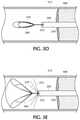
- FIG. 3Dis a partial longitudinal cross-sectional view of an alternative retrograde blood flow occlusion flushing device in accordance with the present invention, wherein the occluding component is a retractable flap, illustrated in a retracted or collapsed state prior to being deployed;
- FIG. 3Eis a partial longitudinal cross-sectional view of the retrograde blood flow occlusion flushing device of FIG. 3D , wherein the retractable flap is illustrated in the expanded or fully deployed state;
- FIG. 4is an exemplary illustration of the present inventive retrograde blood flow occlusion flushing device of FIG. 3A delivered through an intracranial vessel via a balloon guide catheter to a distal side of a targeted blockage;
- FIG. 5is a particular application of the present invention retrograde blood flow occlusion flushing device of FIG. 3A deployed in each branch of a bifurcated intracranial vessel;
- FIG. 6Ais a partial cross-sectional view through the vessel of deployed collapsible clot capture arms in accordance with the present inventive retrograde blood flow occlusion flushing device prohibiting distal movement of the targeted blockage while the occluding component is in a deflated state;
- FIG. 6Bis a perspective view of a portion of the catheter body of the present inventive retrograde blood flow occlusion flushing device (without the balloon occluding component) depicting the collapsible clot capture arms of FIG. 6A along line 6 B- 6 B while in a fully deployed state;
- FIG. 6Cis an end view of the fully deployed collapsible clot capture arms of FIG. 6B along lines 6 C- 6 C;
- FIG. 6Dis a side view of the catheter body of the present inventive retrograde blood flow occlusion flushing device (without the balloon occluding component) being withdrawn proximally through the lumen of the balloon guide catheter with the collapsible clot capture arms depicted in their wrapped down state.
- distalor “proximal” are used in the following description with respect to a position or direction relative to the treating physician or medical interventionalist. “Distal” or “distally” are a position distant from or in a direction away from the physician or interventionalist. “Proximal” or “proximally” or “proximate” are a position near or in a direction toward the physician or medical interventionist.
- occlusionor “clot” or “blockage” are used interchangeably.
- FIG. 1is an exemplary illustration of a blood pressure environment of a blockage in the distal and proximal vessel segments or a portion of a vessel.
- a normal direction of blood flow or circulationis represented by an arrow (fa), hereinafter referred to as anterograde blood flow.
- Blood pressure (Pp)represents the pressure on the proximal side or face of a blockage 100
- a blood pressure (Pd)represents the pressure on the opposite distal side or face of the blockage 100
- This substantial pressure differential ( ⁇ P)ensures that the blockage moves anterograde and remains lodged in tapering vessels, unless able to be overcome via mechanical intervention with an aspiration catheter or mechanically captured and extracted using an occlusion removal device such as a stent-retriever.
- FIGS. 2A and 2Billustrate two exemplary effects on the pressure differential ( ⁇ P) when the blockage 100 is traversed by a microcatheter 205 .
- ⁇ Ppressure differential
- FIGS. 2A and 2Billustrate two exemplary effects on the pressure differential ( ⁇ P) when the blockage 100 is traversed by a microcatheter 205 .
- similar principlesare equally applicable if the blockage is traversed by a guidewire, instead of a microcatheter, or if the blockage is traversed using both components simultaneously.
- One way the pressure differential may be affectedis depicted in the exemplary illustration of FIG.
- traversal of the blockage 100 by the microcatheter 205may result in the pressure differential ( ⁇ P) remaining substantially unchanged, as illustrated in FIG. 2B .
- Thismay occur if the blockage 100 forms a seal about the microcatheter 205 while traversing the blockage, whereby no blood flow is permitted to traverse the blockage. Otherwise, a small amount of blood flow may traverse from the proximal to the distal side of the blockage (e.g., Factional Flow Reserve ⁇ approximately 0.5), however, not sufficient to equalize the pressure differential ( ⁇ P) so the pressure differential remains substantially unchanged (Pp>>Pd).
- the blockage 100may undesirably move or advance in a distal direction in the vessel.
- the present inventionis employed during a revascularization procedure or treatment for establishing retrograde blood flow (reversal of blow flow opposite normal directional flow) by intentionally establishing a reverse pressure differential ( ⁇ P) across the blockage, that is, the pressure on the distal side of the blockage (Pd) is increased until substantially greater than that of the pressure on the proximal side of the blockage (Pp) ⁇ e.g., (Pd>>Pp) ⁇ .
- ⁇ Preverse pressure differential
- the blockageis advantageously pushed in a retrograde direction of blood flow (opposite normal blood flow direction, e.g., anterograde direction) proximally through the vessel.
- the pressure differentialis sufficiently large to dislodge the targeted blockage abutted to the inner walls of the vessel. Once dislodged, thereafter the pressure differential may be reduced, but still be sufficient to propel the blockage proximally through the vessel.
- initially the pressuremay be increased on the distal face of the of the targeted blockage until the pressure differential is at least approximately 25%, thereafter the pressure differential may be reduced in value to at least approximately 5%.
- Retrograde (reversal relative to that of normal) of blood flowis achieved in accordance with the present invention by positioning distal to a targeted blockage a retrograde (reversal) blood flow occlusion flushing device including a catheter body with an occluding component disposed proximate a distal end of the catheter body.
- the occluding componentupon activation transitions from an unsealed, unblocked, collapsed or deflated state to a sealed, blocked, occluded, extended or inflated state.
- the occluding componentflares radially outward as measured from the longitudinal axis of the catheter body farther in comparison to that while in a deflated or compressed state (having a reduced diameter).
- the retrograde blood flow occlusion flushing device(while its occluding component is in a collapsed or deflated state) is introduced intravascularly crossing or traversing the targeted blockage until its occluding component is disposed distally of the targeted blockage.
- the retrograde blood flow occlusion flushing devicemay be advanced to a desired position distally of the targeted blockage via a lumen of a microcatheter.
- the microcathetermay be eliminated altogether and the retrograde blood flow occlusion flushing device may be tracked over a wire alone to the desired position distally of the targeted blockage. Except for crossing or traversing the blockage with a wire and a low-profile device (e.g., the collapsed or deflated occluding component), the blockage is not mechanically compressed or sheared using the present inventive retrograde blood flow reversal occlusion flushing device as much as it would be when a conventional stent-retriever is deployed across the clot and then withdrawn.
- a low-profile devicee.g., the collapsed or deflated occluding component
- the occluding componentis activated (e.g., extended or inflated) radially outward from the catheter body until physically contacting and thereby establishing a seal with an interior wall of the vessel.
- Such sealprohibits distal flow (anterograde flow—normal blood flow) beyond the extended or inflated occluding component.
- the seal provided by the extended or inflated occluding componentprovides a barrier preventing fragmentation (in whole or in part) of the embolus from advancing distally through the vessel beyond the temporary barrier.
- the present inventive retrograde blood flow occlusion flushing devicemay be a catheter 300 , as illustrated in FIGS. 3A-3C , with a multi-lumen catheter body 305 having a proximal end 313 and an opposite distal end 315 .
- An inflatable occluding component 310is situated distally on the catheter body 305 .
- the inflatable occluding component 310is a balloon, depicted in FIGS.
- 3A-3Cin an inflated state, having an enlarged diameter sufficient to temporarily (until intentionally deflated) block, occlude or seal off blood flow by making physical contact against the interior wall of the vessel while positioned distally of the targeted blockage.
- Occlusion of the vessel by the inflated occluding component 310prior to removal of the targeted blockage safeguards embolic fragments of blockage advancing distally through the vessel beyond the temporary barrier formed by the occluding component.
- FIG. 3Bdepicts the cross-sectional view of the exemplary multi-lumen catheter body 305 along line 3 B- 3 B in FIG. 3A .
- three lumens( 320 , 325 , 330 ) are defined longitudinally through the catheter body 305 .
- One of the lumen 320is sufficiently sized in diameter to receive therein a wire 340 over which the balloon catheter 300 may be tracked.
- the balloon cathetermay alternatively be advanced through the vessel to a desired site using a microcatheter in which case the need for the wire lumen 320 in the catheter body may be eliminated altogether.
- the balloon occluding component 310is inflated (enlarged in diameter) by introduction of an inflating fluid (e.g., gas, air, liquid, or any combination thereof) delivered via a second lumen 325 , hereinafter referred to as an inflating lumen, of the catheter body 305 .
- an inflating fluide.g., gas, air, liquid, or any combination thereof
- a third lumen 330hereinafter a flushing lumen, as shown in FIG. 3B is used to dispense a flushing liquid (e.g., saline, contrast fluid, or other biocompatible liquid) into the vessel to establish a reverse pressure differential ( ⁇ P) in a retrograde direction.
- a flushing liquide.g., saline, contrast fluid, or other biocompatible liquid
- the inflation lumenmay also be one and the same as the flushing lumen by enabling the balloon to expel fluid once inflated through a one-way valve mechanism positioned at the distal end of the catheter.
- Each of the three lumens( 320 , 325 , 330 ) may, but need not necessarily be, substantially equal in inner diameter. It is contemplated and within the intended scope of the present invention to have any number of two or more lumen, as desired. In a configuration of the catheter body 305 having only two lumens, one of the lumen may be utilized for multiple functions. For example, a single lumen may be used for both insertion of a wire and inflation of the balloon.
- the lumenextends from the proximal end to the opposite distal end of the catheter body and that portion of the lumen extending through the balloon 310 may have one or more radial openings defined therein to allow the inflating fluid to be dispensed into the balloon 310 .
- a third lumene.g., a wire lumen
- FIG. 3Cis an enlarged partial longitudinal cross-section of the retrograde blood flow reversal catheter 300 in the dashed circle of FIG. 3A . From this particular view, it is evident that a distal end of the wire lumen 320 extends longitudinally completely through the balloon occluding component 310 , preferably to the distal end 315 of the catheter body 310 . A distal end of the inflating lumen 325 is disposed to terminate and empty into the balloon occluding component 310 itself. Whereas a distal end of the flushing lumen 330 has a side exit port or opening 335 defined in an outer circumference of the catheter body 305 proximally of the balloon occluding component 310 .
- Side exit port or opening 335allows the flushing fluid (e.g., saline, contrast fluid, or other biocompatible liquid) delivered via the flushing lumen 330 to be dispensed from the catheter body 310 between the balloon occluding component 310 (while in an inflated state) and the targeted blockage.
- flushing fluide.g., saline, contrast fluid, or other biocompatible liquid
- the occluding component 310may alternatively while in a compressed or retracted state have a reduced or lower profile in a radially outward direction from the longitudinal axis of the catheter body such as a retractable flap, like that of a parachute, as depicted in FIGS. 3D & 3E .
- One or more tethers 360may be provided to secure the retractable flap (e.g., parachute 350 ) to the catheter body 305 .
- the flape.g., parachute 350
- Blood flow or flow from the flushing fluide.g., introduced saline, contrast fluid, or other biocompatible liquid 355
- the flushing fluide.g., introduced saline, contrast fluid, or other biocompatible liquid 355
- the flushing lumen 330 ′is design to have an exit port 335 ′ located at the distal end of the catheter body 305 .
- Configuring the exit port 335 ′ at the distal end of the catheter bodydirects the flow of flushing fluid therefrom towards the center of the collapsed parachute 350 . This assists both in deployment of the parachute 350 , and once deployed, maintains the parachute in its open (fully expanded or fully deployed) state.
- the retractable flape.g., parachute 350
- the retractable flapseals off the vessel 415 by making physical contact with its interior wall thereby forming a seal therebetween and increases the pressure on the distal side or face of the blockage 400 , as illustrated in FIG. 3E .
- FIG. 4depicts an optional ancillary device, namely, a balloon guide catheter 420 (since it is equipped with a balloon proximate its distal tip, or, if not, simply a guide catheter) having a lumen 425 defined longitudinally therethrough for delivery of the present inventive retrograde flow reversal catheter 300 via an intracranial vessel 415 until the balloon occluding component 310 (while in a deflated state) traverses the targeted blockage 400 to its distal side or face.
- a balloon guide catheter 420since it is equipped with a balloon proximate its distal tip, or, if not, simply a guide catheter having a lumen 425 defined longitudinally therethrough for delivery of the present inventive retrograde flow reversal catheter 300 via an intracranial vessel 415 until the balloon occluding component 310 (while in a deflated state) traverses the targeted blockage 400 to its distal side or face.
- the retrograde flow reversal catheter 300is advanced via the lumen 425 in a distal direction (i.e., an anterograde direction—in the same direction as normal blood flow) and out through the distal end of the guide catheter 420 until the balloon occluding component 310 (still in a deflated state) is positioned distally of the targeted blockage 400 .
- a guidewire and/or microcathetermay optionally be used, either one following the other or in tandem, to deliver the present inventive occluding component 310 through the vessel 415 to the desired site on a distal side of the targeted blockage.
- An inflating fluide.g., a gas such as air or a liquid such as saline, is introduced via the inflating lumen 325 to enlarge, expand or inflate the balloon occluding component 310 sufficient in diameter to physically contact against the inner wall of the vessel 415 to block, obstruct, occlude or seal the vessel distally of the targeted blockage 400 .
- a gassuch as air
- a liquidsuch as saline
- a flushing fluide.g., saline, contrast fluid, or other biocompatible liquid
- salinea flushing fluid
- contrast fluida flushing fluid
- any flushing fluid dispensed via the flushing lumen 330 and out from the side exit port 335is forced to flow in a retrograde direction (denoted by the arrow “fr”) reversal to that of the normal blood flow (i.e., anterograde direction—denoted by the arrow “fa”).
- the volume of flushing fluid administered via the flushing lumen 330is increased until the pressure (Pd) on the distal side of the targeted blockage 400 exceeds the pressure (Pp) on the proximal side of the targeted blockage 410 , i.e., Pd>>Pp.
- a reversal of pressure differential( ⁇ P, wherein Pd>>Pp) is therefore established that imparts a greater counterbalancing force in the retrograde direction (reverse of the direction of normal blood flow) pushing the targeted blockage in the same direction.
- Positioning of the inflated balloon occluding component 310 distally of the targeted blockage 400serves the dual purpose of serving as a barrier to prohibit fragments of the blockage from embolizing distally beyond the barrier.
- the guide catheter 420provides structural support and when combined with aspiration (e.g., vacuum pressure via a syringe or pump) promotes retrograde movement (i.e., flow reversal) of the clot during treatment while simultaneously removing excess flushing fluid (e.g., saline, contrast fluid, or other biocompatible liquid) introduced during the procedure along with blood and blockage fragments.
- the balloon guide catheter 420temporarily obstructs flow (e.g., blood and/or blockage fragments) on the proximal side of the occlusion during its removal resulting in proximal flow arrest that reduces the proximal pressure on the blockage, occlusion or clot.
- a conventional distal access cathetermay optionally be used in combination with the balloon guide catheter to provide local aspiration closer to the occlusion, blockage or clot 400 .
- Such ancillary aspiration devicesby applying a vacuum pressure in the retrograde direction further reduces the proximal pressure (Pp), which in combination with the reversal of pressure differential ( ⁇ P), assists in moving the targeted blockage 400 in the retrograde direction reverse of normal blood flow, essentially reversing the process whereby the blockage initially travelled through the vessel.
- a potential limitation to application of the present inventive retrograde flow reversal balloon guide catheteris in the specific application where once the balloon occluding component 310 is positioned distally of the targeted blockage a bifurcation of the vessel (i.e., a main branch vessel 435 and a side branch vessel 440 ) is present between the distal end of the targeted blockage 400 and the proximal end of the balloon occluding component 310 .
- a bifurcation of the vesseli.e., a main branch vessel 435 and a side branch vessel 440
- the balloon occluding component 310while in an inflated state blocks, occludes or seals only one of the two branches (e.g., the main branch vessel 435 ) forming the bifurcated vessel leaving the other branch (e.g., the side branch vessel 440 ) unblocked, as illustrated in FIG. 5 .
- the force of the flushing fluid 345(e.g., saline, contrast fluid, or other biocompatible liquid) flowing through the flushing lumen 330 and exiting from the side opening or port 335 may be insufficient to reverse the pressure differential ( ⁇ P)(i.e., (Pd) may not be substantially greater than (Pp)).
- the flushing fluide.g., saline, contrast fluid, or other biocompatible liquid
- the flushing fluidmay disadvantageously be allowed to flow in an anterograde direction through the unblocked bifurcated branch vessel (i.e., that bifurcated branch vessel ( 440 ) not blocked by the inflated balloon occluding component).
- both branches of the bifurcated vesselare preferably blocked independently of the other by deploying two separate inflatable balloon occluding components either directly or via a microcatheter, one balloon occluding component deployed in each respective branch of the bifurcated vessel ( 435 , 440 ).
- the present inventive retrograde flow reversal balloon catheter 300may have to be deployed and retracted multiple times or passes before an aspiration catheter and/or an occlusion removal device (e.g., stent-retriever) may be employed to capture and remove the targeted blockage proximally from the vessel.
- an occlusion removal devicee.g., stent-retriever
- the retrograde flow reversal cathetertraverses or advances across the targeted blockage in a distal direction and subsequently is withdrawn proximally backwards across the targeted blockage and through the vessel.
- the balloon occluding component 310is returned to a deflated state each time the retrograde flow reversal balloon guide catheter is withdrawn proximally through the vessel.
- the targeted blockage 400may disadvantageously advance through the vessel in a distal direction (anterograde direction in the direction of normal blood flow).
- the present inventive retrograde flow reversal balloon guide cathetermay further include a clot capture mechanical component.
- the clot capture mechanical componentcomprises one or more retractable, collapsible or expandable components 605 (e.g., protrusions or arms) extending radially outward from the distal section of the catheter body 305 .
- the protrusions or arms 605When deployed or expanded the protrusions or arms 605 extend in a zone or region of the vessel 415 disposed between the deflated balloon occluding component 310 and the targeted blockage 400 .
- three projections or arms 605are equidistantly mounted to and extend or flare radially outward from the catheter body 305 .
- each projection or arm 605 while fully extended or deployedis sufficient in length to physically contact the inner wall of the vessel 415 .
- Each deployed projection or arm 605preferably has an enlarged free terminating end so that, when deployed and in physical contact with, don't damage the inner wall of the vessel. While in its deployed state, distal movement of the targeted blockage through the vessel distally beyond the clot capture components 605 is prohibited until such time that the balloon occluding component 310 may be re-inflated.
- protrusions 605automatically collapse or wrap down thereby reducing in diameter when withdrawn proximally backwards into the lumen 425 of the microcatheter 420 .
- the present inventive retrograde blood flow occlusion flushing deviceprovides multi-purpose functionality. As described in greater detail above, when the occluding component is in the expanded state having an enlarged diameter sealing the vessel from within at a position distally of the targeted blockage, advancement distally in the vessel beyond the occluding device of the targeted blockage or debris associated therewith is prohibited.
- the temporary blockage, occlusion or seal formed by the occluding component when positioned distally of the targeted blockage and while in an expanded statesimultaneously serves as a barrier prohibiting distal embolization of any fragments of the embolism distally beyond the barrier during treatment.
- the introduction of the flushing fluid into the vessel in a zone or region between the occluding component while in an expanded state and the targeted blockage by the present invention retrograde blood flow occlusion flushing deviceestablishes a reverse pressure differential ( ⁇ P), wherein Pd>>Pp.
- ⁇ Preverse pressure differential
- the targeted blockageis advantageously pushed in a retrograde direction (reversing the normal blood flow in the anterograde direction) towards an aspirator catheter and/or mechanical occlusion removal device (e.g., stent-retriever), which optionally may be employed in combination with the present invention.
- the present inventive retrograde blood flow occlusion flushing devicereduces compression and possible shearing of the targeted blockage.
- the present inventive balloon catheterhas been illustrated and described for use in a mechanical thrombectomy procedure but is applicable for use in other neurovascular or endovascular medical procedures.
Landscapes
- Health & Medical Sciences (AREA)
- Life Sciences & Earth Sciences (AREA)
- Heart & Thoracic Surgery (AREA)
- Surgery (AREA)
- General Health & Medical Sciences (AREA)
- Engineering & Computer Science (AREA)
- Biomedical Technology (AREA)
- Animal Behavior & Ethology (AREA)
- Public Health (AREA)
- Veterinary Medicine (AREA)
- Vascular Medicine (AREA)
- Molecular Biology (AREA)
- Medical Informatics (AREA)
- Nuclear Medicine, Radiotherapy & Molecular Imaging (AREA)
- Anesthesiology (AREA)
- Hematology (AREA)
- Orthopedic Medicine & Surgery (AREA)
- Biophysics (AREA)
- Pulmonology (AREA)
- Child & Adolescent Psychology (AREA)
- Reproductive Health (AREA)
- Surgical Instruments (AREA)
- External Artificial Organs (AREA)
Abstract
Description
Claims (20)
Priority Applications (10)
| Application Number | Priority Date | Filing Date | Title |
|---|---|---|---|
| US16/152,159US11253287B2 (en) | 2018-10-04 | 2018-10-04 | Retrograde blood flow occlusion flushing device |
| KR1020190122389AKR20200039583A (en) | 2018-10-04 | 2019-10-02 | Retrograde blood flow occlusion flushing device |
| BR102019020723ABR102019020723A2 (en) | 2018-10-04 | 2019-10-02 | rinsing device for retrograde blood flow occlusion |
| EP21161554.7AEP3851056B1 (en) | 2018-10-04 | 2019-10-03 | Retrograde blood flow occlusion flushing device |
| ES19201293TES2868198T3 (en) | 2018-10-04 | 2019-10-03 | Retrograde blood flow occlusion flushing device |
| ES21161554TES2939625T3 (en) | 2018-10-04 | 2019-10-03 | Retrograde blood flow occlusion flushing device |
| EP19201293.8AEP3632352B1 (en) | 2018-10-04 | 2019-10-03 | Retrograde blood flow occlusion flushing device |
| JP2019182735AJP7408333B2 (en) | 2018-10-04 | 2019-10-03 | Retrograde blood flow obstruction flushing device |
| CN201910949289.4ACN111000616A (en) | 2018-10-04 | 2019-10-08 | Reverse blood flow blocking flushing device |
| US17/575,560US20220133343A1 (en) | 2018-10-04 | 2022-01-13 | Retrograde Blood Flow Occlusion Flushing Device |
Applications Claiming Priority (1)
| Application Number | Priority Date | Filing Date | Title |
|---|---|---|---|
| US16/152,159US11253287B2 (en) | 2018-10-04 | 2018-10-04 | Retrograde blood flow occlusion flushing device |
Related Child Applications (1)
| Application Number | Title | Priority Date | Filing Date |
|---|---|---|---|
| US17/575,560ContinuationUS20220133343A1 (en) | 2018-10-04 | 2022-01-13 | Retrograde Blood Flow Occlusion Flushing Device |
Publications (2)
| Publication Number | Publication Date |
|---|---|
| US20200107851A1 US20200107851A1 (en) | 2020-04-09 |
| US11253287B2true US11253287B2 (en) | 2022-02-22 |
Family
ID=68137906
Family Applications (2)
| Application Number | Title | Priority Date | Filing Date |
|---|---|---|---|
| US16/152,159Active2039-12-20US11253287B2 (en) | 2018-10-04 | 2018-10-04 | Retrograde blood flow occlusion flushing device |
| US17/575,560AbandonedUS20220133343A1 (en) | 2018-10-04 | 2022-01-13 | Retrograde Blood Flow Occlusion Flushing Device |
Family Applications After (1)
| Application Number | Title | Priority Date | Filing Date |
|---|---|---|---|
| US17/575,560AbandonedUS20220133343A1 (en) | 2018-10-04 | 2022-01-13 | Retrograde Blood Flow Occlusion Flushing Device |
Country Status (7)
| Country | Link |
|---|---|
| US (2) | US11253287B2 (en) |
| EP (2) | EP3632352B1 (en) |
| JP (1) | JP7408333B2 (en) |
| KR (1) | KR20200039583A (en) |
| CN (1) | CN111000616A (en) |
| BR (1) | BR102019020723A2 (en) |
| ES (2) | ES2939625T3 (en) |
Families Citing this family (6)
| Publication number | Priority date | Publication date | Assignee | Title |
|---|---|---|---|---|
| US12285182B2 (en) | 2018-10-10 | 2025-04-29 | Innova Vascular, Inc. | Devices and methods for removing an embolus |
| US11197684B1 (en) | 2021-03-04 | 2021-12-14 | Nventric Corporation | Thrombectomy device and method |
| CN115737061A (en)* | 2022-11-14 | 2023-03-07 | 杭州诺纳生物医疗科技有限公司 | Shock wave device |
| US12114880B1 (en) | 2023-08-03 | 2024-10-15 | Nventric Corporation | Thrombectomy device having open frame cell ring |
| CN116849750B (en)* | 2023-09-02 | 2023-11-21 | 杭州亿科医疗科技有限公司 | Aneurysm turbulent flow device capable of being mechanically released |
| WO2025128443A1 (en)* | 2023-12-13 | 2025-06-19 | Stryker Corporation | Method of treating an ophthalmic artery stenosis |
Citations (123)
| Publication number | Priority date | Publication date | Assignee | Title |
|---|---|---|---|---|
| US5928192A (en) | 1997-07-24 | 1999-07-27 | Embol-X, Inc. | Arterial aspiration |
| US6080170A (en) | 1996-07-26 | 2000-06-27 | Kensey Nash Corporation | System and method of use for revascularizing stenotic bypass grafts and other occluded blood vessels |
| WO2000054673A1 (en) | 1999-03-16 | 2000-09-21 | Percusurge, Inc. | Apparatus for containing and removing occlusions in the carotid arteries |
| US6168579B1 (en) | 1999-08-04 | 2001-01-02 | Scimed Life Systems, Inc. | Filter flush system and methods of use |
| US20020032432A1 (en) | 2000-03-10 | 2002-03-14 | Nash John E. | Tool for facilitating the connecting of a catheter or other tubular member onto a guide-wire without access to the ends of the guide-wire |
| US20020169436A1 (en) | 2001-05-08 | 2002-11-14 | Hitinder Gurm | Percutaneous method of preventing distal embolisation while maintaining adequate distal perfusion in percutaneous interventional procedures |
| US6635070B2 (en) | 2001-05-21 | 2003-10-21 | Bacchus Vascular, Inc. | Apparatus and methods for capturing particulate material within blood vessels |
| US20050085769A1 (en) | 2001-07-17 | 2005-04-21 | Kerberos Proximal Solutions | Fluid exchange system for controlled and localized irrigation and aspiration |
| US20050113798A1 (en) | 2000-07-21 | 2005-05-26 | Slater Charles R. | Methods and apparatus for treating the interior of a blood vessel |
| US6994718B2 (en) | 2003-10-29 | 2006-02-07 | Medtronic Vascular, Inc. | Distal protection device for filtering and occlusion |
| US20100069900A1 (en)* | 2008-09-18 | 2010-03-18 | Cook Incorporated | Dual balloon catheter assembly |
| US8226673B2 (en) | 1996-07-26 | 2012-07-24 | Kensey Nash Corporation | System and method of use for agent delivery and revascularizing of grafts and vessels |
| US20130158511A1 (en) | 2011-12-19 | 2013-06-20 | Cook Medical Technologies Llc | Thrombus removal apparatus and method |
| WO2013105099A2 (en) | 2012-01-15 | 2013-07-18 | Triticum Ltd. | Device and method for removing occlusions in a biological vessel |
| WO2014204860A1 (en) | 2013-06-18 | 2014-12-24 | Slik Road Medical, Inc. | Methods and systems for tretment of acute ischemic stroke |
| US9084857B2 (en) | 2012-04-16 | 2015-07-21 | W. L. Gore & Associates, Inc. | Single access flow-reversal catheter devices and methods |
| US20160338720A1 (en) | 2011-06-08 | 2016-11-24 | Cvdevices, Llc | Thrombus removal systems and devices and methods of using the same |
| US9532792B2 (en) | 2008-07-14 | 2017-01-03 | Medtronic, Inc. | Aspiration catheters for thrombus removal |
| US9532873B2 (en) | 2008-09-17 | 2017-01-03 | Medtronic CV Luxembourg S.a.r.l. | Methods for deployment of medical devices |
| US9533344B2 (en) | 2005-11-17 | 2017-01-03 | Microvention, Inc. | Three-dimensional complex coil |
| US9539382B2 (en) | 2013-03-12 | 2017-01-10 | Medtronic, Inc. | Stepped catheters with flow restrictors and infusion systems using the same |
| US9539022B2 (en) | 2012-11-28 | 2017-01-10 | Microvention, Inc. | Matter conveyance system |
| US9539011B2 (en) | 2013-03-14 | 2017-01-10 | Stryker Corporation | Vaso-occlusive device delivery system |
| US9539122B2 (en) | 2001-07-20 | 2017-01-10 | Microvention, Inc. | Aneurysm treatment device and method of use |
| US20170007265A1 (en) | 2013-03-14 | 2017-01-12 | Stryker Corporation | Vaso-occlusive device delivery system |
| US20170007264A1 (en) | 2007-12-21 | 2017-01-12 | Microvention, Inc. | Implantation devices including hydrogel filaments |
| US9549830B2 (en) | 2008-03-25 | 2017-01-24 | Medtronic Vascular, Inc. | Eversible branch stent-graft and deployment method |
| US20170020700A1 (en) | 2010-09-17 | 2017-01-26 | Medtronic Vascular, Inc. | Method of Forming a Drug-Eluting Medical Device |
| US20170020670A1 (en) | 2011-05-12 | 2017-01-26 | Medtronic, Inc. | Delivery Catheter System With Micro and Macro Movement Control |
| US9554805B2 (en) | 2008-07-15 | 2017-01-31 | Penumbra, Inc. | Embolic coil implant system and implantation method |
| US20170027692A1 (en) | 2004-11-19 | 2017-02-02 | Medtronic, Inc. | Apparatus for treatment of cardiac valves and method of its manufacture |
| US20170027640A1 (en) | 2005-06-20 | 2017-02-02 | Medtronic Ablation Frontiers Llc | Ablation catheter |
| US20170027725A1 (en) | 2013-05-30 | 2017-02-02 | Medtronic Vascular, Inc. | Delivery System Having a Single Handed Deployment Handle for a Retractable Outer Sheath |
| US9561125B2 (en) | 2010-04-14 | 2017-02-07 | Microvention, Inc. | Implant delivery device |
| US20170035567A1 (en) | 2015-08-07 | 2017-02-09 | Medtronic Vascular, Inc. | System and method for deflecting a delivery catheter |
| US20170035436A1 (en) | 2015-08-07 | 2017-02-09 | Microvention, Inc. | Complex Coil And Manufacturing Techniques |
| US20170042548A1 (en) | 2015-08-11 | 2017-02-16 | Microvention, Inc. | System And Method For Implant Delivery |
| US9572982B2 (en) | 2008-04-30 | 2017-02-21 | Medtronic, Inc. | Techniques for placing medical leads for electrical stimulation of nerve tissue |
| US20170049596A1 (en) | 2014-04-30 | 2017-02-23 | Stryker Corporation | Implant delivery system and method of use |
| US9579484B2 (en) | 2014-09-19 | 2017-02-28 | Medtronic Vascular, Inc. | Sterile molded dispenser |
| US9585642B2 (en) | 2012-12-07 | 2017-03-07 | Medtronic, Inc. | Minimally invasive implantable neurostimulation system |
| US20170079812A1 (en) | 2015-09-18 | 2017-03-23 | Microvention, Inc. | Vessel Prosthesis |
| US20170079820A1 (en) | 2015-09-18 | 2017-03-23 | Microvention, Inc. | Pushable Implant Delivery System |
| US20170079767A1 (en) | 2015-09-21 | 2017-03-23 | Stryker Corporation | Embolectomy devices |
| US20170079817A1 (en) | 2015-09-18 | 2017-03-23 | Microvention, Inc. | Implant Retention, Detachment, And Delivery System |
| US20170079671A1 (en)* | 2015-09-22 | 2017-03-23 | Medtronic Vascular, Inc. | Occlusion Bypassing Apparatus With a Re-Entry Needle and a Stabilization Tube |
| US20170079819A1 (en) | 2015-09-18 | 2017-03-23 | Microvention, Inc. | Releasable Delivery System |
| US20170079766A1 (en) | 2015-09-21 | 2017-03-23 | Stryker Corporation | Embolectomy devices |
| US20170086996A1 (en) | 2012-04-26 | 2017-03-30 | Medtronic Vascular, Inc. | Apparatus and methods for filling a drug eluting medical device via capillary action |
| US20170086851A1 (en) | 2014-05-28 | 2017-03-30 | Stryker European Holdings I, Llc | Vaso-occlusive devices and methods of use |
| US9615951B2 (en) | 2009-09-22 | 2017-04-11 | Penumbra, Inc. | Manual actuation system for deployment of implant |
| US9615832B2 (en) | 2006-04-07 | 2017-04-11 | Penumbra, Inc. | Aneurysm occlusion system and method |
| US20170100143A1 (en) | 2015-10-07 | 2017-04-13 | Stryker Corporation | Multiple barrel clot removal devices |
| US20170100183A1 (en) | 2015-10-09 | 2017-04-13 | Medtronic, Inc. | Method for closure and ablation of atrial appendage |
| US20170100141A1 (en) | 2015-10-07 | 2017-04-13 | Medtronic Vascular, Inc. | Occlusion Bypassing Apparatus With A Re-Entry Needle and a Distal Stabilization Balloon |
| US9622753B2 (en) | 2001-07-20 | 2017-04-18 | Microvention, Inc. | Aneurysm treatment device and method of use |
| US20170113023A1 (en) | 2015-10-26 | 2017-04-27 | Medtronic Vascular, Inc. | Sheathless Guide Catheter Assembly |
| US9636439B2 (en) | 2003-09-19 | 2017-05-02 | Medtronic Vascular, Inc. | Delivery of therapeutics to treat aneurysms |
| US9636115B2 (en) | 2005-06-14 | 2017-05-02 | Stryker Corporation | Vaso-occlusive delivery device with kink resistant, flexible distal end |
| US9642675B2 (en) | 2004-10-14 | 2017-05-09 | Medtronic Ablation Frontiers Llc | Ablation catheter |
| US9655633B2 (en) | 2004-09-10 | 2017-05-23 | Penumbra, Inc. | System and method for treating ischemic stroke |
| US9655989B2 (en) | 2012-10-15 | 2017-05-23 | Microvention, Inc. | Polymeric treatment compositions |
| US9655645B2 (en) | 2011-05-27 | 2017-05-23 | Stryker Corporation | Assembly for percutaneously inserting an implantable medical device, steering the device to a target location and deploying the device |
| US20170147765A1 (en) | 2015-11-19 | 2017-05-25 | Penumbra, Inc. | Systems and methods for treatment of stroke |
| US9662238B2 (en) | 2010-07-23 | 2017-05-30 | Medtronic, Inc. | Attachment mechanism for stent release |
| US9662425B2 (en) | 2013-04-22 | 2017-05-30 | Stryker European Holdings I, Llc | Method for drug loading hydroxyapatite coated implant surfaces |
| US20170151032A1 (en) | 2015-11-30 | 2017-06-01 | Penumbra, Inc. | System for endoscopic intracranial procedures |
| US9668898B2 (en) | 2014-07-24 | 2017-06-06 | Medtronic Vascular, Inc. | Stent delivery system having dynamic deployment and methods of manufacturing same |
| US9675782B2 (en) | 2013-10-10 | 2017-06-13 | Medtronic Vascular, Inc. | Catheter pull wire actuation mechanism |
| US9675477B2 (en) | 2013-03-15 | 2017-06-13 | Medtronic Vascular, Inc. | Welded stent having a welded soluble core |
| US9676022B2 (en) | 2012-04-03 | 2017-06-13 | Medtronic Vascular, Inc. | Apparatus for creating formed elements used to make wound stents |
| US20170165062A1 (en) | 2015-12-14 | 2017-06-15 | Medtronic, Inc. | Delivery system having retractable wires as a coupling mechanism and a deployment mechanism for a self-expanding prosthesis |
| US20170165454A1 (en) | 2015-12-09 | 2017-06-15 | Medtronic Vascular, Inc. | Catheter with a lumen shaped as an identification symbol |
| US20170165065A1 (en) | 2015-12-14 | 2017-06-15 | Medtronic, Inc. | Delivery system having retractable wires as a coupling mechanism and a deployment mechanism for a self-expanding prosthesis |
| US20170172772A1 (en) | 2014-04-08 | 2017-06-22 | Stryker Corporation | Implant delivery system and method of use |
| US20170172766A1 (en) | 2012-03-16 | 2017-06-22 | Microvention, Inc. | Stent And Stent Delivery Device |
| US9692557B2 (en) | 2015-02-04 | 2017-06-27 | Stryker European Holdings I, Llc | Apparatus and methods for administering treatment within a bodily duct of a patient |
| US9693852B2 (en) | 2013-03-15 | 2017-07-04 | Microvention, Inc. | Embolic protection device |
| US20170189033A1 (en) | 2016-01-06 | 2017-07-06 | Microvention, Inc. | Occlusive Embolic Coil |
| US20170189035A1 (en) | 2015-12-30 | 2017-07-06 | Stryker Corporation | Embolic devices and methods of manufacturing same |
| US9700399B2 (en) | 2012-04-26 | 2017-07-11 | Medtronic Vascular, Inc. | Stopper to prevent graft material slippage in a closed web stent-graft |
| US9700262B2 (en) | 2011-05-17 | 2017-07-11 | Stryker Corporation | Method of fabricating implantable medical devices from a polymer coupon that is bonded to rigid substrate |
| US9717502B2 (en) | 2013-03-14 | 2017-08-01 | Stryker Corporation | Vaso-occlusive device delivery system |
| US9717421B2 (en) | 2012-03-26 | 2017-08-01 | Medtronic, Inc. | Implantable medical device delivery catheter with tether |
| US9717500B2 (en) | 2009-04-15 | 2017-08-01 | Microvention, Inc. | Implant delivery system |
| US9724526B2 (en) | 2004-06-10 | 2017-08-08 | Medtronic Urinary Solutions, Inc. | Implantable pulse generator systems and methods for operating the same |
| US9724103B2 (en) | 2006-06-15 | 2017-08-08 | Microvention, Inc. | Embolization device constructed from expansile polymer |
| US20170224953A1 (en) | 2016-02-10 | 2017-08-10 | Microvention, Inc. | Intravascular Treatment Site Access |
| US20170224355A1 (en) | 2016-02-10 | 2017-08-10 | Microvention, Inc. | Devices for Vascular Occlusion |
| US20170224467A1 (en) | 2016-02-09 | 2017-08-10 | Medtronic Vascular, Inc. | Endoluminal prosthetic assemblies, and associated systems and methods for percutaneous repair of a vascular tissue defect |
| US20170231749A1 (en) | 2016-02-12 | 2017-08-17 | Medtronic Vascular, Inc. | Stent graft with external scaffolding and method |
| US9750565B2 (en) | 2011-09-30 | 2017-09-05 | Medtronic Advanced Energy Llc | Electrosurgical balloons |
| US9757260B2 (en) | 2006-03-30 | 2017-09-12 | Medtronic Vascular, Inc. | Prosthesis with guide lumen |
| US9764111B2 (en) | 2012-10-01 | 2017-09-19 | Microvention, Inc. | Catheter markers |
| US9770577B2 (en) | 2014-09-15 | 2017-09-26 | Medtronic Xomed, Inc. | Pressure relief for a catheter balloon device |
| US9770251B2 (en) | 2012-08-13 | 2017-09-26 | Microvention, Inc. | Shaped removal device |
| US9775706B2 (en) | 2010-04-20 | 2017-10-03 | Medtronic Vascular, Inc. | Controlled tip release stent graft delivery system and method |
| US20170281909A1 (en) | 2016-04-05 | 2017-10-05 | Stryker Corporation | Medical devices and methods of manufacturing same |
| US20170281331A1 (en) | 2016-03-31 | 2017-10-05 | Medtronic Vascular, Inc. | Endoluminal prosthetic devices having fluid-absorbable compositions for repair of a vascular tissue defect |
| US20170281344A1 (en) | 2016-03-31 | 2017-10-05 | Medtronic Vascular, Inc. | Expandable introducer sheath having a steering mechanism |
| US20170281912A1 (en) | 2016-04-04 | 2017-10-05 | Medtronic Vascular, Inc. | Drug coated balloon |
| US20170290654A1 (en) | 2016-04-12 | 2017-10-12 | Medtronic Vascular, Inc. | Gutter filling stent-graft and method |
| US9788800B2 (en) | 2012-07-17 | 2017-10-17 | Stryker Corporation | Notification system of deviation from predefined conditions |
| US20170296325A1 (en) | 2016-04-18 | 2017-10-19 | Medtronic Vascular, Inc. | Stent-graft prosthesis and method of manufacture |
| US20170296324A1 (en) | 2016-04-13 | 2017-10-19 | Medtronic Vascular, Inc. | Iliac branch device and method |
| US9795391B2 (en) | 2013-10-25 | 2017-10-24 | Medtronic Vascular, Inc. | Tissue compression device with tension limiting strap retainer |
| US20170304097A1 (en) | 2016-04-21 | 2017-10-26 | Medtronic Vascular, Inc. | Stent-graft delivery system having an inner shaft component with a loading pad or covering on a distal segment thereof for stent retention |
| US20170303939A1 (en) | 2016-04-25 | 2017-10-26 | Stryker Corporation | Methods for advancing inverting mechanical thrombectomy apparatuses in the vasculature |
| US20170304041A1 (en) | 2016-04-25 | 2017-10-26 | Medtronic Vascular, Inc. | Dissection prosthesis system and method |
| US20170303947A1 (en) | 2016-04-25 | 2017-10-26 | Stryker Corporation | Clot-engulfing mechanical thrombectomy apparatuses |
| US20170304595A1 (en) | 2016-04-25 | 2017-10-26 | Medtronic Vascular, Inc. | Balloon catheter including a drug delivery sheath |
| US20170303948A1 (en) | 2016-04-25 | 2017-10-26 | Stryker Corporation | Anti-jamming and macerating thrombectomy apparatuses and methods |
| US9801980B2 (en) | 2010-12-20 | 2017-10-31 | Microvention, Inc. | Polymer stents and methods of manufacture |
| US20170316561A1 (en) | 2016-04-28 | 2017-11-02 | Medtronic Navigation, Inc. | Method and Apparatus for Image-Based Navigation |
| US20170312109A1 (en) | 2016-04-28 | 2017-11-02 | Medtronic Vascular, Inc. | Implantable medical device delivery system |
| US20170312484A1 (en) | 2016-04-28 | 2017-11-02 | Medtronic Vascular, Inc. | Drug coated inflatable balloon having a thermal dependent release layer |
| US9808599B2 (en) | 2013-12-20 | 2017-11-07 | Microvention, Inc. | Device delivery system |
| US20170333228A1 (en) | 2016-05-17 | 2017-11-23 | Medtronic Vascular, Inc. | Tool and method for compressing a stented prosthesis |
| US9833604B2 (en) | 2013-12-20 | 2017-12-05 | Microvention, Inc. | Delivery adapter |
| US9833625B2 (en) | 2012-03-26 | 2017-12-05 | Medtronic, Inc. | Implantable medical device delivery with inner and outer sheaths |
| US9833252B2 (en) | 2013-03-15 | 2017-12-05 | Microvention, Inc. | Multi-component obstruction removal system and method |
| US20170348014A1 (en) | 2016-06-03 | 2017-12-07 | Stryker Corporation | Inverting thrombectomy apparatuses and methods |
| US20170348514A1 (en) | 2016-06-01 | 2017-12-07 | Microvention, Inc. | Reinforced Balloon Catheter |
Family Cites Families (18)
| Publication number | Priority date | Publication date | Assignee | Title |
|---|---|---|---|---|
| JPH04221544A (en)* | 1990-12-25 | 1992-08-12 | Olympus Optical Co Ltd | Laser probe |
| US5514092A (en)* | 1994-08-08 | 1996-05-07 | Schneider (Usa) Inc. | Drug delivery and dilatation-drug delivery catheters in a rapid exchange configuration |
| US5908407A (en)* | 1997-07-25 | 1999-06-01 | Neuroperfusion, Inc. | Retroperfusion catheter apparatus and method |
| US6350271B1 (en)* | 1999-05-17 | 2002-02-26 | Micrus Corporation | Clot retrieval device |
| JP2002143311A (en)* | 2000-11-15 | 2002-05-21 | Olympus Optical Co Ltd | Balloon catheter |
| US6582448B1 (en)* | 2000-12-21 | 2003-06-24 | Advanced Cardiovascular Systems, Inc. | Vessel occlusion device for embolic protection system |
| US20020188253A1 (en)* | 2001-06-07 | 2002-12-12 | Pharmaspec Corporation | Method and apparatus for drug delivery in veins |
| US8298169B2 (en)* | 2004-03-22 | 2012-10-30 | Vahe Stephan Yacoubian | System, methods and apparatus for cerebral protection |
| EP4101399B1 (en)* | 2011-08-05 | 2025-04-09 | Route 92 Medical, Inc. | System for treatment of acute ischemic stroke |
| US9445828B2 (en)* | 2012-07-05 | 2016-09-20 | Cognition Medical Corp. | Methods, devices, and systems for postconditioning with clot removal |
| US10561827B2 (en)* | 2012-07-09 | 2020-02-18 | A V Medical Technologies, Ltd. | Disrupting fibrin sheath from a host blood vessel and visualization thereof |
| JP2015526259A (en)* | 2012-08-30 | 2015-09-10 | バガオイサン,セルソ | Apparatus and method for treating vascular disease |
| JP6352642B2 (en)* | 2013-12-03 | 2018-07-04 | 川澄化学工業株式会社 | Intravascular foreign body removal catheter |
| EP3017775A1 (en)* | 2014-11-07 | 2016-05-11 | National University of Ireland, Galway | A thrombectomy device |
| ES2975734T3 (en)* | 2015-01-29 | 2024-07-12 | Becton Dickinson Co | Integrated Quick Insert Catheter |
| JP6329101B2 (en)* | 2015-04-15 | 2018-05-23 | オリンパス株式会社 | Endoscope treatment tool and method for manufacturing endoscope treatment tool |
| ES2991271T3 (en)* | 2016-01-04 | 2024-12-03 | Corflow Therapeutics Ag | System for the treatment of microvascular obstruction |
| US11229445B2 (en)* | 2016-10-06 | 2022-01-25 | Mivi Neuroscience, Inc. | Hydraulic displacement and removal of thrombus clots, and catheters for performing hydraulic displacement |
- 2018
- 2018-10-04USUS16/152,159patent/US11253287B2/enactiveActive
- 2019
- 2019-10-02KRKR1020190122389Apatent/KR20200039583A/ennot_activeCeased
- 2019-10-02BRBR102019020723Apatent/BR102019020723A2/ennot_activeIP Right Cessation
- 2019-10-03EPEP19201293.8Apatent/EP3632352B1/enactiveActive
- 2019-10-03ESES21161554Tpatent/ES2939625T3/enactiveActive
- 2019-10-03JPJP2019182735Apatent/JP7408333B2/enactiveActive
- 2019-10-03EPEP21161554.7Apatent/EP3851056B1/enactiveActive
- 2019-10-03ESES19201293Tpatent/ES2868198T3/enactiveActive
- 2019-10-08CNCN201910949289.4Apatent/CN111000616A/enactivePending
- 2022
- 2022-01-13USUS17/575,560patent/US20220133343A1/ennot_activeAbandoned
Patent Citations (150)
| Publication number | Priority date | Publication date | Assignee | Title |
|---|---|---|---|---|
| US7981129B2 (en) | 1996-07-26 | 2011-07-19 | Kensey Nash Corporation | System for opening a lumen in an occluded blood vessel |
| US6080170A (en) | 1996-07-26 | 2000-06-27 | Kensey Nash Corporation | System and method of use for revascularizing stenotic bypass grafts and other occluded blood vessels |
| US8226673B2 (en) | 1996-07-26 | 2012-07-24 | Kensey Nash Corporation | System and method of use for agent delivery and revascularizing of grafts and vessels |
| US5928192A (en) | 1997-07-24 | 1999-07-27 | Embol-X, Inc. | Arterial aspiration |
| US6196994B1 (en) | 1997-07-24 | 2001-03-06 | Embol-X, Inc. | Arterial aspiration |
| US20040054347A1 (en)* | 1999-03-16 | 2004-03-18 | Gholam-Reza Zadno-Azizi | Method for containing and removing occlusions in the carotid arteries |
| WO2000054673A1 (en) | 1999-03-16 | 2000-09-21 | Percusurge, Inc. | Apparatus for containing and removing occlusions in the carotid arteries |
| US6168579B1 (en) | 1999-08-04 | 2001-01-02 | Scimed Life Systems, Inc. | Filter flush system and methods of use |
| US6620148B1 (en) | 1999-08-04 | 2003-09-16 | Scimed Life Systems, Inc. | Filter flush system and methods of use |
| US8444665B2 (en) | 1999-08-04 | 2013-05-21 | Boston Scientific Scimed, Inc. | Filter flush system and methods of use |
| US20020032432A1 (en) | 2000-03-10 | 2002-03-14 | Nash John E. | Tool for facilitating the connecting of a catheter or other tubular member onto a guide-wire without access to the ends of the guide-wire |
| US20050113798A1 (en) | 2000-07-21 | 2005-05-26 | Slater Charles R. | Methods and apparatus for treating the interior of a blood vessel |
| US20020169436A1 (en) | 2001-05-08 | 2002-11-14 | Hitinder Gurm | Percutaneous method of preventing distal embolisation while maintaining adequate distal perfusion in percutaneous interventional procedures |
| US6635070B2 (en) | 2001-05-21 | 2003-10-21 | Bacchus Vascular, Inc. | Apparatus and methods for capturing particulate material within blood vessels |
| US20050085769A1 (en) | 2001-07-17 | 2005-04-21 | Kerberos Proximal Solutions | Fluid exchange system for controlled and localized irrigation and aspiration |
| US9539122B2 (en) | 2001-07-20 | 2017-01-10 | Microvention, Inc. | Aneurysm treatment device and method of use |
| US9622753B2 (en) | 2001-07-20 | 2017-04-18 | Microvention, Inc. | Aneurysm treatment device and method of use |
| US9636439B2 (en) | 2003-09-19 | 2017-05-02 | Medtronic Vascular, Inc. | Delivery of therapeutics to treat aneurysms |
| US6994718B2 (en) | 2003-10-29 | 2006-02-07 | Medtronic Vascular, Inc. | Distal protection device for filtering and occlusion |
| US9724526B2 (en) | 2004-06-10 | 2017-08-08 | Medtronic Urinary Solutions, Inc. | Implantable pulse generator systems and methods for operating the same |
| US9655633B2 (en) | 2004-09-10 | 2017-05-23 | Penumbra, Inc. | System and method for treating ischemic stroke |
| US9642675B2 (en) | 2004-10-14 | 2017-05-09 | Medtronic Ablation Frontiers Llc | Ablation catheter |
| US20170027692A1 (en) | 2004-11-19 | 2017-02-02 | Medtronic, Inc. | Apparatus for treatment of cardiac valves and method of its manufacture |
| US9636115B2 (en) | 2005-06-14 | 2017-05-02 | Stryker Corporation | Vaso-occlusive delivery device with kink resistant, flexible distal end |
| US20170027640A1 (en) | 2005-06-20 | 2017-02-02 | Medtronic Ablation Frontiers Llc | Ablation catheter |
| US20170072452A1 (en) | 2005-11-17 | 2017-03-16 | Microvention, Inc. | Three-dimensional complex coil |
| US9533344B2 (en) | 2005-11-17 | 2017-01-03 | Microvention, Inc. | Three-dimensional complex coil |
| US9757260B2 (en) | 2006-03-30 | 2017-09-12 | Medtronic Vascular, Inc. | Prosthesis with guide lumen |
| US20170333236A1 (en) | 2006-03-30 | 2017-11-23 | Medtronic Vascular, Inc. | Prosthesis with guide lumen |
| US9615832B2 (en) | 2006-04-07 | 2017-04-11 | Penumbra, Inc. | Aneurysm occlusion system and method |
| US20170172581A1 (en) | 2006-04-07 | 2017-06-22 | Penumbra, Inc. | Aneursym occlusion system and method |
| US20170290593A1 (en) | 2006-06-15 | 2017-10-12 | Microvention, Inc. | Embolization device constructed from expansile polymer |
| US9724103B2 (en) | 2006-06-15 | 2017-08-08 | Microvention, Inc. | Embolization device constructed from expansile polymer |
| US20170007264A1 (en) | 2007-12-21 | 2017-01-12 | Microvention, Inc. | Implantation devices including hydrogel filaments |
| US9549830B2 (en) | 2008-03-25 | 2017-01-24 | Medtronic Vascular, Inc. | Eversible branch stent-graft and deployment method |
| US9572982B2 (en) | 2008-04-30 | 2017-02-21 | Medtronic, Inc. | Techniques for placing medical leads for electrical stimulation of nerve tissue |
| US9662129B2 (en) | 2008-07-14 | 2017-05-30 | Medtronic Inc. | Aspiration catheters for thrombus removal |
| US9532792B2 (en) | 2008-07-14 | 2017-01-03 | Medtronic, Inc. | Aspiration catheters for thrombus removal |
| US9554805B2 (en) | 2008-07-15 | 2017-01-31 | Penumbra, Inc. | Embolic coil implant system and implantation method |
| US20170095259A1 (en) | 2008-07-15 | 2017-04-06 | Penumbra, Inc. | Embolic coil implant system and implantation method |
| US9775621B2 (en) | 2008-07-15 | 2017-10-03 | Penumbra, Inc. | Embolic coil implant system and implantation method |
| US20170071737A1 (en) | 2008-09-17 | 2017-03-16 | Medtronic CV Luxembourg S.a.r.l. | Delivery system for deployment of medical devices |
| US9532873B2 (en) | 2008-09-17 | 2017-01-03 | Medtronic CV Luxembourg S.a.r.l. | Methods for deployment of medical devices |
| US20100069900A1 (en)* | 2008-09-18 | 2010-03-18 | Cook Incorporated | Dual balloon catheter assembly |
| US20170281192A1 (en) | 2009-04-15 | 2017-10-05 | Microvention, Inc. | Implant delivery system |
| US9717500B2 (en) | 2009-04-15 | 2017-08-01 | Microvention, Inc. | Implant delivery system |
| US9615951B2 (en) | 2009-09-22 | 2017-04-11 | Penumbra, Inc. | Manual actuation system for deployment of implant |
| US20170100126A1 (en) | 2010-04-14 | 2017-04-13 | Microvention, Inc. | Implant delivery device |
| US9561125B2 (en) | 2010-04-14 | 2017-02-07 | Microvention, Inc. | Implant delivery device |
| US9775706B2 (en) | 2010-04-20 | 2017-10-03 | Medtronic Vascular, Inc. | Controlled tip release stent graft delivery system and method |
| US9662238B2 (en) | 2010-07-23 | 2017-05-30 | Medtronic, Inc. | Attachment mechanism for stent release |
| US20170224511A1 (en) | 2010-07-23 | 2017-08-10 | Medtronic, Inc. | Attachment mechanism for stent release |
| US20170020700A1 (en) | 2010-09-17 | 2017-01-26 | Medtronic Vascular, Inc. | Method of Forming a Drug-Eluting Medical Device |
| US9801980B2 (en) | 2010-12-20 | 2017-10-31 | Microvention, Inc. | Polymer stents and methods of manufacture |
| US20170020670A1 (en) | 2011-05-12 | 2017-01-26 | Medtronic, Inc. | Delivery Catheter System With Micro and Macro Movement Control |
| US9700262B2 (en) | 2011-05-17 | 2017-07-11 | Stryker Corporation | Method of fabricating implantable medical devices from a polymer coupon that is bonded to rigid substrate |
| US20170252064A1 (en) | 2011-05-27 | 2017-09-07 | Stryker Corporation | Steerable introducer assembly for first percutaneously identifying target tissue and then defining a percutaneous path to the target tissue for an implantable medical device |
| US9655645B2 (en) | 2011-05-27 | 2017-05-23 | Stryker Corporation | Assembly for percutaneously inserting an implantable medical device, steering the device to a target location and deploying the device |
| US20160338720A1 (en) | 2011-06-08 | 2016-11-24 | Cvdevices, Llc | Thrombus removal systems and devices and methods of using the same |
| US9750565B2 (en) | 2011-09-30 | 2017-09-05 | Medtronic Advanced Energy Llc | Electrosurgical balloons |
| US20170340383A1 (en) | 2011-09-30 | 2017-11-30 | Medtronic Advanced Energy Llc | Electrosurgical balloons |
| US20170215902A1 (en) | 2011-10-05 | 2017-08-03 | Penumbra, Inc. | System and method for treating ischemic stroke |
| US20130158511A1 (en) | 2011-12-19 | 2013-06-20 | Cook Medical Technologies Llc | Thrombus removal apparatus and method |
| WO2013105099A2 (en) | 2012-01-15 | 2013-07-18 | Triticum Ltd. | Device and method for removing occlusions in a biological vessel |
| US20170172766A1 (en) | 2012-03-16 | 2017-06-22 | Microvention, Inc. | Stent And Stent Delivery Device |
| US9717421B2 (en) | 2012-03-26 | 2017-08-01 | Medtronic, Inc. | Implantable medical device delivery catheter with tether |
| US9833625B2 (en) | 2012-03-26 | 2017-12-05 | Medtronic, Inc. | Implantable medical device delivery with inner and outer sheaths |
| US9676022B2 (en) | 2012-04-03 | 2017-06-13 | Medtronic Vascular, Inc. | Apparatus for creating formed elements used to make wound stents |
| US9084857B2 (en) | 2012-04-16 | 2015-07-21 | W. L. Gore & Associates, Inc. | Single access flow-reversal catheter devices and methods |
| US9700399B2 (en) | 2012-04-26 | 2017-07-11 | Medtronic Vascular, Inc. | Stopper to prevent graft material slippage in a closed web stent-graft |
| US20170086996A1 (en) | 2012-04-26 | 2017-03-30 | Medtronic Vascular, Inc. | Apparatus and methods for filling a drug eluting medical device via capillary action |
| US9788800B2 (en) | 2012-07-17 | 2017-10-17 | Stryker Corporation | Notification system of deviation from predefined conditions |
| US9770251B2 (en) | 2012-08-13 | 2017-09-26 | Microvention, Inc. | Shaped removal device |
| US9764111B2 (en) | 2012-10-01 | 2017-09-19 | Microvention, Inc. | Catheter markers |
| US9655989B2 (en) | 2012-10-15 | 2017-05-23 | Microvention, Inc. | Polymeric treatment compositions |
| US20170216484A1 (en) | 2012-10-15 | 2017-08-03 | Microvention, Inc. | Polymeric treatment compositions |
| US9539022B2 (en) | 2012-11-28 | 2017-01-10 | Microvention, Inc. | Matter conveyance system |
| US20170079680A1 (en) | 2012-11-28 | 2017-03-23 | Microvention, Inc. | Matter conveyance system |
| US9585642B2 (en) | 2012-12-07 | 2017-03-07 | Medtronic, Inc. | Minimally invasive implantable neurostimulation system |
| US9539382B2 (en) | 2013-03-12 | 2017-01-10 | Medtronic, Inc. | Stepped catheters with flow restrictors and infusion systems using the same |
| US9539011B2 (en) | 2013-03-14 | 2017-01-10 | Stryker Corporation | Vaso-occlusive device delivery system |
| US20170007265A1 (en) | 2013-03-14 | 2017-01-12 | Stryker Corporation | Vaso-occlusive device delivery system |
| US9717502B2 (en) | 2013-03-14 | 2017-08-01 | Stryker Corporation | Vaso-occlusive device delivery system |
| US20170265983A1 (en) | 2013-03-15 | 2017-09-21 | Microvention, Inc. | Embolic Protection Device |
| US9675477B2 (en) | 2013-03-15 | 2017-06-13 | Medtronic Vascular, Inc. | Welded stent having a welded soluble core |
| US9833252B2 (en) | 2013-03-15 | 2017-12-05 | Microvention, Inc. | Multi-component obstruction removal system and method |
| US9693852B2 (en) | 2013-03-15 | 2017-07-04 | Microvention, Inc. | Embolic protection device |
| US9662425B2 (en) | 2013-04-22 | 2017-05-30 | Stryker European Holdings I, Llc | Method for drug loading hydroxyapatite coated implant surfaces |
| US20170027725A1 (en) | 2013-05-30 | 2017-02-02 | Medtronic Vascular, Inc. | Delivery System Having a Single Handed Deployment Handle for a Retractable Outer Sheath |
| WO2014204860A1 (en) | 2013-06-18 | 2014-12-24 | Slik Road Medical, Inc. | Methods and systems for tretment of acute ischemic stroke |
| US9675782B2 (en) | 2013-10-10 | 2017-06-13 | Medtronic Vascular, Inc. | Catheter pull wire actuation mechanism |
| US9795391B2 (en) | 2013-10-25 | 2017-10-24 | Medtronic Vascular, Inc. | Tissue compression device with tension limiting strap retainer |
| US20170319826A1 (en) | 2013-12-20 | 2017-11-09 | Microvention, Inc. | Steerable guidewire system |
| US9833604B2 (en) | 2013-12-20 | 2017-12-05 | Microvention, Inc. | Delivery adapter |
| US20170333678A1 (en) | 2013-12-20 | 2017-11-23 | Microvention, Inc. | Segmented embolic system |
| US9808599B2 (en) | 2013-12-20 | 2017-11-07 | Microvention, Inc. | Device delivery system |
| US9775732B2 (en) | 2014-04-08 | 2017-10-03 | Stryker Corporation | Implant delivery system and method of use |
| US20170172772A1 (en) | 2014-04-08 | 2017-06-22 | Stryker Corporation | Implant delivery system and method of use |
| US20170049596A1 (en) | 2014-04-30 | 2017-02-23 | Stryker Corporation | Implant delivery system and method of use |
| US20170086851A1 (en) | 2014-05-28 | 2017-03-30 | Stryker European Holdings I, Llc | Vaso-occlusive devices and methods of use |
| US9668898B2 (en) | 2014-07-24 | 2017-06-06 | Medtronic Vascular, Inc. | Stent delivery system having dynamic deployment and methods of manufacturing same |
| US9770577B2 (en) | 2014-09-15 | 2017-09-26 | Medtronic Xomed, Inc. | Pressure relief for a catheter balloon device |
| US9579484B2 (en) | 2014-09-19 | 2017-02-28 | Medtronic Vascular, Inc. | Sterile molded dispenser |
| US9692557B2 (en) | 2015-02-04 | 2017-06-27 | Stryker European Holdings I, Llc | Apparatus and methods for administering treatment within a bodily duct of a patient |
| US20170035436A1 (en) | 2015-08-07 | 2017-02-09 | Microvention, Inc. | Complex Coil And Manufacturing Techniques |
| US20170035567A1 (en) | 2015-08-07 | 2017-02-09 | Medtronic Vascular, Inc. | System and method for deflecting a delivery catheter |
| US20170042548A1 (en) | 2015-08-11 | 2017-02-16 | Microvention, Inc. | System And Method For Implant Delivery |
| US20170079812A1 (en) | 2015-09-18 | 2017-03-23 | Microvention, Inc. | Vessel Prosthesis |
| US20170079819A1 (en) | 2015-09-18 | 2017-03-23 | Microvention, Inc. | Releasable Delivery System |
| US20170079817A1 (en) | 2015-09-18 | 2017-03-23 | Microvention, Inc. | Implant Retention, Detachment, And Delivery System |
| US20170079820A1 (en) | 2015-09-18 | 2017-03-23 | Microvention, Inc. | Pushable Implant Delivery System |
| US20170079766A1 (en) | 2015-09-21 | 2017-03-23 | Stryker Corporation | Embolectomy devices |
| US20170079767A1 (en) | 2015-09-21 | 2017-03-23 | Stryker Corporation | Embolectomy devices |
| US20170079671A1 (en)* | 2015-09-22 | 2017-03-23 | Medtronic Vascular, Inc. | Occlusion Bypassing Apparatus With a Re-Entry Needle and a Stabilization Tube |
| US20170100143A1 (en) | 2015-10-07 | 2017-04-13 | Stryker Corporation | Multiple barrel clot removal devices |
| US20170100141A1 (en) | 2015-10-07 | 2017-04-13 | Medtronic Vascular, Inc. | Occlusion Bypassing Apparatus With A Re-Entry Needle and a Distal Stabilization Balloon |
| US20170100183A1 (en) | 2015-10-09 | 2017-04-13 | Medtronic, Inc. | Method for closure and ablation of atrial appendage |
| US20170113023A1 (en) | 2015-10-26 | 2017-04-27 | Medtronic Vascular, Inc. | Sheathless Guide Catheter Assembly |
| US20170147765A1 (en) | 2015-11-19 | 2017-05-25 | Penumbra, Inc. | Systems and methods for treatment of stroke |
| US20170151032A1 (en) | 2015-11-30 | 2017-06-01 | Penumbra, Inc. | System for endoscopic intracranial procedures |
| US20170165454A1 (en) | 2015-12-09 | 2017-06-15 | Medtronic Vascular, Inc. | Catheter with a lumen shaped as an identification symbol |
| US20170165062A1 (en) | 2015-12-14 | 2017-06-15 | Medtronic, Inc. | Delivery system having retractable wires as a coupling mechanism and a deployment mechanism for a self-expanding prosthesis |
| US20170165065A1 (en) | 2015-12-14 | 2017-06-15 | Medtronic, Inc. | Delivery system having retractable wires as a coupling mechanism and a deployment mechanism for a self-expanding prosthesis |
| US20170189035A1 (en) | 2015-12-30 | 2017-07-06 | Stryker Corporation | Embolic devices and methods of manufacturing same |
| US20170189033A1 (en) | 2016-01-06 | 2017-07-06 | Microvention, Inc. | Occlusive Embolic Coil |
| US20170224467A1 (en) | 2016-02-09 | 2017-08-10 | Medtronic Vascular, Inc. | Endoluminal prosthetic assemblies, and associated systems and methods for percutaneous repair of a vascular tissue defect |
| US20170224350A1 (en) | 2016-02-10 | 2017-08-10 | Microvention, Inc. | Devices for Vascular Occlusion |
| US20170224953A1 (en) | 2016-02-10 | 2017-08-10 | Microvention, Inc. | Intravascular Treatment Site Access |
| US20170224355A1 (en) | 2016-02-10 | 2017-08-10 | Microvention, Inc. | Devices for Vascular Occlusion |
| US20170231749A1 (en) | 2016-02-12 | 2017-08-17 | Medtronic Vascular, Inc. | Stent graft with external scaffolding and method |
| US20170281344A1 (en) | 2016-03-31 | 2017-10-05 | Medtronic Vascular, Inc. | Expandable introducer sheath having a steering mechanism |
| US20170281331A1 (en) | 2016-03-31 | 2017-10-05 | Medtronic Vascular, Inc. | Endoluminal prosthetic devices having fluid-absorbable compositions for repair of a vascular tissue defect |
| US20170281912A1 (en) | 2016-04-04 | 2017-10-05 | Medtronic Vascular, Inc. | Drug coated balloon |
| US20170281909A1 (en) | 2016-04-05 | 2017-10-05 | Stryker Corporation | Medical devices and methods of manufacturing same |
| US20170290654A1 (en) | 2016-04-12 | 2017-10-12 | Medtronic Vascular, Inc. | Gutter filling stent-graft and method |
| US20170296324A1 (en) | 2016-04-13 | 2017-10-19 | Medtronic Vascular, Inc. | Iliac branch device and method |
| US20170296325A1 (en) | 2016-04-18 | 2017-10-19 | Medtronic Vascular, Inc. | Stent-graft prosthesis and method of manufacture |
| US20170304097A1 (en) | 2016-04-21 | 2017-10-26 | Medtronic Vascular, Inc. | Stent-graft delivery system having an inner shaft component with a loading pad or covering on a distal segment thereof for stent retention |
| US20170303939A1 (en) | 2016-04-25 | 2017-10-26 | Stryker Corporation | Methods for advancing inverting mechanical thrombectomy apparatuses in the vasculature |
| US20170303948A1 (en) | 2016-04-25 | 2017-10-26 | Stryker Corporation | Anti-jamming and macerating thrombectomy apparatuses and methods |
| US20170303942A1 (en) | 2016-04-25 | 2017-10-26 | Stryker Corporation | Pre-loaded inverting tractor thrombectomy apparatuses and methods |
| US20170304595A1 (en) | 2016-04-25 | 2017-10-26 | Medtronic Vascular, Inc. | Balloon catheter including a drug delivery sheath |
| US20170303947A1 (en) | 2016-04-25 | 2017-10-26 | Stryker Corporation | Clot-engulfing mechanical thrombectomy apparatuses |
| US20170304041A1 (en) | 2016-04-25 | 2017-10-26 | Medtronic Vascular, Inc. | Dissection prosthesis system and method |
| US20170312484A1 (en) | 2016-04-28 | 2017-11-02 | Medtronic Vascular, Inc. | Drug coated inflatable balloon having a thermal dependent release layer |
| US20170312109A1 (en) | 2016-04-28 | 2017-11-02 | Medtronic Vascular, Inc. | Implantable medical device delivery system |
| US20170316561A1 (en) | 2016-04-28 | 2017-11-02 | Medtronic Navigation, Inc. | Method and Apparatus for Image-Based Navigation |
| US20170333228A1 (en) | 2016-05-17 | 2017-11-23 | Medtronic Vascular, Inc. | Tool and method for compressing a stented prosthesis |
| US20170348514A1 (en) | 2016-06-01 | 2017-12-07 | Microvention, Inc. | Reinforced Balloon Catheter |
| US20170348014A1 (en) | 2016-06-03 | 2017-12-07 | Stryker Corporation | Inverting thrombectomy apparatuses and methods |
Non-Patent Citations (2)
| Title |
|---|
| EP search Report for counterpart EP Application No. EP 21 16 1554 (dated Jun. 17, 2021)(pp. 10). |
| Sorimachi et al., "Blood pressure measurement in the artery proximal and distal to an intra-arterial embolus during throbolytic therapy", J. NeuroInterventional Surgery, vol. 3, Issue 1 (Dec. 16, 2010), pp. 43-46. |
Also Published As
| Publication number | Publication date |
|---|---|
| ES2868198T3 (en) | 2021-10-21 |
| ES2939625T3 (en) | 2023-04-25 |
| CN111000616A (en) | 2020-04-14 |
| US20220133343A1 (en) | 2022-05-05 |
| EP3632352A1 (en) | 2020-04-08 |
| EP3851056A1 (en) | 2021-07-21 |
| EP3851056B1 (en) | 2022-12-07 |
| US20200107851A1 (en) | 2020-04-09 |
| JP7408333B2 (en) | 2024-01-05 |
| JP2020058799A (en) | 2020-04-16 |
| BR102019020723A2 (en) | 2020-04-14 |
| EP3632352B1 (en) | 2021-03-10 |
| KR20200039583A (en) | 2020-04-16 |
Similar Documents
| Publication | Publication Date | Title |
|---|---|---|
| US20220133343A1 (en) | Retrograde Blood Flow Occlusion Flushing Device | |
| JP7546309B2 (en) | Method and system for treating acute ischemic stroke | |
| JP7681924B2 (en) | Methods and systems for treating acute ischemic stroke - Patents.com | |
| EP2236170B1 (en) | Low profile apparatus for reducing embolization during treatment of carotid artery disease | |
| CN100382859C (en) | Embolectomy catheters and methods of treatment | |
| JP2005515797A (en) | Embolization prevention device and related uses | |
| US20240237998A1 (en) | Improved funnel catheter and novel methods of utilization | |
| EP3932341A1 (en) | Intravascular plaque isolation, destabilization, and aspiration | |
| EP3932340A1 (en) | Isolated stenting with distal balloon | |
| JP7648029B2 (en) | Isolated endovascular procedures with perfusion bypass | |
| US20080091141A1 (en) | Angioplasty device with embolic recapture mechanism for treatment of occlusive vascular diseases |
Legal Events
| Date | Code | Title | Description |
|---|---|---|---|
| FEPP | Fee payment procedure | Free format text:ENTITY STATUS SET TO UNDISCOUNTED (ORIGINAL EVENT CODE: BIG.); ENTITY STATUS OF PATENT OWNER: LARGE ENTITY | |
| AS | Assignment | Owner name:NEURAVI LIMITED, IRELAND Free format text:ASSIGNMENT OF ASSIGNORS INTEREST;ASSIGNOR:MCCARTHY, RAY;REEL/FRAME:050390/0064 Effective date:20181128 | |
| STPP | Information on status: patent application and granting procedure in general | Free format text:RESPONSE TO NON-FINAL OFFICE ACTION ENTERED AND FORWARDED TO EXAMINER | |
| STPP | Information on status: patent application and granting procedure in general | Free format text:NON FINAL ACTION MAILED | |
| STPP | Information on status: patent application and granting procedure in general | Free format text:RESPONSE TO NON-FINAL OFFICE ACTION ENTERED AND FORWARDED TO EXAMINER | |
| STPP | Information on status: patent application and granting procedure in general | Free format text:FINAL REJECTION MAILED | |
| STPP | Information on status: patent application and granting procedure in general | Free format text:RESPONSE AFTER FINAL ACTION FORWARDED TO EXAMINER | |
| STPP | Information on status: patent application and granting procedure in general | Free format text:NOTICE OF ALLOWANCE MAILED -- APPLICATION RECEIVED IN OFFICE OF PUBLICATIONS | |
| STCF | Information on status: patent grant | Free format text:PATENTED CASE | |
| RR | Request for reexamination filed | Effective date:20220608 | |
| LIMR | Reexamination decision: claims changed and/or cancelled | Kind code of ref document:C1 Free format text:REEXAMINATION CERTIFICATE; CLAIMS 1-3, 5-8, 11-13 AND 15-18 ARE CANCELLED. CLAIMS 4 AND 14 ARE DETERMINED TO BE PATENTABLE AS AMENDED. CLAIMS 9, 10, 19 AND 20 WERE NOT REEXAMINED. Filing date:20220608 Effective date:20240807 | |
| MAFP | Maintenance fee payment | Free format text:PAYMENT OF MAINTENANCE FEE, 4TH YEAR, LARGE ENTITY (ORIGINAL EVENT CODE: M1551); ENTITY STATUS OF PATENT OWNER: LARGE ENTITY Year of fee payment:4 |